JP2016055916A - Packaging bag - Google Patents
Packaging bagDownload PDFInfo
- Publication number
- JP2016055916A JP2016055916AJP2014186122AJP2014186122AJP2016055916AJP 2016055916 AJP2016055916 AJP 2016055916AJP 2014186122 AJP2014186122 AJP 2014186122AJP 2014186122 AJP2014186122 AJP 2014186122AJP 2016055916 AJP2016055916 AJP 2016055916A
- Authority
- JP
- Japan
- Prior art keywords
- packaging bag
- gusset
- film
- folded
- spout
- Prior art date
- Legal status (The legal status is an assumption and is not a legal conclusion. Google has not performed a legal analysis and makes no representation as to the accuracy of the status listed.)
- Pending
Links
Images


Landscapes
- Bag Frames (AREA)
Abstract
Description
Translated fromJapanese本発明は、包装袋に関するものである。 The present invention relates to a packaging bag.
シャンプー、リンス、パーマ液、ヘアカラー液、液体洗濯用洗剤、柔軟剤等の液体の製品を収納する容器は、従来、プラスチックボトルが多く用いられてきた。そして、近年、これらのプラスチックボトルへの詰め替え用として、空になったプラスチックボトルに丁度入るような容量の液体製品が、スタンディングパウチに充填されて、商店の棚を広く占めるようになって来た。 Conventionally, plastic bottles have been often used as containers for storing liquid products such as shampoo, rinse, perm liquid, hair color liquid, liquid laundry detergent, and softener. In recent years, as a refill for these plastic bottles, liquid products with the capacity to fit into empty plastic bottles have been filled in standing pouches and have become widely occupied in store shelves. .
また、更に低コスト化するために、繰り返し使用するプラスチックボトルの数倍の容量の包装袋に充填された液体製品が発売されるようになって、空になったプラスチックボトルに繰り返し詰め替えることも行われるようになった。 In order to further reduce costs, liquid products filled in packaging bags that are several times the capacity of plastic bottles that are used repeatedly will be released, and refilled empty plastic bottles may be repeated. Came to be.
このような包装袋や、業務用の液体製品の包装袋では、重さが数キログラムになるので、通常の形態では持ち上げて詰め替えることが難しいということがあった。このような問題から持ちやすい包装袋の要求がある。 Such a packaging bag or a packaging bag for liquid products for business use has a weight of several kilograms, and it has been difficult to lift and refill in a normal form. Due to these problems, there is a demand for easy-to-hold packaging bags.
この持ちやすく工夫された包装袋としては、取っ手を付けた包装袋がある。例えば、表裏のフィルムの周縁部をシールした包装袋であって、表裏のフィルムの間にガゼット部が設けられ、一方のガゼット部には再密封可能な注出部が形成され、他方のガゼット部にシート状のストリップからなる運搬取っ手が接着剤で、又は、熱融着で接着されて配置された包装袋がある(特許文献1)。 As a packaging bag that is easy to hold and devised, there is a packaging bag with a handle. For example, a packaging bag in which the peripheral portions of the front and back films are sealed, and a gusset portion is provided between the front and back films, and a re-sealable pouring portion is formed in one gusset portion, and the other gusset portion In addition, there is a packaging bag in which a transport handle made of a sheet-like strip is bonded with an adhesive or heat-sealed (Patent Document 1).
公知文献を以下に示す。 Known documents are shown below.
前述の包装袋では、ガゼット部にシート状のストリップを取り付けて取っ手としているので、液体製品に用いると重量があるので、ストリップの両端を余程強固に接着していなくては取っ手が取れてしまう恐れがあり、用いる接着剤の種類が限られる。あるいは、熱融着する場合は、ガゼット部の外表面が熱溶融可能である必要があり製袋にかなりの工夫が必要になる。 In the above-described packaging bag, a sheet-like strip is attached to the gusset portion to form a handle, so there is a weight when used for liquid products, and the handle can be removed unless both ends of the strip are bonded too firmly. There is a risk, and the type of adhesive used is limited. Or when heat-seal | fusing, the outer surface of a gusset part needs to be heat-meltable, and a considerable device is required for bag making.
また、別部材のストリップを取り付けるため、通常の製袋工程のほかに、取り付ける工程が必要であり手間が掛かる上、コストアップにもなる。また、ガゼット部を引っ張り上げるようになるので、表裏のフィルムの間が狭まり、液体の内容物では、圧迫され飛び出してしまう恐れがある。 Moreover, in order to attach the strip of another member, in addition to the normal bag making process, an attaching process is required, which takes time and increases the cost. Further, since the gusset portion is pulled up, the gap between the front and back films is narrowed, and the liquid contents may be pressed and popped out.
本発明は上記のような事情に鑑みてなされたもので、重量のある内容物を包装しても、持ちやすく、取っ手の取れる恐れがなく、持ちやすい包装袋を提供することを課題とする。 The present invention has been made in view of the above circumstances, and it is an object of the present invention to provide a packaging bag that is easy to hold even when heavy contents are packaged, and that is easy to hold without taking a handle.
本発明は係る課題に鑑みなされたものであり、請求項1の発明は、表裏のフィルムの周縁部をシールした包装袋であって、
該包装袋の側辺にガゼットフィルムを差し込まれてサイドガゼットが設けられ、一方の前記ガゼットフィルムは、断面M字型に蛇腹折りされ、中の2面を熱融着して接着させ、接着した前記2面に、切込み、または、貫通孔によるサイド側取っ手が設けられていることを特徴とする包装袋である。This invention is made in view of the subject which concerns, The invention of
A side gusset is provided by inserting a gusset film on the side of the packaging bag, and one of the gusset films is accordion-folded into an M-shaped cross section, and the two surfaces inside are heat-bonded and bonded. The packaging bag is characterized in that a cut side or a side handle by a through hole is provided on the two surfaces.
本発明の包装袋は、以上のような構成であって、ガゼットフィルムを、断面M字型に蛇腹折りして、中の2面を熱融着して接着させ、接着した2面に、サイド側取っ手となる切込み、または、貫通孔が設けられているので、重量のある内容物を包装しても、持ちやすく、取っ手の取れる恐れがなく、持ちやすい
本発明の請求項2の発明は、蛇腹折りされた前記ガゼットフィルムは、長手方向の上端部が前記M字型の下端に重なるように、上端側で三角形に折られ、包装袋の前記側辺の上端から離して差し込まれ、表裏の前記フィルムに挟まれてシールされ取り付けられていることを特徴とする請求項1に記載の包装袋である。The packaging bag of the present invention is configured as described above, and the gusset film is folded in a bellows shape into an M-shaped cross section, and the two inner surfaces are bonded by heat fusion, and the two bonded sides are Since there is a cut or a through hole to be used as a side handle, it is easy to hold even if a heavy content is packaged, and there is no risk of taking the handle. The bellows-folded gusset film is folded into a triangle on the upper end side so that the upper end portion in the longitudinal direction overlaps the lower end of the M-shape, and is inserted away from the upper end of the side of the packaging bag. The packaging bag according to
本発明は、蛇腹折りされたガゼットフィルムが、長手方向の上端部がM字型の下端に重なるように、上端側で三角形に折られ、包装袋の前記側辺の上端から離して差し込まれ、表裏の前記フィルムに挟まれて熱融着され取り付けられているので、液体を充填したときに、上部が薄くなり、下部が内容物で膨らむので、立たせて置いたときに安定している。 In the present invention, the bellows-folded gusset film is folded in a triangle on the upper end side so that the upper end portion in the longitudinal direction overlaps the lower end of the M shape, and is inserted away from the upper end of the side of the packaging bag, Since the film is sandwiched between the front and back films and heat-sealed and attached, the upper part becomes thinner and the lower part swells with the contents when filled with liquid, so that it is stable when placed upright.
本発明の請求項3の発明は、蛇腹折りされた前記ガゼットフィルムが取り付けられていない他方の側辺と、上辺との隅部に注出口が設けられていることを特徴とする請求項1または2に記載の包装袋である。 The invention according to
本発明は、蛇腹折りされた前記ガゼットフィルムが取り付けられていない他方の側辺と、上辺との隅部に注出口が設けられているので、サイド側取っ手を持って注ぎやすい。また、ガゼットフィルムが、包装袋の側辺の上端から離して差し込まれているので、このように、他方の側辺と上辺との隅部に注出口を設けることができる。 In the present invention, since the spout is provided at the corner between the other side where the bellows-folded gusset film is not attached and the upper side, it is easy to pour with the side handle. Further, since the gusset film is inserted away from the upper end of the side of the packaging bag, the spout can be provided at the corner between the other side and the upper side.
本発明の請求項4の発明は、前記注出口に口栓が取り付けられていることを特徴とする請求項3に記載の包装袋である。 The invention according to
本発明はさらに、注出口に口栓が取り付けられているので、再封が容易で、何回でも繰り返し再封することもできる。 Furthermore, since the present invention has a spout attached to the spout, it is easy to reseal and can be resealed any number of times.
本発明の請求項5の発明は、上辺の前記注出口が設けられていない隅部に隅部広幅シール部が設けられ、該隅部広幅シール部に、切込み、または、貫通孔による隅部側取っ手が設けられていることを特徴とする請求項3または4に記載の包装袋である。 According to a fifth aspect of the present invention, a corner wide seal portion is provided at a corner portion of the upper side where the spout is not provided, and the corner wide seal portion is cut or provided at a corner side by a through hole. The handle according to
本発明の包装袋は、注出口が設けられていない隅部に隅部広幅シール部が設けられ、この隅部広幅シール部に隅部側取っ手が設けられるので、立てて置かれていたときに持ち上げやすく、縦長の包装袋であれば、安定して持ち運びができる。また、内容部を注ぎ出すときに、サイド側取っ手と隅部側取っ手を同時に持つことよって、ゆっくり傾けることができ、注ぎだしやすい。 The packaging bag of the present invention is provided with a corner wide seal portion at a corner where no spout is provided, and a corner side handle is provided at the corner wide seal portion. If it is easy to lift and is a vertically long packaging bag, it can be carried stably. Further, when the content portion is poured out, the side portion handle and the corner portion handle can be held at the same time, so that the content portion can be tilted slowly and is easily poured out.
本発明の請求項6の発明は、蛇腹折りされた前記ガゼットフィルムと反対側のガゼットフィルムに注出口が設けられていることを特徴とする請求項1または2に記載の包装袋である。 The invention according to
本発明の包装袋では、蛇腹折りされたガゼットフィルムと反対側のガゼットフィルムに注出口が設けられているので、サイド側取っ手を持って、注ぎ出すことができる。 In the packaging bag of this invention, since the spout is provided in the gusset film on the opposite side to the accordion-folded gusset film, it can be poured out with the side handle.
本発明の請求項7の発明は、前記注出口に口栓が取り付けられていることを特徴とする請求項6に記載の包装袋である。 A seventh aspect of the present invention is the packaging bag according to the sixth aspect, wherein a plug is attached to the spout.
本発明はさらに、注出口に口栓が取り付けられているので、再封が容易で、何回でも繰り返し再封することもできる。 Furthermore, since the present invention has a spout attached to the spout, it is easy to reseal and can be resealed any number of times.
本発明の請求項8の発明は、上辺に上部広幅シール部が設けられ、該上部広幅シール部に、切込み、または、貫通孔による上部側取っ手が設けられていることを特徴とする請求項6または7に記載の包装袋である。 The invention according to
本発明の包装袋では、上辺に上部広幅シール部が設けられ、上部広幅シール部に上部側取っ手が設けられているので、立てて置かれていたときに持ち上げやすく、縦長の包装袋であれば、安定して持ち運びができる。また、内容部を注ぎ出すときに、サイド側取っ手と上部側取っ手を同時に持つことによって、ゆっくり傾けることができ、注ぎだしやすい。 In the packaging bag of the present invention, since the upper wide seal portion is provided on the upper side and the upper side handle is provided on the upper wide seal portion, it is easy to lift when placed upright, and if it is a vertically long packaging bag Can be carried stably. Moreover, when pouring out the content part, it can be tilted slowly by holding the side handle and the upper handle at the same time, and it is easy to pour out.
本発明の包装袋は、重量のある内容物を包装しても、持ちやすく、取っ手が取れる恐れがない。 The packaging bag of the present invention is easy to hold, even if a heavy content is packaged, and there is no possibility of removing the handle.
<第1の実施形態>
以下、本発明を実施するための第1の実施形態につき説明する。
図1は、本発明の包装袋の第1の実施形態を模式的に平面で示した説明図、図2は、(A)〜(C)本発明の包装袋の第1の実施形態の他方のガゼットフィルムの折り方を説明する説明図、図3(A)〜(F)は、本発明の包装袋の第1の実施形態の一方のガゼットフィルムの折り方を説明する説明図、図4は、本発明の包装袋の第1の実施形態に用いる口栓の説明図で、(A)は、正面図、(B)は、平面図、図5は、本発明の包装袋の第1の実施形態に内容物を充填した状態の説明図である。<First Embodiment>
Hereinafter, a first embodiment for carrying out the present invention will be described.
FIG. 1 is an explanatory view schematically showing the first embodiment of the packaging bag of the present invention in a plan view, and FIG. 2 is the other of the first embodiment of the packaging bag of the present invention (A) to (C). Explanatory drawing explaining how to fold the gusset film, FIGS. 3A to 3F are explanatory views explaining how to fold one of the gusset films of the first embodiment of the packaging bag of the present invention, FIG. BRIEF DESCRIPTION OF THE DRAWINGS These are explanatory drawings of the stopper used for 1st Embodiment of the packaging bag of this invention, (A) is a front view, (B) is a top view, FIG. 5 is 1st of the packaging bag of this invention. It is explanatory drawing of the state which filled the content in this embodiment.
第1の実施形態の包装袋100は、表裏のフィルムの周縁部をシールした包装袋であっ
て、図1のように、包装袋の側辺にガゼットフィルム1、2が差し込まれてサイドガゼットが設けられたサイドガゼット袋である。The
ガゼットフィルム1、2は、包装袋の上端から離して差し込まれていて、ガゼットフィルム1の取り付けられた左側辺と上辺との隅部には斜めシール部3が設けられ、斜めシール部3に注出口となる口栓4が取り付けられている。 The
また、反対側のガゼットフィルム2の取り付けられた右側辺と上辺との隅部には、隅部広幅シール部5が設けられていて、この隅部広幅シール部5には、切込みによる隅部側取っ手6が設けられている。 Further, a corner
本実施形態では、持ったときに痛くないように、また、製袋で異物混入の恐れのある抜きくずが出ないように、切込みにより隅部側取っ手6を設けたが、貫通孔によって隅部側取っ手を設けても良い。 In the present embodiment, the corner side handle 6 is provided by cutting so that it does not hurt when held, and so that there is no possibility of foreign material contamination in the bag making. A side handle may be provided.
左側辺に差し込まれたガゼットフィルム1は、図2(A)のような短冊形のフィルム(図の2点鎖線は折り位置で谷折りを示す、以下同様)を、図2(B)のように、縦に折って、通常のガゼットフィルムのように二つ折りされているが、包装袋100の上端から離して差し込まれているので、内容物収納部と連通しないように、図2(C)のように、上端部を三角形になるように斜めに折って、上端縁が左側の外端縁に重なるように折って、包装袋100に差し込まれ、側辺のシール部に端縁が収まるようにシールされている。 The
右側辺に差し込まれたガゼットフィルム2は、図3(A)のような幅の広い短冊形のフィルム(図の1点鎖線は折り位置で山折りを示す、以下同様)で、中央に山折りする折り位置aと、その左右に谷折りする折り位置b、bを示す。この中央の折り位置aで、図3(B)のように山折りする。そして、折り位置aと折り位置bの間を熱融着し接着する。このようにして、後で断面M字型に蛇腹折りしたときに、中の2面となる部分を熱融着して接着させることができる。 The
次に、この接着した折り位置aと折り位置bの間、接着した中の2面に、図3(C)のように、切込みによるサイド側取っ手7を設ける。更に、図3(D)のように、折り位置b、bを折る。図3(E)は、図3(D)の断面形状を示していて、ガゼットフィルム2の断面がM字型になり、蛇腹折り(経本折り、アコーディオン折り、とも云う)されている。 Next, as shown in FIG. 3C, side-
そして、ガゼットフィルム1と同様に、内容物収納部と連通しないように、図3(F)のように、上端部を三角形になるように斜めに折って、上端縁が右側の外端縁に重なるように折って、包装袋100に差し込まれている。 And, like the
ガゼットフィルム1、2を包装袋100に差し込む位置は、下端が包装袋100の下端に一致させるが、上端は包装袋の側辺の上端から離して差し込まれる。包装袋100の全高をXmmのとき、ガゼットフィルム1、2の上端の包装袋100の上端からの距離をYmmとすると、Yの範囲は、1/50X≦Y≦2/5Xであることが好ましい。 The position where the
上端からの距離Yが、全高Xの1/50より小さいと包装袋100と立てて置くとき、内容物が包装袋100の上部まで入ったものになるので、自立安定性が悪い。また、注出するときに、内容物が勢い良く飛び出して、詰め替える場合にこぼれてしまう。距離Yが、全高Xの2/5より大きいと、包装袋100の上部が折れ曲がり、やはり自立安定性が悪い。 If the distance Y from the upper end is smaller than 1/50 of the total height X, the contents will be contained up to the upper part of the
斜めシール部3に注出口として取り付けられた口栓4は、図4(A)の正面図のように、キャップ41とスパウト42からなり、スパウトの下部の台座部42aは、図4(B)の平面図のように左右に細長くのばされている。 As shown in the front view of FIG. 4A, the
この台座部42aが、斜めシール部3の表裏のフィルムに挟まれて熱融着され、取り付けられている。そして、スパウト42の中央には注出路が設けられ、スパウト42の上部はキャップ41と螺合していて、キャップ41を外して、内容物が注出路を通って注出できるようになっている。 This
このように包装袋100が構成されているので、内容物を充填すると、ガゼットフィルム1は、折った部分が延ばされ平坦になる。ガゼットフィルム2は、中の2面は接着されているので、外側の2面が延ばされ平坦になる。 Since the
このため、図5のように、中の2面のサイド側取っ手7の部分が押し出されてくる。このようになるので、サイド側取っ手7を持って、包装袋100を持ち上げて傾け、キャップ41を外した口栓4から内容物を注ぎだすことが容易にできる。また、このとき、他方の手で、隅部側取っ手6を持って、補助するとより注ぎやすい。 For this reason, as shown in FIG. 5, the portions of the side handle 7 on the two inner surfaces are pushed out. Thus, the contents can be easily poured out from the
包装袋100の表裏のフィルムやガゼットフィルム1、2は、外層側の基材フィルムと内層側のシーラント層とが積層された積層フィルムからなっている。基材フィルムとして、ナイロン、ポリエチレンテレフタレート、ポリプロピレンなどの2軸延伸のプラスチックフィルムが好ましく使用できる。また、これらのフィルムの内面に無機酸化物蒸着層を設けた蒸着フィルムを用いてもよい。 The front and back films and
シーラント層としては、熱溶融性樹脂が用いられる。ポリプロピレンや、低密度ポリエチレン、直鎖状低密度ポリエチレン、あるいは、酸変性ポリエチレンなどが用いられる。これらの樹脂を押し出して、押し出しラミネート法により、積層し設けることができる。あるいは、これらの無延伸のフィルムを用いて、ドライラミネート法で積層してもよい。 As the sealant layer, a heat-meltable resin is used. Polypropylene, low density polyethylene, linear low density polyethylene, acid-modified polyethylene, or the like is used. These resins can be extruded and laminated by an extrusion laminating method. Alternatively, these unstretched films may be laminated by a dry lamination method.
また、シーラント層として、低密度ポリエチレンや高密度ポリエチレンなどを真ん中にして、両面に直鎖状低密度ポリエチレンの層を設けたような多層のシーラントフィルムを用いてもよい。 Further, as the sealant layer, a multilayer sealant film in which a low-density polyethylene, a high-density polyethylene or the like is in the middle and a linear low-density polyethylene layer is provided on both sides may be used.
さらに、基材フィルムとシーラント層の間に中間層を設けてもよい。中間層としては、基材フィルムを用いるのと同様な2軸延伸のプラスチックフィルムを、種類を違えて用いることもできる。また、中間層には、これらの樹脂の無延伸のフィルムや、1軸延伸のフィルムを用いてもよい。 Further, an intermediate layer may be provided between the base film and the sealant layer. As the intermediate layer, the same biaxially stretched plastic film as that used for the base film can be used with different types. Moreover, you may use the unstretched film of these resin, and the film of uniaxial stretching for an intermediate | middle layer.
バリア性が要求される場合は、アルミニウム箔などの金属箔や、ナイロン、ポリエチレンテレフタレート、ポリプロピレン、エチレンビニルアルコール共重合体などの2軸延伸のプラスチックフィルムに、酸化珪素や酸化アルミニウムなどの無機酸化物蒸着層を設けた蒸着フィルムを中間層に用いることができる。 When barrier properties are required, inorganic foils such as silicon oxide and aluminum oxide are added to metal foils such as aluminum foil, biaxially stretched plastic films such as nylon, polyethylene terephthalate, polypropylene, and ethylene vinyl alcohol copolymer. A vapor deposition film provided with a vapor deposition layer can be used for the intermediate layer.
<第2の実施形態>
以下本発明を実施するための第2の実施形態につき説明する。
図6は、本発明の包装袋の第2の実施形態を模式的に平面で示した説明図、図7(A)〜(C)は、本発明の包装袋の第2の実施形態の他方のガゼットフィルムの折り方を説明する説明図、図8は、本発明の包装袋の第2の実施形態に用いる口栓とその取り付け方を説明する説明図、図9は、本発明の包装袋の第2の実施形態に内容物を充填した状態の説明図である。<Second Embodiment>
Hereinafter, a second embodiment for carrying out the present invention will be described.
FIG. 6 is an explanatory view schematically showing a second embodiment of the packaging bag of the present invention on a plane, and FIGS. 7A to 7C are the other side of the second embodiment of the packaging bag of the present invention. FIG. 8 is an explanatory view for explaining how to fold the gusset film, FIG. 8 is an explanatory view for explaining a stopper used in the second embodiment of the packaging bag of the present invention and how to attach it, and FIG. 9 is a packaging bag of the present invention. It is explanatory drawing of the state which filled the content in 2nd Embodiment of this.
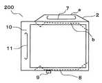
第2の実施形態の包装袋200は、表裏のフィルムの周縁部をシールした包装袋であって、図6のように、包装袋の側辺にガゼットフィルム8、2が差し込まれてサイドガゼットが設けられたサイドガゼット袋である。 The
ガゼットフィルム8、2は、包装袋の上端から離して差し込まれていて、ガゼットフィルム8の上部には、注出口となる口栓9が取り付けられている。また、包装袋200の上辺には、上部広幅シール部10が設けられている。この上部広幅シール部10に、切込みによる上部側取っ手11が設けられている。 The
本実施形態では、持ったときに痛くないように、また、製袋で異物混入の恐れのある抜きくずが出ないように、切込みにより上部側取っ手11を設けたが、貫通孔によって隅部側取っ手6を設けても良い。 In the present embodiment, the
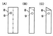
左側辺に差し込まれたガゼットフィルム8は、図7(A)のように、短冊形のフィルムからなっていて、口栓9が取り付けられている。この短冊形のフィルムを、図7(B)のように、縦に折って、通常のガゼットフィルムのように二つ折りされるが、包装袋200の上端から離して差し込まれているので、内容物収納部と連通しないように、図7(C)のように、上端部を三角形になるように斜めに折って、上端縁が左側の外端縁に重なるように折って、包装袋200に差し込まれ、側辺のシール部に端縁が収まるようにシールされている。 The
右側辺に差し込まれたガゼットフィルム2は、第1の実施形態の包装袋100のガゼットフィルム2と同じものを用いて、包装袋200に同様に差し込まれているので、説明は省略する。 Since the
ガゼットフィルム8、2を包装袋200に差し込む位置は、包装袋100と同様に、下端を包装袋200の下端に一致させるが、上端は包装袋の側辺の上端から離して差し込まれる。 The position at which the
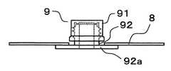
ガゼットフィルム8に注出口として取り付けられた口栓9は、図8のように、キャップ91とスパウト92からなり、スパウトの下部の台座部92aは、薄い板状に成型されていている。 The
口栓9は、ガゼットフィルム8の裏面から差し込まれ、台座部92aがガゼットフィルム8の裏面に熱融着され、取り付けられている。そして、スパウト92の中央は注出路が設けられ、スパウト92の上部はキャップ91と螺合していて、キャップ91を外して、内容物が注出路を通って注出できるようになっている。 The
このように包装袋200が構成されているので、内容物を充填すると、ガゼットフィルム8は、折った部分が延ばされ平坦になる。ガゼットフィルム2は、中の2面は接着されているので、外側の2面が延ばされ平坦になる。 Since the
このため、図9のように、中の2面のサイド側取っ手7の部分が押し出されてくる。このようになるので、サイド側取っ手7を持って、包装袋200を持ち上げて傾け、キャップ91を外した口栓9から内容物を注ぎ出すことが容易にできる。また、このとき、他方の手で、上部側取っ手11を持って、補助するとより注ぎやすい。 For this reason, as shown in FIG. 9, the portions of the side handle 7 on the two inner sides are pushed out. Thus, the contents can be easily poured out from the
包装袋200の表裏のフィルムやガゼットフィルム8、2は、包装袋100に用いたものと同様の積層フィルムを用いることができる。 As the front and back films and the
100、200・・・包装袋
1、2、8・・・ガゼットフィルム
3・・・斜めシール部
4、9・・・口栓
41、91・・・キャップ
42、92・・・スパウト
42a、92a・・・台座部
5・・・隅部広幅シール部
6・・・隅部側取っ手
7・・・サイド側取っ手
10・・・上部広幅シール部
11・・・上部側取っ手
a、b・・・折り位置100, 200 ...
Claims (8)
Translated fromJapanese該包装袋の側辺にガゼットフィルムを差し込まれてサイドガゼットが設けられ、一方の前記ガゼットフィルムは、断面M字型に蛇腹折りされ、中の2面を熱融着して接着させ、接着した前記2面に、切込み、または、貫通孔によるサイド側取っ手が設けられていることを特徴とする包装袋。A packaging bag that seals the periphery of the front and back films,
A side gusset is provided by inserting a gusset film on the side of the packaging bag, and one of the gusset films is accordion-folded into an M-shaped cross section, and the two surfaces inside are heat-bonded and bonded. The packaging bag according to claim 2, wherein a side handle by a cut or through hole is provided on the two surfaces.
Priority Applications (1)
| Application Number | Priority Date | Filing Date | Title |
|---|---|---|---|
| JP2014186122AJP2016055916A (en) | 2014-09-12 | 2014-09-12 | Packaging bag |
Applications Claiming Priority (1)
| Application Number | Priority Date | Filing Date | Title |
|---|---|---|---|
| JP2014186122AJP2016055916A (en) | 2014-09-12 | 2014-09-12 | Packaging bag |
Publications (1)
| Publication Number | Publication Date |
|---|---|
| JP2016055916Atrue JP2016055916A (en) | 2016-04-21 |
Family
ID=55756429
Family Applications (1)
| Application Number | Title | Priority Date | Filing Date |
|---|---|---|---|
| JP2014186122APendingJP2016055916A (en) | 2014-09-12 | 2014-09-12 | Packaging bag |
Country Status (1)
| Country | Link |
|---|---|
| JP (1) | JP2016055916A (en) |
Cited By (4)
| Publication number | Priority date | Publication date | Assignee | Title |
|---|---|---|---|---|
| JP2017210257A (en)* | 2016-05-25 | 2017-11-30 | 凸版印刷株式会社 | Gazette bag with spout |
| JP2018027821A (en)* | 2016-08-10 | 2018-02-22 | フジモリプラケミカル株式会社 | Gazette bag body |
| JP2020203726A (en)* | 2019-06-14 | 2020-12-24 | 株式会社フジシールインターナショナル | Packaging bag |
| KR102439170B1 (en)* | 2022-02-08 | 2022-09-01 | 주식회사 명지피앤피 | Packaging bag with handle and manufacturing method therefor |
Citations (9)
| Publication number | Priority date | Publication date | Assignee | Title |
|---|---|---|---|---|
| JPH04503044A (en)* | 1989-01-26 | 1992-06-04 | インダグ、ゲゼルシャフト、フュア、インデュストリーベダルフ、エムベーハー | upright storage bag |
| JPH04216927A (en)* | 1990-03-02 | 1992-08-07 | Emzo Sa Ic | Pliable container which can be recycled for liquid and its mass-producing machine |
| JPH05310257A (en)* | 1992-04-30 | 1993-11-22 | Dainippon Printing Co Ltd | Gusset bag that is easy to open |
| JPH0752284A (en)* | 1993-08-20 | 1995-02-28 | The Pack Kk | Bag for package with carrier and manufacture thereof |
| DE4419835A1 (en)* | 1994-06-07 | 1995-12-14 | Lemo Maschb Gmbh | Plastics foil packaging bag |
| JP2002211587A (en)* | 2001-01-19 | 2002-07-31 | Dainippon Printing Co Ltd | Self-supporting bag |
| KR100645001B1 (en)* | 2003-06-09 | 2006-11-17 | 홍종팔 | Vinyl bag with sealable outlet |
| US20100054634A1 (en)* | 2008-08-28 | 2010-03-04 | Michael Ray Runyon | Two-handled bag |
| JP3190130U (en)* | 2014-02-06 | 2014-04-17 | 株式会社タキガワ・コーポレーション・ジャパン | Packaging bag with a hand |
- 2014
- 2014-09-12JPJP2014186122Apatent/JP2016055916A/enactivePending
Patent Citations (9)
| Publication number | Priority date | Publication date | Assignee | Title |
|---|---|---|---|---|
| JPH04503044A (en)* | 1989-01-26 | 1992-06-04 | インダグ、ゲゼルシャフト、フュア、インデュストリーベダルフ、エムベーハー | upright storage bag |
| JPH04216927A (en)* | 1990-03-02 | 1992-08-07 | Emzo Sa Ic | Pliable container which can be recycled for liquid and its mass-producing machine |
| JPH05310257A (en)* | 1992-04-30 | 1993-11-22 | Dainippon Printing Co Ltd | Gusset bag that is easy to open |
| JPH0752284A (en)* | 1993-08-20 | 1995-02-28 | The Pack Kk | Bag for package with carrier and manufacture thereof |
| DE4419835A1 (en)* | 1994-06-07 | 1995-12-14 | Lemo Maschb Gmbh | Plastics foil packaging bag |
| JP2002211587A (en)* | 2001-01-19 | 2002-07-31 | Dainippon Printing Co Ltd | Self-supporting bag |
| KR100645001B1 (en)* | 2003-06-09 | 2006-11-17 | 홍종팔 | Vinyl bag with sealable outlet |
| US20100054634A1 (en)* | 2008-08-28 | 2010-03-04 | Michael Ray Runyon | Two-handled bag |
| JP3190130U (en)* | 2014-02-06 | 2014-04-17 | 株式会社タキガワ・コーポレーション・ジャパン | Packaging bag with a hand |
Cited By (5)
| Publication number | Priority date | Publication date | Assignee | Title |
|---|---|---|---|---|
| JP2017210257A (en)* | 2016-05-25 | 2017-11-30 | 凸版印刷株式会社 | Gazette bag with spout |
| JP2018027821A (en)* | 2016-08-10 | 2018-02-22 | フジモリプラケミカル株式会社 | Gazette bag body |
| JP7028571B2 (en) | 2016-08-10 | 2022-03-02 | フジモリプラケミカル株式会社 | Gazette bag |
| JP2020203726A (en)* | 2019-06-14 | 2020-12-24 | 株式会社フジシールインターナショナル | Packaging bag |
| KR102439170B1 (en)* | 2022-02-08 | 2022-09-01 | 주식회사 명지피앤피 | Packaging bag with handle and manufacturing method therefor |
Similar Documents
| Publication | Publication Date | Title |
|---|---|---|
| CN101506053A (en) | Branch type standing pouch | |
| JPH1179195A (en) | Refill pouches | |
| JP6830842B2 (en) | Pouch | |
| JP2016055916A (en) | Packaging bag | |
| JP6229379B2 (en) | Double bag | |
| JP6892817B2 (en) | Gazette bag with spout | |
| JP5476633B2 (en) | Composite container with dispensing part | |
| JP2011178458A (en) | Bag having spout | |
| JP2009057071A (en) | Free-standing bag | |
| JPH10278947A (en) | Refill pouches | |
| JP7170465B2 (en) | Gusseted bags and bag-in-box | |
| JP6379613B2 (en) | Holder and packaging bag with holder | |
| JP2015189502A (en) | Packaging bag | |
| JPH1111496A (en) | Standing pouch | |
| JP3819188B2 (en) | Liquid container and manufacturing method thereof | |
| JP3183512U (en) | Free-standing bag | |
| JP5590673B2 (en) | Packaging bag with handle | |
| JP2017081593A (en) | Pouch with spout | |
| JP3185296U (en) | Standing pouch | |
| JP6136488B2 (en) | Package and method for producing the same | |
| JP2017222390A (en) | Refilling container | |
| JP2001031119A (en) | Sealed package with spout | |
| JP7297025B2 (en) | Pouch, method for manufacturing package using said pouch, and package | |
| JP2007112489A (en) | Self-supporting packaging bag with reseal function | |
| JPH11321886A (en) | Deformed gusset pouch |
Legal Events
| Date | Code | Title | Description |
|---|---|---|---|
| A621 | Written request for application examination | Free format text:JAPANESE INTERMEDIATE CODE: A621 Effective date:20170822 | |
| A977 | Report on retrieval | Free format text:JAPANESE INTERMEDIATE CODE: A971007 Effective date:20180406 | |
| A131 | Notification of reasons for refusal | Free format text:JAPANESE INTERMEDIATE CODE: A131 Effective date:20180417 | |
| A521 | Request for written amendment filed | Free format text:JAPANESE INTERMEDIATE CODE: A523 Effective date:20180612 | |
| A02 | Decision of refusal | Free format text:JAPANESE INTERMEDIATE CODE: A02 Effective date:20180626 |