JP2016052606A - Dual chamber passive retraction needle syringe - Google Patents
Dual chamber passive retraction needle syringeDownload PDFInfo
- Publication number
- JP2016052606A JP2016052606AJP2016006637AJP2016006637AJP2016052606AJP 2016052606 AJP2016052606 AJP 2016052606AJP 2016006637 AJP2016006637 AJP 2016006637AJP 2016006637 AJP2016006637 AJP 2016006637AJP 2016052606 AJP2016052606 AJP 2016052606A
- Authority
- JP
- Japan
- Prior art keywords
- plunger rod
- barrel
- needle hub
- needle
- stopper
- Prior art date
- Legal status (The legal status is an assumption and is not a legal conclusion. Google has not performed a legal analysis and makes no representation as to the accuracy of the status listed.)
- Granted
Links
Images


Classifications
- A—HUMAN NECESSITIES
- A61—MEDICAL OR VETERINARY SCIENCE; HYGIENE
- A61M—DEVICES FOR INTRODUCING MEDIA INTO, OR ONTO, THE BODY; DEVICES FOR TRANSDUCING BODY MEDIA OR FOR TAKING MEDIA FROM THE BODY; DEVICES FOR PRODUCING OR ENDING SLEEP OR STUPOR
- A61M5/00—Devices for bringing media into the body in a subcutaneous, intra-vascular or intramuscular way; Accessories therefor, e.g. filling or cleaning devices, arm-rests
- A61M5/178—Syringes
- A61M5/31—Details
- A61M5/32—Needles; Details of needles pertaining to their connection with syringe or hub; Accessories for bringing the needle into, or holding the needle on, the body; Devices for protection of needles
- A61M5/3205—Apparatus for removing or disposing of used needles or syringes, e.g. containers; Means for protection against accidental injuries from used needles
- A61M5/321—Means for protection against accidental injuries by used needles
- A61M5/322—Retractable needles, i.e. disconnected from and withdrawn into the syringe barrel by the piston
- A61M5/3234—Fully automatic needle retraction, i.e. in which triggering of the needle does not require a deliberate action by the user
- A—HUMAN NECESSITIES
- A61—MEDICAL OR VETERINARY SCIENCE; HYGIENE
- A61M—DEVICES FOR INTRODUCING MEDIA INTO, OR ONTO, THE BODY; DEVICES FOR TRANSDUCING BODY MEDIA OR FOR TAKING MEDIA FROM THE BODY; DEVICES FOR PRODUCING OR ENDING SLEEP OR STUPOR
- A61M5/00—Devices for bringing media into the body in a subcutaneous, intra-vascular or intramuscular way; Accessories therefor, e.g. filling or cleaning devices, arm-rests
- A61M5/178—Syringes
- A61M5/31—Details
- A61M5/315—Pistons; Piston-rods; Guiding, blocking or restricting the movement of the rod or piston; Appliances on the rod for facilitating dosing ; Dosing mechanisms
- A61M5/31511—Piston or piston-rod constructions, e.g. connection of piston with piston-rod
- A—HUMAN NECESSITIES
- A61—MEDICAL OR VETERINARY SCIENCE; HYGIENE
- A61M—DEVICES FOR INTRODUCING MEDIA INTO, OR ONTO, THE BODY; DEVICES FOR TRANSDUCING BODY MEDIA OR FOR TAKING MEDIA FROM THE BODY; DEVICES FOR PRODUCING OR ENDING SLEEP OR STUPOR
- A61M5/00—Devices for bringing media into the body in a subcutaneous, intra-vascular or intramuscular way; Accessories therefor, e.g. filling or cleaning devices, arm-rests
- A61M5/178—Syringes
- A61M5/31—Details
- A61M5/32—Needles; Details of needles pertaining to their connection with syringe or hub; Accessories for bringing the needle into, or holding the needle on, the body; Devices for protection of needles
- A61M5/3293—Needles; Details of needles pertaining to their connection with syringe or hub; Accessories for bringing the needle into, or holding the needle on, the body; Devices for protection of needles characterised by features of the needle hub
- A—HUMAN NECESSITIES
- A61—MEDICAL OR VETERINARY SCIENCE; HYGIENE
- A61M—DEVICES FOR INTRODUCING MEDIA INTO, OR ONTO, THE BODY; DEVICES FOR TRANSDUCING BODY MEDIA OR FOR TAKING MEDIA FROM THE BODY; DEVICES FOR PRODUCING OR ENDING SLEEP OR STUPOR
- A61M5/00—Devices for bringing media into the body in a subcutaneous, intra-vascular or intramuscular way; Accessories therefor, e.g. filling or cleaning devices, arm-rests
- A61M5/50—Devices for bringing media into the body in a subcutaneous, intra-vascular or intramuscular way; Accessories therefor, e.g. filling or cleaning devices, arm-rests having means for preventing re-use, or for indicating if defective, used, tampered with or unsterile
- A61M5/5013—Means for blocking the piston or the fluid passageway to prevent illegal refilling of a syringe
- A61M5/502—Means for blocking the piston or the fluid passageway to prevent illegal refilling of a syringe for blocking the piston
- A—HUMAN NECESSITIES
- A61—MEDICAL OR VETERINARY SCIENCE; HYGIENE
- A61M—DEVICES FOR INTRODUCING MEDIA INTO, OR ONTO, THE BODY; DEVICES FOR TRANSDUCING BODY MEDIA OR FOR TAKING MEDIA FROM THE BODY; DEVICES FOR PRODUCING OR ENDING SLEEP OR STUPOR
- A61M5/00—Devices for bringing media into the body in a subcutaneous, intra-vascular or intramuscular way; Accessories therefor, e.g. filling or cleaning devices, arm-rests
- A61M5/50—Devices for bringing media into the body in a subcutaneous, intra-vascular or intramuscular way; Accessories therefor, e.g. filling or cleaning devices, arm-rests having means for preventing re-use, or for indicating if defective, used, tampered with or unsterile
- A61M5/5066—Means for preventing re-use by disconnection of piston and piston-rod
- A—HUMAN NECESSITIES
- A61—MEDICAL OR VETERINARY SCIENCE; HYGIENE
- A61M—DEVICES FOR INTRODUCING MEDIA INTO, OR ONTO, THE BODY; DEVICES FOR TRANSDUCING BODY MEDIA OR FOR TAKING MEDIA FROM THE BODY; DEVICES FOR PRODUCING OR ENDING SLEEP OR STUPOR
- A61M5/00—Devices for bringing media into the body in a subcutaneous, intra-vascular or intramuscular way; Accessories therefor, e.g. filling or cleaning devices, arm-rests
- A61M5/178—Syringes
- A61M5/31—Details
- A61M5/32—Needles; Details of needles pertaining to their connection with syringe or hub; Accessories for bringing the needle into, or holding the needle on, the body; Devices for protection of needles
- A61M5/3205—Apparatus for removing or disposing of used needles or syringes, e.g. containers; Means for protection against accidental injuries from used needles
- A61M5/321—Means for protection against accidental injuries by used needles
- A61M5/322—Retractable needles, i.e. disconnected from and withdrawn into the syringe barrel by the piston
- A61M5/3221—Constructional features thereof, e.g. to improve manipulation or functioning
- A61M2005/3227—Constructional features thereof, e.g. to improve manipulation or functioning the needle being retracted laterally outside the syringe barrel, e.g. with separate guideway
- A—HUMAN NECESSITIES
- A61—MEDICAL OR VETERINARY SCIENCE; HYGIENE
- A61M—DEVICES FOR INTRODUCING MEDIA INTO, OR ONTO, THE BODY; DEVICES FOR TRANSDUCING BODY MEDIA OR FOR TAKING MEDIA FROM THE BODY; DEVICES FOR PRODUCING OR ENDING SLEEP OR STUPOR
- A61M5/00—Devices for bringing media into the body in a subcutaneous, intra-vascular or intramuscular way; Accessories therefor, e.g. filling or cleaning devices, arm-rests
- A61M5/178—Syringes
- A61M5/31—Details
- A61M5/32—Needles; Details of needles pertaining to their connection with syringe or hub; Accessories for bringing the needle into, or holding the needle on, the body; Devices for protection of needles
- A61M5/3205—Apparatus for removing or disposing of used needles or syringes, e.g. containers; Means for protection against accidental injuries from used needles
- A61M5/321—Means for protection against accidental injuries by used needles
- A61M5/322—Retractable needles, i.e. disconnected from and withdrawn into the syringe barrel by the piston
- A61M5/3234—Fully automatic needle retraction, i.e. in which triggering of the needle does not require a deliberate action by the user
- A61M2005/3235—Fully automatic needle retraction, i.e. in which triggering of the needle does not require a deliberate action by the user triggered by radial deflection of the anchoring parts between needle mount and syringe barrel or needle housing, e.g. spreading of needle mount retaining hooks having slanted surfaces by engagement with correspondingly shaped surfaces on the piston at the end of an injection stroke
Landscapes
- Health & Medical Sciences (AREA)
- Engineering & Computer Science (AREA)
- Hematology (AREA)
- Anesthesiology (AREA)
- Biomedical Technology (AREA)
- Heart & Thoracic Surgery (AREA)
- Vascular Medicine (AREA)
- Life Sciences & Earth Sciences (AREA)
- Animal Behavior & Ethology (AREA)
- General Health & Medical Sciences (AREA)
- Public Health (AREA)
- Veterinary Medicine (AREA)
- Environmental & Geological Engineering (AREA)
- Infusion, Injection, And Reservoir Apparatuses (AREA)
Abstract
Description
Translated fromJapanese本発明の様相は、格納(引き込み)可能なニードル及び再使用防止の特徴を含んでいる注射器アセンブリ、及びかかる注射器アセンブリの使用方法に関する。 Aspects of the invention relate to a syringe assembly that includes a retractable needle and a non-reusable feature, and a method of using such a syringe assembly.
ニードルの格納(引き込み)の特徴部は、使用者を針刺し損傷から護るために注射器アセンブリに組み込まれている。従来のアセンブリにおいては、ニードルカニューレを含んでいるニードルハブアセンブリが、注射器のバレル(胴部)に取り付けられ、そして注射器のバレル(胴部)内に使用者によって、又は格納(引き込み)特徴部によって引き込まれねばならない。代わりには、ニードル遮蔽物がニードルカニューレを覆って、使用者により又は別の方法で置かれてもよい。 The needle retracting feature is incorporated into the syringe assembly to protect the user from needle stick damage. In conventional assemblies, a needle hub assembly that includes a needle cannula is attached to the barrel of the syringe and is placed by the user in the barrel of the syringe or by a retracting (retracting) feature. Must be pulled in. Alternatively, a needle shield may be placed by the user or otherwise over the needle cannula.
ニードルハブアセンブリが格納(引き込み)特徴部によって注射器のバレル(胴部)に引き込まれる従来の注射器アセンブリにおいては、引き込み特徴部が、注射器のバレル(胴部)及び/又は注射器のバレル(胴部)内に配置されたプランジャーロッド内に、しばしば、設けられている。具体的にいうと、プランジャーロッドは、ニードルハブが引き込まれた後にそれを収容するチャンバーを含んでもよい。引き込み特徴部は、典型的には、引き込まれたニードルハブを受け入れるべくプランジャーロッドのチャンバーを露呈するために、注射器のバレル(胴部)の内容物が放出された後に、ストッパーを開くべく用いられる、プランジャーロッドとストッパーとの間に配置された切断要素を含んでいる。スプリングも頻繁に、ニードルハブのプランジャーロッドへの格納を促進するために、ニードルハブアセンブリに組み込まれている。 In conventional syringe assemblies, where the needle hub assembly is retracted into the syringe barrel by a retractable feature, the retractable feature is the syringe barrel and / or the syringe barrel. Often provided within a plunger rod disposed therein. Specifically, the plunger rod may include a chamber that houses the needle hub after it has been retracted. The retraction feature is typically used to open the stopper after the contents of the syringe barrel have been released to expose the plunger rod chamber to receive the retracted needle hub. A cutting element disposed between the plunger rod and the stopper. Springs are also often incorporated into the needle hub assembly to facilitate retracting the needle hub into the plunger rod.
従って、かかる格納(引き込み)特徴部は、作動(活性化)のための切断、破壊、穴明け、又は他の力−集中的な機械的作用、及び、かくて、シールされたプランジャーとストッパーが作動(活性化)中に破壊されるのを可能にすべく、より一層の複雑さを要求している。さらに、最も従来方式で設計された格納(引き込み)可能なニードルが、投薬後に、プランジャーロッドの後部への継続する圧力によって作動されるとき、引き込み特徴部の不用意な作動(活性化)が起こるかもしれない。注射器バレル(胴部)の内容物を放出するときに、同じ力が加えられねばならないからである。また、ある装置は、注射器の内容物の放出中に十分な圧力が発生されないなら、例えば、薬剤が粘性で、そして引き込み特徴部を作動させるのに要求される力を超える追加の圧力ないしは力を使用者がプランジャーロッドに加えることを必要とするときは、投薬中に不用意に作動されるかもしれない。時期尚早の作動(活性化)は、強い力がプランジャーロッドに加えられる場合、例えば、高速注入中での適用において特に問題になる。 Thus, such a retracting (retracting) feature can be cut, broken, drilled, or other force-intensive mechanical action for activation (activation), and thus sealed plungers and stoppers. It requires even more complexity to be able to be destroyed during operation (activation). In addition, when the retractable needle designed in the most conventional manner is actuated by continuous pressure on the back of the plunger rod after dosing, inadvertent actuation (activation) of the retraction feature will occur. May happen. This is because the same force must be applied when discharging the contents of the syringe barrel. Also, some devices may provide additional pressure or force, for example, if the drug is viscous and exceeds the force required to actuate the retracting feature if sufficient pressure is not generated during the release of the syringe contents. When the user needs to add to the plunger rod, it may be inadvertently activated during medication. Premature actuation (activation) becomes particularly problematic when a strong force is applied to the plunger rod, for example in applications during fast injection.
従来のプランジャーで作動される注射器のバレル(胴部)の引き込み特徴部は、上述のように、増加した注射器圧力及びプランジャーロッドに加えられる力に関連した増加に耐えなければならない。これらの増加した力及び圧力は、時期尚早の作動(活性化)を防止するために、操作力を超えるであろう大きな作動(活性化)力の要求へとつながる。多くの従来の注射器のバレル(胴部)は、完全な投薬の後に、投薬運動と同じ方法での追加のプランジャー運動を利用しているので、使用者が完全に底づきされるプランジャーと引き込み特徴部の作動(活性化)との間で差別化するのを許容するために、閾値力が用いられねばならなかった。当該閾値力は、確定させ、そして注射器のバレル(胴部)の内容物を放出するためにプランジャーロッドに加えられる力から切り離して維持するのは困難である。さらに、当該閾値力を適切にかけるには、注射器のバレル(胴部)及びニードルカニューレを患者の皮膚にほぼ平行に位置決めする代わりに、注射器のバレル(胴部)及びニードルカニューレを患者の皮膚に対して増加した角度で位置決めすることを使用者に要求するかもしれない。引き込み特徴部を作動させるのに要求される追加の力は、ストッパー又はプランジャーロッドにおける他の除去可能な開口に発生される追加の圧力を生じさせるかもしれしれず、その追加の圧力はストッパー及び/又はプランジャーロッドを機能不全にさせるに十分であるかもしれない。 The retraction feature of a conventional plunger-operated syringe barrel must withstand the increases associated with increased syringe pressure and force applied to the plunger rod, as described above. These increased forces and pressures lead to a demand for a large actuation (activation) force that will exceed the operating force to prevent premature actuation (activation). Many conventional syringe barrels utilize an additional plunger movement in the same way as the dosing movement after a complete dosing, so that the A threshold force had to be used to allow differentiation between actuation (activation) of the retract feature. The threshold force is difficult to determine and maintain separately from the force applied to the plunger rod to release the contents of the syringe barrel. Further, in order to properly apply the threshold force, instead of positioning the syringe barrel and needle cannula substantially parallel to the patient's skin, the syringe barrel and needle cannula are applied to the patient's skin. It may require the user to position at an increased angle relative to the user. The additional force required to actuate the retraction feature may cause additional pressure generated at the stopper or other removable opening in the plunger rod, the additional pressure being the stopper and It may be sufficient to / or cause the plunger rod to malfunction.
従来の格納(引き込み)可能な注射器における引き込み特徴部及び後続のニードルハブの収容部が流体経路内に包含されている従来の注射器アセンブリにおいて、引き込み特徴部及び収容部は、注射器のバレル(胴部)内に捕捉される薬剤の容量を生じさせ、それによって、浪費を増加し、且つ潜在的に投薬精度に影響を及ぼしている。さらに、捕捉されている薬剤の一部は引き込み特徴部の作動(活性化)中に放出され得、ニードルカニューレが患者の外側にあるときに引き込み特徴部が作動されるなら飛び散りを生じさせ、又は、ニードルカニューレが患者の内側にあるときに引き込み特徴部が作動されるなら患者に投与される用量における意図されない増加を生じさせる。注射器のバレル(胴部)内の引き込み特徴部の配置はまた、注射器をパージ又はプライムするときに、捕捉された空気を注射器のバレル(胴部)内に残す原因となり得る。これは空気が注入される可能性につながる。注射器のバレル(胴部)の大きさは、引き込み特徴部及び格納(引き込み)後に収容されるであろう、ニードルハブアセンブリにもまた適応しなければならない。 In a conventional syringe assembly in which a retractable feature in a conventional retractable syringe and a subsequent needle hub containment are included in the fluid path, the retractable feature and containment are in the barrel of the syringe. ) Produces a volume of drug trapped in it, thereby increasing waste and potentially affecting dosing accuracy. Further, a portion of the drug being captured may be released during actuation (activation) of the retraction feature, causing splatter if the retraction feature is activated when the needle cannula is outside the patient, or If the retracting feature is activated when the needle cannula is inside the patient, it will cause an unintended increase in the dose administered to the patient. The placement of the retraction feature in the syringe barrel can also cause trapped air to remain in the syringe barrel when purging or priming the syringe. This leads to the possibility of air being injected. The size of the barrel of the syringe must also accommodate the retraction feature and the needle hub assembly that will be accommodated after storage (retraction).
引き込み特徴部を流体経路内に収容していない注射器アセンブリにおいて、引き込み特徴部は、使用者が引き込み特徴部を作動させるためには、注射器アセンブリのそれらのグリップの変更を要求する位置にしばしば配置されている。 In a syringe assembly that does not contain the retraction feature in the fluid path, the retraction feature is often located at a location where a user requires a change in their grip on the syringe assembly to activate the retraction feature. ing.
従来の格納(引き込み)注射器アセンブリは、しばしば、再使用防止特徴部を組み込んでおらず、従って、格納(引き込み)機構はリセットされ、そうして注射器のバレル(胴部)は再使用され得る。消毒又は十分な消毒なしでの注射器アセンブリの再使用は、接触伝染性の病気の伝染を助長すると信じられており、さらに、従来の注射器の引き込み特徴部はまた、使用者が格納(引き込み)機構を能動的に作動させることをしばしば要求する。従って、格納(引き込み)機構を作動させる又は適切に作動させるのを失敗する人為的エラーの機会が、ニードルの継続する露出につながり得る。 Conventional storage (retraction) syringe assemblies often do not incorporate anti-reuse features, so that the storage (retraction) mechanism is reset and thus the syringe barrel can be reused. Reuse of the syringe assembly without disinfection or sufficient disinfection is believed to facilitate the transmission of contact infectious diseases, and in addition, the retraction features of conventional syringes are also user retractable (retraction) mechanisms Often require active activation. Thus, the opportunity for human error to fail to actuate or properly actuate the retracting (retraction) mechanism can lead to continued exposure of the needle.
従って、注射器アセンブリの通常動作を妨げることがなく、受動的に作動され、及び時期尚早の作動(活性化)又は格納(引き込み)機構の危険性を低減する、格納(引き込み)特徴部を備える格納(引き込み)可能な注射器アセンブリを提供することが望ましいであろう。再使用防止の特徴部を組み込んだ格納(引き込み)可能な注射器アセンブリを提供することもまた、望ましいであろう。 Thus, a storage with a storage (retraction) feature that is passively operated and reduces the risk of premature operation (activation) or storage (retraction) mechanisms without interfering with the normal operation of the syringe assembly. It would be desirable to provide a syringe assembly that can be retracted. It would also be desirable to provide a retractable syringe assembly that incorporates anti-reuse features.
本発明の1つの実施形態は、流体を保持するための流体チャンバーを画成する内側表面を有し、そして第1の断面幅を有する側壁と、開口した基端部と、末端壁を含んでいる末端部とを含む流体バレル、当該流体チャンバー内に配置されたプランジャーロッドであって、末端部、基端部、当該末端部から当該基端部まで延在しているプランジャーロッド本体、及び当該バレルの内側表面との液密シールを形成するためにプランジャーロッドの末端部に配置されたストッパーを備えるプランジャーロッド、当該流体バレルの側壁に隣接して配置された格納バレルであって、ニードルチャンバーを画成する内部表面を有する壁、開口した基端部、障壁を含んで開口した末端部、当該流体チャンバーと当該ニードルチャンバーとが流体連通するための、流体バレルの壁及び流体バレルの側壁の間の開口部、及びニードルハブと、当該開口部に流体連通して当該ニードルハブに取り付けられたニードルカニューレと、を備えるニードルハブアセンブリであって、基端方向に移動すべく付勢されているニードルハブアセンブリ、を含む格納バレル、及びプランジャーロッドと共に移動し、当該格納バレルのニードルチャンバー内に延在しているトリガー要素であって、ニードルカニューレが格納バレル内に引き込むのを起こさせるトリガー力を提供するトリガー要素、を備えることを特徴とする注射器アセンブリ、に関する。 One embodiment of the present invention has an inner surface defining a fluid chamber for holding fluid and includes a sidewall having a first cross-sectional width, an open proximal end, and a distal wall. A fluid barrel including a distal end portion, a plunger rod disposed in the fluid chamber, the distal end portion, a proximal end portion, and a plunger rod body extending from the distal end portion to the proximal end portion, And a plunger rod comprising a stopper disposed at the distal end of the plunger rod to form a fluid tight seal with the inner surface of the barrel, a storage barrel disposed adjacent to the sidewall of the fluid barrel A wall having an inner surface defining a needle chamber, an open proximal end, an open distal end including a barrier, for fluid communication between the fluid chamber and the needle chamber A needle hub assembly comprising: a fluid barrel wall and an opening between the fluid barrel sidewall; and a needle hub; and a needle cannula in fluid communication with the opening and attached to the needle hub. A storage barrel including a needle hub assembly biased to move in an end direction, and a trigger element that moves with the plunger rod and extends into the needle chamber of the storage barrel, the needle cannula being A syringe assembly comprising: a triggering element that provides a triggering force that causes retraction in a storage barrel.
本発明の1つ以上の実施形態において、本発明の注射器アセンブリの当該壁は、ニードルチャンバー内に配置されたニードルアセンブリに係合する支持要素を含み、及び当該支持要素は、第1の位置においてニードルカニューレが格納バレルの開口した末端部を末端方向に越えて延在するように、ニードルハブに末端方向の力を加えるべく位置されている。 In one or more embodiments of the present invention, the wall of the syringe assembly of the present invention includes a support element that engages a needle assembly disposed within the needle chamber, and the support element is in a first position. The needle cannula is positioned to apply a distal force to the needle hub such that the needle cannula extends distally beyond the open end of the storage barrel.
本発明の1つ以上の実施形態において、当該トリガー要素は、当該ニードルカニューレが格納バレル内に収容されるように、当該支持要素とニードルハブとを係合解除させるべくニードルハブにトリガー力を提供する。 In one or more embodiments of the present invention, the trigger element provides a trigger force to the needle hub to disengage the support element and the needle hub such that the needle cannula is received within the storage barrel. To do.
本発明の1つ以上の実施形態において、当該ニードルハブは、ニードルハブと障壁との間に配置され、ニードルハブに基端方向に力を及ぼすスプリングによって付勢されている。 In one or more embodiments of the invention, the needle hub is disposed between the needle hub and the barrier and is biased by a spring that exerts a proximal force on the needle hub.
本発明の1つ以上の実施形態において、当該トリガー要素は、プランジャーロッドの末端部に取り付けられている。本発明の1つ以上の実施形態において、当該トリガー要素は、プランジャーロッドの基端部に取り付けられた基端部と、トリガー力を提供する自由で開口した末端部と、当該基端部から当該末端部まで延在し、及び中空の内部を画成している内部表面を含むトリガー要素本体と、を含んでいる。 In one or more embodiments of the invention, the trigger element is attached to the distal end of the plunger rod. In one or more embodiments of the present invention, the trigger element includes a proximal end attached to the proximal end of the plunger rod, a free open distal end that provides a triggering force, and a proximal end. And a trigger element body including an interior surface extending to the distal end and defining a hollow interior.
本発明の1つ以上の実施形態において、注射器のバレル(胴部)の内側表面は、前記基端部に隣接して、第1の断面幅よりも狭い第2の断面幅を画成する保持リングを含み、且つプランジャーロッド本体は、当該バレルのリブにおける断面幅より大きな断面幅を有する可撓性の突出部、及び壊れ易い部分を含んでいる。 In one or more embodiments of the present invention, the inner surface of the barrel of the syringe is adjacent to the proximal end and defines a second cross-sectional width that is narrower than the first cross-sectional width. The plunger rod body, including the ring, includes a flexible protrusion having a cross-sectional width greater than the cross-sectional width of the barrel rib, and a fragile portion.
本発明の1つ以上の実施形態において、当該プランジャーロッド本体は、末端部分及び基端部分と、当該末端部分及び基端部分の間に配置された突出部とを備えている。本発明の1つ以上の実施形態において、当該プランジャーロッド本体の当該末端部分は、可撓性の突出部の基端側に隣接して配置された支持部材、及び当該支持部材の基端側に隣接して配置された少なくとも1つの壊れ易い部分を備えている。本発明の1つ以上の実施形態において、当該トリガー要素の基端部は、プランジャーロッドの親指押さえに取り付けられている。本発明の1つ以上の実施形態において、当該プランジャーロッドの末端部はストッパー係合部分を含み、及び当該ストッパーはプランジャーロッドのストッパー係合部分に取り付けられており、当該ストッパーは、当該ストッパーの末端部が当該バレルの末端壁に接触するとき、当該突出部が当該バレルのリブを過ぎて末端方向に前進し、且つ当該注射器アセンブリの再使用を防止すべくプランジャーロッドを当該バレル内にロックするのを可能にするように、当該ストッパー係合部分に対して予め選定された軸方向距離だけ末端方向及び基端方向に移動可能である。本発明の1つ以上の実施形態において、当該プランジャーロッドのストッパー係合部分は、当該バレルを保持しながら、基端方向に向けられた初期の力がプランジャーロッドに加えられたとき、ストッパーが静止して残ったまま、当該プランジャーロッド及びトリガー要素が当該バレル内を基端方向に軸方向の距離の長さ移動するのを生じさせるように、当該ストッパーに連結されている。本発明の1つ以上の実施形態において、当該プランジャーロッドのストッパー係合部分は、当該バレルを保持しながら、基端方向に向けられた継続した力がプランジャーロッドに加えられたとき、当該ストッパー、当該プランジャーロッド及びトリガー要素が当該バレル内を基端方向に共に移動するのを生じさせるように、当該ストッパーに連結されている。本発明の1つ以上の実施形態において、当該プランジャーロッドのストッパー係合部分は、当該バレルを保持しながら、基端方向に向けられた初期の力をプランジャーロッドに加えた後に、末端方向に向けられた初期の力をプランジャーロッドに加えると、ストッパーが静止して残り、当該プランジャーロッド及びトリガー要素が当該バレル内を末端方向に軸方向の距離の長さ移動するのを生じさせるように、当該ストッパーに連結されている。本発明の1つ以上の実施形態において、当該プランジャーロッドのストッパー係合部分は、末端方向に向けられた継続した力がプランジャーロッドに加えられると、当該ストッパー、当該プランジャーロッド及びトリガー要素が当該バレル内を基端方向に共に、当該ストッパーが当該バレルの末端部に到達するまで移動するのを生じさせるように、当該ストッパーに連結されている。本発明の1つ以上の実施形態において、当該ストッパーと当該バレルの末端壁との接触は、当該支持要素がニードルハブから係合解除すること、及び当該突出部が当該バレルのリブを過ぎて末端方向に前進すること、及び当該注射器アセンブリの再使用を防止すべく、プランジャーロッドを当該バレル内にロックすることを生じさせる。本発明の1つ以上の実施形態において、突出部がリブを過ぎて末端方向に前進した後にプランジャーに基端方向に向けられた力を加えると、プランジャーロッドの少なくとも1つの壊れ易い部分の破損を生じさせる。本発明の1つ以上の実施形態において、プランジャーロッドに継続的な基端方向に向けられた力を加えると、ストッパー係合部分のストッパーからの係合解除を生じさせる。 In one or more embodiments of the present invention, the plunger rod body includes a distal portion and a proximal portion and a protrusion disposed between the distal and proximal portions. In one or more embodiments of the invention, the distal portion of the plunger rod body includes a support member disposed adjacent to a proximal side of the flexible protrusion, and a proximal side of the support member At least one fragile portion disposed adjacent to the. In one or more embodiments of the invention, the proximal end of the trigger element is attached to a plunger rod thumb retainer. In one or more embodiments of the present invention, the distal end of the plunger rod includes a stopper engaging portion, and the stopper is attached to the stopper engaging portion of the plunger rod, the stopper being the stopper When the distal end of the barrel contacts the distal wall of the barrel, the protrusion advances distally past the barrel rib and a plunger rod is inserted into the barrel to prevent reuse of the syringe assembly. It is movable in the distal and proximal directions by a preselected axial distance relative to the stopper engaging portion to allow locking. In one or more embodiments of the present invention, the stopper engaging portion of the plunger rod is configured to stop when an initial force directed in the proximal direction is applied to the plunger rod while holding the barrel. The plunger rod and trigger element are connected to the stopper so as to cause the plunger rod and trigger element to move proximally in the axial direction for a length of the axial distance. In one or more embodiments of the present invention, the stopper engaging portion of the plunger rod retains the barrel and when a continuous force directed in the proximal direction is applied to the plunger rod, the The stopper, the plunger rod, and the trigger element are connected to the stopper so as to cause movement in the proximal direction in the barrel. In one or more embodiments of the invention, the stopper engaging portion of the plunger rod is applied in the distal direction after applying an initial force directed in the proximal direction to the plunger rod while holding the barrel. When an initial force directed to the plunger rod is applied to the plunger rod, the stopper remains stationary, causing the plunger rod and trigger element to move axially a distance in the distal direction within the barrel. As such, it is connected to the stopper. In one or more embodiments of the present invention, the stopper engaging portion of the plunger rod is configured such that the distal end, the plunger rod, and the trigger element when a continuous force directed in the distal direction is applied to the plunger rod. Are coupled to the stopper so as to cause the stopper to move together in the proximal direction until the stopper reaches the distal end of the barrel. In one or more embodiments of the present invention, the contact between the stopper and the end wall of the barrel is such that the support element disengages from the needle hub, and the protrusion extends past the rib of the barrel. Advancing in the direction and causing the plunger rod to lock into the barrel to prevent reuse of the syringe assembly. In one or more embodiments of the present invention, applying a proximally directed force to the plunger after the protrusion has advanced distally past the ribs, at least one fragile portion of the plunger rod. Cause damage. In one or more embodiments of the invention, applying a continuous proximal force on the plunger rod causes the stopper engaging portion to disengage from the stopper.
本発明の一様相において、当該トリガー要素の開口した末端部は、末端方向に延在している傾斜された縁部を備えている。 In one aspect of the invention, the open end of the trigger element has a beveled edge extending in the distal direction.
本発明の1つ以上の実施形態において、格納バレルは流体バレルに平行に配置されている。 In one or more embodiments of the invention, the containment barrel is disposed parallel to the fluid barrel.
本発明のもう1つの実施形態は、開口した基端部と、流体を保持するための流体チャンバーを画成する内側表面を有し、且つ第1の断面幅を有する側壁と、ニードルハブアセンブリを収容するためのニードルチャンバーとを含むバレルであって、当該流体チャンバー及び当該ニードルチャンバーは、当該流体チャンバーと当該ニードルチャンバーとの間の流体連通を可能にする第1の開口部を有する障壁によって分けられており、当該ニードルチャンバーは、その内部に配置されたニードルハブアセンブリに係合するべく当該ニードルチャンバー内に延在している可撓性タブを含んでいる、バレルと、当該ニードルチャンバー内に配置されたニードルハブアセンブリであってニードルハブと当該第1の開口部に流体連通して当該ニードルハブに取り付けられたニードルカニューレとを備え、当該ニードルカニューレは基端方向に移動するべく付勢され、位置決めされた第1の位置において当該ニードルカニューレが格納バレルの開口した末端部を越えて延在するように当該可撓性タブはニードルハブに係合してニードルハブに末端方向の力を加えるべく位置決めされている、ニードルハブアセンブリと、流体チャンバー内に配置されたプランジャーロッドであって、末端部と、基端部と、当該バレルの内側表面とで液密シールを形成するためにプランジャーロッドの当該末端部に配置されたストッパーと、当該末端部から当該基端部まで延在しているプランジャーロッド本体と、当該可撓性タブを移動させてニードルカニューレを引き込み格納バレル内の第2の位置において収容されるのを生じさせるべくプランジャーロッドに配置された起動要素とを備える、プランジャーロッドと、を備えることを特徴とする注射器アセンブリに関する。 Another embodiment of the present invention includes an open proximal end, a sidewall having an inner surface defining a fluid chamber for holding fluid and having a first cross-sectional width, and a needle hub assembly. A barrel including a needle chamber for containing the fluid chamber and the needle chamber separated by a barrier having a first opening that allows fluid communication between the fluid chamber and the needle chamber. The needle chamber includes a barrel that includes a flexible tab extending into the needle chamber to engage a needle hub assembly disposed therein; A needle hub assembly disposed in fluid communication with the needle hub and the first opening; An attached needle cannula, wherein the needle cannula is biased to move proximally so that the needle cannula extends beyond the open distal end of the storage barrel in the first position positioned. The flexible tab includes a needle hub assembly positioned to engage and apply a distal force to the needle hub, and a plunger rod disposed within the fluid chamber, the distal end And a stopper disposed at the distal end of the plunger rod to form a fluid tight seal with the proximal end and the inner surface of the barrel, and extending from the distal end to the proximal end The plunger rod body and the flexible tab are moved to retract the needle cannula and receive it in the second position in the storage barrel. And a starting element arranged in the plunger rod to cause the that the plunger rod, to a syringe assembly comprising: a.
本発明の1つ以上の実施形態において、当該ニードルカニューレは、基端方向に移動すべく、ニードルハブと障壁との間に配置され当該ニードルハブに力を及ぼすスプリングによって付勢され、そして当該スプリングは、可撓性タブが当該ニードルハブに係合しているときに圧縮されている。本発明の1つ以上の実施形態において、当該ニードルチャンバー障壁はさらに、当該可撓性タブが当該ニードルチャンバー内に内方に曲がるのを可能にする第2の開口部、及び流体チャンバーに外方に延在する傾斜部を備えている。当該可撓性タブ及びニードルハブの係合解除は、当該スプリングが拡張するのを可能にし、そしてニードルハブが当該トリガー要素の中空の内部に引き込むのを生じさせる。 In one or more embodiments of the present invention, the needle cannula is urged by a spring disposed between the needle hub and the barrier to exert a force on the needle hub to move proximally, and the spring Is compressed when the flexible tab engages the needle hub. In one or more embodiments of the invention, the needle chamber barrier further includes a second opening that allows the flexible tab to bend inwardly into the needle chamber, and outwardly into the fluid chamber. It is provided with the inclined part extended to. The disengagement of the flexible tab and needle hub allows the spring to expand and causes the needle hub to retract into the hollow interior of the trigger element.
本発明の1つ以上の実施形態において、当該トリガー要素は、プランジャーロッド本体に配置され、当該プランジャーロッド本体から半径方向外方に延在している。本発明の1つ以上の実施形態において、当該バレルは、側壁の外側表面に配置された用量限界指示器を備えている。本発明の1つ以上の実施形態において、プランジャーロッドへ基端方向の力を加えると、プランジャーロッドの基端方向への移動及び液体の流体チャンバーへの吸引を生じさせ、及び後続して末端方向の力を加えると、プランジャーロッドの傾斜部への係合、及びニードルハブに末端方向に加えられる力を解放すべく、当該可撓性タブの流体チャンバーへの外方への撓みを生じさせる。本発明の1つ以上の実施形態において、当該流体チャンバーにおける側壁の内側表面は、前記基端部に隣接して、第1の断面幅よりも狭い第2の断面幅を画成する保持リングを含み、及び当該プランジャーロッド本体は、当該バレルのリブにおける断面幅より大きな断面幅を有する可撓性の突出部及び壊れ易い部分を含んでいる。 In one or more embodiments of the invention, the trigger element is disposed on the plunger rod body and extends radially outward from the plunger rod body. In one or more embodiments of the invention, the barrel includes a dose limit indicator disposed on the outer surface of the sidewall. In one or more embodiments of the present invention, applying proximal force to the plunger rod causes proximal movement of the plunger rod and suction of liquid into the fluid chamber, and subsequently. Applying a distal force will cause the flexible tab to flex outwardly to release the engagement of the plunger rod ramp and the force applied distally to the needle hub. Cause it to occur. In one or more embodiments of the present invention, the inner surface of the sidewall in the fluid chamber includes a retaining ring that defines a second cross-sectional width that is narrower than the first cross-sectional width adjacent to the proximal end. The plunger rod body includes a flexible protrusion and a fragile portion having a cross-sectional width greater than the cross-sectional width of the barrel rib.
本発明の1つ以上の実施形態において、当該ストッパーと当該バレルの末端壁とが接触すると、当該可撓性タブのニードルハブからの係合解除、当該突出部の当該バレルのリブを過ぎての末端方向への前進、及び注射器アセンブリの再使用を防止するための当該バレル内でのプランジャーロッドのロックを生じさせる。本発明の1つ以上の実施形態において、当該プランジャーロッドの末端部はストッパー係合部分を含み、及びストッパーはプランジャーロッドの当該ストッパー係合部分に取り付けられ、当該ストッパーは、プランジャーロッドに末端方向に力が加えられ、及び当該ストッパーの末端部が当該バレルの末端壁に接触したとき、突出部が当該バレルのリブを過ぎて末端方向に前進し、及び注射器アセンブリの再使用を防止するために当該バレル内でプランジャーロッドをロックするのが可能にされるように、ストッパー係合部分に対して予め選定された軸方向距離だけ、末端方向及び基端方向に移動可能である。 In one or more embodiments of the present invention, when the stopper and the end wall of the barrel come into contact, the flexible tab is disengaged from the needle hub, the protrusion is past the rib of the barrel. This causes locking of the plunger rod within the barrel to prevent distal advancement and reuse of the syringe assembly. In one or more embodiments of the present invention, the distal end of the plunger rod includes a stopper engaging portion, and the stopper is attached to the stopper engaging portion of the plunger rod, the stopper being attached to the plunger rod. When a force is applied in the distal direction and the end of the stopper contacts the end wall of the barrel, the protrusion advances distally past the barrel rib and prevents reuse of the syringe assembly Therefore, it is movable in the distal and proximal directions by a preselected axial distance relative to the stopper engaging portion so that the plunger rod can be locked in the barrel.
本発明のさらにもう1つの実施形態は、流体を保持するための流体チャンバーを画成する内側表面を有し、そして第1の断面幅を有する側壁と、開口した基端部と、末端壁を含んでいる末端部とを含む流体バレル、当該流体チャンバー内に配置されたプランジャーロッドであって、末端部、基端部、当該末端部から当該基端部まで延在しているプランジャーロッド本体、及び当該バレルの内側表面との液密シールを形成するためにプランジャーロッドの末端部に配置されたストッパーを備えるプランジャーロッド、当該流体バレルの側壁に隣接して配置された格納バレルであって、ニードルチャンバーを画成する内部表面を有する壁、開口した基端部、障壁を含んで開口した末端部、当該流体チャンバーと当該ニードルチャンバーとが流体連通するための、流体バレルの壁及び流体バレルの側壁の間の開口部、及びニードルハブと、当該開口部に流体連通して当該ニードルハブに取り付けられたニードルカニューレと、を備えるニードルハブアセンブリであって、基端方向に移動すべく付勢されているニードルハブアセンブリ、を含む格納バレル、及び格納バレルへニードルカニューレを引き込む格納(引き込み)機構を備え、当該格納バレルは、当該流体バレルに入れ子にされ、及び当該格納バレルは当該流体バレルの断面の寸法の90%より小さい断面の寸法を有していることを特徴とする注射器アセンブリに関する。 Yet another embodiment of the present invention has an inner surface defining a fluid chamber for holding fluid and has a side wall having a first cross-sectional width, an open proximal end, and an end wall. A fluid barrel including a distal end portion, a plunger rod disposed in the fluid chamber, the distal end portion, a proximal end portion, and a plunger rod extending from the distal end portion to the proximal end portion A plunger rod comprising a body and a stopper disposed at the distal end of the plunger rod to form a fluid tight seal with the inner surface of the barrel; a storage barrel disposed adjacent to the sidewall of the fluid barrel; A wall having an inner surface defining a needle chamber, an open proximal end, an open distal end including a barrier, and the fluid chamber and the needle chamber are in fluid communication. A needle hub assembly comprising: a fluid barrel wall and an opening between the fluid barrel sidewall; and a needle hub; and a needle cannula in fluid communication with the opening and attached to the needle hub. A storage barrel that includes a needle hub assembly that is biased to move proximally, and a storage (retraction) mechanism that retracts the needle cannula into the storage barrel, the storage barrel nested within the fluid barrel. And the storage barrel has a cross-sectional dimension that is less than 90% of the cross-sectional dimension of the fluid barrel.
本発明のいくつかの模範的な実施形態を説明する前に、本発明は、以下の説明において述べられる構成ないしはプロセスの詳細に限定されないということが理解されるべきである。本発明は他の実施形態も可能であり、及び種々のやり方で実施され又は実行され得る。 Before describing some exemplary embodiments of the present invention, it is to be understood that the present invention is not limited to the details of construction or process described in the following description. The invention is capable of other embodiments and of being practiced or carried out in various ways.
この開示において、装置の末端部とは患者に最も近い端部であり、及び装置の基端部とは患者から離れ、且つ施術者に最も近い端部であるという慣習に従う。 In this disclosure, the convention is that the distal end of the device is the end closest to the patient and the proximal end of the device is the end away from the patient and closest to the practitioner.
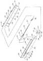
本発明の第1の様相は、受動的な格納(引き込み)特徴部を有する格納(引き込み)可能な注射器アセンブリに関する。1つ以上の実施形態の格納(引き込み)可能な注射器アセンブリ100は、双数の注射器バレル(胴部)、すなわち、流体チャンバーを引き込み特徴部から隔離している単一の注射器バレル(胴部)を利用している。 A first aspect of the invention relates to a retractable syringe assembly having a passive retractable feature. In one or more embodiments, the
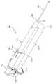
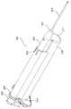
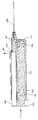
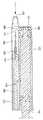
図1ないし11に示されている実施形態において、格納(引き込み)可能な注射器アセンブリは、流体バレル110及び格納バレル120を含んでいる双数の注射器バレル(胴部)101を含む。当該格納(引き込み)可能な注射器はまた、ニードルハブアセンブリ140、プランジャーロッド160、ストッパー170、及びトリガー要素190を含む。図4に示されている流体バレルは、末端部111、開口した基端部119、当該末端部111及び当該基端部119から延在し、チャンバー115を画成する内側表面114を含んでいる側壁112を含む。当該内側表面114は、断面幅を規定し、及び以下に詳細に説明される再使用防止特徴部を含んでもよい。末端部111は、当該末端部111を囲む末端壁117を含んでいる。図示された実施形態において、当該側壁112は流体バレル及び格納バレル間の流体連通を可能にする第1の開口部118を含んでいる。以下に詳細に論じられるように、当該第1の開口部118はまた、格納バレル120内に配置されたニードルカニューレと流体バレル110との間の流体連通を可能にする。 In the embodiment shown in FIGS. 1-11, the retractable syringe assembly includes a
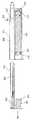
図4に示されている流体バレル110は、再使用防止特徴部を含んでいる。具体的には、流体バレル110は、流体バレルの基端部119に隣接した位置で当該流体バレル110の内側表面114の全周に延在するリブの形態で示されている保持要素116を含んでいる。保持要素116における当該内側表面114の断面幅は、第1の断面幅、すなわち、流体バレルの長さに沿った残りの位置における当該内側表面114の断面幅よりも狭い。1つ以上の実施形態において、流体バレル110の第1の断面幅よりも狭い断面幅を有する流体バレル110の領域を創成するために、選択肢としてタブ又は戻り止めが用いられてもよい。当該保持リング116はまた、再使用防止特徴部の作動(活性化)を容易にすべく形状付けられてもよい。例えば、流体バレル110はまた、流体バレル110の基端部119に当該保持要素116に隣接して基端側に配置された直径遷移領域を含んでもよい。流体バレルの当該内側表面114の断面幅は、当該直径遷移領域において流体バレル110の末端部111から基端部119へと増大している。下により詳細に説明されるように、再使用防止特徴部を用いている格納(引き込み)可能な注射器アセンブリの実施形態においては、流体バレル110の当該再使用防止特徴部は、流体バレル110内でプランジャーロッド160をロックする及び/又はプランジャーロッド160のさらなる使用を不能にすべく、プランジャーロッド160の対応する再使用防止特徴部と協働する。 The
もう1つの代替の実施形態においては、格納(引き込み)可能な注射器アセンブリが、単一のバレルを含んでもよく、そこでは、当該バレルの一部分が分割壁によって、流体バレル及び引き込み特徴部及びニードルハブアセンブリを収容する当該バレルの残りの部分に分けられている。当該分割壁は、流体バレルと引き込み特徴部及びニードルハブアセンブリを収容する当該バレルの残りの部分との間の流体連通を可能にする開口部を含んでもよい。 In another alternative embodiment, the retractable syringe assembly may include a single barrel, where a portion of the barrel is separated by a dividing wall and the fluid barrel and retraction feature and needle hub. It is divided into the remaining part of the barrel that houses the assembly. The dividing wall may include an opening that allows fluid communication between the fluid barrel and the rest of the barrel that houses the retracting feature and needle hub assembly.
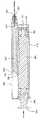
格納バレル120は、図4に示された実施形態においては、流体バレル110の側壁112に隣接して配置されている。格納バレル120は、ニードルハブアセンブリ140をその中に、及び引き込み特徴部を収容すべく構成されている。格納バレル120は、開口した末端部121及び開口した基端部129を含んでいる。ニードルチャンバー125を画成する内部表面124を有する壁122は、開口した末端部121から開口した基端部129まで延在している。格納(引き込み)チャンバーの当該壁122は流体バレル110の側壁112に隣接している。1つ以上の実施形態において、当該壁122は、流体バレル110に直接に接触していない、格納バレル120の部分の周りに延在してもよく、且つ当該側壁112が格納バレル120と流体バレル110の間の障害を形成してもよい。換言すると、当該側壁112の外側表面は、流体バレル110に直接に接触している格納バレル120の部分に沿って、格納バレル120の内側表面124を形成してもよい。 The
当該ニードルチャンバー125の大きさは、ニードルハブアセンブリ140及び/又は引き込み特徴部を収容すべく修正されてもよい。1つ以上の実施形態に従えば、格納バレル120の内側表面124は流体バレル110の第1の断面幅よりも小さな断面幅を有している。特定の実施形態では、格納バレルの内側表面124の断面幅は、流体バレルの内側表面114の断面幅の約90%、80%、70%、60%、50%、40%、30%、又は20%より狭い。かかる格納バレルの内側表面124の断面幅が流体バレルの内側表面114の断面幅よりも狭い設計(デザイン)は、人間工学的及び機能的利点を提供する。例えば、全体の外観及び当該双数バレルの注射器を取り扱うことは、使用者に対してより訴求力がある。ある実施形態においては、格納バレルが流体バレル内に入れ子にされてもよい。例えば、格納バレル及び流体バレルの両者が共に接合され、すなわち、共通壁によって外接されてもよく、及び格納バレルが流体バレル内に部分的に又は全体的に配置されるか、又は代わりに、分割壁が単一のバレルを2つの別々のバレル、すなわち、流体バレル及び格納バレルに分離してもよい。 The size of the
図示された実施形態においては、格納バレル120の開口した末端部121が、開口した末端部121を部分的に囲む障壁127を含んでいる。開口した末端部121は、障壁127がなく、且つ完全に開口していてもよい。当該壁122は流体チャンバー115及びニードルチャンバー125の流体連通を可能とする第2の開口部128を含んでいてもよい。当該壁の第2の開口部128はまた、流体チャンバー115、ニードルチャンバー125及びニードルカニューレの間の流体連通を許容する。流体バレル110及び格納バレル120の間の流体連通は、流体バレル110の第1の開口部118及び格納バレルの第2の開口部128から延在している第1の導管路130によって提供されてもよい。図示された実施形態においては、第1の導管路130は側壁112及び壁122の幅に沿って延在している。 In the illustrated embodiment, the
ニードルハブアセンブリは、ニードルカニューレの開口端部から格納バレルの第2の開口部128まで延在している第2の導管路132を含んでいてもよい。当該第2の導管路132は、ニードルカニューレと流体バレル間の流体連通を可能とするために、第2の開口部128に整列されねばならない開口133を含んでいてもよい。 The needle hub assembly may include a
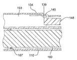
ニードルハブアセンブリ140は格納バレル120内に配置され、ニードルハブ142及びニードルハブ142に取り付けられたニードルカニューレ150を含んでいる。ニードルハブ142は末端部141及び基端部149を含んでいる。当該ニードルカニューレ150は、自由で開口した末端部151及びニードルハブの末端部141に取り付けられた開口した基端部159を含んでいる。図6に示されているニードルハブ142は、ニードルハブ本体144、ニードルハブ本体に末端方向に隣接して配置されたニードルハブ支持体146、及びニードルハブ本体144から基端方向に延在しているニードルハブ延長部148を含んでいる。当該ニードルハブ支持体146は、ニードルカニューレの基端部159を部分的に収容するためのくぼみ部分147を含んでいる。図示された実施形態においては、当該くぼみ部分147はニードルハブ142を通って格納バレルの第2の開口部128まで延在している第2の導管路132の一部分を含んでいる。1つ以上の代替の実施形態において、ニードルカニューレの基端部159は、くぼみ部分147を通って、ニードルハブ本体144内に全体的に位置されてニードルカニューレ支持体146内にまで延在していない第2の導管路132にまで延在してもよい。ニードルハブ延長部148は、ニードルチャンバー125内に延び、そして当該格納(引き込み)可能な注射器アセンブリ100の引き込み特徴部の一部を形成している。ニードルハブ延長部148は、図6に示されているように、円柱形状の細長いロッドの形態で提供されている。しかしながら、ニードルハブ延長部は他の形状であってもよい。ニードルハブ延長部148は、ニードルハブ延長部148から放射状外方に延在しているラッチ部分145を含んでいる。
当該ニードルハブアセンブリ140のニードルカニューレ150は、基端方向に移動すべく付勢されている。図示された実施形態においては、ニードルハブアセンブリ140が基端方向に移動すべく付勢され、それによって、取り付けられたニードルカニューレ150を付勢している。図示された実施形態において、ニードルハブアセンブリ140は、ニードルハブ142と格納バレル120の障壁127との間に配置された付勢要素152によって基端方向に移動すべく付勢されている。当該付勢要素152は、ニードルハブ142に基端方向に一定の力をかける圧縮バネであってもよいスプリング153を含んでいてもよい。代替の実施形態においては、当該付勢要素152は他の形態で提供されてもよく、例えば、レバーアーム(不図示)がニードルハブと障壁との間に配置されてもよい。格納バレル120は、ニードルハブが基端方向に移動するのを防止する支持要素134を含んでいる。以下により詳細に説明されるように、当該支持要素134を解放すると、付勢されているニードルハブ142及びそれに取り付けられているニードルカニューレ150が格納バレル120内に引き込むのを許容する。1つ以上の変形例において、ニードルハブ142の一部分が付勢されてもよい。例えば、ニードルカニューレ支持体146及びニードルハブ延長部148がニードルハブ本体144とは別の構成部品として提供されてもよく、そして当該支持要素134が解放されたとき、ニードルハブ本体144は静止して留まったまま、ニードルハブ延長部148及びニードルカニューレ支持体146が当該ニードルカニューレ150と共に格納バレル120内に引き込まれるように付勢されてもよい。 The
ニードルハブアセンブリは、当該ニードルチャンバー内で移動可能な大きさにされている。ニードルハブアセンブリの大きさ及び形状は、異なる大きさを有するニードルチャンバー内での移動を可能にすべく修正されてもよい。組立てられた状態において、使用の前に、ニードルハブアセンブリは格納バレルの開口した末端部に位置決めされる。 The needle hub assembly is sized to move within the needle chamber. The size and shape of the needle hub assembly may be modified to allow movement within needle chambers having different sizes. In the assembled state, prior to use, the needle hub assembly is positioned at the open end of the storage barrel.
格納バレル120の当該壁122は、ニードルハブアセンブリ140が格納バレルの開口した末端部121に位置決めされるように、ニードルハブアセンブリ140に末端方向の力を提供すべく、ニードルハブアセンブリ140の少なくとも一部分に係合する、又はニードルハブアセンブリ140と相互作用する支持要素134を含んでいる。具体的にいうと、ニードルハブアセンブリ140は、当該ニードルカニューレ150が第1の位置において格納バレルの開口した末端部121を越えて延在するように、位置決めされる。第1の位置において、当該支持要素134は、付勢要素152によってニードルハブ142に基端方向に加えられる力より大きな力をニードルハブ142に末端方向に提供する。図示された実施形態における支持要素134は、格納バレルの壁122に取り付けられている可撓性アーム135の形態で提供されている。当該壁122は、可撓性アーム135が外方に撓むのを可能にする開口136を含んでいる。図示された実施形態において、当該可撓性アーム135は、当該壁122に取り付けられている末端部137、及びニードルチャンバー125内に半径方向内方に延びているタブ139を含んでいる自由な基端部138を含んでいる。当該タブ139は、ラッチ部分145に係合することによってニードルハブの基端部149を支持する。当該タブ139及び当該可撓性アーム135は、ラッチ部分145に係合し、且つニードルハブ142及びニードルカニューレ150を支持するような大きさ及び形状にされている。当該タブ139及び可撓性アーム135はまた、ニードルハブアセンブリが第1の位置において位置決めされるように、付勢要素152を圧縮すべき大きさ及び形状にされている。ニードルカニューレ150を格納バレル120内に引き込むためには、下により詳細に説明されるように、ラッチ部分145を解放すべく可撓性アーム135が移動される。換言すると、当該タブ139が、最早、ニードルハブ延長部148を支持せず、及び付勢要素152によってニードルハブ142に基端方向に加えられる力より大きな力をニードルハブ延長部148又はニードルハブ142に末端方向に加えない位置にまで、当該可撓性アーム135は移動される。 The
もう1つの代替の実施形態において、当該支持要素134が格納バレルの壁122から内方に延びる壊れ易い区分の形態で提供されてもよい。当該壊れ易い区分は、ニードルハブアセンブリ140を支持する壊れ易い棚を含んでもよい。当該壊れ易い区分は、ニードルハブアセンブリを解放するか、又は付勢要素152によってニードルハブ142に基端方向に加えられる力より大きな力を、最早、ニードルハブ延長部148又はニードルハブ142に末端方向に加えないように破損してもよい。 In another alternative embodiment, the
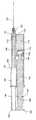
プランジャーロッド160は流体チャンバー125内に配置され、及び図5により明瞭に示されている。プランジャーロッド160は末端部161及び基端部169を含んでいる。プランジャーロッド160は、末端部161からプランジャーロッド本体163まで延在しているストッパー係合部分162を含んでいる。1つ以上の実施形態において、プランジャーロッド本体163はストッパー係合部分162からプランジャーロッドの基端部169まで延在してもよい。図5に示された実施形態においては、プランジャーロッド本体163がストッパー係合部分162から再使用防止特徴部まで延在し、当該再使用防止特徴部は、プランジャーロッド本体163からプランジャーロッドの基端部169に配置されている親指押さえ164まで延在している。親指押さえ164は、親指押さえ支持体184を含んでいてもよい。
ストッパー係合部分162は、プランジャーロッドの末端部に配置された環状のディスク165、及び環状のディスク165からプランジャーロッド本体163まで延在している細い部分166を含んでいる。当該環状のディスク165は、ストッパー170に係合し、それでストッパー170がプランジャーロッドの末端部に配置される。1つ以上の実施形態において、プランジャーロッド160の細い部分166及びストッパー170はプランジャーロッド160のストッパー170に関しての相対運動を提供すべく形状付けられてもよい。1つ以上の代替の実施形態において、プランジャーロッド160がストッパー170に固定された関係で取り付けられてもよい。
図5に示されているように、ストッパー170は、末端部171、基端部179、ストッパー本体172、及び流体バレル110の内側表面114とのシールを形成する周縁部173を有している。1つ以上の実施形態において、ストッパー170の当該周縁部173は、流体バレル内でストッパー170が基端及び末端の方向に摺動するのを可能にする断面幅を有している。ストッパー170は、残留流体の減少及び流体バレルからの流体の排出を容易にするために、その末端部171に選択肢としての細長い先端部(不図示)を含んでいてもよい。 As shown in FIG. 5, the
ストッパー170は、周縁部173から基端部179まで延在しているストッパー本体174を含んでいる。ストッパー本体174は、内側表面176で画成された凹部175を含んでいる。当該凹部175は、基端部179に隣接して配置されたネック部177を含み、当該ネック部177における内側表面176の断面幅は、当該凹部175の残りの位置における内側表面176の断面幅よりも狭い。当該凹部175は、プランジャーロッド160のストッパー係合部分162がストッパー170に連結するのを許容する。当該環状のディスク165は、ストッパー170をプランジャーロッド160に保持するために、ネック部177に係合する。1つ以上の代替の実施形態において、ストッパー170をプランジャーロッド160に保持するために、ストッパー170及び/又はストッパー係合部分162上の戻り止め(不図示)又はタブ(不図示)が用いられ得る。 The
1つ以上の実施形態において、内側表面176の断面幅は、凹部175内でのストッパー係合部分162の相対運動を防止すべく、大きさ及び/又は形状が定められてもよい。図5に示された実施形態においては、ストッパーの内側表面176の断面幅は、凹部175内でのストッパー係合部分162の相対運動を可能にすべく、大きさ及び形状が定められている、代わりに、環状のディスク165及び/又は細い部分166が、凹部175内でのストッパー係合部分162の相対運動を可能にする又は防止するべく、大きさ及び/又は形状が定められてもよい。 In one or more embodiments, the cross-sectional width of the
ストッパーは、典型的には、プラスチック又は他の容易に廃棄可能及び/又はリサイクル可能な材料から作られる。天然又は合成のゴムをストッパーに組み込むか、又は天然又は合成のゴムシールをストッパーと共に用いることが望ましい。ストッパーは多重のシールを組み込み得ることが理解されよう。 The stopper is typically made from plastic or other easily disposable and / or recyclable material. It is desirable to incorporate natural or synthetic rubber into the stopper, or to use a natural or synthetic rubber seal with the stopper. It will be appreciated that the stopper may incorporate multiple seals.
当該格納(引き込み)可能な注射器アセンブリ100はまた、末端部191及び基端部199を含むトリガー要素190を含んでいる。当該トリガー要素190は、プランジャーロッド160と共に移動可能であるが、格納バレル120のニードルチャンバー125内に延在している。図示された実施形態においては、当該トリガー要素190はプランジャーロッドの親指押さえ支持体184に取り付けられている。1つ以上の変形例において、当該トリガー要素190は別々に提供されてもよいが、末端方向に向けられた力がプランジャーロッド160に加えられたときは、末端方向にプランジャーロッド160と共に移動するように構成されている。かかる実施形態においては、使用者が力をプランジャーロッド160に末端方向に加えたときに、当該トリガー要素190及びプランジャーロッド160は共に末端方向に移動する。 The
当該トリガー要素190は、支持要素134及びラッチ部分145を係合解除させ、ニードルカニューレ150が引き込み、そして格納バレル内に収容されるように、ニードルハブ142にトリガー力を提供するべく、大きさ、形状が定められ、且つ位置付けられている。トリガー要素190は、末端部191から基端部199まで延在しているトリガー要素本体192を含んでいる。当該トリガー要素本体192は、円筒形状を有するべく形状付けられ、及び細長にされている。図示された実施形態においては、当該トリガー要素190は開口した末端部191を有し、及び当該トリガー要素本体192は、ニードルハブ142及びニードルカニューレ150を収容するための中空の内部193を有している。当該トリガー要素の基端部199は閉じられ、そしてニードルハブ142及びニードルカニューレ150が格納バレル内に引き込まれた後、中空の内部193内にニードルハブ142を保持すべくテーパー付けられてもよい。 The
当該トリガー要素の開口した末端部191は、可撓性アーム135を半径方向外方に曲げる又は移動させる、傾斜された縁部を有していてもよい。当該可撓性アーム135の半径方向外方への移動は、タブ139をもまた半径方向外方へ移動するのを生じさせ、タブ139が、最早、ラッチ部分145に係合、又はニードルハブ延長部148を支持しなくなる。当該タブ139の移動は、当該タブ139によってニードルハブ延長部148に末端方向に加えられている力を解放し、そして、結果として、付勢要素152によってニードルハブ142に基端方向に加えられる力(付勢要素152の圧縮の故にとどまっている)が、ニードルハブ142の引き込み、すなわち、格納バレル120内への、具体的にいうと、トリガー要素の中空の内部193内への移動を生じさせる。 The
ここに説明された実施形態は、受動的な格納(引き込み)機構を利用している。当該トリガー要素190は、流体バレル110の内容物を放出するために使用者がプランジャーロッドに末端方向に力を加えたときに、作動されるからである。具体的にいうと、当該トリガー要素190及び引き込み特徴部は、薬剤の全用量ないしは流体バレル110の全内容物が放出されたときに作動されるのみである。従って、ここに説明された格納(引き込み)注射器アセンブリは、流体バレルからの高速注入、又は粘性液体の注入中に発生される水(液)圧(これは、しばしば、時期尚早の作動(活性化)を生じさせる)に対し無関心である。。さらに、独立した格納バレル及びその中の引き込み特徴部のハウジングは、格納(引き込み)注射器のバレル(胴部)が当該トリガー要素190の末端方向への移動にのみ基づく低い作動(活性化)力、又はニードルハブ142から係合解除させるべく当該支持要素134へのトリガー力の適用を有することを許容する。従って、ここに説明された実施形態においては、ニードルハブ142及びニードルカニューレ150の引き込みは、切断、破壊、穴明け、又は他の力−集中的な機械的作用を要求せず、むしろ、ニードルハブに基端方向に加えられる力に反対に作用するニードルハブ142に末端方向に加えられる力を解放するための、支持要素134及びタブ139の曲げに依存している。 The embodiments described herein utilize a passive storage (retraction) mechanism. This is because the
図示された実施形態においては、プランジャーロッド160は再使用防止特徴部を含んでいる。具体的には、プランジャーロッド160は、プランジャーロッド本体163の基端側に隣接して配置された可撓性の突出部167、及び可撓性の突出部167と親指押さえ164との間に配置された壊れ易い部分168を含んでいる。プランジャーロッド160は、プランジャーロッド本体163がストッパー係合部分162から延在し、そして末端部分及び基端部分を含み、そこで可撓性の突出部167が当該末端部分と当該基端部分との間に配置されるように、特徴付けられてもよい。当該基端部分は、壊れ易い部分168を含んでいる。 In the illustrated embodiment, the
当該突出部167は、流体バレル110の内側表面114の保持要素116での断面幅より大きな断面幅を有している。少なくとも1つの実施形態において、当該格納(引き込み)可能な注射器アセンブリは、使用者が当該バレル内でプランジャーロッド160を底づけるとき、すなわち、流体バレル110内の全ての内容物が放出されてストッパー170が流体バレルの末端壁117に接触しているときに、プランジャーロッド160を流体バレル110内でロックするべく、突出部167が保持要素116を過ぎて末端方向に前進するのを許容するように構成されている。具体的にいうと、プランジャーロッドに末端方向に向けられた力が加えられて、プランジャーロッド160が流体バレル110内で末端方向に移動されたとき、突出部167は保持要素116を過ぎて末端方向に移動する。図示された実施形態において、突出部167の保持要素116を過ぎての末端方向への移動は、ストッパー170が流体バレルの末端壁117に接触しているときに生じる。保持要素116におけるより小さな流体バレルの内側表面114の断面幅は、一旦、突出部167が保持要素116を過ぎて末端方向に移動すると、プランジャーロッド160の基端方向への移動を阻止する。1つ以上の変形例において、突出部167は、後続の注射器の作動の議論において明らかになるように、保持要素116を末端方向に過ぎて、及び流体バレル110内への突出部167の末端方向への移動を容易にするテーパー付けられた部分(不図示)を有している周縁部を含んでもよい。当該可撓性の突出部167はまた、保持要素116を末端方向に過ぎて移動するにつれ、基端方向に曲がってもよい。 The
図示された実施形態においては、プランジャーロッド160はさらに、プランジャーロッド160が流体バレル110内でロックされた後、使用者がプランジャーロッド160に十分な基端方向の力を加えたとき、プランジャーロッド160の残りの部分からプランジャーロッドの少なくとも一部分を分離するための壊れ易い部分168を含んでいる。図示された実施形態においては、当該壊れ易い部分168は突出部167と親指押さえ164との間に位置されている。図示されている当該壊れ易い部分168は模範的な例であり、及びプランジャーロッドに永久的に損傷を与える、又はさもなければプランジャーロッドの少なくとも一部分を主要な本体から分離する他の適切な手段が提供されてもよいことが理解されよう。図示された実施形態においては、当該壊れ易い部分168は、当該可撓性の突出部167から複数の点連結部181まで延在している支持部材180を含み、当該複数の点連結部181は当該支持部材180を親指押さえ164に連結している。図5に示されている支持部材180は末端部182及び基端部183を有している。当該支持部材180の断面幅は、可撓性の突出部167に隣接している末端部182から複数の点連結部181が配置されている基端部183まで増加している。当該支持部材180は、円形の断面、及び当該支持部材180の基端部183の周縁部に配置された複数の点連結部181を有して、示されている。当該点連結部181は、支持部材180と親指押さえ164との間に、狭められた連結点を形成する個別的な連結部である。支持部材180と親指押さえ164との間に狭められた連結点を形成するために、単一の点連結部181もまた利用され得るということが理解されよう。親指押さえ支持体184がさらに、親指押さえを支持し、及び複数の点連結部181を当該親指押さえ164に連結してもよい。 In the illustrated embodiment, the
使用中、当該可撓性の突出部167が保持要素116を末端方向に過ぎて前進し、及び使用者がプランジャーロッドに基端方向に力を加えるとき、当該可撓性の突出部167が保持要素116に打ち勝つのに必要とされる力は、複数の点連結部181を破壊するのに必要とされる力を超える。 During use, when the
ストッパーに関してのプランジャーロッドの相対運動を可能にしている、ストッパー及びプランジャーロッドを利用している実施形態においては、この相対運動は、使用の前に、ストッパーが末端壁117に接触しているのを可能にし、その結果、可撓性の突出部が当該保持要素に基端側に隣接して残るのを未だに許容し、及びかくて、プランジャーロッドの末端及び基端方向への移動を許容しつつ、流体バレル内の空気が最小にされる。この位置においては、環状のディスク165はストッパーのネック部177に隣接して配置されており、プランジャーロッドとストッパーとの長さは最大化されている。換言すると、かかる実施形態においては、ストッパー170がストッパー係合部分162に取り付けられ、及び環状のディスク165がネック部177に係合しているとき、ストッパー170とプランジャーロッド本体163との間に予め選定された軸方向距離102を画成する間隙が存在している。この位置において、使用者は流体又は液体を流体チャンバー内に引き入れるためにプランジャーロッドに基端方向に力を加えることができ、及びストッパー及びプランジャーロッドはそれらの組み合わされた長さが最大化された状態で同じ位置に止まるであろう。具体的にいうと、使用者がプランジャーロッド160に基端方向に力を加えたとき、ストッパー係合部分162がストッパー170にネック部177によって連結されている間、プランジャーロッド160及びストッパー170は共に基端方向に移動する。この構成においては、ストッパー170及びプランジャーロッド160が共に基端方向に移動する間、予め選定された軸方向距離102を画成している間隙が維持される。 In embodiments that utilize a stopper and plunger rod that allows relative movement of the plunger rod with respect to the stopper, this relative movement causes the stopper to contact the
図7に示されているように、使用者は所定の又は所望の量の液体が注射器内に吸込まれ又は引込まれるまで、プランジャーロッドに基端方向の力を加える。吸込みステップ中、プランジャーロッド及びストッパー本体は、注射器内に薬剤を引き込むべく予め選定された軸方向距離102を維持しながら、基端方向に共に移動する。トリガー要素190はトリガー力を提供することなく、及び支持要素134とタブ139はラッチ部分145に係合し続け、且つニードルハブ延長部148を支持している。 As shown in FIG. 7, the user applies a proximal force to the plunger rod until a predetermined or desired amount of liquid is drawn or drawn into the syringe. During the inhalation step, the plunger rod and the stopper body move together in the proximal direction while maintaining a preselected
注入ないしは放出ステップ中、流体バレル110の内容物を放出するために末端方向の力がプランジャーロッド160に加えられたとき、当該末端方向に向けられた力は当該間隙を閉じ、ストッパー170は、図8に示されているように、静止して止まりつつ、及びプランジャーロッド160が予め選定された軸方向距離102移動するのを生じさせる。少なくとも1つの実施形態と一致して、一旦、ストッパー係合部分162が凹部175内で予め選定された軸方向距離102末端方向に移動すると、当該ストッパー係合部分162は、最早、ネック部177には接触していない。ストッパー170に関してのプランジャーロッド160のこの相対運動の後に、ストッパー170及びプランジャーロッド160は末端方向に縦一列になって移動し始める。この位置において、プランジャーロッド及びストッパーの長さは短くなっている。 When a distal force is applied to the
1つの実施形態において、吸込まれた流体のいくらかをフラッシュないしは放出するために、使用者は、当該可撓性の突出部167が保持要素116に基端側に隣接して位置されて止まるのを条件として、プランジャーロッド160を流体バレル110内でロックすることなく、吸込まれた流体の制限された量を噴射する、又は制限された力をプランジャーロッド160に末端方向に及ぼすことができる。しかしながら、さらに下記に説明されるように、使用者は、典型的には、流体バレルの末端壁117に対してストッパー170を底づけることによって流体バレルの内容物のほぼ全部を放出するであろう。使用者が末端方向の力をプランジャーロッド160に施すにつれ、プランジャーロッド160は流体バレル110内で末端方向に移動しつつ、当該トリガー要素190は格納バレル120内をプランジャーロッド160と共に移動する。 In one embodiment, in order to flush or release some of the inhaled fluid, the user stops the
上述のように、且つ図9に示されているように、ストッパーが末端壁117に接触しているとき、ストッパー170に関してのプランジャーロッド160の相対運動によって起こされたプランジャーロッド160及びストッパー170の短縮された長さのせいで、当該可撓性の突出部167は保持要素116を末端方向に過ぎて移動しているであろう。当該トリガー要素190はトリガー力を支持要素134に加え、当該支持要素134が半径方向外方に曲がる、すなわち、半径方向外方に移動するのを生じさせる。当該支持要素134が半径方向外方に移動するときは、タブ139は最早ニードルハブ延長部148に末端方向には力を加えず、及び付勢要素152によって基端方向に加えられる力が、図10に示されているように、ニードルハブ142とニードルカニューレ150との格納バレル120内への移動を生じさせる。 As described above and shown in FIG. 9, when the stopper is in contact with the
さて、プランジャーロッド160が流体バレル110内部でロックされた後の注射器アセンブリを図示している図11を参照するに、使用者がプランジャーロッド160に基端方向に力を加えることによって、当該格納(引き込み)可能な注射器アセンブリの再使用を試みたとき、プランジャーロッドに複数の点連結部181を破壊するのに必要とされる力より大きな基端方向に向けられた力を加えると、複数の点連結部181においてプランジャーロッド160の一部分の分離を生じさせる。当該複数の点連結部181は、破壊する。保持要素116によって可撓性の突出部167に及ぼされた力が複数の点連結部181の破壊力を超えるからである。 Referring now to FIG. 11 illustrating the syringe assembly after the
プランジャーロッド160の部分が、図11に示されているように、プランジャーロッドの残りの部分から取外されると、ニードルハブアセンブリ140は格納バレル120内に止まる。ニードルカニューレ150は完全に格納バレル120内に収容されている。支持要素134及びタブ139は、最早、曲げられていない。トリガー要素190が、最早、トリガー力を加えていないからである。この位置において、支持要素134及びタブ139はニードルハブ142の一部分に係合しており、ニードルハブ及びカニューレの格納バレルからの退去を防止している。具体的にいうと、1つ以上の実施形態のニードルハブ142は、ニードルハブの退去を防止すべく当該タブ139に係合するラッチ部分145を含んでいてもよい。1つ以上の代替の実施形態においては、当該トリガー要素の基端部199が、ニードルハブ142が中空の内部193内に保持され、且つニードルカニューレ150が露出されないように、ニードルハブ延長部148に係合する狭められた断面部分(不図示)を有してもよい。 When the portion of
1つ以上の実施形態において、ストッパー係合部分162とストッパー170との間の連結は壊れ易くてもよい。例えば、ストッパー170の周縁部173は、流体バレルの内側表面114の保持要素116における断面幅110より大きな断面幅を有してもよい。かかる実施形態においては、基端方向に向けられた力がプランジャーロッド160及びストッパー170に加えられ、そしてストッパー170が流体バレルの基端部119に移動した後に、保持要素116はストッパー170の周縁部173に係合し、そしてストッパーの周縁部173が保持要素116を過ぎて基端方向に移動するのを防止する。かかる実施形態においては、基端方向の力の継続的な適用ないしは基端方向に向けられた力の適用は、ストッパー係合部分162とストッパー170との間の連結の破壊を生じさせる。この破壊は、使用者が当該格納(引き込み)可能な注射器アセンブリの部品を分解するのを防止している。理論によって制限されることなしに、ストッパー係合部分162とストッパー170との間の連結を破壊するのに必要とされる力は、保持要素116によってストッパーの周縁部173に及ぼされる力より小さいと信じられる。 In one or more embodiments, the connection between the
再使用防止特徴部を組み込んでいない実施形態においては、プランジャーロッド160及びストッパー170を基端方向に移動させるために、使用者はプランジャーロッド160に基端方向に力を加える。プランジャーロッド160及びストッパー170の基端方向への移動は、流体バレル110内に真空を創成する。この位置において、トリガー要素190は支持要素134にトリガー力を加えず、及び支持要素134及びタブ139はニードルハブ142に付勢要素152によって基端方向に加えられる力より大きな力をニードルハブ142に末端方向に加え続ける。所望の量の液体が流体バレル110内へ吸込まれた後に、使用者はプランジャーロッド160に末端方向に力を加える。プランジャーロッド160及びストッパー170が末端方向に移動するにつれ、トリガー要素190もまたプランジャーロッド160と共に末端方向に移動する。一旦、流体バレル110の内容物の全てがストッパーによって放出され、及びストッパー170が末端壁117に接触すると、当該トリガー要素190が支持要素134にトリガー力を加え、支持要素134及びタブ139を半径方向外方に移動させるので、当該支持要素134及びタブ139は、最早、ニードルハブ142に末端方向に力を加えず、解放される。ニードルハブ142に末端方向に加えられる力は、支持要素134及びタブ139が、最早、ニードルハブ延長部248を支持していないので、解放される。付勢要素152によってニードルハブ142に基端方向に加えられる力が、その後ニードルハブ142及びニードルカニューレ150を格納バレル内に駆動する。 In embodiments that do not incorporate anti-reuse features, the user applies a force in the proximal direction to the
本発明の代替の実施形態が図12ないし22に示されている。図12ないし22は、流体バレル210及びここで別のものとして説明されている格納バレル220を含んでいる、格納(引き込み)可能な注射器アセンブリ200を示している。当該格納(引き込み)可能な注射器はまた、ニードルハブアセンブリ240、プランジャーロッド260、ストッパー270、及びトリガー要素290を含んでいる。図14ー15に示されている流体バレルは、末端部211、開いた基端部219、当該末端部211から延在している側壁212を含み、且つ当該基端部219はチャンバー215を画成する内側表面214を含んでいる。当該内側表面214は断面幅を規定し、そして再使用防止特徴部を含んでいてもよい。末端部211は、当該末端部211を囲む末端壁217を含んでいる。図示された実施形態においては、側壁212が、流体バレル及び格納バレル間の流体連通を可能にする第1の開口部218を含んでいる。以下に詳細に論じられるように、当該第1の開口部218はまた、格納バレル220内に配置されたニードルカニューレと格納バレル220及び流体バレル210との間の流体連通を可能とする。 An alternative embodiment of the present invention is shown in FIGS. FIGS. 12-22 illustrate a
図14−15に示されている流体バレル210は再使用防止特徴部を含んでいる。具体的には、流体バレル210は、流体バレルの基端部219に隣接した位置に、図4を参照して上述したように、流体バレル210の内側表面214の全周に延在するリブの形態で示されている保持要素216を含んでいる。 The
格納バレル220は、図14−15に示された実施形態においては、流体バレル210の側壁212に隣接して配置されている。格納バレル220は、ニードルハブアセンブリ240をその内部に、及び引き込み特徴部を収容するべく構成されている。格納バレル220は、開口した末端部221及び開口した基端部229を含んでいる。ニードルチャンバー225を画成する内部表面224を有している壁222は、開口した末端部221から開口した基端部229まで延在している。格納(引き込み)チャンバーの壁222は、流体バレル210の側壁212に隣接している。1つ以上の実施形態において、当該壁222は流体バレル210に直接に接触していない、格納バレル220の部分の周りに延在してもよく、及び側壁212が格納バレル220と流体バレル210との間に障害物を形成してもよい。換言すると、当該側壁212の外側表面は、流体バレル210に直接に接触している、格納バレル220の部分に沿って格納バレル220の内側表面224を形成してもよい。 The
ニードルチャンバー225の大きさは、ニードルハブアセンブリ240及び/又は引き込み特徴部を収容すべく修正されてもよい。1つ以上の実施形態によれば、格納バレル220の内側表面224は流体バレル210の第1の断面幅より小さな断面幅を有している。特定の実施形態では、格納バレルの内側表面224の断面幅は、流体バレルの内側表面214の断面幅の約90%、80%、70%、60%、50%、40%、30%、又は20%よりも小さい。かかる格納バレルの内側表面224の断面幅が流体バレルの内側表面214の断面幅よりも小さい設計(デザイン)は、人間工学的及び機能的な利点を提供する。例えば、全体の外観及び当該双数バレルの注射器の取り扱いは、使用者に対してより訴求力がある。 The size of the
図示された実施形態における格納バレル220の開口した末端部221は、開口した末端部221を部分的に囲む障壁227を含んでいる。開口した末端部221は障壁227がなくてもよく、及び完全に開口していてもよい。当該壁222は、流体チャンバー215及びニードルチャンバー225との流体連通を可能とする第2の開口部228を含んでいてもよい。当該壁の第2の開口部228はまた、流体チャンバー215、ニードルチャンバー225、及びニードルカニューレ間の流体連通を許容してもよい。流体バレル210と格納バレル220との間の流体連通は、流体バレル210の第1の開口部218及び格納バレルの第2の開口部228から延在する第1の導管路230によって提供されてもよい。図示された実施形態においては、第1の導管路230は側壁212及び壁222の幅に沿って延在している。 The
ニードルハブアセンブリは、ニードルカニューレの開口端部から格納バレルの第2の開口部228まで延在している第2の導管路232を含んでもよい。当該第2の導管路232は、ニードルカニューレと流体バレルとの間の流体連通を可能にするためには第2の開口部228に整列されねばならない、開口233を含んでいてもよい。 The needle hub assembly may include a
ニードルハブアセンブリ240は、格納バレル220内に配置され、及びニードルハブ242及び当該ニードルハブ242に取り付けられたニードルカニューレ250を含んでいる。ニードルハブ242は、末端部241及び基端部249を含んでいる。ニードルカニューレ250は、自由で開口した末端部251、及びニードルハブの末端部241に取り付けられている開口した基端部259を含んでいる。図17に示されているニードルハブ242は、ニードルハブ本体244、ニードルハブ本体に隣接して末端方向に配置されたニードルハブ支持体246、及びニードルハブ本体244から基端方向に延在しているニードルハブ延長部248を含んでいる。ニードルハブ支持体246は、ニードルカニューレの基端部259を部分的に収容するためのくぼみ部分247を含んでいる。図示された実施形態においては、当該くぼみ部分247は、ニードルハブ242を通り格納バレルの第2の開口部228まで延在している第2の導管路232の一部分を含んでいる。1つ以上の代替の実施形態において、ニードルカニューレの当該基端部259は、くぼみ部分247を通りニードルハブ本体244内に全体的に配置されて、そしてニードルカニューレ支持体246内に延在していない第2の導管路232まで延在してもよい。ニードルハブ延長部248は、ニードルチャンバー225内に延在し、当該格納(引き込み)可能な注射器アセンブリ200の引き込み特徴部の部分を形成している。図17に示されているニードルハブ延長部248は、円柱状の形状である細長いロッドの形態で提供されている。しかしながら、ニードルハブ延長部は他の形状を有してもよい。図17に示されている実施形態のニードルハブ延長部248は、以下により詳細に説明されるように、当該壁の支持要素234に係合し外方に延在しているラッチ部分245を含んでいる。 Needle hub assembly 240 includes a
ニードルハブアセンブリ240のニードルカニューレ250は、基端方向に移動すべく付勢されている。図示された実施形態においては、ニードルハブアセンブリ240が基端方向に移動すべく付勢されている。図示された実施形態においては、ニードルハブアセンブリ240は、基端方向に移動すべくニードルハブ242と格納バレル220の障壁227との間に配置された付勢要素252によって付勢されている。当該付勢要素252は、ニードルハブ242に基端方向に一定の力を加える圧縮バネであってもよいスプリング253を含んでいる。代替の実施形態において、付勢要素252は他の形態で提供されてもよく、例えば、ニードルハブと障壁との間に配置されたレバーアーム(不図示)であってもよい。格納バレル220は、ニードルハブが基端方向に移動するのを防止する支持要素234を含んでいる。以下により詳細に説明されるように、当該支持要素234の解放は、付勢されたニードルハブ242及びそれに取り付けられているニードルカニューレ250が格納バレル220内に引き込むのを許容するであろう。1つ以上の変形例において、ニードルハブ242の部分が付勢されてもよい。例えば、当該ニードルカニューレ支持体246及びニードルハブ延長部248がニードルハブ本体244とは別の構成部品として提供され、そして当該支持要素234が解放されたとき、ニードルハブ本体244が静止して残ったまま、ニードルハブ延長部248及びニードルカニューレ支持体246がニードルカニューレ250と共に格納バレル220内に引き込まれ得るように、付勢されてもよい。
ニードルハブアセンブリは、ニードルチャンバー内を移動可能な大きさにされている。ニードルハブアセンブリの大きさ及び形状は、異なる大きさを有するニードルチャンバー内での移動を可能にすべく、修正されてもよい。組立てられた状態では、使用の前に、ニードルハブアセンブリは格納バレルの開口した末端部に位置決めされる。 The needle hub assembly is sized to move within the needle chamber. The size and shape of the needle hub assembly may be modified to allow movement within needle chambers having different sizes. In the assembled state, the needle hub assembly is positioned at the open end of the storage barrel prior to use.
格納バレル220の壁222は、ニードルハブアセンブリ240が格納バレルの開口した末端部221に位置決めされるように、ニードルハブアセンブリ240の少なくとも一部分に係合するか、又はニードルハブアセンブリ240に末端方向の力を提供すべくニードルハブアセンブリ240と相互作用する支持要素234を含んでいる。具体的にいうと、ニードルハブアセンブリ240は、ニードルカニューレ250が第1の位置において格納バレルの開口した末端部221を越えて延在するように、位置決めされる。第1の位置において、当該支持要素234は、ニードルハブ延長部248のラッチ部分245に係合し、そして付勢要素252によってニードルハブ242に基端方向に加えられる力より大きな力をニードルハブ242に末端方向にかける。図示された実施形態においては、当該支持要素234は、格納バレルの壁222に取り付けられている可撓性アーム235の形態で提供されている。当該壁222は、当該可撓性アーム235が外方に撓むのを可能にする開口236を含んでいる。図示された実施形態においては、当該可撓性アーム235は、当該壁222に取り付けられた末端部237及びニードルチャンバー225内に半径方向内方に延びているタブ239を含む自由な基端部238を含んでいる。タブ239は、具体的にいうと、ニードルハブ延長部のラッチ部分245に係合し、ニードルハブ延長部248を支持している。当該タブ239及び可撓性アーム235は、ニードルハブアセンブリが第1の位置に位置決めされるように、ニードルハブ延長部のラッチ部分245に係合し、且つ付勢要素252を圧縮する大きさ及び形状にされている。ニードルカニューレ250を格納バレル220に引き込むためには、以下により詳細に説明されるように、可撓性アーム235が、ニードルハブアセンブリ240のラッチ部分245を解放するべく移動される。換言すると、当該可撓性アーム235は、タブ239が最早ラッチ部分245に係合せず、且つ当該支持要素234が最早ニードルハブ延長部248又はニードルハブ242に末端方向に、付勢要素252によってニードルハブ242に基端方向に加えられる力より大きな力を加えることのない位置に移動される。 The
プランジャーロッド260は流体チャンバー225内に配置されている。当該プランジャーロッド260は、末端部261及び基端部269を含んでいる。プランジャーロッド260は、末端部261からプランジャーロッド本体263まで延在しているストッパー係合部分262を含んでいる。1つ以上の実施形態において、プランジャーロッド本体263はストッパー係合部分262からプランジャーロッドの基端部269まで延在していてもよい。図16に示された実施形態においては、プランジャーロッド本体263は、ストッパー係合部分262から、プランジャーロッド本体263からプランジャーロッドの基端部269に配置されている親指押さえ264まで延在している、再使用防止特徴部まで延在している。当該親指押さえ264は親指押さえ支持体284を含んでいてもよい。
ストッパー係合部分262は、プランジャーロッドの末端部に配置された環状のディスク265、及び環状のディスク265からプランジャーロッド本体263まで延在している細い部分266を含んでいる。当該環状のディスク265は、ストッパー270に係合し、それでストッパー270がプランジャーロッドの末端部に配置される。1つ以上の実施形態において、プランジャーロッド260の細い部分266及びストッパー270はプランジャーロッド260のストッパー270に関しての相対運動を提供すべく形状付けられてもよい。1つ以上の代替の実施形態において、プランジャーロッド260がストッパー270に固定された関係で取り付けられてもよい。
図14に示されているように、ストッパー270は、末端部271、基端部279、ストッパー本体272、及び流体バレル210の内側表面214とのシールを形成する周縁部273を有している。1つ以上の実施形態において、ストッパー270の当該周縁部273は、流体バレル内でストッパー270が基端及び末端の方向に摺動するのを可能にする断面幅を有している。ストッパー270は、残留流体の減少及び流体バレルからの流体の排出を容易にするために、その末端部271に選択肢としての細長い先端部(不図示)を含んでいてもよい。 As shown in FIG. 14, the
ストッパー270は、周縁部273から基端部279まで延在しているストッパー本体274を含んでいる。ストッパー本体274は、内側表面276で画成された凹部275を含んでいる。当該凹部275は、基端部279に隣接して配置されたネック部277を含み、当該ネック部277における内側表面276の断面幅は、当該凹部275の残りの位置における内側表面276の断面幅よりも狭い。当該凹部275は、プランジャーロッド260のストッパー係合部分262がストッパー270に連結するのを許容する。当該環状のディスク265は、ストッパー270をプランジャーロッド260に保持するために、ネック部277に係合している。1つ以上の代替の実施形態において、ストッパー270をプランジャーロッド260に保持するために、ストッパー270及び/又はストッパー係合部分262上の戻り止め(不図示)又はタブ(不図示)が用いられ得る。 The
プランジャーロッド260及びストッパー270は、図5及び7−8を参照して上に述べたように、ストッパー270に関してのプランジャーロッド260相対運動を提供するための構造を有している。図18−19は、プランジャーロッド260及びストッパー270の相対運動を提供する構造を図解している。具体的にいうと、ストッパー係合部分262は、ストッパーの凹部265内で基端及び末端の方向に移動することができる。ストッパー係合部分262がネック部278に隣接又は接触して位置決めされるとき、プランジャーロッド及びストッパーの長さは最大化される。ストッパー係合部分262がネック部278からある距離に配置されたときには、プランジャーロッド及びストッパーの長さは短縮される。
プランジャーロッド260はまた、再使用防止特徴部、例えば、図5及び7−11を参照して上述の可撓性の突出部267を含んでもよい。再使用防止特徴部は、図4及び7−11を参照して上述したように、流体バレルの内側表面224に配置された保持要素226と相互作用する。プランジャーロッド260はまた、再使用防止特徴部が作動され、及びプランジャーロッド260が流体バレル210内でロックされた後に、プランジャーロッド260に基端方向に力が加えられると破損する壊れ易い部分268を含んでもよい。 The
使用中、図20に示されているように、ストッパー270は流体バレルの末端壁217に接触している。ストッパーに関してのプランジャーロッドの相対運動が可能であるプランジャーロッド及びストッパーを利用している実施形態においては、当該プランジャーロッドは、ストッパー係合部分272がネック部278に接触するか又は隣接するように位置される。プランジャーロッド260及びストッパー270の長さは、この構成において最大化される。使用者が、流体バレルを満たすべく、プランジャーロッドに基端方向に力を加えると、プランジャーロッド260及びストッパー270は共に基端方向に移動する。この移動によって創成された真空が流体バレル210内に液体を引き入れる。プランジャーロッド及び/又は流体バレルの再使用防止特徴部を利用している実施形態においては、当該再使用防止特徴部はまだ作動されない。プランジャーロッド上の可撓性の突出部、及び注射器バレル(胴部)の保持要素を利用している実施形態においては、図7−11に関して上述したように、可撓性の突出部267は保持要素216に基端側に隣接して位置されて残る。 In use, the
所望の量の液体が流体バレル210内に引き込まれた後、使用者はプランジャーロッド260に末端方向に力を加える。図示された実施形態においては、トリガー要素290及びプランジャーロッド260が単一のユニットとして取り付けられており、それ故に、当該トリガー要素290はプランジャーロッド260と共に末端方向に移動する。 After the desired amount of liquid has been drawn into the
流体バレル210の内容物の全部が放出され、且つストッパー270が末端壁217に接触するとき、トリガー要素290は支持要素234にトリガー力を加え、及び当該支持要素234を、タブ239がラッチ部分245に最早係合せず、そして付勢要素152によってニードルハブ242に加えられる力がニードルハブ242及びニードルカニューレ250を格納バレル内に引き込むように、半径方向外方に移動させる。ストッパーが末端壁217に接触するとき、突出部267は流体バレル210の保持要素216を末端方向に過ぎて移動し、及びプランジャーロッド260を流体バレル210内にロックする。プランジャーロッド260の壊れ易い部分268を破壊するのに必要とされる破壊力よりも大きな基端方向の力がプランジャーロッド260に加えられる。 When the entire contents of the
第3の様相である格納(引き込み)可能な注射器アセンブリ300が図23ないし27に示されている。当該格納(引き込み)可能な注射器アセンブリは、分割壁302を備える単一のバレル301を含み、分割壁302は当該バレル301を流体バレル310及び格納バレル320に分割している。 A third aspect, a
図23に示された実施形態においては、当該格納(引き込み)可能な注射器アセンブリは流体バレル310及び格納バレル320を含んでいる。当該格納(引き込み)可能な注射器はまた、ニードルハブアセンブリ340、プランジャーロッド360、ストッパー370、及びトリガー要素390を含んでいる。 In the embodiment shown in FIG. 23, the retractable syringe assembly includes a
流体バレル310は、プランジャーロッド360上の再使用防止特徴部と協働する再使用防止特徴部を含んでいてもよい。図7ないし11を参照して上述したように、ストッパー370及びプランジャーロッド360は、ストッパー370に関してのプランジャーロッド360の相対運動を許容する特徴部を有してもよい。図7ないし11に関して上述したように、1つ以上の代替の実施形態においては、プランジャーロッド360がストッパー370に固定された関係で取り付けられてもよい。 The
流体バレル310及び格納バレル320は、末端部311、開口した基端部319、当該末端部311及び当該基端部319から延在しチャンバー315を画成する内側表面314を含む側壁312を含んでいる。内側表面314は断面幅を規定し、及び以下により詳しく論じられる再使用防止特徴部を含んでいてもよい。流体バレル310の末端部311は、格納バレルの末端部311は開口322を含んでいるけれども、当該末端部311を囲む末端壁317を含んでいる。図示された実施形態においては、当該分割壁302は流体バレル及び格納バレル間の流体連通を可能にする第1の開口部318を含んでいる。以下に詳細に論じられるように、当該第1の開口部318はまた、格納バレル320内に配置されたニードルカニューレと格納バレル320及び流体バレル310との間の流体連通を可能にする。
格納バレル320は、ニードルハブアセンブリ340及び引き込み特徴部をその中に収容するべく構成されている。格納バレル320は、開口した末端部321及び閉じられた基端部329を含んでいる。側壁312及び分割壁302は、開口した末端部321から閉じられた基端部329まで延在するニードルチャンバー325を形成している。当該ニードルチャンバー325の大きさは、ニードルハブアセンブリ340及び/又は引き込み特徴部を収容すべく修正されてもよい。1つ以上の実施形態に従えば、格納バレル320の内側表面324は流体バレル310の第1の断面幅より小さな断面幅を有している。特定の実施形態では、格納バレルの内側表面324の断面幅は、流体バレルの内側表面314の断面幅の約90%、80%、70%、60%、50%、40%、30%、又は20%より小さい。かかる格納バレルの内側表面324の断面幅が流体バレルの内側表面314の断面幅より小さい設計(デザイン)は、人間工学的及び機能的な利点を提供する。例えば、全体の外観及びhandlingof当該双数バレルの注射器の取り扱いは使用者に対してより訴求力がある。 The
図示された実施形態における格納バレル320の開口した末端部321は、開口した末端部321を部分的に囲むテーパー部327を含んでいる。もう1つの代替の実施形態においては、開口した末端部321は障壁327がなく完全に開いていてもよい。壁の第1の開口部318はまた、流体チャンバー315とニードルチャンバー325及びニードルカニューレとの間の流体連通を許容してもよい。流体バレル310及び格納バレル320間の流体連通は、流体バレル310の第1の開口部318から延在する第1の導管路330によって提供されてもよい。 The
ニードルハブアセンブリは、ニードルカニューレの開口端部から格納バレルの第2の開口部328まで延在する第2の導管路332を含んでいてもよい。当該第2の導管路330は、ニードルカニューレと流体バレルとの間の流体連通を可能にするためには第2の開口部328に整列されねばならない開口333を含んでいてもよい。 The needle hub assembly may include a
ニードルハブアセンブリ340は、格納バレル320内に配置され、そしてニードルハブ342及びニードルハブ342に取り付けられたニードルカニューレ350を含んでいる。ニードルハブ342は、末端部341及び基端部349を含んでいる。ニードルカニューレ350は、自由で開口した末端部351及びニードルハブの末端部341に取り付けられた開口した基端部359を含んでいる。図23−27に示されているニードルハブ342は、図17を参照して上述されたのと同じであってもよい。
ニードルハブアセンブリ340のニードルカニューレ350は、基端方向に移動すべく付勢されている。図示された実施形態においては、ニードルハブアセンブリ340は、基端方向に移動すべく付勢されている。図示された実施形態においては、ニードルハブアセンブリ340は、基端方向に移動すべくニードルハブ342と格納バレル320の障壁327との間に配置された付勢要素352によって付勢されている。ここで別の方法で説明されているように、当該付勢要素352はニードルハブ342に基端方向に一定の力を加える。代替の実施形態において、当該付勢要素352は他の形態で提供されてもよく、例えば、レバーアーム(不図示)がニードルハブと障壁との間に配置されてもよい。格納バレル320は、ニードルハブが基端方向に移動するのを防止する支持要素334を含んでいる。以下により詳細に説明されるように、当該支持要素334の解放は、付勢されたニードルハブ342及びそれに取り付けられたニードルカニューレ350が格納バレル320に引き込むのを許容するであろう。1つ以上の変形例において、ニードルハブ342の部分が付勢されてもよい。
ニードルハブアセンブリは当該ニードルチャンバー内で移動可能な大きさにされている。ニードルハブアセンブリの大きさ及び形状は、異なる大きさを有するニードルチャンバー内での移動を可能にすべく修正されてもよい。組立てられた状態では、使用の前に、当該ニードルハブアセンブリは格納バレルの開口した末端部に位置決めされる。 The needle hub assembly is sized to move within the needle chamber. The size and shape of the needle hub assembly may be modified to allow movement within needle chambers having different sizes. In the assembled state, the needle hub assembly is positioned at the open end of the storage barrel prior to use.
図23−27に図示された実施形態においては、格納(引き込み)機構は、別のトリガー要素のよっては駆動されず、むしろプランジャーロッド360及び注射器のバレル(胴部)301の内部構造によって駆動される。具体的にいうと、分割壁302は、ニードルハブアセンブリ340が格納バレルの開口した末端部321に位置決めされるように、ニードルハブアセンブリ340に末端方向の力を提供するために、ニードルハブアセンブリ340の少なくとも一部分に係合する、又はニードルハブアセンブリ340と相互作用する支持要素303を含んでいる。具体的にいうと、ニードルハブアセンブリ340は、ニードルカニューレ350が格納バレルの開口した末端部321を越えて延在するように位置決めされる。当該第1の位置において、支持要素334は、ニードルハブ342に末端方向に、ニードルハブ342に基端方向に付勢要素352によって加えられる力より大きな力を提供する。図示された実施形態における支持要素334は、分割壁302に配置され、ニードルチャンバー325内に延在する直角のタブ304、及び分割壁302に配置され、流体チャンバー315内に延在する傾斜部307の形態で提供されている。当該分割壁302は、プランジャーロッドが傾斜部307と相互作用するとき、直角のタブ304が外方に流体チャンバー325内に撓むのを可能にする開口305を含んでいる。図示された実施形態においては、直角のタブ304に隣接している分割壁302の部分はまた、直角のタブ304を移動させるべく内方に撓む。当該直角のタブ304は、ニードルハブ342及びニードルカニューレ350を支持し、且つニードルハブアセンブリが第1の位置に位置決めされるように付勢要素352を圧縮するべき大きさ及び形状にされている。ニードルカニューレ350を格納バレル320に引き込むために、以下により詳細に説明されるように、304ニードルハブアセンブリ340を解放するべく直角のタブ304は移動される。換言すると、直角のタブ304は、それが最早ニードルハブ342を支持することができず、及び付勢要素352によってニードルハブ342に基端方向に加えられるより大きな力をニードルハブ342に末端方向に加えることができない位置に移動される。 In the embodiment illustrated in FIGS. 23-27, the retracting mechanism is not driven by a separate trigger element, but rather by the internal structure of the
ここに説明された格納(引き込み)可能な注射器アセンブリ100、200及び300に用いられている格納(引き込み)機構は、米国特許仮出願(P−9275)に記載された格納(引き込み)機構に置き換えられてもよい。具体的にいうと、図8−12、24−29及び33−37に示されている格納(引き込み)機構である。 The retractable (retractable) mechanism used in the retractable (retractable)
プランジャーロッド360は、流体チャンバー325内に配置されている。プランジャーロッド360は、末端部361及び基端部369を含んでいる。プランジャーロッド360は、末端部361から格納(引き込み)可能な注射器アセンブリ100及び200に関して、別の方法で記載されたように、形状付けられ及び大きさにされてもよいプランジャーロッド本体363まで延在しているストッパー係合部分362を含んでいる。1つ以上の実施形態において、プランジャーロッド本体363はストッパー係合部分362からプランジャーロッドの基端部369まで延在してもよい。図23−27に図示された実施形態においては、プランジャーロッド本体363は、ストッパー係合部分362から、プランジャーロッド本体363からプランジャーロッドの基端部369に配置されている親指押さえ364にまで延在している再使用防止特徴部にまで、延在する。当該親指押さえ364は親指押さえ支持体384を含んでいてもよい。
プランジャーロッド本体363は、プランジャーロッド本体363から半径方向外方に延在する突出部306を含んでいる。当該突出部306は、分割壁302の傾斜部307と相互作用するべく、形状付けられた大きさにされ、及び位置付けられている。具体的にいうと、突出部306は、分割壁302及び直角のタブ304の流体チャンバー内への曲がりないしは移動を生じさせるべく、末端方向に向けられた力を傾斜部307に加え、それによって、ニードルハブ342に末端方向に加えられる力を解放し、及び付勢要素352によってニードルハブ342に加えられる力がニードルハブ及びニードルカニューレを格納バレルに引き込むのを許容する。ストッパー370は、ストッパー係合部分362に取り付けられ、及び格納(引き込み)可能な注射器アセンブリ100及び200を参照して別の方法で説明されたように、形状付けられた大きさにされてもよい。ストッパー370は、プランジャーロッドがストッパーに対して基端及び末端の方向に移動するのを可能にするべく、形状付けられた大きさで且つ特徴部を含んでいてもよい。 The
図24−25に示されているように、所望の量の流体が流体バレル内に吸込まれた後、流体バレルの内容物を放出するべく、プランジャーロッド360に末端方向に力が加えられる。プランジャーロッド360が基端方向に移動し、そして突出部306が傾斜部307に末端方向に力を加えると、当該分割壁302及び直角のタブ304の内方への曲り及びニードルハブの解放が生じ、その結果、図26に示されているように、付勢要素がニードルハブの格納バレルへの引き込みを生じさせる。当該格納(引き込み)可能な注射器のバレル(胴部)の再使用防止特徴部はまた、別の方法で説明され及び図27に示されているように、プランジャーロッド360を流体バレル310内にロックする。 As shown in FIGS. 24-25, after a desired amount of fluid has been drawn into the fluid barrel, a force is applied to the
この明細書の全体に亘り、「1つの実施形態」、「ある実施形態」、「1つ以上の実施形態」又は「一実施形態」との言及は、実施形態との関連で説明された特有の特徴、構造、材料、又は特性が本発明の少なくとも1つの実施形態に含まれていることを意味する。
従って、この明細書の全体に亘り種々の箇所での「1つ以上の実施形態において」、「ある実施形態においては」、「1つの実施形態において」、又は「一実施形態において」のような語句の出現は、本発明の同じ実施形態を必ずしも言及していない。さらに、特有の特徴、構造、材料、又は特性は、1つ以上の実施形態において、いずれかの適切な方法で組み合わされてもよい。Throughout this specification, references to “one embodiment,” “an embodiment,” “one or more embodiments,” or “one embodiment” are specific to the embodiments described in connection with the embodiments. Of features, structures, materials, or characteristics are included in at least one embodiment of the invention.
Accordingly, such as "in one or more embodiments", "in one embodiment", "in one embodiment", or "in one embodiment" in various places throughout this specification. The appearance of phrases does not necessarily refer to the same embodiment of the invention. Furthermore, the particular features, structures, materials, or characteristics may be combined in any suitable manner in one or more embodiments.
ここに、本発明が特有の実施形態を参照して説明されたが、これらの実施形態は本発明の原理及び適用の単なる例示であることが理解されるべきである。本発明の方法及び装置に対しての種々の修正及び変形が本発明の趣旨及び範囲を逸脱することなくなされ得ることは、当業者には明らかであろう。従って、本発明は、添付の請求項及びそれらの均等物の範囲内にある修正及び変形を含むことが意図されている。 Although the invention herein has been described with reference to particular embodiments, it is to be understood that these embodiments are merely illustrative of the principles and applications of the present invention. It will be apparent to those skilled in the art that various modifications and variations can be made to the method and apparatus of the present invention without departing from the spirit and scope of the invention. Thus, it is intended that the present invention include modifications and variations that are within the scope of the appended claims and their equivalents.
Claims (26)
Translated fromJapanese当該ニードルチャンバー内に配置されたニードルハブアセンブリであって、ニードルハブと当該第1の開口部に流体連通して当該ニードルハブに取り付けられたニードルカニューレとを備え、当該ニードルカニューレは基端方向に移動するべく付勢され、位置決めされた第1の位置において当該ニードルカニューレが格納バレルの開口した末端部を越えて延在するように、当該可撓性タブがニードルハブに係合してニードルハブに末端方向の力を加えるべく位置決めされているニードルハブアセンブリと、
流体チャンバー内に配置されたプランジャーロッドであって、末端部と、基端部と、当該バレルの内側表面とで液密シールを形成するためにプランジャーロッドの当該末端部に配置されたストッパーと、当該末端部から当該基端部まで延在しているプランジャーロッド本体と、当該可撓性タブを移動させてニードルカニューレを引き込み、格納バレル内の第2の位置において収容されるのを生じさせるべくプランジャーロッドに配置された起動要素とを備えるプランジャーロッドと、
を備えることを特徴とする注射器アセンブリ。A barrel including an open proximal end, a sidewall having an inner surface defining a fluid chamber for holding fluid and having a first cross-sectional width, and a needle chamber for receiving a needle hub assembly Wherein the fluid chamber and the needle chamber are separated by a barrier having a first opening that allows fluid communication between the fluid chamber and the needle chamber, A barrel including a flexible tab extending into the needle chamber to engage a needle hub assembly disposed therein;
A needle hub assembly disposed within the needle chamber, comprising a needle hub and a needle cannula in fluid communication with the first opening and attached to the needle hub, the needle cannula being proximally The flexible tab engages the needle hub so that the needle cannula extends beyond the open end of the storage barrel in the first position biased and positioned for movement. A needle hub assembly positioned to apply a distal force to the
A plunger rod disposed within the fluid chamber, the stopper disposed at the distal end of the plunger rod to form a fluid tight seal with the distal end, the proximal end, and the inner surface of the barrel A plunger rod body extending from the distal end to the proximal end, and moving the flexible tab to retract the needle cannula to be received in a second position within the storage barrel. A plunger rod comprising an actuating element disposed on the plunger rod to cause generation;
A syringe assembly comprising:
プランジャーロッドの傾斜部への係合、及びニードルハブに末端方向に加えられる力を解放すべく、当該可撓性タブの流体チャンバーへの外方への撓みを生じさせることを特徴とする請求項4に記載の注射器アセンブリ。Applying a proximal force to the plunger rod causes proximal movement of the plunger rod and suction of the liquid into the fluid chamber, and subsequently applying a distal force.
The flexible tab is deflected outwardly into the fluid chamber in order to release the engagement of the plunger rod into the ramp and the force applied distally to the needle hub. Item 5. The syringe assembly according to Item 4.
当該ニードルチャンバー内に配置されたニードルハブアセンブリであって、ニードルハブと、当該第1の開口部に流体連通して当該ニードルハブに取り付けられたニードルカニューレと、当該ニードルカニューレの開口端部から当該ニードルチャンバーの第2の開口部まで延在する第2の導管路とを備え、当該ニードルカニューレは基端方向に移動するべく付勢要素によって付勢され、当該分割壁は、ニードルハブに係合すべく当該ニードルチャンバー内に延在する支持要素及び流体チャンバー内に延在する傾斜部を含み、
当該支持要素は、当該ニードルカニューレが格納バレルの開口した末端部を越えて延在するように、位置決めされた第1の位置において当該ニードルハブに末端方向の力を加える、ニードルハブアセンブリと、
流体チャンバー内に配置されたプランジャーロッドであって、末端部と、基端部と、当該バレルの内側表面とで液密シールを形成するためにプランジャーロッドの当該末端部に配置されたストッパーと、当該末端部から当該基端部まで延在しているプランジャーロッド本体と、分割壁の傾斜部分と共に作用して当該ニードルカニューレが引き込まれニードルチャンバー内の第2の位置において収容されるのを生じさせるべく、プランジャーロッドから半径方向の外方に延びている突起とを備える、プランジャーロッドと、
を備えることを特徴とする注射器アセンブリ。An open proximal end, a distal end, a sidewall extending from the distal end to the open proximal end and defining a chamber having an inner surface, and a first cross-sectional width for holding fluid A dividing wall that divides the chamber to define a needle chamber for receiving the fluid chamber and the needle hub assembly, the first opening allowing fluid communication between the fluid chamber and the needle chamber Having a dividing wall and a barrel, including
A needle hub assembly disposed within the needle chamber, the needle hub, a needle cannula in fluid communication with the first opening, and attached to the needle hub; and from the open end of the needle cannula A second conduit passage extending to the second opening of the needle chamber, the needle cannula being biased by a biasing element to move proximally, the dividing wall engaging the needle hub Preferably includes a support element extending into the needle chamber and a ramp extending into the fluid chamber;
The support element applies a distal force to the needle hub in a first position positioned such that the needle cannula extends beyond the open end of the storage barrel;
A plunger rod disposed within the fluid chamber, the stopper disposed at the distal end of the plunger rod to form a fluid tight seal with the distal end, the proximal end, and the inner surface of the barrel A plunger rod body extending from the distal end to the proximal end and an inclined portion of the dividing wall to retract the needle cannula and receive it in a second position within the needle chamber. A plunger rod comprising a protrusion extending radially outward from the plunger rod to produce
A syringe assembly comprising:
当該流体チャンバーの第1の断面寸法より小さな断面寸法を有していることを特徴とする請求項11に記載の注射器アセンブリ。The needle chamber
The syringe assembly of claim 11, wherein the syringe assembly has a cross-sectional dimension that is smaller than a first cross-sectional dimension of the fluid chamber.
Applications Claiming Priority (4)
| Application Number | Priority Date | Filing Date | Title |
|---|---|---|---|
| US36674910P | 2010-07-22 | 2010-07-22 | |
| US61/366,749 | 2010-07-22 | ||
| US13/187,045US8721599B2 (en) | 2010-07-22 | 2011-07-20 | Dual chamber passive retraction needle syringe |
| US13/187,045 | 2011-07-20 |
Related Parent Applications (1)
| Application Number | Title | Priority Date | Filing Date |
|---|---|---|---|
| JP2013520859ADivisionJP5919269B2 (en) | 2010-07-22 | 2011-07-21 | Passive retraction needle syringe with dual chamber |
Related Child Applications (1)
| Application Number | Title | Priority Date | Filing Date |
|---|---|---|---|
| JP2017188359ADivisionJP6526141B2 (en) | 2010-07-22 | 2017-09-28 | Dual chamber passive pull-in needle syringe |
Publications (2)
| Publication Number | Publication Date |
|---|---|
| JP2016052606Atrue JP2016052606A (en) | 2016-04-14 |
| JP6219985B2 JP6219985B2 (en) | 2017-10-25 |
Family
ID=44629123
Family Applications (3)
| Application Number | Title | Priority Date | Filing Date |
|---|---|---|---|
| JP2013520859AActiveJP5919269B2 (en) | 2010-07-22 | 2011-07-21 | Passive retraction needle syringe with dual chamber |
| JP2016006637AActiveJP6219985B2 (en) | 2010-07-22 | 2016-01-15 | Passive retraction needle syringe with dual chamber |
| JP2017188359AActiveJP6526141B2 (en) | 2010-07-22 | 2017-09-28 | Dual chamber passive pull-in needle syringe |
Family Applications Before (1)
| Application Number | Title | Priority Date | Filing Date |
|---|---|---|---|
| JP2013520859AActiveJP5919269B2 (en) | 2010-07-22 | 2011-07-21 | Passive retraction needle syringe with dual chamber |
Family Applications After (1)
| Application Number | Title | Priority Date | Filing Date |
|---|---|---|---|
| JP2017188359AActiveJP6526141B2 (en) | 2010-07-22 | 2017-09-28 | Dual chamber passive pull-in needle syringe |
Country Status (9)
| Country | Link |
|---|---|
| US (3) | US8721599B2 (en) |
| EP (3) | EP2595679B1 (en) |
| JP (3) | JP5919269B2 (en) |
| CN (2) | CN105233371B (en) |
| BR (1) | BR112013001622B1 (en) |
| CA (1) | CA2806036C (en) |
| ES (3) | ES2904448T3 (en) |
| MX (2) | MX371135B (en) |
| WO (1) | WO2012012603A1 (en) |
Families Citing this family (44)
| Publication number | Priority date | Publication date | Assignee | Title |
|---|---|---|---|---|
| US9381309B2 (en) | 2008-06-10 | 2016-07-05 | Retractable Technologies, Inc. | Frontal attachment device for syringe with pinch-activated retraction |
| US9308353B2 (en) | 2010-07-29 | 2016-04-12 | Retractable Technologies, Inc. | Needle retraction apparatus |
| US8323249B2 (en) | 2009-08-14 | 2012-12-04 | The Regents Of The University Of Michigan | Integrated vascular delivery system |
| US8814833B2 (en) | 2010-05-19 | 2014-08-26 | Tangent Medical Technologies Llc | Safety needle system operable with a medical device |
| WO2011146769A2 (en) | 2010-05-19 | 2011-11-24 | Tangent Medical Technologies Llc | Integrated vascular delivery system |
| US9550030B2 (en) | 2010-07-22 | 2017-01-24 | Becton, Dickinson And Company | Dual chamber syringe with retractable needle |
| US8721599B2 (en) | 2010-07-22 | 2014-05-13 | Becton, Dickinson And Company | Dual chamber passive retraction needle syringe |
| US8556854B2 (en)* | 2010-07-22 | 2013-10-15 | Becton, Dickinson And Company | Dual chamber syringe with retractable needle |
| US8556855B2 (en)* | 2010-07-22 | 2013-10-15 | Becton, Dickinson And Company | Dual chamber syringe with retractable needle |
| CA2854003C (en) | 2011-11-07 | 2020-07-14 | Safety Syringes, Inc. | Contact trigger release needle guard |
| WO2013134614A2 (en) | 2012-03-08 | 2013-09-12 | Becton, Dickinson And Company | Drug reconstitution system |
| TWI551319B (en)* | 2012-06-15 | 2016-10-01 | Fan Xiao Yi | A push rod with a card retracting structure |
| EP2679262B1 (en)* | 2012-06-25 | 2015-02-25 | Becton Dickinson France | Prefillable drug delivery device |
| US9956352B2 (en) | 2012-12-14 | 2018-05-01 | Retractable Technologies, Inc. | Combined medical device with sliding frontal attachment and retractable needle |
| USD823461S1 (en) | 2012-12-14 | 2018-07-17 | Retractable Technologies, Inc. | Slimline syringe with offset needle retraction chamber and frontal attachment |
| USD823457S1 (en) | 2012-12-14 | 2018-07-17 | Retractable Technologies, Inc. | Blood collection tube holder with offset needle retraction chamber and frontal attachment |
| USD829891S1 (en) | 2012-12-14 | 2018-10-02 | Retractable Technologies, Inc. | Syringe with offset needle retraction chamber and frontal attachment |
| US9302055B2 (en) | 2012-12-14 | 2016-04-05 | Retractable Technologies, Inc. | Frontal attachment device for syringe with rotationally activated retractable needle |
| US9320469B2 (en) | 2012-12-14 | 2016-04-26 | Retractable Technologies, Inc. | Retractable needle for blood gas sampling |
| USD823463S1 (en) | 2012-12-14 | 2018-07-17 | Retractable Technologies, Inc. | Frontal attachment for medical device |
| US10568554B2 (en) | 2012-12-14 | 2020-02-25 | Retractable Technologies, Inc. | Blood collection tube holder with slide-activated needle retraction |
| CA2898997C (en)* | 2013-02-07 | 2020-05-05 | Endoaid Ltd. | Endoscopic sleeve |
| USD766426S1 (en)* | 2013-11-21 | 2016-09-13 | Smarthealth, Inc. | Prefilled syringe dispensing device |
| GB201323171D0 (en)* | 2013-12-31 | 2014-02-12 | Creo Medical Ltd | Electrosurgical apparatus and device |
| CA2937744C (en) | 2014-02-04 | 2022-08-09 | Icu Medical, Inc. | Self-priming systems and methods |
| WO2015164648A1 (en)* | 2014-04-24 | 2015-10-29 | Becton, Dickinson And Company | Catheter insertion mechanism for a patch pump |
| GB2528269A (en)* | 2014-07-15 | 2016-01-20 | Commodious Llp | Single use safety syringe with automatic retractable needle |
| CA2960278A1 (en)* | 2014-09-11 | 2016-03-17 | Psivida Us, Inc. | Injector apparatus |
| CN106267462A (en)* | 2015-05-25 | 2017-01-04 | 美敦力公司 | For the fluid infusion apparatus that patient is administered |
| JP6924189B2 (en)* | 2015-11-27 | 2021-08-25 | サノフィ−アベンティス・ドイチュラント・ゲゼルシャフト・ミット・ベシュレンクテル・ハフツング | Drug injection device |
| EP3225269B1 (en)* | 2016-03-31 | 2021-09-08 | Galderma S.A. | Plunger slack syringe |
| FR3077737B1 (en)* | 2018-02-12 | 2023-06-16 | Adda Jean Marc | HEAD FOR INJECTION OF A FLUID SUBSTANCE ALLOWING CONTROL OF THE INJECTION SITE BEFORE INJECTION OF THE FLUID SUBSTANCE AND SYRINGE COMPRISING SUCH A HEAD |
| US12268848B2 (en) | 2018-03-29 | 2025-04-08 | Retractable Technologies, Inc. | Syringe with flat indicia display surface |
| US12064605B2 (en) | 2018-03-29 | 2024-08-20 | Retractable Technologies, Inc. | Syringe with flat indicia display surface |
| CN108721730B (en)* | 2018-07-02 | 2023-06-02 | 中国人民解放军总医院 | Injector for viscous medicinal liquids |
| CA3113230A1 (en)* | 2018-09-17 | 2020-03-26 | Rx Bandz, Llc | Miniaturized wearable medication administration device |
| USD894381S1 (en)* | 2019-03-29 | 2020-08-25 | Retractable Technologies, Inc. | Syringe barrel |
| USD914874S1 (en) | 2019-07-12 | 2021-03-30 | Retractable Technologies, Inc | Syringe barrel |
| USD914875S1 (en) | 2019-07-12 | 2021-03-30 | Retractable Technologies, Inc. | Syringe barrel |
| USD914873S1 (en) | 2019-07-12 | 2021-03-30 | Retractable Technologies, Inc | Syringe barrel |
| USD914871S1 (en) | 2019-07-12 | 2021-03-30 | Retractable Technologies, Inc. | Syringe barrel |
| USD914872S1 (en) | 2019-07-12 | 2021-03-30 | Retractable Technologies, Inc. | Syringe barrel |
| US20210402097A1 (en)* | 2020-06-26 | 2021-12-30 | Aktivax, Inc. | Auto-injector with uniform pressure exertion of a primary container |
| CN113082383B (en)* | 2021-04-28 | 2025-04-18 | 杨斌堂 | Syringes and injection platforms |
Citations (3)
| Publication number | Priority date | Publication date | Assignee | Title |
|---|---|---|---|---|
| US4941883A (en)* | 1987-04-24 | 1990-07-17 | Aldo Venturini | Disposable safety syringe |
| EP0479303A1 (en)* | 1990-10-05 | 1992-04-08 | Amorino Morandini | Accessory mounted on syringes enabling automatic needle withdrawal |
| WO2008154616A1 (en)* | 2007-06-12 | 2008-12-18 | Becton, Dickinson And Company | Syringe with disabling mechanism |
Family Cites Families (63)
| Publication number | Priority date | Publication date | Assignee | Title |
|---|---|---|---|---|
| US3055362A (en)* | 1956-05-16 | 1962-09-25 | Auguste Rooseboom | Hypodermic injection apparatus |
| US4375815A (en) | 1981-03-23 | 1983-03-08 | Becton Dickinson And Company | Retractable lancet assembly |
| US4388925A (en) | 1981-03-23 | 1983-06-21 | Becton Dickinson And Company | Automatic retractable lancet assembly |
| US4535769A (en) | 1981-03-23 | 1985-08-20 | Becton, Dickinson And Company | Automatic retractable lancet assembly |
| US4449529A (en) | 1981-11-18 | 1984-05-22 | Becton Dickinson And Company | Automatic retractable lancet assembly |
| US4616649A (en) | 1984-09-20 | 1986-10-14 | Becton, Dickinson And Company | Lancet |
| US4624253A (en) | 1985-01-18 | 1986-11-25 | Becton, Dickinson And Company | Lancet |
| US5451210A (en)* | 1991-04-29 | 1995-09-19 | Lifequest Medical, Inc. | System and method for rapid vascular drug delivery |
| US5531694A (en)* | 1993-08-31 | 1996-07-02 | Clemens; Anton H. | Needle retraction system |
| US6053929A (en) | 1993-12-08 | 2000-04-25 | Becton Dickinson And Company | Surgical scalpel |
| US5919201A (en) | 1993-12-08 | 1999-07-06 | Becton, Dickinson And Company | Surgical scalpel |
| US5938676A (en) | 1993-12-08 | 1999-08-17 | Becton, Dickinson & Company | Surgical scalpel |
| US5941892A (en) | 1993-12-08 | 1999-08-24 | Becton, Dickinson And Company | Surgical scalpel |
| US5431672A (en) | 1994-05-09 | 1995-07-11 | Becton, Dickinson And Company | Surgical scalpel with retractable blade |
| US6177037B1 (en) | 1994-06-20 | 2001-01-23 | Becton, Dickinson And Company | Method of forming a slit in a reseal element for a needleless injection site |
| US5533970A (en) | 1994-09-28 | 1996-07-09 | Becton, Dickinson And Company | Retractable needle syringe |
| US5620454A (en) | 1994-10-25 | 1997-04-15 | Becton, Dickinson And Company | Guarded surgical scalpel |
| US6090077A (en) | 1995-05-11 | 2000-07-18 | Shaw; Thomas J. | Syringe plunger assembly and barrel |
| US5578011A (en) | 1995-05-11 | 1996-11-26 | Shaw; Thomas J. | Tamperproof retractable syringe |
| US5632733A (en) | 1995-05-11 | 1997-05-27 | Shaw; Thomas J. | Tamperproof retractable syringe |
| US5830190A (en) | 1996-06-11 | 1998-11-03 | Becton Dickinson And Company | Protected needle catheter placement device having needle placement visualization features and method for its use |
| US5797880A (en) | 1996-09-05 | 1998-08-25 | Becton And Dickinson And Company | Catheter and placement needle assembly with retractable needle |
| CN1651103A (en) | 1998-07-27 | 2005-08-10 | 安塔雷斯药品公司 | Injection device |
| US6010486A (en) | 1998-12-18 | 2000-01-04 | Becton Dickinson And Company | Retracting needle syringe |
| US6036674A (en) | 1998-12-18 | 2000-03-14 | Becton Dickinson And Company | Retracting needle syringe |
| US6221052B1 (en) | 1998-12-18 | 2001-04-24 | Becton, Dickinson And Company | Retracting needle syringe |
| US6776776B2 (en) | 1999-10-14 | 2004-08-17 | Becton, Dickinson And Company | Prefillable intradermal delivery device |
| US6086568A (en) | 1999-10-15 | 2000-07-11 | Becton Dickinson And Company | Syringe plunger rod for retracting needle syringe |
| US6368303B1 (en) | 1999-10-15 | 2002-04-09 | Becton, Dickinson And Company | Retracting needle syringe |
| US6517516B1 (en) | 1999-10-15 | 2003-02-11 | Becton Dickinson And Company | Method of making a retracting needle syringe |
| US6840291B2 (en) | 1999-10-15 | 2005-01-11 | Becton Dickinson And Company | Attachment for a medical device |
| US6183440B1 (en) | 2000-05-25 | 2001-02-06 | Becton, Dickinson And Company | Hypodermic syringe having a selectively retractable needle |
| US6599268B1 (en) | 2000-06-27 | 2003-07-29 | Becton Dickinson And Company | Hypodermic syringe with a selectively retractable needle |
| US6585690B1 (en) | 2000-06-29 | 2003-07-01 | Becton Dickinson And Company | Hypodermic syringe with selectivity retractable needle |
| US6432087B1 (en) | 2000-07-31 | 2002-08-13 | Becton, Dickinson And Company | Hypodermic syringe with selectively retractable needle |
| US6689106B2 (en) | 2000-07-31 | 2004-02-10 | Becton Dickinson And Company | Retracting needle assembly for a syringe |
| US6558357B1 (en) | 2000-08-30 | 2003-05-06 | Becton Dickinson And Company | Hypodermic syringe with selectively retractable needle |
| US6413237B1 (en) | 2000-08-31 | 2002-07-02 | Becton, Dickinson And Company | Hypodermic syringe with selectively retractable needle |
| US6409701B1 (en) | 2000-09-29 | 2002-06-25 | Becton, Dickinson And Company | Hypodermic syringe with selectively retractable needle |
| US6468250B2 (en)* | 2000-12-26 | 2002-10-22 | Kuo-Chen Yang | Dual-chamber safety hypodermic syringe |
| US20020165501A1 (en)* | 2001-05-04 | 2002-11-07 | Yang Zhan Bo | Safety Syringe |
| JP2004538103A (en) | 2001-08-09 | 2004-12-24 | ベクトン・ディキンソン・アンド・カンパニー | Retractable safety needle device |
| US7294118B2 (en) | 2001-10-24 | 2007-11-13 | Becton, Dickinson And Company | Retractable needle assembly |
| US6952604B2 (en) | 2001-12-21 | 2005-10-04 | Becton, Dickinson And Company | Minimally-invasive system and method for monitoring analyte levels |
| US20030125676A1 (en) | 2001-12-28 | 2003-07-03 | Becton, Dickinson And Company | Medical needle assemblies |
| US20030125677A1 (en) | 2001-12-28 | 2003-07-03 | Becton, Dickinson And Company | Medical needle assemblies |
| US20030163096A1 (en) | 2002-02-28 | 2003-08-28 | Becton, Dickinson And Company | Shieldable fluid collection set |
| US7258678B2 (en) | 2002-03-14 | 2007-08-21 | Becton, Dickinson And Company | Retractable safety needle |
| US6926700B2 (en) | 2002-03-19 | 2005-08-09 | Becton, Dickinson And Company | Needle assembly |
| CA2422516A1 (en) | 2002-03-19 | 2003-09-19 | Becton, Dickinson And Company | Needle device |
| CN1485103A (en)* | 2002-09-27 | 2004-03-31 | 陆爱平 | Disposable syringe |
| US7018344B2 (en) | 2003-01-21 | 2006-03-28 | Becton, Dickinson And Company | Retractable needle shielding device |
| US6808512B1 (en)* | 2003-04-09 | 2004-10-26 | Hsiu-Chih Lin | Safety syringe |
| US7604613B2 (en) | 2004-01-20 | 2009-10-20 | Beckton, Dickinson And Company | Syringe having a retractable needle |
| US7344517B2 (en) | 2004-01-20 | 2008-03-18 | Becton, Dickinson And Company | Syringe having a retractable needle |
| US9380975B2 (en) | 2004-05-07 | 2016-07-05 | Becton, Dickinson And Company | Contact activated lancet device |
| US7713245B2 (en) | 2005-10-28 | 2010-05-11 | Becton, Dickinson And Company | Plunger for retracting needle syringe |
| US8277409B2 (en) | 2005-12-05 | 2012-10-02 | Becton, Dickinson And Company | Cutting element for a retracting needle syringe |
| US9320459B2 (en) | 2006-05-08 | 2016-04-26 | Becton, Dickinson And Company | Gravity-drop safety holder |
| US8257313B2 (en) | 2006-08-11 | 2012-09-04 | Becton, Dickinson And Company | Integrated septum and needle tip shield for a catheter assembly |
| CN101195051B (en)* | 2006-12-05 | 2010-12-29 | 山东威高集团医用高分子制品股份有限公司 | Safe self-breaking syringe |
| US7972302B2 (en) | 2007-06-12 | 2011-07-05 | Becton, Dickinson And Company | Syringe with disabling mechanism |
| US8721599B2 (en) | 2010-07-22 | 2014-05-13 | Becton, Dickinson And Company | Dual chamber passive retraction needle syringe |
- 2011
- 2011-07-20USUS13/187,045patent/US8721599B2/enactiveActive
- 2011-07-21CNCN201510500216.9Apatent/CN105233371B/enactiveActive
- 2011-07-21EPEP11736531.2Apatent/EP2595679B1/enactiveActive
- 2011-07-21EPEP14181476.4Apatent/EP2818192B1/enactiveActive
- 2011-07-21BRBR112013001622-1Apatent/BR112013001622B1/enactiveIP Right Grant
- 2011-07-21CNCN201180042489.3Apatent/CN103096954B/enactiveActive
- 2011-07-21EPEP18173795.8Apatent/EP3384945B1/enactiveActive
- 2011-07-21MXMX2013000879Apatent/MX371135B/enactiveIP Right Grant
- 2011-07-21ESES18173795Tpatent/ES2904448T3/enactiveActive
- 2011-07-21MXMX2020000610Apatent/MX381367B/enunknown
- 2011-07-21JPJP2013520859Apatent/JP5919269B2/enactiveActive
- 2011-07-21CACA2806036Apatent/CA2806036C/enactiveActive
- 2011-07-21ESES14181476Tpatent/ES2701166T3/enactiveActive
- 2011-07-21ESES11736531.2Tpatent/ES2525016T3/enactiveActive
- 2011-07-21WOPCT/US2011/044795patent/WO2012012603A1/enactiveApplication Filing
- 2014
- 2014-03-24USUS14/222,923patent/US9636469B2/enactiveActive
- 2016
- 2016-01-15JPJP2016006637Apatent/JP6219985B2/enactiveActive
- 2017
- 2017-04-28USUS15/582,048patent/US10286160B2/enactiveActive
- 2017-09-28JPJP2017188359Apatent/JP6526141B2/enactiveActive
Patent Citations (3)
| Publication number | Priority date | Publication date | Assignee | Title |
|---|---|---|---|---|
| US4941883A (en)* | 1987-04-24 | 1990-07-17 | Aldo Venturini | Disposable safety syringe |
| EP0479303A1 (en)* | 1990-10-05 | 1992-04-08 | Amorino Morandini | Accessory mounted on syringes enabling automatic needle withdrawal |
| WO2008154616A1 (en)* | 2007-06-12 | 2008-12-18 | Becton, Dickinson And Company | Syringe with disabling mechanism |
Also Published As
| Publication number | Publication date |
|---|---|
| ES2525016T3 (en) | 2014-12-16 |
| CN105233371A (en) | 2016-01-13 |
| JP5919269B2 (en) | 2016-05-18 |
| US8721599B2 (en) | 2014-05-13 |
| US10286160B2 (en) | 2019-05-14 |
| US20170232207A1 (en) | 2017-08-17 |
| BR112013001622B1 (en) | 2021-01-19 |
| MX381367B (en) | 2025-03-12 |
| CN103096954A (en) | 2013-05-08 |
| MX371135B (en) | 2020-01-17 |
| CN105233371B (en) | 2019-04-12 |
| US20120022464A1 (en) | 2012-01-26 |
| ES2904448T3 (en) | 2022-04-05 |
| EP2818192B1 (en) | 2018-09-05 |
| US9636469B2 (en) | 2017-05-02 |
| JP2013532522A (en) | 2013-08-19 |
| CN103096954B (en) | 2015-09-16 |
| JP6219985B2 (en) | 2017-10-25 |
| CA2806036C (en) | 2017-04-18 |
| BR112013001622A2 (en) | 2016-05-24 |
| US20140288498A1 (en) | 2014-09-25 |
| EP2595679B1 (en) | 2014-09-17 |
| EP3384945B1 (en) | 2021-10-20 |
| EP2595679A1 (en) | 2013-05-29 |
| JP6526141B2 (en) | 2019-06-05 |
| CA2806036A1 (en) | 2012-01-26 |
| EP3384945A1 (en) | 2018-10-10 |
| ES2701166T3 (en) | 2019-02-21 |
| MX2013000879A (en) | 2013-02-27 |
| WO2012012603A1 (en) | 2012-01-26 |
| JP2018029984A (en) | 2018-03-01 |
| EP2818192A1 (en) | 2014-12-31 |
Similar Documents
| Publication | Publication Date | Title |
|---|---|---|
| JP6219985B2 (en) | Passive retraction needle syringe with dual chamber | |
| US12290669B2 (en) | Dual chamber syringe with retractable needle | |
| US10525207B2 (en) | Dual chamber syringe with retractable needle | |
| US8556855B2 (en) | Dual chamber syringe with retractable needle | |
| JP6078165B2 (en) | Pre-fillable and automatically retractable safety syringe |
Legal Events
| Date | Code | Title | Description |
|---|---|---|---|
| A621 | Written request for application examination | Free format text:JAPANESE INTERMEDIATE CODE: A621 Effective date:20160128 | |
| A977 | Report on retrieval | Free format text:JAPANESE INTERMEDIATE CODE: A971007 Effective date:20160916 | |
| A131 | Notification of reasons for refusal | Free format text:JAPANESE INTERMEDIATE CODE: A131 Effective date:20161101 | |
| A601 | Written request for extension of time | Free format text:JAPANESE INTERMEDIATE CODE: A601 Effective date:20170201 | |
| A521 | Request for written amendment filed | Free format text:JAPANESE INTERMEDIATE CODE: A523 Effective date:20170331 | |
| TRDD | Decision of grant or rejection written | ||
| A01 | Written decision to grant a patent or to grant a registration (utility model) | Free format text:JAPANESE INTERMEDIATE CODE: A01 Effective date:20170829 | |
| A61 | First payment of annual fees (during grant procedure) | Free format text:JAPANESE INTERMEDIATE CODE: A61 Effective date:20170928 | |
| R150 | Certificate of patent or registration of utility model | Ref document number:6219985 Country of ref document:JP Free format text:JAPANESE INTERMEDIATE CODE: R150 | |
| R250 | Receipt of annual fees | Free format text:JAPANESE INTERMEDIATE CODE: R250 | |
| R250 | Receipt of annual fees | Free format text:JAPANESE INTERMEDIATE CODE: R250 | |
| R250 | Receipt of annual fees | Free format text:JAPANESE INTERMEDIATE CODE: R250 | |
| R250 | Receipt of annual fees | Free format text:JAPANESE INTERMEDIATE CODE: R250 | |
| R250 | Receipt of annual fees | Free format text:JAPANESE INTERMEDIATE CODE: R250 |