JP2016048762A - Method for creating pattern data, template, and method for manufacturing semiconductor device - Google Patents
Method for creating pattern data, template, and method for manufacturing semiconductor deviceDownload PDFInfo
- Publication number
- JP2016048762A JP2016048762AJP2014173802AJP2014173802AJP2016048762AJP 2016048762 AJP2016048762 AJP 2016048762AJP 2014173802 AJP2014173802 AJP 2014173802AJP 2014173802 AJP2014173802 AJP 2014173802AJP 2016048762 AJP2016048762 AJP 2016048762A
- Authority
- JP
- Japan
- Prior art keywords
- template
- pattern
- stress
- pattern data
- resist
- Prior art date
- Legal status (The legal status is an assumption and is not a legal conclusion. Google has not performed a legal analysis and makes no representation as to the accuracy of the status listed.)
- Granted
Links
Images


Classifications
- G—PHYSICS
- G05—CONTROLLING; REGULATING
- G05B—CONTROL OR REGULATING SYSTEMS IN GENERAL; FUNCTIONAL ELEMENTS OF SUCH SYSTEMS; MONITORING OR TESTING ARRANGEMENTS FOR SUCH SYSTEMS OR ELEMENTS
- G05B19/00—Programme-control systems
- G05B19/02—Programme-control systems electric
- G05B19/418—Total factory control, i.e. centrally controlling a plurality of machines, e.g. direct or distributed numerical control [DNC], flexible manufacturing systems [FMS], integrated manufacturing systems [IMS] or computer integrated manufacturing [CIM]
- G—PHYSICS
- G03—PHOTOGRAPHY; CINEMATOGRAPHY; ANALOGOUS TECHNIQUES USING WAVES OTHER THAN OPTICAL WAVES; ELECTROGRAPHY; HOLOGRAPHY
- G03F—PHOTOMECHANICAL PRODUCTION OF TEXTURED OR PATTERNED SURFACES, e.g. FOR PRINTING, FOR PROCESSING OF SEMICONDUCTOR DEVICES; MATERIALS THEREFOR; ORIGINALS THEREFOR; APPARATUS SPECIALLY ADAPTED THEREFOR
- G03F7/00—Photomechanical, e.g. photolithographic, production of textured or patterned surfaces, e.g. printing surfaces; Materials therefor, e.g. comprising photoresists; Apparatus specially adapted therefor
- G03F7/0002—Lithographic processes using patterning methods other than those involving the exposure to radiation, e.g. by stamping
- G—PHYSICS
- G05—CONTROLLING; REGULATING
- G05B—CONTROL OR REGULATING SYSTEMS IN GENERAL; FUNCTIONAL ELEMENTS OF SUCH SYSTEMS; MONITORING OR TESTING ARRANGEMENTS FOR SUCH SYSTEMS OR ELEMENTS
- G05B2219/00—Program-control systems
- G05B2219/30—Nc systems
- G05B2219/45—Nc applications
- G05B2219/45031—Manufacturing semiconductor wafers
Landscapes
- Physics & Mathematics (AREA)
- General Physics & Mathematics (AREA)
- Engineering & Computer Science (AREA)
- General Engineering & Computer Science (AREA)
- Manufacturing & Machinery (AREA)
- Quality & Reliability (AREA)
- Automation & Control Theory (AREA)
- Shaping Of Tube Ends By Bending Or Straightening (AREA)
- Exposure Of Semiconductors, Excluding Electron Or Ion Beam Exposure (AREA)
Abstract
Description
Translated fromJapanese本発明の実施形態は、パターンデータ作成方法、テンプレートおよび半導体装置の製造方法に関する。 Embodiments described herein relate generally to a pattern data creation method, a template, and a semiconductor device manufacturing method.
近年、半導体装置を形成する際に用いられるプロセスの1つとしてインプリント法が注目されている。このインプリント法では、原版の型であるテンプレートが、基板上に塗布されている光硬化性有機材料(レジスト)に押し当てられる。この状態で、レジストが硬化させられ、硬化したレジストからテンプレートが離型される。これにより、基板上にレジストパターンが形成される。 In recent years, an imprint method has attracted attention as one of processes used when forming a semiconductor device. In this imprint method, a template, which is an original mold, is pressed against a photocurable organic material (resist) applied on a substrate. In this state, the resist is cured, and the template is released from the cured resist. Thereby, a resist pattern is formed on the substrate.
しかしながら、インプリント法では、テンプレートのレジストへの押し当て時に、テンプレートの所定エリアに応力が集中する。このため、テンプレートの寿命が短くなる場合があった。このようなインプリント法においては、テンプレートがレジストに押し当てられた際のテンプレートにかかる応力を均一化することが望まれている。 However, in the imprint method, stress concentrates on a predetermined area of the template when the template is pressed against the resist. For this reason, the lifetime of the template may be shortened. In such an imprint method, it is desired to make the stress applied to the template uniform when the template is pressed against the resist.
本発明が解決しようとする課題は、テンプレートがレジストに押し当てられた場合のテンプレートにかかる応力を均一化することができるパターンデータ作成方法、テンプレートおよび半導体装置の製造方法を提供することである。 The problem to be solved by the present invention is to provide a pattern data creation method, a template and a semiconductor device manufacturing method capable of equalizing stress applied to the template when the template is pressed against the resist.
実施形態によれば、パターンデータ作成方法が提供される。前記パターンデータ作成方法は、算出ステップと、判定ステップと、修正ステップと、を含んでいる。前記算出ステップでは、テンプレートパターンを有したテンプレートをレジストに押し当てた場合の前記テンプレートにかかる応力の応力分布が算出される。また、前記判定ステップでは、前記テンプレートパターンの中で閾値よりも大きな応力値を示す応力集中箇所があるか否かが判定される。また、前記修正ステップでは、前記応力集中箇所がある場合には、前記応力集中箇所での応力値が前記閾値以下の応力値となるよう前記テンプレートパターンのパターンデータが修正される。 According to the embodiment, a pattern data creation method is provided. The pattern data creation method includes a calculation step, a determination step, and a correction step. In the calculation step, the stress distribution of the stress applied to the template when the template having the template pattern is pressed against the resist is calculated. In the determination step, it is determined whether or not there is a stress concentration portion showing a stress value larger than a threshold value in the template pattern. In the correction step, when there is the stress concentration portion, the pattern data of the template pattern is corrected so that the stress value at the stress concentration portion becomes a stress value equal to or less than the threshold value.
以下に添付図面を参照して、実施形態に係るパターンデータ作成方法、テンプレートおよび半導体装置の製造方法を詳細に説明する。なお、この実施形態により本発明が限定されるものではない。 Exemplary embodiments of a pattern data creation method, a template, and a method for manufacturing a semiconductor device will be described below in detail with reference to the accompanying drawings. In addition, this invention is not limited by this embodiment.
(実施形態)
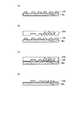
図1は、実施形態に係るパターンデータ作成方法の概念を説明するための図である。図1の(a)は、テンプレート20の構成を示す斜視図である。図1の(b)は、テンプレート20のレジストへの押し当てた場合のテンプレート20にかかる応力分布を示す図である。図1の(b)では、ハッチングの濃い位置ほど大きな応力値を示している。(Embodiment)
FIG. 1 is a diagram for explaining the concept of the pattern data creation method according to the embodiment. FIG. 1A is a perspective view showing the configuration of the
なお、以下では、修正前のテンプレートをテンプレート20といい、修正後のテンプレートをテンプレート20Xという。また、テンプレート20のパターンデータをテンプレートパターンデータDといい、テンプレート20XのパターンデータをテンプレートパターンデータDxという。したがって、テンプレート20は、テンプレートパターンデータDを用いて形成されたテンプレートであり、テンプレート20Xは、テンプレートパターンデータDxを用いて形成されたテンプレートである。 In the following, the template before correction is referred to as
テンプレート20,20Xには、凹凸パターンであるテンプレートパターンが配置されている。そして、インプリント処理の際には、テンプレート20がレジストに押し当てられ、これによりテンプレート20,20Xに応力がかかる。 In the
本実施形態では、テンプレート20にかかる応力分布に基づいて、テンプレート20XのテンプレートパターンデータDxが作成される。このとき、予め作成されたテンプレートパターンデータDに修正を加えることによって、応力が緩和されたテンプレートパターンデータDxが作成される。テンプレートパターンデータD,Dxは、テンプレート20,20Xを上面(パターン面)から見た場合のテンプレートパターンの形状を示す設計データなどである。 In the present embodiment, based on the stress distribution applied to the
テンプレートパターンデータDxが作成される際には、修正前のテンプレートパターンデータDを用いた押印シミュレーションによって、テンプレート20での応力分布が算出される。算出される応力分布は、テンプレート20がレジストに押し当てられた場合の、テンプレート20にかかる応力の分布である。 When the template pattern data Dx is created, the stress distribution in the
これにより、テンプレート20上で所定値(閾値)よりも大きな応力が発生する箇所(以下、応力集中箇所100という)が予測される。そして、応力集中箇所100の近傍に補助パターン25が配置される。補助パターン25は、レジストへの押し当てられた場合にテンプレート20にかかる応力が均一化される位置に配置される。換言すると、応力集中箇所100での応力値が閾値以下の応力値となるようテンプレートパターンのパターンデータが修正される。 Thereby, the location (henceforth the stress concentration location 100) where stress larger than a predetermined value (threshold value) occurs on the
補助パターン25は、例えば、インプリント後のプロセスによって除去される。なお、補助パターン25は、インプリント後のプロセスによって除去されなくてもよい。また、テンプレート20に補助パターン25を配置する代わりに、テンプレート20のテンプレートパターン(設計レイアウト)を変更してもよい。 The
本実施形態では、修正前のテンプレートパターンデータDに対応するテンプレートパターンに、補助パターン25の配置などが行われる。そして、補助パターン25の配置などが行われたテンプレートパターンデータDxを用いて、実際のテンプレート20Xが形成される。この後、テンプレート20Xを用いて、ウエハWaなどの被転写基板に、インプリント処理が行われる。 In the present embodiment, the
テンプレート20,20Xのレジストへの押し当ては、テンプレート20,20Xがレジストに接触してからレジストから引き離されるまでである。具体的には、テンプレート20,20Xがレジストに接触し、レジストがテンプレートパターンに充填され、レジストが硬化され、硬化したレジストからテンプレート20,20Xが引き離されるまでが、レジストへの押し当てである。 The
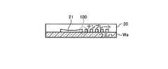
図2は、インプリント装置の構成を示す図である。インプリント装置1は、ウエハWaなどの被転写基板に、モールド基板であるテンプレート20Xのテンプレートパターンを転写する装置である。インプリント装置1は、光ナノインプリントリソグラフィ法などのインプリント法を用いてウエハWa上にパターンを形成する。テンプレート20Xは、原版の型であり、テンプレートパターンは、ウエハWaに転写される回路パターンなどである。テンプレート20Xは、石英ガラス基板などを用いて形成されている。 FIG. 2 is a diagram illustrating a configuration of the imprint apparatus. The imprint apparatus 1 is an apparatus that transfers a template pattern of a
インプリント装置1は、原版ステージ2、制御部3、基板チャック4、試料ステージ5、基準マーク6、アライメントセンサ7、UV光源8、ステージベース9、液滴下装置15を備えている。 The imprint apparatus 1 includes an original stage 2, a control unit 3, a substrate chuck 4, a
試料ステージ5は、ウエハWaを載置するとともに、載置したウエハWaと平行な平面内(水平面内)を移動する。また、試料ステージ5は、ウエハWaに転写材としてのレジスト13Aを滴下する際には、ウエハWaを液滴下装置15の下方側に移動させる。また、試料ステージ5は、ウエハWaへの押印処理を行う際には、ウエハWaをテンプレート20Xの下方側に移動させる。 The
また、試料ステージ5上には、基板チャック4が設けられている。基板チャック4は、ウエハWaを試料ステージ5上の所定位置に固定する。また、試料ステージ5上には、基準マーク6が設けられている。基準マーク6は、試料ステージ5の位置を検出するためのマークであり、ウエハWaを試料ステージ5上にロードする際の位置合わせに用いられる。 A substrate chuck 4 is provided on the
ステージベース9の底面側であるウエハWa側には、原版ステージ2が設けられている。原版ステージ2は、テンプレート20Xの裏面側(テンプレートパターンの形成されていない側の面)からテンプレート20Xを真空吸着などによって所定位置に固定する。 The original stage 2 is provided on the wafer Wa side, which is the bottom surface side of the
ステージベース9は、原版ステージ2によってテンプレート20Xを支持するとともに、テンプレート20XのテンプレートパターンをウエハWa上のレジスト13Aに押し当てる。ステージベース9は、鉛直方向に移動することにより、テンプレート20Xのレジスト13Aへの押し当てと、テンプレート20Xのレジスト13Aからの引き離しである離型と、を行う。また、ステージベース9上には、アライメントセンサ7が設けられている。アライメントセンサ7は、ウエハWaの位置検出やテンプレート20Xの位置検出を行うセンサである。 The
液滴下装置15は、インクジェット法によってウエハWa上にレジスト13Aを滴下する装置である。液滴下装置15が備えるインクジェットヘッド(図示せず)は、レジスト13Aの液滴を噴出する複数の微細孔を有している。 The
UV光源8は、UV光を照射する光源であり、ステージベース9の上方に設けられている。UV光源8は、テンプレート20Xがレジスト13Aに押し当てられた状態で、テンプレート20X上からUV光を照射する。 The UV light source 8 is a light source that irradiates UV light, and is provided above the
制御部3は、インプリント装置1の各構成要素に接続され、各構成要素を制御する。図2では、制御部3が、液滴下装置15、ステージベース9に接続されているところを図示しており、他の構成要素との接続は図示省略している。 The control unit 3 is connected to each component of the imprint apparatus 1 and controls each component. In FIG. 2, the control unit 3 is illustrated as being connected to the
ウエハWaへのインプリントを行う際には、試料ステージ5に載せられたウエハWaが液滴下装置15の直下まで移動させられる。そして、ウエハWaの所定ショット位置にレジスト13Aが滴下される。 When imprinting on the wafer Wa, the wafer Wa placed on the
ウエハWa上にレジスト13Aが滴下された後、試料ステージ5上のウエハWaがテンプレート20Xの直下に移動させられる。そして、テンプレート20XがウエハWa上のレジスト13Aに押し当てられる。 After the resist 13A is dropped on the wafer Wa, the wafer Wa on the
テンプレート20Xとレジスト13Aとが所定時間だけ接触させられた後、この状態でUV光源8がUV光をレジスト13Aに照射させる。これにより、レジスト13Aが硬化し、テンプレートパターンに対応する転写パターンがウエハWa上のレジスト13Aにパターニングされる。この後、次のショットへのインプリント処理が行われる。 After the
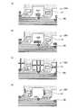
つぎに、インプリント工程の処理手順について説明する。図3は、インプリント工程の処理手順を説明するための図である。図3では、インプリント工程におけるウエハWa、テンプレート20XおよびウエハWaの断面図を示している。 Next, the processing procedure of the imprint process will be described. FIG. 3 is a diagram for explaining the processing procedure of the imprint process. FIG. 3 shows a cross-sectional view of the wafer Wa, the
図3の(a)に示すように、ウエハWaの上面にはレジスト13Aが滴下される。これにより、ウエハWaに滴下されたレジスト13Aの各液滴はウエハWa面内に広がる。そして、図3の(b)に示すように、テンプレート20Xがレジスト13A側に移動させられ、図3の(c)に示すように、テンプレート20Xがレジスト13Aに押し当てられる。このように、石英基板等を掘り込んで作ったテンプレート20Xがレジスト13Aに接触させられると、毛細管現象によりテンプレート20Xのテンプレートパターン内にレジスト13Aが流入する。 As shown in FIG. 3A, a resist 13A is dropped on the upper surface of the wafer Wa. Thereby, each droplet of the resist 13A dropped on the wafer Wa spreads in the wafer Wa plane. Then, as shown in FIG. 3B, the
予め設定しておいた時間だけ、レジスト13Aをテンプレート20Xに充填させた後、UV光が照射される。これにより、レジスト13Aが硬化する。そして、図3の(d)に示すように、テンプレート20Xが硬化したレジストパターン13Bから離型されることにより、テンプレートパターンを反転させたレジストパターン13BがウエハWa上に形成される。 After filling the
図4は、実施形態に係るパターンデータ作成装置の構成を示す図である。パターンデータ作成装置30は、テンプレートパターンデータDxを作成するコンピュータなどである。パターンデータ作成装置30は、修正前のテンプレートパターンデータDに対して補助パターン25のパターンデータを付加することによって、テンプレートパターンデータDxを作成する。なお、パターンデータ作成装置30は、テンプレートパターンデータDxに対してさらに補助パターン25のパターンデータを付加してもよい。 FIG. 4 is a diagram illustrating a configuration of the pattern data creation device according to the embodiment. The pattern
パターンデータ作成装置30は、入力部31、応力算出部32、判定部33、パターン修正部34、出力部35を備えている。入力部31へは、修正前のテンプレートパターンデータDが入力される。また、入力部31へは、パターン修正指示、応力許容値、パターン修正条件(許容範囲)などが入力される。 The pattern
入力部31へ入力されるパターン修正指示は、修正前のテンプレートパターンデータDやテンプレートパターンデータDxの修正を指示する情報である。また、入力部31に入力される応力許容値は、テンプレート20,20Xに許容される上限の応力値(閾値)である。また、入力部31に入力される修正条件は、修正前のテンプレートパターンデータDやテンプレートパターンデータDxを修正する際に用いられる条件である。 The pattern correction instruction input to the
パターン修正条件は、例えば、補助パターン25に対する制約条件である。補助パターン25に対する制約条件は、補助パターン25を配置してもよい位置、配置してもよい補助パターン25の大きさ、形状などである。 The pattern correction condition is a constraint condition for the
補助パターン25を配置してもよい位置は、例えば、テンプレートパターンと補助パターン25との間の距離(許容範囲)などによって規定されている。これにより、テンプレートパターン(凸パターン)から所定の距離以上離れた位置であって、且つ応力集中箇所100から所定距離内の位置に補助パターン25が配置される。 The position where the
補助パターン25を配置してもよい位置は、例えば、補助パターン25が他のテンプレートパターンに影響を及ぼさず、且つ応力集中箇所100の応力値を閾値以下に低下させることができる位置である。テンプレートパターンと補助パターン25との間の距離は、補助パターン25を露光処理などの後のプロセスで除去可能な距離であってもよい。 The position where the
また、配置してもよい補助パターン25の形状は、例えば、補助パターン25を上面側から見た場合のアスペクト比である。アスペクト比は、補助パターン25を上面側(Z軸方向)から見た場合の縦寸法(X方向)と横寸法(Y方向)との比である。 The shape of the
修正条件は、例えば、応力集中箇所100における応力値の大きさ毎に設定されている。例えば、応力値が第1の応力値である場合には、第1の修正条件が適用され、応力値が第N(Nは自然数)の応力値である場合には、第Nの修正条件が適用される。 The correction condition is set for each magnitude of the stress value at the
修正条件は、例えば、応力値と補助パターン25との対応付けしたテーブルデータであってもよい。この場合、テーブルデータの補助パターン25には、形状と配置位置(許容範囲)などが設定されている。 The correction condition may be, for example, table data in which the stress value and the
入力部31は、修正前のテンプレートパターンデータDが入力されると、修正前のテンプレートパターンデータDを応力算出部32およびパターン修正部34に送る。また、入力部31は、パターン修正指示が入力されると、パターン修正指示を応力算出部32に送る。また、入力部31は、応力許容値が入力されると、応力許容値を判定部33に送る。また、入力部31は、パターン修正条件が入力されると、パターン修正条件をパターン修正部34に送る。 When the template pattern data D before correction is input, the
応力算出部32は、修正前のテンプレートパターンデータDに基づいて、テンプレート20がレジスト13Aに押し当てられた場合の、テンプレート20(テンプレートパターン)にかかる応力の分布を算出する。 Based on the template pattern data D before correction, the stress calculation unit 32 calculates the distribution of stress applied to the template 20 (template pattern) when the
また、応力算出部32は、テンプレートパターンデータDxがパターン修正部34から送られてきた場合には、テンプレート20の応力分布を算出する。このとき、応力算出部32は、テンプレートパターンデータDxに基づいて、テンプレート20Xがレジスト13Aに押し当てられた場合の、テンプレート20X(テンプレートパターン)にかかる応力の分布を算出する。 Further, the stress calculation unit 32 calculates the stress distribution of the
応力算出部32は、例えば、押印シミュレーションによって、テンプレート20やテンプレート20Xでの応力分布を算出する。応力算出部32は、算出した応力分布を判定部33に送る。 The stress calculation unit 32 calculates the stress distribution in the
判定部33は、応力許容値と、応力算出部32で算出された応力分布と、に基づいて、テンプレート20やテンプレート20Xでの応力が許容範囲内であるか否かを判定する。判定部33は、応力算出部32で算出された応力分布内に応力許容値よりも大きな応力値(不適切な応力値)が含まれている場合、この不適切な応力値を抽出する。また、判定部33は、不適切な応力値となっている位置を応力集中箇所100に設定する。 The determination unit 33 determines whether or not the stress in the
判定部33は、不適切な応力値と、応力集中箇所100とを対応付けし、対応付けした情報を異常情報としてパターン修正部34に送る。また、判定部33は、不適切な応力値が含まれていない場合、テンプレートパターンデータDxを出力部35に送る。 The determination unit 33 associates an inappropriate stress value with the
パターン修正部34は、修正前のテンプレートパターンデータDを修正することによって、テンプレートパターンデータDxを作成する。また、パターン修正部34は、テンプレートパターンデータDxをさらに修正することによって、新たなテンプレートパターンデータDxを作成してもよい。 The pattern correction unit 34 generates template pattern data Dx by correcting the template pattern data D before correction. The pattern correction unit 34 may create new template pattern data Dx by further correcting the template pattern data Dx.
パターン修正部34は、異常情報と、パターン修正条件とに基づいて、テンプレートパターンデータDxを作成する。パターン修正部34は、修正前のテンプレートパターンデータDが送られてきた場合には、修正前のテンプレートパターンデータDを修正する。また、パターン修正部34は、テンプレートパターンデータDxが送られてきた場合には、テンプレートパターンデータDxを修正する。 The pattern correction unit 34 creates template pattern data Dx based on the abnormality information and the pattern correction conditions. When the template pattern data D before correction is sent, the pattern correction unit 34 corrects the template pattern data D before correction. The pattern correction unit 34 corrects the template pattern data Dx when the template pattern data Dx is sent.
パターン修正部34は、補助パターン25の配置処理を実行することによって、テンプレートパターンデータDxを作成する。パターン修正部34は、例えば、応力集中箇所100の近傍に補助パターン25を配置する。 The pattern correction unit 34 creates the template pattern data Dx by executing the arrangement process of the
なお、パターン修正部34は、補助パターン25の配置の代わりにテンプレートパターンのレイアウト変更処理を実行してもよい。この場合、パターン修正部34は、異常情報と、パターン修正条件と、テンプレートパターンのデザインルールとに基づいて、テンプレートパターンのレイアウトを変更する。 The pattern correction unit 34 may execute a template pattern layout change process instead of the layout of the
パターン修正部34は、作成したテンプレートパターンデータDxを応力算出部32に送る。出力部35は、判定部33から送られてきたテンプレートパターンデータDxを外部装置などに出力する。 The pattern correction unit 34 sends the created template pattern data Dx to the stress calculation unit 32. The output unit 35 outputs the template pattern data Dx sent from the determination unit 33 to an external device or the like.
なお、ここではパターンデータ作成装置30が、応力算出部32、判定部33を備える構成としたが、パターンデータ作成装置30と応力算出部32とを別構成としてもよい。また、パターンデータ作成装置30と判定部33とを別構成としてもよい。 Here, the pattern
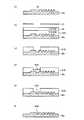
つぎに、実施形態に係るパターンデータ作成処理の処理手順について説明する。図5は、実施形態に係るパターンデータ作成処理の処理手順を示すフローチャートである。パターンデータ作成装置30の入力部31へは、修正前のテンプレートパターンデータD、パターン修正指示、応力許容値、パターン修正条件などが入力される。 Next, a processing procedure of pattern data creation processing according to the embodiment will be described. FIG. 5 is a flowchart illustrating a processing procedure of pattern data creation processing according to the embodiment. The template pattern data D before correction, a pattern correction instruction, an allowable stress value, a pattern correction condition, and the like are input to the
応力算出部32は、修正前のテンプレートパターンデータDに基づいて、テンプレート20がレジスト13Aに押し当てられた場合のテンプレート20にかかる応力の分布を算出する(ステップS10)。応力算出部32は、例えば、押印シミュレーションによって、テンプレート20での応力分布を算出する。応力算出部32は、算出した応力分布を判定部33に送る。 Based on the template pattern data D before correction, the stress calculation unit 32 calculates the distribution of stress applied to the
判定部33は、応力許容値と、応力算出部32で算出された応力分布と、に基づいて、テンプレート20での応力値が許容範囲内であるか否かを判定する(ステップS20)。換言すると、判定部33は、テンプレート20での応力値のうち閾値から外れたものがあるか否かを判定する。具体的には、判定部33は、応力算出部32で算出された応力分布内に応力許容値よりも大きな応力値(不適切な応力値)が含まれているか否かを判定する。 The determination unit 33 determines whether or not the stress value in the
判定部33は、不適切な応力値が含まれている場合、この不適切な応力値を抽出する。そして、判定部33は、不適切な応力値となっているテンプレートパターンの位置を応力集中箇所100に設定する。判定部33は、不適切な応力値と、応力集中箇所100とを対応付けし、対応付けした情報を異常情報としてパターン修正部34に送る。 When the inappropriate stress value is included, the determination unit 33 extracts the inappropriate stress value. Then, the determination unit 33 sets the position of the template pattern having an inappropriate stress value in the
これにより、応力が許容範囲内でない場合には(ステップS20、No)、修正前のテンプレートパターンデータDが修正される(ステップS30)。このように、修正前のテンプレートパターンデータDが修正されることによって、テンプレートパターンデータDxが作成される。 Thereby, when the stress is not within the allowable range (step S20, No), the template pattern data D before correction is corrected (step S30). As described above, the template pattern data Dx is created by correcting the template pattern data D before correction.
具体的には、パターン修正部34は、異常情報と、パターン修正条件とに基づいて、テンプレートパターンデータDxを作成する。このとき、パターン修正部34は、補助パターン25を修正前のテンプレートパターンデータDに対応するテンプレートパターンに配置することによって、テンプレートパターンデータDxを作成する。パターン修正部34は、例えば、応力集中箇所100の近傍に補助パターン25を配置する。 Specifically, the pattern correction unit 34 creates template pattern data Dx based on the abnormality information and the pattern correction condition. At this time, the pattern correction unit 34 creates the template pattern data Dx by arranging the
図6は、応力集中箇所を説明するための図である。図6では、テンプレート20の断面図を示している。テンプレート20は、修正前のテンプレートパターンデータDを用いて作製されたテンプレートである。 FIG. 6 is a diagram for explaining a stress concentration portion. FIG. 6 shows a cross-sectional view of the
レジスト13A(図6では図示せず)の塗布されたウエハWaにテンプレート20が押し当てられると、テンプレート20には応力がかかる。テンプレート20のテンプレートパターンのうち、例えば、大きな空隙(凹パターン21)の近傍で応力が集中する。この応力の集中する箇所が応力集中箇所100である。 When the
図7は、補助パターンの配置例を示す図である。図7では、テンプレート20Xの断面図を示している。テンプレート20Xは、テンプレートパターンデータDxを用いて作製されたテンプレートである。 FIG. 7 is a diagram illustrating an arrangement example of auxiliary patterns. FIG. 7 shows a cross-sectional view of the
本実施形態では、応力の集中する凹パターン21などに補助パターン25が配置される。補助パターン25は、例えば、テンプレートパターンのうち所定値よりも大きな凹部領域内に配置される。 In the present embodiment, the
補助パターン25は、例えば、応力集中箇所100から所定の距離範囲内に配置される。パターンデータ作成装置30は、応力集中箇所100の近傍に補助パターン25が配置されるよう、テンプレートパターンデータDxを作成する。この後、テンプレートパターンデータDxを用いてテンプレート20Xが作製される。 For example, the
補助パターン25は、テンプレート20内の他のテンプレートパターン(凸パターン)と略同じ高さを有した凸パターンである。これにより、テンプレート20Xがレジスト13Aに押し当てられた場合に、他のテンプレートパターンと同様に補助パターン25にも応力がかかる。この結果、テンプレート20Xにかかる応力が平均化される。 The
パターンデータ作成装置30のパターン修正部34は、補助パターン25を配置したテンプレートパターンデータDxを作成すると、このテンプレートパターンデータDxを応力算出部32に送る。 When the pattern correction unit 34 of the pattern
この後、修正前のテンプレートパターンデータDと同様の方法によって、テンプレートパターンデータDxの判定処理および必要に応じた修正処理が行われる。具体的には、応力算出部32は、テンプレートパターンデータDxに基づいて、テンプレート20Xがレジスト13Aに押し当てられた場合のテンプレート20Xにかかる応力の分布を算出する(ステップS10)。そして、応力算出部32は、算出した応力分布を判定部33に送る。 Thereafter, template pattern data Dx determination processing and correction processing as necessary are performed by the same method as the template pattern data D before correction. Specifically, the stress calculation unit 32 calculates the distribution of stress applied to the
判定部33は、応力許容値と、応力算出部32で算出された応力分布と、に基づいて、テンプレート20Xにかかる応力が許容範囲内であるか否かを判定する(ステップS20)。判定部33は、不適切な応力値が含まれている場合、不適切な応力値と、応力集中箇所100とを対応付けた異常情報をパターン修正部34に送る。 The determination unit 33 determines whether or not the stress applied to the
これにより、応力が許容範囲内でない場合には(ステップS20、No)、テンプレートパターンデータDxがさらに修正される(ステップS30)。このように、テンプレートパターンデータDxが修正されることによって、新たなテンプレートパターンデータDxが作成される。 Thereby, when the stress is not within the allowable range (step S20, No), the template pattern data Dx is further corrected (step S30). In this way, new template pattern data Dx is created by correcting the template pattern data Dx.
具体的には、パターン修正部34は、異常情報と、パターン修正条件とに基づいて、新たなテンプレートパターンデータDxを作成する。このとき、パターン修正部34は、補助パターン25をテンプレートパターンデータDxに対応するテンプレートパターンに配置することによって、新たなテンプレートパターンデータDxを作成する。 Specifically, the pattern correction unit 34 creates new template pattern data Dx based on the abnormality information and the pattern correction condition. At this time, the pattern correction unit 34 creates new template pattern data Dx by arranging the
パターンデータ作成装置30では、テンプレート20Xにかかる応力が許容範囲内となるまで、ステップS10〜S30の処理が繰り返される。テンプレート20Xにかかる応力が許容範囲内になると(ステップS20、Yes)、テンプレートパターンデータDxの作成処理が終了する。 In the pattern
具体的には、判定部33は、不適切な応力値が含まれていないと判断すると、テンプレートパターンデータDxを出力部35に送る。そして、出力部35は、テンプレートパターンデータDxを外部装置などに出力する。 Specifically, when the determination unit 33 determines that an inappropriate stress value is not included, the determination unit 33 sends the template pattern data Dx to the output unit 35. Then, the output unit 35 outputs the template pattern data Dx to an external device or the like.
つぎに、補助パターン25の形状について説明する。図8は、補助パターンの形状例を示す図である。図8では、テンプレートパターンの上面図を示している。図8においては、ハッチングの付している箇所がテンプレートパターン(凸パターン)であり、ハッチングの付していない箇所がスペースパターン(凹部領域)である。 Next, the shape of the
図8の(a)では、テンプレート20の一例であるテンプレート20Aを示している。テンプレート20Aには、補助パターン25の一例である補助パターン25Aが配置されている。補助パターン25Aは、1つのパターンである。補助パターン25Aは、各応力集中箇所100の近傍にある凹パターン21に対して1つずつ配置されている。 In FIG. 8A, a
補助パターン25Aは、例えば、テンプレートパターンのうちのラインパターンに対して平行となるよう配置される。換言すると、ラインパターンの長手方向と、補助パターン25Aの長手方向とが平行となるよう補助パターン25Aが配置される。 For example, the
図8の(b)では、テンプレート20の一例であるテンプレート20Bを示している。テンプレート20Bには、補助パターン25の一例である補助パターン25Bが配置されている。 In FIG. 8B, a
補助パターン25Bは、所定サイズよりも小さな複数のパターンである。このため、補助パターン25BがウエハWaに転写された後に、ウエハWa上から補助パターン25Bに対応する転写パターンを容易に除去することが可能となる。補助パターン25Bは、各応力集中箇所100の近傍にある凹パターン21に対して複数個ずつ配置されている。 The
図8の(c)では、テンプレート20の一例であるテンプレート20Cを示している。テンプレート20Cには、補助パターン25の一例である補助パターン25Cが配置されている。補助パターン25Cは、テンプレートパターンの空隙(凹部領域)を分割するよう配置された凸パターンである。補助パターン25Cは、ラインパターンを有している。補助パターン25Cは、各応力集中箇所100の近傍にある凹パターン21に対して1〜複数本ずつ配置されている。 FIG. 8C shows a
図8の(d)では、テンプレート20の一例であるテンプレート20Dを示している。テンプレート20Dには、補助パターン25の一例である補助パターン25Dが配置されている。補助パターン25Dは、スペースパターン(凹パターン)である。補助パターン25Dは、各応力集中箇所100の近傍にある凸パターン領域に対して1〜複数個ずつ配置されている。 In FIG. 8D, a
パターン修正部34は、上述した補助パターン25A〜25Dに対応するパターンデータをテンプレートパターンデータDに付加することによって、テンプレートパターンデータDxを作成する。 The pattern correction unit 34 creates template pattern data Dx by adding pattern data corresponding to the
なお、テンプレート20A〜20Dは、ハッチングの付している箇所がスペースパターン(凹部領域)であってもよい。この場合、テンプレート20A〜20Dは、ハッチングの付していない箇所がテンプレートパターン(凸パターン)である。この場合、テンプレート20A〜20Cでは、凸パターン領域内に、凹パターンとしての補助パターン25A〜25Cが配置される。また、テンプレート20Dでは、凹パターン領域内に、凸パターンとしての補助パターン25Dが配置される。 In addition, as for
また、パターン修正部34は、修正前のテンプレートパターンデータDまたはテンプレートパターンデータDxに対してテンプレートパターンのレイアウト変更処理を実行してもよい。 The pattern correction unit 34 may execute a template pattern layout change process on the template pattern data D or the template pattern data Dx before correction.
図9は、テンプレートパターンのレイアウト変更処理を説明するための図である。図9においては、ハッチングの付している箇所がテンプレートパターンであり、ハッチングの付していない箇所がスペースパターンである。 FIG. 9 is a diagram for explaining the template pattern layout change processing. In FIG. 9, the hatched portions are template patterns, and the unhatched portions are space patterns.
図9では、テンプレート20の一例であるテンプレート20Eを示している。テンプレート20Eでは、各応力集中箇所100の近傍にあるテンプレートパターン26が太くなるようレイアウト変更されている。これにより、テンプレート20Eにかかる応力が平均化される。なお、テンプレートパターンのレイアウト変更処理は、テンプレートパターンを太くする処理に限らず、何れの処理によってテンプレートパターンのレイアウトを変更してもよい。 In FIG. 9, a
つぎに、テンプレートパターンの修正による応力分布の変化(応力緩和)について説明する。図10は、テンプレートパターンの修正による応力分布の変化を説明するための図である。図10では、補助パターンの上面形状と、テンプレート押印時の応力分布との関係を示している。 Next, changes in stress distribution (stress relaxation) due to template template correction will be described. FIG. 10 is a diagram for explaining a change in the stress distribution due to the correction of the template pattern. FIG. 10 shows the relationship between the top surface shape of the auxiliary pattern and the stress distribution at the time of template stamping.
図10では、修正無し(修正前)のテンプレートパターン40、空隙内柱型(凸形状)の補助パターン27Aを配置した場合のテンプレートパターン41、空隙内分割型の補助パターン27Cを配置した場合のテンプレートパターン42を示している。 In FIG. 10, the
空隙内柱型の補助パターン27Aは、補助パターン25Aと同様に凹パターン(空隙)22に対して1つずつ配置された柱状のテンプレートパターンである。空隙内分割型の補助パターン27Cは、補助パターン25Cと同様に凹パターン(空隙)22を分割するように配置されたテンプレートパターンである。 The columnar
修正無しのテンプレートパターン40では、応力集中箇所100が存在している。一方、テンプレートパターン41では、応力集中箇所100の近傍に補助パターン27Aが配置されることによって、応力集中箇所100が無くなっている。同様に、テンプレートパターン42では、応力集中箇所100の近傍に補助パターン27Cが配置されることによって、応力集中箇所100が無くなっている。 In the
ここで、補助パターン25がウエハWa上に転写されたもの(以下、転写補助パターン50という)を除去する方法について説明する。図11は、転写補助パターンの除去処理手順を説明するための図である。図11では、ウエハWaの断面形状を示している。 Here, a method for removing the transfer of the
図11の(a)に示すように、ウエハWa上には、補助パターン25に対応する転写補助パターン50が形成される。この後、図11の(b)に示すように、ウエハWa上にマスク材61Aが配置され、さらにマスク材61A上にレジスト62が塗布される。そして、転写補助パターン50よりも大きな開口パターンを有したフォトマスク63を用いてレジスト62への露光が行われる。ここでの開口パターンは、転写補助パターン50に対応する位置に配置されている。 As shown in FIG. 11A, a transfer assist
この後、レジスト62が現像されることにより、レジスト62のうち開口パターンに応じた位置のレジストが除去される。これにより、転写補助パターン50上に開口パターンを有したレジストパターンが形成される。このレジストパターン上からエッチングが行われることによって、マスク材61Aのうちレジストパターンの開口位置に対応する位置が開口する。これにより、図11の(c)に示すように、転写補助パターン50上に開口パターンを有したマスク材パターン61Bが形成される。 Thereafter, by developing the resist 62, the resist at a position corresponding to the opening pattern in the resist 62 is removed. As a result, a resist pattern having an opening pattern is formed on the
そして、図11の(d)に示すように、マスク材パターン61Bの開口部に埋め込み材64が埋め込まれることにより、転写補助パターン50内に埋め込み材64Aが埋め込まれる。 Then, as shown in FIG. 11D, the embedding
さらに、埋め込み材64Aがエッチバックされることによって、図11の(e)に示すように、転写補助パターン50内に埋め込み材64Bが残され、その他の埋め込み材は除去される。 Further, by etching back the burying
そして、ウエハWa上からマスク材パターン61Bが除去されることによって、図11の(f)に示すように、転写補助パターン50が除去されたウエハ上パターンが形成される。なお、転写補助パターン50は、図11で説明した方法以外の方法によってウエハWa上から除去されてもよい。 Then, by removing the
テンプレートパターンデータDxの作成処理は、例えばウエハプロセスのレイヤ毎に行われる。そして、作成されたテンプレートパターンデータDxを用いてテンプレート20Xが作製される。さらに、作製されたテンプレート20Xを用いて半導体装置(半導体集積回路)が製造される。 The template pattern data Dx creation process is performed for each layer of the wafer process, for example. Then, a
この後、レジストの塗布されたウエハにテンプレート20Xを用いてインプリント処理が実行される。これにより、ウエハ上にレジストパターンが形成される。そして、レジストパターンをマスクとしてレジストパターンの下層側がエッチングされる。これにより、レジストパターンに対応する実パターンがウエハ上に形成される。半導体装置を製造する際には、テンプレートパターンデータDxの作成処理、テンプレート20Xの作製処理、インプリント処理、エッチング処理などがレイヤ毎に繰り返される。 Thereafter, an imprint process is executed on the resist-coated wafer using the
つぎに、パターンデータ作成装置30のハードウェア構成について説明する。図12は、パターンデータ作成装置のハードウェア構成を示す図である。パターンデータ作成装置30は、CPU(Central Processing Unit)91、ROM(Read Only Memory)92、RAM(Random Access Memory)93、表示部94、入力部95を有している。パターンデータ作成装置30では、これらのCPU91、ROM92、RAM93、表示部94、入力部95がバスラインを介して接続されている。 Next, the hardware configuration of the pattern
CPU91は、コンピュータプログラムであるパターンデータ作成プログラム97を用いてテンプレートパターンデータDxを作成する。パターンデータ作成プログラム97は、コンピュータで実行可能な、テンプレートパターンデータDxを作成するための複数の命令を含むコンピュータ読取り可能かつ非遷移的な記録媒体(nontransitory computer readable medium)を有するコンピュータプログラムプロダクトである。パターンデータ作成プログラム97では、前記複数の命令がテンプレートパターンデータDxの作成をコンピュータに実行させる。 The
表示部94は、液晶モニタなどの表示装置であり、CPU91からの指示に基づいて、修正前のテンプレートパターンデータD、テンプレートパターンデータDx、応力許容値、パターン修正条件、応力分布などを表示する。 The
入力部95は、マウスやキーボードを備えて構成され、使用者から外部入力される指示情報(パターンデータの作成に必要なパラメータ等)を入力する。入力部95へ入力された指示情報は、CPU91へ送られる。 The
パターンデータ作成プログラム97は、ROM92内に格納されており、バスラインを介してRAM93へロードされる。図12では、パターンデータ作成プログラム97がRAM93へロードされた状態を示している。 The pattern
CPU91はRAM93内にロードされたパターンデータ作成プログラム97を実行する。具体的には、パターンデータ作成装置30では、使用者による入力部95からの指示入力に従って、CPU91がROM92内からパターンデータ作成プログラム97を読み出してRAM93内のプログラム格納領域に展開して各種処理を実行する。CPU91は、この各種処理に際して生じる各種データをRAM93内に形成されるデータ格納領域に一時的に記憶させておく。 The
パターンデータ作成装置30で実行されるパターンデータ作成プログラム97は、応力算出部32、判定部33、パターン修正部34を含むモジュール構成となっており、これらが主記憶装置上にロードされ、これらが主記憶装置上に生成される。 The pattern
なお、パターンデータ作成プログラム97は、応力算出部32の機能を有していなくてもよい。この場合、パターンデータ作成プログラム97とは異なる他のコンピュータプログラムによって応力分布が算出される。 Note that the pattern
また、パターンデータ作成プログラム97は、判定部33の機能を有していなくてもよい。この場合、パターンデータ作成プログラム97とは異なる他のコンピュータプログラムによってテンプレート20,20Xでの応力が許容範囲内であるか否かが判定される。 Further, the pattern
このように実施形態では、テンプレート20をレジスト13Aに押し当てた場合のテンプレート20Aにかかる応力の応力分布が算出されている。そして、テンプレートパターンの中で閾値よりも大きな応力値を示す応力集中箇所100があるか否かが判定されている。さらに、応力集中箇所100がある場合には、応力集中箇所100での応力値が閾値以下の応力値となるようテンプレートパターンデータDが修正されてテンプレートパターンデータDxが作成される。したがって、テンプレート20Xがレジスト13Aに押し当てられた場合のテンプレート20Xにかかる応力を均一化することが可能となる。 Thus, in the embodiment, the stress distribution of the stress applied to the
本発明のいくつかの実施形態を説明したが、これらの実施形態は、例として提示したものであり、発明の範囲を限定することは意図していない。これら新規な実施形態は、その他の様々な形態で実施されることが可能であり、発明の要旨を逸脱しない範囲で、種々の省略、置き換え、変更を行うことができる。これら実施形態やその変形は、発明の範囲や要旨に含まれるとともに、特許請求の範囲に記載された発明とその均等の範囲に含まれる。 Although several embodiments of the present invention have been described, these embodiments are presented by way of example and are not intended to limit the scope of the invention. These novel embodiments can be implemented in various other forms, and various omissions, replacements, and changes can be made without departing from the scope of the invention. These embodiments and modifications thereof are included in the scope and gist of the invention, and are included in the invention described in the claims and the equivalents thereof.
1…インプリント装置、13A…レジスト、20,20X、20A〜20E…テンプレート、21…凹パターン、25,25A〜25D,27A,27C…補助パターン、26…テンプレートパターン、30…パターンデータ作成装置、32…応力算出部、33…判定部、34…パターン修正部、40〜42…テンプレートパターン、50…転写補助パターン、63…フォトマスク、100…応力集中箇所、Wa…ウエハ。 DESCRIPTION OF SYMBOLS 1 ... Imprint apparatus, 13A ... Resist, 20, 20X, 20A-20E ... Template, 21 ... Concave pattern, 25, 25A-25D, 27A, 27C ... Auxiliary pattern, 26 ... Template pattern, 30 ... Pattern data creation apparatus, 32 ... Stress calculation unit, 33 ... Determination unit, 34 ... Pattern correction unit, 40-42 ... Template pattern, 50 ... Transfer assist pattern, 63 ... Photomask, 100 ... Stress concentration location, Wa ... Wafer.
Claims (5)
Translated fromJapanese前記テンプレートパターンの中で閾値よりも大きな応力値を示す応力集中箇所があるか否かを判定する判定ステップと、
前記応力集中箇所がある場合には、前記応力集中箇所での応力値が前記閾値以下の応力値となるよう前記テンプレートパターンのパターンデータを修正する修正ステップと、
を含むことを特徴とするパターンデータ作成方法。A calculation step of calculating a stress distribution of stress applied to the template when a template having a template pattern is pressed against a resist;
A determination step of determining whether or not there is a stress concentration point indicating a stress value larger than a threshold value in the template pattern;
If there is the stress concentration location, a correction step of correcting the pattern data of the template pattern so that the stress value at the stress concentration location is equal to or less than the threshold value,
A pattern data creating method comprising:
前記算出および前記判定を再度行い、
前記応力集中箇所での応力値が前記閾値以下の応力値となるまで、前記算出、前記判定および前記修正を繰り返す、
ことを特徴とする請求項1に記載のパターンデータ作成方法。For the modified pattern data,
Perform the calculation and the determination again,
The calculation, the determination, and the correction are repeated until the stress value at the stress concentration point becomes a stress value equal to or less than the threshold value.
The pattern data creation method according to claim 1, wherein:
ことを特徴とする請求項1に記載のパターンデータ作成方法。When correcting the pattern data, an auxiliary pattern is added to the template pattern.
The pattern data creation method according to claim 1, wherein:
補助パターンと、
を有し、
前記補助パターンは、前記テンプレートパターンがレジストに押し当てられた場合の前記テンプレートパターンにかかる応力値が閾値以下の応力値となるよう配置され、かつ前記テンプレートパターンの凸パターンと同じ高さを有している、
テンプレート。With template patterns,
An auxiliary pattern,
Have
The auxiliary pattern is arranged so that a stress value applied to the template pattern when the template pattern is pressed against a resist is equal to or lower than a threshold value, and has the same height as the convex pattern of the template pattern. ing,
template.
前記テンプレートパターンの中で閾値よりも大きな応力値を示す応力集中箇所があるか否かを判定する判定ステップと、
前記応力集中箇所がある場合には、前記応力集中箇所での応力値が前記閾値以下の応力値となるよう前記テンプレートパターンのパターンデータを修正する修正ステップと、
修正後のパターンデータを用いて第2のテンプレートを作製する作製ステップと、
前記第2のテンプレートを用いて、半導体基板にインプリント処理を行うインプリント処理ステップと、
を含むことを特徴とする半導体装置の製造方法。A calculation step of calculating a stress distribution of stress applied to the first template when the first template having the template pattern is pressed against the resist;
A determination step of determining whether or not there is a stress concentration point indicating a stress value larger than a threshold value in the template pattern;
If there is the stress concentration location, a correction step of correcting the pattern data of the template pattern so that the stress value at the stress concentration location is equal to or less than the threshold value,
A production step of producing a second template using the corrected pattern data;
Using the second template, an imprint processing step of performing an imprint process on a semiconductor substrate;
A method for manufacturing a semiconductor device, comprising:
Priority Applications (2)
| Application Number | Priority Date | Filing Date | Title |
|---|---|---|---|
| JP2014173802AJP6279433B2 (en) | 2014-08-28 | 2014-08-28 | Pattern data generation method, template, and semiconductor device manufacturing method |
| US14/630,672US9971342B2 (en) | 2014-08-28 | 2015-02-25 | Pattern data creating method, template, and semiconductor device manufacturing method |
Applications Claiming Priority (1)
| Application Number | Priority Date | Filing Date | Title |
|---|---|---|---|
| JP2014173802AJP6279433B2 (en) | 2014-08-28 | 2014-08-28 | Pattern data generation method, template, and semiconductor device manufacturing method |
Publications (2)
| Publication Number | Publication Date |
|---|---|
| JP2016048762Atrue JP2016048762A (en) | 2016-04-07 |
| JP6279433B2 JP6279433B2 (en) | 2018-02-14 |
Family
ID=55403387
Family Applications (1)
| Application Number | Title | Priority Date | Filing Date |
|---|---|---|---|
| JP2014173802AActiveJP6279433B2 (en) | 2014-08-28 | 2014-08-28 | Pattern data generation method, template, and semiconductor device manufacturing method |
Country Status (2)
| Country | Link |
|---|---|
| US (1) | US9971342B2 (en) |
| JP (1) | JP6279433B2 (en) |
Families Citing this family (1)
| Publication number | Priority date | Publication date | Assignee | Title |
|---|---|---|---|---|
| JP2020047691A (en) | 2018-09-18 | 2020-03-26 | キオクシア株式会社 | Slide inhibition portion extraction method, pattern formation method, and method for manufacturing semiconductor device |
Citations (5)
| Publication number | Priority date | Publication date | Assignee | Title |
|---|---|---|---|---|
| JP2009066773A (en)* | 2007-09-10 | 2009-04-02 | Murata Mfg Co Ltd | Imprint mold and fine pattern forming method |
| JP2010052288A (en)* | 2008-08-28 | 2010-03-11 | Hitachi Industrial Equipment Systems Co Ltd | Fine structure transfer mold and fine structure transfer device |
| WO2011155035A1 (en)* | 2010-06-09 | 2011-12-15 | パイオニア株式会社 | Transfer device |
| JP2013069789A (en)* | 2011-09-21 | 2013-04-18 | Toshiba Corp | Patterning device, patterning method and patterning program |
| JP2013145616A (en)* | 2012-01-13 | 2013-07-25 | Hitachi High-Technologies Corp | Stamper, imprinting device and processed product, as well as processed product manufacturing device and processed product manufacturing method |
Family Cites Families (7)
| Publication number | Priority date | Publication date | Assignee | Title |
|---|---|---|---|---|
| JPH08213296A (en) | 1994-10-20 | 1996-08-20 | Hitachi Ltd | Thin film manufacturing equipment and semiconductor equipment |
| JP2003142367A (en) | 2001-10-31 | 2003-05-16 | Sony Corp | Evaluation mask and method for evaluating mask |
| JP2010177374A (en)* | 2009-01-28 | 2010-08-12 | Toshiba Corp | Pattern verifying method and method for manufacturing semiconductor device |
| JP4792096B2 (en) | 2009-03-19 | 2011-10-12 | 株式会社東芝 | A template pattern design method, a template manufacturing method, and a semiconductor device manufacturing method. |
| JP5127785B2 (en) | 2009-07-21 | 2013-01-23 | 株式会社東芝 | Imprint apparatus and imprint method |
| NL2009824A (en) | 2011-12-21 | 2013-06-24 | Asml Netherlands Bv | Lithographic apparatus with a deformation sensor. |
| JP5849750B2 (en) | 2012-02-09 | 2016-02-03 | 大日本印刷株式会社 | Fine structure forming method and imprint apparatus |
- 2014
- 2014-08-28JPJP2014173802Apatent/JP6279433B2/enactiveActive
- 2015
- 2015-02-25USUS14/630,672patent/US9971342B2/enactiveActive
Patent Citations (5)
| Publication number | Priority date | Publication date | Assignee | Title |
|---|---|---|---|---|
| JP2009066773A (en)* | 2007-09-10 | 2009-04-02 | Murata Mfg Co Ltd | Imprint mold and fine pattern forming method |
| JP2010052288A (en)* | 2008-08-28 | 2010-03-11 | Hitachi Industrial Equipment Systems Co Ltd | Fine structure transfer mold and fine structure transfer device |
| WO2011155035A1 (en)* | 2010-06-09 | 2011-12-15 | パイオニア株式会社 | Transfer device |
| JP2013069789A (en)* | 2011-09-21 | 2013-04-18 | Toshiba Corp | Patterning device, patterning method and patterning program |
| JP2013145616A (en)* | 2012-01-13 | 2013-07-25 | Hitachi High-Technologies Corp | Stamper, imprinting device and processed product, as well as processed product manufacturing device and processed product manufacturing method |
Also Published As
| Publication number | Publication date |
|---|---|
| JP6279433B2 (en) | 2018-02-14 |
| US9971342B2 (en) | 2018-05-15 |
| US20160064368A1 (en) | 2016-03-03 |
Similar Documents
| Publication | Publication Date | Title |
|---|---|---|
| JP6437387B2 (en) | Substrate flattening method | |
| JP2009088376A (en) | Imprint method and imprint system | |
| JP6262015B2 (en) | Resist placement method and resist placement program | |
| JP5694219B2 (en) | Drop position setting program, imprint method, and imprint apparatus | |
| JP5289343B2 (en) | Exposure amount determination method, semiconductor device manufacturing method, exposure amount determination program, and exposure amount determination apparatus | |
| JP5426489B2 (en) | Template manufacturing method | |
| JP6294679B2 (en) | Imprint apparatus and article manufacturing method | |
| US11106128B2 (en) | Method for designing mask set, recording medium, template, and method for manufacturing template | |
| JP5840584B2 (en) | Exposure apparatus, exposure method, and manufacturing method of semiconductor device | |
| CN105751495B (en) | Three-dimensional printing device and printing compensation method thereof | |
| JP2011159764A (en) | Method of forming pattern, system for calculating resist coating distribution, and program for calculating the same | |
| JP6523864B2 (en) | Imprint apparatus and imprint method | |
| JP6279433B2 (en) | Pattern data generation method, template, and semiconductor device manufacturing method | |
| US8423922B2 (en) | Photomask designing method and photomask designing program | |
| CN103744265B (en) | Improve the optical proximity correction method of process window | |
| JP2011165950A (en) | Pattern verification method, pattern generation method, device fabrication method, pattern verification program, and pattern verification system | |
| US10331028B2 (en) | Imprinting apparatus, recording medium, and imprinting method | |
| CN109901357B (en) | Reticle and mask correction method | |
| JP2019140209A (en) | Imprint system, method for manufacturing semiconductor device and program | |
| JP4984230B2 (en) | Optical proximity correction method | |
| JP2017168660A (en) | Drawing position correction data creation method and template manufacturing method | |
| US9165095B2 (en) | Target point generation for optical proximity correction | |
| US8336004B2 (en) | Dimension assurance of mask using plurality of types of pattern ambient environment | |
| JP2016038550A (en) | Method for designing semiconductor device | |
| JP2024133869A (en) | Pattern design method, template manufacturing method, and pattern design device |
Legal Events
| Date | Code | Title | Description |
|---|---|---|---|
| A621 | Written request for application examination | Free format text:JAPANESE INTERMEDIATE CODE: A621 Effective date:20160831 | |
| A977 | Report on retrieval | Free format text:JAPANESE INTERMEDIATE CODE: A971007 Effective date:20170526 | |
| A711 | Notification of change in applicant | Free format text:JAPANESE INTERMEDIATE CODE: A712 Effective date:20170605 | |
| A131 | Notification of reasons for refusal | Free format text:JAPANESE INTERMEDIATE CODE: A131 Effective date:20170606 | |
| A521 | Request for written amendment filed | Free format text:JAPANESE INTERMEDIATE CODE: A523 Effective date:20170728 | |
| TRDD | Decision of grant or rejection written | ||
| A01 | Written decision to grant a patent or to grant a registration (utility model) | Free format text:JAPANESE INTERMEDIATE CODE: A01 Effective date:20171219 | |
| A61 | First payment of annual fees (during grant procedure) | Free format text:JAPANESE INTERMEDIATE CODE: A61 Effective date:20180117 | |
| R150 | Certificate of patent or registration of utility model | Ref document number:6279433 Country of ref document:JP Free format text:JAPANESE INTERMEDIATE CODE: R150 | |
| S111 | Request for change of ownership or part of ownership | Free format text:JAPANESE INTERMEDIATE CODE: R313111 | |
| R350 | Written notification of registration of transfer | Free format text:JAPANESE INTERMEDIATE CODE: R350 |