JP2016045605A - Tactile presentation device - Google Patents
Tactile presentation deviceDownload PDFInfo
- Publication number
- JP2016045605A JP2016045605AJP2014168072AJP2014168072AJP2016045605AJP 2016045605 AJP2016045605 AJP 2016045605AJP 2014168072 AJP2014168072 AJP 2014168072AJP 2014168072 AJP2014168072 AJP 2014168072AJP 2016045605 AJP2016045605 AJP 2016045605A
- Authority
- JP
- Japan
- Prior art keywords
- film
- piezoelectric film
- presentation device
- diaphragm
- touch
- Prior art date
- Legal status (The legal status is an assumption and is not a legal conclusion. Google has not performed a legal analysis and makes no representation as to the accuracy of the status listed.)
- Granted
Links
Images


Landscapes
- Input From Keyboards Or The Like (AREA)
- User Interface Of Digital Computer (AREA)
Abstract
Description
Translated fromJapanese本発明は、利用者に振動を伝えることで触覚フィードバックを与える触覚提示装置に関する。 The present invention relates to a haptic presentation device that provides haptic feedback by transmitting vibration to a user.
近年、タッチパネル式のキーボード等において、利用者がキーをタッチした時に振動を伝えることで触覚フィードバックを与え、打鍵感を提供する触覚提示装置が提案されている。 2. Description of the Related Art In recent years, there has been proposed a tactile sensation presentation device that provides tactile feedback by transmitting vibration when a user touches a key in a touch panel type keyboard or the like, thereby providing a keystroke feeling.
例えば、特許文献1には、圧電セラミックス等からなる圧電バイモルフ素子の両端を低弾性体で保持し、当該圧電バイモルフ素子の中央部をタッチパネルと連結させた構造が記載されている。特許文献1の構造では、タッチパネルに触れると、圧電バイモルフ素子に交流信号が入力して、圧電バイモルフ素子が振動する。これにより、タッチパネルに触れたユーザは打鍵感を得ることができる。 For example, Patent Document 1 describes a structure in which both ends of a piezoelectric bimorph element made of piezoelectric ceramics or the like are held by a low-elasticity body and the central portion of the piezoelectric bimorph element is connected to a touch panel. In the structure of Patent Document 1, when a touch panel is touched, an AC signal is input to the piezoelectric bimorph element, and the piezoelectric bimorph element vibrates. Thereby, the user who touched the touch panel can obtain a keystroke feeling.
例えば、キーボードに用いられるメカニカルスイッチでは、押下によりキートップが沈み、メカニカルスイッチに内蔵されたバネの作用によりキートップが元の位置に戻る。そして、それぞれの過程で異なる感覚が生じ、それらの感覚が合わさることで確かな打鍵感が生じる。しかし、特許文献1に記載の触覚提示装置では、タッチパネルに触れても、圧電バイモルフ素子による単調な振動が生じるだけなので、確かな打鍵感を得ることができない。 For example, in a mechanical switch used for a keyboard, the key top sinks when pressed, and the key top returns to its original position by the action of a spring built in the mechanical switch. Then, different sensations are generated in each process, and when these sensations are combined, a certain keystroke feeling is generated. However, in the tactile sense presentation device described in Patent Document 1, even if the touch panel is touched, only a monotonous vibration is generated by the piezoelectric bimorph element, so that a certain keystroke feeling cannot be obtained.
本発明の目的は、確かな打鍵感を与えることができる触覚提示装置を提供することにある。 An object of the present invention is to provide a tactile sense presentation device capable of giving a certain keystroke feeling.
本発明の触覚提示装置は、第1フィルム、平板状の振動板、タッチ検出部、第2フィルムおよび駆動部を備える。第1フィルムは電圧を加えることで面方向に変形する。振動板は、曲げ応力が発生する状態で第1フィルムに固定される。タッチ検出部は、振動板の主面のうち第1フィルム側の反対側の主面に設けられ、タッチ操作を検出する。第2フィルムは、振動板とタッチ検出部との間に設けられ、電圧を加えることで変形する。駆動部は、タッチ検出部がタッチ操作を検出したときに、第1フィルムおよび第2フィルムに駆動信号を印加する。 The tactile sense presentation device of the present invention includes a first film, a flat diaphragm, a touch detection unit, a second film, and a drive unit. The first film is deformed in the surface direction by applying a voltage. The diaphragm is fixed to the first film in a state where bending stress is generated. A touch detection part is provided in the main surface on the opposite side to the 1st film side among the main surfaces of a diaphragm, and detects touch operation. A 2nd film is provided between a diaphragm and a touch detection part, and deform | transforms by applying a voltage. The drive unit applies a drive signal to the first film and the second film when the touch detection unit detects a touch operation.
この構成では、ユーザがタッチ検出部に対してタッチ操作を行うと、第1フィルムおよび第2フィルムが伸縮する。第1フィルムの伸縮による振動板の振動および第2フィルムによる振動により、複雑な振動が形成される。この複雑な振動がタッチ検出部に伝わることにより、ユーザは確かな打鍵感を得ることができる。 In this configuration, when the user performs a touch operation on the touch detection unit, the first film and the second film expand and contract. Complex vibration is formed by the vibration of the diaphragm caused by the expansion and contraction of the first film and the vibration caused by the second film. By transmitting this complicated vibration to the touch detection unit, the user can obtain a certain keystroke feeling.
本発明の触覚提示装置では、第2フィルムは振動板の主面に垂直な方向に伸縮することが好ましい。この構成では、第2フィルムの伸縮が振動板により阻害されないので、第2フィルムの伸縮の幅を大きくすることができる。また、第1フィルムおよび第2フィルムを同時に伸縮させることで、タッチ検出部の振動の振幅を大きくすることができる。 In the tactile sense presentation device of the present invention, it is preferable that the second film expands and contracts in a direction perpendicular to the main surface of the diaphragm. In this configuration, since the expansion and contraction of the second film is not inhibited by the diaphragm, the expansion and contraction width of the second film can be increased. Moreover, the amplitude of the vibration of the touch detection unit can be increased by simultaneously expanding and contracting the first film and the second film.
本発明の触覚提示装置は、次のように構成されてもよい。第2フィルムおよびタッチ検出部は、それぞれ対応して複数設けられる。駆動部は、タッチ操作を検出したタッチ検出部に対応する、第2フィルムに駆動信号を印加する。この構成では、第2フィルムを用いて、タッチ操作されたタッチ検出部のみを振動させることができる。 The tactile sense presentation device of the present invention may be configured as follows. A plurality of second films and touch detection units are provided correspondingly. The drive unit applies a drive signal to the second film corresponding to the touch detection unit that has detected the touch operation. In this configuration, it is possible to vibrate only the touch detection unit that has been touched using the second film.
本発明の触覚提示装置では、駆動部は、タッチ検出部がタッチ操作を検出すると、先ず、第1フィルムに駆動信号を印加し、次に、第2フィルムに、第1フィルムに比べて高周波数の駆動信号を印加することが好ましい。 In the tactile sense presentation device of the present invention, when the touch detection unit detects a touch operation, the drive unit first applies a drive signal to the first film, and then the second film has a higher frequency than the first film. It is preferable to apply the drive signal.
この構成では、振動板が低周波数で振動した後に、第2フィルムが高周波数で振動する。振動板による低周波数の振動は、タッチ位置がゆっくり動いた感触をユーザに生じさせる。第2フィルムによる高周波数の振動は、タッチ位置が鋭く動いた感触をユーザに発生させる。これにより、ユーザは、先ず、キーを押込むような感覚を得て、次に、キーから押返されるような感覚を得ることができる。 In this configuration, after the diaphragm vibrates at a low frequency, the second film vibrates at a high frequency. The low-frequency vibration caused by the diaphragm causes the user to feel that the touch position has moved slowly. The high-frequency vibration caused by the second film causes the user to feel that the touch position has moved sharply. Thereby, the user can first obtain the feeling of pressing the key, and then can obtain the feeling of being pushed back from the key.
本発明の触覚提示装置は、次にように構成されてもよい。駆動部は、タッチ検出部がタッチ操作を検出すると、先ず、第1フィルムが伸長するように第1フィルムに駆動信号を印加する。次に、第2フィルムが伸長するように第2フィルムに駆動信号を印加する。次に、第1フィルムが縮むように第1フィルムに駆動信号を印加する。 The haptic presentation device of the present invention may be configured as follows. When the touch detection unit detects a touch operation, the drive unit first applies a drive signal to the first film so that the first film extends. Next, a drive signal is applied to the second film so that the second film extends. Next, a drive signal is applied to the first film so that the first film shrinks.
この構成では、先ず、振動板が押込み方向に変位する。これにより、ユーザはキーを押し込むような感覚を得ることができる。次に、第2フィルムが押戻し方向に変位する。これにより、ユーザは、わずかにキーから押戻されるような感覚を得ることができる。次に、振動板が押戻し方向に変位する。これにより、ユーザは、しっかりとした押戻しの感覚を得ることができる。 In this configuration, first, the diaphragm is displaced in the pushing direction. Thereby, the user can obtain a feeling of pressing the key. Next, the second film is displaced in the pushback direction. Thereby, the user can obtain a feeling of being pushed back slightly from the key. Next, the diaphragm is displaced in the pushback direction. Thereby, the user can obtain a firm sense of pushing back.
本発明によれば、確かな打鍵感を与える触覚提示装置を実現することができる。 According to the present invention, it is possible to realize a tactile sensation presentation device that gives a certain keystroke feeling.
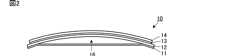
本発明の第1の実施形態に係る触覚提示装置10について説明する。図1は触覚提示装置10の外観斜視図である。図2は触覚提示装置10の側面図である。 A tactile
触覚提示装置10は、圧電フィルム11、振動板12、圧電フィルム13およびタッチパネル14を備えている。圧電フィルム11は本発明の第1フィルムに相当する。圧電フィルム13は本発明の第2フィルムに相当する。触覚提示装置10は、いわゆるキーボードであり、平板状のタッチパネル14には、キー配列に対応した位置に複数のタッチセンサ15が設けられている。タッチセンサ15は本発明のタッチ検出部に相当する。タッチセンサ15は、ユーザのタッチ操作を検出する機能であればどの様な方式でもよく、メンブレン方式、静電容量方式、圧電フィルム方式等の様々な方式を用いることができる。 The tactile
タッチパネル14は、圧電フィルム13を介して振動板12の一方の主面(正面)に装着されている。圧電フィルム13および振動板12は矩形平板状である。圧電フィルム13は振動板12の正面の略全面に設けられ、圧電フィルム13の主面は振動板12およびタッチパネル14に当接している。振動板12は、その他方の主面の(背面)において短手方向の両端が圧電フィルム11に固定されている。なお、振動板12は、その共振周波数(固有振動数)が後述の駆動信号の周波数に対応するように設計されている。 The
圧電フィルム11および圧電フィルム13は、矩形平板状のベースフィルムと、ベースフィルムの対向する両主面に形成された電極を備える。ベースフィルムは、圧電性を有するフィルムであれば良く、例えば、ポリフッ化ビニリデン(PVDF)、キラル高分子等の材料を用いた圧電性樹脂である。振動板12は、例えばアクリル樹脂PMMAで構成されている。なお、振動板12には、金属板、PET、ポリカーボネイト(PC)、PLLA、ガラス等の他の材料を用いてもよい。 The
圧電フィルム11および圧電フィルム13の電極には、図示しない引き出し用の配線導体が接続されており、駆動信号が当該配線導体を介して電極へ印加されるようになっている。図3に示すように、タッチパネル14に設けられたタッチセンサ15をユーザがタッチすると、駆動部17が圧電フィルム11および圧電フィルム13の電極に駆動信号を印加する。これにより、圧電フィルム11はその短手方向に伸縮し、圧電フィルム13はその厚み方向(振動板12の主面に垂直な方向)に伸縮する。すなわち、圧電フィルム11は電圧を加えることで面方向に変形し、圧電フィルム13は電圧を加えることで厚み方向に変形する。なお、駆動部17は、例えば、圧電フィルム11を駆動する第1駆動回路、圧電フィルム13を駆動する第2駆動回路、ならびに、第1駆動回路および第2駆動回路を制御する制御回路を含む。すなわち、圧電フィルム11と圧電フィルム13とは別々の駆動回路で駆動される。 A lead wiring conductor (not shown) is connected to the electrodes of the
図1および図2に示すように、振動板12は、圧電フィルム11の存在する側(振動板12の背面側)に対して反対側(振動板12の正面側)に湾曲して突出する形状となるように、圧電フィルム11へ固定されている。この構成により、振動板12と圧電フィルム11との間には、中空領域16が形成される。そして、この振動板12のある側が触覚提示装置10の正面側となり、圧電フィルム11がある側が触覚提示装置10の背面側となる。 As shown in FIGS. 1 and 2, the
ただし、本実施形態において、振動板12の湾曲状態は、説明のために誇張して記載しており、実際には、振動板12の主面と圧電フィルム11の主面は、より平行に近く、中空領域16は、できるだけ少ないほうが望ましい。 However, in the present embodiment, the curved state of the
このように、振動板12は、平板面が湾曲した状態で圧電フィルム11に固定されるため、曲げ応力が加わった状態で圧電フィルム11に固定される。また、圧電フィルム11には、圧電フィルム11の主面における短手方向に引張力が係った状態となる。 Thus, since the
図4は、振動板12の動作を説明する側面図である。ここで、触覚提示装置10の厚み方向をZ方向とし、触覚提示装置10の短手方向をX方向とし、触覚提示装置10の長手方向をY方向とする。駆動部17(図3参照)により圧電フィルム11に駆動信号が印加されると、圧電フィルム11は駆動信号の周波数でX方向に伸縮する。振動板12のX方向の端部は、圧電フィルム11の伸縮により、互いに近づいたり、離れたりすることを繰り返す。振動板12は、振動板12のX方向の端部が変位することで、振動板12の主面の曲率が変化するように弾性変形する。すなわち、X方向における振動板12の端部はZ方向に変位せず、X方向における振動板12の中央部は駆動信号の周波数でZ方向に振動する。 FIG. 4 is a side view for explaining the operation of the
図5は、触覚提示装置10の動作フローを示す図である。ユーザがタッチセンサ15(図1参照)をタッチすると、タッチセンサ15は、タッチ操作を検出し、そのことを駆動部17(図3参照)に送信する(S11)。タッチ操作の検出を受信した駆動部17は、低周波数の駆動信号を圧電フィルム11に所定時間印加する(S12)。これにより、振動板12そしてタッチパネル14が低周波数でZ方向(図4参照)に振動する。駆動部17は、圧電フィルム11への駆動信号の印加が終了すると、高周波数の駆動信号を圧電フィルム13に所定時間印加する(S13)。これにより、圧電フィルム13そしてタッチパネル14が高周波数でZ方向に振動する。 FIG. 5 is a diagram showing an operation flow of the tactile
なお、圧電フィルム11に駆動信号が印加される時間は、例えば、メカニカルスイッチにおいて、押下によりキートップが沈み始めてから、キートップが最も下に達するまでの時間に基づいて設定される。圧電フィルム13に駆動信号が印加される時間は、例えば、メカニカルスイッチにおいて、押下によりキートップが最も下に達してから、押下の終了によりキートップが元の位置に戻るまでの時間に基づいて設定される。 Note that the time for which the drive signal is applied to the
第1の実施形態では、ユーザがタッチセンサ15をタッチすると、先ず、振動板12が低周波数で振動し、次に、圧電フィルム13が高周波数で振動する。振動板12による低周波数の振動は、タッチ位置がゆっくり動いた感触をユーザに生じさせる。圧電フィルム13による高周波数の振動は、タッチ位置が鋭く動いた感触をユーザに発生させる。これにより、ユーザは、先ずキーを押込むような感覚を得て、次にキーから押返されるような感覚を得る。このため、触覚提示装置10では、確かな打鍵感を提供することができる。すなわち、触覚提示装置10では、複雑な振動を生じさせることで、タッチ操作を行うユーザに使い心地の良さを提供することができる。 In the first embodiment, when the user touches the
なお、第1の実施形態では、圧電フィルム11への駆動信号の印加が終了した後に、圧電フィルム13に駆動信号が印加されるが、本発明はこれに限定されない。タッチ操作が検出されると、圧電フィルム11および圧電フィルム13に同時に駆動信号が印加されてもよい。また、タッチ操作が検出されると、先ず、圧電フィルム11に駆動信号が印加され、次に、圧電フィルム11および圧電フィルム13の両方に駆動信号が印加されてもよい。これらの構成では、互いに異なる振動数の振動が重ね合わされることで、複雑な振動を生じさせることができる。また、タッチパネル14の振動の振幅を大きくすることができる。このため、確かな打鍵感を提供することができる。 In the first embodiment, the drive signal is applied to the
図6は、第1の実施形態の変形例に係る触覚提示装置20の模式的側面図である。触覚提示装置20では、振動板12の正面のうちキー配列に対応した位置に、複数の圧電フィルム23が設けられている。タッチセンサ15と圧電フィルム23とは、互いにほぼ等しいサイズに形成され、平面視で重なっている。駆動部17(図3参照)は、タッチ操作を検出したタッチセンサ15の下に設けられた、圧電フィルム23に駆動信号を印加する。触覚提示装置20では、圧電フィルム23を用いて、タッチされたタッチセンサ15のみを振動させることができる。なお、触覚提示装置20では、圧電フィルム23の代わりに、電圧印加用の電極が形成された圧電セラミックスを用いてもよい。 FIG. 6 is a schematic side view of a tactile
《第2の実施形態》
本発明の第2の実施形態に係る触覚提示装置について説明する。第2の実施形態の触覚提示装置は、その動作フローを除いて、第1の実施形態の触覚提示装置と同様である。なお、以下では、第2の実施形態の触覚提示装置におけるタッチパネル14(図1参照)側から圧電フィルム11側に向く方向を押込み方向と称し、押込み方向の反対方向を押戻し方向と称する。<< Second Embodiment >>
A tactile presentation device according to a second embodiment of the present invention will be described. The tactile presentation device of the second embodiment is the same as the tactile presentation device of the first embodiment except for the operation flow. In the following, the direction from the touch panel 14 (see FIG. 1) side to the
図7は、第2の実施形態の触覚提示装置の動作フローを示す図である。ユーザがタッチセンサ15(図1参照)をタッチすると、タッチセンサ15は、タッチ操作を検出し、そのことを駆動部17(図3参照)に送信する(S31)。タッチ操作の検出を受信した駆動部17は、圧電フィルム11が伸長するように圧電フィルム11に駆動信号を所定時間印加する(S32)。これにより、振動板12そしてタッチパネル14が押込み方向に変位する。なお、第2の実施形態における駆動信号の周期は、駆動信号を印加する時間の2倍以上に設定されている。 FIG. 7 is a diagram illustrating an operation flow of the tactile presentation device according to the second embodiment. When the user touches the touch sensor 15 (see FIG. 1), the
駆動部17は、圧電フィルム11への駆動信号の印加が終了すると、圧電フィルム13が伸長するように圧電フィルム13に駆動信号を所定時間印加する(S33)。これにより、圧電フィルム13そしてタッチパネル14が押戻し方向に変位する。駆動部17は、圧電フィルム13への駆動信号の印加が終了すると、圧電フィルム11が縮むように圧電フィルム11に駆動信号を所定時間印加する(S34)。これにより、振動板12そしてタッチパネル14が押戻し方向に変位する。なお、圧電フィルム11および圧電フィルム13に駆動信号が印加される時間は、例えば、メカニカルスイッチの押込みおよび押戻しにかかる時間に基づいて設定される。 When the
第2の実施形態では、振動板12が押込み方向に変位することにより、キーを押し込むような感覚が得られる。圧電フィルム13が押戻し方向に変位することにより、わずかにキーから押戻されるような感覚が得られる。振動板12が押戻し方向に変位することにより、しっかりとした押戻しの感覚が得られる。このため、第2の実施形態の触覚提示装置では、確かな打鍵感を提供することができる。 In the second embodiment, when the
なお、第2の実施形態では、圧電フィルム13への駆動信号の印加が終了した後に、圧電フィルム11に駆動信号が印加されるが、本発明はこれに限定されない。圧電フィルム13への駆動信号の印加と同時に、圧電フィルム11が縮むように圧電フィルム11に駆動信号が印加されてもよい。この構成では、タッチパネル14の押戻し方向の変位を大きくすることができる。 In the second embodiment, the drive signal is applied to the
なお、本発明の第1フィルムおよび第2フィルムは上述の実施形態の圧電フィルムに限定されない。本発明の第1フィルムおよび第2フィルムは、電歪フィルム、エレクトレットフィルム、コンポジットフィルム、電気活性高分子フィルム等でもよい。 In addition, the 1st film and 2nd film of this invention are not limited to the piezoelectric film of the above-mentioned embodiment. The first film and the second film of the present invention may be an electrostrictive film, an electret film, a composite film, an electroactive polymer film, or the like.
電気活性フィルムとは、電気的駆動によって応力を発生するフィルム、または電気的駆動によって変形して変位を発生するフィルムである。具体的には、電歪フィルム、コンポジット材料(圧電セラミックスを樹脂モールドした材料)、電気駆動型エラストマー、または液晶エラストマー等がある。 An electroactive film is a film that generates stress by electrical driving or a film that deforms and generates displacement by electrical driving. Specifically, there are an electrostrictive film, a composite material (a material obtained by resin-molding piezoelectric ceramics), an electrically driven elastomer, or a liquid crystal elastomer.
本発明の第1フィルムは、圧電フィルムと、圧電性を有しない樹脂フィルム(エキサイタフィルム)と、を用いることでも実現することができる。この場合、圧電フィルムは、エキサイタフィルムの主面に貼り付けられ、当該エキサイタフィルムの端部が振動板に接続される。 The first film of the present invention can also be realized by using a piezoelectric film and a resin film having no piezoelectricity (exciter film). In this case, the piezoelectric film is attached to the main surface of the exciter film, and the end of the exciter film is connected to the diaphragm.
また、本発明の第1フィルムは、圧電セラミックスと、複数のエキサイタフィルムと、を用いることでも実現することができる。この場合、複数のエキサイタフィルムは、それぞれ一方の端部が圧電セラミックスに接続され、他方の端部が振動板に接続される。 The first film of the present invention can also be realized by using piezoelectric ceramics and a plurality of exciter films. In this case, each of the plurality of exciter films has one end connected to the piezoelectric ceramic and the other end connected to the diaphragm.
また、上述の実施形態では、圧電フィルム13は厚み方向に伸縮するが、本発明の第2フィルムは面方向に伸縮してもよい。この構成でも、互いに異なる振動数の振動を用いて、複雑な振動を形成することができる。 Moreover, in the above-mentioned embodiment, although the
また、本発明において、駆動信号が印加されるタイミングは、上述の実施形態に限定されず、適宜設定される。これにより、駆動信号の設定に応じて多様な触感を提供することができる。 In the present invention, the timing at which the drive signal is applied is not limited to the above-described embodiment, and is set as appropriate. Thereby, various tactile sensations can be provided according to the setting of the drive signal.
また、本実施形態では、平板状の振動板12を湾曲させて圧電フィルム11に固定しているが、本発明はこれに限定されない。本発明では、湾曲板状の振動板を平坦に弾性変形させて圧電フィルムに固定してもよい。この場合でも、振動板には、本実施形態と同様に曲げ応力が発生する。 In this embodiment, the
10,20…触覚提示装置
11…圧電フィルム(第1フィルム)
12…振動板
13,23…圧電フィルム(第2フィルム)
14…タッチパネル
15…タッチセンサ(タッチ検出部)
16…中空領域
17…駆動部10, 20 ... tactile
12 ...
14 ...
16 ...
Claims (5)
Translated fromJapanese曲げ応力が発生する状態で前記第1フィルムに固定される平板状の振動板と、
前記振動板の主面のうち前記第1フィルム側の反対側の主面に設けられ、タッチ操作を検出するタッチ検出部と、
前記振動板と前記タッチ検出部との間に設けられ、電圧を加えることで変形する第2フィルムと、
前記タッチ検出部がタッチ操作を検出したときに、前記第1フィルムおよび前記第2フィルムに駆動信号を印加する駆動部と、を備える、触覚提示装置。A first film that deforms in a plane direction by applying a voltage;
A flat diaphragm fixed to the first film in a state where bending stress is generated;
A touch detection unit that is provided on a main surface opposite to the first film side of the main surface of the diaphragm and detects a touch operation;
A second film that is provided between the diaphragm and the touch detection unit and deforms by applying a voltage;
A tactile sense presentation device comprising: a drive unit that applies a drive signal to the first film and the second film when the touch detection unit detects a touch operation.
前記駆動部は、タッチ操作を検出した前記タッチ検出部に対応する、前記第2フィルムに駆動信号を印加する、請求項1または2に記載の触覚提示装置。A plurality of the second film and the touch detection unit are provided correspondingly,
The tactile sense presentation device according to claim 1, wherein the driving unit applies a driving signal to the second film corresponding to the touch detection unit that detects a touch operation.
Priority Applications (1)
| Application Number | Priority Date | Filing Date | Title |
|---|---|---|---|
| JP2014168072AJP6337685B2 (en) | 2014-08-21 | 2014-08-21 | Tactile presentation device |
Applications Claiming Priority (1)
| Application Number | Priority Date | Filing Date | Title |
|---|---|---|---|
| JP2014168072AJP6337685B2 (en) | 2014-08-21 | 2014-08-21 | Tactile presentation device |
Publications (2)
| Publication Number | Publication Date |
|---|---|
| JP2016045605Atrue JP2016045605A (en) | 2016-04-04 |
| JP6337685B2 JP6337685B2 (en) | 2018-06-06 |
Family
ID=55636144
Family Applications (1)
| Application Number | Title | Priority Date | Filing Date |
|---|---|---|---|
| JP2014168072AActiveJP6337685B2 (en) | 2014-08-21 | 2014-08-21 | Tactile presentation device |
Country Status (1)
| Country | Link |
|---|---|
| JP (1) | JP6337685B2 (en) |
Cited By (1)
| Publication number | Priority date | Publication date | Assignee | Title |
|---|---|---|---|---|
| JP2020086944A (en)* | 2018-11-26 | 2020-06-04 | ホシデン株式会社 | Vibration imparting device and vibration imparting method |
Citations (11)
| Publication number | Priority date | Publication date | Assignee | Title |
|---|---|---|---|---|
| US20040201326A1 (en)* | 2003-04-10 | 2004-10-14 | Murata Manufacturing Co., Ltd. | Piezoelectric acoustic transducer |
| JP2005078644A (en)* | 2003-09-01 | 2005-03-24 | Siemens Ag | Display with touch operation surface |
| JP2005078403A (en)* | 2003-09-01 | 2005-03-24 | Citizen Electronics Co Ltd | Touch panel with loudspeaker |
| JP2006007919A (en)* | 2004-06-24 | 2006-01-12 | Mazda Motor Corp | Operating unit for vehicle |
| WO2009139237A1 (en)* | 2008-05-12 | 2009-11-19 | 学校法人関西大学 | Piezoelectric element and audio equipment |
| JP2011008749A (en)* | 2009-06-29 | 2011-01-13 | J Touch Corp | Array-type tactile feedback touch panel |
| JP2011044679A (en)* | 2009-08-21 | 2011-03-03 | J Touch Corp | Light transmissive vibrating element and module of the same |
| JP2012027765A (en)* | 2010-07-26 | 2012-02-09 | Ricoh Co Ltd | Touch panel device, display device with touch panel including touch panel device and touch panel device control method |
| JP2012181867A (en)* | 2012-05-21 | 2012-09-20 | Sony Corp | Tactile sheet device, input device and electronic apparatus |
| WO2012157691A1 (en)* | 2011-05-17 | 2012-11-22 | 株式会社村田製作所 | Planar speaker and av device |
| WO2014092037A1 (en)* | 2012-12-12 | 2014-06-19 | 株式会社村田製作所 | Planar speaker and audiovisual device |
- 2014
- 2014-08-21JPJP2014168072Apatent/JP6337685B2/enactiveActive
Patent Citations (12)
| Publication number | Priority date | Publication date | Assignee | Title |
|---|---|---|---|---|
| US20040201326A1 (en)* | 2003-04-10 | 2004-10-14 | Murata Manufacturing Co., Ltd. | Piezoelectric acoustic transducer |
| JP2004312581A (en)* | 2003-04-10 | 2004-11-04 | Murata Mfg Co Ltd | Piezoelectric electroacoustic transducer |
| JP2005078644A (en)* | 2003-09-01 | 2005-03-24 | Siemens Ag | Display with touch operation surface |
| JP2005078403A (en)* | 2003-09-01 | 2005-03-24 | Citizen Electronics Co Ltd | Touch panel with loudspeaker |
| JP2006007919A (en)* | 2004-06-24 | 2006-01-12 | Mazda Motor Corp | Operating unit for vehicle |
| WO2009139237A1 (en)* | 2008-05-12 | 2009-11-19 | 学校法人関西大学 | Piezoelectric element and audio equipment |
| JP2011008749A (en)* | 2009-06-29 | 2011-01-13 | J Touch Corp | Array-type tactile feedback touch panel |
| JP2011044679A (en)* | 2009-08-21 | 2011-03-03 | J Touch Corp | Light transmissive vibrating element and module of the same |
| JP2012027765A (en)* | 2010-07-26 | 2012-02-09 | Ricoh Co Ltd | Touch panel device, display device with touch panel including touch panel device and touch panel device control method |
| WO2012157691A1 (en)* | 2011-05-17 | 2012-11-22 | 株式会社村田製作所 | Planar speaker and av device |
| JP2012181867A (en)* | 2012-05-21 | 2012-09-20 | Sony Corp | Tactile sheet device, input device and electronic apparatus |
| WO2014092037A1 (en)* | 2012-12-12 | 2014-06-19 | 株式会社村田製作所 | Planar speaker and audiovisual device |
Cited By (2)
| Publication number | Priority date | Publication date | Assignee | Title |
|---|---|---|---|---|
| JP2020086944A (en)* | 2018-11-26 | 2020-06-04 | ホシデン株式会社 | Vibration imparting device and vibration imparting method |
| JP7141927B2 (en) | 2018-11-26 | 2022-09-26 | ホシデン株式会社 | Vibration imparting device and vibration control method |
Also Published As
| Publication number | Publication date |
|---|---|
| JP6337685B2 (en) | 2018-06-06 |
Similar Documents
| Publication | Publication Date | Title |
|---|---|---|
| JP6037039B2 (en) | Tactile presentation device | |
| JP6132074B2 (en) | Tactile presentation device | |
| JP6187703B2 (en) | Vibration device | |
| JP6128281B2 (en) | Vibration device and tactile presentation device | |
| JP6137418B2 (en) | Vibration device | |
| CN102498460A (en) | Tactile sensation providing device and control method for tactile sensation providing device | |
| JP2011175518A (en) | Touch panel device | |
| JP6827387B2 (en) | Control device, input system and control method | |
| JP2011175364A (en) | Method for driving touch panel device | |
| JP6176409B2 (en) | Vibration device and tactile presentation device | |
| JP6337685B2 (en) | Tactile presentation device | |
| JP6065158B2 (en) | Tactile presentation device | |
| JPWO2015076321A1 (en) | Tactile presentation device | |
| US11369995B2 (en) | Method for controlling a mobile device | |
| CN102946579A (en) | Vibration material, dummy sensibility generator, sensibility controlled module and vibration film | |
| JP2011150467A (en) | Touch panel assembly and driving method therefor | |
| JP6311464B2 (en) | Tactile presentation device | |
| JP6504011B2 (en) | Tactile presentation device | |
| JP6318970B2 (en) | Vibrating body and tactile presentation device | |
| JP6137415B2 (en) | Tactile presentation device | |
| JP2017091324A (en) | Haptic feedback device | |
| WO2018105639A1 (en) | Tactile sensation presentation device | |
| JP6428076B2 (en) | Tactile presentation device | |
| JP2016053889A (en) | Tactile sense presentation device | |
| WO2023021937A1 (en) | Vibration device |
Legal Events
| Date | Code | Title | Description |
|---|---|---|---|
| A621 | Written request for application examination | Free format text:JAPANESE INTERMEDIATE CODE: A621 Effective date:20170707 | |
| A977 | Report on retrieval | Free format text:JAPANESE INTERMEDIATE CODE: A971007 Effective date:20180328 | |
| TRDD | Decision of grant or rejection written | ||
| A01 | Written decision to grant a patent or to grant a registration (utility model) | Free format text:JAPANESE INTERMEDIATE CODE: A01 Effective date:20180410 | |
| A61 | First payment of annual fees (during grant procedure) | Free format text:JAPANESE INTERMEDIATE CODE: A61 Effective date:20180423 | |
| R150 | Certificate of patent or registration of utility model | Ref document number:6337685 Country of ref document:JP Free format text:JAPANESE INTERMEDIATE CODE: R150 |