JP2016042654A - Operation terminal of vacuum cleaner and program for functioning operation terminal of vacuum cleaner - Google Patents
Operation terminal of vacuum cleaner and program for functioning operation terminal of vacuum cleanerDownload PDFInfo
- Publication number
- JP2016042654A JP2016042654AJP2014165906AJP2014165906AJP2016042654AJP 2016042654 AJP2016042654 AJP 2016042654AJP 2014165906 AJP2014165906 AJP 2014165906AJP 2014165906 AJP2014165906 AJP 2014165906AJP 2016042654 AJP2016042654 AJP 2016042654A
- Authority
- JP
- Japan
- Prior art keywords
- vacuum cleaner
- gui
- state
- invalid
- instruction
- Prior art date
- Legal status (The legal status is an assumption and is not a legal conclusion. Google has not performed a legal analysis and makes no representation as to the accuracy of the status listed.)
- Granted
Links
Images


Landscapes
- Electric Vacuum Cleaner (AREA)
- Selective Calling Equipment (AREA)
- Telephonic Communication Services (AREA)
Abstract
Description
Translated fromJapanese本発明に係る実施形態は、電気掃除機の操作端末、および電気掃除機の操作端末を機能させるプログラムに関する。 Embodiments according to the present invention relate to an operation terminal of a vacuum cleaner and a program that causes the operation terminal of the vacuum cleaner to function.
レイアウト画像に含まれるアイコンの中から操作対象とする自律型掃除機を選択する選択指示、および選択した自律型掃除機に対する操作内容を指定する操作指示を使用者から受け付ける操作部と、設定情報記憶部に記憶されている家電情報と選択指示および操作指示とに基づいて使用者が選択した自律型掃除機に使用者が指定した操作内容を指示するための操作信号を生成する制御部と、を備える自律型電気掃除機の操作システムが知られている。 An operation unit that receives a selection instruction for selecting an autonomous cleaner to be operated from icons included in the layout image, and an operation instruction for specifying an operation content for the selected autonomous cleaner, and setting information storage A control unit that generates an operation signal for instructing the operation content specified by the user to the autonomous vacuum cleaner selected by the user based on the home appliance information stored in the unit, the selection instruction, and the operation instruction; An operation system of an autonomous vacuum cleaner provided is known.
インターネットやイントラネットを含む電気通信網を通じて遠隔から自律型掃除機を操作する場合、使用者の視界に自律型掃除機が存在せず、運転動作中であったり、運転停止中であったり、充電のためにステーションユニットに接続されていたりなどの自律型掃除機の状態を把握することが困難になる。そして、自律型掃除機の状態を把握することが困難な場合には、その状態に応じて遠隔からどのような操作が可能であり、またどのような操作が不可能であるか、判然としない。 When operating an autonomous vacuum cleaner remotely via the telecommunications network including the Internet or an intranet, there is no autonomous vacuum cleaner in the user's field of view and it is in operation, stopped, or charged. For this reason, it becomes difficult to grasp the state of the autonomous cleaner such as being connected to the station unit. And when it is difficult to grasp the state of the autonomous vacuum cleaner, it is unclear what operation can be done remotely and what operation is impossible according to the state .
そこで、本発明は、遠隔の端末から電気通信網を通じて操作する際に、可能な操作と不可能な操作を使用者に容易に認知させることが可能な電気掃除機の操作端末、および電気掃除機の操作端末を機能させるプログラムを提案する。 Therefore, the present invention relates to an operation terminal of a vacuum cleaner that allows a user to easily recognize possible operations and impossible operations when operating from a remote terminal through a telecommunication network, and a vacuum cleaner We propose a program that allows the operation terminal to function.
前記の課題を解決するため本発明の実施形態に係る電気掃除機の操作端末は、電気掃除機へ運転開始指示、運転停止指示を含む操作指示のそれぞれに対応するGUI(Graphical User Interface)を表示する表示部と、前記電気通信網を経由して取得する前記電気掃除機の状態に応じて、前記GUIのうち前記電気掃除機に対する前記操作指示が有効な有効GUIよりも前記電気掃除機に対する前記操作指示が無効な無効GUIの視認性を低下させて前記GUIを前記表示部に表示させる表示制御部と、を備えている。 In order to solve the above problems, an operation terminal of a vacuum cleaner according to an embodiment of the present invention displays a GUI (Graphical User Interface) corresponding to each of operation instructions including an operation start instruction and an operation stop instruction to the vacuum cleaner. The display unit to be operated and the state of the vacuum cleaner acquired via the telecommunication network, the GUI for the vacuum cleaner is more effective than the effective GUI for which the operation instruction for the vacuum cleaner is effective. A display control unit configured to display the GUI on the display unit by reducing the visibility of the invalid GUI in which the operation instruction is invalid.
また、前記の課題を解決するため本発明の実施形態に係る電気掃除機の操作端末を機能させるプログラムは、前記操作端末を、電気掃除機へ運転開始指示、運転停止指示を含む操作指示のそれぞれに対応するGUI(Graphical User Interface)を表示する表示部と、前記電気通信網を経由して取得する前記電気掃除機の状態に応じて、前記GUIのうち前記電気掃除機に対する前記操作指示が有効な有効GUIよりも前記掃除機に対する前記操作指示が無効な無効GUIの視認性を低下させて前記GUIを前記表示部に表示させる表示制御部と、として機能させる。 In addition, in order to solve the above-described problem, a program for causing an operation terminal of a vacuum cleaner according to an embodiment of the present invention to function causes each of the operation instructions including an operation start instruction and an operation stop instruction to the vacuum cleaner. A display unit that displays a GUI (Graphical User Interface) corresponding to the screen, and the operation instruction to the vacuum cleaner out of the GUI is valid according to the state of the vacuum cleaner acquired via the telecommunication network The display control unit functions to display the GUI on the display unit by lowering the visibility of the invalid GUI in which the operation instruction to the cleaner is invalid than the valid GUI.
本発明に係る電気掃除機の操作端末、および電気掃除機の操作端末を機能させるプログラムの実施形態について図1から図7を参照して説明する。 Embodiments of a vacuum cleaner operation terminal and a program for causing a vacuum cleaner operation terminal to function will be described with reference to FIGS. 1 to 7.
図1は、本発明の実施形態に係る電気掃除機を含む運転制御システムを示すシステム構成図である。 FIG. 1 is a system configuration diagram showing an operation control system including a vacuum cleaner according to an embodiment of the present invention.
図1に示すように、本実施形態に係る電気掃除機1は、運転制御システム2に通信可能に接続されている。 As shown in FIG. 1, the
そして、運転制御システム2は、電気通信網3に通信可能に接続される接続されるサーバ4を経由して、遠隔操作端末5と電気掃除機1との間で運転開始指示を含む通信信号を双方向通信する。また、運転制御システム2は、電気通信網3に通信可能に接続される接続されるサーバ4を経由して、構内端末6と電気掃除機1との間で運転開始指示を含む通信信号を双方向通信する。なお、遠隔操作端末5および構内端末6を操作端末41と総称する。 Then, the
電気通信網3は、外部ネットワーク7と、構内通信網8と、構内通信網8と外部ネットワーク7との間で通信を双方向に中継する中継通信機器11と、を含んでいる。 The
構内通信網8は、中継通信機器11に一体化される無線または有線の電気通信網3である。電気掃除機1および構内端末6は、構内通信網8に通信可能に接続されている。 The local communication network 8 is a wireless or
外部ネットワーク7は、インターネット13を含んでいる。中継通信機器11、サーバ4、および遠隔操作端末5は、公衆電話網や携帯電話網などを介してインターネット13に接続されている。 The
サーバ4は、電気掃除機1と遠隔操作端末5との情報通信を仲介している。サーバ4は、インターネット13を介して多数の電気掃除機1との間で通信している。サーバ4は、多数の電気掃除機1それぞれに識別子を付与している。電気掃除機1の使用者は、サーバ4が提供する識別子によって、遠隔操作端末5と自宅の電気掃除機1との間で双方向通信を確立する。 The server 4 mediates information communication between the
遠隔操作端末5は、公衆無線回線や携帯電話回線を介してインターネット13に接続され、サーバ4との間で双方向通信可能な装置である。遠隔操作端末5は、電気掃除機1の掃除運転開始指示、一時停止指示、および停止指示などの操作指示の入力を受け付ける。また、遠隔操作端末5は、運転中、一時停止中、および停止中など、電気掃除機1の状態を通知する通信信号をサーバ4から取得して画面に出力する。 The remote control terminal 5 is a device that is connected to the Internet 13 via a public wireless line or a mobile phone line and is capable of bidirectional communication with the server 4. The remote operation terminal 5 receives input of operation instructions such as a cleaning operation start instruction, a pause instruction, and a stop instruction of the
他方、電気掃除機1は、自律走行して居室内を掃除する自律型掃除ユニット21と、自律型掃除ユニット21の充電台22と、を備えている。 On the other hand, the
自律型掃除ユニット21は、いわゆるロボットクリーナである。自律型掃除ユニット21は、居室内の被掃除面を全域に渡って自律移動して塵埃を捕集し、この後、充電台22へ帰巣して次の掃除運転を待機する。自律型掃除ユニット21は、赤外線通信によって充電台22の相対的な位置を検出する。自律型掃除ユニット21は、中空円盤形状の本体ケース25に覆われ、本体ケース25内の二次電池26の電力を消費して自律で移動する。 The
充電台22は、居室内の被掃除面上に設置されている。充電台22は、本体ケース25を接続または離脱可能であって、本体ケース25が接続された状態において、商用交流電源から二次電池26へ電力を導く電源コード27を備えている。電源コード27は、二次電池26へ送電する電路である。 The charging
また、自律型掃除ユニット21は、本体ケース25が充電台22に接続されて電源コード27から二次電池26への送電が可能になったか否かを判定する接続判定部28を備えている。接続判定部28は、接触式のセンサであっても良いし、非接触式のセンサであっても良い。 In addition, the
次に、本発明の実施形態に係る自律型掃除ユニット21について詳細に説明する。 Next, the
図2は、本発明の実施形態に係る電気掃除機の自律型掃除ユニットを示すブロック図である。 FIG. 2 is a block diagram showing an autonomous cleaning unit of the vacuum cleaner according to the embodiment of the present invention.
図2に示すように、本実施形態に係る自律型掃除ユニット21は、中空円盤形状の本体ケース25と、本体ケース25の後部に設けられる塵埃容器29と、本体ケース25内に収容されて塵埃容器29に接続される電動送風機31と、被掃除面上の本体ケース25を移動させる移動部32と、移動部32を駆動させる駆動部33と、駆動部33を制御して被掃除面上の本体ケース25を自律で移動させる自律制御部35と、中継通信機器11との間で運転開始指示を含む通信信号を送受信する通信部36と、自律制御部35への指示入力を受け付ける入力部37と、通信信号に含まれる運転開始指示を通信部36から取得した自律制御部35が掃除運転を開始するときに、掃除運転を開始することを報知する報知部38と、電動送風機31、自律制御部35、および駆動部33で消費される電力を蓄える二次電池26と、を備えている。 As shown in FIG. 2, the
塵埃容器29は、電動送風機31が発生させる吸込負圧によって本体ケース25底面の吸込口(図示省略)から吸い込まれる塵埃を蓄積する。塵埃容器29は、塵埃を濾過捕集するフィルタや、遠心分離(サイクロン分離)や直進分離などの慣性分離によって塵埃を蓄積する分離装置である。 The
電動送風機31は、二次電池26の電力を消費して駆動し、吸込負圧を生じさせる。 The
移動部32は、本体ケース25の底面に配置される左右一対の駆動輪(図示省略)と、本体ケース25の底面に配置される旋回輪(図示省略)と、を備えている。 The moving
駆動部33は、一対の駆動輪のそれぞれに接続される一対の電動機である。駆動部33は、左右の駆動輪をそれぞれ独立に駆動させる。 The
通信部36は、中継通信機器11から掃除運転開始指示、一時停止指示、および停止指示など、自律型掃除ユニット21に対する操作指示を含む通信信号を受信する一方、運転中、一時停止中、および停止中など、自律型掃除ユニット21の状態を通知する通信信号を送信する。 The
通信部36は、中継通信機器11との間で無線通信回線を確立して、自律型掃除ユニット21に対する操作指示を含む通信信号を受信する一方、自律型掃除ユニット21の状態を通知する通信信号を送信する。 The
入力部37は、本体ケース25に設けられる例えばスイッチの他に、赤外線を利用して操作指示を自律制御部35へ送信するリモートコントローラであっても良い。 The input unit 37 may be a remote controller that transmits an operation instruction to the
二次電池26は、電動送風機31、駆動部33、および自律制御部35の電源であり、これらへ供給される電力を蓄えている。 The
報知部38は、音声や警告音などの音、点灯や点滅などの光学的な表示によって、使用者や自律型掃除ユニット21の周囲にいる第三者に掃除運転の開始を知らせる。なお、報知部38は、タイマー処理に従って掃除運転を開始する際にも、利用することができる。 The
自律制御部35は、マイクロプロセッサ(図示省略)、およびマイクロプロセッサが実行する各種演算プログラム、パラメータなどを記憶する記憶装置(図示省略)を備えている。自律制御部35は、電動送風機31および駆動部33に電気的に接続されている。自律制御部35は、入力部37から取得する指示内容、および通信部36から取得する操作指示の内容に応じて電動送風機31および駆動部33を制御し、掃除を行う。 The
自律制御部35が実行する操作指示の内容には、電気掃除機1の掃除運転開始指示、一時停止指示、掃除運転再開指示、および停止指示などが含まれている。自律制御部35は、これらの操作指示の内容を入力部37または通信部36から取得する。なお、掃除運転再開指示とは、掃除運転の一時停止中の運転開始指示のことである。 The contents of the operation instructions executed by the
また、自律制御部35は、計時部39を含み、電気掃除機1の掃除運転開始指示、一時停止指示、掃除運転再開指示、および停止指示をタイマー処理して使用者の所望する時宜に実行することもできる。自律制御部35は、掃除運転開始指示、一時停止指示、掃除運転再開指示、および停止指示などのタイマー処理を行うこと、あるいは行ったことを通信部36から電気通信網3を経て構内端末6、および遠隔操作端末5へ報知することができる。 Moreover, the
さらに、自律制御部35は、通信信号に含まれる運転開始指示を通信部36から取得して掃除運転を開始するときに、掃除運転を開始すること、または開始したことを通信信号に含めて通信部36から中継通信機器11へ送信させる。掃除運転を開始すること、または開始したことを含む通信信号は、中継通信機器11から遠隔操作を指示した構内端末6、または遠隔操作端末5へ送信され、使用者に掃除運転が開始されたことを知らせる。 Furthermore, when the
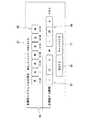
図3は、本発明の実施形態に係る電気掃除機の操作端末を示すブロック図である。 FIG. 3 is a block diagram illustrating an operation terminal of the vacuum cleaner according to the embodiment of the present invention.
図3に示すように、本実施形態に係る電気掃除機1の操作端末41(具体的には遠隔操作端末5および構内端末6)は、電気通信網3を介してサーバ4との間で運転開始指示を含む通信信号を送受信する通信部42と、電気掃除機1の操作指示のそれぞれに対応するGUI(Graphical User Interface)を表示する表示部43と、操作指示の入力を受け付けて制御部45へ伝達する操作部46と、各部の動作を制御する制御部45と、を備えている。 As shown in FIG. 3, the operation terminal 41 (specifically, the remote operation terminal 5 and the local terminal 6) of the
操作端末41は、例えば、スマートフォン、タブレット端末、携帯電話機、PDA(Personal Digital Assistance)、パソコン、携帯型ゲーム機など無線または有線でサーバ4と電気通信可能な機器である。 The operation terminal 41 is a device that can communicate with the server 4 wirelessly or by wire, such as a smartphone, a tablet terminal, a mobile phone, a PDA (Personal Digital Assistance), a personal computer, or a portable game machine.
通信部42は、外部ネットワーク7を通じて電気掃除機1と通信する。通信部42は、外部ネットワーク7との接続のために、公衆電話網、携帯電話網、移動体通信網、衛星通信網などを利用する。また、通信部42は、中継通信機器11との接続のために、例えば、無線LAN規格の1つであるIEEE802.11(IEEE802.11n、IEEE802.11a、IEEE802.11g、およびIEEE802.11bなど)や、Bluetooth(登録商標)、ZigBee(登録商標)など近距離無線通信規格を利用する。 The
表示部43は、例えば、液晶表示パネル、有機ELパネル、およびプラズマディスプレイパネルなどである。表示部43は、制御部45の指示に応じて使用者に提示する各種のGUI(Graphical User Interface)を表示する。 The
操作部46は、例えば、タッチパネルおよびボタンスイッチなどである。 The
表示部43および操作部46は、ディスプレイとタッチパネルとを組み合わせた、いわゆるタッチスクリーンであっても良い。タッチスクリーンは、使用者に触れられた位置を検知して、その箇所の表示内容に応じた入力を受け付ける。 The
制御部45は、操作端末41の各部の動作を制御している。制御部45は、例えば、マイクロプロセッサ(図示省略)、およびマイクロプロセッサが実行する各種演算プログラム、パラメータなどを記憶する記憶装置(図示省略)を備えるコンピュータである。記憶装置には、例えば、RAM(Random Access Memory)、ROM(Read Only Memory)、HDD(Hard Disk Drive)などが用いられる。 The
制御部45には、表示部43を制御する表示制御部99が含まれている。 The
図4は、本発明の実施形態に係る電気掃除機の操作端末のGUIの一例を示す図である。 FIG. 4 is a diagram illustrating an example of the GUI of the operation terminal of the vacuum cleaner according to the embodiment of the present invention.
図4に示すように、本実施形態に係る操作端末41の表示部43は、電気掃除機1の操作指示のそれぞれに対応するGUI(Graphical User Interface)を表示する。 As shown in FIG. 4, the
具体的には、表示部43は、GUIの一例として、電気掃除機1の自律型掃除ユニット21が充電台22へ帰巣していることを表す帰巣状態表示51、自律型掃除ユニット21の二次電池26が充電中であることの充電状況表示52、二次電池26の電池残量を表す電池残量表示53、およびタイマー処理による自律型掃除ユニット21の次回の運転時刻を表す次回運転表示55を表示している。 Specifically, as an example of the GUI, the
また、表示部43は、GUIの一例として、充電台22に帰巣していない自律型掃除ユニット21を充電台22へ帰巣させるための帰巣指示を受け付ける帰巣指示入力表示56、自律型掃除ユニット21への掃除運転開始指示(または掃除運転再開指示)を受け付ける運転開始指示入力表示57、および自律型掃除ユニット21への停止指示(または一時停止指示)を受け付ける停止指示入力表示58を表示している。 In addition, the
さらに、表示部43は、GUIの一例として、自律型掃除ユニット21の掃除モード設定を受け付けるモード指示表示59を表示している。モード指示表示59には、電動送風機31を通常よりも低入力で運転して自律型掃除ユニット21を静音運転させるか否かを選択するマナーモード入力表示62、および掃除運転中に自律型掃除ユニット21に搭載されたカメラ(図示省略)で掃除状況を撮影するか否かを選択する撮影要否入力表示63を表示している。 Further, the
そして、操作端末41の表示制御部47は、電気通信網3を経由して取得する電気掃除機1の状態に応じて、GUIのうち電気掃除機1に対する操作指示が有効な有効GUIよりも電気掃除機1に対する操作指示が無効な無効GUIの視認性を低下させてGUIを表示部43に表示させる。 And the
電気掃除機1の状態には、電気掃除機1の運転動作中、および運転停止中が含まれている。表示制御部47は、運転動作中における有効GUIおよび無効GUIと、運転停止中における有効GUIおよび無効GUIと、をそれぞれの状態の間で切り替えて表示する。 The state of the
また、電気掃除機1の状態には、自律型掃除ユニット21が充電台22に電気的に接続されているか、および自律型掃除ユニット21が充電台22に電気的に接続されていないかが含まれている。表示制御部47は、自律型掃除ユニット21が充電台22に電気的に接続されている状態における有効GUIおよび無効GUIと、自律型掃除ユニット21が充電台22に電気的に接続されていない状態における有効GUIおよび無効GUIと、をそれぞれの状態の間で切り替えて表示する。 Further, the state of the
具体的には、帰巣状態表示51は、自律型掃除ユニット21および充電台22をシンボル化した表示を用い、自律型掃除ユニット21に主眼を置いて表示されている。帰巣状態表示51は、自律型掃除ユニット21が充電台22へ帰巣している場合には充電台22の表示を可視化され、自律型掃除ユニット21が充電台22へ帰巣していない場合には充電台22の表示を消去して不可視化される。 Specifically, the homing
充電状況表示52は、自律型掃除ユニット21が充電されている最中に可視化され、自律型掃除ユニット21が満充電されれば不可視化される。充電状況表示52は、シンボル化された自律型掃除ユニット21の表示に重ねて表示されている。 The charging
電池残量表示53は、二次電池26の電池残量を例えば3段階で表示している。 The remaining
帰巣指示入力表示56は、自律型掃除ユニット21が帰巣している場合には、帰巣指示が無効にされて受け付けられないことを表現するために、薄いグレーの表示、所謂グレーアウトされて視認性が下がる。他方、帰巣指示入力表示56は、自律型掃除ユニット21が帰巣していない場合には、帰巣指示が有効に受け付けられることを表現するために、鮮やかな色彩で表示されて視認性が上がる。 The homing
停止指示入力表示58は、自律型掃除ユニット21が停止(または一時停止)している場合には、停止指示(または一時停止指示)が無効にされて受け付けられないことを表現するために、グレーアウトされて視認性が下がる。他方、停止指示入力表示58は、自律型掃除ユニット21が掃除運転している場合には、停止指示(または一時停止)が有効に受け付けられることを表現するために、鮮やかな色彩で表示されて視認性が上がる。 The stop
モード指示表示59は、自律型掃除ユニット21が掃除運転している場合には、掃除モードの変更が無効にされて受け付けられないことを表現するために、グレーアウトされて視認性が下がる。他方、モード指示表示59は、自律型掃除ユニット21が掃除運転している場合には、掃除モードの変更が有効に受け付けられることを表現するために、鮮やかな色彩で表示されて視認性が上がる。 When the
図5および図6は、本発明の実施形態に係る電気掃除機の操作端末の運転開始指示入力表示の遷移の一例を示す図である。 5 and 6 are diagrams showing an example of transition of the operation start instruction input display of the operation terminal of the vacuum cleaner according to the embodiment of the present invention.
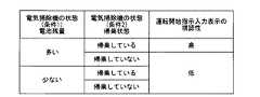
図5に示すように、本実施形態に係る操作端末41の運転開始指示入力表示57は、二次電池26の電池残量の多少と、自律型掃除ユニット21が充電台22へ帰巣しているか否かとに応じて、表示が変化する。 As shown in FIG. 5, the operation start
電気掃除機1の状態には、二次電池26の電池残量が含まれている。表示制御部47は、二次電池26の電池残量に応じて有効GUIおよび無効GUIを切り替えて表示する。 The state of the
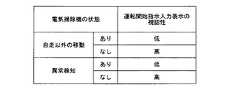
電気掃除機1の状態には、非自走の移動があったか、および非自走の移動がなかったかが含まれている。表示制御部47は、非自走の移動があった状態においてGUIの全てを無効GUIにする。 The state of the
電気掃除機1の状態には、異常発生の有無が含まれている。表示制御部47は、異常発生があった状態においてGUIの全てを無効GUIにする。 The state of the
具体的には、運転開始指示入力表示57は、二次電池26の電池残量が多く(電池残量が20%〜25%より多い)、かつ自律型掃除ユニット21が充電台22へ帰巣している場合には、運転開始指示が有効に受け付けられることを表現するために、鮮やかな色彩で表示されて視認性が上がる。 Specifically, the operation start
他方、運転開始指示入力表示57は、二次電池26の電池残量が多く(電池残量が20%〜25%より多い)ても、自律型掃除ユニット21が充電台22へ帰巣していない場合には、運転開始指示が無効にされて受け付けられないことを表現するために、グレーアウトされて視認性が下がる。また、運転開始指示入力表示57は、二次電池26の電池残量が少ない(電池残量が20%〜25%以下)の場合には、自律型掃除ユニット21が充電台22へ帰巣状態にかかわらず、運転開始指示が無効にされて受け付けられないことを表現するために、グレーアウトされて視認性が下がる。 On the other hand, the operation start
これらの条件は、二次電池26の電池残量から自律型掃除ユニット21が掃除運転の途中で帰巣できなくなることを回避するものであり、また、例えばテーブル上に放置されていたり、階段の際に配置されていたりせず、自律型掃除ユニット21が充電台22へ帰巣していることを以て自律型掃除ユニット21が安全な箇所にあることを確認するためのものである。 These conditions are to prevent the
また、図6に示すように、本実施形態に係る操作端末41の運転開始指示入力表示57は、自走以外の移動(非自走の移動)、例えば自律型掃除ユニット21が被掃除面から持ち上げられると、運転開始指示が無効にされて受け付けられないことを表現するために、グレーアウトされて視認性が下がる。自走以外の移動(非自走の移動)には、例えば自律型掃除ユニット21が被掃除面から持ち上げられることや、自律型掃除ユニット21が外力によって駆動部33の動作を伴わずに被掃除面上を移動することが含まれる。自律型掃除ユニット21の自走以外の移動(非自走の移動)は、本体ケース25に設けられる赤外線センサ(図示省略)などの検知器によって検知される。 Further, as shown in FIG. 6, the operation start
さらに、本実施形態に係る操作端末41の運転開始指示入力表示57は、自律型掃除ユニット21が異常を検知すると、運転開始指示が無効にされて受け付けられないことを表現するために、グレーアウトされて視認性が下がる。 Further, the operation start
自律型掃除ユニット21の異常は、本体ケース25に設けられる障害物センサ(図示省略)や段差センサ(図示省略)、本体ケース25のバンパ(図示省略)に設けられるマイクロスイッチ(図示省略)によって検知される。障害物センサや段差センサには、赤外線センサなどの非接触センサが用いられる。 Abnormality of the
自律型掃除ユニット21に検知される異常には、自律型掃除ユニット21が例えば家具に囲まれた狭隘な場所に入り込んだり移動中に立ち往生していたりすること、異物(糸、髪の毛、紙、玩具など)が塵埃容器29に通じる吸込口(図示省略)に設けられる回転ブラシ(図示省略)にからまっていること、異物(糸、髪の毛、紙、玩具など)が左右の駆動輪の少なくともいずれか一方にからまっていること、バンパが作動したままの状態(誤作動)になっていること、障害物センサによごれが付いていること、段差センサによごれが付いていること、自律型掃除ユニット21の前進方向における左右それぞれの側方から吸込口へ塵埃を掃き寄せるサイドブラシ(図示省略)に異物(糸、髪の毛、紙、玩具など)がからまっていること、電動送風機31の回転が異常となっていること、二次電池26の温度が高温または低温の状態になっていること、などがある。 Abnormalities detected by the
図7は、本発明の実施形態に係る電気掃除機の操作端末のGUIの一例を示す図である。 FIG. 7 is a diagram illustrating an example of the GUI of the operation terminal of the vacuum cleaner according to the embodiment of the present invention.
図7に示すように、本実施形態に係る操作端末41の表示部43は、電気掃除機1の操作指示のそれぞれに対応するGUI(Graphical User Interface)を表示する。 As shown in FIG. 7, the
電気掃除機1の状態には、電気掃除機1への直接的な操作(例えば、タイマー設定の入力操作)の有無が含まれている。表示制御部47は、電気掃除機1が直接的な操作を受け付けている状態においてGUIの全てを無効GUIにする。 The state of the
具体的には、表示部43は、GUIの一例として、自律型掃除ユニット21のタイマー設定表示65を表示している。タイマー設定表示65は、例えば、図4の次回運転表示55が入力を受け付けたり、タイマー設定用に表示される設定入力表示(図示省略)が入力を受け付けたりすると図4から図7へ画面遷移が起きて表示される。 Specifically, the
タイマー設定表示65には、タイマー処理による掃除運転を設定する曜日を選択する曜日入力表示66、掃除運転を選択した曜日に対応して掃除運転の開始時間の設定を受け付ける開始時間入力表示67、掃除運転を選択した曜日に対応して掃除運転の終了時間の設定を受け付ける終了時間入力表示68、曜日、開始時間および終了時間の決定を受け付ける設定完了表示69、曜日、開始時間および終了時間の破棄(キャンセル)を受け付ける設定破棄表示71を含んでいる。設定完了表示69または設定破棄表示71が入力を受け付けると図4のGUIへ遷移する。 The
タイマー設定表示65は、自律型掃除ユニット21の機側で入力部37からタイマー設定を受け付けている最中には、操作端末41側からのタイマー設定が無効にされて受け付けられないことを表現するために、グレーアウトされて視認性が下がる。この場合、GUIのいずれかの箇所が触れられると図4のGUIへ遷移する。他方、タイマー設定表示65は、自律型掃除ユニット21の機側で入力部37からタイマー設定の受付の最中以外の場合には、操作端末41側からのタイマー設定が有効に受け付けられることを表現するために、鮮やかな色彩で表示されて視認性が上がる。 The
本実施形態に係る電気掃除機1の操作端末41は、電気通信網3を経由して取得する電気掃除機1の状態に応じて、GUIのうち電気掃除機1に対する操作指示が有効な有効GUIよりも電気掃除機1に対する操作指示が無効な無効GUIの視認性を低下させてGUIを表示部43に表示させることによって、自律型掃除ユニット21の状態に応じて操作端末41からどのような操作が可能であり、またどのような操作が不可能であるかを明らかにして、遠隔における自律型掃除ユニット21の操作性を向上させる。 The operation terminal 41 of the
また、本実施形態に係る電気掃除機1の操作端末41は、自律型掃除ユニット21の運転動作中における有効GUIおよび無効GUIと、運転停止中における有効GUIおよび無効GUIと、をそれぞれの状態の間で切り替えて表示することによって、自律型掃除ユニット21の状態に応じて操作端末41からどのような操作が可能であり、またどのような操作が不可能であるかを明らかにして、遠隔における自律型掃除ユニット21の操作性を向上させる。 In addition, the operation terminal 41 of the
さらに、本実施形態に係る電気掃除機1の操作端末41は、自律型掃除ユニット21が充電台22に電気的に接続されている状態における有効GUIおよび無効GUIと、自律型掃除ユニット21が充電台22に電気的に接続されていない状態における有効GUIおよび無効GUIと、をそれぞれの状態の間で切り替えて表示することによって、自律型掃除ユニット21の状態に応じて操作端末41からどのような操作が可能であり、またどのような操作が不可能であるかを明らかにして、遠隔における自律型掃除ユニット21の操作性を向上させる。 Furthermore, the operation terminal 41 of the
さらにまた、本実施形態に係る電気掃除機1の操作端末41は、非自走の移動があった状態においてGUIの全てを無効GUIにすることによって、自律型掃除ユニット21の状態に応じて操作端末41からどのような操作が可能であり、またどのような操作が不可能であるかを明らかにして、遠隔における自律型掃除ユニット21の操作性を向上させる。 Furthermore, the operation terminal 41 of the
また、本実施形態に係る電気掃除機1の操作端末41は、異常発生があった状態においてGUIの全てを無効GUIにすることによって、自律型掃除ユニット21の状態に応じて操作端末41からどのような操作が可能であり、またどのような操作が不可能であるかを明らかにして、遠隔における自律型掃除ユニット21の操作性を向上させる。 In addition, the operation terminal 41 of the
さらに、本実施形態に係る電気掃除機1の操作端末41は、二次電池26の電池残量に応じて有効GUIおよび無効GUIを切り替えて表示することによって、自律型掃除ユニット21の状態に応じて操作端末41からどのような操作が可能であり、またどのような操作が不可能であるかを明らかにして、遠隔における自律型掃除ユニット21の操作性を向上させる。 Furthermore, the operation terminal 41 of the
さらにまた、本実施形態に係る電気掃除機1の操作端末41は、電気掃除機1の自律型掃除ユニット21が直接的な操作を受け付けている状態においてGUIの全てを無効GUIにすることによって、自律型掃除ユニット21の状態に応じて操作端末41からどのような操作が可能であり、またどのような操作が不可能であるかを明らかにして、遠隔における自律型掃除ユニット21の操作性を向上させる。特に、自律型掃除ユニット21の機側における操作入力と、操作端末41からの操作入力に矛盾を生じない。 Furthermore, the operation terminal 41 of the
本実施形態に係る電気掃除機1の操作端末41は、表示部43に図4および図7を一例とするGUIを表示して電気掃除機1を遠隔操作させるためのプログラムを制御部45および表示制御部47が実行することによって機能する。本実施形態に係る電気掃除機1の操作端末41で実行されるプログラムは、制御部45で実行されることによって制御部45の記憶装置上に表示制御部99を生成する。 The operation terminal 41 of the
なお、本実施形態に係る電気掃除機1の操作端末41で実行されるプログラムは、電気通信網3に接続されたコンピュータ(図示省略)上に格納し、電気通信網3を経由して操作端末41へ提供または配布されるものであっても良い。また、本実施形態に係る電気掃除機1の操作端末41で実行されるプログラムは、操作端末41にインストール可能な形式または実行可能な形式の電子情報でCD−ROM、フレキシブルディスク(FD)、CD−R、DVD(Digital Versatile Disk)等のコンピュータで読み取り可能な記録媒体に記録して提供してもよい。 The program executed by the operation terminal 41 of the
したがって、本実施形態に係る電気掃除機1の操作端末41およびプログラムによれば、遠隔の操作端末41から電気通信網3を通じて操作する際に、可能な操作と不可能な操作を使用者に容易に認知させることができる。 Therefore, according to the operation terminal 41 and the program of the
本発明のいくつかの実施形態を説明したが、これらの実施形態は、例として提示したものであり、発明の範囲を限定することは意図していない。これら新規な実施形態は、その他の様々な形態で実施されることが可能であり、発明の要旨を逸脱しない範囲で、種々の省略、置き換え、変更を行うことができる。これら実施形態やその変形は、発明の範囲や要旨に含まれるとともに、特許請求の範囲に記載された発明とその均等の範囲に含まれる。 Although several embodiments of the present invention have been described, these embodiments are presented by way of example and are not intended to limit the scope of the invention. These novel embodiments can be implemented in various other forms, and various omissions, replacements, and changes can be made without departing from the scope of the invention. These embodiments and modifications thereof are included in the scope and gist of the invention, and are included in the invention described in the claims and the equivalents thereof.
1 電気掃除機
2 運転制御システム
3 電気通信網
4 サーバ
5 遠隔操作端末
6 構内端末
7 外部ネットワーク
8 構内通信網
11 中継通信機器
13 インターネット
21 自律型掃除ユニット
22 充電台
25 本体ケース
26 二次電池
27 電源コード
28 接続判定部
29 塵埃容器
31 電動送風機
32 移動部
33 駆動部
35 自律制御部
36 通信部
37 入力部
38 報知部
39 計時部
41 操作端末
42 通信部
43 表示部
45 制御部
46 操作部
47 表示制御部
51 帰巣状態表示
52 充電状況表示
53 電池残量表示
55 次回運転表示
56 帰巣指示入力表示
57 運転開始指示入力表示
58 停止指示入力表示
59 モード指示表示
62 マナーモード入力表示
63 撮影要否入力表示
65 タイマー設定表示
66 曜日入力表示
67 開始時間入力表示
68 終了時間入力表示
69 設定完了表示
71 設定破棄表示DESCRIPTION OF
Claims (8)
Translated fromJapanese前記電気通信網を経由して取得する前記電気掃除機の状態に応じて、前記GUIのうち前記電気掃除機に対する前記操作指示が有効な有効GUIよりも前記電気掃除機に対する前記操作指示が無効な無効GUIの視認性を低下させて前記GUIを前記表示部に表示させる表示制御部と、を備える電気掃除機の操作端末。A display unit for displaying a GUI (Graphical User Interface) corresponding to each operation instruction including an operation start instruction and an operation stop instruction to the vacuum cleaner;
According to the state of the vacuum cleaner acquired via the telecommunication network, the operation instruction for the vacuum cleaner is invalid than the valid GUI for which the operation instruction for the vacuum cleaner is valid among the GUI. An operation terminal of a vacuum cleaner, comprising: a display control unit that reduces visibility of an invalid GUI and displays the GUI on the display unit.
前記表示制御部は、前記運転動作中における前記有効GUIおよび前記無効GUIと、前記運転停止中における前記有効GUIおよび前記無効GUIと、をそれぞれの状態の間で切り替えて表示する請求項1に記載の電気掃除機の操作端末。The state of the vacuum cleaner includes during operation of the vacuum cleaner and during operation stop,
2. The display control unit according to claim 1, wherein the effective GUI and the invalid GUI during the driving operation and the valid GUI and the invalid GUI during the operation stop are displayed by switching between the respective states. The operation terminal of the vacuum cleaner.
前記電気掃除機の状態には、前記自律型掃除ユニットが前記充電台に電気的に接続されているか、および前記自律型掃除ユニットが前記充電台に電気的に接続されていないかが含まれ、
前記表示制御部は、前記自律型掃除ユニットが前記充電台に電気的に接続されている状態における前記有効GUIおよび前記無効GUIと、前記自律型掃除ユニットが前記充電台に電気的に接続されていない状態における前記有効GUIおよび前記無効GUIと、をそれぞれの状態の間で切り替えて表示する請求項1または2に記載の電気掃除機の操作端末。The electric vacuum cleaner comprises an autonomous cleaning unit that autonomously moves on the surface to be cleaned and collects dust on the surface to be cleaned, and a charging stand that can charge the autonomous cleaning unit,
The state of the vacuum cleaner includes whether the autonomous cleaning unit is electrically connected to the charging stand and whether the autonomous cleaning unit is not electrically connected to the charging stand,
The display control unit includes the effective GUI and the invalid GUI in a state where the autonomous cleaning unit is electrically connected to the charging stand, and the autonomous cleaning unit is electrically connected to the charging stand. The operation terminal of the vacuum cleaner of Claim 1 or 2 which switches and displays the said effective GUI and the said invalid GUI in a state without each.
前記表示制御部は、非自走の移動があった状態において前記GUIの全てを前記無効GUIにする請求項1から3のいずれか1項に記載の電気掃除機の操作端末。The state of the vacuum cleaner includes whether there was non-self-propelled movement and whether there was non-self-propelled movement,
The operation terminal of the vacuum cleaner according to any one of claims 1 to 3, wherein the display control unit sets all of the GUIs to the invalid GUI in a state where there is non-self-propelled movement.
前記表示制御部は、異常発生があった状態において前記GUIの全てを前記無効GUIにする請求項1から4のいずれか1項に記載の電気掃除機の操作端末。The state of the vacuum cleaner includes whether or not an abnormality has occurred,
The operation terminal of the vacuum cleaner according to any one of claims 1 to 4, wherein the display control unit sets all of the GUIs to the invalid GUI in a state where an abnormality has occurred.
前記表示制御部は、前記電池残量に応じて前記有効GUIおよび前記無効GUIを切り替えて表示する請求項1から5のいずれか1項に記載の電気掃除機の操作端末。The state of the vacuum cleaner includes the remaining battery level of the secondary battery,
The operation terminal of the vacuum cleaner according to any one of claims 1 to 5, wherein the display control unit switches and displays the effective GUI and the invalid GUI according to the remaining battery level.
前記表示制御部は、前記電気掃除機が直接的な操作を受け付けている状態において前記GUIの全てを前記無効GUIにする請求項1から6のいずれか1項に記載の電気掃除機の操作端末。The state of the vacuum cleaner includes the presence or absence of direct operation to the vacuum cleaner,
The operation terminal of the vacuum cleaner according to any one of claims 1 to 6, wherein the display control unit sets all the GUIs to the invalid GUI in a state where the vacuum cleaner accepts a direct operation. .
電気掃除機へ運転開始指示、運転停止指示を含む操作指示のそれぞれに対応するGUI(Graphical User Interface)を表示する表示部と、
前記電気通信網を経由して取得する前記電気掃除機の状態に応じて、前記GUIのうち前記電気掃除機に対する前記操作指示が有効な有効GUIよりも前記掃除機に対する前記操作指示が無効な無効GUIの視認性を低下させて前記GUIを前記表示部に表示させる表示制御部と、として電気掃除機の操作端末を機能させるプログラム。The operation terminal of the vacuum cleaner
A display unit for displaying a GUI (Graphical User Interface) corresponding to each operation instruction including an operation start instruction and an operation stop instruction to the vacuum cleaner;
According to the state of the vacuum cleaner acquired via the telecommunication network, the operation instruction for the cleaner is invalid and invalid than the valid GUI for which the operation instruction for the vacuum cleaner is valid among the GUI. A program that causes an operation terminal of a vacuum cleaner to function as a display control unit that reduces the visibility of the GUI and displays the GUI on the display unit.
Priority Applications (1)
| Application Number | Priority Date | Filing Date | Title |
|---|---|---|---|
| JP2014165906AJP6505390B2 (en) | 2014-08-18 | 2014-08-18 | Operation terminal of vacuum cleaner and program for operating the operation terminal of vacuum cleaner |
Applications Claiming Priority (1)
| Application Number | Priority Date | Filing Date | Title |
|---|---|---|---|
| JP2014165906AJP6505390B2 (en) | 2014-08-18 | 2014-08-18 | Operation terminal of vacuum cleaner and program for operating the operation terminal of vacuum cleaner |
Publications (2)
| Publication Number | Publication Date |
|---|---|
| JP2016042654Atrue JP2016042654A (en) | 2016-03-31 |
| JP6505390B2 JP6505390B2 (en) | 2019-04-24 |
Family
ID=55592221
Family Applications (1)
| Application Number | Title | Priority Date | Filing Date |
|---|---|---|---|
| JP2014165906AExpired - Fee RelatedJP6505390B2 (en) | 2014-08-18 | 2014-08-18 | Operation terminal of vacuum cleaner and program for operating the operation terminal of vacuum cleaner |
Country Status (1)
| Country | Link |
|---|---|
| JP (1) | JP6505390B2 (en) |
Cited By (6)
| Publication number | Priority date | Publication date | Assignee | Title |
|---|---|---|---|---|
| WO2018230549A1 (en)* | 2017-06-14 | 2018-12-20 | 東芝ライフスタイル株式会社 | Electric vacuum cleaner |
| CN110098986A (en)* | 2018-01-31 | 2019-08-06 | 日立空调·家用电器株式会社 | Program and Home Appliance System |
| WO2020141605A1 (en)* | 2019-01-04 | 2020-07-09 | シャープ株式会社 | Electric vacuum cleaner, operation method, notification method, noise-reduction method, control method and program |
| JP2020156962A (en)* | 2019-03-28 | 2020-10-01 | 日立グローバルライフソリューションズ株式会社 | Vacuum cleaner |
| JP2021065630A (en)* | 2019-10-28 | 2021-04-30 | 東芝ライフスタイル株式会社 | Vacuum cleaner |
| CN113712466A (en)* | 2020-05-26 | 2021-11-30 | 东芝生活电器株式会社 | Electric vacuum cleaner |
Citations (5)
| Publication number | Priority date | Publication date | Assignee | Title |
|---|---|---|---|---|
| JP2002085305A (en)* | 2000-09-12 | 2002-03-26 | Toshiba Tec Corp | Robot cleaner and robot cleaner system |
| JP2008053962A (en)* | 2006-08-23 | 2008-03-06 | Sharp Corp | Communication terminal device |
| JP2010198064A (en)* | 2009-02-23 | 2010-09-09 | Japan Science & Technology Agency | System and method for robot control |
| US20130060379A1 (en)* | 2011-09-07 | 2013-03-07 | Suuk Choe | Robot cleaner, and system and method for remotely controlling the same |
| WO2014113091A1 (en)* | 2013-01-18 | 2014-07-24 | Irobot Corporation | Environmental management systems including mobile robots and methods using same |
- 2014
- 2014-08-18JPJP2014165906Apatent/JP6505390B2/ennot_activeExpired - Fee Related
Patent Citations (5)
| Publication number | Priority date | Publication date | Assignee | Title |
|---|---|---|---|---|
| JP2002085305A (en)* | 2000-09-12 | 2002-03-26 | Toshiba Tec Corp | Robot cleaner and robot cleaner system |
| JP2008053962A (en)* | 2006-08-23 | 2008-03-06 | Sharp Corp | Communication terminal device |
| JP2010198064A (en)* | 2009-02-23 | 2010-09-09 | Japan Science & Technology Agency | System and method for robot control |
| US20130060379A1 (en)* | 2011-09-07 | 2013-03-07 | Suuk Choe | Robot cleaner, and system and method for remotely controlling the same |
| WO2014113091A1 (en)* | 2013-01-18 | 2014-07-24 | Irobot Corporation | Environmental management systems including mobile robots and methods using same |
Cited By (11)
| Publication number | Priority date | Publication date | Assignee | Title |
|---|---|---|---|---|
| WO2018230549A1 (en)* | 2017-06-14 | 2018-12-20 | 東芝ライフスタイル株式会社 | Electric vacuum cleaner |
| JP2019000295A (en)* | 2017-06-14 | 2019-01-10 | 東芝ライフスタイル株式会社 | Vacuum cleaner |
| CN110381791A (en)* | 2017-06-14 | 2019-10-25 | 东芝生活电器株式会社 | Electric dust collector |
| JP7044487B2 (en) | 2017-06-14 | 2022-03-30 | 東芝ライフスタイル株式会社 | Vacuum cleaner |
| CN110098986A (en)* | 2018-01-31 | 2019-08-06 | 日立空调·家用电器株式会社 | Program and Home Appliance System |
| JP2019134274A (en)* | 2018-01-31 | 2019-08-08 | 日立グローバルライフソリューションズ株式会社 | Program and household appliance system including program, operation terminal including program, and household appliance |
| CN110098986B (en)* | 2018-01-31 | 2021-07-23 | 日立环球生活方案株式会社 | Operation terminal and home appliance product system |
| WO2020141605A1 (en)* | 2019-01-04 | 2020-07-09 | シャープ株式会社 | Electric vacuum cleaner, operation method, notification method, noise-reduction method, control method and program |
| JP2020156962A (en)* | 2019-03-28 | 2020-10-01 | 日立グローバルライフソリューションズ株式会社 | Vacuum cleaner |
| JP2021065630A (en)* | 2019-10-28 | 2021-04-30 | 東芝ライフスタイル株式会社 | Vacuum cleaner |
| CN113712466A (en)* | 2020-05-26 | 2021-11-30 | 东芝生活电器株式会社 | Electric vacuum cleaner |
Also Published As
| Publication number | Publication date |
|---|---|
| JP6505390B2 (en) | 2019-04-24 |
Similar Documents
| Publication | Publication Date | Title |
|---|---|---|
| JP6505390B2 (en) | Operation terminal of vacuum cleaner and program for operating the operation terminal of vacuum cleaner | |
| US10349794B2 (en) | Autonomous traveling body | |
| EP2949252B1 (en) | Robot cleaner, robot cleaner system and control method of the same | |
| KR101741583B1 (en) | Robot cleaner and controlling method thereof | |
| US20120152280A1 (en) | Touch Sensitive Display For Surface Cleaner | |
| US20150212500A1 (en) | Device for creation of layout information, system for operation of domestic electrical appliances, and self-propelled electronic device | |
| KR101378883B1 (en) | Robot cleaner, terminal, and system and method for remotely controlling the robot | |
| EP3738724B1 (en) | Mobile robot and method for controlling mobile robot | |
| JP2016042285A (en) | Autonomous mobile | |
| CN108628302A (en) | The method for running the ground processing equipment independently advanced | |
| US12340683B2 (en) | Control device of robot cleaner | |
| CN107485335B (en) | Identification method, identification device, electronic equipment and storage medium | |
| CN108536135B (en) | Path control method and device and cleaning robot | |
| JP2020075032A (en) | Autonomic type vacuum cleaner | |
| JP6223673B2 (en) | Self-propelled electronic device | |
| KR20130039623A (en) | Robot cleaner, method for the robot cleaner and remote controlling system for the same | |
| JP6366064B2 (en) | Electric vacuum cleaner | |
| CN204120953U (en) | robot vacuum cleaner | |
| JP2019129416A (en) | Program, home appliance system, and home appliance | |
| JP2022065709A (en) | Autonomous travel type cleaner and cleaner system | |
| JP2020098404A (en) | Autonomous vacuum cleaner | |
| KR102804683B1 (en) | Robot cleaner and robot cleaning system | |
| JP2018192083A (en) | Autonomous vacuum cleaner | |
| CN105395137A (en) | Robotic dust cleaner | |
| KR20210045784A (en) | Cleaner System |
Legal Events
| Date | Code | Title | Description |
|---|---|---|---|
| A711 | Notification of change in applicant | Free format text:JAPANESE INTERMEDIATE CODE: A711 Effective date:20160610 | |
| A621 | Written request for application examination | Free format text:JAPANESE INTERMEDIATE CODE: A621 Effective date:20170607 | |
| A977 | Report on retrieval | Free format text:JAPANESE INTERMEDIATE CODE: A971007 Effective date:20180629 | |
| A131 | Notification of reasons for refusal | Free format text:JAPANESE INTERMEDIATE CODE: A131 Effective date:20180710 | |
| A521 | Request for written amendment filed | Free format text:JAPANESE INTERMEDIATE CODE: A523 Effective date:20180910 | |
| TRDD | Decision of grant or rejection written | ||
| A01 | Written decision to grant a patent or to grant a registration (utility model) | Free format text:JAPANESE INTERMEDIATE CODE: A01 Effective date:20190226 | |
| A61 | First payment of annual fees (during grant procedure) | Free format text:JAPANESE INTERMEDIATE CODE: A61 Effective date:20190327 | |
| R150 | Certificate of patent or registration of utility model | Ref document number:6505390 Country of ref document:JP Free format text:JAPANESE INTERMEDIATE CODE: R150 | |
| LAPS | Cancellation because of no payment of annual fees |