JP2016042284A - Parallel computer system, management device, method for controlling parallel computer system, and management device control program - Google Patents
Parallel computer system, management device, method for controlling parallel computer system, and management device control programDownload PDFInfo
- Publication number
- JP2016042284A JP2016042284AJP2014165903AJP2014165903AJP2016042284AJP 2016042284 AJP2016042284 AJP 2016042284AJP 2014165903 AJP2014165903 AJP 2014165903AJP 2014165903 AJP2014165903 AJP 2014165903AJP 2016042284 AJP2016042284 AJP 2016042284A
- Authority
- JP
- Japan
- Prior art keywords
- job
- resource usage
- information processing
- unit
- execution
- Prior art date
- Legal status (The legal status is an assumption and is not a legal conclusion. Google has not performed a legal analysis and makes no representation as to the accuracy of the status listed.)
- Withdrawn
Links
Images


Classifications
- G—PHYSICS
- G06—COMPUTING OR CALCULATING; COUNTING
- G06F—ELECTRIC DIGITAL DATA PROCESSING
- G06F9/00—Arrangements for program control, e.g. control units
- G06F9/06—Arrangements for program control, e.g. control units using stored programs, i.e. using an internal store of processing equipment to receive or retain programs
- G06F9/46—Multiprogramming arrangements
- G06F9/50—Allocation of resources, e.g. of the central processing unit [CPU]
- G06F9/5005—Allocation of resources, e.g. of the central processing unit [CPU] to service a request
- G06F9/5027—Allocation of resources, e.g. of the central processing unit [CPU] to service a request the resource being a machine, e.g. CPUs, Servers, Terminals
- G06F9/505—Allocation of resources, e.g. of the central processing unit [CPU] to service a request the resource being a machine, e.g. CPUs, Servers, Terminals considering the load
- G—PHYSICS
- G06—COMPUTING OR CALCULATING; COUNTING
- G06F—ELECTRIC DIGITAL DATA PROCESSING
- G06F2209/00—Indexing scheme relating to G06F9/00
- G06F2209/50—Indexing scheme relating to G06F9/50
- G06F2209/5019—Workload prediction
Landscapes
- Engineering & Computer Science (AREA)
- Software Systems (AREA)
- Theoretical Computer Science (AREA)
- Physics & Mathematics (AREA)
- General Engineering & Computer Science (AREA)
- General Physics & Mathematics (AREA)
- Debugging And Monitoring (AREA)
Abstract
Description
Translated fromJapanese本発明は、並列計算機システム、管理装置、並列計算機システムの制御方法及び管理装置の制御プログラムに関する。 The present invention relates to a parallel computer system, a management apparatus, a parallel computer system control method, and a management apparatus control program.
並列計算機システムは、複数のプロセッサに処理(以下、ジョブともいう)を分散して割り当て、複数のプロセッサが割り当てられたジョブを並列して実行することで、システム全体の処理性能を向上させる。並列計算機システムで実行されるジョブは、負荷が分散されるように実行スケジュールを調整して、各プロセッサに割り当てられる。ジョブの実行スケジュールを調整する方法の一つに、ジョブの実行履歴に基づくスケジューリングがある。 A parallel computer system distributes and assigns processes (hereinafter also referred to as jobs) to a plurality of processors, and executes the jobs to which the plurality of processors are assigned in parallel, thereby improving the processing performance of the entire system. Jobs executed in the parallel computer system are assigned to each processor by adjusting the execution schedule so that the load is distributed. One method for adjusting the job execution schedule is scheduling based on the job execution history.
ジョブの実行履歴に基づくスケジューリングでは、新規に投入されたジョブの類似ジョブが、実行履歴から検出される。実行履歴は、例えば、プロセッサの使用時間、メモリの使用量、使用ノード数等の実行条件を含む。検出された類似ジョブの実行履歴に基づいて、新たに投入される新規ジョブの実行条件を予測し、負荷が分散されるようにジョブの実行スケジュールが調整される。 In scheduling based on a job execution history, a similar job to a newly submitted job is detected from the execution history. The execution history includes, for example, execution conditions such as processor usage time, memory usage, and number of nodes used. Based on the detected execution history of the similar job, the execution condition of the new job to be newly input is predicted, and the execution schedule of the job is adjusted so that the load is distributed.
しかしながら、ジョブの実行履歴に基づくスケジューリングにおいて、適切な類似ジョブの実行条件を得られない場合がある。例えば、同一の並列プログラムは、毎回、同じ並列度で実行されるとは限らない。即ち、同一のプログラムを実行する複数のジョブは、同一の実行条件を有しない場合があり得る。このとき、適切な類似ジョブの実行条件は得られない。 However, in the scheduling based on the job execution history, an appropriate similar job execution condition may not be obtained. For example, the same parallel program is not always executed with the same degree of parallelism. That is, a plurality of jobs that execute the same program may not have the same execution condition. At this time, an appropriate execution condition for similar jobs cannot be obtained.
また、近年、プロセッサの並列化手段が多様化している。並列計算機システム内の一部ノードに、General-Purpose computing on Graphics Processing Units(GPGPU)又はField Programmable Gate Array(FPGA)等のアクセラレータが配置される場合が
ある。一部のノードがアクセラレータを搭載するような、異種のプロセッサが混在するヘテロジニアスなシステム構成では、ジョブ名、使用ノード数等が同じでも、実行条件が異なる場合があり得る。このとき、適切な類似ジョブの実行条件は得られない。Also, in recent years, the parallelization means of processors has been diversified. Accelerators such as General-Purpose computing on Graphics Processing Units (GPGPU) or Field Programmable Gate Array (FPGA) may be arranged at some nodes in the parallel computer system. In a heterogeneous system configuration in which different types of processors are mixed such that some nodes have accelerators, even if the job name, the number of used nodes, etc. are the same, the execution conditions may be different. At this time, an appropriate execution condition for similar jobs cannot be obtained.
さらに、並列計算機システムは、一部のノードのCentral Processing Unit(CPU)
がアップグレードされたり、次世代のCPUを搭載するノード群が増設されたりすることで、ヘテロジニアスなシステム構成となる。このとき、環境の差を考慮した適切な類似ジョブの実行条件は得られない。Furthermore, the parallel computer system is a central processing unit (CPU) of some nodes.
Is upgraded, or a node group equipped with a next-generation CPU is added, resulting in a heterogeneous system configuration. At this time, it is not possible to obtain an appropriate execution condition for similar jobs in consideration of environmental differences.
適切な類似ジョブの実行条件が得られない場合、新規ジョブの実行条件の推定ができないため、スケジューリングによって、ジョブを実行する複数の情報処理装置における負荷の平準化が図れない。 If an appropriate execution condition for similar jobs cannot be obtained, the execution condition for a new job cannot be estimated. Therefore, the load cannot be leveled in a plurality of information processing apparatuses that execute jobs by scheduling.
開示の実施形態の一態様は、ジョブを実行する複数の情報処理装置における負荷の平準化を向上させることができる並列計算機システム、管理装置、並列計算機システムの制御方法及び管理装置の制御プログラムを提供することを目的とする。 One aspect of an embodiment of the disclosure provides a parallel computer system, a management device, a control method for a parallel computer system, and a control program for the management device that can improve load leveling in a plurality of information processing devices that execute jobs The purpose is to do.
開示の実施形態の態様の一つは、並列計算機システムによって例示される。本並列計算機システムは、
複数の情報処理装置と、前記複数の情報処理装置を制御する管理装置とを有する並列計算機システムにおいて、
前記複数の情報処理装置の各々は、
自装置が実行するジョブに対し、自装置の資源ごとの資源使用量の変動を所定の時間単位で出力する出力部を備え、
前記管理装置は、
ジョブの実行ごとに、実行対象の前記ジョブの属性及び各情報処理装置の出力部が出力する資源使用量の変動を含む実行履歴を生成する生成部と、
新たに投入された新規ジョブと属性が類似する類似ジョブの実行履歴に含まれる資源使用量の変動に基づいて、前記新規ジョブの資源使用量を推定する推定部と、
推定された前記資源使用量に基づいて、前記新規ジョブを割り当てる情報処理装置を特定する特定部とを備える。One aspect of the disclosed embodiment is exemplified by a parallel computer system. This parallel computer system
In a parallel computer system having a plurality of information processing devices and a management device for controlling the plurality of information processing devices,
Each of the plurality of information processing devices
For a job executed by the own device, an output unit that outputs a change in resource usage for each resource of the own device in a predetermined time unit is provided.
The management device
A generation unit that generates an execution history including a change in the attribute of the job to be executed and the resource usage output by the output unit of each information processing apparatus for each job execution;
An estimation unit that estimates the resource usage of the new job based on a change in the resource usage included in the execution history of a similar job with similar attributes to the newly submitted new job;
A specifying unit that specifies an information processing apparatus to which the new job is assigned based on the estimated resource usage.
開示の並列計算機システム、管理装置、並列計算機システムの制御方法及び管理装置の制御プログラムによれば、ジョブを実行する複数の情報処理装置における負荷の平準化を向上させることができる。 According to the disclosed parallel computer system, management apparatus, parallel computer system control method, and management apparatus control program, load leveling in a plurality of information processing apparatuses that execute jobs can be improved.
以下、図面に基づいて、本発明の実施の形態を説明する。以下の実施形態の構成は例示であり、本発明は実施形態の構成に限定されない。 Hereinafter, embodiments of the present invention will be described with reference to the drawings. The configuration of the following embodiment is an exemplification, and the present invention is not limited to the configuration of the embodiment.
<第1実施形態>
第1実施形態では、並列計算機システムは、実行するジョブの資源使用量の変動を単位時間ごとに記録し、実行履歴を生成する。新たに投入されたジョブ(以下、新規ジョブともいう)に対し、並列計算機システムは、新規ジョブと所定の類似性を有する既存のジョブ(以下、類似ジョブともいう)の実行履歴に基づいて、新規ジョブの資源使用量を推定する。<First Embodiment>
In the first embodiment, the parallel computer system records changes in resource usage of jobs to be executed for each unit time, and generates an execution history. For a newly submitted job (hereinafter also referred to as a new job), the parallel computer system creates a new job based on the execution history of an existing job (hereinafter also referred to as a similar job) having a predetermined similarity to the new job. Estimate the job resource usage.
ジョブの実行履歴は、クラスタ分析により複数のクラスタに分類してもよい。この場合、各クラスタの資源使用量は、クラスタ内の実行履歴に基づき、例えば、回帰分析によって推定することができる。新規ジョブの資源使用量は、類似ジョブを含むクラスタの資源使用量に基づいて推定してもよい。 The job execution history may be classified into a plurality of clusters by cluster analysis. In this case, the resource usage of each cluster can be estimated by, for example, regression analysis based on the execution history in the cluster. The resource usage of a new job may be estimated based on the resource usage of a cluster that includes similar jobs.
<システム構成>
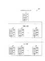
図1は、並列計算機システム10のシステム構成の一例を示す図である。並列計算機システム10は、ジョブスケジューラ・ノード1、計算ノード21から2Nで例示される計算ノード群、Input / Output(IO)ノード31から3Nで例示されるIOノード群を含み、各ノードは相互に接続される。なお、ネットワーク・トポロジーは、図1の構成に限定されず、N次元メッシュ、N次元トーラス、Fat Tree又はこれらの組み合わせであってもよい。<System configuration>
FIG. 1 is a diagram illustrating an example of a system configuration of the
並列計算機システム10において、計算ノードの数及びIOノードの数は、限定されない。並列計算機システム10内で相互に接続される計算ノードは、計算ノード2と総称される。また、並列計算機システム10内で相互に接続されるIOノードは、IOノード3と総称される。 In the
ジョブスケジューラ・ノード1は、ジョブの資源使用状況を管理し、各ジョブに資源を割り当てる。図1において、ジョブスケジューラ・ノード1は、Central Processing Unit(CPU)1a、メモリ1b、Network Interface Card(NIC)1cを備える。なお
、ジョブスケジューラ・ノード1の具体的な装置構成は、図1に示されるものに限定されず、適宜、追加、置換、削除等の変更が可能である。The
CPU 1aは、メモリ1b上に実行可能に展開されたコンピュータプログラムを実行することによって、様々な処理を実行する。CPU 1aは、1つに限られず、複数備えられてもよい。 The
メモリ1bは、CPU 1aに、プログラムをロードするための記憶領域、及びプログラムを実行するための作業領域を提供する。メモリ1bは、データを一時的に保持するためのバッファとして用いられる。また、メモリ1bは、様々なプログラムや、各プログラムの実行に際してCPU 1aが使用するデータを格納する。メモリ1bは、例えば、揮発性のRandom Access Memory(RAM)、不揮発性のRead Only Memory(ROM)等の半導体メモリである。 The
NIC 1cは、ネットワークと情報を入出力するためのインターフェースである。NIC 1cは、有線のネットワーク、又は無線のネットワークと接続する。NIC 1cを介して受信されたデータ等は、メモリ1bに格納される。 The
計算ノード2は、ジョブスケジューラ・ノード1によって割り当てられたジョブを実行し、ジョブの実行による資源使用量の変動量を単位時間ごとに資源使用変動として記録する。資源使用変動は、資源ごとに記録され、管理される。資源は、例えば、CPU時間、ワーキングセットサイズ、仮想空間サイズ、単位時間ごとのメモリアクセス量(即ち、キャッシュミス発生量)、Input/Output Per Second(IOPS)、IOバンド幅である。
また、計算ノード2のCPU 2aが、複数のプロセッサコアを含むマルチプロセッサ等である場合、資源使用変動は、コアごとに記録される。The
In addition, when the CPU 2a of the
図1において、計算ノード21は、CPU 21a、メモリ21b、NIC 21cを備える。計算ノード22は、CPU 22a、メモリ22b、NIC 22cを備える。計算ノード2Nは、CPU 2Na、メモリ2Nb、NIC 2Ncを備える。なお、計算ノード2の具体的な装置構成は、図1に示されるものに限定されず、適宜、追加、置換、削除等の変更が可能である。 In FIG. 1, the
各計算ノード2が備えるCPU 21aから2Naは、CPU 2aと総称される。各計算ノードが備えるメモリ21bから2Nbは、メモリ2bと総称される。各計算ノードが備えるNIC 21cから2Ncは、NIC 2cと総称される。計算ノード21と同様に、各計算ノード2は、それぞれにCPU 2a、メモリ2b、NIC 2cを備える。
CPU 2aは、メモリ2b上に実行可能に展開されたコンピュータプログラムを実行することによって、様々な処理を実行する。CPU 2aは、1つに限られず、複数備えられてもよい。また、CPU 2aは、複数のプロセッサコアを搭載したマルチコアプロセッサでもよい。さらに、CPU 2aは、General-Purpose computing on Graphics Processing Units(GPGPU)、Field Programmable Gate Array(FPGA)等のアク
セラレータとしてもよい。アクセラレータは、複数のプロセッサコアを含むものであってもよい。CPU 2aがマルチコアプロセッサである場合、CPU 2aに含まれる各プロセッサコアを、以下、コアともいう。The CPU 2a executes various processes by executing computer programs that are executably expanded on the memory 2b. The number of CPUs 2a is not limited to one, and a plurality of CPUs 2a may be provided. The CPU 2a may be a multi-core processor equipped with a plurality of processor cores. Further, the CPU 2a may be an accelerator such as General-Purpose computing on Graphics Processing Units (GPGPU) or Field Programmable Gate Array (FPGA). The accelerator may include a plurality of processor cores. When the CPU 2a is a multi-core processor, each processor core included in the CPU 2a is hereinafter also referred to as a core.
メモリ2bは、CPU 2aに、プログラムをロードするための記憶領域、及びプログラムを実行するための作業領域を提供する。メモリ2bは、データを一時的に保持するためのバッファとして用いられる。また、メモリ2bは、様々なプログラムや、各プログラムの実行に際してCPU 2aが使用するデータを格納する。メモリ2bは、例えば、揮発性のRandom Access Memory(RAM)、不揮発性のRead Only Memory(ROM)等の半導体メモリである。 The memory 2b provides the CPU 2a with a storage area for loading a program and a work area for executing the program. The memory 2b is used as a buffer for temporarily holding data. The memory 2b stores various programs and data used by the CPU 2a when executing each program. The memory 2b is a semiconductor memory such as a volatile Random Access Memory (RAM) or a nonvolatile Read Only Memory (ROM).
NIC 2cは、ネットワークと情報を入出力するためのインターフェースである。NIC 2cは、有線のネットワーク、又は無線のネットワークと接続する。メモリ2bに記録されたデータ等は、NIC 2cを介してネットワークに送信される。 The NIC 2c is an interface for inputting / outputting information to / from the network. The NIC 2c is connected to a wired network or a wireless network. Data recorded in the memory 2b is transmitted to the network via the NIC 2c.
IOノード3は、ジョブの実行に使用するデータを保持する。計算ノード2は、ネットワーク経由でIOノード3にアクセスするため、ジョブの実行時にはネットワーク資源が使用される。図1において、IOノード31は、CPU 31a、メモリ31b、NIC
31cを備える。IOノード32は、CPU 32a、メモリ32b、NIC 32cを備える。IOノード3Nは、CPU 3Na、メモリ3Nb、NIC 3Ncを備える。なお、IOノード3の具体的な装置構成は、図1に示されるものに限定されず、適宜、追加、置換、削除等の変更が可能である。The IO node 3 holds data used for job execution. Since the
31c. The
各IOノードが備えるCPUは、CPU 3aと総称される。各IOノードが備えるメ
モリは、メモリ3bと総称される。各IOノードが備えるNICは、NIC 3cと総称される。IOノード31と同様に、各IOノード3は、それぞれにCPU 3a、メモリ3b、NIC 3cを備える。The CPU provided in each IO node is generically referred to as CPU 3a. Memory included in each IO node is generically referred to as memory 3b. NICs included in each IO node are collectively referred to as NIC 3c. Similar to the
CPU 3aは、メモリ1b上に実行可能に展開されたコンピュータプログラムを実行することによって、様々な処理を実行する。CPU 3aは、1つに限られず、複数備えられてもよい。 The CPU 3a executes various processes by executing computer programs that are executably expanded on the
メモリ3bは、CPU 3aに、プログラムをロードするための記憶領域、及びプログラムを実行するための作業領域を提供する。メモリ3bは、データを一時的に保持するためのバッファとして用いられる。また、メモリ3bは、様々なプログラムや、各プログラムの実行に際してCPU 3aが使用するデータを格納する。メモリ3bは、例えば、揮発性のRandom Access Memory(RAM)、不揮発性のRead Only Memory(ROM)等の半導体メモリである。メモリ3bは、例えば、ジョブの実行に使用されるデータを格納する。 The memory 3b provides the CPU 3a with a storage area for loading a program and a work area for executing the program. The memory 3b is used as a buffer for temporarily holding data. The memory 3b stores various programs and data used by the CPU 3a when executing each program. The memory 3b is a semiconductor memory such as a volatile Random Access Memory (RAM) or a nonvolatile Read Only Memory (ROM). The memory 3b stores, for example, data used for job execution.
NIC 3cは、ネットワークと情報を入出力するためのインターフェースである。NIC 3cは、有線のネットワーク、又は無線のネットワークと接続する。メモリ3bに記録されたデータ等は、NIC 3cを介して計算ノード2に送信され、ジョブの実行に使用される。 The NIC 3c is an interface for inputting / outputting information to / from the network. The NIC 3c is connected to a wired network or a wireless network. Data or the like recorded in the memory 3b is transmitted to the
<処理構成>
図2は、並列計算機システム10の処理構成の例を示し、図3から図7は、各処理構成において使用されるデータのデータ構造の例を示す。<Processing configuration>
FIG. 2 shows an example of the processing configuration of the
図2は、並列計算機システム10における各ノード及びサーバの処理構成の一例を示す図である。図2において、並列計算機システム10は、ジョブスケジューラ・ノード1、計算ノード2(21から2N)、database(DB)サーバ4を含む。 FIG. 2 is a diagram showing an example of the processing configuration of each node and server in the
ジョブスケジューラ・ノード1は、スケジューラ(マスター)として、ジョブの実行スケジュールを調整する。ジョブスケジューラ・ノード1は、通信処理部11、資源割当処理部12、最適化処理部13を備える。CPU 1aは、コンピュータプログラムにより、ジョブスケジューラ・ノード1が備える各処理構成の処理を実行する。ジョブスケジューラ・ノード1が備える各処理構成のいずれか、またはその処理の一部がハードウェア回路により実行されてもよい。 The
通信処理部11は、計算ノード2との通信処理を制御する。資源割当処理部12は、通信処理部11を介して、計算ノード2からデータを受信したり、計算ノード2にジョブの実行を指示したりする。通信処理部11及び資源割当処理部12は、制御部の一例である。 The communication processing unit 11 controls communication processing with the
資源割当処理部12は、資源使用状況を管理し、ジョブに対して資源を割り当て、計算ノード2にジョブの実行開始を指示する。資源割当処理部12は、ジョブ実行開始指示部/終了監視部121、資源使用状況管理部122、資源使用履歴データ受信部123、最
適化処理呼出インターフェース124を備える。The resource
ジョブ実行開始指示部/終了監視部121は、ジョブを割り当てた計算ノード2に対し
、ジョブの実行開始を指示する。また、ジョブ実行開始指示部/終了監視部121は、ジ
ョブの実行を監視し、ジョブの終了を検知する。The job execution start instruction unit /
資源使用状況管理部122は、計算ノード2の各資源の使用状況を管理し、資源使用状況に応じて、ジョブに割り当てる計算ノード2の割当て位置の候補(以下、割当て位置候補ともいう)を、最適化処理部13に通知する。ここで、割当て位置とは、並列計算機システム10において、ジョブに割り当てる一の計算ノード2、又は複数の計算ノード2の組み合わせを意味する。 The resource usage
資源使用履歴データ受信部123は、通信処理部11を介して、計算ノード2から、ジョブの実行による資源使用の変動量を資源ごとに記録した資源使用変動データを受信する。資源使用履歴データ受信部123は、例えば、ジョブ実行開始指示部/終了監視部12
1が検知したジョブの終了時に、資源使用変動データを受信することができる。The resource usage history
When the job detected by 1 is completed, the resource usage fluctuation data can be received.
さらに、資源使用履歴データ受信部123は、受信した資源使用変動データから、ジョブごとに実行履歴を生成する。生成された実行履歴は、DBサーバ4に記憶される。資源使用履歴データ受信部123は、生成部の一例である。 Further, the resource usage history
最適化処理呼出インターフェース124は、最適化処理部13で実行する処理を呼び出すためのインターフェースである。最適化処理部13で実行する処理は、実行履歴から新規ジョブの資源使用の変動量を推定するための処理を含む。 The optimization
最適化処理部13は、実行履歴を複数のグループに分類し、新規ジョブが属するグループに含まれる実行履歴から、新規ジョブの資源使用の変動を推定することで、新規ジョブの割当て位置を最適化する。最適化処理部13は、実行履歴クラスタ作成部131、新規ジョブ所属クラスタ推定部132、資源使用変動パターン推定部133、専有資源特定部134、DBインターフェース135を備える。 The
実行履歴クラスタ作成部131は、実行履歴を複数のグループに分類する。例えば、実行履歴クラスタ作成部131は、最短距離法、メディアン法等のクラスタリング手法により、1つの「最上位」クラスタに統合される「ツリー」を形成する「階層化クラスタ」を作成することで、実行履歴を複数のクラスタに分類することができる。各クラスタは、一以上の実行履歴を含む。同一のクラスタに含まれる実行履歴は、相互に所定の類似度を有する。実行履歴クラスタ作成部131は、分類部の一例である。 The execution history
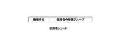
新規ジョブ所属クラスタ推定部132は、新規ジョブが、実行履歴クラスタ作成部131により作成されたクラスタのうち、どのクラスタに所属するかを推定する。新規ジョブ所属クラスタ推定部132は、ジョブの属性が類似する類似ジョブの実行履歴を含むクラスタを、新規ジョブの所属するクラスタとして推定する。ジョブの属性は、例えば、プログラム名、使用されるロードモジュール、ライブラリ関数のバイナリハッシュ値、使用者、使用者が所属するグループ、実行予定時間である。 The new job affiliation
資源使用変動パターン推定部133は、新規ジョブが所属するクラスタに含まれる類似ジョブの実行履歴に基づいて、新規ジョブの資源使用変動パターンを推定する。資源使用変動パターンは、具体的には例えば、資源使用変動の周波数成分である。資源使用変動パターン推定部133は、クラスタ内の実行履歴の回帰分析により、新規ジョブの資源使用変動パターンを推定することができる。類似ジョブの実行履歴が複数のクラスタに含まれる場合、資源使用変動パターン推定部133は、各クラスタに含まれる類似ジョブの実行履歴の数に応じた所属確率を考慮して、新規ジョブの資源使用変動パターンを推定してもよい。資源使用変動パターン推定部133は、推定部の一例である。 The resource usage fluctuation
専有資源特定部134は、推定された新規ジョブの資源使用変動パターンに基づいて、新規ジョブを割り当てる資源を特定する。DBインターフェース135は、DBサーバ4
とのインターフェースである。最適化処理部13は、DBインターフェース135を介して、新規ジョブの資源使用変動パターンの推定に使用するデータを、DBサーバ4から取得する。専有資源特定部134は、は特定部の一例である。The exclusive resource specifying unit 134 specifies the resource to which the new job is allocated based on the estimated resource usage variation pattern of the new job. The
Interface. The
計算ノード2は、スケジューラ(サブ)として、ジョブスケジューラ・ノード1から割り当てられたジョブを実行し、各計算ノード2上の資源使用変動を、所定の単位時間ごとに記録する。計算ノード2は、例えば、1秒ごとに自身の計算ノード2上での資源使用変動を記録する。CPU 2aがマルチコアプロセッサ等である場合、資源使用変動は、コアごとに記録される。 The
図2において、計算ノード21は、ジョブ起動/終了管理部211、ジョブ資源使用量
監視部212、資源使用状況通知部213を備える。計算ノード22は、ジョブ起動/終
了管理部221、ジョブ資源使用量監視部222、資源使用状況通知部223を備える。計算ノード2Nは、ジョブ起動/終了管理部2N1、ジョブ資源使用量監視部2N2、資
源使用状況通知部2N3を備える。In FIG. 2, the
各計算ノード2が備えるジョブ起動/終了管理部211から2N1は、ジョブ起動/終了管理部21と総称される。各計算ノード2が備えるジョブ資源使用量監視部212から2N2は、ジョブ資源使用量監視部22と総称される。各計算ノード2が備える資源使用状況通知部213から2N3は、資源使用状況通知部23と総称される。計算ノード21と同様に、各計算ノード2は、それぞれにジョブ起動/終了管理部21、ジョブ資源使用量
監視部22、資源使用状況通知部23を備える。The job start / end management units 211 to 2N1 included in each
CPU 2aは、コンピュータプログラムにより、計算ノード2が備える各処理構成の処理を実行する。計算ノード2が備える各処理構成のいずれか、またはその処理の一部がハードウェア回路により実行されてもよい。 The CPU 2a executes processing of each processing configuration included in the
ジョブ起動/終了管理部21は、ジョブ実行開始指示部/終了監視部121からの指示を受けてジョブを起動する。また、ジョブ起動/終了管理部21は、ジョブ実行開始指示部/終了監視部121にジョブの終了を通知する。 The job start /
ジョブ資源使用量監視部22は、ジョブの資源使用量を監視し、各ジョブの時間の経過に伴って、各ノード上での資源使用変動を所定の単位時間ごとに記録する。資源使用変動は、資源別に記録してもよい。ジョブ資源使用量監視部22は、資源使用変動を、資源使用履歴としてメモリ2bに記憶することができる。ジョブ資源使用量監視部22は、出力部の一例である。資源使用状況通知部23は、ジョブ資源使用量監視部22が記録した資源使用変動データを、資源使用履歴データ受信部123に通知する。 The job resource
DBサーバ4は、資源使用履歴データ受信部123が生成したジョブの実行履歴を記憶する。DBサーバ4は、実行履歴データベース41を備える。実行履歴データベース41は、入力パラメタ−実行時間−サブレコード表411、専有資源表412、資源使用変動表413を含む。 The
入力パラメタ−実行時間−サブレコード表411は、ジョブの実行履歴を記憶するメインテーブルである。専有資源表412は、ジョブの実行に使用した専有資源を記憶する。専有資源は、ジョブが使用する装置、例えば、CPU 2a、CPU 2aのコア、メモリ2b、メモリ内の特定領域等である。 The input parameter-execution time-sub-record table 411 is a main table that stores a job execution history. The exclusive resource table 412 stores the exclusive resources used for executing the job. The dedicated resources are devices used by the job, for example, the CPU 2a, the core of the CPU 2a, the memory 2b, a specific area in the memory, and the like.
資源使用変動表413は、各計算ノード2上又は各コア上での、資源ごとの資源使用変動を周波数成分に分解して、周波数成分ごとに記憶する。資源使用変動は、例えば、離散
フーリエ変換により、周波数成分に分解される。ここで、離散フーリエ変換は、離散コサイン変換や離散サイン変換を含む広義の離散フーリエ変換である。The resource usage fluctuation table 413 decomposes the resource usage fluctuation for each resource on each
図3は、資源使用履歴のデータ構造の一例を示す図である。資源使用履歴は、計算ノード2のジョブ資源使用量監視部22によって記録される資源使用変動である。図3において、資源使用履歴は、「タイムスタンプ」及び「資源使用量の差分」を記憶する。「タイムスタンプ」は、資源使用量の差分を記録する時刻である。「資源使用量の差分」は、直前のタイムスタンプからの資源使用量の変動量である。図3の例では、資源使用履歴は、資源ごとに記録されるものとする。 FIG. 3 is a diagram illustrating an example of a data structure of a resource usage history. The resource usage history is a resource usage change recorded by the job resource
図4は、実行履歴のデータ構造の一例を示す図である。実行履歴は、入力パラメタ−実行時間−サブレコード表411として、実行履歴データベース41に記憶される。入力パラメタ−実行時間−サブレコード表411は、「入力パラメタ」、「実行時間」、「専有資源レコードリスト」、「専有資源変動レコードリスト」を記憶する。「入力パラメタ」は、ジョブの実行前に指定されるパラメタのデータである。「実行時間」、「専有資源レコードリスト」、「専有資源変動レコードリスト」は、ジョブの実行後に、実行結果として登録されるデータである。 FIG. 4 is a diagram illustrating an example of the data structure of the execution history. The execution history is stored in the
「入力パラメタ」は、オペレーティングシステム(Operating System、OS)、ジョブスケジューラ、又は言語処理系のランタイムシステムによる管理対象としての特徴を示すデータを含む。例えば、「入力パラメタ」は、プログラム名、プログラムのバイナリハッシュ値、使用するロードモジュールやライブラリ関数のバイナリハッシュ値、使用者、使用者が所属するグループ、実行予定時間等のデータを含む。使用するロードモジュールやライブラリ関数のバイナリハッシュ値は、ジョブのプログラムから取得することができる。さらに、ジョブの実行に使用する計算ノード2又はコアに関する条件を指定する場合には、「入力パラメタ」は、使用ノード数、使用コア数、使用ノードの配置等の指定した条件を含む。入力パラメタは、属性の一例である。 The “input parameter” includes data indicating characteristics as a management target by an operating system (OS), a job scheduler, or a runtime system of a language processing system. For example, the “input parameter” includes data such as the program name, the binary hash value of the program, the binary hash value of the load module or library function to be used, the user, the group to which the user belongs, the scheduled execution time, and the like. The binary hash value of the load module or library function to be used can be acquired from the job program. Furthermore, in the case of specifying the conditions regarding the
「実行時間」は、ジョブの実行に要した時間を記憶する。「専有資源レコードリスト」は、専有資源表412で管理される専有資源レコードの所定数のリストである。「専有資源変動レコードリスト」は、資源使用変動表413で管理される専有資源変動レコードの所定数のリストである。“Execution time” stores the time required to execute the job. The “exclusive resource record list” is a list of a predetermined number of exclusive resource records managed in the exclusive resource table 412. The “exclusive resource change record list” is a list of a predetermined number of exclusive resource change records managed by the resource use change table 413.
また、実行履歴は、以下に示す2つの集合CP、TRから定まる直積集合CP×TRの要素と考えることができる。
CP=[入力パラメタ(の組み合わせ):I}
TR=[実行時に採取されるデータ(実行時間、専有資源、資源使用変動):D]
(I,D)∈ CP×TRFurther, the execution history can be considered as an element of a Cartesian product set CP × TR determined from the following two sets CP and TR.
CP = [input parameter (combination): I}
TR = [Data collected during execution (execution time, proprietary resources, resource usage fluctuation): D]
(I, D) ∈ CP × TR
図5A、図5B、図5C、図5Dは、入力パラメタを例示する図である。図5Aは、入力パラメタのデータ構造の一例を示す図である。入力パラメタは、「プログラムレコード」、「使用者レコード」、「ジョブ資源指定レコード」を含む。図5B、図5C、図5Dは、それぞれ「プログラムレコード」、「使用者レコード」、「ジョブ資源指定レコード」のデータ構造を例示する。 5A, 5B, 5C, and 5D are diagrams illustrating input parameters. FIG. 5A is a diagram illustrating an example of a data structure of an input parameter. The input parameters include “program record”, “user record”, and “job resource designation record”. FIG. 5B, FIG. 5C, and FIG. 5D illustrate data structures of “program record”, “user record”, and “job resource designation record”, respectively.
図5Bは、プログラムレコードのデータ構造の一例を示す図である。プログラムレコードは、「プログラム名」及び「プログラムのバイナリハッシュ値」を含む。「プログラム名」は、ジョブのプログラム名を記憶する。「プログラムのバイナリハッシュ値」は、当該プログラムのバイナリハッシュ値を記憶する。 FIG. 5B is a diagram illustrating an example of a data structure of a program record. The program record includes “program name” and “binary hash value of program”. “Program name” stores the program name of the job. The “binary hash value of program” stores the binary hash value of the program.
図5Cは、使用者レコードのデータ構造の一例を示す図である。使用者レコードは、「使用者名」及び「使用者の所属グループ」を含む。「使用者名」は、ジョブの使用者を記憶する。「使用者の所属グループ」は、当該使用者の所属グループを記憶する。 FIG. 5C is a diagram illustrating an example of a data structure of a user record. The user record includes “user name” and “user affiliation group”. “User name” stores the user of the job. The “user affiliation group” stores the affiliation group of the user.
図5Dは、ジョブ資源指定レコードのデータ構造の一例を示す図である。ジョブ資源指定レコードは、「実行予定時間」、「ノード配置形状」、「使用ノード種別」を含む。「実行予定時間」は、予測される実行時間を記憶する。「ノード配置形状」は、ジョブの実行に使用する一以上の計算ノード2の組合せを記憶する。「使用ノード種別」は、ジョブの実行に使用する計算ノード2の種別を記憶する。計算ノード2の種別は、計算ノード2に含まれる資源の仕様、例えば、CPU 2aの性能、メモリ2bの容量、又はCPU 2aがGPGPUやFPGA等のアクセラレータであるか否か等の仕様により指定される種別である。 FIG. 5D is a diagram illustrating an example of a data structure of a job resource designation record. The job resource designation record includes “scheduled execution time”, “node arrangement shape”, and “used node type”. “Scheduled execution time” stores the predicted execution time. The “node arrangement shape” stores a combination of one or
図6は、専有資源レコードのデータ構造の一例を示す図である。専有資源レコードは、「専有資源の種別」、「資源数」、「ノード配置形状」を含む。「専有資源の種別」は、CPU 2a、CPU 2aのコア、メモリ2b、メモリ内の特定領域等の専有資源の種別を記憶する。「資源数」は、ジョブの実行に使用される当該専有資源の数を記憶する。「ノード配置形状」は、ジョブの実行に使用された一以上の計算ノード2の組合せを記憶する。 FIG. 6 is a diagram illustrating an example of a data structure of a dedicated resource record. The exclusive resource record includes “exclusive resource type”, “number of resources”, and “node arrangement shape”. The “exclusive resource type” stores the type of the exclusive resource such as the CPU 2a, the core of the CPU 2a, the memory 2b, and a specific area in the memory. “Number of resources” stores the number of the dedicated resources used for job execution. The “node arrangement shape” stores a combination of one or
図7は、資源使用変動レコードのデータ構造の一例を示す図である。資源使用変動レコードは、「資源種別」、「資源使用の周波数成分識別子」、「使用ノード種別」を含む。「資源種別」は、各計算ノード2上又は各コア上の資源の種別である。資源は、例えば、CPU時間、ワーキングセットサイズ、仮想空間サイズ、単位時間ごとのメモリアクセス量(即ち、キャッシュミス発生量)、IOPS、IOバンド幅である。「資源使用の周波数成分識別子」は、各計算ノード2上又は各コア上での当該資源の使用量の変動を周波数成分に分解したものを特定する識別子を記憶する。資源使用の周波数成分は、ジョブの実行終了後に、DBサーバ4内の補助記憶装置(図示せず)上に記憶され、「資源使用の周波数成分識別子」を介して取得される。「使用ノード種別」は、ジョブの実行に使用された計算ノード2の種別を記憶する。 FIG. 7 is a diagram illustrating an example of a data structure of a resource usage change record. The resource use change record includes “resource type”, “frequency component identifier of resource use”, and “use node type”. “Resource type” is the type of resource on each
<処理の流れ>
図8から12は、第1実施形態の処理の流れを説明するための図である。図8は、資源使用量の変動を記録する処理のフローチャートの一例である。図8に示される処理は、計算ノード2のジョブ起動/終了管理部21がジョブを起動することにより開始される。<Process flow>
8 to 12 are diagrams for explaining the processing flow of the first embodiment. FIG. 8 is an example of a flowchart of processing for recording changes in resource usage. The process shown in FIG. 8 is started when the job start /
OP11では、ジョブ資源使用量監視部22は、計算ノード2上でジョブが実行中であるか否かを判定する。ジョブが実行中である場合には(OP11:Y)、処理がOP12に進む。ジョブが実行中でない場合には(OP11:N)、図8に示される処理が終了する。 In OP11, the job resource
OP12では、ジョブ資源使用量監視部22は、計算ノード2上での資源使用の変動量を、資源ごとにメモリ2bに記録する。各資源使用の変動量は、例えば、図3に示す資源使用変動のデータ構造により記録される。次に処理がOP13に進む。 In OP12, the job resource
OP13では、ジョブ資源使用量監視部22は、所定の時間待機する。次に処理がaに戻り、ジョブの実行中(OP11:Y)、OP11からOP13の処理が繰り返される。ここでは、計算ノード2ごとの資源使用変動を記録する例を示したが、CPU 2aがマルチコアプロセッサ等、複数のプロセッサコアを含む場合、ジョブ資源使用量監視部22は、コアごとに資源使用変動を記録する。 In OP13, the job resource
図9は、ジョブの実行終了後に実行履歴を登録する処理のフローチャートの一例である。実行履歴を登録する処理は、図8に示される処理によって各計算ノード2上の資源使用変動が記録され、ジョブの実行が終了した後に開始される。図9に示される処理は、例えば、ジョブ実行開始指示部/終了監視部121が、ジョブを実行する計算ノード2から、
各計算ノード2上でのジョブの終了の通知を受信することにより開始される。FIG. 9 is an example of a flowchart of processing for registering an execution history after the end of job execution. The process of registering the execution history is started after the resource usage fluctuation on each
The processing is started by receiving a job end notification on each
OP21では、資源使用履歴データ受信部123は、ジョブを実行する計算ノード2から資源使用変動データを受信し、資源使用量の変動を離散フーリエ変換により、周波数成分を取り出す。次に処理がOP22に進む。 In OP21, the resource usage history
OP22では、資源使用履歴データ受信部123は、取り出した周波数成分を含むジョブの実行履歴を生成し、実行履歴データベース41に登録する。ジョブの実行履歴は、例えば、図4に示す実行履歴のデータ構造により記録される。その後、図9に示される処理が終了する。 In OP <b> 22, the resource usage history
図10は、実行履歴のクラスタ分析処理のフローチャートの一例である。図10に示される処理は、図9に示される処理によって生成されたジョブの実行履歴に対するクラスタ分析処理である。図10においてクラスタ分析処理は、1つの「最上位」クラスタに統合される「ツリー」を形成する「階層化クラスタ」を作成する。実行履歴クラスタ作成部131は、クラスタ分析処理を所定のタイミングで開始し、動的に実行する。 FIG. 10 is an example of a flowchart of execution history cluster analysis processing. The process shown in FIG. 10 is a cluster analysis process for the job execution history generated by the process shown in FIG. In FIG. 10, the cluster analysis process creates a “hierarchical cluster” that forms a “tree” integrated into one “top-level” cluster. The execution history
OP31では、実行履歴クラスタ作成部131は、初期状態として、個々のジョブ実行履歴データを1つのクラスタとする。次に処理がOP32に進む。OP32では、実行履歴クラスタ作成部131は、クラスタ数Kをジョブ実行履歴データの数nとする。なお、OP31及びOP32の処理は順序が入れ替わってもよい。次に処理がOP33に進む。 In OP31, the execution history
OP33では、実行履歴クラスタ作成部131は、K個のクラスタの中で最も非類似度が小さい対を求め、その対を1つのクラスタとして融合する。非類似度とは、実行履歴間または実行履歴のクラスタ間の距離に相当する。 In OP33, the execution history
本実施形態における距離は、ジョブの開始日時等の間隔尺度、又は資源使用量等の比例尺度のような数値データに対しては、ユークリッド距離とすることができる。また、定性的な利用者名等の名義尺度に対しては、距離は、同一か否かを示す0、1等の2値データとすることができる。 The distance in the present embodiment can be the Euclidean distance for numerical data such as an interval scale such as job start date and time or a proportional scale such as resource usage. In addition, for a nominal measure such as a qualitative user name, the distance can be binary data such as 0 and 1 indicating whether or not the distance is the same.
比較の際に複数の尺度、例えば名義尺度、間隔尺度、比例尺度を使用する場合、各尺度の重みづけを考慮し、各尺度に所定の重み係数を掛けて加算したものを、距離、即ち非類似度として定めてもよい。OP33の次に、処理がOP34に進む。 When multiple scales are used in the comparison, such as nominal scale, interval scale, and proportional scale, the weight of each scale is taken into account, and each scale multiplied by a predetermined weighting factor is added to the distance, i.e., non- The degree of similarity may be determined. Following OP33, the process proceeds to OP34.
OP34では、実行履歴クラスタ作成部131は、KにK−1を代入し、クラスタ数Kを1減らす。次に処理がOP35に進む。OP35では、Kが1より大きいか否かを判定する。Kが1より大きい場合には(OP35:Y)、処理がOP36に進む。Kが1以下である場合には(OP11:N)、図9に示される処理が終了する。 In OP34, the execution history
OP36では、実行履歴クラスタ作成部131は、OP33において対の融合により生成された新規クラスタと、他のクラスタの非類似度を求める。次に処理がbに戻り、Kが1より大きい場合(OP35:Y)、即ち、階層化クラスタの作成が完了するまで、OP33からOP36の処理が繰り返される。 In OP36, the execution history
図11は、クラスタ間の非類似度を求める処理のフローチャートの一例である。図11は、図10のOP36の処理の詳細を示す。なお、OP41からOP44の処理は、任意の順序で行ってもよい。 FIG. 11 is an example of a flowchart of processing for obtaining the dissimilarity between clusters. FIG. 11 shows details of the process of OP36 of FIG. Note that the processing from OP41 to OP44 may be performed in an arbitrary order.
OP41では、実行履歴クラスタ作成部131は、C(i)に、OP33において融合されたクラスタの対のうち、構成データ数が少ない方のクラスタを設定する。OP42では、実行履歴クラスタ作成部131は、C(j)に、OP33において融合されたクラスタの対のうち、構成データ数が少なくない方のクラスタを設定する。融合されたクラスタの対の構成データ数が同じである場合は、一方のクラスタをC(i)とし、他方のクラスタをC(j)とすればよい。 In OP41, the execution history
OP43では、実行履歴クラスタ作成部131は、CLに、融合されたクラスタの対、即ちC(i)、C(j)以外のクラスタのリストを設定する。OP44では、実行履歴クラスタ作成部131は、DLに空のリストを設定する。次に処理がOP45に進む。 In OP43, the execution history
OP45では、実行履歴クラスタ作成部131は、CLが空のリストであるか否かを判定する。CLが空のリストである場合には(OP45:Y)、図11に示される処理が終了し、処理が図10のbに戻る。CLが空のリストでない場合には(OP45:N)、処理がOP46に進む。 In OP45, the execution history
OP46では、実行履歴クラスタ作成部131は、C(k)に、CLの先頭要素のクラスタを設定する。次に処理がOP47に進む。OP47では、実行履歴クラスタ作成部131は、CLから先頭要素のクラスタC(k)を取り外す。次に処理がOP48に進む。 In OP46, the execution history
OP48では、実行履歴クラスタ作成部131は、OP33における融合により生成された新規クラスタC(i)∪C(j)と、CLの先頭要素のクラスタC(k)との距離を、下記の式により求める。
(数1)
d(C(i)∪C(j),C(k)) = α(i)*d(C(i),C(k))+α(j)*d(C(j),C(k))
+β*d(C(i),C(j))+γ|d(C(i),C(k))-d(C(j),C(k))|In OP48, the execution history
(Equation 1)
d (C (i) ∪C (j), C (k)) = α (i) * d (C (i), C (k)) + α (j) * d (C (j), C ( k))
+ β * d (C (i), C (j)) + γ | d (C (i), C (k))-d (C (j), C (k)) |
(数1)において、dはクラスタ間の距離を示す。例えば、d(C(i),C(j))は、クラスタC(i)とクラスタC(j)の距離である。また、α(i)、α(j)、β、γは、クラスタリング手法
により定まる係数である。例えば、最短距離法及びメディアン法を使用する場合、係数は以下の値をとる。
最短距離法:α(i)=α(j)=1/2、β=0、γ=−1/2
メディアン法:α(i)=α(j)=1/2、β=−1/4、γ=0
他にも、(数1)において係数の定め方が異なるクラスタリング手法が、複数知られている。In (Equation 1), d indicates the distance between clusters. For example, d (C (i), C (j)) is the distance between cluster C (i) and cluster C (j). Α (i), α (j), β, and γ are coefficients determined by a clustering method. For example, when the shortest distance method and the median method are used, the coefficient takes the following values.
Shortest distance method: α (i) = α (j) = 1/2, β = 0, γ = −1 / 2
Median method: α (i) = α (j) = 1/2, β = −1 / 4, γ = 0
In addition, a plurality of clustering methods in which the method of determining the coefficients in (Expression 1) is different are known.
(数1)により求めた距離は、クラスタC(i)∪C(j)とクラスタC(k)との非類似度とする。次に処理がcに戻り、CLのリストが空になるまで、OP45からOP48までの処理を繰り返す。図11に示される処理により、クラスタC(i)∪C(j)と、OP43でCLに設定されたリスト内の各クラスタC(k)との非類似度が求められる。 The distance obtained by (Expression 1) is the dissimilarity between cluster C (i) ∪C (j) and cluster C (k). Next, the processing returns to c, and the processing from OP45 to OP48 is repeated until the CL list becomes empty. By the processing shown in FIG. 11, the dissimilarity between the cluster C (i) CC (j) and each cluster C (k) in the list set to CL in OP43 is obtained.
図12は、新規ジョブの資源使用量の推定値を求める処理のフローチャートの一例である。新規ジョブが複数のクラスタに所属する場合、各クラスタへの所属確率に応じて、資源使用量が推定してもよい。また、実行履歴からの資源使用量の推定は、クラスタ内において、入力パラメタ、実行時間、専有資源、資源使用変動を変数とする回帰分析により行うことができる。 FIG. 12 is an example of a flowchart of processing for obtaining an estimated value of resource usage of a new job. When a new job belongs to a plurality of clusters, the resource usage may be estimated according to the belonging probability to each cluster. Further, the estimation of the resource usage from the execution history can be performed by regression analysis using the input parameters, execution time, dedicated resources, and resource usage fluctuations as variables in the cluster.
ここでの回帰分析は、複数の説明変数に基づく重回帰分析を含む。例えば、重回帰分析は、入力パラメタと専有資源レコードリストを説明変数として、ある資源使用変動の各周波数成分を目的変数としてもよい。また、重回帰分析は、入力パラメタを説明変数として、ある資源使用変動の各周波数成分を目的変数としてもよい。ただし、説明変数は1つであってもよい。例えば、入力パラメタに実行予定時間が含まれる場合、実際の実行時間は、1つのパラメタで説明することができる。 The regression analysis here includes multiple regression analysis based on a plurality of explanatory variables. For example, in the multiple regression analysis, input parameters and a dedicated resource record list may be used as explanatory variables, and each frequency component of a certain resource usage change may be used as an objective variable. In addition, the multiple regression analysis may use input parameters as explanatory variables and frequency components of a certain resource usage variation as objective variables. However, there may be one explanatory variable. For example, when the scheduled execution time is included in the input parameters, the actual execution time can be described with one parameter.
図12に示される処理は、例えば、新規ジョブの投入により開始される。OP51では、新規ジョブ所属クラスタ推定部132は、CLに、資源使用量推定が可能なクラスタC1のリストを設定する。資源使用量推定が可能なクラスタC1は、所定数の実行履歴を含み、回帰分析等により資源使用量を推定することができるクラスタである。次に処理がOP52に進む。 The process shown in FIG. 12 is started, for example, by inputting a new job. In OP51, the new job affiliation
OP52では、新規ジョブ所属クラスタ推定部132は、CLリスト内に、新規ジョブの入力パラメタPと同一の入力パラメタを持つ実行履歴を含むクラスタがあるか否かを判定する。同一の入力パラメタを持つ実行履歴を含むクラスタがある場合には(OP52:Y)、処理がOP53に進む。同一の入力パラメタを持つ実行履歴を含むクラスタがない場合には(OP52:N)、処理がOP57に進む。 In OP52, the new job affiliation
OP53では、新規ジョブ所属クラスタ推定部132は、MLに、条件を満たすクラスタで最下位のクラスタC2のリストを設定する。条件を満たすクラスタは、新規ジョブの入力パラメタPと同一の入力パラメタを持つ実行履歴を含むクラスタである。次に処理がOP54に進む。 In OP <b> 53, the new job affiliation
OP54では、資源使用変動パターン推定部133は、MLの各要素C2に対し、入力パラメタがPの新規ジョブが所属した場合の資源使用量推定値を求める。次に処理がOP55に進む。 In OP54, the resource usage fluctuation
OP55では、資源使用変動パターン推定部133は、MLの各要素C2に対し、入力パラメタがPの新規ジョブの推定所属確率を求める。入力パラメタ又は入力パラメタの組みあわせがPと同一であるという条件で、新規ジョブがクラスタC2に所属する確率は、各クラスタC2の要素で入力パラメタがPと同一の実行履歴の数に比例するものとして、以下のように計算する。
N(C2)=(入力パラメタがPである実行履歴の数)
N(ALL2)=(入力パラメタがPである実行履歴の総数)
クラスタC2に対する入力パラメタPのジョブの所属確率=N(C2)/N(ALL2)
なお、MLの要素C2が1つの場合、その1つのクラスタに対する所属確率を1とする。次に処理がOP56に進む。In OP55, the resource usage fluctuation
N (C2) = (number of execution histories whose input parameter is P)
N (ALL2) = (total number of execution histories whose input parameter is P)
Probability of job of input parameter P for cluster C2 = N (C2) / N (ALL2)
When there is one ML element C2, the affiliation probability for that one cluster is 1. Next, the process proceeds to OP56.
OP56では、資源使用変動パターン推定部133は、ML全体における資源使用量の推定値を、MLの各クラスタC2に対する(推定所属確率)×(資源使用量推定値)の総
和とする。その後、処理がd3に進み、図12に示される処理が終了する。In OP56, the resource usage fluctuation
OP57では、新規ジョブ所属クラスタ推定部132は、DLに、CL内で新規ジョブの入力パラメタPとの距離がd以下であるクラスタC3のリストを設定する。距離dは、例えば、入力パラメタの各成分に異なる重みをつけたユークリッド距離としてもよい。次に処理がOP58に進む。 In OP57, the new job affiliation
OP58では、新規ジョブ所属クラスタ推定部132は、DLが空のリストであるか否かを判定する。DLが空のリストである場合には(OP58:Y)、処理がOP59に進む。DLが空のリストでない場合には(OP58:N)、処理がOP60に進む。 In OP58, the new job affiliation
OP59では、新規ジョブ所属クラスタ推定部132は、新規ジョブの入力パラメタPとの距離dを所定の値だけ増加させる。距離dを増加させることで、新規ジョブの入力パラメタPとの距離がd以下となるクラスタの対象範囲が広がる。次に処理がd1に戻り、D
Lにリストが設定されるまで、OP57からOP59までの処理が繰り返される。In OP59, the new job affiliation
Until the list is set in L, the processing from OP57 to OP59 is repeated.
OP60では、資源使用変動パターン推定部133は、DLの各要素C3に対し、入力パラメタがPの新規ジョブが所属した場合の資源使用量推定値を求める。次に処理がOP61に進む。 In OP60, the resource usage fluctuation
OP61では、資源使用変動パターン推定部133は、DLの各要素C3に対し、入力パラメタがPの新規ジョブの推定所属確率を求める。新規ジョブがクラスタC3に所属する確率は、各クラスタC3の要素で入力パラメタPとの距離がd以下である実行履歴の数
に比例するものとして、以下のように計算する。
N(C3)=(入力パラメタPとの距離がd以下である実行履歴の数)
N(ALL3)=(入力パラメタPとの距離がd以下である実行履歴の総数)
クラスタC3に対する入力パラメタPのジョブの所属確率=N(C3)/N(ALL3)
なお、DLの要素C3が1つの場合、その1つのクラスタに対する所属確率を1とする。次に処理がOP62に進む。In OP61, the resource usage fluctuation
N (C3) = (number of execution histories whose distance from the input parameter P is d or less)
N (ALL3) = (total number of execution histories whose distance from the input parameter P is d or less)
Probability of job of input parameter P for cluster C3 = N (C3) / N (ALL3)
When there is one DL element C3, the affiliation probability for the one cluster is 1. Next, the process proceeds to OP62.
OP62では、資源使用変動パターン推定部133は、DL全体における資源使用量の推定値を、DLの各クラスタC3に対する(推定所属確率)×(資源使用量推定値)の総
和とする。その後、処理がd3に進み、図12に示される処理が終了する。In OP62, the resource usage fluctuation
以上により得られた新規ジョブの資源使用量の推定値に基づいて、専有資源特定部134は、新規ジョブが使用する計算ノード2の割当て位置を特定する。 Based on the estimated value of the resource usage of the new job obtained as described above, the dedicated resource specifying unit 134 specifies the allocation position of the
<第1実施形態の作用効果>
資源使用変動パターン推定部133は、クラスタ内での回帰分析により資源使用変動を推定する場合、説明変数として、入力パラメタ、実行時間、専有資源、資源使用変動等の条件を任意に組み合わせてもよい。これにより、資源使用変動パターン推定部133は、着目する資源に応じて、柔軟な負荷の平準化を図ることができる。<Operational effects of the first embodiment>
When estimating resource usage fluctuations by regression analysis within a cluster, the resource usage fluctuation
新規ジョブの類似ジョブの実行履歴が複数のクラスタに含まれる場合、資源使用変動パターン推定部133は、各クラスタに含まれる類似ジョブの実行履歴の数に応じた所属確率を考慮して、新規ジョブの資源使用変動パターンを推定してもよい。これにより、資源使用変動パターン推定部133は、特定のクラスタに含まれる実行履歴よりも多くの実行履歴から推定するため、新規ジョブの資源使用量を精度良く推定することができる。 When the execution history of similar jobs of a new job is included in a plurality of clusters, the resource use variation
資源使用変動パターン推定部133は、資源使用変動から、離散フーリエ変換により周波数成分を取り出して比較することで、資源使用変動パターンの類似性を判定する。資源使用変動パターン推定部133は、周波数成分の比較により、例えば、少し時間をずらして平行移動したほぼ同じ資源使用変動パターンの類似性の見落としが避けられる。これにより、資源使用変動パターン推定部133は、新規ジョブに対し、適切な類似ジョブを特定し、新規ジョブの資源使用量を精度よく推定することができる。 The resource usage variation
新規ジョブ所属クラスタ推定部132は、新規ジョブと類似ジョブとの非類似度を、各ジョブの入力パラメタに含まれる各尺度の値から算出されるユークリッド距離とすることができる。これにより、新規ジョブと入力パラメタが一致する類似ジョブが存在しない場合でも、新規ジョブ所属クラスタ推定部132は、非類似度が、所定の閾値より小さいジョブを類似ジョブとして、新規ジョブの所属クラスタを推定することができる。 The new job affiliation
新規ジョブ所属クラスタ推定部132は、ユークリッド距離を求める際、各尺度に所定の重み係数を掛けてもよい。これにより、新規ジョブ所属クラスタ推定部132は、着目する尺度に応じた類似ジョブを推定することができる。 When determining the Euclidean distance, the new job affiliation
以上より、専有資源特定部134は、新規ジョブに対し、適切な類似ジョブを特定し、新規ジョブの資源使用量を精度よく推定することにより、新規ジョブに対する計算ノード2の割当てを最適化し、負荷の平準化を向上させることができる。 As described above, the dedicated resource specifying unit 134 optimizes the allocation of the
<第2実施形態>
第2実施形態では、並列計算機システムは、既存ジョブの資源使用量も含めた各計算ノード2上の資源使用量に基づいて、ジョブ間の干渉を低減するように、新規ジョブの割当て位置を最適化する。本実施形態では、新規ジョブを割り当てる対象が計算ノード2であるものとして説明するが、CPU 2aが複数のプロセッサコアを含むマルチプロセッサ等である場合、新規ジョブを割り当てる対象は、コアであってもよい。Second Embodiment
In the second embodiment, the parallel computer system optimizes the allocation position of a new job so as to reduce interference between jobs based on the resource usage on each
第2実施形態における装置構成及び処理構成は、第1実施形態と同様である。第2実施形態では、第1実施形態と重複する説明は省略される。第2実施形態において、専有資源特定部134は、各計算ノード2から各IOノード3への時間帯別のネットワーク資源使用量を推定し、ネットワークの輻輳が最小となるように、新規ジョブが使用する計算ノード2の割当て位置を最適化する。 The apparatus configuration and processing configuration in the second embodiment are the same as those in the first embodiment. In the second embodiment, descriptions overlapping with those in the first embodiment are omitted. In the second embodiment, the dedicated resource identification unit 134 estimates the network resource usage by time zone from each
<処理の流れ>
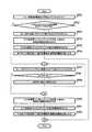
図13は、新規ジョブが使用する資源の割当て位置を最適化する処理のフローチャートの一例である。ここでの割当て位置の最適化は、ネットワーク資源の使用量に基づくネットワーク負荷を平準化するため処理として説明される。図13に示される処理は、図12に示される処理によって、資源使用変動パターンが推定された後、開始される。<Process flow>
FIG. 13 is an example of a flowchart of processing for optimizing the allocation position of resources used by a new job. The optimization of the allocation position here is explained as a process for leveling the network load based on the usage amount of the network resource. The process shown in FIG. 13 is started after the resource use variation pattern is estimated by the process shown in FIG.
OP71では、専有資源特定部134は、LLに、入力パラメタから定まる計算ノード2の割当て位置候補のリストを設定する。割当て位置候補は、一の計算ノード2又は複数の計算ノード2の組合せである。割当て位置候補のリストは、ジョブスケジューラ・ノード1から取得される。次に処理がOP72に進む。 In OP71, the dedicated resource specifying unit 134 sets a list of allocation position candidates of the
OP72では、専有資源特定部134は、FFに、ジョブのIOによって発生するネットワーク負荷の全周波数成分の推定値を設定する。ネットワーク負荷は、ネットワーク資源の使用量に相当する。また、全周波数成分は、新規ジョブと既存ジョブにおけるネットワーク資源使用量の周波数成分を含む。次に処理がOP73に進む。 In OP72, the dedicated resource specifying unit 134 sets, in the FF, estimated values of all frequency components of the network load generated by the job IO. The network load corresponds to the amount of network resources used. The total frequency component includes the frequency component of the network resource usage amount in the new job and the existing job. Next, the process proceeds to OP73.
OP73では、専有資源特定部134は、逆フーリエ変換により、FFから一定時間間隔でのネットワーク負荷の推定値を求める。次に処理がOP74に進む。OP74では、専有資源特定部134は、ELに、各割当て位置候補における各時間帯での負荷の推定値を設定する。負荷の推定値は、割当て位置候補に含まれる計算ノード2ごとに求められる。また、負荷の推定値は、新規ジョブと既存ジョブの負荷の推定値の和である。次に処理がOP75に進む。 In OP73, the dedicated resource specifying unit 134 obtains an estimated value of the network load at a constant time interval from the FF by inverse Fourier transform. Next, the process proceeds to OP74. In OP74, the dedicated resource specifying unit 134 sets an estimated value of the load in each time slot in each allocation position candidate in EL. The estimated load value is obtained for each
OP75では、専有資源特定部134は、XLに各割当て位置候補での輻輳度を設定する。各割当て位置候補での輻輳度は、(各時間帯での負荷の推定値が適正負荷を上回る箇
所の超過負荷×時間)の和である。次に処理がOP76に進む。In OP75, the dedicated resource specifying unit 134 sets the congestion level at each allocation position candidate in XL. The degree of congestion at each allocation position candidate is the sum of (excess load x time where the estimated load value in each time zone exceeds the appropriate load). Next, the process proceeds to OP76.
OP76では、専有資源特定部134は、XLから、輻輳度が最小となる割当て位置候補を割当て位置とする。その後、図13に示される処理が終了する。 In OP76, the dedicated resource specifying unit 134 sets, from XL, an allocation position candidate having the minimum congestion level as an allocation position. Thereafter, the process shown in FIG. 13 ends.
<第2実施形態の作用効果>
並列計算機環境では、計算ノード群はIOノード群と分離されており、IOノード群は、計算ノード群からネットワーク経由でアクセスすべき共有資源となる。このため、ネットワーク負荷を含むIO負荷を平準化し、IO負荷間の干渉を低減することが求められる。<Effects of Second Embodiment>
In the parallel computer environment, the computation node group is separated from the IO node group, and the IO node group becomes a shared resource to be accessed from the computation node group via the network. For this reason, it is required to level out the IO load including the network load and reduce the interference between the IO loads.
第2実施形態では、専有資源特定部134は、新規ジョブ及び既存ジョブのネットワーク資源の資源使用量を推定し、各専有資源における各時間帯での資源使用量を平準化する割当て位置候補に、新規ジョブを割り当てる。これにより、並列計算機システム10は、ネットワークを考慮したIO負荷の平準化及び既存ジョブとの干渉の低減を図ることができる。 In the second embodiment, the dedicated resource specifying unit 134 estimates the resource usage of the network resources of the new job and the existing job, and assigns the resource usage in each time zone in each dedicated resource to the allocation position candidate. Assign a new job. Thereby, the
負荷の平準化や干渉の低減を図るために考慮する資源は、ネットワーク資源に限られない。他の資源、又はネットワーク資源を含む複数の資源の組み合わせに基づいて、資源使用量を推定し、割当て位置が最適化されてもよい。並列計算機システムは、考慮した資源又は資源の組み合わせに応じた負荷の平準化や干渉の低減を図ることができる。 Resources that are considered for leveling loads and reducing interference are not limited to network resources. Based on the combination of a plurality of resources including other resources or network resources, the resource usage may be estimated and the allocation position may be optimized. The parallel computer system can achieve load leveling and interference reduction according to the resource or combination of resources considered.
<記録媒体>
コンピュータその他の機械、装置(以下、コンピュータ等)に上記いずれかの機能を実現させるプログラムをコンピュータ等が読み取り可能な記録媒体に記録することができる。そして、コンピュータ等に、この記録媒体のプログラムを読み込ませて実行させることにより、その機能を提供させることができる。<Recording medium>
A program for causing a computer or other machine or device (hereinafter, a computer or the like) to realize any of the above functions can be recorded on a recording medium that can be read by the computer or the like. Then, the function can be provided by causing the computer or the like to read and execute the program of the recording medium.
ここで、コンピュータ等が読み取り可能な記録媒体とは、データやプログラム等の情報を電気的、磁気的、光学的、機械的、または化学的作用によって蓄積し、コンピュータ等から読み取ることができる記録媒体をいう。このような記録媒体のうちコンピュータ等から取り外し可能なものとしては、例えばフレキシブルディスク、光磁気ディスク、CD−ROM、CD−R/W、DVD、ブルーレイディスク、DAT、8mmテープ、フラッシュメモリなどのメモリカード等がある。また、コンピュータ等に固定された記録媒体としてハードディスクやROM(リードオンリーメモリ)等がある。さらに、Solid State Drive(SSD)はコンピュータ等から取り外し可能な記録媒体としても、コンピュータ等
に固定された記録媒体としても利用可能である。Here, a computer-readable recording medium is a recording medium that stores information such as data and programs by electrical, magnetic, optical, mechanical, or chemical action and can be read from a computer or the like. Say. Examples of such a recording medium that can be removed from a computer or the like include a flexible disk, a magneto-optical disk, a CD-ROM, a CD-R / W, a DVD, a Blu-ray disk, a DAT, an 8 mm tape, a flash memory, and the like. There are cards. In addition, as a recording medium fixed to a computer or the like, there are a hard disk, a ROM (read only memory), and the like. Furthermore, the Solid State Drive (SSD) can be used as a recording medium removable from a computer or the like, or as a recording medium fixed to the computer or the like.
10 並列計算機システム
1 ジョブスケジューラ・ノード
2 計算ノード
3 IOノード
1a、2a、3a CPU
1b、2b、3b メモリ
1c、2c、3c NIC
11 通信処理部
12 資源割当処理部
121 ジョブ実行開始指示部/終了監視部
122 資源使用状況管理部
123 資源使用履歴データ受信部
124 最適化処理呼出インターフェース
13 最適化処理部
131 実行履歴クラスタ作成部
132 新規ジョブ所属クラスタ推定部
133 資源使用変動パターン推定部
134 専有資源特定部
135 DBインターフェース
21 ジョブ起動/終了管理部
22 ジョブ資源使用量監視部
23 資源使用状況通知部
4 DBサーバ
41 実行履歴データベース10
1b, 2b,
11
Claims (11)
Translated fromJapanese前記複数の情報処理装置の各々は、
自装置が実行するジョブに対し、自装置の資源ごとの資源使用量の変動を所定の時間単位で出力する出力部を備え、
前記管理装置は、
ジョブの実行ごとに、実行対象の前記ジョブの属性及び各情報処理装置の出力部が出力する資源使用量の変動を含む実行履歴を生成する生成部と、
新たに投入された新規ジョブと属性が類似する類似ジョブの実行履歴に含まれる資源使用量の変動に基づいて、前記新規ジョブの資源使用量を推定する推定部と、
推定された前記資源使用量に基づいて、前記新規ジョブを割り当てる情報処理装置を特定する特定部とを備える、
並列計算機システム。In a parallel computer system having a plurality of information processing devices and a management device for controlling the plurality of information processing devices,
Each of the plurality of information processing devices
For a job executed by the own device, an output unit that outputs a change in resource usage for each resource of the own device in a predetermined time unit is provided.
The management device
A generation unit that generates an execution history including a change in the attribute of the job to be executed and the resource usage output by the output unit of each information processing apparatus for each job execution;
An estimation unit that estimates the resource usage of the new job based on a change in the resource usage included in the execution history of a similar job with similar attributes to the newly submitted new job;
A specifying unit that specifies an information processing apparatus to which the new job is assigned based on the estimated resource usage;
Parallel computer system.
生成された実行履歴を、属性及び資源使用量の変動における所定の類似度に基づいて、複数のグループに分類する分類部をさらに備え、
前記推定部は、前記類似ジョブの実行履歴を含むグループの資源使用量の変動を回帰分析により推定し、推定された前記資源使用量の変動に基づいて、前記新規ジョブの資源使用量を推定する、
請求項1に記載の並列計算機システム。The management device
A classification unit that classifies the generated execution history into a plurality of groups based on a predetermined similarity in the variation of the attribute and the resource usage;
The estimation unit estimates a variation in resource usage of the group including the execution history of the similar job by regression analysis, and estimates the resource usage of the new job based on the estimated variation in the resource usage. ,
The parallel computer system according to claim 1.
請求項1又は2に記載の並列計算機システム。When there are a plurality of groups including the execution history of the similar job, the estimation unit calculates a probability of belonging to each group based on the number of execution history of the similar job included in each group, Estimating the resource usage of the new job based on the change in resource usage and the affiliation probability;
The parallel computer system according to claim 1 or 2.
請求項1から3のいずれか一項に記載の並列計算機システム。The fluctuation of the resource usage is included in the execution history as a frequency component.
The parallel computer system according to any one of claims 1 to 3.
請求項1から4のいずれか一項に記載の並列計算機システム。The similar job is a job whose Euclidean distance calculated using the attribute value of the attribute of the similar job and the attribute value of the attribute of the new job as a component is smaller than a predetermined threshold value.
The parallel computer system according to any one of claims 1 to 4.
請求項5に記載の並列計算機システム。The Euclidean distance is obtained by multiplying a different weighting coefficient for each component.
The parallel computer system according to claim 5.
請求項1から6のいずれか一項に記載の並列計算機システム。The specifying unit sets a combination of one or more information processing devices selected from the plurality of information processing devices as an allocation position candidate, and the information processing device included in the allocation position candidate among the plurality of allocation position candidates Specifying an allocation position candidate whose sum of estimated values of resource usage of new jobs and existing jobs is smaller than other allocation position candidates as an information processing apparatus to which the new job is allocated;
The parallel computer system according to any one of claims 1 to 6.
資源使用量の一つとして、前記演算ノードと前記入出力ノードとの間のネットワーク資
源の使用量を含む、
請求項1から7のいずれか一項に記載の並列計算機システム。The plurality of information processing apparatuses include an operation node that executes an operation process of a job, and an input / output node that executes an input / output process for the job,
As one of the resource usage, including the usage of network resources between the operation node and the input / output node,
The parallel computer system according to any one of claims 1 to 7.
前記複数の情報処理装置の各々有する出力部が、自装置が実行するジョブに対し、自装置の資源ごとの資源使用量の変動を所定の時間単位で出力し、
前記管理装置が有する生成部が、ジョブの実行ごとに、実行対象の前記ジョブの属性及び各情報処理装置が出力する資源使用量の変動を含む実行履歴を生成し、
前記管理装置が有する推定部が、新たに投入された新規ジョブと属性が類似する類似ジョブの実行履歴に含まれる資源使用量の変動に基づいて、前記新規ジョブの資源使用量を推定し、
前記管理装置が有する特定部が、推定された前記資源使用量に基づいて、前記新規ジョブを割り当てる情報処理装置を特定する、
並列計算機システムの制御方法。In a control method of a parallel computer system having a plurality of information processing devices and a management device for controlling the plurality of information processing devices,
The output unit of each of the plurality of information processing devices outputs, in a predetermined time unit, a change in resource usage for each resource of the own device, for a job executed by the own device.
The generation unit included in the management device generates an execution history including a change in the attribute of the job to be executed and a resource usage output from each information processing device for each execution of the job,
The estimation unit of the management device estimates the resource usage of the new job based on the change in the resource usage included in the execution history of a similar job with similar attributes to the newly submitted new job,
The specifying unit of the management device specifies an information processing device to which the new job is assigned based on the estimated resource usage.
A method for controlling a parallel computer system.
前記複数の情報処理装置の各々が実行するジョブの実行ごとに、実行対象の前記ジョブの属性及び各情報処理装置が出力する資源使用量の変動を含む実行履歴を生成する生成部と、
新たに投入された新規ジョブと属性が類似する類似ジョブの実行履歴に含まれる資源使用量の変動に基づいて、前記新規ジョブの資源使用量を推定する推定部と、
推定された前記資源使用量に基づいて、前記新規ジョブを割り当てる情報処理装置を特定する特定部と、
を備える管理装置。In a management device that controls a plurality of information processing devices,
For each execution of a job executed by each of the plurality of information processing devices, a generation unit that generates an execution history including a change in the attribute of the job to be executed and a resource usage amount output by each information processing device;
An estimation unit that estimates the resource usage of the new job based on a change in the resource usage included in the execution history of a similar job with similar attributes to the newly submitted new job;
A specifying unit that specifies an information processing apparatus to which the new job is assigned based on the estimated resource usage;
A management device comprising:
前記管理装置が有する生成部に、前記複数の情報処理装置の各々が実行するジョブの実行ごとに、実行対象の前記ジョブの属性及び各情報処理装置が出力する資源使用量の変動を含む実行履歴を生成させ、
前記管理装置が有する推定部に、新たに投入された新規ジョブと属性が類似する類似ジョブの実行履歴に含まれる資源使用量の変動に基づいて、前記新規ジョブの資源使用量を推定させ、
前記管理装置が有する特定部に、推定された前記資源使用量に基づいて、前記新規ジョブを割り当てる情報処理装置を特定させる、
管理装置の制御プログラム。In a control program of a management device that controls a plurality of information processing devices,
An execution history including a change in the attribute of the job to be executed and the resource usage output by each information processing device for each execution of the job executed by each of the plurality of information processing devices in the generation unit of the management device To generate
The estimation unit of the management apparatus has the resource usage amount of the new job estimated based on a change in the resource usage amount included in the execution history of a similar job whose attribute is similar to the newly submitted new job,
Causing the specifying unit of the management device to specify an information processing device to which the new job is assigned based on the estimated resource usage;
Control program for management device.
Priority Applications (2)
| Application Number | Priority Date | Filing Date | Title |
|---|---|---|---|
| JP2014165903AJP2016042284A (en) | 2014-08-18 | 2014-08-18 | Parallel computer system, management device, method for controlling parallel computer system, and management device control program |
| US14/794,858US20160048413A1 (en) | 2014-08-18 | 2015-07-09 | Parallel computer system, management apparatus, and control method for parallel computer system |
Applications Claiming Priority (1)
| Application Number | Priority Date | Filing Date | Title |
|---|---|---|---|
| JP2014165903AJP2016042284A (en) | 2014-08-18 | 2014-08-18 | Parallel computer system, management device, method for controlling parallel computer system, and management device control program |
Publications (1)
| Publication Number | Publication Date |
|---|---|
| JP2016042284Atrue JP2016042284A (en) | 2016-03-31 |
Family
ID=55302244
Family Applications (1)
| Application Number | Title | Priority Date | Filing Date |
|---|---|---|---|
| JP2014165903AWithdrawnJP2016042284A (en) | 2014-08-18 | 2014-08-18 | Parallel computer system, management device, method for controlling parallel computer system, and management device control program |
Country Status (2)
| Country | Link |
|---|---|
| US (1) | US20160048413A1 (en) |
| JP (1) | JP2016042284A (en) |
Cited By (1)
| Publication number | Priority date | Publication date | Assignee | Title |
|---|---|---|---|---|
| US10423902B2 (en) | 2016-11-22 | 2019-09-24 | Fujitsu Limited | Parallel processing apparatus and method of estimating power consumption of jobs |
Families Citing this family (11)
| Publication number | Priority date | Publication date | Assignee | Title |
|---|---|---|---|---|
| US9740705B2 (en)* | 2015-12-04 | 2017-08-22 | International Business Machines Corporation | Storlet workflow optimization leveraging clustered file system roles |
| US9501493B1 (en)* | 2015-12-04 | 2016-11-22 | International Business Machines Corporation | Instantiating virtualization unit on storage or proxy node for performing operation based on node having hardware characteristics for serving required file system role for operation |
| TWI620075B (en)* | 2016-11-23 | 2018-04-01 | 財團法人資訊工業策進會 | Server and cloud computing resource optimization method thereof for cloud big data computing architecture |
| US10671440B2 (en) | 2018-02-02 | 2020-06-02 | Workday, Inc. | Resource usage prediction for cluster provisioning |
| US11461631B2 (en)* | 2018-03-22 | 2022-10-04 | Amazon Technologies, Inc. | Scheduling neural network computations based on memory capacity |
| US11475306B2 (en) | 2018-03-22 | 2022-10-18 | Amazon Technologies, Inc. | Processing for multiple input data sets |
| US10698737B2 (en)* | 2018-04-26 | 2020-06-30 | Hewlett Packard Enterprise Development Lp | Interoperable neural network operation scheduler |
| US20220124008A1 (en)* | 2019-01-16 | 2022-04-21 | Convida Wireless, Llc | Automated Service Layer Message Flow Management In A Communications Network |
| JP7235960B2 (en)* | 2019-02-07 | 2023-03-09 | 富士通株式会社 | Job power prediction program, job power prediction method, and job power prediction device |
| CN110191155B (en)* | 2019-05-07 | 2022-01-18 | 中国人民解放军国防科技大学 | Parallel job scheduling method, system and storage medium for fat tree interconnection network |
| US11340951B2 (en) | 2019-10-23 | 2022-05-24 | Microsoft Technology Licensing, Llc | Estimating an amount of resources that a program is expected to consume in a data center |
Family Cites Families (8)
| Publication number | Priority date | Publication date | Assignee | Title |
|---|---|---|---|---|
| US6055433A (en)* | 1996-09-20 | 2000-04-25 | Northern Telecom Limited | Data processing system and method for balancing a load in a communications network |
| US6697791B2 (en)* | 2001-05-04 | 2004-02-24 | International Business Machines Corporation | System and method for systematic construction of correlation rules for event management |
| US20040039803A1 (en)* | 2002-08-21 | 2004-02-26 | Eddie Law | Unified policy-based management system |
| US20070180451A1 (en)* | 2005-12-30 | 2007-08-02 | Ryan Michael J | System and method for meta-scheduling |
| US7583677B1 (en)* | 2006-11-03 | 2009-09-01 | Juniper Networks, Inc. | Dynamic flow-based multi-path load balancing with quality of service assurances |
| JP5061999B2 (en)* | 2008-03-28 | 2012-10-31 | 富士通株式会社 | Analysis apparatus, analysis method, and analysis program |
| US8589931B2 (en)* | 2009-03-18 | 2013-11-19 | International Business Machines Corporation | Environment based node selection for work scheduling in a parallel computing system |
| JP5776339B2 (en)* | 2011-06-03 | 2015-09-09 | 富士通株式会社 | File distribution method, file distribution system, master server, and file distribution program |
- 2014
- 2014-08-18JPJP2014165903Apatent/JP2016042284A/ennot_activeWithdrawn
- 2015
- 2015-07-09USUS14/794,858patent/US20160048413A1/ennot_activeAbandoned
Cited By (1)
| Publication number | Priority date | Publication date | Assignee | Title |
|---|---|---|---|---|
| US10423902B2 (en) | 2016-11-22 | 2019-09-24 | Fujitsu Limited | Parallel processing apparatus and method of estimating power consumption of jobs |
Also Published As
| Publication number | Publication date |
|---|---|
| US20160048413A1 (en) | 2016-02-18 |
Similar Documents
| Publication | Publication Date | Title |
|---|---|---|
| JP2016042284A (en) | Parallel computer system, management device, method for controlling parallel computer system, and management device control program | |
| CN110301128B (en) | Implementation method of learning-based resource management data center cloud architecture | |
| US20220083389A1 (en) | Ai inference hardware resource scheduling | |
| Fu et al. | DRS: Dynamic resource scheduling for real-time analytics over fast streams | |
| EP3640799A1 (en) | Determining an allocation of computing resources for a job | |
| US8799916B2 (en) | Determining an allocation of resources for a job | |
| JP6241300B2 (en) | Job scheduling apparatus, job scheduling method, and job scheduling program | |
| US11228489B2 (en) | System and methods for auto-tuning big data workloads on cloud platforms | |
| JP6953800B2 (en) | Systems, controllers, methods, and programs for running simulation jobs | |
| US10771982B2 (en) | Resource utilization of heterogeneous compute units in electronic design automation | |
| CN111813523A (en) | Duration pre-estimation model generation method, system resource scheduling method, device, electronic equipment and storage medium | |
| CN108205469B (en) | MapReduce-based resource allocation method and server | |
| US11340951B2 (en) | Estimating an amount of resources that a program is expected to consume in a data center | |
| JP7234702B2 (en) | Information processing device, container placement method, and container placement program | |
| US20240303127A1 (en) | Systems and methods for edge system resource capacity performance prediction | |
| CN108845886B (en) | Cloud computing energy consumption optimization method and system based on phase space | |
| CN112328332B (en) | Database configuration optimization method for cloud computing environment | |
| US20210397485A1 (en) | Distributed storage system and rebalancing processing method | |
| Yadav et al. | Maintaining container sustainability through machine learning | |
| US12056525B2 (en) | Hybrid scheduling method for deep learning workloads, and computing apparatus with hybrid scheduling | |
| KR102742714B1 (en) | Efficient multi-gpu based deep learning inference using critical-path-based scheduling | |
| Li et al. | Dynamic data replacement and adaptive scheduling policies in spark | |
| US20240303134A1 (en) | Systems and methods for edge resource demand load estimation | |
| US20240303121A1 (en) | Systems and methods for hypergraph edge resource demand knowledge management | |
| US20240303129A1 (en) | Systems and methods for continued edge resource demand load estimation |
Legal Events
| Date | Code | Title | Description |
|---|---|---|---|
| A621 | Written request for application examination | Free format text:JAPANESE INTERMEDIATE CODE: A621 Effective date:20170511 | |
| A761 | Written withdrawal of application | Free format text:JAPANESE INTERMEDIATE CODE: A761 Effective date:20170808 |