JP2016034412A - Surgery support device, surgery support program, and surgery support method - Google Patents
Surgery support device, surgery support program, and surgery support methodDownload PDFInfo
- Publication number
- JP2016034412A JP2016034412AJP2014158642AJP2014158642AJP2016034412AJP 2016034412 AJP2016034412 AJP 2016034412AJP 2014158642 AJP2014158642 AJP 2014158642AJP 2014158642 AJP2014158642 AJP 2014158642AJP 2016034412 AJP2016034412 AJP 2016034412A
- Authority
- JP
- Japan
- Prior art keywords
- display
- display area
- endoscope
- image
- displayed
- Prior art date
- Legal status (The legal status is an assumption and is not a legal conclusion. Google has not performed a legal analysis and makes no representation as to the accuracy of the status listed.)
- Granted
Links
Images


Landscapes
- Endoscopes (AREA)
- Closed-Circuit Television Systems (AREA)
Abstract
Translated fromJapaneseDescription
Translated fromJapanese本発明は、内視鏡を用いて実施される手術のシミュレーション、あるいは手術中のナビゲーションを行う手術支援装置および手術支援プログラム、手術支援方法に関する。 The present invention relates to a surgery support apparatus, a surgery support program, and a surgery support method for performing simulation of surgery performed using an endoscope or navigation during surgery.
医療現場において、より適切な手術を行うために、手術前のシミュレーションや手術中のナビゲーションを行うことが可能な手術支援装置が活用されている。
従来の手術支援装置は、例えば、X線CT画像や核磁気共鳴画像(MRI画像)、PET(陽電子放射断層法)によって取得された画像等の断層画像情報を取得する断層画像情報取得部と、断層画像情報取得部に接続されたメモリと、メモリに接続されたボリュームレンダリング演算部と、ボリュームレンダリング演算部の演算結果を表示するディスプレイと、ディスプレイに表示された表示対象物に対して切削指示を行う入力部と、を備えていた。
また、このような手術支援装置には、一般的な開腹手術に加えて、内視鏡を用いて実施される手術に対応したシミュレーションやナビゲーションを実施可能なものがある。In a medical field, in order to perform a more appropriate operation, an operation support apparatus capable of performing a simulation before operation and navigation during an operation is used.
A conventional surgery support apparatus includes, for example, a tomographic image information acquisition unit that acquires tomographic image information such as an X-ray CT image, a nuclear magnetic resonance image (MRI image), an image acquired by PET (positron emission tomography), A memory connected to the tomographic image information acquisition unit, a volume rendering calculation unit connected to the memory, a display for displaying the calculation result of the volume rendering calculation unit, and a cutting instruction for a display object displayed on the display And an input unit to perform.
In addition to a general laparotomy, such a surgery support device includes a device capable of performing simulation and navigation corresponding to a surgery performed using an endoscope.
例えば、特許文献1には、内視鏡を用いて実施される手術において、内視鏡の操作中に内視鏡本体を光軸周りに回転させてもTVモニタ上において像が回転することなく上下(天地)方向を維持することが可能な電子式内視鏡装置について開示されている。 For example, in
しかしながら、上記従来の電子式内視鏡装置では、以下に示すような問題点を有している。
すなわち、上記公報に開示された電子式内視鏡装置では、内視鏡の操作時に内視鏡を光軸周りに回転させた場合でも表示される像が回転しないようにするために、磁界等を利用して内視鏡本体の回転量を求める検出手段と、像の向きを回転させる像回転手段と、像回転手段を操作する駆動機構と、検出手段において検出された回転量に応じて自動的に駆動機構が像回転手段を操作してTVモニタに表示される像が回転しないように制御を行う回転補正手段と、を備えている。
このため、従来の電子式内視鏡装置では、内視鏡を光軸周りに回転させた際の回転量を求める検出手段や駆動機構等の構成を設ける必要があるため、内視鏡装置の構成が複雑かつ大型化してしまう。However, the conventional electronic endoscope apparatus has the following problems.
That is, in the electronic endoscope device disclosed in the above publication, a magnetic field or the like is used to prevent the displayed image from rotating even when the endoscope is rotated around the optical axis during the operation of the endoscope. Is used to detect the amount of rotation of the endoscope body, an image rotating unit that rotates the direction of the image, a drive mechanism that operates the image rotating unit, and an automatic operation according to the amount of rotation detected by the detecting unit. And a rotation correction unit for controlling the image rotation unit so that the image displayed on the TV monitor does not rotate by operating the image rotation unit.
For this reason, in the conventional electronic endoscope apparatus, it is necessary to provide a configuration such as a detection unit and a driving mechanism for obtaining the rotation amount when the endoscope is rotated around the optical axis. The configuration is complicated and large.
このような内視鏡装置は、例えば、開創器等のレトラクタの内部に内視鏡と切削具等を挿入して行われる手術では、内視鏡の構成が複雑化するとレトラクタの内部のスペースが狭くなって切削具等を操作するスペースが十分に確保できなくなるおそれがある。
本発明の課題は、簡素な構成により、内視鏡によって取得される映像に対応して表示装置に表示される断層画像情報のボリュームレンダリングによる画像を拡大・縮小した場合でも、画像の回転の基準位置を容易に認識して画像の向きを調整することが可能な手術支援装置および手術支援プログラム、手術支援方法を提供することにある。In such an endoscope apparatus, for example, in an operation performed by inserting an endoscope and a cutting tool into a retractor such as a retractor, if the structure of the endoscope becomes complicated, the space inside the retractor becomes large. There is a possibility that the space for operating the cutting tool or the like cannot be sufficiently secured due to narrowing.
An object of the present invention is to provide a reference for image rotation even when an image is enlarged or reduced by volume rendering of tomographic image information displayed on a display device corresponding to an image acquired by an endoscope with a simple configuration. An object of the present invention is to provide a surgery support device, a surgery support program, and a surgery support method capable of easily recognizing a position and adjusting the orientation of an image.
第1の発明に係る手術支援装置は、レトラクタの内部に内視鏡を挿入して行う手術中のシミュレーション画像あるいはナビゲーション画像を表示させる手術支援装置であって、断層画像情報取得部と、メモリと、ボリュームレンダリング演算部と、表示制御部と、を備えている。断層画像情報取得部は、患者の断層画像情報を取得する。メモリは、断層画像情報取得部に接続されており、断層画像情報のボクセル情報を格納する。ボリュームレンダリング演算部は、メモリに接続されており、ボクセル情報に基づいて、ボクセル情報をサンプリングする。表示制御部は、ボリュームレンダリング演算部によって生成された内視鏡によって取得される画像を表示する第1表示エリアを表示装置に表示させ、または、ボリュームレンダリング演算部によって生成された内視鏡によって取得される画像を表示する第1表示エリアおよびレトラクタの内壁によって遮られる視野範囲に対応する第2表示エリアを表示装置に表示させ、通常表示状態において、表示装置の第1表示エリア、または第2表示エリア、または第1表示エリアおよび第2表示エリアに内視鏡の光軸周りの回転の基準位置を示す第1回転位置表示を表示させるとともに、第1表示エリアの画像、または第1表示エリアおよび第2表示エリアを拡大表示した拡大表示状態において、第1回転位置表示が第1表示エリアまたは第2表示エリア、または第1表示エリアおよび第2表示エリアに表示されるように、表示制御を行う。 A surgery support apparatus according to a first aspect of the present invention is a surgery support apparatus for displaying a simulation image or a navigation image during surgery performed by inserting an endoscope into a retractor, and includes a tomographic image information acquisition unit, a memory, A volume rendering operation unit and a display control unit. The tomographic image information acquisition unit acquires the tomographic image information of the patient. The memory is connected to the tomographic image information acquisition unit and stores voxel information of the tomographic image information. The volume rendering operation unit is connected to the memory, and samples the voxel information based on the voxel information. The display control unit causes the display device to display a first display area for displaying an image acquired by the endoscope generated by the volume rendering calculation unit, or acquired by the endoscope generated by the volume rendering calculation unit The first display area for displaying the image to be displayed and the second display area corresponding to the visual field range blocked by the inner wall of the retractor are displayed on the display device, and in the normal display state, the first display area or the second display of the display device The first rotation position display indicating the rotation reference position around the optical axis of the endoscope is displayed in the area, or the first display area and the second display area, and the image of the first display area, or the first display area and In the enlarged display state in which the second display area is enlarged, the first rotation position display is the first display area or the second display area. A or as displayed on the first display area and a second display area, and performs display control.
第2の発明に係る手術支援装置は、レトラクタの内部に内視鏡を挿入して行う手術中のシミュレーション画像あるいはナビゲーション画像を表示させる手術支援装置であって、断層画像情報取得部と、メモリと、ボリュームレンダリング演算部と、表示制御部と、を備えている。断層画像情報取得部は、患者の断層画像情報を取得する。メモリは、断層画像情報取得部に接続されており、断層画像情報のボクセル情報を格納する。ボリュームレンダリング演算部は、メモリに接続されており、ボクセル情報に基づいて、ボクセル情報をサンプリングする。表示制御部は、ボリュームレンダリング演算部によって生成された内視鏡によって取得される画像を表示する第1表示エリアを表示装置に表示させ、または、ボリュームレンダリング演算部によって生成された内視鏡によって取得される画像を表示する第1表示エリアおよびレトラクタの内壁によって遮られる視野範囲に対応する第2表示エリアを表示装置に表示させ、通常表示状態において、第1表示エリアまたは第2表示エリアの外周部に内視鏡の光軸周りの回転の基準位置を示す第2回転位置表示を表示させるとともに、第1表示エリアの画像、または第1表示エリアおよび第2表示エリアを拡大表示した拡大表示状態において、第2回転位置表示を、内視鏡の光軸周りの回転の基準位置を示す第1回転位置表示に切り替えて、表示装置の第1表示エリアまたは第2表示エリア、または第1表示エリアおよび第2表示エリアに表示されるように表示制御を行う。 A surgery support apparatus according to a second invention is a surgery support apparatus for displaying a simulation image or a navigation image during surgery performed by inserting an endoscope into a retractor, and includes a tomographic image information acquisition unit, a memory, A volume rendering operation unit and a display control unit. The tomographic image information acquisition unit acquires the tomographic image information of the patient. The memory is connected to the tomographic image information acquisition unit and stores voxel information of the tomographic image information. The volume rendering operation unit is connected to the memory, and samples the voxel information based on the voxel information. The display control unit causes the display device to display a first display area for displaying an image acquired by the endoscope generated by the volume rendering calculation unit, or acquired by the endoscope generated by the volume rendering calculation unit The first display area for displaying the image to be displayed and the second display area corresponding to the visual field range blocked by the inner wall of the retractor are displayed on the display device, and in the normal display state, the outer periphery of the first display area or the second display area In the enlarged display state in which the second rotation position display indicating the rotation reference position around the optical axis of the endoscope is displayed and the image of the first display area or the first display area and the second display area are enlarged. The second rotation position display is switched to the first rotation position display that indicates the reference position of rotation around the optical axis of the endoscope. The first display area and the second display area, or the display control as displayed on the first display area and the second display area performs the.
本発明に係る手術支援装置によれば、簡素な構成により、内視鏡によって取得される映像に対応して表示装置に表示される断層画像情報のボリュームレンダリングによる画像を拡大・縮小した場合でも、画像の回転の基準位置を容易に認識して画像の向きを適切に調整することができる。 According to the surgical operation support device according to the present invention, with a simple configuration, even when the image by volume rendering of tomographic image information displayed on the display device corresponding to the video acquired by the endoscope is enlarged or reduced, It is possible to easily recognize the reference position of image rotation and adjust the orientation of the image appropriately.
本発明の一実施形態に係るパーソナルコンピュータ(手術支援装置)について、図1〜図17を用いて説明すれば以下の通りである。
なお、本実施形態では、レトラクタ(開創器)の内部に内視鏡および切削用の術具等を挿入して腰部脊椎管狭窄症の手術を実施する際の手術シミュレーションおよび手術ナビゲーションを実施する場合について、以下で説明する。
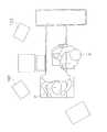
本実施形態に係るパーソナルコンピュータ1は、図1に示すように、ディスプレイ(表示装置)2、位置・角度検出装置29、斜視内視鏡ユニット32、測位用トランスミッタ(磁場発生装置)34とともに手術支援システム100を構成する(なお、内視鏡は、斜視型でなくてもよい。)。
パーソナルコンピュータ1は、本実施形態の手術支援方法をコンピュータに実行させる手術支援プログラムを読み込んで手術支援装置として機能する。なお、パーソナルコンピュータ1の構成については、後段にて詳述する。A personal computer (surgery support device) according to an embodiment of the present invention will be described below with reference to FIGS.
In the present embodiment, a surgical simulation and surgical navigation when performing an operation for lumbar spinal canal stenosis by inserting an endoscope and a surgical tool for cutting into the retractor (retractor) are performed. Will be described below.
As shown in FIG. 1, the
The
ディスプレイ(表示装置)2は、後段にて詳述する手術中のナビゲーションや術前シミュレーションを行う3次元画像を表示するとともに、手術ナビゲーションや術前シミュレーションの設定画面等を表示する。
なお、手術中のナビゲーションを表示する表示装置としては、手術中の術者に分かり易くナビゲーション画面を表示する必要があるため、パーソナルコンピュータ1のディスプレイ2に加えて、図1の手術支援システム100に含まれる大型の液晶ディスプレイ102も併用される。
位置・角度検出装置29は、パーソナルコンピュータ1、測位用トランスミッタ34等に接続されており、斜視内視鏡ユニット32や術具33等に取り付けられた3次元センサである位置角度センサ35a〜36b(図1参照)における検知結果に基づいて、実際の手術中の斜視内視鏡ユニット32や術具33の位置や姿勢を検出する。The display (display device) 2 displays a three-dimensional image for performing navigation during surgery and preoperative simulation, which will be described in detail later, and displays a setting screen for surgical navigation and preoperative simulation.
As a display device for displaying navigation during surgery, it is necessary to display a navigation screen that is easy to understand for the surgeon during surgery. Therefore, in addition to the
The position /
術具33は、手術中に使用される器具であって、例えば、図3(a)に示す電気メスや、図3(b)に示す超音波メス、あるいは図3(c)に示す鉗子等が含まれる。また、術具33には、その根元付近に2本の位置角度センサ35a,35bが設けられている。これにより、実際の手術中における術具33の位置・姿勢等を、位置角度センサ35a,35bによって検出することができる。
斜視内視鏡(内視鏡)32は、手術が行われる部分に近い体表部から、後述する筒状のレトラクタ(例えば、チューブレトラクタ)31内に沿って挿入され、手術部位の映像を取得する。また、斜視内視鏡ユニット32にも、2本の位置角度センサ36a,36bが取り付けられている。
測位用トランスミッタ(磁場発生装置)34は、患者が横になる手術台の近傍に配置され、磁場を発生させる。これにより、斜視内視鏡ユニット32や術具33に取り付けられる位置角度センサ35a〜36bにおいて測位用トランスミッタ34で発生した磁場を検出することで、斜視内視鏡ユニット32や術具33の位置や姿勢を検出することができる。The
A perspective endoscope (endoscope) 32 is inserted along a cylindrical retractor (for example, a tube retractor) 31, which will be described later, from a body surface portion close to a portion where surgery is performed, and displays an image of the surgical site. get. Also, two
The positioning transmitter (magnetic field generator) 34 is disposed in the vicinity of the operating table on which the patient lies, and generates a magnetic field. As a result, the
(パーソナルコンピュータ1)
パーソナルコンピュータ1は、図2に示すように、ディスプレイ(表示部)2と、各種入力部(キーボード3、マウス4、およびタブレット5(図4参照))と、を備えている。
ディスプレイ2は、X線CT画像等の複数の断層画像から形成される骨や臓器(図2の例では、内視鏡画像を表示)等の3次元画像を表示するとともに、切削シミュレーションの結果や手術ナビゲーションの内容を表示する。
また、パーソナルコンピュータ1は、図4に示すように、内部に、断層画像情報取得部6等の制御ブロックを形成する。
断層画像情報取得部6には、ボクセル情報抽出部7を介して、断層画像情報部8が接続されている。つまり、断層画像情報部8では、CTあるいはMRI、PET等の断層画像を撮影する機器から断層画像情報が供給され、この断層画像情報がボクセル情報抽出部7によってボクセル情報として抽出される。(Personal computer 1)
As shown in FIG. 2, the
The
Further, as shown in FIG. 4, the
A tomographic
メモリ9は、パーソナルコンピュータ1内に設けられており、ボクセル情報格納部10、ボクセルラベル格納部11、および色情報格納部12、内視鏡パラメータ格納部22、術具パラメータ格納部24を有している。また、メモリ9には、ボリュームレンダリング演算部(表示制御部)13が接続されている。
ボクセル情報格納部10は、ボクセル情報抽出部7から断層画像情報取得部6を介して受信したボクセル情報を格納している。
ボクセルラベル格納部11は、第1ボクセルラベル格納部、第2ボクセルラベル格納部、第3ボクセルラベル格納部を有している。これらの第1〜第3ボクセルラベル格納部は、後述する予め設定されたCT値の範囲、つまり表示対象となる臓器にそれぞれ対応して設けられている。例えば、第1ボクセルラベル格納部は、肝臓を表示するCT値の範囲に対応しており、第2ボクセルラベル格納部は、血管を表示するCT値の範囲に対応しており、第3ボクセルラベル格納部は、骨を表示するCT値の範囲に対応している。The
The voxel
The voxel
色情報格納部12は、内部に複数の格納部を有している。各格納部は、予め設定されたCT値の範囲、つまり表示対象となる骨、血管、神経、臓器等にそれぞれ対応して設けられている。例えば、肝臓を表示するCT値の範囲に対応する格納部、血管を表示するCT値の範囲に対応する格納部、骨を表示するCT値の範囲に対応する格納部等が挙げられる。このとき、各格納部には、表示対象となる骨、血管、神経、臓器ごとにそれぞれ異なる色情報が設定されている。例えば、骨に対応するCT値の範囲には白色の色情報、血管に対応するCT値の範囲には赤色の色情報がそれぞれ格納されている。
なお、表示対象となる骨や血管、神経、臓器ごとに設定されるCT値とは、人体におけるX線吸収の程度を数値化したものであり、水を0とする相対値(単位:HU)として表される。例えば、骨が表示されるCT値の範囲は500〜1000HU、血液が表示されるCT値の範囲は30〜50HU、肝臓が表示されるCT値の範囲は60〜70HU、腎臓が表示されるCT値の範囲は30〜40HUである。The color
The CT value set for each bone, blood vessel, nerve, and organ to be displayed is a numerical value of the degree of X-ray absorption in the human body, and is a relative value with water as 0 (unit: HU). Represented as: For example, the CT value range in which bone is displayed is 500 to 1000 HU, the CT value range in which blood is displayed is 30 to 50 HU, the CT value range in which the liver is displayed is 60 to 70 HU, and the CT is in which the kidney is displayed. The range of values is 30-40 HU.
内視鏡パラメータ格納部22は、図5に示すように、第1内視鏡パラメータ格納部22a、第2内視鏡パラメータ格納部22b、第3内視鏡パラメータ格納部22cを有している。第1〜第3内視鏡パラメータ格納部22a〜22cには、例えば、内視鏡の斜視角、視野角、位置、姿勢、内視鏡のカメラヘッド回転角度等の情報がそれぞれ格納されている。また、内視鏡パラメータ格納部22は、図4に示すように、内視鏡パラメータ設定部23と接続されている。
内視鏡パラメータ設定部23は、キーボード3やマウス4を介して内視鏡パラメータの設定を行い、内視鏡パラメータ格納部22へ送る。
術具パラメータ格納部24は、図6に示すように、第1術具パラメータ格納部24a、第2術具パラメータ格納部24b、第3術具パラメータ格納部24cを有している。第1〜第3術具パラメータ格納部24a〜24cには、例えば、術具を切削用のドリルとすると、ドリルの長さ、先端形状、位置、姿勢等の情報がそれぞれ格納されている。あるいは。術具を筒状のレトラクタ31とすると、筒状のレトラクタ31の筒形、筒長さ、位置、姿勢等の情報がそれぞれ格納されている。また、術具パラメータ格納部24は、図4に示すように、術具パラメータ設定部25と接続されている。As shown in FIG. 5, the endoscope
The endoscope
As shown in FIG. 6, the surgical instrument
術具パラメータ設定部25は、キーボード3やマウス4を介してレトラクタ31やドリル等の術具パラメータの設定を行い、術具パラメータ格納部24へ送る。
内視鏡/術具位置・姿勢取得部26は、バス16を介して、内視鏡や術具の位置や角度を検出する位置・角度検出装置29における検出結果を受信して、ボリュームレンダリング演算部13、レジストレーション演算部27へ送る。
ボリュームレンダリング演算部13は、ボクセル情報格納部10に格納されているボクセル情報と、ボクセルラベル格納部11に格納されているボクセルラベルと、色情報格納部12に格納されている色情報と、に基づいて、視線に対してほぼ垂直で、かつZ方向の間隔が一定の複数枚のスライス情報を取得する。そして、ボリュームレンダリング演算部13は、その演算結果を3次元画像としてディスプレイ2に表示させる。The surgical instrument
The endoscope / surgical instrument position /
The volume rendering operation unit 13 includes: voxel information stored in the voxel
また、ボリュームレンダリング演算部13は、内視鏡パラメータ格納部22に格納されている内視鏡情報と、術具パラメータ格納部24に格納されている術具情報と、内視鏡/術具位置・姿勢取得部26における検出結果と、に基づいて、実際の内視鏡や術具の動きを3次元画像に組み合わせたリアルタイム表示を行う。
さらに、ボリュームレンダリング演算部13は、上記内視鏡情報および術具情報に基づいて、内視鏡によって得られる画像情報に対してレトラクタ31によって視野が制限される画像情報を反映させたマスキング状態で、ディスプレイ2に仮想内視鏡画像を表示させる。具体的には、ボリュームレンダリング演算部13は、内視鏡パラメータ格納部22に格納された内視鏡に関する情報(斜視角、視野角、位置等)と、術具パラメータ格納部24に格納された術具に関する情報(径、長さ等)とに基づいて、内視鏡によって取得される内視鏡画像表示エリア(第1表示エリア)A1(図13等参照)と表示制限エリア(第2表示エリア)A2(図13等参照)とを設定する。The volume rendering operation unit 13 also includes endoscope information stored in the endoscope
Further, the volume rendering calculation unit 13 is in a masking state in which the image information whose field of view is limited by the
ここで、内視鏡画像表示エリアA1とは、実際の内視鏡手術中において、または術前の内視鏡手術シミュレーションにおいて、内視鏡によって取得される画像情報を基にボリュームレンダリング演算部13によって生成された仮想的な画像をディスプレイ2等のモニタ画面上に表示する表示エリアである。表示制限エリアA2とは、筒状のレトラクタ31等の術具の内壁部分等によって、内視鏡によって取得される画像情報を基にボリュームレンダリング演算部13によって生成された仮想的な画像の表示が制限される表示エリアであって、実際の内視鏡手術中においては術具の内壁によって見えなくなっている領域であり、術前の内視鏡手術シミュレーションにおいてはマスキングされて表示される領域を意味している(図13等参照)。なお、表示制限エリアA2は、マスキング以外にも、例えば、半透明な状態で表示してもよい。この場合には、術具の内壁に相当する部分の透過率を変更可能とすることで、術具の内壁で見えなくなっていた内視鏡画像表示エリアA1に表示されている画像に連続する部分の画像を表示制限エリアA2においても確認することができる。 Here, the endoscope image display area A1 refers to the volume rendering calculation unit 13 based on image information acquired by the endoscope during an actual endoscopic surgery or in a preoperative endoscopic surgery simulation. This is a display area for displaying a virtual image generated by the above on a monitor screen such as the
ボクセルラベル設定部(表示制御部)18は、ボクセルラベル格納部11およびバス16と接続されている。
バス16には、上述したボリュームレンダリング演算部13およびボクセルラベル設定部18に加えて、メモリ9内の色情報格納部12等、ウィンドウ座標取得部20、内視鏡/術具位置・姿勢取得部26が接続されており、キーボード3、マウス4、タブレット5、位置・角度検出装置29、内視鏡映像取得部30等から入力された内容に基づいて、ディスプレイ2に3次元画像等を表示する。
ウィンドウ座標取得部20には、色情報設定部21とレジストレーション演算部27とが接続されている。
色情報設定部21は、メモリ9内の色情報格納部12に接続されている。The voxel label setting unit (display control unit) 18 is connected to the voxel
In addition to the volume rendering calculation unit 13 and the voxel
A color
The color
内視鏡/術具位置・姿勢取得部26は、上述したように、斜視内視鏡ユニット32や術具33に取り付けられる3次元センサである位置角度センサ35a〜36bにおいて測位用トランスミッタ34で発生した磁場を検出することで、斜視内視鏡ユニット32や術具33の位置や姿勢に関する情報を取得する。
なお、斜視内視鏡ユニット32の3次元における位置や姿勢を検出するための位置角度センサ36a,36bは、斜視内視鏡ユニット32の把持部における操作の邪魔にならない位置に設けられている。また、術具33の3次元における位置や姿勢を検出するための位置角度センサ35a,35bは、術具33の把持部における操作の邪魔にならない位置に設けられている。
レジストレーション演算部27は、ボリュームレンダリング演算部13において生成される3次元画像と、実際の手術中の患者の基準位置、内視鏡ユニット32および術具33の3次元位置および回転角度を一致させるための演算を行う。As described above, the endoscope / surgical instrument position /
Note that the
The
変換行列保持部28は、レジストレーション演算部27およびボリュームレンダリング演算部13と接続されており、レジストレーション処理(座標変換処理)を実施する際に使用される変換行列を複数保持している。
位置・角度検出装置29は、上述したように、パーソナルコンピュータ1、測位用トランスミッタ34、および斜視内視鏡ユニット32に接続されており、斜視内視鏡ユニット32や術具33等に取り付けられた位置角度センサ35a〜36bにおける検知結果に基づいて、実際の手術中の斜視内視鏡ユニット32や術具33の位置や姿勢を検出する。
内視鏡映像取得部30は、斜視内視鏡ユニット32において取得された映像を取得する。内視鏡映像取得部30において取得された内視鏡の映像は、バス16を介して、ディスプレイ2,102に表示される。The transformation
As described above, the position /
The endoscopic
レトラクタ31は、本実施形態では、上述したように、斜視内視鏡ユニット32やドリル等の術具33が内部に挿入される部材であって、筒状の術具や筒状の開創器も含まれる。実際の手術において、手術部位の近傍の体表面から患者の体内へ挿入されて固定される。
斜視内視鏡(内視鏡)32は、上述した筒状のレトラクタ31の内周面に沿って挿入され、手術部位の映像を取得する。また、斜視内視鏡ユニット32には、手術中にリアルタイムで斜視内視鏡ユニット32の3次元位置や姿勢を検出するために、位置角度センサ36a,36bが取り付けられている。
斜視内視鏡ユニット32に取り付けられた位置角度センサ36a,36bは、斜視内視鏡ユニット32の後端部側における側面に2本設けられている。よって、斜視内視鏡ユニット32の先端位置は、上述した内視鏡パラメータ格納部22に保存された斜視内視鏡ユニット32の長さや形状に基づいて、計算によって算出される。なお、本実施形態では、斜視内視鏡ユニット32に取り付けられる位置角度センサ36a,36bとして、2本の6軸センサを用いている。このため、(x、y、z)、y(ヨー)、p(ピッチ)、r(ロール)の6つのパラメータを、1本の位置角度センサによって測位することができる。なお、斜視内視鏡ユニット32の具体的な構成については、後段にて詳述する。In this embodiment, as described above, the
A perspective endoscope (endoscope) 32 is inserted along the inner peripheral surface of the
Two
術具33は、本実施形態では、手術部位を切削するドリルを用いている。この術具(ドリル)33についても、斜視内視鏡ユニット32と同様に、後端部付近に位置角度センサ35a,35bが取り付けられている。これにより、切削を行う術具(ドリル)33の先端(処置部)の位置についても、術具パラメータ格納部24に保存されたドリルの長さや形状に基づいて算出することができる。
より具体的には、実空間において、実際に手術に使用される術具33の把持部における邪魔にならない位置に位置角度センサ35a,35bが取り付けられていることで、仮想空間において、術具画像33aの先端位置をマルチポイントモデルによってモデリングを行う。
そして、実際の術具33の操作に合わせて、リアルタイムに術具33の位置や姿勢等を検知した結果に基づいて、仮想空間上において、術具33の先端のマルチポイントから手術計画された切削部位までの距離を算出して表示する。In the present embodiment, the
More specifically, in the real space, the
Then, based on the result of detecting the position and posture of the
また、術具33の先端のマルチポイントから手術計画された切削部位までの距離は、接近する方向にサンプリングしていき、マルチポイントが接近する速度、加速度および方向に応じて表示モードを変更する。
これにより、術者は、ナビゲーション用の仮想空間を示す画像を見ながら、切削部位に対する術具先端の位置をより正確に把握することができる。
なお、本実施形態において、術具位置と内視鏡視点位置が近接して使用されることを利用して、術具位置から内視鏡視点位置を、逆に内視鏡位置から術具位置を推定することや、どちらか一方の位置をユーザ操作で決定することで、内視鏡と術具のどちらか一方に位置角度センサを取り付ける構成としてもよい。
また、位置角度センサを用いずに、ユーザ操作で内視鏡位置を決定することで患部を表示し、ユーザ操作によって術具位置を決定して切削シミュレーションを行うことも可能であり、そのシミュレーション画像を術中で参照するような構成としてもよい。Further, the distance from the multipoint at the distal end of the
Thereby, the surgeon can grasp the position of the distal end of the surgical tool with respect to the cutting site more accurately while viewing the image showing the virtual space for navigation.
In the present embodiment, using the fact that the surgical instrument position and the endoscope viewpoint position are used in close proximity, the endoscope viewpoint position is changed from the surgical instrument position to the surgical instrument position. It is good also as a structure which attaches a position angle sensor to either an endoscope or a surgical instrument by estimating one or determining one position by user operation.
Moreover, it is also possible to display a diseased part by determining an endoscope position by a user operation without using a position angle sensor, and to perform a cutting simulation by determining a surgical instrument position by a user operation. It is good also as a structure which refers to during operation.
<手術中の術者と患者との位置関係>
本実施形態では、図7に示すように、腰椎椎間板手術が行われる際に、医師(術者)Dが、うつぶせの患者Pの左側方に立って手術を行う。なお、手術室では、図7に示すように、医師Dが手術前のシミュレーション画像や手術中のナビゲーション画像を確認するための液晶ディスプレイ102が正面左側に配置されている。また、手術室には、実際の手術中の手術部位等を表示するための透視モニタ103が医師Dの正面右側に配置されている。
これにより、医師D等は、手術中のナビゲーション等を実施する際に、実際の手術中の画面とナビゲーション画面とを見比べながら、手術を行うことができる。
ここで、患者Pの手術部位の映像を取得する斜視内視鏡ユニット32は、筒状のレトラクタ31内に挿入されて使用されるが、レトラクタ31内において斜視内視鏡ユニット32が光軸周りに回転すると、実際に表示される画像も回転してしまうおそれがある。<Positional relationship between surgeon and patient during operation>
In the present embodiment, as shown in FIG. 7, when a lumbar disc operation is performed, a doctor (operator) D performs an operation while standing on the left side of a prone patient P. In the operating room, as shown in FIG. 7, a
Thereby, the doctor D or the like can perform the operation while comparing the screen during the actual operation with the navigation screen when performing the navigation or the like during the operation.
Here, the
このため、手術を行う医師Dが正確に内視鏡を操作して手術を実施するために、ディスプレイ2,102に表示される内視鏡画像は、医師Dから見た実際の方向と一致させた状態で表示させる必要がある。
本実施形態のパーソナルコンピュータ1では、斜視内視鏡ユニット32の光軸周りの回転位置を調整するための手術前のシミュレーション、および手術中のナビゲーションを実施する。
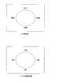
具体的には、図8(a)に示すように、実際の手術中に医師Dから見た方向を、上下左右の順に、正中、外側、頭側、尾側とすると、図8(b)に示すように、斜視内視鏡ユニット32の回転方向(12時、6時、9時、3時)を調整する。これにより、ボリュームレンダリング演算部13によって作成された内視鏡画像と、実際の内視鏡によって取得された画像との向きが、医師Dの位置から見た向きになるように、医師Dが斜視内視鏡ユニット32の回転操作部51(図10(a)参照)を回転させて画像の向きを調整することができる。For this reason, in order for the doctor D performing the operation to operate the endoscope accurately, the endoscopic image displayed on the
In the
Specifically, as shown in FIG. 8 (a), assuming that the directions viewed from the doctor D during the actual operation are the median, outer, cranial, and caudal sides in the order of up, down, left, and right, FIG. 8 (b). As shown, the rotational direction (12 o'clock, 6 o'clock, 9 o'clock, 3 o'clock) of the
なお、本実施形態のように、腰椎椎間板手術を行う際には、図9(a)に示す筒状のレトラクタ31を、図9(b)に示すように、患者Pの体表P1を開創した状態で挿入し骨(椎骨)P2に当てて固定される。
そして、図10(a)に示す斜視内視鏡ユニット32が、図10(b)に示すように、レトラクタ31にセットされることで、斜視内視鏡ユニット32で患者Pの手術部位の映像を取得しながら手術を行うことができる。
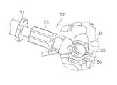
斜視内視鏡ユニット32は、図10(a)に示すように、回転操作部51、焦点操作部52、カメラヘッド53、照明ガイドケーブル54、アタッチメント55、固定ノブ55aおよびエンドスコープ56を有している。
回転操作部51は、レトラクタ31の内部に挿入されるエンドスコープ56と接続されており、回転操作されると、レトラクタ31内においてエンドスコープ56を光軸周りに回転させる。これにより、斜視内視鏡ユニット32によって取得される映像の回転方向における位置(向き)の調整を行う。When performing lumbar disc surgery as in this embodiment, the
Then, the
As shown in FIG. 10A, the
The
焦点操作部52は、回転操作されることで、斜視内視鏡ユニット32によって取得される手術部位等の焦点調整を行う。
カメラヘッド53は、エンドスコープ56の先端に装着されたレンズから入射してきた映像を取得する。
照明ガイドケーブル54は、エンドスコープ56の先端から手術部位に対して照射される光を導入する。
アタッチメント55は、上述した回転操作部51や照明ガイドケーブル54等を一体化させるとともに、筒状のレトラクタ31の上端部に装着される。
エンドスコープ56は、筒状のレトラクタ31の内部に挿入された状態で手術部位の映像を取得する。また、エンドスコープ56は、図11に示すように、上面視において、レトラクタ31の内径側における図中左上端部に配置される。これにより、エンドスコープ56によって術具33の操作範囲が狭まってしまう範囲を最小限とすることができる。The
The
The
The
The
<本手術支援方法に関する制御フロー>
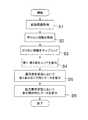
ここで、本実施形態のパーソナルコンピュータ1による手術支援方法の流れを示す制御フローについて、図12を用いて説明すれば以下の通りである。
すなわち、本実施形態では、レトラクタの内部に内視鏡を挿入して行う手術中のシミュレーション画像あるいはナビゲーション画像を表示させる手術支援方法を以下のような手順で実施する。
まず、ステップS1では、患者Pの断層画像情報を取得する。
次に、ステップS2では、断層画像情報のボクセル情報をメモリ9に格納する。
次に、ステップS3では、ボクセル情報に基づいて、ボクセル情報をサンプリングする。<Control flow for this surgery support method>
Here, the control flow showing the flow of the operation support method by the
That is, in the present embodiment, a surgical support method for displaying a simulation image or navigation image during surgery performed by inserting an endoscope into the retractor is performed in the following procedure.
First, in step S1, tomographic image information of the patient P is acquired.
Next, in step S2, the voxel information of the tomographic image information is stored in the
Next, in step S3, the voxel information is sampled based on the voxel information.
次に、ステップS4では、ディスプレイ2および液晶ディスプレイ102に、ボリュームレンダリング演算部13により、斜視内視鏡ユニット32によって取得される映像に対応する画像を表示する内視鏡画像表示エリアA1およびレトラクタ31の内壁によって遮られる視野範囲に対応する表示制限エリアA2を表示させる。
次に、ステップS5では、通常表示状態において、内視鏡画像表示エリアA1(または表示制限エリアA2)に斜視内視鏡ユニット32の光軸周りの回転の基準位置を示すマーカ(第1回転位置表示)40を表示させる。
次に、ステップS6では、内視鏡画像表示エリアA1の画像(または内視鏡画像表示エリアA1および表示制限エリアA2)を拡大表示した拡大表示状態において、マーカ40が液晶ディスプレイ102等の表示範囲外へ移動しないように、表示範囲内(内視鏡画像表示エリアA1または表示制限エリアA2)に表示させる。Next, in step S4, the endoscope image display area A1 and the
Next, in step S5, in the normal display state, a marker (first rotation position) indicating a reference position for rotation around the optical axis of the
Next, in step S6, in the enlarged display state in which the image of the endoscope image display area A1 (or the endoscope image display area A1 and the display restriction area A2) is enlarged, the
なお、通常表示状態および拡大表示状態において表示されるマーカ40等の表示については、後段にて詳述する。
<ディスプレイ2、液晶ディスプレイ102の表示画面>
本実施形態では、上述した手術支援方法を実施する際に、パーソナルコンピュータ1のディスプレイ2や液晶ディスプレイ102のモニタ画面M上に、図13〜図18に示す画像が表示されるように表示制御される。
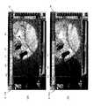
(通常表示状態)
ディスプレイ2,102のモニタ画面Mには、図13に示すように、内視鏡画像を含む内視鏡画像表示エリアA1および表示制限エリアA2のほぼ全体を表示する通常表示状態を示す画面が表示される。また、モニタ画面Mの上部には、表示制御の各種設定を行う設定エリアA3が表示されている。The display of the
<Display screen of
In the present embodiment, when performing the above-described surgery support method, display control is performed so that the images shown in FIGS. 13 to 18 are displayed on the monitor screen M of the
(Normal display state)
On the monitor screen M of the
図13に示す通常表示状態では、内視鏡画像表示エリアA1と、内視鏡画像表示エリアA1の外側に表示制限エリアA2とが表示されるとともに、内視鏡画像表示エリアA1内、または内視鏡画像表示エリアA1と表示制限エリアA2内に、マーカ(第1回転位置表示)40と、中抜き十字(視点表示)41とが表示されている。マーカ(第1回転位置表示)40について言えば、内視鏡画像表示エリアA1、または表示制限エリアA2内、または内視鏡画像表示エリアA1と表示制限エリアA2に亘って、表示されている。なお、レトラクタ31と斜視内視鏡ユニット32との挿入方向の位置関係によって、内視鏡画像表示エリアA1と表示制限エリアA2の表示面積比が変わってくる。このため、マーカ(第1回転位置表示)40と中抜き十字(視点表示)41とは、内視鏡画像表示エリアA1に表示されることもあれば、内視鏡画像表示エリアA1と表示制限エリアA2に亘って表示されることもある。 In the normal display state shown in FIG. 13, the endoscope image display area A1 and the display restriction area A2 are displayed outside the endoscope image display area A1, and the endoscope image display area A1 or the inside is displayed. A marker (first rotation position display) 40 and a hollow cross (viewpoint display) 41 are displayed in the endoscope image display area A1 and the display restriction area A2. Speaking of the marker (first rotation position display) 40, it is displayed over the endoscope image display area A1, the display restriction area A2, or the endoscope image display area A1 and the display restriction area A2. The display area ratio between the endoscope image display area A1 and the display restriction area A2 varies depending on the positional relationship between the
マーカ40は、レトラクタ31内に挿入された斜視内視鏡ユニット32のエンドスコープ56の回転方向における向きの基準となる指標として表示されている。より詳細には、マーカ40は、エンドスコープ56の先端から照射される光の光軸周りにおける回転の基準位置を示す指標として表示されている。よって、実際の斜視内視鏡ユニット32のエンドスコープ56がレトラクタ31内において回転すると、手術前のシミュレーションあるいは手術中のナビゲーション画面においても、マーカ40が連動して回転移動するように表示制御される。
本実施形態では、マーカ40は、中抜き十字41と一体化した状態で、内視鏡画像表示エリアA1内に表示されている。
なお、マーカ40は、中抜き十字41等の視点表示と一体として表示されている形態に限らず、単独で表示されていてもよい。The
In the present embodiment, the
The
中抜き十字41は、例えば、斜視内視鏡ユニット32を操作中にレトラクタ31内においてエンドスコープ56が回転した場合に同期して回転表示されるとともに、エンドスコープ56の回転中心およびエンドスコープ56の視点中心を示す指標であって、内視鏡画像表示エリアA1および表示制限エリアA2内に表示されている。
また、表示制限エリアA2の外縁部分には、図13に示すように、上述したマーカ40と同様に、レトラクタ31内に挿入された斜視内視鏡ユニット32のエンドスコープ56の回転方向における向きの基準となる指標として機能するインジケータ(第2回転位置表示)42が表示されている。
インジケータ42は、マーカ40と同様に、レトラクタ31内に挿入された斜視内視鏡ユニット32のエンドスコープ56の回転方向における向きの基準となる指標として表示されている。より詳細には、インジケータ42は、エンドスコープ56の先端から照射される光の光軸周りにおける回転の基準位置を示す指標として表示されている。よって、実際の斜視内視鏡ユニット32のエンドスコープ56がレトラクタ31内において回転すると、手術前のシミュレーションあるいは手術中のナビゲーション画面においても、マーカ40とともにインジケータ42も連動して回転移動するように表示制御される。For example, the
Further, as shown in FIG. 13, the outer edge portion of the display restriction area A2 is oriented in the rotational direction of the
Similar to the
また、マーカ40およびインジケータ42は、中抜き十字41によって認識されるエンドスコープ56の視点中心となる位置を中心として回転するように表示制御される。
なお、本実施形態では、マーカ40およびインジケータ42が、モニタ画面Mにおける図中右上の位置に揃って表示されている例を挙げて説明したが、これに限定されるものではない。例えば、マーカ40とインジケータ42とが、それぞれ異なる位置に設けられていてもよい。
(拡大表示状態)
本実施形態のパーソナルコンピュータ1では、手術前のシミュレーション等を実施する際に、図13に示す通常表示状態から、仮想的な内視鏡画像表示エリアA1の手術部位周辺等を拡大表示したい場合には、ディスプレイ2,102に、図14に示す拡大表示状態を示す画面を表示させる。In addition, the
In the present embodiment, the
(Enlarged display state)
In the
図14に示す拡大表示状態では、内視鏡画像表示エリアA1の一部と、内視鏡画像表示エリアA1の外側に表示制限エリアA2の一部とが表示され、この表示範囲内(内視鏡画像表示エリアA1内、または内視鏡画像表示エリアA1と表示制限エリアA2内)に、マーカ(第1回転位置表示)40と、中抜き十字(視点表示)41とが引き続き表示されるように制御される。マーカ(第1回転位置表示)40について言えば、内視鏡画像表示エリアA1、または表示制限エリアA2内、または内視鏡画像表示エリアA1と表示制限エリアA2に亘って、表示されている。
一方、図13に示す通常表示状態において表示制限エリアA2の外縁部分に表示されていたインジケータ42は、図14に示す拡大表示状態においては、モニタ画面Mの表示範囲外となっている。In the enlarged display state shown in FIG. 14, a part of the endoscope image display area A1 and a part of the display restriction area A2 are displayed outside the endoscope image display area A1. The marker (first rotation position display) 40 and the hollow cross (viewpoint display) 41 are continuously displayed in the mirror image display area A1 or in the endoscope image display area A1 and the display restriction area A2. To be controlled. Speaking of the marker (first rotation position display) 40, it is displayed over the endoscope image display area A1, the display restriction area A2, or the endoscope image display area A1 and the display restriction area A2.
On the other hand, the
すなわち、手術部位周辺等を拡大表示した際に、図13に示すマーカ40、中抜き十字41等がそのままの位置に表示された場合には、拡大場所によっては、インジケータ42のように、マーカ40が表示範囲外となってしまうおそれがある。この場合には、ディスプレイ2,102を見ながら手術前のシミュレーションや手術中のナビゲーション等を実施している医師等は、斜視内視鏡ユニット32のエンドスコープ56の向きが変わって表示される画像の向きが変化した場合でも、回転位置の指標となるものが表示されなくなっているため、回転位置を適切に調整することが困難である。
そこで、本実施形態のパーソナルコンピュータ1では、図14に示す拡大表示状態においても内視鏡画像の向きを適切に調整可能とするために、拡大表示状態におけるモニタ画面Mの表示範囲内に、マーカ40等の表示がそのまま残されるように表示制御を行う。That is, if the
Therefore, in the
これにより、通常表示状態(図13)および拡大表示状態(図14)の両方の表示状態において、マーカ40や中抜き十字41等がモニタ画面Mの表示範囲内に表示されているため、マーカ40によって示される回転の基準位置を確認しながら、実際のエンドスコープ(内視鏡)56の向きと内視鏡画像の向きとが一致するように調整することができる。
また、本実施形態では、通常表示状態(図13)および拡大表示状態(図14)において、表示制限エリアA2の透過率を調整することができる。これにより、レトラクタ31の内壁等によって制限される範囲の表示を、半透明としたり黒く表示したり、医師D等の要望に応じて切り替えることができる。
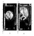
(マーカ40および中抜き十字41の表示のON/OFF制御)
本実施形態のパーソナルコンピュータ1では、図14に示す拡大表示状態において、マーカ40や中抜き十字41が手術部位等を確認する際の邪魔にならないようにするために、設定エリアA3が操作されて、表示のON/OFF制御が実施される。As a result, the
In the present embodiment, the transmittance of the display restriction area A2 can be adjusted in the normal display state (FIG. 13) and the enlarged display state (FIG. 14). Thereby, the display of the range restricted by the inner wall or the like of the
(ON / OFF control of display of
In the
設定エリアA3は、図13および図14に示すように、ディスプレイ2,102のモニタ画面Mの上部に配置されており、表示に関する各種設定が行われる。
ここで、設定エリアA3において設定可能な表示制御内容としては、図15に示すように、シミュレーション画像やナビゲーション画像として表示されるエンドスコープ56の視野角、斜視角、アタッチメント55の回転角、カメラヘッド53の回転角等がある。また、設定エリアA3では、シミュレーション等の画像として表示される画像として、通常レンズに対応するレンズ歪のない画像と、魚眼レンズに対応する魚眼レンズ歪を表現した画像を切り替えることができる。さらに、設定エリアA3では、シミュレーション等の画像として表示される画像中に、レトラクタによる影響を受けたレトラクタ部分に対応する表示エリア制限を設けた画像と、レトラクタによる影響を受けていないレトラクタ部分に対応する表示エリア制限のない画像の切り替えや、マーカ40や中抜き十字41等の表示の有無の切り替えを行うことも可能である。As shown in FIGS. 13 and 14, the setting area A3 is arranged at the upper part of the monitor screen M of the
Here, display control contents that can be set in the setting area A3 include, as shown in FIG. 15, the viewing angle, the perspective angle, the rotation angle of the
具体的には、レトラクタによる影響を受けた画像と影響を受けていない画像との切り替えや、マーカ40や中抜き十字41等の表示の有無の切り替えは、図15に示すように、チェックボックスA4のチェックを入れるか否かで表示設定を切り替えることができる。
例えば、通常表示状態において、マーカ40および中抜き十字41の表示を切り替える場合には、図16(a)に示す表示状態から、設定エリアA3のチェックボックスA4(図15参照)の視点表示のチェックを外すことで、図16(b)に示す未表示状態に切り替えることができる。
同様に、例えば、拡大表示状態において、マーカ40および中抜き十字41の表示を切り替える場合には、図17(a)に示す表示状態から、設定エリアA3のチェックボックスA4(図15参照)の視点表示のチェックを外すことで、図17(b)に示す未表示状態に切り替えることができる。Specifically, as shown in FIG. 15, a check box A4 is used to switch between an image affected by a retractor and an image not affected, or whether to display a
For example, when the display of the
Similarly, for example, when the display of the
これにより、エンドスコープ(内視鏡)56の回転の基準位置となるマーカ40と、回転中心となる中抜き十字41とを必要な状態でのみ表示しつつ、手術部位等をじっくり観察する場合等においては表示無しとする切り替え制御を行うことができる。
[他の実施形態]
以上、本発明の一実施形態について説明したが、本発明は上記実施形態に限定されるものではなく、発明の要旨を逸脱しない範囲で種々の変更が可能である。Thereby, when the
[Other Embodiments]
As mentioned above, although one Embodiment of this invention was described, this invention is not limited to the said embodiment, A various change is possible in the range which does not deviate from the summary of invention.
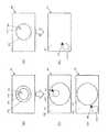
(A)
上記実施形態では、図13に示すように、通常表示状態では、エンドスコープ(内視鏡)56の光軸周りの回転の基準位置となるマーカ40とインジケータ42と組み合わせて表示した例を挙げて説明した。しかし、本発明はこれに限定されるものではない。
例えば、図18(a)に示すように、通常表示状態では、エンドスコープ56の回転の基準位置となる指標としてインジケータ42のみを表示するとともに、図18(b)に示すように、拡大表示状態では、表示範囲外となったインジケータ42の代わりに、新たな回転の基準位置を示すマーカ140を表示してもよい。
このとき、マーカ140は、図18(b)に示すように、手術部位等を確認する際の邪魔にならないように、表示制限エリアA2内に表示することが好ましい。
また、マーカ140は、図18(b)に示すように、円形表示141と組み合わせて表示されていることがより好ましい。これにより、マーカ140の回転中心となる位置も確認しながら、内視鏡画像の向きを調整することができる。(A)
In the above embodiment, as shown in FIG. 13, in the normal display state, an example in which the
For example, as shown in FIG. 18A, in the normal display state, only the
At this time, as shown in FIG. 18B, the
Further, the
(B)
上記実施形態では、図14に示すように、拡大表示状態においても、内視鏡画像表示エリアA1の外周に表示制限エリアA2が表示された例を挙げて説明した。しかし、本発明はこれに限定されるものではない。
例えば、図19(a)に示す通常表示状態から、拡大表示状態とする際に拡大倍率をさらに大きくした場合には、図19(b)に示すように、モニタ画面Mの表示範囲が内視鏡画像表示エリアA1のみとなるように拡大表示することもできる。
この場合には、内視鏡画像表示エリアA1内に、マーカ(第1回転位置表示)40と十字(視点表示)241とを組み合わせて表示すればよい。(B)
In the above embodiment, as shown in FIG. 14, an example in which the display restriction area A2 is displayed on the outer periphery of the endoscope image display area A1 has been described even in the enlarged display state. However, the present invention is not limited to this.
For example, when the enlargement magnification is further increased when changing from the normal display state shown in FIG. 19A to the enlarged display state, the display range of the monitor screen M is internally viewed as shown in FIG. It is also possible to enlarge the display so that only the mirror image display area A1 exists.
In this case, the marker (first rotation position display) 40 and the cross (viewpoint display) 241 may be combined and displayed in the endoscope image display area A1.
(C)
上記実施形態では、図13に示すように、通常表示状態では、エンドスコープ(内視鏡)56の光軸周りの回転の基準位置となるマーカ40とインジケータ42と組み合わせて表示した例を挙げて説明した。しかし、本発明はこれに限定されるものではない。
例えば、図20(a)に示すように、通常表示状態では、エンドスコープ56の回転の基準位置となる指標としてインジケータ42のみを表示するとともに、図20(b)に示すように、拡大表示状態では、表示範囲外となったインジケータ42の代わりに、回転中心位置を示す十字241と組み合わせたマーカ40を、内視鏡画像表示エリアA1内、または内視鏡画像表示エリアA1と表示制限エリアA2内に表示してもよい。マーカ(第1回転位置表示)40については、内視鏡画像表示エリアA1、または表示制限エリアA2内、または内視鏡画像表示エリアA1と表示制限エリアA2に亘って、表示してもよい。
あるいは、図20(c)に示すように、表示範囲外となったインジケータ42の代わりに、円形表示141と組み合わせたマーカ40を、表示制限エリアA2内に表示してもよい。
さらに、通常表示状態において、図20(d)に示すように、表示制限エリアA2が表示されていない状態で拡大表示する場合には、図20(e)に示すように、表示範囲外となったインジケータ42の代わりに、回転中心位置を示す十字241と組み合わせたマーカ40を、内視鏡画像表示エリアA1に表示してもよい。(C)
In the above embodiment, as shown in FIG. 13, in the normal display state, an example in which the
For example, as shown in FIG. 20A, in the normal display state, only the
Or as shown in FIG.20 (c), instead of the
Furthermore, in the normal display state, as shown in FIG. 20D, when the enlarged display is performed in a state where the display restriction area A2 is not displayed, as shown in FIG. 20E, it is out of the display range. Instead of the
(D)
上記実施形態では、図13に示すように、通常表示状態では、エンドスコープ(内視鏡)56の光軸周りの回転の基準位置となるマーカ40とインジケータ42と組み合わせて表示した例を挙げて説明した。しかし、本発明はこれに限定されるものではない。
例えば、図21(a)に示すように、通常表示状態では、エンドスコープ56の回転の基準位置となる指標としてインジケータ42のみを表示するとともに、図21(b)に示すように、拡大表示状態では、表示範囲外となったインジケータ42の代わりに、回転中心位置を示す円形表示141と組み合わせたマーカ40を、内視鏡画像表示エリアA1内、または内視鏡画像表示エリアA1と表示制限エリアA2内に表示してもよい。マーカ(第1回転位置表示)40については、内視鏡画像表示エリアA1、または表示制限エリアA2内、または内視鏡画像表示エリアA1と表示制限エリアA2に亘って、表示してもよい。(D)
In the above embodiment, as shown in FIG. 13, in the normal display state, an example in which the
For example, as shown in FIG. 21A, in the normal display state, only the
あるいは、図21(c)に示すように、表示範囲外となったインジケータ42の代わりに、円形表示141と組み合わせたマーカ40を、表示制限エリアA2内に表示してもよい。
さらに、通常表示状態において、図21(d)に示すように、表示制限エリアA2が表示されていない状態で拡大表示する場合には、図21(e)に示すように、表示範囲外となったインジケータ42の代わりに、回転中心位置を示す円形表示141と組み合わせたマーカ40を、内視鏡画像表示エリアA1の端部に表示してもよい。Or as shown in FIG.21 (c), instead of the
Furthermore, in the normal display state, as shown in FIG. 21D, when the enlarged display is performed in a state where the display restriction area A2 is not displayed, the display is outside the display range as shown in FIG. Instead of the
(E)
上記実施形態では、図13に示すように、通常表示状態では、エンドスコープ(内視鏡)56の光軸周りの回転の基準位置となるマーカ40とインジケータ42と組み合わせて表示した例を挙げて説明した。しかし、本発明はこれに限定されるものではない。
例えば、図22(a)に示すように、通常表示状態では、エンドスコープ56の回転の基準位置となる指標としてマーカ40のみを十字241と組み合わせて表示するとともに、図22(b)に示すように、拡大表示状態では、十字241と組み合わせたマーカ40を、そのまま内視鏡画像表示エリアA1内、または内視鏡画像表示エリアA1と表示制限エリアA2内に表示してもよい。マーカ(第1回転位置表示)40については、内視鏡画像表示エリアA1、または表示制限エリアA2内、または内視鏡画像表示エリアA1と表示制限エリアA2に亘って、表示してもよい。
あるいは、図22(c)に示すように、内視鏡画像表示エリアA1に表示されたマーカ40等の代わりに、円形表示141と組み合わせたマーカ40を、表示制限エリアA2内に表示してもよい。
さらに、通常表示状態において、図22(d)に示すように、表示制限エリアA2が表示されていない状態で拡大表示する場合には、図22(e)に示すように、十字241と組み合わせたマーカ40を、内視鏡画像表示エリアA1にそのまま表示してもよい。(E)
In the above embodiment, as shown in FIG. 13, in the normal display state, an example in which the
For example, as shown in FIG. 22A, in the normal display state, only the
Alternatively, as shown in FIG. 22C, the
Furthermore, in the normal display state, as shown in FIG. 22 (d), when the enlarged display is performed in the state where the display restriction area A2 is not displayed, it is combined with the
(F)
上記実施形態では、図13および図14に示すように、エンドスコープ56の光軸周りの回転の基準位置を示す指標として、回転中心を示す中抜き十字41とマーカ40とを組み合わせて表示した例を挙げて説明した。しかし、本発明はこれに限定されるものではない。
例えば、図23(a)に示すように、エンドスコープ56の回転の基準位置となる指標として、円形表示141とマーカ40とを組み合わせて表示してもよい。
この場合には、図23(b)に示すように、拡大表示状態では、円形表示141と組み合わせたマーカ40を、そのまま内視鏡画像表示エリアA1内、または内視鏡画像表示エリアA1と表示制限エリアA2内に表示すればよい。マーカ(第1回転位置表示)40については、内視鏡画像表示エリアA1、または表示制限エリアA2内、または内視鏡画像表示エリアA1と表示制限エリアA2に亘って、表示してもよい。
あるいは、図23(c)に示すように、円形表示141と組み合わせたマーカ40を、表示制限エリアA2内に表示してもよい。
さらに、通常表示状態において、図23(d)に示すように、表示制限エリアA2が表示されていない状態で拡大表示する場合には、図23(e)に示すように、十字241と組み合わせたマーカ40を、内視鏡画像表示エリアA1の端部にそのまま表示してもよい。(F)
In the above embodiment, as shown in FIGS. 13 and 14, an example in which the
For example, as shown in FIG. 23A, a
In this case, as shown in FIG. 23B, in the enlarged display state, the
Alternatively, as shown in FIG. 23C, the
Furthermore, in the normal display state, as shown in FIG. 23 (d), when the enlarged display is performed in the state where the display restriction area A2 is not displayed, the display is combined with the
(G)
上記実施形態では、図13に示すように、通常表示状態では、エンドスコープ(内視鏡)56の光軸周りの回転の基準位置となるマーカ40とインジケータ42と組み合わせて表示した例を挙げて説明した。しかし、本発明はこれに限定されるものではない。
例えば、図24(a)に示すように、通常表示状態では、エンドスコープ56の回転の基準位置となる指標としてインジケータ42と、円形表示141と組み合わせたマーカ40とを表示するとともに、図24(b)に示すように、拡大表示状態では、インジケータ42は表示範囲外となるものの、円形表示141と組み合わせたマーカ40を、内視鏡画像表示エリアA1内、または内視鏡画像表示エリアA1と表示制限エリアA2内にそのまま残すように表示してもよい。マーカ(第1回転位置表示)40については、内視鏡画像表示エリアA1、または表示制限エリアA2内、または内視鏡画像表示エリアA1と表示制限エリアA2に亘って、表示してもよい。(G)
In the above embodiment, as shown in FIG. 13, in the normal display state, an example in which the
For example, as shown in FIG. 24A, in the normal display state, the
あるいは、図24(c)に示すように、円形表示141と組み合わせたマーカ40を、表示制限エリアA2内に表示してもよい。
さらに、通常表示状態において、図24(d)に示すように、表示制限エリアA2が表示されていない状態で拡大表示する場合には、図24(e)に示すように、回転中心位置を示す円形表示141と組み合わせたマーカ40を、内視鏡画像表示エリアA1の端部に表示してもよい。Alternatively, as shown in FIG. 24C, the
Further, in the normal display state, as shown in FIG. 24D, when the enlarged display is performed in a state where the display restriction area A2 is not displayed, the rotation center position is shown as shown in FIG. The
(H)
上記実施形態では、内視鏡の光軸周りの回転の基準位置を示す指標となるマーカ(第1回転位置表示)40として、回転中心方向を指す三角形の図形を用いた例を挙げて説明した。しかし、本発明はこれに限定されるものではない。
例えば、図25(a)に示すように、回転中心とは逆方向を指すように配置された三角形の図形からなるマーカ140を用いてもよい。あるいは、三角形以外の、他の多角形の図形を用いてもよい。(H)
In the embodiment described above, an example in which a triangular figure indicating the rotation center direction is used as the marker (first rotation position display) 40 serving as an index indicating the reference position of rotation around the optical axis of the endoscope has been described. . However, the present invention is not limited to this.
For example, as shown in FIG. 25A, a
(I)
上記実施形態では、内視鏡の回転中心および内視鏡のレンズ中央に対応する視点表示として、十字形状の中央部が切り欠かれた中抜き十字41を用いた例を挙げて説明した。しかし、本発明はこれに限定されるものではない。
例えば、図25(b)に示すように、視点表示として、十字241を用いてもよい。あるいは、図25(c)に示すように、破円341を用いてもよい。
この場合には、例えば、図25(d)および図25(e)に示すように、図25(b)に示す十字241と、マーカ40,140とを組み合わせて表示してもよい。
また、図26(a)および図26(b)に示すように、円形表示141とマーカ40,140とを組み合わせて表示してもよい。
さらに、図26(c)および図26(d)に示すように、破円341とマーカ40,140とを組み合わせて表示してもよい。(I)
In the above-described embodiment, an example in which the
For example, as shown in FIG. 25B, a
In this case, for example, as shown in FIGS. 25D and 25E, the
In addition, as shown in FIGS. 26A and 26B, the
Furthermore, as shown in FIGS. 26C and 26D, the
(J)
上記実施形態では、手術支援装置として本発明を実現した例を挙げて説明した。しかし、本発明はこれに限定されるものではない。
例えば、図12に示す制御方法をコンピュータに実行させる手術支援プログラムとして、本発明を実現してもよい。
(K)
上記実施形態では、本発明の手術支援装置を用いて実施される手術として、腰椎椎間板の内視鏡手術を例として挙げて説明した。しかし、本発明はこれに限定されるものではない。
例えば、内視鏡を用いて実施される手術であれば、他の手術に対して本発明の手術支援装置を用いてもよい。(J)
In the embodiment described above, an example in which the present invention is realized as a surgery support apparatus has been described. However, the present invention is not limited to this.
For example, the present invention may be realized as a surgery support program that causes a computer to execute the control method shown in FIG.
(K)
In the above embodiment, the endoscopic operation of the lumbar disc has been described as an example of the operation performed using the operation support apparatus of the present invention. However, the present invention is not limited to this.
For example, if the operation is performed using an endoscope, the operation support device of the present invention may be used for other operations.
本発明の手術支援装置は、簡素な構成により、内視鏡によって取得される映像に対応して表示装置に表示される断層画像情報のボリュームレンダリングによる画像を拡大・縮小した場合でも、画像の回転の基準位置を容易に認識して画像の向きを調整することができるという効果を奏することから、各種手術を実施する際の手術支援装置に対して広く適用可能である。 The surgical operation support device of the present invention has a simple configuration and can rotate an image even when an image is enlarged or reduced by volume rendering of tomographic image information displayed on a display device corresponding to an image acquired by an endoscope. Therefore, it is possible to easily recognize the reference position and adjust the orientation of the image. Therefore, the present invention can be widely applied to surgical operation support devices when performing various types of surgery.
1 パーソナルコンピュータ(手術支援装置)
2 ディスプレイ(表示装置)
3 キーボード
4 マウス
5 タブレット
6 断層画像情報取得部
7 ボクセル情報抽出部
8 断層画像情報部
9 メモリ
10 ボクセル情報格納部
11 ボクセルラベル格納部
12 色情報格納部
13 ボリュームレンダリング演算部(表示制御部)
16 バス
18 ボクセルラベル設定部(表示制御部)
20 ウィンドウ座標取得部
21 色情報設定部
22 内視鏡パラメータ格納部
23 内視鏡パラメータ設定部
24 術具パラメータ格納部
25 術具パラメータ設定部
26 内視鏡/術具位置・姿勢取得部
27 レジストレーション演算部
28 変換行列保持部
29 位置・角度検出装置
30 内視鏡映像取得部
31 レトラクタ
32 斜視内視鏡ユニット
33 術具
34 BOX型トランスミッタ(磁場発生装置)
35a,35b 位置角度センサ
36a,36b 位置角度センサ
40 マーカ(第1回転位置表示)
41 中抜き十字(視点表示)
42 インジケータ(第2回転位置表示)
51 回転操作部
52 焦点操作部
53 カメラヘッド
54 照明ガイドケーブル
55 アタッチメント
55a 固定ノブ
56 エンドスコープ(内視鏡)
100 手術支援システム
102 液晶ディスプレイ(表示装置)
103 透視モニタ
140 マーカ(第1回転位置表示)
141 円形表示(視点表示)
241 十字(視点表示)
341 破円
A1 内視鏡画像表示エリア(第1表示エリア)
A2 表示制限エリア(第2表示エリア)
A3 設定エリア
A4 チェックボックス
D 医師(術者)
M モニタ画面
P 患者
P1 体表
P2 骨(椎骨)1 Personal computer (Surgery support device)
2 Display (display device)
3 keyboard 4
16
20 Window coordinate
35a, 35b
41 hollow cross (viewpoint display)
42 Indicator (second rotation position indication)
51
100
103
141 Circular display (viewpoint display)
241 Cross (viewpoint display)
341 Broken circle A1 Endoscopic image display area (first display area)
A2 Display restriction area (second display area)
A3 Setting area A4 Check box D Doctor (operator)
M Monitor screen P Patient P1 Body surface P2 Bone (vertebra)
Claims (15)
Translated fromJapanese患者の断層画像情報を取得する断層画像情報取得部と、
前記断層画像情報取得部に接続されており、前記断層画像情報のボクセル情報を格納するメモリと、
前記メモリに接続されており、前記ボクセル情報に基づいて、ボクセル情報をサンプリングするボリュームレンダリング演算部と、
前記ボリュームレンダリング演算部によって生成された前記内視鏡によって取得される画像を表示する第1表示エリアを表示装置に表示させ、または、前記ボリュームレンダリング演算部によって生成された前記内視鏡によって取得される画像を表示する第1表示エリアおよびレトラクタの内壁によって遮られる視野範囲に対応する第2表示エリアを表示装置に表示させ、通常表示状態において、前記表示装置の前記第1表示エリア、または前記第2表示エリア、または前記第1表示エリアおよび前記第2表示エリアに前記内視鏡の光軸周りの回転の基準位置を示す第1回転位置表示を表示させるとともに、前記第1表示エリアの画像、または前記第1表示エリアおよび前記第2表示エリアを拡大表示した拡大表示状態において、前記第1回転位置表示が前記第1表示エリアまたは前記第2表示エリア、または前記第1表示エリアおよび前記第2表示エリアに表示されるように、表示制御を行う表示制御部と、
を備えている手術支援装置。A surgery support device for displaying a simulation image or navigation image during surgery performed by inserting an endoscope inside a retractor,
A tomographic image information acquisition unit for acquiring tomographic image information of a patient;
A memory that is connected to the tomographic image information acquisition unit and stores voxel information of the tomographic image information;
A volume rendering operation unit connected to the memory and sampling the voxel information based on the voxel information;
A first display area for displaying an image acquired by the endoscope generated by the volume rendering operation unit is displayed on a display device, or acquired by the endoscope generated by the volume rendering operation unit. A first display area for displaying an image to be displayed and a second display area corresponding to a visual field range obstructed by the inner wall of the retractor. The display device displays the first display area or the first display area in the display device in a normal display state. 2 display area, or the first display area and the second display area to display a first rotation position display indicating a reference position of rotation around the optical axis of the endoscope, and an image of the first display area, Alternatively, in the enlarged display state in which the first display area and the second display area are enlarged, the first time So that the position display is displayed in the first display area and the second display area or said first display area and the second display area, a display control unit for controlling the display,
An operation support apparatus comprising:
患者の断層画像情報を取得する断層画像情報取得部と、
前記断層画像情報取得部に接続されており、前記断層画像情報のボクセル情報を格納するメモリと、
前記メモリに接続されており、前記ボクセル情報に基づいて、ボクセル情報をサンプリングするボリュームレンダリング演算部と、
前記ボリュームレンダリング演算部によって生成された前記内視鏡によって取得される画像を表示する第1表示エリアを表示装置に表示させ、または、前記ボリュームレンダリング演算部によって生成された前記内視鏡によって取得される画像を表示する第1表示エリアおよびレトラクタの内壁によって遮られる視野範囲に対応する第2表示エリアを表示装置に表示させ、通常表示状態において、前記第1表示エリアまたは前記第2表示エリアの外周部に前記内視鏡の光軸周りの回転の基準位置を示す第2回転位置表示を表示させるとともに、前記第1表示エリアの画像、または前記第1表示エリアおよび前記第2表示エリアを拡大表示した拡大表示状態において、前記第2回転位置表示を、前記内視鏡の光軸周りの回転の基準位置を示す第1回転位置表示に切り替えて、前記表示装置の前記第1表示エリアまたは前記第2表示エリア、または前記第1表示エリアおよび前記第2表示エリアに表示されるように表示制御を行う表示制御部と、
を備えている手術支援装置。A surgery support device for displaying a simulation image or navigation image during surgery performed by inserting an endoscope inside a retractor,
A tomographic image information acquisition unit for acquiring tomographic image information of a patient;
A memory that is connected to the tomographic image information acquisition unit and stores voxel information of the tomographic image information;
A volume rendering operation unit connected to the memory and sampling the voxel information based on the voxel information;
A first display area for displaying an image acquired by the endoscope generated by the volume rendering operation unit is displayed on a display device, or acquired by the endoscope generated by the volume rendering operation unit. A first display area for displaying an image to be displayed and a second display area corresponding to a visual field range blocked by the inner wall of the retractor on the display device, and in the normal display state, the outer periphery of the first display area or the second display area And displaying a second rotation position display indicating a reference position of rotation around the optical axis of the endoscope on the part, and displaying an image of the first display area or the first display area and the second display area in an enlarged manner. In the enlarged display state, the second rotation position display is a first rotation position indicating a reference position for rotation around the optical axis of the endoscope. Switch to the rotational position indicator, and the display of the first display area and the second display area or the display control unit that performs display control be displayed on the first display area and the second display area, the device,
An operation support apparatus comprising:
請求項1に記載の手術支援装置。The display control unit performs display control so as to further display a display in which the rotation center of the first rotation position display can be recognized.
The surgery support apparatus according to claim 1.
請求項3に記載の手術支援装置。The display capable of recognizing the rotation center of the first rotation position display is a viewpoint display indicating the viewpoint center of the endoscope.
The surgery support apparatus according to claim 3.
請求項4に記載の手術支援装置。The display control unit performs ON / OFF control for switching presence or absence of the viewpoint display.
The surgery support apparatus according to claim 4.
請求項4または5に記載の手術支援装置。The viewpoint display has one of a cross shape, a cross shape in which a central portion is cut out, and a circular shape,
The surgery support apparatus according to claim 4 or 5.
請求項1,3から6のいずれか1項に記載の手術支援装置。A second rotation position display that is provided separately from the first rotation position display and that indicates a reference position for rotation of the endoscope;
The surgery support apparatus according to any one of claims 1, 3 to 6.
請求項1から7のいずれか1項に記載の手術支援装置。The first rotation position display has the polygonal shape,
The surgery support apparatus according to any one of claims 1 to 7.
請求項4から8のいずれか1項に記載の手術支援装置。The first rotation position display is disposed at an end of the viewpoint display.
The surgery support apparatus according to any one of claims 4 to 8.
請求項1から9のいずれか1項に記載の手術支援装置。The display control unit performs display control by changing the transmittance of the second display area.
The surgery support apparatus according to any one of claims 1 to 9.
請求項1から10のいずれか1項に記載の手術支援装置。The retractor is a retractor that is fixed in a state where the patient's body surface is opened during surgery, and the endoscope and various cutting tools are inserted into a cylindrical interior.
The surgery support apparatus according to any one of claims 1 to 10.
患者の断層画像情報を取得するステップと、
前記断層画像情報のボクセル情報を格納するステップと、
前記ボクセル情報に基づいて、前記ボクセル情報をサンプリングするステップと、
前記内視鏡によって取得される画像を表示する第1表示エリアを表示させ、または、ボリュームレンダリング演算部によって生成された前記内視鏡によって取得される画像を表示する第1表示エリアおよびレトラクタの内壁によって遮られる視野範囲に対応する第2表示エリアを表示装置に表示させ、通常表示状態において、前記表示装置の前記第1表示エリア、または前記第2表示エリア、または前記第1表示エリアおよび前記第2表示エリアに前記内視鏡の光軸周りの回転の基準位置を示す第1回転位置表示を表示させるとともに、前記第1表示エリアの画像、または前記第1表示エリアおよび前記第2表示エリアを拡大表示した拡大表示状態において、前記第1回転位置表示が前記第1表示エリアまたは前記第2表示エリア、または前記第1表示エリアおよび前記第2表示エリアに表示されるように、表示制御を行うステップと、
を備えている手術支援方法をコンピュータに実行させる手術支援プログラム。An operation support program for displaying a simulation image or navigation image during an operation performed by inserting an endoscope inside a retractor,
Acquiring tomographic image information of a patient;
Storing voxel information of the tomographic image information;
Sampling the voxel information based on the voxel information;
A first display area for displaying an image acquired by the endoscope or a first display area for displaying an image acquired by the endoscope generated by a volume rendering calculation unit and an inner wall of the retractor The display device displays a second display area corresponding to the visual field range blocked by the first display area, the second display area, the first display area, and the first display area of the display device in a normal display state. And displaying a first rotation position display indicating a reference position of rotation around the optical axis of the endoscope in the two display areas, and displaying an image of the first display area, or the first display area and the second display area. In the enlarged display state in which the display is enlarged, the first rotation position display is the first display area, the second display area, or the front As displayed in the first display area and the second display area, a step of performing display control,
An operation support program for causing a computer to execute an operation support method.
患者の断層画像情報を取得するステップと、
前記断層画像情報のボクセル情報を格納するステップと、
前記ボクセル情報に基づいて、前記ボクセル情報をサンプリングするステップと、
前記内視鏡によって取得される画像を表示する第1表示エリアを表示装置に表示させ、または、ボリュームレンダリング演算部によって生成された前記内視鏡によって取得される画像を表示する第1表示エリアおよびレトラクタの内壁によって遮られる視野範囲に対応する第2表示エリアを表示装置に表示させ、通常表示状態において、前記第1表示エリアまたは前記第2表示エリアの外周部に前記内視鏡の光軸周りの回転の基準位置を示す第2回転位置表示を表示させるとともに、前記第1表示エリアの画像を拡大表示した拡大表示状態において、前記第2回転位置表示を、前記内視鏡の光軸周りの回転の基準位置を示す第1回転位置表示に切り替えて、前記表示装置の前記第1表示エリアまたは前記第2表示エリア、または前記第1表示エリアおよび前記第2表示エリアに表示されるように表示制御を行うステップと、
を備えている手術支援方法をコンピュータに実行させる手術支援プログラム。An operation support program for displaying a simulation image or navigation image during an operation performed by inserting an endoscope inside a retractor,
Acquiring tomographic image information of a patient;
Storing voxel information of the tomographic image information;
Sampling the voxel information based on the voxel information;
A first display area for displaying an image acquired by the endoscope, or a first display area for displaying an image acquired by the endoscope generated by a volume rendering operation unit; A second display area corresponding to the visual field range blocked by the inner wall of the retractor is displayed on the display device, and in the normal display state, around the optical axis of the endoscope on the outer periphery of the first display area or the second display area In a magnified display state in which an image of the first display area is magnified and displayed, the second rotational position is displayed around the optical axis of the endoscope. The first display area or the second display area of the display device, or the first display is switched to the first rotation position display indicating the rotation reference position. And performing display control to appear on the rear and the second display area,
An operation support program for causing a computer to execute an operation support method.
患者の断層画像情報を取得するステップと、
前記断層画像情報のボクセル情報を格納するステップと、
前記ボクセル情報に基づいて、前記ボクセル情報をサンプリングするステップと、
前記内視鏡によって取得される画像を表示する第1表示エリアを表示させ、または、ボリュームレンダリング演算部によって生成された前記内視鏡によって取得される画像を表示する第1表示エリアおよびレトラクタの内壁によって遮られる視野範囲に対応する第2表示エリアを表示装置に表示させ、通常表示状態において、前記表示装置の前記第1表示エリア、または前記第2表示エリア、または前記第1表示エリアおよび前記第2表示エリアに前記内視鏡の光軸周りの回転の基準位置を示す第1回転位置表示を表示させるとともに、前記第1表示エリアの画像、または前記第1表示エリアおよび前記第2表示エリアを拡大表示した拡大表示状態において、前記第1回転位置表示が前記第1表示エリアまたは前記第2表示エリア、または前記第1表示エリアおよび前記第2表示エリアに表示されるように、表示制御を行うステップと、
を備えている手術支援方法。An operation support method for displaying a simulation image or a navigation image during an operation performed by inserting an endoscope inside a retractor,
Acquiring tomographic image information of a patient;
Storing voxel information of the tomographic image information;
Sampling the voxel information based on the voxel information;
A first display area for displaying an image acquired by the endoscope or a first display area for displaying an image acquired by the endoscope generated by a volume rendering calculation unit and an inner wall of the retractor The display device displays a second display area corresponding to the visual field range blocked by the first display area, the second display area, the first display area, and the first display area of the display device in a normal display state. And displaying a first rotation position display indicating a reference position of rotation around the optical axis of the endoscope in the two display areas, and displaying an image of the first display area, or the first display area and the second display area. In the enlarged display state in which the display is enlarged, the first rotation position display is the first display area, the second display area, or the front As displayed in the first display area and the second display area, a step of performing display control,
A surgical support method comprising:
患者の断層画像情報を取得するステップと、
前記断層画像情報のボクセル情報を格納するステップと、
前記ボクセル情報に基づいて、前記ボクセル情報をサンプリングするステップと、
前記内視鏡によって取得される画像を表示する第1表示エリアを表示装置に表示させ、または、ボリュームレンダリング演算部によって生成された前記内視鏡によって取得される画像を表示する第1表示エリアおよびレトラクタの内壁によって遮られる視野範囲に対応する第2表示エリアを表示装置に表示させ、通常表示状態において、前記第1表示エリアまたは前記第2表示エリアの外周部に前記内視鏡の光軸周りの回転の基準位置を示す第2回転位置表示を表示させるとともに、前記第1表示エリアの画像を拡大表示した拡大表示状態において、前記第2回転位置表示を、前記内視鏡の光軸周りの回転の基準位置を示す第1回転位置表示に切り替えて、前記表示装置の前記第1表示エリアまたは前記第2表示エリア、または前記第1表示エリアおよび前記第2表示エリアに表示されるように表示制御を行うステップと、
を備えている手術支援方法。An operation support method for displaying a simulation image or a navigation image during an operation performed by inserting an endoscope inside a retractor,
Acquiring tomographic image information of a patient;
Storing voxel information of the tomographic image information;
Sampling the voxel information based on the voxel information;
A first display area for displaying an image acquired by the endoscope, or a first display area for displaying an image acquired by the endoscope generated by a volume rendering operation unit; A second display area corresponding to the visual field range blocked by the inner wall of the retractor is displayed on the display device, and in the normal display state, around the optical axis of the endoscope on the outer periphery of the first display area or the second display area In a magnified display state in which an image of the first display area is magnified and displayed, the second rotational position is displayed around the optical axis of the endoscope. The first display area or the second display area of the display device, or the first display is switched to the first rotation position display indicating the rotation reference position. And performing display control to appear on the rear and the second display area,
A surgical support method comprising:
Priority Applications (1)
| Application Number | Priority Date | Filing Date | Title |
|---|---|---|---|
| JP2014158642AJP6435578B2 (en) | 2014-08-04 | 2014-08-04 | Surgery support device, surgery support program, and surgery support method |
Applications Claiming Priority (1)
| Application Number | Priority Date | Filing Date | Title |
|---|---|---|---|
| JP2014158642AJP6435578B2 (en) | 2014-08-04 | 2014-08-04 | Surgery support device, surgery support program, and surgery support method |
Publications (2)
| Publication Number | Publication Date |
|---|---|
| JP2016034412Atrue JP2016034412A (en) | 2016-03-17 |
| JP6435578B2 JP6435578B2 (en) | 2018-12-12 |
Family
ID=55522699
Family Applications (1)
| Application Number | Title | Priority Date | Filing Date |
|---|---|---|---|
| JP2014158642AActiveJP6435578B2 (en) | 2014-08-04 | 2014-08-04 | Surgery support device, surgery support program, and surgery support method |
Country Status (1)
| Country | Link |
|---|---|
| JP (1) | JP6435578B2 (en) |
Cited By (4)
| Publication number | Priority date | Publication date | Assignee | Title |
|---|---|---|---|---|
| JP2019042506A (en)* | 2017-08-31 | 2019-03-22 | バイオセンス・ウエブスター・(イスラエル)・リミテッドBiosense Webster (Israel), Ltd. | Displaying position and optical axis of endoscope in anatomical image |
| JP2021083638A (en)* | 2019-11-27 | 2021-06-03 | 株式会社Jimro | Endoscope apparatus |
| WO2024033898A1 (en)* | 2022-08-11 | 2024-02-15 | Auris Health, Inc. | User interfaces for navigating anatomical channels in medical procedures |
| US12150723B2 (en) | 2020-11-20 | 2024-11-26 | Auris Health, Inc. | Automated procedure evaluation |
Citations (4)
| Publication number | Priority date | Publication date | Assignee | Title |
|---|---|---|---|---|
| JP2005131043A (en)* | 2003-10-29 | 2005-05-26 | Olympus Corp | Insertion supporting system |
| JP2006198032A (en)* | 2005-01-18 | 2006-08-03 | Olympus Corp | Surgery support system |
| JP2013202312A (en)* | 2012-03-29 | 2013-10-07 | Panasonic Corp | Surgery support device and surgery support program |
| JP2013202313A (en)* | 2012-03-29 | 2013-10-07 | Panasonic Corp | Surgery support device and surgery support program |
- 2014
- 2014-08-04JPJP2014158642Apatent/JP6435578B2/enactiveActive
Patent Citations (4)
| Publication number | Priority date | Publication date | Assignee | Title |
|---|---|---|---|---|
| JP2005131043A (en)* | 2003-10-29 | 2005-05-26 | Olympus Corp | Insertion supporting system |
| JP2006198032A (en)* | 2005-01-18 | 2006-08-03 | Olympus Corp | Surgery support system |
| JP2013202312A (en)* | 2012-03-29 | 2013-10-07 | Panasonic Corp | Surgery support device and surgery support program |
| JP2013202313A (en)* | 2012-03-29 | 2013-10-07 | Panasonic Corp | Surgery support device and surgery support program |
Cited By (6)
| Publication number | Priority date | Publication date | Assignee | Title |
|---|---|---|---|---|
| JP2019042506A (en)* | 2017-08-31 | 2019-03-22 | バイオセンス・ウエブスター・(イスラエル)・リミテッドBiosense Webster (Israel), Ltd. | Displaying position and optical axis of endoscope in anatomical image |
| JP7350470B2 (en) | 2017-08-31 | 2023-09-26 | バイオセンス・ウエブスター・(イスラエル)・リミテッド | Display of endoscope position and optical axis in anatomical images |
| JP2021083638A (en)* | 2019-11-27 | 2021-06-03 | 株式会社Jimro | Endoscope apparatus |
| JP7313630B2 (en) | 2019-11-27 | 2023-07-25 | 帝人ナカシマメディカル株式会社 | Endoscope device |
| US12150723B2 (en) | 2020-11-20 | 2024-11-26 | Auris Health, Inc. | Automated procedure evaluation |
| WO2024033898A1 (en)* | 2022-08-11 | 2024-02-15 | Auris Health, Inc. | User interfaces for navigating anatomical channels in medical procedures |
Also Published As
| Publication number | Publication date |
|---|---|
| JP6435578B2 (en) | 2018-12-12 |
Similar Documents
| Publication | Publication Date | Title |
|---|---|---|
| US12063338B2 (en) | Augmented reality guidance for spinal surgery with stereoscopic displays and magnified views | |
| JP2021112588A (en) | Guide wire maneuvering for sinus surgery | |
| ES2292593T3 (en) | GUIDING SYSTEM | |
| JP6604977B2 (en) | System that provides distance and orientation feedback during 3D navigation | |
| Wagner et al. | Virtual image guided navigation in tumor surgery—technical innovation | |
| EP2641561A1 (en) | System and method for determining camera angles by using virtual planes derived from actual images | |
| US9204116B2 (en) | Portable laser projection device for medical image display | |
| WO2013145730A1 (en) | Surgery assistance device and surgery assistance program | |
| EP3426128B1 (en) | Image processing device, endoscopic surgery system, and image processing method | |
| JP2021166706A (en) | User interface for image-guided surgical system | |
| CN111356395A (en) | System and method for facilitating visualization during a procedure | |
| EP2329786A2 (en) | Guided surgery | |
| CN111212609A (en) | System and method for using augmented reality with shape alignment for placement of medical devices in bone | |
| US20160360117A1 (en) | Improved overlay of anatomical information in a microscope image | |
| KR20170127560A (en) | System and method for rendering screen-based identification information of a device in a remotely operated medical system | |
| CN110236693A (en) | System and method for being indicated outside the screen of the instrument in remote control operation medical system | |
| JP2008126063A (en) | Medical navigation system and method with integration of tools and / or buried plants into fluoroscopic image projection | |
| JP5961504B2 (en) | Virtual endoscopic image generating apparatus, operating method thereof, and program | |
| JP6435578B2 (en) | Surgery support device, surgery support program, and surgery support method | |
| WO2025103076A1 (en) | Navigation method for endoscopic spine surgery, electronic device, and navigation system | |
| JP5807826B2 (en) | Surgery support device and surgery support program | |
| WO2015091226A1 (en) | Laparoscopic view extended with x-ray vision | |
| Bichlmeier et al. | Laparoscopic virtual mirror for understanding vessel structure evaluation study by twelve surgeons | |
| JP7172086B2 (en) | Surgery simulation device and surgery simulation program |
Legal Events
| Date | Code | Title | Description |
|---|---|---|---|
| A711 | Notification of change in applicant | Free format text:JAPANESE INTERMEDIATE CODE: A711 Effective date:20170425 | |
| A621 | Written request for application examination | Free format text:JAPANESE INTERMEDIATE CODE: A621 Effective date:20170727 | |
| A521 | Request for written amendment filed | Free format text:JAPANESE INTERMEDIATE CODE: A523 Effective date:20170901 | |
| RD02 | Notification of acceptance of power of attorney | Free format text:JAPANESE INTERMEDIATE CODE: A7422 Effective date:20170901 | |
| A977 | Report on retrieval | Free format text:JAPANESE INTERMEDIATE CODE: A971007 Effective date:20180524 | |
| A131 | Notification of reasons for refusal | Free format text:JAPANESE INTERMEDIATE CODE: A131 Effective date:20180529 | |
| A521 | Request for written amendment filed | Free format text:JAPANESE INTERMEDIATE CODE: A523 Effective date:20180727 | |
| TRDD | Decision of grant or rejection written | ||
| A01 | Written decision to grant a patent or to grant a registration (utility model) | Free format text:JAPANESE INTERMEDIATE CODE: A01 Effective date:20180925 | |
| A711 | Notification of change in applicant | Free format text:JAPANESE INTERMEDIATE CODE: A712 Effective date:20181025 | |
| A61 | First payment of annual fees (during grant procedure) | Free format text:JAPANESE INTERMEDIATE CODE: A61 Effective date:20181025 | |
| A521 | Request for written amendment filed | Free format text:JAPANESE INTERMEDIATE CODE: A821 Effective date:20181025 | |
| R150 | Certificate of patent or registration of utility model | Ref document number:6435578 Country of ref document:JP Free format text:JAPANESE INTERMEDIATE CODE: R150 | |
| S111 | Request for change of ownership or part of ownership | Free format text:JAPANESE INTERMEDIATE CODE: R313113 | |
| R350 | Written notification of registration of transfer | Free format text:JAPANESE INTERMEDIATE CODE: R350 |