JP2016031307A - Signal processing method and signal processing apparatus - Google Patents
Signal processing method and signal processing apparatusDownload PDFInfo
- Publication number
- JP2016031307A JP2016031307AJP2014154211AJP2014154211AJP2016031307AJP 2016031307 AJP2016031307 AJP 2016031307AJP 2014154211 AJP2014154211 AJP 2014154211AJP 2014154211 AJP2014154211 AJP 2014154211AJP 2016031307 AJP2016031307 AJP 2016031307A
- Authority
- JP
- Japan
- Prior art keywords
- period
- signal
- unit
- periodic
- pulse generation
- Prior art date
- Legal status (The legal status is an assumption and is not a legal conclusion. Google has not performed a legal analysis and makes no representation as to the accuracy of the status listed.)
- Granted
Links
Images


Landscapes
- Testing Of Devices, Machine Parts, Or Other Structures Thereof (AREA)
Abstract
Translated fromJapaneseDescription
Translated fromJapanese本発明は、信号処理方法及び信号処理装置に関する。詳しくは、本発明は、信号の周期性解析に関し、工学、医療、通信その他の分野で利用できる。 The present invention relates to a signal processing method and a signal processing device. More specifically, the present invention relates to signal periodicity analysis and can be used in engineering, medical care, communication, and other fields.
例えば、回転機械設備の状態監視分野においては、検知したい損傷とは別に、歯車の噛み合いやチェーン機構といった回転機構に由来する周期的な外乱ノイズが重畳し、状態監視を困難にする場合がある。また、インバーター駆動の回転機械においては、インバーター駆動に起因するパルス状の電気ノイズが周期的に重畳し、誤診断を誘発する恐れがある。これらにおいては、周期ノイズの弁別及び除去が、状態監視の信頼性を高めるために重要である。さらに、医療の分野では、生体の活動によって生じる周期的な脈動による信号を抽出又は除去するなどの利用が考えられる。 For example, in the field of state monitoring of rotating machinery equipment, in addition to damage to be detected, periodic disturbance noise derived from a rotating mechanism such as gear meshing or a chain mechanism may be superimposed, making it difficult to monitor the state. Further, in an inverter-driven rotating machine, pulsed electric noise caused by the inverter drive is periodically superimposed, which may cause a false diagnosis. In these, discrimination and removal of periodic noise are important in order to improve the reliability of state monitoring. Furthermore, in the medical field, utilization such as extraction or removal of a signal due to periodic pulsation caused by the activity of a living body can be considered.
このように周期性信号は、機械要因、電気要因、及び生体要因のような様々な原因で発生し、周期性信号の処理技術は分野を問わず重要な意味を持つ。 As described above, the periodic signal is generated due to various causes such as a mechanical factor, an electrical factor, and a biological factor, and the processing technology of the periodic signal is important regardless of the field.
以降は特に、回転設備の軸受の状態監視について説明する。例えば、回転設備の軸受の状態監視では、回転運動に付随して発生する振動や音響を測定し、例えば特許文献1に開示されているような方法で、音響や振動の発生状況を示すパラメーターを算出し、その健全性の診断を実施する。しかし、軸受損傷に起因して発生する振動や音響以外にも、歯車やチェーンの噛み合いに起因する振動や音響も発生し、これらは測定信号中のノイズとなり、検査の信頼性が低下する原因となる。そのため、ノイズの低減又は除去が必要となる。 Hereinafter, in particular, the state monitoring of the bearings of the rotating equipment will be described. For example, in the state monitoring of a rotating equipment bearing, vibrations and sounds generated in association with the rotational motion are measured, and parameters indicating the state of occurrence of the sounds and vibrations are measured by a method as disclosed in
ノイズの低減又は除去の方法としては、特許文献2に、軸受損傷による信号とノイズ信号の周波数帯域の違いを利用したノイズの低減方法が開示されている。しかし、この種の方法は軸受損傷信号とノイズ信号の周波数帯域が重なっている場合、適用できないという問題がある。 As a method for reducing or removing noise,
周波数帯域に重なりがあっても、信号の発生周期の違いから軸受け損傷信号とノイズ信号を判別できる場合がある。発生周期の違いを利用したノイズ除去方法としては、特許文献3に、ビデオカメラの音声信号中のモーター音などの機械音の除去方法が開示されている。これは、音声信号に短時間フーリエ変換を適用し、一定時間間隔のマスクパターンの重畳によって周期発生成分を検出し、さらに、スペクトル形状の時不変性から機械音を識別するものである。この方法では一定周期で繰り返し発生している信号を検出するためにマスクパターンを用いているが、このマスクパターンは機械音の周期と位相に合わせて設計される。 Even if there is an overlap in frequency bands, the bearing damage signal and the noise signal may be discriminated from the difference in signal generation period. As a noise removal method using the difference in generation cycle,
しかし、回転設備の軸受診断などでは、歯車の構造が既知であっても、回転数の正確な測定が困難な場合が多く、ノイズ信号の発生周期は正確には分からず、位相もまた同様である。さらに、特にエスカレーターの踏板駆動ギアのような特殊な構造の場合、歯車の噛み合いによるノイズ信号が、同じ周期でありながら複数の異なる位相で発生する場合がある。よって、こういった場合、まず正確な周期と位相をサーチすることが必要になる。 However, in bearing diagnosis of rotating equipment, it is often difficult to accurately measure the rotational speed even if the gear structure is known, and the generation period of the noise signal is not accurately known, and the phase is also the same. is there. Further, particularly in the case of a special structure such as an escalator tread driving gear, a noise signal due to the meshing of the gear may be generated at a plurality of different phases with the same period. Therefore, in such a case, it is first necessary to search for an accurate period and phase.
一般的な発生周期解析方法としては、包絡線検波処理を行った後、高速フーリエ変換や自己相関などを用いる方法があるが、扱いづらい点がある。これらの方法は参照波形との積をとった波形の積分値を利用するという点では共通しており、時間軸方向の情報のみでなく振幅の情報も多分に含んでいる。そのため、大振幅の周期成分と小振幅の周期成分が同様に周期発生していても、それらを対等に評価することができず、小振幅の周期成分を見逃す恐れがある。 As a general generation period analysis method, there is a method using fast Fourier transform, autocorrelation, etc. after performing envelope detection processing, but it is difficult to handle. These methods are common in that an integrated value of a waveform obtained by multiplying a product with a reference waveform is used, and not only information in the time axis direction but also amplitude information is included. For this reason, even if a large-amplitude periodic component and a small-amplitude periodic component are generated in the same manner, they cannot be evaluated on an equal basis, and there is a risk of overlooking the small-amplitude periodic component.
本発明は、信号の有する正確な周期や位相が不明な場合、及び、信号が同周期かつ異位相で周期発生する場合にも、そのような信号の周期と位相を正確に判別することを課題とする。 The present invention can accurately determine the period and phase of such a signal even when the exact period and phase of the signal are unknown and when the signal is generated with the same period and a different phase. Let it be an issue.
本発明の第1の態様は、時系列信号のうちでパルス発生点のみを1、その他を0とするパルス発生点フラグ波形を算出し、このパルス発生点フラグ波形に対し、時間軸上の任意の開始点から所定の設定周期ごとに配置される所定の時間幅の周期パルス検出区間を設定し、設定した全区間数のうち、周期パルス検出区間内にパルス発生点フラグが存在する区間数の割合である正規化周期パルス発生頻度を設定周期と開始点の関数として算出し、この設定周期を変化させ、個々の設定周期について正規化周期パルス発生頻度を算出し、最も卓越した周期性が認められた周期である卓越周期を決定し、その卓越周期において正規化周期パルス発生頻度が所定の閾値を超える全ての卓越開始点を抽出し、全ての卓越開始点と、卓越周期と、所定の時間幅とによって設定される周期パルス検出区間内にパルス発生点フラグが存在する全てのパルスを、特定周期成分であると判別し、抽出又は除去する、信号処理方法を提供する。 The first aspect of the present invention calculates a pulse generation point flag waveform in which only the pulse generation point is set to 1 and the others are set to 0 in the time series signal, and the pulse generation point flag waveform is arbitrarily set on the time axis. A periodic pulse detection section having a predetermined time width is set for each predetermined set period from the start point of the number of sections, and among all the set sections, the number of sections in which the pulse generation point flag exists in the periodic pulse detection section Normalized periodic pulse generation frequency, which is a ratio, is calculated as a function of the set period and start point, and this set period is changed, and the normalized periodic pulse generation frequency is calculated for each set period, and the most excellent periodicity is recognized. The prevailing period is determined, and all the prevailing start points whose normalized periodic pulse occurrence frequency exceeds a predetermined threshold in the prevailing period are extracted, and all the prevailing start points, the prominent periods, and the predetermined time are extracted. All pulses are present periodic pulse detection interval pulse generation point flag in the set by a, it is determined that the specific period component is extracted or removed, to provide a signal processing method.
この方法によれば、パルス発生点か否かを1又は0で表現するパルス発生点フラグ波形を使用することにより、振幅の大小という情報を排除してパルス発生の時間間隔のみに基づく周期性解析が可能である。また、過渡応答などの情報を排除し、パルス発生点のみ抽出しているので、精度の高い周期性解析が可能である。 According to this method, by using a pulse generation point flag waveform that expresses whether or not a pulse generation point is 1 or 0, periodicity analysis based on only the time interval of pulse generation is eliminated by eliminating the information of amplitude magnitude Is possible. In addition, since information such as transient responses is excluded and only pulse generation points are extracted, highly accurate periodicity analysis is possible.
また、所定の設定周期を変化させ、個々の設定周期について正規化周期パルス発生頻度を算出し、最も卓越した周期性が認められた周期である卓越周期を決定するため、抽出又は除去したい成分の正確な周期が不明な場合にも、その周期を高精度に求めた上で、特定周期成分を判別し、抽出又は除去できる。 In addition, the predetermined set cycle is changed, the normalized cycle pulse frequency is calculated for each set cycle, and the dominant cycle, which is the cycle in which the most outstanding periodicity is recognized, is determined. Even when the exact period is unknown, the specific period component can be determined and extracted or removed after obtaining the period with high accuracy.
また、周期信号の位相に対応する開始点を変化させ、個々の開始点について正規化周期パルス発生頻度が所定の閾値を超える全ての卓越開始点を求めるため、抽出又は除去したい成分の正確な位相が不明な場合、さらに同じ周期でありながら複数の異なる位相で、抽出又は除去したい特定周期成分が発生している場合にも、周期信号が発生している全ての位相を求めた上で特定周期成分を判別し、抽出又は除去できる。 In addition, by changing the start point corresponding to the phase of the periodic signal and obtaining all the superior start points at which the normalized periodic pulse occurrence frequency exceeds a predetermined threshold for each start point, the exact phase of the component to be extracted or removed If the specific period component to be extracted or removed is generated in a plurality of different phases with the same period, the specific period is obtained after obtaining all the phases in which the periodic signal is generated. Components can be identified and extracted or removed.
本発明の第2の態様は、時系列信号の入力を受け付ける信号入力部と、時系列信号がアナログデータであればこれを離散化し、デジタルデータを生成するA/D変換部と、時系列信号のベースノイズレベルを算出するベースノイズレベル算出部と、時系列信号からパルス発生点を抽出するパルス発生点抽出部と、時系列信号の正規化周期パルス発生頻度を算出する際に使用する所定の設定周期を決定する卓越周期決定部と、時系列信号の卓越位相を決定する卓越位相決定部と、所定の設定周期と卓越位相から時系列信号の特定周期成分を判別する特定周期成分判別部と、特定周期成分と判別された周期成分以外の全てのデータか、又は特定周期成分と判別された周期成分の全てのデータをベースノイズレベルのランダム値で置換することで、特定周期成分の抽出又は除去を行う特定周期成分抽出部又は特定周期成分除去部と、特定周期成分と判別された周期成分を抽出又は除去した後の信号を出力する時系列信号出力部とを備える、信号処理装置を提供する。 According to a second aspect of the present invention, there is provided a signal input unit that receives input of a time series signal, an A / D conversion unit that generates digital data by discretizing the time series signal if the time series signal is analog data, and a time series signal. A base noise level calculation unit that calculates a base noise level of the signal, a pulse generation point extraction unit that extracts a pulse generation point from the time series signal, and a predetermined frequency used when calculating a normalized periodic pulse generation frequency of the time series signal A superior period determining unit that determines a set period; a superior phase determining unit that determines a superior phase of a time-series signal; and a specific period component determining unit that determines a specific period component of a time-series signal from a predetermined set period and the dominant phase. By replacing all the data other than the periodic component determined to be the specific periodic component or all the data of the periodic component determined to be the specific periodic component with a random value of the base noise level, A specific periodic component extracting unit or specific periodic component removing unit that extracts or removes a periodic component, and a time-series signal output unit that outputs a signal after extracting or removing a periodic component determined to be a specific periodic component A signal processing device is provided.
本発明によれば、特定の周期で正規化周期パルス発生頻度が所定の閾値を超える全ての卓越開始点を抽出するため、信号の有する正確な周期や位相が不明な場合、及び、信号が同周期かつ異位相で周期発生する場合にも、そのような信号の周期と位相を正確に判別できる。 According to the present invention, in order to extract all the superior starting points whose normalized periodic pulse generation frequency exceeds a predetermined threshold in a specific period, the exact period and phase of the signal are unknown, and the signal is the same. Even when a cycle is generated with a cycle and a different phase, the cycle and phase of such a signal can be accurately determined.
次に、添付図面を参照して本発明の実施形態を説明する。 Next, embodiments of the present invention will be described with reference to the accompanying drawings.
図1は、本発明の実施形態にかかる信号処理装置1を実装した診断装置2の一例を示す。信号処理装置1は、センサー3を通じて得られる測定対象4に関する信号からノイズを弁別する。診断装置2は、信号処理装置1によりノイズを除去した信号を用いて測定対象4の健全性を診断する。 FIG. 1 shows an example of a
図1のように、診断装置2は、信号処理装置1と診断部10を備える。信号処理装置1は、信号入力部11、A/D変換部12、ベースノイズレベル算出部13、パルス発生点抽出部14、ノイズ周期決定部15、ノイズ位相決定部16、周期ノイズ成分判別部17、周期ノイズ除去部18、及びノイズ除去後信号出力部19を備える。診断装置2は、プロセッシングユニット、RAM、ROMのような記憶装置を含むハードウェアと、それに実装されたソフトウェアとにより構築されている。また、信号処理装置1は、図2のように包絡線検波処理部20をさらに備えていてもよい。 As shown in FIG. 1, the
以下、信号処理装置1により実行される信号処理方法を説明する。 Hereinafter, a signal processing method executed by the
図1において、信号入力部11は、センサー3で測定した測定対象4の任意の波形の信号入力を受け付ける。この信号入力データは、アナログデータでもデジタルデータでもよい。図3は、信号入力データの一例として、測定対象4がエスカレーターの踏段駆動軸受である場合、測定対象4に設置したセンサー3を通じて測定した信号の生波形を示す。 In FIG. 1, the
本実施形態では、図3の信号を測定するセンサー3としてAE(Acoustic Emission)センサーを使用しているが、センサー3の種類は、AEセンサー以外にも、振動センサー、超音波センサーなどを使用してもよく、特に限定されない。エスカレーターの踏段駆動軸受の信号ではチェーンの噛み合いによる周期ノイズが顕著な場合があり、その場合には、正確に健全性を診断するためには、周期ノイズを除去する必要がある。 In the present embodiment, an AE (Acoustic Emission) sensor is used as the
図1において、A/D変換部12は、包絡線検波波形もしくは入力された生波形がアナログデータであればこれを離散化し、デジタルデータに変換する。また、A/D変換部12でアナログデータをデジタルデータに変換する前に、必要に応じて包絡線検波処理を行ってもよい。この場合、信号処理装置1は、図2のように包絡線検波処理部20をさらに備える。包絡線検波処理部20は、信号入力部11で受け付けた入力波形に対して包絡線検波処理を実施し、入力された生波形から包絡線検波波形を生成する。 In FIG. 1, if the envelope detection waveform or the input raw waveform is analog data, the A /
図3は、信号入力部11で受け付けた時系列信号の入力データの生波形と、これを包絡線検波処理部20が包絡線検波処理した包絡線検波波形を示す。図3の例では、包絡線検波波形はデジタルデータで示されているが、包絡線検波波形がアナログデータであれば、A/D変換部12でこれを離散化する。これらの処理で、図4のようなデジタルデータが算出される。本実施形態では、包絡線検波処理部20は、図3に示す包絡線検波処理をピークホールドによる処理で行っている。しかし、包絡線検波処理の方法として、ピークホールド以外に、ローパスフィルター、ヒルベルト変換などの他の方法を使用してもよい。 FIG. 3 shows a raw waveform of the input data of the time series signal received by the
ベースノイズレベル算出部13は、任意の方法で入力された信号の生波形もしくは包絡線検波波形、又は、その両方のベースノイズレベルを算出する。ベースノイズレベルを算出する方法には、例えば、周波数フィルターによってベースノイズを抽出する方法や、統計処理による方法などがある。ベースノイズレベル算出部13で求めたベースノイズレベルは、後述するパルス発生点抽出部14や周期ノイズ除去部18で使用される。 The base noise
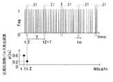
パルス発生点抽出部14は、任意の方法で入力された信号の生波形もしくは包絡線検波波形、又は、その両方のそれぞれのパルス発生点を抽出する。具体的には、図5のようにパルス発生点のみ1、それ以外を0としたパルス発生点フラグ波形を算出してもよい。図5は、図4の時系列信号のパルス発生点を抽出し、パルス発生点のみ1、それ以外を0としたパルス発生点フラグ波形を示す。パルス発生点の抽出方法は、図4の水平方向の破線で示した振幅閾値Pth1を越え、かつ、パルスの極大値をとる点をパルスの発生点と決定し、これらを抽出している。パルス発生点の抽出方法として、このように振幅閾値Pth1を設定する方法には、固定値を設定する方法、又は、ベースノイズレベル算出部13で算出したベースノイズレベルを使用して自動設定する方法がある。The pulse generation
パルス発生点か否かを1又は0で表現するパルス発生点フラグ波形を使用することにより、振幅の大小という情報を排除してパルス発生の時間間隔のみに基づく周期性解析が可能である。また、過渡応答などの情報を排除し、パルス発生点のみ抽出しているので、精度の高い周期性解析が可能である。 By using a pulse generation point flag waveform that expresses 1 or 0 as to whether or not it is a pulse generation point, it is possible to exclude periodicity analysis and to analyze periodicity based only on the time interval of pulse generation. In addition, since information such as transient responses is excluded and only pulse generation points are extracted, highly accurate periodicity analysis is possible.
ノイズ周期決定部(卓越周期決定部)15は、判別するノイズ成分の周期を決定又は抽
出する。ノイズ周期決定部15は、測定対象4に起因する所定の周期を設定周期Tと決定
してもよい。また測定対象から想定される主たるパルス周期の略整数倍を設定周期Tと決
定してもよい。例えば、基本的には回転機械の噛み合いノイズ周期は軸回転周期をスプロ
ケット歯数で除算したT’で求められるが、エスカレーターのような特殊構造では、その機械構造から、正確にT’の周期でノイズが発生するのではなく、一定程度の揺らぎを持って発生する場合がある。従って、T’ではなくT’の整数倍である踏段搬送周期を設定周期Tとすることで、適切な結果が得られる場合がある。The noise period determining unit (excellent period determining unit) 15 determines or extracts the period of the noise component to be discriminated. The noise
また、ノイズ周期決定部15は、所定の周期を設定周期Tとして使用するだけでなく、設定周期Tを変化させ、個々の設定周期Tについて後述する正規化周期パルス発生頻度p(ts)を算出し、この算出に基づいて卓越周期Tpdを抽出してもよい。In addition, the noise
図5を参照すると、上記の卓越周期Tpdの抽出のために、時系列信号において、任意の時間t=tsを開始点とし、t=ts+T、t=ts+2T、…とデータ末まで所定の設定周期Tごとに所定の区間時間幅tw(=tw1)の周期パルス検出区間21を設定する。所定の区間時間幅twを小さく設定すればするほど、時間分解能の高い解析が可能であるが、パルス波形は少なくともサンプリング点3点で形成されることから、区間時間幅twはサンプリング時間間隔の3倍ないしそれ以上の値とすればよい。本実施形態では、区間時間幅tw(=tw1)をデジタルデータのサンプリング時間間隔の3倍とした。開始点tsは0〜Tの値であり、所定の設定周期Tの波の位相φ=0〜2πと対応する。Referring to FIG. 5, in order to extract the above-described dominant period Tpd , in a time series signal, an arbitrary time t = ts is set as a starting point, t = ts + T, t = ts + 2T,. A periodic
設定した周期パルス検出区間21の総数Nと、これら全ての周期パルス検出区間21のうち、パルス又はパルス発生点フラグが存在する区間の数nを計数し、以下の式(1)により、所定の設定周期Tにおける、ある特定の開始点tsでの正規化周期パルス発生頻度p_tsを算出する。 The total number N of the set periodic

設定する周期パルス検出区間21の総数Nは変化しないが、これら全ての周期パルス検出区間21のうち、パルス又はパルス発生点フラグが存在する区間の数nは、n(ts)のように、開始点の変化に伴い、変化する。The total number N of periodic
図6と図7は、異なる開始点t1,t2での正規化周期パルス発生頻度p(t1),p(t2)をそれぞれ算出した結果を示す。図6では、開始点ts=t1のとき、設定した周期パルス検出区間21の総数Nは5であり、この5つの周期パルス検出区間21のうち、パルス又はパルス発生点フラグが存在する区間の数n(t1)が3であるため、式(2)の正規化周期パルス発生頻度p(t1)は0.6(=3/5)となる。図7では、開始点ts=t2のとき、設定した周期パルス検出区間21の総数Nは5であり、この5つの周期パルス検出区間21のうち、パルス又はパルス発生点フラグが存在する区間の数n(t2)が1であるため、式(2)の正規化周期パルス発生頻度p(t2)は0.2(=1/5)となる。 6 and 7 show the results of calculating normalized periodic pulse generation frequencies p (t1) and p (t2) at different start points t1 and t2, respectively. In FIG. 6, when the starting point ts = t1, the total number N of the set periodic
このようにして、開始点tsの変化に伴い、正規化パルス発生頻度p(ts)は変化する。このような演算を、開始点tsをさらに変化させ、個々の開始点tsについて、正規化周期パルス発生頻度p(ts)をそれぞれ算出することで、所定の設定周期Tに関して、開始点tsの関数としての正規化周期パルス発生頻度p(ts)を求めることができる。 In this way, the normalized pulse generation frequency p (ts) changes with the change of the start point ts. In such a calculation, the start point ts is further changed, and the normalized periodic pulse generation frequency p (ts) is calculated for each start point ts, whereby the function of the start point ts with respect to the predetermined set period T is calculated. The normalized periodic pulse generation frequency p (ts) can be obtained.
さらに、式(2)の正規化周期パルス発生頻度p(ts)を求める演算を、設定周期Tを任意の刻み幅で変化させ、個々の設定周期Tについて行う。 Further, the calculation for obtaining the normalized periodic pulse generation frequency p (ts) in Expression (2) is performed for each set period T by changing the set period T by an arbitrary step size.
図8は、設定周期T=T0の場合に、開始点tsを変化させ、個々の開始点tsについて正規化周期パルス発生頻度p(ts)を求めたグラフである。図8の結果では、グラフ中でいずれの開始点tsにおいても正規化周期パルス発生頻度p(ts)は、卓越した値を示していない。この結果は入力された信号が設定周期T=T0で周期性を有していないことを意味する。 FIG. 8 is a graph obtained by changing the start point ts and obtaining the normalized periodic pulse generation frequency p (ts) for each start point ts when the set period T = T0. In the result of FIG. 8, the normalized periodic pulse generation frequency p (ts) does not show an excellent value at any starting point ts in the graph. This result means that the input signal does not have periodicity with the set period T = T0.
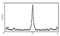
これに対し、図9は、設定周期T=T1の場合に、開始点tsを変化させ、個々の開始点tsについて正規化周期パルス発生頻度p(ts)を求めたグラフである。図9の結果では、グラフ中で複数の開始点tsにおいて正規化周期パルス発生頻度p(ts)は、卓越した値を示している。この結果は入力信号が所定の設定周期T=T1で周期性を有していることを意味しており、これによりノイズ成分による卓越周期Tpdが周期T1であると決定できる。On the other hand, FIG. 9 is a graph in which the start point ts is changed and the normalized period pulse generation frequency p (ts) is obtained for each start point ts when the set period T = T1. In the result of FIG. 9, the normalized periodic pulse generation frequency p (ts) at a plurality of start points ts in the graph shows an excellent value. This result means that the input signal has a periodicity with a predetermined set period T = T1, and thereby, it is possible to determine that the dominant period Tpd due to the noise component is the period T1.
このようにして、設定周期Tを変化させ、個々の設定周期Tについて上記演算を行うことで、卓越周期T1を抽出できる。 In this way, by changing the set period T and performing the above calculation for each set period T, the dominant period T1 can be extracted.
なお、正規化周期パルス発生頻度p(ts)が卓越しているか否かを明確に決定する場合、及び、自動処理により卓越周期Tpdを決定する場合には、いずれの設定周期Tで最も正規化周期パルス発生頻度p(ts)が卓越しているか判断する指標が必要である。この指標としては、例えば、図8と図9のような設定周期T0とT1での各正規化周期パルス発生頻度p(ts)のグラフにおいて、まず正規化周期パルス発生頻度p(ts)の平均値p0を算出する。次に、この平均値p0を越えた正規化周期パルス発生頻度p(ts)の極大値の平均値から平均値p0以下の正規化周期パルス発生頻度p(ts)の極大値の平均値を引算した結果の値が利用できる。このようにして、所定の設定周期Tを変化させ、個々の設定周期Tについて、上記引算の値を計算した結果を図10に示す。図10より、最大値をとる設定周期T1を卓越周期Tpdと決定できる。In the case where it is clearly determined whether or not the normalized periodic pulse generation frequency p (ts) is superior, and when the superior period Tpd is determined by automatic processing, it is most normal in any set period T. An index for determining whether the periodic pulse generation frequency p (ts) is excellent is necessary. As this index, for example, in the graph of each normalized periodic pulse generation frequency p (ts) in the set periods T0 and T1 as shown in FIGS. 8 and 9, first, the average of the normalized periodic pulse generation frequency p (ts) The value p0 is calculated. Next, the average value of the maximum values of the normalized periodic pulse generation frequency p (ts) below the average value p0 is subtracted from the average value of the normalized periodic pulse generation frequency p (ts) exceeding the average value p0. The calculated value can be used. FIG. 10 shows the result of calculating the subtraction value for each set period T by changing the predetermined set period T in this way. From FIG. 10, the set period T1 that takes the maximum value can be determined as the dominant periodTpd .
また、その他の指標としては、正規化周期パルス発生頻度p(ts)のグラフのうち、上位k個(kは任意の整数)の極大値の平均値を使用する方法もある。例えば、あるエスカレーターの踏段駆動ギアとチェーンの噛み合いによる周期ノイズはその機械的構造から6つの位相で卓越することが既知なため、このような測定対象4の場合は、k=6として計算すればよい。 As another index, there is a method of using the average value of the top k (k is an arbitrary integer) maximum values in the graph of the normalized periodic pulse generation frequency p (ts). For example, since it is known that periodic noise due to meshing between a step drive gear and a chain of an escalator is superior in six phases due to its mechanical structure, in the case of such a
なお、こういった知見がなくとも、任意の適当な整数kを使って、上位k個の正規化周期パルス発生頻度p(ts)の平均値を指標に使用する方法でも卓越周期T1の決定は十分正確に実施できる場合が多い。 Even if there is no such knowledge, the determination of the dominant period T1 is possible even in a method using the average value of the top k normalized periodic pulse generation frequencies p (ts) as an index using any appropriate integer k. In many cases, it can be implemented sufficiently accurately.
このようにして、所定の設定周期Tを変化させ、個々の設定周期Tについて正規化周期パルス発生頻度p(ts)を算出し、最も卓越した周期性が認められた周期である卓越周期T1を決定する。従って、抽出又は除去したい成分の正確な周期が不明な場合にも、その周期を高精度に求めた上で、特定周期成分を判別し、抽出又は除去できる。 In this way, the predetermined set period T is changed, the normalized period pulse generation frequency p (ts) is calculated for each set period T, and the superior period T1 which is the period in which the most excellent periodicity is recognized is obtained. decide. Therefore, even when the exact cycle of the component to be extracted or removed is unknown, the specific cycle component can be determined and extracted or removed after obtaining the cycle with high accuracy.
ノイズ位相決定部(卓越位相決定部)16は、ノイズ周期決定部(卓越周期決定部)15で決定した所定の設定周期Tにおける、又は、算出した卓越周期Tpd(本実施形態では周期T1)における正規化周期パルス発生頻度p(ts)のグラフから、ノイズの卓越位相とこれに対応する卓越開始点ts1(k)を算出する。この算出は、正規化周期パルス発生頻度p(ts)のグラフから卓越したピークを探し、その極大値を与えている開始点tsを求めればよい。図11は、卓越周期Tpd(=T1)における正規化周期パルス発生頻度p(ts)のグラフにおいて、卓越開始点ts1(k)(k=1,2,…,6)を示すグラフである。The noise phase determining unit (excellent phase determining unit) 16 is a predetermined set period T determined by the noise period determining unit (excellent period determining unit) 15 or the calculated excellent period Tpd (period T1 in this embodiment). From the graph of the normalized periodic pulse generation frequency p (ts) at, the noise dominant phase and the corresponding superior start point ts1 (k) are calculated. This calculation may be performed by searching for an excellent peak from the graph of the normalized periodic pulse generation frequency p (ts) and obtaining the starting point ts giving the maximum value. FIG. 11 is a graph showing the dominant start point ts1 (k) (k = 1, 2,..., 6) in the graph of the normalized periodic pulse generation frequency p (ts) in the dominant cycle Tpd (= T1). .
なお、卓越開始点ts1(k)の算出を明確に又は自動で行う場合には、正規化周期パルス発生頻度p(ts)のグラフ中で、いずれのピークが卓越しているかを判断する指標が必要である。この指標としては、例えば、正規化周期パルス発生頻度p(ts)の閾値Pth2を設定し、閾値p1を越える極大値を与えている開始点tsを選ぶ方法が簡単である。本実施形態では下記の式によって閾値Pth2を算出した。When the calculation of the superior start point ts1 (k) is performed clearly or automatically, an index for determining which peak is superior in the graph of the normalized periodic pulse generation frequency p (ts). is necessary. As this index, for example, a method of setting a threshold value Pth2 of the normalized periodic pulse generation frequency p (ts) and selecting a starting point ts giving a maximum value exceeding the threshold value p1 is simple. In the present embodiment, the threshold value Pth2 is calculated by the following equation.
このようにして、周期信号の位相に対応する開始点tsを変化させ、個々の開始点tsについて、正規化周期パルス発生頻度p(ts)が所定の閾値p1を超える全ての卓越開始点tspd(k)(k=1,2,3…)を求める。従って、抽出又は除去したい成分の正確な位相が不明な場合、さらに同じ周期でありながら複数の異なる位相で、抽出又は除去したい特定周期成分が発生している場合にも、周期信号が発生している全ての位相を求めた上で特定周期成分を判別し、抽出又は除去できる。In this way, the start point ts corresponding to the phase of the periodic signal is changed, and for each start point ts, all the superior start points tspd whose normalized periodic pulse generation frequency p (ts) exceeds the predetermined threshold value p1. (K) (k = 1, 2, 3,...) Is obtained. Therefore, if the exact phase of the component to be extracted or removed is unknown, and even if a specific periodic component to be extracted or removed is generated in a plurality of different phases with the same period, a periodic signal is generated. The specific periodic component can be discriminated and extracted or removed after all the phases are obtained.
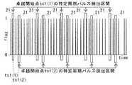
周期ノイズ成分判別部(特定周期成分判別部)17は、区間時間幅twと、上記の方法で算出した卓越周期Tpd及び卓越開始点tspd(k)(k=1,2,3…)を使用して、任意の方法で入力された信号の生波形もしくは包絡線検波波形、又は、パルス発生点フラグ波形上において、t=tspd(1)、t=tspd(2)、t=tspd(3)、…、t=tspd(1)+Tpd、t=tspd(2)+Tpd、t=tspd(3)+Tpd、…、t=tspd(1)+2Tpd、t=tspd(2)+2Tpd、t=tspd(3)+2Tpd、…とデータ末まで特定周期パルス検出区間21を設定する。ここで、区間時間幅twはノイズ周期決定部15で使用した区間時間幅tw1と同じ値でもよいし、異なる値でもよい。The periodic noise component discriminating unit (specific periodic component discriminating unit) 17 includes the section time width tw, the superior period Tpd calculated by the above method and the superior start point tspd (k) (k = 1, 2, 3...) , T = tspd (1), t = tspd (2), and t = tspd (1) on the raw waveform or envelope detection waveform of the signal input by an arbitrary method or on the pulse generation point flag waveform tspd (3), ..., t = tspd (1) + Tpd , t = tspd (2) + Tpd , t = tspd (3) + Tpd , ..., t = tspd (1) +2 Tpd, t = Tspd (2) + 2Tpd , t = tspd (3) + 2Tpd ,... And the specific period
図12は、周期ノイズ成分判別のための特定周期パルス検出区間21の設定例を示す。図12では、例として卓越周期T1において卓越開始点ts1(1)とts1(2)によって設定される特定周期パルス検出区間21を示している。このように特定周期パルス検出区間21を設定することで、同周期でも異なる位相で発生するパルス又は全てのパルス発生点フラグを確実に検出できる。なお、図12で特定周期パルス検出区間21を縦にずらして描画しているのは、卓越開始点ts1(1)によって設定される特定周期パルス検出区間21と卓越開始点ts1(2)によって設定される特定周期パルス検出区間21を視覚的に識別しやすくするためである。 FIG. 12 shows a setting example of the specific periodic
周期ノイズ成分判別部17は、これらの特定周期パルス検出区間21の内に存在する全てのパルス又は全てのパルス発生点フラグは、特定周期成分及び特定位相成分によるものと判定する。本実施形態では、即ち周期ノイズ成分と判定する。さらに、これらのパルス発生点フラグと図4の包絡線検波波形との時間軸上の対応関係から、包絡線検波波形中でいずれのパルスが周期ノイズ成分であるかを明確に判別できる。 The periodic noise
また、周期ノイズ成分を明確に判別するためには、時系列信号中の1つのパルスを構成するデータ範囲が、時間軸上でどこからどこまでのデータ範囲であるかを決定する必要がある。 In addition, in order to clearly discriminate the periodic noise component, it is necessary to determine from where to where on the time axis the data range constituting one pulse in the time-series signal.
本実施形態では、時系列信号において、パルスの極大点から時間軸上の前後に離れるにしたがって振幅は減少するが、振幅が所定の振幅閾値を下回る直前まで、もしくは減少する振幅が増加に転じる直前までをパルスの一部としている。この振幅閾値は固定値であっても良いが、様々な入力信号に対して変化するノイズに対応してパルスのデータ範囲を決定できるように、ベースノイズレベル算出部13で算出したベースノイズレベルを利用するのが好ましい。その他の方法としては、例えば、パルスの極大点から時間軸上の前後±5点をパルスの一部とするように、パルスの有するデータ点数又は時間幅を一定とする方法などがある。 In the present embodiment, in the time series signal, the amplitude decreases as it moves away from the maximum point of the pulse on the time axis, but immediately before the amplitude falls below a predetermined amplitude threshold or immediately before the decreasing amplitude starts to increase. Is part of the pulse. The amplitude threshold value may be a fixed value, but the base noise level calculated by the base noise
以上より、時系列信号において、信号の有する正確な周期や位相が不明な場合、及び、信号が同周期かつ異位相で周期発生する場合にも、周期ノイズ成分を明確に判別できる。さらに、時系列信号が包絡線検波波形の場合でも、図3のように包絡線検波波形と入力された生波形の時間軸上の対応関係から、入力された生波形において周期ノイズ成分を明確に判別できる。 As described above, in the time-series signal, the periodic noise component can be clearly discriminated when the exact period or phase of the signal is unknown or when the signal is generated with the same period and different phase. Further, even when the time series signal is an envelope detection waveform, the periodic noise component in the input raw waveform is clarified from the correspondence on the time axis between the envelope detection waveform and the input raw waveform as shown in FIG. Can be determined.
周期ノイズ除去部(特定周期成分除去部)18は、入力波形もしくは包絡線検波波形、又は、その両方において、周期ノイズ成分判別部17にて周期ノイズ成分と判別されたデータを全て、それぞれのベースノイズレベルのランダム値で置換する。従って、入力波形もしくは包絡線検波波形、又は、その両方から周期ノイズ成分を除去できる。ベースノイズレベルのランダム値を置換に使用するのは、時系列信号中で周期ノイズ成分を置換した部分が不自然に一定値をとらないようにするためであるが、実際上、一定値でも信号処理に影響はない。従って、ベースノイズレベル以下の値であれば、置換に使用する値はランダム値に限定されない。 The periodic noise removing unit (specific periodic component removing unit) 18 uses all the data determined to be the periodic noise component by the periodic noise
ノイズ除去後信号出力部19は、周期ノイズ成分を除去した波形を出力する。図13は図4の包絡線検波波形から卓越周期Tpd(=T1)の周期ノイズ成分を除去し、ノイズ除去後信号出力部19が出力した結果を示すグラフである。図4のグラフでは周期ノイズが複数のパルスとして存在していたが、図13では、これらの周期ノイズ成分は除去されている。The post-noise removal
診断部10は、ノイズ除去後信号出力部19により出力された周期ノイズ成分を除去した波形に基づいて測定対象4の診断を行う。診断部10での診断は、信号処理装置1により周期ノイズ成分が除去された波形を使用するため、周期ノイズ成分による誤差を伴わない正確な診断が可能である。診断部10は、診断結果を例えば視覚的に表示してもよい。また、診断部10は、診断結果を他の外部に出力してもよい。 The
本実施形態では、測定対象4をエスカレーターの踏段駆動軸受としているが、測定対象4の種類は特に限定されない。例えば、インバーター駆動の回転機械においては、インバーター駆動に起因するパルス状の電気ノイズが周期的に重畳し、誤診断を誘発する恐れがある。このような電気ノイズを除去するために、本発明の信号処理装置1は利用できる。さらに、測定対象4は回転機械の分野に限らず、医療の分野においては、生体の活動によって生じる周期的な脈動による信号を抽出又は除去するなどに信号処理装置1は利用できる。 In this embodiment, the measuring
1 信号処理装置
2 診断装置
3 センサー
4 測定対象
10 診断部
11 信号入力部
12 A/D変換部
13 ベースノイズレベル算出部
14 パルス発生点抽出部
15 ノイズ周期決定部(卓越周期決定部)
16 ノイズ位相決定部(卓越位相決定部)
17 周期ノイズ成分判別部(特定周期成分判別部)
18 周期ノイズ除去部(特定周期成分除去部)
19 ノイズ除去後信号出力部
20 包絡線検波処理部
21 周期パルス検出区間DESCRIPTION OF
16 Noise phase determination unit (excellent phase determination unit)
17 Periodic noise component discriminator (specific periodic component discriminator)
18 Periodic noise removal unit (specific periodic component removal unit)
19 Signal output section after
Claims (11)
Translated fromJapanese前記周期パルス検出区間の全区間数のうち、前記周期パルス検出区間の中にパルスが存在する区間数の割合である正規化周期パルス発生頻度を求める計算を、前記開始点を変化させ、個々の開始点について行うことで、前記開始点の関数として前記正規化周期パルス発生頻度を算出し、
前期正規化周期パルス発生頻度が所定の閾値を越える全ての卓越開始点を抽出し、
全ての前記卓越開始点と、前記所定の設定周期と、前記所定の時間幅とによって設定される全ての前記周期パルス検出区間内の全てのパルスを特定周期成分であると判別する、信号処理方法。For a time-series signal, arrange a periodic pulse detection section of a predetermined time width for each predetermined set period from an arbitrary start point on the time axis,
The calculation for obtaining the normalized periodic pulse generation frequency, which is the ratio of the number of sections in which the pulse exists in the periodic pulse detection section, out of the total number of the periodic pulse detection sections, changes the start point, By performing for the start point, calculate the normalized periodic pulse generation frequency as a function of the start point,
Extract all the prominent start points where the frequency of normalization period pulse generation exceeds the predetermined threshold,
A signal processing method for discriminating that all pulses in all the periodic pulse detection sections set by all the superior starting points, the predetermined setting period, and the predetermined time width are specific period components. .
前記時系列信号がアナログデータであればこれを離散化し、デジタルデータを生成するA/D変換部と、
前記時系列信号のベースノイズレベルを算出するベースノイズレベル算出部と、
前記時系列信号からパルス発生点を抽出するパルス発生点抽出部と、
前記時系列信号の正規化周期パルス発生頻度を算出する際に使用する所定の設定周期を決定する卓越周期決定部と、
前記時系列信号の卓越位相を決定する卓越位相決定部と、
前記所定の設定周期と前記卓越位相から前記時系列信号の特定周期成分を判別する特定周期成分判別部と、
前記特定周期成分と判別された周期成分以外の全てのデータか、又は特定周期成分と判別された周期成分の全てのデータを前記ベースノイズレベルのランダム値で置換することで、前記特定周期成分の抽出又は除去を行う特定周期成分抽出部又は特定周期成分除去部と、
前記特定周期成分と判別された周期成分を抽出又は除去した後の信号を出力する時系列信号出力部と
を備える、信号処理装置。A signal input unit for receiving time-series signal input;
If the time series signal is analog data, it is discretized and an A / D converter that generates digital data;
A base noise level calculation unit for calculating a base noise level of the time series signal;
A pulse generation point extraction unit for extracting a pulse generation point from the time series signal;
A dominant period determination unit for determining a predetermined set period used when calculating the normalized period pulse generation frequency of the time series signal;
A superior phase determining unit for determining an excellent phase of the time series signal;
A specific period component determining unit that determines a specific period component of the time-series signal from the predetermined set period and the dominant phase;
Replacing all the data other than the periodic component determined as the specific periodic component or all the data of the periodic component determined as the specific periodic component with a random value of the base noise level, A specific periodic component extracting unit or a specific periodic component removing unit that performs extraction or removal;
A signal processing device comprising: a time-series signal output unit that outputs a signal after extracting or removing the periodic component determined to be the specific periodic component.
前記時系列信号を入力して包絡線検波処理により包絡線検波波形を抽出する包絡線検波処理部と、
前記包絡線検波波形がアナログデータであればこれを離散化してデジタルデータを生成するA/D変換部と、
前記包絡線検波波形のベースノイズレベルを算出するベースノイズレベル算出部と、
前記包絡線検波波形から信号の所定の振幅閾値を越えている点のうち、時系列の前後の隣接点と同じ又はそれより大きい振幅値を持つ点を1、その他を0としたパルス発生点フラグ波形を算出するパルス発生点抽出部と、
前記パルス発生点フラグ波形の卓越周期を決定する卓越周期決定部と、
前記パルス発生点フラグ波形の卓越位相を決定する卓越位相決定部と、
前記卓越周期と前記卓越位相から前記包絡線検波波形の特定周期成分を判別する特定周期成分判別部と、
前記特定周期成分と判別された周期成分以外の全てのデータか、又は特定周期成分と判別された周期成分の全てのデータを、前記ベースノイズレベルのランダム値で置換することにより前記特定周期成分の抽出又は除去を行う特定周期成分除去部又は特定周期成分抽出部と、
前記特定周期成分と判別された周期成分を抽出又は除去した後の信号を出力する時系列信号出力部と
を備える、信号処理装置。A signal input unit for receiving time-series signal input;
An envelope detection processing unit that inputs the time-series signal and extracts an envelope detection waveform by envelope detection processing;
If the envelope detection waveform is analog data, an A / D converter that discretizes the data to generate digital data;
A base noise level calculation unit for calculating a base noise level of the envelope detection waveform;
Of the points exceeding the predetermined amplitude threshold of the signal from the envelope detection waveform, a pulse generation point flag in which 1 is the point having the same or larger amplitude value as the adjacent points before and after the time series, and 0 is the others A pulse generation point extraction unit for calculating a waveform;
A dominant cycle determining unit for determining a dominant cycle of the pulse generation point flag waveform;
A dominant phase determination unit for determining a dominant phase of the pulse generation point flag waveform;
A specific period component determining unit for determining a specific period component of the envelope detection waveform from the dominant period and the dominant phase;
Replacing all data other than the periodic component determined as the specific periodic component or all data of the periodic component determined as the specific periodic component with a random value of the base noise level A specific periodic component removing unit or a specific periodic component extracting unit for performing extraction or removal;
A signal processing device comprising: a time-series signal output unit that outputs a signal after extracting or removing the periodic component determined to be the specific periodic component.
Priority Applications (1)
| Application Number | Priority Date | Filing Date | Title |
|---|---|---|---|
| JP2014154211AJP6483972B2 (en) | 2014-07-29 | 2014-07-29 | Signal processing method and signal processing apparatus |
Applications Claiming Priority (1)
| Application Number | Priority Date | Filing Date | Title |
|---|---|---|---|
| JP2014154211AJP6483972B2 (en) | 2014-07-29 | 2014-07-29 | Signal processing method and signal processing apparatus |
Publications (2)
| Publication Number | Publication Date |
|---|---|
| JP2016031307Atrue JP2016031307A (en) | 2016-03-07 |
| JP6483972B2 JP6483972B2 (en) | 2019-03-13 |
Family
ID=55441772
Family Applications (1)
| Application Number | Title | Priority Date | Filing Date |
|---|---|---|---|
| JP2014154211AActiveJP6483972B2 (en) | 2014-07-29 | 2014-07-29 | Signal processing method and signal processing apparatus |
Country Status (1)
| Country | Link |
|---|---|
| JP (1) | JP6483972B2 (en) |
Cited By (4)
| Publication number | Priority date | Publication date | Assignee | Title |
|---|---|---|---|---|
| JP2019028032A (en)* | 2017-08-03 | 2019-02-21 | 一般財団法人電力中央研究所 | Sign detection device, method for detecting sign, sign detection program, and sign detection system |
| JP2019177962A (en)* | 2018-03-30 | 2019-10-17 | 理想科学工業株式会社 | Meandering control device |
| CN115102563A (en)* | 2022-07-22 | 2022-09-23 | 北京中宸微电子有限公司 | Method and system for eliminating impulse noise of power line carrier receiver |
| WO2024252713A1 (en)* | 2023-06-06 | 2024-12-12 | 日本精工株式会社 | State determination device and state determination method for ball screw |
Citations (5)
| Publication number | Priority date | Publication date | Assignee | Title |
|---|---|---|---|---|
| JPS60238896A (en)* | 1984-05-11 | 1985-11-27 | 富士通株式会社 | Fundamental frequency extraction system |
| JP2006234785A (en)* | 2005-01-26 | 2006-09-07 | Nsk Ltd | Machine equipment abnormality diagnosis apparatus and abnormality diagnosis method |
| JP2011013214A (en)* | 2009-06-30 | 2011-01-20 | Mitsubishi Electric Research Laboratories Inc | Probabilistic determination method of time interval between periodic events disturbing signal |
| JP5423312B2 (en)* | 2009-10-23 | 2014-02-19 | 富士通株式会社 | Data correction apparatus and data correction method |
| US20140088891A1 (en)* | 2012-09-21 | 2014-03-27 | National Central University | Method for determining the precision of gears |
- 2014
- 2014-07-29JPJP2014154211Apatent/JP6483972B2/enactiveActive
Patent Citations (5)
| Publication number | Priority date | Publication date | Assignee | Title |
|---|---|---|---|---|
| JPS60238896A (en)* | 1984-05-11 | 1985-11-27 | 富士通株式会社 | Fundamental frequency extraction system |
| JP2006234785A (en)* | 2005-01-26 | 2006-09-07 | Nsk Ltd | Machine equipment abnormality diagnosis apparatus and abnormality diagnosis method |
| JP2011013214A (en)* | 2009-06-30 | 2011-01-20 | Mitsubishi Electric Research Laboratories Inc | Probabilistic determination method of time interval between periodic events disturbing signal |
| JP5423312B2 (en)* | 2009-10-23 | 2014-02-19 | 富士通株式会社 | Data correction apparatus and data correction method |
| US20140088891A1 (en)* | 2012-09-21 | 2014-03-27 | National Central University | Method for determining the precision of gears |
Cited By (5)
| Publication number | Priority date | Publication date | Assignee | Title |
|---|---|---|---|---|
| JP2019028032A (en)* | 2017-08-03 | 2019-02-21 | 一般財団法人電力中央研究所 | Sign detection device, method for detecting sign, sign detection program, and sign detection system |
| JP2019177962A (en)* | 2018-03-30 | 2019-10-17 | 理想科学工業株式会社 | Meandering control device |
| JP7027225B2 (en) | 2018-03-30 | 2022-03-01 | 理想科学工業株式会社 | Meander control device |
| CN115102563A (en)* | 2022-07-22 | 2022-09-23 | 北京中宸微电子有限公司 | Method and system for eliminating impulse noise of power line carrier receiver |
| WO2024252713A1 (en)* | 2023-06-06 | 2024-12-12 | 日本精工株式会社 | State determination device and state determination method for ball screw |
Also Published As
| Publication number | Publication date |
|---|---|
| JP6483972B2 (en) | 2019-03-13 |
Similar Documents
| Publication | Publication Date | Title |
|---|---|---|
| JP6038347B2 (en) | Abnormal sound diagnosis device | |
| JP5067979B2 (en) | Bearing diagnostic device | |
| CN101464212A (en) | Method and apparatus for vibration-based automatic condition monitoring of a wind turbine | |
| CN109724802B (en) | A method for diagnosing weak faults of motor bearings based on the evaluation and optimization of spectrograms | |
| JP2016048267A5 (en) | ||
| CN104819766B (en) | Based on it is humorous make an uproar than envelope demodulation frequency band determine method | |
| JP6190343B2 (en) | Rotating machine abnormality diagnosis device, rotating machine abnormality diagnosis method, and rotating machine | |
| JP6922708B2 (en) | Anomaly detection computer program, anomaly detection device and anomaly detection method | |
| JP6483972B2 (en) | Signal processing method and signal processing apparatus | |
| JP5740208B2 (en) | Bearing diagnosis method and system | |
| JP2018179735A (en) | Method and apparatus for diagnosing abnormality of rotating parts | |
| JP2008292288A (en) | Bearing diagnostic device for reduction gear | |
| JP2017032520A (en) | State monitoring device and state monitoring method | |
| JP7083293B2 (en) | Status monitoring method and status monitoring device | |
| JP5218614B2 (en) | Abnormality diagnosis device, rotating device, railway vehicle, automobile and abnormality diagnosis method | |
| JP2010266327A (en) | Facility diagnosis device and facility diagnosis method | |
| JP2011252762A (en) | Method and device for monitoring bearing state | |
| JP2016170085A (en) | Abnormality diagnostic device and abnormality diagnostic method | |
| JPH07311082A (en) | Failure diagnostic device of rotating equipment | |
| JP7040920B2 (en) | Bearing condition monitoring device and abnormality diagnosis method | |
| JP6815489B2 (en) | Vibration detection device and abnormality judgment system | |
| JP2018189448A (en) | Dynamic equipment diagnostic system, method and program | |
| JP2023006667A (en) | Abnormality diagnosis device for rolling bearing, method for diagnosing abnormality, and program | |
| CN102830177B (en) | Abnormality checking method and abnormality checking apparatus | |
| JP2016075563A (en) | Vibration diagnosis apparatus, method and program for rotating equipment |
Legal Events
| Date | Code | Title | Description |
|---|---|---|---|
| A621 | Written request for application examination | Free format text:JAPANESE INTERMEDIATE CODE: A621 Effective date:20170705 | |
| A977 | Report on retrieval | Free format text:JAPANESE INTERMEDIATE CODE: A971007 Effective date:20180530 | |
| A131 | Notification of reasons for refusal | Free format text:JAPANESE INTERMEDIATE CODE: A131 Effective date:20180612 | |
| A521 | Request for written amendment filed | Free format text:JAPANESE INTERMEDIATE CODE: A523 Effective date:20180810 | |
| TRDD | Decision of grant or rejection written | ||
| A01 | Written decision to grant a patent or to grant a registration (utility model) | Free format text:JAPANESE INTERMEDIATE CODE: A01 Effective date:20190129 | |
| A61 | First payment of annual fees (during grant procedure) | Free format text:JAPANESE INTERMEDIATE CODE: A61 Effective date:20190215 | |
| R150 | Certificate of patent or registration of utility model | Ref document number:6483972 Country of ref document:JP Free format text:JAPANESE INTERMEDIATE CODE: R150 | |
| S111 | Request for change of ownership or part of ownership | Free format text:JAPANESE INTERMEDIATE CODE: R313117 | |
| R350 | Written notification of registration of transfer | Free format text:JAPANESE INTERMEDIATE CODE: R350 |