JP2016026542A - Tracheostomy tube device - Google Patents
Tracheostomy tube deviceDownload PDFInfo
- Publication number
- JP2016026542A JP2016026542AJP2015112731AJP2015112731AJP2016026542AJP 2016026542 AJP2016026542 AJP 2016026542AJP 2015112731 AJP2015112731 AJP 2015112731AJP 2015112731 AJP2015112731 AJP 2015112731AJP 2016026542 AJP2016026542 AJP 2016026542A
- Authority
- JP
- Japan
- Prior art keywords
- air
- air supply
- tube
- utterance
- tracheostomy tube
- Prior art date
- Legal status (The legal status is an assumption and is not a legal conclusion. Google has not performed a legal analysis and makes no representation as to the accuracy of the status listed.)
- Granted
Links
- 230000000241respiratory effectEffects0.000claimsabstractdescription32
- 230000029058respiratory gaseous exchangeEffects0.000claimsdescription34
- 210000003437tracheaAnatomy0.000claimsdescription19
- 210000000214mouthAnatomy0.000claimsdescription12
- 210000004072lungAnatomy0.000claimsdescription10
- 230000028327secretionEffects0.000description11
- 210000001260vocal cordAnatomy0.000description8
- 230000000694effectsEffects0.000description3
- 238000005452bendingMethods0.000description2
- 238000000034methodMethods0.000description2
- XLYOFNOQVPJJNP-UHFFFAOYSA-NwaterSubstancesOXLYOFNOQVPJJNP-UHFFFAOYSA-N0.000description2
- 230000002378acidificating effectEffects0.000description1
- 230000002411adverseEffects0.000description1
- 230000000740bleeding effectEffects0.000description1
- 238000007599dischargingMethods0.000description1
- 238000005516engineering processMethods0.000description1
- 238000005469granulationMethods0.000description1
- 230000003179granulationEffects0.000description1
- 238000003780insertionMethods0.000description1
- 230000037431insertionEffects0.000description1
- 239000000463materialSubstances0.000description1
- 238000012986modificationMethods0.000description1
- 230000004048modificationEffects0.000description1
- 238000000465mouldingMethods0.000description1
- 229920000915polyvinyl chloridePolymers0.000description1
- 239000004800polyvinyl chlorideSubstances0.000description1
- 238000005086pumpingMethods0.000description1
- 230000000630rising effectEffects0.000description1
- 238000001356surgical procedureMethods0.000description1
- 238000009423ventilationMethods0.000description1
- 230000001755vocal effectEffects0.000description1
Images


Landscapes
- Prostheses (AREA)
Abstract
Description
Translated fromJapanese外部より発声用空気等を上部気道に送ることによって気管切開手術を行った患者の発声を補助することが可能な気管切開チューブ装置に関する。 The present invention relates to a tracheostomy tube device capable of assisting the voice of a patient who has performed tracheostomy surgery by sending voice air or the like to the upper airway from the outside.
従来、外部より発声用空気等を供給し、患者の発声をサポートする気管切開チューブ(いわゆるスピーチカニューレ)が知られている(例えば、特許文献1参照)。一般的な気管切開チューブは、気管切開孔より気管に挿入するためにポリ塩化ビニル製等の化学的に安定な材料のチューブを約90度の方向に規定の半径を保った状態で曲げられた形状を有している。 2. Description of the Related Art Conventionally, a tracheostomy tube (so-called speech cannula) that supplies utterance air or the like from the outside and supports the utterance of a patient is known (see, for example, Patent Document 1). A general tracheostomy tube is bent with a specified radius in a direction of about 90 degrees in a tube made of a chemically stable material such as polyvinyl chloride for insertion into the trachea through a tracheostomy hole. It has a shape.
この気管切開チューブの一方は、気管切開部から外部に露出し、気道の確保や人工呼吸器等による呼吸管理を行うために使用される。気管切開チューブの一端に人工呼吸器を接続した場合は、患者の容態によって適切な呼吸管理を行うために、気管切開チューブの内部を呼吸用空気等が吸入や排気するために、方向を交互に変えながら流れることになる。また、患者の気管内に挿入された気管切開チューブの下端側からは、気道より肺に向かう呼気や逆に肺より気道に向かう呼気の流出や流入が行われている。 One of the tracheostomy tubes is exposed to the outside from the tracheostomy part, and is used for securing an airway or performing respiratory management using a ventilator or the like. When a ventilator is connected to one end of the tracheostomy tube, in order to perform appropriate respiratory management according to the patient's condition, in order to inhale and exhaust air inside the tracheostomy tube, alternate directions It will flow while changing. Further, from the lower end side of the tracheostomy tube inserted into the trachea of the patient, exhalation from the airway toward the lungs, and conversely, exhalation from the lungs toward the airway is performed.
このような気管切開チューブには、上記呼気の移動を効果的に行うために、気道と気管切開チューブとの間の隙間を閉鎖するためのカフ(プロフィールカフ)を備えている。これは、人工呼吸器等から供給される空気等の気管上部への漏出を防ぐためのもので、これを備えることにより、効率よく肺への空気等の供給や肺からの吸入を行うことができる、いわゆる陽圧換気を行うことができるようになる。 Such a tracheostomy tube is provided with a cuff (profile cuff) for closing a gap between the airway and the tracheostomy tube in order to effectively move the exhalation. This is to prevent leakage of air supplied from a ventilator to the upper part of the trachea. By providing this, air can be efficiently supplied to the lungs and inhaled from the lungs. So-called positive pressure ventilation can be performed.
しかしながら、スピーチカニューレではない一般的な気管切開チューブでは、カフを装着した状態で肺が空気等を排出する際に、気道上部への呼気の排出は行われずに、人工呼吸器に排出されるために、呼気の排出を利用することによる発声ができなくなる。そのため、患者は気管切開チューブを挿入された時点より発声ができなくなり、多大なストレスが負荷されてしまうことになる。
これを改善するために考案されたものが上記スピーチカニューレである。このスピーチカニューレは、一般的な上記の気管切開チューブに発声用空気等を外部より供給できる構造を持ち、これをカフより上部の気道内に吐出させることによって発声用空気等を確保しようとするものである。However, in a general tracheostomy tube that is not a speech cannula, when the lungs discharge air with the cuff attached, exhalation is not discharged to the upper airway, but is discharged to the ventilator. In addition, it becomes impossible to utter by using the discharge of exhalation. Therefore, the patient cannot speak from the time when the tracheostomy tube is inserted, and a great deal of stress is applied.
The speech cannula has been devised to improve this. This speech cannula has a structure that can supply voice air etc. to the above-mentioned tracheostomy tube from the outside, and tries to secure voice air etc. by discharging it into the airway above the cuff It is.
スピーチカニューレは、例えば図7に示すように、一般的な気管切開チューブのチューブ本体105内部に、呼気用空気等が流れる呼吸用空気流路から隔絶された空気等を流入させるいわゆる発声用サイドライン113を持つ二重構造になっている。スピーチカニューレにおいても人工呼吸器等による呼吸管理が行われ、肺より空気等を排出しスピーチカニューレ内部を人体より外に向かって流れているときに、発声用サイドライン113中を発声用空気等が人体の内部側に向かって流れ、カフ116の上部付近に備えられた送気口113aより気道内に流出し、発声に利用される構造になっている。また、カフ116の上部付近に貯留した気管分泌物等の吸引除去を行う際にも発声用サイドライン113は利用され、発声用空気等の供給との兼用になっている。なお、カフ116は、カフ用チューブ117の先端に接続されている。 For example, as shown in FIG. 7, the speech cannula is a so-called vocal side line that allows air or the like isolated from a breathing air flow path through which exhalation air or the like flows into a
上記従来の技術には、以下の課題が残されている。
すなわち、従来のスピーチカニューレでは、発声用サイドラインより供給される発声用空気等を患者の発声時にタイミングに合わせて供給させることが好ましいが、患者自身が発声用空気等の供給を操作する方法では患者に負担が大きいため、自動的に呼吸のタイミングに合わせて発声用空気を供給する装置が望まれていた。
また、カフの上部に備えられた発声用空気等の送気口が、気道壁近傍のチューブ側面に設けられているものや、横方向に噴出する構造のものがあり、送気口から吐出した空気等が気道壁に直接当たることになってしまい、気道壁での肉芽形成や出血などの悪影響を与えてしまう問題があった。
また、発声用サイドラインは、チューブ内部に形成されるため、比較的細い管を利用することが多いが、細い管は大きい圧力損失等があり、発声用空気等を発声に必要な圧力を超えて供給する必要性が生じ、気道内に吐出した空気等は高い圧力による動圧を保持した状態になる。このため、患者は気道内に抵抗感を覚え、発声をスムースに行えなくなるという不都合があった。
さらに、気管切開した後に気道内に一定期間挿入された状態となるため、気道内部等の衛生管理を厳密に行う必要があるが、特にカフ上に分泌物等が貯留しやすく、発声用サイドラインの送気口をカフ上に配すると、分泌物等が送気口に流入してしまうおそれがあった。The following problems remain in the conventional technology.
That is, in the conventional speech cannula, it is preferable to supply the utterance air supplied from the utterance side line in accordance with the timing at the time of the patient's utterance. However, in the method in which the patient himself operates the supply of the utterance air etc. Since the burden on the patient is large, an apparatus that automatically supplies voice air in accordance with the timing of breathing has been desired.
In addition, there are air outlets for speech air etc. provided at the upper part of the cuff provided on the side of the tube near the airway wall and structures that blow out in the lateral direction, and discharged from the air outlet There is a problem that air or the like directly hits the airway wall, and adverse effects such as granulation or bleeding on the airway wall occur.
In addition, since the utterance side line is formed inside the tube, a relatively thin tube is often used. However, the thin tube has a large pressure loss and the utterance air exceeds the pressure required for utterance. Therefore, the air discharged into the airway is in a state where the dynamic pressure due to the high pressure is maintained. For this reason, there is a problem that the patient feels resistance in the airway and cannot speak smoothly.
In addition, since it is inserted into the airway for a certain period after tracheostomy, it is necessary to strictly manage the hygiene inside the airway, etc. When the air supply port is arranged on the cuff, there is a possibility that secretions and the like may flow into the air supply port.
本発明は、前述の課題に鑑みてなされたもので、患者への負担を減らしながらより効率よく発声することができる気管切開チューブ装置を提供することを目的とする。 The present invention has been made in view of the above-described problems, and an object of the present invention is to provide a tracheostomy tube device that can utter more efficiently while reducing the burden on a patient.
本発明は、前記課題を解決するために以下の構成を採用した。すなわち、第1の発明に係る気管切開チューブ装置は、気管切開チューブと、人工呼吸器と、発声補助機とを備え、前記気管切開チューブが、呼吸気用空気流路を内部に有すると共に気管内に先端側が留置されるチューブ本体と、前記チューブ本体の先端部外周に設けられ膨張可能なカフと、前記チューブ本体に取り付けられ前記カフに空気を注入可能なカフ用チューブと、前記チューブ本体に設けられ前記カフより基端側に形成された送気口から外部に空気を送気可能な発声用空気供給流路と、前記発声用空気供給流路に接続された発声用チューブとを備え、前記人工呼吸器が、呼吸気用チューブを介して前記呼吸気用空気流路に接続され、前記呼吸気用空気流路に空気を送り込む吸気動作と、前記呼吸気用空気流路から空気を吸引する呼気動作とを交互に行い、前記発声補助機が、前記発声用空気供給流路に前記発声用チューブを介して接続され、前記人工呼吸器による前記呼気動作に合わせて前記発声用空気供給流路に空気を送り込むことを特徴とする。 The present invention employs the following configuration in order to solve the above problems. That is, a tracheostomy tube device according to a first invention includes a tracheostomy tube, a ventilator, and a voice assist device, and the tracheostomy tube has a respiratory air flow channel therein and an endotracheal tube. A tube body in which the distal end side is indwelled, an inflatable cuff provided on the outer periphery of the distal end portion of the tube body, a cuff tube attached to the tube body and capable of injecting air into the cuff, and provided in the tube body An utterance air supply channel capable of supplying air to the outside from an air supply port formed on the proximal side from the cuff, and a utterance tube connected to the utterance air supply channel, A ventilator is connected to the respiratory air flow channel via a respiratory air tube, and performs an inhalation operation for sending air to the respiratory air flow channel, and sucks air from the respiratory air flow channel Call The voice assist device is connected to the voice air supply channel via the voice tube, and is connected to the voice air supply channel in accordance with the exhalation operation by the ventilator. It is characterized by sending air.
この気管切開チューブ装置では、発声補助機が、発声用空気供給流路に発声用チューブを介して接続され、人工呼吸器による呼気動作に合わせて発声用空気供給流路に空気を送り込むので、呼気時に自動的に発声用空気が声帯側に送り込まれることで患者に負担無く適切なタイミングで発声を行うことができる。また、この気管切開チューブ装置では、チューブ本体が、呼吸気用空気流路と、発声用空気供給流路との二重管構造を有するので、従来の発声用サイドラインに比べて、チューブ本体の断面内において発声用空気供給流路としてなるべく大きい断面積を確保することが可能になり、発声用空気をなるべく低圧力で比較的大量に送り込むこともできる。 In this tracheostomy tube device, the utterance assisting device is connected to the utterance air supply channel via the utterance tube, and sends air into the utterance air supply channel in accordance with the exhalation operation by the ventilator. Sometimes, the utterance air is automatically sent to the vocal cord side, so that the utterance can be performed at an appropriate timing without burden on the patient. Further, in this tracheostomy tube device, the tube body has a double tube structure of the breathing air flow path and the utterance air supply flow path. In the cross section, it is possible to ensure a large cross sectional area as much as possible as a voice air supply flow path, and it is possible to feed a voice in a relatively large amount at a pressure as low as possible.
第2の発明に係る気管切開チューブ装置は、第1の発明において、前記人工呼吸器が、前記呼気動作を行う際に呼気動作信号を発信可能であり、前記発声補助機が、前記呼気動作信号を受信可能であり、受信した前記呼気動作信号に基づいて前記発声用空気供給流路に空気を送り込むことを特徴とする。
すなわち、この気管切開チューブ装置では、発声補助機が、呼気動作信号を受信可能であり、受信した呼気動作信号に基づいて発声用空気供給流路に空気を送り込むので、人工呼吸器の呼吸圧出力などの呼気動作信号を利用して正確に呼気動作に合わせて発声用空気を送り込むことができる。A tracheostomy tube device according to a second invention is the tracheostomy tube device according to the first invention, wherein the ventilator is capable of transmitting an exhalation operation signal when performing the exhalation operation, and the voice assist device is configured to transmit the exhalation operation signal. , And air is sent into the utterance air supply channel based on the received exhalation operation signal.
That is, in this tracheostomy tube device, the voice assist device can receive the exhalation operation signal, and air is sent into the air supply channel for vocalization based on the received exhalation operation signal, so that the respiratory pressure output of the ventilator Using the exhalation operation signal, it is possible to send the utterance air accurately in accordance with the exhalation operation.
第3の発明に係る気管切開チューブ装置は、第1の発明において、前記発声補助機が、前記呼吸気用チューブに設けられ前記呼吸気用チューブ内の圧力を測定可能な圧力センサを備え、前記圧力センサで測定した圧力に基づいて前記発声用空気供給流路に空気を送り込むことを特徴とする。
すなわち、この気管切開チューブ装置では、発声補助機が、圧力センサで測定した圧力に基づいて発声用空気供給流路に空気を送り込むので、呼吸気用チューブ内の呼吸圧の変化を圧力センサで読み取って正確に呼気動作に合わせて発声用空気を送り込むことができる。なお、この装置では、人工呼吸器が呼吸圧出力などの呼気動作信号の出力機能を有していない場合で、呼吸気用チューブに圧力センサを取り付けることで、正確なタイミングで発声用空気の送気が可能になる。A tracheostomy tube device according to a third aspect of the present invention is the tracheostomy tube device according to the first aspect, wherein the utterance assisting device includes a pressure sensor provided in the respiratory air tube and capable of measuring the pressure in the respiratory air tube, Air is fed into the utterance air supply channel based on pressure measured by a pressure sensor.
That is, in this tracheostomy tube device, the utterance assisting device feeds air into the utterance air supply channel based on the pressure measured by the pressure sensor, so the change in the respiratory pressure in the breathing tube is read by the pressure sensor. Therefore, it is possible to send voice air accurately in accordance with the exhalation operation. In this device, when the ventilator does not have a function of outputting an exhalation operation signal such as a breathing pressure output, a pressure sensor is attached to the breathing tube, so that the voice can be sent at an accurate timing. Qi is possible.
第4の発明に係る気管切開チューブ装置は、第1から第3の発明のいずれかにおいて、前記チューブ本体が、中間部分に屈曲部を有した屈曲形状とされ、先端部が肺側に向けて気管内に留置され、前記発声用空気供給流路の送気口が、気管内に留置された際に前記屈曲部の口腔側に向いた位置に形成されていることを特徴とする。
すなわち、この気管切開チューブ装置では、発声用空気供給流路の送気口が、気管内に留置された際に屈曲部の口腔側に向いた位置に形成されているので、吐出される発声用空気が気道内壁に直接当たり難くなり、気道内壁面への影響を最小限に抑えることができる。A tracheostomy tube device according to a fourth invention is the tracheostomy tube device according to any one of the first to third inventions, wherein the tube main body has a bent shape having a bent portion at an intermediate portion, and a distal end portion faces the lung side. It is detained in the trachea, and the air supply port of the utterance air supply flow path is formed at a position facing the oral cavity side of the bent portion when detained in the trachea.
That is, in this tracheostomy tube device, the air supply port of the utterance air supply flow path is formed at a position facing the oral cavity side of the bent portion when placed in the trachea. Air becomes difficult to directly hit the inner wall of the airway, and the influence on the inner wall of the airway can be minimized.
第5の発明に係る気管切開チューブ装置は、第4の発明のいずれかにおいて、前記発声用空気供給流路の送気口が、前記屈曲部の上部から口腔側に向けて突出した凸部に形成されていることを特徴とする。
すなわち、この気管切開チューブ装置では、発声用空気供給流路の送気口が、屈曲部の上部から口腔側に向けて突出した凸部に形成されているので、上方からの分泌物が送気口に流入し難くなる。特に、徐々に盛り上がったドーム状の凸部とすることで、気管切開チューブを気管に挿入する際にはスムーズに挿入することができる。A tracheostomy tube device according to a fifth invention is the tracheostomy tube device according to any one of the fourth inventions, wherein the air supply port of the utterance air supply flow path is a convex portion protruding from the upper part of the bent portion toward the oral cavity. It is formed.
That is, in this tracheostomy tube device, the air supply port of the utterance air supply flow path is formed as a convex part protruding from the upper part of the bent part toward the oral cavity side, so that secretions from above are supplied to the air supply. It becomes difficult to flow into the mouth. In particular, when the tracheostomy tube is inserted into the trachea, it can be smoothly inserted by forming the dome-shaped convex portion gradually rising.
第6の発明に係る気管切開チューブ装置は、第1から第5の発明のいずれかにおいて、前記チューブ本体の前記カフと前記送気口との間に形成された吸引口に接続された吸引用チューブを備えていることを特徴とする。
すなわち、この気管切開チューブ装置では、チューブ本体のカフと送気口との間に形成された吸引口に接続された吸引用チューブを備えているので、分泌物等の吸引除去専用の吸引用チューブを別途設けていることで、発声用空気供給流路及び発声用チューブで分泌物等の吸引を行う必要が無くなり、発声用空気供給流路内や発声用チューブ内に分泌物等が残留することが無くなる。A tracheostomy tube device according to a sixth invention is the suction device according to any one of the first to fifth inventions, connected to a suction port formed between the cuff of the tube body and the air supply port. It is characterized by having a tube.
That is, in this tracheostomy tube device, a suction tube connected to a suction port formed between the cuff of the tube body and the air supply port is provided. Since there is no need to suck secretions with the voice supply channel and the voice tube, the secretions remain in the voice supply channel and the voice tube. Disappears.
第7の発明に係る気管切開チューブ装置は、第1から第6の発明のいずれかにおいて、前記発声用空気供給流路の先端に、前記送気口に向けて上方に傾斜する誘導壁が形成されていることを特徴とする。
すなわち、この気管切開チューブ装置では、発声用空気供給流路の先端に、送気口に向けて上方に傾斜する誘導壁が形成されているので、送り込まれた空気が誘導壁で送気口に向かう上方に誘導されることで、空気を送気口から上向きに吹き出させることができる。A tracheostomy tube device according to a seventh invention is the tracheostomy tube device according to any one of the first to sixth inventions, wherein a guide wall that is inclined upward toward the air supply port is formed at a tip of the utterance air supply channel. It is characterized by being.
That is, in this tracheostomy tube device, a guide wall that is inclined upward toward the air supply port is formed at the tip of the utterance air supply flow path. By being guided upward, air can be blown upward from the air supply port.
第8の発明に係る気管切開チューブ装置は、第1から第6の発明のいずれかにおいて、前記発声用空気供給流路の内面で軸方向に直交する断面の中央に、内側に突出して少なくとも前記送気口の近傍まで前記発声用空気供給流路に沿って延在した突条部が形成されていることを特徴とする。
すなわち、この気管切開チューブ装置では、発声用空気供給流路の内面で軸方向に直交する断面の中央に、内側に突出して少なくとも送気口の近傍まで発声用空気供給流路に沿って延在した突条部が形成されているので、発声用空気供給流路の空気が突条部で左右に分かれ、左右両側から回り込んで送気口から出ることで、空気の直進成分が抑制されて上方へ吹き出し易くなる。A tracheostomy tube device according to an eighth invention is the tracheostomy tube device according to any one of the first to sixth inventions, wherein the tracheostomy tube device projects inwardly at the center of a cross section orthogonal to the axial direction on the inner surface of the voice supply air flow path. A protrusion that extends along the utterance air supply flow path to the vicinity of the air supply port is formed.
That is, in this tracheostomy tube device, the inner surface of the utterance air supply channel projects inward at the center of the cross section orthogonal to the axial direction and extends along the utterance air supply channel to at least the vicinity of the air supply port. Since the protruding ridges are formed, the air in the utterance air supply flow path is divided into left and right at the ridges, wraps around from both the left and right sides and exits from the air supply port, so that the straight component of the air is suppressed It becomes easy to blow out upward.
第9の発明に係る気管切開チューブ装置は、第8の発明において、前記送気口が、前記発声用空気供給流路の先端側の途中に設けられ、前記発声用空気供給流路の先端部に、前記送気口の部分から前記チューブ本体の先端側に向けて形成された穴部が形成されていることを特徴とする。
すなわち、この気管切開チューブ装置では、発声用空気供給流路の先端部に、送気口の部分からチューブ本体の先端側に向けて形成された穴部が形成されているので、突条部で左右に分離された空気が穴部で合流して互いの直進成分がさらに抑制されることで、送気口から上方へより吹き出し易くなる。A tracheostomy tube device according to a ninth invention is the tracheostomy tube device according to the eighth invention, wherein the air supply port is provided in the middle of the distal end side of the utterance air supply flow path, and the distal end portion of the utterance air supply flow path Further, a hole portion formed from the air supply port portion toward the distal end side of the tube main body is formed.
That is, in this tracheostomy tube device, since the hole portion formed from the air supply port portion toward the distal end side of the tube main body is formed at the distal end portion of the utterance air supply flow path, The air separated into the right and left merges at the hole portion, and the mutual linear components are further suppressed, so that it becomes easier to blow out upward from the air supply port.
本発明によれば、以下の効果を奏する。
すなわち、本発明に係る気管切開チューブ装置によれば、発声補助機が、発声用空気供給流路に発声用チューブを介して接続され、人工呼吸器による呼気動作に合わせて発声用空気供給流路に空気を送り込むので、呼気時に自動的に発声用空気が声帯側に送り込まれることで患者に負担無く適切なタイミングで発声を行うことができる。したがって、本発明によれば、患者がスピーチカニューレを装着していながら満足する状態で発声することが可能になる。The present invention has the following effects.
That is, according to the tracheostomy tube device of the present invention, the utterance assisting device is connected to the utterance air supply channel via the utterance tube, and the utterance air supply channel is adapted to the exhalation operation by the ventilator. Since the air is sent to the voice, the voice is automatically sent to the vocal cord side at the time of exhalation, so that the voice can be uttered at an appropriate timing without burdening the patient. Therefore, according to the present invention, it is possible to speak while the patient is satisfied while wearing the speech cannula.
以下、本発明に係る気管切開チューブ装置の第1実施形態を、図1から図4を参照しながら説明する。
本実施形態の気管切開チューブ装置1は、図1及び図2に示すように、気管切開チューブ2と、人工呼吸器3と、発声補助機4とを備えている。Hereinafter, a first embodiment of a tracheostomy tube device according to the present invention will be described with reference to FIGS. 1 to 4.
As shown in FIGS. 1 and 2, the tracheostomy tube device 1 of the present embodiment includes a
上記気管切開チューブ2は、いわゆるスピーチカニューレであって、内部に呼吸気用空気流路5aを有すると共に気管T内に先端側が留置されるチューブ本体5と、チューブ本体5の先端部外周に設けられ膨張可能なカフ6と、チューブ本体5に取り付けられカフ6に空気を注入可能なカフ用チューブ7と、チューブ本体5に設けられカフ6より基端側に形成された送気口8aから外部(気道内)に空気を送気可能な発声用空気供給流路8と、発声用空気供給流路8に接続された発声用チューブ9とを備えている。 The
上記人工呼吸器3は、呼吸気用チューブ10の他端に接続され、呼吸気用空気流路5aに空気を送り込む吸気動作と、呼吸気用空気流路5aから空気を吸引する呼気動作とを交互に行う機能を有している。
上記発声補助機4は、発声用空気供給流路8に発声用チューブ9を介して接続され、人工呼吸器3による呼気動作に合わせて発声用空気供給流路8に空気を送り込む機能を有している。The ventilator 3 is connected to the other end of the
The
人工呼吸器3は、呼吸気用チューブ10を介して呼吸気用空気流路5aに接続され、呼気動作を行う際に呼気動作信号を発信可能であり、発声補助機4は、呼気動作信号を受信可能であり、受信した呼気動作信号に基づいて発声用空気供給流路8に空気を送り込む機能を有している。なお、呼吸気用チューブ10の一端は、チューブ本体5の基端開口部(呼吸気用空気流路5aの基端)に接続され、他端は人工呼吸器3に接続されている。また、人工呼吸器3と発声補助機4とは、呼吸器接続コード12Aで接続され、発声補助機4は、呼気動作信号を呼吸器接続コード12Aを介して受信する。 The ventilator 3 is connected to the breathing
また、発声補助機4は、呼吸気用チューブ10に設けられ呼吸気用チューブ10内の圧力を測定可能な圧力センサSを備え、圧力センサSで測定した圧力に基づいて発声用空気供給流路8に空気を送り込む機能を有している。
なお、本実施形態では、呼気動作信号に基づいて発声用空気供給流路8に空気を送り込むか、圧力センサSで測定した圧力に基づいて発声用空気供給流路8に空気を送り込むかを発声補助機4側で任意に選択可能になっている。また、発声補助機4は、圧力センサSとセンサ接続コード12Bで接続されている。Further, the
In the present embodiment, it is uttered whether air is fed into the utterance
上記チューブ本体5は、図3に示すように、呼吸気用チューブ10に接続された呼吸気用空気流路5aと、発声用空気供給流路8との二重管構造を有している。すなわち、発声用空気供給流路8は、呼吸気用空気流路5aと隔絶させた状態で、チューブ本体5内に一体的に形成されている。 As shown in FIG. 3, the
また、チューブ本体5は、中間部分に屈曲部を有した屈曲形状とされ、先端部が肺側に向けて気管内に留置される。すなわち、チューブ本体5は、基端部に対して先端部が約90度に規定の半径で折り曲げられ全体が略逆L字状とされている。チューブ本体5の先端部は、気管T内に留置された状態で肺側(下方)に向けて開口しており、基端部は、気管切開部から外部に露出される。
なお、チューブ本体5の基端部には、気管切開部にチューブ本体5を固定するためのフランジ部5bが形成されている。Further, the
A
発声用空気供給流路8の送気口8aは、気管T内に留置された際に屈曲部の口腔側に向いた位置に形成されている。この発声用空気供給流路8の送気口8aは、屈曲部の上部から口腔側に向けて突出した凸部8bに形成されている。すなわち、送気口8aは、チューブ本体5の屈曲部上部に形成されたドーム状の凸部8bの上方側に開口して設けられ、発声用空気供給流路8に送り込まれた発声用空気が送気口8aから声帯側(口腔側、上方)に向けて吐出されるようになっている。 The
また、本実施形態の気管切開チューブ装置1は、チューブ本体5のカフ6近傍上部に開口した吸引口13aに先端が接続された吸引用チューブ13を備えている。
また、チューブ本体5には、図3に示すように、呼吸気用空気流路5aと発声用空気流路8とが分離されて別々に内部に設けられている。なお、吸引用チューブ13及び呼吸気用チューブ7は、チューブ本体5内の呼吸気用空気流路5a内に挿通されている。In addition, the tracheostomy tube device 1 of the present embodiment includes a
In addition, as shown in FIG. 3, the breathing air
次に、この気管切開チューブ装置1による発声用空気の送気方法について、図4を参照して説明する。 Next, a method for supplying voice air by the tracheostomy tube device 1 will be described with reference to FIG.
まず、図4に示すように、吸気動作の際には、人工呼吸器3が吸気用に空気を送り込み(流量がプラス)、逆に呼気動作の際には、人工呼吸器3が患者の呼気を吸引する(流量がマイナス)。人工呼吸器3は、この吸気動作と呼気動作とを交互に行うが、発声補助機4に対して呼吸圧出力を動作信号として送信する。この呼吸圧出力のうち、少なくとも呼気に対応する出力を呼気動作信号として発声補助機4が受信する。
発声補助機4は、受信した呼気動作信号に基づいて発声用チューブ9及び発声用空気流路8を介して発声用空気を送気口8aから気管T内に供給する。これにより呼気のタイミングに合わせて患者は発声を行うことができる。First, as shown in FIG. 4, during the inhalation operation, the ventilator 3 sends air for inhalation (the flow rate is positive), and conversely, during the exhalation operation, the ventilator 3 performs the exhalation of the patient. (The flow rate is negative). The ventilator 3 alternately performs the inhalation operation and the exhalation operation, but transmits a respiratory pressure output as an operation signal to the
The
また、本実施形態の気管切開チューブ装置1では、圧力センサSを用いて発声補助機4を動作させることも可能である。すなわち、呼吸気用チューブ10内の呼吸気の圧力を圧力センサSが測定し、その圧力信号を発声補助機4へ送信する。発声補助機4は、受信した圧力信号に基づいて発声用チューブ9及び発声用空気流路8を介して発声用空気を送気口8aから気管T内に供給する。これにより呼気のタイミングに合わせて患者は発声を行うことができる。 Further, in the tracheostomy tube device 1 of the present embodiment, the
例えば、図4に示すように、呼吸気の流量変化に対応して気道内圧が変化するが、同様に呼吸気用チューブ10内の圧力も変化する。すなわち、人工呼吸器3の呼気動作時には空気の流量がマイナスになると共に気道内圧及び呼吸気用チューブ10内の圧力が急激に低下する。この際の圧力低下を圧力センサSによって読み取ることで、発声補助機4による発声用空気の供給を行う。
このようにして、圧力センサSで読み取る圧力に基づいて、呼吸圧の制御や空気の圧送タイミング等を制御することで、発声に適した空気を発声補助機4から気管切開チューブ2へ送り込むことが可能になる。For example, as shown in FIG. 4, the airway pressure changes in response to a change in the flow rate of respiratory air, but the pressure in the
In this way, by controlling the breathing pressure, the air pumping timing, and the like based on the pressure read by the pressure sensor S, it is possible to send air suitable for speech from the
このように本実施形態の気管切開チューブ1では、発声補助機4が、発声用空気供給流路8に発声用チューブ9を介して接続され、人工呼吸器3による呼気動作に合わせて発声用空気供給流路8に空気を送り込むので、呼気時に自動的に発声用空気が声帯側に送り込まれることで患者に負担無く適切なタイミングで発声を行うことができる。また、チューブ本体5が、呼吸気用空気流路5aと、発声用空気供給流路8との二重管構造を有するので、従来の発声用サイドラインに比べて、チューブ本体5の断面内において発声用空気供給流路8としてなるべく大きい断面積を確保することが可能になり、発声用空気をなるべく低圧力で比較的大量に送り込むこともできる。 As described above, in the tracheostomy tube 1 of the present embodiment, the
また、発声補助機4が、呼気動作信号を受信可能であり、受信した呼気動作信号に基づいて発声用空気供給流路8に空気を送り込むので、人工呼吸器3の呼吸圧出力などの呼気動作信号を利用して正確に呼気動作に合わせて発声用空気を送り込むことができる。
また、発声補助機4が、圧力センサSで測定した圧力に基づいても発声用空気供給流路8に空気を送り込むことができるので、呼吸気用チューブ10内の呼吸圧の変化を圧力センサSで読み取って正確に呼気動作に合わせて発声用空気を送り込むことができる。Further, the
In addition, since the
さらに、発声用空気供給流路8の送気口8aが、気管T内に留置された際に屈曲部の口腔側に向いた位置に形成されているので、吐出される発声用空気が気道内壁に直接当たり難くなり、気道内壁面への影響を最小限に抑えることができる。
また、発声用空気供給流路8の送気口8aが、屈曲部の上部から口腔側に向けて突出した凸部8bに形成されているので、上方からの分泌物が送気口8aに流入し難くなる。特に、徐々に盛り上がったドーム状の凸部8bとすることで、気管切開チューブ2を気管Tに挿入する際にはスムーズに挿入することができる。Further, since the
Moreover, since the
また、チューブ本体5のカフ6と送気口8aとの間に形成された吸引口13aに接続された吸引用チューブ13を備えているので、分泌物等の吸引除去専用の吸引用チューブ13を別途設けていることで、発声用空気供給流路8及び発声用チューブ9で分泌物等の吸引を行う必要が無くなり、発声用空気供給流路8内や発声用チューブ9内に分泌物等が残留することが無くなる。 Moreover, since the
次に、本発明に係る気管切開チューブ装置の第2から第7実施形態について、図5及び図6を参照して以下に説明する。なお、以下の実施形態の説明において、上記実施形態において説明した同一の構成要素には同一の符号を付し、その説明は省略する。 Next, second to seventh embodiments of the tracheostomy tube device according to the present invention will be described below with reference to FIGS. 5 and 6. Note that, in the following description of the embodiment, the same components described in the above embodiment are denoted by the same reference numerals, and the description thereof is omitted.
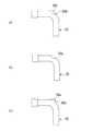
第2実施形態と第1実施形態との異なる点は、第1実施形態では、ドーム状の凸部8bに送気口8aが形成されているのに対し、第2実施形態では、図5の(a)に示すように、チューブ本体25の屈曲部に切り込みで開けられた送気口28aが形成され、送気口28aの上方に蓋状部28bが形成されている点である。この第2実施形態では、送気口28aの上方が蓋状部28bで覆われているので、分泌物等がより送気口28aに入り難くなっている。 The difference between the second embodiment and the first embodiment is that the
次に、第3実施形態と第2実施形態との異なる点は、第2実施形態では、送気口28aの上方が蓋状部28bで覆われているのに対し、第3実施形態では、図5の(b)に示すように、チューブ本体35に蓋状部28bが無く、送気口38aが全体的に開口している点である。この第3実施形態では、第2実施形態に比べて分泌物等が侵入しやすいが、声帯側に向けて大きく送気口38aが開口していることで、発声用空気を大量に声帯に向けて送り込むことが容易になる。 Next, the difference between the third embodiment and the second embodiment is that, in the second embodiment, the upper part of the
次に、第4実施形態と第1実施形態との異なる点は、第1実施形態では、ドーム状の凸部8bに送気口8aが形成されているのに対し、第4実施形態では、図5の(c)に示すように、チューブ本体45の屈曲部上に上方に向けて突出して円管状の凸部48bが形成され、凸部48bの上端開口部が送気口48aとなっている点である。この第4実施形態では、声帯側に向けて突出した円管状の凸部48bの上端に配された送気口48aから発声用空気が供給されるので、発声用空気の出射方向がより声帯側(上方)に方向付けされて気道壁への影響をさらに抑制することができる。 Next, the difference between the fourth embodiment and the first embodiment is that, in the first embodiment, the
次に、第5実施形態と第1実施形態との異なる点は、第1実施形態では、チューブ本体5内において呼吸気用空気流路5aの上に発声用空気流路8が形成されているのに対し、第5実施形態では、図6の(a)に示すように、チューブ本体55が同心軸上に形成された二重管構造であり、内側の断面円形状の呼吸気用空気流路55aの周囲を覆うように断面円環状の発声用空気流路58が形成されている点である。 Next, the difference between the fifth embodiment and the first embodiment is that, in the first embodiment, the utterance
また、第6実施形態では、図6の(b)に示すように、チューブ本体56において断面上部が発声用空気流路68とされ、断面下部が呼吸気用空気流路68とされ、発声用空気流路68と呼吸気用空気流路68との流路断面が同じに設定されている点で第1実施形態と異なっている。
さらに、第7実施形態では、図6の(c)に示すように、第1実施形態よりも発声用空気流路75の流路断面形状をチューブ本体75の周方向に延ばして流路面積を大きく設定している点で第1実施形態と異なっている。In the sixth embodiment, as shown in FIG. 6B, the upper cross section of the tube main body 56 is a voice
Further, in the seventh embodiment, as shown in FIG. 6C, the flow passage cross-sectional shape of the utterance
したがって、これら第4から第7実施形態では、第1実施形態に比べて発声用空気流路58,68,75の流路断面積が大きく設定されており、発声用空気をより低圧力にて比較的大量に送り込むことができる。 Therefore, in these fourth to seventh embodiments, the voice
次に、本発明に係る気管切開チューブ装置の第8及び第9実施形態について、図8及び図14を参照して以下に説明する。 Next, eighth and ninth embodiments of the tracheostomy tube device according to the present invention will be described below with reference to FIGS.
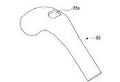
第8実施形態と第3実施形態との異なる点は、第3実施形態では、発声用空気供給流路の先端に送気口38aが単に接続されているのに対し、第8実施形態のチューブ本体85は、図8から図10に示すように、発声用空気供給流路88の先端に、送気口88aに向けて上方に傾斜する誘導壁88bが形成されている点である。
すなわち、第8実施形態では、誘導壁88bに発声用空気供給流路88内の空気が突き当たった際に、送気口88aに向けて空気を誘導するように傾斜している。
なお、送気口88aは、チューブ本体85の下部直胴部における軸線上に配されている。また、チューブ本体85の下部直胴部は、上部よりも外径が細く設定されている。The difference between the eighth embodiment and the third embodiment is that, in the third embodiment, the
That is, in the eighth embodiment, when the air in the utterance air
The
このように第8実施形態の気管切開チューブ装置では、発声用空気供給流路88の先端に、送気口88aに向けて上方に傾斜する誘導壁88bが形成されているので、送り込まれた空気が誘導壁88bで送気口88aに向かう上方に誘導されることで、空気を送気口88aから上向きに吹き出させることができる。 As described above, in the tracheostomy tube device of the eighth embodiment, the leading
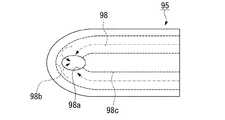
次に、第9実施形態と第8実施形態との異なる点は、第8実施形態では、発声用空気供給流路88の軸方向に直交する断面形状が略三日月形状であるのに対し、第9実施形態のチューブ本体95は、図11から図14に示すように、発声用空気供給流路98の軸方向に直交する断面形状が、左右に比べて中央部が狭くなった形状とされている点である。
すなわち、第9実施形態では、発声用空気供給流路98の内面で軸方向に直交する断面の中央に、内側に突出して少なくとも送気口98aの近傍まで発声用空気供給流路98に沿って延在した突条部98cが形成されている。Next, the difference between the ninth embodiment and the eighth embodiment is that, in the eighth embodiment, the cross-sectional shape orthogonal to the axial direction of the utterance air
That is, in the ninth embodiment, the inner surface of the utterance
また、第9実施形態では、送気口98aが、発声用空気供給流路98の先端側の途中に設けられ、発声用空気供給流路98の先端部に、送気口98aの部分からチューブ本体95の先端側に向けて形成された穴部98bが形成されている。
第9実施形態では、発声用空気供給流路98に送り込まれた空気が、図14に示すように、突条部98cによって左右に分離し、左右から送気口98aに向かうと共に、一部は穴部98bにまで回り込み、左右の流れが衝突して上方の送気口98aに向かう。なお、図14において、空気の流れを二点鎖線の矢印で簡易的に図示している。In the ninth embodiment, the
In the ninth embodiment, as shown in FIG. 14, the air sent into the utterance air
なお、チューブ本体95には、基端にカフ用チューブ7が接続されると共に先端がカフ6に接続されるカフ用流路97と、基端が吸引用チューブ13に接続されると共に先端がチューブ本体95の下部に形成された吸引口13aに接続された吸引用流路93とが一体成形で形成されている。すなわち、本実施形態では、カフ用チューブ7と吸引用チューブ13とをチューブ本体95の内部奥まで挿入する必要がなく、カフ用流路97がカフ用チューブ7の延長として機能し、吸引用流路93が吸引用チューブ13の延長として機能する。 The
このように第9実施形態の気管切開チューブ装置では、発声用空気供給流路98の内面で軸方向に直交する断面の中央に、内側に突出して少なくとも送気口98aの近傍まで発声用空気供給流路98に沿って延在した突条部98cが形成されているので、発声用空気供給流路98の空気が突条部98cで左右に分かれ、左右両側から回り込んで送気口98aから出ることで、空気の直進成分が抑制されて上方へ吹き出し易くなる。なお、突条部98cの突出量を大きく設定し、突条部98cが発声用空気供給流路98を完全に左右に分離していても構わない。 As described above, in the tracheotomy tube device of the ninth embodiment, the utterance air supply protrudes inwardly to the center of the cross section orthogonal to the axial direction on the inner surface of the utterance air
また、発声用空気供給流路98の先端部に、送気口98aの部分からチューブ本体95の先端側に向けて形成された穴部98bが形成されているので、突条部98cで左右に分離された空気が穴部98bで合流して互いの直進成分がさらに抑制されることで、送気口98aから上方へより吹き出し易くなる。 Further, since the
なお、本発明の技術範囲は上記各実施形態に限定されるものではなく、本発明の趣旨を逸脱しない範囲において種々の変更を加えることが可能である。 The technical scope of the present invention is not limited to the above embodiments, and various modifications can be made without departing from the spirit of the present invention.
例えば、上記各実施形態では、発声用チューブ及び発声用空気流路を介して発声用空気を送気口から気道内に供給するが、この発声用空気に霧化した殺菌水(微酸性電解水)を混入させても構わない。この場合、気管切開チューブ内部やカフ上面付近の衛生状態を良好に保つことが可能になる。
また、上記各実施形態では、上述したように発声用空気流路をチューブ本体に一体的に形成することが好ましいが、チューブ本体内に発声用チューブに接続されたチューブを取り付けて発声用空気流路としても構わない。For example, in each of the above embodiments, the utterance air is supplied from the air supply port into the airway through the utterance tube and the utterance air flow path. The sterilized water (slightly acidic electrolyzed water) atomized into the utterance air ) May be mixed. In this case, it becomes possible to maintain a good sanitary condition inside the tracheostomy tube and near the upper surface of the cuff.
In each of the above embodiments, as described above, it is preferable to integrally form the speech air flow path in the tube body. However, a tube connected to the speech tube is attached in the tube body so that the speech air flow is It does not matter as a road.
1…気管切開チューブ装置、2…気管切開チューブ、3…人工呼吸器、4…発声補助機、5,25,35,45,55,65,75,85,95,105…チューブ本体、5a,55a,65a,75a…呼吸気用空気流路、6…カフ、7…カフ用チューブ、8,58,68,78,88,98…発声用空気供給流路、8a、28a,38a,48a,88a,98a…発声用空気供給流路の送気口、8b,28b,48b…凸部、9…発声用チューブ、10…呼吸気用チューブ、13…吸引用チューブ、13a,93a…吸引口、88b…誘導壁、98b…穴部、98c…突条部、S…圧力センサ、T…気管 DESCRIPTION OF SYMBOLS 1 ... Tracheostomy tube apparatus, 2 ... Tracheostomy tube, 3 ... Ventilator, 4 ... Voice assistance machine, 5, 25, 35, 45, 55, 65, 75, 85, 95, 105 ... Tube main body, 5a, 55a, 65a, 75a ... breathing air flow path, 6 ... cuff, 7 ... cuff tube, 8, 58, 68, 78, 88, 98 ... voice supply air flow path, 8a, 28a, 38a, 48a, 88a, 98a ... Air supply port of voice air supply flow path, 8b, 28b, 48b ... convex part, 9 ... voice tube, 10 ... breathing tube, 13 ... suction tube, 13a, 93a ... suction port, 88b ... guide wall, 98b ... hole, 98c ... projection, S ... pressure sensor, T ... trachea
Claims (9)
Translated fromJapanese前記気管切開チューブが、呼吸気用空気流路を内部に有すると共に気管内に先端側が留置されるチューブ本体と、前記チューブ本体の先端部外周に設けられ膨張可能なカフと、前記チューブ本体に取り付けられ前記カフに空気を注入可能なカフ用チューブと、前記チューブ本体に設けられ前記カフより基端側に形成された送気口から外部に空気を送気可能な発声用空気供給流路と、前記発声用空気供給流路に接続された発声用チューブとを備え、
前記人工呼吸器が、呼吸気用チューブを介して前記呼吸気用空気流路に接続され、前記呼吸気用空気流路に空気を送り込む吸気動作と、前記呼吸気用空気流路から空気を吸引する呼気動作とを交互に行い、
前記発声補助機が、前記発声用空気供給流路に前記発声用チューブを介して接続され、前記人工呼吸器による前記呼気動作に合わせて前記発声用空気供給流路に空気を送り込むことを特徴とする気管切開チューブ装置。A tracheostomy tube, a ventilator, and a voice assist device;
The tracheostomy tube has an air flow passage for breathing air inside, a tube main body in which the distal end side is indwelled in the trachea, an inflatable cuff provided on the outer periphery of the distal end of the tube main body, and attached to the tube main body A cuff tube capable of injecting air into the cuff, and a voicing air supply channel provided in the tube main body and capable of supplying air to the outside from an air supply port formed on the proximal side from the cuff; A speech tube connected to the speech air supply flow path;
The ventilator is connected to the respiratory air flow channel via a respiratory air tube, and performs an inhalation operation for sending air to the respiratory air flow channel, and sucks air from the respiratory air flow channel Alternately perform exhalation operation,
The utterance assisting device is connected to the utterance air supply channel via the utterance tube, and sends air into the utterance air supply channel in accordance with the exhalation operation by the ventilator. Tracheostomy tube device.
前記人工呼吸器が、前記呼気動作を行う際に呼気動作信号を発信可能であり、
前記発声補助機が、前記呼気動作信号を受信可能であり、受信した前記呼気動作信号に基づいて前記発声用空気供給流路に空気を送り込むことを特徴とする気管切開チューブ装置。The tracheostomy tube device according to claim 1,
The ventilator is capable of transmitting an exhalation operation signal when performing the exhalation operation;
The tracheostomy tube device, wherein the speech assisting device is capable of receiving the exhalation operation signal and sends air into the speech air supply channel based on the received exhalation operation signal.
前記発声補助機が、前記呼吸気用チューブに設けられ前記呼吸気用チューブ内の圧力を測定可能な圧力センサを備え、前記圧力センサで測定した圧力に基づいて前記発声用空気供給流路に空気を送り込むことを特徴とする気管切開チューブ装置。The tracheostomy tube device according to claim 1,
The utterance assisting device includes a pressure sensor provided in the respiratory air tube and capable of measuring a pressure in the respiratory air tube, and air is supplied to the utterance air supply channel based on the pressure measured by the pressure sensor. A tracheostomy tube device, characterized in that
前記チューブ本体が、中間部分に屈曲部を有した屈曲形状とされ、先端部が肺側に向けて気管内に留置され、
前記発声用空気供給流路の送気口が、気管内に留置された際に前記屈曲部の口腔側に向いた位置に形成されていることを特徴とする気管切開チューブ装置。In the tracheostomy tube device according to any one of claims 1 to 3,
The tube body has a bent shape with a bent portion in the middle portion, the distal end portion is placed in the trachea toward the lung side,
A tracheostomy tube device, wherein the air supply port of the voice supply air flow path is formed at a position facing the oral cavity side of the bent portion when placed in the trachea.
前記発声用空気供給流路の送気口が、前記屈曲部の上部から口腔側に向けて突出した凸部に形成されていることを特徴とする気管切開チューブ装置。The tracheostomy tube device according to claim 4,
The tracheostomy tube device according to claim 1, wherein the air supply port of the utterance air supply channel is formed as a convex portion protruding from the upper part of the bent portion toward the oral cavity.
前記チューブ本体の前記カフと前記送気口との間に形成された吸引口に接続された吸引用チューブを備えていることを特徴とする気管切開チューブ装置。In the tracheostomy tube device according to any one of claims 1 to 5,
A tracheostomy tube device comprising a suction tube connected to a suction port formed between the cuff of the tube body and the air supply port.
前記発声用空気供給流路の先端に、前記送気口に向けて上方に傾斜する誘導壁が形成されていることを特徴とする気管切開チューブ装置。The tracheostomy tube device according to any one of claims 1 to 6,
A tracheostomy tube device, characterized in that a guide wall that is inclined upward toward the air supply port is formed at the tip of the voice supply air supply channel.
前記発声用空気供給流路の内面で軸方向に直交する断面の中央に、内側に突出して少なくとも前記送気口の近傍まで前記発声用空気供給流路に沿って延在した突条部が形成されていることを特徴とする気管切開チューブ装置。The tracheostomy tube device according to any one of claims 1 to 6,
At the center of the cross section orthogonal to the axial direction on the inner surface of the utterance air supply flow path, a protrusion that protrudes inward and extends along the utterance air supply flow path to at least the vicinity of the air supply port is formed. A tracheostomy tube device, characterized in that
前記送気口が、前記発声用空気供給流路の先端側の途中に設けられ、
前記発声用空気供給流路の先端部に、前記送気口の部分から前記チューブ本体の先端側に向けて形成された穴部が形成されていることを特徴とする気管切開チューブ装置。The tracheostomy tube device according to claim 8,
The air supply port is provided in the middle of the distal end side of the utterance air supply flow path,
A tracheostomy tube device, wherein a hole formed from the air supply port portion toward the distal end side of the tube main body is formed at a distal end portion of the voice supply air supply channel.
Priority Applications (1)
| Application Number | Priority Date | Filing Date | Title |
|---|---|---|---|
| JP2015112731AJP6220815B2 (en) | 2014-06-26 | 2015-06-03 | Tracheostomy tube device |
Applications Claiming Priority (3)
| Application Number | Priority Date | Filing Date | Title |
|---|---|---|---|
| JP2014130900 | 2014-06-26 | ||
| JP2014130900 | 2014-06-26 | ||
| JP2015112731AJP6220815B2 (en) | 2014-06-26 | 2015-06-03 | Tracheostomy tube device |
Publications (2)
| Publication Number | Publication Date |
|---|---|
| JP2016026542Atrue JP2016026542A (en) | 2016-02-18 |
| JP6220815B2 JP6220815B2 (en) | 2017-10-25 |
Family
ID=55352209
Family Applications (1)
| Application Number | Title | Priority Date | Filing Date |
|---|---|---|---|
| JP2015112731AExpired - Fee RelatedJP6220815B2 (en) | 2014-06-26 | 2015-06-03 | Tracheostomy tube device |
Country Status (1)
| Country | Link |
|---|---|
| JP (1) | JP6220815B2 (en) |
Cited By (6)
| Publication number | Priority date | Publication date | Assignee | Title |
|---|---|---|---|---|
| WO2018088385A1 (en)* | 2016-11-08 | 2018-05-17 | 俊郎 梅▲崎▼ | Tracheotomy tube having freely openable/closable lateral hole |
| CN109172986A (en)* | 2018-10-15 | 2019-01-11 | 福建中医药大学附属人民医院(福建省人民医院) | A kind of auxiliary sounding device and bionical vocal technique |
| CN109350305A (en)* | 2018-11-15 | 2019-02-19 | 王吉喆 | A kind of air-flow sounding electronic auxiliary system and method based on reed artificial larynx |
| WO2019121645A1 (en)* | 2017-12-22 | 2019-06-27 | Tracoe Medical Gmbh | Tracheostomy cannula having a phonation opening |
| CN115590658A (en)* | 2022-12-15 | 2023-01-13 | 首都医科大学附属北京同仁医院(Cn) | Artificial larynx system and control method |
| EP4129377A1 (en)* | 2021-08-07 | 2023-02-08 | Löwenstein Medical Technology S.A. | Ventilator system with speaking function |
Citations (3)
| Publication number | Priority date | Publication date | Assignee | Title |
|---|---|---|---|---|
| US4280492A (en)* | 1979-10-05 | 1981-07-28 | Latham Phillip B | Tracheostomy tube |
| JP2001079090A (en)* | 1999-07-26 | 2001-03-27 | Hansa Medical Products Inc | Valved and windowed trackeotomy tube having inner and outer cannulae |
| JP2009153775A (en)* | 2007-12-27 | 2009-07-16 | Arao Ichi | Phonation assisting device |
- 2015
- 2015-06-03JPJP2015112731Apatent/JP6220815B2/ennot_activeExpired - Fee Related
Patent Citations (3)
| Publication number | Priority date | Publication date | Assignee | Title |
|---|---|---|---|---|
| US4280492A (en)* | 1979-10-05 | 1981-07-28 | Latham Phillip B | Tracheostomy tube |
| JP2001079090A (en)* | 1999-07-26 | 2001-03-27 | Hansa Medical Products Inc | Valved and windowed trackeotomy tube having inner and outer cannulae |
| JP2009153775A (en)* | 2007-12-27 | 2009-07-16 | Arao Ichi | Phonation assisting device |
Cited By (8)
| Publication number | Priority date | Publication date | Assignee | Title |
|---|---|---|---|---|
| WO2018088385A1 (en)* | 2016-11-08 | 2018-05-17 | 俊郎 梅▲崎▼ | Tracheotomy tube having freely openable/closable lateral hole |
| US11000659B2 (en) | 2016-11-08 | 2021-05-11 | Toshiro UMEZAKI | Tracheotomy tube having freely openable/closable lateral hole |
| WO2019121645A1 (en)* | 2017-12-22 | 2019-06-27 | Tracoe Medical Gmbh | Tracheostomy cannula having a phonation opening |
| CN109172986A (en)* | 2018-10-15 | 2019-01-11 | 福建中医药大学附属人民医院(福建省人民医院) | A kind of auxiliary sounding device and bionical vocal technique |
| CN109350305A (en)* | 2018-11-15 | 2019-02-19 | 王吉喆 | A kind of air-flow sounding electronic auxiliary system and method based on reed artificial larynx |
| EP4129377A1 (en)* | 2021-08-07 | 2023-02-08 | Löwenstein Medical Technology S.A. | Ventilator system with speaking function |
| CN115590658A (en)* | 2022-12-15 | 2023-01-13 | 首都医科大学附属北京同仁医院(Cn) | Artificial larynx system and control method |
| CN115590658B (en)* | 2022-12-15 | 2023-03-14 | 首都医科大学附属北京同仁医院 | Artificial larynx system and control method |
Also Published As
| Publication number | Publication date |
|---|---|
| JP6220815B2 (en) | 2017-10-25 |
Similar Documents
| Publication | Publication Date | Title |
|---|---|---|
| JP6220815B2 (en) | Tracheostomy tube device | |
| CN101628134B (en) | Respiration device | |
| US10525221B2 (en) | High flow therapy artificial airway interfaces and related methods | |
| RU2556520C2 (en) | Development of breathing appliance | |
| US6655382B1 (en) | Spontaneous breathing apparatus and method | |
| JP4931586B2 (en) | Patient breathing assistance method, breathing assistance device, prosthesis and catheter | |
| JP5215365B2 (en) | Speech aids | |
| US20080053449A1 (en) | Respiratory Mask for Use in Endoscopy Procedures | |
| JP2000084083A (en) | Respiration aid device | |
| JP2011030863A (en) | Endotracheal tube introducer | |
| EP2964299B1 (en) | Tracheal cannula and speaking-respiration system for mechanical respiration | |
| KR101955699B1 (en) | Device for assisting vocalization of Tracheostomy tube | |
| SE522361C2 (en) | Ventilatortub | |
| KR101647972B1 (en) | Endotracheal tube | |
| CN106880897A (en) | A kind of anesthetic tube | |
| CN208389131U (en) | A kind of Multifunctional oropharyngeal airway | |
| CN203183463U (en) | Multi-cavity laryngeal mask | |
| CN2857966Y (en) | Throat cover with single cavity | |
| JP2013085900A (en) | Tracheostomy tube | |
| KR20160024097A (en) | Endotracheal tube | |
| EP4217033B1 (en) | Breath sensing with remote pressure sensor | |
| CN215875851U (en) | Oropharynx and nasopharynx ventilation catheter | |
| WO2014174582A1 (en) | Tracheotomy tube | |
| JP7078957B2 (en) | Tracheostomy tube with side holes that can be opened and closed freely | |
| JP2008114022A (en) | Tube for tracheal intubation |
Legal Events
| Date | Code | Title | Description |
|---|---|---|---|
| A621 | Written request for application examination | Free format text:JAPANESE INTERMEDIATE CODE: A621 Effective date:20160530 | |
| A977 | Report on retrieval | Free format text:JAPANESE INTERMEDIATE CODE: A971007 Effective date:20170215 | |
| A131 | Notification of reasons for refusal | Free format text:JAPANESE INTERMEDIATE CODE: A131 Effective date:20170306 | |
| A521 | Request for written amendment filed | Free format text:JAPANESE INTERMEDIATE CODE: A523 Effective date:20170428 | |
| TRDD | Decision of grant or rejection written | ||
| A01 | Written decision to grant a patent or to grant a registration (utility model) | Free format text:JAPANESE INTERMEDIATE CODE: A01 Effective date:20170905 | |
| A61 | First payment of annual fees (during grant procedure) | Free format text:JAPANESE INTERMEDIATE CODE: A61 Effective date:20171002 | |
| R150 | Certificate of patent or registration of utility model | Ref document number:6220815 Country of ref document:JP Free format text:JAPANESE INTERMEDIATE CODE: R150 | |
| R250 | Receipt of annual fees | Free format text:JAPANESE INTERMEDIATE CODE: R250 | |
| LAPS | Cancellation because of no payment of annual fees |