JP2016026159A - Phosphorescent materials - Google Patents
Phosphorescent materialsDownload PDFInfo
- Publication number
- JP2016026159A JP2016026159AJP2015161797AJP2015161797AJP2016026159AJP 2016026159 AJP2016026159 AJP 2016026159AJP 2015161797 AJP2015161797 AJP 2015161797AJP 2015161797 AJP2015161797 AJP 2015161797AJP 2016026159 AJP2016026159 AJP 2016026159A
- Authority
- JP
- Japan
- Prior art keywords
- compound
- compounds
- mmol
- mixture
- synthesis
- Prior art date
- Legal status (The legal status is an assumption and is not a legal conclusion. Google has not performed a legal analysis and makes no representation as to the accuracy of the status listed.)
- Granted
Links
- OIRDBPQYVWXNSJ-UHFFFAOYSA-NCOS(C(F)(F)F)(=O)=OChemical compoundCOS(C(F)(F)F)(=O)=OOIRDBPQYVWXNSJ-UHFFFAOYSA-N0.000description1
- ITMCEJHCFYSIIV-UHFFFAOYSA-M[O-]S(C(F)(F)F)(=O)=OChemical compound[O-]S(C(F)(F)F)(=O)=OITMCEJHCFYSIIV-UHFFFAOYSA-M0.000description1
- QKVWPNRUXZYLQV-UHFFFAOYSA-Nc(cc1c2ccc3)ccc1[s]c2c3-c1cccc(-c2cc3c(cccc4)c4c(cccc4)c4c3cc2)c1Chemical compoundc(cc1c2ccc3)ccc1[s]c2c3-c1cccc(-c2cc3c(cccc4)c4c(cccc4)c4c3cc2)c1QKVWPNRUXZYLQV-UHFFFAOYSA-N0.000description1
Images


Classifications
- C—CHEMISTRY; METALLURGY
- C07—ORGANIC CHEMISTRY
- C07F—ACYCLIC, CARBOCYCLIC OR HETEROCYCLIC COMPOUNDS CONTAINING ELEMENTS OTHER THAN CARBON, HYDROGEN, HALOGEN, OXYGEN, NITROGEN, SULFUR, SELENIUM OR TELLURIUM
- C07F15/00—Compounds containing elements of Groups 8, 9, 10 or 18 of the Periodic Table
- C07F15/0006—Compounds containing elements of Groups 8, 9, 10 or 18 of the Periodic Table compounds of the platinum group
- C07F15/0033—Iridium compounds
- C—CHEMISTRY; METALLURGY
- C09—DYES; PAINTS; POLISHES; NATURAL RESINS; ADHESIVES; COMPOSITIONS NOT OTHERWISE PROVIDED FOR; APPLICATIONS OF MATERIALS NOT OTHERWISE PROVIDED FOR
- C09K—MATERIALS FOR MISCELLANEOUS APPLICATIONS, NOT PROVIDED FOR ELSEWHERE
- C09K11/00—Luminescent, e.g. electroluminescent, chemiluminescent materials
- C09K11/06—Luminescent, e.g. electroluminescent, chemiluminescent materials containing organic luminescent materials
- H—ELECTRICITY
- H05—ELECTRIC TECHNIQUES NOT OTHERWISE PROVIDED FOR
- H05B—ELECTRIC HEATING; ELECTRIC LIGHT SOURCES NOT OTHERWISE PROVIDED FOR; CIRCUIT ARRANGEMENTS FOR ELECTRIC LIGHT SOURCES, IN GENERAL
- H05B33/00—Electroluminescent light sources
- H05B33/12—Light sources with substantially two-dimensional radiating surfaces
- H05B33/14—Light sources with substantially two-dimensional radiating surfaces characterised by the chemical or physical composition or the arrangement of the electroluminescent material, or by the simultaneous addition of the electroluminescent material in or onto the light source
- H—ELECTRICITY
- H10—SEMICONDUCTOR DEVICES; ELECTRIC SOLID-STATE DEVICES NOT OTHERWISE PROVIDED FOR
- H10K—ORGANIC ELECTRIC SOLID-STATE DEVICES
- H10K50/00—Organic light-emitting devices
- H10K50/10—OLEDs or polymer light-emitting diodes [PLED]
- H10K50/11—OLEDs or polymer light-emitting diodes [PLED] characterised by the electroluminescent [EL] layers
- H10K50/12—OLEDs or polymer light-emitting diodes [PLED] characterised by the electroluminescent [EL] layers comprising dopants
- H—ELECTRICITY
- H10—SEMICONDUCTOR DEVICES; ELECTRIC SOLID-STATE DEVICES NOT OTHERWISE PROVIDED FOR
- H10K—ORGANIC ELECTRIC SOLID-STATE DEVICES
- H10K85/00—Organic materials used in the body or electrodes of devices covered by this subclass
- H10K85/30—Coordination compounds
- H10K85/341—Transition metal complexes, e.g. Ru(II)polypyridine complexes
- H10K85/342—Transition metal complexes, e.g. Ru(II)polypyridine complexes comprising iridium
- C—CHEMISTRY; METALLURGY
- C09—DYES; PAINTS; POLISHES; NATURAL RESINS; ADHESIVES; COMPOSITIONS NOT OTHERWISE PROVIDED FOR; APPLICATIONS OF MATERIALS NOT OTHERWISE PROVIDED FOR
- C09K—MATERIALS FOR MISCELLANEOUS APPLICATIONS, NOT PROVIDED FOR ELSEWHERE
- C09K2211/00—Chemical nature of organic luminescent or tenebrescent compounds
- C09K2211/10—Non-macromolecular compounds
- C09K2211/1003—Carbocyclic compounds
- C09K2211/1007—Non-condensed systems
- C—CHEMISTRY; METALLURGY
- C09—DYES; PAINTS; POLISHES; NATURAL RESINS; ADHESIVES; COMPOSITIONS NOT OTHERWISE PROVIDED FOR; APPLICATIONS OF MATERIALS NOT OTHERWISE PROVIDED FOR
- C09K—MATERIALS FOR MISCELLANEOUS APPLICATIONS, NOT PROVIDED FOR ELSEWHERE
- C09K2211/00—Chemical nature of organic luminescent or tenebrescent compounds
- C09K2211/10—Non-macromolecular compounds
- C09K2211/1003—Carbocyclic compounds
- C09K2211/1011—Condensed systems
- C—CHEMISTRY; METALLURGY
- C09—DYES; PAINTS; POLISHES; NATURAL RESINS; ADHESIVES; COMPOSITIONS NOT OTHERWISE PROVIDED FOR; APPLICATIONS OF MATERIALS NOT OTHERWISE PROVIDED FOR
- C09K—MATERIALS FOR MISCELLANEOUS APPLICATIONS, NOT PROVIDED FOR ELSEWHERE
- C09K2211/00—Chemical nature of organic luminescent or tenebrescent compounds
- C09K2211/10—Non-macromolecular compounds
- C09K2211/1018—Heterocyclic compounds
- C09K2211/1025—Heterocyclic compounds characterised by ligands
- C09K2211/1059—Heterocyclic compounds characterised by ligands containing three nitrogen atoms as heteroatoms
- C09K2211/1066—Heterocyclic compounds characterised by ligands containing three nitrogen atoms as heteroatoms with sulfur
- C—CHEMISTRY; METALLURGY
- C09—DYES; PAINTS; POLISHES; NATURAL RESINS; ADHESIVES; COMPOSITIONS NOT OTHERWISE PROVIDED FOR; APPLICATIONS OF MATERIALS NOT OTHERWISE PROVIDED FOR
- C09K—MATERIALS FOR MISCELLANEOUS APPLICATIONS, NOT PROVIDED FOR ELSEWHERE
- C09K2211/00—Chemical nature of organic luminescent or tenebrescent compounds
- C09K2211/10—Non-macromolecular compounds
- C09K2211/1018—Heterocyclic compounds
- C09K2211/1025—Heterocyclic compounds characterised by ligands
- C09K2211/1074—Heterocyclic compounds characterised by ligands containing more than three nitrogen atoms as heteroatoms
- C—CHEMISTRY; METALLURGY
- C09—DYES; PAINTS; POLISHES; NATURAL RESINS; ADHESIVES; COMPOSITIONS NOT OTHERWISE PROVIDED FOR; APPLICATIONS OF MATERIALS NOT OTHERWISE PROVIDED FOR
- C09K—MATERIALS FOR MISCELLANEOUS APPLICATIONS, NOT PROVIDED FOR ELSEWHERE
- C09K2211/00—Chemical nature of organic luminescent or tenebrescent compounds
- C09K2211/10—Non-macromolecular compounds
- C09K2211/1018—Heterocyclic compounds
- C09K2211/1025—Heterocyclic compounds characterised by ligands
- C09K2211/1092—Heterocyclic compounds characterised by ligands containing sulfur as the only heteroatom
- C—CHEMISTRY; METALLURGY
- C09—DYES; PAINTS; POLISHES; NATURAL RESINS; ADHESIVES; COMPOSITIONS NOT OTHERWISE PROVIDED FOR; APPLICATIONS OF MATERIALS NOT OTHERWISE PROVIDED FOR
- C09K—MATERIALS FOR MISCELLANEOUS APPLICATIONS, NOT PROVIDED FOR ELSEWHERE
- C09K2211/00—Chemical nature of organic luminescent or tenebrescent compounds
- C09K2211/18—Metal complexes
- C09K2211/185—Metal complexes of the platinum group, i.e. Os, Ir, Pt, Ru, Rh or Pd
- H—ELECTRICITY
- H10—SEMICONDUCTOR DEVICES; ELECTRIC SOLID-STATE DEVICES NOT OTHERWISE PROVIDED FOR
- H10K—ORGANIC ELECTRIC SOLID-STATE DEVICES
- H10K2101/00—Properties of the organic materials covered by group H10K85/00
- H10K2101/10—Triplet emission
- H—ELECTRICITY
- H10—SEMICONDUCTOR DEVICES; ELECTRIC SOLID-STATE DEVICES NOT OTHERWISE PROVIDED FOR
- H10K—ORGANIC ELECTRIC SOLID-STATE DEVICES
- H10K50/00—Organic light-emitting devices
- H10K50/10—OLEDs or polymer light-emitting diodes [PLED]
- H10K50/11—OLEDs or polymer light-emitting diodes [PLED] characterised by the electroluminescent [EL] layers
- H—ELECTRICITY
- H10—SEMICONDUCTOR DEVICES; ELECTRIC SOLID-STATE DEVICES NOT OTHERWISE PROVIDED FOR
- H10K—ORGANIC ELECTRIC SOLID-STATE DEVICES
- H10K85/00—Organic materials used in the body or electrodes of devices covered by this subclass
- H10K85/30—Coordination compounds
- H10K85/321—Metal complexes comprising a group IIIA element, e.g. Tris (8-hydroxyquinoline) gallium [Gaq3]
- H10K85/324—Metal complexes comprising a group IIIA element, e.g. Tris (8-hydroxyquinoline) gallium [Gaq3] comprising aluminium, e.g. Alq3
- H—ELECTRICITY
- H10—SEMICONDUCTOR DEVICES; ELECTRIC SOLID-STATE DEVICES NOT OTHERWISE PROVIDED FOR
- H10K—ORGANIC ELECTRIC SOLID-STATE DEVICES
- H10K85/00—Organic materials used in the body or electrodes of devices covered by this subclass
- H10K85/60—Organic compounds having low molecular weight
- H10K85/615—Polycyclic condensed aromatic hydrocarbons, e.g. anthracene
- H10K85/622—Polycyclic condensed aromatic hydrocarbons, e.g. anthracene containing four rings, e.g. pyrene
- H—ELECTRICITY
- H10—SEMICONDUCTOR DEVICES; ELECTRIC SOLID-STATE DEVICES NOT OTHERWISE PROVIDED FOR
- H10K—ORGANIC ELECTRIC SOLID-STATE DEVICES
- H10K85/00—Organic materials used in the body or electrodes of devices covered by this subclass
- H10K85/60—Organic compounds having low molecular weight
- H10K85/631—Amine compounds having at least two aryl rest on at least one amine-nitrogen atom, e.g. triphenylamine
- H10K85/633—Amine compounds having at least two aryl rest on at least one amine-nitrogen atom, e.g. triphenylamine comprising polycyclic condensed aromatic hydrocarbons as substituents on the nitrogen atom
- H—ELECTRICITY
- H10—SEMICONDUCTOR DEVICES; ELECTRIC SOLID-STATE DEVICES NOT OTHERWISE PROVIDED FOR
- H10K—ORGANIC ELECTRIC SOLID-STATE DEVICES
- H10K85/00—Organic materials used in the body or electrodes of devices covered by this subclass
- H10K85/60—Organic compounds having low molecular weight
- H10K85/649—Aromatic compounds comprising a hetero atom
- H10K85/657—Polycyclic condensed heteroaromatic hydrocarbons
- H10K85/6576—Polycyclic condensed heteroaromatic hydrocarbons comprising only sulfur in the heteroaromatic polycondensed ring system, e.g. benzothiophene
- Y—GENERAL TAGGING OF NEW TECHNOLOGICAL DEVELOPMENTS; GENERAL TAGGING OF CROSS-SECTIONAL TECHNOLOGIES SPANNING OVER SEVERAL SECTIONS OF THE IPC; TECHNICAL SUBJECTS COVERED BY FORMER USPC CROSS-REFERENCE ART COLLECTIONS [XRACs] AND DIGESTS
- Y02—TECHNOLOGIES OR APPLICATIONS FOR MITIGATION OR ADAPTATION AGAINST CLIMATE CHANGE
- Y02E—REDUCTION OF GREENHOUSE GAS [GHG] EMISSIONS, RELATED TO ENERGY GENERATION, TRANSMISSION OR DISTRIBUTION
- Y02E10/00—Energy generation through renewable energy sources
- Y02E10/50—Photovoltaic [PV] energy
- Y02E10/549—Organic PV cells
Landscapes
- Chemical & Material Sciences (AREA)
- Organic Chemistry (AREA)
- Engineering & Computer Science (AREA)
- Materials Engineering (AREA)
- Inorganic Chemistry (AREA)
- Crystallography & Structural Chemistry (AREA)
- Physics & Mathematics (AREA)
- Optics & Photonics (AREA)
- Electroluminescent Light Sources (AREA)
- Pyridine Compounds (AREA)
- Spectroscopy & Molecular Physics (AREA)
- Low-Molecular Organic Synthesis Reactions Using Catalysts (AREA)
- Plural Heterocyclic Compounds (AREA)
Abstract
Description
Translated fromJapanese本出願は、2007年5月25日出願の米国仮出願第60/940310号、2008年9月3日出願の米国仮出願第61/093967号、2008年12月23日出願の米国仮出願第61/140459号、2009年7月28日出願の米国仮出願第61/229088号及び2009年7月29日出願のPCT/US09/52045に関する優先権を請求するものである。これらの開示を全体として参照により本明細書に明確に組み込む。 This application includes US provisional application No. 60/940310 filed on May 25, 2007, US provisional application No. 61/093967 filed on September 3, 2008, and US provisional application filed on December 23, 2008. No. 61/140459, US Provisional Application No. 61/229088 filed July 28, 2009 and PCT / US09 / 52045 filed July 29, 2009. These disclosures are expressly incorporated herein by reference in their entirety.
請求された発明は、産学共同(joint university corporation)研究契約にかかる次の団体:ザリージェンツオブザユニバーシティオブミシガン(Regents of the University of Michigan)、プリンストン大学、南カリフォルニア大学及びユニバーサルディスプレイコーポレーション(Universal Display Corporation)の1つまたは複数によって、それらのために、及び/またはそれらに関連してなされたものである。上記契約は請求された発明がなされたときまたはそれ以前からその効力を発揮し、請求された発明はその契約の範囲での活動の結果としてなされたものである。 The claimed invention is based on the following organizations under a joint university corporation research contract: The Regents of the University of Michigan, Princeton University, University of Southern California, and Universal Display Corporation. ) For, and / or in connection with them. The contract is effective when the claimed invention was made or before, and the claimed invention was made as a result of activities within the scope of the contract.
本発明は、有機発光性デバイスで使用するのに有利な有機材料に関する。より特定すると、本発明は、そうしたデバイス用の有機材料ならびに新規な有機材料を作製する方法に関する。 The present invention relates to organic materials that are advantageous for use in organic light emitting devices. More particularly, the present invention relates to organic materials for such devices as well as methods for making new organic materials.
有機材料を使用する光電子デバイスは、いくつかの理由から、ますます望まれてきている。そうしたデバイスを作るのに使用される材料の多くは比較的安価であり、したがって有機光電子デバイスは、無機デバイスに対してコスト的に有利な潜在性を有している。さらに、その柔軟性などの有機材料の固有の特性は、それらを柔軟な基板上での加工などの特定の用途に十分適したものにしている。有機光電子デバイスの例には、有機発光性デバイス(OLED)、有機光トランジスタ、有機光電池及び有機光検知器が含まれる。OLEDのために、有機材料は、従来の材料にまさる性能優位性を有することができる。例えば、有機発光層が光を放出できる波長を、通常適切なドーパントで容易に調整することができる。 Optoelectronic devices that use organic materials are becoming increasingly desirable for several reasons. Many of the materials used to make such devices are relatively inexpensive, and thus organic optoelectronic devices have a cost-effective potential for inorganic devices. Furthermore, the inherent properties of organic materials, such as their flexibility, make them well suited for specific applications such as processing on flexible substrates. Examples of organic optoelectronic devices include organic light emitting devices (OLEDs), organic phototransistors, organic photovoltaic cells, and organic photodetectors. For OLEDs, organic materials can have performance advantages over conventional materials. For example, the wavelength at which the organic light emitting layer can emit light can usually be easily adjusted with a suitable dopant.
OLEDには、デバイスに電圧をかけたとき発光する有機薄膜が使用される。OLEDはますます、フラットパネルディスプレイ、照明及びバックライト用などの用途に使用するための興味ある技術となってきている。いくつかのOLED材料及び構造物が米国特許第5844363号、同第6303238号及び同第5707745号(これらを全体として参照により本明細書に組み込む)に記載されている。 OLEDs use organic thin films that emit light when a voltage is applied to the device. OLED is increasingly becoming an interesting technology for use in applications such as flat panel displays, lighting and backlighting. Several OLED materials and structures are described in US Pat. Nos. 5,844,363, 6,303,238 and 5,707,745, which are hereby incorporated by reference in their entirety.
リン発光性分子の1つの用途はフルカラーディスプレイである。そうしたディスプレイのための業界標準は、「飽和」色と称される特定の色を発光するように適合された画素を求める。特に、これらの標準は飽和した赤色、緑色及び青色画素を求める。色は、当技術分野で周知のCIE座標を用いて測られる。 One application of phosphorescent molecules is a full color display. Industry standards for such displays require pixels that are adapted to emit a particular color, referred to as a “saturated” color. In particular, these standards require saturated red, green and blue pixels. Color is measured using CIE coordinates well known in the art.
緑色発光性分子の一例はIr(ppy)3で表されるトリス(2-フェニルピリジン)イリジウムである。これは次の構造:
上記、及び本明細書で以下に示す図において、窒素から金属(ここでは、Ir)への配位結合を直線で示す。 In the above and the following figures in this specification, the coordination bond from nitrogen to metal (here Ir) is shown by a straight line.
本明細書で用いる「有機」という用語は、有機光電子デバイスを組み立てるのに用いられるポリマー材料ならびに小分子有機材料を含む。「小分子」は、ポリマーではない任意の有機材料を指すが、「小分子」は実際には相当大きくてよい。小分子は、場合によっては繰り返し単位を含むことができる。例えば、置換基として長鎖アルキル基を用いても、その分子が「小分子」の部類から除外されることはない。小分子は、例えば、ポリマー主鎖上の懸垂基またはその主鎖の一部として、ポリマー中に組み込むこともできる。小分子は、コア部分上に構築された一連の化学シェルからなるデンドリマーのコア部分としても働くことができる。デンドリマーのコア部分は、蛍光性またはリン光性の小分子エミッターであってよい。デンドリマーは「小分子」であってよく、OLEDの分野で現在使用されているすべてのデンドリマーは小分子であると考えられる。 As used herein, the term “organic” includes polymeric materials as well as small molecule organic materials used to assemble organic optoelectronic devices. “Small molecule” refers to any organic material that is not a polymer, but “small molecules” may actually be quite large. Small molecules can optionally include repeat units. For example, using a long chain alkyl group as a substituent does not remove the molecule from the “small molecule” class. Small molecules can also be incorporated into the polymer, for example, as a pendant group on the polymer backbone or as part of the backbone. Small molecules can also serve as the core part of a dendrimer consisting of a series of chemical shells built on the core part. The core portion of the dendrimer may be a fluorescent or phosphorescent small molecule emitter. Dendrimers may be “small molecules” and all dendrimers currently used in the field of OLED are considered small molecules.
本明細書で用いる「頂部」は、基板から最も遠いところを意味し、「底部」は、基板から最も近いところを意味する。第1の層が第2の層の「上に配置されている」と表現されている場合、その第1の層は基板から最も遠い位置に配置されている。第1の層が第2の層と「接触している」という指定がない限り、第1の層と第2の層の間に他の層が存在していてよい。例えば、種々の有機層がその間に存在していたとしても、カソードは、アノードの「上に配置されている」と表現することができる。 As used herein, “top” means the point farthest from the substrate and “bottom” means the point closest to the substrate. When the first layer is expressed as “disposed on” the second layer, the first layer is disposed farthest from the substrate. There may be other layers between the first layer and the second layer, unless it is specified that the first layer is “in contact with” the second layer. For example, the cathode can be described as “arranged on” the anode, even though various organic layers were present therebetween.
本明細書で用いる「溶液加工性」は、溶液形態であっても懸濁形態であっても、液媒体中に溶解、分散もしくは輸送するか、かつ/またはそこから析出することができることを意味する。 As used herein, “solution processability” means that it can be dissolved, dispersed or transported in and / or precipitated from a liquid medium, whether in solution or suspension form. To do.
配位子が発光性材料の光活性特性に直接寄与していると考えられる場合、配位子を「光活性」と称することができる。配位子が発光性材料の光活性特性に寄与しないが、補助的配位子が光活性配位子の特性を変えることができる場合、配位子を「補助的」と称することができる。 A ligand can be referred to as “photoactive” if it is believed that the ligand contributes directly to the photoactive properties of the luminescent material. A ligand can be referred to as “auxiliary” if the ligand does not contribute to the photoactive properties of the luminescent material, but the auxiliary ligand can alter the properties of the photoactive ligand.
本明細書で使用されかつ当業者に一般に理解されているように、第1のエネルギー準位が真空エネルギー準位に、より近接している場合、第1の「最高被占分子軌道」(HOMO)または「最低空分子軌道」(LUMO)エネルギー準位は、第2のHOMOまたはLUMOエネルギー準位「より大きい」または「より高い」といえる。イオン化ポテンシャル(IP)は真空準位に対して負エネルギーとして測定されるので、より高いHOMOエネルギー準位は、より小さい絶対値を有するIP(より小さい負の値のIP)に対応する。同様に、より高いLUMOエネルギー準位は、より小さい絶対値を有する電子親和力(EA)(より小さい負の値のEA)に対応する。真空準位が頂部にある慣用的なエネルギー準位ダイアグラム上では、ある材料のLUMOエネルギー準位は、同じ材料のHOMOエネルギー準位より高い。「より高い」HOMOまたはLUMOエネルギー準位は、「より低い」HOMOまたはLUMOエネルギー準位より、そうしたダイアグラムの頂部により近接しているように見える。 As used herein and generally understood by those skilled in the art, when the first energy level is closer to the vacuum energy level, the first `` highest occupied molecular orbital '' (HOMO ) Or “lowest unoccupied molecular orbital” (LUMO) energy level can be said to be “greater than” or “higher” than the second HOMO or LUMO energy level. Since the ionization potential (IP) is measured as a negative energy relative to the vacuum level, a higher HOMO energy level corresponds to an IP having a smaller absolute value (a smaller negative value IP). Similarly, a higher LUMO energy level corresponds to an electron affinity (EA) having a smaller absolute value (a smaller negative EA). On a conventional energy level diagram with the vacuum level at the top, the LUMO energy level of a material is higher than the HOMO energy level of the same material. “Higher” HOMO or LUMO energy levels appear to be closer to the top of such diagrams than “lower” HOMO or LUMO energy levels.
本明細書で使用されかつ当業者に一般に理解されているように、第1の仕事関数がより高い絶対値を有している場合、第1の仕事関数は第2の仕事関数「より大きい」または「より高い」といえる。仕事関数は通常、真空準位に対して負の数として測られるので、これは、「より高い」仕事関数は負の値がより大きいことを意味する。真空準位が頂部にある慣用的なエネルギー準位ダイアグラム上では、「より高い」仕事関数は真空準位から下方にさらに遠いと表される。したがって、HOMO及びLUMOエネルギー準位の定義は、仕事関数とは異なった慣例に従うことになる。 As used herein and generally understood by those skilled in the art, a first work function is “greater than” a second work function when the first work function has a higher absolute value. Or “higher”. Since the work function is usually measured as a negative number with respect to the vacuum level, this means that a “higher” work function has a larger negative value. On the conventional energy level diagram with the vacuum level at the top, the “higher” work function is expressed as being further down from the vacuum level. Therefore, the definition of HOMO and LUMO energy levels follows a convention different from work function.
OLED及び上記定義についての詳細は米国特許第7279704号(これを全体として参照により本明細書に組み込む)に見ることができる。 Details on OLEDs and the above definitions can be found in US Pat. No. 7,279,704, which is incorporated herein by reference in its entirety.
拡張共役を有するヘテロレプティックIr(III)錯体を作製するための方法を提供する。その方法は、
さらに、リン発光性材料を提供する。この材料は、複素環上に拡張共役を有するヘテロレプティック錯体である。この材料は有機発光性デバイスにおいて有利に使用することができる。特に、この材料はそうしたデバイスの発光性ドーパントとして有用である。この材料は、
一態様では、化合物1が好ましい。他の態様では、化合物2が好ましい。 In one aspect,
さらに、有機発光性デバイスを提供する。デバイスは、アノード、カソード、及びそのアノードとカソードの間に配置された有機層を有し、その有機層は化合物1〜6から選択される化合物を含む。有機層はホストをさらに含むことができる。好ましくは、そのホストはトリフェニレン基を含む。より好ましくは、そのホストはテルフェニルでさらに置換されたトリフェニレンを含む。最も好ましくは、そのホストはH1である。 Furthermore, an organic light emitting device is provided. The device has an anode, a cathode, and an organic layer disposed between the anode and cathode, the organic layer comprising a compound selected from compounds 1-6. The organic layer can further include a host. Preferably, the host contains a triphenylene group. More preferably, the host comprises triphenylene further substituted with terphenyl. Most preferably, the host is H1.
消費者製品も提供する。その製品はアノード、カソード及びそのアノードとカソードの間に配置された有機層を有するデバイスを含み、その有機層は化合物1〜6から選択される化合物をさらに含む。 It also provides consumer products. The product includes a device having an anode, a cathode and an organic layer disposed between the anode and cathode, the organic layer further comprising a compound selected from compounds 1-6.
有機発光性デバイスにおいて有利に使用できるヘテロレプティックイリジウム化合物を提供する。ヘテロレプティック化合物は、
一態様では、化合物8が好ましい。他の態様では、化合物9が好ましい。さらに他の態様では、化合物10が好ましい。他の態様では、化合物11が好ましい。さらに他の態様では、化合物12が好ましい。他の態様では、化合物13が好ましい。さらに他の態様では、化合物14が好ましい。 In one aspect, compound 8 is preferred. In other embodiments,
さらに、有機発光性デバイスを提供する。デバイスは、アノード、カソード及びそのアノードとカソードの間に配置された有機層を有し、その有機層は化合物8〜14から選択される化合物を含む。有機層は、アリールまたはヘテロアリールでさらに置換されたトリフェニレン基を有するホストをさらに含むことができる。好ましくは、ホストはテルフェニルまたはジベンゾチオフェンでさらに置換されたトリフェニレン基を含む。より好ましくは、ホストはH1またはH2である。 Furthermore, an organic light emitting device is provided. The device has an anode, a cathode and an organic layer disposed between the anode and cathode, the organic layer comprising a compound selected from compounds 8-14. The organic layer can further include a host having a triphenylene group further substituted with aryl or heteroaryl. Preferably, the host comprises a triphenylene group further substituted with terphenyl or dibenzothiophene. More preferably, the host is H1 or H2.
消費者製品も提供する。その製品はアノード、カソード及びそのアノードとカソードの間に配置された有機層を有するデバイスを含み、その有機層は化合物8〜14から選択される化合物をさらに含む。 It also provides consumer products. The product includes a device having an anode, a cathode and an organic layer disposed between the anode and cathode, the organic layer further comprising a compound selected from compounds 8-14.
さらに、著しい配位子の乱れ(scrambling)を伴うことなくヘテロレプティック化合物を作製するための方法を提供する。その方法は、
式Ir(LA-B)2(LC-D)を有するヘテロレプティック化合物を提供する。LA-Bは、
新規なリン光性有機材料を提供する。その有機材料は、その置換基アリールが通常の不飽和フェニル-フェニルより、平面の外にねじれ出ている(すなわち、本明細書ではねじれ型(twisted)アリール)、アルキル置換基及びアリール置換基を有する少なくとも1つの配位子を含む化合物である。この化合物は、有機発光性デバイスにおいて有利に使用することができる。特に、この化合物はそうしたデバイスにおいて発光性ドーパントとして有用である。 A novel phosphorescent organic material is provided. The organic material has an alkyl substituent and an aryl substituent, where the substituent aryl is twisted out of the plane from the usual unsaturated phenyl-phenyl (i.e., twisted aryl herein). It is a compound containing at least one ligand. This compound can be advantageously used in organic light-emitting devices. In particular, this compound is useful as a luminescent dopant in such devices.
以下の構造:
B及びCはそれぞれ独立に、5員または6員の炭素環または複素環である。A-Bは、環A上の窒素原子及び環B上のsp2混成炭素原子を介して金属Mと配位している炭素環または複素環の結合対を表す。A-Cは炭素環または複素環の結合対を表す。Ra、Rb及びRCは、一置換、二置換、三置換または四置換を表すことができる。Ra、Rb及びRCは独立に、水素、アルキル、アルコキシ、アミノ、アルケニル、アルキニル、arylkyl、アリール及びヘテロアリールからなる群から選択される。X1、X2、X3、X4、X5、X6、X7、X8及びX9は独立に、炭素及び窒素から選択される。好ましくは、Aはピリジンである。R1及びR2は独立に、水素、アルキル、アルコキシ、アミノ、アルケニル、アルキニル、arylkyl、アリール及びヘテロアリールからなる群から選択される。R1、R2、及び環Cと隣接するRa置換基の少なくとも1つは水素ではない。好ましくは、R1、R2、及びCと隣接するRa置換基のうちの1つだけは水素ではない。好ましくは、R1、R2、及びCと隣接するRa置換基のうちの1つだけはアルキルである。より好ましくは、R1、R2、及びCと隣接するRa置換基のうちの1つだけはエチルである。最も好ましくは、R1、R2、及びCと隣接するRa置換基のうちの1つだけはメチルである。配位子Lは、40より大きい原子番号を有する金属Mと配位している。好ましくは、その金属MはIrである。B and C are each independently a 5-membered or 6-membered carbocyclic or heterocyclic ring. AB represents a carbocyclic or heterocyclic bonded pair coordinated with metal M through a nitrogen atom on ring A and an sp2 hybridized carbon atom on ring B. AC represents a carbocyclic or heterocyclic bond pair. Ra , Rb and RC can represent mono-, di-, tri- or tetra-substitution. Ra , Rb and RC are independently selected from the group consisting of hydrogen, alkyl, alkoxy, amino, alkenyl, alkynyl, arylkyl, aryl and heteroaryl. X1 , X2 , X3 , X4 , X5 , X6 , X7 , X8 and X9 are independently selected from carbon and nitrogen. Preferably A is pyridine. R1 and R2 are independently selected from the group consisting of hydrogen, alkyl, alkoxy, amino, alkenyl, alkynyl, arylkyl, aryl and heteroaryl. At least one of R1 , R2 , and the Ra substituent adjacent to ring C is not hydrogen. Preferably, onlyone of R1 , R2 , and the Ra substituent adjacent to C is not hydrogen. Preferably, onlyone of R1 , R2 , and the Ra substituent adjacent to C is alkyl. More preferably, onlyone of R1 , R2 , and the Ra substituent adjacent to C is ethyl. Most preferably, onlyone of R1 , R2 , and the Ra substituent adjacent to C is methyl. Ligand L is coordinated with metal M having an atomic number greater than 40. Preferably, the metal M is Ir.
化合物の例は以下の構造を有する化合物:
mは酸化状態の金属Mである。好ましくは、その金属MはIrである。好ましくは、Aはピリジンでである。nは少なくとも1である。L'はモノアニオン二座配位子である。好ましくは、R1、R2、及びCと隣接するRa置換基のうちの1つだけは水素ではない。好ましくは、R1、R2、及びCと隣接するRa置換基のうちの1つだけはアルキルである。より好ましくは、R1、R2、及びCと隣接するRa置換基のうちの1つだけはエチルである。最も好ましくは、R1、R2、及びCと隣接するRa置換基のうちの1つだけはメチルである。m is an oxidized metal M. Preferably, the metal M is Ir. Preferably A is pyridine. n is at least 1. L ′ is a monoanionic bidentate ligand. Preferably, onlyone of R1 , R2 , and the Ra substituent adjacent to C is not hydrogen. Preferably, onlyone of R1 , R2 , and the Ra substituent adjacent to C is alkyl. More preferably, onlyone of R1 , R2 , and the Ra substituent adjacent to C is ethyl. Most preferably, onlyone of R1 , R2 , and the Ra substituent adjacent to C is methyl.
式IIを有する化合物の特定の例を提供する。それらには、化合物15〜化合物20が含まれる。Rは水素ではない。好ましくは、Rはアルキルである。 Specific examples of compounds having Formula II are provided. They include compound 15 to compound 20. R is not hydrogen. Preferably R is alkyl.
式IIを有する化合物の具体的な例を提供する。それらには、化合物21〜化合物37が含まれる。一態様では、化合物21、22、25、29、30、31及び34は好ましい化合物である。 Specific examples of compounds having Formula II are provided. They include compound 21 to compound 37. In one aspect, compounds 21, 22, 25, 29, 30, 31, and 34 are preferred compounds.
一態様では、
他の態様では、化合物は、
式IIを有する化合物は、ホモレプティック化合物及びヘテロレプティック化合物を含む。ホモレプティック化合物の例には、化合物21〜24及び35が含まれる。ヘテロレプティック化合物の例には、化合物25〜34、36及び37が含まれる。 Compounds having formula II include homoleptic compounds and heteroleptic compounds. Examples of homoleptic compounds include compounds 21-24 and 35. Examples of heteroleptic compounds include compounds 25-34, 36 and 37.
一態様では、
一態様では、アルキル置換基(すなわち、アリール置換基においてねじれをもたらすアルキル置換基)が配位子Lのピリジン環上に存在する化合物が好ましい。好ましくはその化合物は、その化合物21〜23、29〜31、34、36及び37からなる群から選択される。 In one aspect, compounds in which an alkyl substituent (ie, an alkyl substituent that results in a twist in the aryl substituent) is present on the pyridine ring of the ligand L are preferred. Preferably the compound is selected from the group consisting of compounds 21-23, 29-31, 34, 36 and 37.
他の態様では、アルキル置換基がピリジン環の窒素に対してパラ位である化合物が特に好ましい。好ましくはその化合物は、化合物21、22、29〜31、34、36及び37からなる群から選択される。 In other embodiments, compounds where the alkyl substituent is para to the nitrogen of the pyridine ring are particularly preferred. Preferably the compound is selected from the group consisting of compounds 21, 22, 29-31, 34, 36 and 37.
有機発光性デバイスも提供する。デバイスは、アノード、カソード及びそのアノードとカソードの間に配置された有機層を有し、その有機層は上記したような式Iを有する化合物を含む。式Iを有する化合物に好ましいと記載されている置換基のための選択は、式Iを有する化合物を含むデバイスについても好ましい。これらの選択は、金属M;式II〜VI;置換基R、R1、R2、R3、R4、R5、及び環Cと隣接するRa置換基;環Cの位置;ならびに環A、B及びCについて記載されているものを含む。An organic light emitting device is also provided. The device has an anode, a cathode and an organic layer disposed between the anode and cathode, the organic layer comprising a compound having formula I as described above. The choice for substituents described as preferred for compounds having Formula I is also preferred for devices comprising compounds having Formula I. These choices include metal M; Formulas II-VI; substituents R, R1 , R2 , R3 , R4 , R5 , and Ra substituent adjacent to ring C; position of ring C; and ring Including those described for A, B and C.
一態様では、そのデバイスは、上記したような式IIを有する化合物を含む。好ましくは、その金属MはIrである。好ましくは、Aはピリジンである。他の態様では、そのデバイスは上記したような式IIIまたは式IVを有する化合物を含む。R1、R2、及びCと隣接するRa置換基のうちの1つだけがアルキルである化合物を含むデバイスも好ましい。さらに他の態様では、そのデバイスは、上記したような式Vまたは式VIを有する化合物を含む。化合物21〜化合物37からなる群から選択される化合物を含む特定のデバイスを提供する。好ましくは、そのデバイスは、化合物21、化合物22、化合物25、化合物29、化合物30、化合物31または化合物34を含む。In one aspect, the device comprises a compound having Formula II as described above. Preferably, the metal M is Ir. Preferably A is pyridine. In other embodiments, the device comprises a compound having Formula III or Formula IV as described above. Also preferred are devices comprising compounds in which only one of R1 , R2 , and the Ra substituent adjacent to C is alkyl. In yet other embodiments, the device comprises a compound having Formula V or Formula VI as described above. Certain devices comprising a compound selected from the group consisting of Compound 21 to Compound 37 are provided. Preferably, the device comprises compound 21, compound 22, compound 25, compound 29, compound 30, compound 31 or compound 34.
一態様では、その有機層が発光層であり、式Iの式を有する化合物が発光性ドーパントであるデバイスを提供する。さらに、その有機層はホストをさらに含むことができる。好ましくは、そのホストは次の構造:
デバイスを含む消費者製品も提供する。そのデバイスは、アノード、カソード、及びそのアノードとカソードの間に配置された有機層含み、その有機層は上記したような式Iを有する化合物を含む。式Iを有する化合物に好ましいと記載されている置換基のための選択は、式Iを有する化合物を含むデバイスを含む消費者製品における使用についても好ましい。これらの選択は、金属M;式II〜VI;置換基R、R1、R2、R3、R4、R5、及び環Cと隣接するRa置換基;環Cの位置;ならびに環A、B及びCについて記載されているものを含む。It also provides consumer products including devices. The device comprises an anode, a cathode, and an organic layer disposed between the anode and cathode, the organic layer comprising a compound having formula I as described above. The choice for substituents described as preferred for compounds having formula I is also preferred for use in consumer products comprising devices comprising compounds having formula I. These choices include metal M; Formulas II-VI; substituents R, R1 , R2 , R3 , R4 , R5 , and the Ra substituent adjacent to ring C; the position of ring C; and the ring Including those described for A, B and C.
さらに、ホモレプティック化合物を作製するための低温法を提供する。特に、その方法はホモレプティックIr(III)化合物を作製するための方法である。これらの化合物は好ましくはねじれ型アリールを含むことができる。 In addition, a low temperature method for making homoleptic compounds is provided. In particular, the method is a method for preparing a homoleptic Ir (III) compound. These compounds can preferably comprise a twisted aryl.
ホモレプティックIr(III)錯体を作製するための第1の方法を提供する。その第1の方法は、
RA及びRBの少なくとも1つはアルキル基であり、そのアルキル基はピリジン環上の窒素と隣接していない。Sは中性配位子である。Xは対イオンである。好ましくは、Xはトリフラートである。A及びBはそれぞれ独立に、5員または6員の炭素環または複素環である。A-Bは、環A上の窒素原子及び環B上のsp2混成炭素原子を介してイリジウムと配位している炭素環または複素環の結合対を表す。RA及びRBのそれぞれは、一置換、二置換、三置換または四置換を表すことができる。RA及びRBはそれぞれ独立に、水素、アルキル、アルコキシ、アミノ、アルケニル、アルキニル、arylkyl、アリール及びヘテロアリールからなる群から選択される。At least one of RA and RB is an alkyl group that is not adjacent to the nitrogen on the pyridine ring. S is a neutral ligand. X is a counter ion. Preferably X is triflate. A and B are each independently a 5- or 6-membered carbocyclic or heterocyclic ring. AB represents a carbocyclic or heterocyclic bonded pair coordinated with iridium via a nitrogen atom on ring A and an sp2 hybridized carbon atom on ring B. Each of RA and RB can represent mono-, di-, tri- or tetra-substitution. RA and RB are each independently selected from the group consisting of hydrogen, alkyl, alkoxy, amino, alkenyl, alkynyl, arylkyl, aryl and heteroaryl.
一態様では、その低沸点アルコールは、メタノール、エタノール、n-プロパノール、イソプロパノール、n-ブタノール、1:1の比のエタノール及びメタノール、2-メトキシエタノールならびに2-エトキシエタノールからなる群から選択される。好ましくは、低沸点アルコールは、108℃で沸騰するイソプロパノール、78℃で沸騰するエタノールならびに65℃及び78℃の沸点を有する1:1の比のエタノール及びメタノールからなる群から選択される。より好ましくは、低沸点アルコールはエタノールまたは1:1の比のエタノール及びメタノールである。最も好ましくは、低沸点アルコールは1:1の比のエタノール及びメタノールである。 In one embodiment, the low boiling alcohol is selected from the group consisting of methanol, ethanol, n-propanol, isopropanol, n-butanol, 1: 1 ratio of ethanol and methanol, 2-methoxyethanol and 2-ethoxyethanol. . Preferably, the low boiling alcohol is selected from the group consisting of isopropanol boiling at 108 ° C., ethanol boiling at 78 ° C. and a 1: 1 ratio of ethanol and methanol having boiling points of 65 ° C. and 78 ° C. More preferably, the low boiling alcohol is ethanol or a 1: 1 ratio of ethanol and methanol. Most preferably, the low boiling alcohol is a 1: 1 ratio of ethanol and methanol.
好ましくは、Aは、
Cは5員または6員の炭素環または複素環である。A-Cは炭素環または複素環の結合対を表す。RA及びRCは、一置換、二置換、三置換または四置換を表すことができる。RA及びRCは独立に、水素、アルキル、アルコキシ、アミノ、アルケニル、アルキニル、arylkyl、アリール及びヘテロアリールからなる群から選択される。X1、X2、X3、X4、X5、X6、X7、X8及びX9は独立に、炭素及び窒素から選択される。R1及びR2は独立に、水素、アルキル、アルコキシ、アミノ、アルケニル、アルキニル、arylkyl、アリール及びヘテロアリールからなる群から選択される。R1、R2、及びCと隣接するRa置換基の少なくとも1つは水素ではない。C is a 5- or 6-membered carbocyclic or heterocyclic ring. AC represents a carbocyclic or heterocyclic bond pair. RA and RC can represent mono-, di-, tri- or tetra-substitution. RA and RC are independently selected from the group consisting of hydrogen, alkyl, alkoxy, amino, alkenyl, alkynyl, arylkyl, aryl and heteroaryl. X1 , X2 , X3 , X4 , X5 , X6 , X7 , X8 and X9 are independently selected from carbon and nitrogen. R1 and R2 are independently selected from the group consisting of hydrogen, alkyl, alkoxy, amino, alkenyl, alkynyl, arylkyl, aryl and heteroaryl. At least one of the Ra substituents adjacent to R1 , R2 , and C is not hydrogen.
一態様では、第1の方法は、
ホモレプティックIr(III)化合物を作製するための第2の方法も提供する。第2の方法は、
RA及びRBの少なくとも1つはアルキル基であり、そのアルキル基はピリジン環上の窒素に隣接している。Sは中性配位子である。Xは対イオンである。好ましくは、Xはトリフラートである。A及びBはそれぞれ独立に、5員または6員の炭素環または複素環である。A-Bは、環A上の窒素原子及び環B上のsp2混成炭素原子を介してイリジウムと配位している炭素環または複素環の結合対を表す。RA及びRBのそれぞれは、一置換、二置換、三置換または四置換を表すことができる。RA及びRBはそれぞれ独立に、水素、アルキル、アルコキシ、アミノ、アルケニル、アルキニル、arylkyl、アリール及びヘテロアリールからなる群から選択される。At least one of RA and RB is an alkyl group, which is adjacent to the nitrogen on the pyridine ring. S is a neutral ligand. X is a counter ion. Preferably X is triflate. A and B are each independently a 5- or 6-membered carbocyclic or heterocyclic ring. AB represents a carbocyclic or heterocyclic bonded pair coordinated with iridium via a nitrogen atom on ring A and an sp2 hybridized carbon atom on ring B. Each of RA and RB can represent mono-, di-, tri- or tetra-substitution. RA and RB are each independently selected from the group consisting of hydrogen, alkyl, alkoxy, amino, alkenyl, alkynyl, arylkyl, aryl and heteroaryl.
好ましくは、Aは、
Cは5員または6員の炭素環または複素環である。A-Cは炭素環または複素環の結合対を表す。RA及びRCは、一置換、二置換、三置換または四置換を表すことができる。RA及びRCは独立に、水素、アルキル、アルコキシ、アミノ、アルケニル、アルキニル、arylkyl、アリール及びヘテロアリールからなる群から選択される。X1、X2、X3、X4、X5、X6、X7、X8及びX9は独立に、炭素及び窒素から選択される。R1及びR2は独立に、水素、アルキル、アルコキシ、アミノ、アルケニル、アルキニル、arylkyl、アリール及びヘテロアリールからなる群から選択される。R1、R2、及びCと隣接するRa置換基の少なくとも1つは水素ではない。C is a 5- or 6-membered carbocyclic or heterocyclic ring. AC represents a carbocyclic or heterocyclic bond pair. RA and RC can represent mono-, di-, tri- or tetra-substitution. RA and RC are independently selected from the group consisting of hydrogen, alkyl, alkoxy, amino, alkenyl, alkynyl, arylkyl, aryl and heteroaryl. X1 , X2 , X3 , X4 , X5 , X6 , X7 , X8 and X9 are independently selected from carbon and nitrogen. R1 and R2 are independently selected from the group consisting of hydrogen, alkyl, alkoxy, amino, alkenyl, alkynyl, arylkyl, aryl and heteroaryl. At least one of the Ra substituents adjacent to R1 , R2 , and C is not hydrogen.
一態様では、第2の方法は、
化合物23を含む特定の化合物は、この方法を用いて生成させることができる。In one aspect, the second method comprises:
Certain compounds, including compound 23, can be generated using this method.
一般に、OLEDは、アノードとカソードの間に配置され、かつ、それらと電気的に連結された少なくとも1つの有機層を含む。電流を流すと、アノードは正孔を有機層中に注入し、カソードは電子を有機層中に注入する。注入された正孔と電子はそれぞれ、反対に帯電した電極の方へ移動する。電子と正孔が同じ分子上に局在化すると、励起エネルギー状態を有する局在化した電子-正孔対である「エキシトン」を生成する。光電子放出機構によってエキシトンが緩和されると、光が放出される。いくつかの場合、エキシトンはエキシマーまたはエキシプレックス上で局在化することができる。熱緩和などの非放射性機構も起こり得るが、一般に望ましくないと考えられている。 In general, an OLED includes at least one organic layer disposed between and electrically connected to an anode and a cathode. When current is passed, the anode injects holes into the organic layer and the cathode injects electrons into the organic layer. The injected holes and electrons each move to the oppositely charged electrode. When electrons and holes are localized on the same molecule, they produce “excitons”, which are localized electron-hole pairs with an excited energy state. When the exciton is relaxed by the photoelectron emission mechanism, light is emitted. In some cases, excitons can be localized on excimers or exciplexes. Non-radioactive mechanisms such as thermal relaxation can also occur but are generally considered undesirable.
初期のOLEDには、例えば米国特許第4769292号(これらを全体として参照により本明細書に組み込む)に開示されているような、一重項状態から光(「蛍光」)を放出する発光性分子が用いられた。蛍光発光は通常10ナノ秒未満の時間枠で起こる。 Early OLEDs have emissive molecules that emit light (`` fluorescence '') from a singlet state, as disclosed, for example, in U.S. Pat.No. 4,476,922, which is hereby incorporated by reference in its entirety. Used. Fluorescence usually occurs in a time frame of less than 10 nanoseconds.
最近になって、三重項状態から光(「リン光」)を放出する発光性材料を有するOLEDが示されている。Baldoら、「Highly Efficient Phosphorescent Emission from Organic Electroluminescent Devices」、Nature, vol. 395, 151〜154頁、1998;(「Baldo-I」)及びBaldoら、「Very high-efficiency green organic light-emitting devices based on electrophosphorescence」、Appl. Phys. Lett., vol. 75, No. 3, 4〜6頁(1999)(「Baldo-II」)(これらを全体として参照により本明細書に組み込む)。リン光については米国特許第7279704号の段落5〜6(これらを参照により本明細書に組み込む)により詳細に記載されている。 More recently, OLEDs having luminescent materials that emit light from triplet states (“phosphorescence”) have been shown. Baldo et al., "Highly Efficient Phosphorescent Emission from Organic Electroluminescent Devices", Nature, vol. 395, 151-154, 1998; ("Baldo-I") and Baldo et al., "Very high-efficiency green organic light-emitting devices based. on electrophosphorescence ", Appl. Phys. Lett., vol. 75, No. 3, pp. 4-6 (1999) (" Baldo-II "), which are incorporated herein by reference in their entirety. Phosphorescence is described in more detail in US Pat. No. 7,279,704, paragraphs 5-6, which are incorporated herein by reference.
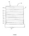
図1に有機発光性デバイス100を示す。これらの図は必ずしも縮尺通りではない。デバイス100は、基板110、アノード115、正孔注入層120、正孔輸送層125、電子阻止層130、発光層135、正孔阻止層140、電子輸送層145、電子注入層150、保護層155及びカソード160を備えることができる。カソード160は、第1の導電層162及び第2の導電層164を有する化合物カソードである。デバイス100は、これらの層を順番に積層させて組み立てることができる。これらの種々の層の特性及び機能ならびに例示の材料は、米国特許第7279704号の段落6〜10(これらを参照により本明細書に組み込む)により詳細に記載されている。 FIG. 1 shows an organic
これらの層のそれぞれについてのさらなる例を得ることができる。例えば、柔軟で透明な基板-アノードの組合せが米国特許第5844363号(これを全体として参照により本明細書に組み込む)に開示されている。p-ドープ正孔輸送層の例は、米国特許出願公開第2003/0230980号(これを全体として参照により本明細書に組み込む)に開示されている50:1のモル比でF.sub.4-TCNQでドープされたm-MTDATAである。発光材料及びホスト材料の例は、Thompsonらの米国特許第6303238号(これを全体として参照により本明細書に組み込む)に開示されている。n-ドープ電子輸送層の例は、米国特許出願公開第2003/0230980号(これを全体として参照により本明細書に組み込む)に開示されている1:1のモル比でLiでドープされたBPhenである。米国特許第5703436号及び同第5707745号(これらを全体として参照により本明細書に組み込む)は、透明な導電性のスパッタリング蒸着したITO層で覆われたMg:Agなどの金属の薄層を有する化合物カソードを含むカソードの例を開示している。阻止層の理論及びその使用については、米国特許第6097147号及び米国特許出願公開第2003/0230980号(これらを参照により本明細書に組み込む)により詳細に記載されている。注入層の例は、米国特許出願公開第2004/0174116号(これを全体として参照により本明細書に組み込む)に提供されている。保護層の説明は米国特許出願公開第2004/0174116号(これを全体として参照により本明細書に組み込む)に見ることができる。 Further examples can be obtained for each of these layers. For example, a flexible and transparent substrate-anode combination is disclosed in US Pat. No. 5,844,363, which is hereby incorporated by reference in its entirety. An example of a p-doped hole transport layer is F.sub.4 at a 50: 1 molar ratio disclosed in U.S. Patent Application Publication No. 2003/0230980, which is hereby incorporated by reference in its entirety. M-MTDATA doped with -TCNQ. Examples of luminescent and host materials are disclosed in Thompson et al. US Pat. No. 6,303,238, which is incorporated herein by reference in its entirety. An example of an n-doped electron transport layer is BPhen doped with Li at a 1: 1 molar ratio as disclosed in U.S. Patent Application Publication No. 2003/0230980, which is hereby incorporated by reference in its entirety. It is. US Pat. Nos. 5,703,436 and 5,707,745 (which are incorporated herein by reference in their entirety) have a thin layer of a metal such as Mg: Ag covered with a transparent conductive sputter deposited ITO layer. An example of a cathode comprising a compound cathode is disclosed. The theory of blocking layers and their use are described in more detail in US Pat. No. 6,097,147 and US Patent Application Publication No. 2003/0230980, which are hereby incorporated by reference. Examples of injection layers are provided in US Patent Application Publication No. 2004/0174116, which is incorporated herein by reference in its entirety. A description of the protective layer can be found in US Patent Application Publication No. 2004/0174116, which is incorporated herein by reference in its entirety.
図2は逆転したOLED200を示す。デバイスは、基板210、カソード215、発光層220、正孔輸送層225及びアノード230を備える。デバイス200は、上記層を順番に積層させて組み立てることができる。最も一般的なOLED構造はアノードの上に配置されたカソードを有し、デバイス200はアノード230の下に配置されたカソード215を有するので、デバイス200を「逆転した」OLEDと称することができる。デバイス100に関して記載したものに類似した材料を、デバイス200の対応する層に用いることができる。図2は、デバイス100の構造から、いくつかの層をいかに省くことができるかという一例を示している。 FIG. 2 shows an
図1及び図2に例示した簡単な層状構造を、非限定的な例で提供するが、本発明の実施形態は、様々な他の構造に関連して用いることができることを理解されたい。説明される具体的な材料及び構造は実際には例示的なものであり、他の材料及び構造を使用することができる。機能性OLEDを、別の形で説明される種々の層を組み合わせることによって実現するか、または、設計、性能及びコスト要素をもとにして、層を完全に省くことができる。具体的には説明されていない他の層も含むことができる。具体的に説明したもの以外の材料を用いることができる。本明細書で提供する例の多くは、単一の材料を含むものとして種々の層を説明しているが、ホストとドーパントの混合物などの材料の組合せ、またはより一般的には混合物を使用できることを理解されたい。また、その層は種々の副層をもつことができる。本明細書で種々の層に与えられた名称は厳密に限定しようとするものではない。例えば、デバイス200において、正孔輸送層225は正孔を輸送し、正孔を発光層220中に注入し、これを正孔輸送層または正孔注入層として表すことができる。一実施形態では、OLEDはカソードとアノードの間に配置された「有機層」を有すると表すことができる。この有機層は、単一の層を含むか、または、例えば図1及び図2に関して説明したような異なる有機材料でできた複数の層をさらに含むことができる。 While the simple layered structure illustrated in FIGS. 1 and 2 is provided in a non-limiting example, it should be understood that embodiments of the present invention can be used in connection with various other structures. The specific materials and structures described are illustrative in nature and other materials and structures can be used. Functional OLEDs can be realized by combining various layers described in different ways, or layers can be omitted entirely based on design, performance and cost factors. Other layers not specifically described may also be included. Materials other than those specifically described can be used. Many of the examples provided herein describe various layers as comprising a single material, but combinations of materials, such as a mixture of host and dopant, or more generally mixtures can be used. I want you to understand. The layer can also have various sublayers. The names given to the various layers herein are not intended to be strictly limiting. For example, in the
Friendらの米国特許第5247190号(これを全体として参照により本明細書に組み込む)に開示されているようなポリマー材料(PLED)を含むOLEDなどの具体的に説明されていない構造及び材料も使用することができる。他の例としては、単一の有機層を有するOLEDを使用することができる。例えば、Forrestらの米国特許第5707745号(これを全体として参照により本明細書に組み込む)に記載されているようにして、OLEDを積み重ねることができる。OLED構造は、図1及び図2に例示したような簡単な層状構造から逸脱していてもよい。例えば、基板は、Forrestらの米国特許第6091195号に記載されているメサ構造及び/またはBulovicらの米国特許第5834893号(これらを参照により本明細書に組み込む)に記載されているくぼみ構造などのアウトカップリングを改善するための角度のある反射面を含むことができる。 Also used are not specifically described structures and materials such as OLEDs including polymer materials (PLEDs) as disclosed in Friend et al. US Pat. No. 5,247,190, which is hereby incorporated by reference in its entirety. can do. As another example, an OLED having a single organic layer can be used. For example, OLEDs can be stacked as described in US Pat. No. 5,777,745 to Forrest et al., Which is incorporated herein by reference in its entirety. The OLED structure may deviate from a simple layered structure as illustrated in FIGS. For example, the substrate may be a mesa structure as described in Forrest et al., US Pat. No. 6091195, and / or a recessed structure as described in Bulovic et al., US Pat. No. 5,834,893, which is incorporated herein by reference. An angled reflective surface to improve the outcoupling of the substrate can be included.
別段の指定のない限り、様々な実施形態の層のどれも、適当な方法で析出することができる。有機層のための好ましい方法には、米国特許第6013982号及び同第6087196号(これらを参照により本明細書に組み込む)に記載されているものなどの熱蒸発、インクジェット、Forrestらの米国特許第6337102号(これを全体として参照により本明細書に組み込む)に記載されているものなどの有機気相堆積法(OVPD)、及び米国特許出願第10/233470号(これを全体として参照により本明細書に組み込む)に記載されているものなどの有機蒸気ジェットプリンティング(OVJP)による析出が含まれる。他の適切な析出法には、スピンコーティング及び他の溶液をベースとしたプロセスが含まれる。溶液をベースとしたプロセスは、窒素または不活性雰囲気下で行うことが好ましい。他の層のための好ましい方法には熱蒸発が含まれる。好ましいパターニング法には、米国特許第6294398号及び同第6468819号(これらを参照により本明細書に組み込む)に記載されているものなどのマスクを通した析出、冷間圧接ならびにインクジェット及びOVJDなどの析出法のいくつかと関連したパターニングが含まれる。他の方法も用いることができる。デポジットする材料は、特定の析出法に適合するようにそれらを改変することができる。例えば、分岐状または非分岐状であり、好ましくは少なくとも3個の炭素を含むアルキル及びアリール基などの置換基を小分子中に用いて、溶液加工を受ける能力を高めることができる。20個以上の炭素を有する置換基を用いることができるが、3〜20個の炭素が好ましい範囲である。非対称材料は再結晶化する傾向が低いので、非対称構造を有する材料は対称構造を有する材料より良好な溶液加工性を有することができる。デンドリマー置換基を用いて、小分子が溶液加工を受ける能力を高めることができる。 Unless otherwise specified, any of the various embodiment layers can be deposited in any suitable manner. Preferred methods for the organic layer include thermal evaporation such as those described in US Pat. Nos. 6,013,982 and 6,087,196, which are incorporated herein by reference, inkjet, Forrest et al. Organic Vapor Deposition (OVPD), such as that described in US Pat. No. 6,337,102, which is hereby incorporated by reference in its entirety, and U.S. Patent Application No. 10/233470, which is hereby incorporated by reference in its entirety. Including vapor deposition by organic vapor jet printing (OVJP). Other suitable deposition methods include spin coating and other solution based processes. The solution based process is preferably performed under nitrogen or an inert atmosphere. Preferred methods for the other layers include thermal evaporation. Preferred patterning methods include deposition through a mask, such as those described in US Pat. Nos. 6,294,398 and 6,688,819 (which are incorporated herein by reference), cold welding, and inkjet and OVJD. Patterning associated with some of the deposition methods is included. Other methods can also be used. The depositing materials can be modified to suit a particular deposition method. For example, substituents such as alkyl and aryl groups that are branched or unbranched, preferably containing at least 3 carbons, can be used in the small molecule to enhance the ability to undergo solution processing. Although substituents having 20 or more carbons can be used, 3-20 carbons is a preferred range. Since asymmetric materials are less prone to recrystallization, materials with asymmetric structures can have better solution processability than materials with symmetric structures. Dendrimer substituents can be used to increase the ability of small molecules to undergo solution processing.
本発明の実施形態により組み立てられるデバイスは、フラットパネルディスプレイ、コンピュータ用モニター、テレビ受信機、広告用掲示板、屋内または屋外照明及び/または信号用の照明灯、ヘッドアップディスプレイ、完全透明ディスプレイ、フレキシブルディスプレイ、レーザープリンター、電話、携帯電話、携帯情報端末(PDA)、ラップトップ型コンピュータ、デジタルカメラ、ビデオカメラ、ファインダー、マイクロディスプレイ、車両、大面積ウォール、劇場またはスタジアムのスクリーンまたは標識を含む広範な消費者製品に組み込むことができる。パッシブマトリクス及びアクティブマトリクスを含む様々な制御機構を用いて、本発明により組み立てられたデバイスを制御することができる。デバイスの多くは、18℃〜30℃、より好ましくは室温(20〜25℃)などの人に心地よい範囲の温度で使用するようになっている。 Devices assembled according to embodiments of the present invention include flat panel displays, computer monitors, television receivers, advertising bulletin boards, indoor or outdoor lighting and / or signal lighting, head-up displays, fully transparent displays, flexible displays. Extensive consumption, including laser printers, phones, cell phones, personal digital assistants (PDAs), laptop computers, digital cameras, video cameras, viewfinders, micro displays, vehicles, large area walls, theater or stadium screens or signs Can be incorporated into the product. Various control mechanisms, including passive and active matrices, can be used to control devices assembled in accordance with the present invention. Many of the devices are designed to be used at a temperature range comfortable to humans, such as 18 ° C. to 30 ° C., more preferably room temperature (20-25 ° C.).
本明細書で説明する材料及び構造はOLED以外のデバイスにも用途を有している。例えば、有機太陽電池及び有機光検知器などの他の光電子デバイスにこの材料及び構造を用いることができる。より一般的には、有機トランジスタなどの有機デバイスにこの材料及び構造を用いることができる。 The materials and structures described herein have application in devices other than OLEDs. For example, this material and structure can be used in other optoelectronic devices such as organic solar cells and organic photodetectors. More generally, this material and structure can be used in organic devices such as organic transistors.
ハロ、ハロゲン、アルキル、シクロアルキル、アルケニル、アルキニル、arylkyl、複素環基、アリール、芳香族基及びヘテロアリールという用語は当技術分野で公知であり、米国特許第7279704号の段落31〜32(これを参照により本明細書に組み込む)に定義されている。 The terms halo, halogen, alkyl, cycloalkyl, alkenyl, alkynyl, arylkyl, heterocyclic group, aryl, aromatic group and heteroaryl are known in the art and are described in U.S. Pat. Are incorporated herein by reference).
拡張共役を有するヘテロレプティックIr(III)錯体を含む化合物を提供する。特に、その錯体は窒素を介して金属と配位した複素環上に拡張共役を有する。その光物理的、熱的及び電子的特性を金属中心に結合する配位子によって調整することができるので、ヘテロレプティックイリジウム錯体は非常に興味のあるものである。ヘテロレプティックイリジウム錯体を使用する1つの利点は、それらが、ホモレプティックIr(III)錯体と比べて、より改善されたデバイス寿命とより低い昇華温度をもたらし、したがって、製造法が改善されることである。例えば、2-フェニルピリジン及び2-(ビフェニル-3-イル)ピリジンを含むヘテロレプティック錯体は、関連するホモレプティック錯体と比べて長い寿命を示す。さらに、ヘテロレプティック錯体の昇華温度はホモレプティック錯体よりほとんど70℃低い。米国仮出願第60/940310号を参照されたい。本明細書で開示するものなどの改善された安定性と低い昇華温度を示すヘテロレプティック錯体は、OLEDで使用するのに非常に望ましものである。特に、ヘテロレプティックIr(III)錯体は白色有機発光性デバイス(WOLED)において使用するのに特に望ましい。 Compounds comprising heteroleptic Ir (III) complexes with extended conjugation are provided. In particular, the complex has an extended conjugation on the heterocyclic ring coordinated to the metal via nitrogen. Heteroleptic iridium complexes are of great interest because their photophysical, thermal and electronic properties can be tuned by ligands attached to the metal center. One advantage of using heteroleptic iridium complexes is that they result in improved device lifetime and lower sublimation temperature compared to homoleptic Ir (III) complexes, thus improving the manufacturing process That is. For example, heteroleptic complexes comprising 2-phenylpyridine and 2- (biphenyl-3-yl) pyridine exhibit a long lifetime compared to related homoleptic complexes. Furthermore, the sublimation temperature of the heteroleptic complex is almost 70 ° C. lower than that of the homoleptic complex. See US Provisional Application No. 60/940310. Heteroleptic complexes that exhibit improved stability and low sublimation temperatures, such as those disclosed herein, are highly desirable for use in OLEDs. In particular, heteroleptic Ir (III) complexes are particularly desirable for use in white organic light emitting devices (WOLED).
多くのヘテロレプティックイリジウム錯体を作製するための既存の合成方法はあまり実際的ではない。特に、既存の合成経路は、イリジウム錯体のハロゲン化及びさらなる官能化(Stosselら、Rhodium complexes and iridium complexes、2005、欧州特許第1504015B1号;Stosselら、Rhodium and indium complexes、2006、米国特許第7125998号を参照されたい)、ハロゲン化錯体及びさらなる官能化により得られるボロン酸エステル置換されたイリジウム錯体の使用(Kwongら、Method or synthesis of iridium(III)complexes with sterically demanding ligands、2006、米国特許出願第12/044848号を参照されたい)、及び低温BuLi/ZnCl2法(Huoら、OLEDs with mixed ligand cyclometallated complexes、2006、米国特許出願公開第20060134459A1号を参照されたい)を含む。低温BuLi/ZnCl2法は、例えば錯体のmer異性体を生成する。これは、一般に望ましいものではなく、したがって錯体の有用なfac異性体に転換しなければならない。Huoら、OLEDs with mixed ligand cyclometallated complexes、2006、米国特許出願公開第20060134459A1号を参照されたい。したがって、この方法は、錯体の大規模な合成のためには実際的ではない。向上した収率をもたらすが、臭素化イリジウム錯体をボロン酸エステルに転換して最後に最終生成物を得ることを含む方法は直接的なものではない。Kwongら、Method for synthesis of iridium(III)complexes with sterically demanding ligands、2006、米国特許出願第12/044848号を参照されたい。したがって、ヘテロレプティックIr(III)錯体を作製するためのより実際的で直接的な合成方法を提供することが特に望まれている。Existing synthetic methods for making many heteroleptic iridium complexes are not very practical. In particular, existing synthetic routes include halogenation and further functionalization of iridium complexes (Stossel et al., Rhodium complexes and iridium complexes, 2005, European Patent No. 1504015B1; Stossel et al., Rhodium and indium complexes, 2006, US Pat. The use of halogenated complexes and boronate-substituted iridium complexes obtained by further functionalization (Kwong et al., Method or synthesis of iridium (III) complexes with sterically demanding ligands, 2006, U.S. patent application no. And the low temperature BuLi / ZnCl2 method (see Huo et al., OLEDs with mixed ligand cyclometallated complexes, 2006, US Patent Application Publication No. 20060134459A1). The low temperature BuLi / ZnCl2 method produces, for example, the mer isomer of the complex. This is generally not desirable and therefore must be converted to a useful fac isomer of the complex. See Huo et al., OLEDs with mixed ligand cyclometallated complexes, 2006, US Patent Application Publication No. 20060134459A1. This method is therefore impractical for large scale synthesis of complexes. While providing improved yields, the process involving converting the iridium bromide complex to a boronate ester and finally obtaining the final product is not straightforward. See Kwong et al., Method for synthesis of iridium (III) complexes with sterically demanding ligands, 2006, US patent application Ser. No. 12/044848. Therefore, it is particularly desirable to provide a more practical and direct synthetic method for making heteroleptic Ir (III) complexes.
本明細書で説明する方法は、OLEDにおいて、特にWOLEDにおいて使用するのに有利なヘテロレプティックIr(III)錯体を作製するために用いることができる。例えば、本明細書で説明する方法は、化合物1、化合物2及び化合物7などの特に望ましいヘテロレプティックIr(III)錯体を作製するために用いることができる。 The methods described herein can be used to make heteroleptic Ir (III) complexes that are advantageous for use in OLEDs, particularly WOLEDs. For example, the methods described herein can be used to make particularly desirable heteroleptic Ir (III) complexes such as
拡張共役を有するIr(III)ヘテロレプティック錯体を作製するための方法であって、
この方法の一態様では、対イオンXは、トリフラート、トシレート、トリフルオロアセテート、テトラフルオロボレート及びヘキサフルオロホスフェートからなる群から選択される。 In one embodiment of this method, the counter ion X is selected from the group consisting of triflate, tosylate, trifluoroacetate, tetrafluoroborate and hexafluorophosphate.
一態様では、RA、RB、RC及びRDは、ベンゼン、ピリミジン、ピリジン、チオフェン、チアナフテン、フッ素、カルバゾール及びジベンゾチオフェンからなる群から選択される。In one aspect, RA , RB , RC and RD are selected from the group consisting of benzene, pyrimidine, pyridine, thiophene, thianaphthene, fluorine, carbazole and dibenzothiophene.
他の態様では、本方法は、
本方法の一態様では、基B(OR)2は環Cと結合している。他の態様では、基B(OR)2は環Dと結合している。本方法の特定の態様では、基B(OR)2は、
一態様では、本方法は、
一態様では、本方法は、
他の態様では、本方法は、
他の態様では、本方法は、
他の態様では、本方法は、
さらに他の態様では、本方法は、
他の態様では、本方法は、
さらに、リン発光性化合物を提供する。特に、この化合物は、窒素を介して金属と配位した複素環上に拡張共役を有するIr(III)ヘテロレプティック錯体である。提供される化合物は、下記:
からなる群から選択される式を有する。Having a formula selected from the group consisting of
特定の化合物は特に有益である。一態様では、好ましくはその化合物は化合物1である。他の態様では、好ましくはその化合物は化合物2である。 Certain compounds are particularly beneficial. In one embodiment, preferably the compound is
有機発光性デバイスにおける使用に有利なヘテロレプティックイリジウム化合物を提供する。特に、その化合物はそうしたデバイスの発光性ドーパントとして有用である。ヘテロレプティック化合物は、
特定の化合物は特に有益である。一態様では、好ましくはその化合物は化合物8である。他の態様では、好ましくはその化合物は化合物9である。さらに他の態様では、好ましくはその化合物は化合物10である。他の態様では、好ましくはその化合物は化合物11である。さらに他の態様では、好ましくはその化合物は化合物12である。他の態様では、好ましくはその化合物は化合物13である。さらに他の態様では、好ましくはその化合物は化合物14である。 Certain compounds are particularly beneficial. In one embodiment, preferably the compound is compound 8. In another embodiment, preferably the compound is
さらに、アノード、カソード、及びそのアノードとカソードの間に配置された有機層を含む有機発光性デバイスであって、その有機層が
一態様では、そのデバイスの有機層はホストをさらに含む。化合物1及び2は、トリフェニレン基を含むホストを有するデバイスにおいて特によく機能することが分かっている。特に、これらの化合物は、そのホストが式
アノード、カソード、及びそのアノードとカソードの間に配置された有機層を含む有機発光性デバイスを提供する。その有機層は、
デバイスの有機層はホストをさらに含むことができる。化合物7〜12はトリフェニレン基を含むホストを有するデバイスにおいて特によく機能することが分かっている。特に、これらの化合物はホストが、Rがアリールまたはヘテロアリールである次の式
さらに、デバイスを含む消費者製品も提供する。そのデバイスはアノード、カソード、及びそのアノードとカソードの間に配置された有機層をさらに含む。その有機層は化合物1〜6から選択される化合物を含む。 In addition, consumer products including devices are also provided. The device further includes an anode, a cathode, and an organic layer disposed between the anode and the cathode. The organic layer contains a compound selected from compounds 1-6.
アノード、カソード、及びアノードとカソードの間に配置された有機層をさらに含むデバイスを含む消費者製品も提供する。その有機層は、化合物8〜14からなる群から選択される化合物をさらに含む。 There is also provided a consumer product comprising a device further comprising an anode, a cathode, and an organic layer disposed between the anode and the cathode. The organic layer further includes a compound selected from the group consisting of compounds 8-14.
上記に論じたように、ヘテロレプティックイリジウム錯体を作製するための既存の合成方法は多くの化合物を作製するのには実際的でない可能性がある。一般に用いられている1つの合成経路は、有機溶媒中でイリジウムトリフラート中間体を第2の配位子と反応させてヘテロレプティックイリジウム錯体を得る方法を含む。 As discussed above, existing synthetic methods for making heteroleptic iridium complexes may not be practical for making many compounds. One commonly used synthetic route involves reacting an iridium triflate intermediate with a second ligand in an organic solvent to obtain a heteroleptic iridium complex.
しかし、この方法はしばしば、反応の間の配位子の乱れのため、生成物の混合物をもたらす。具体的には、この方法は、主生成物と少量生成物の両方を様々な収率で生成する。生成化合物の混合物は、所望生成物を精製するのに問題を引き起こす恐れがあり、したがって、この合成の実用性は限定されている。 However, this method often results in a mixture of products due to ligand perturbations during the reaction. Specifically, this process produces both main and minor products in varying yields. The mixture of product compounds can cause problems in purifying the desired product, and therefore the usefulness of this synthesis is limited.
本明細書で提供するヘテロレプティックイリジウム化合物のいくつか(すなわち、化合物10、11及び14)は、アルキル置換トリフラート中間体(例えば、6'-メチルフェニルピリジン)を用いた場合、トリフラート中間体合成法により、高収率でかつそれほどの量の夾雑少量生成物を生成することなく得られることに注目すべきである。構造的に化合物11と類似した他の化合物(例えば、化合物2)を作製するために用いた場合、同じ合成法では同じ結果を得ることはできなかったので、化合物10、11及び14の合成における配位子の乱れの程度が非常に低いということは、少なくとも一部では予期しないことであった。実施例8及び実験の部を参照されたい。 Some of the heteroleptic iridium compounds provided herein (i.e., compounds 10, 11 and 14) can be synthesized using an alkyl-substituted triflate intermediate (e.g., 6'-methylphenylpyridine). It should be noted that the process can be obtained in high yield and without producing a significant amount of contaminating minor product. When used to make other compounds that are structurally similar to compound 11 (e.g., compound 2), the same results could not be obtained with the same synthetic method, so in the synthesis of
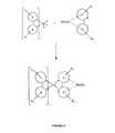
したがって、本明細書では拡張共役を有するヘテロレプティック化合物を作製するための方法を提供する(図6に例示する)。この方法は、
好ましくは、対イオンXは、トリフラート、トシレート、トリフルオロボレート及びヘキサフルオロホスフェートからなる群から選択される。 Preferably, the counter ion X is selected from the group consisting of triflate, tosylate, trifluoroborate and hexafluorophosphate.
RA、RB、RC及びRDは、ベンゼン、ピリミジン、ピリジン、チオフェン、チアナフテン、フッ素、カルバゾール及びジベンゾチオフェンからなる群から選択される。さらに、RZは好ましくはアルキルであり、より好ましくはRZはメチルである。RA , RB , RC and RD are selected from the group consisting of benzene, pyrimidine, pyridine, thiophene, thianaphthene, fluorine, carbazole and dibenzothiophene. Further, RZ is preferably alkyl, more preferably RZ is methyl.
一態様では、本方法は、
好ましくは、
この方法は、A-B配位子としてフェニルピリジンの代わりに、C-D配位子と反応したとき反応生成物の乱れをそれほどもたらさず、したがって生成物を精製するのにより容易にするアルキル置換フェニルピリジン(例えば、6-メチルフェニルピリジン)を含む。特に、上記方法は、化合物10、11及び14を合成するのに用いられ、乱れた夾雑生成物が非常に少ない高収率の所望生成物をもたらした。反応が完了した後、反応生成物をクロマトグラフで分析した。具体的には、未精製の沈殿生成物において、化合物10、11及び14についての主生成物のHPLC割合は99.4%、99.4及び99.4%とそれぞれ算出され、少量生成物は一緒にしたHPLC割合でそれぞれ0.3%、0.5%及び0.5%であった。他方、ヘテロレプティック化合物を作製するために、既存のトリフラート中間体法を用いる、すなわちLA-Bの6位が置換されていない場合、生成物の著しい乱れが起こり得る。特に、既存の方法を用いた化合物2及び7の合成により、未精製の反応混合物において(HPLCで判定して)、それぞれ92%及び91%の主生成物、それぞれ8%及び9%の少量生成物がもたらされる。したがって、上記のアルキル置換フェニルピリジン配位子を用いた方法は、ヘテロレプティック化合物の改善された合成を提供する。This method, instead of phenylpyridine as an AB ligand, does not significantly disturb the reaction product when reacted with a CD ligand, thus making it easier to purify the product (e.g., alkyl substituted phenylpyridines) 6-methylphenylpyridine). In particular, the above method was used to synthesize
さらに、式Ir(LA-B)2(LC-D)を有するヘテロレプティック化合物を提供する。LA-Bは、
配位子LC-Dは好ましくは、
2-フェニルピリジン及びアルキル置換2-フェニルピリジン配位子は有益な特性を提供することができる。特に、これらの配位子はイリジウム(III)と強固に結合する。したがって、2-フェニルピリジン及びアルキル置換2-フェニルピリジンは良好な化学的安定性を提供する。さらに、イリジウム及び2-フェニルピリジン配位子のトリス錯体は高真空下、低温(すなわち、<250℃)で蒸発する。しかし、エミッターとしてこれらの錯体を用いたPHOLEDの作動安定性は劣っており、したがって改善する必要がある。2-フェニルピリジン上でのアリール置換はデバイス安定性を改善することができる。残念ながら、アリール置換2-フェニルピリジンのトリスイリジウム錯体は高温(すなわち、>290℃)でしか蒸発しない。高い蒸発温度は、分解があるため、長期間の製造には望ましくない。したがって、PHOLEDにおけるそうしたトリスアリール置換2-フェニルピリジンの使用は限定される。本明細書で提供するヘテロレプティック化合物は、2つの非置換2-フェニルピリジン配位子またはアルキル置換2-フェニルピリジン配位子と、1つのアリール置換2-フェニルピリジン配位子を含む。したがって、本明細書で提供するヘテロレプティック化合物は、より低い蒸発温度を提供し、デバイス動作寿命を改善することができる。 2-Phenylpyridine and alkyl-substituted 2-phenylpyridine ligands can provide valuable properties. In particular, these ligands bind strongly to iridium (III). Accordingly, 2-phenylpyridine and alkyl-substituted 2-phenylpyridine provide good chemical stability. Furthermore, tris complexes of iridium and 2-phenylpyridine ligands evaporate under high vacuum and low temperature (ie <250 ° C.). However, the operational stability of PHOLEDs using these complexes as emitters is poor and therefore needs to be improved. Aryl substitution on 2-phenylpyridine can improve device stability. Unfortunately, trisiridium complexes of aryl-substituted 2-phenylpyridines evaporate only at high temperatures (ie,> 290 ° C.). High evaporation temperatures are undesirable for long-term production due to decomposition. Thus, the use of such trisaryl substituted 2-phenylpyridines in PHOLED is limited. The heteroleptic compounds provided herein include two unsubstituted 2-phenylpyridine ligands or alkyl-substituted 2-phenylpyridine ligands and one aryl-substituted 2-phenylpyridine ligand. Accordingly, the heteroleptic compounds provided herein can provide lower evaporation temperatures and improve device operating lifetime.
特に、2つの2-フェニルピリジン配位子と1つの2-(ビフェニル-3-イル)ピリジン配位子を有する化合物7は、トリス(2-フェニルピリジン)イリジウム(III)と比べて、PHOLEDにおいて改善された安定性を示す。化合物7の発光スペクトルは若干赤色にシフトしていた。しかし、トリス(2-(ビフェニル-3-イル)ピリジン)イリジウム(III)と比べて、その発光は青色にシフトしていた。総合すれば、これは、両方の配位子、すなわち2-フェニルピリジンと2-(ビフェニル-3-イル)ピリジンが多分発光に寄与していることを示唆している。さらに、化合物7、トリス(2-フェニルピリジン)イリジウム(III)及びトリス(2-(ビフェニル-3-イル)ピリジン)イリジウム(III)の酸化及び還元特性をサイクリックボルタンメトリーで測定して、3つの異なる化合物の値の間に有意の差はなかった。したがって、この化合物の置換パターンは、錯体のHOMO及びLUMO準位をそれほどシフトさせない。 In particular, compound 7, which has two 2-phenylpyridine ligands and one 2- (biphenyl-3-yl) pyridine ligand, compared to tris (2-phenylpyridine) iridium (III), in PHOLED Shows improved stability. The emission spectrum of Compound 7 was slightly shifted to red. However, compared to tris (2- (biphenyl-3-yl) pyridine) iridium (III), the emission was shifted to blue. Taken together, this suggests that both ligands, namely 2-phenylpyridine and 2- (biphenyl-3-yl) pyridine, probably contribute to the emission. In addition, the oxidation and reduction properties of compound 7, tris (2-phenylpyridine) iridium (III) and tris (2- (biphenyl-3-yl) pyridine) iridium (III) were measured by cyclic voltammetry, and There was no significant difference between the values of different compounds. Therefore, the substitution pattern of this compound does not significantly shift the HOMO and LUMO levels of the complex.
本明細書で提供するヘテロレプティック化合物Ir(LA-B)2(LC-D)について、配位子LC-Dと配位子LA-Bを組み合わせると、LUMOが位置するピリジン環に、より良好な共役がもたらされる。理論に拘泥するわけではないが、共役の結果、提供されたヘテロレプティック化合物のLUMOが相当還元され、ピリジン環を安定化したと考えられる。同時に、発光スペクトルは、Ir(LC-D)3、すなわちピリジン上にアリールを有するトリス(2-フェニルピリジン)イリジウム(III)とほとんど同一となった。これは、発光はLC-Dによって支配されているが、LA-Bは非発光性配位子であることを示唆している。本明細書で開示するヘテロレプティック化合物Ir(LA-B)2(LC-D)は高いデバイス安定性を提供する。本明細書で提供するヘテロレプティック化合物Ir(LA-B)(LC-D)2について、その効果は同様である。For the heteroleptic compound Ir (LAB )2 (LCD ) provided herein, the combination of ligand LCD and ligand LAB gives better conjugation to the pyridine ring where LUMO is located. Brought about. Without being bound by theory, it is believed that as a result of conjugation, the LUMO of the provided heteroleptic compound has been considerably reduced, stabilizing the pyridine ring. At the same time, the emission spectrum was almost identical to Ir (LCD )3 , ie tris (2-phenylpyridine) iridium (III) with aryl on pyridine. This light emission is dominated by LCD but, LAB suggests that it is non-luminescent ligand. The heteroleptic compound Ir (LAB )2 (LCD ) disclosed herein provides high device stability. The effect is similar for the heteroleptic compound Ir (LAB ) (LCD )2 provided herein.
上記段落で論じたように、ヘテロレプティックIr(III)錯体の合成は、ボロン酸エステル官能化エステルを直接イリジウム錯体中間体と反応させる方法で改良することができる。この方法も図4に示す。特に、この合成法は錯体の大規模な合成により有用である。反応生成物は、カラムまたは他の方法で分離することができる。さらに、複素環からの拡張共役を有するヘテロレプティックIr(III)錯体を、本明細書で説明する方法によって作製することができる。これらの化合物も図5に示す。デバイスにおけるこれらの錯体の使用は、デバイスの改善された安定性と製造法をもたらすことができる。 As discussed in the previous paragraph, the synthesis of heteroleptic Ir (III) complexes can be improved by reacting the boronate ester functionalized ester directly with the iridium complex intermediate. This method is also shown in FIG. In particular, this synthesis method is useful for large-scale synthesis of complexes. The reaction products can be separated by column or other method. In addition, heteroleptic Ir (III) complexes with extended conjugation from heterocycles can be made by the methods described herein. These compounds are also shown in FIG. The use of these complexes in the device can lead to improved stability and manufacturing methods of the device.
上記で論じたように、ヘテロレプティックIr(III)化合物の合成は、置換トリフラートイリジウム中間体を第2の配位子と反応させる方法によって改善することができる。この方法も図6に示す。特に、この合成は、配位子の乱れを著しく低減することによって、生成物の精製を改善することができる。 As discussed above, the synthesis of heteroleptic Ir (III) compounds can be improved by a method of reacting a substituted triflate iridium intermediate with a second ligand. This method is also shown in FIG. In particular, this synthesis can improve product purification by significantly reducing ligand perturbations.
ねじれ型アリールを含む少なくとも1つの配位子を含む新規な化合物(図7に示す)を提供する。提供する特定の化合物は、ねじれ型フェニル環を含むIr(2-フェニルピリジン)型化合物(図8に示す)を含む。これらのねじれ型アリール化合物は、OLEDにおいて有利に使用して、改良された効率、安定性及び製造法を有するデバイスを提供することができる。好ましくは、これらの化合物は、そうしたデバイスの発光性ドーパントとして使用することができる。 Novel compounds (shown in FIG. 7) comprising at least one ligand comprising a twisted aryl are provided. Specific compounds provided include Ir (2-phenylpyridine) type compounds (shown in FIG. 8) that contain a twisted phenyl ring. These twisted aryl compounds can be advantageously used in OLEDs to provide devices with improved efficiency, stability and manufacturing methods. Preferably, these compounds can be used as luminescent dopants in such devices.
ねじれ型アリール基を含む化合物は文献に報告されている(例えば、米国特許出願公開第2007/0003789号及び同第2009/0124805号を参照されたい)。 Compounds containing twisted aryl groups have been reported in the literature (see, eg, US Patent Application Publication Nos. 2007/0003789 and 2009/0124805).
2-フェニルピリジン及びアルキル置換2-フェニルピリジン配位子は良好な特性を有するイリジウム(III)化合物を形成するが、これらの化合物は、デバイスにおいて実際に使用するのには限界がある(例えば、低い動作安定性)。2-フェニルピリジン上でのアリール置換はデバイス効率を改善するが、アリール置換2-フェニルピリジンのトリスイリジウム化合物は高温でしか(すなわち、290℃超)蒸発せず、そのためこれらの化合物の使用も限定される(すなわち、製造の際の分解)。特定の置換パターンを有する2-フェニルピリジン型配位子が特に有益であることが分かっている。特に、2-フェニルピリジン型配位子上でのアルキル及びフェニル置換の戦略的組合せは、平面外にじねじれ出た置換基アリール基(すなわち、ねじれ型アリール)をもたらし、それによってパッキングを低減し、蒸発温度を低下させる。本明細書で提供する化合物は、その置換基アリールがねじれ型アリールであるようなアルキル及びアリール置換基を有する少なくとも1つの配位子を含む。したがって、これらの化合物は、より低い蒸発温度を提供し、デバイスの製造を改良し、デバイス動作寿命を改善することができる。 Although 2-phenylpyridine and alkyl-substituted 2-phenylpyridine ligands form iridium (III) compounds with good properties, these compounds have limitations for practical use in devices (e.g. Low operational stability). Aryl substitution on 2-phenylpyridine improves device efficiency, but trisiridium compounds of aryl-substituted 2-phenylpyridine evaporate only at high temperatures (ie, above 290 ° C), thus limiting the use of these compounds (Ie, decomposition during manufacture). 2-phenylpyridine type ligands with specific substitution patterns have been found to be particularly beneficial. In particular, the strategic combination of alkyl and phenyl substitution on a 2-phenylpyridine type ligand results in a substituent aryl group that twists out of plane (i.e., twisted aryl), thereby reducing packing. Reduce the evaporation temperature. The compounds provided herein include at least one ligand having an alkyl and aryl substituent such that the substituent aryl is a twisted aryl. Thus, these compounds can provide lower evaporation temperatures, improve device manufacturing, and improve device operating lifetime.
2-フェニルピリジン上で置換されたアリール基は、配位子の共役も増加させ、それによって赤色にシフトした発光をもたらすことができる。540nm〜580nmなどのスペクトルの黄色部分の長波長で発光を有するそうした化合物は、発光がスペクトルの黄色部分に限定されるので、使用は限定される。したがって、青色にシフトした範囲などの異なる範囲で発光を有する化合物が望ましい。特に、約521nm〜約540nmの標的エネルギー範囲に発光を有する化合物が特に好ましい。置換基アリール環がアルキル基の付加によってねじれている化合物は、限られた共役を有し、青色にシフトした発光を示すことができると考えられる。特に、本明細書で提供するそのねじれ型アリール化合物は、非ねじれ型アリール置換基を含む対応する化合物と比べて青色にシフトした発光エネルギーを有することができる。したがって、これらの青色にシフトした化合物は特に好ましい。 Aryl groups substituted on 2-phenylpyridine can also increase ligand conjugation, thereby resulting in red-shifted emission. Such compounds that emit at a long wavelength in the yellow portion of the spectrum, such as 540 nm to 580 nm, are limited in use because the emission is limited to the yellow portion of the spectrum. Therefore, a compound having light emission in a different range such as a blue shifted range is desirable. In particular, compounds having emission in a target energy range of about 521 nm to about 540 nm are particularly preferred. A compound in which a substituent aryl ring is twisted by addition of an alkyl group is considered to have limited conjugation and can exhibit blue-shifted emission. In particular, the twisted aryl compounds provided herein can have emission energy shifted to a blue color compared to the corresponding compounds containing non-twisted aryl substituents. Therefore, these blue shifted compounds are particularly preferred.
ねじれ型アリールを含む少なくとも1つの配位子を含む化合物を提供する。置換されたIr(2-フェニルピリジン)型リン光性材料及びそうした材料を含むデバイスについての構造-特性の関係を確立するために、発光性配位子上での異なるねじれ型アリール置換パターンの効果を試験した。蒸発温度、蒸発安定性及び溶解性を含む材料加工性のいくつかの側面、ならびに化合物を含むねじれ型フェニルを用いたPHOLEDのデバイス特性を試験した。化合物上に存在する戦略的に配置された置換基は、置換基アリール環のねじれをもたらすことができる。例えば、アリール基(すなわち、環C)上か、またはねじれ型アリールに隣接したピリジン環(すなわち、環A)上に存在する置換基は、アリール基の追加的なねじれを誘発することができる。結果として、ねじれ型アリール部分を有する化合物は、(i)共役の減少をもたらし、それによって共役の増大(すなわち、フェニルの追加)に通常関係する赤色へのシフト効果を最少にし、(ii)積み重ねの減少をもたらし、それによって蒸発温度を低下させ、長期熱安定性及び加工性を向上させ、(iii)狭い発光をもたらし、したがって高い発光効率(すなわち、高いLE:EQE)をもたらすことができる。 Provided are compounds comprising at least one ligand comprising a twisted aryl. Effects of different twisted aryl substitution patterns on luminescent ligands to establish structure-property relationships for substituted Ir (2-phenylpyridine) type phosphorescent materials and devices containing such materials Was tested. Several aspects of material processability, including evaporation temperature, evaporation stability and solubility, as well as device properties of PHOLEDs using twisted phenyl containing compounds were tested. Strategically placed substituents present on the compound can result in twisting of the substituent aryl ring. For example, substituents present on the aryl group (ie, ring C) or on the pyridine ring adjacent to the twisted aryl (ie, ring A) can induce additional twisting of the aryl group. As a result, compounds with a twisted aryl moiety result in (i) a decrease in conjugation, thereby minimizing the red-shift effect normally associated with increased conjugation (i.e., addition of phenyl), and (ii) stacking. , Thereby lowering the evaporation temperature, improving long-term thermal stability and processability, and (iii) providing narrow emission and thus high emission efficiency (ie, high LE: EQE).
ねじれ型アリールと限られた数の置換基(例えば、単一の置換基)を含む化合物は、効率及び製造の向上などのねじれ型アリールの利益を保持しながら、安定性を改善することができる。さらに、本明細書で提供する特定の化合物は、特に狭い発光を示し、したがって、他の注目すべき改善に加えて、特に良好な発光効率を有するデバイスを提供することができる。したがって、本明細書で提供するは特に望ましい。 Compounds containing a twisted aryl and a limited number of substituents (e.g., a single substituent) can improve stability while retaining the benefits of twisted aryl such as increased efficiency and manufacturing. . Furthermore, certain compounds provided herein exhibit particularly narrow emission, and thus can provide devices with particularly good luminous efficiency, in addition to other notable improvements. Therefore, it is particularly desirable to provide here.
理論に拘泥するわけではないが、置換基アリールにおいてねじれを誘発する置換基を1つだけ有する化合物は、特に有益であると考えられる。特に、アリール置換基のねじれを誘発する単一の置換基を含む化合物は、複数の置換基を含む対応化合物より安定である。単一の置換基を有する化合物は、平面からより大きな程度にねじれ出ている複数の置換基を有する化合物と比べて、置換基アリールと配位子の残り部分との間により小さな程度のねじれを有し、したがってより多い共役を有することができると考えられる。特に、単一のメチル置換基を有する化合物は、複数のメチル置換基を有する化合物と比べて改善された安定性を有することができると考えられる。例えば、デバイス実施例28が発光性ドーパントとして化合物35を使用しデバイス比較例6が発光性ドーパントとしてE4を使用すること以外は、デバイス実施例28とデバイス比較例6は同じデバイス構造及び組成を有する。化合物35とE4はどちらも、2-フェニルピリジンの5位に結合したねじれ型アリール基を有する配位子を含むトリスホモレプティック化合物(すなわち、IrL3)である。唯一の違いは、E4においてはそのアリールが2-メチルフェニル基であるのに対して、化合物35においてはそのアリールが2,6-ジメチルフェニルであるということである。Without being bound by theory, compounds having only one substituent that induces twist in the substituent aryl are believed to be particularly beneficial. In particular, compounds containing a single substituent that induces twisting of the aryl substituent are more stable than the corresponding compounds containing multiple substituents. A compound with a single substituent has a smaller degree of twist between the substituent aryl and the rest of the ligand compared to a compound with multiple substituents that are twisted to a greater extent from the plane. Thus, it is believed that it can have more conjugation. In particular, it is believed that a compound having a single methyl substituent can have improved stability compared to a compound having multiple methyl substituents. For example, Device Example 28 and Device Comparative Example 6 have the same device structure and composition, except that Device Example 28 uses Compound 35 as the luminescent dopant and Device Comparative Example 6 uses E4 as the luminescent dopant. . Both compounds 35 and E4 are tris homoleptic compounds (ie, IrL3 ) containing a ligand having a twisted aryl group bonded to the 5-position of 2-phenylpyridine. The only difference is that in E4 the aryl is a 2-methylphenyl group, whereas in compound 35 the aryl is 2,6-dimethylphenyl.
E4中の追加のメチル基は、化合物35におけるそれより、ねじれ型アリールをねじれさせる。結果(Table 8(表8))は、化合物35を含むデバイス(デバイス実施例28、RT80%=200時間)が、E4を含むデバイス(デバイス比較例6、RT80%=42時間)よりずっと安定であることを示している。より共役した配位子は、より安定な発光性ドーパントをもたらすことができると考えられる。メチル基の数が、0から1、2へと増加するにしたがって(すなわち、ピリジンとC環の間のねじれが増大する)一連のE3、化合物35及びE4において共役は減少する。したがって、発光性ドーパントとしてE3を含むデバイスが、発光性ドーパントとして化合物35を含むデバイスより安定であると考えるのは妥当である。しかし、共役の増大は、対応するIr錯体の発光において赤色へのシフトも引き起こす。Table 7(表7)は、E3(デバイス比較例5)が548nmのλmax及び(0.430、0.560)のCIEを有するのに対して、化合物35(デバイス実施例28)は532nmのλmax及び(0.368、0.607)のCIEを有し、E4(デバイス比較例6)は520nmのλmax及び(0.320、0.632)のCIEを有することを示している。したがって、E3はより安定であるが、その発光は黄色であり、これはフルカラーRGBディスプレイに適していない。化合物35は、E3とE4の間に共役を有しており、E4(共役がほとんどない)よりずっと改善された安定性と、E3(共役が多すぎる)より良好な緑色を達成している。The additional methyl group in E4 twists the twisted aryl from that in compound 35. The results (Table 8) show that the device containing Compound 35 (Device Example 28, RT80% = 200 hours) is much more than the device containing E4 (Device Comparison Example 6, RT80% = 42 hours). It shows that it is stable. It is believed that a more conjugated ligand can provide a more stable luminescent dopant. As the number of methyl groups increases from 0 to 1, 2 (ie, the twist between the pyridine and C rings increases), conjugation decreases in the series of E3, compounds 35 and E4. Therefore, it is reasonable to consider that a device containing E3 as the luminescent dopant is more stable than a device containing compound 35 as the luminescent dopant. However, increased conjugation also causes a shift to red in the emission of the corresponding Ir complex. Table 7 shows that E3 (Device Comparative Example 5) has a λmax of 548 nm and a CIE of (0.430, 0.560), whereas Compound 35 (Device Example 28) has a λmax of 532 nm and ( E4 (device comparative example 6) has a λmax of 520 nm and a CIE of (0.320, 0.632). Thus, E3 is more stable, but its emission is yellow, which is not suitable for full color RGB displays. Compound 35 has a conjugation between E3 and E4, achieving much improved stability over E4 (little conjugation) and better green than E3 (too much conjugation).
その置換基アリールがねじれており、次の構造:
B及びCはそれぞれ独立に、5員または6員の炭素環または複素環である。A-Bは、環Aの窒素原子及び環Bのsp2混成原子を介して金属Mと配位している炭素環または複素環の結合対を表す。A-Cは炭素環または複素環の結合対を表す。Ra、Rb及びRCは、一置換、二置換、三置換または四置換を表すことができる。Ra、Rb及びRCは独立に、水素、アルキル、アルコキシ、アミノ、アルケニル、アルキニル、arylkyl、アリール及びヘテロアリールからなる群から選択される。X1、X2、X3、X4、X5、X6、X7、X8及びX9は独立に、炭素及び窒素から選択される。好ましくは、Aはピリジンである。R1及びR2は独立に、水素、アルキル、アルコキシ、アミノ、アルケニル、アルキニル、arylkyl、アリール及びヘテロアリールからなる群から選択される。R1、R2、及びCと隣接するRa置換基の少なくとも1つは水素ではない。好ましくは、R1、R2、及びCと隣接するRa置換基のうちの1つだけは水素ではない。好ましくは、R1、R2、及びCと隣接するRa置換基のうちの1つだけはアルキルである。より好ましくは、R1、R2、及びCと隣接するRa置換基のうちの1つだけはエチルである。最も好ましくは、R1、R2、及びCと隣接するRa置換基のうちの1つだけはメチルである。配位子Lは、40より大きい原子番号を有する金属Mと配位している。好ましくは、その金属MはIrである。B and C are each independently a 5-membered or 6-membered carbocyclic or heterocyclic ring. AB represents a carbocyclic or heterocyclic bond pair that is coordinated to the metal M via the ring A nitrogen atom and the ring B sp2 hybrid atom. AC represents a carbocyclic or heterocyclic bond pair. Ra , Rb and RC can represent mono-, di-, tri- or tetra-substitution. Ra , Rb and RC are independently selected from the group consisting of hydrogen, alkyl, alkoxy, amino, alkenyl, alkynyl, arylkyl, aryl and heteroaryl. X1 , X2 , X3 , X4 , X5 , X6 , X7 , X8 and X9 are independently selected from carbon and nitrogen. Preferably A is pyridine. R1 and R2 are independently selected from the group consisting of hydrogen, alkyl, alkoxy, amino, alkenyl, alkynyl, arylkyl, aryl and heteroaryl. At least one of the Ra substituents adjacent to R1 , R2 , and C is not hydrogen. Preferably, onlyone of R1 , R2 , and the Ra substituent adjacent to C is not hydrogen. Preferably, onlyone of R1 , R2 , and the Ra substituent adjacent to C is alkyl. More preferably, onlyone of R1 , R2 , and the Ra substituent adjacent to C is ethyl. Most preferably, onlyone of R1 , R2 , and the Ra substituent adjacent to C is methyl. Ligand L is coordinated with metal M having an atomic number greater than 40. Preferably, the metal M is Ir.
次の構造:
mは酸化状態の金属Mである。nは少なくとも1である。L'はモノアニオン二座配位子である。好ましくは、R1、R2、及びCと隣接するRa置換基のうちの1つだけは水素ではない。好ましくは、R1、R2、及びCと隣接するRa置換基のうちの1つだけはアルキルである。より好ましくは、R1、R2、及びCと隣接するRa置換基のうちの1つだけはエチルである。最も好ましくは、R1、R2、及びCと隣接するRa置換基のうちの1つだけはメチルである。好ましくは、Aはピリジンである。m is an oxidized metal M. n is at least 1. L ′ is a monoanionic bidentate ligand. Preferably, onlyone of R1 , R2 , and the Ra substituent adjacent to C is not hydrogen. Preferably, onlyone of R1 , R2 , and the Ra substituent adjacent to C is alkyl. More preferably, onlyone of R1 , R2 , and the Ra substituent adjacent to C is ethyl. Most preferably, onlyone of R1 , R2 , and the Ra substituent adjacent to C is methyl. Preferably A is pyridine.
式IIを有する化合物の具体的な例を提供する。その化合物は、
Rは水素ではない。好ましくは、Rはアルキルである。 R is not hydrogen. Preferably R is alkyl.
式IIを有する化合物の具体的な例を提供する。一態様では、その化合物は、
好ましくは、その化合物は、化合物21、化合物22、化合物25、化合物29、化合物30、化合物31及び化合物34からなる群から選択される。 Preferably, the compound is selected from the group consisting of Compound 21, Compound 22, Compound 25, Compound 29, Compound 30, Compound 31 and Compound 34.
一態様では、
R1、R2、R3及びR4の少なくとも1つは水素ではない。R5は、水素、アルキル、アルコキシ、アミノ、アルケニル、アルキニル、arylkyl、アリール及びヘテロアリールからなる群から選択される。At least one of R1 , R2 , R3 and R4 is not hydrogen. R5 is selected from the group consisting of hydrogen, alkyl, alkoxy, amino, alkenyl, alkynyl, arylkyl, aryl and heteroaryl.
上記で論じたように、置換基アリール環(すなわち、C環)と隣接する置換基を誘発するねじれの部分は、平面からでたC環をもたらし、それによってパッキングを減少させ、蒸発温度、溶解性、エネルギー準位、デバイス効率及び発光スペクトルの狭さの幅広い調整可能性を提供する。さらに、置換基は、化学的にもまたデバイス動作においても安定な官能基であってよい。 As discussed above, the portion of the twist that induces the substituent adjacent to the substituent aryl ring (i.e., C ring) results in a C ring that is out of plane, thereby reducing packing, evaporating temperature, melting Offers a wide range of tunability of energy, energy level, device efficiency and narrowness of emission spectrum. Furthermore, the substituents may be functional groups that are stable both chemically and in device operation.
一態様では、R1及びR2は水素であり、R3及びR4の1つはアルキルである。例としての化合物には、化合物21〜24及び29〜34、36及び37が含まれる。他の態様では、R1及びR2の1つはアルキルであり、R3及びR4は水素である。例としての化合物には、化合物25〜28及び35が含まれる。In one aspect, R1 and R2 are hydrogen and one of R3 and R4 is alkyl. Exemplary compounds include compounds 21-24 and 29-34, 36 and 37. In other embodiments,one of R1 and R2 is alkyl and R3 and R4 are hydrogen. Exemplary compounds include compounds 25-28 and 35.
他の態様では、その化合物は、
式IIを有する化合物にはホモレプティック化合物及びヘテロレプティック化合物が含まれる。ホモレプティック化合物の非限定的な例には、化合物21〜24及び35が含まれる。ヘテロレプティック化合物の非限定的な例には、化合物25〜34、36及び37が含まれる。 Compounds having formula II include homoleptic compounds and heteroleptic compounds. Non-limiting examples of homoleptic compounds include compounds 21-24 and 35. Non-limiting examples of heteroleptic compounds include compounds 25-34, 36 and 37.
その化合物が、
R'1、R'2及びR'3は独立に、水素、アルキル、アルコキシ、アミノ、アルケニル、アルキニル、arylkyl、アリール及びヘテロアリールからなる群から選択される。R ′1 , R ′2 and R ′3 are independently selected from the group consisting of hydrogen, alkyl, alkoxy, amino, alkenyl, alkynyl, arylkyl, aryl and heteroaryl.
アリール置換基も有する、2-フェニルピリジン配位子のピリジン環上に存在するアルキル置換基を有するねじれ型アリール含有化合物が好ましい。特に、化合物21〜化合物23、化合物29〜化合物31、化合物34、化合物36及び化合物37からなる群から選択される好ましい化合物を提供する。より好ましい化合物は、2-フェニルピリジン配位子の4位(すなわち、ピリジン窒素に対してパラ)にアルキル基を有する化合物21、化合物22、化合物29〜31、化合物34、化合物36及び化合物37である。それは、そうした置換がねじれをもたらし、また若干の青色シフト効果ももたらしてこの化合物がより深い緑色を発光できるようにするからである。例えば、デバイス実施例13は525nmのλmax及び(0.342、0.612)のCIEを有し、他方、デバイス実施例19は532nmのλmax及び(0.372、0.599)のCIEを有する。実施例13は、2-フェニルピリジン配位子の4位にメチル基を有する発光性ドーパントとして化合物12を用いているが、実施例19は、ねじれフェニルの2位にメチル基を有する発光性ドーパントとして化合物25を用いている。両方の場合で構造的に誘発されたねじれは同じようなものであると考えられるが、ピリジン窒素に対してパラのメチルが、電子供与効果を提供し、錯体のLUMOエネルギー準位を高め、また三重項エネルギーも高め、それによって発光の青色シフトをもたらす。Preference is given to twisted aryl-containing compounds having an alkyl substituent present on the pyridine ring of the 2-phenylpyridine ligand which also has an aryl substituent. In particular, a preferred compound selected from the group consisting of Compound 21 to Compound 23, Compound 29 to Compound 31, Compound 34, Compound 36 and Compound 37 is provided. More preferred compounds are Compound 21, Compound 22, Compounds 29 to 31, Compound 34, Compound 36 and Compound 37 having an alkyl group at the 4-position of the 2-phenylpyridine ligand (ie, para to the pyridine nitrogen). is there. This is because such substitutions cause a twist and also a slight blue shift effect, allowing the compound to emit a deeper green color. For example,
有機発光性デバイスも提供する。デバイスは、アノード、カソード及びそのアノードとカソードの間に配置された有機層を有し、その有機層は上記したような式Iを有する化合物を含む。式Iを有する化合物に好ましいと記載されている置換基のための選択は、式Iを有する化合物を含むデバイスについても好ましい。これらの選択は、金属M;式II〜VI;R、R1、R2、及び環Cと隣接するRa置換基;環Cの位置;ならびに環A、B及びCについて記載されているものを含む。An organic light emitting device is also provided. The device has an anode, a cathode and an organic layer disposed between the anode and cathode, the organic layer comprising a compound having formula I as described above. The choice for substituents described as preferred for compounds having Formula I is also preferred for devices comprising compounds having Formula I. These choices are those described for metals M; Formulas II-VI; R, R1 , R2 , and the Ra substituent adjacent to ring C; the position of ring C; and rings A, B, and C including.
一態様では、そのデバイスは上記したような式IIを有する化合物を含む。好ましくは、その金属MはIrである。好ましくは、Aはピリジンである。他の態様では、そのデバイスは上記したような式IIIまたは式IVを有する化合物を含む。R1、R2、及びCと隣接するRa置換基のうちの1つだけがアルキルである化合物を含むデバイスも好ましい。他の態様では、そのデバイスは上記したような式Vまたは式VIを有する化合物を含む。化合物21〜化合物37からなる群から選択される化合物を含む特定のデバイスを提供する。好ましくは、そのデバイスは、化合物21、化合物22、化合物25、化合物29、化合物30、化合物31または化合物34を含む。In one aspect, the device comprises a compound having Formula II as described above. Preferably, the metal M is Ir. Preferably A is pyridine. In other embodiments, the device comprises a compound having Formula III or Formula IV as described above. Also preferred are devices comprising compounds in which only one of R1 , R2 , and the Ra substituent adjacent to C is alkyl. In other embodiments, the device comprises a compound having Formula V or Formula VI as described above. Certain devices comprising a compound selected from the group consisting of Compound 21 to Compound 37 are provided. Preferably, the device comprises compound 21, compound 22, compound 25, compound 29, compound 30, compound 31 or compound 34.
一態様では、その有機層が発光層であり、式Iの式を有する化合物が発光性ドーパントであるデバイスを提供する。さらに、その有機層はホストをさらに含むことができる。好ましくは、そのホストは次式:
デバイス含む消費者製品も提供する。そのデバイスはアノード、カソード、及びそのアノードとカソードの間に配置された有機層を含み、その有機層は上記したような式Iを有する化合物を含む。式Iを有する化合物に好ましいと記載されている置換基のための選択は、式Iを有する化合物を含むデバイスを含む消費者製品についても好ましい。これらの選択は、金属M;式II〜VI;R、R1、R2、及びCと隣接したRA置換基;環Cの位置;ならびに環A、B及びCについて記載されているものを含む。It also provides consumer products including devices. The device includes an anode, a cathode, and an organic layer disposed between the anode and cathode, the organic layer including a compound having Formula I as described above. The choice for substituents described as preferred for compounds having Formula I is also preferred for consumer products including devices comprising compounds having Formula I. These choices include those described for metals M; Formulas II-VI; R, R1 , R2 , and RA substituents adjacent to C; the position of ring C; and rings A, B, and C Including.
さらに、ホモレプティックIr(III)化合物(図9に示す)を作製するための新規な方法を提供する。ホモレプティックIr(III)化合物を作製するのに一般的に用いられる方法は、グリセロールを還流させながら(約180℃)または溶媒なしで>230℃で、Ir(acac)3と配位子の混合物を加熱することを含む。そうした高温での反応は、配位子及び得られる錯体の熱分解などの問題を引き起こす恐れがある。したがって、より低温でホモレプティックIr(III)化合物を作製するための新規な方法を提供することが非常に望まれる。上記した方法は、OLEDにおいて使用するのに有利なホモレプティックIr(III)化合物を作製するために用いることができる。特に、ホモレプティックIr(III)化合物を有するものを作製するための第1の方法を提供する。その第1の方法は、配位子のヘテロレプティック環内において窒素と隣接していないアルキル基を有する化合物を合成するために用いることができる。例えば、提供する第1の方法を用いて化合物21、22及び24を合成することができる。ホモレプティックIr(III)化合物を作製するための第2の方法も提供する。この第2の方法は、配位子の複素環内において窒素と隣接したアルキル基を有する化合物を合成するために用いることができる。例えば、提供する第2の方法を用いて化合物23を合成することができる。In addition, a novel method for making homoleptic Ir (III) compounds (shown in FIG. 9) is provided. A commonly used method for making homoleptic Ir (III) compounds is to irrigate Ir (acac)3 and the ligand with glycerol at reflux (approximately 180 ° C.) or without solvent at> 230 ° C. Heating the mixture. Such high temperature reactions can cause problems such as thermal decomposition of the ligand and the resulting complex. Therefore, it would be highly desirable to provide a new method for making homoleptic Ir (III) compounds at lower temperatures. The methods described above can be used to make homoleptic Ir (III) compounds that are advantageous for use in OLEDs. In particular, a first method for making one having a homoleptic Ir (III) compound is provided. The first method can be used to synthesize compounds having an alkyl group that is not adjacent to the nitrogen in the heteroleptic ring of the ligand. For example, compounds 21, 22, and 24 can be synthesized using the first method provided. A second method for making a homoleptic Ir (III) compound is also provided. This second method can be used to synthesize compounds having an alkyl group adjacent to nitrogen in the ligand heterocycle. For example, compound 23 can be synthesized using the second method provided.
ホモレプティックIr(III)錯体を作製するための第1の方法を提供する。その第1の方法は、
RA及びRBの少なくとも1つはアルキル基であり、そのアルキル基はピリジン環上の窒素と隣接していない。Sは中性配位子である。Xは対イオンである。好ましくは、Xはトリフラートである。A及びBはそれぞれ独立に、5員または6員の炭素環または複素環である。A-Bは、環A上の窒素原子及び環B上のsp2混成炭素原子を介してイリジウムと配位している炭素環または複素環の結合対を表す。RA及びRBのそれぞれは、一置換、二置換、三置換または四置換を表すことができる。RA及びRBはそれぞれ独立に、水素、アルキル、アルコキシ、アミノ、アルケニル、アルキニル、arylkyl、アリール及びヘテロアリールからなる群から選択される。At least one of RA and RB is an alkyl group that is not adjacent to the nitrogen on the pyridine ring. S is a neutral ligand. X is a counter ion. Preferably X is triflate. A and B are each independently a 5- or 6-membered carbocyclic or heterocyclic ring. AB represents a carbocyclic or heterocyclic bonded pair coordinated with iridium via a nitrogen atom on ring A and an sp2 hybridized carbon atom on ring B. Each of RA and RB can represent mono-, di-, tri- or tetra-substitution. RA and RB are each independently selected from the group consisting of hydrogen, alkyl, alkoxy, amino, alkenyl, alkynyl, arylkyl, aryl and heteroaryl.
低沸点アルコールは、108℃以下の沸点を有する任意のアルコールを含むことができる。一態様では、その低沸点アルコールは、メタノール、エタノール、n-プロパノール、イソプロパノール、n-ブタノール、1:1の比のエタノール及びメタノール、2-メトキシエタノールならびに2-エトキシエタノールからなる群から選択される。好ましくは、低沸点アルコールは、108℃で沸騰するイソプロパノール、78℃で沸騰するエタノールならびに1:1の比のエタノール及びメタノール(64℃及び78℃で沸騰する)からなる群から選択される。より好ましくは、低沸点アルコールはエタノールまたは1:1の比のエタノール及びメタノールである。最も好ましくは、低沸点アルコールは1:1の比のエタノール及びメタノールである。 The low boiling alcohol can include any alcohol having a boiling point of 108 ° C. or lower. In one embodiment, the low boiling alcohol is selected from the group consisting of methanol, ethanol, n-propanol, isopropanol, n-butanol, 1: 1 ratio of ethanol and methanol, 2-methoxyethanol and 2-ethoxyethanol. . Preferably, the low boiling alcohol is selected from the group consisting of isopropanol boiling at 108 ° C., ethanol boiling at 78 ° C. and a 1: 1 ratio of ethanol and methanol (boiling at 64 ° C. and 78 ° C.). More preferably, the low boiling alcohol is ethanol or a 1: 1 ratio of ethanol and methanol. Most preferably, the low boiling alcohol is a 1: 1 ratio of ethanol and methanol.
好ましくは、Aは、
Cは5員または6員の炭素環または複素環である。A-Cは炭素環または複素環の結合対を表す。RA及びRCは、一置換、二置換、三置換または四置換を表すことができる。RA及びRCは独立に、水素、アルキル、アルコキシ、アミノ、アルケニル、アルキニル、arylkyl、アリール及びヘテロアリールからなる群から選択される。X1、X2、X3、X4、X5、X6、X7、X8及びX9は独立に、炭素及び窒素から選択される。R1及びR2は独立に、水素、アルキル、アルコキシ、アミノ、アルケニル、アルキニル、arylkyl、アリール及びヘテロアリールからなる群から選択される。R1、R2、及びCと隣接するRa置換基の少なくとも1つは水素ではない。C is a 5- or 6-membered carbocyclic or heterocyclic ring. AC represents a carbocyclic or heterocyclic bond pair. RA and RC can represent mono-, di-, tri- or tetra-substitution. RA and RC are independently selected from the group consisting of hydrogen, alkyl, alkoxy, amino, alkenyl, alkynyl, arylkyl, aryl and heteroaryl. X1 , X2 , X3 , X4 , X5 , X6 , X7 , X8 and X9 are independently selected from carbon and nitrogen. R1 and R2 are independently selected from the group consisting of hydrogen, alkyl, alkoxy, amino, alkenyl, alkynyl, arylkyl, aryl and heteroaryl. At least one of the Ra substituents adjacent to R1 , R2 , and C is not hydrogen.
一態様では、第1の方法は、
化合物21、22及び24を含む特定の化合物は、この方法を用いて生成させることができる。 Certain compounds, including compounds 21, 22, and 24, can be generated using this method.
ホモレプティックIr(III)化合物を作製するための第2の方法を提供する。その第2の方法は、
RA及びRBの少なくとも1つはアルキル基であり、そのアルキル基はピリジン環上の窒素に隣接している。Sは中性配位子である。Xは対イオンである。好ましくは、Xはトリフラートである。A及びBはそれぞれ独立に、5員または6員の炭素環または複素環である。A-Bは、環A上の窒素原子及び環B上のsp2混成炭素原子を介してイリジウムと配位している炭素環または複素環の結合対を表す。RA及びRBのそれぞれは、一置換、二置換、三置換または四置換を表すことができる。RA及びRBはそれぞれ独立に、水素、アルキル、アルコキシ、アミノ、アルケニル、アルキニル、arylkyl、アリール及びヘテロアリールからなる群から選択される。At least one of RA and RB is an alkyl group, which is adjacent to the nitrogen on the pyridine ring. S is a neutral ligand. X is a counter ion. Preferably X is triflate. A and B are each independently a 5- or 6-membered carbocyclic or heterocyclic ring. AB represents a carbocyclic or heterocyclic bonded pair coordinated with iridium via a nitrogen atom on ring A and an sp2 hybridized carbon atom on ring B. Each of RA and RB can represent mono-, di-, tri- or tetra-substitution. RA and RB are each independently selected from the group consisting of hydrogen, alkyl, alkoxy, amino, alkenyl, alkynyl, arylkyl, aryl and heteroaryl.
好ましくは、Aは、
Cは5員または6員の炭素環または複素環である。A-Cは炭素環または複素環の結合対を表す。RA及びRCは、一置換、二置換、三置換または四置換を表すことができる。RA及びRCは独立に、水素、アルキル、アルコキシ、アミノ、アルケニル、アルキニル、arylkyl、アリール及びヘテロアリールからなる群から選択される。X1、X2、X3、X4、X5、X6、X7、X8及びX9は独立に、炭素及び窒素から選択される。R1及びR2は独立に、水素、アルキル、アルコキシ、アミノ、アルケニル、アルキニル、arylkyl、アリール及びヘテロアリールからなる群から選択される。R1、R2、及びCと隣接するRa置換基の少なくとも1つは水素ではない。C is a 5- or 6-membered carbocyclic or heterocyclic ring. AC represents a carbocyclic or heterocyclic bond pair. RA and RC can represent mono-, di-, tri- or tetra-substitution. RA and RC are independently selected from the group consisting of hydrogen, alkyl, alkoxy, amino, alkenyl, alkynyl, arylkyl, aryl and heteroaryl. X1 , X2 , X3 , X4 , X5 , X6 , X7 , X8 and X9 are independently selected from carbon and nitrogen. R1 and R2 are independently selected from the group consisting of hydrogen, alkyl, alkoxy, amino, alkenyl, alkynyl, arylkyl, aryl and heteroaryl. At least one of the Ra substituents adjacent to R1 , R2 , and C is not hydrogen.
一態様では、第2の方法は、
化合物23を含む特定の化合物は、この方法を用いて生成させることができる。
特に、化合物23は以下の合成方法で、すなわち、
In particular, compound 23 is synthesized by the following method:
有機発光性デバイスにおける特定の層に有用であるとして本明細書で説明する材料は、デバイス中に存在する広範囲の他の材料と一緒に用いることができる。例えば、本明細書で開示する発光性ドーパントは、広範囲のホスト、輸送層、阻止層、注入層、電極及び存在してよい他の層と一緒に用いることができる。以下に説明または参照する材料は、本明細書で開示する化合物と一緒に用いるのに有用な材料の非限定的な例である。当業者は、容易に、文献を調べて、一緒に用いるのに有用な他の材料を特定することができる。 The materials described herein as being useful for certain layers in organic light emitting devices can be used with a wide range of other materials present in the device. For example, the luminescent dopants disclosed herein can be used with a wide range of hosts, transport layers, blocking layers, injection layers, electrodes, and other layers that may be present. The materials described or referenced below are non-limiting examples of materials useful for use with the compounds disclosed herein. One skilled in the art can readily review the literature and identify other materials useful for use together.
本明細書で開示する材料に加え、かつ/またはそれと一緒に、多くの正孔注入材料、正孔輸送材料、ホスト材料、ドーパント材料、エキシトン/正孔阻止層材料、電子輸送及び電子注入材料をOLEDに使用することができる。本明細書で開示する材料と一緒にOLEDに使用することができる材料の非限定的な例を以下のTable 1(表1)に示す。Table 1(表1)には、材料の非限定的な部類、各部類についての化合物の非限定的な例及びその材料を開示している文献を挙げる。 In addition to and / or together with the materials disclosed herein, many hole injection materials, hole transport materials, host materials, dopant materials, exciton / hole blocking layer materials, electron transport and electron injection materials Can be used for OLED. Non-limiting examples of materials that can be used in OLEDs with the materials disclosed herein are shown in Table 1 below. Table 1 lists non-limiting classes of materials, non-limiting examples of compounds for each class, and literature disclosing the materials.
実験
化合物の例
いくつかのヘテロレプティックIr(III)錯体を、以下のように合成した。Examples of experimental compounds Several heteroleptic Ir (III) complexes were synthesized as follows.
化合物1の合成
2-フェニル-4(4,4,5,5-テトラメチル-1,3,2-ジオキサボロラン-2イル)ピリジンの合成。ジオキサン100mL中において2-フェニル-4-ブロモピリジン(4.28g、18.28mmol)、ビス(ピナコラト)ジボロン(9.29g、36.57mmol)及び酢酸カリウム(5.38g、54.84mmol)の混合物を調製した。この混合物中に窒素を30分間、直接にバブリングした。ジクロロ[1,1'-フェロセニルビス(ジフェニルホスフィン)]パラジウム(II)ジクロロメタン(448mg、0.55mmol)を添加し、窒素をさらに15分間バブリングした。この反応混合物を、内温で90℃に加熱した。1時間後に反応を完了し、熱を遮断した。溶媒を蒸発させて油を得た。この油を、200℃におけるクーゲルロールにより精製して、過剰のビス(ピナコラト)ジボロンを除去した。沸騰ポット中に残った残渣を、酢酸エチル中に溶解し、硫酸マグネシウムを通して濾過し、酢酸エチルですすぎ、濾液を蒸発乾固した。次のステップにおいて説明する通りに使用した。収量は、生成物約4gであった。 Synthesis of 2-phenyl-4 (4,4,5,5-tetramethyl-1,3,2-dioxaborolan-2-yl) pyridine. A mixture of 2-phenyl-4-bromopyridine (4.28 g, 18.28 mmol), bis (pinacolato) diboron (9.29 g, 36.57 mmol) and potassium acetate (5.38 g, 54.84 mmol) was prepared in 100 mL dioxane. Nitrogen was bubbled directly into the mixture for 30 minutes. Dichloro [1,1′-ferrocenylbis (diphenylphosphine)] palladium (II) dichloromethane (448 mg, 0.55 mmol) was added and nitrogen was bubbled for an additional 15 minutes. The reaction mixture was heated to 90 ° C. at internal temperature. The reaction was complete after 1 hour and the heat was shut off. The solvent was evaporated to give an oil. This oil was purified by Kugelrohr at 200 ° C. to remove excess bis (pinacolato) diboron. The residue remaining in the boiling pot was dissolved in ethyl acetate, filtered through magnesium sulfate, rinsed with ethyl acetate and the filtrate was evaporated to dryness. Used as described in the next step. Yield was about 4 g of product.
PPY二量体の合成。塩化イリジウム14.7g(0.04mol)及び2-フェニルピリジン26.0g(0.17mol)を、1Lの丸底フラスコ中に入れた。2-エトキシエタノール300ml及び水100mlを添加した。この混合物を、終夜、窒素雰囲気下で還流した。室温に冷却した後に、沈殿を濾過し、メタノールで洗浄した。乾燥後に、二量体22gを得た(収率99%)。 Synthesis of PPY dimer. 14.7 g (0.04 mol) of iridium chloride and 26.0 g (0.17 mol) of 2-phenylpyridine were placed in a 1 L round bottom flask. 300 ml of 2-ethoxyethanol and 100 ml of water were added. The mixture was refluxed overnight under a nitrogen atmosphere. After cooling to room temperature, the precipitate was filtered and washed with methanol. After drying, 22 g of dimer was obtained (99% yield).
トリフレートの合成。二量体22gを、ジクロロメタン1L中に溶解した。銀トリフレート10.5g(0.04mol)を、この溶液に添加した。次いで、メタノール25mlを添加した。この溶液を5時間攪拌した。塩化銀を濾別した。溶液を蒸発乾固した。生成物26gを得た。この固体を、さらに精製することなく、次のステップのために用いた。 Triflate synthesis. 22 g of the dimer was dissolved in 1 L of dichloromethane. 10.5 g (0.04 mol) of silver triflate was added to this solution. Then 25 ml of methanol was added. The solution was stirred for 5 hours. Silver chloride was filtered off. The solution was evaporated to dryness. 26 g of product was obtained. This solid was used for the next step without further purification.
ホウ酸エステル前駆体の合成。エタノール100ml中においてトリフレート(4.6g、7.11mmol)及び2-フェニル-4(4,4,5,5-テトラメチル-1,3,2-ジオキサボロラン-2イル)ピリジン(約4g、約14.23mmol)の混合物を調製した。この混合物を、6時間、窒素下で還流しつつ加熱した。溶媒を蒸発させ、ヘキサンを添加した。固体を濾別し、ヘキサンで洗浄した。この固体を、ジクロロメタンで溶離するカラムクロマトグラフィーにより精製した後に、メタノールをいくらか添加した。橙色の固体0.92gを得た(約17%)。 Synthesis of borate ester precursor. Triflate (4.6 g, 7.11 mmol) and 2-phenyl-4 (4,4,5,5-tetramethyl-1,3,2-dioxaborolan-2-yl) pyridine (about 4 g, about 14.23 mmol) in 100 ml of ethanol ) Was prepared. The mixture was heated at reflux for 6 hours under nitrogen. The solvent was evaporated and hexane was added. The solid was filtered off and washed with hexane. The solid was purified by column chromatography eluting with dichloromethane and then some methanol was added. 0.92 g of orange solid was obtained (about 17%).
化合物1の合成。トルエン50mL及び水5mLの中においてホウ酸エステル前駆体(0.92g、1.18mmol)、ブロモベンゼン(0.6g、3.54mmol)、2-ジシクロヘキシルホスフィノ-2',6'-ジメトキシビフェニル(19mg、0.047mmol)、及びリン酸三カリウム(0.82g、3.54mmol)を混合した。この混合物中に、30分間、窒素を直接にバブリングした後に、トリス(ジベンジリデンアセトン)ジパラジウム(0)(11mg、0.0118mmol)を添加した。窒素を、さらに5分間バブリングし、次いで、この反応混合物を加熱して、窒素下で1時間還流した。この混合物を冷却し、橙色の固体を沈殿させた。この固体を濾別し、ヘキサンの次にメタノールで洗浄した。濾液中に固体がいくらか見られたので、濾液を蒸発乾固し、メタノールを添加した。より橙色の固体が濾別された。すべての固体を、50%ジクロロメタン/ヘキサンで溶離するカラムクロマトグラフィーにより精製した。この固体を、280℃で昇華した。0.53gを得た(62%)。 Synthesis of
化合物2の合成
以下の合成を用いて、化合物2を作製することができた。Synthesis of
2-フェニル-5-ブロモピリジンの合成。ジメトキシエタン100mL及び水40mLの中において2,5-ジブロモピリジン(10g、42.21mmol)、フェニルホウ酸(5.1g、42.21mmol)及び炭酸カリウム(11.7g、84.42mmol)の混合物を調製する。この混合物中に窒素を30分間、直接にバブリングする。次に、テトラキス(トリフェニルホスフィン)パラジウム(0)を添加し(244mg、2.11mmol)、この混合物を加熱して、終夜、窒素下で還流する。この混合物を冷却し、酢酸エチル及び水で希釈する。層を分離し、水層を酢酸エチルで抽出する。有機層をブラインで洗浄し、硫酸マグネシウムで乾燥し、濾過し、蒸発させて残渣を得た。残渣を、0、2及び5%酢酸エチル/ヘキサンで溶離するカラムクロマトグラフィーにより精製する。 Synthesis of 2-phenyl-5-bromopyridine. A mixture of 2,5-dibromopyridine (10 g, 42.21 mmol), phenylboric acid (5.1 g, 42.21 mmol) and potassium carbonate (11.7 g, 84.42 mmol) is prepared in 100 mL dimethoxyethane and 40 mL water. Nitrogen is bubbled directly into the mixture for 30 minutes. Then tetrakis (triphenylphosphine) palladium (0) is added (244 mg, 2.11 mmol) and the mixture is heated to reflux under nitrogen overnight. The mixture is cooled and diluted with ethyl acetate and water. The layers are separated and the aqueous layer is extracted with ethyl acetate. The organic layer was washed with brine, dried over magnesium sulfate, filtered and evaporated to give a residue. The residue is purified by column chromatography eluting with 0, 2 and 5% ethyl acetate / hexane.
2-フェニル-5-(4,4,5,5-テトラメチル-1,3,2-ジオキサボロラン-2-イル)ピリジンの合成。ジオキサン100mL中において2-フェニル-4-ブロモピリジン(4.28g、18.28mmol)、ビス(ピナコラト)ジボロン(9.29g、36.57mmol)及び酢酸カリウム(5.38g、54.84mmol)の混合物を調製する。この混合物中に窒素を30分間、直接にバブリングする。ジクロロ[1,1'-フェロセニルビス(ジフェニルホスフィン)]パラジウム(II)ジクロロメタン(448mg、0.55mmol)を添加する。この反応混合物を、3時間、内温で90℃に加熱する。溶媒を蒸発させて油を得る。この油を、クーゲルロールにより精製して、過剰のビス(ピナコラト)ジボロンを除去する。沸騰ポット中に残った残渣を、酢酸エチル中に溶解し、硫酸マグネシウムを通して濾過し、酢酸エチルですすぎ、濾液を蒸発乾固する。この生成物を、精製することなく次のステップにおいて用いることができる。 Synthesis of 2-phenyl-5- (4,4,5,5-tetramethyl-1,3,2-dioxaborolan-2-yl) pyridine. A mixture of 2-phenyl-4-bromopyridine (4.28 g, 18.28 mmol), bis (pinacolato) diboron (9.29 g, 36.57 mmol) and potassium acetate (5.38 g, 54.84 mmol) is prepared in 100 mL dioxane. Nitrogen is bubbled directly into the mixture for 30 minutes. Add dichloro [1,1′-ferrocenylbis (diphenylphosphine)] palladium (II) dichloromethane (448 mg, 0.55 mmol). The reaction mixture is heated to 90 ° C. at internal temperature for 3 hours. The solvent is evaporated to give an oil. The oil is purified by Kugelrohr to remove excess bis (pinacolato) diboron. The residue remaining in the boiling pot is dissolved in ethyl acetate, filtered through magnesium sulfate, rinsed with ethyl acetate and the filtrate is evaporated to dryness. This product can be used in the next step without purification.
ホウ酸エステル前駆体の合成。エタノール100ml中においてトリフレート(4.6g、7.11mmol)及び2-フェニル-5-(4,4,5,5-テトラメチル-1,3,2-ジオキサボロラン-2イル)ピリジン(約4g、約14.23mmol)の混合物を調製する。この混合物を、24時間、窒素下で還流しつつ加熱する。溶媒を蒸発させ、ヘキサンを添加する。固体を濾別し、ヘキサンで洗浄する。この固体を、ジクロロメタンで溶離するカラムクロマトグラフィーにより精製した後に、メタノールをいくらか添加する。 Synthesis of borate ester precursor. Triflate (4.6 g, 7.11 mmol) and 2-phenyl-5- (4,4,5,5-tetramethyl-1,3,2-dioxaborolan-2-yl) pyridine (about 4 g, about 14.23 in 100 ml of ethanol mmol) is prepared. The mixture is heated at reflux for 24 hours under nitrogen. The solvent is evaporated and hexane is added. The solid is filtered off and washed with hexane. The solid is purified by column chromatography eluting with dichloromethane and then some methanol is added.
化合物2の合成。トルエン50mL及び水5mLの中においてホウ酸エステル前駆体(0.92g、1.18mmol)、ブロモベンゼン(0.6g、3.54mmol)、2-ジシクロヘキシルホスフィノ-2',6'-ジメトキシビフェニル(19mg、0.047mmol)及びリン酸三カリウム(0.82g、3.54mmol)を混合する。この混合物中に、30分間、窒素を直接にバブリングした後に、トリス(ジベンジリデンアセトン)ジパラジウム(0)(11mg、0.0118mmol)を添加する。窒素を、さらに5分間バブリングし、次いで、この反応混合物を加熱して、1時間、窒素下で還流する。この混合物を冷却し、橙色の固体を形成する。この固体を濾別し、ヘキサンの次にメタノールで洗浄する。この固体を、50%ジクロロメタン/ヘキサンで溶離するカラムクロマトグラフィーにより精製する。 Synthesis of
化合物3の合成Synthesis of
Irppy中間体(0.70g、0.90mmol)、2-ブロモピリミジン(0.71g、4.5mmol)、トリス(ジベンジリデンアセトン)ジパラジウム(0)[Pd2(dba)3](0.01g、1mol%)、トリシクロヘキシルホスフィン(0.05g、0.18mmol)及びリン酸三カリウム(K3PO4)(0.7g、3.3mmol)を、100mLの三つ口丸底フラスコ中に秤量した。トルエン40mL及び水10mLを反応容器中に添加した。この混合物中に窒素を1時間、直接にバブリングすることにより、この反応混合物を脱気した。この溶液を加熱して、2時間還流した。冷却後に、生成物を濾過し、塩化メチレン中に溶解し、移動相としての塩化メチレン:ヘキサン(50:50)とともにシリカゲルを用いてクロマトグラフィー処理した。溶媒を、ロータリーエバポレータを用いて除去し、生成物を真空下で乾燥して、生成物0.6gを得た(収率90%)。Irppy intermediate (0.70 g, 0.90 mmol), 2-bromopyrimidine (0.71 g, 4.5 mmol), tris (dibenzylideneacetone) dipalladium (0) [Pd2 (dba)3 ] (0.01 g, 1 mol%), Tricyclohexylphosphine (0.05 g, 0.18 mmol) and tripotassium phosphate (K3 PO4 ) (0.7 g, 3.3 mmol) were weighed into a 100 mL three neck round bottom flask. 40 mL of toluene and 10 mL of water were added into the reaction vessel. The reaction mixture was degassed by bubbling nitrogen directly into the mixture for 1 hour. The solution was heated to reflux for 2 hours. After cooling, the product was filtered, dissolved in methylene chloride and chromatographed on silica gel with methylene chloride: hexane (50:50) as the mobile phase. The solvent was removed using a rotary evaporator and the product was dried under vacuum to give 0.6 g of product (90% yield).
化合物4の合成Synthesis of
Irppy中間体(1.0g、1.3mmol)、2-ブロモピリジン(1.01g、6.4mmol)、トリス(ジベンジリデンアセトン)ジパラジウム(0)[Pd2(dba)3](0.05g、1mol%)、トリシクロヘキシルホスフィン(0.08g、5mol%)及びリン酸三カリウム(K3PO4)(4.0g、19.0mmol)を、100mLの三つ口丸底フラスコ中に秤量した。ジオキサン50mL及び水10mLを反応容器中に添加した。この混合物中に窒素を1時間、直接にバブリングすることにより、この反応混合物を脱気した。この溶液を加熱して、2時間還流した。冷却後に、生成物を濾過し、塩化メチレン中に溶解し、移動相としての塩化メチレン:ヘキサン(50:50)とともにシリカゲルを用いてクロマトグラフィー処理した。溶媒を、ロータリーエバポレータを用いて除去し、生成物を真空下で乾燥して、生成物0.8gを得た(収率86%)。Irppy intermediate (1.0 g, 1.3 mmol), 2-bromopyridine (1.01 g, 6.4 mmol), tris (dibenzylideneacetone) dipalladium (0) [Pd2 (dba)3 ] (0.05 g, 1 mol%), Tricyclohexylphosphine (0.08 g, 5 mol%) and tripotassium phosphate (K3 PO4 ) (4.0 g, 19.0 mmol) were weighed into a 100 mL three neck round bottom flask. Dioxane 50 mL and water 10 mL were added into the reaction vessel. The reaction mixture was degassed by bubbling nitrogen directly into the mixture for 1 hour. The solution was heated to reflux for 2 hours. After cooling, the product was filtered, dissolved in methylene chloride and chromatographed on silica gel with methylene chloride: hexane (50:50) as the mobile phase. The solvent was removed using a rotary evaporator and the product was dried under vacuum to give 0.8 g of product (yield 86%).
化合物5の合成Synthesis of
Irppy中間体(1.50g、1.90mmol)、3-ブロモチオフェン(1.61g、9.6mmol)、トリス(ジベンジリデンアセトン)ジパラジウム(0)[Pd2(dba)3](0.02g、1mol%)、トリシクロヘキシルホスフィン(0.04g、4mol%)及びリン酸三カリウム(K3PO4)(1.2g、5.6mmol)を、250mLの三つ口丸底フラスコ中に秤量した。トルエン100mL及び水10mLを反応容器中に添加した。この混合物中に窒素を1時間、直接にバブリングすることにより、この反応混合物を脱気した。この溶液を加熱して、2時間還流した。冷却後に、生成物を濾過し、塩化メチレン中に溶解し、移動相としての塩化メチレン:ヘキサン(50:50)とともにシリカゲルを用いてクロマトグラフィー処理した。溶媒を、ロータリーエバポレータを用いて除去し、生成物を真空下で乾燥して、生成物1.0gを得た(収率74%)。Irppy intermediate (1.50 g, 1.90 mmol), 3-bromothiophene (1.61 g, 9.6 mmol), tris (dibenzylideneacetone) dipalladium (0) [Pd2 (dba)3 ] (0.02 g, 1 mol%), Tricyclohexylphosphine (0.04 g, 4 mol%) and tripotassium phosphate (K3 PO4 ) (1.2 g, 5.6 mmol) were weighed into a 250 mL three neck round bottom flask. 100 mL of toluene and 10 mL of water were added into the reaction vessel. The reaction mixture was degassed by bubbling nitrogen directly into the mixture for 1 hour. The solution was heated to reflux for 2 hours. After cooling, the product was filtered, dissolved in methylene chloride and chromatographed on silica gel with methylene chloride: hexane (50:50) as the mobile phase. The solvent was removed using a rotary evaporator and the product was dried under vacuum to give 1.0 g of product (74% yield).
化合物6の合成Synthesis of compound 6
Irppy中間体(1.50g、1.90mmol)、3-ブロモチアナフテン(2.0g、9.6mmol)、トリス(ジベンジリデンアセトン)ジパラジウム(0)[Pd2(dba)3](0.08g、1mol%)、トリシクロヘキシルホスフィン(0.2g、0.5mmol)及びリン酸三カリウム(K3PO4)(1.2g、5.6mmol)を、250mLの三つ口丸底フラスコ中に秤量した。トルエン100mL及び水10mLを反応容器中に添加した。この混合物中に窒素を1時間、直接にバブリングすることにより、この反応混合物を脱気した。この溶液を加熱して、2時間還流した。冷却後に、生成物を濾過し、塩化メチレン中に溶解し、移動相としての塩化メチレン:ヘキサン(50:50)とともにシリカゲルを用いてクロマトグラフィー処理した。溶媒を、ロータリーエバポレータを用いて除去し、生成物を真空下で乾燥して、生成物1.2gを得た(収率80%)。Irppy intermediate (1.50 g, 1.90 mmol), 3-bromothianaphthene (2.0 g, 9.6 mmol), tris (dibenzylideneacetone) dipalladium (0) [Pd2 (dba)3 ] (0.08 g, 1 mol%) , Tricyclohexylphosphine (0.2 g, 0.5 mmol) and tripotassium phosphate (K3 PO4 ) (1.2 g, 5.6 mmol) were weighed into a 250 mL three neck round bottom flask. 100 mL of toluene and 10 mL of water were added into the reaction vessel. The reaction mixture was degassed by bubbling nitrogen directly into the mixture for 1 hour. The solution was heated to reflux for 2 hours. After cooling, the product was filtered, dissolved in methylene chloride and chromatographed on silica gel with methylene chloride: hexane (50:50) as the mobile phase. The solvent was removed using a rotary evaporator and the product was dried under vacuum to give 1.2 g of product (80% yield).
化合物7の合成Synthesis of compound 7
2-(3-ブロモフェニル)ピリジンの合成。2-ブロモピリジン(75.0g、475mmol)、3-ブロモフェニルホウ酸(104.8g、520mmol)、酢酸パラジウム(2.6g、2.5mol%)、トリフェニルホスフィン(5.37g、5mol%)及び炭酸カリウム(196.0g、1425mmol)を、2Lの三つ口丸底フラスコ中に入れた。ジメトキシエタン500mL及びH2O500mLをこのフラスコ中に添加した。窒素を、この溶液に通して30分間バブリングし、次いで、その溶液を、窒素雰囲気中で8時間還流した。次いで、この反応を、室温に冷却させ、有機相を、水相から分離した。この水相を、酢酸エチルで洗浄し、有機の画分を合わせ、硫酸マグネシウムで乾燥し、溶媒を真空下で除去した。生成物を、溶離剤としての酢酸エチル及びヘキサンとともにシリカゲルを用いてクロマトグラフィー処理した。溶媒を除去して、清澄な油84.0gを得た(収率76%)。Synthesis of 2- (3-bromophenyl) pyridine. 2-bromopyridine (75.0 g, 475 mmol), 3-bromophenylboric acid (104.8 g, 520 mmol), palladium acetate (2.6 g, 2.5 mol%), triphenylphosphine (5.37 g, 5 mol%) and potassium carbonate (196.0 g, 1425 mmol) was placed in a 2 L 3-neck round bottom flask. Dimethoxyethane 500 mL and H2 O 500 mL were added into the flask. Nitrogen was bubbled through the solution for 30 minutes and then the solution was refluxed for 8 hours in a nitrogen atmosphere. The reaction was then allowed to cool to room temperature and the organic phase was separated from the aqueous phase. The aqueous phase was washed with ethyl acetate, the organic fractions combined, dried over magnesium sulfate and the solvent removed in vacuo. The product was chromatographed on silica gel with ethyl acetate and hexane as eluent. Removal of the solvent gave 84.0 g of a clear oil (76% yield).
2-(3-(4,4,5,5-テトラメチル-1,3,2-ジオキサボロラン-2-イル)フェニル)ピリジンの合成。2-(3-ブロモフェニル)ピリジン(25.0g、107mmol)、ビス(ピナコラト)ジボロン(54.2g、214mmol)、Pd(dppf)2Cl2(1.0g、10mol%)及び酢酸カリウム(31.5g、321mmol)を、1Lの丸底フラスコ中に入れた。次いで、ジオキサン600mLをこのフラスコ中に添加した。この反応混合物中に窒素を1時間バブリングし、次いで、そのフラスコを、窒素雰囲気中で12時間、90℃に加熱した。ジオキサンを、ロータリーエバポレータにより減圧下で除去した。暗色の固体を、ジクロロメタン400mL中に溶解し、厚さ2インチのシリカゲルのプラグに通した。ジクロロメタンを、ロータリーエバポレータにより除去すると、黄色の油が残った。次いで、生成物を、クーゲルロールの器具を用いて蒸留して、白色の固体23gを得た(収率77%)。Synthesis of 2- (3- (4,4,5,5-tetramethyl-1,3,2-dioxaborolan-2-yl) phenyl) pyridine. 2- (3-Bromophenyl) pyridine (25.0 g, 107 mmol), bis (pinacolato) diboron (54.2 g, 214 mmol), Pd (dppf)2 Cl2 (1.0 g, 10 mol%) and potassium acetate (31.5 g, 321 mmol) ) Was placed in a 1 L round bottom flask. Dioxane 600 mL was then added into the flask. Nitrogen was bubbled through the reaction mixture for 1 hour, and then the flask was heated to 90 ° C. in a nitrogen atmosphere for 12 hours. Dioxane was removed under reduced pressure by a rotary evaporator. The dark solid was dissolved in 400 mL of dichloromethane and passed through a 2 inch thick silica gel plug. Dichloromethane was removed by rotary evaporator leaving a yellow oil. The product was then distilled using Kugelrohr equipment to give 23 g of white solid (77% yield).
Irppy中間体の合成。Irppyトリフレート(17.5g、25mmol)、及び3モル当量の2-(3-(4,4,5,5-テトラメチル-1,3,2-ジオキサボロラン-2-イル)フェニル)ピリジン(21.50g、117mmol)を、2Lの三つ口丸底フラスコ中に入れた。アルコール600mLをこの反応混合物に添加した。この混合物中に窒素を1時間、直接にバブリングすることにより、この反応混合物を脱気した。次いで、この反応混合物を終夜還流した(その反応混合物の内温は78度であった)。約18時間後に、この熱い反応混合物から生成物がすでに沈殿していた。室温に冷却後に、イソプロパノール200mLを添加して、その反応混合物から生成物をさらに沈殿させた。次いで、この反応混合物を濾過し、生成物/残渣をイソプロパノールで洗浄し(過剰な配位子を除去するため)、次いで、空気乾燥して生成物12gを得た(収率60%)。 Synthesis of Irppy intermediate. Irppy triflate (17.5 g, 25 mmol), and 3 molar equivalents of 2- (3- (4,4,5,5-tetramethyl-1,3,2-dioxaborolan-2-yl) phenyl) pyridine (21.50 g 117 mmol) was placed in a 2 L 3-neck round bottom flask. 600 mL of alcohol was added to the reaction mixture. The reaction mixture was degassed by bubbling nitrogen directly into the mixture for 1 hour. The reaction mixture was then refluxed overnight (the internal temperature of the reaction mixture was 78 degrees). After about 18 hours, the product had already precipitated from this hot reaction mixture. After cooling to room temperature, 200 mL of isopropanol was added to further precipitate the product from the reaction mixture. The reaction mixture was then filtered and the product / residue was washed with isopropanol (to remove excess ligand) and then air dried to give 12 g of product (60% yield).
化合物7の合成。Irppy中間体(0.50g、0.64mmol)、ブロモベンゼン(0.5g、3.2mmol)、トリス(ジベンジリデンアセトン)ジパラジウム(0)[Pd2(dba)3](0.006g、0.0064mmol)、2-ジシクロヘキシルホスフィノ-2',6'-ジメトキシビフェニル(0.10g、0.025mmol)及びリン酸三カリウム(K3PO4)(0.4g、1.92mmol)を、100mLの三つ口丸底フラスコ中に秤量した。トルエン40mL及び水10mLをこの反応容器中に添加した。この混合物中に窒素を1時間、直接にバブリングすることにより、この反応混合物を脱気した。この溶液を加熱して、2時間還流した。冷却後に、生成物を濾過し、塩化メチレン中に溶解し、移動相としての塩化メチレン:ヘキサン(50:50)とともにシリカゲルを用いてクロマトグラフィー処理した。溶媒を、ロータリーエバポレータを用いて除去し、生成物を真空下で乾燥して、生成物0.5gを得た(収率95%)。Synthesis of compound 7. Irppy intermediate (0.50 g, 0.64 mmol), bromobenzene (0.5 g, 3.2 mmol), tris (dibenzylideneacetone) dipalladium (0) [Pd2 (dba)3 ] (0.006 g, 0.0064 mmol), 2- Weigh dicyclohexylphosphino-2 ′, 6′-dimethoxybiphenyl (0.10 g, 0.025 mmol) and tripotassium phosphate (K3 PO4 ) (0.4 g, 1.92 mmol) into a 100 mL three-necked round bottom flask. did. 40 mL of toluene and 10 mL of water were added into the reaction vessel. The reaction mixture was degassed by bubbling nitrogen directly into the mixture for 1 hour. The solution was heated to reflux for 2 hours. After cooling, the product was filtered, dissolved in methylene chloride and chromatographed on silica gel with methylene chloride: hexane (50:50) as the mobile phase. The solvent was removed using a rotary evaporator and the product was dried under vacuum to give 0.5 g of product (95% yield).
化合物2の合成
この以下の別の合成を用いて、化合物2を作製した。Synthesis of
2,5-ジフェニルピリジンの合成。2,5-ジブロモピリジン(10g、42mmol)、フェニルホウ酸(13.4g、110mmol)、ジシクロヘキシル(2',6'-ジメトキシビフェニル-2-イル)ホスフィン(S-Phos)(0.7g、1.6mmol)及びリン酸カリウム(22g、105mmol)を、トルエン200mL及び水20mLの中で混合した。この混合物中に窒素を30分間、直接にバブリングする。次に、Pd2(dba)3を添加し(0.38g、0.4mmol)、この混合物を加熱して、窒素下で2時間還流した。この混合物を冷却し、有機層を分離した。この有機層をブラインで洗浄し、硫酸マグネシウムで乾燥し、濾過し、蒸発させて残渣を得た。残渣を、10%酢酸エチル/ヘキサンで溶離するカラムクロマトグラフィーにより精製した。所望の生成物7gを、精製後に得た(収率91.8%)。Synthesis of 2,5-diphenylpyridine. 2,5-dibromopyridine (10 g, 42 mmol), phenylboric acid (13.4 g, 110 mmol), dicyclohexyl (2 ′, 6′-dimethoxybiphenyl-2-yl) phosphine (S-Phos) (0.7 g, 1.6 mmol) and Potassium phosphate (22 g, 105 mmol) was mixed in 200 mL toluene and 20 mL water. Nitrogen is bubbled directly into the mixture for 30 minutes. Then Pd2 (dba)3 was added (0.38 g, 0.4 mmol) and the mixture was heated to reflux for 2 hours under nitrogen. The mixture was cooled and the organic layer was separated. The organic layer was washed with brine, dried over magnesium sulfate, filtered and evaporated to give a residue. The residue was purified by column chromatography eluting with 10% ethyl acetate / hexane. The desired product 7g was obtained after purification (91.8% yield).
化合物2の合成。イリジウムトリフレート前駆体(2.5g、3.5mmol)及び2,5-ジフェニルピリジン(2.4g、11mmol)を、エタノール200mL中で混合した。この混合物を、窒素下で24時間還流しつつ加熱した。還流中に沈殿が形成された。この反応混合物をセライト床に通して濾過した。生成物を、メタノール及びヘキサンで洗浄した。この固体を、ジクロロメタン中に溶解し、1:1のジクロロメタン及びヘキサンを用いたカラムにより精製した。純粋な生成物1.2gを、カラム精製後に得た。(HPLC純度99.8%) Synthesis of
化合物7の別の合成
以下の別の合成を用いて、化合物2を作製した。Alternative Synthesis of Compound 7
イリジウムトリフレート前駆体(2.5g、3.5mmol)及び2-(ビフェニル-3-イル)ピリジン(2.4g、11mmol)を、エタノール200mL中で混合した。この混合物を、窒素下で24時間還流しつつ加熱した。還流中に沈殿が形成された。この反応混合物をセライト床に通して濾過した。生成物を、メタノール及びヘキサンで洗浄した。この固体を、ジクロロメタン中に溶解し、1:1のジクロロメタン及びヘキサンを用いたカラムにより精製した。純粋な生成物1.5gを、カラム精製後に得た。(HPLC純度99.6%) Iridium triflate precursor (2.5 g, 3.5 mmol) and 2- (biphenyl-3-yl) pyridine (2.4 g, 11 mmol) were mixed in 200 mL of ethanol. The mixture was heated at reflux for 24 hours under nitrogen. A precipitate formed during reflux. The reaction mixture was filtered through a celite bed. The product was washed with methanol and hexane. This solid was dissolved in dichloromethane and purified by column with 1: 1 dichloromethane and hexane. 1.5 g of pure product was obtained after column purification. (HPLC purity 99.6%)
化合物8の合成Synthesis of compound 8
イリジウムトリフレート前駆体(2.5g、3.5mmol)及び2-(ビフェニル-4-イル)ピリジン(2.4g、11mmol)を、エタノール100mL中で混合した。この混合物を、窒素下で24時間還流しつつ加熱した。還流中に沈殿が形成された。この反応混合物をセライト床に通して濾過した。生成物を、メタノール及びヘキサンで洗浄した。この固体を、ジクロロメタン中に溶解し、1:1のジクロロメタン及びヘキサンを用いたカラムにより精製した。純粋な生成物1.2gを、カラム精製後に得た。(HPLC純度99.8%) Iridium triflate precursor (2.5 g, 3.5 mmol) and 2- (biphenyl-4-yl) pyridine (2.4 g, 11 mmol) were mixed in 100 mL of ethanol. The mixture was heated at reflux for 24 hours under nitrogen. A precipitate formed during reflux. The reaction mixture was filtered through a celite bed. The product was washed with methanol and hexane. This solid was dissolved in dichloromethane and purified by column with 1: 1 dichloromethane and hexane. 1.2 g of pure product was obtained after column purification. (HPLC purity 99.8%)
化合物9の合成Synthesis of
イリジウムトリフレート前駆体(2.5g、3.5mmol)及び2-(ビフェニル-4-イル)-4-メチルピリジン(2.6g、11mmol)を、エタノール100mL中で混合した。この混合物を、窒素下で24時間還流しつつ加熱した。還流中に沈殿が形成された。この反応混合物をセライト床に通して濾過した。生成物を、メタノール及びヘキサンで洗浄した。この固体を、ジクロロメタン中に溶解し、1:1のジクロロメタン及びヘキサンを用いたカラムにより精製した。純粋な生成物1.3gを、カラム精製後に得た。(HPLC純度99.9%) Iridium triflate precursor (2.5 g, 3.5 mmol) and 2- (biphenyl-4-yl) -4-methylpyridine (2.6 g, 11 mmol) were mixed in 100 mL of ethanol. The mixture was heated at reflux for 24 hours under nitrogen. A precipitate formed during reflux. The reaction mixture was filtered through a celite bed. The product was washed with methanol and hexane. This solid was dissolved in dichloromethane and purified by column with 1: 1 dichloromethane and hexane. 1.3 g of pure product was obtained after column purification. (HPLC purity 99.9%)
化合物10の合成Synthesis of compound 10
イリジウムトリフレート前駆体(2.0g、2.7mmol)及び2-(ビフェニル-4-イル)-4-メチルピリジン(2.0g、8.2mmol)を、エタノール60mL中で混合した。この混合物を、窒素下で24時間還流しつつ加熱した。還流中に沈殿が形成された。この反応混合物をセライト床に通して濾過した。生成物を、メタノール及びヘキサンで洗浄した。この固体を、ジクロロメタン中に溶解し、1:1のジクロロメタン及びヘキサンを用いたカラムにより精製した。純粋な生成物1.6gを、カラム精製後に得た。(HPLC純度99.4%) Iridium triflate precursor (2.0 g, 2.7 mmol) and 2- (biphenyl-4-yl) -4-methylpyridine (2.0 g, 8.2 mmol) were mixed in 60 mL of ethanol. The mixture was heated at reflux for 24 hours under nitrogen. A precipitate formed during reflux. The reaction mixture was filtered through a celite bed. The product was washed with methanol and hexane. This solid was dissolved in dichloromethane and purified by column with 1: 1 dichloromethane and hexane. 1.6 g of pure product was obtained after column purification. (HPLC purity 99.4%)
化合物11の合成Synthesis of
イリジウムトリフレート前駆体(1.2g、1.6mmol)及び2,5-ジフェニルピリジン(1.2g、4.8mmol)を、エタノール50mL中で混合した。この混合物を、窒素下で24時間還流しつつ加熱した。還流中に沈殿が形成された。この反応混合物をセライト床に通して濾過した。生成物を、メタノール及びヘキサンで洗浄した。この固体を、ジクロロメタン中に溶解し、1:1のジクロロメタン及びヘキサンを用いたカラムにより精製した。純粋な生成物1.0gを、カラム精製後に得た。(HPLC純度99.3%) Iridium triflate precursor (1.2 g, 1.6 mmol) and 2,5-diphenylpyridine (1.2 g, 4.8 mmol) were mixed in 50 mL of ethanol. The mixture was heated at reflux for 24 hours under nitrogen. A precipitate formed during reflux. The reaction mixture was filtered through a celite bed. The product was washed with methanol and hexane. This solid was dissolved in dichloromethane and purified by column with 1: 1 dichloromethane and hexane. 1.0 g of pure product was obtained after column purification. (HPLC purity 99.3%)
化合物11について示す通り、イリジウムトリフレート中間体と第2の配位子との有機溶媒中における反応は、反応中の配位子スクランブリングのために、しばしば混合物を生成する。興味深いことに、化合物11の合成中において、著しいスクランブリングは生じなかった。 As shown for
しかし、この方法を用いた化合物7の合成では、化合物11及び7の間の構造的類似性にもかかわらず、著しいスクランブリングが生じた(すなわち、化合物11は、フェニルピリジン配位子上のメチル基を除いて化合物7と同一である)。詳細には、イリジウムトリフレート中間体を、エタノール中において還流条件下で2,5-ジフェニルピリジンと反応させた。生成物は、以下に示す通りの、化合物7と、他の2種のスクランブリングした生成物との混合物であった。化合物の極性が類似しているので、順相シリカゲルクロマトグラフィーを用いて化合物7からこれらの不純物を分離することは非常に困難である。 However, synthesis of compound 7 using this method resulted in significant scrambling despite the structural similarity between
化合物12の合成Synthesis of
イリジウムトリフレート前駆体(2.5g、3.5mmol)及び4-メチル-2,5-ビフェニルピリジン(2.6g、10.5mmol)を、エタノール100mL中で混合した。この混合物を、窒素下で24時間還流しつつ加熱した。還流中に沈殿が形成された。この反応混合物をセライト床に通して濾過した。生成物を、メタノール及びヘキサンで洗浄した。この固体を、ジクロロメタン中に溶解し、1:1のジクロロメタン及びヘキサンを用いたカラムにより精製した。純粋な生成物1.2gを、カラム精製後に得た。(HPLC純度99.9%) Iridium triflate precursor (2.5 g, 3.5 mmol) and 4-methyl-2,5-biphenylpyridine (2.6 g, 10.5 mmol) were mixed in 100 mL of ethanol. The mixture was heated at reflux for 24 hours under nitrogen. A precipitate formed during reflux. The reaction mixture was filtered through a celite bed. The product was washed with methanol and hexane. This solid was dissolved in dichloromethane and purified by column with 1: 1 dichloromethane and hexane. 1.2 g of pure product was obtained after column purification. (HPLC purity 99.9%)
化合物13の合成Synthesis of
イリジウムトリフレート前駆体(2.5g、2.7mmol)及び2-(ビフェニル-4-イル)-6-メチルピリジン(2.0g、8.1mmol)を、20mLの反応管中に入れた。この反応管を排気し、次いで、窒素を再充填した。この工程を3回繰り返した。この混合物を、窒素下で24時間、130℃に加熱した。この反応混合物を、ジクロロメタン中に溶解し、1:1のジクロロメタン及びヘキサンを用いたカラムにより精製した。純粋な生成物0.98gを、カラム精製後に得た。(HPLC純度99.8%) Iridium triflate precursor (2.5 g, 2.7 mmol) and 2- (biphenyl-4-yl) -6-methylpyridine (2.0 g, 8.1 mmol) were placed in a 20 mL reaction tube. The reaction tube was evacuated and then refilled with nitrogen. This process was repeated three times. The mixture was heated to 130 ° C. under nitrogen for 24 hours. The reaction mixture was dissolved in dichloromethane and purified by column with 1: 1 dichloromethane and hexane. 0.98 g of pure product was obtained after column purification. (HPLC purity 99.8%)
化合物14の合成Synthesis of compound 14
イリジウムトリフレート前駆体(0.86g、1.15mmol)及び4-メチル-2,5-ジフェニルピリジン(0.85g、3.46mmol)を、エタノール30mL中で混合した。この混合物を、窒素下で24時間還流しつつ加熱した。還流中に沈殿が形成された。この反応混合物をセライト床に通して濾過した。生成物を、メタノール及びヘキサンで洗浄した。この固体を、ジクロロメタン中に溶解し、1:1のジクロロメタン及びヘキサンを用いたカラムにより精製した。純粋な生成物0.7gを、カラム精製後に得た。(HPLC純度99.5%) Iridium triflate precursor (0.86 g, 1.15 mmol) and 4-methyl-2,5-diphenylpyridine (0.85 g, 3.46 mmol) were mixed in 30 mL of ethanol. The mixture was heated at reflux for 24 hours under nitrogen. A precipitate formed during reflux. The reaction mixture was filtered through a celite bed. The product was washed with methanol and hexane. This solid was dissolved in dichloromethane and purified by column with 1: 1 dichloromethane and hexane. 0.7 g of pure product was obtained after column purification. (HPLC purity 99.5%)
化合物11について示す通り、イリジウムトリフレート中間体と第2の配位子との有機溶媒中における反応は、反応中の配位子スクランブリングのために、しばしば生成物の混合物を生成する。興味深いことに、化合物10,11及び14の合成中において、著しいスクランブリングは生じなかった。沈殿中における所望の生成物の含有率は、すべての場合において99%超であった。 As shown for
特に、この方法を用いた化合物7の合成では、化合物11及び7の間の構造的類似性にもかかわらず、著しいスクランブリングが生じた(すなわち、化合物11は、フェニルピリジン配位子上のメチル基を除いて化合物7と同一である)。詳細には、イリジウムトリフレート中間体を、エタノール中において還流条件下で2,5-ジフェニルピリジンと反応させた。生成物は、以下に示す通りの、化合物7と、他の2種のスクランブリングした生成物との混合物であった。化合物の極性が類似しているので、順相シリカゲルクロマトグラフィーを用いて化合物7からこれらの不純物を分離することは非常に困難である。 In particular, the synthesis of compound 7 using this method resulted in significant scrambling despite the structural similarity between
化合物21の合成Synthesis of compound 21
2,5-ジフェニル-4-メチルピリジンの合成。フェニルホウ酸(72.9g、598mmol)、2,5-ジブロモ-4-メチルピリジン(50g、199mmol)、2-ジシクロヘキシルホスフィノ-2',6'-ジメトキシビフェニル(3.3g、8mmol)、リン酸三カリウム一水和物(137g、595mmol)、トルエン650mL及び水150mLを、2Lの丸底フラスコ中に入れた。この混合物中に、30分間、窒素を直接にバブリングした後に、トリス(ジベンジリデンアセトン)ジパラジウム(0)(1.79g、1.96mmol)を添加した。窒素を、その反応混合物中にさらに15分間バブリングした後、この反応混合物を加熱して、窒素下で16時間還流した。反応が完了した後に、この混合物を冷却し、有機層を水層から分離した。この有機層を、飽和ブライン溶液で洗浄し、次いで、硫酸マグネシウムで乾燥した。この溶液を濾過し、溶媒を真空下で除去して、粗生成物として黄色の固体を得た。この粗生成物を、固定相としてシリカゲルを、移動相としてヘキサン中10%酢酸エチルを用いたカラムクロマトグラフィーにより精製した。この生成物を、ヘキサンからの再結晶によりさらに精製した。所望の生成物42.6gを、精製後に得た(収率87.2%)。 Synthesis of 2,5-diphenyl-4-methylpyridine. Phenylboric acid (72.9 g, 598 mmol), 2,5-dibromo-4-methylpyridine (50 g, 199 mmol), 2-dicyclohexylphosphino-2 ′, 6′-dimethoxybiphenyl (3.3 g, 8 mmol), tripotassium phosphate Monohydrate (137 g, 595 mmol), 650 mL of toluene and 150 mL of water were placed in a 2 L round bottom flask. Nitrogen was bubbled directly into the mixture for 30 minutes before tris (dibenzylideneacetone) dipalladium (0) (1.79 g, 1.96 mmol) was added. After bubbling nitrogen through the reaction mixture for an additional 15 minutes, the reaction mixture was heated to reflux under nitrogen for 16 hours. After the reaction was complete, the mixture was cooled and the organic layer was separated from the aqueous layer. The organic layer was washed with saturated brine solution and then dried over magnesium sulfate. The solution was filtered and the solvent removed in vacuo to give a yellow solid as a crude product. The crude product was purified by column chromatography using silica gel as the stationary phase and 10% ethyl acetate in hexane as the mobile phase. The product was further purified by recrystallization from hexane. 42.6 g of the desired product was obtained after purification (yield 87.2%).
Ir二量体の合成。IrCl 3・3H2O(7.54g、20.4mol)及び2,5-ジフェニル-4-メチルピリジン(15.0g、61mol)を、1Lの丸底フラスコ中に入れた。次いで、2-エトキシエタノール100mL及び水35mLを添加した。この混合物を、窒素雰囲気下で16時間還流した。この反応混合物を室温に冷却し、沈殿を濾過し、メタノールの次にヘキサンで洗浄した。イリジウム二量体13.6gを得た(収率99%)。Synthesis of Ir dimer. IrCl3 .3H2 O (7.54 g, 20.4 mol) and 2,5-diphenyl-4-methylpyridine (15.0 g, 61 mol) were placed in a 1 L round bottom flask. Then 100 mL 2-ethoxyethanol and 35 mL water were added. The mixture was refluxed for 16 hours under a nitrogen atmosphere. The reaction mixture was cooled to room temperature and the precipitate was filtered and washed with methanol followed by hexane. 13.6 g of iridium dimer was obtained (99% yield).
Irトリフレートの合成。イリジウム二量体13.3gを、ジクロロメタン1.5L中に溶解した。銀トリフレート(5.11g、19.9mmol)を、イソプロパノール500mL中に溶解し、イリジウム二量体溶液に添加した。生成した混合物を、室温で18時間攪拌した。次いで、この溶液をセライトのプラグに注ぎ通して、塩化銀を除去し、溶媒を真空下で蒸発させてイリジウムトリフレート17.0gを得た。この固体を、さらに精製することなく、次のステップのために用いた。 Synthesis of Ir triflate. 13.3 g of iridium dimer was dissolved in 1.5 L of dichloromethane. Silver triflate (5.11 g, 19.9 mmol) was dissolved in 500 mL isopropanol and added to the iridium dimer solution. The resulting mixture was stirred at room temperature for 18 hours. The solution was then poured through a plug of celite to remove the silver chloride and the solvent was evaporated under vacuum to give 17.0 g of iridium triflate. This solid was used for the next step without further purification.
化合物21の合成。イリジウムトリフレート(17.0g、17.9mol)、及び3モル当量の2,5-ジフェニル-4-メチルピリジン(13.1g、53.7mmol)を、1Lの丸底フラスコ中に入れた。エタノール150mLを添加し、この反応混合物を16時間還流した。冷却した溶液にセライトを添加し、この混合物を、2インチのシリカゲル床に注いだ。次いで、このシリカ床を、エタノール(2×50mL)の次にヘキサン(2×50mL)で2回洗浄した。次いで、生成物を、ジクロロメタンとともにシリカのプラグに通して溶離した。ジクロロメタンのほとんどを、真空下で除去し、生成物を、2-プロパノールで沈殿させ、濾過し、ヘキサンで洗浄し、乾燥して、生成物9.69gを得た(収率90.6%)。 Synthesis of compound 21. Iridium triflate (17.0 g, 17.9 mol) and 3 molar equivalents of 2,5-diphenyl-4-methylpyridine (13.1 g, 53.7 mmol) were placed in a 1 L round bottom flask. 150 mL of ethanol was added and the reaction mixture was refluxed for 16 hours. Celite was added to the cooled solution and the mixture was poured onto a 2 inch silica gel bed. The silica bed was then washed twice with ethanol (2 × 50 mL) followed by hexane (2 × 50 mL). The product was then eluted through a plug of silica with dichloromethane. Most of the dichloromethane was removed under vacuum and the product was precipitated with 2-propanol, filtered, washed with hexane and dried to give 9.69 g of product (90.6% yield).
化合物22の合成Synthesis of compound 22
2-アミノ-4-エチル-5-ヨードピリジンの合成。4-エチル-2-アミノピリジン(10.0g、81.9mmol)及び酢酸カリウム(8.00g、81.9mmol)を、酢酸100mL中に溶解し、連続的に攪拌しつつ80℃に加熱した。別個のフラスコ中において、ヨードモノクロリド(13.2g、81.9mmol)を、酢酸30mL中に溶解し、上記の反応混合物に滴下した。添加が完了すると、この反応混合物をさらに4時間加熱した。反応の進行を、ガスクロマトグラフィー及びHPLCにより監視した。反応が完了すると、その反応混合物を、室温に冷却し、飽和亜硫酸水素ナトリウム水溶液(10mL)でクエンチした。酢酸を、真空下で除去し、残渣を、酢酸エチル中に溶解し、飽和NaHCO3で中和した。有機層を水層から分離し、溶媒を真空下で除去した。粗生成物を、25%酢酸エチル/ヘキサンで溶離するシリカゲルカラムクロマトグラフィーにより精製した。所望の生成物15gを得た(収率74%)。Synthesis of 2-amino-4-ethyl-5-iodopyridine. 4-Ethyl-2-aminopyridine (10.0 g, 81.9 mmol) and potassium acetate (8.00 g, 81.9 mmol) were dissolved in 100 mL acetic acid and heated to 80 ° C. with continuous stirring. In a separate flask, iodomonochloride (13.2 g, 81.9 mmol) was dissolved in 30 mL of acetic acid and added dropwise to the above reaction mixture. When the addition was complete, the reaction mixture was heated for an additional 4 hours. The progress of the reaction was monitored by gas chromatography and HPLC. When the reaction was complete, the reaction mixture was cooled to room temperature and quenched with saturated aqueous sodium bisulfite (10 mL). Acetic acid was removed under vacuum and the residue was dissolved in ethyl acetate and neutralized with saturated NaHCO3 . The organic layer was separated from the aqueous layer and the solvent was removed under vacuum. The crude product was purified by silica gel column chromatography eluting with 25% ethyl acetate / hexane. 15 g of the desired product was obtained (74% yield).
2-クロロ-4-エチル-5-ヨードピリジンの合成。4-エチル-5-ヨードピリジン-2-アミン(15.0g、60.48mmol)を、濃HCl140mL中に溶解した。NaNO2を、水40mL中に溶解し、0℃の上記の溶液に滴下した。反応混合物の温度が0℃を超えて上昇することを防ぐように注意した。すべてのNaNO2溶液を添加すると、この反応混合物を室温に温めて、室温でさらに2時間攪拌した。反応の進行を、GC及びHPLCにより監視した。次いで、その反応混合物を、0℃に再冷却し、pHを、飽和NaOHを添加することによりpH=12に調節した。この混合物を、ジクロロメタン(2×200mL)で抽出し、溶媒を、真空下で除去した。粗生成物を、5%酢酸エチル/ヘキサンで溶離するシリカゲルカラムクロマトグラフィーにより精製した。所望の生成物8.0gを、精製後に得た(収率49%)。Synthesis of 2-chloro-4-ethyl-5-iodopyridine. 4-Ethyl-5-iodopyridin-2-amine (15.0 g, 60.48 mmol) was dissolved in 140 mL concentrated HCl. NaNO2 was dissolved in 40 mL of water and added dropwise to the above solution at 0 ° C. Care was taken to prevent the temperature of the reaction mixture from rising above 0 ° C. When all the NaNO2 solution was added, the reaction mixture was warmed to room temperature and stirred at room temperature for an additional 2 hours. The progress of the reaction was monitored by GC and HPLC. The reaction mixture was then re-cooled to 0 ° C. and the pH was adjusted to pH = 12 by adding saturated NaOH. The mixture was extracted with dichloromethane (2 × 200 mL) and the solvent was removed under vacuum. The crude product was purified by silica gel column chromatography eluting with 5% ethyl acetate / hexane. 8.0 g of the desired product was obtained after purification (49% yield).
2,5-ジフェニル-4-エチルピリジンの合成。フェニルホウ酸(11.0g、90mmol)、2-クロロ-4-エチル-5-ヨードピリジン(8.00g、30mmol)、2-ジシクロヘキシルホスフィノ-2',6'-ジメトキシビフェニル(492mg、1.2mmol)及びリン酸三カリウム(20.7g、90mmol)、トルエン250mL及び水25mLを、1Lの丸底フラスコ中に入れた。この混合物中に窒素を30分間、直接にバブリングした後に、トリス(ジベンジリデンアセトン)ジパラジウム(0)(275mg、0.3mmol)を添加した。窒素をさらに15分間バブリングし、次いで、この反応混合物を加熱して、窒素下で16時間還流した。反応が完了した後に、この混合物を冷却し、有機層を水層から分離した。この有機層を飽和ブライン溶液で洗浄し、硫酸マグネシウムで乾燥した。この溶液を濾過し、溶媒を真空下で除去して、オフホワイトの固体を得た。この粗生成物を、10%酢酸エチル/ヘキサンで溶離するシリカゲルカラムクロマトグラフィーにより精製した。所望の生成物7.0gを、精製後に得た(収率90.9%)。 Synthesis of 2,5-diphenyl-4-ethylpyridine. Phenylboric acid (11.0 g, 90 mmol), 2-chloro-4-ethyl-5-iodopyridine (8.00 g, 30 mmol), 2-dicyclohexylphosphino-2 ′, 6′-dimethoxybiphenyl (492 mg, 1.2 mmol) and phosphorus Tripotassium acid (20.7 g, 90 mmol), 250 mL of toluene and 25 mL of water were placed in a 1 L round bottom flask. Nitrogen was bubbled directly into the mixture for 30 minutes before tris (dibenzylideneacetone) dipalladium (0) (275 mg, 0.3 mmol) was added. Nitrogen was bubbled for an additional 15 minutes and then the reaction mixture was heated to reflux under nitrogen for 16 hours. After the reaction was complete, the mixture was cooled and the organic layer was separated from the aqueous layer. The organic layer was washed with saturated brine solution and dried over magnesium sulfate. The solution was filtered and the solvent removed under vacuum to give an off-white solid. The crude product was purified by silica gel column chromatography eluting with 10% ethyl acetate / hexane. 7.0 g of the desired product was obtained after purification (90.9% yield).
Ir二量体の合成。IrCl3・3H2O(1.5g、4.41mmol)及び2,5-ジフェニル-4-エチルピリジン(4.0g、15.44mmol)を、250mLの丸底フラスコ中に入れた。2-エトキシエタノール30mL及び水10mLを添加した。この混合物を、窒素雰囲気下で16時間還流した。次いで、この反応混合物を室温に冷却し、沈殿を濾過し、メタノールの次にヘキサンで洗浄した。乾燥後に、イリジウム二量体2.57gを得た(収率81%)。Synthesis of Ir dimer. IrCl3 .3H2 O (1.5 g, 4.41 mmol) and 2,5-diphenyl-4-ethylpyridine (4.0 g, 15.44 mmol) were placed in a 250 mL round bottom flask. 30 mL 2-ethoxyethanol and 10 mL water were added. The mixture was refluxed for 16 hours under a nitrogen atmosphere. The reaction mixture was then cooled to room temperature and the precipitate was filtered and washed with methanol followed by hexane. After drying, 2.57 g of iridium dimer was obtained (81% yield).
Irトリフレートの合成。イリジウム二量体(2.57g、1.725mmol)を、ジクロロメタン250mL中に溶解した。銀トリフレート(1.0g、3.8mmol)を、2-プロパノール150mL中に溶解し、二量体溶液に添加した。生成した混合物を、5時間攪拌した。次いで、この溶液を、セライトのプラグに注ぎ通して、塩化銀を除去した。溶媒を真空下で蒸発させて、イリジウムトリフレート3.2gを得た。この固体を、さらに精製することなく、次のステップのために用いた。 Synthesis of Ir triflate. Iridium dimer (2.57 g, 1.725 mmol) was dissolved in 250 mL of dichloromethane. Silver triflate (1.0 g, 3.8 mmol) was dissolved in 150 mL of 2-propanol and added to the dimer solution. The resulting mixture was stirred for 5 hours. The solution was then poured through a plug of celite to remove the silver chloride. The solvent was evaporated under vacuum to give 3.2 g of iridium triflate. This solid was used for the next step without further purification.
化合物22の合成。イリジウムトリフレート(3.2g)及び2,5-ジフェニル-4-エチルピリジン(3.2g)を、250mLの丸底フラスコ中に入れた。エタノール50mLを添加し、この混合物を16時間還流した。冷却した溶液にセライトを添加し、この混合物を、2インチのシリカゲル床上に注いだ。次いで、このシリカ床を、エタノール(2×100mL)の次にヘキサン(2×100mL)で2回洗浄した。次いで、生成物を、ジクロロメタンとともにシリカのプラグを通して溶離した。ジクロロメタンのほとんどを、真空下で除去し、生成物を、2-プロパノールで沈殿させ、濾過し、ヘキサンで洗浄し、乾燥して、生成物1.67gを得た(収率52.8%)。 Synthesis of compound 22. Iridium triflate (3.2 g) and 2,5-diphenyl-4-ethylpyridine (3.2 g) were placed in a 250 mL round bottom flask. 50 mL of ethanol was added and the mixture was refluxed for 16 hours. Celite was added to the cooled solution and the mixture was poured onto a 2 inch silica gel bed. The silica bed was then washed twice with ethanol (2 × 100 mL) followed by hexane (2 × 100 mL). The product was then eluted through a plug of silica with dichloromethane. Most of the dichloromethane was removed under vacuum and the product was precipitated with 2-propanol, filtered, washed with hexane and dried to give 1.67 g of product (52.8% yield).
化合物23の合成Synthesis of compound 23
2,5-ジフェニル-6-メチルピリジンの合成。フェニルホウ酸(24.3g、199.25mmol)、2,5-ジブロモ-6-メチルピリジン(10g、39.85mmol)、2-ジシクロヘキシルホスフィノ-2',6'-ジメトキシビフェニル(654mg、1.5mmol)、リン酸三カリウム(27.5g、119.5mmol)、トルエン300mL及び水30mLを、1Lの丸底フラスコ中に入れた。この混合物中に、30分間、窒素を直接にバブリングした後に、トリス(ジベンジリデンアセトン)ジパラジウム(0)(364mg、0.398mmol)を添加した。窒素をさらに15分間バブリングし、次いで、この反応混合物を加熱して、窒素下で16時間還流した。反応が完了した後に、この混合物を冷却し、有機層を分離した。この有機層を、飽和ブライン溶液で洗浄し、硫酸マグネシウムで乾燥した。この溶液を濾過し、溶媒を真空下で除去した。粗生成物を、固定相としてシリカゲルを、移動相としてヘキサン中10%〜20%の酢酸エチルを用いたカラムクロマトグラフィーにより精製した。所望の生成物9.0gを、精製後に得た(収率92.7%)。 Synthesis of 2,5-diphenyl-6-methylpyridine. Phenylboric acid (24.3 g, 199.25 mmol), 2,5-dibromo-6-methylpyridine (10 g, 39.85 mmol), 2-dicyclohexylphosphino-2 ′, 6′-dimethoxybiphenyl (654 mg, 1.5 mmol), phosphoric acid Tripotassium (27.5 g, 119.5 mmol), 300 mL toluene and 30 mL water were placed in a 1 L round bottom flask. Nitrogen was bubbled directly into the mixture for 30 minutes before tris (dibenzylideneacetone) dipalladium (0) (364 mg, 0.398 mmol) was added. Nitrogen was bubbled for an additional 15 minutes and then the reaction mixture was heated to reflux under nitrogen for 16 hours. After the reaction was complete, the mixture was cooled and the organic layer was separated. The organic layer was washed with saturated brine solution and dried over magnesium sulfate. The solution was filtered and the solvent was removed under vacuum. The crude product was purified by column chromatography using silica gel as the stationary phase and 10% to 20% ethyl acetate in hexane as the mobile phase. 9.0 g of the desired product was obtained after purification (92.7% yield).
Ir二量体の合成。IrCl3・3H2O(1.6g、4.66mmol)及び2,5-ジフェニル-6-メチルピリジン(4.0g、16.31mmol)を、250mLの丸底フラスコ中に入れた。2-エトキシエタノール45mL及び水15mLを添加した。この混合物を、窒素雰囲気下で16時間還流した。次いで、この反応混合物を室温に冷却させた。沈殿を濾過し、メタノールの次にヘキサンで洗浄した。乾燥後に、二量体2.75gを得た(収率84.6%)。Synthesis of Ir dimer. IrCl3 .3H2 O (1.6 g, 4.66 mmol) and 2,5-diphenyl-6-methylpyridine (4.0 g, 16.31 mmol) were placed in a 250 mL round bottom flask. 45 mL 2-ethoxyethanol and 15 mL water were added. The mixture was refluxed for 16 hours under a nitrogen atmosphere. The reaction mixture was then allowed to cool to room temperature. The precipitate was filtered and washed with methanol followed by hexane. After drying, 2.75 g of dimer was obtained (yield 84.6%).
Irトリフレートの合成。イリジウム二量体(2.75g、2.2mmol)を、ジクロロメタン200mL中に溶解した。銀トリフレート(1.19g、4.6mmol)を、メタノール100mL中に溶解し、イリジウム二量体溶液に添加した。生成した混合物を、5時間攪拌した。次いで、この溶液を、セライトのプラグに注ぎ通して、塩化銀を除去した。溶媒を真空下で蒸発させて、イリジウムトリフレート3.5gを得た。この固体を、さらに精製することなく、次のステップのために用いた。 Synthesis of Ir triflate. Iridium dimer (2.75 g, 2.2 mmol) was dissolved in 200 mL of dichloromethane. Silver triflate (1.19 g, 4.6 mmol) was dissolved in 100 mL of methanol and added to the iridium dimer solution. The resulting mixture was stirred for 5 hours. The solution was then poured through a plug of celite to remove the silver chloride. The solvent was evaporated under vacuum to give 3.5 g of iridium triflate. This solid was used for the next step without further purification.
化合物23の合成。イリジウムトリフレート(3.0g)及び2,5-ジフェニル-6-メチルピリジン(3.0g)を、100mLの丸底フラスコ中に入れた。この固体混合物を、16時間、130℃に加熱した。冷却後に、この反応混合物を、ジクロロメタン200mL中に溶解した。次いで、この溶液を、2インチのシリカゲルのプラグに注ぎ通した。溶媒を真空下で除去し、残渣を、移動相としてのジクロロメタンとともにシリカゲルを用いてクロマトグラフィー処理した。溶媒のほとんどを蒸発させ、生成物を、2-プロパノールで沈殿させ、濾過し、ヘキサンで洗浄し、次いで乾燥して、生成物2.65gを得た(収率71%)。 Synthesis of compound 23. Iridium triflate (3.0 g) and 2,5-diphenyl-6-methylpyridine (3.0 g) were placed in a 100 mL round bottom flask. The solid mixture was heated to 130 ° C. for 16 hours. After cooling, the reaction mixture was dissolved in 200 mL dichloromethane. The solution was then poured through a 2 inch silica gel plug. The solvent was removed in vacuo and the residue was chromatographed on silica gel with dichloromethane as the mobile phase. Most of the solvent was evaporated and the product was precipitated with 2-propanol, filtered, washed with hexane and then dried to give 2.65 g of product (71% yield).
化合物24の合成Synthesis of compound 24
2,5-(m-トリル(-4-メチルピリジンの合成。m-トリルホウ酸エステル(17.9g、132mmol)、2,5-ジブロモ-4-メチルピリジン(11.0g、44.0mmol)、2-ジシクロヘキシルホスフィノ-2',6'-ジメトキシビフェニル(726mg、1.77mmol)、リン酸三カリウム一水和物(30g、130mmol)、トルエン143mL及び水33mLを、500mLの丸底フラスコ中に入れた。この混合物中に窒素を30分間、直接にバブリングした後に、トリス(ジベンジリデンアセトン)ジパラジウム(0)(394mg、43mmol)を添加した。窒素をさらに15分間バブリングし、次いで、この反応混合物を加熱して、窒素下で16時間還流した。この混合物を室温に冷却し、有機層を水層から分離した。この有機層を、飽和ブライン溶液で洗浄し、硫酸マグネシウムで乾燥した。この溶液を濾過し、溶媒を真空下で除去して、オフホワイトの生成物を得た。粗生成物を、固定相としてシリカゲルを、移動相としてヘキサン中10%の酢酸エチルを用いたカラムクロマトグラフィーにより精製した。所望の生成物11.2gを、精製後に得た(収率93.3%)。 Synthesis of 2,5- (m-tolyl (-4-methylpyridine. M-tolylborate ester (17.9 g, 132 mmol), 2,5-dibromo-4-methylpyridine (11.0 g, 44.0 mmol), 2-dicyclohexyl Phosphino-2 ′, 6′-dimethoxybiphenyl (726 mg, 1.77 mmol), tripotassium phosphate monohydrate (30 g, 130 mmol), 143 mL of toluene and 33 mL of water were placed in a 500 mL round bottom flask. After bubbling nitrogen directly into the mixture for 30 minutes, tris (dibenzylideneacetone) dipalladium (0) (394 mg, 43 mmol) was added, nitrogen was bubbled for an additional 15 minutes, and then the reaction mixture was heated. The mixture was cooled to room temperature and the organic layer was separated from the aqueous layer, which was washed with saturated brine solution and dried over magnesium sulfate. The solvent was removed under vacuum to give an off-white product. Narubutsu and silica gel as the stationary phase, was purified by column chromatography using 10% ethyl acetate in hexane as the mobile phase. The desired product 11.2 g, was obtained after purification (93.3% yield).
Ir二量体の合成。IrCl3・3H2O(1.8g、4.86mmol)及び2,5-ジトリル-4-メチルピリジン(4.0g、14.6mmol)を、100mLの丸底フラスコ中に入れた。2-エトキシエタノール24mL及び水8mLを添加した。この混合物を、窒素雰囲気下で16時間還流した。次いで、この反応混合物を室温に冷却した。沈殿を濾過し、メタノールの次にヘキサンで洗浄した。乾燥後に、イリジウム二量体3.0gを得た(収率79.6%)。Synthesis of Ir dimer. IrCl3 .3H2 O (1.8 g, 4.86 mmol) and 2,5-ditolyl-4-methylpyridine (4.0 g, 14.6 mmol) were placed in a 100 mL round bottom flask. 24 mL of 2-ethoxyethanol and 8 mL of water were added. The mixture was refluxed for 16 hours under a nitrogen atmosphere. The reaction mixture was then cooled to room temperature. The precipitate was filtered and washed with methanol followed by hexane. After drying, 3.0 g of iridium dimer was obtained (yield 79.6%).
Irトリフレートの合成。イリジウム二量体3.0gを、ジクロロメタン380mL中に溶解した。銀トリフレート(1.0g、4.08mmol)を、イソプロパノール20mL中に溶解し、イリジウム二量体溶液に添加した。生成した混合物を、5時間攪拌した。次いで、この溶液を、セライトのプラグに注ぎ通して、塩化銀を除去した。溶媒を真空下で蒸発させて、イリジウムトリフレート2.7gを得た。この固体を、さらに精製することなく、次のステップのために用いた。 Synthesis of Ir triflate. 3.0 g of iridium dimer was dissolved in 380 mL of dichloromethane. Silver triflate (1.0 g, 4.08 mmol) was dissolved in 20 mL of isopropanol and added to the iridium dimer solution. The resulting mixture was stirred for 5 hours. The solution was then poured through a plug of celite to remove the silver chloride. The solvent was evaporated under vacuum to give 2.7 g of iridium triflate. This solid was used for the next step without further purification.
化合物24の合成。イリジウムトリフレート(2.7g、2.95mmol)及び2,5-ジトリル-4-メチルピリジン(3.6g、13.2mmol)を、250mLの丸底フラスコ中に入れた。エタノール100mLを添加し、この混合物を16時間還流した。冷却した溶液にセライトを添加し、この混合物を、2インチのシリカゲル床上に注いだ。次いで、このシリカ床を、エタノール(2×50mL)の次にヘキサン(2×50mL)で2回洗浄した。次いで、生成物を、ジクロロメタンとともにシリカのプラグに通して溶離した。ジクロロメタンのほとんどを、真空下で除去し、生成物を、2-プロパノールで沈殿させ、濾過し、ヘキサンで洗浄し、乾燥して、生成物2.4gを得た(収率80.6%)。 Synthesis of compound 24. Iridium triflate (2.7 g, 2.95 mmol) and 2,5-ditolyl-4-methylpyridine (3.6 g, 13.2 mmol) were placed in a 250 mL round bottom flask. 100 mL of ethanol was added and the mixture was refluxed for 16 hours. Celite was added to the cooled solution and the mixture was poured onto a 2 inch silica gel bed. The silica bed was then washed twice with ethanol (2 × 50 mL) followed by hexane (2 × 50 mL). The product was then eluted through a plug of silica with dichloromethane. Most of the dichloromethane was removed under vacuum and the product was precipitated with 2-propanol, filtered, washed with hexane and dried to give 2.4 g of product (yield 80.6%).
化合物25の合成Synthesis of compound 25
2-フェニル-5-(m-トリル)ピリジンの合成。2-メチルフェニルホウ酸(5.1g、37.59mmol)、2-フェニル-5-ブロモピリジン(8.0g、34.17mmol)、2-ジシクロヘキシルホスフィノ-2',6'-ジメトキシビフェニル(561mg、1.366mmol)、リン酸三カリウム(23.50g、102.51mmol)、トルエン250mL及び水25mLを、1Lの丸底フラスコ中に入れた。この混合物中に窒素を30分間、直接にバブリングした後に、トリス(ジベンジリデンアセトン)ジパラジウム(0)(312mg、0.341mmol)を添加した。次いで、窒素をさらに15分間バブリングし、この反応混合物を加熱して、窒素下で16時間還流した。この混合物を冷却し、有機層を水層から分離した。この有機層を、飽和ブライン溶液で洗浄し、硫酸マグネシウムで乾燥し、濾過し、溶媒を真空下で除去して、粗生成物としてオフホワイトの固体を得た。この粗生成物を、固定相としてシリカゲルを、移動相としてヘキサン中2%の酢酸エチルを用いたカラムクロマトグラフィーにより精製した。所望の生成物6.5gを、精製後に得た(収率78%)。 Synthesis of 2-phenyl-5- (m-tolyl) pyridine. 2-Methylphenylboric acid (5.1 g, 37.59 mmol), 2-phenyl-5-bromopyridine (8.0 g, 34.17 mmol), 2-dicyclohexylphosphino-2 ', 6'-dimethoxybiphenyl (561 mg, 1.366 mmol) , Tripotassium phosphate (23.50 g, 102.51 mmol), 250 mL toluene and 25 mL water were placed in a 1 L round bottom flask. Nitrogen was bubbled directly into the mixture for 30 minutes before tris (dibenzylideneacetone) dipalladium (0) (312 mg, 0.341 mmol) was added. Nitrogen was then bubbled for an additional 15 minutes and the reaction mixture was heated to reflux under nitrogen for 16 hours. The mixture was cooled and the organic layer was separated from the aqueous layer. The organic layer was washed with saturated brine solution, dried over magnesium sulfate, filtered and the solvent removed in vacuo to give an off-white solid as a crude product. The crude product was purified by column chromatography using silica gel as the stationary phase and 2% ethyl acetate in hexane as the mobile phase. 6.5 g of the desired product was obtained after purification (78% yield).
化合物25の合成。イリジウムトリフレート(化合物1の合成から)(3.25g)及び2-フェニル-5-トリルピリジン(3.2g)を、250mLの丸底フラスコ中に入れた。メタノール及びエタノールの50:50混合物(100mL)を添加し、この混合物を16時間還流した。冷却した溶液にセライトを添加し、この混合物を、2インチのシリカゲル床上に注いだ。次いで、このシリカ床を、エタノール(2×100mL)の次にヘキサン(2×100mL)で2回洗浄した。次いで、生成物を、ジクロロメタンとともにシリカのプラグに通して溶離した。ジクロロメタンを真空下で除去して、化合物の混合物として粗生成物を得た。所望の化合物を、固定相としてシリカゲルを、移動相として1:1のジクロロメタン/ヘキサンを用いたカラムクロマトグラフィーにより分離及び単離した。所望の生成物0.53gを、精製後に得た(収率15.6%)。 Synthesis of compound 25. Iridium triflate (from the synthesis of Compound 1) (3.25 g) and 2-phenyl-5-tolylpyridine (3.2 g) were placed in a 250 mL round bottom flask. A 50:50 mixture of methanol and ethanol (100 mL) was added and the mixture was refluxed for 16 hours. Celite was added to the cooled solution and the mixture was poured onto a 2 inch silica gel bed. The silica bed was then washed twice with ethanol (2 × 100 mL) followed by hexane (2 × 100 mL). The product was then eluted through a plug of silica with dichloromethane. Dichloromethane was removed in vacuo to give the crude product as a mixture of compounds. The desired compound was separated and isolated by column chromatography using silica gel as the stationary phase and 1: 1 dichloromethane / hexane as the mobile phase. 0.53 g of the desired product was obtained after purification (yield 15.6%).
化合物26の合成Synthesis of compound 26
化合物26の合成。イリジウムトリフレート(3.25g)及び2-フェニル-5-トリルピリジン(3.2g)を、250mLの丸底フラスコ中に入れた。メタノール及びエタノールの50:50混合物(100mL)を添加し、この混合物を16時間還流した。冷却した溶液にセライトを添加し、この混合物を、2インチのシリカゲル床上に注いだ。次いで、このシリカ床を、エタノール(2×100mL)の次にヘキサン(2×100mL)で2回洗浄した。次いで、生成物を、ジクロロメタンとともにシリカのプラグに通して溶離した。ジクロロメタンを真空下で除去して、所望の化合物として粗生成物を得た。この化合物を、固定相としてシリカゲルを、移動相として1:1のジクロロメタン/ヘキサンを用いたカラムクロマトグラフィーによりさらに精製した。所望の生成物3.38gを、精製後に得た(収率100%)。 Synthesis of compound 26. Iridium triflate (3.25 g) and 2-phenyl-5-tolylpyridine (3.2 g) were placed in a 250 mL round bottom flask. A 50:50 mixture of methanol and ethanol (100 mL) was added and the mixture was refluxed for 16 hours. Celite was added to the cooled solution and the mixture was poured onto a 2 inch silica gel bed. The silica bed was then washed twice with ethanol (2 × 100 mL) followed by hexane (2 × 100 mL). The product was then eluted through a plug of silica with dichloromethane. Dichloromethane was removed under vacuum to give the crude product as the desired compound. The compound was further purified by column chromatography using silica gel as the stationary phase and 1: 1 dichloromethane / hexane as the mobile phase. 3.38 g of the desired product was obtained after purification (yield 100%).
化合物27の合成Synthesis of compound 27
2-フェニル-4-クロロピリジンの合成。2,4-ジクロロピリジン(10g、67.57mmol)、フェニルホウ酸(9.0g、74.32mmol)、炭酸カリウム(28g、202.70mmol)、ジメトキシエタン300mL及び水30mLを、1Lの丸底フラスコ中に入れた。この混合物中に窒素を30分間、直接にバブリングした。テトラキス(トリフェニルホスフィン)パラジウム(0)(780mg、0.675mmol)を添加し、窒素をさらに15分間、この反応混合物中にバブリングした。次いで、この反応混合物を加熱して、窒素下で16時間還流した。次いで、この反応を室温まで冷却させ、酢酸エチル及び水で希釈した。有機層及び水層を分離し、水層を、酢酸エチルで抽出した。有機層を合わせ、飽和ブライン溶液で洗浄した。次いで、この有機層を、硫酸マグネシウムで乾燥し、濾過し、溶媒を真空下で除去して、粗生成物としてオフホワイトの固体を得た。粗生成物を、固定相としてシリカゲルを、移動相としてヘキサン中2%の酢酸エチルを用いたカラムクロマトグラフィーにより精製した。所望の生成物8.0gを、精製後に得た(収率54%)。所望の生成物11.5gを、精製後に得た(収率89.77%)。 Synthesis of 2-phenyl-4-chloropyridine. 2,4-dichloropyridine (10 g, 67.57 mmol), phenylboric acid (9.0 g, 74.32 mmol), potassium carbonate (28 g, 202.70 mmol), 300 mL dimethoxyethane and 30 mL water were placed in a 1 L round bottom flask. Nitrogen was bubbled directly into the mixture for 30 minutes. Tetrakis (triphenylphosphine) palladium (0) (780 mg, 0.675 mmol) was added and nitrogen was bubbled into the reaction mixture for an additional 15 minutes. The reaction mixture was then heated to reflux for 16 hours under nitrogen. The reaction was then allowed to cool to room temperature and diluted with ethyl acetate and water. The organic layer and the aqueous layer were separated, and the aqueous layer was extracted with ethyl acetate. The organic layers were combined and washed with saturated brine solution. The organic layer was then dried over magnesium sulfate, filtered and the solvent removed under vacuum to give an off-white solid as a crude product. The crude product was purified by column chromatography using silica gel as the stationary phase and 2% ethyl acetate in hexane as the mobile phase. 8.0 g of the desired product was obtained after purification (yield 54%). 11.5 g of the desired product was obtained after purification (yield 89.77%).
2-フェニル-4-(m-トリル)ピリジンの合成。2-メチルフェニルホウ酸(6.3g、46.40mmol)、2-フェニル-4-クロロピリジン(8.0g、42.18mmol)、2-ジシクロヘキシルホスフィノ-2',6'-ジメトキシビフェニル(692mg、1.68mmol)、リン酸三カリウム(29.10g、126.54mmol)、トルエン250mL及び水25mLを、500mLの丸底フラスコ中に入れた。この混合物中に窒素を30分間、直接にバブリングした後に、トリス(ジベンジリデンアセトン)ジパラジウム(0)(386mg、0.421mmol)を添加した。次いで、窒素をさらに15分間バブリングし、次いで、この反応混合物を加熱して、窒素下で16時間還流した。この混合物を冷却し、有機層を水層から分離した。この有機層を、飽和ブライン溶液で洗浄し、硫酸マグネシウムで乾燥し、濾過し、溶媒を真空下で除去して、粗生成物としてオフホワイトの固体を得た。粗生成物を、固定相としてシリカゲルを、移動相としてヘキサン中2%の酢酸エチルを用いたカラムクロマトグラフィーにより精製した。所望の生成物8.0gを、精製後に得た(収率77.4%)。 Synthesis of 2-phenyl-4- (m-tolyl) pyridine. 2-methylphenylboric acid (6.3 g, 46.40 mmol), 2-phenyl-4-chloropyridine (8.0 g, 42.18 mmol), 2-dicyclohexylphosphino-2 ', 6'-dimethoxybiphenyl (692 mg, 1.68 mmol) Tripotassium phosphate (29.10 g, 126.54 mmol), 250 mL toluene and 25 mL water were placed in a 500 mL round bottom flask. Nitrogen was bubbled directly into the mixture for 30 minutes before tris (dibenzylideneacetone) dipalladium (0) (386 mg, 0.421 mmol) was added. Nitrogen was then bubbled for an additional 15 minutes and then the reaction mixture was heated to reflux under nitrogen for 16 hours. The mixture was cooled and the organic layer was separated from the aqueous layer. The organic layer was washed with saturated brine solution, dried over magnesium sulfate, filtered and the solvent removed in vacuo to give an off-white solid as a crude product. The crude product was purified by column chromatography using silica gel as the stationary phase and 2% ethyl acetate in hexane as the mobile phase. 8.0 g of the desired product was obtained after purification (yield 77.4%).
化合物27の合成。イリジウムトリフレート(4.0g)及び2-フェニル-4-o-トリルピリジン(4.0g)を、250mLの丸底フラスコ中に入れた。メタノール及びエタノールの50:50混合物(100mL)を添加し、この混合物を16時間還流した。冷却した溶液にセライトを添加し、この混合物を、2インチのシリカゲル床上に注いだ。次いで、このシリカ床を、エタノール(2×100mL)の次にヘキサン(2×100mL)で2回洗浄した。次いで、生成物を、ジクロロメタンとともにシリカのプラグに通して溶離した。ジクロロメタンを真空下で除去して、化合物の混合物として粗生成物を得た。所望の化合物を、固定相としてシリカゲルを、移動相として1:1のジクロロメタン/ヘキサンを用いたカラムクロマトグラフィーにより分離及び単離した。所望の生成物2.0gを、精製後に得た(収率48%)。 Synthesis of compound 27. Iridium triflate (4.0 g) and 2-phenyl-4-o-tolylpyridine (4.0 g) were placed in a 250 mL round bottom flask. A 50:50 mixture of methanol and ethanol (100 mL) was added and the mixture was refluxed for 16 hours. Celite was added to the cooled solution and the mixture was poured onto a 2 inch silica gel bed. The silica bed was then washed twice with ethanol (2 × 100 mL) followed by hexane (2 × 100 mL). The product was then eluted through a plug of silica with dichloromethane. Dichloromethane was removed in vacuo to give the crude product as a mixture of compounds. The desired compound was separated and isolated by column chromatography using silica gel as the stationary phase and 1: 1 dichloromethane / hexane as the mobile phase. 2.0 g of the desired product was obtained after purification (48% yield).
化合物28の合成Synthesis of compound 28
化合物28の合成。イリジウムトリフレート(4.0g)及び2-フェニル-4-o-トリルピリジン(4.0g)を、250mLの丸底フラスコ中に入れた。メタノール及びエタノールの50:50混合物(100mL)を添加し、この混合物を16時間還流した。冷却した溶液にセライトを添加し、この混合物を、2インチのシリカゲル床上に注いだ。次いで、このシリカ床を、エタノール(2×100mL)の次にヘキサン(2×100mL)で2回洗浄した。次いで、生成物を、ジクロロメタンとともにシリカのプラグに通して溶離した。ジクロロメタンを真空下で除去して、所望の化合物として粗生成物を得た。この化合物を、固定相としてシリカゲルを、移動相として1:1のジクロロメタン/ヘキサンを用いたカラムクロマトグラフィーによりさらに精製した。所望の生成物3.6gを、精製後に得た(収率86.6%)。 Synthesis of compound 28. Iridium triflate (4.0 g) and 2-phenyl-4-o-tolylpyridine (4.0 g) were placed in a 250 mL round bottom flask. A 50:50 mixture of methanol and ethanol (100 mL) was added and the mixture was refluxed for 16 hours. Celite was added to the cooled solution and the mixture was poured onto a 2 inch silica gel bed. The silica bed was then washed twice with ethanol (2 × 100 mL) followed by hexane (2 × 100 mL). The product was then eluted through a plug of silica with dichloromethane. Dichloromethane was removed under vacuum to give the crude product as the desired compound. The compound was further purified by column chromatography using silica gel as the stationary phase and 1: 1 dichloromethane / hexane as the mobile phase. 3.6 g of the desired product was obtained after purification (yield 86.6%).
化合物29の合成Synthesis of compound 29
化合物29の合成。イリジウムトリフレート(4.0g、4.62mmol)及び2-フェニルピリジン(2.15g、13.87mmol)を、100mLの丸底フラスコ中に入れた。メタノール及びエタノールの50:50混合物(60mL)を添加し、この混合物を16時間還流した。冷却した溶液にセライトを添加し、この混合物を、2インチのシリカゲル床上に注いだ。次いで、このシリカ床を、エタノール(2×50mL)の次にヘキサン(2×50mL)で2回洗浄した。次いで、生成物を、ジクロロメタンとともにシリカのプラグを通して溶離した。ジクロロメタンを真空下で除去して、化合物の混合物として粗生成物を得た。所望の化合物を、固定相としてシリカゲルを、移動相として1:1のジクロロメタン/ヘキサンを用いたカラムクロマトグラフィーにより分離及び単離した。所望の生成物1.1gを、精製後に得た(収率31.6%)。 Synthesis of compound 29. Iridium triflate (4.0 g, 4.62 mmol) and 2-phenylpyridine (2.15 g, 13.87 mmol) were placed in a 100 mL round bottom flask. A 50:50 mixture of methanol and ethanol (60 mL) was added and the mixture was refluxed for 16 hours. Celite was added to the cooled solution and the mixture was poured onto a 2 inch silica gel bed. The silica bed was then washed twice with ethanol (2 × 50 mL) followed by hexane (2 × 50 mL). The product was then eluted through a plug of silica with dichloromethane. Dichloromethane was removed in vacuo to give the crude product as a mixture of compounds. The desired compound was separated and isolated by column chromatography using silica gel as the stationary phase and 1: 1 dichloromethane / hexane as the mobile phase. 1.1 g of the desired product was obtained after purification (yield 31.6%).
化合物30の合成Synthesis of compound 30
化合物30の合成。イリジウムトリフレート(3.2g)及び2,5-ジフェニル-4-エチルピリジン(3.2g)を、250mLの丸底フラスコ中に入れた。エタノール50mLを添加し、この混合物を16時間還流した。冷却した溶液にセライトを添加し、この混合物を、2インチのシリカゲル床上に注いだ。次いで、このシリカ床を、エタノール(2×50mL)の次にヘキサン(2×50mL)で2回洗浄した。次いで、生成物を、ジクロロメタンとともにシリカのプラグを通して溶離した。ジクロロメタンを真空下で除去して、化合物の混合物として粗生成物を得た。所望の化合物を、固定相としてシリカゲルを、移動相として1:1のジクロロメタン/ヘキサンを用いたカラムクロマトグラフィーにより分離及び単離した。所望の生成物1.22gを、精製後に得た(収率31.6%)。 Synthesis of compound 30. Iridium triflate (3.2 g) and 2,5-diphenyl-4-ethylpyridine (3.2 g) were placed in a 250 mL round bottom flask. 50 mL of ethanol was added and the mixture was refluxed for 16 hours. Celite was added to the cooled solution and the mixture was poured onto a 2 inch silica gel bed. The silica bed was then washed twice with ethanol (2 × 50 mL) followed by hexane (2 × 50 mL). The product was then eluted through a plug of silica with dichloromethane. Dichloromethane was removed in vacuo to give the crude product as a mixture of compounds. The desired compound was separated and isolated by column chromatography using silica gel as the stationary phase and 1: 1 dichloromethane / hexane as the mobile phase. 1.22 g of the desired product was obtained after purification (yield 31.6%).
化合物31の合成Synthesis of compound 31
2-フェニル-5-メチルピリジンの合成。2-ブロモ-5-メチルピリジン(11.25g、65.39mmol)、フェニルホウ酸(9.5g、78.47mmol)、2-ジシクロヘキシルホスフィノ-2',6'-ジメトキシビフェニル(1.0g、2.61mmol)、リン酸三カリウム(45g、196.17mmol)、トルエン250mL及び水25mLを、500mLの丸底フラスコ中に入れた。この混合物中に窒素を30分間、直接にバブリングした後に、トリス(ジベンジリデンアセトン)ジパラジウム(0)(598mg、0.653mmol)を添加した。窒素をさらに15分間バブリングし、次いで、この反応混合物を加熱して、窒素下で16時間還流した。この混合物を冷却し、有機層を水層から分離した。この有機層を、飽和ブライン溶液で洗浄し、硫酸マグネシウムで乾燥し、濾過し、溶媒を真空下で除去して、粗生成物としてオフホワイトの固体を得た。この粗生成物を、固定相としてシリカゲルを、移動相としてヘキサン中5%〜10%の酢酸エチルを用いたカラムクロマトグラフィーにより精製した。所望の生成物10.11gを、精製後に得た(収率92%)。 Synthesis of 2-phenyl-5-methylpyridine. 2-Bromo-5-methylpyridine (11.25g, 65.39mmol), phenylboric acid (9.5g, 78.47mmol), 2-dicyclohexylphosphino-2 ', 6'-dimethoxybiphenyl (1.0g, 2.61mmol), phosphoric acid Tripotassium (45 g, 196.17 mmol), 250 mL of toluene and 25 mL of water were placed in a 500 mL round bottom flask. Nitrogen was bubbled directly into the mixture for 30 minutes before tris (dibenzylideneacetone) dipalladium (0) (598 mg, 0.653 mmol) was added. Nitrogen was bubbled for an additional 15 minutes and then the reaction mixture was heated to reflux under nitrogen for 16 hours. The mixture was cooled and the organic layer was separated from the aqueous layer. The organic layer was washed with saturated brine solution, dried over magnesium sulfate, filtered and the solvent removed in vacuo to give an off-white solid as a crude product. The crude product was purified by column chromatography using silica gel as the stationary phase and 5% to 10% ethyl acetate in hexane as the mobile phase. 10.11 g of the desired product was obtained after purification (92% yield).
Ir二量体の合成。2-フェニル-5-メチルピリジン(10.11g、59.8mmol)及びIrCl3・3H2O(6.0g、17mmol)を、250mLの丸底フラスコ中において、2-エトキシエタノール90mL及び水30mLの中に溶解した。この反応混合物を、窒素下で16時間還流した。次いで、この反応混合物を室温に冷却し、沈殿を濾過し、メタノールの次にヘキサンで洗浄した。次いで、イリジウム二量体を真空下で乾燥し、さらに精製することなく、次のステップのために用いた。二量体8.75gを、真空乾燥後に得た(収率91.0%)。Synthesis of Ir dimer. 2-Phenyl-5-methylpyridine (10.11 g, 59.8 mmol) and IrCl3 3H2 O (6.0 g, 17 mmol) are dissolved in 90 mL 2-ethoxyethanol and 30 mL water in a 250 mL round bottom flask. did. The reaction mixture was refluxed for 16 hours under nitrogen. The reaction mixture was then cooled to room temperature and the precipitate was filtered and washed with methanol followed by hexane. The iridium dimer was then dried under vacuum and used for the next step without further purification. 8.75 g of the dimer was obtained after vacuum drying (91.0% yield).
Irトリフレートの合成。イリジウム二量体(8.74g、7.75mmol)を、ジクロロメタン1.0L中に溶解した。銀トリフレート(4.18g、16.27mmol)を、メタノール500mL中に溶解し、イリジウム二量体溶液に添加した。生成した混合物を、18時間攪拌した。次いで、この溶液を、セライトのプラグに注ぎ通して、塩化銀を除去し、溶媒を蒸発させて、イリジウムトリフレート4.0gを得た。この固体を、さらに精製することなく、次のステップのために用いた。 Synthesis of Ir triflate. Iridium dimer (8.74 g, 7.75 mmol) was dissolved in 1.0 L dichloromethane. Silver triflate (4.18 g, 16.27 mmol) was dissolved in 500 mL of methanol and added to the iridium dimer solution. The resulting mixture was stirred for 18 hours. The solution was then poured through a plug of celite to remove silver chloride and the solvent evaporated to give 4.0 g of iridium triflate. This solid was used for the next step without further purification.
化合物31の合成。イリジウムトリフレート(4.0g)及び2,5-ジフェニル-4-メチルピリジン(4.0g)を、250mLの丸底フラスコ中に入れた。メタノール及びエタノールの50:50混合物(80mL)を添加し、この混合物を16時間還流した。冷却した溶液にセライトを添加し、この混合物を、2インチのシリカゲル床上に注いだ。次いで、このシリカ床を、エタノール(2×100mL)の次にヘキサン(2×100mL)で2回洗浄した。次いで、生成物を、ジクロロメタンとともにシリカのプラグに通して溶離した。ジクロロメタンを真空下で除去して、化合物の混合物として粗生成物を得た。所望の化合物を、固定相としてシリカゲルを、移動相として1:1のジクロロメタン/ヘキサンを用いたカラムクロマトグラフィーにより分離及び単離した。所望の生成物3.75gを、精製後に得た(収率90%)。 Synthesis of compound 31. Iridium triflate (4.0 g) and 2,5-diphenyl-4-methylpyridine (4.0 g) were placed in a 250 mL round bottom flask. A 50:50 mixture of methanol and ethanol (80 mL) was added and the mixture was refluxed for 16 hours. Celite was added to the cooled solution and the mixture was poured onto a 2 inch silica gel bed. The silica bed was then washed twice with ethanol (2 × 100 mL) followed by hexane (2 × 100 mL). The product was then eluted through a plug of silica with dichloromethane. Dichloromethane was removed in vacuo to give the crude product as a mixture of compounds. The desired compound was separated and isolated by column chromatography using silica gel as the stationary phase and 1: 1 dichloromethane / hexane as the mobile phase. 3.75 g of the desired product was obtained after purification (yield 90%).
化合物32の合成Synthesis of compound 32
化合物32の合成。イリジウムトリフレート(2.6g、3.66mmol)及び2,5-ジトリル-4-メチルピリジン(3.0g、11mmol)を、100mLの丸底フラスコ中に入れた。メタノール及びエタノールの50:50混合物(50mL)を添加し、この混合物を16時間還流した。冷却した溶液にセライトを添加し、この混合物を、2インチのシリカゲル床上に注いだ。次いで、このシリカ床を、エタノール(2×100mL)の次にヘキサン(2×100mL)で2回洗浄した。次いで、生成物を、ジクロロメタンとともにシリカのプラグに通して溶離した。ジクロロメタンを真空下で除去して、化合物の混合物として粗生成物を得た。所望の化合物を、固定相としてシリカゲルを、移動相として1:1のジクロロメタン/ヘキサンを用いたカラムクロマトグラフィーにより分離及び単離した。所望の生成物0.9gを、精製後に得た(収率31.8%)。 Synthesis of compound 32. Iridium triflate (2.6 g, 3.66 mmol) and 2,5-ditolyl-4-methylpyridine (3.0 g, 11 mmol) were placed in a 100 mL round bottom flask. A 50:50 mixture of methanol and ethanol (50 mL) was added and the mixture was refluxed for 16 hours. Celite was added to the cooled solution and the mixture was poured onto a 2 inch silica gel bed. The silica bed was then washed twice with ethanol (2 × 100 mL) followed by hexane (2 × 100 mL). The product was then eluted through a plug of silica with dichloromethane. Dichloromethane was removed in vacuo to give the crude product as a mixture of compounds. The desired compound was separated and isolated by column chromatography using silica gel as the stationary phase and 1: 1 dichloromethane / hexane as the mobile phase. 0.9 g of the desired product was obtained after purification (yield 31.8%).
化合物33の合成Synthesis of compound 33
化合物33の合成。イリジウムトリフレート(2.8g)及び2-フェニルピリジン(2.8g)を、250mLの丸底フラスコ中に入れた。メタノール及びエタノールの50:50混合物(80mL)を添加し、この混合物を16時間還流した。冷却した溶液にセライトを添加し、この混合物を、2インチのシリカゲル床上に注いだ。次いで、このシリカ床を、エタノール(2×100mL)の次にヘキサン(2×100mL)で2回洗浄した。次いで、生成物を、ジクロロメタンとともにシリカのプラグに通して溶離した。ジクロロメタンを真空下で除去して、所望の化合物として粗生成物を得た。この化合物を、固定相としてシリカゲルを、移動相として1:1のジクロロメタン/ヘキサンを用いたカラムクロマトグラフィーによりさらに精製した。所望の生成物2.3gを、精製後に得た(収率73.2%)。 Synthesis of compound 33. Iridium triflate (2.8 g) and 2-phenylpyridine (2.8 g) were placed in a 250 mL round bottom flask. A 50:50 mixture of methanol and ethanol (80 mL) was added and the mixture was refluxed for 16 hours. Celite was added to the cooled solution and the mixture was poured onto a 2 inch silica gel bed. The silica bed was then washed twice with ethanol (2 × 100 mL) followed by hexane (2 × 100 mL). The product was then eluted through a plug of silica with dichloromethane. Dichloromethane was removed under vacuum to give the crude product as the desired compound. The compound was further purified by column chromatography using silica gel as the stationary phase and 1: 1 dichloromethane / hexane as the mobile phase. 2.3 g of the desired product was obtained after purification (yield 73.2%).
化合物34の合成Synthesis of Compound 34
化合物34の合成。イリジウムトリフレート(3.5g)及び2-フェニル-5-メチルピリジン(3.5g)を、250mLの丸底フラスコ中に入れた。メタノール及びエタノールの50:50混合物(80mL)を添加し、この混合物を16時間還流した。冷却した溶液にセライトを添加し、この混合物を、2インチのシリカゲル床上に注いだ。次いで、このシリカ床を、エタノール(2×100mL)の次にヘキサン(2×100mL)で2回洗浄した。次いで、生成物を、ジクロロメタンとともにシリカのプラグに通して溶離した。ジクロロメタンを真空下で除去して、化合物の混合物として粗生成物を得た。所望の化合物を、固定相としてシリカゲルを、移動相として1:1のジクロロメタン/ヘキサンを用いたカラムクロマトグラフィーにより分離及び単離した。所望の生成物1.25gを、精製後に得た(収率31.4%)。 Synthesis of compound 34. Iridium triflate (3.5 g) and 2-phenyl-5-methylpyridine (3.5 g) were placed in a 250 mL round bottom flask. A 50:50 mixture of methanol and ethanol (80 mL) was added and the mixture was refluxed for 16 hours. Celite was added to the cooled solution and the mixture was poured onto a 2 inch silica gel bed. The silica bed was then washed twice with ethanol (2 × 100 mL) followed by hexane (2 × 100 mL). The product was then eluted through a plug of silica with dichloromethane. Dichloromethane was removed in vacuo to give the crude product as a mixture of compounds. The desired compound was separated and isolated by column chromatography using silica gel as the stationary phase and 1: 1 dichloromethane / hexane as the mobile phase. 1.25 g of the desired product was obtained after purification (yield 31.4%).
化合物35の合成Synthesis of compound 35
化合物35の合成。2-フェニル-5-o-トリルピリジン(8.8g、35.9mmol、6当量)及びイリジウムトリスアセチルアセトナート(2.93g、5.98mmol、1当量)を、50mLの丸底フラスコ中に入れた。このフラスコを、窒素で0.5時間パージした。次いで、この反応混合物を、砂浴中で48時間、230℃に加熱した。その反応混合物を室温に冷却させ、ジクロロメタン100mLを添加した。この混合物を、シリカゲルのプラグに通して濾過した。溶媒を真空下で除去して、粗生成物を得た。この粗生成物を、固定相としてシリカゲルを、移動相として1:1のジクロロメタン/ヘキサンを用いたカラムクロマトグラフィーにより精製した。所望の生成物0.4gを、精製後に得た(収率7.2%)。 Synthesis of compound 35. 2-Phenyl-5-o-tolylpyridine (8.8 g, 35.9 mmol, 6 eq) and iridium trisacetylacetonate (2.93 g, 5.98 mmol, 1 eq) were placed in a 50 mL round bottom flask. The flask was purged with nitrogen for 0.5 hours. The reaction mixture was then heated to 230 ° C. in a sand bath for 48 hours. The reaction mixture was allowed to cool to room temperature and 100 mL of dichloromethane was added. The mixture was filtered through a plug of silica gel. The solvent was removed under vacuum to give the crude product. The crude product was purified by column chromatography using silica gel as the stationary phase and 1: 1 dichloromethane / hexane as the mobile phase. 0.4 g of the desired product was obtained after purification (yield 7.2%).
化合物36の合成Synthesis of compound 36
化合物36の合成。イリジウムトリフレート、及び3モル当量の2-フェニルピリジンを、メタノール及びエタノールの50:50混合物中に溶解することができ、この混合物を16時間還流した。その混合物を、実施例30に記載の方法と同様の方法を用いて精製することができる。 Synthesis of compound 36. Iridium triflate and 3 molar equivalents of 2-phenylpyridine could be dissolved in a 50:50 mixture of methanol and ethanol and the mixture was refluxed for 16 hours. The mixture can be purified using methods similar to those described in Example 30.
化合物37の合成Synthesis of compound 37
化合物37の合成。イリジウムトリフレート(2.45g)及び2,5-ジフェニル-4-エチルピリジン(2.58g)を、250mLの丸底フラスコ中に入れた。エタノール50mLを添加し、この混合物を16時間還流した。冷却した溶液にセライトを添加し、この混合物を、2インチのシリカゲル床上に注いだ。次いで、このシリカ床を、エタノール(2×50mL)の次にヘキサン(2×50mL)で2回洗浄した。次いで、生成物を、ジクロロメタンとともにシリカのプラグに通して溶離した。ジクロロメタンを真空下で除去して、所望の化合物を得た。この化合物を、固定相としてシリカゲルを、移動相として1:1のジクロロメタン/ヘキサンを用いたカラムクロマトグラフィーによりさらに精製した。所望の生成物1.25gを、精製後に得た(収率48%)。 Synthesis of compound 37. Iridium triflate (2.45 g) and 2,5-diphenyl-4-ethylpyridine (2.58 g) were placed in a 250 mL round bottom flask. 50 mL of ethanol was added and the mixture was refluxed for 16 hours. Celite was added to the cooled solution and the mixture was poured onto a 2 inch silica gel bed. The silica bed was then washed twice with ethanol (2 × 50 mL) followed by hexane (2 × 50 mL). The product was then eluted through a plug of silica with dichloromethane. Dichloromethane was removed under vacuum to give the desired compound. The compound was further purified by column chromatography using silica gel as the stationary phase and 1: 1 dichloromethane / hexane as the mobile phase. 1.25 g of the desired product was obtained after purification (48% yield).
(デバイス実施例)
すべてのデバイス実施例を、高真空(<10-7トール)熱蒸発法により組み立てた。アノード電極は1200Åのインジウムスズ酸化物(ITO)である。カソードは10ÅのLiF、次の1000ÅのAlからなる。組み立てた直後にすべてのデバイスを、窒素グローブボックス中(<1ppmのH20及びO2)で、エポキシ樹脂で密封したガラスふたで封入し、水分ゲッターをそのパッケージ中に組み込んだ。(Device example)
All device examples were assembled by high vacuum (<10-7 torr) thermal evaporation. The anode electrode is 1200Å indium tin oxide (ITO). The cathode is made of 10% LiF and the next 1000% Al. Immediately after assembly, all devices were encapsulated with a glass lid sealed with epoxy resin in a nitrogen glove box (<1 ppm H2 O and O2 ) and a moisture getter was incorporated into the package.
Table 2(表2)中のデバイス実施例1及び2の有機積層物は、ITO表面から順に、正孔注入層(HIL)としての100ÅのE1、正孔輸送層(HTL)としての300Åの4,4'-ビス[N-(1-ナフチル)-N-フェニルアミノ]ビフェニル(α-NPD)、発光層(EML)としての7%または10%の化合物1でドープされた300ÅのH1、阻止層としての50ÅのH1、及びETLとしての400ÅのAlq3(トリス-8-ヒドロキシキノリンアルミニウム)からなる。デバイス実施例のデバイス構造も図3にまとめる。The organic laminates of Device Examples 1 and 2 in Table 2 are, in order from the ITO surface, 100 mm E1 as a hole injection layer (HIL) and 300
比較例1及び2を、発光性ドーパントとしてE1を用いたこと以外は、デバイス実施例と同様にして組み立てた。 Comparative examples 1 and 2 were assembled in the same manner as in the device example except that E1 was used as the luminescent dopant.
デバイス構造及びデータをTable 2(表2)及びTable 3(表3)にまとめる。表2はデバイス構造を示し、Table 3(表3)は、これらのデバイスについての対応する測定結果を示す。本明細書で用いる、E1、H1及びNPDは以下の構造:
Table 3(表3)のデバイス実施例から、本発明の化合物を含むデバイスは特に良好な特性を有することが分かる。特に、発光性ドーパントとして化合物1を含む発光層を有するデバイス。これらのデバイスは、化合物1がデバイス安定性に有益であることを示している。特に、比較例1及びデバイス実施例1は、それぞれ760及び900時間のRT80%(初期輝度L0がその初期輝度の80%に低下するまでの時間と定義される)を有する。比較例2及びデバイス実施例2は、それぞれ1130及び1400時間のRT80%を有する。これらの結果は、ヘテロレプティックIr(III)錯体の拡張共役が、デバイス安定性に有益であることを示している。From the device examples in Table 3, it can be seen that devices comprising the compounds of the invention have particularly good properties. In particular, a device having a light emitting
OLEDの製造のためには低い蒸発温度が望ましい。低い蒸発温度を有する材料がより少ない熱応力を有し、よりきれいな蒸発が得られるように、OLEDの製造の際には、その材料の長期の加熱を必要とする。化合物1のヘテロ原子環にフェニルを付加することによって達成される拡張共役は低い昇華温度をもたらす。したがって、化合物1を含むデバイスは改善された製造をもたらす。 A low evaporation temperature is desirable for OLED manufacturing. In order to produce a cleaner evaporation, a material with a low evaporation temperature will require less heating and longer heating of the material in order to produce cleaner evaporation. The extended conjugation achieved by adding phenyl to the heteroatom ring of
Table 4(表4)のデバイス実施例3〜12の有機積層物は、ITO表面から順に、正孔注入層(HIL)としての100ÅのE1、正孔輸送層(HTL)としての300Åの4,4'-ビス[N-(1-ナフチル)-N-フェニルアミノ]ビフェニル(α-NPD)、発光層(EML)としての7%、10%または15%の本発明の化合物でドープされた300ÅのH1またはH2、阻止層としての50ÅのH1またはH2、及びETLとしての400ÅのAlq3(トリス-8-ヒドロキシキノリンアルミニウム)からなる。デバイス実施例のデバイス構造も図3にまとめる。The organic laminates of device examples 3 to 12 in Table 4 are, in order from the ITO surface, 100 mm E1 as the hole injection layer (HIL), 300
比較例3を、発光性ドーパントとしてE1を用いたこと以外は、デバイス実施例と同様にして組み立てた。 Comparative Example 3 was assembled in the same manner as the device example except that E1 was used as the luminescent dopant.
デバイス構造及びデータをTable 4(表4)及びTable 5(表5)にまとめる。Table 4(表4)はデバイス構造を示し、Table 5(表5)は、これらのデバイスについての対応する測定結果を示す。本明細書で用いる、E1、H1、H2及びNPDは以下の構造:
Table 4(表4)のデバイス実施例から、本発明の化合物を含むデバイスは特に良好な特性を有することが分かる。特に、発光性ドーパントとして化合物1、化合物2、化合物8〜12を含む発光層を有するデバイスは、本発明の化合物がデバイス安定性に有益であることを示している。 From the device examples in Table 4, it can be seen that devices comprising the compounds of the invention have particularly good properties. In particular, devices having a light-emitting
本発明の化合物、化合物21〜化合物35が発光性ドーパントであり、H-2がホストである特定のデバイスを提供する。デバイス実施例21〜35の有機積層物は、ITO表面から順に、正孔注入層(HIL)としての100ÅのE1、正孔輸送層(HTL)としての300Åの4,4'-ビス[N-(1-ナフチル)-N-フェニルアミノ]ビフェニル(α-NPD)、発光層(EML)としての7%の化合物21〜35及び37でドープされた300ÅのH2、電子輸送層(ETL2)としての100ÅのH2、及び電子輸送層(ETL1)としての400ÅのAlq3(トリス-8-ヒドロキシキノリンアルミニウム)からなる。Provided are specific devices wherein the compounds of the present invention, Compound 21 to Compound 35 are luminescent dopants and H-2 is a host. The organic laminates of Device Examples 21 to 35 were, in order from the ITO surface, 100Å E1 as a hole injection layer (HIL),
デバイス比較例4〜6を、デバイス比較例4において発光性ドーパント(として)E2を用い、デバイス比較例5においてホストとしてCBP、発光性ドーパントとしてE3、ETL2として50ÅのHPT、ETL1として450ÅのAlq3を用い、デバイス比較例6において発光性ドーパントとしてE4を用いたこと以外はデバイス実施例と同様にして組み立てた。Device Comparative Examples 4-6 were prepared by using E2 as the luminescent dopant in Device Comparative Example 4, CBP as the host in Device Comparative Example 5, E3 as the luminescent dopant, 50 HP HPT as ETL2, and 450 Al Alq3 as ETL1. Was assembled in the same manner as in the device example except that E4 was used as the luminescent dopant in the device comparative example 6.
本明細書で用いる、以下の化合物は以下の構造:
OLEDにおいて使用するための特定の材料を提供する。その材料は、そうしたデバイスの発光層の発光性ドーパントとして用いることができる。本明細書で提供する材料は、高い効率と狭いエレクトロルミネッセンスを有するデバイスを提供するのに用いることができる。さらに、これらの材料は、安定性を向上させ、高い溶解性及び低い蒸発温度などの加工性を改善することができる。 Provide specific materials for use in OLED. The material can be used as a luminescent dopant in the luminescent layer of such devices. The materials provided herein can be used to provide devices with high efficiency and narrow electroluminescence. In addition, these materials can improve stability and improve processability such as high solubility and low evaporation temperature.
Table 6(表6)は、デバイス実施例で使用する発光性化合物、化合物21〜33の蒸発温度を、それぞれデバイス比較例4及び5で使用する発光性化合物E2及びE3の蒸発温度に比べて示す。特に、化合物21〜24はE3より著しく低い蒸発温度を有する。より低い蒸発温度は、ドーパントの熱蒸発及び長期熱安定性にとって望ましい特性である。化合物21〜23のC環フェニル-ピリジンは2つの環の間に、E3中に存在するようなフェニル-ピリジンねじれより多くのねじれを有すると考えられる。ねじれたC環構造(feature)を有するヘテロレプティック化合物(化合物25〜33及び37)は、C環を全くもたないE2と同等またはそれより低い蒸発温度を有する。結果は、ねじれたC環構造は、蒸発温度を低下させるが、この構造をもたない構造的に類似した化合物と同等かまたはそれ以上の分子量を保持することを示している。 Table 6 shows the evaporation temperatures of the luminescent compounds used in the device examples, compounds 21-33, compared to the evaporation temperatures of the luminescent compounds E2 and E3 used in device comparison examples 4 and 5, respectively. . In particular, compounds 21-24 have a significantly lower evaporation temperature than E3. Lower evaporation temperatures are desirable properties for dopant thermal evaporation and long-term thermal stability. The C-ring phenyl-pyridines of compounds 21-23 are believed to have more twist between the two rings than the phenyl-pyridine twist as present in E3. Heteroleptic compounds having a twisted C ring structure (compounds 25-33 and 37) have an evaporation temperature that is equal to or lower than E2 without any C ring. The results show that the twisted C-ring structure reduces the evaporation temperature, but retains a molecular weight equal to or higher than structurally similar compounds without this structure.
Table 7(表7)は、デバイス実施例及び比較例についての追加のデバイスデータを示す。特に、Table 7(表7)は、デバイス比較例4、5及び6と対比したデバイス実施例16〜18及び27のλmax及びCIE座標を示す。このデータから、デバイス実施例16〜18及び27は、デバイス比較例5から青色へ著しくシフトしていることが分かる。この結果は、ねじれ型フェニルC環の存在によって、共役が減少している可能性があることを示唆している。Table 7 shows additional device data for device examples and comparative examples. In particular, Table 7 shows the λmax and CIE coordinates of Device Examples 16-18 and 27 compared to Device Comparison Examples 4, 5, and 6. From this data, it can be seen that device examples 16-18 and 27 are significantly shifted from device comparative example 5 to blue. This result suggests that conjugation may be reduced by the presence of a twisted phenyl C ring.
Table 8(表8)は、デバイス実施例16〜29と比較例4及び6とのデバイス特性の比較を示す。このデータから、デバイス実施例16(化合物21)、17(化合物22)、19(化合物25)、20(化合物26)、21(化合物27)、23(化合物29)、24(化合物30)、25(化合物31)、27(化合物34)、28(化合物25)、29(化合物37)は、高い効率と長いデバイス寿命を提供することが分かる。特に、それぞれ化合物21、22、25、29、30、31及び34を発光性ドーパントとして用いたデバイス実施例16、17、19、23、24、25及び27は、非常に良好なデバイス性能を有する。これらの特定のデバイスは、デバイス比較例4の196時間のRT80%に比べて、210、260、245 237、223、254及び290時間のRT80%(初期輝度Loが、一定の直流駆動下、室温で100%から80%に低下するのに必要な時間と定義される)を示す。さらに、デバイス実施例16、17、19、23、24、25及び27はすべてデバイス比較例4より高いL0で動作する。結果は、フェニルC環は、発光性ドーパントにいくらかの共役を付加することによってデバイス安定性を改善できることを示している。しかし、共役は、上記したねじれ構造の存在によって限定され、これは、E-3のような通常の共役におけるフェニルと比べて、発光における赤色へのシフトをそれほど引き起こさない。さらに、デバイス実施例16〜20、23〜25及び27〜29のELスペクトルはすべて、比較例4のそれより狭い。狭い発光は、OLED技術における飽和色座標、LE:EQE変換、マイクロキャビティーチューニング及び色フィルターマッチングを達成するための望ましい因子である。Table 8 shows a comparison of device characteristics between device examples 16 to 29 and comparative examples 4 and 6. From this data, Device Examples 16 (Compound 21), 17 (Compound 22), 19 (Compound 25), 20 (Compound 26), 21 (Compound 27), 23 (Compound 29), 24 (Compound 30), 25 It can be seen that (Compound 31), 27 (Compound 34), 28 (Compound 25), 29 (Compound 37) provide high efficiency and long device lifetime. In particular, device examples 16, 17, 19, 23, 24, 25 and 27 using compounds 21, 22, 25, 29, 30, 31 and 34 as luminescent dopants, respectively, have very good device performance. . These particular devices are compared to the RT80% of 196 hours of the device in Comparative Example 4, 210,260,245 237,223,254 and RT80% of 290 hours (initial luminance Lo is a constant DC drive Below, defined as the time required to drop from 100% to 80% at room temperature). Furthermore, device examples 16, 17, 19, 23, 24, 25 and 27 all operate at a higher L0 than device comparison example 4. The results show that the phenyl C ring can improve device stability by adding some conjugation to the luminescent dopant. However, conjugation is limited by the presence of the twisted structure described above, which does not cause as much a shift to red in emission as compared to phenyl in normal conjugation such as E-3. Further, the EL spectra of device examples 16-20, 23-25 and 27-29 are all narrower than that of Comparative Example 4. Narrow emission is a desirable factor to achieve saturated color coordinates, LE: EQE conversion, microcavity tuning and color filter matching in OLED technology.
本明細書で説明する種々の実施形態は例示に過ぎず、本発明の範囲を限定するものではないことを理解されたい。例えば、本明細書で説明する材料及び構造の多くは、本発明の趣旨を逸脱することなく、他の材料及び構造で置き換えることができる。したがって、当業者に明らかであるように、特許請求する本発明は、本明細書で説明する特定の実施例及び好ましい実施形態の変更形態を含むことができる。なぜ本発明が役に立つかということに関しての様々な理論は限定されないものとすることを理解されたい。 It should be understood that the various embodiments described herein are illustrative only and are not intended to limit the scope of the present invention. For example, many of the materials and structures described herein can be replaced with other materials and structures without departing from the spirit of the invention. Thus, it will be apparent to one skilled in the art that the claimed invention can include modifications to the specific examples and preferred embodiments described herein. It should be understood that the various theories as to why the invention is useful are not limited.
100 デバイス
110 基板
115 アノード
120 正孔注入層
125 正孔輸送層
130 電子阻止層
135 発光層
140 正孔阻止層
145 電子輸送層
150 電子注入層
155 保護層
160 カソード
162 第1の導電層
164 第2の導電層100 devices
110 substrates
115 anode
120 hole injection layer
125 hole transport layer
130 electron blocking layer
135 Light-emitting layer
140 Hole blocking layer
145 Electron transport layer
150 electron injection layer
155 Protective layer
160 cathode
162 First conductive layer
164 Second conductive layer
Claims (1)
Translated fromJapaneseA-Bは、環Aの窒素原子及び環Bのsp2混成原子を介して金属Mと配位している芳香族炭素環または芳香族複素環の結合対を表し、
A-Cは芳香族炭素環または芳香族複素環の結合対を表し、
Ra、Rb及びRcは、一置換、二置換、三置換または四置換を表すことができ、
Ra、Rb及びRcは独立に、水素、アルキル、アルコキシ、アミノ、アルケニル、アルキニル、アラルキル、アリール及びヘテロアリールからなる群から選択され、
X1、X2、X3、X4、X5、X6、X7、X8及びX9は、炭素であり、
R1、R2、R3及びR4は、水素又はアルキルから選択され、ここで、R1及びR2が水素であり、R3及びR4の1つがアルキルであるか、または、R1及びR2の1つがアルキルであり、R3及びR4が水素であり、
R5は、水素、アルキル、アルコキシ、アミノ、アルケニル、アルキニル、アラルキル、アリール及びヘテロアリールからなる群から選択され、
金属Mがイリジウムであり、
mは金属Mの酸化数であり、
nは少なくとも1であり、
L'は、
からなる群から選択される)
を有する化合物。The following structure:
AB represents an aromatic carbocyclic or aromatic heterocyclic bond pair coordinated to metal M through ring A nitrogen atom and ring B sp2 hybrid atom;
AC represents an aromatic carbocyclic or aromatic heterocycle bond pair;
Ra , Rb and Rc can represent mono-, di-, tri- or tetra-substitution,
Ra , Rb and Rc are independently selected from the group consisting of hydrogen, alkyl, alkoxy, amino, alkenyl, alkynyl, aralkyl, aryl and heteroaryl;
X1 , X2 , X3 , X4 , X5 , X6 , X7 , X8 and X9 are carbon;
R1 , R2 , R3 and R4 are selected from hydrogen or alkyl, wherein R1 and R2 are hydrogen and one of R3 and R4 is alkyl or R1 And one of R2 is alkyl, R3 and R4 are hydrogen,
R5 is selected from the group consisting of hydrogen, alkyl, alkoxy, amino, alkenyl, alkynyl, aralkyl, aryl and heteroaryl;
Metal M is iridium,
m is the oxidation number of metal M,
n is at least 1,
L '
Selected from the group consisting of
A compound having
Applications Claiming Priority (8)
| Application Number | Priority Date | Filing Date | Title |
|---|---|---|---|
| US9396708P | 2008-09-03 | 2008-09-03 | |
| US61/093,967 | 2008-09-03 | ||
| US14045908P | 2008-12-23 | 2008-12-23 | |
| US61/140,459 | 2008-12-23 | ||
| US22908809P | 2009-07-28 | 2009-07-28 | |
| US61/229,088 | 2009-07-28 | ||
| USPCT/US2009/052045 | 2009-07-29 | ||
| PCT/US2009/052045WO2010027583A1 (en) | 2008-09-03 | 2009-07-29 | Phosphorescent materials |
Related Parent Applications (1)
| Application Number | Title | Priority Date | Filing Date |
|---|---|---|---|
| JP2011526198ADivisionJP5826630B2 (en) | 2008-09-03 | 2009-09-03 | Phosphorescent material |
Related Child Applications (1)
| Application Number | Title | Priority Date | Filing Date |
|---|---|---|---|
| JP2017102470ADivisionJP2017178959A (en) | 2008-09-03 | 2017-05-24 | Phosphorescent materials |
Publications (2)
| Publication Number | Publication Date |
|---|---|
| JP2016026159Atrue JP2016026159A (en) | 2016-02-12 |
| JP6518550B2 JP6518550B2 (en) | 2019-05-22 |
Family
ID=41010418
Family Applications (8)
| Application Number | Title | Priority Date | Filing Date |
|---|---|---|---|
| JP2011526198AActiveJP5826630B2 (en) | 2008-09-03 | 2009-09-03 | Phosphorescent material |
| JP2015098278AActiveJP6050428B2 (en) | 2008-09-03 | 2015-05-13 | Phosphorescent material |
| JP2015161797AActiveJP6518550B2 (en) | 2008-09-03 | 2015-08-19 | Phosphorescent material |
| JP2017102470APendingJP2017178959A (en) | 2008-09-03 | 2017-05-24 | Phosphorescent materials |
| JP2019117474AActiveJP6874061B2 (en) | 2008-09-03 | 2019-06-25 | Phosphorescent material |
| JP2021071019APendingJP2021121588A (en) | 2008-09-03 | 2021-04-20 | Phosphorescent material |
| JP2023050338AActiveJP7528295B2 (en) | 2008-09-03 | 2023-03-27 | Phosphorescent Materials |
| JP2024117625APendingJP2024159757A (en) | 2008-09-03 | 2024-07-23 | Phosphorescent Materials |
Family Applications Before (2)
| Application Number | Title | Priority Date | Filing Date |
|---|---|---|---|
| JP2011526198AActiveJP5826630B2 (en) | 2008-09-03 | 2009-09-03 | Phosphorescent material |
| JP2015098278AActiveJP6050428B2 (en) | 2008-09-03 | 2015-05-13 | Phosphorescent material |
Family Applications After (5)
| Application Number | Title | Priority Date | Filing Date |
|---|---|---|---|
| JP2017102470APendingJP2017178959A (en) | 2008-09-03 | 2017-05-24 | Phosphorescent materials |
| JP2019117474AActiveJP6874061B2 (en) | 2008-09-03 | 2019-06-25 | Phosphorescent material |
| JP2021071019APendingJP2021121588A (en) | 2008-09-03 | 2021-04-20 | Phosphorescent material |
| JP2023050338AActiveJP7528295B2 (en) | 2008-09-03 | 2023-03-27 | Phosphorescent Materials |
| JP2024117625APendingJP2024159757A (en) | 2008-09-03 | 2024-07-23 | Phosphorescent Materials |
Country Status (7)
| Country | Link |
|---|---|
| US (8) | US8519384B2 (en) |
| EP (3) | EP2342305B1 (en) |
| JP (8) | JP5826630B2 (en) |
| KR (10) | KR102530743B1 (en) |
| CN (2) | CN103864675B (en) |
| TW (7) | TWI532724B (en) |
| WO (2) | WO2010027583A1 (en) |
Cited By (1)
| Publication number | Priority date | Publication date | Assignee | Title |
|---|---|---|---|---|
| JP2017178959A (en)* | 2008-09-03 | 2017-10-05 | ユニバーサル ディスプレイ コーポレイション | Phosphorescent materials |
Families Citing this family (196)
| Publication number | Priority date | Publication date | Assignee | Title |
|---|---|---|---|---|
| KR100560790B1 (en)* | 2003-11-25 | 2006-03-13 | 삼성에스디아이 주식회사 | Organic electroluminescent display with excellent high temperature |
| KR20180117719A (en) | 2006-02-10 | 2018-10-29 | 유니버셜 디스플레이 코포레이션 | METAL COMPLEXES OF CYCLOMETALLATED IMIDAZO[1,2-f]PHENANTHRIDINE AND DIIMIDAZO[1,2-A:1',2'-C]QUINAZOLINE LIGANDS AND ISOELECTRONIC AND BENZANNULATED ANALOGS THEREOF |
| JP5047314B2 (en)* | 2010-01-15 | 2012-10-10 | 富士フイルム株式会社 | Organic electroluminescence device |
| US8288187B2 (en) | 2010-01-20 | 2012-10-16 | Universal Display Corporation | Electroluminescent devices for lighting applications |
| US9175211B2 (en) | 2010-03-03 | 2015-11-03 | Universal Display Corporation | Phosphorescent materials |
| EP2905281A1 (en)* | 2010-07-30 | 2015-08-12 | Rohm And Haas Electronic Materials Korea Ltd. | Organic electroluminescent device employing organic light emitting compound as light emitting material |
| KR101745336B1 (en) | 2010-07-30 | 2017-06-14 | 롬엔드하스전자재료코리아유한회사 | Electroluminescent device using the electroluminescent compounds |
| JP2014511563A (en)* | 2011-02-11 | 2014-05-15 | ユニバーサル ディスプレイ コーポレイション | ORGANIC LIGHT EMITTING DEVICE AND MATERIAL FOR USE IN THE ORGANIC LIGHT EMITTING DEVICE |
| WO2012108881A1 (en)* | 2011-02-11 | 2012-08-16 | Universal Display Corporation | Organic light emitting device and materials for use in same |
| US10079349B2 (en)* | 2011-05-27 | 2018-09-18 | Universal Display Corporation | Organic electroluminescent materials and devices |
| US10158089B2 (en) | 2011-05-27 | 2018-12-18 | Universal Display Corporation | Organic electroluminescent materials and devices |
| US9783564B2 (en)* | 2011-07-25 | 2017-10-10 | Universal Display Corporation | Organic electroluminescent materials and devices |
| WO2013022419A1 (en)* | 2011-08-05 | 2013-02-14 | Universal Display Corporation | Phosphorescent organic light emitting devices combined with hole transport material having high operating stability |
| KR101976104B1 (en)* | 2011-11-01 | 2019-05-09 | 유니버셜 디스플레이 코포레이션 | Reducing oled device efficiency at low luminance |
| JP2013103918A (en) | 2011-11-15 | 2013-05-30 | Udc Ireland Ltd | Charge-transporting material, organic electroluminescent element, and light-emitting device, display device and illumination device characterized by using the element |
| EP2676964A1 (en) | 2012-06-18 | 2013-12-25 | Solvay Sa | Preparation of heteroleptic metal complexes |
| JP2015503533A (en) | 2011-12-28 | 2015-02-02 | ソルヴェイ(ソシエテ アノニム) | Production of heteroleptic metal complexes |
| KR102012047B1 (en) | 2012-01-06 | 2019-08-19 | 유니버셜 디스플레이 코포레이션 | Highly efficient phosphorescent materials |
| US9985232B2 (en) | 2012-05-17 | 2018-05-29 | Idemitsu Kosan Co., Ltd. | Biscarbazole derivative host materials for OLED emissive region |
| CN104364344A (en)* | 2012-06-14 | 2015-02-18 | 通用显示公司 | Biscarbazole derivative host materials and red emitters for OLED emissive regions |
| WO2013187896A1 (en)* | 2012-06-14 | 2013-12-19 | Universal Display Corporation | Biscarbazole derivative host materials and green emitter for oled emissive region |
| CN103483387A (en)* | 2012-06-15 | 2014-01-01 | 李晓常 | Stable easy-preparation organic photoelectric material and its application |
| CN104428391B (en) | 2012-07-04 | 2017-06-09 | 三星Sdi株式会社 | Compound for organic photoelectric device, the organic photoelectric device including it and the display device including organic photoelectric device |
| KR101686076B1 (en) | 2012-07-04 | 2016-12-13 | 제일모직주식회사 | COMPOSITION FOR ORGANIC LiGHT EMITTING DIODE, ORGANIC LiGHT EMITTING LAYER INCLUDING THE COMPOSITION, AND ORGANIC LiGHT EMITTING DIODE |
| US9725476B2 (en)* | 2012-07-09 | 2017-08-08 | Universal Display Corporation | Silylated metal complexes |
| US9231218B2 (en) | 2012-07-10 | 2016-01-05 | Universal Display Corporation | Phosphorescent emitters containing dibenzo[1,4]azaborinine structure |
| US9540329B2 (en) | 2012-07-19 | 2017-01-10 | Universal Display Corporation | Organic electroluminescent materials and devices |
| KR102102580B1 (en)* | 2012-07-20 | 2020-04-22 | 롬엔드하스전자재료코리아유한회사 | Organic Electroluminescence Device |
| CN104520308B (en) | 2012-08-07 | 2018-09-28 | 默克专利有限公司 | Metal complex |
| JP6333262B2 (en) | 2012-09-20 | 2018-05-30 | ユー・ディー・シー アイルランド リミテッド | Azadibenzofuran for electronic applications |
| US9252363B2 (en) | 2012-10-04 | 2016-02-02 | Universal Display Corporation | Aryloxyalkylcarboxylate solvent compositions for inkjet printing of organic layers |
| US8946697B1 (en)* | 2012-11-09 | 2015-02-03 | Universal Display Corporation | Iridium complexes with aza-benzo fused ligands |
| US9748500B2 (en) | 2015-01-15 | 2017-08-29 | Universal Display Corporation | Organic light emitting materials |
| US9685617B2 (en) | 2012-11-09 | 2017-06-20 | Universal Display Corporation | Organic electronuminescent materials and devices |
| US9634264B2 (en) | 2012-11-09 | 2017-04-25 | Universal Display Corporation | Organic electroluminescent materials and devices |
| US9196860B2 (en) | 2012-12-04 | 2015-11-24 | Universal Display Corporation | Compounds for triplet-triplet annihilation upconversion |
| US8716484B1 (en) | 2012-12-05 | 2014-05-06 | Universal Display Corporation | Hole transporting materials with twisted aryl groups |
| US9653691B2 (en) | 2012-12-12 | 2017-05-16 | Universal Display Corporation | Phosphorescence-sensitizing fluorescence material system |
| JP5911418B2 (en) | 2012-12-27 | 2016-04-27 | キヤノン株式会社 | Organic light emitting device |
| JP5911419B2 (en) | 2012-12-27 | 2016-04-27 | キヤノン株式会社 | Organic light emitting device and display device |
| JP5818870B2 (en) | 2012-12-27 | 2015-11-18 | キヤノン株式会社 | Organic light emitting device and display device |
| JP6071569B2 (en) | 2013-01-17 | 2017-02-01 | キヤノン株式会社 | Organic light emitting device |
| JP6222931B2 (en) | 2013-01-21 | 2017-11-01 | キヤノン株式会社 | Organic light emitting device |
| JP5984689B2 (en)* | 2013-01-21 | 2016-09-06 | キヤノン株式会社 | Organometallic complex and organic light emitting device using the same |
| US10400163B2 (en)* | 2013-02-08 | 2019-09-03 | Universal Display Corporation | Organic electroluminescent materials and devices |
| EP3301099B1 (en)* | 2013-02-21 | 2021-04-28 | Universal Display Corporation | Phosphorescent homoleptic tris-[deuterated-2-(2-pyridinyl)phenyl]-iridium complexes for use in light-emitting devices |
| US10367154B2 (en)* | 2013-02-21 | 2019-07-30 | Universal Display Corporation | Organic electroluminescent materials and devices |
| WO2014204464A1 (en)* | 2013-06-20 | 2014-12-24 | Universal Display Corporation | Phosphorescent organic light emitting devices having a hole-transporting host in the emissive region |
| JP6341772B2 (en)* | 2013-06-28 | 2018-06-13 | 株式会社半導体エネルギー研究所 | Organometallic complex, light-emitting element, light-emitting device, electronic device, and lighting device |
| KR102103959B1 (en)* | 2013-07-11 | 2020-04-28 | 삼성디스플레이 주식회사 | Iridium complex and Organic light emitting device comprising the same |
| US10074806B2 (en)* | 2013-08-20 | 2018-09-11 | Universal Display Corporation | Organic electroluminescent materials and devices |
| KR20150022529A (en)* | 2013-08-23 | 2015-03-04 | 삼성디스플레이 주식회사 | Organic light emitting device |
| KR102180085B1 (en)* | 2013-09-12 | 2020-11-17 | 덕산네오룩스 주식회사 | Organic electronic element using a compound for organic electronic element, and an electronic device thereof |
| WO2015037548A1 (en)* | 2013-09-12 | 2015-03-19 | Semiconductor Energy Laboratory Co., Ltd. | Organometallic iridium complex, light-emitting element, light-emitting device, electronic device, and lighting device |
| EP3063153B1 (en) | 2013-10-31 | 2018-03-07 | Idemitsu Kosan Co., Ltd. | Azadibenzothiophenes for electronic applications |
| US9876173B2 (en) | 2013-12-09 | 2018-01-23 | Universal Display Corporation | Organic electroluminescent materials and devices |
| US10355227B2 (en)* | 2013-12-16 | 2019-07-16 | Universal Display Corporation | Metal complex for phosphorescent OLED |
| WO2015134017A1 (en)* | 2014-03-05 | 2015-09-11 | Universal Display Corporation | Phosphorescent oled devices |
| US9450198B2 (en) | 2014-04-15 | 2016-09-20 | Universal Display Corporation | Organic electroluminescent materials and devices |
| KR102208247B1 (en)* | 2014-05-29 | 2021-01-27 | 덕산네오룩스 주식회사 | Organic electronic element using a compound for organic electronic element, and an electronic device thereof |
| DE102014008722B4 (en) | 2014-06-18 | 2024-08-22 | Merck Patent Gmbh | Compositions for electronic devices, formulation containing them, use of the composition, use of the formulation and organic electronic device containing the composition |
| US10297762B2 (en) | 2014-07-09 | 2019-05-21 | Universal Display Corporation | Organic electroluminescent materials and devices |
| EP3174885B1 (en) | 2014-07-28 | 2019-10-02 | Idemitsu Kosan Co., Ltd. | 2,9-functionalized benzimidazolo[1,2-a]benzimidazoles as hosts for organic light emitting diodes (oleds) |
| EP2982676B1 (en) | 2014-08-07 | 2018-04-11 | Idemitsu Kosan Co., Ltd. | Benzimidazo[2,1-B]benzoxazoles for electronic applications |
| EP3466957A1 (en) | 2014-08-08 | 2019-04-10 | UDC Ireland Limited | Oled comprising an electroluminescent imidazo-quinoxaline carbene metal complexes |
| EP2993215B1 (en) | 2014-09-04 | 2019-06-19 | Idemitsu Kosan Co., Ltd. | Azabenzimidazo[2,1-a]benzimidazoles for electronic applications |
| US10749113B2 (en)* | 2014-09-29 | 2020-08-18 | Universal Display Corporation | Organic electroluminescent materials and devices |
| US10361375B2 (en) | 2014-10-06 | 2019-07-23 | Universal Display Corporation | Organic electroluminescent materials and devices |
| EP3015469B1 (en) | 2014-10-30 | 2018-12-19 | Idemitsu Kosan Co., Ltd. | 5-(benzimidazol-2-yl)benzimidazo[1,2-a]benzimidazoles for electronic applications |
| WO2016079667A1 (en) | 2014-11-17 | 2016-05-26 | Idemitsu Kosan Co., Ltd. | Indole derivatives for electronic applications |
| KR102512938B1 (en) | 2014-11-18 | 2023-03-23 | 유디씨 아일랜드 리미티드 | Pt- or pd-carbene complexes for use in organic light emitting diodes |
| TWI526448B (en) | 2014-12-03 | 2016-03-21 | 財團法人工業技術研究院 | Organic metal compound, and organic light-emitting device employing the same |
| TWI586672B (en) | 2014-12-03 | 2017-06-11 | 財團法人工業技術研究院 | Organic metal compounds and organic electroluminescence devices employing the same |
| EP3034506A1 (en) | 2014-12-15 | 2016-06-22 | Idemitsu Kosan Co., Ltd | 4-functionalized carbazole derivatives for electronic applications |
| EP3034507A1 (en) | 2014-12-15 | 2016-06-22 | Idemitsu Kosan Co., Ltd | 1-functionalized dibenzofurans and dibenzothiophenes for organic light emitting diodes (OLEDs) |
| KR102343146B1 (en)* | 2014-12-16 | 2021-12-27 | 삼성디스플레이 주식회사 | Organometallic compound and organic light emitting device comprising the same |
| KR102344883B1 (en)* | 2014-12-17 | 2021-12-29 | 삼성전자주식회사 | Organometallic compound and organic light emitting device including the same |
| EP3254317B1 (en) | 2015-02-03 | 2019-07-31 | Merck Patent GmbH | Metal complexes |
| EP3054498B1 (en) | 2015-02-06 | 2017-09-20 | Idemitsu Kosan Co., Ltd. | Bisimidazodiazocines |
| EP3053918B1 (en) | 2015-02-06 | 2018-04-11 | Idemitsu Kosan Co., Ltd. | 2-carbazole substituted benzimidazoles for electronic applications |
| US9929361B2 (en) | 2015-02-16 | 2018-03-27 | Universal Display Corporation | Organic electroluminescent materials and devices |
| GB201511300D0 (en)* | 2015-06-26 | 2015-08-12 | Cambridge Display Tech Ltd | Metal complex and organic light-emitting device |
| EP3061759B1 (en) | 2015-02-24 | 2019-12-25 | Idemitsu Kosan Co., Ltd | Nitrile substituted dibenzofurans |
| US11056657B2 (en) | 2015-02-27 | 2021-07-06 | University Display Corporation | Organic electroluminescent materials and devices |
| KR102032713B1 (en) | 2015-03-10 | 2019-10-16 | 고쿠리츠켄큐카이하츠호진 상교기쥬츠 소고켄큐쇼 | Heterocyclic iridium complex, and a light emitting material and an organic light emitting device using the compound |
| EP3070144B1 (en) | 2015-03-17 | 2018-02-28 | Idemitsu Kosan Co., Ltd. | Seven-membered ring compounds |
| EP3072943B1 (en) | 2015-03-26 | 2018-05-02 | Idemitsu Kosan Co., Ltd. | Dibenzofuran/carbazole-substituted benzonitriles |
| EP3075737B1 (en) | 2015-03-31 | 2019-12-04 | Idemitsu Kosan Co., Ltd | Benzimidazolo[1,2-a]benzimidazole carrying aryl- or heteroarylnitril groups for organic light emitting diodes |
| US9478758B1 (en)* | 2015-05-08 | 2016-10-25 | Universal Display Corporation | Organic electroluminescent materials and devices |
| US9859510B2 (en) | 2015-05-15 | 2018-01-02 | Universal Display Corporation | Organic electroluminescent materials and devices |
| US10418568B2 (en) | 2015-06-01 | 2019-09-17 | Universal Display Corporation | Organic electroluminescent materials and devices |
| US11127905B2 (en) | 2015-07-29 | 2021-09-21 | Universal Display Corporation | Organic electroluminescent materials and devices |
| US11522140B2 (en) | 2015-08-17 | 2022-12-06 | Universal Display Corporation | Organic electroluminescent materials and devices |
| US10672996B2 (en) | 2015-09-03 | 2020-06-02 | Universal Display Corporation | Organic electroluminescent materials and devices |
| US20170092880A1 (en)* | 2015-09-25 | 2017-03-30 | Universal Display Corporation | Organic electroluminescent materials and devices |
| EP3150604B1 (en) | 2015-10-01 | 2021-07-14 | Idemitsu Kosan Co., Ltd. | Benzimidazolo[1,2-a]benzimidazole carrying benzimidazolo[1,2-a]benzimidazolylyl groups, carbazolyl groups, benzofurane groups or benzothiophene groups for organic light emitting diodes |
| WO2017056053A1 (en) | 2015-10-01 | 2017-04-06 | Idemitsu Kosan Co., Ltd. | Benzimidazolo[1,2-a]benzimidazole carrying benzimidazolo[1,2-a]benzimidazolyl groups, carbazolyl groups, benzofurane groups or benzothiophene groups for organic light emitting diodes |
| WO2017056055A1 (en) | 2015-10-01 | 2017-04-06 | Idemitsu Kosan Co., Ltd. | Benzimidazolo[1,2-a]benzimidazole carrying triazine groups for organic light emitting diodes |
| EP3150606B1 (en) | 2015-10-01 | 2019-08-14 | Idemitsu Kosan Co., Ltd. | Benzimidazolo[1,2-a]benzimidazoles carrying benzofurane or benzothiophene groups for organic light emitting diodes |
| WO2017078182A1 (en) | 2015-11-04 | 2017-05-11 | Idemitsu Kosan Co., Ltd. | Benzimidazole fused heteroaryls |
| US11174258B2 (en) | 2015-12-04 | 2021-11-16 | Idemitsu Kosan Co., Ltd. | Benzimidazolo[1,2-a]benzimidazole derivatives for organic light emitting diodes |
| CN105461756B (en)* | 2015-12-09 | 2018-08-14 | 江苏三月光电科技有限公司 | A kind of phosphorescent iridium complex as OLED dopant materials |
| CN105481903B (en)* | 2015-12-09 | 2018-08-17 | 江苏三月光电科技有限公司 | A kind of phosphorescent iridium complex of the pyridazine of phenyl containing 3- structure and its application |
| KR102684614B1 (en) | 2015-12-21 | 2024-07-15 | 유디씨 아일랜드 리미티드 | Transition metal complexes with tripodal ligands and the use thereof in oleds |
| US20170229663A1 (en) | 2016-02-09 | 2017-08-10 | Universal Display Corporation | Organic electroluminescent materials and devices |
| JP6861551B2 (en)* | 2016-04-01 | 2021-04-21 | 株式会社半導体エネルギー研究所 | Organometallic complexes, light emitting elements, light emitting devices, electronic devices, and lighting devices |
| US10236456B2 (en)* | 2016-04-11 | 2019-03-19 | Universal Display Corporation | Organic electroluminescent materials and devices |
| US10968229B2 (en) | 2016-04-12 | 2021-04-06 | Idemitsu Kosan Co., Ltd. | Seven-membered ring compounds |
| US11228002B2 (en)* | 2016-04-22 | 2022-01-18 | Universal Display Corporation | Organic electroluminescent materials and devices |
| US11228003B2 (en)* | 2016-04-22 | 2022-01-18 | Universal Display Corporation | Organic electroluminescent materials and devices |
| US10862054B2 (en) | 2016-06-20 | 2020-12-08 | Universal Display Corporation | Organic electroluminescent materials and devices |
| US10672997B2 (en) | 2016-06-20 | 2020-06-02 | Universal Display Corporation | Organic electroluminescent materials and devices |
| US11482683B2 (en) | 2016-06-20 | 2022-10-25 | Universal Display Corporation | Organic electroluminescent materials and devices |
| US10608186B2 (en) | 2016-09-14 | 2020-03-31 | Universal Display Corporation | Organic electroluminescent materials and devices |
| US10680187B2 (en) | 2016-09-23 | 2020-06-09 | Universal Display Corporation | Organic electroluminescent materials and devices |
| US11183642B2 (en) | 2016-10-03 | 2021-11-23 | Universal Display Corporation | Organic electroluminescent materials and devices |
| US11196010B2 (en)* | 2016-10-03 | 2021-12-07 | Universal Display Corporation | Organic electroluminescent materials and devices |
| US11189804B2 (en) | 2016-10-03 | 2021-11-30 | Universal Display Corporation | Organic electroluminescent materials and devices |
| US11127906B2 (en) | 2016-10-03 | 2021-09-21 | Universal Display Corporation | Organic electroluminescent materials and devices |
| US11011709B2 (en) | 2016-10-07 | 2021-05-18 | Universal Display Corporation | Organic electroluminescent materials and devices |
| US12317745B2 (en) | 2016-11-09 | 2025-05-27 | Universal Display Corporation | Organic electroluminescent materials and devices |
| US10680188B2 (en) | 2016-11-11 | 2020-06-09 | Universal Display Corporation | Organic electroluminescent materials and devices |
| US20180179237A1 (en)* | 2016-12-23 | 2018-06-28 | Universal Display Corporation | Organic electroluminescent materials and devices |
| US11201298B2 (en)* | 2017-01-09 | 2021-12-14 | Universal Display Corporation | Organic electroluminescent materials and devices |
| US11780865B2 (en)* | 2017-01-09 | 2023-10-10 | Universal Display Corporation | Organic electroluminescent materials and devices |
| US10686146B2 (en) | 2017-02-13 | 2020-06-16 | Feng-wen Yen | Paracyclophane-based iridium complexes for organic electroluminescence device |
| US10844085B2 (en) | 2017-03-29 | 2020-11-24 | Universal Display Corporation | Organic electroluminescent materials and devices |
| US10944060B2 (en) | 2017-05-11 | 2021-03-09 | Universal Display Corporation | Organic electroluminescent materials and devices |
| US12098157B2 (en) | 2017-06-23 | 2024-09-24 | Universal Display Corporation | Organic electroluminescent materials and devices |
| US11228010B2 (en) | 2017-07-26 | 2022-01-18 | Universal Display Corporation | Organic electroluminescent materials and devices |
| US11744142B2 (en) | 2017-08-10 | 2023-08-29 | Universal Display Corporation | Organic electroluminescent materials and devices |
| US12180230B2 (en) | 2017-11-28 | 2024-12-31 | University Of Southern California | Carbene compounds and organic electroluminescent devices |
| EP3492480B1 (en) | 2017-11-29 | 2021-10-20 | Universal Display Corporation | Organic electroluminescent materials and devices |
| US11937503B2 (en) | 2017-11-30 | 2024-03-19 | Universal Display Corporation | Organic electroluminescent materials and devices |
| KR102508498B1 (en) | 2018-01-02 | 2023-03-10 | 삼성디스플레이 주식회사 | Organic light-emitting device |
| US11542289B2 (en) | 2018-01-26 | 2023-01-03 | Universal Display Corporation | Organic electroluminescent materials and devices |
| KR20250103804A (en) | 2018-03-08 | 2025-07-07 | 인사이트 코포레이션 | AMINOPYRAZINE DIOL COMPOUNDS AS PI3K-y INHIBITORS |
| US11165028B2 (en) | 2018-03-12 | 2021-11-02 | Universal Display Corporation | Organic electroluminescent materials and devices |
| EP3569605A1 (en) | 2018-05-18 | 2019-11-20 | Idemitsu Kosan Co., Ltd. | Novel electroluminescent metal complexes and an organic electroluminescence device comprising the same |
| US11046658B2 (en) | 2018-07-02 | 2021-06-29 | Incyte Corporation | Aminopyrazine derivatives as PI3K-γ inhibitors |
| US20200075870A1 (en) | 2018-08-22 | 2020-03-05 | Universal Display Corporation | Organic electroluminescent materials and devices |
| CN110872325B (en)* | 2018-09-03 | 2021-05-21 | 广东阿格蕾雅光电材料有限公司 | Organic light-emitting material based on platinum tetradentate ONCN complex, preparation method and application in organic light-emitting diode |
| US11737349B2 (en) | 2018-12-12 | 2023-08-22 | Universal Display Corporation | Organic electroluminescent materials and devices |
| US11780829B2 (en) | 2019-01-30 | 2023-10-10 | The University Of Southern California | Organic electroluminescent materials and devices |
| US20200251664A1 (en) | 2019-02-01 | 2020-08-06 | Universal Display Corporation | Organic electroluminescent materials and devices |
| TWI850329B (en) | 2019-02-11 | 2024-08-01 | 愛爾蘭商Udc愛爾蘭責任有限公司 | Metal complexes |
| JP2020158491A (en) | 2019-03-26 | 2020-10-01 | ユニバーサル ディスプレイ コーポレイション | Organic electroluminescent materials and devices |
| US11827651B2 (en) | 2019-05-13 | 2023-11-28 | Universal Display Corporation | Organic electroluminescent materials and devices |
| US12281128B2 (en) | 2019-07-30 | 2025-04-22 | Universal Display Corporation | Organic electroluminescent materials and devices |
| US12139501B2 (en) | 2019-08-16 | 2024-11-12 | Universal Display Corporation | Organic electroluminescent materials and devices |
| US20210135130A1 (en) | 2019-11-04 | 2021-05-06 | Universal Display Corporation | Organic electroluminescent materials and devices |
| US20210217969A1 (en) | 2020-01-06 | 2021-07-15 | Universal Display Corporation | Organic electroluminescent materials and devices |
| JP7590187B2 (en)* | 2020-01-20 | 2024-11-26 | 住友化学株式会社 | Method for producing dinuclear iridium complexes |
| US12426495B2 (en) | 2020-01-28 | 2025-09-23 | Universal Display Corporation | Organic electroluminescent materials and devices |
| EP4108242B1 (en) | 2020-02-21 | 2025-07-09 | Korea Advanced Institute of Science and Technology | Pharmaceutical composition for preventing or treating cancer, containing mtor-signaling inhibitor as active ingredient |
| US11296292B2 (en) | 2020-04-15 | 2022-04-05 | Cynora Gmbh | Organic electroluminescent device emitting green light |
| EP3937268B1 (en) | 2020-07-10 | 2025-05-07 | Universal Display Corporation | Plasmonic oleds and vertical dipole emitters |
| JP2023542915A (en) | 2020-09-18 | 2023-10-12 | 三星ディスプレイ株式會社 | organic electroluminescent device |
| US12187748B2 (en) | 2020-11-02 | 2025-01-07 | Universal Display Corporation | Organic electroluminescent materials and devices |
| US20220158096A1 (en) | 2020-11-16 | 2022-05-19 | Universal Display Corporation | Organic electroluminescent materials and devices |
| US20220165967A1 (en) | 2020-11-24 | 2022-05-26 | Universal Display Corporation | Organic electroluminescent materials and devices |
| US12325717B2 (en) | 2020-11-24 | 2025-06-10 | Universal Display Corporation | Organic electroluminescent materials and devices |
| US20220271241A1 (en) | 2021-02-03 | 2022-08-25 | Universal Display Corporation | Organic electroluminescent materials and devices |
| EP4060758A3 (en) | 2021-02-26 | 2023-03-29 | Universal Display Corporation | Organic electroluminescent materials and devices |
| EP4059915A3 (en) | 2021-02-26 | 2022-12-28 | Universal Display Corporation | Organic electroluminescent materials and devices |
| US20220298192A1 (en) | 2021-03-05 | 2022-09-22 | Universal Display Corporation | Organic electroluminescent materials and devices |
| US12428599B2 (en) | 2021-03-09 | 2025-09-30 | Universal Display Corporation | Organic electroluminescent materials and devices |
| US20220298190A1 (en) | 2021-03-12 | 2022-09-22 | Universal Display Corporation | Organic electroluminescent materials and devices |
| US12421262B2 (en) | 2021-03-15 | 2025-09-23 | Universal Display Corporation | Organic electroluminescent materials and devices |
| US20220340607A1 (en) | 2021-04-05 | 2022-10-27 | Universal Display Corporation | Organic electroluminescent materials and devices |
| EP4075531A1 (en) | 2021-04-13 | 2022-10-19 | Universal Display Corporation | Plasmonic oleds and vertical dipole emitters |
| US20220352478A1 (en) | 2021-04-14 | 2022-11-03 | Universal Display Corporation | Organic eletroluminescent materials and devices |
| US20220407020A1 (en) | 2021-04-23 | 2022-12-22 | Universal Display Corporation | Organic electroluminescent materials and devices |
| US20230006149A1 (en) | 2021-04-23 | 2023-01-05 | Universal Display Corporation | Organic electroluminescent materials and devices |
| US20230133787A1 (en) | 2021-06-08 | 2023-05-04 | University Of Southern California | Molecular Alignment of Homoleptic Iridium Phosphors |
| KR20220167442A (en)* | 2021-06-11 | 2022-12-21 | 삼성전자주식회사 | Composition, layer including the composition, light emitting device including the composition and an electronic apparatus including the light emitting device |
| EP4151699A1 (en) | 2021-09-17 | 2023-03-22 | Universal Display Corporation | Organic electroluminescent materials and devices |
| CN117343078A (en) | 2021-11-25 | 2024-01-05 | 北京夏禾科技有限公司 | Organic electroluminescent materials and devices |
| US20240343970A1 (en) | 2021-12-16 | 2024-10-17 | Universal Display Corporation | Organic electroluminescent materials and devices |
| EP4231804A3 (en) | 2022-02-16 | 2023-09-20 | Universal Display Corporation | Organic electroluminescent materials and devices |
| US20230292592A1 (en) | 2022-03-09 | 2023-09-14 | Universal Display Corporation | Organic electroluminescent materials and devices |
| KR20250005096A (en) | 2022-04-15 | 2025-01-09 | 가부시키가이샤 한도오따이 에네루기 켄큐쇼 | Organic compounds, light-emitting devices, display devices |
| US20230337516A1 (en) | 2022-04-18 | 2023-10-19 | Universal Display Corporation | Organic electroluminescent materials and devices |
| US20230389421A1 (en) | 2022-05-24 | 2023-11-30 | Universal Display Corporation | Organic electroluminescent materials and devices |
| EP4293001A1 (en) | 2022-06-08 | 2023-12-20 | Universal Display Corporation | Organic electroluminescent materials and devices |
| US20240016051A1 (en) | 2022-06-28 | 2024-01-11 | Universal Display Corporation | Organic electroluminescent materials and devices |
| US20240107880A1 (en) | 2022-08-17 | 2024-03-28 | Universal Display Corporation | Organic electroluminescent materials and devices |
| US20240188319A1 (en) | 2022-10-27 | 2024-06-06 | Universal Display Corporation | Organic electroluminescent materials and devices |
| US20240180025A1 (en) | 2022-10-27 | 2024-05-30 | Universal Display Corporation | Organic electroluminescent materials and devices |
| US20240188419A1 (en) | 2022-10-27 | 2024-06-06 | Universal Display Corporation | Organic electroluminescent materials and devices |
| US20240188316A1 (en) | 2022-10-27 | 2024-06-06 | Universal Display Corporation | Organic electroluminescent materials and devices |
| US20240196730A1 (en) | 2022-10-27 | 2024-06-13 | Universal Display Corporation | Organic electroluminescent materials and devices |
| US20240247017A1 (en) | 2022-12-14 | 2024-07-25 | Universal Display Corporation | Organic electroluminescent materials and devices |
| CN120642614A (en) | 2023-02-17 | 2025-09-12 | 默克专利有限公司 | Material for organic electroluminescent device |
| US20250204238A1 (en) | 2023-12-15 | 2025-06-19 | Universal Display Corporation | Organic electroluminscent materials and devices |
| US20250204239A1 (en) | 2023-12-15 | 2025-06-19 | Universal Display Corporation | Organic electroluminescent materials and devices |
Citations (1)
| Publication number | Priority date | Publication date | Assignee | Title |
|---|---|---|---|---|
| JP2002332292A (en)* | 2001-03-08 | 2002-11-22 | Canon Inc | Metal coordination compound, electroluminescent device and display device |
Family Cites Families (151)
| Publication number | Priority date | Publication date | Assignee | Title |
|---|---|---|---|---|
| US4484806A (en) | 1982-04-28 | 1984-11-27 | Matsushita Electric Industrial Co., Ltd. | Automatic focussing apparatus |
| US4484808A (en) | 1982-11-01 | 1984-11-27 | Polaroid Corporation | Method of and apparatus for controlling scene radiation |
| US4769292A (en) | 1987-03-02 | 1988-09-06 | Eastman Kodak Company | Electroluminescent device with modified thin film luminescent zone |
| GB8909011D0 (en) | 1989-04-20 | 1989-06-07 | Friend Richard H | Electroluminescent devices |
| US5061569A (en)* | 1990-07-26 | 1991-10-29 | Eastman Kodak Company | Electroluminescent device with organic electroluminescent medium |
| EP0650955B1 (en) | 1993-11-01 | 1998-08-19 | Hodogaya Chemical Co., Ltd. | Amine compound and electro-luminescence device comprising same |
| US5703436A (en) | 1994-12-13 | 1997-12-30 | The Trustees Of Princeton University | Transparent contacts for organic devices |
| US5707745A (en) | 1994-12-13 | 1998-01-13 | The Trustees Of Princeton University | Multicolor organic light emitting devices |
| US6939625B2 (en) | 1996-06-25 | 2005-09-06 | Nôrthwestern University | Organic light-emitting diodes and methods for assembly and enhanced charge injection |
| US5844363A (en)* | 1997-01-23 | 1998-12-01 | The Trustees Of Princeton Univ. | Vacuum deposited, non-polymeric flexible organic light emitting devices |
| US6091195A (en) | 1997-02-03 | 2000-07-18 | The Trustees Of Princeton University | Displays having mesa pixel configuration |
| US6013982A (en) | 1996-12-23 | 2000-01-11 | The Trustees Of Princeton University | Multicolor display devices |
| US5834893A (en)* | 1996-12-23 | 1998-11-10 | The Trustees Of Princeton University | High efficiency organic light emitting devices with light directing structures |
| JP3636411B2 (en)* | 1997-03-19 | 2005-04-06 | 富士通株式会社 | Laser diode drive circuit and drive method |
| US6303238B1 (en) | 1997-12-01 | 2001-10-16 | The Trustees Of Princeton University | OLEDs doped with phosphorescent compounds |
| US6337102B1 (en) | 1997-11-17 | 2002-01-08 | The Trustees Of Princeton University | Low pressure vapor phase deposition of organic thin films |
| US6087196A (en)* | 1998-01-30 | 2000-07-11 | The Trustees Of Princeton University | Fabrication of organic semiconductor devices using ink jet printing |
| US6528187B1 (en) | 1998-09-08 | 2003-03-04 | Fuji Photo Film Co., Ltd. | Material for luminescence element and luminescence element using the same |
| US6830828B2 (en)* | 1998-09-14 | 2004-12-14 | The Trustees Of Princeton University | Organometallic complexes as phosphorescent emitters in organic LEDs |
| US6097147A (en) | 1998-09-14 | 2000-08-01 | The Trustees Of Princeton University | Structure for high efficiency electroluminescent device |
| US6294398B1 (en)* | 1999-11-23 | 2001-09-25 | The Trustees Of Princeton University | Method for patterning devices |
| US6458475B1 (en) | 1999-11-24 | 2002-10-01 | The Trustee Of Princeton University | Organic light emitting diode having a blue phosphorescent molecule as an emitter |
| KR100377321B1 (en) | 1999-12-31 | 2003-03-26 | 주식회사 엘지화학 | Electronic device comprising organic compound having p-type semiconducting characteristics |
| JP4290858B2 (en)* | 2000-06-12 | 2009-07-08 | 富士フイルム株式会社 | Organic electroluminescence device |
| US20020121638A1 (en) | 2000-06-30 | 2002-09-05 | Vladimir Grushin | Electroluminescent iridium compounds with fluorinated phenylpyridines, phenylpyrimidines, and phenylquinolines and devices made with such compounds |
| JP2002050860A (en) | 2000-08-04 | 2002-02-15 | Toray Eng Co Ltd | Method and device for mounting |
| CN101924190B (en) | 2000-08-11 | 2012-07-04 | 普林斯顿大学理事会 | Organometallic compounds and emission-shifting organic electrophosphorescence |
| US6579630B2 (en) | 2000-12-07 | 2003-06-17 | Canon Kabushiki Kaisha | Deuterated semiconducting organic compounds used for opto-electronic devices |
| JP3812730B2 (en)* | 2001-02-01 | 2006-08-23 | 富士写真フイルム株式会社 | Transition metal complex and light emitting device |
| DE10109027A1 (en) | 2001-02-24 | 2002-09-05 | Covion Organic Semiconductors | Rhodium and iridium complexes |
| JP4307000B2 (en) | 2001-03-08 | 2009-08-05 | キヤノン株式会社 | Metal coordination compound, electroluminescent element and display device |
| DE10116962A1 (en)* | 2001-04-05 | 2002-10-10 | Covion Organic Semiconductors | Rhodium and iridium complexes |
| JP4310077B2 (en) | 2001-06-19 | 2009-08-05 | キヤノン株式会社 | Metal coordination compound and organic light emitting device |
| CN100440568C (en) | 2001-06-20 | 2008-12-03 | 昭和电工株式会社 | Light-emitting materials and organic light-emitting devices |
| US7071615B2 (en) | 2001-08-20 | 2006-07-04 | Universal Display Corporation | Transparent electrodes |
| US7250226B2 (en) | 2001-08-31 | 2007-07-31 | Nippon Hoso Kyokai | Phosphorescent compound, a phosphorescent composition and an organic light-emitting device |
| US7431968B1 (en)* | 2001-09-04 | 2008-10-07 | The Trustees Of Princeton University | Process and apparatus for organic vapor jet deposition |
| US6835469B2 (en)* | 2001-10-17 | 2004-12-28 | The University Of Southern California | Phosphorescent compounds and devices comprising the same |
| US7166368B2 (en) | 2001-11-07 | 2007-01-23 | E. I. Du Pont De Nemours And Company | Electroluminescent platinum compounds and devices made with such compounds |
| US6863997B2 (en)* | 2001-12-28 | 2005-03-08 | The Trustees Of Princeton University | White light emitting OLEDs from combined monomer and aggregate emission |
| KR100691543B1 (en) | 2002-01-18 | 2007-03-09 | 주식회사 엘지화학 | New material for electron transport and organic light emitting device using the same |
| US6878975B2 (en) | 2002-02-08 | 2005-04-12 | Agilent Technologies, Inc. | Polarization field enhanced tunnel structures |
| JP2003253129A (en)* | 2002-02-28 | 2003-09-10 | Jsr Corp | Luminescent composition |
| DE10215010A1 (en)* | 2002-04-05 | 2003-10-23 | Covion Organic Semiconductors | Rhodium and iridium complexes |
| US20030230980A1 (en) | 2002-06-18 | 2003-12-18 | Forrest Stephen R | Very low voltage, high efficiency phosphorescent oled in a p-i-n structure |
| WO2004016711A1 (en)* | 2002-08-16 | 2004-02-26 | The University Of Southern California | Organic light emitting materials and devices |
| US7189989B2 (en) | 2002-08-22 | 2007-03-13 | Fuji Photo Film Co., Ltd. | Light emitting element |
| JP4313308B2 (en) | 2002-08-27 | 2009-08-12 | 富士フイルム株式会社 | Organic metal complex, organic EL element, and organic EL display |
| US6687266B1 (en)* | 2002-11-08 | 2004-02-03 | Universal Display Corporation | Organic light emitting materials and devices |
| JP4365196B2 (en) | 2002-12-27 | 2009-11-18 | 富士フイルム株式会社 | Organic electroluminescence device |
| JP4365199B2 (en) | 2002-12-27 | 2009-11-18 | 富士フイルム株式会社 | Organic electroluminescence device |
| EP2062908B1 (en) | 2003-03-24 | 2016-07-13 | University of Southern California | Transition metal complexes comprising pyrazolylcarbazole ligands |
| US7090928B2 (en) | 2003-04-01 | 2006-08-15 | The University Of Southern California | Binuclear compounds |
| WO2004093207A2 (en) | 2003-04-15 | 2004-10-28 | Covion Organic Semiconductors Gmbh | Mixtures of matrix materials and organic semiconductors capable of emission, use of the same and electronic components containing said mixtures |
| US7029765B2 (en)* | 2003-04-22 | 2006-04-18 | Universal Display Corporation | Organic light emitting devices having reduced pixel shrinkage |
| JP4655454B2 (en) | 2003-05-28 | 2011-03-23 | コニカミノルタホールディングス株式会社 | Organic electroluminescence element, lighting device and display device |
| US20060186791A1 (en) | 2003-05-29 | 2006-08-24 | Osamu Yoshitake | Organic electroluminescent element |
| JP2005011610A (en) | 2003-06-18 | 2005-01-13 | Nippon Steel Chem Co Ltd | Organic electroluminescence device |
| US20050025993A1 (en)* | 2003-07-25 | 2005-02-03 | Thompson Mark E. | Materials and structures for enhancing the performance of organic light emitting devices |
| TWI390006B (en) | 2003-08-07 | 2013-03-21 | Nippon Steel Chemical Co | Organic EL materials with aluminum clamps |
| DE10338550A1 (en) | 2003-08-19 | 2005-03-31 | Basf Ag | Transition metal complexes with carbene ligands as emitters for organic light-emitting diodes (OLEDs) |
| US20060269780A1 (en) | 2003-09-25 | 2006-11-30 | Takayuki Fukumatsu | Organic electroluminescent device |
| JP3883999B2 (en)* | 2003-09-30 | 2007-02-21 | 三洋電機株式会社 | Organic electroluminescent device |
| JP4822687B2 (en) | 2003-11-21 | 2011-11-24 | 富士フイルム株式会社 | Organic electroluminescence device |
| KR100560790B1 (en)* | 2003-11-25 | 2006-03-13 | 삼성에스디아이 주식회사 | Organic electroluminescent display with excellent high temperature |
| US6870054B1 (en)* | 2003-12-05 | 2005-03-22 | Eastman Kodak Company | Synthesis for organometallic cyclometallated transition metal complexes |
| KR100537621B1 (en)* | 2004-02-02 | 2005-12-19 | 삼성에스디아이 주식회사 | Iridium compound and organic electroluminescent display device using the same |
| US7332232B2 (en) | 2004-02-03 | 2008-02-19 | Universal Display Corporation | OLEDs utilizing multidentate ligand systems |
| JP4952247B2 (en)* | 2004-02-26 | 2012-06-13 | コニカミノルタホールディングス株式会社 | ORGANIC ELECTROLUMINESCENT ELEMENT MATERIAL, ORGANIC ELECTROLUMINESCENT ELEMENT, DISPLAY DEVICE AND LIGHTING DEVICE |
| US7879461B2 (en) | 2004-03-11 | 2011-02-01 | Mitsubishi Chemical Corporation | Composition for charge-transporting film and ion compound, charge-transporting film and organic electroluminescent device using same, and method for manufacturing organic electroluminescent device and method for producing charge-transporting film |
| TW200531592A (en) | 2004-03-15 | 2005-09-16 | Nippon Steel Chemical Co | Organic electroluminescent device |
| JP5045100B2 (en)* | 2004-03-31 | 2012-10-10 | コニカミノルタホールディングス株式会社 | Organic electroluminescence element material and organic electroluminescence element |
| JP4869565B2 (en) | 2004-04-23 | 2012-02-08 | 富士フイルム株式会社 | Organic electroluminescence device |
| US7445855B2 (en) | 2004-05-18 | 2008-11-04 | The University Of Southern California | Cationic metal-carbene complexes |
| US7154114B2 (en) | 2004-05-18 | 2006-12-26 | Universal Display Corporation | Cyclometallated iridium carbene complexes for use as hosts |
| US7393599B2 (en) | 2004-05-18 | 2008-07-01 | The University Of Southern California | Luminescent compounds with carbene ligands |
| US7279704B2 (en) | 2004-05-18 | 2007-10-09 | The University Of Southern California | Complexes with tridentate ligands |
| US7491823B2 (en)* | 2004-05-18 | 2009-02-17 | The University Of Southern California | Luminescent compounds with carbene ligands |
| US7534505B2 (en) | 2004-05-18 | 2009-05-19 | The University Of Southern California | Organometallic compounds for use in electroluminescent devices |
| WO2005123873A1 (en) | 2004-06-17 | 2005-12-29 | Konica Minolta Holdings, Inc. | Organic electroluminescent device material, organic electroluminescent device, display and illuminating device |
| US7820828B2 (en) | 2004-06-28 | 2010-10-26 | Ciba Specialty Chemicals Corp. | Electroluminescent metal complexes with triazoles and benzotriazoles |
| US7005522B2 (en) | 2004-06-29 | 2006-02-28 | Eastman Kodak Company | Synthesis of organometallic cyclometallated transition metal complexes |
| US20060008670A1 (en)* | 2004-07-06 | 2006-01-12 | Chun Lin | Organic light emitting materials and devices |
| EP1784056B1 (en) | 2004-07-23 | 2011-04-13 | Konica Minolta Holdings, Inc. | Organic electroluminescent device, display and illuminating device |
| US20060088728A1 (en)* | 2004-10-22 | 2006-04-27 | Raymond Kwong | Arylcarbazoles as hosts in PHOLEDs |
| DE102004057072A1 (en) | 2004-11-25 | 2006-06-01 | Basf Ag | Use of Transition Metal Carbene Complexes in Organic Light Emitting Diodes (OLEDs) |
| JP4478555B2 (en) | 2004-11-30 | 2010-06-09 | キヤノン株式会社 | Metal complex, light emitting element and image display device |
| US20060134459A1 (en)* | 2004-12-17 | 2006-06-22 | Shouquan Huo | OLEDs with mixed-ligand cyclometallated complexes |
| US8121679B2 (en) | 2004-12-29 | 2012-02-21 | Fruitman Clinton O | Transcutaneous electrical nerve stimulator with hot or cold thermal application |
| WO2006072002A2 (en) | 2004-12-30 | 2006-07-06 | E.I. Dupont De Nemours And Company | Organometallic complexes |
| US8377571B2 (en) | 2005-02-04 | 2013-02-19 | Konica Minolta Holdings, Inc. | Material for organic electroluminescence element, organic electroluminescence element, display device and lighting device |
| CN101146814B (en) | 2005-03-01 | 2013-01-02 | 新加坡科技研究局 | Solution processed organometallic complexes and their use in electroluminescent devices |
| KR100803125B1 (en)* | 2005-03-08 | 2008-02-14 | 엘지전자 주식회사 | Red phosphorescent compound and organic light emitting device using the same |
| JP5125502B2 (en) | 2005-03-16 | 2013-01-23 | コニカミノルタホールディングス株式会社 | Organic electroluminescence element material, organic electroluminescence element |
| DE102005014284A1 (en) | 2005-03-24 | 2006-09-28 | Basf Ag | Use of compounds containing aromatic or heteroaromatic rings containing groups via carbonyl groups as matrix materials in organic light-emitting diodes |
| WO2006103874A1 (en) | 2005-03-29 | 2006-10-05 | Konica Minolta Holdings, Inc. | Organic electroluminescent device material, organic electroluminescent device, display and illuminating device |
| JP5157442B2 (en) | 2005-04-18 | 2013-03-06 | コニカミノルタホールディングス株式会社 | Organic electroluminescence element, display device and lighting device |
| US7807275B2 (en) | 2005-04-21 | 2010-10-05 | Universal Display Corporation | Non-blocked phosphorescent OLEDs |
| CN101171320B (en)* | 2005-05-03 | 2013-04-10 | 默克专利有限公司 | Organic electroluminescent device |
| US9051344B2 (en)* | 2005-05-06 | 2015-06-09 | Universal Display Corporation | Stability OLED materials and devices |
| JP4533796B2 (en) | 2005-05-06 | 2010-09-01 | 富士フイルム株式会社 | Organic electroluminescence device |
| US7851072B2 (en) | 2005-05-19 | 2010-12-14 | Universal Display Corporation | Stable and efficient electroluminescent materials |
| KR20140082808A (en) | 2005-05-31 | 2014-07-02 | 유니버셜 디스플레이 코포레이션 | Triphenylene hosts in phosphorescent light emitting diodes |
| KR101010846B1 (en) | 2005-06-07 | 2011-01-25 | 신닛테츠가가쿠 가부시키가이샤 | Organometallic Complex and Organic Electroluminescent Device Using the Same |
| US7638072B2 (en) | 2005-06-27 | 2009-12-29 | E. I. Du Pont De Nemours And Company | Electrically conductive polymer compositions |
| US20090039771A1 (en) | 2005-07-01 | 2009-02-12 | Konica Minolta Holdings, Inc. | Organic electroluminescent element material, organic electroluminescent element, display device and lighting device |
| WO2007028417A1 (en) | 2005-09-07 | 2007-03-15 | Technische Universität Braunschweig | Triplett emitter having condensed five-membered rings |
| JP4887731B2 (en) | 2005-10-26 | 2012-02-29 | コニカミノルタホールディングス株式会社 | Organic electroluminescence element, display device and lighting device |
| US8394803B2 (en)* | 2005-11-07 | 2013-03-12 | Vertex Pharmaceuticals Incorporated | Gyrase inhibitors and uses thereof |
| WO2007063754A1 (en) | 2005-12-01 | 2007-06-07 | Nippon Steel Chemical Co., Ltd. | Compound for organic electroluminescent element and organic electroluminescent element |
| JPWO2007063796A1 (en) | 2005-12-01 | 2009-05-07 | 新日鐵化学株式会社 | Organic electroluminescence device |
| US8142909B2 (en) | 2006-02-10 | 2012-03-27 | Universal Display Corporation | Blue phosphorescent imidazophenanthridine materials |
| KR20180117719A (en)* | 2006-02-10 | 2018-10-29 | 유니버셜 디스플레이 코포레이션 | METAL COMPLEXES OF CYCLOMETALLATED IMIDAZO[1,2-f]PHENANTHRIDINE AND DIIMIDAZO[1,2-A:1',2'-C]QUINAZOLINE LIGANDS AND ISOELECTRONIC AND BENZANNULATED ANALOGS THEREOF |
| JP4823730B2 (en) | 2006-03-20 | 2011-11-24 | 新日鐵化学株式会社 | Luminescent layer compound and organic electroluminescent device |
| EP2011790B1 (en) | 2006-04-26 | 2016-06-29 | Idemitsu Kosan Co., Ltd. | Aromatic amine derivative, and organic electroluminescence element using the same |
| CN101444142A (en) | 2006-05-11 | 2009-05-27 | 出光兴产株式会社 | organic electroluminescent element |
| EP2034538B1 (en) | 2006-06-02 | 2013-10-09 | Idemitsu Kosan Co., Ltd. | Material for organic electroluminescence element, and organic electroluminescence element using the material |
| WO2008023550A1 (en) | 2006-08-23 | 2008-02-28 | Idemitsu Kosan Co., Ltd. | Aromatic amine derivative and organic electroluminescent device employing the same |
| JP5589251B2 (en) | 2006-09-21 | 2014-09-17 | コニカミノルタ株式会社 | Organic electroluminescence element material |
| EP2080762B1 (en) | 2006-11-09 | 2016-09-14 | Nippon Steel & Sumikin Chemical Co., Ltd. | Compound for organic electroluminescent device and organic electroluminescent device |
| WO2008062636A1 (en) | 2006-11-24 | 2008-05-29 | Idemitsu Kosan Co., Ltd. | Aromatic amine derivative and organic electroluminescent element using the same |
| US8519130B2 (en) | 2006-12-08 | 2013-08-27 | Universal Display Corporation | Method for synthesis of iriduim (III) complexes with sterically demanding ligands |
| US8119255B2 (en) | 2006-12-08 | 2012-02-21 | Universal Display Corporation | Cross-linkable iridium complexes and organic light-emitting devices using the same |
| JP5262104B2 (en)* | 2006-12-27 | 2013-08-14 | 住友化学株式会社 | Metal complexes, polymer compounds, and devices containing them |
| WO2008101842A1 (en) | 2007-02-23 | 2008-08-28 | Basf Se | Electroluminescent metal complexes with benzotriazoles |
| ATE495181T1 (en) | 2007-04-26 | 2011-01-15 | Basf Se | SILANES CONTAINING PHENOTHIAZINE S-OXIDE OR PHENOTHIAZINE S,S-DIOXIDE GROUPS AND THEIR USE IN OLEDS |
| CN101720330B (en) | 2007-06-22 | 2017-06-09 | Udc爱尔兰有限责任公司 | Light emitting cu (I) complex compound |
| EP2165377B1 (en) | 2007-07-05 | 2021-04-28 | UDC Ireland Limited | Organic light-emitting diodes containing carbene transition metal complex emitters and at least one compound selected from disilylcarbazoles, disilyldibenzofurans, disilyldibenzothiophenes, disilyldibenzophospholes, disilyldibenzothiophene s-oxides and disilyldibenzothiophene s,s-dioxides |
| US8221907B2 (en) | 2007-07-07 | 2012-07-17 | Idemitsu Kosan Co., Ltd. | Chrysene derivative and organic electroluminescent device using the same |
| US8779655B2 (en) | 2007-07-07 | 2014-07-15 | Idemitsu Kosan Co., Ltd. | Organic electroluminescence device and material for organic electroluminescence device |
| JPWO2009008199A1 (en) | 2007-07-07 | 2010-09-02 | 出光興産株式会社 | Naphthalene derivative, material for organic EL element, and organic EL element using the same |
| US20090045731A1 (en) | 2007-07-07 | 2009-02-19 | Idemitsu Kosan Co., Ltd. | Organic electroluminescence device and material for organic electroluminescence device |
| TW200909560A (en) | 2007-07-07 | 2009-03-01 | Idemitsu Kosan Co | Organic electroluminescence device and material for organic electroluminescence devcie |
| EP2166584B1 (en) | 2007-07-10 | 2016-06-08 | Idemitsu Kosan Co., Ltd. | Material for organic electroluminescence element, and organic electroluminescence element prepared by using the material |
| US8080658B2 (en) | 2007-07-10 | 2011-12-20 | Idemitsu Kosan Co., Ltd. | Material for organic electroluminescent element and organic electroluminescent element employing the same |
| WO2009018009A1 (en) | 2007-07-27 | 2009-02-05 | E. I. Du Pont De Nemours And Company | Aqueous dispersions of electrically conducting polymers containing inorganic nanoparticles |
| EP3159333B1 (en) | 2007-08-08 | 2020-04-22 | Universal Display Corporation | Benzo-fused thiophene or furan compounds comprising a triphenylene group |
| JP2009040728A (en) | 2007-08-09 | 2009-02-26 | Canon Inc | Organometallic complex and organic light emitting device using the same |
| JP5119812B2 (en)* | 2007-09-03 | 2013-01-16 | コニカミノルタホールディングス株式会社 | Organic electroluminescence element, display device and lighting device |
| JP2011500648A (en) | 2007-10-17 | 2011-01-06 | ビーエーエスエフ ソシエタス・ヨーロピア | Transition metal complexes with bridged carbene ligands and their use in OLEDs |
| US20090101870A1 (en) | 2007-10-22 | 2009-04-23 | E. I. Du Pont De Nemours And Company | Electron transport bi-layers and devices made with such bi-layers |
| US7914908B2 (en) | 2007-11-02 | 2011-03-29 | Global Oled Technology Llc | Organic electroluminescent device having an azatriphenylene derivative |
| DE102007053771A1 (en) | 2007-11-12 | 2009-05-14 | Merck Patent Gmbh | Organic electroluminescent devices |
| KR101353635B1 (en) | 2007-11-15 | 2014-01-20 | 이데미쓰 고산 가부시키가이샤 | Benzochrysene derivative and organic electroluminescent device using the same |
| WO2009066779A1 (en) | 2007-11-22 | 2009-05-28 | Idemitsu Kosan Co., Ltd. | Organic el element |
| EP2221897A4 (en) | 2007-11-22 | 2012-08-08 | Idemitsu Kosan Co | ORGANIC EL ELEMENT AND SOLUTION CONTAINING EL ORGANIC MATERIAL |
| WO2009073245A1 (en) | 2007-12-06 | 2009-06-11 | Universal Display Corporation | Light-emitting organometallic complexes |
| US8221905B2 (en) | 2007-12-28 | 2012-07-17 | Universal Display Corporation | Carbazole-containing materials in phosphorescent light emitting diodes |
| WO2009085344A2 (en) | 2007-12-28 | 2009-07-09 | Universal Display Corporation | Dibenzothiophene-containing materials in phosphorescent light emitting diodes |
| KR101812441B1 (en) | 2008-02-12 | 2017-12-26 | 유디씨 아일랜드 리미티드 | Electroluminescent metal complexes with dibenzo[f,h]quinoxalines |
| WO2010027583A1 (en)* | 2008-09-03 | 2010-03-11 | Universal Display Corporation | Phosphorescent materials |
- 2009
- 2009-07-29WOPCT/US2009/052045patent/WO2010027583A1/enactiveApplication Filing
- 2009-09-02TWTW098129619Apatent/TWI532724B/enactive
- 2009-09-02TWTW103134101Apatent/TWI549960B/enactive
- 2009-09-02TWTW98129561Apatent/TW201016665A/enunknown
- 2009-09-02TWTW109123732Apatent/TWI734557B/enactive
- 2009-09-02TWTW105122940Apatent/TWI593694B/enactive
- 2009-09-02TWTW106117421Apatent/TWI684594B/enactive
- 2009-09-02TWTW108110720Apatent/TWI699369B/enactive
- 2009-09-03KRKR1020217041284Apatent/KR102530743B1/enactiveActive
- 2009-09-03KRKR1020207004780Apatent/KR102207559B1/enactiveActive
- 2009-09-03KRKR1020157033289Apatent/KR101691609B1/enactiveActive
- 2009-09-03KRKR1020187004819Apatent/KR101950655B1/enactiveActive
- 2009-09-03KRKR1020187011992Apatent/KR101969690B1/enactiveActive
- 2009-09-03EPEP09792236.3Apatent/EP2342305B1/enactiveActive
- 2009-09-03CNCN201410050569.9Apatent/CN103864675B/enactiveActive
- 2009-09-03KRKR1020237015100Apatent/KR102838695B1/enactiveActive
- 2009-09-03KRKR1020167036340Apatent/KR101831916B1/enactiveActive
- 2009-09-03KRKR1020117007709Apatent/KR20110065496A/ennot_activeCeased
- 2009-09-03CNCN200980142139.7Apatent/CN102232105B/enactiveActive
- 2009-09-03JPJP2011526198Apatent/JP5826630B2/enactiveActive
- 2009-09-03EPEP23164832.0Apatent/EP4223854A3/enactivePending
- 2009-09-03USUS13/062,141patent/US8519384B2/enactiveActive
- 2009-09-03EPEP18174646.2Apatent/EP3399005B1/enactiveActive
- 2009-09-03KRKR1020197004183Apatent/KR102082091B1/enactiveActive
- 2009-09-03KRKR1020217001710Apatent/KR20210010949A/ennot_activeCeased
- 2009-09-03WOPCT/US2009/055890patent/WO2010028151A1/enactiveApplication Filing
- 2013
- 2013-08-16USUS13/968,551patent/US9076973B2/enactiveActive
- 2015
- 2015-05-13JPJP2015098278Apatent/JP6050428B2/enactiveActive
- 2015-07-06USUS14/791,741patent/US9630983B2/enactiveActive
- 2015-08-19JPJP2015161797Apatent/JP6518550B2/enactiveActive
- 2017
- 2017-03-23USUS15/467,724patent/US10186672B2/enactiveActive
- 2017-05-24JPJP2017102470Apatent/JP2017178959A/enactivePending
- 2018
- 2018-11-27USUS16/201,354patent/US10593896B2/enactiveActive
- 2019
- 2019-06-25JPJP2019117474Apatent/JP6874061B2/enactiveActive
- 2020
- 2020-01-14USUS16/742,028patent/US10892426B2/enactiveActive
- 2020-11-19USUS16/952,586patent/US11482685B2/enactiveActive
- 2021
- 2021-04-20JPJP2021071019Apatent/JP2021121588A/enactivePending
- 2022
- 2022-09-16USUS17/946,129patent/US12127470B2/enactiveActive
- 2023
- 2023-03-27JPJP2023050338Apatent/JP7528295B2/enactiveActive
- 2024
- 2024-07-23JPJP2024117625Apatent/JP2024159757A/enactivePending
Patent Citations (1)
| Publication number | Priority date | Publication date | Assignee | Title |
|---|---|---|---|---|
| JP2002332292A (en)* | 2001-03-08 | 2002-11-22 | Canon Inc | Metal coordination compound, electroluminescent device and display device |
Cited By (1)
| Publication number | Priority date | Publication date | Assignee | Title |
|---|---|---|---|---|
| JP2017178959A (en)* | 2008-09-03 | 2017-10-05 | ユニバーサル ディスプレイ コーポレイション | Phosphorescent materials |
Also Published As
Similar Documents
| Publication | Publication Date | Title |
|---|---|---|
| JP7528295B2 (en) | Phosphorescent Materials |
Legal Events
| Date | Code | Title | Description |
|---|---|---|---|
| A977 | Report on retrieval | Free format text:JAPANESE INTERMEDIATE CODE: A971007 Effective date:20160428 | |
| A131 | Notification of reasons for refusal | Free format text:JAPANESE INTERMEDIATE CODE: A131 Effective date:20160523 | |
| A02 | Decision of refusal | Free format text:JAPANESE INTERMEDIATE CODE: A02 Effective date:20170130 | |
| A521 | Request for written amendment filed | Free format text:JAPANESE INTERMEDIATE CODE: A523 Effective date:20170524 | |
| A911 | Transfer to examiner for re-examination before appeal (zenchi) | Free format text:JAPANESE INTERMEDIATE CODE: A911 Effective date:20170605 | |
| A912 | Re-examination (zenchi) completed and case transferred to appeal board | Free format text:JAPANESE INTERMEDIATE CODE: A912 Effective date:20170804 | |
| A521 | Request for written amendment filed | Free format text:JAPANESE INTERMEDIATE CODE: A523 Effective date:20180319 | |
| A601 | Written request for extension of time | Free format text:JAPANESE INTERMEDIATE CODE: A601 Effective date:20180724 | |
| A521 | Request for written amendment filed | Free format text:JAPANESE INTERMEDIATE CODE: A523 Effective date:20181003 | |
| A61 | First payment of annual fees (during grant procedure) | Free format text:JAPANESE INTERMEDIATE CODE: A61 Effective date:20190422 | |
| R150 | Certificate of patent or registration of utility model | Ref document number:6518550 Country of ref document:JP Free format text:JAPANESE INTERMEDIATE CODE: R150 | |
| R250 | Receipt of annual fees | Free format text:JAPANESE INTERMEDIATE CODE: R250 | |
| R250 | Receipt of annual fees | Free format text:JAPANESE INTERMEDIATE CODE: R250 | |
| R250 | Receipt of annual fees | Free format text:JAPANESE INTERMEDIATE CODE: R250 | |
| R250 | Receipt of annual fees | Free format text:JAPANESE INTERMEDIATE CODE: R250 |