JP2016023464A - Coating tool - Google Patents
Coating toolDownload PDFInfo
- Publication number
- JP2016023464A JP2016023464AJP2014148338AJP2014148338AJP2016023464AJP 2016023464 AJP2016023464 AJP 2016023464AJP 2014148338 AJP2014148338 AJP 2014148338AJP 2014148338 AJP2014148338 AJP 2014148338AJP 2016023464 AJP2016023464 AJP 2016023464A
- Authority
- JP
- Japan
- Prior art keywords
- main body
- keraba
- metal fitting
- body member
- frame
- Prior art date
- Legal status (The legal status is an assumption and is not a legal conclusion. Google has not performed a legal analysis and makes no representation as to the accuracy of the status listed.)
- Granted
Links
- 239000011248coating agentSubstances0.000titleclaims2
- 238000000576coating methodMethods0.000titleclaims2
- 239000000463materialSubstances0.000claimsdescription35
- 239000011810insulating materialSubstances0.000claimsdescription6
- 239000002184metalSubstances0.000abstractdescription129
- 229910052751metalInorganic materials0.000abstractdescription129
- 238000009430construction managementMethods0.000abstractdescription6
- 238000009413insulationMethods0.000description25
- 239000011347resinSubstances0.000description10
- 229920005989resinPolymers0.000description10
- 238000009331sowingMethods0.000description10
- 238000010586diagramMethods0.000description8
- 230000002441reversible effectEffects0.000description5
- 238000009419refurbishmentMethods0.000description4
- 238000010276constructionMethods0.000description3
- 238000001816coolingMethods0.000description3
- 230000000694effectsEffects0.000description3
- 238000010438heat treatmentMethods0.000description3
- 230000001846repelling effectEffects0.000description3
- 238000005096rolling processMethods0.000description3
- 238000010079rubber tappingMethods0.000description3
- 238000004804windingMethods0.000description3
- 239000000919ceramicSubstances0.000description2
- 239000000470constituentSubstances0.000description2
- 229930182556PolyacetalNatural products0.000description1
- 239000004743PolypropyleneSubstances0.000description1
- 229920000122acrylonitrile butadiene styrenePolymers0.000description1
- 230000001154acute effectEffects0.000description1
- 230000000712assemblyEffects0.000description1
- 238000000429assemblyMethods0.000description1
- 238000005452bendingMethods0.000description1
- 229910010293ceramic materialInorganic materials0.000description1
- 238000001746injection mouldingMethods0.000description1
- 239000007769metal materialSubstances0.000description1
- 150000002739metalsChemical class0.000description1
- 238000000034methodMethods0.000description1
- 229920003217poly(methylsilsesquioxane)Polymers0.000description1
- 229920006324polyoxymethylenePolymers0.000description1
- -1polypropylenePolymers0.000description1
- 229920001155polypropylenePolymers0.000description1
- 238000002360preparation methodMethods0.000description1
- 230000000630rising effectEffects0.000description1
- 239000000725suspensionSubstances0.000description1
- 238000003466weldingMethods0.000description1
Images


Landscapes
- Roof Covering Using Slabs Or Stiff Sheets (AREA)
- Finishing Walls (AREA)
Abstract
Description
Translated fromJapanese本発明は、フレームの端部に被覆材を取り付けるために用いられる被覆用具、例えばハゼ式折板の二重屋根のケラバ側での葺き替えに用いられるケラバ用金具に関する。 The present invention relates to a covering tool used for attaching a covering material to an end portion of a frame, for example, a metal fitting for keraba used for turning on a keraba side of a double roof of a goby type folded plate.
近年、ハゼ式折板の二重屋根構造は、工場、倉庫、家屋などの建物に広く普及している。このハゼ式折板の二重屋根構造の葺き替え金具について、図8〜図12を参照しながら説明する。 In recent years, the double roof structure of goby type folded plates has been widely used in buildings such as factories, warehouses and houses. The reversing metal fittings of the double roof structure of this goby type folded plate will be described with reference to FIGS.
図8(a)は、家屋を模式的に示す正面図であり、図8(b)は、図8(a)の家屋の側面図であり、図8(c)は、図8(b)の家屋の屋根を矢印方向Aから見たときの屋根の平面図である。 Fig.8 (a) is a front view which shows a house typically, FIG.8 (b) is a side view of the house of Fig.8 (a), FIG.8 (c) is FIG.8 (b). It is a top view of a roof when the roof of this house is seen from the arrow direction A.
図8(a)〜図8(c)に示すように、一般的に、家屋の屋根は、棟Bおよび軒先C以外の家屋側面の屋根の両端部をケラバと呼んでいる。屋根は、ケラバ葺き始め側Eから中間部分を介してケラバ葺き終わり側Fまで葺き方向Dに順に葺くことにより出来上がる。 As shown in FIG. 8A to FIG. 8C, in general, the roof of the house calls both ends of the roof on the side of the house other than the ridge B and the eaves C as keraba. The roof is completed by rolling in the rolling direction D in order from the keraba sowing start side E through the middle part to the keraba sowing end side F.
図9は、ハゼ式折板の二重屋根構造に用いる従来のケラバ用葺き替え金具および中間部分用葺き替え金具を概略的に示す模式図である。 FIG. 9 is a schematic view schematically showing a conventional keraba re-placement fitting and an intermediate portion re-use fitting used in a double roof structure of a goby type folded plate.
図9において、ケラバ葺き始め側Eにおいて、ケラバ用葺き替え金具101は、逆コ字状の第1金具103と、これと背中合わせに固定されたコ字状でその下端辺104aから斜め方向に延在した第2金具104と、第2金具104の上面104c上に固定されたL字状の吊子部材106とを有している。 In FIG. 9, on the keraba whirl start side E, the keraba
第1金具103は、屋根上のフレーム一方端部のケラバ用の段付き妻フレーム102の頂面102a上に固定部材(図示せず)で固定される。 The
第2金具104は、ケラバ用の段付き妻フレーム102の頂面102aから左側に段落ちした段差平面102b上およびその端から傾斜した傾斜面102c上に搭載されて、傾斜部104bが傾斜面102c上に固定部材(図示せず)で固定される。このとき、二重屋根構造の下屋根はこれらの傾斜部104bと傾斜面102cの間に挟まれて固定部材(図示せず)により固定されている。第1金具103と第2金具104は、第2金具104のコ字状下部のL字部が、段差平面102bおよび段差直面102dで支持された状態で、第1金具103と第2金具104の背面同士を合わせて固定部材105で固定される。このとき、第1金具103の上面103aが第2金具104の上面104cよりも所定高さだけ高くなるように構成されている。 The
吊子部材106の断面L字状の外面が、第2金具104の上面104cから第1金具103の上面103aに至るL字面で支持される。この状態で、吊子部材106は、L字の固定面部106aが上面104cと固定金具107により固定される。吊子部材106は、上面104c上の固定面部106aを左側に配置し、固定面部106aから立設面部106bを介して上屋根の端部(図示せず)を巻き込んで固定するフック部106cを右側に配設している。フック部106cは第1金具103の上面103aの上方に位置している。 The outer surface of the hanging
次に、ケラバ葺き終わり側Fにおいて、ケラバ用葺き替え金具201は、コ字状の第3金具203と、これと背中合わせに固定された逆コ字状でその下端辺204aから斜め方向に延在した第4金具204と、第3金具203の上面203a上に固定されたL字状の吊子部材106とを有している。 Next, on the keraba whispering end side F, the
第3金具203は、屋根上のフレーム他方端部のケラバ用の段付き妻フレーム202の頂面202a上に固定部材(図示せず)で固定される。 The
第4金具204は、ケラバ用の段付き妻フレーム202の頂面202aから右側に段落ちした段差平面202b上およびその端から傾斜した傾斜面202c上に搭載されて、傾斜部204bが傾斜平面202c上に固定部材(図示せず)で固定される。このとき、二重屋根構造の下屋根はこれらの傾斜面202cと傾斜部204bの間に挟まれて固定部材(図示せず)により固定されている。第3金具203と第4金具204は、第4金具204のコ字状下部のL字部が、段差平面202bおよび段差直面202dで支持された状態で、第3金具203と第4金具204の背面同士を合わせて固定部材105で固定される。このとき、第3金具203の上面203aが第4金具204の上面204cよりも所定高さだけ低くなるように構成されている。 The
吊子部材106の断面L字状の外面が、第3金具203の上面203aから第4金具204の上面204cに至るL字面で支持される。この状態で、吊子部材106は、L字の固定面部106aが上面203aと固定金具107により固定される。吊子部材106は、上面203a上の固定面部106aを左側に配置し、固定面部106aから立設面部106bを介して、上屋根の端部(図示せず)を巻き込んで固定するフック部106cを右側に配設している。フック部106cは第4金具204の上面204cの上方に位置している。 The outer surface of the hanging
ケラバ側の段付き妻フレーム102,202上に、第1金具103と第2金具104、および第3金具203と第4金具204の各2種類で合計4種類の金具を組み合わせて別々の形状のケラバ用葺き替え金具101、201として取り付けている。 On the stepped wife frames 102 and 202 on the keraba side, the first metal fitting 103 and the second metal fitting 104, and the third metal fitting 203 and the fourth metal fitting 204, each of which is a total of four types of metal fittings, have different shapes. They are attached as keraba
さらに、中間部分用葺き替え金具301は、フレーム中間部分の段付きタイトフレーム302の頂面302a上に搭載され、段付きタイトフレーム302の段差平面302bから段差直面302dで外面が支持されたL字状の吊子部材305の立ち上がり部305aを挟み込んだ状態で固定部材(図示せず)により固定される。中間部分用葺き替え金具301上にも上屋根の連結用の吊子部材106が搭載されている。 Further, the intermediate portion
次に、室内環境、特に暖冷房費の削減の観点から、断熱効果を有した従来のケラバ用葺き替え断熱金具について説明する。 Next, from the viewpoint of reducing the indoor environment, in particular, heating and cooling costs, a conventional keraba replacement heat insulating metal fitting having a heat insulating effect will be described.
図10(a)は、ケラバ葺き終わり側Fのケラバ用葺き替え断熱金具に用いられる金具の具体例を示す正面図であり、図10(b)は、ケラバ葺き始め側Eのケラバ用葺き替え断熱金具に用いられる金具の具体例を示す正面図である。 FIG. 10A is a front view showing a specific example of a metal fitting used for the keraba repelling heat insulation fitting on the keraba whispering end side F, and FIG. 10B is a keraba respreading heat insulation fitting for the keraba whirling start side E. It is a front view which shows the specific example of the metal fitting used for.
図10(a)において、ケラバ葺き終わり側Fにおけるケラバ用葺き替え断熱金具の第3金具503と第4金具504の具体例を示し、図10(b)において、ケラバ葺き始め側Eにおけるケラバ用葺き替え断熱金具の第1金具403と第2金具404の具体例を示している。第1金具403と第2金具404間およびその上に断熱部材(図示せず)が設けられる。また同様に、第3金具503と第4金具504間およびその上に断熱部材(図示せず)が設けられる。 FIG. 10A shows a specific example of the third metal fitting 503 and the fourth metal fitting 504 of the keraba replacement heat-insulating metal fitting on the keraba burning end side F, and in FIG. The specific example of the 1st metal fitting 403 and the
図11(a)は、ハゼ式折板の二重屋根構造のケラバ葺き始め側Eに用いる従来のケラバ用葺き替え断熱金具を示す正面図であり、図11(b)は、図11(a)の従来のケラバ用葺き替え断熱金具の上面図であり、図11(c)は、図11(a)の従来のケラバ用葺き替え断熱金具の左側面図である。 Fig.11 (a) is a front view which shows the conventional heat insulation metal fitting for keraba repelling used for the keraba sowing start side E of the double roof structure of a goby type folded board, FIG.11 (b) is FIG.11 (a). FIG. 11 (c) is a left side view of the conventional keraba replacement heat insulating metal fitting of FIG. 11 (a).
図11(a)〜図11(c)に示すように、屋根のケラバ葺き始め側Eにおいて、ケラバ用葺き替え金具401は、第1金具403と、第2金具404と、断熱段差部材407と、L字状の吊子部材406とを有している。 As shown in FIGS. 11 (a) to 11 (c), on the keraba sowing start side E of the roof, the
断熱段差部材407は、その凹部内に第1金具403と第2金具404が両側から嵌挿される。断熱段差部材407は第1金具403と第2金具404により挟まれて、固定部材405により固定される。断熱段差部材407の上面は、第1金具403と第2金具404の各上面の段差上に設けられて所定の段差を有している。 The heat-insulating
図12は、フレーム左右端部の段付き妻フレーム上への従来のケラバ用葺き替え断熱金具の取り付け状態を示す断熱金具取付図である。 FIG. 12 is a heat-insulating metal fitting mounting diagram illustrating a state in which a conventional keraba re-heated heat-insulating metal fitting is mounted on the stepped wife frame at the left and right ends of the frame.
図12に示すように、ケラバ用葺き替え断熱金具401は本体部材401Aと吊子部材406とを有する。 As shown in FIG. 12, the refilling heat insulating
本体部材401Aは、フレーム右端部の段付き妻フレーム400上に、左側のフレーム斜辺400aと右側のフレーム水平辺400bに沿って下部(傾斜部404bと横方向部403a)が固定部材(図示せず)により固定されている。本体部材401Aは、その上部が断熱段差部材407を第1金具403と第2金具404で挟み込んで固定部材405で固定されている。この断熱段差部材407の上面には段差が設けられている。 The
ケラバ用葺き替え断熱金具501は本体部材501Aと吊子部材406とを有する。 The keraba reheat
本体部材501Aは、フレーム左端部の段付き妻フレーム500上に、右側のフレーム斜辺500aと左側のフレーム水平辺500bに沿って下部(傾斜部504bと横方向部503a)が固定されている。本体部材501Aは、その上部が断熱段差部材407を第3金具503と第4金具504で挟み込んで固定部材405で固定部材(図示せず)により固定されている。この断熱段差部材407の上面にも段差が設けられている。 The main body member 501A has a lower portion (an
上屋根410は、吊子部材406により屋根の端辺部をそのフック部406a内に巻き込んで固定されている。また、下屋根510は、その端部が段付き妻フレーム400,500の段差部内まで引き込まれて固定されている。この下屋根510と上屋根410の間は、空気層であるか断熱材が収容されて二重屋根構造になっている。この二重屋根構造によって、暖冷房費が大幅に削減される。 The
図12のような従来のケラバ用葺き替え断熱金具を用いてハゼ式折板の二重屋根構造に葺き替える技術は例えば特許文献1に開示されている。 For example,
特許文献1を含む上記従来の構成では、屋根の両端部のケラバ葺き始め側Eとケラバ葺き終わり側Fで別々の形状の例えばケラバ用葺き替え金具101,201を使用せざるを得なかったという問題があった。 In the above-described conventional configuration including
つまり、ケラバ葺き始め側Eから中間部分を介してケラバ葺き終わり側Fに順に上屋根を葺き替えることから、従来のケラバ用葺き替え金具本体上のL字状の吊子部材は同じ向きに配置される。しかも、同じケラバであっても、ケラバ葺き始め側Eとケラバ葺き終わり側Fで、従来のケラバ用葺替金具本体を搭載する段付き妻フレームの傾斜方向が左右逆方向になる。このため、ケラバ用葺き替え金具の形状をケラバ葺き始め側Eとケラバ葺き終わり側Fで変える必要があった。 In other words, since the upper roof is sequentially re-rolled from the keraba whirling start side E through the intermediate portion to the keraba whispering end side F, the L-shaped hanging member on the conventional keraba whirling metal fitting body is arranged in the same direction. The And even if it is the same keraba, the inclination direction of the stepped wife frame which mounts the conventional keraba replacement metal fitting main body becomes the left-right reverse direction on the keraba whistling start side E and the keraba whistling end side F. For this reason, it has been necessary to change the shape of the keraba whirling metal fitting between the keraba whirling start side E and the keraba whispering end side F.
このような別々の形状のケラバ用葺き替え金具では、互いに非常によく似ていることから、施工時のケラバ用葺き替え金具の左右向きの部材管理が煩雑である。例えば、ケラバ側の段付き妻フレーム上に各2種類の金具(図9の場合では第1金具103と第2金具104、および第3金具203と第4金具204)を組み合わせて本体金具として取り付けた後にその金具の組み合わせに間違いが判明した場合には、それらを組み合わせた金具をケラバ側の段付き妻フレーム上から再び取り外すと共に、互いに組み合わせた金具同士も単体の金具に取り外す必要が生じて、非常に煩雑であり施工工数的にも効率が悪過ぎるものであった。 Since such differently shaped keraba replacement metal fittings are very similar to each other, the left-right member management of the keraba replacement metal fittings during construction is complicated. For example, two types of metal fittings (in the case of FIG. 9, the
本発明は、上記従来の問題を解決するもので、施工管理を簡略化でき、部材管理および部材加工管理をも簡略化することができる被覆用具および被覆用具としてのケラバ用金具を提供することを目的とする。 The present invention solves the above-mentioned conventional problems, and provides a covering tool that can simplify construction management, and can also simplify member management and member processing management, and a keraba fitting as a covering tool. Objective.
本発明の被覆用具は、フレームの端部に被覆材を取り付けるために用いられる被覆用具であって、該被覆用具は、該フレームの端部に取り付けられる本体部材と、該本体部材に取り付けられる段差部材であって、段差を有する段差部材と、該段差部材に取り付けられる被覆材固定部材であって、該被覆材を固定する被覆材固定部材とを備え、該本体部材および該段差部材は、該本体部材に対する該段差の向きを変えて該段差部材が該本体部材に取り付けることができるように構成されているものであり、そのことにより上記目的が達成される。 The covering tool of the present invention is a covering tool used for attaching a covering material to an end portion of a frame, and the covering tool includes a main body member attached to the end portion of the frame and a step attached to the main body member. A step member having a step and a covering material fixing member attached to the step member, the covering material fixing member fixing the covering material, and the main body member and the step member By changing the direction of the step with respect to the main body member, the step member can be attached to the main body member, thereby achieving the above object.
また、好ましくは、本発明の被覆用具において、前記本体部材および前記段差部材は、該本体部材に対する該段差の向きが、該本体部材が前記フレームのいずれの端部に取り付けられるかに依存するように構成されている。 Preferably, in the covering tool of the present invention, the main body member and the step member have an orientation of the step relative to the main body member depending on which end of the frame the main body member is attached to. It is configured.
さらに、好ましくは、本発明の被覆用具における被覆材固定部材は吊子部材である被覆材固定部材は、前記本体部材の上面部に取り付けられ、該上面部は線対称の面構造である。 Further preferably, the covering material fixing member in the covering tool of the present invention is a hanging member, and the covering material fixing member is attached to the upper surface portion of the main body member, and the upper surface portion has a line symmetrical surface structure.
さらに、好ましくは、本発明の被覆用具における段差部材は断熱材である。 Further preferably, the step member in the covering tool of the present invention is a heat insulating material.
さらに、好ましくは、本発明の被覆用具における被覆材固定部材は吊子部材である。 Further preferably, the covering material fixing member in the covering tool of the present invention is a hanging member.
さらに、好ましくは、本発明の被覆用具において、前記本体部材および前記段差部材は互いの回り止めの構成を有している。 Further preferably, in the covering tool according to the present invention, the main body member and the step member have a structure of preventing rotation with respect to each other.
さらに、好ましくは、本発明の被覆用具において、前記本体部材、前記段差部材および前記被覆材固定部材の材料はそれぞれ、断熱材、樹脂材料、セラミック材料および金属材料から選択される。 Further preferably, in the covering tool of the present invention, the material of the main body member, the stepped member and the covering material fixing member is selected from a heat insulating material, a resin material, a ceramic material and a metal material, respectively.
本発明のケラバ用金具は、本発明の上記被覆用金具における前記被覆材固定部材は、前記被覆材の端辺部をフック部に巻き込んで取り付ける吊子部材であり、そのことにより上記目的が達成される。 In the metal fitting for keraba of the present invention, the covering material fixing member in the metal fitting for covering of the present invention is a hanging member attached by winding an end side portion of the covering material around a hook portion, thereby achieving the above object. Is done.
上記構成により、以下、本発明の作用を説明する。 With the above configuration, the operation of the present invention will be described below.
本発明においては、フレームの端部に被覆材を取り付けるために用いられる被覆用具であって、被覆用具は、フレームの端部に取り付けられる本体部材と、本体部材に取り付けられる段差部材であって、段差を有する段差部材と、段差部材に取り付けられる被覆材固定部材であって、被覆材を固定する被覆材固定部材とを備え、本体部材および段差部材は、本体部材に対する段差の向きを変えて段差部材が本体部材に取り付けることができるように構成されている。 In the present invention, a covering tool used for attaching a covering material to the end of the frame, the covering tool is a body member attached to the end of the frame, and a step member attached to the body member, A step member having a step and a covering member fixing member attached to the step member, the covering member fixing member fixing the covering member, wherein the main body member and the step member change the direction of the step with respect to the main body member. It is comprised so that a member can be attached to a main body member.
これによって、本体部材および段差部材は、本体部材に対する段差の向きを変えて段差部材を本体部材に取り付けることができることにより、同一部材で両端部側に対応することが可能となって、施工管理を簡略化され、部材管理および部材加工管理をも簡略化される。 As a result, the main body member and the step member can change the direction of the step with respect to the main body member and attach the step member to the main body member. It is simplified, and member management and member processing management are also simplified.
以上により、本発明によれば、本体部材および段差部材は、本体部材に対する段差の向きを変えて段差部材を本体部材に取り付けることができるため、同一部材で両端部側に対応することができて、施工管理を簡略化でき、部材管理および部材加工管理をも簡略化することができる。 As described above, according to the present invention, the main body member and the step member can be attached to the main body member by changing the direction of the step with respect to the main body member. Construction management can be simplified, and member management and member processing management can also be simplified.
以下に、本発明の被覆用具や被覆用金具をケラバ用金具やケラバ用断熱金具に適用した場合の実施形態1、2について図面を参照しながら詳細に説明する。なお、各図における構成部材のそれぞれの厚みや長さなどは図面作成上の観点から、図示する構成に限定されるものではない。また、本発明の被覆用具や被覆用金具をケラバ用金具やケラバ用断熱金具に適用した実施形態1、2は、本願請求項に示した範囲で種々の変更が可能である。即ち、本願請求項に示した範囲で適宜変更した技術的手段を更に組み合わせて得られる実施形態についても本発明の技術的範囲に含まれる。 Hereinafter,
(実施形態1)
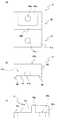
図1は、本発明の実施形態1におけるケラバ用葺き替え断熱金具を含む要部構成例を軒先側から見た断面構造を示す模式図である。(Embodiment 1)
FIG. 1 is a schematic diagram showing a cross-sectional structure of an example of a configuration of a main part including a refilling heat insulating metal fitting for keraba in
図1に示すように、本実施形態1のケラバ用断熱金具としてのケラバ用葺き替え断熱金具11,12は、フレーム両端部としてのケラバ葺き始め側Eとケラバ葺き終わり側Fの段付き妻フレーム21,22上に取り付けられる下部(傾斜部32aと横方向部31a)が左右非対称である本体部材3と、本体部材3の上面部(例えば平面)に、裏面が例えば平面で上面段差方向が左右両方向のいずれにも取り付けられる段差部材4と、段差部材4上に取り付けられて被覆材としての上屋根5aの折板の一方端部または他方端部を固定する被覆材固定部材としてのL字状の吊子部材6とを有している。 As shown in FIG. 1, the keraba reheat
本体部材3の下部が段付き妻フレーム21,22の形状(フレーム全体の中心軸に対して左右対称で、鏡像の関係にある)に対応していることと、その本体部材3の上面部に段差部材4を左右両方向のいずれにも取り付けることができることにより、同一部材(本体部材3と段差部材4共に同一部材)でケラバ葺き始め側Eとケラバ葺き終わり側Fの両側に対応するように構成している。同一部材の本体部材3および段差部材4を、ケラバ葺き始め側Eとケラバ葺き終わり側Fに応じて本体部材3は逆向きに段差部材4は同じ向きになるように組み合わせる。このように、同一の二つの部材(本体部材3と段差部材4)をリバーシブル(取付方向が逆)に組み合わせることによって、両端部の位置で別々の形状のケラバ用葺き替え金具11,12を組み立てることができる。 The lower part of the
中間部分Gの葺き替え断熱金具7は、ケラバ葺き始め側Eとケラバ葺き終わり側Fの間のフレーム中間部分用の段付きタイトフレーム8上に搭載され、段付きタイトフレーム8上の下屋根取付用のL字状の吊子部材6を両側から挟み込んだ状態で固定部材(図示しない)により固定される。この葺き替え金具7上にも別のL字状の吊子部材6が取り付けられており、この吊子部材6により上屋根5aの左右の両端部を連結している。 The intermediate heat insulation bracket 7 of the middle part G is mounted on the stepped
この上屋根5aと下屋根5bの間は空気層が介在するか断熱材が収容されて二重折板屋根の断熱構造が形成されている。この二重屋根内の空気層や断熱材と樹脂製の段差部材4による断熱効果によって暖冷房費を大幅に削減することができる。 An air layer is interposed between the
下屋根5bは、フレーム両端部の段付き妻フレーム21,22のフレーム斜辺21aまたは22a上への本体部材3の傾斜部32aの固定時にそれぞれ、その下屋根5bの端部がそれぞれ段付き妻フレーム21または22の段差部21bまたは22b上まで引き込まれた状態で、フレーム一方端部の段付き妻フレーム21のフレーム斜辺21aと本体部材3の傾斜部32aとの間に挟まれて固定されると共に、他方端部の段付き妻フレーム22のフレーム斜辺22aと本体部材3の傾斜部32aとの間に挟まれて固定される。 The
以下に、上記ケラバ用葺き替え断熱金具11,12の各構成部材についてさらに詳細に説明する。 Below, it demonstrates still in detail about each structural member of the said refilling heat
図2(a)は、図1の本体部材3および段差部材4の組立体を示す正面図であり、図2(b)は、図2(a)の組立体の左側面図である。 2A is a front view showing the assembly of the
図2(a)および図2(b)に示すように、本体部材3は、所定幅の帯材がコ字状に折り曲げられた例えば金属製の第1部材31と、所定幅の帯材が逆コ字状に折り曲げられ、逆コ字状の下端部にフレーム斜面21aに沿う傾斜部32aが連接された、例えば金属製の第2部材32とを有している。第1部材31と第2部材32はコ字状と逆コ字状の中間部分同士が背中合わせの状態で固定部材33(例えばボルトとナット)で固定されている。本体部材3は、第1部材31の上面と第2部材32の上面とが面一の状態に構成されている。これらの第1部材31および第2部材32の各上面の中央部分にはそれぞれ、段差部材4を取り付けるための取付孔に上向きに固定部材34(例えば溶接ボルト)が取り付けられている。 As shown in FIGS. 2A and 2B, the
図3は、フレーム左右端部の段付き妻フレーム21、22上への図2の組立体の取り付け状態を示す組立体取付図である。 FIG. 3 is an assembly mounting diagram showing a mounting state of the assembly of FIG. 2 on the stepped wife frames 21 and 22 at the left and right ends of the frame.
図3において、ケラバ葺き始め側Eの本体部材3は、図示しない固定部材(例えばタッピングねじ)により、その下部を構成する傾斜部32aおよび横方向部31aの各取付孔35を通してフレーム斜辺21aとフレーム水平辺21bにそれぞれ締め付けて固定する。また同様に、ケラバ葺き終わり側Fの本体部材3は、図示しない固定部材(例えばタッピングねじ)により、その下部を構成する傾斜部32aおよび横方向部31aの各取付孔35を通してフレーム斜辺22aとフレーム水平辺22bにそれぞれ締め付けて固定する。ケラバ葺き始め側Eとケラバ葺き終わり側Fにおける本体部材3の下部はそれぞれ、傾斜部32aと横方向部31aの配置が互いに左右逆であるため左右非対称となる。この本体部材3の上部(二つの横部材36)の各上面部はそれぞれ例えば平面である。 In FIG. 3, the
ケラバ葺き始め側Eの本体部材3と、ケラバ葺き終わり側Fの本体部材3は、同一部材であって、左右の取付方向が逆であるだけである。それに対して、段差部材4の向きはケラバ葺き始め側Eとケラバ葺き終わり側Fで同一方向である。 The
これによって、ケラバ葺き始め側Eとケラバ葺き終わり側Fの段付き妻フレーム21、22上に、互いに異なる組立体を、同一部品の本体部材3と段差部材4により組み立てることができる。 Thus, different assemblies can be assembled on the stepped wife frames 21 and 22 on the keraba whirl start side E and the keraba whisper end side F by the
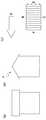
図4(a)は図1〜図3の段差部材4の平面図であり、図4(b)は図4(a)の段差部材4の正面図であり、図4(c)は図4(a)の段差部材4の右側面図である。 4A is a plan view of the step member 4 of FIGS. 1 to 3, FIG. 4B is a front view of the step member 4 of FIG. 4A, and FIG. 4C is FIG. It is a right view of the level | step difference member 4 of (a).
図4(a)〜図4(c)に示すように、段差部材4は、平面視4角形領域の縦方向の中心線を境にして薄い平面側の第1領域41と厚い側の第2領域42(ここでは全体領域の面積的に半々)を有する。第1領域41と第2領域42との間に段差面43が設けられ、第1領域41の平面41cと段差面43により断面L字状の支持面が構成されている。この段差面43の直立位置は、段差部材4を、図4(c)において左右両方向のいずれに取付方向を変えても変化しない位置である。第1領域41と第2領域42に設けられる取付孔41a、42aは、段差面43の直立位置を線中心として振り分けた位置(線対称位置)で幅方向中心位置に形成されている。 As shown in FIGS. 4A to 4C, the step member 4 includes a
第2領域42の取付孔42aの周囲を、段差面43の直立位置から所定幅領域42bを中間部に含む平面視コ字状に残して薄い平面41cの第1領域41と同じ厚さの平面42cに形成する。取付孔42aの固定面の周囲を高くしてナットなどの固定部材(図示せず)を取付孔42aの固定面の周囲に収容し得る空間を有している。この平面視コ字状に厚い平面領域(所定幅領域42bを中間部に含む平面視コ字状領域)により、上屋根5aが重みで下がらないように平面視コ字状領域で下から受けて支持する。なお、ここでは、平面視コ字状に厚い平面領域(所定幅領域42bを中間部に含む平面視コ字状領域)を残したが、これに限らず、第2領域42のうち平面視外周4角形の少なくとも1辺(所定幅領域42bを含む1辺)だけを残してもよい。 A plane having the same thickness as the
また、段差部材4の幅は、本体部材3の帯幅よりも若干広く形成されている。段差部材4の裏面は、本体部材3の帯状部分をその幅方向に嵌合するように、幅方向に対向する辺を各所定幅端部44として残して幅広の溝45が形成される。この幅広の溝45内に本体部材3の上面部が嵌合して、本体部材3の上面部上に段差部材4を取り付ける際に、段差部材4の幅方向両側の所定幅端部44を本体部材3に対する段差部材4の回り止めにすることができる。 Further, the width of the step member 4 is slightly wider than the band width of the
段差部材4は例えば断熱用のために樹脂製である。この場合、その材質がポリアセタール、ABS樹脂およびポリプロピレンなどのうちのいずれかの樹脂材料で構成されていてもよい。この樹脂材料に更なる耐熱のためにガラス繊維などを混合してもよい。樹脂製の段差部材4は、板材などのブロック材から形状加工してもよいが、射出成型によって樹脂製の段差部材4を所定形状に成型してもよい。 The step member 4 is made of resin for heat insulation, for example. In this case, the material may be made of any one of polyacetal, ABS resin, polypropylene and the like. Glass resin or the like may be mixed with this resin material for further heat resistance. The step member 4 made of resin may be processed from a block material such as a plate material, but the step member 4 made of resin may be formed into a predetermined shape by injection molding.
図5(a)は図1〜図3の吊子部材6の側面図であり、図5(b)は図5(a)の吊子部材6の平面図であり、図5(c)は図5(a)の吊子部材6を右側から見た背面図である。 5 (a) is a side view of the hanging
図5(a)〜図5(c)に示すように、本実施形態1のケラバ用葺き替え断熱金具11,12に共通金具として用いられる被覆材固定部材としての吊子部材6は、段差部材4上の取付面61の中央位置に前後方向(図5(a)では左右方向)に長い長孔62が形成されている。一方、段差部材4は、第1領域41の平面41cと段差面43により断面L字状の支持面が構成されているが、固定部材(図示せず)の先端を長孔62に通して、その直立した段差面43に吊子部材6の垂直面63を押し付けた状態で段差部材4上に吊子部材6を固定部材(図示せず)により固定する。このようにして、吊子部材6が段差部材4上に段差面43により支持されて取り付けられ、折板の上屋根5aの端辺部を長手方向のフック部64内に巻き込んで取り付けている。 As shown in FIGS. 5 (a) to 5 (c), the hanging
吊子部材6は、その取付面61の長手方向両側に連接する立設面上端から外側(横方向)に折り曲げられて取付面61の両側に支持面65をそれぞれ形成している。取付面61とその両側の支持面65により長孔62の取付面61が囲まれたその内側にナットやボルトの先端などの固定部材(図示せず)を収容し得る空間を有している。この両側の支持面65により、上屋根5aが重みで下がらないように下から受けて支持している。 The hanging
二重屋根への葺き替えは、ケラバ葺き始め側Eから中間部分Gを介してケラバ葺き終わり側Fに一方向に順に行うため、L字状の吊子部材6は同じ向きに段差部材4上に配置される。ここでは、前述したように、断面L字の底面固定部(長孔62の取付面61)を右側に配置し、立設した垂直面63を介して屋根板固定用のフック部64を左側に配設している。 Since the switching to the double roof is performed in one direction sequentially from the keraba sowing start side E through the intermediate portion G to the keraba sowing end side F, the L-shaped hanging
以上により、本実施形態1によれば、ケラバ用葺き替え金具11,12はそれぞれ、フレーム両端部におけるケラバ葺き始め側Eのフレーム水平辺からフレーム斜辺、ケラバ葺き終わり側Fのフレーム斜辺からフレーム水平辺に沿って本体部材3の下部側が固定され、本体部材3の上部側の上面部が例えば平面である本体部材3と、本体部材3の上面部上に、葺き始め位置と葺き終わり位置とに応じて、フレーム斜辺に対する取り付け方向を左右異ならせて取り付けた段差部材4と、段差部材4上に取り付けられ、折板の端辺部をフック部64に巻き込んで取り付ける吊子部材6とを有している。 As described above, according to the first embodiment, the keraba rewinding
これによって、本体部材3の下部がフレーム両端の段付き妻フレーム21,22の左右対称形状に対応して取り付けられることと、その本体部材3の上面部に段差部材4の上面段差方向が左右両方向のいずれにも段差部材4が取り付けられるため、同一部材で両端部側に対応することができて、施工管理を簡略化でき、部材管理および部材加工管理をも簡略化することができる。 As a result, the lower part of the
なお、本実施形態1では、段差部材4は、ここでは断熱用に樹脂製としたが、これに限らず、金属製であってもよい。金属製の段差部材4を用いた場合には、断熱性が失われるため、ケラバ用葺き替え断熱金具11,12はケラバ用葺き替え金具となる。 In the first embodiment, the step member 4 is made of resin here for heat insulation, but is not limited thereto, and may be made of metal. When the metal step member 4 is used, the heat insulating property is lost, so that the keraba replacement heat insulating
なお、本実施形態1では、本体部材3の上部(第1部材31と第2部材32の二つの横部材36)の各上面部は平面で構成したが、これに限らず、本体部材3の上面部に段差部材4がその上面段差方向が左右両方向のいずれにも取り付けられればよい。そのためには、本体部材3の上面部が線対称面構造で、これに対応する段差部材4の裏面も線対称面構造であればよい。 In the first embodiment, each upper surface portion of the upper portion of the main body member 3 (the two
なお、本実施形態1では、本体部材3の上面部上に段差部材4を取り付ける際に、段差部材4の裏面幅方向両側から突出した各所定幅端部44が本体部材3の上面部を幅方向両側面を挟み込んで本体部材3に対する段差部材4の回り止めとして作業効率を上げることができたが、これに限らず、所定幅端部44の代わりにまたは、所定幅端部44と共に、本体部材3の上面部側に、段差部材4の側面を両側から挟み込んで本体部材3を回り止め用の上面部構造としてもよい。この本体部材3の上面部構造について次の実施形態2にその一例を説明する。この場合にも、前述したように、本体部材3の上面部が線対称面構造で、これに対応するように段差部材4の裏面も線対称面構造である必要がある。 In the first embodiment, when the step member 4 is attached on the upper surface portion of the
(実施形態2)
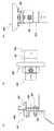
図6は、本発明の実施形態2として回り止め用の本体部材3の上面部構造を図3に適用した組立体取り付け図である。図6では、図3の構成部材と同様の作用効果を奏する構成部材には同一の符号を付してその説明を省略する。(Embodiment 2)
FIG. 6 is an assembly mounting diagram in which the upper surface structure of the
図6に示すように、上記実施形態1の図3の構成と異なるのは、本体部材3Aとその上の段差部材4Aである。以下、詳細に説明する。 As shown in FIG. 6, what is different from the configuration of FIG. 3 of the first embodiment is a
その本体部材3Aの上部(二つの横部材36A)の各上面部に、裏面が平面の段差部材4Aの回り止め用に側面規制部37が設けられている。側面規制部37は、段差部材4Aの前後方向の両側面の一部または全部をそれぞれ覆うように、二つの横部材36Aの左右方向に直交する前後方向の断面が上に開放したコ字状に形成されている。側面規制部37の高さは段差部材4Aの側面の高さと同じかまたはその側面の高さよりも低く設定される。この場合にも、前述したように、本体部材3Aへの段差部材4Aの取付方向を左右逆にするために、本体部材3Aの上面部が線対称面構造(例えば平面)で、これに対応するように段差部材4Aの裏面も線対称面構造(例えば平面)である。 A side
本体部材3Aは、第1部材31Aの上面と第2部材32Aの上面とが面一で各上面の幅方向両端から回り止め用の側面規制部37が立ち上がった状態で側面規制部37(4か所)が本体部材3Aの平面部上面を取り囲んでいる。 The
段差部材4Aの裏面は、上記実施形態1の段差部材4の裏面とは異なり、平面である。また、第2部材32Aの下部形状は、上記実施形態1の第2部材32とは異なり、段付き妻フレーム21、22の段差平面21c、22c上に搭載されている。 Unlike the back surface of the step member 4 of the first embodiment, the back surface of the
以上により、本実施形態2によれば、本体部材3Aの下部がフレーム両端部の段付き妻フレーム21,22の左右対称形状に対応して取り付けられることと、その本体部材3Aの上面部に段差部材4Aの上面段差方向が左右両方向のいずれにも、供回りを確実に抑えて作業効率よく取り付けることができるため、本体部材3Aおよび段差部材4Aが同一部材で、それらの組立体として両端部側(ケラバ側)により容易に対応することができて、施工管理を簡略化できて、部材管理および部材加工管理をも簡略化することができる。 As described above, according to the second embodiment, the lower part of the
なお、本実施形態2では、側面規制部37は、本体部材3Aの平面部(二つの横部材36A)の両側が前後方向コ字状断面になっている回り止め構造について説明したが、これに限らず、この側面規制部37と共にまたは、図7(a)に示すように側面規制部37の代わりに、回り止め構造として、前後方向に直交する左右方向の両先端が所定長さだけ直角または鋭角に折り曲げられた各側面規制部38が設けられてもよい。この側面規制部38の高さは段差部材4Aの左右方向の側面高さと同じかまたはその側面の高さよりも低く設定される。 In the second embodiment, the side
この場合にも、前述したように、本体部材3Bに対して段差部材4Aの取付方向を左右逆にするために、本体部材3Bの上面部が線対称面構造(ここでは平面)で、これに対応するように段差部材4Aの裏面も線対称面構造(ここでは平面)である。 Also in this case, as described above, in order to reverse the mounting direction of the
また、別の事例について説明すると、図7(b)に示すように、本体部材3Cの上面部(二つの横部材36C)は、長手方向(左右方向)の中央部が幅方向(前後方向)に所定高さだけ段落ち(中央段差部)している。要するに、本体部材3Cの上面部は、二つの横部材36Cが両側横方向に曲がった後に所定の段差が形成されて両方で幅方向凹部39が形成されている。この幅方向凹部39内に嵌合する幅方向凸部44Cが段差部材4Cの裏面中央に設けられている。本体部材3Cの上面部の中央の幅方向凹部39と、これに嵌合する段差部材4Cの裏面中央の幅方向凸部44C(凸部は幅方向全部または一部)によって組立時の本体部材3Cに対する段差部材4Cの回り止めとすることができる。 In another example, as shown in FIG. 7B, the upper surface portion (two lateral members 36C) of the main body member 3C has a central portion in the longitudinal direction (left-right direction) in the width direction (front-rear direction). Stepped down by a predetermined height (center step portion). In short, the upper surface portion of the main body member 3C is formed with a predetermined step after the two lateral members 36C are bent in the lateral direction on both sides, and the widthwise concave portion 39 is formed on both. A width direction
この場合にも、前述したように、本体部材3Cに対する段差部材4Cの取付方向を左右逆にするために、本体部材3Cの幅方向凹部39を中央に含む上面部が線対称面構造(ここでは段差平面)で、これに対応するように段差部材4Cの裏面も中央の幅方向凸部44Cを含む線対称面構造(ここでは段差平面)である。 Also in this case, as described above, in order to reverse the mounting direction of the step member 4C with respect to the main body member 3C, the upper surface portion including the width direction concave portion 39 of the main body member 3C has a line-symmetric surface structure (here, In order to correspond to this, the back surface of the step member 4C also has a line-symmetric surface structure (here, a step surface) including the central width direction
なお、上記実施形態1,2では、屋根のケラバ用葺き替え金具またはケラバ用葺き替え断熱金具について詳細に説明したが、屋根(被覆材)の被覆に限らず、壁(被覆材)の被覆に用いることもできて、段差部材4、4Aおよび4Cのいずれかの上にコ字状金具を固定し、壁用被覆材の上からコ字状金具の上面に対して固定部材(例えばタッピングネジ)で固定する部被覆用金具とすることができる。また、本体部材3、3A、3Bは二つの部材から構成したが、これに限らず、フレームの端部に取り付けられるものであれば、一つの部材から構成してもよい。また、これらに限らず、本体部材3、3A〜3C、段差部材4、4Aおよび4C、被覆材固定部材(例えば吊り子部材6)が全て金属、全てセラミックまたは全て樹脂で構成してもよく、このうちの段差部材4、4Aおよび4Cだけを樹脂製にしてもよいが、強度の観点からは、本体部材3、3A〜3C、段差部材4、4Aおよび4C、被覆材固定部材(例えば吊り子部材6)が全て金属で構成する方がよい。断熱の観点からは、本体部材3、3A〜3C、段差部材4、4Aおよび4C、被覆材固定部材(例えば吊り子部材6)が全て金属で構成する方がよい。要するに、本体部材3、3A〜3C、段差部材4、4Aおよび4C、被覆材固定部材(例えば吊り子部材6)の材料は、金属、セラミックおよび樹脂から適宜選択することができて被覆用具とすることができる。 In the first and second embodiments, the keraba refurbishment metal fitting for the roof or the keraba refurbishment heat insulation metal fitting has been described in detail, but it is not limited to the covering of the roof (covering material), but used for covering the wall (covering material). The U-shaped bracket is fixed on one of the
なお、上記実施形態1,2では、本体部材と段差部材とは互いの回り止めの構成を有していたが、これに限らず、本体部材と段差部材とは互いの回り止めの構成を有していなくてもよい。 In the first and second embodiments, the main body member and the step member have a mutual rotation preventing structure. However, the present invention is not limited to this, and the main body member and the step member have a mutual rotation preventing structure. You don't have to.
なお、上記実施形態1,2では、図4(a)〜図4(c)に示すように、第2領域42の取付孔42aの周囲を、段差面43の直立位置から所定幅領域42bを中間部に含む平面視コ字状に残して薄い平面41cの第1領域41と同じ厚さの平面42cに形成したが、これに限らず、この平面視コ字状に厚い平面領域(所定幅領域42bを中間部に含む平面視コ字状領域)を設けずに、第2領域42の全体を厚い領域としてその中央部に取付孔42aを設けてもよい。 In the first and second embodiments, as shown in FIGS. 4A to 4C, the
なお、上記実施形態1,2では、本発明の被覆用具や被覆用金具をケラバ用葺き替え金具やケラバ用葺き替え断熱金具に適用した場合について説明したが、屋根の葺き替えに限らず、屋根や壁の新築にも、本発明の被覆用具や被覆用金具をケラバ用金具やケラバ用断熱金具としてこれに適用することができる。 In the first and second embodiments, the case where the covering tool or covering metal fitting according to the present invention is applied to the keraba refurbishment fitting or the keraba refilling heat insulation fitting has been described. The covering tool and the covering metal fitting of the present invention can be applied to the new construction as the keraba metal fitting and the keraba heat insulating metal fitting.
以上のように、本発明の好ましい実施形態1、2を用いて本発明を例示してきたが、本発明は、この実施形態1、2に限定して解釈されるべきものではない。本発明は、特許請求の範囲によってのみその範囲が解釈されるべきであることが理解される。当業者は、本発明の具体的な好ましい実施形態1、2の記載から、本発明の記載および技術常識に基づいて等価な範囲を実施することができることが理解される。 As mentioned above, although this invention was illustrated using
本発明は、フレームの端部に被覆材を取り付けるために用いられる被覆用具および、例えば屋根のケラバ側でハゼ式折板の二重屋根に葺き替えるのに用いるケラバ用葺き替え金具の分野において、本体部材の下部がフレーム両端の左右対称形状に対応して取り付けられることと、その上の上面部に段差部材の上面段差方向が左右両方向のいずれにも段差部材が取り付けられるため、同一部材で両端部側に対応することができて、施工管理を簡略化でき、部材管理および部材加工管理をも簡略化することができる。 The present invention relates to a covering tool used for attaching a covering material to an end portion of a frame, and a main body in the field of a reversing metal fitting for keraba used to replace a double roof of a goby type folded plate on a keraba side of a roof, for example. Since the lower part of the member is attached corresponding to the symmetrical shape of both ends of the frame, and the step member is attached to the upper surface of the step member in both the left and right directions, the same member has both ends. The construction management can be simplified, and the member management and the member processing management can be simplified.
11、12 ケラバ用葺き替え断熱金具(被覆用金具)
21、22 段付き妻フレーム
21a、22a フレーム斜辺
21b、22b フレーム水平辺
21c、22c 段差平面
3、3A〜3B 本体部材
31、31A〜31C 第1部材
31a 横方向部
32、32A〜32C 第2部材
32a 傾斜部
33 固定部材(ボルトとナット)
34 固定部材(溶接ボルト)
35 取付孔
36、36A〜36C 横部材
37、38 回り止め用の側面規制部
39 幅方向凹部
4、4A、4C 段差部材
41 薄い平面側の第1領域
41a,42a 取付孔
42 厚い側の第2領域
42b 所定幅領域
41c、42c 平面
43 段差面
44 所定幅端部
44C 幅方向凸部
45 幅広の溝
5a 上屋根(被覆材)
5b 下屋根
6、9 吊子部材
61 取付面
62 長孔
63 垂直面
64 フック部
65 支持面
7 中間部分用の葺き替え断熱金具
8 中間部分用の段付きタイトフレーム
E ケラバ葺き始め側
F ケラバ葺き終わり側
G 中間部分
C 中心線11, 12 Replacement heat insulation bracket for keraba (covering bracket)
21, 22 Stepped
34 Fixing member (weld bolt)
35 Mounting
Claims (5)
Translated fromJapanese該被覆用具は、
該フレームの端部に取り付けられる本体部材と、
該本体部材に取り付けられる段差部材であって、段差を有する段差部材と、
該段差部材に取り付けられる被覆材固定部材であって、該被覆材を固定する被覆材固定部材と
を備え、
該本体部材および該段差部材は、該本体部材に対する該段差の向きを変えて該段差部材が該本体部材に取り付けることができるように構成されている、被覆用具。A covering tool used for attaching a covering material to an end of a frame,
The covering tool is:
A body member attached to an end of the frame;
A step member attached to the body member, the step member having a step;
A covering material fixing member attached to the step member, comprising: a covering material fixing member for fixing the covering material;
The main body member and the step member are configured to change the direction of the step with respect to the main body member so that the step member can be attached to the main body member.
該上面部は線対称の面構造である、請求項1または2に記載の被覆用具。The covering material fixing member is attached to the upper surface portion of the main body member,
The covering tool according to claim 1 or 2, wherein the upper surface portion has a line symmetrical surface structure.
Priority Applications (1)
| Application Number | Priority Date | Filing Date | Title |
|---|---|---|---|
| JP2014148338AJP6240868B2 (en) | 2014-07-18 | 2014-07-18 | Coating tool |
Applications Claiming Priority (1)
| Application Number | Priority Date | Filing Date | Title |
|---|---|---|---|
| JP2014148338AJP6240868B2 (en) | 2014-07-18 | 2014-07-18 | Coating tool |
Publications (2)
| Publication Number | Publication Date |
|---|---|
| JP2016023464Atrue JP2016023464A (en) | 2016-02-08 |
| JP6240868B2 JP6240868B2 (en) | 2017-12-06 |
Family
ID=55270492
Family Applications (1)
| Application Number | Title | Priority Date | Filing Date |
|---|---|---|---|
| JP2014148338AActiveJP6240868B2 (en) | 2014-07-18 | 2014-07-18 | Coating tool |
Country Status (1)
| Country | Link |
|---|---|
| JP (1) | JP6240868B2 (en) |
Cited By (1)
| Publication number | Priority date | Publication date | Assignee | Title |
|---|---|---|---|---|
| JP2018145703A (en)* | 2017-03-07 | 2018-09-20 | 株式会社高又製作所 | Auxiliary attachment tool of heat insulating metal fitting for verge |
Citations (4)
| Publication number | Priority date | Publication date | Assignee | Title |
|---|---|---|---|---|
| JPS57158460A (en)* | 1981-03-25 | 1982-09-30 | Sanko Kinzoku Kogyo Kk | Lighting outer enclosure |
| JPS5921329U (en)* | 1982-07-31 | 1984-02-09 | 永松 建治 | Repair on the gable side of the roof |
| JPH08333848A (en)* | 1995-06-06 | 1996-12-17 | Yodogawa Steel Works Ltd | Verge storage structure |
| US20120233941A1 (en)* | 2011-03-14 | 2012-09-20 | Mclain Michael J | Support structures on roofs |
- 2014
- 2014-07-18JPJP2014148338Apatent/JP6240868B2/enactiveActive
Patent Citations (4)
| Publication number | Priority date | Publication date | Assignee | Title |
|---|---|---|---|---|
| JPS57158460A (en)* | 1981-03-25 | 1982-09-30 | Sanko Kinzoku Kogyo Kk | Lighting outer enclosure |
| JPS5921329U (en)* | 1982-07-31 | 1984-02-09 | 永松 建治 | Repair on the gable side of the roof |
| JPH08333848A (en)* | 1995-06-06 | 1996-12-17 | Yodogawa Steel Works Ltd | Verge storage structure |
| US20120233941A1 (en)* | 2011-03-14 | 2012-09-20 | Mclain Michael J | Support structures on roofs |
Cited By (1)
| Publication number | Priority date | Publication date | Assignee | Title |
|---|---|---|---|---|
| JP2018145703A (en)* | 2017-03-07 | 2018-09-20 | 株式会社高又製作所 | Auxiliary attachment tool of heat insulating metal fitting for verge |
Also Published As
| Publication number | Publication date |
|---|---|
| JP6240868B2 (en) | 2017-12-06 |
Similar Documents
| Publication | Publication Date | Title |
|---|---|---|
| KR102451442B1 (en) | Curtain wall assembly for both exposed and hidden types | |
| JP6240868B2 (en) | Coating tool | |
| KR20140090039A (en) | 4-way tenon joint frame of free-form grid shell structures | |
| KR101864681B1 (en) | The structure of metal panel roof-truss supported by double purlin of assembling type | |
| JP2016102360A (en) | Fireproof and heat-insulating structure for exterior wall of steel construction | |
| KR20230061966A (en) | Window system with improved insulation property | |
| JP4605769B2 (en) | Resin sash | |
| CN111075109A (en) | House beam fixing device and house beam | |
| KR101612796B1 (en) | Curtain Wall | |
| CN215670147U (en) | Zigzag floor supporting node | |
| CN207974411U (en) | External corner edge closing bar and external corner receive side component | |
| JP4448982B2 (en) | Deck plate with truss, manufacturing method of deck plate with truss | |
| KR100874446B1 (en) | Refractive angle for fixing balcony window frames | |
| JP4083206B1 (en) | Board and board assembly structure | |
| JP6688967B2 (en) | Solar cell module and solar power generation device | |
| KR100896917B1 (en) | Lightweight large-format wide panel | |
| JP4336280B2 (en) | Floor panel and floor structure | |
| CN116498009B (en) | Manufacturing method of special-shaped steel girder structure suitable for different inclined plane intersection angles | |
| JP6248344B2 (en) | Steel frame structure for double glazing | |
| JP2013087609A (en) | Building panel | |
| JP6703895B2 (en) | Thermal insulation support | |
| JP6904868B2 (en) | balcony | |
| ES2272536T5 (en) | Structural element for sealing flat roofs | |
| JP7056828B2 (en) | Unit building | |
| JP2019143347A (en) | Fitting |
Legal Events
| Date | Code | Title | Description |
|---|---|---|---|
| A621 | Written request for application examination | Free format text:JAPANESE INTERMEDIATE CODE: A621 Effective date:20160621 | |
| A977 | Report on retrieval | Free format text:JAPANESE INTERMEDIATE CODE: A971007 Effective date:20170316 | |
| A131 | Notification of reasons for refusal | Free format text:JAPANESE INTERMEDIATE CODE: A131 Effective date:20170403 | |
| A521 | Request for written amendment filed | Free format text:JAPANESE INTERMEDIATE CODE: A523 Effective date:20170510 | |
| TRDD | Decision of grant or rejection written | ||
| A01 | Written decision to grant a patent or to grant a registration (utility model) | Free format text:JAPANESE INTERMEDIATE CODE: A01 Effective date:20170928 | |
| A61 | First payment of annual fees (during grant procedure) | Free format text:JAPANESE INTERMEDIATE CODE: A61 Effective date:20171004 | |
| R150 | Certificate of patent or registration of utility model | Ref document number:6240868 Country of ref document:JP Free format text:JAPANESE INTERMEDIATE CODE: R150 | |
| R250 | Receipt of annual fees | Free format text:JAPANESE INTERMEDIATE CODE: R250 | |
| R250 | Receipt of annual fees | Free format text:JAPANESE INTERMEDIATE CODE: R250 |