JP2016019187A - Measuring device - Google Patents
Measuring deviceDownload PDFInfo
- Publication number
- JP2016019187A JP2016019187AJP2014141647AJP2014141647AJP2016019187AJP 2016019187 AJP2016019187 AJP 2016019187AJP 2014141647 AJP2014141647 AJP 2014141647AJP 2014141647 AJP2014141647 AJP 2014141647AJP 2016019187 AJP2016019187 AJP 2016019187A
- Authority
- JP
- Japan
- Prior art keywords
- measurement
- sensor
- antenna
- housing
- attached
- Prior art date
- Legal status (The legal status is an assumption and is not a legal conclusion. Google has not performed a legal analysis and makes no representation as to the accuracy of the status listed.)
- Pending
Links
Images


Landscapes
- Mobile Radio Communication Systems (AREA)
- Studio Devices (AREA)
- Selective Calling Equipment (AREA)
Abstract
Translated fromJapaneseDescription
Translated fromJapanese本発明は、計測装置に関し、特に、計測結果を無線伝送する計測装置に関する。 The present invention relates to a measurement apparatus, and more particularly to a measurement apparatus that wirelessly transmits measurement results.
無線端末装置が通信可能なエリアであるセルを形成する無線基地局装置による通信サービスが提供されており、このような通信サービス等を利用したシステムとして、M2M(Machine to Machine)システムが知られている。M2Mシステムでは、たとえば、無線機を搭載した機器同士が人間を介在せずに相互に情報をやり取りすることにより、自動的に機器の制御が行われる。 A communication service is provided by a wireless base station device that forms a cell that is an area in which a wireless terminal device can communicate, and an M2M (Machine to Machine) system is known as a system that uses such a communication service. Yes. In the M2M system, for example, devices are automatically controlled by exchanging information with each other without the intervention of humans.
M2Mシステムの一例として、たとえば、特許文献1(特許第4237134号公報)には、以下のような技術が開示されている。すなわち、無線端末と、当該無線端末との無線通信が可能なゲートウェイノードと、無線端末の位置情報を保持する位置情報記憶装置とを有する移動体通信ネットワークと、上記無線端末からのメッセージ送信先である端末が接続される他のネットワークとがゲートウェイを介して接続されてなるネットワークシステムである。当該ネットワークシステムは、上記無線端末ごとに予め定めた送信先である上記端末のアドレスを保持する端末アドレス保持手段を有する。上記無線端末から上記端末へメッセージを送信する際には、上記ゲートウェイノードは、上記無線端末より無線フレームを受信すると、上記端末アドレス保持手段にアクセスして、無線端末ごとにメッセージの送信先の端末アドレスを特定し、当該特定した送信先の端末宛に上記ゲートウェイを介してメッセージを送信する。上記端末より上記無線端末へメッセージを送信する際には、上記ゲートウェイは、上記位置情報記憶装置にアクセスし、上記無線端末のIDから位置情報を取得し、当該取得した位置情報から該当するゲートウェイノードへメッセージを転送する。当該ゲートウェイノードは、上記無線端末へ上記メッセージを転送する。 As an example of the M2M system, for example, Patent Literature 1 (Japanese Patent No. 4237134) discloses the following technology. That is, a mobile communication network having a wireless terminal, a gateway node capable of wireless communication with the wireless terminal, a location information storage device that holds location information of the wireless terminal, and a message transmission destination from the wireless terminal This is a network system in which another network to which a certain terminal is connected is connected via a gateway. The network system includes terminal address holding means for holding the address of the terminal that is a transmission destination predetermined for each wireless terminal. When transmitting a message from the wireless terminal to the terminal, when the gateway node receives a wireless frame from the wireless terminal, the gateway node accesses the terminal address holding unit, and sends a message destination terminal to each wireless terminal. An address is specified, and a message is transmitted to the specified destination terminal via the gateway. When transmitting a message from the terminal to the wireless terminal, the gateway accesses the position information storage device, acquires position information from the ID of the wireless terminal, and the corresponding gateway node from the acquired position information Forward the message to The gateway node transfers the message to the wireless terminal.
このようなM2Mシステムの1つの利用形態として、対象物の計測を行い、かつ計測結果を無線信号に含めて送信することが可能な1または複数の計測装置を設置し、無線信号の送信先において収集された計測結果に基づいて対象物の状態を管理する管理システムが考えられる。 As one form of use of such an M2M system, one or a plurality of measuring devices that can measure an object and transmit a measurement result in a wireless signal are installed, and the wireless signal is transmitted to a destination. A management system that manages the state of the object based on the collected measurement results can be considered.
しかしながら、上記管理システムが工場等で使用される場合、上記計測装置を設置可能な場所が限られていることがある。そして、このように設置可能な場所が限られている場合、計測装置の備えるセンサを対象物に向け、かつ計測装置における電波の放射強度が強い方向を上記送信先に向けることが困難なことがある。 However, when the management system is used in a factory or the like, the place where the measurement device can be installed may be limited. And when the place where installation is possible is limited in this way, it may be difficult to direct the sensor included in the measurement device toward the object and to direct the direction in which the radio wave emission intensity of the measurement device is strong toward the transmission destination. is there.
たとえば、上記放射強度の強い方向が無線信号の送信先を向いていない場合、計測装置は、対象物の計測結果を良好に伝送できない可能性がある。 For example, when the direction in which the radiation intensity is strong is not directed to the transmission destination of the radio signal, the measurement apparatus may not be able to transmit the measurement result of the object well.
この発明は、上述の課題を解決するためになされたもので、その目的は、対象物の計測および計測結果の伝送を良好に行うことが可能な計測装置を提供することである。 This invention was made in order to solve the above-mentioned subject, The objective is to provide the measuring device which can perform the measurement of a target object, and transmission of a measurement result favorably.
(1)上記課題を解決するために、この発明のある局面に係る計測装置は、アンテナと、センサまたはカメラと、前記センサまたは前記カメラの計測結果を示す計測情報を無線信号に含めて前記アンテナから送信する通信部と、前記アンテナと前記センサまたは前記カメラとの少なくともいずれか一方の位置を変更可能な可動部とを備える。 (1) In order to solve the above problem, a measurement device according to an aspect of the present invention includes an antenna, a sensor or a camera, and measurement information indicating a measurement result of the sensor or the camera included in a wireless signal. And a movable part capable of changing the position of at least one of the antenna and the sensor or the camera.
この発明によれば、対象物の計測および計測結果の伝送を良好に行うことができる。 According to this invention, measurement of a target object and transmission of a measurement result can be performed favorably.
最初に、本発明の実施の形態の内容を列記して説明する。 First, the contents of the embodiment of the present invention will be listed and described.
(1)本発明の実施の形態に係る計測装置は、アンテナと、センサまたはカメラと、前記センサまたは前記カメラの計測結果を示す計測情報を無線信号に含めて前記アンテナから送信する通信部と、前記アンテナと前記センサまたは前記カメラとの少なくともいずれか一方の位置を変更可能な可動部とを備える。 (1) A measurement apparatus according to an embodiment of the present invention includes an antenna, a sensor or a camera, a communication unit that includes measurement information indicating a measurement result of the sensor or the camera in a wireless signal, and transmits from the antenna. A movable part capable of changing a position of at least one of the antenna and the sensor or the camera.
このような構成により、たとえば、アンテナの放射強度の強い方向が無線信号の送信先を向くように計測装置を設置し、計測装置の位置を固定したまま可動部を動かしてセンサまたはカメラを計測対象に向けることができる。また、センサまたはカメラが計測対象を向くように計測装置を設置し、計測装置の位置を固定したまま可動部を動かしてアンテナの放射強度の強い方向を上記送信先に向けることができる。したがって、対象物の計測および計測結果の伝送を良好に行うことができる。 With such a configuration, for example, the measurement device is installed so that the direction of the strong radiation intensity of the antenna faces the transmission destination of the radio signal, and the sensor or camera is measured by moving the movable part while keeping the position of the measurement device fixed. Can be directed to. In addition, the measurement device can be installed so that the sensor or camera faces the measurement target, and the movable portion can be moved while the position of the measurement device is fixed, so that the direction of strong antenna radiation intensity can be directed to the transmission destination. Therefore, the measurement of the object and the transmission of the measurement result can be performed satisfactorily.
(2)好ましくは、前記可動部は、前記センサまたは前記カメラと計測対象との距離を変更可能である。 (2) Preferably, the said movable part can change the distance of the said sensor or the said camera, and a measuring object.
このような構成により、たとえば、計測対象以外の他の物が計測範囲に含まれることによって正しい計測結果を得ることができない場合に、センサまたはカメラと計測対象との距離を小さくすることによって計測範囲を小さくし、当該他の物を計測範囲から外すことができる。 With such a configuration, for example, when a measurement result other than the measurement target is included in the measurement range and a correct measurement result cannot be obtained, the measurement range is reduced by reducing the distance between the sensor or camera and the measurement target. , And the other objects can be removed from the measurement range.
(3)好ましくは、前記計測装置は、さらに、筐体を備え、前記アンテナと前記センサまたは前記カメラとは、前記筐体の同じ面に取り付けられる。 (3) Preferably, the measurement device further includes a housing, and the antenna and the sensor or the camera are attached to the same surface of the housing.
このような構成により、たとえば、アンテナとセンサまたはカメラとを、筐体内に収納されるプリント基板に同じ方向から取り付けることができるため、計測装置の作製を簡単に行うことができ、また、計測装置の小型化を実現することができる。 With such a configuration, for example, the antenna and the sensor or camera can be attached to the printed circuit board accommodated in the housing from the same direction, so that the measurement device can be easily manufactured. Downsizing can be realized.
(4)好ましくは、前記計測装置は、さらに、筐体を備え、前記アンテナと前記センサまたは前記カメラとは、前記筐体の異なる面に取り付けられる。 (4) Preferably, the measurement device further includes a housing, and the antenna and the sensor or the camera are attached to different surfaces of the housing.
このような構成により、アンテナとセンサまたはカメラとが互いに接触しにくくなるため、計測対象の計測および計測結果の伝送において、より適した位置にこれらを配置することができる。 Such a configuration makes it difficult for the antenna and the sensor or camera to come into contact with each other, so that they can be arranged at a more suitable position in measurement of the measurement target and transmission of the measurement result.
(5)好ましくは、前記計測装置は、さらに、前記可動部が取り付けられた筐体を備え、前記筐体は、前記筐体をネジを用いて他の物体に取り付けるためのネジ止め取付具を固定するか、または前記筐体を磁力によって他の物体に取り付けるための磁気取付具を固定することが可能な固定部を含む。 (5) Preferably, the measurement device further includes a housing to which the movable portion is attached, and the housing includes a screw fixing fixture for attaching the housing to another object using a screw. It includes a fixing portion that can fix or fix a magnetic fixture for attaching the casing to another object by magnetic force.
このような構成により、計測装置を壁等に取り付けることができる。また、計測装置を壁等に取り付ける際に、ネジ止め取付具を用いて取り付けるか、または磁気取付具を用いて取り付けるかを選択することができる。 With such a configuration, the measuring device can be attached to a wall or the like. Moreover, when attaching a measuring device to a wall etc., it can be selected whether it attaches using a screwing attachment or a magnetic attachment.
以下、本発明の実施の形態について図面を用いて説明する。なお、図中同一または相当部分には同一符号を付してその説明は繰り返さない。また、以下に記載する実施形態の少なくとも一部を任意に組み合わせてもよい。 Hereinafter, embodiments of the present invention will be described with reference to the drawings. In the drawings, the same or corresponding parts are denoted by the same reference numerals and description thereof will not be repeated. Moreover, you may combine arbitrarily at least one part of embodiment described below.
<第1の実施の形態>
[システム構成]
図1は、本発明の実施の形態に係る管理システムの構成を示す図である。<First Embodiment>
[System configuration]
FIG. 1 is a diagram showing a configuration of a management system according to an embodiment of the present invention.
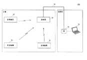
図1を参照して、管理システム101は、基地局30と、1または複数の計測装置31と、蓄積装置32と、管理装置33とを備える。 With reference to FIG. 1, the
管理システム101は、たとえば、事業者の工場および事務所に設置され、工場における生産設備の状態を管理する。この例では、基地局30および計測装置31は工場に設けられ、蓄積装置32および管理装置33は事務所に設けられている。 For example, the
計測装置31は、対象物に接触させずに当該対象物を計測可能なセンサたとえば放射温度センサを含む。この場合、計測装置31は、モータ等の発熱部を含む生産設備の表面の温度計測を行い、計測結果を示す計測情報を無線信号に含めて基地局30へ送信する。 The measuring
基地局30は、各計測装置31から無線信号を受信し、受信した無線信号に含まれる計測情報をイーサネット(登録商標)または無線LAN(Local Area Network)等のネットワーク34経由で蓄積装置32へ送信する。 The
蓄積装置32は、基地局30から受信した計測情報を蓄積する。計測情報は、たとえば、データベース化されて蓄積装置32に蓄積される。 The
管理装置33は、たとえばサーバまたはPC(Personal Computer)であり、蓄積装置32に蓄積された計測情報を取得し、取得した計測情報に基づいて、たとえば生産設備の状態を管理するための管理情報を作成する。なお、管理情報は、計測情報に対して何らかの演算等が行われたデータであってもよいし、計測情報の一部または全部と同じ内容のデータであってもよい。 The
[比較例]
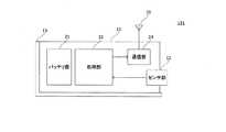
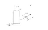
図2は、本発明の第1の実施の形態に係る計測装置の比較例の外観を示す斜視図である。図3は、本発明の第1の実施の形態に係る計測装置の比較例の詳細な構成を示す図である。[Comparative example]
FIG. 2 is a perspective view showing an appearance of a comparative example of the measuring apparatus according to the first embodiment of the present invention. FIG. 3 is a diagram showing a detailed configuration of a comparative example of the measuring apparatus according to the first embodiment of the present invention.
図2および図3を参照して、計測装置131は、アンテナ10と、筐体11と、センサ部12と、ネジ止め取付具13と、バッテリ部21と、処理部22と、通信部24とを備える。 2 and 3, the measuring
ネジ止め取付具13は、筐体11をネジを用いて他の物体たとえば壁または天井に取り付けるための部材であり、ネジ止め板部51と、固定板部52とを含む。バッテリ部21と、処理部22と、通信部24とは、筐体11に収納されている。アンテナ10およびセンサ部12は、筐体11における互いに隣接する面にそれぞれ取り付けられている。アンテナ10は、たとえば棒状アンテナである。 The screwing
センサ部12は、対象物に接触させずに当該対象物を計測可能なセンサを含む。具体的には、センサ部12は、このようなセンサとしてたとえば放射温度センサを含む。 The
センサ部12は、自己の正面すなわち計測装置131の正面に位置する対象物の表面の温度を計測する。そして、センサ部12は、たとえば、計測値の大きさに応じたレベルのセンサ信号を処理部22へ出力する。 The
処理部22は、たとえばマイコンを含み、センサ部12から受けたセンサ信号に基づいて、センサ部12の計測結果を示す計測情報を作成し、通信部24へ出力する。 The
通信部24は、たとえば通信用ICを含み、処理部22から受けた計測結果情報を無線信号に含めて、アンテナ10から基地局30へ送信する。バッテリ部21は、計測装置131における各回路に電力を供給する。 The
ネジ止め取付具13は、筐体11を他の物体たとえば壁に取り付けるために設けられる。ネジ止め取付具13において、ネジ止め板部51および固定板部52は互いに連続しており、これらのなす角は略直角となっている。ネジ止め板部51および固定板部52は、たとえば一体に形成された金属製または樹脂製の部材である。 The screwing
固定板部52は、筐体11のセンサ部12が取り付けられた面と隣接する面に固定されている。固定板部52は、ネジ止めまたは接着剤等により筐体11に固定される。 The fixed
ネジ止め板部51には貫通孔Dが形成されている。貫通孔Dを用いてネジ止め取付具13を壁等にネジ止めすることにより、計測装置131を壁等に取り付けることができる。 A through hole D is formed in the screwing
図4は、本発明の第1の実施の形態に係る計測装置における放射温度センサについて説明するための図である。図5は、本発明の第1の実施の形態に係る計測装置における放射温度センサへの赤外線の入射角と感度との関係の一例を示す図である。 FIG. 4 is a diagram for explaining the radiation temperature sensor in the measuring apparatus according to the first embodiment of the present invention. FIG. 5 is a diagram showing an example of the relationship between the incident angle of infrared rays to the radiation temperature sensor and the sensitivity in the measuring apparatus according to the first embodiment of the present invention.
図4および図5を参照して、放射温度センサ26は、たとえば電源電圧の入力およびセンサ信号の出力に用いる複数のピン27と、たとえば物体から放射される赤外線を受けて起電力を発生するサーモパイルが収納されたパッケージ28と、計測対象である熱源Hから放射される赤外線をパッケージ28内部に取り込むための窓部29とを有する。 4 and 5, a
放射温度センサ26は、熱源Hから放射される赤外線のエネルギーを用いて熱源Hの温度を計測する。放射温度センサ26の赤外線の感度は、赤外線の窓部29への入射角が0°の場合に最も高くなる。 The
入射角0°における感度を100%とした場合において、感度が50%以上である範囲を視野とも称する。以下、視野に含まれる範囲を計測範囲とする。対象物の表面温度を計測する場合、放射温度センサ26の計測範囲を当該対象物の位置に合わせる必要がある。 When the sensitivity at an incident angle of 0 ° is 100%, a range where the sensitivity is 50% or more is also referred to as a visual field. Hereinafter, the range included in the visual field is defined as the measurement range. When measuring the surface temperature of an object, it is necessary to match the measurement range of the
計測範囲は、放射温度センサ26と対象物との距離が大きいほど大きくなる。たとえば、計測範囲に対象物以外の他の物が含まれる場合、当該他の物から放射される赤外線の影響により計測値に誤差が生じることがある。このような場合、たとえば、放射温度センサ26と対象物との距離を小さくすることで計測範囲を小さくすることができ、これによって誤差の発生を防ぐことができる。 The measurement range increases as the distance between the
ここで、工場等において計測装置31等の新たな設備を設置する場合、設置場所が限られていることがある。そして、計測装置131は、設置可能な場所から対象物の表面温度を計測することが困難な場合がある。 Here, when installing a new facility such as the measuring
図6は、本発明の第1の実施の形態に係る計測装置の比較例の設置状態の一例を示す図である。 FIG. 6 is a diagram illustrating an example of an installation state of a comparative example of the measuring apparatus according to the first embodiment of the present invention.
図6を参照して、生産設備40と、たとえば生産設備である計測対象41と、生産設備42と、計測装置131とがたとえば工場における区画45に設置されている。具体的には、計測対象41は、生産設備42に載置され、区画45の壁に接している。計測装置131は、計測対象41の接する壁と反対側の壁に取り付けられている。 With reference to FIG. 6, a
計測装置131の計測範囲は、たとえば計測装置131の正面に限られている。このため、計測装置131は、自己の設置された壁と反対側の壁を計測範囲とする計測を行うことになる。 The measurement range of the
すなわち、この例では、計測対象41が計測装置131の正面に位置していないため、計測装置131は、計測対象41の表面温度を計測することができない。また、たとえば、計測装置131の取り付け位置を下げたとしても、計測装置131と計測対象41との間に生産設備40が存在するため、計測装置131は、計測対象41の表面温度を計測することができない。 That is, in this example, since the
図7は、本発明の第1の実施の形態に係る計測装置の比較例の設置状態の他の例を示す図である。 FIG. 7 is a diagram illustrating another example of the installation state of the comparative example of the measuring apparatus according to the first embodiment of the present invention.
図7を参照して、生産設備40と、計測対象41と、生産設備42と、基地局30と、計測装置131とが区画45に設置されている。具体的には、計測対象41は、生産設備42に載置され、区画45の壁に接している。基地局30は、計測対象41の接する壁と反対側の壁に取り付けられている。計測装置131は、区画45の天井に取り付けられ、自己の下方に位置する計測対象41の表面を計測範囲とする計測を行っている。 With reference to FIG. 7, a
しかしながら、この例では、たとえば棒状アンテナであるアンテナ10の延伸方向が基地局30に向いている。つまり、アンテナ10の指向性パターンPが示すように、アンテナ10の放射強度の弱い方向が基地局30に向けられている。このため、計測装置131は、計測結果を正しく基地局30へ送信できない可能性がある。 However, in this example, for example, the extending direction of the
そこで、管理システム101では、以下のような構成の計測装置31を用いることにより、上述の問題点を解決する。 Therefore, the
[計測装置の構成]
図8は、本発明の第1の実施の形態に係る計測装置の外観を示す斜視図である。図9は、本発明の第1の実施の形態に係る計測装置の詳細な構成を示す図である。図10は、本発明の第1の実施の形態に係る計測装置の可動部を曲げた状態における側面図である。計測装置31の構成および動作は、以下で説明する内容以外については計測装置131と同様である。[Configuration of measuring device]
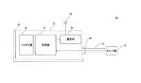
FIG. 8 is a perspective view showing an appearance of the measuring apparatus according to the first embodiment of the present invention. FIG. 9 is a diagram showing a detailed configuration of the measuring apparatus according to the first embodiment of the present invention. FIG. 10 is a side view of the measuring device according to the first embodiment of the present invention in a state where the movable part is bent. The configuration and operation of the
図8〜図10を参照して、計測装置31は、アンテナ10と、筐体11と、ネジ止め取付具13と、センサ部12と、可動部15と、防水カバー16と、バッテリ部21と、処理部22と、通信部24とを備える。 With reference to FIGS. 8 to 10, the
可動部15は、センサ部12と筐体11との間に設けられており、センサ部12の位置を変更可能である。具体的には、可動部15は、たとえばフレキシブルチューブを含み、所望する方向へ曲がることができる。また、可動部15は、たとえば曲がった形状を保持する。可動部15は、曲がることによって、センサ部12の計測対象41に対する方向および距離の少なくともいずれか一方を変更可能である。 The
言い換えれば、可動部15は、センサ部12の位置を変更することにより、センサ部12による計測の対象となる位置を変更する。 In other words, the
可動部15の曲がりの程度に応じて、センサ部12と計測対象41との距離を調整することができる。 The distance between the
アンテナ10およびセンサ部12は、筐体11の異なる面、たとえば筐体11における互いに隣接する面にそれぞれ取り付けられている。具体的には、センサ部12は、可動部15を介して筐体11に取り付けられている。バッテリ部21は、計測装置31における各回路に電力を供給する。 The
ネジ止め取付具13は、筐体11の可動部15が取り付けられた面と異なる面に固定されている。具体的には、ネジ止め取付具13における固定板部52は、筐体11の可動部15が取り付けられた面と隣接する面に固定されている。固定板部52は、たとえばネジ止めにより筐体11に固定される。 The screwing
ネジ止め板部51に形成された貫通孔Dを用いてネジ止め取付具13を壁等にネジ止めすることにより、計測装置31を壁等に取り付けることができる。 The
なお、ネジ止め取付具13は、たとえば平板状の部材であってもよく、また、筐体11の可動部15が取り付けられた面と反対側の面に固定されてもよい。 Note that the screwing
処理部22とセンサ部12とを接続する配線は、たとえば可動部15の内部を通る。当該配線は、たとえば可動部15の曲がりを考慮した余裕のある長さを有する。 The wiring that connects the
防水カバー16は、可動部15と筐体11との接続部分を覆い、水滴および粉塵等の筐体11への侵入を防ぐ。 The
なお、可動部15は、フレキシブルチューブを含む構成に限らず、フレキシブルアームを含む構成であってもよい。この場合、処理部22とセンサ部12とを接続する配線は、可動部15に沿って設けられる。 The
また、可動部15は、フレキシブルチューブを含む構成に限らず、伸縮可能な部材を含む構成であってもよい。たとえば、可動部15は、伸縮可能な蛇腹状のチューブを含む。この場合、処理部22とセンサ部12とを接続する配線は、可動部15の伸縮を考慮した余裕のある長さを有する。 Further, the
また、計測装置31は、ネジ止め取付具13を備えない構成であってもよい。この場合、計測装置31は、たとえば接着剤、結束バンドまたはボルトを用いて壁等に取り付けられる。 Further, the
図11は、本発明の第1の実施の形態に係る計測装置の、ネジ止め取付具が筐体に固定されていない状態における下面図である。 FIG. 11 is a bottom view of the measuring apparatus according to the first embodiment of the present invention in a state where the screwing fixture is not fixed to the housing.
図11を参照して、筐体11は、固定部70を含む。固定部70は、たとえばネジ穴であり、ネジ止め取付具13を筐体11に固定するために用いられる。固定部70は、筐体11の可動部15が取り付けられた面と異なる面に設けられている。具体的には、固定部70は、筐体11の可動部15が取り付けられた面と隣接する面に設けられている。 Referring to FIG. 11, the
なお、固定部70は、筐体11の可動部18が取り付けられた面と反対側の面に設けられてもよい。 Note that the fixed
また、固定部70は、ネジ穴に限らず、ネジ止め取付具13を筐体11に固定することが可能な構成であればよい。具体的には、たとえば、固定部70は、筐体11から突出したボルト状の部分であってもよいし、ネジ止め取付具13を挟んで固定するためのクリップ状の部分であってもよい。 Moreover, the fixing | fixed
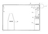
図12は、本発明の第1の実施の形態に係る計測装置の設置状態の一例を示す図である。 FIG. 12 is a diagram illustrating an example of an installation state of the measurement apparatus according to the first embodiment of the present invention.
図12を参照して、生産設備40と、計測対象41と、生産設備42と、基地局30と、計測装置31とが区画45に設置されている。具体的には、計測対象41は、生産設備42に載置され、区画45の壁に接している。基地局30は、計測対象41の接する壁と反対側の壁に取り付けられている。 With reference to FIG. 12, a
計測装置31は、計測対象41の接する壁と同じ壁に取り付けられており、アンテナ10の延伸方向が壁面と平行になっている。このため、アンテナ10の指向性パターンPが示すように、アンテナ10の放射強度の強い方向は基地局30に向けられている。 The measuring
また、可動部15は、計測装置31が計測対象41の表面温度を計測できるように曲がっている。具体的には、可動部15は、センサ部12が計測対象41を向くように、つまりセンサ部12に含まれる放射温度センサ26の窓部29が計測対象41を向くように曲がっている。 The
計測装置31は、自己の下方に位置する計測対象41、の表面を計測範囲a3とする計測を行っている。 The measuring
このように、計測装置31は、可動部15が曲がることにより、アンテナ10の放射強度の強い方向を基地局30に向けた状態で計測対象41の表面温度を計測することができる。 As described above, the measuring
図13は、本発明の第1の実施の形態に係る計測装置の設置状態の他の例を示す図である。 FIG. 13 is a diagram illustrating another example of the installation state of the measuring device according to the first embodiment of the present invention.
図13を参照して、生産設備40と、計測対象41と、生産設備42と、基地局30と、計測装置31とが区画45に設置されている。具体的には、計測対象41は、生産設備42に載置され、区画45の壁に接している。基地局30は、計測対象41の接する壁と反対側の壁に取り付けられている。 With reference to FIG. 13, a
計測装置31は、計測対象41の接する壁と同じ壁に取り付けられており、アンテナ10の延伸方向が壁面と平行となっている。 The measuring
可動部15は、伸縮可能な部材である場合、センサ部12と計測対象41との距離をより大きく変更可能である。この例では、可動部15が図12に示す状態に比べて伸張されたことによって、センサ部12が、計測対象41のより近くに位置している。これによって、計測装置31は、図12に示す状態に比べて狭い範囲の温度計測を行うことができる。 When the
具体的には、図13に示すセンサ部12から計測対象41までの距離b4は、図12に示すセンサ部12から計測対象41までの距離b3に比べて小さく、図13に示す計測範囲a4は、図12に示す計測範囲a3に比べて小さい。 Specifically, the distance b4 from the
なお、センサ部12は、放射温度センサに限らず、対象物に接触させずに当該対象物を計測可能なセンサを含む構成であればよい。たとえばセンサ部12は、放射温度センサの代わりに、照度センサ、近接センサ、放射線センサ、超音波センサ、またはマイクロホンを含む構成であってもよい。 In addition, the
また、計測装置31は、たとえば棒状アンテナであるアンテナ10を備える構成に限らず、基板実装型のアンテナを備える構成であってもよい。この場合、当該アンテナは、筐体11に収納されたプリント基板に実装される。 In addition, the
ところで、M2Mシステムの1つの利用形態として、対象物の計測を行い、かつ計測結果を無線信号に含めて送信することが可能な1または複数の計測装置を設置し、無線信号の送信先において収集された計測結果に基づいて対象物の状態を管理する管理システムが考えられる。 By the way, as one usage form of the M2M system, one or a plurality of measuring devices capable of measuring an object and transmitting a measurement result by including it in a radio signal are installed and collected at a radio signal transmission destination. A management system that manages the state of the object based on the measurement results obtained can be considered.
しかしながら、上記管理システムが工場等で使用される場合、上記計測装置を設置可能な場所が限られていることがある。そして、このように設置可能な場所が限られている場合、計測装置の備えるセンサを対象物に向け、かつ計測装置における電波の放射強度が強い方向を上記送信先に向けることが困難なことがある。 However, when the management system is used in a factory or the like, the place where the measurement device can be installed may be limited. And when the place where installation is possible is limited in this way, it may be difficult to direct the sensor included in the measurement device toward the object and to direct the direction in which the radio wave emission intensity of the measurement device is strong toward the transmission destination. is there.
これに対して、本発明の第1の実施の形態に係る計測装置では、通信部24は、センサ部12の計測結果、つまりセンサ部12が含むセンサの計測結果を示す計測情報を無線信号に含めてアンテナ10から送信する。可動部15は、センサ部12の位置つまり上記センサの位置を変更可能である。 On the other hand, in the measuring apparatus according to the first embodiment of the present invention, the
このような構成により、たとえば、アンテナ10における放射強度の強い方向が無線信号の送信先である基地局30を向くように計測装置31を設置し、計測装置31の位置を固定したまま可動部15を動かして上記センサを計測対象41に向けることができる。 With such a configuration, for example, the measuring
したがって、本発明の第1の実施の形態に係る計測装置では、対象物の計測および計測結果の伝送を良好に行うことができる。 Therefore, in the measuring apparatus according to the first embodiment of the present invention, it is possible to satisfactorily measure the object and transmit the measurement result.
また、本発明の第1の実施の形態に係る計測装置では、可動部15は、センサ部12と計測対象41との距離、つまり上記センサと計測対象41との距離を変更可能である。 Moreover, in the measurement apparatus according to the first embodiment of the present invention, the
このような構成により、たとえば、計測対象41以外の他の物が計測範囲に含まれることによって正しい計測結果を得ることができない場合に、上記センサと計測対象41との距離を小さくすることによって計測範囲を小さくし、当該他の物を計測範囲から外すことができる。 With such a configuration, for example, when a measurement result other than the
また、本発明の第1の実施の形態に係る計測装置では、アンテナ10およびセンサ部12、つまりアンテナ10および上記センサは、筐体11の異なる面にそれぞれ取り付けられる。 In the measuring apparatus according to the first embodiment of the present invention, the
このような構成により、アンテナ10と上記センサとが互いに接触しにくくなるため、計測対象41の計測および計測結果の伝送において、より適した位置にこれらを配置することができる。 Such a configuration makes it difficult for the
また、本発明の第1の実施の形態に係る計測装置は、筐体11を他の物体に取り付けるためのネジ止め取付具13を備える。ネジ止め取付具13は、筐体11の可動部15が取り付けられた面と異なる面に固定される。 In addition, the measuring apparatus according to the first embodiment of the present invention includes a
このような構成により、計測装置31を壁等に取り付けることができる。また、ネジ止め取付具13が筐体11における可動部15の取り付けられた面と異なる面に固定されるため、可動部15の可動範囲がネジ止め取付具13によって制限されにくくなる。 With such a configuration, the measuring
次に、本発明の他の実施の形態について図面を用いて説明する。なお、図中同一または相当部分には同一符号を付してその説明は繰り返さない。 Next, another embodiment of the present invention will be described with reference to the drawings. In the drawings, the same or corresponding parts are denoted by the same reference numerals and description thereof will not be repeated.
<第2の実施の形態>
本実施の形態は、第1の実施の形態に係る計測装置と比べて、可動部の種類が異なる計測装置に関する。以下で説明する内容以外は第1の実施の形態に係る計測装置と同一である。<Second Embodiment>
The present embodiment relates to a measurement apparatus having a different type of movable part as compared to the measurement apparatus according to the first embodiment. The contents other than those described below are the same as those of the measuring apparatus according to the first embodiment.
図14は、本発明の第2の実施の形態に係る計測装置の外観を示す斜視図である。図15は、本発明の第2の実施の形態に係る計測装置の詳細な構成を示す図である。図16は、本発明の第2の実施の形態に係る計測装置の可動部を曲げた状態における側面図である。 FIG. 14 is a perspective view showing an external appearance of a measuring apparatus according to the second embodiment of the present invention. FIG. 15 is a diagram showing a detailed configuration of a measuring apparatus according to the second embodiment of the present invention. FIG. 16: is a side view in the state which bent the movable part of the measuring device which concerns on the 2nd Embodiment of this invention.
図14〜図16を参照して、計測装置31は、アンテナ10と、筐体11と、センサ部12と、ネジ止め取付具13と、可動部18と、防水カバー16と、バッテリ部21と、処理部22と、通信部24とを備える。筐体11は、図示しない固定部70を含む。固定部70には、ネジ止め取付具13が固定されている。 14 to 16, the
可動部18は、センサ部12と筐体11との間に設けられており、センサ部12の位置を変更可能である。具体的には、可動部18は、たとえば、ボールジョイントを含み、所望する方向へ曲がることができる。また、可動部18は、たとえば曲がった形状を保持する。可動部18は、曲がることによって、センサ部12の計測対象41に対する方向および距離の少なくともいずれか一方を変更可能である。 The
アンテナ10およびセンサ部12は、筐体11の異なる面、たとえば筐体11における互いに隣接する面にそれぞれ取り付けられている。具体的には、センサ部12は、可動部18を介して筐体11に取り付けられている。 The
ネジ止め取付具13は、筐体11の可動部18が取り付けられた面と異なる面に固定されている。つまり、固定部70は、筐体11の可動部18が取り付けられた面と異なる面に設けられている。 The screwing
具体的には、固定部70は、筐体11の可動部18が取り付けられた面と隣接する面に設けられている。なお、固定部70は、筐体11の可動部18が取り付けられた面と反対側の面に設けられてもよい。 Specifically, the fixed
その他の構成および動作は第1の実施の形態に係る計測装置と同様であるため、ここでは詳細な説明を繰り返さない。 Since other configurations and operations are the same as those of the measurement apparatus according to the first embodiment, detailed description thereof will not be repeated here.
次に、本発明の他の実施の形態について図面を用いて説明する。なお、図中同一または相当部分には同一符号を付してその説明は繰り返さない。 Next, another embodiment of the present invention will be described with reference to the drawings. In the drawings, the same or corresponding parts are denoted by the same reference numerals and description thereof will not be repeated.
<第3の実施の形態>
本実施の形態は、第1の実施の形態に係る計測装置と比べて、筐体におけるアンテナの取り付け位置が異なる計測装置に関する。以下で説明する内容以外は第1の実施の形態に係る計測装置と同一である。<Third Embodiment>
The present embodiment relates to a measurement apparatus in which the antenna mounting position in the housing is different from that of the measurement apparatus according to the first embodiment. The contents other than those described below are the same as those of the measuring apparatus according to the first embodiment.
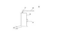
図17は、本発明の第3の実施の形態に係る計測装置の外観を示す斜視図である。 FIG. 17 is a perspective view showing an external appearance of a measuring apparatus according to the third embodiment of the present invention.
図17を参照して、アンテナ10およびセンサ部12は、筐体11の同じ面に取り付けられている。具体的には、センサ部12は、可動部15を介して筐体11に取り付けられている。 Referring to FIG. 17,
ネジ止め取付具13は、筐体11の可動部15が取り付けられた面と異なる面に固定されている。つまり、ネジ止め取付具13が固定された、図示しない固定部70は、筐体11の可動部15が取り付けられた面と異なる面に設けられている。 The screwing
具体的には、固定部70は、筐体11の可動部15が取り付けられた面と隣接する面に設けられている。なお、固定部70は、筐体11の可動部15が取り付けられた面と反対側の面に固定されてもよい。 Specifically, the fixed
図18は、本発明の第3の実施の形態に係る計測装置の設置状態の一例を示す図である。 FIG. 18 is a diagram illustrating an example of an installation state of the measurement apparatus according to the third embodiment of the present invention.
図18を参照して、生産設備40と、たとえば生産設備である計測対象41と、生産設備42と、基地局30と、計測装置31とが区画45に設置されている。具体的には、計測対象41は、生産設備42に載置され、区画45の壁に接している。基地局30は、計測対象41の接する壁と反対側の壁に取り付けられている。 Referring to FIG. 18, a
計測装置31は、区画45の天井に取り付けられている。可動部15が曲がることにより、センサ部12が計測対象41に向けられている。このため、計測装置31は、自己の斜め下方に位置する計測対象41の表面を計測範囲とする計測を行う。 The measuring
また、アンテナ10の延伸方向は、区画45の壁面と平行である。このため、アンテナ10の指向性パターンPが示すように、アンテナ10の放射強度の強い方向が基地局30に向けられている。つまり、計測装置31は、アンテナ10の放射強度の強い方向を基地局30に向けた状態で計測対象41の表面温度を計測することができる。 The extending direction of the
以上のように、本発明の第3の実施の形態に係る計測装置では、アンテナ10およびセンサ部12、つまりアンテナ10およびセンサ部12に含まれるセンサは、筐体11の同じ面に取り付けられる。 As described above, in the measurement apparatus according to the third embodiment of the present invention, the
このような構成により、たとえば、アンテナ10および上記センサを筐体11内に収納されるプリント基板に同じ方向から取り付けることができるため、計測装置31の作製を簡単に行うことができ、また、計測装置31の小型化を実現することができる。 With such a configuration, for example, the
その他の構成および動作は第1の実施の形態に係る計測装置と同様であるため、ここでは詳細な説明を繰り返さない。 Since other configurations and operations are the same as those of the measurement apparatus according to the first embodiment, detailed description thereof will not be repeated here.
次に、本発明の他の実施の形態について図面を用いて説明する。なお、図中同一または相当部分には同一符号を付してその説明は繰り返さない。 Next, another embodiment of the present invention will be described with reference to the drawings. In the drawings, the same or corresponding parts are denoted by the same reference numerals and description thereof will not be repeated.
<第4の実施の形態>
本実施の形態は、第1の実施の形態に係る計測装置と比べて、アンテナの位置が変化する計測装置に関する。以下で説明する内容以外は第1の実施の形態に係る計測装置と同一である。<Fourth embodiment>
The present embodiment relates to a measurement device in which the position of an antenna changes compared to the measurement device according to the first embodiment. The contents other than those described below are the same as those of the measuring apparatus according to the first embodiment.
図19は、本発明の第4の実施の形態に係る計測装置の外観を示す斜視図である。図20は、本発明の第4の実施の形態に係る計測装置の詳細な構成を示す図である。図21は、本発明の第4の実施の形態に係る計測装置の可動部を曲げた状態における側面図である。 FIG. 19 is a perspective view showing an appearance of a measuring apparatus according to the fourth embodiment of the present invention. FIG. 20 is a diagram showing a detailed configuration of a measuring apparatus according to the fourth embodiment of the present invention. FIG. 21 is a side view of the measuring device according to the fourth embodiment of the present invention in a state where the movable part is bent.
図19〜図21を参照して、計測装置31は、アンテナ10と、筐体11と、センサ部12と、ネジ止め取付具13と、可動部17と、バッテリ部21と、処理部22と、通信部24とを備える。筐体11は、図示しない固定部70を含む。固定部70には、ネジ止め取付具13が固定されている。 19 to 21, the
アンテナ10およびセンサ部12は、筐体11の異なる面、たとえば筐体11における互いに隣接する面にそれぞれ取り付けられている。具体的には、アンテナ10は、可動部17を介して筐体11に取り付けられている。なお、アンテナ10およびセンサ部12は筐体11の同じ面に取り付けられてもよい。 The
ネジ止め取付具13は、筐体11の可動部17が取り付けられた面と異なる面に固定されている。つまり、固定部70は、筐体11の可動部17が取り付けられた面と異なる面に設けられている。 The screwing
具体的には、固定部70は、筐体11の可動部17が取り付けられた面の反対側の面に設けられている。なお、固定部70は、筐体11の可動部17が取り付けられた面と隣接する面に設けられてもよい。 Specifically, the fixed
可動部17は、アンテナ10と筐体11との間に設けられており、アンテナ10の位置を変更可能である。具体的には、たとえば、可動部17は、塑性を有する金属製の部材を含み、曲げられることによって、アンテナ10の計測対象41に対する方向および距離の少なくともいずれか一方を変更する。アンテナ10と通信部24とは、可動部17の含む上記部材経由で電気的に接続される。 The
図22は、本発明の第4の実施の形態に係る計測装置の設置状態の一例を示す図である。 FIG. 22 is a diagram illustrating an example of an installation state of a measurement device according to the fourth embodiment of the present invention.
図22を参照して、生産設備40と、たとえば生産設備である計測対象41と、生産設備42と、基地局30と、計測装置31とが区画45に設置されている。具体的には、計測対象41は、生産設備42に載置され、区画45の壁に接している。基地局30は、計測対象41の接する壁と反対側の壁に取り付けられている。 With reference to FIG. 22, a
計測装置31は、区画45の天井に取り付けられ、自己の下方に位置する計測対象41の表面を計測範囲とする計測を行っている。 The
また、可動部17が曲がることにより、アンテナ10の延伸方向が区画45の壁面と平行になっている。このため、アンテナ10の指向性パターンPが示すように、アンテナ10の放射強度の強い方向が基地局30に向けられている。 Further, the bending direction of the
このように、計測装置31は、アンテナ10の放射強度の強い方向を基地局30に向けた状態で計測対象41の表面温度を計測することができる。 As described above, the
以上のように、本発明の第4の実施の形態に係る計測装置では、通信部24は、センサ部12の計測結果つまりセンサ部12が含むセンサの計測結果を示す計測情報を無線信号に含めてアンテナ10から送信する。可動部17は、アンテナ10の位置を変更可能である。 As described above, in the measurement apparatus according to the fourth embodiment of the present invention, the
このような構成により、たとえば、上記センサが計測対象41を向くように計測装置を設置し、計測装置31の位置を固定したまま可動部17を動かしてアンテナ10の放射強度の強い方向を無線信号の送信先である基地局30に向けることができる。 With such a configuration, for example, the measurement device is installed so that the sensor faces the
したがって、本発明の第4の実施の形態に係る計測装置では、対象物の計測および計測結果の伝送を良好に行うことができる。 Therefore, in the measuring apparatus according to the fourth embodiment of the present invention, it is possible to satisfactorily measure the object and transmit the measurement result.
その他の構成および動作は第1の実施の形態に係る計測装置と同様であるため、ここでは詳細な説明を繰り返さない。 Since other configurations and operations are the same as those of the measurement apparatus according to the first embodiment, detailed description thereof will not be repeated here.
次に、本発明の他の実施の形態について図面を用いて説明する。なお、図中同一または相当部分には同一符号を付してその説明は繰り返さない。 Next, another embodiment of the present invention will be described with reference to the drawings. In the drawings, the same or corresponding parts are denoted by the same reference numerals and description thereof will not be repeated.
<第5の実施の形態>
本実施の形態は、第1の実施の形態に係る計測装置と比べて、センサの代わりにカメラを備える計測装置に関する。以下で説明する内容以外は第1の実施の形態に係る計測装置と同一である。<Fifth embodiment>
The present embodiment relates to a measurement apparatus including a camera instead of a sensor, as compared with the measurement apparatus according to the first embodiment. The contents other than those described below are the same as those of the measuring apparatus according to the first embodiment.
図23は、本発明の第5の実施の形態に係る計測装置の構成を示す図である。 FIG. 23 is a diagram showing a configuration of a measuring apparatus according to the fifth embodiment of the present invention.
図23を参照して、計測装置31は、アンテナ10と、筐体11と、ネジ止め取付具13と、カメラ部19と、可動部15と、防水カバー16と、バッテリ部21と、処理部22と、通信部24とを備える。筐体11は、図示しない固定部70を含む。固定部70には、ネジ止め取付具13が固定されている。 Referring to FIG. 23,
カメラ部19は、カメラを含み、計測対象41を撮影し、撮影により得た画像を示す信号を処理部22へ出力する。 The
処理部22は、カメラ部19から受けた信号を用いて、たとえば計測対象41の変位量を計測する。そして、処理部22は、計測結果を示す計測情報を通信部24へ出力する。 The
通信部24は、処理部22から受けた計測結果情報を無線信号に含めて、アンテナ10経由で基地局30へ送信する。 The
アンテナ10およびカメラ部19は、筐体11の異なる面、たとえば筐体11における互いに隣接する面にそれぞれ取り付けられている。具体的には、カメラ部19は、可動部15を介して筐体11に取り付けられている。なお、アンテナ10およびカメラ部19は筐体11の同じ面に取り付けられてもよい。 The
ネジ止め取付具13は、筐体11の可動部15が取り付けられた面と異なる面に固定されている。つまり、固定部70は、筐体11の可動部15が取り付けられた面と異なる面に設けられている。具体的には、固定部70は、筐体11の可動部15が取り付けられた面と隣接する面に設けられている。なお、固定部70は、筐体11の可動部15が取り付けられた面と反対側の面に設けられてもよい。 The screwing
可動部15は、カメラ部19の位置を変更可能である。具体的には、可動部15は、カメラ部19の計測対象41に対する方向および距離の少なくともいずれか一方を変更可能である。 The
また、たとえば可動部15が伸縮可能な部材である場合、可動部15は、カメラ部19と計測対象41との距離をより大きく変更可能である。 For example, when the
以上のように、本発明の第5の実施の形態に係る計測装置では、通信部24は、カメラ部19の計測結果、つまりカメラ部19が含むカメラの計測結果を示す計測情報を無線信号に含めてアンテナ10から送信する。可動部15は、カメラ部19の位置つまり上記カメラの位置を変更可能である。 As described above, in the measurement device according to the fifth embodiment of the present invention, the
このような構成により、たとえば、アンテナ10における放射強度の強い方向が無線信号の送信先である基地局30を向くように計測装置31を設置し、計測装置31の位置を固定したまま可動部15を動かして上記カメラを計測対象41に向けることができる。 With such a configuration, for example, the measuring
したがって、本発明の第5の実施の形態に係る計測装置では、対象物の計測および計測結果の伝送を良好に行うことができる。 Therefore, in the measurement apparatus according to the fifth embodiment of the present invention, it is possible to satisfactorily measure the object and transmit the measurement result.
また、本発明の第5の実施の形態に係る計測装置では、可動部15は、カメラ部19と計測対象41との距離、つまり上記カメラと計測対象41との距離を変更可能である。 In the measurement apparatus according to the fifth embodiment of the present invention, the
このような構成により、たとえば計測対象41以外の他の物が計測範囲に含まれることによって正しい計測結果を得ることができない場合に、上記カメラと計測対象41との距離を小さくすることによって計測範囲を小さくし、当該他の物を計測範囲から外すことができる。 With such a configuration, for example, when a measurement result other than the
また、本発明の第5の実施の形態に係る計測装置では、アンテナ10およびカメラ部19、つまりアンテナ10および上記カメラは、筐体11の異なる面にそれぞれ取り付けられる。 In the measurement apparatus according to the fifth embodiment of the present invention, the
このような構成により、アンテナ10と上記カメラとが互いに接触しにくくなるため、計測対象41の計測および計測結果の伝送において、より適した位置にこれらを配置することができる。 Such a configuration makes it difficult for the
その他の構成および動作は第1の実施の形態に係る計測装置と同様であるため、ここでは詳細な説明を繰り返さない。 Since other configurations and operations are the same as those of the measurement apparatus according to the first embodiment, detailed description thereof will not be repeated here.
次に、本発明の他の実施の形態について図面を用いて説明する。なお、図中同一または相当部分には同一符号を付してその説明は繰り返さない。 Next, another embodiment of the present invention will be described with reference to the drawings. In the drawings, the same or corresponding parts are denoted by the same reference numerals and description thereof will not be repeated.
<第6の実施の形態>
本実施の形態は、第1の実施の形態に係る計測装置と比べて、ネジ止め取付具とは異なる取付具が固定された計測装置に関する。以下で説明する内容以外は第1の実施の形態に係る計測装置と同一である。<Sixth Embodiment>
The present embodiment relates to a measurement device in which a fixture different from the screwing fixture is fixed as compared with the measurement device according to the first embodiment. The contents other than those described below are the same as those of the measuring apparatus according to the first embodiment.
図24は、本発明の第6の実施の形態に係る計測装置の外観を示す斜視図である。 FIG. 24 is a perspective view showing an appearance of a measuring apparatus according to the sixth embodiment of the present invention.
図24を参照して、計測装置31は、ネジ止め取付具13の代わりに、筐体11を磁力によって他の物体に取り付けるための磁気取付具14を備える。磁気取付具14は、筐体11における図示しない固定部70に固定されている。固定部70は、筐体11の可動部15が取り付けられた面に隣接する面に設けられている。ここでは、磁気取付具14は、マグネットベースである。 Referring to FIG. 24, the
固定部70には、たとえば、磁気取付具14または、たとえば図8に示すネジ止め取付具13を固定することが可能である。つまり、固定部70は、磁気取付具14が筐体11に固定される場合、およびネジ止め取付具13が筐体11に固定される場合のいずれの場合においても用いることができる。 For example, the
磁気取付具14は、永久磁石を含み、磁力によって磁性体に吸着することができる。具体的には、磁気取付具14における切替ツマミNBを矢印ALの方向へ回すと、磁気取付具14の含む永久磁石から磁気取付具14の外部に漏えいする磁界が大きくなる。これにより、磁気取付具14は磁性体に吸着する。 The
計測装置31に固定された磁気取付具14を磁性体たとえば鉄を含む壁等に吸着させることにより、計測装置31を壁等に取り付けることができる。 The measuring
図25は、本発明の第6の実施の形態に係る計測装置が壁に取り付けられた状態を示す図である。 FIG. 25 is a diagram showing a state in which a measuring device according to the sixth embodiment of the present invention is attached to a wall.
図25を参照して、計測装置31が磁性体を含む壁60に取り付けられている。具体的には、計測装置31における筐体11に磁気取付具14が固定されており、磁気取付具14が壁60に吸着している。 Referring to FIG. 25, measuring
このような構成により、ネジ等を用いることなく、計測装置31を、壁60に容易に取り付けることができる。 With such a configuration, the measuring
また、切替ツマミNBを図24に示す矢印ALと反対方向に回すことにより、磁気取付具14から外部に漏えいする磁界を小さくすることができるため、壁60から計測装置31を容易に取り外すことができる。 Further, by turning the switching knob NB in the direction opposite to the arrow AL shown in FIG. 24, the magnetic field leaking from the
なお、この例では、磁気取付具14における切替ツマミNBが設けられた面の反対側の面が壁60に吸着しているが、磁気取付具14は、自己の面のうち、切替ツマミNBの設けられた面に隣接する面を壁60に吸着させる構成であってもよい。 In this example, the surface of the
以上のように、本発明の第6の実施の形態に係る計測装置では、筐体11は、ネジ止め取付具13または磁気取付具14を固定することが可能な固定部70を含む。 As described above, in the measurement device according to the sixth embodiment of the present invention, the
このような構成により、計測装置31を壁等に取り付けることができる。また、計測装置31を壁等に取り付ける際に、ネジ止め取付具13を用いて取り付けるか、または磁気取付具14を用いて取り付けるかを選択することができる。 With such a configuration, the measuring
また、本発明の第6の実施の形態に係る計測装置では、磁気取付具14は、筐体11の可動部15が取り付けられた面と異なる面に固定される。 In the measuring device according to the sixth embodiment of the present invention, the
このような構成により、計測装置31を壁等に取り付けることができる。また、磁気取付具14が筐体11における可動部15の取り付けられた面と異なる面に固定されるため、可動部15の可動範囲がネジ止め取付具13によって制限されにくくなる。 With such a configuration, the measuring
上記実施の形態は、すべての点で例示であって制限的なものではないと考えられるべきである。本発明の範囲は、上記説明ではなく特許請求の範囲によって示され、特許請求の範囲と均等の意味および範囲内でのすべての変更が含まれることが意図される。 The above embodiment should be considered as illustrative in all points and not restrictive. The scope of the present invention is defined by the terms of the claims, rather than the description above, and is intended to include any modifications within the scope and meaning equivalent to the terms of the claims.
以上の説明は、以下に付記する特徴を含む。 The above description includes the following features.
[付記1]
アンテナと、
計測対象に接触せずに前記計測対象を計測可能なセンサと、
前記センサの計測結果を示す計測情報を無線信号に含めて前記アンテナから送信する通信部と、
前記センサの位置を変更することにより、前記センサが計測可能となる前記計測対象の位置を変更可能な可動部とを備える、計測装置。[Appendix 1]
An antenna,
A sensor capable of measuring the measurement object without contacting the measurement object;
A communication unit that includes measurement information indicating the measurement result of the sensor in a wireless signal and transmits the information from the antenna;
A measuring apparatus comprising: a movable unit capable of changing a position of the measurement target that enables the sensor to measure by changing a position of the sensor.
10 アンテナ
11 筐体
12 センサ部
13 ネジ止め取付具
14 磁気取付具
15,17,18 可動部
16 防水カバー
19 カメラ部
21 バッテリ部
22 処理部
24 通信部
26 放射温度センサ
27 ピン
28 パッケージ
29 窓部
30 基地局
31,131 計測装置
32 蓄積装置
33 管理装置
34 ネットワーク
40,42 生産設備
41 計測対象
45 区画
51 ネジ止め板部
52 固定板部
53 台座装着部
70 固定部
101 管理システムDESCRIPTION OF
Claims (5)
Translated fromJapaneseセンサまたはカメラと、
前記センサまたは前記カメラの計測結果を示す計測情報を無線信号に含めて前記アンテナから送信する通信部と、
前記アンテナと前記センサまたは前記カメラとの少なくともいずれか一方の位置を変更可能な可動部とを備える、計測装置。An antenna,
A sensor or camera;
A communication unit that includes measurement information indicating a measurement result of the sensor or the camera in a wireless signal and transmits the signal from the antenna;
A measuring apparatus comprising: a movable part capable of changing a position of at least one of the antenna and the sensor or the camera.
筐体を備え、
前記アンテナと前記センサまたは前記カメラとは、前記筐体の同じ面に取り付けられる、請求項1または請求項2に記載の計測装置。The measuring device further includes:
With a housing,
The measuring apparatus according to claim 1, wherein the antenna and the sensor or the camera are attached to the same surface of the housing.
筐体を備え、
前記アンテナと前記センサまたは前記カメラとは、前記筐体の異なる面にそれぞれ取り付けられる、請求項1または請求項2に記載の計測装置。The measuring device further includes:
With a housing,
The measuring device according to claim 1 or 2, wherein the antenna and the sensor or the camera are respectively attached to different surfaces of the casing.
前記可動部が取り付けられた筐体を備え、
前記筐体は、前記筐体をネジを用いて他の物体に取り付けるためのネジ止め取付具を固定するか、または前記筐体を磁力によって他の物体に取り付けるための磁気取付具を固定することが可能な固定部を含む、請求項1から請求項4のいずれか1項に記載の計測装置。The measuring device further includes:
Comprising a housing to which the movable part is attached;
The casing is fixed with a screw fixing fixture for attaching the casing to another object using a screw, or a magnetic fixture for fixing the casing to another object with a magnetic force. The measuring device according to any one of claims 1 to 4, further comprising a fixing portion capable of performing the steps.
Priority Applications (1)
| Application Number | Priority Date | Filing Date | Title |
|---|---|---|---|
| JP2014141647AJP2016019187A (en) | 2014-07-09 | 2014-07-09 | Measuring device |
Applications Claiming Priority (1)
| Application Number | Priority Date | Filing Date | Title |
|---|---|---|---|
| JP2014141647AJP2016019187A (en) | 2014-07-09 | 2014-07-09 | Measuring device |
Related Child Applications (1)
| Application Number | Title | Priority Date | Filing Date |
|---|---|---|---|
| JP2019018222ADivisionJP6766905B2 (en) | 2019-02-04 | 2019-02-04 | Measuring device |
Publications (1)
| Publication Number | Publication Date |
|---|---|
| JP2016019187Atrue JP2016019187A (en) | 2016-02-01 |
Family
ID=55234094
Family Applications (1)
| Application Number | Title | Priority Date | Filing Date |
|---|---|---|---|
| JP2014141647APendingJP2016019187A (en) | 2014-07-09 | 2014-07-09 | Measuring device |
Country Status (1)
| Country | Link |
|---|---|
| JP (1) | JP2016019187A (en) |
Citations (8)
| Publication number | Priority date | Publication date | Assignee | Title |
|---|---|---|---|---|
| JPS6279991A (en)* | 1985-09-30 | 1987-04-13 | 株式会社日立製作所 | Multi-degree-of-freedom arm type inspection device |
| US5495288A (en)* | 1994-01-28 | 1996-02-27 | Ultrak, Inc. | Remote activated surveillance system |
| JPH09322265A (en)* | 1996-05-30 | 1997-12-12 | Honda Motor Co Ltd | Vehicle remote control device |
| JPH11252101A (en)* | 1998-03-03 | 1999-09-17 | Sony Corp | Information collection system |
| JP2003233101A (en)* | 2002-02-12 | 2003-08-22 | Minolta Co Ltd | Photometric meter for photography |
| WO2009090757A1 (en)* | 2008-01-16 | 2009-07-23 | Sagami Chemical Metal Co., Ltd. | Monitoring device and monitoring method using mobile camera |
| JP2011087084A (en)* | 2009-10-14 | 2011-04-28 | Ikari Shodoku Kk | Data storage transmission apparatus, data logger, data transmission system, and radio wave output adjustment unit |
| JP2013095554A (en)* | 2011-11-01 | 2013-05-20 | Mitsubishi Electric Corp | Cage vibration monitoring device for elevator |
- 2014
- 2014-07-09JPJP2014141647Apatent/JP2016019187A/enactivePending
Patent Citations (8)
| Publication number | Priority date | Publication date | Assignee | Title |
|---|---|---|---|---|
| JPS6279991A (en)* | 1985-09-30 | 1987-04-13 | 株式会社日立製作所 | Multi-degree-of-freedom arm type inspection device |
| US5495288A (en)* | 1994-01-28 | 1996-02-27 | Ultrak, Inc. | Remote activated surveillance system |
| JPH09322265A (en)* | 1996-05-30 | 1997-12-12 | Honda Motor Co Ltd | Vehicle remote control device |
| JPH11252101A (en)* | 1998-03-03 | 1999-09-17 | Sony Corp | Information collection system |
| JP2003233101A (en)* | 2002-02-12 | 2003-08-22 | Minolta Co Ltd | Photometric meter for photography |
| WO2009090757A1 (en)* | 2008-01-16 | 2009-07-23 | Sagami Chemical Metal Co., Ltd. | Monitoring device and monitoring method using mobile camera |
| JP2011087084A (en)* | 2009-10-14 | 2011-04-28 | Ikari Shodoku Kk | Data storage transmission apparatus, data logger, data transmission system, and radio wave output adjustment unit |
| JP2013095554A (en)* | 2011-11-01 | 2013-05-20 | Mitsubishi Electric Corp | Cage vibration monitoring device for elevator |
Similar Documents
| Publication | Publication Date | Title |
|---|---|---|
| US10491050B2 (en) | Ad hoc wireless sensor package | |
| US9172405B2 (en) | Light device and positional information management system | |
| US9094793B2 (en) | Transmission system, location management system, and method of transmitting location data | |
| JP5126257B2 (en) | Imaging device | |
| ES2930053T3 (en) | Structure to detect the temperature of an electronic device | |
| JP2005521926A5 (en) | ||
| KR20200132041A (en) | Electronic device including heat radiating structure | |
| CN108603653B (en) | Method and system for aligning a lighting device | |
| US20200220259A1 (en) | Directional antenna with signal strength feedback and methods | |
| US20140087710A1 (en) | Communication terminal, communication method, and recording medium storing communication terminal control program | |
| TW200507335A (en) | Antenna device for communication equipment | |
| CN103454661B (en) | A kind of alignment system based on GPS with range finding angle measurement technique | |
| CN108293077A (en) | The articulated type camera of sealing for communication equipment | |
| US20160223390A1 (en) | Wireless sensing device | |
| JP6766905B2 (en) | Measuring device | |
| KR20200126735A (en) | Electric device including rotating camera | |
| US11424639B2 (en) | Wireless charging coil and electronic device including the same | |
| JP6373449B2 (en) | measuring device | |
| US10523057B2 (en) | Wireless charging module with versatile charging orientation and modularized sensing device therewith | |
| JP2016019187A (en) | Measuring device | |
| JP2014032337A (en) | Explosion prevention device | |
| CN219574376U (en) | Signal transmission mechanism, laser ranging device and mobile robot | |
| JP3223526U (en) | Sensor device | |
| EP3123588B1 (en) | Novel probes arrangement | |
| JP6132645B2 (en) | Wireless communication device |
Legal Events
| Date | Code | Title | Description |
|---|---|---|---|
| A621 | Written request for application examination | Free format text:JAPANESE INTERMEDIATE CODE: A621 Effective date:20170317 | |
| A977 | Report on retrieval | Free format text:JAPANESE INTERMEDIATE CODE: A971007 Effective date:20180213 | |
| A131 | Notification of reasons for refusal | Free format text:JAPANESE INTERMEDIATE CODE: A131 Effective date:20180403 | |
| A521 | Request for written amendment filed | Free format text:JAPANESE INTERMEDIATE CODE: A523 Effective date:20180601 | |
| A02 | Decision of refusal | Free format text:JAPANESE INTERMEDIATE CODE: A02 Effective date:20181106 | |
| A521 | Request for written amendment filed | Free format text:JAPANESE INTERMEDIATE CODE: A523 Effective date:20190204 | |
| A911 | Transfer to examiner for re-examination before appeal (zenchi) | Free format text:JAPANESE INTERMEDIATE CODE: A911 Effective date:20190212 | |
| A912 | Re-examination (zenchi) completed and case transferred to appeal board | Free format text:JAPANESE INTERMEDIATE CODE: A912 Effective date:20190426 |