JP2016016860A - Metrology-based system for operating flexible manufacturing system - Google Patents
Metrology-based system for operating flexible manufacturing systemDownload PDFInfo
- Publication number
- JP2016016860A JP2016016860AJP2015118132AJP2015118132AJP2016016860AJP 2016016860 AJP2016016860 AJP 2016016860AJP 2015118132 AJP2015118132 AJP 2015118132AJP 2015118132 AJP2015118132 AJP 2015118132AJP 2016016860 AJP2016016860 AJP 2016016860A
- Authority
- JP
- Japan
- Prior art keywords
- fuselage
- end effector
- fuselage assembly
- assembly
- platform
- Prior art date
- Legal status (The legal status is an assumption and is not a legal conclusion. Google has not performed a legal analysis and makes no representation as to the accuracy of the status listed.)
- Granted
Links
- 238000004519manufacturing processMethods0.000titledescription229
- 239000012636effectorSubstances0.000claimsabstractdescription224
- 238000000034methodMethods0.000claimsabstractdescription182
- 230000008569processEffects0.000claimsdescription100
- 230000033001locomotionEffects0.000claimsdescription91
- 238000003384imaging methodMethods0.000claimsdescription29
- 238000005259measurementMethods0.000claimsdescription28
- 238000001514detection methodMethods0.000claimsdescription3
- 238000010586diagramMethods0.000description56
- 238000004891communicationMethods0.000description28
- 230000000712assemblyEffects0.000description24
- 238000000429assemblyMethods0.000description24
- 238000009434installationMethods0.000description22
- 238000005304joiningMethods0.000description20
- 238000005553drillingMethods0.000description17
- 238000003860storageMethods0.000description17
- 238000012545processingMethods0.000description15
- 238000003780insertionMethods0.000description14
- 230000037431insertionEffects0.000description14
- 238000007689inspectionMethods0.000description12
- 230000008878couplingEffects0.000description11
- 238000010168coupling processMethods0.000description11
- 238000005859coupling reactionMethods0.000description11
- 230000000087stabilizing effectEffects0.000description10
- 230000014759maintenance of locationEffects0.000description9
- 230000000295complement effectEffects0.000description7
- 238000012423maintenanceMethods0.000description6
- 238000005192partitionMethods0.000description6
- 230000006641stabilisationEffects0.000description6
- 238000011105stabilizationMethods0.000description6
- 230000006870functionEffects0.000description5
- 230000003287optical effectEffects0.000description5
- 238000012546transferMethods0.000description5
- 239000012530fluidSubstances0.000description4
- 238000011900installation processMethods0.000description4
- 230000003601intercostal effectEffects0.000description4
- XLYOFNOQVPJJNP-UHFFFAOYSA-NwaterSubstancesOXLYOFNOQVPJJNP-UHFFFAOYSA-N0.000description4
- 230000010354integrationEffects0.000description3
- 239000000463materialSubstances0.000description3
- 238000012986modificationMethods0.000description3
- 230000004048modificationEffects0.000description3
- 239000003351stiffenerSubstances0.000description3
- 230000009471actionEffects0.000description2
- 230000005540biological transmissionEffects0.000description2
- 239000002131composite materialSubstances0.000description2
- 230000006872improvementEffects0.000description2
- 230000009466transformationEffects0.000description2
- 238000000844transformationMethods0.000description2
- 229910000838Al alloyInorganic materials0.000description1
- 229910000831SteelInorganic materials0.000description1
- RTAQQCXQSZGOHL-UHFFFAOYSA-NTitaniumChemical compound[Ti]RTAQQCXQSZGOHL-UHFFFAOYSA-N0.000description1
- 238000004378air conditioningMethods0.000description1
- 230000008901benefitEffects0.000description1
- 230000015572biosynthetic processEffects0.000description1
- 229910010293ceramic materialInorganic materials0.000description1
- -1communicationSubstances0.000description1
- 238000004590computer programMethods0.000description1
- 238000005094computer simulationMethods0.000description1
- 238000013461designMethods0.000description1
- 230000005611electricityEffects0.000description1
- 230000007613environmental effectEffects0.000description1
- 230000002452interceptive effectEffects0.000description1
- 210000001503jointAnatomy0.000description1
- 230000007246mechanismEffects0.000description1
- 229910052751metalInorganic materials0.000description1
- 239000002184metalSubstances0.000description1
- 229910001092metal group alloyInorganic materials0.000description1
- 239000007769metal materialSubstances0.000description1
- 230000002085persistent effectEffects0.000description1
- 238000002360preparation methodMethods0.000description1
- 230000000644propagated effectEffects0.000description1
- 230000009467reductionEffects0.000description1
- 230000002441reversible effectEffects0.000description1
- 239000000523sampleSubstances0.000description1
- 238000004826seamingMethods0.000description1
- 239000010959steelSubstances0.000description1
- 230000001360synchronised effectEffects0.000description1
- 239000010936titaniumSubstances0.000description1
- 229910052719titaniumInorganic materials0.000description1
- 230000000007visual effectEffects0.000description1
Images


Classifications
- B—PERFORMING OPERATIONS; TRANSPORTING
- B21—MECHANICAL METAL-WORKING WITHOUT ESSENTIALLY REMOVING MATERIAL; PUNCHING METAL
- B21J—FORGING; HAMMERING; PRESSING METAL; RIVETING; FORGE FURNACES
- B21J15/00—Riveting
- B21J15/10—Riveting machines
- B21J15/28—Control devices specially adapted to riveting machines not restricted to one of the preceding subgroups
- G—PHYSICS
- G05—CONTROLLING; REGULATING
- G05B—CONTROL OR REGULATING SYSTEMS IN GENERAL; FUNCTIONAL ELEMENTS OF SUCH SYSTEMS; MONITORING OR TESTING ARRANGEMENTS FOR SUCH SYSTEMS OR ELEMENTS
- G05B19/00—Programme-control systems
- G05B19/02—Programme-control systems electric
- G05B19/418—Total factory control, i.e. centrally controlling a plurality of machines, e.g. direct or distributed numerical control [DNC], flexible manufacturing systems [FMS], integrated manufacturing systems [IMS] or computer integrated manufacturing [CIM]
- B—PERFORMING OPERATIONS; TRANSPORTING
- B21—MECHANICAL METAL-WORKING WITHOUT ESSENTIALLY REMOVING MATERIAL; PUNCHING METAL
- B21J—FORGING; HAMMERING; PRESSING METAL; RIVETING; FORGE FURNACES
- B21J15/00—Riveting
- B21J15/02—Riveting procedures
- B—PERFORMING OPERATIONS; TRANSPORTING
- B21—MECHANICAL METAL-WORKING WITHOUT ESSENTIALLY REMOVING MATERIAL; PUNCHING METAL
- B21J—FORGING; HAMMERING; PRESSING METAL; RIVETING; FORGE FURNACES
- B21J15/00—Riveting
- B21J15/10—Riveting machines
- B—PERFORMING OPERATIONS; TRANSPORTING
- B21—MECHANICAL METAL-WORKING WITHOUT ESSENTIALLY REMOVING MATERIAL; PUNCHING METAL
- B21J—FORGING; HAMMERING; PRESSING METAL; RIVETING; FORGE FURNACES
- B21J15/00—Riveting
- B21J15/10—Riveting machines
- B21J15/14—Riveting machines specially adapted for riveting specific articles, e.g. brake lining machines
- B21J15/142—Aerospace structures
- B—PERFORMING OPERATIONS; TRANSPORTING
- B21—MECHANICAL METAL-WORKING WITHOUT ESSENTIALLY REMOVING MATERIAL; PUNCHING METAL
- B21J—FORGING; HAMMERING; PRESSING METAL; RIVETING; FORGE FURNACES
- B21J15/00—Riveting
- B21J15/10—Riveting machines
- B21J15/30—Particular elements, e.g. supports; Suspension equipment specially adapted for portable riveters
- B21J15/32—Devices for inserting or holding rivets in position with or without feeding arrangements
- B—PERFORMING OPERATIONS; TRANSPORTING
- B21—MECHANICAL METAL-WORKING WITHOUT ESSENTIALLY REMOVING MATERIAL; PUNCHING METAL
- B21J—FORGING; HAMMERING; PRESSING METAL; RIVETING; FORGE FURNACES
- B21J15/00—Riveting
- B21J15/38—Accessories for use in connection with riveting, e.g. pliers for upsetting; Hand tools for riveting
- B21J15/40—Accessories for use in connection with riveting, e.g. pliers for upsetting; Hand tools for riveting for forming rivet heads
- B—PERFORMING OPERATIONS; TRANSPORTING
- B23—MACHINE TOOLS; METAL-WORKING NOT OTHERWISE PROVIDED FOR
- B23P—METAL-WORKING NOT OTHERWISE PROVIDED FOR; COMBINED OPERATIONS; UNIVERSAL MACHINE TOOLS
- B23P19/00—Machines for simply fitting together or separating metal parts or objects, or metal and non-metal parts, whether or not involving some deformation; Tools or devices therefor so far as not provided for in other classes
- B23P19/10—Aligning parts to be fitted together
- B—PERFORMING OPERATIONS; TRANSPORTING
- B25—HAND TOOLS; PORTABLE POWER-DRIVEN TOOLS; MANIPULATORS
- B25B—TOOLS OR BENCH DEVICES NOT OTHERWISE PROVIDED FOR, FOR FASTENING, CONNECTING, DISENGAGING OR HOLDING
- B25B5/00—Clamps
- B25B5/16—Details, e.g. jaws, jaw attachments
- B25B5/163—Jaws or jaw attachments
- B—PERFORMING OPERATIONS; TRANSPORTING
- B25—HAND TOOLS; PORTABLE POWER-DRIVEN TOOLS; MANIPULATORS
- B25J—MANIPULATORS; CHAMBERS PROVIDED WITH MANIPULATION DEVICES
- B25J11/00—Manipulators not otherwise provided for
- B25J11/005—Manipulators for mechanical processing tasks
- B—PERFORMING OPERATIONS; TRANSPORTING
- B25—HAND TOOLS; PORTABLE POWER-DRIVEN TOOLS; MANIPULATORS
- B25J—MANIPULATORS; CHAMBERS PROVIDED WITH MANIPULATION DEVICES
- B25J11/00—Manipulators not otherwise provided for
- B25J11/005—Manipulators for mechanical processing tasks
- B25J11/007—Riveting
- B—PERFORMING OPERATIONS; TRANSPORTING
- B25—HAND TOOLS; PORTABLE POWER-DRIVEN TOOLS; MANIPULATORS
- B25J—MANIPULATORS; CHAMBERS PROVIDED WITH MANIPULATION DEVICES
- B25J5/00—Manipulators mounted on wheels or on carriages
- B25J5/007—Manipulators mounted on wheels or on carriages mounted on wheels
- B—PERFORMING OPERATIONS; TRANSPORTING
- B25—HAND TOOLS; PORTABLE POWER-DRIVEN TOOLS; MANIPULATORS
- B25J—MANIPULATORS; CHAMBERS PROVIDED WITH MANIPULATION DEVICES
- B25J9/00—Programme-controlled manipulators
- B25J9/16—Programme controls
- B25J9/1679—Programme controls characterised by the tasks executed
- B25J9/1682—Dual arm manipulator; Coordination of several manipulators
- B—PERFORMING OPERATIONS; TRANSPORTING
- B25—HAND TOOLS; PORTABLE POWER-DRIVEN TOOLS; MANIPULATORS
- B25J—MANIPULATORS; CHAMBERS PROVIDED WITH MANIPULATION DEVICES
- B25J9/00—Programme-controlled manipulators
- B25J9/16—Programme controls
- B25J9/1679—Programme controls characterised by the tasks executed
- B25J9/1687—Assembly, peg and hole, palletising, straight line, weaving pattern movement
- B—PERFORMING OPERATIONS; TRANSPORTING
- B25—HAND TOOLS; PORTABLE POWER-DRIVEN TOOLS; MANIPULATORS
- B25J—MANIPULATORS; CHAMBERS PROVIDED WITH MANIPULATION DEVICES
- B25J9/00—Programme-controlled manipulators
- B25J9/16—Programme controls
- B25J9/1694—Programme controls characterised by use of sensors other than normal servo-feedback from position, speed or acceleration sensors, perception control, multi-sensor controlled systems, sensor fusion
- B25J9/1697—Vision controlled systems
- B—PERFORMING OPERATIONS; TRANSPORTING
- B29—WORKING OF PLASTICS; WORKING OF SUBSTANCES IN A PLASTIC STATE IN GENERAL
- B29C—SHAPING OR JOINING OF PLASTICS; SHAPING OF MATERIAL IN A PLASTIC STATE, NOT OTHERWISE PROVIDED FOR; AFTER-TREATMENT OF THE SHAPED PRODUCTS, e.g. REPAIRING
- B29C39/00—Shaping by casting, i.e. introducing the moulding material into a mould or between confining surfaces without significant moulding pressure; Apparatus therefor
- B29C39/02—Shaping by casting, i.e. introducing the moulding material into a mould or between confining surfaces without significant moulding pressure; Apparatus therefor for making articles of definite length, i.e. discrete articles
- B29C39/026—Shaping by casting, i.e. introducing the moulding material into a mould or between confining surfaces without significant moulding pressure; Apparatus therefor for making articles of definite length, i.e. discrete articles characterised by the shape of the surface
- B—PERFORMING OPERATIONS; TRANSPORTING
- B29—WORKING OF PLASTICS; WORKING OF SUBSTANCES IN A PLASTIC STATE IN GENERAL
- B29C—SHAPING OR JOINING OF PLASTICS; SHAPING OF MATERIAL IN A PLASTIC STATE, NOT OTHERWISE PROVIDED FOR; AFTER-TREATMENT OF THE SHAPED PRODUCTS, e.g. REPAIRING
- B29C39/00—Shaping by casting, i.e. introducing the moulding material into a mould or between confining surfaces without significant moulding pressure; Apparatus therefor
- B29C39/02—Shaping by casting, i.e. introducing the moulding material into a mould or between confining surfaces without significant moulding pressure; Apparatus therefor for making articles of definite length, i.e. discrete articles
- B29C39/10—Shaping by casting, i.e. introducing the moulding material into a mould or between confining surfaces without significant moulding pressure; Apparatus therefor for making articles of definite length, i.e. discrete articles incorporating preformed parts or layers, e.g. casting around inserts or for coating articles
- B—PERFORMING OPERATIONS; TRANSPORTING
- B29—WORKING OF PLASTICS; WORKING OF SUBSTANCES IN A PLASTIC STATE IN GENERAL
- B29C—SHAPING OR JOINING OF PLASTICS; SHAPING OF MATERIAL IN A PLASTIC STATE, NOT OTHERWISE PROVIDED FOR; AFTER-TREATMENT OF THE SHAPED PRODUCTS, e.g. REPAIRING
- B29C39/00—Shaping by casting, i.e. introducing the moulding material into a mould or between confining surfaces without significant moulding pressure; Apparatus therefor
- B29C39/02—Shaping by casting, i.e. introducing the moulding material into a mould or between confining surfaces without significant moulding pressure; Apparatus therefor for making articles of definite length, i.e. discrete articles
- B29C39/12—Making multilayered or multicoloured articles
- B29C39/123—Making multilayered articles
- B—PERFORMING OPERATIONS; TRANSPORTING
- B29—WORKING OF PLASTICS; WORKING OF SUBSTANCES IN A PLASTIC STATE IN GENERAL
- B29C—SHAPING OR JOINING OF PLASTICS; SHAPING OF MATERIAL IN A PLASTIC STATE, NOT OTHERWISE PROVIDED FOR; AFTER-TREATMENT OF THE SHAPED PRODUCTS, e.g. REPAIRING
- B29C39/00—Shaping by casting, i.e. introducing the moulding material into a mould or between confining surfaces without significant moulding pressure; Apparatus therefor
- B29C39/22—Component parts, details or accessories; Auxiliary operations
- B—PERFORMING OPERATIONS; TRANSPORTING
- B29—WORKING OF PLASTICS; WORKING OF SUBSTANCES IN A PLASTIC STATE IN GENERAL
- B29C—SHAPING OR JOINING OF PLASTICS; SHAPING OF MATERIAL IN A PLASTIC STATE, NOT OTHERWISE PROVIDED FOR; AFTER-TREATMENT OF THE SHAPED PRODUCTS, e.g. REPAIRING
- B29C45/00—Injection moulding, i.e. forcing the required volume of moulding material through a nozzle into a closed mould; Apparatus therefor
- B29C45/14—Injection moulding, i.e. forcing the required volume of moulding material through a nozzle into a closed mould; Apparatus therefor incorporating preformed parts or layers, e.g. injection moulding around inserts or for coating articles
- B29C45/14336—Coating a portion of the article, e.g. the edge of the article
- B—PERFORMING OPERATIONS; TRANSPORTING
- B29—WORKING OF PLASTICS; WORKING OF SUBSTANCES IN A PLASTIC STATE IN GENERAL
- B29C—SHAPING OR JOINING OF PLASTICS; SHAPING OF MATERIAL IN A PLASTIC STATE, NOT OTHERWISE PROVIDED FOR; AFTER-TREATMENT OF THE SHAPED PRODUCTS, e.g. REPAIRING
- B29C65/00—Joining or sealing of preformed parts, e.g. welding of plastics materials; Apparatus therefor
- B29C65/70—Joining or sealing of preformed parts, e.g. welding of plastics materials; Apparatus therefor by moulding
- B—PERFORMING OPERATIONS; TRANSPORTING
- B60—VEHICLES IN GENERAL
- B60G—VEHICLE SUSPENSION ARRANGEMENTS
- B60G3/00—Resilient suspensions for a single wheel
- B60G3/02—Resilient suspensions for a single wheel with a single pivoted arm
- B60G3/12—Resilient suspensions for a single wheel with a single pivoted arm the arm being essentially parallel to the longitudinal axis of the vehicle
- B60G3/14—Resilient suspensions for a single wheel with a single pivoted arm the arm being essentially parallel to the longitudinal axis of the vehicle the arm being rigid
- B60G3/145—Resilient suspensions for a single wheel with a single pivoted arm the arm being essentially parallel to the longitudinal axis of the vehicle the arm being rigid the arm forming the axle housing
- B—PERFORMING OPERATIONS; TRANSPORTING
- B60—VEHICLES IN GENERAL
- B60G—VEHICLE SUSPENSION ARRANGEMENTS
- B60G7/00—Pivoted suspension arms; Accessories thereof
- B60G7/001—Suspension arms, e.g. constructional features
- B—PERFORMING OPERATIONS; TRANSPORTING
- B60—VEHICLES IN GENERAL
- B60G—VEHICLE SUSPENSION ARRANGEMENTS
- B60G7/00—Pivoted suspension arms; Accessories thereof
- B60G7/008—Attaching arms to unsprung part of vehicle
- B—PERFORMING OPERATIONS; TRANSPORTING
- B64—AIRCRAFT; AVIATION; COSMONAUTICS
- B64C—AEROPLANES; HELICOPTERS
- B64C1/00—Fuselages; Constructional features common to fuselages, wings, stabilising surfaces or the like
- B—PERFORMING OPERATIONS; TRANSPORTING
- B64—AIRCRAFT; AVIATION; COSMONAUTICS
- B64C—AEROPLANES; HELICOPTERS
- B64C1/00—Fuselages; Constructional features common to fuselages, wings, stabilising surfaces or the like
- B64C1/06—Frames; Stringers; Longerons ; Fuselage sections
- B—PERFORMING OPERATIONS; TRANSPORTING
- B64—AIRCRAFT; AVIATION; COSMONAUTICS
- B64C—AEROPLANES; HELICOPTERS
- B64C1/00—Fuselages; Constructional features common to fuselages, wings, stabilising surfaces or the like
- B64C1/06—Frames; Stringers; Longerons ; Fuselage sections
- B64C1/068—Fuselage sections
- B—PERFORMING OPERATIONS; TRANSPORTING
- B64—AIRCRAFT; AVIATION; COSMONAUTICS
- B64C—AEROPLANES; HELICOPTERS
- B64C1/00—Fuselages; Constructional features common to fuselages, wings, stabilising surfaces or the like
- B64C1/06—Frames; Stringers; Longerons ; Fuselage sections
- B64C1/12—Construction or attachment of skin panels
- B—PERFORMING OPERATIONS; TRANSPORTING
- B64—AIRCRAFT; AVIATION; COSMONAUTICS
- B64F—GROUND OR AIRCRAFT-CARRIER-DECK INSTALLATIONS SPECIALLY ADAPTED FOR USE IN CONNECTION WITH AIRCRAFT; DESIGNING, MANUFACTURING, ASSEMBLING, CLEANING, MAINTAINING OR REPAIRING AIRCRAFT, NOT OTHERWISE PROVIDED FOR; HANDLING, TRANSPORTING, TESTING OR INSPECTING AIRCRAFT COMPONENTS, NOT OTHERWISE PROVIDED FOR
- B64F5/00—Designing, manufacturing, assembling, cleaning, maintaining or repairing aircraft, not otherwise provided for; Handling, transporting, testing or inspecting aircraft components, not otherwise provided for
- B64F5/10—Manufacturing or assembling aircraft, e.g. jigs therefor
- B—PERFORMING OPERATIONS; TRANSPORTING
- B64—AIRCRAFT; AVIATION; COSMONAUTICS
- B64F—GROUND OR AIRCRAFT-CARRIER-DECK INSTALLATIONS SPECIALLY ADAPTED FOR USE IN CONNECTION WITH AIRCRAFT; DESIGNING, MANUFACTURING, ASSEMBLING, CLEANING, MAINTAINING OR REPAIRING AIRCRAFT, NOT OTHERWISE PROVIDED FOR; HANDLING, TRANSPORTING, TESTING OR INSPECTING AIRCRAFT COMPONENTS, NOT OTHERWISE PROVIDED FOR
- B64F5/00—Designing, manufacturing, assembling, cleaning, maintaining or repairing aircraft, not otherwise provided for; Handling, transporting, testing or inspecting aircraft components, not otherwise provided for
- B64F5/50—Handling or transporting aircraft components
- F—MECHANICAL ENGINEERING; LIGHTING; HEATING; WEAPONS; BLASTING
- F16—ENGINEERING ELEMENTS AND UNITS; GENERAL MEASURES FOR PRODUCING AND MAINTAINING EFFECTIVE FUNCTIONING OF MACHINES OR INSTALLATIONS; THERMAL INSULATION IN GENERAL
- F16B—DEVICES FOR FASTENING OR SECURING CONSTRUCTIONAL ELEMENTS OR MACHINE PARTS TOGETHER, e.g. NAILS, BOLTS, CIRCLIPS, CLAMPS, CLIPS OR WEDGES; JOINTS OR JOINTING
- F16B19/00—Bolts without screw-thread; Pins, including deformable elements; Rivets
- F16B19/04—Rivets; Spigots or the like fastened by riveting
- F16B19/06—Solid rivets made in one piece
- G—PHYSICS
- G05—CONTROLLING; REGULATING
- G05B—CONTROL OR REGULATING SYSTEMS IN GENERAL; FUNCTIONAL ELEMENTS OF SUCH SYSTEMS; MONITORING OR TESTING ARRANGEMENTS FOR SUCH SYSTEMS OR ELEMENTS
- G05B19/00—Programme-control systems
- G05B19/02—Programme-control systems electric
- G05B19/418—Total factory control, i.e. centrally controlling a plurality of machines, e.g. direct or distributed numerical control [DNC], flexible manufacturing systems [FMS], integrated manufacturing systems [IMS] or computer integrated manufacturing [CIM]
- G05B19/41805—Total factory control, i.e. centrally controlling a plurality of machines, e.g. direct or distributed numerical control [DNC], flexible manufacturing systems [FMS], integrated manufacturing systems [IMS] or computer integrated manufacturing [CIM] characterised by assembly
- G—PHYSICS
- G05—CONTROLLING; REGULATING
- G05B—CONTROL OR REGULATING SYSTEMS IN GENERAL; FUNCTIONAL ELEMENTS OF SUCH SYSTEMS; MONITORING OR TESTING ARRANGEMENTS FOR SUCH SYSTEMS OR ELEMENTS
- G05B19/00—Programme-control systems
- G05B19/02—Programme-control systems electric
- G05B19/418—Total factory control, i.e. centrally controlling a plurality of machines, e.g. direct or distributed numerical control [DNC], flexible manufacturing systems [FMS], integrated manufacturing systems [IMS] or computer integrated manufacturing [CIM]
- G05B19/41865—Total factory control, i.e. centrally controlling a plurality of machines, e.g. direct or distributed numerical control [DNC], flexible manufacturing systems [FMS], integrated manufacturing systems [IMS] or computer integrated manufacturing [CIM] characterised by job scheduling, process planning, material flow
- G—PHYSICS
- G05—CONTROLLING; REGULATING
- G05D—SYSTEMS FOR CONTROLLING OR REGULATING NON-ELECTRIC VARIABLES
- G05D1/00—Control of position, course, altitude or attitude of land, water, air or space vehicles, e.g. using automatic pilots
- G05D1/0088—Control of position, course, altitude or attitude of land, water, air or space vehicles, e.g. using automatic pilots characterized by the autonomous decision making process, e.g. artificial intelligence, predefined behaviours
- G—PHYSICS
- G05—CONTROLLING; REGULATING
- G05D—SYSTEMS FOR CONTROLLING OR REGULATING NON-ELECTRIC VARIABLES
- G05D3/00—Control of position or direction
- G05D3/12—Control of position or direction using feedback
- B—PERFORMING OPERATIONS; TRANSPORTING
- B23—MACHINE TOOLS; METAL-WORKING NOT OTHERWISE PROVIDED FOR
- B23P—METAL-WORKING NOT OTHERWISE PROVIDED FOR; COMBINED OPERATIONS; UNIVERSAL MACHINE TOOLS
- B23P21/00—Machines for assembling a multiplicity of different parts to compose units, with or without preceding or subsequent working of such parts, e.g. with programme control
- B23P21/002—Machines for assembling a multiplicity of different parts to compose units, with or without preceding or subsequent working of such parts, e.g. with programme control the units stationary whilst being composed
- B—PERFORMING OPERATIONS; TRANSPORTING
- B23—MACHINE TOOLS; METAL-WORKING NOT OTHERWISE PROVIDED FOR
- B23P—METAL-WORKING NOT OTHERWISE PROVIDED FOR; COMBINED OPERATIONS; UNIVERSAL MACHINE TOOLS
- B23P2700/00—Indexing scheme relating to the articles being treated, e.g. manufactured, repaired, assembled, connected or other operations covered in the subgroups
- B23P2700/01—Aircraft parts
- B—PERFORMING OPERATIONS; TRANSPORTING
- B29—WORKING OF PLASTICS; WORKING OF SUBSTANCES IN A PLASTIC STATE IN GENERAL
- B29C—SHAPING OR JOINING OF PLASTICS; SHAPING OF MATERIAL IN A PLASTIC STATE, NOT OTHERWISE PROVIDED FOR; AFTER-TREATMENT OF THE SHAPED PRODUCTS, e.g. REPAIRING
- B29C45/00—Injection moulding, i.e. forcing the required volume of moulding material through a nozzle into a closed mould; Apparatus therefor
- B29C45/14—Injection moulding, i.e. forcing the required volume of moulding material through a nozzle into a closed mould; Apparatus therefor incorporating preformed parts or layers, e.g. injection moulding around inserts or for coating articles
- B29C45/14336—Coating a portion of the article, e.g. the edge of the article
- B29C45/14344—Moulding in or through a hole in the article, e.g. outsert moulding
- B29C2045/14368—Moulding in or through a hole in the article, e.g. outsert moulding holes with means for anchoring the injected material
- B—PERFORMING OPERATIONS; TRANSPORTING
- B29—WORKING OF PLASTICS; WORKING OF SUBSTANCES IN A PLASTIC STATE IN GENERAL
- B29C—SHAPING OR JOINING OF PLASTICS; SHAPING OF MATERIAL IN A PLASTIC STATE, NOT OTHERWISE PROVIDED FOR; AFTER-TREATMENT OF THE SHAPED PRODUCTS, e.g. REPAIRING
- B29C2793/00—Shaping techniques involving a cutting or machining operation
- B29C2793/0081—Shaping techniques involving a cutting or machining operation before shaping
- B—PERFORMING OPERATIONS; TRANSPORTING
- B29—WORKING OF PLASTICS; WORKING OF SUBSTANCES IN A PLASTIC STATE IN GENERAL
- B29K—INDEXING SCHEME ASSOCIATED WITH SUBCLASSES B29B, B29C OR B29D, RELATING TO MOULDING MATERIALS OR TO MATERIALS FOR MOULDS, REINFORCEMENTS, FILLERS OR PREFORMED PARTS, e.g. INSERTS
- B29K2715/00—Condition, form or state of preformed parts, e.g. inserts
- B—PERFORMING OPERATIONS; TRANSPORTING
- B29—WORKING OF PLASTICS; WORKING OF SUBSTANCES IN A PLASTIC STATE IN GENERAL
- B29L—INDEXING SCHEME ASSOCIATED WITH SUBCLASS B29C, RELATING TO PARTICULAR ARTICLES
- B29L2031/00—Other particular articles
- B29L2031/748—Machines or parts thereof not otherwise provided for
- B—PERFORMING OPERATIONS; TRANSPORTING
- B60—VEHICLES IN GENERAL
- B60G—VEHICLE SUSPENSION ARRANGEMENTS
- B60G2204/00—Indexing codes related to suspensions per se or to auxiliary parts
- B60G2204/10—Mounting of suspension elements
- B60G2204/14—Mounting of suspension arms
- B60G2204/143—Mounting of suspension arms on the vehicle body or chassis
- B—PERFORMING OPERATIONS; TRANSPORTING
- B60—VEHICLES IN GENERAL
- B60G—VEHICLE SUSPENSION ARRANGEMENTS
- B60G2204/00—Indexing codes related to suspensions per se or to auxiliary parts
- B60G2204/40—Auxiliary suspension parts; Adjustment of suspensions
- B60G2204/418—Bearings, e.g. ball or roller bearings
- B—PERFORMING OPERATIONS; TRANSPORTING
- B60—VEHICLES IN GENERAL
- B60G—VEHICLE SUSPENSION ARRANGEMENTS
- B60G2206/00—Indexing codes related to the manufacturing of suspensions: constructional features, the materials used, procedures or tools
- B60G2206/01—Constructional features of suspension elements, e.g. arms, dampers, springs
- B60G2206/80—Manufacturing procedures
- B60G2206/82—Joining
- B60G2206/8207—Joining by screwing
- B—PERFORMING OPERATIONS; TRANSPORTING
- B60—VEHICLES IN GENERAL
- B60G—VEHICLE SUSPENSION ARRANGEMENTS
- B60G2300/00—Indexing codes relating to the type of vehicle
- B60G2300/60—Vehicles using regenerative power
- B—PERFORMING OPERATIONS; TRANSPORTING
- B60—VEHICLES IN GENERAL
- B60P—VEHICLES ADAPTED FOR LOAD TRANSPORTATION OR TO TRANSPORT, TO CARRY, OR TO COMPRISE SPECIAL LOADS OR OBJECTS
- B60P3/00—Vehicles adapted to transport, to carry or to comprise special loads or objects
- B60P3/025—Vehicles adapted to transport, to carry or to comprise special loads or objects the object being a shop, cafeteria or display the object being a theatre or stage
- B—PERFORMING OPERATIONS; TRANSPORTING
- B64—AIRCRAFT; AVIATION; COSMONAUTICS
- B64C—AEROPLANES; HELICOPTERS
- B64C1/00—Fuselages; Constructional features common to fuselages, wings, stabilising surfaces or the like
- B64C1/06—Frames; Stringers; Longerons ; Fuselage sections
- B64C1/068—Fuselage sections
- B64C1/069—Joining arrangements therefor
- B—PERFORMING OPERATIONS; TRANSPORTING
- B64—AIRCRAFT; AVIATION; COSMONAUTICS
- B64C—AEROPLANES; HELICOPTERS
- B64C1/00—Fuselages; Constructional features common to fuselages, wings, stabilising surfaces or the like
- B64C2001/0054—Fuselage structures substantially made from particular materials
- B64C2001/0072—Fuselage structures substantially made from particular materials from composite materials
- G—PHYSICS
- G05—CONTROLLING; REGULATING
- G05B—CONTROL OR REGULATING SYSTEMS IN GENERAL; FUNCTIONAL ELEMENTS OF SUCH SYSTEMS; MONITORING OR TESTING ARRANGEMENTS FOR SUCH SYSTEMS OR ELEMENTS
- G05B2219/00—Program-control systems
- G05B2219/30—Nc systems
- G05B2219/45—Nc applications
- G05B2219/45071—Aircraft, airplane, ship cleaning manipulator, paint stripping
- G—PHYSICS
- G05—CONTROLLING; REGULATING
- G05B—CONTROL OR REGULATING SYSTEMS IN GENERAL; FUNCTIONAL ELEMENTS OF SUCH SYSTEMS; MONITORING OR TESTING ARRANGEMENTS FOR SUCH SYSTEMS OR ELEMENTS
- G05B2219/00—Program-control systems
- G05B2219/30—Nc systems
- G05B2219/45—Nc applications
- G05B2219/45226—Process control
- Y—GENERAL TAGGING OF NEW TECHNOLOGICAL DEVELOPMENTS; GENERAL TAGGING OF CROSS-SECTIONAL TECHNOLOGIES SPANNING OVER SEVERAL SECTIONS OF THE IPC; TECHNICAL SUBJECTS COVERED BY FORMER USPC CROSS-REFERENCE ART COLLECTIONS [XRACs] AND DIGESTS
- Y02—TECHNOLOGIES OR APPLICATIONS FOR MITIGATION OR ADAPTATION AGAINST CLIMATE CHANGE
- Y02P—CLIMATE CHANGE MITIGATION TECHNOLOGIES IN THE PRODUCTION OR PROCESSING OF GOODS
- Y02P90/00—Enabling technologies with a potential contribution to greenhouse gas [GHG] emissions mitigation
- Y02P90/80—Management or planning
- Y—GENERAL TAGGING OF NEW TECHNOLOGICAL DEVELOPMENTS; GENERAL TAGGING OF CROSS-SECTIONAL TECHNOLOGIES SPANNING OVER SEVERAL SECTIONS OF THE IPC; TECHNICAL SUBJECTS COVERED BY FORMER USPC CROSS-REFERENCE ART COLLECTIONS [XRACs] AND DIGESTS
- Y10—TECHNICAL SUBJECTS COVERED BY FORMER USPC
- Y10S—TECHNICAL SUBJECTS COVERED BY FORMER USPC CROSS-REFERENCE ART COLLECTIONS [XRACs] AND DIGESTS
- Y10S901/00—Robots
- Y10S901/01—Mobile robot
- Y—GENERAL TAGGING OF NEW TECHNOLOGICAL DEVELOPMENTS; GENERAL TAGGING OF CROSS-SECTIONAL TECHNOLOGIES SPANNING OVER SEVERAL SECTIONS OF THE IPC; TECHNICAL SUBJECTS COVERED BY FORMER USPC CROSS-REFERENCE ART COLLECTIONS [XRACs] AND DIGESTS
- Y10—TECHNICAL SUBJECTS COVERED BY FORMER USPC
- Y10S—TECHNICAL SUBJECTS COVERED BY FORMER USPC CROSS-REFERENCE ART COLLECTIONS [XRACs] AND DIGESTS
- Y10S901/00—Robots
- Y10S901/02—Arm motion controller
- Y—GENERAL TAGGING OF NEW TECHNOLOGICAL DEVELOPMENTS; GENERAL TAGGING OF CROSS-SECTIONAL TECHNOLOGIES SPANNING OVER SEVERAL SECTIONS OF THE IPC; TECHNICAL SUBJECTS COVERED BY FORMER USPC CROSS-REFERENCE ART COLLECTIONS [XRACs] AND DIGESTS
- Y10—TECHNICAL SUBJECTS COVERED BY FORMER USPC
- Y10S—TECHNICAL SUBJECTS COVERED BY FORMER USPC CROSS-REFERENCE ART COLLECTIONS [XRACs] AND DIGESTS
- Y10S901/00—Robots
- Y10S901/30—End effector
- Y10S901/41—Tool
Landscapes
- Engineering & Computer Science (AREA)
- Mechanical Engineering (AREA)
- Aviation & Aerospace Engineering (AREA)
- Manufacturing & Machinery (AREA)
- Robotics (AREA)
- Transportation (AREA)
- General Engineering & Computer Science (AREA)
- Automation & Control Theory (AREA)
- Physics & Mathematics (AREA)
- General Physics & Mathematics (AREA)
- Quality & Reliability (AREA)
- Evolutionary Computation (AREA)
- Health & Medical Sciences (AREA)
- Artificial Intelligence (AREA)
- Business, Economics & Management (AREA)
- Game Theory and Decision Science (AREA)
- Medical Informatics (AREA)
- Radar, Positioning & Navigation (AREA)
- Remote Sensing (AREA)
- Automatic Assembly (AREA)
- Manipulator (AREA)
- Small-Scale Networks (AREA)
- General Factory Administration (AREA)
- Prostheses (AREA)
- Surface Acoustic Wave Elements And Circuit Networks Thereof (AREA)
- Ultra Sonic Daignosis Equipment (AREA)
- Orthopedics, Nursing, And Contraception (AREA)
- Lining Or Joining Of Plastics Or The Like (AREA)
- Auxiliary Devices For And Details Of Packaging Control (AREA)
- Mechanical Control Devices (AREA)
- Transition And Organic Metals Composition Catalysts For Addition Polymerization (AREA)
- Hardware Redundancy (AREA)
- Numerical Control (AREA)
- Moulding By Coating Moulds (AREA)
- Connection Of Plates (AREA)
- Clamps And Clips (AREA)
- Pivots And Pivotal Connections (AREA)
- Motorcycle And Bicycle Frame (AREA)
- Measuring Fluid Pressure (AREA)
- Mobile Radio Communication Systems (AREA)
Abstract
Translated fromJapaneseDescription
Translated fromJapanese本発明は、概して、航空機に関し、特に航空機の胴体の組み立てに関する。更により詳しくは、本発明は、胴体アセンブリに沿って組み立て作業を実行するために胴体アセンブリの内部及び外側の両方のツールを協調させるための方法、装置、及びシステムに関する。 The present invention relates generally to aircraft, and more particularly to assembling an aircraft fuselage. Even more particularly, the present invention relates to a method, apparatus, and system for coordinating both internal and external tools of a fuselage assembly to perform assembly operations along the fuselage assembly.
胴体の製作は、胴体の外皮パネル及び支持構造体の組み立てを含むことができる。外皮パネル及び支持構造体を、胴体アセンブリを形成するために互いに接合することができる。例えば、これに限られるわけではないが、外皮パネルは、胴体アセンブリの内部に面する外皮パネルの表面に取り付けられたフレーム及びストリンガーなどの支持部材を有することができる。これらの支持部材を、胴体アセンブリの支持構造体を形成するために使用することができる。外皮パネルを、互いに対して配置することができ、支持部材を、この支持構造体を形成するために結合させることができる。 The fabrication of the fuselage can include the assembly of the fuselage skin panel and the support structure. The skin panel and the support structure can be joined together to form a fuselage assembly. For example, but not limited to, the skin panel may have a support member such as a frame and stringer attached to the surface of the skin panel facing the interior of the fuselage assembly. These support members can be used to form the support structure of the fuselage assembly. The skin panels can be positioned relative to each other and the support members can be joined to form this support structure.
次いで、外皮パネル及び支持部材を一体に接合して胴体アセンブリを形成するために、固定作業を実行することができる。これらの固定作業は、例えばリベット打ち作業、締まりばめボルト締め作業、他の種類の取り付け作業、又はこれらの何らかの組み合わせを含むことができる。胴体アセンブリを、胴体アセンブリに関する外側モールドライン(OML)の要件及び内側モールドライン(IML)の要件を満たすやり方で組み立てる必要があるかもしれない。 A securing operation can then be performed to join the skin panel and the support member together to form the fuselage assembly. These securing operations may include, for example, riveting operations, interference fit bolting operations, other types of attachment operations, or some combination thereof. The fuselage assembly may need to be assembled in a manner that meets the outer mold line (OML) and inner mold line (IML) requirements for the fuselage assembly.
現時点において胴体アセンブリの組み立てに利用することができるいくつかの方法においては、外皮パネル及び支持部材を一体に組み立てるために実行される固定作業を、手作業で実行することができる。例えば、これに限られるわけではないが、胴体アセンブリの外側に位置する第1の作業者及び胴体アセンブリの内部に位置する第2の作業者が、これらの固定作業を実行するために、手持ち式の工具を使用することができる。いくつかの場合、この種の手作業での固定プロセスは、所望されるよりも労働集約的となり、時間がかかり、人間工学的に難題となり、或いは高価につく可能性がある。更に、手作業での固定プロセスを含む胴体の製作に使用されるいくつかの現在の組み立て方法は、所望の組み立て施設又は工場において所望の組み立て速度又は所望の組み立てコストで胴体を製作することができない場合がある。 In some methods currently available for assembling the fuselage assembly, the securing operation performed to assemble the skin panel and the support member together can be performed manually. For example, but not limited to, a first operator located outside the fuselage assembly and a second worker located inside the fuselage assembly are handheld to perform these securing operations. Can be used. In some cases, this type of manual fixation process can be more labor intensive, time consuming, ergonomic, or expensive than desired. In addition, some current assembly methods used to fabricate the fuselage, including manual fastening processes, cannot produce the fuselage at the desired assembly speed or desired assembly cost at the desired assembly facility or factory. There is a case.
いくつかの場合、胴体の製作に使用される現在の組み立て方法及びシステムは、これらの胴体を、胴体の製作のために特定的に設計及び恒久的に構成された施設又は工場において製作することを必要とする可能性がある。これらの現在の組み立て方法及びシステムは、異なる種類及び形状の胴体に対応できない可能性がある。例えば、これに限られるわけではないが、胴体の製作に必要な大きくて重たい設備が、工場に恒久的に固定され、特定の種類の胴体についてのみ使用されるように構成される可能性がある。 In some cases, current assembly methods and systems used in fuselage fabrication make it possible to fabricate these fuselages in a facility or factory specifically designed and permanently configured for fuselage fabrication. It may be necessary. These current assembly methods and systems may not be able to accommodate different types and shapes of fuselage. For example, but not limited to this, the large and heavy equipment required for fuselage fabrication may be permanently fixed in the factory and configured to be used only for certain types of fuselage. .
更に、電力、空気、通信、油圧流体、水、及び他の種類のユーティリティ、などのユーティリティを、いくつかの現状の組み立て方法において使用される種々のシステムに供給することが、所望よりも困難又は厄介となる可能性がある。例えば、これに限られるわけではないが、これらの種類のユーティリティを胴体の組み立てに使用されている種々のツールに供給するために必要な種々のケーブル及び接続装置が、製造環境における人員及びツールの移動を妨げ、或いは制限する可能性がある。 In addition, it is more difficult or more difficult than desired to supply utilities, such as power, air, communications, hydraulic fluid, water, and other types of utilities, to various systems used in some current assembly methods. It can be a nuisance. For example, but not limited to, the various cables and connecting devices necessary to supply these types of utilities to the various tools used in the assembly of the fuselage are May hinder or limit movement.
更に、いくつかの現時点において利用可能な組み立て方法は、胴体の表面に配置されてよい軌道に組み合わせられるツールを使用する。これらのツールを、これらの軌道に沿って移動させることによって、胴体の表面に沿った種々の場所に位置させることができる。これらの種類の軌道は、胴体に対するこれらのツールの移動の柔軟性及び自由を制限する可能性があり、人間の作用を所望よりも多く必要とする可能性がある。更に、これらの種類の軌道は、胴体の特定の領域においては使用することができないかもしれない。結果として、所望よりも多数の組み立て作業を、1名以上の作業者によって手作業で実行しなければならないかもしれない。したがって、上述の問題のうちの少なくとも一部及び考えられる他の問題を考慮に入れた方法及び装置を有することが、望ましいと考えられる。 Furthermore, some currently available assembly methods use tools that are combined in a track that may be placed on the surface of the fuselage. By moving these tools along these trajectories, they can be located at various locations along the surface of the fuselage. These types of trajectories can limit the flexibility and freedom of movement of these tools relative to the fuselage and can require more human action than desired. Moreover, these types of tracks may not be used in certain areas of the fuselage. As a result, more assembly tasks than desired may have to be performed manually by one or more workers. Accordingly, it would be desirable to have a method and apparatus that takes into account at least some of the problems discussed above and other possible problems.
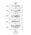
一例示の実施形態においては、エンドエフェクタを胴体アセンブリに対して位置決めするための方法を提供することができる。胴体アセンブリの構成を割り出すことができる。エンドエフェクタを、割り出された構成にもとづいて、胴体アセンブリに対して位置決めすることができる。胴体アセンブリ上の一式の基準点について、一式の実際の基準位置を特定することができる。特定された一式の実際の基準位置にもとづいてエンドエフェクタを作業位置に位置決めすることができる。 In one exemplary embodiment, a method for positioning the end effector relative to the fuselage assembly can be provided. The configuration of the fuselage assembly can be determined. The end effector can be positioned relative to the fuselage assembly based on the indexed configuration. For a set of reference points on the fuselage assembly, a set of actual reference positions can be identified. The end effector can be positioned at the working position based on the identified set of actual reference positions.
別の例示の実施形態においては、エンドエフェクタを位置決めするための方法を提供することができる。エンドエフェクタを、胴体アセンブリに対してマクロに位置決めすることができる。エンドエフェクタを、胴体アセンブリに対してメソに位置決めすることができる。胴体アセンブリ上の一式の基準点について、一式の実際の基準位置を算出することができる。算出された一式の実際の基準位置にもとづいてエンドエフェクタを胴体アセンブリ上の一式の作業位置の各々に対してミクロに位置決めすることができる。 In another exemplary embodiment, a method for positioning an end effector can be provided. The end effector can be positioned macro relative to the fuselage assembly. The end effector can be positioned in the meso relative to the fuselage assembly. For a set of reference points on the fuselage assembly, a set of actual reference positions can be calculated. Based on the calculated set of actual reference positions, the end effector can be micro-positioned for each of the set of working positions on the fuselage assembly.
更に別の例示の実施形態において、装置は、レーザートラッキングシステム及び制御システムを備えることができる。レーザートラッキングシステムは、一式のレーザートラッキング装置と、胴体アセンブリに組み合わせられた胴体レーザーターゲットと、移動プラットフォームに組み合わせられたプラットフォームレーザーターゲットとを備えることができる。制御システムは、一式のレーザートラッキング装置によって生成されるレーザー測定データにもとづいて胴体アセンブリに対するエンドエフェクタの位置決めを制御することができる。 In yet another exemplary embodiment, the apparatus can comprise a laser tracking system and a control system. The laser tracking system may comprise a set of laser tracking devices, a fuselage laser target combined with a fuselage assembly, and a platform laser target combined with a moving platform. The control system can control the positioning of the end effector relative to the fuselage assembly based on the laser measurement data generated by the set of laser tracking devices.
特徴及び機能を、本発明の種々の実施形態において別個独立に達成することができ、或いは以下の説明及び図面を参照して更なる詳細を見て取ることができる更に別の実施形態において組み合わせることができる。 The features and functions may be achieved independently in various embodiments of the present invention or may be combined in yet other embodiments that may be found in further detail with reference to the following description and drawings. .
例示の実施形態に特有であると考えられる新規な特徴が、添付の特許請求の範囲に記載される。しかしながら、例示の実施形態、並びにそれらの好ましい使用の態様、更なる目的及び特徴は、本発明の例示の実施形態の以下の詳細な説明を参照し、添付の図面と併せて検討することによって、最もよく理解されるであろう。 The novel features believed characteristic of the exemplary embodiments are set forth in the appended claims. However, the illustrative embodiments, as well as their preferred use aspects, further objects and features, will be understood by reference to the following detailed description of the illustrative embodiments of the present invention and in conjunction with the accompanying drawings, in which: Will be best understood.
例示の実施形態は、種々の考慮事項を認識及び考慮する。例えば、例示の実施形態は、航空機の胴体アセンブリを製作するプロセスを自動化することが望ましい場合があることを認識及び考慮する。航空機の胴体アセンブリの製作プロセスの自動化は、製作の効率を改善し、製作の品質を向上させ、胴体アセンブリの製作に関するコストを削減することができる。更に、例示の実施形態は、胴体アセンブリの製作プロセスを自動化することで、組み立て作業の実行の正確さ及び精度を改善でき、したがって胴体アセンブリの外側モールドライン(OML)の要件及び内側モールドライン(IML)の要件の順守の改善を保証できることを認識及び考慮する。 The illustrative embodiments recognize and take into account various considerations. For example, the illustrative embodiments recognize and take into account that it may be desirable to automate the process of fabricating an aircraft fuselage assembly. Automation of the aircraft fuselage assembly fabrication process can improve fabrication efficiency, improve fabrication quality, and reduce costs associated with the fabrication of fuselage assemblies. Further, the exemplary embodiment can improve the accuracy and precision of performing assembly operations by automating the fabrication process of the fuselage assembly, thus the fuselage assembly outer mold line (OML) requirements and the inner mold line (IML). ) Recognize and take into account that improvements in compliance with requirements can be guaranteed.
更に、例示の実施形態は、航空機の胴体アセンブリの製作に使用されるプロセスの自動化が、製作サイクルに必要な時間を大幅に削減できることを認識及び考慮する。例えば、これに限られるわけではないが、固定作業の自動化は、作業者がそれらの固定作業並びに他の種類の組み立て作業を実行する必要性を軽減でき、場合によっては皆無にすることができる。 Furthermore, the illustrative embodiments recognize and take into account that the automation of the process used to fabricate the aircraft fuselage assembly can significantly reduce the time required for the fabrication cycle. For example, but not limited to this, automation of fixing operations can reduce the need for an operator to perform those fixing operations as well as other types of assembly operations, and in some cases can be eliminated altogether.
更に、航空機の胴体アセンブリの製作プロセスのこの種の自動化は、このプロセスを主として手作業で実行する場合と比べ、労働力が少なくて済み、時間がかからず、人間工学的に難題でなく、より安価となりうる。手作業による労働の軽減は、労働者のための所望の利益を有することができる。更に、胴体組み立てプロセスの自動化は、胴体アセンブリを所望の組み立て施設及び工場において所望の組み立て速度及び所望の組み立てコストで製作することを可能にすることができる。 In addition, this type of automation of the aircraft fuselage assembly fabrication process requires less labor, less time, and ergonomic challenges compared to performing this process primarily manually. Can be cheaper. The reduction of manual labor can have a desired benefit for workers. Further, the automation of the fuselage assembly process can allow the fuselage assembly to be manufactured at the desired assembly facility and factory at the desired assembly speed and desired assembly cost.
更に、例示の実施形態は、胴体アセンブリの製作プロセスを自動化するために、自律的な駆動及び動作が可能な設備を使用することが望ましい場合があることを認識及び考慮する。特に、工場のフロアを横切って自律的に駆動することができ、胴体アセンブリを製作するために必要に応じて工場のフロアに対して自律的に位置させることができ、胴体アセンブリを製作するために自律的に動作させることができ、その後に胴体アセンブリの製作が完了したときに自律的に動き去ることができる移動システムで構成された自律的なフレキシブル製造システムを有することが望ましいかもしれない。 Furthermore, the illustrative embodiments recognize and take into account that it may be desirable to use equipment capable of autonomous driving and operation to automate the fabrication process of the fuselage assembly. In particular, it can be driven autonomously across the factory floor and can be positioned autonomously with respect to the factory floor as needed to make the fuselage assembly, to make the fuselage assembly It may be desirable to have an autonomous flexible manufacturing system comprised of a mobile system that can operate autonomously and then move away autonomously when the fabrication of the fuselage assembly is complete.
本明細書において使用される場合、任意の作業、行為、又は工程の自律的な実行は、その作業を実質的に人間による入力を必要とせずに実行することを意味することができる。例えば、これに限られるわけではないが、自律的に駆動されることができるプラットフォームは、人間による入力に実質的に関係なく駆動されることができるプラットフォームである。このやり方で、自律的に駆動することができるプラットフォームは、人間による入力に実質的に関係なく駆動すること、又は駆動されることができるプラットフォームであってよい。 As used herein, autonomous execution of any task, action, or process can mean performing the task with substantially no human input required. For example, but not limited to, a platform that can be driven autonomously is a platform that can be driven substantially independently of human input. In this manner, a platform that can be driven autonomously may be a platform that can be driven or driven substantially independently of human input.
したがって、例示の実施形態は、航空機の胴体アセンブリを製作するための方法、装置、及びシステムを提供する。特に、例示の実施形態は、胴体アセンブリの製作のプロセスのすべてではないかもしれないが大部分を自動化する自律的なフレキシブル製造システムを提供する。例えば、これに限られるわけではないが、自律的なフレキシブル製造システムは、胴体アセンブリを製作するために胴体の外皮パネルと胴体の支持構造体とを互いに接合するための締め具の据え付けのプロセスを自動化することができる。例示の実施形態は、胴体アセンブリを簡素な製造施設において製作することを可能にするフレキシブル製造システムを提供する。 Accordingly, the illustrative embodiments provide a method, apparatus, and system for fabricating an aircraft fuselage assembly. In particular, the illustrative embodiments provide an autonomous flexible manufacturing system that automates most if not all of the process of making a fuselage assembly. For example, but not limited to, an autonomous flexible manufacturing system uses a process for installing fasteners to join the fuselage skin panel and the fuselage support structure together to produce the fuselage assembly. Can be automated. The illustrative embodiments provide a flexible manufacturing system that allows the fuselage assembly to be manufactured in a simple manufacturing facility.
しかしながら、例示の実施形態は、自律的なフレキシブル製造システムを用いる胴体アセンブリの製作プロセスの自動化が、独特の技術的解決策を必要とする独特な技術的課題を提示することができることを認識及び考慮する。例えば、例示の実施形態は、ユーティリティを自律的なフレキシブル製造システム内の種々のシステムのすべてに供給することが望しい場合があることを認識及び考慮する。特に、胴体アセンブリの製作のプロセスを中断させたり、遅らせたりすることがなく、或いは工場のフロアにおける自律的なフレキシブル製造システムの種々の移動システムの移動を制限することがないやり方で、これらのユーティリティを供給することが望ましい場合がある。 However, the illustrative embodiments recognize and take into account that automating the fabrication process of a fuselage assembly using an autonomous flexible manufacturing system can present unique technical challenges that require unique technical solutions. To do. For example, the illustrative embodiments recognize and take into account that it may be desirable to provide utilities to all of the various systems within an autonomous flexible manufacturing system. In particular, these utilities do not interrupt or delay the process of manufacturing the fuselage assembly or restrict the movement of the various mobile systems of the autonomous flexible manufacturing system on the factory floor. It may be desirable to supply
例えば、これに限られるわけではないが、一式のユーティリティ一式を提供するユーティリティ一式の供給源の各々への直接的な接続を1つだけしか含まないインフラストラクチャを使用して、電力、通信、及び空気などの一式のユーティリティを自律的なフレキシブル製造システムへ供給することが望ましい場合がある。これらの直接的な接続は、地面の上方にあっても、地面にあっても、或いは埋め込まれていてもよい。これらの直接的な接続を、例えば、これらに限られるわけではないが、ユーティリティフィクスチャを使用して確立することができる。このようにして、インフラストラクチャは、一式のユーティリティ供給源の各々への直接的な接続を提供するユーティリティフィクスチャと、自律的なフレキシブル製造システムの種々のシステムのユーティリティフィクスチャへの接続及び互いの直列接続を可能にする充分に大きいフロアスペースを有する組み立て領域とを含むことができる。このやり方で、一式のユーティリティは、一式のユーティリティ供給源からユーティリティフィクスチャへと流れ、次いで組み立て領域内の自律的なフレキシブル製造システムの種々のシステムへと下流に流れることができる。 For example, but not limited to, using infrastructure that includes only one direct connection to each of a set of utilities that provide a set of utilities, power, communications, and It may be desirable to supply a suite of utilities, such as air, to an autonomous flexible manufacturing system. These direct connections may be above the ground, on the ground, or embedded. These direct connections can be established, for example, using, but not limited to, utility fixtures. In this way, the infrastructure provides a utility fixture that provides a direct connection to each of the set of utility sources, and a connection between the autonomous flexible manufacturing system's various system utility fixtures and each other. And an assembly area having a sufficiently large floor space to allow series connection. In this manner, the set of utilities can flow from the set of utility sources to the utility fixture and then downstream to the various systems of the autonomous flexible manufacturing system within the assembly area.
このように、例示の実施形態は、ユーティリティを自律的なフレキシブル製造システムの種々のシステムに供給するために使用することができる分散ユーティリティネットワークを提供する。分散ユーティリティネットワークは、これらのユーティリティを、自律的なフレキシブル製造システムの種々の移動システムの移動を制約又は妨害することがないやり方で供給することができる。自律的なフレキシブル製造システムの種々の移動システムを、この分散ユーティリティネットワークを生成するために互いに自律的に結合させることができる。 Thus, the illustrative embodiments provide a distributed utility network that can be used to supply utilities to various systems of autonomous flexible manufacturing systems. A distributed utility network can provide these utilities in a manner that does not restrict or interfere with the movement of the various mobile systems of the autonomous flexible manufacturing system. Various mobile systems of an autonomous flexible manufacturing system can be autonomously coupled together to create this distributed utility network.
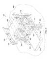
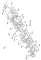
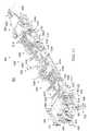
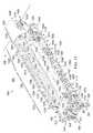
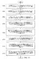
ここで図面を参照し、特に図1〜図7を参照すると、製造環境の図が、例示の実施形態に従って、ブロック図の形態で示されている。特に、図1〜図7には、胴体アセンブリ、フレキシブル製造システム、胴体アセンブリの製作に使用することができるフレキシブル製造システム内の種々のシステム、及び分散ユーティリティネットワークが示されている。 Referring now to the drawings and in particular with reference to FIGS. 1-7, a diagram of a manufacturing environment is shown in block diagram form in accordance with an illustrative embodiment. In particular, FIGS. 1-7 illustrate a fuselage assembly, a flexible manufacturing system, various systems within a flexible manufacturing system that can be used to make a fuselage assembly, and a distributed utility network.
次に図1に目を向けると、製造環境の図が、例示の実施形態に従い、ブロック図の形態で示されている。この例示の例において、製造環境100は、航空機104の胴体102の少なくとも一部分を製造することができる1つの環境の例であってよい。 Turning now to FIG. 1, a diagram of a manufacturing environment is shown in block diagram form, in accordance with an illustrative embodiment. In this illustrative example,
製造環境100は、いくつかの異なる形態をとることができる。例えば、これに限られるわけではないが、製造環境100は、工場、製造施設、屋外工場領域、囲われた製造領域、海上プラットフォーム、又は胴体102の少なくとも一部分の製作に適した何らかの他の種類の製造環境100の形態をとることができる。 The
胴体102を、製造プロセス108を使用して製作することができる。フレキシブル製造システム106を、製造プロセス108の少なくとも一部分を実行するために使用することができる。一例示の例においては、製造プロセス108を、フレキシブル製造システム106を使用して実質的に自動化することができる。他の例示の例では、製造プロセス108のうちの1つ以上の段階だけを、実質的に自動化することができる。 The
フレキシブル製造システム106を、製造プロセス108の少なくとも一部分を自律的に実行するように構成することができる。このやり方で、フレキシブル製造システム106を、自律的なフレキシブル製造システム112と称することができる。他の例示の例では、フレキシブル製造システム106を、自動化フレキシブル製造システムと称することができる。 The
図示のとおり、製造プロセス108は、胴体アセンブリ114を製作するための組み立てプロセス110を含むことができる。フレキシブル製造システム106を、組み立てプロセス110の少なくとも一部分を自律的に実行するように構成することができる。 As shown, the
胴体アセンブリ114は、製造プロセス108の完了前の製造プロセス108の最中の任意の段階における胴体102であってよい。いくつかの場合、胴体アセンブリ114は、途中まで組み立てられた胴体102を指して使用されることもある。実施例に応じて、胴体102の組み立てを完了させるために、1つ以上の他の構成部品を胴体アセンブリ114に取り付ける必要があるかもしれない。他の場合に、胴体アセンブリ114は、完全に組み立てられた胴体102を指して使用されることもある。フレキシブル製造システム106は、航空機104を製作するための製造プロセスにおいて胴体アセンブリ114を次の段階へと移動させるために必要な程度まで、胴体アセンブリ114を製作することができる。いくつかの場合には、フレキシブル製造システム106の少なくとも一部分を、航空機104を製作するための製造プロセスにおける1つ以上の後の段階において使用することができる。 The
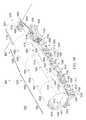
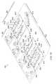
一例示の例において、胴体アセンブリ114は、胴体102の特定の部分を形成するためのアセンブリであってよい。一例として、胴体アセンブリ114は、胴体102の後部を形成するための後部胴体アセンブリ116の形態をとることができる。別の例では、胴体アセンブリ114は、胴体102の前部を形成するための前部胴体アセンブリ117の形態をとることができる。更に別の例では、胴体アセンブリ114は、胴体102の中央部又は胴体102の後部と前部との間の胴体102の何らかの他の中間部を形成するための中央部胴体アセンブリ118の形態をとることができる。 In one illustrative example, the
図示のとおり、胴体アセンブリ114は、複数のパネル120及び支持構造体121を含むことができる。支持構造体121を、複数の部材122で構成することができる。複数の部材122を、複数のパネル120の支持及び複数のパネル120の互いの接続の両方に使用することができる。支持構造体121は、胴体アセンブリ114に強度、剛性、及び荷重支持をもたらすうえで役に立つことができる。 As shown, the
複数の部材122を、複数のパネル120に関連付けることができる。本明細書において使用されるとき、或る構成部品又は構造体が別の構成部品又は構造体に「関連付けられ」る場合、関連付けは、図示の例における物理的な関連付けである。 A plurality of
例えば、複数の部材122のうちの1つなどの第1の構成部品は、複数のパネル120のうちの1つなどの第2の構成部品に関連付けられると考えることができ、第2の構成部品に締め付けられる、第2の構成部品に貼り付けられる、第2の構成部品に据え付けられる、第2の構成部品に取り付けられる、第2の構成部品に結合させられる、第2の構成部品に溶接される、第2の構成部品に固定される、第2の構成部品に接着される、第2の構成部品に糊付けされる、或いは何らかの他の適切なやり方で第2の構成部品に接続される、のうちの少なくとも1つによって、関連付けられると考えることができる。更に、第1の構成部品を、1つ以上の他の構成部品を使用して、第2の構成部品に接続してもよい。例えば、第1の構成部品を、第3の構成部品を使用して第2の構成部品に接続することができる。更に、第1の構成部品を、第2の構成部品の一部、第2の構成部品の延長部、又は両方として形成されることによって、第2の構成部品に関連付けられると考えることができる。別の例では、第1の構成部品を、第2の構成部品と一緒に硬化させることによって、第2の構成部品の一部と考えることができる。 For example, a first component, such as one of the plurality of
本明細書において使用されるとき、「のうちの少なくとも1つ」という表現は、アイテムのリストとともに使用される場合に、リストに挙げられたアイテムのうちの1つ以上のアイテムの種々の組み合わせを使用できることを意味し、リストのアイテムのうちのただ1つだけが必要であってよい。アイテムは、個々の物体、事物、行為、プロセス、又は種類であってよい。換言すると、「のうちの少なくとも1つ」は、アイテムの任意の組み合わせ又はいくつかのアイテムをリストから使用することができるが、必ずしもリストのすべてのアイテムが必要とされるわけではないことを意味する。 As used herein, the expression “at least one of”, when used with a list of items, refers to various combinations of one or more of the items listed. Means that it can be used, and only one of the items in the list may be needed. An item may be an individual object, thing, act, process, or type. In other words, “at least one of” means that any combination of items or several items can be used from the list, but not all items in the list are required. To do.
例えば、「アイテムA、アイテムB、及びアイテムCのうちの少なくとも1つ」又は「アイテムA、アイテムB、又はアイテムCのうちの少なくとも1つ」は、アイテムA、アイテムAとアイテムB、アイテムB、アイテムAとアイテムBとアイテムC、又はアイテムBとアイテムCを意味することができる。いくつかの場合、「アイテムA、アイテムB、及びアイテムCのうちの少なくとも1つ」は、例えば、これらに限られるわけではないが、2つのアイテムAと1つのアイテムBと10個のアイテムC、4つのアイテムBと7つのアイテムC、又は何らかの他の適切な組み合わせを意味することができる。 For example, “at least one of item A, item B, and item C” or “at least one of item A, item B, or item C” includes item A, item A, item B, and item B. , Item A and item B and item C, or item B and item C. In some cases, “at least one of item A, item B, and item C” is, for example, but not limited to, two items A, one item B, and ten items C. It can mean 4 items B and 7 items C, or some other suitable combination.
これらの例示の例において、複数の部材122のうちの或る部材を、複数のパネル120のうちの少なくとも1つに、いくつかの異なるやり方で関連付けることができる。例えば、これらに限られるわけではないが、複数の部材122のうちの或る部材を、ただ1つのパネルに直接取り付けることができ、2つ以上のパネルに取り付けることができ、少なくとも1つのパネルに直接取り付けられた別の部材に取り付けることができ、少なくとも1つのパネルに直接又は間接的に取り付けられた少なくとも1つの部材に取り付けることができ、或いは何らかの他のやり方で複数のパネル120のうちの少なくとも1つに関連付けることができる。 In these illustrative examples, a member of the plurality of
一例示の例では、複数の部材122のうちの実質的にすべて又はすべてを、胴体アセンブリ114を製作するための組み立てプロセス110の開始に先立って、複数のパネル120に関連付けることができる。例えば、複数の部材122の該当する部分を、複数のパネル120を組み立てプロセス110を通じて互いに接合する前に、複数のパネル120の各パネルに関連付けることができる。 In one illustrative example, substantially all or all of the plurality of
別の例示の例では、複数の部材122の第1の部分だけを、組み立てプロセス110の開始に先立って複数のパネル120に関連付けることができる。組み立てプロセス110は、複数のパネル120への支持の提供又は複数のパネル120の互いの接続の少なくとも一方のために、複数の部材122の残りの部分を複数のパネル120に取り付けることを含むことができる。組み立てプロセス110に先立って複数のパネル120に取り付けられた複数の部材122の第1の部分、及び組み立てプロセス110において複数のパネル120に取り付けられた複数の部材122の残りの部分が、協働して支持構造体121を形成することができる。 In another illustrative example, only a first portion of the plurality of
更に別の例示の例では、複数の部材122のすべてを、組み立てプロセス110において複数のパネル120に関連付けることができる。例えば、複数のパネル120の各々は、組み立てプロセス110よりも前は、いかなる部材もパネルに取り付けられておらず、他のやり方で関連付けられてもいない「裸」の状態であってよい。次いで、組み立てプロセス110において、複数の部材122を複数のパネル120に関連付けることができる。 In yet another illustrative example, all of the plurality of
このやり方で、胴体アセンブリ114のための支持構造体121を、いくつかの異なるやり方で作り上げることができる。複数のパネル120及び支持構造体121を備える胴体アセンブリ114は、下記の図2において更に詳しく説明される。 In this manner, the
胴体アセンブリ114の製作は、複数のパネル120を互いに接合することを含むことができる。複数のパネル120の接合を、いくつかの異なるやり方で実行することができる。実施例に応じて、複数のパネル120の互いの接合は、複数の部材122のうちの1つ以上を、複数のパネル120のうちの1つ以上又は複数の部材122のうちの別の部材に接合することを含むことができる。 Fabrication of
特に、複数のパネル120の接合は、少なくとも1つのパネルを少なくとも1つの別のパネルに接合すること、少なくとも1つの部材を少なくとも1つの別の部材に接合すること、又は少なくとも1つの部材を少なくとも1つのパネルに接合すること、或いはこれらの何らかの組み合わせを含むことができる。一例示の例として、第1のパネル及び第2のパネルの互いの接合は、以下のうちの少なくとも1つを含むことができ、すなわち第1のパネルを第2のパネルに直接固定すること、第1のパネルに関連付けられた第1の部材を第2のパネルに関連付けられた第2の部材に接合すること、第1のパネルに関連付けられた部材を第2のパネルに直接接合すること、第1のパネル及び第2のパネルの両方に関連付けられた1つの部材を別の部材に接合すること、選択された部材を第1のパネル及び第2のパネルの両方に接合すること、又は何らかの他の種類の接合作業のうちの少なくとも1つを含むことができる。 In particular, the joining of the plurality of
組み立てプロセス110は、胴体アセンブリ114を製作すべく複数のパネル120を互いに接合するために実行することができる作業124を含むことができる。この例示の例において、作業124の少なくとも一部分を自律的に実行するためにフレキシブル製造システム106を使用することができる。 The
作業124は、例えば、これらに限られるわけではないが、仮接続作業125、穿孔作業126、締め具挿入作業128、締め具据え付け作業130、検査作業132、他の種類の組み立て作業、又はこれらの何らかの組み合わせを含むことができる。仮接続作業125を、複数のパネル120を互いに一時的に接続するために実行することができる。例えば、これに限られるわけではないが、仮接続作業125は、仮留めファスナ(tack fastener)を使用して複数のパネル120を互いに一時的に留めることを含むことができる。 The
穿孔作業126は、複数のパネル120のうちの1つ以上を貫き、場合によっては複数の部材122のうちの1つ以上を貫いて、穴を開けることを含むことができる。締め具挿入作業128は、穿孔作業126によって開けられた穴に締め具を挿入することを含むことができる。 The
締め具据え付け作業130は、穴に挿入された締め具の各々を完全に据え付けることを含むことができる。締め具据え付け作業130は、例えば、これらに限られるわけではないが、リベット打ち作業、締まりばめボルト締め作業、他の種類の締め具据え付け作業、又はこれらの何らかの組み合わせを含むことができる。検査作業132は、完全に据え付けられた締め具の検査を含むことができる。実施例に応じて、任意の数のこれらの種々の種類の作業124を実質的に自律的に実行するためにフレキシブル製造システム106を使用することができる。
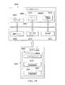
図示のとおり、フレキシブル製造システム106は、複数の移動システム134と、制御システム136と、ユーティリティシステム138とを含むことができる。複数の移動システム134の各々は、駆動可能な移動システムであってよい。いくつかの場合に、複数の移動システム134の各々は、自律的に駆動可能な移動システムであってよい。例えば、これに限られるわけではないが、複数の移動システム134の各々は、製造環境100において或る位置から他の位置へと自律的に駆動されることができる1つ以上の構成要素を含むことができる。複数の移動システム134は、以下で図3において更に詳しく説明される。 As shown, the
この例示の例において、制御システム136を、フレキシブル製造システム106の動作を制御するために使用することができる。例えば、これに限られるわけではないが、制御システム136を、複数の移動システム134を制御するために使用することができる。特に、制御システム136を、製造環境100における複数の移動システム134の各々の移動を指示するために使用することができる。制御システム136は、複数の移動システム134に少なくとも部分的に関連付けられてよい。 In this illustrative example,
一例示の例において、制御システム136は、一式のコントローラー140を含むことができる。本明細書において使用されるとき、「一式」のアイテムは、1つ以上のアイテムを含むことができる。このやり方で、一式のコントローラー140は、1つ以上のコントローラーを含むことができる。 In one illustrative example, the
一式のコントローラー140の各々を、ハードウェア、ファームウェア、ソフトウェア、又はこれらの何らかの組み合わせを使用して実現することができる。一例示の例では、一式のコントローラー140を、複数の移動システム134に関連付けることができる。例えば、これに限られるわけではないが、一式のコントローラー140のうちの1つ以上を、複数の移動システム134の一部として実現することができる。他の例では、一式のコントローラー140のうちの1つ以上を、複数の移動システム134とは別個独立に実現することができる。 Each of the set of
一式のコントローラー140は、フレキシブル製造システム106の複数の移動システム134の動作を制御するための指令142を生成することができる。一式のコントローラー140は、無線通信リンク、有線通信リンク、光通信リンク、又は他の種類の通信リンクのうちの少なくとも1つを使用して、複数の移動システム134と通信することができる。このやり方で、任意の数の種々の種類の通信リンクを、一式のコントローラー140との通信及び一式のコントローラー140間の通信に使用することができる。 The set of
これらの例示の例において、制御システム136は、センサーシステム133から受信されるデータ141を使用して複数の移動システム134の動作を制御することができる。センサーシステム133を、任意の数の個別のセンサーシステム、センサー装置、コントローラー、他の種類の構成要素、又はこれらの組み合わせで構成することができる。一例示の例において、センサーシステム133は、レーザートラッキングシステム135及びレーダーシステム137を含むことができる。レーザートラッキングシステム135を、任意の数のレーザートラッキング装置、レーザーターゲット、又はこれらの組み合わせで構成することができる。レーダーシステム137を、任意の数のレーダーセンサー、レーダーターゲット、又はこれらの組み合わせで構成することができる。 In these illustrative examples,
センサーシステム133を、製造環境100において複数の移動システム134の種々の移動システムの移動及び動作を協調させるために使用することができる。一例示の例として、レーダーシステム137を、移動システム、移動システム内のシステム、移動システム内の構成要素、又はこれらの何らかの組み合わせのマクロな位置決めに使用することができる。更に、レーザートラッキングシステム135を、移動システム、移動システム内のシステム、移動システム内の構成要素、又はこれらの何らかの組み合わせのミクロな位置決めに使用することができる。
複数の移動システム134を、分散ユーティリティネットワーク144を形成するために使用することができる。実施例に応じて、複数の移動システム134のうちの1つ以上が、分散ユーティリティネットワーク144を形成することができる。いくつかのユーティリティ146が、いくつかのユーティリティ供給源148から、分散ユーティリティネットワーク144を構成する複数の移動システム134の種々の移動システムへと流れることができる。 Multiple
この例示の例において、いくつかのユーティリティ供給源148の各々は、製造環境100内に位置することができる。他の例示の例では、いくつかのユーティリティ供給源148のうちの1つ以上が、製造環境100の外部に位置することができる。その場合、これらの1つ以上のユーティリティ供給源によってもたらされる該当のユーティリティを、例えば、これに限られるわけではないが、1つ以上のユーティリティケーブルを使用して製造環境100に運ぶことができる。 In this illustrative example, each of
一例示の例において、分散ユーティリティネットワーク144は、いくつかのユーティリティ146をいくつかのユーティリティ供給源148から何らかの数のユーティリティケーブルを介して複数の移動システム134の1つの移動システムへと直接流すことを可能にすることができる。次いで、この1つの移動システムは、いくつかのユーティリティ146を複数の移動システム134のうちの他の移動システムに分配することができ、したがって、これら他の移動システムは、いくつかのユーティリティ146をいくつかのユーティリティ供給源148から直接受け取る必要がない。 In one illustrative example, the distributed
図示のとおり、分散ユーティリティネットワーク144を、ユーティリティシステム138を使用して形成することができる。ユーティリティシステム138は、ユーティリティフィクスチャ150を含むことができる。いくつかのユーティリティ146をいくつかのユーティリティ供給源148からユーティリティフィクスチャ150へと流すことができるよう、ユーティリティシステム138をいくつかのユーティリティ供給源148につながるように構成することができる。ユーティリティフィクスチャ150は、実施例に応じて、地上にあっても、地中にあってもよい。例えば、これに限られるわけではないが、ユーティリティフィクスチャ150を、製造環境100内の床に埋め込むことができる。 As shown, a distributed
したがって、ユーティリティフィクスチャ150は、いくつかのユーティリティ146を複数の移動システム134のうちの1つ以上に分配することができる。特に、複数の移動システム134のうちの1つのユーティリティフィクスチャ150への1つの自律的な結合に、分散ユーティリティネットワーク144を形成するための移動システムの互いの直列な任意の数の自律的な結合が続くことができる。ユーティリティフィクスチャ150は、移動システムの一連の自律的な結合においてユーティリティフィクスチャ150の下流の複数の移動システム134の各々にいくつかのユーティリティ146を分配することができる。 Accordingly, the
実施例に応じて、分散ユーティリティネットワーク144は、チェーン状の構成又はツリー状の構成を有することができる。一例示の例において、複数の移動システム134は、移動システムAをユーティリティフィクスチャ150に自律的に結合させ、移動システムB、C、及びDを移動システムA及び相互に直列に自律的に結合させた移動システムA、B、C、及びD(図示せず)を含むことができる。分散ユーティリティネットワーク144のチェーン状の構成の例は、いくつかのユーティリティ供給源148から或るいくつかのユーティリティケーブルを介してユーティリティフィクスチャ150へと流れ、ユーティリティフィクスチャ150から移動システムAへと流れ、移動システムAから移動システムBへと流れ、移動システムBから移動システムCへと流れ、移動システムCから移動システムDへと流れるいくつかのユーティリティ146を含むことができる。分散ユーティリティネットワーク144のツリー状の構成の例は、いくつかのユーティリティ供給源148から或るいくつかのユーティリティケーブルを介してユーティリティフィクスチャ150へと流れ、ユーティリティフィクスチャ150から移動システムAへと流れ、移動システムAから移動システムB及び移動システムCの両方へと流れ、移動システムCから移動システムDへと流れるいくつかのユーティリティ146を含むことができる。複数の移動システム134を使用して分散ユーティリティネットワーク144を実現できる1つのやり方の例は、以下で図5において更に詳しく説明される。 Depending on the embodiment, the distributed
いくつかの例示の例では、複数の胴体アセンブリを同時に製作するために複数のフレキシブル製造システムを使用することができる。例えば、フレキシブル製造システム106は、多数のフレキシブル製造システムのうちの第1のフレキシブル製造システムであってよい。 In some illustrative examples, multiple flexible manufacturing systems can be used to fabricate multiple fuselage assemblies simultaneously. For example, the
一例示の例では、後部胴体アセンブリ116、中央部胴体アセンブリ118、及び前部胴体アセンブリ117をそれぞれ製作するために、フレキシブル製造システム106、第2のフレキシブル製造システム152、及び第3のフレキシブル製造システム154を使用することができる。その後に、後部胴体アセンブリ116、中央部胴体アセンブリ118、及び前部胴体アセンブリ117を互いに接合し、完全に組み立てられた胴体102を形成することができる。このやり方で、この例では、フレキシブル製造システム106、第2のフレキシブル製造システム152、及び第3のフレキシブル製造システム154が協働して、フレキシブル胴体製造システム158を形成することができる。 In one illustrative example,
このようにして、胴体アセンブリ114などの任意の数の胴体アセンブリを、フレキシブル製造システム106と同様のやり方で実現される任意の数のフレキシブル製造システムを使用して、製造環境100において製作することができる。同様に、胴体102などの任意の数の完全な胴体を、フレキシブル胴体製造システム158と同様のやり方で実現される任意の数のフレキシブル胴体製造システムを使用して、製造環境100において製作することができる。 In this manner, any number of fuselage assemblies, such as
次に図2を参照すると、図1からの胴体アセンブリ114の図が、例示の実施形態に従って、ブロック図の形態で示されている。上述のように、胴体アセンブリ114は、複数のパネル120と、支持構造体121とを含むことができる。胴体アセンブリ114を、胴体アセンブリ114の製作における任意の段階を指して使用することができる。例えば、胴体アセンブリ114を、複数のパネル120のうちのただ1つ、複数のパネル120のうちの接合済み又は接合中のいくつかのパネル、途中まで製作された胴体アセンブリ、或いは完全に製作された胴体アセンブリを指して使用することができる。 Referring now to FIG. 2, a view of the
図示のとおり、胴体アセンブリ114を、複数の胴体部分205を有するように製作することができる。複数の胴体部分205の各々は、複数のパネル120のうちの1つ以上を含むことができる。この例示の例において、複数の胴体部分205の各々は、円筒形の胴体部分、たる形の胴体部分、テーパ状の円筒形の胴体部分、円すい形の胴体部分、ドーム状の胴体部分、又は何らかの他の種類の形状を有する部分の形態をとることができる。実施例に応じて、複数の胴体部分205のうちの胴体部分は、実質的に円形の断面形状、楕円形の断面形状、長円形の断面形状、丸みを帯びた角を持つ多角形の断面形状、又は他の閉じた曲線による断面形状を有する形状を有することができる。 As shown, the
1つの具体的な例示の例として、複数の胴体部分205の各々は、胴体アセンブリ114のうちで、胴体アセンブリ114の中心軸線又は長手軸線に対して実質的に垂直に得られる胴体アセンブリ114の2つの横断面の間に定められる部分であってよい。このやり方で、複数の胴体部分205は、胴体アセンブリ114の長手軸線に沿って配置されてよい。換言すると、複数の胴体部分205を、長手方向に配置することができる。 As one specific illustrative example, each of the plurality of
胴体部分207が、複数の胴体部分205のうちの1つの胴体部分の例であってよい。胴体部分207を、複数のパネル120のうちの1つ以上で構成することができる。一例示の例では、複数のパネル部分を、胴体部分207の外周を巡って配置し、胴体部分207の外皮を形成することができる。いくつかの場合には、長手方向に隣接する2つ以上のパネルからなる列を複数、胴体部分207の外周を巡って配置して、胴体部分207の外皮を形成することができる。 The
一例示の例において、胴体アセンブリ114は、クラウン200と、キール202と、側面204とを有することができる。側面204は、第1の側面206及び第2の側面208を含むことができる。 In one illustrative example, the
クラウン200は、胴体アセンブリ114の上部であってよい。キール202は、胴体アセンブリ114の下部であってよい。胴体アセンブリ114の側面204は、胴体アセンブリ114のうちのクラウン200とキール202との間の部分であってよい。一例示の例では、胴体アセンブリ114のクラウン200、キール202、第1の側面206、及び第2の側面208の各々を、複数のパネル120の少なくとも1つの少なくとも一部分によって形成することができる。更に、複数の胴体部分205の各々の一部分が、クラウン200、キール202、第1の側面206、及び第2の側面208の各々を形成することができる。
パネル216が、複数のパネル120のうちの1つのパネルの一例でありうる。パネル216は、実施例に応じて、外皮パネル、胴体パネル、又は胴体外皮パネルと呼ばれることもある。いくつかの例示の例において、パネル216は、サブパネルと称することができる複数のより小さなパネルで構成されるメガパネルの形態をとることができる。メガパネルを、スーパーパネルと称することもできる。これらの例示の例では、パネル216を、金属、金属合金、何らかの他の種類の金属材料、複合材料、又は何らかの他の材料のタイプのうちの少なくとも1つで構成することができる。一例示の例として、パネル216を、アルミニウム合金、鋼、チタニウム、セラミック材料、複合材料、何らかの他の材料のタイプ、又はこれらの何らかの組み合わせで構成することができる。 The
胴体アセンブリ114のキール202の形成に使用される場合、パネル216を、キールパネル又は下部パネルと称することができる。胴体アセンブリ114の側面204のうちの1つを形成するために使用される場合、パネル216を、側面パネルと称することができる。胴体アセンブリ114のクラウン200の形成に使用される場合、パネル216を、クラウンパネル又は上部パネルと称することができる。一例示の例として、複数のパネル120は、クラウン200を形成するためのクラウンパネル218、側面204を形成するための側面パネル220、及びキール202を形成するためのキールパネル222を含むことができる。側面パネル220は、第1の側面206を形成するための第1の側面パネル224及び第2の側面208を形成するための第2の側面パネル226を含むことができる。 When used to form the
一例示の例において、胴体アセンブリ114の複数の胴体部分205のうちの胴体部分207は、クラウンパネル218のうちの1つと、側面パネル220のうちの2つと、キールパネル222のうちの1つとを含むことができる。別の例示の例において、胴体部分207は、胴体アセンブリ114の端部を形成することができる。 In one illustrative example, the
いくつかの場合、胴体部分207を、パネル216などの単一のパネルのみで構成することができる。例えば、これに限られるわけではないが、パネル216は、端部パネル228の形態をとることができる。 In some cases, the
端部パネル228を、胴体アセンブリ114の一端を形成するために使用することができる。例えば、胴体アセンブリ114が図1の後部胴体アセンブリ116の形態をとる場合、端部パネル228は、胴体アセンブリ114の最も後ろの端部を形成することができる。胴体アセンブリ114が図1の前部胴体アセンブリ117の形態をとる場合、端部パネル228は、胴体アセンブリ114の最も前方の端部を形成することができる。
一例示の例において、端部パネル228は、円筒形のパネル、円すい形のパネル、たる形のパネル、又はテーパ状の円筒形のパネルの形態をとることができる。例えば、端部パネル228は、胴体アセンブリ114の中心軸線に関して直径が変化してもよい実質的に円形の断面形状を有する単一の円筒形のパネルであってよい。 In one illustrative example, the
このやり方で、上述のように、胴体部分207を、端部パネル228のみで構成することができる。いくつかの例示の例において、胴体部分207は、端部パネル228とすることができるただ1つのパネルのみで構成される端部胴体部分とすることができる。いくつかの場合には、胴体部分207が端部胴体部分である場合に、隔壁272を端部パネル228に関連付けることができる。圧力隔壁とも称することができる隔壁272を、実施例に応じて、端部パネル228とは別であると考えることができ、或いは端部パネル228の一部であると考えることができる。隔壁272は、これらの例示の例では、ドーム式の形状を有することができる。 In this manner, the
胴体アセンブリ114が図1の後部胴体アセンブリ116の形態をとる場合、隔壁272は、後部胴体アセンブリ116の最も後ろの端部に位置する胴体部分207の一部であってよい。胴体アセンブリ114が図1の前部胴体アセンブリ117の形態をとる場合、隔壁272は、後部胴体アセンブリ116の最も前方の端部に位置する胴体部分207の一部であってよい。図1の中央部胴体アセンブリ118は、中央部胴体アセンブリ118のいずれの端部にも隔壁272などの隔壁を備えなくてよい。このやり方で、任意の数の異なるやり方で複数の胴体部分205を実現することができる。 If the
パネル216は、第1の表面230及び第2の表面232を有することができる。第1の表面230を、外向きの表面として使用されるように構成することができる。換言すると、第1の表面230を、胴体アセンブリ114の外側234を形成するために使用することができる。第2の表面232を、内向きの表面として使用されるように構成することができる。換言すると、第2の表面232を、胴体アセンブリ114の内部236を形成するために使用することができる。複数のパネル120の各々を、パネル216と同様のやり方で実現することができる。 The
すでに述べたように、支持構造体121を、複数のパネル120のうちの対応する1つに関連付けることができる。支持構造体121を、パネル216に組み合わせられた複数の部材122で構成することができる。一例示の例では、対応する部分240が、パネル216に対応する複数の部材122の一部分であってよい。対応する部分240は、パネル216に対応する支持部238を形成することができる。支持部238は、支持構造体121の一部であってよい。 As already mentioned, the
複数の部材122は、支持部材242を含むことができる。支持部材242は、例えば、これらに限られるわけではないが、接続部材244、フレーム246、ストリンガー248、補剛材250、支柱252、肋間状構造部材254、又は他の種類の構造部材のうちの少なくとも1つを含むことができる。 The plurality of
接続部材244は、他の種類の支持部材242を互いに接続することができる。いくつかの場合、接続部材244は、支持部材242を複数のパネル120に接続することもできる。接続部材244は、例えば、これらに限られるわけではないが、せん断クリップ256、タイ258、組み継ぎ260、肋間接続部材262、他の種類の機械的な接続部材、又はこれらの何らかの組み合わせを含むことができる。 The connection member 244 can connect other types of support members 242 to each other. In some cases, the connection member 244 may connect the support member 242 to the plurality of
一例示の例では、パネル216が複数のサブパネルで構成される場合に、例えば、これに限られるわけではないが、隣接するサブパネル上をフープ方向に延びるフレーム246のうちの相補的なフレームと、隣接するサブパネル上を長手方向に延びるストリンガー248のうちの相補的なストリンガーとを互いに接続するために、接続部材244を使用することができる。他の例示の例では、複数のパネル120の2つ以上の隣接するパネル上の相補的なフレーム、ストリンガー、又は他の種類の支持部材を互いに接続するために、接続部材244を使用することができる。いくつかの場合には、2つ以上の隣接する胴体部分の相補的な支持部材を互いに接続するために、接続部材244を使用することができる。 In one illustrative example, when the
図1に示されるとおりの作業124を、胴体アセンブリ114を製作すべく複数のパネル120を互いに接合するために実行することができる。一例示の例では、複数の締め具264を、複数のパネル120を互いに接合するために使用することができる。 An
上述のように、複数のパネル120の互いの接合を、いくつかの異なるやり方で実行することができる。複数のパネル120の接合は、複数のパネル120のうちの少なくとも1つのパネルを複数のパネル120のうちの別のパネルに接合すること、複数のパネル120のうちの少なくとも1つのパネルを複数の部材122のうちの少なくとも1つに接合すること、複数の部材122のうちの少なくとも1つの部材を複数の部材122のうちの別の部材に接合すること、又は何らかの他の種類の接合作業のうちの少なくとも1つを含むことができる。複数のパネル120を、複数の部材122によって胴体アセンブリ114の支持構造体121が最終的に形成されるように、互いに接合することができる。 As described above, joining of the plurality of
図示のとおり、いくつかの床266を、胴体アセンブリ114に関連付けることができる。この例示の例において、いくつかの床266は、胴体アセンブリ114の一部であってよい。いくつかの床266は、例えば、これに限られるわけではないが、客室の床、荷物室の床、又は何らかの他の種類の床のうちの少なくとも1つを含むことができる。 As shown,
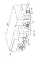
次に図3を参照すると、図1からの製造環境100におけるフレキシブル製造システム106の複数の移動システム134の図が、例示の実施形態に従い、ブロック図の形態で示されている。図示のとおり、フレキシブル製造システム106を、製造環境100のフロア300において胴体アセンブリ114を製作するために使用することができる。製造環境100が工場の形態をとる場合、フロア300を、工場フロア302と称することができる。 Referring now to FIG. 3, a diagram of a plurality of
一例示の例において、フロア300は、実質的に平滑且つ実質的に平坦であってよい。例えば、フロア300は、実質的に水平であってよい。他の例示の例では、フロア300の1つ以上の部分が、傾斜、斜面、又は他の形態で非平坦であってよい。 In one illustrative example, the
組み立て領域304が、胴体アセンブリ114などの胴体アセンブリを製作するために、図1の組み立てプロセス110を実行するように指定された製造環境100内の領域であってよい。組み立て領域304を、セル又は作業セルと称することもできる。この例示の例において、組み立て領域304は、フロア300上の指定された領域であってよい。しかしながら、他の例示の例においては、組み立て領域304が、フロア300上の指定された領域と、この指定された領域の上方の領域とを含むことができる。任意の数の胴体アセンブリを製造環境100において同時に製作できるように、任意の数の組み立て領域が、製造環境100内に存在することができる。 The
図示のとおり、複数の移動システム134は、複数の自律的な車両306、クレードルシステム308、タワーシステム310、及び自律的なツールシステム312を含むことができる。複数の移動システム134の各々は、フロア300の全域に駆動可能であってよい。換言すると、複数の移動システム134の各々は、フロア300上の或る位置315から別の位置317へとフロア300を横切って自律的に駆動されることが可能であってよい。 As shown, the plurality of
一例示の例において、複数の自律的な車両306の各々は、人間の指示又は案内を必要とすることなく独立して動作することが可能であってよい自動案内車両(AGV)の形態をとることができる。いくつかの場合には、複数の自律的な車両306を、複数の自動案内車両(AGV)と称することができる。 In one illustrative example, each of the plurality of
この例示の例において、クレードルシステム308を、図1の組み立てプロセス110の際に胴体アセンブリ114を支持及び保持するために使用することができる。いくつかの場合には、クレードルシステム308を、駆動可能なクレードルシステムと称することができる。更に他の場合には、クレードルシステム308を、自律的に駆動可能なクレードルシステムと称することができる。 In this illustrative example,
クレードルシステム308は、いくつかのフィクスチャ313を含むことができる。本明細書において使用されるとき、「いくつか」のアイテムは、1つ以上のアイテムを含むことができる。このやり方で、いくつかのフィクスチャ313は、1つ以上のフィクスチャを含むことができる。いくつかの例示の例では、いくつかのフィクスチャ313を、いくつかの駆動可能なフィクスチャと称することができる。他の例示の例では、いくつかのフィクスチャ313を、いくつかの自律的に駆動可能なフィクスチャと称することができる。 The
いくつかのフィクスチャ313は、いくつかのクレードルフィクスチャ314を含むことができる。いくつかの例示の例では、いくつかのクレードルフィクスチャ314を、いくつかの駆動可能なクレードルフィクスチャと称することができる。他の例示の例では、いくつかのクレードルフィクスチャ314を、いくつかの自律的に駆動可能なクレードルフィクスチャと称することができる。クレードルフィクスチャ322は、いくつかのクレードルフィクスチャ314のうちの1つのクレードルフィクスチャの例であってよい。 Some
いくつかの保持構造体326を、いくつかのクレードルフィクスチャ314の各々に関連付けることができる。いくつかのクレードルフィクスチャ314の各々に関連付けられたいくつかの保持構造体326を、胴体アセンブリ114に係合させることができ、胴体アセンブリ114を支持するために使用することができる。例えば、複数のパネル120のうちの1つ以上に係合させ、複数のパネル120のうちの1つ以上を支持するために、クレードルフィクスチャ322に関連付けられたいくつかの保持構造体326を使用することができる。 A number of holding
いくつかのクレードルフィクスチャ314は、組み立て領域304へと製造環境100のフロア300を横切って自律的に駆動されてよい。一例示の例では、いくつかのクレードルフィクスチャ314の各々を、複数の自律的な車両306のうちの対応する1つを使用して、フロア300を横切って自律的に駆動することができる。換言すると、これに限られるわけではないが、いくつかのクレードルフィクスチャ314をフロア300を横切って組み立て領域304へと駆動するために、複数の自律的な車両306のうちのいくつかの対応する自律的な車両316を使用することができる。 Some
この例示の例において、いくつかの対応する自律的な車両316は、例えば、これに限られるわけではないが、保持領域318からフロア300を横切って組み立て領域304へと走行することができる。保持領域318は、フレキシブル製造システム106が使用されておらず、或いは特定の装置又はシステムが使用されていない場合に、複数の自律的な車両306、クレードルシステム308、タワーシステム310、自律的なツールシステム312、又は図1からの制御システム136のうちの少なくとも1つを保持することができる領域であってよい。 In this illustrative example, a number of corresponding
実施例に応じて、保持領域318をホーム領域、格納領域、又はベース領域と呼ぶこともできる。保持領域318が、製造環境100の内部に位置するものとして示されているが、他の例示の例では、保持領域318は、製造環境100の外部の何らかの他の領域又は環境に位置してもよい。 Depending on the embodiment, the holding
複数の自律的な車両306のうちのいくつかの対応する自律的な車両316は、いくつかのクレードルフィクスチャ314を、いくつかの選択されたクレードル位置320へと駆動することができる。本明細書において使用される場合、「位置」は、場所、向き、又は両方で構成されてよい。場所は、基準座標系に対する二次元座標又は三次元座標であってよい。向きは、基準座標系に対する二次元の向き又は三次元の向きであってよい。この基準座標系は、例えば、これらに限られるわけではないが、胴体の座標系、航空機の座標系、製造環境100についての座標系、又は何らかの他の種類の座標系であってよい。 Some corresponding
いくつかのクレードルフィクスチャ314が2つ以上のクレードルフィクスチャを含み、いくつかの選択されたクレードル位置320が2つ以上のクレードル位置を含む場合、これらのクレードル位置は、互いに対して選択された位置であってよい。このやり方で、いくつかのクレードルフィクスチャ314を、いくつかのクレードルフィクスチャ314が互いに対していくつかの選択されたクレードル位置320にあるように、配置することができる。 If some
これらの例示の例において、いくつかの対応する自律的な車両316を、いくつかのクレードルフィクスチャ314を組み立て領域304内のいくつかの選択されたクレードル位置320へと駆動するために使用することができる。或る構成要素又はシステムをフロア300を横切って「駆動」することは、例えば、これに限られるわけではないが、その構成要素又はシステムの実質的に全体を或る位置から別の位置へと移動させることを意味することができる。例えば、これに限られるわけではないが、クレードルフィクスチャ322をフロア300を横切って駆動することは、クレードルフィクスチャ322の全体を或る位置から別の位置へと移動させることを意味することができる。換言すると、クレードルフィクスチャ322を構成するすべて又は実質的にすべての構成要素を、或る位置から別の位置へと同時にまとめて移動させることができる。 In these illustrative examples, using a number of corresponding
ひとたびいくつかのクレードルフィクスチャ314が組み立て領域304内のいくつかの選択されたクレードル位置320へと駆動されると、いくつかのクレードルフィクスチャ314を、互いに結合させることができ、タワーシステム310に結合させることができる。次いで、ひとたびいくつかのクレードルフィクスチャ314が選択された公差の範囲内でいくつかの選択されたクレードル位置320に位置したならば、いくつかの対応する自律的な車両316は、例えば、これに限られるわけではないが、いくつかのクレードルフィクスチャ314から離れて保持領域318へと走行することができる。他の例示の例では、いくつかの対応する自律的な車両316を、いくつかのクレードルフィクスチャ314の各々を一度に1つずつ組み立て領域304内のいくつかの選択されたクレードル位置320のうちの対応する選択された位置へと駆動するために使用される単一の自律的な車両で構成することができる。 Once
組み立て領域304において、組み立てフィクスチャ324を形成するように、いくつかのクレードルフィクスチャ314を構成することができる。組み立てフィクスチャ324は、いくつかのクレードルフィクスチャ314のうちの異なるクレードルフィクスチャが互いに対していくつかの選択されたクレードル位置320に配置されたときに形成されてよい。いくつかの場合、組み立てフィクスチャ324は、いくつかのクレードルフィクスチャ314をいくつかの選択されたクレードル位置320に位置させつつ、いくつかのクレードルフィクスチャ314を互いに結合させ、いくつかのクレードルフィクスチャ314の各々に関連付けられたいくつかの保持構造体326を胴体アセンブリ114を受けるように調節した場合に、形成されてよい。
このやり方で、いくつかのクレードルフィクスチャ314は、組み立てフィクスチャ324などの単一のフィクスチャ体を形成することができる。組み立てフィクスチャ324を、胴体アセンブリ114を支持及び保持するために使用することができる。いくつかの場合には、組み立てフィクスチャ324を、組み立てフィクスチャシステム又はフィクスチャシステムと称することができる。いくつかの場合には、組み立てフィクスチャ324を、駆動可能な組み立てフィクスチャと称することができる。他の場合には、組み立てフィクスチャ324を、自律的に駆動可能な組み立てフィクスチャと称することができる。 In this manner,
ひとたび組み立てフィクスチャ324が形成されると、いくつかのクレードルフィクスチャ314は、胴体アセンブリ114を受け入れることができる。換言すると、複数の胴体部分205を、いくつかのクレードルフィクスチャ314に係合させることができる。特に、複数の胴体部分205をいくつかのクレードルフィクスチャ314の各々に関連付けられたいくつかの保持構造体326に係合させることができる。複数の胴体部分205を、任意のいくつかのやり方で、いくつかのクレードルフィクスチャ314に係合させることができる。 Once the
いくつかのクレードルフィクスチャ314がただ1つのクレードルフィクスチャを含む場合、そのクレードルフィクスチャを、胴体アセンブリ114の実質的に全体を支持及び保持するために使用することができる。いくつかのクレードルフィクスチャ314が複数のクレードルフィクスチャを含む場合、それらのクレードルフィクスチャの各々を、複数の胴体部分205のうちの少なくとも1つの対応する胴体部分を支持及び保持するために使用することができる。 If
一例示の例では、複数の胴体部分205の各々に、いくつかのクレードルフィクスチャ314を1つずつ係合させることができる。例えば、これに限られるわけではないが、複数の胴体部分205のうちの特定の胴体部分のすべてのパネルを、互いに対して配置且ついくつかのクレードルフィクスチャ314のうちの対応するクレードルフィクスチャに対して配置し、次いで対応するクレードルフィクスチャに係合させることができる。その後に、複数の胴体部分205のうちの残りの胴体部分を、同様のやり方で形成し、いくつかのクレードルフィクスチャ314に係合させることができる。このやり方で、複数のパネル120を、複数のパネル120がいくつかのクレードルフィクスチャ314によって支持されるように、組み立てフィクスチャ324を構成するいくつかのクレードルフィクスチャ314の各々に関連付けられたいくつかの保持構造体326に複数のパネル120の少なくとも一部分を係合させることによって、いくつかのクレードルフィクスチャ314に係合させることができる。 In one illustrative example,
図2に記載のように、複数のパネル120は、キールパネル222、側面パネル220、及びクラウンパネル218を含むことができる。一例示の例においては、図2の胴体アセンブリ114のキール202を形成するために使用される図2のキールパネル222のすべてを最初にいくつかのクレードルフィクスチャ314に対して配置し、いくつかのクレードルフィクスチャ314に係合させることができる。次に、図2の胴体アセンブリ114の側面204を形成するために使用される図2の側面パネル220のすべてを、キールパネル222に対して配置し、キールパネル222に係合させることができる。その後に、図2の胴体アセンブリ114のクラウン200を形成するために使用される図2のクラウンパネル218のすべてを、側面パネル220に対して配置し、側面パネル220に係合させることができる。このやり方で、複数の胴体部分205を同時に組み立て、胴体アセンブリ114を形成することができる。 As described in FIG. 2, the plurality of
一例示の例において、複数のパネル120の各パネルは、パネルがいくつかのクレードルフィクスチャ314のうちの1つに係合される前に完全に形成されてパネルに関連付けられる複数の部材122の対応する部分を有することができる。複数の部材122のこの対応する部分を支持部と称することができる。例えば、パネル216をいくつかのクレードルフィクスチャ314のうちの1つ又は図2の複数のパネル120のうちの別のパネルに係合させる前に、図2の支持部238を完全に形成して図2のパネル216に関連付けることができる。換言すると、図2のパネル216をいくつかのクレードルフィクスチャ314のうちの1つに係合させる前に、図2の支持部材242の対応する部分をパネル216にすでに取り付け、図2の接続部材244の対応する部分を支持部材242のこの部分を互いに接続するようにすでに設置することができる。 In one illustrative example, each panel of the plurality of
他の例示の例では、複数のパネル120の互いの係合及びいくつかのクレードルフィクスチャ314との係合を済ませた後で、複数の部材122を複数のパネル120に関連付けることができる。更に他の例示の例では、複数のパネル120の互いの係合及びいくつかのクレードルフィクスチャ314との係合よりも前に、複数の部材122の一部分だけを複数のパネル120に関連付けることができ、その後に、複数のパネル120の互いの係合及びいくつかのクレードルフィクスチャ314との係合の後で、複数の部材122の残りの部分を複数のパネル120に関連付けることができる。 In another illustrative example, the plurality of
いくつかの例示の例では、図2の支持部材242のうちの1つ以上、図2の接続部材244のうちの1つ以上、又は両方を、図2のパネル216がいくつかのクレードルフィクスチャ314のうちの1つ又は複数のパネル120のうちの他の1つのパネルに係合させられるときに、パネル216に関連付けなくてもよい。例えば、これに限られるわけではないが、パネル216をクレードルフィクスチャ322に係合させた後に、図2に示したフレーム246を図2のパネル216へ追加することができる。別の例では、パネル216をクレードルフィクスチャ322に係合させた後に、図2に示した補剛材250を図2のパネル216へ追加することができる。 In some illustrative examples, one or more of the support members 242 of FIG. 2, one or more of the connection members 244 of FIG. 2, or both, the
胴体アセンブリ114の製作は、複数のパネル120が組み立てフィクスチャ324のいくつかのクレードルフィクスチャ314上で組み立てられる場合に複数のパネル120を互いに係合させることを含むことができる。例えば、複数のパネル120のうちの隣り合うパネルを、パネルに関連付けられた支持部材の少なくとも一部分を接続することによって接続することができる。実施例に応じて、隣り合うパネルを接続するために、重ね継ぎ、突き当て継ぎ、又は他の種類の継ぎ合わせのうちの少なくとも1つを隣り合うパネルの対応する支持部材の接続に加え、或いは代えて、使用することができる。 Fabrication of the
一例示の例として、複数のパネル120のうちの2つの隣り合うパネルに関連付けられた支持部材を接続部材を使用して一体に接続することで、2つの隣り合うパネルを接続することができる。これら2つの隣り合うパネルに関連付けられた2つの支持部材を、例えば、これらに限られるわけではないが、継ぎ、結び、クリップで留め、鋲で留め、ピンで留め、接合し、或いは何らかの他のやり方で互いに固定することができる。2つの隣り合うパネルが輪のように隣接する場合、相補的なフレームをフープ方向に接続することができる。2つの隣り合うパネルが長手方向に隣接する場合、相補的なストリンガーを長手方向に接続することができる。 As an example, the two adjacent panels can be connected by connecting the supporting members associated with the two adjacent panels of the plurality of
いくつかの場合には、これら2つの隣り合うパネル上の相補的なストリンガー、フレーム、又は他の支持部材の接続は、これらのパネルの継ぎ合わせの一部であってよい。隣り合うパネルを任意の数のパネル継ぎ合わせ、ストリンガー継ぎ合わせ、フレーム継ぎ合わせ、又は他の種類の継ぎ合わせを使用して互いに接続することができる。 In some cases, the connection of complementary stringers, frames, or other support members on these two adjacent panels may be part of the seaming of these panels. Adjacent panels can be connected to each other using any number of panel seams, stringer seams, frame seams, or other types of seams.
一例示の例においては、複数のパネル120又は複数の部材122のうちの少なくとも1つを一時的な締め具又は恒久的な締め具を使用して一時的に固定することによって、複数のパネル120を互いに一時的に接続することができる。例えば、これに限られるわけではないが、一時的なクランプを使用して、複数のパネル120のうちの2つを互いに一時的に接続し、動かぬように保持することができる。複数のパネル120に関連付けられた複数の部材122が胴体アセンブリ114のための図2の支持構造体121を形成するように、複数のパネル120の互いの一時的な接続は、少なくとも2つの複数のパネル120を互いに一時的に接続すること、少なくとも2つの複数の部材122を互いに一時的に接続すること、又は複数のパネル120のうちの少なくとも1つを複数の部材122のうちの少なくとも1つに一時的に接続すること、のうちの少なくとも1つによって実行され得る。 In one illustrative example, the plurality of
一例示の例として、胴体アセンブリ114を形成すべく複数のパネル120を接合するために複数の締め具264が設置されるまで、複数のパネル120を一時的な締め具328を使用して互いに一時的に留め、或いは固定することができる。複数のパネル120の一時的な接続は、複数のパネル120によって形成された図2からの複数の胴体部分205を互いに一時的に接続することである得る。ひとたび複数の締め具264が設置されると、一時的な締め具328を取り除くことができる。 As an illustrative example, the plurality of
このやり方で、いくつかの異なるやり方で複数のパネル120を互いに接続することができる。ひとたび複数のパネル120が互いに接続されると、複数の部材122が胴体アセンブリ114のための支持構造体121を形成していると考えることができる。複数のパネル120の互いの接続及び支持構造体121の形成は、胴体アセンブリ114についての外側モールドラインの要件及び内側モールドラインの要件の所望の順守を維持することができる。換言すると、複数のパネル120を使用して形成される胴体アセンブリ114が選択された公差の範囲内で胴体アセンブリ114についての外側モールドラインの要件及び内側モールドラインの要件を満たすように、複数のパネル120を互いに対して動かぬように一体に保持することができる。 In this manner,
特に、複数のパネル120及び支持構造体121を使用して製作される胴体アセンブリ114が選択された公差の範囲内の形状及び構成を有するように、組み立てフィクスチャ324が複数のパネル120及び複数のパネル120に関連付けられた支持構造体121を支持することができる。このやり方で、胴体アセンブリ114の製作の際に複数のパネル120及び複数のパネル120に組み合わせられた複数の部材122を支持しつつ、この形状及び構成を選択された公差の範囲内に維持することができる。この形状は、例えば、これに限られるわけではないが、胴体アセンブリ114についての外側モールドラインの要件及び内側モールドラインの要件によって少なくとも部分的に決定されてよい。いくつかの場合に、形状は、胴体アセンブリ114のフレーム及びストリンガーの位置及び向きによって少なくとも部分的に決定されてよい。 In particular, the
いくつかの場合には、胴体アセンブリ114を構成する複数のパネル120及び支持構造体121の組み立てが所望の段階に達した場合に、いくつかの対応する自律的な車両316は、組み立てフィクスチャ324を組み立て領域304の外へと駆動することができる。例えば、胴体アセンブリ114を、製造環境100内の異なる領域へとフロア300を横切って動かすことができ、フロア300から異なる製造環境内の別のフロアへと動かすことができ、或いはフロア300から何らかの他の領域又は環境内の別のフロアへと動かすことができる。 In some cases, when the assembly of the plurality of
一例示の例では、2つの組み立てフィクスチャを組み合わせてより大きな組み立てフィクスチャを形成できるよう、組み立てフィクスチャ324を別の組み立てフィクスチャが配置された何らかの他の位置へと動かすことができる。一例示の例として、図1の後部胴体アセンブリ116を保持及び支持するために組み立てフィクスチャ324を使用できる一方で、図1の前部胴体アセンブリ117を保持及び支持するために、組み立てフィクスチャ324と同様のやり方で実現された別の組み立てフィクスチャを使用することができる。図1の中央部胴体アセンブリ118を保持及び支持するために、組み立てフィクスチャ324と同様のやり方で実現される更に別の組み立てフィクスチャを使用することができる。 In one illustrative example, the
ひとたびこれら3つの胴体アセンブリが製作されると、これら3つの胴体アセンブリを接合して図1において説明した胴体102を形成できるように、後部胴体アセンブリ116、中央部胴体アセンブリ118、及び前部胴体アセンブリ117を保持するためのより大きい組み立てフィクスチャを形成すべく、3つの組み立てフィクスチャを集合させることができる。特に、このより大きな組み立てフィクスチャは、胴体102を選択された公差の範囲内で製作できるように、後部胴体アセンブリ116、中央部胴体アセンブリ118、及び前部胴体アセンブリ117を互いに整列させて保持することができる。 Once these three fuselage assemblies have been fabricated, the
別の例示の例においては、組み立てフィクスチャ324と同様のやり方で実現される第1の組み立てフィクスチャ及び第2の組み立てフィクスチャを、それぞれ図1からの後部胴体アセンブリ116及び前部胴体アセンブリ117を保持及び支持するために使用することができる。ひとたびこれら2つの胴体アセンブリが製作されると、これらの胴体アセンブリを接合して胴体102を形成できるように、2つの胴体アセンブリを保持するためのより大きい組み立てフィクスチャを形成すべく、2つの組み立てフィクスチャを集合させることができる。より大きな組み立てフィクスチャは、胴体102を選択された公差の範囲内で製作できるように、後部胴体アセンブリ116及び前部胴体アセンブリ117を互いに整列させて保持することができる。 In another illustrative example, a first assembly fixture and a second assembly fixture implemented in a manner similar to
図示のとおり、タワーシステム310は、いくつかのタワー330を含む。タワー332が、いくつかのタワー330のうちの1つについての一実施の例であってよい。図2に記載の胴体アセンブリ114の内部236へのアクセスを提供するようにタワー332を構成することができる。いくつかの例示の例では、タワー332を、駆動可能なタワーと称することができる。他の例示の例では、タワー332を自律的に駆動可能なタワーと称することができる。 As shown,
一例示の例において、タワー332は、第1のタワー334の形態をとることができる。いくつかの場合には、第1のタワー334を作業者タワーと称することもできる。別の例示の例において、タワー332は、第2のタワー336の形態をとることができる。いくつかの場合には、第2のタワー336をロボットタワーと称することもできる。このやり方で、いくつかのタワー330は、第1のタワー334及び第2のタワー336の両方を含むことができる。 In one illustrative example,
第1のタワー334を、実質的に作業者によって使用されるように構成できる一方で、第2のタワー336を、実質的に、少なくとも1つのロボット装置が関連付けられた移動プラットフォームによって使用されるように構成することができる。換言すると、第1のタワー334は、作業者が胴体アセンブリ114の内部236にアクセス及び進入することを可能にする。第2のタワー336は、移動プラットフォームが胴体アセンブリ114の内部236にアクセス及び進入することを可能にする。 The
第1のタワー334及び第2のタワー336を、組み立てプロセス110の最中の種々の時点において組み立てフィクスチャ324に対して位置させることができる。一例示の例として、第1のタワー334を保持領域318から組み立て領域304内の選択されたタワー位置338へと移動させ、或いは自律的に駆動するために、複数の自律的な車両306のうちの1つを使用することができる。次いで、いくつかのクレードルフィクスチャ314を、いくつかの対応する自律的な車両316を使用して、組み立て領域304内の選択されたタワー位置338にある第1のタワー334に対して、いくつかの選択されたクレードル位置320へと自律的に駆動することができる。 The
図1の組み立てプロセス110の最中の何らかの後の段階において、第2のタワー336を第1のタワー334と交換することができる。例えば、第1のタワー334を組み立て領域304から再び保持領域318へと自律的に移動させるために、複数の自律的な車両306のうちの1つを使用することができる。次いで、第2のタワー336を保持領域318から第1のタワー334によって以前に占められていた組み立て領域304内の選択されたタワー位置338へと自律的に移動させるために、同じ自律的な車両又は複数の自律的な車両306のうちの別の自律的な車両を使用することができる。実施例に応じて、第1のタワー334を、第2のタワー336と後で交換することができる。 At some later stage during the
他の例示の例において、第1のタワー334及び第2のタワー336の各々は、タワーに固定的に関連付けられた複数の自律的な車両306のうちの自律的な車両を有することができる。換言すると、複数の自律的な車両306のうちの1つを第1のタワー334に一体化でき、複数の自律的な車両306のうちの1つを第2のタワー336に一体化できる。例えば、複数の自律的な車両306のうちの1つは、第1のタワー334の一部と考えられてよく、或いは第1のタワー334に組み込まれてよい。したがって、第1のタワー334は、フロア300を横切って自律的に走行できると考えることができる。同様のやり方で、複数の自律的な車両306のうちの1つが、第2のタワー336の一部と考えられてよく、或いは第2のタワー336に組み込まれてよい。したがって、第2のタワー336は、フロア300を横切って自律的に走行できると考えることができる。 In another illustrative example, each of the
タワーシステム310及び組み立てフィクスチャ324を、互いにインターフェイス340を形成するように構成することができる。インターフェイス340は、タワーシステム310と組み立てフィクスチャ324との間の物理的なインターフェイスであってよい。タワーシステム310を、ユーティリティシステム138とのインターフェイス342を形成するように構成することもできる。一例示の例では、インターフェイス340及びインターフェイス342を、自律的に形成することができる。 The
インターフェイス342は、タワーシステム310とユーティリティシステム138との間の物理的なインターフェイスであってよい。これらの例示の例において、インターフェイス340及びインターフェイス342は、物理的なインターフェイスであることに加え、更にユーティリティインターフェイスであってよい。例えば、電力のユーティリティに関して、インターフェイス340及びインターフェイス342を電気インターフェイスと考えることができる。 Interface 342 may be a physical interface between
ユーティリティシステム138は、タワーシステム310及びユーティリティシステム138がインターフェイス342を介して物理的及び電気的に接続された場合に、いくつかのユーティリティ146をタワーシステム310に分配するように構成される。次いで、タワーシステム310は、組み立てフィクスチャ324及びタワーシステム310がインターフェイス340を介して物理的及び電気的に接続されたときに、いくつかのユーティリティ146をクレードルシステム308によって形成された組み立てフィクスチャ324に分配することができる。いくつかのユーティリティ146は、電力、空気、油圧流体、通信、水、又は何らかの他の種類のユーティリティのうちの少なくとも1つを含むことができる。
図示のとおり、ユーティリティシステム138は、ユーティリティフィクスチャ150を含むことができる。ユーティリティフィクスチャ150を、いくつかのユーティリティ146をいくつかのユーティリティ供給源148から受け取るように構成することができる。いくつかのユーティリティ供給源148として、例えば、これらに限られるわけではないが、発電機、電池システム、給水系統、送電線、通信システム、油圧流体系、空気タンク、又は何らかの他の種類のユーティリティ供給源のうちの少なくとも1つを含むことができる。例えば、ユーティリティフィクスチャ150は、発電機から電力を受け取ることができる。 As shown, the
一例示の例では、ユーティリティフィクスチャ150を組み立て領域304に対して配置することができる。実施例に応じて、ユーティリティフィクスチャ150を組み立て領域304の内側又は組み立て領域304の外側に配置することができる。 In one illustrative example, the
いくつかの例示の例では、ユーティリティフィクスチャ150をフロア300に関連付けることができる。実施例に応じて、ユーティリティフィクスチャ150を、フロア300に恒久的に関連付けることができ、或いはフロア300に一時的に組み合わせることができる。他の例示の例においては、ユーティリティフィクスチャ150を、天井などの製造環境100の何らかの他の表面、又は製造環境100内の何らかの他の構造物に関連付けることができる。いくつかの場合には、ユーティリティフィクスチャ150をフロア300に埋め込むことができる。 In some illustrative examples,
一例示の例において、インターフェイス342を第1のタワー334とユーティリティフィクスチャ150との間に形成できるように、第1のタワー334は、ユーティリティフィクスチャ150に対してフロア300に対する選択されたタワー位置338へと自律的に駆動されてよい。ひとたびインターフェイス342が形成されると、いくつかのユーティリティ146は、ユーティリティフィクスチャ150から第1のタワー334へと流れることができる。次いで、組み立てフィクスチャ324は、第1のタワー334と組み立てフィクスチャ324との間にユーティリティケーブルのネットワークを形成するために、第1のタワー334とのインターフェイス340を自律的に形成することができる。ひとたびインターフェイス342及びインターフェイス340の両方が形成されると、ユーティリティフィクスチャ150において受け取られたいくつかのユーティリティ146は、ユーティリティフィクスチャ150から第1のタワー334へと流れ、組み立てフィクスチャ324を形成するいくつかのクレードルフィクスチャ314の各々へと流れることができる。このやり方で、第1のタワー334は、いくつかのユーティリティ146を組み立てフィクスチャ324に分配するための導管又は「仲介者」として機能することができる。 In one illustrative example, the
インターフェイス340が第2のタワー336と組み立てフィクスチャ324との間に形成され、インターフェイス342が第2のタワー336とユーティリティフィクスチャ150との間に形成されたときに、いくつかのユーティリティ146を、上述と同様のやり方で、第2のタワー336及び組み立てフィクスチャ324にもたらすことができる。このように、ユーティリティフィクスチャ150は、タワーシステム310及びクレードル組み立てフィクスチャ324をいくつかのユーティリティ供給源148又は任意の他のユーティリティ供給源に別々に接続する必要なく、タワーシステム310及び組み立てフィクスチャ324にいくつかのユーティリティ146を分配することができる。 When the
胴体アセンブリ114が組み立てフィクスチャ324によって支持及び保持されている場合に複数のパネル120及び支持構造体121を組み立てるために、自律的なツールシステム312を使用することができる。自律的なツールシステム312は、複数の移動プラットフォーム344を含むことができる。複数の移動プラットフォーム344の各々を、図1に記載の組み立てプロセス110における作業124のうちの1つ以上を実行するように構成することができる。特に、胴体アセンブリ114を製作すべく複数のパネル120を互いに接合する作業124を自律的に実行するために、選択された公差の範囲内で複数のパネル120に対して選択された位置へと複数の移動プラットフォーム344を自律的に移動させることができる。複数の移動プラットフォーム344は、図4において更に詳しく後述される。 An
この例示の例において、制御システム136の一式のコントローラー140は、クレードルシステム308、タワーシステム310、ユーティリティシステム138、自律的なツールシステム312、又は複数の自律的な車両306のうちの少なくとも1つの動作を制御するために、図1に記載のとおりの指令142を生成することができる。図1の一式のコントローラー140は、クレードルシステム308、タワーシステム310、ユーティリティシステム138、自律的なツールシステム312、又は複数の自律的な車両306のうちの少なくとも1つと、任意のいくつかの無線通信リンク、有線通信リンク、光通信リンク、他の種類の通信リンク、又はこれらの組み合わせを使用して、通信することができる。 In this illustrative example, the set of
このやり方で、フレキシブル製造システム106の複数の移動システム134を、胴体アセンブリ114の製作のプロセスを自動化するために使用することができる。複数の移動システム134は、全体としての時間、労苦、及び必要とされる人的資源を減らすために、複数のパネル120の互いの接合に関して胴体アセンブリ114を実質的に自律的に製作することを可能にすることができる。 In this manner, the
実施例に応じて、胴体102を製作するための製造プロセス108における次の段階又は航空機104を製作するための製造プロセスにおける次の段階へと胴体アセンブリ114を移動させるために必要な程度まで、フレキシブル製造システム106は、胴体アセンブリ114を製作することができる。いくつかの場合において、組み立てフィクスチャ324の形態のクレードルシステム308は、胴体102及び航空機104を製作するための製造プロセス108におけるこれら後の段階の1つ以上において、胴体アセンブリ114を保持及び支持し続けることができる。 Depending on the embodiment, flexible to the extent necessary to move
次に図4を参照すると、図3の複数の移動プラットフォーム344の図が、例示の実施形態に従って、ブロック図の形態で示されている。図示のとおり、複数の移動プラットフォーム344は、いくつかの外部移動プラットフォーム400及びいくつかの内部移動プラットフォーム402を含むことができる。このやり方で、複数の移動プラットフォーム344は、少なくとも1つの外部移動プラットフォーム及び少なくとも1つの内部移動プラットフォームを含むことができる。 Referring now to FIG. 4, a diagram of the plurality of
いくつかの例示の例においては、いくつかの外部移動プラットフォーム400をいくつかの駆動可能な外部移動プラットフォームと称することができる。同様に、いくつかの場合においては、いくつかの内部移動プラットフォーム402をいくつかの駆動可能な内部移動プラットフォームと称することができる。他の例示の例では、いくつかの外部移動プラットフォーム400及びいくつかの内部移動プラットフォーム402を、それぞれいくつかの自律的に駆動可能な外部移動プラットフォーム及びいくつかの自律的に駆動可能な内部移動プラットフォームと称することができる。 In some illustrative examples, some external
外部移動プラットフォーム404が、いくつかの外部移動プラットフォーム400のうちの1つの例であってよく、内部移動プラットフォーム406が、いくつかの内部移動プラットフォーム402のうちの1つの例であってよい。外部移動プラットフォーム404及び内部移動プラットフォーム406は、自律的に駆動可能なプラットフォームであってよい。実施例に応じて、外部移動プラットフォーム404及び内部移動プラットフォーム406の各々を、自身で、又は図3の複数の自律的な車両306のうちの1つの助けによって、フロア300を横切って自律的に移動するように構成することができる。 The external
一例示の例として、これに限られるわけではないが、複数の自律的な車両306のうちの対応する1つを使用して、外部移動プラットフォーム404をフロア300を横切って自律的に駆動することができる。いくつかの例示の例では、外部移動プラットフォーム404及び複数の自律的な車両306のうちのこの対応する1つが、互いに一体であってよい。例えば、自律的な車両を外部移動プラットフォーム404に固定的に関連付けることができる。自律的な車両をフロア300を横切って駆動することで外部移動プラットフォーム404がフロア300を横切って駆動されるよう、外部移動プラットフォーム404の全荷重を自律的な車両へと伝えることが可能であってよい。 As an illustrative example, but not limited to, driving an external
外部移動プラットフォーム404を、例えば、これに限られるわけではないが、保持領域318から、図1の1つ以上の作業124を実行するための胴体アセンブリ114の外側234に対する位置へと駆動することができる。図示のとおり、少なくとも1つの外部ロボット装置408を、外部移動プラットフォーム404に関連付けることができる。この例示の例において、外部ロボット装置408を外部移動プラットフォーム404の一部と考えることができる。他の例示の例では、外部ロボット装置408を、外部移動プラットフォーム404に物理的に取り付けられた別途の構成要素と考えることができる。外部ロボット装置408は、例えば、これに限られるわけではないが、ロボットアームの形態をとることができる。 Driving the external
外部ロボット装置408は、第1のエンドエフェクタ410を有することができる。任意のいくつかのツールを第1のエンドエフェクタ410に関連付けることができる。これらのツールとして、例えば、これらに限られるわけではないが、穿孔ツール、締め具挿入ツール、締め具据え付けツール、検査ツール、又は何らかの他の種類のツールのうちの少なくとも1つを含むことができる。特に、任意のいくつかの固定ツールを、第1のエンドエフェクタ410に関連付けることができる。 The
図示のとおり、第1のツール411を第1のエンドエフェクタ410に関連付けることができる。一例示の例において、第1のツール411は、第1のエンドエフェクタ410に着脱可能に関連付けられる任意のツールであってよい。換言すると、第1のエンドエフェクタ410に関連付けられた第1のツール411を、種々の作業を実行する必要がある場合に、交換することができる。例えば、これに限られるわけではないが、第1のツール411は、穿孔ツールなど、1つの種類の作業を実行するための1つの種類のツールの形態をとることができる。後に、第1のエンドエフェクタ410に関連付けられた新たな第1のツール411によって異なる種類の作業を実行できるように、このツールを締め具挿入ツールなどの別の種類のツールと交換することができる。 As shown, the first tool 411 can be associated with the
一例示の例において、第1のツール411は、第1のリベット打ちツール412の形態をとることができる。第1のリベット打ちツール412をリベット打ち作業を実行するために使用することができる。いくつかの例示の例では、いくつかの異なるツールを第1のリベット打ちツール412と交換し、第1のエンドエフェクタ410に関連付けることができる。例えば、これらに限られるわけではないが、第1のリベット打ちツール412は、穿孔ルール、締め具挿入ツール、締め具据え付けツール、検査ツール、又は何らかの他の種類のツールと交換可能であってよい。 In one illustrative example, the first tool 411 can take the form of a first riveting tool 412. The first riveting tool 412 can be used to perform a riveting operation. In some illustrative examples, several different tools can be exchanged for the first riveting tool 412 and associated with the
第1のエンドエフェクタ410及び第1のエンドエフェクタ410に関連付けられた第1のツール411を複数のパネル120のうちの1つに対して位置させるために、外部移動プラットフォーム404を、自律的にフロア300を横切って駆動し、胴体アセンブリ114を支持している図3の組み立てフィクスチャ324に対して位置させることができる。例えば、外部移動プラットフォーム404を、組み立てフィクスチャ324に対する外部位置414へとフロア300を横切って自律的に駆動することができる。このやり方で、外部移動プラットフォーム404によって運ばれる第1のツール411について、外部移動プラットフォーム404を用いてマクロな位置決めが可能である。 In order to position the
ひとたび外部位置414に位置すると、第1のエンドエフェクタ410は、第1のエンドエフェクタ410に関連付けられた第1のツール411を複数のパネル120のうちの1つのパネルの外向きの面における特定の位置に対して位置させるために、少なくとも外部ロボット装置408を使用して自律的に制御されてよい。このやり方で、第1のツール411について、特定の位置に対するミクロな位置決めが可能である。 Once located at the
内部移動プラットフォーム406が使用されていない場合に、内部移動プラットフォーム406を図3の第2のタワー336に位置させることができる。図3に記載のインターフェイス342が第2のタワー336と組み立てフィクスチャ324との間に形成される場合、内部移動プラットフォーム406を、第2のタワー336から胴体アセンブリ114の内部236へと駆動し、作業124のうちの1つ以上を実行するために使用することができる。一例示の例において、内部移動プラットフォーム406は、第2のタワー336から胴体アセンブリ114の内部の床への内部移動プラットフォーム406の移動を可能にする移動システムを有することができる。 If the internal mobile platform 406 is not in use, the internal mobile platform 406 can be located in the
少なくとも1つの内部ロボット装置416を、内部移動プラットフォーム406に関連付けることができる。この例示の例において、内部ロボット装置416を内部移動プラットフォーム406の一部と考えることができる。他の例示の例では、内部ロボット装置416を内部移動プラットフォーム406に物理的に取り付けられた別途の構成要素と考えることができる。内部ロボット装置416は、例えば、これに限られるわけではないが、ロボットアームの形態をとることができる。 At least one internal robotic device 416 can be associated with the internal mobile platform 406. In this illustrative example, internal robotic device 416 can be considered part of internal mobile platform 406. In another illustrative example, the internal robotic device 416 can be considered a separate component physically attached to the internal mobile platform 406. The internal robot device 416 may take the form of a robot arm, for example, but is not limited to this.
内部ロボット装置416は、第2のエンドエフェクタ418を有することができる。任意のいくつかのツールを、第2のエンドエフェクタ418に関連付けることができる。例えば、これらに限られるわけではないが、穿孔ルール、締め具挿入ツール、締め具据え付けツール、検査ツール、又は何らかの他の種類のツールのうちの少なくとも1つを、第2のエンドエフェクタ418に関連付けることができる。特に、任意のいくつかの固定ツールを、第2のエンドエフェクタ418に関連付けることができる。 The internal robotic device 416 can have a
図示のとおり、第2のツール419を第2のエンドエフェクタ418に関連付けることができる。一例示の例において、第2のツール419は、第2のエンドエフェクタ418に着脱可能に関連付けられる任意のツールであってよい。換言すると、第2のエンドエフェクタ418に関連付けられた第2のツール419を、種々の作業を実行する必要がある場合に、交換することができる。例えば、これに限られるわけではないが、第1のツール411は、穿孔ツールなど、1つの種類の作業を実行するための1つの種類のツールの形態をとることができる。後に、このツールを、第1のエンドエフェクタ410に関連付けられた新たな第1のツール411によって異なる種類の作業を実行できるように、締め具挿入ツールなどの別の種類のツールと交換することができる。 As shown, the second tool 419 can be associated with the
一例示の例において、第2のツール419は、第2のリベット打ちツール420の形態をとることができる。第2のリベット打ちツール420を第2のエンドエフェクタ418に関連付けることができる。第2のリベット打ちツール420をリベット打ち作業を実行するために使用することができる。いくつかの例示の例では、いくつかの異なるツールを第2のリベット打ちツール420と交換し、第2のエンドエフェクタ418に関連付けることができる。例えば、これらに限られるわけではないが、第2のリベット打ちツール420は、穿孔ルール、締め具挿入ツール、締め具据え付けツール、検査ツール、又は何らかの他の種類のツールと交換可能であってよい。 In one illustrative example, the second tool 419 can take the form of a second
第2のエンドエフェクタ418及び第2のエンドエフェクタ418に関連付けられた第2のツール419を複数のパネル120のうちの1つに対して位置させるために、内部移動プラットフォーム406を第2のタワー336から胴体アセンブリ114の中へと駆動し、胴体アセンブリ114の内部236に対して位置させることができる。一例示の例では、内部移動プラットフォーム406を、胴体アセンブリ114に対して胴体アセンブリ114内の内部位置422へと図2のいくつかの床266のうちの1つへと自律的に駆動することができる。このやり方で、第2のツール419について、内部移動プラットフォーム406を使用して内部位置422へとマクロな位置決めを行うことができる。 In order to position the
ひとたび内部位置422に位置すると、第2のエンドエフェクタ418に関連付けられた第2のツール419を複数のパネル120のうちの1つのパネルの内向きの面又は支持構造体121を構成する図2の複数の部材122のうちの1つの部材の内向きの面の特定の位置に対して位置させるように、第2のエンドエフェクタ418を自律的に制御することができる。このやり方で、第2のツール419について、特定の位置に対するミクロな位置決めが可能である。 Once in the
一例示の例では、外部移動プラットフォーム404のための外部位置414及び内部移動プラットフォーム406のための内部位置422を、外部移動プラットフォーム404と内部移動プラットフォーム406とを使用して胴体アセンブリ114の位置426において固定プロセス424を実行できるように選択することができる。いくつかの例示の例において、位置426は、図1の制御システム136によって計算された作業位置427の形態をとることができる。固定プロセス424は、任意のいくつかの作業を含むことができる。一例示の例において、固定プロセス424は、穿孔作業428、締め具挿入作業430、締め具据え付け作業432、検査作業434、又は何らかの他の種類の作業のうちの少なくとも1つを含むことができる。 In one illustrative example, an
1つの具体例として、外部移動プラットフォーム404の第1のエンドエフェクタ410に関連付けられた第1のツール411又は内部移動プラットフォーム406の第2のエンドエフェクタ418に関連付けられた第2のツール419を使用して、穿孔作業428を自律的に実行することが可能である。例えば、これに限られるわけではないが、第1のツール411又は第2のツール419は、穿孔作業428の実行に使用するための穿孔ツールの形態をとることができる。穿孔作業428を、位置426に孔436を形成するために、第1のツール411又は第2のツール419を使用して自律的に実行することができる。孔436は、複数のパネル120のうちの2つのパネル、複数の部材122のうちの2つの部材、或いはパネル及び複数の部材122のうちの1つ、のうちの少なくとも1つを貫通することができる。 As one specific example, the first tool 411 associated with the
締め具挿入作業430を、外部移動プラットフォーム404の第1のエンドエフェクタ410に関連付けられた第1のツール411又は内部移動プラットフォーム406の第2のエンドエフェクタ418に関連付けられた第2のツール419を使用して自律的に実行することが可能である。締め具挿入作業430は、孔436への締め具438の挿入をもたらすことができる。 The
次いで、外部移動プラットフォーム404の第1のエンドエフェクタ410に関連付けられた第1のツール411又は内部移動プラットフォーム406の第2のエンドエフェクタ418に関連付けられた第2のツール419の少なくとも一方を使用して、締め具据え付け作業432を自律的に実行することが可能である。一例示の例では、締め具438が位置426に据え付けられるリベット442となるように、第1のリベット打ちツール412の形態の第1のツール411及び第2のリベット打ちツール420の形態の第2のツール419を使用して、締め具据え付け作業432を自律的に実行することができる。リベット442は、完全に据え付けられたリベットであってよい。リベット442は、図2に記載の複数の締め具264のうちの1つであってよい。 Then, using at least one of the first tool 411 associated with the
一例示の例において、締め具据え付け作業432は、ボルト−ナット式の据え付けプロセス433の形態をとることができる。第1のエンドエフェクタ410に関連付けられた第1のツール411を、例えば、これに限られるわけではないが、孔436を通ってボルト435を設置するために使用することができる。次いで、ボルト435にナット437を設置するために、第2のエンドエフェクタ418に関連付けられた第2のツール419を使用することができる。いくつかの場合、ナット437の設置は、ナット437の一部分を折り取るような充分なトルクをナット437に加えることを含むことができる。これらの場合、ナット437を、壊れるカラーと称することができる。 In one illustrative example, the
別の例示の例において、締め具据え付け作業432は、締まりばめボルト式の据え付けプロセス439の形態をとることができる。例えば、これに限られるわけではないが、ボルト435と孔436との間に締まりばめが生じるように、孔436を通ってボルト435を設置するために、第1のエンドエフェクタ410に組み合わせられた第1のツール411を使用することができる。次いで、第2のエンドエフェクタ418に関連付けられた第2のツール419を、ボルト435へとナット437を設置するために使用することができる。 In another illustrative example, the
更に別の例示の例において、締め具据え付け作業432は、2段階のリベット打ちプロセス444の形態をとることができる。例えば、これに限られるわけではないが、外部移動プラットフォーム404に関連付けられた第1のリベット打ちツール412及び内部移動プラットフォーム406に関連付けられた第2のリベット打ちツール420を使用して、2段階のリベット打ちプロセス444を実行することができる。 In yet another illustrative example, the
例えば、それぞれ外部移動プラットフォーム404及び内部移動プラットフォーム406によって、第1のリベット打ちツール412及び第2のリベット打ちツール420を互いに対して位置させることができる。例えば、第1のリベット打ちツール412を胴体アセンブリ114の外側234の箇所426に対して位置させるために、外部移動プラットフォーム404及び外部ロボット装置408を使用することができる。第2のリベット打ちツール420を胴体アセンブリ114の内部236の同じ位置426に対して位置させるために、内部移動プラットフォーム406及び内部ロボット装置416を、使用することができる。 For example, a first riveting tool 412 and a second
次いで、位置426にリベット442を形成すべく2段階のリベット打ちプロセス444を実行するために、第1のリベット打ちツール412及び第2のリベット打ちツール420を、使用することができる。リベット442は、複数のパネル120のうちの少なくとも2つを互いに接合でき、複数のパネル120のうちのパネルを複数の部材122によって形成された支持構造体121に接合でき、或いは複数のパネル120のうちの2つのパネルを支持構造体121に接合することができる。 The first riveting tool 412 and the second
この例では、図2に記載のように複数の締め具264を設置するために、胴体アセンブリ114上の複数の位置446の各々において、2段階のリベット打ちプロセス444を実行することができる。2段階のリベット打ちプロセス444は、図2の複数の締め具264が所望の品質及び所望の精度で複数の位置446に設置されることを保証することができる。 In this example, a two-stage
このやり方で、図1に記載の組み立てプロセス110を実行するために内部移動プラットフォーム406及び内部移動プラットフォーム406に関連付けられた第2のリベット打ちツール420を胴体アセンブリ114上の複数の位置446に対して位置させるために、内部移動プラットフォーム406を胴体アセンブリ114の内側において自律的に移動させ、動作させることができる。同様に、動作124を実行するために外部移動プラットフォーム404及び外部移動プラットフォーム404に関連付けられた第1のリベット打ちツール412を胴体アセンブリ114上の複数の位置446に対して位置させるために、外部移動プラットフォーム404を胴体アセンブリ114の周囲において自律的に移動させ、動作させることができる。 In this manner, the internal movement platform 406 and a second
次に図5を参照すると、図1からの分散ユーティリティネットワーク144におけるいくつかのユーティリティ146の流れの図が、例示の実施形態に従い、ブロック図の形態で示されている。図示のとおり、いくつかのユーティリティ146を、分散ユーティリティネットワーク144の全域に分配することができる。 Referring now to FIG. 5, a flow diagram of
分散ユーティリティネットワーク144は、例えば、これらに限られるわけではないが、いくつかのユーティリティ供給源148と、ユーティリティフィクスチャ150と、いくつかのタワー330と、組み立てフィクスチャ324と、いくつかの外部移動プラットフォーム400と、いくつかのユーティリティユニット500とを含むことができる。いくつかの場合、分散ユーティリティネットワーク144は、いくつかの内部移動プラットフォーム402を更に含むことができる。いくつかの例示の例では、いくつかのユーティリティ供給源148を、分散ユーティリティネットワーク144とは別であると考えることができる。 The distributed
この例示の例では、一度にいくつかのタワー330のうちの1つだけが、分散ユーティリティネットワーク144に含まれてよい。第1のタワー334が使用される場合、ユーティリティフィクスチャ150がいくつかのユーティリティ供給源148に接続され、第1のタワー334がユーティリティフィクスチャ150に接続され、組み立てフィクスチャ324が第1のタワー334に接続され、いくつかの外部移動プラットフォーム400がいくつかのユーティリティユニット500に接続された場合に、分散ユーティリティネットワーク144が形成されてよい。 In this illustrative example, only one of
いくつかのユーティリティユニット500は、組み立てフィクスチャ324のいくつかのクレードルフィクスチャ314に関連付けられても、いくつかのクレードルフィクスチャ314とは別であってもよい。例えば、これに限られるわけではないが、いくつかの二連インターフェイスを、1つ以上の二連インターフェイス連結器を使用して、いくつかの外部移動プラットフォーム400、いくつかのユーティリティユニット500、及びいくつかのクレードルフィクスチャ314の間に生成することができる。 Some
第2のタワー336が使用される場合、ユーティリティフィクスチャ150がいくつかのユーティリティ供給源148に接続され、第2のタワー336がユーティリティフィクスチャ150に接続され、組み立てフィクスチャ324が第2のタワー336に接続され、いくつかの内部移動プラットフォーム402が第2のタワー336に接続され、いくつかの外部移動プラットフォーム400がいくつかのユーティリティユニット500(いくつかのクレードルフィクスチャ314に関連付けられても、いくつかのクレードルフィクスチャ314とは別であってもよい)に接続された場合に、分散ユーティリティネットワーク144が形成されてよい。いくつかの内部移動プラットフォーム402は、第2のタワー336に関連付けられたいくつかのケーブル管理システムを通じていくつかのユーティリティ146を受け取ることができる。 When the
このやり方で、いくつかのユーティリティ146を、ただ1つのユーティリティフィクスチャ150を使用して分散ユーティリティネットワーク144の全域に分配することができる。この形式の分散ユーティリティネットワーク144は、ユーティリティ構成要素、ユーティリティケーブル、及びいくつかのユーティリティ146を分散ユーティリティネットワーク144内の種々の構成要素に供給するために必要な他の種類の装置の数を、減らすことができる。更に、この形式の分散ユーティリティネットワーク144によれば、少なくともユーティリティフィクスチャ150から出発して、いくつかのユーティリティ146を、図1の製造環境のフロア300の完全に上方に供給することができる。 In this manner,
例示の実施形態は、図1の胴体アセンブリ114などの胴体アセンブリに対してエンドエフェクタを所望の精度で位置決めするための方法及び装置を有することが望まれる可能性を認識及び考慮する。特に、例示の実施形態は、エンドエフェクタを胴体アセンブリに対して所望の精度で自律的に位置決めするための方法及び装置を有することが望まれる可能性を認識及び考慮する。 The illustrative embodiments recognize and take into account that it may be desirable to have a method and apparatus for positioning an end effector with a desired accuracy relative to a fuselage assembly, such as the
例示の実施形態は、レーザートラッキングシステムなどの計測システムを使用することで、エンドエフェクタ、ツール、又はツール中心点を選択された公差の範囲内で胴体アセンブリに対して測定できるようになる可能性を認識及び考慮する。更に、例示の実施形態は、計測システムによって生成されるデータを処理及び使用して、胴体アセンブリの外側及び内部のツールの配置を正確に協調又は同期させることができることを認識及び考慮する。 Exemplary embodiments may use a measurement system, such as a laser tracking system, to allow the end effector, tool, or tool center point to be measured against the fuselage assembly within selected tolerances. Recognition and consideration. Further, the exemplary embodiments recognize and take into account that data generated by the metrology system can be processed and used to accurately coordinate or synchronize the placement of tools outside and within the fuselage assembly.
次に図6を参照すると、計測システムからのデータにもとづいてエンドエフェクタの配置を制御する制御システム136の図が例示の実施形態に従い、ブロック図の形態で示されている。この例示の例において、制御システム136は、エンドエフェクタ602を図1の胴体アセンブリ114に対して位置決めするために、計測システム601から受信されるデータ600を使用することができる。 Referring now to FIG. 6, a diagram of a
エンドエフェクタ602をロボット装置604に組み合わせることができる。いくつかの場合、エンドエフェクタ602をロボット装置604に着脱可能に組み合わせることができる。ロボット装置604を移動プラットフォーム606に組み合わせることができる。 End effector 602 can be combined with
一例示の例において、エンドエフェクタ602は、図1の第1のエンドエフェクタ410の形態をとることができる。この例において、ロボット装置604は、図4における外部ロボット装置408の形態をとることができる。更に、この例において、移動プラットフォーム606は、図4における外部移動プラットフォーム404の形態をとることができる。 In one illustrative example, end effector 602 can take the form of
別の例示の例において、エンドエフェクタ602は、図4の第2のエンドエフェクタ418の形態をとることができる。この別の例において、ロボット装置604は、図4における内部ロボット装置416の形態をとることができる。更に、この別の例において、移動プラットフォーム606は、図4における内部移動プラットフォーム406の形態をとることができる。 In another illustrative example, end effector 602 can take the form of
この例示の例において、移動プラットフォーム606は、ベース608を有することができる。ロボット装置604を、ロボットベース610を介して移動プラットフォーム606のベース608に関連付けることができる。ロボットベース610は、実施例に応じて、ロボット装置604の一部と考えることができ、或いはロボット装置604とは別であると考えることができる。一例示の例では、ロボットベース610をベース608に直接組み合わせることができる。別の例示の例では、ロボットベース610を支持構造体612を介してベース608に関連付けることができる。例えば、これに限られるわけではないが、支持構造体612をベース608に取り付けることができる。 In this illustrative example,
いくつかの例示の例において、ロボットベース610は、ベース608に対して少なくとも1つの自由度にて移動可能とすることができる。いくつかの場合、ロボットベース610は、支持構造体612に対して移動可能とすることができる。エンドエフェクタ602をロボットベース610に対して、それによって移動プラットフォーム606のベース608に対して移動させるように、ロボット装置604を構成することができる。ロボット装置604は、エンドエフェクタ602を少なくとも1つの自由度にて移動させることができる。一例示の例として、ロボット装置604は、エンドエフェクタ602を最大6つ、又は更に多くの自由度にてロボットベース610に対して移動させることができるロボットアームの形態をとることができる。 In some illustrative examples, the
この例示の例において、いくつかのツール614をエンドエフェクタ602に関連付けることができる。いくつかのツール614は、例えば、これに限られるわけではないが、ツール616を含むことができる。ツール616は、実施例に応じて、図4における第1のツール411又は図4における第2のツール419の形態をとることができる。 In this illustrative example,
ロボット装置604は、ツール中心点(TCP)618を有することができる。ツール中心点618は、ロボット装置604が空間を通って移動する数学的な点であってよい。この例示の例において、ツール中心点618は、ツール616などのツールと関連付けられるように構成されたエンドエフェクタ602の端部に位置することができる。これらの例示の例において、エンドエフェクタ602の移動及び位置決めの制御は、ツール中心点618の移動及び位置決めの制御を含むことができる。 The
この例示の例において、プラットフォーム移動システム620を移動プラットフォーム606のベース608に組み合わせることができる。ベース608、したがって移動プラットフォーム606を製造環境100のフロア300又は胴体アセンブリ114の内部236の床621などの表面に対して移動させるために、プラットフォーム移動システム620を使用することができる。床621は、図2におけるいくつかの床266のうちの1つの床の例であってよい。実施例に応じて、床621は、客室又は貨物室の床の形態をとることができる。 In this illustrative example, platform mobile system 620 can be combined with
一例示の例では、自律的な車両622を使用してプラットフォーム移動システム620を実現することができる。例えば、これに限られるわけではないが、自律的な車両622をベース608に固定的に関連付けることができる。移動プラットフォーム606が図4の外部移動プラットフォーム404の形態をとる場合、自律的な車両622は、製造環境100のフロア300を横切って移動プラットフォーム606を駆動することができる。 In one illustrative example, autonomous vehicle 622 may be used to implement platform movement system 620. For example, but not limited to, an autonomous vehicle 622 can be fixedly associated with the
いくつかの場合、プラットフォーム移動システム620は、トラックシステム623の形態をとることができる。移動プラットフォーム606が図4の内部移動プラットフォーム406の形態をとる場合、胴体アセンブリ114の内部の床621を横切って移動プラットフォーム606を移動させるためにトラックシステム623を使用することができる。例えば、これに限られるわけではないが、移動プラットフォーム606をタワー332上のホーム位置624から床621へと駆動するためにトラックシステム623を使用することができる。 In some cases, platform movement system 620 may take the form of
例えば、これに限られるわけではないが、コンピューター数値制御(CNC)を使用してトラックシステム623を制御することができる。このコンピューター数値制御にもとづいて、床621に対する種々の所定の位置へトラックシステム623を移動させることができる。 For example, but not limited to, the
制御システム136は、胴体アセンブリ114に対するエンドエフェクタ602の位置決めを制御するために、計測システム601から受信されるデータ600を使用することができる。特に、制御システム136は、胴体アセンブリ114に対するエンドエフェクタ602の位置決めを制御するために、胴体アセンブリ114に対するベース608、ロボットベース610、及びロボット装置604の移動を制御することができる。図1において上述したように、制御システム136を図1の一式のコントローラー140で構成することができる。 The
図示のとおり、計測システム601は、図1におけるセンサーシステム133の一実施の例であってよい。データ600は、図1におけるデータ141の一実施の例であってよい。図示のとおり、計測システム601は、図1に示されるとおりのレーザートラッキングシステム135と、図1に示されるとおりのレーダーシステム137と、視覚システム625とを含むことができる。 As shown,
レーザートラッキングシステム135は、任意の数のレーザートラッキング装置及びレーザーターゲットを含むことができる。この例示の例において、レーザートラッキングシステム135は、一式のレーザートラッキング装置626、胴体レーザーターゲット628、及びプラットフォームレーザーターゲット630を含むことができる。一式のレーザートラッキング装置626をタワー332に関連付けることができる。実施例に応じて、一式のレーザートラッキング装置626の一部分を図3の第1のタワー334の形態のタワー332に関連付けることができる一方で、一式のレーザートラッキング装置626の別の一部分を図3の第2のタワー336の形態のタワー332に関連付けることができる。 The
複数の胴体レーザーターゲット628を胴体アセンブリ114に関連付けることができる。例えば、これに限られるわけではないが、胴体レーザーターゲット628の各々を図1及び図2における複数のパネル120のうちのパネル、図1の複数の部材122のうちの部材、又は胴体アセンブリ114に関連付けられた何らかの他の種類の構造物、のうちの少なくとも1つに関連付けることができる。この例示の例において、胴体レーザーターゲット628を胴体アセンブリ114の内部236に取り付けることができる。しかしながら、他の例示の例においては、胴体レーザーターゲット628の少なくとも一部を胴体アセンブリ114の外側234に取り付けることができる。 A plurality of fuselage laser targets 628 may be associated with
プラットフォームレーザーターゲット630を移動プラットフォーム606に関連付けることができる。例えば、これに限られるわけではないが、プラットフォームレーザーターゲット630を、ベース608、ロボットベース610、エンドエフェクタ602、いくつかのツール614のうちの1つ、或いは移動プラットフォーム606に関連付けられた何らかの他の部材、要素、又はユニット、のうちの少なくとも1つに取り付けることができる。一例示の例では、プラットフォームレーザーターゲット630の少なくとも一部をロボットベース610に関連付けることができる。
レーダーシステム137は、任意の数のレーダーセンサー及び任意の数のレーダーターゲットを含むことができる。この例示の例において、レーダーシステム137は、一式のレーダーセンサー632及びいくつかのレーダーターゲット634を含むことができる。一式のレーダーセンサー632をプラットフォーム移動システム620又は移動プラットフォーム606のベース608の少なくとも一方に関連付けることができる。いくつかのレーダーターゲット634を胴体アセンブリ114の支持に使用される組み立てフィクスチャ324に関連付けることができる。一例示の例として、いくつかのレーダーターゲット634のうちの少なくとも1つを、組み立てフィクスチャ324を構成する図3のいくつかのクレードルフィクスチャ314の各々に関連付けることができる。
視覚システム625は、任意の数の撮像システムを含むことができる。例えば、これに限られるわけではないが、視覚システム625は、ロボット装置604に関連付けられた撮像システム635を含むことができる。いくつかの場合、撮像システム635をエンドエフェクタ602に関連付けることができる。 The
制御システム136は、エンドエフェクタ602に関連付けられたいくつかのツール614のうちの少なくとも1つを使用して胴体アセンブリ114について1つ以上の組み立て作業を実行できるように、エンドエフェクタ602を位置決めするためにデータ600を使用することができる。この例示の例では、いくつかのツール614を一式の締め具636を設置するために使用することができる。図示のとおり、一式の締め具636を胴体アセンブリ114の領域638に設置することができる。 The
制御システム136は、一式の基準点640にもとづいて、一式の締め具636の各々を設置すべき領域638内の位置を特定することができる。一式の基準点640は、基準点642を含むことができる。いくつかの場合、基準点642は、第1の基準点644の形態をとることができ、一式の基準点640は、第2の基準点646を更に含むことができる。 Based on the set of
一例示の例において、一式の基準点640の各々は、基準締め具上の点であってよい。基準点642は、基準締め具645上の点であってよい。一式の基準点640を胴体アセンブリ114の外側234において視認できる場合、一式の基準点640を一式の外部基準点と称することができる。一式の基準点640を胴体アセンブリ114の内部236において視認できる場合、一式の基準点640を一式の内部基準点と称することができる。 In one illustrative example, each of the set of
基準点642が第1の基準点644の形態をとる場合、第1の基準点644は、第1の基準締め具648上の点であってよい。第2の基準点646は、第2の基準締め具650上の点であってよい。いくつかの場合、第1の基準点644及び第2の基準点646は、それぞれ第1の基準締め具648及び第2の基準締め具650の端部における中心点であってよい。 Where the
移動プラットフォーム606が図4における内部移動プラットフォーム406の形態をとる場合、第1の基準点644及び第2の基準点646は、それぞれ第1の基準締め具648及び第2の基準締め具650のうちの内部において視認可能な端部における中心点であってよい。移動プラットフォーム606が図4における外部移動プラットフォーム404の形態をとる場合、第1の基準点644及び第2の基準点646は、それぞれ第1の基準締め具648及び第2の基準締め具650のうちの外部において視認可能な端部における中心点であってよい。 When the
基準点642を胴体アセンブリ114上の基準位置652に物理的に位置させることができる。基準位置652を胴体アセンブリ114上の基準点642の真の基準位置又は真の物理的箇所と称することができる。 The
基準点642が第1の基準点644の形態をとる場合、基準位置652は、第1の基準位置654の形態をとることができる。換言すると、第1の基準点644は、胴体アセンブリ114上の第1の基準位置654に物理的に位置することができる。特に、第1の基準点644は、胴体アセンブリ114上の第2の基準位置655において視認可能であってよい。 Where the
第2の基準点646は、胴体アセンブリ114上の第2の基準位置655に物理的に位置することができる。この例示の例において、第2の基準点646は、胴体アセンブリ114上の第2の基準位置655において視認可能であってよい。第1の基準位置654及び第2の基準位置655は、それぞれ第1の基準点644及び第2の基準点646の真の物理的箇所であってよい。 The
これらの例示の例において、一式の締め具636を設置すべき胴体アセンブリ114上の1つ以上の所望の位置の各々にエンドエフェクタ602を正確に位置決めするために、制御システム136は、エンドエフェクタ602のマクロな位置決め656、メソな位置決め658、ミクロな位置決め660、又はこれらの何らかの組み合わせを実行することができる。制御システム136によって制御されるマクロな位置決め656、メソな位置決め658、及びミクロな位置決め660は、図7において更に詳しく後述される。 In these illustrative examples, in order to accurately position the end effector 602 at each of one or more desired locations on the
次に図7を参照すると、例示の実施形態による図6の制御システム136によって実行されるマクロな位置決め656、メソな位置決め658、及びミクロな位置決め660の図が示されている。この例示の例において、図6におけるエンドエフェクタ602のマクロな位置決め656を図6の移動プラットフォーム606のベース608のマクロな位置決めによって実行することができる。 Referring now to FIG. 7, a diagram of
図6に示した製造環境100のフロア300又は図6に示した胴体アセンブリ114の内部の床621に対して図6に示した移動プラットフォーム606のベース608を移動させることによって、マクロな位置決め656を実行することができる。例えば、これに限られるわけではないが、図1における製造環境100のフロア300を横切ってベース608を駆動することによって、ベース608をマクロに位置決めすることができる。 By moving the
いくつかの場合、一式のレーダーセンサー632から受信されるレーダーデータ700を使用して、マクロな位置決め656を実行することができる。レーダーデータ700は、例えば、これに限られるわけではないが、一式のレーダーセンサー632のうちの少なくとも1つと、いくつかのレーダーターゲット634のうちの1つなどの検出されたレーダーターゲットとの間の距離の少なくとも1つの測定値を含むことができる。制御システム136は、レーダーデータ700を処理し、いくつかのマクロ命令702を生成することができる。例えば、図6の移動プラットフォーム606のベース608に関連付けられた図6のプラットフォーム移動システム620によって、いくつかのマクロ命令702を処理することができる。いくつかのマクロ命令702は、図6の移動プラットフォーム606のベース608を胴体アセンブリ114に対する位置に対して移動させるように、図6のプラットフォーム移動システム620を制御することができる。 In some cases,
図6の移動プラットフォーム606が図4における外部移動プラットフォーム404の形態をとる場合、いくつかのマクロ命令702は、いくつかの外部マクロ命令704の形態をとることができる。いくつかの外部マクロ命令704は、図6におけるプラットフォーム移動システム620の移動を制御することができる。特に、いくつかの外部マクロ命令704は、プラットフォーム移動システム620による図6のベース608の図6の製造環境100のフロア300に対する移動を生じさせることができる。図6の移動プラットフォーム606が図4における内部移動プラットフォーム406の形態をとる場合、いくつかのマクロ命令702は、いくつかの内部マクロ命令706の形態をとることができる。いくつかの内部マクロ命令706は、図6のプラットフォーム移動システム620の移動を制御することができる。特に、いくつかの内部マクロ命令706は、プラットフォーム移動システム620による図6のベース608の図6の胴体アセンブリ114の内部の床621に対する移動を生じさせることができる。 If the
いくつかの場合、マクロな位置決め656は、図6のロボットベース610の図6のベース608に対する移動の制御を含むことができる。例えば、いくつかの場合に、ロボットベース610を図6の移動プラットフォーム606のベース608に対して移動させるように図6のロボットベース610に関連付けられた移動システム(図示されていない)に対して更に命令するために、いくつかのマクロ命令702を使用することができる。一例示の例では、図6のロボットベース610を図6の支持構造体612に沿って鉛直方向に移動させることができる。いくつかの場合、この種の位置決めを、図1の胴体アセンブリ114に対するロボットベース610の組み立てステーション(図示されていない)における位置決めと称することができる。 In some cases, the
これらの例示の例において、マクロな位置決め656の後にメソな位置決め658を実行することができる。レーザートラッキングシステム135の一式のレーザートラッキング装置626によって生成されるレーザー測定データ708を使用して、メソな位置決め658を実行することができる。メソな位置決め658は、図6に示した胴体アセンブリ114の構成710の割り出しを含むことができる。構成710を、他の例示の例では、胴体アセンブリ構成と称することもできる。 In these illustrative examples,
図6に示した胴体アセンブリ114に関連付けられた胴体レーザーターゲット628の胴体ターゲット位置712にもとづいて、胴体アセンブリ114の構成710を割り出すことができる。制御システム136は、レーザー測定データ708にもとづいて胴体ターゲット位置712を特定することができる。胴体レーザーターゲット628を、互いに対する既知の構成にて図6に示した胴体アセンブリ114に関連付けることができる。換言すると、互いに対する胴体ターゲット位置712が、既知であってよい。 Based on the
制御システム136は、図6に示した胴体アセンブリ114について胴体アセンブリ114の基準座標系715からの逸脱(あれば)を割り出すために、胴体ターゲット位置712を使用することができる。基準座標系715を胴体アセンブリ114の公称座標系と称することもできる。一例示の例において、基準座標系715は、図6の胴体アセンブリ114のコンピューターモデル(図示されていない)にもとづくことができる。 The
図6に示した胴体アセンブリ114の構成710は、図1及び図6において説明したとおりに胴体アセンブリ114を構成する図1の複数のパネル120及び複数の部材122の互いに対する構成を含むことができる。このやり方で、構成710は、基準座標系715からの胴体アセンブリ114の逸脱(あれば)を根本的に捕捉することができる胴体アセンブリ114の実際の構成を表すことができる。 The
一例示の例では、一式のレーザートラッキング装置626を、胴体レーザーターゲット628のうちの少なくとも3つを走査及び検出するために使用することができる。次いで、一式のレーザートラッキング装置626によって生成されるレーザー測定データ708にもとづき、選択された公差の範囲内で、制御システム136によってこれら3つの胴体レーザーターゲットの位置を特定することができる。ひとたびこれら3つの胴体レーザーターゲットの位置が知られると、制御システム136は、選択された公差の範囲内で胴体レーザーターゲット628の残りの部分の位置を割り出すことが可能であってよい。 In one illustrative example, a set of
制御システム136は、図6の移動プラットフォーム606に関連付けられたプラットフォームレーザーターゲット630のプラットフォームターゲット位置714を、胴体レーザーターゲット628の特定と同様のやり方で特定することができる。図6における移動プラットフォーム606が図4の外部移動プラットフォーム404の形態をとる場合、プラットフォームレーザーターゲット630及びプラットフォームターゲット位置714をそれぞれ外部プラットフォームレーザーターゲット及び外部プラットフォームターゲット箇所と称することができる。図6における移動プラットフォーム606が図4の内部移動プラットフォーム406の形態をとる場合、プラットフォームレーザーターゲット630及びプラットフォームターゲット位置714を、それぞれ内部プラットフォームレーザーターゲット及び内部プラットフォームターゲット位置と称することができる。 The
制御システム136は、プラットフォームターゲット位置714にもとづいて図6のエンドエフェクタ602の現在位置718を特定することができる。例えば、これに限られるわけではないが、プラットフォームターゲット位置714は、図6のロボットベース610に関連付けられたプラットフォームレーザーターゲット630の一部分についての位置を含むことができる。制御システム136は、プラットフォームターゲット位置714を使用して、構成710に対するロボットベース610の現在のベース位置720を特定することができる。次いで、任意のいくつかの変換、運動方程式、エンコーダーデータ、又はこれらの組み合わせを使用して、現在のベース位置720にもとづいて図6の胴体アセンブリ114に対する図6のエンドエフェクタ602の現在位置718を特定することができる。 The
いくつかの場合、図6のプラットフォームレーザーターゲット630の一部分を図6のエンドエフェクタ602に関連付けることができる。したがって、プラットフォームターゲット位置714は、プラットフォームレーザーターゲット630のこの部分に対応する位置を含むことができる。いくつかの例示の例において、制御システム136は、エンドエフェクタ602に関連付けられたプラットフォームレーザーターゲット630の一部分の位置にもとづいて現在位置718を特定することができる。 In some cases, a portion of the
一例示の例において、図6におけるエンドエフェクタ602の現在位置718は、図6の移動プラットフォーム606のベース608に対する初期設定位置716であってよい。この例において、エンドエフェクタ602は、マクロな位置決め656の最中及び後に、図6のベース608に対する初期設定位置716を有することができる。 In one illustrative example, the
次いで、制御システム136は、エンドエフェクタ602を現在位置718から他の位置へと移動させることによって、図6のエンドエフェクタ602のメソな位置決めを行うことができる。一例示の例として、制御システム136は、一式の予想基準位置722を特定するために構成710を使用することができる。一式の予想基準位置722は、構成710にもとづく図6の一式の基準点640の各々についての図6の胴体アセンブリ114における予想位置を含むことができる。 The
例えば、これに限られるわけではないが、図6の一式の基準点640は、基準座標系715に関して互いに対する所定の位置を有することができる。しかしながら、図6に示される組み立てフィクスチャ324上での胴体アセンブリ114の製作において、一式の基準点640の物理的な位置は、これらの所定の位置からずれるかもしれない。 For example, but not limited to, the set of
制御システム136は、胴体ターゲット位置712にもとづいて割り出される構成710を使用して、図6の一式の基準点640について一式の予想基準位置722を算出することができる。一式の予想基準位置722の各々は、図6の一式の基準点640のうちの対応する1つについての真の物理的位置の選択された公差の範囲内に位置することができる。予想基準位置725が、一式の予想基準位置722のうちの1つの予想基準位置の例であってよい。一例示の例では、予想基準位置725を、図6の基準点642について算出することができる。 The
一例示の例では、選択された公差は、例えば、これに限られるわけではないが、約0.5インチ〜約3インチの範囲内であってよい。一例示の例として、基準点642について制御システム136によって算出される予想基準位置725と、図6における基準点642の基準位置652との間の差が、約0.5インチ未満、約1インチ未満、約1.5インチ未満、約2.0インチ未満、又は何らかの他の選択された公差の範囲内であってよい。 In one illustrative example, the selected tolerance may be in the range of, for example, but not limited to, about 0.5 inches to about 3 inches. As an illustrative example, the difference between the expected
図6の移動プラットフォーム606が図4の外部移動プラットフォーム404の形態をとる場合、図6における一式の基準点640は、図6の胴体アセンブリ114の外側234に沿うことができ、一式の予想基準位置722を一式の外部予想基準位置724と称することができる。図6の移動プラットフォーム606が図4の内部移動プラットフォーム406の形態をとる場合、図6における一式の基準点640は、図6の胴体アセンブリ114の内部236に沿うことができ、一式の予想基準位置722を一式の内部予想基準位置726と称することができる。 If the
制御システム136は、図6のエンドエフェクタ602について現在位置718から一式の予想基準位置722のうちの1つに対する位置への移動を制御するためのいくつかのメソ命令728を生成することができる。例えば、これに限られるわけではないが、いくつかのメソ命令728を図6のロボット装置604に送信することができる。次いで、図6のロボット装置604は、図6のエンドエフェクタ602を、図6の胴体アセンブリ114に対する現在位置718から予想基準位置725に対する位置へと移動させることができる。 The
図6の移動プラットフォーム606が図4における外部移動プラットフォーム404の形態をとる場合、いくつかのメソ命令728をいくつかの外部メソ命令730と称することができる。図6の移動プラットフォーム606が図4における内部移動プラットフォーム406の形態をとる場合、いくつかのメソ命令728をいくつかの内部メソ命令732と称することができる。 If the
ひとたび図6のエンドエフェクタ602について予想基準位置725に対するメソな位置決めが行われると、制御システム136は、ミクロな位置決め660を実行することができる。エンドエフェクタ602のミクロな位置決め660は、図6におけるいくつかのツール614のうちの少なくとも1つのミクロな位置決め又は図6におけるツール中心点618のミクロな位置決めの少なくとも一方のミクロな位置決め660を含むことができる。いくつかの場合、エンドエフェクタ602のミクロな位置決めは、基本的に、図6のツール中心点618をミクロに位置決めすることができる。 Once the end effector 602 of FIG. 6 is meso-positioned with respect to the expected
視覚システム625を使用してミクロな位置決め660を実行することができる。例えば、撮像システム635によって生成される撮像データ736を使用してミクロな位置決め660を実行することができる。
撮像データ736を制御システム136によって処理し、選択された公差の範囲内で図6の一式の基準点640について一式の実際の基準位置738を特定することができる。この例示の例において、図6の一式の基準点640についての一式の実際の基準位置738の各々は、胴体アセンブリ114の構成710に関する一式の基準点640の各々についての真の物理的位置の選択された公差の範囲内の計算値であってよい。 The
例えば、これに限られるわけではないが、図6のエンドエフェクタ602について、図6の基準点642についての予想基準位置725に対するメソな位置決めが行われた後で、制御システム136は、基準点642の撮像データ736を生成することができる。一例示の例において、撮像システム635は、図6の基準点642を捕捉する撮像システム635の視野内の胴体アセンブリ114上の領域の画像を生成することができる。次いで、制御システム136は、撮像データ736を使用して、図6の基準点642の実際の基準位置740を算出することができる。制御システム136によって算出される実際の基準位置740は、選択された公差の範囲内で、図6の基準点642の真の物理的位置であってよい図6の基準点642の基準位置652に一致することができる。 For example, but not limited to, after the mesoposition of the end effector 602 of FIG. 6 with respect to the expected
このように、一式の予想基準位置722の各々に対して図6のエンドエフェクタ602を位置決めすることができる。一式の予想基準位置722の各々に対して位置決めされたエンドエフェクタ602の撮像データ736を生成することができる。制御システム136は、撮像データ736を使用して、一式の実際の基準位置738を算出することができる。一例示の例として、図6の一式の基準点640が図6の外側234に沿う場合に、一式の実際の基準位置738を一式の実際の外部基準位置742と称することができる。図6の一式の基準点640が図6の内部236に沿っている場合に、一式の実際の基準位置738を一式の実際の内部基準位置744と称することができる。 In this manner, the end effector 602 of FIG. 6 can be positioned with respect to each of the set of expected reference positions 722.
制御システム136は、一式の実際の基準位置738を使用して、胴体アセンブリ114上の一式の作業位置750を算出することができる。一式の作業位置750の各々は、組み立て作業が実行されるべき図6の胴体アセンブリ114上の位置であってよい。例えば、一式の作業位置750の各々は、図4の固定プロセス424が実行されるべき図6の胴体アセンブリ114上の位置であってよい。1つの具体例として、一式の作業位置750の各々は、図6の一式の締め具636のうちの対応する1つが設置されるべき図6の胴体アセンブリ114上の位置であってよい。図4の作業位置427は、一式の作業位置750のうちの1つの作業位置の例であってよい。 The
図6の移動プラットフォーム606が図4における外部移動プラットフォーム404の形態をとる場合、一式の作業位置750を一式の外部作業位置752と称することができる。図6の移動プラットフォーム606が図4における内部移動プラットフォーム406の形態をとる場合、一式の作業位置750を一式の内部作業位置754と称することができる。 If the
制御システム136は、図2のエンドエフェクタ602を一式の作業位置750の各々に対して位置決めするためのいくつかのミクロ命令760を生成することができる。図6の移動プラットフォーム606が図4における外部移動プラットフォーム404の形態をとる場合、いくつかのミクロ命令760をいくつかの外部ミクロ命令762と称することができる。図6の移動プラットフォーム606が図4における内部移動プラットフォーム406の形態をとる場合、いくつかのミクロ命令760をいくつかの内部ミクロ命令764と称することができる。 The
一例示の例において、制御システム136は、図6の一式の締め具636のうちの対応する1つを設置することができるように、エンドエフェクタ602を一式の作業位置750の各々に対して位置決めすることができる。特に、図6のエンドエフェクタ602を一式の作業位置750の各々に正確に位置決めすることができる。 In one illustrative example, the
いくつかの場合、計測システム601は、方向センサーシステム756を含むことができる。方向センサーシステム756は、図6のエンドエフェクタ602又は図6のエンドエフェクタ602に関連付けられたツール616が図6の胴体アセンブリ114の表面に対して実質的に垂直に向いているか否かを判断するための任意のいくつかのセンサー装置を含むことができる。これらの場合、制御システム136は、ミクロな位置決め660の一部として、方向センサーシステム756によって生成される方向データ758を処理することができる。このように、いくつかのミクロ命令760は、一式の作業位置750の各々に対する図6のエンドエフェクタ602の位置決めを、エンドエフェクタ602又は図6のエンドエフェクタ602に関連付けられたツール616が各々の位置において図6の胴体アセンブリ114の表面に対して実質的に垂直な向きとなるように制御することもできる。 In some cases, the
制御システム136は、マクロな位置決め656、メソな位置決め658、及びミクロな位置決め660を2つのエンドエフェクタについて同時に実行することができる。一例示の例において、制御システム136は、マクロな位置決め656、メソな位置決め658、及びミクロな位置決め660を図4の外部移動プラットフォーム404の第1のエンドエフェクタ410及び図4の内部移動プラットフォーム406の第2のエンドエフェクタ418について同時に実行することができる。 The
最終的に、制御システム136は、図4の第1のエンドエフェクタ410のための一式の外部作業位置752及び図4の第2のエンドエフェクタ418のための一式の内部作業位置754を算出することができる。制御システム136は、一式の外部作業位置752及び一式の内部作業位置754が互いの選択された公差の範囲内となるように、マクロな位置決め656、メソな位置決め658、及びミクロな位置決め660を実行することができる。このやり方で、一式の外部作業位置752及び一式の内部作業位置754を、一式の締め具636を設置することができる最終的な一式の位置と考えることができる。 Finally, the
いくつかの例示の例においては、一式の実際の基準位置738にもとづく一式の作業位置750の算出において、いくつかの変換748を使用することができる。いくつかの変換748は、一式の外部作業位置752が選択された公差の範囲内で一式の内部作業位置754に一致することを保証することができる。 In some illustrative examples,
実施例に応じて、一式の外部作業位置752又は一式の内部作業位置754を図6の一式の締め具636のための最終的な一式の位置と考えることができる。例えば、これに限られるわけではないが、図4の第1のエンドエフェクタ410に関連付けられた第1のツール411は、一式の外部作業位置752のうちの1つにおいて図4において説明したとおりの穿孔作業428及び締め具挿入作業430を実行することができる。次いで、図4の第1のエンドエフェクタ410に関連付けられた第1のツール411及び図4の第2のエンドエフェクタ418に関連付けられた第2のツール419は、第1のツール411を一式の外部作業位置752のうちの特定の1つに位置させ、第2のツール419を一式の内部作業位置754のうちの対応する1つに位置させて、図4において説明した締め具据え付け作業432を協働して実行することができる。一式の内部作業位置754のうちの対応する1つは、図4の締め具据え付け作業432によって据え付けられる締め具が選択された要件を満たすように、選択された公差の範囲内で一式の外部作業位置752のうちの特定の1つに一致することができる。 Depending on the embodiment, the set of external working
図1〜図7の説明は、例示の実施形態を実施できるやり方について、物理的又は構造的な限定を意味するものではない。例示の構成要素に加え、或いは例示の構成要素に代えて、他の構成要素を使用することが可能である。いくつかの構成要素は、随意であってよい。また、ブロックは、何らかの機能的な構成要素を示すために提示されている。これらのブロックの1つ以上を、例示の実施形態において実行されるときに、異なるブロックに組み合わせることができ、分割することができ、或いは組み合わせて分割することができる。 The description of FIGS. 1-7 is not meant to imply physical or structural limitations on the manner in which exemplary embodiments may be implemented. Other components can be used in addition to or in place of the illustrated components. Some components may be optional. Blocks are also presented to show some functional components. One or more of these blocks, when executed in the illustrated embodiment, can be combined into different blocks, divided, or combined and divided.
例えば、いくつかの場合には、2つ以上のフレキシブル製造システムが、製造環境100内に存在することができる。製造環境100において複数の胴体アセンブリを製作するためにこれらの複数のフレキシブル製造システムを使用することができる。他の例示の例において、フレキシブル製造システム106は、複数の胴体アセンブリを製造環境100において製作できるよう、複数のクレードルシステムを含むことができ、複数のタワーシステムを含むことができ、複数のユーティリティシステムを含むことができ、複数の自律的なツールシステムを含むことができ、複数の自律的な車両を複数含むことができる。 For example, in some cases, more than one flexible manufacturing system can exist within the
いくつかの例示の例において、ユーティリティシステム138は、フレキシブル製造システム106とは別であると考えられる複数のユーティリティフィクスチャを含むことができる。これらの複数のユーティリティフィクスチャの各々を、フレキシブル製造システム106及び任意のいくつかの他のフレキシブル製造システムとともに使用されるように構成することができる。 In some illustrative examples, the
加えて、複数の移動システム134における移動システム種々の結合を、これらの例示の例において、自律的に実行することができる。しかしながら、他の例示の例においては、複数の移動システム134のうちの1つの移動システムについて、複数の移動システム134のうちの別の移動システムへの結合を、他の例示の例においては手動で実行することができる。 In addition, various combinations of mobile systems in multiple
更に、他の例示の例では、複数の移動システム134のうちの1つ以上が、例えば、これに限られるわけではないが、作業者によって駆動可能であってよい。例えば、これに限られるわけではないが、いくつかの場合には、第1のタワー334が、人間の案内によって駆動可能であってよい。 Further, in other illustrative examples, one or more of the plurality of
いくつかの場合、胴体アセンブリ114の外側234又は内部236のいずれかに配置された複数の移動プラットフォーム344のうちのただ1つを使用し、複数の移動プラットフォーム344のうちの他の移動プラットフォームのいかなる助け又は協調も必要とすることなく締め具438を据え付けることができる。例えば、これに限られるわけではないが、胴体アセンブリ114の内部236に対して配置されたいくつかの内部移動プラットフォーム402のうちの対応する1つとの協働を必要とすることなく、外側234に対して配置されたいくつかの外部移動プラットフォーム400のうちのただ1つを締め具438の据え付けに使用することができる。実施例に応じて、このただ1つの外部移動プラットフォームについて、胴体アセンブリ114の内部236に位置する作業者との協働が、締め具438を完全に据え付けるために必要であっても、必要でなくてもよい。 In some cases, only one of a plurality of
一例示の例として、内部ロボット装置416の使用を必要とすることなく、胴体アセンブリ114の外側234に締め具438を据え付けるために、外部移動プラットフォーム404の外部ロボット装置408に関連付けられた第1のエンドエフェクタ410に関連付けられる1つ以上のツールを使用することができる。特に、締め具438の据え付けのために、内部ロボット装置416に関連付けられた第2のエンドエフェクタ418を、必ずしも第1のエンドエフェクタ410と協調して胴体アセンブリ114の内部236に配置する必要はない。 As an illustrative example, a first associated with the external
いくつかの場合、胴体アセンブリ114の外側234又は内部236のいずれかにおいて完全に実行することができる固定プロセス424を片側固定プロセスと称することができる。更に、いくつかの場合には、この形式の片側固定プロセスを使用して据え付けられた締め具を片側締め具と称することができる。 In some cases, a
更に、計測システム601は、レーザートラッキングシステム135、レーダーシステム137、及び視覚システム625を含むものとして説明したが、計測システム601は、任意のいくつかのさまざまな種類のセンサー装置、測定装置、プローブ、又は他の種類の計器を含むことができる。更に、計測システム601は、図1のフレキシブル製造システム106及び製造環境に関して任意のいくつかの異なるやり方で構成することができる。計測システム601は、これらに限られるわけではないがマクロな位置決め656、メソな位置決め658、及びミクロな位置決め660を含む種々の位置決めのレベルについて所望の精度又は公差範囲を提供する任意のやり方で構成することができる。 Further, although the
次に図8を参照すると、製造環境の等角投影図が、例示の実施形態に従って示されている。この例示の例において、製造環境800は、図1の製造環境100の一実施の例であってよい。 With reference now to FIG. 8, an isometric view of a manufacturing environment is depicted in accordance with an illustrative embodiment. In this illustrative example,
図示のとおり、製造環境800は、保持環境801及び組み立て環境802を含むことができる。保持環境801は、複数のフレキシブル製造システム806が使用されていない場合に複数のフレキシブル製造システム806を保管するための製造環境800のフロア803上の指定の領域であってよい。複数のフレキシブル製造システム806の各々は、図1及び図3〜図5に記載のフレキシブル製造システム106の一実施の例であってよい。特に、複数のフレキシブル製造システム806の各々は、図1の自律的なフレキシブル製造システム112の一実施の例であってよい。 As shown, the
保持環境801は、複数の保持セル804を含むことができる。この例示の例において、複数の保持セル804の各々を、図3の保持領域318の一実施の例と考えることができる。他の例示の例においては、保持環境801の全体を、図3の保持領域318の一実施の例と考えることができる。 The holding
複数のフレキシブル製造システム806の各々を、複数の保持セル804のうちの対応する1つに収容することができる。特に、複数の保持セル804の各々を、複数のフレキシブル製造システム806のうちの特定の1つに指定することができる。しかしながら、他の例示の例では、複数の保持セル804の任意の1つを、複数のフレキシブル製造システム806の任意の1つを収容するために使用することができる。 Each of the plurality of
図示のとおり、フレキシブル製造システム808が、複数のフレキシブル製造システム806のうちの1つのフレキシブル製造システムの例であってよい。フレキシブル製造システム808は、図1及び図3の複数の移動システム134の一実施の例であってよい複数の移動システム811を含むことができる。 As illustrated, the
フレキシブル製造システム808を複数の保持セル804のうちの保持セル810に収容することができる。この例において、保持環境801のすべてを図3の保持領域318の一実施の例と考えることができる。しかしながら、他の例では、保持環境801内の複数の保持セル804の各々を図3の保持領域318の一実施の例と考えることができる。 The
製造環境800のフロア803は、複数のフレキシブル製造システム806の種々の構成要素及びシステムを製造環境800のフロア803を横切って容易に自律的に駆動できるよう、実質的に平滑であってよい。複数のフレキシブル製造システム806のうちの1つの使用準備の際に、そのフレキシブル製造システムを、保持環境801から組み立て環境802へとフロア803を横切って駆動することができる。 The
組み立て環境802は、胴体アセンブリを製作するためのフロア803上の指定の領域であってよい。複数のフレキシブル製造システム806のいずれも使用されていない場合には、組み立て環境802のフロア803を、実質的に開放且つ実質的に片付けられた状態に保つことができる。 The
図示のとおり、組み立て環境802は、複数の作業セル812を含むことができる。一例示の例において、複数の作業セル812の各々は、図3の組み立て領域304の一実施の例であってよい。したがって、複数の作業セル812の各々は、図1の胴体アセンブリ114を製作するための図1の組み立てプロセス110などの胴体組み立てプロセスを実行するように指定されてよい。他の例示の例においては、組み立て環境802の全体を、図3の組み立て領域304の一実施の例と考えることができる。 As shown, the
この例示の例では、複数の作業セル812の第1の部分814を、図1の前部胴体アセンブリ117などの前部胴体アセンブリの製作に指定することができる一方で、複数の作業セル812の第2の部分816を、図1の後部胴体アセンブリ116などの後部胴体アセンブリの製作に指定することができる。このやり方で、複数の作業セル812は、複数の胴体アセンブリを同時に製作することを可能にすることができる。実施例に応じて、これらの胴体アセンブリの製作を、複数の作業セル812において同時に、又は異なる時期に始めることができる。 In this illustrative example, the
一例示の例において、フレキシブル製造システム808に属する複数の移動システム811を、保持セル810から作業セル813へとフロア803を横切って駆動することができる。作業セル813において、複数の移動システム811を胴体アセンブリ(図示せず)の製作に使用することができる。フレキシブル製造システム808を使用してこの胴体アセンブリを製作できる1つのやり方の例は、図9〜図19において更に詳しく後述される。 In one illustrative example, a plurality of
いくつかの例示の例においては、センサーシステムを複数の作業セル812のうちの1つ以上に関連付けることができる。例えば、これに限られるわけではないが、いくつかの場合には、センサーシステム818を複数の作業セル812のうちの作業セル819に関連付けることができる。センサーシステム818によって生成されるセンサーデータを、作業セル819における胴体アセンブリの製作に指定された複数のフレキシブル製造システム806のうちの対応するフレキシブル製造システムの種々の移動システムの駆動を助けるために使用することができる。一例示の例において、センサーシステム818は、計測システム820の形態をとることができる。 In some illustrative examples, the sensor system can be associated with one or more of the plurality of
実施例に応じて、センサーシステム818は、随意であってよい。例えば、これに限られるわけではないが、他のセンサーシステム(図示せず)が、複数の作業セル812のうちの他の作業セルに関連付けられる。センサーシステム818などのセンサーシステムの不使用は、複数のフレキシブル製造システム806の種々の移動システムをフロア803を横切ってより自由に駆動するうえで役立つように、製造環境800のフロア803をより開放された片付いた状態に保つことを助けることができる。 Depending on the embodiment,
図示のとおり、複数のユーティリティフィクスチャ824をフロア803に恒久的に取り付けることができる。複数のユーティリティフィクスチャ824の各々は、図1のユーティリティフィクスチャ150の一実施の例であってよい。 As shown, a plurality of
複数のユーティリティフィクスチャ824は、いくつかのユーティリティ供給源(この図には示されていない)とやり取りをすることができる。これらのユーティリティ供給源(図示せず)は、例えば、これに限られるわけではないが、フロア803の下方に位置することができる。ユーティリティフィクスチャ826が、複数のユーティリティフィクスチャ824のうちの1つのユーティリティフィクスチャの例であってよい。 The plurality of
この例示の例において、複数のユーティリティフィクスチャ824の各々は、複数の作業セル812のうちの対応する1つに位置する。複数のフレキシブル製造システム806のうちの任意の1つを、複数のユーティリティフィクスチャ824のうちの任意の1つへと駆動し、複数のユーティリティフィクスチャ824のうちの任意の1つとやり取りさせることができる。このやり方で、複数のユーティリティフィクスチャ824を、1つ以上のユーティリティを複数のフレキシブル製造システム806に供給するために使用することができる。 In this illustrative example, each of the plurality of
次に図9〜図19を参照すると、図8からの製造環境800における胴体アセンブリの製作の図が、例示の実施形態に従って示されている。図9〜図19において、図8のフレキシブル製造システム808を胴体アセンブリの製作に使用することができる。胴体アセンブリの製作を図8の複数の作業セル812のうちの任意の1つにおいて実行することができる。例えば、これに限られるわけではないが、胴体アセンブリの製作を図8の複数の作業セル812の第2の部分816の作業セルのうちの1つにおいて実行することができる。 Referring now to FIGS. 9-19, diagrams of the fabrication of the fuselage assembly in the
ここで図9に目を向けると、図8のユーティリティフィクスチャ826に接続された第1のタワーの等角投影図が例示の実施形態に従って示されている。この例示の例においては、第1のタワー900をユーティリティフィクスチャ826に接続することができる。第1のタワー900は、図8のフレキシブル製造システム808の複数の移動システム811のうちの1つの移動システムの例であってよい。特に、第1のタワー900は、図3の第1のタワー334の一実施の例であってよい。 Turning now to FIG. 9, an isometric view of a first tower connected to the
第1のタワー900とユーティリティフィクスチャ826との間にインターフェイス902が形成されるように、第1のタワー900を電気的及び物理的の少なくとも一方にてユーティリティフィクスチャ826に接続することができる。インターフェイス902は、図3のインターフェイス342の一実施の例であってよい。 The
図示のとおり、第1のタワー900は、ベース構造体904を有することができる。ベース構造体904は、上部プラットフォーム906及び下部プラットフォーム907を含むことができる。いくつかの場合、上部プラットフォーム906及び下部プラットフォーム907を、それぞれ上部プラットフォームレベル及び下部プラットフォームレベルと称することができる。胴体アセンブリの内部の客室の床など、胴体アセンブリ(図示せず)の上部の床へのアクセスを作業者に提供するために、上部プラットフォーム906を使用することができる。胴体アセンブリの内部の貨物室の床など、胴体アセンブリ(図示せず)の下部の床へのアクセスを作業者に提供するために、下部プラットフォーム907を使用することができる。 As shown, the
この例示の例では、通路908が、図8のフロア803などのフロアから下部プラットフォーム907へのアクセスを提供することができる。通路910は、下部プラットフォーム907から上部プラットフォーム906へのアクセスを提供することができる。上部プラットフォーム906を動き回る作業者の保護のために、柵912が、上部プラットフォーム906に関連付けられている。下部プラットフォーム907を動き回る作業者の保護のために、柵914が下部プラットフォーム907に関連付けられている。 In this illustrative example,
自律的な車両916を使用して、第1のタワー900をフロア803を横切って自律的に駆動することができる。自律的な車両916は、この例では、自動案内車両(AGV)であってよい。自律的な車両916は、図3の複数の自律的な車両306のうちの1つの車両の例であってよい。図示のとおり、第1のタワー900を図8の保持環境801からユーティリティフィクスチャ826に対する選択されたタワー位置918へと駆動するために、自律的な車両916を使用することができる。選択されたタワー位置918は、図3における選択されたタワー位置338の一実施の例であってよい。 An
第1のタワー900は、ひとたび選択されたタワー位置918へと自律的に駆動されると、ユーティリティフィクスチャ826に自動的に結合することができる。特に、第1のタワー900は、ユーティリティフィクスチャ826に電気的及び物理的に結合し、インターフェイス902を形成することができる。この種の結合は、いくつかのユーティリティをユーティリティフィクスチャ826から第1のタワー900へと流すことを可能にできる。このやり方で、第1のタワー900及びユーティリティフィクスチャ826は、図1及び図5に記載の分散ユーティリティネットワーク144と同様の分散ユーティリティネットワークの少なくとも一部分を確立させることができる。 The
次に図10を参照すると、クレードルシステムの等角投影図が、例示の実施形態に従って示されている。この例示の例において、クレードルシステム1000は、図3のクレードルシステム308の一実施の例であってよい。更に、クレードルシステム1000は、図8のフレキシブル製造システム808の複数の移動システム811のうちの1つの移動システムの例であってよい。このやり方で、クレードルシステム1000は、図8の保持セル810に収容された複数の移動システム811のうちの1つの移動システムの例であってよい。 With reference now to FIG. 10, an isometric view of a cradle system is depicted in accordance with an illustrative embodiment. In this illustrative example,
図示のとおり、クレードルシステム1000をいくつかのフィクスチャ1003で構成することができる。いくつかのフィクスチャ1003は、図3のいくつかのフィクスチャ313の一実施の例であってよい。いくつかのフィクスチャ1003は、いくつかのクレードルフィクスチャ1002と、フィクスチャ1004とを含むことができる。いくつかのクレードルフィクスチャ1002は、図3のいくつかのクレードルフィクスチャ314の一実施の例であってよい。 As shown, the
いくつかのクレードルフィクスチャ1002は、クレードルフィクスチャ1006、クレードルフィクスチャ1008、及びクレードルフィクスチャ1010を含むことができる。フィクスチャ1004を、クレードルフィクスチャ1006に固定に関連付けることができる。この例示の例では、フィクスチャ1004をクレードルフィクスチャ1006の一部と考えることができる。しかしながら、別の例示の例では、フィクスチャ1004をクレードルフィクスチャ1006とは別のフィクスチャと考えることができる。 Some
図示のとおり、クレードルフィクスチャ1006、クレードルフィクスチャ1008、及びクレードルフィクスチャ1010は、それぞれベース1012、ベース1014、及びベース1016を有する。いくつかの保持構造体1018をベース1012に関連付けることができる。いくつかの保持構造体1020をベース1014に関連付けることができる。いくつかの保持構造体1022をベース1016に関連付けることができる。いくつかの保持構造体1018、いくつかの保持構造体1020、及びいくつかの保持構造体1022の各々は、図3のいくつかの保持構造体326の実施の例であってよい。 As illustrated, the
いくつかの保持構造体1018、いくつかの保持構造体1020、及びいくつかの保持構造体1022における各々の保持構造体は、その保持構造体によって受け止められるべき対応する胴体部分の曲率に実質的に一致する湾曲形状を有することができる。保持構造体1023は、いくつかの保持構造体1020のうちの1つの保持構造体の例であってよい。図示のとおり、保持構造体1023は、湾曲形状1025を有することができる。 Each holding structure in some holding
保持構造体1023に係合する対応するキールパネル(図示せず)の曲率に一致するように湾曲形状1025を選択することができる。より具体的には、保持構造体1023は、保持構造体1023に係合する対応するキールパネル(図示せず)と実質的に同じ曲率半径を有することができる。 The
この例示の例において、複数の安定化部材1024、複数の安定化部材1026、及び複数の安定化部材1028を、それぞれベース1012、ベース1014、及びベース1016に関連付けることができる。それぞれベース1012、ベース1014、及びベース1016を製造環境800のフロア803に対して安定させるために、複数の安定化部材1024、複数の安定化部材1026、及び複数の安定化部材1028を使用することができる。 In this illustrative example, a plurality of
一例示の例において、これらの安定化部材は、それぞれのベースをフロア803に対して実質的に水平に保つことができる。更に、複数の安定化部材1024、複数の安定化部材1026、及び複数の安定化部材1028の各々は、それぞれのベースを、当該ベースが製造環境800の内部又は外部の新たな位置に移動させられるまで、実質的に支持することができる。一例示の例においては、複数の安定化部材1024、複数の安定化部材1026、及び複数の安定化部材1028の各々の安定化部材を油圧脚を使用して実現することができる。 In one illustrative example, these stabilizing members can keep their respective bases substantially horizontal to the
図2の航空機104のための胴体アセンブリ114の複数の胴体部分205のうちの1つなど、航空機(図示せず)のための胴体アセンブリ(図示せず)の対応する胴体部分(図示せず)を支持及び保持するために、いくつかのフィクスチャ1003の各々を使用することができる。例えば、これに限られるわけではないが、フィクスチャ1004は、ベース1032に関連付けられたプラットフォーム1030を有することができる。プラットフォーム1030を、実施例に応じて、航空機(図示せず)の前部胴体部分(図示せず)又は後部胴体部分(図示せず)を支持及び保持するように構成することができる。前部胴体部分(図示せず)は、胴体アセンブリ(図示せず)のうちの航空機(図示せず)の機首に最も近い部分であってよい。後部胴体部分(図示せず)は、胴体アセンブリ(図示せず)のうちの航空機(図示せず)の尾部に最も近い部分であってよい。 A corresponding fuselage portion (not shown) of a fuselage assembly (not shown) for an aircraft (not shown), such as one of the plurality of
ここで図11を参照すると、図10のクレードルシステム1000を使用して形成され、図9の第1のタワー900に結合した組み立てフィクスチャの等角投影図が、例示の実施形態に従って示されている。この例示の例においては、クレードルフィクスチャ1010が第1のタワー900に結合し、クレードルフィクスチャ1010、クレードルフィクスチャ1006、及びクレードルフィクスチャ1008が、互いに結合している。 Referring now to FIG. 11, an isometric view of an assembly fixture formed using the
クレードルフィクスチャ1010、クレードルフィクスチャ1008、及びクレードルフィクスチャ1006は、図3からのいくつかの対応する自律的な車両316などのいくつかの対応する自律的な車両(図示せず)を使用し、製造環境800のフロア803を横切って、それぞれ選択されたクレードル位置1100、選択されたクレードル位置1102、及び選択されたクレードル位置1104へと、自律的に駆動されていてよい。クレードルフィクスチャ1006の駆動は、フィクスチャ1004が図示のようにクレードルフィクスチャ1006の一部である場合、フィクスチャ1004の駆動も生じさせることができる。選択されたクレードル位置1100、選択されたクレードル位置1102、及び選択されたクレードル位置1104は、図3におけるいくつかの選択されたクレードル位置320の一実施の例であってよい。
クレードルフィクスチャ1010、クレードルフィクスチャ1008、及びクレードルフィクスチャ1006を選択されたクレードル位置1100、選択されたクレードル位置1102、及び選択されたクレードル位置1104へとそれぞれ駆動した後で、いくつかの対応する自律的な車両(図示せず)を自律的に走り去らせることができる。他の例示の例では、いくつかの対応する自律的な車両(図示せず)が、クレードルフィクスチャ1010、クレードルフィクスチャ1008、及びクレードルフィクスチャ1006の一部として一体化されていてもよい。 After driving
選択されたクレードル位置1100は、第1のタワー900の選択されたタワー位置918に対する位置であってよい。クレードルフィクスチャ1010が第1のタワー900に対して選択されたクレードル位置1100にある場合、クレードルフィクスチャ1010を、インターフェイス1106を形成すべく第1のタワー900に電気的及び物理的に接続することができる。いくつかの場合、クレードルフィクスチャ1010を、インターフェイス1106を形成すべく第1のタワー900に自律的に接続することができる。一例示の例では、クレードルフィクスチャ1010を第1のタワー900に自律的に結合させることによって、インターフェイス1106を形成することができる。インターフェイス1106は、ユーティリティフィクスチャ826から第1のタワー900へと流れているいくつかのユーティリティをクレードルフィクスチャ1010へも流すことができるようにする電気的及び物理的なインターフェイスであってよい。このやり方で、クレードルフィクスチャ1010と第1のタワー900との間でいくつかのユーティリティを自律的に結合させることによって、インターフェイス1106を形成することができる。インターフェイス1106は、図3のインターフェイス340の一実施の例であってよい。この例示の例において、第1のタワー900に接続されるクレードルフィクスチャ1010を、一次クレードルフィクスチャ1111と称することができる。 The selected
更に、図示のとおり、クレードルフィクスチャ1006、クレードルフィクスチャ1008、及びクレードルフィクスチャ1010を、互いに接続することができる。特に、クレードルフィクスチャ1008を、インターフェイス1108を形成するようにクレードルフィクスチャ1010に接続することができる。同様に、クレードルフィクスチャ1006を、インターフェイス1110を形成するようにクレードルフィクスチャ1008に接続することができる。一例示の例では、インターフェイス1108及びインターフェイス1110の両方を、これらのクレードルフィクスチャを互いに自律的に結合させることによって形成することができる。 Further, as shown,
特に、インターフェイス1108及びインターフェイス1110は、いくつかのユーティリティをクレードルフィクスチャ1010からクレードルフィクスチャ1008及びクレードルフィクスチャ1006へと流すことを可能にする電気的及び物理的なインターフェイスの形態をとることができる。このやり方で、クレードルフィクスチャ1010とクレードルフィクスチャ1008との間でいくつかのユーティリティを自律的に結合させることによって、インターフェイス1108を形成することができ、クレードルフィクスチャ1008とクレードルフィクスチャ1006との間でいくつかのユーティリティを自律的に結合させることによって、インターフェイス1110を形成することができる。このやり方で、いくつかのユーティリティ146を、いくつかのクレードルフィクスチャ314のうちの隣り合うクレードルフィクスチャの間で自律的に結合させることができる。 In particular,
このようにして、ユーティリティフィクスチャ826、第1のタワー900、クレードルフィクスチャ1010、クレードルフィクスチャ1008、及びクレードルフィクスチャ1006のすべてが上述のように直列に接続されたとき、いくつかのユーティリティを、ユーティリティフィクスチャ826から下流へと、第1のタワー900、クレードルフィクスチャ1010、クレードルフィクスチャ1008、及びクレードルフィクスチャ1006に分配することができる。この例示の例において、クレードルフィクスチャ1006へと流れる任意のユーティリティを、フィクスチャ1004にも分配することができる。 In this manner, when all of the
任意のいくつかの結合ユニット、構造部材、接続装置、ケーブル、他の種類の要素、又はこれらに組み合わせを、インターフェイス1108及びインターフェイス1110の形成に使用することができる。実施例に応じて、インターフェイス1108及びインターフェイス1110は、クレードルフィクスチャ1010、クレードルフィクスチャ1008、及びクレードルフィクスチャ1006を物理的及び電気的の両方について互いに接続する結合ユニットの形態をとることができる。他の例示の例では、インターフェイス1108及びインターフェイス1110を、何らかの他のやり方で実現してもよい。 Any number of coupling units, structural members, connecting devices, cables, other types of elements, or combinations thereof can be used to form the
クレードルフィクスチャ1010、クレードルフィクスチャ1008、及びクレードルフィクスチャ1006が、それぞれ選択されたクレードル位置1100、選択されたクレードル位置1102、及び選択されたクレードル位置1104にあり、互いに接続されている場合、これらのクレードルフィクスチャは、組み立てフィクスチャ1112を協働して形成する。組み立てフィクスチャ1112は、図3における組み立てフィクスチャ324の一実施の例であってよい。このやり方で、第1のタワー900とクレードルフィクスチャ1010との間のインターフェイス1106を、第1のタワー900と組み立てフィクスチャ1112との間の電気的及び物理的なインターフェイスと考えることもできる。 If
次に図12を参照すると、図11からの組み立てフィクスチャ1112によって支持されている胴体アセンブリの製作のための組み立てプロセスにおける一段階の等角投影図が、例示の実施形態に従って示されている。この例示の例において、組み立てフィクスチャ1112は、組み立てフィクスチャ1112上で製作される場合の胴体アセンブリ1200を支持することができる。 Referring now to FIG. 12, a one-step isometric view of an assembly process for the fabrication of a fuselage assembly supported by the
胴体アセンブリ1200は、図1の後部胴体アセンブリ116の一実施の例である後部胴体アセンブリであってよい。この例示の例において、胴体アセンブリ1200を途中まで組み立てることができる。胴体アセンブリ1200は、この例において、組み立ての初期の段階にあってよい。 The
組み立てプロセスのこの段階において、胴体アセンブリ1200は、端部パネル1201及び複数のキールパネル1202を含んでいる。端部パネル1201は、この例示の例では、先細りの円筒形を有することができる。このやり方で、端部パネル1201の一部分が、胴体アセンブリ1200のキール1205の一部を形成でき、端部パネル1201の別の部分が、胴体アセンブリ1200の側面(完全には示されていない)の一部を形成でき、端部パネル1201の更に別の部分が、胴体アセンブリ1200のクラウン(完全には示されていない)の一部を形成できる。 At this stage of the assembly process, the
更に、図示のとおり、隔壁1203を、端部パネル1201に関連付けることができる。隔壁1203は、圧力隔壁であってよい。隔壁1203は、図2の隔壁272の一実施の例であってよい。 Further, as shown, the
複数のキールパネル1202は、キールパネル1204、キールパネル1206、及びキールパネル1208を含む。端部パネル1201及び複数のキールパネル1202は、組み立てフィクスチャ1112に係合している。特に、端部パネル1201は、フィクスチャ1004に係合している。キールパネル1204、キールパネル1206、及びキールパネル1208は、それぞれクレードルフィクスチャ1006、クレードルフィクスチャ1008、及びクレードルフィクスチャ1010に係合している。 The plurality of
一例示の例では、最初に端部パネル1201がフィクスチャ1004に係合させられ、その後にキールパネル1204、キールパネル1206、及びキールパネル1208が、それぞれクレードルフィクスチャ1006、クレードルフィクスチャ1008、及びクレードルフィクスチャ1010に順次係合させられる。このやり方で、胴体アセンブリ1200のキール1205を、胴体アセンブリ1200の後端から胴体アセンブリ1200の前端への方向に組み立てることができる。 In one illustrative example, the
クレードルフィクスチャ1006、クレードルフィクスチャ1008、及びクレードルフィクスチャ1010の各々は、外側モールドラインの要件及び内側モールドラインの要件を選択された公差の範囲内で満足させるように胴体アセンブリ1200を製作できるように複数のキールパネル1202を受け入れるために、必要に応じて自律的又は手動の少なくとも一方にて調節可能であってよい。いくつかの場合には、クレードルフィクスチャ1006、クレードルフィクスチャ1008、及びクレードルフィクスチャ1010のうちの少なくとも1つが、胴体アセンブリ1200の製作時の荷重の増加に起因する組み立てプロセスの最中の胴体アセンブリ1200のずれに適応するべく、調節可能な少なくとも1つの保持構造体を有することができる。 Each of the
図示のとおり、部材1211を、端部パネル1201及び複数のキールパネル1202に関連付けることができる。部材1211は、この例示の例では、フレーム及びストリンガーを含むことができる。しかしながら、実施例に応じて、部材1211は、これらに限られるわけではないが、補剛材、支柱、肋間構造部材、接続部材、他の種類の構造部材、又はこれらの何らかの組み合わせを含むこともできる。接続部材は、例えば、これらに限られるわけではないが、せん断クリップ、タイ、組み継ぎ、肋間接続部材、他の種類の機械的な接続部材、又はこれらの何らかの組み合わせを含むことができる。 As shown, the
端部パネル1201に取り付けられた部材1211の一部分が、支持部1210を形成できる。部材1211のうちのキールパネル1204、キールパネル1206、及びキールパネル1208に取り付けられた部分が、それぞれ支持部1212、支持部1214、及び支持部1216を形成できる。 A portion of the
この例示の例において、端部パネル1201は、胴体アセンブリ1200のための胴体部分1218を形成することができる。キールパネル1204、キールパネル1206、及びキールパネル1208の各々が、それぞれ胴体アセンブリ1200の胴体部分1220、胴体部分1222、及び胴体部分1224の一部分を形成することができる。胴体部分1218、胴体部分1220、胴体部分1222、及び胴体部分1224は、胴体アセンブリ1200の複数の胴体部分1225を協働して形成することができる。胴体部分1218、胴体部分1220、胴体部分1222、及び胴体部分1224の各々は、図2の胴体部分207の一実施の例であってよい。 In this illustrative example,
端部パネル1201及び複数のキールパネル1202を、例えば、これに限られるわけではないが、仮留めファスナなどの一時的な締め具を使用して互いに一時的に接続することができる。特に、端部パネル1201及び複数のキールパネル1202を、各々のパネルが組み立てフィクスチャ1112及び他のパネルに係合させられる場合に、互いに一時的に接続することができる。 The
例えば、これに限られるわけではないが、連携孔(図示せず)が、端部パネル1201及び複数のキールパネル1202の各々の縁部に存在できる。いくつかの場合、連携孔は、パネルと、パネルに関連付けられた部材1211のうちの少なくとも1つとを、貫通することができる。或るパネルの別のパネルとの係合は、仮留めファスナなどの一時的な締め具をこれらの連携孔に設置できるように、これらの連携孔を整列させることを含むことができる。いくつかの場合、或るパネルの別のパネルとの係合は、或るパネルを貫く連携孔を、別のパネルに関連付けられた部材1211のうちの1つの部材を貫く連携孔に、整列させることを含むことができる。 For example, but not limited thereto, a linkage hole (not shown) can be present at each edge of the
更に別の例示の例において、第1のパネルの別のパネルとの係合は、当接の継ぎ合わせを形成するように2つのパネルの縁部を整列させることを含むことができる。次いで、これら2つのパネルを、例えば継ぎ板の第1のいくつかの連携孔を第1のパネルの対応するいくつかの孔に整列させ、この継ぎ板の第2のいくつかの連携孔を第2のパネルの対応するいくつかの孔に整列させることによって、互いに一時的に接続することができる。その後に、一時的な締め具をこれらの整列した連携孔を通って挿入し、第1のパネルを第2のパネルに一時的に接続することができる。 In yet another illustrative example, engagement of the first panel with another panel can include aligning the edges of the two panels to form an abutting seam. The two panels are then aligned, for example, a first number of associated holes in the joint plate with a corresponding number of holes in the first panel, and a second number of associated holes in the joint plate are By aligning the corresponding holes in the two panels, they can be temporarily connected to each other. Thereafter, temporary fasteners can be inserted through these aligned linkage holes to temporarily connect the first panel to the second panel.
このやり方で、パネル及び部材を互いに係合させ、いくつかの異なるやり方で互いに一時的に接続することができる。ひとたび端部パネル1201及び複数のキールパネル1202が互いに一時的に接続されると、組み立てフィクスチャ1112は、端部パネル1201及び複数のキールパネル1202の各々の互いに対する位置及び向きの維持を助けることができる。 In this manner, the panels and members can be engaged with each other and temporarily connected to each other in several different ways. Once the
ここで図13に目を向けると、胴体アセンブリの製作のための組み立てプロセスにおける別の段階の等角投影図が、例示の実施形態に従って示されている。この例示の例では、貨物室の床1300が、胴体アセンブリ1200に追加されている。特に、貨物室の床1300を、複数のキールパネル1202に関連付けることができる。 Turning now to FIG. 13, an isometric view of another stage in the assembly process for the fabrication of a fuselage assembly is depicted in accordance with an illustrative embodiment. In this illustrative example, a
図示のとおり、貨物室の床1300の少なくとも一部分は、第1のタワー900の下部プラットフォーム907と実質的に同じ高さであってよい。特に、第1のタワー900に最も近い貨物室の床1300の少なくとも一部分が、第1のタワー900の下部プラットフォーム907に実質的に整列してよい。このやり方で、作業者(図示されていない)は、容易に貨物室の床1300に歩行し、胴体アセンブリ1200の内部1301にアクセスするために、第1のタワー900の下部プラットフォーム907を使用することができる。 As shown, at least a portion of the
図示のとおり、第1の側面パネル1302及び第2の側面パネル1304が、胴体アセンブリ1200に追加されている。第1の側面パネル1302及び第2の側面パネル1304は、それぞれ図2の第1の側面パネル224及び第2の側面パネル226の一実施の例であってよい。第1の側面パネル1302、第2の側面パネル1304、並びに端部パネル1201の第1及び第2の部分が、胴体アセンブリ1200の側面1305を形成できる。この例示の例において、複数のキールパネル1202、端部パネル1201、第1の側面パネル1302、及び第2の側面パネル1304のすべてを、例えば、これに限られるわけではないが、仮留めファスナを使用して互いに一時的に接続することができる。 As shown, a
第1の側面パネル1302は、それぞれキールパネル1204、キールパネル1206、及びキールパネル1208に係合させられ、これらのキールパネルに一時的に接続された側面パネル1306、側面パネル1308、及び側面パネル1310を含むことができる。同様に、第2の側面パネル1304は、それぞれキールパネル1204、キールパネル1206、及びキールパネル1208に係合させられ、これらのキールパネルに一時的に接続された側面パネル1312、側面パネル1314、及び側面パネル1316を含むことができる。更に、両方の側面パネル1306及び側面パネル1312は、端部パネル1201に係合させられている。 The
図示のとおり、部材1318を、第1の側面パネル1302に関連付けることができる。他の部材(図示せず)を、第2の側面パネル1304に同様に関連付けることができる。部材1318を部材1211と同様のやり方で実現することができる。この例示の例において、部材1318の対応する部分1320を側面パネル1306に関連付けることができる。部材1318の対応する部分1320は、側面パネル1306に関連付けられた支持部1322を形成することができる。支持部1322は、図2における支持部238の一実施の例であってよい。 As shown,
ここで図14を参照すると、胴体アセンブリの製作のための組み立てプロセスにおける別の段階の等角投影図が、例示の実施形態に従って示されている。この例示の例では、客室の床1400が、胴体アセンブリ1200に追加されている。図示のとおり、客室の床1400は、第1のタワー900の上部プラットフォーム906と実質的に同じ高さであってよい。作業者1402は、客室の床1400へと歩行し、胴体アセンブリ1200の内部1301にアクセスするために、第1のタワー900の上部プラットフォーム906を使用することができる。 Referring now to FIG. 14, an isometric view of another stage in the assembly process for the fabrication of a fuselage assembly is shown in accordance with an illustrative embodiment. In this illustrative example, a
ここで図15を参照すると、胴体アセンブリの製作のための組み立てプロセスにおける別の段階の等角投影図が、例示の実施形態に従って示されている。この例示の例では、複数のクラウンパネル1500が、胴体アセンブリ1200に追加されている。複数のクラウンパネル1500は、図2におけるクラウンパネル218の一実施の例であってよい。 Referring now to FIG. 15, an isometric view of another stage in the assembly process for the fabrication of a fuselage assembly is shown in accordance with an exemplary embodiment. In this illustrative example, a plurality of
この例示の例において、複数のクラウンパネル1500は、クラウンパネル1502、クラウンパネル1504、及びクラウンパネル1506を含むことができる。これらのクラウンパネルは、端部パネル1201の上部とともに、胴体アセンブリ1200のクラウン1507を形成することができる。クラウンパネル1502を、端部パネル1201、図13に示した側面パネル1306、側面パネル1312、及びクラウンパネル1504に係合させ、これらのパネルに一時的に接続することができる。クラウンパネル1504を、クラウンパネル1502、クラウンパネル1506、図13に示した側面パネル1308、及び側面パネル1314に係合させ、これらのパネルに一時的に接続することができる。更に、クラウンパネル1506を、クラウンパネル1504、側面パネル1310、及び側面パネル1316に係合させ、これらのパネルに一時的に接続することができる。 In this illustrative example, the plurality of
端部パネル1201、複数のキールパネル1202、第1の側面パネル1302、第2の側面パネル1304、及び複数のクラウンパネル1500が協働し、胴体アセンブリ1200のための複数のパネル1508を形成することができる。複数のパネル1508は、図1における複数のパネル120の一実施の例であってよい。 The
複数のパネル1508をすべて、胴体アセンブリ1200の製作の際に外側モールドラインの要件及び内側モールドラインの要件の所望の順守を維持することができるように、互いに一時的に接続することができる。換言すると、複数のパネル1508を互いに一時的に接続することで、胴体アセンブリ1200の製作時に、特に複数のパネル1508を互いに接合する際に、外側モールドラインの要件及び内側モールドラインの要件を選択された公差の範囲内で満たすことを可能にすることができる。 The plurality of
部材1318を第1の側面パネル1302に関連付けるやり方と同様のやり方で、部材(図示されていない)を複数のクラウンパネル1500に関連付けることができる。複数のクラウンパネル1500に関連付けられるこれらの部材を、図13及び図14に示したとおりの部材1318及び部材1211と同様のやり方で実現することができる。端部パネル1201、複数のキールパネル1202、複数のクラウンパネル1500、第1の側面パネル1302、及び第2の側面パネル1304に関連付けられた種々の部材は、胴体アセンブリ1200のための複数の部材1510を形成することができる。複数のパネル1508が互いに接合されたとき、複数の部材1510は、図1の支持構造体131と同様の胴体アセンブリ1200のための支持構造体(まだ図示されていない)を形成することができる。 A member (not shown) can be associated with
複数のクラウンパネル1500が胴体アセンブリ1200に追加された後で、第1のタワー900を、組み立てフィクスチャ1112及びユーティリティフィクスチャ826から自律的に切り離すことができる。次いで、例えば、これに限られるわけではないが、図9の自律的な車両916を使用して、ユーティリティフィクスチャ826から離れるように、第1のタワー900を自律的に駆動することができる。一例示の例では、第1のタワー900を再び図8の保持環境801へと自律的に駆動することができる。 After the plurality of
第1のタワー900が組み立てフィクスチャ1112及びユーティリティフィクスチャ826から切り離された場合、分散ユーティリティネットワークにすき間が形成される。このすき間を、図3の第2のタワー336と同様のやり方で実現される第2のタワー(図示せず)を使用して埋めることができる。 When the
ここで図16を参照すると、ユーティリティフィクスチャ826及び図15からの胴体アセンブリ1200を支持する組み立てフィクスチャ1112に接続された第2のタワーの等角投影図が、例示の実施形態に従って示されている。この例示の例において、第2のタワー1600は、組み立てフィクスチャ1112及びユーティリティフィクスチャ826に対して配置されている。第2のタワー1600は、図3の第2のタワー336の一実施の例であってよい。 Referring now to FIG. 16, an isometric view of the second tower connected to the
図9の自律的な車両916と同様の自律的な車両(図示せず)を使用して、フロア803を横切って第2のタワー1600を自律的に駆動することができる。ユーティリティフィクスチャ826に対する選択されたタワー位置1618へと、第2のタワー1600を自律的に駆動することができる。選択されたタワー位置1618は、図3における選択されたタワー位置338の一実施の例であってよい。この例示の例において、選択されたタワー位置1618は、図9における選択されたタワー位置918と実質的に同じであってよい。 An autonomous vehicle (not shown) similar to the
第2のタワー1600は、ひとたび選択されたタワー位置1618へと自律的に駆動されると、ユーティリティフィクスチャ826に自動的に結合することができる。特に、第2のタワー1600は、ユーティリティフィクスチャ826に電気的及び物理的に結合し、インターフェイス1602を形成することができる。インターフェイス1602は、図3のインターフェイス342の一実施の別の例であってよい。この種の結合は、いくつかのユーティリティをユーティリティフィクスチャ826から第2のタワー1600へと流すことを可能にできる。 The
更に、第2のタワー1600は、クレードルフィクスチャ1010に自律的に結合することで、組み立てフィクスチャ1112に自律的に結合してインターフェイス1605を形成することができる。インターフェイス1605は、いくつかのユーティリティを第2のタワー1600から下流に流すことを可能にできる。このやり方で、いくつかのユーティリティは、第2のタワー1600からクレードルフィクスチャ1010へと流れ、クレードルフィクスチャ1008へと流れ、次いでクレードルフィクスチャ1006へと流れることができる。このやり方で、第2のタワー1600は、図15の第1のタワー900が組み立てフィクスチャ1112及びユーティリティフィクスチャ826から切り離されて運び去られた際に生じた分散ユーティリティネットワークのすき間を埋めることができる。 Further, the
図9の第1のタワー900と同様に、第2のタワー1600は、ベース構造体1604、上部プラットフォーム1606、及び下部プラットフォーム1607を含むことができる。しかしながら、上部プラットフォーム1606及び下部プラットフォーム1607は、作業者の代わりに内部移動プラットフォームに胴体アセンブリ1200の内部1301へのアクセスを提供するために使用されてよい。 Similar to the
この例示の例において、内部移動プラットフォーム1608を上部プラットフォーム1606上に配置することができる。内部移動プラットフォーム1608が上部プラットフォーム1606を横切って客室の床1400に自律的に移動できるように、上部プラットフォーム1606を客室の床1400に実質的に整列させることができる。 In this illustrative example, the internal
同様に、内部移動プラットフォーム(この図には示されていない)を下部プラットフォーム1607上に配置することができる。この別の内部移動プラットフォーム(この図には示されていない)が下部プラットフォーム1607を横切って貨物室の床に自律的に移動できるように、下部プラットフォーム1607を図13からの貨物室の床1300(この図には示されていない)に実質的に整列させることができる。内部移動プラットフォーム1608及び別の内部移動プラットフォーム(この図には示されていない)は、図4における内部移動プラットフォーム406の実施の例であってよい。 Similarly, an internal mobile platform (not shown in this figure) can be placed on the
図示のとおり、内部ロボット装置1610及び内部ロボット装置1612を内部移動プラットフォーム1608に関連付けることができる。内部ロボット装置1610及び内部ロボット装置1612が同じ内部移動プラットフォーム1608に関連付けられて図示されているが、他の例示の例では、内部ロボット装置1610が或る内部移動プラットフォームに関連付けられてよく、内部ロボット装置1612が別の内部移動プラットフォームに関連付けられてよい。内部ロボット装置1610及び内部ロボット装置1612の各々は、図4における内部ロボット装置416の一実施の例であってよい。 As shown, internal
胴体アセンブリ1200の内部1301において複数のパネル1508を接合するための作業を実行するために内部ロボット装置1610及び内部ロボット装置1612を使用することができる。例えば、これに限られるわけではないが、胴体アセンブリ1200の内部1301においてリベット打ち作業などの固定作業を実行するために、内部ロボット装置1610及び内部ロボット装置1612を使用することができる。 The internal
一例示の例では、ユーティリティ箱1620をベース構造体1604に関連付けることができる。ユーティリティ箱1620は、インターフェイス1602を介してユーティリティフィクスチャ826から受け取られるいくつかのユーティリティを管理でき、これらのユーティリティをケーブル管理システム1614及びケーブル管理システム1616を使用して管理されるユーティリティケーブルに分配することができる。 In one illustrative example,
この例に示されるように、ケーブル管理システム1614を上部プラットフォーム1606に関連付けることができ、ケーブル管理システム1616を、下部プラットフォーム1607に関連付けることができる。ケーブル管理システム1614及びケーブル管理システム1616は、同様に実現されてよい。 As shown in this example,
ケーブル管理システム1614は、ケーブルホイール1615を含むことができ、ケーブル管理システム1616は、ケーブルホイール1617を含むことができる。内部移動プラットフォーム1608に接続されたユーティリティケーブルを巻くためにケーブルホイール1615を使用することができる。例えば、これに限られるわけではないが、ユーティリティケーブルに選択された大きさの張力を実質的に維持するために、ケーブルホイール1615を何らかのやり方で付勢することができる。この付勢は、例えば、これに限られるわけではないが、1つ以上のばね機構を使用して達成することができる。 The
内部移動プラットフォーム1608が客室の床1400に沿って第2のタワー1600から遠ざかるように移動するとき、ユーティリティケーブルは、内部移動プラットフォーム1608へのユーティリティのサポートを維持し、且つユーティリティケーブルを絡まらないように管理するために、ケーブルホイール1615から延伸することができる。ケーブルホイール1617もケーブルホイール1615と同様のやり方で実現可能である。 When the internal
ユーティリティケーブルを巻くためにケーブルホイール1615を使用することで、ユーティリティケーブルを内部移動プラットフォーム1608から離しておくことができ、したがって内部移動プラットフォーム1608の重量及び内部移動プラットフォーム1608が客室の床1400に加える荷重を減らすことができる。内部移動プラットフォーム1608にもたらされるいくつかのユーティリティは、例えば、これらに限られるわけではないが、電気、空気、水、油圧流体、通信、何らかの他の種類のユーティリティ、又はこれらの何らかの組み合わせを含むことができる。 Using the
次に図17を参照すると、胴体アセンブリ1200の内部1301で固定プロセスを実行している複数の移動プラットフォームの等角投影切断図が、例示の実施形態に従って示されている。この例示の例において、複数の移動プラットフォーム1700を、複数のパネル1508を互いに接合するための固定プロセスを実行するために使用することができる。 Referring now to FIG. 17, an isometric cutaway view of a plurality of moving platforms performing a securing process within the
特に、複数のパネル1508を、胴体アセンブリ1200に沿った選択された位置において互いに接合することができる。複数のパネル1508を重ね継ぎ手、突き合わせ継ぎ手、又は他の種類の継ぎ手のうちの少なくとも1つを形成するように接合することができる。このやり方で、周方向の結合、長手方向の結合、又は何らかの他の種類の結合のうちの少なくとも1つが複数のパネル1508のうちの種々のパネルの間に生み出されるように、複数のパネル1508を接合することができる。 In particular, a plurality of
図示のとおり、複数の移動プラットフォーム1700は、内部移動プラットフォーム1608及び内部移動プラットフォーム1701を含むことができる。内部移動プラットフォーム1608及び内部移動プラットフォーム1701は、図4におけるいくつかの内部移動プラットフォーム402の一実施の例であってよい。内部移動プラットフォーム1608を客室の床1400に沿って移動するように構成できる一方で、内部移動プラットフォーム1701を貨物室の床1300に沿って移動するように構成することができる。 As shown, the plurality of
図示のとおり、内部ロボット装置1702及び内部ロボット装置1704を内部移動プラットフォーム1701に関連付けることができる。内部ロボット装置1702及び内部ロボット装置1704の各々は、図4における内部ロボット装置416の一実施の例であってよい。内部ロボット装置1702及び内部ロボット装置1704は、内部ロボット装置1610及び内部ロボット装置1612と同様であってよい。 As shown, the internal
複数の移動プラットフォーム1700は、外部移動プラットフォーム1705及び外部移動プラットフォーム1707を更に含むことができる。外部移動プラットフォーム1705及び外部移動プラットフォーム1707は、図4におけるいくつかの外部移動プラットフォーム400の少なくとも一部分についての一実施の例であってよい。外部移動プラットフォーム1705及び外部移動プラットフォーム1707は、図4における外部移動プラットフォーム404の実施の例であってよい。 The plurality of
外部ロボット装置1706を外部移動プラットフォーム1705に関連付けることができる。外部ロボット装置1708を外部移動プラットフォーム1707に関連付けることができる。外部ロボット装置1706及び外部ロボット装置1708の各々は、図4における外部ロボット装置408の一実施の例であってよい。 An external
図示のとおり、外部ロボット装置1706及び内部ロボット装置1612は、締め具を胴体アセンブリ1200に自律的に設置するために協働することができる。これらの締め具は、例えば、これらに限られるわけではないが、リベット、締まりばめボルト、非締まりばめボルト、或いは他の種類の締め具又は締め具システムのうちの少なくとも1つの形態をとることができる。同様に、外部ロボット装置1708及び内部ロボット装置1704は、締め具を胴体アセンブリ1200に自律的に設置するために協働することができる。一例示の例として、内部ロボット装置1612のエンドエフェクタ1710及び外部ロボット装置1706のエンドエフェクタ1712を、胴体アセンブリ1200上の同じ位置1720に対して配置し、図4の固定プロセス424などの固定プロセスを位置1720において実行することができる。 As shown, the external
固定プロセスは、例えば、これらに限られるわけではないが、穿孔作業、締め具挿入作業、締め具据え付け作業、検査作業、又は何らかの他の種類の作業のうちの少なくとも1つを含むことができる。締め具据え付け作業は、例えば、これらに限られるわけではないが、図4において説明した2段階のリベット打ちプロセス444、図4において説明した締まりばめボルト式の据え付けプロセス439、図4において説明したボルト−ナット式の据え付けプロセス433、又は何らかの他の種類の締め具据え付け作業の形態をとることができる。 The fixation process can include, for example, but is not limited to, at least one of a drilling operation, a fastener insertion operation, a fastener installation operation, an inspection operation, or some other type of operation. The fastener installation work is not limited to these, for example, but the two-stage
この例示の例において、自律的な車両1711を、外部移動プラットフォーム1705に固定的に関連付けることができる。外部移動プラットフォーム1705を自律的に駆動するために自律的な車両1711を使用することができる。例えば、製造環境800のフロア803を横切って外部移動プラットフォーム1705を組み立てフィクスチャ1112に対して自律的に駆動するために、自律的な車両1711を使用することができる。 In this illustrative example,
同様に、自律的な車両1713を外部移動プラットフォーム1707に固定に関連付けることができる。外部移動プラットフォーム1707を自律的に駆動するために自律的な車両1713を使用することができる。例えば、製造環境800のフロア803を横切って外部移動プラットフォーム1707を組み立てフィクスチャ1112に対して自律的に駆動するために、自律的な車両1713を使用することができる。 Similarly,
外部移動プラットフォーム1705及び外部移動プラットフォーム1707に固定的に関連付けられることで、自律的な車両1711及び自律的な車両1713を、それぞれ外部移動プラットフォーム1705及び外部移動プラットフォーム1707と一体であると考えることができる。しかしながら、他の例示の例において、これらの自律的な車両は、他の例示の例における外部移動プラットフォームから別個独立であってよい。 By being fixedly associated with external
ひとたびすべての固定プロセスが胴体アセンブリ1200について完了すると、それぞれ客室の床1400を横切って再び第2のタワー1600の上部プラットフォーム1606及び下部プラットフォーム1607へ、内部移動プラットフォーム1608及び内部移動プラットフォーム1701を自律的に駆動することができる。次いで、第2のタワー1600を、ユーティリティフィクスチャ826及び組み立てフィクスチャ1112の両方から自律的に切り離すことができる。次いで、第2のタワー1600を自律的に駆動し、或いは運び去るために、自律的な車両1714を使用することができる。 Once all the fixation processes are completed for the
この例示の例において、胴体アセンブリ1200の製作を、胴体の組み立てプロセス全体のこの段階について、今や完了したと考えることができる。したがって、組み立てフィクスチャ1112をフロア803を横切って自律的に駆動し、胴体アセンブリ1200を何らかの他の位置に移動させることができる。他の例示の例では、図9の第1のタワー900を、再びユーティリティフィクスチャ826に対する図9の選択されたタワー位置918へと自律的に駆動することができる。次いで、図9の第1のタワー900を、ユーティリティフィクスチャ826及び組み立てフィクスチャ1112に自律的に再び結合させることができる。図9からの第1のタワー900は、これらに限られるわけではないが検査作業、固定作業、システム設置作業、又は他の種類の作業のうちの少なくとも1つなどの他の作業を実行するために、作業者(図示せず)が胴体アセンブリ1200の内部1301にアクセスすることを可能にすることができる。システム設置作業は、例えば、これらに限られるわけではないが、胴体ユーティリティシステム、空調システム、室内パネル、電子回路、何らかの他の種類のシステム、又はこれらの何らかの組み合わせのうちの少なくとも1つなどのシステムを設置するために作業を含むことができる。 In this illustrative example, the fabrication of
次に図18を参照すると、図17の胴体アセンブリ1200についての作業を実行しているフレキシブル製造システム808の断面図が、例示の実施形態に従って示されている。この例示の例においては、図17の線18−18の方向において得た図17の胴体アセンブリ1200の断面図が示されている。 Referring now to FIG. 18, a cross-sectional view of a
図示のとおり、内部移動プラットフォーム1608及び内部移動プラットフォーム1701は、胴体アセンブリ1200の内部1301において作業を実行している。外部移動プラットフォーム1705及び外部移動プラットフォーム1707は、胴体アセンブリ1200の外側1800に沿って組み立て作業を実行している。 As shown, the
この例示の例では、胴体アセンブリ1200の第1の側1810において、外側1800のうちの軸線1804と軸線1806との間の部分1802に沿って作業を実行するために、外部移動プラットフォーム1705を使用することができる。外部移動プラットフォーム1705の外部ロボット装置1706は、固定プロセスを実行するために内部移動プラットフォーム1608の内部ロボット装置1610と協働することができる。 In this illustrative example, on the
同様に、胴体アセンブリ1200の第2の側1812において、胴体アセンブリ1200の外側1800のうちの軸線1804と軸線1806との間の部分1808に沿って作業を実行するために、外部移動プラットフォーム1707を使用することができる。外部移動プラットフォーム1707の外部ロボット装置1708は、固定プロセスを実行するために内部移動プラットフォーム1701の内部ロボット装置1704と協働することができる。 Similarly, on the
外部移動プラットフォーム1705は、胴体アセンブリ1200の第1の側1810に位置しているものとして示されているが、外部移動プラットフォーム1705を、胴体アセンブリ1200の外側1800のうちの軸線1804と軸線1806との間の部分1811に沿って作業を実行するために、胴体アセンブリ1200の第2の側1812へと自律的な車両1711によって自律的に駆動することが可能である。同様に、外部移動プラットフォーム1707を、胴体アセンブリ1200の外側1800のうちの軸線1804と軸線1806との間の部分1813に沿って作業を実行するために、胴体アセンブリ1200の第2の側1812へと自律的な車両1713によって自律的に駆動することが可能である。 Although the
この例示の例には示されていないが、外部移動プラットフォーム1705と同様の外部移動プラットフォームが、胴体アセンブリ1200の第2の側1812において内部移動プラットフォーム1608の内部ロボット装置1612と協働するように構成された外部ロボット装置を有することができる。同様に、外部移動プラットフォーム1707と同様の外部移動プラットフォームが、胴体アセンブリ1200の第1の側1810において内部移動プラットフォーム1701の内部ロボット装置1702と協働するように構成された外部ロボット装置を有することができる。 Although not shown in this illustrative example, an external mobile platform similar to external
客室の床1400に位置する内部移動プラットフォーム1608によって実行される作業が、貨物室の床1300に位置する内部移動プラットフォーム1701によって実行される作業と比べて、胴体アセンブリ1200の長手軸線に関して異なる位置で生じることができるように、これら4つの異なる外部移動プラットフォーム及び2つの内部移動プラットフォームを、制御することができる。胴体アセンブリ1200の同じ側に位置する2つの外部移動プラットフォームが互いに衝突したり、或いは妨げあったりすることがないように、4つの外部移動プラットフォームを制御することができる。胴体アセンブリ1200の同じ側に位置する2つの外部移動プラットフォームは、この例示の例において、同じ地点を占めることが不可能であってよい。 The work performed by the
この例示の例において、外部移動プラットフォーム1705は、いくつかのユーティリティが組み立てフィクスチャ1112から外部移動プラットフォーム1705へと流れることができるように、組み立てフィクスチャ1112に自律的に結合してインターフェイス1822を形成することができる。換言すると、いくつかのユーティリティを、外部移動プラットフォーム1705と組み立てフィクスチャ1112との間でインターフェイス1822を介して自律的に結合させることができる。特に、外部移動プラットフォーム1705は、インターフェイス1822を介してクレードルフィクスチャ1010に結合している。 In this illustrative example, external
同様に、外部移動プラットフォーム1707は、いくつかのユーティリティが組み立てフィクスチャ1112から外部移動プラットフォーム1707へと流れることができるように、組み立てフィクスチャ1112に自律的に結合してインターフェイス1824を形成することができる。換言すると、外部移動プラットフォーム1707と組み立てフィクスチャ1112との間でインターフェイス1824を介して、いくつかのユーティリティを自律的に結合させることができる。特に、外部移動プラットフォーム1707は、インターフェイス1824を介してクレードルフィクスチャ1010に結合している。 Similarly, the external
作業が外部移動プラットフォーム1705、外部移動プラットフォーム1707、及び任意の他の外部移動プラットフォームによって胴体アセンブリ1200に沿って実行されるとき、これらの外部移動プラットフォームについて、必要に応じて組み立てフィクスチャ1112への結合及び組み立てフィクスチャ1112からの切り離しを行うことができる。例えば、外部移動プラットフォーム1707が胴体アセンブリ1200に沿って後方に移動する場合に、外部移動プラットフォーム1707をクレードルフィクスチャ1010から切り離すことができ、その後で外部移動プラットフォーム1707は、図10〜図17のクレードルフィクスチャ1008(図示されていない)に自律的に結合することができる。更に、これらの外部移動プラットフォームについて、外部移動プラットフォームを組み立てフィクスチャ1112及び胴体アセンブリ1200に対して動かす際に、衝突を回避し、外部移動プラットフォームの互いの干渉を防止するために、組み立てフィクスチャ1112との結合及び組み立てフィクスチャ1112からの切り離しを行うことができる。 As work is performed along the
図示のとおり、自律的な車両1814は、クレードルシステム1000によって形成された組み立てフィクスチャ1112の下方に配置されて示されている。この例示の例において、自律的な車両1814、自律的な車両1711、及び自律的な車両1713は、それぞれ全方向車輪1816、全方向車輪1818、全方向車輪1820を有することができる。いくつかの例示の例において、胴体アセンブリ1200に対する外部移動プラットフォーム1705及び外部移動プラットフォーム1707の位置決めを助けるために、計測システム1826を使用することができる。 As shown, the
次に図19に目を向けると、完全に製作された胴体アセンブリの等角投影図が、例示の実施形態に従って示されている。この例示の例において、胴体アセンブリ1200を、複数のパネル1508が完全に接合された場合に完成したと考えることができる。 Turning now to FIG. 19, an isometric view of a fully fabricated fuselage assembly is shown in accordance with an illustrative embodiment. In this illustrative example,
換言すると、複数のパネル1508を互いに接合するために必要なすべての締め具が完全に据え付けられている。複数のパネル1508を互いに接続することで、支持構造体1900を完全に形成することができる。支持構造体1900は、図1における支持構造体121の一実施の例であってよい。後部胴体アセンブリである胴体アセンブリ1200は、今や対応する中央部胴体アセンブリ(図示されていない)及び前部胴体アセンブリ(図示されていない)に取り付ける準備ができた状態であってよい。 In other words, all the fasteners necessary to join the
図示のとおり、図17に示した自律的な車両1714と同様の自律的な車両(この図には示されていない)を、クレードルフィクスチャ1006のベース1012、クレードルフィクスチャ1008のベース1014、及びクレードルフィクスチャ1010のベース1016の下方にそれぞれ配置することができる。図3におけるいくつかの対応する自律的な車両316などの自律的な車両は、それぞれの複数の安定化部材1024、複数の安定化部材1026、及び複数の安定化部材1028がもはやフロアに触れないように、ベース1012、ベース1014、及びベース1016をそれぞれ持ち上げることができる。 As shown, an autonomous vehicle (not shown in this figure) similar to the
次いで、これらの自律的な車両(図示されていない)は、完全に製作された胴体アセンブリ1200を載せたクレードルシステム1000を自律的に駆動し、図8の組み立て環境802から運び去り、場合によっては図8の製造環境800から運び去ることができる。これらの自律的な車両(図示されていない)のコンピューター制御による移動は、胴体アセンブリ1200を移動させているときにいくつかのクレードルフィクスチャ1002が互いに対する位置を維持することを保証することができる。 These autonomous vehicles (not shown) then autonomously drive the
次に図20を参照すると、製造環境800において製作中の胴体アセンブリの等角投影図が、例示の実施形態に従って示されている。この例示の例では、複数の胴体アセンブリ2000が、製造環境800内の複数の作業セル812において製作中である。 With reference now to FIG. 20, an isometric view of a fuselage assembly being fabricated in a
複数の胴体アセンブリ2000は、複数の作業セル812のうちの第1の部分814において製作中の複数の前部胴体アセンブリ2001と、複数の作業セル812のうちの第2の部分816において製作中の複数の後部胴体アセンブリ2002とを含むことができる。複数の胴体アセンブリ2000の各々は、図1の胴体アセンブリ114の一実施の例であってよい。 The plurality of
図示のとおり、複数の胴体アセンブリ2000が同時に製作中である。しかしながら、複数の胴体アセンブリ2000は、この例示の例において、組み立ての異なる段階にある。 As shown,
前部胴体アセンブリ2004が、複数の前部胴体アセンブリ2001のうちの1つの前部胴体アセンブリの例であってよい。前部胴体アセンブリ2004は、図1における前部胴体アセンブリ117の一実施の例であってよい。後部胴体アセンブリ2005が、複数の後部胴体アセンブリ2002のうちの1つの後部胴体アセンブリの例であってよい。後部胴体アセンブリ2005は、図1における後部胴体アセンブリ116の一実施の例であってよい。この例示の例において、後部胴体アセンブリ2005は、前部胴体アセンブリ2004よりも組み立ての早期の段階にあってよい。 The front fuselage assembly 2004 may be an example of a front fuselage assembly of a plurality of
図1の後部胴体アセンブリ116の別の実施の例であってよい後部胴体アセンブリ2006が、すべてのパネルが接合された胴体アセンブリであってよい。図示のとおり、後部胴体アセンブリ2006は、全体としての胴体及び航空機の製造プロセスにおける次の段階のために、何らかの他の位置へと自律的に駆動されている。 The
上述のように、後部胴体アセンブリ2005は、途中まで組み立てられた状態であってよい。この例示の例において、後部胴体アセンブリ2005は、キール2010と、端部パネル2011と、第1の側面2012とを有している。端部パネル2011は、後部胴体アセンブリ2005の端部胴体部分を形成することができる。図示のとおり、後部胴体アセンブリ2005の第2の側を製作するために、側面パネル2014を後部胴体アセンブリ2005に付け加えることができる。 As described above, the
前部胴体アセンブリ2015が、複数の前部胴体アセンブリ2001のうちの1つの前部胴体アセンブリの別の例であってよい。この例示の例において、前部胴体アセンブリ2015は、キール2016及び端部パネル2018を有している。端部パネル2018は、前部胴体アセンブリ2015の端部胴体部分を形成することができる。図示のとおり、前部胴体アセンブリ2015の第1の側の製作を開始するために、側面パネル2020を前部胴体アセンブリ2015に付け加えることができる。 The
次に図21を参照すると、例示の実施形態による図16及び図17のフレキシブル製造システム808に関連付けられたレーザートラッキングシステム及びレーダーシステムの等角投影図が示されている。図示のとおり、この例示の例においては、レーザートラッキングシステム2100を第2のタワー1600に関連付けることができる。レーザートラッキングシステム2100は、図1、図6、及び図7に示したレーザートラッキングシステム135の一実施の例であってよい。図16の外部移動プラットフォーム1705は、分かりやすくするために示されていない。 Referring now to FIG. 21, there is shown an isometric view of a laser tracking system and a radar system associated with the
この例示の例において、レーザートラッキングシステム2100は、レーザートラッキング装置2102、レーザートラッキング装置2104、レーザートラッキング装置2106、及びレーザートラッキング装置2108を含むことができる。これらのレーザートラッキング装置の各々は、第2のタワー1600のベース構造体1604に関連付けられる。レーザートラッキング装置2102、レーザートラッキング装置2104、レーザートラッキング装置2106、及びレーザートラッキング装置2108は、図6の一式のレーザートラッキング装置626の一実施の例であってよい。 In this illustrative example,
図示のとおり、胴体レーザーターゲット2110を、胴体アセンブリ1200に関連付けることができる。特に、胴体レーザーターゲット2110は、胴体アセンブリ1200の支持構造体1900に関連付けられる。他の例示の例では、胴体レーザーターゲット2110を胴体アセンブリ1200の複数のパネル1508に関連付けることもできる。 As shown, a
外部プラットフォームレーザーターゲット2112を外部移動プラットフォーム1707に関連付けることができる。内部プラットフォームレーザーターゲット2113を内部移動プラットフォーム1608に関連付けることができる。胴体レーザーターゲット2110は、図6の胴体レーザーターゲット628の一実施の例であってよい。外部プラットフォームレーザーターゲット2112及び内部プラットフォームレーザーターゲット2113の各々は、図6のプラットフォームレーザーターゲット630の一実施の例であってよい。 External
レーザーターゲット2114及びレーザーターゲット2116は、外部プラットフォームレーザーターゲット2112に含まれるレーザーターゲットの例であってよい。レーザーターゲット2118及びレーザーターゲット2120は、内部プラットフォームレーザーターゲット2113に含まれるレーザーターゲットの例であってよい。
この例示の例において、内部プラットフォームレーザーターゲット2113及び胴体レーザーターゲット2110のレーザーターゲットを走査して検出するためにレーザートラッキング装置2102を使用することができる。レーザートラッキング装置2102は、選択された公差の範囲内でレーザートラッキング装置2102と特定のレーザーターゲットとの間の距離を測定することが可能であってよい。特に、レーザートラッキング装置2102は、この距離を正確に測定することが可能であってよい。図17の内部移動プラットフォーム1701(図示されていない)に関連付けられたレーザーターゲットを走査して検出するために同様にレーザートラッキング装置2108を使用することができる。 In this illustrative example, a
胴体アセンブリ1200の側面1305の付近のレーザーターゲットを走査して検出するために、レーザートラッキング装置2104及びレーザートラッキング装置2106を使用することができる。例えば、これに限られるわけではないが、外部移動プラットフォーム1707に位置する外部プラットフォームレーザーターゲット2112のレーザーターゲットを走査して検出するために、レーザートラッキング装置2106を使用することができる。レーザートラッキング装置2106は、選択された公差の範囲内でレーザートラッキング装置2106と外部プラットフォームレーザーターゲット2112のうちの1つとの間の距離を測定することが可能であってよい。換言すると、レーザートラッキング装置2106は、この距離を正確に測定することが可能であってよい。 A
更に、この例示の例において、レーダーシステム2122を外部移動プラットフォーム1707及び組み立てフィクスチャ1112に関連付けることができる。レーダーシステム2122は、図1及び6において説明したレーダーシステム137の一実施の例であってよい。レーダーシステム2122は、外部移動プラットフォーム1707に関連付けられた一式のレーダーセンサー2124と、組み立てフィクスチャ1112に関連付けられた複数のレーダーターゲット2126とを含むことができる。 Further, in this illustrative example,
一式のレーダーセンサー2124は、外部移動プラットフォーム1707のベース2132に固定に関連付けられた自律的な車両1713に関連付けられた1つ以上のレーダーセンサーを含むことができる。複数のレーダーターゲット2126のうちのレーダーターゲット2128及びレーダーターゲット2130などのレーダーターゲットを走査して検出するために、一式のレーダーセンサー2124を使用することができる。例えば、これに限られるわけではないが、自律的な車両1713は、外部移動プラットフォーム1707のベース2132、したがって外部ロボット装置1708に関連付けられたツール(図示されていない)を胴体アセンブリ1200に対してマクロに位置決めするために、レーダーターゲット2130の検出を使用することができる。 The set of
次に図22を参照すると、図17の内部移動プラットフォーム1701に関連付けられた図21のレーザートラッキングシステム2100を有する胴体アセンブリ1200の等角投影切断図が、例示の実施形態に従って示されている。この例示の例において、上部プラットフォーム1606に沿ったベース構造体1604の一部分は、胴体アセンブリ1200の内部に位置する内部移動プラットフォーム1701をより明瞭に見て取ることができるように、図示されていない。 Referring now to FIG. 22, an isometric cutaway view of a
この例示の例において、内部プラットフォームレーザーターゲット2200を図17の内部移動プラットフォーム1701に関連付けることができる。内部プラットフォームレーザーターゲット2200は、図6のプラットフォームレーザーターゲット630の一実施の別の例であってよい。レーザーターゲット2202及びレーザーターゲット2204は、内部プラットフォームレーザーターゲット2200に含まれるレーザーターゲットの例であってよい。レーザーターゲット2206は、図21の胴体レーザーターゲット2110に含まれるレーザーターゲットの例であってよい。 In this illustrative example, internal
次に図23を参照すると、図17の外部移動プラットフォーム1705に関連付けられた図21からのレーザートラッキングシステム2100の等角投影図が、例示の実施形態に従って示されている。この例示の例において、外部プラットフォームレーザーターゲット2300を外部移動プラットフォーム1705に関連付けることができる。図16の外部移動プラットフォーム1707は、分かりやすくするため、この図には示されていない。 Referring now to FIG. 23, an isometric view of the
図示のとおり、外部移動プラットフォーム1705は、ベース2301と、支持構造体2302と、支持構造体2302に関連付けられた外部ロボット装置1706とを含むことができる。外部ロボット装置1706は、支持構造体2302に関連付けられた軌道システム2304に沿って鉛直方向に移動可能であってよい。外部プラットフォームレーザーターゲット2300を、ベース2301、支持構造体2302、及び外部ロボット装置1706のうちの少なくとも1つに関連付けることができる。 As shown, the external
更に、一式のレーダーセンサー2306を、外部移動プラットフォーム1705のベース2301に固定的に関連付けられた自律的な車両1711に関連付けることができる。自律的な車両1711は、外部移動プラットフォーム1705のベース2301、したがって外部ロボット装置1706に関連付けられたツール2308を、胴体アセンブリ1200の外側1800に対してマクロに位置決めするために、レーダーターゲット2130の検出を使用することができる。 Further, the set of
次に図24を参照すると、図23の自律的な車両1711の一部分の図が、例示の実施形態に従って示されている。この例示の例において、自律的な車両1711は、図23の線24−24の方向に得て示されている。図示のとおり、自律的な車両1711に関連付けられた一式のレーダーセンサー2306は、レーダーセンサー2400及びレーダーセンサー2402を含むことができる。 Referring now to FIG. 24, a diagram of a portion of the
図8〜図24の説明は、例示の実施形態を実施できるやり方について、物理的又は構造的な限定を意味するものではない。例示の構成要素に加え、或いは例示の構成要素に代えて、他の構成要素を使用することが可能である。いくつかの構成要素は、随意であってよい。 The description of FIGS. 8-24 is not meant to imply physical or structural limitations on the manner in which exemplary embodiments may be implemented. Other components can be used in addition to or in place of the illustrated components. Some components may be optional.
図8〜図24に示した種々の構成要素は、図1〜図7にブロックの形態で示した構成要素をどのように物理的な構造物として実現できるかについての例示の例であってよい。更に、図8〜図24の構成要素のいくつかを、図1〜図7の構成要素と関連付けることができ、図1〜図7の構成要素とともに使用することができ、或いは両者の組み合わせであってよい。 The various components shown in FIGS. 8-24 may be illustrative examples of how the components shown in block form in FIGS. 1-7 can be implemented as physical structures. . In addition, some of the components of FIGS. 8-24 can be associated with the components of FIGS. 1-7, can be used with the components of FIGS. 1-7, or a combination of both. It's okay.
次に図25を参照すると、エンドエフェクタを胴体アセンブリに対して位置決めするための例示の実施形態によるプロセスの図がフロー図の形態で示されている。例えば、これに限られるわけではないが、図6及び図7において説明した制御システム136及び計測システム601を使用して図25に示されるプロセスを実行することができる。 Referring now to FIG. 25, a diagram of a process according to an exemplary embodiment for positioning an end effector relative to a fuselage assembly is shown in flow diagram form. For example, but not limited to, the process shown in FIG. 25 can be performed using the
プロセスは、移動プラットフォーム606のベース608を胴体アセンブリ114に対して配置することを含むことができる(作業2500)。胴体アセンブリ114の構成710を割り出すことができる(作業2502)。例えば、これに限られるわけではないが、レーザートラッキングシステム135を使用して作業2502を実行することができる。 The process may include positioning the
プロセスは、胴体アセンブリ114の構成710に対するエンドエフェクタ602の現在位置718の割り出しを含むことができる(作業2504)。次いで、胴体アセンブリ114について割り出された構成710にもとづいて、エンドエフェクタ602を胴体アセンブリ114に対して位置決めすることができる(作業2506)。特に、作業2506において、作業2504において特定された現在位置718から、胴体アセンブリ114の構成710に対する別の位置へエンドエフェクタ602を移動させることができる。この別の位置は、例えば、これに限られるわけではないが、胴体アセンブリ114上の基準点642についての予想基準位置725に対する位置であってよい。胴体アセンブリ114について割り出された構成710にもとづいて予想基準位置725を特定することができる。 The process may include determining the
その後に、胴体アセンブリ114上の一式の基準点640について、一式の実際の基準位置738を特定することができる(作業2508)。次いで、特定された一式の実際の基準位置738にもとづいてエンドエフェクタ602を作業位置に位置決めすることができ(作業2510)、その後にプロセスは終了する。作業2510において、作業位置は、一式の実際の基準位置738にもとづいて算出される一式の作業位置750のうちの1つであってよい。 Thereafter, for a set of
次に図26を参照すると、エンドエフェクタを位置決めするための例示の実施形態によるプロセスの図が、フロー図の形態で示されている。図6及び図7において説明した制御システム136及び計測システム601を使用して図26に示されるプロセスを実行することができる。 Referring now to FIG. 26, a diagram of a process according to an exemplary embodiment for positioning an end effector is shown in the form of a flow diagram. The
プロセスは、胴体アセンブリ114に対するエンドエフェクタ602のマクロな位置決めによって始まることができる(作業2600)。次に、胴体アセンブリ114上の一式の基準点640について一式の予想基準位置722を算出することができる(作業2602)。次いで、エンドエフェクタ602について、胴体アセンブリ114の一式の基準点640についての一式の予想基準位置722の各々に対するメソな位置決めを行うことができる(作業2604)。一式の実際の基準位置738を一式の基準点640について算出することができる(作業2606)。次いで、算出された一式の実際の基準位置738にもとづいて、胴体アセンブリ114上の一式の作業位置750の各々に対してエンドエフェクタ602のミクロな位置決めを行うことができ(作業2608)、その後にプロセスは終了する。 The process may begin with macro positioning of the end effector 602 relative to the fuselage assembly 114 (operation 2600). A set of expected reference positions 722 can then be calculated for the set of
次に図27を参照すると、2つのエンドエフェクタを胴体アセンブリ上の作業位置に対して位置決めするための例示の実施形態によるプロセスの図がフロー図の形態で示されている。図6及び図7において説明した制御システム136及び計測システム601を使用して図27に示されるプロセスを実行することができる。 Referring now to FIG. 27, a diagram of a process according to an exemplary embodiment for positioning two end effectors relative to a working position on a fuselage assembly is shown in flow diagram form. The
プロセスは、外部移動プラットフォーム404に関連付けられた第1のエンドエフェクタ410の胴体アセンブリ114の外側234に対するマクロな位置決めを含むことができる(作業2700)。作業2700の実行は、胴体アセンブリ114を支持している組み立てフィクスチャ324に対する位置へ、フロア300を横切って外部移動プラットフォーム404のベースを駆動することを含むことができる。いくつかの場合、作業2700は、外部移動プラットフォーム404のベースに取り付けられた支持構造体に対して、外部移動プラットフォーム404の外部ロボット装置408に関連付けられたロボットベースを移動させることを更に含むことができる。 The process may include a macro positioning of the
内部移動プラットフォーム406に関連付けられた第2のエンドエフェクタ418について、胴体アセンブリ114の内部236に対するマクロな位置決めを行うことができる(作業2702)。作業2702の実行は、内部移動プラットフォーム406のベースを胴体アセンブリ114の内部のいくつかの床266のうちの1つを横切って駆動することを含むことができる。例えば、内部移動プラットフォーム406のベースを、客室の床、貨物室の床、又は胴体アセンブリ114の内部の何らかの他の種類の床を横切って駆動することができる。 Macro positioning of the
次に、一式のレーザートラッキング装置626によって生成されるレーザー測定データ708を使用して、胴体アセンブリ114の構成710を割り出すことができる(作業2704)。次いで、胴体アセンブリ114の構成710にもとづき、一式の外部基準点についての一式の外部予想基準位置724の各々に対して、外部移動プラットフォーム404に関連付けられた第1のエンドエフェクタ410のメソな位置決めを行うことができる(作業2706)。胴体アセンブリ114の構成710にもとづいて、一式の内部基準点についての一式の内部予想基準位置726の各々に対して、内部移動プラットフォーム406に関連付けられた第2のエンドエフェクタ418のメソな位置決めを行うことができる(作業2708)。 The
その後に、一式の外部基準点について一式の実際の外部基準位置742を算出することができ、一式の内部基準点について一式の実際の内部基準位置744を算出することができる(作業2710)。一式の外部基準点についての一式の実際の外部基準位置742にもとづいて、一式の外部作業位置752を算出することができ、一式の内部基準点についての一式の実際の内部基準位置744にもとづいて、一式の内部作業位置754を算出することができる(作業2712)。一式の外部作業位置752は、選択された公差の範囲内で一式の内部作業位置754に一致することができる。 Thereafter, a set of actual
第1のエンドエフェクタ410の一式の外部作業位置752の各々におけるミクロな位置決めと、第2のエンドエフェクタ418の一式の内部作業位置754の各々におけるミクロな位置決めとを、協調及び同期したやり方で行うことができ(作業2714)、その後にプロセスは終了する。これらの例示の例において、特定の外部作業位置における第1のエンドエフェクタ410のミクロな位置決め、及び対応する内部作業位置における第2のエンドエフェクタ418のミクロな位置決めを、組み立て作業を実行できるように協調したやり方で実行することができる。 The micro positioning at each of the set of external working
特定の外部位置及び対応する内部位置は、組み立て作業が胴体アセンブリ114上の最終的な作業位置に形成されると考えられるように、実質的に同じであってよい。この最終的な作業位置において、第1のエンドエフェクタ410に関連付けられた少なくとも1つのツール及び第2のエンドエフェクタ418に関連付けられた少なくとも1つのツールを使用して組み立て作業を実行することができる。一例示の例において、組み立て作業は、図4における固定プロセス424であってよい。 The particular external location and corresponding internal location may be substantially the same so that the assembly operation is considered to be formed at the final working location on the
次に図28を参照すると、エンドエフェクタを胴体アセンブリに対して位置決めするための例示の実施形態によるプロセスの図が、フロー図の形態で示されている。図6及び図7において説明した制御システム136及び計測システム601を使用して図28に示されるプロセスを実行することができる。 Referring now to FIG. 28, a diagram of a process according to an exemplary embodiment for positioning the end effector relative to the fuselage assembly is shown in flow diagram form. The
プロセスは、胴体アセンブリ114に対するエンドエフェクタ602のマクロな位置決めによって始まることができる(作業2800)。次に、レーザートラッキングシステム135によって生成されるレーザー測定データ708を使用して胴体アセンブリ114の構成710を割り出すことができる(作業2802)。胴体アセンブリ114の構成710に対するエンドエフェクタ602の現在位置718を特定することができる(作業2804)。 The process may begin with macro positioning of the end effector 602 relative to the fuselage assembly 114 (operation 2800). The
胴体アセンブリ114の構成710にもとづいて、第1の基準点644についての第1の予想基準位置及び第2の基準点646についての第2の予想基準位置を算出することができる(作業2806)。次いで、エンドエフェクタ602について、第1の予想基準位置に対するメソな位置決めを行うことができる(作業2808)。例えば、これに限られるわけではないが、作業2808において、エンドエフェクタ602の現在位置718から第1の予想基準位置に対する位置へエンドエフェクタ602を移動させることができる。 Based on the
次に、エンドエフェクタ602を第1の予想基準位置に対して位置させた状態で、第1の基準点644の撮像データ736を生成することができる(作業2810)。撮像データ736にもとづいて、第1の基準点644の第1の実際の基準位置を算出することができる(作業2812)。 Next,
次いで、エンドエフェクタ602について、第2の予想基準位置に対するメソな位置決めを行うことができる(作業2814)。エンドエフェクタ602を第2の予想基準位置に位置させた状態で第2の基準点646の撮像データ736を生成することができる(作業2816)。撮像データ736にもとづいて、第2の基準点646の第2の実際の基準位置を算出することができる(作業2818)。 The end effector 602 can then be meso-positioned with respect to the second expected reference position (operation 2814).
その後に、第1の実際の基準位置及び第2の実際の基準位置にもとづいて、一式の作業位置750を算出することができる(作業2820)。次いで、エンドエフェクタ602に関連付けられた少なくとも1つのツールを使用して一式の作業位置750の各々において固定プロセス424を実行できるように、一式の作業位置502の各々に対してミクロなエンドエフェクタ602の位置決めを行うことができ(作業2822)、その後にプロセスは終了する。 Thereafter, a set of work positions 750 can be calculated based on the first actual reference position and the second actual reference position (operation 2820). The micro-end effector 602 for each of the set of work positions 502 is then enabled for each of the set of work positions 502 so that the securing
種々の図示の実施形態におけるフロー図及びブロック図は、例示の実施形態における装置及び方法のいくつかの考えられる実施例の構造、機能、及び動作を示している。この点に関し、フロー図又はブロック図における各ブロックは、モジュール、部分、機能、動作又は工程の一部分、或いはこれらの何らかの組み合わせを表すことができる。 The flowcharts and block diagrams in the various illustrated embodiments illustrate the structure, functionality, and operation of some possible examples of apparatus and methods in the illustrated embodiments. In this regard, each block in the flow diagram or block diagram may represent a module, part, function, part of an operation or process, or some combination thereof.
例示の実施形態のいくつかの代案の実施例において、ブロックにて示された1つ以上の機能は、図に示された順序とは異なる順序で生じてもよい。例えば、いくつかの場合に、続けて示されている2つのブロックを、実質的に同時に実行することができ、或いは関係する機能に応じて、ブロックが場合によっては逆順で実行されてもよい。また、フロー図及びブロック図に示されたブロックに加えて、他のブロックが追加されてもよい。 In some alternative examples of exemplary embodiments, one or more functions shown in blocks may occur in a different order than the order shown in the figures. For example, in some cases, two blocks shown in succession can be executed substantially simultaneously, or the blocks may be executed in reverse order, depending on the functions involved. In addition to the blocks shown in the flow diagram and the block diagram, other blocks may be added.
次に図29に目を向けると、データ処理システムの図が、例示の実施形態に従い、ブロック図の形態で示されている。図1の制御システム136を含む上述のコントローラーのいずれかを実現するために、データ処理システム2900を使用することができる。いくつかの例示の例において、図1の一式のコントローラー140のうちの少なくとも1つのコントローラーを実現するために、データ処理システム2900を使用することができる。 Turning now to FIG. 29, a diagram of a data processing system is shown in block diagram form, in accordance with an illustrative embodiment. A
図示のとおり、データ処理システム2900は、プロセッサーユニット2904と、記憶装置2906と、通信ユニット2908と、入力/出力ユニット2910と、表示装置2912との間の通信を提供する通信フレームワーク2902を備えている。いくつかの場合に、通信フレームワーク2902をバスシステムとして実現することができる。 As shown, the
プロセッサーユニット2904は、いくつかの動作を実行するためにソフトウェアのためのインストラクションを実行するように構成される。プロセッサーユニット2904は、実施例に応じて、いくつかのプロセッサー、マルチプロセッサーコア、又は何らかの他の種類のプロセッサーのうちの少なくとも1つを備えることができる。いくつかの場合において、プロセッサーユニット2904は、回路システム、特定用途向け集積回路(ASIC)、プログラマブル論理素子、又は何らかの他の適切な種類のハードウェアユニットなど、ハードウェアユニットの形態をとることができる。 The
プロセッサーユニット2904によって実行されるオペレーティングシステム、アプリケーション、及びプログラムのためのインストラクションが、記憶装置2906に位置することができる。記憶装置2906は、通信フレームワーク2902を介してプロセッサーユニット2904と通信することができる。本明細書において使用されるとき、記憶装置は、コンピューター可読記憶装置とも称されるが、一時的なやり方、恒久的なやり方、又は両方で情報を記憶することができる任意のハードウェアである。この情報は、これらに限られるわけではないが、データ、プログラムコード、他の情報、又はこれらの何らかの組み合わせを含むことができる。 Instructions for operating systems, applications, and programs executed by
メモリー2914及び永続的な記憶部2916は、記憶装置2906の例である。メモリー2914は、例えば、ランダムアクセスメモリー或いは何らかの種類の揮発又は不揮発記憶装置の形態をとることができる。永続的な記憶部2916は、任意のいくつかの構成要素又は装置を備えることができる。例えば、永続的な記憶部2916は、ハードドライブ、フラッシュメモリー、書き換え可能な光ディスク、書き換え可能な磁気テープ、又は以上の何らかの組み合わせを備えることができる。永続的な記憶部2916によって使用される媒体は、取り出し可能であっても、取り出し可能でなくてもよい。
通信ユニット2908は、データ処理システム2900が他のデータ処理システム、装置、又は両方と通信することを可能にする。通信ユニット2908は、物理的な通信リンク、無線通信リンク、又は両方を使用して通信をもたらすことができる。
入力/出力ユニット2910は、データ処理システム2900に接続された他の装置からの入力の受信、及びそのような装置への出力の送信を可能にする。例えば、入力/出力ユニット2910は、キーボード、マウス、何らかの他の種類の入力装置、又はこれらの組み合わせを通じて、ユーザの入力を受信することを可能にすることができる。別の例として、入力/出力ユニット2910は、データ処理システム2900に接続されたプリンタへの出力の送信を可能にすることができる。 Input /
表示装置2912は、情報をユーザへと表示するように構成される。表示装置2912は、例えば、これらに限られるわけではないが、モニタ、タッチ式画面、レーザーディスプレイ、ホログラフィックディスプレイ、仮想ディスプレイ装置、何らかの他の種類のディスプレイ装置、又はこれらの組み合わせを備えることができる。
この例示の例において、コンピューターによって実行されるインストラクションを使用して、プロセッサーユニット2904によって種々の例示の実施形態のプロセスを実行することができる。それらのインストラクションは、プログラムコード、コンピューターにとって使用可能なプログラムコード、又はコンピューター可読プログラムコードと称することができ、プロセッサーユニット2904内の1つ以上のプロセッサーによって読み取って実行することができる。 In this illustrative example, the processes of the various illustrative embodiments may be performed by
これらの例において、プログラムコード2918は、選択的に取り出すことができるコンピューター可読媒体2920上に関数形式で位置し、プロセッサーユニット2904による実行のためにデータ処理システム2900にロード又は転送されてよい。プログラムコード2918及びコンピューター可読媒体2920が合わさって、コンピュータープログラム製品2922を形成する。この例示の例において、コンピューター可読媒体2920は、コンピューター可読記憶媒体2924又はコンピューター可読信号媒体2926であってよい。 In these examples,
コンピューター可読記憶媒体2924は、プログラムコード2918を伝播させ、或いは伝達する媒体よりもむしろ、プログラムコード2918の保存に使用される物理的又は有形の記憶装置である。コンピューター可読記憶媒体2924は、例えば、これらに限られるわけではないが、光又は磁気ディスク、或いはデータ処理システム2900に接続される永続的な記憶装置であってよい。 Computer
或いは、プログラムコード2918を、コンピューター可読信号媒体2926を使用してデータ処理システム2900に伝えることができる。コンピューター可読信号媒体2926は、例えばプログラムコード2918を含んでいる伝播データ信号であってよい。このデータ信号は、電磁信号、光信号、或いは物理的な通信リンク、無線通信リンク、又は両方を介して伝送されうる何らかの他の種類の信号であってよい。 Alternatively,
図29におけるデータ処理システム2900の説明は、例示の実施形態を実行できるやり方に構造的な限定をもたらそうとするものではない。種々の例示の実施形態を、いくつかの構成要素をデータ処理システム2900について説明された構成要素に加えて含み、或いはそのような構成要素に代えて含むデータ処理システムにおいて、実行することが可能である。更に、図29に示した構成要素は、図示の例示の例から変更されてもよい。 The description of
本発明の例示の実施形態を、図30に示されるとおりの航空機の製造及び保守点検方法3000及び図31に示されるとおりの航空機3100の文脈において説明することができる。最初に図30に目を向けると、航空機の製造及び保守点検方法の図が、例示の実施形態に従い、ブロック図の形態で示されている。製造の前段階において、航空機の製造及び保守点検方法3000は、図31の航空機3100の仕様及び設計3002並びに材料調達3004を含むことができる。 An exemplary embodiment of the present invention may be described in the context of an aircraft manufacturing and
製造時に、図31の航空機3100の構成要素及び部分組立品の製造3006並びにシステム統合3008が行われる。その後に、図31の航空機3100を、認証及び搬送3010を経て就航3012させることができる。顧客による就航中3012に、図31の航空機3100について、改良、構成変更、改修、並びに他の整備又は保守点検を含むことができる所定の整備及び保守点検3014が計画される。 During manufacturing, component and
航空機の製造及び保守点検方法3000のプロセスの各々を、システムインテグレーター、第三者、又は運用者のうちの少なくとも1つによって実行又は達成することができる。これらの例において、運用者は、顧客であってよい。本明細書の目的において、システムインテグレーターは、これらに限られるわけではないが、任意の数の航空機メーカー及び主要なシステムの下請け業者を含むことができ、第三者は、これらに限られるわけではないが、任意の数の製造供給元、下請け業者、及びサプライヤーを含むことができ、運用者は、航空会社、リース企業、軍、サービス組織(service organization)、などであってよい。 Each of the processes of aircraft manufacturing and
次に図31を参照すると、例示の実施形態の実行の対象となりうる航空機の図が、ブロック図の形態で示されている。この例において、航空機3100は、図30の航空機の製造及び保守点検方法3000によって製造され、複数のシステム3104及び内部3106を有する機体3102を含むことができる。システム3104の例として、推進システム3108、電気システム3110、油圧システム3112、及び環境システム3114のうちの1つ以上が挙げられる。任意の数の他のシステムが含まれてよい。航空宇宙の例が示されているが、別の例示の実施形態は、自動車産業などの他の産業にも適用可能である。 Referring now to FIG. 31, a diagram of an aircraft that may be the subject of an exemplary embodiment is shown in block diagram form. In this example,
本明細書において具現化された装置及び方法を、図30の航空機の製造及び保守点検方法3000の少なくとも1つの段階において採用することができる。特に、航空機の製造及び保守点検方法3000の各段階の任意のいずれかにおいて航空機3100の機体3102の少なくとも一部分を製作するために図1からのフレキシブル製造システム106を使用することができる。例えば、これに限られるわけではないが、構成要素及び部分組立品の製造3006、システム統合3008、又は航空機3100の機体を形成するための航空機の製造及び保守点検方法3000の何らかの他の段階のうちの少なくとも1つにおいて、図1のフレキシブル製造システム106を使用することができる。 The apparatus and method embodied herein may be employed in at least one stage of the aircraft manufacturing and
一例示の例においては、図30の構成要素及び部分組立品の製造3006において製造される構成要素又は部分組立品を、航空機3100が図30の就航中3012の状態にあるときに製造される構成要素又は部分組立品と同様のやり方で製作又は製造することができる。更に別の例として、1つ以上の装置の実施形態、方法の実施形態、又はそれらの組み合わせを、図30の構成要素及び部分組立品の製造3006並びにシステム統合3008などの製造の段階において利用することができる。1つ以上の装置の実施形態、方法の実施形態、又はそれらの組み合わせを、航空機3100が就航中3012の状態にあるとき、図30の整備及び保守点検3014の最中、或いは両方において利用することができる。いくつかのさまざまな例示の実施形態の使用は、航空機3100の組み立てを大幅に促進し、航空機3100のコストを大幅に削減することができる。 In one illustrative example, the components or subassemblies manufactured in component and
種々の例示の実施形態の説明は、例示及び説明の目的で提示されており、すべてを述べ尽くそうとするものでも、開示された形式の実施形態への限定を意図するものでもない。多数の変更及び変種が、当業者にとって明らかであろう。更に、種々の例示の実施形態は、他の望ましい実施形態と比べて異なる特徴を提供することができる。選択された1つ以上の実施形態は、実施形態の原理及び実際の応用を最も上手く解説するとともに、種々の実施形態の開示を想定される個々の用途に適した種々の変更と併せて当業者にとって理解可能にするために、選択及び説明されている。 The description of various exemplary embodiments is presented for purposes of illustration and description, and is not intended to be exhaustive or limited to the embodiments in the form disclosed. Many modifications and variations will be apparent to practitioners skilled in this art. Further, the various exemplary embodiments may provide different features compared to other desirable embodiments. The selected one or more embodiments will best explain the principles and practical application of the embodiments, as well as various modifications appropriate to the particular application envisioned by the disclosure of the various embodiments. Have been selected and described in order to be understandable to the user.
したがって、要約すると、本発明の第1の態様によれば、以下が提供される。
A1.エンドエフェクタを胴体アセンブリに対して位置決めするための方法であって、前記胴体アセンブリの構成を割り出すステップと、前記割り出された構成にもとづいて前記エンドエフェクタを前記胴体アセンブリに対して位置決めするステップと、前記胴体アセンブリ上の一式の基準点について一式の実際の基準位置を特定するステップと、前記特定された一式の実際の基準位置にもとづいて前記エンドエフェクタを作業位置に位置決めするステップと、を含む方法。Thus, in summary, according to a first aspect of the invention, the following is provided:
A1. A method for positioning an end effector relative to a fuselage assembly, the method comprising: determining a configuration of the fuselage assembly; and positioning the end effector relative to the fuselage assembly based on the determined configuration. Determining a set of actual reference positions for a set of reference points on the fuselage assembly; and positioning the end effector in a working position based on the specified set of actual reference positions. Method.
A2.前記エンドエフェクタを前記胴体アセンブリに対して位置決めするステップは、前記エンドエフェクタを前記胴体アセンブリに対してメソに位置決めするステップを含む段落A1に記載の方法が、更に提供される。 A2. Further provided is the method of paragraph A1, wherein positioning the end effector relative to the fuselage assembly includes positioning the end effector meso relative to the fuselage assembly.
A3.前記胴体アセンブリの前記構成に対する前記エンドエフェクタの現在位置を割り出すステップを更に含む段落A1に記載の方法が、更に提供される。 A3. The method of paragraph A1, further comprising determining a current position of the end effector for the configuration of the fuselage assembly is further provided.
A4.前記構成を割り出すステップは、前記胴体アセンブリに関連付けられた胴体レーザーターゲットについて胴体ターゲット位置を特定するステップを含む段落A1に記載の方法が、更に提供される。 A4. The method of paragraph A1, further comprising the step of determining the configuration includes identifying a fuselage target location for a fuselage laser target associated with the fuselage assembly.
A5.前記胴体ターゲット位置を特定するステップは、一式のレーザートラッキング装置からレーザー測定データを受け取るステップと、前記レーザー測定データを使用して前記胴体レーザーターゲットについての胴体ターゲット位置を特定するステップと、を含む段落A4に記載の方法が、更に提供される。 A5. The step of identifying the fuselage target position includes receiving laser measurement data from a set of laser tracking devices, and using the laser measurement data to identify a fuselage target position for the fuselage laser target. A method as described in A4 is further provided.
A6.前記胴体アセンブリの前記構成にもとづいて前記一式の基準点について一式の予想基準位置を特定するステップを更に含む段落A3に記載の方法が、更に提供される。 A6. The method of paragraph A3 is further provided further comprising identifying a set of expected reference positions for the set of reference points based on the configuration of the fuselage assembly.
A7.前記エンドエフェクタを前記胴体アセンブリに対して位置決めするステップは、前記エンドエフェクタを前記一式の予想基準位置のうちの1つに対して位置決めするステップを含む段落A6に記載の方法が、更に提供される。 A7. The method of paragraph A6, further comprising the step of positioning the end effector relative to the fuselage assembly includes positioning the end effector relative to one of the set of expected reference positions. .
A8.前記一式の基準点について前記一式の実際の基準位置を特定するステップは、前記一式の基準点のうちの基準点の撮像データを生成するステップと、前記撮像データにもとづいて前記基準点について実際の基準位置を算出するステップと、を含む段落A1に記載の方法が、更に提供される。 A8. The step of specifying the actual reference position of the set of reference points for the set of reference points includes generating imaging data of a reference point of the set of reference points, and actualizing the reference point based on the imaging data. The method of paragraph A1, further comprising calculating a reference position is further provided.
A9.前記撮像データを生成するステップは、前記エンドエフェクタを前記基準点についての予想基準位置に対して位置決めする際に撮像システムを使用して前記撮像データを生成するステップを含む段落A8に記載の方法が、更に提供される。 A9. The method of paragraph A8, wherein generating the imaging data includes generating the imaging data using an imaging system when positioning the end effector relative to an expected reference position for the reference point. Further provided.
A10.前記特定された一式の実際の基準位置にもとづいて前記作業位置を算出するステップを更に含む段落A1に記載の方法が、更に提供される。 A10. Further provided is the method of paragraph A1, further comprising calculating the working position based on the identified set of actual reference positions.
A11.前記エンドエフェクタを前記作業位置に位置決めするステップは、前記エンドエフェクタを前記作業位置にミクロに位置決めするステップを含む段落A1に記載の方法が、更に提供される。 A11. Further provided is the method of paragraph A1, wherein positioning the end effector at the working position includes micro-positioning the end effector at the working position.
A12.前記エンドエフェクタを前記胴体アセンブリに対して位置決めするステップは、基準点についての予想基準位置に対して前記エンドエフェクタをメソに位置決めするステップを含む段落A1に記載の方法が、更に提供される。 A12. Further provided is the method of paragraph A1, wherein positioning the end effector relative to the fuselage assembly includes positioning the end effector in a meso relative to an expected reference position for a reference point.
A13.前記エンドエフェクタを前記胴体アセンブリに対してマクロに位置決めするステップを更に含む段落A1に記載の方法が、更に提供される。 A13. The method of paragraph A1, further comprising positioning the end effector macro relative to the fuselage assembly is further provided.
A14.前記エンドエフェクタをマクロに位置決めするステップは、前記エンドエフェクタが関連付けられた移動プラットフォームのベースを前記胴体アセンブリに対してマクロに位置決めするステップを含む段落A13に記載の方法が、更に提供される。 A14. The method of paragraph A13, further comprising the step of positioning the end effector in a macro includes positioning a base of a mobile platform with which the end effector is associated with the macro relative to the fuselage assembly.
A15.前記胴体アセンブリの内部及び外側のうちの一方に対する位置へ前記エンドエフェクタが関連付けられた移動プラットフォームのベースを自律的に駆動するステップを更に含む段落A1に記載の方法が、更に提供される。 A15. The method of paragraph A1, further comprising autonomously driving a base of a mobile platform with which the end effector is associated to a position relative to one of the interior and exterior of the fuselage assembly is further provided.
A16.前記ベースに関連付けられたプラットフォーム移動システムを使用して、前記プラットフォーム移動システム又は前記ベースの少なくとも一方に関連付けられた一式のレーダーセンサーから受信されるレーダーデータにもとづいて、前記エンドエフェクタが関連付けられた移動プラットフォームのベースを駆動するステップを更に含む段落A1に記載の方法が、更に提供される。 A16. Using the platform movement system associated with the base, the movement associated with the end effector based on radar data received from the platform movement system or a set of radar sensors associated with at least one of the base The method of paragraph A1 is further provided further comprising driving the base of the platform.
A17.前記エンドエフェクタが関連付けられた移動プラットフォームのベースを胴体アセンブリの内側において駆動するステップを更に含む段落A1に記載の方法が、更に提供される。 A17. The method of paragraph A1, further comprising driving a base of a mobile platform with which the end effector is associated inside a fuselage assembly is further provided.
A18.前記ベースを駆動するステップは、前記移動プラットフォームの前記ベースを前記胴体アセンブリの内部の床を横切って駆動するステップを含む段落A17に記載の方法が、更に提供される。 A18. The method of paragraph A17 is further provided wherein driving the base includes driving the base of the mobile platform across a floor inside the fuselage assembly.
A19.前記ベースを駆動するステップは、前記移動プラットフォームの前記ベースをタワー上のホーム位置から前記胴体アセンブリの内部の床へ駆動するステップを含む段落A17に記載の方法が、更に提供される。 A19. The method of paragraph A17 is further provided, wherein driving the base includes driving the base of the mobile platform from a home position on a tower to a floor inside the fuselage assembly.
A20.前記エンドエフェクタを前記胴体アセンブリに対して位置決めするステップは、現在位置から前記一式の基準点のうちの基準点についての予想基準位置に対する位置へ前記エンドエフェクタを移動させるステップを含む段落A1に記載の方法が、更に提供される。 A20. The step of positioning the end effector relative to the fuselage assembly includes moving the end effector from a current position to a position relative to an expected reference position for a reference point of the set of reference points. A method is further provided.
A21.前記エンドエフェクタを前記胴体アセンブリに対して位置決めするステップは、該エンドエフェクタが関連付けられた移動プラットフォームのベースに関する初期設定位置から、前記一式の基準点のうちの基準点についての予想基準位置に対する位置へ前記エンドエフェクタを移動させるステップを含む段落A1に記載の方法が、更に提供される。 A21. The step of positioning the end effector relative to the fuselage assembly is from an initial position relative to a base of the mobile platform with which the end effector is associated from a position relative to an expected reference position for a reference point of the set of reference points. The method of paragraph A1 is further provided that includes moving the end effector.
A22.前記胴体アセンブリに関連付けられた少なくとも3つの胴体レーザーターゲットを検出するステップと、前記少なくとも3つの前記胴体レーザーターゲットの検出にもとづいて、前記胴体レーザーターゲットについての胴体ターゲット位置を特定するステップと、を更に含む段落A1に記載の方法が、更に提供される。 A22. Detecting at least three fuselage laser targets associated with the fuselage assembly; and determining a fuselage target location for the fuselage laser target based on the detection of the at least three fuselage laser targets. The method of paragraph A1 comprising is further provided.
A23.前記構成を割り出すステップは、前記特定された胴体ターゲット位置にもとづいて前記胴体アセンブリの前記構成を割り出すステップを含む段落A22に記載の方法が、更に提供される。 A23. The method of paragraph A22 is further provided wherein determining the configuration includes determining the configuration of the fuselage assembly based on the identified fuselage target location.
A24.前記エンドエフェクタを前記作業位置に対して位置決めするステップは、前記エンドエフェクタの端部に位置するツール中心点を前記作業位置に対してミクロに位置決めするステップを含む段落A1に記載の方法が、更に提供される。 A24. The method according to paragraph A1, wherein the step of positioning the end effector with respect to the working position further includes the step of micro-positioning a tool center point located at an end of the end effector with respect to the working position. Provided.
A25.前記エンドエフェクタを前記胴体アセンブリに対して位置決めするステップは、前記エンドエフェクタを前記胴体アセンブリ上の前記一式の基準点についての一式の予想基準位置の各々に対してメソに位置決めするステップを含む段落A1に記載の方法が、更に提供される。 A25. Positioning the end effector relative to the fuselage assembly includes positioning the end effector meso relative to each of a set of expected reference positions for the set of reference points on the fuselage assembly. Is further provided.
A26.前記一式の実際の基準位置を特定するステップは、前記エンドエフェクタが該基準点に対して位置決めされた場合に、前記一式の基準点のうちの基準点についての撮像データを生成するステップと、前記撮像データを使用して前記一式の基準点についての一式の実際の基準位置を算出するステップと、を含む段落A25に記載の方法が、更に提供される。 A26. Identifying the set of actual reference positions comprises generating imaging data for a reference point of the set of reference points when the end effector is positioned relative to the reference point; Further provided is a method according to paragraph A25, comprising: using imaging data to calculate a set of actual reference positions for the set of reference points.
A27.前記エンドエフェクタを前記作業位置に対して位置決めするステップは、前記一式の基準点についての前記一式の実際の基準位置にもとづいて前記作業位置を算出するステップと、前記エンドエフェクタを前記作業位置に対して位置決めするステップと、を含む段落A25に記載の方法が、更に提供される。 A27. The step of positioning the end effector with respect to the working position includes calculating the working position based on the set of actual reference positions with respect to the set of reference points, and the end effector with respect to the working position. There is further provided the method of paragraph A25, comprising:
A28.前記エンドエフェクタに関連付けられたいくつかのツールを使用して前記作業位置において組み立て作業を実行するステップを更に含む段落A1に記載の方法が、更に提供される。 A28. Further provided is the method of paragraph A1, further comprising performing an assembly operation at the working position using a number of tools associated with the end effector.
A29.前記エンドエフェクタに関連付けられたいくつかのツールを使用して前記胴体アセンブリ上の前記作業位置において固定プロセスを実行するステップを更に含む段落A1に記載の方法が、更に提供される。 A29. The method of paragraph A1, further comprising performing a securing process at the working position on the fuselage assembly using a number of tools associated with the end effector is further provided.
本発明のさらなる態様によれば、以下が提供される。
B1.エンドエフェクタを位置決めするための方法であって、前記エンドエフェクタを胴体アセンブリに対してマクロに位置決めするステップと、前記エンドエフェクタを前記胴体アセンブリに対してメソに位置決めするステップと、前記胴体アセンブリ上の一式の基準点について一式の実際の基準位置を算出するステップと、前記算出された一式の実際の基準位置にもとづいて前記エンドエフェクタを前記胴体アセンブリ上の一式の作業位置の各々に対してミクロに位置決めするステップと、を含む方法。According to a further aspect of the invention, the following is provided.
B1. A method for positioning an end effector comprising: macro positioning the end effector relative to a fuselage assembly; positioning the end effector meso relative to the fuselage assembly; and on the fuselage assembly. Calculating a set of actual reference positions for the set of reference points; and micro-adjusting the end effector for each of the set of working positions on the fuselage assembly based on the calculated set of actual reference positions. Positioning.
B2.前記エンドエフェクタをメソに位置決めするステップは、前記胴体アセンブリ上の前記一式の基準点についての一式の予想基準位置の各々に対して前記エンドエフェクタをメソに位置決めするステップを含む段落B1に記載の方法が、更に提供される。 B2. The method of paragraph B1, wherein positioning the end effector in the meso includes positioning the end effector in the meso relative to each of a set of expected reference positions for the set of reference points on the fuselage assembly. Is further provided.
B3.前記胴体アセンブリの構成を割り出すステップを更に含む段落B1に記載の方法が、更に提供される。 B3. The method of paragraph B1, further comprising the step of determining the configuration of the fuselage assembly is further provided.
B4.前記胴体アセンブリの前記構成にもとづいて前記胴体アセンブリ上の前記一式の基準点について一式の予想基準位置を特定するステップを更に含む段落B3に記載の方法が、更に提供される。 B4. Further provided is the method of paragraph B3, further comprising identifying a set of expected reference positions for the set of reference points on the fuselage assembly based on the configuration of the fuselage assembly.
B5.前記エンドエフェクタをメソに位置決めするステップは、前記一式の基準点のうちの基準締め具についての前記一式の予想基準位置のうちの予想基準位置に対して前記エンドエフェクタを位置決めするステップを含む段落B4に記載の方法が、更に提供される。 B5. Positioning the end effector in the meso includes positioning the end effector relative to an expected reference position of the set of expected reference positions for a reference fastener of the set of reference points. Paragraph B4 Is further provided.
本発明のさらなる態様によれば、以下が提供される。
C1.一式のレーザートラッキング装置と、胴体アセンブリに関連付けられた胴体レーザーターゲットと、移動プラットフォームに関連付けられたプラットフォームレーザーターゲットとを備えるレーザートラッキングシステム、及び前記一式のレーザートラッキング装置によって生成されるレーザー測定データにもとづいて前記胴体アセンブリに対するエンドエフェクタの位置決めを制御する制御システムを備える装置。According to a further aspect of the invention, the following is provided.
C1. Based on a laser tracking system comprising a set of laser tracking devices, a fuselage laser target associated with a fuselage assembly, and a platform laser target associated with a moving platform, and laser measurement data generated by the set of laser tracking devices. And a control system for controlling the positioning of the end effector relative to the fuselage assembly.
C2.前記プラットフォームレーザーターゲットは、外部移動プラットフォームに位置する外部プラットフォームレーザーターゲットを含む段落C1に記載の装置が、更に提供される。 C2. Further provided is the apparatus of paragraph C1, wherein the platform laser target includes an external platform laser target located on an external mobile platform.
C3.前記プラットフォームレーザーターゲットは、内部移動プラットフォームに位置する内部プラットフォームレーザーターゲットを含む段落C2に記載の装置が、更に提供される。 C3. Further provided is the apparatus of paragraph C2, wherein the platform laser target includes an internal platform laser target located on an internal mobile platform.
C4.前記胴体レーザーターゲットの各々は、前記胴体アセンブリのパネル又は部材のうちの1つに関連付けられている段落C1に記載の装置が、更に提供される。 C4. Further provided is the apparatus of paragraph C1, wherein each of the fuselage laser targets is associated with one of a panel or member of the fuselage assembly.
C5.前記制御システムは、前記エンドエフェクタのマクロな位置決め、前記エンドエフェクタのメソな位置決め、及び前記エンドエフェクタのミクロな位置決めを制御する段落C1に記載の装置が、更に提供される。 C5. Further provided is the apparatus of paragraph C1, wherein the control system controls macro positioning of the end effector, meso positioning of the end effector, and micro positioning of the end effector.
C6.前記一式のレーザートラッキング装置は、タワーに関連付けられている段落C1に記載の装置が、更に提供される。 C6. The set of laser tracking devices is further provided as described in paragraph C1 associated with a tower.
C7.前記制御システムは一式のコントローラーを備え、該一式のコントローラーのうちの少なくとも1つは、前記タワーに関連付けられている段落C6に記載の装置が、更に提供される。 C7. The control system further comprises a set of controllers, wherein at least one of the set of controllers is further provided with the apparatus of paragraph C6 associated with the tower.
C8.前記タワーは、作業者タワー及びロボットタワーの一方である段落C6に記載の装置が、更に提供される。 C8. Further provided is the apparatus of paragraph C6, wherein the tower is one of an operator tower and a robot tower.
C9.前記プラットフォームレーザーターゲットは、ベース、ロボットベース、ロボット装置、又は移動プラットフォームの支持構造体のうちの少なくとも1つに関連付けられている段落C1に記載の装置が、更に提供される。 C9. The apparatus of paragraph C1 is further provided wherein the platform laser target is associated with at least one of a base, a robot base, a robotic device, or a mobile platform support structure.
C10.視覚システムを更に備える段落C1に記載の装置が、更に提供される。 C10. The apparatus of paragraph C1 further comprising a vision system is further provided.
C11.前記視覚システムは、前記移動プラットフォームに関連付けられたロボット装置又は前記移動プラットフォームに関連付けられた前記エンドエフェクタの少なくとも一方に関連付けられた撮像システムを備える段落C10に記載の装置が、更に提供される。 C11. The apparatus of Paragraph C10 is further provided, wherein the vision system comprises an imaging system associated with at least one of a robotic device associated with the mobile platform or the end effector associated with the mobile platform.
C12.前記撮像システムは、前記エンドエフェクタが前記胴体アセンブリ上の基準点についての前記胴体アセンブリ上の予想基準位置に対して位置決めされた場合に該基準点を捕捉するように構成された視野を有する段落C11に記載の装置が、更に提供される。 C12. The imaging system has a field of view configured to capture a reference point when the end effector is positioned relative to an expected reference position on the fuselage assembly for the reference point on the fuselage assembly. The apparatus described in 1) is further provided.
601 計測システム
602 エンドエフェクタ
604 ロボット装置
606 移動プラットフォーム
608 ベース
610 ロボットベース
612 支持構造体
616 ツール
618 ツール中心点
620 プラットフォーム移動システム
621 床
622 自律的な車両
623 トラックシステム
624 ホーム位置
625 視覚システム
626 一式のレーザートラッキング装置
628 胴体レーザーターゲット
630 プラットフォームレーザーターゲット
632 一式のレーダーセンサー
635 撮像システム
642 基準点
644 第1の基準点
646 第2の基準点
648 第1の基準締め具
650 第2の基準締め具
652 基準位置
654 第1の基準位置
655 第2の基準位置
656 マクロな位置決め
658 メソな位置決め
660 ミクロな位置決め
700 レーダーデータ
708 レーザー測定データ
710 構成
712 胴体ターゲット位置
714 プラットフォームターゲット位置
715 基準座標系
716 初期設定位置
718 現在位置
720 現在のベース位置
722 一式の予想基準位置
724 一式の外部予想基準位置
725 予想基準位置
726 一式の内部予想基準位置
736 撮像データ
738 一式の実際の基準位置
740 実際の基準位置
742 一式の実際の外部基準位置
744 一式の実際の内部基準位置
750 一式の作業位置
752 一式の外部作業位置
754 一式の内部作業位置601 Measurement system 602
Claims (26)
Translated fromJapanese前記胴体アセンブリ(114)の構成(710)を割り出すステップ(2502)と、
前記割り出された構成(710)にもとづいて前記エンドエフェクタ(602)を前記胴体アセンブリ(114)に対して位置決めするステップ(2506)と、
前記胴体アセンブリ(114)上の一式の基準点(640)について一式の実際の基準位置(738)を特定するステップ(2508)と、
前記特定された一式の実際の基準位置(738)にもとづいて前記エンドエフェクタ(602)を作業位置(427)に位置決めするステップ(2510)と、
を含む方法。A method for positioning an end effector (602) relative to a fuselage assembly (114) comprising:
Determining (2502) a configuration (710) of the fuselage assembly (114);
Positioning (2506) the end effector (602) relative to the fuselage assembly (114) based on the indexed configuration (710);
Identifying (2508) a set of actual reference positions (738) for a set of reference points (640) on the fuselage assembly (114);
Positioning (2510) the end effector (602) in a working position (427) based on the identified set of actual reference positions (738);
Including methods.
前記エンドエフェクタ(602)を前記胴体アセンブリ(114)に対してメソに位置決めするステップ
を含む請求項1に記載の方法。Positioning (2506) the end effector (602) relative to the fuselage assembly (114) comprises:
The method of claim 1, comprising positioning the end effector (602) in a meso with respect to the fuselage assembly (114).
を更に含む請求項1に記載の方法。Determining (2504) a current position (718) of the end effector (602) relative to the configuration (710) of the fuselage assembly (114);
The method of claim 1 further comprising:
前記胴体アセンブリ(114)に関連付けられた胴体レーザーターゲット(628)について胴体ターゲット位置(712)を特定するステップ
を含む請求項1に記載の方法。The step (2502) of determining the configuration (710) includes:
The method of claim 1, comprising identifying a fuselage target location (712) for a fuselage laser target (628) associated with the fuselage assembly (114).
前記一式の基準点(640)のうちの基準点(642)の撮像データ(736)を生成するステップと、
前記撮像データ(736)にもとづいて前記基準点(642)について実際の基準位置(740)を算出するステップと、
を含む請求項1に記載の方法。Identifying (2508) the set of actual reference positions (738) for the set of reference points (640) comprises:
Generating imaging data (736) of a reference point (642) of the set of reference points (640);
Calculating an actual reference position (740) for the reference point (642) based on the imaging data (736);
The method of claim 1 comprising:
を更に含む請求項1に記載の方法。The method of claim 1, further comprising calculating the work position (427) based on the identified set of actual reference positions (738).
前記エンドエフェクタ(602)を前記作業位置(427)にミクロに位置決めするステップ
を含む請求項1に記載の方法。Positioning (2510) the end effector (602) in the working position (427);
The method of claim 1, comprising micropositioning the end effector (602) at the working position (427).
基準点(642)についての予想基準位置(725)に対して前記エンドエフェクタ(602)をメソに位置決めするステップ(2604)
を含む請求項1に記載の方法。Positioning (2506) the end effector (602) relative to the fuselage assembly (114) comprises:
Positioning (2604) the end effector (602) in a meso with respect to an expected reference position (725) for a reference point (642).
The method of claim 1 comprising:
を更に含む請求項1に記載の方法。Macro positioning (2600, 2800) the end effector (602) relative to the fuselage assembly (114)
The method of claim 1 further comprising:
を更に含む請求項1に記載の方法。The end effector (602) autonomously drives the base (608) of the associated mobile platform (606) to a position relative to one of the interior (236) and the exterior (234) of the fuselage assembly (114). The method of claim 1, further comprising a step.
を更に含む請求項1に記載の方法。Received from a set of radar sensors (632) associated with at least one of the platform movement system (620) or the base (608) using a platform movement system (620) associated with the base (608). The method of claim 1, further comprising driving a base (608) of a mobile platform (606) with which the end effector (602) is associated based on radar data (700).
を更に含む請求項1に記載の方法。The method of claim 1, further comprising driving a base (608) of a mobile platform (606) with which the end effector (602) is associated inside a fuselage assembly (114).
現在位置(718)から前記一式の基準点(640)のうちの基準点(642)についての予想基準位置(725)に対する位置へ前記エンドエフェクタ(602)を移動させるステップ
を含む請求項1に記載の方法。Positioning (2506) the end effector (602) relative to the fuselage assembly (114) comprises:
The end effector (602) of claim 1, comprising moving the end effector (602) from a current position (718) to a position relative to an expected reference position (725) for a reference point (642) of the set of reference points (640). the method of.
該エンドエフェクタ(602)が関連付けられた移動プラットフォーム(606)のベース(608)に関する初期設定位置(716)から、前記一式の基準点(640)のうちの基準点(642)についての予想基準位置(725)に対する位置へ前記エンドエフェクタ(602)を移動させるステップ
を含む請求項1に記載の方法。Positioning (2506) the end effector (602) relative to the fuselage assembly (114) comprises:
From an initial position (716) for the base (608) of the mobile platform (606) with which the end effector (602) is associated, an expected reference position for a reference point (642) of the set of reference points (640). The method of claim 1, comprising moving the end effector (602) to a position relative to (725).
前記少なくとも3つの前記胴体レーザーターゲット(628)の検出にもとづいて、前記胴体レーザーターゲット(628)についての胴体ターゲット位置(712)を特定するステップと、
を更に含む請求項1に記載の方法。Detecting at least three fuselage laser targets (628) associated with the fuselage assembly (114);
Identifying a fuselage target position (712) for the fuselage laser target (628) based on detection of the at least three fuselage laser targets (628);
The method of claim 1 further comprising:
前記エンドエフェクタ(602)の端部に位置するツール中心点(618)を前記作業位置(427)に対してミクロに位置決めするステップ
を含む請求項1に記載の方法。Positioning (2510) the end effector (602) relative to the working position (427);
The method of claim 1, comprising micro-positioning a tool center point (618) located at an end of the end effector (602) relative to the working position (427).
前記エンドエフェクタ(602)を前記胴体アセンブリ(114)上の前記一式の基準点(640)についての一式の予想基準位置(722)の各々に対してメソに位置決めするステップ(2604)
を含む請求項1に記載の方法。Positioning (2506) the end effector (602) relative to the fuselage assembly (114) comprises:
Positioning (2604) the end effector (602) in a meso with respect to each of a set of expected reference positions (722) for the set of reference points (640) on the fuselage assembly (114);
The method of claim 1 comprising:
を更に含む請求項1に記載の方法。The method of claim 1, further comprising performing an assembly operation at the working location (427) using a number of tools (614) associated with the end effector (602).
を更に含む請求項1に記載の方法。The method further comprises performing a securing process (424) at the working position (427) on the fuselage assembly (114) using a number of tools (614) associated with the end effector (602). The method according to 1.
前記一式のレーザートラッキング装置(626)によって生成されるレーザー測定データ(708)にもとづいて前記胴体アセンブリ(114)に対するエンドエフェクタ(602)の位置決めを制御する制御システム(136)と、
を備える装置。A laser tracking system comprising a set of laser tracking devices (626), a fuselage laser target (628) associated with a fuselage assembly (114), and a platform laser target (630) associated with a mobile platform (606). 135),
A control system (136) for controlling the positioning of the end effector (602) relative to the fuselage assembly (114) based on laser measurement data (708) generated by the set of laser tracking devices (626);
A device comprising:
Applications Claiming Priority (4)
| Application Number | Priority Date | Filing Date | Title |
|---|---|---|---|
| US201462022641P | 2014-07-09 | 2014-07-09 | |
| US62/022,641 | 2014-07-09 | ||
| US14/559,855US10046381B2 (en) | 2014-07-09 | 2014-12-03 | Metrology-based system for operating a flexible manufacturing system |
| US14/559,855 | 2014-12-03 |
Publications (2)
| Publication Number | Publication Date |
|---|---|
| JP2016016860Atrue JP2016016860A (en) | 2016-02-01 |
| JP6671113B2 JP6671113B2 (en) | 2020-03-25 |
Family
ID=52006898
Family Applications (15)
| Application Number | Title | Priority Date | Filing Date |
|---|---|---|---|
| JP2015118132AActiveJP6671113B2 (en) | 2014-07-09 | 2015-06-11 | Measurement-based system for operating flexible manufacturing systems |
| JP2015118133AActiveJP6629525B2 (en) | 2014-07-09 | 2015-06-11 | Clamp leg for end effector |
| JP2015118130AActiveJP6778993B2 (en) | 2014-07-09 | 2015-06-11 | Movable platform for performing work inside the fuselage assembly |
| JP2015118134AActiveJP6668005B2 (en) | 2014-07-09 | 2015-06-11 | Assembly jig for supporting fuselage assembly |
| JP2015118131AActiveJP6538433B2 (en) | 2014-07-09 | 2015-06-11 | Dual interface coupler |
| JP2015119176AActiveJP6714329B2 (en) | 2014-07-09 | 2015-06-12 | Autonomous flexible manufacturing system for making fuselage |
| JP2015119174AActiveJP6352857B2 (en) | 2014-07-09 | 2015-06-12 | Utility jig for generating distributed utility network |
| JP2015119172AActiveJP6644484B2 (en) | 2014-07-09 | 2015-06-12 | Tower to access the interior of the fuselage assembly |
| JP2015119171AActiveJP6608624B2 (en) | 2014-07-09 | 2015-06-12 | Wheel mounting system |
| JP2015119173AActiveJP6608625B2 (en) | 2014-07-09 | 2015-06-12 | Adjustable holding structure for cradle fixture |
| JP2015119170AActiveJP6632814B2 (en) | 2014-07-09 | 2015-06-12 | A movable platform for performing work along the outside of the fuselage assembly |
| JP2015119175AActiveJP6650217B2 (en) | 2014-07-09 | 2015-06-12 | Two-stage tacking |
| JP2018108431AActiveJP6619479B2 (en) | 2014-07-09 | 2018-06-06 | Utility jig for generating distributed utility network |
| JP2019134461AActiveJP6852123B2 (en) | 2014-07-09 | 2019-07-22 | Movable platform for performing work along the outside of the fuselage assembly |
| JP2019204915AActiveJP7407566B2 (en) | 2014-07-09 | 2019-11-12 | Utility jig for generating distributed utility networks |
Family Applications After (14)
| Application Number | Title | Priority Date | Filing Date |
|---|---|---|---|
| JP2015118133AActiveJP6629525B2 (en) | 2014-07-09 | 2015-06-11 | Clamp leg for end effector |
| JP2015118130AActiveJP6778993B2 (en) | 2014-07-09 | 2015-06-11 | Movable platform for performing work inside the fuselage assembly |
| JP2015118134AActiveJP6668005B2 (en) | 2014-07-09 | 2015-06-11 | Assembly jig for supporting fuselage assembly |
| JP2015118131AActiveJP6538433B2 (en) | 2014-07-09 | 2015-06-11 | Dual interface coupler |
| JP2015119176AActiveJP6714329B2 (en) | 2014-07-09 | 2015-06-12 | Autonomous flexible manufacturing system for making fuselage |
| JP2015119174AActiveJP6352857B2 (en) | 2014-07-09 | 2015-06-12 | Utility jig for generating distributed utility network |
| JP2015119172AActiveJP6644484B2 (en) | 2014-07-09 | 2015-06-12 | Tower to access the interior of the fuselage assembly |
| JP2015119171AActiveJP6608624B2 (en) | 2014-07-09 | 2015-06-12 | Wheel mounting system |
| JP2015119173AActiveJP6608625B2 (en) | 2014-07-09 | 2015-06-12 | Adjustable holding structure for cradle fixture |
| JP2015119170AActiveJP6632814B2 (en) | 2014-07-09 | 2015-06-12 | A movable platform for performing work along the outside of the fuselage assembly |
| JP2015119175AActiveJP6650217B2 (en) | 2014-07-09 | 2015-06-12 | Two-stage tacking |
| JP2018108431AActiveJP6619479B2 (en) | 2014-07-09 | 2018-06-06 | Utility jig for generating distributed utility network |
| JP2019134461AActiveJP6852123B2 (en) | 2014-07-09 | 2019-07-22 | Movable platform for performing work along the outside of the fuselage assembly |
| JP2019204915AActiveJP7407566B2 (en) | 2014-07-09 | 2019-11-12 | Utility jig for generating distributed utility networks |
Country Status (8)
| Country | Link |
|---|---|
| US (23) | US10201847B2 (en) |
| EP (14) | EP2965833B1 (en) |
| JP (15) | JP6671113B2 (en) |
| KR (13) | KR102341147B1 (en) |
| CN (20) | CN105270649B (en) |
| BR (12) | BR102015016371B1 (en) |
| ES (3) | ES2793533T3 (en) |
| PT (1) | PT2965994T (en) |
Cited By (3)
| Publication number | Priority date | Publication date | Assignee | Title |
|---|---|---|---|---|
| WO2016121825A1 (en)* | 2015-01-28 | 2016-08-04 | 三菱重工業株式会社 | Aircraft component positioning device, aircraft assembly system, and aircraft assembly method |
| JP2018030225A (en)* | 2016-08-24 | 2018-03-01 | ザ・ボーイング・カンパニーThe Boeing Company | Movement control for a tracked robot assembly manufacturing an aircraft |
| JP2019219378A (en)* | 2018-04-04 | 2019-12-26 | ザ・ボーイング・カンパニーThe Boeing Company | Mobile visual inspection system |
Families Citing this family (143)
| Publication number | Priority date | Publication date | Assignee | Title |
|---|---|---|---|---|
| US9745081B2 (en)* | 2013-07-12 | 2017-08-29 | The Boeing Company | Apparatus and method for moving a structure in a manufacturing environment |
| FR3015329B1 (en)* | 2013-12-19 | 2016-05-20 | Aerolia | METHOD, DEVICE AND SYSTEM FOR ASSEMBLING A PLURALITY OF PANELS |
| US10619213B2 (en) | 2014-06-12 | 2020-04-14 | Toray Industries, Inc. | Prostate cancer detection kit or device, and detection method |
| US9896185B2 (en)* | 2014-06-23 | 2018-02-20 | Greenpoint Technologies, Inc. | Aircraft interior flooring systems |
| US10201847B2 (en)* | 2014-07-09 | 2019-02-12 | The Boeing Company | Clamping feet for an end effector |
| US10654174B2 (en)* | 2014-10-28 | 2020-05-19 | Festo Se & Co. Kg | Universal end of arm robot tool |
| DE102014116560A1 (en)* | 2014-11-12 | 2016-05-12 | Airbus Operations Gmbh | A method and apparatus for securing an aircraft or spacecraft component to a fuselage section of an aircraft or spacecraft |
| JP6513450B2 (en)* | 2015-03-26 | 2019-05-15 | 三重富士通セミコンダクター株式会社 | Semiconductor device |
| US10099375B2 (en)* | 2015-08-19 | 2018-10-16 | GM Global Technology Operations LLC | Component assembly system and method of assembling a component |
| JP6513584B2 (en)* | 2016-02-02 | 2019-05-15 | 三菱重工業株式会社 | Holding jig fixing device |
| JP6513585B2 (en)* | 2016-02-02 | 2019-05-15 | 三菱重工業株式会社 | Shape holding jig and aircraft panel manufacturing method |
| US10549336B2 (en) | 2016-02-22 | 2020-02-04 | The Boeing Company | Limited access fastener installation method |
| JP6622645B2 (en)* | 2016-04-20 | 2019-12-18 | 川崎重工業株式会社 | Aircraft fuselage assembly jig and method of using the same |
| DE102016210089B4 (en)* | 2016-06-08 | 2025-02-20 | Airbus Operations Gmbh | Method for joining skin sections of a circumferentially closed fuselage |
| US10272572B2 (en)* | 2016-06-10 | 2019-04-30 | The Boeing Company | Remotely controlling robotic platforms based on multi-modal sensory data |
| US11117227B2 (en)* | 2016-06-13 | 2021-09-14 | Magna Exteriors Inc. | Clip installation tool |
| CN105882787A (en)* | 2016-06-15 | 2016-08-24 | 沈阳飞机工业(集团)有限公司 | Multi-purpose transportation trailer |
| US10371646B2 (en)* | 2016-09-19 | 2019-08-06 | The Boeing Company | Method and system for automated data collection and part validation |
| JP6444955B2 (en)* | 2016-09-23 | 2018-12-26 | ファナック株式会社 | Injection molding system, injection molding machine and peripheral device |
| US10919746B2 (en)* | 2016-10-31 | 2021-02-16 | The Boeing Company | Flexible hydrostatically normalized cradle to support fuselage sections for assembly |
| EP3486042B1 (en)* | 2016-11-09 | 2020-09-30 | Mitsubishi Heavy Industries, Ltd. | Clamp attaching device, clamp attaching system, and clamp attaching method |
| WO2018088140A1 (en)* | 2016-11-11 | 2018-05-17 | 三菱重工業株式会社 | Component production method, and component production system |
| US10723484B2 (en)* | 2016-11-30 | 2020-07-28 | The Boeing Company | Automated fastening machine using a compound contour vacuum track for automation of final assembly from the interior of a fuselage |
| US10710747B2 (en) | 2016-11-30 | 2020-07-14 | The Boeing Company | Compound contour vacuum track for automation of final assembly from the interior of a fuselage |
| US10675769B2 (en)* | 2017-01-27 | 2020-06-09 | The Boeing Company | Cable carrier crossover supplying four non-static locations |
| US10745251B2 (en) | 2017-01-27 | 2020-08-18 | The Boeing Company | Belt drive dual robot gantry |
| EP3354413B1 (en)* | 2017-01-27 | 2019-08-21 | The Boeing Company | Isolated human work platform for stabilized positioning of collaborative robotics |
| EP3530412B1 (en)* | 2017-01-27 | 2024-09-11 | The Boeing Company | Belt drive dual robot gantry |
| US10815679B2 (en)* | 2017-01-27 | 2020-10-27 | The Boeing Company | System for four collaborative robots and humans in a narrowing work envelope |
| EP3354412B1 (en)* | 2017-01-27 | 2020-03-04 | The Boeing Company | System for four collaborative robots and humans in a narrowing work envelope |
| US10344906B2 (en)* | 2017-01-27 | 2019-07-09 | The Boeing Company | Isolated human work platform for stabilized positioning of collaborative robotics |
| US10967465B2 (en) | 2017-03-08 | 2021-04-06 | Bwxt Nuclear Energy, Inc. | Apparatus and method for baffle bolt repair |
| WO2018178876A1 (en) | 2017-03-27 | 2018-10-04 | Clearpath Robotics, Inc. | Systems and methods for flexible manufacturing using self-driving vehicles |
| US10990919B2 (en) | 2017-03-27 | 2021-04-27 | Clearpath Robotics Inc. | Systems and methods for autonomous lineside parts delivery to an assembly line process |
| US10885495B2 (en) | 2017-03-27 | 2021-01-05 | Clearpath Robotics Inc. | Systems and methods for autonomous provision replenishment |
| CN107696817B (en)* | 2017-06-19 | 2024-02-06 | 库卡机器人(广东)有限公司 | Driving device for unmanned carrier and unmanned carrier with driving device |
| CN109093374B (en)* | 2017-06-20 | 2020-01-21 | 中国航发上海商用航空发动机制造有限责任公司 | Swing posture adjusting mechanism |
| DE102017116716A1 (en)* | 2017-07-24 | 2019-01-24 | Broetje-Automation Gmbh | Processing plant for aircraft structural components |
| DE202017105281U1 (en) | 2017-09-01 | 2017-09-11 | Fft Produktionssysteme Gmbh & Co. Kg | Trolley for transporting and positioning an aircraft component |
| US10988226B2 (en)* | 2017-10-16 | 2021-04-27 | LTA Research and Exploration, LLC | Methods and apparatus for constructing airships |
| AU2018360812A1 (en)* | 2017-11-06 | 2020-03-19 | Crown Equipment Corporation | Industrial vehicle layover system |
| GB201719419D0 (en)* | 2017-11-22 | 2018-01-03 | Airbus Operations Gmbh | Mobile manufacturing module |
| JP6678154B2 (en)* | 2017-12-05 | 2020-04-08 | 株式会社大気社 | Surface treatment system for large objects |
| JP6678155B2 (en)* | 2017-12-05 | 2020-04-08 | 株式会社大気社 | Control method of surface treatment system |
| KR102033124B1 (en)* | 2017-12-15 | 2019-10-16 | 한국항공우주산업 주식회사 | Jig apparatus for tail-cone |
| CN107984679B (en)* | 2017-12-29 | 2023-10-27 | 重庆市灵龙自动化设备有限公司 | Flat rotor automatic assembly machine of moulding plastics |
| US10823815B2 (en)* | 2018-02-28 | 2020-11-03 | The Boeing Company | Hybrid position locating system in a manufacturing environment |
| US10821496B2 (en)* | 2018-03-16 | 2020-11-03 | The Boeing Company | Offset fastener installation system |
| US10926316B2 (en) | 2018-03-16 | 2021-02-23 | The Boeing Company | Collar positioning system |
| US10625419B2 (en)* | 2018-03-21 | 2020-04-21 | The Boeing Company | Robotic system and method for operating on a workpiece |
| US11162241B2 (en)* | 2018-03-27 | 2021-11-02 | Deere & Company | Controlling mobile machines with a robotic attachment |
| US10929574B2 (en)* | 2018-03-30 | 2021-02-23 | The Boeing Company | Integrated standardized metrology system (ISMetS) |
| CN108427391B (en)* | 2018-05-02 | 2019-06-18 | 南京航空航天大学 | Operation method of intelligent flexible production line with mobile robot automatic drilling and milling |
| US11084169B2 (en)* | 2018-05-23 | 2021-08-10 | General Electric Company | System and method for controlling a robotic arm |
| CN108791950B (en)* | 2018-06-26 | 2023-12-29 | 中电科芜湖钻石飞机制造有限公司 | Assembly equipment for assembling large-scale parts of airplane |
| CN108817643B (en)* | 2018-06-27 | 2020-06-30 | 西安飞机工业(集团)有限责任公司 | Device and method for controlling course position of large airplane floor before welding |
| CN109128801B (en)* | 2018-08-24 | 2020-08-07 | 北京航天发射技术研究所 | High-precision automatic butt joint device and butt joint method thereof |
| US10843340B2 (en) | 2018-08-27 | 2020-11-24 | The Boeing Company | Protected worker zones around mobile robotic platforms that manufacture aircraft |
| CN109421455B (en)* | 2018-08-31 | 2024-04-09 | 华南理工大学 | Inverted front suspension plate cushioning chassis based on Mecanum wheel |
| CN110877087A (en)* | 2018-09-05 | 2020-03-13 | 中航贵州飞机有限责任公司 | Flexible automatic top riveting system and top riveting method |
| CN109249371B (en)* | 2018-09-28 | 2024-01-23 | 武汉理工大学 | Movable stage background screen based on cooperative work of AGV and robot and construction method thereof |
| US11180238B2 (en)* | 2018-11-19 | 2021-11-23 | The Boeing Company | Shear ties for aircraft wing |
| JP7191657B2 (en) | 2018-11-22 | 2022-12-19 | 三菱重工業株式会社 | Clamping method and clamping device |
| CN109366884B (en)* | 2018-11-22 | 2024-03-15 | 麦格威饰件科技(苏州)有限公司 | Double-sided IML tectorial membrane injection mold |
| KR102174213B1 (en)* | 2018-12-04 | 2020-11-04 | 한국항공우주산업 주식회사 | Smart platform for aircraft |
| US11449021B2 (en) | 2018-12-17 | 2022-09-20 | Divergent Technologies, Inc. | Systems and methods for high accuracy fixtureless assembly |
| US10981277B2 (en) | 2018-12-17 | 2021-04-20 | The Boeing Company | Shank-fastener apparatuses and methods for joining panels |
| US10987767B2 (en)* | 2018-12-17 | 2021-04-27 | The Boeing Company | Receiver-fastener apparatuses and systems for joining panels |
| EP3670026A1 (en)* | 2018-12-21 | 2020-06-24 | The Boeing Company | High-density robotic system |
| EP3674012A1 (en)* | 2018-12-21 | 2020-07-01 | The Boeing Company | High-density robotic system |
| EP3674011A1 (en)* | 2018-12-21 | 2020-07-01 | The Boeing Company | High-density robotic system |
| NL2022541B1 (en)* | 2019-02-08 | 2020-08-19 | Boeing Co | High-density robotic system |
| NL2022540B1 (en)* | 2019-02-08 | 2020-08-19 | Boeing Co | High-density robotic system |
| US11305390B2 (en) | 2018-12-21 | 2022-04-19 | The Boeing Company | Method and apparatus for single-sided clamp-up |
| US11224951B2 (en) | 2018-12-21 | 2022-01-18 | The Boeing Company | Method and apparatus for single-sided clamp-up |
| NL2022547B1 (en)* | 2019-02-08 | 2020-08-19 | Boeing Co | High-density robotic system |
| EP3677361A1 (en)* | 2018-12-21 | 2020-07-08 | The Boeing Company | Method and apparatus for single-sided clamp-up |
| US11584503B2 (en)* | 2018-12-21 | 2023-02-21 | The Boeing Company | High-density robotic system |
| US11224950B2 (en) | 2018-12-21 | 2022-01-18 | The Boeing Company | Method and apparatus for single-sided clamp-up |
| US11884377B2 (en) | 2018-12-21 | 2024-01-30 | The Boeing Company | High-density robotic system |
| CN109514227B (en)* | 2018-12-28 | 2024-04-02 | 广州康普顿至高建材有限公司 | Keel axial assembling machine |
| US11203120B1 (en)* | 2019-02-06 | 2021-12-21 | Intrinsic Innovation Llc | Mobile robotics frame system |
| ES2941784T3 (en)* | 2019-02-26 | 2023-05-25 | Airbus Operations Gmbh | Unmanned ground transportation vehicle and method of transporting items |
| CN109878760B (en)* | 2019-04-15 | 2022-05-03 | 中国民航大学 | Universal aviation aircraft fault remote assistance platform and repairing method |
| US11518514B2 (en) | 2019-04-25 | 2022-12-06 | Aerovironment, Inc | Off-center parachute flight termination system including latch mechanism disconnectable by burn wire |
| SG11202111296TA (en) | 2019-04-25 | 2021-11-29 | Aerovironment Inc | Methods of climb and glide operations of a high altitude long endurance aircraft |
| US11414210B2 (en)* | 2019-04-25 | 2022-08-16 | Aerovironment, Inc. | Ground support equipment for a high altitude long endurance aircraft |
| US11123867B2 (en)* | 2019-05-13 | 2021-09-21 | Raytheon Company | Automated radar assembly system |
| CN110647149B (en)* | 2019-09-30 | 2022-09-16 | 长春工业大学 | AGV dispatching and intersection shunting control method |
| US11427351B2 (en) | 2019-12-06 | 2022-08-30 | The Boeing Company | Carrier and operational frame system and methods of assembling a structure |
| CN111085980B (en)* | 2019-12-27 | 2022-07-12 | 同济大学 | A robot capable of hooking, climbing, transporting and detecting |
| CN110965654B (en)* | 2019-12-31 | 2025-03-25 | 广州康普顿至高建材有限公司 | Expansion joint structure of suspended ceiling |
| FR3106576B1 (en) | 2020-01-28 | 2022-02-11 | Airbus | Method of assembling on a trolley a central section of an aircraft fuselage |
| US11414213B2 (en)* | 2020-02-10 | 2022-08-16 | The Boeing Company | Low cost, high performance, multi-head drill and fill machine |
| CN111604452A (en)* | 2020-05-20 | 2020-09-01 | 天津天锻航空科技有限公司 | Aerospace forging and pressing digital workshop |
| GB2595471B (en)* | 2020-05-27 | 2024-03-06 | Bae Systems Plc | Alignment jig and alignment system |
| KR102368998B1 (en)* | 2020-09-02 | 2022-03-03 | 한국항공우주산업 주식회사 | A Equipment For Assembling Aircraft |
| CN112222796B (en)* | 2020-09-21 | 2022-01-18 | 上海航天设备制造总厂有限公司 | Rocket barrel section automatic butt joint assembly system based on orthogonal 3-PRR parallel mechanism |
| WO2022073002A1 (en)* | 2020-09-30 | 2022-04-07 | Divergent Technologies, Inc. | Mobile assembly cell layout |
| FR3114573B1 (en)* | 2020-09-30 | 2022-11-18 | Airbus Operations Sas | Assembly installation on the ground of two fuselage sections using a transport trolley associated with an adjustable support |
| EP4002034B1 (en) | 2020-11-18 | 2024-08-14 | The Boeing Company | Systems and methods for fractionally pulsing aircraft components and for designing manufacturing systems utilizing the same |
| EP4001125B1 (en)* | 2020-11-18 | 2025-10-01 | The Boeing Company | Systems and methods for manufacturing aircraft |
| JP2022080868A (en)* | 2020-11-18 | 2022-05-30 | ザ・ボーイング・カンパニー | Fabrication line, systems, and methods for fuselage sections |
| US12202164B2 (en)* | 2020-11-18 | 2025-01-21 | The Boeing Company | Edge trimming for moving-line fabrication of aircraft |
| US11866200B2 (en)* | 2020-11-18 | 2024-01-09 | The Boeing Company | Pulsed line fabrication for a fuselage using work stations |
| US11845566B2 (en)* | 2020-11-18 | 2023-12-19 | The Boeing Company | Frame fabrication line |
| CN112571041B (en)* | 2020-11-27 | 2022-09-09 | 赢诺自动机械(上海)有限公司 | Welcome pedal assembly equipment and assembly process thereof |
| CN112720296A (en)* | 2020-12-20 | 2021-04-30 | 王运松 | Fixing device capable of stably clamping for surface treatment of artware |
| US20240017402A1 (en)* | 2020-12-24 | 2024-01-18 | Kawasaki Jukogyo Kabushiki Kaisha | Robot |
| CN112621952B (en)* | 2020-12-28 | 2022-09-27 | 萧县精工标牌制作有限公司 | Fragrant incense dyeing device for incense production |
| CN112719839B (en)* | 2020-12-30 | 2022-06-03 | 北京中冶设备研究设计总院有限公司 | Maintenance equipment for middle section of blast furnace air supply corrugated pipe |
| EP4480889A1 (en) | 2021-03-05 | 2024-12-25 | Crown Equipment Corporation | Layover bracket system |
| CN113276044B (en)* | 2021-06-01 | 2022-08-02 | 常州博瑞电力自动化设备有限公司 | Flexible positioning device and positioning method for thyristor silicon stack |
| CN113500383B (en)* | 2021-06-21 | 2024-11-08 | 国网安徽省电力有限公司 | A bolt tightening robot for power angle steel towers |
| US12434858B2 (en)* | 2021-07-12 | 2025-10-07 | The Boeing Company | Work platforms and methods of use |
| EP4119446B1 (en)* | 2021-07-15 | 2024-12-11 | Airbus Operations, S.L.U. | Method for the assembly of frames in an aircraft shell |
| US11541576B1 (en) | 2021-09-17 | 2023-01-03 | Blended Wing Aircraft, Inc. | Systems and methods for manufacture of a modular aircraft |
| CN118382560A (en)* | 2021-10-15 | 2024-07-23 | 瓦诺克耐火材料有限公司 | Swing arm type crane trailer assembly |
| NL2029838B1 (en)* | 2021-11-19 | 2023-06-13 | Boeing Co | Methods and systems for manufacturing a structure |
| EP4177167A1 (en) | 2021-11-03 | 2023-05-10 | The Boeing Company | Methods and systems for manufacturing a structure |
| JP2023070096A (en)* | 2021-11-03 | 2023-05-18 | ザ・ボーイング・カンパニー | Methods and systems for manufacturing structure |
| US11938711B2 (en)* | 2021-11-23 | 2024-03-26 | Honeywell Federal Manufacturing & Technologies, Llc | Lap shear bonding fixture |
| CN114346627B (en)* | 2021-11-25 | 2023-04-25 | 北京特种机械研究所 | Portable flight attaches installation debugging frock |
| CN114162343B (en)* | 2021-12-15 | 2023-05-23 | 中航贵州飞机有限责任公司 | External field 0 frame replacement, installation and positioning method |
| EP4198661A1 (en)* | 2021-12-15 | 2023-06-21 | Airbus SAS | System and method for cognitive assistance in at least partially manual aircraft assembly |
| CN114296557B (en)* | 2021-12-28 | 2024-03-01 | 北京半导体专用设备研究所(中国电子科技集团公司第四十五研究所) | Man-machine interaction assembly |
| CN114643596A (en)* | 2022-03-15 | 2022-06-21 | 华能(广东)能源开发有限公司汕头电厂 | Unmanned aerial vehicle telescopic cantilever measuring device |
| CN114714321B (en)* | 2022-04-06 | 2024-11-26 | 深圳市普渡科技有限公司 | Robot and its delivery method, control device and storage medium |
| CN115139074B (en)* | 2022-07-07 | 2023-11-03 | 华南理工大学 | Mechanical arm assembly system and method for flexible tab-plastic shell of mobile phone lithium battery |
| FR3138121A1 (en)* | 2022-07-25 | 2024-01-26 | Airbus Operations | Assembly platform intended to manipulate at least one lower hull of an aircraft without deforming it with a view to assembling an aircraft fuselage body. |
| EP4311782A1 (en)* | 2022-07-25 | 2024-01-31 | Airbus Operations SAS | System for handling a side shell of an aircraft for an assembly of a fuselage body of the aircraft and method for assembling a fuselage body of an aircraft |
| CN115302527B (en)* | 2022-08-10 | 2025-01-07 | 南京航空航天大学 | A dual-robot automatic drilling and riveting equipment |
| CN115070333B (en)* | 2022-08-19 | 2022-11-08 | 长治市三耐铸业有限公司 | Matching device for overturning of positioner |
| KR102533057B1 (en)* | 2022-09-19 | 2023-05-16 | 고부규 | Rivet upset system and method |
| US12290919B2 (en) | 2022-09-29 | 2025-05-06 | The Boeing Company | Fastening end effector |
| CN117182547B (en)* | 2023-03-10 | 2024-06-07 | 中山常成日用制品有限公司 | Caster wheel assembling, packaging and stacking system |
| US12005537B1 (en) | 2023-04-11 | 2024-06-11 | Lockheed Martin Corporation | Fastener removal assembly for automated temporary fastener removal |
| CN118832603B (en)* | 2023-04-25 | 2025-06-17 | 腾讯科技(深圳)有限公司 | Mobile robot and mobile robot control method |
| CN116551684B (en)* | 2023-05-17 | 2024-05-24 | 南京航空航天大学 | Multi-robot collaborative planning method for machining large spacecraft cabin components |
| KR20250003207A (en) | 2023-06-30 | 2025-01-07 | 한국로봇융합연구원 | Riveting robot system |
| US20250071251A1 (en)* | 2023-08-22 | 2025-02-27 | Spirit Aerosystems, Inc. | System and method for locating and visualizing camera images in relation to a large-scale manufacturing product |
| CN118322234B (en)* | 2024-06-07 | 2024-10-29 | 中国人民解放军66028部队 | Maintenance service robot |
| CN119188736B (en)* | 2024-09-11 | 2025-06-06 | 湖南机电职业技术学院 | Grabbing path determining method, grabbing path determining system and grabbing mechanism |
Citations (8)
| Publication number | Priority date | Publication date | Assignee | Title |
|---|---|---|---|---|
| JP2003530561A (en)* | 2000-04-06 | 2003-10-14 | ビ−エイイ− システムズ パブリック リミテッド カンパニ− | Measuring device and method |
| JP2007517676A (en)* | 2004-01-06 | 2007-07-05 | ザ・ボーイング・カンパニー | Laser guided adjustment hole drilling |
| JP2008152355A (en)* | 2006-12-14 | 2008-07-03 | Honda Motor Co Ltd | POSITION CORRECTION DEVICE, POSITION CORRECTION METHOD, AND PROGRAM |
| JP2010520104A (en)* | 2007-02-28 | 2010-06-10 | ザ・ボーイング・カンパニー | Method for mating part assemblies |
| US20110010007A1 (en)* | 2009-07-10 | 2011-01-13 | The Boeing Company | Autonomous robotic platform |
| JP2012104136A (en)* | 1996-06-06 | 2012-05-31 | Boeing Co:The | Method for improving accuracy of machines |
| JP2013124099A (en)* | 2011-12-15 | 2013-06-24 | Boeing Co:The | Automated assembly of panelized aircraft fuselage |
| JP2013154464A (en)* | 2012-01-17 | 2013-08-15 | Boeing Co:The | Robot for clamping onto upright frame member |
Family Cites Families (439)
| Publication number | Priority date | Publication date | Assignee | Title |
|---|---|---|---|---|
| US530733A (en) | 1894-12-11 | John j | ||
| US819866A (en) | 1905-01-24 | 1906-05-08 | Michigan Machinery Mfg Company | Sheet-metal joint. |
| US1128634A (en) | 1913-12-11 | 1915-02-16 | James A Talbot | Casing-coupling. |
| US1533099A (en) | 1924-07-14 | 1925-04-14 | Robert E Carroll | Square-corner glue joint |
| US2123226A (en)* | 1935-11-22 | 1938-07-12 | Elck K Benedek | Motor suspension |
| US2391510A (en) | 1944-05-13 | 1945-12-25 | Ford Motor Co | Mating fixture |
| US2505245A (en) | 1947-07-30 | 1950-04-25 | Aeroquip Corp | Breakaway coupling |
| US2712874A (en) | 1950-05-12 | 1955-07-12 | Lockheed Aircraft Corp | Portable aircraft lifting cradle |
| US2714321A (en)* | 1954-06-04 | 1955-08-02 | Tamplin Roy | Jaw face linings for a pivoted jaw wrench |
| US2896909A (en) | 1955-11-04 | 1959-07-28 | Northrop Aircraft Inc | Elevating dolly |
| US3253842A (en) | 1963-12-10 | 1966-05-31 | Thiokol Chemical Corp | Shear key joint |
| US3355346A (en) | 1964-01-17 | 1967-11-28 | Uniroyal Inc | Automatic tire building apparatus |
| US3363790A (en)* | 1965-09-29 | 1968-01-16 | Miller Mfg Company Inc | Vehicle mounted container handling equipment |
| US3348572A (en) | 1965-10-21 | 1967-10-24 | Vriel A Hall | Portable source of fluid |
| US3391950A (en)* | 1966-02-24 | 1968-07-09 | John Talman Carter | Vehicle coupling systems |
| US3403749A (en)* | 1966-09-15 | 1968-10-01 | Mc Donnell Douglas Corp | Aircraft stairway assembly |
| US3609851A (en)* | 1967-10-19 | 1971-10-05 | Univ Ohio State | Metal working apparatus and process |
| US3747467A (en) | 1967-12-06 | 1973-07-24 | I Rosman | Rivet fastener system and method |
| US3644938A (en)* | 1969-11-03 | 1972-02-22 | Hughes Aircraft Co | Umbilical connector |
| US3630329A (en)* | 1970-08-24 | 1971-12-28 | Ltv Aerospace Corp | Braking and coupling device |
| JPS5141934B2 (en) | 1971-08-27 | 1976-11-12 | ||
| FR2153221B1 (en) | 1971-09-23 | 1976-09-17 | Jamer Jacques | |
| CH546691A (en)* | 1972-03-29 | 1974-03-15 | Bobst Fils Sa J | TELESCOPIC SUCTION CUP FOR HANDLING SHEET MATERIALS. |
| US3865203A (en) | 1973-03-08 | 1975-02-11 | Hibma Anne Marie | Scaffold drive and steering unit |
| US3830451A (en)* | 1973-06-28 | 1974-08-20 | Rockwell International Corp | Aircraft control system |
| US3934330A (en) | 1974-03-28 | 1976-01-27 | Briles Franklin S | Reverse end riveting system and method |
| JPS5352568Y2 (en) | 1974-05-18 | 1978-12-15 | ||
| US3952401A (en) | 1975-06-30 | 1976-04-27 | The Boeing Company | Process for installing fatigue-rated rivets |
| JPS5352568A (en)* | 1976-10-23 | 1978-05-13 | Polyplastics Kk | Method of producing rotary part by molding outsert |
| US4310958A (en)* | 1977-12-07 | 1982-01-19 | Regie Nationale Des Usines Renault | Production-line automatic machine |
| US4172591A (en) | 1978-02-27 | 1979-10-30 | Fmc Corporation | Trunnion assembly |
| JPS54163169U (en)* | 1978-05-04 | 1979-11-15 | ||
| JPS54163169A (en) | 1978-06-15 | 1979-12-25 | Tokyo Paipu Kk | Fuel tank employing catalyst* mainly for smoking lighter |
| US4401337A (en)* | 1978-11-06 | 1983-08-30 | Rigging International Maintenance Co. | Interlock system for the locking mechanism of a cargo container lifting spreader |
| JPS5577434A (en)* | 1978-11-27 | 1980-06-11 | Nissan Motor Co Ltd | Car assembly control system |
| US4203204A (en)* | 1979-01-02 | 1980-05-20 | The Boeing Company | Apparatus for the automated assembly of major subassemblies |
| US4310964A (en)* | 1979-01-02 | 1982-01-19 | The Boeing Company | Method and apparatus for the automated assembly of major subassemblies |
| FR2457151A1 (en) | 1979-05-22 | 1980-12-19 | Buathier Sarl | Demountable jaw liner for engineers vice - uses asymmetric angle iron with supple e.g. elastomeric strip mounted on outer face of short leg |
| EP0040222A1 (en) | 1979-11-15 | 1981-11-25 | Welding Industries Of Australia Proprietary Limited | Improved power source for metal transfer processes |
| IT1142775B (en) | 1981-05-22 | 1986-10-15 | Alitalia Spa | HYDRO-PNEUMATIC POSITIONER FOR THE CHANGE OF WING AIRCRAFT ENGINES TO SIMILAR |
| DE3126720C2 (en)* | 1981-07-07 | 1987-04-02 | Messerschmitt-Bölkow-Blohm GmbH, 8012 Ottobrunn | Method for clamping workpieces and device for carrying out the method |
| US4395000A (en)* | 1981-09-30 | 1983-07-26 | The Boeing Company | Latch and lock mechanism for an aircraft cargo door assembly |
| US4461455A (en) | 1981-09-30 | 1984-07-24 | The Boeing Company | Aircraft engine lifting and positioning apparatus |
| US4424741A (en) | 1981-11-18 | 1984-01-10 | Moldestad Jon P | Press machine safety apparatus |
| US4445678A (en)* | 1982-05-24 | 1984-05-01 | George Irwin S | Precision aligned split V-block |
| JPS5953181A (en)* | 1982-09-22 | 1984-03-27 | 日産自動車株式会社 | Mechanical hand of industrial robot |
| EP0110045B1 (en) | 1982-09-22 | 1989-03-29 | Nissan Motor Co., Ltd. | Method and system for automatically attaching sub-assembly to main assembly using industrial robots |
| IL67864A (en) | 1983-02-08 | 1986-01-31 | Dan Raz | Lifting apparatus |
| JPS59197672A (en)* | 1983-04-24 | 1984-11-09 | Uchiyama Mfg Corp | Manufacturing method of seal member for bearing |
| US4583901A (en)* | 1984-06-06 | 1986-04-22 | Uls International Inc. | Gates for self unloading vessels |
| US4685368A (en) | 1985-03-25 | 1987-08-11 | Gardner Dennis S | Band saw joint |
| US4864702A (en) | 1985-06-14 | 1989-09-12 | Gemcor Engineering Corp. | Five axis riveter |
| JPS6246088A (en)* | 1985-08-22 | 1987-02-27 | 川崎製鉄株式会社 | Piping automatic detachable device |
| JPH0432190Y2 (en)* | 1985-11-08 | 1992-08-03 | ||
| JPS62114713A (en) | 1985-11-15 | 1987-05-26 | Kawasaki Steel Corp | Detection of elongation percentage of skin pass mill |
| JPS6286671U (en)* | 1985-11-20 | 1987-06-02 | ||
| US4655630A (en) | 1985-12-31 | 1987-04-07 | Dana Corporation | Robot arm end adapter |
| JPS62114713U (en)* | 1986-01-10 | 1987-07-21 | ||
| US4714339B2 (en) | 1986-02-28 | 2000-05-23 | Us Commerce | Three and five axis laser tracking systems |
| JPS62204489A (en)* | 1986-03-03 | 1987-09-09 | Akai Electric Co Ltd | Parts for plastic outsert mechanism |
| US4730870A (en)* | 1986-03-14 | 1988-03-15 | American Motors Corporation | Modular vehicle construction and assembly method |
| US5090105A (en)* | 1986-03-14 | 1992-02-25 | Chrysler Corporation | Modular vehicle construction and assembly method |
| DE3709566A1 (en) | 1986-09-24 | 1988-04-07 | Klaus Wallisser | CLAMPING DEVICE, IN PARTICULAR VICE |
| US4867595A (en) | 1986-10-28 | 1989-09-19 | Megamation, Incorporated | Coupling method and apparatus for use with robotic devices and the like |
| US4740025A (en) | 1986-12-29 | 1988-04-26 | Zymark Corporation | Compound gripper device |
| US4793053A (en) | 1987-04-16 | 1988-12-27 | General Motors Corporation | Quick disconnect device |
| US4894908A (en)* | 1987-08-20 | 1990-01-23 | Gmf Robotics Corporation | Method for automated assembly of assemblies such as automotive assemblies and system utilizing same |
| US4815190A (en)* | 1987-08-20 | 1989-03-28 | Gmf Robotics Corporation | Method for automated assembly of assemblies such as automotive assemblies |
| US4882842A (en)* | 1987-09-15 | 1989-11-28 | United Technologies Automotive, Inc | Method of simplifying on-line assembly of vehicular door components |
| US4815193A (en) | 1988-02-22 | 1989-03-28 | Cherry Division Of Textron, Inc. | Rivet installation tool and method of installing rivets |
| US4943202A (en) | 1988-03-14 | 1990-07-24 | Donald Galloway | Tilting mobile platform |
| US4853830A (en)* | 1988-03-17 | 1989-08-01 | International Business Machines Corporation | Three stage self alignment structure and method |
| US4885836A (en) | 1988-04-19 | 1989-12-12 | Imta | Riveting process and apparatus |
| DE3819162A1 (en)* | 1988-06-04 | 1989-12-07 | Pietzsch Ibp Gmbh | TORSION SPRING |
| FR2634526B1 (en) | 1988-07-22 | 1990-09-28 | Garonne Ets Auriol & Cie | FIXING MEMBER SUCH AS RIVET, ASSEMBLY METHOD AND ASSEMBLY OBTAINED |
| JPH0287804A (en)* | 1988-09-26 | 1990-03-28 | Hitachi Chem Co Ltd | Structure-mounted type planar antenna setting device |
| FR2647696B1 (en) | 1989-06-06 | 1991-09-27 | Dassault Avions | TOOL ASSEMBLY FOR PARTS RIVETING |
| US4955119A (en)* | 1989-07-11 | 1990-09-11 | Imta | Multi-task end effector for robotic machining center |
| US5005912A (en) | 1989-10-02 | 1991-04-09 | Eaton-Kenway, Inc. | Wheel mounting assembly for a storage and retrieval machine |
| FR2656391B1 (en)* | 1989-12-27 | 1992-04-03 | Aerospatiale | SYSTEM FOR THE COAXIAL ASSEMBLY OF TWO PARTS OF REVOLUTION. |
| US4995148A (en)* | 1990-03-30 | 1991-02-26 | Imta | Robotically controlled multi-task end effector |
| EP0455371A3 (en) | 1990-04-24 | 1992-04-22 | Engineering Incorporated | Robotic carrier mechanism for aircraft maintenance |
| US5060362A (en) | 1990-07-10 | 1991-10-29 | Gemcor Engineering Corp. | Slug riveting method and apparatus with C-frame deflection compensation |
| US5050284A (en) | 1990-09-07 | 1991-09-24 | Avco Corporation | Rivet setting apparatus and method of setting a rivet |
| DE4100648A1 (en) | 1991-01-11 | 1992-07-16 | Otmar Fahrion | AIRPLANE WORKING DOCK |
| EP0507033B1 (en) | 1991-04-05 | 1995-02-01 | Manuel Torres Martinez | Machine tool installation for supporting and machining workpieces |
| US5152228A (en)* | 1991-06-04 | 1992-10-06 | Wabash National Corporation | Universal coupling adapter for rail-highway vehicles |
| US5174772A (en) | 1992-01-22 | 1992-12-29 | The United States Of America As Represented By The Administrator Of The National Aeronautics & Space Administration | Work attachment mechanism/work attachment fixture |
| US5318394A (en)* | 1992-07-30 | 1994-06-07 | The Boeing Company | Template for controlling operation of a drill on a contoured workpiece |
| US5560102A (en)* | 1992-10-13 | 1996-10-01 | The Boeing Company | Panel and fuselage assembly |
| US5302141A (en)* | 1992-11-23 | 1994-04-12 | Cole Hersee Company | Compatible trailer connection |
| US5860900A (en)* | 1993-01-06 | 1999-01-19 | The Boeing Company | End effector storage station |
| US5477597A (en) | 1993-04-14 | 1995-12-26 | Gemcor Engineering Corp. | Apparatus for positioning tooling |
| FR2706369B1 (en) | 1993-06-18 | 1995-08-11 | Giat Ind Sa | Wheel suspension of the pulled arm type for a motor vehicle. |
| US5884948A (en)* | 1993-10-29 | 1999-03-23 | The Eastern Company | Rotary latch and lock |
| JPH07223177A (en) | 1994-02-09 | 1995-08-22 | Mitsubishi Heavy Ind Ltd | Robot moving device |
| US5408219A (en) | 1994-02-18 | 1995-04-18 | Assessment & Control International, Inc. | Fence gate connector for a perimeter security system |
| JPH084968A (en)* | 1994-06-21 | 1996-01-12 | Aioi Seiki Kk | Connector device having self-aligning function |
| JPH0828751A (en) | 1994-07-21 | 1996-02-02 | Yanmar Diesel Engine Co Ltd | Piping assembling robot |
| US6414650B1 (en)* | 1996-04-15 | 2002-07-02 | Addco | Sign system with field changeable screen size and message |
| US6150996A (en)* | 1998-08-26 | 2000-11-21 | Addco, Inc. | Changeable message sign system with reconfigurable sign screen |
| US5659477A (en)* | 1994-12-28 | 1997-08-19 | Collins; Charles Michael | Self reproducing fundamental fabricating machines (F-Units) |
| JP3501863B2 (en)* | 1995-01-06 | 2004-03-02 | Jfeスチール株式会社 | Piping for automatic fittings |
| EP0776264A1 (en) | 1995-05-19 | 1997-06-04 | Waterjet Systems, Inc. | Mobile robotic system |
| US5590870A (en)* | 1995-06-02 | 1997-01-07 | Advanced Machine & Engineering Co. | Universal holding system for a contoured workpiece |
| AU709284B2 (en)* | 1995-07-14 | 1999-08-26 | Intellectual Property, Llc | Movable manufacturing facility for production of standard size dwellings |
| US5666202A (en)* | 1995-08-22 | 1997-09-09 | Kyrazis; Demos | High bandwidth, dynamically rigid metrology system for the measurement and control of intelligent manufacturing processes |
| US5580193A (en)* | 1995-09-27 | 1996-12-03 | Bulk Transportation Services, Inc. | Cooling system for trailer pneumatic unloading process |
| JPH09100981A (en)* | 1995-10-03 | 1997-04-15 | Nichigou Eng Kk | Piping joint group simultaneous attachment / detachment device |
| FR2739794B1 (en) | 1995-10-11 | 1997-12-26 | Dassault Aviat | SHOCK OPERATING RIVET APPARATUS AND METHOD FOR IMPLEMENTING THE APPARATUS |
| JPH09110394A (en)* | 1995-10-23 | 1997-04-28 | Toyota Autom Loom Works Ltd | Roll clamper of fork lift |
| JP3107507B2 (en) | 1995-10-24 | 2000-11-13 | 櫻護謨株式会社 | Hose fittings |
| US5577454A (en)* | 1996-01-26 | 1996-11-26 | Metro Machine Corp. | Tank vessel subassembly for equipment, piping and other nonstructural components |
| AU2079397A (en) | 1996-03-15 | 1997-10-01 | Biw Connector Systems, Inc. | Improved connectors and methods |
| US5795078A (en)* | 1996-03-29 | 1998-08-18 | Li; Alvin Yi | Rotary and angular movement balanceable assembly |
| US5738344A (en)* | 1996-04-01 | 1998-04-14 | Hagman; Erland | Ergonomic workpiece positioner |
| US5896637A (en) | 1996-09-25 | 1999-04-27 | Mcdonnell Douglas Corporation | Assembly tower |
| JPH10113948A (en)* | 1996-10-11 | 1998-05-06 | Aiwa Co Ltd | Outsert substrate |
| US6098260A (en) | 1996-12-13 | 2000-08-08 | Mcdonnell Douglas Corporation | Rivet fastening system for radial fuselage joints |
| US6113343A (en) | 1996-12-16 | 2000-09-05 | Goldenberg; Andrew | Explosives disposal robot |
| US6598029B1 (en) | 1997-02-24 | 2003-07-22 | Geophonic Networks, Inc. | Bidding for energy supply with request for service |
| US6778651B1 (en) | 1997-04-03 | 2004-08-17 | Southwestern Bell Telephone Company | Apparatus and method for facilitating service management of communications services in a communications network |
| CA2286830A1 (en) | 1997-04-16 | 1998-10-22 | Sikorsky Aircraft Corporation | Apparatus and methods for assembling a helicopter main rotor blade subassembly |
| JPH10320880A (en)* | 1997-05-22 | 1998-12-04 | Victor Co Of Japan Ltd | Spindle motor for magnetic disk |
| US6618117B2 (en)* | 1997-07-12 | 2003-09-09 | Silverbrook Research Pty Ltd | Image sensing apparatus including a microcontroller |
| US6042135A (en)* | 1997-07-26 | 2000-03-28 | Ross; Louis J. | Hitch assembly and trailer |
| US6073326A (en)* | 1998-11-24 | 2000-06-13 | The Boeing Company | Lap splice mini-riveter system |
| US6210084B1 (en)* | 1997-11-26 | 2001-04-03 | The Boeing Company | Pressure foot assembly for clamping a joint |
| CA2254508C (en)* | 1997-11-26 | 2010-05-25 | The Boeing Company | Lap splice mini-riveter system |
| US6158666A (en) | 1997-11-26 | 2000-12-12 | Banks; David P. | Vacuum fastened guide and method for supporting tooling on a component |
| SE511665C2 (en)* | 1998-03-19 | 1999-11-08 | Haegglunds Vehicle Ab | Suspension system for track vehicles |
| AU4214899A (en) | 1998-05-27 | 1999-12-13 | General Electro Mechanical Corporation | Automatic fastening machine and method |
| US6505393B2 (en) | 1998-07-31 | 2003-01-14 | Airbus Deutschland Gmbh | Two-part riveting apparatus and method for riveting barrel-shaped components such as aircraft fuselage components |
| JP2000092619A (en)* | 1998-09-09 | 2000-03-31 | Honda Motor Co Ltd | Motor-driven vehicle charging system |
| WO2000027596A1 (en) | 1998-11-05 | 2000-05-18 | Pascal Kabushiki Kaisha | Tool connecting device for robot hand |
| US6272949B1 (en)* | 1998-12-23 | 2001-08-14 | Amsted Industries Incorporated | Air operated fifth wheel uncoupling apparatus |
| US6357194B1 (en) | 1999-03-11 | 2002-03-19 | Archie Valejo Jones, Jr. | Tapered dovetail joint |
| JP3044217B1 (en)* | 1999-03-25 | 2000-05-22 | 川崎重工業株式会社 | Underwater docking device and docking method for autonomous underwater vehicle |
| DE19929471C1 (en) | 1999-06-26 | 2001-01-18 | Eads Airbus Gmbh | Method and device for producing a three-dimensional large component |
| US6318746B1 (en)* | 1999-07-03 | 2001-11-20 | Ty-Crop Manufacturing Ltd. | Connector system for coupling a trailer suspension frame |
| US6360421B1 (en)* | 1999-07-16 | 2002-03-26 | Honda Giken Kogyo Kabushiki Kaisha | Automotive manufacturing system for frame component |
| US6282036B1 (en) | 1999-09-17 | 2001-08-28 | Rockwell Collins, Inc. | Adjustable optical train |
| US6415476B1 (en) | 2000-01-13 | 2002-07-09 | Mccoy Kevin P. | Locking devices and related methods of locking |
| US6470820B1 (en) | 2000-01-28 | 2002-10-29 | Cdi Corporation | Interlocking system, apparatus and method for connecting modules |
| US6513231B1 (en)* | 2000-04-12 | 2003-02-04 | The Boeing Company | System and method for assembly of large structures using modular traveling workstations |
| US7083810B2 (en) | 2000-04-19 | 2006-08-01 | Wella Aktiengesellschaft | Cosmetic agent in the form of a gel |
| US6430796B1 (en)* | 2000-05-03 | 2002-08-13 | The Boeing Company | Apparatus for performing automated manufacturing operations on panel-shaped workpieces |
| JP2002028745A (en)* | 2000-07-10 | 2002-01-29 | Mitsubishi Heavy Ind Ltd | Rivet driving device |
| US6629354B1 (en)* | 2000-11-13 | 2003-10-07 | Utica Enterprises, Inc. | Apparatus for immobilizing a frame structure in its free state to establish a net datum position thereof |
| US6996576B2 (en) | 2000-11-22 | 2006-02-07 | Bmc Software, Inc. | Database management system and method which automatically schedules and performs actions and monitors results |
| US6546616B2 (en)* | 2000-12-15 | 2003-04-15 | Bell Helicopter Textron Inc. | Six-axis alignment and installation tool |
| DE10134852B4 (en) | 2001-01-16 | 2004-10-28 | Brötje-Automation GmbH | Holding device for holding large-sized components |
| EP1223002B1 (en)* | 2001-01-16 | 2004-04-14 | Airbus Deutschland GmbH | Holding device for holding large structures |
| US7373892B2 (en)* | 2001-02-05 | 2008-05-20 | Veazey Sidney E | Production, transport and use of prefabricated components in shoreline and floating structures |
| JP3962552B2 (en) | 2001-03-12 | 2007-08-22 | 日産自動車株式会社 | Car body transfer device |
| US6757590B2 (en)* | 2001-03-15 | 2004-06-29 | Utc Fuel Cells, Llc | Control of multiple fuel cell power plants at a site to provide a distributed resource in a utility grid |
| US7367973B2 (en) | 2003-06-30 | 2008-05-06 | Intuitive Surgical, Inc. | Electro-surgical instrument with replaceable end-effectors and inhibited surface conduction |
| US6447073B1 (en) | 2001-05-02 | 2002-09-10 | Bernhardt P. Goettker | Torsion axle having a selectively replaceable insert assembly |
| US6691392B2 (en) | 2001-05-16 | 2004-02-17 | Utica Enterprises, Inc. | Method and apparatus for assembling exterior automotive vehicle body components onto an automotive vehicle body |
| US6748642B2 (en)* | 2001-06-30 | 2004-06-15 | The Boeing Company | Preloading for lockbolt installation |
| US6523245B2 (en) | 2001-07-10 | 2003-02-25 | Great Dane Limited Partnership | Automated drill and rivet machine |
| US6575443B2 (en)* | 2001-07-24 | 2003-06-10 | The Boeing Company | Swivel-base work-manipulating platform |
| GB0125079D0 (en) | 2001-10-18 | 2001-12-12 | Cimac Automation Ltd | Auto motion:robot guidance for manufacturing |
| US7209344B2 (en)* | 2001-11-08 | 2007-04-24 | Apple Inc. | Computer controlled display device |
| ITTO20020030A1 (en)* | 2002-01-11 | 2003-07-11 | Bruno Bisiach | DEVICE FOR NAILING LONGITUDINAL ELEMENTS OF REINFORCEMENT ON ALUMINUM PANELS. |
| JP2002312637A (en) | 2002-01-28 | 2002-10-25 | Hitachi Ltd | Make-to-order method |
| US7926583B2 (en)* | 2002-03-20 | 2011-04-19 | Patrick Newnam | Zero turning radius earthworking implement |
| AU2003239385A1 (en) | 2002-05-10 | 2003-11-11 | Richard R. Reisman | Method and apparatus for browsing using multiple coordinated device |
| US20150135214A1 (en) | 2002-05-10 | 2015-05-14 | Convergent Media Solutions Llc | Method and apparatus for browsing using alternative linkbases |
| US20150135206A1 (en) | 2002-05-10 | 2015-05-14 | Convergent Media Solutions Llc | Method and apparatus for browsing using alternative linkbases |
| FR2841809B1 (en) | 2002-07-05 | 2004-10-01 | Torres Disenos Ind Sa M | FLEXIBLE DEVICE FOR CONSTRUCTING STRUCTURES |
| US7377522B2 (en) | 2002-09-18 | 2008-05-27 | Macisaac William L | Vehicle with movable and inwardly tilting safety body |
| GB0228259D0 (en) | 2002-12-04 | 2003-01-08 | Short Brothers Plc | Automated riveting machine |
| US7877235B2 (en)* | 2003-01-31 | 2011-01-25 | Verisae, Inc. | Method and system for tracking and managing various operating parameters of enterprise assets |
| US7064654B2 (en) | 2002-12-10 | 2006-06-20 | Current Technologies, Llc | Power line communication system and method of operating the same |
| US6980090B2 (en)* | 2002-12-10 | 2005-12-27 | Current Technologies, Llc | Device and method for coupling with electrical distribution network infrastructure to provide communications |
| US6980091B2 (en) | 2002-12-10 | 2005-12-27 | Current Technologies, Llc | Power line communication system and method of operating the same |
| US6965303B2 (en) | 2002-12-10 | 2005-11-15 | Current Technologies, Llc | Power line communication system and method |
| US7400264B2 (en) | 2003-02-14 | 2008-07-15 | Energy Technology Group, Inc. | Automated meter reading system, communication and control network for automated meter reading, meter data collector, and associated methods |
| US20050023052A1 (en) | 2003-02-21 | 2005-02-03 | Beck Michael S. | Vehicle having an articulated suspension and method of using same |
| US6915862B2 (en)* | 2003-03-14 | 2005-07-12 | Deere & Co. | Three point hitch for utility vehicle |
| US7111854B1 (en) | 2003-05-30 | 2006-09-26 | Dexter Axle | Trailer sub-frame assembly |
| DE602004017724D1 (en)* | 2003-06-20 | 2008-12-24 | Par Systems Inc | FLEXIBLE BRACKET |
| US7318154B2 (en)* | 2003-09-29 | 2008-01-08 | General Electric Company | Various methods and apparatuses to provide remote access to a wind turbine generator system |
| US7195429B2 (en)* | 2003-10-20 | 2007-03-27 | The Boeing Company | Drill template with integral vacuum attach |
| FR2863516B1 (en) | 2003-12-15 | 2007-03-02 | Airbus France | MACHINE AND METHOD FOR MACHINING A PROFILE OF LARGE LENGTH |
| SE0303445L (en) | 2003-12-17 | 2005-06-18 | Abb Research Ltd | Tools for an industrial robot |
| RU2263829C2 (en) | 2004-01-13 | 2005-11-10 | Кузнецова Елна Юрьевна | Unit for connecting flat members |
| DE102004005859A1 (en) | 2004-02-05 | 2005-08-25 | Claas Fertigungstechnik Gmbh | Device for fixing rivet elements in components |
| WO2005080198A1 (en)* | 2004-02-19 | 2005-09-01 | Eads Astrium Limited | Payload module |
| WO2005084847A1 (en)* | 2004-02-20 | 2005-09-15 | Bell Helicopter Textron, Inc. | Method for manufacturing interchangeable and replaceable parts |
| US7103952B2 (en)* | 2004-03-12 | 2006-09-12 | The Boeing Company | Engine loader and transporter apparatus and methods |
| US7828249B2 (en)* | 2004-03-18 | 2010-11-09 | Michigan Aerospace Corporation | Docking system |
| US20050236888A1 (en)* | 2004-04-23 | 2005-10-27 | Corbin J A | Hydraulic brake coupling for use with a trailer |
| US7344109B1 (en) | 2004-07-26 | 2008-03-18 | Soheil Rezai | System and method for integrating air and ground transportation of passengers and cargo |
| US20060032702A1 (en) | 2004-07-29 | 2006-02-16 | Oshkosh Truck Corporation | Composite boom assembly |
| JP4444033B2 (en)* | 2004-08-10 | 2010-03-31 | 三菱重工業株式会社 | Method for manufacturing aircraft body |
| JP2008510259A (en) | 2004-08-17 | 2008-04-03 | ショー パーシング リミティド ライアビリティ カンパニー | Modular event-driven processing |
| US8196794B2 (en)* | 2004-08-24 | 2012-06-12 | Ford Motor Company | Riveting system and multi-piece self pierce die for improved die life |
| US20070051852A1 (en) | 2004-09-28 | 2007-03-08 | The Boeing Company | Operational ground support system having automated primary servicing |
| JP2006123027A (en)* | 2004-10-26 | 2006-05-18 | Nippon Mektron Ltd | Pressure foot for printed board drilling device |
| US7309045B2 (en)* | 2004-11-01 | 2007-12-18 | The Boeing Company | Modular vehicle units, including aircraft interior storage units, and associated methods |
| DE102004056286B4 (en)* | 2004-11-22 | 2015-12-24 | Airbus Operations Gmbh | Device and method for shape and / or dimension independent assembly and stitching of several individual components to form intrinsically rigid, transportable sections for transport, especially for aircraft |
| DE102004056284B4 (en)* | 2004-11-22 | 2010-08-26 | Airbus Deutschland Gmbh | Device for transporting components for transport |
| US7624488B2 (en)* | 2004-12-07 | 2009-12-01 | The Boeing Company | One-piece barrel assembly cart |
| US20060117547A1 (en) | 2004-12-08 | 2006-06-08 | The Boeing Company | Integral clamping-and-bucking apparatus for utilizing a constant force and installing rivet fasteners in a sheet metal joint |
| US7530607B2 (en) | 2005-01-12 | 2009-05-12 | Luft Peter A | Quick torque coupling |
| US7237789B1 (en) | 2005-03-04 | 2007-07-03 | Anthony Herman | Detachable axle and hitch assembly |
| CN2779207Y (en) | 2005-03-15 | 2006-05-10 | 三一重工股份有限公司 | Emergency sealing device for concrete-conveying pipe |
| CA2540612A1 (en)* | 2005-03-24 | 2006-09-24 | Bld Products, Ltd. | Electrical connector assembly |
| US7527759B2 (en) | 2005-04-13 | 2009-05-05 | The Boeing Company | Method and apparatus for forming structural members |
| US7258362B2 (en)* | 2005-06-10 | 2007-08-21 | Thurm Kenneth R | Vertically stowable modular multi-purpose trailer |
| US7596843B2 (en) | 2005-06-16 | 2009-10-06 | The Boeing Company | Rotating internal support apparatus and method for large hollow structures |
| SI1913157T2 (en) | 2005-06-28 | 2017-02-28 | Genentech, Inc. | Egfr and kras mutations for prediction of patient response to egfr inhibitor treatment |
| WO2007016510A2 (en) | 2005-08-01 | 2007-02-08 | Andrew Erlichson | Transferring of digital information |
| US7377733B2 (en) | 2005-08-15 | 2008-05-27 | The Boeing Company | Universal apparatus for the inspection, transportation, and storage of large shell structures |
| US7832686B2 (en)* | 2005-08-23 | 2010-11-16 | Airbus Deutschland Gmbh | Combined displacement and swivel mechanism |
| US7950004B2 (en)* | 2005-10-21 | 2011-05-24 | Siemens Corporation | Devices systems and methods for testing software |
| US7398586B2 (en)* | 2005-11-01 | 2008-07-15 | The Boeing Company | Methods and systems for manufacturing a family of aircraft wings and other composite structures |
| US7940685B1 (en)* | 2005-11-16 | 2011-05-10 | At&T Intellectual Property Ii, Lp | Method and apparatus for monitoring a network |
| DE102005054869A1 (en) | 2005-11-17 | 2007-05-31 | Airbus Deutschland Gmbh | Method for producing a fuselage cell of an aircraft |
| CN101817041B (en) | 2005-12-05 | 2012-02-29 | 本田技研工业株式会社 | Hemming processing method and hemming processing equipment |
| US7761591B2 (en) | 2005-12-16 | 2010-07-20 | Jean A. Graham | Central work-product management system for coordinated collaboration with remote users |
| US7537255B2 (en) | 2006-02-24 | 2009-05-26 | Syron Engineering & Manufacturing, Llc | Adjustable gripper pads |
| US8914679B2 (en) | 2006-02-28 | 2014-12-16 | International Business Machines Corporation | Software testing automation framework |
| US9090354B2 (en) | 2006-03-02 | 2015-07-28 | The Boeing Company | System and method for identifying a receiving aircraft during airborne fueling |
| US8087145B2 (en)* | 2006-03-17 | 2012-01-03 | The Boeing Company | Alignment tool apparatus and method |
| ITTO20060518A1 (en) | 2006-07-14 | 2008-01-15 | Alenia Aeronautica Spa | METHOD, EQUIPMENT AND PLANT FOR THE MANUFACTURE OF SHELL STRUCTURES |
| CN106342026B (en)* | 2006-08-25 | 2011-12-21 | 中航贵州飞机有限责任公司 | A kind of device for aircraft components assembling |
| US7686287B2 (en) | 2006-08-29 | 2010-03-30 | The Boeing Company | Method and device for positioning a workpiece |
| US7455528B2 (en) | 2006-09-08 | 2008-11-25 | Siemens Energy & Automation, Inc. | Devices and/or systems for coupling a PLC bus |
| US7445180B2 (en) | 2006-10-02 | 2008-11-04 | The Boeing Company | Actuation system for tail section of aircraft |
| US8499433B2 (en)* | 2006-10-05 | 2013-08-06 | The Boeing Company | Reconfigurable clamping system |
| US7591446B2 (en) | 2006-10-12 | 2009-09-22 | Spirit Aerosystems, Inc. | Swivel bracket system |
| US7631837B2 (en)* | 2006-10-30 | 2009-12-15 | The Boeing Company | Electrical interlock and indication system for aircraft |
| US7865746B2 (en) | 2006-12-27 | 2011-01-04 | International Business Machines Corporation | Power state control for a desktop blade in a blade server system |
| US7873847B2 (en) | 2006-12-27 | 2011-01-18 | International Business Machines Corporation | Method of power state control for a server blade in a blade—server chassis system |
| CN101212875A (en) | 2006-12-29 | 2008-07-02 | 鸿富锦精密工业(深圳)有限公司 | Plastic composite structure and manufacturing method thereof |
| US20080178537A1 (en) | 2007-01-31 | 2008-07-31 | Spangler John M | Portable modular manufacturing system |
| ITBO20070066A1 (en) | 2007-02-01 | 2008-08-02 | Franceschi Daniele De | POLYFUNCTION LOCK AND ORGAN SERVOMOTOR ACTUATOR ROLLED ON INTERCHANGEABLE SPROCKET |
| FR2912672B1 (en)* | 2007-02-16 | 2009-05-15 | Airbus France Sa | METHOD FOR ASSEMBLING TWO ASSEMBLIES, SUCH AS AIRCRAFT FUSELAGE ASSEMBLIES |
| US7777155B2 (en)* | 2007-02-21 | 2010-08-17 | United Technologies Corporation | System and method for an integrated additive manufacturing cell for complex components |
| US8006362B2 (en)* | 2007-04-06 | 2011-08-30 | The Boeing Company | Method and apparatus for installing fasteners |
| US8667689B2 (en) | 2007-04-13 | 2014-03-11 | Airbus Operations Gmbh | Method and arrangement for supplying essentially hollow bodies with equipment |
| US8266778B2 (en)* | 2007-04-18 | 2012-09-18 | Airbus Deutschland Gmbh | Assembly apparatus for the assembly of a fuselage section |
| US7421886B1 (en) | 2007-06-15 | 2008-09-09 | Fox Michael A | Quick connect coupling test apparatus and method |
| DE102007028918A1 (en) | 2007-06-22 | 2009-01-02 | Airbus Deutschland Gmbh | Method for producing a fuselage cell of an aircraft and device |
| US9144909B2 (en) | 2007-07-05 | 2015-09-29 | Re2, Inc. | Defense related robotic systems |
| US7765703B2 (en)* | 2007-08-09 | 2010-08-03 | The Boeing Company | Centering mandrel |
| US7601007B1 (en)* | 2007-08-13 | 2009-10-13 | Randall Pogue | Emergency apparatus for lighting an abandoned trailer |
| JP4879849B2 (en)* | 2007-09-05 | 2012-02-22 | 株式会社ユタカ製作所 | Automatic centering auto coupler |
| US8271138B2 (en) | 2007-09-12 | 2012-09-18 | Intelligent Hospital Systems Ltd. | Gripper device |
| EP2195123B1 (en) | 2007-09-13 | 2018-05-16 | Lockheed Martin Corporation | Acility wide mixed mail sorting and/or sequencing system |
| US8195844B2 (en) | 2007-09-20 | 2012-06-05 | Siemens Aktiengesellschaft | Systems, devices, and/or methods for managing communications |
| US9297150B2 (en)* | 2007-10-24 | 2016-03-29 | Michael Edward Klicpera | Water use monitoring apparatus and water damage prevention system |
| US8393068B2 (en)* | 2007-11-06 | 2013-03-12 | The Boeing Company | Method and apparatus for assembling composite structures |
| EP2214855B1 (en)* | 2007-11-29 | 2018-02-28 | Airbus Operations (Sas) | Method of preparing the connection between two fuselage sections of an aircraft |
| US8366592B2 (en) | 2007-11-30 | 2013-02-05 | Cinetic Automation Corp. | Quick change spindle |
| US8916010B2 (en)* | 2007-12-07 | 2014-12-23 | The Boeing Company | Composite manufacturing method |
| US8752293B2 (en)* | 2007-12-07 | 2014-06-17 | The Boeing Company | Method of fabricating structures using composite modules and structures made thereby |
| JP5228469B2 (en)* | 2007-12-18 | 2013-07-03 | マツダ株式会社 | Mixed work line system using automated guided vehicles |
| US8368321B2 (en)* | 2008-04-14 | 2013-02-05 | Digital Lumens Incorporated | Power management unit with rules-based power consumption management |
| US20120235579A1 (en) | 2008-04-14 | 2012-09-20 | Digital Lumens, Incorporated | Methods, apparatus and systems for providing occupancy-based variable lighting |
| US8610377B2 (en) | 2008-04-14 | 2013-12-17 | Digital Lumens, Incorporated | Methods, apparatus, and systems for prediction of lighting module performance |
| US8841859B2 (en) | 2008-04-14 | 2014-09-23 | Digital Lumens Incorporated | LED lighting methods, apparatus, and systems including rules-based sensor data logging |
| US8805550B2 (en) | 2008-04-14 | 2014-08-12 | Digital Lumens Incorporated | Power management unit with power source arbitration |
| US8339069B2 (en) | 2008-04-14 | 2012-12-25 | Digital Lumens Incorporated | Power management unit with power metering |
| US8543249B2 (en) | 2008-04-14 | 2013-09-24 | Digital Lumens Incorporated | Power management unit with modular sensor bus |
| US8754589B2 (en) | 2008-04-14 | 2014-06-17 | Digtial Lumens Incorporated | Power management unit with temperature protection |
| US8373362B2 (en) | 2008-04-14 | 2013-02-12 | Digital Lumens Incorporated | Methods, systems, and apparatus for commissioning an LED lighting fixture with remote reporting |
| US8610376B2 (en) | 2008-04-14 | 2013-12-17 | Digital Lumens Incorporated | LED lighting methods, apparatus, and systems including historic sensor data logging |
| US8866408B2 (en) | 2008-04-14 | 2014-10-21 | Digital Lumens Incorporated | Methods, apparatus, and systems for automatic power adjustment based on energy demand information |
| US8552664B2 (en) | 2008-04-14 | 2013-10-08 | Digital Lumens Incorporated | Power management unit with ballast interface |
| US8823277B2 (en) | 2008-04-14 | 2014-09-02 | Digital Lumens Incorporated | Methods, systems, and apparatus for mapping a network of lighting fixtures with light module identification |
| US8138690B2 (en) | 2008-04-14 | 2012-03-20 | Digital Lumens Incorporated | LED-based lighting methods, apparatus, and systems employing LED light bars, occupancy sensing, local state machine, and meter circuit |
| WO2009143287A1 (en) | 2008-05-20 | 2009-11-26 | Live Meters, Inc. | Remote monitoring and control system comprising mesh and time synchronization technology |
| US8220134B2 (en)* | 2008-06-12 | 2012-07-17 | Gemcor Ii, Llc | Flexible fastening machine tool |
| US20090313363A1 (en) | 2008-06-17 | 2009-12-17 | The Go Daddy Group, Inc. | Hosting a remote computer in a hosting data center |
| US7591621B1 (en)* | 2008-09-11 | 2009-09-22 | Transportation Technology Services, Inc. | Wind turbine blade transportation system and method |
| ES2392833T3 (en) | 2008-09-19 | 2012-12-14 | Abb Ab | Modular motor or generator housing with cast iron fixing bars |
| EP2559533B1 (en) | 2008-09-26 | 2020-04-15 | United Technologies Corporation | Casting |
| CN101357687B (en) | 2008-09-26 | 2010-06-02 | 浙江大学 | A Multi-task Aircraft Auxiliary Assembly System Based on Industrial Robot |
| DE102008061768A1 (en)* | 2008-12-14 | 2010-06-17 | Thomas Hugo Schneegans | Screw tap for tool holder of e.g. drilling machine to cut threads in borehole of metallic workpiece, has predetermined breaking point provided in area of shaft end, where tap breaks-off at breaking point when breaking load is applied |
| US10165089B2 (en) | 2008-10-14 | 2018-12-25 | Mobileguard, Llc | System and method for automatic data security, back-up and control for mobile devices |
| JP2012507090A (en)* | 2008-10-27 | 2012-03-22 | ミューラー インターナショナル エルエルシー | Infrastructure monitoring system and method |
| DE102008062026A1 (en) | 2008-12-12 | 2010-06-17 | Dürr Systems GmbH | Assembly device for structural assembly i.e. lining or wing assembly, of airplane, has positioning units including joints indirectly connected with sections of main part, where one of sections is connected with rail through one of joints |
| CN101462595A (en) | 2009-01-09 | 2009-06-24 | 成都飞机工业(集团)有限责任公司 | Aircraft system member mounting method and apparatus based on industrial robot |
| US20100217437A1 (en) | 2009-02-24 | 2010-08-26 | Branko Sarh | Autonomous robotic assembly system |
| US8812154B2 (en) | 2009-03-16 | 2014-08-19 | The Boeing Company | Autonomous inspection and maintenance |
| SI2416986T1 (en) | 2009-04-09 | 2015-01-30 | Wobben Properties Gmbh | Transport device |
| US8505949B2 (en)* | 2009-04-10 | 2013-08-13 | Saf-Holland, Inc. | Automatic pneumatic/electrical coupler system for tractor-trailer combination vehicles |
| EP2417499A1 (en)* | 2009-04-11 | 2012-02-15 | Abb Ag | Robot system |
| US8954170B2 (en) | 2009-04-14 | 2015-02-10 | Digital Lumens Incorporated | Power management unit with multi-input arbitration |
| US8353199B1 (en)* | 2009-04-17 | 2013-01-15 | Arrowhead Center, Inc. | Multi-degree-of-freedom test stand for unmanned air vehicles |
| KR101115819B1 (en)* | 2009-04-30 | 2012-03-09 | 한국항공우주산업 주식회사 | Universal platform and method of assembling aerial vehicle using the same |
| DE102009018991A1 (en) | 2009-05-01 | 2010-11-04 | Airbus Operations Gmbh | Device for the spatial alignment of at least two subassembly components and method |
| CN201442654U (en) | 2009-05-07 | 2010-04-28 | 山东太古飞机工程有限公司 | Dock for maintaining airplane |
| EP2433440B1 (en) | 2009-05-22 | 2018-07-25 | Mueller International, LLC | Infrastructure monitoring devices, systems, and methods |
| US8992113B2 (en) | 2009-06-08 | 2015-03-31 | Re2, Inc. | Robust manual connector for robotic arm end effector |
| DE102009024983B4 (en)* | 2009-06-16 | 2013-09-05 | Trw Automotive Electronics & Components Gmbh | joint assembly |
| US20110005469A1 (en)* | 2009-07-01 | 2011-01-13 | Jennifer Lynn Dean | Hanging toy for horses and animals |
| CN101602404B (en)* | 2009-07-03 | 2013-12-25 | 朱晓义 | Aircraft with novel structure |
| WO2011009108A2 (en)* | 2009-07-17 | 2011-01-20 | Universal Robotics, Inc. | System and method for automatic calibration of stereo images |
| US8539658B2 (en) | 2009-08-31 | 2013-09-24 | The Boeing Company | Autonomous carrier for continuously moving wing assembly line |
| US8297605B2 (en)* | 2009-11-02 | 2012-10-30 | Berry's Manufacturing, Inc. | Multipurpose ball joint assembly and work holding devices |
| FR2952922B1 (en) | 2009-11-20 | 2012-05-25 | Snecma | HANDLING ASSEMBLY FOR AN AIRCRAFT ENGINE MODULE |
| US8634950B2 (en)* | 2009-12-14 | 2014-01-21 | Embraer S.A. | Automated positioning and alignment method and system for aircraft structures using robots |
| US8839507B2 (en)* | 2009-12-15 | 2014-09-23 | Comau, Inc. | Remote locking apparatus for securing a vehicle body to a vehicle body support |
| CA2784290C (en) | 2009-12-15 | 2017-10-31 | Comau, Inc. | Vehicular body assembly locking apparatus and method |
| US9676497B2 (en)* | 2010-01-21 | 2017-06-13 | The Boeing Company | High rate pulsing wing assembly line |
| WO2011127410A2 (en)* | 2010-04-09 | 2011-10-13 | Deka Products Limited Partnership | System and apparatus for robotic device and methods of using thereof |
| US8602713B1 (en) | 2010-05-28 | 2013-12-10 | International Automated Systems, Inc. | Universal aircraft mule |
| US8931505B2 (en) | 2010-06-16 | 2015-01-13 | Gregory E. HYLAND | Infrastructure monitoring devices, systems, and methods |
| JP5679711B2 (en) | 2010-07-06 | 2015-03-04 | キヤノン株式会社 | Robot system and gripping method |
| US8510952B2 (en)* | 2010-07-15 | 2013-08-20 | The Boeing Company | Agile manufacturing apparatus and method for high throughput |
| US8571777B2 (en)* | 2010-08-13 | 2013-10-29 | Robert Bosch Gmbh | Independent trailer sway controller |
| DE202010008319U1 (en)* | 2010-08-20 | 2011-11-21 | Weidmüller Interface GmbH & Co. KG | DIN rail and module latching |
| US8840128B2 (en)* | 2010-09-03 | 2014-09-23 | Joseph Karl Glazner | Systems and methods for connecting a power supply to a trailer |
| US8678419B2 (en)* | 2010-09-03 | 2014-03-25 | Joseph Karl Glazner | Systems and methods for connecting a power supply to a trailer |
| US8262119B2 (en)* | 2010-09-03 | 2012-09-11 | Joseph Karl Glazner | Systems and methods for connecting a power supply to a trailer |
| CN201800922U (en)* | 2010-09-14 | 2011-04-20 | 四川眉山强力机械有限公司 | Novel platform trailer |
| US20120110816A1 (en) | 2010-11-08 | 2012-05-10 | The Boeing Company | Engine Loading System |
| CN102001451B (en) | 2010-11-12 | 2013-05-29 | 浙江大学 | Aircraft component attitude adjustment and docking system and method based on four numerically controlled positioners, attitude adjustment platform and mobile bracket |
| JP5352568B2 (en) | 2010-11-22 | 2013-11-27 | 三菱エンジニアリングプラスチックス株式会社 | Polycarbonate resin molded product |
| US8381747B2 (en) | 2010-12-16 | 2013-02-26 | The Boeing Company | Automated cleaning system for an aircraft fuselage interior |
| US8171614B2 (en)* | 2010-12-28 | 2012-05-08 | General Electric Company | Systems and method of assembling a tower section |
| US8463449B2 (en) | 2011-01-28 | 2013-06-11 | Dean Sanders | Systems, apparatus, and methods of a solar energy grid integrated system with energy storage appliance |
| US9063525B2 (en) | 2011-01-28 | 2015-06-23 | Sunverge Energy, Inc. | Distributed energy services management system |
| US20120201999A1 (en) | 2011-02-08 | 2012-08-09 | Woods Mark A | Methods and apparatus for mechanically joining metal components and composite components |
| JP5851699B2 (en) | 2011-02-10 | 2016-02-03 | 三菱重工業株式会社 | Assembly jigs used for assembling large structures |
| US9314921B2 (en) | 2011-03-17 | 2016-04-19 | Sarcos Lc | Robotic lift device with human interface operation |
| CN102695215B (en) | 2011-03-22 | 2015-04-29 | 华为技术有限公司 | Method for sending and receiving load information, access network control nodes and system |
| US20120240381A1 (en) | 2011-03-24 | 2012-09-27 | Cvg Management Corporation | Molded connection joint and/or hinge |
| FR2975669B1 (en) | 2011-05-24 | 2013-07-05 | Airbus Operations Sas | METHOD FOR POINTING A PLURALITY OF PREDETERMINAL LOCATIONS WITHIN A STRUCTURE, AND CORRESPONDING SCORING SYSTEM |
| EP2527527B1 (en) | 2011-05-27 | 2017-07-12 | Electrolux Home Products Corporation N.V. | Rotary-drum laundry dryer |
| US9037282B2 (en)* | 2011-06-24 | 2015-05-19 | The Boeing Company | Manufacturing control system |
| US20130008977A1 (en) | 2011-07-05 | 2013-01-10 | Lindsay Corporation | System and method for controlling operation of an irrigation system end gun |
| US9553452B2 (en) | 2011-07-06 | 2017-01-24 | Carla R. Gillett | Hybrid energy system |
| US8700205B2 (en) | 2011-08-05 | 2014-04-15 | GM Global Technology Operations LLC | Moving stop station for robotic assembly |
| KR20140078622A (en) | 2011-08-16 | 2014-06-25 | 베터 플레이스 게엠베하 | Identification of an electric vehicle adjacent to a power replenishment station |
| US20140292538A1 (en)* | 2011-09-07 | 2014-10-02 | Viraj Kumar Pathi | Intelligent coupler device for utility meter and method for operating thereof |
| US9904896B2 (en)* | 2011-09-12 | 2018-02-27 | The Boeing Company | Object management system |
| DE102011053800A1 (en) | 2011-09-20 | 2013-03-21 | Invite GmbH | Holding frame for a multi-coupling for filling and / or emptying a chemical plant container |
| US8763327B2 (en)* | 2011-10-07 | 2014-07-01 | Honda Motor Co., Ltd. | Paneled partition having a retractable extension |
| DE102011116437A1 (en)* | 2011-10-19 | 2013-04-25 | Dürr Systems GmbH | Operating method for a positioning system |
| US8608109B2 (en)* | 2011-11-10 | 2013-12-17 | The Boeing Company | Payload use of wing to body volume in an elliptical fuselage |
| CN102519441B (en) | 2011-12-06 | 2013-12-18 | 南京航空航天大学 | Method for measuring positioning points based on laser tracker in docking process of airplane parts |
| US9014836B2 (en)* | 2011-12-15 | 2015-04-21 | The Boeing Company | Autonomous carrier system for moving aircraft structures |
| US9058464B2 (en)* | 2011-12-16 | 2015-06-16 | The Boeing Company | Customer aircraft customization system |
| US9259779B2 (en) | 2012-01-04 | 2016-02-16 | The Boeing Company | Riveting tool and method with electromagnetic bucking bar normalization |
| US20130176141A1 (en) | 2012-01-05 | 2013-07-11 | General Electric Company | System and method for changing operational parameters of a utility meter |
| FR2985495B1 (en)* | 2012-01-11 | 2014-03-07 | Coutier Ind | VEHICLE DOOR MOUNTING BRACKET |
| EP2628565B1 (en)* | 2012-02-20 | 2015-06-17 | Airbus Operations, S.L. | Riveting device for aircraft fuselages |
| DE202012100646U1 (en)* | 2012-02-27 | 2013-06-04 | Kuka Systems Gmbh | robotic assembly |
| CN103303491B (en) | 2012-03-09 | 2016-03-30 | 陕西飞机工业(集团)有限公司 | A kind of production tooling of Large Aircraft Components docking and docking calculation thereof |
| DE202012101261U1 (en)* | 2012-04-05 | 2012-05-11 | Sec Ship's Equipment Centre Bremen Gmbh | Coupling piece for interconnecting two stacked containers |
| JP6257586B2 (en)* | 2012-04-20 | 2018-01-10 | ショット アクチエンゲゼルシャフトSchott AG | Composite material having decorative coating and method for producing the same |
| US8870118B2 (en)* | 2012-05-07 | 2014-10-28 | The Boeing Company | Method and systems for use in assembling a fuselage |
| NL1039622C2 (en) | 2012-05-23 | 2013-11-26 | Forest Group Nederland Bv | FREE-COUPLING. |
| DE102012209320A1 (en) | 2012-06-01 | 2013-12-05 | Airbus Operations Gmbh | Method and storage device for storing and aligning a component |
| CN102765489B (en) | 2012-08-02 | 2014-06-18 | 西北工业大学 | Method and device for folding and flexibly positioning body wallboard |
| DE102012015666A1 (en) | 2012-08-09 | 2014-02-13 | Premium Aerotec Gmbh | Method and device for mounting frames on a skin panel in the manufacture of a fuselage shell component for an aircraft, and method for producing a fuselage shell component for an aircraft |
| AU2012216352B2 (en)* | 2012-08-22 | 2015-02-12 | Woodside Energy Technologies Pty Ltd | Modular LNG production facility |
| US20150363481A1 (en) | 2012-09-06 | 2015-12-17 | Michael N. Haynes | Systems, Devices, and/or Methods for Managing Information |
| US9562878B2 (en)* | 2012-09-13 | 2017-02-07 | Nordco Inc. | Rail condition monitoring system with carriage |
| US8789837B2 (en)* | 2012-09-18 | 2014-07-29 | The Boeing Company | Transport and assembly system and method for composite barrel segments |
| US8950054B2 (en) | 2012-10-10 | 2015-02-10 | The Boeing Company | Manufacturing method and robotic assembly system |
| US20150244306A1 (en) | 2012-10-26 | 2015-08-27 | Sunculture Solar Inc. | Solar Power Generation, Distribution, and Communication System |
| US9619415B2 (en) | 2012-11-30 | 2017-04-11 | Dell Products, Lp | System and method for intelligent platform management interface keyboard controller style interface multiplexing |
| KR101438613B1 (en) | 2012-12-17 | 2014-09-05 | 현대자동차 주식회사 | Floating hanger for assembling vehicle body roof panel |
| DE102012024865B4 (en) | 2012-12-19 | 2018-09-13 | Audi Ag | Method for operating a vehicle by means of an on-board control system for performing a filling process and control system for controlling the method and vehicle |
| CN103101632B (en)* | 2012-12-29 | 2015-04-22 | 中国人民解放军总参谋部第六十研究所 | Unmanned aerial vehicle body modularization folding tool platform and usage of the same |
| US9592851B2 (en)* | 2013-02-04 | 2017-03-14 | Ford Global Technologies, Llc | Control modes for a trailer backup assist system |
| CN103984494A (en) | 2013-02-07 | 2014-08-13 | 上海帛茂信息科技有限公司 | System and method for intuitive user interaction among multiple pieces of equipment |
| US8925934B2 (en)* | 2013-02-07 | 2015-01-06 | Anderson Mfg., Inc. | Torsion slide suspension |
| US9213786B2 (en)* | 2013-02-20 | 2015-12-15 | The Boeing Company | Manufacturing systems and methods |
| WO2014144518A2 (en)* | 2013-03-15 | 2014-09-18 | Par Systems, Inc. | Multi-axis configurable fixture |
| US9828006B2 (en) | 2013-03-15 | 2017-11-28 | Union Tank Car Company | Disengaging handle assembly for a bottom outlet valve |
| US9491448B2 (en) | 2013-04-01 | 2016-11-08 | The Boeing Company | Laser videogrammetry |
| CN203197915U (en)* | 2013-04-25 | 2013-09-18 | 温州市腾翔机械有限公司 | Mechanical arm and full-automatic lathe with the mechanical arm |
| US9211679B1 (en)* | 2013-05-03 | 2015-12-15 | The Boeing Company | Systems and methods of forming a skin for a composite structure and composite structures including the same |
| US9327751B2 (en) | 2013-05-03 | 2016-05-03 | Embraer S.A. | Assemblies and methods for handling, transporting and/or positioning component parts |
| US10046865B2 (en)* | 2013-05-09 | 2018-08-14 | The Boeing Company | Apparatus and method for installation of a frame assembly to a body |
| DE202013102095U1 (en)* | 2013-05-14 | 2014-08-18 | Hubtex Maschinenbau Gmbh & Co. Kg | Accompanying supply platform |
| US9925629B2 (en)* | 2013-05-29 | 2018-03-27 | The Boeing Company | Modular and reconfigurable support system |
| KR101459465B1 (en) | 2013-06-14 | 2014-11-07 | 현대자동차 주식회사 | Loading jig of trunk lid and tailgate |
| CN103274055B (en)* | 2013-06-14 | 2015-06-10 | 沈阳飞机工业(集团)有限公司 | Indoor-GPS-based (indoor global positioning system-based) stress-free assembly system for large-size airplane parts, and application thereof |
| SI2821159T1 (en) | 2013-07-01 | 2017-02-28 | Comau S.P.A. | Tool head for performing industrial operations having a wireless monitoring system |
| CA2820064C (en)* | 2013-07-04 | 2021-02-09 | Finning International Inc. | Stand for machine components |
| US9999950B1 (en) | 2013-07-08 | 2018-06-19 | The Boeing Company | Fuselage stuffing building and feeder lines |
| CN203486148U (en)* | 2013-07-18 | 2014-03-19 | 四川安德科技有限公司 | Digital measurement control system used for fuselage component flexible assembly |
| US20150066228A1 (en)* | 2013-07-26 | 2015-03-05 | Peaknrg | Building Management and Appliance Control System |
| US9065203B2 (en)* | 2013-08-12 | 2015-06-23 | Craig Davies | Apparatuses and methods for securing a connection of an electrical connection assembly |
| US9311486B2 (en) | 2013-08-13 | 2016-04-12 | American Megatrends, Inc. | Network based firmware feature configuration and firmware image generation |
| CN103434653B (en) | 2013-08-22 | 2015-07-15 | 北京航空航天大学 | Aircraft component digitized flexible assembling measuring method based on laser tracking measuring technique |
| US9096331B2 (en) | 2013-09-12 | 2015-08-04 | The Boeing Company | Method and apparatus for supporting an aircraft structure during repair |
| DE102013110684A1 (en)* | 2013-09-26 | 2015-03-26 | Airbus Operations Gmbh | Method for assembling an aircraft fuselage and hull production station |
| CN203543571U (en)* | 2013-10-09 | 2014-04-16 | 广州普华灵动机器人技术有限公司 | Automatic guidance transport cart driving assembly |
| EP2862795B1 (en)* | 2013-10-17 | 2017-05-10 | Airbus Operations GmbH | Method of joining panels for an airframe |
| US20150113792A1 (en)* | 2013-10-29 | 2015-04-30 | Lokrite Safety Backup Llc | Torque Unit, Vise Unit and Torque and Vise Apparatus and Method of Using Same |
| US9187175B1 (en)* | 2013-10-31 | 2015-11-17 | Franklin Y. K. Chen | Flying-wing and VTOL flying-wing aircraft |
| US9656319B2 (en) | 2013-11-13 | 2017-05-23 | The Boeing Company | Positioning system for electromagnetic riveting |
| US9464887B2 (en)* | 2013-11-21 | 2016-10-11 | Ford Global Technologies, Llc | Illuminated hitch angle detection component |
| US8989053B1 (en) | 2013-11-29 | 2015-03-24 | Fedex Corporate Services, Inc. | Association management in a wireless node network |
| CN110737623B (en) | 2013-12-08 | 2023-08-11 | 跨端口网路解决公司 | Link system for establishing high-speed network communications and file transfer between hosts using I/O device links |
| KR20150071644A (en) | 2013-12-18 | 2015-06-26 | 가부시키가이샤 니프코 | Driving mechanism for member |
| FR3015328B1 (en)* | 2013-12-19 | 2016-05-27 | Aerolia | METHOD AND SYSTEM FOR ASSEMBLING A PLURALITY OF PANELS |
| EP3958405B1 (en)* | 2014-02-06 | 2024-08-28 | Amphenol FCI Asia Pte. Ltd. | Connector assembly |
| US20150375390A1 (en) | 2014-03-06 | 2015-12-31 | Encore Automation | Robotic system for applying surface finishes to large objects |
| US9932045B2 (en)* | 2014-04-10 | 2018-04-03 | National Railroad Passenger Corp. | Loading platform that mitigates gap for passengers |
| US10017277B2 (en)* | 2014-04-30 | 2018-07-10 | The Boeing Company | Apparatus, system, and method for supporting a wing assembly |
| DE102014107855A1 (en)* | 2014-06-04 | 2015-12-17 | Airbus Operations Gmbh | Method and device for aligning segments |
| US9815543B2 (en)* | 2014-06-23 | 2017-11-14 | The Boeing Company | Systems and methods for assembling a structurally reinforced composite structure |
| US10960929B2 (en)* | 2014-07-02 | 2021-03-30 | Divergent Technologies, Inc. | Systems and methods for vehicle subassembly and fabrication |
| US20160087433A1 (en) | 2014-07-04 | 2016-03-24 | Stefan Matan | Data aggregation with operation forecasts for a distributed grid node |
| US10879695B2 (en) | 2014-07-04 | 2020-12-29 | Apparent Labs, LLC | Grid network gateway aggregation |
| US10201847B2 (en) | 2014-07-09 | 2019-02-12 | The Boeing Company | Clamping feet for an end effector |
| ES2561133B1 (en)* | 2014-07-24 | 2016-12-01 | Alejandro Rodriguez Barros | MULTIFUNCTION OUTDOOR REAR VIEW MIRROR WITH LASER ISSUED DEVICE |
| JP5815095B1 (en) | 2014-09-04 | 2015-11-17 | 富士重工業株式会社 | Body manufacturing equipment |
| US9453720B2 (en) | 2014-09-17 | 2016-09-27 | The Boeing Company | Metrology system for generating measurements of fuselage sections |
| US11131982B2 (en)* | 2014-09-17 | 2021-09-28 | The Boeing Company | Fuselage manufacturing system |
| US9927227B2 (en) | 2014-09-17 | 2018-03-27 | The Boeing Company | Metrology system for generating measurements of fuselage sections |
| US9682788B2 (en) | 2014-09-17 | 2017-06-20 | The Boeing Company | Fuselage manufacturing system |
| US9839986B2 (en) | 2014-11-06 | 2017-12-12 | The Boeing Company | Performing surface treatments using an automated guided vehicle |
| KR101687554B1 (en)* | 2014-12-30 | 2016-12-19 | 한국항공우주산업 주식회사 | Aircraft fuselage automatic mounting and dismounting device |
| JP6523693B2 (en)* | 2015-01-28 | 2019-06-05 | 三菱重工業株式会社 | Aircraft component positioning device, aircraft assembly system and aircraft assembly method |
| US9497312B1 (en)* | 2015-02-17 | 2016-11-15 | Amazon Technologies, Inc. | Dynamic unlock mechanisms for mobile devices |
| CN204624973U (en) | 2015-03-25 | 2015-09-09 | 上海大众祥源动力供应有限公司 | A kind of scissors suspender lifting stacking sheet material |
| US10079829B2 (en)* | 2015-04-02 | 2018-09-18 | The Boeing Company | Secure provisioning of devices for manufacturing and maintenance |
| US9969234B2 (en)* | 2015-04-22 | 2018-05-15 | Raizer Enterprises, Llc | Trailer with height-adjusting axle assembly |
| DE102015216272A1 (en)* | 2015-08-26 | 2017-03-02 | Airbus Operations Gmbh | Modular robot kit, swarm of modularized robots, and task accomplishment by a swarm of modularized robots |
| US20170182924A1 (en)* | 2015-09-03 | 2017-06-29 | Joseph T. Lendo | Modular configurable automated guided vehicle |
| DE202015105595U1 (en)* | 2015-10-21 | 2016-01-14 | Fft Produktionssysteme Gmbh & Co. Kg | Absolute robot-assisted positioning method |
| US20170169524A1 (en)* | 2016-02-24 | 2017-06-15 | Martin Geoffrey O'Connor | Regional manufacture and assembly of vehicle and vehicle structure |
| US9802525B2 (en) | 2016-03-01 | 2017-10-31 | The Boeing Company | Rotor blade stands |
| US9751435B1 (en) | 2016-04-15 | 2017-09-05 | Goodrich Corporation | Lateral brake assembly for a seat locking mechanism |
| US9969318B2 (en)* | 2016-04-27 | 2018-05-15 | Mi-Jack Products, Inc. | Locking system for securing a container |
| US10160531B2 (en)* | 2016-06-22 | 2018-12-25 | The Boeing Company | Contour retention in segmented fuselage assemblies |
| US10926407B2 (en)* | 2016-08-24 | 2021-02-23 | The Boeing Company | Movement control for tracked robot assemblies that manufacture aircraft |
- 2014
- 2014-12-03USUS14/559,191patent/US10201847B2/enactiveActive
- 2014-12-03USUS14/559,115patent/US9782822B2/enactiveActive
- 2014-12-03USUS14/559,518patent/US10213823B2/enactiveActive
- 2014-12-03USUS14/559,371patent/US9895741B2/enactiveActive
- 2014-12-03USUS14/559,483patent/US9937549B2/enactiveActive
- 2014-12-03USUS14/558,933patent/US9505051B2/enactiveActive
- 2014-12-03USUS14/559,277patent/US10835947B2/enactiveActive
- 2014-12-03USUS14/559,234patent/US10406593B2/enactiveActive
- 2014-12-03USUS14/559,153patent/US10525524B2/enactiveActive
- 2014-12-03USUS14/559,303patent/US10835948B2/enactiveActive
- 2014-12-03USUS14/559,855patent/US10046381B2/enactiveActive
- 2014-12-03USUS14/559,073patent/US10960458B2/enactiveActive
- 2014-12-05ESES14196497Tpatent/ES2793533T3/enactiveActive
- 2014-12-05EPEP14196485.8Apatent/EP2965833B1/enactiveActive
- 2014-12-05EPEP17168019.2Apatent/EP3216704B1/enactiveActive
- 2014-12-05EPEP19192945.4Apatent/EP3599040B1/enactiveActive
- 2014-12-05EPEP14196608.5Apatent/EP2998045B1/enactiveActive
- 2014-12-05EPEP14196544.2Apatent/EP2965994B1/enactiveActive
- 2014-12-05EPEP14196497.3Apatent/EP2965834B1/enactiveActive
- 2014-12-05EPEP14196568.1Apatent/EP2965835B1/enactiveActive
- 2014-12-05EPEP14196574.9Apatent/EP2965836B1/enactiveActive
- 2014-12-05EPEP14196472.6Apatent/EP2965832B1/enactiveActive
- 2014-12-05ESES14196485.8Tpatent/ES2668687T3/enactiveActive
- 2014-12-05EPEP14196474.2Apatent/EP2965872B1/enactiveActive
- 2014-12-05EPEP14196581.4Apatent/EP2965876B1/enactiveActive
- 2014-12-05ESES14196544Tpatent/ES2763626T3/enactiveActive
- 2014-12-05EPEP14196469.2Apatent/EP2965871B1/enactiveActive
- 2014-12-05PTPT141965442Tpatent/PT2965994T/enunknown
- 2014-12-05EPEP14196476.7Apatent/EP2965929B1/enactiveActive
- 2014-12-05EPEP14196491.6Apatent/EP2966240B1/enactiveActive
- 2015
- 2015-06-11JPJP2015118132Apatent/JP6671113B2/enactiveActive
- 2015-06-11JPJP2015118133Apatent/JP6629525B2/enactiveActive
- 2015-06-11JPJP2015118130Apatent/JP6778993B2/enactiveActive
- 2015-06-11JPJP2015118134Apatent/JP6668005B2/enactiveActive
- 2015-06-11JPJP2015118131Apatent/JP6538433B2/enactiveActive
- 2015-06-12JPJP2015119176Apatent/JP6714329B2/enactiveActive
- 2015-06-12JPJP2015119174Apatent/JP6352857B2/enactiveActive
- 2015-06-12JPJP2015119172Apatent/JP6644484B2/enactiveActive
- 2015-06-12JPJP2015119171Apatent/JP6608624B2/enactiveActive
- 2015-06-12JPJP2015119173Apatent/JP6608625B2/enactiveActive
- 2015-06-12JPJP2015119170Apatent/JP6632814B2/enactiveActive
- 2015-06-12JPJP2015119175Apatent/JP6650217B2/enactiveActive
- 2015-06-29CNCN201510370020.2Apatent/CN105270649B/enactiveActive
- 2015-07-01KRKR1020150093958Apatent/KR102341147B1/enactiveActive
- 2015-07-01KRKR1020150093869Apatent/KR102347290B1/enactiveActive
- 2015-07-02KRKR1020150094486Apatent/KR102349216B1/enactiveActive
- 2015-07-02KRKR1020150094457Apatent/KR102347454B1/enactiveActive
- 2015-07-03KRKR1020150095166Apatent/KR102347453B1/enactiveActive
- 2015-07-03KRKR1020150095024Apatent/KR102341145B1/enactiveActive
- 2015-07-03CNCN201510389151.5Apatent/CN105253319B/enactiveActive
- 2015-07-03CNCN202010376014.9Apatent/CN111498138B/enactiveActive
- 2015-07-06KRKR1020150095674Apatent/KR102341529B1/enactiveActive
- 2015-07-06KRKR1020150095732Apatent/KR102349676B1/enactiveActive
- 2015-07-07CNCN201510394630.6Apatent/CN105253320B/enactiveActive
- 2015-07-07KRKR1020150096358Apatent/KR101903224B1/enactiveActive
- 2015-07-07BRBR102015016371-1Apatent/BR102015016371B1/enactiveIP Right Grant
- 2015-07-07BRBR102015016349-5Apatent/BR102015016349B1/enactiveIP Right Grant
- 2015-07-07KRKR1020150096239Apatent/KR102103808B1/enactiveActive
- 2015-07-07BRBR102015016359-2Apatent/BR102015016359B1/enactiveIP Right Grant
- 2015-07-07CNCN201810927003.8Apatent/CN109050966B/enactiveActive
- 2015-07-07CNCN201910799738.1Apatent/CN110435921B/enactiveActive
- 2015-07-07BRBR102015016336-3Apatent/BR102015016336B1/enactiveIP Right Grant
- 2015-07-07CNCN201911075041.6Apatent/CN110733656B/enactiveActive
- 2015-07-07BRBR102015016368-1Apatent/BR102015016368B1/enactiveIP Right Grant
- 2015-07-07CNCN201510394115.8Apatent/CN105314126B/enactiveActive
- 2015-07-07BRBR102015016348-7Apatent/BR102015016348B1/enactiveIP Right Grant
- 2015-07-07BRBR102015016346-0Apatent/BR102015016346B1/enactiveIP Right Grant
- 2015-07-07BRBR102015016351-7Apatent/BR102015016351B1/enactiveIP Right Grant
- 2015-07-07BRBR102015016367-3Apatent/BR102015016367B1/enactiveIP Right Grant
- 2015-07-07CNCN201510394600.5Apatent/CN105292515B/enactiveActive
- 2015-07-07BRBR102015016369-0Apatent/BR102015016369B1/enactiveIP Right Grant
- 2015-07-07CNCN201910110965.9Apatent/CN109774965B/enactiveActive
- 2015-07-07CNCN201510394571.2Apatent/CN105253313B/enactiveActive
- 2015-07-08CNCN201811406606.XApatent/CN109502044B/enactiveActive
- 2015-07-08CNCN201910379080.9Apatent/CN110182382B/enactiveActive
- 2015-07-08CNCN201510397579.4Apatent/CN105278496B/enactiveActive
- 2015-07-08BRBR102015016489-0Apatent/BR102015016489B1/enactiveIP Right Grant
- 2015-07-08BRBR102015016491-2Apatent/BR102015016491B1/enactiveIP Right Grant
- 2015-07-08KRKR1020150097066Apatent/KR102341143B1/enactiveActive
- 2015-07-08KRKR1020150096876Apatent/KR102358808B1/enactiveActive
- 2015-07-09CNCN201510400476.9Apatent/CN105314127B/enactiveActive
- 2015-07-09CNCN201910456304.1Apatent/CN110171577B/enactiveActive
- 2015-07-09CNCN201510400460.8Apatent/CN105253321B/enactiveActive
- 2015-07-09CNCN201910499671.XApatent/CN110147084B/enactiveActive
- 2015-07-09CNCN201510400526.3Apatent/CN105253322B/enactiveActive
- 2015-07-09CNCN201510400529.7Apatent/CN105259871B/enactiveActive
- 2016
- 2016-11-15USUS15/352,524patent/US10016805B2/enactiveActive
- 2018
- 2018-01-08USUS15/864,427patent/US10744554B2/enactiveActive
- 2018-03-21USUS15/928,084patent/US10792728B2/enactiveActive
- 2018-06-06JPJP2018108431Apatent/JP6619479B2/enactiveActive
- 2018-07-10USUS16/031,196patent/US10737316B2/enactiveActive
- 2018-08-13USUS16/102,466patent/US10974311B2/enactiveActive
- 2018-09-19KRKR1020180112030Apatent/KR102122196B1/enactiveActive
- 2019
- 2019-02-11USUS16/272,916patent/US11203054B2/enactiveActive
- 2019-02-25USUS16/284,417patent/US11724305B2/enactiveActive
- 2019-07-22JPJP2019134461Apatent/JP6852123B2/enactiveActive
- 2019-09-06USUS16/563,156patent/US11548057B2/enactiveActive
- 2019-11-12JPJP2019204915Apatent/JP7407566B2/enactiveActive
- 2020
- 2020-01-07USUS16/736,376patent/US11235375B2/enactiveActive
- 2023
- 2023-07-20USUS18/356,032patent/US12290852B2/enactiveActive
- 2025
- 2025-03-13USUS19/079,006patent/US20250205776A1/enactivePending
Patent Citations (8)
| Publication number | Priority date | Publication date | Assignee | Title |
|---|---|---|---|---|
| JP2012104136A (en)* | 1996-06-06 | 2012-05-31 | Boeing Co:The | Method for improving accuracy of machines |
| JP2003530561A (en)* | 2000-04-06 | 2003-10-14 | ビ−エイイ− システムズ パブリック リミテッド カンパニ− | Measuring device and method |
| JP2007517676A (en)* | 2004-01-06 | 2007-07-05 | ザ・ボーイング・カンパニー | Laser guided adjustment hole drilling |
| JP2008152355A (en)* | 2006-12-14 | 2008-07-03 | Honda Motor Co Ltd | POSITION CORRECTION DEVICE, POSITION CORRECTION METHOD, AND PROGRAM |
| JP2010520104A (en)* | 2007-02-28 | 2010-06-10 | ザ・ボーイング・カンパニー | Method for mating part assemblies |
| US20110010007A1 (en)* | 2009-07-10 | 2011-01-13 | The Boeing Company | Autonomous robotic platform |
| JP2013124099A (en)* | 2011-12-15 | 2013-06-24 | Boeing Co:The | Automated assembly of panelized aircraft fuselage |
| JP2013154464A (en)* | 2012-01-17 | 2013-08-15 | Boeing Co:The | Robot for clamping onto upright frame member |
Cited By (7)
| Publication number | Priority date | Publication date | Assignee | Title |
|---|---|---|---|---|
| WO2016121825A1 (en)* | 2015-01-28 | 2016-08-04 | 三菱重工業株式会社 | Aircraft component positioning device, aircraft assembly system, and aircraft assembly method |
| JP2016137839A (en)* | 2015-01-28 | 2016-08-04 | 三菱重工業株式会社 | Aircraft component positioning device, aircraft assembly system and aircraft assembly method |
| US11198520B2 (en) | 2015-01-28 | 2021-12-14 | Mitsubishi Heavy Industries, Ltd. | Aircraft component positioning device, and aircraft assembly system |
| JP2018030225A (en)* | 2016-08-24 | 2018-03-01 | ザ・ボーイング・カンパニーThe Boeing Company | Movement control for a tracked robot assembly manufacturing an aircraft |
| US10926407B2 (en) | 2016-08-24 | 2021-02-23 | The Boeing Company | Movement control for tracked robot assemblies that manufacture aircraft |
| JP2019219378A (en)* | 2018-04-04 | 2019-12-26 | ザ・ボーイング・カンパニーThe Boeing Company | Mobile visual inspection system |
| JP7300864B2 (en) | 2018-04-04 | 2023-06-30 | ザ・ボーイング・カンパニー | mobile visual inspection system |
Also Published As
Similar Documents
| Publication | Publication Date | Title |
|---|---|---|
| JP6671113B2 (en) | Measurement-based system for operating flexible manufacturing systems | |
| CA2894306C (en) | Metrology-based system for operating a flexible manufacturing system | |
| CA2894299C (en) | Dual-interface coupler | |
| CA2895824A1 (en) | Utility fixture for creating a distributed utility network |
Legal Events
| Date | Code | Title | Description |
|---|---|---|---|
| A621 | Written request for application examination | Free format text:JAPANESE INTERMEDIATE CODE: A621 Effective date:20180518 | |
| A977 | Report on retrieval | Free format text:JAPANESE INTERMEDIATE CODE: A971007 Effective date:20190412 | |
| A131 | Notification of reasons for refusal | Free format text:JAPANESE INTERMEDIATE CODE: A131 Effective date:20190513 | |
| A521 | Request for written amendment filed | Free format text:JAPANESE INTERMEDIATE CODE: A523 Effective date:20190813 | |
| A131 | Notification of reasons for refusal | Free format text:JAPANESE INTERMEDIATE CODE: A131 Effective date:20200106 | |
| A521 | Request for written amendment filed | Free format text:JAPANESE INTERMEDIATE CODE: A523 Effective date:20200120 | |
| TRDD | Decision of grant or rejection written | ||
| A01 | Written decision to grant a patent or to grant a registration (utility model) | Free format text:JAPANESE INTERMEDIATE CODE: A01 Effective date:20200203 | |
| A61 | First payment of annual fees (during grant procedure) | Free format text:JAPANESE INTERMEDIATE CODE: A61 Effective date:20200303 | |
| R150 | Certificate of patent or registration of utility model | Ref document number:6671113 Country of ref document:JP Free format text:JAPANESE INTERMEDIATE CODE: R150 | |
| R250 | Receipt of annual fees | Free format text:JAPANESE INTERMEDIATE CODE: R250 | |
| R250 | Receipt of annual fees | Free format text:JAPANESE INTERMEDIATE CODE: R250 | |
| R250 | Receipt of annual fees | Free format text:JAPANESE INTERMEDIATE CODE: R250 |