JP2016013351A - Vitreous surgery instrument - Google Patents
Vitreous surgery instrumentDownload PDFInfo
- Publication number
- JP2016013351A JP2016013351AJP2014137602AJP2014137602AJP2016013351AJP 2016013351 AJP2016013351 AJP 2016013351AJP 2014137602 AJP2014137602 AJP 2014137602AJP 2014137602 AJP2014137602 AJP 2014137602AJP 2016013351 AJP2016013351 AJP 2016013351A
- Authority
- JP
- Japan
- Prior art keywords
- pair
- vitreous surgery
- linear
- linear bodies
- surgery instrument
- Prior art date
- Legal status (The legal status is an assumption and is not a legal conclusion. Google has not performed a legal analysis and makes no representation as to the accuracy of the status listed.)
- Granted
Links
- 238000001356surgical procedureMethods0.000titleclaimsabstractdescription32
- 239000000463materialSubstances0.000claimsabstractdescription8
- 230000004308accommodationEffects0.000claimsdescription3
- 238000010292electrical insulationMethods0.000claimsdescription2
- 230000002093peripheral effectEffects0.000claims1
- 238000009413insulationMethods0.000abstract1
- 230000003014reinforcing effectEffects0.000description6
- 230000023597hemostasisEffects0.000description5
- 239000007769metal materialSubstances0.000description4
- XEEYBQQBJWHFJM-UHFFFAOYSA-NIronChemical compound[Fe]XEEYBQQBJWHFJM-UHFFFAOYSA-N0.000description2
- PXHVJJICTQNCMI-UHFFFAOYSA-NNickelChemical compound[Ni]PXHVJJICTQNCMI-UHFFFAOYSA-N0.000description2
- 230000000740bleeding effectEffects0.000description2
- 238000004299exfoliationMethods0.000description2
- 238000000034methodMethods0.000description2
- BASFCYQUMIYNBI-UHFFFAOYSA-NplatinumChemical compound[Pt]BASFCYQUMIYNBI-UHFFFAOYSA-N0.000description2
- 210000001525retinaAnatomy0.000description2
- 229920003002synthetic resinPolymers0.000description2
- 239000000057synthetic resinSubstances0.000description2
- 210000004127vitreous bodyAnatomy0.000description2
- VYZAMTAEIAYCRO-UHFFFAOYSA-NChromiumChemical compound[Cr]VYZAMTAEIAYCRO-UHFFFAOYSA-N0.000description1
- RYGMFSIKBFXOCR-UHFFFAOYSA-NCopperChemical compound[Cu]RYGMFSIKBFXOCR-UHFFFAOYSA-N0.000description1
- RTAQQCXQSZGOHL-UHFFFAOYSA-NTitaniumChemical compound[Ti]RTAQQCXQSZGOHL-UHFFFAOYSA-N0.000description1
- 239000000956alloySubstances0.000description1
- 229910045601alloyInorganic materials0.000description1
- 229910052804chromiumInorganic materials0.000description1
- 239000011651chromiumSubstances0.000description1
- 229910017052cobaltInorganic materials0.000description1
- 239000010941cobaltSubstances0.000description1
- GUTLYIVDDKVIGB-UHFFFAOYSA-Ncobalt atomChemical compound[Co]GUTLYIVDDKVIGB-UHFFFAOYSA-N0.000description1
- 229910052802copperInorganic materials0.000description1
- 239000010949copperSubstances0.000description1
- 239000012777electrically insulating materialSubstances0.000description1
- 239000011810insulating materialSubstances0.000description1
- 229910052742ironInorganic materials0.000description1
- 229910052759nickelInorganic materials0.000description1
- 238000007747platingMethods0.000description1
- 229910052697platinumInorganic materials0.000description1
- 230000035755proliferationEffects0.000description1
- 230000005855radiationEffects0.000description1
- 230000002787reinforcementEffects0.000description1
- 210000003786scleraAnatomy0.000description1
- 239000010936titaniumSubstances0.000description1
- 229910052719titaniumInorganic materials0.000description1
- WFKWXMTUELFFGS-UHFFFAOYSA-NtungstenChemical compound[W]WFKWXMTUELFFGS-UHFFFAOYSA-N0.000description1
- 229910052721tungstenInorganic materials0.000description1
- 239000010937tungstenSubstances0.000description1
Images


Landscapes
- Surgical Instruments (AREA)
Abstract
Description
Translated fromJapanese本発明は、硝子体手術器具に関する。 The present invention relates to a vitreous surgery instrument.
硝子体手術に使用される器具として、例えば特許文献1に開示された構成が知られている。図5に示すように、この手術器具50は、本体把持部51と、本体把持部51に対して軸方向に移動自在に取り付けられたピストン部材52と、ピストン部材52に対して軸方向に延びるように固定された管状部材53と、管状部材53に挿通されて本体把持部51に固定された芯部材54と、芯部材54を収容しつつピストン部材52の先端側に軸方向に移動可能に取り付けられた補強部材55と、補強部材55をピストン部材52の先端方向に付勢するばね部材56とを備えている。本体把持部51は、一対の板ばね部51a,51aを備えており、補強部材55の先端部を強膜等の眼の表面に押し当てた状態で板ばね部51a,51aを押圧することにより、クランク59,59を介してピストン部材52および管状部材53が進出するように構成されている。 As an instrument used for vitreous surgery, for example, a configuration disclosed in Patent Document 1 is known. As shown in FIG. 5, the
図6は、図5のA部拡大図である。図6に示すように、芯部材54の先端部にはセッシ54aが設けられており、上述した板ばね部51a,51aの操作により管状部材53が進出すると、セッシ54aが狭まり網膜表面の組織等を剥ぎ取ることができる。 FIG. 6 is an enlarged view of part A in FIG. As shown in FIG. 6, the
ところが、上記従来の手術器具50を用いた硝子体の手術においては、施術中に出血が生じた場合に、ジアテルミー器具等の他の手術器具を用いて止血を行う必要があり、施術が煩雑になり易いという問題があった。 However, in the vitreous surgery using the above-described conventional
そこで、本発明は、硝子体手術を安全に効率良く行うことができる硝子体手術器具の提供を目的とする。 Then, this invention aims at provision of the vitreous surgery instrument which can perform a vitreous surgery safely and efficiently.
本発明の前記目的は、一対の線状体を支持する本体と、一対の前記線状体に外嵌される管体を有する移動体とを備え、前記移動体を一対の前記線状体に沿って移動可能に構成された硝子体手術器具であって、前記線状体は、通電可能な材料からなり、基端側に端子部が設けられ、先端側に高抵抗の把持部が設けられており、前記管体は、電気絶縁性を有する材料からなり、一対の前記線状体を個別に収容する一対の収容路が形成されており、前記管体を先端方向に進出させることにより、一対の前記線状体の前記把持部同士が接触する硝子体手術器具により達成される。 The object of the present invention includes a main body that supports a pair of linear bodies, and a movable body having a tubular body that is fitted around the pair of linear bodies, and the movable bodies are combined into the pair of linear bodies. A vitreous surgery instrument configured to be movable along the wire body, wherein the linear body is made of a material that can be energized, a terminal portion is provided on the proximal end side, and a high-resistance gripping portion is provided on the distal end side. The tube body is made of a material having electrical insulation, and a pair of housing passages for individually housing the pair of linear bodies is formed, and by extending the tube body in the distal direction, This is achieved by a vitreous surgery instrument in which the gripping portions of the pair of linear bodies are in contact with each other.
この硝子体手術器具において、前記管体の先端面には、一対の前記線状体の間に介在される突部が設けられていることが好ましい。 In this vitreous surgery instrument, it is preferable that the distal end surface of the tubular body is provided with a protrusion interposed between the pair of linear bodies.
また、前記線状体は、可撓性を有し、先端側が湾曲形状に癖付けられていることが好ましく、前記把持部同士が接触した際に、前記管体の中心側において前記収容路の開口周縁と接触することが好ましい。 The linear body is preferably flexible and has a distal end that is brazed in a curved shape. When the gripping portions come into contact with each other, the linear body is provided with a central portion of the tubular body. It is preferable to contact the periphery of the opening.
本発明の硝子体手術器具によれば、硝子体手術を安全に効率良く行うことができる。 According to the vitreous surgery instrument of the present invention, vitreous surgery can be performed safely and efficiently.
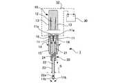
以下、本発明の実施の形態について、添付図面を参照して説明する。図1は、本発明の一実施形態に係る硝子体手術器具の断面図である。図1に示すように、硝子体手術器具1は、本体10および移動体20を備えて構成されている。 Hereinafter, embodiments of the present invention will be described with reference to the accompanying drawings. FIG. 1 is a cross-sectional view of a vitreous surgery instrument according to an embodiment of the present invention. As shown in FIG. 1, the vitreous surgery instrument 1 includes a
本体10は、支持部12と、支持部12の両側に設けられた操作部13,13とを備えており、互いに略平行に延びる一対の線状体11,11の基端側が支持部12に固定されている。線状体11は、通電可能な材料からなり、基端部に端子部11aを有する一方、先端に把持部11bが設けられている。一対の線状体11,11の基端側には絶縁材16が介在されている。 The
線状体11は、全体として可撓性を有しており、把持部11b以外の部分が、銅などの電気抵抗率が低い金属材料から形成されている。把持部11bは、線状体11の他の部分よりも電気抵抗率が高い高抵抗金属材料(例えば、タングステン、コバルト、ニッケル、鉄、白金、クロム、チタンや、これらの合金等)により形成されている。一対の線状体11,11は、通常の状態で把持部11b,11b同士の間に隙間が生じるように、先端側が互いに離隔する方向に湾曲形状となるよう癖付けされている。高抵抗の把持部11bは、例えば、全体が高抵抗の金属材料により形成された線状体11の先端部以外を、低抵抗の金属材料からなるめっき膜等で被覆して形成することもできる。 The
支持部12および操作部13,13は、合成樹脂材料等により一体成形することができ、支持部12に対して操作部13,13の先端側を撓み変形可能に構成されている。操作部13,13の先端側は、両端が回動可能なアーム14,14を介して移動体20に連結されている。支持部12の先端側には受け部15が支持されており、受け部15は、移動体20を移動可能に保持する。 The
移動体20は、ブロック状の基体21に管体22が固定されており、管体22が一対の線状体11,11に外嵌されている。管体22は、合成樹脂パイプ等の電気絶縁性材料からなる直管状の部材であり、一対の線状体11,11の端子部11a,11aと把持部11b,11bとの間で、一対の線状体11,11に沿って移動可能とされている。基体21の先端側には、管体22に外嵌される管状の補強部材23が、基体21に対して移動可能に支持されている。補強部材23は、ばね部材24によって先端方向に付勢される。 In the moving
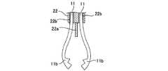
図2は、図1に示す硝子体手術器具1の要部拡大断面図である。図1および図2に示すように、管体22には、軸線を挟むようにして一対の収容路22b,22bが長手方向に形成されており、それぞれの収容路22b,22bに線状体11,11が個別に収容されている。また、管体22の先端面における一対の収容路22b,22bの間には、一対の線状体11,11の間に介在されるように突部22aが設けられている。 FIG. 2 is an enlarged cross-sectional view of a main part of the vitreous surgery instrument 1 shown in FIG. As shown in FIGS. 1 and 2, the
上記の構成を備える硝子体手術器具1は、一対の線状体11,11の端子部11a,11aを、電源30に接続して使用することができる。この硝子体手術器具1をセッシとして使用する場合には、一対の線状体11,11への通電は不要であるため、スイッチ32はオフの状態にしておくことで上述した従来の手術器具50(図4参照)と同様に使用することができる。すなわち、補強部材23の先端を眼の表面Sに当接させて管体22を眼内に挿入し、図3に示すように、操作部13,13を矢示方向に押圧して、管体22を一対の線状体11,11に沿って先端方向に移動させることにより、一対の線状体11,11の把持部11b,11bが互いに近接して閉じた状態になる。こうして、例えば網膜上の増殖膜等の組織を把持して、剥離除去することができる。把持部11b,11bが閉じた状態においては、図4に示すように、線状体11と収容路22bの開口周縁との接触部cが、管体22の中心側に位置することが好ましく、この接触部cから先端側の把持部11bの弾性力を利用して、組織等を確実に把持することができる。操作部13,13の押圧力を緩めると、ばね部材24の付勢力によって管体22は後退し、把持部11b,11bの間を拡げることができる。 The vitreous surgery instrument 1 having the above-described configuration can be used by connecting the
硝子体手術器具1を用いた施術中に止血が必要になった場合には、スイッチ32をオン状態にした後、操作部13,13を押圧して把持部11b,11b同士を接触させる。これにより、把持部11b,11b間が導通して一対の線状体11,11に電流が流れ、主として高抵抗の把持部11b,11bにおいて発熱する。この把持部11b、11bを出血部位に押し当てることにより、組織を凝固させて止血することができる。管体22の先端面には、本実施形態のように、一対の線状体11,11の間に介在される突部22aを設けることが好ましく、操作部13,13を操作しない状態での把持部11b,11b間の導通を確実に防止することができる。止血の終了後は、スイッチ32をオフにして、把持部11b,11bの放熱後に硝子体手術器具1を再びセッシとして使用することができる。 When hemostasis is required during the treatment using the vitreous surgery instrument 1, after the
このように、本実施形態の硝子体手術器具1は、従来のセッシと同様に組織の剥離除去等に使用することができるだけでなく、組織の剥離等に伴い止血が必要になった場合には、管体22を眼内から引き抜くことなく、一対の線状体11,11に通電して把持部11b,11bを発熱させることにより、組織をピンポイントで熱凝固させることができるので、硝子体手術の安全性・作業性を向上させることができる。 Thus, the vitreous surgery instrument 1 of the present embodiment can be used not only for tissue exfoliation and the like as in the case of the conventional setushi, but also when hemostasis is required due to tissue exfoliation or the like. Since the tissue can be thermally coagulated pinpointly by energizing the pair of
以上、本発明の一実施形態について詳述したが、本発明の硝子体手術器具は、必ずしも本実施形態の構成に限定されるものではなく、例えば、補強部材を備えない従来のセッシにも適用可能である。 As mentioned above, although one Embodiment of this invention was explained in full detail, the vitreous surgery instrument of this invention is not necessarily limited to the structure of this embodiment, For example, it applies also to the conventional setushi which is not provided with a reinforcement member. Is possible.
1 硝子体手術器具
10 本体
11 線状体
11a 端子部
11b 把持部
13 操作部
20 移動体
22 管体
22a 突部
22b 収容路DESCRIPTION OF SYMBOLS 1 Vitreous body
Claims (3)
Translated fromJapanese一対の前記線状体に外嵌される管体を有する移動体とを備え、
前記移動体を一対の前記線状体に沿って移動可能に構成された硝子体手術器具であって、
前記線状体は、通電可能な材料からなり、基端側に端子部が設けられ、先端側に高抵抗の把持部が設けられており、
前記管体は、電気絶縁性を有する材料からなり、一対の前記線状体を個別に収容する一対の収容路が形成されており、
前記管体を先端方向に進出させることにより、一対の前記線状体の前記把持部同士が接触する硝子体手術器具。A main body supporting a pair of linear bodies;
A moving body having a tubular body fitted around the pair of linear bodies,
A vitreous surgery instrument configured to be movable along the pair of linear bodies,
The linear body is made of a material that can be energized, a terminal portion is provided on the proximal end side, and a high resistance gripping portion is provided on the distal end side,
The tubular body is made of a material having electrical insulation, and a pair of housing paths for individually housing the pair of linear bodies are formed.
A vitreous surgery instrument in which the gripping portions of the pair of linear bodies come into contact with each other by advancing the tubular body in the distal direction.
Priority Applications (1)
| Application Number | Priority Date | Filing Date | Title |
|---|---|---|---|
| JP2014137602AJP6358697B2 (en) | 2014-07-03 | 2014-07-03 | Vitreous surgery instrument |
Applications Claiming Priority (1)
| Application Number | Priority Date | Filing Date | Title |
|---|---|---|---|
| JP2014137602AJP6358697B2 (en) | 2014-07-03 | 2014-07-03 | Vitreous surgery instrument |
Publications (2)
| Publication Number | Publication Date |
|---|---|
| JP2016013351Atrue JP2016013351A (en) | 2016-01-28 |
| JP6358697B2 JP6358697B2 (en) | 2018-07-18 |
Family
ID=55230078
Family Applications (1)
| Application Number | Title | Priority Date | Filing Date |
|---|---|---|---|
| JP2014137602AActiveJP6358697B2 (en) | 2014-07-03 | 2014-07-03 | Vitreous surgery instrument |
Country Status (1)
| Country | Link |
|---|---|
| JP (1) | JP6358697B2 (en) |
Cited By (4)
| Publication number | Priority date | Publication date | Assignee | Title |
|---|---|---|---|---|
| US11871451B2 (en) | 2018-09-27 | 2024-01-09 | Interdigital Patent Holdings, Inc. | Sub-band operations in unlicensed spectrums of new radio |
| US11877308B2 (en) | 2016-11-03 | 2024-01-16 | Interdigital Patent Holdings, Inc. | Frame structure in NR |
| US12150146B2 (en) | 2016-05-11 | 2024-11-19 | Interdigital Patent Holdings, Inc. | Radio PDCCH to facilitate numerology operations |
| US12231198B2 (en) | 2016-08-11 | 2025-02-18 | Interdigital Patent Holdings, Inc. | Beamforming sweeping and training in a flexible frame structure for new radio |
Citations (4)
| Publication number | Priority date | Publication date | Assignee | Title |
|---|---|---|---|---|
| US4031898A (en)* | 1974-12-03 | 1977-06-28 | Siegfried Hiltebrandt | Surgical instrument for coagulation purposes |
| US20040215132A1 (en)* | 2003-04-22 | 2004-10-28 | Inbae Yoon | Spot coagulating & occluding instrument and method of use |
| JP2005516714A (en)* | 2002-02-13 | 2005-06-09 | アプライド メディカル リソーシーズ コーポレイション | Tissue melting / welding apparatus and method |
| JP2009072221A (en)* | 2007-09-18 | 2009-04-09 | Hoya Corp | Ophthalmic surgical instrument |
- 2014
- 2014-07-03JPJP2014137602Apatent/JP6358697B2/enactiveActive
Patent Citations (4)
| Publication number | Priority date | Publication date | Assignee | Title |
|---|---|---|---|---|
| US4031898A (en)* | 1974-12-03 | 1977-06-28 | Siegfried Hiltebrandt | Surgical instrument for coagulation purposes |
| JP2005516714A (en)* | 2002-02-13 | 2005-06-09 | アプライド メディカル リソーシーズ コーポレイション | Tissue melting / welding apparatus and method |
| US20040215132A1 (en)* | 2003-04-22 | 2004-10-28 | Inbae Yoon | Spot coagulating & occluding instrument and method of use |
| JP2009072221A (en)* | 2007-09-18 | 2009-04-09 | Hoya Corp | Ophthalmic surgical instrument |
Cited By (5)
| Publication number | Priority date | Publication date | Assignee | Title |
|---|---|---|---|---|
| US12150146B2 (en) | 2016-05-11 | 2024-11-19 | Interdigital Patent Holdings, Inc. | Radio PDCCH to facilitate numerology operations |
| US12231198B2 (en) | 2016-08-11 | 2025-02-18 | Interdigital Patent Holdings, Inc. | Beamforming sweeping and training in a flexible frame structure for new radio |
| US11877308B2 (en) | 2016-11-03 | 2024-01-16 | Interdigital Patent Holdings, Inc. | Frame structure in NR |
| US11871451B2 (en) | 2018-09-27 | 2024-01-09 | Interdigital Patent Holdings, Inc. | Sub-band operations in unlicensed spectrums of new radio |
| US12356456B2 (en) | 2018-09-27 | 2025-07-08 | Interdigital Patent Holdings, Inc. | Sub-band operations in unlicensed spectrums of new radio |
Also Published As
| Publication number | Publication date |
|---|---|
| JP6358697B2 (en) | 2018-07-18 |
Similar Documents
| Publication | Publication Date | Title |
|---|---|---|
| US12156672B2 (en) | Surgical apparatus with jaw force limiter | |
| CN102458291B (en) | Surgical tool assemblies used in electrosurgery | |
| US9782218B2 (en) | Thermocoagulation/cutting device | |
| JP4546424B2 (en) | Endoscopic treatment tool | |
| JP6358697B2 (en) | Vitreous surgery instrument | |
| EP3389528B1 (en) | Microsurgical fine gripping and diathermy forceps and diathermy cutting device for intraocular surgery | |
| US9867649B2 (en) | Electrosurgical gripping instrument | |
| CN107920852B (en) | Medical device | |
| US11452560B2 (en) | Treatment tool with jaws | |
| EP3131474A1 (en) | Surgical operating apparatus with temperature control | |
| JP2017524389A5 (en) | ||
| JP5290658B2 (en) | Endoscopic treatment tool | |
| CN101584904B (en) | catheter handle | |
| EP3106112A1 (en) | Treatment instrument | |
| JP6125133B1 (en) | Treatment tool | |
| CN106999224A (en) | therapeutic disposal device | |
| JP2003144451A (en) | Operation instrument | |
| JP2007282847A (en) | Flexible bipolar forceps | |
| JP6841029B2 (en) | Medical high frequency treatment tool | |
| JP4880251B2 (en) | High frequency treatment tool | |
| JP2008126031A (en) | Endoscopic high-frequency treatment instrument for endoscope | |
| JP5372094B2 (en) | High frequency treatment tool | |
| JP5699013B2 (en) | Bipolar treatment tool | |
| JP2009022623A (en) | Bipolar high-frequency treating instrument for endoscope | |
| JP2007319679A (en) | High-frequency incision instrument for endoscope |
Legal Events
| Date | Code | Title | Description |
|---|---|---|---|
| A711 | Notification of change in applicant | Free format text:JAPANESE INTERMEDIATE CODE: A711 Effective date:20170628 | |
| RD03 | Notification of appointment of power of attorney | Free format text:JAPANESE INTERMEDIATE CODE: A7423 Effective date:20170628 | |
| A621 | Written request for application examination | Free format text:JAPANESE INTERMEDIATE CODE: A621 Effective date:20170629 | |
| A521 | Request for written amendment filed | Free format text:JAPANESE INTERMEDIATE CODE: A821 Effective date:20170628 | |
| A131 | Notification of reasons for refusal | Free format text:JAPANESE INTERMEDIATE CODE: A131 Effective date:20180315 | |
| A521 | Request for written amendment filed | Free format text:JAPANESE INTERMEDIATE CODE: A523 Effective date:20180514 | |
| TRDD | Decision of grant or rejection written | ||
| A01 | Written decision to grant a patent or to grant a registration (utility model) | Free format text:JAPANESE INTERMEDIATE CODE: A01 Effective date:20180524 | |
| A61 | First payment of annual fees (during grant procedure) | Free format text:JAPANESE INTERMEDIATE CODE: A61 Effective date:20180615 | |
| R150 | Certificate of patent or registration of utility model | Ref document number:6358697 Country of ref document:JP Free format text:JAPANESE INTERMEDIATE CODE: R150 |