JP2016007892A - Vehicle airbag device - Google Patents
Vehicle airbag deviceDownload PDFInfo
- Publication number
- JP2016007892A JP2016007892AJP2014128433AJP2014128433AJP2016007892AJP 2016007892 AJP2016007892 AJP 2016007892AJP 2014128433 AJP2014128433 AJP 2014128433AJP 2014128433 AJP2014128433 AJP 2014128433AJP 2016007892 AJP2016007892 AJP 2016007892A
- Authority
- JP
- Japan
- Prior art keywords
- airbag
- center
- vehicle
- width direction
- vehicle width
- Prior art date
- Legal status (The legal status is an assumption and is not a legal conclusion. Google has not performed a legal analysis and makes no representation as to the accuracy of the status listed.)
- Granted
Links
Images


Classifications
- B—PERFORMING OPERATIONS; TRANSPORTING
- B60—VEHICLES IN GENERAL
- B60R—VEHICLES, VEHICLE FITTINGS, OR VEHICLE PARTS, NOT OTHERWISE PROVIDED FOR
- B60R21/00—Arrangements or fittings on vehicles for protecting or preventing injuries to occupants or pedestrians in case of accidents or other traffic risks
- B60R21/02—Occupant safety arrangements or fittings, e.g. crash pads
- B60R21/16—Inflatable occupant restraints or confinements designed to inflate upon impact or impending impact, e.g. air bags
- B60R21/20—Arrangements for storing inflatable members in their non-use or deflated condition; Arrangement or mounting of air bag modules or components
- B60R21/205—Arrangements for storing inflatable members in their non-use or deflated condition; Arrangement or mounting of air bag modules or components in dashboards
- B—PERFORMING OPERATIONS; TRANSPORTING
- B60—VEHICLES IN GENERAL
- B60R—VEHICLES, VEHICLE FITTINGS, OR VEHICLE PARTS, NOT OTHERWISE PROVIDED FOR
- B60R21/00—Arrangements or fittings on vehicles for protecting or preventing injuries to occupants or pedestrians in case of accidents or other traffic risks
- B60R21/02—Occupant safety arrangements or fittings, e.g. crash pads
- B60R21/16—Inflatable occupant restraints or confinements designed to inflate upon impact or impending impact, e.g. air bags
- B60R21/23—Inflatable members
- B60R21/231—Inflatable members characterised by their shape, construction or spatial configuration
- B60R2021/23107—Inflatable members characterised by their shape, construction or spatial configuration the bag being integrated in a multi-bag system
- B—PERFORMING OPERATIONS; TRANSPORTING
- B60—VEHICLES IN GENERAL
- B60R—VEHICLES, VEHICLE FITTINGS, OR VEHICLE PARTS, NOT OTHERWISE PROVIDED FOR
- B60R21/00—Arrangements or fittings on vehicles for protecting or preventing injuries to occupants or pedestrians in case of accidents or other traffic risks
- B60R21/02—Occupant safety arrangements or fittings, e.g. crash pads
- B60R21/16—Inflatable occupant restraints or confinements designed to inflate upon impact or impending impact, e.g. air bags
- B60R21/23—Inflatable members
- B60R21/231—Inflatable members characterised by their shape, construction or spatial configuration
- B60R2021/23161—Inflatable members characterised by their shape, construction or spatial configuration specially adapted for protecting at least two passengers, e.g. preventing them from hitting each other
Landscapes
- Engineering & Computer Science (AREA)
- Mechanical Engineering (AREA)
- Air Bags (AREA)
Abstract
Description
Translated fromJapanese本発明は、車両用エアバッグ装置に関する。 The present invention relates to a vehicle airbag device.
下記特許文献1に記載された車両用エアバッグ装置では、エアバッグが一対の膨出部を有しており、一対の膨出部における乗員の頭部又は肩部に対応する高さ部位から車両後側へ向けて一対の延長部が延長されている。これにより、車両の斜め衝突(以下、斜突という)時に、斜め前方側へ移動する助手席の乗員を拘束することができる。なお、車両用エアバッグ装置として、他に下記特許文献2〜特許文献4に記載されたものがある。 In the vehicle airbag device described in Patent Document 1 below, the airbag has a pair of bulging portions, and the vehicle is moved from a height portion corresponding to the head or shoulder of the occupant in the pair of bulging portions. A pair of extensions are extended toward the rear side. Thereby, it is possible to restrain the passenger in the passenger seat that moves diagonally forward in the event of an oblique collision of the vehicle (hereinafter referred to as an oblique collision). In addition, there exist some which were described in following patent document 2-patent document 4 as a vehicle airbag apparatus.
ところで、車両の斜突時に斜め前方側へ移動する乗員に対する拘束性を向上するために、乗員に対して車幅方向中央側に配置される第2バッグをエアバッグに設けることが考えられる。 By the way, in order to improve the restraint property with respect to the passenger | crew who moves diagonally forward at the time of the vehicle's oblique collision, it is possible to provide the airbag with the 2nd bag arrange | positioned with respect to a passenger | crew in the vehicle width direction center side.
しかしながら、例えば、インストルメントパネルの車幅方向中央部にディスプレイ等の内装部品が設置された場合には、第2バッグの膨張展開が内装部品によって阻害されて、第2バッグの膨張展開性が悪化する可能性がある。また、このとき、当該内装部品が破損する虞がある。一方、当該内装部品を避けるような形状に第2バッグの先端部を設定すると、車両後側からの荷重に対する第2バッグの支持が不十分になり、第2バッグにおいて車両の斜突時に乗員に対する十分な反力を作用させることができなくなる。これにより、乗員に対する拘束性が低くなる。 However, for example, when an interior part such as a display is installed in the center of the instrument panel in the vehicle width direction, the expansion and deployment of the second bag is hindered by the interior part, and the expansion and deployment of the second bag is deteriorated. there's a possibility that. At this time, the interior part may be damaged. On the other hand, if the tip of the second bag is set to a shape that avoids the interior parts, the support of the second bag with respect to the load from the rear side of the vehicle becomes insufficient, and the second bag does not support the occupant when the vehicle leans. Sufficient reaction force cannot be applied. Thereby, the restraint property with respect to a passenger | crew becomes low.
本発明は、上記事実を考慮し、車幅方向中央側に配置される第2バッグの膨張展開が内装部品によって阻害されることを抑制又は防止しつつ乗員に対する拘束性を向上できる車両用エアバッグ装置を提供することを目的とする。 In consideration of the above-described facts, the present invention provides a vehicle airbag that can improve restraint on an occupant while suppressing or preventing the expansion and deployment of a second bag disposed on the center side in the vehicle width direction from being hindered by interior parts. An object is to provide an apparatus.
請求項1に記載の車両用エアバッグ装置は、インストルメントパネルの裏側に設けられ、インフレータからのガスの供給を受けて前記インストルメントパネルの表側へ膨張展開されると共に、乗員の車両前側で膨張展開される第1バッグ及び前記第1バッグに対して車幅方向中央側で膨張展開される第2バッグを有するエアバッグと、膨張展開された前記第2バッグの下面に形成され、車両下側へ開放されると共に、前記インストルメントパネルの車幅方向中央部に配設された内装部品を車両上側から覆う窪み部と、を備えている。 The vehicle airbag device according to claim 1 is provided on the back side of the instrument panel, is inflated and deployed to the front side of the instrument panel upon receiving gas supply from the inflator, and is inflated on the front side of the occupant's vehicle. An airbag having a first bag that is deployed and a second bag that is inflated and deployed on the center side in the vehicle width direction with respect to the first bag, and a lower side of the vehicle formed on a lower surface of the inflated and deployed second bag. And a hollow portion that covers an interior part disposed in the vehicle width direction center portion of the instrument panel from the vehicle upper side.
請求項1に記載の車両用エアバッグ装置では、インストルメントパネルの裏側にエアバッグが設けられており、エアバッグは、インフレータからのガスの供給を受けて、インストルメントパネルの表側へ膨張展開される。具体的には、エアバッグの第1バッグが乗員の車両前側で膨張展開されて、エアバッグの第2バッグが第1バッグに対して車幅方向中央側で膨張展開される。このため、車両の斜突時に車幅方向中央側斜め前方への移動しようとする乗員が第2バッグによって拘束される。これにより、乗員に対する拘束性を向上することができる。 In the vehicle airbag device according to claim 1, the airbag is provided on the back side of the instrument panel, and the airbag is inflated and deployed to the front side of the instrument panel in response to the supply of gas from the inflator. The Specifically, the first bag of the airbag is inflated and deployed on the front side of the occupant's vehicle, and the second bag of the airbag is inflated and deployed on the center side in the vehicle width direction with respect to the first bag. For this reason, the passenger | crew who tries to move to the vehicle width direction center side diagonally forward at the time of a vehicle oblique collision is restrained by the 2nd bag. Thereby, the restraint property with respect to a passenger | crew can be improved.
ここで、膨張展開された第2バッグの下面には、車両下側へ開放された窪み部が形成されており、インストルメントパネルの車幅方向中央部に配設された内装部品が窪み部によって車両上側から覆われる。すなわち、第2バッグの窪み部が内装部品を車両上側から覆うようにエアバッグが膨張展開される。このため、第2バッグの膨張展開が内装部品によって阻害されることを抑制又は防止することができる。また、第2バッグの膨張展開後において、第2バッグによって内装部品を車両前後方向に挟み込むようにすることができる。これにより、第2バッグの前端部が内装部品によって支持されるため、第2バッグにおいて車両の斜突時に乗員に対する反力を作用させることができる。 Here, the lower surface of the inflated and deployed second bag is formed with a recessed portion that is opened to the lower side of the vehicle, and the interior part disposed at the center in the vehicle width direction of the instrument panel is formed by the recessed portion. Covered from the top of the vehicle. That is, the airbag is inflated and deployed so that the hollow portion of the second bag covers the interior part from the upper side of the vehicle. For this reason, it can suppress or prevent that the expansion | deployment deployment of a 2nd bag is inhibited by interior components. Further, after the second bag is inflated and deployed, the interior part can be sandwiched between the second bag in the vehicle front-rear direction. Thereby, since the front-end part of a 2nd bag is supported by interior components, the reaction force with respect to a passenger | crew can be made to act on the 2nd bag at the time of an oblique collision of a vehicle.
以上により、本発明の車両用エアバッグ装置によれば、車幅方向中央側に配置される第2バッグの膨張展開が内装部品によって阻害されることを抑制又は防止しつつ乗員に対する拘束性を向上できる。 As described above, according to the vehicle airbag device of the present invention, the restraint to the occupant is improved while suppressing or preventing the expansion and deployment of the second bag disposed on the center side in the vehicle width direction from being hindered by the interior parts. it can.
以下、図面を用いて本実施の形態に係る車両用エアバッグ装置30について説明する。なお、各図に適宜示す矢印FR、矢印UP、矢印LHは、それぞれ車両用エアバッグ装置30が適用された自動車Vの前側、上側、車幅方向の一方側である左側を示している。以下、単に前後、上下、左右の方向を用いて説明する場合は、特に断りのない限り、車両前後方向の前後、車両上下方向の上下、車両(前方を向いた場合)の左右を示すものとする。 Hereinafter, the
(自動車V内部の概略構成について)
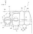
図1には、車両用エアバッグ装置30が適用された自動車VにおけるキャビンC内の前部を含む一部が模式的な平面図にて示されている。なお、図1では、後述する車両用エアバッグ装置30のエアバッグ34が膨張展開された状態が示されている。この図に示されるように、キャビンC内には、左右一対の車両用シート10が車幅方向に並んで配置されている。この車両用シート10は、座部として機能するシートクッション12と、背凭れ部として機能するシートバック14と、を含んで構成されており、シートバック14の下端部がシートクッション12の後端部に連結されている。(About the schematic configuration inside the automobile V)
FIG. 1 is a schematic plan view showing a part including a front portion in a cabin C in an automobile V to which the
そして、本実施形態では、左側に配置された車両用シート10が運転席10Dとされ、右側に配置された車両用シート10が助手席10Pとされている。また、運転席10Dと助手席10Pとの間にはセンタコンソール16が配置されている。すなわち、本実施形態の自動車Vは、運転席10Dと助手席10Pとの間に中央座席が配置されない構成となっている。なお、自動車Vを、センタコンソール16を備えない構成(例えば、左右の車両用シート10間を通路とし得る構成)にしてもよい。 In the present embodiment, the
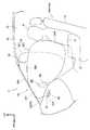
また、図2にも示されるように、運転席10D及び助手席10Pの前側には、車幅方向に延びるインストルメントパネル18が設けられており、インストルメントパネル18の車幅方向中央部には、センタパネル20(図1参照)が設けられている。そして、前述したセンタコンソール16の前端がインストルメントパネル18の車幅方向中央部分に繋がっている。また、インストルメントパネル18における車幅方向の運転席10D側部分には、ステアリングホイール22が配置されている。ステアリングホイール22は、ステアリングコラム24を介して支持されて、インストルメントパネル18に対して後側(運転席10D側)に配置されている。 Further, as shown in FIG. 2, an
さらに、運転席10D及び助手席10Pには、乗員拘束用のシートベルト装置(図示省略)がそれぞれ設けられており、シートベルト装置は所謂3点式シートベルト装置とされている。このため、運転席10Dの乗員D(以下、「運転者D」という)及び助手席10Pの乗員P(以下、「助手席乗員P」という)の腰部がラップベルトによって拘束されると共に、運転者D及び助手席乗員Pの上体がショルダベルトによって拘束されるようになっている。 Further, the driver's
また、図2及び図3に示されるように、キャビンC内における車両用シート10の前方でかつ上部には、ルームミラー26が設けられている。ルームミラー26は、ウインドシールドガラスWS上部又はルーフRF前端における車幅方向中央部に配置されている。さらに、図1〜図3に示されるように、センタパネル20には、「内装部品」としてのディスプレイ28(表示装置)が配設されている。ディスプレイ28は、略矩形偏平状に形成されて、センタパネル20から上側へ突出されると共に、表示面を後側にして配置されている。 As shown in FIGS. 2 and 3, a
(車両用エアバッグ装置30について)
図1に示されるように、車両用エアバッグ装置30は、上側へ開放された略矩形箱状のモジュールケース32(広義には「ケース」として把握される要素である)と、モジュールケース32内に折畳まれた状態で収納されたエアバッグ34と、ガスを噴出してエアバッグ34に供給する左右一対のインフレータ42(ガス発生装置)と、を含んで構成されている。車両用エアバッグ装置30は助手席10Pの前側のインストルメントパネル18内(裏側)に配置されており、車両用エアバッグ装置30(モジュールケース32)の車幅方向中心線CLが、助手席10Pのシート幅方向中心線(図示省略)に略一致する位置に設定されている。また、車両用エアバッグ装置30は、インストルメントパネル18内において車幅方向に延在されたインストルメントパネルリインフォース(図示省略)等に支持されている。そして、インストルメントパネル18には、モジュールケース32を覆う部位において、エアバッグドアが形成されている。(Vehicle airbag device 30)
As shown in FIG. 1, the
(エアバッグ34について)
図2にも示されるように、エアバッグ34は、一例として複数の基布の外周部を縫製することにより袋状に構成されている。また、エアバッグ34の膨張展開状態では、エアバッグ34は、助手席乗員Pの前側で膨張される「第1バッグ」としての助手席エアバッグ36と、助手席エアバッグ36に連通され且つ助手席エアバッグ36に対して車幅方向中央側に隣接し前後方向に膨張される「第2バッグ」としてのセンタエアバッグ38と、を備えている。(About airbag 34)
As shown in FIG. 2, the
助手席エアバッグ36は、左バッグ部36Lと右バッグ部36Rとを含んで構成されて、平面視で略左右対称を成す形状に膨張展開されるようになっている。また、左バッグ部36Lと右バッグ部36Rとの境界線(すなわち助手席エアバッグ36の車幅方向中心線)は、車両用エアバッグ装置30の車幅方向中心線CLに略一致する構成とされている。さらに、助手席エアバッグ36の膨張展開状態では、左バッグ部36Lの後端が助手席乗員Pの左肩の前側に位置し、右バッグ部36Rの後端が助手席乗員Pの右肩の前側に位置するようになっている。また、左バッグ部36L及び右バッグ部36Rの後端間に形成される凹部36Nは、助手席乗員Pの頭部の前側に位置するようになっている。 The
センタエアバッグ38は、前述したように、助手席エアバッグ36に対して車幅方向中央側に隣接し前後方向に膨張展開されるようになっている。詳しくは、センタエアバッグ38が、後述する左右一対のインフレータ42に対して車幅方向中央側へオフセットして、センタコンソール16の上側で膨張展開されるようになっている。これにより、エアバッグ34が、車幅方向中央側へ拡大されて、平面視で左右非対称を成す形状に膨張展開されるようになっている。 As described above, the
また、センタエアバッグ38の膨張展開状態では、センタエアバッグ38の前端部38Fが、インストルメントパネル18のセンタパネル20とウインドシールドガラスWSとの間に配置されるようになっている(図3参照)。一方、センタエアバッグ38の後端38Rは、前後方向において、助手席エアバッグ36の後端よりも後側に位置している。すなわち、センタエアバッグ38の後端部が、平面視で助手席エアバッグ36に対して後側へ突出されて、助手席乗員Pの左斜め前側に位置するようになっている。これにより、センタエアバッグ38の前後方向の長さが助手席エアバッグ36の前後方向の長さに比べて長く設定されている。 In the inflated and deployed state of the
また、図1に示されるように、センタエアバッグ38の前端部38Fには、運転席10D側に張り出す張出部38Pが形成されている。さらに、図3に示されるように、センタエアバッグ38の上端38Uは、助手席エアバッグ36の上端36Uよりも低く設定されている。具体的には、センタエアバッグ38は、ルームミラー26に干渉しない構成とされている。 Further, as shown in FIG. 1, the
また、図1〜図3に示されるように、センタエアバッグ38の前端部38Fには、下面において、窪み部40が形成されている。この窪み部40は、下側へ開放されたポケット状を成すと共に、略楕円錐状に形成されている。また、窪み部40は、センタパネル20上に配設されたディスプレイ28に対応する位置に形成されて、ディスプレイ28を上側から覆っている。すなわち、センタエアバッグ38の膨張展開時では、窪み部40がディスプレイ28を上側から覆うようにセンタエアバッグ38が膨張展開されるように構成されている。また、センタエアバッグ38の膨張展開後では、センタエアバッグ38が、窪み部40の部位において、ディスプレイ28を前後方向に挟み込む構成にされている。 As shown in FIGS. 1 to 3, a
(インフレータ42について)
図1に示されるように、左右一対のインフレータ42は、エアバッグ34(詳しくは、助手席エアバッグ36)の前端部に内蔵されて、車幅方向に並んで配置されている。具体的には、一対のインフレータ42が、平面視で車両用エアバッグ装置30の車幅方向中心線CLに対して左右対称の位置に配置されて、ディスプレイ28に対して前側に配置されている。このインフレータ42は、金属製とされると共に、中空の略円柱状に形成されて、上下方向を軸方向にして配置されている。また、インフレータ42の外周部には、上下方向中間部において、図示しない取付フランジが設けられている。そして、図3に示されるように、インフレータ42が、モジュールケース32の底壁32Aに形成された取付孔(図示省略)内に挿入されて、取付フランジがボルト等の締結部材(図示省略)によって底壁32Aに固定されている。これにより、インフレータ42の上部がモジュールケース32の底壁32Aに対して上側へ突出されており、一対のインフレータ42の下部がモジュールケース32対して下側へ突出されている。(About the inflator 42)
As shown in FIG. 1, the pair of left and
図1に示されるように、インフレータ42はエアバッグECU50(制御装置)に電気的に接続されている。そして、エアバッグECU50によってインフレータ42が作動すると、インフレータ42の上部から噴出されるガスがエアバッグ34へ供給されて、エアバッグ34が膨張展開されるようになっている。また、エアバッグ34の膨張展開に伴ってエアバッグ34がエアバッグドア(インストルメントパネル18)を開裂させて、エアバッグ34がインストルメントパネル18の外側(表側)で膨張展開されるようになっている。以下、エアバッグECU50について説明する。 As shown in FIG. 1, the
エアバッグECU50は、衝突センサ(又はセンサ群)52に電気的に接続されると共に、前述した一対のインフレータ42に電気的に接続されている。このエアバッグECU50は、衝突センサ52からの情報に基づいて、適用された自動車Vに対する各種前面衝突(の発生又は不可避であること)を区別することなく(又は衝突形態毎に)検知又は予測可能とされている。エアバッグECU50は、衝突センサ52からの情報に基づいて前面衝突を検知又は予測すると、一対のインフレータ42を同時に作動させるようになっている。なお、エアバッグECU50が一対のインフレータ42を作動させる前面衝突の形態には、斜め衝突及び微小ラップ衝突等の車幅方向一方側にオフセットした位置への前面衝突が含まれる。 The
ここで、斜め衝突(MDB斜突、オブリーク衝突)とは、例えばNHSTAにて規定される斜め前方(一例として、衝突相手方との相対角15°、車幅方向のラップ量35%程度の衝突)とされる。この実施形態では、一例として相対速度90km/hrでの斜め衝突が想定されている。また、微小ラップ衝突とは、自動車Vの前面衝突のうち、例えばIIHSにて規定される衝突相手方との車幅方向のラップ量が25%以下の衝突とされる。例えば車体骨格であるフロントサイドメンバに対する車幅方向外側への衝突が微小ラップ衝突に該当する。この実施形態では、一例として相対速度64km/hrでの微小ラップ衝突が想定されている。 Here, the oblique collision (MDB oblique collision, oblique collision) is, for example, an oblique forward defined by NHSTA (for example, a collision with a relative angle of 15 ° with the collision partner and a lap amount of about 35% in the vehicle width direction). It is said. In this embodiment, an oblique collision at a relative speed of 90 km / hr is assumed as an example. Further, the micro lap collision is a collision in which the lap amount in the vehicle width direction with the collision partner prescribed by IIHS is 25% or less among the front collision of the automobile V. For example, a collision to the outside in the vehicle width direction with respect to a front side member that is a vehicle body skeleton corresponds to a minute lap collision. In this embodiment, a minute lap collision at a relative speed of 64 km / hr is assumed as an example.
一方、自動車Vは運転席エアバッグ装置60を備えており、運転席エアバッグ装置60は、ステアリングホイール22の中心部でステアリングコラム24の後端部内に設けられている。この運転席エアバッグ装置60は、運転席エアバッグ62と、ガスを噴出して運転席エアバッグ62に供給する図示しないインフレータ(ガス発生装置)と、を含んで構成されている。また、運転席エアバッグ装置60のインフレータはエアバッグECU50に電気的に接続されており、エアバッグECU50によって当該インフレータが作動すると、ステアリングホイール22に対して運転席10D側において運転席エアバッグ62が膨張展開されるようになっている。また、このとき、運転席エアバッグ62とエアバッグ34のセンタエアバッグ38とは、車幅方向において干渉しないように構成されている。 On the other hand, the automobile V includes a
次に、本実施形態の作用及び効果について説明する。 Next, the operation and effect of this embodiment will be described.
エアバッグECU50が、衝突センサ52からの信号に基づいて自動車Vへの前面衝突を検知又は予測すると、一対のインフレータ42及び運転席エアバッグ装置60のインフレータを作動させる。これにより、一対のインフレータ42からガスの供給を受けたエアバッグ34が、インストルメントパネル18に設定されたエアバッグドアを開裂しつつ膨張展開される。そして、エアバッグ34の助手席エアバッグ36が助手席乗員Pの前側で膨張展開されると共に、エアバッグ34のセンタエアバッグ38が助手席エアバッグ36に対して車幅方向中央側で膨張展開される。一方、運転席エアバッグ装置60のインフレータが作動すると、運転席エアバッグ62が運転者Dの前側で膨張展開される。 When the
(運転席側への斜め衝突又は微小ラップ衝突)
自動車Vへの前面衝突が運転席10D側(左側)への斜め衝突又は微小ラップ衝突であった場合、助手席乗員Pは、図1に矢印Aにて示すように、前方へ移動しつつ、車体に対し車幅方向の衝突側である左側へ移動する。すなわち、助手席乗員Pが左斜め前方へ移動する(図1の2点鎖線で示された助手席乗員Pを参照)。なお、助手席乗員Pには3点式シートベルト装置が装着されているため、助手席乗員Pの前方への移動は、腰部を中心に前傾する形態となる。(An oblique collision or micro lap collision on the driver's seat side)
When the frontal collision to the vehicle V is an oblique collision or a minute lap collision to the driver's
そして、左斜め前方へ移動する助手席乗員Pが助手席エアバッグ36及びセンタエアバッグ38に衝突する。このとき、助手席乗員Pの上半身が助手席エアバッグ36及びセンタエアバッグ38によって支持されて、助手席乗員Pの移動が制限される。その結果、斜め衝突又は微小ラップ衝突時において、左斜め前方へ移動する助手席乗員Pを助手席エアバッグ36及びセンタエアバッグ38によって拘束することができる。 Then, the passenger seat occupant P moving diagonally leftward collides with the
(助手席側への斜め衝突又は微小ラップ衝突)
自動車Vへの前面衝突が助手席10P側(右側)への斜め衝突又は微小ラップ衝突であった場合、運転者Dは、図1に矢印Bにて示すように、前方へ移動しつつ、車体に対し車幅方向の衝突側である右側へ移動する。すなわち、運転者Dが右斜め前方へ移動する。このとき、上記と同様に、運転者Dには3点式シートベルト装置が装着されているため、運転者Dの前方への移動は、腰部を中心に前傾する形態となる。(An oblique collision or small lap collision on the passenger side)
When the frontal collision to the vehicle V is an oblique collision or a minute lap collision to the
そして、右斜め前方へ移動する運転者Dが運転席エアバッグ62及びセンタエアバッグ38に衝突する。このとき、運転者Dの上半身が運転席エアバッグ62及びセンタエアバッグ38によって支持されて、運転者Dの移動が制限される。その結果、斜め衝突又は微小ラップ衝突時において、右斜め前方へ移動する運転者Dを運転席エアバッグ62及びセンタエアバッグ38によって拘束することができる。 Then, the driver D moving diagonally forward to the right collides with the driver's
一方、自動車Vでは、インストルメントパネル18の車幅方向中央部において、ディスプレイ28が配設されており、ディスプレイ28はセンタパネル20から上側へ突出されている。このため、エアバッグ34の膨張展開時において、センタエアバッグ38の膨張展開がディスプレイ28によって阻害される虞がある。 On the other hand, in the automobile V, a
ここで、膨張展開されたセンタエアバッグ38の前端部38Fにおける下面には、下側へ開放されたポケット状の窪み部40が形成されており、ディスプレイ28が窪み部40によって上側から覆われる。すなわち、センタエアバッグ38の窪み部40がディスプレイ28を上側から覆うようにセンタエアバッグ38(エアバッグ34)が膨張展開される。このため、センタエアバッグ38(エアバッグ34)の膨張展開がディスプレイ28によって阻害されることを抑制又は防止することができる。これにより、インストルメントパネル18の車幅方向中央部にディスプレイ28を配設した場合でも、センタエアバッグ38(エアバッグ34)の膨張展開性の悪化を抑制しつつセンタエアバッグ38を車幅方向中央側に配置することができる。また、センタエアバッグ38の窪み部40がディスプレイ28を上側から覆うようにエアバッグ34が膨張展開されるため、センタエアバッグ38の膨張展開時におけるディスプレイ28の破損や飛散を抑制又は防止することができる。 Here, a pocket-
また、センタエアバッグ38の膨張展開後では、センタエアバッグ38が窪み部40の部位においてディスプレイ28を前後方向に挟み込んでいる。このため、後側からの荷重に対してセンタエアバッグ38の前端部38Fがディスプレイ28、インストルメントパネル18、ウインドシールドガラスWSによって支持される。これにより、自動車Vの斜突時にセンタエアバッグ38に衝突する助手席乗員P又は運転者Dに対して、センタエアバッグ38から十分な反力を作用させることができる。したがって、インストルメントパネル18の車幅方向中央部にディスプレイ28が配設された自動車Vに対して、自動車Vの斜突時に助手席乗員P又は運転者Dをセンタエアバッグ38によって良好に拘束することができる。以上により、車幅方向中央側に配置されるセンタエアバッグ38の膨張展開がディスプレイ28によって阻害されることを抑制又は防止しつつ助手席乗員P又は運転者Dに対する拘束性を向上できる。 In addition, after the
(変形例)
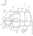
本実施の形態では、センタエアバッグ38の下面に形成された窪み部40が下側へ開放された略楕円錐状に形成されているが、窪み部40の形状はこれに限らない。例えば、図4及び図5に示されるように、窪み部40を車幅方向外側へ延ばして、窪み部40の車幅方向外側部分をインストルメントパネル18のエアバッグドアに近接して配置してもよい。これにより、窪み部40の開口部が車幅方向外側へ拡大されるため、センタエアバッグ38の膨張展開時に窪み部40がディスプレイ28を上側から良好に覆うことができる。これにより、センタエアバッグ38の膨張展開性を向上することができる。(Modification)
In the present embodiment, the
なお、本実施の形態及び上記変形例では、一対のインフレータ42がエアバッグECU50によって同時に作動するように構成されているが、エアバッグ34の膨張展開性を考慮して、一対のインフレータ42の作動時間をずらすように構成してもよい。例えば、車幅方向中央側に配置されたインフレータ42の作動後に、車幅方向外側に配置されたインフレータ42を作動させてもよい。 In the present embodiment and the above modification, the pair of
また、本実施の形態及び上記変形例では、エアバッグ34において助手席エアバッグ36及びセンタエアバッグ38が一体の袋状に形成されている。これに代えて、助手席エアバッグ36とセンタエアバッグ38とを別体の袋状に形成して、両者を縫製等によって一体化してもよい。この場合には、助手席エアバッグ36とセンタエアバッグ38とが、少なくとも前端部において連通する構成にされる。 Further, in the present embodiment and the above modification, the
18 インストルメントパネル
28 ディスプレイ(内装部品)
30 車両用エアバッグ装置
34 エアバッグ
36 助手席エアバッグ(第1バッグ)
38 センタエアバッグ(第2バッグ)
40 窪み部18
30 Airbag Device for
38 Center airbag (second bag)
40 indentation
Claims (1)
Translated fromJapanese膨張展開された前記第2バッグの下面に形成され、車両下側へ開放されると共に、前記インストルメントパネルの車幅方向中央部に配設された内装部品を車両上側から覆う窪み部と、
を備えた車両用エアバッグ装置。A first bag provided on the back side of the instrument panel, inflated to the front side of the instrument panel upon receiving gas supply from the inflator, and inflated and deployed on the front side of the occupant's vehicle An airbag having a second bag inflated and deployed on the center side in the vehicle width direction,
A recess formed on the lower surface of the inflated and deployed second bag and opened to the lower side of the vehicle and covering an interior part disposed in the vehicle width direction center of the instrument panel from the upper side of the vehicle,
A vehicle airbag device comprising:
Priority Applications (2)
| Application Number | Priority Date | Filing Date | Title |
|---|---|---|---|
| JP2014128433AJP6299477B2 (en) | 2014-06-23 | 2014-06-23 | Airbag device for vehicle |
| US14/743,290US9421935B2 (en) | 2014-06-23 | 2015-06-18 | Vehicle airbag device |
Applications Claiming Priority (1)
| Application Number | Priority Date | Filing Date | Title |
|---|---|---|---|
| JP2014128433AJP6299477B2 (en) | 2014-06-23 | 2014-06-23 | Airbag device for vehicle |
Publications (2)
| Publication Number | Publication Date |
|---|---|
| JP2016007892Atrue JP2016007892A (en) | 2016-01-18 |
| JP6299477B2 JP6299477B2 (en) | 2018-03-28 |
Family
ID=54868929
Family Applications (1)
| Application Number | Title | Priority Date | Filing Date |
|---|---|---|---|
| JP2014128433AActiveJP6299477B2 (en) | 2014-06-23 | 2014-06-23 | Airbag device for vehicle |
Country Status (2)
| Country | Link |
|---|---|
| US (1) | US9421935B2 (en) |
| JP (1) | JP6299477B2 (en) |
Cited By (10)
| Publication number | Priority date | Publication date | Assignee | Title |
|---|---|---|---|---|
| JP2016016716A (en)* | 2014-07-07 | 2016-02-01 | トヨタ自動車株式会社 | Airbag device for vehicle |
| JP2017024478A (en)* | 2015-07-17 | 2017-02-02 | トヨタ自動車株式会社 | Airbag device for vehicle |
| JPWO2015162943A1 (en)* | 2014-04-25 | 2017-04-13 | オートリブ ディベロップメント エービー | Airbag device |
| JP2018127057A (en)* | 2017-02-07 | 2018-08-16 | トヨタ自動車株式会社 | Air bag device for front passenger seat |
| JP2019077229A (en)* | 2017-10-20 | 2019-05-23 | 本田技研工業株式会社 | Air bag device |
| JP2019077225A (en)* | 2017-10-20 | 2019-05-23 | オートリブ ディベロップメント エービー | Air bag device |
| US10328884B2 (en) | 2015-12-04 | 2019-06-25 | Toyota Jidosha Kabushiki Kaisha | Airbag device for front passenger seat |
| US10363895B2 (en) | 2016-12-07 | 2019-07-30 | Toyoda Gosei Co., Ltd. | Airbag device for a front passenger seat |
| JP2019127102A (en)* | 2018-01-23 | 2019-08-01 | トヨタ自動車株式会社 | Vehicle display device mounting structure |
| WO2024122216A1 (en)* | 2022-12-05 | 2024-06-13 | オートリブ ディベロップメント エービー | Occupant restraint apparatus |
Families Citing this family (37)
| Publication number | Priority date | Publication date | Assignee | Title |
|---|---|---|---|---|
| JP5942969B2 (en)* | 2013-12-12 | 2016-06-29 | トヨタ自動車株式会社 | Front seat airbag system |
| JP6107757B2 (en)* | 2014-07-11 | 2017-04-05 | トヨタ自動車株式会社 | Passenger airbag device |
| JP6263627B2 (en)* | 2014-08-04 | 2018-01-17 | オートリブ ディベロップメント エービー | Airbag device |
| JP2016040155A (en)* | 2014-08-12 | 2016-03-24 | 豊田合成株式会社 | Airbag device for front passenger seat |
| JP6398667B2 (en)* | 2014-12-03 | 2018-10-03 | 豊田合成株式会社 | Airbag device for passenger seat |
| JP6331146B2 (en)* | 2014-12-05 | 2018-05-30 | 本田技研工業株式会社 | Airbag device |
| EP3251900B1 (en)* | 2015-01-29 | 2019-07-17 | Autoliv Development AB | Air bag device |
| JPWO2016147683A1 (en)* | 2015-03-19 | 2017-11-02 | オートリブ ディベロップメント エービー | Airbag device |
| JP6350367B2 (en)* | 2015-04-09 | 2018-07-04 | トヨタ自動車株式会社 | Vehicle airbag system |
| KR102508056B1 (en)* | 2015-08-13 | 2023-03-09 | 현대모비스 주식회사 | Airbag apparatus |
| US9758121B2 (en)* | 2015-09-15 | 2017-09-12 | Autoliv Asp, Inc. | Supplemental airbags and related airbag support systems |
| JP6451597B2 (en)* | 2015-11-06 | 2019-01-16 | トヨタ自動車株式会社 | Airbag device for driver's seat |
| JP6390596B2 (en)* | 2015-11-18 | 2018-09-19 | トヨタ自動車株式会社 | Airbag device |
| US10011243B2 (en)* | 2016-01-29 | 2018-07-03 | Ford Global Technologies, Llc | Passenger airbag having head orienting extension and depression |
| DE112017000853B4 (en)* | 2016-02-16 | 2020-06-18 | Joyson Safety Systems Acquisition Llc | Center side airbag module |
| US9902361B2 (en)* | 2016-02-29 | 2018-02-27 | Toyoda Gosei Co., Ltd. | Center airbag device |
| EP3222475B1 (en)* | 2016-03-24 | 2019-06-12 | Volvo Car Corporation | Dashboard protection arrangement |
| US9731677B1 (en)* | 2016-04-18 | 2017-08-15 | Ford Global Technologies, Llc | Passive restraint system |
| KR20180000263A (en)* | 2016-06-22 | 2018-01-02 | 현대모비스 주식회사 | Center air bag apparatus |
| JP6658377B2 (en)* | 2016-07-20 | 2020-03-04 | 豊田合成株式会社 | Airbag device for passenger seat |
| JP6423394B2 (en)* | 2016-08-04 | 2018-11-14 | トヨタ自動車株式会社 | Airbag device for passenger seat |
| JP6711254B2 (en)* | 2016-12-07 | 2020-06-17 | 豊田合成株式会社 | Airbag device for passenger seat |
| US10183645B2 (en)* | 2017-03-01 | 2019-01-22 | Autoliv Asp, Inc. | Frontal airbag systems for oblique impact |
| US10710543B2 (en)* | 2017-03-01 | 2020-07-14 | Trw Vehicle Safety Systems Inc. | Central passenger air bag |
| KR102391012B1 (en)* | 2017-05-19 | 2022-04-26 | 현대자동차주식회사 | Airbag apparatus for vehicle |
| US10589705B2 (en)* | 2017-08-01 | 2020-03-17 | Ford Global Technologies, Llc | Restraint system |
| JP6916089B2 (en)* | 2017-10-31 | 2021-08-11 | トヨタ自動車株式会社 | Passenger seat airbag device |
| JP6977678B2 (en)* | 2018-07-05 | 2021-12-08 | 豊田合成株式会社 | Passenger seat airbag device |
| US10576924B2 (en)* | 2018-07-31 | 2020-03-03 | Toyoda Gosei Co., Ltd. | Vehicle airbag apparatus |
| US10730472B2 (en) | 2018-10-23 | 2020-08-04 | Trw Vehicle Safety Systems Inc. | Airbag and method for protecting an occupant of a vehicle |
| JP7188153B2 (en)* | 2019-02-05 | 2022-12-13 | 豊田合成株式会社 | passenger airbag |
| US10953833B2 (en)* | 2019-04-09 | 2021-03-23 | Ford Global Technologies, Llc | Airbag with breakable band |
| US11027688B2 (en) | 2019-08-27 | 2021-06-08 | Autoliv Asp, Inc. | Systems and methods to support an inflatable airbag cushion |
| US11014522B2 (en) | 2019-10-08 | 2021-05-25 | Ford Global Technologies, Llc | Dual-chambered side and front airbag |
| CN119928728A (en)* | 2021-04-19 | 2025-05-06 | 群创光电股份有限公司 | Safety airbag module arranged adjacent to display module and vehicle including the same |
| EP4227168A1 (en)* | 2022-02-14 | 2023-08-16 | ZF Automotive Germany GmbH | AIRBAG FOR A DRIVERýS SEAT OF A VEHICLE AND AIRBAG MODULE, VEHICLE OCCUPANT SAFETY SYSTEM AND VEHICLE COMPRISING SUCH AN AIRBAG |
| CN117984934A (en)* | 2022-10-28 | 2024-05-07 | 采埃孚汽车安全系统(日照)有限公司 | Airbag and co-driver airbag |
Citations (6)
| Publication number | Priority date | Publication date | Assignee | Title |
|---|---|---|---|---|
| JPH0672276A (en)* | 1992-08-28 | 1994-03-15 | Mazda Motor Corp | Air bag arranging structure of automobile |
| JP2005088683A (en)* | 2003-09-16 | 2005-04-07 | Toyoda Gosei Co Ltd | Airbag device for front passenger seat |
| JP2007038713A (en)* | 2005-07-29 | 2007-02-15 | Nippon Plast Co Ltd | Airbag device |
| JP2008285092A (en)* | 2007-05-21 | 2008-11-27 | Mazda Motor Corp | Vehicular airbag device |
| JP2015157602A (en)* | 2014-02-25 | 2015-09-03 | 豊田合成株式会社 | Crew protection device |
| US20150258958A1 (en)* | 2014-03-13 | 2015-09-17 | Ford Global Technologies, Llc | Passenger airbag with secondary chamber |
Family Cites Families (19)
| Publication number | Priority date | Publication date | Assignee | Title |
|---|---|---|---|---|
| US5306043A (en)* | 1991-10-24 | 1994-04-26 | Trw Vehicle Safety Systems Inc. | Dashboard top mounted vehicle air bag assembly |
| JP3181378B2 (en) | 1992-07-03 | 2001-07-03 | マツダ株式会社 | Automotive airbag equipment |
| DE29713112U1 (en)* | 1997-07-23 | 1998-01-22 | Trw Repa Gmbh | Airbag restraint system |
| JP3746193B2 (en) | 2000-11-28 | 2006-02-15 | 本田技研工業株式会社 | Airbag device |
| JP2003182500A (en)* | 2001-12-25 | 2003-07-03 | Takata Corp | Occupant protection device |
| US20050098994A1 (en)* | 2003-11-07 | 2005-05-12 | Takata Corporation | Airbag cushion with angled recess |
| JP4321228B2 (en)* | 2003-11-14 | 2009-08-26 | タカタ株式会社 | Air bag and air bag device |
| US7350807B2 (en)* | 2005-05-25 | 2008-04-01 | Autoliv Asp, Inc. | Divided airbag system |
| US7625008B2 (en)* | 2005-10-17 | 2009-12-01 | Key Safety Systems, Inc. | Air bag with groove or recess, open or partially covered |
| US7607683B2 (en)* | 2006-05-11 | 2009-10-27 | Trw Vehicle Safety Systems Inc. | Vehicle occupant protection apparatus with pocket and method of making same |
| DE102007052974A1 (en)* | 2007-11-07 | 2009-05-14 | GM Global Technology Operations, Inc., Detroit | Restraint system for front vehicle occupants |
| US7695012B2 (en)* | 2008-04-03 | 2010-04-13 | Autoliv Asp, Inc. | Airbag systems with a split pocket |
| JP5440088B2 (en)* | 2008-12-19 | 2014-03-12 | タカタ株式会社 | Airbag device and vehicle |
| CN102341275A (en)* | 2009-04-24 | 2012-02-01 | 本田技研工业株式会社 | airbag device |
| JP5445406B2 (en) | 2010-09-06 | 2014-03-19 | トヨタ自動車株式会社 | Airbag device for passenger seat |
| US8944462B2 (en)* | 2011-04-15 | 2015-02-03 | Trw Vehicle Safety Systems Inc. | Air bag with uninflated pocket |
| JP5942969B2 (en)* | 2013-12-12 | 2016-06-29 | トヨタ自動車株式会社 | Front seat airbag system |
| US9969349B2 (en)* | 2014-04-24 | 2018-05-15 | Ford Global Technologies, Llc | Passenger airbag with extended base |
| US9248799B2 (en)* | 2014-06-03 | 2016-02-02 | Autoliv Asp, Inc. | Dual cushion airbag with independent inflation |
- 2014
- 2014-06-23JPJP2014128433Apatent/JP6299477B2/enactiveActive
- 2015
- 2015-06-18USUS14/743,290patent/US9421935B2/enactiveActive
Patent Citations (6)
| Publication number | Priority date | Publication date | Assignee | Title |
|---|---|---|---|---|
| JPH0672276A (en)* | 1992-08-28 | 1994-03-15 | Mazda Motor Corp | Air bag arranging structure of automobile |
| JP2005088683A (en)* | 2003-09-16 | 2005-04-07 | Toyoda Gosei Co Ltd | Airbag device for front passenger seat |
| JP2007038713A (en)* | 2005-07-29 | 2007-02-15 | Nippon Plast Co Ltd | Airbag device |
| JP2008285092A (en)* | 2007-05-21 | 2008-11-27 | Mazda Motor Corp | Vehicular airbag device |
| JP2015157602A (en)* | 2014-02-25 | 2015-09-03 | 豊田合成株式会社 | Crew protection device |
| US20150258958A1 (en)* | 2014-03-13 | 2015-09-17 | Ford Global Technologies, Llc | Passenger airbag with secondary chamber |
Cited By (11)
| Publication number | Priority date | Publication date | Assignee | Title |
|---|---|---|---|---|
| JPWO2015162943A1 (en)* | 2014-04-25 | 2017-04-13 | オートリブ ディベロップメント エービー | Airbag device |
| JP2016016716A (en)* | 2014-07-07 | 2016-02-01 | トヨタ自動車株式会社 | Airbag device for vehicle |
| JP2017024478A (en)* | 2015-07-17 | 2017-02-02 | トヨタ自動車株式会社 | Airbag device for vehicle |
| US10308207B2 (en) | 2015-07-17 | 2019-06-04 | Toyota Jidosha Kabushiki Kaisha | Vehicle airbag device |
| US10328884B2 (en) | 2015-12-04 | 2019-06-25 | Toyota Jidosha Kabushiki Kaisha | Airbag device for front passenger seat |
| US10363895B2 (en) | 2016-12-07 | 2019-07-30 | Toyoda Gosei Co., Ltd. | Airbag device for a front passenger seat |
| JP2018127057A (en)* | 2017-02-07 | 2018-08-16 | トヨタ自動車株式会社 | Air bag device for front passenger seat |
| JP2019077229A (en)* | 2017-10-20 | 2019-05-23 | 本田技研工業株式会社 | Air bag device |
| JP2019077225A (en)* | 2017-10-20 | 2019-05-23 | オートリブ ディベロップメント エービー | Air bag device |
| JP2019127102A (en)* | 2018-01-23 | 2019-08-01 | トヨタ自動車株式会社 | Vehicle display device mounting structure |
| WO2024122216A1 (en)* | 2022-12-05 | 2024-06-13 | オートリブ ディベロップメント エービー | Occupant restraint apparatus |
Also Published As
| Publication number | Publication date |
|---|---|
| US20150367802A1 (en) | 2015-12-24 |
| JP6299477B2 (en) | 2018-03-28 |
| US9421935B2 (en) | 2016-08-23 |
Similar Documents
| Publication | Publication Date | Title |
|---|---|---|
| JP6299477B2 (en) | Airbag device for vehicle | |
| JP6361600B2 (en) | Airbag device for vehicle | |
| JP5942969B2 (en) | Front seat airbag system | |
| JP5679075B2 (en) | Automotive airbag system | |
| EP3640093B1 (en) | Occupant protection system | |
| JP6201920B2 (en) | Passenger seat airbag device for vehicle | |
| US9004526B2 (en) | Vehicular passive safety device | |
| JP5754436B2 (en) | Vehicle occupant restraint system | |
| JP5761220B2 (en) | Curtain airbag device | |
| JP6197756B2 (en) | Airbag device for vehicle | |
| JP2016130043A (en) | Airbag device | |
| JP2015189399A (en) | Airbag device | |
| JP2017222185A (en) | Airbag device for vehicle | |
| JP2014069729A (en) | Vehicular occupant protection system | |
| JP5914556B2 (en) | Airbag device | |
| JP5962602B2 (en) | Front seat airbag system | |
| JP2016020104A (en) | Air bag device for frontal collision | |
| JP2018075962A (en) | Crew protection device | |
| JP6233198B2 (en) | Airbag device for vehicle | |
| JP6056695B2 (en) | Center airbag device for vehicle and occupant protection device for vehicle | |
| JP2014184855A (en) | Far side occupant restraint device | |
| JP6237531B2 (en) | Passenger airbag device | |
| JP6098541B2 (en) | Vehicle airbag system | |
| JP2016043712A (en) | Vehicle airbag system | |
| JP2018062212A (en) | Occupant protection device |
Legal Events
| Date | Code | Title | Description |
|---|---|---|---|
| A621 | Written request for application examination | Free format text:JAPANESE INTERMEDIATE CODE: A621 Effective date:20160120 | |
| A977 | Report on retrieval | Free format text:JAPANESE INTERMEDIATE CODE: A971007 Effective date:20161026 | |
| A131 | Notification of reasons for refusal | Free format text:JAPANESE INTERMEDIATE CODE: A131 Effective date:20161101 | |
| A521 | Written amendment | Free format text:JAPANESE INTERMEDIATE CODE: A523 Effective date:20161207 | |
| A131 | Notification of reasons for refusal | Free format text:JAPANESE INTERMEDIATE CODE: A131 Effective date:20170606 | |
| A521 | Written amendment | Free format text:JAPANESE INTERMEDIATE CODE: A523 Effective date:20170804 | |
| TRDD | Decision of grant or rejection written | ||
| A01 | Written decision to grant a patent or to grant a registration (utility model) | Free format text:JAPANESE INTERMEDIATE CODE: A01 Effective date:20180130 | |
| A61 | First payment of annual fees (during grant procedure) | Free format text:JAPANESE INTERMEDIATE CODE: A61 Effective date:20180212 | |
| R151 | Written notification of patent or utility model registration | Ref document number:6299477 Country of ref document:JP Free format text:JAPANESE INTERMEDIATE CODE: R151 |