JP2016007663A - Cutting insert - Google Patents
Cutting insertDownload PDFInfo
- Publication number
- JP2016007663A JP2016007663AJP2014128969AJP2014128969AJP2016007663AJP 2016007663 AJP2016007663 AJP 2016007663AJP 2014128969 AJP2014128969 AJP 2014128969AJP 2014128969 AJP2014128969 AJP 2014128969AJP 2016007663 AJP2016007663 AJP 2016007663A
- Authority
- JP
- Japan
- Prior art keywords
- cutting
- cutting edge
- cutting insert
- scale
- polishing
- Prior art date
- Legal status (The legal status is an assumption and is not a legal conclusion. Google has not performed a legal analysis and makes no representation as to the accuracy of the status listed.)
- Pending
Links
Images


Landscapes
- Milling Processes (AREA)
Abstract
Description
Translated fromJapaneseこの発明は、傷んだ切れ刃を再研磨によって再生して再利用する刃先交換式切削工具用の切削インサートに関する。 The present invention relates to a cutting insert for a cutting edge exchangeable cutting tool that regenerates and reuses a damaged cutting edge by regrinding.
切れ刃を単結晶ダイヤモンドなどの高価な材料で形成した刃先交換式切削工具用の切削インサートは、傷んだ切れ刃を再研磨により再生して高価な材料の有効利用を図ることが行われている。 Cutting inserts for cutting edge-exchangeable cutting tools whose cutting edges are made of an expensive material such as single crystal diamond are used to recycle the damaged cutting edges by regrinding and to make effective use of expensive materials. .
例えば、下記特許文献1には、切れ刃をダイヤモンドや立方晶型窒化硼素焼結体で形成した刃具を、刃振れ調整機構を具備した工具本体に装着して使用する回転切削工具が記載されており、この種の切削工具では、再研磨による切れ刃の再生が繰り返されている。 For example,
切れ刃を再生して使用する切削インサートについては、切削インサートが性能保証限界寸法に達するまでは再研磨を繰り返すことが行われているが、従来の再研磨式の切削インサートは、何回目の再研磨であるのか、どの位置まで研磨するのかなどがわからず、加工の段取りに時間がかかっているのが実情である。 For cutting inserts that are used by regenerating the cutting edge, regrinding is repeated until the cutting insert reaches the performance guarantee limit dimensions. Actually, it is difficult to know whether it is polishing or where it is polished, and it takes time to set up the processing.
この発明は、再研磨して使用する切削インサートについて、再研磨可能領域が何回分残っているかの確認や、再研磨位置の確認が容易にできるようにすることを課題としている。 It is an object of the present invention to make it possible to easily confirm how many re-polishing regions remain for a cutting insert to be used after re-polishing and to confirm the re-polishing position.
上記の課題を解決するため、この発明においては、台金と、この台金に貼り付けられた刃先チップとを有する切削インサートを、切れ刃と、線又は点が再研磨(による切れ刃再生)によって切れ刃位置が後退する方向に定ピッチで付された再研磨領域の表示目盛りを含むものにした。 In order to solve the above-described problems, in the present invention, a cutting insert having a base and a cutting edge tip attached to the base is re-polished with a cutting edge and a line or a point (by cutting edge regeneration). Thus, the display scale of the regrinding area marked with a constant pitch in the direction in which the cutting edge position is retracted is included.
この発明は、その切削インサートとこの切削インサートを装着する工具本体を含む回転切削工具も併せて提供する。 The present invention also provides a rotary cutting tool including the cutting insert and a tool body on which the cutting insert is mounted.
この発明の切削インサート及びそれを用いた回転切削工具は、再研磨可能領域が何回分残っているかと、再研磨をどの位置まで行うかを残存した目盛りによって確認することができる。 In the cutting insert of the present invention and the rotary cutting tool using the cutting insert, it is possible to check the number of remaining re-polishing regions and to what position the re-polishing is performed by the remaining scale.
以下、添付図面の図1〜図5に基づいて、この発明の切削インサートの実施の形態を説明する。 Embodiments of a cutting insert according to the present invention will be described below with reference to FIGS.
例示の切削インサート1は、台金2の上面の片方のコーナ部に、単結晶ダイヤモンド、焼結ダイヤモンド(PCD)、立方晶窒化硼素(CBN)などで形成された刃先チップ3を接合したものである。 The illustrated
刃先チップ3には、切れ刃4が設けられている。例示の切れ刃4は、主切れ刃4aと、サラエ刃4bと、図2において主切れ刃4aの上端よりも上側にある予備領域4cを組み合わせた刃にしている。予備領域4cは、再研磨によって切れ刃位置が後退する方向に延びている。 The
上記予備領域とは、再研磨による切れ刃の再生を可能となす領域を言う。 The preliminary area refers to an area where the cutting edge can be regenerated by regrinding.
その切れ刃4を備えた刃先チップ3は、図1において上を向いた面がすくい面3aとして使用される。 The
この切削インサート1は、刃先チップ3に高価な材料を用いているので、性能保証限界寸法に達するまで再研磨による切れ刃再生を繰り返して使用される。 Since this
この切削インサート1には、再研磨の各回の研磨位置を示す目盛り5が施されている。例示の切削インサートの目盛り5は、切れ刃の前記予備領域4cに対して垂直な線を再研磨によって切れ刃位置が後退する方向に定ピッチで複数(再研磨の許容回数と同数)付して形成されているが、目盛り5は図示の形態のものに限定されない。 The
1回毎の再研磨位置がわかる目盛りであればよい。線に代えて目印となる点を再研磨によって切れ刃位置が後退する方向に定ピッチで必要数付して目盛りとすることもできる。 Any scale may be used as long as it indicates the re-polishing position for each time. Instead of the line, a necessary number of points can be used as a scale in a direction in which the cutting edge position moves backward by regrinding at a constant pitch.
また、1回当たりの再研磨代と同じ長さの前記予備領域4cと平行な線の複数本を、互いが連ならないように位置をずらしながら再研磨によって切れ刃位置が後退する方向に配列して目盛りとすることもできる。 Further, a plurality of lines parallel to the
要は、1回毎の再研磨領域を確認でき、さらに、各回の再研磨によって目盛りの残存数が減少し、残存した目盛りの数から再研磨の残存回数を確認しうるものであればよい。 In short, it is only necessary to be able to confirm the re-polishing region for each time, and further to reduce the number of remaining scales by each re-polishing and to confirm the remaining number of re-polishing from the number of remaining scales.
図示の目盛り5は、レーザマーキングによって付したものであるが、機械加工したものであってもよい。 The
例示の切削インサートの目盛り5は、台金2の表面の再研磨によって削り取られる領域に施されている。図示の目盛り5は、1目盛りが1回分の研磨代を表している。この目盛り5は、台金2の側面や刃先チップのすくい面3aに施すことも可能である。 The
切れ刃再生のための再研磨は、基本的には1回の再研磨で1目盛り分の研磨代が除去されるように行う。研磨面が目盛り5の表示点と重なるところを各回の再研磨の完了位置とすれば、過剰研磨が起こらない。 The re-polishing for cutting edge regeneration is basically performed so that the polishing allowance for one scale is removed by one re-polishing. If the polishing surface overlaps with the display point of the
目盛り5を構成する線や点は、再研磨が繰り返される毎に残存数が減少していく。従って、その線や点がいくつ残されているかで、再研磨の可能残存回数を知ることができる。 The number of remaining lines and points constituting the
また、1回の再研磨で1目盛り分の研磨代を除去すれば再研磨を何回行ったかも知ることができる。 In addition, it is possible to know how many times re-polishing has been performed by removing the polishing allowance for one scale in one re-polishing.
図示の切削インサート1の目盛り設置点は、切削加工時に発生する切屑の擦過が起こらない領域が選択されており、切屑の擦過による目盛り5の消失は起こらない。 As the scale setting point of the
なお、刃先の損傷の程度によっては、1回の再研磨で複数目盛り分の研磨代を除去することがあり得る。従って、目盛り5は、再研磨の完了済み回数を知るための目盛りとしては万全のものとは言えないが、線や点の残存数からあと何回再研磨が可能であるかは確実に知ることができる。 Depending on the degree of damage to the blade edge, the polishing allowance for a plurality of scales may be removed by one re-polishing. Therefore, the
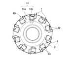
図示の切削インサート1は、回転切削工具に利用される。その切削インサート1を採用した回転切削工具の一例を図6〜図8に示す。 The illustrated
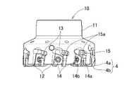
例示の回転切削工具10は、仕上げ加工用の正面フライスカッタであって、工具本体11に切削インサート1を複数装着して構成されている。 The illustrated
工具本体11の先端外周には、周方向に所定の間隔をあけて切屑ポケット12と、各切屑ポケットに面したインサート支持座13が設けられている。 A
また、切削インサート1を固定するクランプ機構14と、切れ刃4の工具軸方向位置を調節する刃振れ調整機構15が設けられている。 Further, a
その工具本体11の各インサート支持座13に、図1〜図5に示した切削インサート1が、刃先チップ3の図2に現れた面がすくい面、刃先チップ3の切れ刃4が主切れ刃4aとサラエ刃4bを構成する姿勢にして装着されている。 The
そして、それぞれの切削インサート1が、クランプ機構14によって工具本体11に固定されている。 Each
図示のクランプ機構14は、楔14aを工具本体11の楔溝に引き込んでその楔14aで切削インサート1を押圧固定する周知の機構である。 The illustrated
楔14aは、工具本体11にねじ込まれる一端側と、楔14aにねじ込まれる他端側に逆ねじを切ったいわゆるWねじ14bによって楔溝に引き込まれるものが設けられている。 The
刃振れ調整機構15は、調整ねじ15aの一端を位置基準面にして切削インサート1に当接させ、その調整ねじ15aの工具本体11に対するねじ込み量を変化させることで位置基準面を工具軸方向に変位させて刃振れを調整するものであって、これも周知の機構である。 The blade run-out
その刃振れ調整機構15を有する切削工具は、回転工具、非回転工具を問わず、切削インサートの刃振れ調整方向の寸法変化を刃振れ調整機構15によって吸収することができる。そのために、再研磨によって切れ刃を再生した切削インサートを使用することができる。 The cutting tool having the blade run-out
なお、この発明を適用する切削インサートは、図示の形状に限定されない。また、図示の回転切削工具に設けたクランプ機構とは構造の異なるクランプ機構で工具本体に固定されるものであってもよいし、台金にクランプねじなどが挿通される取付け孔を設けたものなどであってもよい。 Note that the cutting insert to which the present invention is applied is not limited to the illustrated shape. Also, the clamp mechanism provided in the illustrated rotary cutting tool may be fixed to the tool body by a clamp mechanism having a different structure, or provided with an attachment hole through which a clamp screw or the like is inserted. It may be.
さらに、その切削インサートは、刃振れ調整機構を有する刃先交換式切削工具の全てに利用することができる。 Furthermore, the cutting insert can be used for all cutting edge-exchangeable cutting tools having a blade run-out adjusting mechanism.
1 切削インサート
2 台金
3 刃先チップ
4 切れ刃
4a 主切れ刃
4b サラエ刃
5 目盛り
10 回転切削工具
11 工具本体
12 切屑ポケット
13 インサート支持座
14 クランプ機構
14a 楔
14b Wねじ
15 刃振れ調整機構
15a 調整ねじDESCRIPTION OF
Claims (6)
Translated fromJapanesePriority Applications (1)
| Application Number | Priority Date | Filing Date | Title |
|---|---|---|---|
| JP2014128969AJP2016007663A (en) | 2014-06-24 | 2014-06-24 | Cutting insert |
Applications Claiming Priority (1)
| Application Number | Priority Date | Filing Date | Title |
|---|---|---|---|
| JP2014128969AJP2016007663A (en) | 2014-06-24 | 2014-06-24 | Cutting insert |
Publications (1)
| Publication Number | Publication Date |
|---|---|
| JP2016007663Atrue JP2016007663A (en) | 2016-01-18 |
Family
ID=55225619
Family Applications (1)
| Application Number | Title | Priority Date | Filing Date |
|---|---|---|---|
| JP2014128969APendingJP2016007663A (en) | 2014-06-24 | 2014-06-24 | Cutting insert |
Country Status (1)
| Country | Link |
|---|---|
| JP (1) | JP2016007663A (en) |
Citations (9)
| Publication number | Priority date | Publication date | Assignee | Title |
|---|---|---|---|---|
| US3909896A (en)* | 1974-05-02 | 1975-10-07 | William Krozal | Cutting tool for parting or grooving a workpiece |
| JPS5325982A (en)* | 1976-08-21 | 1978-03-10 | Mitsubishi Metal Corp | Throw-away tip |
| JPS57149107A (en)* | 1981-02-02 | 1982-09-14 | Warner Swasey Co | Metal cutting insert which can be ground again |
| JPS57149901U (en)* | 1981-03-11 | 1982-09-20 | ||
| JPH03264201A (en)* | 1990-03-09 | 1991-11-25 | Mitsubishi Heavy Ind Ltd | Sintered tool |
| JPH0727717U (en)* | 1993-10-25 | 1995-05-23 | 東芝タンガロイ株式会社 | Face milling machine with cutting edge adjustment mechanism |
| JPH08141822A (en)* | 1994-09-22 | 1996-06-04 | Sumitomo Electric Ind Ltd | Throw-away tip for milling cutter and milling cutter using the same |
| JP2005111651A (en)* | 2003-09-19 | 2005-04-28 | Tungaloy Corp | Tip, milling cutter, and machining method using the same |
| JP2010046728A (en)* | 2008-08-19 | 2010-03-04 | Ntn Corp | Throw-away tip |
- 2014
- 2014-06-24JPJP2014128969Apatent/JP2016007663A/enactivePending
Patent Citations (9)
| Publication number | Priority date | Publication date | Assignee | Title |
|---|---|---|---|---|
| US3909896A (en)* | 1974-05-02 | 1975-10-07 | William Krozal | Cutting tool for parting or grooving a workpiece |
| JPS5325982A (en)* | 1976-08-21 | 1978-03-10 | Mitsubishi Metal Corp | Throw-away tip |
| JPS57149107A (en)* | 1981-02-02 | 1982-09-14 | Warner Swasey Co | Metal cutting insert which can be ground again |
| JPS57149901U (en)* | 1981-03-11 | 1982-09-20 | ||
| JPH03264201A (en)* | 1990-03-09 | 1991-11-25 | Mitsubishi Heavy Ind Ltd | Sintered tool |
| JPH0727717U (en)* | 1993-10-25 | 1995-05-23 | 東芝タンガロイ株式会社 | Face milling machine with cutting edge adjustment mechanism |
| JPH08141822A (en)* | 1994-09-22 | 1996-06-04 | Sumitomo Electric Ind Ltd | Throw-away tip for milling cutter and milling cutter using the same |
| JP2005111651A (en)* | 2003-09-19 | 2005-04-28 | Tungaloy Corp | Tip, milling cutter, and machining method using the same |
| JP2010046728A (en)* | 2008-08-19 | 2010-03-04 | Ntn Corp | Throw-away tip |
Similar Documents
| Publication | Publication Date | Title |
|---|---|---|
| JP5641204B2 (en) | Christmas cutter and turbine blade root cutting method using the same | |
| JP5961646B2 (en) | End mill cutter | |
| JP6217045B2 (en) | Cutting insert for milling | |
| CN101687261B (en) | Cutting tool for bevel gears with cutting bars | |
| JP6657547B2 (en) | Cutting tool and manufacturing method thereof | |
| KR102227667B1 (en) | Peripheral cutting tool utilizing stick blades | |
| JP7061371B2 (en) | Machine parts and their applications in cutting | |
| CN105517741B (en) | end mill | |
| JP4878517B2 (en) | Diamond tools | |
| CN101778685A (en) | Cutting insert comprising a ribbed swarf guiding level | |
| JP2007283487A (en) | Throwaway tip and its manufacturing method | |
| TW577786B (en) | Method and apparatus for making a cutting tool having a flute | |
| JP6457257B2 (en) | Milling tool and machining method using the same | |
| JP2016163910A (en) | Cutting insert, tool body and cutting tool | |
| JP2008290237A (en) | Cutting tool and its manufacturing method | |
| JP2008183657A (en) | Single crystal diamond multi-blade tool and method for manufacturing the same | |
| GB2137543A (en) | Tool for cutting tooth flanks | |
| JP6210276B2 (en) | Throw-away cutting tool | |
| JP2016007663A (en) | Cutting insert | |
| JP4702902B2 (en) | Sharpening tool and sharpening method | |
| JP2022554124A (en) | Manufacturing method for cutting tool having recessed portion | |
| JP2007313590A (en) | Thread cutting tip, and its manufacturing method | |
| JP2007044833A (en) | Rotary cutting tool | |
| JP5872629B2 (en) | Cutting tools | |
| JP2018103355A (en) | Cutting tool for thread whirling processing and cutting insert |
Legal Events
| Date | Code | Title | Description |
|---|---|---|---|
| A625 | Written request for application examination (by other person) | Free format text:JAPANESE INTERMEDIATE CODE: A625 Effective date:20170223 | |
| A977 | Report on retrieval | Free format text:JAPANESE INTERMEDIATE CODE: A971007 Effective date:20171221 | |
| A131 | Notification of reasons for refusal | Free format text:JAPANESE INTERMEDIATE CODE: A131 Effective date:20171226 | |
| A02 | Decision of refusal | Free format text:JAPANESE INTERMEDIATE CODE: A02 Effective date:20180626 |