JP2016003963A - Battery model identification method - Google Patents
Battery model identification methodDownload PDFInfo
- Publication number
- JP2016003963A JP2016003963AJP2014124578AJP2014124578AJP2016003963AJP 2016003963 AJP2016003963 AJP 2016003963AJP 2014124578 AJP2014124578 AJP 2014124578AJP 2014124578 AJP2014124578 AJP 2014124578AJP 2016003963 AJP2016003963 AJP 2016003963A
- Authority
- JP
- Japan
- Prior art keywords
- current
- battery
- voltage waveform
- voltage
- waveform
- Prior art date
- Legal status (The legal status is an assumption and is not a legal conclusion. Google has not performed a legal analysis and makes no representation as to the accuracy of the status listed.)
- Pending
Links
Images


Classifications
- Y—GENERAL TAGGING OF NEW TECHNOLOGICAL DEVELOPMENTS; GENERAL TAGGING OF CROSS-SECTIONAL TECHNOLOGIES SPANNING OVER SEVERAL SECTIONS OF THE IPC; TECHNICAL SUBJECTS COVERED BY FORMER USPC CROSS-REFERENCE ART COLLECTIONS [XRACs] AND DIGESTS
- Y02—TECHNOLOGIES OR APPLICATIONS FOR MITIGATION OR ADAPTATION AGAINST CLIMATE CHANGE
- Y02E—REDUCTION OF GREENHOUSE GAS [GHG] EMISSIONS, RELATED TO ENERGY GENERATION, TRANSMISSION OR DISTRIBUTION
- Y02E60/00—Enabling technologies; Technologies with a potential or indirect contribution to GHG emissions mitigation
- Y02E60/10—Energy storage using batteries
Landscapes
- Tests Of Electric Status Of Batteries (AREA)
- Charge And Discharge Circuits For Batteries Or The Like (AREA)
- Secondary Cells (AREA)
Abstract
Translated fromJapaneseDescription
Translated fromJapanese本発明は、電池モデル同定方法に関する。 The present invention relates to a battery model identification method.
従来技術では、電池の周波数特性を交流インピーダンス測定で評価し、設定した電池モデルのパラメータを同定している。特許文献1では、周波数成分の異なるM系列信号を電流入力として電池に入力し、その際の電池の端子電圧を測定する。そして測定結果に基づいてシステム同定を行い、電池の周波数特性を算出し、算出した周波数特性に基づいて電池モデルのパラメータを推定している。 In the prior art, the frequency characteristics of the battery are evaluated by AC impedance measurement, and the parameters of the set battery model are identified. In
しかしながら、測定対象の電池が充電方向と放電方向で電池モデルのパラメータが異なる場合には、充電時の波形と放電時の波形の両方を入力としていては、正確なパラメータを同定することができない。又、燃料電池のように放電方向にしか電流を流せない電池モデルの場合、従来技術のような充電方向の電流を含む電流を流すことができない。 However, when the parameters of the battery model of the battery to be measured differ between the charge direction and the discharge direction, it is impossible to identify an accurate parameter if both the waveform during charging and the waveform during discharge are input. In addition, in the case of a battery model such as a fuel cell that can flow current only in the discharge direction, a current including a current in the charge direction as in the prior art cannot flow.
本発明は、上記問題点に着目してなされたもので、その目的とするところは、パラメータを精度よく同定することができる電池モデル同定方法を提供することにある。 The present invention has been made paying attention to the above problems, and an object of the present invention is to provide a battery model identification method capable of accurately identifying parameters.
上記課題を解決するため、第1の発明に係る電池モデル同定方法は、電流センサが電池に入力される電流波形を測定し、電圧センサが電池の端子電圧の電圧波形を測定し、システム同定演算部が、前記電流波形と測定した電圧波形とに基づいて電池モデルのシステム同定を行い、前記電池の周波数特性を算出し、算出した周波数特性に基づいて前記電池モデルのパラメータを推定することを特徴とする電池モデル同定方法において、前記システム同定を行う工程で、同定しているパラメータに対応する方向に流れる電流に対応する電圧波形である第1の電圧波形と前記第1の電圧波形の符号を変えてなる第2の電圧波形とを用いることを特徴とする。 In order to solve the above problem, a battery model identification method according to a first aspect of the present invention is a system identification calculation in which a current sensor measures a current waveform input to a battery, a voltage sensor measures a voltage waveform of a terminal voltage of the battery. The system performs system identification of a battery model based on the current waveform and the measured voltage waveform, calculates a frequency characteristic of the battery, and estimates a parameter of the battery model based on the calculated frequency characteristic. In the battery model identification method, the first voltage waveform, which is a voltage waveform corresponding to a current flowing in the direction corresponding to the parameter being identified, and the sign of the first voltage waveform in the system identification step A second voltage waveform that is changed is used.
第2の発明に係る電池モデル同定方法は、好ましくは、前記電池に入力する前記電流は、前記同定しているパラメータに対応する方向に流れる第1の電流パルスと前記第1の電流パルスの逆方向に流れる第2の電流パルスとが連続してなる電流パルスセットを含み、前記電流パルスセットに含まれる前記第1の電流パルスのパルス幅と前記第2の電流パルスのパルス幅とがそれぞれ同一であり、かつ前記パルス幅はランダム信号にて決定され、前記システム同定を行う工程で、前記測定した電圧波形の前記第2の電流パルスの入力に対応する部分が前記第2の電圧波形に置き換えられてなる電圧波形を用いることを特徴とする。 In the battery model identification method according to the second invention, preferably, the current input to the battery is the reverse of the first current pulse and the first current pulse flowing in a direction corresponding to the identified parameter. A current pulse set in which a second current pulse flowing in a direction is continuous, and the pulse width of the first current pulse and the pulse width of the second current pulse included in the current pulse set are the same. And the pulse width is determined by a random signal, and the step of performing the system identification replaces the portion of the measured voltage waveform corresponding to the input of the second current pulse with the second voltage waveform. The obtained voltage waveform is used.
第3の発明に係る電池モデル同定方法は、好ましくは、前記システム同定演算部が、電流積算法で前記電池の充電率を求める工程をさらに含み、前記システム同定を行う工程で、充電率−開放電圧特性に基づいて、前記充電率から換算された前記開放電圧を前記端子電圧の電圧波形から減算してなる電圧波形を用い、前記第1の電流パルスの電流値の絶対値と前記第2の電流パルスの電流値の絶対値とが同一であることを特徴とする。 In the battery model identification method according to the third invention, preferably, the system identification calculation unit further includes a step of obtaining a charge rate of the battery by a current integration method, wherein the charge rate is released in the step of performing the system identification. Based on a voltage characteristic, a voltage waveform obtained by subtracting the open-circuit voltage converted from the charging rate from the voltage waveform of the terminal voltage is used, and the absolute value of the current value of the first current pulse and the second value The absolute value of the current value of the current pulse is the same.
第4の発明に係る電池モデル同定方法は、好ましくは、前記第2の電流パルスの電流値が0であり、前記システム同定を行う工程で、前記端子電圧の電圧波形のピーク値を結ぶ線が示す遅い応答成分に相当する値を、前記端子電圧の電圧波形から減算してなる電圧波形を用いることを特徴とする。 In the battery model identification method according to the fourth aspect of the invention, preferably, the current value of the second current pulse is 0, and a line connecting the peak values of the voltage waveform of the terminal voltage is a step of performing the system identification. A voltage waveform obtained by subtracting a value corresponding to the slow response component shown from the voltage waveform of the terminal voltage is used.
よって、第1の発明に係る電池モデル同定方法にあっては、パラメータを精度よく同定することができる。 Therefore, in the battery model identification method according to the first invention, parameters can be identified with high accuracy.
また、第2の発明に係る電池モデル同定方法にあっては、同定しようとしているパラメータに対応する方向とは逆方向の電流による電圧波形を置き換えるときの操作が容易になる。 Moreover, in the battery model identification method according to the second invention, the operation for replacing the voltage waveform due to the current in the direction opposite to the direction corresponding to the parameter to be identified becomes easy.
さらに、第3の発明に係る電池モデル同定方法にあっては、端子電圧全体を扱うよりも正確にパラメータを同定できる。 Furthermore, in the battery model identification method according to the third invention, parameters can be identified more accurately than when the entire terminal voltage is handled.
あるいは、第4の発明に係る電池モデル同定方法にあっては、放電方向にしか電流が流れない電池、例えば燃料電池のパラメータを同定するときに有効である。 Alternatively, the battery model identification method according to the fourth invention is effective when identifying parameters of a battery, for example, a fuel cell, in which current flows only in the discharge direction.
以下、本発明に係る実施形態について、図面に示す実施例に基づき詳細に説明する。 DESCRIPTION OF EMBODIMENTS Hereinafter, embodiments according to the present invention will be described in detail based on examples shown in the drawings.
(第1の実施形態)
まず、充電方向と放電方向とのパラメータが異なる電池、例えば鉛電池の電池モデルを同定する方法に関する実施形態を説明する。(First embodiment)
First, an embodiment relating to a method of identifying a battery model of a battery, for example, a lead battery, having different parameters for the charge direction and the discharge direction will be described.
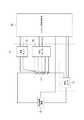
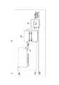
図1は、第1の実施形態に係る電池モデル同定方法を実施するための接続図である。電池モデル同定の対象となるバッテリーセル11、充放電用電源12、及び回路を流れる電流を測定する電流センサ13を直列に接続した電気回路と、電気回路を構成する各部分と信号回路によって結ばれているシステム同定演算部14とを含んでいる。システム同定演算部14は、電流センサ13と温度センサ15と電圧センサ16とを含むセンサ入力部17を通じてバッテリーセル11の状態を取得する。そしてシステム同定演算部14は、電圧センサ16が測定した電圧波形と入力した電流波形とに基づいて電池モデルのシステム同定を行い、前記電池の周波数特性を算出し、算出した周波数特性に基づいて前記電池モデルのパラメータを推定する。本実施形態において電池モデル同定の対象とするバッテリーセル11は、充放電の電池パラメータの差が比較的大きい鉛蓄電池であるが、これに限られない。バッテリーセル11は、充電可能なその他の二次電池であってもよい。 FIG. 1 is a connection diagram for carrying out the battery model identification method according to the first embodiment. An electric circuit in which a
図2は、第1の実施形態に係る電池モデル同定方法を実施するためのシステムのブロック図であり、センサ入力部17及びシステム同定演算部14が含まれる。システム同定演算部14には、充電率(SOC)と開放電圧(OCV)との関係を示すSOC−OCVテーブルを格納する記憶部(図示せず)、SOC−OCVテーブルを用いて初期電圧を初期SOCに変換する初期SOC算出部21、バッテリの満充電容量と電流積算量とからSOCを算出するSOC算出部22、SOC−OCVテーブルを用いてSOCをOCVに変換するSOC−OCV変換部23、過電圧成分を抽出する過電圧抽出部24、過電圧成分を抽出してなる電圧波形を修正する電圧波形修正部25、及びシステム同定を行うシステム同定部26が含まれている。 FIG. 2 is a block diagram of a system for carrying out the battery model identification method according to the first embodiment, and includes a
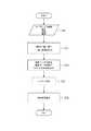
図3は、第1の実施形態に係る電池モデル同定方法を示すフローチャートである。図2のブロック図と関連付けて説明する。まず、システム同定演算部14は、電池モデルを同定する対象となっている電池について電流、電圧及び温度をセンサ入力部17から取得する(ステップS1)。次に、初期SOC算出部21及びSOC算出部22が、検出して得られたデータを用いて電流積算法によりSOCを算出する。また、SOC−OCV変換部23及び過電圧抽出部24が、その結果からOCV及び過電圧を算出する(ステップS2)。さらに、電圧波形修正部25が過電圧を用いて電圧波形を修正する(ステップS3)。続いて、システム同定部26が、加工した電圧波形と入力した電流波形とを用いて電池パラメータを同定する(ステップS4、ステップS5)。 FIG. 3 is a flowchart showing the battery model identification method according to the first embodiment. Description will be made in association with the block diagram of FIG. First, the system
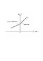
ここで、鉛蓄電池等、充電方向と放電方向とで電池パラメータが異なる場合がある。これは、充電と放電の反応に必要な活性化エネルギーが異なったり、電極近傍でイオンの拡散速度が違ったりすることが原因である。図4は電池の電流電圧特性を示す。充電方向と放電方向とで電池パラメータが異なる電池の電流電圧特性は図4の実線(“実際の特性”)のようになる。しかし、充放電のパラメータが異なることを考慮せずに充放電データをそのまま用いてシステム同定を行うと、充放電のパラメータを平均した値を同定することとなってしまい、図4の破線(“充放電を平均した特性”)のような特性を同定してしまう。 Here, the battery parameters may differ between the charge direction and the discharge direction, such as a lead storage battery. This is because the activation energy required for the reaction between charge and discharge is different, or the ion diffusion rate is different near the electrode. FIG. 4 shows the current-voltage characteristics of the battery. The current-voltage characteristics of the batteries having different battery parameters in the charging direction and discharging direction are as shown by the solid line in FIG. 4 (“actual characteristics”). However, if the system identification is performed using the charge / discharge data as it is without considering that the charge / discharge parameters are different, an average value of the charge / discharge parameters is identified, and the broken line (“ Characteristics such as “average characteristics of charge / discharge” are identified.
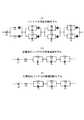
図5は、充電方向と放電方向とで電池パラメータが異なる電池モデルの等価回路を示す。図5(a)は充放電両方向でそれぞれ異なるパラメータを含んだモデルであって、ダイオードを挿入して充電方向及び放電方向の電流パスが制限することによって電流の方向に応じてパラメータが異なることを表している。図5(b)は図5(a)の回路から放電方向に電流を流したときに実際に電流が流れる回路要素を抜き出した回路モデルである。図5(c)は図5(b)とは逆に充電方向に電流を流したときに実際に電流が流れる回路要素を抜き出した回路モデルである。 FIG. 5 shows an equivalent circuit of a battery model in which battery parameters are different between the charging direction and the discharging direction. FIG. 5 (a) is a model including different parameters in both charge and discharge directions. By inserting a diode and limiting the current paths in the charge direction and the discharge direction, the parameters differ depending on the current direction. Represents. FIG. 5B is a circuit model obtained by extracting circuit elements through which current actually flows when current flows in the discharging direction from the circuit of FIG. FIG. 5C is a circuit model obtained by extracting circuit elements through which current actually flows when current flows in the charging direction, contrary to FIG. 5B.
等価回路モデルを作成することで、机上シミュレーションで電池に関する推定ロジックの検討が可能となるため、開発を効率よく行うことが可能となる。等価回路モデルの一部は過電圧の算出に必要となり、このモデルの精度がSOC等の推定精度に影響を及ぼす。等価回路モデルの作成にあたっては、電池が置かれる環境の温度やSOC、流す電流によって電池モデルのパラメータが変化するため、様々な温度、SOC、電流ごとに実験を行って等価回路モデルのパラメータを同定する必要がある。したがって、例えば図5のような等価回路が、温度、SOC、電流の条件ごとに作成されることとなる。 By creating an equivalent circuit model, it is possible to study the estimation logic related to the battery by desktop simulation, so that development can be performed efficiently. A part of the equivalent circuit model is necessary for calculating the overvoltage, and the accuracy of this model affects the estimation accuracy of the SOC and the like. When creating an equivalent circuit model, the parameters of the battery model change depending on the temperature, SOC, and current flowing in the environment where the battery is placed. Therefore, experiments are performed for each temperature, SOC, and current to identify the parameters of the equivalent circuit model. There is a need to. Therefore, for example, an equivalent circuit as shown in FIG. 5 is created for each condition of temperature, SOC, and current.
なお、線形システムを同定する場合は、2値信号を用いれば十分である。図5の等価回路モデルもOCVを除いて線形システムで表されるため同定に用いるデータは2値信号であればよい。システム同定を行うにあたり、線形システムを表現できる多項式ブラックボックスモデルを用いるが、ARX(Auto-Regressive eXogeneous)モデルがシステム同定において利用される重要なモデルであるため、ARXをシステム同定に利用する。 Note that when identifying a linear system, it is sufficient to use a binary signal. Since the equivalent circuit model of FIG. 5 is also expressed by a linear system excluding OCV, the data used for identification may be a binary signal. In performing system identification, a polynomial black box model that can represent a linear system is used. Since an ARX (Auto-Regressive eXogeneous) model is an important model used in system identification, ARX is used for system identification.
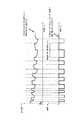
図6は、電池の電流波形と電圧波形を示す。上側が電圧波形を示し、下側が電流波形を示す。横軸はそれらに共通する時間軸である。電流の符号は、充電方向を正、放電方向を負として図示している。電流の符号の正負の関係は、以下同様とする。システム同定を行うために、充放電で2値の電流となるようなM系列信号を電池に入力し、その時の端子電圧を計測する。2値電流は放電方向と充電方向とに交互に流れるパルス電流とみなすことができる。以下、放電方向又は充電方向のいずれか一方に流れるパルス電流を第1の電流パルスと定義し、その逆方向に流れる電流を第2の電流パルスと定義する。上記の2値電流は、ランダムな白色性2値信号が一般的であるが、本実施形態では第1の電流パルスと第2の電流パルスとが連続してなる電流パルスセットを定義し、電流パルスセットに含まれる電流パルスそれぞれのパルス幅(以下、電流パルス時間ともいう。)が同一になるようなM系列信号を用いる。電流パルスセットごとのパルス幅をランダム信号で決定することにより、広い周波数帯の情報を得ることができるという効果を奏する。電池の等価回路モデルパラメータはSOCにより異なるため、異なるSOCごとにパラメータの同定を行って、電池の等価回路モデルを作成する場合は、入力波形によるSOC変化が少なくなるようにする必要がある。したがって、一定時間の放電後に同じ電荷を充電すれば、SOCの変化を最小限にすることができる。そのためには、第1の電流パルスと第2の電流パルスとの間でさらに電流値を同一にすればよい。 FIG. 6 shows the current waveform and voltage waveform of the battery. The upper side shows a voltage waveform, and the lower side shows a current waveform. The horizontal axis is a time axis common to them. The sign of the current is illustrated with the charging direction as positive and the discharging direction as negative. The same applies to the positive / negative relationship of the signs of current. In order to perform system identification, an M-sequence signal that becomes a binary current by charging / discharging is input to the battery, and the terminal voltage at that time is measured. The binary current can be regarded as a pulse current that flows alternately in the discharging direction and the charging direction. Hereinafter, a pulse current flowing in either the discharging direction or the charging direction is defined as a first current pulse, and a current flowing in the opposite direction is defined as a second current pulse. The binary current is generally a random whiteness binary signal, but in this embodiment, a current pulse set in which a first current pulse and a second current pulse are continuous is defined, M-sequence signals are used such that the pulse widths (hereinafter also referred to as current pulse times) of the current pulses included in the pulse set are the same. By determining the pulse width for each current pulse set with a random signal, there is an effect that information in a wide frequency band can be obtained. Since the equivalent circuit model parameter of the battery differs depending on the SOC, when the equivalent circuit model of the battery is created by identifying the parameter for each different SOC, it is necessary to reduce the SOC change due to the input waveform. Therefore, if the same charge is charged after discharging for a certain time, the change in SOC can be minimized. For this purpose, the current value may be made the same between the first current pulse and the second current pulse.
図7は、電池に電流パルスを入力したときのSOC変化を示す。従来は第1の電流パルスと第2の電流パルスとが交互に繰り返して連続するときにそれぞれのパルス幅を同一にするとは限らなかったためSOCの変化が大きくなっている。しかし本実施形態においては放電の電荷と充電の電荷とが同一になるように第1の電流パルスと第2の電流パルスとの間で電流値及びパルス幅を同一にしている。そのため、本実施形態においては、実際にSOCの変化が小さくなっている。また、SOCの変化が少ないと、同定した等価回路パラメータの変化も少なくなり、パラメータ同定の精度も向上する。 FIG. 7 shows the SOC change when a current pulse is input to the battery. Conventionally, when the first current pulse and the second current pulse are alternately repeated, the respective pulse widths are not always the same, and thus the change in the SOC is large. However, in this embodiment, the current value and the pulse width are made the same between the first current pulse and the second current pulse so that the discharge charge and the charge charge are the same. Therefore, in the present embodiment, the change in the SOC is actually small. Further, when the change in SOC is small, the change in the identified equivalent circuit parameter is also small, and the accuracy of parameter identification is improved.
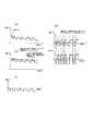
放電又は充電に対応するパラメータを別々に同定する目的で放電又は充電のいずれか一方のみのM系列信号を入力すると、例えば放電のみの場合、イオンの拡散移動などの遅い応答の影響で、内部が安定するのに時間がかかる。図8は二次電池の端子電圧の変動を示している。図8(a)は放電のみを続ける場合の変動を示しているが、端子電圧が減少していく。このため電圧波形の修正が必要となる。さらに、SOCも徐々に変化してしまう。図8(b)は充放電を同じ電流で行う場合の変動を示しており、遅い応答の影響が打ち消されて少なくなり、内部状態が初めから安定するため、電圧の減少は起こらない。 When an M-sequence signal for only one of discharge or charge is input for the purpose of separately identifying parameters corresponding to discharge or charge, for example, in the case of only discharge, the inside is affected by the slow response such as ion diffusion movement. It takes time to stabilize. FIG. 8 shows fluctuations in the terminal voltage of the secondary battery. FIG. 8A shows the fluctuation when only discharging is continued, but the terminal voltage decreases. For this reason, it is necessary to correct the voltage waveform. Further, the SOC gradually changes. FIG. 8B shows fluctuations when charging / discharging is performed with the same current. The influence of the slow response is canceled and reduced, and the internal state is stabilized from the beginning, so that the voltage does not decrease.
また、充電に係るパラメータのみを同定する目的で、充放電でのM系列の電流と電圧から充電のデータを抽出して充電のみの電流と電圧でシステム同定を行うと、入力波形である電流が2値信号でないため同定した等価回路モデルのパラメータの精度が低下してしまう。これは放電のみの電流と電圧でシステム同定を行った場合においても同じである。 In addition, for the purpose of identifying only the parameters related to charging, when charging data is extracted from M-sequence current and voltage during charging and system identification is performed with current and voltage only during charging, the current that is the input waveform is Since it is not a binary signal, the accuracy of the parameter of the identified equivalent circuit model is reduced. This is the same when the system identification is performed with the current and voltage of only discharge.
したがって、充電と放電とで別々に等価回路パラメータを同定する場合においても充放電それぞれが同じ電流になるようなM系列信号を用いることが望ましい。 Therefore, it is desirable to use an M-sequence signal such that each charge / discharge has the same current even when the equivalent circuit parameters are identified separately for charge and discharge.
ここで、パラメータ同定方法をさらに具体的に説明する。まず、図3のフローチャートのステップS2において、初期SOC算出部21は、入力するM系列電流と時間0(s)での端子電圧から、OCVを算出して、SOCとOCVの関係から、初期のSOCを算出する。次に、SOC算出部22は、電流積算法によりSOCを算出する。すなわちSOC算出部22は、初期のSOCとバッテリの満充電容量と電流積算値に基づき、SOCを計算する。続いて、SOC−OCV変換部23は、SOCとOCVの関係を示すSOC−OCV特性に基づいてOCVを算出する。さらに、過電圧抽出部24は、電池の端子電圧からOCVを減算し、過電圧(電池の等価回路モデルに起因する電圧)を算出する。OCVを電池の端子電圧から取り除いて過電圧を算出するのは、電池の等価回路モデルのパラメータを同定するにあたってOCVが不要な信号成分となるためである。OCVを除いて過電圧からパラメータを同定することによってパラメータ同定の精度が上がるという効果を奏する。 Here, the parameter identification method will be described more specifically. First, in step S2 of the flowchart of FIG. 3, the initial
図9に、過電圧成分の抽出を行った場合の具体的な波形の例を示す。図9(a)はOCVを含む電圧波形である。端子電圧からOCVを減算することによって、図9(b)の電圧波形が得られる。すなわち図9(b)の波形は過電圧を示している。このとき、充放電それぞれの電池の内部抵抗が異なるため、充電と放電とが対称ではない。 FIG. 9 shows an example of a specific waveform when the overvoltage component is extracted. FIG. 9A shows a voltage waveform including OCV. By subtracting OCV from the terminal voltage, the voltage waveform of FIG. 9B is obtained. That is, the waveform in FIG. 9B indicates an overvoltage. At this time, charging and discharging are not symmetrical because the internal resistance of each battery is different.
次に図3のフローチャートのステップS3について説明する。図2の電圧波形修正部25では、放電に対応するパラメータを同定するために過電圧の波形を修正する。図10は過電圧の波形を修正した場合の具体的な波形の例を示す図である。図10(a)は電流と電圧波形の例を示している。上側が電圧波形、下側が電流波形であり、横軸は共通の時間軸である。電圧波形は過電圧を抽出した波形であり、電流波形は入力した電流パルスを表している。電圧波形において放電方向に流した電流に対応する電圧波形をそのまま残し、実線で表している。充電方向に流した電流に対応する電圧波形を破線で表しているが、これを、放電方向に流した電流に対応する電圧波形に−1を乗算して符号を変えて生成した波形を電流パルス時間だけずらしたもので置換する。結果として得られた波形を実線で示している。このようにして図10(a)の電圧波形は実線で示すような波形となり、この波形は放電方向に電流を流したときの電圧波形のみで疑似的に作成した充放電の電圧波形となっている。 Next, step S3 in the flowchart of FIG. 3 will be described. The voltage
図10(a)では放電に対応するパラメータを同定するときの例を示したが、充電に対応するパラメータを同定するときも包含するように説明する。以下の説明では、便宜上放電方向に係るパラメータを同定している場合であることを前提とするが、そのまま充電方向と読み替えてもよい。図10(b)に放電と充電とを1サイクル行ったときの電流と電圧波形を示し、波形のそれぞれの部分に定義した用語を付している。上側が電圧波形、下側が電流波形であり、横軸は共通の時間軸であることは図10(a)と同様である。電圧波形の実線は過電圧を抽出した波形である。同定しているパラメータに対応する方向に流すパルス電流、すなわちここでは放電方向に流すパルス電流を第1の電流パルスとし、それとは逆方向に流すパルス電流、すなわちここでは充電方向に流すパルス電流を第2の電流パルスとする。また、第1の電流パルスと第2の電流パルスとを組にしたものを電流パルスセットとして示している。さらに、第1の電流パルスに対応した電圧波形を第1の電圧波形とし、第1の電圧波形に−1を乗算して符号を変えて、電流パルス時間だけずらして得られる波形を第2の電圧波形とする。第2の電圧波形を実線で表し、第2の電流パルスに対応した電圧波形を破線で表している。第2の電流パルスに対応した電圧波形を第2の電圧波形で置換することによって、図10(a)上側に示した電圧波形のように、放電方向に電流を流した時の電圧波形のみで疑似的に充放電の電圧波形を作成することができる。なお、1つの電流パルスセットに含まれる第1の電流パルスと第2の電流パルスのそれぞれのパルス幅を同一にすることによって、第2の電流パルスに対応した電圧波形の占める長さと第2の電圧波形が占める長さとが同一となって、置換が容易になるという効果を奏する。充電に対応するパラメータを同定する場合には、充電方向に流すパルス電流を第1の電流パルスとみなせば、同様の電圧波形を作成することができる。 Although FIG. 10A shows an example of identifying a parameter corresponding to discharging, the description will be made so as to include the case of identifying a parameter corresponding to charging. In the following description, it is assumed that the parameter relating to the discharge direction is identified for convenience, but it may be read as the charge direction as it is. FIG. 10B shows a current and voltage waveform when one cycle of discharging and charging is performed, and the defined terms are attached to respective portions of the waveform. The upper side is a voltage waveform, the lower side is a current waveform, and the horizontal axis is a common time axis, as in FIG. The solid line of the voltage waveform is a waveform obtained by extracting the overvoltage. The pulse current that flows in the direction corresponding to the identified parameter, that is, the pulse current that flows in the discharge direction here is the first current pulse, and the pulse current that flows in the opposite direction, that is, the pulse current that flows in the charging direction here. The second current pulse is assumed. Further, a combination of the first current pulse and the second current pulse is shown as a current pulse set. Further, the voltage waveform corresponding to the first current pulse is set as the first voltage waveform, the sign is changed by multiplying the first voltage waveform by −1, and the waveform obtained by shifting by the current pulse time is changed to the second waveform. Use voltage waveform. The second voltage waveform is represented by a solid line, and the voltage waveform corresponding to the second current pulse is represented by a broken line. By replacing the voltage waveform corresponding to the second current pulse with the second voltage waveform, only the voltage waveform when the current is passed in the discharge direction as shown in the upper side of FIG. A charge / discharge voltage waveform can be created in a pseudo manner. In addition, by making the pulse widths of the first current pulse and the second current pulse included in one current pulse set the same, the length occupied by the voltage waveform corresponding to the second current pulse and the second current pulse are set. The length occupied by the voltage waveform is the same, and the replacement is facilitated. When identifying a parameter corresponding to charging, a similar voltage waveform can be created if the pulse current flowing in the charging direction is regarded as the first current pulse.
図10で示したように、放電方向に電流を流した時の電圧波形のみで疑似的に充放電の電圧波形を作成することによって、図5(b)に示した放電方向のパラメータのみを精度よく同定することができる。すなわち本実施形態では、システム同定を行う工程で、同定しているパラメータに対応する方向に流れる電流に対応する電圧波形である第1の電圧波形と第1の電圧波形の符号を変えてなる第2の電圧波形とを用いることを特徴とする。これにより放電方向のパラメータのみを精度よく同定することができる。同様に、充電方向に電流を流した時の電圧波形のみで疑似的に充放電の電圧波形を作成することによって、図5(c)に示した充電方向のパラメータのみを精度よく同定することができる。 As shown in FIG. 10, only the voltage in the discharge direction shown in FIG. 5B is accurately obtained by creating a pseudo charge / discharge voltage waveform only with the voltage waveform when the current flows in the discharge direction. Can be identified well. That is, in the present embodiment, in the system identification step, the first voltage waveform, which is the voltage waveform corresponding to the current flowing in the direction corresponding to the parameter being identified, and the sign of the first voltage waveform are changed. 2 voltage waveforms are used. Thereby, only the parameter of the discharge direction can be identified with high accuracy. Similarly, it is possible to accurately identify only the charge direction parameters shown in FIG. 5C by creating a pseudo charge / discharge voltage waveform using only the voltage waveform when a current flows in the charge direction. it can.
表1は、第1の実施形態に係る電池モデル同定方法を実施することによって同定した電池モデルの内部抵抗を示す。従来の電池モデル同定方法では充放電の内部抵抗が同一であるものとして内部抵抗を同定していたが(表の3行目「従来」)、第1の実施形態に係る電池モデル同定方法によれば、充放電それぞれの内部抵抗を別々に同定することができている(表の1行目「放電」及び2行目「充電」)。従来の方法で同定していた内部抵抗は本発明に係る方法で同定した充放電それぞれの内部抵抗の間の値であったことが分かる。 Table 1 shows the internal resistance of the battery model identified by performing the battery model identification method according to the first embodiment. In the conventional battery model identification method, the internal resistance is identified as having the same charge / discharge internal resistance (“Conventional” in the third row of the table). However, according to the battery model identification method according to the first embodiment, Thus, the internal resistance of each charge / discharge can be identified separately (“Discharge” in the first row and “Charge” in the second row in the table). It can be seen that the internal resistance identified by the conventional method was a value between the internal resistances of the charge and discharge identified by the method according to the present invention.

図11は、第1の実施形態に係る電池モデル同定方法を実施することによって同定した電池モデルの端子電圧と実際の電池の端子電圧との誤差を示す図である。従来の電池モデル同定方法により同定した電池モデルの端子電圧は0.5V程度の誤差をもっているところ、第1の実施形態に係る電池モデル同定方法により同定した電池モデルの端子電圧は0.3V程度の誤差となっており、誤差が0.2V程度減少したことを確認できている。 FIG. 11 is a diagram illustrating an error between the terminal voltage of the battery model identified by performing the battery model identification method according to the first embodiment and the terminal voltage of the actual battery. The terminal voltage of the battery model identified by the conventional battery model identification method has an error of about 0.5 V, but the terminal voltage of the battery model identified by the battery model identification method according to the first embodiment is about 0.3 V. It is an error, and it has been confirmed that the error has decreased by about 0.2V.
(第2の実施形態)
次に、放電方向にしか電流が流れない電池、例えば燃料電池の電池モデルを同定する方法に関する実施形態を説明する。第1の実施形態と共通する部分については省略する。本実施形態で同定できる対象は充電方向に電流を流せない電池であるが、これに限られず、一次電池も対象となりうる。(Second Embodiment)
Next, an embodiment relating to a method for identifying a battery model in which a current flows only in the discharge direction, for example, a battery model of a fuel cell will be described. Parts common to the first embodiment are omitted. The target that can be identified in the present embodiment is a battery that cannot flow current in the charging direction, but is not limited to this, and a primary battery can also be a target.
第2の実施形態に係る電池モデル同定方法の接続図は、図1と同様であり、バッテリーセル11が燃料電池セルである点のみ異なるため省略する。 The connection diagram of the battery model identification method according to the second embodiment is the same as that in FIG. 1, and the description is omitted because only the
図12は、第2の実施形態に係る電池モデル同定方法を実施するためのシステムのブロック図であり、センサ入力部17とシステム同定演算部14とが含まれる。システム同定演算部14には、過電圧抽出部24、電圧波形電流波形修正部125、及びシステム同定部26が含まれる。 FIG. 12 is a block diagram of a system for performing the battery model identification method according to the second embodiment, and includes a
図13は、第2の実施形態に係る電池モデル同定方法を示すフローチャートである。図13のステップS11〜S15は図3のステップS1〜S5にそれぞれ対応する。過電圧を算出するステップ(ステップS12)において、図12の過電圧抽出部24が、遅い応答の成分を端子電圧から減算することによって過電圧を算出する点で図3とは異なる。 FIG. 13 is a flowchart showing a battery model identification method according to the second embodiment. Steps S11 to S15 in FIG. 13 correspond to steps S1 to S5 in FIG. 3, respectively. In the step of calculating the overvoltage (step S12), the
図14は、燃料電池モデルの等価回路モデルである。燃料電池は放電方向にしか電流が流れないため、図5(a)とは異なり、放電方向のパラメータのみを表す回路となっている。等価回路モデルの作成にあたっては、電池が置かれる環境の温度や流す電流によって電池モデルのパラメータが変化するため、様々な温度や電流ごとに実験を行って等価回路モデルのパラメータを同定する必要がある。したがって、例えば図14のモデルが、温度や電流ごとに作成されることとなる。 FIG. 14 is an equivalent circuit model of the fuel cell model. Since current flows only in the discharge direction of the fuel cell, unlike FIG. 5A, the circuit represents only the parameters in the discharge direction. When creating an equivalent circuit model, the parameters of the battery model change depending on the temperature of the environment in which the battery is placed and the current that flows. Therefore, it is necessary to perform experiments at various temperatures and currents to identify the parameters of the equivalent circuit model. . Therefore, for example, the model of FIG. 14 is created for each temperature and current.
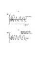
図15は、燃料電池の電流波形と電圧波形を示す。図6との違いは、充電方向には電流を流さないことである。ここでは放電方向に流れる電流を第1の電流パルスとし、その逆方向である充電方向には電流を流さないので第2の電流パルスの電流値が0であるとみなせる。放電のみ行うとき、イオンの拡散移動などの遅い応答の影響で、内部が安定するのに時間がかかる。図16は、燃料電池の端子電圧変化を示す。遅い応答の影響でこのように端子電圧が減少していく。このため電圧波形の修正が必要となる。 FIG. 15 shows the current waveform and voltage waveform of the fuel cell. The difference from FIG. 6 is that no current flows in the charging direction. Here, the current flowing in the discharging direction is the first current pulse, and no current is passed in the charging direction, which is the opposite direction, so that the current value of the second current pulse can be regarded as zero. When only discharging is performed, it takes time for the inside to stabilize due to the influence of a slow response such as diffusion movement of ions. FIG. 16 shows the terminal voltage change of the fuel cell. In this way, the terminal voltage decreases due to the slow response. For this reason, it is necessary to correct the voltage waveform.
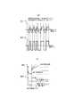
図13のステップS13に対応して電圧波形電流波形修正部125が電圧波形と電流波形とを修正する。図17は電圧波形と電流波形とを修正した具体例を示す。図17(a)は未修正の電圧波形を示し、図17(b)にはそのピークを結ぶ線、すなわち遅い成分を示す線を破線で図示している。図17(c)は測定した電圧波形から遅い成分を引いて得られる波形を示している。遅い成分を引いて過電圧のみを扱うことによって、パラメータ同定の精度が上がるという効果を奏する。図17(d)は電圧波形と電流波形とを示した図であり、上側が電圧波形、下側が電流波形である。電流を流していない期間の波形を破線で示している。燃料電池の性質上、充電方向には電流を流すことができないが、放電方向の電流パルスに−1をかけて符号を変えた電流パルスを充電方向に流したものとみなして電流波形に実線で図示している。さらに疑似的に作った充電方向に流れる電流パルスに対応させるように、放電方向に電流を流しているときの電圧波形に−1をかけて符号を変え、電流を流していない期間の波形と置換して得られる波形を電圧波形に実線で示している。以上の操作によって、第2の電流パルスの電流値が0であるとみなした場合でも、疑似的に充電方向にも電流を流したような2値信号が得られる。 Corresponding to step S13 in FIG. 13, the voltage waveform current
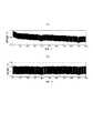
図18(a)は電圧波形の修正操作を行う前の電圧波形を示し、図18(b)は図18(a)の一部(両向き矢印で示した範囲)を拡大した波形を示す。放電を繰り返すことによって端子電圧が徐々に低下していることが分かる。図19は修正した電圧波形を示し、図19(a)と(b)とはそれぞれ図18(a)と(b)を修正したものである。修正したことによって端子電圧から遅い成分が除去されて平坦になっていることが分かる。 FIG. 18A shows a voltage waveform before the voltage waveform correcting operation, and FIG. 18B shows a waveform obtained by enlarging a part of FIG. 18A (a range indicated by a double-pointed arrow). It can be seen that the terminal voltage gradually decreases by repeating the discharge. FIG. 19 shows a corrected voltage waveform, and FIGS. 19 (a) and 19 (b) are obtained by correcting FIGS. 18 (a) and 18 (b), respectively. It can be seen that the correction removes the slow component from the terminal voltage and makes it flat.
なお、図20と図21に遅い成分を示す線の算出方法を示した。図20は端子電圧を示す電圧波形(図20(a))の上側ピークを5次関数で近似して遅い成分を示す線(図20(b))を算出している。図21は端子電圧を示す電圧波形(図21(a))の上下のピークの中間値を算出して、その中間値を近似する線を求め(図21(b))、上側ピークまでシフトすることによって遅い成分を示す線を算出している。 20 and 21 show a method for calculating a line indicating a slow component. FIG. 20 calculates a line (FIG. 20B) indicating a slow component by approximating the upper peak of the voltage waveform indicating the terminal voltage (FIG. 20A) with a quintic function. FIG. 21 calculates the intermediate value of the upper and lower peaks of the voltage waveform indicating the terminal voltage (FIG. 21A), obtains a line approximating the intermediate value (FIG. 21B), and shifts to the upper peak. Thus, a line indicating a slow component is calculated.
図22(a)は、燃料電池の電流電圧特性を示している。放電のみ可能であるから、充電方向の電流は図示されていない。第2の実施形態においては疑似的に充電方向の電流を流したように電圧波形を修正するため、図22(b)のような電流電圧特性が得られる。この特性のうち充電方向の電流は疑似的に作成され破線で示している。このように疑似的に2値信号を扱うことによって、放電方向にしか電流が流れない燃料電池モデルのパラメータ同定の精度が向上するという効果を奏する。 FIG. 22A shows the current-voltage characteristics of the fuel cell. Since only discharging is possible, the current in the charging direction is not shown. In the second embodiment, since the voltage waveform is corrected so that a current in the charging direction flows in a pseudo manner, a current-voltage characteristic as shown in FIG. 22B is obtained. Among these characteristics, the current in the charging direction is artificially created and indicated by a broken line. In this way, by treating the binary signal in a pseudo manner, there is an effect that the accuracy of parameter identification of the fuel cell model in which current flows only in the discharge direction is improved.
以上、電池モデル同定方法の具体的な実施形態を説明してきた。本発明の一実施形態に係る電池モデル同定方法を用いることによって、充電方向に電流を流したときのパラメータと放電方向に電流を流したときのパラメータとをそれぞれ精度よく同定することができる。 The specific embodiments of the battery model identification method have been described above. By using the battery model identification method according to an embodiment of the present invention, it is possible to accurately identify a parameter when a current flows in the charging direction and a parameter when a current flows in the discharging direction.
また、本発明の実施形態に係る電池モデル同定方法を用いることによって、充電方向に電流を流すことができない電池であっても充電方向に電流を流している波形を生成することができるので、充電方向に電流を流すことができる電池を対象とした電池モデル同定方法を適用できる。 In addition, by using the battery model identification method according to the embodiment of the present invention, even a battery that cannot flow current in the charging direction can generate a waveform that flows current in the charging direction. A battery model identification method for a battery capable of passing a current in the direction can be applied.
また、電池に電流を流すときに放電を行う方向に電流を流す時間と充電を行う方向に電流を流す時間とを同一にすることによって、電圧応答波形からパラメータを同定するために用いる波形を生成することが容易となる。また充電電流と放電電流とを同一にすることによって、SOC一定を保ってパラメータ同定することができる。 Generates a waveform used to identify a parameter from the voltage response waveform by making the time for flowing the current in the discharge direction and the time for flowing the current in the charging direction the same when flowing the current through the battery. Easy to do. Further, by making the charging current and the discharging current the same, it is possible to perform parameter identification while keeping the SOC constant.
また、電池に電流を流す時間をランダム信号によって決定することによって、電池に電流パルス波形を入力したときの電圧応答波形から多くの情報を得ることができる。 In addition, by determining the time during which the current flows to the battery by a random signal, a lot of information can be obtained from the voltage response waveform when the current pulse waveform is input to the battery.
また、電流積算法によって電池のSOCを推定できる場合は、SOCとOCVの関係からOCVを算出し、OCVを電圧応答波形から減じて過電圧成分のみを抽出することによって、より正確にパラメータを同定することができる。 Also, when the SOC of the battery can be estimated by the current integration method, the OCV is calculated from the relationship between the SOC and the OCV, and the parameters are identified more accurately by subtracting the OCV from the voltage response waveform and extracting only the overvoltage component. be able to.
また、電圧応答波形から同定で取り扱わない遅い成分(主に指数関数に起因する低周波成分)を取り除くことによって、より正確にパラメータを同定することができる。 Further, by removing a slow component (mainly a low-frequency component caused by an exponential function) that is not handled by identification from the voltage response waveform, the parameter can be identified more accurately.
以上、本発明を上記各実施形態に基づき説明してきたが、本発明はこれらの実施形態に限られず、本発明の要旨を逸脱しない範囲で設計変更等があった場合でも、本発明に含まれる。 As mentioned above, although this invention has been demonstrated based on said each embodiment, this invention is not restricted to these embodiment, Even when there is a design change etc. in the range which does not deviate from the summary of this invention, it is contained in this invention. .
11 バッテリーセル
12 充放電用電源
13 電流センサ
14 システム同定演算部
15 温度センサ
16 電圧センサ
17 センサ入力部
21 初期SOC算出部
22 SOC算出部
23 OCV変換部
24 過電圧抽出部
25 電圧波形修正部
26 システム同定部
125 電圧波形電流波形修正部DESCRIPTION OF
Claims (4)
Translated fromJapanese電圧センサが、電池の端子電圧の電圧波形を測定し、
システム同定演算部が、前記電流波形と測定した電圧波形とに基づいて電池モデルのシステム同定を行い、前記電池の周波数特性を算出し、算出した周波数特性に基づいて前記電池モデルのパラメータを推定する、
ことを特徴とする電池モデル同定方法において、
前記システム同定を行う工程で、同定しているパラメータに対応する方向に流れる電流に対応する電圧波形である第1の電圧波形と前記第1の電圧波形の符号を変えてなる第2の電圧波形とを用いる、
ことを特徴とする電池モデル同定方法。The current sensor measures the current waveform input to the battery,
The voltage sensor measures the voltage waveform of the battery terminal voltage,
A system identification calculation unit performs system identification of the battery model based on the current waveform and the measured voltage waveform, calculates a frequency characteristic of the battery, and estimates a parameter of the battery model based on the calculated frequency characteristic ,
In a battery model identification method characterized by:
In the step of performing system identification, a first voltage waveform which is a voltage waveform corresponding to a current flowing in a direction corresponding to the identified parameter and a second voltage waveform obtained by changing the sign of the first voltage waveform And
The battery model identification method characterized by the above-mentioned.
前記電池に入力する前記電流は、前記同定しているパラメータに対応する方向に流れる第1の電流パルスと前記第1の電流パルスの逆方向に流れる第2の電流パルスとが連続してなる電流パルスセットを含み、
前記電流パルスセットに含まれる前記第1の電流パルスのパルス幅と前記第2の電流パルスのパルス幅とがそれぞれ同一であり、かつ前記パルス幅はランダム信号にて決定され、
前記システム同定を行う工程で、前記測定した電圧波形の前記第2の電流パルスの入力に対応する部分が前記第2の電圧波形に置き換えられてなる電圧波形を用いる、
ことを特徴とする電池モデル同定方法。The battery model identification method according to claim 1,
The current input to the battery is a current in which a first current pulse flowing in a direction corresponding to the identified parameter and a second current pulse flowing in the opposite direction of the first current pulse are continuous. Including pulse sets,
The pulse width of the first current pulse and the pulse width of the second current pulse included in the current pulse set are the same, and the pulse width is determined by a random signal,
In the step of performing the system identification, a voltage waveform in which a portion corresponding to the input of the second current pulse of the measured voltage waveform is replaced with the second voltage waveform is used.
The battery model identification method characterized by the above-mentioned.
前記電池モデル同定方法は、
前記システム同定演算部が、電流積算法で前記電池の充電率を求める工程をさらに含み、
前記システム同定を行う工程で、充電率−開放電圧特性に基づいて前記充電率から換算された前記開放電圧を、前記端子電圧の電圧波形から減算してなる電圧波形を用い、
前記第1の電流パルスの電流値の絶対値と前記第2の電流パルスの電流値の絶対値とが同一である、
ことを特徴とする電池モデル同定方法。The battery model identification method according to claim 2,
The battery model identification method includes:
The system identification calculation unit further includes a step of obtaining a charging rate of the battery by a current integration method,
In the step of performing the system identification, using a voltage waveform obtained by subtracting the open voltage converted from the charge rate based on the charge rate-open voltage characteristics from the voltage waveform of the terminal voltage,
The absolute value of the current value of the first current pulse and the absolute value of the current value of the second current pulse are the same;
The battery model identification method characterized by the above-mentioned.
前記第2の電流パルスの電流値が0であり、
前記システム同定を行う工程で、前記端子電圧の電圧波形のピーク値を結ぶ線が示す遅い応答成分に相当する値を、前記端子電圧の電圧波形から減算してなる電圧波形を用いる、
ことを特徴とする電池モデル同定方法。The battery model identification method according to claim 2,
The current value of the second current pulse is 0;
In the step of performing the system identification, a voltage waveform formed by subtracting a value corresponding to a slow response component indicated by a line connecting peak values of the voltage waveform of the terminal voltage from the voltage waveform of the terminal voltage is used.
The battery model identification method characterized by the above-mentioned.
Priority Applications (1)
| Application Number | Priority Date | Filing Date | Title |
|---|---|---|---|
| JP2014124578AJP2016003963A (en) | 2014-06-17 | 2014-06-17 | Battery model identification method |
Applications Claiming Priority (1)
| Application Number | Priority Date | Filing Date | Title |
|---|---|---|---|
| JP2014124578AJP2016003963A (en) | 2014-06-17 | 2014-06-17 | Battery model identification method |
Publications (1)
| Publication Number | Publication Date |
|---|---|
| JP2016003963Atrue JP2016003963A (en) | 2016-01-12 |
Family
ID=55223330
Family Applications (1)
| Application Number | Title | Priority Date | Filing Date |
|---|---|---|---|
| JP2014124578APendingJP2016003963A (en) | 2014-06-17 | 2014-06-17 | Battery model identification method |
Country Status (1)
| Country | Link |
|---|---|
| JP (1) | JP2016003963A (en) |
Cited By (10)
| Publication number | Priority date | Publication date | Assignee | Title |
|---|---|---|---|---|
| JP2017198542A (en)* | 2016-04-27 | 2017-11-02 | カルソニックカンセイ株式会社 | Battery parameter estimation device |
| JP2018009940A (en)* | 2016-07-15 | 2018-01-18 | 日立化成株式会社 | Simulation method and simulation apparatus |
| JP2018009939A (en)* | 2016-07-15 | 2018-01-18 | 日立化成株式会社 | Simulation method and simulation apparatus |
| JP2018040677A (en)* | 2016-09-07 | 2018-03-15 | 日立化成株式会社 | Power storage device characteristic measuring apparatus, power storage device characteristic measuring method, and program for measuring power storage device characteristics |
| JP2018040676A (en)* | 2016-09-07 | 2018-03-15 | 日立化成株式会社 | Parameter identification method and parameter identification device for in-vehicle power storage device model |
| JP2018189579A (en)* | 2017-05-10 | 2018-11-29 | トヨタ自動車株式会社 | Device for estimating degradation of secondary battery |
| CN110068771A (en)* | 2019-05-28 | 2019-07-30 | 山东大学 | High accuracy battery model parameter identification method and system based on output response reconstruct |
| CN110709716A (en)* | 2018-02-07 | 2020-01-17 | 株式会社Lg化学 | Method for estimating parameters of equivalent circuit model of battery and battery management system |
| JP2020524264A (en)* | 2018-02-01 | 2020-08-13 | エルジー・ケム・リミテッド | Equivalent circuit model parameter estimation method for battery and battery management system |
| JP7266958B1 (en) | 2022-12-16 | 2023-05-01 | マレリ株式会社 | estimation device |
- 2014
- 2014-06-17JPJP2014124578Apatent/JP2016003963A/enactivePending
Cited By (15)
| Publication number | Priority date | Publication date | Assignee | Title |
|---|---|---|---|---|
| JP2017198542A (en)* | 2016-04-27 | 2017-11-02 | カルソニックカンセイ株式会社 | Battery parameter estimation device |
| JP2018009940A (en)* | 2016-07-15 | 2018-01-18 | 日立化成株式会社 | Simulation method and simulation apparatus |
| JP2018009939A (en)* | 2016-07-15 | 2018-01-18 | 日立化成株式会社 | Simulation method and simulation apparatus |
| JP2018040677A (en)* | 2016-09-07 | 2018-03-15 | 日立化成株式会社 | Power storage device characteristic measuring apparatus, power storage device characteristic measuring method, and program for measuring power storage device characteristics |
| JP2018040676A (en)* | 2016-09-07 | 2018-03-15 | 日立化成株式会社 | Parameter identification method and parameter identification device for in-vehicle power storage device model |
| JP2018189579A (en)* | 2017-05-10 | 2018-11-29 | トヨタ自動車株式会社 | Device for estimating degradation of secondary battery |
| JP2020524264A (en)* | 2018-02-01 | 2020-08-13 | エルジー・ケム・リミテッド | Equivalent circuit model parameter estimation method for battery and battery management system |
| US11269013B2 (en) | 2018-02-01 | 2022-03-08 | Lg Energy Solution, Ltd. | Method for estimating parameter of equivalent circuit model for battery, and battery management system |
| CN110709716A (en)* | 2018-02-07 | 2020-01-17 | 株式会社Lg化学 | Method for estimating parameters of equivalent circuit model of battery and battery management system |
| JP2020524267A (en)* | 2018-02-07 | 2020-08-13 | エルジー・ケム・リミテッド | Method and battery management system for estimating parameters of equivalent circuit model for battery |
| US11125823B2 (en) | 2018-02-07 | 2021-09-21 | Lg Chem, Ltd. | Method for estimating parameter of equivalent circuit model for battery, and battery management system |
| CN110709716B (en)* | 2018-02-07 | 2021-12-28 | 株式会社Lg化学 | Method for estimating parameters of equivalent circuit model of battery and battery management system |
| CN110068771A (en)* | 2019-05-28 | 2019-07-30 | 山东大学 | High accuracy battery model parameter identification method and system based on output response reconstruct |
| JP7266958B1 (en) | 2022-12-16 | 2023-05-01 | マレリ株式会社 | estimation device |
| JP2024086011A (en)* | 2022-12-16 | 2024-06-27 | マレリ株式会社 | Estimation Device |
Similar Documents
| Publication | Publication Date | Title |
|---|---|---|
| JP2016003963A (en) | Battery model identification method | |
| JP6488105B2 (en) | Storage battery evaluation apparatus and method | |
| JP5739788B2 (en) | Charging / discharging planning system and charging / discharging planning method | |
| JP5605717B2 (en) | Cell balance apparatus and method using voltage change behavior of battery cell | |
| JP6182025B2 (en) | Battery health estimation device and health estimation method | |
| CN108028439B (en) | Method and device for estimating the current no-load voltage profile of a battery pack | |
| JP6548387B2 (en) | Method and apparatus for estimating state of charge of secondary battery | |
| JP6044512B2 (en) | Battery characteristics learning device | |
| JP5994521B2 (en) | State estimation device, open-circuit voltage characteristics generation method | |
| JP2018096953A (en) | Battery state estimation device | |
| JP2009080093A (en) | Method and device for detecting internal information of secondary battery | |
| WO2019003377A1 (en) | Storage battery remaining quantity estimation device, storage battery remaining quantity estimation method, and program | |
| JP6294207B2 (en) | Secondary battery control method | |
| JP2012057998A (en) | Charge rate calculation apparatus for secondary battery and charge rate calculation method | |
| JP2015224975A (en) | Battery charge/discharge current detection device | |
| JP2019070621A (en) | Secondary battery system | |
| TW201337297A (en) | Method for estimating state of health (SOH) of battery cell | |
| JP6421411B2 (en) | Estimation program for estimating battery charging rate, estimation method for estimating battery charging rate, and estimation device for estimating battery charging rate | |
| CN107271902B (en) | Estimation device and estimation method | |
| JP2013208034A (en) | Open-circuit voltage estimation device | |
| JP2016065828A (en) | Estimation program, estimation method, and estimation apparatus | |
| JP6541412B2 (en) | Charging rate calculation method and charging rate calculation device | |
| WO2022219903A1 (en) | State-of-charge estimation device and power grid system | |
| JP2016065844A (en) | Battery system control apparatus and control method of battery system | |
| JP2013148458A (en) | Charged state estimation device, charged state estimation method, and program |