JP2015532040A - Method and system for video streaming - Google Patents
Method and system for video streamingDownload PDFInfo
- Publication number
- JP2015532040A JP2015532040AJP2015527561AJP2015527561AJP2015532040AJP 2015532040 AJP2015532040 AJP 2015532040AJP 2015527561 AJP2015527561 AJP 2015527561AJP 2015527561 AJP2015527561 AJP 2015527561AJP 2015532040 AJP2015532040 AJP 2015532040A
- Authority
- JP
- Japan
- Prior art keywords
- image
- video
- encoding
- frame
- view
- Prior art date
- Legal status (The legal status is an assumption and is not a legal conclusion. Google has not performed a legal analysis and makes no representation as to the accuracy of the status listed.)
- Granted
Links
Images


Classifications
- A—HUMAN NECESSITIES
- A61—MEDICAL OR VETERINARY SCIENCE; HYGIENE
- A61B—DIAGNOSIS; SURGERY; IDENTIFICATION
- A61B1/00—Instruments for performing medical examinations of the interior of cavities or tubes of the body by visual or photographical inspection, e.g. endoscopes; Illuminating arrangements therefor
- A61B1/00002—Operational features of endoscopes
- A61B1/00004—Operational features of endoscopes characterised by electronic signal processing
- A61B1/00009—Operational features of endoscopes characterised by electronic signal processing of image signals during a use of endoscope
- H—ELECTRICITY
- H04—ELECTRIC COMMUNICATION TECHNIQUE
- H04N—PICTORIAL COMMUNICATION, e.g. TELEVISION
- H04N19/00—Methods or arrangements for coding, decoding, compressing or decompressing digital video signals
- H04N19/10—Methods or arrangements for coding, decoding, compressing or decompressing digital video signals using adaptive coding
- H04N19/134—Methods or arrangements for coding, decoding, compressing or decompressing digital video signals using adaptive coding characterised by the element, parameter or criterion affecting or controlling the adaptive coding
- H04N19/157—Assigned coding mode, i.e. the coding mode being predefined or preselected to be further used for selection of another element or parameter
- H04N19/159—Prediction type, e.g. intra-frame, inter-frame or bidirectional frame prediction
- A—HUMAN NECESSITIES
- A61—MEDICAL OR VETERINARY SCIENCE; HYGIENE
- A61B—DIAGNOSIS; SURGERY; IDENTIFICATION
- A61B1/00—Instruments for performing medical examinations of the interior of cavities or tubes of the body by visual or photographical inspection, e.g. endoscopes; Illuminating arrangements therefor
- A61B1/00002—Operational features of endoscopes
- A61B1/00011—Operational features of endoscopes characterised by signal transmission
- A—HUMAN NECESSITIES
- A61—MEDICAL OR VETERINARY SCIENCE; HYGIENE
- A61B—DIAGNOSIS; SURGERY; IDENTIFICATION
- A61B1/00—Instruments for performing medical examinations of the interior of cavities or tubes of the body by visual or photographical inspection, e.g. endoscopes; Illuminating arrangements therefor
- A61B1/00002—Operational features of endoscopes
- A61B1/00043—Operational features of endoscopes provided with output arrangements
- A61B1/00045—Display arrangement
- A—HUMAN NECESSITIES
- A61—MEDICAL OR VETERINARY SCIENCE; HYGIENE
- A61B—DIAGNOSIS; SURGERY; IDENTIFICATION
- A61B1/00—Instruments for performing medical examinations of the interior of cavities or tubes of the body by visual or photographical inspection, e.g. endoscopes; Illuminating arrangements therefor
- A61B1/04—Instruments for performing medical examinations of the interior of cavities or tubes of the body by visual or photographical inspection, e.g. endoscopes; Illuminating arrangements therefor combined with photographic or television appliances
- A—HUMAN NECESSITIES
- A61—MEDICAL OR VETERINARY SCIENCE; HYGIENE
- A61B—DIAGNOSIS; SURGERY; IDENTIFICATION
- A61B17/00—Surgical instruments, devices or methods
- A61B17/00234—Surgical instruments, devices or methods for minimally invasive surgery
- A—HUMAN NECESSITIES
- A61—MEDICAL OR VETERINARY SCIENCE; HYGIENE
- A61B—DIAGNOSIS; SURGERY; IDENTIFICATION
- A61B34/00—Computer-aided surgery; Manipulators or robots specially adapted for use in surgery
- A61B34/30—Surgical robots
- H—ELECTRICITY
- H04—ELECTRIC COMMUNICATION TECHNIQUE
- H04N—PICTORIAL COMMUNICATION, e.g. TELEVISION
- H04N19/00—Methods or arrangements for coding, decoding, compressing or decompressing digital video signals
- H04N19/10—Methods or arrangements for coding, decoding, compressing or decompressing digital video signals using adaptive coding
- H04N19/102—Methods or arrangements for coding, decoding, compressing or decompressing digital video signals using adaptive coding characterised by the element, parameter or selection affected or controlled by the adaptive coding
- H04N19/103—Selection of coding mode or of prediction mode
- H04N19/114—Adapting the group of pictures [GOP] structure, e.g. number of B-frames between two anchor frames
- H—ELECTRICITY
- H04—ELECTRIC COMMUNICATION TECHNIQUE
- H04N—PICTORIAL COMMUNICATION, e.g. TELEVISION
- H04N19/00—Methods or arrangements for coding, decoding, compressing or decompressing digital video signals
- H04N19/10—Methods or arrangements for coding, decoding, compressing or decompressing digital video signals using adaptive coding
- H04N19/134—Methods or arrangements for coding, decoding, compressing or decompressing digital video signals using adaptive coding characterised by the element, parameter or criterion affecting or controlling the adaptive coding
- H04N19/136—Incoming video signal characteristics or properties
- H04N19/137—Motion inside a coding unit, e.g. average field, frame or block difference
- H—ELECTRICITY
- H04—ELECTRIC COMMUNICATION TECHNIQUE
- H04N—PICTORIAL COMMUNICATION, e.g. TELEVISION
- H04N19/00—Methods or arrangements for coding, decoding, compressing or decompressing digital video signals
- H04N19/10—Methods or arrangements for coding, decoding, compressing or decompressing digital video signals using adaptive coding
- H04N19/134—Methods or arrangements for coding, decoding, compressing or decompressing digital video signals using adaptive coding characterised by the element, parameter or criterion affecting or controlling the adaptive coding
- H04N19/164—Feedback from the receiver or from the transmission channel
- H—ELECTRICITY
- H04—ELECTRIC COMMUNICATION TECHNIQUE
- H04N—PICTORIAL COMMUNICATION, e.g. TELEVISION
- H04N19/00—Methods or arrangements for coding, decoding, compressing or decompressing digital video signals
- H04N19/10—Methods or arrangements for coding, decoding, compressing or decompressing digital video signals using adaptive coding
- H04N19/169—Methods or arrangements for coding, decoding, compressing or decompressing digital video signals using adaptive coding characterised by the coding unit, i.e. the structural portion or semantic portion of the video signal being the object or the subject of the adaptive coding
- H04N19/17—Methods or arrangements for coding, decoding, compressing or decompressing digital video signals using adaptive coding characterised by the coding unit, i.e. the structural portion or semantic portion of the video signal being the object or the subject of the adaptive coding the unit being an image region, e.g. an object
- H04N19/172—Methods or arrangements for coding, decoding, compressing or decompressing digital video signals using adaptive coding characterised by the coding unit, i.e. the structural portion or semantic portion of the video signal being the object or the subject of the adaptive coding the unit being an image region, e.g. an object the region being a picture, frame or field
- H—ELECTRICITY
- H04—ELECTRIC COMMUNICATION TECHNIQUE
- H04N—PICTORIAL COMMUNICATION, e.g. TELEVISION
- H04N19/00—Methods or arrangements for coding, decoding, compressing or decompressing digital video signals
- H04N19/50—Methods or arrangements for coding, decoding, compressing or decompressing digital video signals using predictive coding
- H04N19/503—Methods or arrangements for coding, decoding, compressing or decompressing digital video signals using predictive coding involving temporal prediction
- H—ELECTRICITY
- H04—ELECTRIC COMMUNICATION TECHNIQUE
- H04N—PICTORIAL COMMUNICATION, e.g. TELEVISION
- H04N19/00—Methods or arrangements for coding, decoding, compressing or decompressing digital video signals
- H04N19/50—Methods or arrangements for coding, decoding, compressing or decompressing digital video signals using predictive coding
- H04N19/59—Methods or arrangements for coding, decoding, compressing or decompressing digital video signals using predictive coding involving spatial sub-sampling or interpolation, e.g. alteration of picture size or resolution
- H—ELECTRICITY
- H04—ELECTRIC COMMUNICATION TECHNIQUE
- H04N—PICTORIAL COMMUNICATION, e.g. TELEVISION
- H04N21/00—Selective content distribution, e.g. interactive television or video on demand [VOD]
- H04N21/20—Servers specifically adapted for the distribution of content, e.g. VOD servers; Operations thereof
- H04N21/21—Server components or server architectures
- H04N21/218—Source of audio or video content, e.g. local disk arrays
- H04N21/2187—Live feed
- H—ELECTRICITY
- H04—ELECTRIC COMMUNICATION TECHNIQUE
- H04N—PICTORIAL COMMUNICATION, e.g. TELEVISION
- H04N21/00—Selective content distribution, e.g. interactive television or video on demand [VOD]
- H04N21/20—Servers specifically adapted for the distribution of content, e.g. VOD servers; Operations thereof
- H04N21/23—Processing of content or additional data; Elementary server operations; Server middleware
- H04N21/24—Monitoring of processes or resources, e.g. monitoring of server load, available bandwidth, upstream requests
- H04N21/2402—Monitoring of the downstream path of the transmission network, e.g. bandwidth available
- H—ELECTRICITY
- H04—ELECTRIC COMMUNICATION TECHNIQUE
- H04N—PICTORIAL COMMUNICATION, e.g. TELEVISION
- H04N21/00—Selective content distribution, e.g. interactive television or video on demand [VOD]
- H04N21/20—Servers specifically adapted for the distribution of content, e.g. VOD servers; Operations thereof
- H04N21/25—Management operations performed by the server for facilitating the content distribution or administrating data related to end-users or client devices, e.g. end-user or client device authentication, learning user preferences for recommending movies
- H04N21/266—Channel or content management, e.g. generation and management of keys and entitlement messages in a conditional access system, merging a VOD unicast channel into a multicast channel
- H04N21/2662—Controlling the complexity of the video stream, e.g. by scaling the resolution or bitrate of the video stream based on the client capabilities
- A—HUMAN NECESSITIES
- A61—MEDICAL OR VETERINARY SCIENCE; HYGIENE
- A61B—DIAGNOSIS; SURGERY; IDENTIFICATION
- A61B90/00—Instruments, implements or accessories specially adapted for surgery or diagnosis and not covered by any of the groups A61B1/00 - A61B50/00, e.g. for luxation treatment or for protecting wound edges
- A61B90/36—Image-producing devices or illumination devices not otherwise provided for
- A61B90/361—Image-producing devices, e.g. surgical cameras
- H—ELECTRICITY
- H04—ELECTRIC COMMUNICATION TECHNIQUE
- H04N—PICTORIAL COMMUNICATION, e.g. TELEVISION
- H04N19/00—Methods or arrangements for coding, decoding, compressing or decompressing digital video signals
- H04N19/10—Methods or arrangements for coding, decoding, compressing or decompressing digital video signals using adaptive coding
- H04N19/134—Methods or arrangements for coding, decoding, compressing or decompressing digital video signals using adaptive coding characterised by the element, parameter or criterion affecting or controlling the adaptive coding
- H04N19/146—Data rate or code amount at the encoder output
- H—ELECTRICITY
- H04—ELECTRIC COMMUNICATION TECHNIQUE
- H04N—PICTORIAL COMMUNICATION, e.g. TELEVISION
- H04N19/00—Methods or arrangements for coding, decoding, compressing or decompressing digital video signals
- H04N19/10—Methods or arrangements for coding, decoding, compressing or decompressing digital video signals using adaptive coding
- H04N19/134—Methods or arrangements for coding, decoding, compressing or decompressing digital video signals using adaptive coding characterised by the element, parameter or criterion affecting or controlling the adaptive coding
- H04N19/164—Feedback from the receiver or from the transmission channel
- H04N19/166—Feedback from the receiver or from the transmission channel concerning the amount of transmission errors, e.g. bit error rate [BER]
Landscapes
- Health & Medical Sciences (AREA)
- Engineering & Computer Science (AREA)
- Life Sciences & Earth Sciences (AREA)
- Surgery (AREA)
- Signal Processing (AREA)
- Multimedia (AREA)
- Heart & Thoracic Surgery (AREA)
- Animal Behavior & Ethology (AREA)
- Veterinary Medicine (AREA)
- Public Health (AREA)
- Nuclear Medicine, Radiotherapy & Molecular Imaging (AREA)
- Biomedical Technology (AREA)
- General Health & Medical Sciences (AREA)
- Medical Informatics (AREA)
- Molecular Biology (AREA)
- Pathology (AREA)
- Optics & Photonics (AREA)
- Biophysics (AREA)
- Radiology & Medical Imaging (AREA)
- Physics & Mathematics (AREA)
- Robotics (AREA)
- Databases & Information Systems (AREA)
- Oral & Maxillofacial Surgery (AREA)
- Compression Or Coding Systems Of Tv Signals (AREA)
- Endoscopes (AREA)
- Closed-Circuit Television Systems (AREA)
Abstract
Translated fromJapaneseDescription
Translated fromJapanese(関連出願の参照)
この出願は2012年8月15日に出願された米国仮特許出願大61/683,493号の利益を主張し、その全文を参照としてここに援用する。(Refer to related applications)
This application claims the benefit of US Provisional Patent Application No. 61 / 683,493, filed Aug. 15, 2012, which is incorporated herein by reference in its entirety.
本開示はビデオデータを処理することに概ね向けられる。より具体的には、本開示の特徴は、遠隔部位で捕捉される、例えば、最小侵襲的外科処置中の遠隔手術部位で捕捉される、ビデオデータを処理する方法及びシステムに関する。 The present disclosure is generally directed to processing video data. More specifically, features of the present disclosure relate to a method and system for processing video data that is captured at a remote site, eg, captured at a remote surgical site during a minimally invasive surgical procedure.
最小侵襲的手術技法は、一般的には、健康な組織に対する損傷を最小限化させならがら、様々な外科処置を行うことを試みる。(例えば、手作業の或いは遠隔ロボット制御される最小侵襲的手術器具を含む)最小侵襲的手術器具を様々な手術において用い得る。それらは様々な構造を有し得る。多くのそのような器具は、患者内の遠隔手術部位に達するよう開口(例えば、体壁切開、自然開口部等)を通じて(例えば、腹腔鏡的に或いは胸腔鏡的に)挿入されるように構成される長いシャフトの遠位端に取り付けられる手術エンドエフェクタを含むが、それに限定されない。一部の器具では、関節作動する手首機構が器具のシャフトの遠位端に取り付けられて、エンドエフェクタを支持し、シャフトの長手軸に対するエンドエフェクタの向き(例えば、縦揺れ及び/又は偏揺れ)を変更する。 Minimally invasive surgical techniques generally attempt to perform a variety of surgical procedures while minimizing damage to healthy tissue. Minimally invasive surgical instruments (including, for example, manually or remotely robotically controlled minimally invasive surgical instruments) may be used in various procedures. They can have various structures. Many such instruments are configured to be inserted (eg, laparoscopically or thoracoscopically) through openings (eg, body wall incisions, natural openings, etc.) to reach a telesurgical site within a patient. Including, but not limited to, a surgical end effector attached to the distal end of a long shaft. In some instruments, an articulating wrist mechanism is attached to the distal end of the instrument shaft to support the end effector and the orientation of the end effector relative to the longitudinal axis of the shaft (eg, pitch and / or yaw). To change.
観血外科処置において従来的に行われる様々な外科処置のいずれかを含む様々な機能を行うように、そのような手術器具のエンドエフェクタを構成し得る。実施例は、密封(sealing)、切断(cutting)、焼灼(cauterizing)、切除(ablating)、縫合(suturing)、ステープリング(stapling)等を含むが、それらに限定されない。エンドエフェクタの動きを制御するために、力又はトルクを手術器具の近位端から器具シャフトを下ってエンドエフェクタに伝達し得る。 The end effector of such a surgical instrument may be configured to perform a variety of functions, including any of the various surgical procedures conventionally performed in open surgical procedures. Examples include but are not limited to sealing, cutting, cauterizing, ablating, suturing, stapling and the like. Force or torque may be transmitted from the proximal end of the surgical instrument down the instrument shaft to the end effector to control the movement of the end effector.
遠隔ロボット手術システムにおいて、外科医は外科医側コンソールで様々な入力装置(ここではマスタ入力と呼ぶことがある)を操作して、遠隔手術部位で1つ又はそれよりも多くの対応する遠隔制御される手術器具を制御する。外科医側コンソールでの入力は、遠隔制御手術器具とインターフェース接続される患者側カートに伝達され、患者側カートでは、患者に対する外科処置及び/又は他の処置を遠隔手術部位で行うために、手術器具の対応する遠隔制御/遠隔ロボット操作が起こる。 In a remote robotic surgical system, a surgeon operates various input devices (sometimes referred to herein as master inputs) at the surgeon's console and is controlled by one or more corresponding remote controls at the remote surgical site. Control surgical instruments. Input at the surgeon's console is transmitted to a patient-side cart that is interfaced with a remote-controlled surgical instrument, where the surgical instrument is used to perform surgical and / or other procedures on the patient at the remote surgical site. Corresponding remote control / remote robot operation occurs.
最小侵襲的外科処置を、例えば、遠隔ロボット制御される手術システム又は他の最小侵襲的手術器具を介して、遠隔に行うときには(例えば、従来的な手作業の腹腔鏡検査処置又は内視鏡検査処置)、内視鏡カメラを介して手術部位で捕捉されるイメージ(画像)を表示するために、ビデオディスプレイ(例えば、モニタ)を用い得る。ロボット手術システムでは、例えば、患者側カートに内視鏡カメラを取り付け、外科医側コンソールでの入力を介して内視鏡カメラを操作し得る。 When minimally invasive surgical procedures are performed remotely, eg, via a remote robot controlled surgical system or other minimally invasive surgical instrument (eg, conventional manual laparoscopic procedures or endoscopy) Procedure), a video display (eg, a monitor) may be used to display an image captured at the surgical site via an endoscopic camera. In a robotic surgical system, for example, an endoscopic camera may be attached to a patient side cart and the endoscopic camera may be operated via input at a surgeon side console.
手術部位で捕捉されるビデオイメージが、比較的規則性を伴って並びにビデオイメージ捕捉とビデオイメージ表示との間の最小の待ち時間(latency)で或いは待ち時間なしで(例えば、可能な限り高いフレームレートで)、ビデオディスプレイに到達するのが好ましくあり得る。しかしながら、ビデオディスプレイで比較的高い忠実度(fidelity)をもたらすことも好ましくあり得る。このようにして、ビデオ処理及びディスプレイシステムが手術部位の高い忠実度の不断の「実時間」ビデオを表示し、よって、手術部位の比較的鮮明で正確なビデオイメージを外科医に提供する。 Video images captured at the surgical site may be relatively regular and with minimal or no latency between video image capture and video image display (eg, as high a frame as possible). It may be preferable to reach the video display. However, it may also be desirable to provide a relatively high fidelity in a video display. In this way, the video processing and display system displays a high fidelity, uninterrupted “real time” video of the surgical site, thus providing the surgeon with a relatively clear and accurate video image of the surgical site.
手術部位で捕捉されるビデオイメージが比較的規則性を伴って最小の待ち時間でビデオシステムに到達しないならば、ビデオディスプレイは手術部位の実質的に不断の実時間ビデオを表示し得ない。例えば、手術部位で捕捉されるビデオイメージをビデオディスプレイに転送するためにデータネットワークに依存するとき、ビデオイメージの到達の規則性は、例えば、ネットワーク混雑及び/又はネットワークノード故障のような、データネットワークに概ね関連付けられる条件によって影響させられ得る。手術部位でのビデオイメージの捕捉とビデオディスプレイでのビデオイメージの表示との間の所定の待ち時間を維持することは、所定の待ち時間がデータ遅延(例えば、ネットワークに基づく遅延)の大部分又は全部を超過するならば、ネットワーク状況によって引き起こされる中断を減少させ或いは解消し得る。しかしながら、(例えば、手術用途におけるように)低い待ち時間又は待ち時間がないことが望ましい用途では、中断の大部分又は全部を減少させ或いは解消する程に十分に長い所定の待ち時間が、そのような用途のために望ましいと考えられる待ち時間を超過し得る。 If the video image captured at the surgical site does not reach the video system with relatively regularity and minimal latency, the video display cannot display a substantially constant real-time video of the surgical site. For example, when relying on a data network to transfer a video image captured at a surgical site to a video display, the regularity of the arrival of the video image is, for example, a data network, such as network congestion and / or network node failure. Can be influenced by conditions generally related to Maintaining a predetermined latency between the capture of the video image at the surgical site and the display of the video image on the video display means that the predetermined latency is a large portion of data delay (eg, network-based delay) or If all are exceeded, interruptions caused by network conditions may be reduced or eliminated. However, in applications where it is desirable that there be no low latency or latency (eg, in surgical applications), a predetermined latency that is long enough to reduce or eliminate most or all of the interruptions Latency that may be desirable for certain applications may be exceeded.
更に、そのような移転がデータネットワークのような共用媒体を通じて起こるときに概ね当て嵌まるように、手術部位とディスプレイとの間のビデオイメージの転送が帯域幅で限定されるならば、ビデオイメージのビデオストリームを転送するための平均テータ転送速度を減少させるために、ビデオイメージは符号化/圧縮される必要があり得る。しかしながら、例えば、ビデオストリームを転送するためにデータの量を減少させる技術を用いる、(国際標準化機構/国際電気標準会議(ISO/IEC)、ムービング・ピクチャー・エクスパーツ・グループ・バージョン4(MPEG−4)アドバンスト・ビデオ・コーディング(AVC)規格(又はISO/IEC MPEG−4AVC規格)としても既知の)国際電気通信連合(ITU)電気通信標準化部(IT−T)推奨/規格H.264のような、既知のビデオ符号化/符号化規格は、特定の状況の下では十分に高い忠実度のビデオイメージをもたらし得ない。例えば、(例えば、手術部位で起こっている大きな運動又は他の変化の故の)捕捉される連続的なビデオイメージにおける比較的大きな差のために、ビデオ符号化/復号化規格によって用いられるデータ整理技法(data reduction techniques)は比較的低い忠実度のイメージを生成し得る。連続的なビデオイメージの間の差が予想できないときには、これはより問題であり得る。 Further, if the transfer of the video image between the surgical site and the display is limited in bandwidth so that such transfer is generally true when it occurs through a shared medium such as a data network, the video of the video image The video image may need to be encoded / compressed in order to reduce the average data rate for transferring the stream. However, for example, using techniques that reduce the amount of data to transfer a video stream (International Organization for Standardization / International Electrotechnical Commission (ISO / IEC), Moving Picture Experts Group Version 4 (MPEG- 4) Advanced Video Coding (AVC) standard (also known as ISO / IEC MPEG-4 AVC standard) International Telecommunication Union (ITU) Telecommunication Standardization Department (IT-T) Recommendation / Standard H.264 Known video encoding / coding standards, such as H.264, may not yield sufficiently high fidelity video images under certain circumstances. For example, data reduction used by video encoding / decoding standards due to relatively large differences in consecutive video images captured (eg, due to large movements or other changes occurring at the surgical site) Data reduction techniques can produce relatively low fidelity images. This can be more problematic when the difference between successive video images is unpredictable.
比較的低い待ち時間(実質的に実時間の表示が望まれる用途にとって有用である)並びに手術部位で捕捉され且つビデオディスプレイでの表示のために転送されるイメージの高い忠実度をもたらすビデオ処理システム及び方法を提供する必要が存在する。例えば、外科医側コンソールディスプレイでの低い待ち時間で手術部位の実質的に不断の高い忠実度のビデオイメージを提示する遠隔ロボット手術システムのような、最小侵襲的手術システムを提供する必要も存在する。 Video processing system that provides relatively low latency (useful for applications where substantially real-time display is desired) as well as high fidelity of images captured at the surgical site and transferred for display on a video display And there is a need to provide a method. There is also a need to provide a minimally invasive surgical system, such as a remote robotic surgical system that presents a substantially constant high fidelity video image of the surgical site with low latency on the surgeon's console display.
本開示は上述の問題のうちの1つ又はそれよりも多くを解決し且つ/或いは上述の所望の機能のうちの1つ又はそれよりも多くを実証する。他の機能及び/又は利点は以下の記載から明らかになり得る。 The present disclosure solves one or more of the problems described above and / or demonstrates one or more of the desired functions described above. Other features and / or advantages may become apparent from the description below.
少なくとも1つの例示的な実施態様によれば、本開示は、外科処置を遂行する手術システムの状態の変化のような、処置を遂行するシステムの状態の変化と関連付けられる入力を受信することに応答して、ビデオエンコーダの符号化構成を調節することを含む、ビデオを処理するための方法を想起する。本方法は、調節される符号化構成に基づき、状態の変化の後に捕捉される外科処置のイメージデータを符号化することを更に含み得る。 According to at least one exemplary embodiment, the present disclosure is responsive to receiving input associated with a change in the state of the system performing the procedure, such as a change in the state of the surgical system performing the surgical procedure. Thus, recall a method for processing video comprising adjusting the coding configuration of a video encoder. The method may further include encoding surgical image data captured after the change in state based on the adjusted encoding configuration.
少なくとも1つの他の例示的な実施態様によれば、本開示は、内視的なイメージキャプチャ装置と、イメージデータを符号化するためにビデオ符号化構成データを生成するビデオプロセッサとを含む、手術システムを想起する。ビデオプロセッサは、手術システムの状態の変化に関連付けられる入力を受信し、その入力に基づき調整されるビデオ符号化構成データを出力するように構成される。 In accordance with at least one other exemplary embodiment, the present disclosure includes an operation including an endoscopic image capture device and a video processor that generates video encoding configuration data to encode the image data. Recall system. The video processor is configured to receive input associated with a change in the state of the surgical system and output video encoding configuration data that is adjusted based on the input.
追加的な目的及び利点は、部分的には以下の記載中に示され、部分的には記載から明らかであるか、或いは本開示及び/又は請求項の実施によって学習され得る。付属の請求項において具体的に指摘される要素及び組み合わせによって、これらの目的及び利点の少なくとも一部を実現し且つ取得し得る。 Additional objects and advantages will be set forth in part in the description which follows, and in part will be obvious from the description, or may be learned by practice of the disclosure and / or the claims. At least some of these objects and advantages may be realized and obtained by means of the elements and combinations particularly pointed out in the appended claims.
前述の一般的な記載及び後続の詳細な記載の両方は例示的且つ説明的であるに過ぎず、開示され或いは請求されるような本発明を限定しないことが理解されるべきである。請求項は均等物を含むそれらの全幅の範囲を得る資格がある。 It is to be understood that both the foregoing general description and the following detailed description are exemplary and explanatory only and are not restrictive of the invention as disclosed or claimed. The claims are entitled to their full breadth, including equivalents.
以下の詳細な記載から単独で或いは添付の図面と共に本開示を理解し得る。図面は本開示の更なる理解をもたらすために含められ、この明細書に組み込まれ且つこの明細書の一部を構成する。この明細書に組み込まれ且つこの明細書の一部を構成する図面は、本開示の1つ又はそれよりも多くの実施態様を例示し、本記載と共に特定の原理及び動作を説明する働きをする。 The disclosure may be understood from the following detailed description either alone or in conjunction with the accompanying drawings. The drawings are included to provide a further understanding of the present disclosure, and are incorporated in and constitute a part of this specification. The drawings incorporated in and forming a part of this specification illustrate one or more embodiments of the disclosure and, together with the description, serve to explain specific principles and operations. .
この記載及び添付の図面は例示的な実施態様を例示しており、限定的であると理解されるべきでなく、請求項が均等物を含む本開示の範囲を定める。この記載及び均等物を含む請求項の範囲を逸脱することなく、様々の機械的、組成的、構造的、電気的、及び動作的な変更を行い得る。一部の場合には、開示を曖昧にしないよう、周知の構造及び技法を詳細に示したり記載したりしない。2つ又はそれよりも多くの図面における同等の番号は、同じ又は類似の要素を表す。更に、1つの実施態様を参照して詳細に記載される要素及びそれらに関連付けられる特徴は、実際的であるときはいつでも、それらが特別に示したり記載したりしない他の実施態様に含められる。例えば、ある要素が1つの実施態様を参照して詳細に記載されているが、第2の実施態様を参照して記載されていないならば、それにも拘わらず、その要素は第2の実施態様に含められているものとして主張され得る。その上、ここにおける描写は例示的な目的のために過ぎず、システム又は電気外科器具の実際の形状、大きさ、又は寸法を必ずしも反映していない。 This description and the accompanying drawings illustrate exemplary embodiments, and are not to be understood as limiting, and the claims define the scope of the disclosure including equivalents. Various mechanical, compositional, structural, electrical, and operational changes may be made without departing from the scope of the claims, including this description and equivalents. In some instances, well-known structures and techniques are not shown or described in detail to avoid obscuring the disclosure. Equivalent numbers in two or more drawings represent the same or similar elements. In addition, elements described in detail with reference to one embodiment and features associated therewith are included in other embodiments where they are not specifically shown or described whenever practical. For example, if an element is described in detail with reference to one embodiment, but not described with reference to the second embodiment, then the element is nevertheless Can be claimed as being included. Moreover, the depiction herein is for exemplary purposes only and does not necessarily reflect the actual shape, size, or dimensions of the system or electrosurgical instrument.
この明細書及び付属の請求項において用いられるとき、単数形の形態及び任意の用語の単数形の使用は、明示的に且つ明確に1つの支持物に限定されない限り、複数の支持物を含むこと付記される。ここにおいて用いられるとき、「含む」という用語及びその文法的変形は、あるリストにおける品目の列挙が列挙される品目と置換し得る或いは列挙される品目に追加し得る他の同等の品目を排除しないよう、非限定的であることが意図される。 As used in this specification and the appended claims, the use of the singular form and the singular form of any term includes the plural supports, unless expressly and expressly limited to one support. It is appended. As used herein, the term “comprising” and grammatical variations thereof do not exclude other equivalent items that may replace or add to the listed item's enumeration of items in a list. As such, it is intended to be non-limiting.
様々な例示的な実施態様によれば、本開示は、ビデオデータが或る部位で捕捉されるビデオ用途のための実時間ビデオデータ、特に、例えば遠隔ロボット又は遠隔操作手術システムのような、最小侵襲的手術システムにおける使用のための実時間ビデオデータを処理する方法及びシステムを企図する。従って、様々な例示的な実施態様は、例えば、内視鏡カメラによって或る部位で捕捉されるビデオイメージ(ビデオ画像)の比較的不断で高い忠実度の「実時間」ビデオストリームをビデオディスプレイで提供する方法及びシステムに向けられている。例えば、様々な例示的な実施態様は、比較的不断のビデオ、例えば、毎秒15フレームよりも多くのビデオをもたらすよう十分に高いイメージフレームレートと、例えば1.5秒未満のように実質的に瞬間的に現れるよう、対応するイメージが捕捉される時間からの十分に低い待ち時間とを有する、ビデオディスプレイを提供し得る。 According to various exemplary embodiments, the present disclosure provides for real-time video data for video applications in which video data is captured at a site, in particular minimal, such as a remote robot or teleoperated surgical system. Methods and systems for processing real-time video data for use in invasive surgical systems are contemplated. Thus, various exemplary embodiments, for example, provide a relatively constant and high fidelity “real-time” video stream of a video image (video image) captured at a site by an endoscopic camera on a video display. It is directed to a method and system to provide. For example, the various exemplary implementations are substantially high, such as an image frame rate sufficiently high to yield relatively constant video, eg, more than 15 frames per second, eg, less than 1.5 seconds. A video display may be provided that has a sufficiently low latency from the time that the corresponding image is captured to appear instantaneously.
様々な例示的な実施態様によれば、手術システムの全体的な使用に対応する様々な状態変化をモニタリング(監視)し得るし、視野内のイメージコンテンツデータに影響を及ぼし得るイメージキャプチャ装置の視野内の手術部位での起こり得る変化が予期されることの十分に早期の表示として、手術システムの全体的な使用に対応する様々な状態変化に依存し得る。手術システム内に起こる様々な動作命令又は他の状態変化をモニタリングすることによって、並びにそれらの動作命令/状態変化の手術部位に対する機能及びそれらの起こり得る影響の知識に依存することによって、様々な例示的な実施態様に従った処理方法及びシステムが、受動的な方法においてよりもむしろ能動的な方法において捕捉されるビデオイメージの符号化を最適化するよう、前もってエンコーダを設定し得る。 According to various exemplary embodiments, the field of view of the image capture device that can monitor various state changes corresponding to the overall use of the surgical system and can affect image content data within the field of view. As a sufficiently early indication that a possible change at an internal surgical site is expected, one can rely on various state changes corresponding to the overall use of the surgical system. Various examples are provided by monitoring various motion commands or other state changes that occur within the surgical system and by relying on knowledge of the function of the motion commands / state changes on the surgical site and their possible impact. The processing method and system according to the exemplary embodiment may set the encoder in advance to optimize the encoding of the video image captured in the active method rather than in the passive method.
例示的な実施態様及び以下の記載は、例えば、ロボット手術システムを介するような、最小侵襲的外科処置を行うためのビデオイメージの実時間ビデオストリームの生成に主に焦点を置くが、例示的な実施態様の原理はそのように限定されず、例えば、実時間においてストリーミングされ且つ表示されることが意図される任意のビデオデータ並びに遠隔記憶装置場所からストリーミングされることが意図される非実時間ビデオデータ(例えば、以前に記録され且つ記憶されたデータ)のビデオ生成のような、他のビデオ処理用途においても提供され得る。様々な例示的な実施態様において、本開示は遠隔部位からのビデオイメージが捕捉される様々な場において用途を見出し得、視野内のイメージデータコンテンツに影響を及ぼす機能を行い得るシステムが状態を変更しているかもしれないことを前もって知ることが可能であり得、その場合には、例えば、物質及び/又は他の成分が視野から出ている或いは視野に入っていることを前もって知り得る。よって、そのような状態変化の結果として、イメージデータコンテンツ視野に対する影響を前もって予想し得るので、ビデオ符号化パラメータを受け身的というよりもむしろ先を見越して調節し得る。非外科用途の1つの非限定的な実施例は、例えば、石油及び/又はガス業界において、イメージを捕捉すること及び捕捉されるイメージをパイプ内に表示することを含み得、遠隔にモニタリングされる処置が起こっており、その場合には、用いられるイメージキャプチャ装置の視野及び結果として得られるイメージデータコンテンツに影響を及ぼす特定の作用が起こっていることを前もって知り得る。加えて、本開示は様々な他の用途において適用可能であり得、その場合には、ビデオストリーミングに影響を及ぼし得る通信ネットワークのネットワーク状態を予測することが可能であり得る。 Although the exemplary embodiments and the following description focus primarily on generating a real-time video stream of video images for performing minimally invasive surgical procedures, such as, for example, via a robotic surgical system, The principles of implementation are not so limited, for example, any video data that is intended to be streamed and displayed in real time as well as non-real time video that is intended to be streamed from a remote storage location. It can also be provided in other video processing applications, such as video generation of data (eg, previously recorded and stored data). In various exemplary embodiments, the present disclosure may find use in various fields where video images from remote locations are captured, and a system that can perform functions that affect image data content in the field of view changes state. It may be possible to know in advance that it may be doing, in which case, for example, it may be known in advance that the substance and / or other components are out of or in the field of view. Thus, as a result of such state changes, the impact on the image data content field of view can be predicted in advance, so that video encoding parameters can be adjusted proactively rather than passively. One non-limiting example of a non-surgical application may include capturing an image and displaying the captured image in a pipe, for example, in the oil and / or gas industry and monitored remotely A procedure is taking place, in which case it can be known in advance that certain actions are occurring that affect the field of view of the image capture device used and the resulting image data content. In addition, the present disclosure may be applicable in various other applications, in which case it may be possible to predict the network conditions of a communication network that may affect video streaming.
更に、当業者は、本開示の様々な例示的な実施態様を、本開示の範囲から逸脱することなく、二次元及び三次元表示のためにフォーマットされるビデオイメージをストリーミングするためのビデオストリーム用途に適用可能であり得ることを理解するであろう。 Further, those skilled in the art will appreciate that various exemplary embodiments of the present disclosure can be used to stream video images formatted for two-dimensional and three-dimensional display without departing from the scope of the present disclosure. It will be understood that it may be applicable to:
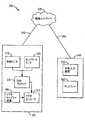
図1を参照すると、ロボット手術システム100の例示的な実施態様の概略図が描写されている。手術システム100は、患者側カート105と、外科医コンソール110と、電子機器/制御装置コンソール115とを含む。図1中のシステム構成部品は、如何なる特定の位置付けにおいても示されておらず、患者に対して手術を実施するよう患者に対して患者側カート105を配置した状態で、図1中のシステム構成部品を所望に配置し得ることが付記される。システム100のようなロボット手術システムの非限定的な例示的な実施態様は、Sunnyvale, CaliforniaのIntuitive Surgical, Inc.によって商品化されているda Vinci(R)(モデル番号IS3000)である。 With reference to FIG. 1, a schematic diagram of an exemplary embodiment of a robotic
ロボット手術システム100は、様々な手術器具とインターフェース接続し且つそれらを制御することによって、最小侵襲的ロボット手術を行うために用いられる。患者側カート105は、様々な手術器具及び/又は関連工具を保持し、位置付け、且つ操作するための、様々なアーム(患者側マニピュレータと呼ぶことがある)を含む。図1に示されるように、患者側カート105のアーム120は、1つ又はそれよりも多くの遠隔制御される手術器具125とインターフェース接続し且つそれらを制御するように構成され、1つ又はそれよりも多くの遠隔制御される手術器具は、例えば、エンドエフェクタ(詳細には示されていない)を含み得る。手術部位でイメージを捕捉するために内視鏡カメラ126も患者側カート105に取り付け得る。 The robotic
外科医コンソール110は、様々な入力装置による外科医からの入力を受信し、様々な入力装置は、1つ又はそれよりも多くのマスタグリップ入力機構130及びフットペダル135のグリップ入力レバー(図示せず)を含むが、それらに限定されない。外科医コンソール110は、マスタコントローラとしての機能を果たし、外科医コンソール110によって、患者側カート105にあるアーム120、手術器具125、及び内視鏡カメラ126は、任意の所望の動き実施し、相応して所望の外科処置を行う、スレーブとして作用する。しかしながら、手術システム100は、外科医コンソール110で入力を受信することに限定されず、患者側カート105で手術器具の操作を正しく実現し得る如何なる装置でも入力を受信し得る。例えば、他の手術器具支持装置との組み合わせにおける外科医コンソール110を通じて、或いは使用者、例えば、外科医から受信される入力の結果として、完全に他の手術支持装置を通じて、患者側カート105にある手術器具を患者側カート105で操作し得る。 The
外科医コンソール110は、プロセッサを含む電子データ処理システムを更に含み得る。プロセッサは、外科医コンソール110からの或いは任意の他の手術器具支持装置からの入力を受信して処理し、そして、そのような入力に基づき患者側カート105での1つ又はそれよりも多くの手術器具の操作を制御するように構成され得る。しかしながら、そのような電子データ処理システムの要素を手術システム100内の他の場所にも設け得る。 The
例えば、プロセッサ及び/又は他の機能的ユニット(例えば、電気外科エネルギ供給ユニット及び/又は他の外科フラックス供給ユニット)を含み得る補助的な電子機器/制御装置カート115が、患者側カート105及び外科医コンソール110から様々な制御信号を受信し、患者側カート105及び外科医コンソール110に送信する。電子機器/制御装置カート115は、例えば、外科医コンソール110にあるディスプレイ140及び/又は電子機器/制御装置カート115と関連付けられるディスプレイ145のようなディスプレイのために、光を送信して(例えば、患者側カート105にある内視鏡カメラ126からの)イメージを処理し得る。当業者は遠隔制御される手術システムのそのような電子機器/制御装置カートを概ね熟知している。 For example, an auxiliary electronics /
様々な例示的な実施態様において、患者側カート105は患者に近接して位置付けられ、例えば、外科医コンソール110から遠隔制御される、手術器具及び/又は内視鏡カメラは、例えば、マスタグリップ入力機構130の手持ち式グリップ入力レバー、フットペダル135、及び/又はカメラ制御機構(印が付されていない)のような、様々なマスタ入力装置を介して、外科医コンソール110から入力を受信する。例えば、遠隔制御される手術器具の組織密封及び/又は切断のような、特定の処置を行うために有用な、例えば、電気焼灼エネルギのような、フラックス(flux)を供給するよう命令信号をもたらすために、フットペダル135を用い得る。例えば、一部のエンドエフェクタの横揺れ、並進、縦揺れ/偏揺れ動作、及び把持/切断動作を含む、遠隔制御される手術器具の動作を制御するよう信号を送信するために、マスタグリップ入力機構130の手持ち式グリップ入力レバーを用い得る。 In various exemplary embodiments, the patient-
手術部位に対するカメラの位置/向き、カメラレンズのズーム、カメラレンズの集束等のような、手術部位のビデオイメージを捕捉し且つ処理することに関連する様々な特徴を制御するよう、アーム120の1つに埋設される内視鏡カメラマニピュレータ(「ECM」)及び内視鏡カメラに信号を送信するために、1つ又はそれよりも多くのカメラ制御機構を用い得る。非限定的な実施例によって、フットペダル135のうちの1つ又はそれよりも多くをカメラ制御機構として割り当て得る。従って、割り当てられるフットペダル135を押すことは、カメラ制御モードに入るようにシステムを移行させ、カメラ制御モードでは、例えば、その移行、更なる入力(「カメラ追従」モード)に基づき及び/又は他の器具の動作(「器具追従」モード)に基づき、カメラを位置決め/方向付け或いはその他の方法で調節し得る。当業者は、患者側カートとインターフェース接続する手術器具及び内視鏡カメラの両方の動作に最終的に影響を及ぼすために外科医コンソールで外科医からの入力をもたらす、そのような遠隔操作されるロボット手術システムの使用を概ね熟知している。 One of the
図2は、本教示の例示的な実施態様に従ったアーム200に取り付けられた例示的な内視鏡カメラ205を備えるカメラアーム200の一部の側面図を例示している。例示的な実施態様において、カメラアーム200は、設置部分210と、マニピュレータ部分ECM215とを含む。ECM215は、偏揺れ動作アクチュエータ220と、縦揺れ動作アクチュエータ225と、入力/出力動作(例えば、並進)アクチュエータ230とを含み、例えば、マスタ入力グリップ機構(例えば、マスタグリップ入力機構130)によって、それらの全てを制御し得る。内視鏡カメラ205はキャリッジ組立体235に取り付けられ、内視鏡カニューレ240がカメラカニューレ取付台245に取り付けられる。ECM215は内視鏡カメラ205を遠隔運動中心250の周りで並びに遠隔運動中心250を通じて移動させる。例示的な実施態様に従ったカメラアームが、図2に例示されるものよりも多い又は少ない要素を含み得る。例えば、本教示に従ったカメラアームが、本教示の精神から逸脱することなく、より多くの又はより少ない図2に示される運動アクチュエータを含んでもよいし、或いは全く含まなくてもよい。更に、本教示はロボット手術システムに限定されず、従って、本教示に従った内視鏡カメラを図2に示されるようなカメラアームに取り付けなくてよく、その代わりに手作業で挿入され且つ操縦される器具であってもよい。 FIG. 2 illustrates a side view of a portion of a
図1及び2を参照して記載されるようなロボット手術システムの操作において、外科処置は患者の体に1つ又はそれよりも多くの切開を作ることを含み得る。そのような切開をそのような切開内で用いられる一片の器具も意味し得る用語である「開口」と呼ぶこともある。一部の外科処置では、手術部位のためのアクセス及び撮像をもたらすために、幾つかの器具及び/又はカメラ開口を用い得る。 In the operation of a robotic surgical system as described with reference to FIGS. 1 and 2, the surgical procedure may include making one or more incisions in the patient's body. Such an incision may be referred to as an “opening”, a term that can also mean a piece of instrument used within such an incision. In some surgical procedures, several instruments and / or camera apertures may be used to provide access and imaging for the surgical site.
図3は、本開示に従ったビデオ処理システムの1つの例示的な実施態様の機能的なブロック図300を例示している。ブロック305は、例えば、図2の内視鏡カメラ205のような、本開示に従ったビデオキャプチャ装置を表している。ビデオキャプチャ装置305は、例えば、手術部位の、視野のイメージコンテンツデータを捕捉する。ブロック310は、例えば、(ISO/IEC MPEG−4 AVCとしても既知である)ITU−T推奨/規格H.264のような、ビデオキャプチャ装置305によって捕捉されるビデオイメージを符号化するためのビデオエンコーダを表している。 FIG. 3 illustrates a functional block diagram 300 of one exemplary embodiment of a video processing system in accordance with the present disclosure.
ブロック315は、視野のイメージコンテンツにおける変化、よって、ビデオキャプチャ装置305によって捕捉されるイメージにおける変化を引き起こし得る状況をモニタリングするための状態モニタを表している。例えば、視野内の物体の動き(例えば、手術器具動作を含む)、ビデオキャプチャ装置の動き、ビデオキャプチャ装置の構成(例えば、ズームイン/ズームアウト)、視野内の液体、気体、又は他の物質/材料の導入/除去のような、1つ又はそれよりも多くの条件によって、視野のイメージコンテンツにおける変化を引き起こし得る。様々な例示的な実施態様では、特定の状況に基づき並びに手術システムの全体的な制御と関連付けられる入力に依存することによって、視野のイメージコンテンツにおける変化を引き起こし得る特定の状態の検出とその特定の状態が引き起こし得る視野のイメージコンテンツにおける対応する変化及び/又は変化の強さとの間のタイミングを予想し且つ/或いは予測し得る。
ブロック320は、符号化されるビデオフレームを対応するネットワークを通じて目的地に送信し得るデータ転送速度に影響を及ぼし得るネットワーク状況をモニタリングするためのネットワークモニタを表している。ブロック325は、ビデオキャプチャ装置305の視野のイメージコンテンツ、よって、符号化されるビデオイメージの品質に影響を及ぼし得る状況(例えば、状態及び/又はネットワーク状況の変化)に基づきビデオエンコーダ310を構成するよう局所的に結合される所謂ビデオ品質向上(VQI)プロセッサを表している。
例示的な実施態様によれば、VQIプロセッサ325は、状態モニタ315及び/又はネットワークモニタ320から情報を受信して、ビデオキャプチャ装置305によって捕捉されるビデオイメージ(即ち、視野のイメージコンテンツ)を符号化するビデオエンコーダ310のための最適な構成を決定する。具体的には、状態モニタ315及びネットワークモニタ320は、ビデオキャプチャ装置305によって捕捉される視野のイメージコンテンツに対する将来的な影響を有し得る変化に関して、VQIプロセッサ325に情報を提供する。VQIプロセッサ325はこの情報を用いて、将来的なビデオイメージの符号化と関連付けられる構成パラメータを更新し、例えば、捕捉されるビデオイメージの高い忠実度、「実時間」ディスプレイを維持するために、変化を予測してその将来的なビデオイメージをより良好に符号化する。 According to an exemplary embodiment, the
非限定的な実施例によって、遠隔制御される手術用途における物体の動きは、例えば、特定の機能(例えば、切断処置を行うための切断刃の活性化)を行うための手術要素の活性化のような、例えば、視野を形成する手術部位での1つ又はそれよりも多くの手術要素の動作を含み得る。撮像される手術部位での動きは、例えば、体部分の動き(例えば、鼓動する心臓、脈打つ静脈等)、例えば、焼灼組織からの煙、洗浄、吸引、血液と関連付けられる液体及び/又は気体の導入及び/又は除去、撮像を助ける蛍光染料又は他の物質の導入等も含み得る。これらの動作/作用は、以下に詳細に説明するように予測し得る、視野のイメージコンテンツにおける変化を引き起こし得る。よって、それらは、視野のイメージコンテンツに対する動作/作用の予測される影響を最小限化するよう、VQIプロセッサ325にビデオエンコーダ310を構成させ得る。 By way of non-limiting example, the movement of an object in a remotely controlled surgical application may be, for example, the activation of a surgical element to perform a specific function (eg, activation of a cutting blade to perform a cutting procedure). Such as, for example, operation of one or more surgical elements at a surgical site that forms a field of view. Motion at the surgical site to be imaged is, for example, body part movement (eg, beating heart, pulsating vein, etc.), eg smoke from ablated tissue, lavage, aspiration, liquid and / or gas associated with blood It may also include introduction and / or removal, introduction of fluorescent dyes or other materials that aid in imaging, and the like. These actions / actions can cause changes in the image content of the field of view that can be predicted as described in detail below. Thus, they may cause the
例えば、特定の遠隔制御される手術作業のために、特定の外科要素又は外科処置を作動させ且つ/或いは操作させ得る前に、外科医は1つ又はそれよりも多くの入力命令を提供することを必要とし得る。例えば、切断処置のために、図1のアーム120のうちの1つのような、ロボットアームで埋設される外科器具125のエンドエフェクタでの切断刃の活性化を含み得る処置を行う準備が出来ていることを示すために、外科医側コンソールでの命令によって生成される第1の入力信号を必要とし得る。図1のフットペダル135のうちの1つのようなフットペダルを押すことによって、第1の入力信号を引き起こし得る。第1の入力信号に応答して、切断要素の状態を「装備状態」(“armed state”)に移行させるように、電子機器/制御装置115のような電子機器/制御装置カートを構成し得る。「装備状態」になるや否や、切断要素の状態を動作状態に移行させる(例えば、切断要素の作動を引き起こす)前に、例えば、フットペダルの第2の押圧によって引き起こされ得る、第2の入力信号を待つように、電子機器/制御装置コンソールを構成し得る。 For example, a surgeon may provide one or more input instructions before a particular surgical element or procedure can be activated and / or manipulated for a particular remotely controlled surgical task. You may need it. For example, for a cutting procedure, ready to perform a procedure that may include activation of a cutting blade at an end effector of a
他の実施例では、外科医がカメラを取り付けるアームを能動的に制御し、それによって、例えば、マスタグリップ入力機構135のうちの1つを用いて、外科医がカメラを移動させるよう制御する場所にカメラを移動させ得るよう、ECMを「追従中」(“in-following”)状態に配置する、外科医側コンソールでの入力命令を提供し得る。(例えば、「追従中」でないカメラと比較され、静止構成記録イメージ中に単に配置される)やがて起こるより大きなカメラ動作、よって、撮像される視野のイメージコンテンツにおける比較的動的で且つ大きい変化を示す状態変化が将来において起こり得るので、そのような命令をモニタリングし得る。更に、特定の状態変化又は状態変化の組み合わせの知識は、視野の目下のイメージコンテンツに対する変化の程度をもたらし得る。視野のイメージコンテンツにおけるやがて起こる変化に関する上記の情報に基づき、VQIプロセッサ325は、視野のイメージコンテンツにおけるやがて起こる変化の予測される影響を最小限化するよう、ビデオエンコーダ310を構成し得る。 In other embodiments, the camera is in a location where the surgeon actively controls the arm to which the camera is attached, thereby controlling the surgeon to move the camera, eg, using one of the master grip input mechanisms 135. An input command at the surgeon's console may be provided that places the ECM in an “in-following” state so that it can be moved. Larger camera movements that will occur in the future (e.g., compared to a camera that is not "following" and simply placed in a static configuration recording image), thus causing relatively dynamic and large changes in the image content of the field of view being imaged. Such a command can be monitored because the indicated state change may occur in the future. Further, knowledge of a particular state change or combination of state changes can result in a degree of change to the current image content of the field of view. Based on the above information regarding upcoming changes in view image content,
上記の実施例は例示的であるに過ぎず、当業者は撮像されるイメージに対する並びに視野内のイメージコンテンツに対する予期される影響と関連付けられるよう前もって知り且つモニタリングし得る手術システムの数多くの他の動作命令を理解するであろう。結果として得られる予期される機能性又は捕捉される視野内のイメージコンテンツの変化をもたらすことが予期されるシステム動作を伴う実質的に如何なるモニタリングされる状態変化にも本開示の範囲を適用し得る。 The above embodiments are exemplary only and many other operations of the surgical system that one skilled in the art can know and monitor in advance to be associated with the expected impact on the imaged image as well as on the image content in the field of view. You will understand the instruction. The scope of the present disclosure can be applied to virtually any monitored state change with system behavior that is expected to result in a change in image content within the resulting expected functionality or captured field of view. .
よって、先行する実施例を例示として用いるならば、本開示の例示的な実施態様において、ブロック315は、様々な入力(例えば、フットペダル135の1つ又はそれよりも多くの押圧)をモニタリングすることによって、ロボット手術システムの状態をモニタリングすることができ、そして、切断要素の状態をVQIプロセッサ325に提供することができ、VQIプロセッサ325は、図4に関して以下に更に説明するように、この情報を用いて、将来的なビデオイメージの符号化と関連付けられる構成パラメータを更新し、例えば、将来的なビデオイメージをより良好に符号化して、切断要素の作動によって引き起こされ得る視野のイメージコンテンツにおける変化を予測して捕捉されるビデオイメージの高い忠実度の「実時間」表示を維持することができる。 Thus, using the preceding example as an illustration, in an exemplary embodiment of the present disclosure, block 315 monitors various inputs (eg, one or more presses of foot pedal 135). By virtue of this, the status of the robotic surgical system can be monitored and the status of the cutting element can be provided to the
上記のブロック305、310、320、及び325は、ブロック330内で具現されるように図3に例示されており、例示的な実施態様では、ブロック330を、例えば、図1の患者側カート105及び/又は電子機器/制御装置115のような、遠隔制御される外科処置を行うための患者側カート及び/又は電子機器/制御装置コンソールにおいて具現し得る。ブロック330内に具現されるように図3に描写される構成部品は通信リンク340を通じて通信ネットワーク335に論理的に結合され、よって、ブロック330内に例示される機能ブロックの少なくとも一部を通信ネットワーク335に論理的に結合させてよく、よって、通信ネットワーク335を通じてブロック330の外部にある要素からデータを受信し且つ/或いはそれられにデータを提供してよい。 The above blocks 305, 310, 320, and 325 are illustrated in FIG. 3 as embodied in
上記のブロック305、310、315、320、及び325は、ブロック330内で具現されるように図3に例示されているが、本開示の例示的な実施態様はそのように限定されず、当業者は本開示の範囲から逸脱せずにこれらのブロックの1つ又はそれよりも多くを互いに別個に並びに/或いは患者側カート及び/又は電子機器/制御装置コンソールと別個に具現し得ることを理解するであろう。当業者は、これらの機能的ブロックのうちの1つ又は1つの装置内で起こるものとして記載される機能を、本開示の範囲から逸脱せずに、分散的な方法において多数の機能ブロック及び/又は多数の装置によって行い得ることを理解するであろう。更に、当業者は、例示的な実施態様が、例えば、簡潔性の故にここでは省略されている、符号化されるビデオイメージを送信し且つ制御情報を受信するための通信インターフェースのような、追加的な機能ブロックを含み得ることも理解するであろう。 Although the
通信ネットワーク335は、機能ブロック345に論理的に結合され、例示的な実施態様では、機能ブロック345を、通信リンク350を通じて、例えば、図1の外科医コンソール110のような、外科医コンソール内で具現に得る。外科医コンソール345は、ブロック355を含むように例示されており、ブロック355は、遠隔制御される手術を行うために外科医コンソール345で操作可能な入力装置を表している。外科医コンソール345は、ブロック360も含み、ブロック360は、ビデオキャプチャ装置305によって捕捉されるイメージから最終的に受信される手術部位のビデオイメージを表示するための、図1の外科医コンソール110のディスプレイ140のような、ディスプレイを表している。外科医コンソール345は、簡潔性のために示されていない追加的な機能ブロックも含み得る。例えば、外科医コンソール345は、その全文を参照としてここに援用する、両方ともMETHOD AND SYSTEM FOR VIDEO PROCESSINGという名称の、2012年5月14日に出願された米国仮特許出願第61/646,597号及び2013年5月10日に出願された米国特許出願第13/891,838号に記載されているような、患者側カート330から受信される符号化されたビデオイメージを復号化するための機能ブロックと、復号化されるビデオイメージを記憶するための機能ブロックと、復号化されるイメージをディスプレイ360に提供するための機能ブロックとを含み得る。ここでは、簡潔性のために、そのような機能ブロックを省略した。
従って、例えば、ビデオエンコーダ310によって符号化される符号化イメージ及び手術入力装置355からの手術制御信号を含む、患者側カート及び電子機器/制御装置コンソール330及び外科医コンソール345の間のデータ通信を、通信リンク340及び350並びに通信ネットワーク335を含む通信経路を通じて実現し得る。 Thus, for example, data communication between the patient-side cart and electronics /
本開示の様々な例示的な実施態様において、通信リンク325及び335は、有線リンク、無線リンク、又はそれらの組み合わせを含み得る。有線リンクは、輸送媒体として金属、ガラス、空気、空間、又は何らかの他の材料を含み得、そこにおける通信を、例えば、インターネットプロトコル(IP)、イーサネット、若しくは当業者が熟知している何らかの他の通信フォーマット、又はそれらの組み合わせのような、通信プロトコルを通じて実現し得る。通信ネットワーク335は、ルータ、コンピュータシステム、又は多数のデバイスを論理的に相互接続し得る任意の他の要素を含み得る。通信ネットワーク335を、構内ネットワーク(LAN)、イントラネット、広域ネットワーク(WAN)、キャリアネットワーク、インターネット、若しくは何らかの他の種類の通信ネットワーク、又はそれらの組み合わせとして具現し得る。よって、本開示の範囲から逸脱せずに、患者側カート及び/又は電子機器/制御装置コンソール330を外科医コンソール345に近接して或いはそこから数百マイルに配置し得る。 In various exemplary embodiments of the present disclosure, the
ビデオキャプチャ装置305は、ビデオイメージを捕捉し且つそのようなビデオイメージをビデオエンコーダ310に提供するための回路構成及び他の構成部品を含み得る。ビデオエンコーダ310は、ビデオキャプチャ装置305から受信されるビデオイメージを符号化するための並びに符号化されるビデオイメージを通信ネットワーク320を通じてディスプレイ360に送信するための回路構成及び他の構成部品を含み得る。例えば、ビデオキャプチャ装置305は、図2の内視鏡カメラ205のような内視鏡カメラを含み得るが、それに限定されない。内視鏡カメラ205は、例えば、デジタルイメージセンサ(例えば、CCD又はCMOS)、実時間磁気共鳴映像法(MRI)キャプチャシステム(図示せず)、超音波キャプチャシステム(図示せず)、又は実時間イメージを遠隔場所に提供し得る任意の他の種類の実時間撮像キャプチャ技術を含む、当業者に既知の様々なイメージキャプチャシステムを利用し得るが、それらに限定されない。
図3に例示される例示的な実施態様のような、本開示の様々な例示的な実施態様において、ビデオキャプチャ装置305は、手術部位のビデオイメージを捕捉し、ビデオイメージをビデオエンコーダ310に提供する。ビデオエンコーダ310は、VQIプロセッサ325によって設定される構成に基づき、受信されるビデオイメージを符号化し、VQIプロセッサ325は、前述のように、視野状態モニタ315及びネットワークモニタ320の少なくとも一方から受信される情報に基づき、そのような構成を設定する。符号化されるイメージは、ディスプレイ360での表示のために通信ネットワーク335を通じて送信される。それらがほぼ捕捉されるときに(例えば、実時間において)、ディスプレイ360を外科医コンソール345に配置し得るし、或いは外科医コンソール345から分離し得る。そのような場合には、例えば、通信ネットワーク335のネットワーク状況によって引き起こされる、通信遅延の如何なる否定的な影響をも最小限化すると同時に、ビデオキャプチャ装置305でのビデオイメージの捕捉とディスプレイ360でのビデオイメージの表示との間の低い待ち時間を維持することが望ましい。捕捉されるものに対する高い忠実度をイメージに提供することも望ましく、イメージが最小のジッター又は他のノイズの現れを伴って比較的滑らかで連続的な方法においてディスプレイ360で現れることも望ましい。 In various exemplary embodiments of the present disclosure, such as the exemplary embodiment illustrated in FIG. 3, the
図4は、例えば、本開示の様々な例示的な実施態様に従った、図3のVQIプロセッサ325のような、VQIプロセッサによって遂行されるVQIアルゴリズムの潜在的な動作を例示するために用いられる表である。具体的には、図4は、例えば、図3の状態モニタ315によってモニタリングされるような、視野のイメージコンテンツに影響を及ぼすことが予期される状態変化に基づき、例えば、図3のビデオエンコーダ310のような、エンコーダの構成を例示している。様々の例示的な実施態様の動作の原理を例示するために、図4は一定の帯域幅(即ち、一定のネットワーク状態)に基づいている。 FIG. 4 is used to illustrate the potential operation of a VQI algorithm performed by a VQI processor, such as, for example, the
列Aは、図3のネットワークモニタ320のようなネットワークモニタから、符号化されるビデオイメージを、例えば、ビデオエンコーダ310から図3のディスプレイ360に送信するために本開示の例示的な実施態様に割り当てられる、予想される最大帯域幅のVQIプロセッサへの入力を提供する。上述のように、視野のイメージコンテンツに影響を及ぼす状態変化に基づくエンコーダの構成に関係する図4の記載の目的のために、列Aは行1−5に沿って一定である(例えば、例示的な実施例において毎秒1メガバイト(Mbps))。 Column A is an exemplary implementation of the present disclosure for transmitting an encoded video image from a network monitor, such as network monitor 320 of FIG. 3, from
本開示の様々な実施態様では、H.264ビデオ圧縮規格に従ってビデオエンコーダ310によってビデオイメージを符号化し得る。H.264では、当業者に周知であるように、H.264エンコーダは、予測、変換、及び符号化プロセスを実行し、圧縮されたH.264ビットストリームの符号化されたビデオイメージを生成する。具体的には、H.264エンコーダは、異なる種類のフレームを生成し、一部のフレーム(いわゆるイントラコード化フレーム(intra-coded frames)又はi−フレーム(i-frames))は、関連するイメージを再現するのに必要な情報を含むのに対し、他のフレーム(いわゆる予測フレーム(predicted frames)又はp−フレーム(p-frames)或いは双方向予測フレーム(bi-predictive frames)又はb-フレーム(b-frames))は、あるフレームと1つ又はそれよりも多くの連続的なフレームとの間の変化のみを含む。簡潔性のために、H.264エンコーダはi−フレーム及びp−フレームのみを生成すると仮定するが、当業者は本開示がそのように限定されず、本開示に従ったH.264エンコーダがb−フレームも生成し得ることを理解するであろう。 In various embodiments of the present disclosure, H.264. The video image may be encoded by the
当業者が同様に熟知しているように、i−フレーム及びp−フレームが(秒当たりのフレーム(fps)において)生成される速度、データがどのように生成されるか(秒当たりのビット(bps))、及び総fps(即ち、秒当たりに生成される全てのフレームの合計)を変更するように、H.264エンコーダを構成し得る。H.264ビデオエンコーダは、H.264ビットストリームを復号化し、逆変換し、且つ再構築する相補的なプロセスを実行し、表示されるビデオイメージを生成する。 As those skilled in the art are familiar, the rate at which i-frames and p-frames are generated (in frames per second (fps)), how the data is generated (bits per second ( bps)), and total fps (ie, the sum of all frames generated per second). H.264 encoder may be configured. H. H.264 video encoder A complementary process of decoding, inverse transforming and reconstructing the H.264 bit stream is performed to produce a displayed video image.
上述のように、図4は、VQIアルゴリズムの動作を記載する表である。列B及びCは、上記H.264ビデオ圧縮規格に従ってビデオイメージを符号化し且つ符号化されたビデオイメージを送信する生成し得る、i−フレーム及びp−フレームの例示的な大きさをそれぞれ提供している。しかしながら、当業者は、本開示に従った様々な例示的な実施態様が他の符号化/復号化アルゴリズムに依存し得ること、或いはH.264規格の異なる実施に依存し得ることを認識するであろう(例えば、H264規格及び本開示はi−フレーム及びp−フレームだけを生成することに限定されず、本開示の例示的な実施態様はb−フレームも生成し得る)。 As described above, FIG. 4 is a table that describes the operation of the VQI algorithm. Columns B and C are the same as those described in H. 2 illustrates exemplary sizes of i-frames and p-frames, respectively, that can be generated to encode a video image and transmit the encoded video image according to the H.264 video compression standard. However, those skilled in the art will recognize that various exemplary embodiments according to the present disclosure may depend on other encoding / decoding algorithms, or It will be appreciated that different implementations of the H.264 standard may be relied upon (eg, the H264 standard and the present disclosure is not limited to generating only i-frames and p-frames; Can also generate b-frames).
加えて、簡潔性のために、一般的には図4の記載において、具体的には列B及びCにおいて、全てのi−フレームは同じ大きさであり且つ全てのpフレームは同じ大きさであると仮定されている。しかしながら、当業者は、これらのフレームの大きさが、例えば、図3のビデオキャプチャ装置305のような、対応するビデオキャプチャ装置によって捕捉されるビデオイメージの特性及び連続的なビデオイメージの量に依存して、異なり得ることを理解するであろう。表4ではp−フレームがi−フレームの半分の大きさであることも仮定されている。しかしながら、当業者は、本開示の範囲から逸脱せずに、符号化構成のi−フレーム対p−フレーム比が実施毎に異なり得ること及び単一の実施内でさえも異なり得ることも理解するであろう。 In addition, for brevity, generally in the description of FIG. 4, specifically in columns B and C, all i-frames are the same size and all p-frames are the same size. It is assumed that there is. However, those skilled in the art will appreciate that the size of these frames depends on the characteristics of the video image captured by a corresponding video capture device, such as the
列Dは、状態モニタの視野から対応するビデオキャプチャ装置(VCD)の視野のイメージコンテンツにおける変化の予測される程度のVQIプロセッサへの入力を提供する。列Dにおいて、レベル1は、VCDの視野のイメージコンテンツにおける小さな変化の予測を示し、レベル9は、VCDの視野のイメージコンテンツにおける大きな変化の予測を示している。 Column D provides an input to the VQI processor of the expected degree of change in the image content of the corresponding video capture device (VCD) field of view from the state monitor field of view. In column D,
例えば、図3の状態モニタ315によって、視野のイメージコンテンツにおける変化の予測される程度をVQIプロセッサに提供し得る。そして、視野のイメージコンテンツにおける変化の予測される程度は、例えば、図3の入力装置345のような、外科医コンソールでの使用者/外科医からの1つ又はそれよりも多くの入力に基づき得る。図3のVCD305の視野のイメージコンテンツにおける変化を引き起こし得る動作を要求する入力装置345での入力を受信した後、状態モニタ315は、受信した入力が引き起こし得る変化の程度を予想し得る。視野のイメージコンテンツにおける変化の程度は、視野のイメージコンテンツを変化させ得る1つ又は多数の事象に基づき得る。そのような事象は、本開示の範囲から逸脱することなく、VCDの構成(例えば、ズームイン/ズームアウト及びカメラを「追従中」に配置すること)、VCDの視野内での1つ又はそれよりも多くの手術器具(例えば、エンドエフェクタ)の作動、手術部位への液体、気体、又は他の物質/材料の導入/除去、及び物体(例えば、体部分及び/又は手術装置)の動作を含み得るが、それらに限定されない。 For example, the status monitor 315 of FIG. 3 may provide the VQI processor with an expected degree of change in the field of view image content. And the expected degree of change in the image content of the field of view may be based on one or more inputs from a user / surgeon at the surgeon console, such as, for example,
本開示の様々な例示的な実施態様によれば、VQIプロセッサは、VCD305の視野のイメージコンテンツにおける予想される変化に基づき、捕捉されるビデオイメージの符号化を動的に構成し得る。視野のイメージコンテンツにおける変化を予測することは、横たわるシステム内の1つ又はそれよりも多くの入力が視野のイメージコンテンツに対して有することが予想される影響の知識に鑑みて、様々な例示的な実施態様において可能にされる。 According to various exemplary embodiments of the present disclosure, the VQI processor may dynamically configure the encoding of the captured video image based on expected changes in the image content of the
例えば、ロボット制御される手術の脈絡において、図3の外科医コンソール345のような、遠隔の外科医コンソールからの入力を、そのような入力が視野のイメージコンテンツにおける変化を引き起こす前に、図3の状態モニタ315によって検出し得る。具体的には、図3に関して上で説明したように、特定の遠隔制御される外科手術のために、特定の手術要素を活性化させ且つ/或いは移動させ得る前に、複数の入力命令を提供することを外科医に要求してよく、それは予想されるべき特定の手術要素の動作によって生成される視野のイメージコンテンツにおける変化を可能にする。外科医がマスタグリップ入力のうちの1つのマスタグリップ入力の動作に従うようカメラを作動させ得る「追従中」モードにおいて作動するように、或いは他の例示的な実施態様では、例えば、切断手術要素及び/又は把持手術要素のような、特定の手術器具の動作に自動的に「従う」ように、図1の内視鏡カメラのようなVCDを構成し得る。 For example, in the context of a robot-controlled surgical procedure, input from a remote surgeon console, such as
特定の手術器具及び/又はカメラが外科医コンソールで積極的に制御され且つ/或いは外科医コンソールでの入力に基づき自動的に制御されるとき、システムは、図3に関して説明したように、予想し得る視野のイメージコンテンツに影響を及ぼす動作及び/又は他の機能を前もって知り得る。加えて、特定の手術要素、それらの動作及び/又は機能、並びに視野のイメージコンテンツに対するそれらの対応する影響についての知識に依存して、視野に対する同じことの可変の影響を予測し得る。例えば、手術器具のジョー付きエンドエフェクタの把持動作が、例えば、視野内の液体、気体、又は他の物質/材料の導入及び/又は除去よりも少なく(例えば、より遅い速度で)視野のイメージコンテンツを変更させ得る。同様に、例えば、視野を体内の1つの場所から他の場所に移動させるために、内視鏡カメラが追従中である間に、そのような把持動作は、内視鏡カメラの動作よりも少ない視野のイメージコンテンツに対する変化を有し得る。 When a particular surgical instrument and / or camera is actively controlled at the surgeon console and / or automatically controlled based on input at the surgeon console, the system may have a predictable field of view as described with respect to FIG. The operations and / or other functions that affect the image content can be known in advance. In addition, depending on the knowledge of specific surgical elements, their behavior and / or function, and their corresponding impact on the image content of the field of view, the same variable effect on the field of view can be predicted. For example, the grasping action of the jawed end effector of the surgical instrument is less (e.g., at a slower rate) than the introduction and / or removal of liquids, gases, or other substances / materials in the field of view. Can be changed. Similarly, such grasping motion is less than that of the endoscopic camera while the endoscopic camera is following, eg, to move the field of view from one location in the body to another. There may be changes to the image content of the field of view.
視野のイメージコンテンツに対する予想される影響を引き起こすそのような状態の変化に関する状態モニタ315からの情報の受信後、VQIプロセッサ325は、視野のイメージコンテンツにおける予想される変化が起こる前に、視野のイメージコンテンツのイメージの高い忠実度の符号化フレームを生成するように、ビデオエンコーダ310を構成し得る。例えば、VQIプロセッサ325は、捕捉されるビデオイメージの符号化品質を改良するためにi−フレームレートを増大させるように、ビデオエンコーダ310を構成し得る。符号化品質におけるこの先買の増大は、さもなければ視野のイメージコンテンツにおける予想される変化が引き起こす品質の減少を未然に防ぎ得る。しかしながら、前述のように、i−フレームレートにおける増大は、ネットワークを通じて符号化ビデオイメージを送信するビットレートを自動的に増大させる。様々な例示的な実施態様において割り当てられる帯域幅は限定的であるので、利用可能な帯域幅に基づき、標的ビットレートが維持されなければならない。よって、i−フレームレートの増大を補償するために、ビデオ送信の総フレームレート(フレーム/秒)は減少させられなければならない。そのような状況の下で、様々な例示的な実施態様によれば、i−フレームレートの増大を補償するためには、p−フレームレートを減少させなければならない。低すぎるpfsは待ち時間を増大させ、よって、適用の実時間性を妥協するので、fpsにおける減少も限定的であることに留意のこと。 After receiving information from the state monitor 315 regarding such state changes that cause the expected effect on the field of view image content, the
列E及びFは、本開示の様々な例示的な実施態様に従ったVCDの視野のイメージコンテンツにおける予想される変化の程度に基づくi−フレーム対p−フレーム比を提供している。 Columns E and F provide i-frame to p-frame ratios based on the expected degree of change in the image content of the VCD field of view in accordance with various exemplary embodiments of the present disclosure.
簡潔性のために、i−フレーム対p−フレーム比を例示するために10の一群のピクチャ(GOP)を選択した(GOPは1つのi−フレームに依存することによって幾つのピクチャ/イメージを提供し得るかを概ね示す)。しかしながら、本開示の様々な例示的な実施態様はそのように限定されず、異なるGOPに依存し得る。 For simplicity, a group of 10 pictures (GOP) was selected to illustrate the i-frame to p-frame ratio (GOP provides several pictures / images by relying on one i-frame. It's generally possible). However, the various exemplary embodiments of the present disclosure are not so limited and may depend on different GOPs.
例示されているように、予想されるVCDの視野のイメージコンテンツにおける小さい程度の変化があるならば、i−フレーム対p−フレーム比はその最小(1/9)である。何故ならば、捕捉されるビデオイメージの高忠実度の実時間の再生をもたらすために、より少ないi−フレームが必要であり得るからである。他方、VCDの視野のイメージコンテンツにおける大きい程度の変化が予想されるならば、i−フレーム対p−フレーム比はその最大(9/1)である。何故ならば、捕捉されるビデオイメージの高い忠実度の実時間の再生をもたらすために、より多くのi−フレームが必要であり得るからである。 As illustrated, if there is a small degree of change in the image content of the expected VCD field of view, the i-frame to p-frame ratio is its minimum (1/9). This is because fewer i-frames may be needed to provide high fidelity real-time playback of the captured video image. On the other hand, if a large degree of change in the image content of the VCD field of view is expected, the i-frame to p-frame ratio is its maximum (9/1). This is because more i-frames may be needed to provide high fidelity real-time playback of the captured video image.
しかしながら、前述のように、利用可能な限定的な帯域幅の故に、i−フレーム対p−フレーム比における増大は、提供し得るフレームの総数における減少を必要とし、それは待ち時間を増大させ且つ適用の実時間性を妥協させ得る。例えば、図4は、行1に例示されるような比較的低いi−フレーム対p−フレーム比で、9fpsのi−フレームレート及び81fpsのp−フレームレートを実現し得、それは合計で90fpsをもたらすと同時に、1Mbpsの最大帯域幅より下の使用される帯域幅を維持する(使用される帯域幅が0.99Mbpsになる列Jを参照)。他方、表の列5において例示されるように、VCDの視野のイメージコンテンツにおける有意な程度の変化が予想されるならば、高い忠実度を維持するために、45fpsのi−フレームレート及び5fpsのみのp−フレームレートを必要とし得る。しかしながら、そのような構成は、使用される帯域幅を1Mbpsの最大帯域幅より下に維持するために、50fpsを生成する(使用される帯域幅が0.95Mbpsになる列Jを参照)。 However, as mentioned above, because of the limited bandwidth available, an increase in the i-frame to p-frame ratio requires a decrease in the total number of frames that can be provided, which increases latency and application. Can compromise real-time performance. For example, FIG. 4 may achieve an i-frame rate of 9 fps and a p-frame rate of 81 fps with a relatively low i-frame to p-frame ratio as illustrated in
図4に関する上記の数/値は例示的且つ非限定的な開示であり、当業者は本開示の例示的な実施態様がここに例示されていない他の数/値を支持し得ることを理解する。例えば、最小侵襲的外科処置のために、15fpsのレートは十分な忠実度をもたらし得るのに対し、20〜30fpsのレート又はそれよりも高いレートは最適な忠実度をもたらし得る。しかしながら、他の用途のためには、本開示の範囲から逸脱せずに、最小侵襲的外科処置のための上記以外の異なるfpsレートが望ましくあり得る。 The above numbers / values with respect to FIG. 4 are exemplary and non-limiting disclosure, and one of ordinary skill in the art will understand that exemplary embodiments of the present disclosure may support other numbers / values not illustrated here. To do. For example, for a minimally invasive surgical procedure, a rate of 15 fps may provide sufficient fidelity, while a rate of 20-30 fps or higher may provide optimal fidelity. However, other fps rates other than those described above for minimally invasive surgical procedures may be desirable for other applications without departing from the scope of the present disclosure.
従って、本開示の様々な例示的な実施態様によれば、VCDの視野のイメージコンテンツに影響を及ぼすことを予想し得る状況がモニタリングされ、エンコーダはビデオキャプチャ装置によって捕捉されるビデオイメージを相応して符号化するように構成される。具体的には、視野のイメージコンテンツにおける変化が起こる前のシステム全体における状態のモニタリングされ且つ検出される変化の故に、視野のイメージコンテンツにおける予想される変化を予測してVCDによって捕捉されるビデオイメージを符号化するように、エンコーダを構成し得る。よって、そのような事象が起こる前に忠実度を下げる事象を予測して高忠実度の符号化を達成し得、それはビデオエンコーダを受け身的に(即ち、忠実度を減少させる事象が起こった後に)構成することに概ね関連付けられる低い忠実度のイメージ期間を未然に防ぎ得る。 Thus, according to various exemplary embodiments of the present disclosure, situations that can be expected to affect the image content of the VCD's field of view are monitored, and the encoder adapts the video image captured by the video capture device. And is configured to be encoded. Specifically, a video image captured by a VCD in anticipation of an expected change in view image content because of the monitored and detected change in state throughout the system before the change in view image content occurs. The encoder may be configured to encode. Thus, high fidelity encoding can be achieved by predicting events that reduce fidelity before such an event occurs, which is passive (ie, after an event that reduces fidelity occurs). It can obviate the low fidelity image periods that are generally associated with constructing.
図5は、本開示の様々の例示的な実施態様に従った、例えば、図3のVQIプロセッサ325のような、VQIプロセッサによって遂行されるVQIアルゴリズムの潜在的な動作を例示するために用いられる表である。具体的には、図5は、例えば、図3のネットワークモニタ320によってモニタリングされるような、視野内で捕捉され且つディスプレイに送信されるイメージコンテンツに影響を及ぼすことが予想されるネットワーク状況における変化に基づく、例えば、図3のビデオエンコーダ310のような、エンコーダの構成を例示している。図5は、本開示の様々な例示的な実施態様に従った、視野の一定なイメージコンテンツ(この場合、図3のVCD305のような、対応するVCDの視野のイメージコンテンツにおける小さな変化)に基づく。 FIG. 5 is used to illustrate the potential operation of a VQI algorithm performed by a VQI processor, such as, for example, the
列Aは、例えば、ビデオエンコーダ310から図3のディスプレイ360に、符号化されたビデオイメージを送信するための、ネットワークモニタから本開示の例示的な実施態様に割り当てられる予想される最大帯域幅のVQIプロセッサへの入力を提供する。しかしながら、列Aが一定なままである図4に示される例示的な条件と対照的に、図5は、通信ネットワーク355に亘って可変の帯域幅をもたらす、可変のネットワーク状況の下のVQIアルゴリズムの動きを例示している。 Column A is the maximum expected bandwidth allocated to an exemplary embodiment of the present disclosure from a network monitor, for example, for transmitting an encoded video image from
図4におけるように、列B及びCは、ビデオイメージを符号化し且つ符号化されたビデオイメージを、例えば、H.264ビデオ圧縮規格に従って送信するよう生成し得る、i−フレーム及びp−フレームの例示的なサイズ(大きさ)をそれぞれ提供している。従って、これらの列はここでは記載されない。 As in FIG. 4, columns B and C encode the video image and the encoded video image, e.g. Each provides exemplary sizes of i-frames and p-frames that can be generated for transmission according to the H.264 video compression standard. Therefore, these columns are not described here.
列Dに関して、図4におけるように、それは対応するVCDの視野のイメージコンテンツにおける予想される変化の程度の視野状態モニタからの入力を提供する。しかしながら、上述のように、図5は可変のネットワーク状況の下のVQIアルゴリズムの例示的な動作を例示している。従って、他の状態変化と無関係に可変のネットワーク状況の影響を具体的に例示するために、図5において、列Dは行1〜5を通じて一定なままである。 With respect to column D, as in FIG. 4, it provides input from the visual state monitor of the degree of expected change in the image content of the corresponding VCD visual field. However, as described above, FIG. 5 illustrates an exemplary operation of the VQI algorithm under variable network conditions. Thus, in order to illustrate specifically the effect of variable network conditions independent of other state changes, in FIG. 5, column D remains constant throughout rows 1-5.
当業者は、図5が状態モニタ315から来る可変の状態状況を例示し、VCD変化の程度は、様々な例示的な実施態様が、例えば、ネットワーク320によってモニタリングされるような、ネットワーク状況における変動に適合するよう、どのようにVQIアルゴリズムを実施するかの理解をもたらす、簡潔性のための例示的なモニタリングされる状態状況であることを理解するであろう。 Those skilled in the art will illustrate the variable status situation that FIG. 5 comes from
列E及びFは、VCDの視野のイメージコンテンツにおける予想される変化の程度に基づくi−フレーム対p−フレーム比を提供する。上述のように、図5は、VCDの視野のイメージコンテンツに影響を及ぼす状態変化の代わりに、(例えば、手術要素の動作のような)可変のネットワーク状況の下のVQIアルゴリズムの動作に向けられるので、列Dは行1〜5に沿って一定なままである。従って、列E及びFは列Dに示される値に依存するので、列E及びFも列1〜5を通じて一定なままである。 Columns E and F provide an i-frame to p-frame ratio based on the expected degree of change in the image content of the VCD field of view. As described above, FIG. 5 is directed to the operation of the VQI algorithm under variable network conditions (eg, operation of surgical elements) instead of state changes that affect the image content of the VCD field of view. So column D remains constant along rows 1-5. Thus, columns E and F remain constant throughout columns 1-5 as columns E and F depend on the values shown in column D.
図5の列G、H、及びIは、本開示の様々な例示的な実施態様に従ったエンコーダの構成を例示している。ネットワークの予想される最大帯域幅が減少すると、本開示に従ったVQIプロセッサの例示的な実施態様が、列G及びHに示されるように、i−フレーム対p−フレーム比を調節して、所望のi−フレーム対p−フレーム比を維持する。結果的に、列Iに示されるように、総フレームレートは減少する。例えば、図5は、表の行1に例示されるように、予想される最大レートが1Mbpsであるとき、9毎秒フレーム(fps)のi−フレームレート及び81fpsのp−フレームレートを実現し得、それは合計で90fpsを生成しながら、使用される帯域幅を最大帯域幅の1Mbpsよりも下に維持することを例示している(使用される帯域幅が0.099Mbpsになる列Jを参照)。例えば、表の行5に例示されるように、予想される最大帯域幅が減少すると、i−フレームレート及びp−フレームレートの両方が減少させられ、よって、総fpsは40fpsまで減少させられて、使用される帯域幅を0.5Mbpsの最大帯域幅より下に維持する(使用される帯域幅が0.44Mbpsになる列Jを参照)。 Columns G, H, and I in FIG. 5 illustrate encoder configurations according to various exemplary embodiments of the present disclosure. As the expected maximum bandwidth of the network decreases, an exemplary implementation of a VQI processor according to the present disclosure adjusts the i-frame to p-frame ratio as shown in columns G and H, Maintain the desired i-frame to p-frame ratio. As a result, as shown in column I, the total frame rate decreases. For example, FIG. 5 may achieve an i-frame rate of 9 frames per second (fps) and a p-frame rate of 81 fps when the maximum expected rate is 1 Mbps, as illustrated in
従って、本開示の様々な例示的な実施態様によれば、符号化されるビデオイメージを送信するのに利用可能な最大帯域幅に影響を及ぼすことを予想し得る1つ又はそれよりも多くの状況がモニタリングされ、エンコーダはそれらの状況に基づきビデオキャプチャ装置によって捕捉されるビデオイメージを符号化するように構成される。具体的には、利用可能な最大帯域幅における変化が起こる前に利用可能な最大帯域幅における予想される変化を予測してビデオキャプチャ装置によって捕捉されるビデオイメージを符号化するように、エンコーダを構成し得る。よって、忠実度を下げるネットワーク状況事象が起こる前から、そのような事象を予測して、高い忠実度の「実時間」符号化を達成し得る。それはビデオエンコーダを受け身的に(即ち、忠実度を下げる事象が起こった後に)構成することに概ね関連付けられる低い忠実度のイメージ期間を未然に防ぎ得る。 Thus, according to various exemplary embodiments of the present disclosure, one or more that can be expected to affect the maximum bandwidth available to transmit the encoded video image. The situations are monitored and the encoder is configured to encode a video image captured by the video capture device based on those situations. Specifically, the encoder is used to encode the video image captured by the video capture device in anticipation of the expected change in the maximum available bandwidth before the change in the maximum available bandwidth occurs. Can be configured. Thus, before a network situation event that reduces fidelity occurs, such an event can be predicted to achieve high fidelity “real-time” coding. It can obviate the low fidelity image periods that are generally associated with passively configuring the video encoder (ie, after an event that reduces fidelity occurs).
図4及び5に示され且つそれらのそれぞれの記載において用いられる数/値は、本開示の例示的な実施態様の動作の特定の原理の理解を助けるために選択されたに過ぎない予言的な実施例である。当業者はこれらの数/値が限定的でなく、本開示の例示的な実施態様がここに例示されていない他の数/値を支持し得ることを理解しよう。 The numbers / values shown in FIGS. 4 and 5 and used in their respective descriptions are only prophetic selected to help understand the specific principles of operation of the exemplary embodiments of the present disclosure. This is an example. Those skilled in the art will appreciate that these numbers / values are not limiting, and exemplary embodiments of the present disclosure may support other numbers / values not illustrated here.
図4はVCDの視野のイメージコンテンツに対する予想される変化の観点における本開示の様々な実施態様に従ったVQIアルゴリズムを例示し、図5は符号化されるビデオイメージを送信するために利用可能な予測される帯域幅に対する予想される変化の観点における本開示の様々な実施態様に従ったVQIアルゴリズムを例示しているが、本開示はそのように限定されない。当業者は、本開示の範囲から逸脱せずに、VQIアルゴリズムが視野のイメージコンテンツ及び対応する捕捉イメージ並びにネットワーク状況(例えば、帯域幅)変化の組み合わせに基づきビデオイメージの符号化を構成し得ることを理解するであろう。 FIG. 4 illustrates a VQI algorithm according to various embodiments of the present disclosure in terms of expected changes to the image content of the VCD field of view, and FIG. 5 can be used to transmit the encoded video image. Although illustrated as a VQI algorithm in accordance with various embodiments of the present disclosure in terms of expected changes to expected bandwidth, the present disclosure is not so limited. One skilled in the art can configure the video image encoding based on a combination of field of view image content and corresponding captured image and network status (eg, bandwidth) changes without departing from the scope of this disclosure. Will understand.
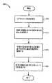
図6は、本開示の少なくとも1つの例示的な実施態様に従ってビデオを処理するための方法を描写しているフロー図である。ステップ605で、本方法は、例えば、図3のビデオキャプチャ装置305のような、ビデオキャプチャ装置によって捕捉される、例えば、手術部位のビデオイメージを受信することを含む。ステップ610で、本方法は、ビデオキャプチャ装置の視野のイメージコンテンツに影響を及ぼし得る状態の変化の表示を受信することを含む。図3及び図4に関して上記で詳細に説明したように、例えば、手術要素の動作、ビデオキャプチャ装置の動作、ビデオキャプチャ装置の構成(例えば、ズームイン/ズームアウト)、及び/又は手術部位での液体、気体、又は他の物質/材料の適用/除去のような、1つ又はそれよりも多くのシステム状況によって、視野のイメージコンテンツに影響を及ぼし得る状態の変化を引き起こし得るし、特定の状況に基づき視野のイメージコンテンツにおける変化の程度を予想し得る。更に、上述のように、外科医側コンソールで受信される様々な入力命令及び/又は外科医コンソールで提供される動作状態における変化若しくは入力命令に続いて起こる自動的機能によって、システム状況を変更し得る。 FIG. 6 is a flow diagram depicting a method for processing video in accordance with at least one exemplary embodiment of the present disclosure. In
ステップ615で、本方法は、ステップ610で受信される表示によって表示される視野のイメージコンテンツにおける状態の変化の予測される影響に基づき捕捉されるビデオイメージを符号化するために、符号化構成を選択的に調節することを含む。符号化構成における変化は、符号化されるべき将来的なイメージのうちの少なくとも1つのイメージの解像度を調節すること、又は符号化されるビデオイメージを生成するために/例えば図3のディスプレイ360のような受信システムに送信するためにイメージフレーム生成レート/送信レートを調節することを含み得る。ステップ620で、本方法は、調節される符号化構成に基づき捕捉されるビデオイメージを符号化することを含む。 In
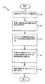
よって、本開示の様々な例示的な実施態様によれば、例えば、VQIを介して、ビデオキャプチャ装置の視野に対するモニタリングされる条件の予測される影響に基づきビデオイメージを符号化するように、ビデオイメージエンコーダを構成し得る。よって、忠実度を下げる事象が起こる前に忠実度を下げる事象を予測して高忠実度の符号化を達成することができ、それはビデオエンコーダを受け身的に(即ち、忠実度を下げる事象が起こった後に並びに忠実度を下げる事象に応答して)構成することに概ね関連付けられる、低い忠実度のイメージ期間を未然に防ぎ得る。図7は、本開示の他の例示的な実施態様に従ってビデオを処理するための方法を描写するフロー図である。ステップ705で、本方法は、例えば、図3のビデオキャプチャ装置305のようなビデオキャプチャ装置によって、例えば、手術部位で捕捉される、ビデオイメージを受信することを含む。ステップ710で、本方法は、ビデオキャプチャ装置の視野のイメージコンテンツに影響を及ぼし得る状態の変化の表示を受信することを含む。図6に関して(更に図3及び図4に関して)上述したように、例えば、手術要素の動き、ビデオキャプチャ装置(例えば、内視鏡カメラ205)の動き、ビデオキャプチャ装置の構成(例えば、ズームイン/ズームアウト)、及び/又は手術部位での液体、気体、又は他の物質/材料の適用/除去のような、1つ又はそれよりも多くののシステム状況によって、視野のイメージコンテンツに影響を及ぼし得る状態の変化を引き起こし得るし、特定の状況に基づき視野のイメージコンテンツにおける変化の程度を予想し得る。 Thus, according to various exemplary embodiments of the present disclosure, video, such as via VQI, to encode a video image based on the expected impact of the monitored condition on the field of view of the video capture device. An image encoder may be configured. Thus, high fidelity encoding can be achieved by predicting the low fidelity event before the low fidelity event occurs, which is passive to the video encoder (ie the low fidelity event occurs). Low fidelity image periods, which are generally associated with composing (after and in response to events that reduce fidelity) may be obviated. FIG. 7 is a flow diagram depicting a method for processing video according to another exemplary embodiment of the present disclosure. In
ステップ715で、本方法は、例えば図3のディスプレイ360のような受信システムへの符号化されるビデオイメージの送信に影響を及ぼし得るネットワーク状況の変化の表示を受信することを含む。例えば、受信システムに符号化されるビデオイメージを転送するために用いられる、例えば、図3の通信ネットワーク335のような、ネットワークの混雑によって、ネットワーク状況の変化を引き起こし得る。例えば、ネットワークを通じる或る量のパケットデータ待ち時間又は損失パケットの決定によって、ネットワーク状況を決定し得る。 In
ステップ720で、本方法は、受信される表示によって示される視野のイメージコンテンツにおける変化のの予測される影響及びそれらの目的地への符号化ビデオイメージの送信におけるネットワーク状況の予想される影響に基づき、捕捉されるビデオイメージを符号化するための符号化構成を選択的に調節することを含む。符号化構成における変化は、符号化されるべき将来的なイメージのうちの少なくとも1つのイメージの解像度を調節すること、又は符号化されるビデオイメージ生成し/符号化されるビデオイメージを図3のディスプレイ360のような受信システムに送信するためのイメージフレーム生成レート/送信レートを調節することを含み得る。ステップ725で、本方法は、調節される符号化構成に基づき、捕捉されるビデオイメージを符号化することを含む。 At
よって、本開示の様々な例示的な実施態様によれば、ビデオキャプチャ装置の視野のイメージコンテンツに関するモニタリングされる状態状況及び/又は符号化されるビデオイメージを目的地に送信するために用いられるネットワークの状況の予想される影響に基づき、VQIを介して、例えば、ビデオイメージを符号化するように、ビデオイメージエンコーダを構成し得る。従って、視野のイメージコンテンツに影響を及ぼすことが予想される状態の発生のみならず、視野のイメージコンテンツに対する予想される影響の性質(例えば、程度)も予測するために(例えば、吸引、洗浄、及び/又は焼灼処置によって引き起こされる大きな流体運動と比較してジョー付きエンドエフェクタの動作又は内視鏡カメラが「追従中」である間の1つの場所から他の場所への内視鏡カメラの移動と比較してジョー付きエンドエフェクタの動作を予想すること)、様々な例示的な実施態様はロボット手術システムの状態及び/又はネットワーク状況をモニタリングするのを更に許容する。 Thus, according to various exemplary embodiments of the present disclosure, a network used to transmit a monitored status situation and / or a video image to be encoded with respect to an image content of a video capture device field of view. The video image encoder may be configured to encode, for example, a video image via VQI based on the expected impact of the situation. Thus, to predict not only the occurrence of conditions that are expected to affect the image content of the field of view, but also the nature (eg, degree) of the expected effect on the image content of the field of view (eg, aspiration, washing, And / or movement of the end effector with jaws compared to the large fluid movement caused by the cauterization procedure or movement of the endoscope camera from one place to another while the endoscope camera is “following” Predicting the operation of the end effector with jaws as compared to), various exemplary embodiments further allow monitoring of the status and / or network status of the robotic surgical system.
図8は、本開示の更に他の実施態様に従ってビデオを処理するための方法を描写している。ステップ805で、例えば、内視鏡カメラ又は図3の患者側カート330に取り付けられる他のビデオキャプチャ装置のような、ビデオキャプチャが、遠隔手術部位のビデオイメージを捕捉し始め、所定の符号化構成に基づき予測されるビデオイメージを図3の外科医コンソール345のディスプレイ360のような遠隔ディスプレイにストリーミングする。遠隔手術部位でのカメラからディスプレイへのビデオイメージの送信は、図3の通信ネットワーク335のような通信ネットワークを通じて起こる。 FIG. 8 depicts a method for processing video according to yet another embodiment of the present disclosure. In
ステップ810で、本方法は、ビデオキャプチャ及び符号化システムのビデオキャプチャ装置の視野のイメージコンテンツに、よって、捕捉されるイメージに影響を及ぼし得る、下に横たわるシステムのビデオキャプチャ及び符号化システム要素での状況をモニタリングすることを含む。図3及び図4に関して詳細に説明したように、遠隔制御される手術システムにおいて、例えば、視野内のロボットアーム及び/又は手術器具の動作、カメラズーム/速度、又は視野内の手術部位への液体又は気体のような物質の導入/除去は、遠隔制御される手術のために、手術部位のビデオを捕捉するビデオキャプチャ装置の視野のイメージコンテンツに影響を及ぼし得る。特定の状況に基づき、視野のイメージコンテンツにおける変化の程度を予想し得る。 In
ステップ815で、本方法は、視野のイメージコンテンツに影響を及ぼすことが予想される状態の変化が起こったか否かを決定することを含む。状態の変化が起こったならば、ステップ820で、本方法は、視野のイメージコンテンツにおける状態の変化の予測される影響が所定の閾値を超えることが予想されるか否かを決定することを含む。所定の閾値は特定の状態の変化に依存し、例えば、視野のイメージコンテンツを捕捉するイメージキャプチャ装置の動作、視野の調節(例えば、ズームイン/ズームアウト)、視野内の器具の動作、又は視野のイメージコンテンツにおける変化を引き起こすことを予測し得る任意の他の作用に基づき得る。 In
例えば、本開示の様々な例示的な実施態様では、例えば、フットペダルを活性化させること(例えば、押圧すること)のような入力が、カメラ制御モードへの移行を示し得る。目下の視野内の特定の変化を引き起こすために、カメラの位置/向きを調節するための更なる入力を予測し得る。予測される変化は、視野での入力及び/又は目下の状況に基づくカメラの予想される速度(例えば、視野内で受ける或いは受けることが予想される他の動作)に基づき得る。従って、カメラの調節の速度のような測定可能な値を、符号化されるパラメータの調節の必要及び程度を決定する所定のカメラ速度閾値と比較し得る。 For example, in various exemplary embodiments of the present disclosure, an input such as, for example, activating (eg, pressing) a foot pedal may indicate a transition to a camera control mode. Further inputs for adjusting the position / orientation of the camera may be predicted to cause specific changes in the current field of view. The expected change may be based on the expected speed of the camera based on the input in the field of view and / or the current situation (e.g., other motions received or expected to be received in the field of view). Thus, a measurable value, such as the speed of camera adjustment, can be compared to a predetermined camera speed threshold that determines the need and degree of adjustment of the encoded parameter.
視野のイメージコンテンツにおける予測される変化の程度及び符号化パラメータにおける関連する変化の決定は、本開示の範囲から逸脱することなく、(使用者からの入力に基づき)遠隔部位で或いは外科医コンソールで起こり得ることを付記する。例えば、様々な例示的な実施態様において、外科医コンソールでのカメラの位置/向きを調節するための入力の受信後、外科医コンソールにある処理ユニットが、入力によって引き起こされるカメラの予想される速度に基づき目下の視野及び視野内のイメージコンテンツの変化を予測し得るし、符号化パラメータの調節の必要及び程度を決定し得る。処理ユニットは符号化パラメータの対応する調節を更に決定し且つCODECの構成のために患者側カートに符号化パラメータを提供し得る。 Determining the expected degree of change in the image content of the field of view and the associated change in the encoding parameters can occur at a remote site (based on input from the user) or at the surgeon console without departing from the scope of this disclosure. Note that you get. For example, in various exemplary embodiments, after receiving input to adjust the position / orientation of the camera at the surgeon console, the processing unit at the surgeon console may be based on the expected speed of the camera caused by the input. Changes in the current field of view and image content within the field of view can be predicted, and the need and degree of adjustment of the encoding parameters can be determined. The processing unit may further determine the corresponding adjustment of the encoding parameters and provide the encoding parameters to the patient side cart for configuration of the CODEC.
状態の変化の予想される影響が所定の閾値を超えるならば、ステップ825で、予想される影響を最小限化するために、符号化構成パラメータを調節する。調節は、本開示の範囲から逸脱することなく、例えば、予想される影響に応じて或いは予想される影響に従った機能に基づき、所定のプロファイルに従ってi−フレームレートを増大させることを含み得る。例えば、限定としてでなく、状態の変化の手段としてイメージキャプチャ装置の速度を用いるとき、i−フレームレートのような符号化構成パラメータにおける変化が、所定の閾値を超えて、イメージキャプチャ装置の速度と比例し得る。 If the expected impact of the state change exceeds a predetermined threshold, in
状態の変化の予想される影響が所定の閾値を超えないならば、ステップ830で、符号化構成パラメータを不変のままとし得るし、或いは符号化パラメータは所定のデフォルト構成状態にあり得る。利用可能な帯域幅のような他の条件が好ましいならば、状態の変化は、それにも拘わらず、例えば、状態の変化の如何なる影響をも最小限化するために、構成パラメータが調節されるようにさせ得る。この調節は、例えば、i−フレームレートを所定の量(例えば、秒当たり1つの追加的なi−フレーム)だけ増大させることを含み得るし、或いは所定のデフォルト構成状態の更新を含み得る。 If the expected impact of the state change does not exceed a predetermined threshold, at
ステップ840で、本方法は、ビデオキャプチャ装置と遠隔ディスプレイとの間のネットワーク状況をモニタリングすることも含み得る。モニタリングし得るネットワーク状況は、例えば、符号化されるビデオイメージを送信するための利用可能な帯域幅、及び/又はパケット損失レートを含む。ステップ845で、本方法は、利用可能な帯域幅における減少又はパケット損失の割合における増大のようなネットワーク状況における変化が起こったか否かを決定する。ステップ850で、ネットワーク状況が変化したならば(例えば、利用可能な帯域幅における減少)、例えば、送信データ転送速度(即ち、ビットレート)を減少させること、i−フレームレートを減少させること、及び/又は受信システムに送信されるフレームの全体的なフレームレートを減少させることによって、ネットワーク状況における変化の影響を克服するために、符号化構成パラメータは調節される。ステップ855で、本方法は、あらゆる調節される符号化構成パラメータを、例えば、図3のビデオエンコーダ310のような、ビデオエンコーダに提供することを含む。 At
よって、本開示の様々な例示的な実施態様によれば、ビデオキャプチャ装置の視野に対するモニタリングされる状態及び符号化されるビデオイメージを目的地に送信するために用いられるネットワークの状況の予想される影響に基づきビデオイメージを符号化するように、ビデオイメージエンコーダを構成し得る。よって、忠実度を下げる事象が起こる前に忠実度を下げる事象を予想して高い忠実度の符号化を達成し得る。それはビデオエンコーダを受け身的に(即ち、忠実度を下げる事象が起こった後に)ビデオエンコーダを構成することに概ね関連付けられる低い忠実度イメージ期間を未然に防ぎ得る。 Thus, according to various exemplary embodiments of the present disclosure, the expected state of the network being used to transmit the monitored status to the field of view of the video capture device and the encoded video image to the destination. A video image encoder may be configured to encode a video image based on the influence. Thus, high fidelity encoding can be achieved in anticipation of an event that reduces fidelity before an event that reduces fidelity occurs. It may obviate the low fidelity image period that is generally associated with configuring the video encoder passively (i.e., after an event that reduces fidelity occurs).
図9は、本開示に従ったビデオ処理システムの例示的な実施態様を例示している。ビデオ処理システム900は、VQIプロセッサ325の実施例であるが、当業者は本開示に従ったVQIプロセッサを別に構成し得ることを認識するであろう。ビデオプロセッサ900は、通信インターフェース901と、処理システム903とを含む。処理システム903は、通信インターフェース901にリンクさせられる。処理システム903は、処理回路構成と、ソフトウェア905を記憶する記憶システム904とを含む。ビデオプロセッサ900は、明瞭性のために示さない電力システム、電池、及び/又は筐体(enclosure)のような、他の周知の構成部品を含み得る。 FIG. 9 illustrates an exemplary implementation of a video processing system in accordance with the present disclosure.
通信インターフェース901は、ビデオ処理システム900の外部の装置とインターフェース接続する少なくとも通信回路構成を含み、有線及び/又は無線通信のための回路構成を含み得る。更に、上述の図3の状態モニタ315、図3のネットワークモニタ320、及び図3のビデオエンコーダ310のような、本開示の様々な例示的な実施態様によって遂行される機能の少なくとも一部を実施するために、他のシステム及び/又は要素と通信するように、通信インターフェース901を構成し得る。通信インターフェース901は、メモリ装置、ソフトウェア、処理回路構成、又は何らかの他の通信装置も含み得るし、或いは本開示において言及される通信の種類を実現し得る。
処理システム903は、記憶システム904からソフトウェア905を抽出し且つソフトウェア905を実行する、マイクロプロセッサ及び他の回路構成を含み得る。記憶システム904は、ディスクドライブ、フラッシュドライブ、データ記憶装置回路構成、又は何らかの他の記憶装置を含む。処理システム903は、典型的には、記憶システム904及び/又は通信インターフェース901の部分も保持し得る回路板に取り付けられる。 Processing system 903 may include a microprocessor and other circuitry that extracts
ソフトウェア905は、例えば、本開示おいて記載したVQIアルゴリズムのような、アルゴリズムを実施するために、コンピュータプログラム、ファームウェア、又は何らかの他の形態の機械読取り可能な処理指令を含む。ソフトウェア905は、オペレーティングシステム、ユーティリティ、ドライバ、ネットワークインターフェース、アプリケーション、又は何らかの他の種類のソフトウェアを含み得る。処理システム903によって実行されるとき、ソフトウェア905は、処理システム903に命令して、VQIプロセッサ325のためにここに記載されるようにビデオプロセッサ900を作動させる。 The
データを記憶し、抽出し、処理し、且つ/或いは出力し、且つ/或いは他のコンピュータと通信し得る(非限定的な実施例においる)任意のコンピュータのような、コンピュータハードウェア(コンピュータ装置)及び/又はソフトウェアにおいて、本開示の様々な示的な実施態様を実施し得る。生成される結果をコンピュータハードウェアのディスプレイに表示し得る。上記で議論したような電気手術処理ユニットのような電子機器/制御装置115のプロセッサによって、或いは電子機器/制御装置115と共に、本開示の様々な例示的な実施態様に従った様々な応答及び信号処理に影響を及ぼすアルゴリズムを含む1つ又はそれよりも多くのプログラム/ソフトウェアを実施し得るし、コンピュータ読取り可能な記録及び/又は記憶媒体を含むコンピュータ読取り可能な媒体に記録し得る。コンピュータ読取り可能な記録媒体の実施例は、磁気記録装置、光ディスク、光磁気ディスク、及び/又は半導体メモリ(例えば、RAM,ROM等)を含む。磁気記録装置の実施例は、ハードディスクドライブ(HDD)、フレキシブルディスク(FD)、及び磁気テープ(MT)を含む。光ディスクの実施例は、DVD(デジタル多目的ディスク)、DVD−RAM、CD−ROM(コンパクトディスク−読出し専用記憶装置)、及びCD−R(記録可能)/RWを含む。 Computer hardware (computer, such as any computer (in a non-limiting example) that can store, extract, process, and / or output data and / or communicate with other computers. Various illustrative embodiments of the present disclosure may be implemented in the device) and / or software. The generated results may be displayed on a computer hardware display. Various responses and signals according to various exemplary embodiments of the present disclosure by or in conjunction with a processor of an electronic device /
上述のように、器具の近位端にある送信機構を介して作動させられる構成部品を介して多数の外科処置を遂行するように構成されるエンドエフェクタを有する手術器具と共に、様々な例示的な実施態様に従った方法及びシステムを用い得る。更に、実施態様の或る特徴によれば、既述の特徴、機能、及び/又は操作の如何なる組み合わせをも提供し得る。 As described above, various exemplary instruments may be used with a surgical instrument having an end effector configured to perform a number of surgical procedures via a component that is actuated via a transmission mechanism at the proximal end of the instrument. Methods and systems according to embodiments may be used. Further, certain features of the embodiments may provide any combination of the features, functions, and / or operations described above.
H.264符号化/復号化プロトコルに従ったイメージの符号化/復号化及び送信の脈絡内で様々な例示的な実施態様に従った方法及びシステムを説明した。しかしながら、当業者は、本開示がそのように限定されないこと、本開示の範囲から逸脱することなく、1つ又はそれよりも多くの他の符号化/復号化の脈絡内で本開示の要素の一部又は全部を用い得ることを理解する。 H. Methods and systems according to various exemplary embodiments have been described within the context of image encoding / decoding and transmission according to the H.264 encoding / decoding protocol. However, one of ordinary skill in the art will recognize that the present disclosure is not so limited, and that one or more other encoding / decoding contexts within the context of the present disclosure may be used without departing from the scope of the present disclosure. Understand that some or all may be used.
本開示及びここにある請求項の明細及び実施の考察から、本発明の他の実施態様は当業者に明らかであろう。明細及び実施例は例示的であるに過ぎないとして考えられるべきことが意図され、均等物を含む範囲は請求項によって示される。 Other embodiments of the invention will be apparent to those skilled in the art from consideration of the specification and practice of the disclosure and the claims herein. It is intended that the specification and examples be considered as exemplary only, with a scope including equivalents being indicated by the claims.
Claims (17)
Translated fromJapanese前記イメージキャプチャ装置の視野内で処置を遂行するシステムの状態の変化と関連付けられる入力を受信することに応答して、ビデオエンコーダの符号化構成を調節することを含み、
前記システムの前記状態の変化は、前記視野内のイメージデータコンテンツに対する影響を有することが予想される、
方法。A method of processing a video of image data captured by an image capture device, comprising:
Adjusting the encoding configuration of the video encoder in response to receiving input associated with a change in the state of the system performing a procedure within the field of view of the image capture device;
The change in state of the system is expected to have an impact on the image data content in the field of view.
Method.
前記符号化構成を調節することは、前記i−フレームレート及び/又は前記p−フレームレートを調節することを含む、
請求項1に記載の方法。Encoding the image data based on the adjusted encoding configuration generates an i-frame at an intra frame (i-frame) rate and a p-frame at a predicted inter frame (p-frame) rate. Including generating,
Adjusting the coding configuration includes adjusting the i-frame rate and / or the p-frame rate.
The method of claim 1.
前記p−フレームレートを調節することは、前記i−フレームレート及び所定の送信データ転送速度の前記調節に基づく、
請求項4に記載の方法。Further comprising transmitting the generated i-frame and p-frame to a video decoder at a predetermined transmission data rate;
Adjusting the p-frame rate is based on the adjustment of the i-frame rate and a predetermined transmission data rate.
The method of claim 4.
前記符号化構成を調節することは、目下捕捉されているイメージコンテンツデータと前記状態の変化によって影響させられるときの予想される捕捉されるイメージコンテンツデータとの間の予測される差に基づく、
請求項1に記載の方法。The input associated with the change in state includes an input associated with controlling operation of the image capture device, an input associated with controlling adjustment of a field of view of the image capture device, and the input of the image capture device. Including at least one of inputs associated with controlling movement of an element within the field of view;
Adjusting the encoding configuration is based on an expected difference between the currently captured image content data and the expected captured image content data when affected by the change in state.
The method of claim 1.
イメージデータを符号化するようビデオ符号化構成データを生成するためのビデオプロセッサとを含む、
手術システムであって、
前記ビデオプロセッサは、
当該手術システムの状態の変化に関連付けられる入力を受信し、且つ
該入力に基づき調節されるビデオ符号化構成データを出力するように構成される、
手術システム。An endoscopic image capture device;
A video processor for generating video encoding configuration data to encode image data;
A surgical system,
The video processor is
Configured to receive input associated with a change in state of the surgical system and to output video encoding configuration data adjusted based on the input;
Surgery system.
該イメージエンコーダは、
前記プロセッサから前記ビデオ符号化構成データを受信し、
前記内視的イメージキャプチャ装置から前記イメージデータを受信し、且つ
前記受信されるビデオ符号化構成データに基づき前記受信されるイメージデータを符号化するように構成される、
請求項10に記載の手術システム。An image encoder logically coupled to the processor and the endoscopic image capture device;
The image encoder is
Receiving the video encoding configuration data from the processor;
Receiving the image data from the endoscopic image capture device, and configured to encode the received image data based on the received video encoding configuration data;
The surgical system according to claim 10.
前記ビデオプロセッサは、前記通信リンクの状態を示す入力を受信するように更に構成され、
前記調節されるビデオ符号化構成データは、イントラフレーム(i−フレーム)レートパラメータと、前記通信リンクの状態を示す前記入力に基づき前記視野の前記捕捉されるイメージコンテンツを符号化するための予測インターフレーム(p−フレーム)レートパラメータとを含む、
請求項12に記載の手術システム。An output communication interface logically coupled to the image encoder to provide the encoded image data to a display over a communication link;
The video processor is further configured to receive an input indicating a status of the communication link;
The adjusted video encoding configuration data includes a predictive interface for encoding the captured image content of the field of view based on an intra frame (i-frame) rate parameter and the input indicating a state of the communication link. Frame (p-frame) rate parameters,
The surgical system according to claim 12.
前記ビデオプロセッサは、前記通信リンクの状態を示す入力を受信するように更に構成され、
前記調節されるビデオ符号化構成データは、イメージ符号化解像度及び/又は前記通信リンクの状態を示す前記入力に基づき前記イメージデータを符号化するためのイメージ符号化レートを更に含む、
請求項10に記載の手術システム。An output communication interface that is logically coupled to the image encoder to provide image data encoded over the communication link to the display;
The video processor is further configured to receive an input indicating a status of the communication link;
The adjusted video encoding configuration data further includes an image encoding rate for encoding the image data based on the input indicating an image encoding resolution and / or a state of the communication link.
The surgical system according to claim 10.
Applications Claiming Priority (3)
| Application Number | Priority Date | Filing Date | Title |
|---|---|---|---|
| US201261683493P | 2012-08-15 | 2012-08-15 | |
| US61/683,493 | 2012-08-15 | ||
| PCT/US2013/054862WO2014028573A1 (en) | 2012-08-15 | 2013-08-14 | Methods and systems for optimizing video streaming |
Related Child Applications (1)
| Application Number | Title | Priority Date | Filing Date |
|---|---|---|---|
| JP2017242775ADivisionJP6567030B2 (en) | 2012-08-15 | 2017-12-19 | Method and system for video streaming |
Publications (2)
| Publication Number | Publication Date |
|---|---|
| JP2015532040Atrue JP2015532040A (en) | 2015-11-05 |
| JP6265994B2 JP6265994B2 (en) | 2018-01-24 |
Family
ID=50100509
Family Applications (5)
| Application Number | Title | Priority Date | Filing Date |
|---|---|---|---|
| JP2015527561AActiveJP6265994B2 (en) | 2012-08-15 | 2013-08-14 | Method and system for video streaming |
| JP2017242775AActiveJP6567030B2 (en) | 2012-08-15 | 2017-12-19 | Method and system for video streaming |
| JP2019139464AActiveJP6833926B2 (en) | 2012-08-15 | 2019-07-30 | Methods and systems for video streaming |
| JP2021015674AActiveJP7114760B2 (en) | 2012-08-15 | 2021-02-03 | Method and system for video streaming |
| JP2022119978AActiveJP7379609B2 (en) | 2012-08-15 | 2022-07-27 | Method and system for video streaming |
Family Applications After (4)
| Application Number | Title | Priority Date | Filing Date |
|---|---|---|---|
| JP2017242775AActiveJP6567030B2 (en) | 2012-08-15 | 2017-12-19 | Method and system for video streaming |
| JP2019139464AActiveJP6833926B2 (en) | 2012-08-15 | 2019-07-30 | Methods and systems for video streaming |
| JP2021015674AActiveJP7114760B2 (en) | 2012-08-15 | 2021-02-03 | Method and system for video streaming |
| JP2022119978AActiveJP7379609B2 (en) | 2012-08-15 | 2022-07-27 | Method and system for video streaming |
Country Status (6)
| Country | Link |
|---|---|
| US (2) | US10806325B2 (en) |
| EP (3) | EP4284001A3 (en) |
| JP (5) | JP6265994B2 (en) |
| KR (3) | KR102365946B1 (en) |
| CN (2) | CN109348220B (en) |
| WO (1) | WO2014028573A1 (en) |
Cited By (5)
| Publication number | Priority date | Publication date | Assignee | Title |
|---|---|---|---|---|
| JP2022540169A (en)* | 2019-07-11 | 2022-09-14 | シーエムアール・サージカル・リミテッド | Correction of data from surgical robotic systems |
| JP2022164926A (en)* | 2018-10-06 | 2022-10-27 | シスメックス株式会社 | REMOTE SUPPORT METHOD FOR SURGERY ASSIST ROBOT, AND REMOTE SUPPORT SYSTEM |
| JP2023507063A (en)* | 2019-12-19 | 2023-02-21 | ソニーグループ株式会社 | Methods, devices, and systems for controlling image capture devices during surgery |
| JP2024133585A (en)* | 2019-08-23 | 2024-10-02 | インテュイティブ サージカル オペレーションズ, インコーポレイテッド | Movable Display System |
| WO2025023331A1 (en)* | 2023-07-27 | 2025-01-30 | 地方独立行政法人神奈川県立産業技術総合研究所 | Remote medical support system, remote medical support method, and program |
Families Citing this family (21)
| Publication number | Priority date | Publication date | Assignee | Title |
|---|---|---|---|---|
| KR102365946B1 (en)* | 2012-08-15 | 2022-02-23 | 인튜어티브 서지컬 오퍼레이션즈 인코포레이티드 | Methods and systems for optimizing video streaming |
| DE102013108228A1 (en)* | 2013-07-31 | 2015-02-05 | MAQUET GmbH | Assistance device for the imaging support of an operator during a surgical procedure |
| KR20170035831A (en)* | 2014-03-14 | 2017-03-31 | 시냅티브 메디컬 (바베이도스) 아이엔씨. | Intelligent positioning system and methods therefore |
| DE102014016843A1 (en)* | 2014-11-13 | 2016-05-19 | Kuka Roboter Gmbh | System with a medical instrument and a receiving means |
| EP3029936A1 (en)* | 2014-12-05 | 2016-06-08 | Axis AB | Method and device for real-time encoding |
| EP3463158B1 (en)* | 2016-05-26 | 2023-08-30 | Covidien LP | Cannula assemblies for use with robotic surgical systems |
| CN110062608B (en)* | 2016-11-11 | 2023-04-25 | 直观外科手术操作公司 | Teleoperated surgical system with scan-based positioning |
| JP6858593B2 (en)* | 2017-03-02 | 2021-04-14 | ソニー・オリンパスメディカルソリューションズ株式会社 | Medical observation device and control method |
| US11712320B2 (en) | 2017-03-21 | 2023-08-01 | Stryker Corporation | Methods and systems to automate surgical interventions |
| JP6975004B2 (en)* | 2017-10-03 | 2021-12-01 | ソニー・オリンパスメディカルソリューションズ株式会社 | Medical observation device and medical observation system |
| BR102018007667A2 (en)* | 2018-04-16 | 2019-10-29 | Mendes Alves Pereira Ricardo | clinical-surgical data storage device, system and process |
| EP3579553B1 (en)* | 2018-06-05 | 2020-05-20 | Axis AB | A method, controller, and system for encoding a sequence of video frames |
| JP2023523561A (en)* | 2020-04-13 | 2023-06-06 | カリベル・ラブズ・インコーポレーテッド | System and method for computer-assisted signage or fiducial placement in video |
| DE102021100124A1 (en)* | 2021-01-07 | 2022-07-07 | Schölly Fiberoptic GmbH | Method for transmitting a raw image data stream from an image sensor |
| US20220238202A1 (en)* | 2021-01-22 | 2022-07-28 | Ethicon Llc | Cooperative processing of surgical sensor-data streams |
| WO2022221341A1 (en) | 2021-04-12 | 2022-10-20 | Chandra Jonelagadda | Systems and methods for using image analysis in superior capsule reconstruction |
| EP4350654B1 (en) | 2022-10-03 | 2024-11-27 | Axis AB | Camera information handover |
| KR20240102817A (en)* | 2022-12-26 | 2024-07-03 | 광운대학교 산학협력단 | Video compression transmission method and apparatus for telemedicine system |
| CN115811610B (en)* | 2023-01-13 | 2023-05-05 | 安徽医科大学 | An image transmission method and system suitable for wireless endoscopes |
| CN117221177B (en)* | 2023-11-08 | 2024-01-09 | 湖南省华芯医疗器械有限公司 | Image transmission delay monitoring method and system |
| CN117281616B (en)* | 2023-11-09 | 2024-02-06 | 武汉真彩智造科技有限公司 | Operation control method and system based on mixed reality |
Citations (7)
| Publication number | Priority date | Publication date | Assignee | Title |
|---|---|---|---|---|
| JP2002199398A (en)* | 2000-12-27 | 2002-07-12 | Kddi Corp | Variable bit rate video encoding device and recording medium |
| JP2004521662A (en)* | 2000-05-15 | 2004-07-22 | ギブン・イメージング・リミテツド | System for controlling capture and display rates of an in vivo camera |
| JP2005073218A (en)* | 2003-08-07 | 2005-03-17 | Matsushita Electric Ind Co Ltd | Image processing device |
| JP2005143668A (en)* | 2003-11-12 | 2005-06-09 | Olympus Corp | Capsule endoscope |
| JP2006128997A (en)* | 2004-10-28 | 2006-05-18 | Sharp Corp | Video transmission device, video reception device, video transmission method, and video transmission system |
| JP2010142597A (en)* | 2008-12-22 | 2010-07-01 | Hoya Corp | Endoscope system |
| WO2012033200A1 (en)* | 2010-09-10 | 2012-03-15 | オリンパスメディカルシステムズ株式会社 | Image capture device |
Family Cites Families (38)
| Publication number | Priority date | Publication date | Assignee | Title |
|---|---|---|---|---|
| US5217453A (en)* | 1991-03-18 | 1993-06-08 | Wilk Peter J | Automated surgical system and apparatus |
| JPH0896522A (en) | 1994-09-20 | 1996-04-12 | Sony Corp | Data encoder |
| US6111870A (en) | 1996-11-07 | 2000-08-29 | Interdigital Technology Corporation | Method and apparatus for compressing and transmitting high speed data |
| JP3592025B2 (en)* | 1997-03-11 | 2004-11-24 | キヤノン株式会社 | Captured image recording device |
| US6026097A (en)* | 1997-03-13 | 2000-02-15 | 8 X 8, Inc. | Data processor having controlled scalable input data source and method thereof |
| US20020128661A1 (en)* | 1998-02-24 | 2002-09-12 | Brock David L. | Surgical instrument |
| US10973397B2 (en)* | 1999-03-01 | 2021-04-13 | West View Research, Llc | Computerized information collection and processing apparatus |
| KR100367000B1 (en) | 1999-06-29 | 2003-01-06 | 한국전자통신연구원 | PC-based codec device for multichannel audio/speech and data with multimedia engine and input/output modules for multimedia data processing |
| US6873655B2 (en) | 2001-01-09 | 2005-03-29 | Thomson Licensing A.A. | Codec system and method for spatially scalable video data |
| JP4194771B2 (en)* | 2001-06-29 | 2008-12-10 | オリンパス株式会社 | Heat treatment device |
| US7319720B2 (en)* | 2002-01-28 | 2008-01-15 | Microsoft Corporation | Stereoscopic video |
| DE10219528A1 (en)* | 2002-05-02 | 2003-11-13 | Philips Intellectual Property | Fast nuclear magnetic resonance imaging with gradient echoes |
| EP1520431B1 (en)* | 2002-07-01 | 2018-12-26 | E G Technology Inc. | Efficient compression and transport of video over a network |
| JP3944440B2 (en) | 2002-09-27 | 2007-07-11 | 三菱電機株式会社 | Moving picture transmission system, emergency medical transmission system, and moving picture transmission apparatus |
| CN101243688A (en)* | 2004-06-07 | 2008-08-13 | 斯灵媒体公司 | Personal Media Broadcasting System |
| US7984179B1 (en)* | 2004-06-29 | 2011-07-19 | Sextant Navigation, Inc. | Adaptive media transport management for continuous media stream over LAN/WAN environment |
| US8934533B2 (en)* | 2004-11-12 | 2015-01-13 | Pelco, Inc. | Method and apparatus for controlling a video surveillance display |
| JP4727221B2 (en)* | 2004-12-21 | 2011-07-20 | ルネサスエレクトロニクス株式会社 | Video signal processing apparatus and video signal processing method |
| US7894531B1 (en)* | 2005-02-15 | 2011-02-22 | Grandeye Ltd. | Method of compression for wide angle digital video |
| JP2007036650A (en)* | 2005-07-27 | 2007-02-08 | Keio Gijuku | Multimedia communication device |
| JP2009507617A (en)* | 2005-09-14 | 2009-02-26 | ネオガイド システムズ, インコーポレイテッド | Method and apparatus for performing transluminal and other operations |
| US8079950B2 (en)* | 2005-09-29 | 2011-12-20 | Intuitive Surgical Operations, Inc. | Autofocus and/or autoscaling in telesurgery |
| US8373748B2 (en)* | 2005-12-14 | 2013-02-12 | Stryker Corporation | Automatic endoscope recognition and selection of image processing and display settings |
| EP2030097A1 (en)* | 2006-05-31 | 2009-03-04 | Koninklijke Philips Electronics N.V. | Controlling a viewing parameter |
| US20080117968A1 (en)* | 2006-11-22 | 2008-05-22 | Capso Vision, Inc. | Movement detection and construction of an "actual reality" image |
| WO2008154007A1 (en) | 2007-06-08 | 2008-12-18 | Cynosure, Inc. | Surgical waveguide |
| US8057394B2 (en)* | 2007-06-30 | 2011-11-15 | St. Jude Medical, Atrial Fibrillation Division, Inc. | Ultrasound image processing to render three-dimensional images from two-dimensional images |
| US8774950B2 (en)* | 2008-01-22 | 2014-07-08 | Carnegie Mellon University | Apparatuses, systems, and methods for apparatus operation and remote sensing |
| JP5154961B2 (en) | 2008-01-29 | 2013-02-27 | テルモ株式会社 | Surgery system |
| US8808164B2 (en)* | 2008-03-28 | 2014-08-19 | Intuitive Surgical Operations, Inc. | Controlling a robotic surgical tool with a display monitor |
| JP5587331B2 (en)* | 2008-11-21 | 2014-09-10 | ストライカー コーポレイション | Wireless operating room communication system |
| US8291855B2 (en) | 2009-01-16 | 2012-10-23 | Hoerl Jr Jeffrey Joseph | Mobile robot printer for large image reproduction |
| JP2010199656A (en)* | 2009-02-23 | 2010-09-09 | Panasonic Corp | Video image pickup device |
| US20100283857A1 (en)* | 2009-05-05 | 2010-11-11 | Honeywell International Inc. | Event based dynamic change in video quality parameters of network cameras |
| US10178406B2 (en)* | 2009-11-06 | 2019-01-08 | Qualcomm Incorporated | Control of video encoding based on one or more video capture parameters |
| JP5496852B2 (en)* | 2010-10-26 | 2014-05-21 | 富士フイルム株式会社 | Electronic endoscope system, processor device for electronic endoscope system, and method for operating electronic endoscope system |
| US9445058B2 (en) | 2012-05-14 | 2016-09-13 | Intuitive Surgical Operations, Inc | Method for video processing using a buffer |
| KR102365946B1 (en)* | 2012-08-15 | 2022-02-23 | 인튜어티브 서지컬 오퍼레이션즈 인코포레이티드 | Methods and systems for optimizing video streaming |
- 2013
- 2013-08-14KRKR1020217034593Apatent/KR102365946B1/enactiveActive
- 2013-08-14EPEP23203785.3Apatent/EP4284001A3/enactivePending
- 2013-08-14EPEP19202592.2Apatent/EP3624045B1/enactiveActive
- 2013-08-14KRKR1020217013970Apatent/KR102319400B1/enactiveActive
- 2013-08-14WOPCT/US2013/054862patent/WO2014028573A1/enactiveApplication Filing
- 2013-08-14JPJP2015527561Apatent/JP6265994B2/enactiveActive
- 2013-08-14EPEP13829827.8Apatent/EP2885765B1/enactiveActive
- 2013-08-14KRKR1020157003668Apatent/KR102252078B1/enactiveActive
- 2013-08-14CNCN201811328542.6Apatent/CN109348220B/enactiveActive
- 2013-08-14USUS13/966,642patent/US10806325B2/enactiveActive
- 2013-08-14CNCN201380043166.5Apatent/CN104584068B/enactiveActive
- 2017
- 2017-12-19JPJP2017242775Apatent/JP6567030B2/enactiveActive
- 2019
- 2019-07-30JPJP2019139464Apatent/JP6833926B2/enactiveActive
- 2020
- 2020-09-28USUS17/034,878patent/US11889975B2/enactiveActive
- 2021
- 2021-02-03JPJP2021015674Apatent/JP7114760B2/enactiveActive
- 2022
- 2022-07-27JPJP2022119978Apatent/JP7379609B2/enactiveActive
Patent Citations (7)
| Publication number | Priority date | Publication date | Assignee | Title |
|---|---|---|---|---|
| JP2004521662A (en)* | 2000-05-15 | 2004-07-22 | ギブン・イメージング・リミテツド | System for controlling capture and display rates of an in vivo camera |
| JP2002199398A (en)* | 2000-12-27 | 2002-07-12 | Kddi Corp | Variable bit rate video encoding device and recording medium |
| JP2005073218A (en)* | 2003-08-07 | 2005-03-17 | Matsushita Electric Ind Co Ltd | Image processing device |
| JP2005143668A (en)* | 2003-11-12 | 2005-06-09 | Olympus Corp | Capsule endoscope |
| JP2006128997A (en)* | 2004-10-28 | 2006-05-18 | Sharp Corp | Video transmission device, video reception device, video transmission method, and video transmission system |
| JP2010142597A (en)* | 2008-12-22 | 2010-07-01 | Hoya Corp | Endoscope system |
| WO2012033200A1 (en)* | 2010-09-10 | 2012-03-15 | オリンパスメディカルシステムズ株式会社 | Image capture device |
Non-Patent Citations (1)
| Title |
|---|
| J. ARATA ET AL.: "A remote surgery experiment between Japan-Korea using the minimally invasive surgical system", PROCEEDINGS OF THE 2006 INTERNATIONAL CONFERENCE ON ROBOTICS AND AUTOMATION, JPN6017009914, May 2006 (2006-05-01), pages 257 - 262, XP010921283, ISSN: 0003600635, DOI: 10.1109/ROBOT.2006.1641193* |
Cited By (17)
| Publication number | Priority date | Publication date | Assignee | Title |
|---|---|---|---|---|
| JP7578852B2 (en) | 2018-10-06 | 2024-11-06 | シスメックス株式会社 | Remote support method and system for surgical support robot |
| JP2022164927A (en)* | 2018-10-06 | 2022-10-27 | シスメックス株式会社 | REMOTE SUPPORT METHOD FOR SURGERY ASSIST ROBOT, AND REMOTE SUPPORT SYSTEM |
| JP7437467B2 (en) | 2018-10-06 | 2024-02-22 | シスメックス株式会社 | Remote support method and remote support system for surgical support robot |
| JP7437468B2 (en) | 2018-10-06 | 2024-02-22 | シスメックス株式会社 | Remote support method and remote support system for surgical support robot |
| JP2024036695A (en)* | 2018-10-06 | 2024-03-15 | シスメックス株式会社 | Remote support method and remote support system for surgical support robot |
| JP2022164926A (en)* | 2018-10-06 | 2022-10-27 | シスメックス株式会社 | REMOTE SUPPORT METHOD FOR SURGERY ASSIST ROBOT, AND REMOTE SUPPORT SYSTEM |
| US12108996B2 (en) | 2018-10-06 | 2024-10-08 | Sysmex Corporation | Method of remotely supporting surgery assistant robot and remote support system |
| JP2024036696A (en)* | 2018-10-06 | 2024-03-15 | シスメックス株式会社 | Remote support method and remote support system for surgical support robot |
| JP7578853B2 (en) | 2018-10-06 | 2024-11-06 | シスメックス株式会社 | Remote support method and system for surgical support robot |
| US12223092B2 (en) | 2019-07-11 | 2025-02-11 | Cmr Surgical Limited | Modifying data from a surgical robotic system |
| US12423473B2 (en) | 2019-07-11 | 2025-09-23 | Cmr Surgical Limited | Anonymising robotic data |
| JP7412528B2 (en) | 2019-07-11 | 2024-01-12 | シーエムアール・サージカル・リミテッド | Modifying data from surgical robotic systems |
| JP2022540169A (en)* | 2019-07-11 | 2022-09-14 | シーエムアール・サージカル・リミテッド | Correction of data from surgical robotic systems |
| JP2024133585A (en)* | 2019-08-23 | 2024-10-02 | インテュイティブ サージカル オペレーションズ, インコーポレイテッド | Movable Display System |
| JP7722365B2 (en) | 2019-12-19 | 2025-08-13 | ソニーグループ株式会社 | SYSTEM, METHOD, AND COMPUTER PROGRAM PRODUCT FOR CONTROLLING IMAGE CAPTURE DEVICES INTRA-SURGICAL OPERATIONS - Patent application |
| JP2023507063A (en)* | 2019-12-19 | 2023-02-21 | ソニーグループ株式会社 | Methods, devices, and systems for controlling image capture devices during surgery |
| WO2025023331A1 (en)* | 2023-07-27 | 2025-01-30 | 地方独立行政法人神奈川県立産業技術総合研究所 | Remote medical support system, remote medical support method, and program |
Also Published As
| Publication number | Publication date |
|---|---|
| EP3624045B1 (en) | 2024-01-10 |
| EP2885765A1 (en) | 2015-06-24 |
| JP2018042293A (en) | 2018-03-15 |
| EP4284001A2 (en) | 2023-11-29 |
| KR20210133316A (en) | 2021-11-05 |
| US20140051921A1 (en) | 2014-02-20 |
| WO2014028573A1 (en) | 2014-02-20 |
| US20210007577A1 (en) | 2021-01-14 |
| KR102319400B1 (en) | 2021-11-01 |
| JP6833926B2 (en) | 2021-02-24 |
| KR102252078B1 (en) | 2021-05-17 |
| CN104584068B (en) | 2018-12-14 |
| CN109348220A (en) | 2019-02-15 |
| JP2019208262A (en) | 2019-12-05 |
| EP4284001A3 (en) | 2024-01-17 |
| KR20210057209A (en) | 2021-05-20 |
| EP2885765A4 (en) | 2016-02-24 |
| JP7379609B2 (en) | 2023-11-14 |
| JP6265994B2 (en) | 2018-01-24 |
| CN104584068A (en) | 2015-04-29 |
| CN109348220B (en) | 2023-06-06 |
| US11889975B2 (en) | 2024-02-06 |
| US10806325B2 (en) | 2020-10-20 |
| JP2022136244A (en) | 2022-09-15 |
| JP6567030B2 (en) | 2019-08-28 |
| KR20150043324A (en) | 2015-04-22 |
| JP2021072644A (en) | 2021-05-06 |
| JP7114760B2 (en) | 2022-08-08 |
| EP2885765B1 (en) | 2019-12-18 |
| KR102365946B1 (en) | 2022-02-23 |
| EP3624045A1 (en) | 2020-03-18 |
Similar Documents
| Publication | Publication Date | Title |
|---|---|---|
| JP6567030B2 (en) | Method and system for video streaming | |
| US11818509B2 (en) | Method for video processing using a buffer | |
| CN109937574B (en) | Transmission device, transmission method, and content distribution system | |
| CN109964487B (en) | Management device and management method | |
| JP7081597B2 (en) | Communication system and transmitter | |
| JP2014039201A (en) | Method of remote control by using roi during use of a plurality of cameras | |
| US11394759B2 (en) | Communication system and control apparatus |
Legal Events
| Date | Code | Title | Description |
|---|---|---|---|
| A621 | Written request for application examination | Free format text:JAPANESE INTERMEDIATE CODE: A621 Effective date:20160701 | |
| A977 | Report on retrieval | Free format text:JAPANESE INTERMEDIATE CODE: A971007 Effective date:20170314 | |
| A131 | Notification of reasons for refusal | Free format text:JAPANESE INTERMEDIATE CODE: A131 Effective date:20170328 | |
| A521 | Request for written amendment filed | Free format text:JAPANESE INTERMEDIATE CODE: A523 Effective date:20170627 | |
| A131 | Notification of reasons for refusal | Free format text:JAPANESE INTERMEDIATE CODE: A131 Effective date:20170718 | |
| TRDD | Decision of grant or rejection written | ||
| A01 | Written decision to grant a patent or to grant a registration (utility model) | Free format text:JAPANESE INTERMEDIATE CODE: A01 Effective date:20171121 | |
| A61 | First payment of annual fees (during grant procedure) | Free format text:JAPANESE INTERMEDIATE CODE: A61 Effective date:20171219 | |
| R150 | Certificate of patent or registration of utility model | Ref document number:6265994 Country of ref document:JP Free format text:JAPANESE INTERMEDIATE CODE: R150 | |
| R250 | Receipt of annual fees | Free format text:JAPANESE INTERMEDIATE CODE: R250 | |
| R250 | Receipt of annual fees | Free format text:JAPANESE INTERMEDIATE CODE: R250 | |
| R250 | Receipt of annual fees | Free format text:JAPANESE INTERMEDIATE CODE: R250 | |
| R250 | Receipt of annual fees | Free format text:JAPANESE INTERMEDIATE CODE: R250 | |
| R250 | Receipt of annual fees | Free format text:JAPANESE INTERMEDIATE CODE: R250 |