JP2015528713A - Surgical robot platform - Google Patents
Surgical robot platformDownload PDFInfo
- Publication number
- JP2015528713A JP2015528713AJP2015518631AJP2015518631AJP2015528713AJP 2015528713 AJP2015528713 AJP 2015528713AJP 2015518631 AJP2015518631 AJP 2015518631AJP 2015518631 AJP2015518631 AJP 2015518631AJP 2015528713 AJP2015528713 AJP 2015528713A
- Authority
- JP
- Japan
- Prior art keywords
- axis
- robot
- transmitter
- marker
- surgical
- Prior art date
- Legal status (The legal status is an assumption and is not a legal conclusion. Google has not performed a legal analysis and makes no representation as to the accuracy of the status listed.)
- Pending
Links
- 0C*CNC(C)CChemical compoundC*CNC(C)C0.000description4
- GDOPTJXRTPNYNR-UHFFFAOYSA-NCC1CCCC1Chemical compoundCC1CCCC1GDOPTJXRTPNYNR-UHFFFAOYSA-N0.000description1
Images


Classifications
- A—HUMAN NECESSITIES
- A61—MEDICAL OR VETERINARY SCIENCE; HYGIENE
- A61B—DIAGNOSIS; SURGERY; IDENTIFICATION
- A61B34/00—Computer-aided surgery; Manipulators or robots specially adapted for use in surgery
- A61B34/30—Surgical robots
- A—HUMAN NECESSITIES
- A61—MEDICAL OR VETERINARY SCIENCE; HYGIENE
- A61B—DIAGNOSIS; SURGERY; IDENTIFICATION
- A61B10/00—Instruments for taking body samples for diagnostic purposes; Other methods or instruments for diagnosis, e.g. for vaccination diagnosis, sex determination or ovulation-period determination; Throat striking implements
- A61B10/02—Instruments for taking cell samples or for biopsy
- A61B10/0233—Pointed or sharp biopsy instruments
- A61B10/0266—Pointed or sharp biopsy instruments means for severing sample
- A61B10/0275—Pointed or sharp biopsy instruments means for severing sample with sample notch, e.g. on the side of inner stylet
- A—HUMAN NECESSITIES
- A61—MEDICAL OR VETERINARY SCIENCE; HYGIENE
- A61B—DIAGNOSIS; SURGERY; IDENTIFICATION
- A61B17/00—Surgical instruments, devices or methods
- A61B17/02—Surgical instruments, devices or methods for holding wounds open, e.g. retractors; Tractors
- A61B17/025—Joint distractors
- A—HUMAN NECESSITIES
- A61—MEDICAL OR VETERINARY SCIENCE; HYGIENE
- A61B—DIAGNOSIS; SURGERY; IDENTIFICATION
- A61B17/00—Surgical instruments, devices or methods
- A61B17/16—Instruments for performing osteoclasis; Drills or chisels for bones; Trepans
- A61B17/1613—Component parts
- A61B17/1615—Drill bits, i.e. rotating tools extending from a handpiece to contact the worked material
- A—HUMAN NECESSITIES
- A61—MEDICAL OR VETERINARY SCIENCE; HYGIENE
- A61B—DIAGNOSIS; SURGERY; IDENTIFICATION
- A61B17/00—Surgical instruments, devices or methods
- A61B17/16—Instruments for performing osteoclasis; Drills or chisels for bones; Trepans
- A61B17/1662—Instruments for performing osteoclasis; Drills or chisels for bones; Trepans for particular parts of the body
- A61B17/1671—Instruments for performing osteoclasis; Drills or chisels for bones; Trepans for particular parts of the body for the spine
- A—HUMAN NECESSITIES
- A61—MEDICAL OR VETERINARY SCIENCE; HYGIENE
- A61B—DIAGNOSIS; SURGERY; IDENTIFICATION
- A61B17/00—Surgical instruments, devices or methods
- A61B17/16—Instruments for performing osteoclasis; Drills or chisels for bones; Trepans
- A61B17/17—Guides or aligning means for drills, mills, pins or wires
- A61B17/1703—Guides or aligning means for drills, mills, pins or wires using imaging means, e.g. by X-rays
- A—HUMAN NECESSITIES
- A61—MEDICAL OR VETERINARY SCIENCE; HYGIENE
- A61B—DIAGNOSIS; SURGERY; IDENTIFICATION
- A61B17/00—Surgical instruments, devices or methods
- A61B17/16—Instruments for performing osteoclasis; Drills or chisels for bones; Trepans
- A61B17/17—Guides or aligning means for drills, mills, pins or wires
- A61B17/1739—Guides or aligning means for drills, mills, pins or wires specially adapted for particular parts of the body
- A61B17/1757—Guides or aligning means for drills, mills, pins or wires specially adapted for particular parts of the body for the spine
- A—HUMAN NECESSITIES
- A61—MEDICAL OR VETERINARY SCIENCE; HYGIENE
- A61B—DIAGNOSIS; SURGERY; IDENTIFICATION
- A61B17/00—Surgical instruments, devices or methods
- A61B17/56—Surgical instruments or methods for treatment of bones or joints; Devices specially adapted therefor
- A61B17/58—Surgical instruments or methods for treatment of bones or joints; Devices specially adapted therefor for osteosynthesis, e.g. bone plates, screws or setting implements
- A61B17/68—Internal fixation devices, including fasteners and spinal fixators, even if a part thereof projects from the skin
- A61B17/70—Spinal positioners or stabilisers, e.g. stabilisers comprising fluid filler in an implant
- A61B17/7074—Tools specially adapted for spinal fixation operations other than for bone removal or filler handling
- A61B17/7076—Tools specially adapted for spinal fixation operations other than for bone removal or filler handling for driving, positioning or assembling spinal clamps or bone anchors specially adapted for spinal fixation
- A61B17/7082—Tools specially adapted for spinal fixation operations other than for bone removal or filler handling for driving, positioning or assembling spinal clamps or bone anchors specially adapted for spinal fixation for driving, i.e. rotating, screws or screw parts specially adapted for spinal fixation, e.g. for driving polyaxial or tulip-headed screws
- A—HUMAN NECESSITIES
- A61—MEDICAL OR VETERINARY SCIENCE; HYGIENE
- A61B—DIAGNOSIS; SURGERY; IDENTIFICATION
- A61B17/00—Surgical instruments, devices or methods
- A61B17/56—Surgical instruments or methods for treatment of bones or joints; Devices specially adapted therefor
- A61B17/58—Surgical instruments or methods for treatment of bones or joints; Devices specially adapted therefor for osteosynthesis, e.g. bone plates, screws or setting implements
- A61B17/88—Osteosynthesis instruments; Methods or means for implanting or extracting internal or external fixation devices
- A61B17/8866—Osteosynthesis instruments; Methods or means for implanting or extracting internal or external fixation devices for gripping or pushing bones, e.g. approximators
- A—HUMAN NECESSITIES
- A61—MEDICAL OR VETERINARY SCIENCE; HYGIENE
- A61B—DIAGNOSIS; SURGERY; IDENTIFICATION
- A61B34/00—Computer-aided surgery; Manipulators or robots specially adapted for use in surgery
- A61B34/10—Computer-aided planning, simulation or modelling of surgical operations
- A—HUMAN NECESSITIES
- A61—MEDICAL OR VETERINARY SCIENCE; HYGIENE
- A61B—DIAGNOSIS; SURGERY; IDENTIFICATION
- A61B34/00—Computer-aided surgery; Manipulators or robots specially adapted for use in surgery
- A61B34/20—Surgical navigation systems; Devices for tracking or guiding surgical instruments, e.g. for frameless stereotaxis
- A—HUMAN NECESSITIES
- A61—MEDICAL OR VETERINARY SCIENCE; HYGIENE
- A61B—DIAGNOSIS; SURGERY; IDENTIFICATION
- A61B34/00—Computer-aided surgery; Manipulators or robots specially adapted for use in surgery
- A61B34/25—User interfaces for surgical systems
- A—HUMAN NECESSITIES
- A61—MEDICAL OR VETERINARY SCIENCE; HYGIENE
- A61B—DIAGNOSIS; SURGERY; IDENTIFICATION
- A61B34/00—Computer-aided surgery; Manipulators or robots specially adapted for use in surgery
- A61B34/30—Surgical robots
- A61B34/32—Surgical robots operating autonomously
- A—HUMAN NECESSITIES
- A61—MEDICAL OR VETERINARY SCIENCE; HYGIENE
- A61B—DIAGNOSIS; SURGERY; IDENTIFICATION
- A61B34/00—Computer-aided surgery; Manipulators or robots specially adapted for use in surgery
- A61B34/70—Manipulators specially adapted for use in surgery
- A—HUMAN NECESSITIES
- A61—MEDICAL OR VETERINARY SCIENCE; HYGIENE
- A61B—DIAGNOSIS; SURGERY; IDENTIFICATION
- A61B34/00—Computer-aided surgery; Manipulators or robots specially adapted for use in surgery
- A61B34/70—Manipulators specially adapted for use in surgery
- A61B34/74—Manipulators with manual electric input means
- A—HUMAN NECESSITIES
- A61—MEDICAL OR VETERINARY SCIENCE; HYGIENE
- A61B—DIAGNOSIS; SURGERY; IDENTIFICATION
- A61B34/00—Computer-aided surgery; Manipulators or robots specially adapted for use in surgery
- A61B34/70—Manipulators specially adapted for use in surgery
- A61B34/76—Manipulators having means for providing feel, e.g. force or tactile feedback
- A—HUMAN NECESSITIES
- A61—MEDICAL OR VETERINARY SCIENCE; HYGIENE
- A61B—DIAGNOSIS; SURGERY; IDENTIFICATION
- A61B46/00—Surgical drapes
- A61B46/20—Surgical drapes specially adapted for patients
- A—HUMAN NECESSITIES
- A61—MEDICAL OR VETERINARY SCIENCE; HYGIENE
- A61B—DIAGNOSIS; SURGERY; IDENTIFICATION
- A61B5/00—Measuring for diagnostic purposes; Identification of persons
- A61B5/06—Devices, other than using radiation, for detecting or locating foreign bodies ; Determining position of diagnostic devices within or on the body of the patient
- A61B5/061—Determining position of a probe within the body employing means separate from the probe, e.g. sensing internal probe position employing impedance electrodes on the surface of the body
- A61B5/062—Determining position of a probe within the body employing means separate from the probe, e.g. sensing internal probe position employing impedance electrodes on the surface of the body using magnetic field
- A—HUMAN NECESSITIES
- A61—MEDICAL OR VETERINARY SCIENCE; HYGIENE
- A61B—DIAGNOSIS; SURGERY; IDENTIFICATION
- A61B5/00—Measuring for diagnostic purposes; Identification of persons
- A61B5/06—Devices, other than using radiation, for detecting or locating foreign bodies ; Determining position of diagnostic devices within or on the body of the patient
- A61B5/065—Determining position of the probe employing exclusively positioning means located on or in the probe, e.g. using position sensors arranged on the probe
- A61B5/066—Superposing sensor position on an image of the patient, e.g. obtained by ultrasound or x-ray imaging
- A—HUMAN NECESSITIES
- A61—MEDICAL OR VETERINARY SCIENCE; HYGIENE
- A61B—DIAGNOSIS; SURGERY; IDENTIFICATION
- A61B50/00—Containers, covers, furniture or holders specially adapted for surgical or diagnostic appliances or instruments, e.g. sterile covers
- A61B50/10—Furniture specially adapted for surgical or diagnostic appliances or instruments
- A61B50/13—Trolleys, e.g. carts
- A—HUMAN NECESSITIES
- A61—MEDICAL OR VETERINARY SCIENCE; HYGIENE
- A61B—DIAGNOSIS; SURGERY; IDENTIFICATION
- A61B90/00—Instruments, implements or accessories specially adapted for surgery or diagnosis and not covered by any of the groups A61B1/00 - A61B50/00, e.g. for luxation treatment or for protecting wound edges
- A61B90/10—Instruments, implements or accessories specially adapted for surgery or diagnosis and not covered by any of the groups A61B1/00 - A61B50/00, e.g. for luxation treatment or for protecting wound edges for stereotaxic surgery, e.g. frame-based stereotaxis
- A61B90/14—Fixators for body parts, e.g. skull clamps; Constructional details of fixators, e.g. pins
- A—HUMAN NECESSITIES
- A61—MEDICAL OR VETERINARY SCIENCE; HYGIENE
- A61B—DIAGNOSIS; SURGERY; IDENTIFICATION
- A61B90/00—Instruments, implements or accessories specially adapted for surgery or diagnosis and not covered by any of the groups A61B1/00 - A61B50/00, e.g. for luxation treatment or for protecting wound edges
- A61B90/36—Image-producing devices or illumination devices not otherwise provided for
- A61B90/37—Surgical systems with images on a monitor during operation
- A—HUMAN NECESSITIES
- A61—MEDICAL OR VETERINARY SCIENCE; HYGIENE
- A61B—DIAGNOSIS; SURGERY; IDENTIFICATION
- A61B90/00—Instruments, implements or accessories specially adapted for surgery or diagnosis and not covered by any of the groups A61B1/00 - A61B50/00, e.g. for luxation treatment or for protecting wound edges
- A61B90/39—Markers, e.g. radio-opaque or breast lesions markers
- A—HUMAN NECESSITIES
- A61—MEDICAL OR VETERINARY SCIENCE; HYGIENE
- A61B—DIAGNOSIS; SURGERY; IDENTIFICATION
- A61B90/00—Instruments, implements or accessories specially adapted for surgery or diagnosis and not covered by any of the groups A61B1/00 - A61B50/00, e.g. for luxation treatment or for protecting wound edges
- A61B90/90—Identification means for patients or instruments, e.g. tags
- A61B90/94—Identification means for patients or instruments, e.g. tags coded with symbols, e.g. text
- A61B90/96—Identification means for patients or instruments, e.g. tags coded with symbols, e.g. text using barcodes
- A—HUMAN NECESSITIES
- A61—MEDICAL OR VETERINARY SCIENCE; HYGIENE
- A61B—DIAGNOSIS; SURGERY; IDENTIFICATION
- A61B90/00—Instruments, implements or accessories specially adapted for surgery or diagnosis and not covered by any of the groups A61B1/00 - A61B50/00, e.g. for luxation treatment or for protecting wound edges
- A61B90/90—Identification means for patients or instruments, e.g. tags
- A61B90/98—Identification means for patients or instruments, e.g. tags using electromagnetic means, e.g. transponders
- A—HUMAN NECESSITIES
- A61—MEDICAL OR VETERINARY SCIENCE; HYGIENE
- A61M—DEVICES FOR INTRODUCING MEDIA INTO, OR ONTO, THE BODY; DEVICES FOR TRANSDUCING BODY MEDIA OR FOR TAKING MEDIA FROM THE BODY; DEVICES FOR PRODUCING OR ENDING SLEEP OR STUPOR
- A61M5/00—Devices for bringing media into the body in a subcutaneous, intra-vascular or intramuscular way; Accessories therefor, e.g. filling or cleaning devices, arm-rests
- A61M5/14—Infusion devices, e.g. infusing by gravity; Blood infusion; Accessories therefor
- A61M5/168—Means for controlling media flow to the body or for metering media to the body, e.g. drip meters, counters ; Monitoring media flow to the body
- A61M5/172—Means for controlling media flow to the body or for metering media to the body, e.g. drip meters, counters ; Monitoring media flow to the body electrical or electronic
- A—HUMAN NECESSITIES
- A61—MEDICAL OR VETERINARY SCIENCE; HYGIENE
- A61N—ELECTROTHERAPY; MAGNETOTHERAPY; RADIATION THERAPY; ULTRASOUND THERAPY
- A61N1/00—Electrotherapy; Circuits therefor
- A61N1/02—Details
- A61N1/04—Electrodes
- A61N1/05—Electrodes for implantation or insertion into the body, e.g. heart electrode
- A61N1/0526—Head electrodes
- A61N1/0529—Electrodes for brain stimulation
- B—PERFORMING OPERATIONS; TRANSPORTING
- B25—HAND TOOLS; PORTABLE POWER-DRIVEN TOOLS; MANIPULATORS
- B25J—MANIPULATORS; CHAMBERS PROVIDED WITH MANIPULATION DEVICES
- B25J9/00—Programme-controlled manipulators
- B25J9/10—Programme-controlled manipulators characterised by positioning means for manipulator elements
- B25J9/106—Programme-controlled manipulators characterised by positioning means for manipulator elements with articulated links
- B25J9/1065—Programme-controlled manipulators characterised by positioning means for manipulator elements with articulated links with parallelograms
- A—HUMAN NECESSITIES
- A61—MEDICAL OR VETERINARY SCIENCE; HYGIENE
- A61B—DIAGNOSIS; SURGERY; IDENTIFICATION
- A61B17/00—Surgical instruments, devices or methods
- A61B17/16—Instruments for performing osteoclasis; Drills or chisels for bones; Trepans
- A61B17/17—Guides or aligning means for drills, mills, pins or wires
- A—HUMAN NECESSITIES
- A61—MEDICAL OR VETERINARY SCIENCE; HYGIENE
- A61B—DIAGNOSIS; SURGERY; IDENTIFICATION
- A61B10/00—Instruments for taking body samples for diagnostic purposes; Other methods or instruments for diagnosis, e.g. for vaccination diagnosis, sex determination or ovulation-period determination; Throat striking implements
- A61B10/02—Instruments for taking cell samples or for biopsy
- A61B2010/0208—Biopsy devices with actuators, e.g. with triggered spring mechanisms
- A—HUMAN NECESSITIES
- A61—MEDICAL OR VETERINARY SCIENCE; HYGIENE
- A61B—DIAGNOSIS; SURGERY; IDENTIFICATION
- A61B17/00—Surgical instruments, devices or methods
- A61B2017/00017—Electrical control of surgical instruments
- A61B2017/00115—Electrical control of surgical instruments with audible or visual output
- A61B2017/00119—Electrical control of surgical instruments with audible or visual output alarm; indicating an abnormal situation
- A—HUMAN NECESSITIES
- A61—MEDICAL OR VETERINARY SCIENCE; HYGIENE
- A61B—DIAGNOSIS; SURGERY; IDENTIFICATION
- A61B17/00—Surgical instruments, devices or methods
- A61B2017/00017—Electrical control of surgical instruments
- A61B2017/00203—Electrical control of surgical instruments with speech control or speech recognition
- A—HUMAN NECESSITIES
- A61—MEDICAL OR VETERINARY SCIENCE; HYGIENE
- A61B—DIAGNOSIS; SURGERY; IDENTIFICATION
- A61B17/00—Surgical instruments, devices or methods
- A61B2017/00017—Electrical control of surgical instruments
- A61B2017/00207—Electrical control of surgical instruments with hand gesture control or hand gesture recognition
- A—HUMAN NECESSITIES
- A61—MEDICAL OR VETERINARY SCIENCE; HYGIENE
- A61B—DIAGNOSIS; SURGERY; IDENTIFICATION
- A61B17/00—Surgical instruments, devices or methods
- A61B2017/00831—Material properties
- A61B2017/00876—Material properties magnetic
- A—HUMAN NECESSITIES
- A61—MEDICAL OR VETERINARY SCIENCE; HYGIENE
- A61B—DIAGNOSIS; SURGERY; IDENTIFICATION
- A61B17/00—Surgical instruments, devices or methods
- A61B17/02—Surgical instruments, devices or methods for holding wounds open, e.g. retractors; Tractors
- A61B17/025—Joint distractors
- A61B2017/0256—Joint distractors for the spine
- A—HUMAN NECESSITIES
- A61—MEDICAL OR VETERINARY SCIENCE; HYGIENE
- A61B—DIAGNOSIS; SURGERY; IDENTIFICATION
- A61B34/00—Computer-aided surgery; Manipulators or robots specially adapted for use in surgery
- A61B34/10—Computer-aided planning, simulation or modelling of surgical operations
- A61B2034/107—Visualisation of planned trajectories or target regions
- A—HUMAN NECESSITIES
- A61—MEDICAL OR VETERINARY SCIENCE; HYGIENE
- A61B—DIAGNOSIS; SURGERY; IDENTIFICATION
- A61B34/00—Computer-aided surgery; Manipulators or robots specially adapted for use in surgery
- A61B34/20—Surgical navigation systems; Devices for tracking or guiding surgical instruments, e.g. for frameless stereotaxis
- A61B2034/2046—Tracking techniques
- A61B2034/2051—Electromagnetic tracking systems
- A—HUMAN NECESSITIES
- A61—MEDICAL OR VETERINARY SCIENCE; HYGIENE
- A61B—DIAGNOSIS; SURGERY; IDENTIFICATION
- A61B34/00—Computer-aided surgery; Manipulators or robots specially adapted for use in surgery
- A61B34/20—Surgical navigation systems; Devices for tracking or guiding surgical instruments, e.g. for frameless stereotaxis
- A61B2034/2046—Tracking techniques
- A61B2034/2055—Optical tracking systems
- A—HUMAN NECESSITIES
- A61—MEDICAL OR VETERINARY SCIENCE; HYGIENE
- A61B—DIAGNOSIS; SURGERY; IDENTIFICATION
- A61B34/00—Computer-aided surgery; Manipulators or robots specially adapted for use in surgery
- A61B34/20—Surgical navigation systems; Devices for tracking or guiding surgical instruments, e.g. for frameless stereotaxis
- A61B2034/2046—Tracking techniques
- A61B2034/2059—Mechanical position encoders
- A—HUMAN NECESSITIES
- A61—MEDICAL OR VETERINARY SCIENCE; HYGIENE
- A61B—DIAGNOSIS; SURGERY; IDENTIFICATION
- A61B34/00—Computer-aided surgery; Manipulators or robots specially adapted for use in surgery
- A61B34/20—Surgical navigation systems; Devices for tracking or guiding surgical instruments, e.g. for frameless stereotaxis
- A61B2034/2072—Reference field transducer attached to an instrument or patient
- A—HUMAN NECESSITIES
- A61—MEDICAL OR VETERINARY SCIENCE; HYGIENE
- A61B—DIAGNOSIS; SURGERY; IDENTIFICATION
- A61B34/00—Computer-aided surgery; Manipulators or robots specially adapted for use in surgery
- A61B34/30—Surgical robots
- A61B2034/301—Surgical robots for introducing or steering flexible instruments inserted into the body, e.g. catheters or endoscopes
- A—HUMAN NECESSITIES
- A61—MEDICAL OR VETERINARY SCIENCE; HYGIENE
- A61B—DIAGNOSIS; SURGERY; IDENTIFICATION
- A61B34/00—Computer-aided surgery; Manipulators or robots specially adapted for use in surgery
- A61B34/70—Manipulators specially adapted for use in surgery
- A61B34/74—Manipulators with manual electric input means
- A61B2034/741—Glove like input devices, e.g. "data gloves"
- A—HUMAN NECESSITIES
- A61—MEDICAL OR VETERINARY SCIENCE; HYGIENE
- A61B—DIAGNOSIS; SURGERY; IDENTIFICATION
- A61B34/00—Computer-aided surgery; Manipulators or robots specially adapted for use in surgery
- A61B34/70—Manipulators specially adapted for use in surgery
- A61B34/74—Manipulators with manual electric input means
- A61B2034/742—Joysticks
- A—HUMAN NECESSITIES
- A61—MEDICAL OR VETERINARY SCIENCE; HYGIENE
- A61B—DIAGNOSIS; SURGERY; IDENTIFICATION
- A61B34/00—Computer-aided surgery; Manipulators or robots specially adapted for use in surgery
- A61B34/70—Manipulators specially adapted for use in surgery
- A61B34/74—Manipulators with manual electric input means
- A61B2034/743—Keyboards
- A—HUMAN NECESSITIES
- A61—MEDICAL OR VETERINARY SCIENCE; HYGIENE
- A61B—DIAGNOSIS; SURGERY; IDENTIFICATION
- A61B34/00—Computer-aided surgery; Manipulators or robots specially adapted for use in surgery
- A61B34/70—Manipulators specially adapted for use in surgery
- A61B34/74—Manipulators with manual electric input means
- A61B2034/744—Mouse
- A—HUMAN NECESSITIES
- A61—MEDICAL OR VETERINARY SCIENCE; HYGIENE
- A61B—DIAGNOSIS; SURGERY; IDENTIFICATION
- A61B90/00—Instruments, implements or accessories specially adapted for surgery or diagnosis and not covered by any of the groups A61B1/00 - A61B50/00, e.g. for luxation treatment or for protecting wound edges
- A61B90/03—Automatic limiting or abutting means, e.g. for safety
- A61B2090/033—Abutting means, stops, e.g. abutting on tissue or skin
- A61B2090/034—Abutting means, stops, e.g. abutting on tissue or skin abutting on parts of the device itself
- A—HUMAN NECESSITIES
- A61—MEDICAL OR VETERINARY SCIENCE; HYGIENE
- A61B—DIAGNOSIS; SURGERY; IDENTIFICATION
- A61B90/00—Instruments, implements or accessories specially adapted for surgery or diagnosis and not covered by any of the groups A61B1/00 - A61B50/00, e.g. for luxation treatment or for protecting wound edges
- A61B90/06—Measuring instruments not otherwise provided for
- A61B2090/064—Measuring instruments not otherwise provided for for measuring force, pressure or mechanical tension
- A—HUMAN NECESSITIES
- A61—MEDICAL OR VETERINARY SCIENCE; HYGIENE
- A61B—DIAGNOSIS; SURGERY; IDENTIFICATION
- A61B90/00—Instruments, implements or accessories specially adapted for surgery or diagnosis and not covered by any of the groups A61B1/00 - A61B50/00, e.g. for luxation treatment or for protecting wound edges
- A61B90/08—Accessories or related features not otherwise provided for
- A61B2090/0807—Indication means
- A61B2090/0811—Indication means for the position of a particular part of an instrument with respect to the rest of the instrument, e.g. position of the anvil of a stapling instrument
- A—HUMAN NECESSITIES
- A61—MEDICAL OR VETERINARY SCIENCE; HYGIENE
- A61B—DIAGNOSIS; SURGERY; IDENTIFICATION
- A61B90/00—Instruments, implements or accessories specially adapted for surgery or diagnosis and not covered by any of the groups A61B1/00 - A61B50/00, e.g. for luxation treatment or for protecting wound edges
- A61B90/36—Image-producing devices or illumination devices not otherwise provided for
- A61B2090/364—Correlation of different images or relation of image positions in respect to the body
- A61B2090/365—Correlation of different images or relation of image positions in respect to the body augmented reality, i.e. correlating a live optical image with another image
- A—HUMAN NECESSITIES
- A61—MEDICAL OR VETERINARY SCIENCE; HYGIENE
- A61B—DIAGNOSIS; SURGERY; IDENTIFICATION
- A61B90/00—Instruments, implements or accessories specially adapted for surgery or diagnosis and not covered by any of the groups A61B1/00 - A61B50/00, e.g. for luxation treatment or for protecting wound edges
- A61B90/36—Image-producing devices or illumination devices not otherwise provided for
- A61B90/37—Surgical systems with images on a monitor during operation
- A61B2090/374—NMR or MRI
- A—HUMAN NECESSITIES
- A61—MEDICAL OR VETERINARY SCIENCE; HYGIENE
- A61B—DIAGNOSIS; SURGERY; IDENTIFICATION
- A61B90/00—Instruments, implements or accessories specially adapted for surgery or diagnosis and not covered by any of the groups A61B1/00 - A61B50/00, e.g. for luxation treatment or for protecting wound edges
- A61B90/36—Image-producing devices or illumination devices not otherwise provided for
- A61B90/37—Surgical systems with images on a monitor during operation
- A61B2090/376—Surgical systems with images on a monitor during operation using X-rays, e.g. fluoroscopy
- A61B2090/3762—Surgical systems with images on a monitor during operation using X-rays, e.g. fluoroscopy using computed tomography systems [CT]
- A61B2090/3764—Surgical systems with images on a monitor during operation using X-rays, e.g. fluoroscopy using computed tomography systems [CT] with a rotating C-arm having a cone beam emitting source
- A—HUMAN NECESSITIES
- A61—MEDICAL OR VETERINARY SCIENCE; HYGIENE
- A61B—DIAGNOSIS; SURGERY; IDENTIFICATION
- A61B90/00—Instruments, implements or accessories specially adapted for surgery or diagnosis and not covered by any of the groups A61B1/00 - A61B50/00, e.g. for luxation treatment or for protecting wound edges
- A61B90/36—Image-producing devices or illumination devices not otherwise provided for
- A61B90/37—Surgical systems with images on a monitor during operation
- A61B2090/378—Surgical systems with images on a monitor during operation using ultrasound
- A—HUMAN NECESSITIES
- A61—MEDICAL OR VETERINARY SCIENCE; HYGIENE
- A61B—DIAGNOSIS; SURGERY; IDENTIFICATION
- A61B90/00—Instruments, implements or accessories specially adapted for surgery or diagnosis and not covered by any of the groups A61B1/00 - A61B50/00, e.g. for luxation treatment or for protecting wound edges
- A61B90/39—Markers, e.g. radio-opaque or breast lesions markers
- A61B2090/3937—Visible markers
- A61B2090/3941—Photoluminescent markers
- A—HUMAN NECESSITIES
- A61—MEDICAL OR VETERINARY SCIENCE; HYGIENE
- A61B—DIAGNOSIS; SURGERY; IDENTIFICATION
- A61B90/00—Instruments, implements or accessories specially adapted for surgery or diagnosis and not covered by any of the groups A61B1/00 - A61B50/00, e.g. for luxation treatment or for protecting wound edges
- A61B90/39—Markers, e.g. radio-opaque or breast lesions markers
- A61B2090/3937—Visible markers
- A61B2090/3945—Active visible markers, e.g. light emitting diodes
- A—HUMAN NECESSITIES
- A61—MEDICAL OR VETERINARY SCIENCE; HYGIENE
- A61B—DIAGNOSIS; SURGERY; IDENTIFICATION
- A61B90/00—Instruments, implements or accessories specially adapted for surgery or diagnosis and not covered by any of the groups A61B1/00 - A61B50/00, e.g. for luxation treatment or for protecting wound edges
- A61B90/39—Markers, e.g. radio-opaque or breast lesions markers
- A61B2090/3937—Visible markers
- A61B2090/395—Visible markers with marking agent for marking skin or other tissue
- A—HUMAN NECESSITIES
- A61—MEDICAL OR VETERINARY SCIENCE; HYGIENE
- A61B—DIAGNOSIS; SURGERY; IDENTIFICATION
- A61B90/00—Instruments, implements or accessories specially adapted for surgery or diagnosis and not covered by any of the groups A61B1/00 - A61B50/00, e.g. for luxation treatment or for protecting wound edges
- A61B90/39—Markers, e.g. radio-opaque or breast lesions markers
- A61B2090/3966—Radiopaque markers visible in an X-ray image
- A—HUMAN NECESSITIES
- A61—MEDICAL OR VETERINARY SCIENCE; HYGIENE
- A61B—DIAGNOSIS; SURGERY; IDENTIFICATION
- A61B90/00—Instruments, implements or accessories specially adapted for surgery or diagnosis and not covered by any of the groups A61B1/00 - A61B50/00, e.g. for luxation treatment or for protecting wound edges
- A61B90/39—Markers, e.g. radio-opaque or breast lesions markers
- A61B2090/397—Markers, e.g. radio-opaque or breast lesions markers electromagnetic other than visible, e.g. microwave
- A61B2090/3975—Markers, e.g. radio-opaque or breast lesions markers electromagnetic other than visible, e.g. microwave active
- A61B2090/3979—Markers, e.g. radio-opaque or breast lesions markers electromagnetic other than visible, e.g. microwave active infrared
- A—HUMAN NECESSITIES
- A61—MEDICAL OR VETERINARY SCIENCE; HYGIENE
- A61B—DIAGNOSIS; SURGERY; IDENTIFICATION
- A61B90/00—Instruments, implements or accessories specially adapted for surgery or diagnosis and not covered by any of the groups A61B1/00 - A61B50/00, e.g. for luxation treatment or for protecting wound edges
- A61B90/39—Markers, e.g. radio-opaque or breast lesions markers
- A61B2090/3983—Reference marker arrangements for use with image guided surgery
- A—HUMAN NECESSITIES
- A61—MEDICAL OR VETERINARY SCIENCE; HYGIENE
- A61B—DIAGNOSIS; SURGERY; IDENTIFICATION
- A61B5/00—Measuring for diagnostic purposes; Identification of persons
- A61B5/06—Devices, other than using radiation, for detecting or locating foreign bodies ; Determining position of diagnostic devices within or on the body of the patient
- A61B5/061—Determining position of a probe within the body employing means separate from the probe, e.g. sensing internal probe position employing impedance electrodes on the surface of the body
- A61B5/064—Determining position of a probe within the body employing means separate from the probe, e.g. sensing internal probe position employing impedance electrodes on the surface of the body using markers
- A—HUMAN NECESSITIES
- A61—MEDICAL OR VETERINARY SCIENCE; HYGIENE
- A61B—DIAGNOSIS; SURGERY; IDENTIFICATION
- A61B90/00—Instruments, implements or accessories specially adapted for surgery or diagnosis and not covered by any of the groups A61B1/00 - A61B50/00, e.g. for luxation treatment or for protecting wound edges
- A61B90/10—Instruments, implements or accessories specially adapted for surgery or diagnosis and not covered by any of the groups A61B1/00 - A61B50/00, e.g. for luxation treatment or for protecting wound edges for stereotaxic surgery, e.g. frame-based stereotaxis
- A61B90/11—Instruments, implements or accessories specially adapted for surgery or diagnosis and not covered by any of the groups A61B1/00 - A61B50/00, e.g. for luxation treatment or for protecting wound edges for stereotaxic surgery, e.g. frame-based stereotaxis with guides for needles or instruments, e.g. arcuate slides or ball joints
Landscapes
- Health & Medical Sciences (AREA)
- Life Sciences & Earth Sciences (AREA)
- Surgery (AREA)
- Engineering & Computer Science (AREA)
- Veterinary Medicine (AREA)
- Animal Behavior & Ethology (AREA)
- Public Health (AREA)
- General Health & Medical Sciences (AREA)
- Heart & Thoracic Surgery (AREA)
- Biomedical Technology (AREA)
- Medical Informatics (AREA)
- Molecular Biology (AREA)
- Nuclear Medicine, Radiotherapy & Molecular Imaging (AREA)
- Pathology (AREA)
- Oral & Maxillofacial Surgery (AREA)
- Robotics (AREA)
- Orthopedic Medicine & Surgery (AREA)
- Neurology (AREA)
- Radiology & Medical Imaging (AREA)
- Human Computer Interaction (AREA)
- Physics & Mathematics (AREA)
- Dentistry (AREA)
- Biophysics (AREA)
- Neurosurgery (AREA)
- Gynecology & Obstetrics (AREA)
- Psychology (AREA)
- Cardiology (AREA)
- Electromagnetism (AREA)
- Vascular Medicine (AREA)
- Anesthesiology (AREA)
- Hematology (AREA)
- Mechanical Engineering (AREA)
- Manipulator (AREA)
- Apparatus For Radiation Diagnosis (AREA)
- Surgical Instruments (AREA)
Abstract
Translated fromJapaneseDescription
Translated fromJapanese 関連出願
本出願は、米国特許法第119条に基づいて、2012年6月21日に出願された米国仮特許出願第61/662,702号明細書および2013年3月15日に出願された米国仮特許出願第61/800,527号明細書に対する優先権を主張し、それらは、全体として参照により本明細書に組み込まれる。RELATED APPLICATIONS This application is filed on US Provisional Patent Application No. 61 / 662,702, filed on June 21, 2012, and filed on March 15, 2013, under 35 USC 119. Claims priority to US Provisional Patent Application No. 61 / 800,527, which is incorporated herein by reference in its entirety.
さまざまな医療処置において、最適化された治療を行うために体内における外科用器具の3次元位置を正確に特定することが必要である。たとえば、椎骨を固定する外科処置によっては、外科医が所定位置で骨構造に複数の穴をあける必要がある場合がある。固定システムにおいて高度な機械的完全性を達成するために、かつ骨構造で発生する力を平衡させるために、穴は正確な位置にあける必要がある。椎骨は、大部分の骨構造と同様に、非平面の湾曲面から構成された複雑な形状を有しており、それにより精密かつ垂直な穴あけが困難となる。従来、外科医は、手動により、ドリルガイドチューブを保持し、誘導システムを用いてドリルチューブの位置を骨構造の3次元画像の上に重ね合せることにより、ドリルガイドチューブを位置決めする。この手動プロセスは、煩わしく、時間がかかる。外科手術の成功は、それを行う外科医の器用さに大きく依存する。 In various medical procedures, it is necessary to accurately identify the three-dimensional position of the surgical instrument in the body in order to perform optimized therapy. For example, depending on the surgical procedure that fixes the vertebra, the surgeon may need to drill multiple holes in the bone structure in place. In order to achieve a high degree of mechanical integrity in the fixation system and to balance the forces generated in the bone structure, the holes need to be in the correct position. The vertebrae, like most bone structures, have a complex shape composed of non-planar curved surfaces, which makes it difficult to drill precisely and vertically. Traditionally, surgeons manually position a drill guide tube by holding the drill guide tube and using a guidance system to superimpose the position of the drill tube over a three-dimensional image of the bone structure. This manual process is cumbersome and time consuming. The success of surgery depends largely on the dexterity of the surgeon performing it.
外科処置用の限定されたロボット支援が、目下利用可能である。たとえば、da Vinci(登録商標)医療ロボットシステム(da Vinci(登録商標)は、Intuitive Surgicalの登録商標である)は、いくつかの外科手術用途で使用されるロボットである。da Vinci(登録商標)システムでは、ユーザが、ロボットアクチュエータを制御するマニピュレータを制御する。このシステムは、外科医のすべての動きをロボットアクチュエータの微小移動に変換する。da Vinci(登録商標)システムは、手の震えをなくし、ユーザが小さい開口部を通して作業を行うことができるようにするが、今日市販されているロボットの多くのように、高価であり、邪魔になり、設定が煩雑である。さらに、胸腰椎弓根スクリュー挿入等の処置の場合、これらの従来の方法は、誤りが起こりやすくかつ煩わしいものであることが知られている。 Limited robotic assistance for surgical procedures is currently available. For example, the da Vinci® medical robotic system (da Vinci® is a registered trademark of Intuitive Surgical) is a robot used in several surgical applications. In the da Vinci (registered trademark) system, a user controls a manipulator that controls a robot actuator. This system translates all surgeon movements into micro-movements of the robot actuator. The da Vinci® system eliminates hand tremors and allows the user to work through a small opening, but is expensive and disturbing, as many of the robots on the market today. Therefore, the setting is complicated. Furthermore, in the case of procedures such as thoracolumbar pedicle screw insertion, these conventional methods are known to be error prone and cumbersome.
外科手術用途で用いられる、外科手術を誤りが起こりやすくする現行のロボットの多くの特徴のうちの1つは、それらが一続きの回転関節に基づく関節アームを使用する、ということである。関節システムの使用により、その関節システムにおける各関節にわたってあらゆる誤りのレベルが増大するため、正確に標的にされた位置に到達するのが困難になる可能性がある。 One of the many features of current robots used in surgical applications that makes surgical procedures error-prone is that they use articulated arms based on a series of rotating joints. The use of a joint system can increase the level of any error across each joint in the joint system, making it difficult to reach a precisely targeted location.
本発明のいくつかの実施形態は、外科用器具の移動がx軸、y軸およびz軸において個々に制御されるのを可能にするデカルト測位座標系を利用する手術ロボット(および任意選択的に撮像システム)を提供する。いくつかの実施形態では、手術ロボットは、基部と、基部に結合されかつ基部に対して関節接合されるように構成されたロボットアームとともに、ロボットアームの遠位端(先端部)に結合されたエンドエフェクタ(end−effectuator)を含むことができる。エフェクタ要素は、外科用器具を含むことができ、または外科用器具に動作可能に結合されるように構成され得る。本発明の幾つかの実施形態は、エンドエフェクタおよび/または外科用器具のロール回転、ピッチ回転およびヨー回転が、x軸、y軸またはz軸に沿った移動をもたらすことなく制御されるのを可能にする。 Some embodiments of the present invention provide a surgical robot (and optionally, optionally) that uses a Cartesian positioning coordinate system that allows the movement of the surgical instrument to be individually controlled in the x, y, and z axes. Imaging system). In some embodiments, the surgical robot is coupled to the distal end (tip) of the robot arm, with the base and a robot arm configured to be coupled to and articulated to the base. An end-effector can be included. The effector element can include a surgical instrument or can be configured to be operably coupled to the surgical instrument. Some embodiments of the present invention allow the end effector and / or surgical instrument roll rotation, pitch rotation, and yaw rotation to be controlled without effecting movement along the x, y, or z axis. to enable.
いくつかの実施形態では、エンドエフェクタは、ガイドチューブ、器具、および/または前縁が傾斜している貫通シャフト(角度を付けて斜めに切断されたシャフト)かまたは傾斜していない貫通シャフト(尖った先端で終端するシャフト)を含むことができる。いくつかの実施形態では、傾斜していないエンドエフェクタ要素を採用して、典型的な傾斜組織切断システムによってもたらされる機械的力およびたわみを回避しながら、組織を通る経路を切除して標的位置に達することができる。 In some embodiments, the end effector is a guide tube, instrument, and / or a penetrating shaft with a beveled leading edge (shaft that is angled and cut obliquely) or a non-tilted penetrating shaft (pointed). A shaft that terminates at the tip. In some embodiments, an untilted end effector element is employed to ablate the path through the tissue to the target location while avoiding the mechanical forces and deflections provided by typical tilted tissue cutting systems. Can reach.
手術ロボットのいくつかの実施形態は、3つのリニアモータを備えるモータアセンブリを含むことができ、それらリニアモータは、それぞれのx軸、y軸およびz軸におけるエフェクタ要素および/または外科用器具の移動を別個に制御する。これらの別個のモータは、従来の手術ロボットが提供しない精度を提供することができ、それにより、外科医が、3次元画像において位置および突当り(strike)角度をより正確に求めることができるようにする。 Some embodiments of a surgical robot can include a motor assembly that includes three linear motors that move effector elements and / or surgical instruments in their respective x-, y-, and z-axes. Are controlled separately. These separate motors can provide accuracy that conventional surgical robots do not provide, thereby allowing the surgeon to more accurately determine position and strike angle in a three-dimensional image. .
いくつかの実施形態では、エフェクタ要素および/または外科用器具に少なくとも1つのRF送信器を取り付けることができる。手術ロボットの周辺に3つ以上のRF受信器を取り付けることができる。RF送信器、したがって外科用器具の位置を、RF送信器から発せられるRF信号を分析することによって正確に求めることができる。たとえば、送信器から既知の位置に配置されたRF受信器までのRF信号の飛行時間(time of flight)を測定することにより、患者に対するエンドエフェクタ要素の位置を求めることができる。いくつかの実施形態では、医師または外科医は、背痛を緩和する患者の体内へのステロイドの硬膜外注射を、目下X線透視技法で必要とされるようなX線を使用することなく行うことができる。 In some embodiments, at least one RF transmitter can be attached to the effector element and / or the surgical instrument. More than two RF receivers can be attached around the surgical robot. The position of the RF transmitter, and thus the surgical instrument, can be accurately determined by analyzing the RF signal emitted from the RF transmitter. For example, the position of the end effector element relative to the patient can be determined by measuring the time of flight of the RF signal from the transmitter to the RF receiver placed at a known location. In some embodiments, the physician or surgeon performs an epidural injection of a steroid into the patient's body that relieves back pain without using X-rays as currently required by fluoroscopy techniques. be able to.
本発明のいくつかの実施形態は、RFフィードバックを用いて、手術ロボットの移動を能動的に制御する。たとえば、RF信号を、RF送信器から反復的に送信し、その後、反復プロセスで分析して、手術ロボットがエフェクタ要素および/または外科用器具を患者の体内の所望の位置に自動的に移動させることができるようにすることができる。エフェクタ要素および/または外科用器具の位置を、動的に更新することができ、任意選択的にユーザにリアルタイムに表示することができる。 Some embodiments of the present invention use RF feedback to actively control the movement of the surgical robot. For example, RF signals are repeatedly transmitted from an RF transmitter and then analyzed in an iterative process so that the surgical robot automatically moves the effector element and / or surgical instrument to a desired location within the patient's body. Can be able to. The position of the effector element and / or surgical instrument can be updated dynamically and optionally displayed to the user in real time.
いくつかの実施形態では、少なくとも1つのRF送信器を、手術ロボットの他の要素に、または、他のデバイスを追跡するために、侵襲的処置が行われている部屋の内部のいずれかの場所に配置することができる。 In some embodiments, at least one RF transmitter, either to other elements of the surgical robot, or anywhere within the room where an invasive procedure is being performed to track other devices Can be arranged.
本発明のいくつかの実施形態は、侵襲的処置の標的である患者の解剖学的部分に1つまたは複数のRF送信器を配置する。このシステムを用いて、解剖学的標的が処置中に移動した場合に手術ロボットの移動を補正することができる。 Some embodiments of the present invention place one or more RF transmitters in the anatomical portion of the patient that is the target of the invasive procedure. This system can be used to correct the movement of the surgical robot if the anatomical target moves during the procedure.
いくつかの実施形態では、システムを、エンドエフェクタおよび/または外科用器具を、たとえば椎弓根スクリュー挿入処置中の椎弓根スクリューの選択された軌道等、必要な軌道と正確に位置合せして自動的に位置決めし堅く保持するように構成することができる。患者が動いた場合、システムを、解剖学的関心領域に対する所望の位置合せを維持するようにロボットの位置を自動的に調整するように構成することができる。 In some embodiments, the system accurately aligns the end effector and / or surgical instrument with the required trajectory, such as the selected trajectory of the pedicle screw during the pedicle screw insertion procedure. It can be configured to automatically position and hold tight. If the patient moves, the system can be configured to automatically adjust the position of the robot to maintain the desired alignment with the anatomical region of interest.
本発明のいかなる実施形態も詳細に説明する前に、本発明は、以下の説明に示すかまたは以下の図面に例示する構成要素の構成および配置の詳細に対してその適用が限定されないことが理解されるべきである。本発明は、他の実施形態が可能であり、さまざまな方法で実施されるかまたは実行されることが可能である。また、本明細書で用いる用語および専門用語は、説明の目的のものであり、限定するものとしてみなされるべきではないことが理解されるべきである。本明細書における「含む(including)」、「備える(comprising)」または「有する(having)」およびその変形の使用は、その後に列挙される項目およびその等価物とともに追加の項目を包含するように意図されている。特に指定または限定されない限り、「取り付けられ(mounted)」、「接続され(connected)」、「支持され(supported)」および「結合され(coupled)」という用語およびその変形は、広く用いられており、直接的および間接的両方の取付、接続、支持および結合を包含する。さらに、「接続され」および「結合され」は、物理的または機械的な接続または結合に限定されない。 Before describing in detail any embodiment of the present invention, it is understood that the present invention is not limited in its application to the details of the construction and arrangement of the components set forth in the following description or illustrated in the following drawings. It should be. The invention is capable of other embodiments and of being practiced or carried out in various ways. It is also to be understood that the terminology and terminology used herein is for the purpose of description and should not be regarded as limiting. The use of “including”, “comprising” or “having” and variations thereof herein is intended to encompass additional items along with the items listed thereafter and equivalents thereof. Is intended. Unless otherwise specified or limited, the terms “mounted”, “connected”, “supported” and “coupled” and variations thereof are widely used. Including both direct and indirect attachment, connection, support and coupling. Further, “connected” and “coupled” are not limited to physical or mechanical connections or couplings.
以下の考察は、当業者が本発明の実施形態を作製し使用するのを可能にするように提示されている。例示する実施形態に対するさまざまな変形は、当業者には容易に明らかになり、本明細書における包括的な原理を、本発明の実施形態から逸脱することなく他の実施形態および用途に適用することができる。したがって、本発明の実施形態は、図示する実施形態に限定されるようには意図されておらず、本明細書に開示する原理および特徴に一貫する最も広い範囲が与えられるべきである。以下の詳細な説明は、図を参照して読まれるべきであり、異なる図における同様の要素は同様の参照数字を有している。必ずしも正確な縮尺ではない図は、選択された実施形態を示し、本発明の実施形態の範囲を限定するようには意図されていない。当業者は、本明細書に提供する例が、多くの有用な代替形態を有し、本発明の実施形態の範囲内にあることを理解するであろう。 The following discussion is presented to enable those skilled in the art to make and use embodiments of the present invention. Various modifications to the illustrated embodiments will be readily apparent to those skilled in the art, and the generic principles herein may be applied to other embodiments and applications without departing from the embodiments of the invention. Can do. Accordingly, the embodiments of the present invention are not intended to be limited to the illustrated embodiments, but are to be accorded the widest scope consistent with the principles and features disclosed herein. The following detailed description should be read with reference to the drawings, in which like elements in different drawings have like reference numerals. The drawings, which are not necessarily to scale, illustrate selected embodiments and are not intended to limit the scope of embodiments of the present invention. Those skilled in the art will appreciate that the examples provided herein have many useful alternatives and are within the scope of embodiments of the present invention.
本発明を、以下の詳細な説明、例、図面および特許請求の範囲ならびにそれらの先の説明および以下の説明を参照してより容易に理解することができる。しかしながら、本デバイス、システムおよび/または方法を開示し説明する前に、本発明は、特に指定しない限り、開示する具体的なデバイス、システムおよび/または方法に限定されず、したがって、当然ながら変更が可能であることが理解されるべきである。本明細書で用いる専門用語は、単に特定の態様を説明する目的のものであり、限定するように意図されていないこともまた理解されるべきである。 The present invention may be understood more readily by reference to the following detailed description, examples, drawings and claims, and their previous description and following description. However, prior to disclosing and describing the present device, system and / or method, the present invention is not limited to the specific devices, systems and / or methods disclosed, unless otherwise specified, and, of course, changes may be made. It should be understood that this is possible. It is also to be understood that the terminology used herein is for the purpose of describing particular embodiments only and is not intended to be limiting.
以下の説明は、本発明のその最良の現時点で既知の実施形態での可能な教示として提供される。この目的で、当業者は、依然として本発明の有益な結果を得ながら、本明細書に記載する発明のさまざまな態様に対して多くの変更を行うことができることを理解し認識するであろう。本発明の所望の利益のうちのいくつかを、本発明の特徴のうちのいくつかを他の特徴を利用することなく選択することによって得ることができることも明らかとなろう。したがって、当業者は、本発明に対する多くの変更および適合が可能であり、状況によってはさらには望ましい場合もあり、本発明の一部であることを理解するであろう。したがって、以下の説明は、本発明の原理を限定するのではなく例示するものとして提供される。 The following description is provided as a possible teaching of the best presently known embodiment of the present invention. For this purpose, those skilled in the art will understand and appreciate that many modifications can be made to the various aspects of the invention described herein, while still obtaining the beneficial results of the invention. It will also be apparent that some of the desired benefits of the present invention can be obtained by selecting some of the features of the present invention without utilizing other features. Thus, those skilled in the art will appreciate that many modifications and adaptations to the present invention are possible and may even be desirable in some circumstances and are part of the present invention. Accordingly, the following description is provided as an illustration rather than limiting of the principles of the invention.
全体を通して用いる単数形「1つの(a、an)」および「その(the)」は、文脈に特に明確に示されていない限り、複数の指示対象を含む。したがって、たとえば、「送達導管」と言う場合、それは、文脈に特に示されていない限り、2つ以上のこうした送達導管を含むことができる。 As used throughout, the singular forms “a” and “the” include plural referents unless the context clearly dictates otherwise. Thus, for example, reference to a “delivery conduit” can include two or more such delivery conduits unless the context clearly indicates otherwise.
本明細書で用いる「任意選択的な」または「任意選択的に」という用語は、その後に記載する事象または状況が発生する場合もあれば発生しない場合もあることと、その記載が、前記事象または状況が発生する場合と発生しない場合とを含むことを意味する。 As used herein, the terms “optional” or “optionally” may or may not cause the event or situation described below, This includes the case where an elephant or situation occurs and the case where it does not occur.
いくつかの実施形態において、開示するデバイスおよびシステムは、米国特許出願公開第2007/0238985号明細書、同第2008/0154389号明細書および同第2008/0215181号明細書に記載されているデバイスおよびシステムの要素を含むことができ、それらの開示内容は、全体として参照により本明細書に組み込まれる。 In some embodiments, the disclosed devices and systems include devices described in U.S. Patent Application Publication Nos. 2007/0238985, 2008/0154389, and 2008/0215181. The elements of the system can be included and their disclosures are incorporated herein by reference in their entirety.
本明細書および添付図面において使用する「ユニット」、「コンポーネント」、「インタフェース」、「システム」、「プラットフォーム」等の用語は、コンピュータ関連エンティティ、または1つあるいは複数の具体的な機能を備えた動作可能な装置に関連するエンティティを含むように意図されており、コンピュータ関連エンティティまたは動作可能な装置に関連するエンティティは、ハードウェア、ハードウェアおよびソフトウェアの組合せ、ソフトウェア、または実行中のソフトウェアのいずれかであり得る。こうしたエンティティのうちの1つまたは複数を、「機能要素」とも呼ぶ。例として、ユニットは、限定されないが、プロセッサで実行しているプロセス、プロセッサ、オブジェクト、実行可能コンピュータプログラム、実行のスレッド、プログラム、メモリ(たとえばハードディスクドライブ)および/またはコンピュータであり得る。別の例として、ユニットを、プロセッサが実行するソフトウェアアプリケーションまたはファームウェアアプリケーションによって動作する電気回路または電子回路によって動作する機械部品によって提供される具体的な機能を備えた装置とすることができ、そこでは、プロセッサを装置の内部または外部とすることができ、プロセッサは、ソフトウェアアプリケーションまたはファームウェアアプリケーションの少なくとも一部を実行する。さらにまたは別法として、ユニットは、ハードウェア要素の物理的構造または具体的な配置に基づく具体的な機能を提供することができる。さらに別の例として、ユニットを、機械部品なしに電子機能素子を通して具体的な機能を提供する装置とすることができ、電子機能素子は、電子機能素子の機能を少なくとも部分的に提供するソフトウェアまたはファームウェアを実行するプロセッサを内部に含むことができる。こうした装置の例示は、プログラマブルロジックコントローラ等の制御回路であり得る。上述した例および関連する例示は、単にいくつかの例であり、限定するようには意図されていない。さらに、こうした例示をユニットに対して提示しているが、上述した例は、コンポーネント、システム、プラットフォーム等にも適用される。いくつかの実施形態では、またはいくつかの態様あるいはその特徴に関して、「ユニット」、「コンポーネント」、「システム」、「インタフェース」、「プラットフォーム」という用語を、同義で利用することができることに留意されたい。 The terms “unit”, “component”, “interface”, “system”, “platform”, etc. as used in this specification and the accompanying drawings have a computer-related entity or one or more specific functions. It is intended to include an entity associated with an operable device, which may be either hardware, a combination of hardware and software, software, or running software. It can be. One or more of these entities are also referred to as “functional elements”. By way of example, a unit may be, but is not limited to being, a process running on a processor, a processor, an object, an executable computer program, a thread of execution, a program, a memory (eg, a hard disk drive), and / or a computer. As another example, the unit can be a device with specific functions provided by mechanical parts operated by electrical or electronic circuits operated by a software or firmware application executed by the processor, where , The processor can be internal or external to the device, and the processor executes at least part of a software application or firmware application. Additionally or alternatively, the unit may provide specific functions based on the physical structure or specific arrangement of hardware elements. As yet another example, the unit can be a device that provides a specific function through an electronic functional element without mechanical parts, the electronic functional element being software or at least partially providing the functionality of the electronic functional element. A processor that executes firmware may be included therein. An example of such a device may be a control circuit such as a programmable logic controller. The examples described above and related illustrations are merely some examples and are not intended to be limiting. Furthermore, although these examples are presented to the units, the examples described above also apply to components, systems, platforms, etc. It is noted that in some embodiments, or with respect to some aspects or features thereof, the terms “unit”, “component”, “system”, “interface”, “platform” may be used interchangeably. I want.
本明細書の説明および特許請求の範囲を通して、「備える(comprise)」という語および「備えている(comprising)」および「備える(comprises)」等のその語の変形は、「含むが限定されない」を意味し、たとえば他の付加物、構成要素、完全体またはステップを排除するようには意図されていない。 Throughout the description and claims of this specification, the word “comprise” and variations of that word, such as “comprising” and “comprises” are “including but not limited to”. And is not intended to exclude other appendages, components, whole bodies or steps, for example.
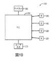
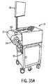
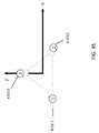
ここで図1および図35Aを参照すると、いくつかの実施形態は、医療処置が行われている部屋10内に開示された手術ロボットシステム1を含む。いくつかの実施形態では、手術ロボットシステム1は、手術ロボット15と1つまたは複数の測位センサ12とを備えることができる。この態様では、手術ロボット15は、(たとえば、図10に示すディスプレイ150を含む)表示手段29およびハウジング27を備えることができる。いくつかの実施形態では、ディスプレイ150を手術ロボット15に取り付けることができ、他の実施形態では、表示手段29を、手術室10内でまたは遠隔地で、手術ロボット15から取り外すことができる。いくつかの実施形態では、ハウジング27は、ロボットアーム23と、少なくとも1つのモータ160によって制御される、ロボットアーム23に結合されたエンドエフェクタ30とを備えることができる。たとえば、いくつかの実施形態では、手術ロボットシステム1は、(図10では160として表す)少なくとも1つのモータを備えるモータアセンブリ155を含むことができる。いくつかの実施形態では、エンドエフェクタ30は、外科用器具35を備えることができる。他の実施形態では、エンドエフェクタ30を外科用器具35に結合することができる。本明細書で用いる「エンドエフェクタ」という用語は、「エンドエフェクタ」、「エフェクタ要素」および「エフェクタ要素」という用語と同義で用いられている。いくつかの実施形態では、エンドエフェクタ30は、外科用器具35の移動を所望の方法でもたらすあらゆる既知の構造を備えることができる。 Referring now to FIGS. 1 and 35A, some embodiments include a surgical
いくつかの実施形態では、侵襲的処置を行う前に、患者18の所望の手術部位の3次元(「3D」)画像スキャンを取得し、本明細書に記載するような手術ロボット15と通信するコンピュータプラットフォームに送信することができる(たとえば、図34に示すコンピューティングデバイス3401を含むプラットフォーム3400を参照)。いくつかの実施形態では、医師は、その後、外科用器具35が患者18の体内または体表の所望の解剖学的標的に達するように所望の挿入点および軌道をプログラムすることができる。いくつかの実施形態では、所望の挿入点および軌道を3D画像スキャンで計画することができ、それを、いくつかの実施形態では、表示手段29に表示することができる。いくつかの実施形態では、医師は、患者18のコンピュータ断層撮影スキャン(以下、「CTスキャン」と呼ぶ)で軌道および所望の挿入点(ある場合)を計画することができる。いくつかの実施形態では、CTスキャンは、当技術分野において既知であるように、アイソセントリックC−アーム型スキャン、Oアーム型スキャンまたは術中CTスキャンであり得る。しかしながら、いくつかの実施形態では、本明細書に記載する本発明の実施形態に従って、あらゆる既知の3D画像スキャンを用いることができる。 In some embodiments, prior to performing an invasive procedure, a three-dimensional (“3D”) image scan of the desired surgical site of
いくつかの実施形態では、手術ロボットシステム1は、外科用器具35の位置を追跡する屋内測位システム(local positioning system)(「LPS」)サブアセンブリを備えることができる。LPSサブアセンブリは、エンドエフェクタ30または外科用器具35の所望の位置に結合されるかまたは取り付けられる少なくとも1つの無線周波数(RF)送信器120を備えることができる。いくつかの実施形態では、少なくとも1つのRF送信器120は、たとえば少なくとも3つのRF送信器120等、複数の送信器120を含むことができる。別の実施形態では、LPSサブアセンブリは、少なくとも1つのRF送信器120によって生成された1つまたは複数のRF信号を受信するように構成された少なくとも1つのRF受信器110を備えることができる。いくつかの実施形態では、少なくとも1つのRF受信器110は、たとえば少なくとも3つのRF受信器110等、複数のRF受信器110を含むことができる。これらの実施形態では、RF受信器110を、医療処置が行われる部屋10内の既知の位置に配置することができる。いくつかの実施形態では、RF受信器110を、部屋10の床に対して平行な平面内で同一平面状でないように、部屋10内の既知の位置に配置することができる。 In some embodiments, the surgical
いくつかの実施形態では、使用中、少なくとも1つのRF送信器120の各RF送信器120から少なくとも1つのRF受信器110(たとえば、1つのRF受信器、2つのRF受信器、3つのRF受信器等)の各RF受信器110へのRF信号の飛行時間を測定して、各RF送信器120の位置を計算することができる。RF信号の速度が既知であるため、飛行時間の測定により、各RF送信器120に対する(各RF受信器110に対して1つの)少なくとも3つの距離測定値がもたらされる。 In some embodiments, in use, each
いくつかの実施形態では、手術ロボットシステム1は、制御デバイス(たとえば、プロセッサとプロセッサに結合されたメモリとを有するコンピュータ100)を備えることができる。いくつかの実施形態では、制御デバイス100のプロセッサを、本明細書に記載するように飛行時間の計算を実行するように構成することができる。さらに、いくつかの実施形態では、侵襲的処置を行うかまたは行うのに役立つように利用される外科用器具35またはエンドエフェクタ30の動作端部に対する、少なくとも1つのRF送信器120の位置の幾何学的記述を提供するように構成することができる。いくつかのさらなる実施形態では、RF送信器120の位置とともに、外科用器具35またはエフェクタ要素30の寸法特性を、モニタ(たとえば、図10に示すディスプレイ150等の表示手段29)に表示することができる。一実施形態では、エンドエフェクタ30は、たとえば、脊椎手術の実施を容易にするように患者18の脊椎に対して所望の位置に配置される、管状要素(たとえばガイドチューブ50)であり得る。いくつかの実施形態では、ガイドチューブ50を、対応するロボットモータ160によって画定されたz軸70と位置合せすることができ、またはたとえば、z軸70に対して選択された角度で配置することができる。いずれの場合も、制御デバイス(すなわちコンピュータ100)のプロセッサを、管状要素の向きおよびRF送信器120の位置を考慮するように構成することができる。本明細書においてさらに記載するように、いくつかの実施形態では、制御デバイス(たとえばコンピュータ100)のメモリは、本明細書に示す外科手術方法ステップの多くを行うために必要な計算および/または分析を実行するソフトウェアを格納することができる。 In some embodiments, surgical
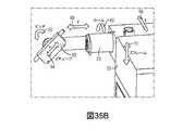
開示する手術ロボットシステム1の別の実施形態は、x軸、y軸およびz軸(図35Bにおける66、68、70を参照)に沿ってエンドエフェクタ30を移動させることができるロボット15の利用を含む。この実施形態では、x軸66はy軸68およびz軸70に直交することができ、y軸68はx軸66およびz軸70に直交することができ、z軸70はx軸66およびy軸68に直交することができる。いくつかの実施形態では、ロボット15を、他の軸とは無関係に1つの軸に沿ってエンドエフェクタ30の移動をもたらすように構成することができる。たとえば、いくつかの実施形態では、ロボット15は、y軸68またはz軸70に沿ったエンドエフェクタ30のいかなる著しい移動ももたらすことなく、エンドエフェクタ30をx軸66に沿って所与の距離移動させることができる。 Another embodiment of the disclosed
いくつかのさらなる実施形態では、エンドエフェクタ30を、x軸66、y軸68およびz軸70のうちの1つまたは複数を中心に選択的に回転するように構成することができる(それにより、エンドエフェクタ30に関連するカルダンオイラー角(たとえば、ロール、ピッチおよび/またはヨー)のうちの1つまたは複数を選択的に制御することができる)。いくつかの実施形態では、動作中、エンドエフェクタ30および/または外科用器具35を、手術ロボットシステム1を作動させることができるエージェント(たとえば、コンピュータ100およびプラットフォーム3400)が選択的に変更しモニタリングすることができる選択された方向付け(orientation)軸(図35Bにおいて「Zチューブ」と標識)と位置合せすることができる。いくつかの実施形態では、エンドエフェクタ30の軸方向回転および向きの選択的な制御により、たとえば、回転軸のみを備える6自由度ロボットアーム23を利用する従来のロボットと比較して精度が著しく向上した医療処置の実施を可能にすることができる。 In some further embodiments,
いくつかの実施形態では、図1に示すように、エンドエフェクタ30が患者18の身体に向かってz軸に対して選択的に角度が付けられている、患者18の身体の上方に配置することができるロボットアーム23。これに関して、いくつかの実施形態では、ロボット手術システム1は、停電時にロボットアーム23、エンドエフェクタ30および/または外科用器具35をそれらのそれぞれの位置で安定させるシステムを備えることができる。いくつかの実施形態では、ロボットアーム23、エンドエフェクタ30および/または外科用器具35は、z軸70に沿ったロボットアームの移動をもたらすように構成された、ロボットアーム23に結合された従来のウォーム駆動機構(図示せず)を備えることができる。いくつかの実施形態では、ロボットアーム23、エンドエフェクタ30および/または外科用器具35を安定させるシステムは、ロボットアーム23に結合された釣合い重りを備えることができる。別の実施形態では、ロボットアーム23、エンドエフェクタ30および/または外科用器具35を維持する手段は、たとえばエンドエフェクタ30等、ロボットアーム23の少なくとも一部に結合され、かつ手術ロボット15の電力喪失または「電源切断」状態に応答して起動するように構成された、従来の制動機構(図示せず)を備えることができる。 In some embodiments, as shown in FIG. 1, the
図1を参照すると、いくつかの実施形態では、手術ロボットシステム1は、部屋10内に位置する少なくとも1つの従来のRF送信器(図示せず)からRF信号を受信するように構成された複数の測位センサ12を備えることができる。いくつかの実施形態では、少なくとも1つのRF送信器120を、手術ロボット15および/または患者18のさまざまな箇所に配置することができる。たとえば、いくつかの実施形態では、少なくとも1つのRF送信器120を、ハウジング27、ロボットアーム23、エンドエフェクタ30および外科用器具35のうちの1つまたは複数に取り付けることができる。いくつかの実施形態は、いくつかの実施形態ではRF受信器110を備える測位センサ12を含む。いくつかの実施形態では、RF受信器110は、RF送信器120から信号を受信する、本明細書に記載するコンピュータプラットフォーム(たとえば、図34のコンピューティングデバイス3401を備える3400を参照)と通信する。いくつかの実施形態では、少なくとも1つのRF送信器120の各送信器120は、異なる周波数でRFエネルギーを送信することができ、それにより、部屋10内の各送信器120の識別(identity)を確定することができる。いくつかの実施形態では、少なくとも1つのRF送信器120、したがって送信器120が取り付けられる対象の位置は、飛行時間プロセスを用いてコンピュータ(たとえば図34のコンピューティングデバイス3401)によって計算される。 Referring to FIG. 1, in some embodiments, a surgical
いくつかの実施形態では、コンピュータ(図1には示さず)はまた、手術ロボット15とも通信する。いくつかの実施形態では、コンピューティングデバイス3401のコンピュータ100の従来のプロセッサ(図示せず)を、処置の前に選択された事前に計画された軌道に従って手術ロボット15の移動をもたらすように構成することができる。たとえば、いくつかの実施形態では、コンピューティングデバイス3401のコンピュータ100は、ロボット誘導ソフトウェア3406およびロボット誘導データ記憶部3407(図34に示す)を用いて、手術ロボット15の移動をもたらすことができる。 In some embodiments, the computer (not shown in FIG. 1) also communicates with the
いくつかの実施形態では、手術ロボット15が処置の間いつでも外科用器具35の位置を認識するように、外科用器具35の位置を動的に更新することができる。したがって、いくつかの実施形態では、手術ロボット15は、患者18に対する損傷を最小限に、かつ医師からのいかなるそれ以上の支援なしに(医師がそのように望まない限り)、外科用器具35を所望の位置に迅速に移動させることができる。いくつかのさらなる実施形態では、手術ロボット15は、外科用器具35が選択された事前に計画された軌道から逸れた場合に、外科用器具35の経路を補正するように構成することができる。 In some embodiments, the position of the
いくつかの実施形態では、手術ロボット15を、エンドエフェクタ30および/または外科用器具35の移動の停止、変更および/または手動制御を可能にするように構成することができる。したがって、使用時、いくつかの実施形態では、システム1を作動させることができるエージェント(たとえば、医師または他のユーザ)には、エンドエフェクタ30および/または外科用器具35の自律移動を停止させ、変更し、または手動制御する選択肢がある。さらに、いくつかの実施形態では、手術ロボット15および/またはコンピュータプラットフォーム3400のプロセッサに許容範囲制御を事前にプログラムすることができる(それにより、指定された条件が満たされることに応じて、エンドエフェクタ30および/または外科用器具35の移動が調整される)。たとえば、いくつかの実施形態では、手術ロボット15が、少なくとも1つのRF送信器120の誤動作のために外科用器具35の位置を検出することができない場合、手術ロボット15を、エンドエフェクタ30および/または外科用器具35の移動を停止させるように構成することができる。いくつかの実施形態では、手術ロボット15が、許容レベルを超える力抵抗またはトルク抵抗等の抵抗を検出した場合に、手術ロボット15を、エンドエフェクタ30および/または外科用器具35の移動を停止させるように構成することができる。 In some embodiments, the
いくつかの実施形態では、(たとえば、コンピューティングデバイス3401によって表される)システムで使用されるコンピュータ100を、本明細書においてさらに記載するように、手術ロボット15内に、または別法として、手術室10内の別の位置にまたは遠隔地に配置することができる。いくつかの実施形態では、コンピュータ100を、測位センサ12および手術ロボット15と動作可能に通信するように配置することができる。 In some embodiments, the
いくつかのさらなる実施形態では、手術ロボット15を、既存の従来の誘導システムとともに使用することも可能である。したがって、本明細書に具体的に開示するもの以外の代替的な従来の誘導システムは、本発明の範囲および趣旨の中にある。たとえば、外科用デバイスの位置を追跡する従来の光学追跡システム3417、またはOptotrak(登録商標)(Optotrak(登録商標)は、Northern Digital Inc.Northern Digital、Waterloo、Ontario、Canadaの登録商標である)等の市販の赤外線光学追跡システム3417を、患者18の移動ならびにロボットの基部25の位置および/または中間軸位置を追跡するために使用し、かつ手術ロボットシステム1とともに使用することができる。手術ロボットシステム1が従来の赤外線光学追跡システム3417を備えるいくつかの実施形態では、手術ロボットシステム1は、光を発するかまたは反射するように構成された、エンドエフェクタ30および/または外科用器具35の選択された位置に取り付けられた従来の光学マーカを備えることができる。いくつかの実施形態では、マーカから発せられかつ/または反射された光をカメラ(たとえば、図81に示すカメラ8200を含む)および/または光学センサによって読み取ることができ、対象の位置を、三角測量(ステレオ写真測量等)を通して計算することができる。 In some further embodiments, the
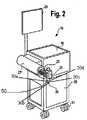
ここで図2を参照すると、いくつかの実施形態において、手術ロボット15が車輪31に接続された基部25を備えることができることが分かる。これらの実施形態のサイズおよび移動性により、手術ロボットを、要求に応じて患者間でかつ部屋間で容易に移動させることを可能にすることができる。図示するように、いくつかの実施形態では、手術ロボット15はケース40をさらに備えることができ、ケース40は、基部25が位置する面に対して実質的に垂直なz軸70に沿って上下に摺動することができるように、基部25に摺動可能に取り付けられている。いくつかの実施形態では、手術ロボット15は、表示手段29と、ロボットアーム23を収容するハウジング27とを含むことができる。 Referring now to FIG. 2, it can be seen that in some embodiments, the
上述したように、エンドエフェクタ30は外科用器具35を備えることができ、他の実施形態では、エンドエフェクタ30を外科用器具35に結合することができる。いくつかの実施形態では、外科用器具35をエンドエフェクタ30に取り外し可能に取り付けて、アーム23をエンドエフェクタ30に接続することができる。 As described above, the
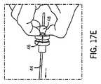
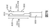
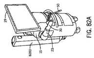
ここで、図2、図3A〜図3B、図4、図5A〜図5B、図6、図7および図8A〜図8Bを参照すると、いくつかの実施形態では、エフェクタ要素30は、外面30dを含むことができ、傾斜した前縁30bおよび傾斜していない前縁30cを画定する遠位端30aを備えることができる。いくつかの実施形態では、外科用器具35は、(外科処置、治療処置および診断処置を含む)侵襲的医療処置または非侵襲的医療処置の実施中に使用される、あらゆる既知の従来の器具、デバイス、ハードウェアコンポーネントおよび/または付属品であり得る。たとえば、限定はされないが、いくつかの実施形態では、外科用器具35を、針7405、7410、従来のプローブ、従来のスクリュー、従来のドリル、従来のタップ、従来のカテーテル、従来のメス鉗子等に埋め込むことができ、または外科用器具35はそうしたものを備えることができる。さらにまたは別法として、いくつかの実施形態では、外科用器具35は、たとえば、限定はされないが、患者18の体内を通して生物学的に作用する化合物を分散させることができる、従来のシリンジ等の生物学的送達デバイスであり得る。いくつかの実施形態では、外科用器具35は、1つまたは複数の追加の外科用器具35を受け入れるように構成された中心ボアを画定するガイドチューブ50(本明細書では「Zチューブ50」とも呼ぶ)を備えることができる。 Referring now to FIGS. 2, 3A-3B, 4, 5A-5B, 6, 7 and 8A-8B, in some embodiments, the
いくつかの実施形態では、手術ロボット15は、標的位置に正確にかつ精密に達する能力を向上させるために、複数の軸(たとえば、x軸66、y軸68およびz軸70)において移動可能である。いくつかの実施形態は、デカルト測位座標系で移動するロボット15を含み、すなわち、異なる軸における移動が、一連の関節の端部を除き、互いに相対的に独立して発生することができる。 In some embodiments, the
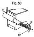
ここで図3Aおよび図3Bを参照すると、手術ロボット15の基部25に対するケース40の移動は、システム1の高さおよび基部25に対するケース40の位置の変化として表わされている。図示するように、いくつかの実施形態では、ケース40を、z軸に沿って基部25に対して上昇および下降するように構成することができる。いくつかの実施形態は、ケース40に取り付け、ケース40が上昇および下降する時にケース40とともに(zフレーム72によって画定される)z方向に移動するように構成することができる、ハウジング27を含む。したがって、いくつかの実施形態では、アーム23、エンドエフェクタ30および外科用器具35を、ケース40が基部25に対して上昇および下降する際にケース40とともに移動するように構成することができる。 3A and 3B, the movement of the
さらなる実施形態では、ここで図4を参照すると、ハウジング27を、ケース40に対してx軸66に沿って、かつケース40が基部25に対して移動する方向に対して実質的に垂直に伸長および後退することができるように、ケース40に摺動可能に取り付けることができる。したがって、いくつかの実施形態では、ロボットアーム23、エンドエフェクタ30および外科用器具35を、ハウジング27がケース40に対して伸長および後退する際にハウジング27とともに移動するように構成することができる。 In a further embodiment, referring now to FIG. 4, the
ここで図5Aおよび図5Bを参照すると、y軸68に沿ったアーム23の伸長が示されている。いくつかの実施形態では、ロボットアーム23は、ケース40、基部25およびハウジング27に対してy軸68に沿って伸長可能であり得る。したがって、いくつかの実施形態では、エンドエフェクタ30および外科用器具35を、アーム23がハウジング27に対して伸長および後退する際にアーム23とともに移動するように構成することができる。いくつかの実施形態では、アーム23を、ハウジング27に入れられる薄型レールシステム(図示せず)に取り付けることができる。 Referring now to FIGS. 5A and 5B, the extension of
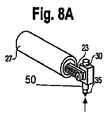
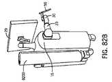
ここで図6、図7および図8A〜図8Bを参照すると、エンドエフェクタ30の移動が示されている。図6は、y軸68を中心に回転して、所定のロール62を有する回転を実施するように構成されたエンドエフェクタ30の実施形態を示す。図7は、x軸66を中心に回転して、所定のピッチ60を有する回転を実施するように構成されたエンドエフェクタ30の実施形態を示す。図8は、「Zチューブ軸64」と呼ぶ二次可動軸64であり得る、実質的に垂直な軸に沿って、外科用器具35を上昇および下降させるように構成されたエンドエフェクタ30の実施形態を示す。いくつかの実施形態では、ガイドチューブ50の向きを最初にz軸70に位置合せすることができるが、この向きは、ロール62および/またはピッチ60の変化に応じて変化することができる。 Referring now to FIGS. 6, 7 and 8A-8B, the movement of the
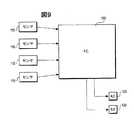
図9は、本発明のいくつかの実施形態による3D測位センサ110、コンピュータ100およびRF送信器120のシステム図を示す。図示するように、コンピュータ100は、測位センサ110と通信している。いくつかの実施形態では、作動中、RF送信器120は、手術ロボット15のさまざまな箇所に取り付けられる。いくつかの実施形態では、RF送信器120を、患者18の解剖学的標的の上または周囲のさまざまな箇所に取り付けることも可能である。いくつかの実施形態では、コンピュータ100を、RF送信器120が測位センサ110によって読み取られるRF信号を送信するのを促す信号をRF送信器120に送信するように構成することができる。いくつかの実施形態では、コンピュータ100を、無線か有線かに関らず任意の従来の通信手段を用いてRF送信器120に結合することができる。いくつかの実施形態では、測位センサ110はコンピュータ100と通信することができ、コンピュータ100を、測位センサ110から受け取られた飛行時間情報に基づいて、すべてのRF送信器120の場所の位置を計算するように構成することができる。いくつかの実施形態では、コンピュータ100を、エージェントに表示することができる、処置において使用されている外科用器具35および/またはエンドエフェクタ30の計算された位置を動的に更新するように構成することができる。 FIG. 9 shows a system diagram of
いくつかの実施形態は、図10に示すように提供される、コンピュータ100、ディスプレイ150を含む表示手段29、ユーザ入力部170およびモータ160を有する手術ロボットシステム1のシステム図を含むことができる。いくつかの実施形態では、モータ160は、手術ロボット15に設置され、上述したようにエンドエフェクタ30および/または外科用器具35の移動を制御することができる。いくつかの実施形態では、コンピュータ100を、処置で使用されている外科用器具35の位置を動的に更新するように構成することができ、かつ手術ロボット15がコンピュータ100によって受け取られる情報に対応して応答するように、モータ160に適切な信号を送信するように構成することができる。たとえば、いくつかの実施形態では、コンピュータ100によって受け取られた情報に応じて、コンピュータ100を、事前に計画された軌道に沿って外科用器具35を移動させるようにモータ160に指示するように構成することができる。 Some embodiments may include a system diagram of a
いくつかの実施形態では、たとえば侵襲的外科処置等、医療処置を行う前に、ユーザ入力部170を用いて、所望のナビゲーションに対して軌道を計画することができる。医療処置を開始した後に、エンドエフェクタ30および/または外科用器具35の軌道および/または移動について変更が望まれる場合、ユーザは、ユーザ入力部170を用いて所望の変更を入力することができ、コンピュータ100を、ユーザ入力部170に応じてモータ160に対応する信号を送信するように構成することができる。 In some embodiments, the
いくつかの実施形態では、モータ160を従来のパルスモータとすることができ、またはモータ160はそうしたパルスモータを備えることができる。この態様では、いくつかの実施形態では、パルスモータは、外科用器具35に取り付けられた従来の直接駆動構成またはベルト駆動機構およびプーリの組合せであり得る。別法として、他の実施形態では、モータ160は、従来のベルト駆動ラック・ピニオンシステムまたは同等の従来の動力伝達構成要素に取り付けられる従来のパルスモータであり得る。 In some embodiments, the
いくつかの実施形態では、手術ロボット15内で従来のリニアパルスモータを用いることにより、エンドエフェクタ30および/または外科用器具35に対して非固定位置を確立することを可能にすることができる。したがって、いくつかの実施形態では、エンドエフェクタ30および/または外科用器具35は、完全に固定された位置に固定されず、むしろ、エンドエフェクタ30および/または外科用器具35を、エージェント(たとえば、外科医または他のユーザ)がx軸66およびy軸68を越えて、エンドエフェクタ30および/または外科用器具35をその現位置から移動させることができるように構成することができる。たとえば、いくつかの実施形態では、こうした軸を越えるために必要な力の量を、自動的にまたはエージェントによって調整し構成することができる。いくつかの実施形態では、手術ロボット15は、以下のうちの1つまたは複数をモニタリングするように構成された回路を備えることができる。すなわち、(a)x軸66、y軸68およびz軸70に沿ったロボットアーム23、エンドエフェクタ30および/または外科用器具35の位置、(b)x軸(66)、y軸(68)およびz軸(70)に対するロボットアーム23、エンドエフェクタ30および/または外科用器具35の回転位置(たとえば、ロール62およびピッチ60)、ならびに(c)エンドエフェクタ30および外科用器具35に対して常に平行である再方向付け可能な軸(Zチューブ軸64)の行程に沿ったエンドエフェクタ30および/または外科用器具35の位置である。 In some embodiments, a conventional linear pulse motor can be used within the
一実施形態では、x軸66、y軸68、z軸70、Zチューブ軸64、ロール62および/またはピッチ60の位置をモニタリングする回路は、モータ160のうちの少なくとも1つの従来のアクチュエータおよび/または軸受内に埋め込まれるかまたはそれらに機能的に結合された相対的なまたは絶対的な従来のエンコーダユニット(エンコーダとも呼ぶ)を備えることができる。任意選択的に、いくつかの実施形態では、手術ロボット15の回路を、軌道に対する所望の量の位置許容範囲(たとえば、回転許容範囲、並進許容範囲、それらの組合せ等)が超過された場合に、外科医または他のユーザに聴覚、視覚および/または触覚フィードバックを提供するように構成することができる。いくつかの実施形態では、位置許容範囲を、たとえば度および/またはミリメートルの単位で、構成可能とし定義することができる。 In one embodiment, the circuitry for monitoring the position of the
いくつかの実施形態では、ロボット15は、外科医が、たとえば、限定はされないが従来のスクリュー、生検針8110等の選択された外科用器具35を送達する用意ができている、選択された位置まで移動する。いくつかの実施形態では、外科医が、作業する際に、エンドエフェクタ30および/または外科用器具35を所望の軌道から不注意で外した場合、システム1が、可聴警告および/または視覚的警告を提供するように構成することができる。たとえば、いくつかの実施形態では、システム1は、可聴警告音を生成し、かつ/または、許容可能な許容範囲が超過された軸も表示しながら、「警告:軌道外(Warning:Off Trajectory)」等の警告メッセージを表示手段29に表示することができる。 In some embodiments, the
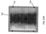
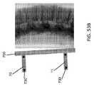
いくつかの実施形態では、可聴警告に加えてまたはその代りに、エンドエフェクタ30、ガイドチューブ50、患者18の手術部位(すなわち、手術野17)またはこれらの領域の組合せに、光照明を向けることができる。たとえば、いくつかの実施形態は、患者18の手術野17を照明することができる少なくとも1つの視覚的指示900を含む。いくつかの実施形態は、手術野17に照明を投影することによって標的ロックを示すことができる少なくとも1つの視覚的指示900を含む。いくつかの実施形態では、システム1は、ロボット15が標的上でロックされているか否かに関するフィードバックをユーザに提供することができる。いくつかの他の実施形態では、システム1は、少なくとも1つのマーカ720が遮られているか否か、またはシステム1が1つあるいは複数のマーカ720を能動的に探しているか否かに関する警報をユーザに提供することができる。 In some embodiments, light illumination is directed at the
いくつかの実施形態では、ロボットエンドエフェクタ30にまたはその近くに取り付けられた1つまたは複数の従来の発光ダイオードによって、視覚的指示900を投影することができる。いくつかの実施形態では、視覚的指示は、現状を示す色を含む、手術野17に投影される光を含むことができる(たとえば、図80を参照)。いくつかの実施形態では、緑色の投影光は標的ロックオン状況を表すことができ、いくつかの実施形態では、赤色の照明は軌道エラーまたはマーカ720が覆い隠されたことを示すことができる。いくつかの他の実施形態では、黄色の照明は、システム1が1つまたは複数のマーカ720を能動的に探していることを示すことができる。 In some embodiments, the
いくつかの実施形態では、外科医が許容可能な許容範囲を超えようとしている場合、ロボット15を、このようなエンドエフェクタ30および/または外科用器具35の移動に対する機械的抵抗(「押し返し」または触覚フィードバック)を提供し、それによりエンドエフェクタ30および/または外科用器具35を正確な選択された向きに戻るように移動させるように構成することができる。いくつかの実施形態では、その後、外科医が不適切な位置を補正し始めると、ロボット15を、エンドエフェクタ30および/または外科用器具35を所望の軌道に実質的に即座に戻すように構成することができ、その時点で、可聴および視覚的警告および警報を終了するように構成することができる。たとえば、いくつかの実施形態では、視覚的警告は、許容範囲が超過されていない場合の緑色の光、または許容範囲が超過されようとしているかまたは超過された場合の赤色の光を含むことができる、視覚的指示900を含むことができる。 In some embodiments, if the surgeon is about to exceed acceptable tolerances, the
理解されるように、従来のウォーム駆動システムは、完全に固定であり、こうしたウォーム駆動システムを有するロボット15は、外科医がいかに激しく押しても、(ロボット15を破壊せずには)受動的に移動させることができない。さらに、完全に固定の関節接合システムは、本質的に患者18に対して安全ではない可能性がある。たとえば、こうしたロボット15が患者18に向かって移動しており、不注意で組織にぶつかった場合、これらの組織は損傷を受ける可能性がある。これらのリスクを補償するように、こうしたロボット15の表面に従来のセンサを配置することができるが、こうしたセンサは、システム1全体に対して相当な複雑性を加える可能性があり、フェールセーフモードで動作することが困難である。対照的に、本明細書に記載するロボット15の使用中、エンドエフェクタ30および/または外科用器具35が患者18の組織と不注意にぶつかった場合、衝突は、こうした組織に損傷を与える可能性が低い、より許与可能な力で発生する。さらに、いくつかの実施形態では、障害物を克服するために必要な電流の増大を示すように、上述したような可聴フィードバックおよび/または視覚的フィードバックを提供することができる。さらに、いくつかの実施形態では、ロボット15のエンドエフェクタ30を、必要なモータ160電流閾値になった場合に不注意に接触した組織からそれ自体が変位する(離れるように移動する)ように構成することができる。いくつかの実施形態では、この閾値を、組織とエンドエフェクタ30との間の係合に関連する適度な力を認識しかつ/または回避することができるように、各軸に対して(たとえば制御コンポーネントにより)構成することができる。 As will be appreciated, the conventional worm drive system is completely stationary, and the
いくつかの実施形態では、エンドエフェクタ30および/または外科用器具35の位置決めおよび向きに関連する固定(rigidity)量を、選択的に変更することができる。たとえば、いくつかの実施形態では、ロボット15を、高固定モードと低固定モードとの間でシフトするように構成することができる。いくつかの実施形態では、ロボット15を、エンドエフェクタ30および外科用器具35が標的軌道および/または標的位置に近づくにしたがって、開始位置から、それらが1つの軌道から別の軌道にシフトする際に低固定モードに自動的にシフトするようにプログラムすることができる。さらに、いくつかの実施形態では、エンドエフェクタ30および/または外科用器具35が、たとえば標的の約1°および約1mm以内等、標的軌道および/または標的位置の選択された距離内になると、ロボット15を、高固定モードにシフトするように構成することができる。いくつかの実施形態では、ロボット15は、低固定モードにある間に患者18と不注意にぶつかった場合に損傷をもたらす可能性が低いため、この機構は安全性を向上させることができる。 In some embodiments, the amount of rigidity associated with the positioning and orientation of the
いくつかの実施形態は、エンドエフェクタ30および/または外科用器具35の移動を選択された一続きの別個の移動でもたらすように構成することができるロボット15を含む。いくつかの実施形態では、エンドエフェクタ30および/または外科用器具35が1つの軌道から別の軌道に移動している間、x軸66、y軸68、ロール62および60ピッチ60の向きはすべて同時に変化し、エンドエフェクタ30の移動の速度を上昇させることができる。したがって、エンドエフェクタ30が移動する位置の範囲により、患者18の組織との衝突の可能性もまた増大する可能性がある。このため、いくつかの実施形態では、ロボット15を、x軸66およびy軸68内のエンドエフェクタ30および/または外科用器具35の位置が、エンドエフェクタ30および/または外科用器具35のロール62およびピッチ60が調整される前に調整されるように、エンドエフェクタ30および/または外科用器具35の移動をもたらすように構成することができる。いくつかの代替実施形態では、ロボット15を、ロール62およびピッチ60が0°にシフトするように、エンドエフェクタ30および/または外科用器具35の移動をもたらすように構成することができる。x軸66およびy軸68内のエンドエフェクタ30および/または外科用器具35の位置が調整され、その後、エンドエフェクタ30および/または外科用器具35のロール62およびピッチ60が調整される。 Some embodiments include a
いくつかの実施形態は、エンドエフェクタ30および/または外科用器具35が、エンドエフェクタ30および/または外科用器具35の位置および/または軌道の変化がもたらされる前に、x軸70に沿って垂直に(患者18から離れるように)選択された量だけ移動することを確実にするように、任意選択的に構成することができるロボット15を含む。たとえば、いくつかの実施形態では、エージェント(たとえば、外科医あるいは他のユーザ、または機器)が、エンドエフェクタ30および/または外科用器具35の軌道を第1軌道から第2軌道に変更した場合、ロボット15を、(x軸66構成およびy軸68構成を、たとえば第1軌道ベクトルであり続けるように調整しながら)エンドエフェクタ30および/または外科用器具35を患者18の身体からz軸70に沿って選択された量だけ垂直に変位させ、その後、エンドエフェクタ30および/または外科用器具35の位置および/または向きの変化をもたらすように構成することができる。これにより、エンドエフェクタ30および/または外科用器具35が患者18の組織内に埋め込まれている間に横方向に移動しないことが確実になる。任意選択的に、いくつかの実施形態では、ロボット15を、最初にエンドエフェクタ30および/または外科用器具35をz軸に沿って変位させることなく、安全にエンドエフェクタ30および/または外科用器具35の軌道の変更に進むことができるという確認をエージェント(たとえば、外科医あるいは他のユーザまたは機器)に求める警告メッセージを生成するように構成することができる。 Some embodiments allow the
いくつかの実施形態では、少なくとも1つの従来の力センサ(図示せず)を、方向付け軸(Zチューブ軸64)に沿って外科用器具35に加えられる力を受けるように、エンドエフェクタ30および/または外科用器具35に結合することができる。いくつかの実施形態では、少なくとも1つの力センサを、デジタル信号を生成するように構成することができる。たとえばいくつかの実施形態では、デジタル信号は、外科用器具35が患者18の組織内に前進するにしたがい、患者18の身体によって外科用器具35に対してZチューブ軸64の方向に加えられる力を示すことができる。いくつかの実施形態では、少なくとも1つの力センサは、従来の歪みゲージ機構に基づく小型の従来の単軸ロードセルであり得る。いくつかの実施形態では、単軸ロードセルを、たとえばアナログ・デジタルフィルタリングに結合して、システム1に連続的なデジタルデータストリームを供給することができる。任意選択的に、いくつかの実施形態では、少なくとも1つの力センサを、現時点で外科用器具35に加えられている力を示す信号を実質的に連続的に生成するように構成することができる。いくつかの実施形態では、x軸66およびy軸68に沿ったエンドエフェクタ30および/または外科用器具35の位置が、選択された軌道ベクトルとの位置合せが実質的に維持されるように調整されている間に、外科用器具35を、z軸70を下降させることによって患者18の組織内に前進させることができる。さらに、いくつかの実施形態では、外科用器具35が選択された軌道ベクトルに沿って向けられたままであるように、ロール62およびピッチ60の向きは、x軸(66)、y軸(68)およびz軸(70)の移動中、一定のままであるかまたは自動調整することができる。いくつかの実施形態では、外科用器具35が患者18の組織内に前進する際に、z軸70に沿ったエンドエフェクタ30の位置を、(患者18から選択された距離、間隔が空けられている)選択された中間位置で固定することができる。いくつかの実施形態では、エンドエフェクタ30および/または外科用器具35の剛性を、本明細書においてさらに記載するように、選択されたレベルに設定することができる。たとえば、いくつかの実施形態では、エンドエフェクタ30および/または外科用器具35のZチューブ軸64位置の剛性を、エンドエフェクタ30および/または外科用器具35に所望の長手方向剛性特性を与えるように構成された従来の機械的固定具(図示せず)に結合することができる。いくつかの実施形態では、エンドエフェクタ30および/または外科用器具35に十分な長手方向剛性がない場合、外科用器具35の貫入中に患者18の皮膚によってかけられる反対の力が、外科用器具35の前進の方向に対抗する可能性があり、それにより、外科用器具35は選択された軌道ベクトルに沿って前進することができない。言い換えれば、z軸70が下方に前進する際、Zチューブ軸64が強制的に上昇する可能性があり、外科用器具35の正味の前進がない可能性がある。いくつかの実施形態では、少なくとも1つの力センサにより、エージェント(たとえば、外科医あるいは他のユーザまたは機器)が、(エンドエフェクタ30および/または外科用器具35の力センサによってモニタリングされる加えられた力のレベルの急な上昇に基づいて)、外科用器具35が患者18の体内の骨または他の所定の構造に遭遇した時を判断することを可能にすることができる。 In some embodiments, the
いくつかの代替的な実施形態では、エンドエフェクタ30および/または外科用器具35ならびにx軸66およびy軸68の方向付け角度を、Zチューブ軸64を、完全に後退したZチューブ位置における所望の軌道ベクトルと位置合せするように構成することができ、一方で、z軸70位置は、外科用器具35の遠位先端が組織に入る状態で保たれるように設定される。この構成では、いくつかの実施形態では、エンドエフェクタ30を、たとえば、ガイドチューブ50に沿ってのみ前進するかのように、軌道ベクトルに沿って正確にまたは実質的に正確に移動することができるように、配置することができる。こうしたシナリオにおいて、いくつかの実施形態では、Zチューブ軸64を前進させることにより、ガイドチューブ50が組織内に入ることができ、エージェント(外科医あるいは他のユーザ、機器等)は、荷重センサから力の変化をモニタリングすることができる。外科用器具35が骨に接触した時点で加えられる力の急な増大が検出されるまで、前進を続けることができる。 In some alternative embodiments, the orientation angle of the
いくつかの実施形態では、ロボット15を、Zチューブ軸64を前進させる1つまたは複数のモータ160の作動を停止させ、それにより、エンドエフェクタ30および/または外科用器具35の位置がモニタリングされ続けている間に、エンドエフェクタ30および/または外科用器具35がZチューブ軸64方向に自由に移動することができるように、構成することができる。いくつかの実施形態では、外科医は、その後、エンドエフェクタ30をZチューブ軸64(所望の軌道ベクトルと一致する)に沿って手で押し下げることができる。いくつかの実施形態では、エンドエフェクタ30の位置が軌道ベクトルと整列しないようにずらされた場合、外科用器具35の位置を、x軸(66)および/またはy軸(68)に沿ったかつ/またはロール62および/またはピッチ60の方向における調整によって補正することができる。いくつかの実施形態では、外科用器具35のZチューブ50の移動に関するモータ160の作動が停止すると、エージェント(たとえば、外科医あるいは他のユーザまたは機器)は、外科用器具35の触覚が骨、または身体の別の既知の領域と接触するまで、外科用器具35を手動で前進させることができる。 In some embodiments, the
いくつかのさらなる実施形態では、ロボット手術システム1は、複数の従来の追跡マーカ720を備えることができ、それらは、ロボットアーム23、エンドエフェクタ30および/または外科用器具35の移動を3次元で追跡するように構成されている。追跡マーカ720からの3次元位置情報を、ロボット15の各軸における絶対的なまたは相対的な従来のリニアエンコーダからの1次元線形位置情報とともに用いて、高い精度を維持することができることが認識されるべきである。いくつかの実施形態では、複数の追跡マーカ720を、たとえば、限定はされないがロボット15の基部25またはロボットアーム23等の、ロボット15の外面に取り付ける(または他の方法で固定する)ことができる。いくつかの実施形態では、複数の追跡マーカ720を、ロボット15アーム、エンドエフェクタ30および/または外科用器具35の移動を追跡するように構成することができる。いくつかの実施形態では、コンピュータ100は、追跡情報を利用して、x軸66、y軸68、z軸70、Zチューブ軸64ならびにロール62およびピッチ60の軸に沿ったエンコーダカウントに基づいて、外科用器具35の遠位先端30aの向きおよび座標を計算することができる。さらに、いくつかの実施形態では、複数の追跡マーカ720を、外科医、手術用具、またはロボット15の他の部分によって覆い隠される可能性を低減するように、手術野17から間隔を空けて、ロボット15の基部に配置することができる。いくつかの実施形態では、複数の追跡マーカ720のうちの少なくとも1つの追跡マーカ720を、エンドエフェクタ30に取り付けるかまたは他の方法で固定することができる。いくつかの実施形態では、エンドエフェクタ30に1つまたは複数の追跡マーカ720を配置することにより、(ロボット15の基部のマーカからの位置情報ならびにx軸(66)、y軸(68)、ロール62軸、ピッチ60軸およびZチューブ軸64のエンコーダカウントから計算された)エンドエフェクタ30の位置を検査するかまたは検証する役割を果たすことにより、位置測定の精度を最大限にすることができる。 In some further embodiments, the robotic
いくつかのさらなる実施形態では、ロボット15の基部25のマーカ720の代りにまたはそれに加えて、複数の光学追跡マーカ720のうちの少なくとも1つの光学マーカを、ロボット15の基部25とエンドエフェクタ30との間でロボット15に配置することができる(図16を参照)。いくつかの実施形態では、少なくとも1つの追跡マーカ720を、エンドエフェクタ30および/または外科用器具35のx軸に沿った移動をもたらすロボット15の一部に取り付けて、エンドエフェクタ30および外科用器具35がx軸66に沿って移動する際に、追跡マーカ720が、x軸66に沿って移動するのを可能にすることができる(図76を参照)。追跡マーカ720をこのように配置することにより、外科医がカメラまたは検出デバイスから追跡マーカ720を遮るか、または追跡マーカ720が外科医に対する障害物となる可能性を低減することができる。いくつかの実施形態では、追跡マーカ720の出力および/または各軸からのエンコーダカウントに基づいてエンドエフェクタ30の向きおよび位置を計算する精度が高いため、エンドエフェクタ30の位置を非常に正確に求めることを可能にすることができる。たとえば、いくつかの実施形態では、x軸66と基部25との間である、z軸70用の軸エンコーダのカウントを知る必要なしに、x軸66におけるマーカ720の位置とy軸(68)、ロール62軸、ピッチ60軸およびZチューブ軸64におけるエンコーダのカウントとのみを知ることにより、エンドエフェクタ30の位置の計算を可能にすることができる。いくつかの実施形態では、ロボット15のあらゆる中間軸にマーカ720を配置することもまた、こうしたマーカ720の位置とマーカ720とエンドエフェクタ30との間の軸(66、62、60、64)におけるエンコーダのカウントとに基づいて、エンドエフェクタ30の正確な位置を計算することを可能にすることができる。いくつかの実施形態では、ロボット15(たとえば、図2を参照)の構成から、基部25からエンドエフェクタ30までの軸の順序は、z(70)、x(66)、y(68)、ロール62、ピッチ60、Zチューブ64である。したがって、たとえば、追跡マーカ720が、ロール62軸とともに移動するロボット15のハウジング27に配置される実施形態では、こうした追跡マーカ720の位置とピッチ60軸およびZチューブ軸64のエンコーダカウントとが、エンドエフェクタ30の位置を計算するために十分であり得る。 In some further embodiments, instead of or in addition to the
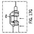
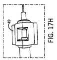
いくつかの実施形態では、外科用器具35は、ガイドチューブ50を用いて患者18の組織内に前進すると、所定量の突出(たとえば、図17A〜図17Bを参照)に達した時に外科用器具35が前進するのを防止するように構成された止め機構52を備えることができる。いくつかの実施形態では、ガイドチューブ50および外科用器具35の長さと、外科用器具35のそれぞれの端部の間の距離と、止め機構52が取り付けられる位置を知ることにより、外科用器具35が突出することができる、ガイドチューブ50の端部を越えた最大距離を求めることができる。 In some embodiments, the
いくつかの実施形態では、外科用器具35の最大突出距離のみでなく、挿入プロセス中のあらゆる瞬間における実際の突出距離もモニタリングすることが望ましい場合がある。したがって、いくつかの実施形態では、ロボット15は、突出距離を実質的に連続的にモニタリングすることができ、いくつかの実施形態では、距離をディスプレイ(表示手段29等)に表示することができる。いくつかの実施形態では、突出距離を、ばね式機構55aとワイパ56が結合されたセンサパッド55bとを含むばね式プランジャ54を用いて、実質的に連続的にモニタリングすることができる(たとえば図17Bを参照)。いくつかの実施形態では、外科用器具35の止め機構52を、ガイドチューブ50の端部と接触する前にばね式機構55と十分に接触するように構成することができる。いくつかの実施形態では、ワイパ56が位置センサパッド55bを横切って移動すると、その線形位置がサンプリングされ、それにより、外科用器具35がガイドチューブ50の端部を越えて突出する距離の実質的にリアルタイムでの計算が可能になる。いくつかの実施形態では、任意の従来のリニアエンコード機構を用いて、本明細書においてさらに記載するように、プランジャの押下深さをモニタリングし、その情報をコンピュータ100に送信することができる。 In some embodiments, it may be desirable to monitor not only the maximum protrusion distance of the
いくつかの実施形態は、ドリルビット42のストッパが、ドリルビット42のマーキング44に対して手動で調整されるのを可能にする器具を含む。たとえば、図17C〜図17Eは、本発明の一実施形態による、ドリルビットマーキング44に対してドリルストッパ46を手動で調整する器具を示す。図示するように、いくつかの実施形態では、ドリルビット42は、ドリルストッパ46の各端部に解除機構48を含むことができる。いくつかの実施形態では、ドリルストッパ46の一端の解除機構48が引っ張られた場合、ドリルストッパ46をドリルビット42のシャフトを上昇して移動させることができる。いくつかの実施形態では、ドリルストッパ46の他端の解除機構48が引っ張られると、ドリルストッパ46を、シャフトを下降して移動させることができる(図17Dおよび図17Eの移動の方向を参照)。いくつかの実施形態では、いずれの解除機構48も引っ張られない場合、ドリルストッパ46は、ぶつかった場合であっても、いずれの方向にも移動しない。 Some embodiments include an instrument that allows the stopper of the
いくつかの実施形態は、ドリルビット42を、それが収容されているチューブ50に対して設定された位置で係止し保持する機能を含むことができる。たとえば、いくつかの実施形態では、ドリルビット42を、係止機構を用いてドリルストッパ46をチューブ50に対して係止することによって係止することができる。図17F〜図17Jは、本発明の一実施形態による、ドリルビット42を設定された位置で係止し保持する器具を示す。いくつかの実施形態では、図17Hに示す係止機構49は、2つのクラムシェル49を備えることができる(図17Fに示す)。いくつかの実施形態では、クラムシェルをドリルストッパ46の周囲に組み付けることにより(図17Gに示す)、ドリルビット42を適所に係止することができる。この機能により、ユーザは、先端がチューブ50の端部をわずかに越えて突出するような位置でドリルビット42を係止することができる(図17Iおよび図17Jを参照)。この位置で、ユーザは、(たとえば経皮的脊椎スクリュー挿入中に)チューブ50を骨と接触させるように、チューブ50を軟組織に貫通させることができる。 Some embodiments may include the ability to lock and hold the
いくつかのさらなる実施形態では、エンドエフェクタ30を、追跡光学マーカ720を遮るかまたは外科医の妨げとなることがないように構成することができる。たとえば、いくつかの実施形態では、図18Aおよび図18Bに示すように、エンドエフェクタ30は、この構成を可能にするアクチュエータ33aを含むクリアランス機構33を備えることができる。図示するように、ガイドチューブ50を、2つのシャフト32を用いてエンドエフェクタ30のハウジング内に固定することができる。いくつかの実施形態では、シャフト32は互いに対して移動し、クリアランス機構33の平行四辺形効果により、ガイドチューブ50の位置は、エンドエフェクタ30の位置を模倣することができる(図18Bを参照)。 In some further embodiments, the
頸部固定手術または腰椎固定手術等の用途では、ハードウェアを適所に係止する前に、脊椎の1つまたは複数のレベルにわたって牽引または圧迫を(前方にまたは後方に)加えることが有益である場合がある。いくつかの実施形態では、エンドエフェクタ30は、こうした力を加えるように構成された取付要素37(たとえば図19A〜図19Bを参照)を備えることができる。いくつかの実施形態では、エンドエフェクタ30の取付要素37を、クリアランス機構33と実質的に同じ位置でエンドエフェクタ30に結合するように構成することができる。いくつかの実施形態では、取付要素37のあるエンドエフェクタ30は、取付要素37のないエンドエフェクタ30と同じ場所にスナップ式に嵌まる。いくつかの実施形態では、エンドエフェクタ30の取付要素37の使用中、角形成30eによってもたらされる2つのシャフト32の相対移動により、ピッチ60方向における移動はもたらされず、代りに、(図19Aにおける取付要素37の距離37aから図19Bにおける距離37Bまで移動するものとして示す)牽引がもたらされる。さらに、図19A〜図19Bに示すようなシャフト32の移動によって牽引がもたらされるが、30eによって表される方向に対して反対方向のアクチュエータ33aの回転は圧迫をもたらす(すなわち、図19Bにおける距離37bが図19Aにおける距離37aに向かって移動する)。 In applications such as cervical or lumbar fusion surgery, it is beneficial to apply traction or compression (forward or backward) across one or more levels of the spine before locking the hardware in place. There is a case. In some embodiments, the
上述した実施形態を鑑みて、開示した主題に従って実施することができるいくつかの実施形態を、図24〜図33のフローチャートを参照してよりよく理解することができる。説明を簡略化する目的で、本明細書に記載する実施形態によって開示する方法は、一連のステップとして提示し記載するが、いくつかの行為は、本明細書に図示し記載するものとは異なる順序でかつ/または他の行為と同時に行われる可能性があるため、請求項に係る主題は行為の順序によって限定されないことが理解され認識されるべきである。たとえば、本発明のいくつかの実施形態のさまざまな方法またはプロセスを、別法として、状態図等、一連の相互に関連する状態または事象として表わすことができる。さらに、本発明のいくつかの実施形態による方法を実施するために、例示するすべての行為が必要であるとは限らない。さらに、開示する方法またはプロセスのうちの2つ以上を、互いに組み合せて実施することにより、本明細書に記載する1つまたは複数の特徴または利点を達成することができる。 In view of the above-described embodiments, some embodiments that can be implemented in accordance with the disclosed subject matter can be better understood with reference to the flowcharts of FIGS. For the purpose of simplifying the description, the methods disclosed by the embodiments described herein are presented and described as a series of steps, although some acts are different from those shown and described herein. It should be understood and appreciated that claimed subject matter is not limited by the order of actions, as it may occur in order and / or concurrently with other actions. For example, various methods or processes of some embodiments of the invention may alternatively be represented as a series of interrelated states or events, such as a state diagram. Moreover, not all illustrated acts may be required to implement a methodology in accordance with some embodiments of the invention. Further, two or more of the disclosed methods or processes can be performed in combination with each other to achieve one or more features or advantages described herein.
本明細書を通して記載するさまざまな実施形態に開示する方法を、こうした方法をコンピューティングデバイス(たとえば、デスクトップコンピュータ、モバイルコンピュータ、携帯電話、ブレードコンピュータ、プログラマブルロジックコントローラ等)に、コンピューティングデバイスのプロセッサによる実行、したがって実施のために、またはそのメモリに格納するために、搬送し転送するのを容易にするために、製品またはコンピュータ可読媒体に格納することができることがさらに認識されるべきである。 The methods disclosed in the various embodiments described throughout the present specification can be converted into computing devices (eg, desktop computers, mobile computers, cell phones, blade computers, programmable logic controllers, etc.) by the computing device processor. It should further be appreciated that the product can be stored on a product or computer readable medium to facilitate transport and transfer for execution, and hence implementation, or for storage in its memory.
いくつかの実施形態では、外科用ロボット15は、エンドエフェクタ30を意図された(すなわち計画された)位置まで移動させるために、その姿勢を自動的に連続的にまたは実質的に連続的に調整することができる。たとえば、いくつかの実施形態では、外科用ロボット15は、追跡マーカ、LPSまたは他の追跡データの現スナップショットによって提供されるようなエンドエフェクタ30および外科手術標的の現位置に基づいて、その姿勢を自動的に連続的にまたは実質的に連続的に調整することができる。いくつかの位置調整戦略は非効率であり得ることがさらに認識されるべきである。たとえば、ロボット15が標的位置を見つける非効率な戦略は、必要な移動方向を推定し、標的位置に向かって移動し、その後、現位置と標的位置との不整合(誤差と呼ぶ不整合)を評価し、新たな方向を推定し、標的位置が十分な誤差範囲内で達成されるまで、推定−移動−評価のサイクルを繰り返す反復的アルゴリズムであり得る。逆に、本発明のいくつかの実施形態による位置調整戦略は、反復的戦略より実質的に効率的である。たとえば、いくつかの実施形態では、手術ロボット15は、移動を行い、個々の軸の各々を正確な位置まで移動させることができる必要なモータエンコーダカウントの一意の組の、追跡データの各フレームにおける各軸の相対的な動きの方向を校正する(コンピュータ100によるソフトウェアまたはファームウェアの実行を介する計算を可能にする)ことにより、その位置を調整することができる。いくつかの実施形態では、開示するロボット15のデカルト設計により、ロボット15の座標系を確立し主要回転軸を求めることによって、こうした構成が行われるのを可能にすることができる。 In some embodiments, the
以下より詳細に記載するように、いくつかの実施形態では、ロボット15の軸の相対的な方向を校正する方法は、各々が単一軸にある、一続きの注意深く計画された移動を利用することができる。いくつかの実施形態では、これらの移動中、一時的追跡マーカ720がエンドエフェクタ30に取り付けられ、エンドエフェクタ30の動きを取り込む。開示する方法では、ロボット15の軸が正確にまたは実質的に垂直である必要はなく、特定の軸(x軸66等)が移動する際に沿うベクトルが、回転(主にx軸66を中心に発生するピッチ60等)が発生する際に中心となるベクトルと一致する必要もない。いくつかの実施形態では、開示する方法は、直線で発生する所定のロボット15軸に沿う動きを含む。いくつかの実施形態では、ロボット15の軸の相対的な移動方向を校正する開示する方法は、エンドエフェクタ30のガイドチューブ50に一時的に取り付けられたマーカ720から、x軸(66)、y軸(68)、ロール軸(62)、ピッチ軸(60)およびZチューブ軸64において行われる個々の移動の最後に取り込まれる追跡データの1つまたは複数のフレームを利用することができる。いくつかの実施形態では、個々の軸を移動させる時、他のすべての軸を、ゼロ位置(たとえば、その軸のエンコーダが0カウントを示す位置)にあるように構成することができる。さらにまたは別法として、0カウント(中立位置)にあるすべてのロボット15軸による追跡データの1つまたは複数のフレームが必要である場合があり、ガイドチューブ50の長手方向軸を中心とする異なる位置まで回転した一時的マーカ720によるデータの1つまたは複数のフレームが必要である場合がある。いくつかの実施形態では、これらの移動からのマーカ720の位置を用いて、ロボット15のデカルト座標系を確立することができ、そこでは、原点(0,0,0)は、エンドエフェクタ30の中心を通り、ピッチ60が発生する場所に最も近いエンドエフェクタ30に沿った位置にある。さらにまたは別法として、いくつかの実施形態では、この座標系を、ロボット15のy軸68移動が座標系のy軸68に正確にまたは実質的に沿って発生することができ、一方でロボット15のx軸66移動が、y軸68に対して実質的に垂直に発生するが、座標系の構成により、z軸70座標にはいかなる変化ももたらされない。位置合せまで回転することができる。いくつかの実施形態では、少なくとも上述した個々の移動に基づいてロボット15の座標系を確立するステップは、以下を含むことができる。まず、エンドエフェクタ30の長軸を中心とする追跡マーカ720の手動回転の初期位置および最終位置から、運動の有限らせん軸(finite helical axis)が計算され、それを、エンドエフェクタ30に中心が置かれかつそれと位置合せされるベクトルによって表すことができる。3つ以上のマーカの2つの位置から運動の有限らせん軸を計算する方法は、たとえば、SpoorおよびVeldpausによってによって、文献に記載されている(Spoor,C.W.およびF.E.Veldpaus,“Rigid body motion calculated from spatial co−ordinates of markers,”J Biomech13(4):391−393(1980))。いくつかの実施形態では、らせん軸を計算するのではなく、エンドエフェクタ30に中心が置かれかつそれと位置合せされるベクトルを、Zチューブ軸64上のガイドチューブ50の入口および出口に一時的に取り付けることができる2つの別個の剛体に取り付けられる2つの点を相互接続することによって、定義しまたは構築することができる。この場合、2つの剛体の各々は、少なくとも1つの追跡マーカ720(たとえば、1つの追跡マーカ720、2つの追跡マーカ720、3つの追跡マーカ720、4つ以上の追跡マーカ720等)を含むことができ、追跡マーカに対してガイドチューブ50の入口および出口に隣接する剛体の位置を示す情報を提供する校正を行うことができる。 As described in more detail below, in some embodiments, the method of calibrating the relative orientation of the axes of the
ピッチ60移動から、ロボット15のx軸に対して実質的に平行であるが計算された第1らせん軸との垂線にも近いベクトルを提供する、第2らせん軸を計算することができる。いくつかの実施形態では、第1らせん軸上の第2らせん軸に最も近い点(またはエンドエフェクタ30に位置合せされたベクトル)が、単純な幾何学形状を用いて計算され、ロボットの座標系の原点(0,0,0)を定義するために使用される。ロール62軸の2つの位置から第3らせん軸が計算される。いくつかのシナリオでは、ロールが発生する際の中心となるベクトル(第3らせん軸)とy軸68が移動する際に沿うベクトルとは正確にまたは実質的に平行であると想定することはできない。さらに、ピッチ60が発生する際に中心となるベクトルとx軸66の動きが発生する際に沿うベクトルとが正確にまたは実質的に平行であると想定することはできない。x軸66およびy軸68の動きのベクトルを、x軸66およびy軸68の中立位置および伸長位置から求め、別個に格納することができる。本明細書に記載するように、いくつかの実施形態では、座標系を再度位置合せして、ロボット15のy軸移動が、正確にまたは実質的に座標系のy軸68方向において発生し、ロボット15のx軸66移動がz座標(70)にいかなる変化もなしに発生するのを可能にすることができる。概して、座標系のこうした変換を行うために、座標軸を中心とする一連の回転が、現座標系のすべての関心点に対して実行され適用される。そして、各点は、新たな座標系において表されるものとみなされる。いくつかの実施形態では、特定の軸を中心として3×1ベクトルによって表される点の回転を適用するために、ベクトルに、3×3回転行列を事前に乗算することができる。x軸を中心とするRx度の回転に対する3×3回転行列は以下の通りである。
いくつかの実施形態では、座標系を変換するために、一続きの3回転を行うことができる。たとえば、こうした回転を、x移動ベクトル、y移動ベクトルおよびらせん軸の各々を含む、現座標系のすべてのベクトルおよび関心点に適用して、y移動ベクトルを新たな座標系のy軸と位置合せし、x移動ベクトルを、z=0における新たな座標系のx軸に可能な限り近く位置合せすることができる。2回以上のあり得る連続したこれらの回転を行って、実質的に同じ目標を達成することができることも認識されるべきである。たとえば、いくつかの実施形態では、一連の3回転は、(1)y移動ベクトルをそのz座標が0に等しくなるまで回転させるのに適切なRx値を用いるxを中心とする回転と、それに続く(2)y移動ベクトルをそのx座標が0に等しくなるまで回転させるのに適切なRz値を用いるzを中心とする回転と、それに続く(3)x移動ベクトルをそのz座標が0に等しくなるまで回転させるために適切なRy値を用いるyを中心とする回転とを含むことができる。いくつかの実施形態では、所与の回転を達成するために適切な回転角度を見つけるために、逆正接関数を利用することができる。たとえば、いくつかの実施形態では、y1=0までz軸を中心とする点またはベクトル(x1,y1,z1)を回転させるために必要な角度は、−arctan(y1/x1)である。In some embodiments, a series of three rotations can be performed to transform the coordinate system. For example, such rotation may be applied to all vectors and points of interest in the current coordinate system, including each of the x, y, and helical axes to align the y motion vector with the new coordinate system's y axis. The x motion vector can then be aligned as close as possible to the x axis of the new coordinate system at z = 0. It should also be appreciated that two or more possible successive rotations can be performed to achieve substantially the same goal. For example, in some embodiments, the series of three rotations is (1) a rotation about x that uses an appropriate Rx value to rotate the y motion vector until its z coordinate is equal to zero; Subsequent (2) rotation aboutz using the appropriate Rz value to rotate the y motion vector until its x coordinate is equal to 0, followed by (3) the z motion vector with its z coordinate Rotation around y using an appropriate Ry value to rotate until equal to zero. In some embodiments, an arc tangent function can be utilized to find an appropriate rotation angle to achieve a given rotation. For example, in some embodiments, the angle required to rotate a point or vector (x1, y1, z1) about the z-axis until y1 = 0 is −arctan (y1 / x1).
座標系の変換の後、いくつかの実施形態では、手術ロボット15のy移動軸が座標系のy軸68と正確にまたは実質的に正確に位置合せされるように位置合せされるが、ロボット15のロール62回転移動は、座標系のy軸68と位置合せされたベクトルを中心として正確にまたは実質的に正確に発生するようには想定されるべきではないことが認識されるべきである。同様に、いくつかの実施形態では、手術ロボット15のピッチ60移動は、座標系のx軸と位置合せされたベクトルを中心として正確にまたは実質的に正確に発生するものと想定されるべきではない。いくつかの実施形態では、ロール62およびピッチ60の回転移動において、運動のらせん軸から最も近い座標軸まで線形かつ方向性の「オフセット」がある可能性がある。いくつかの実施形態では、追跡されたマーカを用いて上記のように求められたらせん軸から、こうしたオフセットを計算し保持する(たとえば、コンピューティングデバイスのメモリに格納する)ことができ、それにより、作動中に発生するいかなる回転に対しても、オフセットを適用することができ、回転を行うことができ、その後、負のオフセットを適用して、回転運動によって発生する位置の変化が真の回転中心を考慮するようにすることができる。 After transformation of the coordinate system, in some embodiments, the y-motion axis of the
いくつかの実施形態では、追跡中、所望の軌道を、最初に医療画像座標系において計算し、その後、アクティブマーカの少なくとも既知の相対位置に基づいてロボット15座標系に変換することができる。たとえば、いくつかの実施形態では、光学追跡システム3417に関連する従来の発光マーカおよび/または従来の反射マーカを用いることができる(たとえば図20Aのアクティブマーカ720を参照)。他の実施形態では、電磁追跡システムに関連する従来の電磁センサを用いることができる。いくつかの他の実施形態では、放射線不透過性マーカ(たとえば、図20Aに示すマーカ730)を、CT撮像システムで用いることができる。いくつかの実施形態では、放射線不透過性マーカ730(少なくとも部分的に金属または他の高密度材料から形成された球体)を用いて、少なくとも部分的にX線を吸収することができるマーカ730を提供し、CTスキャン画像に球体の高コントラストな画像を生成することができる。 In some embodiments, during tracking, the desired trajectory can be first calculated in the medical image coordinate system and then converted to the
いくつかの実施形態では、エンドエフェクタ30がロボット15の座標系の所望の位置に達するために必要なカウントを、以下のプロセス例に基づいて計算することができる。まず、所望の角度方向に達するために必要なカウントを計算することができる。いくつかの実施形態では、一連の3回転を適用して、座標系を一時的に新たな座標系にシフトさせることができ、そこでは、y軸68はロール62に対する運動のらせん軸と一致するかまたは実質的に一致し、x軸66はピッチ60に対する運動のらせん軸と定義上、大部分位置合せされ、ピッチ60に対する運動のらせん軸は定数z=0を有する。そして、所望のピッチ60を達成するために必要なカウントの数を、このピッチ60がロール62にいかに影響を与え得るかを追跡して求めることができる。一実施態様では、所望のピッチを達成するために必要なカウントを見つけるために、ピッチ角60の変化に、ピッチに対して1度あたりの先に校正されたモータカウントを乗算することができる。ピッチ60のこの変化によってもたらされるロール62の変化を、らせん軸の向きとらせん軸を中心とする回転角(ピッチ)とから計算することができる。そして、計画された軌道位置合せに達するように所望のロール62に達するために必要なロール62を計算することができ、それには、ロール62の適用により、座標系の定義上、それ以上ピッチにいかなる変化ももたらされないという利点がある。そして、座標系は、上記適用した3回転の逆回転によって、上述したロボット15座標系に戻るようにシフトされる。そして、所望のx軸66位置に達するために必要なカウントを、またこのx軸66位置の変化がy軸68位置にいかに影響を与えるかを追跡して計算することができる。そして、所望のy軸位置に達するために必要なy軸68カウントを容易に計算することができ、それには、y軸動きベクトルが定義上ロボットのy軸68に位置合せされるため、y軸68座標の変化が他のいかなる軸にも影響を与えないようにすることができるという利点がある。Zチューブ50位置が能動的に制御されているシナリオでは、Zチューブ50移動ベクトルの向きは、ロール62およびピッチ60を調整する時に調整され、それが軌道ベクトルに沿った所望の位置まで移動するために必要なカウントは、オフセットから計算される。いくつかの実施形態では、すべての軸において所望の位置に達するために必要なカウントが上述したように計算された後、これらのカウントを、軸を計算された位置まで移動させるために、コンピュータアクセス可能命令(たとえば、コンピュータ可読命令および/またはコンピュータ実行可能命令)として、各軸に対するそれぞれのコントローラに送信することができる。 In some embodiments, the count required for the
図24は、本発明の一実施形態による1つまたは複数の態様による、軟組織を通して位置決めし前進させる方法2400のフローチャートである。図示するように、いくつかの実施形態では、ブロック2410において、医療画像がアクセスされる(たとえば、受信され、検索され、または他の方法で取得される)。本明細書に記載するように、医療画像は、限定されないがCTスキャン、磁気共鳴画像スキャン(以下、「MRIスキャン」と呼ぶ)、X線画像または他の解剖学的スキャンを含む、3D解剖学的画像スキャンであり得る。3D解剖学的スキャンを、手術ロボット15で利用することができ、それは、本発明の範囲内にあることが認識されるべきである。いくつかの実施形態では、ブロック2420において、医療画像に対して標的固定具690が校正される。いくつかの実施形態では、校正は、半自動または自動であり得る。いくつかの実施形態では、ブロック2430において、医療画像に関連する意図された軌道を示すデータが受け取られる。いくつかの実施形態では、ブロック2440において、ロボット15は意図された軌道に実質的に維持される。いくつかの実施形態では、制御プラットフォーム(たとえば、図34に示すプラットフォーム3400)は、意図された軌道を実質的に維持するためにロボット15の移動を調整することができる。 FIG. 24 is a flowchart of a
図25〜図26は、本発明の1つまたは複数の実施形態による医療画像に対して標的固定具690を校正する方法のフローチャートである。図25に示すように、いくつかの実施形態では、方法2500は、半自動校正法を採用することができ、いくつかのシナリオではブロック2420の一部として実施され(たとえば実行され)得る。いくつかの実施形態では、ブロック2510において、複数の放射線不透過性マーカ(たとえば、放射線不透過性マーカ730)の表現を有する医療画像を示すデータが受け取られる。一実施形態では、本明細書に記載するように、こうした複数の放射線不透過性マーカは4つの放射線不透過性マーカ730を含むことができる。いくつかの実施形態では、ブロック2520において、医療画像に関連する座標系において、各放射線不透過性マーカ730の幾何学的中心が求められる。いくつかの実施形態では、画像閾値処理を利用して、各放射線不透過性マーカ730の1つまたは複数の縁およびその幾何学的中心を定義することができる。閾値処理は、2D領域内のピクセル強度をモニタリングすることができる画像処理技法を指す。たとえば、強度が所定値に達するピクセルのx、y位置(たとえばmmで表現される)を取得することができる。同様に、閾値は、明から暗の遷移光強度を指す。いくつかの実施形態では、医療画像の2Dスライスにおいて、放射線不透過性マーカ730は明るく見える可能性があり、隣接する空間(組織または空気等)は暗く見える可能性がある。いくつかの実施形態では、放射線不透過性マーカの縁に現れる強度で閾値処理基準を満たすピクセルを表示することにより、医療画像上でマーカの輪郭を描く大部分円形であるトレースをもたらすことができる。いくつかの実施形態では、マーカ730は球状であり得るため、2D像でマーカ730の中心を見つける方法は、2D像を、最初に、中心に向かって球体の高強度画像があり外縁に向かって低強度のピクセルがあるサンプリング領域に制限することを含むことができる。第2に、方法は、平均x閾値位置(たとえば、閾値基準を満たすピクセルの最大x座標に、閾値基準を満たすピクセルの最小x座標を足して2で割る)を見つけることと、同様の方法を用いて平均y閾値位置を見つけることとを含むことができる。いくつかの実施形態では、球体の中心を、2つの直交する像における同じマーカ730を通るスライスの2D中心を求めることによって見つけることができる。たとえば、いくつかの実施形態では、方法は、xyスライスから平均xおよび平均yを見つけ、その後、xyスライスから平均xおよび平均zを見つけて、マーカ730の中心を表す平均x軸、y軸およびz軸座標を得ることを含むことができる。さらに、平均x、平均yおよび平均zが見つかった時または見つかった後、新たなxyスライスおよびxzスライスを再度評価することができ、最大および最小のx閾値、y閾値およびz閾値を再度求めて、各像における閾値処理された対象の寸法を評価することができる。この方法から、いくつかの実施形態では、脊椎の側部から離れるように延在する皮質骨の小突起等、高強度の非球状の対象は、突起が1つまたは複数の方向において領域から延出する可能性があるため、(1)領域の中間の近くが高強度であって全体的に低強度である条件、または(2)中心が求められた対象のx、yおよびzの寸法が互いに一致しないという条件(たとえば非球状の場合)を満たさなくなる可能性がある、ということを認識することができる。 FIGS. 25-26 are flowcharts of a method of calibrating a
図25に示すように、いくつかの実施形態では、ブロック2530において、校正されている固定具に対する各放射線不透過性マーカ730に対して、1つの中心が求められた球体が確定されたか否かが確認される。いくつかの実施形態では、少なくとも1つのこうした球体が確定または特定されない場合、閾値設定が調整され、フローはブロック2510に向けられる。いくつかの実施形態では、ブロック2540において、各中心が求められた球体は、複数の放射線不透過性マーカ730のうちの各放射線不透過性マーカ730にマッピングされる。図示するように、いくつかの実施形態では、ブロック2540は、いくつかの実施形態では、複数の放射線不透過性マーカ730のうちの所定の1つに関連する所定の中心が求められた球体を確立するように分類プロセスを実施することを含むことができるマッピング作用を表すことができる。いくつかの実施形態では、複数の放射線不透過性マーカ730は、(たとえば、OP1、OP2、OP3およびOP4として表わされる)4つの放射線不透過性マーカ730を含む。いくつかの実施形態では、分類プロセスは、4つの中心が求められたマーカ730の各々1つをOP1、OP2、OP3またはOP4のうちの1つにマッピングすることができる。いくつかの実施形態では、分類プロセスは、4つの特定されていないマーカ730の平均位置からマーカ間距離を測定し、こうした距離を、マーカ固定具上の各マーカ730に対して、現存のマーカ間距離(たとえば、事前に測定され、大容量記憶装置3404等のメモリに保持されているもの)と比較することにより、所定のマーカ730を特定することができる。いくつかの実施形態では、固定具690上の放射線不透過性マーカ730を非対称に配置することができ、各マーカ730を、こうしたマーカ730に対応するマーカ間距離の一意の組から特定することができる。たとえば、医療画像から測定された他の3つのマーカ730に対する1つの未知のマーカ730のマーカ間距離の合計がDであるいくつかの実施形態では、単一の物理的マーカ730(OP1、OP2、OP3またはOP4のうちの1つ)が、Dの指定された公差(±1mm等)内で一致するマーカ間距離合計を有することができる。いくつかの実施形態では、ブロック2550において、各中心が求められた球体の座標を(たとえば、コンピュータプラットフォーム3400のメモリに)保持することができる。本明細書に記載するように、いくつかの実施形態では、こうした座標を、ロボット15の移動を追跡するプロセスで利用することができる。 As shown in FIG. 25, in some embodiments, at
いくつかの実施形態は、自動化校正方法を具現化することができ、いくつかのシナリオではブロック2420の一部として実施され(たとえば実行され)得る方法2600(図26におけるフローチャートとして示す)を含む。いくつかの実施形態では、ブロック2605において、Z位置に対し、テスト領域正方形のx−yグリッドが生成される。いくつかの実施形態では、各テスト領域正方形を、画像化されると放射線不透過性として現れる材料から構成された、標的固定具690に関連する球体(放射線不透過性マーカ730)の直径より大きくすることができる。いくつかの実施形態では、各テスト領域正方形は、少なくとも1つの隣接するテスト領域正方形と少なくとも部分的に重なることができる。本発明の一実施形態では、テスト領域正方形の表面の略半分が、隣接するテスト領域正方形の表面と重なることができる。いくつかの実施形態では、ブロック2610において、校正が、場所Z=0、x−yグリッド行0、x−yグリッド列0で初期化される。いくつかの実施形態では、ブロック2615において、第1テスト領域正方形内の医療画像の輪郭が求められる。いくつかの実施形態では、球体を円形領域として描くことができるが、医療画像において表される骨の一部は非対称である可能性があることが認識されるべきである。いくつかの実施形態では、本明細書に記載する1つまたは複数の態様による閾値処理プロセスを実施して、対象のx軸、y軸およびz軸の輪郭が、形状が球形であることと一貫して、実質的に等価な寸法であるか否かを評価することにより、1つまたは複数の無効なマーカ730を排除することができる。 Some embodiments include methods 2600 (shown as a flowchart in FIG. 26) that may embody an automated calibration method and that may be implemented (eg, performed) as part of
いくつかの実施形態では、ブロック2620において、最大(max)輪郭座標がテスト領域の最大座標より小さいか否か、最小(min)輪郭座標がテスト領域の最小座標より大きいか否か、および画像に描写された特徴の垂直スパンがこうした特徴の水平スパンと等しいあるいは実質的に等しいか否かが判断される。図26に示すように、いくつかの実施形態では、否定の場合、フローはブロック2645に向けられ、そこでは、第1テスト領域が次のグリッド位置および次のZ平面に移動する。逆に、3つの上記条件が満たされる場合、フローはブロック2625に向けられ、そこで、X座標およびY座標は現テスト領域の中心に中心合せされる。いくつかの実施形態では、ブロック2630において、XZ平面および/またはYZ平面において上方にかつ下方に広がる第2テスト領域正方形を生成することによってZ座標が調査され、対象の1つまたは複数の輪郭が求められる。いくつかの実施形態では、ブロック2635において、XZ平面において観察された対象の輪郭が、対象の形状が球体であることと一貫して、x−y平面における輪郭に対して(垂直にかつ水平に)実質的に等価な相対的間隔であるか否かが判断される。いくつかの実施形態では、こうした輪郭の間隔が異なる場合、フローはブロック2645に向けられる。逆に、こうした輪郭の間隔が像間で実質的に等価である場合、ブロック2640において、X座標、Y座標およびZ座標に中心がある球体が特定され、フローはブロック2645に向けられる。 In some embodiments, at
いくつかの実施形態では、ブロック2650において、x−yグリッドにおける最後の行および列に達し、ブロック2645における第1テスト領域を更新した結果として最後のZ平面に達したか否かが判断される。いくつかの実施形態では、否定の場合、フローはブロック2615に向けられ、そこでは、第1領域は先の第1領域の更新された場合であり、フローはブロック2620からブロック2645のうちの1つまたは複数を再度反復する。逆に、肯定の場合、フローはブロック2655に向けられ、そこで、無効なマーカ730を排除することができる。いくつかの実施形態では、対化プロセスを実施して1つまたは複数の無効なマーカ730を排除することができる。この対化プロセスに対して、いくつかの実施形態では、標的固定具690上のN個(Nは自然数)の放射線不透過性マーカ730の各々と標的固定具690上の各他の放射線不透過性マーカ730との間の既知の間隔を、医療画像で見つかったマーカ730と比較することができる。医療画像においてN個を超えるマーカ730が見つかったシナリオでは、N−1個の他のマーカ730に対して、たとえばリストに保持された既知の間隔の許容可能な許容範囲内にある間隔を有していない、医療画像上で見つかったいかなる球体も、無効であるとみなすことができる。たとえば、標的固定具690が4つの放射線不透過性マーカ730を有する場合、6個の既知の間隔があり、各マーカ730は、他の3つのマーカ730に対して定量化可能な間隔、すなわち、マーカ1−2、1−3、1−4、2−3、2−4および3−4に対するマーカ間間隔を有している。標的固定具690の3D医療画像において、いくつかの実施形態では、医療画像上に5つのあり得るマーカ730が見つかる場合、それらのマーカ間間隔を計算することができる。このシナリオでは、10個のマーカ間間隔、すなわち1−2、1−3、1−4、1−5、2−3、2−4、2−5、3−4、3−5および4−5があり、各球体は、4つの他のマーカ730に対して定量可能な間隔を有している。5つのあり得るマーカ730の各々を個々に考慮すると、こうした5つのマーカ730のいずれも、6つの先に定量化された既知の間隔のリストにおいて、間隔の非常に小さい距離内にその4つのマーカ間間隔のうちの3つを有していない場合、それは無効であるとみなされる。 In some embodiments, at
いくつかの実施形態では、ブロック2660において、ブロック2640において特定された各中心が求められた放射線不透過性マーカ730を、複数の放射線不透過性マーカ730の各放射線不透過性マーカ730にマッピングすることができる。いくつかの実施形態では、本明細書に記載する1つまたは複数の態様による分類プロセスを実施して、こうしたマーカ730を放射線不透過性マーカ730にマッピングすることができる。いくつかの実施形態では、ブロック2665において、各中心が求められた球体の座標を(たとえば、コンピュータプラットフォーム3400のメモリに)保持することができる。本明細書に記載するように、いくつかの実施形態では、こうした座標を、ロボット15の移動を追跡するプロセスで利用することができる。いくつかの実施形態では、追跡中、アクティブマーカ720と放射線不透過性マーカ730との間の確立された(たとえば校正された)空間的関係を利用して、座標系を医療画像の座標系から追跡システム3417の座標系に変換することができ、その逆も可能である。いくつかの実施形態は、座標を医療画像の座標系から追跡システムの座標系に変換するプロセスを含み、4つのアクティブマーカAM1、AM2、AM3、AM4(たとえば、アクティブマーカ720)に対する堅く固定された位置に、4つの放射線不透過性マーカOP1、OP2、OP3およびOP4(たとえば、放射線不透過性マーカ730)を備えた固定具690を含むことができる。いくつかの実施形態では、固定具690の校正が発生した時点で、この位置関係を、いかなる後のデータのフレームにおいても変換を通して容易に到達可能であり得る4つの任意の基準デカルト座標系の組で、後にアクセスするために、リアルタイムでまたは実質的にリアルタイムでコンピュータメモリ(たとえば、システムメモリ3412)に保持することができる。いくつかの実施形態では、各基準座標系は、アクティブマーカ720のうちの3つの明確な位置決めを利用することができる。いくつかの実施形態は、AM1、AM2およびAM3に対する基準座標系を含むことができ、それは、AM1を原点(たとえば、3次元ベクトル(0,0,0)に配置することができ、AM2をx軸に配置することができ(たとえば、x座標AM2x>0、y座標AM2y=0およびz座標AM2z=0)、AM3をx−y平面に配置することができる(たとえば、x座標AM3x制限なし、y座標AM3y>0およびz座標AM3z=0)座標系であり得る。いくつかの実施形態は、こうした座標系への変換を生成する方法を含み、それは、(1)AM1ベクトル位置が(0,0,0)であるようなAM1、AM2、AM3、OP1、OP2、OP3およびOP4の並進と、(2)z=0における位置AM2に好適な角度でのx軸を中心とする回転(たとえば、AM2、AM3およびOP1〜OP4に適用された回転)と、(3)y=0およびx>0における位置AM2に対して好適な角度でのz軸を中心とする回転(たとえば、AM2、AM3およびOP1〜OP4に適用された回転)と、(4)z=0およびy>0での位置AM3に対して好適な角度でのx軸を中心とする回転(たとえば、AM3およびOP1〜OP4に適用された回転)を含むことができる。いくつかの実施形態では、これらの変換をたとえばコンピュータメモリに保持することは不要であり、むしろ、後にアクセスするために保持される情報は、こうした基準座標系におけるAM1〜AM3およびOP1〜OP4の座標であり得ることが認識されるべきである。いくつかの実施形態では、別のこうした基準座標系は、AM2、AM3およびAM4を利用することによってOP1〜OP4を変換することができる。いくつかの実施形態では、別のこうした基準座標系は、AM1、AM3およびAM4を利用することによってOP1〜OP4を変換することができる。いくつかのさらなる実施形態では、別のこうした基準座標系は、AM1、AM2およびAM4を利用することによってOP1〜OP4を変換することができる。 In some embodiments, at
いくつかの実施形態では、追跡の時点で、あらゆる所与のデータのフレーム中、アクティブマーカAM1〜AM4の座標を、追跡システム3417によって提供することができる。いくつかの実施形態では、マーカAM1、AM2およびAM3を利用することにより、基準座標系の条件に達するために好適な変換を適用することができる。いくつかの実施形態では、こうした変換は、x−y平面上のAM1、AM2およびAM3を、この基準座標系に対してコンピュータメモリに以前に格納された位置に近接した位置に配置することができる。いくつかの実施形態では、たとえば、それらの格納された位置においてアクティブマーカ720の三つ組の最良適合を達成するために、最小二乗アルゴリズムを利用して、マーカ720の三つ組にオフセットおよび回転を適用することができる。一実施態様では、最小二乗アルゴリズムを、Sneathによって記載されているように実施することができる(Sneath P.H.A.,Trend−surface analysis of transformation grids,J.Zoology 151,65−122(1967))。いくつかの実施形態では、最小二乗調整を含む、基準座標系に達するために好適な変換を、メモリ(たとえば、システムメモリ3412および/または大容量記憶装置3404)に保持することができる。いくつかの実施形態では、こうした基準座標系におけるOP1〜OP4の保持された座標を検索することができ、基準座標系を達成するための保持された変換の逆をこうした座標に適用することができる。OP1〜OP4の新たな座標(変換の逆の適用からもたらされる座標)は、追跡システム3417の座標系にあることが認識されるべきである。同様に、いくつかの実施形態では、アクティブマーカ720の残りの3つの三つ組を利用することにより、OP1〜OP4の座標を取得することができる。 In some embodiments, the coordinates of active markers AM1-AM4 may be provided by tracking system 3417 in any given frame of data at the time of tracking. In some embodiments, by utilizing the markers AM1, AM2 and AM3, suitable transformations can be applied to reach the conditions of the reference coordinate system. In some embodiments, such a transformation can place AM1, AM2, and AM3 on the xy plane at a location proximate to a location previously stored in computer memory relative to this reference coordinate system. . In some embodiments, for example, applying an offset and rotation to the triplet of
いくつかの実施形態では、アクティブマーカ720の異なる三つ組から計算することができる追跡システムの座標系におけるOP1〜OP4座標の4つの組が、およそ等価である座標を有するものと考えられる。いくつかの実施形態では、座標が等価でない場合、データセットを分析して、現フレームにおけるアクティブマーカ720の各三つ組がアクティブマーカ720の保持された位置にいかに正確に重なるかを評価することによって、アクティブマーカ720のうちのいずれが非好適な(または不十分な)データを提供するかを判断することができる。いくつかの他の実施形態では、座標が略等価である場合、4つの組から得られた平均値を、各放射線不透過性マーカ730に利用することができる。いくつかの実施形態では、他のデータ(医療画像座標系からの軌道等)の座標を追跡システムの座標系に変換するために、データに対して同じ変換を適用することができる。たとえば、いくつかの実施形態では、軌道ベクトルの先端および末端を、4つの基準座標系に変換し、その後、データの任意のフレームにおいてアクティブマーカ720の三つ組を用いて取り出し、追跡システムの座標系に変換することができる。 In some embodiments, four sets of OP1-OP4 coordinates in the coordinate system of the tracking system that can be calculated from different triplets of
図27は、本発明のいくつかの実施形態による、手術ロボット15を実質的に軌道上に自動的に維持する方法2700のフローチャートである。いくつかの実施形態では、ブロック2710において、Zフレーム72またはZチューブ50のうちの1つまたは複数の位置を示すデータが受け取られる。いくつかの実施形態では、ブロック2720において、各軸モータ160のエンコーダカウント等、手術ロボット15の各ロボット15関節を示すデータがアクセスされる。いくつかの実施形態では、ブロック2730において、計画された軌道上の現ロボット15位置がアクセスされる(その位置は、カメラ座標系または他の追跡デバイスの座標系で表される)。一実施形態では、計画された軌道をオペレータが生成することができる。たとえば、オペレータ(たとえば外科医)が、所望の解剖学的構造を3つの直交する平面(典型的には、矢状スライス、冠状スライスおよび軸方向スライス)を表す3つのウィンドウで見ることができるまで、画像スライスを通してスクロールおよび回転させることができる。そして、オペレータは、1つのウィンドウにおいて所望の傾斜および位置に線を描くことができ、線は、同時に計算され、それが描かれたウィンドウの画面および向きの像によって制約される他の2つのウィンドウに現れる。 FIG. 27 is a flowchart of a
別の実施形態では、角度および位置の両方において画像に固定されている線(たとえば、線tと呼ぶ)は所望の軌道を表し、外科医は、画像を回転させかつスクロールさせて、この軌道を解剖学的構造の所望の位置および向きに位置合せしなければならない。こうした実施形態の少なくとも1つの利点は、所望の軌道に関して解剖学的構造のより完全な全包括的な像を提供することができ、それにより、オペレータが描かれた後の線を消去し最初からやり直すかまたは少しずつ動かす必要をなくすことができるということであり、したがって、このプロセスが採用された。いくつかの実施形態では、計画された軌道をコンピューティングデバイス(たとえば、コンピューティングデバイス3401)のメモリに保持することができ、コンピューティングデバイスは、手術ロボット15を制御し、または所定の処置の間に使用されるように手術ロボット15に結合される。いくつかの実施形態では、各計画された軌道を、計画された軌道とともにメモリに保持することができる記述子に関連付けることができる。例として、記述子は、スクリュー挿入が計画される脊椎のレベルおよび面であり得る。 In another embodiment, a line that is fixed to the image in both angle and position (eg, referred to as line t) represents the desired trajectory, and the surgeon rotates and scrolls the image to dissect this trajectory. Must be aligned to the desired position and orientation of the anatomy. At least one advantage of such embodiments can provide a more complete and comprehensive picture of the anatomy with respect to the desired trajectory, thereby eliminating the line after the operator has drawn and from the beginning. This means that it is possible to eliminate the need to redo or move little by little, so this process was adopted. In some embodiments, the planned trajectory can be maintained in the memory of a computing device (eg, computing device 3401) that controls the
別の実施形態では、(所望の軌道を表す、角度および位置の両方において画像に固定された)線tは、ロボットのエンドエフェクタ30の現位置によって、または、エンドエフェクタガイドチューブ50の外挿(器具35が同じベクトルに沿ってそのガイドチューブ50から延出するとすれば)によって決まる。いくつかの実施形態では、ロボット15が、個々のまたは結合された軸64、66、68、70を制御するモータ160を作動させることによって、患者18の上に手動で押し出される際、この外挿線(ロボットのエンドエフェクタ30)の位置は、ロボットに取り付けられたマーカ720、軸の現位置を示す従来のエンコーダ、またはそれら記録器の組合せに基づいて、医療画像上で更新される。いくつかの実施形態では、所望の軌道に達すると、医療画像座標系におけるそのベクトルの位置がコンピュータメモリに(たとえば、コンピュータプラットフォーム3400のメモリに)格納され、それにより、後に呼び出されると、ロボット15は、このベクトルを横切るように水平面において自動的に移動することになる。いくつかの実施形態では、モータ160を作動させることによってロボット15を手動で駆動する代りに、ロボットの軸を受動状態にすることができる。いくつかの実施形態では、受動状態では、マーカ720は、ロボットアーム23位置に関するデータを補正し続け、各軸64、66、68、70上のエンコーダは、軸の位置に関する情報を提供し続け、したがって、外挿線の位置は、受動ロボット15が水平面においていかなる向きおよび位置に引っ張られる際にも、医療画像上で更新され得る。いくつかの実施形態では、所望の軌道に達すると、その位置をコンピュータメモリに格納することができる。いくつかの実施形態は、位置または軌道を即座に堅く保持し、患者18の移動の補償を開始するように、ロボット15を能動状態にすることができる、従来のソフトウェア制御または従来のスイッチ起動を含む。 In another embodiment, the line t (fixed to the image in both angle and position, representing the desired trajectory) depends on the current position of the
いくつかのさらなる実施形態では、方法2700を実施し、または手術ロボット15に結合されるコンピューティングデバイスは、1つまたは複数の計画された軌道を描くことができる。こうした情報により、各所望の軌道に達するために必要なモータ160エンコーダカウントを計算し、カウントが各軸のあり得るカウントの範囲内にあるか否かを評価することにより、計画された軌道がロボット15のリーチの範囲内にあることを確認するのを可能にすることができる。 In some further embodiments, a computing device that performs
いくつかの実施形態では、各軌道が範囲内にあるか否かと、各軌道がいかに範囲から外れる寸前であるかとを含む情報を、エージェント(外科医あるいは他のユーザまたは機器)に提供することができる。たとえば、いくつかの実施形態では、表示手段29(表示装置3411等)が、各標的軌道が目下位置している、1つまたは複数の軸の軸カウントの限界値または線形あるいは角度位置および各軸の位置を描く(すなわち、表示する)ことができる。 In some embodiments, an agent (surgeon or other user or instrument) can be provided with information including whether each trajectory is in range and how close each trajectory is out of range. . For example, in some embodiments, the display means 29 (such as the display 3411) may be configured such that the axis count limit or linear or angular position of each or more axes where each target trajectory is currently located, and each axis. Can be drawn (ie, displayed).
別の実施形態では、表示装置3411(たとえば、ディスプレイ150)は、水平作業場の像を矩形として描くことができ、そこではロボットのx軸66移動およびy軸68移動の範囲が、それぞれ矩形の水平寸法および垂直寸法を定義している。いくつかの実施形態では、矩形上のマーク(たとえば、円)が、患者18に対するロボット15の現物理的位置における各計画された軌道の位置を表すことができる。別の実施形態では、3Dデカルトボリュームが、ロボット15のx軸66移動、y軸68移動およびz軸70移動の範囲を表すことができる。いくつかの実施形態では、ボリュームに描かれた線分または円柱は、患者18に対するロボット15の現位置における各計画された軌道の位置を表すことができる。ロボット15または患者18の所望の軌道の範囲内にある位置への再配置は、この時点で行われる。他の実施形態では、外科医はZフレーム72の位置を調整することができ、それは、ロボット15が到達することができる軌道のx軸66範囲およびy軸68範囲に影響を与える可能性がある(たとえば、ロボット15がx軸70において下降するほど、収束する軌道に必要なx軸66またはy軸リーチが小さくなる)。この間、同時に、画面は、患者18およびロボット15上の追跡マーカが追跡システム(たとえば、図34に示す光学追跡システム3417および図81におけるカメラ8200)の検出デバイスの視野内にあるか否かを示す。必要な場合は、追跡センサのすぐれた可視性または最適な検出のために、この時点でカメラ8200の再配置も行われる。 In another embodiment, the display device 3411 (eg, display 150) can draw a horizontal workplace image as a rectangle, where the robot's
いくつかの実施形態では、ブロック2740において、ロボット15座標系におけるエンドエフェクタ30の向きが計算される。いくつかの実施形態では、ブロック2750において、ロボット15座標系におけるエンドエフェクタ30の位置が計算される。いくつかの実施形態では、ブロック2760において、ロボット15座標系において計画された軌道を定義する線tが求められる。いくつかの実施形態では、ブロック2770において、ロボット15位置は、計画された軌道において現Zレベルで固定される。いくつかの実施形態では、ブロック2780において、軌道固定の質を示す情報を提供することができる。いくつかの実施形態では、手術ロボット15の実際の座標を、計画された軌道のそれぞれの座標とともに描くことができる。いくつかの実施形態では、こうした質に基づいて、聴覚的しるしを提供することができる。たとえば、いくつかの実施形態では、高周波数および/または高振幅ノイズが、低質な固定を表すのに好適な聴覚的しるしを具現化することができる。いくつかの代替実施形態では、計画された軌道への固定の成功を示すように、コンピュータによってUSBメモリデバイスの認識の成功に関連する音等、短いメロディを繰り返し再生することができる。他の実施形態では、軸に機械的に過度の力が加わっているためにロボット15がその標的に達することができない場合、または追跡マーカ720がカメラ8200または他のマーカ位置センサによって検出不可能である場合に、バズまたは他の警告音を鳴らすことができる。 In some embodiments, at
いくつかの実施形態では、ブロック2790において、外科処置が終了したか否かが判断され、肯定の場合、フローは終了する。他の実施形態では、フローはブロック2710に向けられる。いくつかの実施形態では、方法2700は、いくつかのシナリオではブロック2440の一部として実施され(すなわち実行され)得る。いくつかの実施形態では、方法2700はまた、ロボット15の移動を可能にする少なくとも1つの機能を有するあらゆるロボット15に対しても実施され得ることが認識されるべきである。 In some embodiments, at
図28Aは、本発明の1つの少なくとも1つの実施形態による、ロボット15におけるエンドエフェクタ30の位置および/または向きを計算する方法2800aのフローチャートである。いくつかの実施形態では、位置および/または向きを、少なくとも、ロボットのx軸66に取り付けられた追跡アレイ690のモニタリングされた位置と、y軸68、ロール62、ピッチ60およびZチューブ軸64のアクチュエータ上のエンコーダのモニタリングされたカウントとに基づいて、計算することができる。いくつかの実施形態では、位置および/または向きは、ロボット15座標系で計算される。いくつかの実施形態では、方法2800aは、ブロック2740または2750のうちの1つまたは複数を具現化することができる。いくつかの実施形態では、ブロック2805aにおいて、x軸66に取り付けられたロボット15追跡マーカの現位置(すなわち、3D位置)がアクセスされる。いくつかの実施形態では、ブロック2810aにおいて、ロボット15に取り付けられた追跡アレイ690の現位置は、中立位置に変換される。これは、先に格納された位置であり、ロボット15が、トラッカ690とロボット15基部との間の各軸(この構成ではx軸66およびz軸70)上でゼロカウントであった追跡アレイ690の位置を表す。いくつかの実施形態では、現位置から中立位置に変換する変換(T1)の組を、コンピュータメモリ(たとえば、システムメモリ3412および/または大容量記憶装置3404)に保持することができる。いくつかの実施形態では、エンドエフェクタ30と整列するベクトルを表す線分の先端および末端を、少なくとも本明細書に記載するプロセスに基づいて計算することができる。いくつかの実施形態では、このプロセスにより、ロボット15座標系を確立し、追跡マーカ720をエンドエフェクタ30に一時的に取り付けることができる場合、ロボット15の移動の軸の相対的な向きを校正することができる。いくつかの実施形態では、空間におけるベクトルの位置を、ガイドチューブ50の周りの2つの位置まで手動で回転したマーカ720の運動の有限らせん軸を見つけることによって求めることができる。いくつかの実施形態では、空間におけるベクトルの位置を、(追跡マーカ720のある一時的に取り付けられた剛体690によって特定される)ガイドチューブ50の入口に位置する点を、(追跡マーカ720がある第2の一時的に取り付けられた剛体690によって特定される)ガイドチューブ50の出口に位置する点に接続することによって求めることができる。 FIG. 28A is a flowchart of a
いくつかの実施形態では、線分の先端を、ピッチ中の運動のらせん軸を表すベクトルに最も近いベクトルに沿った点として得ることができる。いくつかの実施形態では、線分の末端に、ガイドチューブ50および/または第1らせん軸に位置合せされたベクトルを進んだ任意の距離(たとえば、約100mm)を設定することができる。いくつかの実施形態では、こうした先端位置および末端位置のデカルト座標を、本明細書に記載する座標系に変換することができ、そこでは、y軸68移動は座標系のy軸68と一致することができ、x軸66を、x軸66移動によって、x軸66の方向において最大の変化をもたらすことができ、y軸68において穏やかな変化をもたらすことができ、z軸70において変化がないように位置合せすることができる。いくつかの実施形態では、これらの座標を、後に検索するためにコンピュータメモリ(たとえば、システムメモリ3412)に保持することができる。いくつかの実施形態では、ブロック2815aにおいて、中立に対する先端座標および末端座標がアクセスされる(すなわち、検索される)。いくつかの実施形態では、ブロック2820aにおいて、先端および末端は、モニタリングされたZチューブ50カウント分、Zチューブ50中立単位ベクトルに沿って並進する。いくつかの実施形態では、ブロック2825aにおいて、瞬間回転軸(「IAR」)にアクセスされる。IARは、中立に対するピッチ60のらせん軸に沿った並進の要素を無視した運動のらせん軸と同じである。上述したように、いくつかの実施形態では、このIARに対するベクトルは、ロボット15の座標系が校正された時点でコンピュータメモリに事前に格納されている。いくつかの実施形態では、ブロック2830aにおいて、先端座標、末端座標ならびにIARベクトルの方向および位置座標は、IARがX軸に位置合せされる新たな座標系に変換される(たとえば、反復的に変換される)。いくつかの実施形態では、こうした変換(T2)を示すデータを格納することができる。いくつかの実施形態では、ブロック2835aにおいて、先端座標および末端座標は、ピッチ60角度、X軸を中心に回転する。いくつかの実施形態では、ブロック2840aにおいて、先端座標および末端座標は、T2の逆によって、先の座標系に戻るように変換される。いくつかの実施形態では、ブロック2845aにおいて、ロール62に対するIARを表す、事前に格納されたベクトルがアクセスされる。いくつかの実施形態では、ブロック2850aにおいて、先端座標、末端座標、IAR座標が、IARがy軸68に位置合せされる新たな座標系に変換される(たとえば、反復的に変換される)。いくつかの実施形態では、こうした変換(T3)示すデータをメモリに保持することができる。いくつかの実施形態では、ブロック2855aにおいて、先端座標および末端座標は、ロール62角度、y軸68を中心に回転する。いくつかの実施形態では、ブロック2860aにおいて、先端座標および末端座標は、T3の逆によって、先の座標系に戻るように変換される。いくつかの実施形態では、ブロック2865aにおいて、先端座標および末端座標は、モニタリングされたカウント分、y軸68単位ベクトル(たとえば、この座標系ではy軸68に位置合せされたベクトル)に沿って並進する。いくつかの実施形態では、ブロック2870aにおいて、先端座標および末端座標は、T1の逆によって、追跡システム3417によってモニタリングされた現座標系に戻るように変換される。 In some embodiments, the line segment tip can be obtained as a point along a vector that is closest to the vector representing the helical axis of motion in the pitch. In some embodiments, the end of the line segment can be set to any distance (eg, about 100 mm) advanced through the vector aligned with the
図28Bは、本発明の一実施形態による、ロボット15におけるエンドエフェクタ30の位置および/または向きを計算する方法2800bのフローチャートである。いくつかの実施形態では、位置および/または向きを、少なくとも、ロボット15のロール62軸に取り付けられた追跡アレイ690のモニタリングされた位置と、ピッチ60およびZチューブ50のアクチュエータ上のエンコーダのモニタリングされたカウントとに基づいて計算することができる。いくつかの実施形態では、位置および/または向きを、ロボット15座標系で計算することができる。本発明のいくつかの実施形態によれば、方法2800Bは、ブロック2740または2750のうちの1つまたは複数を具現化することができる。いくつかの実施形態では、ブロック2805bにおいて、1つまたは複数のロボット15追跡マーカ720のアレイの現位置がアクセスされる。いくつかの実施形態では、現位置は3D位置であり、ロボット15追跡マーカ720のアレイを、ロボット15のロール62軸に取り付けることができる。いくつかの実施形態では、ブロック2810bにおいて、ロボット15に取り付けられたロボット15追跡マーカ720のアレイの現位置は、中立位置に変換される。いくつかの実施形態では、中立位置を、事前に格納された位置とすることができ、それは、ロボット15がトラッカ690とロボット基部25との間の各軸(たとえば、この構成ではz軸70、x軸68、y軸66およびロール62軸)においてゼロカウントを有していた時のロボット15追跡アレイ690の位置を表すことができる。いくつかの実施形態では、現位置から中立位置への変換(T1)の組を示すデータを、コンピュータメモリ(たとえば、大容量記憶装置3404またはシステムメモリ3412)に格納することができる。 FIG. 28B is a flowchart of a
いくつかの実施形態では、ロボット15座標系を確立しロボット15の移動の軸の相対的な向きを校正するために、追跡マーカ720が一時的に取り付けられたエンドエフェクタ30と整列するベクトルを表す線分の先端および末端の位置が特定される。いくつかの実施形態では、空間におけるベクトルの位置を、ガイドチューブ50の周囲の2つの位置まで手動で回転したマーカの運動の有限らせん軸を見つけることによって求めることができる。他の実施形態では、空間におけるベクトルの位置を、(追跡マーカ720のある一時的に取り付けられた剛体690によって特定される)ガイドチューブ50の入口に位置する点を、(追跡マーカ720のある第2の一時的に取り付けられた剛体690によって特定される)ガイドチューブ50の出口に位置する点に接続することによって、求めることができる。 In some embodiments, the
いくつかの実施形態では、線分の先端を、ピッチ中の運動のらせん軸を表すベクトルに最も近いベクトルに沿った点として見つけることができる。いくつかの実施形態では、線分の末端に、ガイドチューブ/第1らせん軸に位置合せされたベクトルを進んだ任意の距離(たとえば、略100mm)に設定することができる。いくつかの実施形態では、これらの先端位置および末端位置のデカルト座標を、本明細書に記載する座標系に変換することができ、そこでは、y軸68移動は実質的に座標系のy軸68に一致し、x軸66移動は、いくつかの実施形態では、x軸66移動により、x軸66の方向において最大の変化がもたらされ、y軸68ではわずかな変化がもたらされ、z軸70では変化がないように、位置合せされる。こうした座標を、後に検索するためにメモリ(たとえば、システムメモリ3412)に保持することができることが認識されるべきである。いくつかの実施形態では、ブロック2815bにおいて、中立位置に対する先端座標および末端座標がアクセスされる(すなわち、検索されるかまたは他の方法で取得される)。いくつかの実施形態では、ブロック2820bにおいて、先端および末端は、モニタリングされたZチューブ50カウント分、Zチューブ50中立単位ベクトルに沿って並進する。いくつかの実施形態では、ブロック2825bにおいて、IARがアクセスされる。一実施態様では、このIARに対するベクトルを、コンピュータメモリにおいて入手可能とすることができ、たとえば、こうしたベクトルを、本明細書に記載する1つまたは複数の実施形態に従ってロボット15の座標系が校正される時点で、コンピュータメモリに保持することができる。いくつかの実施形態では、ブロック2830bにおいて、先端座標、末端座標ならびにIARベクトルの方向および位置の座標は、IARがx軸66に位置合せされる新たな座標系に変換される。いくつかの実施形態では、適用された変換(T2)を示すデータを、コンピュータメモリに保持することができる。いくつかの実施形態では、ブロック2835bにおいて、先端座標および末端座標は、ピッチ60角度、x軸66を中心に回転する。いくつかの実施形態では、ブロック2840bにおいて、先端座標および末端座標は、T2の逆を適用することにより、先の座標系に戻るように変換される。いくつかの実施形態では、ブロック2870bにおいて、先端座標および末端座標は、T1の逆を適用することにより、追跡システム3417によってモニタリングされる現座標系に戻るように変換される。 In some embodiments, the line segment tip can be found as the point along the vector closest to the vector representing the helical axis of motion in the pitch. In some embodiments, the end of the line segment can be set to any distance traveled by a vector aligned with the guide tube / first helical axis (eg, approximately 100 mm). In some embodiments, the Cartesian coordinates of these tip and end positions can be converted to the coordinate system described herein, where the y-
図29は、本発明の一実施形態による、ロボット15座標系において軌道を示す線を確定する方法2900のフローチャートである。いくつかの実施形態では、軌道は、外科処置に関連する計画された軌道であり得る。いくつかの実施形態では、ブロック2910において、標的固定具690上の一組の現アクティブマーカ720位置に対して、剛体源(固定具690等)からそれぞれの放射線不透過性マーカ730位置がアクセスされる。いくつかの実施形態では、ブロック2920において、放射線不透過性マーカ730位置は、画像座標系における表現から現アクティブマーカ720座標系における表現に変換される。いくつかの実施形態では、ブロック2930において、計画された軌道が、画像座標系における表現から現アクティブマーカ720座標系における表現に変換される。いくつかの実施形態では、ブロック2940において、ロボット15上の一組の現マーカ720位置は、ロボット15座標系における表現に変換される。いくつかの実施形態では、ブロック2950において、計画された軌道は、現アクティブマーカ720座標系における表現からロボット15座標系に変換される。 FIG. 29 is a flowchart of a
図30は、本発明の一実施形態による軌道で固定するようにロボット15位置を調整する方法3000のフローチャートである。図示するように、いくつかの実施形態では、軌道を、現Z平面で、または手術野17の上方で水平に固定することができる。いくつかの実施形態では、ブロック3005において、エンドエフェクタ30のロール62が(線t(またはt)によって表される)軌道のロールに一致するか否かが判断される。否定の場合、いくつかの実施形態では、ブロック3010において、ロール62軸を移動させる命令が送信され、フローはブロック3015に向けられる。逆に、肯定の場合、いくつかの実施形態では、フローはブロック3015に向けられ、そこで、エンドエフェクタ30のピッチ60が軌道のピッチに一致したか否かが判断される。否定の場合、ブロック3020において、ピッチ60軸を移動させる命令が送信され、フローはブロック3025に向けられる。肯定の場合、いくつかの実施形態では、フローはブロック3025に向けられ、そこで、エンドエフェクタ30のベクトル上の点のx軸66座標が所望の軌道ベクトルのx軸66座標を遮るか否かが判断される。否定の場合、いくつかの実施形態では、x軸66を移動させる命令が送信され、フローは3035に向けられる。肯定の場合、いくつかの実施形態では、フローはブロック3035に向けられ、そこで、エンドエフェクタ30のベクトル上の点のy軸68座標が所望の軌道ベクトルのy軸68座標を遮るか否かが判断される。否定の場合、いくつかの実施形態では、ブロック3040において、y軸68を移動させる命令を送信することができ、フローはブロック3045に向けられる。肯定の場合、いくつかの実施形態では、フローはブロック3045に向けられ、そこでZチューブ50が調整されているか否かが判断される。いくつかの実施形態では、エンドユーザは、たとえば、Zチューブ50を所望の位置に制御するように、Zチューブ50が調整されていることを示す情報(すなわち、データまたはメタデータ)を構成することができる。否定の場合、いくつかの実施形態では、フローは終了する。肯定の場合、いくつかの実施形態では、フローはブロック3050に向けられ、ぞこで、Zチューブ50が解剖学的構造から所定距離に配置されているか否かが判断される。肯定の場合、いくつかの実施形態では、フローは終了し、Zチューブ50は、解剖学的構造(骨、生検部位等)における標的位置に対して所望の位置に配置される。否定の場合、いくつかの実施形態では、ブロック3055において、Zチューブ軸64を移動させる命令が送信され、フローはブロック3050に向けられる。本方法3000では、いくつかの実施形態において、ただしすべての実施形態ではなく、示された軸(x軸66、y軸68、Zチューブ軸64、ロール62およびピッチ60)の各々における移動が、方法フローにおける以前の他の軸に影響を与えることなく発生する必要がある場合があることが留意されるべきである。たとえば、いくつかの実施形態では、ブロック3040におけるy軸68移動は、ブロック3025においてすでに検査されたx軸66座標の位置の変化をもたらすべきではない。いくつかの実施形態では、方法3000を、軸が完全に独立して移動しない場合、所望の最終位置に達するために反復的に実施することができる。いくつかの実施形態では、方法3000は、すべての軸位置を略同時に考慮することができ、各軸において必要な移動の正確な量を求めることができ、従って、より効率的であり得る。 FIG. 30 is a flowchart of a
図31は、本発明の一実施形態による、空間においてエンドエフェクタ30を位置決めする方法3100のフローチャートである。いくつかの実施形態では、位置決めは、エンドエフェクタ30を第1平面(たとえば、x−y平面または水平面)において位置決めすることと、第1平面に対して実質的に垂直な方向に沿ってエンドエフェクタ30を移動させることとを含むことができる。図32〜図33は、本発明の一実施形態による、エンドエフェクタ30を処置位置に駆動する方法のフローチャートである。例として、いくつかの実施形態では、処置位置は、ハードウェアの他の部品の従来のスクリューが挿入されるべき骨の表面の位置であり得る。いくつかの実施形態では、エンドエフェクタ30に、ガイドチューブ50または従来の拡張器を備えることができる。いくつかの実施形態では、エンドエフェクタ30を備える手術ロボット15のZチューブ50が固定され、Zフレーム72が前進するべきであるシナリオでは、方法3200を実施する(すなわち、実行する)ことができる。従来のスクリューが骨内に押し込まれる用途では、外科医は、ガイドチューブ50または従来の拡張器が備えられたエンドエフェクタ先端30を、骨に至るまで移動させたい場合がある(たとえば、後述する図62を参照)。いくつかの実施形態では、第1横方向移動が、患者18が横たわっている高さを越えて発生するため、図31〜図33および図62に示す方法は、ロボット15が患者18とランダムにぶつかる可能性を軽減することができる。いくつかの実施形態では、方法はまた、ロボットのデカルトアーキテクチャと、無限軌道ベクトルに沿って整合された移動を容易に行うことができることとを利用することも可能である。すなわち、いくつかの実施形態では、このベクトルに沿って移動するために、ロール62軸およびピッチ60軸は調整が不要であり、一方で、x軸66、y軸68およびZフレーム72軸は固定速度で移動する。いくつかの実施形態では、関節ロボット15がこうした移動を行うために、複数の角度軸は、すべての軸が可変速度で同時に移動して、非線形に同期しなければならない。 FIG. 31 is a flowchart of a
図34は、本発明のいくつかの実施形態による、本発明のさまざまな特徴、および本明細書に開示するさまざまな方法の実施を可能にするコンピューティングデバイス3401を有するコンピュータプラットフォーム3400のブロック図を示す。いくつかの実施形態では、コンピューティングデバイス3401は、本明細書に記載する態様に従って、手術ロボット15および光学追跡システム3417の動作を制御することができる。いくつかの実施形態では、制御は、相対的な座標系の校正、計画された軌道の生成、手術ロボット15のさまざまなユニットおよび/またはそれに機能的に結合されたユニットの位置のモニタリング、および安全プロトコルの実施等を含むことができる。たとえば、いくつかの実施形態では、コンピューティングデバイス3401は、本明細書に記載するような手術ロボット15の動作を制御することができるプログラマブルコントローラを具現化することができる。本発明のいくつかの実施形態によれば、動作環境3400は、動作環境の単なる例であり、動作環境アーキテクチャの使用または機能性の範囲に関していかなる限定も示唆するようには意図されていないことが認識されるべきである。本発明のいくつかの実施形態では、動作環境3400を、任意の1つの機能要素(たとえば、ユニット、コンポーネント、アダプタ等)または機能要素の組合せに関していかなる依存性または要件もあるようには解釈するべきではない。 FIG. 34 depicts a block diagram of a computer platform 3400 having a computing device 3401 that enables the various features of the invention and the implementation of the various methods disclosed herein, according to some embodiments of the invention. Show. In some embodiments, the computing device 3401 can control the operation of the
本発明のさまざまな実施形態は、多数の他の汎用または専用コンピューティングシステム環境または構成で動作可能であり得る。本発明のシステムおよび方法との使用に好適であり得る周知のコンピューティングシステム、環境および/または構成の例は、パーソナルコンピュータ、サーバコンピュータ、ラップトップデバイスまたはハンドヘルドデバイス、およびマルチプロセッサシステムを含む。追加の例は、モバイルデバイス、プログラム可能な家電、ネットワークPC、ミニコンピュータ、メインフレームコンピュータ、上記システムまたはデバイスのうちのいずれかを含む分散コンピューティング環境等を含む。 Various embodiments of the invention may be operational with numerous other general purpose or special purpose computing system environments or configurations. Examples of well known computing systems, environments and / or configurations that may be suitable for use with the systems and methods of the present invention include personal computers, server computers, laptop or handheld devices, and multiprocessor systems. Additional examples include mobile devices, programmable home appliances, network PCs, minicomputers, mainframe computers, distributed computing environments including any of the above systems or devices, and the like.
いくつかの実施形態では、開示するシステムおよび方法において実施される処理を、ソフトウェアコンポーネントが実行することができる。いくつかの実施形態では、開示するシステムおよび方法を、コンピューティングデバイス3401または他のコンピューティングデバイス等の1つまたは複数のコンピュータによって実行されている、プログラムモジュール等のコンピュータ実行可能命令の一般的文脈で記述することができる。一般に、プログラムモジュールは、特定のタスクを実行するかまたは特定の抽象データタイプを実施する、コンピュータコード、ルーチン、プログラム、オブジェクト、コンポーネント、データ構造等を含む。開示する方法を、グリッドベースおよび分散コンピューティング環境で実施することも可能であり、そこでは、タスクは、通信ネットワークを通してリンクされるリモート処理デバイスによって実行される。分散コンピューティング環境では、プログラムモジュールを、メモリ記憶装置を含むローカルコンピュータ記憶媒体およびリモートコンピュータ記憶媒体の両方に配置することができる。 In some embodiments, software components may perform the processes performed in the disclosed systems and methods. In some embodiments, the general context of computer-executable instructions, such as program modules, being executed by one or more computers, such as computing device 3401 or other computing devices, in a disclosed system and method. It can be described by. Generally, program modules include computer code, routines, programs, objects, components, data structures, etc. that perform particular tasks or implement particular abstract data types. The disclosed method may also be practiced in grid-based and distributed computing environments, where tasks are performed by remote processing devices that are linked through a communications network. In a distributed computing environment, program modules may be located in both local and remote computer storage media including memory storage devices.
さらに、当業者は、本明細書に開示するシステムおよび方法を、コンピューティングデバイス3401の形態の汎用コンピューティングデバイスを介して実施することができることを認識するであろう。いくつかの実施形態では、コンピューティングデバイス3401のコンポーネントは、限定されないが、1つまたは複数のプロセッサ3403または処理ユニット3403、システムメモリ3412、およびプロセッサ3403を含むさまざまなシステムコンポーネントをシステムメモリ3412に結合するシステムバス3413を含むことができる。いくつかの実施形態では、複数の処理ユニット3403の場合、システムは並列コンピューティングを利用することができる。 Moreover, those skilled in the art will recognize that the systems and methods disclosed herein can be implemented via a general purpose computing device in the form of computing device 3401. In some embodiments, the components of computing device 3401 couple various system components to
概して、プロセッサ3403または処理ユニット3403は、限定されないが、シングルコアプロセッサ、ソフトウェアマルチスレッド実行機能を有するシングルプロセッサ、マルチコアプロセッサ、ソフトウェアマルチスレッド実行機能を有するマルチコアプロセッサ、ハードウェアマルチスレッド技術を有するマルチコアプロセッサ、並列プラットフォーム、および分散共有メモリを有する並列プラットフォームを含む、あらゆる計算処理ユニットまたは処理デバイスを指す。さらにまたは別法として、プロセッサ3403または処理ユニット3403は、集積回路、特定用途向け集積回路(ASIC)、デジタル信号プロセッサ(DSP)、フィールドプログラマブルゲートアレイ(FPGA)、プログラマブルロジックコントローラ(PLC)、複合プログラマブルロジックデバイス(CPLD)、ディスクリートゲートまたはトランジスタロジック、ディスクリートハードウェアコンポーネント、または本明細書に記載する機能を実行するように設計されたそれらの任意の組合せを指すことができる。本明細書で言及するプロセッサまたは処理ユニットは、本発明のさまざまな態様を実施することができるコンピューティングデバイスの空間使用率を最適化しまたは性能を向上させるために、分子および量子ドットベースのトランジスタ、スイッチおよびゲート等、ナノスケールアーキテクチャを利用することができる。いくつかの実施形態では、プロセッサ3403または処理ユニット3403を、計算処理ユニットの組合せとして実施することも可能である。 In general, the
システムバス3413は、メモリバスまたはメモリコントローラ、周辺バス、アクセラレイテッドグラフィックスポート(acclerated graphics port)、および種々のバスアーキテクチャのうちのいずれかを使用するプロセッサまたはローカルバスを含む、いくつかのあり得るタイプのバス構造のうちの1つまたは複数を表す。例として、こうしたアーキテクチャは、業界標準アーキテクチャ(Industry Standard Architecture)(ISA)バス、マイクロチャネルアーキテクチャ(Micro Channel Architecture)(MCA)バス、拡張ISA(Enhanced−ISA)(EISA)バス、ビデオエレクトロニクスタンダーズアソシエーション(Video Electronics Standards Association)(VESA)ローカルバス、アクセラレイテッドグラフィックポート(Accelerated Graphics Port)(AGP)バス、およびペリフェラルコンポーネントインターコネクト(Peripheral Component Interconnects)(PCI)、PCIエクスプレスバス、パーソナルコンピュータメモリカードインダストリーアソシエーション(Personal Computer Memory Card Industry Association)(PCMCIA)、ユニバーサルシリアルバス(Universal Serial Bus)(USB)等を含むことができる。バス3413、ならびに本明細書および添付図面で指定するすべてのバスを、有線または無線ネットワーク接続を介して実施することも可能であり、プロセッサ3403、大容量記憶装置3404、オペレーティングシステム3405、ロボット誘導ソフトウェア3406、ロボット誘導データ記憶部3407、ネットワークアダプタ3408、システムメモリ3412、入出力インタフェース3410、ディスプレイアダプタ3409、表示装置3411およびヒューマンマシンインタフェース3402を含むサブシステムの各々を、実質的に完全分散システムを実施する、この形態のバスを通して機能的に連結された(たとえば、通信可能に連結された)、物理的に別個の位置にある1つまたは複数のリモートコンピューティングデバイス3414a、3414b内に含めることができる。 The system bus 3413 can be several, including a memory bus or memory controller, a peripheral bus, an accelerated graphics port, and a processor or local bus that uses any of a variety of bus architectures. Represents one or more of the types of bus structures. By way of example, these architectures include the Industry Standard Architecture (ISA) bus, the Micro Channel Architecture (MCA) bus, the Enhanced ISA (EISA) bus, and the Video Electronics Standards Association. (Video Electronics Standards Association) (VESA) Local Bus, Accelerated Graphics Port (AGP) Bus, and Peripheral Component Interconnect (Peripheral Component Interconnect) s) (PCI), PCI Express bus, Personal Computer Memory Card Industry Association (PCMCIA), Universal Serial Bus (USB), and the like. The bus 3413 and all buses specified in this specification and the accompanying drawings can also be implemented via a wired or wireless network connection, and include a
いくつかの実施形態では、ロボット誘導ソフトウェア3406は、コンピューティングデバイス3401またはそのプロセッサを、本発明の態様によるローカルロボット3416(たとえば、手術ロボット15)の位置の自動制御を実行するように構成することができる。こうした制御を、少なくとも部分的に追跡システム3417によって可能にすることができる。いくつかの実施形態では、コンピューティングデバイス3401が、手術ロボット15に機能的に結合されたコンピュータ100を具現化する場合、ロボット誘導ソフトウェア3406は、こうしたコンピュータ100を、本発明において記載する機能を実行するように構成することができる。いくつかの実施形態では、ロボット誘導ソフトウェア3406を、コンピュータアクセス可能命令(たとえば、コンピュータ可読命令、コンピュータ実行可能命令またはコンピュータ可読コンピュータ実行可能命令)群としてメモリに保持することができる。いくつかの実施形態では、コンピュータアクセス可能命令群は、(本発明のいくつかの実施形態による図24〜図33に示す方法等)本発明の方法をコード化することができる。いくつかの実施形態では、コンピュータアクセス可能命令群は、コンピュータビジョントラッキング(computer vision tracking)用のさまざまなフォーマリズム(たとえば、画像セグメンテーション)をコード化することができる。いくつかの実施形態は、こうしたコンピュータアクセス可能命令のコンパイルされたインスタンス、こうしたコンピュータアクセス可能命令のリンクされたインスタンス、こうしたコンピュータ実行可能命令のコンパイルされリンクされたインスタンス、またはコンピュータアクセス可能命令群の他の実行可能インスタンスを含むことができる、ロボット誘導ソフトウェア3406を含む。 In some embodiments,
いくつかの実施形態は、ロボット誘導ソフトウェア3406の実施(たとえば、コンパイル、リンク、実行およびそれらの組合せ)を可能にすることができるさまざまなタイプのデータを含むことができるロボット誘導データ記憶部3407を含む。いくつかの実施形態では、ロボット誘導データ記憶部3407は、術中撮像、ローカルロボット3416および/またはリモートロボット3422の位置の自動調整等に関連するデータを含むことができる。いくつかの実施形態では、ロボット誘導データ記憶部3407に保持されたデータを、業界標準フォーマットにおける任意の画像データに従ってフォーマットすることができる。図示するように、いくつかの実施形態では、リモート追跡システム3424が、少なくとも部分的にリモートロボット3422の制御を可能にすることができる。いくつかの実施形態では、情報は、追跡情報、軌道情報、外科処置情報、安全プロトコル等を含むことができる。 Some embodiments include a robot
本発明のいくつかの実施形態では、コンピューティングデバイス3401は、典型的には、種々のコンピュータ可読媒体を含む。可読媒体は、コンピュータ3401によってアクセス可能であり、たとえば、限定するようには意図されていない、揮発性および不揮発性両方の媒体、リムーバブルおよび非リムーバブル両方の媒体を含む、あらゆる入手可能な媒体であり得る。いくつかの実施形態では、システムメモリ3412は、ランダムアクセスメモリ(RAM)等の揮発性メモリおよび/またはリードオンリメモリ(ROM)等の不揮発性メモリの形態のコンピュータ可読媒体を含む。いくつかの実施形態では、システムメモリ3412は、典型的には、データ(コードバッファに採用されるトークン群等)および/または処理ユニット3403によって即座にアクセス可能でありかつ/または処理ユニット3403が目下動作させているオペレーティングシステム3405およびロボット誘導ソフトウェア3406等のプログラムモジュールを含む。いくつかの実施形態では、オペレーティングシステム3405は、Windowsオペレーティングシステム、Unix、Linux、Symbian、Android、Apple iOSオペレーティングシステム、Chromium、および無線コンピューティングデバイスまたはコード付き(tethered)コンピューティングデバイス用の実質的にあらゆるオペレーティングシステム等、オペレーティングシステムを含むことができる。Apple(登録商標)は、米国および他の国において登録されたApple Computer,Inc.の商標である。iOS(登録商標)は、Ciscoの登録商標であり、Apple Inc.によるライセンスの下で使用されている。Microsoft(登録商標)およびWindows(登録商標)は、米国および/または他の国でMicrosoft Corporationの登録商標または商標である。Android(登録商標)およびChrome(登録商標)オペレーティングシステムは、Google Inc.の登録商標である。Symbian(登録商標)は、Symbian Ltd.の登録商標である。Linux(登録商標)は、Linus Torvaldsの登録商標である。UNIX(登録商標)は、The Open Groupの登録商標である。 In some embodiments of the invention, computing device 3401 typically includes a variety of computer readable media. Readable media can be any available media that can be accessed by computer 3401 and includes, for example, both volatile and non-volatile media, both removable and non-removable media, not intended to be limiting. obtain. In some embodiments,
いくつかの実施形態では、コンピューティングデバイス3401は、他のリムーバブル/非リムーバブル、揮発性/不揮発性コンピュータ記憶媒体を含むことができる。図示するように、いくつかの実施形態では、コンピューティングデバイス3401は、コンピュータコード(たとえば、コンピュータ実行可能命令)、コンピュータ可読命令、データ構造、プログラムモジュール、およびコンピューティングデバイス3401用の他のデータの不揮発性記憶機構を提供することができる、大容量記憶装置3404を含む。たとえば、いくつかの実施形態では、大容量記憶装置3404は、ハードディスク、リムーバブル磁気ディスク、リムーバブル光ディスク、磁気カセットまたは他の磁気記憶装置、フラッシュメモリカード、CD−ROM、デジタルバーサタイルディスク(DVD)または他の光学ストレージ、ランダムアクセスメモリ(RAM)、リードオンリメモリ(ROM)、電気的に消去可能なプログラム可能リードオンリメモリ(EEPROM)等であり得る。 In some embodiments, the computing device 3401 may include other removable / non-removable, volatile / nonvolatile computer storage media. As shown, in some embodiments, computing device 3401 includes computer code (eg, computer-executable instructions), computer-readable instructions, data structures, program modules, and other data for computing device 3401. It includes a mass storage device 3404 that can provide a non-volatile storage mechanism. For example, in some embodiments, the mass storage device 3404 may be a hard disk, a removable magnetic disk, a removable optical disk, a magnetic cassette or other magnetic storage device, a flash memory card, a CD-ROM, a digital versatile disk (DVD) or others. Optical storage, random access memory (RAM), read only memory (ROM), electrically erasable programmable read only memory (EEPROM), and the like.
いくつかの実施形態では、任意選択的には、例としてオペレーティングシステム3405および追跡ソフトウェア3406を含む、あらゆる数のプログラムモジュールを大容量記憶装置3404に格納することができる。いくつかの実施形態では、オペレーティングシステム3405および追跡ソフトウェア3406の各々(またはそれらの何らかの組合せ)は、プログラミングおよび追跡ソフトウェア3406の要素を含むことができる。いくつかの実施形態では、データおよびコード(たとえば、コンピュータ実行可能命令、患者特定軌道および患者18の解剖学的データ)を、追跡ソフトウェア3406の一部として保持し、大容量記憶装置3404に格納することができる。いくつかの実施形態では、追跡ソフトウェア3406ならびに関連データおよびコードを、当技術分野において既知である1つまたは複数のデータベースのいずれかに格納することができる。こうしたデータベースの例は、DB2(登録商標)、Microsoft(登録商標)Access、Microsoft(登録商標)SQL Server、Oracle(登録商標)、mySQL、PostgreSQL等を含む。さらなる例としては、membaseデータベースおよびフラットファイルデータベースが挙げられる。データベースを集中化することができ、または複数のシステムにわたって分散させることができる。 In some embodiments, optionally, any number of program modules, including by way of
DB2(登録商標)は、米国においてIBMの登録商標である。 DB2 (registered trademark) is a registered trademark of IBM in the United States.
Microsoft(登録商標)、Microsoft(登録商標)Access(登録商標)およびMicrosoft(登録商標)SQL ServerTMは、米国および/または他の国においてMicrosoft Corporationの登録商標または商標である。Microsoft®, Microsoft® Access®, and Microsoft® SQL Server™ are registered trademarks or trademarks of Microsoft Corporation in the United States and / or other countries.
Oracle(登録商標)は、Oracle Corporationおよび/またはその系列会社の登録商標である。 Oracle (registered trademark) is a registered trademark of Oracle Corporation and / or its affiliates.
MySQL(登録商標)は、米国、欧州連合および他の国においてMySQL ABの登録商標である。 MySQL (R) is a registered trademark of MySQL AB in the United States, the European Union and other countries.
PostgreSQL(登録商標)およびPostgreSQL(登録商標)ロゴは、米国および他の国においてThe PostgreSQL Global Development Groupの商標または登録商標である。 PostgreSQL (R) and the PostgreSQL (R) logo are trademarks or registered trademarks of The PostgreSQL Global Development Group in the United States and other countries.
いくつかの実施形態では、エージェント(たとえば、外科医あるいは他のユーザまたは機器)は、コマンドおよび情報を、入力デバイス(図示せず)を介してコンピューティングデバイス3401に入力することができる。こうした入力デバイスの例は、限定されないが、カメラ(または非光学的追跡マーカ用の他の検出デバイス)、キーボード、ポインティングデバイス(たとえばマウス)、マイクロフォン、ジョイスティック、スキャナ(たとえば、バーコードスキャナ)、無線周波数識別(RFID)リーダまたは磁気ストライプリーダ等のリーダデバイス、触覚入力デバイス(たとえば、タッチスクリーン、グローブおよび他の体を覆うものまたはウェアラブルデバイス)等のジェスチャによる入力デバイス、音声認識デバイスまたは自然なインタフェース等を含むことができる。いくつかの実施形態では、これらおよび他の入力デバイスを、システムバス3413に結合されるヒューマンマシンインタフェース3402を介して処理ユニット3403に接続することができる。他のいくつかの実施形態では、それらを、パラレルポート、ゲームポート、IEEE1394ポート(ファイヤワイヤポートとしても知られる)、シリアルポートまたはユニバーサルシリアルバス(USB)等、他のインタフェースおよびバス構造によって接続することができる。 In some embodiments, an agent (eg, a surgeon or other user or instrument) can enter commands and information into the computing device 3401 via an input device (not shown). Examples of such input devices include, but are not limited to, cameras (or other detection devices for non-optical tracking markers), keyboards, pointing devices (eg, mice), microphones, joysticks, scanners (eg, barcode scanners), wireless Input devices with gestures such as reader devices such as frequency identification (RFID) readers or magnetic stripe readers, tactile input devices (eg touch screens, gloves and other body-covering or wearable devices), speech recognition devices or natural interfaces Etc. can be included. In some embodiments, these and other input devices can be connected to the
いくつかのさらなる実施形態では、表示装置3411を、ディスプレイアダプタ3409等のインタフェースを介してシステムバス3413に機能的に結合することも可能である。いくつかの実施形態では、コンピュータ3401は、2つ以上のディスプレイアダプタ3409を有することができ、コンピュータ3401は2つ以上の表示装置3411を有することができる。たとえば、いくつかの実施形態では、表示装置3411は、モニタ、液晶ディスプレイまたはプロジェクタであり得る。さらに、表示装置3411に加えて、いくつかの実施形態は、入出力インタフェース3410を介してコンピュータ3401に接続されることが可能なスピーカ(図示せず)およびプリンタ(図示せず)等のコンポーネントを含むことができる他の出力周辺デバイスを含むことができる。いくつかの実施形態では、入出力インタフェース3410は、コンピューティングデバイス3410に繋がれているかまたは無線で連結されている、ポインティングデバイスであり得る。いくつかの実施形態では、本方法のあらゆるステップおよび/または結果を、あらゆる形態で出力デバイスに出力することができる。いくつかの実施形態では、出力は、限定されないが、テキスト、グラフィック、アニメーション、音声、触覚等を含むあらゆる形態の視覚的表現であり得る。 In some further embodiments,
いくつかの実施形態では、1つまたは複数のカメラ(たとえば、図81に示すカメラ8200)を、追跡システム3417に含めるかまたは機能的に連結することができ、追跡システム3417は、1つまたは複数の入出力インタフェース3410のうちの入出力インタフェースを介してシステムバス3413に機能的に連結される。こうした機能的連結により、1つまたは複数のカメラを、コンピューティングデバイス3401の他の機能的要素に連結することを可能にすることができる。一実施形態では、入出力インタフェース、システムバス3413の少なくとも一部およびシステムメモリ3412は、1つまたは複数のカメラのうちの少なくとも1つによって取得される撮像データを受け取るのを可能にすることができるフレームグラバユニットを具現化することができる。いくつかの実施形態では、フレームグラバは、アナログフレームグラバ、デジタルフレームグラバまたはそれらの組合せであり得る。いくつかの実施形態では、フレームグラバがアナログフレームグラバである場合、プロセッサ3403は、アナログ・デジタル変換機能およびデコーダ機能を提供して、フレームグラバが医療撮像データで動作するのを可能にすることができる。さらに、いくつかの実施形態では、入出力インタフェースは、1つまたは複数のカメラのうちの少なくとも1つのカメラから受け取られたアナログ信号を収集する回路を含むことができる。いくつかの実施形態では、プロセッサ3403による実行に応じて、追跡ソフトウェア3406は、本明細書に記載するさまざまな態様に従って撮像データを受け取るようにフレームグラバを動作させることができる。 In some embodiments, one or more cameras (eg,
いくつかの実施形態は、1つまたは複数のリモートコンピューティングデバイス3414a、3414b、リモートロボット3422および追跡システム3424への論理的接続を用いてネットワーク環境(たとえば、産業環境)で動作することができるコンピューティングデバイス3401を含む。例として、いくつかの実施形態では、リモートコンピューティングデバイスは、パーソナルコンピュータ、ポータブルコンピュータ、携帯電話、サーバ、ルータ、ネットワークコンピュータ、ピアデバイスまたは他の共通ネットワークノード等であり得る。特に、いくつかの実施形態では、エージェント(たとえば、外科医あるいは他のユーザまたは機器)は、追跡され滅菌されることが可能な手持ち式プローブ等のリモートコンピューティングデバイス3414を用いて、患者18の解剖学的構造を含む他の追跡される構造を指すことができる。いくつかの実施形態では、コンピュータ3401とリモートコンピューティングデバイス3414a、3414bとの間の論理接続を、ローカルエリアネットワーク(LAN)および汎用広域ネットワーク(WAN)を介して行うことができる。いくつかの実施形態では、ネットワーク接続を、ネットワークアダプタ3408を通して実施することができる。いくつかの実施形態では、ネットワークアダプタ3408を、有線環境および無線環境の両方で実施することができる。いくつかの実施形態は、オフィス、企業規模コンピュータネットワーク、イントラネットにおいて従来のかつ一般的であり得るネットワーキング環境を含む。いくつかの実施形態では、ネットワーキング環境を、概して、有線ネットワークまたは無線ネットワーク(たとえば、第3世代(「3G」)および第4世代(「4G」)セルラネットワーク等のセルラネットワーク、設備に基づくネットワーク(たとえば、フェムトセル、ピコセル、wifiネットワーク))で具現化することができる。いくつかの実施形態では、1つまたは複数のネットワーク3415群は、こうしたネットワーキング環境を提供することができる。本発明のいくつかの実施形態では、1つまたは複数のネットワークは、本明細書に記載するシステム1を備える産業環境で展開されるLANを含むことができる。 Some embodiments are computing devices that can operate in a network environment (eg, an industrial environment) with logical connections to one or more
例示として、いくつかの実施形態では、アプリケーションプログラム、およびオペレーティングシステム3405等の他の実行可能プログラムコンポーネントは、本明細書では別個のブロックとして示すが、こうしたプログラムおよびコンポーネントは、コンピューティングデバイス3401の異なる記憶コンポーネントにさまざまな時点で存在し、コンピュータ100のデータプロセッサによって実行されることが理解される。いくつかの実施形態は、いくつかの形態のコンピュータ可読媒体に格納するかまたはそれらにわたって送信することができる追跡ソフトウェア3406の実施態様を含む。開示する方法のいずれも、コンピュータ可読媒体で具現化されたコンピュータ可読命令によって実行することができる。コンピュータ可読媒体は、コンピュータがアクセスすることができるあらゆる入手可能な媒体であり得る。例として限定する意図なしに、コンピュータ可読媒体は、「コンピュータ記憶媒体」または「コンピュータ可読記憶媒体」および「通信媒体」を含むことができる。「コンピュータ記憶媒体」は、コンピュータ可読命令、データ構造、プログラムモジュールまたは他のデータ等の情報を格納するあらゆる方法または技術で実施される、揮発性および不揮発性、リムーバブルおよび非リムーバブル媒体を含む。本発明のいくつかの実施形態では、コンピュータ記憶媒体は、限定されないが、RAM、ROM、EEPROM、フラッシュメモリあるいは他のメモリ技術、CD−ROM、デジタルバーサタイルディスク(DVD)あるいは他の光学ストレージ、磁気カセット、磁気テープ、磁気ディスク記憶装置あるいは他の磁気記憶装置、または所望の情報を格納するために使用することができかつコンピュータがアクセスすることができる他のあらゆる媒体を含む。 By way of illustration, in some embodiments, application programs and other executable program components, such as
本明細書に記載するように、いくつかの実施形態は、ローカルロボット3416および/またはリモートロボット3422の動作を制御することができるコンピューティングデバイス3401を含む。ローカルロボット3416またはリモートロボット3422が手術ロボット15である実施形態の範囲において、コンピューティングデバイス3401は、こうしたロボット3416、3422、15を制御するようにロボット誘導ソフトウェア3407を実行することができる。いくつかの実施形態では、ロボット誘導ソフトウェア3407は、実行に応じて、リモートでまたはローカルで計画しかつ/または構成することができる軌道(先端座標および末端座標等)を利用することができる。追加の態様または別の態様では、実行に応じて、ロボット誘導ソフトウェア3407は、ローカルロボットのコンピュータまたはリモートロボットのコンピュータにおいて本明細書に記載する方法のうちの1つまたは複数を実施して、1つまたは複数の軌道に従ってリモートロボット15またはローカルロボット15の移動をもたらすことができる。 As described herein, some embodiments include a computing device 3401 that can control the operation of a
いくつかの実施形態では、コンピューティングデバイス3401は、外科処置の術前計画を可能にすることができる。 In some embodiments, the computing device 3401 may allow preoperative planning of the surgical procedure.
いくつかの実施形態では、コンピューティングデバイス3401は、術中処置の間に、外科用器具(たとえば、器具35)の空間的位置決めおよび方向付けを可能にすることができる。いくつかのさらなる実施形態では、コンピューティングデバイス3401は開腹処置を可能にすることができる。いくつかの他の実施形態では、コンピューティングデバイス3401は、経皮的処置を可能にすることができる。 In some embodiments, the computing device 3401 may allow for spatial positioning and orientation of a surgical instrument (eg, instrument 35) during an intraoperative procedure. In some further embodiments, computing device 3401 may allow a laparotomy procedure. In some other embodiments, the computing device 3401 may allow a percutaneous procedure.
いくつかの実施形態では、コンピューティングデバイス3401およびロボット誘導ソフトウェア3407は、デバイスおよび患者18の解剖学的構造の位置を同時にモニタリングするように3D追跡システム3417を具現化することができる。いくつかの実施形態では、3D追跡システム3417を、患者の解剖学的構造およびエンドエフェクタ30を共通座標系にはめ込むように構成することができる。 In some embodiments, the computing device 3401 and
いくつかの実施形態では、コンピューティングデバイス3401は、従来の静的記憶装置から画像データをアクセスする(すなわちロードする)ことができる。いくつかの実施形態では、コンピューティングデバイス3401は、患者18の解剖学的構造の3Dボリューム表現が、メモリ(たとえばシステムメモリ3412)にロードされ(たとえば表示装置3411を介して)表示されるのを可能にすることができる。 In some embodiments, the computing device 3401 can access (ie load) image data from conventional static storage. In some embodiments, the computing device 3401 may allow a 3D volume representation of the anatomy of the patient 18 to be loaded into memory (eg, the system memory 3412) and displayed (eg, via the display device 3411). Can be possible.
いくつかの実施形態では、コンピューティングデバイス3401は、ロボット誘導ソフトウェア3407の実行に応じて、患者の解剖学的構造の3Dボリューム表現を通してナビゲーションを可能にすることができる。 In some embodiments, the computing device 3401 may allow navigation through a 3D volume representation of the patient's anatomy in response to execution of the
いくつかの実施形態では、コンピューティングデバイス3401は、指定された国で販売されるようにデバイスを提供するために必要な従来の電源で動作することができる。電力を供給する従来の電源ケーブルは、従来の病院のコンセントにアクセスするために十分な長さであり得る。いくつかの実施形態では、停電時、コンピューティングデバイス3401は、エージェント(たとえば、外科医あるいは他のユーザまたは機器)がエンドエフェクタ30を手動で移動させない限り、現エンドエフェクタ30を適所に保持することができる。 In some embodiments, the computing device 3401 can operate with the conventional power source necessary to provide the device for sale in a designated country. A conventional power cable for supplying power may be long enough to access a conventional hospital outlet. In some embodiments, during a power failure, the computing device 3401 may hold the
いくつかの実施形態では、コンピューティングデバイス3401は、システムの物理的状態データをモニタリングすることができる。いくつかの実施形態では、コンピューティングデバイス3401は、オペレータ(たとえば外科医)に対して、物理的状態データの各々を報告し、範囲外値を示すことができる。 In some embodiments, the computing device 3401 can monitor the physical state data of the system. In some embodiments, the computing device 3401 can report each of the physical state data and indicate an out-of-range value to an operator (eg, a surgeon).
いくつかの実施形態では、コンピューティングデバイス3401は、たとえば入出力インタフェース3410を用いて、エンドエフェクタ30の位置決めのための製造校正値の入力および格納を可能にすることができる。 In some embodiments, the computing device 3401 may allow input and storage of manufacturing calibration values for positioning of the
いくつかの実施形態では、コンピューティングデバイス3401は、適切なアクセスレベルに認証されたエージェント(たとえば、外科医あるいは他のユーザまたは機器)による製造校正値へのアクセスを可能にすることができる。いくつかの実施形態では、データを、ロボット誘導データ記憶部3407に保持することができ、またはデータがリモートコンピューティングデバイス3414aに保持される時に、ネットワーク3415を介してデータにアクセスすることができる。 In some embodiments, the computing device 3401 may allow access to manufacturing calibration values by an agent (eg, a surgeon or other user or instrument) authorized to the appropriate access level. In some embodiments, the data can be stored in the robot
いくつかの実施形態では、コンピューティングデバイス3401は、(たとえば表示装置3411を用いて)エンドエフェクタ30の位置決め校正およびシステム健全性データのサブセットを用いて技術的画面を描くことができる。情報は、適切なレベルに認証されたエージェント(たとえば、外科医あるいは他のユーザまたは機器)のみがアクセス可能である。 In some embodiments, the computing device 3401 may draw a technical screen using a subset of the
いくつかの実施形態では、コンピューティングデバイス3401は、適切なアクセスレベルに認証されたエージェント(たとえば、外科医あるいは他のユーザまたは機器)のみによるエンドエフェクタ30位置決めの現場校正を可能にすることができる。 In some embodiments, the computing device 3401 may allow field calibration of the
いくつかの実施形態では、コンピューティングデバイス3401は、視覚的警報あるいは音声警報を用いて、適所にロックされているローカルロボット3416、リモートロボット3422および/または他のデバイスの状態を知らせることができる。 In some embodiments, the computing device 3401 can use visual or audio alerts to inform the status of the
いくつかのさらなる実施形態では、コンピューティングデバイス3401は、起動時に、プロセッサ3403ではなくデバイスのモータ160への電力を使用不可にする緊急停止制御を含むことができる。いくつかの実施形態では、緊急停止制御を、コンピューティングデバイス3401のオペレータによってアクセス可能とすることができる。いくつかの実施形態では、コンピューティングデバイス3401は、緊急停止状態をモニタリングし、オペレータに対して、緊急停止が起動されたことを示すことができる。 In some further embodiments, the computing device 3401 may include an emergency stop control that disables power to the device's
いくつかの他の実施形態では、コンピューティングデバイス3401を、エンドエフェクタ30の手動位置決めを可能にするモードで作動させることができる。 In some other embodiments, the computing device 3401 can be operated in a mode that allows manual positioning of the
いくつかの実施形態では、コンピューティングデバイス3401は、ロボット誘導ソフトウェア3406を表すアプリケーションを直接立ち上げることができる。いくつかの実施形態では、コンピューティングデバイス3401は、各使用前にシステムチェックを実行することができる。システムチェックが失敗するシナリオでは、コンピューティングデバイス3401はオペレータに通知することができる。 In some embodiments, the computing device 3401 may launch an application representing the
いくつかの実施形態では、コンピューティングデバイス3401は、システム状態を報告するインジケータを生成することができる。 In some embodiments, the computing device 3401 may generate an indicator that reports system status.
いくつかの実施形態は、処理の遅延を最小限にすることができるかまたは軽減することができ、処理の遅延時にエージェント(たとえば、外科医あるいは他のユーザまたは機器)に通知することができる、コンピューティングデバイス3401を含む。たとえば、いくつかの実施形態では、システム状態を評価するためにシステムスキャンが実行されている間に遅延が発生する可能性があり、したがって、コンピューティングデバイス3401は、システムスキャンを使用率の低い時に発生するようにスケジュールする(たとえば、プロセスキューを生成する)ことができる。いくつかの実施形態では、コンピューティングデバイス3401のシステムクロックを、プロセスの計算を完了するために必要な時間の長さを評価する主要プロセスの前および後に読み出すことができる。いくつかの実施形態では、プロセスを完了する実際の時間を、予測された時間と比較することができる。いくつかの実施形態では、許容可能な許容範囲を超える不具合が見つかる場合、エージェントに通知することができ、かつ/または同時に実行している必須ではない計算タスクを終了させることができる。一実施形態では、従来のシステムクロック(図示せず)は、プロセッサ3403の一部であり得る。 Some embodiments allow a computing delay that can minimize or mitigate processing delays and notify an agent (eg, a surgeon or other user or device) upon processing delays. Including a storage device 3401. For example, in some embodiments, a delay may occur while a system scan is being performed to assess system status, so that the computing device 3401 may be able to use a system scan when usage is low. It can be scheduled to occur (eg, create a process queue). In some embodiments, the system clock of the computing device 3401 can be read before and after the main process that evaluates the length of time required to complete the calculation of the process. In some embodiments, the actual time to complete the process can be compared to the predicted time. In some embodiments, if a defect is found that exceeds an acceptable tolerance, the agent can be notified and / or a non-essential computing task running concurrently can be terminated. In one embodiment, a conventional system clock (not shown) may be part of
いくつかの実施形態では、コンピューティングデバイス3401は、標準化ワークフローに従う表示を生成することができる。 In some embodiments, the computing device 3401 may generate a display that follows a standardized workflow.
いくつかの実施形態では、コンピューティングデバイス3401は、テキストが、適切な距離から読みやすいように十分なサイズおよびコントラストのフォントで描き、または描かれることを確実にすることができる。 In some embodiments, the computing device 3401 may ensure that text is drawn or drawn in a font of sufficient size and contrast to be readable from the appropriate distance.
いくつかの実施形態では、コンピューティングデバイス3401は、オペレータが外科用インプラントまたは器具の意図された位置を特定するのを可能にすることができる。 In some embodiments, the computing device 3401 may allow an operator to identify the intended location of the surgical implant or instrument.
いくつかのさらなる実施形態では、コンピューティングデバイス3401は、患者18の解剖学的構造に対するエンドエフェクタ30の相対位置を求めることができる。たとえば、少なくともこうした目的で、コンピューティングデバイス3401は、光学追跡システム3417からデータを収集することができ、データを分析して、こうした相対位置を示すデータを生成することができる。 In some further embodiments, the computing device 3401 can determine the relative position of the
いくつかの実施形態では、コンピューティングデバイス3401は、エンドエフェクタ30の位置および向きを示すことができる。 In some embodiments, the computing device 3401 can indicate the position and orientation of the
いくつかの実施形態では、コンピューティングデバイス3401は、患者18の解剖学的構造に対するエンドエフェクタ30の位置の連続的な制御を可能にすることができる。 In some embodiments, the computing device 3401 may allow continuous control of the position of the
いくつかの実施形態では、コンピューティングデバイス3401は、エージェント(たとえば、外科医あるいは他のユーザまたは機器)が外科用インプラントまたは器具(たとえば、器具35)の意図された位置をマーキングするのを可能にすることができる。 In some embodiments, the computing device 3401 enables an agent (eg, surgeon or other user or instrument) to mark the intended location of a surgical implant or instrument (eg, instrument 35). be able to.
いくつかの実施形態では、コンピューティングデバイス3401は、従来の手持ち式プローブ(または器具35)の位置および向きが、患者の解剖学的構造の画像の上に重なって表示されるのを可能にすることができる。 In some embodiments, the computing device 3401 allows the position and orientation of a conventional handheld probe (or instrument 35) to be displayed overlying an image of the patient's anatomy. be able to.
いくつかの実施形態では、コンピューティングデバイス3401は、エージェント(たとえば、外科医あるいは他のユーザまたは機器)が、従来の外科用スクリューを位置決めするのを可能にすることができる。いくつかの実施形態では、コンピューティングデバイス3401は、エージェントによる外科用スクリューの長さおよび直径の選択を可能にすることができる。さらに別の態様では、コンピューティングデバイスは、スクリューの相対位置、サイズおよびスケールが、グラフィカル表現である時にディスプレイ3411に維持されることを確実にすることができる。いくつかの実施形態では、コンピューティングデバイス3401は、動作範囲に対してスクリュー経路計画を検証し、この範囲外のスクリュー経路計画を排除することができる。さらに別の態様では、コンピューティングデバイス3401は、グラフィカルなスクリュー表現の非表示を可能にすることができる。 In some embodiments, the computing device 3401 may allow an agent (eg, a surgeon or other user or instrument) to position a conventional surgical screw. In some embodiments, the computing device 3401 may allow the agent to select the length and diameter of the surgical screw. In yet another aspect, the computing device can ensure that the relative position, size, and scale of the screws are maintained on the
いくつかの実施形態では、コンピューティングデバイス3401は、現時点の像を格納することができる機能を使用可能にすることができる。いくつかの実施形態では、コンピューティングデバイス3401は、現時点の像を事前に格納された像に戻すように設定する像リセット機能を使用可能にすることができる。 In some embodiments, the computing device 3401 may enable a feature that can store a current image. In some embodiments, the computing device 3401 may enable an image reset function that sets the current image back to a pre-stored image.
いくつかの実施形態では、コンピューティングデバイス3401は、認証ベースの階層アクセスシステムを使用可能にすることができる。 In some embodiments, the computing device 3401 can enable an authentication-based hierarchical access system.
いくつかの実施形態では、コンピューティングデバイス3401は、システムアクティビティのログを記録しシステムアクティビティを格納することができる。いくつかの実施形態では、コンピューティングデバイス3401は、適切なレベルに認証されたエージェントによるシステムアクティビティログへのアクセスを可能にすることができる。 In some embodiments, the computing device 3401 may log system activity and store system activity. In some embodiments, the computing device 3401 may allow access to the system activity log by an agent authenticated to an appropriate level.
いくつかの実施形態では、コンピューティングデバイス3401は、患者18データの入力および格納を可能にすることができる。 In some embodiments, the computing device 3401 may allow entry and storage of
いくつかの実施形態では、コンピューティングデバイス3401は、患者18データおよび/または処置データの適切な配置を可能にすることができる。たとえば、こうしたデータが研究のために収集されているシナリオでは、コンピューティングデバイス3401は、患者18のプライバシ要件を満たすためにデータの匿名化を実施することができる。いくつかの実施形態では、匿名化を、メモリ3412またはコンピューティングデバイス3401がアクセス可能な他の任意のメモリに保持されたコンピュータ実行可能命令の実行に応じて実施することができる。いくつかの実施形態では、匿名化を、患者18データおよび/または処置データがリポジトリまたは他のいずれかのデータ記憶機構(たとえば大容量記憶装置3404を含む)に送信される前に自動的に実行することができる。いくつかの実施形態では、処置の最後に患者18データおよび/または処置データを永久的に削除するようにエージェント(たとえば、機械または人間)に対して促すように(たとえば表示装置3411において)しるし(たとえば、ダイアログボックス)を描くことができる。 In some embodiments, the computing device 3401 may allow proper placement of
図11は、いくつかの実施形態による、ロボット15の全体的な動作のフローチャート図1100を示す。いくつかの実施形態では、ステップ210において、屋内測位システム(本明細書では「LPS」と呼ぶ)は、侵襲的処置が行われる部屋10に対して空間座標測定系を確立し、言い換えれば、LPSが校正される。いくつかの実施形態では、LPSを校正するために、複数の校正送信器120が取り付けられた従来の機械的固定具が、測位センサ12が位置する部屋10内に配置される。本発明のいくつかの実施形態では、少なくとも3つの校正送信器120が必要であるが、3つを超えるいかなる数の校正送信器120も本発明の範囲内にある。また、いくつかの実施形態では、少なくとも3つの測位センサ12が必要であるが、3つ超えるいかなる数の測位センサ12も本発明の範囲内にあり、システムの精度は、より多くの測位センサを追加するほど向上する。 FIG. 11 shows a flowchart diagram 1100 of the overall operation of
いくつかの実施形態では、校正ステップ210の前に、校正送信器120の各々の間の互いに対する距離が測定される。各校正送信器120は、異なる周波数でRF信号を送信し、それにより、測位センサ12は、いずれの送信器120が特定のRF信号を発したかを判断することができる。いくつかの実施形態では、これらの送信器120の各々の信号は、測位センサ12によって受信される。いくつかの実施形態では、校正送信器120の各々の間の距離が既知であり、センサ12が、既知の周波数に基づいて校正送信器120の各々からの信号を識別することができるため、飛行時間計算を用いて、測位センサ12は、測位センサ12の各々の互いに対する空間的距離を計算することができる。システム1はこの時に校正される。結果として、いくつかの実施形態では、測位センサ12は、この時、測位センサ12に対して部屋10内に導入されるあらゆる新たなRF送信器120の空間的位置を求めることができる。 In some embodiments, prior to the
いくつかの実施形態では、解剖学的標的の、CTスキャン等の3D解剖学的画像スキャンが取得されるステップ220a。手術ロボット15ではいかなる3D解剖学的画像スキャンも使用することができ、それは本発明の範囲内にある。 In some embodiments, a 220D anatomical image scan, such as a CT scan, of an anatomical target is acquired 220a. Any 3D anatomical image scan can be used with the
いくつかの実施形態では、ステップ230において、解剖学的標的を追跡するRF送信器120の位置が、測位センサ110によって読み取られる。これらの送信器120は、解剖学的標的の初期位置と処置中の位置のあらゆる変化とを特定することができる。 In some embodiments, in
いくつかの実施形態では、いずれかのRF送信器120がRF信号特性を変化させる媒体を通して送信しなければならない場合、システムは、送信器120の位置を求める時にこれらの変化を補償する。 In some embodiments, if any
いくつかの実施形態では、ステップ240において、解剖学的構造の上の送信器120の位置が、LPS座標系に対して校正される。言い換えれば、LPSは基準系を提供し、LPS座標に対して解剖学的標的の位置が計算される。いくつかの実施形態では、LPSに対して解剖学的構造を校正するために、解剖学的標的に取り付けられた送信器120の位置は、解剖学的画像において同様に特定された厳密に既知の解剖学的目印の上に配置された一時的送信器120の位置と同時に記録される。この計算はコンピュータ100によって実行される。 In some embodiments, in
いくつかの実施形態では、ステップ250において、解剖学的標的を追跡するRF送信器120の位置が読み取られる。解剖学的標的上の送信器120の位置はすでに校正されているため、システムは、解剖学的標的の位置に何らかの変化があったか否かを容易に判断することができる。 In some embodiments, in
いくつかの実施形態はステップ260を含み、そこでは、外科用器具35上の送信器120の位置が読み取られる。送信器120を、外科用器具35自体の上に配置することができ、かつ/または手術ロボット15のさまざまな位置に送信器120を取り付けることができる。 Some embodiments include a
本発明のいくつかの実施形態では、手術ロボット15には、外科用器具35の位置を求めるのに役立つ複数の従来の位置エンコーダを取り付けることも可能である。いくつかの実施形態では、位置エンコーダは、基準位置に対する位置または移動を示す電子信号を生成するために使用されるデバイスであり得る。いくつかの他の実施形態では、位置信号を、従来の磁気センサ、従来の容量センサおよび従来の光センサを用いて生成することができる。 In some embodiments of the present invention, the
いくつかの実施形態では、位置エンコーダから読み取られた位置データを用いて、処置で使用される外科用器具35の位置を求めることができる。いくつかの実施形態では、データは、外科用器具35上に位置するRF送信器120から計算された位置データの冗長であり得る。したがって、いくつかの実施形態では、位置エンコーダからの位置データを用いて、LPSから読み取られている位置を二重チェックすることができる。 In some embodiments, the position data read from the position encoder can be used to determine the position of the
いくつかの実施形態では、ステップ270において、外科用器具35上の送信器120の位置および/または位置エンコーダから読み取られた位置の座標が、解剖学的座標系に対して校正される。言い換えれば、いくつかの実施形態では、外科用器具35の位置データは、患者の解剖学的構造と同じ座標系に同期される。いくつかの実施形態では、この計算は、コンピュータ100によって自動的に実行され、それは、解剖学的標的上の送信器120の位置および外科用器具35上の送信器120の位置は同じ座標系にあり、解剖学的標的上の送信器120の位置は解剖学的構造に対してすでに校正されているためである。 In some embodiments, in
いくつかの実施形態では、ステップ280において、コンピュータ100は、ステップ220で取得された患者18の3D解剖学的画像の上に、外科用器具のステップ270において計算された位置の表現を重ね合せる。いくつかの実施形態では、重ね合わされた画像を、エージェントに表示することができる。 In some embodiments, at
いくつかの実施形態では、ステップ290において、コンピュータ100は、モータ160に対して手術ロボット15を駆動するために適切な信号を送信する。いくつかの実施形態では、エージェントが軌道を事前プログラムした場合、ロボット15は、エージェントからそれ以上の入力がない場合に外科用器具35が事前プログラムされた軌道に従うように駆動される。いくつかの実施形態では、エージェント入力がある場合、コンピュータ100は、エージェント入力に応じてロボット15を駆動する。 In some embodiments, in
いくつかの実施形態では、ステップ295において、コンピュータ100は、解剖学的構造が再校正される必要があるか否かを判断する。いくつかの実施形態では、エージェントは、解剖学的構造を再校正するように選択することができ、その場合、コンピュータ100はエージェント入力に応答する。別法として、いくつかの実施形態では、コンピュータ100を、いくつかの事象に応じて解剖学的構造を再校正するようにプログラムすることができる。たとえば、いくつかの実施形態では、解剖学的標的上のRF送信器120が解剖学的標的の位置がRF送信器120に対してシフトした(すなわち、この空間的関係が調整されるべきである)ことを示す場合、コンピュータ100を、解剖学的構造を再校正するようにプログラムすることができる。いくつかの実施形態では、解剖学的標的の位置が送信器120に対してシフトしたという指標は、コンピュータ100が、穴あけまたは貫通が実際に行われていない時に外科用器具35が骨の内側にあるように見えると計算する場合である。 In some embodiments, at
いくつかの実施形態では、解剖学的構造が校正される必要がある場合、ステップ230で開始するプロセスが繰り返される。いくつかの実施形態では、解剖学的構造が再校正される必要がない場合、ステップ250で開始するプロセスが繰り返される。 In some embodiments, if the anatomy needs to be calibrated, the process starting at
いくつかの実施形態では、処置中のいかなる時点でも、いくつかの障害状態により、コンピュータ100がプログラムに割り込みそれに応じて応答する可能性がある。たとえば、いくつかの実施形態では、RF送信器120からの信号を読み取ることができない場合、コンピュータ100を、ロボット15の移動を停止させるかまたは外科用器具35を患者18から取り除くようにプログラムすることができる。障害状態の別の例は、ロボット15が事前プログラムされた許容範囲レベルを超えた抵抗を受ける場合である。 In some embodiments, at any point during the procedure, some fault condition may cause the
図12は、本発明の実施形態による、クローズドスクリュー/針挿入処置のフローチャート図1200を示す。クローズド椎弓根スクリュー挿入処置では、いくつかの実施形態では、ロボット15は、ガイドチューブ50を、従来の椎弓根スクリューが組織を通して患者18の骨内に挿入される箇所において、正確な角度方向で患者18に隣接して保持する。 FIG. 12 shows a flowchart diagram 1200 of a closed screw / needle insertion procedure according to an embodiment of the present invention. In a closed pedicle screw insertion procedure, in some embodiments, the
いくつかの実施形態では、校正ステップ300の前に、校正送信器120の各々の間の互いに対する距離が測定される。いくつかの実施形態では、各校正送信器120は、異なる周波数でRF信号を送信し、そのため、測位センサ12は、いずれの送信器120が特定のRF信号を発したかを判断することができる。いくつかの実施形態では、これらの送信器120の各々の信号は、測位センサ12によって受信される。校正送信器120の各々の間の距離が既知であり、かつセンサ12が、既知の周波数に基づいて校正送信器120の各々からの信号を識別することができるため、いくつかの実施形態では、飛行時間計算を用いて、測位センサ12は、測位センサ12の各々の互いに対する空間的距離を計算することができる。システム1はこの時に校正される。結果として、いくつかの実施形態では、測位センサ12は、この時、測位センサ12に対して、部屋10内に導入されるあらゆる新たなRF送信器120の空間的位置を求めることができる。 In some embodiments, prior to the
いくつかの実施形態では、ステップ310において、解剖学的標的のCTスキャン等の3D解剖学的画像スキャンが取得される。手術ロボット15ではいかなる3D解剖学的画像スキャンも使用することができ、それは本発明の範囲内にある。 In some embodiments, at
いくつかの実施形態では、ステップ320において、オペレータは、ステップ310において取り込まれた解剖学的画像上で、外科用器具35の所望の軌道および挿入箇所を選択する。いくつかの実施形態では、所望の軌道および挿入箇所は、ロボット15が軌道に従うようにガイドチューブ50を自動的に駆動することができるように、コンピュータ100にプログラムされている。 In some embodiments, at
いくつかの実施形態では、ステップ330において、解剖学的標的を追跡するRF送信器120の位置が、測位センサ110によって読み取られる。いくつかの実施形態では、これらの送信器120は、解剖学的標的の初期位置と処置中の位置のあらゆる変化とを特定する。 In some embodiments, in
いくつかの実施形態では、いずれかのRF送信器120がRF信号特性を変化させる媒体を通して送信しなければならない場合、システムは、送信器120の位置を求める時にこれらの変化を補償する。 In some embodiments, if any
いくつかの実施形態では、ステップ340において、解剖学的構造の上の送信器120の位置が、LPS座標系に対して校正される。言い換えれば、LPSは基準系を提供し、LPS座標に対して解剖学的標的の位置が計算される。いくつかの実施形態では、LPSに対して解剖学的構造を校正するために、解剖学的標的に取り付けられた送信器120の位置は、解剖学的画像において同様に特定された厳密に既知の解剖学的目印の上の一時的送信器120の位置と同時に記録される。この計算はコンピュータによって実行される。 In some embodiments, in
いくつかの実施形態では、ステップ350において、解剖学的標的を追跡するRF送信器120の位置が読み取られる。解剖学的標的上の送信器120の位置はすでに校正されているため、いくつかの実施形態では、システムは、解剖学的標的の位置に何らかの変化があったか否かを容易に判断することができる。 In some embodiments, at
いくつかの実施形態では、ステップ360において、外科用器具35上の送信器120の位置が読み取られる。いくつかの実施形態では、送信器120を、外科用器具35の上に配置することができ、かつ/または手術ロボット15のさまざまな箇所に取り付けることができる。 In some embodiments, at
いくつかの実施形態では、ステップ370において、外科用器具35上の送信器120の位置および/または位置エンコーダから読み取られた位置の座標が、解剖学的座標系に対して校正される。言い換えれば、外科用器具35の位置データは、解剖学的構造と同じ座標系に同期される。この計算は、コンピュータ100によって自動的に実行され、それは、解剖学的標的上の送信器120の位置および外科用器具35上の送信器120の位置は同じ座標系にあり、解剖学的標的上の送信器120の位置は解剖学的構造に対してすでに校正されているためである。 In some embodiments, in
いくつかの実施形態では、ステップ380において、コンピュータ100は、ステップ310で取得された患者18の3D解剖学的画像の上に、外科用器具のステップ370において計算された位置の表現を重ね合せる。重ね合わされた画像を、ユーザに表示することができる。 In some embodiments, at
いくつかの実施形態では、ステップ390において、コンピュータ100は、ガイドチューブ50が、ステップ320において計画された軌道に従うように正確な向きおよび位置にあるか否かを判断する。そうでない場合、ステップ393に至る。ガイドチューブ50が軌道に従う正確な向きおよび位置にある場合、ステップ395に至る。 In some embodiments, at
いくつかの実施形態では、ステップ393において、コンピュータ100は、ガイドチューブ50が事前計画された軌道に従うようにするために、いかなる調整を行う必要があるかを判断する。コンピュータ100は、ガイドチューブの移動を補正するために、モータ160を駆動する適切な信号を送信する。 In some embodiments, at
いくつかの実施形態では、ステップ395において、コンピュータ100は、処置が完了したか否かを判断する。処置が完了していない場合、ステップ350で開始するプロセスが繰り返される。 In some embodiments, at
いくつかの実施形態では、処置中のいかなる時点でも、いくつかの障害状態により、コンピュータ100がプログラムに割り込みそれに応じて応答する可能性がある。たとえば、いくつかの実施形態では、RF送信器120からの信号を読み取ることができない場合、コンピュータ100を、ロボット15の移動を停止させるかまたはガイドチューブ50を患者18から持ち上げるプログラムすることができる。障害状態の別の例は、ロボット15が事前プログラムされた許容範囲レベルを超えた抵抗を受ける場合である。障害状態の別の例は、解剖学的標的上のRF送信器120がシフトして、解剖学的構造の実際の位置および計算された位置が一致しなくなる場合である。解剖学的標的の位置が送信器120に対してシフトしたという指標は、コンピュータ100が、穴あけまたは貫通が実際に行われていない時に外科用器具35が骨の内側にあるように見えると計算する場合である。 In some embodiments, at any point during the procedure, some fault condition may cause the
いくつかの実施形態では、各状態に対する適切な応答を、システムにプログラムすることができ、または具体的な応答をユーザが開始することができる。たとえば、コンピュータ100は、解剖学的構造のシフトに応じて、解剖学的構造が再校正されなければならないと判断する場合があり、ステップ330で開始するプロセスが繰り返されるべきである。別法として、障害状態では、フローチャートがステップ300から繰り返すことが必要である場合がある。別の代替例は、ユーザが、ステップ330からの再校正が望まれると判断し、自身でそのステップを開始する場合があるということである。 In some embodiments, an appropriate response for each condition can be programmed into the system, or a specific response can be initiated by the user. For example, the
ここで図13を参照すると、本発明のいくつかの実施形態による、本明細書に記載するシステムを用いて行われるセーフゾーン外科処置のフローチャート図1300が示されている。セーフゾーン外科処置では、外科用デバイスが留まらなければならない手術部位の周囲に定義されたセーフゾーンがある。医師は、手術ロボット15のエンドエフェクタ30に取り付けられた外科用デバイスを手動で制御する。医師が、外科用デバイスをセーフゾーンの外側に移動させた場合、手術ロボット15はアーム23を堅くして、医師が、セーフゾーンの外側に外科用器具35を移動させるいかなる方向にも器具35を移動させることができないようにする。 Referring now to FIG. 13, a flowchart diagram 1300 of a safe zone surgical procedure performed using the system described herein is shown in accordance with some embodiments of the present invention. In a safe zone surgical procedure, there is a defined safe zone around the surgical site where the surgical device must stay. The doctor manually controls the surgical device attached to the
いくつかの実施形態では、校正ステップ400の前に、校正送信器120の各々の間の互いに対する距離が測定される。各校正送信器120は、異なる周波数でRF信号を送信し、そのため、測位センサ12は、いずれの送信器120が特定のRF信号を発したかを判断することができる。これらの送信器120の各々の信号は、測位センサ12によって受信される。校正送信器120の各々の間の距離が既知であり、センサ12が、既知の周波数に基づいて校正送信器120の各々からの信号を識別することができるため、測位センサ12は、飛行時間計算を用いて、測位センサ12の各々の互いに対する空間的距離を計算することができる。システム1はこの時に校正される。結果として、測位センサ12は、この時、測位センサ12に対して部屋10内に導入されるあらゆる新たなRF送信器120の空間的位置を求めることができる。 In some embodiments, prior to the
いくつかの実施形態では、ステップ410において、解剖学的標的の、CTスキャン等の3D解剖学的画像スキャンが取得される。手術ロボット15ではいかなる3D解剖学的画像スキャンも使用することができ、それは本発明の範囲内にある。 In some embodiments, at
いくつかの実施形態では、ステップ420において、オペレータは、ステップ410において取得された解剖学的画像において所望のセーフゾーンを入力する。本発明の実施形態では、オペレータは、コンピュータ100への入力を用いて、ステップ410における患者18の取得されたCTスキャン上にセーフゾーンを描く。 In some embodiments, at
いくつかの実施形態では、ステップ430において、解剖学的標的を追跡するRF送信器120の位置が、測位センサ110によって読み取られる。これらの送信器120は、解剖学的標的の初期位置と処置中の位置のあらゆる変化とを特定することができる。 In some embodiments, at
いくつかの実施形態では、いずれかのRF送信器120がRF信号特性を変化させる媒体を通して送信しなければならない場合、システムは、送信器120の位置を求める時にこれらの変化を補償する。 In some embodiments, if any
いくつかの実施形態では、ステップ440において、解剖学的構造の上の送信器120の位置が、LPS座標系に対して校正される。言い換えれば、LPSは基準系を提供し、LPS座標に対して解剖学的標的の位置が計算される。LPSに対して解剖学的構造を校正するために、解剖学的標的に取り付けられた送信器120の位置は、解剖学的画像において同様に特定することができる解剖学的構造上の厳密に既知の目印の上の一時的送信器120の位置と同時に記録される。この計算はコンピュータ100によって実行される。 In some embodiments, in
いくつかの実施形態では、ステップ450において、解剖学的標的を追跡するRF送信器120の位置が読み取られる。解剖学的標的上の送信器120の位置はすでに校正されているため、システムは、解剖学的標的の位置に何らかの変化があったか否かを容易に判断することができる。 In some embodiments, in
いくつかの実施形態では、ステップ460において、外科用器具35上の送信器120の位置が読み取られる。送信器120を、外科用器具35自体の上に配置することができ、かつ/または手術ロボット15のさまざまな箇所に送信器120を取り付けることができる。 In some embodiments, at
いくつかの実施形態では、ステップ470において、外科用器具35上の送信器120の位置および/または位置エンコーダから読み取られた位置の座標が、解剖学的座標系に対して校正される。言い換えれば、外科用器具35の位置データは、解剖学的構造と同じ座標系に同期される。この計算は、コンピュータ100によって自動的に実行され、それは、解剖学的標的上の送信器120の位置および外科用器具35上の送信器120の位置は同じ座標系にあり、解剖学的標的上の送信器120の位置は解剖学的構造に対してすでに校正されているためである。 In some embodiments, in
いくつかの実施形態では、ステップ480において、コンピュータ100は、ステップ410で取得された患者18の3D解剖学的画像の上に、外科用器具のステップ470において計算された位置の表現を重ね合せる。いくつかの実施形態では、重ね合わされた画像を、ユーザに表示することができる。 In some embodiments, at
いくつかの実施形態では、ステップ490において、コンピュータ100は、手術ロボット15のエンドエフェクタ30に取り付けられた外科用器具がセーフゾーン境界の指定された範囲内(たとえば、セーフゾーン境界に達する1ミリメートル以内)にあるか否かを判断する。いくつかの実施形態では、エンドエフェクタ30が境界まであと少しのところである場合、ステップ493に至る。いくつかの実施形態では、エンドエフェクタ30が十分にセーフゾーン境界内にある場合、ステップ495に至る。 In some embodiments, in
いくつかの実施形態では、ステップ493において、コンピュータ100は、手術ロボット15のアームを、ユーザが外科用器具35をセーフゾーン境界により近づけるように移動させることができる任意の方向に堅くする。 In some embodiments, at
いくつかの実施形態では、ステップ495において、コンピュータ100は、解剖学的構造が再校正される必要があるか否かを判断する。いくつかの実施形態では、ユーザは、解剖学的構造を再校正するように選択することができ、その場合、コンピュータ100はユーザ入力に応答する。別法として、いくつかの実施形態では、コンピュータ100を、いくつかの事象に応じて解剖学的構造を再校正するようにプログラムすることができる。たとえば、いくつかの実施形態では、解剖学的標的上のRF送信器120が解剖学的標的の位置がRF送信器120に対してシフトした(すなわち、この空間的関係が調整されるべきである)ことを示す場合、コンピュータ100を、解剖学的構造を再校正するようにプログラムすることができる。いくつかの実施形態では、解剖学的標的の位置が送信器120に対してシフトしたという指標は、コンピュータ100が、穴あけまたは貫通が実際に行われていない時に外科用器具35が骨の内側にあるように見えると計算する場合である。 In some embodiments, at
いくつかの実施形態では、解剖学的構造が校正される必要がある場合、ステップ430で開始するプロセスが繰り返される。いくつかの実施形態では、解剖学的構造が再校正される必要がない場合、ステップ450で開始するプロセスが繰り返される。 In some embodiments, if the anatomy needs to be calibrated, the process starting at
いくつかの実施形態では、処置中のいかなる時点でも、いくつかの障害状態により、コンピュータ100がプログラムに割り込みそれに応じて応答する可能性がある。たとえば、いくつかの実施形態では、RF送信器120からの信号を読み取ることができない場合、コンピュータ100を、ロボット15の移動を停止させるかまたは外科用器具35を患者18から取り除くようにプログラムすることができる。障害状態の別の例は、ロボット15が事前プログラムされた許容範囲レベルを超えた抵抗を受ける場合である。 In some embodiments, at any point during the procedure, some fault condition may cause the
ここで図14を参照すると、本発明の実施形態による、従来の可撓性カテーテルまたはワイヤの挿入処置のフローチャート図1400が示されている。カテーテルは、種々の医療処置で患者の体内の所定部位に医薬品を送達するために使用される。多くの場合、所定位置への送達が必要とされ、そのため、その後、標的疾患部位を治療することができる。時として、カテーテルを直接挿入する代りに可撓性ワイヤが最初に挿入され、その上に可撓性カテーテルを摺動させることができる。 Referring now to FIG. 14, there is shown a flowchart diagram 1400 of a conventional flexible catheter or wire insertion procedure, according to an embodiment of the present invention. Catheters are used to deliver pharmaceuticals to a predetermined site within a patient's body in various medical procedures. In many cases, delivery to a predetermined location is required so that the target disease site can then be treated. Sometimes, instead of inserting the catheter directly, a flexible wire is inserted first and the flexible catheter can be slid over it.
いくつかの実施形態では、校正ステップ500の前に、校正送信器120の各々の間の互いに対する距離が測定される。いくつかの実施形態では、各校正送信器120は、異なる周波数でRF信号を送信し、そのため、測位センサ12、110は、いずれの送信器120が特定のRF信号を発したかを判断することができる。いくつかの実施形態では、これらの送信器120の各々からの信号は、測位センサ12、110によって受信される。校正送信器120の各々の間の距離が既知であり、センサ12が、既知の周波数に基づいて校正送信器120の各々からの信号を識別することができるため、いくつかの実施形態では、飛行時間計算を用いて、測位センサ12、110は、測位センサ12、110の各々の互いに対する空間的距離を計算することができる。システムはこの時に校正される。結果として、いくつかの実施形態では、測位センサ12、110は、この時、測位センサ12、110に対して部屋10内に導入されるあらゆる新たなRF送信器120の空間的位置を求めることができる。 In some embodiments, prior to the
いくつかの実施形態では、ステップ510において、RF送信器120を含む基準針が体内に挿入される。これらの針の目的は、処置中にまたは患者18の移動により変形する軟組織の主要部位の移動を追跡することである。 In some embodiments, at
いくつかの実施形態では、ステップ520において、解剖学的標的の3D解剖学的画像スキャン(CTスキャン等)が取得される。手術ロボット15ではいかなる3D解剖学的画像スキャンも使用することができ、それは本発明の範囲内にある。いくつかの実施形態では、解剖学的画像取込み領域は、基準針の先端を含み、それにより、解剖学的構造に対してそれらの送信器120の位置を求めることができる。 In some embodiments, at
いくつかの実施形態では、ステップ530において、カテーテルチップおよび基準針からのRF信号が読み取られる。 In some embodiments, at
いくつかの実施形態では、ステップ540において、カテーテルチップの位置が計算される。基準針に対するカテーテルチップの位置と解剖学的構造に対する基準針の位置とが既知であるため、コンピュータ100は、解剖学的構造に対するカテーテルチップの位置を計算することができる。 In some embodiments, at
いくつかの実施形態では、ステップ550において、重ね合わされたカテーテルチップおよびシャフトの表現が、ステップ520において取得された解剖学的画像の上に表示される。 In some embodiments, at
いくつかの実施形態では、ステップ560において、コンピュータ100は、カテーテルチップが解剖学的標的に向かって前進しているか否かを判断する。カテーテルチップが解剖学的標的まで移動していない場合、ステップ563に至る。カテーテルチップが正しく移動している場合、ステップ570に至る。 In some embodiments, at
いくつかの実施形態では、ステップ563において、ロボット15アームが、カテーテルチップを所望の方向に誘導するように調整される。解剖学的構造が校正される必要がある場合、いくつかの実施形態では、ステップ520で開始するプロセスが繰り返される。解剖学的構造が校正される必要がない場合、ステップ540で開始するプロセスが繰り返される。 In some embodiments, at
いくつかの実施形態では、ステップ570において、コンピュータ100は、処置が完了したか否かを判断する。処置が完了していない場合、ステップ540で開始するプロセスが繰り返される。 In some embodiments, at
いくつかの実施形態では、処置中のいかなる時点でも、いくつかの障害状態により、コンピュータ100がプログラムに割り込みそれに応じて応答する可能性がある。たとえば、いくつかの実施形態では、RF送信器120からの信号を読み取ることができない場合、コンピュータ100を、ロボット15の移動を停止させるかまたは可撓性カテーテルを患者18から取り除くようにプログラムすることができる。障害状態の別の例は、ロボット15が事前プログラムされた許容範囲レベルを超えた抵抗を受ける場合である。障害状態のさらなる例は、解剖学的標的上のRF送信器120が、解剖学的構造の実際の位置および計算された位置が一致しなくなるような、解剖学的標的のシフトの位置を示す場合である。いくつかの実施形態では、解剖学的標的の位置が送信器120に対してシフトしたという指標は、コンピュータ100が、穴あけまたは貫通が実際に行われていない時に外科用器具35が骨の内側にあるように見えると計算する場合である。 In some embodiments, at any point during the procedure, some fault condition may cause the
いくつかの実施形態では、各状態に対する適切な応答を、システムにプログラムすることができ、または具体的な応答をユーザが開始することができる。たとえば、いくつかの実施形態では、コンピュータ100は、解剖学的構造のシフトに応じて、解剖学的構造が再校正されなければならないと判断する場合があり、ステップ520で開始するプロセスが繰り返されるべきである。別法として、いくつかの実施形態では、障害状態では、フローチャートがステップ500から繰り返すことが必要である場合がある。他の実施形態では、ユーザが、ステップ520からの再校正が望まれると判断し、自身でそのステップを開始する場合がある。 In some embodiments, an appropriate response for each condition can be programmed into the system, or a specific response can be initiated by the user. For example, in some embodiments, the
ここで図15Aおよび図15Bを参照すると、本発明のいくつかの実施形態による、記載したシステムで使用されるソフトウェアのスクリーンショットが提供されている。ソフトウェアは、外科手術の標的部位を選択し、手術経路を計画し、手術経路の計画された軌道を検査し、位置決めシステムに対して医療画像を同期させ、外科手術中に位置決めシステムを厳密に制御する方法を提供する。手術位置決めシステムおよびナビゲーションソフトウェアは、位置決めシステムと通信する光学誘導システムまたはRF屋内測位システム(RF−LPS)を含む。 Referring now to FIGS. 15A and 15B, screenshots of software used in the described system are provided in accordance with some embodiments of the present invention. The software selects the surgical target site, plans the surgical path, examines the planned trajectory of the surgical path, synchronizes the medical image to the positioning system, and tightly controls the positioning system during the surgery Provide a way to do it. The surgical positioning system and navigation software include an optical guidance system or an RF indoor positioning system (RF-LPS) that communicates with the positioning system.
図15Aは、本発明のいくつかの実施形態による、本明細書に記載するようなソフトウェアプログラムを用いるユーザに対する選択ステップのスクリーンショット600を示す。スクリーンショット600は、種々の平面に手術標的630の3D解剖学的画像を示すウィンドウ615、625および635を含む。このステップでは、ユーザは、処置が行われる解剖学的位置に対応する適切な3D画像を選択する。いくつかの実施形態では、ユーザは、グラフィックコントロールを用いて、種々の角度からの画像がより容易に見えるために、画像の視点を変更する。いくつかの実施形態では、ユーザは、それぞれ各ウィンドウ615、625および635におけるデータベースの各解剖学的位置に対して、x軸座標、y軸座標およびz軸座標の各々に対して別個の整合された像内で手術標的630を見ることができる。 FIG. 15A shows a
いくつかの実施形態では、手術標的630の所望の3D画像を選択した後、ユーザは、選択された画像上で適切な軌道を計画する。いくつかの実施形態では、外科用器具35の軌道を計画するために、ソフトウェアとともに入力制御部が使用される。本発明の一実施形態では、入力制御部は、ユーザが軌道を計画することができる生検針8110の形態である。 In some embodiments, after selecting a desired 3D image of the
図15Bは、本発明のいくつかの実施形態による、医療処置中のスクリーンショット650を示す。いくつかの実施形態では、ユーザは、依然として、ウィンドウ615、625および635上で異なるx軸座標像、y軸座標像およびz軸座標像で解剖学的標的630を見ることができる。スクリーンショット650に示すように、ユーザは、複数のウィンドウ615および625で、計画された軌道線670を見ることができる。画像の上に、外科用器具35の実際の軌道および位置が重ね合わされる(線分660として示す)。いくつかの実施形態では、外科用器具35の実際の軌道および位置は、動的に更新されかつ表示され、線分660として示される。いくつかの他の実施形態では、外科用器具35の実際の軌道および位置を、不確実な領域を表すように、ぼけたまたは半透明な縞によって包囲された台形または実線の中心線として示すことができる。いくつかの実施形態では(組織に入る際に外科用器具が曲がらない完全な条件下で)、追跡システム3417およびロボット15エンコーダは、外科用器具35が実線または台形の中心に位置するべきであると計算する。いくつかの実施形態では、密度の異なる組織を横切る場合に発生する可能性がある器具35の曲げのために、曲げがある可能性があり、適合に予測された曲げの量が台形または縞の縁として表示される。いくつかの実施形態では、この縁のサイズを、ガイドチューブ50内の外科用器具35の剛性および耐性を知って、かつ事前の制御された条件下で同じ器具35に対して収集された実験データを使用することによって、推定することができる。いくつかの実施形態では、この不確実な領域を表示することは、ユーザが、システムが物理的に不可能なレベルの精度で器具を標的軌道に送達することを予期するのを防止するのに役立つ。 FIG. 15B shows a
上述したように、いくつかの実施形態では、手術ロボット15を、LPS以外の代替誘導システムで使用することができる。いくつかの実施形態では、手術ロボットシステム1は、誘導システムと使用される標的固定具690を備えることができる。いくつかの実施形態では、図20A〜図20Eに示すように、1つの標的固定具690は校正フレーム700を備えている。校正フレーム700を、多くの侵襲的処置に関連して使用することができ、たとえば、胸腰椎弓根スクリュー挿入において、より正確な軌道位置を達成するのに役立つために使用することができる。いくつかの実施形態では、校正フレーム700の使用は、校正処置を簡略化することができる。本発明のいくつかの実施形態では、校正フレーム700を、医療処置に対して選択された部位を包囲する患者18の皮膚に一時的に取り付けることができ、その後、校正フレームによって画定された窓を通して医療処置を行うことができる。 As described above, in some embodiments, the
図20Aおよび図20Bに示すように、本発明のいくつかの実施形態では、校正フレーム700は、放射線不透過性マーカ730および赤外線または「アクティブ」マーカ720の組合せを備えることができる。いくつかの実施形態では、放射線不透過性マーカ730を、CTスキャン領域710内に配置することができ、アクティブマーカ720を、CTスキャン領域710の外側に配置することができる。いくつかの実施形態では、手術野17(すなわち、侵襲性処置が行われる部位)を、放射線不透過性マーカ730によって生成された外周部内に配置することができる。いくつかの実施形態では、放射線不透過性マーカ730およびアクティブマーカ720の互いに対する実際の距離を、校正フレームの高精度レーザスキャンから測定することができる。さらにまたは別法として、いくつかの実施形態では、アクティブマーカ720の位置を能動的に測定することにより、実際の相対距離を測定することができ、略同時にまたは同時に、従来のデジタル化プローブ等のポインティングデバイスを用いて、放射線不透過性マーカ730の表面上の1つまたは複数の位置を指すことができる。いくつかの実施形態では、デジタル化プローブは、剛体690に埋め込まれたアクティブマーカ720と剛体から延出している先端とを備えることができる。 As shown in FIGS. 20A and 20B, in some embodiments of the present invention, the
いくつかの実施形態では、工場校正または枢動校正等の他の校正法を通して、プローブの剛体に対するプローブ先端の位置を確立することができる。いくつかの実施形態では、その後、プローブのアクティブマーカ720からプローブの先端の位置を計算することが可能であり得る。いくつかの実施形態では、上述したように校正される凹状先端を備えたプローブの場合、プローブの作動中に返される空間内の点は、先端の凹面の中心におけるプローブの先端に対して遠位の点を表すことができる。したがって、いくつかの実施形態では、(凹状先端があるように構成され、標的固定具の放射線不透過性マーカ730と同じかまたは略同じ直径のマーカ730に校正された)プローブは、放射線不透過性マーカ730に接触すると、球体の中心を指すことができる。いくつかの実施形態では、ロボット15および校正フレーム700の位置を同時にまたは略同時にモニタリングするために、アクティブマーカ720をロボットの上にも配置することができる。 In some embodiments, the position of the probe tip relative to the probe rigid body can be established through other calibration methods such as factory calibration or pivotal calibration. In some embodiments, it may then be possible to calculate the position of the probe tip from the probe
いくつかの実施形態では、校正フレーム700は、手術/生検の前に患者の皮膚の上に取り付けられ、処置全体の間に取り付けられたままになる。手術/生検は、フレーム700の中心を通して行われる。 In some embodiments, the
いくつかの実施形態では、放射線不透過性マーカ730があるプレートの領域が、術中にまたは外科手術の前に(たとえばCTスキャナを用いて)スキャンされる場合、CTスキャンは、患者の骨の解剖学的構造の医療画像と、放射線不透過性マーカ730の球状表現とをともに含む。いくつかの実施形態では、ソフトウェアを用いて、医療画像上に外科医が画定した軌道に対してマーカ730の中心の位置が求められる。CTスキャンのピクセル間隔を、DICOM画像のコード化ヘッダ内で搬送することができ、または他の方法で追跡ソフトウェア(たとえば、ロボット誘導ソフトウェア3406)に利用可能とすることができるため、いくつかの実施形態では、(たとえばミリメートル、または他の長さ単位での)デカルト座標におけるマーカ730の中心の位置を登録することを可能にすることができる。いくつかの実施形態では、同じ長さ単位で各軌道の先端および末端のデカルト座標を登録することを可能にすることができる。 In some embodiments, if an area of the plate with
いくつかの実施形態では、システムは、放射線不透過性マーカ730に対する軌道の位置と、アクティブマーカ720に対する放射線不透過性マーカ730の位置と、ロボット15上のアクティブマーカ(図示せず)に対する校正フレーム700上のアクティブマーカ720の位置とが既知であるため、画定された軌道に対してロボットのエンドエフェクタ30を位置決めするために必要なすべての情報を有する。 In some embodiments, the system includes a position of the trajectory relative to the
本発明のいくつかの他の実施形態では、校正フレーム700は、校正フレーム700の周辺部に埋め込まれた少なくとも3つの放射線不透過性マーカ730を備えることができる。いくつかの実施形態では、少なくとも3つの放射線不透過性マーカ730を、校正フレーム700の周辺部に非対称に配置することができ、それにより、本明細書に記載されるようなソフトウェアは、各マーカ730の幾何学的座標のみに基づいて少なくとも3つの放射線不透過性マーカ730を分類することができる。いくつかの実施形態では、校正フレーム700は、アクティブマーカ720の少なくとも1つのバンク(bank)を備えることができる。いくつかの実施形態では、少なくとも1つのバンクの各バンクは、少なくとも3つのアクティブマーカ720を備えることができる。いくつかの実施形態では、アクティブマーカ720の少なくとも1つのバンクは、少なくとも3つのアクティブマーカ720を含むことができる。いくつかの実施形態では、アクティブマーカ720の少なくとも1つのバンクは、アクティブマーカ720の4つのバンクを含むことができる。さらに別の態様では、校正フレーム700は、校正フレーム700のそれぞれのコーナ領域に結合された複数の平準化ポスト77を備えることができる。いくつかの実施形態では、校正フレーム700のコーナ領域は、放射線透過性材料を含むことができる平準化ポスト77を含むことができる。いくつかの実施形態では、複数の平準化ポスト77を、校正フレーム700と患者18の皮膚との間に均一な強固な接触を促進するように構成することができる。いくつかの実施形態では、たとえば、限定はされないが3MTM製のIobanTM等の、外科グレードの粘着フィルムを用いて、校正フレーム700を患者18の皮膚に一時的に付着させることができる。3MTMおよびIobanTMは、3M Companyの登録商標である。いくつかのさらなる実施形態では、校正フレーム700は、フレーム700から離れるように角度が付けられた複数の直立ポスト75を備えることができる(たとえば、図20B参照)。いくつかの実施形態では、複数のアクティブマーカ720を複数の直立ポスト75に取り付けることができる。In some other embodiments of the present invention, the
図20Bに示すように、いくつかの実施形態では、OP1、OP2、OP3、OP4と標識された、フレームの周辺部に埋め込まれた4つの放射線不透過性マーカ730がある。いくつかの実施形態では、空間内で剛体の向きを求めるためには3つのマーカ730のみが必要である(第4マーカは、精度を向上させるためにある)。 As shown in FIG. 20B, in some embodiments, there are four
いくつかの実施形態では、放射線不透過性マーカ730は、非対称構成で配置されている(いかにOP1およびOP2がOP3およびOP4より距離をあけて互いから分離されているか、いかにOP1およびOP4が間隙を横切って互いに位置合せされているか、ただし、いかにOP3がOP2より中心に向かって配置されているかに留意されたい)。この配置の理由は、コンピュータアルゴリズムが、4つのマーカの識別ではなく生座標のみが与えられた場合にどれがどれであるかを判断するためにマーカを自動的に分類することができるためである。 In some embodiments,
いくつかの実施形態では、アクティブマーカ720の4つのバンク(バンク毎に3つのマーカ720)がある。3つのマーカ720の1つのバンクのみが必要である(余分なマーカ720は精度を向上させるために、かつ外科医、器具またはロボットがマーカのうちのいくつかを遮っている場合にシステムが依然として作業するようにある)。 In some embodiments, there are four banks of active markers 720 (three
いくつかの実施形態では、患者18が水平に向けられているにも関らず、直立ポストに角が形成されていることにより、アクティブマーカ720はカメラ(たとえば、図81に示すカメラ8200)または追跡システム(たとえば、追跡システム3417)の検出デバイスの方に面することを可能にすることができる。いくつかの実施形態では、直立ポストを、校正フレームから約10°離れるように角度を付けることができる。 In some embodiments, the
いくつかの用途では、アクティブマーカ720と放射線不透過性マーカ730との間の空間的関係を確立するために、プローブの先端に対して既知の関係でアクティブマーカ720が埋め込まれた、6マーカプローブ等の従来のデジタル化プローブ(たとえば図20Cを参照)を用いて、放射線不透過性マーカ730の各々を指すことができる。いくつかの実施形態では、プローブは、プローブ先端およびフレーム700上のアクティブマーカ720の位置を同時に記録しながら、球形の放射線不透過性マーカ730の2つの対向する面の位置を指すことができる。そして、球体の中心に対応する、2つの表面座標の平均位置を取得することができる。この標的固定具690と用いられるロボット15の像を図20Dに示す。従来の外科用スクリューの配置、生検、注射または他の処置のために、いくつかの実施形態では、ロボット15は、フレーム700によって形成された窓を通して作業することができる。手術処置中、いくつかの実施形態では、作業パネルは、フレーム700の内側に維持され、フレーム700の外側のマーカ720は、基準が、手術が行われている部位から離れて取り付けられるシステムに比較して、精度を向上させることができる。理論、シミュレーションおよび/またはモデリングによって束縛されることを望まないが、精度が向上する理由は、追跡マーカ720が追跡されているフレーム700の外周部に配置された場合に、追跡マーカ720の最適な精度を達成することができるということであることが考えられる。 In some applications, a six marker probe in which the
本発明のさらなる実施形態を、校正フレーム700を示す図20Eに示す。この固定具690は、外科医の邪魔にならないように簡略化されている。いくつかの実施形態では、校正フレーム700は、上述しかつ図20A〜図20Dに示すアクティブマーカ720より薄型である4つのアクティブマーカ720を備えることができる。たとえば、校正フレーム700は、校正フレームから約10°離れるように角度が付けられた複数の直立ポスト75を備えることができる。いくつかの実施形態では、アクティブマーカ720は、10°後方に角度が付けられたポスト75に取り付けられており、このように角度が付けられることにより、マーカ720は患者が水平になっていてもカメラの方に面した状態で維持される。 A further embodiment of the present invention is shown in FIG. This
さらに、いくつかの実施形態では、正面マーカ720が背面マーカ720を覆い隠す可能性を低くすることができる。たとえば、カメラから最も遠くまたは追跡システム3417の検出デバイスから最も遠く離れているポスト75を、カメラに最も近いポスト75より縦長にし、横方向により間隔を空けることができる。 Further, in some embodiments, the likelihood of the
本発明のいくつかのさらなる実施形態では、校正フレーム700は、医療撮像スキャナによって検出されるように放射線不透過性であるとともに、カメラによって可視であるかまたはリアルタイム追跡システム3417によって他の方法で検出可能である、マーカ730を備えることができる。いくつかの実施形態では、放射線不透過性マーカ730とアクティブマーカ(730、720)との関係は、それらが同じものであるため、測定されるかまたは確立される必要はない。したがって、いくつかの実施形態では、CTスキャン(または他の撮像スキャン)から位置が特定されるとすぐに、ロボット15と患者18の解剖学的構造との空間的関係を定義することができる。 In some further embodiments of the invention, the
他の実施形態では、標的固定具690は、可撓性ロール構成を備えることができる。いくつかの実施形態では、標的固定具690は、剛性の外枠を画定する3つ以上の放射線不透過性マーカ730と、可撓性ロール状の材料(たとえば、図21Aの可撓性ロール705)に埋め込まれた9個以上のアクティブマーカ720とを備えることができる。上述したように、放射線不透過性マーカ730は、CTスキャン、および/またはMRI等の他の医療診断画像、またはOアームあるいはIso−Cスキャンからの復元において可視であり、それらの重心を、3D画像から求めることができる。アクティブマーカ720は、カメラまたは他の手段を用いてリアルタイムに検出可能な3D座標を有する追跡マーカ720を含む。いくつかの実施形態は、Motion Analysis Inc.またはPeak Performance等の反射光学系に基づくアクティブマーカシステムを利用することができる。他の好適な技術としては、Optotrak等の赤外線放射マーカシステム、MedtronicのAxiem(登録商標)あるいはFlock of Birds(登録商標)等の電磁システム、または米国特許出願公開第2007/0238985号明細書においてSmithらによって記載されている屋内測位システム(「LPS」)が挙げられる。 In other embodiments, the
Flock Of Birds(登録商標)は、Ascension Technology Corporationの登録商標である。 Flock Of Birds (registered trademark) is a registered trademark of Ascension Technology Corporation.
Axiemは、Medtronic,Inc.およびその系列会社の商標である。 Axiem is available from Medtronic, Inc. And trademarks of its affiliates.
Medtronic(登録商標)は、外科用および医療用の装置、機器および器具(Surgical and Medical Apparatus,Appliances and Instruments)に対して使用される登録商標である。 Medtronic® is a registered trademark used for surgical and medical devices, instruments, and instruments (Surical and Medical Apparatus, Appliances and Instruments).
本発明のいくつかの実施形態では、可撓性ロール705の少なくとも一部は、たとえば、限定はされないが日常的に使用されている手術室製品モデル6651EZ(3M、St.Paul、MN)に類似する、3MTMIobanTM粘着フィルム(ヨウ素含浸透明サージカルドレープ)等の、自己粘着フィルムを含むことができる。IobanTMは、3M社の商標である。In some embodiments of the present invention, at least a portion of the
いくつかの実施形態では、可撓性ロール705内で、放射線不透過性マーカおよびアクティブマーカ(730、720)を互いに堅く結合することができ、各放射線不透過性マーカ730は3つ以上のアクティブマーカ720に結合される。別法として、いくつかの実施形態では、マーカは、同時に放射線不透過性マーカおよびアクティブマーカとしての役割を果たすことができ(たとえば、カメラまたは他のセンサから位置を検出することができるアクティブマーカ720)、3D医療画像から確定される位置は、実質的に正確にマーカ720の中心に対応することができる。いくつかの実施形態では、3つ程度のこうしたマーカ720を可撓性ロール705に埋め込むことができ、それらが依然として、ロボット15と患者18の解剖学的構造との間の空間的関係の確定を可能にすることができる。放射線不透過性マーカ730およびアクティブマーカ720が同じものでない場合、いくつかの実施形態では、剛体上の点の相対位置を明確に定義するために3つの別個の非同一直線上の点が必要であるため、少なくとも3つのアクティブマーカ720を各放射線不透過性マーカ730に堅く接続しなければならない。すなわち、1つまたは2つのアクティブマーカ720しか見えない場合、堅く結合された放射線不透過性マーカがあり得る2つ以上のあり得る計算された位置がある。 In some embodiments, within the
本発明のいくつかの実施形態では、他の考慮事項を用いて、放射線不透過性マーカ730毎に2つのアクティブマーカ720の使用を可能にすることができる。たとえば、いくつかの実施形態では、2つのアクティブマーカ720および1つの放射線不透過性マーカ730が、放射線不透過性マーカ730が2つのアクティブマーカ720の間の厳密に中間点にあって、意図的に同一直線状に配置された場合、放射線不透過性マーカ730の位置を、2つのアクティブマーカ720の中間位置として求めることができる。別法として、いくつかの実施形態では、2つのアクティブマーカ720および放射線不透過性マーカ730が、同一直線上に、ただし放射線不透過性マーカ730が一方のアクティブマーカ720に他方のアクティブマーカ720より近いように意図的に配置された場合(たとえば、図21Bを参照)、いくつかの実施形態では、放射線不透過性マーカ730は、2つのアクティブマーカ720によって形成された空間内で線に沿った2つのあり得る位置のうちの1つでなければならない(図21Bを参照)。この場合、いくつかの実施形態では、可撓性ロール705は、アクティブマーカ720の各対が(その最終位置にある時)、一方のマーカ720が可撓性ロール705の中心により向かうように向けられるように構成される場合、種々の領域からのすべてのマーカまたはマーカのいくつかの組合せの向きから、各領域内の2つのあり得る位置のうちのいずれが放射線不透過性マーカ730に対して正しい位置であるかを確定することができる(胴部の上に巻かれて示されかつマーカ720、730を適所に配置して胴部の上で広げられて示されている可撓性ロール705を示す図21Cを参照)。図示するように、放射線不透過性マーカ730を、フレーム705)の内側に向けて配置することができ、図の上部に近い方のマーカ群は、放射線不透過性マーカ730がアクティブマーカ720の下方に配置されており、図の底部に近いマーカ群は、放射線不透過性マーカがアクティブマーカ720の上方に配置されている。 In some embodiments of the invention, other considerations may be used to allow the use of two
いくつかの実施形態では、可撓性ロール705を、患者の背中または他の部位を横切って配置し、広げられる際に患者18の皮膚に付着させることができる。いくつかの実施形態では、アクティブマーカ720の各三つ組と堅く結合された放射線不透過性マーカ730との間の空間的関係を知ることにより、ロボット15(それ自体のアクティブマーカ720によって位置が確立される)と解剖学的構造(MRI、CTまたは他の3Dスキャン上の放射線不透過性マーカ730とともに視覚化される)との関係を確立することができる。いくつかの実施形態では、可撓性ロール705を完全に使い捨てとすることができる。別法として、他のいくつかの実施形態では、可撓性ロール705は、患者18に付着するように各面に医療グレード接着剤がある使い捨てロールと一体化された再使用可能マーカ群とマーカ群720、730とを備えることができる。いくつかのさらなる実施形態では、可撓性ロール705は、患者18を覆うように可撓性ロール705内に組み込まれたドレープを備えることができ、ドレープは、ロール705から外側に折り重なるように構成されている。 In some embodiments, a
いくつかの実施形態では、ロール705は、広げられた後、患者18の骨の解剖学的構造に対してその位置が実質的に変化しないように所望の剛性を有することができる。本発明のいくつかの実施形態では、従来の放射線透過性ワイヤをフレーム700の外周部に埋め込むことができる。いくつかの実施形態では、図21Dに示す市販の三脚等、プラスチックビーズの鎖、または市販の「スネークライト」型固定具を採用して、広げられた固定具に、それが広げられた後にその位置を維持するように、所望の剛性を与えることができる。たとえば、いくつかの実施形態では、図示するようなプラスチックビーズの鎖のビーズを、移動するとそれらの位置を保持するように、高摩擦力で互いに取り付けることができる。さらに、いくつかの実施形態では、ビーズの鎖が、フレーム700の外周部に組み込まれ、かつその外周部を画定することができる。いくつかの実施形態では、このタイプのフレームに、塗布時に混合する従来の化学物質を装填することができる。たとえば、いくつかの実施形態では、従来の二液性エポキシ樹脂の成分を、ユーザが最初にビーズの操作を開始した時にははじけて開く、フレーム内の別個の破れやすい小さい袋の中に保持することができる。いくつかの実施形態では、ユーザは、フレームを患者18に取り付け、それを患者の身体の輪郭に沿わせる。短時間後、フレーム700は固化して、非常に剛性のフレームを形成し、ビーズをそれらの現向きで固定する。 In some embodiments, the
本発明のいくつかの実施形態では、標的固定具690を、患者18の皮膚に一時的に取り付けられるように構成された付着可能固定具とすることができる。たとえば、いくつかの実施形態では、標的固定具690を、撮像中、患者18に一時的に付着させ、取り外し、その後、外科手術等、引き続きの医療処置中に再度取り付けることができる。いくつかの実施形態では、標的固定具690を、脳深部刺激用の電極の配置に使用するために、患者18の頭蓋骨に適用することができる。いくつかの実施形態では、この方法は、単一の固定具690、または2つの関連する固定具を使用することができる。この例では、2つの関連する固定具が、同じ表面形状を共有することができる。しかしながら、1つの固定具690を、医療画像スキャン時に一時的に取り付けることができ、その固定具690は(アクティブマーカ720ではなく)放射線不透過性マーカ730を含むことができ、第2固定具690を外科手術時に取り付けることができ、その固定具690が、(放射線不透過性マーカ730ではなく)アクティブマーカ720を含むことができる。 In some embodiments of the present invention, the
いくつかの実施形態では、第1固定具(スキャン用)は、3つ以上の埋め込まれた放射線不透過性マーカ730と、マーキング(図22Bにおいて750として示すマーキング)の適用のための2つ以上の開口部740とを備えた、フレーム690を備えることができる。いくつかの実施形態では、デバイス690を、患者18の頭皮に付着させることができ、開口部740を用いて、たとえばヘナまたは染料を用いて頭皮上に(図22Bにおいて「+」マーク750として示す)マークを塗ることができる。この固定具690が適所に配置されると、いくつかの実施形態では、患者18は3Dスキャン(たとえば、MRIまたはCTスキャン)を受けることができ、そこでは、放射線不透過性マーカ730が取り込まれる。図22Bによって示すように、いくつかの実施形態では、その後、頭皮上に染料マーク750を残して、固定具690を取り除くことができる。いくつかの実施形態では、後日(染料マーク750が徐々に消える前)、患者18は戻ることができ、外科医または技師は、術中追跡のためにアクティブマーカ720を含む第2固定具(手術用)を取り付けることができる(図22C〜図22Dを参照)。いくつかの実施形態では、図22Cに示す固定具690を、頭皮に取り付け、事前に配置された染料マーク750が第2固定具690の穴と整列することを確実にすることにより、先に付着した第1固定具(図22Aに示す)と同じ位置において空間的に位置決めし方向付けることができる(図22Cに示す位置合せ矢印を参照)。任意選択的に、いくつかの実施形態では、固定具690は、十分な視覚化のために透明なフレームを有することができる。上述した方法では、マーク750の位置は、スキャンと外科手術のために患者18が戻る時との間の期間にわたって変化しないものと想定する。(スキャンにおいて現れる)一時的(第1)固定具690からの放射線不透過性マーカ730と適用された第2固定具690上のアクティブマーカ720との間の相対位置が、校正を通してかつ/または固定具690の注意深い製造によって既知であるため、解剖学的構造の座標系とアクティブマーカ720の座標系とを同期させることができ、それにより、ロボット15は、本明細書にさらに記載するように3D画像上のあらゆる計画された軌道を標的にすることができる。さらに、いくつかの実施形態では、この方法は、1回のみの術前スキャンで、患者18が術前スキャン後に帰宅する必要なしに、画像誘導を可能にすることができる。これにより、患者18が、患者18の頭皮に侵襲的に開けられる標的スクリューからの創傷に対処する必要がなくなる。 In some embodiments, the first fixture (for scanning) includes three or more embedded
本発明のいくつかの実施形態では、標的固定具690は、標的固定具690を患者18に固定して取り付ける従来の締付機構を備えることができる。たとえば、いくつかの実施形態では、標的固定具690を患者18の棘突起6301に、外科医が棘突起を外科的に露出させた後、締め付けるように構成することができる。図23は、本発明のいくつかの実施形態による、患者18の腰椎の棘突起2310に取り付けられた動的追跡デバイス2300を示す。この標的固定具は、MedtronicのStealthStationとともに使用される。この図は、Bartolomei J,Henn JS,Lemole GM Jr.,Lynch J,Dickman CA,Sonntag VKH,Application of frameless stereotaxy to spinal surgery,Barrow Quarterly 17(1),35−43 (2001)から転載したものである。 In some embodiments of the present invention, the
StealthStation(登録商標)は、Medtronic,Inc.およびその系列会社の商標である。 StealthStation® is a trademark of Medtronic, Inc. And trademarks of its affiliates.
いくつかの実施形態では、画像誘導とともに従来の締付機構を有する標的固定具690の使用中、マーカ720、730と患者18の骨の解剖学的構造との間の関係を、レジストレーション(registration)プロセスを用いて確立することができ、そこでは、トラッカ上のマーカが可視であるのと同じ時点で、既知の目印にデジタル化プローブで接触する。本発明のいくつかの実施形態では、プローブ自体が、マーカ720、730群から突出するシャフトを有することができ、それにより、追跡システム3417は、マーカ720、730に対してプローブ先端の座標を計算することができる。 In some embodiments, during use of a
いくつかの実施形態では、標的固定具690の締付機構を、棘突起2310に締め付けられるように構成することができ、または固定具690が実質的に固定され容易に移動しないように、患者18の骨に係留されるように構成することができる。いくつかのさらなる実施形態では、標的固定具690は、少なくとも3つのアクティブマーカ720と、好ましくは(骨に近接する)締付具の近くで、CTまたは他の3D画像上で検出される別個の放射線不透過性マーカ730とを備えることができる。いくつかの代替実施形態では、アクティブマーカ720自体を、CTまたは他の3D画像上で正確に視覚化されるように構成しなければならない。いくつかの実施形態では、放射線不透過性マーカ730を含む固定具690の部分を、3D画像が取得された後に取り付け具からの取り外しを可能にするように脱着可能とすることができる。いくつかのさらなる実施形態では、放射線不透過性マーカ730およびアクティブマーカ720の組合せにより、上述したフレーム型標的固定具690で可能な方法と同様に、ロボット15による追跡を可能にすることができる。 In some embodiments, the clamping mechanism of the
いくつかの実施形態では、本明細書に開示するソフトウェアおよび/またはファームウェアの一態様は、CTスキャンが、典型的にはz方向に1.5mm以上間隔が開けられ、かつx軸方向およびy軸方向に約0.3mm解像度でサンプリングされるスライスを含むことができるという事実を利用する、上述したマーカ730の中心の位置を特定する一意のプロセスである。いくつかの実施形態では、放射線不透過性マーカ730の直径がこのスライス間隔より数倍大きいため、球体の異なるzスライスは、各連続するx−y平面スライス上の異なる直径の円として現れることになる。いくつかの実施形態では、球体の直径が事前に定義されているため、スライスに対する球体の中心の必要なz位置を計算して、さまざまな直径の円の所与の組を提供することができる。同様に、いくつかの実施形態では、実質的に正確に球の中心を通るzスライスが、球体の半径と実質的に同じである半径Rを有する円をもたらすことができる。いくつかの実施形態では、球体の頂部または底部の点を通るzスライスが、半径Rがゼロに近づく円をもたらすことができる。いくつかの他の実施形態では、球体の中心と頂部または底部との間のz軸座標Z1を通るzスライスが、半径R1=Rcos(arcsin(Z1/R))である円をもたらすことができる。 In some embodiments, one aspect of the software and / or firmware disclosed herein is that CT scans are typically spaced 1.5 mm or more in the z-direction, and the x-axis and y-axis A unique process for locating the center of the
本発明のいくつかの実施形態では、スライス間間隔が既知であるzスライス上の円の観察された半径を、R1=Rcos(arcsin(Z1/R))によって定義された式を用いて分析することができる。これは、球体の中心からの各スライスの距離の確定を可能にする一意の数学的解を提供する。球体が、球体を通るいくつかのスライスのみが医療画像上に現れるために十分小さい直径を有する場合、このプロセスにより、球体の中心をより精密に提供することができる。 In some embodiments of the present invention, the observed radius of a circle on a z-slice with a known inter-slice spacing is analyzed using the formula defined by R1 = Rcos (arcsin (Z1 / R)). be able to. This provides a unique mathematical solution that allows the determination of the distance of each slice from the center of the sphere. If the sphere has a sufficiently small diameter so that only a few slices passing through the sphere appear on the medical image, this process can provide a more precise center of the sphere.
校正フレーム700の使用のいくつかの実施形態について、使用方法をさらに明確にするように説明する。たとえば、いくつかの実施形態は、以下のように、校正フレーム700を利用する、従来のクローズドスクリューまたは従来の針(たとえば、生検針8110)挿入処置のステップを含む。いくつかの実施形態では、校正フレーム700が、実質的に手術/生検が行われる領域内で、患者18の皮膚に取り付けられる。いくつかの実施形態では、患者18は、仰臥位または伏臥位のいずれか、その位置決めにより校正フレーム700が上方に向けられる方で、CTスキャンを受け取る。いくつかの実施形態では、外科医は、後に、患者18のCT画像の3つの2次元像を回転および並進により操作する。いくつかの実施形態では、その後、外科医は、エンドエフェクタ30の所望の位置および突当り角度を定義する軌道を画像上に描く。いくつかの実施形態では、校正フレーム700の放射線不透過性マーカ730の中心を得て、アクティブマーカ720と放射線不透過性マーカ730との間の格納された関係を利用するために、自動校正を実行することができる。この手続きにより、ロボット15が、解剖学的構造の座標系および/または描かれた軌道において移動することができる。 Several embodiments of the use of the
いくつかの実施形態では、その後、ロボット15は所望の位置まで移動する。いくつかの実施形態では、事前設定された許容範囲を超える強力な抵抗が超過された場合、ロボット15は一時停止する。いくつかのさらなる実施形態では、ロボット15は、ガイドチューブ50を所望の位置および突当り角度で保持して、外科医が従来のスクリューまたは針(たとえば、針7405、7410または生検針8110)を挿入することができるようにすることができる。いくつかの実施形態では、組織が加えられた力に応じてまたは呼吸により移動する場合、その移動は、光学マーカ720によって追跡され、ロボットの位置は自動的に調整される。 In some embodiments, the
代替誘導システムを用いる処置のさらなる例として、いくつかの実施形態では、光学誘導システムを利用するオープン(open)スクリュー挿入処置のステップについて説明する。いくつかの実施形態では、外科的露出の後、たとえば、光学マーカの小さいツリーを備える標的固定具690を、関心部位において骨の隆起部に取り付けることができる。いくつかの実施形態では、画像誘導のための従来の校正手続きを利用して、光学追跡システム3417および医療画像に対して解剖学的構造を確立することができる。別の例では、標的固定具690は、CTスキャンで画像化することができる、堅く取り付けられた、実質的に永久的なまたは脱着可能な放射線不透過性マーカ730を含むことができる。いくつかの実施形態では、校正フレーム700に対して述べたものと一貫する校正手続きを利用して、ロボット15および医療画像に対して解剖学的構造を確立することができる。 As a further example of a procedure using an alternative guidance system, some embodiments describe the steps of an open screw insertion procedure that utilizes an optical guidance system. In some embodiments, after surgical exposure, for example, a
いくつかの実施形態では、外科医は、患者のCT画像の3つの二次元像を、回転および並進を用いて操作する。いくつかの実施形態では、外科医はその後、エンドエフェクタ30の所望の位置および突当り角度を定義する軌道を画像の上に描く。いくつかの実施形態では、ロボット15は所望の位置まで移動する。いくつかの実施形態では、事前設定された許容範囲を超える強力な抵抗が超過された場合、ロボット15は一時停止する。いくつかの実施形態では、ロボット15は、ガイドチューブ50を、外科医が従来のスクリューを挿入するのを可能にするように所望の位置および突当り角度で保持する。いくつかの実施形態では、組織が加えられた力に応じてまたは呼吸により移動すると、その移動は、光学マーカ720によって追跡され、ロボットの位置は自動的に調整される。 In some embodiments, the surgeon manipulates three two-dimensional images of the patient's CT image using rotation and translation. In some embodiments, the surgeon then draws a trajectory on the image that defines the desired position and angle of impact of the
図36は、本発明の1つまたは複数の態様による、監視マーカ710を利用する手術ロボットシステム1の例としての実施形態3600を示す。図示するように、例としての実施形態3600は、患者18に取り付けられかつ監視マーカを有する4マーカトラッカアレイ3610と、ロボット15上の4マーカトラッカアレイ3620とを備えている。いくつかの実施形態では、使用中、患者18上のトラッカアレイまたはトラッカ(図36の3610)が不注意にシフトする可能性がある。たとえば、トラッカ3610が取り付けられる患者18の棘突起2310上に配置された従来の締付具に外科医の腕がぶつかり、それが棘突起2310に対して新たな位置に移動する(すなわち、曲がるかまたは並進する)可能性がある。または、患者18の皮膚に取り付けられるトラッカ3610が、皮膚が経時的に沈下するかまたは伸縮する際、皮膚とともに徐々に移動する可能性がある。この場合、トラッカ3610が、トラッカに対して医療画像スキャン中にあった位置と同じ位置でなくなる医療画像からの骨の解剖学的構造を参照する可能性があるため、ロボット15移動の精度が喪失する可能性がある。こうした問題に対処するために、本発明のいくつかの実施形態は、図36に示すように、監視マーカ710を提供する。図示するように、いくつかの実施形態では、監視マーカ710を、第1トラッカアレイ3610が取り付けられる位置とは異なる位置、たとえば、異なる棘突起2310、皮膚上、または腸骨内にドリルで挿入された小さいポスト上で、患者18に堅く取り付けられた1つまたは複数のマーカ710として具現化することができ、またはそうしたマーカ710を含むことができる。したがって、いくつかの実施形態では、監視マーカ710を、第1トラッカアレイ3610と同じ剛体であるが、剛体の異なる位置に配置することができる。 FIG. 36 illustrates an
一実施形態では、監視マーカ710の配置に応じて、制御ソフトウェアアプリケーション(たとえば、ロボット誘導ソフトウェア3406)の実行により、エージェント(たとえば、外科医、看護師、診断医)が「設定された監視マーカ」を選択するのを可能にすることができる。この時点で、監視マーカ710と第1トラッカアレイ3610上のマーカ3611、3612、3613および3614の各々との間のベクトル(3D)距離を取得して、コンピュータ100メモリ(制御ソフトウェアアプリケーションを実行するコンピューティングデバイス3401のメモリ等)に保持することができる。4マーカトラッカアレイ3610が利用される実施形態(図36)では、監視マーカ710とマーカ3611、3612、3613および3614との間の距離を表す4つの距離3611a、3612a、3613aおよび3614aを取得し保持することができる。こうした実施形態では、処置中のリアルタイムデータの各フレームにおいて、本明細書に開示する手術ロボットシステム1は、第1トラッカアレイ3610上のマーカ3611、3612、3613および3614の各々と監視マーカ710との間の更新された距離を計算することができる。そして、システム1は、更新された距離またはその計量(たとえば、各距離の大きさの合計)を入手可能な値(たとえば、コンピュータ100メモリに保持された値)と比較することができる。いくつかの実施形態では、監視マーカ710およびトラッカアレイ3610が同じ剛体上にあり得ることを鑑みて、更新された距離および/またはその計量(それらの合計等)が、トラッカアレイ3610または監視マーカ710のうちの1つまたは複数がシフトするまで、実質的に固定されたままであり得る。いくつかの実施形態では、トラッカアレイ3610あるいは監視マーカ710または両方のシフトに応じて、エージェントに対して移動精度の喪失を警告するように通知を発行することができる。いくつかの実施形態では、監視マーカ710オフセットが事前設定量を超過した場合、手術ロボットシステム1の動作を一時停止させることができる。いくつかの実施形態では、ユーザがトラッカアレイ3610または監視マーカ710を新たな位置に意図的にシフトさせることに応じて、制御ソフトウェアアプリケーションの実行により、後続するフレームと比較するために一組の1つまたは複数の格納された距離を新たな値で上書きするのを可能にすることができる。 In one embodiment, depending on the placement of monitoring
いくつかの実施形態では、図36に示すように、手術ロボットシステム1の実施形態3600は、監視マーカ710と、患者18に取り付けられた4マーカトラッカアレイ3610と、ロボット15上の4マーカトラッカアレイ3620とを利用する。いくつかの実施形態では、ロボット15上の4マーカトラッカアレイ3620は、患者18上の4マーカアレイトラッカ3610に対する方法と同様に意図しないシフトがある可能性があることが認識されるべきである。したがって、いくつかの実施形態では、こうした意図しない移動を少なくとも部分的に制御するために、ロボット15アーム上のロボットの4マーカトラッカアレイ3620とは異なる位置に、監視マーカ(図示せず)を取り付けることができる。いくつかの実施形態では、ロボット15アームを、ロボットのトラッカアレイ3620または監視マーカ(図示せず)がシフトする可能性をごくわずかまたは最小限にして製造することができることを鑑みて、ロボット15上の監視マーカが提供する効率が、患者18上の監視マーカ710より低い可能性がある。さらにまたは別法として、他の実施形態は、ロボットのトラッカアレイ3620に対して企図することができる、トラッカ3620が移動したか否かを登録する手段を含むことができる。たとえば、いくつかの実施形態では、登録する手段は、監視マーカを含まない可能性があるが、現存のロボット15追跡システム3417と入手可能な従来のエンコーダのうちの1つまたは複数とを備えることができる。いくつかの実施形態では、システム1およびエンコーダは、トラッカ3620から登録された移動を、各ロボット15軸上のエンコーダ(図示せず)のカウントから登録された移動と比較することができる。たとえば、いくつかの実施形態では、ロボットのトラッカアレイ3620が、(z軸70、x軸66、y軸68およびロール62軸より基部25から遠くに離れている可能性がある)ロール62軸で回転するハウジング27に取り付けられる場合、z軸70、x軸66、y軸68およびロール62軸のエンコーダカウントの変化が、追跡システム3417およびロボット15の座標系におけるロボットのトラッカアレイ3620の位置の十分予測可能な変化を提供することができる。いくつかの実施形態では、既知のカウントの適用後のエンコーダカウントおよびトラッカアレイ3620の追跡された3D位置に基づく予測された移動を比較することができ、値が実質的に異なる(または値が所定閾値を超える)場合、エージェントに対して、動作上の問題または誤動作の存在を警告することができる。動作上の問題は、カウントの登録における誤動作(すなわち、電気機械的問題)、トラッカのマーカ3621、3622、3623、3624のレジストレーションにおける誤動作(たとえば、追跡システムの最適値外)、または移動中のロボット15の表面上のトラッカ3620の位置のシフトのうちの1つまたは複数から発生する可能性がある。 In some embodiments, as shown in FIG. 36,
手術ロボットシステム1におけるロボット15の移動の追跡を阻止する可能性がある動作上の問題に対応するために、他の技法(たとえば、方法、システムおよびそれらの組合せ等)を実施することができることが認識されるべきである。一実施形態では、より安定した追跡のために、マーカ復元を実施することができる。いくつかの実施形態では、マーカ復元により、エージェントが、開示する手術ロボットシステム1の動作中にマーカを部分的に遮る場合であっても、ロボットエンドエフェクタ30を安定して維持することができる。 Other techniques (eg, methods, systems and combinations thereof, etc.) can be implemented to address operational issues that may prevent tracking of the movement of the
本明細書に記載するように、いくつかの実施形態では、ロボットのエンドエフェクタ30の追跡移動の少なくともいくつかの特徴は、1つまたは複数のマーカ720のアレイを利用して剛体上の視覚的点を追跡することを含むことができ、こうした追跡は、1つまたは複数の連続した並進および回転を含む。例示として、3つの取り付けられたマーカのアレイを用いて剛体上の視覚的点を追跡する方法例について、本明細書においてより詳細に説明し、こうした方法を利用して、本発明の1つまたは複数の態様によるマーカ復元技法を実施することができる。たとえば、図37は、3つの取り付けられたマーカ4001、4002、4003のアレイを用いて剛体上の視覚的点4010を追跡する方法の例を示す。いくつかの実施形態では、方法は、基準データフレームを企図することを含む。いくつかの実施形態では、基準データフレームを、マーカ4001、4002、4003の相対位置(ただし、必ずしも定義された位置ではない)に対する一組の再現可能な条件に関連付けることができる。 As described herein, in some embodiments, at least some features of the tracking movement of the robot's
図38は、本発明のいくつかの実施形態による、図37に示す方法から受け取られた画像に基づいて、3つのマーカ4001、4001、4003に対する関心点4010の位置をモニタリングする手続きを示す。図示するように、方法は、図示するような条件によりマーカ4001、4002、4003および関心点4010を並進させかつ回転させることを含む。いくつかの実施形態では、方法は、将来使用するために、この基準座標系における関心点4010のx軸座標、y軸座標およびz軸座標を保存することを含むことができる。いくつかの実施形態では、各後続するデータフレームに対して方法は、以下のステップを含むことができる。すなわち、1)基準座標系に対して定義された条件を用いて(回転および並進を追跡して)マーカ4001、4002、4003を変換ステップ、2)(基準座標系を確立した後に保存された)関心点4010を追加するステップ、および3)ステップ1からの保存された並進および回転の逆を用いて、関心点4010をマーカ4001、4002、4003の現位置に戻るように変換するステップである。いくつかの実施形態では、上記ステップ1を完了した時またはその後、マーカ4001、4002、4003のそれらの元の基準データフレームに対する実際の近接性が、マーカノイズおよび剛体の剛性(rigidity)によって決まる。いくつかの実施形態では、マーカは、基準座標系を確立する時に格納されたそれらの対応するマーカと決して完全には重ならない。いくつかの実施形態では、開示する方法により、マーカ4001、4002、4003は、それらの元の相対間隔に可能な限り近づくのを可能にすることができる。 FIG. 38 illustrates a procedure for monitoring the position of the point of
図39A〜図39Fは、本発明のいくつかの実施形態による、3つの取り付けられたマーカ4001、4002および4003のアレイに基づく追跡方法の例を示す。いくつかの実施形態では、目標は、(図39Aに示す)原点上のマーカ4001と、正のx軸上のマーカ4002と、正のy方向におけるx−y平面のマーカ4003であり得る。図39Bに示すような開始構成を想定すると、いくつかの実施形態では、方法は、マーカ4001が図39Cに示すような原点にあるように、剛体を並進させることを含むことができる。いくつかの実施形態では、方法は、次いで、マーカ4002がx−y平面(すなわち、z=0)にあるようなy軸を中心とする回転を含むことができる(図39Dを参照)。いくつかの実施形態では、方法は、次いで、(図39Eに示すように)マーカ4002がy=0、正のx座標にあるようにz軸を回転させることを含むことができる。最後に、いくつかの実施形態では、方法は、マーカ4003がz=0、正のy座標にあるようにx軸を中心として回転させることを含むことができる。いくつかの実施形態では、関心点を追加した後に負の値を利用して位置を戻すように変換するために、並進および回転の記録を保持することができる。いくつかの実施形態では、マーカ4001が原点に移動するように剛体を並進させる場合、各マーカの位置ベクトルに追加されるベクトルは、単純に負の4001位置ベクトルである。いくつかの実施形態では、ステップ2、3および4において回転行列に代入するθの値を求めるために、逆正接を用いる。たとえば、y軸を中心としてマーカ4002をz=0まで以下のように回転させる。
図40は、本発明のいくつかの実施形態による、y軸を中心とする回転の2次元表現の例を示す。図示するように、図40は、回転が発生する際の中心となる軸を見下ろす2次元表現を示す一実施形態を示す(たとえば、y軸がページ内に入っている)。この例では、4002をz=0にするために、y軸を中心とするθ=56.3°の位置回転が必要である。回転行列に代入する回転角度の適切な方向(+または−)は複雑であり得ることが認識されるべきである。いくつかの実施形態では、ページ表面に含まれる平面から出る回転軸による回転の平面を描くことが有益であり(たとえば、右手の法則は好適な向きを提供することができる)、その後、左回りの回転は正であり、右回りの回転は負である。上述した例では、軸はページ表面に入り、したがって、右回り回転が正であった。 FIG. 40 shows an example of a two-dimensional representation of rotation about the y-axis, according to some embodiments of the invention. As shown, FIG. 40 shows one embodiment showing a two-dimensional representation looking down on the central axis when rotation occurs (eg, the y-axis is in the page). In this example, in order to set 4002 to z = 0, a position rotation of θ = 56.3 ° around the y-axis is necessary. It should be appreciated that the appropriate direction of rotation angle (+ or −) to be substituted into the rotation matrix can be complex. In some embodiments, it is beneficial to draw a plane of rotation with a rotation axis that emerges from a plane included in the page surface (eg, the right hand rule can provide a suitable orientation), and then turn counterclockwise The rotation of is positive and the clockwise rotation is negative. In the example described above, the axis entered the page surface and therefore clockwise rotation was positive.
図41A〜図41Cは、本発明のいくつかの実施形態による、各平面を左回りに正および右回りに負に対していかに描くことができるかを示す、軸を中心とする回転の2次元表現の代替表現を示す。図示するように、図41Aは、X軸を中心とする回転に対する2次元表現の代替表現を示す。図41Bは、Y軸を中心とする回転に対する2次元表現の代替表現を示す。図41Cは、Z軸を中心とする回転に対する2次元表現の代替表現を示す。 41A-41C are two-dimensional rotations about an axis showing how each plane can be drawn counterclockwise positive and clockwise counterclockwise according to some embodiments of the present invention. Indicates an alternative representation of the expression. As shown, FIG. 41A shows an alternative representation of a two-dimensional representation for rotation about the X axis. FIG. 41B shows an alternative representation of a two-dimensional representation for rotation about the Y axis. FIG. 41C shows an alternative representation of a two-dimensional representation for rotation about the Z axis.
いくつかの実施形態では、4002がx−y平面(z=0)となるようにy軸を中心に剛体を回転させるためには、以下の通りである。
いくつかの実施形態では、4002がy=0となるようにz軸を中心に剛体を回転させるためには、以下の通りである。
いくつかの実施形態では、4003がz=0となるようにx軸を中心に剛体を回転させるためには、以下の通りである。
本明細書に記載するように、マーカ4001、4002、4003を基準座標系に可能な限り近いように変換する方法例は、1)4001が原点(0,0,0)にあるように剛体を並進させ、2)4002がx−y平面(すなわち、z=0)にあるようにy軸を中心に回転させ、3)4002がy=0、正のx座標にあるようにz軸を中心に回転させ、4)4003がz=0、正のy座標にあるようにx軸を中心に回転させることを含むことができる。他の実施形態では、同じ基準に達する方法は、1)4001が原点(0,0,0)にあるように剛体を並進させ、2)4002がx−y平面(すなわちz=0)にあるようにx軸を中心に回転させ、3)4002がy=0、正のx座標にあるようにz軸を中心に回転させ、4)4003がz=0、正のy座標にあるようにx軸を中心に回転させることを含むことができる。選択された基準座標系において、かつ剛体がいかにそこに達するように操作されるかにおいて、他のあり得る方法および関連する行為があることが認識されるべきである。記載する方法は単純であるが、マーカを等しく扱わない。基準座標系は、4001が最も制限され(点にされ)、4002はそれより制限されず(線にされ)、4003は最も制限されない(平面にされる)ことを必要とする。結果として、マーカのノイズからの誤差は、非対称に現れる。たとえば、(図42に示すように)、あるデータのフレームにおいて、ノイズにより3つのマーカの各々が実際にまたは基準座標系が格納された時(4001a、4002aおよび4003aによって表す)よりさらに外側に見えることになる場合を考慮する。 As described herein, an example method for transforming
いくつかの実施形態では、明らかなマーカをそれらの基準位置に「可能な限り近く」位置合せするために変換が行われる場合、それらはずれることになる。たとえば、格納された関心点が追加されると、それは、マーカがアルゴリズムにおいて4001として選択された方向において間違った場所に置かれることになる(図43におけるたとえば4003、4003aおよび4002、4002aを参照)。 In some embodiments, if transformations are made to align obvious markers “as close as possible” to their reference positions, they will be off. For example, if a stored interest point is added, it will place the marker in the wrong place in the direction selected as 4001 in the algorithm (see eg 4003, 4003a and 4002, 4002a in FIG. 43). .
いくつかの実施形態は、実際のマーカ位置を格納された基準位置と重ね合せるより対称的な方法を含むことができる、関心点を追跡する追加のまたは別の方法を提供する。たとえば、いくつかの実施形態では、3つのマーカ4001、4002、4003に対して、動物学において通常利用される2次元フィッティング法を実施することができる。(たとえば、Sneath P.H.A.,“Trend−surface analysis of transformation grids,”J.Zoology 151,65−122(1967)を参照されたい。)方法は、基準座標系を確立し、マーカを基準に可能な限り近づくように変換する、最小二乗フィッティングアルゴリズムを含むことができる。この場合、基準座標系は、共通平均点(以下、「CMP」と呼ぶ)がマーカ4001ではなく原点であることを除き、上述したものと同じである。いくつかの実施形態では、マーカをx−y平面になるようにした後のCMPは、以下の式で定義される(図44に表すことができる)。
いくつかの実施形態では、マーカがCMPに中心合せされるように、CMPを4001、4002および4003から減算することにより、マーカを並進させることができる。追跡されている関心点はCMPrefの確定に含まれないことが留意されるべきである。In some embodiments, the marker can be translated by subtracting CMP from 4001, 4002, and 4003 such that the marker is centered on CMP. It should be noted that the point of interest being tracked is not included in the CMPref determination.
いくつかの実施形態では、この基準座標系に可能な限り近づくようにマーカを並進させる方法は、1)4001が原点(0,0,0)にあるように剛体を並進させることと、2)4002がx−y平面(すなわち、z=0)にあるようにy軸を中心に回転させることと、3)4002がy=0、正のx座標にあるように、X線平面に入るように、z軸を中心に回転させることと、4)4003がz=0、正のy座標にあるようにx軸を中心に回転させることと、最後に、5)マーカ4001、4002、4003に対するCMPを計算し、CMPが原点にあるように剛体を並進させる(すなわち、変換された各点からCMPを減算する)こととを含むことができる。いくつかの実施形態では、ステップ1〜5は、関心点の位置が既知であるマーカの元の組に対して、かつ関心点を追加している新たな組に対して行われる。新たな組に対してさらなるステップ、たとえば、6)格納された基準マーカに最もよく重なるようにz軸を中心に回転させるステップを含めることができる。いくつかの実施形態では、以下のようにSneathからの公式を用いて回転角度θが見つけられる。
いくつかの実施形態では、M1、M2、M3が格納された基準マーカを示し、M’1、M’2、M’3が、このデータフレームにおいて追跡されている位置を示す場合、以下のように式を書くことができる。
この回転角度を小さくする(たとえば、約1°より小さくする)ことができることが留意されるべきである。いくつかの実施形態では、マーカ4001、4002、4003が重なった後、本発明のいくつかの実施形態は、関心点を追加することと、その後、関心点を、現データのフレームにおいてその真の現位置に戻るように変換することとを含むことができる。いくつかの実施形態では、戻るように変換するために、上述したような順方向変換ステップ1〜6から保存された負の値を利用することができる。すなわち、たとえば、負のθだけ回転させることにより、ステップ6からステップ5に進み、CMPを加算することによってステップ5からステップ4に進む等である。) It should be noted that this rotation angle can be reduced (eg, less than about 1 °). In some embodiments, after the
いくつかの実施形態では、この最小二乗アルゴリズムを用いて、ノイズがより対称的に現れ、関心点は、その実際の位置により近くなるように計算される可能性が高くなる。これを、基準座標系を確立し、ノイズを含む図44に示すようなマーカ4001、4002、4003を変換する最小二乗フィッティングアルゴリズムを適用した結果の説明を示す、図45に示すことができる。いずれの方法が用いられるかには無関係に、所与のデータのフレームにおけるマーカ位置と基準マーカ位置との間の誤差をモニタリングすることが有益であり得る。いくつかの実施形態では、方法は、各マーカのベクトル距離を計算しそれを合計し、その値をmmで報告することを含むことができる。 In some embodiments, using this least squares algorithm, the noise appears more symmetrical and the points of interest are more likely to be calculated closer to their actual location. This can be shown in FIG. 45, which illustrates the result of applying a least square fitting algorithm that establishes a reference coordinate system and transforms the
図46は、たとえば、本発明のいくつかの実施形態による、基準座標系マーカに対する誤差計算の説明を示す。いくつかの実施形態では、この誤差値を連続的に表示することにより、マーカ4001、4002、4003が部分的に覆い隠された場合、またはマーカ4001、4002、4003が剛体に固定してまたは堅く取り付けられなくなった場合、エージェントに対して警告することができる。いくつかの実施形態では、4つ以上のマーカに対して最良適合を実行する時、それらを平面にすることはできず、したがって、問題ははるかにより困難になる。いくつかの実施形態では、1つの解決法は、3つのマーカ4001、4002、4003群によって形成されたすべてのまたは略すべてのあり得る三角形を検査し、いずれが頂点の角度の最小標準偏差を与えるかを評価することである。Cheze L,Fregly B.J.,Dimnet J,:Technical note: A solidification procedure to facilitate kinematic analyses based on video system data,”Journal of Biomechanics 28(7),879−884(1995)を参照されたい。いくつかの他の実施形態では、方法は、行列分解を行うように反復を必要とする、幾何学的形状の頂点の最小二乗適合を計算することを含むことができる(すなわち、ニュートン・ラフソン(Newton−Raphson)法)。たとえば、Veldpaus FE,Woltring HJ,Dortmans LJMG,‘A least−squares algorithm for the equiform transformation from spatial marker co−ordinates’,Journal of Biomechanics 21(1),45−54(1988)を参照されたい。 FIG. 46 illustrates an explanation of error calculation for a reference coordinate system marker, for example, according to some embodiments of the present invention. In some embodiments, this error value is displayed continuously so that the
いくつかの実施形態では、剛体(たとえば、ロボット15エンドエフェクタ30または標的の骨)の3D移動を、剛体の堅く取り付けられる3つの追跡マーカ4001、4002、4003のアレイを使用して追跡する時、動きを定量化する1つの方法例は、第1(中立)位置(本明細書では「A」として定義)から第2(現フレーム)位置(本明細書では「B」と呼ぶ)に移動するための変換(並進および回転)を確定することを含むことができる。いくつかの実施形態では、回転を、位置Bにおける剛体の3×3方向変換行列(方向余弦)として記述し、3つの並進値を、位置Bに変換された位置A座標系の原点のx座標、y座標、z座標を含む3×1ベクトルとして扱うことが好都合であり得る。いくつかの実施形態では、方向余弦行列は3×3行列であり、その列は、中立座標系のx座標、y座標およびz座標とそれぞれ最初に位置合せされた単位ベクトルを含む。いくつかの実施形態では、方向余弦行列を構築するために、3×3行列Aを、その列が、x軸、y軸およびz軸にそれぞれ位置合せされた単位ベクトルi、jおよびkであるように定義することができる。
座標系の回転が発生した時またはその後、いくつかの実施形態では、(方向余弦行列A’である)新たな行列は以下のようになり、そこでは、単位ベクトルi’、j’およびk’は、座標軸に最初に位置合せされた単位ベクトルの新たな向きを表す。
いくつかの実施形態では、方向余弦および並進ベクトルを求めるために、原点および単位ベクトルを、本明細書に記載するように4つの追跡された関心点として座標軸と位置合せされるものとして扱うことができる。たとえば、原点(o)および3つの単位ベクトル(i、j、k)が座標軸と位置合せされる場合、それらは、以下の座標の仮想追跡関心点として扱われる。
いくつかの実施形態では、これらの関心点は、位置Aから位置Bへ3つのマーカとともに移動した時の移動に対する方向余弦および並進を提供することができる。いくつかの実施形態では、仮想点を3×4行列Pに配置されたこれらの4つの点に移動する方法を実施する(たとえば、実行する)ことが好都合であり得る。 In some embodiments, these points of interest can provide direction cosine and translation for movement when moved with three markers from position A to position B. In some embodiments, it may be advantageous to implement (eg, perform) a method of moving virtual points to these four points arranged in a 3 × 4 matrix P.
いくつかの実施形態では、行列は以下のように位置Aにある。
いくつかの実施形態では、行列は以下のように位置Bにある。
いくつかの実施形態では、移動後、方向余弦行列は以下のようになる。
いくつかの実施形態では、ベクトルo’は原点の新たな位置を表す。いくつかの実施形態では、3つのマーカ4001、4002、4003を位置Aから位置Bに移動させ、3つのマーカ4001、4002、4003とともに4つの点を(3×4行列として)もたらした後、原点の並進は第1列によって記述される。さらに、いくつかの実施形態では、軸の新たな角度方向を、第2列、第3列および第4列から原点を減算することによって得ることができる。これらの方法は、剛体の3次元移動を追跡する方法のグラフィカル表現を示す図47における、続くグラフィック表現から容易に明らかなはずである。 In some embodiments, the vector o 'represents the new position of the origin. In some embodiments, after moving three
いくつかの実施形態では、剛体の移動を追跡するために、4つ以上のマーカ4001、4002、4003が利用される場合、同じ方法を、存在する程度の多くのマーカの三つ組に対して繰返し実施することができる。たとえば、4つのマーカM1、M2、M3およびM4が剛体に取り付けられるシナリオでは、4つの三つ組、すなわち{M1、M2,M3}、{M1,M2,M4}、{M1,M3,M4}および{M2,M3,M4}によって形成されるものがある。いくつかの実施形態では、これらの三つ組の各々を、剛体の動きを計算するために本明細書において上述した方法において独立して使用することができる。いくつかの実施形態では、その後、並進および回転の最終的な値は、4つの三つ組を用いて求められた値の平均であり得る。いくつかの実施形態では、別法としてまたはさらに、4つ以上のマーカを用いる場合に最良適合に達する他の方法を使用することができる。 In some embodiments, if four or
いくつかの実施形態では、4つのマーカを用いて追跡する場合、4つのマーカのうちの1つが覆い隠されるシナリオでは、4つではなく残りの3つのマーカを用いて剛体を追跡するように切り替わることが望ましい場合がある。しかしながら、この追跡モダリティの変化により、追跡に利用される1つまたは複数の計算の結果が急に変動する可能性がある。いくつかの実施形態では、1つの残りの三つ組からの解が4つの三つ組の平均と実質的に異なる可能性があるため、変動が発生する可能性がある。いくつかの実施形態では、ロボット15エンドエフェクタの位置を制御するためにフィードバックループにおいて剛体の追跡された位置を用いる場合、計算の結果の急な変動は、ロボット15エンドエフェクタ30の位置の物理的な急なシフトとして現れる可能性がある。いくつかの実施形態では、ロボット15は、非常に高精度でガイドチューブ50を安定して保持するように意図されているため、この挙動は望ましくない。 In some embodiments, when tracking with four markers, in a scenario where one of the four markers is obscured, it switches to track the rigid body with the remaining three markers instead of four Sometimes it is desirable. However, this change in tracking modality can cause the results of one or more calculations utilized for tracking to fluctuate rapidly. In some embodiments, variations can occur because the solution from one remaining triplet can be substantially different from the average of the four triplets. In some embodiments, when using a rigid body tracked position in a feedback loop to control the position of the
いくつかの実施形態は、4つのマーカM1、M2、M3、M4のうちの1つが遮られ、それにより位置が4つの三つ組の平均ではなく単一の三つ組から計算されることになる時に発生する急な変動の問題に対処する方法例を含み、視覚的マーカとして遮られたマーカを復元することを含むことができる。いくつかの実施形態では、こうした復元ステップを高精度で実施するために、4つのマーカM1、M2、M3、M4すべてが可視である最新のデータのフレームを、実質的に連続的にまたは略連続的に(たとえば、本方法例を実施するコンピューティングデバイスのメモリに)保持することができる。いくつかの実施形態では、4つのマーカM1、M2、M3、M4すべてが見える場合、4つのマーカM1、M2、M3およびM4の各々のx軸座標、y軸座標およびz軸座標がコンピュータ100メモリに格納される。いくつかの実施形態では、すべてまたは実質的にすべてのフレームのログを記録することは不要である可能性があり、同じメモリブロックを完全に可視のフレームからの最新のマーカ座標で上書きすることで十分であることが認識されるべきである。そして、いくつかの実施形態では、4つのマーカM1、M2、M3およびM4のうちの1つが喪失されたデータのフレームにおいて、喪失されたマーカの位置を、残りの三つ組に基づいて、残りの3つのマーカに対して本明細書に記載する方法例を用いて計算することができる。すなわち、三つ組(3つの可視マーカ)が基準に変換される。そして、格納されたマーカの組が、この時、仮想目印として作用している第4マーカとともに対応する三つ組を用いて、同じ基準に変換される。そして、喪失された第4マーカの回復された位置を、それを基準位置にした変換の逆を用いて、空間内の現位置に戻るように変換することができる。いくつかの実施形態では、喪失されたマーカの位置が復元された後、第4三つ組の平均、または位置Aから位置Bに剛体を変換する他の最良適合法に基づいて、上述したように剛体移動の計算を行うことができる。 Some embodiments occur when one of the four markers M1, M2, M3, M4 is interrupted so that the position is to be calculated from a single triple instead of an average of the four triples. An example method for dealing with the problem of sudden fluctuations can be included and can include restoring the obstructed marker as a visual marker. In some embodiments, to perform such a restoration step with high accuracy, a frame of the most recent data in which all four markers M1, M2, M3, M4 are all visible is substantially continuously or substantially continuous. (Eg, in the memory of a computing device that implements the example method). In some embodiments, if all four markers M1, M2, M3, M4 are visible, the x-axis coordinates, y-axis coordinates, and z-axis coordinates of each of the four markers M1, M2, M3, and M4 are stored in
いくつかの実施形態では、マーカ720を復元する方法の拡張は、同じマーカ720を追跡する複数のカメラ8200を介して複数の曖昧な同期された視線を用いることである。たとえば、2つ以上のカメラ8200(Optotrak(登録商標)またはPolaris(登録商標)等)を、標的固定具690またはロボット15上の追跡マーカ720に焦点合せされた異なる視点から設定することができる。いくつかの実施形態では、1つのカメラユニットを患者のベッドの脚に配置することができ、別のカメラユニットをロボット15に取り付けることができる。いくつかの実施形態では、別のカメラユニットを天井に取り付けることができる。いくつかの実施形態では、すべてのカメラ8200が実質的に同時にマーカ720を見る場合、座標を共通座標系に変換することができ、マーカ720のうちのいずれの位置も、使用されるすべてのカメラからのそのマーカの3次元位置の平均(中間)であるとみなされる。いくつかの実施形態では、極めて正確なカメラを用いても、システムノイズにより、異なるカメラから感知された座標が正確に等しくないため、平均は必要である。しかしながら、1つの視線が覆い隠された場合、(マーカ720を依然として見ることができる)他のカメラ8200からの視線を用いて、ロボット15および標的固定具690を追跡することができる。いくつかの実施形態では、1つの視線が喪失された時にロボット15の痙攣のような移動を緩和するために、覆い隠された視線からのマーカ720位置を、覆い隠されていない視線に対するマーカ720の最後に格納された位置の間の想定された固定関係に基づいて、上述したような方法を用いて復元することができる可能性がある。さらに、いくつかの実施形態では、すべてのフレームにおいて、カメラ2からのマーカ1の位置に対するカメラ1からのマーカ720の位置が格納され、その後、カメラ1が覆い隠された場合、視線が復元されるまで、この相対位置が(たとえば、コンピュータプラットフォーム3400のメモリにおける)コンピュータメモリから呼び戻され、カメラ1からのマーカ720の復元が、カメラ2からのマーカの記録された位置に基づいて挿入される。いくつかの実施形態では、本方法は、1つのカメラユニットの正面で立っているかまたは歩いている人等、一時的な視線の障害物を補償することができる。 In some embodiments, an extension of the method for restoring the
いくつかの実施形態では、マーカM1、M2、M3、M4が喪失されるが、本明細書に記載する1つまたは複数の態様に従ってうまく復元される場合、復元されたマーカを、表示装置3411に描くことができる。一実施態様例では、各マーカを表す円をグラフィカルに描き、うまく追跡されるマーカM1、M2、M3、M4に対する円を緑色に、うまく復元されるマーカM1、M2、M3、M4に対する円を青色に、追跡することも復元することもできないマーカM1、M2、M3、M4に対する円を赤色に着色することができる。エージェントに対するこうした警告は、状態が追跡に対して最適ではないことと、たとえば、カメラを再配置するかまたはマーカが遮られていない異なる位置で立つことにより、4つの追跡マーカのすべてが完全に可視になるように努力することが賢明であることとを示すのに役立つことができることが理解されるべきである。他のフォーマットおよび/またはしるしを利用して、視覚的マーカを描き、かつ/またはこうしたマーカをうまく追跡されたマーカから識別することができる。いくつかの実施形態では、本明細書に記載する方法を、5つ以上のマーカによる状況に拡張することができる。たとえば、1つの剛体において5つのマーカが利用され、5つのマーカのうちの1つが遮られる実施形態では、4つの残りの三つ組の平均から、または5つのマーカすべての格納された最後の可視位置に対する4つの残りのマーカの最良適合のための別の方法から、遮られたマーカを復元することが可能である。いくつかの実施形態では、復元されると、剛体の平均位置は、10個のあり得る三つ組、すなわち{M1,M2,M3}、{M1,M2,M4}、{M1,M2,M5}、{M1,M3,M4}、{M1,M3,M5}、{M1,M4,M5}、{M2,M3,M4}、{M2,M3,M5}、{M2,M4,M5}、{M3,M4,M5}の平均から、または5つのマーカの位置Aから位置Bへの最良適合の別の方法から計算される。 In some embodiments, markers M1, M2, M3, M4 are lost, but if restored successfully in accordance with one or more aspects described herein, the restored markers are displayed on
上述したように、いくつかの実施形態では、エンドエフェクタ30を、外科用器具35に動作可能に結合することができる。この動作可能な結合を、多種多様の構造を用いる多種多様の方法で達成することができる。いくつかの実施形態では、図48に示すように、バヨネットマウント5000を用いて、外科用器具35がエンドエフェクタ30に取り外し可能に結合される。たとえば、図48は、外科用器具35をエンドエフェクタ30に取り外し可能に結合するために用いられるバヨネットマウント5000を例示する斜視図を示す。いくつかの実施形態では、バヨネットマウント5000は、エンドエフェクタ30に対して外科用器具35を適所に固定して保持し、外科用器具35の動作可能な縁または先端の反復可能かつ予測可能な位置を可能にする。 As described above, in some embodiments, the
いくつかの実施形態では、バヨネットマウント5000は、外科用器具35の識別を可能にしかつ同様に互換性のある接続を確保する傾斜部5010を含むことができる。いくつかの実施形態では、傾斜部5010を、外科用器具35に結合されるかまたは外科用器具35に一体化されたバヨネットマウント5000の周囲において一貫するまたは異なるサイズとすることができる。いくつかの実施形態では、図48に示すように、サイズの異なる傾斜部5010が、エンドエフェクタ30に結合されるかまたはそれに一体化した相補的溝穴5020に係合することができる。 In some embodiments, the
いくつかの実施形態では、設置されている特定の外科用器具35を一意に識別するように、異なる外科用器具35は異なる傾斜部5010および相補的溝穴5020を含むことができる。さらに、いくつかの実施形態では、異なる傾斜部5010および溝穴5020構成は、特定の処置に対して正しい外科用器具35のみが設置されることを確実にするのに役立つことができる。 In some embodiments, different
いくつかの実施形態では、外科用器具35の自動識別を可能にするために、傾斜部5010にまたはそれに隣接して、従来の軸方向突起(インタフェースの詳細を示すために必要に応じて本明細書に組み込まれる米国特許第6,949,189号明細書に示すもの等)を取り付けることができる。いくつかの実施形態では、外科用器具35の自動識別を可能にするために、傾斜部5010にまたはそれに隣接して他の追加の構造を取り付けることができる。いくつかの実施形態では、軸方向突起は、特定の外科用器具35の識別をコンピューティングデバイス3401または他の所望のユーザインタフェースに通信するために、マイクロスイッチまたは多種多様な他の従来の近接センサと接触することができる。別法として、本発明の幾つかの他の実施形態では、特定の外科用器具35の識別を、コンピューティングデバイス3401または他の所望のユーザインタフェースに手動で入力することができる。 In some embodiments, a conventional axial protrusion (as needed to show interface details, as described herein), at or adjacent to the
いくつかの実施形態では、放射線不透過性マーカ730およびアクティブマーカ720の組合せからなる標的固定具690の代りに、中間校正を介して標的固定具690に対してレジストレーションを行うことができる。たとえば、いくつかの実施形態では、こうした校正方法の例は、放射線不透過性マーカ730、アクティブマーカ720を後に既知の位置に取り付けることができる開放支持具785(スナップ、磁石、Velcroまたは他の機構等)を含む、一時的な剛性プレート780を取り付けることを含むことができる。たとえば、本発明の一実施形態による、患者18の脊椎部分19に結合された標的固定具690の例示を示す図49A〜図49Fを参照されたい。)そして、本方法は、(たとえばCT、MRI等を用いて)対象をスキャンすることと、それに続く、上述したものなどの経皮的トラッカ795、またはたとえば図49Bにおけるような解剖学的構造19に堅く取り付けられる3つ以上のアクティブマーカ720の他のアレイを取り付けることと、その後、図49Cに示すように、スナップ、磁石、velcro等によって指定された既知の位置においてアクティブマーカ720を一時的プレート780に取り付けることを含むことができる。いくつかの実施形態では、さらなるステップは、一時的プレート780上のアクティブマーカ720と同時に解剖学的構造19に堅く取り付けられたトラッカ795の位置を読み取るように、カメラ8200を起動させることを含むことができる。このステップは、一時的プレート780上の放射線不透過性マーカ730に対する一時的プレート780上のアクティブマーカ720の位置とともに、一時的プレート780上のアクティブマーカ720に対するトラッカ795上のアクティブマーカ720の位置を確立し、したがって、トラッカ795上のアクティブマーカ720に対する解剖学的構造の位置を確立する。アクティブマーカ720および放射線不透過性マーカ730を含む一時的プレート780を(図49Dに示すように)取り除くことができる。これらのマーカは、堅く取り付けられたトラッカ795上のアクティブマーカに対してレジストレーションが行われたため、不要となる。 In some embodiments, instead of a
いくつかの代替実施形態では、上述したステップの順序の変形も用いることができる。たとえば、アクティブマーカ720を、スキャンの時点ですでに取り付けることができる。この方法は、放射線不透過性マーカ730を、それらがアクティブマーカ720を備えたトラッカ795にいかに取り付けられるかに関する問題なしに、対象となる解剖学的構造に近接して配置することができるという利点がある。しかしながら、レジストレーションプロセスに追加のステップが必要であるという不都合がある。いくつかの実施形態では、精度を向上させるために、アクティブマーカ720の2つのトラッカが関心領域の上方および下方に取り付けられるこの方法の変形を用いることも可能である。たとえば、関心領域に対して吻側のトラッカ(795として示す)を、上位腰椎における棘突起2310締付具とすることができ、関心領域に対して尾側のトラッカ(800として示す)を、仙骨内にねじ込まれるアクティブマーカ720の剛性アレイとすることができる(たとえば図49Eを参照)。校正の後、一時的プレート780は取り除かれ、(領域805内の)2つのトラッカの間の部位に対してレジストレーションが行われる(たとえば図49Fを参照)。 In some alternative embodiments, variations in the order of the steps described above can also be used. For example, the
いくつかの実施形態は、レジストレーションを転写する方法を含むことができる。たとえば、医療画像座標系(CTスキャンされた脊椎等)をカメラの座標系に移すために変換を確立するように実行されるレジストレーションを、後に異なる基準に転写することができる。図49A〜図49Fに関連して上述した例では、放射線不透過性マーカ730およびアクティブマーカ720を備えた一時的固定具780が患者18の上に配置され、それに対してレジストレーションが行われる。その後、アクティブマーカ720のみを備える異なる固定具795が患者に取り付けられる。そして、カメラ(たとえば、カメラ8200)が起動され、一時的プレート780上のアクティブマーカ720は、新たな追跡固定具795上のアクティブマーカ720と同時に見られる。一時的マーカ(一時的プレート780上のマーカ)から新たなマーカ(すなわち、固定具795上のマーカ)にするために必要な変換が確立され、その後、一時的プレート780を取り除くことができる。言い換えれば、レジストレーションが新たな基準(固定具795)に転写された。いくつかの実施形態では、この転写をいかなる回数繰り返すことも可能であるべきである。重要なことには、いくつかの実施形態では、1回のレジストレーションを二重にして複数の基準に転写することも可能である。いくつかの実施形態では、レジストレーションの複数の基準への転写は、2つの剛体の相対的な動きを追跡する手段を提供する。たとえば、一時的標的固定具を用いて、カメラ8200に対して解剖学的構造に対しレジストレーションを行うことができる。そして、2つの新たな標的固定具を、レジストレーションに使用された医療画像にともに含まれる別個の骨の上に配置することができる。一時的標的固定具からのレジストレーションが新たな標的固定具の両方に転写された場合、これらの骨の両方を同時に追跡することができ、両骨に対するロボットエンドエフェクタ30または他の任意の追跡されたプローブあるいは器具の位置を視覚化することができる。そして、一方の骨が他方の骨に対して移動する場合、エンドエフェクタの位置が、2つのトラッカおよび2つの医療画像に対して異なるように特定される(たとえば、脊椎19の上に配置された2つのトラッカ796および797を示す図50B〜図50Dを参照)。 Some embodiments can include a method of transferring a registration. For example, a registration performed to establish a transformation to transfer a medical image coordinate system (such as a CT-scanned spine) to the camera coordinate system can later be transferred to a different reference. In the example described above in connection with FIGS. 49A-49F, a
いくつかの実施形態では、レジストレーションが両トラッカ796、797に転写された後、ロボットエンドエフェクタ30を、図示するように配置される両トラッカ796、797によって感知することができる。いくつかの実施形態では、図50Cに誇張して示すように、トラッカが取り付けられる骨のうちの一方が他方の骨に対して移動する可能性がある。いくつかの実施形態では、エンドエフェクタ30が固定されているとみなされる場合、追跡システム3417およびソフトウェアによる認識は、いずれのトラッカが追従されるかに応じて、脊椎19が2つのあり得る相対位置に配置されたというものである(たとえば、図50Dの表現を参照)。したがって、いくつかの実施形態では、両医療画像の表現を重ね合せることにより、トラッカ796、797が取り付けられる骨の相対移動を視覚化することが可能になる。たとえば、画面上に再スライスされた医療画像を表示しその画像に対してロボットエンドエフェクタ30の位置を示す代りに、2つの再スライスされた医療画像を部分的に重ね(各々が幾分かの透過性を可能にする)、同時に表示し、ロボットエンドエフェクタが目下両画像に対して配置されている1つの位置を示すことができる(図50E〜図50Fを参照)。しかしながら、骨の二重化により表現が雑然とし、したがって、いくつかの実施形態では、特定のトラッカ796、797に対して移動しない骨のみが画像上に表現されるように、医療画像を自動的にまたは手動でセグメント化することを可能にすることができる(図50Eにおいて、領域19bが薄くなり、骨19aが、トラッカ796に対して意味のある骨領域に関連するものとして強調表示されて示され、図50Fにおいて、領域19bが薄くなり、骨19aが、トラッカ797に対して意味のある骨領域に関連して強調表示されて示されている)。セグメント化は、(図50Eおよび図50Fにおいて薄くなった領域19bとして表わす)ユーザが見たくない3D医療画像ボリュームの部分を、隠すこと、薄くすること、または切り取ることを意味する。 In some embodiments, after registration is transferred to both
いくつかの実施形態では、セグメント化は、3D画像ボリューム上の輪郭を定める壁、または医療画像を含む2Dスライス上の輪郭を定める曲線を識別することを含むことができる。いくつかの実施形態では、単純な6面ボリュームをセグメント化することにより、タスクに対して重要な要素の十分な分離を視覚化することができる。いくつかの実施形態では、図50Gおよび図50Hに示すCTスキャンからのスライス上の骨は、図50Eおよび図50Fにおいて参照した骨領域19aに対応する領域20a、および領域19bに対応する領域20bにセグメント化した状態で示されている。いくつかの実施形態では、領域20aおよび20bを異なる色合いで表すことができる(たとえば、20aは青色、20bは黄色)。さらに、図示するように、表示されるようなセグメント化は、CTボリューム全体を含むようにページの内外に進むように示される。さらに、椎間板腔を一通り通るが、このセグメント化は、図50Gの画像において1つの棘突起2310を横断し、図50Hに表された異なるスライスに示すように、独立して移動する骨をセグメント化するように椎間関節の関節接合部は追従しない。しかしながら、これらの部分的に重なったボリュームの再スライスされた画像は、たとえば、椎弓根スクリューを配置する場合、椎弓根が画像において適切にセグメント化されるため、依然として有用であるはずである。 In some embodiments, segmentation can include identifying a contouring wall on a 3D image volume or a contouring curve on a 2D slice containing a medical image. In some embodiments, segmenting a simple six-sided volume can visualize sufficient separation of the elements that are important to the task. In some embodiments, the bone on the slice from the CT scans shown in FIGS. 50G and 50H is in the
レジストレーションの複数のトラッカへの転写の例は、従来の椎弓根スクリュー配置と、それに続く椎骨の圧迫および牽引とを含む。たとえば、椎弓根スクリューが腰椎骨L4およびL5に配置されている場合、トラッカをL3に配置し、それに対してレジストレーションを行うことができる。いくつかの実施形態では、その後、従来の椎弓根スクリューをL4およびL5に配置することができ、配置の後、各スクリュー頭部からの延長部が残る。いくつかの実施形態では、その後、2つの新たなトラッカ(たとえば、796、797に実質的に類似するトラッカ)を、スクリュー頭部の延長部に、1つをL4に1つをL5に取り付けることができる。そして、レジストレーションを、これらの新たなトラッカの両方に転写することができ、L3のトラッカを取り除き、その後は無視することができる。いくつかの実施形態では、L4および吻側の解剖学的構造がL4のトラッカに対して示されるように医療画像がセグメント化される(一方で、L5および尾側の解剖学的構造はL5のトラッカに対して示される)場合、L4およびL5の椎骨が、その関節を横切って圧迫力または牽引力が加えられる際に互いに対していかに移動するかを見ることを可能にすることができる。いくつかの実施形態では、こうした圧迫または牽引を、椎間板腔を椎体間スペーサに対して用意するかあるいはスペーサを挿入する時、または椎体間スペーサが適所に置かれた後に外科用器具を用いて椎骨を合せて圧迫する時、かつ骨を相互接続する椎弓根スクリューを固定する前に、外科医によって加えることができる。 Examples of registration transfer to multiple trackers include conventional pedicle screw placement followed by vertebra compression and traction. For example, if the pedicle screw is placed in the lumbar vertebrae L4 and L5, the tracker can be placed in L3 and registered against it. In some embodiments, conventional pedicle screws can then be placed at L4 and L5, leaving an extension from each screw head after placement. In some embodiments, two new trackers (eg, trackers substantially similar to 796, 797) are then attached to the extension of the screw head, one at L4 and one at L5. Can do. The registration can then be transferred to both of these new trackers, the L3 tracker can be removed and then ignored. In some embodiments, the medical image is segmented such that the L4 and rostral anatomy is shown relative to the L4 tracker (while the L5 and caudal anatomy are L5 When shown to the tracker), it can be possible to see how the L4 and L5 vertebrae move relative to each other as compression or traction is applied across their joints. In some embodiments, such compression or traction is achieved using a surgical instrument when the disc space is prepared relative to the interbody spacer or when the spacer is inserted, or after the interbody spacer is in place. Can be applied by the surgeon when compressing the vertebrae together and before fixing the pedicle screw interconnecting the bones.
いくつかの実施形態では、たとえば、脊椎の蛇行がある場合、従来のスクリューが適所に押し込まれるかまたは外科医が脊椎の1つの部分に局所的な力を加えると、2つのマーカツリーが、異なる量、かつ異なる向きに移動する(図50Aに示す)(トラッカ795の場合は795a、トラッカ800の場合は800aとして示す)。トラッカ795、800の変更された向きおよび位置を用いて、脊椎がいかに蛇行したかを計算し、ロボット15またはプローブの感知された位置を、補償するように調整することができる。いくつかの実施形態では、椎骨の複数の自由度があるため、2つのトラッカの向きがいかにシフトするかを知ることにより、単一の一意の解は可能とならない。しかしながら、新たな位置を計算するためにすべての椎骨の間で曲げが対称であると想定することができ、この想定が完全でない場合であっても、適度に正確な解を提供するはずである。いくつかの実施形態では、死体の脊椎が局所的な力にいかに反応するかを追跡する実験を用いて、特定のタイプの外部荷重の間に腰椎の2つの端部がいかに反応するかを予測するのに役立つデータを収集することができる。 In some embodiments, for example, if there is a vertebral meander, the two marker trees will differ by different amounts when a conventional screw is pushed in place or the surgeon applies a local force to one part of the vertebra. And move in different directions (shown in FIG. 50A) (shown as 795a for
いくつかの実施形態では、2つのX線透視像のみが得られる異なる状況において3D画像化を用いるナビゲーションに対して、すでに説明したものと同じ手術ロボット15を使用することが可能である。この場合、手術ロボット15は、これらの2つのX線透視像上に事前に計画される所望の位置まで正確に移動することができる。2つのX線透視像は、外科医または放射線技師がすでに慣れている像を表すことができるため、これらの像の上で軌道を計画することは簡単明瞭であるはずである。X線透視像を得る際、ロボット15の座標系に対する解剖学的構造の座標系の位置を確立する方法が必要である。いくつかの実施形態では、このレジストレーションを遂行する方法は、X線透視画像上で識別可能な特徴を含む標的固定具690が患者18に取り付けられている間にX線透視像を得るというものである。たとえば、図51は、本発明の一実施形態による、X線透視像で使用される固定具の例を示す。いくつかの実施形態では、図示するような標的固定具690は、2つのX線透視像の上に現れることになる特徴と、リアルタイム追跡のためのアクティブマーカ720とを含むことができる。この標的固定具690は、2つのX線透視画像から解剖学的構造の座標系を設定するのを可能にするのに役立つ特性を有する。たとえば、いくつかの実施形態では、図示するようなポスト75は、ポスト75および/またはそれらの埋め込まれたマーカ730がX線画像上で重なるように、フレーム700の周囲に対称に間隔を空けて配置されている。すなわち、視差がない場合、位置合せされた位置にある2つのポスト75は、2つではなく単一の線分として現れ、各々に2つの放射線不透過性マーカ730が埋め込まれている2つのポスト75は、X線画像上に4つのドットの代りに2つのドットとして現れる。これらの特徴により、患者18またはX線装置の位置を、こうした重なりが達成されるまで調整することが可能になりかつ容易になる。同様に、頂部からまたは底部から見て、ポスト75および/またはそれらの埋め込まれたマーカ730は重なり、X線透視装置および患者18が要求通りに位置合せされるように調整されると、単一ポストが線分ではなくドットとして現れるか、または1つのポストの2つの埋め込まれたマーカ730が2つではなく1つのドットとして現れる。いくつかの実施形態では、ポスト75を、一時的に挿入されるように設計することができる(すなわち、それらは、スキャン中に存在するが、後に、手術中にはフレームから引き抜かれ、そのためユーザの邪魔にならない)。いくつかの実施形態では、アクティブマーカ720は、後の追跡に必要であるが、放射線不透過性マーカ730に対してフレーム700上の既知の位置に対して高精度で取り付けることができる限り、必ずしもスキャン中に存在する必要はない。たとえば、いくつかの実施形態では、固定具690上の従来のソケットにより、後に、アクティブマーカ720を、フレーム700の製造によって決まるかまたはデジタル化プローブを用いて校正される位置にスナップ留めすることができる。さらに、目的は、必ずしも、脊椎または他の解剖学的構造の完全な側面および前後の解剖学的像を得ることではないことに留意されたい。目的は、X線像上で固定具700を位置合せすることである。それは、解剖学的平面との位置合せも達成するために、視覚化されているものを理解するのに有益であり得るが、レジストレーションには不要である。図52A〜図52Bに、標的固定具690が、患者の背中に取り付けられているがまだX線投影と位置合せされない時の、前後すなわち「A−P」および側面のX線にいかに現れる可能性があるかの例を示す。 In some embodiments, it is possible to use the same
いくつかの実施形態では、患者18およびX線透視ユニットの位置を調整した後、放射線不透過性マーカ730によって画像に対する確実性の高いオーバレイを得ることができる。図53A〜図53Bは、たとえば、本発明の一実施形態による、十分に位置合せされたX線透視(X線)装置による脊椎の前後および側面のX線上の予測された画像を示す。図示するように、X線透視画像では、フレーム700が、解剖学的構造に正確に位置合せされるように配置されるかまたは垂直および水平であるように回転する必要はない。いくつかの実施形態では、X線透視法によって得られた画像は、画像が校正された座標系を適切に表すように、正確なアスペクト比を有する必要はない。いくつかの実施形態では、ポスト75間またはマーカ730間の既知の距離、ポスト75のX線可視長を用いて、または画像が完全に円形または正方形であるはずであると想定して、アスペクト比を調整するように画像を再スケーリングすることが可能である。これらの距離は、製造プロセスにより、またはデジタル化プローブあるいは他の手段を用いる校正により、画像を取得するのに先立って既知である。いくつかの実施形態では、視差が考慮されると、既知のマーカ間距離の比を、平面画像上で測定されかつ正確なアスペクト比を達成するために平面画像をスケーリングするために使用されるマーカ間距離の比と比較することができる。いくつかの実施形態では、画像を再スケーリングする必要はないが、それは、適切なアスペクト比で表示された時、画像および解剖学的構造をユーザがより適切に可視化するのに役立つことができる。いくつかの実施形態では、比較を用いて、放射線不透過性マーカ730の相対位置ならびに計画された軌道の先端および末端を確定するのに使用するために、画像上で1mmあたりのピクセルの数を求めることも可能である。いくつかの実施形態では、再スケーリングにより、x方向およびy方向における1mmあたりのピクセルは同じ値であるため、2D空間と3D空間との間のマッピングの式が容易になる。 In some embodiments, a
いくつかの実施形態では、2つの画像を得た後、それら2つの画像は2つの直交する像からの同じもの(固定具)の画像を表すため、それら2つの画像を用いて3Dデカルト座標系を構成することができる。たとえば、A−P画像を用いてX−Z平面を表すことができ、側面画像を用いてY−Z平面を表すことができる。A−P画像上の放射線不透過性マーカ730は、(製造プロセスから記録されるように、またはデジタル化プローブあるいは他の手段を用いる校正により)既知のx軸座標およびz軸座標を有し、同じ放射線不透過性マーカ730は、側面画像の上に既知のy軸座標およびz軸座標を有する。したがって、いくつかの実施形態では、マーカ730のx軸座標、y軸座標およびz軸座標を2つの画像で見つけることができ、これらの基準に対する解剖学的構造および計画された軌道の位置をこれらの基準位置に関連付けることができる。いくつかの実施形態では、点の3D空間から2D画像へのマッピングおよびその逆を、冠状画像または矢状画像上のピクセルあたりの一定のmm、Cを知り、画像の中心および座標系が重なるようにシフトした場合にこれらの定数を点に乗算または除算して、実行することができる。 In some embodiments, after obtaining two images, the two images represent the same (fixture) image from two orthogonal images, so they are used to create a 3D Cartesian coordinate system. Can be configured. For example, an AP image can be used to represent the XZ plane, and a side image can be used to represent the YZ plane.
図54A〜図54Bは、本発明の一実施形態による、十分に位置合せされたX線透視(X線)装置による脊椎の前後および側面のX線における予測された画像を示す。図示するように、図54A〜図54Bは、重ねられたコンピュータ生成グラフィカル画像を含み、ロボット15エンドエフェクタ30の計画された軌道(赤色6001)と現時点の実際の位置(明るい青色6003)とを示す。6001における赤色の円は、ユーザが計画された軌道の末端を(先端に対するものとして)識別するために提供される。他の実施形態では、線分は、末端から先端を識別するために異なる色の端部、または各端部の異なる形状(とがった端部対鈍い端部)を有することができる。 54A-54B show predicted images in anteroposterior and lateral x-rays of a spine with a well-aligned fluoroscope (X-ray) device, according to one embodiment of the present invention. As shown, FIGS. 54A-54B include superimposed computer-generated graphical images showing the planned trajectory of
いくつかの実施形態では、A−PのX線がX−Z平面を表し、側面のX線がY−Z平面を表すものと想定すると、軌道を計画しこの計画された軌道をロボット15座標系に関連づけるアルゴリズムは、以下のステップを含むことができる。すなわち、1)A−Pおよび側面のX線像の上に、所望の軌道が配置されるべきである場所を表す線を引くステップ(たとえば図54A〜図54Bを参照)である。いくつかの実施形態では、次のステップは、2)A−P像から、基準放射線不透過性マーカならびに所望の軌道の先端および末端のX座標およびZ座標を見つけるステップと、3)側面像から、基準放射線不透過性マーカならびに所望の軌道の先端および末端のY座標およびZ座標を見つけるステップと、4)放射線不透過性マーカに対するアクティブマーカの既知の座標に基づいて、先端/末端のX座標、Y座標、Z座標をアクティブマーカの座標系に変換するステップを含むことができる。いくつかの実施形態では、本方法は、後に検索するために、コンピュータ100メモリにこの座標系における先端および末端の位置を格納することを含むことができる。いくつかの実施形態では、方法の次のステップは、5)リアルタイムで任意のフレームにおいて、カメラ8200の座標系においてアクティブマーカ720位置を検索するステップと、6)アクティブマーカ720に対する先端および末端の格納された座標と、カメラ8200の座標系におけるアクティブマーカ720の現位置とに基づいて、カメラ8200の座標系における所望の先端および末端の現位置を計算するステップとを含むことができる。いくつかの実施形態では、方法の次のステップは、7)ロボット15上のマーカが基準として利用される上述した方法を用いて、アクティブマーカ720の位置および軌道の先端/末端位置をロボット15の座標系に変換するステップと、8)上述した方法を用いてロボット15を所望の先端/末端位置に送るステップとを含むことができる。 In some embodiments, assuming that the AP X-rays represent the XZ plane and the side X-rays represent the YZ plane, the trajectory is planned and the planned trajectory is represented by
いくつかの実施形態では、ロボット15が所望の向きおよび位置になるように移動する間、以下を含むことができる方法によって、X線透視画像の上にロボット15の現位置のグラフィカル表現を重ね合せることができる。すなわち、1)ロボットに取り付けられたアクティブマーカ720に基づいて、カメラ8200の座標系におけるロボット15ガイドチューブ50の現位置を検索することと、2)標的固定具690上のアクティブマーカの位置に基づいて、ガイドの先端および末端を医療画像の座標系に変換することと、3)A−P画像の上にガイドチューブ50の先端/末端の現位置を、先端のX座標、Z座標を末端のX座標、Z座標に接続する線分(または他の好適なグラフィカル表現)によって、表すことと、4)側面画像の上にガイドチューブ50の先端/末端の現位置を、先端のY座標、Z座標を末端のY座標、Z座標に接続する線分(または他の好適なグラフィカル表現)によって、表すこととである。 In some embodiments, while the
いくつかの実施形態では、2つの画像に基づいてデカルト座標系を構成する際、方向性を考慮することが重要である。すなわち、いくつかの実施形態では、X−Z平面のX線画像は、右側に正のX、左側の負のX、またはその逆を示すことができる。いくつかの実施形態では、そのX線画像は、上方に正のZ、下方に負のZ、またはその逆を示すことができる。いくつかの実施形態では、Y−Z平面のX線画像は、右側に正のY、左側に負のY、またはその逆を示すことができる。いくつかの実施形態では、そのX線画像は、上方に正のZ、下方に負のZ、またはその逆を示すことができる。いくつかの実施形態では、軸のうちの1つの方向性に関して不正確な想定が行われる場合、それは、構成された3D座標系が、その軸のうちの1つまたは複数が間違った方向に向いていることを意味する。いくつかの実施形態では、これにより、ロボット15が間違った位置に送られる可能性がある。いくつかの実施形態では、正確な方向性を確保する1つの方法は、画像上の方向性の検証を要求し、かつ/またはユーザがディスプレイ29、150、3401上で画像を反転させる(反射させる)のを可能にして、ユーザに問い合せるというものである。いくつかの実施形態では、正確な方向性を確保する別の方法は、放射線不透過性マーカ730が非対称に間隔を空けて配置されるように標的固定具690を設計するというものである。いくつかの他の実施形態では、正確な方向性を確保する別の方法は、標的固定具690を、画像上の頂部、底部、左、右、正面および背面を明確に識別する追加の放射線不透過性特徴があるように設計するというものである。たとえば、図55A〜図55Bは、十分に位置合せされたX線透視(X線)装置を用いる脊椎の前後および側面のX線における予測された画像を示す。図示するように、図55A〜図55Bに示す標的固定具690は、本発明の一実施形態による、方向性に関する曖昧さを実質的になくすように設計された特徴755を含む。図示するように、特徴755は、方向の曖昧さを実質的になくすように、像が正確である場合にX線上に「L」、「T」または他の記号を示すことができる。さらに、「T」という特徴を、スクリプト
いくつかの実施形態では、本明細書に記載するアルゴリズムは、ユーザに、軌道を計画するために用いる垂直なX線像を提供し、プローブの現位置の視覚的フィードバックを提供する。典型的には、これらの2つの像は、側面像および前後(A−P)像であり得る。いくつかの実施形態では、ユーザが、第3平面(たとえば、軸方向平面)を見ることが望ましい場合もある。X線で可視である解剖学的構造および目印の知識に基づき、いくつかの実施形態では、軸位像を示す大まかな「下絵(cartoon)」を生成することが可能である。いくつかの実施形態では、下絵は、ユーザが、ロボット15またはプローブのおよその現位置を理解するのに役立つことができる。図56は、X線からいかに下絵を生成することができるかを示す。下絵は、椎骨体の湾曲等の詳細に関して不完全となるが、椎弓根境界等、主要目印は、適度の十分に画定されるべきであることに留意されたい。こうした手法は、典型的な椎骨がいかなる形状であるかに基づく。たとえば、図56は、本発明の一実施形態による、側面X線5602および前後X線5603に基づいて、脊椎5601の下絵のような軸方向近似をいかに構成することができるかを示す、脊椎の軸位像を示す。図示するように、隣接するX線像における主要目印が下絵と交差する位置を、下絵およびX線と重なる水平線または垂直線によって識別することができる。ユーザが、ソフトウェアインタフェースを用いてこれらのラインを配置し、またはソフトウェアが、X線におけるこれらの特徴を自動的に認識して、線が、椎体左輪郭5604、椎体右輪郭5605、椎体前壁5606、椎外後壁5607、後方脊柱管5608、左内側椎弓根輪郭5609、左外側椎弓根輪郭5610、棘突起5611の先端等にちょうど接する線等、主要目印と交差する。ソフトウェアを用いてこれらの線を、X線において正確な位置と交差するように移動させた後、ソフトウェアは、必要に応じて下絵を引き伸ばし変形させて、これらの解剖学的境界線に適合させることができる。この下絵とロボットまたはプローブの計画された軌道および現位置のコンピュータディスプレイ上の像を、ユーザに対してさらなる視覚的フィードバックを提供するように、ソフトウェアによって生成することができる。 In some embodiments, the algorithms described herein provide the user with a vertical x-ray image used to plan the trajectory and provide visual feedback of the current position of the probe. Typically, these two images can be a side image and an anterior-posterior (AP) image. In some embodiments, it may be desirable for the user to view a third plane (eg, an axial plane). Based on the knowledge of the anatomy and landmarks that are visible in X-rays, in some embodiments it is possible to generate a rough “carton” showing the axial image. In some embodiments, the sketch can help the user understand the approximate current position of the
いくつかの実施形態では、図53A〜図53Bに示すもののような十分に位置合せされたX線を達成するために、1つのあり得る方法は、試行錯誤法である。たとえば、ユーザは、X線装置を標的固定具690に位置合せされるように試み、位置合せを目で評価しようとし、その後、X線を放射して、それがいかに見えるかを視認することができる。いくつかの実施形態では、(たとえば図52A〜図52Bに示すように)ドットがずれている場合、調整が行われ、新たなX線画像を用意することができる。この方法は有効であり得るが、位置合せを評価し補正を行うオペレータの技能によって決まる可能性があり、したがって、患者18およびスタッフがX線に曝露する結果となる可能性がある。いくつかの実施形態では、標的固定具690の位置合せに役立つように器具を生成することが可能である。いくつかの実施形態では、器具は、X線が進む方向に対して平行なレーザビームを通すことができる、X線装置の放射源または集光パネルに取り付けることができる従来のレーザであり得る。いくつかの実施形態では、レーザを、有向ビームが固定具690に向かって照らすことができるようにして、X線装置から延出し正確な方向に向けられたアームに接続されるように、一時的に(従来の磁石または接着剤を用いて)または永久的に取り付けることができる。いくつかの実施形態では、固定具690が、このレーザ光のベクトル方向に関してユーザに視覚的または他のフィードバックを可能にする幾何学的特徴、電子的特徴または他の特徴を有する場合、それは、いかなるX線も取り込むことなくX線アームの位置合せを可能にする。図57Aおよび図57Bに、こうした特徴の例を示す。図57A〜図57Bは、本発明の一実施形態による、標的固定具690の例を示し、それは、X線画像平面に対する標的固定具690の所望の位置合せを容易にする。図示するように、いくつかの実施形態は、標的固定具690に一時的に追加される特徴765を含む。いくつかの実施形態では、(X線放射源または集光器の表面に取り付けられた)レーザが、開口部766を通って基部の十字線に向かうように向けられた場合に、AP像からのX線画像平面に対する標的固定具690の所望の位置合せを容易にする、一時的に追加された特徴765。いくつかの実施形態では、レーザ光が十字線767の正確な中心に突き当たらない場合、X線ユニットの向きのさらなる調整が必要である。(X線放射源または集光器の正面に取り付けられた)レーザが、開口部を通って反対側の面における十字線に向かうように向けられた場合、側面像からのX線画像平面に対する標的固定具690の所望の位置合せを容易にする、一時的に追加された特徴765。いくつかの実施形態では、レーザ光が十字線の正確な中心に突き当たらない場合、X線ユニットの向きのさらなる調整が必要である。 In some embodiments, one possible way to achieve well-aligned x-rays such as those shown in FIGS. 53A-53B is trial and error. For example, the user may attempt to align the X-ray device to the
いくつかの実施形態では、放射線不透過性マーカ730を位置合せするこの方法は、視差効果によって提供を受ける試行錯誤法に比較して有利であり、後述するように、必要に応じてマーカを位置合せする能力を混乱させない。たとえば、視差により、マーカ730が画像の中心の周囲にいかに対称に配置されるかに応じて、マーカ730の十分な位置合せが達成される時がユーザに明らかではない可能性がある。 In some embodiments, this method of aligning the
視差誤差により、X線は、対象を直線で通過せず、代りに、放射源から受光器まで円錐状パターンで進む可能性がある。円錐状経路により、X線の放射源により近接した2D X線における解剖学的構造の細部が、受光板により近接した解剖学的構造の細部より横方向にさらに離れて見える画像が生成される可能性がある。図53A〜図53BにおけるX線画像の場合、放射線不透過性マーカ730が重なって見える代りに、それらは図58A〜図58Bに示すように見える可能性がある。たとえば、図58A〜図58Bは、本発明の一実施形態による、視差が存在する場合の、十分に位置合せされたX線透視(X線)装置による脊椎の前後および側面のX線における予測された画像を示す。図示するように、視差は、画像のx、y中心の周囲で対称に間隔をあけて配置することに影響を与え、X線ユニットの受光板に近い方のマーカ730の位置ほど、画像の中心に近く見える。 Due to parallax errors, X-rays may not pass through the object in a straight line, but instead may travel in a conical pattern from the radiation source to the light receiver. The conical path can produce an image where the details of the anatomical structure in 2D X-rays closer to the source of X-rays can be seen laterally further than the details of the anatomical structures closer to the light receiver There is sex. In the case of the X-ray images in FIGS. 53A-53B, instead of the
さらに、本明細書では、使用する2つの用語は「近平面(near plane)」および「遠平面(far plane)」であり、これらの用語は、視差のために相対的に離れているかまたは互いに相対的に知いように見える2D像におけるマーカを指す。マーカが相対的に離れているかまたは互いに相対的に近い理由は、X線装置の放射源または集光部に対するそれらの近接性のためであり、放射源に近いマーカほど離れて見え、集光器に近いマーカほど互いに近づいて見える。しかしながら、放射源および集光器からの距離に言及するのではなく、「近平面」は、拡大されて(目により近く)見えるマーカを指し、「遠平面」は、より遠くに見えるマーカを指す。 Further, as used herein, the two terms used are “near plane” and “far plane”, which terms are either relatively distant from each other or due to parallax. A marker in a 2D image that appears to be relatively known. The reason why the markers are relatively distant or relatively close to each other is due to their proximity to the radiation source or concentrator of the X-ray device, the markers closer to the radiation source appear farther away and the concentrator Markers closer to, appear closer to each other. However, instead of referring to the distance from the radiation source and collector, “near plane” refers to a marker that appears magnified (closer to the eye) and “far plane” refers to a marker that appears farther away. .
視差は、画像の中心の周囲において画像に対して対称に影響を与える。たとえば、いくつかの実施形態では、同じ投影位置にありかつ画像の中心にある2つのマーカ730(1つは近平面にあり1つは遠平面にある)は、厳密に互いに重なって見える可能性があり、同じ投影位置にあるが画像の縁に近い、近平面および遠平面にあるマーカ730は、実質的な距離、分離して見える可能性がある。 The parallax affects the image symmetrically around the center of the image. For example, in some embodiments, two
図59Aは、本発明の一実施形態による、同一に位置合せされた放射線不透過性マーカ730を備えた2つの平行プレートを示す。図示するように、これは、同じ投影された視線にある2つの平面上のマーカ730からのX線におけるあり得るマーカ730の分離を示す。図59Bは、本発明の一実施形態による、図59Aに示すような2つの平行プレートを用いて、マーカオーバレイが視差によっていかに影響を受けるかを論証する、結果としての予測されたX線を示す。図59Aに示す同一に配置された放射線不透過性マーカ730を備えた2つの平行プレートを比較することにより、図59Bにおける結果としての予測されたX線は、マーカオーバレイが視差によっていかに影響を受けるかを論証する。いくつかの実施形態では、この視差の影響を考慮するアルゴリズムを実施することができる。そうすることにより、プローブまたはロボット15の位置を示すグラフィカル画像を、視差によってもたらされる知覚されたずれをより正確に考慮するように調整することができる。 FIG. 59A shows two parallel plates with
いくつかの実施形態では、アルゴリズムでは、画像上のマーカ730の近平面の位置および遠平面の位置で情報が収集される必要がある。すなわち、ユーザは、図60に示すように、ソフトウェアまたは画像の自動スキャンを用いて、マーカ730間の間隔を示すことができ、図60は、本発明の一実施形態による、同じ形状を有する2つのプレート上の放射線不透過性マーカ730の上にグラフィカルマーカ732、734が上に重なっている、視差によって影響を受けるX線画像を含む、コンピュータ画像の描写の表現を示す。いくつかの実施形態では、マーカ730が埋め込まれるプレート700の初期の校正のために、近平面のマーカ730と近平面のマーカ730との間の間隔は既知であり、画像の中心に対するマーカ730の水平位置および垂直位置は検出可能である。したがって、いくつかの実施形態では、マーカの視差ずれを計算し、あらゆる計算された3次元点の2次元画像へのマッピング、およびあらゆる必要な位置ずれの適用にも適用することができる。たとえば、いくつかの実施形態では、2次元画像の上に、(光学追跡を用いて追跡されている)プローブまたはロボット15のガイドチューブ50のシャフトが、X線撮像に従っていかに見えるかを表す線分を表示することが重要である場合がある。いくつかの実施形態では、(光学追跡データから計算された)線分の各端部のx軸、y軸およびz軸の位置を、既知の視差に基づいて移動させることができる。さらに、いくつかの実施形態では、投影された対象が2D X線画像でいかに見えるべきかをよりよく表す新たな線分を表示することができる。 In some embodiments, the algorithm requires information to be collected at near and far plane positions of the
いくつかの実施形態では、ロボット15を制御するために2つの直交するX線透視画像のこのシステムを実施する方法は、ロボット15およびX線透視ユニットを単一の相互接続されたデバイスに結合することを含むことができる。この結合のいくつかの利点があり得る。たとえば、蛍光アームを適所まで旋回させると同時に、(ロボット15は、通常、蛍光アームと同時に手術野17にないため)ロボットアームをずらすように旋回させることができる、従来の回転する向き変更可能な機構を組み込むことができる。さらに、いくつかの実施形態では、ロボットアーム23のサイズを、独立型ロボット15に比較して低減することができ、それは、蛍光アームの質量が、ロボットアーム23を安定させるのに役立つ釣合いおもりとしての役割を果たすためである。さらに、いくつかの実施形態では、統合化により、X線透視ユニットは、より迅速に画像をコンピュータ100に転送し、たとえば、画像の中心で開始し画像の周囲に放射状に延在する(パイのスライスに類似する)線分としてのグラフィカルプロットと重ね合せて、適切なマーカ730のオーバレイを容易にすることができる。いくつかの実施形態では、重ね合わされた近平面のマーカ730および遠平面のマーカ730は、対象の埋め込まれたマーカ730を含むプレート690が実質的に平行に位置合せされる場合に、同じ放射線上に常にあるはずである(たとえば、ユーザがX線装置を物理的に配置調整するのに役立つように意図されたX線画像画面に対するグラフィカルオーバレイを示す図61を参照)。いくつかの実施形態では、X線画像画面に対するグラフィカルオーバレイは、ユーザが視差を回避するようにX線装置を物理的に配置調整するのに役立つことができる。視差により、2つのプレート上の対応するマーカのいかなる対も同じ放射状線の上にあるべきであるが、遠平面のマーカが画像の中間により近く位置することになる。いくつかの実施形態では、このオーバレイは、透明フィルム等の物理的物体、またはコンピュータ生成グラフィカル画像であり得る。いくつかの実施形態では、線は10度、半径方向に間隔を空けて配置されるが、実際の間隔(線の頻度)および線が引かれる領域は、ユーザが選択可能であり得る。 In some embodiments, a method of implementing this system of two orthogonal fluoroscopic images to control the
いくつかの実施形態は、視差を考慮しながら、3D解剖学的座標系を2つの2D直交像にマッピングすること(およびその逆)を含むことができる。たとえば、いくつかの実施形態では、患者に剛性フレームが取り付けられ、2つの垂直なX線が取り込まれて、3D座標系が生成される。この3D座標系を定義するために、2D像(各々に視差がある)からの点を3Dボリュームにマッピングしかつその逆を行う必要がある。3D座標系は座標x、y、zを有し、2つの2D座標系は、座標xAP、zAPおよびxLat、zLatを有する(「AP」は「前後」像、「Lat」は「側面」像)。Some embodiments may include mapping a 3D anatomical coordinate system to two 2D orthogonal images (and vice versa) while considering parallax. For example, in some embodiments, a rigid frame is attached to a patient and two vertical x-rays are captured to generate a 3D coordinate system. In order to define this 3D coordinate system, it is necessary to map points from 2D images (each with parallax) to a 3D volume and vice versa. The 3D coordinate system has coordinates x, y, z, and the two 2D coordinate systems have coordinates xAP , zAP and xLat , zLat (“AP” is the “front and back” image, “Lat” is “ Side view ").
いくつかの実施形態では、放射源から受光器までのX線経路が円錐状であると想定することができ、したがって、線形内挿/外挿を用いて、表された点の位置を調整することができる。いくつかの実施形態では、ソフトウェアは、各目印から画像の中心までの距離(破線矢印または点線矢印によって示す)を計算することができる。これらの距離は、近平面プレートと遠平面プレートとの間の既知の距離とともに、位置が3Dで既知であるグラフィカルオブジェクトをこの2D画像に戻すようにマッピングする時に、視差ずれを考慮するために必要な情報を提供することができる。 In some embodiments, the x-ray path from the radiation source to the receiver can be assumed to be conical, and thus linear interpolation / extrapolation is used to adjust the position of the represented point. be able to. In some embodiments, the software can calculate the distance from each landmark to the center of the image (indicated by a dashed arrow or a dotted arrow). These distances, along with the known distance between the near plane plate and the far plane plate, are necessary to take into account the parallax shift when mapping a graphical object whose position is known in 3D back into this 2D image. Information can be provided.
いくつかの実施形態は、x、y、zをxAP、zAPおよびxLat、zLatにマッピングするように解くことを含むことができる。たとえば、以下のように表される2つの中間2D AP像および側面像を考慮する。
xtaおよびztaを、AP平面におけるxおよびzの一時的にスケーリングされた値と呼ぶことができる場合、ytlおよびztlは、Lat平面におけるyおよびzの一時的にスケーリングされた値であり、sAPは、既知の近平面1のマーカ間隔から求められる、AP平面における倍率である。sLatは、側面マーカの既知の近平面のマーカ間隔から求められる、Lat平面における倍率であり、xoa、zoa、yolおよびzolは、マーカを、画像上のマーカのレジストレーションが行われた位置から求められる画像に中心合せされて見えるようにマーカを位置付ける、AP平面およびLat平面におけるオフセットである。言い換えれば、(xta,zta)=(0,0)は、AP画像の中心を表し、(ytl,ztl)=(0,0)は側面画像の中心を表す。これらの平面値は、視差存在するか、または近平面のマーカのみが表示されていた場合に2D表現を表示するのに十分である。If xta and zta can be referred to as the temporarily scaled values of x and z in the AP plane, ytl and ztl are the temporarily scaled values of y and z in the Lat plane. Yes, sAP is a magnification in the AP plane, which is obtained from the marker interval of the known near plane1 . sLat is a magnification in the Lat plane obtained from a known near-plane marker interval of the side marker, and xoa , zoa , yol and zol are the markers and the registration of the markers on the image This is the offset in the AP and Lat planes that positions the marker so that it appears centered on the image determined from the position. In other words, (xta , zta ) = (0,0) represents the center of the AP image, and (ytl , ztl ) = (0,0) represents the center of the side image. These plane values are sufficient to display a 2D representation when there is parallax or only near plane markers are displayed.
いくつかの実施形態では、X線における中心からの距離の比が、一時的にスケーリングされた値における中心からの距離からの距離の比と同じであるため、xoa、zoa、yolおよびzolを求めるために、X線における点の対を考慮する。たとえば、以下の通りである。
いくつかの実施形態では、この式から、xAP1≒xAP2である点(それによりゼロ除算エラーがもたらされるため)から離れることが重要であることが分かる。以下のように、zoa、yolおよびzolに対して同様の式を書くことができる。
この一時的にスケーリングされた値へのマッピングにより、正確にマッピングされた近平面のマーカが得られるが、以下のように、近平面以外のあらゆる位置を考慮するために調整が必要である。
指定されるように、kaはyの関数であり、klはxの関数である。kaの場合、この関数は、線形補間関数であり、そこでは、yが近平面のy位置(yn)である場合、ka=1であり、yが遠平面のy位置(yf)である場合、kaは、近平面の間隔に対する遠平面の間隔の比、raである。klの場合、この関数は線形補間関数であり、そこでは、xが近平面のx位置(xn)である場合、kl=1であり、xが遠平面のx位置(xf)である場合、klは、近平面の間隔に対する遠平面の間隔の比、rlである。yn、yf、xnおよびxfは、画像の中心に原点がある座標系にあることに留意されたい。
以下のように式を結合する。
xAP、zAP、yLatおよびzLatをx、y、zにマッピングすることも可能であるべきである。4つの式および4つの未知数がある。
そして、以下のようにこの式に代入する。
また、xtaに対して以下のように解く。
二次方程式
そして、ztlに対して以下のようにこの式に代入して解く。
そして、ztaに対して以下のようにこの式に代入して解く。
以下のように、zに対して別の選択肢を与えるように異なるように解く。
以下のように代入する。
また、ytlに対して以下のように解く。
二次方程式
いくつかの実施形態では、追加の測定ハードウェア(たとえば、従来の超音波、レーザ、光学追跡、またはテープメジャーのような物理的延長部)を、X線透視ユニットに取り付けて、取り付けられたプレート、または解剖学的構造上の他の点までの距離を測定して、X線透視画像が得られる時にプレートが平行であることを確実にすることができる。 In some embodiments, additional measurement hardware (eg, a physical extension such as conventional ultrasound, laser, optical tracking, or tape measure) is attached to the fluoroscopic unit and attached plate Or the distance to other points on the anatomy can be measured to ensure that the plates are parallel when a fluoroscopic image is obtained.
いくつかの実施形態では、外科用器具35の識別を、手術ロボットシステム1用のコンピューティングデバイス3401の制御システムまたは他のコントローラによって使用することができる。いくつかの実施形態では、制御システム3401は、外科用器具35の識別に基づいて、軸方向挿入および/または力ならびに加えられるトルクを自動的に調整することができる。 In some embodiments, the identification of the
いくつかの実施形態では、針7405、7410またはプローブの挿入(生検、椎間関節ブロック(facet injection)、腫瘍焼灼、脳深部刺激等)に対して典型的な処置を行う時、最初に、外科医または技師により患者18に標的固定具690が取り付けられる。標的固定具690は、(開腹または経皮的に)骨に締め付けられるか、皮膚に剛性物体として付着させられるか、(たとえば、図21Aにおいて705として示す可撓性ロールを用いて)広げられて皮膚に付着させられる。いくつかの実施形態では、ロール705には、使い捨てドレープを組み込むことができる。可撓性ロール705が使用される場合、その後、いくつかの実施形態では、反射マーカ720が適所にスナップ留めされる。 In some embodiments, when performing typical procedures for
いくつかの実施形態では、標的固定具690が取り付けられると、患者18は、関心領域とともに視野内に含まれる放射線不透過性マーカ730によって術中3D画像(Iso−C、O−Armまたは術中CT)を受けることができる。いくつかの実施形態では、最良の精度および解像度のために、微細スライス画像が好ましい(CTスライス間隔=1mm以下)。3Dスキャンは、放射線不透過性マーカ730および対象の解剖学的構造を含まなければならず、両方を含まないと、ロボット15に対する校正は可能とならない。 In some embodiments, once the
いくつかの実施形態では、一連の3D画像は、ロボット15のコンピュータ100に転送される(または、直接取得される)。3D画像は、標的固定具690に埋め込まれる放射線不透過性マーカ730の3D画像の位置を用いて空間におけるロボットの位置に対して校正されなければならない。いくつかの実施形態では、この校正を、技師が画像スライスをスクロールし、ソフトウェアを用いてそれらにマーキングすることにより、または、自動的に医療画像の各スライスを検査し、マーカ730を見つけて、それらが、それらの物理的間隔に基づいて対象となるマーカ730であることを検証するアルゴリズム(アルゴリズムは、本明細書において文書化されている)によって、行うことができる。いくつかの実施形態では、精度を確保し、主観性を制限し、プロセスを高速化するために、放射線不透過性マーカ730の縁を画定し、その後、マーカ730の中心を見つけるのに役立つように、画像閾値処理が用いられる(プログラムは、本明細書において文書化されている)。ソフトウェアのいくつかの実施形態は、標準剛体計算を通して解剖学的構造に対するロボットマーカの室内の位置を求めるために必要な空間変換を行うことができる。たとえば、医療画像の座標系における放射線不透過性マーカ730の位置を知り、これらの放射線不透過性マーカ730に対する校正フレーム700におけるアクティブマーカ720の位置を知り、ロボット15および標的固定具690上のアクティブマーカの位置をモニタリングすることによる。 In some embodiments, a series of 3D images is transferred (or directly acquired) to the
いくつかの実施形態により、外科医は、ソフトウェアを用いて針/プローブ7405、7410に対する軌道を計画することができる。いくつかの実施形態では、ソフトウェアにより、あらゆる数の軌道を処置中に使用するために格納することができ、各軌道には記述子が付随している。 Some embodiments allow the surgeon to plan a trajectory for the needle /
いくつかの実施形態では、ロボット15は、処置台の隣まで移動し、ロボット15および患者18を追跡するカメラ8200が起動される。カメラ8200およびロボット15は、外科医が対象部位にアクセスするのに好都合ないかなる場所にも配置される。ロボット15上のマーカ支持具は、マーカ720が各あり得る構成でカメラ8200の方に面することができるように調整可能な位置を有している。いくつかの実施形態では、ロボット15が、計画されるすべての軌道に対して、現Zフレーム72の位置に対して配置されている場所を示すように、画面にアクセスすることができる。いくつかの実施形態では、この画面の使用により、計画された軌道がロボットのリーチの範囲内にあることを確認することができる。いくつかの実施形態では、すべての軌道の範囲内にある位置へのロボット15の再配置は、この時点で行われる。別法としてまたはさらに、いくつかの実施形態では、外科医は、ロボット15が達することができる軌道の範囲に影響を与えるZフレーム72位置を調整することができる(ロボット15がz軸70において下方にあるほど、収束する軌道に必要なx−yリーチは短くなる)。この間、実質的に同時に、画面は、患者18およびロボット15上のマーカ720、730がカメラ8200の視野にあるか否かを示す。必要な場合は、この時点で、可視性を向上させるために、カメラ8200の再配置も行われる。 In some embodiments, the
いくつかの実施形態では、その後、外科医は、第1の計画された軌道を選択し、外科医(または助手)は「準備完了(go)」を押す。ロボット15は、x−y(水平)平面において移動し、エンドエフェクタ30のチューブが軌道ベクトルと交差するまで、ロール62およびピッチ60に角度を付ける。いくつかの実施形態では、この位置までの駆動のプロセスの間、小さいレーザ光が、患者18に向かう軌道ベクトルに沿ってビームを投射することにより、エンドエフェクタ30位置を示す。このレーザは、エンドエフェクタ30のチューブの頂部に単にスナップ式に嵌まっている。いくつかの実施形態では、ロボットのエンドエフェクタ30のチューブは、軌道ベクトルと一致して指定された許容範囲内にある時、所望の軌道が達成されかつ保持されていることを示すように可聴フィードバックが提供される。別法としてまたはさらに、いくつかの実施形態では、意味のある色の光が手術野17に投影される。たとえば、いくつかの実施形態では、患者18またはロボット15の移動が光学マーカ720によって検出され、位置合せを維持するように、必要なx軸66、y軸68、ロール62軸およびピッチ60軸が調整される。 In some embodiments, the surgeon then selects the first planned trajectory and the surgeon (or assistant) presses “Ready (go)”. The
いくつかの実施形態では、その後、外科医は、エンドエフェクタ30の先端がプローブまたは針の標的(典型的には、皮膚表面)から所望の距離に達するまで、Zフレーム72を下方に駆動する。移動している間、投射されるレーザビーム点は、移動が軌道ベクトルに沿って発生しているため、固定位置にあり続けるべきである。所望のZフレーム72位置になると、いくつかの実施形態では、外科医または他のユーザは、呼吸または他の移動中に皮膚から固定距離にあり続けるように、Zチューブ50の位置を固定する選択肢を選択することができる。この時点で、外科医は、プローブまたは針7405、7410を挿入する用意ができている。ガイドチューブ50の長さが指定されており、ある長さを通過した後にガイドチューブ50を制限するように、針7405、7410またはプローブ上にストッパが存在する場合、いくつかの実施形態では、プローブ/針7405、7410の先端の最終的な位置を計算し、医療画像上に表示することができる。上述したように、さらに、いくつかの実施形態では、ガイドチューブ50の入口に、貫通穴があるばね式プランジャ54から構成され、プローブまたは針7405、7410が目下ガイドチューブ50の先端から突出している量に対応する、プランジャ54の押下の深さを電子的に測定する機構を組み込むことが可能である。 In some embodiments, the surgeon then drives the
いくつかの実施形態では、処置の間のいかなる時点でも、緊急事態があり、ロボット15が外科医の邪魔になっている場合、ロボット15上の「緊急停止(E−stop)」ボタンを押下することができ、その時点で、Zフレーム軸72を除くすべての軸が自由に動くようになり、ロボットのエンドエフェクタ30を、押すことによって手術野から手動で取り除くことができる。 In some embodiments, pressing an “E-stop” button on the
いくつかの実施形態は、骨スクリューまたはハードウェアによる処置を含むことができる。たとえば、脊椎における従来のスクリューまたはハードウェアの挿入の典型的な処置の間、患者18は、処置台の上で伏臥位(または他の姿勢)で配置され、支持される。いくつかの実施形態では、外科医または技師により、患者の脊椎に標的固定具690が取り付けられる。いくつかの実施形態では、標的固定具690は、(開腹または経皮的に)骨に締め付けられるか、または(たとえばロール705を用いて)広げて皮膚に付着させられる。ロール705に、使い捨てドレープを組み込むことができる。可撓性ロール705が使用される場合、その後、いくつかの実施形態では、反射マーカ720が適所にスナップ留めされる。 Some embodiments may include a bone screw or hardware treatment. For example, during a typical procedure of conventional screw or hardware insertion in the spine, the
いくつかの実施形態では、標的固定具690が取り付けられると、患者18に対して、放射線不透過性マーカ730が骨の関心領域とともに視野に含まれて、術中3D画像(Iso−C、O−Armまたは術中CT)を取得することができる。いくつかの実施形態では、最良の精度および解像度のために、微細スライス画像が好ましい(CTスライス間隔=1mm以下)。3Dスキャンは、いくつかの実施形態では、放射線不透過性マーカ730および骨の解剖学的構造を含まなければならず、両方を含まなければロボット15に対する校正が可能にならない。 In some embodiments, once the
いくつかの実施形態では、一連の3D画像は、ロボット15のコンピュータ100に転送され(または直接取得され)、3D画像は、針7405、7410またはプローブの挿入に対して上述した方法と同様に校正される。そして、外科医は、ソフトウェアを用いて、ハードウェア器具類(たとえば、椎弓根スクリュー、椎間関節スクリュー)に対して軌道を計画する。ソフトウェアの幾つかの実施形態により、あらゆる数の軌道を、処置中に使用されるように格納することができ、各軌道には、単にスクリュー挿入が計画される脊椎のレベルおよび面であり得る記述子が付随している。 In some embodiments, a series of 3D images are transferred (or acquired directly) to the
いくつかの実施形態では、ロボット15は、処置台の隣まで移動し、ロボット15および患者18を追跡するカメラ8200が起動される。カメラ8200は、患者の頭部の近くに配置される。いくつかの実施形態では、ロボット15用のマーカは、カメラ8200の方に、典型的にはロボットの座標系の正のy軸68方向に面している。いくつかの実施形態では、ロボット15が、現Zフレーム72位置に対して計画されているすべての軌道に対して配置されている場所を示すように、画面にアクセスすることができる。この画面を用いて、計画されている軌道がロボットのリーチの範囲内にあることを確認することができる。いくつかの実施形態では、すべての軌道の範囲内にある位置に対するロボット15の再配置は、この時点で行われる。別法としてまたはさらに、いくつかの実施形態では、外科医は、ロボット15が達することができる軌道の範囲に影響を与えるZフレーム72位置を調整することができる(ロボット15がZにおいて下方にあるほど、収束する軌道に必要なx−yリーチは短くなる)。この間、いくつかの実施形態では同時に、画面は、患者18およびロボット15上のマーカ720がカメラ8200の視野にあるか否かを示す。必要な場合は、この時点で、可視性を向上させるために、カメラ8200の再配置も行われる。 In some embodiments, the
いくつかの実施形態では、その後、外科医は、第1の計画された軌道を選択し、外科医(または助手)は「準備完了(go)」を押す。ロボット15は、x−y(水平)平面において移動し、エンドエフェクタ30のチューブが軌道ベクトルと交差するまで、ロール62およびピッチ60に角度を付ける。いくつかの実施形態では、この位置まで駆動するプロセスの間、小さいレーザ光が、患者18に向かう軌道ベクトルに沿ってビームを投射することにより、エンドエフェクタ30の位置を示す。このレーザは、エンドエフェクタのガイドチューブ50の頂部に単にスナップ式に嵌まっている。いくつかの実施形態では、ロボットのエンドエフェクタのガイドチューブ50は、軌道ベクトルと一致して指定された許容範囲内にある時、所望の軌道が達成されかつ保持されていることを示すように可聴フィードバックが提供される。いくつかの実施形態では、患者18またはロボット15の移動が光学マーカ720によって検出され、位置合せを維持するように、必要なx軸66、y軸68、ロール62軸およびピッチ60軸が調整される。 In some embodiments, the surgeon then selects the first planned trajectory and the surgeon (or assistant) presses “Ready (go)”. The
本発明のいくつかの実施形態では、その後、外科医は、典型的には、エンドエフェクタ30の先端が手術部位から適度な開始距離、典型的には手術野17内にある皮膚表面または第1組織のすぐ近位に達するまで、Zフレーム72を下方に駆動する。移動している間、投射されるレーザビーム点は、移動が軌道ベクトルに沿って発生しているため、固定位置にあり続けるべきである。所望の位置になると、ユーザは、呼吸または他の移動中に解剖学的構造から固定距離にあり続けるように、Zチューブ50の位置を固定する選択肢を選択する場合もあれば選択しない場合もある。 In some embodiments of the present invention, the surgeon then typically enters the skin surface or first tissue where the tip of the
従来のガイドワイヤおよびスクリューをあらゆる量の軟組織を通して骨に挿入する1つの問題は、スクリューまたはワイヤが、骨表面に直交する軌道によって骨とぶつからない場合に望ましくない軌道において、偏向するか、それるか、または骨を「回避する(skive)」場合があるということである。この難題に対処するために、いくつかの実施形態は、特に経皮的挿入に対して意図された特別に設計されコーティングされたスクリューを使用することができる。いくつかの他の実施形態は、骨まで押し込むことができる、ガイドチューブ50または拡張器が取り付けられたエンドエフェクタ30先端を使用することができる。この場合、ガイドチューブ50は、鋭利な(傾斜した)前縁30bを有する必要があり、骨と接触するとガイドチューブ50を骨に十分に固定する歯または別の特徴を必要とする可能性がある。この傾斜したチューブ50(すなわち、傾斜した前縁30bを含むガイドチューブ50)は、記載するような手術ロボットシステム1を用いる2つの異なる方法のうちの一方により、軟組織を通って骨に隣接するまで押し込まれる。 One problem with inserting conventional guidewires and screws into bone through any amount of soft tissue is that the screw or wire deflects or deviates in an undesired trajectory if it does not hit the bone by a trajectory orthogonal to the bone surface. Or that the bone may be “skived”. To address this challenge, some embodiments can use specially designed and coated screws specifically intended for percutaneous insertion. Some other embodiments can use an
従来のスクリューが骨に押し込まれる用途では、外科医は、ガイドチューブ50または従来の拡張器が取り付けられたエンドエフェクタ先端30を、骨まで移動させたい場合がある。ステップ6210、6215、6220、6225、6230、6235、6240、6245および6250、6255、6260および6260または6270、6275、6280および6285を示す図62を参照すると、2つの実施形態がこの必要に対処する。いくつかの実施形態では、ユーザは、チューブ50を挿入して、それを手でまたはロボット15を用いて軸Zチューブ軸64を、力のピークが触感により、または(骨との接触を通知する)エンドエフェクタ30の従来の力センサにより示されるまで押し下げる。この時点で、それ以上、ドリルビット42の先端はチューブ50の先端を越えて配置される必要はない(実際には、わずかに後退させる方がよい)。上述したように、ドリルビット42はドリルストッパ46を含むことができ、ドリルビット42を係止し保持することができる(たとえば、図17C〜図17Eおよび図17F〜図17Jを参照)。いくつかの実施形態では、その後、ドリルビット42上のストッパ46を、解除機構48のうちの1つを引っ張り、その位置をわずかに調整することによって、調整することができる。そして、チューブ50を、骨に対して持上げてそこで係止することができる。ここで、ドリルビット42が先端を越えていかに突出するかを示すように、ストッパ46を調整することができる。この同じ値を用いて、ドリルビット42の先端の最終的に至る場所をユーザに示して、ソフトウェアにおいてチューブ50の先端を補う(外挿する)ことができる。 In applications where a conventional screw is pushed into the bone, the surgeon may wish to move the
いくつかの実施形態では、Zチューブ軸64には従来の力センサが取り付けられており、連続した力読取値が画面(表示手段29等)に表示される。いくつかの実施形態では、その後、チューブ50を軌道ベクトルに位置合せされたまま維持するようにx軸66およびy軸68を連続的に調整しながら、Zフレーム72が組織内に押し込まれる。いくつかの実施形態では、6210、6215、6220、6225、6230、6235、6240、6245、6250および6255のステップを用いて、チューブ50を標的に向かって押し込むことができる。この場合、Zチューブ50を中間部で堅く係止されるように保持する間、x軸66、y軸68およびこのベクトルに沿ったZ軸70としてのZフレーム72を移動させる間、向きを定義するロール62およびピッチ60は変化するべきではない。この手続きに対して、いくつかの実施形態では、Zチューブ50の剛性は非常に高く設定されなければならず、従来の機械的係止が実施される必要がある可能性がある。いくつかの実施形態では、Zチューブ50の剛性が十分でない場合、貫通されている組織からの反力により、Zチューブは、Zフレーム72の反対方向に戻るように移動する可能性があり、チューブ50は、いかなる正味の前進もなくなることになる。いくつかの実施形態では、外科医の事前の経験および研究室試験に基づいて、Zフレーム72は、Zチューブ50に対するモニタリングされた力からの力レベルが骨との衝突に対して典型的な力と一致するまで押し下げられる(ステップ6260)。 In some embodiments, a conventional force sensor is attached to the
いくつかの代替実施形態では、Zチューブ50はその範囲の頂部の近くに配置され、Zフレーム72は、(x軸66およびy軸68を軌道ベクトルに留まるように調整しながら)チューブ50先端が切開された組織の最外輪郭(すなわち、経皮的処置の間の皮膚)の近くになるまで前進する。いくつかの実施形態では、その後、Zチューブのモータ160は停止して、Zチューブが、その位置を依然としてモニタリングしている間に自由に移動するのを可能にする(ステップ6270)。いくつかの実施形態では、その後、外科医は、x軸66、y軸68、ロール62およびピッチ60の調整によってチューブ50が軌道ベクトルと位置合せされるのを可能にしながら、エンドエフェクタ30を押し下げる(ステップ6275)。さらに、Zチューブ50が受動的であるため、いくつかの実施形態では、外科医は、チューブが骨にぶつかる触感を感じるまでチューブ50を手動で前進させることができ、そうした触感を感じた時点で、Zチューブ50の位置は、外科医または助手によって固定される(モータ160が作動する)(ステップ6280、6285)。 In some alternative embodiments, the
この時点で、いくつかの実施形態では、ガイドチューブ50は骨に隣接し、外科医は、従来のガイドワイヤまたはドリルビットを用いて骨に穴を開けるかまたはスクリューを挿入することを望む可能性がある。スクリューの準備および挿入に対して、いくつかの実施形態では、外科医は、ガイドワイヤを組み込んだ方法またはガイドワイヤを用いない方法のいずれかを使用する。 At this point, in some embodiments, the
いくつかの実施形態は、ガイドワイヤ法を含む。たとえば、いくつかの実施形態では、ガイドワイヤは、ガイドチューブ50を通して骨にドリルで押し込まれる。ガイドワイヤが適所に置かれた後、Zフレーム72およびチューブ50が、軌道ベクトルに沿って上方に、体外に出るまで引き戻される。いくつかの実施形態では、その後、チューブは、ロボットのエンドエフェクタ30からクイックリリース機構によって解除され、そのため、チューブを、次の軌道に配置することができる。いくつかの実施形態では、その後、脊椎手術においてすでに一般に使用されているカニューレスクリュー(cannulated screw)を、ガイドワイヤにわたって適所に押し込むことができる。 Some embodiments include a guidewire method. For example, in some embodiments, the guidewire is drilled through the
いくつかの実施形態は、非ガイドワイヤ法を含む。たとえば、最初に、パイロット穴をあける場合もあればあけない場合もある。いくつかの実施形態では、その後、スクリューが、骨に当接するガイドチューブ50を通して直接骨に押し込まれる。いくつかの実施形態では、スクリューの先端は、上述した特別な非回避型(non−skiving)設計を有することができる。 Some embodiments include a non-guidewire method. For example, the pilot hole may or may not be drilled first. In some embodiments, the screw is then pushed directly into the bone through a
いくつかの実施形態では、スクリュー以外のハードウェアが挿入されている場合、外科医は、軟組織を拡張するように望む場合がある。いくつかの実施形態では、拡張された経路により、より大きいかつ/またはより多くの器具およびインプラントを挿入することができる。いくつかの実施形態では、拡張は、最初の中心シャフトまたはチューブの上を一連の径が大きくなっていくチューブを摺動させることによって行われる。いくつかの実施形態では、ロボットのエンドエフェクタ30に一体化するように特に設計された一連の拡張器が、この目的で互いに逐次スナップ式に嵌まる。 In some embodiments, if hardware other than a screw is inserted, the surgeon may desire to expand the soft tissue. In some embodiments, the expanded pathway allows larger and / or more instruments and implants to be inserted. In some embodiments, the expansion is performed by sliding a tube of increasing diameter over the initial central shaft or tube. In some embodiments, a series of dilators specifically designed to be integrated into the
いくつかの実施形態では、スクリューまたはハードウェアが第1軌道で挿入された後、外科医は、ロボット15を、患者18から離れるように軌道ベクトルを後退させる。いくつかの実施形態では、エンドエフェクタ30がZ方向において患者18から離れた後、次の軌道が選択され、ロボット15は上記ステップを繰り返す。 In some embodiments, after the screw or hardware is inserted in the first trajectory, the surgeon retracts the trajectory vector away from the patient 18 by the
いくつかの実施形態では、処置の間のいかなる時点でも、緊急事態があり、ロボット15が外科医の邪魔になっている場合、ロボット15上の「緊急停止(E−stop)」ボタンを押下することができ、その時点で、Zフレーム72を除くすべての軸が自由に動くようになり、ロボットのエンドエフェクタ30を、押すことによって手術から手動で取り除くことができる。 In some embodiments, if there is an emergency at any point during the procedure and the
いくつかの実施形態では、医療処置中に神経回避のために、ロボット15で使用することができる特別な従来の拡張チューブ(図示せず)。いくつかの実施形態では、拡張チューブは、その先端に、神経が近接しているか否かを見つけるだけでなく、いずれの半径方向が神経に向かって最も近い方向であるかを見つけるように逐次作動させることができる複数の電極を含むことができる。いくつかの実施形態は、このガイドチューブ50を組み込み、神経をよけるように識別し、警告し、または自動アルゴリズムを組み込むことができる。 In some embodiments, a special conventional dilation tube (not shown) that can be used with the
いくつかの実施形態では、椎弓根スクリュー等の骨スクリューの対には、互いの方に向かうように向けられた場合のスクリューの引抜きに対してより優れた抵抗があることが知られている。いくつかの実施形態では、あり得る最適な生物力学的安定性のために、2スクリュー外科用構造物は、XZ平面において相互接続する特別に設計された従来のスクリュー(図示せず)から構成され得る。すなわち、一方のスクリューは他方のスクリューのねじ切り位置を受け入れるソケットを有することができ、それにより、スクリューがそれらの先端で相互接続する。このような手続きには格別な精度が必要であり(そうでなければ、スクリュー先端は適切に交差しない)、したがって、これは手術ロボット15に特に適している。この種のハードウェアは、本発明のいくつかの実施形態で有用である。 In some embodiments, pairs of bone screws, such as pedicle screws, are known to have better resistance to screw withdrawal when directed towards each other. . In some embodiments, for optimum possible biomechanical stability, the two-screw surgical structure is comprised of specially designed conventional screws (not shown) that interconnect in the XZ plane. obtain. That is, one screw can have a socket that receives the threading position of the other screw, thereby interconnecting the screws at their tips. Such a procedure requires extraordinary accuracy (otherwise the screw tips do not cross properly) and is therefore particularly suitable for the
いくつかの実施形態では、外科医は、セーフゾーン手術のために、軌道計画に対して、直線のみではなく、いくつかの選択肢、すなわち、直線、曲線または境界線を有している。曲線経路計画の場合、いくつかの実施形態では、外科医は、医療画像の上に、ユーザが選択可能な半径の曲率を有する経路を描くことができる。いくつかの実施形態では、これらの湾曲経路を実行するために、特別な従来の針およびハウジングを使用することができる。セーフゾーン手術(腫瘍または外傷)では、いくつかの実施形態では、外科医は、最初に、医療画像において、ドリルまたは焼灼器具を組み込んだプローブ先端が存在することができる領域の周囲に、ボックスまたは球を計画する。いくつかの実施形態では、ロボット15は、上述したように自動的にまたは手動で軌道ベクトルに沿って下方に駆動され、プローブの先端をセーフゾーンの中心にあるように位置付ける。いくつかの実施形態では、外科医は、その後、組織を保存し目下の作業に対する効率および有効性を最大限にする目的で望む所望の衝撃に基づいて、(長軸に直交する)器具の回転軸を選ぶことができる。たとえば、いくつかの実施形態では、皮膚の表面における回転軸を、器具が横方向に移動し皮膚を引き裂く量を最小限にするように選択することができる。 In some embodiments, the surgeon has several options for trajectory planning, not just a straight line, namely a straight line, a curve, or a boundary line for safe zone surgery. For curved path planning, in some embodiments, the surgeon can draw a path with a radius of curvature that the user can select on the medical image. In some embodiments, special conventional needles and housings can be used to perform these curved paths. In safe zone surgery (tumor or trauma), in some embodiments, the surgeon first places a box or sphere around the area in the medical image where a probe tip incorporating a drill or cautery instrument can be present. To plan. In some embodiments, the
いくつかの実施形態では、ロボット15は追跡のために光学マーカを使用する。いくつかの実施形態は、患者18に対するロボット15の正確な位置特定を提供することができ、視線に制限されないという利点のためにLPSを利用する。さらに、いくつかの実施形態では、(LPSによって追跡されることが可能である)先端のRF放射源を利用するプローブを、体内で可撓性プローブを操縦するために使用することができる。いくつかの実施形態では、LPSが位置特定に対してまだ機能しない場合、Northern DigitalによるAurora等の電磁システムを用いて位置特定を行うことができる。Aurora(登録商標)は、Northern Digital Inc.の登録商標である。たとえば、この場合、電磁コイルおよびRF放射源はともにプローブ先端に存在する。いくつかの実施形態は、操縦可能な針7600によるLPSまたは電磁気による位置特定の選択肢を提供することができる。本発明のこの実施形態では、外科医は、医療画像上で、プローブ先端が目下配置されている現位置をリアルタイムでモニタリングし、ジョイスティックを用いてプローブ先端を所望の方向に前進させ操縦するようにRF電極を作動させることができる。 In some embodiments, the
上述したように、いくつかの実施形態では、図48に示すように、エンドエフェクタ30は、外科用器具35をエンドエフェクタ30に取り外し可能に結合するために使用されるバヨネットマウント5000を含むことができる。いくつかの実施形態は、棘突起6301を完全に露出させることなく、棘突起6301の上で締付部品6300を摺動させる機能を可能にする変更を、マウント5000に含めることができる。本発明の少なくとも1つの実施形態による、締付部品6300を備えた変更されたマウント5000を含むエンドエフェクタ30のさまざまな実施形態を示す図63A〜図63Bを参照されたい。図示するように、締付部品6300は、少なくとも1つの傾斜縁6310および締付歯6330を含む締付具6302を備えている。 As described above, in some embodiments, the
いくつかの実施形態では、外科医は、中線に刺切創を形成し、その後、締付部品6300の締付具6302を、締付部品の先端が前進するにしたがって組織を押しやって、棘突起6301の両側に沿って下方に摺動させる。いくつかの実施形態では、締付機構6300の前縁は傾斜しており(締付機構6300の各締付具6302の前縁6305を参照)、骨膜起子のような形状を有している。これにより、締付機構6300は、前進する際に、筋組織を骨の棘突起6301から分離することができる。いくつかの実施形態では、締付機構6300の前縁6305に通電して、過度な出血を防止するように、締付機構6300が筋組織および結合組織を通ってより容易に摺動するのを可能にすることができる。 In some embodiments, the surgeon forms a puncture wound at the midline, and then pushes the
いくつかの実施形態では、シャフト上でさらに後方から起動される機構(たとえば、ねじ回し6320、従来のばね等)を作動させて、締付具6302上に締付歯6330を展開させることができる。同じ機構または別の機構が、締付具6302を閉鎖し合せて圧縮して、締付機構6300を棘突起6301に堅固に固定する(図63B〜図63Cを参照)。さらに、いくつかの実施形態では、ハンドル6350に位置合せされたスクリュー6340が、棘突起6301内にねじ込まれるように展開することができる(たとえば、図63Cを参照)。 In some embodiments, a mechanism (eg,
上述し図63A〜図63Cに示すような実施形態は、締付機構6300を取り付けるために作製された穴が、従来の椎弓根スクリュー頭部を相互接続するように従来のロッドを挿入するための穴としても使用することができるため、経皮的椎弓根スクリュー−ロッド手術に特に適している。さらに、上述し図63A〜図63Cに示すような実施形態は、マーカツリー(たとえば、図50Aに示すマーカツリー795)を、横突起、長骨、頭蓋底等、他の骨の隆起部に取り付けるためにも有用であり得る。 The embodiment described above and illustrated in FIGS. 63A-63C is for inserting a conventional rod so that the hole created for attaching the
図64および図65は、本発明のいくつかの実施形態による、棘突起6301における締付部品6300作動の実施形態を示す。いくつかの実施形態では、締付歯6330を展開させる機構を、歯6330を含む中空歯先端6360から構成することができ、歯6330は、挿入中は中空腔6370の一方の側にあるが、機構が展開される時は反対側に向かって付勢され、それにより、埋め込まれた歯が骨を貫入する(図64における貫入した歯6330aの例示を参照)。 FIGS. 64 and 65 illustrate an embodiment of the
図65は、棘突起6301に対する締付部品6300の作動の代替実施形態を示す。図示するように、歯6330群が、中空歯先端6360の中空腔6360aを下って伸びるロッド6365に取り付けられている。これらのロッド6365は、ハンドル6350をさらに上方に枢動させ(枢動点は描かれていない)、締付歯6330は互いに付勢される。さらに、いくつかの実施形態では、ロッド6365は、骨から離れる側において中空歯先端6360の中空腔6360a内に押し込まれ、締付歯6330を骨に対してかつ骨内に押し込む(たとえば、図65における貫入した歯6330aを参照)。 FIG. 65 shows an alternative embodiment of the operation of the
上述したように、解剖学的構造のCTスキャンには、放射線不透過性マーカ730が含まれなければならない。しかしながら、解像度を向上させるために、CTスキャンを可能な限り脊椎の近くで切り取ることが望ましい。いくつかの実施形態では、アクティブマーカ720が位置する場所の近くでマーカ730を使用する代りに、代替例は、スキャンが取得される時に脊椎の近くに一時的に取り付けられる放射線不透過性マーカ730を含む剛性延長部を有することである。いくつかの実施形態では、締付部品6300を、標的固定具690に結合するかまたは他の方法で標的締付具690によって変更することができる。たとえば、図66Aは、本発明の少なくとも1つの実施形態による、一時的マーカスカート6600を含む標的固定具690で変更された締付部品6300を示し、図66Bは、本発明の少なくとも1つの実施形態による、一時的マーカスカート6600が取り外された、図66Aに示すような標的固定具690によって変更された締付部品6300を示す。図示するように、一時的マーカスカート6600は、締付装置6300の基部の周囲に一時的「スカート」での放射線不透過性マーカ730を含む。一時的マーカスカート6600および締付装置6300の設計は、スカート6600のマーカ730が、さらに離れた追跡用のマーカ720に対して既知の位置を有している、というものでなければならない。スキャンが取得されると、放射線不透過性マーカ730は不要になる。したがって、いくつかの実施形態では、従来の解除機構を押下することにより、スカート6600を取り除くことができ、そのため、それは、外科医の邪魔とはならない(たとえば図66Bを参照)。 As described above, a CT scan of an anatomical structure must include a
いくつかの実施形態では、標的固定具690を患者18にすでに堅く取り付けられている別の部品に取り付けることもまた望ましい場合がある。たとえば、患者18がMayfield頭部保持器に配置される脳深部刺激または他の脳処置の場合、頭部保持器は、標的固定具690のための取付箇所としての役割を果たすことができる。頭部保持器6700および頭蓋が剛体を形成するため、頭蓋が頭部保持器6700と同じ量移動すると想定して、頭部保持器6700を追跡することが可能である。さらに、本発明のいくつかの実施形態では、監視マーカ(図36に示すような監視マーカ710等)を使用することができる。この標的固定具690に対して、アクティブマーカ720および放射線不透過性マーカ730は、頭部保持器6700に堅く取り付けられる。放射線不透過性マーカ730は、スキャン(CT、MRI等)が取得される時にのみ適所にあればよく、その後に取り除くことが可能である。アクティブマーカ720は、スキャンが取得される時に適所にある必要はないが、代りに、追跡を開始する必要がある時に適所にスナップ留めされ得る。たとえば、図67は、本発明の一実施形態による、Mayfieldフレーム6700に取り付けられたアクティブマーカ720および放射線不透過性マーカ730に対する1つのあり得る構成を示す。他の標的固定具690と同様に、3つ以上の放射線不透過性マーカ730および3つ以上のアクティブマーカ720が同じ剛体に取り付けられる必要がある。 In some embodiments, it may also be desirable to attach the
いくつかのロボット処置での1つの問題は、ガイドチューブ50がロボットのエンドエフェクタに物理的に堅く取り付けられなければならず、したがって、1つまたは複数の拡張チューブの取付が難題であり得るということである。この問題に対処するために、いくつかの実施形態では、ロボットエンドエフェクタ30を取り除くことなく、中心ガイドチューブ50の上に拡張器を配置することができる。たとえば、いくつかの実施形態は、少なくとも1つの拡張チューブ6800、6810を含むエンドエフェクタ30を含むことができる。たとえば、図68は、本発明の少なくとも1つの実施形態による、入れ子式拡張器6805を含むエンドエフェクタ30を示す。図示するように、2つ以上の使い捨てまたは非使い捨て拡張器6800、6810の入れ子式の組6805を、ロボットのエンドエフェクタ30に取り付けることができる。いくつかの実施形態では、各拡張器6800、6810は、外科医または自動機構が拡張器を軟組織内に押し下げるのを可能にする、それ自体の取り外し可能な従来のハンドルを有することができる。いくつかの実施形態は、追加の拡張器を含むことができ、たとえば、低侵襲性スクリュー挿入または外科用インプラントの適用のための入口を生成するために、7mm、11mmおよび14mmの直径の3つの拡張器の入れ子式の組(図示せず)が有用であり得る。いくつかの実施形態では、各拡張器6800、6810は、中心ガイドチューブ50に近づくほど大きい長さを有することができ、それにより、拡張チューブ6800、6810を半径方向にそれ以上前進させることなく、より中心のチューブ50を前進させることができる。 One problem with some robotic procedures is that the
いくつかのさらなる実施形態では、システム1は、少なくとも1つの円筒状拡張チューブ6900に結合されるエンドエフェクタ30を含むことができる。たとえば、図69A〜図69Cは、本発明の少なくとも1つの実施形態による、円筒状拡張チューブ6900を含むエンドエフェクタ30のさまざまな実施形態を示す。図示するように、いくつかの実施形態では、円筒状拡張チューブ6900を、互いにスナップ式に嵌まる2つの半体から形成することができる。いくつかの実施形態では、円筒状拡張チューブ6900を、互いにスナップ式に嵌まる2つの半体から形成することができ、いくつかの実施形態では、2つの半体は、先の拡張チューブ6900の上でスナップ式に嵌まる。いくつかの実施形態では、チューブ6900を、半径方向圧縮に耐えるように強力であるが、必ずしも半径方向拡張に耐えるように強力ではない(それらの反対の力は抵抗する軟組織となるため)ように作製することができる。いくつかの実施形態では、チューブ6900は、従来のハンドルを、ハンドルの容易な挿入および挿入に続くハンドルのその後の除去のために、近位端に一時的に取り付ける機構からも利益を得ることができる。さらに、いくつかの実施形態は、各チューブ6900またはチューブ6900のかたまりを把持し抜き取るか、または1つあるいは複数のチューブ6900を中心ガイドチューブ50に取り付ける機構を含む。図69Bおよび図69Cに示すように、ロボットのエンドエフェクタ30が(図69Bに示すチューブ6900挿入に続いて)上昇すると、チューブ6900またはチューブ6900のかたまりがそれとともに抜き取られ、最外拡張器6910aを残し、外科手術用の回廊を形成する。さらに、いくつかの実施形態では、外科医は、所望の軌道を定義する無限ベクトルと一致するように、ただし患者18の上方にロボットのエンドエフェクタ30を送ることができる。いくつかの実施形態では、その後、外科医は、中心ガイドピンまたはチューブ50の先端が軟組織を貫通する用意ができるまで、ロボットのエンドエフェクタ30をこのベクトルに沿って送る。いくつかの実施形態では、中心ガイドチューブ50が組織表面を貫通するのに役立つように、始動切開を形成することができる。いくつかの実施形態では、外科医は、ロボットのエンドエフェクタ30を、軌道ベクトルに沿って送り続け、標的に達する(たとえば、チューブ50が標的領域の骨と当接する時)まで軟組織を貫通する。そして、いくつかの実施形態では、ロボット15が中心チューブ50を安定して保持する間、各連続した拡張器6900は、先の拡張器6900の上を、中心チューブ50の下方に摺動する。所望の拡張が完了すると、いくつかの実施形態では、拡張チューブ6900の近位端を、患者18(または外部アセンブリ)に固定することができ、中心チューブ50と最外拡張チューブ6910を除くすべてのチューブとが取り除かれる。 In some further embodiments, the
いくつかの実施形態は、ポリマー材料を含むチューブ6900を含む。いくつかの実施形態では、チューブ6900は、少なくとも1つの放射線透過性材料または放射線不透過性材料のいずれかを含むことができる。いくつかの実施形態では、拡張器6900は、それらの位置をX線によって容易に確認することができるように、放射線不透過性であり得る。さらに、いくつかの実施形態では、最外拡張器6910は、チューブを通して引き抜かれる病変部、またはチューブを通して患者内に渡されるインプラントあるいは物質の位置をX線によって視覚化することができるように、放射線透過性であり得る。 Some embodiments include a
上述したように、いくつかの実施形態では、手術ロボット15内で従来のリニアパルスモータ160を使用することにより、エンドエフェクタ30および/または外科用器具35に対して非固定位置の確立を可能にすることができる。いくつかの実施形態では、ウォームギア駆動装置を備えたモータの代りにリニアパルスモータ160を使用することにより、ロボット15は、能動モードと受動モードとの間で迅速に切り替わることができる。 As described above, in some embodiments, the use of a conventional
能動モードと受動モードとの間で迅速に切り替わることができることは、さまざまな実施形態に対して重要であり得る。たとえば、ロボット15を手術野内に配置するか、または手術野からロボット15を取り除く必要がある場合。ロボット15を手術野に入るかまたは手術野から出るように駆動しなければならない代りに、いくつかの実施形態では、ユーザは、単にモータ160を停止させて、ロボット15を受動的にすることができる。そして、ユーザは、ロボット15を必要な場合は手動で引っ張り、その後、モータ160を再作動させることができる。 The ability to switch quickly between active and passive modes can be important for various embodiments. For example, when it is necessary to place the
能動モードと受動モードとの間で迅速に切り換わることができることは、セーフゾーン手術に対して重要であり得る。いくつかの実施形態では、ユーザは、医療画像の上に病変部(たとえば、腫瘍7300)のある領域に輪郭を描くことができる(たとえば、表示手段29上の表示された腫瘍7310を示す図70を参照)。いくつかの実施形態では、その後、領域の境界に達した時にロボット15が能動モードから受動モードに切り替わるアルゴリズムを実施することができる。たとえば、図70は、表示手段上に領域7325として表示される、患者18の体内の境界領域7320を示す。境界7320の外側のいずれの場所でも、ロボットは能動的になり、エンドエフェクタ30をセーフゾーンに向かって(すなわち境界7320内)戻そうとする。境界7320内では、ロボット15は受動的なままであり、外科医は、エンドエフェクタ30に取り付けられた器具(ドリルビット42等)を移動させることができる。 The ability to switch quickly between active and passive modes can be important for safe zone surgery. In some embodiments, a user can outline a region of a lesion (eg, tumor 7300) on a medical image (eg, a displayed
いくつかのさらなる実施形態では、ユーザは、セーフゾーン(たとえば、境界7320、図70において境界7325として表示される)内で器具によって可能となる向きの範囲に対して制限を(ソフトウェアを通して)課すことができる。いくつかの実施形態では、器具は、厳密に皮膚の高さにあるシャフトに沿った点を中心にのみ枢動することができる。この場合、ロボット15は、自由に外科医がエンドエフェクタ30を内外に移動させ枢動させるのを可能にするが、枢動のない左右または前後の移動は可能にしない。たとえば、いくつかの実施形態では、外科医は、腫瘍7300上の左端の点に達したい場合、器具を、枢動点を中心に枢動させ、境界7320条件を満たすように適切な挿入深さまで押し込み、先端(たとえば、ドリルビット42の先端)をその位置まで押しこまなければならない。この種の制限は、ドリルが腫瘍7320を破壊するように移動する際に外科医が組織を「切り裂く」のを防止することができるため、有用であり得る。さらに、外科医が、より近位の重要な構造を避けながら、より遠位のセーフゾーンにアクセスすることも可能にする。 In some further embodiments, the user imposes restrictions (through software) on the range of orientations allowed by the instrument within the safe zone (eg,
いくつかの実施形態は、標的(たとえば、上述した腫瘍7320等)への非線形軌道に対して湾曲した針および/またはシース付き針を含む。いくつかの実施形態では、湾曲軌道の場合、直線軌道を介して達することが本来は不可能であり得る、患者18の体内の標的に近づくことができる。たとえば、図71Aは、本発明の少なくとも1つの実施形態による、湾曲したまたは直線状のワイヤまたは器具7410と使用される湾曲したガイドチューブ7400に結合されたロボットエンドエフェクタ30を示す。いくつかの実施形態では、湾曲したまたは直線状のワイヤまたは器具7410を湾曲したガイドワイヤ7400に通すことにより、少なくとも幾分かの曲率がワイヤまたは器具7410に与えられる。いくつかの実施形態では、湾曲したまたは直線状のワイヤまたは器具7410は、ガイドチューブ7400の曲率に一致することができるコンプライアンスの高いワイヤを含むことができる。いくつかの他の実施形態では、湾曲したまたは直線状のワイヤまたは器具7410は、ガイドチューブ7400に入った後および出た後にその形状を実質的に維持することができる、コンプライアンスの低いワイヤを含むことができる。非常にコンプライアンスの高いワイヤを使用する不都合は、それが接触する組織が、それを容易に所望の経路から外す可能性があるということである。非常にコンプライアンスの低いワイヤを使用する都合は、有用な量の曲率を達成することが困難であるということである。さらに、中間のコンプライアンスの直線状ワイヤを湾曲したガイドチューブ7400に通すことにより、ワイヤの幾分かの曲率であるが、ガイドチューブ7400の曲率より小さい曲率を生成することができる。どれくらいの曲率が与えられるかを確定するために、ワイヤ7410の機械的挙動を数学的にまたは実験的にモデル化することが可能である。たとえば、ガイドチューブ7400の向きを知ることにより、いくつかの実施形態では、ロボットを使用して、ワイヤ7410が組織を通って移動する際に最終的に至る場所を予測するようにコンピュータ化計画を用いることにより、湾曲したワイヤ7410を所望の標的に正確に誘導することができる。さらに、いくつかの実施形態では、非常にコンプライアンスの低いワイヤまたは器具7410を、所定の曲率半径である弧の形状で製造し、その後、同じ曲率半径のガイドチューブ7400を通して供給することができる。ガイドチューブ7400の向き(すなわち、実質的にワイヤまたは器具7410と同じ)を知ることにより、コンピュータ化計画を用いて、ワイヤまたは器具7410が組織を通して移動する際に最終的に至る場所を予測することができる。 Some embodiments include a curved and / or sheathed needle with respect to a non-linear trajectory to a target (eg,
いくつかの他の実施形態は、湾曲しているかまたは直線状であり得るワイヤまたは器具7410とともに直線状のガイドチューブ50を使用することができる。たとえば、図71Bは、本発明の少なくとも1つの実施形態による、湾曲したまたは直線状のワイヤまたは器具7405、7410と使用される直線状のガイドチューブ50に結合されたロボットエンドエフェクタ30を示す。いくつかの外科手術法は、手動で配置される湾曲した針7410を使用する場合がある。概して、針は、剛性の直線状外側ガイドチューブから構成され、そこを、湾曲形状をとる傾向がある内側針7405が通される。既存の手動デバイスでは、内側針7405は、ニチノール、すなわち形状記憶合金から構成され、著しい曲率で形成される。この湾曲した針7410が平坦化され、その後、外側ガイドチューブを通して供給される。内側針7405は、ガイドチューブの他端から出る時、その元の湾曲形態に戻るように著しい力で屈曲する。こうしたシステムを、針の出ている部分の出ている単位寸法あたりの曲率が既知である場合、すなわち直線状ハウジングに対する湾曲した針7410の半径方向位置が既知である場合、ロボット15で使用されるように適合させることができる。いくつかの実施形態では、湾曲した針7410の半径方向位置を、湾曲部分および直線状部分に配置されたマークを使用することにより、または直線状のガイドチューブおよび湾曲した針7410の非円形断面(たとえば、各々の正方形断面)を通して、確定することができる。この場合、いくつかの実施形態では、その後、標的(腫瘍7300等)への経路を術前に計画し、その後、この経路を通して湾曲したワイヤまたは器具7410を誘導するようにロボット15を調整することが可能である。いくつかの実施形態では、システム1は、ワイヤ(たとえば、ワイヤ7405、7410等)を、軟組織を通して前進させる間、遠位側を電気的に刺激する機能を含むことができる。たとえば、いくつかの実施形態は、シャフト全体に沿って絶縁されているが先端またはその近くに電極7510を有する、エンドエフェクタ30によってロボット15に結合されることが可能なガイドチューブ7500を含む(たとえば、図72を参照)。いくつかの実施形態では、筋電図検査(electromygraphy)(「EMG」)を行うためにチューブ7500を使用することにより、システム1は、ガイドチューブ7500が前進する際に、神経がガイドチューブ7500と接触するか否かを検出するのを可能にすることができる。いくつかの代替実施形態は、シャフトに沿って絶縁されているが先端は絶縁されていないチューブ7500の代りに、従来のピン(たとえば、Kirschnerワイヤ等のステンレス鋼ピン)を含むことができる。いくつかの実施形態では、ワイヤを、体外の刺激器に接続することができ、ワイヤは、軟組織を通してピンを前進させる間に遠位側を刺激する機能を有する。いくつかの実施形態では、刺激により、重要な組織構造(すなわち、神経、叢等)を識別することを可能にすることができる。 Some other embodiments may use a
いくつかのさらなる実施形態では、ガイドチューブ7500の前縁の一部を絶縁する(すなわち、その部分が実質的に非導電性領域を含む)ことができ、前縁の一部を絶縁しなくてもよい(すなわち、その領域は本来導電性領域である)。この場合、チューブ7500が回転する際に反応を注視することにより、神経に最も近いチューブ7500の半径方向を求めることを可能にすることができる。すなわち、チューブ7500が回転する際、EMG神経検出は、非絶縁部分が神経に最も近い場合、最も顕著な反応を有し、非絶縁部分が神経から最も遠い場合、最も顕著ではない反応を有する。いくつかの実施形態では、その後、ユーザは、チューブ7500を神経からさらに離れるように自動的に操縦するようにロボット15を手動で操縦することができる。さらに、この変更されたチューブ7500は、下にある筋線維を緩やかに広げるように展開させることができる従来の扇状拡張器(図示せず)を有することができ、それにより、椎間板除去またはスクリュー挿入のために進入点を生成することができる。いくつかの実施形態では、EMGおよび緩やかな拡張の組合せにより、ロボット支援脊椎手術の安全性を向上させ転帰を改善することができる。 In some further embodiments, a portion of the leading edge of the
上述したように、指向性筋電図検査反応を利用する1つの方法は、ユーザがチューブ7500を手動で回転させることである。いくつかの他の実施形態では、チューブ7500を、電位がモニタリングされている間にその軸を中心に回転させて前後に連続的に振動させることができる。いくつかの実施形態では、チューブ7500を回転させることなく同じ機能を達成するために、チューブ7500の前縁は、電位をモニタリングしている間に自動的に逐次作動させることができる導電部分を有することができる。たとえば、いくつかの実施形態では、2つ、3つ、4つまたはそれより多くの電極7510のアレイ(図72に示す)を、チューブ7500の前縁の周囲に配置することができる。図72に示すように、電極7510の間の領域7511は互いに絶縁されている(7500の外面が絶縁されているため)。いくつかの実施形態では、電極7510を非常に高速で逐次作動させ、その間、電位を記録し、いずれの電極が最大の反応をもたらすかを相関させることができる。 As mentioned above, one way to utilize a directional electromyogram reaction is for the user to manually rotate the
いくつかの実施形態は、体内で追跡することができる操縦可能な針を含むことができる。たとえば、参照により本明細書に組み込まれる、米国特許第8,010,181号明細書、「System utilizing radio frequency signals for tracking and improving navigation of slender instruments during insertion in the body」は、操縦に使用される、先端に2つ以上のRF電極がある、操縦可能な可撓性カテーテルについて記載している。米国特許第8,010,181号明細書に記載されている方法によれば、電極がRFを発する先端の1つまたは複数の側部は摩擦が相対的に小さく、したがって、プローブはこれらの側部から離れるように向くことになる。 Some embodiments can include a steerable needle that can be tracked in the body. For example, U.S. Pat. No. 8,010,181, incorporated herein by reference, "System utility radio frequency for tracking and imprinting navigation of the instrumentation used in instrumentation." Describes a steerable flexible catheter with two or more RF electrodes at the tip. According to the method described in U.S. Pat. No. 8,010,181, one or more sides of the tip where the electrode emits RF are relatively low in friction, so the probe is on these sides. It will turn away from the club.
本発明のいくつかの実施形態では、システム1に操縦可能な針7600を結合することができる。いくつかの実施形態では、システム1は、結合されたエンドエフェクタ30を介してロボット15に結合された操縦可能な針7600を含むことができ、操縦可能な針7600を、患者18の体内で追跡することができる。たとえば、図73は、本発明の少なくとも1つの実施形態による操縦可能な針7600を示す。いくつかの実施形態では、操縦可能な針7600は、プローブの先端に複数の平坦化した角度付き斜面7605(すなわち、ファセット)を備えることができ、各斜面7605の各平坦面はRF電極7610を有している。針7600内に埋め込まれた磁気コイルセンサ7620が、電極7610に隣接する先端の位置特定を可能にすることができる。いくつかの実施形態では、(たとえば、上述したRF送信器120を用いる)RFを操縦に使用することができ、そこでは、位置特定は、磁気コイルセンサ7620とともに電極7610を使用する。上述したようないくつかの実施形態は、カテーテルの内側に嵌合することができる小型コイルを有する、Northern Digital,Inc.(http://www.ndigital.com)製のAurora(登録商標)等、既製の電磁位置特定システムを使用することができる。 In some embodiments of the present invention, a
外科処置中、椎弓根スクリューまたは前方椎体スクリューは2つの位置に挿入される。しかしながら、スクリューの引抜きのための不具合の可能性がある。引抜きに対する抵抗を強化するために、スクリューは互いに向かって角度が付けられる。たとえば、いくつかの実施形態は、本発明の少なくとも1つの実施形態による骨スクリュー7700を交差させ噛み合せる1つの実施形態を示す、図74に示すもののような骨スクリュー7700を交差させ噛み合せることを含むことができる。図示するように、骨スクリュー7700を結合することができ、それらは交差し噛み合うことが可能である7720。いくつかの実施形態では、図示するような交差し噛み合う骨スクリュー7700を、骨の広い領域を破壊することなく取り除くことができる。 During the surgical procedure, the pedicle screw or anterior vertebral body screw is inserted into two locations. However, there is a possibility of malfunction due to screw withdrawal. The screws are angled toward each other to enhance resistance to drawing. For example, some embodiments include crossing and meshing a
システム1のいくつかの実施形態は、二重焦点領域を備えた従来の追跡カメラを含むことができる。たとえば、Northern Digital,Inc.のOptotrak(登録商標)またはPolaris(登録商標)等のカメラユニットを、それらの校正ボリュームおよび焦点領域が設定されるようにバーに取り付けることができる。Optotrak(登録商標)またはPolaris(登録商標)は、Northern Digital,Incの登録商標である(たとえば、カメラバー8200を示す図81を参照)。いくつかの実施形態では、光学トラッカ(たとえば、アクティブマーカ720)を用いてロボット15および標的固定具690を追跡する場合、マーカ720をボリュームの中心に維持することにより、最適な焦点を提供することができる。しかしながら、標的固定具690のマーカおよびロボット15のマーカ両方が同時に実質的に中心合せされることは可能ではなく、したがって、両方は、実質的に同じ距離、中心からずれている。 Some embodiments of the
いくつかの実施形態では、この問題に対する1つの解決法は、カメラ8200の2つの対を、1のカメラが共有される、すなわち、カメラ1および2が1つの対を形成し、カメラ2および3が別の対を形成するように設定することである。この構成は、Optotrak(登録商標)システムと同じである(すなわち、単一バーに3つのカメラ)が、Optotrak(登録商標)には、1つのボリュームおよび1つの共通焦点しかない。逆に、本発明のいくつかの実施形態は、標的固定具690およびロボット15の両方が同時に中心合せされるのを可能にする、2つの焦点および2つのボリュームを有するように調整される。いくつかの実施形態では、側面カメラの向きを、焦点およびボリュームに対する予測可能な影響により、既知の量で調整することができる。 In some embodiments, one solution to this problem is that two pairs of
本発明のさらなる実施形態では、2つの別個のカメラユニット(たとえば、2つのPolaris(登録商標)ユニットを、調整機構(図示せず)を含むカスタマイズされた従来のブラケット固定具に取り付けることができる。いくつかの実施形態では、この固定具は、ボリュームの方向および焦点までの距離を定義するベクトルを、既知の量で調整可能とすることができるように校正される。いくつかの実施形態では、その後、ユーザは、一方のPolaris(登録商標)ユニットをロボットマーカに、他方のPolaris(登録商標)ユニットを標的固定具690のマーカ720に向けることができる。ブラケット上の調整機構の位置により、コンピュータに対して、一方のカメラの座標系から他方の座標系になるために必要な変換が分かる。 In further embodiments of the present invention, two separate camera units (eg, two Polaris® units can be attached to a customized conventional bracket fixture that includes an adjustment mechanism (not shown). In some embodiments, the fixture is calibrated so that the vector defining the direction of the volume and the distance to the focal point can be adjusted by a known amount. The user can then point one Polaris® unit to the robot marker and the other Polaris® unit to the
いくつかのさらなる実施形態では、特定の領域に焦点合せされたカメラ8200(Optotrak(登録商標)またはPolaris(登録商標)等)を、カメラ8200を標的の中心に向ける従来の自動機構によってさらに改善することができる。こうした方法は、一般に、画質は縞に向かうより焦点の中心に向かう方が良くなるため、精度を向上させる。いくつかの実施形態では、従来の電動式タレットを利用して、カメラ8200のねらいを定める従来のブラケットアセンブリの方位角および仰角(および/または図81に示すようなカメラアーム8210上のカメラ8200の移動とともに)を調整することができる。いくつかの実施形態では、視野内のアクティブマーカ720の現位置からのフィードバックを用いて、カメラ8200が標的を直接指すまで、標的がロボット15のマーカ720の中心(中間点)にあるか、標的固定具720上のマーカ720の中心にあるか、またはすべてのマーカ720の中心にあるかに関らず、方位角および仰角が調整される。いくつかの実施形態では、こうした方法により、患者18またはロボットが移動する際にカメラ8200の焦点の中心が、自動的に連続して移動するのを可能にし、それにより、処置中のすべての時点で最適な向きが確保される。 In some further embodiments, a
いくつかの実施形態は、(アクティブマーカ720を含む)追跡固定具690が取り付けられたスナップ取付式のエンドエフェクタ30を含むことができる。たとえば、いくつかの実施形態は、エンドエフェクタ30および追跡固定具690に取り付けられたスナップ取付式ポスト7800を含む。いくつかの実施形態では、スナップ取付式ポスト7800は、マーカ720が各エンドエフェクタ30に取り付けられるのを可能にすることにより、追跡マーカ720を、カメラ8200を異なる設定で向けるように方向付けるのを容易にすることができる。図75A〜図75Bは、スナップ取付式ポスト7800を用いてエンドエフェクタ30に結合された標的固定具690を含む、患者18のベッドの横に配置されるロボット15の構成を示す。いくつかの実施形態では、ロボット15が典型的な構成で患者18の頭部が左に向いた状態でベッドの横に並ぶと、1つのエンドエフェクタ30が、ベッドの脚に配置されたカメラ8200に対して右に向いたマーカ720(固定具690)(図75Aに示す)を有することができる。いくつかの実施形態では、同じタイプのエンドエフェクタ30が、ベッドの頭部に配置されたカメラ8200に対して左に面するマーカ720(固定具690)(図75Bに示す)を有することができる。いくつかの実施形態では、固定具690は、エンドエフェクタ30よりカメラ8200に近接する場所に取り付けられ、それにより、外科医は、チューブ50を使用している時にカメラからマーカ720を覆い隠すように遮らない。いくつかのさらなる実施形態では、各交換可能なエンドエフェクタ30は、従来の識別電子回路を含むことができる。たとえば、いくつかの実施形態では、各交換可能エンドエフェクタ30に、従来のチップを埋め込み、電気コネクタを圧入することができる。いくつかの実施形態では、システム1が、追跡固定具690が取り付けられたスナップ取付式エンドエフェクタ30を含む場合、コンピュータ100は、識別電子回路を用いて、いずれのエンドエフェクタが目下取り付けられているかを認識することができる。いくつかの実施形態では、システム1は、追跡固定具690が取り付けられたスナップ取付式エンドエフェクタ30を含む場合、コンピュータ100は、識別電子回路を用いて、いずれのエンドエフェクタが目下取り付けられているかを認識し、格納された校正設定を適用することができる。 Some embodiments may include a snap-on
ロボットシステム1は、反復プロセスを必要とすることなく標的位置までの精密な移動を可能にするいくつかの一意のソフトウェアアルゴリズムを含む。いくつかの実施形態では、最初のステップは、エンドエフェクタ30の各座標軸の校正を含む。校正中、ロボット15は、エンドエフェクタに一時的に取り付けられるアクティブマーカ720の移動を記録しながら、一続きの個々の移動を経る(図76を参照)。直交軸のある座標系に入る必要はないこれらの個々の移動から、すべての軸における必要な移動の要求された組合せが計算される。 The
いくつかの実施形態では、ロボット15の基部上に、ロボット15の移動を追跡する光学マーカ720を取り付け、その後、一連の軸の移動に基づいてガイドチューブ50の向きおよび座標を計算することができる(図16に関連する先の説明を参照)。ロボット15の基部にマーカ720を取り付ける利点は、それらが邪魔にならず、外科医、器具、またはロボットの部品によって覆い隠される可能性が低くなるということである。しかしながら、マーカ720がエンドエフェクタ30から離れるほど、各関節において誤差が増幅される。その一方で、(図76に示すように)エンドエフェクタ30上に光学マーカ720を取り付けることが可能である。エンドエフェクタにマーカ720を取り付ける利点は、マーカ720が、厳密にエンドエフェクタ30が目下配置されている場所に関するフィードバックを提供するため、精度が最大化されるということである。不都合は、外科医、器具、またはロボット15の部品がマーカ720を容易に覆い隠す可能性があり、それにより、空間におけるエンドエフェクタ30の位置を求めることができない、ということである。 In some embodiments, an
いくつかの実施形態では、マーカ720を、いずれかの端部にまたは中間軸に取り付けることができる。たとえば、いくつかの実施形態では、マーカ720をx軸66に取り付けることができる。したがって、x軸66が移動すると、光学マーカ720も移動する。この位置では、外科医がカメラ8200からそれらを遮るか、またはそれらが外科医の障害物になる可能性が低くなる。各軸からのエンコーダ出力に基づいてエンドエフェクタ30の向きおよび位置を計算する際の精度が高いため、x軸66上のマーカの位置のみを知ることにより、エンドエフェクタ30の位置を非常に正確に求めることができる。 In some embodiments, the
いくつかの実施形態は、医療画像上の放射線不透過性マーカ730の中心を自動的に検出するアルゴリズムを含む。このアルゴリズムは、医療画像を全体としてスキャンして、十分な勾配の輪郭によってすべての側部において境界が定められた領域を見つける。さらなるマーカ730が見つかる場合、それらは、格納された位置に対して検査され、許容範囲外にある場合、除外される。 Some embodiments include an algorithm that automatically detects the center of the
生検処置によっては、たとえば、肺生検を行う場合、患者の呼吸プロセスによって影響を受ける可能性がある。処置によっては、臨床医が、正確な呼吸位相の間にサンプルを取得することが困難である。患者の骨に結合された追跡マーカ720を使用することは、単独では、標的生検部位の呼吸が引き起こす移動を補償することはできない。いくつかの実施形態は、システム1を用いて呼吸を補正する肺生検を行う方法を含む。現在、肺腫瘍の放射線治療では、呼吸は、CTスキャン取得中、「ベローズ(bellows)」ベルトを使用してモニタリングされる(たとえば、ベローズ画像8010を含む、図77のCTスキャナ8000を参照。ベローズは、呼吸の位相をモニタリングし、臨床医が患者に息を止めるように伝えると、患者18のCTスキャンが行われる。ベローズ出力8010は、CTが取得された位相を示す。後に、治療段階中に、肺がベローズによってモニタリングされたような正しい位置にある時に、的を絞った放射線バーストを適用することができる。ベローズが呼吸位相をモニタリングしている間、かつCTスキャン中に患者が息を止めた時に、CTスキャンが取得される。後に、患者18が再度息を止める必要なしに、同じ位相に達した時に、放射線バーストが瞬時に適用される。 Some biopsy procedures, for example, when performing a lung biopsy, may be affected by the patient's respiratory process. Depending on the procedure, it may be difficult for the clinician to obtain a sample during the correct respiratory phase. Using the
いくつかの実施形態は、システム1を使用して呼吸補正を伴う肺生検を行う方法を含む。いくつかの実施形態では、生検部位と患者18の腰の上のベローズベルトの近くにおいて、追跡固定具690が患者18に取り付けられる。いくつかの実施形態では、患者が息を止めている状態で、呼吸位相をモニタリングしている間、患者18のCTスキャンが行われる。いくつかの実施形態では、臨床医は、CTボリューム上で標的(たとえば、腫瘍)の位置を特定し、上述したような実施形態のうちの少なくとも1つを用いてロボット15を標的に対して構成する。いくつかの実施形態では、少なくとも1つの追跡マーカ720、730の位置に基づいて、ロボット15は生検部位の上方の適所まで移動する。いくつかの実施形態では、ベローズベルトは適所にあり続け、他の実施形態では、患者18上のマーカ720、730は呼吸位相を追跡することができる。いくつかの実施形態では、ベローズまたは追跡マーカ720、730に基づいて、プラットフォーム3400内のコンピューティングデバイス3401のコンピュータ100は、ロボット誘導ソフトウェア3406を用いて、標的(腫瘍等)の生検を迅速に抽出するように生検銃(バイオプシガン)を展開させるように、校正された呼吸位相中にトリガを送出することができる。いくつかの実施形態では、従来の生検銃(または、図78の生検銃先端8100等の器具)を、ロボットのエンドエフェクタ30に取り付け、従来の機構により(たとえば、トグル式デジタル出力ポートによる等)作動させることができる。たとえば、図示するように、生検銃先端8100は、ストローク長8120、サンプリング窓8130および生検先端部8140を含む生検針8110を備えることができる。いくつかの実施形態では、生検銃先端8100の生検針8110を、エンドエフェクタ30に取り付けることができる。いくつかの実施形態では、生検針8110を、標的(たとえば、移動する肺腫瘍)の近くの表面組織内に少なくとも部分的に(ロボット15による誘導により)挿入することができる。いくつかの実施形態では、生検銃先端8100は、生検を取得するために必要なわずかな貫通のみで、ソフトウェア3406トリガによって指示されるように発射することができる。 Some embodiments include a method of performing a lung biopsy with respiratory correction using the
脳深部刺激(「DBS」)では、電極が脳内の標的に精密に配置される必要がある。現行の技術では、骨の解剖学的構造(頭蓋)に対して脳の解剖学的構造を視覚化するために、CTスキャンおよびMRIスキャンを融合することができる。したがって、3Dの結合されたCT/MRIボリュームを使用して、またはCTあるいはMRIのみから、電極に対する軌道を計画することが可能である。いくつかの実施形態は、システム1を用いて睡眠時脳深部刺激のためにロボット15電極を配置することを含み、そこでは、取得されたボリュームを用いて、ロボット15を校正し、電極植込みのためにガイド50を保持するようにロボット15を適所まで移動させることができる。 Deep brain stimulation ("DBS") requires the electrodes to be precisely placed on a target in the brain. With current technology, CT and MRI scans can be fused to visualize brain anatomy against bone anatomy (cranium). Thus, it is possible to plan trajectories for the electrodes using a 3D combined CT / MRI volume or from CT or MRI alone. Some embodiments include using the
いくつかの実施形態では、(本発明の一実施形態による図67に示す)アクティブマーカおよび放射線不透過性マーカに対する1つのあり得る構成を含む、変更されたMayfieldフレーム6700を、睡眠時脳深部刺激に対して電極を配置するために使用することができる。いくつかの実施形態では、アクティブマーカ720は、それらの最終的な位置が明確に固定される限り、スキャンの時点で取り付けられる必要はない。いくつかの実施形態では、アクティブマーカ720の相対位置がスキャンの時点から変化しないままである限り、放射線不透過性マーカ730をスキャンの後に取り除くことができる。いくつかの実施形態では、マーカ730を、セラミックまたは金属の球体とすることができ、MRIの場合、好適なマーカは球形ビタミンEカプセルである。いくつかの実施形態では、エンドエフェクタ30は、従来の電極カニューレで供給し、電極ハウジングを患者18の頭蓋に(たとえば、デバイスを頭蓋に係留するMedtronic StimLoc(登録商標)リードを用いて)固定するためのインタフェースを含むことができる。StimLoc(登録商標)は、Medtronic,Inc.およびその系列会社の商標である。 In some embodiments, a modified
いくつかの実施形態では、システム1は、DBS電極配置に対して図79に概説するような方法ステップ7910〜7990を実行することができる。図示するように、いくつかの実施形態では、患者18はMRI7910を受けることができ、標的および軌道を計画することができる7915。外科手術を、全身麻酔をかけて開始することができ7920、(図67に示すような)頭部フレームを、頭蓋7925に3つのスクリューを用いて患者18に取り付けることができる。いくつかの実施形態では、CTスキャンを行うことができ7930、事前に取得されたMRI7910をCTスキャンと融合することができる7935。CTスキャン中、ソフトウェアは、頭部保持器に取り付けられているマーカ720、730に対して解剖学的構造に対して自動的にレジストレーションを行うことができる。いくつかの実施形態では、ロボット15は、患者18の皮膚にレーザを向けることにより皮弁をつけることができる7940。いくつかの実施形態では、患者18の皮膚を用意しドレープで覆い7945、頭皮皮弁を用意することができる7950。図示するように、いくつかの実施形態では、ロボット15は、進入穴7955をレーザであけることができ、StimLocを両側に固定することができる7960(永久インプラント、電極毎に2つのスクリュー)。いくつかの実施形態では、ロボット15は、従来の電極ガイドを、標的から固定(既知)の距離で進入点に隣接して自動配置することができる7965。いくつかの実施形態では、硬膜を切開することができ、カニューレおよび電極を挿入することができ、StimLockクリップを配置することができる7970。いくつかの実施形態では、患者の頭蓋の反対側に対してステップ7965、7970が繰り返される7975。いくつかの実施形態では、確認CTスキャンが行われ7980、StimLocの上にクリップが配置され、皮弁が閉鎖される。 In some embodiments, the
いくつかの実施形態では、ロボットシステム1には少なくとも1つのカメラが搭載されている。たとえば、図81は、本発明の一実施形態によるカメラアームを含むロボットシステムの斜視図を示す。いくつかの実施形態では、視線の問題に対処するために、ロボットから延出しているアーム8210上に、患者18およびロボット15を追跡するカメラを搭載することができる。図81に示すように、いくつかの実施形態では、アーム8210は関節8210aを介してカメラアーム8200に結合され、アーム8210は、関節8210bを介してシステム1に結合されている。いくつかの実施形態では、カメラアーム8200を患者の上方に(たとえば、図81に示すようにベッドまたはストレッチャの上に横たわる患者18の上方に)配置することができる。この位置で、いくつかの実施形態では、システム1が使用される時(たとえば、外科手術および/または患者検査中)外科医がカメラを遮る可能性を低くすることができる。さらに、いくつかの実施形態では、関節8210a、8210bを使用して、カメラの現位置(すなわち、カメラアーム8200の位置)を検知することができる。さらに、いくつかの実施形態では、カメラの座標系におけるエンドエフェクタ30の正確な位置を、各ロボット軸66、68、70、64の上のモニタリングされるカウントに基づいて計算することができ、いくつかの実施形態では、したがって、カメラ8200は、患者18上のマーカ720を追跡するだけでよい。 In some embodiments, the
いくつかの実施形態は、ロボットシステム1の搬送のために小型形態に折り畳むことができるアーム8210およびカメラアーム8200を含む。たとえば、図82Aは、本発明の一実施形態による、格納位置にあるカメラアームを含むロボットシステムの正面斜視図を示し、図82Bは、本発明の一実施形態による、格納位置にあるカメラアームを含むロボットシステムの背面斜視図を示す。 Some embodiments include an
いくつかの実施形態は、撮像誘導療法のための追跡を用いる前立腺8330固定の方法を含むことができる。いくつかの実施形態では、3D画像誘導を利用して前立腺8330内への針(たとえば、7405、7410、7600、8110)の挿入を可能にするために、基準マーカ720、730または他の追跡システム3417に対する前立腺8330の3Dスキャンが必要である。しかしながら、前立腺8330は相対的に動きやすく、患者18の移動によりずれる可能性がある。いくつかの実施形態では、追跡マーカ720を近接して配置し固定もしながら、前立腺8330を固定して、前立腺8330における追跡および画像誘導を改善することが可能であり得る。 Some embodiments can include a method of
前立腺8330は、解剖学的に、膀胱8320、恥骨8310および直腸8340に隣接して配置されている(たとえば、前立腺8330、直腸8340、膀胱8320および恥骨8310の通常の相対位置を示す、仰臥位で横たわっている患者の側面図を示す図83を参照)。この位置により、特に拡大した時の前立腺8330の、直腸8340内で適用される前方変位を介して膀胱8320および恥骨8310に対する閉じ込めが容易になる。いくつかの実施形態では、変位を、バルーン8410、パドル8420または2つの要素の組合せを用いて適用することができる。たとえば、図84Aは、仰臥位に横たわっている患者の側面図を示し、本発明の一実施形態による、バルーンの膨張により、恥骨8310に向かう前立腺8330の前方変位と、恥骨8310に対する制御可能な量の圧迫とをいかにもたらすことができるかを示す。さらに、図84Bは、仰臥位で横たわっている患者の側面図を示し、本発明の一実施形態による、直腸8340内のパドルの移動により、恥骨8310に向かう前立腺8330の前方変位と、恥骨8310に対する制御可能な量の圧迫とをいかにもたらすことができるかを示す。 The
いくつかの実施形態では、バルーン8410には、直腸8340内に膨張していない状態で挿入することができ、その後、膨張した時、という利点がある。いくつかの実施形態では、バルーン8410は、直腸8340の壁および前立腺8330を恥骨8310に向かって側方に変位させる。いくつかの実施形態では、肛門近くの枢動点が使用される場合、パドル8420により、直腸壁および前立腺8330の側方変位をもたらすことができる。 In some embodiments, the
いくつかの実施形態では、バルーン8410およびパドル8420からなるデバイスを、基準がデバイスに埋め込まれ、これらの基準が3D医療画像(たとえばMRI等)の上で検出可能であるように構成することができる。たとえば、図85は、本発明の一実施形態による、画像誘導外科処置中に前立腺8330を追跡するために使用される標的固定具および固定デバイスの概略図を示す。図示するように、能動追跡マーカ720をパドル要素8420に、これらの追跡マーカ720が直腸8340から突出し、医療処置中に追跡カメラ(たとえば、8200)に可視であるように、堅く相互接続することができる。たとえば、図86は、本発明の一実施形態による、直腸8340内の適所にある図85に示すようなデバイスの例示を示し、前立腺8330は圧迫され固定され、追跡マーカは、直腸8340に対して尾側に突出して見える。 In some embodiments, a device consisting of
いくつかの実施形態では、直腸8340の側から側方の力を加えることに加えて、患者18の腹部の側から側方の力を加えることも可能である。いくつかの実施形態では、直腸壁からの力とともに用いられるこの第2の側方の力は、前立腺8330を固定して維持するのに役立つことができる。さらに、それは、追跡マーカ720が取り付けられる支持具としての役割を果たすことができ、より優れた安定性のために直腸パドル/バルーン8420、8410を取り付けることができる支持具としての役割を果たすことができる。いくつかの実施形態では、腹部支持具は、膀胱8320領域の頂部に対して押圧するように前方から後方/下方に向かって押圧する部品から構成され得る。たとえば、脚を取り囲む従来のストラップまたは部品が追加の支持を提供することができる。腹部の形状および脚の形状は患者毎に異なるため、いくつかのカスタマイズが有益である。いくつかの実施形態では、熱可塑性材料製の調整可能なストラップおよび支持具を、カスタマイズに利用することができる。いくつかの実施形態では、市販の(たとえば、Aquaplast Incの)熱可塑性支持具を使用することができる。いくつかの実施形態では、支持具は、最初に支持具材料を温水に浸漬して軟化させ、その後、支持具を患者の皮膚にあてがって成形することによって形成される。温水から支持具材料を取り除いた後、温度は、皮膚を火傷させないように十分低いが、支持具材料を1分間〜5分間軟質で維持するのに十分温かい。いくつかの実施形態では、支持具は、冷めると、それが形成される皮膚輪郭を維持する。いくつかの実施形態では、この種の支持具を、前立腺8330形状のような成形可能ブリーフを固定するために作製することができる。この場合、支持具は、温水に浸漬され、その後、外部ストラップおよび/または手動圧力を加えて、支持デバイスを前立腺8330に向かって押下げる。さらに、いくつかの実施形態では、支持具を2つの半体で製造し、2つの半体が結び付けられている間に成形し、その後、冷めると取り除く(解放する)ことができる(それにより、後に、処置中に同じ形態で再度取り付けることができる)。 In some embodiments, in addition to applying lateral force from the side of the
いくつかの実施形態では、上述したような要素の組合せ(バルーン8410および/またはパドル8420を含む)により、前立腺8330のリアルタイム追跡と、画像誘導下での標的化に基づく針(たとえば、7405、7410、7600、8110)の前立腺8330への手動によるまたはロボット支援の挿入とが可能になる。いくつかの実施形態では、処置は、上述したような従来の腹部支持デバイスを含むことができる。デバイスは、軟化するまで温水に浸漬し、その後、膀胱8320領域および前立腺8330に対して前方から後方/下方に穏やかな圧力を維持するように、患者にあてがうことによって用意される。いくつかの実施形態では、触知により、追跡デバイス(図85に示すマーカ720を含む固定具690が結合されたパドル8420)が、パドル8420および放射線不透過性マーカ730が前立腺8330に隣接するように、直腸8340内に挿入される。この場合、外科医が突出するハンドルに手動で穏やかな圧力を加えることにより、内部パドル8420の位置を維持することができる。いくつかの実施形態では、バルーン8410が膨張して、前立腺8330に対して穏やかな圧迫を維持し、恥骨8310に対して前立腺8330を固定する。いくつかの実施形態では、従来の腹部デバイスが使用される場合、腹部デバイスは、さらなる安定性のためにこの時点で直腸デバイスに相互接続される。いくつかの実施形態では、MRIが取得される。MRI中、能動追跡マーカ720は、金属であるため取り付けられない。いくつかの実施形態では、ソケットまたは他の従来のクイックコネクト機械的装置が、マーカ720またはマーカツリー(固定具690)が後に挿入される場所に存在する。いくつかの実施形態では、MRIは、前立腺8330とハンドル8425に埋め込まれた放射線不透過性マーカ730との画像を取り込む。いくつかの実施形態では、MRIを、患者18がスキャナのガントリ内にはまることができるように患者の脚を下方にして取り込むことができる。いくつかの実施形態では、患者18は、脚を上げて処置台に配置される。追跡マーカ730は、突出したハンドル上のソケット内にスナップ留めされるか、またはマーカ720を含むマーカツリー690が他の方法で締結される。いくつかの実施形態では、マーカ730、720のレジストレーションは、医療画像上の放射線不透過性マーカ730の位置を自動的に検出する(たとえば、コンピューティングデバイス3401を用いてソフトウェア3406の1つまたは複数のモジュールを使用する)ソフトウェアによって達成される。いくつかの実施形態では、能動追跡マーカ720および放射線不透過性マーカ730の基準の既知の相対位置は、患者18の解剖学的構造、追跡システム3417およびソフトウェア3406、ならびにロボット15の座標系を同期させる。いくつかの実施形態では、外科医は、医療画像上で前立腺8330への針7405挿入のための軌道を計画し、ロボット15は、既知の長さの針7405が所望の深さまで挿入されるようにガイドチューブ50を所望の3D位置まで移動させる。 In some embodiments, combinations of elements as described above (including
いくつかの実施形態は、画像誘導療法のために二重モード前立腺8330追跡を使用することができる。たとえば、いくつかの実施形態では、光ファイバ追跡を含む2つの追跡モダリティの組合せを用いて前立腺8330を正確に追跡することができる。この代替方法を使用するために、光学トラッカ(光ファイバプローブ8700)が、最初に外側から適用される。このプローブ8700は、CT撮像を用いる脊椎追跡の場合のように、上述した方法と実質的に同様に、3D医療画像に対して(たとえば、MRIスキャンを用いて)レジストレーションが行われる。いくつかの実施形態では、医療画像およびカメラ8200の座標系が同期するようにレジストレーションを行い校正した後、前立腺8330の移動に対する更新および補正手段を使用することができる。いくつかの実施形態では、プローブ8700は、ブラッググレーティング(Bragg grating)による光ファイバセンサを備えることができる。たとえば、図87は、本発明の一実施形態による、可撓性光ファイバケーブルを用いるファイバブラッググレーティング(「FBG」)インタロゲーション(interrogation)技術の実演を示す。図示するように、この技術は、Technobis Fibre Technologies、Uitgeest、Hollandから入手可能である。光ファイバケーブルが手で曲げられると、システムは、ケーブルが変形する位置を正確に検知する。図88に示すように、いくつかの実施形態では、プローブ8700を、センサの先端を前立腺8330に配置して尿道内に挿入することができる。前立腺8330が尿道を包囲するため、尿道内に配置されたプローブ8700等のセンサは、前立腺8330がいかに移動するかを非常に正確に示すはずである。図示するように、プローブ8700を、マーカ720、730を含む固定具690に結合し、ロボット15に結合され、コンピュータ100に、コンピュータ100に結合された光学トラッカ電子回路8810および光ファイバ電子回路800によって結合することができる。 Some embodiments may use
いくつかの実施形態では、MRIで視覚化されることが可能なマーキング8910(グラデーション)を、プローブ8700の外側シャフトに配置することができる(たとえば、図89を参照)。いくつかの実施形態では、プローブ8700が尿道内の適所にある間にMRIが取得される場合、プローブ8700の長さに沿ったいずれの1つまたは複数の点が前立腺8330内の主要な目印(たとえば、遠位入口、近位出口、中間点)を表すかを判断することができる。いくつかの実施形態では、その後、処置の間に、光ファイバ電子回路8800によってこれらの点を追跡することができる。いくつかの実施形態では、その後、それらの点を使用して、周囲の解剖学的構造(特に、追跡マーカ720、740が取り付けられる解剖学的構造)が前立腺8330に対してシフトする場合であっても、局所座標系が光学追跡システム3417の座標系と適切に同期したままであるように、前立腺8330の座標系を調整することができる。言い換えれば、患者の皮膚の表面における追跡マーカ720、730の位置は、前立腺8330が目下位置する場所のおよその推定を与え、(追跡固定具690に堅く相互接続される)光ファイバプローブ8700は、この位置を、精度を実質的に向上させかつ前立腺8330のシフトを考慮するように補正する。 In some embodiments, a marking 8910 (gradation) that can be visualized with MRI can be placed on the outer shaft of the probe 8700 (see, eg, FIG. 89). In some embodiments, if the MRI is acquired while the
いくつかの実施形態では、上述したような実施形態のうちの1つまたは複数を用いて、画像誘導療法を行うことができる。たとえば、いくつかの実施形態では、図88に示すような光ファイバプローブは、光学的に可視8900およびMRI可視8910を含むことができる。いくつかの実施形態では、プローブ8700は、陰茎内に挿入され、先端が膀胱8320内に入るまで進められる(図89に示す)。いくつかの実施形態では、マーキング8900、8910は、光ファイバのいずれの部分が前立腺8330内に配置されているかに関する情報を提供する。いくつかの実施形態では、挿入深さは、陰茎に入っていない近位端における可視マーキング8900に基づいて記録される。いくつかの実施形態では、この情報を用いて、プローブ8700が移動したか否かを検査するか、またはプローブ8700が意図的に動かされた場合にそれを再配置することができる。いくつかの実施形態では、近位端を陰茎に固定して(テープで留めて)患者18の移動による前進または引抜を防止することができる。いくつかの実施形態では、遠位端は、容易に膀胱8320から出るように摺動するのを防止する機構を有することができる。たとえば、図90に示すように、いくつかの実施形態は、膨張式先端部8920を備えたプローブ8700を含む。いくつかの実施形態では、膨張式先端部8920を、先端部の近くの領域で拡大または膨張させることができる。いくつかの実施形態では、先端部8920は、先端部が膀胱8320内に入った後に膨張可能なバルーンを備え、他の実施形態では、先端部8920は、先端部が膀胱8320内に入った後に展開する従来の軟質の翼を備える。図90に示すように、いくつかの実施形態では、標的固定具690は、会陰部の領域(または腹部あるいは他の好適な表面)において患者18に取り付けられる。標的固定具は、MRI(または他の3Dスキャン)で現れる埋め込まれた放射線不透過性基準マーカ730を有し、後に能動追跡マーカ720との取付を許容する従来のクイックコネクトインタフェースが備えられている。これらの追跡マーカ720は、特にMRI互換性でない場合、存在する必要はない。標的固定具690を、光ファイバプローブ8700の近位端に堅く相互接続することができる。 In some embodiments, image-guided therapy can be performed using one or more of the embodiments as described above. For example, in some embodiments, a fiber optic probe as shown in FIG. 88 can include optically visible 8900 and
いくつかの実施形態では、患者18は、スキャンの前にMRIスキャナのガントリの外側または中に配置される。いくつかの実施形態では、光ファイバ追跡システム9100は、後に参照するためにその全長に沿って光ファイバプローブ8700の位置を記録するように短時間起動される(図91を参照)。記録されると、光ファイバ追跡システム9100用の電子インタフェース(8800)を切り離し、MRI領域から取り除くことができる。 In some embodiments, the
いくつかの実施形態では、MRIスキャンが得られる。スキャンは、前立腺8330と、標的固定具690上の放射線不透過性基準730と、光ファイバプローブ8700で追跡される尿道管に沿って存在するマーキング8910とを視覚化しなければならない。いくつかの実施形態では、スキャン時に光ファイバプローブ8700に沿った前立腺8330の位置は、その表面の放射線不透過性マーキング8910から記録される。 In some embodiments, an MRI scan is obtained. The scan must visualize the
いくつかの実施形態では、患者が処置台に配置され、光学追跡マーカ720が標的固定具にスナップ留めされ(図92を参照)起動される。いくつかの実施形態では、マーカ720のレジストレーションは、医療画像上の放射線不透過性マーカ730の位置を自動的に検出するソフトウェアにより(たとえば、デバイス3401内の1つまたは複数のモジュールにより)達成される。能動追跡マーカ720および放射線不透過性基準730の既知の相対位置は、解剖学的構造、追跡システム3417およびロボット15の座標系を同期させる。光ファイバ追跡システム9100が起動される。 In some embodiments, the patient is placed on the treatment table and the
いくつかの実施形態では、MRIスキャンに記録された位置からの前立腺8330のオフセットが、MRIスキャン時の位置に対するプローブ8700の光学的に検知された位置における前立腺8330のオフセットとして求められる。いくつかの実施形態では、外科医は、針7405を前立腺8330に挿入するための軌道を(医療画像から)計画し、ロボット15は、針7405が所望の深さに挿入されるようにガイドチューブ50を所望の3D位置まで移動させる(図93を参照)。幾つかの実施形態では、前立腺8330の正確な領域が標的となることを確実にするために必要なオフセットは、プローブ8700が検知するオフセットとガイドチューブ50の位置とから求められる。 In some embodiments, the offset of
いくつかの他の実施形態では、プローブ8700を、食道に挿入して、胃、腸、または消化系のあらゆる部分の移動を追跡することができる。いくつかの実施形態では、プローブ8700を血管内に挿入して、体内の主要血管の位置を追跡することができる。いくつかの実施形態では、プローブ8700を、尿道を通して膀胱、尿管または腎臓内に挿入することができる。すべての場合において、それは、治療のためのより優れた追跡のための内部箇所を局所化するのに役立つ。 In some other embodiments, the
いくつかのさらなる実施形態では、プローブ8700を、他の使用のために従来のカテーテルと結合することができる。たとえば、流体を、長さを通してプローブ8700に取り付けられる中空の従来のカテーテルを通して注入するかまたは抜き取ることができる。さらに、いくつかの実施形態では、従来のバルーンカテーテルも利用することができる。バルーンを、尿道または体内の他の部分の中でプローブ8700の一部を固定するように一時的に膨張させることができ、それにより、所望の場所に配置されると、プローブ8700は前方または後方に移動しないことが確実になる。 In some further embodiments, the
放射線なしでの軟組織および骨の解剖学的構造のリアルタイム3D視覚化のための多数の技法が利用可能であり、かつ/または開発中である。いくつかの実施形態では、手術ロボット15は、外科手術、または他の画像誘導療法中、これらの技術を使用することができる。いくつかの実施形態では、リアルタイム3D視覚化、自動非直線経路計画、ならびに非直線経路における可撓性カテーテルまたはワイヤ(たとえば、ワイヤ7405、7410、8600または8110)の自動操縦および前進の使用は、ますます重要になっている。 Numerous techniques for real-time 3D visualization of soft tissue and bone anatomy without radiation are available and / or in development. In some embodiments, the
いくつかの実施形態では、MRI(磁気共鳴画像法)と超音波または造影超音波(「CEUS」)とを組み合せることによって軟組織をリアルタイムに視覚化することが可能であり得る。たとえば、いくつかの実施形態では、対象となる解剖学的構造のMRIスキャンおよびベースライン超音波スキャンが得られる。いくつかの実施形態では、超音波で視覚化される目印は、MRI(たとえば、器官、血管、骨などの輪郭)に相関される。いくつかの実施形態では、主要な目印の別個の組を、これらの目印の間の他の関心点の移動を補間することができるように相関させることができる。いくつかの実施形態では、コンピュータ化された幾何学モデル(その移動しないベースライン位置はMRI上で見られる解剖学的構造に対応する)が生成される。そして、超音波で目印点の移動が検出されると、モデルで視覚化された対応する組織の位置を調整することができる。いくつかの実施形態では、超音波を連続的に送ることができ、目印の位置に関するリアルタイムデータが提供される。いくつかの実施形態では、目印の位置の変化を用いて、リアルタイムにモデルを更新し、放射線への曝露なしに軟組織の正確な3D表現が提供される。いくつかの実施形態では、従来の超音波プローブに取り付けられた光学追跡マーカ720は、モデル校正に影響を与える、解剖学的構造に対するプローブの移動に関するデータを提供することができる。いくつかの実施形態では、軟組織上の点の正確な3D位置に対して、互いに対して固定した向きに係止されたいくつかの従来の超音波プローブを利用する必要がある場合がある。他の実施形態では、超音波プローブを同期させることができ、それにより、それらの相対位置が既知となるかまたはそれを抽出することができる。いくつかの実施形態では、複数の従来の超音波プローブ上の光学マーカ720は、同じ座標系における複数の超音波プローブの向きのレジストレーションを可能にする。 In some embodiments, it may be possible to visualize soft tissue in real time by combining MRI (Magnetic Resonance Imaging) and ultrasound or contrast-enhanced ultrasound (“CEUS”). For example, in some embodiments, an MRI scan and a baseline ultrasound scan of the anatomy of interest are obtained. In some embodiments, landmarks visualized with ultrasound are correlated to MRI (eg, contours of organs, blood vessels, bones, etc.). In some embodiments, distinct sets of primary landmarks can be correlated so that the movement of other points of interest between these landmarks can be interpolated. In some embodiments, a computerized geometric model (its non-moving baseline position corresponds to an anatomical structure seen on MRI) is generated. When the movement of the mark point is detected by the ultrasonic wave, the position of the corresponding tissue visualized by the model can be adjusted. In some embodiments, ultrasound can be sent continuously, providing real-time data regarding the location of the landmark. In some embodiments, changes in landmark position are used to update the model in real time, providing an accurate 3D representation of soft tissue without exposure to radiation. In some embodiments, an
本発明のいくつかのさらなる実施形態では、微弱電流として組織の導電性、静電容量またはインダクタンス等、対象となる組織までの距離を評価する他の方法が適用される。 In some further embodiments of the invention, other methods of assessing the distance to the tissue of interest, such as tissue conductivity, capacitance or inductance as a weak current, are applied.
軟組織を視覚化するための上述したモデリング手法では、多数の目印を追跡することが、モデルが正確であることを確実にするのに役立つということが理解されるべきである。しかしながら、多数の目印がプロセスの速度を落とし、リアルタイム更新を不可能にし、または冗長なレジストレーションプロセスを必要とする可能性があるというトレードオフがある。いくつかの実施形態では、追跡される目印が少なくなると、モデルの追跡されない部分の変形を予測する組織モデリングがますます重要になる。いくつかの実施形態では、組織モデリングの場合、組織の弾性および他の機械的特性が必要である。分光法等の機構を通して組織の状態を評価することを可能とすることができ、その場合、組織を通過した光の吸光度が、組織の組成、導電性、DEXAスキャン、MRIスキャン、CTスキャンまたは他の手段に関する情報を提供することができる。この情報を、軟組織の変形のより優れた推定を可能にするためにコンピュータモデルに提供することができる。 In the modeling approach described above for visualizing soft tissue, it should be understood that tracking multiple landmarks helps to ensure that the model is accurate. However, there are tradeoffs where multiple landmarks can slow down the process, make real-time updates impossible, or require a redundant registration process. In some embodiments, as fewer landmarks are tracked, tissue modeling that predicts deformation of untracked portions of the model becomes increasingly important. In some embodiments, for tissue modeling, tissue elasticity and other mechanical properties are required. It is possible to evaluate the state of the tissue through a mechanism such as spectroscopy, in which case the absorbance of the light that has passed through the tissue depends on the composition of the tissue, conductivity, DEXA scan, MRI scan, CT scan or others Information on the means can be provided. This information can be provided to the computer model to allow a better estimation of soft tissue deformation.
軟組織を視覚化する別のあり得る機構は、種々の組織が外部スキャンによって一時的に検出可能となるようにする、患者18内に従来の液体トレーサを注入することを含むことができる。たとえば、トレーサは、いくつかのタイプの細胞に対して他のタイプの細胞より吸引される放射性同位元素を含むことができる。そして、患者が従来の放射線センサのアレイの近くに配置されると、センサは、種々の空間的位置において同位元素の濃度を検出することができる。 Another possible mechanism for visualizing soft tissue can include injecting a conventional liquid tracer into the patient 18 that allows various tissues to be temporarily detected by an external scan. For example, a tracer can include radioisotopes that are aspirated from other types of cells for some types of cells. And when a patient is placed near an array of conventional radiation sensors, the sensor can detect the concentration of isotopes at various spatial locations.
いくつかの実施形態は、ユーザがロボット15のインタフェースを介して可撓性カテーテルまたはワイヤ(たとえば、ワイヤ7405、7410、7600または8110)の前進および方向を制御するのを可能にする機構を含む。いくつかの実施形態では、この機構は、ロボットのエンドエフェクタ30内にスナップ式に嵌まるかまたは係止され得る。いくつかの実施形態では、ロボットのエンドエフェクタ30のガイドチューブ50は、カテーテルまたはワイヤのそれが患者の体内に入る箇所における正確に制御された向きおよび位置を提供する。いくつかの実施形態では、その後、この機構により、ユーザは、チューブ50の前進の速度および量、チューブ50の回転の速度および量、ならびに(たとえば、図73において操縦可能な針7600に関して上述したような)操縦RFエネルギーの作動を制御することができる。いくつかの実施形態では、軟組織の状態と、患者の体内への進入口と標的との間の血管、神経または器官等の障害物の位置とに関する想定に基づいて、非直線経路が、パラメータがユーザに制御されてソフトウェア3406によって計画される。たとえば、いくつかの実施形態では、本方法は、「5mm前進、+35°の方位角に向かって操縦するように作動、1°/秒で回転している間に5mm前進を継続」等、コマンドシーケンスを含むことができる。いくつかの実施形態では、カテーテルまたはワイヤ7600(または他のワイヤ7405、7410または8110)の前進中、チップのリアルタイム位置は、LPSまたは他の視覚化手段を用いて追跡される。いくつかの実施形態では、経路計画は、予測された経路からの逸脱に基づいて再計算され、前進が継続する。いくつかの実施形態では、この前進/回転スナップ取付式機構を、傾斜した針と使用して、傾斜の方向、および前進する時に針を傾斜面から離れて側方に移動させる傾斜面偏向力を利用することも可能である。いくつかの実施形態では、ソフトウェア3406は、針前進の種々の段階の間に傾斜のいずれの方向が向けられるべきであるかを計画する。 Some embodiments include a mechanism that allows a user to control the advancement and direction of a flexible catheter or wire (eg,
いくつかの実施形態では、上述したものに類似する機構を、自動穴作製およびスクリュー挿入に使用することも可能である。たとえば、いくつかの実施形態では、エンドエフェクタ30は、手術野17の外側のいずれかに位置する従来の器具収納場所から器具が取り出されるのを可能にする従来の機構を有することができる。いくつかの実施形態では、器具ホルダの特徴により、器具の容易な自動係合および係合解除が可能になる。いくつかの実施形態では、器具を取り出した後、エンドエフェクタ30は、計画されたねじ位置まで移動し、アセンブリを前進させながら最適な穴あけ速度で回転させることによりパイロット穴をあける。いくつかの実施形態では、その後、システム1は、ドリルを収納場所に戻し、適切なサイズのスクリューとともにドライバを取り出すように、ロボット15を誘導する。いくつかの実施形態では、その後、スクリューは自動的に配置され挿入される。いくつかの実施形態では、スクリューの挿入中、骨内へのスクリューの十分な食い込みを提供するように推力およびトルクが調整されるべきである。すなわち、回転中に適切な量の前方推力が加えられるべきであり、そのため、スクリューは穴をすりへらさない。 In some embodiments, mechanisms similar to those described above may be used for automatic hole making and screw insertion. For example, in some embodiments, the
本方法のいくつかの実施形態は、従来のスクリューを自動的に位置決めするアルゴリズムも含む。たとえば、いくつかの実施形態では、種々の考慮事項により、スクリューを配置すべき場所の判断が決まる可能性がある。いくつかの実施形態では、スクリューを、スクリューが最も厚く強力な骨によって包囲されるように、骨の中に配置することが望ましい場合がある。いくつかの実施形態では、CTスキャンまたはDEXAスキャンから最良の質の骨の位置を特定し、スクリューの周囲の骨の幅が最も厚く、または大部分、海綿骨質の代りに皮質骨内に残るような、最適な軌道を見つけるアルゴリズムを使用することができる。いくつかの実施形態では、スクリューに対して最も垂直であるか、または骨の関節接合部のピークまたは勾配の代りに「谷」にある進入点において、骨の中にスクリューを配置することが望ましい場合がある。いくつかの実施形態では、スクリューをこのように配置することにより、挿入中に回避するかまたは回転する可能性が低くなり、したがって、最終的により正確な挿入位置になる可能性が高い。いくつかの実施形態では、表面にアクセスし、骨表面に対して垂直に骨を貫通しながらスクリューを標的に誘導するための最適な進入点を見つけるアルゴリズムを使用することができる。他の実施形態では、スクリュー頭部のすべてが直線でまたは椎弓根湾曲に沿って整列するように、スクリューを多段ケースに配置することが望ましい場合がある。いくつかの実施形態では、スクリュー頭部をこのように位置合せすることにより、外科医が相互接続ロッドを曲げなければならない量が最小限になり、処置の時間が短縮し、曲げの繰返しのために金属ロッドが脆弱化することが低減される。いくつかの実施形態では、予期された頭部位置を計画されている際に追跡し、同等の骨の足掛かりを提供するが、より適切なロッド位置合せを提供する軌道への調整を提案するアルゴリズムを使用することができる。 Some embodiments of the method also include an algorithm for automatically positioning a conventional screw. For example, in some embodiments, various considerations may determine where to place the screw. In some embodiments, it may be desirable to place the screw in the bone so that the screw is surrounded by the thickest and strongest bone. In some embodiments, the best quality bone location is determined from a CT or DEXA scan so that the width of the bone around the screw is the thickest or mostly remains in the cortical bone instead of the cancellous bone Any algorithm that finds the optimal trajectory can be used. In some embodiments, it may be desirable to place the screw in the bone at an entry point that is most perpendicular to the screw or in the “valley” instead of the peak or slope of the bone articulation There is a case. In some embodiments, placing the screw in this way is less likely to avoid or rotate during insertion, and thus more likely to be a more accurate insertion position in the end. In some embodiments, an algorithm can be used to access the surface and find the optimal entry point for guiding the screw to the target while penetrating the bone perpendicular to the bone surface. In other embodiments, it may be desirable to place the screws in a multi-stage case so that all of the screw heads are aligned in a straight line or along the pedicle curvature. In some embodiments, this alignment of the screw head minimizes the amount that the surgeon has to bend the interconnecting rod, shortens the procedure time and allows for repeated bending. The weakening of the metal rod is reduced. In some embodiments, an algorithm that tracks the expected head position as planned and provides an equivalent bone footing, but suggests an adjustment to the trajectory that provides a better rod alignment Can be used.
本発明のいくつかの実施形態は、放射源から受光器のアレイまでのRF信号の飛行時間を用いて放射源の位置を特定する、LPSシステムを使用することができる。いくつかの実施形態では、LPSシステムの精度を、それを他のモダリティと組み合せることによって向上させることが可能であり得る。たとえば、いくつかの実施形態では、RFが進む領域における組織および他の媒体の密度および位置を評価するために、磁場、超音波スキャン、レーザスキャン、CT、MRIまたは他の手段を使用することが可能であり得る。RFは種々の媒体(空気、組織、金属等)を通って種々の速度で進むため、RFが通って進む媒体の空間的な向きを知ることにより、飛行時間計算の精度が向上する。 Some embodiments of the present invention may use an LPS system that uses the time of flight of the RF signal from the source to the array of receivers to locate the source. In some embodiments, it may be possible to improve the accuracy of the LPS system by combining it with other modalities. For example, in some embodiments, magnetic fields, ultrasound scans, laser scans, CT, MRI or other means may be used to assess the density and location of tissue and other media in the region where RF travels. It may be possible. Because RF travels through various media (air, tissue, metal, etc.) at various speeds, knowing the spatial orientation of the media through which RF travels improves the accuracy of time-of-flight calculations.
いくつかの実施形態では、ロボット15の拡張は、ガイドチューブ50内に従来の超音波プローブを挿入することを含むことができる。いくつかの実施形態では、ガイドチューブ50が前方にあるものを視覚化するのに役立つように、ガイドチューブ50が軟組織を貫通する際に、超音波プローブを使用することができる。ガイドチューブ50が前進して、軟組織を貫通し骨に近づくと、超音波プローブは、近づいている骨の輪郭を検出することができる。いくつかの実施形態では、この情報を視覚的基準として使用して、近づいている実際の解剖学的構造が、ロボットがナビゲートしている3D再スライス医療画像に目下示されている解剖学的構造と同じであることを確認することができる。たとえば、いくつかの実施形態では、骨の小さい突起が、前方に押されているプローブ/ガイド50の正確な中心に近づいている場合、隆起した骨を表す超音波場の中心の領域が、骨に対する最短距離を示すべきであり、一方で、外周部に向かう領域は、骨に対するより長い距離を示すべきである。いくつかの実施形態では、再スライス医療画像上の骨の関節接合部の位置が、プローブが近づいている場所の2D超音波像と整列するように見えない場合、この位置ずれを用いて、医療画像に対するロボット15のレジストレーションを調整することができる。同様に、いくつかの実施形態では、プローブチップの骨までの距離が医療画像で知覚された距離に一致しない場合もまた、レジストレーションを調整することができる。いくつかの実施形態では、ガイドチューブ50が骨以外の何かに近づいている場合、この方法は、内部軟組織、器官、血管および神経の相対移動が発生する時を示すためにも有用であり得る。 In some embodiments, expansion of the
いくつかの実施形態は神経検知プローブを含むことができる。たとえば、いくつかの実施形態では、貫通するプローブが神経に近いか否かを検知するために、印加された電流に対する筋電図検査(「EMG」)反応を使用することができ、ロボット15が神経をよける能力が可能になる。たとえば、図94に示すように、プローブ9400を使用することができ、細いワイヤ9410が先端部9405から前方に、先端部9405の一方の側に伸長するのを可能にするプローブ9400の中心軸から1つまたは複数の挿管ずれがある。傾斜した先端部9405(または円錐状あるいは丸い先端部)を使用することができる。 Some embodiments can include a nerve sensing probe. For example, in some embodiments, an electromyography ("EMG") response to an applied current can be used to detect whether the penetrating probe is close to a nerve and the
いくつかの実施形態では、プローブ9400を手動でまたは自動的に前進させかつ停止させることができ、その後、刺激ワイヤ9410を伸長させ電流を印加することができる。いくつかの実施形態では、EMGを検査して、神経が近接しているか否かを検証することができる。いくつかの実施形態では、刺激ワイヤ9410を後退させることができ、刺激ワイヤ9410用の入口が異なる方位角指標に配置されるように、プローブ9400を回転させることができる。いくつかの実施形態では、プローブ9400を再度伸長させて、前方の異なる領域に神経が存在するか検査することができる。いくつかの実施形態では、神経に遭遇した場合、神経がいずれの方向に位置しているかと、神経を回避するようにプローブ9400をいずれの方向に操縦される必要があるかとが分かる。いくつかの実施形態では、単一ワイヤ9410が伸長し神経があるかを検査する代りに、複数のワイヤ9410を、プローブ9400の周囲のいくつかの入口から同時に伸長させることができる。いくつかの実施形態では、ワイヤ9410は逐次起動されて、EMG信号を検査し、いずれのワイヤ9410が回避するかまたはよける方向を特定するような応答をもたらしたかを識別することができる。いくつかの実施形態では、プローブ9400の進行を遮ることを回避するようにプローブ9400をさらに前進させようとする前に、刺激ワイヤ9410を完全に後退させる必要がある可能性がある。いくつかの実施形態では、刺激ワイヤ9410は、神経損傷をもたらすことなく神経を貫通することができるように十分小さい直径を有する。 In some embodiments, the
本明細書の別の場所で示したように、患者18の体内への経路に対するロボット15が実行する軌道は、ソフトウェア(たとえば、コンピュータ100を含むコンピューティングデバイス3401で実行しているソフトウェア3406の少なくとも1つのモジュール)を用いて計画され、そこでは、所望のベクトルは、画像上の放射線不透過性マーカ730に対して、したがって標的固定具690上のアクティブマーカ720に対して定義される。いくつかの実施形態では、これらの軌道を、画像が取得された後、レジストレーションが行われる前、または行われた後の任意の時点で計画することができる。いくつかの実施形態では、この軌道計画を、別のコンピュータ化デバイスで行うことができる可能性がある。たとえば、いくつかの実施形態では、従来の携帯型デバイス(タブレットコンピュータ、またはラップトップコンピュータ、またはスマートフォンコンピュータ)を使用することができる。いくつかの実施形態では、3D画像ボリュームは携帯型デバイスに転送され、その後、ユーザが、所望の軌道を計画し保存する。いくつかの実施形態では、ロボット制御が必要な場合、この同じ画像ボリュームを、ロボット15を制御するコンソールにロードすることができ、軌道計画を、携帯型デバイスから転送することができる。いくつかの実施形態では、したがって、このアルゴリズムを用いて、一連の患者18に対して各々に対し追跡固定具690が付与されCTスキャン等の撮像スキャンが行われることが可能である。いくつかの実施形態では、各患者18に対する3Dボリュームを異なる携帯型デバイスのエクスポートすることができ、同じかまたは異なる外科医が、各患者18に対して軌道を計画することができる。いくつかの実施形態では、その後、同じかまたは異なるロボット15が、部屋の間を移動することができる。いくつかの実施形態では、各部屋において、ロボット15は、滅菌され(または滅菌ドレープがかけられ)、スキャンおよび軌道計画を受ける。その後、ロボット15は、計画を実行し、その後、次の部屋に移動してプロセスを繰り返す。同様に、放射線不透過性マーカ730に対して3D画像ボリュームが探索されるレジストレーションプロセスの部分を、携帯型デバイスで実行することができる。その後、いくつかの実施形態では、ロボット15が到着した時、レジストレーション情報および軌道はともにロボット15コンソールに転送される。いくつかの実施形態では、この手続きに従うことにより、ロボット15コンソールにおける画像探索アルゴリズムの計算の時間がなくなり、ロボット15が複数の部屋で必要とされる場合のプロセス全体の効率が向上する。 As indicated elsewhere herein, the trajectory that the
上記明細書において、本発明のいくつかの実施形態について開示したが、本発明が関連し、上述した説明および関連する図面に提示した教示の利益を有する本発明の多くの変更および他の実施形態が、思い浮かぶことが理解される。したがって、本発明は、本明細書において上で開示した具体的な実施形態に限定されず、添付の請求項の範囲内に多くの変更および他の実施形態が含まれるように意図されていることが理解される。さらに、本明細書において、かつ以下の特許請求の範囲において、具体的な用語が使用されているが、それらは、単に包括的かつ説明的な意味で使用されており、記載した発明および以下の特許請求の範囲を限定する目的ではない。 While several embodiments of the invention have been disclosed in the foregoing specification, many modifications and other embodiments of the invention have been made to which the invention relates and which have the benefit of the teachings presented in the foregoing descriptions and the associated drawings. However, it is understood that it comes to mind. Accordingly, the present invention is not limited to the specific embodiments disclosed hereinabove, but is intended to include many modifications and other embodiments within the scope of the appended claims. Is understood. Furthermore, although specific terms are used herein and in the claims that follow, they are used in a comprehensive and descriptive sense only and are intended to describe the invention described and the following It is not intended to limit the scope of the claims.
当業者により、本発明を特定の実施形態および例に関連して上述したが、本発明は必ずしもそのように限定されるものではなく、多数の他の実施形態、例、使用、変更、ならびに実施形態、例および使用からの逸脱が、本明細書に添付の特許請求の範囲によって包含されるように意図されていることが認識されよう。本明細書で引用した各特許および刊行物の開示全体が、こうした特許または刊行物の各々が参照により個々に本明細書に組み込まれているかのように、参照により組み込まれる。本発明のさまざまな特徴および利点を、以下の特許請求の範囲に示す。 Although the present invention has been described above with respect to specific embodiments and examples by those skilled in the art, the present invention is not necessarily so limited and numerous other embodiments, examples, uses, modifications, and implementations are possible. It will be appreciated that departures from forms, examples and uses are intended to be encompassed by the claims appended hereto. The entire disclosure of each patent and publication cited herein is incorporated by reference as if each such patent or publication was individually incorporated herein by reference. Various features and advantages of the invention are set forth in the following claims.
Claims (27)
Translated fromJapaneseエフェクタ要素に結合されたロボットであって、制御されて移動し位置決めされるように構成されたロボットと、
1つまたは複数の信号を発するように構成された少なくとも1つの送信器であって、前記エフェクタ要素に結合された器具に結合されている少なくとも1つの送信器と、
前記ロボットに結合されたモータアセンブリであって、前記エフェクタ要素をx軸、y軸およびz軸のうちの1つまたは複数に沿って移動させ、その際、前記x軸、前記y軸または前記z軸のうちの1つに沿った前記エフェクタ要素の移動が、前記x軸、前記y軸および前記z軸のうちの他の軸に沿った前記エフェクタ要素の移動とは独立して発生するように構成され、前記x軸が前記y軸および前記z軸に対して実質的に垂直であり、前記y軸が前記x軸および前記z軸に対して実質的に垂直であり、前記z軸が前記x軸および前記y軸に対して実質的に垂直である、モータアセンブリと、
前記少なくとも1つの送信器によって発せられる前記1つまたは複数の信号を受信するように構成された複数の受信器と、
前記モータアセンブリおよび前記複数の受信器に結合された制御ユニットであって、前記モータアセンブリに1つまたは複数の命令信号を供給するように構成され、前記命令信号が、前記モータアセンブリに対して、前記エフェクタ要素を前記x軸、前記y軸および前記z軸のうちの少なくとも1つに沿って選択的に移動させるように構成され、前記制御ユニットが、(i)前記複数の受信器によって受信される前記信号の分析により前記少なくとも1つの送信器の位置を計算し、(ii)前記患者の身体に対する前記少なくとも1つの送信器の位置を表示し、(iii)前記複数の受信器によって受信される前記信号に応じて、前記モータアセンブリの作動を選択的に制御するようにさらに構成されている、制御ユニットと、
を備えるシステム。A medical robot system,
A robot coupled to an effector element, the robot configured to be controlled and moved and positioned;
At least one transmitter configured to emit one or more signals, wherein the at least one transmitter is coupled to an instrument coupled to the effector element;
A motor assembly coupled to the robot, wherein the effector element is moved along one or more of an x-axis, a y-axis, and a z-axis, wherein the x-axis, the y-axis, or the z-axis Movement of the effector element along one of the axes occurs independently of movement of the effector element along the other axis of the x, y and z axes. The x-axis is substantially perpendicular to the y-axis and the z-axis, the y-axis is substantially perpendicular to the x-axis and the z-axis, and the z-axis is the a motor assembly that is substantially perpendicular to the x-axis and the y-axis;
A plurality of receivers configured to receive the one or more signals emitted by the at least one transmitter;
A control unit coupled to the motor assembly and the plurality of receivers, the control unit configured to provide one or more command signals to the motor assembly, wherein the command signals are to the motor assembly; Configured to selectively move the effector element along at least one of the x-axis, the y-axis, and the z-axis, wherein the control unit is (i) received by the plurality of receivers. Analyzing the signal to calculate the position of the at least one transmitter; (ii) displaying the position of the at least one transmitter with respect to the patient's body; and (iii) being received by the plurality of receivers. A control unit further configured to selectively control operation of the motor assembly in response to the signal;
A system comprising:
エフェクタ要素に結合されたロボットであって、制御されて移動し位置決めされるように構成されたロボットと、
1つまたは複数の信号を発するように構成された少なくとも1つの送信器であって、前記エフェクタ要素に結合されている少なくとも1つの送信器と、
前記ロボットに結合されたモータアセンブリであって、前記エフェクタ要素をx軸、y軸およびz軸のうちの1つまたは複数に沿って移動させ、その際、前記x軸、前記y軸または前記z軸のうちの1つに沿った前記エフェクタ要素の移動が、前記x軸、前記y軸および前記z軸のうちの他の軸に沿った前記エフェクタ要素の移動とは独立して発生するように構成され、前記x軸が前記y軸および前記z軸に対して実質的に垂直であり、前記y軸が前記x軸および前記z軸に対して実質的に垂直であり、前記z軸が前記x軸および前記y軸に対して実質的に垂直である、モータアセンブリと、
前記少なくとも1つの送信器によって発せられる前記1つまたは複数の信号を受信するように構成された複数の受信器と、
前記モータアセンブリおよび前記複数の受信器に動作可能に結合された制御ユニットであって、前記エフェクタ要素を前記x軸、前記y軸および前記z軸のうちの少なくとも1つに沿って選択的に移動させるように、前記モータアセンブリを動作可能に制御するように構成され、(i)前記複数の受信器によって受信される前記信号の分析により前記少なくとも1つの送信器の位置を計算し、(ii)前記患者の身体に対する前記少なくとも1つの送信器の位置を表示し、(iii)前記エフェクタ要素またはそれに結合された器具の所望の軌道の選択を可能にし、(iv)前記複数の受信器によって受信される前記信号に応じて、前記所望の軌道選択に基づいて前記モータアセンブリの作動を選択的に制御するようにさらに構成されている制御ユニットと、
を備える医療ロボットシステム。A medical robot system,
A robot coupled to an effector element, the robot configured to be controlled and moved and positioned;
At least one transmitter configured to emit one or more signals, wherein the at least one transmitter is coupled to the effector element;
A motor assembly coupled to the robot, wherein the effector element is moved along one or more of an x-axis, a y-axis, and a z-axis, wherein the x-axis, the y-axis, or the z-axis Movement of the effector element along one of the axes occurs independently of movement of the effector element along the other axis of the x, y and z axes. The x-axis is substantially perpendicular to the y-axis and the z-axis, the y-axis is substantially perpendicular to the x-axis and the z-axis, and the z-axis is the a motor assembly that is substantially perpendicular to the x-axis and the y-axis;
A plurality of receivers configured to receive the one or more signals emitted by the at least one transmitter;
A control unit operably coupled to the motor assembly and the plurality of receivers, wherein the effector element is selectively moved along at least one of the x-axis, the y-axis, and the z-axis And (i) calculating the position of the at least one transmitter by analysis of the signals received by the plurality of receivers; and (ii) Displaying the position of the at least one transmitter relative to the patient's body; (iii) allowing selection of a desired trajectory of the effector element or instrument coupled thereto; and (iv) received by the plurality of receivers. Is further configured to selectively control operation of the motor assembly based on the desired trajectory selection in response to the signal. And a control unit,
A medical robot system comprising:
Applications Claiming Priority (5)
| Application Number | Priority Date | Filing Date | Title |
|---|---|---|---|
| US201261662702P | 2012-06-21 | 2012-06-21 | |
| US61/662,702 | 2012-06-21 | ||
| US201361800527P | 2013-03-15 | 2013-03-15 | |
| US61/800,527 | 2013-03-15 | ||
| PCT/US2013/047194WO2013192598A1 (en) | 2012-06-21 | 2013-06-21 | Surgical robot platform |
Publications (1)
| Publication Number | Publication Date |
|---|---|
| JP2015528713Atrue JP2015528713A (en) | 2015-10-01 |
Family
ID=49769457
Family Applications (1)
| Application Number | Title | Priority Date | Filing Date |
|---|---|---|---|
| JP2015518631APendingJP2015528713A (en) | 2012-06-21 | 2013-06-21 | Surgical robot platform |
Country Status (4)
| Country | Link |
|---|---|
| US (26) | US9782229B2 (en) |
| EP (1) | EP2863827B1 (en) |
| JP (1) | JP2015528713A (en) |
| WO (1) | WO2013192598A1 (en) |
Cited By (43)
| Publication number | Priority date | Publication date | Assignee | Title |
|---|---|---|---|---|
| JP2018108344A (en)* | 2016-11-04 | 2018-07-12 | グローバス メディカル インコーポレイティッド | System and method for measuring depth of instruments |
| JP2018110841A (en)* | 2016-11-10 | 2018-07-19 | グローバス メディカル インコーポレイティッド | Systems and methods of checking positioning for surgical systems |
| JP2018161477A (en)* | 2017-03-27 | 2018-10-18 | グローバス メディカル インコーポレイティッド | Surgical robot automation using tracking markers |
| JP2018202156A (en)* | 2017-05-31 | 2018-12-27 | グローバス メディカル インコーポレイティッド | Surgical robotic automation with tracking markers |
| JP2019022658A (en)* | 2017-07-21 | 2019-02-14 | グローバス メディカル インコーポレイティッド | Robot surgery platform |
| JP2019122768A (en)* | 2018-01-10 | 2019-07-25 | グローバス メディカル インコーポレイティッド | Surgical robotic systems with target trajectory deviation monitoring and related methods |
| KR102060998B1 (en)* | 2018-03-23 | 2019-12-31 | 주식회사 제이엘유 | Laser medical treatment |
| US10624710B2 (en) | 2012-06-21 | 2020-04-21 | Globus Medical, Inc. | System and method for measuring depth of instrumentation |
| US10646280B2 (en) | 2012-06-21 | 2020-05-12 | Globus Medical, Inc. | System and method for surgical tool insertion using multiaxis force and moment feedback |
| JP2020519417A (en)* | 2017-05-12 | 2020-07-02 | サイバー、サージェリー、ソシエダッド、リミターダCyber Surgery, S.L. | Surgical robot for orthopedic intervention |
| US10758315B2 (en) | 2012-06-21 | 2020-09-01 | Globus Medical Inc. | Method and system for improving 2D-3D registration convergence |
| US10799298B2 (en) | 2012-06-21 | 2020-10-13 | Globus Medical Inc. | Robotic fluoroscopic navigation |
| US10842461B2 (en) | 2012-06-21 | 2020-11-24 | Globus Medical, Inc. | Systems and methods of checking registrations for surgical systems |
| US10874466B2 (en) | 2012-06-21 | 2020-12-29 | Globus Medical, Inc. | System and method for surgical tool insertion using multiaxis force and moment feedback |
| US11045267B2 (en) | 2012-06-21 | 2021-06-29 | Globus Medical, Inc. | Surgical robotic automation with tracking markers |
| US11135022B2 (en) | 2012-06-21 | 2021-10-05 | Globus Medical, Inc. | Surgical robot platform |
| JP2021194538A (en)* | 2020-06-09 | 2021-12-27 | グローバス メディカル インコーポレイティッド | Subject tracking and synthetic imaging in visible light surgery via reference seed |
| JP2022500215A (en)* | 2018-09-14 | 2022-01-04 | ニューラリンク コーポレーションNeuralink Corp. | Device embedding using cartridges |
| JP2022507008A (en)* | 2018-10-12 | 2022-01-18 | ソニーグループ株式会社 | Operating room control systems, methods, and programs |
| US11253327B2 (en) | 2012-06-21 | 2022-02-22 | Globus Medical, Inc. | Systems and methods for automatically changing an end-effector on a surgical robot |
| US11298196B2 (en) | 2012-06-21 | 2022-04-12 | Globus Medical Inc. | Surgical robotic automation with tracking markers and controlled tool advancement |
| US11317971B2 (en) | 2012-06-21 | 2022-05-03 | Globus Medical, Inc. | Systems and methods related to robotic guidance in surgery |
| JP2022075580A (en)* | 2020-11-04 | 2022-05-18 | グローバス メディカル インコーポレイティッド | Auto segmentation using 2-d images taken during 3-d imaging spin |
| JP2022526593A (en)* | 2019-04-04 | 2022-05-25 | メモリアル スローン ケタリング キャンサー センター | Robot anatomical operation system and method |
| US11399900B2 (en) | 2012-06-21 | 2022-08-02 | Globus Medical, Inc. | Robotic systems providing co-registration using natural fiducials and related methods |
| JP2023500464A (en)* | 2019-11-06 | 2023-01-06 | コーニンクレッカ フィリップス エヌ ヴェ | Robotic placement of equipment |
| US11589771B2 (en) | 2012-06-21 | 2023-02-28 | Globus Medical Inc. | Method for recording probe movement and determining an extent of matter removed |
| JP2023511272A (en)* | 2020-01-13 | 2023-03-17 | ストライカー・コーポレイション | Systems and methods for monitoring offset during navigation-assisted surgery |
| JP2023043189A (en)* | 2021-09-15 | 2023-03-28 | グローバス メディカル インコーポレイティッド | Robot surgical platform for cranial surgery |
| JP2023102277A (en)* | 2022-01-11 | 2023-07-24 | ジーエイチシー カンパニー リミテッド | Low carbon wound cleansing irrigator |
| JP2023107726A (en)* | 2022-01-24 | 2023-08-03 | 河北工業大学 | Control Method for End Path Contour Error of Robot |
| US11793570B2 (en) | 2012-06-21 | 2023-10-24 | Globus Medical Inc. | Surgical robotic automation with tracking markers |
| US11857266B2 (en) | 2012-06-21 | 2024-01-02 | Globus Medical, Inc. | System for a surveillance marker in robotic-assisted surgery |
| US11857149B2 (en) | 2012-06-21 | 2024-01-02 | Globus Medical, Inc. | Surgical robotic systems with target trajectory deviation monitoring and related methods |
| US11864745B2 (en) | 2012-06-21 | 2024-01-09 | Globus Medical, Inc. | Surgical robotic system with retractor |
| US11864839B2 (en) | 2012-06-21 | 2024-01-09 | Globus Medical Inc. | Methods of adjusting a virtual implant and related surgical navigation systems |
| US11883217B2 (en) | 2016-02-03 | 2024-01-30 | Globus Medical, Inc. | Portable medical imaging system and method |
| US11896446B2 (en) | 2012-06-21 | 2024-02-13 | Globus Medical, Inc | Surgical robotic automation with tracking markers |
| US11963755B2 (en) | 2012-06-21 | 2024-04-23 | Globus Medical Inc. | Apparatus for recording probe movement |
| US11974822B2 (en) | 2012-06-21 | 2024-05-07 | Globus Medical Inc. | Method for a surveillance marker in robotic-assisted surgery |
| US12004905B2 (en) | 2012-06-21 | 2024-06-11 | Globus Medical, Inc. | Medical imaging systems using robotic actuators and related methods |
| US12133699B2 (en) | 2012-06-21 | 2024-11-05 | Globus Medical, Inc. | System and method for surgical tool insertion using multiaxis force and moment feedback |
| US12150728B2 (en) | 2021-04-14 | 2024-11-26 | Globus Medical, Inc. | End effector for a surgical robot |
Families Citing this family (541)
| Publication number | Priority date | Publication date | Assignee | Title |
|---|---|---|---|---|
| US8010180B2 (en)* | 2002-03-06 | 2011-08-30 | Mako Surgical Corp. | Haptic guidance system and method |
| US9155544B2 (en)* | 2002-03-20 | 2015-10-13 | P Tech, Llc | Robotic systems and methods |
| US8361067B2 (en) | 2002-09-30 | 2013-01-29 | Relievant Medsystems, Inc. | Methods of therapeutically heating a vertebral body to treat back pain |
| US8219178B2 (en)* | 2007-02-16 | 2012-07-10 | Catholic Healthcare West | Method and system for performing invasive medical procedures using a surgical robot |
| US10653497B2 (en) | 2006-02-16 | 2020-05-19 | Globus Medical, Inc. | Surgical tool systems and methods |
| US10357184B2 (en) | 2012-06-21 | 2019-07-23 | Globus Medical, Inc. | Surgical tool systems and method |
| US10893912B2 (en)* | 2006-02-16 | 2021-01-19 | Globus Medical Inc. | Surgical tool systems and methods |
| US9204923B2 (en) | 2008-07-16 | 2015-12-08 | Intuitive Surgical Operations, Inc. | Medical instrument electronically energized using drive cables |
| US10028753B2 (en) | 2008-09-26 | 2018-07-24 | Relievant Medsystems, Inc. | Spine treatment kits |
| CA2737374C (en) | 2008-09-26 | 2017-03-28 | Relievant Medsystems, Inc. | Systems and methods for navigating an instrument through bone |
| US8672837B2 (en) | 2010-06-24 | 2014-03-18 | Hansen Medical, Inc. | Methods and devices for controlling a shapeable medical device |
| US9921712B2 (en) | 2010-12-29 | 2018-03-20 | Mako Surgical Corp. | System and method for providing substantially stable control of a surgical tool |
| US9119655B2 (en) | 2012-08-03 | 2015-09-01 | Stryker Corporation | Surgical manipulator capable of controlling a surgical instrument in multiple modes |
| US9308050B2 (en) | 2011-04-01 | 2016-04-12 | Ecole Polytechnique Federale De Lausanne (Epfl) | Robotic system and method for spinal and other surgeries |
| US20150127154A1 (en)* | 2011-06-02 | 2015-05-07 | Brain Corporation | Reduced degree of freedom robotic controller apparatus and methods |
| US9566710B2 (en) | 2011-06-02 | 2017-02-14 | Brain Corporation | Apparatus and methods for operating robotic devices using selective state space training |
| WO2013009887A1 (en) | 2011-07-11 | 2013-01-17 | Board Of Regents Of The University Of Nebraska | Robotic surgical devices, systems and related methods |
| US9204939B2 (en)* | 2011-08-21 | 2015-12-08 | M.S.T. Medical Surgery Technologies Ltd. | Device and method for assisting laparoscopic surgery—rule based approach |
| US9707043B2 (en)* | 2011-09-02 | 2017-07-18 | Stryker Corporation | Surgical instrument including housing, a cutting accessory that extends from the housing and actuators that establish the position of the cutting accessory relative to the housing |
| US20130072982A1 (en)* | 2011-09-19 | 2013-03-21 | Peter Melott Simonson | Spinal assembly load gauge |
| KR102072870B1 (en)* | 2011-09-29 | 2020-02-03 | 알쓰로메다, 인코포레이티드 | system and method for precise prosthesis positioning in hip arthroplasty |
| WO2013052137A2 (en) | 2011-10-03 | 2013-04-11 | Board Of Regents Of The University Of Nebraska | Robotic surgical devices, systems and related methods |
| JP5893330B2 (en)* | 2011-10-18 | 2016-03-23 | オリンパス株式会社 | Operation input device and method for initializing operation input device |
| AU2012362524B2 (en) | 2011-12-30 | 2018-12-13 | Relievant Medsystems, Inc. | Systems and methods for treating back pain |
| EP2844181B1 (en) | 2012-05-01 | 2021-03-10 | Board of Regents of the University of Nebraska | Single site robotic device and related systems |
| US11135026B2 (en) | 2012-05-11 | 2021-10-05 | Peter L. Bono | Robotic surgical system |
| US10429182B2 (en)* | 2012-06-19 | 2019-10-01 | Brainlab Ag | Method and apparatus for detecting undesirable rotation of medical markers |
| US11607149B2 (en) | 2012-06-21 | 2023-03-21 | Globus Medical Inc. | Surgical tool systems and method |
| US20170172669A1 (en)* | 2012-06-21 | 2017-06-22 | Globus Medical, Inc. | System and method for a surveillance marker in robotic-assisted surgery |
| US11395706B2 (en) | 2012-06-21 | 2022-07-26 | Globus Medical Inc. | Surgical robot platform |
| US10350013B2 (en) | 2012-06-21 | 2019-07-16 | Globus Medical, Inc. | Surgical tool systems and methods |
| US11116576B2 (en)* | 2012-06-21 | 2021-09-14 | Globus Medical Inc. | Dynamic reference arrays and methods of use |
| US20220346895A1 (en)* | 2012-06-21 | 2022-11-03 | Globus Medical, Inc. | Robotic systems providing co-registration using natural fiducials and related methods |
| US12310683B2 (en)* | 2012-06-21 | 2025-05-27 | Globus Medical, Inc. | Surgical tool systems and method |
| US20150032164A1 (en) | 2012-06-21 | 2015-01-29 | Globus Medical, Inc. | Methods for Performing Invasive Medical Procedures Using a Surgical Robot |
| US10136954B2 (en) | 2012-06-21 | 2018-11-27 | Globus Medical, Inc. | Surgical tool systems and method |
| CN107198567B (en) | 2012-08-03 | 2021-02-09 | 史赛克公司 | Systems and methods for robotic surgery |
| US9226796B2 (en) | 2012-08-03 | 2016-01-05 | Stryker Corporation | Method for detecting a disturbance as an energy applicator of a surgical instrument traverses a cutting path |
| EP2882331A4 (en) | 2012-08-08 | 2016-03-23 | Univ Nebraska | ROBOTIC SURGICAL SYSTEMS AND DEVICES, AND ASSOCIATED METHODS |
| US12295680B2 (en) | 2012-08-08 | 2025-05-13 | Board Of Regents Of The University Of Nebraska | Robotic surgical devices, systems and related methods |
| US10588691B2 (en) | 2012-09-12 | 2020-03-17 | Relievant Medsystems, Inc. | Radiofrequency ablation of tissue within a vertebral body |
| US20160164976A1 (en)* | 2012-09-24 | 2016-06-09 | Suitable Technologies, Inc. | Systems and methods for remote presence |
| US9008757B2 (en) | 2012-09-26 | 2015-04-14 | Stryker Corporation | Navigation system including optical and non-optical sensors |
| US9724156B2 (en)* | 2012-10-09 | 2017-08-08 | Mohammadreza Meymanat | System for detecting, actively targeting and selectively treating malignant cells in human body by non-invasive procedure |
| WO2014071161A1 (en) | 2012-11-05 | 2014-05-08 | Relievant Medsystems, Inc. | System and methods for creating curved paths through bone and modulating nerves within the bone |
| KR101433242B1 (en)* | 2012-11-16 | 2014-08-25 | 경북대학교 산학협력단 | Reduction surgical robot and method for driving control thereof |
| US10013531B2 (en)* | 2012-12-20 | 2018-07-03 | Accenture Global Services Limited | Context based augmented reality |
| JP6356147B2 (en)* | 2013-01-04 | 2018-07-11 | デピュイ・シンセス・プロダクツ・インコーポレイテッド | Bone implant design and manufacturing method |
| US9993273B2 (en) | 2013-01-16 | 2018-06-12 | Mako Surgical Corp. | Bone plate and tracking device using a bone plate for attaching to a patient's anatomy |
| EP4309613B1 (en)* | 2013-01-16 | 2025-07-23 | Stryker Corporation | Navigation systems for indicating line-of-sight errors |
| US9057600B2 (en) | 2013-03-13 | 2015-06-16 | Hansen Medical, Inc. | Reducing incremental measurement sensor error |
| CA2906672C (en) | 2013-03-14 | 2022-03-15 | Board Of Regents Of The University Of Nebraska | Methods, systems, and devices relating to force control surgical systems |
| US9629595B2 (en) | 2013-03-15 | 2017-04-25 | Hansen Medical, Inc. | Systems and methods for localizing, tracking and/or controlling medical instruments |
| US9271663B2 (en) | 2013-03-15 | 2016-03-01 | Hansen Medical, Inc. | Flexible instrument localization from both remote and elongation sensors |
| US10274553B2 (en) | 2013-03-15 | 2019-04-30 | Canon U.S.A., Inc. | Needle placement manipulator with attachment for RF-coil |
| US9014851B2 (en) | 2013-03-15 | 2015-04-21 | Hansen Medical, Inc. | Systems and methods for tracking robotically controlled medical instruments |
| US9764468B2 (en) | 2013-03-15 | 2017-09-19 | Brain Corporation | Adaptive predictor apparatus and methods |
| US9037396B2 (en)* | 2013-05-23 | 2015-05-19 | Irobot Corporation | Simultaneous localization and mapping for a mobile robot |
| US11020016B2 (en) | 2013-05-30 | 2021-06-01 | Auris Health, Inc. | System and method for displaying anatomy and devices on a movable display |
| US9242372B2 (en) | 2013-05-31 | 2016-01-26 | Brain Corporation | Adaptive robotic interface apparatus and methods |
| WO2014198796A1 (en) | 2013-06-11 | 2014-12-18 | Minmaxmedical | System for positioning a surgical device |
| US9179051B1 (en)* | 2013-06-13 | 2015-11-03 | Clara Stoudt | Voice-activated hands-free camera holder systems |
| JP6010225B2 (en) | 2013-06-13 | 2016-10-19 | テルモ株式会社 | Medical manipulator |
| US9792546B2 (en) | 2013-06-14 | 2017-10-17 | Brain Corporation | Hierarchical robotic controller apparatus and methods |
| US9314924B1 (en) | 2013-06-14 | 2016-04-19 | Brain Corporation | Predictive robotic controller apparatus and methods |
| DE102013213727A1 (en)* | 2013-07-12 | 2015-01-15 | Siemens Aktiengesellschaft | Interventional imaging system |
| US10966700B2 (en) | 2013-07-17 | 2021-04-06 | Virtual Incision Corporation | Robotic surgical devices, systems and related methods |
| KR101534097B1 (en)* | 2013-08-13 | 2015-07-06 | 삼성전자주식회사 | Apparatus for obtaining medical image and method for adjusting location of table by using the same |
| FR3010628B1 (en) | 2013-09-18 | 2015-10-16 | Medicrea International | METHOD FOR REALIZING THE IDEAL CURVATURE OF A ROD OF A VERTEBRAL OSTEOSYNTHESIS EQUIPMENT FOR STRENGTHENING THE VERTEBRAL COLUMN OF A PATIENT |
| CN105636635B (en)* | 2013-09-22 | 2019-10-22 | 马佐尔机器人有限公司 | Automatic expander |
| US9579789B2 (en) | 2013-09-27 | 2017-02-28 | Brain Corporation | Apparatus and methods for training of robotic control arbitration |
| US9283048B2 (en)* | 2013-10-04 | 2016-03-15 | KB Medical SA | Apparatus and systems for precise guidance of surgical tools |
| FR3012030B1 (en) | 2013-10-18 | 2015-12-25 | Medicrea International | METHOD FOR REALIZING THE IDEAL CURVATURE OF A ROD OF A VERTEBRAL OSTEOSYNTHESIS EQUIPMENT FOR STRENGTHENING THE VERTEBRAL COLUMN OF A PATIENT |
| JP7107635B2 (en)* | 2013-10-24 | 2022-07-27 | グローバス メディカル インコーポレイティッド | Surgical tool system and method |
| US9463571B2 (en) | 2013-11-01 | 2016-10-11 | Brian Corporation | Apparatus and methods for online training of robots |
| US9597797B2 (en) | 2013-11-01 | 2017-03-21 | Brain Corporation | Apparatus and methods for haptic training of robots |
| KR20150053860A (en)* | 2013-11-08 | 2015-05-19 | 삼성전자주식회사 | Method and apparatus for controlling a movement of a medical device |
| DE102013112375A1 (en)* | 2013-11-11 | 2015-05-13 | Aesculap Ag | Surgical referencing device, surgical navigation system and method |
| US20150157197A1 (en)* | 2013-12-09 | 2015-06-11 | Omer Aslam Ilahi | Endoscopic image overlay |
| CA2930172C (en)* | 2013-12-10 | 2018-08-07 | Halliburton Energy Services, Inc. | Continuous live tracking system for placement of cutting elements |
| US9066755B1 (en)* | 2013-12-13 | 2015-06-30 | DePuy Synthes Products, Inc. | Navigable device recognition system |
| US9358685B2 (en) | 2014-02-03 | 2016-06-07 | Brain Corporation | Apparatus and methods for control of robot actions based on corrective user inputs |
| WO2015121311A1 (en) | 2014-02-11 | 2015-08-20 | KB Medical SA | Sterile handle for controlling a robotic surgical system from a sterile field |
| KR102327850B1 (en)* | 2014-02-20 | 2021-11-17 | 인튜어티브 서지컬 오퍼레이션즈 인코포레이티드 | Limited movement of a surgical mounting platform controlled by manual motion of robotic arms |
| JP6467434B2 (en) | 2014-02-27 | 2019-02-13 | ザ ブリガム アンド ウィメンズ ホスピタル インコーポレイテッドThe Brigham and Women’s Hospital, Inc. | Mounting device |
| CN106061427B (en) | 2014-02-28 | 2020-10-27 | 索尼公司 | Robot arm apparatus, robot arm control method, and program |
| WO2015142762A1 (en)* | 2014-03-17 | 2015-09-24 | Brown Roy A | Surgical targeting systems and methods |
| KR102363661B1 (en) | 2014-03-17 | 2022-02-17 | 인튜어티브 서지컬 오퍼레이션즈 인코포레이티드 | Systems and methods for offscreen indication of instruments in a teleoperational medical system |
| CN106456267B (en)* | 2014-03-28 | 2020-04-03 | 直观外科手术操作公司 | Quantitative 3D visualization of instruments in the field of view |
| DE102014104800A1 (en) | 2014-04-03 | 2015-10-08 | Aesculap Ag | Medical fastening device and referencing device and medical instruments |
| US20150282735A1 (en)* | 2014-04-04 | 2015-10-08 | Izi Medical Products,Llc | Reference device for surgical navigation system |
| US10603114B2 (en)* | 2014-04-17 | 2020-03-31 | Koninklijke Philips N.V. | Method and system for detecting a fast moving surgical device |
| EP3134022B1 (en) | 2014-04-24 | 2018-01-10 | KB Medical SA | Surgical instrument holder for use with a robotic surgical system |
| US9346167B2 (en) | 2014-04-29 | 2016-05-24 | Brain Corporation | Trainable convolutional network apparatus and methods for operating a robotic vehicle |
| US10251670B2 (en) | 2014-05-09 | 2019-04-09 | Canon U.S.A., Inc. | Positioning apparatus |
| EP3811891B8 (en) | 2014-05-14 | 2025-01-08 | Stryker European Operations Holdings LLC | Navigation system and processor arrangement for tracking the position of a work target |
| US10836038B2 (en) | 2014-05-21 | 2020-11-17 | Fanuc America Corporation | Learning path control |
| KR101633774B1 (en)* | 2014-05-29 | 2016-06-28 | 주식회사 고영테크놀러지 | Assistance robot for vertebra surgery |
| WO2015184146A1 (en)* | 2014-05-30 | 2015-12-03 | Sameh Mesallum | Systems for automated biomechanical computerized surgery |
| US9717443B2 (en)* | 2014-06-12 | 2017-08-01 | Coloplast A/S | Surgical tool and method for identifying an incision site |
| CN106999248B (en)* | 2014-06-19 | 2021-04-06 | Kb医疗公司 | Systems and methods for performing minimally invasive surgery |
| US9603668B2 (en) | 2014-07-02 | 2017-03-28 | Covidien Lp | Dynamic 3D lung map view for tool navigation inside the lung |
| USD823312S1 (en)* | 2014-08-11 | 2018-07-17 | Sony Corporation | Display panel or screen with graphical user interface |
| JP2016045874A (en)* | 2014-08-26 | 2016-04-04 | ソニー株式会社 | Information processor, method for information processing, and program |
| US9993177B2 (en) | 2014-08-28 | 2018-06-12 | DePuy Synthes Products, Inc. | Systems and methods for intraoperatively measuring anatomical orientation |
| EP4477143A3 (en)* | 2014-09-05 | 2025-03-19 | PROCEPT BioRobotics Corporation | Physician controlled tissue resection integrated with treatment mapping of target organ images |
| JP7045664B2 (en) | 2014-09-12 | 2022-04-01 | ザ ブリガム アンド ウィメンズ ホスピタル インコーポレイテッド | Needle positioning device |
| CA2961079A1 (en)* | 2014-09-24 | 2016-03-31 | 7D Surgical Inc. | Tracking marker support structure and surface registration methods employing the same for performing navigated surgical procedures |
| US9630318B2 (en) | 2014-10-02 | 2017-04-25 | Brain Corporation | Feature detection apparatus and methods for training of robotic navigation |
| EP3009091A1 (en)* | 2014-10-17 | 2016-04-20 | Imactis | Medical system for use in interventional radiology |
| JP6894839B2 (en)* | 2014-10-17 | 2021-06-30 | コーニンクレッカ フィリップス エヌ ヴェKoninklijke Philips N.V. | A system for real-time organ segmentation and instrument navigation during instrument insertion within interventional treatment, and how it operates |
| EP3009095A1 (en)* | 2014-10-17 | 2016-04-20 | Imactis | Method for planning the introduction of a needle in a patient's body |
| EP3009096A1 (en)* | 2014-10-17 | 2016-04-20 | Imactis | Method and system for displaying the position and orientation of a linear instrument navigated with respect to a 3D medical image |
| US10441366B2 (en)* | 2014-10-22 | 2019-10-15 | Think Surgical, Inc. | Actively controlled optical tracker with a robot |
| US20160119593A1 (en)* | 2014-10-24 | 2016-04-28 | Nurep, Inc. | Mobile console |
| KR102479287B1 (en) | 2014-10-27 | 2022-12-20 | 인튜어티브 서지컬 오퍼레이션즈 인코포레이티드 | System and method for monitoring control points during reactive motion |
| EP3212107B1 (en) | 2014-10-27 | 2025-04-09 | Intuitive Surgical Operations, Inc. | Medical device with active brake release control |
| CN110236853B (en) | 2014-10-27 | 2021-06-04 | 直观外科手术操作公司 | System and method for registration to an operating table |
| KR102545930B1 (en) | 2014-10-27 | 2023-06-22 | 인튜어티브 서지컬 오퍼레이션즈 인코포레이티드 | System and method for integrated surgical table |
| WO2016069663A1 (en) | 2014-10-27 | 2016-05-06 | Intuitive Surgical Operations, Inc. | System and method for integrated surgical table motion |
| EP4082466B1 (en) | 2014-10-27 | 2025-07-30 | Intuitive Surgical Operations, Inc. | System for instrument disturbance compensation |
| EP3217890B1 (en) | 2014-11-11 | 2020-04-08 | Board of Regents of the University of Nebraska | Robotic device with compact joint design |
| EP3226781B1 (en) | 2014-12-02 | 2018-08-01 | KB Medical SA | Robot assisted volume removal during surgery |
| DE102014226240A1 (en)* | 2014-12-17 | 2016-06-23 | Kuka Roboter Gmbh | System for robot-assisted medical treatment |
| CN107110631B (en) | 2015-02-02 | 2020-01-31 | 西安大略大学 | system for tracking objects |
| CN107405137B (en)* | 2015-02-17 | 2020-10-09 | 皇家飞利浦有限公司 | Device for locating a marker in a 3D ultrasound image volume |
| WO2016131903A1 (en)* | 2015-02-18 | 2016-08-25 | KB Medical SA | Systems and methods for performing minimally invasive spinal surgery with a robotic surgical system using a percutaneous technique |
| EP3261571B1 (en) | 2015-02-25 | 2023-03-08 | Mako Surgical Corporation | Navigation systems and methods for reducing tracking interruptions during a surgical procedure |
| US9717387B1 (en) | 2015-02-26 | 2017-08-01 | Brain Corporation | Apparatus and methods for programming and training of robotic household appliances |
| US11576578B2 (en) | 2015-03-02 | 2023-02-14 | Shanghai United Imaging Healthcare Co., Ltd. | Systems and methods for scanning a patient in an imaging system |
| US11576645B2 (en) | 2015-03-02 | 2023-02-14 | Shanghai United Imaging Healthcare Co., Ltd. | Systems and methods for scanning a patient in an imaging system |
| CN104644205A (en) | 2015-03-02 | 2015-05-27 | 上海联影医疗科技有限公司 | Method and system for positioning patient during diagnostic imaging |
| US10123842B2 (en)* | 2015-03-11 | 2018-11-13 | Covidien Lp | Surgical robotic cart immobilizer |
| GB2536650A (en) | 2015-03-24 | 2016-09-28 | Augmedics Ltd | Method and system for combining video-based and optic-based augmented reality in a near eye display |
| US10959783B2 (en) | 2015-04-15 | 2021-03-30 | Mobius Imaging, Llc | Integrated medical imaging and surgical robotic system |
| WO2016181317A2 (en) | 2015-05-12 | 2016-11-17 | Navix International Limited | Calculation of an ablation plan |
| US9622831B2 (en)* | 2015-05-20 | 2017-04-18 | Siemens Healthcare Gmbh | Method and apparatus to provide updated patient images during robotic surgery |
| US10376335B2 (en)* | 2015-05-20 | 2019-08-13 | Siemens Healthcare Gmbh | Method and apparatus to provide updated patient images during robotic surgery |
| FR3036279B1 (en) | 2015-05-21 | 2017-06-23 | Medtech Sa | NEUROSURGICAL ASSISTANCE ROBOT |
| KR102371053B1 (en)* | 2015-06-04 | 2022-03-10 | 큐렉소 주식회사 | Surgical robot system |
| GB201509887D0 (en)* | 2015-06-08 | 2015-07-22 | Univ Strathclyde | Remote operations system |
| CN114376733B (en)* | 2015-06-09 | 2025-01-10 | 直观外科手术操作公司 | Configuring surgical systems using surgical procedure atlases |
| DE102015109371A1 (en)* | 2015-06-12 | 2016-12-15 | avateramedical GmBH | Apparatus and method for robotic surgery |
| US9867673B2 (en) | 2015-07-14 | 2018-01-16 | Canon U.S.A, Inc. | Medical support device |
| US10639065B2 (en) | 2015-07-21 | 2020-05-05 | Canon U.S.A., Inc. | Medical assist device |
| US10646298B2 (en)* | 2015-07-31 | 2020-05-12 | Globus Medical, Inc. | Robot arm and methods of use |
| WO2017024081A1 (en) | 2015-08-03 | 2017-02-09 | Board Of Regents Of The University Of Nebraska | Robotic surgical devices systems and related methods |
| US10702226B2 (en)* | 2015-08-06 | 2020-07-07 | Covidien Lp | System and method for local three dimensional volume reconstruction using a standard fluoroscope |
| WO2017028916A1 (en)* | 2015-08-19 | 2017-02-23 | Brainlab Ag | Reference array holder |
| JP6894431B2 (en)* | 2015-08-31 | 2021-06-30 | ケービー メディカル エスアー | Robotic surgical system and method |
| US10034716B2 (en)* | 2015-09-14 | 2018-07-31 | Globus Medical, Inc. | Surgical robotic systems and methods thereof |
| JP6824967B2 (en) | 2015-09-18 | 2021-02-03 | オーリス ヘルス インコーポレイテッド | Tubular net navigation |
| EP3147086B1 (en)* | 2015-09-22 | 2020-11-04 | Airbus Defence and Space GmbH | Automation of robot operations in aircraft construction |
| WO2017064851A1 (en)* | 2015-10-14 | 2017-04-20 | 川崎重工業株式会社 | Method for teaching robot and device for controlling robot arm |
| ITUB20155057A1 (en) | 2015-10-16 | 2017-04-16 | Medical Microinstruments S R L | Robotic surgery set |
| US10595941B2 (en)* | 2015-10-30 | 2020-03-24 | Orthosensor Inc. | Spine measurement system and method therefor |
| FI20155784A (en)* | 2015-11-02 | 2017-05-03 | Cryotech Nordic Oü | Automated system for laser-assisted dermatological treatment and control procedure |
| EP3200719B1 (en)* | 2015-11-02 | 2019-05-22 | Brainlab AG | Determining a configuration of a medical robotic arm |
| US10456211B2 (en) | 2015-11-04 | 2019-10-29 | Medicrea International | Methods and apparatus for spinal reconstructive surgery and measuring spinal length and intervertebral spacing, tension and rotation |
| GB2546388B (en) | 2015-11-24 | 2020-10-21 | Cmr Surgical Ltd | Port Control |
| US10143526B2 (en) | 2015-11-30 | 2018-12-04 | Auris Health, Inc. | Robot-assisted driving systems and methods |
| CN105616004B (en)* | 2015-12-09 | 2018-10-26 | 北京工业大学 | A kind of surgical robot system and operating method of radioactive particle interventional treatment tumour |
| CN106913383B (en)* | 2015-12-25 | 2020-04-21 | 先健科技(深圳)有限公司 | Development structure and implantable medical device with development structure |
| US10806523B2 (en) | 2015-12-28 | 2020-10-20 | Xact Robotics Ltd. | Adjustable registration frame |
| WO2017115235A1 (en)* | 2015-12-29 | 2017-07-06 | Koninklijke Philips N.V. | Image-based adaptive path planning for a robot |
| US10335241B2 (en) | 2015-12-30 | 2019-07-02 | DePuy Synthes Products, Inc. | Method and apparatus for intraoperative measurements of anatomical orientation |
| US9554411B1 (en) | 2015-12-30 | 2017-01-24 | DePuy Synthes Products, Inc. | Systems and methods for wirelessly powering or communicating with sterile-packed devices |
| WO2017123731A1 (en)* | 2016-01-12 | 2017-07-20 | Virginia Commonwealth University | Systems, devices, and methods for position monitoring and motion compensation |
| WO2017132505A1 (en) | 2016-01-29 | 2017-08-03 | Canon U.S.A., Inc. | Tool placement manipulator |
| WO2017139556A1 (en)* | 2016-02-12 | 2017-08-17 | Medos International Sarl | Systems and methods for intraoperatively measuring anatomical orientation |
| WO2017141184A1 (en)* | 2016-02-17 | 2017-08-24 | Dupont Authentication, Inc | Method for determining authenticity using images that exhibit parallax |
| CA3015683C (en)* | 2016-02-25 | 2020-02-04 | Synaptive Medical (Barbados) Inc. | System and method for automatic muscle movement detection |
| US11064904B2 (en) | 2016-02-29 | 2021-07-20 | Extremity Development Company, Llc | Smart drill, jig, and method of orthopedic surgery |
| US11185373B2 (en)* | 2016-03-02 | 2021-11-30 | Think Surgical, Inc. | Method for recovering a registration of a bone |
| US11353326B2 (en)* | 2016-03-06 | 2022-06-07 | Arizona Board Of Regents On Behalf Of The University Of Arizona | Traverse and trajectory optimization and multi-purpose tracking |
| CN105536093B (en)* | 2016-03-10 | 2019-05-03 | 京东方科技集团股份有限公司 | Intelligent infusion system and infusion method using intelligent infusion system |
| CA3017070C (en) | 2016-03-13 | 2023-09-26 | Synaptive Medical (Barbados) Inc. | System and method for sensing tissue deformation |
| CN120419981A (en)* | 2016-03-13 | 2025-08-05 | 乌泽医疗有限公司 | Devices and methods for use with bone surgery |
| JP6733239B2 (en)* | 2016-03-18 | 2020-07-29 | セイコーエプソン株式会社 | Controller and robot system |
| JP6719059B2 (en)* | 2016-03-30 | 2020-07-08 | パナソニックIpマネジメント株式会社 | Data storage device, robot system, and data storage method |
| US12145004B2 (en)* | 2016-04-01 | 2024-11-19 | Siemens Healthineers International Ag | Systems and methods for detecting and/or measuring motion and position associated with a patient |
| EP3241518B1 (en) | 2016-04-11 | 2024-10-23 | Globus Medical, Inc | Surgical tool systems |
| CN105997250B (en)* | 2016-04-27 | 2018-11-20 | 中国科学院深圳先进技术研究院 | A kind of spinal lamina grinding attachment |
| US20170312033A1 (en)* | 2016-04-27 | 2017-11-02 | Metal Industries Research&Development Centre | Surgery navigation system |
| WO2017197170A1 (en)* | 2016-05-12 | 2017-11-16 | The Regents Of The University Of California | Safely controlling an autonomous entity in presence of intelligent agents |
| CA3024623A1 (en) | 2016-05-18 | 2017-11-23 | Virtual Incision Corporation | Robotic surgical devices, systems and related methods |
| US10537395B2 (en) | 2016-05-26 | 2020-01-21 | MAKO Surgical Group | Navigation tracker with kinematic connector assembly |
| US10331138B2 (en)* | 2016-07-05 | 2019-06-25 | Baidu Usa Llc | Standard scene-based planning control methods for operating autonomous vehicles |
| CN114469211A (en)* | 2016-07-12 | 2022-05-13 | 莫比乌斯成像公司 | Multistage dilator and cannula system and method |
| CN109789315A (en)* | 2016-07-13 | 2019-05-21 | 胜赛斯医疗有限责任公司 | Radiotherapy in robot art |
| US11350996B2 (en) | 2016-07-14 | 2022-06-07 | Navix International Limited | Characteristic track catheter navigation |
| US10052163B2 (en)* | 2016-07-19 | 2018-08-21 | Hcl Technologies Limited | Assisting a surgeon to operate a surgical device |
| DE102016214319A1 (en)* | 2016-08-03 | 2018-02-08 | Siemens Healthcare Gmbh | biopsy unit |
| US11210780B2 (en) | 2016-08-05 | 2021-12-28 | Brainlab Ag | Automatic image registration of scans for image-guided surgery |
| US11058496B2 (en)* | 2016-08-15 | 2021-07-13 | Biosense Webster (Israel) Ltd. | Registering probe and sheath images on a display |
| KR101848027B1 (en)* | 2016-08-16 | 2018-04-12 | 주식회사 고영테크놀러지 | Surgical robot system for stereotactic surgery and method for controlling a stereotactic surgery robot |
| KR101861176B1 (en) | 2016-08-16 | 2018-05-28 | 주식회사 고영테크놀러지 | Surgical robot for stereotactic surgery and method for controlling a stereotactic surgery robot |
| WO2018045036A1 (en) | 2016-08-30 | 2018-03-08 | Board Of Regents Of The University Of Nebraska | Robotic device with compact joint design and an additional degree of freedom and related systems and methods |
| CN106241686B (en)* | 2016-08-31 | 2019-07-05 | 山东新华医疗器械股份有限公司 | Raw material explosive barrel automatic cap fastening machine |
| CN110248618B (en)* | 2016-09-09 | 2024-01-09 | 莫比乌斯成像公司 | Method and system for displaying patient data in computer-assisted surgery |
| US10820835B2 (en) | 2016-09-12 | 2020-11-03 | Medos International Sarl | Systems and methods for anatomical alignment |
| US10993771B2 (en)* | 2016-09-12 | 2021-05-04 | Synaptive Medical Inc. | Trackable apparatuses and methods |
| US10650621B1 (en) | 2016-09-13 | 2020-05-12 | Iocurrents, Inc. | Interfacing with a vehicular controller area network |
| EP3512450A4 (en)* | 2016-09-16 | 2020-11-04 | Mobius Imaging LLC | System and method for mounting a robotic arm in a surgical robotic system |
| AU2017340607B2 (en)* | 2016-10-05 | 2022-10-27 | Nuvasive, Inc. | Surgical navigation system and related methods |
| CN206062123U (en)* | 2016-10-10 | 2017-04-05 | 韩力 | Gas heating type smoking article |
| JP6948389B2 (en) | 2016-10-19 | 2021-10-13 | キヤノン ユーエスエイ, インコーポレイテッドCanon U.S.A., Inc | Placement manipulators and attachments for positioning puncture devices |
| CN111417352B (en) | 2016-10-21 | 2024-05-24 | 莫比乌斯成像公司 | Method and system for setting trajectory and target location for image guided surgery |
| FR3057757B1 (en)* | 2016-10-21 | 2021-04-16 | Medtech | AUTOMATIC REGISTRATION DEVICE AND METHOD FOR 3D INTRA-OPERATIVE IMAGES |
| US11751948B2 (en) | 2016-10-25 | 2023-09-12 | Mobius Imaging, Llc | Methods and systems for robot-assisted surgery |
| DE102016221222A1 (en) | 2016-10-27 | 2018-05-03 | Siemens Healthcare Gmbh | A method of operating a collision protection system for a medical surgical device, medical surgical device, computer program and data carrier |
| WO2018076114A1 (en)* | 2016-10-28 | 2018-05-03 | Orthosoft Inc. | Robotic cutting workflow |
| EP3534817A4 (en)* | 2016-11-04 | 2020-07-29 | Intuitive Surgical Operations Inc. | RECONFIGURABLE DISPLAY IN COMPUTER-BASED REMOTE-CONTROLLED SURGERY |
| US10350010B2 (en)* | 2016-11-14 | 2019-07-16 | Intai Technology Corp. | Method and system for verifying panoramic images of implants |
| CN110072449B (en) | 2016-11-16 | 2023-02-24 | 纳维斯国际有限公司 | Esophageal position detection by electrical mapping |
| WO2018092071A1 (en) | 2016-11-16 | 2018-05-24 | Navix International Limited | Estimators for ablation effectiveness |
| WO2018092059A1 (en) | 2016-11-16 | 2018-05-24 | Navix International Limited | Tissue model dynamic visual rendering |
| WO2018092062A1 (en) | 2016-11-16 | 2018-05-24 | Navix International Limited | Real-time display of tissue deformation by interactions with an intra-body probe |
| US10709507B2 (en) | 2016-11-16 | 2020-07-14 | Navix International Limited | Real-time display of treatment-related tissue changes using virtual material |
| US12408984B2 (en) | 2016-11-17 | 2025-09-09 | Globus Medical, Inc. | Surgical image system and method |
| WO2018109556A1 (en) | 2016-12-12 | 2018-06-21 | Medicrea International | Systems and methods for patient-specific spinal implants |
| US11202682B2 (en) | 2016-12-16 | 2021-12-21 | Mako Surgical Corp. | Techniques for modifying tool operation in a surgical robotic system based on comparing actual and commanded states of the tool relative to a surgical site |
| US10918445B2 (en) | 2016-12-19 | 2021-02-16 | Ethicon Llc | Surgical system with augmented reality display |
| US10244926B2 (en) | 2016-12-28 | 2019-04-02 | Auris Health, Inc. | Detecting endolumenal buckling of flexible instruments |
| US11173003B2 (en)* | 2017-01-10 | 2021-11-16 | Intuitive Surgical Operations, Inc. | Systems and methods for using a robotic medical system |
| US12343069B2 (en) | 2017-02-01 | 2025-07-01 | Avent, Inc. | EMG guidance for probe placement, nearby tissue preservation, and lesion confirmation |
| EP3582711A1 (en)* | 2017-02-14 | 2019-12-25 | Atracsys Sàrl | High-speed optical tracking with compression and/or cmos windowing |
| US11158415B2 (en)* | 2017-02-16 | 2021-10-26 | Mako Surgical Corporation | Surgical procedure planning system with multiple feedback loops |
| US10010379B1 (en)* | 2017-02-21 | 2018-07-03 | Novarad Corporation | Augmented reality viewing and tagging for medical procedures |
| EP3369394B1 (en)* | 2017-03-03 | 2020-06-10 | Globus Medical, Inc. | System for a surveillance marker in robotic-assisted surgery |
| US10687863B2 (en)* | 2017-03-10 | 2020-06-23 | Board Of Trustees Of Michigan State University | Apparatus and method for minimally invasive osteosynthesis of sacroiliac luxations/fractures |
| JP7018604B2 (en)* | 2017-03-16 | 2022-02-14 | 東芝エネルギーシステムズ株式会社 | Subject positioning device, subject positioning method, subject positioning program and radiation therapy system |
| US10682129B2 (en) | 2017-03-23 | 2020-06-16 | Mobius Imaging, Llc | Robotic end effector with adjustable inner diameter |
| WO2018183727A1 (en) | 2017-03-31 | 2018-10-04 | Auris Health, Inc. | Robotic systems for navigation of luminal networks that compensate for physiological noise |
| IL310828A (en) | 2017-03-31 | 2024-04-01 | Empyrean Medical Systems Inc | A three-dimensional beam that creates an x-ray radiation source |
| US10349986B2 (en) | 2017-04-20 | 2019-07-16 | Warsaw Orthopedic, Inc. | Spinal implant system and method |
| EP3612122B1 (en) | 2017-04-21 | 2023-12-20 | Medicrea International | A system for developing one or more patient-specific spinal implants |
| US10471605B2 (en)* | 2017-04-26 | 2019-11-12 | Ready Robotics | Programmable adapters for detachably connecting robotic peripherals to adaptively retool robots |
| WO2018209042A2 (en)* | 2017-05-10 | 2018-11-15 | Mako Surgical Corp. | Robotic spine surgery system and methods |
| US11033341B2 (en) | 2017-05-10 | 2021-06-15 | Mako Surgical Corp. | Robotic spine surgery system and methods |
| CA3063693A1 (en)* | 2017-05-25 | 2018-11-29 | Covidien Lp | Systems and methods for detection of objects within a field of view of an image capture device |
| TWI670681B (en)* | 2017-06-04 | 2019-09-01 | 鈦隼生物科技股份有限公司 | Method and system of determining one or more points on operation pathway |
| US11109898B2 (en)* | 2017-06-09 | 2021-09-07 | K2M, Inc. | Fixation systems and methods of repairing a pars fracture |
| US10022192B1 (en) | 2017-06-23 | 2018-07-17 | Auris Health, Inc. | Automatically-initialized robotic systems for navigation of luminal networks |
| WO2019005696A1 (en) | 2017-06-28 | 2019-01-03 | Auris Health, Inc. | Electromagnetic distortion detection |
| CN116725667A (en) | 2017-06-28 | 2023-09-12 | 奥瑞斯健康公司 | System for providing positioning information and method for positioning an instrument within an anatomical structure |
| US10695132B2 (en)* | 2017-07-07 | 2020-06-30 | Canon U.S.A., Inc. | Multiple probe ablation planning |
| US11406338B2 (en) | 2017-07-08 | 2022-08-09 | Vuze Medical Ltd. | Apparatus and methods for use with image-guided skeletal procedures |
| EP3655103A1 (en) | 2017-07-18 | 2020-05-27 | Sensus Healthcare, Inc. | Real-time x-ray dosimetry in intraoperative radiation therapy |
| US20210361357A1 (en)* | 2017-07-21 | 2021-11-25 | Globus Medical, Inc. | Robot surgical platform |
| US10448978B2 (en)* | 2017-07-27 | 2019-10-22 | Warsaw Orthopedic, Inc. | Spinal implant system and method |
| JP2019025572A (en)* | 2017-07-28 | 2019-02-21 | セイコーエプソン株式会社 | Control device of robot, the robot, robot system, and method of checking abnormality of the robot |
| US11660145B2 (en) | 2017-08-11 | 2023-05-30 | Mobius Imaging Llc | Method and apparatus for attaching a reference marker to a patient |
| CN107551387B (en)* | 2017-08-17 | 2020-05-15 | 济南优科医疗技术有限公司 | Multifunctional auxiliary treatment robot |
| US20190059850A1 (en) | 2017-08-25 | 2019-02-28 | Neural Analytics, Inc. | Portable headset |
| US10605875B2 (en)* | 2017-08-28 | 2020-03-31 | Synaptive Medical (Barbados) Inc. | Contrast system and methods for reflective markers |
| CN117017492A (en) | 2017-09-27 | 2023-11-10 | 虚拟切割有限公司 | Robotic surgical device with tracking camera technology and related systems and methods |
| EP3691545A4 (en) | 2017-10-04 | 2022-02-16 | Mobius Imaging, LLC | SYSTEMS AND METHODS FOR PERFORMING SPINAL SURGERY WITH LATERAL APPROACH |
| AU2018346790B2 (en) | 2017-10-05 | 2024-09-26 | Mobius Imaging, Llc | Methods and systems for performing computer assisted surgery |
| US11197723B2 (en) | 2017-10-09 | 2021-12-14 | Canon U.S.A., Inc. | Medical guidance system and method using localized insertion plane |
| US10555778B2 (en) | 2017-10-13 | 2020-02-11 | Auris Health, Inc. | Image-based branch detection and mapping for navigation |
| US11058493B2 (en) | 2017-10-13 | 2021-07-13 | Auris Health, Inc. | Robotic system configured for navigation path tracing |
| CN111356407A (en)* | 2017-10-20 | 2020-06-30 | 昆山华大智造云影医疗科技有限公司 | Ultrasonic detection device, ultrasonic control device, ultrasonic system and ultrasonic imaging method |
| WO2019083983A2 (en) | 2017-10-23 | 2019-05-02 | Bono Peter L | Rotary oscillating/reciprocating surgical tool |
| EP3476358B8 (en)* | 2017-10-27 | 2020-10-21 | Siemens Healthcare GmbH | System for tracking a position of a target object |
| WO2019095149A1 (en)* | 2017-11-15 | 2019-05-23 | 深圳市瑞立视多媒体科技有限公司 | Rigid body configuration method and apparatus, terminal device and computer storage medium |
| US10918422B2 (en) | 2017-12-01 | 2021-02-16 | Medicrea International | Method and apparatus for inhibiting proximal junctional failure |
| WO2019118336A1 (en) | 2017-12-14 | 2019-06-20 | Intuitive Surgical Operations, Inc. | Medical tools having tension bands |
| US11510736B2 (en) | 2017-12-14 | 2022-11-29 | Auris Health, Inc. | System and method for estimating instrument location |
| WO2019125964A1 (en) | 2017-12-18 | 2019-06-27 | Auris Health, Inc. | Methods and systems for instrument tracking and navigation within luminal networks |
| CA3087672A1 (en) | 2018-01-05 | 2019-07-11 | Board Of Regents Of The University Of Nebraska | Single-arm robotic device with compact joint design and related systems and methods |
| AU2019208033A1 (en) | 2018-01-12 | 2020-09-03 | Capstone Surgical Technologies, Llc | Surgical sensor anchor system |
| CA3088304A1 (en)* | 2018-01-12 | 2019-07-18 | Peter L. BONO | Robotic surgical control system |
| CN118662240A (en) | 2018-01-26 | 2024-09-20 | 马科外科公司 | End effector, system, and method for impacting a prosthesis guided by a surgical robot |
| US20190254753A1 (en)* | 2018-02-19 | 2019-08-22 | Globus Medical, Inc. | Augmented reality navigation systems for use with robotic surgical systems and methods of their use |
| US10856942B2 (en)* | 2018-03-02 | 2020-12-08 | Ethicon Llc | System and method for closed-loop surgical tool homing |
| EP3761897A4 (en) | 2018-03-07 | 2021-11-24 | Intuitive Surgical Operations, Inc. | LOW-FRICTION MEDICAL TOOLS WITH SMALL PROFILE AND ASSEMBLY-FRIENDLY COMPONENTS |
| US11992286B2 (en) | 2018-03-07 | 2024-05-28 | Intuitive Surgical Operations, Inc. | Low-friction medical tools having roller-assisted tension members |
| US12082900B2 (en) | 2018-03-07 | 2024-09-10 | Intuitive Surgical Operations, Inc. | Low-friction, small profile medical tools having easy-to-assemble components |
| WO2019191144A1 (en) | 2018-03-28 | 2019-10-03 | Auris Health, Inc. | Systems and methods for registration of location sensors |
| JP7225259B2 (en) | 2018-03-28 | 2023-02-20 | オーリス ヘルス インコーポレイテッド | Systems and methods for indicating probable location of instruments |
| JP6810087B2 (en)* | 2018-03-29 | 2021-01-06 | ファナック株式会社 | Machine learning device, robot control device and robot vision system using machine learning device, and machine learning method |
| US11672491B2 (en) | 2018-03-30 | 2023-06-13 | Empyrean Medical Systems, Inc. | Validation of therapeutic radiation treatment |
| WO2019198061A1 (en) | 2018-04-13 | 2019-10-17 | Universidade Do Minho | Guidance system, method and devices thereof |
| US11039894B2 (en) | 2018-04-20 | 2021-06-22 | Verb Surgical Inc. | Robotic port placement guide and method of use |
| US11980507B2 (en) | 2018-05-02 | 2024-05-14 | Augmedics Ltd. | Registration of a fiducial marker for an augmented reality system |
| TWI740138B (en)* | 2018-05-04 | 2021-09-21 | 醫百科技股份有限公司 | Composite surgical probe device |
| EP3566670A1 (en) | 2018-05-07 | 2019-11-13 | Koninklijke Philips N.V. | Safety system for surgical robot |
| EP4606308A2 (en)* | 2018-05-10 | 2025-08-27 | Siemens Medical Solutions USA, Inc. | Visual indicator system for patient bed |
| EP3566669A1 (en) | 2018-05-10 | 2019-11-13 | Globus Medical, Inc. | Systems and methods related to robotic guidance in surgery |
| US10966736B2 (en)* | 2018-05-21 | 2021-04-06 | Warsaw Orthopedic, Inc. | Spinal implant system and methods of use |
| DE102018208203B4 (en)* | 2018-05-24 | 2020-02-13 | Carl Zeiss Industrielle Messtechnik Gmbh | Target body, arrangement with target body and method for determining a position and / or an orientation of a target body |
| US11191594B2 (en)* | 2018-05-25 | 2021-12-07 | Mako Surgical Corp. | Versatile tracking arrays for a navigation system and methods of recovering registration using the same |
| US10905499B2 (en) | 2018-05-30 | 2021-02-02 | Auris Health, Inc. | Systems and methods for location sensor-based branch prediction |
| MX2020012904A (en) | 2018-05-31 | 2021-02-26 | Auris Health Inc | Image-based airway analysis and mapping. |
| JP7371026B2 (en) | 2018-05-31 | 2023-10-30 | オーリス ヘルス インコーポレイテッド | Path-based navigation of tubular networks |
| KR102567087B1 (en) | 2018-05-31 | 2023-08-17 | 아우리스 헬스, 인코포레이티드 | Robotic systems and methods for navigation of luminal networks detecting physiological noise |
| JP6979049B2 (en) | 2018-06-07 | 2021-12-08 | グローバス メディカル インコーポレイティッド | Robot systems and related methods that provide co-registration using natural standards |
| DE102019004233B4 (en) | 2018-06-15 | 2022-09-22 | Mako Surgical Corp. | SYSTEMS AND METHODS FOR TRACKING OBJECTS |
| ES1215739Y (en)* | 2018-06-15 | 2018-10-17 | Fundacion Instituto De Investig Marques De Valdecilla | Navigation reference team in robotic surgery assisted by stereotactic navigation of the organs and soft parts of a patient's pelvic area |
| US10589423B2 (en)* | 2018-06-18 | 2020-03-17 | Shambhu Nath Roy | Robot vision super visor for hybrid homing, positioning and workspace UFO detection enabling industrial robot use for consumer applications |
| US11094221B2 (en) | 2018-06-21 | 2021-08-17 | University Of Utah Research Foundation | Visual guidance system and method for posing a physical object in three dimensional space |
| JP7082090B2 (en) | 2018-06-27 | 2022-06-07 | グローバス メディカル インコーポレイティッド | How to tune virtual implants and related surgical navigation systems |
| EP3586782A1 (en) | 2018-06-28 | 2020-01-01 | Globus Medical, Inc. | Controlling a surgical robot to avoid robotic arm collision |
| DE102018116558A1 (en)* | 2018-07-09 | 2020-01-09 | Aesculap Ag | Medical technology instruments and processes |
| WO2020012576A1 (en)* | 2018-07-11 | 2020-01-16 | オリンパス株式会社 | Endoscope system, method of calibrating endoscope, and device for controlling endoscope |
| WO2020020433A1 (en)* | 2018-07-23 | 2020-01-30 | Brainlab Ag | Planning of surgical anchor placement location data |
| TWI695765B (en)* | 2018-07-31 | 2020-06-11 | 國立臺灣大學 | Robotic arm |
| WO2020025001A1 (en)* | 2018-08-01 | 2020-02-06 | Brain Navi Biotechnology Co., Ltd. | Method and system of tracking patient position in operation |
| US11298186B2 (en)* | 2018-08-02 | 2022-04-12 | Point Robotics Medtech Inc. | Surgery assistive system and method for obtaining surface information thereof |
| US11409276B2 (en)* | 2018-08-17 | 2022-08-09 | Michael Isakov | Method and system for controlling robots within in an interactive arena and generating a virtual overlayed |
| US11911111B2 (en)* | 2018-08-24 | 2024-02-27 | University Of Hawaii | Autonomous system and method for planning, tracking, and controlling the operation of steerable surgical devices |
| CA3112749A1 (en) | 2018-09-14 | 2020-03-19 | Neuralink Corp. | Computer vision techniques |
| JP7427654B2 (en) | 2018-09-17 | 2024-02-05 | オーリス ヘルス インコーポレイテッド | Systems and methods for performing associated medical procedures |
| US11160672B2 (en) | 2018-09-24 | 2021-11-02 | Simplify Medical Pty Ltd | Robotic systems and methods for distraction in intervertebral disc prosthesis implantation |
| US11819424B2 (en) | 2018-09-24 | 2023-11-21 | Simplify Medical Pty Ltd | Robot assisted intervertebral disc prosthesis selection and implantation system |
| US11648058B2 (en) | 2018-09-24 | 2023-05-16 | Simplify Medical Pty Ltd | Robotic system and method for bone preparation for intervertebral disc prosthesis implantation |
| CN112804959B (en) | 2018-09-28 | 2025-01-28 | 奥瑞斯健康公司 | Robotic systems and methods for accompanying endoscopic and percutaneous medical procedures |
| CN112804961B (en)* | 2018-10-04 | 2025-04-11 | 直观外科手术操作公司 | System and method for device verification and sensor calibration |
| CA3116287A1 (en) | 2018-10-15 | 2020-04-23 | Mazor Robotics Ltd. | Versatile multi-arm robotic surgical system |
| US10940334B2 (en) | 2018-10-19 | 2021-03-09 | Sensus Healthcare, Inc. | Systems and methods for real time beam sculpting intra-operative-radiation-therapy treatment planning |
| US11897127B2 (en)* | 2018-10-22 | 2024-02-13 | Intuitive Surgical Operations, Inc. | Systems and methods for master/tool registration and control for intuitive motion |
| US20200129241A1 (en)* | 2018-10-30 | 2020-04-30 | Think Surgical, Inc. | Surgical markers for robotic surgery with reduced bone penetration |
| US11857351B2 (en) | 2018-11-06 | 2024-01-02 | Globus Medical, Inc. | Robotic surgical system and method |
| KR102864377B1 (en)* | 2018-11-08 | 2025-09-26 | 마코 서지컬 코포레이션 | Robotic spine surgery system and method |
| US11278360B2 (en) | 2018-11-16 | 2022-03-22 | Globus Medical, Inc. | End-effectors for surgical robotic systems having sealed optical components |
| US11287874B2 (en) | 2018-11-17 | 2022-03-29 | Novarad Corporation | Using optical codes with augmented reality displays |
| US11364084B2 (en) | 2018-11-21 | 2022-06-21 | Biosense Webster (Israel) Ltd. | Contact force compensation in a robot manipulator |
| US11766296B2 (en) | 2018-11-26 | 2023-09-26 | Augmedics Ltd. | Tracking system for image-guided surgery |
| JP6882249B2 (en)* | 2018-11-29 | 2021-06-02 | ファナック株式会社 | Operation device for robots |
| CN109240092B (en)* | 2018-11-30 | 2021-09-10 | 长春工业大学 | Reconfigurable modular flexible mechanical arm trajectory tracking control method based on multiple intelligent agents |
| US11744655B2 (en)* | 2018-12-04 | 2023-09-05 | Globus Medical, Inc. | Drill guide fixtures, cranial insertion fixtures, and related methods and robotic systems |
| US11123142B2 (en) | 2018-12-06 | 2021-09-21 | Biosense Webster (Israel) Ltd. | Quick registration of coordinate systems for robotic surgery |
| EP3666212A1 (en)* | 2018-12-14 | 2020-06-17 | Globus Medical, Inc. | Surgical robotic automation with tracking markers |
| US11254009B2 (en) | 2018-12-20 | 2022-02-22 | Auris Health, Inc. | Systems and methods for robotic arm alignment and docking |
| WO2020146348A1 (en) | 2019-01-07 | 2020-07-16 | Virtual Incision Corporation | Robotically assisted surgical system and related devices and methods |
| JP7619045B2 (en)* | 2019-01-11 | 2025-01-22 | Toppanホールディングス株式会社 | Inspection seal unit |
| CN118986524A (en)* | 2019-01-21 | 2024-11-22 | 华科精准(北京)医疗设备股份有限公司 | Surgical robot system and application method thereof |
| US20200237459A1 (en)* | 2019-01-25 | 2020-07-30 | Biosense Webster (Israel) Ltd. | Flexible multi-coil tracking sensor |
| US11911110B2 (en)* | 2019-01-30 | 2024-02-27 | Medtronic Navigation, Inc. | System and method for registration between coordinate systems and navigation of selected members |
| US11426242B2 (en) | 2019-01-30 | 2022-08-30 | Medtronic Navigation, Inc. | System and method for registration between coordinate systems and navigation of selected members |
| US11857277B2 (en) | 2019-02-08 | 2024-01-02 | Auris Health, Inc. | Robotically controlled clot manipulation and removal |
| US12349982B2 (en) | 2019-02-21 | 2025-07-08 | Surgical Targeted Solutions Inc. | Instrument bourne optical time of flight kinematic position sensing system for precision targeting and methods of surgery |
| US11065065B2 (en)* | 2019-02-22 | 2021-07-20 | Warsaw Orthopedic, Inc. | Spinal implant system and methods of use |
| US11090122B2 (en) | 2019-02-25 | 2021-08-17 | Verb Surgical Inc. | Systems and methods for magnetic sensing and docking with a trocar |
| US11162825B2 (en)* | 2019-02-26 | 2021-11-02 | Humanetics Innovative Solutions, Inc. | System and method for calibrating an optical fiber measurement system |
| CN120436784A (en)* | 2019-03-12 | 2025-08-08 | 直观外科手术操作公司 | Hierarchical functionality for user input mechanisms in computer-assisted surgery systems |
| KR102269772B1 (en)* | 2019-03-13 | 2021-06-28 | 큐렉소 주식회사 | End effector for surgical robot |
| US11690690B2 (en) | 2019-03-15 | 2023-07-04 | Cilag Gmbh International | Segmented control inputs for surgical robotic systems |
| US11666401B2 (en) | 2019-03-15 | 2023-06-06 | Cilag Gmbh International | Input controls for robotic surgery |
| US11471229B2 (en)* | 2019-03-15 | 2022-10-18 | Cilag Gmbh International | Robotic surgical systems with selectively lockable end effectors |
| US11992282B2 (en) | 2019-03-15 | 2024-05-28 | Cilag Gmbh International | Motion capture controls for robotic surgery |
| US11583350B2 (en) | 2019-03-15 | 2023-02-21 | Cilag Gmbh International | Jaw coordination of robotic surgical controls |
| US11490981B2 (en)* | 2019-03-15 | 2022-11-08 | Cilag Gmbh International | Robotic surgical controls having feedback capabilities |
| US11701190B2 (en) | 2019-03-15 | 2023-07-18 | Cilag Gmbh International | Selectable variable response of shaft motion of surgical robotic systems |
| US11284957B2 (en) | 2019-03-15 | 2022-03-29 | Cilag Gmbh International | Robotic surgical controls with force feedback |
| US11998287B1 (en)* | 2019-03-18 | 2024-06-04 | Dopl Technologies Inc. | Platform for facilitating remote robotic medical procedures |
| US11382549B2 (en) | 2019-03-22 | 2022-07-12 | Globus Medical, Inc. | System for neuronavigation registration and robotic trajectory guidance, and related methods and devices |
| US11806084B2 (en) | 2019-03-22 | 2023-11-07 | Globus Medical, Inc. | System for neuronavigation registration and robotic trajectory guidance, and related methods and devices |
| US11419616B2 (en) | 2019-03-22 | 2022-08-23 | Globus Medical, Inc. | System for neuronavigation registration and robotic trajectory guidance, robotic surgery, and related methods and devices |
| US11317978B2 (en) | 2019-03-22 | 2022-05-03 | Globus Medical, Inc. | System for neuronavigation registration and robotic trajectory guidance, robotic surgery, and related methods and devices |
| US11571265B2 (en) | 2019-03-22 | 2023-02-07 | Globus Medical Inc. | System for neuronavigation registration and robotic trajectory guidance, robotic surgery, and related methods and devices |
| US20200297357A1 (en)* | 2019-03-22 | 2020-09-24 | Globus Medical, Inc. | System for neuronavigation registration and robotic trajectory guidance, robotic surgery, and related methods and devices |
| US20200297426A1 (en) | 2019-03-22 | 2020-09-24 | Globus Medical, Inc. | System for neuronavigation registration and robotic trajectory guidance, and related methods and devices |
| US11877801B2 (en) | 2019-04-02 | 2024-01-23 | Medicrea International | Systems, methods, and devices for developing patient-specific spinal implants, treatments, operations, and/or procedures |
| US11944385B2 (en) | 2019-04-02 | 2024-04-02 | Medicrea International | Systems and methods for medical image analysis |
| US11925417B2 (en) | 2019-04-02 | 2024-03-12 | Medicrea International | Systems, methods, and devices for developing patient-specific spinal implants, treatments, operations, and/or procedures |
| FR3094627B1 (en)* | 2019-04-04 | 2022-09-02 | Quantum Surgical | Device for guiding a medical needle |
| US11608148B2 (en)* | 2019-04-05 | 2023-03-21 | Fmc Technologies, Inc. | Submersible remote operated vehicle tool change control |
| EP3952779A4 (en) | 2019-04-08 | 2023-01-18 | Auris Health, Inc. | SYSTEMS, PROCESSES AND WORKFLOW FOR CONCURRENT PROCEEDINGS |
| US11083501B2 (en) | 2019-04-24 | 2021-08-10 | Warsaw Orthopedic, Inc. | Surgical system and method |
| CN113271884A (en)* | 2019-05-01 | 2021-08-17 | 直观外科手术操作公司 | System and method for integrating motion with an imaging device |
| EP3733112A1 (en) | 2019-05-03 | 2020-11-04 | Globus Medical, Inc. | System for robotic trajectory guidance for navigated biopsy needle |
| WO2020236937A1 (en) | 2019-05-20 | 2020-11-26 | Icahn School Of Medicine At Mount Sinai | A system and method for interaction and definition of tool pathways for a robotic cutting tool |
| CA3141828A1 (en)* | 2019-05-30 | 2020-12-03 | Icahn School Of Medicine At Mount Sinai | Robot mounted camera registration and tracking system for orthopedic and neurological surgery |
| US12303320B2 (en) | 2019-06-19 | 2025-05-20 | Dandelion Technologies Llc | Ultrasound probe with an integrated needle assembly and a computer program product, a method and a system for providing a path for inserting a needle of the ultrasound probe |
| US11129588B2 (en) | 2019-06-19 | 2021-09-28 | Paul Adams | Ultrasound probe with an integrated needle assembly and a computer program product, a method and a system for providing a path for inserting a needle of the ultrasound probe |
| US12023119B2 (en) | 2019-06-26 | 2024-07-02 | Auris Health, Inc. | Systems and methods for robotic arm alignment and docking |
| CN112137722B (en) | 2019-06-26 | 2024-06-07 | 格罗伯斯医疗有限公司 | Surgical robotic systems, methods, and devices |
| CN114072258A (en)* | 2019-07-01 | 2022-02-18 | 瓦斯菲·阿希达法特 | Medical artificial intelligent robot arrangement for robot doctor |
| US11628023B2 (en) | 2019-07-10 | 2023-04-18 | Globus Medical, Inc. | Robotic navigational system for interbody implants |
| US11730560B2 (en) | 2019-07-12 | 2023-08-22 | Stuckenbrock Medizintechnik Gmbh | Fast-action clamping device with locking mechanism, and surgical device |
| WO2021016066A1 (en)* | 2019-07-19 | 2021-01-28 | Mako Surgical Corp. | Tool assembly and methods for robotic-assisted surgery |
| US11980506B2 (en) | 2019-07-29 | 2024-05-14 | Augmedics Ltd. | Fiducial marker |
| US12178666B2 (en) | 2019-07-29 | 2024-12-31 | Augmedics Ltd. | Fiducial marker |
| US12089902B2 (en) | 2019-07-30 | 2024-09-17 | Coviden Lp | Cone beam and 3D fluoroscope lung navigation |
| US10820871B1 (en) | 2019-08-09 | 2020-11-03 | GE Precision Healthcare LLC | Mobile X-ray imaging system including a parallel robotic structure |
| WO2021030536A1 (en)* | 2019-08-13 | 2021-02-18 | Duluth Medical Technologies Inc. | Robotic surgical methods and apparatuses |
| US11147633B2 (en) | 2019-08-30 | 2021-10-19 | Auris Health, Inc. | Instrument image reliability systems and methods |
| US11207141B2 (en) | 2019-08-30 | 2021-12-28 | Auris Health, Inc. | Systems and methods for weight-based registration of location sensors |
| EP4025921A4 (en) | 2019-09-03 | 2023-09-06 | Auris Health, Inc. | DETECTION AND COMPENSATION OF ELECTROMAGNETIC DISTORTION |
| US11612440B2 (en) | 2019-09-05 | 2023-03-28 | Nuvasive, Inc. | Surgical instrument tracking devices and related methods |
| CN114375182A (en) | 2019-09-10 | 2022-04-19 | 奥瑞斯健康公司 | System and method for kinematic optimization using shared robot degrees of freedom |
| US11958183B2 (en) | 2019-09-19 | 2024-04-16 | The Research Foundation For The State University Of New York | Negotiation-based human-robot collaboration via augmented reality |
| WO2021058087A1 (en)* | 2019-09-24 | 2021-04-01 | Brainlab Ag | Method and system for projecting an incision marker onto a patient |
| US10959792B1 (en) | 2019-09-26 | 2021-03-30 | Auris Health, Inc. | Systems and methods for collision detection and avoidance |
| WO2021059100A1 (en) | 2019-09-26 | 2021-04-01 | Auris Health, Inc. | Systems and methods for collision avoidance using object models |
| US11123870B2 (en) | 2019-09-27 | 2021-09-21 | HighRes Biosolutions, Inc. | Robotic transport system and method therefor |
| EP4041115A1 (en)* | 2019-10-10 | 2022-08-17 | Intersect ENT International GmbH | Registration method and navigation system |
| CN112932668A (en)* | 2019-11-26 | 2021-06-11 | 格罗伯斯医疗有限公司 | Surgical robotic system for performing surgery on anatomical features of a patient |
| CN110811844B (en)* | 2019-12-02 | 2025-05-06 | 北京唯迈医疗设备有限公司 | A disposable sterile box for interventional surgery robot |
| US12133772B2 (en)* | 2019-12-10 | 2024-11-05 | Globus Medical, Inc. | Augmented reality headset for navigated robotic surgery |
| US11382712B2 (en) | 2019-12-22 | 2022-07-12 | Augmedics Ltd. | Mirroring in image guided surgery |
| US11769251B2 (en) | 2019-12-26 | 2023-09-26 | Medicrea International | Systems and methods for medical image analysis |
| WO2021137109A1 (en) | 2019-12-31 | 2021-07-08 | Auris Health, Inc. | Alignment techniques for percutaneous access |
| EP4084721B1 (en) | 2019-12-31 | 2025-10-01 | Auris Health, Inc. | Anatomical feature identification and targeting |
| WO2021137108A1 (en) | 2019-12-31 | 2021-07-08 | Auris Health, Inc. | Alignment interfaces for percutaneous access |
| CN111012456B (en)* | 2020-01-06 | 2021-01-19 | 赛诺联合医疗科技(北京)有限公司 | Ablation operation automatic positioning and needle inserting device based on image guide equipment |
| CN113081269B (en) | 2020-01-08 | 2024-07-23 | 格罗伯斯医疗有限公司 | Surgical robotic system for performing surgery on anatomical features of a patient |
| EP4090264A4 (en) | 2020-01-16 | 2024-01-17 | Spinal Innovations, LLC | PRESSURE ACTIVATED SURGICAL INSTRUMENT FOR USE IN SPINAL DECOMPRESSION PROCEDURES AND METHOD OF USE THEREOF |
| US11237627B2 (en) | 2020-01-16 | 2022-02-01 | Novarad Corporation | Alignment of medical images in augmented reality displays |
| US11154405B2 (en) | 2020-01-23 | 2021-10-26 | Globus Medical, Inc. | Articulating expandable interbody fusions devices |
| US12414752B2 (en)* | 2020-02-17 | 2025-09-16 | Globus Medical, Inc. | System and method of determining optimal 3-dimensional position and orientation of imaging device for imaging patient bones |
| US11207150B2 (en)* | 2020-02-19 | 2021-12-28 | Globus Medical, Inc. | Displaying a virtual model of a planned instrument attachment to ensure correct selection of physical instrument attachment |
| US12127798B2 (en)* | 2020-03-06 | 2024-10-29 | Covidien Lp | Uterine manipulator including position sensor |
| CN111436937B (en)* | 2020-03-16 | 2024-06-11 | 北京东软医疗设备有限公司 | Catheter/guide wire tracking method and device and scanning equipment |
| EP3881791A1 (en) | 2020-03-18 | 2021-09-22 | Globus Medical, Inc. | System for neuronavigation registration and robotic trajectory guidance, and related methods and devices |
| JP7006714B2 (en)* | 2020-03-23 | 2022-01-24 | カシオ計算機株式会社 | Positioning system, position measuring device, position measuring method and program |
| US20210298830A1 (en)* | 2020-03-25 | 2021-09-30 | Covidien Lp | Robotic surgical system and methods of use thereof |
| US12370002B2 (en) | 2020-03-30 | 2025-07-29 | Auris Health, Inc. | Workspace optimization for robotic surgery |
| US11737663B2 (en) | 2020-03-30 | 2023-08-29 | Auris Health, Inc. | Target anatomical feature localization |
| EP3895646A1 (en)* | 2020-04-16 | 2021-10-20 | Surgivisio | Method and system for determining a safety criterion during an autonomous manipulation of a surgical tool by a robotic system to treat an anatomical structure |
| US12193768B2 (en)* | 2020-04-21 | 2025-01-14 | Mazor Robotics Ltd. | System and method for aligning an imaging device |
| CN111546378B (en)* | 2020-04-22 | 2022-05-17 | 哈尔滨工业大学 | A fast collision detection method for space manipulator |
| WO2021222471A2 (en)* | 2020-04-28 | 2021-11-04 | Libsch Xerxes Maximilian | System for substrate detection and mapping using force sensing and magnetic coupling |
| US11253216B2 (en) | 2020-04-28 | 2022-02-22 | Globus Medical Inc. | Fixtures for fluoroscopic imaging systems and related navigation systems and methods |
| KR20230010216A (en)* | 2020-05-11 | 2023-01-18 | 씽크 써지컬, 인크. | Measurement-guided reprocessing during robotic ablation |
| CN111544120A (en)* | 2020-05-14 | 2020-08-18 | 上海交通大学医学院附属第九人民医院 | Precision measuring device for surgical robot navigation system |
| CN113799115B (en)* | 2020-06-11 | 2023-03-24 | 台达电子工业股份有限公司 | Coordinate correction method of robot arm |
| US11389252B2 (en) | 2020-06-15 | 2022-07-19 | Augmedics Ltd. | Rotating marker for image guided surgery |
| US12076027B2 (en) | 2020-06-16 | 2024-09-03 | Mazor Robotics Ltd. | Drilling tool, systems, and methods |
| CN115802975A (en) | 2020-06-29 | 2023-03-14 | 奥瑞斯健康公司 | System and method for detecting contact between a connecting rod and an external object |
| CN115734765A (en) | 2020-06-30 | 2023-03-03 | 奥瑞斯健康公司 | Robotic medical system with crash proximity indicator |
| US11357586B2 (en) | 2020-06-30 | 2022-06-14 | Auris Health, Inc. | Systems and methods for saturated robotic movement |
| EP4171890B1 (en) | 2020-06-30 | 2025-08-13 | Mazor Robotics Ltd. | Time-spaced robotic reference frames |
| DE102020208325A1 (en)* | 2020-07-02 | 2022-01-05 | Siemens Healthcare Gmbh | Method and system for creating a navigation plan for a catheter with a robot |
| US11357640B2 (en) | 2020-07-08 | 2022-06-14 | Globus Medical Inc. | Expandable interbody fusions devices |
| US11877807B2 (en) | 2020-07-10 | 2024-01-23 | Globus Medical, Inc | Instruments for navigated orthopedic surgeries |
| WO2022020355A1 (en)* | 2020-07-20 | 2022-01-27 | Humatics Corporation | Radio-frequency systems and methods for co-localization of multiple devices and/or people |
| US11931113B2 (en)* | 2020-08-03 | 2024-03-19 | Mazor Robotics Ltd. | Systems, devices, and methods for retractor interference avoidance |
| US11980426B2 (en) | 2020-08-03 | 2024-05-14 | Warsaw Orthopedic, Inc. | System and method for preliminary registration |
| WO2022034536A1 (en)* | 2020-08-12 | 2022-02-17 | Ods Medical Inc. | Automated raman signal collection device |
| US12329410B2 (en)* | 2020-08-12 | 2025-06-17 | Mazor Robotics Ltd. | Cannulation devices, systems, and methods |
| US12262956B2 (en)* | 2020-08-17 | 2025-04-01 | Georgia Tech Research Corporation | Systems and methods for magnetic resonance imaging guided robotics |
| US11737831B2 (en)* | 2020-09-02 | 2023-08-29 | Globus Medical Inc. | Surgical object tracking template generation for computer assisted navigation during surgical procedure |
| US12239385B2 (en) | 2020-09-09 | 2025-03-04 | Augmedics Ltd. | Universal tool adapter |
| CN111905273B (en)* | 2020-09-21 | 2022-06-10 | 哈尔滨市全科医疗技术发展有限责任公司 | Rotary movable far infrared physiotherapy instrument |
| US20220096175A1 (en)* | 2020-09-25 | 2022-03-31 | Duke University | Artificial training data collection system for rfid surgical instrument localization |
| US12082876B1 (en) | 2020-09-28 | 2024-09-10 | Relievant Medsystems, Inc. | Introducer drill |
| US12274525B2 (en) | 2020-09-29 | 2025-04-15 | Mazor Robotics Ltd. | Systems and methods for tracking anatomical motion |
| US12080415B2 (en) | 2020-10-09 | 2024-09-03 | Humatics Corporation | Radio-frequency systems and methods for co-localization of medical devices and patients |
| NL2026719B1 (en)* | 2020-10-21 | 2022-06-16 | Adimec Advanced Image Systems B V | X-ray detector with adaptive resolution |
| US20220125405A1 (en)* | 2020-10-22 | 2022-04-28 | Yanwei Wang | System and Methods for Ultrasound Imaging with Modularized Frontend and Personal Computer System |
| US11911112B2 (en) | 2020-10-27 | 2024-02-27 | Globus Medical, Inc. | Robotic navigational system |
| EP4236851A1 (en) | 2020-10-30 | 2023-09-06 | MAKO Surgical Corp. | Robotic surgical system with slingshot prevention |
| US12347100B2 (en) | 2020-11-19 | 2025-07-01 | Mazor Robotics Ltd. | Systems and methods for generating virtual images |
| US11980415B2 (en) | 2020-12-11 | 2024-05-14 | Nuvasive, Inc. | Robotic surgery |
| EP4268150A4 (en) | 2020-12-22 | 2024-12-18 | Relievant Medsystems, Inc. | PREDICTION OF CANDIDATES FOR SPINAL NEUROMODULATION |
| US12070287B2 (en) | 2020-12-30 | 2024-08-27 | Cilag Gmbh International | Robotic surgical tools having dual articulation drives |
| US12016633B2 (en) | 2020-12-30 | 2024-06-25 | Novarad Corporation | Alignment of medical images in augmented reality displays |
| US12239404B2 (en) | 2020-12-30 | 2025-03-04 | Cilag Gmbh International | Torque-based transition between operating gears |
| CN116669652A (en)* | 2020-12-30 | 2023-08-29 | 奥瑞斯健康公司 | Method and device for transmitting emergency signals via differential signal lines in a robotic system |
| US12059170B2 (en) | 2020-12-30 | 2024-08-13 | Cilag Gmbh International | Surgical tool with tool-based translation and lock for the same |
| US11813746B2 (en) | 2020-12-30 | 2023-11-14 | Cilag Gmbh International | Dual driving pinion crosscheck |
| CN112869778B (en)* | 2021-01-11 | 2022-04-15 | 北京航空航天大学 | Variable rigidity throat swab holder |
| US20220218428A1 (en)* | 2021-01-11 | 2022-07-14 | Mazor Robotics Ltd. | Systems, methods, and devices for robotic manipulation of the spine |
| US20220241031A1 (en)* | 2021-02-01 | 2022-08-04 | Mazor Robotics Ltd. | Systems and methods for rod insertion planning and rod insertion |
| US20220249172A1 (en)* | 2021-02-05 | 2022-08-11 | Biosense Webster (Israel) Ltd. | System and method for alignment of balloon ablation catheter in pulmonary vein |
| US12295678B2 (en) | 2021-02-08 | 2025-05-13 | Medtronic Navigation, Inc. | Systems and methods for intraoperative re-registration |
| WO2022170201A1 (en)* | 2021-02-08 | 2022-08-11 | Medtronic Navigation, Inc | Systems and methods for intraoperative re-registration |
| DE102021201727A1 (en) | 2021-02-24 | 2022-08-25 | Siemens Healthcare Gmbh | Device for moving a medical object and method for providing a correction specification |
| DE102021201729A1 (en) | 2021-02-24 | 2022-08-25 | Siemens Healthcare Gmbh | Device for moving a medical object and method for providing a control specification |
| CA3211365A1 (en)* | 2021-03-15 | 2022-09-22 | Relievant Medsystems, Inc. | Robotic spine systems and robotic-assisted methods for tissue modulation |
| DE102021202753A1 (en) | 2021-03-22 | 2022-09-22 | Siemens Healthcare Gmbh | Providing a corrected data set |
| US12042241B2 (en) | 2021-03-31 | 2024-07-23 | Moon Surgical Sas | Co-manipulation surgical system having automated preset robot arm configurations |
| WO2022208414A1 (en) | 2021-03-31 | 2022-10-06 | Moon Surgical Sas | Co-manipulation surgical system for use with surgical instruments for performing laparoscopic surgery |
| US12167900B2 (en) | 2021-03-31 | 2024-12-17 | Moon Surgical Sas | Co-manipulation surgical system having automated preset robot arm configurations |
| US12178418B2 (en) | 2021-03-31 | 2024-12-31 | Moon Surgical Sas | Co-manipulation surgical system having a coupling mechanism removeably attachable to surgical instruments |
| US11819302B2 (en) | 2021-03-31 | 2023-11-21 | Moon Surgical Sas | Co-manipulation surgical system having user guided stage control |
| US11812938B2 (en) | 2021-03-31 | 2023-11-14 | Moon Surgical Sas | Co-manipulation surgical system having a coupling mechanism removeably attachable to surgical instruments |
| US11844583B2 (en) | 2021-03-31 | 2023-12-19 | Moon Surgical Sas | Co-manipulation surgical system having an instrument centering mode for automatic scope movements |
| US11832909B2 (en) | 2021-03-31 | 2023-12-05 | Moon Surgical Sas | Co-manipulation surgical system having actuatable setup joints |
| US12315616B1 (en)* | 2021-05-06 | 2025-05-27 | Dignity Health | Systems and methods for a spatial quantitative and anatomically accurate surgical corridor modeling platform |
| DE102021204728A1 (en) | 2021-05-10 | 2022-11-10 | Siemens Healthcare Gmbh | Method and system for providing a corrected data set |
| EP4349295A1 (en)* | 2021-06-02 | 2024-04-10 | Shanghai Microport Medbot (Group) Co., Ltd. | Remote center of motion follow-up adjustment system for support apparatus, intraoperative remote center of motion adjustment method, readable storage medium and surgical robot system |
| CN113303848B (en)* | 2021-06-02 | 2022-10-18 | 南充市中心医院 | Neurosurgery posterior cranial distraction and drainage device |
| EP4389054B1 (en)* | 2021-06-02 | 2025-09-10 | Shanghai Droidsurg Medical Co., Ltd | Operation system for bone tissue |
| EP4104786A1 (en) | 2021-06-15 | 2022-12-21 | Stryker European Operations Limited | Technique for determining poses of tracked vertebrae |
| US12318144B2 (en) | 2021-06-23 | 2025-06-03 | Medicrea International SA | Systems and methods for planning a patient-specific spinal correction |
| US20220415473A1 (en)* | 2021-06-24 | 2022-12-29 | Medtech S.A. | Instrument identification for surgical robot |
| US11896445B2 (en) | 2021-07-07 | 2024-02-13 | Augmedics Ltd. | Iliac pin and adapter |
| US11925426B2 (en) | 2021-07-16 | 2024-03-12 | DePuy Synthes Products, Inc. | Surgical robot with anti-skive feature |
| US12274627B2 (en) | 2021-07-20 | 2025-04-15 | Globus Medical, Inc. | Interlaminar lumbar interbody fusion system and associated robotic systems |
| US11534309B1 (en) | 2021-07-20 | 2022-12-27 | Globus Medical Inc. | Interlaminar lumbar interbody fusion implants, intradiscal implants, instruments, and methods |
| US12150821B2 (en) | 2021-07-29 | 2024-11-26 | Augmedics Ltd. | Rotating marker and adapter for image-guided surgery |
| USD1044829S1 (en) | 2021-07-29 | 2024-10-01 | Mako Surgical Corp. | Display screen or portion thereof with graphical user interface |
| CN113397617B (en)* | 2021-08-04 | 2022-11-01 | 平昌县人民医院 | Clinical operation tractive equipment of using of department of general surgery |
| US12082896B2 (en)* | 2021-08-04 | 2024-09-10 | Pixee Medical | Surgical navigation system on wearable computer combining augmented reality and robotics |
| US12108993B2 (en)* | 2021-08-05 | 2024-10-08 | GE Precision Healthcare LLC | Methods and system for guided device insertion during medical imaging |
| US20230048662A1 (en)* | 2021-08-11 | 2023-02-16 | Medtronic Ireland Manufacturing Unlimited Company | Percutaneous medical device navigation system |
| WO2023021448A1 (en) | 2021-08-18 | 2023-02-23 | Augmedics Ltd. | Augmented-reality surgical system using depth sensing |
| US20230135286A1 (en)* | 2021-11-01 | 2023-05-04 | Medtronic Navigation, Inc. | Systems, devices, and methods for tracking one or more surgical landmarks |
| US20230145909A1 (en)* | 2021-11-05 | 2023-05-11 | Avent, Inc. | Configurable System and Method for Indicating Deviation from a Medical Device Placement Pathway |
| US12433668B1 (en) | 2021-11-08 | 2025-10-07 | Relievant Medsystems, Inc. | Impedance stoppage mitigation during radiofrequency tissue ablation procedures |
| CN114129263B (en)* | 2021-11-29 | 2023-07-25 | 武汉联影智融医疗科技有限公司 | Surgical robot path planning method, system, equipment and storage medium |
| US11963733B2 (en) | 2021-12-01 | 2024-04-23 | Nuvasive Inc. | Connector assemblies for connecting a robotic arm with a medical end effector |
| CN114191108A (en)* | 2021-12-20 | 2022-03-18 | 王超 | General anesthesia operation vehicle |
| US11911115B2 (en)* | 2021-12-20 | 2024-02-27 | Globus Medical Inc. | Flat panel registration fixture and method of using same |
| EP4238523A1 (en)* | 2022-03-01 | 2023-09-06 | Stryker European Operations Limited | Technique for determining a marker arrangement that defines marker positions of a tracker |
| CN114587560B (en)* | 2022-03-16 | 2023-08-25 | 燕山大学 | Remote control injection device for bone cement and injection method thereof |
| EP4511809A1 (en) | 2022-04-21 | 2025-02-26 | Augmedics Ltd. | Systems and methods for medical image visualization |
| US12137904B2 (en) | 2022-06-15 | 2024-11-12 | Cilag Gmbh International | Impact mechanism for grasp clamp fire |
| GB2621584B (en)* | 2022-08-15 | 2024-10-23 | Cmr Surgical Ltd | Alarm system for a surgical robot |
| WO2024039796A1 (en)* | 2022-08-19 | 2024-02-22 | Method Ai, Inc. | Surgical procedure segmentation |
| EP4577381A1 (en)* | 2022-08-23 | 2025-07-02 | Abb Schweiz Ag | Method of determining relationship between robot coordinate system and external surface |
| CN116269798B (en)* | 2022-09-08 | 2025-09-30 | 北京唯迈医疗设备有限公司 | A dual-body vascular interventional surgery robot |
| IL319523A (en) | 2022-09-13 | 2025-05-01 | Augmedics Ltd | Augmented reality eyewear for image-guided medical intervention |
| CN115533863B (en)* | 2022-10-11 | 2024-06-18 | 杭州三坛医疗科技有限公司 | Method, system and device for determining positioning tracer mounting groove and electronic equipment |
| US12329574B2 (en) | 2022-10-31 | 2025-06-17 | Procept Biorobotics Corporation | Fiducial systems for probe tracking and identification |
| EP4364699A1 (en) | 2022-11-07 | 2024-05-08 | Globus Medical, Inc. | Expandable fusion device with integrated deployable retention spikes |
| US12370001B2 (en) | 2023-01-09 | 2025-07-29 | Moon Surgical Sas | Co-manipulation surgical system having automated user override detection |
| US11839442B1 (en) | 2023-01-09 | 2023-12-12 | Moon Surgical Sas | Co-manipulation surgical system for use with surgical instruments for performing laparoscopic surgery while estimating hold force |
| US11986165B1 (en) | 2023-01-09 | 2024-05-21 | Moon Surgical Sas | Co-manipulation surgical system for use with surgical instruments for performing laparoscopic surgery while estimating hold force |
| US11844585B1 (en)* | 2023-02-10 | 2023-12-19 | Distalmotion Sa | Surgical robotics systems and devices having a sterile restart, and methods thereof |
| DE102023104761B3 (en)* | 2023-02-27 | 2024-06-06 | Forbencap Gmbh | Non-invasive neurostimulation device and surgical device |
| CN116158851B (en)* | 2023-03-01 | 2024-03-01 | 哈尔滨工业大学 | Scanning target positioning system and method of medical remote ultrasonic automatic scanning robot |
| FR3146587A1 (en) | 2023-03-16 | 2024-09-20 | Quantum Surgical | Collaborative medical robot to secure the insertion of medical instruments |
| WO2024254698A1 (en)* | 2023-06-13 | 2024-12-19 | Cobionix Corporation | End effector and haptic control system |
| US20250000665A1 (en) | 2023-06-27 | 2025-01-02 | Globus Medical, Inc. | Expandable intervertebral interbody implants |
| CN116966416B (en)* | 2023-07-04 | 2024-06-21 | 上海交通大学医学院附属第九人民医院 | A cochlear implant microelectrode implantation system and method for remote point control |
| EP4494593A1 (en)* | 2023-07-18 | 2025-01-22 | Fondation de Coopération Scientifique | Device for assisting the guiding of a therapy delivery instrument |
| CN116839482B (en)* | 2023-08-23 | 2023-12-12 | 成都利尼科医学技术发展有限公司 | Mechanical isocenter measuring device and method for medical accelerator |
| WO2025046576A1 (en)* | 2023-08-31 | 2025-03-06 | Mazor Robotics Ltd. | System and method for navigation |
| CN116983058A (en)* | 2023-09-27 | 2023-11-03 | 北京红立方医疗设备有限公司 | Auxiliary medical instrument for implantation of biological materials in minimally invasive surgery |
| WO2025085139A1 (en)* | 2023-10-17 | 2025-04-24 | Latent Strategies LLC | Generating guidance data for agents using generative machine learning models |
| DE102023129187A1 (en)* | 2023-10-24 | 2025-04-24 | Karl Storz Se & Co. Kg | Medical imaging method and medical imaging system |
| WO2025104724A1 (en)* | 2023-11-13 | 2025-05-22 | Mazor Robotics Ltd. | Predicting a movement of an anatomical element |
| WO2025117100A1 (en)* | 2023-11-27 | 2025-06-05 | Smith & Nephew, Inc. | Guidance of off-axis surgical instruments |
| EP4574097A1 (en) | 2023-12-22 | 2025-06-25 | Globus Medical, Inc. | Expandable intervertebral interbody implants |
| US20250221743A1 (en) | 2024-01-08 | 2025-07-10 | Globus Medical, Inc. | Pedicle screw stabilization systems and instruments |
| FR3158628A1 (en)* | 2024-01-26 | 2025-08-01 | Quantum Surgical | Collaborative medical robot to guide instrument insertion |
Citations (3)
| Publication number | Priority date | Publication date | Assignee | Title |
|---|---|---|---|---|
| JP2007029232A (en)* | 2005-07-25 | 2007-02-08 | Hitachi Medical Corp | System for supporting endoscopic operation |
| US20080215181A1 (en)* | 2007-02-16 | 2008-09-04 | Catholic Healthcare West (D/B/A St. Joseph's Hospital And Medical Center) | Method and system for performing invasive medical procedures using a surgical robot |
| WO2012063266A2 (en)* | 2010-11-10 | 2012-05-18 | Perfint Healthcare Pvt. Ltd | Systems and methods for planning image-guided interventional procedures |
Family Cites Families (704)
| Publication number | Priority date | Publication date | Assignee | Title |
|---|---|---|---|---|
| DE2614083B2 (en) | 1976-04-01 | 1979-02-08 | Siemens Ag, 1000 Berlin Und 8000 Muenchen | X-ray film device for the production of transverse slice images |
| US4979949A (en)* | 1988-04-26 | 1990-12-25 | The Board Of Regents Of The University Of Washington | Robot-aided system for surgery |
| US5354314A (en) | 1988-12-23 | 1994-10-11 | Medical Instrumentation And Diagnostics Corporation | Three-dimensional beam localization apparatus and microscope for stereotactic diagnoses or surgery mounted on robotic type arm |
| US5086401A (en)* | 1990-05-11 | 1992-02-04 | International Business Machines Corporation | Image-directed robotic system for precise robotic surgery including redundant consistency checking |
| US5246010A (en) | 1990-12-11 | 1993-09-21 | Biotrine Corporation | Method and apparatus for exhalation analysis |
| US5417210A (en) | 1992-05-27 | 1995-05-23 | International Business Machines Corporation | System and method for augmentation of endoscopic surgery |
| US5184601A (en)* | 1991-08-05 | 1993-02-09 | Putman John M | Endoscope stabilizer |
| CN1071291A (en) | 1991-09-30 | 1993-04-21 | 莫托罗拉公司 | The portable communications receiver that has compact virtual image display |
| US5631973A (en) | 1994-05-05 | 1997-05-20 | Sri International | Method for telemanipulation with telepresence |
| US6963792B1 (en) | 1992-01-21 | 2005-11-08 | Sri International | Surgical method |
| CA2128606C (en)* | 1992-01-21 | 2008-07-22 | Philip S. Green | Teleoperator system and method with telepresence |
| US5657429A (en) | 1992-08-10 | 1997-08-12 | Computer Motion, Inc. | Automated endoscope system optimal positioning |
| US5397323A (en) | 1992-10-30 | 1995-03-14 | International Business Machines Corporation | Remote center-of-motion robot for surgery |
| US5732703A (en)* | 1992-11-30 | 1998-03-31 | The Cleveland Clinic Foundation | Stereotaxy wand and tool guide |
| US6406472B1 (en)* | 1993-05-14 | 2002-06-18 | Sri International, Inc. | Remote center positioner |
| EP0699053B1 (en)* | 1993-05-14 | 1999-03-17 | Sri International | Surgical apparatus |
| US5413454A (en)* | 1993-07-09 | 1995-05-09 | Movsesian; Peter | Mobile robotic arm |
| US5531227A (en)* | 1994-01-28 | 1996-07-02 | Schneider Medical Technologies, Inc. | Imaging device and method |
| US6096048A (en)* | 1994-04-20 | 2000-08-01 | Howard, Iii; Matthew A. | Noninvasive, reattachable skull fiducial marker system |
| JP3378401B2 (en) | 1994-08-30 | 2003-02-17 | 株式会社日立メディコ | X-ray equipment |
| US5492527A (en) | 1994-09-09 | 1996-02-20 | Linvatec Corporation | Arthroscopic shaver with rotatable collet and slide aspiration control valve |
| DE69531994T2 (en)* | 1994-09-15 | 2004-07-22 | OEC Medical Systems, Inc., Boston | SYSTEM FOR POSITION DETECTION BY MEANS OF A REFERENCE UNIT ATTACHED TO A PATIENT'S HEAD FOR USE IN THE MEDICAL AREA |
| US6646541B1 (en) | 1996-06-24 | 2003-11-11 | Computer Motion, Inc. | General purpose distributed operating room control system |
| US6978166B2 (en) | 1994-10-07 | 2005-12-20 | Saint Louis University | System for use in displaying images of a body part |
| ATE228338T1 (en) | 1994-10-07 | 2002-12-15 | Univ St Louis | SURGICAL NAVIGATION ARRANGEMENT INCLUDING REFERENCE AND LOCATION SYSTEMS |
| US6246898B1 (en)* | 1995-03-28 | 2001-06-12 | Sonometrics Corporation | Method for carrying out a medical procedure using a three-dimensional tracking and imaging system |
| US5882206A (en) | 1995-03-29 | 1999-03-16 | Gillio; Robert G. | Virtual surgery system |
| US5887121A (en) | 1995-04-21 | 1999-03-23 | International Business Machines Corporation | Method of constrained Cartesian control of robotic mechanisms with active and passive joints |
| US6122541A (en) | 1995-05-04 | 2000-09-19 | Radionics, Inc. | Head band for frameless stereotactic registration |
| US5576830A (en) | 1995-05-23 | 1996-11-19 | Eastman Kodak Company | Position sensor with half tone optical gradient wedge |
| US5649956A (en) | 1995-06-07 | 1997-07-22 | Sri International | System and method for releasably holding a surgical instrument |
| DE69637531D1 (en) | 1995-06-07 | 2008-06-26 | Stanford Res Inst Int | Surgical manipulator for a remote-controlled robot system |
| US5638819A (en)* | 1995-08-29 | 1997-06-17 | Manwaring; Kim H. | Method and apparatus for guiding an instrument to a target |
| US5825982A (en) | 1995-09-15 | 1998-10-20 | Wright; James | Head cursor control interface for an automated endoscope system for optimal positioning |
| US6351659B1 (en)* | 1995-09-28 | 2002-02-26 | Brainlab Med. Computersysteme Gmbh | Neuro-navigation system |
| US5772594A (en) | 1995-10-17 | 1998-06-30 | Barrick; Earl F. | Fluoroscopic image guided orthopaedic surgery system with intraoperative registration |
| US5682886A (en)* | 1995-12-26 | 1997-11-04 | Musculographics Inc | Computer-assisted surgical system |
| US5855583A (en) | 1996-02-20 | 1999-01-05 | Computer Motion, Inc. | Method and apparatus for performing minimally invasive cardiac procedures |
| SG64340A1 (en) | 1996-02-27 | 1999-04-27 | Inst Of Systems Science Nation | Curved surgical instruments and methods of mapping a curved path for stereotactic surgery |
| US5636255A (en)* | 1996-03-05 | 1997-06-03 | Queen's University At Kingston | Method and apparatus for CT image registration |
| US6167145A (en) | 1996-03-29 | 2000-12-26 | Surgical Navigation Technologies, Inc. | Bone navigation system |
| US5799055A (en)* | 1996-05-15 | 1998-08-25 | Northwestern University | Apparatus and method for planning a stereotactic surgical procedure using coordinated fluoroscopy |
| US5792135A (en) | 1996-05-20 | 1998-08-11 | Intuitive Surgical, Inc. | Articulated surgical instrument for performing minimally invasive surgery with enhanced dexterity and sensitivity |
| US6167296A (en) | 1996-06-28 | 2000-12-26 | The Board Of Trustees Of The Leland Stanford Junior University | Method for volumetric image navigation |
| US7302288B1 (en) | 1996-11-25 | 2007-11-27 | Z-Kat, Inc. | Tool position indicator |
| US8529582B2 (en) | 1996-12-12 | 2013-09-10 | Intuitive Surgical Operations, Inc. | Instrument interface of a robotic surgical system |
| US9050119B2 (en) | 2005-12-20 | 2015-06-09 | Intuitive Surgical Operations, Inc. | Cable tensioning in a robotic surgical system |
| US7727244B2 (en) | 1997-11-21 | 2010-06-01 | Intuitive Surgical Operation, Inc. | Sterile surgical drape |
| US6205411B1 (en) | 1997-02-21 | 2001-03-20 | Carnegie Mellon University | Computer-assisted surgery planner and intra-operative guidance system |
| US6012216A (en) | 1997-04-30 | 2000-01-11 | Ethicon, Inc. | Stand alone swage apparatus |
| US5820559A (en) | 1997-03-20 | 1998-10-13 | Ng; Wan Sing | Computerized boundary estimation in medical images |
| US5911449A (en) | 1997-04-30 | 1999-06-15 | Ethicon, Inc. | Semi-automated needle feed method and apparatus |
| US6276471B1 (en) | 1997-06-06 | 2001-08-21 | EXPRESSO DEUTSCHLAND TRANSPOTGERäTE GMBH | Delivery cart |
| US6231565B1 (en) | 1997-06-18 | 2001-05-15 | United States Surgical Corporation | Robotic arm DLUs for performing surgical tasks |
| EP2362286B1 (en) | 1997-09-19 | 2015-09-02 | Massachusetts Institute Of Technology | Robotic apparatus |
| US6226548B1 (en) | 1997-09-24 | 2001-05-01 | Surgical Navigation Technologies, Inc. | Percutaneous registration apparatus and method for use in computer-assisted surgical navigation |
| US5951475A (en) | 1997-09-25 | 1999-09-14 | International Business Machines Corporation | Methods and apparatus for registering CT-scan data to multiple fluoroscopic images |
| US5999837A (en)* | 1997-09-26 | 1999-12-07 | Picker International, Inc. | Localizing and orienting probe for view devices |
| US5987960A (en) | 1997-09-26 | 1999-11-23 | Picker International, Inc. | Tool calibrator |
| US6212419B1 (en) | 1997-11-12 | 2001-04-03 | Walter M. Blume | Method and apparatus using shaped field of repositionable magnet to guide implant |
| US6157853A (en) | 1997-11-12 | 2000-12-05 | Stereotaxis, Inc. | Method and apparatus using shaped field of repositionable magnet to guide implant |
| US6031888A (en) | 1997-11-26 | 2000-02-29 | Picker International, Inc. | Fluoro-assist feature for a diagnostic imaging device |
| US6348058B1 (en)* | 1997-12-12 | 2002-02-19 | Surgical Navigation Technologies, Inc. | Image guided spinal surgery guide, system, and method for use thereof |
| US6165170A (en) | 1998-01-29 | 2000-12-26 | International Business Machines Corporation | Laser dermablator and dermablation |
| US6949106B2 (en) | 1998-02-24 | 2005-09-27 | Endovia Medical, Inc. | Surgical instrument |
| FR2779339B1 (en) | 1998-06-09 | 2000-10-13 | Integrated Surgical Systems Sa | MATCHING METHOD AND APPARATUS FOR ROBOTIC SURGERY, AND MATCHING DEVICE COMPRISING APPLICATION |
| US6477400B1 (en) | 1998-08-20 | 2002-11-05 | Sofamor Danek Holdings, Inc. | Fluoroscopic image guided orthopaedic surgery system with intraoperative registration |
| DE19839825C1 (en) | 1998-09-01 | 1999-10-07 | Siemens Ag | Diagnostic X=ray device |
| US6033415A (en) | 1998-09-14 | 2000-03-07 | Integrated Surgical Systems | System and method for performing image directed robotic orthopaedic procedures without a fiducial reference system |
| DE19842798C1 (en) | 1998-09-18 | 2000-05-04 | Howmedica Leibinger Gmbh & Co | Calibration device |
| WO2000021442A1 (en) | 1998-10-09 | 2000-04-20 | Surgical Navigation Technologies, Inc. | Image guided vertebral distractor |
| US6951535B2 (en)* | 2002-01-16 | 2005-10-04 | Intuitive Surgical, Inc. | Tele-medicine system that transmits an entire state of a subsystem |
| US8527094B2 (en) | 1998-11-20 | 2013-09-03 | Intuitive Surgical Operations, Inc. | Multi-user medical robotic system for collaboration or training in minimally invasive surgical procedures |
| US6459926B1 (en)* | 1998-11-20 | 2002-10-01 | Intuitive Surgical, Inc. | Repositioning and reorientation of master/slave relationship in minimally invasive telesurgery |
| US6659939B2 (en)* | 1998-11-20 | 2003-12-09 | Intuitive Surgical, Inc. | Cooperative minimally invasive telesurgical system |
| US8600551B2 (en)* | 1998-11-20 | 2013-12-03 | Intuitive Surgical Operations, Inc. | Medical robotic system with operatively couplable simulator unit for surgeon training |
| US7125403B2 (en) | 1998-12-08 | 2006-10-24 | Intuitive Surgical | In vivo accessories for minimally invasive robotic surgery |
| US6325808B1 (en) | 1998-12-08 | 2001-12-04 | Advanced Realtime Control Systems, Inc. | Robotic system, docking station, and surgical tool for collaborative control in minimally invasive surgery |
| US6322567B1 (en) | 1998-12-14 | 2001-11-27 | Integrated Surgical Systems, Inc. | Bone motion tracking system |
| US6451027B1 (en) | 1998-12-16 | 2002-09-17 | Intuitive Surgical, Inc. | Devices and methods for moving an image capture device in telesurgical systems |
| US7016457B1 (en) | 1998-12-31 | 2006-03-21 | General Electric Company | Multimode imaging system for generating high quality images |
| JP3270834B2 (en) | 1999-01-27 | 2002-04-02 | ファイザー・プロダクツ・インク | Heteroaromatic bicyclic derivatives useful as anticancer agents |
| DE19905974A1 (en) | 1999-02-12 | 2000-09-07 | Siemens Ag | Computer tomography scanning method using multi-line detector |
| US6560354B1 (en) | 1999-02-16 | 2003-05-06 | University Of Rochester | Apparatus and method for registration of images to physical space using a weighted combination of points and surfaces |
| WO2000053473A1 (en) | 1999-03-08 | 2000-09-14 | Continental Teves Ag & Co. Ohg | Method of maintaining the effect of the engine brake |
| US6501981B1 (en) | 1999-03-16 | 2002-12-31 | Accuray, Inc. | Apparatus and method for compensating for respiratory and patient motions during treatment |
| US6144875A (en) | 1999-03-16 | 2000-11-07 | Accuray Incorporated | Apparatus and method for compensating for respiratory and patient motion during treatment |
| US6778850B1 (en) | 1999-03-16 | 2004-08-17 | Accuray, Inc. | Frameless radiosurgery treatment system and method |
| US6080161A (en) | 1999-03-19 | 2000-06-27 | Eaves, Iii; Felmont F. | Fastener and method for bone fixation |
| US6470207B1 (en)* | 1999-03-23 | 2002-10-22 | Surgical Navigation Technologies, Inc. | Navigational guidance via computer-assisted fluoroscopic imaging |
| JP2000271110A (en) | 1999-03-26 | 2000-10-03 | Hitachi Medical Corp | Medical x-ray system |
| US6565554B1 (en) | 1999-04-07 | 2003-05-20 | Intuitive Surgical, Inc. | Friction compensation in a minimally invasive surgical apparatus |
| US6594552B1 (en) | 1999-04-07 | 2003-07-15 | Intuitive Surgical, Inc. | Grip strength with tactile feedback for robotic surgery |
| US6424885B1 (en) | 1999-04-07 | 2002-07-23 | Intuitive Surgical, Inc. | Camera referenced control in a minimally invasive surgical apparatus |
| US6301495B1 (en) | 1999-04-27 | 2001-10-09 | International Business Machines Corporation | System and method for intra-operative, image-based, interactive verification of a pre-operative surgical plan |
| DE19927953A1 (en) | 1999-06-18 | 2001-01-11 | Siemens Ag | X=ray diagnostic apparatus |
| US7203491B2 (en) | 2001-04-18 | 2007-04-10 | Space Data Corporation | Unmanned lighter-than-air safe termination and recovery methods |
| US6314311B1 (en) | 1999-07-28 | 2001-11-06 | Picker International, Inc. | Movable mirror laser registration system |
| DE19936364A1 (en)* | 1999-08-03 | 2001-02-15 | Siemens Ag | Identification and localisation of marks in a 3D medical scanning process |
| US6788018B1 (en) | 1999-08-03 | 2004-09-07 | Intuitive Surgical, Inc. | Ceiling and floor mounted surgical robot set-up arms |
| US8004229B2 (en) | 2005-05-19 | 2011-08-23 | Intuitive Surgical Operations, Inc. | Software center and highly configurable robotic systems for surgery and other uses |
| US8271130B2 (en) | 2009-03-09 | 2012-09-18 | Intuitive Surgical Operations, Inc. | Master controller having redundant degrees of freedom and added forces to create internal motion |
| US7594912B2 (en) | 2004-09-30 | 2009-09-29 | Intuitive Surgical, Inc. | Offset remote center manipulator for robotic surgery |
| US6312435B1 (en) | 1999-10-08 | 2001-11-06 | Intuitive Surgical, Inc. | Surgical instrument with extended reach for use in minimally invasive surgery |
| US6379302B1 (en) | 1999-10-28 | 2002-04-30 | Surgical Navigation Technologies Inc. | Navigation information overlay onto ultrasound imagery |
| US7366562B2 (en) | 2003-10-17 | 2008-04-29 | Medtronic Navigation, Inc. | Method and apparatus for surgical navigation |
| US8239001B2 (en) | 2003-10-17 | 2012-08-07 | Medtronic Navigation, Inc. | Method and apparatus for surgical navigation |
| US8644907B2 (en) | 1999-10-28 | 2014-02-04 | Medtronic Navigaton, Inc. | Method and apparatus for surgical navigation |
| US6235038B1 (en) | 1999-10-28 | 2001-05-22 | Medtronic Surgical Navigation Technologies | System for translation of electromagnetic and optical localization systems |
| US6499488B1 (en) | 1999-10-28 | 2002-12-31 | Winchester Development Associates | Surgical sensor |
| US6245028B1 (en)* | 1999-11-24 | 2001-06-12 | Marconi Medical Systems, Inc. | Needle biopsy system |
| US20010036302A1 (en) | 1999-12-10 | 2001-11-01 | Miller Michael I. | Method and apparatus for cross modality image registration |
| US7635390B1 (en) | 2000-01-14 | 2009-12-22 | Marctec, Llc | Joint replacement component having a modular articulating surface |
| US6377011B1 (en) | 2000-01-26 | 2002-04-23 | Massachusetts Institute Of Technology | Force feedback user interface for minimally invasive surgical simulator and teleoperator and other similar apparatus |
| AU2001233019A1 (en) | 2000-01-28 | 2001-08-07 | Intersense, Inc. | Self-referenced tracking |
| US6725080B2 (en)* | 2000-03-01 | 2004-04-20 | Surgical Navigation Technologies, Inc. | Multiple cannula image guided tool for image guided procedures |
| JP2003534035A (en) | 2000-03-15 | 2003-11-18 | オーソソフト インコーポレイテッド | Automatic calibration system for computer assisted surgical instruments |
| US6535756B1 (en) | 2000-04-07 | 2003-03-18 | Surgical Navigation Technologies, Inc. | Trajectory storage apparatus and method for surgical navigation system |
| US6949189B2 (en) | 2000-04-20 | 2005-09-27 | Cuno Incorporated | Keyed filter assembly |
| US6484049B1 (en) | 2000-04-28 | 2002-11-19 | Ge Medical Systems Global Technology Company, Llc | Fluoroscopic tracking and visualization system |
| US6856827B2 (en) | 2000-04-28 | 2005-02-15 | Ge Medical Systems Global Technology Company, Llc | Fluoroscopic tracking and visualization system |
| US6856826B2 (en) | 2000-04-28 | 2005-02-15 | Ge Medical Systems Global Technology Company, Llc | Fluoroscopic tracking and visualization system |
| US6614453B1 (en) | 2000-05-05 | 2003-09-02 | Koninklijke Philips Electronics, N.V. | Method and apparatus for medical image display for surgical tool planning and navigation in clinical environments |
| ES2180486T3 (en)* | 2000-05-09 | 2003-02-16 | Brainlab Ag | METHOD OF RECORDING IMAGE DATA OF A PATIENT RESULTING FROM A NAVIGATION METHOD, FOR SURGICAL OPERATIONS WITH X-RAYS. |
| US7085400B1 (en)* | 2000-06-14 | 2006-08-01 | Surgical Navigation Technologies, Inc. | System and method for image based sensor calibration |
| US6645196B1 (en) | 2000-06-16 | 2003-11-11 | Intuitive Surgical, Inc. | Guided tool change |
| US6782287B2 (en) | 2000-06-27 | 2004-08-24 | The Board Of Trustees Of The Leland Stanford Junior University | Method and apparatus for tracking a medical instrument based on image registration |
| US6837892B2 (en) | 2000-07-24 | 2005-01-04 | Mazor Surgical Technologies Ltd. | Miniature bone-mounted surgical robot |
| US6902560B1 (en) | 2000-07-27 | 2005-06-07 | Intuitive Surgical, Inc. | Roll-pitch-roll surgical tool |
| DE10037491A1 (en) | 2000-08-01 | 2002-02-14 | Stryker Leibinger Gmbh & Co Kg | Process for three-dimensional visualization of structures inside the body |
| US6823207B1 (en) | 2000-08-26 | 2004-11-23 | Ge Medical Systems Global Technology Company, Llc | Integrated fluoroscopic surgical navigation and imaging workstation with command protocol |
| US7139418B2 (en) | 2000-09-25 | 2006-11-21 | Z-Kat, Inc. | Fluoroscopic registration artifact with optical and/or magnetic markers |
| WO2002034152A1 (en) | 2000-10-23 | 2002-05-02 | Deutsches Krebsforschungszentrum Stiftung des öffentlichen Rechts | Method, device and navigation aid for navigation during medical interventions |
| US6582390B1 (en)* | 2000-11-08 | 2003-06-24 | Endovascular Technologies, Inc. | Dual lumen peel-away sheath introducer |
| US6718194B2 (en) | 2000-11-17 | 2004-04-06 | Ge Medical Systems Global Technology Company, Llc | Computer assisted intramedullary rod surgery system with enhanced features |
| US6666579B2 (en) | 2000-12-28 | 2003-12-23 | Ge Medical Systems Global Technology Company, Llc | Method and apparatus for obtaining and displaying computed tomography images using a fluoroscopy imaging system |
| US6840938B1 (en) | 2000-12-29 | 2005-01-11 | Intuitive Surgical, Inc. | Bipolar cauterizing instrument |
| ES2304430T3 (en)* | 2001-01-29 | 2008-10-16 | The Acrobot Company Limited | ROBOTS WITH ACTIVE LIMITATION. |
| EP1364183B1 (en) | 2001-01-30 | 2013-11-06 | Mako Surgical Corp. | Tool calibrator and tracker system |
| WO2002071369A1 (en) | 2001-03-01 | 2002-09-12 | Xitact S.A. | Device for determining the position of a device used for simulating surgical operations |
| US7220262B1 (en) | 2001-03-16 | 2007-05-22 | Sdgi Holdings, Inc. | Spinal fixation system and related methods |
| JP4439812B2 (en)* | 2001-03-26 | 2010-03-24 | エルビー メディカル ゲーエムベーハー | Material excision or material processing method and device system |
| FR2822674B1 (en) | 2001-04-03 | 2003-06-27 | Scient X | STABILIZED INTERSOMATIC MELTING SYSTEM FOR VERTEBERS |
| US8046057B2 (en) | 2001-04-11 | 2011-10-25 | Clarke Dana S | Tissue structure identification in advance of instrument |
| US6994708B2 (en) | 2001-04-19 | 2006-02-07 | Intuitive Surgical | Robotic tool with monopolar electro-surgical scissors |
| US8398634B2 (en) | 2002-04-18 | 2013-03-19 | Intuitive Surgical Operations, Inc. | Wristed robotic surgical tool for pluggable end-effectors |
| US7824401B2 (en) | 2004-10-08 | 2010-11-02 | Intuitive Surgical Operations, Inc. | Robotic tool with wristed monopolar electrosurgical end effectors |
| US6783524B2 (en) | 2001-04-19 | 2004-08-31 | Intuitive Surgical, Inc. | Robotic surgical tool with ultrasound cauterizing and cutting instrument |
| US6636757B1 (en) | 2001-06-04 | 2003-10-21 | Surgical Navigation Technologies, Inc. | Method and apparatus for electromagnetic navigation of a surgical probe near a metal object |
| US7607440B2 (en) | 2001-06-07 | 2009-10-27 | Intuitive Surgical, Inc. | Methods and apparatus for surgical planning |
| ES2292593T3 (en) | 2001-06-13 | 2008-03-16 | Volume Interactions Pte. Ltd. | GUIDING SYSTEM |
| US6584339B2 (en) | 2001-06-27 | 2003-06-24 | Vanderbilt University | Method and apparatus for collecting and processing physical space data for use while performing image-guided surgery |
| AU2002322374B2 (en) | 2001-06-29 | 2006-10-26 | Intuitive Surgical, Inc. | Platform link wrist mechanism |
| US7063705B2 (en) | 2001-06-29 | 2006-06-20 | Sdgi Holdings, Inc. | Fluoroscopic locator and registration device |
| US20040243147A1 (en) | 2001-07-03 | 2004-12-02 | Lipow Kenneth I. | Surgical robot and robotic controller |
| ITMI20011759A1 (en) | 2001-08-09 | 2003-02-09 | Nuovo Pignone Spa | SCRAPER DEVICE FOR PISTON ROD OF ALTERNATIVE COMPRESSORS |
| US7708741B1 (en)* | 2001-08-28 | 2010-05-04 | Marctec, Llc | Method of preparing bones for knee replacement surgery |
| US6728599B2 (en) | 2001-09-07 | 2004-04-27 | Computer Motion, Inc. | Modularity system for computer assisted surgery |
| US6587750B2 (en)* | 2001-09-25 | 2003-07-01 | Intuitive Surgical, Inc. | Removable infinite roll master grip handle and touch sensor for robotic surgery |
| US6619840B2 (en) | 2001-10-15 | 2003-09-16 | Koninklijke Philips Electronics N.V. | Interventional volume scanner |
| US6839612B2 (en) | 2001-12-07 | 2005-01-04 | Institute Surgical, Inc. | Microwrist system for surgical procedures |
| US7634306B2 (en)* | 2002-02-13 | 2009-12-15 | Kinamed, Inc. | Non-image, computer assisted navigation system for joint replacement surgery with modular implant system |
| US6711431B2 (en)* | 2002-02-13 | 2004-03-23 | Kinamed, Inc. | Non-imaging, computer assisted navigation system for hip replacement surgery |
| US6947786B2 (en) | 2002-02-28 | 2005-09-20 | Surgical Navigation Technologies, Inc. | Method and apparatus for perspective inversion |
| US8010180B2 (en)* | 2002-03-06 | 2011-08-30 | Mako Surgical Corp. | Haptic guidance system and method |
| US7831292B2 (en)* | 2002-03-06 | 2010-11-09 | Mako Surgical Corp. | Guidance system and method for surgical procedures with improved feedback |
| TW200304608A (en)* | 2002-03-06 | 2003-10-01 | Z Kat Inc | System and method for using a haptic device in combination with a computer-assisted surgery system |
| US8996169B2 (en) | 2011-12-29 | 2015-03-31 | Mako Surgical Corp. | Neural monitor-based dynamic haptics |
| AU2003224711A1 (en) | 2002-03-19 | 2003-10-08 | Breakaway Imaging, Llc | Computer tomograph with a detector following the movement of a pivotable x-ray source |
| AU2003224882A1 (en) | 2002-04-05 | 2003-10-27 | The Trustees Of Columbia University In The City Of New York | Robotic scrub nurse |
| AU2003234576A1 (en)* | 2002-05-17 | 2003-12-02 | Case Western Reserve University | Chemical shift markers for improved wireless fiducial marker tracking |
| US7099428B2 (en) | 2002-06-25 | 2006-08-29 | The Regents Of The University Of Michigan | High spatial resolution X-ray computed tomography (CT) system |
| US7248914B2 (en) | 2002-06-28 | 2007-07-24 | Stereotaxis, Inc. | Method of navigating medical devices in the presence of radiopaque material |
| US7630752B2 (en) | 2002-08-06 | 2009-12-08 | Stereotaxis, Inc. | Remote control of medical devices using a virtual device interface |
| US6922632B2 (en) | 2002-08-09 | 2005-07-26 | Intersense, Inc. | Tracking, auto-calibration, and map-building system |
| US7231063B2 (en) | 2002-08-09 | 2007-06-12 | Intersense, Inc. | Fiducial detection system |
| AU2003257309A1 (en)* | 2002-08-13 | 2004-02-25 | Microbotics Corporation | Microsurgical robot system |
| US6892090B2 (en) | 2002-08-19 | 2005-05-10 | Surgical Navigation Technologies, Inc. | Method and apparatus for virtual endoscopy |
| US7331967B2 (en) | 2002-09-09 | 2008-02-19 | Hansen Medical, Inc. | Surgical instrument coupling mechanism |
| ES2204322B1 (en) | 2002-10-01 | 2005-07-16 | Consejo Sup. De Invest. Cientificas | FUNCTIONAL BROWSER. |
| JP3821435B2 (en) | 2002-10-18 | 2006-09-13 | 松下電器産業株式会社 | Ultrasonic probe |
| US9308002B2 (en)* | 2002-11-07 | 2016-04-12 | Crescent H Trust | Precise hip component positioning for hip replacement surgery |
| US7599730B2 (en)* | 2002-11-19 | 2009-10-06 | Medtronic Navigation, Inc. | Navigation system for cardiac therapies |
| US7318827B2 (en) | 2002-12-02 | 2008-01-15 | Aesculap Ag & Co. Kg | Osteotomy procedure |
| US7319897B2 (en) | 2002-12-02 | 2008-01-15 | Aesculap Ag & Co. Kg | Localization device display method and apparatus |
| US8814793B2 (en) | 2002-12-03 | 2014-08-26 | Neorad As | Respiration monitor |
| US7386365B2 (en) | 2004-05-04 | 2008-06-10 | Intuitive Surgical, Inc. | Tool grip calibration for robotic surgery |
| US7945021B2 (en) | 2002-12-18 | 2011-05-17 | Varian Medical Systems, Inc. | Multi-mode cone beam CT radiotherapy simulator and treatment machine with a flat panel imager |
| US7505809B2 (en) | 2003-01-13 | 2009-03-17 | Mediguide Ltd. | Method and system for registering a first image with a second image relative to the body of a patient |
| US7660623B2 (en)* | 2003-01-30 | 2010-02-09 | Medtronic Navigation, Inc. | Six degree of freedom alignment display for medical procedures |
| US7542791B2 (en) | 2003-01-30 | 2009-06-02 | Medtronic Navigation, Inc. | Method and apparatus for preplanning a surgical procedure |
| WO2004069040A2 (en) | 2003-02-04 | 2004-08-19 | Z-Kat, Inc. | Method and apparatus for computer assistance with intramedullary nail procedure |
| US6988009B2 (en) | 2003-02-04 | 2006-01-17 | Zimmer Technology, Inc. | Implant registration device for surgical navigation system |
| US7083615B2 (en) | 2003-02-24 | 2006-08-01 | Intuitive Surgical Inc | Surgical tool having electrocautery energy supply conductor with inhibited current leakage |
| US20110015521A1 (en)* | 2003-03-27 | 2011-01-20 | Boulder Innovation Group, Inc. | Means of Tracking Movement of Bodies During Medical Treatment |
| JP4163991B2 (en) | 2003-04-30 | 2008-10-08 | 株式会社モリタ製作所 | X-ray CT imaging apparatus and imaging method |
| US20060281991A1 (en)* | 2003-05-09 | 2006-12-14 | Fitzpatrick J M | Fiducial marker holder system for surgery |
| US9060770B2 (en) | 2003-05-20 | 2015-06-23 | Ethicon Endo-Surgery, Inc. | Robotically-driven surgical instrument with E-beam driver |
| US7194120B2 (en) | 2003-05-29 | 2007-03-20 | Board Of Regents, The University Of Texas System | Methods and systems for image-guided placement of implants |
| US7171257B2 (en) | 2003-06-11 | 2007-01-30 | Accuray Incorporated | Apparatus and method for radiosurgery |
| US9002518B2 (en) | 2003-06-30 | 2015-04-07 | Intuitive Surgical Operations, Inc. | Maximum torque driving of robotic surgical tools in robotic surgical systems |
| US7042184B2 (en) | 2003-07-08 | 2006-05-09 | Board Of Regents Of The University Of Nebraska | Microrobot for surgical applications |
| US7960935B2 (en) | 2003-07-08 | 2011-06-14 | The Board Of Regents Of The University Of Nebraska | Robotic devices with agent delivery components and related methods |
| WO2005004722A2 (en) | 2003-07-15 | 2005-01-20 | Koninklijke Philips Electronics N.V. | Computed tomography scanner with large gantry bore |
| US7313430B2 (en) | 2003-08-28 | 2007-12-25 | Medtronic Navigation, Inc. | Method and apparatus for performing stereotactic surgery |
| US7835778B2 (en) | 2003-10-16 | 2010-11-16 | Medtronic Navigation, Inc. | Method and apparatus for surgical navigation of a multiple piece construct for implantation |
| US20050171558A1 (en) | 2003-10-17 | 2005-08-04 | Abovitz Rony A. | Neurosurgery targeting and delivery system for brain structures |
| US7840253B2 (en) | 2003-10-17 | 2010-11-23 | Medtronic Navigation, Inc. | Method and apparatus for surgical navigation |
| US20050096502A1 (en) | 2003-10-29 | 2005-05-05 | Khalili Theodore M. | Robotic surgical device |
| US8206304B1 (en)* | 2003-12-16 | 2012-06-26 | Vascular Technology Incorporated | Doppler transceiver and probe for use in minimally invasive procedures |
| US9393039B2 (en) | 2003-12-17 | 2016-07-19 | Brainlab Ag | Universal instrument or instrument set for computer guided surgery |
| US7466303B2 (en) | 2004-02-10 | 2008-12-16 | Sunnybrook Health Sciences Center | Device and process for manipulating real and virtual objects in three-dimensional space |
| US20060100610A1 (en) | 2004-03-05 | 2006-05-11 | Wallace Daniel T | Methods using a robotic catheter system |
| WO2005086062A2 (en) | 2004-03-05 | 2005-09-15 | Depuy International Limited | Registration methods and apparatus |
| US20080269596A1 (en) | 2004-03-10 | 2008-10-30 | Ian Revie | Orthpaedic Monitoring Systems, Methods, Implants and Instruments |
| US7657298B2 (en) | 2004-03-11 | 2010-02-02 | Stryker Leibinger Gmbh & Co. Kg | System, device, and method for determining a position of an object |
| JP2007529007A (en)* | 2004-03-12 | 2007-10-18 | ブラッコ イメージング ソチエタ ペル アチオニ | Overlay error measurement method and measurement system in augmented reality system |
| US7163542B2 (en)* | 2004-03-30 | 2007-01-16 | Synthes (U.S.A.) | Adjustable depth drill bit |
| WO2005111203A2 (en)* | 2004-04-08 | 2005-11-24 | Genencor International, Inc. | MUTANT α ΑMYLASES |
| US8475495B2 (en) | 2004-04-08 | 2013-07-02 | Globus Medical | Polyaxial screw |
| WO2005112563A2 (en) | 2004-04-13 | 2005-12-01 | The University Of Georgia Research Foundation, Inc. | Virtual surgical system and methods |
| KR100617974B1 (en) | 2004-04-22 | 2006-08-31 | 한국과학기술원 | Laparoscopic device capable of command following |
| US20050245820A1 (en)* | 2004-04-28 | 2005-11-03 | Sarin Vineet K | Method and apparatus for verifying and correcting tracking of an anatomical structure during surgery |
| US7567834B2 (en) | 2004-05-03 | 2009-07-28 | Medtronic Navigation, Inc. | Method and apparatus for implantation between two vertebral bodies |
| US7379790B2 (en) | 2004-05-04 | 2008-05-27 | Intuitive Surgical, Inc. | Tool memory-based software upgrades for robotic surgery |
| US8528565B2 (en) | 2004-05-28 | 2013-09-10 | St. Jude Medical, Atrial Fibrillation Division, Inc. | Robotic surgical system and method for automated therapy delivery |
| US7974674B2 (en) | 2004-05-28 | 2011-07-05 | St. Jude Medical, Atrial Fibrillation Division, Inc. | Robotic surgical system and method for surface modeling |
| FR2871363B1 (en) | 2004-06-15 | 2006-09-01 | Medtech Sa | ROBOTIZED GUIDING DEVICE FOR SURGICAL TOOL |
| FR2872152B1 (en) | 2004-06-24 | 2006-08-11 | Inst Francais Du Petrole | HIERARCHISED POROSITY MATERIAL COMPRISING SILICON |
| US7327865B2 (en) | 2004-06-30 | 2008-02-05 | Accuray, Inc. | Fiducial-less tracking with non-rigid image registration |
| GB2415838B (en)* | 2004-07-01 | 2008-05-21 | Abb Offshore Systems Ltd | Cable connection |
| ITMI20041448A1 (en) | 2004-07-20 | 2004-10-20 | Milano Politecnico | APPARATUS FOR THE MERGER AND NAVIGATION OF ECOGRAPHIC AND VOLUMETRIC IMAGES OF A PATIENT USING A COMBINATION OF ACTIVE AND PASSIVE OPTICAL MARKERS FOR THE LOCALIZATION OF ECHOGRAPHIC PROBES AND SURGICAL INSTRUMENTS COMPARED TO THE PATIENT |
| US7440793B2 (en) | 2004-07-22 | 2008-10-21 | Sunita Chauhan | Apparatus and method for removing abnormal tissue |
| CA2513202C (en) | 2004-07-23 | 2015-03-31 | Mehran Anvari | Multi-purpose robotic operating system and method |
| US9072535B2 (en) | 2011-05-27 | 2015-07-07 | Ethicon Endo-Surgery, Inc. | Surgical stapling instruments with rotatable staple deployment arrangements |
| GB2422759B (en) | 2004-08-05 | 2008-07-16 | Elekta Ab | Rotatable X-ray scan apparatus with cone beam offset |
| US8016835B2 (en)* | 2004-08-06 | 2011-09-13 | Depuy Spine, Inc. | Rigidly guided implant placement with control assist |
| US8182491B2 (en) | 2004-08-06 | 2012-05-22 | Depuy Spine, Inc. | Rigidly guided implant placement |
| US7702379B2 (en) | 2004-08-25 | 2010-04-20 | General Electric Company | System and method for hybrid tracking in surgical navigation |
| US7555331B2 (en) | 2004-08-26 | 2009-06-30 | Stereotaxis, Inc. | Method for surgical navigation utilizing scale-invariant registration between a navigation system and a localization system |
| DE102004042489B4 (en) | 2004-08-31 | 2012-03-29 | Siemens Ag | Medical examination or treatment facility with associated method |
| US7726171B2 (en) | 2004-09-15 | 2010-06-01 | Ao Technology Ag | Device and process for calibrating geometrical measurements of surgical tools and orienting the same in space |
| WO2006038145A1 (en) | 2004-10-06 | 2006-04-13 | Philips Intellectual Property & Standards Gmbh | Computed tomography method |
| US7831294B2 (en) | 2004-10-07 | 2010-11-09 | Stereotaxis, Inc. | System and method of surgical imagining with anatomical overlay for navigation of surgical devices |
| US7983733B2 (en) | 2004-10-26 | 2011-07-19 | Stereotaxis, Inc. | Surgical navigation using a three-dimensional user interface |
| US7318327B2 (en) | 2004-10-26 | 2008-01-15 | Respironics In-X, Inc. | Liquefying and storing a gas |
| US20060111704A1 (en)* | 2004-11-22 | 2006-05-25 | Rox Medical, Inc. | Devices, systems, and methods for energy assisted arterio-venous fistula creation |
| US7062006B1 (en) | 2005-01-19 | 2006-06-13 | The Board Of Trustees Of The Leland Stanford Junior University | Computed tomography with increased field of view |
| US7837674B2 (en) | 2005-01-24 | 2010-11-23 | Intuitive Surgical Operations, Inc. | Compact counter balance for robotic surgical systems |
| US7763015B2 (en) | 2005-01-24 | 2010-07-27 | Intuitive Surgical Operations, Inc. | Modular manipulator support for robotic surgery |
| US20060184396A1 (en) | 2005-01-28 | 2006-08-17 | Dennis Charles L | System and method for surgical navigation |
| US7231014B2 (en) | 2005-02-14 | 2007-06-12 | Varian Medical Systems Technologies, Inc. | Multiple mode flat panel X-ray imaging system |
| WO2006091494A1 (en) | 2005-02-22 | 2006-08-31 | Mako Surgical Corp. | Haptic guidance system and method |
| US7623902B2 (en) | 2005-03-07 | 2009-11-24 | Leucadia 6, Llc | System and methods for improved access to vertebral bodies for kyphoplasty, vertebroplasty, vertebral body biopsy or screw placement |
| US8375808B2 (en) | 2005-12-30 | 2013-02-19 | Intuitive Surgical Operations, Inc. | Force sensing for surgical instruments |
| US8496647B2 (en) | 2007-12-18 | 2013-07-30 | Intuitive Surgical Operations, Inc. | Ribbed force sensor |
| US8465771B2 (en) | 2005-03-30 | 2013-06-18 | The University Of Western Ontario | Anisotropic hydrogels |
| US9421019B2 (en)* | 2005-04-07 | 2016-08-23 | Omnilife Science, Inc. | Robotic guide assembly for use in computer-aided surgery |
| US7720523B2 (en) | 2005-04-20 | 2010-05-18 | General Electric Company | System and method for managing power deactivation within a medical imaging system |
| US8208988B2 (en) | 2005-05-13 | 2012-06-26 | General Electric Company | System and method for controlling a medical imaging device |
| US8073528B2 (en)* | 2007-09-30 | 2011-12-06 | Intuitive Surgical Operations, Inc. | Tool tracking systems, methods and computer products for image guided surgery |
| US8147503B2 (en)* | 2007-09-30 | 2012-04-03 | Intuitive Surgical Operations Inc. | Methods of locating and tracking robotic instruments in robotic surgical systems |
| US8398541B2 (en)* | 2006-06-06 | 2013-03-19 | Intuitive Surgical Operations, Inc. | Interactive user interfaces for robotic minimally invasive surgical systems |
| JP4999012B2 (en) | 2005-06-06 | 2012-08-15 | インチュイティブ サージカル,インコーポレイテッド | Laparoscopic ultrasonic robotic surgical system |
| JP2007000406A (en) | 2005-06-24 | 2007-01-11 | Ge Medical Systems Global Technology Co Llc | X-ray ct method and x-ray ct apparatus |
| US7840256B2 (en) | 2005-06-27 | 2010-11-23 | Biomet Manufacturing Corporation | Image guided tracking array and method |
| US20070005002A1 (en) | 2005-06-30 | 2007-01-04 | Intuitive Surgical Inc. | Robotic surgical instruments for irrigation, aspiration, and blowing |
| JP2009500086A (en)* | 2005-07-01 | 2009-01-08 | ハンセン メディカル,インク. | Robotic guide catheter system |
| US20070038059A1 (en) | 2005-07-07 | 2007-02-15 | Garrett Sheffer | Implant and instrument morphing |
| ATE555737T1 (en)* | 2005-08-11 | 2012-05-15 | Navotek Medical Ltd | LOCALIZATION OF A RADIOACTIVE SOURCE |
| US20080302950A1 (en) | 2005-08-11 | 2008-12-11 | The Brigham And Women's Hospital, Inc. | System and Method for Performing Single Photon Emission Computed Tomography (Spect) with a Focal-Length Cone-Beam Collimation |
| US7787699B2 (en) | 2005-08-17 | 2010-08-31 | General Electric Company | Real-time integration and recording of surgical image data |
| US8800838B2 (en) | 2005-08-31 | 2014-08-12 | Ethicon Endo-Surgery, Inc. | Robotically-controlled cable-based surgical end effectors |
| US7643862B2 (en) | 2005-09-15 | 2010-01-05 | Biomet Manufacturing Corporation | Virtual mouse for use in surgical navigation |
| US20070073133A1 (en) | 2005-09-15 | 2007-03-29 | Schoenefeld Ryan J | Virtual mouse for use in surgical navigation |
| US7835784B2 (en) | 2005-09-21 | 2010-11-16 | Medtronic Navigation, Inc. | Method and apparatus for positioning a reference frame |
| US8079950B2 (en) | 2005-09-29 | 2011-12-20 | Intuitive Surgical Operations, Inc. | Autofocus and/or autoscaling in telesurgery |
| US7643158B2 (en) | 2005-10-04 | 2010-01-05 | Motion Analysis Corporation | Method for synchronizing the operation of multiple devices for generating three dimensional surface models of moving objects |
| EP1946243A2 (en) | 2005-10-04 | 2008-07-23 | Intersense, Inc. | Tracking objects with markers |
| US20070213616A1 (en)* | 2005-10-20 | 2007-09-13 | Thomas Anderson | Systems and methods for arteriotomy localization |
| US8182444B2 (en)* | 2005-11-04 | 2012-05-22 | Medrad, Inc. | Delivery of agents such as cells to tissue |
| CN101351236B (en)* | 2005-11-15 | 2013-05-29 | 约翰霍普金斯大学 | An active sleeve for biosensing and surgery |
| WO2007061890A2 (en) | 2005-11-17 | 2007-05-31 | Calypso Medical Technologies, Inc. | Apparatus and methods for using an electromagnetic transponder in orthopedic procedures |
| US7711406B2 (en) | 2005-11-23 | 2010-05-04 | General Electric Company | System and method for detection of electromagnetic radiation by amorphous silicon x-ray detector for metal detection in x-ray imaging |
| DE602005007509D1 (en) | 2005-11-24 | 2008-07-24 | Brainlab Ag | Medical referencing system with gamma camera |
| US8498691B2 (en)* | 2005-12-09 | 2013-07-30 | Hansen Medical, Inc. | Robotic catheter system and methods |
| US8190238B2 (en)* | 2005-12-09 | 2012-05-29 | Hansen Medical, Inc. | Robotic catheter system and methods |
| US8672922B2 (en) | 2005-12-20 | 2014-03-18 | Intuitive Surgical Operations, Inc. | Wireless communication in a robotic surgical system |
| US7819859B2 (en) | 2005-12-20 | 2010-10-26 | Intuitive Surgical Operations, Inc. | Control system for reducing internally generated frictional and inertial resistance to manual positioning of a surgical manipulator |
| US7689320B2 (en) | 2005-12-20 | 2010-03-30 | Intuitive Surgical Operations, Inc. | Robotic surgical system with joint motion controller adapted to reduce instrument tip vibrations |
| US7762825B2 (en) | 2005-12-20 | 2010-07-27 | Intuitive Surgical Operations, Inc. | Electro-mechanical interfaces to mount robotic surgical arms |
| US8182470B2 (en) | 2005-12-20 | 2012-05-22 | Intuitive Surgical Operations, Inc. | Telescoping insertion axis of a robotic surgical system |
| US8054752B2 (en) | 2005-12-22 | 2011-11-08 | Intuitive Surgical Operations, Inc. | Synchronous data communication |
| ES2292327B1 (en) | 2005-12-26 | 2009-04-01 | Consejo Superior Investigaciones Cientificas | MINI CAMERA GAMMA AUTONOMA AND WITH LOCATION SYSTEM, FOR INTRACHIRURGICAL USE. |
| US7907166B2 (en) | 2005-12-30 | 2011-03-15 | Intuitive Surgical Operations, Inc. | Stereo telestration for robotic surgery |
| EP2289455B1 (en) | 2005-12-30 | 2019-11-13 | Intuitive Surgical Operations, Inc. | Modular force sensor |
| US7930065B2 (en) | 2005-12-30 | 2011-04-19 | Intuitive Surgical Operations, Inc. | Robotic surgery system including position sensors using fiber bragg gratings |
| US7533892B2 (en) | 2006-01-05 | 2009-05-19 | Intuitive Surgical, Inc. | Steering system for heavy mobile medical equipment |
| KR100731052B1 (en) | 2006-01-23 | 2007-06-22 | 한양대학교 산학협력단 | Computer Integrated Surgery Support System for Microinvasive Surgery |
| US8142420B2 (en) | 2006-01-25 | 2012-03-27 | Intuitive Surgical Operations Inc. | Robotic arm with five-bar spherical linkage |
| US8162926B2 (en) | 2006-01-25 | 2012-04-24 | Intuitive Surgical Operations Inc. | Robotic arm with five-bar spherical linkage |
| US7845537B2 (en) | 2006-01-31 | 2010-12-07 | Ethicon Endo-Surgery, Inc. | Surgical instrument having recording capabilities |
| US20110295295A1 (en) | 2006-01-31 | 2011-12-01 | Ethicon Endo-Surgery, Inc. | Robotically-controlled surgical instrument having recording capabilities |
| EP1815950A1 (en) | 2006-02-03 | 2007-08-08 | The European Atomic Energy Community (EURATOM), represented by the European Commission | Robotic surgical system for performing minimally invasive medical procedures |
| US8219177B2 (en)* | 2006-02-16 | 2012-07-10 | Catholic Healthcare West | Method and system for performing invasive medical procedures using a surgical robot |
| US10357184B2 (en)* | 2012-06-21 | 2019-07-23 | Globus Medical, Inc. | Surgical tool systems and method |
| EP1991121B1 (en) | 2006-02-16 | 2014-08-06 | Globus Medical, Inc. | System utilizing radio frequency signals for tracking and improving navigation of slender instruments during insertion into the body |
| US10893912B2 (en)* | 2006-02-16 | 2021-01-19 | Globus Medical Inc. | Surgical tool systems and methods |
| US20090048514A1 (en)* | 2006-03-09 | 2009-02-19 | Slender Medical Ltd. | Device for ultrasound monitored tissue treatment |
| US8526688B2 (en) | 2006-03-09 | 2013-09-03 | General Electric Company | Methods and systems for registration of surgical navigation data and image data |
| US8882777B2 (en)* | 2006-03-17 | 2014-11-11 | Zimmer Technology, Inc. | Indicator device for use with a surgical guide instrument |
| WO2007113703A2 (en) | 2006-03-30 | 2007-10-11 | Koninklijke Philips Electronics N. V. | Targeting method, targeting device, computer readable medium and program element |
| US20070233238A1 (en) | 2006-03-31 | 2007-10-04 | Medtronic Vascular, Inc. | Devices for Imaging and Navigation During Minimally Invasive Non-Bypass Cardiac Procedures |
| WO2007120744A2 (en) | 2006-04-14 | 2007-10-25 | William Beaumont Hospital | Scanning slot cone-beam computed tomography and scanning focus spot cone-beam computed tomography |
| US8021310B2 (en) | 2006-04-21 | 2011-09-20 | Nellcor Puritan Bennett Llc | Work of breathing display for a ventilation system |
| US8112292B2 (en) | 2006-04-21 | 2012-02-07 | Medtronic Navigation, Inc. | Method and apparatus for optimizing a therapy |
| US7940999B2 (en) | 2006-04-24 | 2011-05-10 | Siemens Medical Solutions Usa, Inc. | System and method for learning-based 2D/3D rigid registration for image-guided surgery using Jensen-Shannon divergence |
| EP1854425A1 (en)* | 2006-05-11 | 2007-11-14 | BrainLAB AG | Position determination for medical devices with redundant position measurement and weighting to prioritise measurements |
| US20090259123A1 (en) | 2006-05-16 | 2009-10-15 | Surgiceye Gmbh | Method and device for 3d acquisition, 3d visualization and computer guided surgery using nuclear probes |
| EP1857070A1 (en)* | 2006-05-18 | 2007-11-21 | BrainLAB AG | Contactless medical registration with distance measurement |
| WO2007136769A2 (en)* | 2006-05-19 | 2007-11-29 | Mako Surgical Corp. | Method and apparatus for controlling a haptic device |
| WO2007136739A2 (en)* | 2006-05-19 | 2007-11-29 | Mako Surgical Corp. | A method and apparatus for controlling a haptic device |
| US9718190B2 (en)* | 2006-06-29 | 2017-08-01 | Intuitive Surgical Operations, Inc. | Tool position and identification indicator displayed in a boundary area of a computer display screen |
| US20080004523A1 (en) | 2006-06-29 | 2008-01-03 | General Electric Company | Surgical tool guide |
| DE102006032127B4 (en) | 2006-07-05 | 2008-04-30 | Aesculap Ag & Co. Kg | Calibration method and calibration device for a surgical referencing unit |
| US20080013809A1 (en) | 2006-07-14 | 2008-01-17 | Bracco Imaging, Spa | Methods and apparatuses for registration in image guided surgery |
| US9084622B2 (en)* | 2006-08-02 | 2015-07-21 | Omnitek Partners Llc | Automated laser-treatment system with real-time integrated 3D vision system for laser debridement and the like |
| DE502006005408D1 (en) | 2006-08-08 | 2009-12-31 | Brainlab Ag | Planning procedure and system for free-form implant adaptation |
| RU2452385C2 (en) | 2006-08-17 | 2012-06-10 | Конинклейке Филипс Электроникс Н.В. | Obtaining computer-tomographic images |
| WO2008024815A2 (en)* | 2006-08-22 | 2008-02-28 | Dimensions Imaging | Method and system for providing tolerance to interference and obstructions of line of sight observation |
| DE102006041033B4 (en) | 2006-09-01 | 2017-01-19 | Siemens Healthcare Gmbh | Method for reconstructing a three-dimensional image volume |
| US8231610B2 (en) | 2006-09-06 | 2012-07-31 | National Cancer Center | Robotic surgical system for laparoscopic surgery |
| WO2008031077A2 (en) | 2006-09-08 | 2008-03-13 | Hansen Medical, Inc. | Robotic surgical system with forward-oriented field of view guide instrument navigation |
| US8150497B2 (en) | 2006-09-08 | 2012-04-03 | Medtronic, Inc. | System for navigating a planned procedure within a body |
| US8532741B2 (en) | 2006-09-08 | 2013-09-10 | Medtronic, Inc. | Method and apparatus to optimize electrode placement for neurological stimulation |
| US8150498B2 (en) | 2006-09-08 | 2012-04-03 | Medtronic, Inc. | System for identification of anatomical landmarks |
| US8248413B2 (en) | 2006-09-18 | 2012-08-21 | Stryker Corporation | Visual navigation system for endoscopic surgery |
| JP5609112B2 (en) | 2006-09-25 | 2014-10-22 | メイザー ロボティックス リミテッド | How to create 3D image data |
| US8660635B2 (en) | 2006-09-29 | 2014-02-25 | Medtronic, Inc. | Method and apparatus for optimizing a computer assisted surgical procedure |
| US8052688B2 (en) | 2006-10-06 | 2011-11-08 | Wolf Ii Erich | Electromagnetic apparatus and method for nerve localization during spinal surgery |
| US20080144906A1 (en) | 2006-10-09 | 2008-06-19 | General Electric Company | System and method for video capture for fluoroscopy and navigation |
| US8216211B2 (en)* | 2006-10-09 | 2012-07-10 | Brianlab Ag | Holding device for medical instruments |
| US8401620B2 (en)* | 2006-10-16 | 2013-03-19 | Perfint Healthcare Private Limited | Needle positioning apparatus and method |
| US20080109012A1 (en) | 2006-11-03 | 2008-05-08 | General Electric Company | System, method and apparatus for tableside remote connections of medical instruments and systems using wireless communications |
| US8551114B2 (en) | 2006-11-06 | 2013-10-08 | Human Robotics S.A. De C.V. | Robotic surgical device |
| US20080108912A1 (en) | 2006-11-07 | 2008-05-08 | General Electric Company | System and method for measurement of clinical parameters of the knee for use during knee replacement surgery |
| US20080108991A1 (en) | 2006-11-08 | 2008-05-08 | General Electric Company | Method and apparatus for performing pedicle screw fusion surgery |
| US8682413B2 (en) | 2006-11-15 | 2014-03-25 | General Electric Company | Systems and methods for automated tracker-driven image selection |
| US7935130B2 (en) | 2006-11-16 | 2011-05-03 | Intuitive Surgical Operations, Inc. | Two-piece end-effectors for robotic surgical tools |
| EP2081494B1 (en) | 2006-11-16 | 2018-07-11 | Vanderbilt University | System and method of compensating for organ deformation |
| US8727618B2 (en) | 2006-11-22 | 2014-05-20 | Siemens Aktiengesellschaft | Robotic device and method for trauma patient diagnosis and therapy |
| US7835557B2 (en) | 2006-11-28 | 2010-11-16 | Medtronic Navigation, Inc. | System and method for detecting status of imaging device |
| US8320991B2 (en) | 2006-12-01 | 2012-11-27 | Medtronic Navigation Inc. | Portable electromagnetic navigation system |
| US7683332B2 (en) | 2006-12-08 | 2010-03-23 | Rush University Medical Center | Integrated single photon emission computed tomography (SPECT)/transmission computed tomography (TCT) system for cardiac imaging |
| US7683331B2 (en) | 2006-12-08 | 2010-03-23 | Rush University Medical Center | Single photon emission computed tomography (SPECT) system for cardiac imaging |
| US8556807B2 (en) | 2006-12-21 | 2013-10-15 | Intuitive Surgical Operations, Inc. | Hermetically sealed distal sensor endoscope |
| US20080177203A1 (en) | 2006-12-22 | 2008-07-24 | General Electric Company | Surgical navigation planning system and method for placement of percutaneous instrumentation and implants |
| US8357165B2 (en)* | 2006-12-22 | 2013-01-22 | Depuy Products, Inc. | Reference array mounting bracket for use with a computer assisted orthopaedic surgery system |
| DE102006061178A1 (en) | 2006-12-22 | 2008-06-26 | Siemens Ag | Medical system for carrying out and monitoring a minimal invasive intrusion, especially for treating electro-physiological diseases, has X-ray equipment and a control/evaluation unit |
| US20080161680A1 (en) | 2006-12-29 | 2008-07-03 | General Electric Company | System and method for surgical navigation of motion preservation prosthesis |
| US9220573B2 (en) | 2007-01-02 | 2015-12-29 | Medtronic Navigation, Inc. | System and method for tracking positions of uniform marker geometries |
| US7780349B2 (en)* | 2007-01-03 | 2010-08-24 | James G. Schwade | Apparatus and method for robotic radiosurgery beam geometry quality assurance |
| US8684253B2 (en) | 2007-01-10 | 2014-04-01 | Ethicon Endo-Surgery, Inc. | Surgical instrument with wireless communication between a control unit of a robotic system and remote sensor |
| US8374673B2 (en) | 2007-01-25 | 2013-02-12 | Warsaw Orthopedic, Inc. | Integrated surgical navigational and neuromonitoring system having automated surgical assistance and control |
| CA2920567C (en) | 2007-02-01 | 2019-03-05 | Ravish V. Patwardhan | Surgical navigation system for guiding an access member |
| US20090036900A1 (en) | 2007-02-02 | 2009-02-05 | Hansen Medical, Inc. | Surgery methods using a robotic instrument system |
| US20080249536A1 (en)* | 2007-02-15 | 2008-10-09 | Hansen Medical, Inc. | Interface assembly for controlling orientation of robotically controlled medical instrument |
| US8233963B2 (en) | 2007-02-19 | 2012-07-31 | Medtronic Navigation, Inc. | Automatic identification of tracked surgical devices using an electromagnetic localization system |
| US8600478B2 (en) | 2007-02-19 | 2013-12-03 | Medtronic Navigation, Inc. | Automatic identification of instruments used with a surgical navigation system |
| DE102007009017B3 (en) | 2007-02-23 | 2008-09-25 | Siemens Ag | Arrangement for supporting a percutaneous procedure |
| US8784425B2 (en)* | 2007-02-28 | 2014-07-22 | Smith & Nephew, Inc. | Systems and methods for identifying landmarks on orthopedic implants |
| US10039613B2 (en) | 2007-03-01 | 2018-08-07 | Surgical Navigation Technologies, Inc. | Method for localizing an imaging device with a surgical navigation system |
| US8098914B2 (en) | 2007-03-05 | 2012-01-17 | Siemens Aktiengesellschaft | Registration of CT volumes with fluoroscopic images |
| US20080228068A1 (en) | 2007-03-13 | 2008-09-18 | Viswanathan Raju R | Automated Surgical Navigation with Electro-Anatomical and Pre-Operative Image Data |
| US8821511B2 (en) | 2007-03-15 | 2014-09-02 | General Electric Company | Instrument guide for use with a surgical navigation system |
| US20080235052A1 (en) | 2007-03-19 | 2008-09-25 | General Electric Company | System and method for sharing medical information between image-guided surgery systems |
| US8150494B2 (en) | 2007-03-29 | 2012-04-03 | Medtronic Navigation, Inc. | Apparatus for registering a physical space to image space |
| US7879045B2 (en) | 2007-04-10 | 2011-02-01 | Medtronic, Inc. | System for guiding instruments having different sizes |
| US8560118B2 (en) | 2007-04-16 | 2013-10-15 | Neuroarm Surgical Ltd. | Methods, devices, and systems for non-mechanically restricting and/or programming movement of a tool of a manipulator along a single axis |
| WO2009044287A2 (en)* | 2007-04-16 | 2009-04-09 | The Governors Of The University Of Calgary | Methods, devices, and systems for automated movements involving medical robots |
| US8301226B2 (en) | 2007-04-24 | 2012-10-30 | Medtronic, Inc. | Method and apparatus for performing a navigated procedure |
| US8010177B2 (en) | 2007-04-24 | 2011-08-30 | Medtronic, Inc. | Intraoperative image registration |
| US20090012509A1 (en) | 2007-04-24 | 2009-01-08 | Medtronic, Inc. | Navigated Soft Tissue Penetrating Laser System |
| US8311611B2 (en) | 2007-04-24 | 2012-11-13 | Medtronic, Inc. | Method for performing multiple registrations in a navigated procedure |
| US8108025B2 (en) | 2007-04-24 | 2012-01-31 | Medtronic, Inc. | Flexible array for use in navigated surgery |
| US8062364B1 (en) | 2007-04-27 | 2011-11-22 | Knee Creations, Llc | Osteoarthritis treatment and device |
| DE102007022122B4 (en) | 2007-05-11 | 2019-07-11 | Deutsches Zentrum für Luft- und Raumfahrt e.V. | Gripping device for a surgery robot arrangement |
| US8057397B2 (en) | 2007-05-16 | 2011-11-15 | General Electric Company | Navigation and imaging system sychronized with respiratory and/or cardiac activity |
| US20080287771A1 (en) | 2007-05-17 | 2008-11-20 | General Electric Company | Surgical navigation system with electrostatic shield |
| US8934961B2 (en) | 2007-05-18 | 2015-01-13 | Biomet Manufacturing, Llc | Trackable diagnostic scope apparatus and methods of use |
| US20080300478A1 (en) | 2007-05-30 | 2008-12-04 | General Electric Company | System and method for displaying real-time state of imaged anatomy during a surgical procedure |
| US20080300477A1 (en) | 2007-05-30 | 2008-12-04 | General Electric Company | System and method for correction of automated image registration |
| US9096033B2 (en) | 2007-06-13 | 2015-08-04 | Intuitive Surgical Operations, Inc. | Surgical system instrument sterile adapter |
| US20080314181A1 (en)* | 2007-06-19 | 2008-12-25 | Bruce Schena | Robotic Manipulator with Remote Center of Motion and Compact Drive |
| US9468412B2 (en) | 2007-06-22 | 2016-10-18 | General Electric Company | System and method for accuracy verification for image based surgical navigation |
| US8343171B2 (en) | 2007-07-12 | 2013-01-01 | Board Of Regents Of The University Of Nebraska | Methods and systems of actuation in robotic devices |
| US7834484B2 (en) | 2007-07-16 | 2010-11-16 | Tyco Healthcare Group Lp | Connection cable and method for activating a voltage-controlled generator |
| JP2009045428A (en) | 2007-07-25 | 2009-03-05 | Terumo Corp | Operating mechanism, medical manipulator and surgical robot system |
| WO2009018086A2 (en) | 2007-07-27 | 2009-02-05 | The Cleveland Clinic Foundation | Oblique lumbar interbody fusion |
| US8035685B2 (en) | 2007-07-30 | 2011-10-11 | General Electric Company | Systems and methods for communicating video data between a mobile imaging system and a fixed monitor system |
| US8328818B1 (en) | 2007-08-31 | 2012-12-11 | Globus Medical, Inc. | Devices and methods for treating bone |
| CA2737938C (en) | 2007-09-19 | 2016-09-13 | Walter A. Roberts | Direct visualization robotic intra-operative radiation therapy applicator device |
| US20090080737A1 (en) | 2007-09-25 | 2009-03-26 | General Electric Company | System and Method for Use of Fluoroscope and Computed Tomography Registration for Sinuplasty Navigation |
| US9050120B2 (en) | 2007-09-30 | 2015-06-09 | Intuitive Surgical Operations, Inc. | Apparatus and method of user interface with alternate tool mode for robotic surgical tools |
| WO2009043369A1 (en)* | 2007-10-01 | 2009-04-09 | Abb Technology Ab | A method for controlling a plurality of axes in an industrial robot system and an industrial robot system |
| US9522046B2 (en) | 2010-08-23 | 2016-12-20 | Gip | Robotic surgery system |
| US9265589B2 (en)* | 2007-11-06 | 2016-02-23 | Medtronic Navigation, Inc. | System and method for navigated drill guide |
| JP2011502567A (en) | 2007-11-06 | 2011-01-27 | コーニンクレッカ フィリップス エレクトロニクス エヌ ヴィ | Nuclear medicine SPECT-CT apparatus with integrated asymmetric flat panel cone beam CT and SPECT system |
| DE102007055203A1 (en) | 2007-11-19 | 2009-05-20 | Kuka Roboter Gmbh | A robotic device, medical workstation and method for registering an object |
| US8561473B2 (en) | 2007-12-18 | 2013-10-22 | Intuitive Surgical Operations, Inc. | Force sensor temperature compensation |
| JP2011507581A (en) | 2007-12-21 | 2011-03-10 | コーニンクレッカ フィリップス エレクトロニクス エヌ ヴィ | Synchronous interventional scanner |
| US8400094B2 (en) | 2007-12-21 | 2013-03-19 | Intuitive Surgical Operations, Inc. | Robotic surgical system with patient support |
| US8864798B2 (en) | 2008-01-18 | 2014-10-21 | Globus Medical, Inc. | Transverse connector |
| EP2244784A2 (en) | 2008-01-30 | 2010-11-03 | The Trustees of Columbia University in the City of New York | Systems, devices, and methods for robot-assisted micro-surgical stenting |
| US20090198121A1 (en) | 2008-02-01 | 2009-08-06 | Martin Hoheisel | Method and apparatus for coordinating contrast agent injection and image acquisition in c-arm computed tomography |
| US8573465B2 (en) | 2008-02-14 | 2013-11-05 | Ethicon Endo-Surgery, Inc. | Robotically-controlled surgical end effector system with rotary actuated closure systems |
| US8696458B2 (en) | 2008-02-15 | 2014-04-15 | Thales Visionix, Inc. | Motion tracking system and method using camera and non-camera sensors |
| US7925653B2 (en) | 2008-02-27 | 2011-04-12 | General Electric Company | Method and system for accessing a group of objects in an electronic document |
| US9220514B2 (en)* | 2008-02-28 | 2015-12-29 | Smith & Nephew, Inc. | System and method for identifying a landmark |
| US20090228019A1 (en) | 2008-03-10 | 2009-09-10 | Yosef Gross | Robotic surgical system |
| US20090223019A1 (en) | 2008-03-10 | 2009-09-10 | Bigfish Consulting Llc | Apparatus for wrapping around one or more target objects for gripping, as a hanging structure and/or to provide an extension |
| US8282653B2 (en) | 2008-03-24 | 2012-10-09 | Board Of Regents Of The University Of Nebraska | System and methods for controlling surgical tool elements |
| US8808164B2 (en) | 2008-03-28 | 2014-08-19 | Intuitive Surgical Operations, Inc. | Controlling a robotic surgical tool with a display monitor |
| DK2255560T3 (en) | 2008-03-28 | 2016-06-06 | ERICSSON TELEFON AB L M (publ) | Identification of a manipulated or defect base station during a handover |
| US8333755B2 (en) | 2008-03-31 | 2012-12-18 | Intuitive Surgical Operations, Inc. | Coupler to transfer controller motion from a robotic manipulator to an attached instrument |
| US7843158B2 (en) | 2008-03-31 | 2010-11-30 | Intuitive Surgical Operations, Inc. | Medical robotic system adapted to inhibit motions resulting in excessive end effector forces |
| US7886743B2 (en) | 2008-03-31 | 2011-02-15 | Intuitive Surgical Operations, Inc. | Sterile drape interface for robotic surgical instrument |
| US9002076B2 (en) | 2008-04-15 | 2015-04-07 | Medtronic, Inc. | Method and apparatus for optimal trajectory planning |
| US9345875B2 (en) | 2008-04-17 | 2016-05-24 | Medtronic, Inc. | Method and apparatus for cannula fixation for an array insertion tube set |
| US8169468B2 (en) | 2008-04-26 | 2012-05-01 | Intuitive Surgical Operations, Inc. | Augmented stereoscopic visualization for a surgical robot |
| US8364243B2 (en) | 2008-04-30 | 2013-01-29 | Nanosys, Inc. | Non-fouling surfaces for reflective spheres |
| US20090281452A1 (en)* | 2008-05-02 | 2009-11-12 | Marcus Pfister | System and method for a medical procedure using computed tomography |
| US9579161B2 (en) | 2008-05-06 | 2017-02-28 | Medtronic Navigation, Inc. | Method and apparatus for tracking a patient |
| US8663130B2 (en)* | 2008-05-28 | 2014-03-04 | Technion Researh & Development Foundation Ltd. | Ultrasound guided robot for flexible needle steering |
| WO2009151206A1 (en) | 2008-06-09 | 2009-12-17 | (주)미래컴퍼니 | Master interface for surgical robot and control method |
| TW201004607A (en) | 2008-07-25 | 2010-02-01 | Been-Der Yang | Image guided navigation system and method thereof |
| US8054184B2 (en) | 2008-07-31 | 2011-11-08 | Intuitive Surgical Operations, Inc. | Identification of surgical instrument attached to surgical robot |
| US8771170B2 (en) | 2008-08-01 | 2014-07-08 | Microaccess, Inc. | Methods and apparatus for transesophageal microaccess surgery |
| JP2010035984A (en) | 2008-08-08 | 2010-02-18 | Canon Inc | X-ray imaging apparatus |
| ES2608820T3 (en) | 2008-08-15 | 2017-04-17 | Stryker European Holdings I, Llc | System and method of visualization of the inside of a body |
| US8500728B2 (en) | 2008-08-18 | 2013-08-06 | Encision, Inc. | Enhanced control systems including flexible shielding and support systems for electrosurgical applications |
| DE102008041813B4 (en) | 2008-09-04 | 2013-06-20 | Carl Zeiss Microscopy Gmbh | Method for the depth analysis of an organic sample |
| US7900524B2 (en) | 2008-09-09 | 2011-03-08 | Intersense, Inc. | Monitoring tools |
| US8165658B2 (en) | 2008-09-26 | 2012-04-24 | Medtronic, Inc. | Method and apparatus for positioning a guide relative to a base |
| US8073335B2 (en) | 2008-09-30 | 2011-12-06 | Intuitive Surgical Operations, Inc. | Operator input device for a robotic surgical system |
| WO2010041193A2 (en) | 2008-10-10 | 2010-04-15 | Koninklijke Philips Electronics N.V. | Method and apparatus to improve ct image acquisition using a displaced geometry |
| KR100944412B1 (en) | 2008-10-13 | 2010-02-25 | (주)미래컴퍼니 | Surgical slave robot |
| WO2010044852A2 (en) | 2008-10-14 | 2010-04-22 | University Of Florida Research Foundation, Inc. | Imaging platform to provide integrated navigation capabilities for surgical guidance |
| WO2010048160A2 (en) | 2008-10-20 | 2010-04-29 | The Johns Hopkins University | Environment property estimation and graphical display |
| EP2179703B1 (en) | 2008-10-21 | 2012-03-28 | BrainLAB AG | Integration of surgical instrument and display device for supporting image-based surgery |
| US8784385B2 (en) | 2008-10-31 | 2014-07-22 | The Invention Science Fund I, Llc | Frozen piercing implements and methods for piercing a substrate |
| KR101075363B1 (en) | 2008-10-31 | 2011-10-19 | 정창욱 | Surgical Robot System Having Tool for Minimally Invasive Surgery |
| US9033958B2 (en) | 2008-11-11 | 2015-05-19 | Perception Raisonnement Action En Medecine | Surgical robotic system |
| TWI435705B (en) | 2008-11-20 | 2014-05-01 | Been Der Yang | Surgical position device and image guided navigation system using the same |
| TWI498827B (en) | 2008-11-21 | 2015-09-01 | Verayo Inc | Non-networked rfid-puf authentication |
| US8787520B2 (en) | 2008-11-27 | 2014-07-22 | Hitachi Medical Corporation | Radiation imaging device |
| US8483800B2 (en) | 2008-11-29 | 2013-07-09 | General Electric Company | Surgical navigation enabled imaging table environment |
| US8992580B2 (en) | 2008-12-01 | 2015-03-31 | Mazor Robotics Ltd. | Robot guided oblique spinal stabilization |
| ES2341079B1 (en) | 2008-12-11 | 2011-07-13 | Fundacio Clinic Per A La Recerca Biomedica | EQUIPMENT FOR IMPROVED VISION BY INFRARED VASCULAR STRUCTURES, APPLICABLE TO ASSIST PHYTOSCOPIC, LAPAROSCOPIC AND ENDOSCOPIC INTERVENTIONS AND SIGNAL TREATMENT PROCESS TO IMPROVE SUCH VISION. |
| US8021393B2 (en) | 2008-12-12 | 2011-09-20 | Globus Medical, Inc. | Lateral spinous process spacer with deployable wings |
| US8830224B2 (en) | 2008-12-31 | 2014-09-09 | Intuitive Surgical Operations, Inc. | Efficient 3-D telestration for local robotic proctoring |
| US8184880B2 (en) | 2008-12-31 | 2012-05-22 | Intuitive Surgical Operations, Inc. | Robust sparse image matching for robotic surgery |
| US8594841B2 (en) | 2008-12-31 | 2013-11-26 | Intuitive Surgical Operations, Inc. | Visual force feedback in a minimally invasive surgical procedure |
| US8374723B2 (en) | 2008-12-31 | 2013-02-12 | Intuitive Surgical Operations, Inc. | Obtaining force information in a minimally invasive surgical procedure |
| EP2389114A1 (en) | 2009-01-21 | 2011-11-30 | Koninklijke Philips Electronics N.V. | Method and apparatus for large field of view imaging and detection and compensation of motion artifacts |
| EP2389220A4 (en)* | 2009-01-23 | 2017-09-13 | Intersect ENT, Inc. | Devices and methods for dilating tissues |
| US20100198052A1 (en)* | 2009-01-28 | 2010-08-05 | Kimble Jenkins | Mri-compatible articulating arms and related systems and methods |
| US8611985B2 (en) | 2009-01-29 | 2013-12-17 | Imactis | Method and device for navigation of a surgical tool |
| KR101038417B1 (en) | 2009-02-11 | 2011-06-01 | 주식회사 이턴 | Surgical Robot System and Its Control Method |
| US8662801B2 (en)* | 2009-02-24 | 2014-03-04 | Black & Decker Inc. | Depth gauge for drill bit |
| US8418073B2 (en) | 2009-03-09 | 2013-04-09 | Intuitive Surgical Operations, Inc. | User interfaces for electrosurgical tools in robotic surgical systems |
| US8423182B2 (en)* | 2009-03-09 | 2013-04-16 | Intuitive Surgical Operations, Inc. | Adaptable integrated energy control system for electrosurgical tools in robotic surgical systems |
| US9737235B2 (en) | 2009-03-09 | 2017-08-22 | Medtronic Navigation, Inc. | System and method for image-guided navigation |
| US8918207B2 (en) | 2009-03-09 | 2014-12-23 | Intuitive Surgical Operations, Inc. | Operator input device for a robotic surgical system |
| US8120301B2 (en) | 2009-03-09 | 2012-02-21 | Intuitive Surgical Operations, Inc. | Ergonomic surgeon control console in robotic surgical systems |
| US20120053597A1 (en) | 2009-03-10 | 2012-03-01 | Mcmaster University | Mobile robotic surgical system |
| US8335552B2 (en) | 2009-03-20 | 2012-12-18 | Medtronic, Inc. | Method and apparatus for instrument placement |
| CN107510506A (en) | 2009-03-24 | 2017-12-26 | 伊顿株式会社 | Utilize the surgical robot system and its control method of augmented reality |
| US20100249571A1 (en) | 2009-03-31 | 2010-09-30 | General Electric Company | Surgical navigation system with wireless magnetoresistance tracking sensors |
| US8882803B2 (en) | 2009-04-01 | 2014-11-11 | Globus Medical, Inc. | Orthopedic clamp and extension rod |
| US20120041263A1 (en) | 2009-04-23 | 2012-02-16 | M.S.T. Medical Surgery Technologies Ltd. | Two-part endoscope surgical device |
| EP2429438A1 (en) | 2009-04-24 | 2012-03-21 | Medtronic, Inc. | Electromagnetic navigation of medical instruments for cardiothoracic surgery |
| US9031637B2 (en)* | 2009-04-27 | 2015-05-12 | Smith & Nephew, Inc. | Targeting an orthopaedic implant landmark |
| US8945147B2 (en)* | 2009-04-27 | 2015-02-03 | Smith & Nephew, Inc. | System and method for identifying a landmark |
| CN106974651A (en)* | 2009-04-27 | 2017-07-25 | 史密夫和内修有限公司 | System and method for recognizing boundary mark |
| CA2876807C (en) | 2009-05-18 | 2016-07-12 | Teleflex Medical Incorporated | Method and devices for performing minimally invasive surgery |
| ES2388029B1 (en) | 2009-05-22 | 2013-08-13 | Universitat Politècnica De Catalunya | ROBOTIC SYSTEM FOR LAPAROSCOPIC SURGERY. |
| CN101897593B (en) | 2009-05-26 | 2014-08-13 | 清华大学 | A computer tomography device and method |
| US8121249B2 (en) | 2009-06-04 | 2012-02-21 | Virginia Tech Intellectual Properties, Inc. | Multi-parameter X-ray computed tomography |
| WO2011013164A1 (en) | 2009-07-27 | 2011-02-03 | 株式会社島津製作所 | Radiographic apparatus |
| WO2011015957A1 (en) | 2009-08-06 | 2011-02-10 | Koninklijke Philips Electronics N.V. | Method and apparatus for generating computed tomography images with offset detector geometries |
| EP2467798B1 (en) | 2009-08-17 | 2020-04-15 | Mazor Robotics Ltd. | Device for improving the accuracy of manual operations |
| US9844414B2 (en) | 2009-08-31 | 2017-12-19 | Gregory S. Fischer | System and method for robotic surgical intervention in a magnetic resonance imager |
| EP2298223A1 (en) | 2009-09-21 | 2011-03-23 | Stryker Leibinger GmbH & Co. KG | Technique for registering image data of an object |
| US8465476B2 (en) | 2009-09-23 | 2013-06-18 | Intuitive Surgical Operations, Inc. | Cannula mounting fixture |
| WO2011038759A1 (en) | 2009-09-30 | 2011-04-07 | Brainlab Ag | Two-part medical tracking marker |
| NL1037348C2 (en) | 2009-10-02 | 2011-04-05 | Univ Eindhoven Tech | Surgical robot, instrument manipulator, combination of an operating table and a surgical robot, and master-slave operating system. |
| US8685098B2 (en) | 2010-06-25 | 2014-04-01 | Globus Medical, Inc. | Expandable fusion device and method of installation thereof |
| US8709086B2 (en) | 2009-10-15 | 2014-04-29 | Globus Medical, Inc. | Expandable fusion device and method of installation thereof |
| US8556979B2 (en) | 2009-10-15 | 2013-10-15 | Globus Medical, Inc. | Expandable fusion device and method of installation thereof |
| US8679183B2 (en) | 2010-06-25 | 2014-03-25 | Globus Medical | Expandable fusion device and method of installation thereof |
| US8062375B2 (en) | 2009-10-15 | 2011-11-22 | Globus Medical, Inc. | Expandable fusion device and method of installation thereof |
| US20110098553A1 (en) | 2009-10-28 | 2011-04-28 | Steven Robbins | Automatic registration of images for image guided surgery |
| US8411927B2 (en)* | 2009-10-29 | 2013-04-02 | Siemens Aktiengesellschaft | Marker detection in X-ray images |
| USD631966S1 (en) | 2009-11-10 | 2011-02-01 | Globus Medical, Inc. | Basilar invagination implant |
| US8521331B2 (en) | 2009-11-13 | 2013-08-27 | Intuitive Surgical Operations, Inc. | Patient-side surgeon interface for a minimally invasive, teleoperated surgical instrument |
| US8363919B2 (en)* | 2009-11-25 | 2013-01-29 | Imaging Sciences International Llc | Marker identification and processing in x-ray images |
| US9082177B2 (en)* | 2009-11-25 | 2015-07-14 | Dental Imaging Technologies Corporation | Method for tracking X-ray markers in serial CT projection images |
| US9082036B2 (en)* | 2009-11-25 | 2015-07-14 | Dental Imaging Technologies Corporation | Method for accurate sub-pixel localization of markers on X-ray images |
| US20110137152A1 (en) | 2009-12-03 | 2011-06-09 | General Electric Company | System and method for cooling components of a surgical navigation system |
| US8277509B2 (en) | 2009-12-07 | 2012-10-02 | Globus Medical, Inc. | Transforaminal prosthetic spinal disc apparatus |
| US9750465B2 (en) | 2009-12-10 | 2017-09-05 | Koninklijke Philips N.V. | Scanning system for differential phase contrast imaging |
| US8694075B2 (en) | 2009-12-21 | 2014-04-08 | General Electric Company | Intra-operative registration for navigated surgical procedures |
| US8353963B2 (en) | 2010-01-12 | 2013-01-15 | Globus Medical | Expandable spacer and method for use thereof |
| US9381045B2 (en) | 2010-01-13 | 2016-07-05 | Jcbd, Llc | Sacroiliac joint implant and sacroiliac joint instrument for fusing a sacroiliac joint |
| CN102711650B (en) | 2010-01-13 | 2015-04-01 | 皇家飞利浦电子股份有限公司 | Image integration based registration and navigation for endoscopic surgery |
| WO2011085814A1 (en) | 2010-01-14 | 2011-07-21 | Brainlab Ag | Controlling and/or operating a medical device by means of a light pointer |
| US9039769B2 (en) | 2010-03-17 | 2015-05-26 | Globus Medical, Inc. | Intervertebral nucleus and annulus implants and method of use thereof |
| US20110238080A1 (en) | 2010-03-25 | 2011-09-29 | Date Ranjit | Robotic Surgical Instrument System |
| US20140330288A1 (en) | 2010-03-25 | 2014-11-06 | Precision Automation And Robotics India Ltd. | Articulating Arm for a Robotic Surgical Instrument System |
| IT1401669B1 (en) | 2010-04-07 | 2013-08-02 | Sofar Spa | ROBOTIC SURGERY SYSTEM WITH PERFECT CONTROL. |
| US8870880B2 (en) | 2010-04-12 | 2014-10-28 | Globus Medical, Inc. | Angling inserter tool for expandable vertebral implant |
| AU2011241103A1 (en)* | 2010-04-13 | 2012-11-08 | Sentreheart, Inc. | Methods and devices for treating atrial fibrillation |
| IT1399603B1 (en) | 2010-04-26 | 2013-04-26 | Scuola Superiore Di Studi Universitari E Di Perfez | ROBOTIC SYSTEM FOR MINIMUM INVASIVE SURGERY INTERVENTIONS |
| US8717430B2 (en) | 2010-04-26 | 2014-05-06 | Medtronic Navigation, Inc. | System and method for radio-frequency imaging, registration, and localization |
| CA2797302C (en) | 2010-04-28 | 2019-01-15 | Ryerson University | System and methods for intraoperative guidance feedback |
| JP2013530028A (en) | 2010-05-04 | 2013-07-25 | パスファインダー セラピューティクス,インコーポレイテッド | System and method for abdominal surface matching using pseudo features |
| US8738115B2 (en) | 2010-05-11 | 2014-05-27 | Siemens Aktiengesellschaft | Method and apparatus for selective internal radiation therapy planning and implementation |
| DE102010020284A1 (en) | 2010-05-12 | 2011-11-17 | Siemens Aktiengesellschaft | Determination of 3D positions and orientations of surgical objects from 2D X-ray images |
| US8883210B1 (en) | 2010-05-14 | 2014-11-11 | Musculoskeletal Transplant Foundation | Tissue-derived tissuegenic implants, and methods of fabricating and using same |
| US8603077B2 (en) | 2010-05-14 | 2013-12-10 | Intuitive Surgical Operations, Inc. | Force transmission for robotic surgical instrument |
| KR101181569B1 (en) | 2010-05-25 | 2012-09-10 | 정창욱 | Surgical robot system capable of implementing both of single port surgery mode and multi-port surgery mode and method for controlling same |
| US20110295370A1 (en) | 2010-06-01 | 2011-12-01 | Sean Suh | Spinal Implants and Methods of Use Thereof |
| DE102010026674B4 (en) | 2010-07-09 | 2012-09-27 | Siemens Aktiengesellschaft | Imaging device and radiotherapy device |
| US8675939B2 (en) | 2010-07-13 | 2014-03-18 | Stryker Leibinger Gmbh & Co. Kg | Registration of anatomical data sets |
| EP2593922A1 (en) | 2010-07-14 | 2013-05-22 | BrainLAB AG | Method and system for determining an imaging direction and calibration of an imaging apparatus |
| DE102010031943A1 (en)* | 2010-07-22 | 2012-01-26 | Siemens Aktiengesellschaft | Method for marking a predetermined guide path of a medical instrument and orientation device |
| US20120035507A1 (en) | 2010-07-22 | 2012-02-09 | Ivan George | Device and method for measuring anatomic geometries |
| US8740882B2 (en) | 2010-07-30 | 2014-06-03 | Lg Electronics Inc. | Medical robotic system and method of controlling the same |
| CN103037799B (en) | 2010-08-02 | 2016-03-09 | 约翰霍普金斯大学 | For tool changing interface and the control algolithm of the operating robot that cooperates |
| EP3659490B1 (en) | 2010-08-20 | 2025-10-01 | Veran Medical Technologies, Inc. | Apparatus and method for four dimensional soft tissue navigation |
| JP2012045278A (en) | 2010-08-30 | 2012-03-08 | Fujifilm Corp | X-ray imaging apparatus and x-ray imaging method |
| WO2012030304A1 (en) | 2010-09-01 | 2012-03-08 | Agency For Science, Technology And Research | A robotic device for use in image-guided robot assisted surgical training |
| KR20120030174A (en) | 2010-09-17 | 2012-03-28 | 삼성전자주식회사 | Surgery robot system and surgery apparatus and method for providing tactile feedback |
| EP2431003B1 (en) | 2010-09-21 | 2018-03-21 | Medizinische Universität Innsbruck | Registration device, system, kit and method for a patient registration |
| US8679125B2 (en) | 2010-09-22 | 2014-03-25 | Biomet Manufacturing, Llc | Robotic guided femoral head reshaping |
| US8657809B2 (en) | 2010-09-29 | 2014-02-25 | Stryker Leibinger Gmbh & Co., Kg | Surgical navigation system |
| EP2625746B1 (en) | 2010-10-06 | 2017-11-01 | Sonics & Materials, Inc. | System and method for terminating aluminum conductors |
| US8718346B2 (en) | 2011-10-05 | 2014-05-06 | Saferay Spine Llc | Imaging system and method for use in surgical and interventional medical procedures |
| US8526700B2 (en) | 2010-10-06 | 2013-09-03 | Robert E. Isaacs | Imaging system and method for surgical and interventional medical procedures |
| US9913693B2 (en) | 2010-10-29 | 2018-03-13 | Medtronic, Inc. | Error correction techniques in surgical navigation |
| US8876866B2 (en) | 2010-12-13 | 2014-11-04 | Globus Medical, Inc. | Spinous process fusion devices and methods thereof |
| CA2821110A1 (en) | 2010-12-13 | 2012-06-21 | Ortho Kinematics, Inc. | Methods, systems and devices for clinical data reporting and surgical navigation |
| US9364171B2 (en)* | 2010-12-22 | 2016-06-14 | Veebot Systems, Inc. | Systems and methods for autonomous intravenous needle insertion |
| EP3266381B1 (en) | 2010-12-22 | 2022-01-05 | ViewRay Technologies, Inc. | System and method for image guidance during medical procedures |
| EP2663252A1 (en) | 2011-01-13 | 2013-11-20 | Koninklijke Philips N.V. | Intraoperative camera calibration for endoscopic surgery |
| KR101181613B1 (en) | 2011-02-21 | 2012-09-10 | 윤상진 | Surgical robot system for performing surgery based on displacement information determined by user designation and control method therefor |
| US20120226145A1 (en) | 2011-03-03 | 2012-09-06 | National University Of Singapore | Transcutaneous robot-assisted ablation-device insertion navigation system |
| US9026247B2 (en) | 2011-03-30 | 2015-05-05 | University of Washington through its Center for Communication | Motion and video capture for tracking and evaluating robotic surgery and associated systems and methods |
| US9308050B2 (en) | 2011-04-01 | 2016-04-12 | Ecole Polytechnique Federale De Lausanne (Epfl) | Robotic system and method for spinal and other surgeries |
| US8951195B2 (en)* | 2011-04-05 | 2015-02-10 | Houston Medical Robotics, Inc. | Motorized systems and methods for accessing the lumen of a vessel |
| US20150213633A1 (en) | 2011-04-06 | 2015-07-30 | The Trustees Of Columbia University In The City Of New York | System, method and computer-accessible medium for providing a panoramic cone beam computed tomography (cbct) |
| US20120256092A1 (en) | 2011-04-06 | 2012-10-11 | General Electric Company | Ct system for use in multi-modality imaging system |
| WO2012149548A2 (en) | 2011-04-29 | 2012-11-01 | The Johns Hopkins University | System and method for tracking and navigation |
| US20150127154A1 (en)* | 2011-06-02 | 2015-05-07 | Brain Corporation | Reduced degree of freedom robotic controller apparatus and methods |
| US20140096369A1 (en) | 2011-06-06 | 2014-04-10 | Ono & Co., Ltd. | Method for manufacturing registration template |
| US8498744B2 (en) | 2011-06-30 | 2013-07-30 | Mako Surgical Corporation | Surgical robotic systems with manual and haptic and/or active control modes |
| RU2609203C2 (en)* | 2011-07-06 | 2017-01-30 | Си.Ар. Бард, Инк. | Determination and calibration of needle length for needle guidance system |
| WO2013009887A1 (en) | 2011-07-11 | 2013-01-17 | Board Of Regents Of The University Of Nebraska | Robotic surgical devices, systems and related methods |
| US8818105B2 (en) | 2011-07-14 | 2014-08-26 | Accuray Incorporated | Image registration for image-guided surgery |
| KR20130015146A (en) | 2011-08-02 | 2013-02-13 | 삼성전자주식회사 | Method and apparatus for processing medical image, robotic surgery system using image guidance |
| US10866783B2 (en) | 2011-08-21 | 2020-12-15 | Transenterix Europe S.A.R.L. | Vocally activated surgical control system |
| US9707043B2 (en)* | 2011-09-02 | 2017-07-18 | Stryker Corporation | Surgical instrument including housing, a cutting accessory that extends from the housing and actuators that establish the position of the cutting accessory relative to the housing |
| US9427330B2 (en) | 2011-09-06 | 2016-08-30 | Globus Medical, Inc. | Spinal plate |
| US8864833B2 (en) | 2011-09-30 | 2014-10-21 | Globus Medical, Inc. | Expandable fusion device and method of installation thereof |
| US9060794B2 (en) | 2011-10-18 | 2015-06-23 | Mako Surgical Corp. | System and method for robotic surgery |
| US8894688B2 (en) | 2011-10-27 | 2014-11-25 | Globus Medical Inc. | Adjustable rod devices and methods of using the same |
| DE102011054910B4 (en) | 2011-10-28 | 2013-10-10 | Ovesco Endoscopy Ag | Magnetic end effector and means for guiding and positioning same |
| US8693730B2 (en) | 2011-11-15 | 2014-04-08 | Macdonald Dettwiler & Associates Inc. | Method of real-time tracking of moving/flexible surfaces |
| FR2983059B1 (en) | 2011-11-30 | 2014-11-28 | Medtech | ROBOTIC-ASSISTED METHOD OF POSITIONING A SURGICAL INSTRUMENT IN RELATION TO THE BODY OF A PATIENT AND DEVICE FOR CARRYING OUT SAID METHOD |
| WO2013084221A1 (en) | 2011-12-05 | 2013-06-13 | Mazor Robotics Ltd. | Active bed mount for surgical robot |
| KR101901580B1 (en) | 2011-12-23 | 2018-09-28 | 삼성전자주식회사 | Surgical robot and control method thereof |
| CN106923903B (en) | 2011-12-30 | 2020-09-29 | 玛口外科股份有限公司 | System for image-based robotic surgery |
| FR2985167A1 (en) | 2011-12-30 | 2013-07-05 | Medtech | ROBOTISE MEDICAL METHOD FOR MONITORING PATIENT BREATHING AND CORRECTION OF ROBOTIC TRAJECTORY. |
| US9265583B2 (en) | 2011-12-30 | 2016-02-23 | Mako Surgical Corp. | Method for image-based robotic surgery |
| KR20130080909A (en) | 2012-01-06 | 2013-07-16 | 삼성전자주식회사 | Surgical robot and method for controlling the same |
| US9138297B2 (en) | 2012-02-02 | 2015-09-22 | Intuitive Surgical Operations, Inc. | Systems and methods for controlling a robotic surgical system |
| JP6290099B2 (en)* | 2012-02-03 | 2018-03-07 | インテュイティブ サージカル オペレーションズ, インコーポレイテッド | Steerable flexible needle with implantable shape sensing function |
| EP2816966B1 (en) | 2012-02-22 | 2023-10-25 | Veran Medical Technologies, Inc. | Steerable surgical catheter comprising a biopsy device at the distal end portion thereof |
| US11207132B2 (en) | 2012-03-12 | 2021-12-28 | Nuvasive, Inc. | Systems and methods for performing spinal surgery |
| US8855822B2 (en) | 2012-03-23 | 2014-10-07 | Innovative Surgical Solutions, Llc | Robotic surgical system with mechanomyography feedback |
| DE102012006352B4 (en)* | 2012-03-28 | 2014-07-17 | Mbda Deutschland Gmbh | Device for testing and / or operating an active unit |
| KR101946000B1 (en) | 2012-03-28 | 2019-02-08 | 삼성전자주식회사 | Robot system and Control Method thereof for surgery |
| US8888821B2 (en) | 2012-04-05 | 2014-11-18 | Warsaw Orthopedic, Inc. | Spinal implant measuring system and method |
| US10354377B2 (en)* | 2012-04-11 | 2019-07-16 | The Trustees Of Columbia University In The City Of New York | Techniques for segmentation of lymph nodes, lung lesions and other solid or part-solid objects |
| WO2013158640A1 (en) | 2012-04-16 | 2013-10-24 | Neurologica Corp. | Wireless imaging system |
| JP6338570B2 (en) | 2012-04-16 | 2018-06-06 | ニューロロジカ・コーポレーション | Imaging system with fixedly mounted reference markers |
| US20140142591A1 (en) | 2012-04-24 | 2014-05-22 | Auris Surgical Robotics, Inc. | Method, apparatus and a system for robotic assisted surgery |
| US10383765B2 (en) | 2012-04-24 | 2019-08-20 | Auris Health, Inc. | Apparatus and method for a global coordinate system for use in robotic surgery |
| WO2013166098A1 (en) | 2012-05-01 | 2013-11-07 | The Johns Hopkins University | Improved method and apparatus for robotically assisted cochlear implant surgery |
| JP2015519108A (en) | 2012-05-02 | 2015-07-09 | 医百科技股▲ふん▼有限公司 | Auxiliary guide method during intraoral surgery |
| US9125556B2 (en) | 2012-05-14 | 2015-09-08 | Mazor Robotics Ltd. | Robotic guided endoscope |
| WO2013173666A1 (en) | 2012-05-18 | 2013-11-21 | Carestream Health, Inc. | Cone beam computed tomography volumetric imaging system |
| KR20130132109A (en) | 2012-05-25 | 2013-12-04 | 삼성전자주식회사 | Supporting device and surgical robot system adopting the same |
| CN107595392B (en) | 2012-06-01 | 2020-11-27 | 直观外科手术操作公司 | Avoidance of manipulator arm collisions with patient using null space |
| EP4070755A1 (en) | 2012-06-01 | 2022-10-12 | Intuitive Surgical Operations, Inc. | Multi-port surgical robotic system architecture |
| US20170172669A1 (en)* | 2012-06-21 | 2017-06-22 | Globus Medical, Inc. | System and method for a surveillance marker in robotic-assisted surgery |
| US20150032164A1 (en)* | 2012-06-21 | 2015-01-29 | Globus Medical, Inc. | Methods for Performing Invasive Medical Procedures Using a Surgical Robot |
| US11607149B2 (en)* | 2012-06-21 | 2023-03-21 | Globus Medical Inc. | Surgical tool systems and method |
| US10646280B2 (en)* | 2012-06-21 | 2020-05-12 | Globus Medical, Inc. | System and method for surgical tool insertion using multiaxis force and moment feedback |
| US10624710B2 (en)* | 2012-06-21 | 2020-04-21 | Globus Medical, Inc. | System and method for measuring depth of instrumentation |
| US11589771B2 (en)* | 2012-06-21 | 2023-02-28 | Globus Medical Inc. | Method for recording probe movement and determining an extent of matter removed |
| EP2863827B1 (en) | 2012-06-21 | 2022-11-16 | Globus Medical, Inc. | Surgical robot platform |
| US10231791B2 (en)* | 2012-06-21 | 2019-03-19 | Globus Medical, Inc. | Infrared signal based position recognition system for use with a robot-assisted surgery |
| US11896446B2 (en)* | 2012-06-21 | 2024-02-13 | Globus Medical, Inc | Surgical robotic automation with tracking markers |
| US11116576B2 (en)* | 2012-06-21 | 2021-09-14 | Globus Medical Inc. | Dynamic reference arrays and methods of use |
| US11395706B2 (en)* | 2012-06-21 | 2022-07-26 | Globus Medical Inc. | Surgical robot platform |
| US11786324B2 (en)* | 2012-06-21 | 2023-10-17 | Globus Medical, Inc. | Surgical robotic automation with tracking markers |
| US10350013B2 (en)* | 2012-06-21 | 2019-07-16 | Globus Medical, Inc. | Surgical tool systems and methods |
| US20170258535A1 (en)* | 2012-06-21 | 2017-09-14 | Globus Medical, Inc. | Surgical robotic automation with tracking markers |
| US20130345757A1 (en) | 2012-06-22 | 2013-12-26 | Shawn D. Stad | Image Guided Intra-Operative Contouring Aid |
| EP3189948B1 (en) | 2012-06-22 | 2018-10-17 | Board of Regents of the University of Nebraska | Local control robotic surgical devices |
| US9408606B2 (en)* | 2012-06-28 | 2016-08-09 | Ethicon Endo-Surgery, Llc | Robotically powered surgical device with manually-actuatable reversing system |
| US20140001231A1 (en)* | 2012-06-28 | 2014-01-02 | Ethicon Endo-Surgery, Inc. | Firing system lockout arrangements for surgical instruments |
| US8747238B2 (en)* | 2012-06-28 | 2014-06-10 | Ethicon Endo-Surgery, Inc. | Rotary drive shaft assemblies for surgical instruments with articulatable end effectors |
| US9072536B2 (en)* | 2012-06-28 | 2015-07-07 | Ethicon Endo-Surgery, Inc. | Differential locking arrangements for rotary powered surgical instruments |
| US8880223B2 (en) | 2012-07-16 | 2014-11-04 | Florida Institute for Human & Maching Cognition | Anthro-centric multisensory interface for sensory augmentation of telesurgery |
| US20140031664A1 (en) | 2012-07-30 | 2014-01-30 | Mako Surgical Corp. | Radiographic imaging device |
| KR101997566B1 (en) | 2012-08-07 | 2019-07-08 | 삼성전자주식회사 | Surgical robot system and control method thereof |
| EP2882331A4 (en) | 2012-08-08 | 2016-03-23 | Univ Nebraska | ROBOTIC SURGICAL SYSTEMS AND DEVICES, AND ASSOCIATED METHODS |
| US9770305B2 (en) | 2012-08-08 | 2017-09-26 | Board Of Regents Of The University Of Nebraska | Robotic surgical devices, systems, and related methods |
| US10110785B2 (en) | 2012-08-10 | 2018-10-23 | Karl Storz Imaging, Inc. | Deployable imaging system equipped with solid state imager |
| KR102109594B1 (en) | 2012-08-15 | 2020-05-12 | 인튜어티브 서지컬 오퍼레이션즈 인코포레이티드 | Systems and methods for cancellation of joint motion using the null-space |
| HK1211820A1 (en) | 2012-08-24 | 2016-06-03 | University Of Houston | Robotic device and systems for image-guided and robot-assisted surgery |
| US20140080086A1 (en) | 2012-09-20 | 2014-03-20 | Roger Chen | Image Navigation Integrated Dental Implant System |
| US8892259B2 (en) | 2012-09-26 | 2014-11-18 | Innovative Surgical Solutions, LLC. | Robotic surgical system with mechanomyography feedback |
| US9757160B2 (en) | 2012-09-28 | 2017-09-12 | Globus Medical, Inc. | Device and method for treatment of spinal deformity |
| US20140107473A1 (en)* | 2012-10-17 | 2014-04-17 | Cincinnati Children's Hospital Medical Center | Laser Guidance System for Interventions |
| US9226579B2 (en) | 2012-11-02 | 2016-01-05 | Paragon Furniture LP | Modular desk systems and methods |
| KR102038632B1 (en) | 2012-11-06 | 2019-10-30 | 삼성전자주식회사 | surgical instrument, supporting device, and surgical robot system adopting the same |
| WO2014078425A1 (en) | 2012-11-14 | 2014-05-22 | Intuitive Surgical Operations, Inc. | Smart drapes for collision avoidance |
| KR20140064329A (en) | 2012-11-20 | 2014-05-28 | 삼성전기주식회사 | Printed circuit board and manufacturing method thereof |
| KR102079945B1 (en) | 2012-11-22 | 2020-02-21 | 삼성전자주식회사 | Surgical robot and method for controlling the surgical robot |
| US9008752B2 (en) | 2012-12-14 | 2015-04-14 | Medtronic, Inc. | Method to determine distribution of a material by an infused magnetic resonance image contrast agent |
| US9393361B2 (en) | 2012-12-14 | 2016-07-19 | Medtronic, Inc. | Method to determine a material distribution |
| DE102012025101A1 (en) | 2012-12-20 | 2014-06-26 | avateramedical GmBH | Active positioning device of a surgical instrument and a surgical robotic system comprising it |
| US9001962B2 (en) | 2012-12-20 | 2015-04-07 | Triple Ring Technologies, Inc. | Method and apparatus for multiple X-ray imaging applications |
| US20150005784A2 (en) | 2012-12-20 | 2015-01-01 | avateramedical GmBH | Device for Supporting and Positioning of a Surgical Instrument and/or an Endoscope for Use in Minimal-Invasive Surgery and a Surgical Robotic System |
| US9002437B2 (en) | 2012-12-27 | 2015-04-07 | General Electric Company | Method and system for position orientation correction in navigation |
| US10028788B2 (en) | 2012-12-31 | 2018-07-24 | Mako Surgical Corp. | System for image-based robotic surgery |
| KR20140090374A (en) | 2013-01-08 | 2014-07-17 | 삼성전자주식회사 | Single port surgical robot and control method thereof |
| CN103969269B (en) | 2013-01-31 | 2018-09-18 | Ge医疗系统环球技术有限公司 | Method and apparatus for geometric calibration CT scanner |
| US20140221819A1 (en) | 2013-02-01 | 2014-08-07 | David SARMENT | Apparatus, system and method for surgical navigation |
| EP2951743B1 (en) | 2013-02-04 | 2020-04-29 | Children's National Medical Center | Hybrid control surgical robotic system |
| KR20140102465A (en) | 2013-02-14 | 2014-08-22 | 삼성전자주식회사 | Surgical robot and method for controlling the same |
| KR102117270B1 (en) | 2013-03-06 | 2020-06-01 | 삼성전자주식회사 | Surgical robot system and method for controlling the same |
| KR20140110620A (en) | 2013-03-08 | 2014-09-17 | 삼성전자주식회사 | surgical robot system and operating method thereof |
| KR20140110685A (en) | 2013-03-08 | 2014-09-17 | 삼성전자주식회사 | Method for controlling of single port surgical robot |
| US9314308B2 (en) | 2013-03-13 | 2016-04-19 | Ethicon Endo-Surgery, Llc | Robotic ultrasonic surgical device with articulating end effector |
| KR20140112207A (en) | 2013-03-13 | 2014-09-23 | 삼성전자주식회사 | Augmented reality imaging display system and surgical robot system comprising the same |
| KR102119534B1 (en) | 2013-03-13 | 2020-06-05 | 삼성전자주식회사 | Surgical robot and method for controlling the same |
| CA2905948C (en) | 2013-03-14 | 2022-01-11 | Board Of Regents Of The University Of Nebraska | Methods, systems, and devices relating to robotic surgical devices, end effectors, and controllers |
| US20140276880A1 (en)* | 2013-03-15 | 2014-09-18 | Blackstone Medical, Inc. | Locking assembly for a surgical drill bit guide |
| CA2906772C (en) | 2013-03-15 | 2021-09-21 | Board Of Regents Of The University Of Nebraska | Robotic surgical devices, systems and related methods |
| EP2969409B1 (en)* | 2013-03-15 | 2024-05-01 | Intuitive Surgical Operations, Inc. | Inter-operative switching of tools in a robotic surgical system |
| US9629595B2 (en) | 2013-03-15 | 2017-04-25 | Hansen Medical, Inc. | Systems and methods for localizing, tracking and/or controlling medical instruments |
| KR102117273B1 (en) | 2013-03-21 | 2020-06-01 | 삼성전자주식회사 | Surgical robot system and method for controlling the same |
| KR20140121581A (en) | 2013-04-08 | 2014-10-16 | 삼성전자주식회사 | Surgical robot system |
| KR20140123122A (en) | 2013-04-10 | 2014-10-22 | 삼성전자주식회사 | Surgical Robot and controlling method of thereof |
| US9414859B2 (en) | 2013-04-19 | 2016-08-16 | Warsaw Orthopedic, Inc. | Surgical rod measuring system and method |
| US8964934B2 (en) | 2013-04-25 | 2015-02-24 | Moshe Ein-Gal | Cone beam CT scanning |
| KR20140129702A (en) | 2013-04-30 | 2014-11-07 | 삼성전자주식회사 | Surgical robot system and method for controlling the same |
| US20140364720A1 (en) | 2013-06-10 | 2014-12-11 | General Electric Company | Systems and methods for interactive magnetic resonance imaging |
| KR20150000171A (en) | 2013-06-24 | 2015-01-02 | 삼성전자주식회사 | Movable medical apparatus and method for controlling of movement of the same |
| DE102013012397B4 (en) | 2013-07-26 | 2018-05-24 | Rg Mechatronics Gmbh | Surgical robot system |
| US10786283B2 (en) | 2013-08-01 | 2020-09-29 | Musc Foundation For Research Development | Skeletal bone fixation mechanism |
| US20150085970A1 (en) | 2013-09-23 | 2015-03-26 | General Electric Company | Systems and methods for hybrid scanning |
| CN105813585B (en) | 2013-10-07 | 2020-01-10 | 泰克尼恩研究和发展基金有限公司 | Needle steering by lever manipulation |
| US10561465B2 (en) | 2013-10-09 | 2020-02-18 | Nuvasive, Inc. | Surgical spinal correction |
| US9848922B2 (en) | 2013-10-09 | 2017-12-26 | Nuvasive, Inc. | Systems and methods for performing spine surgery |
| ITBO20130599A1 (en) | 2013-10-31 | 2015-05-01 | Cefla Coop | METHOD AND APPARATUS TO INCREASE THE FIELD OF VIEW IN A COMPUTERIZED TOMOGRAPHIC ACQUISITION WITH CONE-BEAM TECHNIQUE |
| US20150146847A1 (en) | 2013-11-26 | 2015-05-28 | General Electric Company | Systems and methods for providing an x-ray imaging system with nearly continuous zooming capability |
| EP4248901A3 (en) | 2014-03-17 | 2023-11-29 | Intuitive Surgical Operations, Inc. | System and method for breakaway clutching in an articulated arm |
| US10709509B2 (en) | 2014-06-17 | 2020-07-14 | Nuvasive, Inc. | Systems and methods for planning, performing, and assessing spinal correction during surgery |
| CN106687062B (en) | 2014-09-17 | 2019-11-22 | 直观外科手术操作公司 | System and method for controlling movement of manipulator joints using augmented Jacobian matrix |
| CA2961079A1 (en)* | 2014-09-24 | 2016-03-31 | 7D Surgical Inc. | Tracking marker support structure and surface registration methods employing the same for performing navigated surgical procedures |
| WO2016088130A1 (en) | 2014-12-04 | 2016-06-09 | Mazor Robotics Ltd. | Shaper for vertebral fixation rods |
| US20160166329A1 (en) | 2014-12-15 | 2016-06-16 | General Electric Company | Tomographic imaging for interventional tool guidance |
| US10959783B2 (en) | 2015-04-15 | 2021-03-30 | Mobius Imaging, Llc | Integrated medical imaging and surgical robotic system |
| US10180404B2 (en) | 2015-04-30 | 2019-01-15 | Shimadzu Corporation | X-ray analysis device |
| US10058394B2 (en)* | 2015-07-31 | 2018-08-28 | Globus Medical, Inc. | Robot arm and methods of use |
| US10080615B2 (en)* | 2015-08-12 | 2018-09-25 | Globus Medical, Inc. | Devices and methods for temporary mounting of parts to bone |
| US10034716B2 (en)* | 2015-09-14 | 2018-07-31 | Globus Medical, Inc. | Surgical robotic systems and methods thereof |
| AU2016357286B2 (en)* | 2015-11-16 | 2021-10-14 | Think Surgical, Inc. | Method for confirming registration of tracked bones |
| US20170143284A1 (en) | 2015-11-25 | 2017-05-25 | Carestream Health, Inc. | Method to detect a retained surgical object |
| US10070939B2 (en) | 2015-12-04 | 2018-09-11 | Zaki G. Ibrahim | Methods for performing minimally invasive transforaminal lumbar interbody fusion using guidance |
| WO2017127202A1 (en) | 2016-01-20 | 2017-07-27 | Intuitive Surgical Operations, Inc. | System and method for rapid halt and recovery of motion deviations in medical device repositionable arms |
| WO2017127838A1 (en) | 2016-01-22 | 2017-07-27 | Nuvasive, Inc. | Systems and methods for facilitating spine surgery |
| US10842453B2 (en) | 2016-02-03 | 2020-11-24 | Globus Medical, Inc. | Portable medical imaging system |
| US11058378B2 (en) | 2016-02-03 | 2021-07-13 | Globus Medical, Inc. | Portable medical imaging system |
| US10448910B2 (en) | 2016-02-03 | 2019-10-22 | Globus Medical, Inc. | Portable medical imaging system |
| US9962133B2 (en) | 2016-03-09 | 2018-05-08 | Medtronic Navigation, Inc. | Transformable imaging system |
| CN110248618B (en)* | 2016-09-09 | 2024-01-09 | 莫比乌斯成像公司 | Method and system for displaying patient data in computer-assisted surgery |
| US9931025B1 (en) | 2016-09-30 | 2018-04-03 | Auris Surgical Robotics, Inc. | Automated calibration of endoscopes with pull wires |
- 2013
- 2013-06-21EPEP13807863.9Apatent/EP2863827B1/enactiveActive
- 2013-06-21JPJP2015518631Apatent/JP2015528713A/enactivePending
- 2013-06-21USUS13/924,505patent/US9782229B2/enactiveActive
- 2013-06-21WOPCT/US2013/047194patent/WO2013192598A1/enunknown
- 2014
- 2014-09-03USUS14/476,101patent/US10531927B2/enactiveActive
- 2017
- 2017-03-03USUS15/449,260patent/US11135022B2/enactiveActive
- 2017-03-03USUS15/448,830patent/US20170239002A1/ennot_activeAbandoned
- 2017-03-09USUS15/454,379patent/US10912617B2/enactiveActive
- 2017-03-10USUS15/455,662patent/US11103317B2/enactiveActive
- 2017-03-16USUS15/460,974patent/US11284949B2/enactiveActive
- 2017-03-17USUS15/462,280patent/US10485617B2/enactiveActive
- 2017-03-23USUS15/467,005patent/US11684431B2/enactiveActive
- 2017-03-23USUS15/466,937patent/US11331153B2/enactiveActive
- 2017-03-30USUS15/473,698patent/US11026756B2/enactiveActive
- 2017-05-31USUS15/609,322patent/US20170265949A1/ennot_activeAbandoned
- 2017-05-31USUS15/609,305patent/US11191598B2/enactiveActive
- 2017-07-13USUS15/648,621patent/US10835326B2/enactiveActive
- 2017-09-07USUS15/697,943patent/US20170360517A1/ennot_activeAbandoned
- 2017-09-14USUS15/704,636patent/US10835328B2/enactiveActive
- 2019
- 2019-02-05USUS16/267,833patent/US20190167362A1/ennot_activeAbandoned
- 2019-10-08USUS16/595,578patent/US12336775B2/enactiveActive
- 2019-12-10USUS16/708,545patent/US11690687B2/enactiveActive
- 2020
- 2020-10-15USUS17/071,307patent/US12318153B2/enactiveActive
- 2021
- 2021-11-05USUS17/520,196patent/US20230021298A9/enactivePending
- 2022
- 2022-02-28USUS17/652,723patent/US20220409306A1/enactivePending
- 2022-04-19USUS17/724,092patent/US20220233262A1/enactivePending
- 2022-04-22USUS17/727,013patent/US20220241037A1/enactivePending
- 2024
- 2024-01-04USUS18/404,343patent/US12409001B2/enactiveActive
- 2025
- 2025-05-28USUS19/220,152patent/US20250281251A1/enactivePending
Patent Citations (3)
| Publication number | Priority date | Publication date | Assignee | Title |
|---|---|---|---|---|
| JP2007029232A (en)* | 2005-07-25 | 2007-02-08 | Hitachi Medical Corp | System for supporting endoscopic operation |
| US20080215181A1 (en)* | 2007-02-16 | 2008-09-04 | Catholic Healthcare West (D/B/A St. Joseph's Hospital And Medical Center) | Method and system for performing invasive medical procedures using a surgical robot |
| WO2012063266A2 (en)* | 2010-11-10 | 2012-05-18 | Perfint Healthcare Pvt. Ltd | Systems and methods for planning image-guided interventional procedures |
Cited By (67)
| Publication number | Priority date | Publication date | Assignee | Title |
|---|---|---|---|---|
| US11317971B2 (en) | 2012-06-21 | 2022-05-03 | Globus Medical, Inc. | Systems and methods related to robotic guidance in surgery |
| US11135022B2 (en) | 2012-06-21 | 2021-10-05 | Globus Medical, Inc. | Surgical robot platform |
| US11864745B2 (en) | 2012-06-21 | 2024-01-09 | Globus Medical, Inc. | Surgical robotic system with retractor |
| US11857149B2 (en) | 2012-06-21 | 2024-01-02 | Globus Medical, Inc. | Surgical robotic systems with target trajectory deviation monitoring and related methods |
| US11857266B2 (en) | 2012-06-21 | 2024-01-02 | Globus Medical, Inc. | System for a surveillance marker in robotic-assisted surgery |
| US11819365B2 (en) | 2012-06-21 | 2023-11-21 | Globus Medical, Inc. | System and method for measuring depth of instrumentation |
| US11819283B2 (en) | 2012-06-21 | 2023-11-21 | Globus Medical Inc. | Systems and methods related to robotic guidance in surgery |
| US10624710B2 (en) | 2012-06-21 | 2020-04-21 | Globus Medical, Inc. | System and method for measuring depth of instrumentation |
| US10646280B2 (en) | 2012-06-21 | 2020-05-12 | Globus Medical, Inc. | System and method for surgical tool insertion using multiaxis force and moment feedback |
| US11801097B2 (en) | 2012-06-21 | 2023-10-31 | Globus Medical, Inc. | Robotic fluoroscopic navigation |
| US10758315B2 (en) | 2012-06-21 | 2020-09-01 | Globus Medical Inc. | Method and system for improving 2D-3D registration convergence |
| US10799298B2 (en) | 2012-06-21 | 2020-10-13 | Globus Medical Inc. | Robotic fluoroscopic navigation |
| US10842461B2 (en) | 2012-06-21 | 2020-11-24 | Globus Medical, Inc. | Systems and methods of checking registrations for surgical systems |
| US10874466B2 (en) | 2012-06-21 | 2020-12-29 | Globus Medical, Inc. | System and method for surgical tool insertion using multiaxis force and moment feedback |
| US11045267B2 (en) | 2012-06-21 | 2021-06-29 | Globus Medical, Inc. | Surgical robotic automation with tracking markers |
| US12070285B2 (en) | 2012-06-21 | 2024-08-27 | Globus Medical, Inc. | Systems and methods for automatically changing an end-effector on a surgical robot |
| US11793570B2 (en) | 2012-06-21 | 2023-10-24 | Globus Medical Inc. | Surgical robotic automation with tracking markers |
| US12016645B2 (en) | 2012-06-21 | 2024-06-25 | Globus Medical Inc. | Surgical robotic automation with tracking markers |
| US12133699B2 (en) | 2012-06-21 | 2024-11-05 | Globus Medical, Inc. | System and method for surgical tool insertion using multiaxis force and moment feedback |
| US11253327B2 (en) | 2012-06-21 | 2022-02-22 | Globus Medical, Inc. | Systems and methods for automatically changing an end-effector on a surgical robot |
| US11896446B2 (en) | 2012-06-21 | 2024-02-13 | Globus Medical, Inc | Surgical robotic automation with tracking markers |
| US11298196B2 (en) | 2012-06-21 | 2022-04-12 | Globus Medical Inc. | Surgical robotic automation with tracking markers and controlled tool advancement |
| US11684437B2 (en) | 2012-06-21 | 2023-06-27 | Globus Medical Inc. | Systems and methods for automatically changing an end-effector on a surgical robot |
| US11864839B2 (en) | 2012-06-21 | 2024-01-09 | Globus Medical Inc. | Methods of adjusting a virtual implant and related surgical navigation systems |
| US11786324B2 (en) | 2012-06-21 | 2023-10-17 | Globus Medical, Inc. | Surgical robotic automation with tracking markers |
| US11399900B2 (en) | 2012-06-21 | 2022-08-02 | Globus Medical, Inc. | Robotic systems providing co-registration using natural fiducials and related methods |
| US11911225B2 (en) | 2012-06-21 | 2024-02-27 | Globus Medical Inc. | Method and system for improving 2D-3D registration convergence |
| US12004905B2 (en) | 2012-06-21 | 2024-06-11 | Globus Medical, Inc. | Medical imaging systems using robotic actuators and related methods |
| US11589771B2 (en) | 2012-06-21 | 2023-02-28 | Globus Medical Inc. | Method for recording probe movement and determining an extent of matter removed |
| US11974822B2 (en) | 2012-06-21 | 2024-05-07 | Globus Medical Inc. | Method for a surveillance marker in robotic-assisted surgery |
| US11963755B2 (en) | 2012-06-21 | 2024-04-23 | Globus Medical Inc. | Apparatus for recording probe movement |
| US11950865B2 (en) | 2012-06-21 | 2024-04-09 | Globus Medical Inc. | System and method for surgical tool insertion using multiaxis force and moment feedback |
| US11883217B2 (en) | 2016-02-03 | 2024-01-30 | Globus Medical, Inc. | Portable medical imaging system and method |
| JP2018108344A (en)* | 2016-11-04 | 2018-07-12 | グローバス メディカル インコーポレイティッド | System and method for measuring depth of instruments |
| JP7029932B2 (en) | 2016-11-04 | 2022-03-04 | グローバス メディカル インコーポレイティッド | Systems and methods for measuring the depth of instruments |
| JP2018110841A (en)* | 2016-11-10 | 2018-07-19 | グローバス メディカル インコーポレイティッド | Systems and methods of checking positioning for surgical systems |
| JP7112224B2 (en) | 2017-03-27 | 2022-08-03 | グローバス メディカル インコーポレイティッド | Robotic Surgical Automation Using Tracking Markers |
| JP2018161477A (en)* | 2017-03-27 | 2018-10-18 | グローバス メディカル インコーポレイティッド | Surgical robot automation using tracking markers |
| JP2020519417A (en)* | 2017-05-12 | 2020-07-02 | サイバー、サージェリー、ソシエダッド、リミターダCyber Surgery, S.L. | Surgical robot for orthopedic intervention |
| JP2018202156A (en)* | 2017-05-31 | 2018-12-27 | グローバス メディカル インコーポレイティッド | Surgical robotic automation with tracking markers |
| JP7290924B2 (en) | 2017-07-21 | 2023-06-14 | グローバス メディカル インコーポレイティッド | Robotic surgical platform |
| US11771499B2 (en) | 2017-07-21 | 2023-10-03 | Globus Medical Inc. | Robot surgical platform |
| US12193756B2 (en) | 2017-07-21 | 2025-01-14 | Globus Medical, Inc. | Robot surgical platform |
| JP2019022658A (en)* | 2017-07-21 | 2019-02-14 | グローバス メディカル インコーポレイティッド | Robot surgery platform |
| JP2019122768A (en)* | 2018-01-10 | 2019-07-25 | グローバス メディカル インコーポレイティッド | Surgical robotic systems with target trajectory deviation monitoring and related methods |
| KR102060998B1 (en)* | 2018-03-23 | 2019-12-31 | 주식회사 제이엘유 | Laser medical treatment |
| JP2022500215A (en)* | 2018-09-14 | 2022-01-04 | ニューラリンク コーポレーションNeuralink Corp. | Device embedding using cartridges |
| JP7278387B2 (en) | 2018-09-14 | 2023-05-19 | ニューラリンク コーポレーション | Device embedding using cartridge |
| US11925800B2 (en) | 2018-09-14 | 2024-03-12 | Neuralink, Inc. | Device implantation using a cartridge |
| JP2022507008A (en)* | 2018-10-12 | 2022-01-18 | ソニーグループ株式会社 | Operating room control systems, methods, and programs |
| JP7439831B2 (en) | 2018-10-12 | 2024-02-28 | ソニーグループ株式会社 | Operating room control systems, methods, and programs |
| JP2022526593A (en)* | 2019-04-04 | 2022-05-25 | メモリアル スローン ケタリング キャンサー センター | Robot anatomical operation system and method |
| JP2023500464A (en)* | 2019-11-06 | 2023-01-06 | コーニンクレッカ フィリップス エヌ ヴェ | Robotic placement of equipment |
| US12343092B2 (en) | 2020-01-13 | 2025-07-01 | Stryker Corporation | System and method for monitoring offset during navigation-assisted surgery |
| JP7617115B2 (en) | 2020-01-13 | 2025-01-17 | ストライカー・コーポレイション | System and method for monitoring offset during navigation-assisted surgery - Patents.com |
| JP2023511272A (en)* | 2020-01-13 | 2023-03-17 | ストライカー・コーポレイション | Systems and methods for monitoring offset during navigation-assisted surgery |
| JP2021194538A (en)* | 2020-06-09 | 2021-12-27 | グローバス メディカル インコーポレイティッド | Subject tracking and synthetic imaging in visible light surgery via reference seed |
| JP2022075580A (en)* | 2020-11-04 | 2022-05-18 | グローバス メディカル インコーポレイティッド | Auto segmentation using 2-d images taken during 3-d imaging spin |
| US11941814B2 (en) | 2020-11-04 | 2024-03-26 | Globus Medical Inc. | Auto segmentation using 2-D images taken during 3-D imaging spin |
| JP7258107B2 (en) | 2020-11-04 | 2023-04-14 | グローバス メディカル インコーポレイティッド | Automatic segmentation using 2D images taken during 3D imaging spins |
| US12150728B2 (en) | 2021-04-14 | 2024-11-26 | Globus Medical, Inc. | End effector for a surgical robot |
| JP7460714B2 (en) | 2021-09-15 | 2024-04-02 | グローバス メディカル インコーポレイティッド | Cranial surgery planning system, control method and computer program product |
| JP2023043189A (en)* | 2021-09-15 | 2023-03-28 | グローバス メディカル インコーポレイティッド | Robot surgical platform for cranial surgery |
| JP7473252B2 (en) | 2022-01-11 | 2024-04-23 | ジーエイチシー カンパニー リミテッド | Low Carbon Wound Cleansing Device |
| JP2023102277A (en)* | 2022-01-11 | 2023-07-24 | ジーエイチシー カンパニー リミテッド | Low carbon wound cleansing irrigator |
| JP7412799B2 (en) | 2022-01-24 | 2024-01-15 | 河北工業大学 | Control method for robot end path contour error |
| JP2023107726A (en)* | 2022-01-24 | 2023-08-03 | 河北工業大学 | Control Method for End Path Contour Error of Robot |
Also Published As
Similar Documents
| Publication | Publication Date | Title |
|---|---|---|
| US12409001B2 (en) | Surgical robot platform | |
| US11896363B2 (en) | Surgical robot platform | |
| US20220409308A1 (en) | Surgical robot platform |
Legal Events
| Date | Code | Title | Description |
|---|---|---|---|
| A711 | Notification of change in applicant | Free format text:JAPANESE INTERMEDIATE CODE: A711 Effective date:20150515 | |
| A521 | Request for written amendment filed | Free format text:JAPANESE INTERMEDIATE CODE: A821 Effective date:20150515 | |
| A621 | Written request for application examination | Free format text:JAPANESE INTERMEDIATE CODE: A621 Effective date:20160115 | |
| A131 | Notification of reasons for refusal | Free format text:JAPANESE INTERMEDIATE CODE: A131 Effective date:20161108 | |
| A977 | Report on retrieval | Free format text:JAPANESE INTERMEDIATE CODE: A971007 Effective date:20161110 | |
| A521 | Request for written amendment filed | Free format text:JAPANESE INTERMEDIATE CODE: A523 Effective date:20170208 | |
| A131 | Notification of reasons for refusal | Free format text:JAPANESE INTERMEDIATE CODE: A131 Effective date:20170404 | |
| A521 | Request for written amendment filed | Free format text:JAPANESE INTERMEDIATE CODE: A523 Effective date:20170704 | |
| A02 | Decision of refusal | Free format text:JAPANESE INTERMEDIATE CODE: A02 Effective date:20171017 |