JP2015528331A - Calibration of multiple aperture ultrasonic probes - Google Patents
Calibration of multiple aperture ultrasonic probesDownload PDFInfo
- Publication number
- JP2015528331A JP2015528331AJP2015526752AJP2015526752AJP2015528331AJP 2015528331 AJP2015528331 AJP 2015528331AJP 2015526752 AJP2015526752 AJP 2015526752AJP 2015526752 AJP2015526752 AJP 2015526752AJP 2015528331 AJP2015528331 AJP 2015528331A
- Authority
- JP
- Japan
- Prior art keywords
- data
- image
- array
- error
- reflector
- Prior art date
- Legal status (The legal status is an assumption and is not a legal conclusion. Google has not performed a legal analysis and makes no representation as to the accuracy of the status listed.)
- Granted
Links
Images


Classifications
- A—HUMAN NECESSITIES
- A61—MEDICAL OR VETERINARY SCIENCE; HYGIENE
- A61B—DIAGNOSIS; SURGERY; IDENTIFICATION
- A61B6/00—Apparatus or devices for radiation diagnosis; Apparatus or devices for radiation diagnosis combined with radiation therapy equipment
- A61B6/58—Testing, adjusting or calibrating thereof
- A61B6/582—Calibration
- A61B6/583—Calibration using calibration phantoms
- A61B6/584—Calibration using calibration phantoms determining position of components of the apparatus or device using images of the phantom
- A—HUMAN NECESSITIES
- A61—MEDICAL OR VETERINARY SCIENCE; HYGIENE
- A61B—DIAGNOSIS; SURGERY; IDENTIFICATION
- A61B8/00—Diagnosis using ultrasonic, sonic or infrasonic waves
- A61B8/12—Diagnosis using ultrasonic, sonic or infrasonic waves in body cavities or body tracts, e.g. by using catheters
- A—HUMAN NECESSITIES
- A61—MEDICAL OR VETERINARY SCIENCE; HYGIENE
- A61B—DIAGNOSIS; SURGERY; IDENTIFICATION
- A61B8/00—Diagnosis using ultrasonic, sonic or infrasonic waves
- A61B8/44—Constructional features of the ultrasonic, sonic or infrasonic diagnostic device
- A61B8/4477—Constructional features of the ultrasonic, sonic or infrasonic diagnostic device using several separate ultrasound transducers or probes
- A—HUMAN NECESSITIES
- A61—MEDICAL OR VETERINARY SCIENCE; HYGIENE
- A61B—DIAGNOSIS; SURGERY; IDENTIFICATION
- A61B8/00—Diagnosis using ultrasonic, sonic or infrasonic waves
- A61B8/44—Constructional features of the ultrasonic, sonic or infrasonic diagnostic device
- A61B8/4483—Constructional features of the ultrasonic, sonic or infrasonic diagnostic device characterised by features of the ultrasound transducer
- A61B8/4488—Constructional features of the ultrasonic, sonic or infrasonic diagnostic device characterised by features of the ultrasound transducer the transducer being a phased array
- A—HUMAN NECESSITIES
- A61—MEDICAL OR VETERINARY SCIENCE; HYGIENE
- A61B—DIAGNOSIS; SURGERY; IDENTIFICATION
- A61B8/00—Diagnosis using ultrasonic, sonic or infrasonic waves
- A61B8/44—Constructional features of the ultrasonic, sonic or infrasonic diagnostic device
- A61B8/4483—Constructional features of the ultrasonic, sonic or infrasonic diagnostic device characterised by features of the ultrasound transducer
- A61B8/4494—Constructional features of the ultrasonic, sonic or infrasonic diagnostic device characterised by features of the ultrasound transducer characterised by the arrangement of the transducer elements
- A—HUMAN NECESSITIES
- A61—MEDICAL OR VETERINARY SCIENCE; HYGIENE
- A61B—DIAGNOSIS; SURGERY; IDENTIFICATION
- A61B8/00—Diagnosis using ultrasonic, sonic or infrasonic waves
- A61B8/48—Diagnostic techniques
- A61B8/483—Diagnostic techniques involving the acquisition of a 3D volume of data
- A—HUMAN NECESSITIES
- A61—MEDICAL OR VETERINARY SCIENCE; HYGIENE
- A61B—DIAGNOSIS; SURGERY; IDENTIFICATION
- A61B8/00—Diagnosis using ultrasonic, sonic or infrasonic waves
- A61B8/58—Testing, adjusting or calibrating the diagnostic device
- A61B8/587—Calibration phantoms
- G—PHYSICS
- G01—MEASURING; TESTING
- G01S—RADIO DIRECTION-FINDING; RADIO NAVIGATION; DETERMINING DISTANCE OR VELOCITY BY USE OF RADIO WAVES; LOCATING OR PRESENCE-DETECTING BY USE OF THE REFLECTION OR RERADIATION OF RADIO WAVES; ANALOGOUS ARRANGEMENTS USING OTHER WAVES
- G01S7/00—Details of systems according to groups G01S13/00, G01S15/00, G01S17/00
- G01S7/52—Details of systems according to groups G01S13/00, G01S15/00, G01S17/00 of systems according to group G01S15/00
- G01S7/52017—Details of systems according to groups G01S13/00, G01S15/00, G01S17/00 of systems according to group G01S15/00 particularly adapted to short-range imaging
- G01S7/5205—Means for monitoring or calibrating
- G01S7/52052—Means for monitoring or calibrating with simulation of echoes
Landscapes
- Health & Medical Sciences (AREA)
- Life Sciences & Earth Sciences (AREA)
- Engineering & Computer Science (AREA)
- Physics & Mathematics (AREA)
- Medical Informatics (AREA)
- Surgery (AREA)
- Veterinary Medicine (AREA)
- Pathology (AREA)
- Biomedical Technology (AREA)
- Heart & Thoracic Surgery (AREA)
- Nuclear Medicine, Radiotherapy & Molecular Imaging (AREA)
- Molecular Biology (AREA)
- Biophysics (AREA)
- Animal Behavior & Ethology (AREA)
- General Health & Medical Sciences (AREA)
- Public Health (AREA)
- Radiology & Medical Imaging (AREA)
- Gynecology & Obstetrics (AREA)
- High Energy & Nuclear Physics (AREA)
- Optics & Photonics (AREA)
- Computer Networks & Wireless Communication (AREA)
- General Physics & Mathematics (AREA)
- Radar, Positioning & Navigation (AREA)
- Remote Sensing (AREA)
- Ultra Sonic Daignosis Equipment (AREA)
- Investigating Or Analyzing Materials By The Use Of Ultrasonic Waves (AREA)
Abstract
Translated fromJapaneseDescription
Translated fromJapanese(関連出願の相互参照)
本出願は、引用により本明細書中に組み込まれている2012年8月10日出願の米国仮特許出願第61/681,986号(名称:「多数開口超音波プローブの校正(Calibration of Multiple Aperture Ultrasound Probes)」)の利益を請求するものである。(Cross-reference of related applications)
This application is a US Provisional Patent Application No. 61 / 681,986 filed Aug. 10, 2012 (name: “Calibration of Multiple Aperture Ultrasound Probes”, which is incorporated herein by reference. ) ”).
(引用による組み込み)
本明細書で言及される全ての刊行物及び特許出願は、それぞれの刊行物又は特許出願が引用により明確かつ個別に本明細書中に組み込まれると示されたかのように、引用により本明細書中に組み込まれるものとする。(Incorporation by quotation)
All publications and patent applications mentioned in this specification are hereby incorporated by reference as if each publication or patent application was shown to be expressly and individually incorporated herein by reference. It shall be incorporated in
(分野)
本開示は、一般に、超音波イメージングシステムに関し、より詳細には、多数開口超音波プローブを校正するためシステム及び方法に関する。(Field)
The present disclosure relates generally to ultrasound imaging systems, and more particularly to systems and methods for calibrating multi-aperture ultrasound probes.
(背景)
従来の超音波イメージングでは、超音波エネルギーの集束ビームを検査するべき体組織に送信し、戻されたエコーを検出してプロットし、これにより画像を形成する。超音波は、診断目的で広く使用されているが、従来の超音波は、スキャニングの深度、スペックルノイズ、低い方位分解能、隠れた組織、及び他のこのような問題によって大きく制限される。(background)
In conventional ultrasound imaging, a focused beam of ultrasound energy is transmitted to the body tissue to be examined, and the returned echo is detected and plotted, thereby forming an image. While ultrasound is widely used for diagnostic purposes, conventional ultrasound is severely limited by scanning depth, speckle noise, low azimuthal resolution, hidden tissue, and other such problems.
体組織を超音波照射するために、超音波ビームは、典型的には、フェーズドアレイ又は成形トランスデューサのいずれかによって形成され、集束される。フェーズドアレイ超音波は、医療用超音波検査で画像を形成するために狭い超音波ビームを誘導及び集束させる一般的に使用されている方法である。フェーズドアレイプローブは、多数の小型超音波トランスデューサ素子を有し、該素子はそれぞれ、個別にパルスすることができる。超音波パルスのタイミングを変更することにより(例えば、一列に沿って素子を1つずつ順にパルスすることによって)、建設的干渉パターンが形成され、これにより、ビームが選択された角度で誘導される。これは、ビーム誘導として知られている。次いで、このような誘導超音波ビームを、検査されるべき組織又は物体全体に照射することができる。次いで、多数のビームからのデータを組み合わせて、物体を通るスライスを示す視覚画像を形成する。 In order to ultrasonically illuminate body tissue, an ultrasonic beam is typically formed and focused by either a phased array or a shaped transducer. Phased array ultrasound is a commonly used method of guiding and focusing a narrow ultrasound beam to form an image in medical ultrasonography. A phased array probe has a number of miniature ultrasonic transducer elements, each of which can be individually pulsed. By changing the timing of the ultrasonic pulses (eg by sequentially pulsing the elements one by one along a line), a constructive interference pattern is formed, which guides the beam at a selected angle . This is known as beam guidance. Such a guided ultrasound beam can then be applied to the entire tissue or object to be examined. The data from multiple beams is then combined to form a visual image showing a slice through the object.
従来、超音波ビームを送信するために使用されるものと同じトランスデューサ又はアレイを使用して、戻るエコーを検出する。このデザイン構成は、医療用途での超音波イメージングの使用における最も大きな制限の1つであり、方位分解能が低い。理論的には、方位分解能は、超音波プローブの開口の幅を広げることによって改善することができるが、該開口のサイズを拡大する上での実施上の問題は、該開口を小さいままとしなければならないことである。疑う余地なく、超音波イメージングは、たとえこの制限があっても非常に有用であるが、分解能が向上すればさらに有効であろう。 Traditionally, the same transducer or array used to transmit the ultrasound beam is used to detect the returning echo. This design configuration is one of the biggest limitations in the use of ultrasound imaging in medical applications and has low orientation resolution. Theoretically, the azimuth resolution can be improved by increasing the width of the aperture of the ultrasound probe, but the practical problem in increasing the size of the aperture is to keep the aperture small. It must be done. Undoubtedly, ultrasound imaging is very useful even with this limitation, but would be more effective if the resolution was improved.
超音波プローブを校正する方法が提供され、該方法は、該超音波プローブの第1のアレイ及び第2のアレイを所定の位置に配置してファントムを画像化するステップであって、該第1及び該第2のアレイが、複数のトランスデューサ素子を有する、該ステップと、該第1のアレイを用いて該ファントムを画像化して基準画像を得るステップであって、該画像化が、該第1のアレイの各トランスデューサ素子の位置を表すデータに依存する、該ステップと、該第2のアレイを用いて該ファントムを画像化して試験画像を得るステップであって、該画像化が、該第2のアレイの各トランスデューサ素子の位置を表すデータに依存する、該ステップと、該基準画像と該試験画像との間の第1の誤差を定量化するステップと、該第1の誤差が最小となるまで、該第2のアレイの該各トランスデューサ素子の位置を表す該データを反復的に最適化するステップとを含む。 A method of calibrating an ultrasound probe is provided, the method comprising: placing a first array and a second array of the ultrasound probe in place to image a phantom comprising: And wherein the second array comprises a plurality of transducer elements and imaging the phantom using the first array to obtain a reference image, the imaging comprising the first array Relying on data representing the position of each transducer element of the array, and imaging the phantom with the second array to obtain a test image, wherein the imaging comprises the second Relying on data representing the position of each transducer element in the array, quantifying a first error between the reference image and the test image, wherein the first error is minimized Until the second And a step of iteratively optimize the data representing the position of the respective transducer elements of the array.
一部の実施態様では、該方法は、該超音波プローブの、複数のトランスデューサ素子を有する第3のアレイを用いて該ファントムを画像化して第2の試験画像を得ること、該基準画像と該第2の試験画像との間の第2の誤差を定量化すること、及び該第2の誤差が最小となるまで、該第3のアレイの各素子の位置を表すデータを反復的に最適化することをさらに含む。 In some embodiments, the method comprises imaging the phantom with a third array of the ultrasound probe having a plurality of transducer elements to obtain a second test image, the reference image and the Quantify the second error between the second test image and iteratively optimize the data representing the position of each element of the third array until the second error is minimized To further include.
一部の実施態様では、該方法は、該ファントムを該第2のアレイを用いて画像化している間に、受信した生エコーデータを保存することをさらに含む。 In some embodiments, the method further includes storing received raw echo data while imaging the phantom with the second array.
一実施態様では、該反復的に最適化するステップは、該第2のアレイの該トランスデューサ素子の該位置を表す該データを調整して第1の調整された位置データを生成すること、該第1の調整された位置データを用いて該保存されたエコーデータを再ビーム形成して反射体の第2の試験画像を形成すること、該第2の試験画像と該基準画像との間の第2の誤差を定量化すること、及び該第2の誤差が該第1の誤差よりも小さいか否かを決定することを含む。 In one embodiment, the iterative optimizing step comprises adjusting the data representing the position of the transducer elements of the second array to generate first adjusted position data, the first Re-beamforming the stored echo data using the adjusted position data of 1 to form a second test image of the reflector, a second between the second test image and the reference image Quantifying the error of 2 and determining whether the second error is less than the first error.
一実施態様では、該第2のアレイの該トランスデューサ素子の該位置を表す該データを調整することは、該アレイの基準点の位置及び該アレイの表面の角度を調整することを含むが、該第2のアレイの該素子間の間隔を調整することを含まない。 In one embodiment, adjusting the data representing the position of the transducer elements of the second array includes adjusting a position of a reference point of the array and an angle of the surface of the array, Does not include adjusting the spacing between the elements of the second array.
一部の実施態様では、該方法は、第1の反復的に最適化するステップの後に、第2の反復的に最適化するステップを行うことをさらに含み、該第2の反復的に最適化するステップは、該第2のアレイの少なくとも2つのトランスデューサ素子間の間隔を調整して第2の調整された位置データを生成することを含む、該第1の調整された位置データを調整すること、該第2の調整された位置データを用いて該保存されたエコーデータを再ビーム形成して該反射体の第3の試験画像を形成すること、該第3の試験画像と該基準画像との間の第3の誤差を定量化すること、及び該第3の誤差が該第2の誤差よりも小さいか否かを決定することを含む。 In some embodiments, the method further comprises performing a second iterative optimization step after the first iterative optimization step, the second iterative optimization step. Adjusting the first adjusted position data comprising adjusting a spacing between at least two transducer elements of the second array to generate second adjusted position data Re-beamforming the stored echo data using the second adjusted position data to form a third test image of the reflector; the third test image and the reference image; Quantifying the third error between and determining whether the third error is less than the second error.
一実施態様では、該トランスデューサ素子の位置データを反復的に最適化するステップは、最小二乗最適化プロセスを用いて最適化することを含む。 In one embodiment, the step of iteratively optimizing the transducer element position data comprises optimizing using a least squares optimization process.
他の実施態様では、該第1の誤差を定量化するステップは、該基準画像の反射体の位置と該試験画像の同じ反射体の位置との間の距離を定量化することを含む。一部の実施態様では、該第1の誤差を定量化するステップは、該基準画像の反射体と該試験画像の反射体との間の輝度の差異を定量化することを含む。追加の実施態様では、該第1の誤差を定量化するステップは、該基準画像の反射体及び孔のパターンと該試験画像の孔及び反射体のパターンとの間の差異を定量化することを含む。 In another embodiment, quantifying the first error comprises quantifying a distance between a reflector position of the reference image and the same reflector position of the test image. In some embodiments, the step of quantifying the first error comprises quantifying a difference in brightness between the reflector of the reference image and the reflector of the test image. In an additional embodiment, the step of quantifying the first error comprises quantifying the difference between the reflector and hole pattern of the reference image and the hole and reflector pattern of the test image. Including.
一実施態様では、該基準画像及び該試験画像は、反射体、孔、又は該反射体と該孔の両方の3次元パターンの3次元ボリューム画像である。 In one embodiment, the reference image and the test image are a three-dimensional volume image of a reflector, a hole, or a three-dimensional pattern of both the reflector and the hole.
他の実施態様では、該ファントムは生きた組織を含む。 In other embodiments, the phantom includes living tissue.
一部の実施態様では、該方法は、該ファントムの反射体の位置を特定するステップ、及び数学的に画定された曲線を反射体の検出されたパターンに適合させるステップをさらに含む。 In some embodiments, the method further includes locating the reflector of the phantom and fitting a mathematically defined curve to the detected pattern of the reflector.
一実施態様では、該曲線は直線である。 In one embodiment, the curve is a straight line.
他の実施態様では、該第1の誤差を定量化するステップは、反射体のパターンに対する曲線の適合の程度を定量化する決定係数を計算することを含む。 In another embodiment, the step of quantifying the first error includes calculating a coefficient of determination that quantifies the degree of fit of the curve to the reflector pattern.
超音波プローブを校正する方法が提供され、該方法は、ファントムの複数の反射体を該超音波プローブを用いて超音波照射するステップ、該超音波プローブでエコーデータを受信するステップ、該エコーデータを保存するステップ、第1のトランスデューサ素子の位置データを用いて該保存されたエコーデータをビーム形成して該反射体の画像を形成するステップ、該反射体を表す基準データを得るステップ、該画像と該基準データとの間の誤差を定量化するステップ、及び該定量化された誤差に基づいて該トランスデューサ素子の位置データを反復的に最適化するステップを含む。 A method of calibrating an ultrasonic probe is provided, the method comprising: irradiating a plurality of reflectors of a phantom with the ultrasonic probe; receiving echo data with the ultrasonic probe; Storing the echo data using the position data of the first transducer element to form an image of the reflector, obtaining reference data representing the reflector, the image And quantifying the error between the reference data and iteratively optimizing the transducer element position data based on the quantified error.
一部の実施態様では、該反復的に最適化するステップは、該トランスデューサ素子の位置データを最小二乗最適化プロセスで反復的に最適化することを含む。 In some embodiments, the iterative optimizing step includes iteratively optimizing the transducer element position data in a least squares optimization process.
一実施態様では、該反復的に最小化するステップは、該トランスデューサ素子の位置データを調整すること、該調整されたトランスデューサ素子の位置データを用いて該保存されたエコーデータを再ビーム形成して該反射体の第2の画像を形成すること、該第2の画像に基づいて第2の誤差を定量化すること、及び該第2の誤差を評価して、該調整されたトランスデューサ素子の位置データが該画像を改善するか否かを決定することを含む。 In one embodiment, the step of iteratively minimizing comprises adjusting the transducer element position data, re-beamforming the stored echo data using the adjusted transducer element position data. Forming a second image of the reflector, quantifying a second error based on the second image, and evaluating the second error to position the adjusted transducer element Determining whether the data improves the image.
一部の実施態様では、該トランスデューサ素子の位置データを調整することは、アレイの水平位置変数、アレイの垂直位置変数、及びアレイの角度変数を調整することを含む。他の実施態様では、該トランスデューサ素子の位置データを調整することは、共通アレイ上の隣接するトランスデューサ素子間の間隔を調整することを含まない。 In some embodiments, adjusting the transducer element position data includes adjusting an array horizontal position variable, an array vertical position variable, and an array angle variable. In other embodiments, adjusting the position data of the transducer elements does not include adjusting the spacing between adjacent transducer elements on the common array.
一実施態様では、該基準データは、該ファントムの物理的測定に基づいている。 In one embodiment, the reference data is based on physical measurements of the phantom.
一部の実施態様では、該方法は、該ファントムの基準画像から該基準データを導出することをさらに含む。 In some embodiments, the method further comprises deriving the reference data from a reference image of the phantom.
一実施態様では、該基準画像は、該超音波を照射するステップ及び該受信するステップに使用されたトランスデューサ素子の群とは異なる該プローブのトランスデューサ素子の群を用いて得られる。 In one embodiment, the reference image is obtained using a group of transducer elements of the probe that is different from the group of transducer elements used for irradiating and receiving the ultrasound.
追加の実施態様では、該トランスデューサ素子の位置データを反復的に最適化するステップは、最小二乗最適化プロセスを用いることを含む。 In additional embodiments, the step of iteratively optimizing the transducer element position data comprises using a least squares optimization process.
一部の実施態様では、該方法は、該ファントムの反射体の位置を特定すること、及び数学的に画定された曲線を反射体の検出されたパターンに適合させることをさらに含む。一実施態様では、該曲線は直線である。 In some embodiments, the method further includes locating the reflector of the phantom and fitting a mathematically defined curve to the detected pattern of the reflector. In one embodiment, the curve is a straight line.
一部の実施態様では、該第1の誤差を定量化するステップは、該反射体のパターンに対する該曲線の適合の程度を定量化する決定係数を計算することを含む。 In some embodiments, quantifying the first error comprises calculating a coefficient of determination that quantifies the degree of fit of the curve to the reflector pattern.
超音波イメージングデータを校正する方法が提供され、該方法は、生エコーデータをメモリ装置から取り出すステップであって、該生エコーデータが複数のエコーストリングを含み、該各エコーストリングが、1つの送信開口から送信されて1つの受信素子で受信される1つの超音波ピングのエコーに対応するエコー記録の集合体を含む、ステップ、該各エコーストリングに対応する各受信トランスデューサ素子の位置を表す第1の校正データを取り出すステップ、該各エコーストリングに関連した送信ピングに対応する少なくとも1つのトランスデューサ素子の位置を表す第2の校正データを取り出すステップ、受信トランスデューサ素子の第1の群に対応するエコーストリングの第1の集合体をビーム形成することによって基準画像を形成するステップであって、ビーム形成することが、該第1及び該第2の校正データに基づいて反射体の位置を三角測量することを含む、該ステップ、該トランスデューサ素子の第1の群と同一ではないトランスデューサ素子の第2の群に対応するエコーストリングの第2の集合体をビーム形成することによって試験画像を形成するステップ、該基準画像と該試験画像との間の第1の誤差を定量化するステップ、該第1の校正データを調整して、該第2の群の素子の調整された位置を表すステップ、該第2の群の素子の調整された位置を用いて該試験画像を再ビーム形成して、第2の試験画像を得るステップ、該第2の試験画像と該基準画像との間の第2の誤差を定量化するステップ、及び新しい誤差を評価して、該第2の誤差が該第1の誤差よりも小さいか否かを決定するステップを含む。 A method is provided for calibrating ultrasound imaging data, the method comprising retrieving raw echo data from a memory device, wherein the raw echo data includes a plurality of echo strings, each echo string being a transmission Including a collection of echo records corresponding to one ultrasonic ping echo transmitted from the aperture and received at one receiving element, a first representing a position of each receiving transducer element corresponding to each echo string Retrieving calibration data, retrieving second calibration data representing a position of at least one transducer element corresponding to a transmit ping associated with each echo string, an echo string corresponding to a first group of receive transducer elements Forming a reference image by beam-forming the first assembly of The beam forming includes triangulating the position of the reflector based on the first and second calibration data, the step being the same as the first group of transducer elements Forming a test image by beamforming a second collection of echo strings corresponding to a second group of non-transducer elements, quantifying a first error between the reference image and the test image Adjusting the first calibration data to represent the adjusted position of the second group of elements, and re-calibrating the test image using the adjusted position of the second group of elements. Beam forming to obtain a second test image, quantifying a second error between the second test image and the reference image, and evaluating a new error to evaluate the second error A scan that determines whether the error is less than the first error. Tsu, including the flop.
一部の実施態様では、該方法は、該生エコーデータを生成するために使用されるプローブに対する物理的又は電子的な接続を一切用いずに行われる。 In some embodiments, the method is performed without any physical or electronic connection to the probe used to generate the raw echo data.
一部の実施態様では、該メモリ装置に接続された超音波プローブが存在しない。 In some embodiments, there is no ultrasound probe connected to the memory device.
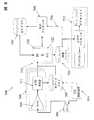
超音波プローブ校正システムが提供され、該システムは、複数の送信トランスデューサ素子及び複数の受信トランスデューサ素子を有する超音波プローブ、反射体のパターンを有するファントム、該ファントムの反射体のパターンを表す基準データを含む第1のメモリ装置、該各送信トランスデューサ素子及び該各受信トランスデューサ素子の共通座標系に対する位置を表すトランスデューサ素子の位置データを含む第2のメモリ装置、及び校正プログラムコードを含むイメージング制御システムを含み、該イメージング制御システムが、該送信トランスデューサ素子を用いて該ファントムを超音波照射し、該受信トランスデューサ素子でエコーデータを受信し、そして第3のメモリ装置にエコーデータを保存し、該トランスデューサ素子の位置データを用いて該保存されたエコーデータをビーム形成することによって該反射体のパターンの第1の画像を形成し、該第1の画像によって示される該反射体のパターンの位置を表す測定データを決定し、該測定データと該基準データとの間の誤差を定量化し、かつ該定量化された誤差に基づいて該トランスデューサ素子の位置データを反復的に最適化するように、該校正プログラムコードが構成されている。 An ultrasonic probe calibration system is provided, the system comprising an ultrasonic probe having a plurality of transmitting transducer elements and a plurality of receiving transducer elements, a phantom having a reflector pattern, and reference data representing the reflector pattern of the phantom. A first memory device comprising: a second memory device comprising position data of the transducer elements representing positions relative to a common coordinate system of the respective transmitting transducer elements and the respective receiving transducer elements; and an imaging control system comprising calibration program code The imaging control system ultrasonically illuminates the phantom with the transmit transducer element, receives echo data with the receive transducer element, and stores the echo data in a third memory device; position Forming a first image of the reflector pattern by beam-forming the stored echo data using a data and measuring data representing the position of the reflector pattern indicated by the first image The calibration program code so as to quantify errors between the measurement data and the reference data and to iteratively optimize the position data of the transducer elements based on the quantified errors Is configured.
一部の実施態様では、該イメージング制御システムは、該トランスデューサ素子の位置データを調整すること、該調整されたトランスデューサ素子の位置データを用いて該保存されたエコーデータを再ビーム形成することによって該反射体のパターンの第2の画像を形成すること、該第2の画像に基づいて第2の誤差を定量化すること、及び該第2の誤差を評価して、該調整されたトランスデューサ素子の位置データが該画像を改善するか否かを決定することによって、該ファントムを反復的に最適化するように構成されている。 In some embodiments, the imaging control system adjusts the transducer element position data and re-beamforms the stored echo data using the adjusted transducer element position data. Forming a second image of a pattern of reflectors, quantifying a second error based on the second image, and evaluating the second error to evaluate the adjusted transducer element It is configured to iteratively optimize the phantom by determining whether position data improves the image.
一実施態様では、該基準データは、該ファントムの物理的測定に基づいている。 In one embodiment, the reference data is based on physical measurements of the phantom.
他の実施態様では、該基準データは基準画像に基づいている。 In other embodiments, the reference data is based on a reference image.
一部の実施態様では、該イメージング制御システムは、最小二乗最適化プロセスを用いて該トランスデューサ素子の位置データを反復的に最適化するように構成されている。 In some implementations, the imaging control system is configured to iteratively optimize the transducer element position data using a least squares optimization process.
他の実施態様では、該ファントムは、超音波信号を吸収する少なくとも1つの領域をさらに含む。 In another embodiment, the phantom further comprises at least one region that absorbs the ultrasound signal.
一部の実施態様では、該超音波プローブは、複数のトランスデューサアレイを備える。別の実施態様では、該超音波プローブは、1つの連続トランスデューサアレイを備える。一実施態様では、該超音波プローブは、凹状湾曲を有するトランスデューサアレイを備える。 In some embodiments, the ultrasound probe comprises a plurality of transducer arrays. In another embodiment, the ultrasound probe comprises one continuous transducer array. In one embodiment, the ultrasound probe comprises a transducer array having a concave curvature.
一部の実施態様では、該ファントムはピンのパターンを含む。 In some embodiments, the phantom includes a pin pattern.
一実施態様では、該ファントムは生きた組織を含む。 In one embodiment, the phantom includes living tissue.
一部の実施態様では、該校正プログラムコードは、反射体の検出されたパターンに曲線を適合させることによって測定データを決定するように構成されている。 In some embodiments, the calibration program code is configured to determine measurement data by fitting a curve to a detected pattern of reflectors.
一実施態様では、該校正プログラムコードは、該曲線の適合の程度を定量化する決定係数を決定することによって誤差を定量化するように構成されている。 In one embodiment, the calibration program code is configured to quantify the error by determining a coefficient of determination that quantifies the degree of fit of the curve.
別の実施態様では、該第1のメモリ装置、該第2のメモリ装置、及び該第3のメモリ装置の少なくとも2つは、1つの物理的メモリ装置の論理部分である。 In another embodiment, at least two of the first memory device, the second memory device, and the third memory device are logical portions of one physical memory device.
(図面の簡単な説明)
本発明の新規な特徴は、特に添付の特許請求の範囲で説明する。本発明の特徴及び利点は、本発明の原理が利用されている例示的な実施態様を説明する以下の詳細な説明、及び添付の図面を参照すればより良く理解できるであろう。(Brief description of the drawings)
The novel features of the invention are set forth with particularity in the appended claims. The features and advantages of the present invention may be better understood with reference to the following detailed description that sets forth illustrative embodiments, in which the principles of the invention are utilized, and the accompanying drawings of which:
(詳細な説明)
様々な実施態様を、添付の図面を参照して詳細に説明する。特定の例及び実施についての言及は、例示目的であり、本発明の範囲又は特許請求の範囲を限定することを意図とするものではない。(Detailed explanation)
Various embodiments are described in detail with reference to the accompanying drawings. References to specific examples and implementations are for illustrative purposes, and are not intended to limit the scope of the invention or the claims.
本明細書の様々な実施態様は、静止ファントムを用いて多数開口超音波プローブを動的に校正するためのシステム及び方法を提供する。多数開口超音波イメージングプローブの校正は、一般に、プローブの各トランスデューサ素子の音響位置を決定すること含み得る。動的校正プロセスの一部の実施態様は、一般に、反射体の既知のパターンを有する校正ファントムを画像化するステップ、ファントムについての既知の情報と画像化で得られる情報との間の誤差を定量化するステップ、及び改善されたトランスデューサ素子の位置変数を得るために、反復最適化ルーチンを行って誤差関数を最小化するステップを含み得る。次いで、このような改善されたトランスデューサ素子の位置変数を、校正されたプローブを用いる後の画像化で使用するために保存することができる。 Various embodiments herein provide systems and methods for dynamically calibrating multi-aperture ultrasound probes using a stationary phantom. Calibration of a multi-aperture ultrasound imaging probe may generally include determining the acoustic position of each transducer element of the probe. Some implementations of the dynamic calibration process generally image a calibration phantom having a known pattern of reflectors, quantifying the error between the known information about the phantom and the information obtained from the imaging. And obtaining an improved transducer element position variable may include performing an iterative optimization routine to minimize the error function. Such improved transducer element position variables can then be saved for use in subsequent imaging with a calibrated probe.
(イントロダクションと定義)
様々な実施態様が、様々な解剖学的構造の超音波イメージングに関連付けて本明細書で説明されるが、本明細書に図示され、説明される多くの方法及び装置を、他の用途、例えば、非解剖学的構造及び物体のイメージング及び評価にも使用することができることを理解されたい。例えば、本明細書で説明されるプローブ、システム、及び方法は、様々な機械的物体、構造的物体、又は材料、例えば、接合部、管、梁、板材、圧力容器などの非破壊試験又は評価に使用することができる。(Introduction and definition)
While various embodiments are described herein in connection with ultrasound imaging of various anatomical structures, many methods and devices illustrated and described herein may be used in other applications, such as It should be understood that it can also be used for imaging and evaluation of non-anatomical structures and objects. For example, the probes, systems, and methods described herein provide non-destructive testing or evaluation of various mechanical objects, structural objects, or materials such as joints, tubes, beams, plates, pressure vessels, etc. Can be used for
本明細書で使用される「超音波トランスデューサ」及び「トランスデューサ」は、超音波イメージング技術の分野の技術者が理解する通常の意味を有することができ、限定されるものではないが、電気信号を超音波信号に変換することができ、かつ/又は逆も同様に行うことができる任意の1つの構成要素を指し得る。例えば、一部の実施態様では、超音波トランスデューサは、圧電素子を含み得る。他の実施態様では、超音波トランスデューサは、容量性微細加工超音波トランスデューサ(CMUT)を含み得る。 As used herein, “ultrasound transducers” and “transducers” can have their ordinary meaning as understood by those skilled in the art of ultrasound imaging technology and include, but are not limited to, electrical signals. It may refer to any one component that can be converted to an ultrasound signal and / or vice versa. For example, in some implementations, the ultrasonic transducer may include a piezoelectric element. In other embodiments, the ultrasonic transducer may include a capacitive micromachined ultrasonic transducer (CMUT).
トランスデューサは、多数の個々のトランスデューサ素子のアレイに構成される場合が多い。本明細書で使用される「トランスデューサアレイ」又は「アレイ」という語は、一般に、共通の支持プレートに取り付けられたトランスデューサ素子の集合体を指す。このようなアレイは、1次元(1D)、2次元(2D)、1.X次元(1.XD)、又は3次元(3D)を有し得る。当業者に理解される他の次元のアレイも使用することができる。環状アレイ、例えば、同心円アレイ及び楕円アレイも使用することができる。トランスデューサアレイの素子は、アレイの最も小さい別個に機能する構成要素であり得る。例えば、圧電トランスデューサ素子のアレイの場合には、各素子は、単一の圧電結晶、又は圧電結晶の単一の機械加工ブロックとすることができる。 Transducers are often configured in an array of many individual transducer elements. As used herein, the term “transducer array” or “array” generally refers to a collection of transducer elements attached to a common support plate. Such arrays can have one dimension (1D), two dimensions (2D), 1.X dimensions (1.XD), or three dimensions (3D). Other dimensional arrays understood by those skilled in the art can also be used. Circular arrays such as concentric and elliptical arrays can also be used. The elements of the transducer array can be the smallest separately functioning component of the array. For example, in the case of an array of piezoelectric transducer elements, each element can be a single piezoelectric crystal or a single machining block of piezoelectric crystals.
本明細書で使用される「送信素子」及び「受信素子」という語は、超音波イメージング技術の分野の技術者が理解する通常の意味を有し得る。「送信素子」という語は、限定されるものではないが、電気信号が超音波信号に変換される送信機能を少なくとも瞬間的に果たす超音波トランスデューサ素子を指すこともある。同様に、「受信素子」という語は、限定されるものではないが、該素子に衝当する超音波信号を電気信号に変換する受信機能を少なくとも瞬間的に果たす超音波トランスデューサ素子を指すこともある。超音波の媒体への送信は、本明細書では「超音波照射」と呼ばれることもある。超音波を反射する物体又は構造は、「反射体」又は「散乱体」と呼ばれることもある。 As used herein, the terms “transmitting element” and “receiving element” may have their ordinary meaning as understood by those skilled in the art of ultrasound imaging technology. The term “transmitting element” may refer, but is not limited to, an ultrasonic transducer element that at least instantaneously performs a transmitting function in which an electrical signal is converted into an ultrasonic signal. Similarly, the term “receiving element” refers to, but is not limited to, an ultrasonic transducer element that at least instantaneously performs a receiving function of converting an ultrasonic signal impinging on the element into an electrical signal. is there. Transmission of ultrasound to a medium is sometimes referred to herein as “ultrasound irradiation”. Objects or structures that reflect ultrasound are sometimes referred to as “reflectors” or “scatterers”.
本明細書で使用される「開口」という語は、超音波信号を送信し、かつ/又は受信することができる概念的な「開口部」を指し得る。実際の実施では、開口は、単に、1つのトランスデューサ素子、又はイメージング制御電子機器によって共通の群としてまとめて管理されるトランスデューサ素子群である。例えば、一部の実施態様では、開口は、隣接する開口の素子から物理的に分離することができる物理的な素子群とすることができる。しかしながら、隣接する開口は、必ずしも物理的に分離する必要はない。 As used herein, the term “aperture” may refer to a conceptual “aperture” capable of transmitting and / or receiving ultrasound signals. In actual implementation, the aperture is simply a single transducer element or a group of transducer elements managed together as a common group by imaging control electronics. For example, in some implementations, the apertures can be a group of physical elements that can be physically separated from adjacent aperture elements. However, adjacent openings need not necessarily be physically separated.
本明細書で使用される「受信開口」、「超音波照射開口」、及び/又は「送信開口」という語は、所望の物理的視点又は開口から所望の送信機能又は受信機能を果たす個々の素子、アレイ内の素子群、又は共通のハウジング内のアレイ全体を指すために使用されることに留意されたい。一部の実施態様では、このような送信開口及び受信開口は、専用の機能を有する物理的に別個の構成要素として形成することができる。他の実施態様では、任意の数の送信開口及び/又は受信開口を、必要に応じて、動的かつ電子的に定義することができる。他の実施態様では、多数開口超音波イメージングシステムは、専用の機能の開口と動的機能の開口との組み合わせを使用することができる。 As used herein, the terms “receive aperture”, “ultrasound aperture”, and / or “transmit aperture” refer to individual elements that perform a desired transmit or receive function from a desired physical point of view or aperture. Note that it is used to refer to a group of elements within an array, or an entire array within a common housing. In some implementations, such transmit apertures and receive apertures can be formed as physically separate components that have dedicated functions. In other implementations, any number of transmit and / or receive apertures can be dynamically and electronically defined as desired. In other embodiments, the multi-aperture ultrasound imaging system may use a combination of dedicated functional apertures and dynamic functional apertures.
本明細書で使用される「全開口」という語は、全てのイメージング開口の全積算サイズを指す。言い換えれば、「全開口」という語は、特定のイメージングサイクルに使用される送信素子及び/又は受信素子の任意の組み合わせにおける最も遠いトランスデューサ素子間の最大距離によって決定される1つ以上の寸法を指すこともある。従って、全開口は、特定のサイクルで送信開口又は受信開口として指定される任意の数のサブ開口から構成される。単一開口イメージング構成の場合は、全開口、サブ開口、送信開口、及び受信開口は、全て同じ寸法を有する。多数アレイプローブの場合は、全開口の寸法は、全てのアレイの寸法の合計を含み得る。 As used herein, the term “total aperture” refers to the total integrated size of all imaging apertures. In other words, the term “full aperture” refers to one or more dimensions determined by the maximum distance between the furthest transducer elements in any combination of transmitting and / or receiving elements used in a particular imaging cycle. Sometimes. Thus, the full aperture consists of any number of sub-apertures designated as transmit apertures or receive apertures in a particular cycle. For a single aperture imaging configuration, the full aperture, sub aperture, transmit aperture, and receive aperture all have the same dimensions. In the case of a multiple array probe, the size of the total aperture may include the sum of the dimensions of all the arrays.
一部の実施態様では、2つの開口が、連続アレイ上に互いに隣接して位置し得る。なお他の実施態様では、2つの開口は、少なくとも1つの素子が2つの別個の開口の一部として機能するように、連続アレイ上に互いに重ね合わせることができる。開口の位置、機能、素子の数、及び開口の物理的サイズを、特定の適用例に必要な任意の方式で動的に決定することができる。特定の適用例のこれらのパラメータに対する制約が以下に示され、かつ/又は、このような制約は当業者には明白であろう。 In some embodiments, the two openings can be located adjacent to each other on the continuous array. In yet other embodiments, the two openings can overlap each other on a continuous array such that at least one element functions as part of two separate openings. The location, function, number of elements, and physical size of the aperture can be determined dynamically in any manner required for a particular application. Constraints on these parameters for a particular application are set forth below and / or such constraints will be apparent to those skilled in the art.
本明細書で説明される素子及びアレイは、多機能であっても良い。すなわち、ある時点でのトランスデューサ素子又はアレイの送信機としての指定は、次の時点でのこれらの受信機としての即時の再指定を排除するものではない。さらに、本明細書の制御システムの実施態様は、このような指定を、ユーザーの入力、プリセットスキャン、プリセット解像度基準、又は他の自動的に決定される基準に基づいて電子的に行う能力を有する。 The elements and arrays described herein may be multifunctional. That is, designation of a transducer element or array as a transmitter at one point in time does not preclude immediate re-designation as these receivers at the next point in time. In addition, the control system embodiments herein have the ability to make such designation electronically based on user input, preset scans, preset resolution criteria, or other automatically determined criteria. .
本明細書で使用される「点源送信」という語は、1つの空間位置からの送信超音波エネルギーの媒体への導入を指すこともある。これは、1つの超音波トランスデューサ素子、又は1つの送信開口として一緒に送信する隣接するトランスデューサ素子の組み合わせを用いて達成することができる。点源送信開口からの1回の送信を、均一な球形波面に、又は2Dスライスを画像化する場合には該2Dスライス内の均一な円形波面に近づける。場合によっては、点源送信開口からの円形又は球形の波面の1回の送信は、本明細書では「ピング」又は「点源パルス」と呼ばれることもある。 As used herein, the term “point source transmission” may refer to the introduction of transmitted ultrasonic energy from one spatial location into the medium. This can be accomplished using one ultrasonic transducer element or a combination of adjacent transducer elements that transmit together as one transmission aperture. A single transmission from the point source transmission aperture is approximated to a uniform spherical wavefront, or to a uniform circular wavefront within the 2D slice if a 2D slice is to be imaged. In some cases, a single transmission of a circular or spherical wavefront from a point source transmission aperture may be referred to herein as a “ping” or “point source pulse”.
点源送信は、トランスデューサ素子アレイから特定の方向にエネルギーを集束させる「フェーズドアレイ送信」とはその空間的特徴の点で異なる。フェーズドアレイ送信は、目的の特定の領域への波面の照射を強める、又は誘導するようにトランスデューサ素子群の位相を順に操作する。短期間のフェーズドアレイ送信は、本明細書では「フェーズドアレイパルス」と呼ばれることもある。 Point source transmission differs from "phased array transmission", which focuses energy in a specific direction from the transducer element array in terms of its spatial characteristics. Phased array transmission sequentially manipulates the phase of transducer elements to intensify or direct the irradiation of the wavefront to a specific area of interest. A short-term phased array transmission is sometimes referred to herein as a “phased array pulse”.
一部の実施態様では、一連の送信ピングを使用する多数開口イメージングは、第1の送信開口から点源ピングを送信して、2つ以上の受信開口の素子でエコーを受信することによって行うことができ、これらの受信開口の1つ以上が、送信開口の一部又は全ての素子を含み得る。完全な画像は、ピングの送信とエコーの受信との間の遅延時間、音速、及び送信トランスデューサ素子と受信トランスデューサ素子との相対位置に基づいて散乱体の位置を三角測量することによって形成することができる。結果として、各受信開口は、各送信ピングのエコーから完全な画像を形成することができる。一部の実施態様では、1つの時間領域フレームは、1つの送信ピングからの、2つ以上の受信開口で受信されるエコーから形成される画像を組み合わせることによって形成することができる。他の実施態様では、1つの時間領域フレームは、2つ以上の送信ピングからの、1つ以上の受信開口で受信されるエコーから形成される画像を組み合わせることによって形成することができる。一部のこのような実施態様では、多数の送信ピングは、異なる送信開口を起源とし得る。 In some embodiments, multi-aperture imaging using a series of transmit pings is performed by transmitting a point source ping from a first transmit aperture and receiving echoes at elements of two or more receive apertures And one or more of these receive apertures may include some or all of the elements of the transmit aperture. A complete image can be formed by triangulating the position of the scatterer based on the delay time between ping transmission and echo reception, the speed of sound, and the relative position of the transmitting and receiving transducer elements. it can. As a result, each receive aperture can form a complete image from each transmit ping echo. In some implementations, a time domain frame can be formed by combining images formed from echoes received at two or more receive apertures from one transmit ping. In other implementations, a time domain frame can be formed by combining images formed from echoes received at one or more receive apertures from two or more transmit pings. In some such implementations, multiple transmit pings can originate from different transmit apertures.
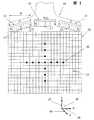
図1は、3アレイ多数開口超音波イメージングプローブ10及び画像化されるファントム20の一実施態様を例示している。ファントム20は、一般に、固体又は液体媒体35内の反射体30のパターンを含む。一部の実施態様では、ファントム20は、超音波信号を実質的に吸収して超音波信号をそれほど反射しない1つ以上の「孔」−領域又は物体も含み得る。プローブ10は、「n」、「j」、及び「k」(本明細書では簡略化して参照符号Ln、Lj、及びLkで示すこともある)と付された3つの送信開口を有し得る左トランスデューサアレイ12を備えて示されている。右トランスデューサアレイ14も、「n」、「j」、及び「k」(本明細書では簡略化して参照符号Rn、Rj、及びRkで示すこともある)と付された3つの送信開口を有し得る。左トランスデューサアレイ12の一部又は全ての素子は、左受信開口13として指定することもできる。同様に、右トランスデューサアレイ14の一部又は全ての素子は、右受信開口15として指定することもできる。これらの左アレイ及び右アレイに加えて、多数開口超音波プローブ10は、中心トランスデューサアレイ16を備えることができ、該トランスデューサアレイ16は、「n」、「j」、及び「k」(本明細書では簡略化して参照符号Cn、Cj、及びCkで示すこともある)と付された3つの送信開口を備えることができる。中心トランスデューサアレイ16の一部又は全ての素子は、中心受信開口17として指定することもできる。3つの開口はそれぞれ、1次元、2次元、又は3次元において、互いに離間させることができる任意の数のトランスデューサ素子を含み得ることを理解されたい。 FIG. 1 illustrates one embodiment of a three-array multiple aperture
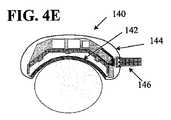
他の実施態様では、その他の多数開口超音波イメージングプローブも、以下に説明されるシステム及び方法を用いて校正することができる。例えば、図2は、ファントム20の上に配置された1つの大きい(即ち、意図するイメージングの適用例の予想コヒーレント幅よりも大きい)連続湾曲アレイ18を備えた多数開口超音波プローブ55を例示している。以下の校正の方法及び装置の一部の実施態様は、図3に例示されているような調整可能なプローブに特に有用であり得る。図3は、ファントム20の上に配置された調整可能な多数開口超音波プローブ11を例示している。図4Aは、経食道配置及びイメージングのためのサイズ及び構成の、内視鏡104の遠位端部に配置された1つ以上のトランスデューサアレイ102を備える多数開口超音波プローブ100を例示している。図4Bは、経直腸配置及びイメージングのためのサイズ及び構成の、1つ以上のトランスデューサアレイ112及びハウジング114を備える多数開口超音波プローブ110を例示している。図4Cは、それぞれ静脈内配置及びイメージングのためのサイズ及び構成にすることができる、1つ以上のトランスデューサアレイ122及びカテーテル126の遠位端部に配置されたハウジング124を備えた多数開口超音波プローブ120を例示している。図4Dは、経膣配置及びイメージングのためのサイズ及び構成の、1つ以上のトランスデューサアレイ132及びハウジング134を備える多数開口超音波プローブ130を例示している。図4Eは、湾曲した解剖学的構造、例えば、腕及び脚に配置するためのサイズ及び構成の、連続湾曲トランスデューサアレイ142、ハウジング144、及び側面に取り付けられたケーブル416を備える多数開口超音波プローブ140を例示している。図4Fは、2つの軸を中心に凹状湾曲を有し得る大きい円形アレイ152を備えた多数開口超音波プローブ150を例示している。図4Fのプローブ及び他のプローブは、直交軸に沿った実質的に変位したトランスデューサ素子を備えることができる。このようなプローブは、3次元ボリュームからエコーデータを直接得るのに特に適し得る。これら又は他の超音波プローブ(単一開口超音波プローブを含む)はいずれも、本明細書のシステム及び方法を用いて校正することができる。 In other embodiments, other multi-aperture ultrasound imaging probes can be calibrated using the systems and methods described below. For example, FIG. 2 illustrates a
本明細書で使用される「ファントム」という語は、超音波プローブによって画像化される任意の実質的に静止している物体を指し得る。例えば、超音波検査者の訓練用に設計された任意の数のファントムが、医療機器の様々な供給者、例えば、Gammex, Inc.(gammex.com)によって広く販売されている。一部の市販のファントムは、画像化されるべき物体、例えば、特殊又は一般的なヒト組織のイメージング特性に似るように形成されている。このような特性は、以下にさらに説明される本発明の様々な実施態様に必要な場合もあるし、必要でない場合もある。「ファントム」という語は、実質的に静止した反射体を備える他の物体、例えば、実質的に静止した強力な反射体を備えるヒト又は動物の体の領域も含み得る。物体は、本明細書に説明される校正プロセス用のファントムとして使用されるファントムとして専用に形成する必要はない。 As used herein, the term “phantom” can refer to any substantially stationary object that is imaged by an ultrasound probe. For example, any number of phantoms designed for sonographer training are widely sold by various suppliers of medical devices, such as Gammex, Inc. (gammex.com). Some commercial phantoms are shaped to resemble the imaging properties of the object to be imaged, eg, special or general human tissue. Such characteristics may or may not be necessary for various embodiments of the invention described further below. The term “phantom” may also include other objects with a substantially stationary reflector, for example a human or animal body region with a substantially stationary and strong reflector. The object need not be specially formed as a phantom used as a phantom for the calibration process described herein.
図1を参照すると、多数開口イメージングプロセスの例示的な一実施態様では、第1の送信開口Lnから第1のピングを送信して、左受信開口13で第1のピングのエコーを受信することによって第1の画像を形成することができる。第2の画像は、右受信開口15で受信される第1のピングのエコーから形成することができる。第3及び第4の画像は、第2の送信開口Ljから第2のピングを送信して、左受信開口13及び右受信開口15で第2のピングのエコーを受信することによって形成することができる。一部の実施態様では、次いで、4つ全ての画像を組み合わせて1つの時間領域フレームを形成することができる。他の実施態様では、1つの時間領域フレームは、任意の数の送信開口によって送信される任意の数のピングからの、任意の数の受信開口で受信されるエコーから得ることができる。次いで、時間領域画像フレームを、連続動画としてディスプレイ画面上に連続的に表示することができる。静止画も、任意の上記の技術を用いて形成することができる。 Referring to FIG. 1, in an exemplary embodiment of a multiple aperture imaging process, transmitting a first ping from a first transmit aperture Ln and receiving an echo of the first ping at the left receive
一部の実施態様では、受信開口の幅は、散乱体から受信開口の各素子までのどの経路でも音速が同じであるという仮定によって限定することができる。十分に狭い受信開口では、この仮定の単純化は許容範囲である。しかしながら、受信開口の幅が広くなると、変曲点に達し(本明細書では「最大コヒーレント開口幅」又は「コヒーレント幅」と呼ばれる)、エコーの戻り経路が、音速が異なる様々な種類の組織を通過しなければならない。この差異が180度を超える位相シフトとなると、最大コヒーレント受信開口幅を超える追加の受信素子は、画像を向上させるのではなく、実際には画像を劣化させることになる。コヒーレント幅は、目的とするイメージングの適用例によって異なり、事前に予測することは不可能ではないにしても困難である。 In some implementations, the width of the receive aperture can be limited by the assumption that the speed of sound is the same for any path from the scatterer to each element of the receive aperture. For sufficiently narrow receive apertures, this assumption simplification is acceptable. However, as the width of the receive aperture increases, an inflection point is reached (referred to herein as “maximum coherent aperture width” or “coherent width”), and the return path of the echo passes through various types of tissue with different sound speeds. Must pass. If this difference is a phase shift exceeding 180 degrees, additional receiving elements that exceed the maximum coherent receiving aperture width will not actually improve the image, but will actually degrade the image. The coherent width depends on the intended imaging application and is difficult if not impossible to predict in advance.
従って、最大コヒーレント幅よりも広い全開口幅を有する広幅プローブを使用するために、全プローブ幅を、多数の開口に物理的又は理論的に分割することができ、分割される各開口は、最大コヒーレント開口幅よりも狭い幅に限定して、受信信号の位相相殺を回避する十分に小さい大きさにすることができる。最大コヒーレント幅は、患者によって、及び同じ患者でもプローブ位置によって異なり得る。一部の実施態様では、所与のプローブシステムに対して妥当な幅を決定することができる。他の実施態様では、多数開口超音波イメージング制御システムを、動的アルゴリズムを用いて構成して、多数開口の利用可能な素子を、著しい位相相殺を回避するために十分に小さい群にさらに分割することができる。 Thus, to use a wide probe with a total aperture width that is wider than the maximum coherent width, the total probe width can be physically or theoretically divided into a number of apertures, with each divided aperture having a maximum By limiting to a width narrower than the coherent aperture width, the size can be made sufficiently small to avoid phase cancellation of the received signal. The maximum coherent width may vary from patient to patient and even with the same patient depending on the probe position. In some implementations, a reasonable width can be determined for a given probe system. In another embodiment, the multi-aperture ultrasound imaging control system is configured using a dynamic algorithm to further divide the multi-aperture available elements into groups that are small enough to avoid significant phase cancellation. be able to.
一部の実施態様では、最大コヒーレント幅よりも狭い幅の開口に素子をグループ分けするときに、さらなるデザインの制約を満たすことが困難になる、又は不可能になるであろう。例えば、非常に狭い領域に対して物質の種類が多すぎると、最大コヒーレント幅よりも狭くなるように十分に小さい開口を形成することは実現困難であろう。同様に、システムが、かなりの深さで非常に小さい標的を画像化するようにデザインされると、最大コヒーレント幅よりも幅の広い開口が必要になり得る。このような場合、最大コヒーレント幅よりも幅の広い受信開口は、異なる経路に沿った音速の差異を考慮するためにさらなる調整又は補正を行うことができるようにすることにより達成することができる。このような音速の調整の一部の例が本明細書に記載されている。 In some implementations, it may be difficult or impossible to meet additional design constraints when grouping elements into openings that are narrower than the maximum coherent width. For example, if there are too many types of material for a very narrow region, it would be difficult to form an aperture that is small enough to be narrower than the maximum coherent width. Similarly, if the system is designed to image very small targets at a significant depth, an aperture wider than the maximum coherent width may be required. In such cases, a receive aperture wider than the maximum coherent width can be achieved by allowing further adjustments or corrections to be made to account for differences in sound speed along different paths. Some examples of such sound speed adjustments are described herein.
点源送信イメージング技術(ピングベースイメージングとも呼ばれる)を用いる多数開口プローブでは、各画像画素は、受信エコーデータをビーム形成して、多数の各送信開口からの、多数の各受信開口で受信されるエコーからの情報を組み合わせることによって構築することができる。点源送信を用いる多数開口イメージングの一部の実施態様では、受信ビーム形成は、検査される物体の散乱体から受信トランスデューサ素子に戻る時間遅延エコーを合計することによって再構成画像の画素を形成することを含む。この時間遅延は、プローブ素子の幾何学的形状及び画像化される媒体を通る音速の仮定値によって決定することができる。 In a multi-aperture probe using point source transmit imaging techniques (also called ping-based imaging), each image pixel is received at a number of receive apertures from a number of transmit apertures, beamforming the received echo data. It can be constructed by combining information from echoes. In some embodiments of multi-aperture imaging using point source transmission, receive beamforming forms pixels of the reconstructed image by summing the time delayed echoes from the scatterers of the object being examined back to the receive transducer elements. Including that. This time delay can be determined by the assumed geometry of the probe element and the speed of sound through the imaged medium.
1つの反射体の位置は、送信トランスデューサ素子(複数可)の位置に第1の焦点を有し、かつ受信トランスデューサ素子の位置に第2の焦点を有する楕円上にある。いくつかの他の可能な反射体が同じ楕円上に存在するが、同じ反射体のエコーは、受信開口の他の各受信トランスデューサ素子によっても受信される。各受信トランスデューサ素子の僅かに異なる位置は、各受信素子が、所与の反射体に対してやや異なる楕円を画定することを意味する。共通の受信開口の全ての素子の楕円をコヒーレント加算することによる結果の累積は、反射体の楕円の交差、従って、反射体を表す画素を表示する点に向かって収束することを示す。従って、任意の数の受信素子によって受信されるエコーの振幅を各画素値に組み合わせることができる。他の実施態様では、実質的に同じ画像に到達するように計算を異なる方式で行うことができる。 The position of one reflector is on an ellipse having a first focal point at the position of the transmitting transducer element (s) and a second focal point at the position of the receiving transducer element. Although several other possible reflectors exist on the same ellipse, echoes of the same reflector are also received by each other receive transducer element of the receive aperture. A slightly different position of each receive transducer element means that each receive element defines a slightly different ellipse for a given reflector. Accumulation of the results by coherently adding the ellipses of all elements in the common receive aperture indicates that the intersection of the reflector ellipses and thus converge towards the point displaying the pixel representing the reflector. Therefore, the amplitude of the echo received by any number of receiving elements can be combined with each pixel value. In other embodiments, the calculations can be performed in different ways to arrive at substantially the same image.
各送信素子及び受信素子の位置が、ピングベース超音波イメージング中に画像の形成で重要な役割を果たすため、ピングベースイメージングから形成される画像の質は、トランスデューサ素子の相対位置を表す情報の精度によって実質的に決まる。 Because the position of each transmitting and receiving element plays an important role in image formation during ping-based ultrasound imaging, the quality of the image formed from ping-based imaging is the accuracy of information representing the relative position of the transducer elements Depends substantially on
別個の受信素子によって受信されるエコー信号の組み合わせに様々なアルゴリズムを使用することができる。例えば、一部の実施態様は、エコー信号を個々に処理し、各エコー信号をその楕円に沿った全ての可能な位置にプロットし、次いで、次のエコー信号に進むことができる。あるいは、各画素位置を個々に処理し、次の画素位置に進む前にその画素位置に寄与する可能性がある全てのエコーを特定して処理することができる。 Various algorithms can be used to combine the echo signals received by the separate receiving elements. For example, some implementations can process the echo signals individually, plot each echo signal at all possible positions along its ellipse, and then proceed to the next echo signal. Alternatively, each pixel position can be processed individually, and all echoes that may contribute to that pixel position can be identified and processed before proceeding to the next pixel position.
同じ又は異なる点源(又は多数の異なる点源)から送信される、1つ以上の後の送信ピングからビームフォーマーによって形成される画像を組み合わせることによって、画質をさらに改善することができる。2つ以上の受信開口によって形成される画像を組み合わせることによって、画質のなおさらなる改善を達成することができる。重要な検討事項は、異なるピング、異なる送信点源、又は異なる受信開口からの画像の加算が、コヒーレント加算(位相感受性)であるか、又はインコヒーレント加算(位相情報を考慮しない信号の大きさの加算)であるかである。 Image quality can be further improved by combining images formed by a beamformer from one or more subsequent transmit pings transmitted from the same or different point sources (or multiple different point sources). By combining the images formed by two or more receiving apertures, still further improvements in image quality can be achieved. An important consideration is that the addition of images from different pings, different transmission point sources, or different reception apertures is coherent addition (phase sensitive) or incoherent addition (of signal magnitudes that do not take into account phase information) Addition).
一部の実施態様では、一連の送信ピングを用いる多数開口イメージングは、第1の送信開口から点源ピングを送信して、1つ以上の受信開口(送信開口と重複し得る)の素子でエコーを受信することによって行うことができる。完全な画像は、送信と受信エコーとの間の遅延時間、及び各受信素子の各点源送信開口に対する既知の位置に基づいて散乱体の位置を三角測量することによって形成することができる。結果として、完全な画像は、各送信ピングのエコーからの、各受信開口で受信したデータから形成することができる。 In some implementations, multi-aperture imaging using a series of transmit pings transmits a point source ping from the first transmit aperture and echoes at elements of one or more receive apertures (which may overlap the transmit aperture) Can be done by receiving A complete image can be formed by triangulating the position of the scatterer based on the delay time between the transmit and receive echoes and the known position of each receive element relative to each point source transmit aperture. As a result, a complete image can be formed from the data received at each receive aperture from each transmit ping echo.
ピングと受信開口の様々なユニークな組み合わせから得られる画像を、本明細書では画像層と呼ぶことがある。多数の画像層を組み合わせて、最終組み合わせ画像の全体の質を改善することができる。従って、一部の実施態様では、画像層の数は、受信開口の数と送信開口の数との積とすることができる(この場合、「送信開口」は、1つの送信素子又は一群の送信素子とすることができる)。他の実施態様では、同じピングイメージングプロセスも、1つの受信開口を用いて行うことができる。 Images obtained from various unique combinations of pings and receive apertures are sometimes referred to herein as image layers. Multiple image layers can be combined to improve the overall quality of the final combined image. Thus, in some implementations, the number of image layers can be the product of the number of receive apertures and the number of transmit apertures (in this case, a “transmit aperture” is a transmit element or a group of transmit apertures). Element). In other embodiments, the same ping imaging process can be performed with a single receive aperture.
(ファントムの校正の実施態様)
ファントムを用いる超音波プローブ校正法の一部の実施態様は、一般に、いくつかの既知のベースライン基準データを用いてファントムを特徴付けるステップ、次に、校正されるべきプローブを用いてファントムを画像化するステップを含む。次いで、既知の基準データと形成される画像から得られるデータとの間の誤差を定量化することができ、反復最適化ルーチンを使用して、改善されたトランスデューサ素子の位置情報を得ることができる。次いで、このような改善されたトランスデューサ素子の位置変数を、校正されたプローブを用いる後のイメージングで使用するために保存することができる。(Phantom calibration embodiment)
Some embodiments of ultrasonic probe calibration methods using phantoms generally characterize the phantom using a number of known baseline reference data, and then image the phantom using the probe to be calibrated Including the steps of: The error between the known reference data and the data obtained from the formed image can then be quantified and an iterative optimization routine can be used to obtain improved transducer element position information. . Such improved transducer element position variables can then be saved for use in subsequent imaging with a calibrated probe.
図1は、多数開口プローブの校正に使用することができるファントム20の一実施態様を例示している。一部の実施態様では、多数開口プローブを校正するためのファントム20は、一定で既知の音速を有する固体、液体、又はゲル材料35内で2次元パターンに配置された複数の反射体30を含み得る。反射体は、任意の材料、例えば、プラスチック、金属、木材、セラミック、又は周囲の媒体よりも超音波の反射率が実質的に高い任意の他の固体材料から形成することができる。 FIG. 1 illustrates one embodiment of a phantom 20 that can be used to calibrate multiple aperture probes. In some embodiments, a
一部の実施態様では、反射体30は、校正プロセスを容易にするために選択される特徴を有し得るパターンでファントム20内に配置することができる。例えば、非反復反射体パターンでは、校正プロセスが、混乱することなく反射体の画像化位置を認識することができる。例えば、完全な格子パターンは、該パターンの各部分が、全格子位置が1つずれるだけで同一に複製されるため、高度に反復的である。一部の実施態様では、反射体のパターンは、Y軸47に沿って変位した多数の反射体にほぼ等しいX軸46に沿って変位した多数の反射体も含み得る。従って、一部の実施態様では、十字型又はプラス記号のパターンを使用することができる。他の実施態様では、反射体は、ランダムに配置しても良いし、又は他のパターン、例えば、X型、アスタリスク、日輪型、螺旋、もしくは任意の他のパターンに配置しても良い。 In some implementations, the
一部の実施態様では、反射体は、z方向48に深度又は識別可能な細部も有し得る。例えば、反射体30は、z方向48に沿った長手方向軸を有するロッドとすることができる。あるいは、反射体は、実質的に球形又は均一な3次元形状とすることができる。他の実施態様では、交差するワイヤ又はロッドの構成を使用して、ファントム内の3次元空間に識別可能なパターンを形成することができる。 In some implementations, the reflector may also have depth or identifiable details in the
校正ファントム20内の反射体30は、所望に応じて任意のサイズ又は形状にすることができる。一部の実施態様では、反射体30は、使用される超音波信号の波長とほぼ同じ大きさの円の直径を有し得る。一般に、小さい反射体ほど、優れた校正を行うことができるが、一部の実施態様では、反射体の正確なサイズは、必ずしも重要な因子ではない。一部の実施態様では、ファントム内の全ての反射体30は、互いに同じサイズにすることができ、他の実施態様では、反射体30は、様々なサイズにすることができる。 The
一部の実施態様では、ファントム20内の反射体の物理的なサイズ及び位置は、ファントムの形成の前、最中、もしくは後でのファントムの機械的な測定によって(又は他の方法、例えば、既知の校正システムを用いる光測定もしくは超音波測定によって)決定することができる。次いで、反射体の位置の基準データを、校正プロセスを行うソフトウェア又はファームウェアがアクセス可能なメモリ装置に反射体の位置情報を保存することによって得ることができる。このような基準データは、ファントム内の反射体及び/又は孔についての情報、例えば、位置、サイズ、向き、構成、又は他の情報を含み得る。基準データは、基準画像として、又は一連のデータ点として表す又は保存することができる。あるいは、基準データは、基準超音波画像から取り出すことができる。 In some embodiments, the physical size and position of the reflector within the
一部の実施態様では、ファントムの基準画像は、十分に校正されていることが分かっているプローブ又はプローブ内のアレイを用いて得ることができる。他の実施態様では、ファントムの基準画像は、プローブの選択された素子群を用いて得ることができる。次いで、反射体のサイズ及び/又は位置情報を、プローブの残りの素子又は別のプローブの校正に使用される基準画像から決定することができる。 In some implementations, a reference image of the phantom can be obtained using a probe or an array within the probe that is known to be fully calibrated. In other embodiments, a reference image of the phantom can be obtained using a selected group of elements of the probe. The reflector size and / or position information can then be determined from the reference image used to calibrate the remaining elements of the probe or another probe.
従って、一部の実施態様では、基準画像は、以前に決定された反射体の位置データをメモリ装置から取り出すことによって得ることができる。他の実施態様では、基準画像は、プローブ内の素子のサブセット又は全素子を用いてファントムを画像化することによって得ることができる。一部の実施態様では、仮定最大コヒーレント幅(上記説明された)以下の開口を用いて基準画像を得ることが望ましいであろう。これにより、異なる超音波経路に沿った音速の変動を補正しなくても、基準画像を形成することが可能となる。ファントムが、均一の音速(反射体及び/又は孔を除く)を有することが分かっている場合は、コヒーレント幅は、多数開口プローブの全開口全体と同じ大きさにすることができる。このような実施態様では、意図するイメージングの適用例のコヒーレント幅よりも小さい受信開口を用いて基準画像を得ることは、開始点として有用であり得る。 Thus, in some implementations, the reference image can be obtained by retrieving previously determined reflector position data from the memory device. In other embodiments, the reference image can be obtained by imaging a phantom with a subset or all of the elements in the probe. In some implementations, it may be desirable to obtain a reference image with an aperture that is less than or equal to the assumed maximum coherent width (described above). As a result, it is possible to form a reference image without correcting the variation in the speed of sound along different ultrasonic paths. If the phantom is known to have a uniform sound velocity (excluding reflectors and / or holes), the coherent width can be as large as the entire full aperture of the multi-aperture probe. In such an implementation, it may be useful as a starting point to obtain a reference image with a receive aperture that is smaller than the coherent width of the intended imaging application.
例えば、図1に示されているような3アレイプローブを校正する場合、基準画像は、唯1つのアレイ(例えば、中心アレイ16、左アレイ12、又は右アレイ14)を用いてファントム20を画像化することによって得ることができる。他の実施態様では、例えば、図2に示されているような連続凸状トランスデューサアレイ19を用いてプローブを校正する場合、基準画像は、アレイのトランスデューサ素子の少数の群のみを用いてファントム20を画像化することによって得ることができる。例えば、湾曲アレイの中心に近い素子の群を、基準画像を得るための送信素子及び/又は受信素子として使用することができる。同様に、基準画像は、図3に示されているような調整可能なプローブ11の1つの調整可能なアレイ19を用いて得ることができる。基準画像は、同様の方式で任意の多数開口超音波イメージングプローブを用いて得ることができる。 For example, when calibrating a three-array probe as shown in FIG. 1, the reference image is an image of
例えば、図2に示されているように、一部の実施態様では、ファントムは、プローブ保持部50を備えるエンクロージャ内に取り付けることができる。取り付けブラケット52を、校正プロセス中にプローブ55をファントム20に対して一定の位置に確実に保持するために設けることもできる。任意の機械的なブラケットを使用することができる。一部の実施態様では、結合ゲル及び/又はゲルもしくは流体充填スタンドオフ42を使用して、超音波信号が通過する連続媒体を形成することができる。結合ゲル及び/又はスタンドオフ42は、ファントム媒体とほぼ同じ音速を有するべきである。一部の実施態様では、スタンドオフ42は、液体又はゲル充填バッグとすることができる。 For example, as shown in FIG. 2, in some embodiments, the phantom can be mounted in an enclosure that includes a
図5Aは、特定の形状のプローブを受容するように設計された複数の受容スロット310を有するドッキングセクション342を含む代替の構成を例示している。ドッキングセクション342は、ファントム20の材料と同じ材料から形成することができる。あるいは、ドッキングセクション342は、ファントム20と同じ音速特性を有する材料から形成することができる。図5Bに例示されているように、多数のプローブ受容スロット310を1つのドッキングセクション342に設けることができる。様々な実施態様では、各プローブ受容スロット310は、1つ以上の特定の超音波プローブを受容するサイズ、形状、及び構成にすることができる。 FIG. 5A illustrates an alternative configuration that includes a
図6は、ファントムを用いて多数の開口プローブを校正するプロセス400の一実施態様を例示する工程系統図である。一般に、プロセス400の一部の実施態様は、ファントムについての既知の情報(例えば、反射体又は孔の位置、サイズなど)を特徴付ける基準データを得るステップ402、試験送信(TX)開口を用いてファントムを超音波照射するステップ404、試験受信(RX)開口でエコーを受信するステップ405、受信したエコーデータを少なくとも一時的に保存するステップ406、エコーデータをビーム形成することによって反射体の試験画像を形成するステップ408、形成した画像と基準データとの比較に基づいて誤差関数を決定するステップ412、及び誤差関数を最小化して414、改善されたトランスデューサ素子の位置変数を得るステップ416を含み得る。得られる改善された素子の位置情報を、ビーム形成プロセスでの後の使用のためにメモリ装置に保存することができる。次いで、ステップ404〜416を、プローブの追加の送信開口及び/又は開口のそれぞれに対して繰り返すことができ、プローブ内の送信開口及び/又は受信開口のそれぞれにおける各トランスデューサ素子の位置を、共通の座標系に対して決定することができる。 FIG. 6 is a process flow diagram illustrating one embodiment of a
一部の実施態様では、プロセス400は、ソフトウェア又はファームウェアで完全に自動化することができる。他の実施態様では、少なくとも一部のステップは、人間の関与、例えば、得られた画像と基準画像との間の誤差の確認又は定量化を伴い得る。他の実施態様では、人間の使用者も、得られる画像が「十分良好である」かどうか、又は校正プロセスが反復もしくは継続されるかどうかを決定する際に必要とされ得る。 In some implementations, the
様々な実施態様では、プロセス400を使用して、1つ以上の試験送信開口、1つ以上の試験受信開口、又は両方の位置を校正することができる。どのタイプの開口を校正するかの選択は、因子、例えば、プローブの構造、送信開口もしくは受信開口の数、又は他の因子に基づくことができる。校正プロセスに使用される試験送信開口及び試験受信開口の定義は、プローブを用いた通常の画像化に使用される開口の定義と同じにすることができるが、必ずしも同じにする必要はない。従って、本明細書で使用される「試験開口」という熟語は、特段の記載がない限り、送信試験開口又は受信試験開口のいずれかを指し得る。 In various implementations, the
一部の実施態様では、図6のプロセス400の最中に使用される試験送信開口及び試験受信開口は、実質的に互いに近接させることができる。例えば、一部の実施態様では、試験送信開口及び試験受信開口は、互いに対して、意図するイメージングの適用例の予想コヒーレント幅の範囲内にすることができる。例えば、一部の実施態様では、受信開口は、共通のアレイ上の全ての素子(例えば、共通のバッキングブロック(backing block)を共有する素子)を含み得る。あるいは、受信開口は、2つ以上の別個のアレイの素子を含み得る。さらなる実施態様では、受信開口は、大きい連続アレイに沿ったトランスデューサ素子の選択された群を含み得る。他の実施態様では、試験送信開口及び試験受信開口は、互いに接近させる必要がなく、どの予想コヒーレント幅よりも大きい距離、互いに離間させることができる。さらなる実施態様では、ファントムが、均一な音速を有することが分かっている場合は、コヒーレント幅は、それほど考慮する必要がない。 In some implementations, the test transmit aperture and test receive aperture used during the
一部の実施態様では、1つの送信試験開口を使用して、基準画像、及び試験画像を形成することができるデータの両方を得ることができる。このような実施態様では、第1の受信開口を使用して基準画像を形成することができ、第2(又は第3など)の受信開口を使用して試験画像データを得ることができる。同様に、異なる送信開口が基準画像及び試験画像データに使用される場合も、1つの受信開口を、基準画像及び試験画像用のデータの両方を得るために使用することができる。従って、試験送信開口及び試験受信開口は、必ずしも互いに近づける必要がない。他の実施態様では、基準画像は、第1のアレイの送信素子及び受信素子を用いて得ることができ、試験画像用のデータは、第2のアレイの送信素子及び受信素子を用いて得ることができ、該第2のアレイは、校正されるべき試験アレイである。 In some implementations, a single transmission test aperture can be used to obtain both a reference image and data from which a test image can be formed. In such an embodiment, the first reception aperture can be used to form a reference image, and a second (or third, etc.) reception aperture can be used to obtain test image data. Similarly, if different transmit apertures are used for reference and test image data, one receive aperture can be used to obtain both data for the reference and test images. Therefore, the test transmission opening and the test reception opening do not necessarily have to be close to each other. In other embodiments, the reference image can be obtained using a first array of transmitting and receiving elements and the test image data can be obtained using a second array of transmitting and receiving elements. And the second array is a test array to be calibrated.
上記説明されたように、一部の実施態様では、基準データを得るステップ402は、データ保存装置から基準データを取り出すことを含み得る。このようなデータ保存装置は、校正制御装置内、超音波イメージングシステム内、プローブ内、又は有線もしくは無線ネットワーク接続を介してアクセス可能な別個の保存装置に物理的に配置することができる。あるいは、基準データを得るステップ402は、トランスデューサ素子の基準の群を用いてファントムを画像化することを含み得る。 As described above, in some implementations, obtaining 402 reference data may include retrieving reference data from a data storage device. Such a data storage device can be physically located in the calibration controller, in the ultrasound imaging system, in the probe, or in a separate storage device accessible via a wired or wireless network connection. Alternatively, obtaining 402 reference data may include imaging the phantom with a reference group of transducer elements.
一部の実施態様では、試験送信開口を用いてファントムを超音波照射するステップ404は、送信開口の1つ以上の送信素子から1つ以上のピングを送信することを含み得る。1つの送信開口は、典型的には、1つ、2つ、3つ、又は少数の隣接した素子を含み得る。 In some implementations, sonicating the phantom with the
各ピングが送信された後に、戻りエコーを、試験受信開口の全ての受信素子で受信することができ、エコーデータをデジタル化してデジタルメモリ装置に保存することができる406。このメモリ装置は、イメージング及び校正プロセスを行う計算装置によって電子的にアクセス可能な、任意の物理的位置にある任意の揮発性又は不揮発性デジタルメモリ装置とすることができる。 After each ping is transmitted, the return echo can be received at all receiving elements of the test receive aperture, and the echo data can be digitized and stored 406 in a digital memory device. The memory device may be any volatile or non-volatile digital memory device in any physical location that is electronically accessible by a computing device that performs the imaging and calibration process.
次いで、受信したエコーデータを、ビーム形成し、処理して試験画像を形成することができる408。一部の実施態様では、試験送信開口からファントムを超音波照射するステップ404及び試験受信開口でエコーを受信するステップ405は、異なる送信開口及び/又は受信開口の多数の組み合わせを用いて繰り返すことができ、このような送信及び受信から得られた(408)画像を、プロセス400の後のステップに進む前に画像層の組み合わせと呼ばれるプロセスで組み合わせることができる。 The received echo data can then be beamformed and processed 408 to form a test image. In some embodiments, the
様々な実施態様では、誤差関数は、ファントム基準データ(例えば、ファントム内の反射体の位置についての既知の情報)と試験受信開口で得られるファントムの画像との間のある種の差異から決定することができる。一部の実施態様では、誤差関数の選択は、使用されるファントムの特性、利用可能な処理能力、選択される最適化法、又は多数の他の因子に基づくことができる。 In various embodiments, the error function is determined from certain differences between phantom reference data (eg, known information about the position of the reflector within the phantom) and the phantom image obtained at the test receive aperture. be able to. In some implementations, the selection of the error function can be based on the characteristics of the phantom used, the available processing power, the optimization method selected, or a number of other factors.
一部の実施態様では、修正された最小二乗最適化法を使用して、予想反射体中心と画像化された反射体中心との間の集約直線誤差距離(aggregated straight-line error distance)の二乗に基づいて誤差関数を最小化することができる。例えば、試験受信開口で受信されたエコーを用いてファントムの画像を形成した後に、システムは、既知の反射体のそれぞれの大よその予想位置で大よそ予想されるサイズの画像における最も明るい点を特定することによって画像における各反射体の位置を特定することができる。各反射体の位置が特定されたら、各反射体の画像化された位置と予想位置との間の誤差を決定することができる。一部の実施態様では、次いで、これらの個々の反射体位置の誤差を、例えば、全ての個々の反射体の誤差を加算することによって集団反射体パターン誤差(collective reflector pattern error)に集約することができる。あるいは、個々の誤差を、任意の他の関数を用いて、例えば、最大誤差、平均、又は個々の誤差の加重和をとって集約することができる。例えば、ファントムが、他の反射体よりも検出が困難なある種の反射体を有する場合、検出が困難な反射体に、よりバランスの取れた結果を得るために集約誤差関数で少なめの重みを付加することができる。様々な実施態様では、このような個々の誤差及び/又は集約誤差は、スカラー量又はベクトル量とすることができる。 In some embodiments, a modified least squares optimization method is used to square the aggregate straight-line error distance between the expected reflector center and the imaged reflector center. The error function can be minimized based on For example, after forming an image of a phantom using the echoes received at the test receive aperture, the system determines the brightest point in the roughly sized image at each roughly expected position of the known reflector. By specifying, the position of each reflector in the image can be specified. Once the position of each reflector is identified, the error between the imaged position of each reflector and the expected position can be determined. In some embodiments, these individual reflector position errors are then aggregated into a collective reflector pattern error, for example, by adding the errors of all individual reflectors. Can do. Alternatively, individual errors can be aggregated using any other function, eg, taking a maximum error, an average, or a weighted sum of individual errors. For example, if the phantom has some kind of reflector that is more difficult to detect than other reflectors, the aggregate error function will give a lesser weight to the more difficult reflector to obtain a more balanced result. Can be added. In various implementations, such individual and / or aggregate errors can be scalar quantities or vector quantities.
一部の実施態様では、反射体画像を、各反射体の予想位置を取り囲む所定の探索領域内で探すことができる。探索領域の形状及びサイズは、反射体の既知のパターン及び反射体間の距離に基づいて画定することができる。一部の実施態様では、反射体の画像は、近傍の反射体についての情報及び反射体の既知のパターンを用いる人工知能又は確率分析法によって確認することができる。他の実施態様では、各反射体を取り囲む探索領域は、予想反射体位置の中心の点を中心とする円、長方形、又は他の幾何学的領域を含み得る。探索領域のサイズは、画像化される反射体よりも大きいが、典型的には隣接する探索領域が重複しないように十分に小さいサイズに選択することができる。 In some implementations, the reflector image can be searched within a predetermined search area that surrounds the expected position of each reflector. The shape and size of the search area can be defined based on the known pattern of reflectors and the distance between the reflectors. In some implementations, the image of the reflector can be confirmed by artificial intelligence or probability analysis using information about nearby reflectors and a known pattern of reflectors. In other implementations, the search area surrounding each reflector may include a circle, rectangle, or other geometric area centered about a point at the center of the expected reflector location. The size of the search area is larger than the reflector to be imaged, but typically can be selected to be small enough so that adjacent search areas do not overlap.
一部の実施態様では、ファントム内の反射体の実際の位置が既知である場合、この知識を使用して、ファントムの画像を形成するプロセスを大幅に単純化することができる。例えば、画像を形成するステップ408は、(全画像範囲をビーム形成するのではなく)ファントム内の反射体の予想位置を取り囲む探索領域を表すエコーのみをビーム形成することに限定することができる。他の実施態様では、ビーム形成は、反射体のパターン全体を画定する探索領域に限定することができる。例えば、これは、一部の実施態様では、図1のピンの予想位置よりも僅かに広い垂直及び水平の画素バンドをビーム形成することによって達成することができる。 In some implementations, if the actual position of the reflector in the phantom is known, this knowledge can be used to greatly simplify the process of forming an image of the phantom. For example, the
一部の実施態様では、誤差関数は、1つ以上の仮定の単純化に基づいて定義することができる。例えば、それぞれの反射体の2次元位置又は3次元位置に基づいた検出及び最適化の代わりに、直線又は曲線を一連の反射体に適合させることができる。例えば、図1に示されているファントムレイアウトを用いて、Y軸に沿って離間したピンを通る垂線を引くことができる。実際、垂直ピンの近似位置にある反射体を検出することができ、検出された反射体を通る適合線を計算することができ、適合線の質を、因子、例えば、決定係数(R2値)を用いて評価することができる。次いで、誤差関数を、垂直ピンを連結する線のR2値に基づいて定義することができる。同様のアプローチを、水平ピンでもとることができる。線に適合するピンの仮定の単純化は、適合線に沿ったピン間の間隔を無視することがあり、従って、各ピンの2次元位置に基づいて誤差関数を定義する方法よりも精度が低くなることがある。しかしながら、1本の線の線分に基づいた最適化は、複数のそれぞれのピン反射体位置に基づく最適化よりも処理時間を実質的に短縮することができる。従って、このような単純化は、処理時間の短縮と引き換えに有益な情報をなお提供することができる。代替の実施態様では、多項式曲線、円形、又は他の数学的に定義される幾何学的形状を、ファントム内の反射体のパターンを表すための単純化として使用することができる。In some implementations, the error function can be defined based on a simplification of one or more assumptions. For example, instead of detection and optimization based on the two-dimensional or three-dimensional position of each reflector, a straight line or curve can be fitted to a series of reflectors. For example, the phantom layout shown in FIG. 1 can be used to draw a perpendicular line through pins spaced along the Y axis. In fact, it is possible to detect a reflector in the approximate position of the vertical pin, calculate a fitted line through the detected reflector, and determine the quality of the fitted line by a factor, eg, a coefficient of determination (R2 value) ) Can be used for evaluation. An error function can then be defined based on the R2 values of the lines connecting the vertical pins. A similar approach can be taken with a horizontal pin. The simplification of the assumption of pins that fit into the line may ignore the spacing between the pins along the fitted line and is therefore less accurate than defining an error function based on the two-dimensional position of each pin May be. However, optimization based on a single line segment can substantially reduce processing time over optimization based on multiple respective pin reflector positions. Thus, such simplification can still provide useful information at the expense of reduced processing time. In alternative embodiments, polynomial curves, circles, or other mathematically defined geometric shapes can be used as simplifications to represent the pattern of reflectors in the phantom.
他の実施態様では、誤差関数は、反射体の位置以外のある種の量として定義することができる。例えば、一部の実施態様では、誤差関数は、基準画像に対する個々の画像化された反射体の輝度における絶対値の差の合計として定義することができる。別の実施態様では、誤差関数は、完全な集団反射体のパターンに基づいて定義することができる。例えば、ファントムは、2進数の形式で参照数字を表す反射体のアレイを含むように設計することができる(即ち、反射体は「1」で表すことができ、格子位置における反射体の非存在は「0」で表すことができる)。このような実施態様では、校正プロセスは、2進値を「読み取る」ように構成することができ、誤差関数は、予想参照数字とは異なるビット数として定義することができる。さらなる実施態様では、誤差関数は、「孔」−超音波エネルギーを吸収するファントムの領域のパターンに少なくとも部分的に基づくことができる。多くの他の誤差関数も使用することができる。 In other implementations, the error function can be defined as some quantity other than the position of the reflector. For example, in some implementations, the error function can be defined as the sum of absolute value differences in the brightness of individual imaged reflectors relative to a reference image. In another embodiment, the error function may be defined based on a complete collective reflector pattern. For example, the phantom can be designed to include an array of reflectors that represent reference numbers in binary form (ie, the reflector can be represented by “1” and the absence of reflectors at the grid location) Can be represented by "0"). In such an implementation, the calibration process can be configured to “read” the binary value and the error function can be defined as a number of bits that is different from the expected reference number. In a further embodiment, the error function can be based at least in part on a pattern of “holes” —areas of the phantom that absorbs ultrasonic energy. Many other error functions can also be used.
図7は、トランスデューサ素子の位置変数を調整することによって誤差関数を最小化するための反復最適化プロセス414の一実施態様を例示している。ステップ412で初期誤差関数(E0)を決定した後、プロセス414は、次に進んで、試験送信開口及び/又は試験受信開口の素子位置を表す1つ以上の変数に対して増分調整を行うことによって最小の誤差関数を反復的に求めることができる。従って、第1の反復中に、このプロセスは、1つ以上の初期試験開口素子の位置変数(P0)を調整して452、新しい試験開口素子の位置変数(P1)を得ることができる。次いで、ファントムを再び超音波照射しなくても、保存された受信エコーデータ(図6の406から)を、新しいファントムの画像を形成するために、調整された素子位置のパラメータ(P1)を用いて再ビーム形成することができる454(このステップ中に必要に応じて、画像層を組み合わせることもできる)。新しい画像から、新しい誤差関数(E1)を定量化し456、次いで、第2の反復のために評価又は保存して460、ステップ452に戻ることができる。調整452及び誤差の評価460の特性は、使用される最適化ルーチンの種類によって異なり得る。FIG. 7 illustrates one embodiment of an
一部の実施態様では、素子の位置変数に対する調整は、各反復で本質的にランダムにすることができる(即ち、前の反復で行われた調整に関連しない)。このようなランダム調整は、既存の素子位置データの校正ミスが起きる頻度の予想に基づいて、現在の素子位置データに対する値の所定範囲内で行うことができる。ランダム調整の場合は、各反復から得られる誤差関数を保存することができ、全ての反復の結果を比較することによって最小誤差関数を見つけることができる。 In some implementations, the adjustments to the element position variables can be essentially random at each iteration (ie, not related to the adjustments made at the previous iteration). Such random adjustment can be performed within a predetermined range of values for the current element position data based on the prediction of the frequency with which calibration errors of existing element position data occur. In the case of random adjustment, the error function obtained from each iteration can be saved and the minimum error function can be found by comparing the results of all iterations.
他の実施態様では、調整は、前の反復からの情報、例えば、誤差値における変化の大きさ及び/又は方向の評価に直接基づくことができる。例えば、一部の実施態様では、新しい誤差関数E1が、初期誤差関数E0よりも小さい場合は、ステップ452で行われる調整が、良好な調整であると決定することができ、プロセスは、位置変数(複数可)に対するさらなる増分調整を行うより多くの反復のために繰り返すことができる。第1の反復で得られた新しい誤差関数E1が、初期誤差関数E0以上である場合(即ち、E1≧E0)、ステップ452の調整が誤った方向で行われたと見なすことができる。従って、第2の反復では、ステップ452中に、元の素子の位置変数(複数可)P0を、第1の反復中に試された方向とは反対方向に調整することができる。得られる新しい誤差関数E2が、初期誤差関数E0以上である場合は、(少なくとも、調整された素子の位置変数(複数可)に対しては)誤差関数は最小である。このような場合、誤差最小化プロセスを停止することができ、最後の良好な位置変数を、新しいトランスデューサ素子位置として保存することができる。In other implementations, the adjustment can be based directly on information from previous iterations, eg, an assessment of the magnitude and / or direction of change in error values. For example, in some implementations, if the new error function E1 is less than the initial error function E0 , the adjustment performed in
一部の実施態様では、プロセス414は、誤差関数が最小になるまで必要に応じて反復を何回でも繰り返すことができる。他の実施態様では、プロセス414は、一定数の反復の後に停止することができる。当業者には明らかなように、多数の「最適」解が存在し得る。結果として、一部の実施態様では、反復校正プロセスは、複数回繰り返すことができ、何回かの校正の結果を(画像処理技術を用いて自動的に、又は個人が手動で)比較して、適切な解を見つけることができる。いずれの場合も、必ずしも絶対的な最善の結果を見つけ出す必要はない。 In some implementations, the
様々な実施態様では、トランスデューサ素子の位置は、多数の変量によって表すことができる。最終的に、一部の既知の座標系に対する各トランスデューサ素子の音響位置(素子の明らかな機械的位置とは異なり得る)を知ることが望ましい。従って、一部の実施態様では、各トランスデューサ素子の音響位置は、(例えば、図1〜図3に示されているようなデカルト座標系45を基準とする)x位置、y位置、及びz位置によって定義することができる。最適化プロセス414中のこのような量の調整では、位置変数を、個々に又は群で調整することができる。 In various implementations, the position of the transducer element can be represented by a number of variables. Finally, it is desirable to know the acoustic position of each transducer element relative to some known coordinate system (which may be different from the apparent mechanical position of the element). Thus, in some embodiments, the acoustic position of each transducer element is the x, y, and z position (eg, with reference to a Cartesian coordinate
各トランスデューサ素子のx位置、y位置、及びz位置を調整することによる最適化プロセスの実施は、1つの開口が数百の個々の素子を含み得るため、計算がやや集中的であり得る。これは、数千の変数ではないにしても、数百の反復的な調整となり得る。これは、2Dアレイ(即ち、X方向及びZ方向に互いに離間したトランスデューサ素子を備えるアレイ)、湾曲1D又は2Dアレイ(即ち、X軸又はZ軸を中心とする湾曲を有するアレイ)、及び3Dアレイ(即ち、2つの軸を中心とする湾曲を有するプローブ)を備えるプローブに特に当てはまる。計算が集中する可能性があるが、本明細書の様々な実施態様を使用して、大きい連続平面又は湾曲1Dもしくは2Dアレイ及び2つの軸を中心とする湾曲を有する大きい連続3Dアレイを備える任意の超音波プローブを校正することができる。 Implementation of the optimization process by adjusting the x-position, y-position, and z-position of each transducer element can be somewhat intensive because one aperture can contain hundreds of individual elements. This can be hundreds of repetitive adjustments if not thousands of variables. This includes 2D arrays (ie, arrays with transducer elements spaced apart from each other in the X and Z directions), curved 1D or 2D arrays (ie, arrays having a curvature around the X or Z axis), and 3D arrays This is especially true for probes with (i.e., a probe having a curvature about two axes). Any computation with a large continuous plane or curved 1D or 2D array and a large continuous 3D array with a curvature about two axes, which may be computationally intensive, but using various embodiments herein The ultrasonic probe can be calibrated.
代替として、一部の実施態様は、1つ以上の仮定の単純化を利用することができる。例えば、一部の実施態様では、1つのアレイ内での素子の位置関係が、互いに対して固定が維持され、これにより共通のバッキングブロックを有するアレイのみが移動する、均一に膨張又は収縮すると仮定することもできる。一部の実施態様では、素子がアレイ全体に均一に分布すると仮定することもできる。このような仮定を用いると、既知のデータに対するアレイの中心点、アレイの幅、及びアレイ表面の角度を決定することにより、各素子の音響位置についての十分な情報を提供することができる。例えば(図1を参照すると)、左アレイ12の全ての素子の位置を、全アレイの位置変数に基づいて仮定することができ、該変数は、アレイ幅(「w」)、スキャン平面(即ち、X−Y平面)におけるアレイの中心の位置(i)、及びスキャン平面におけるアレイ表面のある種のベースラインに対する角度(θ)を含み得る。素子の音響中心が、1Dアレイの場合にはX方向に、2Dアレイの場合にはX及びZ方向に一定の間隔でアレイ全体に均一に分布すると仮定すると、各トランスデューサ素子の音響中心を、上記4つの変数(中心−X、中心−Y、幅、及び角度)について数学的に表すことができる。一部の実施態様では、アレイが2Dアレイである場合、Z方向におけるアレイの中心の位置を表す第5の変数(中心−Z)も使用することができる。あるいは、これらの変数の1つ以上を、一部の実施態様では固定として取り扱うことができる。このような単純化を使用すると、誤差関数最小化プロセスは、4つ又は5つのトランスデューサ素子の位置変数を反復的に最適化するだけで良い。様々なプローブ構成の場合には、様々な仮定の単純化を使用することもできる。 Alternatively, some implementations can utilize simplification of one or more assumptions. For example, in some implementations, it is assumed that the positional relationships of elements within one array remain fixed relative to each other, so that only arrays with a common backing block move, uniformly expand or contract You can also In some implementations, it can be assumed that the elements are evenly distributed throughout the array. Using such assumptions, sufficient information about the acoustic location of each element can be provided by determining the array center point, the array width, and the array surface angle relative to known data. For example (see FIG. 1), the positions of all elements of the
一部の実施態様では、プロセスの効率、校正の精度、又はこれらの両方を改善するために、2つ以上の最適化プロセスを組み合わせて、並列又は逐次プロセスにすることができる。例えば、一実施態様では、2段階最適化プロセスを使用することができ、このプロセスでは、第1の段階で、1つ以上の仮定の単純化に依存して素子の位置変数の粗改善が行われる。次いで、第2の段階で、より少ない仮定の単純化に依存するが、第1の段階で得られた改善された情報から開始する、素子の位置変数に対するより詳細な改善を行うことができる。例示的な一実施態様の第1の段階で、多数の反射体を、1つの幾何学的形状、例えば、線で表すことができ、トランスデューサ素子間の間隔を固定(即ち、このような値が最適化中に変動しない)として取り扱うことができる。次いで、2段階プロセスを行って、各ピンの位置を、トランスデューサ素子間の間隔を含む素子の位置変数を変更することによって最適化することができる。 In some implementations, two or more optimization processes can be combined into a parallel or sequential process to improve process efficiency, calibration accuracy, or both. For example, in one embodiment, a two-stage optimization process can be used, in which the first stage provides a rough improvement of the element's position variables depending on the simplification of one or more assumptions. Is called. Then, in the second stage, depending on the simplification of fewer assumptions, a more detailed improvement to the position variables of the elements can be made starting from the improved information obtained in the first stage. In the first stage of an exemplary embodiment, multiple reflectors can be represented by a single geometric shape, eg, a line, and the spacing between transducer elements is fixed (ie, such a value is Can be treated as not changing during optimization). A two-stage process can then be performed to optimize the position of each pin by changing element position variables, including the spacing between transducer elements.
一部の実施態様では、同様の校正プロセスを使用して、図2に例示されているような大きい連続アレイ18を備えるプローブ55を校正することができる。この連続アレイ18は、物理的に分離されていないため、図1のプローブに関連して上記説明された同じ仮定の単純化を適用することができない。代わりに、図2のプローブ55は、大きいアレイの形状についての仮定の単純化を行うことによって校正することができ、開口を、アレイに沿った様々な位置にある素子の比較的小さい群を用いることによって定義することができる。一部の実施態様では、開口における各素子のx−y位置を、最適化されるべき素子の位置パラメータとして使用することができる。次いで、このような選択された開口を、上記説明された方式と実質的に同じ方式で校正することができる。 In some implementations, a similar calibration process can be used to calibrate a
反復誤差関数最小化プロセス414で最適化される変数の数に関係なく、素子の位置変数を、直列又は並列のいずれかで調整することができる452。例えば、位置変数が直列に調整される実施態様では、1つの変数のみを、各反復中に調整することができる。直列最適化の一部の実施態様は、次の変数に進む前に1つの変数を最適化することができる(即ち、誤差関数を、その1つの変数のみを調整することによって最小化することができる)。2つ以上の位置変数が並列に調整される実施態様では、2つ以上の変数をそれぞれ、各反復中に調整することができる。一部の実施態様では、これらの2つの変数を、他の変数の最適化に進む前に最適化することができる。あるいは、全ての変数を並列に最適化することができる。他の実施態様では、位置変数を、直列アプローチと並列アプローチの組み合わせを用いて最適化することができる。直列最適化アプローチと並列最適化アプローチとの間のこの差異は、並列計算処理と混同するべきではないことに留意されたい。使用される計算ハードウェアによっては、上記説明されたように直列で行われる最適化でさえも、並列プロセスで別のスレッドを用いて同時に計算することができる。 Regardless of the number of variables optimized in the iterative error
第1のアレイ又は開口の校正が完了したら、図6のプロセスを、残りの各アレイ又は開口に対して個々に繰り返すことができる。例えば、図1の3アレイプローブを用いて、校正プロセスを、右アレイ14に対して繰り返し、次いで左アレイ12に対しても同様に繰り返すことができる。第1のアレイについての最新の素子の位置データを決定した後に、続く各試験アレイの最新の素子の位置データを決定し、共通の座標系に対して保存して、プローブのどの素子の位置も他の素子に対して決定できるようにする。例えば、校正プロセスは、中心アレイの中心を決定することができ、この中心を、他のアレイの座標系の中心として使用することができる。中心アレイの角度は、他のアレイの角度を定義することができるデータとしても使用することもできる。他の実施態様では、開口の位置及び向きは、どのアレイからも独立して、ある種の他のデータに対して決定することができる。他の実施態様では、素子の位置は、プローブに対する任意の点を中心とする任意の座標系を用いて最終的に決定することができる。 Once the calibration of the first array or aperture is complete, the process of FIG. 6 can be repeated individually for each remaining array or aperture. For example, using the three-array probe of FIG. 1, the calibration process can be repeated for the
一部の実施態様では、トランスデューサ素子の位置調整を、新しく訂正された素子の位置座標の形式で得て保存することができる。他の実施態様では、位置調整は、前の素子の位置座標に加えられる又は乗じられる係数として得て保存することができる。例えば、一部の実施態様では、「工場」での素子の位置データを、超音波システム、例えば、プローブハウジング内のROMチップによって読み取り可能な位置にある読み取り専用メモリ装置に保存することができる。このような工場での位置データは、プローブを製造する時に設定することができ、これに続く校正データを、工場での位置データに対する調整として適用することができる係数として保存することができる。 In some implementations, transducer element position adjustments can be obtained and stored in the form of newly corrected element position coordinates. In other embodiments, the alignment can be obtained and stored as a factor that is added to or multiplied by the position coordinates of the previous element. For example, in some implementations, element data at the “factory” can be stored in a read-only memory device in a position that is readable by an ultrasound system, eg, a ROM chip in the probe housing. Such factory position data can be set when the probe is manufactured, and subsequent calibration data can be stored as a coefficient that can be applied as an adjustment to the factory position data.
一部の実施態様では、プローブ内の各トランスデューサ素子の調整された素子の位置データを、プローブハウジング内に配置された不揮発性メモリ装置に保存することができる。他の実施態様では、調整された素子の位置データは、イメージングシステム内、遠隔サーバー上、又は画像ビーム形成中にイメージングシステムによって情報を取り出すことができる任意の他の位置に配置された不揮発性メモリ装置に保存することができる。 In some implementations, the adjusted element position data for each transducer element in the probe can be stored in a non-volatile memory device located in the probe housing. In other embodiments, the tuned element position data is stored in a non-volatile memory located in the imaging system, on a remote server, or in any other location where information can be retrieved by the imaging system during image beamforming. Can be stored in the device.
一部の実施態様では、上記説明された方法を使用する校正プロセスは、図3に例示されているような調整可能なプローブを迅速に再校正するのに特に有用であり得る。一般に、「調整可能なプローブ」は、1つ以上のトランスデューサアレイ又はトランスデューサ素子の位置及び/又は向きを1つ以上の他のトランスデューサアレイ又は素子に対して変更することができる超音波イメージングプローブとすることができる。図3に示されている以外の多数の調整可能なプローブ構成も可能であり、このような調整可能なプローブ構成は、特定のイメージングの適用例のために設計することができる。 In some implementations, a calibration process using the method described above may be particularly useful for rapidly recalibrating an adjustable probe as illustrated in FIG. In general, an “adjustable probe” is an ultrasound imaging probe that can change the position and / or orientation of one or more transducer arrays or transducer elements relative to one or more other transducer arrays or elements. be able to. Many adjustable probe configurations other than those shown in FIG. 3 are possible, and such adjustable probe configurations can be designed for specific imaging applications.
一部の実施態様では、調整可能なプローブ内の1つ以上のアレイ(例えば、中心アレイ、左端アレイ、又は右端アレイ)を、固定された向き及び位置でハウジングに永久的に固定することができ、残りのアレイを、画像化されるべき物体の形状に適合するように移動可能とすることができる。従って、固定されたアレイは、永久的に既知の位置及び向きである。あるいは、1つ以上のアレイの位置及び向きは、調整可能なプローブ内の1つ以上の位置センサを基準に既知とすることができる。次いで、位置が既知のアレイ(複数可)を使用して、ファントムの基準画像(又は画像化されるべき物体もしくは患者のある領域さえも)を得ることができ、最適化プロセスを使用して、移動可能アレイの調整された位置を決定することができる。例えば、音波検査者が、調整可能なプローブの調整可能なアレイを調整して患者の解剖学的構造に適合させることができる。次いで、通常の画像化の際に、基準画像を既知のアレイを用いて得ることができ、残りのアレイの位置を、中心アレイから得られる基準画像と調整可能な各アレイから得られる画像との間の誤差を決定する誤差関数を(例えば、上記説明された最適化ルーチンを使用して)最小化するように構成された最適化ルーチンによって決定することができる。 In some embodiments, one or more arrays within the adjustable probe (eg, center array, left end array, or right end array) can be permanently fixed to the housing in a fixed orientation and position. The remaining array can be movable to fit the shape of the object to be imaged. Thus, the fixed array is in a permanently known position and orientation. Alternatively, the position and orientation of the one or more arrays can be known relative to one or more position sensors within the adjustable probe. The array (s) of known position can then be used to obtain a phantom reference image (or even an area of the object or patient to be imaged), using an optimization process, The adjusted position of the movable array can be determined. For example, a sonographer can adjust an adjustable array of adjustable probes to fit the patient's anatomy. Then, during normal imaging, a reference image can be obtained using a known array, and the position of the remaining array can be determined between the reference image obtained from the central array and the image obtained from each adjustable array. The error function that determines the error in between may be determined by an optimization routine configured to minimize (eg, using the optimization routine described above).
他の実施態様では、音波検査者が、調整可能なプローブのアレイを調整して患者の解剖学的構造に適合させることができる。次いで、音波検査者は、調整された位置でプローブを受容するように構成された適合可能な部分を備えるファントムに該プローブを配置することができる。例えば、適合可能な部分は、ファントムの材料と実質的に同じ音速で超音波信号を送信するように選択された液体又はゲルを含む可撓性バッグを備え得る。次いで、校正プロセスを開始することができ、調整可能な各アレイの位置を、ファントムを表す基準データを各アレイで得られたファントムの画像と比較する反復最適化ルーチンによって決定することができる。 In other embodiments, the sonographer can adjust the array of adjustable probes to fit the patient's anatomy. The sonographer can then place the probe in a phantom with an adaptable portion configured to receive the probe in an adjusted position. For example, the adaptable portion may comprise a flexible bag that includes a liquid or gel that is selected to transmit ultrasound signals at substantially the same speed of sound as the material of the phantom. The calibration process can then be initiated and the position of each adjustable array can be determined by an iterative optimization routine that compares reference data representing the phantoms with the phantom images obtained with each array.
一部の実施態様では、素子の位置情報は、校正作業の実施と生の超音波データの収集との間で変化し得る。例えば、プローブが、生のサンプルデータの収集セッションの前又は最中に落下する、損傷する、又は変形する(例えば、かなりの温度変化による熱膨張又は収縮によって)ことがある。一部の実施態様では、プローブは、以下に説明されるように収集されて保存された生のエコーデータを用いて再校正することができる。 In some implementations, element position information may change between performing a calibration operation and collecting raw ultrasound data. For example, the probe may fall, be damaged, or deform (eg, by thermal expansion or contraction due to significant temperature changes) before or during a raw sample data collection session. In some implementations, the probe can be recalibrated using raw echo data collected and stored as described below.
他の実施態様では、校正システムは、超音波イメージングシステムに含めることができる。一部の実施態様では、例えば、図8に示されているように、超音波イメージングシステム500は、生のビーム形成されていないエコーデータを収集して保存するように構成された生データメモリ装置502を含み得る。図8に示されているように、最適化ベースの校正を行うように構成された超音波イメージングシステムは、送信制御サブシステム504、プローブサブシステム506、受信サブシステム508、画像形成サブシステム510、ビデオサブシステム512、校正メモリ530、及び校正プロセッサ540を含み得る。画像形成サブシステムは、ビームフォーマー520(ハードウェア又はソフトウェア)及び画像層組み合わせブロック522を含み得る。 In other implementations, the calibration system can be included in an ultrasound imaging system. In some implementations, for example, as shown in FIG. 8, the
一部の実施態様では、校正システムは、イメージングシステムとは独立して設けることができる。このような実施態様では、構成要素、例えば、ビデオサブシステム512を排除することができる。図8に示されている他の構成要素も、実施可能な場合は排除することができる。 In some implementations, the calibration system can be provided independently of the imaging system. In such implementations, components such as
実際、送信制御サブシステム504は、プローブに超音波信号をファントムに直接送信させることができる。プローブに戻るエコーは、電気信号を生成することができ、該電気信号が受信サブシステム508に送られ、アナログフロントエンドによって処理され、そしてアナログデジタル変換器によってデジタルデータに変換される。次いで、デジタルエコーデータを、生データメモリ装置502に保存することができる。次いで、デジタルエコーデータを、各反射体の位置を決定して画像を形成するために、ビームフォーマー520によって処理することができる。ビーム形成の計算を行う際に、ビームフォーマーは、校正メモリ530から構成データを取り出すことができる。校正データは、プローブ内の各トランスデューサ素子の位置を表すことができる。新たな校正を行うために、校正プロセッサは、画像形成ブロック520から、又は1つの画像フレーム及び/もしくは個々の画像層を保存することができる画像バッファメモリ装置526から画像データを受け取ることができる。 In fact, the
次いで、校正プロセスは、最適化ベースの校正ルーチンを行うことができる。校正プロセスが完了すると、新しい校正情報を、後にイメージングプロセッサ又は追加の校正プロセスで使用するために校正メモリ装置530に保存することができる。 The calibration process can then perform an optimization-based calibration routine. Once the calibration process is complete, new calibration information can be stored in the
このようなシステムを用いて、ファントムの生エコーデータを収集して、(例えば、患者を用いる)標的物体イメージングセッションからの生エコーデータと共に収集して保存することができる。イメージングセッションの前及び/又は後のファントムの生エコーデータの収集及び保存は、後のイメージングセッションデータの最適化を可能にし得る。このような最適化は、保存された生データ及び上記説明された方法を用いてイメージングセッション後の任意の時点で適用することができる。 Using such a system, phantom raw echo data can be collected and stored with raw echo data from a target object imaging session (eg, using a patient). Collection and storage of raw phantom echo data before and / or after an imaging session may allow for optimization of the subsequent imaging session data. Such optimization can be applied at any point after the imaging session using stored raw data and the methods described above.
図8に示されているように、超音波イメージングシステム500は、複数の個々の超音波トランスデューサ素子を含み得る超音波プローブ506を備えることができ、これらの超音波トランスデューサ素子の一部を送信素子として指定し、残りを受信素子として指定することができる。一部の実施態様では、各プローブトランスデューサ素子は、超音波振動を時変電気信号に変換することができ、逆も同様である。一部の実施態様では、プローブ506は、任意の数の超音波トランスデューサアレイをあらゆる所望の構成で備え得る。本明細書で説明されるシステム及び方法に関連して使用されるプローブ506は、単一開口プローブ及び多数開口プローブを含め、所望に応じて任意の構成とすることができる。 As shown in FIG. 8, an
プローブ506の素子からの超音波信号の送信は、送信制御装置504によって制御することができる。送信信号のエコーを受信すると、プローブ素子は、受信超音波振動に一致する時変電気信号を生成することができる。受信エコーを表す信号を、プローブ506から出力して、受信サブシステム508に送信することができる。一部の実施態様では、受信サブシステム508は、多数のチャネルを含み得る。各チャネルは、アナログフロントエンド装置(「AFE」)509及びアナログデジタル変換装置(ADC)511を備え得る。一部の実施態様では、受信サブシステム508の各チャネルは、ADC 511の後にデジタルフィルタ及びデータ調整装置(不図示)も備え得る。一部の実施態様では、ADC 511の前にアナログフィルタを設けることもできる。各ADC 511の出力は、生データメモリ装置502に案内することができる。一部の実施態様では、受信サブシステム508の1つの独立したチャネルを、プローブ506の各受信トランスデューサ素子に設けることができる。他の実施態様では、2つ以上のトランスデューサ素子が、共通の受信チャネルを共有することができる。 Transmission of ultrasonic signals from the elements of the
一部の実施態様では、超音波イメージングシステムは、さらなるビーム形成、フィルタリング、画像層の組み合わせ、又は他の画像処理が行われる前に、個々の受信素子によって受信される超音波エコー信号のタイミング、位相、大きさ、及び/又は周波数を表すデジタルデータを生データメモリ装置502に保存することができる。 In some implementations, the ultrasound imaging system may include timing of ultrasound echo signals received by individual receiving elements before further beamforming, filtering, image layer combination, or other image processing is performed. Digital data representing phase, magnitude, and / or frequency can be stored in the raw
受信エコーデータに加えて、エコーデータの特定のセットを生成した1つ以上の超音波送信信号についての情報を、メモリ装置、例えば、生データメモリ装置502又は別のメモリ装置に保存することもできる。例えば、上記説明された多数開口ピング超音波法で画像化する場合、エコーの特定のセットを生成した送信ピングについての情報を知ることが望ましい。このような情報は、1つ以上の送信素子の識別及び/又は位置、並びに送信超音波信号の周波数、大きさ、継続期間、又は該信号を表す他の情報を含み得る。送信データは、本明細書ではまとめて「TXデータ」と呼ばれる。一部の実施態様では、このようなTXデータは、生エコーデータが保存される同じ生データメモリ装置に明示的に保存することができる。例えば、送信信号を表すTXデータは、送信信号によって生エコーデータのセットが生成される前はヘッダーとして、生エコーデータのセットが生成された後はフッターとして保存することができる。他の実施態様では、TXデータは、ビーム成形プロセスを行っているシステムもアクセス可能な別個のメモリ装置に明示的に保存することができる。送信データが明示的に保存される実施態様では、「生エコーデータ」又は「生データ」という熟語は、このように明示的に保存されたTXデータも含み得る。 In addition to received echo data, information about one or more ultrasound transmission signals that generated a particular set of echo data can also be stored in a memory device, eg, raw
TXデータは、黙示的に保存することもできる。例えば、イメージングシステムが、矛盾しない又は既知の順序で矛盾なく定義された超音波信号(例えば、矛盾しない大きさ、形状、周波数、継続期間など)を送信するように構成されている場合は、ビーム形成プロセス中にこのような情報を仮定することができる。このような場合、エコーデータに関連させる必要がある情報は、送信トランスデューサ(複数可)の位置(又は識別)のみである。一部の実施態様では、このような情報は、生データメモリ内の生エコーデータの編成に基づいて黙示的に得ることができる。 TX data can also be stored implicitly. For example, if the imaging system is configured to transmit ultrasound signals that are consistent or defined consistently in a known order (eg, consistent magnitude, shape, frequency, duration, etc.) Such information can be assumed during the formation process. In such cases, the only information that needs to be associated with the echo data is the position (or identification) of the transmitting transducer (s). In some implementations, such information can be obtained implicitly based on the organization of raw echo data in the raw data memory.
例えば、システムは、各ピングの後に一定数のエコー記録を保存するように構成することができる。このような実施態様では、第1のピングからのエコーを、メモリ位置0〜「n」(「n」は各ピングについて保存される記録数)で保存することができ、第2のピングからのエコーを、メモリ位置n+1〜2n+1に保存することができる。他の実施態様では、1つ以上の空の記録を、エコーのセット間に残すことができる。一部の実施態様では、受信エコーデータは、送信ピングと受信エコーデータ点(又はエコーの群)との間の関係を暗示するために、様々なメモリインターリービング技術を用いて保存すことができる。一般に、1つの受信素子によって受信される1つの送信ピングのエコーに対応するエコー記録の集合体は、本明細書では1つの「エコーストリング」と呼ばれることもある。完全なエコーストリングは、受信素子によって受信される1つのピングの全てのエコーを指すことができ、部分ストリングは、受信素子によって受信される1つのピングの全てのエコーのサブセットを指すことができる。 For example, the system can be configured to save a certain number of echo records after each ping. In such an embodiment, echoes from the first ping can be stored at memory locations 0 to “n” (where “n” is the number of records stored for each ping) and from the second ping. The echo can be stored in memory locations n + 1 to 2n + 1. In other implementations, one or more empty records can be left between sets of echoes. In some implementations, the received echo data can be stored using various memory interleaving techniques to imply a relationship between the transmitted ping and the received echo data points (or groups of echoes). . In general, a collection of echo records corresponding to one transmit ping echo received by one receiving element may be referred to herein as one “echo string”. A complete echo string can refer to all echoes of one ping received by the receiving element, and a partial string can refer to a subset of all echoes of one ping received by the receiving element.
同様に、仮定データが、矛盾しない既知のサンプリングレートでサンプリングされるとすると、各エコーデータ点が受信された時間は、メモリ内のそのデータ点の位置から推測することができる。一部の実施態様では、同じ技術を使用して、多数の受信チャネルからのデータを1つの生データメモリ装置に黙示的に保存することもできる。 Similarly, if hypothetical data is sampled at a known sampling rate that is consistent, the time at which each echo data point was received can be inferred from the location of that data point in memory. In some implementations, the same technique can be used to implicitly store data from multiple receive channels in one raw data memory device.
他の実施態様では、エコーデータを取り出すシステムが、どのエコー信号がどの受信トランスデューサ素子及び送信ピングに対応するかを決定できるとすると、生データメモリ装置520に保存された生エコーデータを、所望に応じて任意の他の構造にすることができる。一部の実施態様では、各受信トランスデューサ素子の位置を表す位置データを、その同じ素子によって受信されるエコーデータに関連付けることができる情報と共に校正メモリ装置に保存することができる。同様に、各送信トランスデューサ素子の位置を表す位置データを、各送信ピングを表すTXデータに関連付けることができる情報と共に校正メモリ装置に保存することができる。 In another embodiment, if the system that retrieves the echo data can determine which echo signal corresponds to which receive transducer element and transmit ping, the raw echo data stored in the raw
一部の実施態様では、生データメモリ装置内の各エコーストリングは、エコーを受信した受信トランスデューサ素子の位置を表す位置データ、及びエコーデータを生成するピングを送信した送信開口の1つ以上の送信素子の位置を表すデータに関連付けることができる。各エコーストリングも、送信ピングの特徴を表すTXデータに関連付けることができる。 In some implementations, each echo string in the raw data memory device includes position data representative of the position of the receiving transducer element that received the echo, and one or more transmissions of the transmit aperture that transmitted the ping that produced the echo data. It can be associated with data representing the position of the element. Each echo string can also be associated with TX data that represents the characteristics of the transmit ping.
一部の実施態様では、プローブは、ファントム画像の生データを用いずに、メモリ装置に保存された生エコーデータを用いて校正することができる。少なくとも1つのアレイ(又はアレイの一部分)が、十分に校正されていることが既知である、又は十分に校正されていると推測されるとすると、強い反射体のパターンを有するほぼどの画像データを使用しても、第2、第3、又は別のアレイもしくはアレイセグメントを校正することができる。例えば、既知の校正された開口、アレイ、又はアレイセグメントからのエコーデータをビーム形成して基準画像を得ることができる。次いで、残りの開口/アレイからの保存されたエコーデータを、上記説明された任意の方法を用いて校正して、第1のアレイ、開口、又はアレイセグメントに対する残りのアレイ、開口、又はアレイセグメントの位置を校正することができる。保存されたエコーデータを用いて校正プロセスを行うことにより、たとえプローブ自体及び患者(又は他の画像化された物体)のいずれもが、再ビーム形成及び画像処理を行っている装置に物理的に近接して存在しなくても、プローブを校正することができる。このような実施態様では、ファントムを超音波照射するステップ404及びエコーを受信するステップ405は、これらのステップが、生データが収集されるイメージングセッション中に行われるため、校正プロセスの時点で図6のプロセス400から排除することができる。 In some implementations, the probe can be calibrated using raw echo data stored in the memory device without using raw phantom image data. Assuming that at least one array (or part of an array) is known to be fully calibrated or suspected to be fully calibrated, almost any image data with a strong reflector pattern will be Even in use, the second, third, or another array or array segment can be calibrated. For example, echo data from a known calibrated aperture, array, or array segment can be beamformed to obtain a reference image. The stored echo data from the remaining aperture / array is then calibrated using any of the methods described above to obtain the remaining array, aperture, or array segment relative to the first array, aperture, or array segment. Can be calibrated. By performing a calibration process using the stored echo data, both the probe itself and the patient (or other imaged object) are physically connected to the device performing the re-beamforming and image processing. The probe can be calibrated without being in close proximity. In such an embodiment, the
本発明は、特定の好ましい実施態様及び例の文脈で開示されているが、当業者であれば、本発明が、特別に開示された実施態様だけではなく他の代替の実施態様並びに/又は本発明及びその明らかな変更形態や等価物の使用にまで拡大されることを理解されよう。上記実施態様の様々な変更形態は、当業者には容易に明らかであり、本明細書で定義される一般原理を、本発明の概念又は範囲から逸脱することなく他の実施態様に適用することができる。従って、本明細書で開示される本発明の範囲は、上記の特定の開示された実施態様によって限定されるべきものではなく、以下の特許請求の範囲の正しい解釈によってのみ限定されるべきものである。 Although the present invention has been disclosed in the context of certain preferred embodiments and examples, those skilled in the art will recognize that the present invention is not limited to the specifically disclosed embodiments, but other alternative embodiments and / or books. It will be appreciated that the invention extends to the use of obvious variations and equivalents thereof. Various modifications to the above embodiments will be readily apparent to those skilled in the art, and the general principles defined herein may be applied to other embodiments without departing from the concept or scope of the invention. Can do. Accordingly, the scope of the invention disclosed herein should not be limited by the particular disclosed embodiments described above, but only by a correct interpretation of the following claims. is there.
特に、材料及び製造技術は、当業者のレベルの範囲内で利用することができる。さらに、単数のアイテムの言及は、同じアイテムが複数存在する可能性があることを含む。より具体的には、本明細書及び添付の特許請求の範囲で使用される単数形「1つの(a)」、「及び(and)」、「前記(said)」、及び「その(the)」は、文脈上他の意味に解釈するべき場合を除き、複数の指示対象を含む。特段の記載がない限り、本明細書で使用される「又は」という語は、提示される全ての代替物を含み、一般的に使用される句「及び/又は」と本質的に同じ意味である。従って、例えば、「A又はBは青色であり得る」という句は、次のいずれも意味し得る:Aのみが青色である、Bのみが青色である、AとBの両方が青色である、及びAとBとCが青色である。特許請求の範囲は、任意選択の要素を全て排除するように起草できることにさらに留意されたい。従って、この文章は、クレームの構成要素の記述に関連した「だけ(solely)」及び「のみ(only)」などの排他的な語の使用、又は「負の」限定の使用のための先行詞として役立たせることを目的とする。本明細書に特段の記載がない限り、本明細書で使用される全ての科学技術用語は、本発明の属する分野の一般的な技術者が一般に理解する意味と同じ意味を有する。 In particular, materials and manufacturing techniques can be utilized within the level of ordinary skill in the art. Further, reference to a single item includes the possibility that there are a plurality of the same items. More specifically, the singular forms “a”, “and”, “said”, and “the” as used herein and in the appended claims. "" Includes a plurality of designated objects, unless the context requires otherwise. Unless stated otherwise, the word “or” as used herein includes all alternatives presented and has essentially the same meaning as the commonly used phrase “and / or”. is there. Thus, for example, the phrase “A or B can be blue” can mean any of the following: only A is blue, only B is blue, both A and B are blue, And A, B and C are blue. It is further noted that the claims can be drafted to exclude any optional element. Therefore, this sentence is an antecedent for the use of exclusive words, such as “solely” and “only”, or the use of a “negative” limitation in connection with the description of a claim component. The purpose is to serve as. Unless defined otherwise herein, all technical and scientific terms used herein have the same meaning as commonly understood by one of ordinary skill in the art to which this invention belongs.
Claims (44)
Translated fromJapanese該超音波プローブの第1のアレイ及び第2のアレイを所定の位置に配置してファントムを画像化するステップであって、該第1及び該第2のアレイの各々が、複数のトランスデューサ素子を有する、該ステップ;
該第1のアレイを用いて該ファントムを画像化して基準画像を得るステップであって、該画像化が、該第1のアレイの各トランスデューサ素子の位置を表すデータに依存する、該ステップ;
該第2のアレイを用いて該ファントムを画像化して試験画像を得るステップであって、該画像化が、該第2のアレイの各トランスデューサ素子の位置を表すデータに依存する、該ステップ;
該基準画像と該試験画像との間の第1の誤差を定量化するステップ;
該第1の誤差が最小となるまで、該第2のアレイの該各トランスデューサ素子の位置を表す該データを反復的に最適化するステップ;を含む、前記方法。A method for calibrating an ultrasonic probe comprising:
Imaging the phantom with the first and second arrays of ultrasound probes in place, each of the first and second arrays comprising a plurality of transducer elements; Having the step;
Imaging the phantom with the first array to obtain a reference image, wherein the imaging depends on data representing the position of each transducer element in the first array;
Imaging the phantom with the second array to obtain a test image, the imaging being dependent on data representing the position of each transducer element in the second array;
Quantifying a first error between the reference image and the test image;
Repetitively optimizing the data representing the position of each transducer element of the second array until the first error is minimized.
前記第2のアレイの前記トランスデューサ素子の前記位置を表す前記データを調整して第1の調整された位置データを生成すること;
該第1の調整された位置データを用いて前記保存されたエコーデータを再ビーム形成して反射体の第2の試験画像を形成すること;
該第2の試験画像と前記基準画像との間の第2の誤差を定量化すること;及び
該第2の誤差が前記第1の誤差よりも小さいか否かを決定すること;を含む、請求項3記載の方法。The iterative optimization steps include:
Adjusting the data representing the position of the transducer elements of the second array to generate first adjusted position data;
Re-beamforming the stored echo data using the first adjusted position data to form a second test image of the reflector;
Quantifying a second error between the second test image and the reference image; and determining whether the second error is less than the first error; The method of claim 3.
前記第2のアレイの少なくとも2つのトランスデューサ素子間の間隔を調整して第2の調整された位置データを生成することを含む、前記第1の調整された位置データを調整すること;
該第2の調整された位置データを用いて前記保存されたエコーデータを再ビーム形成して前記反射体の第3の試験画像を形成すること;
該第3の試験画像と前記基準画像との間の第3の誤差を定量化すること;及び
該第3の誤差が前記第2の誤差よりも小さいか否かを決定すること;を含む、請求項5記載の方法。After the first iterative optimization step, the method further includes performing a second iterative optimization step, wherein the second iterative optimization step:
Adjusting the first adjusted position data, including adjusting a spacing between at least two transducer elements of the second array to generate second adjusted position data;
Re-beamforming the stored echo data with the second adjusted position data to form a third test image of the reflector;
Quantifying a third error between the third test image and the reference image; and determining whether the third error is less than the second error. 6. The method according to claim 5.
ファントムの複数の反射体を該超音波プローブを用いて超音波照射するステップ;
該超音波プローブでエコーデータを受信するステップ;
該エコーデータを保存するステップ;
第1のトランスデューサ素子の位置データを用いて該保存されたエコーデータをビーム形成して該反射体の画像を形成するステップ;
該反射体を表す基準データを得るステップ;
該画像と該基準データとの間の誤差を定量化するステップ;及び
該定量化された誤差に基づいて該トランスデューサ素子の位置データを反復的に最適化するステップ;を含む、前記方法。A method for calibrating an ultrasonic probe comprising:
Irradiating a plurality of reflectors of the phantom with the ultrasonic probe;
Receiving echo data with the ultrasound probe;
Storing the echo data;
Beam-forming the stored echo data using the position data of the first transducer element to form an image of the reflector;
Obtaining reference data representing the reflector;
Quantifying an error between the image and the reference data; and iteratively optimizing position data of the transducer element based on the quantified error.
前記トランスデューサ素子の位置データを調整すること;
該調整されたトランスデューサ素子の位置データを用いて前記保存されたエコーデータを再ビーム形成して前記反射体の第2の画像を形成すること;
該第2の画像に基づいて第2の誤差を定量化すること;及び
該第2の誤差を評価して、該調整されたトランスデューサ素子の位置データが該画像を改善するか否かを決定すること;を含む、請求項16記載の方法。The iterative optimization steps include:
Adjusting the position data of the transducer elements;
Re-beamforming the stored echo data using the adjusted transducer element position data to form a second image of the reflector;
Quantifying a second error based on the second image; and evaluating the second error to determine whether the adjusted transducer element position data improves the image. 17. The method of claim 16, comprising:
生エコーデータをメモリ装置から取り出すステップであって、該生エコーデータが複数のエコーストリングを含み、該各エコーストリングが、1つの送信開口から送信されて1つの受信素子で受信される1つの超音波ピングのエコーに対応するエコー記録の集合体を含む、ステップ;
該各エコーストリングに対応する各受信トランスデューサ素子の位置を表す第1の校正データを取り出すステップ;
該各エコーストリングに関連した送信ピングに対応する少なくとも1つのトランスデューサ素子の位置を表す第2の校正データを取り出すステップ;
受信トランスデューサ素子の第1の群に対応するエコーストリングの第1の集合体をビーム形成することによって基準画像を形成するステップであって、ビーム形成することが、該第1及び該第2の校正データに基づいて反射体の位置を三角測量することを含む、該ステップ;
該トランスデューサ素子の第1の群と同一ではないトランスデューサ素子の第2の群に対応するエコーストリングの第2の集合体をビーム形成することによって試験画像を形成するステップ;
該基準画像と該試験画像との間の第1の誤差を定量化するステップ;
該第1の校正データを調整して、該第2の群の素子の調整された位置を表すステップ;
該第2の群の素子の調整された位置を用いて該試験画像を再ビーム形成して、第2の試験画像を得るステップ;
該第2の試験画像と該基準画像との間の第2の誤差を定量化するステップ;及び
新しい誤差を評価して、該第2の誤差が該第1の誤差よりも小さいか否かを決定するステップ;を含む、前記方法。A method for calibrating ultrasound imaging data comprising:
Retrieving raw echo data from a memory device, wherein the raw echo data includes a plurality of echo strings, each echo string being transmitted from one transmission aperture and received by one receiving element; Including a collection of echo records corresponding to echoes of the acoustic ping;
Retrieving first calibration data representing the position of each receiving transducer element corresponding to each echo string;
Retrieving second calibration data representative of the position of at least one transducer element corresponding to the transmit ping associated with each echo string;
Forming a reference image by beamforming a first collection of echo strings corresponding to a first group of receive transducer elements, wherein beamforming comprises the first and second calibration Including triangulating the position of the reflector based on the data;
Forming a test image by beamforming a second collection of echo strings corresponding to a second group of transducer elements that are not identical to the first group of transducer elements;
Quantifying a first error between the reference image and the test image;
Adjusting the first calibration data to represent the adjusted position of the second group of elements;
Re-beamforming the test image with the adjusted position of the second group of elements to obtain a second test image;
Quantifying a second error between the second test image and the reference image; and evaluating a new error to determine whether the second error is less than the first error. Determining the method.
複数の送信トランスデューサ素子及び複数の受信トランスデューサ素子を有する超音波プローブ;
反射体のパターンを有するファントム;
該ファントムの反射体のパターンを表す基準データを含む第1のメモリ装置;
該各送信トランスデューサ素子及び該各受信トランスデューサ素子の共通座標系に対する位置を表すトランスデューサ素子の位置データを含む第2のメモリ装置;及び
校正プログラムコードを含むイメージング制御システムを含み、該イメージング制御システムが:
該送信トランスデューサ素子を用いて該ファントムを超音波照射し、該受信トランスデューサ素子でエコーデータを受信し、そして第3のメモリ装置にエコーデータを保存し、
該トランスデューサ素子の位置データを用いて該保存されたエコーデータをビーム形成することによって該反射体のパターンの第1の画像を形成し、
該第1の画像によって示される該反射体のパターンの位置を表す測定データを決定し、
該測定データと該基準データとの間の誤差を定量化し、かつ
該定量化された誤差に基づいて該トランスデューサ素子の位置データを反復的に最適化するように、該校正プログラムコードが構成されている、前記システム。An ultrasonic probe calibration system,
An ultrasonic probe having a plurality of transmitting transducer elements and a plurality of receiving transducer elements;
A phantom with a pattern of reflectors;
A first memory device including reference data representing a pattern of a reflector of the phantom;
A second memory device containing position data of the transducer elements representing the position of each transmit transducer element and each receive transducer element relative to a common coordinate system; and an imaging control system including calibration program code, the imaging control system comprising:
Sonicating the phantom with the transmitting transducer element, receiving echo data with the receiving transducer element, and storing the echo data in a third memory device;
Forming a first image of the reflector pattern by beamforming the stored echo data using the transducer element position data;
Determining measurement data representing the position of the reflector pattern indicated by the first image;
The calibration program code is configured to quantify an error between the measurement data and the reference data and to iteratively optimize the transducer element position data based on the quantified error. The system.
前記トランスデューサ素子の位置データを調整すること;
前記調整されたトランスデューサ素子の位置データを用いて前記保存されたエコーデータを再ビーム形成することによって前記反射体のパターンの第2の画像を形成すること;
前記第2の画像に基づいて第2の誤差を定量化すること;及び
該第2の誤差を評価して、該調整されたトランスデューサ素子の位置データが該画像を改善するか否かを決定することによって、前記ファントムを反復的に最適化するように構成されている、請求項30記載のシステム。The imaging control system includes:
Adjusting the position data of the transducer elements;
Forming a second image of the reflector pattern by re-beamforming the stored echo data with the adjusted transducer element position data;
Quantifying a second error based on the second image; and evaluating the second error to determine whether the adjusted transducer element position data improves the image. 32. The system of claim 30, wherein the system is configured to iteratively optimize the phantom.
Applications Claiming Priority (3)
| Application Number | Priority Date | Filing Date | Title |
|---|---|---|---|
| US201261681986P | 2012-08-10 | 2012-08-10 | |
| US61/681,986 | 2012-08-10 | ||
| PCT/US2013/054515WO2014026185A1 (en) | 2012-08-10 | 2013-08-12 | Calibration of multiple aperture ultrasound probes |
Publications (2)
| Publication Number | Publication Date |
|---|---|
| JP2015528331Atrue JP2015528331A (en) | 2015-09-28 |
| JP6270843B2 JP6270843B2 (en) | 2018-01-31 |
Family
ID=50066103
Family Applications (1)
| Application Number | Title | Priority Date | Filing Date |
|---|---|---|---|
| JP2015526752AExpired - Fee RelatedJP6270843B2 (en) | 2012-08-10 | 2013-08-12 | Calibration of multiple aperture ultrasonic probes |
Country Status (7)
| Country | Link |
|---|---|
| US (5) | US9572549B2 (en) |
| EP (1) | EP2883079B1 (en) |
| JP (1) | JP6270843B2 (en) |
| KR (1) | KR102176193B1 (en) |
| CN (1) | CN104620128B (en) |
| IN (1) | IN2015DN00556A (en) |
| WO (1) | WO2014026185A1 (en) |
Cited By (4)
| Publication number | Priority date | Publication date | Assignee | Title |
|---|---|---|---|---|
| JP2017108970A (en)* | 2015-12-17 | 2017-06-22 | キヤノン株式会社 | Analyte information acquisition device and control method thereof |
| JP2020153770A (en)* | 2019-03-19 | 2020-09-24 | 株式会社東芝 | Ultrasonic inspection equipment |
| JP2023111288A (en)* | 2022-01-31 | 2023-08-10 | キヤノンメディカルシステムズ株式会社 | Ultrasonic diagnostic apparatus and probe inspection apparatus |
| JP2024160244A (en)* | 2018-05-31 | 2024-11-13 | ファクション・イメージング・インコーポレイテッド | Medical imaging method using multiple arrays - Patents.com |
Families Citing this family (90)
| Publication number | Priority date | Publication date | Assignee | Title |
|---|---|---|---|---|
| WO2007092054A2 (en) | 2006-02-06 | 2007-08-16 | Specht Donald F | Method and apparatus to visualize the coronary arteries using ultrasound |
| WO2008051639A2 (en) | 2006-10-25 | 2008-05-02 | Maui Imaging, Inc. | Method and apparatus to produce ultrasonic images using multiple apertures |
| US9282945B2 (en) | 2009-04-14 | 2016-03-15 | Maui Imaging, Inc. | Calibration of ultrasound probes |
| JP6274724B2 (en) | 2010-02-18 | 2018-02-07 | マウイ イマギング,インコーポレーテッド | Point source transmission and sound velocity correction using multi-aperture ultrasound imaging |
| KR101906838B1 (en) | 2010-10-13 | 2018-10-11 | 마우이 이미징, 인코포레이티드 | Concave ultrasound transducers and 3d arrays |
| JP2015503404A (en) | 2011-12-29 | 2015-02-02 | マウイ イマギング,インコーポレーテッド | Arbitrary path M-mode ultrasound imaging |
| JP6438769B2 (en) | 2012-02-21 | 2018-12-19 | マウイ イマギング,インコーポレーテッド | Determination of material hardness using multiple aperture ultrasound. |
| WO2013148673A1 (en) | 2012-03-26 | 2013-10-03 | Maui Imaging, Inc. | Systems and methods for improving ultrasound image quality by applying weighting factors |
| JP6270843B2 (en)* | 2012-08-10 | 2018-01-31 | マウイ イマギング,インコーポレーテッド | Calibration of multiple aperture ultrasonic probes |
| US20140064513A1 (en) | 2012-09-06 | 2014-03-06 | MUSIC Group IP Ltd. | System and method for remotely controlling audio equipment |
| WO2014160291A1 (en) | 2013-03-13 | 2014-10-02 | Maui Imaging, Inc. | Alignment of ultrasound transducer arrays and multiple aperture probe assembly |
| KR101660369B1 (en)* | 2013-07-26 | 2016-09-27 | 삼성전자주식회사 | Apparatus and method for generating ultrasound image |
| US9883848B2 (en) | 2013-09-13 | 2018-02-06 | Maui Imaging, Inc. | Ultrasound imaging using apparent point-source transmit transducer |
| WO2015068080A1 (en)* | 2013-11-11 | 2015-05-14 | Koninklijke Philips N.V. | Robust ultrasound transducer probes having protected integrated circuit interconnects |
| US9476859B2 (en)* | 2013-12-16 | 2016-10-25 | Olympus Ndt, Inc. | Automatic calibration for phased array inspection of girth weld |
| WO2015164886A2 (en) | 2014-08-05 | 2015-10-29 | Waag Robert C | Device, system, and method for hemispheric breast imaging |
| CN106794007B (en) | 2014-08-18 | 2021-03-09 | 毛伊图像公司 | Network-based ultrasound imaging system |
| US11064891B2 (en) | 2014-09-05 | 2021-07-20 | Canon Kabushiki Kaisha | Object information acquiring apparatus |
| US10925579B2 (en) | 2014-11-05 | 2021-02-23 | Otsuka Medical Devices Co., Ltd. | Systems and methods for real-time tracking of a target tissue using imaging before and during therapy delivery |
| US10905396B2 (en) | 2014-11-18 | 2021-02-02 | C. R. Bard, Inc. | Ultrasound imaging system having automatic image presentation |
| WO2016081321A2 (en) | 2014-11-18 | 2016-05-26 | C.R. Bard, Inc. | Ultrasound imaging system having automatic image presentation |
| SG11201707641PA (en)* | 2015-03-18 | 2017-10-30 | Decision Sciences Medical Company Llc | Synthetic aperture ultrasound system |
| KR102681141B1 (en)* | 2015-03-30 | 2024-07-02 | 마우이 이미징, 인코포레이티드 | Ultrasonic imaging systems and methods for detecting object motion |
| CN105193445B (en)* | 2015-09-01 | 2018-04-17 | 中国科学院深圳先进技术研究院 | A kind of ultrasonic probe nominal volume mould, ultrasonic probe calibration system and its scaling method |
| CN108474837A (en) | 2015-12-22 | 2018-08-31 | 皇家飞利浦有限公司 | Tracking based on ultrasound |
| JP7076369B2 (en)* | 2015-12-31 | 2022-05-27 | コーニンクレッカ フィリップス エヌ ヴェ | Systems and methods for intervention acoustic imaging |
| CN108778530B (en) | 2016-01-27 | 2021-07-27 | 毛伊图像公司 | Ultrasound imaging with sparse array detectors |
| US10470741B2 (en)* | 2016-03-31 | 2019-11-12 | General Electric Company | Ultrasound transducer for imaging systems |
| US10325915B2 (en) | 2016-05-04 | 2019-06-18 | Invensense, Inc. | Two-dimensional array of CMOS control elements |
| US10315222B2 (en) | 2016-05-04 | 2019-06-11 | Invensense, Inc. | Two-dimensional array of CMOS control elements |
| US10670716B2 (en)* | 2016-05-04 | 2020-06-02 | Invensense, Inc. | Operating a two-dimensional array of ultrasonic transducers |
| US10445547B2 (en) | 2016-05-04 | 2019-10-15 | Invensense, Inc. | Device mountable packaging of ultrasonic transducers |
| US10656255B2 (en) | 2016-05-04 | 2020-05-19 | Invensense, Inc. | Piezoelectric micromachined ultrasonic transducer (PMUT) |
| US10441975B2 (en) | 2016-05-10 | 2019-10-15 | Invensense, Inc. | Supplemental sensor modes and systems for ultrasonic transducers |
| US10452887B2 (en) | 2016-05-10 | 2019-10-22 | Invensense, Inc. | Operating a fingerprint sensor comprised of ultrasonic transducers |
| US10408797B2 (en) | 2016-05-10 | 2019-09-10 | Invensense, Inc. | Sensing device with a temperature sensor |
| US10562070B2 (en) | 2016-05-10 | 2020-02-18 | Invensense, Inc. | Receive operation of an ultrasonic sensor |
| US10600403B2 (en) | 2016-05-10 | 2020-03-24 | Invensense, Inc. | Transmit operation of an ultrasonic sensor |
| US10706835B2 (en) | 2016-05-10 | 2020-07-07 | Invensense, Inc. | Transmit beamforming of a two-dimensional array of ultrasonic transducers |
| US11673165B2 (en)* | 2016-05-10 | 2023-06-13 | Invensense, Inc. | Ultrasonic transducer operable in a surface acoustic wave (SAW) mode |
| US10632500B2 (en) | 2016-05-10 | 2020-04-28 | Invensense, Inc. | Ultrasonic transducer with a non-uniform membrane |
| US10539539B2 (en) | 2016-05-10 | 2020-01-21 | Invensense, Inc. | Operation of an ultrasonic sensor |
| US10064604B2 (en) | 2016-07-01 | 2018-09-04 | Carestream Health, Inc. | Ultrasound calibration fixture |
| US11793487B2 (en)* | 2017-01-26 | 2023-10-24 | Annamarie Saarinen | Transducer array device, method and system for cardiac conditions |
| US10891461B2 (en) | 2017-05-22 | 2021-01-12 | Invensense, Inc. | Live fingerprint detection utilizing an integrated ultrasound and infrared sensor |
| US10474862B2 (en) | 2017-06-01 | 2019-11-12 | Invensense, Inc. | Image generation in an electronic device using ultrasonic transducers |
| US10643052B2 (en) | 2017-06-28 | 2020-05-05 | Invensense, Inc. | Image generation in an electronic device using ultrasonic transducers |
| US11701090B2 (en)* | 2017-08-16 | 2023-07-18 | Mako Surgical Corp. | Ultrasound bone registration with learning-based segmentation and sound speed calibration |
| CN107518917A (en)* | 2017-08-21 | 2017-12-29 | 慈溪立声科技有限公司 | A kind of imaging device of deformable hand-held three dimensional ultrasound probe and the application probe |
| JP6905422B2 (en)* | 2017-09-01 | 2021-07-21 | 日立Geニュークリア・エナジー株式会社 | Ultrasonic probe, ultrasonic flaw detector and method |
| US10997388B2 (en) | 2017-12-01 | 2021-05-04 | Invensense, Inc. | Darkfield contamination detection |
| US10984209B2 (en) | 2017-12-01 | 2021-04-20 | Invensense, Inc. | Darkfield modeling |
| US10936841B2 (en) | 2017-12-01 | 2021-03-02 | Invensense, Inc. | Darkfield tracking |
| US10739316B2 (en)* | 2017-12-11 | 2020-08-11 | Insightec, Ltd. | Phased array calibration for geometry and aberration correction |
| US11151355B2 (en) | 2018-01-24 | 2021-10-19 | Invensense, Inc. | Generation of an estimated fingerprint |
| KR102607016B1 (en)* | 2018-01-31 | 2023-11-29 | 삼성메디슨 주식회사 | Ultrasonic probe |
| US10755067B2 (en) | 2018-03-22 | 2020-08-25 | Invensense, Inc. | Operating a fingerprint sensor comprised of ultrasonic transducers |
| US10539515B2 (en)* | 2018-03-30 | 2020-01-21 | Ge Inspection Technologies, Lp | Computed tomographic system calibration |
| US11547391B2 (en)* | 2018-06-14 | 2023-01-10 | Biosense Webster (Israel) Ltd. | Acoustic phantom and method for intracardiac ultrasound localization catheter |
| US10751883B2 (en)* | 2018-08-16 | 2020-08-25 | Mitutoyo Corporation | Robot system with supplementary metrology position coordinates determination system |
| US11002529B2 (en) | 2018-08-16 | 2021-05-11 | Mitutoyo Corporation | Robot system with supplementary metrology position determination system |
| US10871366B2 (en) | 2018-08-16 | 2020-12-22 | Mitutoyo Corporation | Supplementary metrology position coordinates determination system for use with a robot |
| US11745354B2 (en) | 2018-08-16 | 2023-09-05 | Mitutoyo Corporation | Supplementary metrology position coordinates determination system including an alignment sensor for use with a robot |
| CN108852413B (en)* | 2018-08-31 | 2023-10-24 | 华南理工大学 | Ultrasonic pulse detection probe and detection method based on multi-aperture coupling piece |
| US10913156B2 (en) | 2018-09-24 | 2021-02-09 | Mitutoyo Corporation | Robot system with end tool metrology position coordinates determination system |
| CN109580786B (en)* | 2018-12-04 | 2020-07-24 | 广州三瑞医疗器械有限公司 | Ultrasonic probe calibration method |
| US10936843B2 (en) | 2018-12-28 | 2021-03-02 | Invensense, Inc. | Segmented image acquisition |
| CN111616735B (en)* | 2019-02-27 | 2024-05-14 | 深圳市理邦精密仪器股份有限公司 | Alignment method, device and system of multi-array element ultrasonic transducer and storage medium |
| US11188735B2 (en) | 2019-06-24 | 2021-11-30 | Invensense, Inc. | Fake finger detection using ridge features |
| US11216681B2 (en) | 2019-06-25 | 2022-01-04 | Invensense, Inc. | Fake finger detection based on transient features |
| US11216632B2 (en) | 2019-07-17 | 2022-01-04 | Invensense, Inc. | Ultrasonic fingerprint sensor with a contact layer of non-uniform thickness |
| US11176345B2 (en) | 2019-07-17 | 2021-11-16 | Invensense, Inc. | Ultrasonic fingerprint sensor with a contact layer of non-uniform thickness |
| US11400212B2 (en)* | 2019-07-19 | 2022-08-02 | Nexus Medical, Llc | Clinical assessment of an intravenous catheter site |
| US11232549B2 (en) | 2019-08-23 | 2022-01-25 | Invensense, Inc. | Adapting a quality threshold for a fingerprint image |
| US11392789B2 (en) | 2019-10-21 | 2022-07-19 | Invensense, Inc. | Fingerprint authentication using a synthetic enrollment image |
| US11460957B2 (en) | 2020-03-09 | 2022-10-04 | Invensense, Inc. | Ultrasonic fingerprint sensor with a contact layer of non-uniform thickness |
| US11243300B2 (en) | 2020-03-10 | 2022-02-08 | Invensense, Inc. | Operating a fingerprint sensor comprised of ultrasonic transducers and a presence sensor |
| US11328165B2 (en) | 2020-04-24 | 2022-05-10 | Invensense, Inc. | Pressure-based activation of fingerprint spoof detection |
| JP7445513B2 (en)* | 2020-05-15 | 2024-03-07 | キヤノンメディカルシステムズ株式会社 | Ultrasound diagnostic equipment |
| CN111683234B (en)* | 2020-06-04 | 2022-05-31 | 深圳开立生物医疗科技股份有限公司 | An endoscope imaging method, device and related equipment |
| CN111769885B (en)* | 2020-06-29 | 2022-02-11 | 北京小米移动软件有限公司 | Ultrasonic data transmission method, device, system, terminal equipment and medium |
| US11995909B2 (en) | 2020-07-17 | 2024-05-28 | Tdk Corporation | Multipath reflection correction |
| US12174295B2 (en) | 2020-08-07 | 2024-12-24 | Tdk Corporation | Acoustic multipath correction |
| CN112530154B (en) | 2020-11-13 | 2022-07-01 | 北京小米移动软件有限公司 | Information transmission method, information transmission device, and electronic device |
| KR102375825B1 (en)* | 2021-04-28 | 2022-03-17 | 주식회사 엣지케어 | Ultrasound imaging device and ultrasound imaging system including the same |
| US12416807B2 (en) | 2021-08-20 | 2025-09-16 | Tdk Corporation | Retinal projection display system |
| US12260050B2 (en) | 2021-08-25 | 2025-03-25 | Tdk Corporation | Differential receive at an ultrasonic transducer |
| CN114145767B (en)* | 2021-11-30 | 2024-04-19 | 京东方科技集团股份有限公司 | Acoustic wave probe, positioning method of acoustic wave receiving array element of acoustic wave probe and imaging method of acoustic wave receiving array element |
| US12174005B2 (en) | 2021-12-27 | 2024-12-24 | Mitutoyo Corporation | Metrology system with position and orientation tracking utilizing light beams |
| US20230301621A1 (en)* | 2022-03-25 | 2023-09-28 | UtopiaCompression Corporation | Systems and methods for detection of traumatic brain injury using combined 3d computational modeling and elastography |
Citations (1)
| Publication number | Priority date | Publication date | Assignee | Title |
|---|---|---|---|---|
| JP2008188427A (en)* | 2007-01-31 | 2008-08-21 | Biosense Webster Inc | Accurate ultrasound catheter calibration |
Family Cites Families (717)
| Publication number | Priority date | Publication date | Assignee | Title |
|---|---|---|---|---|
| US180792A (en) | 1876-08-08 | Improvement in car-starters | ||
| US3174286A (en) | 1963-06-27 | 1965-03-23 | Gen Motors Corp | Master cylinder |
| JPS4911189A (en) | 1972-05-29 | 1974-01-31 | ||
| US3895381A (en) | 1973-02-21 | 1975-07-15 | Winston E Kock | Synthetic aperture imaging systems |
| AT343265B (en) | 1973-08-16 | 1978-05-26 | Siemens Ag | DEVICE FOR MEASURING THE SPEED OF MEDIA IN PARTICULAR IN CABLES |
| US4072922A (en) | 1975-11-13 | 1978-02-07 | Seiscom Delta Inc. | Method for seismic exploration for enhanced results in simulated cylindrical or plane waves |
| US4105018A (en) | 1976-02-02 | 1978-08-08 | University Of Utah | Acoustic examination, material characterization and imaging of the internal structure of a body by measurement of the time-of-flight of acoustic energy therethrough |
| US4097835A (en) | 1976-09-20 | 1978-06-27 | Sri International | Dual transducer arrangement for ultrasonic imaging system |
| US4055988A (en) | 1976-12-09 | 1977-11-01 | J. B. Engineering And Sales Company, Inc. | Alignment control apparatus for a turntable used in an ultrasonic testing system |
| JPS5444375A (en) | 1977-09-14 | 1979-04-07 | Oki Electric Ind Co Ltd | Ultrasonic wave reflection system |
| US4229798A (en) | 1978-01-30 | 1980-10-21 | Alistair Francis McDermott | Liquid storage tank contents gauge |
| US4333474A (en) | 1978-02-06 | 1982-06-08 | New York Institute Of Technology | Ultrasonic imaging system |
| US4271842A (en) | 1978-03-03 | 1981-06-09 | Smith Kline Instruments, Inc. | Apparatus and method for providing multiple ultrasonic sector image displays |
| US4180792A (en) | 1978-03-09 | 1979-12-25 | General Electric Company | Transmit-receive transducer array and ultrasonic imaging system |
| US4205394A (en) | 1978-11-03 | 1980-05-27 | The United States Of America As Represented By The Secretary Of The Navy | Sealed cavity hydrophone array calibration |
| JPS55103839A (en) | 1979-02-03 | 1980-08-08 | Fujitsu Ltd | Ultrasonic diagnosis apparatus |
| CA1137210A (en) | 1979-04-26 | 1982-12-07 | Francis S. Foster | Ultrasonic imaging method and device using one transducer having a line focus aligned with another transducer |
| US4259733A (en) | 1979-05-14 | 1981-03-31 | Seiscom Delta, Inc. | Multi-dimensional seismic imaging |
| US4265126A (en) | 1979-06-15 | 1981-05-05 | General Electric Company | Measurement of true blood velocity by an ultrasound system |
| US4327738A (en) | 1979-10-19 | 1982-05-04 | Green Philip S | Endoscopic method & apparatus including ultrasonic B-scan imaging |
| US4328569A (en) | 1979-11-14 | 1982-05-04 | The United States Of America As Represented By The Secretary Of The Navy | Array shading for a broadband constant directivity transducer |
| JPS56103327A (en) | 1980-01-21 | 1981-08-18 | Hitachi Ltd | Ultrasonic image pickup apparatus |
| US4325257A (en) | 1980-02-20 | 1982-04-20 | Kino Gordon S | Real-time digital, synthetic-focus, acoustic imaging system |
| JPS5731848A (en) | 1980-08-01 | 1982-02-20 | Fujitsu Ltd | Ultrasonic diagnostic device |
| JPS5849137A (en) | 1981-09-18 | 1983-03-23 | 株式会社東芝 | Ultrasonic blood flow measuring device |
| US6324453B1 (en) | 1998-12-31 | 2001-11-27 | Automotive Technologies International, Inc. | Methods for determining the identification and position of and monitoring objects in a vehicle |
| JPS58223059A (en) | 1982-06-21 | 1983-12-24 | Toshiba Corp | Ultrasonic flaw detector |
| US4452084A (en) | 1982-10-25 | 1984-06-05 | Sri International | Inherent delay line ultrasonic transducer and systems |
| JPS59101143A (en) | 1982-12-02 | 1984-06-11 | 富士通株式会社 | Ultrasonic measurement or processing device |
| JPH064074B2 (en) | 1983-02-14 | 1994-01-19 | 株式会社日立製作所 | Ultrasonic diagnostic device and sound velocity measuring method using the same |
| JPS59174151A (en) | 1983-03-25 | 1984-10-02 | 横河メディカルシステム株式会社 | Ultrasonic image apparatus |
| US5141738A (en) | 1983-04-15 | 1992-08-25 | Schering Aktiengesellschaft | Ultrasonic contrast medium comprising gas bubbles and solid lipophilic surfactant-containing microparticles and use thereof |
| JPS6013109U (en) | 1983-07-07 | 1985-01-29 | アロカ株式会社 | Ultrasound diagnostic equipment |
| US4604697A (en) | 1983-08-05 | 1986-08-05 | Interspec, Inc. | Body imaging using vectorial addition of acoustic reflection to achieve effect of scanning beam continuously focused in range |
| JPS6068836A (en) | 1983-09-24 | 1985-04-19 | 株式会社島津製作所 | Ultrasonic diagnostic apparatus |
| US4539847A (en) | 1984-01-03 | 1985-09-10 | Texaco Inc. | Acoustic method and apparatus for measuring thickness of a coating layer on a substrate |
| JPS60150735A (en) | 1984-01-18 | 1985-08-08 | 株式会社東芝 | Ultrasound diagnostic equipment |
| US4694434A (en) | 1984-06-12 | 1987-09-15 | Von Ramm Olaf T | Three-dimensional imaging system |
| US4662222A (en) | 1984-12-21 | 1987-05-05 | Johnson Steven A | Apparatus and method for acoustic imaging using inverse scattering techniques |
| US4781199A (en) | 1985-01-07 | 1988-11-01 | Kabushiki Kaisha Toshiba | System and method for measuring sound velocity of internal tissue in an object being investigated |
| JPS61203949A (en) | 1985-03-04 | 1986-09-09 | 株式会社東芝 | Ultrasonic diagnostic apparatus |
| US4669482A (en) | 1985-10-28 | 1987-06-02 | Board Of Regents, The University Of Texas System | Pulse echo method and apparatus for sound velocity estimation in vivo |
| US4817434A (en) | 1985-11-19 | 1989-04-04 | Forrest Anderson | Device for imaging three dimensions using simultaneous multiple beam formation |
| US5027658A (en) | 1986-05-02 | 1991-07-02 | Anderson Forrest L | Three dimensional imaging method and device using ellipsoidal backprojection with arbitrarily shaped pulses |
| US5477858A (en) | 1986-07-30 | 1995-12-26 | Siemens Medical Systems, Inc. | Ultrasound blood flow/tissue imaging system |
| US4831601A (en) | 1986-10-31 | 1989-05-16 | Siemens Aktiengesellschaft | Apparatus for transmitting and receiving ultrasonic signals |
| FR2607631B1 (en) | 1986-11-28 | 1989-02-17 | Thomson Cgr | PROBE FOR ULTRASONIC APPARATUS HAVING A CONCEIVED ARRANGEMENT OF PIEZOELECTRIC ELEMENTS |
| JPS63216539A (en) | 1987-03-05 | 1988-09-08 | テルモ株式会社 | Apparatus for continuously measuring relative change of heart rate output quantity |
| JP2619446B2 (en) | 1987-12-21 | 1997-06-11 | 株式会社日立製作所 | Ultrasound diagnostic equipment |
| US4893628A (en) | 1988-04-04 | 1990-01-16 | Bjorn Angelsen | Dual element ultrasonic transducer probe for combined imaging of tissue structures and blood flow in real time |
| US4893284A (en)* | 1988-05-27 | 1990-01-09 | General Electric Company | Calibration of phased array ultrasound probe |
| US4984159A (en)* | 1988-08-09 | 1991-01-08 | General Electric Company | Method and apparatus for estimating elliptical body contours in fan beam computed tomographic systems |
| US5197475A (en) | 1988-08-10 | 1993-03-30 | The Board Of Regents, The University Of Texas System | Method and apparatus for analyzing material properties using ultrasound |
| US4990462A (en) | 1989-04-12 | 1991-02-05 | Advanced Micro Devices, Inc. | Method for coplanar integration of semiconductor ic devices |
| JP2777197B2 (en) | 1989-06-13 | 1998-07-16 | 株式会社東芝 | Ultrasound diagnostic equipment |
| JPH03126443A (en) | 1989-10-11 | 1991-05-29 | Matsushita Electric Ind Co Ltd | Ultrasonic probe |
| US5050588A (en) | 1990-02-08 | 1991-09-24 | Richard Grey | High energy ultrasonic lens assembly with mounting facets |
| JP2849159B2 (en) | 1990-05-11 | 1999-01-20 | 淑 中山 | Ultrasound diagnostic equipment |
| US5060205A (en) | 1990-05-29 | 1991-10-22 | Deere & Company | Ultrasonic distance measuring system |
| JPH0467856A (en) | 1990-07-09 | 1992-03-03 | Yokogawa Medical Syst Ltd | Ultrasonic imager by bistatic transmission/reception |
| JP3015527B2 (en) | 1991-08-14 | 2000-03-06 | 株式会社東芝 | Ultrasound diagnostic equipment |
| US5062295A (en) | 1990-12-24 | 1991-11-05 | Sparktech | Dual tube sonic level gage |
| US5161536A (en) | 1991-03-22 | 1992-11-10 | Catheter Technology | Ultrasonic position indicating apparatus and methods |
| US5191890A (en) | 1991-04-22 | 1993-03-09 | Interspec, Inc. | Ultrasonic probe assembly |
| US5230339A (en) | 1991-06-13 | 1993-07-27 | Array Tech, Inc. | Performance evaluation of ultrasonic examination equipment |
| US5442462A (en) | 1992-06-10 | 1995-08-15 | D.V.P. Technologies Ltd. | Apparatus and method for smoothing images |
| US5349960A (en) | 1991-10-01 | 1994-09-27 | Olympus Optical Co., Ltd. | Ultrasonic diagnosis apparatus |
| US5704361A (en) | 1991-11-08 | 1998-01-06 | Mayo Foundation For Medical Education And Research | Volumetric image ultrasound transducer underfluid catheter system |
| US5278757A (en) | 1991-11-15 | 1994-01-11 | The Trustees Of The University Of Pennsylvania | Synthetic aperture ultrasonic imaging system using a minimum or reduced redundancy phased array |
| JP3043873B2 (en) | 1991-11-29 | 2000-05-22 | フクダ電子株式会社 | Ultrasonic aperture synthesis system |
| US5269309A (en) | 1991-12-11 | 1993-12-14 | Fort J Robert | Synthetic aperture ultrasound imaging system |
| US5226019A (en) | 1992-01-10 | 1993-07-06 | Amoco Corporation | Method of geophysical exploration |
| US5871446A (en) | 1992-01-10 | 1999-02-16 | Wilk; Peter J. | Ultrasonic medical system and associated method |
| US7497828B1 (en) | 1992-01-10 | 2009-03-03 | Wilk Ultrasound Of Canada, Inc. | Ultrasonic medical device and associated method |
| US5301674A (en) | 1992-03-27 | 1994-04-12 | Diasonics, Inc. | Method and apparatus for focusing transmission and reception of ultrasonic beams |
| US5744898A (en) | 1992-05-14 | 1998-04-28 | Duke University | Ultrasound transducer array with transmitter/receiver integrated circuitry |
| US5409010A (en) | 1992-05-19 | 1995-04-25 | Board Of Regents Of The University Of Washington | Vector doppler medical devices for blood velocity studies |
| US5339282A (en) | 1992-10-02 | 1994-08-16 | University Of Utah Research Foundation | Resolution enhancement for ultrasonic reflection mode imaging |
| JPH06125908A (en) | 1992-10-19 | 1994-05-10 | Toshiba Corp | Ultrasonic diagnostic equipment |
| US5355888A (en) | 1992-11-12 | 1994-10-18 | Massachusetts Institute Of Technology | High resolution phased array echo imager |
| US5381794A (en) | 1993-01-21 | 1995-01-17 | Aloka Co., Ltd. | Ultrasonic probe apparatus |
| DE4302538C1 (en) | 1993-01-29 | 1994-04-07 | Siemens Ag | Ultrasonic therapy device for tumour treatment lithotripsy or osteorestoration - with ultrasonic imaging and ultrasonic treatment modes using respective acoustic wave frequencies |
| JPH06254092A (en) | 1993-03-05 | 1994-09-13 | Hitachi Ltd | Ultrasonic signal processor |
| US5305756A (en) | 1993-04-05 | 1994-04-26 | Advanced Technology Laboratories, Inc. | Volumetric ultrasonic imaging with diverging elevational ultrasound beams |
| US5340510A (en) | 1993-04-05 | 1994-08-23 | Materials Systems Incorporated | Method for making piezoelectric ceramic/polymer composite transducers |
| US5293871A (en) | 1993-05-05 | 1994-03-15 | Cornell Research Foundation Inc. | System for ultrasonically determining corneal layer thicknesses and shape |
| US5345426A (en) | 1993-05-12 | 1994-09-06 | Hewlett-Packard Company | Delay interpolator for digital phased array ultrasound beamformers |
| US5398216A (en) | 1993-08-30 | 1995-03-14 | General Electric Company | Method for detecting two-dimensional flow for ultrasound color flow imaging |
| US5842473A (en) | 1993-11-29 | 1998-12-01 | Life Imaging Systems | Three-dimensional imaging system |
| IT1268599B1 (en) | 1994-01-14 | 1997-03-06 | Igea Srl | ULTRASONIC MEASURING SYSTEM FOR DETECTION OF DENSITY AND BONE STRUCTURE. |
| JPH07204201A (en) | 1994-01-25 | 1995-08-08 | Aloka Co Ltd | Ultrasonographic diagnostic device |
| JPH07204202A (en) | 1994-01-26 | 1995-08-08 | Toshiba Corp | Ultrasonic therapy equipment |
| US5522393A (en) | 1994-05-24 | 1996-06-04 | Duke University | Multi-dimensional real-time ultrasonic blood flow imaging apparatus and method |
| US5454372A (en) | 1994-06-17 | 1995-10-03 | Siemens Medical Systems, Inc. | Angle independent doppler in ultrasound imaging |
| US5625149A (en) | 1994-07-27 | 1997-04-29 | Hewlett-Packard Company | Ultrasonic transductor |
| US5570691A (en) | 1994-08-05 | 1996-11-05 | Acuson Corporation | Method and apparatus for real-time, concurrent adaptive focusing in an ultrasound beamformer imaging system |
| US5581517A (en) | 1994-08-05 | 1996-12-03 | Acuson Corporation | Method and apparatus for focus control of transmit and receive beamformer systems |
| DE19581718T5 (en) | 1994-08-05 | 2013-11-07 | Siemens Medical Solutions USA, Inc. (n.d. Ges. d. Staates Delaware) | Method and apparatus for transmit beamformer system |
| NO943214D0 (en) | 1994-08-30 | 1994-08-30 | Vingmed Sound As | Method of ultrasound imaging |
| JP2006130313A (en) | 1994-09-17 | 2006-05-25 | Toshiba Corp | Ultrasonic therapy device |
| US5503152A (en) | 1994-09-28 | 1996-04-02 | Tetrad Corporation | Ultrasonic transducer assembly and method for three-dimensional imaging |
| JP3555699B2 (en) | 1994-12-08 | 2004-08-18 | 株式会社日立メディコ | Ultrasonic device |
| US5563949A (en) | 1994-12-12 | 1996-10-08 | Amoco Corporation | Method of seismic signal processing and exploration |
| US5930730A (en) | 1994-12-12 | 1999-07-27 | Amoco Corporation | Method and apparatus for seismic signal processing and exploration |
| US5544659A (en) | 1994-12-29 | 1996-08-13 | Siemens Medical Systems, Inc. | Ultrasonic doppler imager having a reduced hardware adaptive tissue rejection filter arrangement |
| JP3612358B2 (en) | 1995-03-17 | 2005-01-19 | 株式会社日立メディコ | Ultrasonic diagnostic equipment |
| US5515853A (en) | 1995-03-28 | 1996-05-14 | Sonometrics Corporation | Three-dimensional digital ultrasound tracking system |
| GB9508525D0 (en) | 1995-04-27 | 1995-06-14 | Geco As | Method of processing seismic data |
| JP3358167B2 (en) | 1995-05-12 | 2002-12-16 | 北海道大学長 | Subject identification method, apparatus and system |
| US5558092A (en) | 1995-06-06 | 1996-09-24 | Imarx Pharmaceutical Corp. | Methods and apparatus for performing diagnostic and therapeutic ultrasound simultaneously |
| US5999836A (en) | 1995-06-06 | 1999-12-07 | Nelson; Robert S. | Enhanced high resolution breast imaging device and method utilizing non-ionizing radiation of narrow spectral bandwidth |
| US5651365A (en) | 1995-06-07 | 1997-07-29 | Acuson Corporation | Phased array transducer design and method for manufacture thereof |
| US5675550A (en) | 1995-06-08 | 1997-10-07 | Ekhaus; Ira B. | Reduced wavenumber synthetic aperture |
| CA2225622A1 (en) | 1995-06-29 | 1997-01-16 | Steven R. Broadstone | Portable ultrasound imaging system |
| US5904652A (en) | 1995-06-29 | 1999-05-18 | Teratech Corporation | Ultrasound scan conversion with spatial dithering |
| IL116701A0 (en) | 1995-10-04 | 1996-10-16 | Sunlight Ultrasound Technologi | Ultrasonic device for determining bone characteristics |
| JPH09103429A (en) | 1995-10-13 | 1997-04-22 | Hitachi Medical Corp | Ultrasonic diagnostic device |
| JP3707882B2 (en) | 1995-11-21 | 2005-10-19 | 株式会社東芝 | Ultrasonic diagnostic equipment |
| IL125755A (en) | 1996-02-15 | 2003-05-29 | Biosense Inc | Catheter calibration and usage monitoring system |
| WO1997032277A1 (en) | 1996-02-29 | 1997-09-04 | Acuson Corporation | Multiple ultrasound image registration system, method and transducer |
| US5784334A (en) | 1996-03-13 | 1998-07-21 | Atlantic Richfield Company | Method and system for detecting hydrocarbon reservoirs using amplitude versus offset analysis of seismic signals |
| US5720291A (en) | 1996-03-22 | 1998-02-24 | Advanced Technology Laboratories, Inc. | Three dimensional medical ultrasonic diagnostic image of tissue texture and vasculature |
| US5628320A (en) | 1996-03-29 | 1997-05-13 | Siemens Medical Systems, Inc. | Ultrasound image reconstruction using back-propagation |
| AU710968B2 (en) | 1996-04-12 | 1999-09-30 | Core Laboratories Global N.V. | Method and apparatus for seismic signal processing and exploration |
| US5673697A (en) | 1996-04-24 | 1997-10-07 | Raytheon Company | High-resolution three, dimensional ultrasound imaging device |
| US5862100A (en) | 1996-05-28 | 1999-01-19 | Atlantic Richfield Company | Method and system for detecting hydrocarbon reservoirs using statistical normalization of amplitude-versus-offset indicators based upon seismic signals |
| GB9611800D0 (en) | 1996-06-06 | 1996-08-07 | Univ Bristol | Post-reception focusing in remote detection systems |
| GB9611801D0 (en) | 1996-06-06 | 1996-08-07 | Univ Bristol | Apparatus for and method of detecting a reflector with a medium |
| US6416475B1 (en) | 1996-06-28 | 2002-07-09 | Sonosite, Inc. | Ultrasonic signal processor for a hand held ultrasonic diagnostic instrument |
| JP4100709B2 (en) | 1996-07-02 | 2008-06-11 | ベー コー メディカル アクティーゼルスカブ | Apparatus for determining the motion and velocity of moving objects |
| NO963175D0 (en) | 1996-07-30 | 1996-07-30 | Vingmed Sound As | Method of analysis and measurement |
| US6213958B1 (en) | 1996-08-29 | 2001-04-10 | Alan A. Winder | Method and apparatus for the acoustic emission monitoring detection, localization, and classification of metabolic bone disease |
| US5795297A (en) | 1996-09-12 | 1998-08-18 | Atlantis Diagnostics International, L.L.C. | Ultrasonic diagnostic imaging system with personal computer architecture |
| GB2318414B (en) | 1996-10-19 | 2001-02-14 | Univ Cranfield | Improvements relating to flow measurement |
| US5769079A (en) | 1996-10-22 | 1998-06-23 | Acuson Corporation | Method and apparatus for determining quantitative measures of flow parameters |
| US5696733A (en)* | 1996-10-30 | 1997-12-09 | Western Atlas International Inc. | Method for verifying the location of an array of sensors |
| US5797845A (en) | 1996-11-04 | 1998-08-25 | Barabash; Leonid S. | Ultrasound apparatus for three dimensional image reconstruction |
| US7104956B1 (en) | 1996-11-08 | 2006-09-12 | Research Corporation Technologies, Inc. | Finite amplitude distortion-based inhomogeneous pulse echo ultrasonic imaging |
| US5850622A (en) | 1996-11-08 | 1998-12-15 | Amoco Corporation | Time-frequency processing and analysis of seismic data using very short-time fourier transforms |
| JP3862793B2 (en) | 1996-11-19 | 2006-12-27 | 株式会社日立メディコ | Ultrasonic probe and ultrasonic diagnostic apparatus using the same |
| IL119701A0 (en) | 1996-11-26 | 1997-02-18 | Novadent Ltd | Device and method for the ultrasonic detection of dental caries |
| US5870691A (en) | 1996-12-06 | 1999-02-09 | Amoco Corporation | Spectral decomposition for seismic interpretation |
| US5891038A (en) | 1996-12-30 | 1999-04-06 | General Electric Company | Method, apparatus and applications for combining transmit wave functions to obtain synthetic waveform in ultrasonic imaging system |
| US5720708A (en) | 1997-01-02 | 1998-02-24 | Mayo Foundation For Medical Education And Research | High frame rate imaging with limited diffraction beams |
| US6166853A (en) | 1997-01-09 | 2000-12-26 | The University Of Connecticut | Method and apparatus for three-dimensional deconvolution of optical microscope images |
| US6122538A (en) | 1997-01-16 | 2000-09-19 | Acuson Corporation | Motion--Monitoring method and system for medical devices |
| JPH10216128A (en) | 1997-02-05 | 1998-08-18 | Olympus Optical Co Ltd | Ultrasonic diagnosing apparatus |
| US5938612A (en) | 1997-05-05 | 1999-08-17 | Creare Inc. | Multilayer ultrasonic transducer array including very thin layer of transducer elements |
| US5817023A (en) | 1997-05-12 | 1998-10-06 | General Electrical Company | Ultrasound imaging system with dynamic window function generator |
| US5876342A (en) | 1997-06-30 | 1999-03-02 | Siemens Medical Systems, Inc. | System and method for 3-D ultrasound imaging and motion estimation |
| US6738096B1 (en) | 1998-07-10 | 2004-05-18 | Silverbrook Research Pty Ltd | Low-cost disposable camera including print media carrying indication of postage paid |
| US7551201B2 (en) | 1997-07-15 | 2009-06-23 | Silverbrook Research Pty Ltd | Image capture and processing device for a print on demand digital camera system |
| US6614560B1 (en) | 1997-07-15 | 2003-09-02 | Silverbrook Research Pty Ltd | Integrated camera circuit including image sensor, image processing, and printer drive circuits |
| US6196739B1 (en) | 1997-07-15 | 2001-03-06 | Silverbrook Research Pty Ltd | Paper guide system in a print on demand digital camera system |
| US5940778A (en) | 1997-07-31 | 1999-08-17 | Bp Amoco Corporation | Method of seismic attribute generation and seismic exploration |
| US6490474B1 (en) | 1997-08-01 | 2002-12-03 | Cardiac Pathways Corporation | System and method for electrode localization using ultrasound |
| GB9716994D0 (en)* | 1997-08-11 | 1997-10-15 | Univ Cambridge Tech | Ultrasound machine calibration |
| US6148095A (en) | 1997-09-08 | 2000-11-14 | University Of Iowa Research Foundation | Apparatus and method for determining three-dimensional representations of tortuous vessels |
| JP3888744B2 (en) | 1997-09-16 | 2007-03-07 | アロカ株式会社 | Ultrasonic bone measuring device |
| US5990598A (en) | 1997-09-23 | 1999-11-23 | Hewlett-Packard Company | Segment connections for multiple elevation transducers |
| US5957850A (en) | 1997-09-29 | 1999-09-28 | Acuson Corporation | Multi-array pencil-sized ultrasound transducer and method of imaging and manufacture |
| US6050943A (en) | 1997-10-14 | 2000-04-18 | Guided Therapy Systems, Inc. | Imaging, therapy, and temperature monitoring ultrasonic system |
| US6007499A (en) | 1997-10-31 | 1999-12-28 | University Of Washington | Method and apparatus for medical procedures using high-intensity focused ultrasound |
| KR100280197B1 (en) | 1997-11-10 | 2001-02-01 | 이민화 | Ultrasonic Signal Concentration Method and Apparatus in Ultrasonic Imaging System |
| JPH11239578A (en) | 1997-12-17 | 1999-09-07 | Nippon Koden Corp | 3D position calibrator and calibration method |
| US6193663B1 (en) | 1997-12-18 | 2001-02-27 | Acuson Corporation | Diagnostic ultrasound imaging method and system with improved frame rate |
| US5919139A (en) | 1997-12-19 | 1999-07-06 | Diasonics Ultrasound | Vibrational doppler ultrasonic imaging |
| NO305720B1 (en) | 1997-12-22 | 1999-07-12 | Eureka Oil Asa | Procedure for increasing oil production from an oil reservoir |
| US6431175B1 (en) | 1997-12-30 | 2002-08-13 | Remon Medical Technologies Ltd. | System and method for directing and monitoring radiation |
| IL122839A0 (en) | 1997-12-31 | 1998-08-16 | Ultra Guide Ltd | Calibration method and apparatus for calibrating position sensors on scanning transducers |
| US6092026A (en) | 1998-01-22 | 2000-07-18 | Bp Amoco Corporation | Seismic signal processing and exploration |
| CA2318771A1 (en) | 1998-01-26 | 1999-07-29 | Scimed Life Systems, Inc. | Catheter assembly with distal end inductive coupler and embedded transmission line |
| US6077224A (en) | 1998-03-23 | 2000-06-20 | Lang; Philipp | Methods and device for improving broadband ultrasonic attenuation and speed of sound measurements using anatomical landmarks |
| US6585649B1 (en) | 1998-05-02 | 2003-07-01 | John D. Mendlein | Methods and devices for improving ultrasonic measurements using multiple angle interrogation |
| US6013032A (en) | 1998-03-13 | 2000-01-11 | Hewlett-Packard Company | Beamforming methods and apparatus for three-dimensional ultrasound imaging using two-dimensional transducer array |
| US6847737B1 (en) | 1998-03-13 | 2005-01-25 | University Of Houston System | Methods for performing DAF data filtering and padding |
| US6385474B1 (en) | 1999-03-19 | 2002-05-07 | Barbara Ann Karmanos Cancer Institute | Method and apparatus for high-resolution detection and characterization of medical pathologies |
| US6200266B1 (en) | 1998-03-31 | 2001-03-13 | Case Western Reserve University | Method and apparatus for ultrasound imaging using acoustic impedance reconstruction |
| DE19819928A1 (en)* | 1998-05-05 | 1999-11-11 | Philips Patentverwaltung | Medical imaging system e.g. for image-assisted surgery |
| US6238342B1 (en) | 1998-05-26 | 2001-05-29 | Riverside Research Institute | Ultrasonic tissue-type classification and imaging methods and apparatus |
| US6511426B1 (en) | 1998-06-02 | 2003-01-28 | Acuson Corporation | Medical diagnostic ultrasound system and method for versatile processing |
| DE69903306T2 (en) | 1998-07-07 | 2003-05-22 | Lightouch Medical, Inc. | METHOD FOR TISSUE MODULATION FOR QUANTITATIVE NON-INVASIVE IN VIVO SPECTROSCOPIC ANALYSIS OF TISSUE |
| JP2002521082A (en) | 1998-07-21 | 2002-07-16 | アコースティック・サイエンシズ・アソシエイツ | Synthetic structural imaging and volume estimation of biological tissue organs |
| US6058074A (en) | 1998-07-31 | 2000-05-02 | Atlantic Richfield Company | Method and system for detecting hydrocarbon reservoirs using amplitude-versus-offset analysis with improved measurement of background statistics |
| US6279399B1 (en) | 1998-08-03 | 2001-08-28 | Vingmed Sound A/S | Multi-dimensional transducer array apparatus |
| US6138075A (en) | 1998-08-05 | 2000-10-24 | Landmark Graphics Corporation | Methods and apparatus for analyzing seismic data |
| US6135960A (en) | 1998-08-31 | 2000-10-24 | Holmberg; Linda Jean | High-resolution, three-dimensional whole body ultrasound imaging system |
| US6425867B1 (en) | 1998-09-18 | 2002-07-30 | University Of Washington | Noise-free real time ultrasonic imaging of a treatment site undergoing high intensity focused ultrasound therapy |
| US6048315A (en) | 1998-09-28 | 2000-04-11 | General Electric Company | Method and apparatus for ultrasonic synthetic transmit aperture imaging using orthogonal complementary codes |
| US5951479A (en) | 1998-09-29 | 1999-09-14 | General Electric Company | Method and apparatus for synthetic transmit aperture imaging |
| US6547732B2 (en) | 1998-10-01 | 2003-04-15 | Koninklijke Philips Electronics N.V. | Adaptive image processing for spatial compounding |
| AU9619598A (en) | 1998-10-23 | 2000-05-15 | Gang Li | Method, transducer wheel and flaw detection system for ultrasonic detecting railroad rails |
| US7837624B1 (en) | 1998-11-20 | 2010-11-23 | Siemens Medical Solutions Usa, Inc. | Medical diagnostic ultrasound imaging methods for extended field of view |
| US6166384A (en) | 1998-11-06 | 2000-12-26 | General Electric Company | Method and apparatus for minimizing blurring and generating a high resolution image in a radiation imaging system |
| US6605043B1 (en) | 1998-11-19 | 2003-08-12 | Acuson Corp. | Diagnostic medical ultrasound systems and transducers utilizing micro-mechanical components |
| US6113547A (en) | 1998-11-20 | 2000-09-05 | Atl Ultrasound, Inc. | Ultrasonic diagnostic imaging with cordless scanhead transmission system |
| US6526163B1 (en) | 1998-11-23 | 2003-02-25 | G.E. Diasonics Ltd. | Ultrasound system with parallel processing architecture |
| US6310968B1 (en)* | 1998-11-24 | 2001-10-30 | Picker International, Inc. | Source-assisted attenuation correction for emission computed tomography |
| US6645147B1 (en) | 1998-11-25 | 2003-11-11 | Acuson Corporation | Diagnostic medical ultrasound image and system for contrast agent imaging |
| US6224556B1 (en) | 1998-11-25 | 2001-05-01 | Acuson Corporation | Diagnostic medical ultrasound system and method for using a sparse array |
| US6278949B1 (en) | 1998-11-25 | 2001-08-21 | M. Aftab Alam | Method for multi-attribute identification of structure and stratigraphy in a volume of seismic data |
| US6123670A (en) | 1998-12-15 | 2000-09-26 | General Electric Company | Ultrasound imaging with optimal image quality in region of interest |
| US6193665B1 (en) | 1998-12-31 | 2001-02-27 | General Electric Company | Doppler angle unfolding in ultrasound color flow and Doppler |
| GB9901306D0 (en) | 1999-01-21 | 1999-03-10 | Smythe David | 3D/4D ultrasound imaging system |
| GB9901270D0 (en) | 1999-01-21 | 1999-03-10 | Quadrant Healthcare Uk Ltd | Method and apparatus for ultrasound contrast imaging |
| FR2788959B1 (en) | 1999-02-01 | 2002-03-08 | Siemens Ag | DEVICE FOR A THERAPY HEAD FOR RECEIVING A LOCATION DEVICE AND THERAPY HEAD COMPRISING SUCH A DEVICE |
| KR100330855B1 (en) | 1999-02-09 | 2002-04-03 | 이민화 | Digital-ultrasound imaging system of memorizing the pre-received signals and again using the memorized signals |
| US10973397B2 (en) | 1999-03-01 | 2021-04-13 | West View Research, Llc | Computerized information collection and processing apparatus |
| US6373984B1 (en) | 1999-03-16 | 2002-04-16 | Indigo Medical Incorporated | System and method for detecting patterns or objects in a digital image |
| IL129461A0 (en) | 1999-04-15 | 2000-02-29 | F R A Y Project Dev Ltd | 3-D ultrasound imaging system |
| US6167297A (en) | 1999-05-05 | 2000-12-26 | Benaron; David A. | Detecting, localizing, and targeting internal sites in vivo using optical contrast agents |
| KR100803810B1 (en) | 1999-05-21 | 2008-02-14 | 엑조겐 인코포레이티드 | Apparatus for treating tissues ultrasonically and electromagnetically |
| US6370480B1 (en) | 1999-05-21 | 2002-04-09 | General Electric Company | Quantitative analysis system and method for certifying ultrasound medical imaging equipment |
| US20040015079A1 (en) | 1999-06-22 | 2004-01-22 | Teratech Corporation | Ultrasound probe with integrated electronics |
| US6835178B1 (en) | 1999-06-23 | 2004-12-28 | Hologic, Inc. | Ultrasonic bone testing with copolymer transducers |
| US6423002B1 (en) | 1999-06-24 | 2002-07-23 | Acuson Corporation | Intra-operative diagnostic ultrasound multiple-array transducer probe and optional surgical tool |
| US6056693A (en) | 1999-08-16 | 2000-05-02 | General Electric Company | Ultrasound imaging with synthetic transmit focusing |
| US6251073B1 (en) | 1999-08-20 | 2001-06-26 | Novasonics, Inc. | Miniaturized ultrasound apparatus and method |
| US6417795B1 (en)* | 1999-09-07 | 2002-07-09 | Veridian Erim International, Inc. | Method of reducing backscatter through object shaping using the calculus of variations |
| US6264609B1 (en) | 1999-09-15 | 2001-07-24 | Wake Forest University | Ultrasound apparatus and method for tissue characterization |
| US6704692B1 (en)* | 1999-10-25 | 2004-03-09 | The Boeing Company | Method and system for tracking multiple objects |
| US6480790B1 (en) | 1999-10-29 | 2002-11-12 | Exxonmobil Upstream Research Company | Process for constructing three-dimensional geologic models having adjustable geologic interfaces |
| US6210335B1 (en) | 1999-12-08 | 2001-04-03 | General Electric Company | Acoustic flash to increase penetration |
| JP4610719B2 (en) | 1999-12-27 | 2011-01-12 | Geヘルスケア・ジャパン株式会社 | Ultrasound imaging device |
| US6692450B1 (en) | 2000-01-19 | 2004-02-17 | Medtronic Xomed, Inc. | Focused ultrasound ablation devices having selectively actuatable ultrasound emitting elements and methods of using the same |
| US6361500B1 (en) | 2000-02-07 | 2002-03-26 | Scimed Life Systems, Inc. | Three transducer catheter |
| US6304684B1 (en) | 2000-02-15 | 2001-10-16 | Cyberecord, Inc. | Information processing system and method of using same |
| US6374185B1 (en) | 2000-02-18 | 2002-04-16 | Rdsp I, L.P. | Method for generating an estimate of lithological characteristics of a region of the earth's subsurface |
| US6517484B1 (en) | 2000-02-28 | 2003-02-11 | Wilk Patent Development Corporation | Ultrasonic imaging system and associated method |
| US6309356B1 (en) | 2000-03-06 | 2001-10-30 | Acuson Corporation | Method and apparatus for forming medical ultrasound images |
| US6551246B1 (en) | 2000-03-06 | 2003-04-22 | Acuson Corporation | Method and apparatus for forming medical ultrasound images |
| JP3725522B2 (en)* | 2000-03-17 | 2005-12-14 | 株式会社東芝 | Ultrasonic diagnostic apparatus, maintenance management method thereof, and maintenance management system thereof |
| US6565510B1 (en) | 2000-03-22 | 2003-05-20 | General Electric Company | Method and apparatus for servicing remote ultrasound beamformer from central service facility |
| US6640634B2 (en) | 2000-03-31 | 2003-11-04 | Kabushiki Kaisha Toshiba | Ultrasonic probe, method of manufacturing the same and ultrasonic diagnosis apparatus |
| US6503204B1 (en) | 2000-03-31 | 2003-01-07 | Acuson Corporation | Two-dimensional ultrasonic transducer array having transducer elements in a non-rectangular or hexagonal grid for medical diagnostic ultrasonic imaging and ultrasound imaging system using same |
| US6690816B2 (en) | 2000-04-07 | 2004-02-10 | The University Of North Carolina At Chapel Hill | Systems and methods for tubular object processing |
| US6543272B1 (en)* | 2000-04-21 | 2003-04-08 | Insightec-Txsonics Ltd. | Systems and methods for testing and calibrating a focused ultrasound transducer array |
| US7085400B1 (en)* | 2000-06-14 | 2006-08-01 | Surgical Navigation Technologies, Inc. | System and method for image based sensor calibration |
| US6464637B1 (en) | 2000-06-23 | 2002-10-15 | Koninklijke Philips Electronics N.V. | Automatic flow angle correction by ultrasonic vector |
| ES2259330T3 (en) | 2000-07-21 | 2006-10-01 | Compagnie Gervais Danone | PROCEDURE FOR THE DETECTION OF MICROORGANISMS. |
| ATE449352T1 (en)* | 2000-07-21 | 2009-12-15 | Schlumberger Technology Bv | METHOD AND DEVICE FOR ANALYZING NUCLEAR MAGNETIC RESONANCE DATA |
| US6462542B1 (en)* | 2000-07-21 | 2002-10-08 | Schlumberger Technology Corporation | Nuclear magnetic resonance measurements and methods of analyzing nuclear magnetic resonance data |
| US6468216B1 (en) | 2000-08-24 | 2002-10-22 | Kininklijke Philips Electronics N.V. | Ultrasonic diagnostic imaging of the coronary arteries |
| DE60115837T2 (en) | 2000-08-24 | 2006-08-17 | Koninklijke Philips Electronics N.V. | TRANSDUCER ARRANGEMENT OF AN ULTRASOUND DIAGNOSTIC PICTURE SYSTEM WITH MULTIPLE LINES |
| US6450960B1 (en) | 2000-08-29 | 2002-09-17 | Barbara Ann Karmanos Cancer Institute | Real-time three-dimensional acoustoelectronic imaging and characterization of objects |
| US6790182B2 (en) | 2000-09-05 | 2004-09-14 | Koninklijke Philips Electronics N.V. | Ultrasound system and ultrasound diagnostic apparatus for imaging scatterers in a medium |
| US6690962B2 (en) | 2000-09-15 | 2004-02-10 | Institut fur Diagnostikforshung GmbH | Process for graphic visualization and diagnosis of thrombi by means of nuclear spin tomography with use of particulate contrast media |
| US6582367B1 (en) | 2000-09-15 | 2003-06-24 | Koninklijke Philips Electronics N.V. | 2D ultrasonic transducer array for two dimensional and three dimensional imaging |
| US6508768B1 (en) | 2000-11-22 | 2003-01-21 | University Of Kansas Medical Center | Ultrasonic elasticity imaging |
| US7615008B2 (en) | 2000-11-24 | 2009-11-10 | U-Systems, Inc. | Processing and displaying breast ultrasound information |
| US7556602B2 (en) | 2000-11-24 | 2009-07-07 | U-Systems, Inc. | Breast cancer screening with adjunctive ultrasound mammography |
| AU2002239360A1 (en) | 2000-11-28 | 2002-06-11 | Allez Physionix Limited | Systems and methods for making non-invasive physiological assessments |
| US6475150B2 (en) | 2000-12-01 | 2002-11-05 | The Regents Of The University Of California | System and method for ultrasonic tomography |
| US6487502B1 (en) | 2000-12-01 | 2002-11-26 | Rdsp I, L.P. | System for estimating the locations of shaley subsurface formations |
| DE10100572A1 (en) | 2001-01-09 | 2002-07-11 | Philips Corp Intellectual Pty | Method for displaying blood flow in a vascular tree |
| JP2002209894A (en) | 2001-01-19 | 2002-07-30 | Fuji Photo Film Co Ltd | Ultrasonic probe |
| GB2371623B (en) | 2001-01-26 | 2004-07-14 | David Nathaniel Alleyne | Inspection of non axi-symmetric elongate bodies |
| US20020111568A1 (en) | 2001-02-12 | 2002-08-15 | Shmuel Bukshpan | Method for phased array ultrasonic transmission |
| US6514203B2 (en) | 2001-02-12 | 2003-02-04 | Sonata Technologies Ltd. | Method for ultrasonic coronary thrombolysis |
| JP2002253548A (en) | 2001-03-02 | 2002-09-10 | Fuji Photo Film Co Ltd | Ultrasonic examination device |
| JP2002253549A (en) | 2001-03-02 | 2002-09-10 | Fuji Photo Film Co Ltd | Ultrasonic image pickup device and method, and probe |
| US6508770B1 (en) | 2001-03-08 | 2003-01-21 | Acuson Corporation | Aperture compounding for medical imaging |
| GB2374744B (en) | 2001-04-18 | 2003-04-16 | Voxar Ltd | Correction of boundary artefacts in image data processing |
| US6589175B2 (en) | 2001-04-30 | 2003-07-08 | Koninklijke Philips Electronics N.V. | Real-time arbitrary mmode for ultrasonic imaging system |
| US6579240B2 (en) | 2001-06-12 | 2003-06-17 | Ge Medical Systems Global Technology Company, Llc | Ultrasound display of selected movement parameter values |
| US7135809B2 (en) | 2001-06-27 | 2006-11-14 | Koninklijke Philips Electronics, N.V. | Ultrasound transducer |
| US7366704B2 (en) | 2001-06-28 | 2008-04-29 | Waters Investments, Limited | System and method for deconvoluting the effect of topography on scanning probe microscopy measurements |
| US6620101B2 (en) | 2001-07-26 | 2003-09-16 | Dentosonic Ltd. | Bone measurement device |
| US6585653B2 (en) | 2001-07-31 | 2003-07-01 | Koninklijke Philips Electronics N.V. | Micro-machined ultrasonic transducer (MUT) array |
| US6668654B2 (en) | 2001-08-15 | 2003-12-30 | Lockheed Martin Corporation | Method and apparatus for generating specific frequency response for ultrasound testing |
| JP4022393B2 (en) | 2001-12-12 | 2007-12-19 | 株式会社日立メディコ | Ultrasonic diagnostic equipment |
| AU2003207947A1 (en) | 2002-01-07 | 2003-07-24 | Medson Ltd. | A system and method of mapping irregularities of hard tissue |
| US7285094B2 (en) | 2002-01-30 | 2007-10-23 | Nohara Timothy J | 3D ultrasonic imaging apparatus and method |
| US7806828B2 (en) | 2002-02-05 | 2010-10-05 | Inceptio Medical Technologies, Lc | Multiplanar ultrasonic vascular sensor assembly and apparatus for movably affixing a sensor assembly to a body |
| US6755789B2 (en) | 2002-02-05 | 2004-06-29 | Inceptio Medical Technologies, Llc | Ultrasonic vascular imaging system and method of blood vessel cannulation |
| JP2003235839A (en) | 2002-02-18 | 2003-08-26 | Matsushita Electric Ind Co Ltd | Ultrasound diagnostic equipment |
| JP2003305035A (en)* | 2002-02-25 | 2003-10-28 | Ge Medical Systems Global Technology Co Llc | Method and apparatus for reconstruction calibration of detector position and source motion based on multi-pin phantom |
| US7006594B2 (en)* | 2002-02-25 | 2006-02-28 | Ge Medical Systems Global Technology Company, Llc | Method and apparatus for reconstruction calibration of detector position and source motion based on a multi-pin phantom |
| US7269243B2 (en)* | 2002-02-25 | 2007-09-11 | Ge Medical Systems Global Technology Company, Llc | Method and apparatus for controlling electron beam motion based on calibration information |
| US7231072B2 (en) | 2002-02-27 | 2007-06-12 | Konica Corporation | Image processing method and image converting apparatus |
| GB0205000D0 (en) | 2002-03-04 | 2002-04-17 | Isis Innovation | Unsupervised data segmentation |
| CA2478085C (en) | 2002-03-08 | 2013-05-28 | University Of Virginia Patent Foundation | An intuitive ultrasonic imaging system and related method thereof |
| JP4201311B2 (en) | 2002-03-12 | 2008-12-24 | 株式会社日立メディコ | Ultrasonic diagnostic equipment |
| US7128711B2 (en)* | 2002-03-25 | 2006-10-31 | Insightec, Ltd. | Positioning systems and methods for guided ultrasound therapy systems |
| US7534211B2 (en) | 2002-03-29 | 2009-05-19 | Sonosite, Inc. | Modular apparatus for diagnostic ultrasound |
| US6719693B2 (en) | 2002-03-29 | 2004-04-13 | Becs Technology, Inc. | Apparatus and system for real-time synthetic focus ultrasonic imaging |
| US6679847B1 (en) | 2002-04-30 | 2004-01-20 | Koninklijke Philips Electronics N.V. | Synthetically focused ultrasonic diagnostic imaging system for tissue and flow imaging |
| US7197193B2 (en) | 2002-05-03 | 2007-03-27 | Creatv Microtech, Inc. | Apparatus and method for three dimensional image reconstruction |
| US6783497B2 (en) | 2002-05-23 | 2004-08-31 | Volumetrics Medical Imaging, Inc. | Two-dimensional ultrasonic array with asymmetric apertures |
| US7450746B2 (en) | 2002-06-07 | 2008-11-11 | Verathon Inc. | System and method for cardiac imaging |
| DE10225518B4 (en) | 2002-06-10 | 2004-07-08 | Rayonex Schwingungstechnik Gmbh | Method and device for controlling and determining the position of an instrument or device |
| US6780152B2 (en) | 2002-06-26 | 2004-08-24 | Acuson Corporation | Method and apparatus for ultrasound imaging of the heart |
| US6843770B2 (en) | 2002-06-26 | 2005-01-18 | Acuson Corporation | Compound tuning method and system |
| US6837853B2 (en) | 2002-06-27 | 2005-01-04 | Acuson Corporation | System and method for using an ultrasound transducer with an integrated transducer information system |
| US6695778B2 (en) | 2002-07-03 | 2004-02-24 | Aitech, Inc. | Methods and systems for construction of ultrasound images |
| EP1525430B1 (en) | 2002-07-17 | 2011-06-15 | Agfa NDT GmbH | Method for determining the sound velocity in a basic material, particularly for measuring the thickness of a wall |
| US6681185B1 (en) | 2002-07-26 | 2004-01-20 | Eseis | Method of seismic signal processing |
| JP4202697B2 (en) | 2002-08-12 | 2008-12-24 | 株式会社東芝 | Ultrasonic diagnostic apparatus, ultrasonic image display apparatus, and ultrasonic image display method |
| US7838296B2 (en) | 2002-08-28 | 2010-11-23 | Separation Technology, Inc. | Methods and apparatus for ultrasonic determination of red blood cell indices |
| FR2844058B1 (en) | 2002-09-02 | 2004-11-12 | Centre Nat Rech Scient | IMAGING METHOD AND DEVICE USING SHEAR WAVES |
| US6866632B1 (en) | 2002-09-18 | 2005-03-15 | Zonare Medical Systems, Inc. | Adaptive receive aperture for ultrasound image reconstruction |
| US6764448B2 (en) | 2002-10-07 | 2004-07-20 | Duke University | Methods, systems, and computer program products for imaging using virtual extended shear wave sources |
| US6629929B1 (en) | 2002-11-08 | 2003-10-07 | Koninklijke Philips Electronics N.V. | Method and apparatus for automatically setting the transmit aperture and apodization of an ultrasound transducer array |
| JP2004167092A (en) | 2002-11-21 | 2004-06-17 | Aloka Co Ltd | Ultrasonic diagnostic apparatus |
| US7053530B2 (en) | 2002-11-22 | 2006-05-30 | General Electric Company | Method for making electrical connection to ultrasonic transducer through acoustic backing material |
| US7283652B2 (en) | 2002-11-27 | 2007-10-16 | General Electric Company | Method and system for measuring disease relevant tissue changes |
| ITSV20020058A1 (en) | 2002-11-28 | 2004-05-29 | Esaote Spa | METHOD AND DEVICE FOR THE FORMATION OF BEAMS OF ACOUSTIC WAVES, IN PARTICULAR ULTRASOUND AND IN A SPECIAL WAY FOR |
| US7466848B2 (en) | 2002-12-13 | 2008-12-16 | Rutgers, The State University Of New Jersey | Method and apparatus for automatically detecting breast lesions and tumors in images |
| US6926672B2 (en) | 2002-12-18 | 2005-08-09 | Barbara Ann Karmanos Cancer Institute | Electret acoustic transducer array for computerized ultrasound risk evaluation system |
| US6837854B2 (en) | 2002-12-18 | 2005-01-04 | Barbara Ann Karmanos Cancer Institute | Methods and systems for using reference images in acoustic image processing |
| US8088067B2 (en) | 2002-12-23 | 2012-01-03 | Insightec Ltd. | Tissue aberration corrections in ultrasound therapy |
| US9244160B2 (en) | 2003-01-14 | 2016-01-26 | University Of Virginia Patent Foundation | Ultrasonic transducer drive |
| ATE557296T1 (en) | 2003-01-14 | 2012-05-15 | Univ Virginia Patent Found | ULTRASONIC BEAM SHAPER APPARATUS AND METHOD |
| CA2513422C (en) | 2003-01-15 | 2013-12-24 | University Of Virginia Patent Foundation | System and method for ultrasound c-scanning |
| JP2004215987A (en) | 2003-01-16 | 2004-08-05 | Matsushita Electric Ind Co Ltd | Ultrasonic diagnostic apparatus and ultrasonic diagnostic method |
| WO2004064614A2 (en) | 2003-01-23 | 2004-08-05 | 3G Ultrasound, Inc. | Ultrasonic imaging device, system and method of use |
| US7574026B2 (en) | 2003-02-12 | 2009-08-11 | Koninklijke Philips Electronics N.V. | Method for the 3d modeling of a tubular structure |
| US7087023B2 (en) | 2003-02-14 | 2006-08-08 | Sensant Corporation | Microfabricated ultrasonic transducers with bias polarity beam profile control and method of operating the same |
| US7150716B2 (en) | 2003-02-20 | 2006-12-19 | Siemens Medical Solutions Usa, Inc. | Measuring transducer movement methods and systems for multi-dimensional ultrasound imaging |
| FR2851662B1 (en) | 2003-02-24 | 2006-08-25 | Socomate Internat | METHOD AND DEVICE FOR DETECTING DISCONTINUITIES IN A MEDIUM |
| US6865140B2 (en) | 2003-03-06 | 2005-03-08 | General Electric Company | Mosaic arrays using micromachined ultrasound transducers |
| US7313053B2 (en) | 2003-03-06 | 2007-12-25 | General Electric Company | Method and apparatus for controlling scanning of mosaic sensor array |
| US7443765B2 (en) | 2003-03-06 | 2008-10-28 | General Electric Company | Reconfigurable linear sensor arrays for reduced channel count |
| US6932767B2 (en) | 2003-03-20 | 2005-08-23 | Siemens Medical Solutions Usa, Inc. | Diagnostic medical ultrasound system having a pipes and filters architecture |
| JP4244300B2 (en) | 2003-03-24 | 2009-03-25 | 富士フイルム株式会社 | Ultrasonic transceiver |
| JP2006523115A (en) | 2003-03-27 | 2006-10-12 | コーニンクレッカ フィリップス エレクトロニクス エヌ ヴィ | Method for guiding an invasive medical device using a combined three-dimensional ultrasound imaging system |
| US7601122B2 (en) | 2003-04-22 | 2009-10-13 | Wisconsin Alumni Research Foundation | Ultrasonic elastography with angular compounding |
| JP4262517B2 (en) | 2003-05-16 | 2009-05-13 | オリンパス株式会社 | Ultrasonic image processing device |
| JP2004340809A (en) | 2003-05-16 | 2004-12-02 | Mitsubishi Heavy Ind Ltd | Phased array probe and ultrasonic test equipment using it |
| DE10322739B4 (en) | 2003-05-20 | 2006-10-26 | Siemens Ag | Method for markerless navigation in preoperative 3D images using an intraoperatively obtained 3D C-arm image |
| US7303530B2 (en) | 2003-05-22 | 2007-12-04 | Siemens Medical Solutions Usa, Inc. | Transducer arrays with an integrated sensor and methods of use |
| US6974415B2 (en) | 2003-05-22 | 2005-12-13 | Magnetus Llc | Electromagnetic-acoustic imaging |
| US20050061536A1 (en) | 2003-09-19 | 2005-03-24 | Siemens Medical Solutions Usa, Inc. | Reduced crosstalk ultrasound cable |
| US7090639B2 (en) | 2003-05-29 | 2006-08-15 | Biosense, Inc. | Ultrasound catheter calibration system |
| US7850613B2 (en) | 2003-05-30 | 2010-12-14 | Orison Corporation | Apparatus and method for three dimensional ultrasound breast imaging |
| US7156551B2 (en) | 2003-06-23 | 2007-01-02 | Siemens Medical Solutions Usa, Inc. | Ultrasound transducer fault measurement method and system |
| DE602004002523T2 (en) | 2003-06-25 | 2007-05-10 | Aloka Co. Ltd., Mitaka | Diagnostic ultrasound imaging device with a 2D transducer with variable subarrays |
| US7637869B2 (en) | 2003-06-30 | 2009-12-29 | Koninklijke Philips Electronics N.V. | Two-dimensional transducer arrays for improved field of view |
| US7066895B2 (en) | 2003-06-30 | 2006-06-27 | Ethicon, Inc. | Ultrasonic radial focused transducer for pulmonary vein ablation |
| EP1646317A1 (en)* | 2003-07-10 | 2006-04-19 | Koninklijke Philips Electronics N.V. | Apparatus and method for navigating an instrument through an anatomical structure |
| AU2004203173A1 (en) | 2003-07-14 | 2005-02-03 | Sunnybrook And Women's College And Health Sciences Centre | Optical image-based position tracking for magnetic resonance imaging |
| US7611465B2 (en) | 2003-07-15 | 2009-11-03 | Board Of Regents, The University Of Texas System | Rapid and accurate detection of bone quality using ultrasound critical angle reflectometry |
| US7207942B2 (en) | 2003-07-25 | 2007-04-24 | Siemens Medical Solutions Usa, Inc. | Adaptive grating lobe suppression in ultrasound imaging |
| JP2005046192A (en) | 2003-07-29 | 2005-02-24 | Toshiba Medical System Co Ltd | Medical information system, medical database system, ultrasonic diagnostic apparatus, and medical data supply method |
| JP2005046193A (en) | 2003-07-29 | 2005-02-24 | Toshiba Corp | Ultrasonic diagnostic apparatus and ultrasonic image data generation method |
| US7447535B2 (en) | 2003-08-04 | 2008-11-04 | Koninklijke Philips Electronics N.V. | Mapping the coronary arteries on a sphere |
| US7033320B2 (en) | 2003-08-05 | 2006-04-25 | Siemens Medical Solutions Usa, Inc. | Extended volume ultrasound data acquisition |
| US7473226B2 (en) | 2003-08-06 | 2009-01-06 | Hitachi Medical Corporation | Ultrasonographic device and ultrasonographic method |
| US20050053305A1 (en) | 2003-09-10 | 2005-03-10 | Yadong Li | Systems and methods for implementing a speckle reduction filter |
| US7269299B2 (en) | 2003-10-10 | 2007-09-11 | Orbimage Si Opco, Inc. | Image warp |
| EP1523939B1 (en) | 2003-10-14 | 2012-03-07 | Olympus Corporation | Ultrasonic diagnostic apparatus |
| US7972271B2 (en) | 2003-10-28 | 2011-07-05 | The Board Of Trustees Of The Leland Stanford Junior University | Apparatus and method for phased subarray imaging |
| US7331927B2 (en) | 2003-10-28 | 2008-02-19 | General Electric Company | Methods and systems for medical imaging |
| FI20035205A0 (en) | 2003-11-12 | 2003-11-12 | Valtion Teknillinen | Procedure for combining short- and long-axis heart images when quantifying the heart |
| WO2005050252A1 (en) | 2003-11-20 | 2005-06-02 | Koninklijke Philips Electronics, N.V. | Ultrasonic diagnostic imaging with automatic adjustment of beamforming parameters |
| US20050124883A1 (en) | 2003-11-20 | 2005-06-09 | Hunt Thomas J. | Adaptive parallel artifact mitigation |
| JP2007512068A (en) | 2003-11-21 | 2007-05-17 | コーニンクレッカ フィリップス エレクトロニクス エヌ ヴィ | Three-dimensional ultrasound imaging using mechanical probe with beam scanning reversal |
| US7527591B2 (en) | 2003-11-21 | 2009-05-05 | General Electric Company | Ultrasound probe distributed beamformer |
| US20050113689A1 (en) | 2003-11-21 | 2005-05-26 | Arthur Gritzky | Method and apparatus for performing multi-mode imaging |
| US7497830B2 (en) | 2003-11-21 | 2009-03-03 | Koninklijke Philips Electronics N.V. | Three dimensional ultrasonic imaging using mechanical probes with beam scanning reversal |
| US9310475B2 (en) | 2003-11-21 | 2016-04-12 | General Electric Company | Method and apparatus for transmitting multiple beams |
| JP2005152187A (en) | 2003-11-25 | 2005-06-16 | Mitsubishi Electric Corp | 3D ultrasonic phantom |
| WO2005104729A2 (en) | 2004-04-26 | 2005-11-10 | U-Systems, Inc. | Versatile breast ultrasound scanning |
| US7833163B2 (en) | 2003-12-10 | 2010-11-16 | Siemens Medical Solutions Usa, Inc. | Steering angle varied pattern for ultrasound imaging with a two-dimensional array |
| US7288068B2 (en) | 2003-12-15 | 2007-10-30 | Siemens Medical Solutions Usa, Inc. | Automatic optimization for ultrasound medical imaging |
| US20050148874A1 (en) | 2003-12-19 | 2005-07-07 | Brock-Fisher George A. | Ultrasonic imaging aberration correction with microbeamforming |
| US20050165312A1 (en) | 2004-01-26 | 2005-07-28 | Knowles Heather B. | Acoustic window for ultrasound probes |
| AU2005212310C1 (en) | 2004-02-06 | 2011-04-07 | Wake Forest University Health Sciences | Tissue evaluation using global tissue characteristics of non-invasive imaging and systems for determining global tissue characteristics of images |
| US8202219B2 (en) | 2004-02-23 | 2012-06-19 | Cyberlogic, Inc. | Ultrasonic bone assessment apparatus and method |
| US7637871B2 (en) | 2004-02-26 | 2009-12-29 | Siemens Medical Solutions Usa, Inc. | Steered continuous wave doppler methods and systems for two-dimensional ultrasound transducer arrays |
| EP1728098A2 (en) | 2004-03-01 | 2006-12-06 | Sunnybrook and Women's College Health Sciences Centre | System and method for ecg-triggered retrospective color flow ultrasound imaging |
| US7567696B2 (en) | 2004-03-02 | 2009-07-28 | Siemens Medical Solutions Usa, Inc. | System and method for detecting the aortic valve using a model-based segmentation technique |
| US7744532B2 (en) | 2004-03-31 | 2010-06-29 | Siemens Medical Solutions Usa, Inc. | Coherence factor adaptive ultrasound imaging methods and systems |
| EP1744676B1 (en)* | 2004-04-15 | 2015-07-22 | The Johns Hopkins University | Ultrasound calibration and real-time quality assurance based on closed form formulation |
| US7494467B2 (en) | 2004-04-16 | 2009-02-24 | Ethicon Endo-Surgery, Inc. | Medical system having multiple ultrasound transducers or an ultrasound transducer and an RF electrode |
| JP4542813B2 (en) | 2004-04-26 | 2010-09-15 | 株式会社東芝 | 3D ultrasonic inspection equipment |
| US20080194959A1 (en) | 2004-06-04 | 2008-08-14 | Shih-Ping Wang | Breast Ultrasound Scanning Promoting Patient Comfort and Improved Imaging Near Chest Wall |
| US7914454B2 (en) | 2004-06-25 | 2011-03-29 | Wilk Ultrasound Of Canada, Inc. | Real-time 3D ultrasonic imaging apparatus and method |
| JPWO2006006460A1 (en) | 2004-07-08 | 2008-04-24 | 株式会社日立メディコ | Ultrasonic imaging device |
| EP1774312B1 (en)* | 2004-07-20 | 2017-04-12 | Elekta Ltd. | Calibrating ultrasound imaging devices |
| US7632229B2 (en) | 2004-08-09 | 2009-12-15 | General Electric Company | Range dependent weighting for spatial compound imaging |
| JP4532209B2 (en) | 2004-08-24 | 2010-08-25 | アロカ株式会社 | Ultrasonic diagnostic equipment |
| SG120301A1 (en) | 2004-08-27 | 2006-03-28 | Univ Nanyang | Home ultrasound system |
| EP1784130A4 (en) | 2004-08-31 | 2014-11-19 | Univ Washington | ULTRASONIC TECHNIQUE FOR EVALUATING VIBRATIONS OF WALLS IN STENOSED BLOOD VESSELS |
| US8057392B2 (en) | 2004-10-05 | 2011-11-15 | University Of Virgina Patent Foundation | Efficient architecture for 3D and planar ultrasonic imaging—synthetic axial acquisition and method thereof |
| DE102004043695B4 (en) | 2004-09-09 | 2006-09-28 | Siemens Ag | Method for simple geometric visualization of tubular anatomical structures |
| US7824348B2 (en) | 2004-09-16 | 2010-11-02 | Guided Therapy Systems, L.L.C. | System and method for variable depth ultrasound treatment |
| US7862508B2 (en) | 2004-09-20 | 2011-01-04 | Innervision Medical Technologies Inc. | Systems and methods for ultrasound imaging |
| US7850611B2 (en) | 2004-09-20 | 2010-12-14 | Innervision Medical Technologies Inc. | System and methods for improved ultrasound imaging |
| US7819805B2 (en) | 2004-09-20 | 2010-10-26 | Mgb Investments Limited Partnership | Sub-nyquist sampling of acoustic signals in ultrasound imaging |
| US8234923B2 (en) | 2004-09-20 | 2012-08-07 | Innervision Medical Technologies Inc. | Systems and methods for ultrasound imaging |
| CN101031244A (en) | 2004-09-29 | 2007-09-05 | 皇家飞利浦电子股份有限公司 | Methods and apparatus for performing enhanced ultrasound diagnostic breast imaging |
| JP4787569B2 (en) | 2004-09-29 | 2011-10-05 | 日立アロカメディカル株式会社 | Ultrasonic diagnostic equipment |
| US20060074315A1 (en) | 2004-10-04 | 2006-04-06 | Jianming Liang | Medical diagnostic ultrasound characterization of cardiac motion |
| JP2008522642A (en) | 2004-10-06 | 2008-07-03 | ガイデッド セラピー システムズ, エル.エル.シー. | Method and system for beauty enhancement |
| JP5094402B2 (en) | 2004-10-06 | 2012-12-12 | ガイデッド セラピー システムズ, エル.エル.シー. | Method and system for ultrasonic tissue processing |
| EP2409731B1 (en) | 2004-10-06 | 2017-09-13 | Guided Therapy Systems, L.L.C. | System for controlled thermal treatment of human superficial tissue |
| US8133180B2 (en) | 2004-10-06 | 2012-03-13 | Guided Therapy Systems, L.L.C. | Method and system for treating cellulite |
| US7627386B2 (en) | 2004-10-07 | 2009-12-01 | Zonaire Medical Systems, Inc. | Ultrasound imaging system parameter optimization via fuzzy logic |
| US8515527B2 (en) | 2004-10-13 | 2013-08-20 | General Electric Company | Method and apparatus for registering 3D models of anatomical regions of a heart and a tracking system with projection images of an interventional fluoroscopic system |
| US20060094962A1 (en) | 2004-10-29 | 2006-05-04 | Clark David W | Aperture shading estimation techniques for reducing ultrasound multi-line image distortion |
| US8016758B2 (en) | 2004-10-30 | 2011-09-13 | Sonowise, Inc. | User interface for medical imaging including improved pan-zoom control |
| US7722541B2 (en) | 2004-12-10 | 2010-05-25 | Siemens Medical Solutions Usa, Inc. | Multiple receive beams for rapid acquisition |
| DE102004059856B4 (en) | 2004-12-11 | 2006-09-14 | Fraunhofer-Gesellschaft zur Förderung der angewandten Forschung e.V. | Method for the non-destructive examination of a specimen by means of ultrasound |
| US7293462B2 (en) | 2005-01-04 | 2007-11-13 | General Electric Company | Isolation of short-circuited sensor cells for high-reliability operation of sensor array |
| KR100748178B1 (en) | 2005-01-05 | 2007-08-09 | 주식회사 메디슨 | Ultrasound Diagnostic System and Method for Displaying Arbitrary M-Mode Images |
| DE602005025257D1 (en) | 2005-01-18 | 2011-01-20 | Esaote Spa | Ultrasonic probe, in particular for diagnostic imaging |
| US20060173313A1 (en) | 2005-01-27 | 2006-08-03 | Siemens Medical Solutions Usa, Inc. | Coherence factor adaptive ultrasound imaging |
| GB0502651D0 (en) | 2005-02-09 | 2005-03-16 | Univ Bristol | Methods and apparatus for measuring the internal structure of an object |
| US7444875B1 (en) | 2005-02-18 | 2008-11-04 | University Of Rochester | Real time visualization of shear wave propagation in soft materials with sonoelastography |
| US7750311B2 (en) | 2005-02-25 | 2010-07-06 | Intramedical Imaging, Llc | Positron emission detectors and configurations |
| CA2604649C (en) | 2005-04-14 | 2015-01-06 | Verasonics, Inc. | Ultrasound imaging system with pixel oriented processing |
| RU2404711C2 (en) | 2005-04-25 | 2010-11-27 | Конинклейке Филипс Электроникс Н.В. | Method and device for continuous visualisation by system of ultrasonic converter |
| JP2008539908A (en) | 2005-05-12 | 2008-11-20 | コンピュメディクス メディカル イノベーション ピーティーワイ リミテッド | Ultrasound diagnostic and treatment equipment |
| JP4193812B2 (en) | 2005-05-13 | 2008-12-10 | カシオ計算機株式会社 | Imaging apparatus, imaging method, and program thereof |
| US7505143B2 (en) | 2005-05-17 | 2009-03-17 | Kla-Tencor Corporation | Dynamic reference plane compensation |
| US20090306510A1 (en) | 2005-06-17 | 2009-12-10 | Kunio Hashiba | Ultrasound Imaging Apparatus |
| US7625343B2 (en) | 2005-07-01 | 2009-12-01 | Scimed Life Systems, Inc. | Concave phased array imaging catheter |
| US7514851B2 (en) | 2005-07-13 | 2009-04-07 | Siemens Medical Solutions Usa, Inc. | Curved capacitive membrane ultrasound transducer array |
| GB0514715D0 (en) | 2005-07-18 | 2005-08-24 | Isis Innovation | Combination of images |
| US8002705B1 (en) | 2005-07-22 | 2011-08-23 | Zonaire Medical Systems, Inc. | Continuous transmit focusing method and apparatus for ultrasound imaging system |
| US7880154B2 (en)* | 2005-07-25 | 2011-02-01 | Karl Otto | Methods and apparatus for the planning and delivery of radiation treatments |
| US8182428B2 (en) | 2005-07-26 | 2012-05-22 | Surf Technology As | Dual frequency band ultrasound transducer arrays |
| WO2007013814A2 (en) | 2005-07-26 | 2007-02-01 | Angelsen Bjoern A J | Dual frequency band ultrasound transducer arrays |
| US20070043290A1 (en) | 2005-08-03 | 2007-02-22 | Goepp Julius G | Method and apparatus for the detection of a bone fracture |
| JP5137832B2 (en) | 2005-08-05 | 2013-02-06 | コーニンクレッカ フィリップス エレクトロニクス エヌ ヴィ | Curved two-dimensional array ultrasonic transducer and method for volumetric imaging |
| KR100806331B1 (en) | 2005-08-11 | 2008-02-27 | 주식회사 메디슨 | Ultrasound Image Synthesis Method |
| US7764817B2 (en) | 2005-08-15 | 2010-07-27 | Siemens Medical Solutions Usa, Inc. | Method for database guided simultaneous multi slice object detection in three dimensional volumetric data |
| US7621873B2 (en) | 2005-08-17 | 2009-11-24 | University Of Washington | Method and system to synchronize acoustic therapy with ultrasound imaging |
| EP1757955B1 (en) | 2005-08-24 | 2010-11-17 | Medison Co., Ltd. | Apparatus and method for processing an ultrasound image |
| CN100525711C (en) | 2005-08-29 | 2009-08-12 | 深圳迈瑞生物医疗电子股份有限公司 | Anatomy M shape imaging method and apparatus based on sport interpolation |
| US7914451B2 (en) | 2005-09-15 | 2011-03-29 | Innervision Medical Technologies Inc. | Determining attributes using ultrasound |
| US7682311B2 (en) | 2005-09-22 | 2010-03-23 | Siemens Medical Solutions Usa, Inc. | Phase unwrapped velocity display for ultrasound medical imaging |
| US7464114B2 (en) | 2005-09-27 | 2008-12-09 | International Business Machines Corporation | Method and apparatus to capture and transmit dense diagnostic data of a file system |
| US20070083109A1 (en) | 2005-09-28 | 2007-04-12 | Ustuner Kutay F | Adaptive line synthesis for ultrasound |
| US7878977B2 (en) | 2005-09-30 | 2011-02-01 | Siemens Medical Solutions Usa, Inc. | Flexible ultrasound transducer array |
| DE102005051781A1 (en) | 2005-10-28 | 2007-05-03 | Fraunhofer-Gesellschaft zur Förderung der angewandten Forschung e.V. | Method for the non-destructive examination of a specimen by means of ultrasound |
| EP1952175B1 (en) | 2005-11-02 | 2013-01-09 | Visualsonics, Inc. | Digital transmit beamformer for an arrayed ultrasound transducer system |
| WO2007055320A1 (en) | 2005-11-11 | 2007-05-18 | Hitachi Medical Corporation | Ultrasonic probe and ultrasonographic device |
| US20070167824A1 (en) | 2005-11-30 | 2007-07-19 | Warren Lee | Method of manufacture of catheter tips, including mechanically scanning ultrasound probe catheter tip, and apparatus made by the method |
| US8465431B2 (en) | 2005-12-07 | 2013-06-18 | Siemens Medical Solutions Usa, Inc. | Multi-dimensional CMUT array with integrated beamformation |
| US7817839B2 (en) | 2005-12-07 | 2010-10-19 | Siemens Corporation | System and method for adaptive spatial compounding for ultrasound imaging |
| US7963919B2 (en) | 2005-12-07 | 2011-06-21 | Siemens Medical Solutions Usa, Inc. | Ultrasound imaging transducer array for synthetic aperture |
| US7960671B2 (en) | 2005-12-20 | 2011-06-14 | Metal Improvement Company Llc | Laser shock processing with momentum trap |
| JP4805669B2 (en) | 2005-12-27 | 2011-11-02 | 株式会社東芝 | Ultrasonic image processing apparatus and control program for ultrasonic image processing apparatus |
| US20070161898A1 (en) | 2006-01-10 | 2007-07-12 | Siemens Medical Solutions Usa, Inc. | Raw data reprocessing in ultrasound diagnostic imaging |
| DE102006003978A1 (en) | 2006-01-27 | 2007-08-09 | Fraunhofer-Gesellschaft zur Förderung der angewandten Forschung e.V. | Method for the non-destructive examination of a specimen having at least one acoustically anisotropic material region |
| US7677078B2 (en) | 2006-02-02 | 2010-03-16 | Siemens Medical Solutions Usa, Inc. | Line-based calibration of ultrasound transducer integrated with a pose sensor |
| WO2007092054A2 (en) | 2006-02-06 | 2007-08-16 | Specht Donald F | Method and apparatus to visualize the coronary arteries using ultrasound |
| EP1991121B1 (en) | 2006-02-16 | 2014-08-06 | Globus Medical, Inc. | System utilizing radio frequency signals for tracking and improving navigation of slender instruments during insertion into the body |
| CN101395493A (en) | 2006-03-01 | 2009-03-25 | 皇家飞利浦电子股份有限公司 | Linear array ultrasound transducer with microbeamformer |
| KR100908252B1 (en) | 2006-03-10 | 2009-07-20 | 주식회사 메디슨 | Image Processing System and Method |
| JP4713382B2 (en) | 2006-03-28 | 2011-06-29 | 富士フイルム株式会社 | Ultrasonic diagnostic apparatus and data analysis measurement apparatus |
| FR2899336B1 (en) | 2006-03-29 | 2008-07-04 | Super Sonic Imagine | METHOD AND DEVICE FOR IMAGING A VISCOELASTIC MEDIUM |
| EP1982654B1 (en) | 2006-03-31 | 2018-10-03 | Toshiba Medical Systems Corporation | Ultrasound diagnostic device and control method for ultrasound diagnostic device |
| US8128568B2 (en) | 2006-05-02 | 2012-03-06 | U-Systems, Inc. | Handheld volumetric ultrasound scanning device |
| EP2019624B1 (en) | 2006-05-12 | 2016-03-30 | Koninklijke Philips N.V. | Ultrasonic synthetic transmit focusing with a multiline beamformer |
| US7874991B2 (en) | 2006-06-23 | 2011-01-25 | Teratech Corporation | Ultrasound 3D imaging system |
| CN101478922A (en) | 2006-06-27 | 2009-07-08 | 皇家飞利浦电子股份有限公司 | Ultrasound imaging system and method using multiline acquisition with high frame rate |
| JP4253334B2 (en) | 2006-07-12 | 2009-04-08 | 株式会社東芝 | Two-dimensional array type ultrasonic probe |
| CN101116622B (en) | 2006-08-02 | 2010-12-01 | 深圳迈瑞生物医疗电子股份有限公司 | Beam unitized real-time computing technique for receiving apodized parameters and the device thereof |
| US20080044572A1 (en) | 2006-08-15 | 2008-02-21 | Loeffler Stephen D | Right-sized vacuum precursor (rsvp) distillation system |
| WO2008027520A2 (en) | 2006-08-30 | 2008-03-06 | The Trustees Of Columbia University In The City Of New York | Systems and methods for composite elastography and wave imaging |
| US8038622B2 (en) | 2007-08-03 | 2011-10-18 | Innoscion, Llc | Wired and wireless remotely controlled ultrasonic transducer and imaging apparatus |
| US8540638B2 (en) | 2006-10-24 | 2013-09-24 | Alla Gourevitch | 3-D quantitative-imaging ultrasonic method for bone inspections and device for its implementation |
| WO2008051639A2 (en) | 2006-10-25 | 2008-05-02 | Maui Imaging, Inc. | Method and apparatus to produce ultrasonic images using multiple apertures |
| US7984651B2 (en) | 2006-11-10 | 2011-07-26 | Penrith Corporation | Transducer array imaging system |
| US9084574B2 (en) | 2006-11-10 | 2015-07-21 | Siemens Medical Solution Usa, Inc. | Transducer array imaging system |
| US8220334B2 (en) | 2006-11-10 | 2012-07-17 | Penrith Corporation | Transducer array imaging system |
| US8600299B2 (en) | 2006-11-10 | 2013-12-03 | Siemens Medical Solutions Usa, Inc. | Transducer array imaging system |
| US8079263B2 (en) | 2006-11-10 | 2011-12-20 | Penrith Corporation | Transducer array imaging system |
| US9295444B2 (en) | 2006-11-10 | 2016-03-29 | Siemens Medical Solutions Usa, Inc. | Transducer array imaging system |
| US8312771B2 (en) | 2006-11-10 | 2012-11-20 | Siemens Medical Solutions Usa, Inc. | Transducer array imaging system |
| US20080114246A1 (en) | 2006-11-10 | 2008-05-15 | Penrith Corporation | Transducer array imaging system |
| US20080114250A1 (en) | 2006-11-10 | 2008-05-15 | Penrith Corporation | Transducer array imaging system |
| US8499634B2 (en) | 2006-11-10 | 2013-08-06 | Siemens Medical Solutions Usa, Inc. | Transducer array imaging system |
| JP4884930B2 (en) | 2006-11-10 | 2012-02-29 | 三菱重工業株式会社 | Ultrasonic flaw detection apparatus and method |
| US20070161904A1 (en) | 2006-11-10 | 2007-07-12 | Penrith Corporation | Transducer array imaging system |
| US8490489B2 (en) | 2006-11-10 | 2013-07-23 | Siemens Medical Solutions Usa, Inc. | Transducer array imaging system |
| US20080114241A1 (en) | 2006-11-10 | 2008-05-15 | Penrith Corporation | Transducer array imaging system |
| US20080112265A1 (en) | 2006-11-10 | 2008-05-15 | Penrith Corporation | Transducer array imaging system |
| US20080114247A1 (en) | 2006-11-10 | 2008-05-15 | Penrith Corporation | Transducer array imaging system |
| KR20080044737A (en) | 2006-11-16 | 2008-05-21 | 주식회사 메디슨 | Ultrasound Image Processing Method |
| US8449467B2 (en) | 2006-11-28 | 2013-05-28 | Siemens Medical Solutions Usa, Inc. | Helical acoustic array for medical ultrasound |
| CN101190134B (en) | 2006-11-28 | 2011-09-07 | 深圳迈瑞生物医疗电子股份有限公司 | Method and device for transmitting and receiving multiple wave beams in ultrasound wave diagnosis system |
| CN101190133B (en) | 2006-11-28 | 2011-05-18 | 深圳迈瑞生物医疗电子股份有限公司 | Method and device for transmitting wide wave beam in ultrasound wave diagnosis system |
| US8206305B2 (en) | 2006-11-28 | 2012-06-26 | Siemens Medical Solutions Usa, Inc. | Multi-twisted acoustic array for medical ultrasound |
| CN101199430B (en) | 2006-12-15 | 2011-12-28 | 深圳迈瑞生物医疗电子股份有限公司 | Spatial compound imaging method and equipment and ultrasonic imaging system thereof |
| JP2010514322A (en) | 2006-12-20 | 2010-04-30 | コーニンクレッカ フィリップス エレクトロニクス エヌ ヴィ | Multi-beam transmission separation |
| EP1944070A1 (en) | 2007-01-12 | 2008-07-16 | Esaote S.p.A. | Bidimensional ultrasonic array for volumetric imaging |
| US8790263B2 (en) | 2007-02-05 | 2014-07-29 | Siemens Medical Solutions Usa, Inc. | Automated movement detection with audio and visual information |
| US8118744B2 (en) | 2007-02-09 | 2012-02-21 | Duke University | Methods, systems and computer program products for ultrasound shear wave velocity estimation and shear modulus reconstruction |
| US8574157B2 (en) | 2007-02-14 | 2013-11-05 | General Electric Company | Method and apparatus for generating an ultrasound image of moving objects using deformable models |
| US20080208061A1 (en) | 2007-02-23 | 2008-08-28 | General Electric Company | Methods and systems for spatial compounding in a handheld ultrasound device |
| FR2913875B1 (en) | 2007-03-21 | 2009-08-07 | Echosens Sa | DEVICE FOR MEASURING VISCOELASTIC PROPERTIES OF BIOLOGICAL TISSUES AND METHOD USING THE DEVICE |
| KR101055589B1 (en) | 2007-03-23 | 2011-08-23 | 삼성메디슨 주식회사 | Ultrasound System and Method for Forming Ultrasound Images |
| US9380992B2 (en) | 2007-03-30 | 2016-07-05 | General Electric Company | Method and apparatus for measuring flow in multi-dimensional ultrasound |
| JP5536300B2 (en) | 2007-04-10 | 2014-07-02 | 株式会社日立メディコ | Ultrasonic probe and ultrasonic diagnostic apparatus |
| WO2008127927A1 (en) | 2007-04-13 | 2008-10-23 | Koninklijke Philips Electronics, N.V. | Tissue border detection in ultrasonic thick slice imaging |
| US8961421B2 (en) | 2007-04-19 | 2015-02-24 | General Electric Company | Transmit/receive circuitry for ultrasound systems |
| JP5404390B2 (en) | 2007-04-24 | 2014-01-29 | パナソニック株式会社 | Ultrasonic diagnostic equipment |
| WO2008137030A1 (en) | 2007-05-01 | 2008-11-13 | The Regents Of The University Of California | A flexible conformal ultrasonic imaging transducer and system |
| US8870771B2 (en) | 2007-05-04 | 2014-10-28 | Barbara Ann Karmanos Cancer Institute | Method and apparatus for categorizing breast density and assessing cancer risk utilizing acoustic parameters |
| WO2008143901A2 (en) | 2007-05-15 | 2008-11-27 | Techniscan, Inc. | Improved imaging system |
| CA2685886C (en) | 2007-05-16 | 2016-02-23 | Super Sonic Imagine | Method and device for measuring a mean value of visco-elasticity of a region of interest |
| US8241220B2 (en) | 2007-05-21 | 2012-08-14 | Siemens Medical Solutions Usa, Inc. | Biplane ultrasound imaging and corresponding transducer |
| CN101677810B (en) | 2007-06-04 | 2012-04-04 | 松下电器产业株式会社 | Ultrasonic diagnostic device |
| US7780601B2 (en) | 2007-06-05 | 2010-08-24 | Siemens Medical Solutions Usa, Inc. | Adaptive clinical marker preservation in spatial compound ultrasound imaging |
| JP5478814B2 (en) | 2007-06-05 | 2014-04-23 | 株式会社東芝 | Ultrasonic diagnostic apparatus and ultrasonic speed measurement method |
| US8265175B2 (en)* | 2007-06-05 | 2012-09-11 | Constellation Designs, Inc. | Methods and apparatuses for signaling with geometric constellations |
| JP2008307087A (en) | 2007-06-12 | 2008-12-25 | Toshiba Corp | Ultrasonic diagnostic equipment |
| US20100168578A1 (en) | 2007-06-12 | 2010-07-01 | University Of Virginia Patent Foundation | System and Method for Combined ECG-Echo for Cardiac Diagnosis |
| US8771188B2 (en) | 2007-06-20 | 2014-07-08 | Perception Raisonnement Action En Medecine | Ultrasonic bone motion tracking system |
| US8057394B2 (en)* | 2007-06-30 | 2011-11-15 | St. Jude Medical, Atrial Fibrillation Division, Inc. | Ultrasound image processing to render three-dimensional images from two-dimensional images |
| US7984637B2 (en) | 2007-07-06 | 2011-07-26 | General Electric Company | System and method for field calibration of flow meters |
| US8483804B2 (en)* | 2007-07-10 | 2013-07-09 | General Electric Company | Method and apparatus for reconstructing images of moving structures based on motion cycle temporal data |
| US20090015665A1 (en) | 2007-07-13 | 2009-01-15 | Willsie Todd D | Medical diagnostic ultrasound video timing control |
| EP2026280B1 (en) | 2007-07-23 | 2013-10-23 | Esaote S.p.A. | Method and corresponding apparatus for quantitative measurements on sequences of images, particularly ultrasonic images |
| US8323201B2 (en) | 2007-08-06 | 2012-12-04 | Orison Corporation | System and method for three-dimensional ultrasound imaging |
| US7750537B2 (en) | 2007-08-16 | 2010-07-06 | University Of Virginia Patent Foundation | Hybrid dual layer diagnostic ultrasound transducer array |
| US8824743B2 (en) | 2007-08-23 | 2014-09-02 | Verasonics, Inc. | Adaptive ultrasound image reconstruction based on sensing of local media motion |
| US8506487B2 (en) | 2007-08-27 | 2013-08-13 | Hitachi Medical Corporation | Ultrasound imaging device |
| US8277380B2 (en) | 2007-09-11 | 2012-10-02 | Siemens Medical Solutions Usa, Inc. | Piezoelectric and CMUT layered ultrasound transducer array |
| US8137278B2 (en) | 2007-09-12 | 2012-03-20 | Sonosite, Inc. | System and method for spatial compounding using phased arrays |
| US8641628B2 (en) | 2007-09-26 | 2014-02-04 | Siemens Medical Solutions Usa, Inc. | Aperture synthesis using cMUTs |
| US20100256488A1 (en) | 2007-09-27 | 2010-10-07 | University Of Southern California | High frequency ultrasonic convex array transducers and tissue imaging |
| US10226234B2 (en) | 2011-12-01 | 2019-03-12 | Maui Imaging, Inc. | Motion detection using ping-based and multiple aperture doppler ultrasound |
| US9282945B2 (en) | 2009-04-14 | 2016-03-15 | Maui Imaging, Inc. | Calibration of ultrasound probes |
| US9788813B2 (en) | 2010-10-13 | 2017-10-17 | Maui Imaging, Inc. | Multiple aperture probe internal apparatus and cable assemblies |
| US20090099483A1 (en) | 2007-10-11 | 2009-04-16 | Andrey Rybyanets | Apparatus and method for ultrasound treatment |
| EP2053420B1 (en) | 2007-10-25 | 2012-12-05 | Samsung Medison Co., Ltd. | Method of removing an effect of side lobes in forming an ultrasound synthetic image by motion estimation and compensation |
| GB0721694D0 (en) | 2007-11-05 | 2007-12-12 | Univ Bristol | Methods and apparatus for measuring the contents of a search volume |
| US7508737B1 (en) | 2007-11-07 | 2009-03-24 | Aloka Co., Ltd. | Ultrasound receive beamformer |
| KR101132531B1 (en) | 2007-11-14 | 2012-04-03 | 삼성메디슨 주식회사 | Ultrasound diagnostic device having transducers facing each other |
| US8170809B2 (en) | 2007-11-14 | 2012-05-01 | Fbs, Inc. | Guided waves for nondestructive testing of pipes |
| CN101438967B (en) | 2007-11-22 | 2012-09-05 | Ge医疗系统环球技术有限公司 | Ultrasonic imaging apparatus |
| CN101449983B (en) | 2007-11-29 | 2014-12-10 | 深圳迈瑞生物医疗电子股份有限公司 | Scanning changing interpolation method and device of ultrasonic linear-array deflexion imaging |
| US8320711B2 (en) | 2007-12-05 | 2012-11-27 | Biosense Webster, Inc. | Anatomical modeling from a 3-D image and a surface mapping |
| CA2708675C (en) | 2007-12-12 | 2016-07-19 | Jeffrey J. L. Carson | Three-dimensional photoacoustic imager and methods for calibrating an imager |
| CN101965232B (en) | 2008-01-09 | 2014-04-23 | 海浪科技有限公司 | Multiple frequency band acoustic transducer arrays |
| US20090182233A1 (en) | 2008-01-10 | 2009-07-16 | Robert Gideon Wodnicki | Ultrasound System With Integrated Control Switches |
| JP4688893B2 (en) | 2008-01-15 | 2011-05-25 | アロカ株式会社 | Ultrasonic diagnostic equipment |
| JP5269427B2 (en) | 2008-01-31 | 2013-08-21 | 株式会社東芝 | Ultrasonic diagnostic apparatus, diagnostic imaging apparatus, and program |
| US20090203997A1 (en) | 2008-02-07 | 2009-08-13 | Kutay Ustuner | Ultrasound displacement imaging with spatial compounding |
| US8478382B2 (en) | 2008-02-11 | 2013-07-02 | C. R. Bard, Inc. | Systems and methods for positioning a catheter |
| US9117439B2 (en) | 2008-03-13 | 2015-08-25 | Supersonic Imagine | Method and apparatus for ultrasound synthetic imagining |
| KR101048554B1 (en) | 2008-03-28 | 2011-07-11 | 연세대학교 산학협력단 | Ultrasonic Tissue Elasticity and Curing Measurement System |
| JP5373308B2 (en) | 2008-03-31 | 2013-12-18 | 富士フイルム株式会社 | Ultrasonic imaging apparatus and ultrasonic imaging method |
| US20090259128A1 (en) | 2008-04-14 | 2009-10-15 | Stribling Mark L | Moveable ultrasound elements for use in medical diagnostic equipment |
| US20090264760A1 (en) | 2008-04-21 | 2009-10-22 | Siemens Medical Solutions Usa, Inc. | Compounding in medical diagnostic ultrasound for infant or adaptive imaging |
| JP5495607B2 (en) | 2008-05-27 | 2014-05-21 | キヤノン株式会社 | Ultrasonic diagnostic equipment |
| DE102008002859A1 (en) | 2008-05-28 | 2009-12-03 | Ge Inspection Technologies Gmbh | Apparatus and method for non-destructive testing of articles by ultrasound and use of matrix phased array probes |
| JP4839338B2 (en) | 2008-05-30 | 2011-12-21 | 株式会社日立製作所 | Ultrasonic flaw detection apparatus and method |
| EP2280652A4 (en) | 2008-05-30 | 2012-12-19 | Gore Enterprise Holdings Inc | Real time ultrasound catheter probe |
| RU2507535C2 (en) | 2008-06-05 | 2014-02-20 | Конинклейке Филипс Электроникс Н.В. | Extended field of view ultrasonic imaging with two dimensional array probe |
| JP5473381B2 (en) | 2008-06-23 | 2014-04-16 | キヤノン株式会社 | Ultrasonic device |
| US9606206B2 (en)* | 2008-06-25 | 2017-03-28 | Koninklijke Philips Electronics N.V. | Radiation therapy system with real time magnetic resonance monitoring |
| CN102123668B (en) | 2008-06-26 | 2015-11-25 | 维拉声学公司 | Use the high frame rate quantitative doppler flow imaging not focusing on and send wave beam |
| DE102008040266A1 (en) | 2008-07-09 | 2010-01-14 | Biotronik Crm Patent Ag | Implantable measuring arrangement |
| WO2010004479A1 (en) | 2008-07-10 | 2010-01-14 | Koninklijke Philips Electronics, N.V. | Ultrasonic assessment of cardiac synchronicity and viability |
| ES2736276T3 (en) | 2008-07-14 | 2019-12-27 | Arizona Board Of Regents For And On Behalf Of Arizona State Univ | Cellular activity modulation devices using ultrasound |
| FR2934695B1 (en) | 2008-07-31 | 2011-07-15 | Intelligence In Medical Technologies | METHOD AND SYSTEM FOR CENTRALIZING IMAGE CONSTRUCTION |
| WO2010017445A2 (en) | 2008-08-08 | 2010-02-11 | Maui Imaging, Inc. | Imaging with multiple aperture medical ultrasound and synchronization of add-on systems |
| WO2010021709A1 (en) | 2008-08-18 | 2010-02-25 | Pocketsonics, Inc. | Front end circuitry for imaging systems and methods of use |
| US8485976B2 (en) | 2008-08-29 | 2013-07-16 | Hitachi Medical Corporation | Ultrasonic diagnostic apparatus |
| US8133182B2 (en) | 2008-09-09 | 2012-03-13 | Siemens Medical Solutions Usa, Inc. | Multi-dimensional transducer array and beamforming for ultrasound imaging |
| US10080544B2 (en) | 2008-09-15 | 2018-09-25 | Teratech Corporation | Ultrasound 3D imaging system |
| US20120179044A1 (en) | 2009-09-30 | 2012-07-12 | Alice Chiang | Ultrasound 3d imaging system |
| JP5376877B2 (en) | 2008-09-17 | 2013-12-25 | 株式会社東芝 | Ultrasonic diagnostic apparatus and image display program |
| US9364194B2 (en) | 2008-09-18 | 2016-06-14 | General Electric Company | Systems and methods for detecting regions of altered stiffness |
| JP2010099452A (en) | 2008-09-25 | 2010-05-06 | Fujifilm Corp | Ultrasound diagnostic apparatus and ultrasound diagnostic method |
| US8194102B2 (en) | 2008-10-06 | 2012-06-05 | Microsoft Corporation | Rendering annotations for images |
| WO2010040396A1 (en) | 2008-10-08 | 2010-04-15 | Tomtec Imaging Systems Gmbh | Method of filtering an image dataset |
| US20100106431A1 (en) | 2008-10-29 | 2010-04-29 | Hitachi, Ltd. | Apparatus and method for ultrasonic testing |
| US8199953B2 (en) | 2008-10-30 | 2012-06-12 | Avago Technologies Wireless Ip (Singapore) Pte. Ltd. | Multi-aperture acoustic horn |
| US8696573B2 (en) | 2008-11-10 | 2014-04-15 | Canon Kabushiki Kaisha | Ultrasonographic diagnostic system and ultrasonic diagnostic device |
| EP2189112A1 (en) | 2008-11-24 | 2010-05-26 | Bracco Research S.A. | Real-time perfusion imaging and quantification |
| US8956296B2 (en) | 2008-11-24 | 2015-02-17 | Fujifilm Sonosite, Inc. | Systems and methods for active optimized spatio-temporal sampling |
| JP5420884B2 (en) | 2008-11-25 | 2014-02-19 | 株式会社東芝 | Ultrasonic diagnostic equipment |
| US8398550B2 (en) | 2008-12-01 | 2013-03-19 | The Board Of Trustees Of The University Of Illinois | Techniques to evaluate mechanical properties of a biologic material |
| KR101313218B1 (en) | 2008-12-08 | 2013-09-30 | 삼성메디슨 주식회사 | Handheld ultrasound system |
| US8444558B2 (en) | 2009-01-07 | 2013-05-21 | Bam Labs, Inc. | Apparatus for monitoring vital signs having fluid bladder beneath padding |
| WO2010095094A1 (en) | 2009-02-20 | 2010-08-26 | Koninklijke Philips Electronics N.V. | Ultrasonic imaging with a variable refractive lens |
| US20100228126A1 (en) | 2009-03-06 | 2010-09-09 | Mirabilis Medica Inc. | Ultrasound treatment and imaging applicator |
| US8147410B2 (en) | 2009-03-23 | 2012-04-03 | The Hong Kong Polytechnic University | Method and apparatus for ultrasound imaging and elasticity measurement |
| US8416643B2 (en) | 2009-03-24 | 2013-04-09 | Texas Instruments Incorporated | Receive beamformer for ultrasound having delay value sorting |
| JP4776707B2 (en) | 2009-03-30 | 2011-09-21 | 株式会社東芝 | Ultrasonic imaging device |
| KR101659723B1 (en)* | 2009-04-14 | 2016-09-26 | 마우이 이미징, 인코포레이티드 | Multiple aperture ultrasound array alignment fixture |
| EP2419023A4 (en) | 2009-04-14 | 2013-01-16 | Maui Imaging Inc | Universal multiple aperture medical ultrasound probe |
| JP4926199B2 (en) | 2009-04-16 | 2012-05-09 | 富士フイルム株式会社 | Diagnosis support apparatus, diagnosis support program, and diagnosis support method |
| US8992426B2 (en) | 2009-05-04 | 2015-03-31 | Siemens Medical Solutions Usa, Inc. | Feedback in medical ultrasound imaging for high intensity focused ultrasound |
| US20100286527A1 (en) | 2009-05-08 | 2010-11-11 | Penrith Corporation | Ultrasound system with multi-head wireless probe |
| JP5449852B2 (en) | 2009-05-08 | 2014-03-19 | 株式会社東芝 | Ultrasonic diagnostic equipment |
| US10039527B2 (en) | 2009-05-20 | 2018-08-07 | Analogic Canada Corporation | Ultrasound systems incorporating spatial position sensors and associated methods |
| JP5653057B2 (en) | 2009-05-27 | 2015-01-14 | キヤノン株式会社 | measuring device |
| US9168021B2 (en) | 2009-06-04 | 2015-10-27 | Super Sonic Imagine | Method and apparatus for measuring heart contractility |
| US8170318B2 (en) | 2009-06-05 | 2012-05-01 | Siemens Medical Solutions Usa, Inc. | Filter bank for ultrasound image enhancement |
| US20100324418A1 (en) | 2009-06-23 | 2010-12-23 | Essa El-Aklouk | Ultrasound transducer |
| US8594398B2 (en) | 2009-06-26 | 2013-11-26 | International Business Machines Corporation | Systems and methods for cardiac view recognition and disease recognition |
| CN101609150B (en)* | 2009-07-07 | 2011-09-14 | 哈尔滨工程大学 | Quick beamforming method capable of improving array resolution and gain |
| WO2011004661A1 (en) | 2009-07-07 | 2011-01-13 | 株式会社 日立メディコ | Ultrasonic diagnosis apparatus and ultrasonic measurement method |
| US8245577B2 (en) | 2009-07-08 | 2012-08-21 | Siemens Medical Solutions Usa, Inc. | Pulse period jitter for artifact detection or reduction in ultrasound imaging |
| US9274088B2 (en) | 2009-07-22 | 2016-03-01 | Siemens Medical Solutions Usa, Inc. | Redistribution layer in an ultrasound diagnostic imaging transducer |
| WO2011015952A1 (en) | 2009-08-07 | 2011-02-10 | Medinol Ltd. | Method and system for stabilizing a series of intravascular ultrasound images and extracting vessel lumen from the images |
| US20120165670A1 (en) | 2009-09-03 | 2012-06-28 | Koninklijke Philips Electronics N.V. | Contralateral array based correction of transcranial ultrasound aberration |
| US8500639B2 (en) | 2009-09-11 | 2013-08-06 | Mr Holdings (Hk) Limited | Systems and methods for shear wave field formation |
| US9025849B2 (en) | 2009-09-16 | 2015-05-05 | Monash University | Partical image velocimetry suitable for X-ray projection imaging |
| WO2011032210A1 (en)* | 2009-09-16 | 2011-03-24 | Monash University | Particle image velocimetry suitable for x-ray projection imaging |
| US20110112400A1 (en) | 2009-11-06 | 2011-05-12 | Ardian, Inc. | High intensity focused ultrasound catheter apparatuses, systems, and methods for renal neuromodulation |
| EP2498920B1 (en) | 2009-11-09 | 2016-09-14 | Koninklijke Philips N.V. | Curved ultrasonic hifu transducer with pre-formed spherical matching layer |
| WO2011057252A1 (en) | 2009-11-09 | 2011-05-12 | Sonosite, Inc. | Systems and methods for beam enhancement |
| KR101175497B1 (en) | 2009-11-19 | 2012-08-20 | 삼성메디슨 주식회사 | Ultrasound system and method for providing ultrasound spatial compound iamge |
| CN102667522B (en) | 2009-11-25 | 2014-10-08 | 皇家飞利浦电子股份有限公司 | Ultrasonic shear wave imaging with focused scanline beamforming |
| WO2011068783A1 (en) | 2009-12-03 | 2011-06-09 | The United States Of America, As Represented By The Secretary, Department Of Health And Human Services | Signal-to-noise enhancement imaging applications using a time series of images |
| US8532951B2 (en) | 2009-12-22 | 2013-09-10 | Delphinus Medical Technologies, Inc. | Method for calibrating a transducer array |
| CN101785684B (en) | 2010-01-27 | 2012-10-10 | 天津大学 | Ultrasonic endoscopic synthetic aperture imaging system and synthetic method of larger aperture |
| EP2528509B1 (en) | 2010-01-29 | 2021-10-13 | University Of Virginia Patent Foundation | Ultrasound for locating anatomy or probe guidance |
| US9204858B2 (en) | 2010-02-05 | 2015-12-08 | Ultrasonix Medical Corporation | Ultrasound pulse-wave doppler measurement of blood flow velocity and/or turbulence |
| CN102869301B (en) | 2010-02-12 | 2016-06-29 | 戴尔菲纳斯医疗科技公司 | The method characterizing the tissue of patient |
| JP6274724B2 (en) | 2010-02-18 | 2018-02-07 | マウイ イマギング,インコーポレーテッド | Point source transmission and sound velocity correction using multi-aperture ultrasound imaging |
| US8414564B2 (en)* | 2010-02-18 | 2013-04-09 | Alcon Lensx, Inc. | Optical coherence tomographic system for ophthalmic surgery |
| US9254116B2 (en)* | 2010-04-02 | 2016-02-09 | Duke University | Methods, systems and apparatuses for Van-Cittert Zernike imaging |
| EP2385391A3 (en) | 2010-05-04 | 2012-08-01 | Sony Corporation | Active imaging device and method for speckle noise reduction |
| CN101832975B (en)* | 2010-05-06 | 2013-03-20 | 符丰 | Correction method of inner arc probe or outer arc probe in ultrasonic flaw detector |
| US9575165B2 (en) | 2010-05-25 | 2017-02-21 | General Electric Company | Ultrasound probe and ultrasound imaging system |
| JP5570877B2 (en) | 2010-06-04 | 2014-08-13 | 株式会社東芝 | Ultrasonic diagnostic equipment |
| WO2011156624A2 (en) | 2010-06-09 | 2011-12-15 | Regents Of The University Of Minnesota | Dual mode ultrasound transducer (dmut) system and method for controlling delivery of ultrasound therapy |
| US8647279B2 (en) | 2010-06-10 | 2014-02-11 | Siemens Medical Solutions Usa, Inc. | Volume mechanical transducer for medical diagnostic ultrasound |
| JP5575554B2 (en) | 2010-06-23 | 2014-08-20 | 株式会社東芝 | Ultrasonic diagnostic equipment |
| US9513368B2 (en) | 2010-06-30 | 2016-12-06 | General Electric Company | Method and system for ultrasound data processing |
| US9569891B2 (en) | 2010-07-16 | 2017-02-14 | Tyoterveyslaitos | Method, an apparatus and an arrangement for visualizing information |
| US8582848B2 (en) | 2010-07-30 | 2013-11-12 | Siemens Medical Solutions Usa, Inc. | System and method for detection of acoustic shadows and automatic assessment of image usability in 3D ultrasound images |
| KR101140934B1 (en) | 2010-08-05 | 2012-05-03 | 삼성전기주식회사 | Method for Estimating Acoustic Velocity of Ultrasonic Image and Ultrasonic Diagnosis Apparatus using the same |
| CN101912278A (en) | 2010-08-12 | 2010-12-15 | 陈庆武 | Ultrasound dynamic elastic imaging probe and method |
| WO2012028896A1 (en) | 2010-08-31 | 2012-03-08 | B-K Medical Aps | 3d view of 2d ultrasound images |
| US8627724B2 (en) | 2010-09-02 | 2014-01-14 | Alliant Techsystems Inc. | Non-intrusive sensor for in-situ measurement of recession rate of ablative and eroding materials |
| JP5647957B2 (en) | 2010-09-10 | 2015-01-07 | 富士フイルム株式会社 | Ultrasonic diagnostic equipment |
| US8343054B1 (en) | 2010-09-30 | 2013-01-01 | Hitachi Aloka Medical, Ltd. | Methods and apparatus for ultrasound imaging |
| US9116226B2 (en) | 2010-10-07 | 2015-08-25 | Siemens Medical Solutions Usa, Inc. | Ultrasound image performance determination |
| WO2012051216A1 (en) | 2010-10-11 | 2012-04-19 | The Regents Of The University Of Colorado, A Body Corporate | Direct echo particle image velocimetry flow vector mapping on ultrasound dicom images |
| US20130258805A1 (en) | 2010-10-11 | 2013-10-03 | B-K Medical Aps | Methods and systems for producing compounded ultrasound images |
| KR101906838B1 (en) | 2010-10-13 | 2018-10-11 | 마우이 이미징, 인코포레이티드 | Concave ultrasound transducers and 3d arrays |
| WO2012049612A2 (en) | 2010-10-14 | 2012-04-19 | Koninklijke Philips Electronics N.V. | High intensity focused ultrasound system, computer-implemented method, and computer program product |
| KR101202510B1 (en) | 2010-10-20 | 2012-11-20 | 삼성메디슨 주식회사 | Ultrasound system and method for providing ultrasound spatial compound image based on phased array probe |
| US8279705B2 (en) | 2010-10-20 | 2012-10-02 | Kabushiki Kaisha Toshiba | Ultrasonic diagnostic apparatus and ultrasonic transmission/reception method |
| KR101386098B1 (en) | 2010-11-10 | 2014-04-29 | 삼성메디슨 주식회사 | Ultrasound system and method for enhancing quality of ultrasound spatial compound image based on beam profile |
| EP2605035B1 (en) | 2010-11-10 | 2016-10-26 | Samsung Medison Co., Ltd. | Enhancing quality of ultrasound image in an ultrasound system via image filtering |
| WO2012063929A1 (en) | 2010-11-11 | 2012-05-18 | オリンパスメディカルシステムズ株式会社 | Ultrasound observation device, operating method for ultrasound observation device, and operating program for ultrasound observation device |
| JP5587743B2 (en) | 2010-11-16 | 2014-09-10 | 日立アロカメディカル株式会社 | Ultrasonic image processing device |
| US8876715B2 (en)* | 2010-11-19 | 2014-11-04 | General Electric Company | Method and system for correcting ultrasound data |
| WO2012078639A1 (en) | 2010-12-06 | 2012-06-14 | Salzman Aram T | Flexible ultrasound transducer device |
| JP5574936B2 (en) | 2010-12-07 | 2014-08-20 | ジーイー・メディカル・システムズ・グローバル・テクノロジー・カンパニー・エルエルシー | Ultrasonic probe and ultrasonic diagnostic apparatus |
| US9668716B2 (en) | 2010-12-10 | 2017-06-06 | General Electric Company | Ultrasound imaging system and method for ultrasound imaging a three dimensional volume |
| KR101253608B1 (en) | 2010-12-27 | 2013-04-11 | 서강대학교산학협력단 | Method of forming a synthesized image and ultrasound imaging device using it |
| US9492139B2 (en) | 2011-01-13 | 2016-11-15 | Ultrasonic Medical Mapping, Llc | Non-imaging low frequency ultrasonic testing and diagnostic evaluation system |
| US8968205B2 (en) | 2011-02-10 | 2015-03-03 | Siemens Medical Solutions Usa, Inc. | Sub-aperture control in high intensity focused ultrasound |
| CN103582455B (en)* | 2011-02-14 | 2016-12-28 | 罗切斯特大学 | Computer aided detection based on cone beam breast CT image and the method and apparatus of diagnosis |
| CN106269451B (en) | 2011-02-15 | 2020-02-21 | 富士胶卷迪马蒂克斯股份有限公司 | Piezoelectric transducer using micro-dome array |
| US8922554B2 (en) | 2011-03-18 | 2014-12-30 | Siemens Medical Solutions Usa, Inc. | Three-dimensional reconstruction for irregular ultrasound sampling grids |
| US20140046606A1 (en) | 2011-03-25 | 2014-02-13 | Norweigian University Of Science And Technology (Ntnu) | Methods and apparatus for multibeam doppler ultrasound display |
| US20120253194A1 (en) | 2011-03-30 | 2012-10-04 | Tadashi Tamura | Methods and apparatus for ultrasound imaging |
| AU2012242639B2 (en) | 2011-04-14 | 2016-09-01 | Regents Of The University Of Minnesota | Vascular characterization using ultrasound imaging |
| EP2514368B1 (en) | 2011-04-18 | 2017-09-20 | TomTec Imaging Systems GmbH | Method for transforming a Doppler velocity dataset into a velocity vector field |
| US9138204B2 (en) | 2011-04-29 | 2015-09-22 | Medtronic Navigation, Inc. | Method and apparatus for calibrating and re-aligning an ultrasound image plane to a navigation tracker |
| US9310485B2 (en) | 2011-05-12 | 2016-04-12 | Georgia Tech Research Corporation | Compact, energy-efficient ultrasound imaging probes using CMUT arrays with integrated electronics |
| US20140088429A1 (en) | 2011-05-25 | 2014-03-27 | Orcasonix Ltd. | Ultrasound imaging system and method |
| JP5438066B2 (en) | 2011-05-25 | 2014-03-12 | 日立アロカメディカル株式会社 | Ultrasonic image processing apparatus and program |
| CN102283679B (en) | 2011-08-04 | 2014-05-21 | 中国科学院深圳先进技术研究院 | Ultrasonic imaging system for elasticity measurement and method for measuring elasticity of biological tissue |
| US20130046168A1 (en) | 2011-08-17 | 2013-02-21 | Lei Sui | Method and system of characterization of carotid plaque |
| EP2747664A1 (en) | 2011-08-26 | 2014-07-02 | University Of Dundee | Ultrasound probe |
| US8853918B2 (en) | 2011-09-22 | 2014-10-07 | General Electric Company | Transducer structure for a transducer probe and methods of fabricating same |
| US9579078B2 (en) | 2011-09-22 | 2017-02-28 | Koninklijke Philips N.V. | Excitation schemes for low-cost transducer arrays |
| DE102011114333B4 (en)* | 2011-09-24 | 2016-10-06 | Ziehm Imaging Gmbh | A method of registering an X-ray volume with a position sensing system using a registration phantom |
| US9538987B2 (en) | 2011-09-28 | 2017-01-10 | General Electric Company | System and method for ultrasound imaging |
| EP2574956A1 (en) | 2011-09-30 | 2013-04-03 | GE Inspection Technologies Ltd | Ultrasound imaging system and method with side lobe suppression via coherency factor weighting |
| US8611567B2 (en) | 2011-10-06 | 2013-12-17 | General Electric Company | Direct writing of functionalized acoustic backing |
| EP2765917A4 (en)* | 2011-10-10 | 2015-08-05 | Univ Monash | CARDIAC IMAGING METHOD |
| EP3689250B1 (en) | 2011-10-17 | 2022-12-07 | BFLY Operations, Inc. | Transmissive imaging and related apparatus and methods |
| JP6049371B2 (en) | 2011-11-09 | 2016-12-21 | 東芝メディカルシステムズ株式会社 | Ultrasound diagnostic system |
| KR101288178B1 (en) | 2011-11-30 | 2013-07-19 | 삼성전기주식회사 | Sensor and method for detecting fingerprint |
| JP5972561B2 (en) | 2011-12-08 | 2016-08-17 | 東芝メディカルシステムズ株式会社 | Ultrasonic diagnostic apparatus, image processing apparatus, and image processing program |
| US9277861B2 (en)* | 2011-12-14 | 2016-03-08 | Universität Bern | Automatic image optimization system, particularly for stereomicroscopes |
| JP2015503404A (en) | 2011-12-29 | 2015-02-02 | マウイ イマギング,インコーポレーテッド | Arbitrary path M-mode ultrasound imaging |
| US20150265250A1 (en) | 2012-01-19 | 2015-09-24 | Brigham And Women's Hospital, Inc. | Data reconstruction for improved ultrasound imaging |
| US9271661B2 (en)* | 2012-01-30 | 2016-03-01 | Beth Israel Deaconess Medical Center, Inc | Method for free-breathing magnetic resonance imaging using iterative image-based respiratory motion correction |
| US20130204137A1 (en) | 2012-02-03 | 2013-08-08 | Delphinus Medical Technologies, Inc. | Method and System for Denoising Acoustic Travel Times and Imaging a Volume of Tissue |
| WO2013116809A1 (en) | 2012-02-03 | 2013-08-08 | Los Alamos National Security, Llc | Ultrasound waveform tomography with tv regularization |
| US20130204136A1 (en) | 2012-02-03 | 2013-08-08 | Delphinus Medical Technologies, Inc. | System and method for imaging a volume of tissue |
| JP6438769B2 (en) | 2012-02-21 | 2018-12-19 | マウイ イマギング,インコーポレーテッド | Determination of material hardness using multiple aperture ultrasound. |
| CN104272134B (en) | 2012-02-29 | 2017-05-31 | 克里斯塔韦尔医学影像有限公司 | Clutter Suppression in Ultrasonic Imaging Systems |
| JP6016387B2 (en)* | 2012-03-09 | 2016-10-26 | キヤノン株式会社 | Subject information acquisition apparatus and calibration apparatus |
| WO2013148673A1 (en) | 2012-03-26 | 2013-10-03 | Maui Imaging, Inc. | Systems and methods for improving ultrasound image quality by applying weighting factors |
| CA2872437C (en)* | 2012-05-03 | 2020-06-16 | Vioptix, Inc. | Tissue oximetry probe geometry for robust calibration and self-correction |
| WO2013170053A1 (en) | 2012-05-09 | 2013-11-14 | The Regents Of The University Of Michigan | Linear magnetic drive transducer for ultrasound imaging |
| US9268776B2 (en)* | 2012-06-25 | 2016-02-23 | International Business Machines Corporation | Methods and apparatus for data collection |
| JP6270843B2 (en) | 2012-08-10 | 2018-01-31 | マウイ イマギング,インコーポレーテッド | Calibration of multiple aperture ultrasonic probes |
| WO2014031642A1 (en)* | 2012-08-21 | 2014-02-27 | Maui Imaging, Inc. | Ultrasound imaging system memory architecture |
| US20140064513A1 (en) | 2012-09-06 | 2014-03-06 | MUSIC Group IP Ltd. | System and method for remotely controlling audio equipment |
| DE102012217759A1 (en)* | 2012-09-28 | 2014-04-03 | Siemens Ag | X-ray detector system for computed tomography apparatus, has primary and secondary detector elements whose portions in raster with raster spacings are arranged with respect to respective adjacent detector elements along detector array |
| JP6205709B2 (en) | 2012-10-30 | 2017-10-04 | セイコーエプソン株式会社 | Ultrasonic measuring device |
| KR102070262B1 (en) | 2012-11-29 | 2020-03-02 | 삼성전자주식회사 | Ultrasonic Probe apparatus and Method for controlling Ultrasonic Probe apparatus thereof |
| US9217660B2 (en)* | 2013-01-30 | 2015-12-22 | A.P.M. Automation Solutions Ltd. | Surface mapping by virtual array processing via separate transmissions |
| US9247874B2 (en)* | 2013-02-01 | 2016-02-02 | Carl Zeiss Meditec, Inc. | Systems and methods for sub-aperture based aberration measurement and correction in interferometric imaging |
| WO2014160291A1 (en) | 2013-03-13 | 2014-10-02 | Maui Imaging, Inc. | Alignment of ultrasound transducer arrays and multiple aperture probe assembly |
| EP2789308B1 (en)* | 2013-04-12 | 2018-01-31 | CADFEM GmbH | Computer-implemented technique for generating a data set that geometrically defines a bone cut configuration |
| US9901407B2 (en)* | 2013-08-23 | 2018-02-27 | Stryker European Holdings I, Llc | Computer-implemented technique for determining a coordinate transformation for surgical navigation |
| US9339239B2 (en)* | 2013-09-10 | 2016-05-17 | Ohio State Innovation Foundation | Methods and devices for optimization of magnetic resonance imaging protocols |
| US9883848B2 (en) | 2013-09-13 | 2018-02-06 | Maui Imaging, Inc. | Ultrasound imaging using apparent point-source transmit transducer |
| US9152761B2 (en)* | 2014-01-10 | 2015-10-06 | Heartflow, Inc. | Systems and methods for identifying medical image acquisition parameters |
| CN106794007B (en) | 2014-08-18 | 2021-03-09 | 毛伊图像公司 | Network-based ultrasound imaging system |
| KR101686005B1 (en)* | 2015-02-02 | 2016-12-13 | 삼성전자주식회사 | A magnetic resonance imaging apparatus and a magnetic resonance spectrography using the magnetic resonance imaging apparatus |
| US10806346B2 (en)* | 2015-02-09 | 2020-10-20 | The Johns Hopkins University | Photoacoustic tracking and registration in interventional ultrasound |
| KR102681141B1 (en) | 2015-03-30 | 2024-07-02 | 마우이 이미징, 인코포레이티드 | Ultrasonic imaging systems and methods for detecting object motion |
| CN108778530B (en) | 2016-01-27 | 2021-07-27 | 毛伊图像公司 | Ultrasound imaging with sparse array detectors |
| US9706972B1 (en)* | 2016-09-28 | 2017-07-18 | General Electric Company | Systems and methods for reconstruction of emission activity image |
| US10799208B2 (en)* | 2016-11-04 | 2020-10-13 | Siemens Medical Solutions Usa, Inc. | Compressional sound speed imaging using ultrasound |
| KR20230124893A (en) | 2020-10-21 | 2023-08-28 | 마우이 이미징, 인코포레이티드 | Systems and methods for tissue characterization using multi-aperture ultrasound |
- 2013
- 2013-08-12JPJP2015526752Apatent/JP6270843B2/ennot_activeExpired - Fee Related
- 2013-08-12KRKR1020157006234Apatent/KR102176193B1/enactiveActive
- 2013-08-12WOPCT/US2013/054515patent/WO2014026185A1/enactiveApplication Filing
- 2013-08-12USUS13/964,701patent/US9572549B2/enactiveActive
- 2013-08-12ININ556DEN2015patent/IN2015DN00556A/enunknown
- 2013-08-12EPEP13827256.2Apatent/EP2883079B1/enactiveActive
- 2013-08-12CNCN201380047310.2Apatent/CN104620128B/enactiveActive
- 2017
- 2017-01-06USUS15/400,826patent/US10064605B2/enactiveActive
- 2018
- 2018-09-04USUS16/121,303patent/US11253233B2/enactiveActive
- 2022
- 2022-02-18USUS17/675,390patent/US12171621B2/enactiveActive
- 2024
- 2024-11-14USUS18/948,323patent/US20250176948A1/enactivePending
Patent Citations (1)
| Publication number | Priority date | Publication date | Assignee | Title |
|---|---|---|---|---|
| JP2008188427A (en)* | 2007-01-31 | 2008-08-21 | Biosense Webster Inc | Accurate ultrasound catheter calibration |
Cited By (7)
| Publication number | Priority date | Publication date | Assignee | Title |
|---|---|---|---|---|
| JP2017108970A (en)* | 2015-12-17 | 2017-06-22 | キヤノン株式会社 | Analyte information acquisition device and control method thereof |
| JP2024160244A (en)* | 2018-05-31 | 2024-11-13 | ファクション・イメージング・インコーポレイテッド | Medical imaging method using multiple arrays - Patents.com |
| JP2020153770A (en)* | 2019-03-19 | 2020-09-24 | 株式会社東芝 | Ultrasonic inspection equipment |
| US11318497B2 (en) | 2019-03-19 | 2022-05-03 | Kabushiki Kaisha Toshiba | Ultrasonic inspection device |
| JP7145799B2 (en) | 2019-03-19 | 2022-10-03 | 株式会社東芝 | ultrasonic inspection equipment |
| JP2023111288A (en)* | 2022-01-31 | 2023-08-10 | キヤノンメディカルシステムズ株式会社 | Ultrasonic diagnostic apparatus and probe inspection apparatus |
| JP7725384B2 (en) | 2022-01-31 | 2025-08-19 | キヤノンメディカルシステムズ株式会社 | Ultrasound diagnostic equipment and probe inspection equipment |
Also Published As
| Publication number | Publication date |
|---|---|
| US9572549B2 (en) | 2017-02-21 |
| CN104620128A (en) | 2015-05-13 |
| WO2014026185A1 (en) | 2014-02-13 |
| US20190008487A1 (en) | 2019-01-10 |
| JP6270843B2 (en) | 2018-01-31 |
| IN2015DN00556A (en) | 2015-06-26 |
| US20170112476A1 (en) | 2017-04-27 |
| CN104620128B (en) | 2017-06-23 |
| US20250176948A1 (en) | 2025-06-05 |
| KR102176193B1 (en) | 2020-11-09 |
| EP2883079B1 (en) | 2017-09-27 |
| EP2883079A1 (en) | 2015-06-17 |
| EP2883079A4 (en) | 2016-04-13 |
| US20140043933A1 (en) | 2014-02-13 |
| KR20150043403A (en) | 2015-04-22 |
| US11253233B2 (en) | 2022-02-22 |
| HK1206817A1 (en) | 2016-01-15 |
| US10064605B2 (en) | 2018-09-04 |
| US20220167949A1 (en) | 2022-06-02 |
| US12171621B2 (en) | 2024-12-24 |
Similar Documents
| Publication | Publication Date | Title |
|---|---|---|
| JP6270843B2 (en) | Calibration of multiple aperture ultrasonic probes | |
| US4105018A (en) | Acoustic examination, material characterization and imaging of the internal structure of a body by measurement of the time-of-flight of acoustic energy therethrough | |
| JP6722656B2 (en) | Network-based ultrasound imaging system | |
| CN110389346B (en) | Ultrasound imaging using apparent point source transmit transducers | |
| US10231707B2 (en) | Ultrasound waveform tomography with wave-energy-based preconditioning | |
| US20190209089A1 (en) | Mapping of Intra-Body Cavity Using a Distributed Ultrasound Array on Basket Catheter | |
| CN112533673B (en) | Improved reflection autofocus | |
| EP3324853B1 (en) | A method of, and apparatus for, determination of position in ultrasound imaging | |
| EP2538846A1 (en) | Ultrasonic imaging apparatus and method of controlling delay | |
| JP2015503404A (en) | Arbitrary path M-mode ultrasound imaging | |
| JP6598667B2 (en) | Subject information acquisition apparatus and control method thereof | |
| US11272906B2 (en) | Ultrasonic imaging device and method for controlling same | |
| KR20140137037A (en) | ultrasonic image processing apparatus and method | |
| JP6376938B2 (en) | Subject information acquisition device | |
| JP2018089368A (en) | Ultrasonic imaging apparatus and ultrasonic monitoring apparatus | |
| JPH069561B2 (en) | Ultrasonic diagnostic equipment | |
| HK1206817B (en) | Calibration of multiple aperture ultrasound probes | |
| JP2016034435A (en) | Subject information acquisition device | |
| KR20240106958A (en) | A beamforming method and system |
Legal Events
| Date | Code | Title | Description |
|---|---|---|---|
| A621 | Written request for application examination | Free format text:JAPANESE INTERMEDIATE CODE: A621 Effective date:20160714 | |
| A977 | Report on retrieval | Free format text:JAPANESE INTERMEDIATE CODE: A971007 Effective date:20170425 | |
| A131 | Notification of reasons for refusal | Free format text:JAPANESE INTERMEDIATE CODE: A131 Effective date:20170509 | |
| A601 | Written request for extension of time | Free format text:JAPANESE INTERMEDIATE CODE: A601 Effective date:20170712 | |
| A521 | Request for written amendment filed | Free format text:JAPANESE INTERMEDIATE CODE: A523 Effective date:20171107 | |
| TRDD | Decision of grant or rejection written | ||
| A01 | Written decision to grant a patent or to grant a registration (utility model) | Free format text:JAPANESE INTERMEDIATE CODE: A01 Effective date:20171205 | |
| A61 | First payment of annual fees (during grant procedure) | Free format text:JAPANESE INTERMEDIATE CODE: A61 Effective date:20171226 | |
| R150 | Certificate of patent or registration of utility model | Ref document number:6270843 Country of ref document:JP Free format text:JAPANESE INTERMEDIATE CODE: R150 | |
| R250 | Receipt of annual fees | Free format text:JAPANESE INTERMEDIATE CODE: R250 | |
| R250 | Receipt of annual fees | Free format text:JAPANESE INTERMEDIATE CODE: R250 | |
| R250 | Receipt of annual fees | Free format text:JAPANESE INTERMEDIATE CODE: R250 | |
| R250 | Receipt of annual fees | Free format text:JAPANESE INTERMEDIATE CODE: R250 | |
| LAPS | Cancellation because of no payment of annual fees |