JP2015526844A - Rechargeable flashlight - Google Patents
Rechargeable flashlightDownload PDFInfo
- Publication number
- JP2015526844A JP2015526844AJP2015518558AJP2015518558AJP2015526844AJP 2015526844 AJP2015526844 AJP 2015526844AJP 2015518558 AJP2015518558 AJP 2015518558AJP 2015518558 AJP2015518558 AJP 2015518558AJP 2015526844 AJP2015526844 AJP 2015526844A
- Authority
- JP
- Japan
- Prior art keywords
- rechargeable
- rechargeable battery
- flashlight
- battery pack
- charging
- Prior art date
- Legal status (The legal status is an assumption and is not a legal conclusion. Google has not performed a legal analysis and makes no representation as to the accuracy of the status listed.)
- Pending
Links
Images


Classifications
- F—MECHANICAL ENGINEERING; LIGHTING; HEATING; WEAPONS; BLASTING
- F21—LIGHTING
- F21L—LIGHTING DEVICES OR SYSTEMS THEREOF, BEING PORTABLE OR SPECIALLY ADAPTED FOR TRANSPORTATION
- F21L4/00—Electric lighting devices with self-contained electric batteries or cells
- F21L4/08—Electric lighting devices with self-contained electric batteries or cells characterised by means for in situ recharging of the batteries or cells
- F—MECHANICAL ENGINEERING; LIGHTING; HEATING; WEAPONS; BLASTING
- F21—LIGHTING
- F21L—LIGHTING DEVICES OR SYSTEMS THEREOF, BEING PORTABLE OR SPECIALLY ADAPTED FOR TRANSPORTATION
- F21L4/00—Electric lighting devices with self-contained electric batteries or cells
- F21L4/005—Electric lighting devices with self-contained electric batteries or cells the device being a pocket lamp
- H—ELECTRICITY
- H01—ELECTRIC ELEMENTS
- H01M—PROCESSES OR MEANS, e.g. BATTERIES, FOR THE DIRECT CONVERSION OF CHEMICAL ENERGY INTO ELECTRICAL ENERGY
- H01M10/00—Secondary cells; Manufacture thereof
- H01M10/42—Methods or arrangements for servicing or maintenance of secondary cells or secondary half-cells
- H01M10/48—Accumulators combined with arrangements for measuring, testing or indicating the condition of cells, e.g. the level or density of the electrolyte
- H01M10/488—Cells or batteries combined with indicating means for external visualization of the condition, e.g. by change of colour or of light density
- H—ELECTRICITY
- H01—ELECTRIC ELEMENTS
- H01M—PROCESSES OR MEANS, e.g. BATTERIES, FOR THE DIRECT CONVERSION OF CHEMICAL ENERGY INTO ELECTRICAL ENERGY
- H01M50/00—Constructional details or processes of manufacture of the non-active parts of electrochemical cells other than fuel cells, e.g. hybrid cells
- H01M50/20—Mountings; Secondary casings or frames; Racks, modules or packs; Suspension devices; Shock absorbers; Transport or carrying devices; Holders
- H01M50/202—Casings or frames around the primary casing of a single cell or a single battery
- H—ELECTRICITY
- H01—ELECTRIC ELEMENTS
- H01M—PROCESSES OR MEANS, e.g. BATTERIES, FOR THE DIRECT CONVERSION OF CHEMICAL ENERGY INTO ELECTRICAL ENERGY
- H01M50/00—Constructional details or processes of manufacture of the non-active parts of electrochemical cells other than fuel cells, e.g. hybrid cells
- H01M50/20—Mountings; Secondary casings or frames; Racks, modules or packs; Suspension devices; Shock absorbers; Transport or carrying devices; Holders
- H01M50/204—Racks, modules or packs for multiple batteries or multiple cells
- H01M50/207—Racks, modules or packs for multiple batteries or multiple cells characterised by their shape
- H01M50/213—Racks, modules or packs for multiple batteries or multiple cells characterised by their shape adapted for cells having curved cross-section, e.g. round or elliptic
- H—ELECTRICITY
- H01—ELECTRIC ELEMENTS
- H01M—PROCESSES OR MEANS, e.g. BATTERIES, FOR THE DIRECT CONVERSION OF CHEMICAL ENERGY INTO ELECTRICAL ENERGY
- H01M50/00—Constructional details or processes of manufacture of the non-active parts of electrochemical cells other than fuel cells, e.g. hybrid cells
- H01M50/20—Mountings; Secondary casings or frames; Racks, modules or packs; Suspension devices; Shock absorbers; Transport or carrying devices; Holders
- H01M50/247—Mountings; Secondary casings or frames; Racks, modules or packs; Suspension devices; Shock absorbers; Transport or carrying devices; Holders specially adapted for portable devices, e.g. mobile phones, computers, hand tools or pacemakers
- H—ELECTRICITY
- H01—ELECTRIC ELEMENTS
- H01M—PROCESSES OR MEANS, e.g. BATTERIES, FOR THE DIRECT CONVERSION OF CHEMICAL ENERGY INTO ELECTRICAL ENERGY
- H01M50/00—Constructional details or processes of manufacture of the non-active parts of electrochemical cells other than fuel cells, e.g. hybrid cells
- H01M50/20—Mountings; Secondary casings or frames; Racks, modules or packs; Suspension devices; Shock absorbers; Transport or carrying devices; Holders
- H01M50/296—Mountings; Secondary casings or frames; Racks, modules or packs; Suspension devices; Shock absorbers; Transport or carrying devices; Holders characterised by terminals of battery packs
- Y—GENERAL TAGGING OF NEW TECHNOLOGICAL DEVELOPMENTS; GENERAL TAGGING OF CROSS-SECTIONAL TECHNOLOGIES SPANNING OVER SEVERAL SECTIONS OF THE IPC; TECHNICAL SUBJECTS COVERED BY FORMER USPC CROSS-REFERENCE ART COLLECTIONS [XRACs] AND DIGESTS
- Y02—TECHNOLOGIES OR APPLICATIONS FOR MITIGATION OR ADAPTATION AGAINST CLIMATE CHANGE
- Y02E—REDUCTION OF GREENHOUSE GAS [GHG] EMISSIONS, RELATED TO ENERGY GENERATION, TRANSMISSION OR DISTRIBUTION
- Y02E60/00—Enabling technologies; Technologies with a potential or indirect contribution to GHG emissions mitigation
- Y02E60/10—Energy storage using batteries
Landscapes
- Chemical & Material Sciences (AREA)
- Chemical Kinetics & Catalysis (AREA)
- Electrochemistry (AREA)
- General Chemical & Material Sciences (AREA)
- Engineering & Computer Science (AREA)
- General Engineering & Computer Science (AREA)
- Manufacturing & Machinery (AREA)
- Life Sciences & Earth Sciences (AREA)
- Biophysics (AREA)
- Computer Hardware Design (AREA)
- Battery Mounting, Suspending (AREA)
- Charge And Discharge Circuits For Batteries Or The Like (AREA)
Abstract
Translated fromJapaneseDescription
Translated fromJapanese(関連出願の参照)
本出願は2012年6月21日に出願された「Rechargeable Flashlight」という名称の米国特許出願第13/529,777号の優先権を主張する。(Refer to related applications)
This application claims priority to US patent application Ser. No. 13 / 529,777 filed Jun. 21, 2012, entitled “Rechargeable Flashlight”.
ここにおける実施態様はフラッシュライト(懐中電灯)の分野に関する。 Embodiments herein relate to the field of flashlights.
フラッシュライトは、照明をもたらすために蓄積エネルギを必要とする。このエネルギを提供するために、フラッシュライトは、1つ又はそれよりも多くの動力電池を有するバッテリ又はバッテリパックを含むことが多い。しかしながら、使い捨て式のバッテリの使用は、しばしば浪費的であり不便であると考えられる。 Flashlights require stored energy to provide illumination. In order to provide this energy, flashlights often include a battery or battery pack having one or more power cells. However, the use of disposable batteries is often considered wasteful and inconvenient.
よって、充電可能なバッテリ及びバッテリパックがフラッシュライトにおいて頻繁に用いられるが、充電可能なバッテリの使用もそれ自体の問題を提起し得る。多くの場合、バッテリが充電されるためには、バッテリが別個の充電ステーションに配置されなければならず、フラッシュライト及びバッテリのみならず充電器をも持ち運び且つ経過を追うことを使用者に要求する。 Thus, although rechargeable batteries and battery packs are frequently used in flashlights, the use of rechargeable batteries can also present its own problems. In many cases, in order for the battery to be charged, the battery must be located in a separate charging station, requiring the user to carry and keep track of the flashlight and battery as well as the charger. .
従来技術の上記欠点を解決することが本発明の目的である。 It is an object of the present invention to solve the above disadvantages of the prior art.
添付の図面及び付属の請求項と共に以下の詳細な記載によって実施態様が容易に理解されるであろう。限定の目的ではなく例示の目的として実施態様を付属の図面の図中に例示する。 The embodiments will be readily understood by the following detailed description in conjunction with the accompanying drawings and appended claims. The embodiments are illustrated in the accompanying drawing figures for purposes of illustration and not limitation.
以下の詳細な記載では、その一部を形成する図面を参照する。図面には、実施し得る実施態様を例示の目的として示す。他の実施態様を利用し得ること並びに範囲から逸脱せずに構造的又は論理的な変更を行い得ることが理解されなければならない。従って、以下の詳細な記載は限定的な意味において理解されるべきでなく、実施態様の範囲は付属の請求項及びそれらの均等物によって定められる。 In the following detailed description, reference is made to the drawings that form a part hereof. In the drawings, possible implementations are shown by way of example. It should be understood that other embodiments may be utilized and structural or logical changes may be made without departing from the scope. The following detailed description is, therefore, not to be taken in a limiting sense, and the scope of the embodiments is defined by the appended claims and their equivalents.
実施態様を理解するのに役立ち得る方法において様々の動作を順に多数の別個の動作として記載し得るが、記載の順序はこれらの動作が順序依存的であることを暗示するものと理解されてはならない。 While various operations may be described in turn as a number of separate operations in a manner that may be helpful in understanding the embodiments, the order of description is to be understood as implying that these operations are order dependent. Don't be.
記載は上/下、前/後、及び頂/底のような視野に基づく記載を用い得る。そのような記載は議論を容易化するために用いられるに過ぎず、開示の実施態様の適用を制約することを意図しない。 The description may use descriptions based on fields of view such as top / bottom, front / back, and top / bottom. Such descriptions are merely used to facilitate the discussion and are not intended to limit the application of the disclosed embodiments.
「結合され」及び「接続され」という用語をそれらの活用形と共に用いることがある。これらの用語は互いに同義語として意図しない。むしろ、特定の実施態様では、2つ又はそれよりも多くの要素が互いに直接的に物理的又は電気的に接触し合うことを示すために「接続され」を用い得る。しかしながら、「結合され」は、2つ又はそれよりも多くの要素が互いに直接的に接触しないが、依然として互いに協働し或いは相互作用することも示し得る。 The terms “coupled” and “connected” may be used with their conjugations. These terms are not intended as synonyms for each other. Rather, in particular embodiments, “connected” may be used to indicate that two or more elements are in direct physical or electrical contact with each other. However, “coupled” may also indicate that two or more elements do not contact each other directly, but still cooperate or interact with each other.
記載の目的のために、「A/B」の形態の或いは「A及び/又はB」の形態の成句は、(A)、(B)、又は(A及びB)を意味する。記載の目的のために、「A、B、及びCのうちの少なくとも1つ」の形態の成句は、(A)、(B)、(C)、(A及びB)、(A及びC)、(B及びC)、又は(A、B、及びC)を意味する。記載の目的のために、「(A)B」の形態の成句は、(B)又は(AB)、即ち、Aは任意的な要素であることを意味する。 For the purpose of description, phrases in the form “A / B” or in the form “A and / or B” mean (A), (B), or (A and B). For the purposes of description, phrases in the form of “at least one of A, B, and C” are (A), (B), (C), (A and B), (A and C) , (B and C), or (A, B, and C). For the purposes of description, phrases in the form “(A) B” mean (B) or (AB), ie, A is an optional element.
記載は「実施態様」又は「複数の実施態様」という用語を用いることがあり、それはそれぞれ同一又は異なる実施態様のうちの1つ又はそれよりも多くを意味する。更に、実施態様に関して用いるとき、「含む」、「包含する」、「有する」、及び類似物という用語は、同義語であり且つ概ね「開放」用語として意図する(例えば、「含む」という用語は「非限定的に含む」として解釈されなければならず、「有する」という用語は「少なくとも有する」として解釈されなければならず、「包含する」という用語は「非限定的に包含する」として理解されなければならない等である)。 The description may use the terms “embodiment” or “a plurality of embodiments”, each meaning one or more of the same or different embodiments. Further, as used with respect to the embodiments, the terms “comprising”, “including”, “having”, and the like are synonymous and generally intended as “open” terms (eg, the term “including” Must be construed as "including but not limited to", the term "having" must be construed as "having at least", and the term "including" is understood as "including but not limited to" Etc.).
ここにおけるあらゆる複数及び/又は単数の用語の使用に関して、当業者は文脈及び/又は適用にとって適切であるように複数から単数並びに/或いは単数から複数に変換し得る。明瞭性の故に、ここにおいて様々の単数/複数の置換を明示的に示し得る。 With respect to the use of any plural and / or singular terms herein, one of ordinary skill in the art may convert from plural to singular and / or singular to plural as appropriate to the context and / or application. For clarity, various singular / plural permutations may be explicitly indicated herein.
ここに記載する実施態様は、例えばフラッシュライト(懐中電灯)における使用のために、充電可能なバッテリパックを提供する。フラッシュライトは、リチウムイオン充電可能なバッテリ(battery)のような充電可能な電池(cell)を含み得る。バッテリパックは、mini-USBポート又はmicro-USBポートのような充電ポートも含み得る。充電可能なポートは、充電プラグ(例えば、mini-USBケーブル又はmicro-USBケーブル)が充電ポート内に差し込まれるとき、充電可能な電池の充電を容易化するよう、充電可能な電池に結合される。バッテリパックは、1つ又はそれよりも多くの伝導性接点も含み得る。1つ又はそれよりも多くの伝導性接点は、フラッシュライトの1つ又はそれよりも多くの接点との接触を維持し、それにより、フラッシュライトに電力供給するよう、充電可能なバッテリパック上に外部的に位置付けられる。バッテリパックは、内蔵式ユニットとして、充電可能な電池、充電ポート、及び伝導性接点を維持するケーシングも含み得る。よって、充電可能なバッテリパックは、外部的な充電ステーション又は装置の使用を伴わない、フラッシュライトにおける使用のための取外し可能なバッテリを充電する能力を使用者に提供し得る。 Embodiments described herein provide a rechargeable battery pack for use in, for example, a flashlight. The flashlight may include a rechargeable battery such as a lithium ion rechargeable battery. The battery pack may also include a charging port such as a mini-USB port or a micro-USB port. The rechargeable port is coupled to the rechargeable battery to facilitate charging of the rechargeable battery when a charging plug (eg, mini-USB cable or micro-USB cable) is plugged into the charging port. . The battery pack may also include one or more conductive contacts. One or more conductive contacts on the rechargeable battery pack to maintain contact with the flashlight's one or more contacts, thereby powering the flashlight. Positioned externally. The battery pack may also include as a self-contained unit a rechargeable battery, a charging port, and a casing that maintains conductive contacts. Thus, a rechargeable battery pack may provide a user with the ability to charge a removable battery for use in a flashlight without the use of an external charging station or device.
ここに記載する実施態様は、上述のような充電可能なバッテリパックと、フラッシュライトとを含む、フラッシュライトキットも提供し、フラッシュライトは、充電可能なバッテリパックとフラッシュライトに電力供給するよう充電可能なバッテリパックの伝導性接点と結合する伝導性接点とを受け入れる空洞を備えて構成される。フラッシュライトキットは、フラッシュライトに電力供給するために充電不能なバッテリパックもフラッシュライトの空洞内に配置し得るように、1つ又はそれよりも多くの充電不能な電池を保持し且つ類似の伝導性接点を収容するよう構成される充電不能なバッテリパックも含み得る。 Embodiments described herein also provide a flashlight kit that includes a rechargeable battery pack as described above and a flashlight, the flashlight being charged to power the rechargeable battery pack and the flashlight. It is configured with a cavity for receiving a conductive contact that couples with a conductive contact of a possible battery pack. The flashlight kit holds one or more non-rechargeable batteries and similar conduction so that an unchargeable battery pack can also be placed in the flashlight cavity to power the flashlight. A non-rechargeable battery pack configured to accommodate the sex contacts may also be included.
ここに記載する実施態様は、充電可能なペンライト(pen light)にも向けられている。充電可能なペンライトは、その本体上に1つ又はそれよりも多くの伝導性部分を含み得る。ペンライト内の充電可能な電池を充電するために、充電コンセント(充電ソケット)を1つ又はそれよりも多くの伝導性部分に接触させ得る。充電コンセントを、ペンライトの端の上に、例えば、ペンライトの光源アセンブリ(light assembly)を配置する端の上に配置し得る。充電コンセントは、可撓ケーブル上のような充電カバー又は充電中にペンライトを支持し得る充電スタンドであり得る。充電のための本体の伝導性部分の使用は、充電可能な電池が取り外し可能であることを必要とせずに、ペンライトが充電可能な電池の充電をもたらすことを可能にする。加えて、本体の伝導性部分の使用は、充電のために別個の特殊な充電接点を必要としない充電可能なペンライトを提供する。 The embodiments described herein are also directed to rechargeable pen lights. A rechargeable penlight may include one or more conductive portions on its body. To charge a rechargeable battery in the penlight, a charging outlet (charging socket) can be brought into contact with one or more conductive parts. A charging outlet may be placed on the end of the penlight, for example, on the end on which the light assembly of the penlight is placed. The charging outlet can be a charging cover, such as on a flexible cable, or a charging stand that can support the penlight during charging. The use of the conductive portion of the body for charging allows the penlight to effect charging of the rechargeable battery without requiring the rechargeable battery to be removable. In addition, the use of the conductive portion of the body provides a rechargeable penlight that does not require a separate special charging contact for charging.
図1A−1Cは、充電可能なバッテリパック100の実施例を示している。充電可能なバッテリパック100は、充電可能なバッテリパック100の様々の構成部品を内蔵式ユニットとして収容し或いは部分的に収容するケーシング150を含み得る。ケーシング150は、頂ケーシング部分130と、底ケーシング部分120とを含み得る。頂ケーシング部分及び底ケーシング部分は、充電可能なバッテリパック100の長手軸に沿って接触するよう成形される。例えば、ケーシングの2つの部分を締結するよう底ケーシング部分120のスロット160に挿入し得る頂ケーシング部分130の移動可能な弾性タブ165を通じて、頂ケーシング部分130を底ケーシング部分120に締結して閉塞ケーシングを維持し得る。他の実施態様では、ケーシングの頂ケーシング部分及び底ケーシング部分を代替的な方法を用いて締結し得るし、且つ/或いは充電可能なバッテリパック100の異なる領域で接触させ得る。ケーシング150は、フラッシュライト内に挿入する方向を使用者に示し得る方向指示器110も含み得る。 1A-1C show an embodiment of a
充電可能なバッテリパック100は、例えばケーシング150の切欠きから突出し得る、1つ又はそれよりも多くの伝導性電力接点170を含み得る。伝導性電力接点170がフラッシュライトの伝導性接点と接触するよう充電可能なバッテリパックが配置されるときにフラッシュライトへの電力の伝導を容易化するために、これらの伝導性電力接点170をここで議論する内部的な充電可能な電池に結合し得る。例示されるように、一部の実施態様では、フラッシュライト内での充電可能なバッテリパック100の回転が電力回路を妨げないように、(充電可能なバッテリパック100を用いてフラッシュライト内で接触し得るような)ある程度の径方向対称性で伝導性電力接点170を構成し得る。 The
充電可能なバッテリパック100は、例えば外部的な充電プラグか、電池に電力を供給するよう、充電可能な電池に結合し得る充電ポート175も含み得る。ケーシング150は、充電ポート175へのアクセスを許容する切欠きを含み得る。充電可能なバッテリパック100は、ここで議論するように、充電可能なバッテリパック100の充電可能な電池が充電されているときを示すよう1つ又はそれよりも多くの充電構成部品に結合し得る、充電表示灯195も含み得る。充電可能な電池の充電中に第1の色で照らし、充電可能な電池が完全に充電されたときに異なる色で照らすよう、充電表示灯195を構成し得る。 The
図2は充電可能なバッテリパック100の後方端の実施例を例示している。例示されるように、充電可能なバッテリパック100は、1つ又はそれよりも多くの伝導性のスイッチ接点190を含み得るスイッチ接点プレート139を含み得る。以下に議論するように、充電可能なバッテリパック100がフラッシュライト内に配置されるときにフラッシュライトに電力供給するよう回路を完結するためにスイッチとの接触を行うよう、伝導性のスイッチ接点190を構成し得る。図2に例示されるように、充電ポート175を(例示されるような)mini-USBプラグ又はmicro-USBプラグのような充電プラグ169に接続し得る。他の実施態様では、充電ポート及び充電プラグの他の組み合わせを利用し得る。 FIG. 2 illustrates an example of the rear end of the
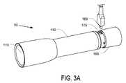
図3A及び3Bは、充電可能なバッテリパック100によって電力供給されるよう構成されるフラッシュライト50の実施例を例示している。フラッシュライト50は、充電可能なバッテリパック100を受け入れる空洞を含む本体110を含み得る。フラッシュライト50は、充電可能なバッテリパック100によって電力を供給し得る光源アセンブリ115も含み得る。フラッシュライト50は、キャップ190も含み得る。一部の実施態様において、キャップ190は、光源アセンブリ115に電力を供給するために充電可能なバッテリパック100との回路の完結を制御し得るスイッチ193を含み得る。充電可能なバッテリパック100がフラッシュライト50の空洞内に配置されるときに充電可能なバッテリパック100へのアクセスをもたらすよう、キャップ190を取り外し可能に構成してもよい。図3A中の実施例が例示するように、一部の実施態様では、キャップ190が取り外されるときに充電ポート175にアクセスし得るよう、フラッシュライト50の空洞は充電可能なバッテリパック100の長さよりも短くてもよい。 3A and 3B illustrate an embodiment of a
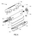
図4は、充電可能なバッテリパック100の例示的な分解図を例示している。充電可能なバッテリパック100は、リチウムイオンバッテリのような充電可能な電池135を含み得る。他の実施態様では、他の充電可能な電池を用い得る。充電可能な電池135をプリント回路基板133に結合させ、プリント回路基板133を、例えばバネ172を通じて、伝導性の電力接点170に結合させ得る。加えて、充電可能なバッテリパック100は、充電システム138を含み得る。充電ポート175からの充電可能な電池135の充電を容易化するために、充電システム138を(例えば、バネ137を通じて)充電ポート175に並びに充電可能な電池135に結合し得る。1つ又はそれよりも多くのワイヤ131を通じて充電システム138をプリント回路基板133にも結合し得る。一部の実施態様において、充電システム138は、充電システム138が充電可能な電池135への結合を行う側とは反対の側にスイッチ接点プレート139も含み得る。他の実施態様において、充電システム138及びスイッチ接点プレート139は、別個の構成部品を含み得る。 FIG. 4 illustrates an exemplary exploded view of the
一部の実施態様において、充電速度のような充電可能な電池135の充電の特徴を制御するように充電システム138を構成し得る。例えば、充電可能な電池が完全に充電されたときに充電可能な電池135の充電を遅め或いは停止させるように充電システム138を構成し得る。 In some implementations, the
充電システム138を充電表示灯195にも結合し得る。上述のような様々の実施態様では、充電可能なバッテリパック100の充電状態を表示するために光源を照らさせるように充電システム138を構成し得る。例えば、充電可能な電池の充電中に第1の色で照らし、充電可能な電池が完全に充電されたときに異なる色で照らすように、充電表示灯195を構成し得る。
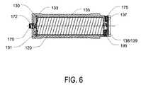
図5は、伝導性の電力接点170と(ケーシング部分130及び120として印される)ケーシング150とを示す、充電可能なバッテリパック100の前方端面図を示している。図6は、充電可能なバッテリパック100を図5の前方端面図の断面として例示している。図6に例示されるように、ケーシング150が図4に示される様々の構成部品の回りに締結されるときには、充電可能な電池135を充電可能なバッテリパック100の前方端で接点170に結合させ得る。更に、充電のために並びに光源アセンブリ115に電力を供給するために回路を完結させるよう、プリント回路基板133及びワイヤ131並びにバネ137を通じて、充電システム138/スイッチ接点プレート139を充電可能な電池135に接続し得る。他の実施態様では、回路を完結するために他の伝導性の構成部品を用い得る。 FIG. 5 shows a front end view of
図7は、フラッシュライト50と共に使用するための充電不能なバッテリパック200の実施例を例示している。例示されるように、充電不能なバッテリパック200は、単2バッテリ若しくは単3バッテリ又は他の種類のバッテリ又は動力電池のような、1つ又はそれよりも多くの充電不能な電池235を含み得る。これらの充電不能な電池をトレッスル255(trestle)内に保持し且つ1つ又はそれよりも多くの伝導性のバネ250を通じて所定の場所に保持し得る。これらの伝導性のバネ250は、フラッシュライト50との電力回路を完結する電気リード線の機能を果たし得る。回路が短絡を形成するのを防止するために、短絡防止回路組237を伝導性のバネ250及び充電不能な電池に結合させ得る。 FIG. 7 illustrates an embodiment of an
後方端に、充電不能なバッテリパック200はスイッチ接点プレート239を含み得る。充電不能なバッテリパック200をフラッシュライト50のキャップ190のスイッチ193と共に使用するのを可能にするために、このスイッチ接点プレート239は、充電可能なバッテリパック100のスイッチ伝導性プレート139の伝導性スイッチ接点190への類似の伝導性スイッチ接点を有し得る。前方端に、充電不能なバッテリパック200は、1つ又はそれよりも多くのバネ250を通じて充電不能な電池に結合し得る、1つ又はそれよりも多くの伝導性の電力接点270を含み得る。次に、一体に組み立てられ且つ例えばネジ205を通じて締結され得るプレート230、回路カバー240、及び接点カバー275を通じて、伝導性のバネを保持し得る。 At the rear end, the
一部の実施態様において、トレッスル255、バネ250、プレート230、回路カバー240、接点カバー275、スイッチ接点カバー238、及び伝導性の電力接点270のアセンブリ(組立体)は、充電不能な電池235を充電可能なバッテリパック100に類似するフォームファクタ(形状因子)内にしっかり挿入するよう、1つ又はそれよりも多くの空洞を提供し得る。よって、充電可能なバッテリパック100に類似する方法におけるフラッシュライト50の空洞内への配置を通じてフラッシュライト50に電力供給するために、充電不能なバッテリパック200を用い得る。一部の実施態様では、フラッシュライト50内の充電可能なバッテリパック200の回転が電力回路を妨げないように、(充電可能なバッテリパック200を用いてフラッシュライト50内で接触し得るような)ある程度の径方向対称性で伝導性の電力接点270を構成してもよい。 In some embodiments, the assembly of the
図8は、フラッシュライトキット25の実施例を例示している。フラッシュライトキット25は、フラッシュライト50と、充電可能なバッテリパック100とを含み得る。一部の実施態様において、フラッシュライトキット25は、充電不能なバッテリパック200も含み得る。図8は、フラッシュライト空洞55も例示しており、フラッシュライト空洞55には、フラッシュライト50並びにスイッチ193を通じてフラッシュライト50に電力供給するための回路を完結するためにスイッチ伝導性接点190及び290と結合し得るキャップスイッチ接点138に電力供給するよう、充電可能なバッテリパック100及び/又は充電可能なバッテリパック200を配置し得る。 FIG. 8 illustrates an example of the
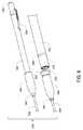
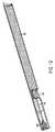
図9は、ペンライトキット300の実施例の一部としての充電可能なペンライト350の実施例の2つの図を例示している。例示されるように、充電可能なペンライトは、実質的に円筒形の形状であり得る。よって、一部の実施態様において、充電可能なペンライトは、長手軸と、円形の断面とを有し得る。加えて、充電可能なペンライト350は、端から端まで実質的に一定の直径を有し得る。 FIG. 9 illustrates two views of an embodiment of a
充電可能なペンライト350を充電コンセント340と結合させ得る。例示される実施例におけるように、充電コンセント340は、電力を引き得るケーブル339に直接的に取り付け得る充電カバーであり得る。充電カバーは、上述のように充電プロセスの状態を示し得る、充電表示灯341も含み得る。 A
充電コンセント340は、充電可能なペンライト350の部分と選択的に接触するよう構成し得る1つ又はそれよりも多くの伝導性接点を包含し得る。充電可能なペンライト350の内部的な充電可能な電池(図示せず)を充電するために、これらの接点を1つ又はそれよりも多くの電気リード線に接続し得る。例示されるように、これらの部分は、伝導性部分310及び320のような、充電可能なペンライト350の本体の伝導性部分を含み得る。一部の実施態様では、本体330の非伝導性部分をこれらの2つの伝導性部分の間に配置し得る。一部の実施態様において、伝導性部分310及び320の一方又は両方は、充電可能なペンライト350の全周を含み得る。これらの実施態様では、充電コンセントを充電可能なペンライト350上に配置し、且つ伝導性部分310及び320との伝導性接触を依然として維持しながら回転させ得る。 The charging
一部の実施態様では、充電コンセント340によるより容易なアクセスを許容するために、伝導性部分の一方をペンライト350の端に或いは端の近傍に配置し得る。よって、図示の実施例において、伝導性部分310は、光源アセンブリ305に隣接して、充電可能なペンライト350の前方端に配置される。他の実施態様では、伝導性部分の一方を光源アセンブリ305とは反対側の充電可能なペンライトの後方端に配置し得る。しかしながら、充電可能なペンライトの後方端をスイッチ305のようなスイッチ又はクリップ303のようなクリップのために用い得るので、これは一部の実施態様では好ましくないかもしれない。一部の実施態様において、充電可能なペンライト350は、実質的に一定な直径を有し、或いは、充電コンセントによって端を覆うことを容易化するために、充電のために用いられる端の付近で先細る直径を有し得る。 In some embodiments, one of the conductive portions may be placed at or near the end of the
一部の実施態様において、充電可能なペンライトは、充電コンセントの内径よりも小さい直径を有し得る。よって、一部の実施態様において、充電可能なペンライトキット100は、リングの形状におけるサイズ変換シート345を含み得る。サイズ変換シート345は、充電可能なペンライト350の直径の大きさの内径と、充電コンセント340の内径の大きさの外径とを含み得る。一部の実施態様において、サイズ変換シート345は、サイズ変換シート345の一部が充電コンセント340の内径よりも大きいようにフレアを含み得る。サイズ変換シート345のこの構造は、サイズ変換シート345を後に容易に取り外すことを依然として可能にしながら、サイズ変換シート345を充電コンセント内に挿入することを可能にし得ることを、使用者にもたらし得る。 In some embodiments, the rechargeable penlight may have a diameter that is smaller than the inner diameter of the charging outlet. Thus, in some embodiments, the
図10A−Eは、充電コンセント340の1つの実現として働く充電スタンド380の実施例を例示している。充電スタンド380は、充電可能なペンライト350の1つ又はそれよりも多くを受け入れ得る1つ又はそれよりも多くの空洞347を含み得る。一部の実施態様では、充電可能なペンライト350は空洞347よりも小さい直径を有し得るので、充電中に充電可能なペンライト350を安定化させるために空洞347内に挿入させられ得るよう、1つ又はそれよりも多くのサイズ変換シート345を含め得る。例示されるように、図10A及び10Bは、サイズ変換シート345の使用を伴う充電を例示しているのに対し、図10C−Eは、サイズ変換シート345を伴わない充電を例示している。 FIGS. 10A-E illustrate an embodiment of a charging
図10Aに例示されるように、充電スタンド380は、第1及び第2の伝導性接点315及び325を含み得る。上述のように、充電可能なペンライト350の内部的な充電可能な電池を充電するために、これらの接点を1つ又はそれよりも多くの電気リード線に接続し得る。第1の伝導性部分310及び第2の伝導性部分320にそれぞれ達するよう、これらの伝導性接点を寸法取り得る。一部の実施態様において、第1及び第2の伝導性接点315及び325は、弾性金属を含み得るし、充電可能なペンライト350が空洞347内に座するや否や、それらがそれら自体を充電可能なペンライト350の本体に対して配置し得るよう、内向きに撓まされ得る。第1及び第2の伝導性接点315及び325は、充電可能なペンライト350が空洞347内に位置付けられる間に、第1の伝導性部分310及び第2の伝導性部分320との接触を追加的に維持し得る。充電中、上記で議論したように、1つ又はそれよりも多くの充電表示灯341が照明して充電状態を示し得る。 As illustrated in FIG. 10A, the charging
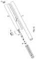
図11−14は、図9の充電可能なペンライト350と共に用い得るバッテリ及び充電システムを例示している。このバッテリ及び充電システムは、電力を引き得る充電ケーブル439を有する充電コンセント440と結合し得る充電プラグ402(図14を参照)を含み得る。充電コンセント440は、図12及び14に最良に示される、従来的な設計のmicro-USBの形態にあり得る。 FIGS. 11-14 illustrate a battery and charging system that may be used with the
充電コンセント440は、図11−14のバッテリ及び充電システムの部分と選択的に接触するよう構成し得る1つ又はそれよりも多くの伝導性接点を含み得る。内部的な充電可能な電池435を充電するために、これらの接点を1つ又はそれよりも多くの電気リード線に接続し得る。充電可能な電池は、1つ又はそれよりも多くのリチウムイオンバッテリの形態にあり得るが、他の充電可能なバッテリを代替的に用い得る。よって、充電可能な電池435を充電するために、充電プラグ402、充電コンセント440、及び充電ケーブル439を用い得る。前述の実施態様と同様に、充電速度のような充電可能な電池435の充電の特徴を制御するために、充電システムを構成し得る。例えば、充電可能な電池が完全に充電されたときに充電可能な電池435の充電を遅め或いは停止するように、充電システムを構成し得る。 The charging outlet 440 may include one or more conductive contacts that may be configured to selectively contact the battery and portions of the charging system of FIGS. 11-14. These contacts can be connected to one or more electrical leads to charge the internal
バッテリ及び充電システムを充電可能な電池435の充電状態を表示するよう光源を照明させる充電表示灯(図示せず)にも結合し得る。例えば、前述の実施態様と同様に、充電可能な電池の充電中に第1の色で照明し、充電可能な電池が完全に充電させられたときに異なる色で照明するように、充電表示灯を構成し得る。 It may also be coupled to a charging indicator light (not shown) that illuminates the light source to indicate the state of charge of the
図12及び13に最良に示されるように、充電可能な電池をプリント回路基板433の一端に結合し、プリント回路基板133をスイッチ(図示せず)に結合し得る。充電コンセント440を、図示のように、ワイヤ404によって相互接続される充電可能な電池435の他端に位置付け得る。前述のように、描写の実施態様は、micro-USBポート440を含み、micro-USBポート440は、充電作業を制御するが充電可能な電池を過充電から守る充電及び保護回路を含み得る。図12に示されるように、第2のプリント回路基板406が充電コンセント440の前方に配置され、充電コンセント440と電気接触し、次に、コネクタプラグ408に接続される。コネクタプラグ408は、充電可能な電池435からの電力をLEDを含むバッテリ及び充電システムの前方410に伝達するよう設計される。図13に示されるように、PVCのような非伝導性材料で作製される円筒形の覆い412をバッテリ及び充電システム上に嵌め、そして、金属シリンダをその上に嵌め、図9に描写されるペンライト350のようなペンライトの外部を形成し得る。 As best shown in FIGS. 12 and 13, a rechargeable battery may be coupled to one end of the printed circuit board 433 and the printed
Micro-USBポート440を有する代わりに、図11−14のバッテリ及び充電システムをペンライトの前方410に適合する充電コンセント340を示す図9に描写される充電システムのような充電システムに差し込み得る。この変形は図9及び11−14の教示を組み合わせることによって十分に記載されているので、それを追加的な図において描写しない。 Instead of having a Micro-USB port 440, the battery and charging system of FIGS. 11-14 can be plugged into a charging system such as the charging system depicted in FIG. 9 showing a charging
特定の実施態様をここにおいて例示し且つ記載したが、当業者は、範囲から逸脱せずに、同じ目的を達成するために計画される広範な代替的な及び/又は均等な実施態様又は具現を、図示し且つ記載した実施態様と置換し得ることを理解するであろう。当業者は実施態様を極めて広範な方法において実施し得ることを直ちに理解するであろう。この出願はここにおいて議論する実施態様の如何なる適応又は変形をもカバーすることを意図する。従って、実施態様は請求項及びそれらの均等物によってのみ制限されることを明白に意図する。 While particular embodiments have been illustrated and described herein, those skilled in the art will recognize a wide range of alternative and / or equivalent embodiments or implementations that are planned to accomplish the same purpose without departing from the scope. It will be understood that the embodiments shown and described may be substituted. One skilled in the art will readily appreciate that the embodiments may be implemented in a very wide variety of ways. This application is intended to cover any adaptations or variations of the embodiments discussed herein. Therefore, it is manifestly intended that embodiments be limited only by the claims and the equivalents thereof.
Claims (37)
Translated fromJapanese充電可能な電池と、
該充電可能な電池に結合され且つ該充電可能な電池を充電するために電力を供給する充電プラグを受け入れるよう構成される充電ポートと、
前記充電可能な電池に結合され、且つフラッシュライトの第2の伝導性接点と結合するよう配置される、1つ又はそれよりも多くの第1の伝導性接点と、
当該充電可能なバッテリパックを内蔵ユニットとして入れるよう、前記充電可能な電池、充電ポート、及び1つ又はそれよりも多くの第1の伝導性接点の周りに配置されるケーシングとを含む、
充電可能なバッテリパック。Rechargeable battery pack for flashlight,
Rechargeable battery,
A charging port coupled to the rechargeable battery and configured to receive a charging plug for supplying power to charge the rechargeable battery;
One or more first conductive contacts coupled to the rechargeable battery and arranged to couple with a second conductive contact of the flashlight;
Including a rechargeable battery, a charging port, and a casing disposed around one or more first conductive contacts to enclose the rechargeable battery pack as a built-in unit;
Rechargeable battery pack.
前記充電プラグによる前記充電ポートへのアクセスを可能にする第1の切欠きと、
前記1つ又はそれよりも多くの第2の伝導性接点による前記1つ又はそれよりも多くの第1の伝導性接点へのアクセスを可能にする1つ又はそれよりも多くの第2の切欠きとを含む、
請求項1に記載の充電可能なバッテリパック。The casing is
A first notch that allows access to the charging port by the charging plug;
One or more second cuts that allow access to the one or more first conductive contacts by the one or more second conductive contacts. Including notches,
The rechargeable battery pack according to claim 1.
前記第1の切欠きは、前記実質的に円形の断面の周囲に沿って配置される、
請求項3に記載の充電可能なバッテリパック。The housing has a longitudinal axis and a substantially circular cross-section;
The first notch is disposed along a circumference of the substantially circular cross section;
The rechargeable battery pack according to claim 3.
前記第2の切欠きは、前記ハウジングの前記第1の端に配置される、
請求項2に記載の充電可能なバッテリパック。The casing has a first end;
The second notch is disposed at the first end of the housing;
The rechargeable battery pack according to claim 2.
充電可能なバッテリパックとを含む、
フラッシュライトキットであって、
前記フラッシュライトは、
光源アセンブリと、
該光源アセンブリを保持し且つ空洞を定めるハウジングとを含み、
前記空洞は、バッテリパックを受け入れるよう構成され、前記ハウジングは、前記光源アセンブリに電力を供給するために前記バッテリパックと接触するよう配置される1つ又はそれよりも多くの第1の接点を有し、
前記充電可能なバッテリパックは、
充電可能な電池と、
該充電可能な電池に結合され且つ該充電可能な電池を充電するために電力を供給する充電プラグを受け入れるよう構成される充電ポートと、
前記充電可能な電池に結合され、且つ前記充電可能なバッテリパックが前記フラッシュライトの前記空洞内に配置されるときに前記1つ又はそれよりも多くの第1の接点と接触するよう前記充電可能なバッテリパックの表面に配置される、1つ又はそれよりも多くの第2の接点とを含む、
フラッシュライトキット。With flashlight,
Including a rechargeable battery pack,
A flashlight kit,
The flashlight is
A light source assembly;
A housing for holding the light source assembly and defining a cavity;
The cavity is configured to receive a battery pack, and the housing has one or more first contacts arranged to contact the battery pack to provide power to the light source assembly. And
The rechargeable battery pack is
Rechargeable battery,
A charging port coupled to the rechargeable battery and configured to receive a charging plug for supplying power to charge the rechargeable battery;
The rechargeable battery coupled to the rechargeable battery and rechargeable to contact the one or more first contacts when the rechargeable battery pack is disposed within the cavity of the flashlight. Including one or more second contacts disposed on the surface of the battery pack,
Flash light kit.
該充電不能なバッテリパックは、
1つ又はそれよりも多くの充電不能な電池を保持するトレッスルと、
前記充電不能な電池が前記トレッスル内に配置されるときに前記1つ又はそれよりも多くの充電不能な電池と接触するよう前記ハウジング内に配置される1つ又はそれよりも多くの伝導性リード線と、
該1つ又はそれよりも多くの伝導性リード線に結合され、且つ前記充電不能なバッテリパックが前記フラッシュライトの前記空洞内に配置されるときに前記1つ又はそれよりも多くの第1の接点と接触するよう前記充電不能なバッテリパックの表面に配置される、1つ又はそれよりも多くの第3の接点とを含む、
請求項9に記載のフラッシュライトキット。A battery pack that cannot be recharged;
The unchargeable battery pack is
A trestle holding one or more non-rechargeable batteries;
One or more conductive leads disposed in the housing to contact the one or more non-chargeable batteries when the non-chargeable battery is disposed in the trestle. Lines and,
The one or more first leads coupled to the one or more conductive leads and when the unchargeable battery pack is disposed in the cavity of the flashlight. One or more third contacts disposed on the surface of the non-chargeable battery pack to contact the contacts;
The flashlight kit according to claim 9.
前記充電可能なバッテリパックが前記フラッシュライトの前記空洞内に配置されるときに、前記充電可能なバッテリパックの前記長手軸は、前記フラッシュライトの前記空洞の前記長手軸と一致する、
請求項9に記載のフラッシュライトキット。The cavity of the flashlight and the rechargeable battery pack have respective longitudinal axes and a substantially circular cross-section;
When the rechargeable battery pack is disposed in the cavity of the flashlight, the longitudinal axis of the rechargeable battery pack coincides with the longitudinal axis of the cavity of the flashlight;
The flashlight kit according to claim 9.
前記第2の接点は、前記充電可能なバッテリパックの前記第1の端に配置される、
請求項12に記載のフラッシュライトキット。The rechargeable battery pack has a first end;
The second contact is disposed at the first end of the rechargeable battery pack;
The flashlight kit according to claim 12.
該本体の前記第1の端に収容される光源アセンブリと、
前記光源アセンブリに結合され且つ前記本体内に収容される充電可能な電池とを含み、
前記本体は、前記本体の表面に配置され且つ前記充電可能な電池に結合される第1の伝導性部分と第2の伝導性部分とを有し、
前記第1の伝導性部分は、前記本体の前記第1の端又は前記第2の端の近傍に配置され、前記第2の伝導性部分は、前記第1の伝導性部分と前記第1の伝導性領域に近接する端とは反対の端との間に配置され、
充電コンセントが前記本体の前記第2の端に配置されるときに、前記充電コンセントは、前記本体の前記第2の端を受け入れるための空洞を有し、第1及び第2の伝導性接点が、当該充電可能なフラッシュライトに電荷を供給するために前記空洞内に配置され、前記充電コンセントの前記第1の伝導性接点は、前記第1の伝導性部分と接触し、前記充電コンセントの前記第2の伝導性接点は、前記第2の伝導性部分と接触して、前記充電可能な電池を充電する回路を完結する、
充電可能なフラッシュライト。A body having a first end, a second end, and a longitudinal axis;
A light source assembly housed at the first end of the body;
A rechargeable battery coupled to the light source assembly and housed within the body;
The body has a first conductive portion and a second conductive portion disposed on a surface of the main body and coupled to the rechargeable battery;
The first conductive portion is disposed in the vicinity of the first end or the second end of the body, and the second conductive portion includes the first conductive portion and the first conductive portion. Located between the end adjacent to the conductive region and the opposite end,
When a charging outlet is disposed at the second end of the body, the charging outlet has a cavity for receiving the second end of the body, and the first and second conductive contacts are , Disposed in the cavity for supplying charge to the rechargeable flashlight, wherein the first conductive contact of the charging outlet contacts the first conductive portion and the charging outlet A second conductive contact contacts the second conductive portion to complete a circuit for charging the rechargeable battery;
Rechargeable flashlight.
充電コンセントとを含む、
充電可能なペンライトキットであって、
前記充電可能なペンライトは、
第1の端と、第2の端と、長手軸とを有する、円筒形の本体と、
該本体の前記第1の端に収容される光源アセンブリと、
該光源アセンブリに結合され且つ前記本体に収容される充電可能な電池と、
前記本体の表面に配置され且つ前記充電可能な電池に結合される第1の伝導性部分及び第2の伝導性部分とを含み、
前記第1の伝導性部分は、前記本体の前記第1に配置され、前記第2の伝導性部分は、前記第1の伝導性部分と前記本体の前記第2の端との間に配置され、
前記充電コンセントは、前記本体の前記第2の端を収容するための空洞と、前記充電可能なペンライトに電荷を供給するために前記空洞内に配置される第1及び第2の伝導性接点とを有することで、前記充電可能なペンライトが前記充電コンセントの前記空洞内に配置されるときに、前記充電コンセントの前記第1の伝導性接点が前記第1の伝導性接点と接触し、前記充電コンセントの前記第2の伝導性接点が前記第2の伝導性部分と接触して、前記充電可能な電池を充電する回路を完結する、
充電可能なペンライトキット。A rechargeable penlight,
Including charging outlet,
A rechargeable penlight kit,
The rechargeable penlight is
A cylindrical body having a first end, a second end, and a longitudinal axis;
A light source assembly housed at the first end of the body;
A rechargeable battery coupled to the light source assembly and housed in the body;
A first conductive portion and a second conductive portion disposed on a surface of the body and coupled to the rechargeable battery;
The first conductive portion is disposed on the first of the body, and the second conductive portion is disposed between the first conductive portion and the second end of the body. ,
The charging outlet includes a cavity for receiving the second end of the body, and first and second conductive contacts disposed in the cavity for supplying charge to the rechargeable penlight. So that when the rechargeable penlight is disposed in the cavity of the charging outlet, the first conductive contact of the charging outlet contacts the first conductive contact; The second conductive contact of the charging outlet contacts the second conductive portion to complete a circuit for charging the rechargeable battery;
Rechargeable penlight kit.
前記充電コンセントの前記空洞は、ある直径を備える円形の断面を有する、
請求項29に記載の充電可能なペンライトキット。The rechargeable penlight has a circular cross section with a certain diameter;
The cavity of the charging outlet has a circular cross section with a diameter;
30. The rechargeable penlight kit of claim 29.
当該充電可能なペンライトキットは、リング形状のサイズ変換シートを更に含み、該サイズ変換シートは、前記充電可能なペンライトの前記円形の断面の前記直径と実質的に類似する内径と、前記充電コンセントの前記円形の断面と少なくとも同じ大きさの外径とを備える、
請求項30に記載の充電可能なペンライトキット。The diameter of the cross section of the cavity of the charging outlet is greater than the diameter of the circular cross section of the penlight;
The rechargeable penlight kit further includes a ring-shaped size conversion sheet, the size conversion sheet having an inner diameter substantially similar to the diameter of the circular cross section of the chargeable penlight, and the charging An outer diameter of at least the same size as the circular cross section of the outlet,
The rechargeable penlight kit according to claim 30.
Applications Claiming Priority (3)
| Application Number | Priority Date | Filing Date | Title |
|---|---|---|---|
| US13/529,777 | 2012-06-21 | ||
| US13/529,777US20130343042A1 (en) | 2012-06-21 | 2012-06-21 | Rechargeable flashlight |
| PCT/US2013/046609WO2013192325A1 (en) | 2012-06-21 | 2013-06-19 | Rechargeable flashlight |
Publications (1)
| Publication Number | Publication Date |
|---|---|
| JP2015526844Atrue JP2015526844A (en) | 2015-09-10 |
Family
ID=49769342
Family Applications (1)
| Application Number | Title | Priority Date | Filing Date |
|---|---|---|---|
| JP2015518558APendingJP2015526844A (en) | 2012-06-21 | 2013-06-19 | Rechargeable flashlight |
Country Status (6)
| Country | Link |
|---|---|
| US (1) | US20130343042A1 (en) |
| EP (1) | EP2864693A4 (en) |
| JP (1) | JP2015526844A (en) |
| CN (1) | CN104641165A (en) |
| AU (1) | AU2013277223A1 (en) |
| WO (1) | WO2013192325A1 (en) |
Families Citing this family (42)
| Publication number | Priority date | Publication date | Assignee | Title |
|---|---|---|---|---|
| US10060582B2 (en)* | 2012-01-24 | 2018-08-28 | Tactical Impulse Llc | Modular flashlight system with retention device |
| US9377878B2 (en)* | 2012-07-11 | 2016-06-28 | ACCO Brands Corporation | Tablet stylus with presentation interaction functionality |
| US8888311B2 (en)* | 2012-07-31 | 2014-11-18 | Armament Systems And Procedures, Inc. | Flashlight with USB charger |
| US9651208B2 (en)* | 2013-02-22 | 2017-05-16 | Streamlight, Inc. | Portable light chargeable from different sources |
| US20150003050A1 (en)* | 2013-07-01 | 2015-01-01 | Armament Systems And Procedures, Inc. | Flashlight with hidden charge plug |
| US9843208B2 (en)* | 2013-08-14 | 2017-12-12 | Mathew Inskeep | High power rechargeable flashlight with two way universal serial bus |
| USD790099S1 (en) | 2014-11-06 | 2017-06-20 | Lawrence Jay Pius | Panoramic flashlight |
| CN208041675U (en)* | 2014-12-02 | 2018-11-02 | 迈克尔·沃特斯 | flashlight and communication device |
| USD824557S1 (en) | 2014-12-02 | 2018-07-31 | Michael Waters | Flashlight |
| US10172742B2 (en) | 2015-02-02 | 2019-01-08 | 3M Innovative Properties Company | Hearing protector with compartment for rechargeable battery pack |
| US9917457B2 (en) | 2015-02-02 | 2018-03-13 | Black & Decker Inc. | Power tool with USB connection |
| US10283817B2 (en) | 2015-02-23 | 2019-05-07 | Black & Decker, Inc. | Battery charger and method of charging a battery |
| TWM512740U (en)* | 2015-05-01 | 2015-11-21 | Waltop Int Corp | Charging type capacitance touch pen |
| EP3101333B1 (en)* | 2015-06-04 | 2019-11-06 | Inskeep, Mathew | Portable light device |
| RU2597203C1 (en)* | 2015-08-24 | 2016-09-10 | Константин Дмитриевич Клочков | Power supply device of electronic devices |
| CN105299492B (en)* | 2015-11-18 | 2018-05-08 | 江苏天网光电科技有限公司 | A kind of push type can automatically reset micro electric hitter torch |
| US9780580B1 (en)* | 2016-03-30 | 2017-10-03 | Symbol Technologies, Llc | Rechargeable battery pack for an electro-optical reader, and method of charging the battery pack and powering the reader with the charged battery pack |
| US10088138B2 (en) | 2016-04-14 | 2018-10-02 | Bayco Products, Inc. | Tactical flashlight with dual emitters and tail cap control |
| WO2018068325A1 (en) | 2016-10-14 | 2018-04-19 | Milwaukee Electric Tool Corporation | Battery pack |
| USD899355S1 (en) | 2016-08-15 | 2020-10-20 | Milwaukee Electric Tool Corporation | Battery |
| WO2018057705A1 (en)* | 2016-09-21 | 2018-03-29 | The Coleman Company, Inc. | Rechargeable product with on board disposable battery charging |
| US20180224077A1 (en)* | 2017-02-09 | 2018-08-09 | Aixia Bian | Methods and apparatus for a multi-functional folding straight light |
| US20180231214A1 (en)* | 2017-02-10 | 2018-08-16 | Aixia Bian | Multi-functional flash lights |
| CN108626599A (en)* | 2017-03-17 | 2018-10-09 | 朗德万斯公司 | Flashlight with LED light source |
| WO2018191062A1 (en) | 2017-04-11 | 2018-10-18 | Milwaukee Electric Tool Corporation | Battery charger |
| US10260733B2 (en)* | 2017-07-13 | 2019-04-16 | Armament Systems And Procedures, Inc. | High power flashlight with polymer shell |
| US10605418B2 (en) | 2018-07-26 | 2020-03-31 | E. Mishan & Sons, Inc. | Rechargeable flashlight |
| KR102497913B1 (en)* | 2018-12-12 | 2023-02-09 | 주식회사 엘지에너지솔루션 | Storage case for battery cell and storage device including the same |
| USD914257S1 (en)* | 2018-12-14 | 2021-03-23 | Coast Cutlery Co. | Flashlight |
| USD941751S1 (en) | 2020-01-16 | 2022-01-25 | Streamlight, Inc. | Battery with charging port and key way |
| USD945037S1 (en) | 2020-04-14 | 2022-03-01 | E. Mishan & Sons, Inc. | Flashlight |
| CN212430501U (en)* | 2020-07-14 | 2021-01-29 | 广东百创源科技股份有限公司 | Lighting lamp with rotatable support |
| USD949095S1 (en) | 2020-08-14 | 2022-04-19 | Streamlight, Inc. | Battery with charging port and key way |
| US11639789B2 (en)* | 2021-01-13 | 2023-05-02 | Streamlight, Inc. | Portable light and keyed rechargeable USB battery |
| CN112909440A (en)* | 2021-02-06 | 2021-06-04 | 深圳市东方芯愿新能源有限公司 | Rechargeable battery with illumination |
| CN112865250B (en)* | 2021-02-10 | 2025-08-12 | 李文杰 | Mobile power supply |
| US11876237B2 (en)* | 2021-07-05 | 2024-01-16 | Xiaofeng Zhang | Cylindrical waterproof battery box |
| US20230090299A1 (en)* | 2021-09-23 | 2023-03-23 | Rosemount Inc. | Intrinsically safe, reusable, power module for field devices |
| US12146624B2 (en)* | 2022-04-08 | 2024-11-19 | LB Marketing, Inc. | Dual power light source |
| US12385630B2 (en) | 2022-05-24 | 2025-08-12 | Black & Decker Inc. | Portable flashlight |
| US12196380B2 (en) | 2022-05-24 | 2025-01-14 | Black & Decker Inc. | Portable illumination apparatus |
| US12085241B1 (en)* | 2024-02-20 | 2024-09-10 | Infinity X1 Llc | Flashlight with rechargeable battery assembly |
Family Cites Families (33)
| Publication number | Priority date | Publication date | Assignee | Title |
|---|---|---|---|---|
| US4114187A (en)* | 1976-11-05 | 1978-09-12 | Alan Kurt Uke | Diver's flashlight |
| US4224383A (en)* | 1978-12-26 | 1980-09-23 | Power-Lite Industries, Inc. | Rechargeable battery pack |
| US4357648A (en)* | 1980-02-08 | 1982-11-02 | Kel-Lite Industries, Inc. | Rechargeable flashlight |
| US4382220A (en)* | 1981-07-20 | 1983-05-03 | The Bridgeport Metal Goods Mfg. Co. | Rechargeable battery pack and combination thereof with lantern |
| US5019767A (en)* | 1989-02-16 | 1991-05-28 | Nintendo Co., Ltd. | Portable power supply |
| US5220269A (en)* | 1991-10-04 | 1993-06-15 | Innova Electronics Corporation | Power supply unit |
| US5160879A (en)* | 1991-10-08 | 1992-11-03 | Curtis Manufacturing Company, Inc. | Safe, rechargeable, battery-containing power pack and method |
| US5709964A (en)* | 1996-03-19 | 1998-01-20 | The Laitram Corporation | Modular battery pack |
| US5871272A (en)* | 1997-01-28 | 1999-02-16 | Streamlight, Incorporated | Flashlight with rotatable lamp head |
| US6056415A (en)* | 1997-04-11 | 2000-05-02 | Minrad Inc. | Penlight having low magnetic susceptibility |
| US7101057B2 (en)* | 2001-08-20 | 2006-09-05 | Pelican Products, Inc. | Pistol grip flashlight |
| US6953260B1 (en)* | 2001-11-16 | 2005-10-11 | Allen David M | Convertible flashlight-headlamp |
| KR200339019Y1 (en)* | 2003-10-07 | 2004-01-16 | 김정기 | Available charge lantern for mobile device power |
| TWM254548U (en)* | 2004-02-04 | 2005-01-01 | Pentalite Corp | Power supply regulator of a flashlight |
| TWM255574U (en)* | 2004-04-19 | 2005-01-11 | Yu-Huei Huang | Battery box with power input/output |
| US20050276042A1 (en)* | 2004-06-10 | 2005-12-15 | Ko-Liang Ho | Lighting device |
| US7579782B2 (en)* | 2004-12-07 | 2009-08-25 | Mag Instrument, Inc. | Circuitry for portable lighting devices and portable rechargeable electronic devices |
| TWM276379U (en)* | 2005-03-23 | 2005-09-21 | Yu-Huei Huang | Portable battery charge box |
| US20070278995A1 (en)* | 2006-05-31 | 2007-12-06 | Steven Lynn Batdorff | Recharging power source with lighting accessory |
| CN201152460Y (en)* | 2007-12-14 | 2008-11-19 | 蔡成信 | Power supply for a flashlight |
| US20090226802A1 (en)* | 2008-01-31 | 2009-09-10 | Night Operations Systems | Connector for battery pack of lighting system |
| US7806555B2 (en)* | 2008-04-15 | 2010-10-05 | Yun-Zhao Liu | Power supply control device of a flashlight |
| US7926971B2 (en)* | 2009-01-14 | 2011-04-19 | Mag Instrument, Inc. | Battery pack assemblies and portable lighting devices employing same |
| US9247598B2 (en)* | 2009-01-16 | 2016-01-26 | Mag Instrument, Inc. | Portable lighting devices |
| US20100190052A1 (en)* | 2009-01-27 | 2010-07-29 | Umesh Rajani | Battery pack with high and low current discharge terminals |
| US8461805B2 (en)* | 2009-06-22 | 2013-06-11 | Shuang SA | Rechargeable battery pack with connecting ports for internal and external charging/output operations |
| JP5065353B2 (en)* | 2009-09-16 | 2012-10-31 | 廣東正飛移動照明有限公司 | Chargeable / dischargeable flashlight |
| US8246193B2 (en)* | 2010-03-02 | 2012-08-21 | Rui-Hong Weng | Solar lamp |
| US20120033416A1 (en)* | 2010-08-06 | 2012-02-09 | Ballard Jay A | Portable power module assembly |
| US8425078B2 (en)* | 2010-09-21 | 2013-04-23 | Surefire, Llc | Lighting device with multi-position joystick |
| US8545069B2 (en)* | 2011-01-19 | 2013-10-01 | Light & Motion Industries | Portable light assembly |
| CN201954278U (en)* | 2011-02-22 | 2011-08-31 | 邓志强 | Flashlight with USB (universal serial bus) power supply |
| CN202140805U (en)* | 2011-06-20 | 2012-02-08 | 徐永伟 | Rechargeable flashlight |
- 2012
- 2012-06-21USUS13/529,777patent/US20130343042A1/ennot_activeAbandoned
- 2013
- 2013-06-19JPJP2015518558Apatent/JP2015526844A/enactivePending
- 2013-06-19AUAU2013277223Apatent/AU2013277223A1/ennot_activeAbandoned
- 2013-06-19CNCN201380032722.9Apatent/CN104641165A/enactivePending
- 2013-06-19EPEP13807076.8Apatent/EP2864693A4/ennot_activeWithdrawn
- 2013-06-19WOPCT/US2013/046609patent/WO2013192325A1/enactiveApplication Filing
Also Published As
| Publication number | Publication date |
|---|---|
| EP2864693A1 (en) | 2015-04-29 |
| AU2013277223A1 (en) | 2015-01-15 |
| CN104641165A (en) | 2015-05-20 |
| WO2013192325A1 (en) | 2013-12-27 |
| EP2864693A4 (en) | 2015-12-09 |
| US20130343042A1 (en) | 2013-12-26 |
Similar Documents
| Publication | Publication Date | Title |
|---|---|---|
| JP2015526844A (en) | Rechargeable flashlight | |
| US7746029B2 (en) | Battery charger with USB connector and cable storage recess | |
| US9080734B2 (en) | Modular flash light with magnetic connection | |
| US7562997B2 (en) | Flashlight with a battery device having plural joined-together batteries | |
| US8002432B2 (en) | Desk lamp with a separable magnifier | |
| US20140091766A1 (en) | Power bracelet | |
| US7785723B2 (en) | Battery device with plural joined-together batteries | |
| EA200702269A1 (en) | CHARGER DEVICE WITH IMPROVED CONTACT FOR A POCKET LANTERN | |
| US7540624B2 (en) | Spare battery holder | |
| US20030151914A1 (en) | Safety flashlight | |
| US6616300B1 (en) | Flashlight adaptor for providing alternative direct current power supply to other electronic instruments | |
| US10096805B1 (en) | Battery adapter for battery-powered device | |
| US10135045B2 (en) | Battery pack with light source | |
| JP5740071B2 (en) | Portable luminaire with rotatable cylindrical head | |
| EP1978292A3 (en) | Flashlight with a battery device having plural joined-together batteries | |
| US20060082991A1 (en) | Flashlight adaptor for providing alternative direct current power supply to other electronic instruments | |
| CN209748765U (en) | With supporting receiver that charges that uses of bluetooth headset | |
| WO2016185359A1 (en) | Portable power supply apparatus | |
| TWM557932U (en) | Mobile charging device and its power supply component | |
| JP3093989U (en) | Assembled battery | |
| US20170224028A1 (en) | Portable charging apparatus and pants that allow charging using the same | |
| CN220066906U (en) | Energy storage device | |
| CN220103040U (en) | Camping lamp with pluggable power supply structure | |
| CN216619410U (en) | Working lamp | |
| CN214580555U (en) | Portable charging box |