JP2015526329A - Method and apparatus for inspecting railway wheels - Google Patents
Method and apparatus for inspecting railway wheelsDownload PDFInfo
- Publication number
- JP2015526329A JP2015526329AJP2015518846AJP2015518846AJP2015526329AJP 2015526329 AJP2015526329 AJP 2015526329AJP 2015518846 AJP2015518846 AJP 2015518846AJP 2015518846 AJP2015518846 AJP 2015518846AJP 2015526329 AJP2015526329 AJP 2015526329A
- Authority
- JP
- Japan
- Prior art keywords
- rails
- railway
- electromagnet
- wheel
- inspected
- Prior art date
- Legal status (The legal status is an assumption and is not a legal conclusion. Google has not performed a legal analysis and makes no representation as to the accuracy of the status listed.)
- Granted
Links
Images

Classifications
- B—PERFORMING OPERATIONS; TRANSPORTING
- B61—RAILWAYS
- B61K—AUXILIARY EQUIPMENT SPECIALLY ADAPTED FOR RAILWAYS, NOT OTHERWISE PROVIDED FOR
- B61K9/00—Railway vehicle profile gauges; Detecting or indicating overheating of components; Apparatus on locomotives or cars to indicate bad track sections; General design of track recording vehicles
- B61K9/12—Measuring or surveying wheel-rims
- G—PHYSICS
- G01—MEASURING; TESTING
- G01N—INVESTIGATING OR ANALYSING MATERIALS BY DETERMINING THEIR CHEMICAL OR PHYSICAL PROPERTIES
- G01N27/00—Investigating or analysing materials by the use of electric, electrochemical, or magnetic means
- G01N27/72—Investigating or analysing materials by the use of electric, electrochemical, or magnetic means by investigating magnetic variables
- G01N27/82—Investigating or analysing materials by the use of electric, electrochemical, or magnetic means by investigating magnetic variables for investigating the presence of flaws
- G—PHYSICS
- G01—MEASURING; TESTING
- G01M—TESTING STATIC OR DYNAMIC BALANCE OF MACHINES OR STRUCTURES; TESTING OF STRUCTURES OR APPARATUS, NOT OTHERWISE PROVIDED FOR
- G01M17/00—Testing of vehicles
- G01M17/08—Railway vehicles
- G01M17/10—Suspensions, axles or wheels
Landscapes
- Chemical & Material Sciences (AREA)
- Physics & Mathematics (AREA)
- General Physics & Mathematics (AREA)
- Health & Medical Sciences (AREA)
- Electrochemistry (AREA)
- Chemical Kinetics & Catalysis (AREA)
- Engineering & Computer Science (AREA)
- Life Sciences & Earth Sciences (AREA)
- Analytical Chemistry (AREA)
- Biochemistry (AREA)
- General Health & Medical Sciences (AREA)
- Mechanical Engineering (AREA)
- Immunology (AREA)
- Pathology (AREA)
- Investigating Or Analyzing Materials By The Use Of Magnetic Means (AREA)
Abstract
Translated fromJapaneseDescription
Translated fromJapanese本発明は、使用に起因する摩耗及び/又は材料欠陥に関して鉄道用車輪を検査するための技術的な解決手段に関する。この場合、鉄道車両に取り付けられた鉄道用車輪が、この鉄道車両の走行移動中に検査される。 The present invention relates to a technical solution for inspecting railway wheels for wear and / or material defects resulting from use. In this case, the railway wheels attached to the railway vehicle are inspected during the traveling movement of the railway vehicle.
様々な構造の鉄道用車輪が公知である。当該鉄道用車輪は、例えば、車輪体上に焼き嵌めされ且つレール上を転動する車輪リム部又は中実体から成る車輪円盤を有する。この車輪円盤では、その踏面が、この車輪円盤の一体化部分として形成されている。具体的なそれぞれの構成に関わらず、鉄道用車輪は、車輪レール系における大きな荷重がかかる要素であり、レールとの接触によって必ず摩耗する。当該踏面が、それらの踏面とレール頭部との接触に起因して摩耗し、車輪フランジが、それらの車輪フランジと当該レール頭部の内面との接触に起因して、特に線路のカーブ内とポイントの通過時に摩耗する。当該車輪の、機能に起因するこの摩耗のほかに、材料欠陥も、車輪の過荷重によって又は製造時の製造誤差によって発生し得る。それ故に、さらに安全な走行動作を保証するため、鉄道用車輪が、従来の方法(超音波、渦電流、X線)を用いて手動又は半自動的に一定の間隔で材料欠陥に関して検査される。しかしながら、1本の列車における多数の車軸に起因して、当該検査は、停車期間を長くさせ、優秀な適任者と相当程度の検査技術の使用とを必要とする。これに関しては、様々な検査方法が、従来の技術として既に公知である。 Various structures of railway wheels are known. The railway wheel has, for example, a wheel disk formed of a wheel rim portion or a solid body that is shrink-fitted on a wheel body and rolls on the rail. In this wheel disk, the tread surface is formed as an integral part of the wheel disk. Regardless of the specific configuration, railway wheels are elements that are subjected to a large load in the wheel rail system, and always wear due to contact with the rails. The treads are worn due to contact between the treads and the rail head, and the wheel flanges are caused by contact between the wheel flanges and the inner surface of the rail head, particularly in the curve of the track. Wear when passing points. In addition to this wear due to the function of the wheel, material defects can also occur due to overloading of the wheel or manufacturing errors during manufacturing. Therefore, in order to ensure safer driving behavior, railway wheels are inspected for material defects at regular intervals, either manually or semi-automatically using conventional methods (ultrasound, eddy currents, x-rays). However, due to the large number of axles in a single train, the inspection lengthens the stopping period and requires the use of highly qualified personnel and a considerable degree of inspection technology. In this regard, various inspection methods are already known as conventional techniques.
すなわち、独国特許第69303989号明細書は、特に鉄道用車輪の製造業者のために適した、鉄道用車輪における硬度及び残留応力を検査するための技術的解決手段を開示する。当該硬度は、ボール圧子によって検査され、当該残留応力は、超音波を用いて検査される。この場合、測定技術を制御するための多数の固定装置及び移動装置を有るガントリー式の装置が使用される。 That is, German Patent No. 69303989 discloses a technical solution for inspecting hardness and residual stresses in railway wheels, which is particularly suitable for railway wheel manufacturers. The hardness is inspected with a ball indenter, and the residual stress is inspected using ultrasonic waves. In this case, a gantry-type device is used which has a number of fixing devices and moving devices for controlling the measurement technique.
独国特許第10352166号明細書は、修理工場で使用するために考案された、取り付けられた状態の鉄道用車輪の踏面の表面状態を半自動的に検出するための装置に関する。この場合、それぞれ1つの測定装置が、1つの車軸の両車輪用の1つの測定プラットフォーム上に配置されている。両車輪が、若干持ち上げられた後に、回転運動に移行され、各車輪の踏面が、測定ビームによってインクリメンタル式に走査される。測定装置と当該車輪の踏面との間の、この測定ビームによって検出された距離が、非真円度及び表面状態を評価するためにコンピュータ制御式に計測される。 DE 10352166 relates to a device for semi-automatic detection of the surface condition of the tread of an installed railway wheel designed for use in a repair shop. In this case, each one measuring device is arranged on one measuring platform for both wheels of one axle. After both wheels have been lifted slightly, they are transferred to rotational movement, and the treads of each wheel are scanned incrementally with the measuring beam. The distance detected by this measuring beam between the measuring device and the tread of the wheel is measured in a computer-controlled manner in order to evaluate the non-roundness and the surface condition.
いわゆる測定子を有する装置が、独国特許第112006002123号明細書から公知である。この測定子は、鉄道用車輪上に取り外し可能に取り付けられ得、当該鉄道用車輪の一般的な幾何学的構成要素を測定するための複数のセンサ、例えばフランジ高さセンサ及びフランジ厚さセンサに付設されている。この測定子は、制御評価装置と相互に作用する。 A device with a so-called probe is known from DE 112006002123. The stylus can be removably mounted on a railway wheel and can be attached to a plurality of sensors for measuring the general geometric components of the railway wheel, such as a flange height sensor and a flange thickness sensor. It is attached. This measuring element interacts with the control evaluation device.
独国特許出願公開第19924781号明細書は、鉄道車両に取り付けられた鉄道用車輪を検査するための別の技術的解決手段を開示する。この場合、1つの鉄道列車が、低い速度で検査区間上を走行される。最初に、1つの検査測定子が、当該検査区間に対して平行な1つの走行レール上で、直線動作によって当該鉄道列車の走行速度に合わせられ、次いでこの検査測定子が、鉄道用車輪に接触する。 German Offenlegungsschrift 199224781 discloses another technical solution for inspecting railway wheels mounted on a railway vehicle. In this case, one railway train runs on the inspection section at a low speed. First, one inspection probe is adjusted to the traveling speed of the railway train by linear motion on one traveling rail parallel to the inspection section, and then this inspection probe contacts the railway wheel. To do.
同様な解決手段の使用が、独国特許第19943744号明細書から公知である。この場合、列車が、メンテナンス用のハンガーレール内に乗り入れ中に、特に車輪リム部とリム部フィレットとが、定期検査用の検査線路上で複数の検査測定子によって同時に検査される。 The use of a similar solution is known from DE 19943744. In this case, while the train enters the maintenance hanger rail, in particular, the wheel rim portion and the rim portion fillet are simultaneously inspected by the plurality of inspection measuring elements on the inspection track for periodic inspection.
鉄道用車輪を検査するための多くの技術的解決手段が、既に公知であるものの、さらなる改良の余地がある。何故なら、特に、ロバストで且つ効率の良い自動検査技術が、益々要求されているからである。 Although many technical solutions for inspecting railway wheels are already known, there is room for further improvement. This is because, in particular, robust and efficient automatic inspection technology is increasingly required.
本発明の課題は、摩耗する構造部品又は構造部分を有する様々な構造の鉄道用車輪が、場合によっては起こり得る破損に関して短期間に許容できるコストで検査され得る技術的解決手段を提供することにある。特に、当該鉄道用車輪の検査は、走行動作中に実施されなければならない。当該検査によれば、完全な1つの列車に対する検査結果が、走行期間中に、付設された検査装置によって提供され得る。さらに、様々な欠陥の検出が、当該検査工程時に保証されなければならない。 The object of the present invention is to provide a technical solution whereby variously structured railway wheels having worn structural parts or parts can be inspected at an acceptable cost in a short time for possible damage. is there. In particular, the inspection of the railway wheel must be carried out during the running operation. According to the said inspection, the inspection result with respect to one complete train can be provided by the attached inspection apparatus during a driving | running | working period. Furthermore, the detection of various defects must be ensured during the inspection process.
転動する鉄道車軸が、空間的に限定された磁場を通過し、この磁場が、複数のレールを通じて印加され、当該鉄道車両が、これらのレール上で運転されることによって、この課題は、方法技術的に解決される。1つの装置が、この課題のために使用される。この装置では、1つの電磁石が、これらのレール同士間に配置されている。磁束の変化を記録するための1つの測定巻線も、この電磁石上に設けられている。好適な構成は、従属請求項に記載されている。これらの好適な構成の技術的な特徴は、実施の形態に詳しく説明されている。 The rolling rail axle passes through a spatially limited magnetic field, this magnetic field is applied through a plurality of rails, and the railway vehicle is driven on these rails, the task is Technically solved. One device is used for this task. In this device, one electromagnet is disposed between these rails. One measuring winding for recording the change in magnetic flux is also provided on the electromagnet. Preferred configurations are described in the dependent claims. The technical features of these preferred configurations are described in detail in the embodiments.
本発明によれば、鉄道用車輪の材料が、荷重を受けた転動する1つの輪軸を透過する磁束を分析することによって検査される。このため、左側のレールと右側のレールとが、1つの磁石の磁極片を機能的に形成するように、1つの線路区間が提供される。通常の構造の鉄道用車輪は、強磁性鋼から成る複数の構造部品を有し、特に1つの輪軸の軸と2つの車輪円盤とを有し、場合によってはブレーキディスク及び/又はピニオンギアも有する。当該輪軸を通じてこの線路区間の一方のレールから他方のレールまで透過する磁束が、車輪とレールとのヘルツ接触面によって、軸上の車輪円盤の車輪座によって、及び荷重の変化中に予め磁化された回転している材料中のいわゆるバルクハウゼンジャンプによって変調される。したがって、正確に回転対称な車輪体では、構造又は踏面に欠陥を有する車輪体とは違う変調が発生する。すなわち、異なる信号が、実際の車輪状態に応じて発生する。対応する複数の信号変化が、分析され、分類され、これらの信号変化の特徴にしたがってその車軸の躯体的な状態に割り当てられる。 According to the invention, the material of a railway wheel is inspected by analyzing the magnetic flux that passes through one rolling axle under load. For this reason, one line section is provided so that the left rail and the right rail functionally form one magnet pole piece. Conventionally constructed railway wheels have a plurality of structural parts made of ferromagnetic steel, in particular with one axle shaft and two wheel disks, possibly also with brake discs and / or pinion gears. . The magnetic flux transmitted from one rail to the other rail in this track section through the wheel shaft was pre-magnetized by the Hertz contact surface between the wheels, by the wheel seat of the wheel disc on the shaft, and during load changes. Modulated by the so-called Barkhausen jump in the rotating material. Therefore, in a wheel body that is precisely rotationally symmetric, a modulation different from that of a wheel body having a defect in structure or tread surface occurs. That is, different signals are generated depending on the actual wheel condition. Corresponding signal changes are analyzed, classified and assigned to the anatomical state of the axle according to the characteristics of these signal changes.
したがって、本発明によれば、材料欠陥を検出するための技術的解決手段が、取り付けられた鉄道用車輪の状態で列車の走行中に提供可能である。この場合、上記課題を解決するための手段は、磁束の変化によって回転している輪軸内の欠陥を見つけ出すことを含む。 Therefore, according to the present invention, a technical solution for detecting material defects can be provided during train travel in the state of attached rail wheels. In this case, the means for solving the above problem includes finding a defect in the rotating wheel shaft by the change of magnetic flux.
以下に、本発明の実施の形態を図面に基づいて説明する。 Embodiments of the present invention will be described below with reference to the drawings.
図面に示された装置は、(図示されていない)鉄道車両に取り付けられている鉄道用車輪を検査することを目的とする。この場合、車軸1が、鉄道車両の走行移動中に1つの線路区間を転動する。この線路区間には、1つの電磁石が、左側のレール2と右側のレール3との間に配置されている。この電磁石は、励磁コイル4と検出器コイル5とから構成される。この検出器コイル5は、磁束の変化を記録するための測定巻線として効力を発揮する。 The device shown in the drawing is intended for inspecting railway wheels attached to a railway vehicle (not shown). In this case, the axle 1 rolls on one track section during the traveling movement of the railway vehicle. In this line section, one electromagnet is disposed between the
測定信号に起因する渦電流損失を小さく保持するため、当該電磁石4;5は、特に変圧器用電磁鋼板又はフェライトから成る。この電磁石4;5は、多様に構成され得る。したがって、レール2とレール3とが、電磁石として機能するように構成されたまくら木6を介して結合され得る。同様に、測定巻線5が、磁束の変化を記録するためにこのまくら木6上に配置されている。この代わりに、電磁石4;5が、まくら木としての支持機能を伴わずにレール2とレール3との間に取り付けられることが可能である。具体的な構成に関わらず、時間的に速く変化する磁束の変化を記録するため、複数のホール素子又は機能的に等価な複数の磁気センサが、これらのレール2及び3とこの電磁石4;5との間に取り付けられている。 In order to keep the eddy current loss due to the measurement signal small, the
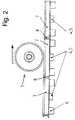
(例えば、1つのボギー台車内のような)近くに並んで存在する少なくとも2つの車軸1が、並行して検査可能であるように、特に、それぞれ2つのレール2;3から構成された線路区間7の長さ及び数が選択される。さらに、通常の1つの鉄道用車輪の全周が、各線路区間7によって検査可能であるように、これらの線路区間7の長さ及び数が選択されることが有益である。例えば、それぞれ1.1メートルの長さを有する4つの線路区間7が使用されるならば、これらの要求は満たされ得る。この場合、このことは、本発明の構成を限定するものとみなしてはならない。別の好適な構成は、連続する複数の線路区間7がそれぞれ、複数のミューメタルプレート8によって互いに分離されていて且つ互いに連結されていることを提唱する。 In particular, a track section composed of two
使用に起因する摩耗及び/又は材料欠陥に関して鉄道用車輪を検査するため、当該鉄道車両に取り付けられた鉄道用車輪が走行移動される。この場合、当該転動方向が、図2に矢印によって概略的に示されている。転動する鉄道車軸1が、図1及び2による装置の使用中に空間的に限定された磁場を通過する。この磁場は、当該鉄道車両が走行するレール2及び3を通じて印加される。当該磁束が、図1に循環している矢印の輪郭線によって概略的に示されている。その結果、測定信号が電磁誘導される。当該測定信号は、特に、転動する車輪とレールとの接触によって、車輪の荷重によって及び車軸1の材料組織によって影響を受ける。これらの測定信号の評価は、検査された鉄道車軸1の、使用に起因する摩耗又はその他の材料欠陥に関する情報の提供を可能にする。 In order to inspect the railway wheels for wear and / or material defects resulting from use, the railway wheels attached to the railway vehicle are moved. In this case, the rolling direction is schematically indicated by arrows in FIG. The rolling rail axle 1 passes through a spatially limited magnetic field during use of the device according to FIGS. This magnetic field is applied through the
1 輪軸
2 レール
3 レール
4 励磁コイル
5 検出器コイル/測定巻線
6 まくら木
7 線路区間
8 ミューメタルプレート1
Claims (8)
Translated fromJapanese転動する鉄道車軸が、空間的に限定された磁場を通過し、この磁場が、複数のレールを通じて印加され、当該鉄道車両が、前記複数のレール上で運転されることを特徴とする方法。In a method for inspecting a railway wheel for wear and / or material defects resulting from use, wherein the railway wheel attached to a railway vehicle is inspected during travel of the railway vehicle ,
A rolling railway axle passes through a spatially limited magnetic field, the magnetic field is applied through a plurality of rails, and the railway vehicle is operated on the plurality of rails.
1つの電磁石(4;5)が、前記複数のレール(2;3)間に配置されていて、磁束の変化を記録するための1つの測定巻線が、この電磁石(4;5)上に一緒に配置されていることを特徴とする装置。An apparatus for inspecting railway wheels for wear and / or material defects due to use, wherein the rolling railway axle according to claim 1 passes through a spatially limited magnetic field, and this magnetic field. Is applied through the plurality of rails, and the mounted railway vehicle travels on the plurality of rails, so that the railway wheels attached to the railway vehicle are moved during the traveling movement of the railway vehicle. In the device being inspected,
One electromagnet (4; 5) is arranged between the rails (2; 3), and one measuring winding for recording the change of magnetic flux is on this electromagnet (4; 5). A device characterized by being placed together.
Applications Claiming Priority (3)
| Application Number | Priority Date | Filing Date | Title |
|---|---|---|---|
| DE102012013626.9 | 2012-07-04 | ||
| DE102012013626.9ADE102012013626A1 (en) | 2012-07-04 | 2012-07-04 | Method and device for checking railway wheels |
| PCT/DE2013/000370WO2014005574A2 (en) | 2012-07-04 | 2013-07-02 | Method and device for inspecting railway wheels |
Publications (2)
| Publication Number | Publication Date |
|---|---|
| JP2015526329Atrue JP2015526329A (en) | 2015-09-10 |
| JP6192717B2 JP6192717B2 (en) | 2017-09-06 |
Family
ID=49546197
Family Applications (1)
| Application Number | Title | Priority Date | Filing Date |
|---|---|---|---|
| JP2015518846AActiveJP6192717B2 (en) | 2012-07-04 | 2013-07-02 | Method and apparatus for inspecting railway wheels |
Country Status (12)
| Country | Link |
|---|---|
| US (1) | US9707984B2 (en) |
| EP (1) | EP2870451B1 (en) |
| JP (1) | JP6192717B2 (en) |
| KR (1) | KR102082438B1 (en) |
| CN (1) | CN104583749B (en) |
| AU (1) | AU2013286358B2 (en) |
| CA (1) | CA2880627C (en) |
| DE (1) | DE102012013626A1 (en) |
| ES (1) | ES2755755T3 (en) |
| PL (1) | PL2870451T3 (en) |
| RU (1) | RU2638891C2 (en) |
| WO (1) | WO2014005574A2 (en) |
Families Citing this family (17)
| Publication number | Priority date | Publication date | Assignee | Title |
|---|---|---|---|---|
| US10349491B2 (en) | 2015-01-19 | 2019-07-09 | Tetra Tech, Inc. | Light emission power control apparatus and method |
| CA2892885C (en) | 2015-02-20 | 2020-07-28 | Tetra Tech, Inc. | 3d track assessment system and method |
| CN105118044B (en)* | 2015-06-16 | 2017-11-07 | 华南理工大学 | A kind of wheel shape cast article defect automatic testing method |
| RU2632369C1 (en)* | 2016-03-09 | 2017-10-04 | Общество с ограниченной ответственностью "Энергосервис" (ООО "Энергосервис") | Split solenoid |
| EP3429902A4 (en)* | 2016-03-18 | 2019-10-30 | Pure Technologies Ltd | Methods and system for inspecting train wheels and axles |
| US10989692B2 (en) | 2016-03-21 | 2021-04-27 | Railpod, Inc. | Combined passive and active method and systems to detect and measure internal flaws within metal rails |
| EP3586310A4 (en) | 2017-02-22 | 2020-12-30 | Tetra Tech Inc. | Broken wheel detection system |
| RU2680857C1 (en)* | 2018-05-31 | 2019-02-28 | Открытое акционерное общество "Радиоавионика" | Wheelset rim magnetic flaw detection device |
| US11377130B2 (en) | 2018-06-01 | 2022-07-05 | Tetra Tech, Inc. | Autonomous track assessment system |
| US10625760B2 (en) | 2018-06-01 | 2020-04-21 | Tetra Tech, Inc. | Apparatus and method for calculating wooden crosstie plate cut measurements and rail seat abrasion measurements based on rail head height |
| US10807623B2 (en) | 2018-06-01 | 2020-10-20 | Tetra Tech, Inc. | Apparatus and method for gathering data from sensors oriented at an oblique angle relative to a railway track |
| US10730538B2 (en) | 2018-06-01 | 2020-08-04 | Tetra Tech, Inc. | Apparatus and method for calculating plate cut and rail seat abrasion based on measurements only of rail head elevation and crosstie surface elevation |
| CA3130198C (en) | 2019-05-16 | 2022-05-17 | Darel Mesher | System and method for generating and interpreting point clouds of a rail corridor along a survey path |
| RU192859U1 (en)* | 2019-06-17 | 2019-10-03 | ФГБОУ ВО " Омский государственный университет путей сообщения" | Device for monitoring the technical condition of rolling stock trolleys |
| IT202000013051A1 (en) | 2020-06-01 | 2021-12-01 | Alessio Gellini | Device for the maintenance of railway tracks and trolleys of railway vehicles |
| IT202000013063A1 (en) | 2020-06-03 | 2021-12-03 | Alessio Gellini | Device for railway maintenance |
| IT202000013066A1 (en) | 2020-06-03 | 2021-12-03 | Alessio Gellini | Advanced railway maintenance device |
Citations (2)
| Publication number | Priority date | Publication date | Assignee | Title |
|---|---|---|---|---|
| US6523411B1 (en)* | 2000-03-21 | 2003-02-25 | International Electronic Machines Corp. | Wheel inspection system |
| US20090054566A1 (en)* | 2002-05-30 | 2009-02-26 | Daniel Thibaut | Amorphous solid modification of bis(2,4-dicumylphenyl)pentaerythritol diphoshite |
Family Cites Families (19)
| Publication number | Priority date | Publication date | Assignee | Title |
|---|---|---|---|---|
| US1702997A (en) | 1928-02-23 | 1929-02-19 | Robert H Ewing | Signal-control apparatus |
| US2442491A (en)* | 1945-03-05 | 1948-06-01 | Marion W Gieskieng | Railway wheel checking device |
| SU403803A1 (en)* | 1969-03-24 | 1973-10-26 | Всесоюзный научно исследовательский институт железнодорожного транспорта | |
| US3844513A (en)* | 1970-04-22 | 1974-10-29 | Ericsson Telefon Ab L M | Method and system for detecting wheel flats on rail vehicles |
| RU2005912C1 (en)* | 1989-06-26 | 1994-01-15 | Валерий Измайлович Мулуянов | Piston compressor with electrodynamic drive |
| DE4031899A1 (en)* | 1990-10-08 | 1992-04-16 | Daimler Benz Ag | Magnetic data transmission procedure to wheels of railway vehicles - safeguarding by utilisation of portions of wheels less affected by temp. for binary code read-out |
| FR2692671B1 (en) | 1992-06-18 | 1994-09-30 | Valdunes | Device for checking the rim of a railway wheel. |
| DE19826422C2 (en)* | 1998-06-05 | 2002-09-26 | Bernd Woop | Device for the continuous control of the wheel sets of rail vehicles for mechanical defects and faulty wheel arches, as well as detection of dangerous driving conditions |
| DE19836513A1 (en)* | 1998-08-12 | 2000-02-17 | Fiessler Elektronik Wolfgang F | Device to test sample objects for internal defects, especially for in-service testing of train wheels has arrangement of electromagnet placed close to wheel with associated measurement coil |
| DE19924781A1 (en) | 1999-05-29 | 2000-11-30 | Bbc Reaktor Gmbh | Non-destructive testing of railway wheels installed in railway vehicles involves driving vehicle over test section, moving test probe holder into successive test positions during travel |
| DE19943744B4 (en) | 1999-09-02 | 2006-01-26 | Wolfgang Spruch | Method and device for wheelset testing |
| US6262573B1 (en)* | 1999-09-17 | 2001-07-17 | General Electric Company | Electromagnetic system for railroad track crack detection and traction enhancement |
| CN2466012Y (en)* | 2001-02-27 | 2001-12-19 | 北方交通大学 | Wheel tread scuff and wear non-contact dynamic measuring device |
| DE10352166B3 (en) | 2003-11-05 | 2005-04-21 | Db Cargo Ag | Tire tread examination for wheels of goods wagons on railway involves measurement platform, drive motor for rotating wheels, triangulation lasers and light barrier and reflector |
| US20070043486A1 (en) | 2005-08-18 | 2007-02-22 | Moffett Jeffrey P | Rail wheel measurement |
| CN2919190Y (en)* | 2006-06-23 | 2007-07-04 | 西南交通大学 | Electromagnetic Ultrasonic Transducer for On-line Dynamic Detection of Rolling Stock Wheelset Defects |
| KR20090042621A (en)* | 2007-10-26 | 2009-04-30 | 한국철도기술연구원 | Abnormal Defect Test System |
| CN101149358A (en)* | 2007-11-05 | 2008-03-26 | 钢铁研究总院 | Automatic electromagnetic ultrasonic testing device and method for train wheel surface |
| KR101247377B1 (en)* | 2010-09-10 | 2013-03-26 | 조선대학교산학협력단 | Automatic Operation System for Wheel Tread Inspection of Rail Installation Type |
- 2012
- 2012-07-04DEDE102012013626.9Apatent/DE102012013626A1/ennot_activeWithdrawn
- 2013
- 2013-07-02USUS14/412,262patent/US9707984B2/enactiveActive
- 2013-07-02CNCN201380035904.1Apatent/CN104583749B/enactiveActive
- 2013-07-02CACA2880627Apatent/CA2880627C/enactiveActive
- 2013-07-02RURU2015103539Apatent/RU2638891C2/enactive
- 2013-07-02KRKR1020157003058Apatent/KR102082438B1/enactiveActive
- 2013-07-02ESES13786410Tpatent/ES2755755T3/enactiveActive
- 2013-07-02WOPCT/DE2013/000370patent/WO2014005574A2/enactiveApplication Filing
- 2013-07-02AUAU2013286358Apatent/AU2013286358B2/enactiveActive
- 2013-07-02PLPL13786410Tpatent/PL2870451T3/enunknown
- 2013-07-02EPEP13786410.4Apatent/EP2870451B1/enactiveActive
- 2013-07-02JPJP2015518846Apatent/JP6192717B2/enactiveActive
Patent Citations (2)
| Publication number | Priority date | Publication date | Assignee | Title |
|---|---|---|---|---|
| US6523411B1 (en)* | 2000-03-21 | 2003-02-25 | International Electronic Machines Corp. | Wheel inspection system |
| US20090054566A1 (en)* | 2002-05-30 | 2009-02-26 | Daniel Thibaut | Amorphous solid modification of bis(2,4-dicumylphenyl)pentaerythritol diphoshite |
Also Published As
| Publication number | Publication date |
|---|---|
| RU2638891C2 (en) | 2017-12-18 |
| CN104583749B (en) | 2019-03-08 |
| WO2014005574A3 (en) | 2014-03-27 |
| KR20150032323A (en) | 2015-03-25 |
| AU2013286358A1 (en) | 2015-02-26 |
| ES2755755T3 (en) | 2020-04-23 |
| KR102082438B1 (en) | 2020-02-27 |
| DE102012013626A1 (en) | 2014-01-09 |
| US20150239480A1 (en) | 2015-08-27 |
| CA2880627C (en) | 2020-07-07 |
| PL2870451T3 (en) | 2020-02-28 |
| RU2015103539A (en) | 2016-08-27 |
| CN104583749A (en) | 2015-04-29 |
| WO2014005574A2 (en) | 2014-01-09 |
| EP2870451A2 (en) | 2015-05-13 |
| US9707984B2 (en) | 2017-07-18 |
| CA2880627A1 (en) | 2014-01-09 |
| AU2013286358B2 (en) | 2017-09-07 |
| JP6192717B2 (en) | 2017-09-06 |
| EP2870451B1 (en) | 2019-08-14 |
Similar Documents
| Publication | Publication Date | Title |
|---|---|---|
| JP6192717B2 (en) | Method and apparatus for inspecting railway wheels | |
| Barke et al. | Structural health monitoring in the railway industry: a review | |
| CN102501887B (en) | Non-contact dynamic detection device and detection method for tire tread defects | |
| RU2349480C2 (en) | Diagnostic and monitoring method and device for railway points, crossings, turn-outs or rail joints | |
| AU2018213965A1 (en) | Method and system for non-destructive rail inspection | |
| CA2971075A1 (en) | A system for detecting a break in a rail | |
| EP2208041A1 (en) | Monitoring system for wheel profile defect of railway vehicles | |
| JP2011214986A (en) | Rail flaw detection device | |
| RU2586090C1 (en) | Method for magnetic inspection of weld joints of rails | |
| RU2293982C2 (en) | Method for ultrasound flaw detection of wheel pairs of rail transport and device for realization of said method | |
| RU2708693C1 (en) | Device and method for detecting defects of wheels of railway vehicles in motion | |
| Thomas et al. | Eddy current test method for early detection of rolling contact fatigue (RCF) in rails | |
| RU2578620C1 (en) | Automated diagnostic system for monitoring technical state of suspension elements of railway facilities | |
| RU2717683C1 (en) | Method of determining local defects of rails rolling surface | |
| RU2671368C1 (en) | Method of magnetic detection of rails regular objects | |
| US3705531A (en) | Method and apparatus for determining the operating performance of wheeled vehicles on a track | |
| RU219001U1 (en) | Flaw trolley | |
| RU38320U1 (en) | DEFECTIVE TROLLEY FOR MAGNETIC AND ULTRASONIC RAILWAY CONTROL | |
| CN108982653A (en) | The adaptive magnetic memory detection device of portable wheel tread and method | |
| RU2843087C1 (en) | Method of magnetic flux creation in railway track rails | |
| RU2742368C1 (en) | Hand scanner for nondestructive inspection of rolling surface and adjacent areas of wheels of railway vehicles | |
| JP2008216091A (en) | Rail rail bottom corrosion detector | |
| Juna | On the characterisation and detection of rolling contact fatigue (RCF) type cracks in railway vehicle wheels using an alternating current field measurement (ACFM) technique | |
| Kwon et al. | Evaluation of surface and internal defects of railway wheel using induced current focusing potential drop | |
| Kwon et al. | Defect Monitoring In Railway Wheel and Axle |
Legal Events
| Date | Code | Title | Description |
|---|---|---|---|
| A621 | Written request for application examination | Free format text:JAPANESE INTERMEDIATE CODE: A621 Effective date:20160527 | |
| A977 | Report on retrieval | Free format text:JAPANESE INTERMEDIATE CODE: A971007 Effective date:20170324 | |
| A131 | Notification of reasons for refusal | Free format text:JAPANESE INTERMEDIATE CODE: A131 Effective date:20170329 | |
| A521 | Request for written amendment filed | Free format text:JAPANESE INTERMEDIATE CODE: A523 Effective date:20170627 | |
| TRDD | Decision of grant or rejection written | ||
| A01 | Written decision to grant a patent or to grant a registration (utility model) | Free format text:JAPANESE INTERMEDIATE CODE: A01 Effective date:20170712 | |
| A61 | First payment of annual fees (during grant procedure) | Free format text:JAPANESE INTERMEDIATE CODE: A61 Effective date:20170808 | |
| R150 | Certificate of patent or registration of utility model | Ref document number:6192717 Country of ref document:JP Free format text:JAPANESE INTERMEDIATE CODE: R150 | |
| R250 | Receipt of annual fees | Free format text:JAPANESE INTERMEDIATE CODE: R250 | |
| R250 | Receipt of annual fees | Free format text:JAPANESE INTERMEDIATE CODE: R250 | |
| R250 | Receipt of annual fees | Free format text:JAPANESE INTERMEDIATE CODE: R250 | |
| R250 | Receipt of annual fees | Free format text:JAPANESE INTERMEDIATE CODE: R250 | |
| R250 | Receipt of annual fees | Free format text:JAPANESE INTERMEDIATE CODE: R250 | |
| R250 | Receipt of annual fees | Free format text:JAPANESE INTERMEDIATE CODE: R250 |