JP2015524736A - Needle catheter that delivers drug directly into the vessel wall - Google Patents
Needle catheter that delivers drug directly into the vessel wallDownload PDFInfo
- Publication number
- JP2015524736A JP2015524736AJP2015527497AJP2015527497AJP2015524736AJP 2015524736 AJP2015524736 AJP 2015524736AJP 2015527497 AJP2015527497 AJP 2015527497AJP 2015527497 AJP2015527497 AJP 2015527497AJP 2015524736 AJP2015524736 AJP 2015524736A
- Authority
- JP
- Japan
- Prior art keywords
- catheter
- wire
- positioning
- lumen
- wires
- Prior art date
- Legal status (The legal status is an assumption and is not a legal conclusion. Google has not performed a legal analysis and makes no representation as to the accuracy of the status listed.)
- Granted
Links
Images


Classifications
- A—HUMAN NECESSITIES
- A61—MEDICAL OR VETERINARY SCIENCE; HYGIENE
- A61M—DEVICES FOR INTRODUCING MEDIA INTO, OR ONTO, THE BODY; DEVICES FOR TRANSDUCING BODY MEDIA OR FOR TAKING MEDIA FROM THE BODY; DEVICES FOR PRODUCING OR ENDING SLEEP OR STUPOR
- A61M25/00—Catheters; Hollow probes
- A61M25/01—Introducing, guiding, advancing, emplacing or holding catheters
- A61M25/0105—Steering means as part of the catheter or advancing means; Markers for positioning
- A61M25/0133—Tip steering devices
- A61M25/0147—Tip steering devices with movable mechanical means, e.g. pull wires
- A—HUMAN NECESSITIES
- A61—MEDICAL OR VETERINARY SCIENCE; HYGIENE
- A61M—DEVICES FOR INTRODUCING MEDIA INTO, OR ONTO, THE BODY; DEVICES FOR TRANSDUCING BODY MEDIA OR FOR TAKING MEDIA FROM THE BODY; DEVICES FOR PRODUCING OR ENDING SLEEP OR STUPOR
- A61M25/00—Catheters; Hollow probes
- A61M25/01—Introducing, guiding, advancing, emplacing or holding catheters
- A61M25/02—Holding devices, e.g. on the body
- A61M25/04—Holding devices, e.g. on the body in the body, e.g. expansible
- A—HUMAN NECESSITIES
- A61—MEDICAL OR VETERINARY SCIENCE; HYGIENE
- A61M—DEVICES FOR INTRODUCING MEDIA INTO, OR ONTO, THE BODY; DEVICES FOR TRANSDUCING BODY MEDIA OR FOR TAKING MEDIA FROM THE BODY; DEVICES FOR PRODUCING OR ENDING SLEEP OR STUPOR
- A61M25/00—Catheters; Hollow probes
- A61M25/0067—Catheters; Hollow probes characterised by the distal end, e.g. tips
- A61M25/0082—Catheter tip comprising a tool
- A61M25/0084—Catheter tip comprising a tool being one or more injection needles
- A61M2025/0089—Single injection needle protruding axially, i.e. along the longitudinal axis of the catheter, from the distal tip
- A61M2025/009—Single injection needle protruding axially, i.e. along the longitudinal axis of the catheter, from the distal tip the needle having a bent tip, i.e. the needle distal tip is angled in relation to the longitudinal axis of the catheter
- A—HUMAN NECESSITIES
- A61—MEDICAL OR VETERINARY SCIENCE; HYGIENE
- A61M—DEVICES FOR INTRODUCING MEDIA INTO, OR ONTO, THE BODY; DEVICES FOR TRANSDUCING BODY MEDIA OR FOR TAKING MEDIA FROM THE BODY; DEVICES FOR PRODUCING OR ENDING SLEEP OR STUPOR
- A61M25/00—Catheters; Hollow probes
- A61M25/10—Balloon catheters
- A61M2025/1043—Balloon catheters with special features or adapted for special applications
- A61M2025/1047—Balloon catheters with special features or adapted for special applications having centering means, e.g. balloons having an appropriate shape
- A—HUMAN NECESSITIES
- A61—MEDICAL OR VETERINARY SCIENCE; HYGIENE
- A61M—DEVICES FOR INTRODUCING MEDIA INTO, OR ONTO, THE BODY; DEVICES FOR TRANSDUCING BODY MEDIA OR FOR TAKING MEDIA FROM THE BODY; DEVICES FOR PRODUCING OR ENDING SLEEP OR STUPOR
- A61M25/00—Catheters; Hollow probes
- A61M25/0097—Catheters; Hollow probes characterised by the hub
Landscapes
- Health & Medical Sciences (AREA)
- Life Sciences & Earth Sciences (AREA)
- Engineering & Computer Science (AREA)
- Hematology (AREA)
- Pulmonology (AREA)
- Anesthesiology (AREA)
- Biomedical Technology (AREA)
- Heart & Thoracic Surgery (AREA)
- Biophysics (AREA)
- Animal Behavior & Ethology (AREA)
- General Health & Medical Sciences (AREA)
- Public Health (AREA)
- Veterinary Medicine (AREA)
- Mechanical Engineering (AREA)
- Media Introduction/Drainage Providing Device (AREA)
- Infusion, Injection, And Reservoir Apparatuses (AREA)
Abstract
Translated fromJapaneseDescription
Translated fromJapanese本発明は、一般的には疾患を治療する医療装置、システム、および方法に関する。とりわけ本発明は、血管内に送達される化合物または薬剤による神経調節を達成するシステムおよび方法に関する。 The present invention relates generally to medical devices, systems, and methods for treating disease. In particular, the present invention relates to systems and methods that achieve neuromodulation with compounds or agents delivered into blood vessels.
高血圧症、すなわち高血圧は、世界の成人人口の大部分に影響を及ぼしている。腎臓または腎血管で、高血圧は腎動脈の狭小化による腎臓の低灌流によって引き起こされうる。腎臓は、塩分および水分を維持するよう身体に信号を送るホルモンを出すことにより反応し、血圧の上昇を引き起こす。腎動脈は、動脈損傷またはアテローム性動脈硬化により狭小しうる。レニン−アンジオテンシン−アルドステロン経路を調節する、または身体から過剰な液体を取り除き血圧を下げる効果的な薬剤治療法にもかかわらず、多くの高血圧患者が抵抗性疾患に悩まされている。 Hypertension, or high blood pressure, affects the majority of the world's adult population. In the kidney or renal blood vessels, hypertension can be caused by renal hypoperfusion due to narrowing of the renal arteries. The kidneys react by producing hormones that signal the body to maintain salt and water, causing an increase in blood pressure. The renal arteries can become narrowed due to arterial injury or atherosclerosis. Despite effective drug therapy that regulates the renin-angiotensin-aldosterone pathway or removes excess fluid from the body and lowers blood pressure, many hypertensive patients suffer from resistant disease.
抵抗性高血圧は、患者を薬物治療だけで高血圧をコントロールできないときに引き起こされる一般的な臨床的問題である。抵抗性高血圧は、高齢で肥満の人々には特に問題である。これら両方の人口統計は増加しつつある。これらの患者では症状は明確でないが、彼らが血圧をコントロールできないとき心血管のリスクは非常に増大する。 Resistant hypertension is a common clinical problem that is caused when patients are unable to control hypertension just by medication. Resistant hypertension is a particular problem for older and obese people. Both demographics are increasing. In these patients, the symptoms are not clear, but the cardiovascular risk is greatly increased when they cannot control blood pressure.
交感神経系(SNS)は、末梢神経系および中枢神経系の両方の一部である一連の相互接続した神経細胞を通して作動する。化学的シナプスを通して、交感神経系は化学的連鎖反応を生じる化学的メッセンジャを放出することが可能であり、それが最終的に生理学的反応を誘発させる。従って、交感神経系を通して移動するメッセージは、血管緊張の上昇調節および下降調節(それぞれ血管収縮および血管拡張)を含む多くの身体機能の変化を誘発しうる。血管収縮は、アンジオテンシンIの放出およびそのアンジオテンシンIIへの転換により誘発されうる。アンジオテンシンIIは血管の狭窄を直接引き起こし、それからそれが体血圧を上げる。特定の状況でこの体血圧の上昇は高血圧に現れ、腎臓の血流の阻害、アテローム性動脈硬化の促進、および肥大の刺激を含む有害な影響を多数のプロセスに有しうる。 The sympathetic nervous system (SNS) operates through a series of interconnected neurons that are part of both the peripheral and central nervous systems. Through chemical synapses, the sympathetic nervous system can release chemical messengers that cause a chemical chain reaction, which ultimately triggers a physiological response. Thus, messages that travel through the sympathetic nervous system can trigger many changes in bodily functions, including up-regulation and down-regulation of vascular tone (vasoconstriction and vasodilation, respectively). Vasoconstriction can be triggered by the release of angiotensin I and its conversion to angiotensin II. Angiotensin II directly causes stenosis of blood vessels, which then increases body blood pressure. In certain circumstances, this increase in body blood pressure appears in hypertension and can have deleterious effects on many processes, including inhibition of renal blood flow, promotion of atherosclerosis, and stimulation of hypertrophy.
腎臓の交感神経の活動亢進によっても、高血圧は引き起こされる。腎臓の交感遠心性神経および求心性神経は、大動脈から腎臓につながる動脈の外側に沿って長手方向に通常走る。これらの神経は、全身性高血圧の発生および維持管理に非常に重要である。これらの神経を切断することにより、血圧を下降可能であることが示された。 Hypertension is also caused by increased activity of the kidney sympathetic nerves. The sympathetic efferent and afferent nerves of the kidney usually run longitudinally along the outside of the artery leading from the aorta to the kidney. These nerves are very important for the development and maintenance of systemic hypertension. It was shown that blood pressure can be lowered by cutting these nerves.
交感神経系の機能と多くの生命を脅かす疾患の間の強い相関に注目すると、治療の可能性は交感神経系の活動をコントロールすべきであろうという強い示唆が存在する。実際に、研究は求心性神経の刺激が交感神経の活動および関連する血圧に大きな影響を有することを示した(Aars,et al., Reflex Changes in Sympathetic Activity and Arterial Blood Pressure Evoked by Afferent Stimulation of Renal Nerve(1970))。さらに特許公開は、交感神経を切断、そうでなければ心臓組織を刺激するよう意図されたカテーテル装置を開示し、さらにそのような切断が心細動、頻脈または心不整脈を有益に治療することを開示した。例えば、米国特許第6,292,695号(2001年発行)を見られたい。 Focusing on the strong correlation between sympathetic nervous system function and many life-threatening diseases, there is strong suggestion that therapeutic potential should control sympathetic nervous system activity. In fact, studies have shown that stimulation of afferent nerves has a significant impact on sympathetic nerve activity and associated blood pressure (Aars, et al., Reflex Change in Sympathetic Activity and Artificial Blood Evoked by Affected Beverage Affair. Nerve (1970)). Furthermore, the patent publication discloses a catheter device intended to cut sympathetic nerves or otherwise stimulate heart tissue, and further that such cutting beneficially treats cardiac fibrillation, tachycardia or cardiac arrhythmia. Disclosed. For example, see US Pat. No. 6,292,695 (issued in 2001).
経皮的または内視鏡的介入処置は、米国および世界中の他の国々で非常に一般的である。バルーン血管形成、ステント配置、アテレクトミー、血栓の回復、光線力学療法および薬剤送達のような処置に、血管内カテーテルシステムが使用される。これらの処置の全ては、観血的手術の必要なしに身体の深いくぼみへのアクセスを提供するため、動脈、静脈、または身体の他の内腔内へのカテーテルの配置を含む。 Percutaneous or endoscopic interventional procedures are very common in the United States and other countries around the world. Intravascular catheter systems are used for procedures such as balloon angioplasty, stent placement, atherectomy, thrombus recovery, photodynamic therapy and drug delivery. All of these procedures involve the placement of a catheter within an artery, vein, or other lumen of the body to provide access to a deep cavity in the body without the need for open surgery.
腎動脈の閉塞が薬物治療でコントロールできない高血圧を引き起こすケースで、他の可能性がある療法は腎動脈のバルーン血管形成を含む。まれなケースで、薬物治療の代替として外科的バイパス移植を検討してもよい。腎臓の血管形成が血圧降下に有効でありうる一方で、血管形成は弾性反跳、切開および新生内膜増殖により結果として生じる再狭窄に悩まされる。腎臓ステントは結果を改善するかもしれないが、また新生内膜増殖により動脈の再狭窄または再狭小化につながる。 In cases where renal artery occlusion causes hypertension that cannot be controlled with medication, other possible therapies include balloon angioplasty of the renal artery. In rare cases, surgical bypass grafts may be considered as an alternative to drug treatment. While renal angiogenesis can be effective in lowering blood pressure, angiogenesis suffers from restenosis resulting from elastic recoil, incision and neointimal proliferation. Kidney stents may improve outcomes, but neointimal proliferation also leads to arterial restenosis or restenosis.
過去に外科的方法で腎臓の除神経が実行されてきたが、最近は加熱および高周波切断を用いて腎動脈内から神経を破壊するカテーテルベースの療法が研究されてきた。 In the past, renal denervation has been performed by surgical methods, but recently catheter-based therapies have been studied that destroy the nerve from within the renal artery using heat and radiofrequency cutting.
カテーテルベースの高周波(RF)除神経は治療効果を有するように見えるが、どんな長期間の影響がRF処置による血管壁および神経へ引き起こされる永久的な損傷から生じるかは分からない。高周波エネルギーは、血管壁内に熱を生じることにより除神経を行う。RFプローブが動脈の内層に接触し、RFエネルギーが組織を通して伝達される。 Although catheter-based radio frequency (RF) denervation appears to have a therapeutic effect, it is not known what long-term effects result from permanent damage caused to the vessel walls and nerves by RF treatment. High frequency energy performs denervation by generating heat in the vessel wall. An RF probe contacts the inner lining of the artery and RF energy is transmitted through the tissue.
しかし、交感神経系の活動を妨げるカテーテルによる切断は、欠点を有する。例えば、神経束の切断は矛盾または不完全であるかもしれない。またカテーテル法は最小の侵襲であると考えられるが、体外の手段を通してのような非侵襲的方法で療法を達成するのが望ましいであろう。さらに、交感神経系がカテーテルが到達不可能な領域の血管壁の外側にも存在することを考えると、交感神経系の特定の領域はカテーテル法で達成するには困難または不可能であるかもしれない。 However, cutting with a catheter that impedes sympathetic nervous system activity has drawbacks. For example, amputation of the nerve bundle may be inconsistent or incomplete. Catheterization is also considered minimally invasive, but it would be desirable to achieve therapy in a non-invasive manner such as through extracorporeal means. Furthermore, given that the sympathetic nervous system is also outside the vessel wall in areas where the catheter cannot be reached, certain areas of the sympathetic nervous system may be difficult or impossible to achieve with catheterization. Absent.
これらの全ての理由のため、腎動脈の外膜/血管周囲/動脈周囲の領域内へ、神経機能を調整可能な他の薬剤を含む交感神経抑制薬または交感神経遮断薬を送達して、生物学的および可逆性の除神経を達成し、一方で血管への損傷を生じず、または潜在する血管疾患を悪化させない、追加されたおよび改善されたシステムおよび方法を提供するのが望ましいであろう。結果として、交感神経系のあらゆる場所を療法の対象とするのを可能にする、非侵襲的な方法で交感神経系の求心性および遠心性活動を妨げる手段のニーズが存在する。 For all of these reasons, a sympatholytic or sympatholytic agent, including other drugs that can modulate neural function, is delivered into the adventitia / perivascular / periarterial region of the renal artery to It would be desirable to provide additional and improved systems and methods that achieve anatomical and reversible denervation while not causing damage to blood vessels or exacerbating potential vascular disease . As a result, there is a need for means to prevent afferent and efferent activity of the sympathetic nervous system in a non-invasive manner that makes it possible to target every location of the sympathetic nervous system.
先行技術のさらなる態様で、患者の血管の解剖学的構造内の深い場所から患者に薬物および薬剤を注入するシステムが知られる。通常これらのシステムは、膨らませるのが可能なまたは拡張可能な手段を用いてカテーテルを血管の半径方向の中心の固定された位置に設置し、針がカテーテルから突出し血管壁の組織に貫入するよう進められる。そのような先行技術システムに伴う問題は、針がどれぐらい深く組織内に進んだか判断するのに内科医が通常困難を有することである。針が血管壁に到達する前に、まずカテーテルから半径方向に特定の距離を進み、血管内の領域を通らなければならないので、この問題が生じる。血管の局所的な解剖学的構造によって、この距離は予測できず、蛍光透視法を用いて適切な精度では分からない。よって、針先端部がカテーテル外部の壁からどれだけ伸びたか内科医が正確に分かる場合でも、カテーテルと血管壁の間の距離が分からないので、先端部が組織内にどれだけ貫入されたか内科医は算定できない。 In a further aspect of the prior art, a system for injecting drugs and agents into a patient from a deep location within the patient's vascular anatomy is known. These systems typically place the catheter in a fixed position in the radial center of the vessel using inflatable or expandable means so that the needle protrudes from the catheter and penetrates the tissue in the vessel wall. It is advanced. The problem with such prior art systems is that physicians usually have difficulty determining how deep the needle has advanced into the tissue. This problem arises because before the needle reaches the vessel wall, it must first travel a certain distance radially from the catheter and pass through an area within the vessel. Due to the local anatomy of the blood vessels, this distance cannot be predicted and is not known with adequate accuracy using fluoroscopy. Therefore, even if the physician knows exactly how much the needle tip extends from the wall outside the catheter, the distance between the catheter and the vessel wall is not known, so how much the tip penetrates into the tissue. Cannot be calculated.
結果として、内科医が正確に分かる距離で血管壁内に針を挿入するのに使用しうる注入カテーテルの当業界にニーズが存在する。本発明は、これらおよび他のニーズに対処する。 As a result, there is a need in the art for infusion catheters that can be used to insert a needle into a vessel wall at a distance that is accurately understood by a physician. The present invention addresses these and other needs.
本発明は、血管内治療システムである。それは、ハイポチューブを受け入れるよう構成された内腔を形成する細長い軸を有するカテーテルを備える。内腔は、カテーテルの外側の側壁の遠位開口部で終了する。ハイポチューブは内腔内に摺動可能に受け入れられ、鋭くした遠位先端部を有し、かつカテーテルに対して遠位先端部が内腔内に完全に収容される引っ込められた状態、および遠位先端部が遠位開口部から突出する進められた状態を有するよう構成される。 The present invention is an endovascular treatment system. It comprises a catheter having an elongate shaft that forms a lumen configured to receive a hypotube. The lumen terminates at a distal opening in the outer sidewall of the catheter. The hypotube is slidably received within the lumen, has a sharpened distal tip, and is retracted with the distal tip fully contained within the lumen with respect to the catheter, and The distal tip is configured to have an advanced state protruding from the distal opening.
複数の位置決めワイヤが、カテーテルの外部を伸び、カテーテルに対して、それぞれのワイヤがカテーテルの外壁に対して畳まれた血管内の送達のための拡張されていない状態、およびそれぞれのワイヤがカテーテルから離れて、細長い軸から離れて半径方向に伸びる想像上の面に沿って曲げられた血管内のカテーテルの位置決めのための拡張状態を有するよう構成される。この構成のもとで、曲げられたワイヤにより占められた全ての想像上の半径方向の面が、180度以下の細長い軸の周辺の角度を持つ弧の内に含まれる。望ましくは、拡張状態の曲げられたワイヤが、角度を持つ弧が遠位開口部の位置の実質的に直径方向に反対側である中心を有するように、カテーテルに対して位置付けられる。この構成のもとで、位置決めワイヤに拡張状態をとらせることはワイヤに血管壁の1つの側に対して圧迫させ、よって遠位開口部が血管壁と接触するように血管の直径方向に反対側の壁に対して押させる。よって、ハイポチューブの鋭くした先端部が遠位開口部から伸びる状態を引き起こされたとき、それはカテーテルと血管壁の間の距離を全くカバーすることなく、血管壁を通って血管周囲の領域に直接貫入させられる。 Multiple positioning wires extend out of the catheter, with respect to the catheter, each wire being folded against the outer wall of the catheter, unexpanded for intravascular delivery, and each wire from the catheter Separately configured to have an expanded state for positioning of the catheter within the blood vessel bent along an imaginary plane extending radially away from the elongate axis. Under this configuration, all imaginary radial planes occupied by the bent wire are contained within an arc having an angle around the elongated axis of 180 degrees or less. Desirably, the expanded bent wire is positioned relative to the catheter such that the angled arc has a center that is substantially diametrically opposite the position of the distal opening. Under this configuration, allowing the positioning wire to expand will force the wire to compress against one side of the vessel wall and thus diametrically opposite the vessel so that the distal opening contacts the vessel wall Push against the side wall. Thus, when the hypotube's sharpened tip is caused to extend from the distal opening, it does not cover the distance between the catheter and the vessel wall at all, directly through the vessel wall to the area surrounding the vessel. Intruded.
システムはさらに、軸方向の圧迫力を受けてそれぞれの位置決めワイヤを取り付け、それによってそれぞれのワイヤが拡張状態でカテーテルから離れて曲げられる手段を有する。いくつかの実施形態では、軸方向の圧迫力を受けてそれぞれの位置決めワイヤを取り付ける手段がラックおよびピニオンを備え、ラックがそれぞれのワイヤの近位端部を遠位方向へ移動するよう構成される。他の実施形態では、軸方向の圧迫力を受けてそれぞれの位置決めワイヤを取り付ける手段が、それぞれのワイヤの遠位端部が付着される引張構成要素を有し、引張構成要素は関係カテーテル内を近位に移動するよう構成される。引張構成要素をカテーテルの内腔内に摺動可能に受け入れてもよく、それぞれの位置決めワイヤの遠位端部が引張構成要素に接合し、それによって引張構成要素の近位移動がワイヤが曲がり拡張状態をとる状態を起こしてもよい。いくつかの実施形態では、引張構成要素はガイドワイヤを受け入れる内腔を形成してもよい。 The system further includes means for attaching each positioning wire under an axial compression force so that each wire is bent away from the catheter in the expanded state. In some embodiments, means for attaching each positioning wire in response to an axial compression force comprises a rack and a pinion, the rack being configured to move the proximal end of each wire distally . In other embodiments, the means for attaching each positioning wire under an axial compression force has a tensioning component to which the distal end of each wire is attached, the tensioning component within the associated catheter. Configured to move proximally. A tensile component may be slidably received within the lumen of the catheter, with the distal end of each positioning wire joined to the tensile component so that proximal movement of the tensile component causes the wire to bend and expand A state that takes a state may be caused. In some embodiments, the tensioning component may form a lumen that receives the guidewire.
システムはさらに、ハイポチューブを引っ込められた状態から遠位に進められた状態に移動する手段を有する。いくつかの実施形態では、ハイポチューブを引っ込められた状態から遠位に進められた状態に移動する手段が、ラックおよびピニオンを含む。1つの実施形態では、複数の位置決めワイヤは合計4本である。さらなる実施形態で、システムはカテーテルを通して伸びる複数の位置決め内腔をさらに有してもよく、それぞれのワイヤがワイヤの長さの少なくとも一部の間を位置決め内腔を通って伸び、ワイヤが第1の長さをカテーテルの外部へ伸び、遠位開口部が第1の長さに沿って実質的に中ほどの位置に位置付けられる。この構成のもとで、ハイポチューブの遠位先端部が血管壁に貫入しうるように、位置決めワイヤによりカテーテルに加えられた力は遠位開口部に集中され、カテーテルは血管壁に対してきっちりと押し入れられ、ユーザは、カテーテルから現れるハイポチューブの長さ全体が血管壁を通って血管周囲の領域に貫入するのを確信しうる。 The system further comprises means for moving the hypotube from a retracted state to a distally advanced state. In some embodiments, the means for moving the hypotube from the retracted state to the distally advanced state includes a rack and a pinion. In one embodiment, there are a total of four positioning wires. In a further embodiment, the system may further include a plurality of positioning lumens extending through the catheter, each wire extending through the positioning lumen between at least a portion of the length of the wire, wherein the wires are first And the distal opening is positioned substantially midway along the first length. Under this configuration, the force applied to the catheter by the positioning wire is concentrated in the distal opening so that the distal tip of the hypotube can penetrate the vessel wall, and the catheter is tight against the vessel wall. And the user can be confident that the entire length of the hypotube emerging from the catheter will penetrate the vessel wall and into the area surrounding the vessel.
別の実施形態では、本発明は医学的状態について患者を治療する方法である。方法は、細長い軸を有するカテーテルを患者の血管内に進めるステップを含む。カテーテルに軸に垂直に向けられた力が加えられ、それによってカテーテルの外部の側壁を血管壁と接触させる。鋭くした遠位先端部を有するハイポチューブがカテーテル内の内腔の開口部を通して進められ、それによってカテーテルの外部の側壁が血管壁と接触した箇所で血管壁に鋭くした先端部で貫入する。この力が加えられると、薬剤がハイポチューブを通しておよび血管壁を通して血管周囲の領域内へ注入される。この構成のもとで、ハイポチューブの鋭くした遠位先端部が血管壁を通ってカテーテルが血管壁と接触した箇所で貫入し、従ってカテーテルから伸びるハイポチューブの長さ全体が血管周囲の領域内に伸びるのをユーザは確信しうる。よって、ユーザはハイポチューブによる貫入の完了範囲を知っていると確信しうる。いくつかの実施形態では、カテーテルに力を加えるステップが、軸方向の圧縮力をカテーテルの外部に沿って伸びる複数のワイヤに加え、ワイヤをゆがませカテーテルから半径方向に離れて湾曲させることを含む。他の実施形態では、軸方向の圧縮力を複数のワイヤに加えるステップが、ワイヤの近位端部をカテーテルの遠位端部の方へ移動することを含み、さらに他の実施形態では、軸方向の圧縮力を複数のワイヤに加えるステップが、ワイヤの遠位端部をカテーテルの近位端部の方へ移動することを含む。 In another embodiment, the present invention is a method of treating a patient for a medical condition. The method includes advancing a catheter having an elongated shaft into a patient's blood vessel. A force is applied to the catheter perpendicular to the axis, thereby bringing the outer sidewall of the catheter into contact with the vessel wall. A hypotube with a sharpened distal tip is advanced through the lumen opening in the catheter, thereby penetrating the vessel wall with the sharpened tip where the outer sidewall of the catheter contacts the vessel wall. When this force is applied, the drug is injected through the hypotube and through the vessel wall into the area surrounding the vessel. Under this configuration, the sharpened distal tip of the hypotube penetrates through the vessel wall where the catheter contacts the vessel wall, so that the entire length of the hypotube extending from the catheter is within the region surrounding the vessel. The user can be confident that Thus, the user can be confident that he knows the complete range of penetration by the hypotube. In some embodiments, the step of applying a force to the catheter includes applying an axial compressive force to the plurality of wires extending along the exterior of the catheter, causing the wires to be distorted and bent radially away from the catheter. Including. In other embodiments, applying an axial compressive force to the plurality of wires includes moving the proximal end of the wire toward the distal end of the catheter, and in yet other embodiments, the shaft Applying a directional compressive force to the plurality of wires includes moving the distal end of the wire toward the proximal end of the catheter.
本発明のこれらおよび他の利点は、図および望ましい実施形態の簡単な説明を踏まえるとき、より十分に理解されるであろう。 These and other advantages of the present invention will be more fully understood in light of the drawings and brief description of the preferred embodiments.
本出願は本発明の実施形態を開示し、患者の腎動脈を取り囲む交感神経系へ物質を導入するシステムおよび方法を記載する。いくつかの実施形態では、物質は局在的に一重項酸素を発生可能であり、それが次に交感神経系に細胞毒性を有し、腎動脈を取り囲む神経系を除神経または変調するため送達される。 This application discloses embodiments of the present invention and describes systems and methods for introducing substances into the sympathetic nervous system surrounding a patient's renal artery. In some embodiments, the substance can locally generate singlet oxygen, which is then cytotoxic to the sympathetic nervous system and delivered to denervate or modulate the nervous system surrounding the renal arteries. Is done.
システムのいくつかの実施形態の構成要素は、以下を有してもよい。 The components of some embodiments of the system may include:
(a)溶媒マトリックスの溶液の形態、または代替的にバイオポリマーまたは非生分解性ポリマーのナノ粒子またはミクロ粒子の形態の光感作性薬剤 (A) a photosensitizing agent in the form of a solution in a solvent matrix, or alternatively in the form of nanoparticles or microparticles of biopolymers or non-biodegradable polymers
(b)増感剤または微粒子剤を患者の腎動脈の動脈周囲/外膜周囲の領域内へ注入するよう構成された注入カテーテル (B) An infusion catheter configured to infuse a sensitizer or microparticle into the periarterial / pericardial region of the patient's renal artery
(c)増感剤により吸収されるであろう光を同一の波長で生成可能で、さらに患者の腎動脈内へ挿入可能な光カテーテル (C) An optical catheter that can generate light that will be absorbed by the sensitizer at the same wavelength and that can be inserted into the renal artery of the patient.
本発明のシステムおよび方法の適用において、いくつかの実施形態は、患者の腎動脈を取り囲む所望の位置内への光増感剤の注入、それに続く注入された光増感剤に向かう動脈壁を貫通するカテーテルからの光エネルギーの印加を含み、それで増感剤の神経毒性効果が活性化され、腎動脈を取り囲む神経を切断または変調する効果を有する。次に本発明の構成要素および方法を、より詳細に記載する。 In application of the system and method of the present invention, some embodiments provide for the injection of a photosensitizer into a desired location surrounding the patient's renal artery, followed by the arterial wall toward the injected photosensitizer. Including the application of light energy from a penetrating catheter, whereby the neurotoxic effect of the sensitizer is activated and has the effect of cutting or modulating the nerve surrounding the renal artery. The components and methods of the present invention will now be described in more detail.
光線力学療法は、感光剤、光、および組織の酸素の3つの構成要素の間の相互作用を含む方法である。感光剤は、ポルフィリンまたは同様の構造の化学薬品を含む。それらを、局所的または全身的に導入可能である。治療濃度では、多くの光増感剤は分離状態で識別可能な効果を有さないが、増感剤の吸収特性に合致する波長の光を局所に当てる必要がある。増感剤の送達に続く光の送達のタイミングが、所望の生物学的反応を得るのに非常に重要であり、また個々の増感剤の薬物動態で変わる。 Photodynamic therapy is a method that involves the interaction between three components: photosensitizer, light, and tissue oxygen. Photosensitizers include porphyrins or similarly structured chemicals. They can be introduced locally or systemically. At therapeutic concentrations, many photosensitizers have no discernable effect in the separated state, but light of a wavelength that matches the absorption characteristics of the sensitizer must be applied locally. The timing of light delivery following delivery of the sensitizer is very important to obtain the desired biological response and will vary with the pharmacokinetics of the individual sensitizer.
この結果を提示するため、光−通常はレーザからの赤色光の形態で−が、初期のレーザ血管形成の特徴であった熱の影響を防ぐ出力レベルで送達される。適切な出力レベルおよび波長で当てられた光にさらされるとき、光増感剤は電子的励起状態に転換され、そのエネルギーを、一重項酸素を発生させるために組織の酸素に、または他のフリーラジカル中間体を生じるために他の生体分子へ移すことが可能である。一重項酸素および他の活性種の半減期(0.6×10⁻⁶秒)および拡散距離(0.1μm)の短さは、細胞効果がこれらの種が生成される箇所に極度に局在的であることを意味する。細胞膜内へ含浸された光増感剤の活性化は、腫脹、ブレブ形成、および小胞の減少、ならびにNa+/K+アデノシントリホスファターゼのような膜伝達系の阻害をもたらす。影響される他の箇所は、ミトコンドリア、ゴルジ装置、粗面小胞体およびリソソームを含む。細胞毒性は細胞および細胞下レベルで調整され、アポトーシスまたは壊死により起こりうる。To present this result, light—usually in the form of red light from the laser—is delivered at a power level that prevents the thermal effects that were characteristic of early laser angiogenesis. When exposed to light applied at the appropriate power level and wavelength, the photosensitizer is converted to an electronically excited state and its energy is converted to tissue oxygen to generate singlet oxygen, or other free It can be transferred to other biomolecules to generate radical intermediates. The short half-life (0.6 × 10⁻⁶ s) and diffusion distance (0.1 μm) of singlet oxygen and other active species makes the cellular effects extremely localized where these species are generated Means that Activation of the photosensitizer impregnated into the cell membrane results in swelling, bleb formation, and vesicle reduction and inhibition of membrane transduction systems such as Na + / K + adenosine triphosphatase. Other locations that are affected include mitochondria, Golgi apparatus, rough endoplasmic reticulum and lysosomes. Cytotoxicity is regulated at the cellular and subcellular level and can occur by apoptosis or necrosis.
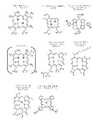
これらの作用を概略的に図1に示し、ここで光線力学療法の作用のメカニズムを例示する。光感作性薬剤が、特定の波長の光により活性化される。励起状態で光増感剤は組織の酸素と反応し、種々の反応性酸化種を生じ、細胞および組織の損傷につながる特定の細胞および細胞外の影響を誘発する。 These actions are shown schematically in FIG. 1, where the mechanism of action of photodynamic therapy is illustrated. A photosensitizing agent is activated by light of a specific wavelength. In the excited state, the photosensitizer reacts with tissue oxygen to produce various reactive oxidative species, inducing specific cellular and extracellular effects that lead to cell and tissue damage.
本発明の実施形態で使用されるレーザ波長は、動脈内に位置する光源から動脈組織に貫入するのに十分に長いように選択されるのが望ましい。通常は、レーザ波長が増すと組織内へのレーザの貫入の深さが増す。レーザの放射波長は、400〜900nmの範囲で構成されるのが望ましい。量子収量(すなわち光エネルギーの光子が三重項酸素を一重項酸素に変換する生成量)が比較的高い光増感剤が多くあるので、波長は500〜800nmの範囲内であるのがより望ましい。本発明の実施形態で使用される光増感剤は、以下の1つまたは複数から選択されるのが望ましい。
a.ヘマトポルフィリン誘導体(HPD)
b.ポルフィリン
c.ベンゾポルフィリン誘導体一塩基酸環A(BPD−MA)
d.フタロシアニンおよびナフタロシアニン
e.テキサフィリン
f.カチオン性フラーレン
g.2−[1−ヘキシルオキシエチル]−2−デビニル−ピロフェオホルビド−a(HPPH)
h.クロリンおよびバクテリオクロリンThe laser wavelength used in embodiments of the present invention is preferably selected to be long enough to penetrate the arterial tissue from a light source located within the artery. Normally, as the laser wavelength increases, the depth of penetration of the laser into the tissue increases. The radiation wavelength of the laser is preferably configured in the range of 400 to 900 nm. The wavelength is more preferably in the range of 500-800 nm because there are many photosensitizers that have a relatively high quantum yield (ie, the amount of photon photons that convert triplet oxygen to singlet oxygen). The photosensitizer used in the embodiments of the present invention is desirably selected from one or more of the following.
a. Hematoporphyrin derivative (HPD)
b. Porphyrin c. Benzoporphyrin derivative monobasic acid ring A (BPD-MA)
d. Phthalocyanine and naphthalocyanine e. Texaphyrin f. Cationic fullerene g. 2- [1-Hexyloxyethyl] -2-devinyl-pyropheophorbide-a (HPPH)
h. Chlorine and bacteriochlorin
図2は、これらおよび他の化学構造、およびいくつかの臨床的に知られた光増感剤の特性を例示する。疎水性および両親媒性光増感剤は一般的に、疎水性環境の一重項酸素の寿命がより長いので、光不活性化へ細胞を増感するのにより効率的であり、細胞膜を通したおよびその内へのそのような光増感剤の貫入がより容易であることを述べるべきである。生物学的環境で、イオン種として多くの光増感剤が存在してもよく、これらのいくつかが疎水性であってもよいこともまた述べるべきである。 FIG. 2 illustrates these and other chemical structures and properties of some clinically known photosensitizers. Hydrophobic and amphiphilic photosensitizers are generally more efficient at sensitizing cells to photoinactivation because of the longer lifetime of singlet oxygen in the hydrophobic environment and across the cell membrane And it should be mentioned that penetration of such photosensitizers into it is easier. It should also be mentioned that there may be many photosensitizers as ionic species in the biological environment, some of which may be hydrophobic.
本発明のシステムおよび方法のいくつかの実施形態の構成要素として使用するのに適切な注入カテーテルを、ここに記載する。そのようなカテーテルは、患者の腎動脈内に常駐するカテーテルの遠位端部まで最小の侵襲的手段で挿入されうるサイズおよび柔軟性で構成される。そのようなカテーテルの遠位端部は、2つの状態を有しうる注入針を装備する。第1の状態で針はカテーテル内の内腔内に摺動して引っ込められ、カテーテルが針からの干渉なしに腎動脈内へおよび腎動脈を通して導入されることを可能にする。第2の状態で針をカテーテルから伸ばして腎動脈の壁に貫入させてもよく、その位置から適切な光感作性薬剤を針を介して腎動脈を取り囲む領域内に注入してもよい。 Infusion catheters suitable for use as components of some embodiments of the systems and methods of the present invention are described herein. Such catheters are configured with a size and flexibility that can be inserted with minimal invasive means up to the distal end of the catheter residing within the patient's renal artery. The distal end of such a catheter is equipped with an injection needle that can have two states. In the first state, the needle is slid and retracted into the lumen within the catheter, allowing the catheter to be introduced into and through the renal artery without interference from the needle. In the second state, the needle may be extended from the catheter to penetrate the wall of the renal artery, and from that position an appropriate photosensitizing agent may be injected through the needle into the area surrounding the renal artery.
図3〜図12を参照すると、システムおよび方法のいくつかの実施形態が示されている。カテーテルシステム全体の実施形態の一般的な概念が図3に見られ、通常は番号10で示す。システム10は、近位に位置するハンドル14により操作可能な遠位に位置する柔軟なカテーテル12を有する。 With reference to FIGS. 3-12, several embodiments of systems and methods are shown. The general concept of an embodiment of the overall catheter system can be seen in FIG. The
カテーテル12は、その遠位部分が患者の血管内、望ましくは腎動脈内に位置付け可能であるように、患者の脈管内に最小の侵襲的手段で挿入可能なサイズおよび柔軟性で構成される。第1の実施形態のカテーテル12は、これから記載する機能を可能にするよう、カテーテル内に軸方向に配置された複数の内腔を有する。カテーテルが脈管内に予め導入されたガイドワイヤ上を通ることが可能であるように、既知の構成のガイドワイヤ17を受け入れる大きさである第1の内腔16が提供される。(ガイドワイヤ17は図9、図10に示されるが、明確にするため図6、図7、図8、図11、および図12には図示しない)いくつかの実施形態では、カテーテルをオーバーザワイヤ(OTW)タイプのガイドワイヤとして構成してもよいが、それを迅速交換タイプのガイドワイヤとして構成してもよい。 The
カテーテル12は、内部の内腔21を有する鋭くしたハイポチューブ20を受け入れる大きさである第2の内腔18を有する。内部の内腔は、カテーテル12の近位部から遠位部へ伸びる。ハイポチューブは、鋭くした遠位先端部22と共に皮下注射器として機能するよう構成される。引っ込められた状態で、針の先端部は第2の内腔18に沿ってカテーテル12の本体内へ引き入れられ、カテーテルが患者の脈管を通して前進するのを容易にする。カテーテル12が脈管内の所望の位置に到達すると、例えば、図7、図9、図11、および図12に見られるように、カテーテルの外面上の開口部24から正確な距離”D”を伸びるように、ハイポチューブを(後述するハンドル14内の前進手段によって)内腔18に沿って数ミリメートル進めてもよい。この伸びた状態で、針の先端部は、動脈(図7で”V”で示す)を取り囲む動脈周囲の領域(図7で”P.V.”で示す)の組織内の所望の位置に針の先端部を正確に位置決めるため、血管壁に貫入するよう構成される。
第1および第2の内腔16、18に加え、カテーテル12の長さに沿って伸びるさらなる内腔のセットが含まれる。いくつかの実施形態では、さらなる内腔のセットは、合計で3つから5つの間、最も望ましくは合計4つの内腔を有し、図で番号26a、26b、26c、および26d(または総称して26)で示す。 In addition to the first and
それぞれの位置決め内腔に沿って伸びるのは位置決めワイヤであり、識別番号28a、28b、28c、28d(または総称して28)に対応する。それぞれの位置決めワイヤはニッケルチタン合金のような形状記憶合金で製造されるのが望ましく、カテーテルの遠位端部近辺でその関連する内腔から現れるよう、およびそれぞれのワイヤの遠位先端部がカテーテルの本体に固定して取り付けられる前に、カテーテルの外部に沿って(図6、図8で示されるような)短い距離”E”を伸びるよう構成される。長さ”E”およびカテーテルの外部に沿って伸びるそれぞれの位置決めワイヤの位置は、カテーテル内の針開口部24がこの長さのおよそ中間点で位置決められるように構成される。この構成のもと、位置決めワイヤ28のそれぞれに圧縮する軸方向の力が加えられたとき、ワイヤはそれらがカテーテルの外側に位置決められる領域内でゆがみ、図6、図7、および図9に示されるようにカテーテルから離れて半径方向に伸びる。この実施形態では、後でより十分に説明するように、位置決めワイヤの近位端部をそれらの遠位端部へ押すことによって、圧縮する軸方向の力が位置決めワイヤ28に加えられるように、カテーテル12が構成される。 Extending along each positioning lumen is a positioning wire, corresponding to
いくつかの実施形態では、位置決め内腔の外側を(距離E上を)伸びるそれぞれの位置決めワイヤの一部が、想像上の面(「端と端を合わせて」見られる半径方向に伸び、カテーテル軸に沿って実質的に軸から離れて伸びる面P、Q、R、およびSとして図9に示す)に沿って細長いカテーテルから離れて半径方向に曲がる状態にさせられるように、位置決めワイヤをカテーテル12に対して構成してもよい。この実施形態のもとで、全ての位置決めワイヤは、カテーテルから離れて曲げられたとき、位置決めワイヤに占有された全ての想像上の半径方向の面が(図9で角度βで示される)180度を超えない、望ましくは120度を超えない細長い軸の周辺の角度を持つ弧の内に含まれるようにカテーテルに対して構成される。望ましくは、(図9で角度αで示される)近接したワイヤから1つのワイヤを切り離す弧の内の角度は、ワイヤが弧の内に均一に広げられるように、全て等しい。さらに図9で例示されるように、角度を持つ弧の中心が遠位開口部24の位置の実質的に直径方向に反対側であるように、曲げられた位置決めワイヤをカテーテルに対して位置付けてもよい。およびさらに望ましくは、図6で見られるように、位置決めワイヤがカテーテル外部で伸びる距離(距離E)の中心が、カテーテル24の軸方向に開口部と実質的に一致するよう構成される。この構成を、位置決めワイヤを単に拡張させることによって、内科医が針20の配置前に針穴24を血管壁に直接接触して位置決めることを可能にするため使用してもよい。 In some embodiments, a portion of each positioning wire that extends outside the positioning lumen (over distance E) extends radially in an imaginary plane ("end-to-end"), and the catheter The positioning wire is placed in the catheter so that it can be bent radially away from the elongate catheter along surfaces P, Q, R, and S that extend substantially away from the axis along the axis. 12 may be configured. Under this embodiment, when all positioning wires are bent away from the catheter, all imaginary radial surfaces occupied by the positioning wires are 180 (shown at angle β in FIG. 9). It is configured for the catheter to be contained within an arc having an angle around the elongate axis that does not exceed degrees, and preferably does not exceed 120 degrees. Desirably, the angles within the arc separating one wire from the adjacent wires (shown at angle α in FIG. 9) are all equal so that the wires are spread evenly within the arc. Further, as illustrated in FIG. 9, the bent positioning wire is positioned relative to the catheter so that the center of the angled arc is substantially diametrically opposite the position of the
図11および図12に例示された他の実施形態で、カテーテル12’が示される。この実施形態では、位置決めワイヤ28a、28b、28c、28dが、それらの遠位端部を引き、一方で近位端部を固定して保持することによる圧迫で配置されるよう構成される。カテーテル12’のこの実施形態では、カテーテルの近位端部から遠位先端部104へ伸びる引張構成要素100を摺動可能に受け入れるよう構成された直径を有する内腔16’が提供される。引張構成要素は、ガイドワイヤを受け入れるよう構成された内部の内腔102を形成する(図11、および図12では図示せず)。引張構成要素はカテーテルの遠位先端部を越えて伸び、位置決めワイヤの遠位端部ははんだ付けのような適切な手段によって引張構成要素100の遠位先端部106に近接して接合される。この構成のもとで、カテーテルは2つの状態を有する。第1の状態(図内で図示せず)で引張構成要素100は、位置決め構成要素がカテーテル12’に対して平坦な状態になるまで遠位に伸ばされ、それによって外形を縮小しカテーテルが血管内へ挿入されるのを可能にする。図11および図12に例示される第2の状態で、引張構成要素100は近位に引っ込められる。前述したようにこの動作は位置決めワイヤ28a、28b、28c、28dがゆがんでカテーテル軸から離れて半径方向に外側に広がる状態を起こし、結果として利点を生じる。この実施形態では、位置決めワイヤがカテーテルの近位端部への全ての距離へ伸びることは重要でないことが理解されるだろう。それどころか、それらを開口部24’の後方の軸方向の短い距離のカテーテルに固定して取り付けてもよい。 In another embodiment illustrated in FIGS. 11 and 12, a catheter 12 'is shown. In this embodiment, locating
いくつかの実施形態では、カテーテルは、カテーテルの長さの内に挿入された半透明部分50を有してもよい(図6および図7)。半透明部分50を、針開口部24を有するようにカテーテルの長さに沿って位置してもよい。半透明部分は、半透明のアクリルのような光学的に透明または実質的に透明な素材で製造される。後述するように、カテーテルは、その内腔からガイドワイヤまたはハイポチューブのどちらかが引き抜かれることを可能にするよう、および光ファイバケーブル(図内で示さず)が空いた内腔内へ半透明部分50までの全ての距離に挿入されることを可能にするよう構成される。光ファイバケーブルの長さを、ケーブルの遠位先端部がカテーテルの半透明部分に到達すると、ケーブルがカテーテル内のその全移動距離に達してそれ以上移動できないように構成してもよい。この段階で、半透明部分50およびケーブル7の先端部は、位置合わせされ使用準備ができている。それから光エネルギー源(いくつかの実施形態ではレーザ)を光ファイバケーブルの近位端部に加え、それによって遠位先端部への全ての距離への全内反射の公知の原理により移動することは、それが光拡散反射器の動作を受けてそれがケーブルから現れうることであった。光拡散反射器を針開口部24に近接した血管壁の領域内へ光を集束するよう構成してもよく、またはそれを血管壁周辺の円周路内へ光を集束するよう構成してもよい。これらの構成要素の使用は、さらに後述する。 In some embodiments, the catheter may have a
注入システムの近位端部のハンドル組立体14は、(カテーテル内腔内の流動性向上剤および/または洗浄液の)液体源に接合するよう構成され、第1の内腔16および第2の内腔18への通路を提供する。 A
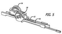
ハンドル14は、
カテーテルの遠位端部を血管内の所望の位置に固定するため位置決めワイヤをカテーテルから離れて湾曲するのが望まれるとき、位置決めワイヤ28a、28b、28c、28dが軸方向に圧縮する負荷を受けて取り付けられる状態を起こすよう構成された位置決め手段もまた有する。位置決め手段は、第1のラック52とピニオン54の組み合わせを有する。第1のピニオンはハンドルの外形から充分露出され、ユーザがピニオンを親指で回転し、それによってラック52を遠位に伸ばすことを可能にする。The
When it is desired to bend the positioning wire away from the catheter to secure the distal end of the catheter in the desired position within the vessel, the
1つの実施形態では、第1のピニオンの前方回転が位置決めワイヤを遠位に伸ばし、それによってそれらを軸方向に圧縮する負荷を受けて取り付けさせ、血管壁に対してカテーテルを押すのに適切にカテーテルの遠位端部でゆがませることによって外側に広がる状態を起こすよう、位置決めワイヤは動作可能にラックに接合される。後方回転は、位置決めワイヤを、カテーテルを引き抜くのに適切なカテーテルに近接した畳まれた状態に戻らせる。 In one embodiment, the forward rotation of the first pinion causes the positioning wires to extend distally, thereby causing them to be loaded under an axial compression and suitably adapted to push the catheter against the vessel wall The positioning wire is operably joined to the rack so as to cause outward spreading by distorting at the distal end of the catheter. The backward rotation causes the positioning wire to return to the collapsed state adjacent to the appropriate catheter to withdraw the catheter.
図11および図12に例示された別の実施形態では、第1のピニオン54の後方回転が引張構成要素を近位に伸ばし、それによって位置決めワイヤを軸方向に圧縮する負荷を受けて取り付け、よってそれらが血管壁に対してカテーテルを押すのに適切に、カテーテルの遠位端部でゆがませることによって外側に広がる状態を起こすように、引張構成要素100を動作可能にラックに接合してもよい。前方回転は、位置決めワイヤを、カテーテルを引き抜くのに適切なカテーテルに近接した畳まれた状態に戻らせる。 In another embodiment illustrated in FIGS. 11 and 12, the backward rotation of the first pinion 54 attaches under a load that extends the tension component proximally, thereby axially compressing the positioning wire, and thus The
ハンドル組立体14はさらに、カテーテルが血管内の所望の位置で位置決められると針ハイポチューブ20を進めるよう構成された血管壁貫入手段を有する。血管壁貫入手段は、これもユーザの親指の回転により作動する第2のラック56とピニオン58の組み合わせを有する。このケースでは、ラック56はハイポチューブ20に動作可能に接合され、前方回転がハイポチューブを遠位に進ませ、後方回転がそれを近位に引き抜かせる。 The
図に見られるように、2つのピニオンギア54、58は、軸方向にわずかに離れて互いに近接して位置決められ、ユーザに移動の容易性および柔軟性をもたらす。 As can be seen, the two pinion gears 54, 58 are positioned slightly apart in the axial direction and in close proximity to each other, giving the user ease of movement and flexibility.
いくつかの実施形態では、使用中に、カテーテルシステムを以下のように適用してもよい。まず第1のガイドワイヤを、患者の脈管の所望の位置へ既知の方法で通してもよい。それからカテーテル12を、薄型の構成(GIS.8、10)で経皮的にガイドワイヤ上に通してもよく、その構成では、カテーテルの先端部が患者の血管の所望の位置に到達するまで、針20の遠位先端部22がカテーテル内へ引っ込められ、位置決めワイヤ28が畳まれた状態である。カテーテルの位置決めは、既知の蛍光透視法により達成されうる。望ましくは、内科医が動脈内の針開口部の位置を観察しうるように、針開口部24を放射線不透過マーカー(図示せず)で目立たせてもよい。針開口部24が脈管内の所望の位置で正確に位置決められたとき、第1のピニオン54を前方に回転させてカテーテル内の位置決めワイヤを進めてもよい。図6、図7、および図9に見られるように、この動作は位置決めワイヤをカテーテルから離れて半径方向に広げ、それによって針開口部24を形成するカテーテルの部分を腎動脈の壁上に直接押す。第1のピニオンを既知の手段によって適切な位置に固定し、ピニオンが回転するのを一時的に抑制し、よって位置決めワイヤがその広げられた構成を失うのを抑制してもよい。図11および図12の別の実施形態では、ユーザはピニオンを後方に回転して引張構成要素100を引っ込め、それによって位置決めワイヤ28をゆがませて外側に広げ、前述の実施形態と同様の結果を得てもよい。同一の目的のため、同様の固定手段を使用してもよい。よって、血管のサイズに合うように、広げられた構成の程度を選択し、固定しうる。 In some embodiments, during use, the catheter system may be applied as follows. First, the first guidewire may be threaded in a known manner to the desired location in the patient's vasculature. The
この地点で、ユーザは第2のピニオン58を前方に回転し、それによって針20を内腔18に沿って遠位に進めてもよい。第2のピニオン58は、針先端部がカテーテルから伸びた距離、よって針先端部が動脈周囲/血管周囲の領域”P.V.”(図7)内に進んだ距離を正確に示すマークを有してもよい。 At this point, the user may rotate the
このカテーテル構成が提供する1つの利点は、図7で示されるように内腔開口部24が血管壁と直接接触するので、血管組織内へ針が貫入したに違いない正確な深さ”D”を内科医が知ることを可能にすることである。よって、全ての針の移動が血管組織内で行われる。この態様は、針が大きさが内科医に正確に分からない血管の半径方向の中心の位置から移動を開始する先行技術の特徴を解消する。従って、そのような先行技術注入装置を使用する内科医は針先端部がどれだけカテーテルの外側を移動したか分かるかもしれないが、針先端部はカテーテルと血管壁の間の分からない距離をまずカバーしなければならないので、ユーザは必ずしも針先端部がどれだけ血管壁内を移動したかは分からない。 One advantage this catheter configuration provides is the precise depth “D” that the needle must have penetrated into the vascular tissue since the
針先端部22が所望の組織の深さ”D”に進められると、選択された薬剤が既知の圧力注入手段によりハイポチューブ20を通して動脈周囲の領域内へ注入される。1つの実施形態では、薬剤は、患者の組織内の急速すぎる分散を防ぐよう、粘性の液と組み合わせて調製される。さらなる態様で、薬剤をナノ粒子または他のミクロ粒子によって粒子の形態で送達してもよい。 As the
いくつかの実施形態では、システムの使用は、後述の追加ステップを含んでもよい。薬剤が血管周囲の領域内に注入されると、カテーテル12を脈管から取り除くことなく針20をその内腔18から引き抜いてもよく、光ファイバケーブル(図示せず)を、光ケーブルの遠位先端部がカテーテルの半透明部分50内に位置するまで、空の内腔内に進めてもよい。この段階で、望ましくはレーザエネルギーの形態の光エネルギーを光ケーブルの近位端部内へ向けてもよく、結果として光エネルギーがケーブルの遠位先端部から現れ、カテーテルの半透明部分を通って血管壁およびそれ故に血管を取り囲む組織内へ通る。前述のような光活性化の処理により、動脈周囲の領域に注入された薬剤を活性化し、腎神経にその神経毒性効果を提供し、それによって所望の神経調節効果を提供してもよい。 In some embodiments, use of the system may include additional steps described below. When the drug is injected into the area surrounding the blood vessel, the
カテーテルを、例えばポリエチレン、ポリビニルクロリド、ポリエステル、ポリアミド、ポリイミド、ポリウレタン、および複合材料のようなすでに血管内カテーテルで有用であることが分かっている材料を押出およびネッキングすることによって、従来の技術により形成可能である。種々の構成要素を、融着または接着剤の使用のような従来の接着方法を用いて密着してもよい。カテーテル軸の設計について従来知られるような、チューブの1つまたは複数の層または区画で形成される1つまたは複数のチューブ状部材を含んだ、さまざまな適切な構成を使用可能である。 The catheter is formed by conventional techniques by extruding and necking materials already known to be useful in intravascular catheters, such as polyethylene, polyvinyl chloride, polyester, polyamide, polyimide, polyurethane, and composite materials. Is possible. The various components may be brought into close contact using conventional bonding methods such as fusion or the use of adhesives. A variety of suitable configurations can be used, including one or more tubular members formed of one or more layers or sections of tubing, as is known in the art for catheter shaft designs.
「カテーテル」の語は、患者の脈管を通して経皮的に進むよう構成された細長形の構造を通常有するさまざまな装置設計をいうと理解すべきである。本発明を特定の実施形態に関して本明細書に記載したが、その範囲から逸脱することなく種々の修正および改良を本発明になしうることを、当業者は理解するだろう。また、本発明の1つの実施形態の個々の機能を本明細書に述べ、または1つの実施形態の図に示し、他の実施形態ではそうしなかったかもしれないが、1つの実施形態の個々の機能を他の実施形態の1つまたは複数の機能、または複数の実施形態からの機能と組み合わせてもよいことは明らかであるはずである。 The term “catheter” should be understood to refer to various device designs that typically have an elongated structure configured to be percutaneously advanced through a patient's vessel. Although the invention has been described herein with reference to specific embodiments, those skilled in the art will recognize that various modifications and improvements can be made to the invention without departing from the scope thereof. Also, the individual functions of one embodiment of the present invention are described herein or shown in the drawings of one embodiment and may not have been done in other embodiments, but the individual features of one embodiment It should be apparent that these functions may be combined with one or more functions of other embodiments or functions from multiple embodiments.
もちろん本発明を、本発明の本質的な特性から逸脱することなく本明細書で述べた以外の他の特定の方法で実行してもよい。従って示された実施形態は、全ての点で一例であって制限するものではないとして考えられるべきであり、本発明の範囲を以下の請求項に記載する。 Of course, the present invention may be implemented in other specific ways than those described herein without departing from the essential characteristics of the invention. Accordingly, the illustrated embodiments are to be considered in all respects as illustrative and not restrictive, and the scope of the invention is set forth in the following claims.
Claims (16)
Translated fromJapanese内腔内に摺動可能に受け入れられ、鋭くした遠位先端部を有し、かつ前記カテーテルに対して前記遠位先端部が前記内腔内に完全に収容される引っ込められた状態、および
前記遠位先端部が前記遠位開口部から突出する進められた状態を有するよう構成されるハイポチューブと、
前記カテーテルの外部を伸び、前記カテーテルに対して、それぞれのワイヤが前記カテーテルの外壁に対して畳まれた血管内の送達のための拡張されていない状態、および前記それぞれのワイヤが前記カテーテルから離れて、前記細長い軸から離れて半径方向に伸びる想像上の面に沿って曲げられた血管内の前記カテーテルの位置決めのための拡張状態を有するよう構成され、前記曲げられたワイヤにより占められた全ての想像上の半径方向の面が180度以下の細長い軸の周辺の角度を持つ弧の内に含まれ、前記拡張状態の前記曲げられたワイヤが、前記角度を持つ弧が前記遠位開口部の位置の実質的に直径方向に反対側である中心を有するように前記カテーテルに対して位置付けられる複数の位置決めワイヤと、を備える、
血管内治療システム。A catheter having an elongate shaft defining a lumen configured to receive a hypotube, the lumen terminating in a distal opening in the outer sidewall of the catheter;
A retracted condition slidably received within the lumen, having a sharpened distal tip, and wherein the distal tip is fully contained within the lumen with respect to the catheter; and A hypotube configured to have an advanced state in which a distal tip projects from the distal opening;
Unextended condition for intravascular delivery extending out of the catheter and with each wire folded against the outer wall of the catheter, and the respective wire is separated from the catheter All configured to have an expanded state for positioning of the catheter in a blood vessel bent along an imaginary plane extending radially away from the elongate axis and occupied by the bent wire The imaginary radial plane of the wire is included in an arc having an angle around an elongated axis of 180 degrees or less, and the bent wire in the expanded state has the arc having the angle formed in the distal opening. A plurality of positioning wires positioned relative to the catheter to have a center that is substantially diametrically opposite the position of
Endovascular treatment system.
前記カテーテルに前記軸に垂直に向けられた力を加え、それによって前記カテーテルの外部の側壁を血管壁と接触させるステップと、
鋭くした遠位先端部を有するハイポチューブを前記カテーテル内の内腔の開口部を通して進め、それによって前記カテーテルの前記外部の側壁が前記血管壁と接触した箇所で前記血管壁に前記鋭くした先端部で貫入するステップと、
薬剤を前記ハイポチューブを通して血管周囲の領域内へ注入するステップと、を含む、
医学的状態について患者を治療する方法。Advancing a catheter having an elongated shaft into a patient's blood vessel;
Applying a force directed perpendicular to the axis to the catheter, thereby bringing the outer sidewall of the catheter into contact with the vessel wall;
A hypotube having a sharpened distal tip is advanced through a lumen opening in the catheter so that the sharpened tip on the vessel wall where the outer side wall of the catheter contacts the vessel wall Steps to penetrate with,
Injecting a drug through the hypotube into the area surrounding the blood vessel.
How to treat a patient for a medical condition.
Applications Claiming Priority (3)
| Application Number | Priority Date | Filing Date | Title |
|---|---|---|---|
| US13/586,746 | 2012-08-15 | ||
| US13/586,746US9033917B2 (en) | 2012-08-15 | 2012-08-15 | Needle catheter for delivery of agents directly into vessel wall |
| PCT/US2013/054188WO2014028306A1 (en) | 2012-08-15 | 2013-08-08 | Needle catheter for delivery of agents directly into vessel wall |
Publications (3)
| Publication Number | Publication Date |
|---|---|
| JP2015524736Atrue JP2015524736A (en) | 2015-08-27 |
| JP2015524736A5 JP2015524736A5 (en) | 2016-09-29 |
| JP6193997B2 JP6193997B2 (en) | 2017-09-06 |
Family
ID=49029220
Family Applications (1)
| Application Number | Title | Priority Date | Filing Date |
|---|---|---|---|
| JP2015527497AExpired - Fee RelatedJP6193997B2 (en) | 2012-08-15 | 2013-08-08 | Needle catheter that delivers drug directly into the vessel wall |
Country Status (5)
| Country | Link |
|---|---|
| US (1) | US9033917B2 (en) |
| EP (1) | EP2885041B1 (en) |
| JP (1) | JP6193997B2 (en) |
| CN (1) | CN104661699B (en) |
| WO (1) | WO2014028306A1 (en) |
Families Citing this family (45)
| Publication number | Priority date | Publication date | Assignee | Title |
|---|---|---|---|---|
| US9636174B2 (en) | 2002-04-08 | 2017-05-02 | Medtronic Ardian Luxembourg S.A.R.L. | Methods for therapeutic renal neuromodulation |
| US20080213331A1 (en) | 2002-04-08 | 2008-09-04 | Ardian, Inc. | Methods and devices for renal nerve blocking |
| US8150519B2 (en) | 2002-04-08 | 2012-04-03 | Ardian, Inc. | Methods and apparatus for bilateral renal neuromodulation |
| US20070129761A1 (en) | 2002-04-08 | 2007-06-07 | Ardian, Inc. | Methods for treating heart arrhythmia |
| US7617005B2 (en) | 2002-04-08 | 2009-11-10 | Ardian, Inc. | Methods and apparatus for thermally-induced renal neuromodulation |
| US20070135875A1 (en) | 2002-04-08 | 2007-06-14 | Ardian, Inc. | Methods and apparatus for thermally-induced renal neuromodulation |
| JP5219518B2 (en) | 2004-12-09 | 2013-06-26 | ザ ファウンドリー, エルエルシー | Aortic valve repair |
| JP5759615B2 (en) | 2011-04-08 | 2015-08-05 | コヴィディエン リミテッド パートナーシップ | Iontophoretic catheter system and method for renal sympathetic denervation and iontophoretic drug delivery |
| US9486276B2 (en) | 2012-10-11 | 2016-11-08 | Tva Medical, Inc. | Devices and methods for fistula formation |
| US20140200639A1 (en) | 2013-01-16 | 2014-07-17 | Advanced Neuromodulation Systems, Inc. | Self-expanding neurostimulation leads having broad multi-electrode arrays |
| CN105228683B (en) | 2013-03-14 | 2022-06-10 | Tva医疗公司 | Fistula-forming device and method for forming fistula |
| EP3653156B1 (en) | 2013-10-25 | 2023-08-02 | Intuitive Surgical Operations, Inc. | Flexible instrument with grooved steerable tube |
| US11007026B2 (en)* | 2013-10-25 | 2021-05-18 | Intuitive Surgical Operations, Inc. | Flexible instrument with embedded actuation conduits |
| JP6268673B2 (en)* | 2014-03-17 | 2018-01-31 | ニプロ株式会社 | Child catheter |
| US11826172B2 (en) | 2014-05-06 | 2023-11-28 | St. Jude Medical, Cardiology Division, Inc. | Electrode support structure assembly |
| US10118022B2 (en) | 2014-06-05 | 2018-11-06 | St. Jude Medical, Cardiology Division, Inc. | Deflectable catheter shaft section |
| US9844645B2 (en) | 2014-06-17 | 2017-12-19 | St. Jude Medical, Cardiology Division, Inc. | Triple coil catheter support |
| US10898096B2 (en) | 2014-10-27 | 2021-01-26 | St. Jude Medical, Cardiology Division, Inc. | Apparatus and method for connecting elements in medical devices |
| CN107205774B (en) | 2015-01-28 | 2020-05-29 | 圣犹达医疗用品心脏病学部门有限公司 | Thermal mapping catheter |
| US10603040B1 (en) | 2015-02-09 | 2020-03-31 | Tva Medical, Inc. | Methods for treating hypertension and reducing blood pressure with formation of fistula |
| WO2016176515A1 (en)* | 2015-04-28 | 2016-11-03 | Kassab Ghassan S | Materials and methods of using the same to improve structural integrity of a wall of a mammalian luminal organ |
| US10602983B2 (en) | 2015-05-08 | 2020-03-31 | St. Jude Medical International Holding S.À R.L. | Integrated sensors for medical devices and method of making integrated sensors for medical devices |
| CN114668490B (en) | 2015-10-21 | 2025-10-03 | 圣犹达医疗用品心脏病学部门有限公司 | High-density electrode mapping catheter |
| EP4205685B1 (en) | 2015-10-21 | 2024-08-28 | St. Jude Medical, Cardiology Division, Inc. | High density electrode mapping catheter |
| US10874422B2 (en) | 2016-01-15 | 2020-12-29 | Tva Medical, Inc. | Systems and methods for increasing blood flow |
| JP7219090B2 (en) | 2016-01-15 | 2023-02-07 | ティーブイエー メディカル, インコーポレイテッド | Systems and methods for gluing vessels |
| WO2017124062A1 (en) | 2016-01-15 | 2017-07-20 | Tva Medical, Inc. | Devices and methods for forming a fistula |
| CN114042224B (en) | 2016-01-15 | 2024-09-17 | Tva医疗公司 | Device and method for advancing a wire |
| EP3858277B1 (en) | 2016-05-03 | 2023-02-22 | St. Jude Medical, Cardiology Division, Inc. | Irrigated high density electrode catheter |
| WO2018080985A1 (en) | 2016-10-24 | 2018-05-03 | St. Jude Medical, Cardiology Division, Inc. | Catheter insertion devices |
| US11172858B2 (en) | 2016-10-28 | 2021-11-16 | St. Jude Medical, Cardiology Division, Inc. | Flexible high-density mapping catheter |
| US12011549B2 (en) | 2017-01-19 | 2024-06-18 | St. Jude Medical, Cardiology Division, Inc. | Sheath visualization |
| US10912566B2 (en)* | 2017-03-27 | 2021-02-09 | Boston Scientific Scimed, Inc. | Systems and methods to effect movement of tissue structures |
| US11647935B2 (en) | 2017-07-24 | 2023-05-16 | St. Jude Medical, Cardiology Division, Inc. | Masked ring electrodes |
| CN111278497B (en) | 2017-11-28 | 2024-01-12 | 圣犹达医疗用品心脏病学部门有限公司 | Lumen control catheter |
| US11116561B2 (en) | 2018-01-24 | 2021-09-14 | Medtronic Ardian Luxembourg S.A.R.L. | Devices, agents, and associated methods for selective modulation of renal nerves |
| EP3768185B1 (en) | 2018-05-21 | 2023-06-14 | St. Jude Medical, Cardiology Division, Inc. | Radio-frequency ablation and direct current electroporation catheters |
| US12156979B2 (en) | 2018-05-21 | 2024-12-03 | St. Jude Medical, Cardiology Division, Inc. | Deflectable catheter shaft with pullwire anchor feature |
| WO2020039392A2 (en) | 2018-08-23 | 2020-02-27 | St. Jude Medical, Cardiology Division, Inc. | Curved high density electrode mapping catheter |
| US12082936B2 (en) | 2018-09-27 | 2024-09-10 | St. Jude Medical, Cardiology Division, Inc. | Uniform mapping balloon |
| US11918762B2 (en) | 2018-10-03 | 2024-03-05 | St. Jude Medical, Cardiology Division, Inc. | Reduced actuation force electrophysiology catheter handle |
| US20210186601A1 (en)* | 2019-12-23 | 2021-06-24 | Ethicon, Inc. | Transesophageal Catheter for Thermal Protection of the Esophagus |
| WO2022038546A1 (en) | 2020-08-18 | 2022-02-24 | St. Jude Medical, Cardiology Division, Inc. | High-density electrode catheters with magnetic position tracking |
| CN115530910B (en)* | 2022-10-21 | 2024-10-29 | 苏州心锐医疗科技有限公司 | Quantitative medical liquid conveying system |
| US20250144382A1 (en)* | 2023-11-03 | 2025-05-08 | Theraheart Inc. | Expandable apposition elements for shunting catheters |
Citations (6)
| Publication number | Priority date | Publication date | Assignee | Title |
|---|---|---|---|---|
| JP2002514111A (en)* | 1997-04-11 | 2002-05-14 | トランスバスキュラー インコーポレイテッド | Catheter and related devices for forming passages between blood vessels or other anatomical structures |
| US6726677B1 (en)* | 1995-10-13 | 2004-04-27 | Transvascular, Inc. | Stabilized tissue penetrating catheters |
| US20050096590A1 (en)* | 2003-10-30 | 2005-05-05 | Medtronic Inc. | Steerable catheter |
| US20050148929A1 (en)* | 2003-11-17 | 2005-07-07 | Bruce Gingles | Catheter with centering wire |
| JP2008540060A (en)* | 2005-05-19 | 2008-11-20 | スピラス メディカル インコーポレーテッド | Rotating advance catheter insertion system |
| JP2012020105A (en)* | 2010-06-18 | 2012-02-02 | Olympus Corp | Catheter |
Family Cites Families (21)
| Publication number | Priority date | Publication date | Assignee | Title |
|---|---|---|---|---|
| DE1466889B1 (en)* | 1965-07-28 | 1970-04-23 | Eberhard Dr Regenbogen | Rectoscope for endoscopy of the area of the human intestine known as the sigma |
| US4578061A (en) | 1980-10-28 | 1986-03-25 | Lemelson Jerome H | Injection catheter and method |
| US5509900A (en) | 1992-03-02 | 1996-04-23 | Kirkman; Thomas R. | Apparatus and method for retaining a catheter in a blood vessel in a fixed position |
| DE4235506A1 (en) | 1992-10-21 | 1994-04-28 | Bavaria Med Tech | Drug injection catheter |
| DE4408108A1 (en) | 1994-03-10 | 1995-09-14 | Bavaria Med Tech | Catheter for injecting a fluid or a drug |
| US5464395A (en) | 1994-04-05 | 1995-11-07 | Faxon; David P. | Catheter for delivering therapeutic and/or diagnostic agents to the tissue surrounding a bodily passageway |
| US6283951B1 (en) | 1996-10-11 | 2001-09-04 | Transvascular, Inc. | Systems and methods for delivering drugs to selected locations within the body |
| ATE440559T1 (en) | 1995-10-13 | 2009-09-15 | Medtronic Vascular Inc | DEVICE FOR INTERSTITIAL TRANSVASCULAR PROCEDURES |
| US6375615B1 (en) | 1995-10-13 | 2002-04-23 | Transvascular, Inc. | Tissue penetrating catheters having integral imaging transducers and their methods of use |
| GB2327614B (en) | 1997-07-30 | 2002-03-06 | Univ Dundee | A hypodermic needle |
| WO1999065561A1 (en) | 1998-06-19 | 1999-12-23 | Cordis Webster, Inc. | Method and apparatus for transvascular treatment of tachycardia and fibrillation |
| ES2228165T3 (en) | 1998-12-09 | 2005-04-01 | Cook Incorporated | HOLLOW NEEDLE, CURVED, SUPERELASTIC, FOR MEDICAL USE. |
| US6217554B1 (en) | 1999-02-12 | 2001-04-17 | Pharmaspec Corporation | Methods and apparatus for delivering substances into extravascular tissue |
| US6302870B1 (en) | 1999-04-29 | 2001-10-16 | Precision Vascular Systems, Inc. | Apparatus for injecting fluids into the walls of blood vessels, body cavities, and the like |
| US6213976B1 (en) | 1999-07-22 | 2001-04-10 | Advanced Research And Technology Institute, Inc. | Brachytherapy guide catheter |
| US6629987B1 (en) | 1999-07-30 | 2003-10-07 | C. R. Bard, Inc. | Catheter positioning systems |
| US6458098B1 (en) | 2000-03-17 | 2002-10-01 | Nozomu Kanesaka | Vascular therapy device |
| JP4229621B2 (en) | 2002-03-05 | 2009-02-25 | 修 加藤 | Chemical injection catheter |
| US7141041B2 (en) | 2003-03-19 | 2006-11-28 | Mercator Medsystems, Inc. | Catheters having laterally deployable needles |
| US20060167437A1 (en) | 2003-06-17 | 2006-07-27 | Flowmedica, Inc. | Method and apparatus for intra aortic substance delivery to a branch vessel |
| DE102007052513A1 (en) | 2007-10-26 | 2009-04-30 | Karl Storz Gmbh & Co. Kg | Medical instrument with laterally expandable injection needles |
- 2012
- 2012-08-15USUS13/586,746patent/US9033917B2/enactiveActive
- 2013
- 2013-08-08WOPCT/US2013/054188patent/WO2014028306A1/enactiveApplication Filing
- 2013-08-08EPEP13752760.2Apatent/EP2885041B1/ennot_activeNot-in-force
- 2013-08-08CNCN201380042759.XApatent/CN104661699B/ennot_activeExpired - Fee Related
- 2013-08-08JPJP2015527497Apatent/JP6193997B2/ennot_activeExpired - Fee Related
Patent Citations (6)
| Publication number | Priority date | Publication date | Assignee | Title |
|---|---|---|---|---|
| US6726677B1 (en)* | 1995-10-13 | 2004-04-27 | Transvascular, Inc. | Stabilized tissue penetrating catheters |
| JP2002514111A (en)* | 1997-04-11 | 2002-05-14 | トランスバスキュラー インコーポレイテッド | Catheter and related devices for forming passages between blood vessels or other anatomical structures |
| US20050096590A1 (en)* | 2003-10-30 | 2005-05-05 | Medtronic Inc. | Steerable catheter |
| US20050148929A1 (en)* | 2003-11-17 | 2005-07-07 | Bruce Gingles | Catheter with centering wire |
| JP2008540060A (en)* | 2005-05-19 | 2008-11-20 | スピラス メディカル インコーポレーテッド | Rotating advance catheter insertion system |
| JP2012020105A (en)* | 2010-06-18 | 2012-02-02 | Olympus Corp | Catheter |
Also Published As
| Publication number | Publication date |
|---|---|
| US20140052052A1 (en) | 2014-02-20 |
| WO2014028306A1 (en) | 2014-02-20 |
| CN104661699B (en) | 2016-06-08 |
| EP2885041A1 (en) | 2015-06-24 |
| EP2885041B1 (en) | 2015-12-30 |
| US9033917B2 (en) | 2015-05-19 |
| CN104661699A (en) | 2015-05-27 |
| JP6193997B2 (en) | 2017-09-06 |
Similar Documents
| Publication | Publication Date | Title |
|---|---|---|
| JP6193997B2 (en) | Needle catheter that delivers drug directly into the vessel wall | |
| US5425703A (en) | Method and apparatus for inducing the permeation of medication into internal tissue | |
| US20020095197A1 (en) | Application of photochemotherapy for the treatment of cardiac arrhythmias | |
| US6058937A (en) | Photodynamic Therapy of highly vascularized tissue | |
| EP0814719B1 (en) | Ultrasound therapy device | |
| US20150080709A1 (en) | Implantable Medical Devices, Methods of Use, and Apparatus for Extraction Thereof | |
| CA2339384C (en) | Improved method for targeted topical treatment of disease | |
| EP2866891A1 (en) | Devices and methods for photodynamically modulating neural function in a human | |
| Ayaru et al. | Photodynamic therapy for pancreatic and biliary tract carcinoma | |
| AU2002314846B2 (en) | Method for improving treatment selectivity and efficacy using intravascular photodynamic therapy | |
| AU2002314846A1 (en) | Method for improving treatment selectivity and efficacy using intravascular photodynamic therapy | |
| Land | Porphyrin phototherapy of human cancer | |
| EP1166784B1 (en) | Inhibition of vascular restenosis after angioplasty | |
| US20130116496A1 (en) | Apparatus and method for radiation treatment of a desired area in the renal vascular system of a patient | |
| Narciso Jr et al. | SnET2 for the treatment of vascular disease: dose/response study in New Zealand white (NZW) rabbits | |
| Nyamekye et al. | Adjunctive arterial injury and photodynamic therapy with aluminium disulphonated phthalocyanine inhibits intimal hyperplasia | |
| Rosenthal | Studies of the laser thermal probe in cardiovascular disease | |
| HK1123191A (en) | Treatment of esophageal high grade dysplasia using photodynamic therapy |
Legal Events
| Date | Code | Title | Description |
|---|---|---|---|
| A529 | Written submission of copy of amendment under article 34 pct | Free format text:JAPANESE INTERMEDIATE CODE: A529 Effective date:20150317 | |
| A521 | Request for written amendment filed | Free format text:JAPANESE INTERMEDIATE CODE: A523 Effective date:20160805 | |
| A621 | Written request for application examination | Free format text:JAPANESE INTERMEDIATE CODE: A621 Effective date:20160805 | |
| A871 | Explanation of circumstances concerning accelerated examination | Free format text:JAPANESE INTERMEDIATE CODE: A871 Effective date:20160805 | |
| A975 | Report on accelerated examination | Free format text:JAPANESE INTERMEDIATE CODE: A971005 Effective date:20160906 | |
| A131 | Notification of reasons for refusal | Free format text:JAPANESE INTERMEDIATE CODE: A131 Effective date:20161025 | |
| A521 | Request for written amendment filed | Free format text:JAPANESE INTERMEDIATE CODE: A523 Effective date:20170105 | |
| A131 | Notification of reasons for refusal | Free format text:JAPANESE INTERMEDIATE CODE: A131 Effective date:20170214 | |
| A521 | Request for written amendment filed | Free format text:JAPANESE INTERMEDIATE CODE: A523 Effective date:20170502 | |
| TRDD | Decision of grant or rejection written | ||
| A01 | Written decision to grant a patent or to grant a registration (utility model) | Free format text:JAPANESE INTERMEDIATE CODE: A01 Effective date:20170711 | |
| A61 | First payment of annual fees (during grant procedure) | Free format text:JAPANESE INTERMEDIATE CODE: A61 Effective date:20170810 | |
| R150 | Certificate of patent or registration of utility model | Ref document number:6193997 Country of ref document:JP Free format text:JAPANESE INTERMEDIATE CODE: R150 | |
| R250 | Receipt of annual fees | Free format text:JAPANESE INTERMEDIATE CODE: R250 | |
| R250 | Receipt of annual fees | Free format text:JAPANESE INTERMEDIATE CODE: R250 | |
| R250 | Receipt of annual fees | Free format text:JAPANESE INTERMEDIATE CODE: R250 | |
| LAPS | Cancellation because of no payment of annual fees |