JP2015521525A - Tissue thickness compensator with improved visibility - Google Patents
Tissue thickness compensator with improved visibilityDownload PDFInfo
- Publication number
- JP2015521525A JP2015521525AJP2015520297AJP2015520297AJP2015521525AJP 2015521525 AJP2015521525 AJP 2015521525AJP 2015520297 AJP2015520297 AJP 2015520297AJP 2015520297 AJP2015520297 AJP 2015520297AJP 2015521525 AJP2015521525 AJP 2015521525A
- Authority
- JP
- Japan
- Prior art keywords
- staple
- tissue thickness
- thickness compensator
- anvil
- tissue
- Prior art date
- Legal status (The legal status is an assumption and is not a legal conclusion. Google has not performed a legal analysis and makes no representation as to the accuracy of the status listed.)
- Granted
Links
- 0CCCC(CI)=C=*1C(C(C)C#CCCN=O)C1C[*+]Chemical compoundCCCC(CI)=C=*1C(C(C)C#CCCN=O)C1C[*+]0.000description3
Images


Classifications
- A—HUMAN NECESSITIES
- A61—MEDICAL OR VETERINARY SCIENCE; HYGIENE
- A61B—DIAGNOSIS; SURGERY; IDENTIFICATION
- A61B17/00—Surgical instruments, devices or methods
- A61B17/068—Surgical staplers, e.g. containing multiple staples or clamps
- A—HUMAN NECESSITIES
- A61—MEDICAL OR VETERINARY SCIENCE; HYGIENE
- A61B—DIAGNOSIS; SURGERY; IDENTIFICATION
- A61B17/00—Surgical instruments, devices or methods
- A61B17/068—Surgical staplers, e.g. containing multiple staples or clamps
- A61B17/072—Surgical staplers, e.g. containing multiple staples or clamps for applying a row of staples in a single action, e.g. the staples being applied simultaneously
- A61B17/07292—Reinforcements for staple line, e.g. pledgets
- A—HUMAN NECESSITIES
- A61—MEDICAL OR VETERINARY SCIENCE; HYGIENE
- A61B—DIAGNOSIS; SURGERY; IDENTIFICATION
- A61B17/00—Surgical instruments, devices or methods
- A61B17/00491—Surgical glue applicators
- A—HUMAN NECESSITIES
- A61—MEDICAL OR VETERINARY SCIENCE; HYGIENE
- A61B—DIAGNOSIS; SURGERY; IDENTIFICATION
- A61B17/00—Surgical instruments, devices or methods
- A61B17/064—Surgical staples, i.e. penetrating the tissue
- A61B17/0643—Surgical staples, i.e. penetrating the tissue with separate closing member, e.g. for interlocking with staple
- A—HUMAN NECESSITIES
- A61—MEDICAL OR VETERINARY SCIENCE; HYGIENE
- A61B—DIAGNOSIS; SURGERY; IDENTIFICATION
- A61B17/00—Surgical instruments, devices or methods
- A61B17/068—Surgical staplers, e.g. containing multiple staples or clamps
- A61B17/0682—Surgical staplers, e.g. containing multiple staples or clamps for applying U-shaped staples or clamps, e.g. without a forming anvil
- A61B17/0686—Surgical staplers, e.g. containing multiple staples or clamps for applying U-shaped staples or clamps, e.g. without a forming anvil having a forming anvil staying below the tissue during stapling
- A—HUMAN NECESSITIES
- A61—MEDICAL OR VETERINARY SCIENCE; HYGIENE
- A61B—DIAGNOSIS; SURGERY; IDENTIFICATION
- A61B17/00—Surgical instruments, devices or methods
- A61B17/068—Surgical staplers, e.g. containing multiple staples or clamps
- A61B17/072—Surgical staplers, e.g. containing multiple staples or clamps for applying a row of staples in a single action, e.g. the staples being applied simultaneously
- A61B17/07207—Surgical staplers, e.g. containing multiple staples or clamps for applying a row of staples in a single action, e.g. the staples being applied simultaneously the staples being applied sequentially
- A—HUMAN NECESSITIES
- A61—MEDICAL OR VETERINARY SCIENCE; HYGIENE
- A61B—DIAGNOSIS; SURGERY; IDENTIFICATION
- A61B17/00—Surgical instruments, devices or methods
- A61B17/11—Surgical instruments, devices or methods for performing anastomosis; Buttons for anastomosis
- A61B17/115—Staplers for performing anastomosis, e.g. in a single operation
- A61B17/1155—Circular staplers comprising a plurality of staples
- A—HUMAN NECESSITIES
- A61—MEDICAL OR VETERINARY SCIENCE; HYGIENE
- A61B—DIAGNOSIS; SURGERY; IDENTIFICATION
- A61B90/00—Instruments, implements or accessories specially adapted for surgery or diagnosis and not covered by any of the groups A61B1/00 - A61B50/00, e.g. for luxation treatment or for protecting wound edges
- A61B90/90—Identification means for patients or instruments, e.g. tags
- A61B90/92—Identification means for patients or instruments, e.g. tags coded with colour
- A—HUMAN NECESSITIES
- A61—MEDICAL OR VETERINARY SCIENCE; HYGIENE
- A61L—METHODS OR APPARATUS FOR STERILISING MATERIALS OR OBJECTS IN GENERAL; DISINFECTION, STERILISATION OR DEODORISATION OF AIR; CHEMICAL ASPECTS OF BANDAGES, DRESSINGS, ABSORBENT PADS OR SURGICAL ARTICLES; MATERIALS FOR BANDAGES, DRESSINGS, ABSORBENT PADS OR SURGICAL ARTICLES
- A61L17/00—Materials for surgical sutures or for ligaturing blood vessels ; Materials for prostheses or catheters
- A61L17/005—Materials for surgical sutures or for ligaturing blood vessels ; Materials for prostheses or catheters containing a biologically active substance, e.g. a medicament or a biocide
- A—HUMAN NECESSITIES
- A61—MEDICAL OR VETERINARY SCIENCE; HYGIENE
- A61B—DIAGNOSIS; SURGERY; IDENTIFICATION
- A61B17/00—Surgical instruments, devices or methods
- A61B17/064—Surgical staples, i.e. penetrating the tissue
- A61B17/0644—Surgical staples, i.e. penetrating the tissue penetrating the tissue, deformable to closed position
- A—HUMAN NECESSITIES
- A61—MEDICAL OR VETERINARY SCIENCE; HYGIENE
- A61B—DIAGNOSIS; SURGERY; IDENTIFICATION
- A61B17/00—Surgical instruments, devices or methods
- A61B17/28—Surgical forceps
- A61B17/29—Forceps for use in minimally invasive surgery
- A61B17/2909—Handles
- A—HUMAN NECESSITIES
- A61—MEDICAL OR VETERINARY SCIENCE; HYGIENE
- A61B—DIAGNOSIS; SURGERY; IDENTIFICATION
- A61B17/00—Surgical instruments, devices or methods
- A61B2017/00004—(bio)absorbable, (bio)resorbable or resorptive
- A—HUMAN NECESSITIES
- A61—MEDICAL OR VETERINARY SCIENCE; HYGIENE
- A61B—DIAGNOSIS; SURGERY; IDENTIFICATION
- A61B17/00—Surgical instruments, devices or methods
- A61B2017/00477—Coupling
- A—HUMAN NECESSITIES
- A61—MEDICAL OR VETERINARY SCIENCE; HYGIENE
- A61B—DIAGNOSIS; SURGERY; IDENTIFICATION
- A61B17/00—Surgical instruments, devices or methods
- A61B2017/00526—Methods of manufacturing
- A—HUMAN NECESSITIES
- A61—MEDICAL OR VETERINARY SCIENCE; HYGIENE
- A61B—DIAGNOSIS; SURGERY; IDENTIFICATION
- A61B17/00—Surgical instruments, devices or methods
- A61B2017/00526—Methods of manufacturing
- A61B2017/0053—Loading magazines or sutures into applying tools
- A—HUMAN NECESSITIES
- A61—MEDICAL OR VETERINARY SCIENCE; HYGIENE
- A61B—DIAGNOSIS; SURGERY; IDENTIFICATION
- A61B17/00—Surgical instruments, devices or methods
- A61B2017/00535—Surgical instruments, devices or methods pneumatically or hydraulically operated
- A61B2017/00561—Surgical instruments, devices or methods pneumatically or hydraulically operated creating a vacuum
- A—HUMAN NECESSITIES
- A61—MEDICAL OR VETERINARY SCIENCE; HYGIENE
- A61B—DIAGNOSIS; SURGERY; IDENTIFICATION
- A61B17/00—Surgical instruments, devices or methods
- A61B2017/00743—Type of operation; Specification of treatment sites
- A61B2017/00818—Treatment of the gastro-intestinal system
- A—HUMAN NECESSITIES
- A61—MEDICAL OR VETERINARY SCIENCE; HYGIENE
- A61B—DIAGNOSIS; SURGERY; IDENTIFICATION
- A61B17/00—Surgical instruments, devices or methods
- A61B2017/00831—Material properties
- A61B2017/00862—Material properties elastic or resilient
- A—HUMAN NECESSITIES
- A61—MEDICAL OR VETERINARY SCIENCE; HYGIENE
- A61B—DIAGNOSIS; SURGERY; IDENTIFICATION
- A61B17/00—Surgical instruments, devices or methods
- A61B2017/00831—Material properties
- A61B2017/00876—Material properties magnetic
- A—HUMAN NECESSITIES
- A61—MEDICAL OR VETERINARY SCIENCE; HYGIENE
- A61B—DIAGNOSIS; SURGERY; IDENTIFICATION
- A61B17/00—Surgical instruments, devices or methods
- A61B2017/00831—Material properties
- A61B2017/00884—Material properties enhancing wound closure
- A—HUMAN NECESSITIES
- A61—MEDICAL OR VETERINARY SCIENCE; HYGIENE
- A61B—DIAGNOSIS; SURGERY; IDENTIFICATION
- A61B17/00—Surgical instruments, devices or methods
- A61B2017/00831—Material properties
- A61B2017/00889—Material properties antimicrobial, disinfectant
- A—HUMAN NECESSITIES
- A61—MEDICAL OR VETERINARY SCIENCE; HYGIENE
- A61B—DIAGNOSIS; SURGERY; IDENTIFICATION
- A61B17/00—Surgical instruments, devices or methods
- A61B2017/00831—Material properties
- A61B2017/00893—Material properties pharmaceutically effective
- A—HUMAN NECESSITIES
- A61—MEDICAL OR VETERINARY SCIENCE; HYGIENE
- A61B—DIAGNOSIS; SURGERY; IDENTIFICATION
- A61B17/00—Surgical instruments, devices or methods
- A61B2017/00831—Material properties
- A61B2017/00898—Material properties expandable upon contact with fluid
- A—HUMAN NECESSITIES
- A61—MEDICAL OR VETERINARY SCIENCE; HYGIENE
- A61B—DIAGNOSIS; SURGERY; IDENTIFICATION
- A61B17/00—Surgical instruments, devices or methods
- A61B2017/00831—Material properties
- A61B2017/00942—Material properties hydrophilic
- A—HUMAN NECESSITIES
- A61—MEDICAL OR VETERINARY SCIENCE; HYGIENE
- A61B—DIAGNOSIS; SURGERY; IDENTIFICATION
- A61B17/00—Surgical instruments, devices or methods
- A61B2017/00831—Material properties
- A61B2017/00951—Material properties adhesive
- A—HUMAN NECESSITIES
- A61—MEDICAL OR VETERINARY SCIENCE; HYGIENE
- A61B—DIAGNOSIS; SURGERY; IDENTIFICATION
- A61B17/00—Surgical instruments, devices or methods
- A61B17/068—Surgical staplers, e.g. containing multiple staples or clamps
- A61B17/072—Surgical staplers, e.g. containing multiple staples or clamps for applying a row of staples in a single action, e.g. the staples being applied simultaneously
- A61B2017/07214—Stapler heads
- A61B2017/07228—Arrangement of the staples
- A—HUMAN NECESSITIES
- A61—MEDICAL OR VETERINARY SCIENCE; HYGIENE
- A61B—DIAGNOSIS; SURGERY; IDENTIFICATION
- A61B17/00—Surgical instruments, devices or methods
- A61B17/068—Surgical staplers, e.g. containing multiple staples or clamps
- A61B17/072—Surgical staplers, e.g. containing multiple staples or clamps for applying a row of staples in a single action, e.g. the staples being applied simultaneously
- A61B2017/07214—Stapler heads
- A61B2017/07235—Stapler heads containing different staples, e.g. staples of different shapes, sizes or materials
- A—HUMAN NECESSITIES
- A61—MEDICAL OR VETERINARY SCIENCE; HYGIENE
- A61B—DIAGNOSIS; SURGERY; IDENTIFICATION
- A61B17/00—Surgical instruments, devices or methods
- A61B17/068—Surgical staplers, e.g. containing multiple staples or clamps
- A61B17/072—Surgical staplers, e.g. containing multiple staples or clamps for applying a row of staples in a single action, e.g. the staples being applied simultaneously
- A61B2017/07214—Stapler heads
- A61B2017/07242—Stapler heads achieving different staple heights during the same shot, e.g. using an anvil anvil having different heights or staples of different sizes
- A—HUMAN NECESSITIES
- A61—MEDICAL OR VETERINARY SCIENCE; HYGIENE
- A61B—DIAGNOSIS; SURGERY; IDENTIFICATION
- A61B17/00—Surgical instruments, devices or methods
- A61B17/068—Surgical staplers, e.g. containing multiple staples or clamps
- A61B17/072—Surgical staplers, e.g. containing multiple staples or clamps for applying a row of staples in a single action, e.g. the staples being applied simultaneously
- A61B2017/07214—Stapler heads
- A61B2017/07257—Stapler heads characterised by its anvil
- A61B2017/07264—Stapler heads characterised by its anvil characterised by its staple forming cavities, e.g. geometry or material
- A—HUMAN NECESSITIES
- A61—MEDICAL OR VETERINARY SCIENCE; HYGIENE
- A61B—DIAGNOSIS; SURGERY; IDENTIFICATION
- A61B17/00—Surgical instruments, devices or methods
- A61B17/068—Surgical staplers, e.g. containing multiple staples or clamps
- A61B17/072—Surgical staplers, e.g. containing multiple staples or clamps for applying a row of staples in a single action, e.g. the staples being applied simultaneously
- A61B2017/07214—Stapler heads
- A61B2017/07271—Stapler heads characterised by its cartridge
- A—HUMAN NECESSITIES
- A61—MEDICAL OR VETERINARY SCIENCE; HYGIENE
- A61B—DIAGNOSIS; SURGERY; IDENTIFICATION
- A61B17/00—Surgical instruments, devices or methods
- A61B17/068—Surgical staplers, e.g. containing multiple staples or clamps
- A61B17/072—Surgical staplers, e.g. containing multiple staples or clamps for applying a row of staples in a single action, e.g. the staples being applied simultaneously
- A61B2017/07214—Stapler heads
- A61B2017/07278—Stapler heads characterised by its sled or its staple holder
- A—HUMAN NECESSITIES
- A61—MEDICAL OR VETERINARY SCIENCE; HYGIENE
- A61B—DIAGNOSIS; SURGERY; IDENTIFICATION
- A61B17/00—Surgical instruments, devices or methods
- A61B17/068—Surgical staplers, e.g. containing multiple staples or clamps
- A61B17/072—Surgical staplers, e.g. containing multiple staples or clamps for applying a row of staples in a single action, e.g. the staples being applied simultaneously
- A61B2017/07214—Stapler heads
- A61B2017/07285—Stapler heads characterised by its cutter
- A—HUMAN NECESSITIES
- A61—MEDICAL OR VETERINARY SCIENCE; HYGIENE
- A61B—DIAGNOSIS; SURGERY; IDENTIFICATION
- A61B17/00—Surgical instruments, devices or methods
- A61B17/28—Surgical forceps
- A61B17/29—Forceps for use in minimally invasive surgery
- A61B2017/2901—Details of shaft
- A61B2017/2908—Multiple segments connected by articulations
- A—HUMAN NECESSITIES
- A61—MEDICAL OR VETERINARY SCIENCE; HYGIENE
- A61B—DIAGNOSIS; SURGERY; IDENTIFICATION
- A61B17/00—Surgical instruments, devices or methods
- A61B17/28—Surgical forceps
- A61B17/29—Forceps for use in minimally invasive surgery
- A61B17/2909—Handles
- A61B2017/2912—Handles transmission of forces to actuating rod or piston
- A61B2017/2919—Handles transmission of forces to actuating rod or piston details of linkages or pivot points
- A—HUMAN NECESSITIES
- A61—MEDICAL OR VETERINARY SCIENCE; HYGIENE
- A61B—DIAGNOSIS; SURGERY; IDENTIFICATION
- A61B17/00—Surgical instruments, devices or methods
- A61B17/28—Surgical forceps
- A61B17/29—Forceps for use in minimally invasive surgery
- A61B17/2909—Handles
- A61B2017/2912—Handles transmission of forces to actuating rod or piston
- A61B2017/2923—Toothed members, e.g. rack and pinion
- A—HUMAN NECESSITIES
- A61—MEDICAL OR VETERINARY SCIENCE; HYGIENE
- A61B—DIAGNOSIS; SURGERY; IDENTIFICATION
- A61B17/00—Surgical instruments, devices or methods
- A61B17/28—Surgical forceps
- A61B17/29—Forceps for use in minimally invasive surgery
- A61B2017/2926—Details of heads or jaws
- A61B2017/2927—Details of heads or jaws the angular position of the head being adjustable with respect to the shaft
- A—HUMAN NECESSITIES
- A61—MEDICAL OR VETERINARY SCIENCE; HYGIENE
- A61B—DIAGNOSIS; SURGERY; IDENTIFICATION
- A61B17/00—Surgical instruments, devices or methods
- A61B17/28—Surgical forceps
- A61B17/29—Forceps for use in minimally invasive surgery
- A61B2017/2926—Details of heads or jaws
- A61B2017/2932—Transmission of forces to jaw members
- A61B2017/2933—Transmission of forces to jaw members camming or guiding means
- A61B2017/2936—Pins in guiding slots
- A—HUMAN NECESSITIES
- A61—MEDICAL OR VETERINARY SCIENCE; HYGIENE
- A61B—DIAGNOSIS; SURGERY; IDENTIFICATION
- A61B17/00—Surgical instruments, devices or methods
- A61B17/28—Surgical forceps
- A61B17/29—Forceps for use in minimally invasive surgery
- A61B2017/2946—Locking means
- A—HUMAN NECESSITIES
- A61—MEDICAL OR VETERINARY SCIENCE; HYGIENE
- A61B—DIAGNOSIS; SURGERY; IDENTIFICATION
- A61B17/00—Surgical instruments, devices or methods
- A61B17/32—Surgical cutting instruments
- A61B2017/320052—Guides for cutting instruments
- A—HUMAN NECESSITIES
- A61—MEDICAL OR VETERINARY SCIENCE; HYGIENE
- A61B—DIAGNOSIS; SURGERY; IDENTIFICATION
- A61B90/00—Instruments, implements or accessories specially adapted for surgery or diagnosis and not covered by any of the groups A61B1/00 - A61B50/00, e.g. for luxation treatment or for protecting wound edges
- A61B90/08—Accessories or related features not otherwise provided for
- A61B2090/0807—Indication means
- A61B2090/0811—Indication means for the position of a particular part of an instrument with respect to the rest of the instrument, e.g. position of the anvil of a stapling instrument
- A—HUMAN NECESSITIES
- A61—MEDICAL OR VETERINARY SCIENCE; HYGIENE
- A61B—DIAGNOSIS; SURGERY; IDENTIFICATION
- A61B90/00—Instruments, implements or accessories specially adapted for surgery or diagnosis and not covered by any of the groups A61B1/00 - A61B50/00, e.g. for luxation treatment or for protecting wound edges
- A61B90/39—Markers, e.g. radio-opaque or breast lesions markers
- A61B2090/3937—Visible markers
- A—HUMAN NECESSITIES
- A61—MEDICAL OR VETERINARY SCIENCE; HYGIENE
- A61B—DIAGNOSIS; SURGERY; IDENTIFICATION
- A61B90/00—Instruments, implements or accessories specially adapted for surgery or diagnosis and not covered by any of the groups A61B1/00 - A61B50/00, e.g. for luxation treatment or for protecting wound edges
- A61B90/39—Markers, e.g. radio-opaque or breast lesions markers
- A61B2090/3966—Radiopaque markers visible in an X-ray image
- A—HUMAN NECESSITIES
- A61—MEDICAL OR VETERINARY SCIENCE; HYGIENE
- A61L—METHODS OR APPARATUS FOR STERILISING MATERIALS OR OBJECTS IN GENERAL; DISINFECTION, STERILISATION OR DEODORISATION OF AIR; CHEMICAL ASPECTS OF BANDAGES, DRESSINGS, ABSORBENT PADS OR SURGICAL ARTICLES; MATERIALS FOR BANDAGES, DRESSINGS, ABSORBENT PADS OR SURGICAL ARTICLES
- A61L2300/00—Biologically active materials used in bandages, wound dressings, absorbent pads or medical devices
- A61L2300/10—Biologically active materials used in bandages, wound dressings, absorbent pads or medical devices containing or releasing inorganic materials
- A61L2300/102—Metals or metal compounds, e.g. salts such as bicarbonates, carbonates, oxides, zeolites, silicates
- A—HUMAN NECESSITIES
- A61—MEDICAL OR VETERINARY SCIENCE; HYGIENE
- A61L—METHODS OR APPARATUS FOR STERILISING MATERIALS OR OBJECTS IN GENERAL; DISINFECTION, STERILISATION OR DEODORISATION OF AIR; CHEMICAL ASPECTS OF BANDAGES, DRESSINGS, ABSORBENT PADS OR SURGICAL ARTICLES; MATERIALS FOR BANDAGES, DRESSINGS, ABSORBENT PADS OR SURGICAL ARTICLES
- A61L2300/00—Biologically active materials used in bandages, wound dressings, absorbent pads or medical devices
- A61L2300/20—Biologically active materials used in bandages, wound dressings, absorbent pads or medical devices containing or releasing organic materials
- A61L2300/23—Carbohydrates
- A61L2300/232—Monosaccharides, disaccharides, polysaccharides, lipopolysaccharides
- A—HUMAN NECESSITIES
- A61—MEDICAL OR VETERINARY SCIENCE; HYGIENE
- A61L—METHODS OR APPARATUS FOR STERILISING MATERIALS OR OBJECTS IN GENERAL; DISINFECTION, STERILISATION OR DEODORISATION OF AIR; CHEMICAL ASPECTS OF BANDAGES, DRESSINGS, ABSORBENT PADS OR SURGICAL ARTICLES; MATERIALS FOR BANDAGES, DRESSINGS, ABSORBENT PADS OR SURGICAL ARTICLES
- A61L2300/00—Biologically active materials used in bandages, wound dressings, absorbent pads or medical devices
- A61L2300/40—Biologically active materials used in bandages, wound dressings, absorbent pads or medical devices characterised by a specific therapeutic activity or mode of action
- A61L2300/45—Mixtures of two or more drugs, e.g. synergistic mixtures
- F—MECHANICAL ENGINEERING; LIGHTING; HEATING; WEAPONS; BLASTING
- F04—POSITIVE - DISPLACEMENT MACHINES FOR LIQUIDS; PUMPS FOR LIQUIDS OR ELASTIC FLUIDS
- F04C—ROTARY-PISTON, OR OSCILLATING-PISTON, POSITIVE-DISPLACEMENT MACHINES FOR LIQUIDS; ROTARY-PISTON, OR OSCILLATING-PISTON, POSITIVE-DISPLACEMENT PUMPS
- F04C2270/00—Control; Monitoring or safety arrangements
- F04C2270/04—Force
- F04C2270/042—Force radial
- F04C2270/0421—Controlled or regulated
- Y—GENERAL TAGGING OF NEW TECHNOLOGICAL DEVELOPMENTS; GENERAL TAGGING OF CROSS-SECTIONAL TECHNOLOGIES SPANNING OVER SEVERAL SECTIONS OF THE IPC; TECHNICAL SUBJECTS COVERED BY FORMER USPC CROSS-REFERENCE ART COLLECTIONS [XRACs] AND DIGESTS
- Y10—TECHNICAL SUBJECTS COVERED BY FORMER USPC
- Y10T—TECHNICAL SUBJECTS COVERED BY FORMER US CLASSIFICATION
- Y10T29/00—Metal working
- Y10T29/49—Method of mechanical manufacture
- Y10T29/49826—Assembling or joining
Landscapes
- Health & Medical Sciences (AREA)
- Life Sciences & Earth Sciences (AREA)
- Surgery (AREA)
- Engineering & Computer Science (AREA)
- General Health & Medical Sciences (AREA)
- Public Health (AREA)
- Veterinary Medicine (AREA)
- Biomedical Technology (AREA)
- Molecular Biology (AREA)
- Animal Behavior & Ethology (AREA)
- Nuclear Medicine, Radiotherapy & Molecular Imaging (AREA)
- Medical Informatics (AREA)
- Heart & Thoracic Surgery (AREA)
- Chemical & Material Sciences (AREA)
- Materials Engineering (AREA)
- Vascular Medicine (AREA)
- Epidemiology (AREA)
- Oral & Maxillofacial Surgery (AREA)
- Pathology (AREA)
- Surgical Instruments (AREA)
Abstract
Translated fromJapaneseDescription
Translated fromJapanese (関連出願の相互参照)
本出願は、米国特許法第120条に基づく、米国特許出願(END7102USNP)第13/433,129号、表題「TISSUE THICKNESS COMPENSATOR COMPRISING A PLURIALITY OF MEDICAMENTS」(2012年3月28日出願)の一部継続出願であり、この開示の全体が参照により本明細書に組み込まれる。(Cross-reference of related applications)
This application is a part of United States Patent Application (END7102USNP) No. 13 / 433,129, entitled “TISSUE THICKNESS COMPENSATOR COMPRISING A PRIMITY OF MEDICAMENTS” (filed on March 28, 2012), based on Section 120 of the United States Patent Act. This is a continuation application, the entire disclosure of which is incorporated herein by reference.
本発明は、外科用器具に関するものであり、様々な実施形態において、組織の切断及びステープリングのために設計された、外科用切断及びステープリング器具、並びにステープルカートリッジに関する。 The present invention relates to surgical instruments and, in various embodiments, to surgical cutting and stapling instruments and staple cartridges designed for tissue cutting and stapling.
本発明の特徴及び利点、並びにそれらを実現する方法は、本発明の実施形態の以下の説明を添付の図面と併せて参照することでより明らかとなり、また発明自体のより深い理解が得られるであろう。
対応する参照符号は、複数の図面の全体にわたって対応する部材を示す。本明細書において説明される例示は、一形態による本発明の特定の実施形態を示し、かかる例示は、いかなる方法によっても本発明の範囲を限定するものとして解釈されない。 Corresponding reference characters indicate corresponding parts throughout the several views. The illustrations set forth herein illustrate certain embodiments of the invention according to one aspect and such illustrations are not to be construed as limiting the scope of the invention in any way.
本出願の出願人は、また、以下に示す米国特許出願も所有し、それらのそれぞれの全内容が参照により本明細書に組み込まれる。
米国特許出願第12/894,311号、発明の名称「SURGICAL INSTRUMENTS WITH RECONFIGURABLE SHAFT SEGMENTS」(代理人整理番号第END6734USNP/100058号)、
米国特許出願第12/894,340号、発明の名称「SURGICAL STAPLE CARTRIDGES SUPPORTING NON−LINEARLY ARRANGED STAPLES AND SURGICAL STAPLING INSTRUMENTS WITH COMMON STAPEL−FORMING POCKETS」(代理人整理番号第END6735USNP/100059号)、
米国特許出願第12/894,327号、発明の名称「JAW CLOSURE ARRANGEMENTS FOR SURGICAL INSTRUMENTS」(代理人整理番号第END6736USNP/100060号)、
米国特許出願第12/894,351号、発明の名称「SURGICAL CUTTING AND FASTENING INSTRUMENTS WITH SEPARATE AND DISTINCT FASTENER DEPLOYMENT AND TISSUE CUTTING SYSTEMS」(代理人整理番号第END6839USNP/100524号)、
米国特許出願第12/894,338号、発明の名称「IMPLANTABLE FASTENER CARTRIDGE HAVING A NON−UNIFORM ARRANGEMENT」(代理人整理番号第END6840USNP/100525号)、
米国特許出願第12/894,369号、発明の名称「IMPLANTABLE FASTENER CARTRIDGE COMPRISING A SUPPORT RETAINER」(代理人整理番号第END6841USNP/100526号)、
米国特許出願12/894,312号、発明の名称「IMPLANTABLE FASTENER CARTRIDGE COMPRISING MULTIPLE LAYERS」(代理人整理番号第END6842USNP/100527号)、
米国特許出願第12/894,377号、発明の名称「SELECTIVELY ORIENTABLE IMPLANTABLE FASTENER CARTRIDGE」(代理人整理番号第END6843USNP/100528号)、
米国特許出願第12/894,339号、発明の名称「SURGICAL STAPLING INSTRUMENT WITH COMPACT ARTICULATION CONTROL ARRANGEMENT」(代理人整理番号第END6847USNP/100532号)、
米国特許出願第12/894,360号、発明の名称「SURGICAL STAPLING INSTRUMENT WITH A VARIABLE STAPLE FORMING SYSTEM」(代理人整理番号第END6848USNP/100533号)、
米国特許出願第12/894,322号、発明の名称「SURGICAL STAPLING INSTRUMENT WITH INTERCHANGEABLE STAPLE CARTRIDGE ARRANGEMENTS」(代理人整理番号第END6849USNP/100534号)、
米国特許出願第12/894,350号、発明の名称「SURGICAL STAPLE CARTRIDGES WITH DETACHABLE SUPPORT STRUCTURES AND SURGICAL STAPLING INSTRUMENTS WITH SYSTEMS FOR PREVENTING ACTUATION MOTIONS WHEN A CARTRIDGE IS NOT PRESENT」(代理人整理番号第END6855USNP/100540号)、
米国特許出願第12/894,383号、発明の名称「IMPLANTABLE FASTENER CARTRIDGE COMPRISING BIOABSORBABLE LAYERS」(代理人整理番号第END6856USNP/100541号)、
米国特許出願第12/894,389号、発明の名称「COMPRESSIBLE FASTENER CARTRIDGE」(代理人整理番号第END6857USNP/100542号)、
米国特許出願第12/894,345号、発明の名称「FASTENERS SUPPORTED BY A FASTENER CARTRIDGE SUPPORT」(代理人整理番号第END6858USNP/100543号)、
米国特許出願第12/894,306号、発明の名称「COLLAPSIBLE FASTENER CARTRIDGE」(代理人整理番号第END6859USNP/100544号)、
米国特許出願第12/894,318号、発明の名称「FASTENER SYSTEM COMPRISING A PLURALITY OF CONNECTED RETENTION MATRIX ELEMENTS」(代理人整理番号第END6860USNP/100546号)、
米国特許出願第12/894,330号、発明の名称「FASTENER SYSTEM COMPRISING A RETENTION MATRIX AND AN ALIGNMENT MATRIX」(代理人整理番号第END6861USNP/100547号)、
米国特許出願第12/894,361号、発明の名称「FASTENER SYSTEM COMPRISING A RETENTION MATRIX」(代理人整理番号第END6862USNP/100548号)、
米国特許出願第12/894,367号、発明の名称「FASTENING INSTRUMENT FOR DEPLOYING A FASTENER SYSTEM COMPRISING A RETENTION MATRIX」(代理人整理番号第END6863USNP/100549号)、
米国特許出願第12/894,388号、発明の名称「FASTENER SYSTEM COMPRISING A RETENTION MATRIX AND A COVER」(代理人整理番号第END6864USNP/100550号)、
米国特許出願第12/894,376号、発明の名称「FASTENER SYSTEM COMPRISING A PLURALITY OF FASTENER CARTRIDGES」(代理人整理番号第END6865USNP/100551号)、
米国特許出願第13/097,865号、発明の名称「SURGICAL STAPLER ANVIL COMPRISING A PLURALITY OF FORMING POCKETS」(代理人整理番号第END6735USCIP1/100059CIP1号)、
米国特許出願第13/097,936号、発明の名称「TISSUE THICKNESS COMPENSATOR FOR A SURGICAL STAPLER」(代理人整理番号第END6736USCIP1/100060CIP1号)、
米国特許出願第13/097,954号、発明の名称「STAPLE CARTRIDGE COMPRISING A VARIABLE THICKNESS COMPRESSIBLE PORTION」(代理人整理番号第END6840USCIP1/100525CIP1号)、
米国特許出願第13/097,856号、発明の名称「STAPLE CARTRIDGE COMPRISING STAPLES POSITIONED WITHIN A COMPRESSIBLE PORTION THEREOF」(代理人整理番号第END6841USCIP1/100526CIP1号)、
米国特許出願第13/097,928号、発明の名称「TISSUE THICKNESS COMPENSATOR COMPRISING DETACHABLE PORTIONS」(代理人整理番号第END6842USCIP1/100527CIP1号)、
米国特許出願第13/097,891号、発明の名称「TISSUE THICKNESS COMPENSATOR FOR A SURGICAL STAPLER COMPRISING AN ADJUSTABLE ANVIL」(代理人整理番号第END6843USCIP1/100528CIP1号)、
米国特許出願第13/097,948号、発明の名称「STAPLE CARTRIDGE COMPRISING AN ADJUSTABLE DISTAL PORTION」(代理人整理番号第END6847USCIP1/100532CIP1号)、
米国特許出願第13/097,907号、発明の名称「COMPRESSIBLE STAPLE CARTRIDGE ASSEMBLY」(代理人整理番号第END6848USCIP1/100533CIP1号)、
米国特許出願第13/097,861号、発明の名称「TISSUE THICKNESS COMPENSATOR COMPRISING PORTIONS HAVING DIFFERENT PROPERTIES」(代理人整理番号第END6849USCIP1/100534CIP1号)、
米国特許出願第13/097,869号、発明の名称「STAPLE CARTRIDGE LOADING ASSEMBLY」(代理人整理番号第END6855USCIP1/100540CIP1号)、
米国特許出願第13/097,917号、発明の名称「COMPRESSIBLE STAPLE CARTRIDGE COMPRISING ALIGNMENT MEMBERS」(代理人整理番号第END6856USCIP1/100541CIP1号)、
米国特許出願第13/097,873号、発明の名称「STAPLE CARTRIDGE COMPRISING A RELEASABLE PORTION」(代理人整理番号第END6857USCIP1/100542CIP1号)、
米国特許出願第13/097,938号、発明の名称「STAPLE CARTRIDGE COMPRISING COMPRESSIBLE DISTORTION RESISTANT COMPONENTS」(代理人整理番号第END6858USCIP1/100543CIP1号)、
米国特許出願第13/097,924号、発明の名称「STAPLE CARTRIDGE COMPRISING A TISSUE THICKNESS COMPENSATOR」(代理人整理番号第END6859USCIP1/100544CIP1号)、
米国特許出願第13/242,029号、発明の名称「SURGICAL STAPLER WITH FLOATING ANVIL」(代理人整理番号第END6841USCIP2/100526CIP2号)、
米国特許出願第13/242,066号、発明の名称「CURVED END EFFECTOR FOR A STAPLING INSTRUMENT」(代理人整理番号第END6841USCIP3/100526CIP3号)、
米国特許出願第13/242,086号、発明の名称「STAPLE CARTRIDGE INCLUDING COLLAPSIBLE DECK」(代理人整理番号第END7020USNP/110374号)、
米国特許出願第13/241,912号、発明の名称「STAPLE CARTRIDGE INCLUDING COLLAPSIBLE DECK ARRANGEMENT」(代理人整理番号第END7019USNP/110375号)、
米国特許出願第13/241,922号、発明の名称「SURGICAL STAPLER WITH STATIONARY STAPLE DRIVERS」(代理人整理番号第END7013USNP/110377号)、
米国特許出願第13/241,637号、発明の名称「SURGICAL INSTRUMENT WITH TRIGGER ASSEMBLY FOR GENERATING MULTIPLE ACTUATION MOTIONS」(代理人整理番号第END6888USNP3/110378号)、
米国特許出願第13/241,629号、発明の名称「SURGICAL INSTRUMENT WITH SELECTIVELY ARTICULATABLE END EFFECTOR」(代理人整理番号第END6888USNP2/110379号)。The applicant of this application also owns the following US patent applications, the entire contents of each of which are incorporated herein by reference:
US patent application Ser. No. 12 / 894,311, title of invention “SURGICAL INSTRUMENTS WITH RECONFIGURE SHAFFT SEGMENTS” (Attorney Docket No. END 6734 USNP / 100058),
US Patent Application No. 12 / 894,340, Title of Invention “SURGICAL STAPLE CARTRIDGES SUPPORTING NON-LINEARYLY ARRANGED STAMPLES AND SURGICAL STAPLING INSTRUMENTS WITH COMMAND ST67”
US patent application Ser. No. 12 / 894,327, title of invention “JAW CLOSER ARRANGEMENTS FOR SURGICAL INSTRUMENTS” (Attorney Docket No. END6736USNP / 100060),
US Patent Application No. 12 / 894,351, Title of Invention “SURGICAL COUNTING AND FASTENING INSTRUMENTS WITH SEPARATE AND DISTINCT FASTENER DEPLOYMENT AND TISSUE CUTTING SYSTEMS”
US patent application Ser. No. 12 / 894,338, title of invention “IMPLANTABLE FASTENER CARTRIDGE HAVING A NON-UNIFORM ARRANGEMENT” (Attorney Docket No. END 6840 USNP / 100525),
US patent application Ser. No. 12 / 894,369, title of invention “IMPLANTABLE FASTNER CARTRIDGE COMPRISING A SUPPORT RETAINER” (Attorney Docket No. END6841USNP / 100526),
US patent application Ser. No. 12 / 894,377, title of invention “SELECTIVELY ORIENTABLE IMPLANTABLE FASTENER CARTRIDGE” (Attorney Docket No. END6843USNP / 100528),
US patent application No. 12 / 894,339, title of invention “SURGICAL STAPLING INSTRUMENT WITH COMPACT ARTICULATION CONTROL ARRANGEMENT” (Attorney Docket No. END6847USNP / 100532),
US Patent Application No. 12 / 894,360, title of invention “SURGICAL STAPLING INSTRUMENT WITH A VARIABLE STAPLE FORMING SYSTEM” (Attorney Docket No. END6848USNP / 100533),
US patent application Ser. No. 12 / 894,322, title of invention “SURGICAL STAPLING INSTRUMENT WITH INTERCHANGABLE STAPLE CARTRIDGE ARRANGEENTS” (Attorney Docket No. END6849USNP / 100534),
U.S. Patent Application No. 12 / 894,350, entitled "SURGICAL STAPLE CARTRIDGES WITH DETACHABLE SUPPORT STRUCTURES AND SURGICAL STAPLING INSTRUMENTS WITH SYSTEMS FOR PREVENTING ACTUATION MOTIONS WHEN A CARTRIDGE IS NOT PRESENT" (Attorney Docket No. END6855USNP / 100540) ,
US patent application Ser. No. 12 / 894,383, title of invention “IMPLANTABLE FASTNER CARTRIDGE COMPRISING BIOABSORBABLE LAYERS” (Attorney Docket No. END 6856 USNP / 100541),
US patent application Ser. No. 12 / 894,389, title of invention “COMPRESSABLE FASTENER CARTRIDGE” (Attorney Docket No. END6857USNP / 100542),
US patent application Ser. No. 12 / 894,345, title of invention “FASTENERS SUPPORTED BY A FASTNER CARTRIDGE SUPPORT” (Attorney Docket No. END6858USNP / 100543),
US patent application Ser. No. 12 / 894,306, title of invention “COLLAPSIBLE FASTENER CARTRIDGE” (Attorney Docket No. END6859 USNP / 100544),
US patent application Ser. No. 12 / 894,318, title of invention “FASTENER SYSTEM COMPRISING A PLULARITY OF CONNECTED RETENTION MATRIX ELEMENTS” (Attorney Docket No. END6860USNP / 100546),
US patent application Ser. No. 12 / 894,330, title of invention “FASTENER SYSTEM COMPRISING A RETENTION MATRIX AND AN ALIGNMENT MATRIX” (Attorney Docket No. END6861USNP / 100547),
US patent application Ser. No. 12 / 894,361, name of invention “FASTENER SYSTEM COMPRISING A RETENTION MATRIX” (Attorney Docket No. END 6862 USNP / 100548),
US patent application Ser. No. 12 / 894,367, title of invention “FASTENING INSTRUMENT FOR DEPLOYING A FASTENER SYSTEM COMPRISING A RETENTION MATRIX” (Attorney Docket No. END 6863USNP / 100549),
US patent application Ser. No. 12 / 894,388, title of invention “FASTENER SYSTEM COMPRISING A RETENTION MATRIX AND A COVER” (Attorney Docket No. END 6864 USNP / 100550),
US patent application Ser. No. 12 / 894,376, title of invention “FASTENER SYSTEM COMPRISING A PLULARITY OF FASTENER CARTRIDGES” (Attorney Docket No. END6865USNP / 100551),
US patent application No. 13 / 097,865, title of invention "SURGICAL STAPLLER ANVIL COMPRISING A PLURALITY OF FORMING POCKETS" (Attorney Docket No.END6735USCIP1 / 100059CIP1),
US Patent Application No. 13 / 097,936, title of invention “TISSUE THICKNESS COMPENSATOR FOR A SURGICAL STAPLER” (Attorney Docket No. END6736USCIP1 / 100060CIP1),
US Patent Application No. 13 / 097,954, title of invention “STAPLE CARTRIDGE COMPRISING A VARIABLE THICKNESS COMPRESIBLE POTION” (Attorney Docket No. END6840USCIP1 / 100525CIP1),
US patent application No. 13 / 097,856, title of invention “STAPLE CARTRIDGING COMPRISING STAPLES POSITIONED WITHIN COMPRESIBLE PORTION THEREOF” (Attorney Docket No. END6841USCIP1 / 100526CIP1)
US Patent Application No. 13 / 097,928, title of invention “TISSUE THICKNESS COMPENSATOR COMPRISING DETACHABLE PORATIONS” (Attorney Docket No. END6842USCIP1 / 100527CIP1),
US patent application No. 13 / 097,891, title of invention “TISSUE THICKNESS COMPENSATOR FOR A SURGICAL STAPLERS COMPRISING AN ADJUSTABLE ANVIL” (Attorney Docket No. END6843USCIP1 / 100528CIP1)
US Patent Application No. 13 / 097,948, title of invention “STAPLE CARTRIDGE COMPRISING AN ADJUSTABLE DISPORTION” (Attorney Docket No. END6847USCIP1 / 1003542CIP1),
US Patent Application No. 13 / 097,907, title of invention “COMPRESSABLE STAPLE CARTRIDGE ASSEMBLY” (Attorney Docket No. END6848 USCIP1 / 1003353CIP1),
US Patent Application No. 13 / 097,861, title of invention “TISSUE THICKNESS COMPENSATOR COMPRISING PORTITIONs HAVING DIFFERENT PROPERIES” (Attorney Docket No. END6849USCIP1 / 100534CIP1),
US patent application No. 13 / 097,869, title of invention “STAPLE CARTRIDGE LOADING ASSEMBLY” (Attorney Docket No. END6855 USCIP1 / 100540CIP1),
US Patent Application No. 13 / 097,917, title of invention “COMPRESSABLE STAPLE CARTRIDGE COMPRISING ALIGNMENT MEMBERS” (Attorney Docket No. END6856USCIP1 / 1001541CIP1),
U.S. Patent Application No. 13 / 097,873, title of invention "STAPLE CARTRIDGE COMPRISING A RELEASABLE POTION" (Attorney Docket No. END6857USCIP1 / 100542CIP1),
US Patent Application No. 13 / 097,938, title of the invention “STAPLE CARTRIDGE COMPRISING COMPRESIBLE DISTORTION RESISTANT COMPONENTS” (Attorney Docket No. END6858USCIP1 / 1003153CIP1),
US patent application No. 13 / 097,924, title of invention “STAPLE CARTRIDGE COMPRISING A TISSUE THICKNESS COMPENSATOR” (Attorney Docket No. END6859USCIP1 / 100544CIP1),
US patent application No. 13 / 242,029, title of invention "SURGICAL STAPLER WITH FLOATING ANVIL" (Attorney Docket No. END6841USCIP2 / 100526CIP2),
US Patent Application No. 13 / 242,066, title of invention “CURVED END EFFECTOR FOR A STAPLING INSTRUMENT” (Attorney Docket No. END6841USCIP3 / 100526CIP3),
US Patent Application No. 13 / 242,086, title of invention “STAPLE CARTRIDGE INCLUDING COLLAPSIBLE DECK” (Attorney Docket No. END7020USNP / 110374),
US patent application No. 13 / 241,912, title of invention “STAPLE CARTRIDGE INCLUDING COLLAPSIBLE DECK ARRANGEMENT” (Attorney Docket No. END7019 USNP / 110375),
U.S. Patent Application No. 13 / 241,922, title of invention "SURGICAL STAPLIER WITH STATIONARY STAPLE DRIVERS" (Attorney Docket No.END7013USNP / 110377),
US Patent Application No. 13 / 241,637, Title of Invention “SURGICAL INSTRUMENT WITH TRIGGER ASSEMBLY FOR GENERATION MULTIPTION ACTION MOTIONS” (Attorney Docket No. END6888USNP3 / 110378)
US patent application No. 13 / 241,629, title of invention “SURGICAL INSTRUMENT WITH SELECTIVELY ARTICULABLE END EFFECTOR” (Attorney Docket No. END6888USNP2 / 110379).
本出願の出願人は、また、本明細書と同日に出願され、それらの全ての内容がそれぞれ、参照によって本明細書に組み込まれる、以下に示す米国特許出願も所有する。
米国特許出願第13/433,096号、発明の名称「TISSUE THICKNESS COMPENSATOR COMPRISING A PLURALITY OF CAPSULES」である(代理人整理番号END6864USCIP1/100550CIP1);
米国特許出願第13/433,103号、発明の名称「TISSUE 13/433,103 THICKNESS COMPENSATOR COMPRISING A PLURALITY OF LAYERS」(代理人整理番号第END6864USCIP2/100550CIP2号);
米国特許出願第13/433,098号、発明の名称「EXPANDABLE TISSUE THICKNESS COMPENSATOR」である(代理人整理番号END6843USCIP2/100528CIP2);
米国特許出願第13/433,102号、発明の名称「TISSUE THICKNESS COMPENSATOR COMPRISING A RESERVOIR」(代理人整理番号第END6843USCIP3/100528CIP3)
米国出願第13/433,114号、発明の名称「組織厚さコンペンセータを含む保持器アセンブリ」(代理人整理番号END6843USCIP4/100528CIP4)。
米国出願第13/433,136号、発明の名称「少なくとも1つの薬剤を含む組織厚さコンペンセータ」(代理人整理番号END6843USCIP5/100528CIP5)。
米国特許出願第13/433,141号、発明の名称「TISSUE THICKNESS COMPENSATOR COMPRISING CONTROLLED RELEASE AND EXPANSION」、(代理人整理番号第END6843USCIP6/100528CIP6);
米国特許出願第13/433,144号、発明の名称「TISSUE THICKNESS COMPENSATOR COMPRISING FIBERS TO PRODUCE A RESILIENT LOAD」、(代理人整理番号第END6843USCIP7/100528CIP7);
米国特許出願番号第13/433,148号、発明の名称「Tissue Thickness Compensator Comprising Structure To Produce A Resilient Load」(代理人整理番号第END6843USCIP8/100528CIP8号);
米国特許出願第13/433,155号、発明の名称が「TISSUE THICKNESS COMPENSATOR COMPRISING RESILIENT MEMBERS」である(代理人整理番号END6843USCIP9/100528CIP9);
米国特許出願第13/433,163号、発明の名称「METHODS FOR FORMING TISSUE THICKNESS COMPENSATOR ARRANGEMENTS FOR SURGICAL STAPLERS」(代理人整理番号END6843USCIP10/100528CP10);
米国出願第13/433,167号、発明の名称「組織厚さコンペンセータ」(代理人整理番号END6843USCIP11/100528CP11)。
米国特許出願番号第13/433,175号、発明の名称「Layered Tissue Thickness Compensator」(代理人整理番号第END6843USCIP12/100528CP12号)、
米国特許出願第13/433,179号、発明の名称「TISSUE THICKNESS COMPENSATORS FOR CIRCULAR SURGICAL STAPLERS」(代理人整理番号END6843USCIP13/100528CP13);
米国出願第13/433,115号、発明の名称「低圧力環境を規定するカプセルを含む組織厚さコンペンセータ」(代理人整理番号END7100USNP/110601);
米国特許出願第13/433,118号、発明の名称「TISSUE THICKNESS COMPENSATOR COMPRISED OF A PLURALITY OF MATERIALS」、(代理人整理番号第END7101USNP/110602);
米国特許出願第13/433,135号、発明の名称「MOVABLE MEMBER FOR USE WITH A TISSUE THICKNESS COMPENSATOR」(代理人整理番号第END7107USNP/110603号);
米国特許出願第13/433,140号、発明の名称「TISSUE THICKNESS COMPENSATOR AND METHOD FOR MAKING THE SAME」(代理人整理番号第END7103USNP/110605号);
米国特許出願番号第13/433,147号、発明の名称「Tissue Thickness Compensator Comprising Channels」(代理人整理番号第END7104USNP/110606号)、
米国特許出願番号第13/433,126号、発明の名称「Tissue Thickness Compensator Comprising Tissue Ingrowth Features」(代理人整理番号第END7105USNP/110607号)、及び
米国出願第13/433,132号、発明の名称「DEVICES AND METHODS FOR ATTACHING TISSUE THICKNESS COMPENSATING MATERIALS TO SURGICAL STAPLING INSTRUMENTS」(代理人整理番号第END7106USNP/110608号)。The applicant of this application also owns the following US patent applications filed on the same day as this specification, the entire contents of each of which are hereby incorporated by reference:
US Patent Application No. 13 / 433,096, the title of the invention is “TISSUE THICKNESS COMPENSATOR COMPRISING A PLULARITY OF CAPSULES” (Attorney Docket Number END 6864 USCIP1 / 100550CIP1);
US Patent Application No. 13 / 433,103, title of invention “TISSUES 13 / 433,103 THICKNESS COMPENSATOR COMPRISING A PLURALITY OF LAYERS” (Attorney Docket No. END 6864 USCIP2 / 100550CIP2);
US patent application Ser. No. 13 / 433,098, entitled “EXPANDABLE TISSUE TICHKNESS COMPENSATOR” (Attorney Docket No. END6843USCIP2 / 100528CIP2);
US Patent Application No. 13 / 433,102, title of invention “TISSUE THICKNESS COMPENSATOR COMPRISING A RESERVOIR” (Attorney Docket No. END6843USCIP3 / 100528CIP3)
US application Ser. No. 13 / 433,114, entitled “Retainer assembly including tissue thickness compensator” (Attorney Docket No. END6843 USCIP4 / 100528CIP4).
US Application No. 13 / 433,136, entitled “Tissue Thickness Compensator Containing At least One Drug” (Attorney Docket No. END6843 USCIP5 / 100528CIP5).
US patent application Ser. No. 13 / 433,141, title of invention “TISSUE THICKNESS COMPENSOR COMPRISING CONTROLLED RELEASE AND EXPANSION”, (Attorney Docket No. END6843USCIP6 / 100528CIP6);
US Patent Application No. 13 / 433,144, title of invention “TISSUE THICKNESS COMPENSATOR COMPRISING FIBERS TO PRODUCE A RESILIENT LOAD” (Attorney Docket No. END6843USCIP7 / 100528CIP7);
US Patent Application No. 13 / 433,148, title of invention “Tissue Thickness Compensator Completing Structure To Produce A Resident Load” (Attorney Docket No. END6843USCIP8 / 100528CIP8);
US Patent Application No. 13 / 433,155, whose title is “TISSUE THICKNESS COMPENSATOR COMPRISING RESILIENT MEMBERS” (Attorney Docket Number END6843USCIP9 / 100528CIP9);
US Patent Application No. 13 / 433,163, Title of Invention “METHODS FOR FORMING TISSUE THICKNESS COMPENSATOR ARRANGEMENTS FOR SURGICAL STAPLERS” (Attorney Docket No. END6843USCIP10 / 100528CP10);
U.S. Application No. 13 / 433,167, entitled "Tissue Thickness Compensator" (Attorney Docket No. END6843USCIP11 / 100528CP11).
US Patent Application No. 13 / 433,175, title of invention “Layered Tissue Thickness Compensator” (Attorney Docket No. END6843USCIP12 / 100528CP12),
US Patent Application No. 13 / 433,179, title of invention “TISSUE THICKNESS COMPENSATORS FOR CIRCULAR SURGICAL STAPLERS” (Attorney Docket No. END6843USCIP13 / 100528CP13);
US application Ser. No. 13 / 433,115, entitled “Tissue Thickness Compensator with Capsules That Define Low Pressure Environment” (Attorney Docket No. END7100USNP / 110601);
US patent application Ser. No. 13 / 433,118, title of invention “TISSUE THICKNESS COMPENSOR COMPRISED OF A PLULARITY OF MATERIALS”, (Attorney Docket No. END7101USNP / 110602);
US patent application Ser. No. 13 / 433,135, title of invention “MOVABLE MEMBER FOR US WITH A TISSUE THICKNESS COMPENSATOR” (Attorney Docket No. END7107USNP / 110603);
US patent application Ser. No. 13 / 433,140, title of invention “TISSUE THICKNESS COMPENSATOR AND METHOD FOR MAKING THE SAME” (Attorney Docket No. END 7103 USNP / 110605);
US Patent Application No. 13 / 433,147, title of the invention “Tissue Thickness Compensator Compiling Channels” (Attorney Docket No. END7104USNP / 110606),
US Patent Application No. 13 / 433,126, Title of Invention “Tissue Thickness Compensator Comprising Tissue Ingredient Features” (Attorney Docket No. END7105 USNP / 110607), and US Application No. 13 / 433,132, Title of Invention "DEVICES AND METHODS FOR ATTACHING TISSUE THICKNESS COMPENSATING MATERIALS TO SURGICAL STAPLING INSTRUMENTS" (Attorney Reference Number END7106USNP / 110608).
本願で開示する装置及び方法の構造、機能、製造、及び用途の原理が総括的に理解されるように、特定の例示的実施形態について、これから説明することにする。これらの実施形態の1つ以上の例を添付図面に示す。本明細書で詳細に説明され、添付の図面に示される装置及び方法は、非限定的な例示的実施形態である点、並びに、本発明の各種の実施形態の範囲は、特許請求の範囲によってのみ定義されるものである点は、当業者であれば理解されるところであろう。1つの例示的な実施形態との関連において例示又は説明された特徴は、他の実施形態の特徴と組み合わせることができる。こうした改変及び変形は本発明の範囲内に含まれるものとする。 Certain exemplary embodiments will now be described so that the principles of structure, function, manufacture, and application of the devices and methods disclosed herein can be understood generally. One or more examples of these embodiments are illustrated in the accompanying drawings. The apparatus and methods described in detail herein and illustrated in the accompanying drawings are non-limiting exemplary embodiments, and the scope of the various embodiments of the present invention is defined by the claims. Those skilled in the art will understand that this is only defined. Features illustrated or described in the context of one exemplary embodiment may be combined with features of other embodiments. Such modifications and variations are intended to be included within the scope of the present invention.
本明細書全体を通して、「様々な実施形態」、「いくつかの実施形態」、「一実施形態」、又は「実施形態」等の参照は、その実施形態との関連において記述されている特定の特徴、構造、又は特性が、少なくとも1つの実施形態に含まれることを意味する。したがって、本明細書の全体を通じた各所で、「様々な実施形態において」、「いくつかの実施形態において」、「1つの実施形態において」、又は「ある実施形態において」などの語句が出現するが、これらは必ずしも全てが、同じ実施形態を指すわけではない。更に、特定の特徴、構造、又は特性は、1つ以上の実施形態で、任意の好適なやり方で組み合わせることができる。故に、一実施形態に関して図示又は記載される特定の特徴、構造、又は特性は、1つ以上の他の実施形態の特徴、構造、又は特性と、全体として又は部分的に、制限なしに組み合わせることができる。こうした改変及び変形は本発明の範囲内に含まれるものとする。 Throughout this specification, references such as “various embodiments,” “some embodiments,” “one embodiment,” or “embodiments” are specific to the particular embodiment described in connection with that embodiment. A feature, structure, or characteristic is meant to be included in at least one embodiment. Thus, throughout the specification, phrases such as “in various embodiments,” “in some embodiments,” “in one embodiment,” or “in an embodiment” appear. However, these are not necessarily all referring to the same embodiment. Furthermore, the particular features, structures, or characteristics may be combined in any suitable manner in one or more embodiments. Thus, a particular feature, structure, or characteristic illustrated or described with respect to one embodiment may be combined, in whole or in part, without limitation, with the feature, structure, or characteristic of one or more other embodiments. Can do. Such modifications and variations are intended to be included within the scope of the present invention.
「近位」及び「遠位」という用語は、本明細書において、外科用器具のハンドル部分を操作する臨床医を基準にして用いられている。「近位」という用語は、臨床医に最も近い部分を指し、「遠位」という用語は、臨床医から離れた位置にある部分を指す。便宜上及び明確性のために、「垂直」、「水平」、「上」、及び「下」などの、空間的用語は、本明細書では図面に関連して使用することができることが更に理解されよう。しかしながら、外科用器具は、多くの配向及び位置で使用されるものであり、これらの用語は、限定的及び/又は絶対的であることを意図したものではない。 The terms “proximal” and “distal” are used herein with reference to the clinician operating the handle portion of the surgical instrument. The term “proximal” refers to the portion closest to the clinician, and the term “distal” refers to the portion that is remote from the clinician. It is further understood that for convenience and clarity, spatial terms such as “vertical”, “horizontal”, “top”, and “bottom” can be used herein in connection with the drawings. Like. However, surgical instruments are used in many orientations and positions, and these terms are not intended to be limiting and / or absolute.
腹腔鏡下及び最小侵襲の外科手技を実施するための様々な例示的な装置及び方法が提供される。しかしながら、本明細書で開示する様々な方法及び装置が、例えば、開放的な外科手技を含めて、多数の外科手技及び用途で用いられ得ることが、当業者には容易に理解されよう。本明細書の「発明を実施するための形態」を読むにつれ、本明細書に開示される様々な器具を、例えば、天然のオリフィスから、又は組織に形成された切開口若しくは穿刺穴から、といったように任意の方法で体内に挿入することが可能である点は当業者には更に認識されるところであろう。これらの器具の作動部分すなわちエンドエフェクタ部分は、患者の体内に直接に挿入されてもよく、又は、外科用器具のエンドエフェクタ及び細長いシャフトを進めることが可能な作業通路を有するアクセス装置を介して挿入されてもよい。 Various exemplary devices and methods are provided for performing laparoscopic and minimally invasive surgical procedures. However, one of ordinary skill in the art will readily appreciate that the various methods and devices disclosed herein can be used in numerous surgical procedures and applications, including, for example, open surgical procedures. As the specification “Modes for Carrying Out the Invention” is read herein, various instruments disclosed herein can be used, for example, from natural orifices, or from incisions or puncture holes formed in tissue. It will be further recognized by those skilled in the art that it can be inserted into the body in any way. The working or end effector portions of these instruments may be inserted directly into the patient's body or via an access device having a working channel through which the surgical instrument end effector and elongate shaft can be advanced. It may be inserted.
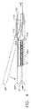
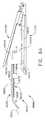
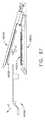
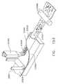
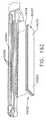
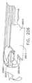
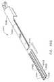
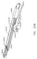
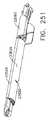
図面に戻り、図面では、同様の参照符号が、複数の図面の全体にわたって同様の構成要素を示す。図1は、いくつかの固有の利点を実施できる外科用器具10を示す。外科用ステープリング器具10は、これに動作可能に取り付けられた、様々な形状及び大きさのエンドエフェクタ12を操作及び/又は作動させるように設計される。図1〜1Eに示されている実施形態において、エンドエフェクタ12は、エンドエフェクタ12の下方ジョー13を形成する細長チャネル14を含む。細長チャネル14は、「埋め込み可能な」ステープルカートリッジ30を支持するように構成され、またエンドエフェクタ12の上方ジョー15として機能するアンビル20を動作可能に支持する。 Returning to the drawings, in which like reference numerals refer to like elements throughout the several views. FIG. 1 illustrates a
様々な実施形態において、細長いチャネル14は、300及び400シリーズ、17−4及び17−7ステンレススチール、チタンなどから作製されてもよく、離間した側壁16で形成されてもよい。アンビル20は、例えば、300及び400シリーズ、17−4及び17−7ステンレススチール、チタンなどから製作されてもよく、内部に形成される複数のステープル形成ポケット23を有する、概ね22として標識される、ステープル形成下面を有してもよい。図1B〜図1Eを参照されたい。加えて、アンビル20は、そこから近位方向に突出する、叉状の傾斜アセンブリ24を有する。アンビルピン26は、細長チャネル14の側壁16内の対応するスロット又は開口18内に受容される、傾斜アセンブリ24の各側方から突出し、ここに可動又は枢動可能に取り付けることを容易にする。 In various embodiments, the
様々な形態の埋め込み可能なステープルカートリッジが、本明細書において開示される外科用器具の様々な実施形態で利用され得る。特定のステープルカートリッジの構成及び構造を、以下で更に詳細に論じる。しかしながら、図1Aに示される実施形態において、埋め込み可能なステープルカートリッジ30が示される。少なくとも一実施形態において、ステープルカートリッジ30は、内部に形成されていない金属ステープル32が並んでいる、例えば、酸化再生セルロース(「ORC」)又は生体吸収性フォームなどの圧縮可能な止血材料からなる、本体部分31を有する。少なくともいくつかの実施形態において、ステープルが影響を受け、止血材料が導入及び配置工程中に活性化することを防ぐため、カートリッジ全体が、生分解性フィルム38、例えば、商標名PDS(登録商標)において販売されるポリジオキサノンフィルム、又はポリグリセロールセバケート(PGS)フィルム、又はPGA(商標Vicrylの商標名で販売されるポリグリセロール酸)、PCL(ポリカプロラクトン)、PLA、若しくはPLLA(ポリ乳酸)、PHA(ポリヒドロキシアルカノエート)、PGCL(商標名Monocrylで販売されるポリグレカプロン25)、又はPGA、PCL、PLA、PDSの複合物(破裂するまでは不透過性である)から形成される他の生分解性フィルムで、コーティング又は被覆され得る。ステープルカートリッジ30の本体31は、図示されるように、細長チャネル14内に取り外し可能に支持されるような大きさであり、それによって、アンビル20がステープルカートリッジ30と接触する際に、内部の各ステープル32が、アンビル内の対応するステープル形成ポケット23と整列される。 Various forms of implantable staple cartridges can be utilized in various embodiments of the surgical instrument disclosed herein. The configuration and structure of a particular staple cartridge is discussed in further detail below. However, in the embodiment shown in FIG. 1A, an
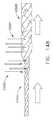
使用の際、エンドエフェクタ12が標的組織に隣接するように位置付けられると、エンドエフェクタ12は、ステープルカートリッジ30の上面36と、アンビル20のステープル形成表面22との間に、標的組織を捕捉又はクランプするように操作される。ステープル32は、細長チャネル14と実質的に平行な経路内でアンビル20を動かして、ステープル形成表面22、及びより具体的には内部のステープル形成ポケット23を、ステープルカートリッジ30の上面36と実質的に同時に接触させることによって形成される。アンビル20がステープルカートリッジ30内に移動し続けると、ステープル32の脚部34は、アンビル20内の対応するステープル形成ポケット23に接触して、ステープル脚部34を折り曲げ、ステープル32を「B字型」に形成することができる。アンビル20の細長チャネル14への更なる移動により、ステープル32を更に圧縮して、所望の最終的に形成される高さ「FF」へと形成する。 In use, when the
上記のステープル形成プロセスは、図1B〜1Eで概ね示される。例えば、図1Bは、アンビル20と埋め込み可能なステープルカートリッジ30の上面36との間に標的組織「T」を有する、エンドエフェクタ12を示す。図1Cは、アンビル20の最初のクランピング位置を示し、アンビル20は、標的組織「T」の上に閉鎖されて、アンビル20とステープルカートリッジ30の上面36との間に標的組織「T」をクランプする。図1Dは、最初のステープル形成を示し、アンビル20は、ステープルカートリッジ30を圧縮し始め、それによってステープル32の脚部34は、アンビル20内のステープル形成ポケット23によって形成され始めている。図1Eは、明確にするためにアンビル20が取り除かれた、標的組織「T」を貫いた、その最終的な形成状態にある、ステープル32を示す。一旦、ステープル32が標的組織「T」に形成及び締結されると、外科医は、アンビル20を開放位置へと移動させて、エンドエフェクタ12が患者から引き抜かれる間、カートリッジ本体31及びステープル32が標的組織に付けられたままとなることを可能にする。エンドエフェクタ12は、2つのジョー13、15が一緒にクランピングされると、全てのステープルを同時に形成する。残っている「折り畳み式」本体材料31は、止血剤(ORC)及びステープルのライン補強部(PGA、PDS又は上記の他のいずれかのフィルム組成38)の両方として機能する。また、ステープル32は、形成中において、カートリッジ本体31を離れることはないため、ステープル32が形成中に変形する可能性は、最小限度に抑えられる。本明細書において使用するとき、用語「埋め込み可能な」とは、ステープルに加えて、ステープルを支持するカートリッジ本体の材料もまた、患者内に留まり、最終的には、患者の身体に吸収されてもよいことを意味する。そのような埋め込み可能なステープルカートリッジは、発射された後に全体がエンドエフェクタ内に位置付けられたままである従来のカートリッジの構成とは区別される。 The above staple forming process is generally illustrated in FIGS. For example, FIG. 1B shows the
様々な実施において、エンドエフェクタ12は、ハンドルアセンブリ100から突出する細長シャフトアセンブリ40と連結されるように構成される。エンドエフェクタ12(閉鎖時)及び細長シャフトアセンブリ40は、同様の断面形状を有してもよく、トロカール管又は別の形状のアクセス器具内の作業チャネルを動作可能に通過するような大きさであり得る。本明細書において使用するとき、用語「動作可能に通過」とは、エンドエフェクタ及び細長シャフトアセンブリの少なくとも一部が、チャネル又は管開口を通って挿入されるか、又は通過することができ、外科用ステープリング手技を完了するために必要に応じてチャネル又は管開口内部で操作され得ることを意味する。いくつかの実施形態において、閉位置にあるとき、エンドエフェクタ12のジョー13及び15は、およそ円形の横断面形状をエンドエフェクタに与えることができ、その形状により、エンドエフェクタが円形の通路/開口部を通り抜けることが容易となる。しかしながら、本発明の様々な実施形態のエンドエフェクタ、並びに細長シャフト組み立て体の実施形態は、考えられる限りでは、非円形の横断面形状を有するアクセス通路及び開口部を通り抜けることができる他の横断面形状を与えられ得る。したがって、閉鎖したエンドエフェクタの断面の全体的な大きさは、エンドエフェクタが通過することが意図される通路又は開口の大きさに関連付けられるであろう。したがって、あるエンドエフェクタは、例えば、「5mmの」エンドエフェクタと呼ばれてもよく、これは、直径が少なくとも約5mmである開口をそのエンドエフェクタが動作可能に通過し得ることを意味する。 In various implementations, the
様々な実施形態において、細長シャフトアセンブリ40は、閉位置にあるときのエンドエフェクタ12の外径と実質的に同じである外径を有してもよい。例えば、5mmのエンドエフェクタは、5mmの断面直径を有する、細長シャフトアセンブリ40と連結されてもよい。しかしながら、この詳細な説明を読み進めると、本発明の様々な実施形態が種々のサイズのエンドエフェクタと関連付けて効果的に使用され得ることが、当業者には明らかとなろう。例えば、10mmのエンドエフェクタが、5mmの断面直径を有する細長シャフトに取り付けられてもよい。逆に、10mm以上のアクセス開口又は通路が設けられるこれらの用途において、細長シャフトアセンブリ40は、10mm(又はそれ以上)の断面直径を有してもよく、また5mm又は10mmのエンドエフェクタを作動させてもよい。したがって、外側シャフト40は、これに取り付けられる閉鎖したエンドエフェクタ12の外径と同じ、又はこれと異なる外径を有してもよい。 In various embodiments, the
示されるように、細長シャフトアセンブリ40は、ハンドルアセンブリ100からほぼ直線上に遠位方向に延在し、長手方向軸A−Aを画定する。様々な実施形態において、例えば、細長シャフトアセンブリ40は、約229〜406mm(9〜16インチ)の長さであり得る。しかし、細長シャフトアセンブリ40は別の長さであり得、他の実施形態において、その内側に接合箇所を有することができ、下記で詳しく説明されているように、シャフト又はハンドルアセンブリの他の部分に対してエンドエフェクタ12のアーティキュレーションを容易にするように構成し得る。様々な実施形態において、細長いシャフトアセンブリ40は、ハンドルアセンブリ100からエンドエフェクタ12まで延びる、スパイン部材50を含む。エンドエフェクタ12の細長チャネル14の近位端は、そこから突出する一対の保持トラニオン17を有し、これは、スパイン部材50の遠位端内に設けられる、対応するトラニオン開口又は受台52に受容される大きさであり、エンドエフェクタ12が、細長シャフトアセンブリ40に取り外し可能に連結されることを可能にする。スパイン部材50は、例えば、6061又は7075アルミニウム、ステンレススチール、チタンなどから製作されてもよい。 As shown, the
様々な実施形態において、ハンドルアセンブリ100は、組み立てる目的のために、2つ以上の部品で作製され得る、ピストルグリップタイプのハウジングを含む。例えば、図示されるハンドルアセンブリ100は、右手ケース部材102、及び左手ケース部材を含み(図示せず)、これらは、ポリマー又はプラスチック材料から成形、あるいは製作され、互いに噛み合うように設計される。かかる場合の部材は、スナップ機構、ペグ、及びその内側に成形、あるいは形成されたソケット、及び/又は接着剤、ねじ等により付着させることができる。スパイン部材50は、その上部に形成されたフランジ56を有する近位端54を有する。フランジ56は、ケース部材102、104のそれぞれから内方向に突出する噛み合うリブ108により形成される溝106内に回転可能に支持されるように構成される。かかる構成により、スパイン部材50をハンドルアセンブリ100に容易に取り付けることができる一方で、スパイン部材50がハンドルアセンブリ100に対し、長手方向軸線A−Aを中心に360°の経路で回転可能にする。 In various embodiments, the
図1に更に見られるように、スパイン部材50は、ハンドルアセンブリ100に回転可能に付けられた取り付けブッシング60を通過し、これによって支持される。取り付けブッシング60は、近位フランジ62、及び遠位フランジ64を有し、これらは、その間のハンドルアセンブリ100の鼻部分101を回転可能に受容するように構成される回転可能な溝65を画定する。かかる構成により、取り付けブッシング60が、ハンドルアセンブリ100に対し、長手方向軸線A−Aを中心に回転することができる。スパイン部材50は、スパインピン66により、取り付けブッシング60に回転不可能にピン留めされている。加えて、回転ノブ70は、取り付けブッシング60に取り付けられる。一実施形態において、例えば、回転ノブ70は、内部に取り付けブッシング60の一部分を受容するような大きさの中空の取り付けフランジ部分72を有する。様々な実施形態において、回転ノブ70は例えば、ガラス又は炭素充填ナイロン、ポリカーボネート、Ultem(登録商標)などから作製されてもよく、また同様にスパインピン66によって取り付けブッシング60に取り付けられる。加えて、内方向に突出する保持フランジ74は、取り付けフランジ部72上に形成され、取り付けブッシング60内に形成された放射状の溝68内に延在するように構成される。したがって、外科医は、回転ノブ70を保持し、これをハンドルアセンブリ100に対して回転させることによって、スパイン部材50(及びこれに取り付けられたエンドエフェクタ12)を長手方向軸線A−Aを中心に、360°の経路で回転させることができる。 As further seen in FIG. 1, the
様々な実施形態において、アンビル20は、アンビルばね21、及び/又は他の付勢構成によって開位置に維持される。アンビル20は、概ね109として示される、発射システムによって、開放位置から様々な閉鎖又はクランピング及び発射位置へと、選択的に可動である。発射システム109は、「発射部材」110を含み、これは様々な実施形態において、中空発射管110を含む。中空発射管110は、スパイン部材50上で軸方向に可動であり、したがって、細長シャフトアセンブリ40の外側部分を形成する。発射管110は、ポリマー、又は他の好適な材料から製作されてもよく、発射システム109の発射ヨーク114に取り付けられる近位端を有してもよい。様々な実施形態において、例えば、発射ヨーク114は、発射管110の近位端にオーバーモールドされてもよい。しかしながら、他の締結具の構成が利用されてもよい。 In various embodiments, the
図1に見られるように、発射ヨーク114は、ハンドルアセンブリ100内で軸方向に動くように構成された支持カラー120内で回転可能に支持される。様々な実施形態において、支持カラー120は、一対の横方向に延びるフィンを有し、これはそれぞれ、右手ケース部材及び左手ケース部材に形成される、フィンスロット内に摺動可能に受容されるような大きさである。したがって、支持カラー120はハンドルハウジング100内に軸方向に摺動可能であり得る一方で、発射ヨーク114及び発射チューブ110がこれに対して、長手方向軸A−Aを中心に回転することが可能となる。様々な実施形態において、細長スロットが、発射管110を通じて提供され、スパインピン66が内部を通じてスパイン部材50内に延びることを可能にし、一方で、スパイン部材50上における発射管110の軸方向の移動を促進する。 As seen in FIG. 1, the firing yoke 114 is rotatably supported within a support collar 120 that is configured to move axially within the
発射システム109は、スパイン部材50上の発射管110の軸方向の移動を制御するのに役立つ、発射トリガー130を更に含む。図1を参照されたい。発射管110を遠位方向の軸方向に移動させて、発射のためにアンビル20と相互作用させることは、本明細書では、「発射運動」と称される。図1に見られるように、発射トリガー130は、枢動ピン132によってハンドルアセンブリ100に可動、又は枢動可能に連結されている。発射トリガー130を、ハンドルアセンブリ100のピストルグリップ部107から、非作動の「開放」又は開始位置へと付勢するために、トーションばね135が利用される。図1に見られるように、発射トリガー130は、支持カラー120に可動に取り付けられた(ピン留めされた)発射リンク136に可動に取り付けられた上部134を有する。したがって、始点位置(図1)から、ハンドルアセンブリ100のピストルグリップ部分107に隣接する終点位置に向かう発射トリガー130の運動によって、発射ヨーク114及び発射管110は遠位方向「DD」に動く。(トーションばね135の付勢により)発射トリガー130のハンドルアセンブリ100のピストルグリップ部107から離れる動きにより、発射ヨーク114及び発射管110は、スパイン部材50の近位方向「PD」に移動するであろう。 The firing system 109 further includes a
本発明の様々な実施形態は、異なる大きさ及び構成の埋め込み可能なステープルカートリッジと利用することができる。例えば、外科用器具10は、第1の発射アダプタ140に接続して使用されるとき、埋め込み可能なステープルカートリッジ30を支持する、およそ20mmの長さ(又は他の長さ)の、5mmのエンドエフェクタ12と共に使用され得る。かかるエンドエフェクタの大きさは、例えば、比較的細かい切開、及び血管処置を完成させるために、特に好適である。しかしながら、以下でより詳細に記載されるように、外科用器具10は、また、例えば、第1の発射アダプタ140を第2の発射アダプタと交換することにより、他の大きさのエンドエフェクタ及びステープルカートリッジと接続して利用することができる。更に他の実施形態において、細長いシャフトアセンブリ40は、少なくとも1つの形状又は大きさのエンドエフェクタに取り付けられるように構成され得る。 Various embodiments of the present invention can be utilized with implantable staple cartridges of different sizes and configurations. For example, when the
エンドエフェクタ12をスパイン部材50に取り外し可能に連結する1つの方法がこれから説明される。連結プロセスは、細長チャネル14上の保持トラニオン17を、スパイン部材50のトラニオン受台52内に挿入することにより開始される。その後、外科医が発射トリガー130を、ハウジングアセンブリ100のピストルグリップ107の方に前進させ、発射管110及び第1の発射アダプタ140を、細長チャネル14の近位端部47を超えて遠位方向に前進させ、それによってトラニオン17をこれらの各受台52に保持する。トラニオン17を超える第1の発射アダプタ140のかかる位置は、本明細書において「連結位置」と称される。本発明の様々な実施形態はまた、エンドエフェクタ12がスパイン部材50に取り付けられた後、発射トリガー130を適所に固定するために、エンドエフェクタ固定アセンブリを有し得る。 One method of removably connecting the
より具体的に、エンドエフェクタロッキングアセンブリ160の一実施形態は、発射トリガー130の上部134内に可動に支持される、保持ピン162を含む。上記のように、発射管110は、最初に、第1の発射アダプタ140がエンドエフェクタ12の保持トラニオン17をスパイン部材50のトラニオン受台52内に保持する、連結位置へと、遠位方向に前進しなくてはならない。外科医は、発射トリガー130を開始位置からピストルグリップ107へ向かってと引くことによって、発射アダプタ140を連結位置へと遠位方向に前進させる。発射トリガー130が最初に作動されると、保持ピン162は、発射管110が第1の発射アダプタ140を連結位置まで前進させるまで、遠位方向に移動し、この連結位置の点において保持ピン162は、ケース部材内に形成されるロッキング空洞164内に付勢される。様々な実施形態において、保持ピン162が固定空洞164に入るとき、ピン162は、可聴「クリック音」、又は他の音を生じてもよく、またエンドエフェクタ12がスパイン部材50に「固定された」という触覚的指示を外科医に提供してもよい。加えて、外科医は、保持ピン162をロッキング空洞164から意図的に付勢しない限り、不注意により発射トリガー130を作動し続けて、ステープル32をエンドエフェクタ12内に形成し始めることはない。同様に、外科医が連結位置にある発射トリガー130を解放する場合、保持ピン162によってその位置に保持され、発射トリガー130が開始位置に戻り、それによってエンドエフェクタ12がスパイン部材50から解放するのを防ぐことができる。 More specifically, one embodiment of the end effector locking assembly 160 includes a retaining
本発明の様々な実施形態は、ハンドルアセンブリ100に枢動可能に取り付けられた、発射システム固定ボタン137を更に含み得る。一形態において、発射システムロックボタン137は、その遠位端上に形成されたラッチ138を有し、これは、発射解放ボタンが第1のラッチング位置にあるときに、発射ヨーク114と係合するように配向される。図1に見られるように、ラッチばね139は、発射システムロックボタン137を第1のラッチ位置へと付勢するように機能する。様々な状況において、ラッチ138は、スパイン部材50上の発射ヨーク114の位置が、第1の発射アダプタ140がアンビル20上のクランピング傾斜面28を遠位方向へと前進して上り始める点と対応する点で、発射ヨーク114と係合する役割を果たす。第1の発射アダプタ140がクランピング傾斜面28を軸方向に前進して上ると、アンビル20が、そのステープル形成表面部22がステープルカートリッジ30の上面36と実質的に平行となるような経路を移動することが理解されるであろう。 Various embodiments of the present invention may further include a firing
エンドエフェクタ12がスパイン部材50と連結すると、ステープル形成プロセスは、発射システムロックボタン137を最初に押圧することによって開始され、発射ヨーク114がスパイン部材50上で遠位方向に更に移動し、最終的にアンビル20をステープルカートリッジ30へと圧迫する。発射システムロックボタン137を押圧した後、外科医は、発射トリガー130をピストルグリップ107の方へ作動し続け、それによって第1のステープルカラー140を、対応するステープル形成傾斜面29を登るように駆動し、アンビル20を、ステープルカートリッジ30内のステープル32と接触させる。発射システムロックボタン137は、外科医がプロセスに備えるまで、ステープル32の不注意による形成を防ぐ。この実施形態において、外科医は、発射トリガー130が更に作動されてステープル形成プロセスを開始する前に、発射システム固定ボタン137を押圧しなくてはならない。 When the
外科用器具10は、所望により、単に組織ステープリング装置として使用されてもよい。しかしながら、本発明の様々な実施形態はまた、一般的に170として指定される、組織切断システムを含み得る。少なくとも一形態において、組織切断システム170は、ナイフ部材172を含み、これは、ナイフ前進トリガー200を作動することによって、エンドエフェクタ12の近位端に隣接する非作動位置から、作動位置へと選択的に前進することができる。ナイフ部材172は、スパイン部材50内に可動に支持され、取り付けられるか、あるいは、ナイフロッド180から突出する。ナイフ部材172は、例えば、38HRC超の硬度(Rockwell硬度Cスケール)を有する420又は440ステンレススチールから製作され、かつその遠位端174上に形成される組織切断縁176を有し、アンビル20のスロット、及びステープルカートリッジ30の中央に配置されたスロット33を通って摺動可能に延在し、エンドエフェクタ12内でクランプされた組織を切断する。様々な実施形態において、ナイフロッド180は、スパイン部材50を通って延在し、ナイフ伝達器と駆動可能に接合する近位端部分を有し、このナイフ伝達器はナイフ前進トリガー200に操作可能に取り付けられている。様々な実施形態において、ナイフ前進トリガー200は、駆動ピン132に取り付けられ、それによってこれは、発射トリガー130を作動することなく、枢動するかないしは別の方法で作動し得る。様々な実施形態において、第1ナイフギア192はまた、枢動ピン132に取り付けられ、それによってナイフ前進トリガー200の作動がまた第1ナイフギア192を枢動させる。発射戻りばね202は、第1のナイフギア192とハンドルハウジング100との間に取り付けられて、ナイフ前進トリガー200を開始又は非作動位置に付勢する。
ナイフ伝達器の様々な実施形態は更に、第2ギアスピンドル上に回転可能に支持され、第1ナイフギア192と噛合係合する、第2ナイフギア194を含む。第2のナイフギア194は、第3のギアスピンドルに支持される第3のナイフギア196と噛合係合する。第4のナイフギア198もまた、第3のギアスピンドル195に支持される。第4のナイフギア198は、ナイフロッド180の近位端上で一連の環状ギアの歯又はリングと駆動しながら係合するように適合される。かかる構成により、第4のナイフギア198は、ナイフロッド180を遠位方向「DD」、又は近位方向「PD」に軸方向に駆動することができる一方で、発射ロッド180が第4のナイフギア198に対して長手方向軸線A−Aを中心に回転することを可能にする。したがって、外科医は、ナイフ前進トリガー200をハンドルアセンブリ100のピストルグリップ107の方へ引くことによって、発射ロッド180を軸方向に前進させ、最終的にナイフ部材172を遠位方向に前進させることができる。 Various embodiments of the knife transmitter further include a second knife gear 194 rotatably supported on the second gear spindle and in meshing engagement with the
本発明の様々な実施形態は、更にナイフロックアウトシステム210を含み、これは、発射トリガー130が完全な発射位置に引かれるとき以外、ナイフ部材172の前進を防ぐ。したがって、かかる特徴により、ステープルが組織内に最初に発射、又は形成されるとき以外、ナイフ前進システム170の作動を防ぐことができる。図1に見られるように、ナイフロックアウトシステム210の様々な実施は、ハンドルアセンブリ100のピストルグリップ部107内に枢動可能に支持される、ナイフロックアウトバー211を含む。ナイフロックアウトバー211は、発射トリガー130が完全に発射済み位置にあるときに、発射トリガー130と係合するように適合される、作動端部212を有する。加えて、ナイフロックアウトバー211は、その他端に保持フック214を有し、これは、第1の切断ギア192上のラッチロッド216に引っ掛けるようにして係合するように適合される。ナイフロックばね218は、ナイフロックアウトバー211を、「ロックされた」位置に付勢するように利用され、ここで保持フック214は、ラッチロッド216と係合した状態に維持され、それによって、発射トリガー130が完全に発射済み位置にある場合を除いてナイフ前進トリガー200の作動を防ぐ。 Various embodiments of the present invention further include a
ステープルが、標的組織内に「発射」(形成)された後、外科医は、発射トリガー解放ボタン167を押圧し、発射トリガー130をトーションばね135の付勢力により開始位置に戻し、これにより、アンビル20は、ばね21の付勢力により開放位置に付勢される。開放位置にあるとき、外科医は、埋め込み可能なステープルカートリッジ30及びステープル32を残してエンドエフェクタ12を引き抜いてもよい。エンドエフェクタが通路、作業チャネルなどを通って挿入される用途において、外科医は、通路又は作業チャネルを通ってエンドエフェクタ12が引き抜けるようにするために、発射トリガー130を起動することによりアンビル20を閉じた位置に戻すであろう。しかしながら、ステープルの発射の後に外科医が標的組織を切断することを所望する場合、外科医は、ナイフ前進トリガー200を上記の方法で起動して、標的組織を通ってナイフバー172を、エンドエフェクタの端部まで駆動する。その後、外科医は、ナイフ前進トリガー200を解放し、これにより、発射戻しばね202により、発射伝達器はナイフバー172を開始(非作動)位置に戻すことができる。ナイフバー172が開始位置に戻ると、外科医は、エンドエフェクタジョー13、15を開き、埋め込み可能なカートリッジ30を患者内で解放し、その後、エンドエフェクタ12を患者から引き抜く。したがって、かかる外科用器具は、比較的小さな作業チャネル及び通路を通って挿入することができる小さい埋め込み可能ステープルカートリッジの使用を促進し、一方で、外科医に、組織を切断せずにステープルを発射するか、又は所望によりステープルが発射された後にまた組織を切断するかの選択肢を提供する。 After the staple is “fired” (formed) into the target tissue, the surgeon presses the firing trigger release button 167 and returns the firing
本発明の様々な固有かつ新規の実施形態は、アンビルと接触する実質的に静的な位置にステープルを支持する、圧縮可能なステープルカートリッジを利用する。様々な実施形態において、アンビルは未形成ステープルに対して駆動され、このとき、少なくともそのような一実施形態において、達成されるステープル形成の度合いは、アンビルがどの程度までステープルに対して駆動されたかに依存する。かかる構成により、外科医は、ステープルにかけられる成形圧力又は発射圧力の度合いを調節し、それによって最終的に形成されるステープルの高さを変更する能力を有することができる。本発明の他の様々な実施形態において、外科用ステープリング構成は、ステープルをアンビルに向かって持ち上げることができるステープル駆動要素を採用することができる。そのような実施形態の詳細は後述される。 Various unique and novel embodiments of the present invention utilize a compressible staple cartridge that supports staples in a substantially static position in contact with the anvil. In various embodiments, the anvil is driven against unformed staples, and at least in one such embodiment, the degree of staple formation achieved is to what extent the anvil is driven against the staples. Depends on. With such a configuration, the surgeon can have the ability to adjust the degree of forming or firing pressure applied to the staples, thereby changing the height of the final formed staples. In various other embodiments of the present invention, the surgical stapling arrangement can employ a staple drive element that can lift the staples toward the anvil. Details of such an embodiment will be described later.
様々な実施形態において、上記に詳述した実施形態に関し、可動性アンビルに適用される発射運動の量は、発射トリガーの差動の度合いに依存する。例えば、外科医が部分的にのみ形成されたステープルを得ることを所望する場合、発射トリガーは、ピストルグリップ107の方へ向かって内側に、部分的にのみ押圧される。更なるステープルの形成を得るため、外科医は、単純に更に発射トリガーを圧縮し、これによりアンビルは、ステープルと接触するように更に駆動される。本明細書において使用するとき、用語「接触する」とは、ステープル形成表面又はステープル形成ポケットがステープル脚部の端と接触し、脚部を形成した位置へと形成又は屈曲させ始めたことを意味する。ステープル形成の度合いとは、ステープル脚部がどれだけ折り畳まれたかを指し、ひいては、上記のステープル形成高さに関連する。当業者であれば、アンビル20は、発射運動がそこにかけられる際に、ステープルカートリッジに対して実質的に平行な関係で移動するため、ステープルが実質的に同時に、実質的に同じ形成高さで形成されることを更に理解するであろう。 In various embodiments, with respect to the embodiments detailed above, the amount of firing motion applied to the movable anvil depends on the differential degree of the firing trigger. For example, if the surgeon wishes to obtain a partially formed staple, the firing trigger is only partially pressed inwardly toward the
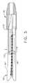
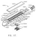
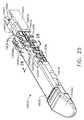
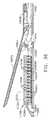
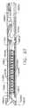
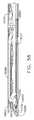
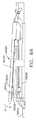
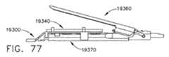
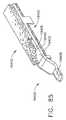
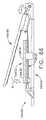
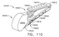
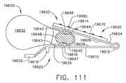
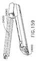
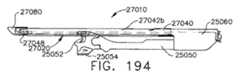
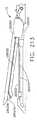
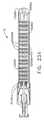
図2及び図3は、ナイフバー172’を収容するように構成された以下の相違点を除けば、上記のエンドエフェクタ12’と同様の別のエンドエフェクタ12”を示している。ナイフバー172’は、ナイフロッド180に連結されるか、又はこれから突出し、他の点においては、ナイフバー172に関連する上記の方法で操作される。しかしながら、本実施形態において、ナイフバー172’は、エンドエフェクタ12”の全長を横断する十分な長さであり、したがって、別個の遠位ナイフ部材は、エンドエフェクタ12”で利用されない。ナイフバー172’は、その上に形成される、上方横断部材173’、及び下方横断部材175’を有する。上方横断部材173’は、アンビル20”の対応する細長スロット250を摺動可能に横断するように配向され、下方横断部材175’は、エンドエフェクタ12”の細長チャネル14”の細長スロット252を横断するように配向される。係合離脱スロット(図示されない)がまたアンビル20”内に設けられ、それによりナイフバー172’が薄いエンドエフェクタ12”と共に終了位置に駆動されるとき、上方横断部材173’は、対応するスロットを通って降下し、アンビル20”が開放位置へと移動して、ステープリング及び切断された組織と係合離脱する。アンビル20”は、その他の点においては、上記のアンビル20と同一であってもよく、細長チャネル14”は、その他の点においては、上記の細長チャネル14と同一であってもよい。 2 and 3 show another
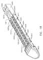
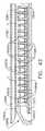
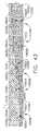
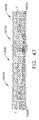
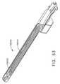
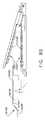
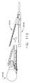
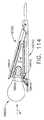
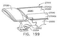
これらの実施形態では、アンビル20”は、ばね又は他の開放機構(図示なし)によって、完全に開いた位置(図2)に付勢される。アンビル20”は、上記の方法により、発射アダプタ150の軸方向の移動によって、開放位置と、完全にクランプした位置との間で移動する。発射アダプタ150が完全にクランプ締めされた位置(図3)まで前進させられた時点で、外科医は更にナイフバー172”を上記の要領で遠位方向に前進させることができる。外科医がエンドエフェクタを、組織を操作するための保持装置として使用することを所望する場合、発射アダプタが近位方向に移動し、アンビル20”は細長チャネル14”から離れることができる(図4に破線で表される)。この実施形態において、ナイフバー172”が遠位方向に移動すると、上方横断部材173’、及び下方横断部材175’は、アンビル20”及び細長チャネル14”を一緒に引き、ナイフバー172”がエンドエフェクタ12”を通じて遠位方向に前進するに伴い、所望のステープル形成を達成する。図5を参照されたい。したがって、この実施形態において、ステープル形成は、組織切断と同時に生じるが、ステープル自体は、ナイフバー172”が遠位方向に駆動される際に順次形成される。 In these embodiments, the
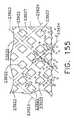
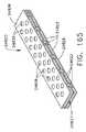
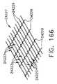
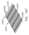
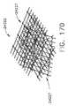
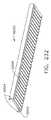
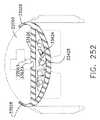
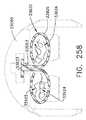
本発明の様々な外科用ステープルカートリッジ、及び外科用器具の固有かつ新規の特徴により、これらのカートリッジのステープルを1つ以上の線形又は非線形のラインに配置することができる。複数のかかるステープルのラインは、その内部を通って組織切断部材を受容するために、ステープルカートリッジ内に中央に配置された、細長スロットの両側に設けられてもよい。1つの構成において、例えば、1つのラインのステープルは、隣接するステープルの(複数の)ラインのステープルと実質的に平行であるが、そこからオフセットしてもよい。更に他の実施形態において、1つ以上のステープルのラインは、非線形の性質を有してもよい。すなわち、ステープルのラインの少なくとも1つのステープルの基部は、同じステープルのラインの他のステープルの基部を、実質的に横断する方向である軸に沿って延在してもよい。例えば、細長スロットの両側のステープルのラインは、ジグザグの外観を有してもよい。 The unique and novel features of the various surgical staple cartridges and surgical instruments of the present invention allow the staples of these cartridges to be placed in one or more linear or non-linear lines. A plurality of such staple lines may be provided on either side of the elongated slot centrally disposed within the staple cartridge for receiving a tissue cutting member therethrough. In one configuration, for example, a line of staples is substantially parallel to, but offset from, the staples of the adjacent line (s). In yet other embodiments, one or more staple lines may have non-linear properties. That is, at least one staple base of a staple line may extend along an axis that is in a direction substantially transverse to other staple bases of the same staple line. For example, the staple lines on either side of the elongated slot may have a zigzag appearance.
様々な実施形態において、ステープルカートリッジは、カートリッジ本体、及びカートリッジ本体内に収容される複数のステープルを含み得る。使用の際、ステープルカートリッジは、手術部位の中へ導入され、処置される組織の側に位置付けられ得る。加えて、ステープル形成アンビルは、組織の反対側に位置付けられ得る。様々な実施形態において、アンビルは、第1ジョーにより保持され得、ステープルカートリッジは、第2ジョーによって保持され得、第1ジョー及び/又は第2ジョーは互いに向かって移動し得る。ステープルカートリッジ及びアンビルが組織に対して位置付けられると、ステープルがステープルカートリッジ本体から排出され、ステープルが組織を貫通してステープル形成アンビルと接触することができる。ステープルがステープルカートリッジ本体から配備されると、その後、ステープルカートリッジ本体が手術部位から取り除かれる。本明細書において開示される様々な実施形態において、ステープルカートリッジ又はステープルカートリッジの少なくとも一部分が、ステープルと共に埋め込まれ得る。少なくとも1つのこのような実施形態において、以下でより詳細に記載されるように、ステープルカートリッジは、アンビルが開放位置から閉鎖位置へと移動するときに、アンビルにより圧縮、圧壊、及び/又は折り畳まれ得る、カートリッジ本体を含み得る。カートリッジ本体が、圧縮、圧潰及び/又は圧壊されるとき、カートリッジ本体内に位置付けられるステープルは、アンビルによって変形され得る。あるいは、ステープルカートリッジを支持するジョーは、アンビルに向かい、閉鎖位置へと移動し得る。いずれにせよ、様々な実施形態において、ステープルは、これらが少なくとも部分的にカートリッジ本体内に位置付けられるときに、変形され得る。いくつかの実施形態において、ステープルは、ステープルカートリッジから発射されなくてもよく、一方でいくつかの実施形態において、ステープルは、カートリッジ本体の一部分と共に、ステープルカートリッジから発射され得る。 In various embodiments, a staple cartridge can include a cartridge body and a plurality of staples housed within the cartridge body. In use, the staple cartridge can be introduced into the surgical site and positioned on the side of the tissue to be treated. In addition, the staple forming anvil can be positioned on the opposite side of the tissue. In various embodiments, the anvil can be held by the first jaw, the staple cartridge can be held by the second jaw, and the first jaw and / or the second jaw can move toward each other. Once the staple cartridge and anvil are positioned with respect to the tissue, the staple can be ejected from the staple cartridge body and the staple can penetrate the tissue and contact the staple forming anvil. Once the staple is deployed from the staple cartridge body, the staple cartridge body is then removed from the surgical site. In various embodiments disclosed herein, a staple cartridge or at least a portion of a staple cartridge can be embedded with staples. In at least one such embodiment, as described in more detail below, the staple cartridge is compressed, crushed, and / or folded by the anvil as the anvil moves from the open position to the closed position. A cartridge body may be included. When the cartridge body is compressed, crushed and / or crushed, staples positioned within the cartridge body can be deformed by the anvil. Alternatively, the jaws that support the staple cartridge can move toward the anvil and into the closed position. In any case, in various embodiments, the staples can be deformed when they are positioned at least partially within the cartridge body. In some embodiments, the staples may not be fired from the staple cartridge, while in some embodiments, the staples may be fired from the staple cartridge along with a portion of the cartridge body.
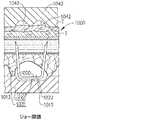
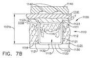
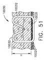
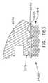
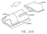
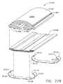
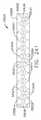
ここで図6A〜図6Dを参照すると、例えば、ステープルカートリッジ1000などの圧縮可能なステープルカートリッジは、圧縮可能、埋め込み可能なカートリッジ本体1010、加えて、圧縮可能なカートリッジ本体1010内に位置付けられる、複数のステープル1020を含むことができるが、図6A〜図6Dでは、1つのステープル1020のみが示されている。図6Aは、ステープルカートリッジ支持体、又はステープルカートリッジチャネル1030によって支持されるカートリッジ1000を示し、ステープルカートリッジ1000は、未圧縮状態で示される。このような未圧縮状態において、アンビル1040は、組織Tと接触してもしなくてもよい。使用の際、アンビル1040は、図6Bに見られるように、開放位置から組織Tへと接触させ、組織Tを、カートリッジ本体1010に対して位置付けるように移動してもよい。図6Bを再び参照すると、アンビル1040は、組織Tをステープルカートリッジ本体1010の組織当接面1019に対して位置付けることができるが、ステープルカートリッジ本体1010は、かかる時点において、圧縮力又は圧力を(受けたとしても)ほとんど受けなくてもよく、ステープル1020は、未形成又は未非発射状態にあってもよい。図6A及び図6Bに示すように、ステープルカートリッジ本体1010は、1つ以上の層を含んでもよく、ステープル1020のステープル脚部1021は、これらの層を通って上方に延在してもよい。様々な実施形態において、カートリッジ本体1010は、第1層1011、第2層1012、第3層1013を含む場合があり、第2層1012は、第1層1011と第3層1013及び第4層1014との中間に位置付けられてもよく、第3層1013は、第2層1012と第4層1014との中間に位置付けられてもよい。少なくとも一実施形態において、ステープル1020の基部1022は、第4層1014の空洞1015内に位置付けられてもよく、ステープル脚部1021は、基部1022から第4層1014、第3層1013、及び第2層1012を通じて上方に延びてもよい。様々な実施形態において、各変形可能な脚部1021は、先端部、例えば鋭い先端部1023を含んでもよく、これは、例えばステープルカートリッジ1000が未圧縮状態にあるときに、第2層1012内に位置付けられてもよい。少なくとも1つのこのような実施形態において、先端部1023は、第1層1011内に及び/又はこれを通じて延びない場合があり、少なくとも一実施形態において、先端部1023は、ステープルカートリッジ1000が未圧縮状態にあるときに、組織接触表面1019を通じて突出しないことがある。いくつかの他の実施形態において、ステープルカートリッジが未圧縮状態にあるときに、鋭い先端部1023は、第3層1013、及び/又は他の任意の好適な層内に位置付けられてもよい。様々な代替的実施形態において、ステープルカートリッジのカートリッジ本体は、例えば、3層以下、又は5層以上など、任意の好適な数の層を有してもよい。 Referring now to FIGS. 6A-6D, a compressible staple cartridge, such as a
様々な実施形態において、以下でより詳細に記載されるように、第1層1011は、バットレス材料及び/又はプラスチック材料、例えば、ポリジオキサノン(PDS)及び/又はポリグリコール酸(PGA)を含むことがあり、第2層1012は、生吸収性フォーム材料及び/又は圧縮可能な止血材料、例えば、酸化再生セルロース(ORC)を含むことがある。様々な実施形態により、1つ以上の第1層1011、第2層1012、第3層1013、及び第4層1014は、ステープルカートリッジ本体1010内にステープル1020を保持してもよく、加えて、ステープル1020を、互いに整列した状態に維持してもよい。様々な実施形態において、第3層1013は、バットレス材料、又は高度に未圧縮性又は非弾性の材料を含んでもよく、これはステープル1020のステープル脚部1021を互いに対して適所に保持するように構成され得る。更に、第3の層1013の両側に位置付けられる、第2層1012及び第4の層1014は、第2層1012及び第4の層1014が、圧縮可能なフォーム又は弾性材料から構成することができる場合であっても、ステープル1020の移動を固定又は低減することができる。いくつかの実施形態において、ステープル脚部1021のステープル先端部1023は、一部分が第1層1011内に埋め込まれていてもよい。少なくとも1つのこのような実施形態において、第1層1011及び第3層1013は、協調して、かつしっかりと、ステープル脚部1021を適所に保持するように構成され得る。少なくとも1つの実施形態において、第1層1011及び第3層1013はそれぞれ、生吸収性プラスチックのシート、例えば、商標名Vicrylで販売されるポリグリコール酸(PGA)、ポリ乳酸(PLA又はPLLA)、ポリジオキサノン(PDS)、ポリヒドロキシアルカノエート(PHA)、商標名Monocrylで販売されるポリグレカプロン25(PGCL)、ポリカプロラクトン(PCL)、及び/又はPGA、PLA、PDS、PHA、PGCL及び/若しくはPCLの混合物を含んでもよく、第2層1012及び第4層1014はそれぞれ、少なくとも1つの止血材料又は薬剤を含んでもよい。 In various embodiments, as described in more detail below, the
第1層1011は、圧縮可能であってもよく、第2層1012は、第1層1011よりも実質的に更に圧縮可能であってもよい。例えば、第2層1012は、第1層1011の約2倍圧縮可能、約3倍圧縮可能、約4倍圧縮可能、約5倍圧縮可能、及び/又は約10倍圧縮可能であってもよい。換言すると、第2層1012は、所与の力により第1層1011の約2倍、約3倍、約4倍、約5倍、及び/又は約10倍圧縮してもよい。いくつかの実施形態において、第2層1012は、第1層1011の、約2倍〜約10倍圧縮可能であり得る。少なくとも一実施形態において、第2層1012は、内部に画定される複数の空隙を含むことがあり、第2層1012における空隙の量及び/又は大きさは、第2層1012の所望の圧縮性を提供するために制御され得る。上記と同様に、第3の層1013は、圧縮可能であってもよく、第4の層1014は、第3の層1013よりも実質的に更に圧縮可能であってもよい。例えば、第4の層1014は、第3の層1013の約2倍圧縮可能、約3倍圧縮可能、約4倍圧縮可能、約5倍圧縮可能、及び/又は約10倍圧縮可能であってもよい。換言すると、第4の層1014は、所与の力により第3の層1013の約2倍、約3倍、約4倍、約5倍、及び/又は約10倍圧縮してもよい。いくつかの実施形態において、第4層1014は、第3層1013の、約2倍〜約10倍圧縮可能であり得る。少なくとも一実施形態において、第4層1014は、内部に画定される複数の空隙を含むことがあり、第4層1014における空隙の量及び/又は大きさは、第4層1014の所望の圧縮性を提供するために制御され得る。様々な状況において、カートリッジ本体、又はカートリッジ本体層の圧縮性は、圧縮率(すなわち、所与の力において層が圧縮される距離)という観点で表現されてもよい。例えば、高い圧縮率を有する層は、層にかけられる所与の圧縮力において、より低い圧縮率を有する層と比較して、より大きな距離を圧縮する。すなわち、第2層1012は、第1層1011よりも高い圧縮率を有してもよく、同様に第4の層1014は、第3の層1013よりも高い圧縮率を有してもよい。様々な実施形態において、第2層1012及び第4層1014は、同じ材料を含む場合があり、同じ圧縮率を含む場合がある。様々な実施形態において、第2層1012及び第4層1014は、異なる圧縮率を有する材料を含み得る。同様に第1層1011及び第3の層1013は、同じ材料から構成されてもよく、同じ圧縮率を含んでもよい。いくつかの実施形態において、第1層1011及び第3層1013は、異なる圧縮率を有する材料を含んでもよい。 The
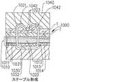
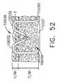
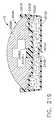
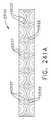
図6Cに示すように、アンビル1040が閉鎖位置に移動すると、アンビル1040は、組織Tに接触し、組織T及びステープルカートリッジ1000に圧縮力をかけることができる。かかる状況において、アンビル1040は、カートリッジ本体1010の上面又は組織当接面1019を、ステープルカートリッジ支持体1030に向かって下方に押すことができる。様々な実施形態において、ステープルカートリッジ支持体1030は、カートリッジ支持表面1031を含む場合があり、これは、ステープルカートリッジ1000がカートリッジ支持表面1031と、アンビル1040の組織接触表面1041との間で圧縮される際に、ステープルカートリッジ1000を支持するように構成され得る。アンビル1040によりかけられる圧力により、カートリッジ本体1010は、圧縮され、アンビル1040がステープル1020と接触することができる。より具体的に、様々な実施形態において、カートリッジ本体1010の圧縮、及び組織接触表面1019の下方移動により、ステープル脚部1021の先端部1023がカートリッジ本体1010の第1層1011を貫通し、組織Tを貫通し、アンビル1040の形成ポケット1042内に入ることがある。カートリッジ本体1010が、アンビル1040によって更に圧縮されると、先端部1023は、形成ポケット1042を画定する壁部に接触することができ、結果として脚部1021は、例えば図6Cに示すように、変形するか、内方向に湾曲し得る。図6Cにまた示すように、ステープル脚部1021が変形すると、ステープル1020の基部1022は、ステープルカートリッジ支持体1030と接触するか、又はこれによって支持され得る。様々な実施形態において、以下により詳細に記載されるように、ステープルカートリッジ支持体1030は例えば、複数の支持機構、例えば、ステープル支持溝、スロット又はトラフ1032を含む場合があり、これらは、ステープル1020が変形される際に、ステープル1020のステープル1020又は少なくとも基部1022を支持するように構成され得る。図6Cにまた示すように、第4の層1014の空洞1015は、ステープルカートリッジ本体1010にかけられた圧縮力の結果として圧壊することができる。空洞1015に加えて、ステープルカートリッジ本体1010は、1つ以上の空隙、例えば空隙1016を更に含んでもよく、これは、その内部に位置付けられたステープルの一部を含んでも、含まなくてもよく、これは、カートリッジ本体1010が圧壊されることを可能にするように構成されてもよい。様々な実施形態において、空洞1015及び/又は空隙1016は、空洞及び/又は壁部を画定する壁部が下方に屈曲して、カートリッジ支持表面1031と接触し並びに/又は空洞及び/若しくは空隙の下に位置付けられるカートリッジ本体1010の層と接触するようにして、折り畳まれるように構成される。 As shown in FIG. 6C, when the
図6Bと図6Cを比較すると、第2層1012及び第4の層1014が、アンビル1040によってかけられた圧縮圧力によって実質的に圧縮されていることが明らかである。尚、第1層1011及び第3の層1013も同様に圧縮されることに注目されたい。アンビル1040がその閉鎖位置に移動すると、アンビル1040は、組織当接面1019をステープルカートリッジ支持体1030に向かって下方に押すことによって、カートリッジ本体1010を更に圧縮し続けることができる。図6Dに示すように、カートリッジ本体1010が更に圧縮されると、アンビル1040は、ステープル1020を、それらの完全に形成された形状に変形することができる。図6Dを参照すると、各ステープル1020の脚部1021は、変形可能な脚部1021と基部1022との間に、組織T、第1層1011、第2層1012、第3の層1013、及び第4の層1014の少なくとも一部を捕捉するため、各ステープル1020の基部1022の方に向かって下方に変形され得る。図6Cと図6Dを比較すると、第2層1012及び第4の層1014が、アンビル1040によってかけられた圧縮圧力によって実質的に更に圧縮されていることが更に明らかである。同様に、図6Cと図6Dを比較した際に、第1層1011及び第3の層1013が更に圧縮されていることにも注目されたい。ステープル1020が完全に又は少なくとも十分に形成された後、アンビル1040が組織Tから離れるように持ち上げられてもよく、ステープルカートリッジ支持体1030は、ステープルカートリッジ1000から離れ、かつ/又は分離されてもよい。図6Dに示すように、上記の結果として、カートリッジ本体1010は、ステープル1020と共に埋め込まれてもよい。様々な状況において、埋め込まれたカートリッジ本体1010は、ステープルのラインに沿って組織を支持することができる。いくつかの状況において、埋め込まれたカートリッジ本体1010内に含有される止血剤及び/又は他の任意の好適な治療用薬剤によって、時間をかけて組織を治療することができる。上記のように、止血剤によって、ステープリング及び/又は切開された組織の出血を低減することができる一方で、結合剤又は組織接着剤によって、時間をかけて組織に強度をもたらすことができる。埋め込まれたカートリッジ本体1010は、例えば、ORC(酸化再生セルロース)、コラーゲンなどの細胞外タンパク質、商標名Vircylで市販されるポリグリコール酸(PGA)、ポリ乳酸(PLA又はPLLA)、ポリジオキサノン(PDS)、ポリヒドロキシアルカノエート(PHA)、商標名Monocrylで市販されるポリグレカプロン25(PGCL)、ポリカプロラクトン(PCL)、並びに/又はPGA、PLA、PDS、PHA、PGCL及び/又はPCL複合体などの材料から構成され得る。ある状況において、カートリッジ本体1010は、抗生物質及び/又は抗菌性物質、例えば、コロイド状銀及び/又はトリクロサンを含んでもよく、これらは、手術部位における感染の可能性を低減させることができる。 Comparing FIG. 6B and FIG. 6C, it is clear that the
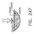
様々な実施形態において、カートリッジ本体1010の層は、互いに接続され得る。少なくとも1つの実施形態において、例えば、フィブリン及び/又はタンパク質ヒドロゲルなどの少なくとも1つの接着剤を使用して、第2層1012が第1層1011に接着されてもよく、第3層1013が第2層1012に接着されてもよく、第4層1014が第3層1013に接着されてもよい。いくつかの実施形態において、例示されないが、カートリッジ本体1010の層は、連結機械機構によって互いに連結され得る。少なくとも1つのそのような実施形態において、第1層1011及び第2層1012はそれぞれ、例えば舌部及び溝部構成及び/又はあり継手構成などの、対応する連結機構を含み得る。同様に、第2層1012及び第3の層1013は、それぞれ、対応するインターロック機構を含んでもよく、一方で第3の層1013及び第4の層1014は、それぞれ、対応するインターロック機構を含んでもよい。いくつかの実施形態において、例示されないが、ステープリングカートリッジ1000は、例えば、カートリッジ本体1010の1つ以上の層を通じて延び得る1つ以上のリベットを含み得る。少なくとも1つのこのような実施形態において、各リベットは、第1層1011と隣接するように位置付けられる第1端部又はヘッド、及び第2ヘッドであって、このリベットの第2端部によって組み立てられるか、又は形成され得る第4層1014と隣接するように位置付けられた、第2ヘッドを含み得る。カートリッジ本体1010の圧縮可能な性質により、少なくとも一実施において、リベットはカートリッジ本体1010を圧縮してもよく、これにより、リベットのヘッドは、例えば、組織接触表面1019、及び/又はカートリッジ本体1010の底面1018に対して陥没していることがある。少なくとも1つのこのような実施形態において、リベットは、商標名Vircylで販売されるポリグリコール酸(PGA)、ポリ乳酸(PLA又はPLLA)、ポリジオキサノン(PDS)、ポリヒドロキシアルカノエート(PHA)、商標名Monocrylで販売されるポリグレカプロン25(PGCL)、ポリカプロラクトン(PCL)、並びに/又はPGA、PLA、PDS、PHA、PGCL及び/若しくはPCLの混合物などの生吸収性材料を含み得る。いくつかの実施形態において、カートリッジ本体1010の層は、内部に含まれるステープル1020によって以外は、互いに接続されないことがある。少なくとも1つのこのような実施形態において、ステープル脚部1021と、カートリッジ本体1010との間の摩擦係合は、カートリッジ本体1010の層を一緒に保持することができ、一度ステープルが形成されると、層はステープル1020内に捕捉され得る。いくつかの実施形態において、ステープル脚部1021の少なくとも一部分は、非平坦化表面又は非平坦なコーティングを含む場合があり、これは、ステープル1020とカートリッジ本体1010との間の摩擦力を含み得る。 In various embodiments, the layers of the
上記のように、外科用器具は、ステープルカートリッジ支持体1030を含む第1のジョー、及びアンビル1040を含む第2のジョーを含んでもよい。様々な実施形態において、以下でより詳細に記載されるように、ステープルカートリッジ1000は、1つ以上の保持機構を含んでもよく、これはステープルカートリッジ支持体1030と係合するように構成されてもよく、結果として、ステープルカートリッジ1000をステープルカートリッジ支持体1030に解放可能に保持する。特定の実施形態において、ステープルカートリッジ1000は、例えば、フィブリン及び/又はタンパク質ヒドロゲルなどの少なくとも1つの接着剤によって、ステープルカートリッジ支持体1030に接着され得る。使用の際、少なくとも1つの状況において、特に腹腔鏡及び/又は内視鏡手術において、例えば、第2のジョーは、第1のジョーと反対側の閉鎖位置に移動しもよく、それによって第1及び第2のジョーがトロカールを通って手術部位に挿入されてもよい。少なくとも1つのこのような実施形態において、トロカールは、およそ5mmの開口又はカニューレを画定する場合があり、これを通じて第1及び第2ジョーが挿入され得る。いくつかの実施形態において、第2ジョーは、開放位置と閉鎖位置との中間の部分的に閉鎖した位置に移動することができ、これは、ステープルカートリッジ本体1010内に含まれるステープル1020を変形することなく、トロカールを通じて第1及び第2ジョーが挿入されることを可能にし得る。少なくとも1つの実施形態において、第2ジョーがその部分的に閉じた中間位置にあるとき、アンビル1040は圧縮力をステープルカートリッジ本体1010に適用しないことがあり、他のいくつかの実施形態において、第2ジョーが部分的に閉じた中間位置にあるときに、アンビル1040はステープルカートリッジ本体1010を圧縮し得る。アンビル1040が、そのような中間位置にあるときに、ステープルカートリッジ本体1010を圧縮することができる場合であっても、アンビル1040は、アンビル1040がステープル1020と接触するように、かつ/又はステープル1020がアンビル1040によって変形されるように、ステープルカートリッジ本体1010を十分に圧縮することができない。第1及び第2のジョーが、トロカールを通って手術部位に挿入されると、第2のジョーは、もう一度、開放され、アンビル1040及びステープルカートリッジ1000が、上記のように標的組織に対して位置付けられることができる。 As described above, the surgical instrument may include a first jaw that includes a
様々な実施形態により、図7A〜7Dを参照して、外科用ステープラのエンドエフェクタは、アンビル1140とステープルカートリッジ支持体1130との中間に位置付けられた埋め込み可能なステープルカートリッジ1100を含み得る。上記と同様に、アンビル1140は、組織当接面1141を含んでもよく、ステープルカートリッジ1100は、組織当接面1119を含んでもよく、ステープルカートリッジ支持体1130は、ステープルカートリッジ1100を支持するように構成されてもよい支持表面1131を含んでもよい。図7Aを参照すると、アンビル1140は、ステープルカートリッジ1100を変形することなく、ステープルカートリッジ1100の組織当接面1119に対して組織Tを位置付けるために使用されてもよく、アンビル1140がかかる位置にあるとき、組織当接面1141は、ステープルカートリッジ支持表面1131から距離1101aで位置付けられてもよく、組織当接面1119は、ステープルカートリッジ支持表面1131から距離1102aで位置付けられてもよい。その後、アンビル1140がステープルカートリッジ支持体1130に向かって移動すると、ここで図7Bを参照すると、アンビル1140は、ステープルカートリッジ1100の上面又は組織当接面1119を下方に押し、カートリッジ本体1110の第1層1111及び第2層1112を圧縮することができる。図7Bを再び参照すると、層1111及び1112が圧縮されると、第2層1112が圧潰し、ステープル1120の脚部1121が、第1層1111を貫通して組織T内に入ることができる。少なくとも一実施形態において、ステープル1120は第2層1112のステープル空洞又は空隙1115内に少なくとも一部分が位置付けられ得、第2層1112が圧縮されると、ステープル空洞1115が折り畳まれ、結果として、第2層1112がステープル1120の周囲で折り畳まれる。様々な実施形態において、第2層1112は、カバー部分1116を含んでもよく、これはステープル空洞1115上に延び、かつステープル空洞1115を包囲するか又は少なくとも一部分を包囲し得る。図7Bは、ステープル空洞1115内へと下方に圧潰されている、カバー部1116を示す。いくつかの実施形態において、第2層1112は、1つ以上の弱化部分を含んでもよく、これは第2層1112が折り畳まれるのを促進し得る。様々な実施形態において、このような弱化部分は、例えば、刻んだ線、穿孔、及び/又は薄い断面を含んでもよく、これはカートリッジ本体1110の制御された折り畳みを促進し得る。少なくとも一実施形態において、第1層1111は、1つ以上の弱化部分を含んでもよく、これは、第1層1111を通じてステープル脚部1121の貫通を促進し得る。様々な実施形態において、このような弱化部分は、例えば、刻んだ線、穿孔、及び/又は薄い断面を含んでもよく、これはステープル脚部1121と整列されるか又は少なくとも実質的に整列され得る。 7A-7D, the surgical stapler end effector may include an
図7Aを再び参照すると、アンビル1140が、部分的に閉鎖した、未発射位置にあるとき、アンビル1140は、カートリッジ支持表面1131から、その間に隙間が画定されるように、距離1101aで位置付けられ得る。空隙はステープルカートリッジ高さ1102aを有するステープルカートリッジ1100、及び組織Tで充填され得る。図7Bを再び参照すると、アンビル1140が下方に移動し、ステープルカートリッジ1100を圧縮すると、組織当接面1141とカートリッジ支持表面1131との間の距離は、距離1101aよりも短い距離1101bで画定され得る。様々な状況において、距離1101bで画定される、アンビル1140の組織当接面1141と、カートリッジ支持表面1131との間の隙間は、元の変形していないステープルカートリッジの高さ1102aよりも大きくてもよい。ここで図7Cを参照すると、アンビル1140がカートリッジ支持表面1131により近く移動すると、第2層1112は、圧壊し続け、ステープル脚部1121と形成ポケット1142との間の距離は、減少し得る。同様に、組織接触表面1141とカートリッジ支持表面1131との間の距離は1101cまで減少することがあり、これは様々な実施形態において、元の変形してないカートリッジ高さ1102aより大きい、これと等しい、又はこれより小さいことがある。図7Dを参照すると、アンビル1140は、ステープル1120が完全に形成された又は少なくとも所望の高さまで形成された、最終的な、発射済み位置まで移動することができる。かかる位置において、アンビル1140の組織当接面1141は、カートリッジ支持表面1131から距離1101dの距離であってもよく、距離1101dは、元の変形していないカートリッジの高さ1102aより短くてもよい。また、図7Dに示すように、ステープル空洞1115は、完全に又は少なくとも実質的に、圧壊されてもよく、ステープル1120は、圧壊された第2層1112によって完全に又は少なくとも実質的に囲まれてもよい。様々な状況において、アンビル1140は、その後、ステープルカートリッジ1100から離れてもよい。アンビル1140がステープルカートリッジ1100から係合離脱すると、カートリッジ本体1110は、様々な位置(すなわち、例えば、ステープル1120に隣接するステープルの中間の位置)において、少なくとも部分的に再膨張することができる。少なくとも一実施形態において、圧壊したカートリッジ本体1110は、弾性的に再拡張しないことがある。様々な実施形態において、形成されたステープル1120及び、加えて、隣接するステープル1120の中間に位置付けられるカートリッジ本体1110は、組織Tに圧力、又は圧縮力を適用することがあり、これは様々な治療的効果を提供し得る。 Referring again to FIG. 7A, when the
上記のように、図7Aに例示される実施形態を再び参照し、各ステープル1120は、そこから延びるステープル脚部1121を含み得る。ステープル1120は、2つのステープル脚部1121を含むものとして示されるが、1つのステープル脚部、あるいは、3つ以上のステープル脚部、例えば、3つのステープル脚部、又は4つのステープル脚部を含んでもよい様々なステープルが使用されてもよい。図7Aに示すように、各ステープル脚部1121は、ステープル1120が第2層1112内に固定されるように、カートリッジ本体1110の第2層1112内に埋め込まれ得る。様々な実施形態において、ステープル1120は、ステープル脚部1121の先端部1123が、基部1122の前に空洞1115内に入るようにして、カートリッジ本体1110のステープル空洞1115内に挿入されることがある。先端部1123が、空洞1115内に挿入された後、様々な実施形態において、先端部1123は、カバー部分1116に押し込まれて、第2層1112を切開する。様々な実施形態において、ステープル1120は、ステープル1120が第2層1112に対して動かないか、又は少なくとも実質的に動かないように、第2層1112内の十分な深さに位置付けられ得る。いくつかの実施形態において、ステープル1120は、基部1122がステープル空洞1115内に位置付けられるか又は埋め込まれるように、第2層1112内の十分な深さに位置付けられ得る。他の様々な実施形態において、基部1122は、第2層1112内に位置付けられないか、又は埋め込まれない場合もある。いくつかの実施形態において、図7Aを参照し、基部1122は、カートリッジ本体1110の底面1118の下に延びてもよい。いくつかの実施形態において、基部1122は、カートリッジ支持表面1130上に位置し得るか、又はこれに対して直接位置付けられ得る。様々な実施形態において、カートリッジ支持表面1130は、ここから延びるか、及び/又は内部に画定される支持機構を含む場合があり、少なくとも1つのこのような実施形態において、ステープル1120の基部1122は、以下でより詳細に記載されるように、ステカートリッジ支持体1130内の、1つ以上の支持溝、スロット、又はトラフ1132内に位置付けられるか、これによって支持され得る。 As noted above, referring again to the embodiment illustrated in FIG. 7A, each staple 1120 may include a
様々な実施形態において、ここで図8及び図9を参照し、例えば、ステープルカートリッジ1200などのステープルカートリッジは、外層1211及び内層1212を含む、圧縮可能な、埋め込み可能なカートリッジ本体1210を含む場合がある。上記と同様に、ステープルカートリッジ1200は、カートリッジ本体1210内に位置付けられる、複数のステープル1220を含んでもよい。様々な実施形態において、各ステープル1220は、基部1222及びここから延びる1つ以上のステープル脚部1221を含み得る。少なくとも1つのこのような実施形態において、ステープル脚部1221は、内層1212に挿入され、例えば、ステープル1220の基部1222が、内層1212の底面1218と隣接する、及び/又は隣接するように位置付けられるような深さに配置され得る。図8及び図9内に示される実施形態において、内層1212は、ステープル1220の一部分を受容するように構成されたステープル空洞を含まず、他の実施形態において内層1212は、このようなステープル空洞を含み得る。上記に加え、様々な実施形態において、内層1212は、例えば、生吸収性フォーム及び/又は酸化再生セルロース(ORC)などの、圧縮可能な材料を含む場合があり、これは、カートリッジ本体1210が圧縮負荷がそこに適用される際に折り畳まれることを可能にするように構成され得る。様々な実施形態において、内層1212は、例えば、ポリ乳酸(PLA)及び/又はポリグリコール酸(PGA)を含む凍結乾燥フォームから構成され得る。ORCは、商標名Surgicelで市販で入手し得て、緩く編まれた(外科用スポンジのような)ファブリック、(コットンボールのような)緩い繊維、及び/又はフォームを備え得る。少なくとも1つの実施形態において、内層1212は、例えば、水で活性化すること及び/又は例えば患者の体液によって活性化することが可能な、そこに包含されている及び/又はそこに塗布されている凍結乾燥トロンビン及び/又はフィブリンのような、医薬品を含む材料で構成され得る。少なくとも1つのそのような実施形態では、凍結乾燥したトロンビン及び/又はフィブリンをVicryl(PGA)マトリックス上に保持し得る。しかし、特定の状況では、ステープルカートリッジ1200が、例えば患者の体内の外科的部位に挿入されたときに、活性化可能な医薬品が、意図せずして、活性化され得る。様々な実施形態において、図8及び図9を参照として、外層1211は、水不透過性、又は少なくとも実質的に水不透過性の材料を含むことができ、それによりカートリッジ本体1210が圧縮されてステープル脚部が外層1211を貫通する後、及び/又は外層1211がなんらかの様式により切開された後まで、液体が内層1212と接触しないか、又は少なくとも実質的に接触しない。様々な実施形態において、外層1211は、例えば、ポリジオキサノン(PDS)、及び/又はポリグリコール酸(PGA)などのバットレス材料及び/又はプラスチック材料から構成される場合がある。いくつかの実施形態において、外層1211は、内層1212及びステープル1220を囲むラップを含み得る。より具体的に、少なくとも一実施形態において、ステープル1220は、内層1212内に挿入されることがあり、外層1211は、内層1212及びステープル1220を含むサブアセンブリの周囲に巻かれ、その後封止され得る。 In various embodiments, referring now to FIGS. 8 and 9, a staple cartridge such as, for example, a
本明細書において記載される様々な実施形態において、ステープルカートリッジのステープルは、アンビルが閉鎖位置に動かされるときに、アンビルによって完全に形成され得る。図10〜13を参照し、様々な他の実施形態において、例えば、ステープルカートリッジ4100などのステープルカートリッジのステープルは、アンビルが閉位置へと動くときにアンビルによって、加えて、ステープルを閉鎖したアンビルへと動かすステープルドライバシステムによって、変形され得る。ステープルカートリッジ4100は、例えば、フォーム材料、及び圧縮可能なカートリッジ本体4110内に少なくとも部分的に位置付けられた、複数のステープル4120から構成されてもよい、圧縮可能なカートリッジ本体4110を含んでもよい。様々な実施形態において、ステープルドライバシステムは、ドライバホルダ4160、ドライバホルダ4160内に位置付けられた複数のステープルドライバ4162、及びドライバホルダ4160内にステープルドライバ4162を保持するように構成され得るステープルカートリッジパン4180を含み得る。少なくとも1つのこのような実施形態において、ステープルドライバ4162は、ドライバホルダ4160の1つ以上のスロット4163内に位置付けられることがあり、スロット4163の側壁は、ステープルドライバ4162をアンビルに向かって上方に案内することを補助し得る。様々な実施形態において、ステープル4120は、ステープルドライバ4162によってスロット4163内に支持されることがあり、少なくとも一実施形態において、ステープル4120は、ステープル4120及びステープルドライバ4162がこれらの非発射位置にある際に、スロット4163内に完全に位置付けられることがある。いくつかの他の実施形態において、ステープル4120の少なくとも一部分は、ステープル4120及びステープルドライバ4162がこれらの非発射位置にあるときに、スロット4163の解放端部4161を通じて上方に延び得る。ここで図11を参照し、少なくとも1つのこのような実施形態において、ステープル4120の基部は、ドライバホルダ4160内に位置付けられることがあり、ステープル4120の先端部は、圧縮可能なカートリッジ本体4110内に埋め込まれることがある。いくつかの実施形態において、ステープル4120の高さのおよそ1/3がドライバホルダ4160内に位置付けられる場合があり、ステープル4120のおよそ2/3が、カートリッジ本体4110内に位置付けられることがある。図10Aを参照し、少なくとも一実施形態において、ステープルカートリッジ4100は、例えば、カートリッジ本体4110及びドライバホルダ4160を囲む、水透過性ラップ又は膜4111を更に含む場合がある。 In various embodiments described herein, the staples of the staple cartridge can be fully formed by the anvil when the anvil is moved to the closed position. With reference to FIGS. 10-13, in various other embodiments, staples of a staple cartridge, such as, for example,
使用の際、ステープルカートリッジ4100は、例えば、ステープルカートリッジチャネル内に位置付けられてもよく、アンビルは、ステープルカートリッジ4100に向かって閉鎖位置へと移動することができる。様々な実施形態において、アンビルは、アンビルがその閉鎖位置に動かされるときに、圧縮可能カートリッジ本体4110と接触し、かつこれを圧縮することができる。いくつかの実施形態において、アンビルは、アンビルがその閉鎖位置にあるときに、ステープル4120に接触しなくてもよい。いくつかの他の実施形態において、アンビルは、アンビルがその閉鎖位置に動かされる際に、ステープル4120の脚部に接触し、少なくとも部分的にステープル4120を変形させてもよい。いずれにしても、ステープルカートリッジ4100は、ステープルカートリッジ4100内で長手方向に前進してもよい1つ以上のスレッド4170を更に含んでもよく、それによって、スレッド4170は、順次、ステープルドライバ4162と係合し、ステープルドライバ4162及びステープル4120をアンビルの方に移動させることができる。様々な実施形態において、スレッド4170は、ステープルカートリッジパン4180と、ステープルドライバ4162との間で摺動し得る。アンビルのクロージャが、ステープル4120の形成プロセスを開始した場合の実施形態において、ステープル4120のアンビルへの上方への移動は、形成プロセスを完了し、ステープル4120をこれらの完全に形成した、又は少なくとも所望の高さへと変形させることができる。アンビルのクロージャが、ステープル4120を変形させていない場合の実施形態において、ステープル4120のアンビルへの上方への移動は、形成プロセスを開始及び完了し、ステープル4120をこれらの完全に形成した、又は少なくとも所望の高さへと変形させることができる。様々な実施形態において、スレッド4170は、ステープルカートリッジ4100の近位端から、ステープルカートリッジ4100の遠位端まで前進することができ、それによって、ステープルカートリッジ4100の近位端内に位置付けられるステープル4120は、ステープルカートリッジ4100の遠位端に位置付けられるステープル4120が完全に形成される前に、完全に形成される。図12を参照し、少なくとも一実施形態において、スレッド4170は、それぞれ、少なくとも1つの角度付き、又は傾いた表面4711を含む場合があり、これは、図76に例示されるように、ステープルドライバ4162の下を摺動し、ステープルドライバ4162を持ち上げるように構成され得る。 In use, the
様々な実施形態において、上記に加え、ステープル4120は、組織Tの少なくとも一部分、及びステープルカートリッジ4100の圧縮可能なカートリッジ本体4110の少なくとも一部分を内部に捕捉するために、形成され得る。ステープル4120が形成された後、外科用ステープラのアンビル及びステープルカートリッジチャネル4130は、埋め込まれたステープルカートリッジ4100から離れることができる。様々な状況において、カートリッジパン4180は、ステープルカートリッジチャネル4130としっかりと係合することができ、その結果、カートリッジパン4180は、ステープルカートリッジチャネル4130が、埋め込まれたカートリッジ本体4110から引き離される際に、圧縮可能なカートリッジ本体4110から分離される。図10を再び参照し、様々な実施形態において、カートリッジパン4180は、対向する側壁4181を含む場合があり、その間に、カートリッジ本体4110が取り外し可能に配置され得る。少なくとも1つのこのような実施形態において、圧縮可能なカートリッジ本体4110は、カートリッジ本体4110が側壁4181の間で、使用中にその間に取り外し可能に保持され、カートリッジパン4180が引き離される際にカートリッジパン4180から解放可能に係合離脱されるように、圧縮され得る。少なくとも1つのこのような実施形態において、ドライバホルダ4160は、カートリッジパン4180が手術部位から取り外すときに、ドライバホルダ4160、ドライバ4162、及び/又はスレッド4170が、カートリッジパン4180内に留まり得るようにして、カートリッジパン4180内に接続され得る。他のいくつかの実施形態において、ドライバ4162は、ドライバ4160から排出されて、手術部位に残されることができる。少なくとも1つのこのような実施形態において、ドライバ4162は、商標名Vircylで販売されるポリグリコール酸(PGA)、ポリ乳酸(PLA又はPLLA)、ポリジオキサノン(PDS)、ポリヒドロキシアルカノエート(PHA)、商標名Monocrylで販売されるポリグレカプロン25(PGCL)、ポリカプロラクトン(PCL)、並びに/又はPGA、PLA、PDS、PHA、PGCL及び/若しくはPCLの混合物などの生吸収性材料を含み得る。様々な実施形態において、ドライバ4162は、ドライバ4162が、ステープル4120と共に展開されるように、ステープル4120に取り付けられることができる。少なくとも1つのこのような実施形態において、各ドライバ4162は、例えば、ステープル4120の基部を受容するように構成されたトラフを含む場合があり、少なくとも1つの実施形態において、トラフは、圧力嵌め及び/又はスナップ嵌めの方法により、ステープル器具を受容するように構成され得る。 In various embodiments, in addition to the above,
更に上記に加え、いくつかの実施形態において、ドライバホルダ4160及び/又はスレッド4170は、カートリッジパン4180から排出され得る。少なくとも1つのこのような実施形態において、スレッド4170は、カートリッジパン4180と、ドライバホルダ4160との間で摺動する場合があり、それにより、スレッド4170がステープルドライバ4162及びステープル4120を上方に駆動するためにスレッド4170が前進する際に、スレッド4170がドライバホルダ4160も同様に、カートリッジパン4180の外側に上方へと移動させることができる。少なくとも1つのこのような実施形態において、ドライバホルダ4160及び/又はスレッド4170は、商標名Vircylで販売されるポリグリコール酸(PGA)、ポリ乳酸(PLA又はPLLA)、ポリジオキサノン(PDS)、ポリヒドロキシアルカノエート(PHA)、商標名Monocrylで販売されるポリグレカプロン25(PGCL)、ポリカプロラクトン(PCL)、並びに/又はPGA、PLA、PDS、PHA、PGCL及び/若しくはPCLの混合物などの生吸収性材料を含み得る。様々な実施形態において、スレッド4170は、ドライババー又は切断部材に一体的に形成される及び/又はこれに取り付けられる場合があり、これはステープルカートリッジ4100を通じてスレッド4170を押す。このような実施形態において、スレッド4170は、カートリッジパン4180から排出されなくてもよく、外科用ステープラと共に留まってもよいが、スレッド4170がドライババーに取り付けられていない他の実施形態において、スレッド4170は、手術部位に残ってもよい。いずれにせよ、上記に加え、カートリッジ本体4110の圧縮性は、ステープラのアンビルが閉鎖するときにカートリッジ本体4110が圧縮又は収縮し得る際に、より厚いステープルカートリッジが、外科用ステープラのエンドエフェクタ内で使用されることを可能にし得る。いくつかの実施形態において、アンビルの閉鎖の際に少なくとも一部分が変形されるステープルの結果として、例えば、およそ4.6mm(0.18”)を有するステープルなどのより高いステープルが使用される場合があり、およそ3.1mm(0.12”)のステープル高さが圧縮可能な層4110内に位置付けられる場合があり、圧縮可能な層4110は、例えば、およそ3.6mm(0.14”)の未圧縮高さを有し得る。 Further to the above, in some embodiments, the
本明細書において記載される多くの実施形態において、ステープルカートリッジは、内部に複数のステープルを含む場合がある。様々な実施形態において、このようなステープルは、2つのステープル脚部を有する実質的にU字型の構成に変形される金属ワイヤを含むことがある。ステープルが、3つ以上のステープル脚部を有する、一緒に結合された2つ以上のワイヤなどの異なる構成を含み得る、他の実施形態が想到される。様々な実施形態において、ステープルを形成するために使用される、ワイヤが、丸い、又は少なくとも実質的に丸い断面を含み得る。少なくとも一実施形態において、ステープルワイヤは、例えば、正方形及び/又は矩形の断面などの、他の任意の好適な断面を含み得る。いくつかの実施形態において、ステープルは、プラスチックワイヤを含む場合がある。少なくとも一実施形態において、ステープルは、プラスチックコーティングされた金属ワイヤを含み得る。様々な実施形態において、カートリッジは、ステープルに加えて、又はその代わりに、任意の好適な種類の締結具を含む場合がある。少なくとも1つのこのような実施形態において、このような締結具は、アンビルと係合する際に折られ得る、枢動可能なアームを含む場合がある。いくつかの実施形態において、二部構成の締結具が使用され得る。少なくとも1つのこのような実施形態において、ステープルカートリッジは、複数の第1締結部分を含む場合があり、アンビルは、アンビルがステープルカートリッジに対して圧縮される際に、第1締結部分に接続される、複数の第2締結部分を含む場合がある。上記のように、いくつかの実施液体において、スレッド又はドライバは、ステープルの形成プロセスを完了するために、ステープルカートリッジ内で前進し得る。いくつかの実施形態において、スレッド又はドライバは、1つ以上の形成部材を、内部に位置付けられた、対向するステープルカートリッジ及びステープル又は締結具と係合するように、下方に動かすために、アンビル内で前進し得る。 In many embodiments described herein, the staple cartridge may include a plurality of staples therein. In various embodiments, such staples may include a metal wire that is deformed into a substantially U-shaped configuration having two staple legs. Other embodiments are contemplated in which the staple may include different configurations such as two or more wires joined together having three or more staple legs. In various embodiments, the wire used to form the staple can include a round or at least substantially round cross-section. In at least one embodiment, the staple wire may include any other suitable cross section, such as, for example, a square and / or rectangular cross section. In some embodiments, the staple may include a plastic wire. In at least one embodiment, the staple may include a plastic-coated metal wire. In various embodiments, the cartridge may include any suitable type of fastener in addition to or instead of staples. In at least one such embodiment, such a fastener may include a pivotable arm that can be folded upon engagement with the anvil. In some embodiments, a two-part fastener may be used. In at least one such embodiment, the staple cartridge may include a plurality of first fastening portions, and the anvil is connected to the first fastening portion when the anvil is compressed against the staple cartridge. In some cases, a plurality of second fastening portions may be included. As noted above, in some implementation liquids, the sled or driver may be advanced within the staple cartridge to complete the staple forming process. In some embodiments, the sled or driver can move one or more forming members within the anvil to move downwardly into engagement with opposing staple cartridges and staples or fasteners positioned therein. You can move forward.
本明細書において記載される様々な実施形態において、ステープルカートリッジは、内部に保存された4列のステープルを含み得る。少なくとも1つの実施形態において、4つのステープル列は、2つの内側ステープル列、及び2つの外側ステープル列に構成され得る。少なくとも1つのこのような実施形態において、内側ステープル及び外側ステープル列は、ステープルカートリッジ内の切断部材又はナイフスロットの第1側部に位置付けられることがあり、同様に、内側ステープル列及び外側ステープル列は、切断部材又はナイフスロットの第2側部に位置付けられることがある。いくつかの実施形態において、ステープルカートリッジは、切断部材スロットを含まない場合があるが、このようなステープルカートリッジは、ステープルカートリッジスロットの代わりに、切断部材によって切開されるように構成された指定部分を含み得る。様々な実施形態において、内側ステープル列は、ステープルカートリッジ内において、これらが切断部材スロットから均等に、又は少なくとも実質的に均等に離間するように配置され得る。同様に、外側ステープル列は、ステープルカートリッジ内において、これらが切断部材スロットから均等に、又は少なくとも実質的に均等に離間するように配置され得る。様々な実施形態において、ステープルカートリッジは、ステープルカートリッジ内に保存された5列以上、又は3列以下のステープルを含み得る。少なくとも一実施形態において、ステープルカートリッジは、6列のステープルを含み得る。少なくとも1つのこのような実施形態において、ステープルカートリッジは、切断部材スロットの第1側部に3列のステープルを含み、切断部材スロットの第2側部に3列のステープルを含む。いくつかの実施形態において、ステープルカートリッジは、奇数のステープル列を含み得る。例えば、ステープルカートリッジは、切断部材スロットの第1の側部に2列のステープルを含み、切断部材スロットの第2の側部に3列のステープルを含んでもよい。様々な実施形態において、ステープル列は、同じ又は少なくとも実質的に同じ、形成されていないステープル高さを含み得る。いくつかの他の実施形態において、1つ以上のステープル列は、他のステープルとは異なる非形成ステープル高さを有するステープルを含み得る。少なくとも1つのこのような実施形態において、切断部材スロットの第1側部のステープルは、第1の非形成高さを有し、切断部材スロットの第2側部は、第2非形成高さを有し、これは、例えば、第1高さとは異なる。 In various embodiments described herein, a staple cartridge can include four rows of staples stored therein. In at least one embodiment, the four staple rows can be configured into two inner staple rows and two outer staple rows. In at least one such embodiment, the inner staple row and the outer staple row may be positioned on a first side of a cutting member or knife slot in the staple cartridge, and similarly, the inner staple row and the outer staple row are May be positioned on the second side of the cutting member or knife slot. In some embodiments, the staple cartridge may not include a cutting member slot, but such a staple cartridge may have a designated portion configured to be incised by the cutting member instead of the staple cartridge slot. May be included. In various embodiments, the inner staple rows may be arranged within the staple cartridge such that they are evenly or at least substantially evenly spaced from the cutting member slot. Similarly, the outer staple rows may be arranged within the staple cartridge such that they are evenly or at least substantially evenly spaced from the cutting member slots. In various embodiments, the staple cartridge can include five or more rows, or no more than three rows of staples stored within the staple cartridge. In at least one embodiment, the staple cartridge may include six rows of staples. In at least one such embodiment, the staple cartridge includes three rows of staples on the first side of the cutting member slot and three rows of staples on the second side of the cutting member slot. In some embodiments, the staple cartridge may include an odd number of staple rows. For example, the staple cartridge may include two rows of staples on the first side of the cutting member slot and three rows of staples on the second side of the cutting member slot. In various embodiments, the staple rows can include the same or at least substantially the same unformed staple height. In some other embodiments, the one or more staple rows may include staples having a non-formed staple height that is different from other staples. In at least one such embodiment, the staple on the first side of the cutting member slot has a first non-forming height and the second side of the cutting member slot has a second non-forming height. This is different from, for example, the first height.
様々な実施形態において、上述のように、ステープルカートリッジは、内部に画定された複数のステープル空洞を有するカートリッジ本体を含み得る。カートリッジ本体は、デッキ及びデッキ上表面を含んでもよく、各ステープル空洞は、デッキ表面に開口を画定してもよい。上記のように、ステープルは、カートリッジ本体から排出されるまでの間、カートリッジ本体内に格納されるように、各ステープル空洞内に位置付けることができる。様々な実施形態において、ステープルは、カートリッジ本体から発射される前に、ステープルがデッキ表面の上に突出しないように、カートリッジ本体内に収容され得る。ステープルはデッキ表面の下に配置されているため、そのような実施形態において、ステープルの損傷及び/又は標的組織に時期尚早に接触する可能性を低減することができる。様々な状況において、ステープルは、カートリッジ本体から突出していない未発射位置と、カートリッジ本体から出現して、ステープルカートリッジの反対側に位置付けられているアンビルに接触することができる発射済み位置との間で、移動することができる。様々な実施形態において、アンビル、及び/又はアンビル内に画定されている形成ポケットは、デッキ表面の上の所定距離に配置することができ、これにより、ステープルがカートリッジ本体から配備される際に、ステープルが所定の形成高さに変形される。いくつかの状況において、アンビルとステープルカートリッジとの間に捕捉された組織の厚さは、変化してもよく、その結果、より厚い組織が特定のステープル内に捕捉されてもよく、より薄い組織が他の特定のステープル内に捕捉されてもよい。いずれにしても、ステープルによって組織にかけられるクランプ圧又はクランプ力は、ステープルによって変化してもよく、あるいは、例えば、ステープル列の一方の端にあるステープルと、そのステープル列の他方の端にあるステープルとの間で変化してもよい。特定の状況において、アンビルとステープルカートリッジデッキとの間の隙間は、ステープルが各ステープル内に所定の最低クランプ圧をかけるように制御することができる。しかしながら、いくつかのそのような状況において、異なるステープル内でクランプ圧の顕著な変動が依然として存在し得る。外科用ステープリング器具が、米国特許第7,380,696号(2008年6月3日発行)に開示されており、その開示全体が参照により本明細書に組み込まれる。外科用ステープリング及び切断用器具の例示的なマルチストロークハンドルは、その開示の全体が参照により本明細書に組み込まれている、同時係属かつ共同出願の米国特許出願「SURGICAL STAPLING INSTRUMENT INCORPORATING A MULTISTROKE FIRING POSITION INDICATOR AND RETRACTION MECHANISM」、Ser.第10/374,026号に詳細が記述されている。本発明と一致する他の適用は、「SURGICAL STAPLING INSTRUMENT HAVING SEPARATE DISTINCT CLOSING AND FIRING SYSTEM」という表題の同時係属及び共同出願の米国特許出願第10/441,632号に詳細が記載されているような、単一発射ストロークが含まれてよい。 In various embodiments, as described above, a staple cartridge can include a cartridge body having a plurality of staple cavities defined therein. The cartridge body may include a deck and a deck top surface, and each staple cavity may define an opening in the deck surface. As described above, staples can be positioned within each staple cavity for storage within the cartridge body until ejection from the cartridge body. In various embodiments, the staples can be contained within the cartridge body such that the staples do not protrude above the deck surface before being fired from the cartridge body. Because the staples are located below the deck surface, in such embodiments, the staple damage and / or the possibility of premature contact with the target tissue can be reduced. In various situations, the staple is between an unfired position that does not protrude from the cartridge body and a fired position that emerges from the cartridge body and can contact an anvil positioned on the opposite side of the staple cartridge. Can move. In various embodiments, the anvil, and / or the forming pocket defined within the anvil, can be disposed at a predetermined distance above the deck surface so that when the staple is deployed from the cartridge body. The staple is deformed to a predetermined formation height. In some situations, the thickness of the tissue captured between the anvil and the staple cartridge may vary so that thicker tissue may be captured within a particular staple and the thinner tissue May be captured in other specific staples. In any case, the clamping pressure or clamping force applied to the tissue by the staple may vary with the staple, or, for example, a staple at one end of the staple row and a staple at the other end of the staple row. And may vary between In certain circumstances, the gap between the anvil and the staple cartridge deck can be controlled so that the staples apply a predetermined minimum clamping pressure within each staple. However, in some such situations, there may still be significant fluctuations in clamping pressure within different staples. A surgical stapling instrument is disclosed in US Pat. No. 7,380,696 (issued June 3, 2008), the entire disclosure of which is incorporated herein by reference. An exemplary multi-stroke handle for a surgical stapling and cutting instrument is a co-pending and co-pending US patent application “SURGICAL STAPLING INSTRUMENTING A MULTISTROKING FIRING, the entire disclosure of which is incorporated herein by reference. “POSITION INDICATOR AND RETRACTION MECHANISM”, Ser. Details are described in 10 / 374,026. Another application consistent with the present invention is as described in detail in co-pending and co-pending US patent application Ser. No. 10 / 441,632 entitled “SURGICAL STAPLING INSTRUMENT HAVING SEPARATE DISTINCT CLOSEING AND FIRING SYSTEM”. A single firing stroke may be included.
本明細書に記述される様々な実施形態において、ステープルカートリッジは、ステープルカートリッジから配備されるステープル内に捕捉される組織の厚さに関して補償を行う手段を含み得る。様々な実施形態において、図14を参照し、ステープルカートリッジ(例えばステープルカートリッジ10000)は、剛性の第1部分(例えば、支持部分10010)と、圧縮可能な第2部分(例えば、組織厚さコンペンセータ10020)とを含み得る。少なくとも一実施形態において、主に図16を参照し、支持部分10010は、カートリッジ本体、デッキ上側表面10011、及び複数のステープル空洞10012を含み得、上記と同様に、各ステープル空洞10012はデッキ表面10011に開口部を画定し得る。例えば、ステープル10030は、各ステープル空洞10012内に取り外し可能に位置付けることができる。少なくともそのような一実施形態において、各ステープル10030は、底面10031と、底面10031から延びる1本又は複数の脚部10032と、を含み得る。ステープル10030が配備される前に、これも詳しくは、後述されるように、ステープル10030の基部10031は、支持部10010内に位置付けられているステープルドライバによって支持されることができ、同時に、ステープル10030の脚部10032は、ステープル空洞10012内に少なくとも部分的に含有されてもよい。様々な実施形態において、ステープル10030は、脚部10032が組織厚さコンペンセータ10020を貫通して動き、組織厚さコンペンセータ10020の上側表面を貫通し、組織Tに入り込み、ステープルカートリッジ10000に相対して配置されるアンビルに接触するよう、未発射位置と発射済み位置との間に配備することができる。脚部10032がアンビルに当たって変形すると、各ステープル10030の脚部10032が、各ステープル10030内で、組織厚さコンペンセータ10020の一部と組織Tの一部とを捕捉し、この組織に圧縮力をかけることができる。上記に対して更に、各ステープル10030の脚部10032は、ステープルの基部10031に向かって下方に変形して、ステープル捕捉領域10039を形成することができ、組織Tと組織厚さコンペンセータ10020が捕捉され得る。様々な状況において、ステープル捕捉領域10039は、変形した脚部10032の内側表面と、基部10031の内側表面との間で画定され得る。ステープルの捕捉領域の大きさは、例えば、脚部の長さ、脚部の直径、基部の幅、及び/又は脚部の変形の程度などのいくつかの要素に依存し得る。 In various embodiments described herein, the staple cartridge may include means for compensating for the thickness of tissue captured within the staples deployed from the staple cartridge. In various embodiments, referring to FIG. 14, a staple cartridge (eg, staple cartridge 10000) includes a rigid first portion (eg, support portion 10010) and a compressible second portion (eg, tissue thickness compensator 10020). ). In at least one embodiment, referring primarily to FIG. 16, the
前述の実施形態において、外科医はしばしば、ステープルを適用する組織に対して適切なステープル高さを有する適切なステープルを選択する必要があった。例えば、外科医は、厚い組織に使用するには、長いステープルを選択し、薄い組織に使用するには、短いステープルを選択することができた。しかしながら、いくつかの状況において、ステープリングされる組織は、均一な厚さを有しておらず、ステープルによっては、望ましい発射形状を達成することができなかった。例えば、図48は、薄い組織に使用された長いステープルを示す。ここで図49を参照すると、組織厚さコンペンセータ(例えば、組織厚さコンペンセータ10020)を薄い組織に使用した場合、大きなステープルであっても、望ましい発射形状を形成することができる。 In the foregoing embodiments, the surgeon often needed to select a suitable staple having the appropriate staple height for the tissue to which the staple was applied. For example, the surgeon could select long staples for use with thick tissue and short staples for use with thin tissue. However, in some situations, the tissue being stapled does not have a uniform thickness and some staples have not been able to achieve the desired firing shape. For example, FIG. 48 shows a long staple used for thin tissue. Referring now to FIG. 49, when a tissue thickness compensator (eg, tissue thickness compensator 10020) is used with thin tissue, even a large staple can form the desired firing shape.
組織厚さコンペンセータの圧縮性のおかげで、組織厚さコンペンセータは、各ステープル内に捕捉された組織の厚さを補正することができる。より具体的には、ここで図43及び44を参照すると、組織厚さコンペンセータ(例えば、組織厚さコンペンセータ10020)は、ステープル捕捉領域10039内に含有された組織の厚さ及び/又はタイプに応じて、各ステープル10030のステープル捕捉領域10039のより大きな部分及び/又はより小さな部分を占めることができる。例えば、より薄い組織Tがステープル10030内に捕捉された場合、組織厚さコンペンセータ10020は、より厚い組織Tがそのステープル10030内に捕捉された場合に比べ、ステープル捕捉領域10039のより大きな部分を占めることができる。同様に、より厚い組織Tがステープル10030内に捕捉された場合、組織厚さコンペンセータ10020は、より薄い組織Tがそのステープル10030内に捕捉された場合に比べ、ステープル捕捉領域10039の中で、より小さな部分を占める場合がある。このようにして、組織厚さコンペンセータは、より薄い組織及び/又はより厚い組織を補正することができ、ステープル内に捕捉された組織厚さとは、無関係に、又は少なくとも実質的に無関係に、圧縮圧力を組織にかけることができる。上記に加え、組織厚さコンペンセータ10020は、異なるステープル10030内に捕捉された組織の様々なタイプ又は圧縮性を、補正することができる。ここで図44を参照すると、組織厚さコンペンセータ10020は、脈管Vを含み得る脈管組織Tに対して圧縮力をかけることができ、その結果、圧縮性のより低い脈管Vを通る血流を制限する一方、周囲の組織Tに対して望ましい圧縮圧力をかけることができる。様々な状況において、上記に対して更に、組織厚コンペンセータ10020はまた、形成不良ステープルをも補正することができる。図45を参照すると、様々なステープル10030の形成不良により、そのようなステープル内に画定される、より大きなステープル捕捉領域10039が生じることがある。組織厚さコンペンセータ10020の弾力性のおかげで、ここで図46を参照して、形成不良ステープル10030内に配置された組織厚さコンペンセータ10020は、そのような形成不良ステープル10030内に画定されたステープル捕捉領域10039が増大している場合であっても、依然として組織Tに十分な圧縮圧力を適用することができる。様々な状況において、例えば、隣接するステープル10030の中間にある組織厚さコンペンセータ10020は、形成不良ステープル10030を包囲する適正形成ステープル10030により、組織Tに対して付勢することができ、その結果、周囲の組織、及び/又は形成不良ステープル10030内に捕捉された組織に対して、圧縮圧力をかけることができる。様々な状況において、組織厚コンペンセータは、例えば石灰化、繊維性領域、及び/又は以前にステープル又は治療が行われた組織などによって生じ得る、異なる組織密度を補正することができる。 Thanks to the compressibility of the tissue thickness compensator, the tissue thickness compensator can correct the thickness of the tissue captured within each staple. More specifically, referring now to FIGS. 43 and 44, a tissue thickness compensator (eg, tissue thickness compensator 10020) depends on the thickness and / or type of tissue contained within the
様々な実施形態において、固定された(変更不能な)組織間隔は、支持部分とアンビルとの間で画定することができ、その結果、ステープルは、ステープル内に捕捉された組織の厚さにかかわらず、所定の高さに変形され得る。組織厚さコンペンセータをこれらの実施形態と共に使用すると、組織厚さコンペンセータが、アンビルと支持部分ステープルカートリッジとの間に捕捉された組織に対して適合することができ、この組織厚さコンペンセータのおかげで、組織厚さコンペンセータが追加の圧縮圧力を組織に対して適用することができる。ここで図50〜55を参照すると、ステープル10030が、所定の高さHに形成されている。図50に関して、組織厚さコンペンセータは、使用されておらず、組織Tがステープル捕捉領域10039の全体を占めている。図57に関して、組織厚さコンペンセータ10020の一部がステープル10030内に捕捉され、組織Tを圧縮し、ステープル捕捉領域10039の少なくとも一部を占めている。ここで図52を参照すると、薄い組織Tがステープル10030内に捕捉されている。この実施形態において、例えば、圧縮された組織Tは約2/9Hの高さを有し、圧縮された組織厚コンペンセータ10020は約7/9Hの高さを有する。ここで図53を参照すると、中間の厚さを有する組織Tが、ステープル10030内に捕捉されている。この実施形態において、例えば、圧縮された組織Tは約4/9Hの高さを有し、圧縮された組織厚コンペンセータ10020は約5/9Hの高さを有する。ここで図54を参照すると、中間の厚さを有する組織Tが、ステープル10030内に捕捉されている。この実施形態において、例えば、圧縮された組織Tは約2/3Hの高さを有し、圧縮された組織厚コンペンセータ10020は約1/3Hの高さを有する。ここで図53を参照すると、厚い組織Tがステープル10030内に捕捉されている。この実施形態において、例えば、圧縮された組織Tは約8/9Hの高さを有し、圧縮された組織厚コンペンセータ10020は約1/9Hの高さを有する。様々な状況において、この組織厚さコンペンセータは、例えば、ステープル捕捉高さの約10%、ステープル捕捉高さの約20%、ステープル捕捉高さの約30%、ステープル捕捉高さの約40%、ステープル捕捉高さの約50%、ステープル捕捉高さの約60%、ステープル捕捉高さの約70%、ステープル捕捉高さの約80%、及び/又はステープル捕捉高さの約90%を含む圧縮高さを含んでもよい。 In various embodiments, a fixed (unchangeable) tissue spacing can be defined between the support portion and the anvil so that the staples are dependent on the thickness of the tissue captured within the staples. Instead, it can be deformed to a predetermined height. Using a tissue thickness compensator with these embodiments, the tissue thickness compensator can be adapted to tissue captured between the anvil and the support portion staple cartridge, thanks to this tissue thickness compensator. The tissue thickness compensator can apply additional compression pressure to the tissue. 50 to 55, the
様々な実施形態において、ステープル10030は任意の好適な未形成高さを含み得る。特定の実施形態において、ステープル10030は、例えば約2mm〜4.8mmの未形成高さを含み得る。ステープル10030は、例えば約2.0mm、約2.5mm、約3.0mm、約3.4mm、約3.5mm、約3.8mm、約4.0mm、約4.1mm、及び/又は約4.8mmの未形成高さを含んでもよい。様々な実施形態において、ステープルが変形され得る高さHは、支持部分10010のデッキ表面10011と、それに相対するアンビルとの間の距離によって規定され得る。少なくとも一実施形態において、デッキ表面10011とアンビルの組織接触表面との間の距離は、例えば約2.5mm(0.097”)であり得る。高さHは、アンビル内に画定される形成ポケットの深さによっても規定され得る。少なくとも一実施形態において、形成ポケットは、例えば組織接触表面から測定される深さを有し得る。様々な実施形態において、詳しくは後述されるように、ステープルカートリッジ10000は更にステープルドライバを含み得、これはステープル10030をアンビルに向かって持ち上げることができ、また少なくとも一実施形態において、ステープルをデッキ表面10011の上に持ち上げる(又は「オーバードライブさせる」)ことができる。そのような実施形態において、ステープル10030が形成される高さHは、ステープル10030がオーバードライブされる距離によっても規定され得る。少なくともそのような一実施形態において、ステープル10030は、例えば約0.71mm(0.028”)オーバードライブされることがあり、これによりステープル10030が例えば約4.80mm(0.189”)の高さに形成され得る。様々な実施形態において、ステープル10030は例えば、約0.8mm、約1.0mm、約1.5mm、約1.8mm、約2.0mm、及び/又は約2.25mmの高さに形成され得る。特定の実施形態において、ステープルは例えば、約2.25mm〜約3.0mmの高さに形成され得る。上記に対して更に、ステープルのステープル捕捉領域の高さは、ステープルの形成高さと、そのステープルを構成するワイヤの幅(又は直径)とによって決定され得る。様々な実施形態において、ステープル10030のステープル捕捉領域10039の高さは、ステープルの形成高さHから、ワイヤの直径幅の2倍を引いたものとなり得る。特定の実施形態において、ステープルワイヤは、例えば、約0.23mm(0.0089”)の直径を含み得る。様々な実施形態において、ステープルワイヤは、例えば、約0.18mm(0.0069”)〜約0.302mm(0.0119”)の直径を含み得る。少なくとも代表的な一実施形態において、例えば、ステープル10030の形成高さHは、約4.80mm(0.189”)であってよく、ステープルワイヤ直径は約0.23mm(0.0089”)であってよく、これによりステープル捕捉高さは約4.34mm(0.171”)となる。 In various embodiments, the
様々な実施形態において、上記に対して更に、組織厚さコンペンセータは、未圧縮(又は配備前の)高さを有し、複数の圧縮高さの1つに変形されるように構成され得る。特定の実施形態において、組織厚さコンペンセータは例えば、約3.18mm(0.125”)の未圧縮高さを含み得る。様々な実施形態において、組織厚さコンペンセータは例えば、約2.0mm(0.080”)以上の未圧縮高さを含み得る。少なくとも一実施形態において、組織厚さコンペンセータは、ステープルの未発射高さよりも高い、未圧縮(又は配備前)高さを含み得る。少なくとも一実施形態において、組織厚さコンペンセータの未圧縮(又は配備前)高さは、未発射のステープル高さよりも、例えば約10%、約20%、約30%、約40%、約50%、約60%、約70%、約80%、約90%、及び/又は約100%高くてもよい。少なくとも一実施形態において、組織厚さコンペンセータの未圧縮(又は配備前)高さは、例えば、未発射のステープル高さよりも、最高約100%高くてもよい。特定の実施形態において、組織厚さコンペンセータの未圧縮(又は配備前)高さは、例えば、未発射のステープル高さよりも、100%以上高くてもよい。少なくとも一実施形態において、組織厚さコンペンセータは、ステープルの未発射高さに等しい未圧縮高さを含み得る。少なくとも一実施形態において、組織厚さコンペンセータは、ステープルの未発射高さより低い未圧縮高さを含み得る。少なくとも一実施形態において、厚さコンペンセータの未圧縮(又は配備前)高さは、例えば、ステープルの未発射高さよりも、約10%、約20%、約30%、約40%、約50%、約60%、約70%、約80%、及び/又は約90%小さくてもよい。様々な実施形態において、圧縮可能な第2部分は、ステープル適用される組織Tの未圧縮高さよりも高い、未圧縮高さを有し得る。特定の実施形態において、組織厚さコンペンセータは、ステープル適用される組織Tの未圧縮高さに等しい未圧縮高さを有し得る。様々な実施形態において、組織厚さコンペンセータは、ステープル適用される組織Tの未圧縮高さよりも低い未圧縮高さを有し得る。 In various embodiments, in addition to the above, the tissue thickness compensator can be configured to have an uncompressed (or pre-deployment) height and be deformed to one of a plurality of compressed heights. In certain embodiments, the tissue thickness compensator can include an uncompressed height of, for example, about 3.18 mm (0.125 ″). In various embodiments, the tissue thickness compensator can be, for example, about 2.0 mm ( 0.080 ") or more uncompressed height. In at least one embodiment, the tissue thickness compensator may include an uncompressed (or pre-deployment) height that is higher than the unfired height of the staples. In at least one embodiment, the uncompressed (or pre-deployment) height of the tissue thickness compensator is, for example, about 10%, about 20%, about 30%, about 40%, about 50% greater than the unfired staple height. About 60%, about 70%, about 80%, about 90%, and / or about 100% higher. In at least one embodiment, the uncompressed (or pre-deployment) height of the tissue thickness compensator may be, for example, up to about 100% higher than the unfired staple height. In certain embodiments, the uncompressed (or pre-deployment) height of the tissue thickness compensator may be, for example, 100% or more higher than the unfired staple height. In at least one embodiment, the tissue thickness compensator can include an uncompressed height equal to the unfired height of the staple. In at least one embodiment, the tissue thickness compensator may include an uncompressed height that is less than the unfired height of the staple. In at least one embodiment, the uncompressed (or pre-deployment) height of the thickness compensator is, for example, about 10%, about 20%, about 30%, about 40%, about 50% greater than the unfired height of the staple. , About 60%, about 70%, about 80%, and / or about 90% smaller. In various embodiments, the compressible second portion may have an uncompressed height that is higher than the uncompressed height of the tissue T to be stapled. In certain embodiments, the tissue thickness compensator may have an uncompressed height equal to the uncompressed height of the tissue T to be stapled. In various embodiments, the tissue thickness compensator may have an uncompressed height that is lower than the uncompressed height of the tissue T to be stapled.
上記のように、組織厚さコンペンセータは、ステープル内に捕捉される組織が厚いか薄いかにかかわらず、複数の形成されたステープル内に圧縮され得る。少なくとも代表的な一実施形態において、ステープルライン(列)内のステープルは、各ステープルのステープル捕捉領域が例えば約2.0mmの高さを含むように変形され得、組織Tと組織厚さコンペンセータが、この高さ内に圧縮され得る。特定の状況において、例えば、組織Tは、ステープル捕捉領域内に約1.75mmの圧縮高さを含んでもよく、一方、組織厚さコンペンセータは、ステープル捕捉領域内に約0.25mmの圧縮高さを含んでもよく、これによって合計で約2.0mmのステープル捕捉領域高さとなる。特定の状況において、例えば、組織Tは、ステープル捕捉領域内に約1.50mmの圧縮高さを含んでもよく、一方、組織厚さコンペンセータは、ステープル捕捉領域内に約0.50mmの圧縮高さを含んでもよく、これによって合計で約2.0mmのステープル捕捉領域高さとなる。特定の状況において、例えば、組織Tは、ステープル捕捉領域内に約1.25mmの圧縮高さを含んでもよく、一方、組織厚さコンペンセータは、ステープル捕捉領域内に約0.75mmの圧縮高さを含んでもよく、これによって合計で約2.0mmのステープル捕捉領域高さとなる。特定の状況において、例えば、組織Tは、ステープル捕捉領域内に約1.0mmの圧縮高さを含んでもよく、一方、組織厚さコンペンセータは、ステープル捕捉領域内に約1.0mmの圧縮高さを含んでもよく、これによって合計で約2.0mmのステープル捕捉領域高さとなる。特定の状況において、例えば、組織Tは、ステープル捕捉領域内に約0.75mmの圧縮高さを含んでもよく、一方、組織厚さコンペンセータは、ステープル捕捉領域内に約1.25mmの圧縮高さを含んでもよく、これによって合計で約2.0mmのステープル捕捉領域高さとなる。特定の状況において、例えば、組織Tは、ステープル捕捉領域内に約1.50mmの圧縮高さを含んでもよく、一方、組織厚さコンペンセータは、ステープル捕捉領域内に約0.50mmの圧縮高さを含んでもよく、これによって合計で約2.0mmのステープル捕捉領域高さとなる。特定の状況において、例えば、組織Tは、ステープル捕捉領域内に約0.25mmの圧縮高さを含んでもよく、一方、組織厚さコンペンセータは、ステープル捕捉領域内に約1.75mmの圧縮高さを含んでもよく、これによって合計で約2.0mmのステープル捕捉領域高さとなる。 As described above, the tissue thickness compensator can be compressed into a plurality of formed staples regardless of whether the tissue captured in the staples is thick or thin. In at least one exemplary embodiment, the staples in the staple line (row) can be deformed such that the staple capture area of each staple includes a height of, for example, about 2.0 mm, and the tissue T and tissue thickness compensator are Can be compressed within this height. In certain circumstances, for example, tissue T may include a compressed height of about 1.75 mm in the staple capture region, while a tissue thickness compensator has a compressed height of about 0.25 mm in the staple capture region. This results in a staple capture area height of about 2.0 mm in total. In certain circumstances, for example, tissue T may include a compressed height of about 1.50 mm in the staple capture region, while a tissue thickness compensator has a compressed height of about 0.50 mm in the staple capture region. This results in a staple capture area height of about 2.0 mm in total. In certain circumstances, for example, tissue T may include a compressed height of about 1.25 mm within the staple capture region, while a tissue thickness compensator may have a compressed height of about 0.75 mm within the staple capture region. This results in a staple capture area height of about 2.0 mm in total. In certain circumstances, for example, tissue T may include a compressed height of about 1.0 mm within the staple capture region, while a tissue thickness compensator is about 1.0 mm compressed height within the staple capture region. This results in a staple capture area height of about 2.0 mm in total. In certain circumstances, for example, the tissue T may include a compressed height of about 0.75 mm in the staple capture area, while the tissue thickness compensator has a compressed height of about 1.25 mm in the staple capture area. This results in a staple capture area height of about 2.0 mm in total. In certain circumstances, for example, tissue T may include a compressed height of about 1.50 mm in the staple capture region, while a tissue thickness compensator has a compressed height of about 0.50 mm in the staple capture region. This results in a staple capture area height of about 2.0 mm in total. In certain circumstances, for example, tissue T may include a compressed height of about 0.25 mm in the staple capture region, while a tissue thickness compensator has a compressed height of about 1.75 mm in the staple capture region. This results in a staple capture area height of about 2.0 mm in total.
様々な実施形態において、上記に対して更に、組織厚さコンペンセータは、ステープルの発射済み高さよりも低い未圧縮高さを含み得る。特定の実施形態において、組織厚さコンペンセータは、ステープルの発射済み高さに等しい未圧縮高さを含み得る。特定のその他の実施形態において、組織厚さコンペンセータは、ステープルの発射済み高さよりも高い未圧縮高さを含み得る。少なくともそのような一実施形態において、組織厚さコンペンセータの未圧縮高さは例えば、形成済みステープル高さの約110%、形成済みステープル高さの約120%、形成済みステープル高さの約130%、形成済みステープル高さの約140%、形成済みステープル高さの約150%、形成済みステープル高さの約160%、形成済みステープル高さの約170%、形成済みステープル高さの約180%、形成済みステープル高さの約190%、及び/又は形成済みステープル高さの約200%の厚さを含み得る。特定の実施形態において、組織厚さコンペンセータは、ステープルの発射済み高さよりも2倍以上高い未圧縮高さを含み得る。様々な実施形態において、組織厚さコンペンセータは例えば、形成済みステープル高さの約85%〜約150%の圧縮高さを含み得る。様々な実施形態において、上述のように、組織厚さコンペンセータは、未圧縮厚さと圧縮済み厚さとの間まで圧縮され得る。特定の実施形態において、組織厚さコンペンセータの圧縮済み厚さは例えば、未圧縮厚さの約10%、未圧縮厚さの約20%、未圧縮厚さの約30%、未圧縮厚さの約40%、未圧縮厚さの約50%、未圧縮厚さの約60%、未圧縮厚さの約70%、未圧縮厚さの約80%、及び/又は未圧縮厚さの約90%であり得る。様々な実施形態において、組織厚さコンペンセータの未圧縮厚さは例えば、圧縮済み厚さの約2倍、約10倍、約50倍、及び/又は約100倍であり得る。少なくとも一実施形態において、組織厚さコンペンセータの圧縮済み厚さは、未圧縮厚さの約60%〜約99%であり得る。少なくとも一実施形態において、組織厚さコンペンセータの圧縮済み厚さは、圧縮済み厚さより少なくとも50%厚くてもよい。少なくとも一実施形態において、組織厚さコンペンセータの圧縮済み厚さは、圧縮済み厚さより最高100倍厚くてもよい。様々な実施形態において、圧縮可能な第2部分は、弾性、又は少なくとも部分的に弾性であってよく、ステープルの変形した脚に対して組織Tを付勢し得る。少なくともそのような一実施形態において、圧縮可能な第2部分は、組織Tをステープルの脚に対して押し付けるために、組織Tとステープルの底面との間で弾力的に膨張し得る。特定の実施形態において、詳しくは後述されるように、組織厚さコンペンセータは組織Tと変形したステープル脚部との中間に配置され得る。様々な状況において、上記の結果、組織厚さコンペンセータは、ステープル捕捉領域内の任意の隙間を埋めるように構成することができる。 In various embodiments, in addition to the above, the tissue thickness compensator can include an uncompressed height that is less than the fired height of the staples. In certain embodiments, the tissue thickness compensator may include an uncompressed height equal to the fired height of the staple. In certain other embodiments, the tissue thickness compensator may include an uncompressed height that is higher than the fired height of the staple. In at least one such embodiment, the uncompressed height of the tissue thickness compensator is, for example, about 110% of the formed staple height, about 120% of the formed staple height, and about 130% of the formed staple height. About 140% of the formed staple height; about 150% of the formed staple height; about 160% of the formed staple height; about 170% of the formed staple height; about 180% of the formed staple height. A thickness of about 190% of the formed staple height and / or about 200% of the formed staple height. In certain embodiments, the tissue thickness compensator may include an uncompressed height that is at least twice as high as the fired height of the staple. In various embodiments, the tissue thickness compensator can include, for example, a compressed height of about 85% to about 150% of the formed staple height. In various embodiments, as described above, the tissue thickness compensator can be compressed to between an uncompressed thickness and a compressed thickness. In certain embodiments, the compressed thickness of the tissue thickness compensator is, for example, about 10% of the uncompressed thickness, about 20% of the uncompressed thickness, about 30% of the uncompressed thickness, About 40%, about 50% uncompressed thickness, about 60% uncompressed thickness, about 70% uncompressed thickness, about 80% uncompressed thickness, and / or about 90% uncompressed thickness %. In various embodiments, the uncompressed thickness of the tissue thickness compensator can be, for example, about 2 times, about 10 times, about 50 times, and / or about 100 times the compressed thickness. In at least one embodiment, the compressed thickness of the tissue thickness compensator can be about 60% to about 99% of the uncompressed thickness. In at least one embodiment, the compressed thickness of the tissue thickness compensator may be at least 50% thicker than the compressed thickness. In at least one embodiment, the compressed thickness of the tissue thickness compensator may be up to 100 times thicker than the compressed thickness. In various embodiments, the compressible second portion can be elastic, or at least partially elastic, and can bias the tissue T against the deformed leg of the staple. In at least one such embodiment, the compressible second portion may elastically expand between the tissue T and the bottom surface of the staple to press the tissue T against the staple legs. In certain embodiments, the tissue thickness compensator may be positioned intermediate the tissue T and the deformed staple leg, as will be described in detail below. In various situations, as a result of the above, the tissue thickness compensator can be configured to fill any gaps in the staple capture region.
様々な実施形態において、組織厚コンペンセータは、例えば、生体適合性、生体吸収性、生体再吸収性、生体耐久性、生体分解性、圧縮性、流体吸収性、膨潤性、自己膨張性、生体活性、薬物、薬学的活性、抗接着、止血性、抗生物質、抗菌、抗ウイルス、栄養性、接着性、透過性、親水性及び/又は疎水性、の1つ以上によって特徴付けられる材料を含んでよい。様々な実施形態において、アンビル及びステープルカートリッジを含む外科用器具には、フィブリン及びトロンビンのような止血剤、ドキシシプルのような抗生剤、マトリックスメタロプロテナーゼ(MMPs)のような薬物の少なくとも1つを含む、アンビル及び/又はステープルカートリッジと連結した組織厚コンペンセータが含まれ得る。 In various embodiments, the tissue thickness compensator is, for example, biocompatible, bioabsorbable, bioresorbable, biodurable, biodegradable, compressible, fluid absorbable, swellable, self-expandable, bioactive Including materials characterized by one or more of: drug, pharmacological activity, anti-adhesion, hemostatic, antibiotic, antibacterial, antiviral, nutritional, adhesive, permeable, hydrophilic and / or hydrophobic Good. In various embodiments, a surgical instrument including anvil and staple cartridge includes at least one of a hemostatic agent such as fibrin and thrombin, an antibiotic agent such as doxyciple, and a drug such as matrix metalloproteinases (MMPs). A tissue thickness compensator coupled to the anvil and / or staple cartridge may be included.
様々な実施形態において、組織厚さコンペンセータは、合成及び/又は非合成材料を含み得る。組織厚さコンペンセータは、1つ以上の合成ポリマー及び/又は1つ以上の非合成ポリマーを含む、ポリマー組成物を含んでもよい。この合成ポリマーは、吸収性合成ポリマー及び/又は非吸収性合成ポリマーを含んでもよい。様々な実施形態において、ポリマー組成物は例えば、生体適合性フォームを含み得る。生体適合性フォームは、例えば、多孔質連続気泡フォーム、及び/又は多孔質独立気泡フォームを含んでもよい。生体適合性フォームは、均一の孔形態を有してもよく、あるいは、勾配のある(すなわち、フォームの厚さにわたって一方向に、小さい孔から大きい孔へと徐々に大きくなる)孔形態を有してもよい。様々な実施形態において、ポリマー組成物は、多孔質スカフォールド、多孔質マトリックス、ゲルマトリックス、ヒドロゲル溶液、溶液マトリックス、繊維状マトリックス、管状マトリックス、複合体マトリックス、膜状マトリックス、生体安定性ポリマー、及び生分解性ポリマー、及びこれらの組み合わせのうち1つ以上を含み得る。例えば、組織厚さコンペンセータは、繊維状マトリックスにより補強されたフォームを含んでもよく、また、体液の存在下で膨張して組織に更に圧力を与える追加のヒドロゲル層を有するフォームを含んでもよい。様々な実施形態において、組織厚さコンペンセータは、更に材料の上のコーティングから構成されてもよく、及び/又は体液の存在下で膨張して組織に更に圧力を提供する第2若しくは第3の層を含んでもよい。そのような層は、例えば、合成及び/又は天然由来の材料であり得るヒドロゲルであってもよく、生体耐久性及び/又は生分解性であってもよい。様々な実施形態において、組織厚さコンペンセータは、ミクロゲル、又はナノゲルを含んでもよい。ヒドロゲルは、炭水化物由来のミクロゲル及び/又はナノゲルを含んでもよい。特定の実施形態において、組織厚さコンペンセータは、追加の柔軟性、合成、及び/又は強度を提供し得るような、例えば、繊維性不織布材料又は繊維性メッシュタイプ構成要素で強化され得る。様々な実施形態において、組織厚さコンペンセータは、多孔質形態を有し、これは例えば、一方の表面に小さい孔、もう一方の表面により大きい孔を備えた勾配構造を呈する。そのような形態は、成長中の組織又は止血処置用に、より最適であり得る。更に、この勾配は、様々な生体吸収性プロフィールと共に構成することもできる。短期的な吸収プロフィールは、止血対処のために好ましく、一方、長期的な吸収プロフィールは、漏れを生じずにより良い組織治癒を行うことができる。 In various embodiments, the tissue thickness compensator can include synthetic and / or non-synthetic materials. The tissue thickness compensator may comprise a polymer composition comprising one or more synthetic polymers and / or one or more non-synthetic polymers. The synthetic polymer may include an absorbent synthetic polymer and / or a non-absorbable synthetic polymer. In various embodiments, the polymer composition can include, for example, a biocompatible foam. The biocompatible foam may include, for example, a porous open cell foam and / or a porous closed cell foam. The biocompatible foam may have a uniform pore morphology, or it may have a gradient (ie, gradually increasing from small to large pores in one direction across the thickness of the foam). May be. In various embodiments, the polymer composition comprises a porous scaffold, porous matrix, gel matrix, hydrogel solution, solution matrix, fibrous matrix, tubular matrix, composite matrix, membrane matrix, biostable polymer, and biostable. One or more of degradable polymers and combinations thereof may be included. For example, a tissue thickness compensator may include a foam reinforced with a fibrous matrix, or may include a foam having an additional hydrogel layer that expands in the presence of body fluid to further apply pressure to the tissue. In various embodiments, the tissue thickness compensator may further comprise a coating on the material and / or a second or third layer that expands in the presence of body fluid to provide more pressure to the tissue. May be included. Such a layer may be, for example, a hydrogel that may be a synthetic and / or naturally derived material, and may be biodurable and / or biodegradable. In various embodiments, the tissue thickness compensator may comprise a microgel or a nanogel. Hydrogels may include carbohydrate-derived microgels and / or nanogels. In certain embodiments, the tissue thickness compensator can be reinforced with, for example, a fibrous nonwoven material or a fibrous mesh type component, which can provide additional flexibility, synthesis, and / or strength. In various embodiments, the tissue thickness compensator has a porous form, which exhibits, for example, a gradient structure with small pores on one surface and larger pores on the other surface. Such a form may be more optimal for growing tissue or hemostasis treatment. Furthermore, this gradient can be configured with various bioabsorbable profiles. A short-term absorption profile is preferred for coping with hemostasis, whereas a long-term absorption profile can provide better tissue healing without leaks.
非合成材料の例としては、凍結乾燥した多糖類、糖タンパク質、牛の心膜、コラーゲン、ゼラチン、フィブリン、フィブリノーゲン、エラスチン、プロテオグリカン、ケラチン、アルブミン、ヒドロキシエチルセルロース、セルロース、酸化セルロース、酸化再生セルロース(ORC)、ヒドロキシプロピルセルロース、カルボキシエチルセルロース、カルボキシメチルセルロース、キチン、キトサン、カゼイン、アルギン酸、及びこれらの組み合わせが挙げられるが、これらに限定されない。 Examples of non-synthetic materials include lyophilized polysaccharides, glycoproteins, bovine pericardium, collagen, gelatin, fibrin, fibrinogen, elastin, proteoglycan, keratin, albumin, hydroxyethylcellulose, cellulose, oxidized cellulose, oxidized regenerated cellulose ( ORC), hydroxypropylcellulose, carboxyethylcellulose, carboxymethylcellulose, chitin, chitosan, casein, alginic acid, and combinations thereof include, but are not limited to.
合成吸収性材料の例としては、ポリ(乳酸)(PLA)、ポリ(L−乳酸)(PLLA)、ポリカプロラクトン(PCL)、ポリグリコール酸(PGA)、ポリ(トリメチレンカーボネート)(TMC)、ポリエチレンテレフタレート(PET)、ポリヒドロキシアルカノエート(PHA)、グリコリドとε−カプロラクトン(PGCL)とのコポリマー、グリコリドと−トリメチレンカーボネートとのコポリマー、ポリ(グリセロールセバシン酸)(PGS)、ポリ(ジオキサノン)(PDS)、ポリエステル、ポリ(オルトエステル類)、ポリオキサエステル類、ポリエーテルエステル類、ポリカーボネート類、ポリアミドエステル類、ポリ無水物類、多糖類、ポリ(エステル−アミド類)、チロシンベースのポリアリレート類、ポリアミン類、チロシンベースのポリイミノカーボネート類、チロシンベースのポリカーボネート類、ポリ(D,L−乳酸−ウレタン)、ポリ(ヒドロキシブチレート)、ポリ(B−ヒドロキシブチレート)、ポリ(E−カプロラクトン)、ポリエチレングリコール(PEG)、ポリ[ビス(カルボキシラトフェノキシ)ホスファゼン]ポリ(アミノ酸)、擬似−ポリ(アミノ酸)、吸収性ポリウレタン類、ポリ(ホスファジン)、ポリホスファゼン類、ポリアルキレンオキシド類、ポリアクリルアミド類、ポリヒドロキシエチルメチルアクリレート、ポリビニルピロリドン、ポリビニルアルコール類、ポリ(カプロラクトン)、ポリアクリル酸、ポリアセテート、ポリプロピレン、脂肪族ポリエステル類、グリセロール類、コポリ(エーテル−エステル)、ポリアルキレンオキサレート類、ポリアミド類、ポリ(イミノカーボネート類)、ポリアルキレンオキサレート類、及びこれらの組み合わせが挙げられるが、これらに限定されない。様々な実施形態において、ポリエステルは、ポリラクチド、ポリグリコリド、トリメチレンカーボネート、ポリジオキサノン、ポリカプロラクトン、ポリブテステル、及びこれらの組み合わせからなる群から選択され得る。 Examples of synthetic absorbent materials include poly (lactic acid) (PLA), poly (L-lactic acid) (PLLA), polycaprolactone (PCL), polyglycolic acid (PGA), poly (trimethylene carbonate) (TMC), Polyethylene terephthalate (PET), polyhydroxyalkanoate (PHA), copolymer of glycolide and ε-caprolactone (PGCL), copolymer of glycolide and -trimethylene carbonate, poly (glycerol sebacic acid) (PGS), poly (dioxanone) (PDS), polyesters, poly (orthoesters), polyoxaesters, polyetheresters, polycarbonates, polyamide esters, polyanhydrides, polysaccharides, poly (ester-amides), tyrosine-based poly Arylates, polya , Tyrosine-based polyiminocarbonates, tyrosine-based polycarbonates, poly (D, L-lactic acid-urethane), poly (hydroxybutyrate), poly (B-hydroxybutyrate), poly (E-caprolactone) , Polyethylene glycol (PEG), poly [bis (carboxylatophenoxy) phosphazene] poly (amino acid), pseudo-poly (amino acid), absorbent polyurethanes, poly (phosphazine), polyphosphazenes, polyalkylene oxides, polyacrylamide Polyhydroxyethylmethyl acrylate, polyvinyl pyrrolidone, polyvinyl alcohols, poly (caprolactone), polyacrylic acid, polyacetate, polypropylene, aliphatic polyesters, glycerols, copoly (ether-es Ter), polyalkylene oxalates, polyamides, poly (imino carbonates), polyalkylene oxalates, and combinations thereof, but are not limited thereto. In various embodiments, the polyester can be selected from the group consisting of polylactide, polyglycolide, trimethylene carbonate, polydioxanone, polycaprolactone, polybutester, and combinations thereof.
様々な実施形態において、合成吸収性ポリマーは例えば、90/10ポリ(グリコリド−L−ラクチド)コポリマー(Ethicon、Inc.から商品名VICRYL(ポリグラクチン(polyglactic)910)として市販)、ポリグリコリド(American Cyanamid Co.から商品名DEXONとして市販)、ポリジオキサノン(Ethicon、Inc.から商品名PDSとして市販)、ポリ(グリコリド−トリメチレンカーボネート)ランダムブロックコポリマー(American Cyanamid Co.から商品名MAXONとして市販)、75/25ポリ(グリコリド−ε−カプロラクトン−ポリグレカプロラクトン25)コポリマー(Ethiconから商品名MONOCRYLとして市販)のうち1つ以上を含み得る。 In various embodiments, the synthetic absorbent polymer is, for example, a 90/10 poly (glycolide-L-lactide) copolymer (commercially available from Ethicon, Inc. under the trade name VICRYL (polyglactic 910)), polyglycolide (American Cyanamid). Co. (commercially available under the trade name DEXON), polydioxanone (commercially available under the trade name PDS from Ethicon, Inc.), poly (glycolide-trimethylene carbonate) random block copolymer (commercially available under the trade name MAXON from American Cyanamid Co.), 75 / One or more of 25 poly (glycolide-ε-caprolactone-polygrecaprolactone 25) copolymers (commercially available from Ethicon under the trade name MONOCRYL) It can be seen.
合成非吸収性材料の例としては、ポリウレタン、ポリプロピレン(PP)、ポリエチレン(PE)、ポリカーボネート、ポリアミド(例えばナイロン)、ポリ塩化ビニル(PVC)、ポリメチルメタクリレート(PMMA)、ポリスチレン(PS)、ポリエステル、ポリエーテルエーテルケトン(PEEK)、ポリテトラフルオロエチレン(PTFE)、ポリトリフルオロクロロエチレン(PTFCE)、ポリフッ化ビニル(PVF)、フッ素化エチレンプロピレン(FEP)、ポリアセタール、ポリスルホン、シリコン、及びこれらの組み合わせが挙げられるが、これらに限定されない。合成非吸収性ポリマーには、例えば、シリコーン、ポリイソプレン、及びゴムなどの発泡エラストマー及び多孔質エラストマーが挙げられ得るがこれらに限定されない。様々な実施形態において、合成ポリマーには、商標名GORE−TEX Soft Tissue PatchでW.L.Gore&Associates,Inc.より市販される、延伸ポリテトラフルオロエチレン(ePTFE)、及び商標名NASOPOREでPolyganicsより市販されるコ−ポリエーテルエステルウレタンフォームが含まれてよい。 Examples of synthetic non-absorbable materials include polyurethane, polypropylene (PP), polyethylene (PE), polycarbonate, polyamide (eg nylon), polyvinyl chloride (PVC), polymethyl methacrylate (PMMA), polystyrene (PS), polyester , Polyetheretherketone (PEEK), polytetrafluoroethylene (PTFE), polytrifluorochloroethylene (PTFCCE), polyvinyl fluoride (PVF), fluorinated ethylene propylene (FEP), polyacetal, polysulfone, silicon, and these Examples include, but are not limited to, combinations. Synthetic non-absorbable polymers can include, but are not limited to, foamed elastomers and porous elastomers such as, for example, silicone, polyisoprene, and rubber. In various embodiments, synthetic polymers include W.M. under the trade name GORE-TEX Soft Tissue Patch. L. Gore & Associates, Inc. More commercially available expanded polytetrafluoroethylene (ePTFE) and co-polyetherester urethane foams sold by Polyganics under the trade name NASSOPORE may be included.
様々な実施形態において、このポリマー組成物には例えば、PLLAのポリマー組成物が約50重量%〜約90重量%、PCLのポリマー組成物が約50重量%〜約10重量%含まれ得る。少なくとも一実施形態において、このポリマー組成物には例えば、PLLAが約70重量%、PCLが約30重量%含まれ得る。様々な実施形態において、このポリマー組成物には例えば、PGAのポリマー組成物が約55重量%〜約85重量%、PCLのポリマー組成物が15重量%〜45重量%含まれ得る。少なくとも一実施形態において、このポリマー組成物には例えば、PGAが約65重量%、PCLが約35重量%含まれ得る。様々な実施形態において、このポリマー組成物には例えば、PGAのポリマー組成物が約90重量%〜約95重量%、PLAのポリマー組成物が約5重量%〜約10重量%含まれ得る。 In various embodiments, the polymer composition can include, for example, about 50% to about 90% by weight of the PLLA polymer composition and about 50% to about 10% by weight of the PCL polymer composition. In at least one embodiment, the polymer composition may include, for example, about 70% PLLA and about 30% PCL. In various embodiments, the polymer composition may comprise, for example, about 55% to about 85% by weight PGA polymer composition and 15% to 45% PCL polymer composition. In at least one embodiment, the polymer composition can include, for example, about 65% by weight of PGA and about 35% by weight of PCL. In various embodiments, the polymer composition can include, for example, about 90% to about 95% by weight of the PGA polymer composition and about 5% to about 10% by weight of the PLA polymer composition.
様々な実施形態において、合成吸収性ポリマーは、生体吸収性で生体適合性のエラストマーコポリマーを含み得る。好適な生体吸収性、生体適合性エラストマーコポリマーとしては、(好ましくは約30:70〜約70:30、好ましくは約35:65〜65:35、及びより好ましくは45:55〜35:65のグリコリドに対するε−カプロラクトンのモル比を有する)ε−カプロラクトンとグリコリドとのコポリマー、(好ましくは約35:65〜約65:35の、より好ましくは45:55〜30:70のラクチドに対するε−カプロラクトンのモル比を有する)L−ラクチド、そのD−ラクチドブレンドを含む、ε−カプロラクトンとラクチドとのエラストマーコポリマー又は乳酸コポリマー、(好ましくは、約40:60〜約60:40のラクチドに対するp−ジオキサノンのモル比を有する)p−ジオキサノン(1,4−ジオキサン−2−オン)と、L−ラクチド、D−ラクチド及び乳酸を含むラクチドとのエラストマーコポリマー、(好ましくは、約30:70〜約70:30のp−ジオキサノンに対するε−カプロラクトンのモル比を有する)ε−カプロラクトンとp−ジオキサノンとのエラストマーコポリマー、(好ましくは、約30:70〜約70:30のトリメチレンカーボネートに対するp−ジオキサノンのモル比を有する)p−ジオキサノンとトリメチレンカーボネートのモル比を有する)p−ジオキサノンとトリメチレンカーボネートとのエラストマーコポリマー、(好ましくは、約30:70〜約70:30のグリコリドに対するトリメチレンカーボネートのモル比を有する)トリメチレンカーボネートとグリコリドとのエラストマーコポリマー、(好ましくは、約30:70〜約70:30のラクチドに対するトリメチレンカーボネートのモル比を有する)トリメチレンカーボネートと、L−ラクチド、D−ラクチド、そのブレンドを含むラクチドとのエラストマーコポリマー、又は乳酸コポリマー、及びそのブレンドが挙げられるが、これらに限定はされない。一実施形態において、エラストマーコポリマーは、グリコリドとε−カプロラクトンとのコポリマーである。別の実施形態において、エラストマーコポリマーは、ラクチドとε−カプロラクトンとのコポリマーである。 In various embodiments, the synthetic absorbable polymer may comprise a bioabsorbable and biocompatible elastomer copolymer. Suitable bioabsorbable, biocompatible elastomeric copolymers include (preferably about 30:70 to about 70:30, preferably about 35:65 to 65:35, and more preferably 45:55 to 35:65. Copolymer of ε-caprolactone and glycolide (having a molar ratio of ε-caprolactone to glycolide), preferably ε-caprolactone to lactide (preferably about 35:65 to about 65:35, more preferably 45:55 to 30:70). L-lactide having a molar ratio of ε-caprolactone and lactide or lactic acid copolymer, preferably p-dioxanone to lactide (preferably from about 40:60 to about 60:40), including its D-lactide blend P-dioxanone (1,4-dioxane-2-one) And an elastomeric copolymer of L-lactide, D-lactide and lactide comprising lactic acid, preferably ε-caprolactone (having a molar ratio of ε-caprolactone to p-dioxanone of about 30:70 to about 70:30) an elastomeric copolymer with p-dioxanone, preferably having a molar ratio of p-dioxanone to trimethylene carbonate (having a molar ratio of p-dioxanone to trimethylene carbonate of from about 30:70 to about 70:30) An elastomeric copolymer of dioxanone and trimethylene carbonate, preferably having a molar ratio of trimethylene carbonate to glycolide of from about 30:70 to about 70:30, and an elastomeric copolymer of trimethylene carbonate and glycolide (preferably about An elastomeric or lactic acid copolymer of trimethylene carbonate and lactide, including L-lactide, D-lactide, and blends thereof, having a molar ratio of trimethylene carbonate to lactide of 0:70 to about 70:30, and blends thereof However, it is not limited to these. In one embodiment, the elastomeric copolymer is a copolymer of glycolide and ε-caprolactone. In another embodiment, the elastomeric copolymer is a copolymer of lactide and ε-caprolactone.
米国特許第5,468,253号、発明の名称「ELASTOMERIC MEDICAL DEVICE」(1995年11月21日発行)、及び同第6,325,810号、発明の名称「FOAM BUTTRESS FOR STAPLING APPARATUS」(2001年12月4日)の開示が、そのそれぞれの全体が参照により本明細書に組み込まれる。 US Pat. No. 5,468,253, title of the invention “ELASTOMERIC MEDICAL DEVICE” (issued on November 21, 1995) and US Pat. No. 6,325,810, title of the invention “FOAM BUTTRESS FOR STAPLING APPARATUS” (2001) The disclosure of each of which is hereby incorporated by reference in its entirety.
様々な実施形態において、組織厚さコンペンセータは、乳化剤を含み得る。乳化剤の例としては、ポリビニルアルコール(PVA)、ポリビニルピロリドン(PVP)、ポリエチレングリコール(PEG)、ポリプロピレングリコール(PPG)、PLURONICS、TWEENS、多糖類、及びこれらの組み合わせなどの水溶性ポリマーが挙げられるが、これらに限定されない。 In various embodiments, the tissue thickness compensator can include an emulsifier. Examples of emulsifiers include water-soluble polymers such as polyvinyl alcohol (PVA), polyvinyl pyrrolidone (PVP), polyethylene glycol (PEG), polypropylene glycol (PPG), PLURONICS, TWEENS, polysaccharides, and combinations thereof. However, it is not limited to these.
様々な実施形態において、組織厚さコンペンセータは、界面活性剤を含み得る。界面活性剤の例としては、ポリアクリル酸、メタロース(methalose)、メチルセルロース、エチルセルロース、プロピルセルロース、ヒドロキシエチルセルロース、カルボキシメチルセルロース、ポリオキシエチレンセチルエーテル、ポリオキシエチレンラウリルエーテル、ポリオキシエチレンオクチルエーテル、ポリオキシエチレンオクチルフェニルエーテル、ポリオキシエチレンオレイルエーテル、ポリオキシエチレンソルビタンモノラウレート、ポリオキシエチレンステアリールエーテル、ポリオキシエチレンノニルフェニルエーテル、ジアルキルフェノキシポリ(エチレンオキシ)エタノール、及びポリオキサマー(polyoxamer)類が挙げられるが、これらに限定されない。 In various embodiments, the tissue thickness compensator can include a surfactant. Examples of surfactants include polyacrylic acid, methalose, methyl cellulose, ethyl cellulose, propyl cellulose, hydroxyethyl cellulose, carboxymethyl cellulose, polyoxyethylene cetyl ether, polyoxyethylene lauryl ether, polyoxyethylene octyl ether, polyoxy Examples include ethylene octyl phenyl ether, polyoxyethylene oleyl ether, polyoxyethylene sorbitan monolaurate, polyoxyethylene stearyl ether, polyoxyethylene nonylphenyl ether, dialkylphenoxypoly (ethyleneoxy) ethanol, and polyoxamers However, it is not limited to these.
様々な実施形態において、ポリマー組成物は、製薬的活性薬剤を含み得る。ポリマー組成物は、治療有効量の薬理活性剤を放出することができる。様々な実施形態において、製薬的活性薬剤は、ポリマー組成物が脱着/吸着される際に放出され得る。様々な実施形態において、製薬的活性薬剤は、そのポリマー組成物の上又は中を通過する液体(例えば血液)内に放出され得る。薬理活性剤の例としては、止血剤及び薬品(例えばフィブリン、トロンビン、及び酸化再生セルロース(ORC))、抗炎症薬品(例えば、ジクロフェナク、アスピリン、ナプロキセン、スリンダク、及びヒドロコルチゾン)、抗生及び抗菌薬品又は抗生及び抗菌剤(例えば、トリクロサン、銀イオン、アンピシリン、ゲンタマイシン、ポリミキシンB、クロラムフェニコール)、並びに抗癌剤(例えば、シスプラチン、マイトマイシン、アドリアマイシン)が挙げられるが、これらに限定されない。 In various embodiments, the polymer composition can include a pharmaceutically active agent. The polymer composition can release a therapeutically effective amount of the pharmacologically active agent. In various embodiments, the pharmaceutically active agent can be released as the polymer composition is desorbed / adsorbed. In various embodiments, the pharmaceutically active agent can be released into a liquid (eg, blood) that passes over or through the polymer composition. Examples of pharmacologically active agents include hemostatic agents and drugs (eg, fibrin, thrombin, and oxidized regenerated cellulose (ORC)), anti-inflammatory drugs (eg, diclofenac, aspirin, naproxen, sulindac, and hydrocortisone), antibiotics and antibacterial drugs or Antibiotics and antibacterial agents (eg, triclosan, silver ions, ampicillin, gentamicin, polymyxin B, chloramphenicol), and anticancer agents (eg, cisplatin, mitomycin, adriamycin) are included, but are not limited to these.
様々な実施形態において、ポリマー組成物は、止血剤を含み得る。組織厚コンペンセータは、ポリ(乳酸)、ポリ(グリコール酸)、ポリ(ヒドロキシブチレート)、ポリ(カプロラクトン)、ポリ(ジオキサノン)、ポリアルキレンオキシド、ポリ(ヒドロキシブチレート)、ポリ(カプロラクトン)、ポリ(ジオキサノン)、ポリアルキレンオキシド、コポリ(エーテル−エステル)、コラーゲン、ゼラチン、トロンビン、フィブリン、フィブリノーゲン、フィブロネクチン、エラスチン、アルブミン、ヘモグロビン、オバルブミン、多糖類、ヒアルロン酸、コンドロイチン硫酸、ヒドロキシエチルデンプン、ヒドロキシエチルセルロース、セルロース、酸化セルロース、ヒドロキシプロピルセルロース、カルボキシエチルセルロース、カルボキシメチルセルロース、キタン、キトサン、アガロース、マルトース、マルトデキストリン、アルギン酸塩、凝固因子、メタクリレート、ポリウレタン、シアノアクリレート、血小板アゴニスト、血管収縮剤、ミョウバン、カルシウム、RGDペプチド、タンパク質、硫酸プロタミン、ε−アミノ化婦論纂、硫酸鉄、亜硫酸鉄、塩化鉄、亜鉛、塩化亜鉛、塩化アルミニウム、硫酸アルミニウム、酢酸アルミニウム、過マンガン酸塩、タンニン、骨ろう、ポリエチレングリコール、フカン及びその組み合わせを含んでよい。組織厚さコンペンセータは、止血特性によって特徴付けられてもよい。 In various embodiments, the polymer composition can include a hemostatic agent. Tissue thickness compensators are poly (lactic acid), poly (glycolic acid), poly (hydroxybutyrate), poly (caprolactone), poly (dioxanone), polyalkylene oxide, poly (hydroxybutyrate), poly (caprolactone), poly (Dioxanone), polyalkylene oxide, copoly (ether-ester), collagen, gelatin, thrombin, fibrin, fibrinogen, fibronectin, elastin, albumin, hemoglobin, ovalbumin, polysaccharides, hyaluronic acid, chondroitin sulfate, hydroxyethyl starch, hydroxyethylcellulose , Cellulose, oxidized cellulose, hydroxypropyl cellulose, carboxyethyl cellulose, carboxymethyl cellulose, chitan, chitosan, agarose, macro Toose, maltodextrin, alginate, coagulation factor, methacrylate, polyurethane, cyanoacrylate, platelet agonist, vasoconstrictor, alum, calcium, RGD peptide, protein, protamine sulfate, ε-aminated fertilizer, iron sulfate, iron sulfite, It may include iron chloride, zinc, zinc chloride, aluminum chloride, aluminum sulfate, aluminum acetate, permanganate, tannin, bone wax, polyethylene glycol, fucan and combinations thereof. The tissue thickness compensator may be characterized by hemostatic properties.
組織厚さコンペンセータのポリマー組成物は、例えば、パーセント有孔率、孔径、及び/又は硬度によって特徴付けられてもよい。様々な実施形態において、ポリマー組成物は例えば、約30体積%〜約99体積%のパーセント有孔率を有し得る。特定の実施形態において、ポリマー組成物は例えば、約60体積%〜約98体積%のパーセント有孔率を有し得る。様々な実施形態において、ポリマー組成物は例えば、約85体積%〜約97体積%のパーセント有孔率を有し得る。少なくとも一実施形態において、ポリマー組成物は例えば、約70重量%のPLLAと約30重量%のPCLを含み得、例えば約90体積%の有孔率を有し得る。少なくともそのような一実施形態において、その結果、ポリマー組成物は約10体積%のコポリマーを含み得る。少なくとも一実施形態において、ポリマー組成物は例えば、約65重量%のPGAと約35重量%のPCLを含み得、例えば約93体積%〜約95体積%の有孔率を有し得る。様々な実施形態において、ポリマー組成物は、85%超の有孔率を有し得る。ポリマー組成物は、例えば、約5μm〜約2000μmの孔径を有してもよい。様々な実施形態において、ポリマー組成物は例えば、約10μm〜約100μmの孔サイズを有し得る。少なくともそのような一実施形態において、ポリマー組成物は例えば、PGAとPClのコポリマーを含み得る。特定の実施形態において、ポリマー組成物は例えば、約100μm〜約1000μmの孔サイズを有し得る。少なくともそのような一実施形態において、ポリマー組成物は例えば、PLLAとPClのコポリマーを含み得る。 The polymer composition of the tissue thickness compensator may be characterized by, for example, percent porosity, pore size, and / or hardness. In various embodiments, the polymer composition can have a percent porosity of, for example, from about 30% to about 99% by volume. In certain embodiments, the polymer composition can have a percent porosity of, for example, from about 60% to about 98% by volume. In various embodiments, the polymer composition can have a percent porosity of, for example, from about 85% to about 97% by volume. In at least one embodiment, the polymer composition can include, for example, about 70% by weight PLLA and about 30% by weight PCL, for example, can have a porosity of about 90% by volume. In at least one such embodiment, as a result, the polymer composition may comprise about 10% by volume copolymer. In at least one embodiment, the polymer composition may comprise, for example, about 65% by weight PGA and about 35% by weight PCL, for example having a porosity of about 93% to about 95% by volume. In various embodiments, the polymer composition can have a porosity greater than 85%. The polymer composition may have a pore size of, for example, about 5 μm to about 2000 μm. In various embodiments, the polymer composition can have a pore size of, for example, from about 10 μm to about 100 μm. In at least one such embodiment, the polymer composition may comprise, for example, a copolymer of PGA and PCl. In certain embodiments, the polymer composition can have a pore size of, for example, from about 100 μm to about 1000 μm. In at least one such embodiment, the polymer composition may comprise, for example, a copolymer of PLLA and PCl.
特定の態様により、ポリマー組成物の硬度は、ショア硬度で表わしてもよく、これは、例えば、ショアデュロメータなどのデュロメータで測定される、材料の恒久的な陥凹に対する抵抗として定義され得る。所与の材料のデュロメータ値を評価するために、「Standard Test Method for Rubber Property−Durometer Hardness」と題されるASTM手順D2240−00に従って、デュロメータインデンターフットで、材料に対して圧力がかけられる。デュロメータインデンターフットは、例えば15秒間などの十分な時間、材料に対して適用してよく、この測定値が適切な目盛で取得される。使用する目盛のタイプに応じて、インデンターフットが材料に完全に貫入したときに読取り値0が得られ、材料に対する貫入が起こらなかった場合に読取り値100が得られる。この読取り値は、無次元である。様々な実施形態において、デュロメータは、ASTM D2240−00に従って、任意の好適な目盛、例えばタイプA及び/又はタイプOOに従って測定され得る。様々な実施形態において、組織厚さコンペンセータのポリマー組成物は、例えば約4A〜約16AのショアA硬度値を有し得、これはショアOO範囲で約45 OO〜約65 OOである。少なくともそのような一実施形態において、ポリマー組成物は例えば、PLLA/PCLコポリマー又はPGA/PCLコポリマーを含み得る。様々な実施形態において、組織厚さコンペンセータのポリマー組成物は、15A未満のショアA硬度値を有し得る。様々な実施形態において、組織厚さコンペンセータのポリマー組成物は、10A未満のショアA硬度値を有し得る。様々な実施形態において、組織厚さコンペンセータのポリマー組成物は、5A未満のショアA硬度値を有し得る。特定の実施形態において、ポリマー組成物は例えば、約35 OO〜約75 OOのショアOO組成物値を有し得る。 According to a particular embodiment, the hardness of the polymer composition may be expressed in terms of Shore hardness, which can be defined as the resistance to permanent depression of the material as measured, for example, by a durometer such as a Shore durometer. To evaluate the durometer value for a given material, pressure is applied to the material at the durometer indenter foot according to ASTM procedure D2240-00, entitled “Standard Test Method for Rubber Property-Durometer Hardness”. The durometer indenter foot may be applied to the material for a sufficient amount of time, for example 15 seconds, and this measurement is taken on an appropriate scale. Depending on the type of scale used, a reading of 0 is obtained when the indenter foot is fully penetrated into the material and a reading of 100 is obtained when no penetration into the material has occurred. This reading is dimensionless. In various embodiments, the durometer may be measured according to any suitable scale, such as Type A and / or Type OO, according to ASTM D2240-00. In various embodiments, the tissue thickness compensator polymer composition can have a Shore A hardness value of, for example, about 4 A to about 16 A, which is about 45 OO to about 65 OO in the Shore OO range. In at least one such embodiment, the polymer composition may comprise, for example, a PLLA / PCL copolymer or a PGA / PCL copolymer. In various embodiments, the polymer composition of the tissue thickness compensator can have a Shore A hardness value of less than 15A. In various embodiments, the tissue thickness compensator polymer composition may have a Shore A hardness value of less than 10A. In various embodiments, the tissue thickness compensator polymer composition may have a Shore A hardness value of less than 5A. In certain embodiments, the polymer composition can have a Shore OO composition value of, for example, from about 35 OO to about 75 OO.
様々な実施形態において、ポリマー組成物は、上述の特性のうち少なくとも2つを有し得る。様々な実施形態において、ポリマー組成物は、上述の特性のうち少なくとも3つを有し得る。ポリマー組成物は、例えば、85体積%〜97体積%の有孔率、5μm〜2000μmの孔径、並びに4A〜16AのショアA硬度及び45 OO〜65 OOのショアOO硬度値を有してもよい。少なくとも一実施形態において、ポリマー組成物は例えば、70重量%のPLLAポリマー組成物と30重量%のPCLポリマー組成物を含み、90体積%の有孔率、100μm〜1000μmの孔サイズ、及び4A〜16AのショアA硬度、及び45 OO〜65 OOのショアOO硬度値を有し得る。少なくとも一実施形態において、ポリマー組成物は例えば、65重量%のPGAポリマー組成物と35重量%のPCLポリマー組成物を含み、93体積%〜95体積%の有孔率、10μm〜100μmの孔サイズ、及び4A〜16AのショアA硬度値、及び45 OO〜65 OOのショアOO硬度値を有し得る。 In various embodiments, the polymer composition can have at least two of the properties described above. In various embodiments, the polymer composition can have at least three of the properties described above. The polymer composition may have, for example, a porosity of 85% to 97% by volume, a pore size of 5 μm to 2000 μm, and a Shore A hardness of 4A to 16A and a Shore OO hardness value of 45 OO to 65 OO. . In at least one embodiment, the polymer composition comprises, for example, 70% by weight PLLA polymer composition and 30% by weight PCL polymer composition, 90% by volume porosity, 100 μm to 1000 μm pore size, and 4A to It may have a Shore A hardness of 16A and a Shore OO hardness value of 45 OO to 65 OO. In at least one embodiment, the polymer composition comprises, for example, 65% by weight PGA polymer composition and 35% by weight PCL polymer composition, with 93% to 95% by volume porosity, 10 μm to 100 μm pore size. And a Shore A hardness value of 4A-16A and a Shore OO hardness value of 45OO-65OO.
様々な実施形態において、組織厚さコンペンセータは、膨張する材料を含み得る。上記のように、組織厚さコンペンセータは、例えば、未圧縮のとき又は配備されたときに膨張する、圧縮済み材料を含んでもよい。様々な実施形態において、組織厚さコンペンセータは、インサイチュで形成される自己膨張材料を含み得る。様々な実施形態において、組織厚コンペンセータは、少なくとも1つの他の前駆体(複数可)、水及び/又は体液と接触する時に、自発的に架橋するように選択した、少なくとも1つの前駆体を含んでよい。様々な実施形態において、第一前駆体は、拡張可能及び/又は膨張性組織厚コンペンセータを形成するために1つ以上の他の前駆体を接触し得る。様々な実施形態において、この組織厚さコンペンセータは、例えば、水膨潤性組成物などの、流体膨潤性組成物を含み得る。様々な実施形態において、組織厚さコンペンセータは、水を含むゲルを含み得る。 In various embodiments, the tissue thickness compensator can include an expanding material. As described above, the tissue thickness compensator may include a compressed material that expands when uncompressed or deployed, for example. In various embodiments, the tissue thickness compensator can include a self-expanding material formed in situ. In various embodiments, the tissue thickness compensator comprises at least one precursor selected to spontaneously crosslink when contacted with at least one other precursor (s), water and / or body fluid. It's okay. In various embodiments, the first precursor may contact one or more other precursors to form an expandable and / or expandable tissue thickness compensator. In various embodiments, the tissue thickness compensator can include a fluid swellable composition, such as, for example, a water swellable composition. In various embodiments, the tissue thickness compensator can comprise a water-containing gel.
様々な実施形態において、この組織厚さコンペンセータは、その中に埋め込まれた乾燥ヒドロゲル粒子又は顆粒を含むカプセルを有する生分解性フォームを含み得る。特定の理論に縛られるものではないが、フォーム内の封入部は、フォームを形成するために、ヒドロゲル前駆体の水溶液と、生体適合性材料の有機溶液を接触させることによって形成し得る。様々な実施形態において、水溶液及び有機液が、ミセルを形成し得る。水溶液及び有機溶液を乾燥して、乾燥ヒドロゲル粒子又は微粒子をフォーム内に封入してもよい。例えば、親水性ポリマーなどのヒドロゲル前駆体は、水中で溶解してミセルの分散を形成してもよい。水溶液は、ポリ(グリコール酸)と、ポリカプロラクトンと、を含む、ジオキサンの有機溶液と接触してもよい。水溶液及び有機溶液は、凍結乾燥されて、生分解性フォーム中で分散された乾燥ヒドロゲル粒子又は微粒子を有する生分解性フォームを形成してもよい。特定の理論に縛られるものではないが、ミセルが、フォーム構造内に分散した乾燥ヒドロゲル粒子又は顆粒を有する封入部を形成すると信じられている。いくつかの実施形態において、封入体を破裂させてもよいし、乾燥ヒドロゲル粒子又は顆粒を体液などの流体に接触させて膨張させることもできる。 In various embodiments, the tissue thickness compensator can include a biodegradable foam having capsules containing dry hydrogel particles or granules embedded therein. Without being bound to a particular theory, the enclosure within the foam can be formed by contacting an aqueous solution of a hydrogel precursor with an organic solution of a biocompatible material to form the foam. In various embodiments, aqueous solutions and organic liquids can form micelles. The aqueous solution and organic solution may be dried to enclose the dried hydrogel particles or microparticles in the foam. For example, hydrogel precursors such as hydrophilic polymers may dissolve in water to form a micelle dispersion. The aqueous solution may be contacted with an organic solution of dioxane comprising poly (glycolic acid) and polycaprolactone. Aqueous and organic solutions may be lyophilized to form a biodegradable foam having dry hydrogel particles or microparticles dispersed in the biodegradable foam. Without being bound to a particular theory, it is believed that the micelles form an enclosure with dry hydrogel particles or granules dispersed within the foam structure. In some embodiments, the inclusion body may be ruptured or the dried hydrogel particles or granules may be expanded in contact with a fluid such as a body fluid.
様々な実施形態において、上述のように、この組織厚さコンペンセータは初期厚さ及び膨張厚さを含み得る。いくつかの実施形態において、組織厚さコンペンセータの初期厚さは、例えば、その膨張厚さの約0.001%、その膨張厚さの約0.01%、その膨張厚さの約0.1%、その膨張厚さの約1%、その膨張厚さの約10%、その膨張厚さの約20%、その膨張厚さの約30%、その膨張厚さの約40%、その膨張厚さの約50%、その膨張厚さの約60%、その膨張厚さの約70%、その膨張厚さの約80%、及び/又はその膨張厚さの約90%であり得る。いくつかの実施形態において、組織厚コンペンセータの拡張した厚さは、例えば、その初期厚さのおよそ2倍、およそ5倍、およそ10倍、およそ50倍、およそ100倍、およそ200倍、およそ300倍、およそ400倍、およそ500倍、およそ600倍、およそ700倍、およそ800倍、およそ900倍、及び/又はおよそ1000倍の厚さであり得る。いくつかの実施形態において、組織厚コンペンセータの初期厚さは、その拡張厚さの1%まで、その拡張厚さの5%まで、その拡張厚さの10%まで、又はその拡張厚さの50%までであり得る。様々な実施形態において、組織厚コンペンセータの拡張した厚さは、その初期厚さよりも50%厚く、その初期厚さよりも100%厚く、その初期厚さよりも300%厚く、及びその初期厚さよりも500%厚くてよい。以上で記載するように、上記の結果、組織厚コンペンセータは、ステープル捕捉領域内の任意の空隙を埋めるように構成することができる。 In various embodiments, as described above, the tissue thickness compensator can include an initial thickness and an expanded thickness. In some embodiments, the initial thickness of the tissue thickness compensator is, for example, about 0.001% of its expanded thickness, about 0.01% of its expanded thickness, and about 0.1 of its expanded thickness. %, About 1% of the expanded thickness, about 10% of the expanded thickness, about 20% of the expanded thickness, about 30% of the expanded thickness, about 40% of the expanded thickness, the expanded thickness About 50% of the thickness, about 60% of the expanded thickness, about 70% of the expanded thickness, about 80% of the expanded thickness, and / or about 90% of the expanded thickness. In some embodiments, the expanded thickness of the tissue thickness compensator is, for example, approximately twice, approximately 5, approximately 10, approximately 50, approximately 100, approximately 200, approximately 300, of its initial thickness. The thickness may be double, approximately 400 times, approximately 500 times, approximately 600 times, approximately 700 times, approximately 800 times, approximately 900 times, and / or approximately 1000 times. In some embodiments, the initial thickness of the tissue thickness compensator is up to 1% of its expanded thickness, up to 5% of its expanded thickness, up to 10% of its expanded thickness, or 50 of its expanded thickness. %. In various embodiments, the expanded thickness of the tissue thickness compensator is 50% thicker than its initial thickness, 100% thicker than its initial thickness, 300% thicker than its initial thickness, and 500% thicker than its initial thickness. % Thicker. As described above, as a result of the above, the tissue thickness compensator can be configured to fill any void in the staple capture region.
上記のように、いくつかの実施形態において、組織厚さコンペンセータは、ヒドロゲルを含み得る。様々な実施形態において、ヒドロゲルは、ホモポリマーヒドロゲル、コポリマーヒドロゲル、マルチポリマーヒドロゲル、相互貫入ポリマーヒドロゲル、及びそれらの組み合わせを含むことができる。様々な実施形態において、ヒドロゲルは、ミクロゲル、ナノゲル、及びこれらの組み合わせを含み得る。ヒドロゲルは、流体を吸収及び/又は保持可能な親水性ポリマー網を含んでもよい。様々な実施形態において、ヒドロゲルは、非架橋ヒドロゲル、架橋ヒドロゲル、及びこれらの組み合わせを含み得る。ヒドロゲルは、化学的架橋、物理的架橋、疎水性領域及び/又は水不溶性領域を含んでもよい。ヒドロゲルは、重合、小分子架橋、及び/又はポリマー−ポリマー架橋によって、化学的に架橋してもよい。ヒドロゲルは、イオン性相互作用、疎水性相互作用、水素結合相互作用、ステレオコンプレックス(stero complexation)形成、及び/又は超分子化学によって、物理的に架橋してもよい。ヒドロゲルは、架橋、疎水性区画及び/又は不溶性区画のために実質的に不溶であるが、吸収及び/又は保持流体のために、拡張性及び/又は膨張性であってよい。いくつかの実施形態において、前駆体は、内因性物質及び/又は組織と架橋してもよい。 As noted above, in some embodiments, the tissue thickness compensator can include a hydrogel. In various embodiments, hydrogels can include homopolymer hydrogels, copolymer hydrogels, multipolymer hydrogels, interpenetrating polymer hydrogels, and combinations thereof. In various embodiments, the hydrogel can include microgels, nanogels, and combinations thereof. The hydrogel may include a hydrophilic polymer network that can absorb and / or retain fluid. In various embodiments, the hydrogel can include non-crosslinked hydrogels, crosslinked hydrogels, and combinations thereof. The hydrogel may include chemical crosslinks, physical crosslinks, hydrophobic regions and / or water insoluble regions. Hydrogels may be chemically crosslinked by polymerization, small molecule crosslinking, and / or polymer-polymer crosslinking. Hydrogels may be physically cross-linked by ionic interactions, hydrophobic interactions, hydrogen bonding interactions, stereo complexation, and / or supramolecular chemistry. Hydrogels are substantially insoluble due to cross-linking, hydrophobic and / or insoluble compartments, but may be expandable and / or swellable due to absorption and / or retention fluids. In some embodiments, the precursor may crosslink with endogenous substances and / or tissues.
様々な実施形態において、ヒドロゲルは、環境に優しいヒドロゲル(ESH)を含むことがある。ESHは、環境条件に関する液膨潤特性を有する材料を含んでもよい。環境条件としては、手術部位の物理的条件、生物学的条件、及び/又は化学的条件が挙げられるが、これらに限定されない。様々な実施形態において、ヒドロゲルは、例えば温度、pH、電界、イオン強度、酵素的及び/又は化学的反応、電気的及び/又は磁気的刺激、並びに他の生理学的及び環境的変数に応答して、膨張又は縮小することができる。様々な実施形態において、ESHは、多官能アクリレート、ヒドロキシエチルメタクリレート(HEMA)、エラストマーアクリレート、及び関連するモノマーを含み得る。 In various embodiments, the hydrogel may comprise an environmentally friendly hydrogel (ESH). The ESH may include a material having liquid swelling properties with respect to environmental conditions. Environmental conditions include, but are not limited to, physical conditions, biological conditions, and / or chemical conditions at the surgical site. In various embodiments, the hydrogel is responsive to, for example, temperature, pH, electric field, ionic strength, enzymatic and / or chemical reactions, electrical and / or magnetic stimuli, and other physiological and environmental variables. Can expand or contract. In various embodiments, the ESH can include multifunctional acrylates, hydroxyethyl methacrylate (HEMA), elastomeric acrylates, and related monomers.
様々な実施形態において、ヒドロゲルを備える組織厚さコンペンセータは、上述した非合成材料及び合成材料のうちの少なくとも1つを含み得る。ヒドロゲルは、合成ヒドロゲル及び/又は非合成ヒドロゲルを含んでもよい。様々な実施形態において、組織厚さコンペンセータは、複数の層を含み得る。複数の層は、多孔層及び/又は非多孔層を含んでもよい。例えば、組織厚さコンペンセータは、非多孔層及び多孔層を含んでもよい。別の例において、組織厚さコンペンセータは、第1の非多孔層と第2の非多孔層との中間の多孔層を含んでもよい。別の例において、組織厚さコンペンセータは、第1の多孔層と第2の多孔層との中間の非多孔層を含んでもよい。非多孔層及び多孔層は、ステープルカートリッジ及び/又はアンビルの表面に対して任意の順序で位置付けられてもよい。 In various embodiments, a tissue thickness compensator comprising a hydrogel can include at least one of the non-synthetic materials and synthetic materials described above. The hydrogel may include a synthetic hydrogel and / or a non-synthetic hydrogel. In various embodiments, the tissue thickness compensator can include multiple layers. The plurality of layers may include a porous layer and / or a non-porous layer. For example, the tissue thickness compensator may include a non-porous layer and a porous layer. In another example, the tissue thickness compensator may include a porous layer intermediate the first non-porous layer and the second non-porous layer. In another example, the tissue thickness compensator may include a non-porous layer intermediate the first porous layer and the second porous layer. The non-porous layer and the porous layer may be positioned in any order relative to the surface of the staple cartridge and / or anvil.
非合成材料の例としては、アルブミン、アルギン酸、炭化水素、カゼイン、セルロース、キチン、キトサン、コラーゲン、血液、デキストラン、エラスチン、フィブリン、フィブリノーゲン、ゼラチン、ヘパリン、ヒアルロン酸、ケラチン、タンパク質、血清及びデンプンが挙げられ得るが、これらに限定はされない。セルロースは、ヒドロキシエチルセルロース、酸化セルロース、酸化再生セルロース(ORC)、ヒドロキシプロピルセルロース、カルボキシエチルセルロース、カルボキシメチルセルロース、及びこれらの組み合わせを含んでもよい。コラーゲンは、牛の心膜を含んでもよい。炭水化物は、凍結乾燥した多糖類などの多糖類を含んでもよい。タンパク質としては、糖タンパク質、プロテオグリカン及びこれらの組み合わせが挙げられ得る。 Examples of non-synthetic materials are albumin, alginic acid, hydrocarbon, casein, cellulose, chitin, chitosan, collagen, blood, dextran, elastin, fibrin, fibrinogen, gelatin, heparin, hyaluronic acid, keratin, protein, serum and starch. Can be mentioned, but is not limited thereto. The cellulose may include hydroxyethyl cellulose, oxidized cellulose, oxidized regenerated cellulose (ORC), hydroxypropyl cellulose, carboxyethyl cellulose, carboxymethyl cellulose, and combinations thereof. The collagen may include bovine pericardium. The carbohydrate may comprise a polysaccharide such as a lyophilized polysaccharide. Proteins can include glycoproteins, proteoglycans and combinations thereof.
合成材料の例としては、ポリ(乳酸)、ポリ(グリコール酸)、ポリ(ヒドロキシブチレート)、ポリ(ホスファジン)、ポリエステル、ポリエチレングリコール、ポリエチレンオキシド、ポリエチレンオキシド−コ−ポリプロピレンオキシド、コ−ポリエチレンオキシド、ポリアルキレンオキシド、ポリアクリルアミド、ポリヒドロキシエチルメチルアクリレート、ポリ(ビニルピロリドン)、ポリビニルアルコール、ポリ(カプロラクトン))、ポリ(ジオキサノン)、ポリアクリル酸、ポリ酢酸、ポリプロピレン、脂肪族ポリエステル、グリセロール、ポリ(アミノ酸)、ポリ(エーテル−エステル)、シュウ酸ポリアルキレン、ポリアミド、ポリ(イミノカルボネート)、ポリオキサエステル、ポリオルソエステル、ポリホスファゼン及びこれらの組み合わせが挙げられ得るが、これらに限定はされない。いくつかの実施形態において、例えば、非合成ヒアルロン酸など、上記の非合成材料は、従来的な方法を使用して合成により調整されてもよい。 Examples of synthetic materials include poly (lactic acid), poly (glycolic acid), poly (hydroxybutyrate), poly (phosphadine), polyester, polyethylene glycol, polyethylene oxide, polyethylene oxide-co-polypropylene oxide, co-polyethylene oxide , Polyalkylene oxide, polyacrylamide, polyhydroxyethyl methyl acrylate, poly (vinyl pyrrolidone), polyvinyl alcohol, poly (caprolactone)), poly (dioxanone), polyacrylic acid, polyacetic acid, polypropylene, aliphatic polyester, glycerol, poly (Amino acid), poly (ether-ester), polyalkylene oxalate, polyamide, poly (iminocarbonate), polyoxaester, polyorthoester, polyphosphatase And it may include combinations of these, but are not limited to. In some embodiments, the non-synthetic materials described above, such as, for example, non-synthetic hyaluronic acid, may be prepared synthetically using conventional methods.
様々な実施形態において、ヒドロゲルは、1つ以上のヒドロゲル前駆体から形成されてもよい。前駆体は、モノマー及び/又はマクロマーを含んでよい。ヒドロゲル前駆体は、求電子官能基及び/又は求核求電子官能基を含んでもよい。概して、求電子剤は、求核剤に反応して、結合を形成することができる。本明細書において使用するとき、用語「官能基」は、互いに反応して結合を形成することができる求電子又は求核基を指す。求電子官能基の例としては、N−ヒドロキシスクシンイミド(「NHS」)、スルホスクシンイミド、カルボニルジイミダゾール、塩化スルホニル、ハロゲン化アリール、スルホスクシンイミジルエステル、N−ヒドロキシスクシンイミジルエステル、スクシンイミジルスクシネート及び/又はスクシンイミジルプロピオネートのようなスクシンイミジルエステル、イソシアネート、チオシアネート、カルボジイミド、ベンゾトリアゾールカルボネート、エポキシド、アルデヒド、マレイミド、イミドエステル、これらの組み合わせなどが挙げられ得るが、これらに限定はされない。少なくとも一実施形態において、求電子性官能基は、スクシンイミジルエステルを含み得る。求電子官能基の例には、−NH2、−SH、−OH、−PH2及びーCO−NH−NH2が含まれ得るが、これらに限定はされない。In various embodiments, the hydrogel may be formed from one or more hydrogel precursors. The precursor may include monomers and / or macromers. The hydrogel precursor may include electrophilic functional groups and / or nucleophilic electrophilic functional groups. In general, electrophiles can react with nucleophiles to form bonds. As used herein, the term “functional group” refers to an electrophilic or nucleophilic group that can react with each other to form a bond. Examples of electrophilic functional groups include N-hydroxysuccinimide (“NHS”), sulfosuccinimide, carbonyldiimidazole, sulfonyl chloride, aryl halide, sulfosuccinimidyl ester, N-hydroxysuccinimidyl ester, succinimid Succinimidyl esters such as rusuccinate and / or succinimidyl propionate, isocyanates, thiocyanates, carbodiimides, benzotriazole carbonates, epoxides, aldehydes, maleimides, imide esters, combinations thereof and the like However, it is not limited to these. In at least one embodiment, the electrophilic functional group can comprise a succinimidyl ester. Examples of electrophilic functionalgroups, -NH 2, -SH, -OH, -
様々な実施形態において、ヒドロゲルは、単一の前駆体又は多数の前駆体から形成され得る。いくつかの実施形態において、ヒドロゲルは、第一前駆体と第二前駆体から形成されてよい。第1のヒドロゲル前駆体及び第2のヒドロゲル前駆体は、接触すると、ヒドロゲルをインサイチュ及び/又はインビボで形成してもよい。ヒドロゲル前駆体は、一般的に、ヒドロゲルを形成する反応に関与することができるポリマー、官能基、巨大分子、小分子、及び/又は架橋剤を指す。前駆体は、均一溶液、例えば、水又は緩衝剤など好適な溶媒における、不均一又は相分離溶液を含んでもよい。緩衝剤のpHは、例えば、約8.2〜約9など、約8〜約12であってもよい。緩衝液の例には、ホウ酸緩衝液が含まれ得るが、これらに限定はされない。いくつかの実施形態において、前駆体はエマルション内にあり得る。様々な実施形態において、第1の前駆体が第2の前駆体と反応してヒドロゲルを形成し得る。様々な実施形態において、第1前駆体は、第2前駆体と接触する際に、自然に架橋し得る。様々な実施形態において、第1の前駆体上の第1の組の求電子官能基は、第2の前駆体上の第2の組の求核官能基に反応してもよい。前駆体が、(例えば、pH、温度、及び/又は溶媒に関する)反応を可能にする環境において混合されると、官能基は、互いに反応して共有結合を形成することができる。前駆体は、前駆体の少なくとも一部が2つ以上の他の前駆体と反応すれば、架橋されてもよい。 In various embodiments, the hydrogel can be formed from a single precursor or multiple precursors. In some embodiments, the hydrogel may be formed from a first precursor and a second precursor. When contacted, the first hydrogel precursor and the second hydrogel precursor may form a hydrogel in situ and / or in vivo. Hydrogel precursors generally refer to polymers, functional groups, macromolecules, small molecules, and / or crosslinkers that can participate in the reaction to form the hydrogel. The precursor may comprise a homogeneous solution, for example a heterogeneous or phase separated solution in a suitable solvent such as water or buffer. The pH of the buffer may be from about 8 to about 12, such as from about 8.2 to about 9. Examples of buffers can include, but are not limited to, borate buffers. In some embodiments, the precursor can be in an emulsion. In various embodiments, the first precursor can react with the second precursor to form a hydrogel. In various embodiments, the first precursor may spontaneously crosslink when in contact with the second precursor. In various embodiments, the first set of electrophilic functional groups on the first precursor may react with the second set of nucleophilic functional groups on the second precursor. Once the precursors are mixed in an environment that allows reaction (eg, with respect to pH, temperature, and / or solvent), the functional groups can react with each other to form a covalent bond. A precursor may be crosslinked if at least a portion of the precursor reacts with two or more other precursors.
様々な実施形態において、組織厚コンペンセータには、3−スルホプロピルアクリレートカリウム塩(「KSPA」)、ナトリウムアクリレート(「NaA」)、N−(トリス(ヒドロキシメチル)メチル)アクリルアミド(「トリスアクリル」)、及び2−アクリルアミド−2−メチル−1−プロパンスルホン酸(AMPS)から選択される少なくとも1つのモノマーが含まれてよい。組織厚さコンペンセータは、KSPA、NaA、トリスアクリル、aMPSからなる群から選択される、2つ以上のモノマーを含む、コポリマーを含んでもよい。組織厚さコンペンセータは、KSPA、NaA、トリスアクリル及びAMPS由来のホモポリマーを含んでもよい。組織厚さコンペンセータは、それと共重合可能な親水性変性モノマーを含んでもよい。親水性変性モノマーは、メチルメタクリレート、ブチルアクリレート、シクロヘキシルアクリレート、スチレン、スチレンスルホン酸を含んでもよい。 In various embodiments, the tissue thickness compensator includes 3-sulfopropyl acrylate potassium salt (“KSPA”), sodium acrylate (“NaA”), N- (tris (hydroxymethyl) methyl) acrylamide (“Trisacryl”). And at least one monomer selected from 2-acrylamido-2-methyl-1-propanesulfonic acid (AMPS). The tissue thickness compensator may comprise a copolymer comprising two or more monomers selected from the group consisting of KSPA, NaA, Trisacryl, aMPS. The tissue thickness compensator may comprise homopolymers derived from KSPA, NaA, Trisacryl and AMPS. The tissue thickness compensator may include a hydrophilic modifying monomer that is copolymerizable therewith. The hydrophilic modifying monomer may include methyl methacrylate, butyl acrylate, cyclohexyl acrylate, styrene, styrene sulfonic acid.
様々な実施形態において、組織厚さコンペンセータは、架橋剤を含み得る。架橋剤には、エチレングリコールジアクリレート又はジメタクリレート、ジ−、トリ−又はテトラエチレン−グリコールジアクリレート又はジメタクリレート、アリル(メタ)クリレート、C2〜C8−アルキレンジアクリレート又はジメタクリレート、ジビニルエーテル、ジビニルスルホン、ジ−及びトリビニルベンゼン、トリメチロールプロパントリアクリレート、又はトリメタクリレート、ペンタエリスリトールテトラアクリレート又はテトラメタクリレート、ビスフェノールAジアクリレート又はジメタクリレート、メチレンビスアクリルアミド又はビスメタクリルアミド、エチレンビスアクリルアミド又はエチレンビスメタクリルアミド、トリアリルフタレート又はジアリルフタレートのような、低分子量ジ−又はポリビニル系架橋剤が含まれ得る。少なくとも一実施形態において、架橋剤は、N,N’−メチレンビスアクリルアミド(「MBAA」)。In various embodiments, the tissue thickness compensator can include a cross-linking agent. The crosslinking agent, ethylene glycol diacrylate or dimethacrylate, di- -, tri - or tetra ethylene - glycol diacrylate or dimethacrylate, allyl (meth) acrylate,
様々な実施形態において、組織厚コンペンセータは、少なくとも1つの、アクリレート及び/又はメタクリレート官能性ヒドロゲル、生体適合性光開始剤、アルキル−シアノアクリレート、任意にアミン官能性マクロマーを含む、イソシアネート官能性マクロマー、任意にアミン及び/又はスルヒドリル官能性マクロマーを含むスクシンイミジルエステル官能性マクロマー、任意にアミン官能性マクロマーを含むエポキシ官能性マクロマー、タンパク質及び/又はポリペプチド及びアルデヒド架橋剤の混合物、ゲニピン、及び水溶性カルボジイミド、陰イオン性多糖類及び多価陽イオンを含んでよい。 In various embodiments, the tissue thickness compensator comprises at least one isocyanate functional macromer, including an acrylate and / or methacrylate functional hydrogel, a biocompatible photoinitiator, an alkyl-cyanoacrylate, optionally an amine functional macromer, Succinimidyl ester functional macromers optionally containing amine and / or sulfhydryl functional macromers, epoxy functional macromers optionally containing amine functional macromers, mixtures of proteins and / or polypeptides and aldehyde crosslinkers, genipin, and water soluble It may contain a functional carbodiimide, an anionic polysaccharide and a polyvalent cation.
様々な実施形態において、組織厚さコンペンセータは、不飽和有機酸モノマー、アクリル置換アルコール類、及び/又はアクリルアミド類を含んでもよい。様々な実施形態において、組織厚さコンペンセータは、メタクリル酸類、アクリル酸類、アクリル酸グリセロール、メタクリル酸グリセロール、2−ヒドロキシエチルメタクリレート、2−ヒドロキシエチルアクリレート、2−(ジメチルアミノエチル)メタクリレート、N−ビニルピロリドン、メタクリルアミド、及び/又はN、N−ジメチルアクリルアミドポリ(メタクリル酸)を含んでもよい。 In various embodiments, the tissue thickness compensator may include unsaturated organic acid monomers, acrylic substituted alcohols, and / or acrylamides. In various embodiments, the tissue thickness compensator comprises methacrylic acids, acrylic acids, glycerol acrylate, glycerol methacrylate, 2-hydroxyethyl methacrylate, 2-hydroxyethyl acrylate, 2- (dimethylaminoethyl) methacrylate, N-vinyl. Pyrrolidone, methacrylamide, and / or N, N-dimethylacrylamide poly (methacrylic acid) may be included.
様々な実施形態において、組織厚さコンペンセータは、強化材を含み得る。様々な実施形態において、強化材は、上記の非合成材料及び合成材料の少なくとも1つを含んでもよい。様々な実施形態において、強化材は、コラーゲン、ゼラチン、フィブリン、フィブリノーゲン、エラスチン、ケラチン、アルブミン、ヒドロキシエチルセルロース、セルロース、酸化セルロース、ヒドロキシプロピルセルロース、カルボキシエチルセルロース、カルボキシメチルセルロース、キチン、キトサン、アルギン酸、ポリ(乳酸)、ポリ(グリコール酸)、ポリ(ヒドロキシ酪酸)、ポリ(ホスファジン)、ポリエステル、ポリエチレングリコール、ポリアルキレンオキシド、ポリアクリルアミド、ポリヒドロキシエチルメチルアクリレート、ポリビニルピロリドン、ポリビニルアルコール、ポリ(カプロラクトン)、ポリ(ジオキサノン)、ポリアクリル酸、ポリアセテート、ポリカプロラクトン、ポリプロピレン、脂肪族ポリエステル、グリセロール、ポリ(アミノ酸)、コポリ(エーテル−エステル)、シュウ酸ポリアルキレン、ポリアミド、ポリ(イミノカーボネート)、シュウ酸ポリアルキレン、ポリオキサエステル、ポリオルトエステル、ポリホスファゼン、及びこれらの組み合わせを含んでもよい。 In various embodiments, the tissue thickness compensator can include a reinforcement. In various embodiments, the reinforcement may include at least one of the non-synthetic and synthetic materials described above. In various embodiments, the reinforcing material comprises collagen, gelatin, fibrin, fibrinogen, elastin, keratin, albumin, hydroxyethylcellulose, cellulose, oxidized cellulose, hydroxypropylcellulose, carboxyethylcellulose, carboxymethylcellulose, chitin, chitosan, alginic acid, poly ( Lactic acid), poly (glycolic acid), poly (hydroxybutyric acid), poly (phosphadine), polyester, polyethylene glycol, polyalkylene oxide, polyacrylamide, polyhydroxyethylmethyl acrylate, polyvinylpyrrolidone, polyvinyl alcohol, poly (caprolactone), poly (Dioxanone), polyacrylic acid, polyacetate, polycaprolactone, polypropylene, aliphatic polyester Tellurium, glycerol, poly (amino acid), copoly (ether-ester), polyalkylene oxalate, polyamide, poly (iminocarbonate), polyalkylene oxalate, polyoxaester, polyorthoester, polyphosphazene, and combinations thereof May be included.
様々な実施形態において、組織厚さコンペンセータは強化材を含む層を含み得る。いくつかの実施形態において、組織厚さコンペンセータの多孔質層及び/又は非多孔質層が、強化材を含んでもよい。例えば、多孔層は、強化材を含んでもよく、非多孔層は、強化材を含まなくてもよい。強化層は、第1の非多孔質層と第2の非多孔質層との中間に内層を含んでもよい。いくつかの実施形態において強化層は、組織厚さコンペンセータの外側層を含んでもよい。いくつかの実施形態において強化層は、組織厚さコンペンセータの外側表面を含んでもよい。 In various embodiments, the tissue thickness compensator can include a layer that includes a reinforcement. In some embodiments, the porous layer and / or the non-porous layer of the tissue thickness compensator may include a reinforcement. For example, the porous layer may include a reinforcing material, and the non-porous layer may not include a reinforcing material. The reinforcing layer may include an inner layer between the first non-porous layer and the second non-porous layer. In some embodiments, the reinforcing layer may include the outer layer of the tissue thickness compensator. In some embodiments, the reinforcing layer may include the outer surface of the tissue thickness compensator.
様々な実施形態において、強化材は、メッシュ、モノフィラメント、マルチフィラメントブレード、繊維、マット、フェルト、粒子、及び/又は粉末を含んでもよい。いくつかの実施形態において、強化剤は、組織厚さコンペンセータの層内に組み込まれてもよい。強化材は、非多孔層及び多孔層の少なくとも1つの中に組み込まれてもよい。強化材を含むメッシュは、例えば、編み、織り、タッチング、及び/又はニップリング(knipling)など、従来の技術を用いて形成してもよい。 In various embodiments, the reinforcement may comprise a mesh, monofilament, multifilament blade, fiber, mat, felt, particle, and / or powder. In some embodiments, the enhancer may be incorporated into the layer of tissue thickness compensator. The reinforcement may be incorporated in at least one of the non-porous layer and the porous layer. The mesh including the reinforcement may be formed using conventional techniques such as, for example, knitting, weaving, touching, and / or knipling.
様々な実施形態において、複数の補強材料は、無作為な方向及び/又は共通の方向に配向され得る。いくつかの実施形態において、共通する方向は、例えば、ステープルラインに平行な方向、及びステープルラインに垂直な方向であり得る。例えば、モノフィラメント及び/又はマルチフィラメントブライスは、無作為方向及び/又は共通方向に配向されてよい。モノフィラメント及びマルチフィラメントブレードは、非多孔層及び/又は多孔層と関連付けられてもよい。様々な実施形態において、組織厚コンペンセータは、非多孔質層内で、無作為方向又は共通方向で配向される複数の強化繊維を含んでよい。様々な実施形態において、組織厚コンペンセータは、非多孔質層内で、無作為方向又は共通方向で配向される複数の強化繊維を含んでよい。 In various embodiments, the plurality of reinforcing materials can be oriented in a random direction and / or a common direction. In some embodiments, the common direction can be, for example, a direction parallel to the staple line and a direction perpendicular to the staple line. For example, monofilament and / or multifilament blythe may be oriented in a random direction and / or a common direction. Monofilament and multifilament blades may be associated with non-porous layers and / or porous layers. In various embodiments, the tissue thickness compensator may include a plurality of reinforcing fibers oriented in a random or common direction within the non-porous layer. In various embodiments, the tissue thickness compensator may include a plurality of reinforcing fibers oriented in a random or common direction within the non-porous layer.
繊維は、例えば、マット及びフェルトのような、不織布材料を形成してよい。繊維は、例えば、0.1mm〜100mm及び0.4mm〜50mmなど、任意の好適な長さであってもよい。強化材料は、粉末まで砕かれてよい。粉末の粒径は、例えば、10マイクロメータ〜1cmであってもよい。粉末は、組織厚さコンペンセータの中に組み込まれてもよい。 The fibers may form a nonwoven material such as, for example, mats and felts. The fibers may be of any suitable length such as, for example, 0.1 mm to 100 mm and 0.4 mm to 50 mm. The reinforcing material may be crushed to a powder. The particle size of the powder may be, for example, 10 micrometers to 1 cm. The powder may be incorporated into a tissue thickness compensator.
様々な実施形態において、組織厚さコンペンセータは、インサイチュに形成され得る。様々な実施形態において、ヒドロゲルがインサイチュに形成され得る。組織厚さコンペンセータは、共有結合、イオン結合、及び/又は疎水結合により、インサイチュで形成されてもよい。物理的(非共有)架橋が、錯化、水素結合、脱溶媒和、ファンデルワールス相互作用、イオン結合及びこれらの組み合わせの結果であってよい。化学的(共有)架橋は、フリーラジカル重合化、濃縮重合化、陰イオン又は陽イオン重合化、逐次重合、求電子−求核反応及びこれらの組み合わせを含む、多くの機構の任意の1つによって達成されてよい。 In various embodiments, the tissue thickness compensator can be formed in situ. In various embodiments, the hydrogel can be formed in situ. The tissue thickness compensator may be formed in situ by covalent bonds, ionic bonds, and / or hydrophobic bonds. Physical (non-covalent) crosslinking may be the result of complexation, hydrogen bonding, desolvation, van der Waals interactions, ionic bonding, and combinations thereof. Chemical (covalent) crosslinking is by any one of a number of mechanisms, including free radical polymerization, concentration polymerization, anionic or cationic polymerization, sequential polymerization, electrophilic-nucleophilic reaction, and combinations thereof. May be achieved.
様々な実施形態において、組織厚コンペンセータのインサイチュ形成には、インサイチュにて接触するまで物理的に分離され、互いに反応してヒドロゲルを形成する、2つ以上の前駆体を反応させることが含まれてよい。インサイチュの重合性ポリマーは、反応して手術部位にポリマーを形成し得る、(複数の)前駆体から調製されてもよい。組織厚さコンペンセータは、インサイチュで、(複数の)前駆体の架橋反応によって形成されてもよい。いくつかの実施形態において、インサイチュ組織厚コンペンセータの形成のために、重合化反応を開始することが可能な開始剤を含んでよい。組織厚コンペンセータは、様々な実施形態において架橋ヒドロゲルを作製するために、適用のとき点で活性化可能な前駆体を含んでよい。組織厚さコンペンセータのインサイチュ形成は、少なくとも1つの前駆体を活性化して、組織厚さコンペンセータを形成するための結合を形成することを含んでもよい。様々な実施形態において、活性化は、これらに限定するものではないが、温度、pH、電界、イオン強度、酵素及び/又は化学反応、電気的及び/又は磁気的刺激、並びにその他の生理的及び環境的変数要因を含めて、手術部位における物理的条件、生物学的条件、及び/又は化学的条件の変化によって達成されてもよい。様々な実施形態において、前駆体は、大概で接触して、手術部位に導入されてもよい。 In various embodiments, in situ formation of a tissue thickness compensator includes reacting two or more precursors that are physically separated until contacted in situ and react with each other to form a hydrogel. Good. In situ polymerizable polymers may be prepared from precursor (s) that can react to form a polymer at the surgical site. The tissue thickness compensator may be formed in situ by a cross-linking reaction of the precursor (s). In some embodiments, an initiator capable of initiating a polymerization reaction may be included for the formation of an in situ tissue thickness compensator. The tissue thickness compensator may include a precursor that can be activated at the point of application to create a crosslinked hydrogel in various embodiments. In situ formation of the tissue thickness compensator may include activating at least one precursor to form a bond to form the tissue thickness compensator. In various embodiments, activation includes, but is not limited to, temperature, pH, electric field, ionic strength, enzyme and / or chemical reaction, electrical and / or magnetic stimulation, and other physiological and It may be achieved by changes in physical, biological, and / or chemical conditions at the surgical site, including environmental variable factors. In various embodiments, the precursor may be introduced into the surgical site, mostly in contact.
様々な実施形態において、組織厚さコンペンセータは、1つ以上の封入部、すなわち、セルを備えてもよく、封入部は、内部に少なくとも1つの構成要素を保存するように構成され得る。いくつかの実施形態において、カプセル化は、ヒドロゲル前駆体を内部に保存するように構成されてもよい。いくつかの実施形態において、カプセル化は、例えば2つの成分を内部に保存するように構成されてもよい。いくつかの実施形態において封入部は、第1のヒドロゲル前駆体及び第2のヒドロゲル前駆体を中に貯蔵するように構成されてもよい。いくつかの実施形態において、第一封入部は、その中に第一ヒドロゲル前駆体を保存するように構成されてよく、第二封入部は、その中に第二ヒドロゲル前駆体を保存するように構成されてよい。以上に記載するように、これらの封入部は、ステープル脚部が封入部に接触するときに、封入部を穿刺及び/又はさもなければ破裂させるように、ステープル脚部と整列される、又は少なくとも部分的に位置合わされ得る。いくつかの実施形態において、ステープルが配備されると、封入部は、圧縮され、圧潰され、圧壊され、かつ/又は破裂されてもよい。封入部を破裂させた後、その内部に格納された(複数の)構成要素は、封入部から流出し得る。内部に格納された構成要素は、他の構成要素、組織厚さコンペンセータの層、及び/又は組織に接触してもよい。様々な実施形態において、他の成分は、組織厚コンペンセータの層内に提供される、及び/又は、臨床医によって手術部位へ提供される、同一の、又は異なる封入部から流れてよい。上記の結果、封入部の内部に格納された(複数の)構成要素は、組織厚さコンペンセータの膨張及び/又は膨潤をもたらし得る。 In various embodiments, the tissue thickness compensator may comprise one or more enclosures, i.e. cells, which may be configured to store at least one component therein. In some embodiments, the encapsulation may be configured to store the hydrogel precursor therein. In some embodiments, the encapsulation may be configured to store, for example, two components therein. In some embodiments, the enclosure may be configured to store a first hydrogel precursor and a second hydrogel precursor therein. In some embodiments, the first enclosure may be configured to store the first hydrogel precursor therein, and the second enclosure may store the second hydrogel precursor therein. May be configured. As described above, these enclosures are aligned with the staple legs, or at least so as to puncture and / or otherwise rupture the enclosure when the staple legs contact the enclosure. It can be partially aligned. In some embodiments, once the staple is deployed, the enclosure may be compressed, crushed, crushed, and / or ruptured. After rupturing the enclosure, the component (s) stored therein may flow out of the enclosure. The components stored therein may contact other components, layers of tissue thickness compensator, and / or tissue. In various embodiments, other components may flow from the same or different enclosures provided within the layer of tissue thickness compensator and / or provided to the surgical site by the clinician. As a result of the above, the component (s) stored within the enclosure may cause the tissue thickness compensator to expand and / or swell.
様々な実施形態において、組織厚さコンペンセータは、封入部を含む層を含み得る。様々な実施形態において、封入部は、層に関連付けられた、空隙、ポケット、ドーム、管、及びこれらの組み合わせを含んでもよい。いくつかの実施形態において、封入部は層内の空隙を含み得る。少なくとも一実施形態において、層は、互いに取り付けられ得る2層を含む場合があり、封入部は、2層の間で画定され得る。いくつかの実施形態において、封入部は、層表面上のドームを含み得る。例えば、封入部の少なくとも一部は、層から上方に延在するドームの内部に位置付けられ得る。いくつかの実施形態において、封入部は、層内に形成されたポケットを含み得る。いくつかの実施形態において、封入部の第一部分にはドームが含まれてよく、封入部の第二部分にはポケットが含まれてよい。いくつかの実施形態において、封入部は、層内に埋め込まれたチューブを含み得る。いくつかの実施形態において、このチューブには、PLAのような、本明細書で記載した任意の非合成材料及び/又は合成材料が含まれてよい。少なくとも一実施形態において、組織厚コンペンセータには、その中に埋め込まれたPLAチューブを含む、ORCのような生物吸収性フォームが含まれてよく、チューブは、例えばハイドロゲルをカプセル封入し得る。いくつかの実施形態において、封入部は、互いに接続されていない別個のセルを含む場合がある。いくつかの実施形態において、封入部の1つ以上が、例えば、層を通じて延びる1つ以上の経路、導管及び/又はチャネルを通じて互いに流体連通し得る。 In various embodiments, the tissue thickness compensator can include a layer that includes an encapsulation. In various embodiments, the enclosure may include voids, pockets, domes, tubes, and combinations thereof associated with the layers. In some embodiments, the enclosure can include voids in the layer. In at least one embodiment, the layer may include two layers that may be attached to each other, and the encapsulation may be defined between the two layers. In some embodiments, the enclosure may include a dome on the layer surface. For example, at least a portion of the enclosure may be positioned inside a dome that extends upward from the layer. In some embodiments, the enclosure can include pockets formed in the layer. In some embodiments, the first portion of the enclosure may include a dome and the second portion of the enclosure may include a pocket. In some embodiments, the enclosure can include a tube embedded in the layer. In some embodiments, the tube may include any non-synthetic material and / or synthetic material described herein, such as PLA. In at least one embodiment, the tissue thickness compensator may include a bioabsorbable foam, such as an ORC, including a PLA tube embedded therein, which may encapsulate, for example, a hydrogel. In some embodiments, the enclosure may include separate cells that are not connected to each other. In some embodiments, one or more of the enclosures can be in fluid communication with each other, eg, through one or more paths, conduits and / or channels extending through the layers.
封入部からの構成要素の放出速度は、例えば、組織厚さコンペンセータの厚さ、組織厚さコンペンセータの組成物、構成要素の大きさ、構成要素の親水性、並びに/又は、構成要素間の物理的及び/若しくは化学的相互作用、組織厚さコンペンセータの組成物、並びに/又は外科用器具、によって制御されてもよい。様々な実施形態において、層は、1つ以上の薄い区分又は弱化部分、例えば、部分的穿孔を含む場合があり、これは、層の切開、及び封入部の破裂を促進する場合がある。様々な実施形態において、部分的な穿孔部は、層を通じて完全に延びていなくてもよく、いくつかの実施形態において、穿孔部は、層を通じて完全に延びてもよい。 The rate of release of the component from the enclosure can be, for example, tissue thickness compensator thickness, tissue thickness compensator composition, component size, component hydrophilicity, and / or physical between components. And / or chemical interactions, tissue thickness compensator compositions, and / or surgical instruments. In various embodiments, a layer may include one or more thin sections or weakened portions, such as partial perforations, which may facilitate incision of the layer and rupture of the enclosure. In various embodiments, the partial perforations may not extend completely through the layers, and in some embodiments, the perforations may extend completely through the layers.
様々な実施形態において、アンビルは、少なくとも1つの微細球粒子を含む封入された構成要素を含む組織厚さコンペンセータを含んでもよい。いくつかの実施形態において、組織厚コンペンセータには、第一封入成分と第二封入成分を含む封入部が含まれてよい。いくつかの実施形態において、組織厚さコンペンセータは、第1の封入されたマイクロスフィア粒子及び第2の封入されたマイクロスフィア粒子を含む封入部を備えてもよい。 In various embodiments, the anvil may include a tissue thickness compensator that includes an encapsulated component that includes at least one microsphere particle. In some embodiments, the tissue thickness compensator may include an encapsulation that includes a first encapsulation component and a second encapsulation component. In some embodiments, the tissue thickness compensator may comprise an enclosure that includes a first encapsulated microsphere particle and a second encapsulated microsphere particle.
様々な実施形態において、組織厚さコンペンセータは、外科用器具と使用するのに好適であり得る。以上で記述するように、組織厚コンペンセータは、ステープルカートリッジ及び/又はアンビルと関連付けられてよい。組織厚さコンペンセータは、ステープルカートリッジ及び/又はアンビルに合うのに好適な、任意の形状、大きさ、及び/又は寸法に構成されてもよい。本明細書に記載されるように、組織厚さコンペンセータは、ステープルカートリッジ及び/又はアンビルに、解放可能に取り付けられてもよい。ステープリングプロセスの前及び間に、ステープルカートリッジ及び/又はアンビルに接触した組織厚さコンペンセータを、保持することが可能な、任意の機械的及び/又は化学的方法で、組織厚さコンペンセータは、ステープルカートリッジ及び/又はアンビルに取り付けられてもよい。ステープルが、組織厚さコンペンセータに貫入した後、組織厚さコンペンセータは、ステープルカートリッジ及び/又はアンビルから、取り外されてもよく、又は解放されてもよい。ステープルカートリッジ及び/又はアンビルが、組織厚さコンペンセータから離れると、組織厚さコンペンセータは、ステープルカートリッジ及び/又はアンビルから、取り外されてもよく、又は解放されてもよい。 In various embodiments, the tissue thickness compensator may be suitable for use with surgical instruments. As described above, the tissue thickness compensator may be associated with a staple cartridge and / or an anvil. The tissue thickness compensator may be configured in any shape, size, and / or dimension suitable to fit a staple cartridge and / or anvil. As described herein, the tissue thickness compensator may be releasably attached to the staple cartridge and / or the anvil. The tissue thickness compensator can be stapled in any mechanical and / or chemical manner that can hold the tissue thickness compensator in contact with the staple cartridge and / or anvil prior to and during the stapling process. It may be attached to the cartridge and / or the anvil. After the staple has penetrated the tissue thickness compensator, the tissue thickness compensator may be removed or released from the staple cartridge and / or anvil. As the staple cartridge and / or anvil leaves the tissue thickness compensator, the tissue thickness compensator may be removed or released from the staple cartridge and / or anvil.
様々な実施形態において、ここで図14を参照すると、ステープルカートリッジ(例えば、ステープルカートリッジ10000)は、支持部分10010と圧縮可能な組織厚さコンペンセータ10020とを含み得る。ここで図16〜図18を参照すると、支持部10010は、支持部10010内に画定されたデッキ表面10011と、複数のステープル空洞10012と、を含んでもよい。各ステープル空洞10012は、例えば、その中にステープル(例えば、ステープル10030)を取り外し可能に格納するようにサイズ決めされ構成することができる。ステープルカートリッジ10000は、更に、複数のステープルドライバ10040を含んでもよく、これは、それぞれ、ステープル10030とステープルドライバ10040が未発射位置にあるときに、ステープル空洞10012内に1つ以上のステープル10030を支持するように構成することができる。少なくともそのような一実施形態において、図22及び23を主に参照すると、各ステープルドライバ10040は、例えば、1つ以上の受台(又はトラフ)10041を含み得、これはステープルを支持し、かつステープル10030とステープルドライバ10040との間の相対的な動きを制限するように構成することができる。様々な実施形態において、再び図16を参照し、ステープルカートリッジ10000は、ステープル発射スレッド10050を更に含み得、これは、ステープルドライバ10040とステープル10030とを、それらの未発射位置から、ステープルカートリッジ10000に相対して配置されているアンビルに向かって連続的に持ち上げるために、ステープルカートリッジの近位端10001から遠位端10002へと動くことができる。特定の実施形態において、図16及び18を主に参照し、各ステープル10030は、底面10031と、その底面10031から延びる1本又は複数の脚部10032とを含み、各ステープルは例えば、実質的にU字型及び実質的にV字型の少なくとも1つであり得る。少なくとも一実施形態において、ステープル10030は、ステープル10030が未発射位置にあるときに、ステープル脚部10032の先端が支持部分10010のデッキ表面10011に対して引っ込んでいるように構成することができる。少なくとも一実施形態において、ステープル10030は、ステープル10030が未発射位置にあるときに、ステープル脚部10032の先端が支持部分10010のデッキ表面10011に対して同一面であるように構成することができる。少なくとも一実施形態において、ステープル10030は、ステープル10030が未発射位置にあるときに、ステープル脚部10032の先端、又はステープル脚部10032の少なくとも一部が、支持部分10010のデッキ表面10011の上に延出するように構成することができる。そのような実施形態において、ステープル脚部10032は、ステープル10030が未発射位置にあるときに、組織厚さコンペンセータ10020内に延出し、この中に埋め込まれ得る。少なくともそのような一実施形態において、ステープル脚部10032は例えば、デッキ表面10011の上に約1.9mm(0.075”)延出し得る。様々な実施形態において、ステープル脚部10032は例えば、デッキ表面10011の上に約0.64mm(0.025”)〜約3.18mm(0.125”)の距離延出し得る。特定の実施形態において、上記に対して更に、組織厚さコンペンセータ10020は例えば、約2mm(0.08”)〜約3.18mm(0.125”)の未圧縮厚さを備え得る。 In various embodiments, referring now to FIG. 14, a staple cartridge (eg, staple cartridge 10000) may include a
上記に対して更に主として図31を参照すると、使用の際、アンビル(例えば、アンビル10060)は、ステープルカートリッジ10000の反対側の閉鎖位置に移動することができる。詳しくは後述されるように、アンビル10060は、組織厚さコンペンセータ10020に対するように組織を配置することができ、かつ、様々な実施形態において、例えば、組織厚さコンペンセータ10020を、支持部分10010のデッキ表面10011に対して圧縮することができる。アンビル10060が好適に位置付けられると、図31にも示されるように、ステープル10030を配備することができる。様々な実施形態において、前述のように、ステープル発射スレッド10050は、図32に示すように、ステープルカートリッジ10000の近位端10001から、遠位端10002に向かって動くことができる。スレッド10050が前進すると、スレッド10050がステープルドライバ10040に接触して、ステープルドライバ10040をステープル空洞10012内で上方に持ち上げることができる。少なくとも一実施形態において、スレッド10050とステープルドライバ10040はそれぞれ、1つ以上の傾斜面(斜めの面)を含み得、これが協働して、ステープルドライバ10040を未発射位置から上側に動かすことができる。少なくともそのような一実施形態において、図19〜23を参照して、各ステープルドライバ10040は、少なくとも1つの傾斜面10042を含み得、スレッド10050は、少なくとも1つ又は複数の傾斜面10052を含み得、これは、スレッド10050がステープルカートリッジ内で遠位方向に前進する際に、傾斜面10052が傾斜面10042の下を摺動できるように構成され得る。ステープルドライバ10040がそれぞれのステープル空洞10012内で上方に持ち上げられると、ステープルドライバ10040がステープル10030を上方に持ち上げ、これによりステープル10030がステープルデッキ10011の開口を通ってステープル空洞10012から現われ得る。主として図25〜図27を参照すると、代表的な発射シーケンス中に、スレッド10050は、最初にステープル10030aに接触し、ステープル10030aを上方に持ち上げ始めることができる。スレッド10050が更に遠位方向に前進すると、スレッド10050が順に、ステープル10030b、10030c、10030d、10030e、及び10030f、並びに他の任意の後続ステープルを持ち上げ始めることができる。図27に示すように、スレッド10050は、ステープル10030を上方に駆動することができ、これによりステープルの脚部10032が対向するアンビルに接触し、望ましい形状に変形され、支持部10010から排出される。様々な状況において、スレッド10030は、発射シーケンスの一部として同時に、いくつかのステープルを上方に移動させることができる。図27に示す発射シーケンスに関して、ステープル10030a及び10030bは、完全に発射済みの位置に移動し、支持部10010から排出されており、ステープル10030c及び10030dは、発射が進行中で、少なくとも部分的に支持部10010内に含有されており、ステープル10030e及び10030fは、まだ未発射位置にある。 Still referring primarily to FIG. 31 above, in use, an anvil (eg, anvil 10060) may be moved to a closed position opposite the
上記のように図33を参照すると、ステープル10030のステープル脚部10032は、ステープル10030が未発射位置にあるときに、支持部10010のデッキ表面10011の上に延在することができる。更に図27に示されるこの発射シーケンスに関して、ステープル10030e及び10030fは、未発射位置に図示されており、そのステープル脚部10032は、デッキ表面10011の上に出て、組織厚さコンペンセータ10020内に延在している。様々な実施形態において、ステープル10030が未発射位置にあるときには、ステープル脚部10032の先端、又はステープル脚部10032のいずれの部分も、組織厚さコンペンセータ10020の組織接触上側表面10021を貫通して突出することはできない。ステープル10030が未発射位置から発射済み位置へと移動すると図27に示すように、ステープル脚部の先端が、組織当接面10032を貫通して突出することができる。様々な実施形態において、ステープル脚部10032の先端は鋭い先端を含み得、これが組織厚さコンペンセータ10020を切開し貫入することができる。特定の実施形態において、組織厚さコンペンセータ10020は複数の開口を含み得、これはステープル脚部10032を受容して、ステープル脚部10032が組織厚さコンペンセータ10020に対して相対的に摺動することができるように構成され得る。特定の実施形態において、支持部分10010は更に、デッキ表面10011から延出する複数のガイド10013を含み得る。ガイド10013は、デッキ表面10011内のステープル空洞の開口部に隣接して位置付けることができ、これによりステープル脚部10032は、ガイド10013により少なくとも部分的に支持され得る。特定の実施形態において、ガイド10013は、ステープル空洞の開口部の近位端及び/又は遠位端に配置され得る。様々な実施形態において、第1ガイド10013は、各ステープル空洞の開口部の第1端に配置することができ、第2ガイド10013は、各ステープル空洞の開口部の第2端に配置することができ、これにより各第1ガイド10013は、ステープル10030の第1ステープル脚部10032を支持することができ、各第2ガイド10013は、ステープルの第2ステープル脚部10032を支持することができる。少なくとも一実施形態において、図33を参照し、各ガイド10013は、溝又はスロット(例えば溝10016)を含み得、この中にステープル脚部10032が摺動可能に収容され得る。様々な実施形態において、各ガイド10013は、デッキ表面10011から延出し得る滑り止め、突起、及び/又はスパイクを含んでよく、これが組織厚さコンペンセータ10020内に延びることができる。少なくとも一実施形態において、詳しくは後述されるように、滑り止め、突起、及び/又はスパイクは、組織厚さコンペンセータ10020と支持部分10010との間の相対的な動きを低減させることができる。特定の実施形態において、ステープル脚部10032の先端は、ガイド10013内に配置することができ、ステープル10030が未発射位置にあるときに、ガイド10013の上側表面の上に延びることはできない。少なくともそのような実施形態において、ガイド10013はガイド高さを画定し、ステープル10030は未発射位置にあるときにこのガイド高さを超えて延びることはできない。 Referring to FIG. 33 as described above, the
様々な実施形態において、組織厚さコンペンセータ(例えば組織厚さコンペンセータ10020)は、1枚のシート材料から構成され得る。少なくとも一実施形態において、組織厚さコンペンセータは、支持部分10010のデッキ上側表面10011全体を覆うことができる、あるいは、デッキ表面10011全体よりも小さい領域を覆うことができる、1枚の連続シート材料を含み得る。特定の実施形態において、シート材料は、支持部分10010のステープル空洞の開口部を覆うことができる一方、他の実施形態において、シート材料は開口部を含み得、これはステープル空洞の開口部と整合、又は少なくとも部分的に整合させることができる。様々な実施形態において、組織厚さコンペンセータは、複数層の材料から構成され得る。いくつかの実施形態において、ここで図15を参照し、組織厚さコンペンセータは、圧縮可能コアと、その圧縮可能コアを包むラップとを含み得る。特定の実施形態において、ラップ10022は、圧縮可能コアを支持部分10010に対して解放可能に保持するように構成され得る。少なくともそのような一実施形態において、支持部分10010は、そこから延出する1つ以上の突起10014(例えば突起(図18))を含み、これは、ラップ10022内に画定された1つ以上の開口及び/又はスロット(例えば開口10024)内に受容され得る。突起10014と開口10024は、突起10014がラップ10022を支持部分10010に対して固定できるように構成することができる。少なくとも一実施形態において、突起10014の端は、例えば熱カシメ工程などによって変形させることができ、これにより突起10014の端を大きくし、その結果、ラップ10022と支持部分10010の間の相対的動きを制限することができる。少なくとも一実施形態において、図15に示すように、ラップ10022は1つ以上の穿孔10025を含み、これがラップ10022を支持部分10010から剥がすのを促進し得る。ここで図24を参照すると、組織厚さコンペンセータは、複数の開口部10223を備えるラップ10222を含んでもよく、開口10223は、支持部10010のステープル空洞の開口部に整列、又は少なくとも部分的に整列され得る。特定の実施形態において、組織厚さコンペンセータのコアも、開口部を含み得、これらは、ラップ10222の開口10223に整合、又は少なくとも部分的に整合し得る。他の実施形態において、組織厚さコンペンセータのコアは連続体を含み得、これは、連続体がデッキ表面10011のステープル空洞の開口部を覆うように、開口10223の下側に延在させることができる。 In various embodiments, a tissue thickness compensator (eg, tissue thickness compensator 10020) can be constructed from a single sheet of material. In at least one embodiment, the tissue thickness compensator can cover one entire continuous sheet material that can cover the entire deck
様々な実施形態において、上述のように、組織厚さコンペンセータは、圧縮可能コアを支持部分10010に対して解放可能に保持しているラップを含み得る。少なくともそのような一実施形態において、図16を参照して、ステープルカートリッジは更に保持クリップ10026を含み得、これは、ラップ及び圧縮可能コアが、支持部分10010から時期尚早に外れるのを阻止するように構成することができる。様々な実施形態において、各保持クリップ10026は開口10028を含み得、これは、支持部分10010から延びる突起10014を受容し、これにより保持クリップ10026が支持部分10010に固定され得るように構成され得る。特定の実施形態において、保持クリップ10026は、それぞれ、少なくとも1つの皿状部分10027を含み得、これは支持部分10010の下側に延在し、ステープルドライバ10040を支持部分10010内に保持することができる。特定の実施形態において、上述のように、組織厚さコンペンセータは、ステープル10030によって支持部分10010に取り外し可能に取り付けることができる。より具体的には、これも上記のように、ステープル10030が未発射位置にあるときに、ステープル10030の脚部が組織厚さコンペンセータ10020内に延在することができ、その結果、組織厚さコンペンセータ10020を支持部10010に解放可能に保持することができる。少なくとも一実施形態において、ステープル10030の脚部は、各ステープル空洞10012の側壁と接触状態にあり得、ステープル脚部10032と側壁との間の摩擦のおかげで、ステープル10030がステープルカートリッジ10000から配備されるまでの間、ステープル10030と組織厚さコンペンセータ10020が定位置に保持され得る。ステープル10030が配備されたとき、組織厚さコンペンセータ10020は、ステープル10030内に捕捉され、ステープリングされた組織Tに対して保持され得る。その後、アンビルが開放位置に移動して組織Tを解放すると、支持部10010が、組織に締結されている組織厚さコンペンセータ10020から離れることができる。特定の実施形態において、接着剤を使用して、組織厚さコンペンセータ10020を支持部分10010に取り外し可能に保持することができる。少なくとも一実施形態において、2成分接着剤を使用することができ、少なくとも一実施形態において、接着剤第1成分をデッキ表面10011上に配置し、接着剤第2成分を組織厚さコンペンセータ10020上に配置することができ、これにより、組織厚さコンペンセータ10020がデッキ表面10011に相対して配置されたときに、第1成分が第2成分と接触して接着剤を活性化させ、組織厚さコンペンセータ10020を支持部分10010に対して取り外し可能に結合させることができる。様々な実施形態において、任意の他の好適な手段を使用して、組織厚さコンペンセータをステープルカートリッジの支持部分に取り外し可能に保持することができる。 In various embodiments, as described above, the tissue thickness compensator can include a wrap that releasably holds the compressible core relative to the
様々な実施形態において、上記に対して更に、スレッド10050を近位端10001から遠位端10002に前進させて、ステープルカートリッジ10000内に収容されているステープル10030全てを完全に配備させることができる。少なくとも一実施形態において、ここで図56〜60を参照し、スレッド10050は、外科用ステープラの発射部材(又はナイフバー)10052によって、支持部分10010内の長手方向空洞10016内で遠位方向に前進することができる。使用の際、ステープルカートリッジ10000は、外科用ステープラのジョー内のステープルカートリッジチャネル、すなわち、ステープルカートリッジチャネル10070)に挿入され、これにより図56に示すように、発射部材10052が前進してスレッド10050に接触することができる。スレッド10050が発射部材10052によって遠位方向に前進すると、スレッド10050が最も近位側の(複数の)ステープルドライバ10040に接触でき、上述のように、カートリッジ本体10010からステープル10030を発射又は排出させることができる。図56に示すように、発射部材10052は、切断縁部10053を更に含んでもよく、ステープル10030が発射されると、これが、支持部10010内のナイフスロットを通って遠位方向に前進し得る。様々な実施形態において、対応するナイフスロットは、ステープルカートリッジ10000に相対して配置されるアンビルを通って延在することができ、これにより、少なくとも一実施形態において、刃先10053がアンビルと支持部分10010との間に延在し、その間にある組織及び組織厚さコンペンセータを切断することができる。様々な状況において、スレッド10050は、図58に示すように、スレッド10050がステープルカートリッジ10000の遠位端10002に達するまで、発射部材10052により遠位方向に前進することができる。その時点において、発射部材10052は、近位側に後退させることができる。いくつかの実施形態において、スレッド10050は、発射部材10052で近位側に後退させることができるが、様々な実施形態において、ここで図59を参照し、スレッド10050は、発射部材10052が後退したときに、ステープルカートリッジ10000の遠位端10002側に残され得る。発射部材10052が十分に後退すると、アンビルが再び開き、組織厚さコンペンセータ10020が支持部10010から分離され、消費されたステープルカートリッジ10000の残りの非埋込み部分(支持部10010を含む)が、ステープルカートリッジチャネル10070から取り除かれ得る。 In various embodiments, in addition to the above, the
消費されたステープルカートリッジ10000がステープルカートリッジチャネルから取り除かれた後、上記に対して更に、新しいステープルカートリッジ10000、又は他の任意の好適なステープルカートリッジを、ステープルカートリッジチャネル10070に挿入することができる。様々な実施形態において、上記に対して更に、ステープルカートリッジチャネル10070、発射部材10052、及び/又はステープルカートリッジ10000は、協働機能を構成することができ、これは、ステープルカートリッジチャネル10070内に配置される新しい(又は未発射の)ステープルカートリッジ10000なしに、2回目(又は後続)に発射部材10052が遠位側に前進するのを阻止することができる。より具体的には図56を再び参照すると、発射部材10052が前進してスレッド10050に接触し、スレッド10050が近位側の未発射位置にあるとき、発射部材10052の支持ノーズ10055は、スレッド10050の支持棚部10056の上及び/又は上方に位置付けることができ、これにより、発射部材10052が十分に上側の位置に保持され、発射部材10052から延在するロック(又はビーム)10054が、ステープルカートリッジチャネル内に画定されるロック凹部内に落ちるのを防ぐことができる。ロック10054がロック凹部に落ちない場合、そのような状況において、ロック10054は、発射部材10052が前進する際に、ロック凹部の遠位側側壁10057に接することができない。発射部材10052がスレッド10050を遠位方向に押すと、発射部材10052は、支持棚部10056の上に乗った支持ノーズ10055のおかげで、上側の発射位置に支持され得る。発射部材10052がスレッド10050に対して後退すると、上記のように、かつ図59に示すように、支持ノーズ10055がスレッド10050の支持棚部10056の上に乗った状態ではなくなり、発射部材10052がその上側位置から下に向かって落ち得る。少なくともそのような一実施形態において、外科用ステープルは、ばね10058、及び/又は任意の他の好適な付勢構成要素を含み得、これは、発射部材10052を下側位置に付勢するように構成され得る。発射部材10052が一旦完全に後退すると、図60に示すように、発射部材10052は、使用済みステープルカートリッジ10000を通って再び遠位方向に前進することはできない。より具体的には、スレッド10050は、操作シーケンスのこの時点において、ステープルカートリッジ10000の遠位端10002に残されているため、発射部材10052は、スレッド10050によって上側位置に保持され得ない。よって、前述のように、発射部材10052が再び、ステープルカートリッジの交換なしに前進する場合、ロックビーム10054がロック凹部の側壁10057に接触し、これにより発射部材10052がステープルカートリッジ10000に対して再び遠位方向に前進するのを妨げる。換言すると、使用済みステープルカートリッジ10000を新しいステープルカートリッジと交換すれば、その新しいステープルカートリッジは、近位側に位置付けられたスレッド10050を有し、これが発射部材10052を上側位置に保持することができ、発射部材10052が再び遠位方向に前進することができる。 After the consumed
上記のように、スレッド10050は、支持部10010からステープル10030を排出するために、第1の未発射位置と、第2の発射済み位置との間で、ステープルドライバ10040を移動させるように構成することができる。様々な実施形態において、ステープル10030が支持部分10010から発射された後、ステープルドライバ10040は、ステープル空洞10012内に収容され得る。特定の実施形態において、支持部分10010は1つ以上の保持機構を構成することができ、これは、ステープルドライバ10040がステープル空洞10012から発射され又は脱落するのを阻止するように構成され得る。様々なその他の実施形態において、スレッド10050は、ステープル10030内の支持部分10010からステープルドライバ10040を発射するように構成することができる。少なくともそのような一実施形態において、ステープルドライバ10040は、生体吸収性及び/又は生体適合性の材料(例えばUltemなど)から構成され得る。特定の実施形態において、ステープルドライバは、ステープル10030に取り付けることができる。少なくともそのような一実施形態において、ステープルドライバは、ドライバがステープルと一体成形されるように、各ステープル10030の底面の上及び/又は周囲に成形することができる。米国特許出願第11/541,123号、発明の名称「SURGICAL STAPLES HAVING COMPRESSIBLE OR CRUSHABLE MEMBERS FOR SECURING TISSUE THEREIN AND STAPLING INSTRUMENTS FOR DEPLOYING THE SAME」(2006年9月29日出願)が、参照により全体が本明細書に組み込まれる。 As described above, the
上記のように、外科用ステープリング器具は、ステープルカートリッジと、ステープルカートリッジチャネルに回転可能に連結されたアンビルと、アンビル及びステープルカートリッジチャネルに対して可動であるナイフエッジを含む発射部材と、を受容するように構成された、ステープルカートリッジチャネルを含んでもよい。使用の際、ステープルカートリッジは、ステープルカートリッジチャネル内に位置付けられ、ステープルカートリッジが少なくとも部分的に消費された後、ステープルカートリッジをステープルカートリッジチャネルから取り外し、新しいステープルカートリッジに交換することができる。いくつかのそのような実施形態において、外科用ステープリング器具のステープルカートリッジチャネル、アンビル、及び/又は発射部材は、交換用ステープルカートリッジと共に最使用することができる。特定のその他の実施形態において、ステープルカートリッジは、使い捨て搭載ユニットアセンブリの一部を含むことができ、これには、ステープルカートリッジチャネル、アンビル、及び/又は発射部材が含まれ得、例えばこれは、使い捨て搭載ユニットアセンブリの交換の一環として、ステープルカートリッジと共に交換することができる。特定の使い捨て搭載ユニットアセンブリは、米国特許出願番号第12/031,817号「END EFECTOR COUPLING ARRANGMENTS FOR A SURGICAL CUTTING AND STAPLING INSTRUMENT」(2008年2月15日出願)に開示されており、この開示全体が参照により本明細書に組み込まれる。 As described above, a surgical stapling instrument receives a staple cartridge, an anvil that is rotatably coupled to the staple cartridge channel, and a firing member that includes a knife edge that is movable relative to the anvil and the staple cartridge channel. A staple cartridge channel configured to be included may be included. In use, the staple cartridge is positioned within the staple cartridge channel, and after the staple cartridge is at least partially consumed, the staple cartridge can be removed from the staple cartridge channel and replaced with a new staple cartridge. In some such embodiments, the staple cartridge channel, anvil, and / or firing member of the surgical stapling instrument can be used with a replacement staple cartridge. In certain other embodiments, the staple cartridge can include a portion of a disposable loading unit assembly, which can include a staple cartridge channel, an anvil, and / or a firing member, such as a disposable cartridge. As part of replacing the mounting unit assembly, it can be replaced with the staple cartridge. A specific disposable mounting unit assembly is disclosed in US patent application Ser. No. 12 / 031,817 “END EFFECTOR COUPLING ARRANGMENTS FOR A SURGICAL CUTING AND STAPLING INSTRUMENT” (filed on Feb. 15, 2008), the entire disclosure Is incorporated herein by reference.
様々な実施形態において、組織厚さコンペンセータは、本明細書に記述される合成及び/又は非合成材料のうち少なくとも1つを含む、押出成形可能、注型成形可能、及び/又は成形可能な組成物を含み得る。様々な実施形態において、組織厚さコンペンセータは、2つ以上の層を含むフィルム又はシートを含み得る。組織厚さコンペンセータは、例えば、混合、配合、調合、噴霧、ウィッキング、溶媒蒸発、浸漬、ブラッシング、蒸着、押出し加工、カレンダリング(calendaring)、鋳造、成形などといった従来の方法を用いて得ることができる。押出し加工において、開口は、少なくとも1つの開口を含み、出てくる押出成形物に形を与える、ダイの形態であってもよい。カレンダリングにおいて、開口は、2つのロールの間にニップを含んでもよい。従来の成形方法としては、吹き込み成形、射出成形、フォーム射出、圧縮成形、熱成形、押出し加工、発泡押出し加工、インフレーション成形、カレンダリング、スピニング、溶着、ディップコーティング及びスピンコーティングなどのコーティング法、溶液流延及び流延成形、プラスチゾル処理(ナイフコーティング、ローラーコーティング及びローラー鋳造を含む)、及びこれらの組み合わせが挙げられるが、これらに限定されない。射出成形において、開口は、ノズル及び/又はチャネル/ランナー及び/又は成形型空洞及び機構を含んでもよい。圧縮成形において、組成物は、成形型空洞内に位置付けられてもよく、好適な温度に熱せられてもよく、比較的高圧で圧縮されることにより成形されてもよい。鋳造において、組成物は、成形型又は物体の中、上、及び/又は周囲に注入、又は供給されてもよい液体又は懸濁液を含んでもよく、成形型又は物体の形体を複製する。鋳造後、組成物を、乾燥、冷却及び/又は硬化して固体を形成することができる。 In various embodiments, the tissue thickness compensator comprises an extrudable, castable, and / or moldable composition comprising at least one of the synthetic and / or non-synthetic materials described herein. Can contain things. In various embodiments, the tissue thickness compensator can include a film or sheet that includes two or more layers. Tissue thickness compensators can be obtained using conventional methods such as mixing, blending, blending, spraying, wicking, solvent evaporation, dipping, brushing, vapor deposition, extrusion, calendaring, casting, molding, etc. Can do. In an extrusion process, the opening may be in the form of a die that includes at least one opening and provides shape to the exiting extrudate. In calendering, the opening may include a nip between the two rolls. Conventional molding methods include blow molding, injection molding, foam injection, compression molding, thermoforming, extrusion, foam extrusion, inflation molding, calendering, spinning, welding, dip coating, spin coating and other coating methods, solutions Casting and casting, plastisol processing (including knife coating, roller coating and roller casting), and combinations thereof include, but are not limited to. In injection molding, the openings may include nozzles and / or channels / runners and / or mold cavities and features. In compression molding, the composition may be positioned within the mold cavity, heated to a suitable temperature, or molded by being compressed at a relatively high pressure. In casting, the composition may include a liquid or suspension that may be injected or fed into, on and / or around the mold or object, and replicates the shape of the mold or object. After casting, the composition can be dried, cooled and / or cured to form a solid.
様々な実施形態において、少なくとも1種の薬物を内部に格納及び/又は吸収して構成された組織厚さコンペンセータの製造方法は、概して組織厚さコンペンセータを提供することと、組織厚さコンペンセータ内に薬物が保持されるように組織厚さコンペンセータ及び薬物を接触させることと、を含むことができる。少なくとも一実施形態において、抗菌材料を含む組織厚さコンペンセータを製造する方法は、ヒドロゲルを準備すること、ヒドロゲルを乾燥させること、硝酸銀の水溶液内でヒドロゲルを膨潤させること、抗菌性を有した組織厚さコンペンセータを形成するためにヒドロゲル及び塩化ナトリウムの溶液を接触させることを含むことができる。組織厚さコンペンセータは、その内部に分散された銀を含んでもよい。 In various embodiments, a method of manufacturing a tissue thickness compensator configured to store and / or absorb at least one drug therein generally provides a tissue thickness compensator and includes a tissue thickness compensator within the tissue thickness compensator. Contacting the tissue thickness compensator and the drug such that the drug is retained. In at least one embodiment, a method of making a tissue thickness compensator comprising an antimicrobial material comprises preparing a hydrogel, drying the hydrogel, swelling the hydrogel in an aqueous solution of silver nitrate, and having a tissue thickness with antimicrobial properties. Contacting the hydrogel and a solution of sodium chloride to form a compensator. The tissue thickness compensator may include silver dispersed therein.
様々な実施形態において、ここで図116を参照すると、例えば組織厚さコンペンセータ22020などの組織厚さコンペンセータは、例えばアンビル22060などの外科用ステープリング器具のアンビルに取り付けることができる。組織厚さコンペンセータ22020は、少なくとも一実施形態において、第1のフィルム22026と第2のフィルム22027との間に画定された空洞22024を有することができ、ここで第1のフィルム22026の少なくとも一部分は第2のフィルム22027に取り付けられる。少なくとも1つのこのような実施形態において、第1フィルム22026は、例えば、横方向シーム22028a及び22028bに沿って第2フィルム22027に取り付けられる場合がある。様々な実施形態において、第1のフィルム22026は封止された外周部に沿って第2のフィルム22027と接着することでキャビティ22024を密封することができる。いくつかの実施形態において、例えば、第1フィルム22026及び第2フィルム22027は、横方向シーム22028a、22028b、及び/又はフィルム22026及び22027を接続する他のいずれかのシームに沿って熱溶接され得る。再び図116を参照すると、アンビル22060は、それぞれステープルの脚部を受容し変形させるように構成され得る複数のステープル形成ポケット22062を備えることができ、少なくとも一実施形態において、第2のフィルム22027は、形成ポケット22062の中に延び得る突起22022を備えることができる。いくつかの実施形態において、突起部22022は、成形ポケット22062内にぴったりと嵌まり、組織厚さコンペンセータ22020をアンビル22060に対して保持することができるようなサイズ及び構成とすることができる。例示される実施形態において、図に示されるように、アンビル22060は6列の成形ポケット22062を有してよく、その場合、組織厚さコンペンセータ22020は成形ポケット22062と整列した6列の突起部22022を有し得る。6列超又は6列未満の形成ポケット22062及び/又は突起22022を備える他の実施形態も利用され得る。いくつかの実施形態において、組織厚さコンペンセータ22020をアンビル20060に保持するために、1つ以上の接着剤が使用され得る。 In various embodiments, referring now to FIG. 116, a tissue thickness compensator, such as a
上で議論したように、組織厚さコンペンセータ22020は、中に画定される空洞22024を備え得る。様々な実施形態において、空洞22024は、アンビル22060に沿って長手方向に延び得る。再び図116を参照すると、組織厚さコンペンセータ22020は、空洞22024内に配置された圧縮性材料を備え得る。少なくとも一実施形態において、ここで図117を参照し、例えば、ステープル22030などのステープルは、ステープルカートリッジから発射することができ、これにより、ステープル22030が組織Tを貫通して、その後、アンビル22060に接触する前に、組織厚さコンペンセータ22020を貫通する。様々な実施形態において、ステープル22030の脚部がアンビル22060によって変形されると、脚部は、もう一度、組織厚さコンペンセータ22020に再侵入するように、下に向けられ得る。いずれにせよ、ステープル22030が組織厚さコンペンセータ22020に侵入すると、例えば、空洞22024内に収容された1種類以上の流体が、組織厚さコンペンセータ22020から組織Tへと流出又は滲出し得る。いくつかの実施形態において、空洞22024は、その中に収容された1種又は2種以上の粉末を含むことができ、この粉末は、例えば、一旦組織厚さコンペンセータ22020がステープル22030によって少なくとも部分的に破裂された後に、空洞22024から漏れ出ることができる。様々な実施形態において、例えば、ステープル22030がその発射後の形態に変形されるとキャビティ22024内に配置された材料22025がステープル22030内で圧縮又は圧搾されることにより、少なくとも一実施形態において、材料22025内に貯蔵された液体が材料22025から絞り出される。様々な実施形態において、再び図117を参照すると、ステープル22030はまた、組織Tのもう一方の側に当接してステープルカートリッジに着脱可能に取り付けられた、例えばコンペンセータ22029などの組織厚さコンペンセータを捕捉するように構成され得る。 As discussed above, the
様々な実施形態において、上記に加え、材料22025は、例えば、凍結乾燥済みトロンビン、凍結乾燥済みフィブリン、及び/又は細径繊維の不織酸化再生セルロースを含むことができる。いくつかの実施形態において、材料22025は、圧迫された粉末ウエファーを含み得る。少なくとも一実施形態において、封止された空洞22024は、組織厚さコンペンセータ22020を囲む大気の圧力よりも低い圧力を有する内部雰囲気を含み得る。このような実施形態において、内部空洞22024内の雰囲気と大気との圧力差が、フィルム22027及び22028を内向きに引き込むことができる。内部空洞22024がステープル22030によって破裂されると、上述のように、内部空洞22024内の真空は周囲大気と等しくなることができ、材料22025は、これも上述のように、内部空洞22024から脱出し得る。そのような状況において、組織厚さコンペンセータ22020は膨張し、ステープル20030内に捕捉された組織Tに圧縮力を加えることができる。組織厚さコンペンセータ22020の内部に材料22025が真空パックされている実施形態において、内部空洞22024が穿刺された後に材料22025が広がることができる。いくつかの実施形態において、フィルム22026、22027は生体吸収性材料で構成することができ、患者の体内への留置後に溶解するように構成することができる。少なくとも1つのこのような実施形態において、各フィルム22026、22027は、例えば厚さ約0.0064mm(0.25ミル)〜約0.013mm(0.50ミル)の層又は積層体で構成することができる。いずれにせよ、上記に加えて、材料22025を含む組織厚さコンペンセータ22020は、ステープル22030がステープルカートリッジから発射されると、切断要素によって切除され得る。 In various embodiments, in addition to the above, the
いくつかの実施形態において、再び図116を参照すると、空洞22024及び組織厚さコンペンセータ22020の材料22025は内側4列のステープル形成ポケット22062の下に位置付けすることができる一方、継目22028a、22028bは形成ポケット22062の外側の列に位置付けすることができる。このような実施形態において、外側のステープルの列の各ステープルは材料22025と係合せず、したがって、その中に材料22025を捕捉しない場合がある。むしろ、そのようなステープルは、継目22028a、22028bに沿ってフィルム22026及び22027を捕捉するだけでよい。様々な別の実施形態において、ここで図118及び119を参照すると、組織厚さコンペンセータ22120は、上記と同様に、第1のフィルム22126と、第2のフィルム22127と、その第1のフィルム22126と第2のフィルム22127との間に捕捉された複数の材料22125a〜22125dとを備え得る。少なくとも1つのこのような実施形態において、例えば、主に図118を参照し、第1材料22125aは、ステープルカートリッジ22000内のステープル22030の外側列、及びアンビル22060内のステープル空洞22062の外側列と整列されてもよく、第2材料22125b及び第3材料22125cはそれぞれ、ステープル22030及びステープル空洞22062の2つの内側列と整列され得、第4材料22126dは、ステープル22030及びステープル空洞22062の別の外側列と整列され得る。このような実施形態において、ここで図119を参照すると、ステープル22030は全て、材料22125a〜22125dのうちの少なくとも1つを中に捕捉することができるように配列され得る。図118及び119に示すように、上記に加えて、ステープル22030は、ステープルカートリッジ22000内に配置されたステープルドライバ22040によって、未発射位置と発射済み位置との間で上向きに持ち上げられ得る。 In some embodiments, referring again to FIG. 116, the
様々な実施形態により、図118及び図119を再び参照し、層22126及び22127は、材料22125a〜dが内部に位置付けられる、1つ以上の封止された空洞を画定し得る。少なくとも一実施形態により、層22126及び22127は、例えば熱及び/又はレーザー溶接などの任意の好適なプロセスを利用して、例えば横方向の継目22128a及び22128bを含むことができる周辺部に沿って一体的に封止できる。いくつかの実施形態において、各材料2215a〜22125dは別個の空洞内に密閉され得るが、他の実施形態において、材料22125a〜22125dの2つ以上が同じ空洞内に密閉されてもよい。様々な実施形態において、材料22125a〜22125dは、同じ材料を含んでもよいが、他の実施形態において、材料22125a〜22125dの1つ以上が異なる材料を含み得る。少なくとも一実施形態において、材料22125a〜22125dの1つ以上が、例えば、ステアリン酸ナトリウム、及び/又はLAEを含み得る。いくつかの実施形態において、材料22125a〜22125dは、潤滑剤を含み得る。このような実施形態において、ステープル22030の脚部は、ステープル脚部が組織厚さコンペンセータ22120の材料22125a〜22125dを貫通する再に、潤滑剤に暴露されてもよい。脚部が組織厚さコンペンセータ22120を通過した後、脚部はアンビル22060と接触し得るが、ここで潤滑剤は、ステープル脚部とアンビル22060との間の摩擦係数、すなわち摩擦力を低減し得る。そのような状況においては、ステープル22030を発射するのに必要な力が低減され得る。アンビル22060に対する組織厚さコンペンセータ22120の位置により、少なくとも一実施形態において、ステープル22030のステープル脚部は、組織厚さコンペンセータ22120から出た直後にアンビル22060と接触し、それによって、ステープル脚部がアンビル22060と接触する前に潤滑剤がステープル脚部から拭い取られ得る可能性を低下させることができる。同様に、ステープル22030のステープル脚部は、組織厚さコンペンセータ22120内の1種類以上の薬物にさらされた直後にアンビル22060と接触し、それによって、ステープル脚部が組織Tに再侵入する前に薬物がステープル脚部から拭い取られ得る可能性を低下させることができる。いくつかの状況において、ステープル脚部は、例えば、ステープル脚部が組織Tに再侵入する前に薬物に再びさらされ得るように、ステープル脚部が下向きに変形されているときに、組織厚さコンペンセータ22120に再侵入し得る。様々な実施形態において、上記と同様に、例えば組織厚さコンペンセータ22120をアンビル22060に保持するために、第2のフィルム22127は、ステープル空洞22062の内部にぴったりと受容されることができる、例えば複数の突起部22122を備えることができる。 According to various embodiments, referring again to FIGS. 118 and 119,
様々な実施形態において、ここで図120及び121を参照すると、外科用ステープリング器具のエンドエフェクタは、例えばコンペンセータ22220などの組織厚さコンペンセータを含み得るが、このコンペンセータ22220は、アンビル22060のステープル形成ポケット22062と整列する複数の空洞22222を備え得る。少なくとも一実施形態において、コンペンセータ22220は、第1の、つまり底部の層22226と、第2の、つまり上部の層22227とから構成され得るが、第1層22226及び/又は第2層22227は、空洞22222を画定し得る複数の隆起部分又は不完全な気泡を含み得る。図120に示すように、コンペンセータ22220は、空洞22222がアンビル22060のステープル形成ポケット22062と整列するか、あるいは少なくとも実質的に整列するように、アンビル22060に取り付けられることができる。様々な実施形態により、各キャビティ22222は、例えば酸化再生セルロース、カルシウム、及び/又はアルギン酸塩などの1つ以上の薬剤を内部に含んでもよい。使用時、いくつかの実施形態において、それぞれの空洞22222は、例えばステープルカートリッジ22000から放出されたステープル22030によって穿刺される前の、封止された未穿刺状態であることができる。ここで図121を参照すると、ステープル22030の脚部が組織Tを通過した後、各ステープル脚部は、第1層22226に穿孔及び貫入し、空洞22222に侵入し得るが、ここでステープル脚部は次いで、第2層22227に穿孔及び貫入する前に、中に収容された1種類以上の薬物を通過し得る。上記と同様に、ステープル22030の脚部は次いで、アンビル22060と接触することができる。 In various embodiments, referring now to FIGS. 120 and 121, the end effector of a surgical stapling instrument can include a tissue thickness compensator, such as a
いくつかの実施形態において、空洞22222は、破裂する前に、乾燥又は少なくとも実質的に乾燥した状態で、内部に保存された1つ以上の薬剤を保持し得る。空洞22222が破裂された後、例えば血液などの流体が空洞22222に侵入し、1種類以上の薬物を混合し得る。少なくとも一実施形態において、薬剤を有する流体の混合物により、薬剤が空洞22222内で広がり、少なくとも1つのこのような実施形態において、薬剤は、例えば、少なくとも1つのヒドロゲルを含み得る。いくつかの実施形態において、薬剤は、例えば、少なくとも1つの止血剤を含み得る。様々な実施形態において、第1層22226及び/又は第2層22227は、薬物の膨張に適合すべく伸長することができる可撓性材料で構成することができる。少なくとも一実施形態において、層22226、22227は、例えばCAP/GLYを含む場合がある。いずれにせよ、例えば、薬物が膨張することにより、ステープル22030内に捕捉されかつ/又はステープル22030の周りに位置する組織Tに圧縮力が加えられ得る。様々な状況において、薬物が膨張することにより、空洞22222を破ることができる。いくつかの実施形態において、例えば、空洞22222の第1の群が内部に第1の薬物を含むことができる一方で、空洞22222の第2群が内部に第2の薬剤を含有することができる。少なくとも1つのこのような実施形態において、例えば、第1の薬剤を、第1の量だけ、かつ/又は第1の速度で膨張するように構成し、第2の薬剤を第2の量だけ、かつ/又は第2の速度で膨張するように構成することができ、その場合、第1の量は第2の量と異なってよく、かつ/又は第1の速度は第2の速度と異なってよい。上記に加え、様々な実施形態において、1つ以上の空洞22222は、各空洞に保存された2つ以上の薬剤を含む場合があり、薬剤は、例えば、第1薬剤及び第2薬剤を含む場合がある。いくつかの実施形態において、キャビティ22222は、破られるまで、第1の薬剤及び第2の薬剤を乾燥状態又は少なくともほぼ乾燥状態に維持することができる。上記のように、空洞22222が破裂した後、例えば血液が空洞22222に入り、第1及び第2薬剤と混合することがあり、少なくとも一実施形態において、第1及び第2薬剤が、膨張するゲルを形成し得る。 In some embodiments, the
様々な実施形態において、空洞22222は、1つ以上の染料、例えば、染料−インドシアニングリーン(ICG)、メチレンブルー、イソスルファンブルー、トリパンブルー、メンブレンブルー、NIR蛍光染料(ICG、Cy5.5、Cy7、Irdye800 CW、及びProSense 750)を含み得る。これは外科医がコンペンセータ、フォーム、及び/又はステープルラインを特定し、可視化するのに役立つ。 In various embodiments,
様々な実施形態において、図122〜124を参照し、例えば、コンペンセータ22320などの組織厚さコンペンセータは、複数の第1空洞22322a及び複数の第2空洞22322bを含む場合があり、これらはそれぞれ、形成ポケット22062a及び22062bを形成するステープルと整列され得る。少なくとも一実施形態において、主として図123を参照すると、ステープル形成ポケット22062a及び22062bは、アンビル22060上の別々の段状表面に画定され得る。より具体的には、例えば、形成ポケット22062aはアンビル22060の第1の表面22069aに画定されることができ、形成ポケット22062bは第2の表面22069bに画定されることができ、第1の表面22069aは、第2の表面22069bに対して偏位して、つまりより高く配置され得る。様々な実施形態において、組織厚さコンペンセータ22320の第1空洞22322aは、第2空洞22322bよりも大きい場合があり、少なくとも1つのこのような実施形態において、第1空洞22322aは、第2空洞22322bよりも高く延びる場合がある。上記の結果、第1の空洞22322aは、第1のステープル形成ポケット22062aの中へと上向きに延び得るが、それと同時に、第2の空洞22322bは、第2のステープル形成ポケット22062bの中へと上向きに延び得る。様々な実施形態において、例えば、第1の空洞22322aのそれぞれは、第2の空洞22322bよりも多量の薬物を収容するように構成され得る。他の実施形態において、第1の空洞22322a及び第2の空洞22322bは異なる大きさを有してよいが、空洞22322a及び22322bは、同じかあるいは少なくとも実質的に同じ量の薬物を中に収容することができる。 In various embodiments, referring to FIGS. 122-124, for example, a tissue thickness compensator, such as
様々な実施形態において、上記に加えて、第1の空洞22322aは、ある列をなして配列され得るが、第2の空洞22322bは、異なる列をなして配列され得る。いくつかの実施形態において、組織厚さコンペンセータは、各成形ポケットと整列したキャビティを有し得るが、他の実施形態において、図130を参照すると、例えば組織厚さコンペンセータ22420のような組織厚さコンペンセータは、一部の成形ポケットのみと整列したキャビティを有してもよい。様々な実施形態において、図123を再び参照し、コンペンセータ22320は、アンビル22060に取り付けられてもよい。少なくとも一実施形態において、空洞22322a及び/又は空洞22322bはそれぞれ、ステープル形成ポケット22062a及び/又は22062bの内部にぴったりと嵌合するように構成できる。いくつかの実施形態において、コンペンセータ22320の第2層22327がアンビル22060の第2の表面22069bに当接して配置されるように、コンペンセータ22320はアンビル22060と組み立てることができる。いくつかの他の実施形態において、ここで図125及び図126を参照し、アンビル22060がステープルカートリッジ22000へと変位し、間の組織Tを圧迫し得るときに、コンペンセータ22320がアンビル22060と当接し得るように、コンペンセータ22320が、アンビル22060へと隣接するように位置付けられてもよい。あるいは、ここで図127を参照すると、ステープル22030がステープルカートリッジ22000から発射され、アンビル22060によって変形されると、コンペンセータ22320は、ステープル22030によって組織Tに捕らえられ、アンビル22060はコンペンセータ22320から離れて移動され得る。ここで図128を参照すると、特定の状況において、ステープル22030のうちの1つ以上が、アンビル22030によって適切に変形されないことがある。ここで図129を参照すると、そのような状況においては、誤発射又は誤形成されたステープルの上にある組織厚さコンペンセータの空洞は、ステープルが発射されたときに穿刺されないことがある。少なくとも1つのこのような実施形態において、組織厚さコンペンセータは、溶解した後、穿孔されていないキャビティ内に含まれる薬剤を放出することができる生体吸収性材料で構成することができる。 In various embodiments, in addition to the above, the
様々な実施形態において、上記に加えて、組織厚さコンペンセータ22320の第1の空洞22322a及び/又は第2の空洞22322bは、例えば空気、二酸化炭素、及び/又は窒素など、中に密封された気体を含み得る。いくつかの実施形態において、空洞22322a及び/又は22322bには、気泡が含まれる場合があり、この気泡は、ステープル22030が空洞22322a及び22322bを通って発射され空洞内に収容される気体が放出されたときに、はじけた音を立て得る。少なくとも一実施形態において、このようなはじけた音は、空洞22322a及び22322bが破裂したという音声フィードバックを外科医にもたらし得る。しかしながら、いくつかの状況において、ステープル22030のうちの一部は、上述のように誤発射されることがあり、またそれらに関連付けられる空洞22322a及び22322bは破裂されないことがある。様々な状況において、外科医は、破裂されていない気泡、つまり空洞22322a及び22322bがないか、ステープリングされた組織を走査し、何らかの是正処置を取る必要があるか判断することができる。 In various embodiments, in addition to the above, the
ここで図131を参照すると、上で議論したように、外科用ステープリング器具は、例えば、切断部材又は切断縁部22081を有し得る、発射部材22080などの発射部材を備えることができ、この切断部材又は切断縁部22081は、発射部材22080がカートリッジ22000を通って前進してステープル22030をそこから配備させると、組織T及び1つ以上の組織厚さコンペンセータを通って前進することができる。様々な実施形態において、主に図133を参照すると、例えば、コンペンセータ22520などのコンペンセータが、外科用ステープリング器具のアンビル22060に取り付けられていてもよく、アンビル22060は、切断部材22081の少なくとも一部分を受容するようにサイズ調整及び構成されたナイフスロット22061を含むことができる。同様に、ステープルカートリッジ22000はナイフスロット22011を備えることができ、このナイフスロット22011もまた、切断部材22081の少なくとも一部分を受容するように寸法決めされ構成され得る。様々な実施形態において、再び図131を参照し、コンペンセータ22520は、コンペンセータ22520の切断線22521に沿って位置付けられた、例えば、空洞22522などの、1つ以上の空洞を含む場合があり、空洞22522は、アンビル22060内に画定されるナイフスロット22061と整列され得る。切断部材22081がステープルカートリッジ22000を通って遠位方向に進行されてステープル22030を配備すると、切断部材22081は、組織T及びコンペンセータ22520の空洞22522を切開することができる。上記と同様に、主として図132を参照すると、各空洞22522は、1種類以上の薬物22525を中に収容することができる密封空洞22524を画定し得る。少なくとも一実施形態において、空洞22522のうちの1つ以上は、空洞22522が切断部材22081によって少なくとも部分的に切開されたときに放出され得る流体を収容するように構成することができる。様々な状況において、切断部材22081は空洞22522を順次切開し、その結果、中に収容された薬物を順次解放することができる。 Referring now to FIG. 131, as discussed above, the surgical stapling instrument can comprise a firing member, such as firing member 2080, which can have a cutting member or cutting
様々な実施形態において、主に図133を参照し、コンペンセータ22520は、その側部に沿って延びる、横方向の突起又はウィング22529を含み得る。少なくとも一実施形態において、突出部22529は、例えば1種類以上の接着剤を用いてアンビル表面22069a及び/又はアンビル表面22069bに固定することができる。いくつかの実施形態において、突起部22522は、アンビル22060のナイフスロット22061内にぴったりとフィットするような大きさ及び構成であってもよく、これにより、少なくとも1つのこのような実施形態において、突起部22522がコンペンセータ22520をアンビル22060に保持し得る。様々な実施形態において、横方向突起22529は、これらが、ステープル形成ポケット22062b及び/又はステープル形成ポケット22062aの上に延び、又はこれと重なるような大きさであり、そのように構成され得る。いくつかの他の実施形態において、ここで図134及び135を参照すると、コンペンセータ22620は、例えば、アンビル22060のステープル成形ポケット22062a及び22062b及び/又は他の任意のステープル成形ポケットを覆って延びていない、又はこれと重なっていない横突出部22629を有してもよい。少なくとも1つのこのような実施形態において、コンペンセータ22620は、ステープルカートリッジ22030から発射されるステープル22030内に捕捉されないことがある。いずれにせよ、再び図131を参照すると、切断部材22081は、コンペンセータ22520がステープル22030によって組織Tに固定されているときに、コンペンセータ22520を切断し得る。そのような実施形態において、コンペンセータ22520は、アンビル22060から分離し、組織Tに残ることができる。図134及び135に例示されるコンペンセータ22620を再び参照し、ステープル22030は、コンペンセータ22620をアンビル22060に固定しないことがあり、少なくとも一実施形態において、切断部材22081がコンペンセータ22620を切断した後も、アンビル22060に取り付けられたままであり得る。 In various embodiments, referring primarily to FIG. 133, the
様々な実施形態において、ここで図136及び137を参照すると、外科用ステープリング器具のエンドエフェクタは、例えばコンペンセータ22720などの組織厚さコンペンセータを備えていてもよく、とりわけアンビル22760などのアンビルに取り付けてもよいし、又は取り付けられるように構成してもよい。少なくとも一実施形態において、上記と同様、切断部材をエンドエフェクタに通して前進させたときに、アンビル22760が、その中に切断部材を受容するように構成された、複数のステープル形成ポケット22762と長手方向のナイフスロット22761とを備えることができる。いくつかの実施形態において、コンペンセータ22720は、互いに接着されてキャビティ22724を画定する第1のフィルム層22726と第2のフィルム層22727とを有し得る。少なくとも1つのこのような実施形態において、第1のフィルム層22726は、封止された外周部22728に沿って第2のフィルム層22727と接着することができ、その場合、封止された外周部22728は例えばキャビティ22724内に少なくとも1種類の薬剤22725を封じ込めることができる。図137に例示されるように、空洞22724及び薬剤22725は、ステープル空洞22762全ての下で延びてもよく、少なくとも一実施形態において、封止された外辺部22728は、最外ステープル空洞22762に対して横方向に位置付けられ得る。様々な実施形態において、コンペンセータ22720は、ナイフスロット22761内に上方に延びるように構成することができる例えば長手方向のリブ22721を更に有してもよい。少なくとも1つのこのような実施形態において、リブ22721は、コンペンセータ22720をアンビル22760に固定するために、ナイフスロット22761内にぴったりと嵌まるように寸法決めされ構成され得る。いくつかの実施形態において、リブ22721は、コンペンセータ22720をアンビル22760と整列するか、真ん中で合わせる。同様に、図138を参照すると、組織厚さコンペンセータ22820は、コンペンセータ22820をアンビル22760に固定するために、例えば、ナイフスロット22761内に配置され得る保持リブ22821を備え得る。再び図137を参照すると、切断部材がナイフスロット22761を通って前進されるとき、様々な状況において、切断部材はリブ22721を切断し、コンペンセータ22720をアンビル22760から解放することができる。そのような切断部材が、例えば、発射部材22080の一部として図138に示されている。 In various embodiments, referring now to FIGS. 136 and 137, the end effector of a surgical stapling instrument may comprise a tissue thickness compensator, such as a
様々な実施形態において、再び図138を参照すると、組織厚さコンペンセータ22820は、第1層22826と第2層22827とを備え得るが、これらは、複数の第1パケット22824aと複数の第2パケット22824bとを画定するように構成及び配列され得る。少なくとも一実施形態において、第1パケット22824aのそれぞれは第1の薬物が含まれるように構成することができ、第2パケット22824bのそれぞれは第2の薬物が含まれるように構成することができ、第2の薬物は第1の薬物とは異なっていてもよい。様々な実施形態において、上で議論したように、第1パケット22824a及び第2パケット22824bは、交互に並ぶ配列をなして配列されることができる。少なくとも1つのこのような実施形態において、例えば、第1ポケット22824a及び第2パケット22824bは、組織厚さコンペンセータ22820にわたって横方向に延びる場合があり、例えば、第2パケット22824bは2つの第1パケット22824aは2つの第1パケット22824aの中間に位置付けられ、第1パケット22824aは、2つの第2パケット22824bの中間に位置付けられる。図138に示すように、切断部材22080がコンペンセータ22820を通って進行すると、切断部材22080は第1パケット22824aを、続いて第2パケット22824bを、続いて第1パケット22824aを、続いて第2パケット22824bを、というように切断し得る。したがって、このような実施形態において、切断部材22080は、例えば、交互の構成にある、第1パケット22824a内に収容される第1薬剤、及び第2パケット22824b内に収容される第2薬剤を連続的に解放することができる。第1パケット22824aと第2パケット22824bとが互いに隣接して配置される実施形態において、第1の薬剤及び第2の薬剤がそれぞれの第1パケット22824a及び第2のキャビティ22322bから放出される際に第1の薬剤が第2の薬剤と混ざり合うように構成することができる。少なくともこのような実施形態において、コンペンセータ22820を通じて切断部材が前進すると、第1薬剤及び第2薬剤を混合することができる。 In various embodiments, referring again to FIG. 138, the
様々な実施形態において、上記に加え、第1薬剤は、第1粉末を含む一方で、第2薬剤は第2粉末を含み得る。少なくとも一実施形態において、第1の薬物及び/又は第2の薬物は、例えば、止血剤、酸化再生セルロース、アルギン酸塩、及び/又はカルシウムからなり得る。いくつかの実施形態において、第1薬剤、及び/又は第2薬剤は、流体を含み得る。少なくとも一実施形態において、1つ以上の第1パケット22824a及び/又は1つ以上の第2パケット22824bが、コンペンセータ22820及び/又は組織Tを通じて発射部材22080を前進させるのに要する力を低減することができる潤滑剤を含んでもよい。様々な実施形態において、1のフィルム層22826及び/又は第2のフィルム層22827は、例えば、PDSなどの生体吸収性材料で構成することができる。いくつかの実施形態において、第1のフィルム層22826及び第2のフィルム層22827は、第1パケット22824aが発射部材22080によって切開されるまで第2パケット22824bに対して封止されているように、互いに付着され得る。いくつかの実施形態において、第1パケット22824a及び/又は第2パケット22825bは、特定の破裂圧に耐えるための特定の破裂強さを有することができる。より具体的には、例えばアンビル22760などのアンビルが、アンビル22760の反対に配置されたステープルカートリッジに向かってコンペンセータ22820を移動させるとき、パケット22824a、22824bは、パケット22824a、22824bとステープルカートリッジとの中間に位置する組織に当接して配置され得るが、アンビル22760は次いで、組織をステープルカートリッジとの間で圧縮するために、ステープルカートリッジに向かって下向きに押されるか、あるいはクランピングされ得る。そのような状況において、パケット22824a、22824bは圧縮圧力にさらされ得る。いくつかの状況において、パケット22824a及び/又はパケット22824bは、切断部材22080によって切開され、かつ/又はステープルカートリッジから発射されたステープルによって穿刺されるまで、元のままであることが望ましい場合がある。特定の他の状況においては、パケット22824a及び/又はパケット22824bが、それらに加えられた圧縮性のクランプ負荷によって破裂することが望ましい場合がある。 In various embodiments, in addition to the above, the first agent can include a first powder while the second agent can include a second powder. In at least one embodiment, the first drug and / or the second drug may comprise, for example, a hemostatic agent, oxidized regenerated cellulose, alginate, and / or calcium. In some embodiments, the first agent and / or the second agent can include a fluid. In at least one embodiment, reducing the force required for one or more
上で議論したように、第1パケット22824a及び第2パケット22842bはコンペンセータ22820を横断して横方向に延び得る。様々な実施形態において、例えば、第1パケット22824aが横軸22823aに沿って延びてよく、第2パケット22824bが横軸22823bに沿って延びてよい。少なくとも一実施形態において、第1の軸22823a及び/又は第2の軸22823bは、コンペンセータ22820の長手方向軸22083に対して垂直又は少なくとも実質的に垂直であってよい。少なくとも1つのこのような実施形態において、長手方向軸22083は、発射部材22080の切断経路を画定し得る。いくつかの実施形態において、第1の軸22823a及び/又は第2の軸22823bは、長手方向軸22083に対して垂直でなくともよく、長手方向軸22083に対して斜めでもよい。様々な実施形態において、上で議論したように、第1パケット22824a及び第2パケット22824bは、交互に並ぶ配列をなして配列されることができる。いくつかの他の実施形態において、第1パケット22824a及び第2パケット22824bのいずれかの他の好適な構成が使用され得る。例えば、組織厚さコンペンセータに配列された一連のパケットは、第1パケット22824aと、第2パケット22824bと、第2パケット22824bと、第1パケット22824aと、を含み得る。いくつかの実施形態において、組織厚さコンペンセータは、第1の薬剤及び第2の薬剤と異なる第3の薬剤を含む複数の第3のパケットを更に有してもよい。少なくとも1つのこのような実施形態において、第1パケット、第2パケット、及び第3パケットは、交互の配置に構成されてもよい。例として、組織厚さコンペンセータに配列された一連のパケットは、例えば、第1パケットを、続いて第2パケットを含み得るが、この第2パケットに第3のパケットが続く。 As discussed above, the
様々な実施形態において、再び図138を参照すると、組織厚さコンペンセータ22820の第1パケット22824a及び/又は第2パケット22824bは、例えば、U字型、又は少なくとも実質的にU字型の断面を画定し得る。いくつかの実施形態において、ここで図139を参照すると、組織厚さコンペンセータ22920のパケット22924は、例えば、円形の又は少なくとも実質的に円形の断面を画定することができる。いくつかの実施形態において、ここで図140を参照すると、組織厚さコンペンセータ23020のパケット23024は、例えば、長円形及び/又は楕円形の断面を画定し得る。様々な実施形態において、再び図138を参照すると、第1の空洞22824a及び第2の空洞22824bは、平行又は少なくとも実質的に平行な列をなして画定される、対照的又は少なくともほぼ対照的な構成を有することができる。いくつかの他の実施形態において、ここで図141を参照すると、例えばコンペンセータ23120などの組織厚さコンペンセータは、その中に画定された非対称的な空洞23122を備え得るが、これらの空洞23122は、例えば不規則的及び/又は非反復的なパターンを有し得る。少なくとも1つのこのような実施形態において、各空洞23122は、1つ以上の異なる薬剤を内部に含み得る。 In various embodiments, referring again to FIG. 138, the
様々な実施形態において、次に図142を参照すると、例えば組織厚さコンペンセータ23220のような組織厚さコンペンセータは、内部にキャビティ23224を画定するケーシング23226、及びキャビティ23224内に配置された材料23225を有し得る。いくつかの実施形態において、ケーシング23226は、例えば吸収性ポリマーPDS、PGA、PLLA、CapGly、及び/又はPCLで構成されてよく、材料23225は、粉末、繊維、及び/又はゲルなどの任意の適当な形態を取り得る例えば止血剤、酸化再生セルロース、Hercules、フィブリン、及び/又はトロンビンで構成することができる。少なくとも一実施形態において、ケーシング23226は、押出成形プロセスを使用して製造され得る。そのような実施形態において、ケーシング23226は、その長さに沿った一定の又は少なくとも実質的に一定の断面を有することができ、この断面は継目を一体に溶着する必要なしに作製することができる。少なくとも1つのこのような実施形態において、空洞23224は、中に画定された開口部を伴わずに、その周囲全体に沿って延びる側壁によって画定され得る。いくつかの実施形態において、ケーシング23226は、開口部が画定されているメッシュ及び/又は藁状の材料で構成することができる。少なくとも一実施形態において、例えば、レーザー切断プロセス、及び/又はダイカットプロセスにより、ケーシング23226内に開口部が形成され得る。 In various embodiments, referring now to FIG. 142, a tissue thickness compensator, such as a
ここで図145〜147を参照すると、材料23225を製造することの一部として、例えば、酸化再生セルロースなどの繊維及び/又は繊維質材料を利用して、ヤーンストランド(yarn strand)を作ることができる。いくつかの実施形態において、図145に示されるより長い繊維23325、及び図146に示されるより短い繊維23425は、図147に例示されるように一緒に混合されて、材料23225の織糸ストランドを形成してもよい。様々な実施形態において、織糸ストランドは、内部に含まれる繊維を長手方向に伸張させるために、延伸される、及び/又は張力をかけられてもよい。いくつかの実施形態において、ここで図148を参照すると、材料23225のヤーンストランドは、グラスパー23290によって毛羽立ちさせることができるが、このグラスパー23290は、ヤーンストランドの体積を増加させるように、材料23225を掴み、捻ることができる。少なくとも1つのこのような実施形態において、例えば、グラスパー23290は、ヤーンストランドがグラスパー23290に対して動く際に、材料23225を毛羽立たせることができる。いくつかの実施形態において、再び図148を参照し、切断部材23291を使用して、例えば、材料23225の織糸ストランド内に小さな切開部、及び/又はミクロの切断部を形成してもよい。上記と同様に、切断部材23291は、ヤーンストランドが切断部材23291に対して移動しているときに材料23225を切断し得る。いくつかの実施形態において、材料23225の撚り糸は、上記の切開が形成される前に毛羽立たせてもよく、他の実施形態において、材料23225の撚り糸が毛羽立たされる前に撚り糸に切開を形成してもよい。 Referring now to FIGS. 145-147, as part of manufacturing the
材料23225のヤーンストランドが適切に調製されると、材料23225はケーシング23226内に配置され得る。少なくとも一実施形態において、次に図149を参照すると、上記に述べたような押出プロセスの一部として2つ以上のケーシング23226を同時に形成し、これらのケーシング23226同士を管23227の一部として連結することができる。様々な実施形態において、材料23225のヤーンストランドは、管23227内に画定された空洞23224の内部に位置付けするか又は引っ張り込むことができる。少なくとも一実施形態において、材料23225のヤーンストランドは、空洞23224の第1の開口端部23221に隣接してかつ/又はその中に配置され得るが、ここでグラスパー23292が空洞23224の第2の開口端部23222を通して挿入され得る。グラスパー23292は次いで、グラスパージョー23292aを操作して材料23225のヤーンストランドを掴むことができるように、グラスパー23292のジョー23292aが第1の開口端部23222を通過しかつ/又は第1の開口端部23222に対して位置決めされるまで、空洞23224を通して押し込まれ得る。いくつかの実施形態において、把持器具は、例えば材料23225のヤーンストランドを把持されるように構成することができるフック部材を備えることができる。いずれにせよ、グラスパー23292が材料23225のヤーンストランドを十分に掴むと、グラスパー23292は、材料23225のヤーンストランドを空洞23224の中に引き入れるために、空洞23224の中に引き戻され得る。様々な実施形態において、グラスパー23292は、ヤーンストランドがチューブ23227の中に引き込まれる前、引き込まれる間、及び/又は引き込まれた後に、材料23225のヤーンストランドをねじるように構成され得る。 Once the yarn strands of
材料23225のヤーンストランドがチューブ23227内に適切に配置されると、グラスパー23292は次いで、材料23225のヤーンストランドを解放するように操作され得る。様々な実施形態において、ヤーンストランドは、チューブ23227の第2の開口端部23222を通してヤーンストランドが引っ張られる前に解放され得るが、他の実施形態において、ヤーンストランドは、図150に示すように、第2の開口端部23222を通じてヤーンストランドが引っ張られた後に解放されてもよい。特定の状況において、ヤーンストランドが解放されるとき、ヤーンストランドが第2の開口端部23222を通ってチューブ23227の中へと縮むか、あるいは復元し得るように、ヤーンストランドは第2の開口端部23222を通って引っ張られ得る。様々な状況において、上記と同様に、ヤーンストランドが第1の開口端部23222を通ってチューブ23227の中へと縮む、あるいは復元し得るように、ヤーンストランドは第1の開口端部23221に隣接する位置で切断され得る。様々な状況において、上記に加えて、グラスパー23292は材料23225のヤーンストランドに引張力を加えることができ、その結果、グラスパー23292がヤーンストランドを解放するとき、及び/又はヤーンストランドが切断されるとき、ヤーンストランド内の引張力が減じられ、それによってヤーンストランドを収縮させることができる。 Once the yarn strand of
例えば、ここで図151を参照すると、材料23225のヤーンストランドがチューブ23227内に十分に配置されると、チューブ23227及び材料23225を複数の区間に切断することができ、各区間は、例えば、組織厚さコンペンセータ23220に作製され得る。様々な実施形態において、そのようなそれぞれのセグメントのカバー23226を通って延在する空洞23224は、その反対側の端部上にある開放端部を含むことができる。少なくとも1つのこのような実施形態において、例えば、開放端部の一方又は両方は、例えば熱かしめ、加熱溶接、及び/又はレーザー溶接プロセスによって閉鎖及び/又は封止することができる。図152を参照すると、カバー23226及びその中にある材料23225の一部分とを備える区間は、カバー23226の開口端部を閉鎖及び/又は封止するように構成されたダイ内に配置され得る。より具体的には、少なくとも一実施形態において、ダイは、例えば基部23294と可動部分23296とを備えることができ、区間は、基部23294に画定された空洞23295内に配置され得る。配置されると、可動部分23296は下向きに移動されて、その区間に力を加えることができる。様々な実施形態において、基部23294及び/又は可動部分23296を介して区間に熱を加えることができ、その区間に加えられた熱及び/又は力はカバー23226を変形させ得る。より具体的には、少なくとも一実施形態において、可動部分23296はポケット23297を画定し得るが、このポケット23297は、カバー23226の開口端部など、カバー23226の特定の部分にクランプ力を加えて、組織厚さコンペンセータ23220のそのような部分を閉鎖、平坦化、及び/又は縮径するように付形され得る。例えば、ポケット23297は、組織厚さコンペンセータ23220の閉鎖端部23228を形成し、組織厚さコンペンセータ23220の、その閉鎖端部23228の中間に位置する部分を平坦化するように構成され得る。組織厚さコンペンセータ23220が適切に形成された後、可動部分23296を開位置に移動させることができ、組織厚さコンペンセータ23220をダイから取り除くことができる。様々な実施形態において、組織厚さコンペンセータ23220は冷却容器内に配置することができ、そこでは、コンペンセータ23220が室温及び/又は他の任意の好適な温度まで冷却させることができる。 For example, referring now to FIG. 151, once the yarn strands of
いくつかの別の実施形態において、上記に加えて、管23227を、その内部に材料23225が配置された後で熱成形型内に配置してもよい。例えば、チューブ23227、及びそのチューブ23227内に配置された材料23225が形成された後、チューブ23227及び材料23225は次いで、複数の組織厚さコンペンセータ23220に分割され得る。様々な実施形態において、再び図142を参照すると、組織厚さコンペンセータ23220は、例えばアンビル22060に取り付けられるように構成することができる側部翼状部又はクリップ23229を有し得る。少なくとも1つのこのような実施形態において、上述したように、例えば、組織厚さコンペンセータ23220がダイ部分23294と23296との間に形成されると、横方向の翼部23229がカバー23226内に形成することができる。ここで図143を参照すると、組織厚さコンペンセータ23320は、カバー23326から延びる側方ウィング23329を備え得る。いくつかの実施形態において、次に図144を参照すると、組織厚さコンペンセータ23420は、1つ以上の横方向可撓性接合部23428を有するカバー23426を含む場合があり、横方向可撓性接合部23428は、上記に述べた熱成形型内でカバー23426に圧縮圧力が作用する際にこれが撓んで平らに潰れることを可能とする。様々な実施形態において、上記の結果として、組織厚さコンペンセータ23220は側方継目を備えなくてもよい。このような実施形態において、図142を再び参照し、材料23225は、例えばアンビル22060の横方向縁部へと延び得る。 In some other embodiments, in addition to the above, the
上述のように、ヤーンストランドはチューブを通して引っ張られ、次いで、1枚以上の組織厚さコンペンセータを形成する長さに切断され得る。様々な実施形態において、上記に関して詳述すると、ヤーンストランドは、剛性ストランドの材料を用いた管を通して牽引することも又はその管に押し込むこともできる。少なくとも1つの実施形態において、例えばPCLなどの剛性ポリマー材料のストランドをそのガラス転移温度よりも高い温度に加熱し、変形した形状に延伸することができる。少なくとも1つのこのような実施形態において、例えば、硬質なストランドは、無変形の蛇行形状を有し得るが、例えば無変形の形状に伸張されると、直線状又は少なくとも実質的に直線状の形状を有し得る。その後、硬質なストランドはその材料のガラス転移温度未満に冷却され得るが、硬質なストランドは、その変形の形状を維持し得るように拘束される。剛性ストランドがその変形した形状となった時点で、様々な実施形態において、例えばORC繊維を剛性ストランドの周囲に成形することができる。いくつかの実施形態において、ORCヤーンストランドは、例えば、剛性ストランドの周囲に巻装され、フロックされ、かつ/又はその上に折り重ねられ得る。あるいは、硬質なストランドは、例えばORC繊維に挿入され得る。いくつかの実施形態において、剛性ストランドが、ORC繊維の内部に圧延かつ/又は浸漬され得る粘着性表面を備えることができる。いずれにせよ、硬質なストランド及びORC繊維は次いで、上記と同様にチューブに挿入され、硬質なストランドのガラス転移温度を超えて再加熱され得る。そのような状況において、硬質なストランドは、拘束されないか、又は少なくとも実質的に拘束されなくてもよく、元の無変形の形状に戻るか、又は少なくとも実質的に戻ることができる。少なくとも1つのこのような実施形態において、硬質のストランドは、これが元の形状に戻るときに収縮し、ORC繊維をチューブ内に後退させることができる。いくつかの実施形態において、剛性管が収縮すると、管の中心が締め付けられて、管の中心に剛性ストランド及びORC繊維を保持することが可能になる。上記と同様に、チューブの端部は、硬質なストランド及びORC繊維を中に封入するように封止され得る。 As described above, the yarn strands can be pulled through the tube and then cut to lengths to form one or more tissue thickness compensators. In various embodiments, as detailed above, the yarn strands can be pulled through or pushed into the tube using rigid strand material. In at least one embodiment, a strand of rigid polymeric material, such as PCL, can be heated to a temperature above its glass transition temperature and drawn into a deformed shape. In at least one such embodiment, for example, the rigid strands can have an undeformed serpentine shape, but when stretched to an undeformed shape, for example, a linear or at least substantially linear shape Can have. The hard strand can then be cooled below the glass transition temperature of the material, but the hard strand is constrained to maintain its deformed shape. Once the rigid strand is in its deformed shape, in various embodiments, for example, ORC fibers can be molded around the rigid strand. In some embodiments, the ORC yarn strands can be wound, flocked and / or folded over, for example, around a rigid strand. Alternatively, rigid strands can be inserted into, for example, ORC fibers. In some embodiments, the rigid strand can comprise an adhesive surface that can be rolled and / or immersed inside the ORC fiber. In any case, the hard strands and ORC fibers can then be inserted into the tube as described above and reheated above the glass transition temperature of the hard strands. In such a situation, the rigid strand may be unconstrained or at least substantially unconstrained and may return to its original undeformed shape or at least substantially return. In at least one such embodiment, the rigid strand can contract as it returns to its original shape, allowing the ORC fibers to retract into the tube. In some embodiments, when the rigid tube contracts, the center of the tube is clamped to allow the rigid strands and ORC fibers to be held in the center of the tube. Similar to the above, the ends of the tube can be sealed to enclose the hard strands and ORC fibers therein.
様々な実施形態において、次に図244を参照すると、組織厚さコンペンセータ33320は、シェル33326、シェル33326内に配置された圧縮可能なコア、及びシェル33326内の圧縮可能なコアを封じ込めるように構成することができる閉鎖端33328を有し得る。少なくとも一実施形態において、上記に加えて、シェル33326は連続押出プロセスで製造することができ、その長さに沿って連続的な断面形状を有し得る。いくつかの実施形態において、ここで図245〜247を参照し、組織厚さコンペンセータ33420は、シェル33426、シェル33426内に画定された空洞33424、及び空洞33424内に位置付けられたコア33425を含み得る。少なくとも1つのこのような実施形態において、シェル33426は、連続的な押出し形状から形成されたフィルム本体を備えることができ、コア33425は、例えばORCなどの繊維性薬物コアを備え得る。少なくとも一実施形態において、シェル33426は、1つ以上の可撓性脚部33423を含む場合があり、これはアンビル22060内に画定されたナイフスロット22063内へと延び、組織厚さコンペンセータ33420をアンビル22060内に解放可能に保持するように構成され得る。いくつかの実施形態において、ここで図248〜250を参照し、組織厚さコンペンセータ33520は、シェル33526、シェル33526内に画定された空洞33524、及び空洞33524内に位置付けられたコア33425を含み得る。少なくとも1つのこのような実施形態において、シェル33526は、連続的な押出し形状から形成されたフィルム本体を備えることができ、コア33425は、例えばORCなどの繊維性薬物コアを備え得る。少なくとも一実施形態において、シェル33526は、1つ以上の保持部材33528を備えることができ、それら保持部材33528は、アンビル22060の外部表面を囲んで延び、組織厚さコンペンセータ33520をアンビル22060に解放可能に保持するように構成され得る。少なくとも1つのこのような実施形態において、例えば、主として図250を参照すると、シェル33526は、可動部分33527と、それら可動部分33527の間に画定された間隙33523と、を備えることができ、組織厚さコンペンセータ33520がアンビル22060から分離された後、可動部分33527はばね様に開放して、中に収容されたコア33425を露出させ得る。いくつかの実施形態において、ここで図251〜252を参照し、組織厚さコンペンセータ33620は、シェル33626、シェル33626内に画定された空洞33424、及び空洞33424内に位置付けられたコア33425を含み得る。少なくとも1つのこのような実施形態において、シェル33626は、連続的な押出し形状から形成されたフィルム本体を備えることができ、コア33425は、例えばORCなどの繊維性薬物コアを備え得る。少なくとも1つの実施形態において、シェル33626は、アンビル22060内に画定されるナイフスロット22063と整列され得る薄い区分33623を含む場合があり、これにより、組織厚さコンペンセータ33620を通過する切断部材は、薄い区分33623を通過し、組織厚さコンペンセータ33620を横切するために必要な力又はエネルギーを低減させることができる。いくつかの実施形態において、ここで図253〜254を参照し、組織厚さコンペンセータ33720は、シェル33726、シェル33726内に画定された空洞33424、及び空洞33424内に位置付けられたコア33425を含み得る。少なくとも1つのこのような実施形態において、シェル33726は、連続的な押出し形状から形成されたフィルム本体を備えることができ、コア33425は、例えばORCなどの繊維性薬物コアを備え得る。少なくとも一実施形態において、シェル33726は、1つ以上の保持部材33723を備えることができ、それら保持部材33528は、アンビル22060の外部表面を囲んで延び、組織厚さコンペンセータ33720をアンビル22060に解放可能に保持するように構成され得る。いくつかの実施形態において、ここで図255〜256を参照し、組織厚さコンペンセータ33820は、シェル33826、シェル33826内に画定された空洞33424、及び空洞33424内に位置付けられたコア33425を含み得る。少なくとも1つのこのような実施形態において、シェル33826は、連続的な押出し形状から形成されたフィルム本体を備えることができ、コア33425は、例えばORCなどの繊維性薬物コアを備え得る。少なくとも一実施形態において、シェル33826は、例えば、実質的に矩形の空洞33424と、弓状の空洞33424と対照的な実質的に平坦な組織接触表面33829と、図254に示す組織接触表面と、を備え得る。いくつかの実施形態において、ここで図257〜258を参照すると、組織厚さコンペンセータ33920は、シェル33926と、シェル33926に画定された複数の空洞33924と、空洞33924のそれぞれの中に配置されたコア33925と、を備え得る。少なくとも1つのこのような実施形態において、シェル33926は、連続的な押出し形状から形成されたフィルム本体を備えることができ、コア33925は、例えばORCなどの繊維性薬物コアを備え得る。いくつかの実施形態において、コア33925は、様々な材料を含み得る。少なくとも一実施形態において、シェル33926は、アンビル22060のナイフスロット22063内に延びるように構成することができる1つ以上の保持部材33923を有し得る。 In various embodiments, referring now to FIG. 244, the
ここで図153を参照すると、組織厚さコンペンセータは、折り畳みプロセスを利用して形成され得る。様々な実施形態において、例えば酸化再生セルロースのような材料23525をカバーシート23526上に置き、このカバーシート23526を折り畳んでから封止することによって材料23525を封入することができる。少なくとも1つのこのような実施形態において、カバーシート23526は、例えば、cap glyを含む場合がある。いくつかの実施形態において、ホッパー23592の下方にカバーシート23526を通すことができる連続プロセスが利用され得るが、このホッパー23592は、材料23525をカバーシート23526の上に分配するように構成されている。少なくとも1つのこのような実施形態において、例えば、材料23525がカバーシート23526上に置かれる前にカバーシート23526をローラー23591とアンビル23590との間で平らに圧し潰すことができる。いくつかの実施形態において、材料23525は、カバーシート23526の一方の側すなわち半分の上に置くことができ、その場合、カバーシート23526の他方の側すなわち半分を材料23525の上に折り畳むか又は裏返すことができる。材料23525がカバーシート23526の上に置かれる前、置かれている間、及び/又は置かれた後に、カバーシート23526は折り畳まれるか、あるいは少なくとも部分的に折り畳まれ得る。様々な実施形態において、アンビル23590に、例えばカム表面23594を具備させてもよく、例えば、長手方向に移動するカバーシート23526の縁部又は側部を持ち上げ、続いてカバーシート23526が半分に折り畳まれるように、このカム表面を構成することができる。少なくとも一実施形態において、カム面23594は、カバーシート23526がカム面23594を通過する際にカバーシート23526の一部を徐々に持ち上げて裏返す3次元カム、又はバレルカムを含み得る。 Referring now to FIG. 153, the tissue thickness compensator can be formed utilizing a folding process. In various embodiments, the
カバーシート23526が材料23525上に折り畳まれた後、折り畳まれたカバーシート23526、及び内部に位置付けられた材料23525は、ダイ23593を通過することができ、少なくとも一実施形態において、ダイは折り畳まれたカバーシート23526及び材料23525を圧縮及び/又は圧迫して、チューブ23527を形成することができる。いくつかの実施形態において、例えば、熱溶着及び/又はレーザー溶接などの任意の好適なプロセスを用い、折り畳まれたカバーシート23526の縁部を封止して閉鎖することができる。様々な実施形態において、チューブ23527は、例えば、チューブ23527の側壁が封止される前に1つ以上のローラー23595により更に平坦化することができる。いくつかの実施形態において、チューブ23527は、チューブ23527の側壁が封止された跡に、1つ以上のローラーによって更に平坦化されてもよい。いずれにせよ、チューブ23527は、別個の組織厚さコンペンセータを作るように、部分に分割され得る。様々な実施形態において、例えば熱溶着及び/又はレーザー溶接などの任意の好適なプロセスを用いて、組織厚さコンペンセータの端部を封止できる一方で、他の実施形態において、代替的に、例えば、組織厚さコンペンセータの一方又は両方の端部を開放構成に維持することもできる。 After the
様々な実施形態において、ここで図154を参照すると、コンペンセータは、例えば、アンビル22060などのアンビルに取り付けることができ、コンペンセータは、少なくとも1種の薬物をその中に格納するように構成することができる。少なくとも一実施形態において、コンペンセータ23620は、中央本体部分23626及びアンビル22060に取り付けられるように構成することができる側部取り付け部分23628を有し得る。いくつかの実施形態において、コンペンセータ23620は、コンペンセータ23620の組織接触表面23625に画定された複数の毛管路23627を更に備えることができ、毛管路23627はその中に1種類以上の薬物を貯蔵するように構成され得る。少なくとも1つのこのような実施形態において、薬剤は、流体張力により、毛管路23627の側壁の間に保持され得る流体を含み得る。様々な状況において、薬物は、コンペンセータ23620がアンビル22060に取り付けられる前に、コンペンセータ23620に適用され得るのに対し、いくつかの状況においては、薬物は、例えば、コンペンセータ23620がアンビル22060に取り付けられた後に、コンペンセータ23620に適用され得る。いずれにせよ、コンペンセータ23620は、アンビル22060とアンビル22060の反対に配置されたステープルカートリッジとの間に位置する組織と接触するように構成され得、毛管路23627に貯蔵された薬物は組織の上に流れることができる。様々な状況において、薬物は毛管路23627内を流れることができる。 In various embodiments, referring now to FIG. 154, the compensator can be attached to an anvil, such as, for example,
様々な実施形態において、図154に例示したコンペンセータ23620を再び参照すると、キャピラリーチャネル23627のアレイは、第1量のチャネル23627が第1の方向に延在することができ、第2量のチャネル23627が第2の方向に延在することができる、クロスハッチパターンにて構築し配置することができる。少なくとも一実施形態において、第1量のチャネル23627は、第2量のチャネル23627と交差し、流体連通することができる。ここで図155を参照すると、コンペンセータ23920は本体23926を備えることができ、本体23926は、組織接触表面23925に画定された毛管路23927の配列を有している。様々な実施形態において、チャネル23927は、線形経路に沿って画定され得る一方で、いくつかの実施形態において、チャネル23927は、非線形の経路に沿って画定され得る。少なくとも一実施形態において、例えば、第1量のチャネル23927は、軸23923に沿って延び得る一方で、第2量のチャネル23927は、軸23924に沿って延びる場合があり、軸23923は軸23924と異なる方向に延びる場合がある。様々な実施形態において、軸23923は、軸23924と垂直、又は少なくとも実質的に垂直であってもよく、少なくとも一実施形態において、チャネル23627は、その間に島23922を画定し得る。少なくとも1つのこのような実施形態において、島23922の上面は、コンペンセータ23920の組織接触表面23925を画定し得る。様々な実施形態において、コンペンセータ23920は、長手方向軸23921を含む場合があり、チャネル23627は、長手方向軸23921を横断するか、又はこれと角度を有する方向に延びる場合がある。いくつかの実施形態において、再び図154を参照すると、コンペンセータ23720は、本体23726及び本体23726に画定された複数の毛管路23727を有し得る。少なくとも一実施形態において、コンペンセータ23720は更に、毛管路23727と流体連通し得る長手方向チャネル23721を含み得る。様々な実施形態において、1つ以上の薬剤が長手方向チャネル23721内に保存されてもよく、薬剤は例えば、チャネル23721と毛管路23727との間に流れる場合がある。少なくとも一実施形態において、チャネル23721は、アンビル22060内に画定される長手方向ナイフスロット22061内へと上方に延び得る、長手方向突起部を画定し得る。 In various embodiments, referring again to the
上で議論したように、再び図154を参照すると、コンペンセータに画定された毛管路の配列は、クロスハッチパターンを有し得る。しかしながら、様々な他の実施形態において、毛管路の配列はいずれかの好適な形状又は構成を含み得る。例えば、図154に示すコンペンセータ23820を参照すると、コンペンセータ23820の本体23826に画定されたチャネル23827は、平行する斜めのチャネルを備え得るが、このチャネルは、例えば、中央チャネル23821に向かって収束し、かつ/又は中央チャネル23821から離れて分岐する。次に図158を参照すると、外科用ステープリング器具のエンドエフェクタは、組織厚さコンペンセータ24010を有するステープルカートリッジ24000を有してよく、少なくとも一実施形態において、組織厚さコンペンセータ24010はその内部又はその表面に例えば薬剤24001のような少なくとも1種類の薬剤を含み得る。ここで図159を参照すると、例えば、アンビル24060に取り付けられたコンペンセータ24020は、コンペンセータ24020を組織厚さコンペンセータ24010と接触させて置くために、閉位置へと移動され得る。そのような状況において、例えば、薬物24001は、組織厚さコンペンセータ24010からコンペンセータ24020へと移送されることができる。少なくとも一実施形態において、ここで図160を参照し、コンペンセータ24020は、組織厚さコンペンセータ24010と接触させることができる組織接触表面24025を含む場合があり、いくつかの実施形態において、薬剤24001は組織接触表面24025内に画定される毛管路24027内に流れ込むことがある。いくつかの実施形態において、ここで図157を参照し、コンペンセータ24020は、例えば上部及び/又は内部に薬剤24002などの少なくとも1つの薬剤を含み場合があり、これはコンペンセータ24020から組織厚さコンペンセータ24010へと移送され得る。 As discussed above, referring again to FIG. 154, the array of capillary passages defined in the compensator may have a cross hatch pattern. However, in various other embodiments, the capillary channel arrangement may include any suitable shape or configuration. For example, referring to the
様々な実施形態において、ここで図240及び241を参照すると、組織厚さコンペンセータ33020は、その表面に画定された複数のチャネル及び/又はウェルを備え得る。少なくとも一実施形態において、組織厚さコンペンセータ33020は、長手方向のチャネル33026を備えることができ、この長手方向のチャネル33026は、組織厚さコンペンセータ33020を通って画定された長手方向の軸線に沿って延びる。少なくとも1つのこのような実施形態において、長手方向溝33026の端部は、組織厚さコンペンセータ33020の外辺部と流体連通してよい。組織厚さコンペンセータ33020は、複数のウェル33022と、それに加えて複数の斜めのチャネル33024と、を更に備え得るが、それらの斜めのチャネル33024は、ウェル33022及び長手方向のチャネル33026と流体連通している。いくつかの実施形態において、組織厚さコンペンセータ33020は、組織厚さコンペンセータ33020のウェル33022及び外辺部と流体連通し得る、複数の入口−出口チャネル33027を更に含み得る。様々な実施形態において、上記の結果、組織厚さコンペンセータ33020が患者の組織に対して埋め込まれる前、埋め込まれている間、及び/又は埋め込まれた後、流体は、組織厚さコンペンセータ33020の中に及び/又は組織厚さコンペンセータ33020の外に流れ得る。いくつかの実施形態において、組織厚さコンペンセータ33020の組織接触表面33025内に画定されたチャネル33024、33026及び33027、並びにウェル33022のパターンは、握持用の縁部を画定することができ、握持用の縁部は組織を接触させるように、かつ組織厚さコンペンセータ33020と組織との間の滑りを制限するように構成することができる。図240A及び241Aに例示される別の実施形態を参照し、組織厚さコンペンセータ33120は、その表面内に画定された複数の円形のチャネルを含み得る。様々な実施形態において、組織厚さコンペンセータ33120は同心円チャネル33127を備えていてもよく、この円形チャネルは、組織厚さコンペンセータ33120の外辺部に画定された開口部を備える。上記と同様に、流体はチャネル33127を通って、組織厚さコンペンセータ33120の中にかつ/又は組織厚さコンペンセータ33120から外に流れ得る。少なくとも一実施形態において、組織厚さコンペンセータ33120は、組織厚さコンペンセータ33120の外辺部内に画定された開口部を含まないことがある、同心円チャネル33122を含み得る。ここで図242及び243に図示される他の実施形態を参照すると、組織厚さコンペンセータ33220は、それから延びる複数のリッジ33227を備えることができ、これらリッジ33227は、組織厚さコンペンセータ33220に当接して配置された組織を把持するように構成され得る。少なくとも一実施形態において、リッジ33227は真っ直ぐであり得る一方で、いくつかの実施形態において、リッジ33227は、例えば、湾曲した輪郭を含み得る。リッジ及び上記のチャネルは組織厚さコンペンセータにとって有用であり得るが、様々な実施形態において、このようなリッジ及びチャネルは、任意の好適な生体吸収性及び/又は生体適合性層と共に使用され得る。 In various embodiments, referring now to FIGS. 240 and 241, the
様々な実施形態において、コンペンセータは、複数の層を含み得る。少なくとも一実施形態において、コンペンセータは例えば、第1層、及び第1層に取り付けられた第2層を含み得る。いくつかの実施形態において、第1層は、組織接触表面と、その組織接触表面に画定された複数の毛管路と、を備え得る。少なくとも一実施形態において、第1層はまた、第2層に面しかつ組織接触表面とは反対側に面する側部内に画定された毛管路を備えていてもよい。いくつかの実施形態において、第2層は、内部に画定された毛管路を含み得る。少なくとも一実施形態において、コンペンセータの第1層と第2層との間にウェルが画定され得る。様々な実施形態において、任意の好適なプロセスを用いて、例えば、層を形成する成形プロセス及び/又は熱かしめプロセス中などに、コンペンセータの層内に毛管路を形成することができる。少なくとも一実施形態において、例えば、コンペンセータの層を互いに取り付けるために、ヒートステーキングプロセスが使用され得る。少なくとも1つのこのような実施形態において、層は、例えばCAP/GLY(36/64)など、熱が加えられると変形可能となり得る材料からなり得る。いずれにせよ、様々な実施形態において、コンペンセータの組織接触面に画定される毛管路は、その間の把持表面を画定する場合があり、これは、外科用ステープリング器具のアンビルとステープルカートリッジとの間に位置付けられた組織に適用され得る把持又は制御を改善し得る。換言すれば、コンペンセータの組織接触表面に画定された毛管路は、コンペンセータが組織と接触し得る面積を低減することができる。そのような状況において、接触面積がより小さくなる結果、所与の力に対し、コンペンセータと組織との接触圧力がより高くなり得る。様々な状況において、接触圧力がより高くなることにより、コンペンセータと組織との間の滑りが低減され得る。 In various embodiments, the compensator can include multiple layers. In at least one embodiment, the compensator can include, for example, a first layer and a second layer attached to the first layer. In some embodiments, the first layer can comprise a tissue contacting surface and a plurality of capillary channels defined in the tissue contacting surface. In at least one embodiment, the first layer may also comprise a capillary channel defined in the side facing the second layer and facing away from the tissue contacting surface. In some embodiments, the second layer can include a capillary channel defined therein. In at least one embodiment, a well may be defined between the first and second layers of the compensator. In various embodiments, any suitable process can be used to form the capillary passages in the layers of the compensator, such as during the forming process and / or the heat staking process. In at least one embodiment, a heat staking process may be used, for example, to attach the layers of compensator together. In at least one such embodiment, the layer can be made of a material that can become deformable when heat is applied, such as, for example, CAP / GLY (36/64). In any case, in various embodiments, the capillary passage defined in the tissue contacting surface of the compensator may define a grasping surface therebetween, which is between the anvil of the surgical stapling instrument and the staple cartridge. Can improve grasping or control that can be applied to tissue positioned in In other words, the capillary passage defined in the tissue contacting surface of the compensator can reduce the area where the compensator can contact the tissue. In such a situation, the contact area between the compensator and the tissue can be higher for a given force as a result of the smaller contact area. In various situations, higher contact pressure can reduce slippage between the compensator and the tissue.
様々な実施形態において、1種または複数の薬物は、第1層と第2層の内部及び/又はそれらの層の間に画定された毛管路及び/又は空隙の内部に配置することができる。いくつかの実施形態において、コンペンセータを含む複数の層は、治療用層、又は治療効果のパックを含む場合がある。例えば、第1層は第1の薬物からなることができ、第2層は第2の薬物からなることができるが、第1の薬物は第2の薬物と異なり得る。少なくとも1つのこのような実施形態において、第1層内に画定された毛管路は第3の薬物を格納することができ、第2層内に画定された毛管路は第4の薬物を格納することができ、ここでは、例えば、第1、第2、第3及び/又は第4の薬物は異なっていてもよい。例えば少なくとも一実施形態において、第1、第2、第3、及び/又は第4薬剤は異なる場合がある。様々な実施形態において、ここで図161を参照すると、コンペンセータ24120は、例えば、層24121〜24125などの複数の層を備えていてもよい。少なくとも一実施形態において、第1層24121及び/又は第5の層24125は、それらの間に第2層24122、第3の層24123、及び/又は第4の層24124を挟み込むことができる平坦な材料のシートを含み得る。様々な実施形態において、層24121〜24125のうちの1つ以上は、その中に画定された1つ以上のチャネル24127備えることができる。少なくとも一実施形態において、チャネル24127は、コンペンセータ24120の一端から他端へと延びてもよく、いくつかの実施形態において、チャネル24127は、コンペンセータ24120の一方の側部から他方へと延びる場合がある。いくつかの他の実施形態において、チャネル24127は、コンペンセータ24120のいずれかの好適な側部及び/又は端部の間で、いずれかの好適な方向で延び得る。様々な実施形態において、ここで図164及び図165を参照すると、コンペンセータ24820は、例えば、コンペンセータ24820の一方の側面から他方の側面に延びる横溝24822を画定し得る2つ以上の内側層24827を有し得る。いくつかの実施形態において、再び図161を参照すると、層24121〜24125のうちの1つに画定されたチャネル24127は、その層に隣接して配置された層内に画定されたチャネルと整列することができる。いくつかの実施形態において、層24121〜24125の1つに画定されるチャネル24127は、これに隣接して位置付けられる層上の平坦な表面と面するか、これに向かって開いている場合がある。様々な実施形態において、図161を再び参照し、層24121〜24125の1つ以上が、内部に画定された少なくとも1つのウェル24129を含み得る。少なくとも一実施形態において、ウェル24129は、層内に画定されるチャネル24127の1つ以上と流体連通し得る。上記と同様に、ウェル24129は、隣接する層に向かって開口するか、あるいはその層に面する開口部を備えることができ、隣接する層はその開口部を被覆し得る。 In various embodiments, the one or more drugs can be disposed within the first and second layers and / or within the capillary passages and / or voids defined between those layers. In some embodiments, the plurality of layers comprising the compensator may comprise a therapeutic layer or a pack of therapeutic effects. For example, the first layer can consist of a first drug and the second layer can consist of a second drug, but the first drug can be different from the second drug. In at least one such embodiment, the capillary passage defined in the first layer can store a third drug and the capillary passage defined in the second layer stores a fourth drug. Here, for example, the first, second, third and / or fourth drug may be different. For example, in at least one embodiment, the first, second, third, and / or fourth agent may be different. In various embodiments, referring now to FIG. 161, the
様々な実施形態において、上記に加えて、チャネル24127及び/又はウェル24129は、1種類以上の薬物を中に収容するように構成され得る。少なくとも一実施形態において、チャネル24127は、薬剤がチャネル24127から流出することを可能にし得る、1つ以上の開放端を含み得る。同様に、少なくとも一実施形態において、溝24127は、例えば血液のような液体が溝24127に流入することを可能とするように構成された1つ以上の開口部を有し得る。そのような実施形態において、液体はコンペンセータ24120に流入し、薬剤及び/又は層24121〜24125の少なくとも一部を吸収し、その後、コンペンセータ24120から流出することができる。再び図164及び165を参照すると、コンペンセータ24820は、例えば、外層24826に画定された開口24828を備え得る。様々な実施形態において、再び図161を参照すると、層24121〜24125は、例えば、生体吸収性ポリマー、PLA、及び/又はPGAなど、任意の好適な材料から構成され得る。一実施形態において、PLA、及び/又はPGAフォームは、内部に組み込まれた可視化手段を有する。この1つの利益は、フォーム吸収速度が、ステープリング後に臨床医によって決定され得る。この一実施例において、フォームは、放射線不透過性にすることができる。硫酸バリウムなどの放射線透過性材料は、臨床後にX線による可視化をもたらすために、フォームに浸透させてもよい。放射線透過性フォームは、外科的な用途の後に、X線により固形の塊として顕れる。これにより、X線による、吸収速度の完全な追跡可能性がもたらされる。別の実施形態において、PLA及び/又はPGAは、第1の色であり、ステープルは第2の色であり、第1及び第2の色は、視覚的に対照的である。例えば、フォームを濃い緑色にすることにより、チタンステープルの茶色に対する良好な対照性がもたらされる。フォームを、濃緑色などの異なる色にすることは、一般的な食品着色料、又は染料−インドシアニングリーン(ICG)、メチレンブルー、イソスルファンブルー、トリパンブルー、メンブレンブルー、NIR蛍光染料(ICG、Cy5.5、Cy7、Irdye800 CW、及びProSense 750)を使用することにより達成され得る。いくつかの実施形態において、層24121〜24125の全てが同じ物質を含んでもよい。いくつかの他の実施形態において、層24121〜24125の1つ以上が、異なる材料を含む場合がある。様々な実施形態において、任意により、層24121〜24125の1つ以上が、内部を通じて延びる孔24128を含む場合があり、これは、例えば、血液などの流体が、例えば、チャネル24127、ウェル24126、及び/又は2つ以上の層24121〜21135に流入させるように構成され得る。いくつかの実施形態において、層24121〜24125のうちの1つ以上は、例えば、熱溶接及び/又はレーザー溶接プロセスを用いて相互に連結することができる。このような実施形態において、コンペンセータ24120に流入する1乃至複数の液体によって、層24121〜24125の溶接部分を溶解し、層24121〜24125を分離及び/又は剥離させることができる。いくつかの実施形態において、層24121〜24125のうちの1つ以上は、他の層24121〜24125を構成する材料又は複数の材料よりも高速で及び/又は低速で溶解する材料から構成されていてもよい。少なくとも1つのこのような実施形態において、コンペンセータ24120の内側層24122〜24124は、例えば、外側層24121及び24125を含む、材料よりも早い速度で溶解する材料を含み得る。このような実施形態において、コンペンセータ24120の内部が溶離する間、コンペンセータ24120は一貫性のある又は少なくとも実質的に一貫性のある一般的形状を維持することができる。いくつかの他の実施形態において、コンペンセータの最外層は、例えば、コンペンセータの最内層を構成する材料よりも速い速度で溶解する材料から構成され得る。様々な実施形態において、各層は、例えば厚さ約0.025mm(1ミル)〜約0.01mm(4ミル)の材料のシートを含み得る。 In various embodiments, in addition to the above, the
様々な実施形態において、ここで図162及び163を参照すると、例えばコンペンセータ24220などのコンペンセータは支持層24226を備えることができ、この支持層24226は、例えばアンビル22060などのアンビル及び/又はステープルカートリッジに取り付けられるように構成され得る。いくつかの実施形態において、コンペンセータ24220は、支持層24226に取り付けられたスカフォールド24222を含む場合があり、スカフォールド24222は複数のスカフォールド層24227を含み得る。少なくとも一実施形態において、スカフォードは、例えば、三次元構造マトリックスを含み得る。様々な実施形態において、スカフォード層24227それぞれが、複数の繊維を含み得る。少なくとも一実施形態において、ここで図166を参照すると、各スカフォールド層24227は、第1の方向に延びる第1の複数の繊維24228と、第2の、つまり異なる方向に延びる第2の複数の繊維24229と、を含む繊維織物から構成され得る。いくつかの実施形態において、各繊維織組織は複数のポケット又は空洞24223を含む場合があり、層24227、繊維24228、24229、及び空洞24223は、組織及び細胞の内部成長にとって好ましいマトリックスを画定し得る。様々な実施形態において、繊維24228、24229、及び/又は他の任意の好適な繊維は、生体吸収性材料で構成することができる。少なくとも一実施形態において、繊維は、互いに編み込むことができる例えば止血材、生物学的及び/又は薬学的に活性であるものなどの結合活性成分、及び/又は支持部材で構成することができる。いずれにせよ、繊維の材料は、例えば、スカフォールド24222への細胞移動、ECM分泌、及び/又は構造支持細胞の増殖など、望ましい生物学的反応を誘発するように選択することができる。 In various embodiments, referring now to FIGS. 162 and 163, a compensator, such as a
上記に加えて、様々な実施形態において、支持層24226は、支持層24226はスカフォールド24222を構造的に支持するように構成することができる。少なくとも一実施形態において、スカフォールド24222は、例えば、1つ以上の生体吸収性接着剤を使用して、支持層24226に取り付けることができる。同様に、いくつかの実施形態において、支持層24226は、例えば1つ以上の生体適合性接着剤を用いてアンビル又はステープルカートリッジに接着することができる。様々な実施形態において、スカフォールド24222の層24227は、任意の好適な方法で配置又は積層され得る。いくつかの実施形態において、それぞれの層24227は繊維のパターンを備えていてもよく、それによって、層24227のパターンが相互いに整列するように層24227をスカフォールド24222内に配置することができる。少なくとも一実施形態において、図167を参照すると、第1層24227内の繊維24228は、第2層24227内の繊維24228と整列するように層24227を互いに積み重ねることができる。同様に、層24227は、第1層24227の繊維24229が第2層24227の繊維24229と整列されるように、互いに積み重ねられ得る。いくつかの実施形態において、ここで図168を参照し、スカフォールド24422は、複数のスカフォールド層24427を含んでもよく、各スカフォールド層24427の繊維24429が、例えば長手方向など同じ方向に向けられる。いくつかの実施形態において、ここで図170を参照すると、各スカフォールド層24227は、ある繊維のパターンを含むことができ、ここで層24227は、層24227のパターンが互いに整列されないように、スカフォールド24322に配列されてもよい。少なくとも一実施形態において、各層24227は、第1層24227内の繊維24228が、第2層24227内の繊維24228に対して横断する方向か又は斜めとなる方向に延びるように互いに積層することができる。同様に、層24227は、第1層24227の繊維24229が、第2層24227の繊維24229に対して直角又は斜めの方向に延びるように積み重ねられ得る。いくつかの実施形態において、ここで図171を参照し、スカフォールド24522は、例えば、各スカフォールド層24427内の繊維24229が、例えば様々な方向に向けられるようにして向けられる、複数のスカフォールド層24427を含むことがある。 In addition to the above, in various embodiments, the
様々な実施形態において、上記に加えて、例えばスカフォールド24222の第1のスカフォールド層24227を第1の材料で構成し、スカフォールド24222の第2のスカフォールド層24227を第2の(又は異なる)材料で構成することができる。少なくとも一実施形態において、例えば、第1の材料は第1の薬剤を含んでよく、第2の材料は第2の(又は異なる)薬剤を含んでよい。様々な実施形態において、上記に加えて、例えば、スカフォールド24222の第1のスカフォールド層24227が、その繊維に吸収された第1の薬物を含み得る一方で、スカフォールド24222の第2のスカフォールド層24227は、その繊維に吸収された第2の、つまり異なる薬物を含み得る。少なくとも一実施形態において、例えば、第1の材料は第1の薬剤を含んでよく、第2の材料は第2の(又は異なる)薬剤を含んでよい。いくつかの実施形態において、スカフォールドは、任意の好適な密度の繊維を有する、任意の好適な枚数の層を備えることができ、それらの繊維は、任意の好適な種類の材料から構成される。 In various embodiments, in addition to the above, for example, the
組織厚さコンペンセータは、例えば、リテーナを利用して、外科用切断及びステープリング装置などの外科用装置に据付けられ得る。例えば、リテーナは把持表面を有し、外科医、看護師、技師、又はその他の人員が、組織厚さコンペンセータの1つ以上を、アンビル及び/又はステープルカートリッジなど、外科用器具の機構と整列させることを可能にする。様々な実施形態において、リテーナは、外科用器具のステープルカートリッジと係合することにより、1つ以上の組織厚さコンペンセータを整列する機構を含み得る。いくつかの実施形態において、リテーナは、外科用器具のアンビルと係合することにより、1つ以上の組織厚さコンペンセータを整列する機構を含み得る。いくつかの実施形態において、外科用器具用のステープルカートリッジはリテーナが付属していてもよく、リテーナを外科用器具に係合させることで、ステープルカートリッジを外科用器具内に設置し、1つ以上の組織厚さコンペンセータを整列させることができる。組織厚さコンペンセータが外科用器具と整列され、外科用器具に取り付けられた後、リテーナは組織厚さコンペンセータから取り外され、次いで外科用器具から取り除かれることができる。 The tissue thickness compensator can be installed in a surgical device, such as a surgical cutting and stapling device, using, for example, a retainer. For example, the retainer has a gripping surface that allows a surgeon, nurse, technician, or other person to align one or more of the tissue thickness compensators with a mechanism of a surgical instrument, such as an anvil and / or staple cartridge. Enable. In various embodiments, the retainer may include a mechanism for aligning one or more tissue thickness compensators by engaging a staple cartridge of a surgical instrument. In some embodiments, the retainer may include a mechanism for aligning one or more tissue thickness compensators by engaging an anvil of the surgical instrument. In some embodiments, the staple cartridge for a surgical instrument may be associated with a retainer, and the staple cartridge is installed within the surgical instrument by engaging the retainer with the surgical instrument. Tissue thickness compensators can be aligned. After the tissue thickness compensator is aligned with and attached to the surgical instrument, the retainer can be removed from the tissue thickness compensator and then removed from the surgical instrument.
図61〜67は、例えば、第1の組織厚さコンペンセータ19002をアンビル19040に、及び第2の組織厚さコンペンセータ19004を外科用ステープラのステープルカートリッジ19050に取り付けるために使用され得るリテーナ19000の実施形態を示している。リテーナ19000と、第1の組織厚さコンペンセータ19002と、第2の組織厚さコンペンセータ19004と、を含むリテーナアセンブリ19060が提供され得る。使用の際、一般に、リテーナアセンブリ19060は、アンビル19040と、ステープルカートリッジ19050を支持するように構成されたチャネルと、の間に挿入され得る。その後に、アンビル19040を閉鎖することができる。アンビル19040を閉鎖することにより、アンビル19040は、第1の組織厚さコンペンセータ19002がアンビル19040に取り付けられ得るように、第1の組織厚さコンペンセータ19002を下向きに押し付けることができる。少なくとも一実施形態において、アンビル19040を閉じることにより、リテーナ19000を下方に押し付け、ステープルカートリッジ19050を、外科用器具のチャネル内へと配置する。アンビル19040が再び開放されると、第1の組織厚さコンペンセータ19002はリテーナ19000から分離することができ、また、リテーナ19000がそれに続いて外科用装置から取り除かれるとき、リテーナ19000は第2の組織厚さコンペンセータ19004から分離することができる。外科用装置は次いで、第1の組織厚さコンペンセータ19002がアンビル19040に取り付けられ、第2の組織厚さコンペンセータ19004がステープルカートリッジ19050に取り付けられて、使用できるようになる。 61-67 illustrate an embodiment of a
図61を参照すると、リテーナ19000はグリップ19014を含んでよく、このグリップ19014によって、外科用器具を準備する外科医、看護師、又は技師などの人は、リテーナ19000を把持することができる。リテーナ19000は、第1の組織厚さコンペンセータ19002が上に配置され得る第1の表面19001と、第2の組織厚さコンペンセータ19004が上に配置され得る、対向する第2の表面19003と、を含み得る。様々な実施形態において、第1及び第2の組織厚さコンペンセータ19002及び19004を第1の表面19001及び/又は第2の表面19003に取り付けるために、1種類以上の接着剤がそれらの表面に塗布され得る。リテーナ19000はまた、例えば、外科用装置のステープルカートリッジ19050と係合し得るクリップを含んでもよい。少なくとも一実施形態において、図64を参照すると、リテーナ19000は、ステープルカートリッジ19050の遠位端にて凹部19056と係合するように構成された遠位クリップ19108と、及び/又はステープルカートリッジ19050上の隆起部又は縁部19054を係合するように構成された近位クリップ19106と、を備えることができる。 Referring to FIG. 61, the
図61を参照すると、様々な実施形態において、第1の組織厚さコンペンセータ19002は、リテーナ対向表面19006及びアンビル対向表面19010を有している。リテーナ接面19006は、例えば、接着剤及び/又は係合機構によって、リテーナ19000の第1の表面19001に付着され得る。アンビル接面19010は、第1の組織厚さコンペンセータ19002を外科用装置のアンビル19040に取り付けることができる少なくとも1種類の接着剤を上に含み得る。例えば、接着剤は、アンビル19040のステープル形成面19044(図63)に付着し得る、活性化可能な接着剤を含み得る。 Referring to FIG. 61, in various embodiments, the first
図61及び63〜66を参照すると、第1の組織厚さコンペンセータのアンビル接面19010は、アンビル19040上の同様の係合機構19042と係合する係合機構19020を含んでよい。したがって、様々な実施形態において、第1の保持力が第1の組織厚さコンペンセータ19002をリテーナ19000に対して保持することができ、第2の保持力が第1の組織厚さコンペンセータ19002をアンビル19040に対して保持することができる。様々な実施形態において、第2保持力は、第1保持力よりも大きい場合があり、第1組織厚さコンペンセータ19002は、アンビル19040に取り付けられたままであり、リテーナ19000がエンドエフェクタから取り外されるときに、リテーナ19000から独立し得る。 Referring to FIGS. 61 and 63-66, the
再び図61を参照すると、第2の組織厚さコンペンセータ19004は、リテーナ接面19008とステープルカートリッジ接面19012とを有し得る。リテーナ接面19006は、例えば、1種類以上の接着剤及び/又は係合機構によって、リテーナ19000の第1の表面19001に付着され得る。ステープルカートリッジ接面19012は、第2の組織厚さコンペンセータ19004を外科用装置のステープルカートリッジ19050に取り付けることができる接着剤を上に含んでよい。例えば、図64を参照すると、接着剤は、第2の組織厚さコンペンセータ19004をステープルカートリッジ19050のステープルデッキ19052に接着させ得る。ステープルカートリッジ接面19012はまた、ステープルカートリッジ19050上の協働する係合機構と係合する係合機構を含んでよい。故に、様々な実施形態において、第1の保持力は第2の組織厚さコンペンセータ19004をリテーナ19000に保持しておくことができ、第2の保持力は第2の組織厚さコンペンセータ19004をステープルカートリッジ19050に保持しておくことができる。様々な実施形態において、第2保持力は、第1保持力よりも大きい場合があり、これにより第2組織厚さコンペンセータ19004は、アンビル19050に取り付けられたままであり、リテーナ19000がエンドエフェクタから取り外されるときに、リテーナ19000から独立し得る。 Referring again to FIG. 61, the second
図64に示すように、リテーナアセンブリ19060は、矢印Aで示すように、ステープルカートリッジ19050に取り付けられ得る。上述のように、リテーナ19000上の遠位クリップ19018はステープルカートリッジの凹部19056と係合することができ、リテーナ上の近位クリップ19016はステープルカートリッジ19050上の縁部又はリッジ19054と係合することができる。そのような時点において、リテーナ19000は、図65に示すように、ステープルカートリッジ19050に取り付けられ、第2の組織厚さコンペンセータ19004はステープルカートリッジ19050に取り付けられ得る。図66に示すように、外科用装置のアンビル19040を矢印Bの方向に閉鎖することにより、例えば、ステープル形成表面及び/又は組織接触表面などのアンビルの表面19044を第1の組織厚さコンペンセータ19002と接触させることができる。上述のように、アンビル19040が第1の組織厚さコンペンセータ19002と接触することで、第1の組織厚さコンペンセータ19002はアンビル19040に取り付けられることになり得る。 As shown in FIG. 64, the
リテーナアセンブリ19060がステープルカートリッジ19050に取り付けられ、アンビル19040が閉鎖された後、第1の組織厚さコンペンセータ19002はアンビル19040に取り付けられることができ、第2の組織厚さコンペンセータ19004はステープルカートリッジ19050に取り付けられることができる。上述のように、第1の組織厚さコンペンセータ19002をリテーナ19000に保持する保持力は、第1の組織厚さコンペンセータ19002をアンビル19040に保持する保持力よりも小さくてよい。したがって、図67に示すように、アンビル19040が再び開放されると、第1の組織厚さコンペンセータ19002はリテーナ19000から分離し、アンビル19040と残ることができる。また上述のように、第2の組織厚さコンペンセータ19004をリテーナ19000に保持する保持力は、第1の組織厚さコンペンセータ19004をステープルカートリッジ19050に保持する保持力よりも小さくてよい。したがって、リテーナ19000が図67の矢印C及びDの方向に取り除かれるとき、リテーナ19000は第2の組織厚さコンペンセータ19004から分離し得る。図67に示す外科用ステープラは、アンビル19040に取り付けられた第1の組織厚さコンペンセータ19002と、ステープルカートリッジ19050に取り付けられた第2の組織厚さコンペンセータ19004と、を含み、使用できる状態である。 After the
図390〜396は、第1の組織厚さコンペンセータ19002及び第2の組織厚さコンペンセータ19004と共に使用されているリテーナ19000を示している。様々な実施形態において、リテーナ19000はまた、第1の組織厚さコンペンセータ19002及び第2の組織厚さコンペンセータ19004のうちの一方のみと共に使用されてもよい。例えば、第1の組織厚さコンペンセータ19002は、省略されてもよい。 FIGS. 390-396 show a
図68〜70は、表面19101上に係合機構19108を含み得るリテーナ19100の一実施形態を示している。図69及び70に示すように、リテーナ19100上の係合機構19108は、第1の組織厚さコンペンセータ19102上の協働する係合機構19109と係合する。 FIGS. 68-70 illustrate one embodiment of a
図71及び72は、組織厚さコンペンセータ19210をアンビル19230と整列させ、アンビル19230に取り付けるように構成された表面19202を含み得るリテーナ19200の一実施形態を示している。リテーナ19200は、表面19202から延びる整列ペグ19204を含んでよい。図71及び72に示すリテーナ19200は、4つの整列ペグ19204を含むが、それより多い又は少ない整列ペグ19204が存在してもよい。図72を参照すると、組織厚さコンペンセータ19210は本体19212を含み得るが、この本体19212は、リテーナ19200から延びる整列ペグ19204の位置に対応するように位置決めされ得る孔19216を含む。組織厚さコンペンセータ19210の各孔19216は、整列ペグ19204に嵌合し、また、孔19216とペグ19204との密接な嵌合により、組織厚さコンペンセータ19210はリテーナ19200と整列され得る。様々な実施形態において、それぞれの穴19216がそのペグ19204上に設置されたときに引き伸ばされるように、それぞれの穴19216はその対応するペグ19204よりやや小型になっていてもよい。そのような広がりにより、孔19216はペグ19204上に保持され得る。いくつかの実施形態において、それぞれの穴19216が内部に接着剤を含むことにより、ペグ19204と組織厚さコンペンセータ19210との間に解放可能な接合を形成することができる。 71 and 72 illustrate one embodiment of a retainer 1920 that may include a
組織厚さコンペンセータ19220は、組織厚さコンペンセータ19220の本体19212から延びるタブ19220を含んでよく、このタブ19220は、アンビル19230のアンビル19230のスロット19234に受容されるように構成され得る。様々な実施形態において、アンビル19230のスロット19234は、例えば、ステープル形成表面19232内に位置してもよい。リテーナ19200がステープルカートリッジに取り付けられた後、上記の実施形態と同様、アンビル19230をリテーナ19200上の組織厚さコンペンセータ19210に対して閉じることができる。アンビル19230が閉鎖される際、図72を参照すると、組織厚さコンペンセータ19210のタブ19220はスロット19234と係合し、それによって、組織厚さコンペンセータ19210をアンビル19230に取り付けることができる。主として図71を参照すると、各タブ19220は先細部分19222を有してよく、先細部分19222は、タブ19220をアンビル19230のスロット19234の中に案内するものである。先細部分19222は傾斜壁を有することができ、その長さ方向に沿って断面積を増加させてよい。各タブ19220の土台部分19226は、先細部分19222の最大断面積よりも小さな断面積を有し得る。様々な実施形態において、テーパ状部分19222は、固定表面19224を含むことがあり、タブ19220がスロット19234に入るとき、固定表面19224はスロット19234のリップ19235に留めることができる。結果として、ロック表面19224は、タブ19220をスロット19234内に保持し、それによって組織厚さコンペンセータ19210をアンビル19230に保持することができる。組織厚さコンペンセータ19210に画定され、タブ19220の間に延びるスロット19228により、タブ19220を内向きに屈曲させ、スロット19234内に嵌合させることができる。様々な実施形態において、スロット19234で保持されているタブ19220は、組織厚さコンペンセータ19210をアンビル19230に保持する第1の保持力を規定することができ、ペグ19204に保持されている組織厚さコンペンセータ19210の孔19216は第2の保持力を規定することができる。様々な実施形態において、第1保持力は、第2保持力よりも大きい場合があり、組織厚さコンペンセータ19210は、アンビル19230に取り付けられたままであり、リテーナ19200がエンドエフェクタから取り外されるときに、リテーナ19200から独立し得る。 The
図71及び72の組織厚さコンペンセータ19210の本体19212も、その中にスロット19214を画定し得る。スロット19214は、組織厚さコンペンセータ19210の長手方向の軸線に沿って整列され得る。例えば、組織厚さコンペンセータ19210がアンビル19230に取り付けられるとき、スロット19214が外科用装置の切断ブレードの長手方向の経路と整列されるように、スロット19214は長手方向の軸線上に配列され得る。スロット19214は、切断ブレードが組織厚さコンペンセータ19210を切断するのに必要なエネルギー量を低減し得る。 The
図73〜83は、クリップ19310を含むリテーナ19300の一実施形態を示しており、クリップ19310は、組織厚さコンペンセータ19340をリテーナ19300の第1の表面19302上に保持するように構成されている。アンビル19360がリテーナ19300上に閉鎖されるとき、上記と同様に、アンビル19360はクリップ19310を外向きに押し、変位させ、その結果、リテーナ19300を組織厚さコンペンセータ19340から分離し得る。様々な実施形態において、組織厚さコンペンセータ19340は、アンビル19360が組織厚さコンペンセータに当接して押し付けられると、アンビル19360に装着でき、かつアンビル19360を再び開けば、リテーナ19300から離れる向きに動かせる。 FIGS. 73-83 illustrate one embodiment of a
リテーナ19300は、ステープルカートリッジ装着クリップ19312及び19314を含んでよく、これらは図61〜70に関連して上述したものに類似し得る。上述した第1の表面19302に加えて、リテーナ19300はまた、第2の組織厚さコンペンセータを担持するように構成され得る第2の表面19304を含んでもよい。様々な実施形態において、第2の表面19304は例えば隆起リッジ19308のようなアラインメント機構を有し得る。隆起リッジ19308は、例えば、第2の組織厚さコンペンセータのスロット及び/又はステープルカートリッジ19370のスロットと係合し得る。 The
図75〜77を参照すると、使用の際、リテーナ19300はクリップ19314及び19312によってステープルカートリッジ19370に取り付けられ得る。第1の組織厚さコンペンセータ19340は、リテーナ19300の第1の表面19302に配置されることができ、クリップ19310によって適所に保持され得る。主として図81〜83を参照すると、各クリップは平部19313を含み、平部19313は、第1の組織厚さコンペンセータ19340をリテーナ19300の第1の表面19302に対してクランプし得る。各クリップ19310は、内向きの先細面又は曲面19311を含み得る。図82を参照すると、アンビル19360が矢印Eの方向に移動すると、アンビル19360の縁部19366がクリップ19310の内向きの曲面19311と接触し得る。アンビル19360が引き続き矢印Eの方向に移動すると、アンビル19360の縁部19366とクリップ19310の曲面19311との干渉により、クリップ19310は、図82に示すように、矢印Fの方向に外向きに押されることができる。クリップ19310が矢印Fの方向に移動すると、第1の組織厚さコンペンセータ19340はクリップ19310の平部19313から解放される。 75-77, in use, the
アンビル19360が引き続き矢印Eの方向に移動すると、アンビル19360はまた組織厚さコンペンセータ19340に接触し、取り付けられる。例えば、アンビル19360が矢印Eの方向に移動すると、組織厚さコンペンセータ19340上の、例えば隆起リッジ19344などの係合機構が、アンビル19360のチャネル19364と係合する。組織厚さコンペンセータ19340がアンビル19360に取り付けられるようにするために、隆起リッジ19344は、チャネル19364と締まり嵌めするように構成されてよい。組織厚さコンペンセータ19340は、アンビル19360の表面に接着する接着剤を含んでもよい。少なくとも一実施形態において、隆起リッジ19344は、チャネル19364の表面に接着する、接着剤を含み得る。同様に、組織厚さコンペンセータ19340の本体19342の表面は、アンビル19360の表面19362に接着する接着剤を含んでもよい。組織厚さコンペンセータ19340がアンビルに取り付けられた後、図83に示すように、アンビル19360が矢印Gの方向に移動することによって開位置に戻ると、組織厚さコンペンセータ19340はリテーナ19300から持ち上げられると共にアンビル19360に残存することができる。 As the
図84は、リテーナ19400の一実施形態の横断側面図を示している。第1の組織厚さコンペンセータ19410は、リテーナ19400の第1の面19402に配置されており、第2の組織厚さコンペンセータ19420は、リテーナ19400の対向する第2の面19404に配置されている。リテーナ19400は、それを貫いて延びる1つ以上の孔19406を画定している。第1の組織厚さコンペンセータ19410及び第2の組織厚さコンペンセータ19420は、孔19406を通って延びるコネクタ19430によって、孔を介して連結されている。様々な実施形態において、第1組織厚さコンペンセータ19410、第2組織厚さコンペンセータ19420、及びコネクタ19430は全て一体型材料から形成され得る。例えば、第1の組織厚さコンペンセータ19410、第2の組織厚さコンペンセータ19420、及びコネクタ19430は、リテーナ19400の上にオーバーモールドされてよい。様々な他の実施形態において、コネクタ19430は、例えば第1の組織厚さコンペンセータ19410など、組織厚さコンペンセータのうちの1つの一部として形成されてもよい。コネクタ19430は、孔19406に通され、次いで、例えば第2の組織厚さコンペンセータ19420など、残りの組織厚さコンペンセータに取り付けられ得る。コネクタ19430は、例えば、接着剤を用いることによって、又はコネクタの端部と第2の組織厚さコンペンセータ19420の受容ポート(図示せず)との締まり嵌めを用いることによって、第2の組織厚さコンペンセータ19420に取り付けられ得る。様々な実施形態において、コネクタ19430は、孔19406内に配置される別個の構成要素であってもよく、例えば、コネクタ19430と、第1組織厚さコンペンセータ19410及び第2組織厚さコンペンセータ19420の受容ポートとの間の接着剤又は締まり嵌めを使用して、ここに第1組織厚さコンペンセータ19410及び第2組織厚さコンペンセータ19420が取り付けられてもよい。 84 illustrates a cross-sectional side view of one embodiment of the
リテーナ19400が、例えば、ステープルカートリッジ19450上に設置された後、外科用装置のアンビル19440は、矢印Hの方向に閉位置へと移動され得る。第1の組織厚さコンペンセータ19410の表面19414上の接着剤及び/又は係合機構は、アンビル19440が閉鎖すると、第1の組織厚さコンペンセータ19410をアンビル19440に取り付けることができる。同様に、第2の組織厚さコンペンセータ19420の表面19424上の接着剤及び/又は係合機構は、第2の組織厚さコンペンセータ19420をステープルカートリッジ19450に取り付けることができる。アンビル19440が閉鎖され、第1及び第2の組織厚さコンペンセータ19410及び19420がそれぞれアンビル19440及びステープルカートリッジ19450に取り付けられた後、リテーナ19400を第1の組織厚さコンペンセータ19410と第2の組織厚さコンペンセータ19420との間から取り除き、コネクタ19430を破断するために、リテーナ19400は矢印I(図88)の方向に引っ張られることができる。図89に示すように、コネクタ19430が破断され、リテーナ19400が取り除かれた後、アンビル19440は再び開放されることができ、第1の組織厚さコンペンセータ19410はアンビル19440に取り付けられることになり、第2の組織厚さコンペンセータ19420はステープルカートリッジ19450に取り付けられることになる。 After the
様々な実施形態において、リテーナ19400の各穴19406の近位部分19407は切断縁部を有してよい。リテーナが矢印I(図88)の方向に引っ張られるとき、孔19406の近位部分19407を通じて引張力が伝達されて、コネクタが破断される。各孔19406の近位部分19407の切断縁部は、伝達された力を各コネクタの比較的小さな面積に集中させる。その結果として、コネクタはより容易に破断することになり、また、第1の組織厚さコンペンセータ19410と第2の組織厚さコンペンセータ19420との間からリテーナ19400を取り除くのに必要な力はより小さくなり得る。 In various embodiments, the proximal portion 19407 of each
上述のように、リテーナアセンブリは、第1の組織厚さコンペンセータと第2の組織厚さコンペンセータとの間に配置されたリテーナを含むことができ、2つの組織厚さコンペンセータが外科用器具のエンドエフェクタに挿入され、そのエンドエフェクタに取り付けられた後、リテーナは、それら組織厚さコンペンセータの間から引っ張られ、エンドエフェクタから取り除かれることができる。いくつかの実施形態において、リテーナは、第1組織厚さコンペンセータと、第2組織厚さコンペンセータとの間に障壁をもたらし得る。リテーナが第1の組織厚さコンペンセータと第2の組織厚さコンペンセータとの間から取り除かれると、例えば、第1の組織厚さコンペンセータの中及び/又は上の物質は、第2の組織厚さコンペンセータの中及び/又は上の物質と反応し得る。いくつかの実施形態において、組織厚さコンペンセータの一方又は両方が、組織厚さコンペンセータ内部に物質を収納するためのフィルムを含み得る。いくつかの実施形態において、これらのフィルムはリテーナに接着させることができ、その場合、上記に述べたようにリテーナが組織厚さコンペンセータの間から引き抜かれると、リテーナが組織厚さコンペンセータからフィルムを引き剥がして内部に含まれる物質が曝露され得る。そのような時点において、組織厚さコンペンセータのそれぞれの中の物質は、互いに作用し得る。 As described above, the retainer assembly can include a retainer disposed between the first tissue thickness compensator and the second tissue thickness compensator, wherein the two tissue thickness compensators are at the end of the surgical instrument. After being inserted into the effector and attached to the end effector, the retainer can be pulled from between the tissue thickness compensators and removed from the end effector. In some embodiments, the retainer may provide a barrier between the first tissue thickness compensator and the second tissue thickness compensator. When the retainer is removed from between the first tissue thickness compensator and the second tissue thickness compensator, for example, the material in and / or on the first tissue thickness compensator may be in the second tissue thickness compensator. Can react with substances in and / or on the compensator. In some embodiments, one or both of the tissue thickness compensators can include a film for containing material within the tissue thickness compensator. In some embodiments, these films can be adhered to the retainer, in which case the retainer removes the film from the tissue thickness compensator when the retainer is withdrawn from between the tissue thickness compensators as described above. The substance contained inside can be exposed by peeling. At such time, the substances in each of the tissue thickness compensators can interact with each other.
図90〜100は、例えば外科用ステープラなどの外科用装置のアンビルと係合するリテーナの一実施形態を示している。リテーナは、第1の組織厚さコンペンセータをアンビルと、及び第2の組織厚さコンペンセータをステープルカートリッジと整列させ得る。アンビルを閉鎖することにより、第1の組織厚さコンペンセータはアンビルに取り付けられ、第2の組織厚さコンペンセータはステープルカートリッジに取り付けられることになる。リテーナはまた、組織厚さコンペンセータがリテーナとステープルカートリッジとの間に任意に配設された状態で、ステープルカートリッジを担持し得る。アンビルを閉鎖することにより、ステープルカートリッジは外科用ステープラのチャネルに取り付けられることになり、第1の組織厚さコンペンセータはアンビルに取り付けられることになる。 90-100 illustrate one embodiment of a retainer that engages an anvil of a surgical device, such as a surgical stapler. The retainer may align the first tissue thickness compensator with the anvil and the second tissue thickness compensator with the staple cartridge. Closing the anvil will attach the first tissue thickness compensator to the anvil and the second tissue thickness compensator to the staple cartridge. The retainer may also carry the staple cartridge with a tissue thickness compensator optionally disposed between the retainer and the staple cartridge. By closing the anvil, the staple cartridge will be attached to the channel of the surgical stapler and the first tissue thickness compensator will be attached to the anvil.
図90〜93はリテーナ19500の一実施形態を示している。リテーナ19500はグリップ19502を含み、このグリップ19502により、外科医、看護師、技師、又はその他の人員はリテーナ19500を操作することができる。グリップ19502は、例えば隆起部分19503など、より良好な把持面を提供し得る非平滑化表面を含み得る。様々な実施形態において、リテーナ19500は、組織厚さコンペンセータを取り付けることができる表面19504を有し得る。表面19504は、1つ以上の突起19506を含んでよく、突起19506は組織厚さコンペンセータの凹部と係合し、組織厚さコンペンセータをリテーナ19500の表面19504に対して整列させ得る。突起19506が、凹部と係合すると、組織厚さコンペンセータを表面19504に保持することができるように、組織厚さコンペンセータの凹部は、突起19506よりもわずかに小さくてもよい。様々な実施形態において、突起19506は、組織厚さコンペンセータ内の孔を通過し、かつ図95に示されるアンビル19550内の切断ブレードスロット19558などスロット係合してもよく、それにより、組織厚さコンペンセータをリテーナ19500と整列し、またリテーナ19500とアンビル19550の更なる整列をもたらす。組織厚さコンペンセータ19540は、組織厚さコンペンセータをアンビル19550に取り付けるために、上述した接着剤及び/又は係合機構を表面19542上に含み得る。 90-93 show one embodiment of a
図94に示されるように、様々な実施形態において、ステープルカートリッジ19530は、リテーナ19500に取り付けられてもよい。ステープルカートリッジ19530は、リテーナ19500から延びるクリップ19510及び19512によって、リテーナ19500に取り付けることができる。リテーナ19500のクリップ19512は、ステープルカートリッジ19530のスロット19534と係合することができる。リテーナ19500のクリップ19510は、ステープルカートリッジ19532の底部19532を囲むことができる。様々な実施形態において、本発明によれば、第2の組織厚さコンペンセータはステープルカートリッジ19530に取り付けることができる。少なくとも一実施形態において、第2組織厚さコンペンセータは、ステープルカートリッジ19530のステープルデッキ19536に取り付けられてもよい。 As shown in FIG. 94, in various embodiments, the
図95及び96に示すように、リテーナ19500と、組織厚さコンペンセータ19540と、ステープルカートリッジ19530と、を含むリテーナアセンブリ19590は、外科用ステープラなどの外科用装置のアンビル19550の上に、矢印Lの方向に滑動し得る。リテーナ19500の案内タブ19508は、アンビル19550の縁部19552を囲み、リテーナアセンブリ19590をアンビル19550に対して配置し得る。リテーナアセンブリ19590は、図97及び98に示すように、アンビル19550に係合した後、アンビルは矢印Mの方向に閉鎖され得る。アンビル19550を閉鎖することにより、ステープルカートリッジ19530を外科用装置のチャネル19560内に配置することができる。少なくとも一実施形態において、アンビル19550を閉じることにより、リテーナ19500から延びるクリップ19510が溝19560の稜線部19562と係合することでステープルカートリッジ19530が溝19560内にしっかりと配置される。ここで図99及び100を参照すると、アンビル19550が矢印Nの方向に再び開放されるとき、組織厚さコンペンセータ19540は、アンビル19550に取り付けられたままであり、リテーナ19500から分離し得る。リテーナ19500は次いで、矢印O(図99及び100)の方向に外科用器具から取り除かれて、ステープルカートリッジ19530を外科用装置のチャネル19560内に残し、組織厚さコンペンセータ19540をアンビル19550に取り付けられた状態に残すことができる。 95 and 96, a
図101及び102は、それぞれ組織厚さコンペンセータ19570及び19580の2つの代替的な実施形態の例を示している。図101は、リテーナ19501に取り付けられた組織厚さコンペンセータ19570の断面図であるが、組織厚さコンペンセータ19570は突出部19574を含むことができ、突出部19574は、アンビル19550の縁部19552と接触し、アンビル19550の外面19556を部分的に囲むことができる。様々な実施形態において、突起部は、アンビル19550を把持するか、かつ/又は1つ以上の接着剤を使用してアンビル19550に接着することができる。組織厚さコンペンセータ19570が患者の組織に対して埋め込まれた後に、コンペンセータ19570をアンビル19550から解放するために、突出部19574は、アンビル19550から外向きに屈曲することができ、それによって、組織厚さコンペンセータ19570をアンビル19550から引き離すことを可能にする。図102は、図101に示すリテーナ19501に取り付けられた組織厚さコンペンセータ19580の断面図である。組織厚さコンペンセータ19580はソックス19584を含み、ソックス19584は、組織厚さコンペンセータ19580をアンビル19550と整列させるように、かつ/又は、組織厚さコンペンセータ19580をアンビル19550上に保持するように、アンビル19550を囲むことができる。様々な実施形態において、ソックス19584は、組織厚さコンペンセータ19580をアンビル19550に保持することができる。ソックス19584をアンビル19550から取り外すには、様々な実施形態において、組織厚さコンペンセータ19580を例えばミシン目19586においてソックス19584から破り取ることができる。したがって、ソックス19584はアンビル19550上に残留することができ、組織厚さコンペンセータ19580の残部は、患者の組織にステープリングされた状態を維持することができる。 101 and 102 show examples of two alternative embodiments of
いくつかの実施形態において、例えば、組織厚さコンペンセータ19570などの組織厚さコンペンセータは、内部に位置付けられた生体適合性物質を含む、内側部分を含み得る。様々な実施形態において、生体適合性物質は、例えば抗炎症剤、凝固剤、及び/又は抗生物質を含み得る。様々な実施形態において、例えばウエファーのような本体を組織厚さコンペンセータ内部の内側部分内に挿入することができる。少なくとも1つのこのような実施形態において、ウエファーは、組織厚さコンペンセータの開放端を通じて、内部に画定される空洞へと挿入されてもよい。いくつかの実施形態において、ウエファーは、締まり嵌めにより、組織厚さコンペンセータの空洞内に保持され得る。いくつかの実施形態において、ウエファーを組織厚さコンペンセータへと組み立てる工程は、組織厚さコンペンセータが膨張するように組織厚さコンペンセータを加熱する第1工程を含み得る。組織厚さコンペンセータが膨張すると、様々な実施形態において、内部に画定される空洞もまた膨張し得る。組織厚さコンペンセータが膨張状態にあるとき、第2の工程によれば、ウエファーは空洞に挿入され得る。次いで、組織厚さコンペンセータが冷めるとき、第3の工程によれば、空洞はウエファーの上へと収縮し、ウエファーを空洞内の適所に保持することができる。 In some embodiments, a tissue thickness compensator, such as, for example,
図103〜115は、別個の挿入用具を含むリテーナの一実施形態を示している。挿入用具は、例えば外科用ステープラなどの外科用器具にアセンブリを挿入するために使用され得る。挿入用具はまた、リテーナアセンブリのステープルカートリッジ及び1つ以上の組織厚さコンペンセータを外科用器具内の適所に押し込むことができる。図103及び104を参照すると、リテーナ19600は、第1プレート19620と第2プレート19622とを含み得る。第1プレート19620及び第2プレート19622は、ヒンジ19612によって連結され得る。ヒンジ19612は、第1プレート19620を、第2プレート19622に対してある角度をなして配置することができ、また、第1プレート19620を、ヒンジ19612を中心として第2プレート19622に対して回転させることができる。 103-115 illustrate one embodiment of a retainer that includes a separate insertion tool. The insertion tool can be used to insert the assembly into a surgical instrument such as a surgical stapler. The insertion tool can also push the staple cartridge and one or more tissue thickness compensators of the retainer assembly into place within the surgical instrument. Referring to FIGS. 103 and 104, the
様々な実施形態において、第1プレート19620は、外向きの面19604と内向きの面19606とを含み得る。同様に、第2プレート19622は、外向きの面19610と内向きの面19608とを含み得る。少なくとも一実施形態において、第1平面19620の内側に面する表面19606は、カム突起部19614を含むことがある。同様に、第2プレート19622の内向きの面19608は、カム突出部19616を含み得る。図110〜115を参照すると、第1プレートの外向きの面19604は、その上に配置された組織厚さコンペンセータを含み得る。第2プレート19622の外向きの面19601もまた、その上に配置された組織厚さコンペンセータを含み得る。組織厚さコンペンセータは、例えば、接着剤、係合機構、及び/又はその他の好適な取り付け手段を使用して、外面19604及び19610に取り付けられ得る。様々な実施形態において、図110、及び112〜115に示されるように、リテーナ19600は、第2プレート19622から延びるクリップ19618を含んでもよく、これは、ステープルカートリッジ10690に係合するように構成され得る。 In various embodiments, the
ここで図105〜109を参照すると、挿入用具19630は第1端部19632と第2端部19634とを含み得る。第1端部19632は、例えば、外科医、看護師、及び/又は技師によって把持されるよう十分に大きいものであってよい。様々な実施形態において、第2端部19634には、内部にカム19648が配置され得るキャビティ19640が画定されている。カム19648の第1の側は、第1のローブ19642と、第2のローブ19644と、それらの間に配置されたアンチローブ19646と、を含み得る。カム19648の第2の側は、第3のローブ19643と、第4のローブ19645と、それらの間に配置された第2のアンチローブ19647と、を含み得る。少なとも1つのこのような実施形態において、ローブ及びアンチローブが、鏡像式に配置され得る。換言すれば、第1のローブ19642は、カム19648の第2の側の第3のローブ19643と正反対に、カム19648の第1の側に配列され得る。同様に、第2のローブ19644は、カム19648の第2の側の第4のローブ19645と正反対に、カム19648の第1の側に配列され得る。更に、第1のアンチローブ19464は、カム19648の第2の側の第2のアンチローブ19647と正反対に、カム19648の第1の側に配列され得る。 105-109, the
使用中、挿入用具19630の第2端部19634は、例えば、第1プレート19620のカム突出部19614がアンチローブ19646と係合され、第2プレート19622のカム突出部19616がアンチローブ19647と係合されるように、リテーナ19600の第1プレート19620と第2プレート19622との間に設置される。図112及び113に示すように、リテーナ19600と、挿入用具19630と、1つ以上の組織厚さコンペンセータと、ステープルカートリッジ19690と、を含む挿入アセンブリ19700が、外科用器具に挿入され得る。外科用ステープラなどの外科用器具は、ステープルカートリッジ19690を受容するように構成されたチャネル19740と、アンビル19720と、を含み得る。挿入アセンブリ19700は、矢印P(図113)の方向に外科用器具内に挿入されて、ステープルカートリッジ19690をチャネル19740にロックすることができる。そのような位置において、カム19614及び19616は、それぞれアンチローブ19646及び19647と整列されることができる。 In use, the
図114に示すように、ステープルカートリッジ19690がチャネル19740内にロックされた後、挿入用具19600は引き続き、外科用器具に対して、矢印Qの方向に移動されることができる。挿入用具19600が矢印Qの方向に更に移動することにより、第1のローブ19642は第1のカム突出部19614と、第3のローブ19634は第2のカム突出部19616と整列し得る。そのような整列により、リテーナプレート19620及び19622は、ヒンジ19612を中心として矢印R(図114)の方向に、互いから離れて回転される。そのような状況において、リテーナ19620及び組織厚さコンペンセータ19670はアンビル19720に向かって移動することができ、またリテーナ19622はアンビル19720に向かって移動し、アンビル19720と接触することができる。様々な実施形態において、上記の結果、組織厚さコンペンセータ19670がアンビル19720上に配置されてもよい。組織厚さコンペンセータ19670がアンビル19720に取り付けられた後、挿入用具19630は、矢印S(図115に示す)の方向に後退又は移動され得る。挿入用具19630が矢印Sの方向に移動することにより、カム突出部19614及び19616をそれぞれ第1のローブ19642及び第3のローブ19643から分離させ、それぞれ第1のアンチローブ19646及び第2のアンチローブ19647と再び整列させることができる。様々な実施形態において、第2ローブ19642及び第4ローブ19645はそれぞれ、カム突起部19614及び19616と当接することができ、少なくとも一実施形態において、挿入用具19630が、リテーナ19600から完全に分離するのを防ぎ得る。カム突出部19614及び19616がアンチローブ19646及び19647と再び整列された状態で、第1プレート19620は、第2プレート19622に向かってヒンジ19612を中心として、またアンビル19720から離れて少なくとも部分的に回転することができる。リテーナ19600はまた、チャネル19740から取り外しでき、様々な実施形態において、例えば、組織厚さコンペンセータ19670をアンビル19720に取り付けたままで、矢印Sの方向取り去ることができる。 As shown in FIG. 114, after the
本明細書において記載される実施形態において、リテーナアセンブリを使用して1つ以上の組織厚さコンペンセータを外科用ステープリング器具のエンドエフェクタ内に設置することができる。いくつかの実施形態において、リテーナアセンブリは、外科用器具に、組織厚さコンペンセータに加えて層を挿入することができる。少なくとも一実施形態において、層は例えば、吸収性材料及び/又は生体適合性材料を含む場合がある。 In the embodiments described herein, a retainer assembly can be used to place one or more tissue thickness compensators in the end effector of a surgical stapling instrument. In some embodiments, the retainer assembly can insert layers into the surgical instrument in addition to the tissue thickness compensator. In at least one embodiment, the layer may comprise, for example, an absorbent material and / or a biocompatible material.
図172を参照すると、エンドエフェクタ12は、エンドエフェクタインサート25002を受容するように構成され得る。様々な実施形態において、エンドエフェクタ12は、下方ジョー25070、及び下方ジョー25070に対して枢動するように構成されたアンビル25060を含む場合がある。いくつかの実施形態において、エンドエフェクタインサート25002は、アンビルインサート25004に枢動可能に接続されたステープルカートリッジ25000を含む場合がある。エンドエフェクタ12は、エンドエフェクタインサート25002を受容するように構成されることができ、その結果、例えばステープルカートリッジ25000は下部ジョー25070のステープルカートリッジチャネル25072内に嵌合し、アンビルインサート25004はアンビル25060と接触する。様々な実施形態において、下部ジョー25070は、ステープルカートリッジ25000をステープルカートリッジチャネル25072に固定するように構成された複数の固定部材25074を備え得る。いくつかの実施形態において、アンビルインサート25004は、アンビル25060内の少なくとも1つの保持用溝に係合するように構成された少なくとも1つの保持用突出部を備えることができる。アンビルインサート25004は、本明細書で更に詳細に説明するように、アンビル25060が下部ジョー25070に向かって旋回するとき、それに対応してステープルカートリッジ25000に向かって旋回するように構成され得る。 Referring to FIG. 172,
依然として図172を参照すると、エンドエフェクタインサート25002は、リテーナ25010を更に備え得る。様々な実施形態において、リテーナ25010は、ステープルカートリッジ25000及びアンビルインサート25004の少なくとも一方としっかりと係合することができる。少なくとも一実施形態において、リテーナ25010は、ステープルカートリッジ25000をクリップ留め、係合、スナップ嵌め、クランプ締め、及び/又は引っ掛けることが可能な少なくとも1つの固定クリップ25012を有し得る。図172に示すように、リテーナ25010は、例えば、その各長手側に2つの固定クリップ25012を備え得る。少なくとも1つのこのような実施形態において、固定クリップ25012は、例えば、ステープルカートリッジ25000の一部に留められるように構成され得る。様々な実施形態において組織厚さコンペンセータは、リテーナ25010によりエンドエフェクタインサート25002に対して適所に保持することができる。例えば、組織厚さコンペンセータは、リテーナ25010とステープルカートリッジ25000との間に配置され得る。 Still referring to FIG. 172, the
様々な実施形態において、操作者がエンドエフェクタ25002をエンドエフェクタ12に挿入しているときに、リテーナ25010が、操作者が把持するための硬質又は実質的に硬質の要素をもたらし得る。更に、リテーナ25010は、例えば、リテーナ25010によって閉じ込められている組織厚さコンペンセータが時期尚早に変形することを防止することができる。様々な実施形態において、エンドエフェクタ12からリテーナ25010を除去してから、エンドエフェクタ12を利用して組織を切断かつ/又は締め付けることもできる。他の実施形態において、リテーナ25010は、エンドエフェクタ12内に位置付けられたままであり得る。例えば、リテーナ25010は、ステープルがステープルカートリッジ25000のステープル空洞25002(図207)から発射される際、切断要素25052(図207)によって切断され得る。様々な実施形態において、リテーナ25010は、例えば生体吸収性、生体適合性エラストマーポリマーなどのポリマー組成物を含むことができる。リテーナ25010は更に、例えば、凍結乾燥多糖類、糖タンパク質、エラスチン、プロテオグリカン、ゼラチン、コラーゲン、及び/又は酸化再生セルロース(ORC)などの、生体吸収性ポリマーを含み得る。いくつかの実施形態において、リテーナ25010は、薬理活性剤又は薬物などの少なくとも1種の治療剤を含むことができる。 In various embodiments, the
図173を参照すると、エンドエフェクタ26012は、アンビル26060と下部ジョー26070と、を備え得る。様々な実施形態において、組織厚さコンペンセータ26020は、アンビル26060、下側ジョー26070、及び/又はアンビル26060及び下側ジョー26070の両方に対して解放可能に固定することができる。例えば、第1の組織コンペンセータ26020は下部ジョー26070のステープルカートリッジ26000に解放可能に固定されることができ、第2の組織コンペンセータ26022はアンビル26060に解放可能に固定され得ることができる。様々な実施形態において、第1及び第2の組織コンペンセータ26020、26022は、本明細書で説明した少なくとも1つの組織厚さコンペンセータと同様に、変形可能及び/又は弾性であってよい。例えば、第1組織厚さコンペンセータ26020及び第2組織厚さコンペンセータ26022は、例えば、生体吸収性、生体適合性エラストマーポリマーなどの、ポリマー組成物を含み得る。例えば、第1及び第2の組織コンペンセータ26020、26022は、例えば凍結乾燥済み多糖類、グリコプロテイン、エラスチン、プロテオグリカン、ゼラチン、コラーゲン、及び/又は酸化再生セルロース(ORC)などの生体吸収性ポリマーを更に含むことができる。いくつかの実施形態において、第1及び第2の組織コンペンセータ26020、26022は、薬理活性剤又は薬物などの少なくとも1種の治療剤を含むことができる。 Referring to FIG. 173, the
いくつかの実施形態において、組織厚さコンペンセータ26020、26022は、硬い、又は実質的に硬い先端部26024、26026を含み得る。例えば、第1の先端部26024は第1の組織コンペンセータ26020の遠位端部に配置されることができ、第2の先端部26026は第2の組織コンペンセータ26022の遠位端部に配置されることができる。様々な実施形態において、先端部26024、26026は、組織厚さコンペンセータ26020、26022の時期尚早な変形を防ぐ、又は制限することができる。例えば、先端部26024、26026は、例えば組織コンペンセータ26020、26022がトロカールを通して移動されかつ/又は患者の組織の周りで操作されるとき、組織コンペンセータ26020、26022を保護することができる。同様に、図174を参照すると、エンドエフェクタ12は、下部ジョー25070のステープルカートリッジ25000に解放可能に固定された第1の組織コンペンセータ25020と、アンビル25060に解放可能に固定された第2の組織コンペンセータ25022と、を備え得る。様々な実施形態において、先端部25026は第2の組織コンペンセータ25022の遠位端部に配置され得る。先端部25026は、組織コンペンセータ25022の変形可能及び/又は弾性部分に隣接して配置されてもよい。いくつかの実施形態において、先端部25026は、組織コンペンセータ25022の一部分上に及び/又は周囲に延在することができ、それにより、この先端部25026は組織コンペンセータ25022の遠位端及び中間部分を保護することができる。 In some embodiments, the
図175〜202を参照すると、例えば、スリーブ27010が、外科用器具のエンドエフェクタ12のアンビル25060と係合するように構成され得る。様々な実施形態において、スリーブ27010は、叉状部分27040(図176〜179)、ノーズ27080(図186〜189)、及びコンペンセータ27120(図180〜182)を有し得る。いくつかの実施形態において、スリーブ27010は、並進発射バー25052(図196)がエンドエフェクタ12の遠位端に近づく際に、コンペンセータ27020を解放するように構成され得る。様々な実施形態において、コンペンセータ27020は、本明細書で説明した少なくとも1つの組織厚さコンペンセータと同様に、変形可能及び/又は弾性であってよい。例えば、コンペンセータ27020は、例えば、生体吸収性、生体適合性エラストマーポリマーなどの、ポリマー組成物を含み得る。コンペンセータ27020は更に、例えば、凍結乾燥多糖類、糖タンパク質、エラスチン、プロテオグリカン、ゼラチン、コラーゲン、及び/又は酸化再生セルロース(ORC)などの、生体吸収性ポリマーを含み得る。いくつかの実施形態において、コンペンセータ27020は、薬理活性剤又は薬物などの少なくとも1種の治療剤を含むことができる。主として図175を参照すると、叉状部分27040は、アンビル25060の外面25061の上及び/又は周りに配置され得る。様々な実施形態において、スリーブ27010のノーズ27080は、アンビル25060の遠位部、及び/又はその周囲に配置することができる。いくつかの実施形態において、コンペンセータ27020は、アンビル25060の内側表面の上、及び/又はその周囲に配置することができる。 Referring to FIGS. 175-202, for example, the
依然として図175を参照すると、叉状部分27040は少なくとも1つの叉27042aを備え得る。図505〜508に例示されているように、様々な実施形態において、叉状部分27040は、第1の叉状部分27042a及び第2の叉状部分27042bを含むことができる。叉27042a、27042bは、例えば、対照的又は実質的に対照的であり得る。いくつかの実施形態において、第1叉状部分27042aは、第2叉状部分27042bに対して対称的であり得る。様々な実施形態において、第1叉状部分27042a、及び/又は第2叉状部分27042bは、その遠位端において捕捉なっている場合がある。例えば、各叉27042a、27042bは狭小化端部27048を備え得る。主として図178を参照すると、叉状部分27040は、例えば付形され得る。様々な実施形態において、再び図175を参照すると、叉状部分27040の外形は、例えばアンビル25060の外側表面25061の外形と一致させるか又はほぼ一致させることができる。主として図178及び179を参照すると、叉状部分27040はまた、第1の叉27042aから延びる少なくとも1つの捕捉部27044aを備え得る。いくつかの実施形態において、第1捕捉部27044aは、叉状部分27040の第1側部に位置付けられてもよく、第2捕捉部27044bは、叉状部分27040の第2側部に位置付けられてもよい。様々な実施形態において、捕捉部27044a、27044bは例えば、叉状部分27040の近位端、又はその付近に位置付けられてもよい。いくつかの実施形態において、捕捉部27044a、27044bは、例えば、第1の及び/又は第2の叉状部分27042a、27042b沿いなどの叉状部分27040の遠位端に、又はその近くに位置付けすることができる。様々な実施形態において、捕捉部27044a、27044bは、叉状部分27040の実質的な長さにわたって、かつ/又は叉状部分27040の短い方の長さにわたって延び得る。いくつかの実施形態において、例えば、複数の捕捉部27044a、27044bが、叉状部分の各長手方向側部に沿って位置付けられる場合がある。主として図179を参照すると、第1の捕捉部27044aは第1の捕捉延長部27046aを備えることができ、かつ/又は第2の捕捉部27044bは第2の捕捉延長部27046bを備えることができる。様々な実施形態において、例えば、第1の捕捉延長部27046aは捕捉部27044aの少なくとも一部分から突出していてもよく、第2の捕捉延長部27046bは捕捉部27044bの少なくとも一部分から突出していることができる。更に、本明細書で詳細に説明するように、第1の捕捉延長部27046a及び第2の捕捉延長部27046bはそれぞれ、コンペンセータ27020の間隙27128(図181)と係合するように構成され得る。 Still referring to FIG. 175, the forked
ここで図201を参照すると、スリーブ27010用のコンペンセータ27020は、長手突出部27024と、コンペンセータ27020の各長手側部の縁部27026と、を備え得る。様々な実施形態において、コンペンセータ27020は、アンビル25060の内側表面25063に隣接するように位置付けることができる。更に、スリーブ27010がアンビル25060上に配置されるとき、長手突出部27024は、アンビル25060の長手スロット25062と実質的に整列されかつ/又はこの長手スロット25062内に配置され得る。コンペンセータ27020の縁部27026は、アンビル25060の外面25061に向かってアンビル25060を少なくとも部分的に包み得る。主として図180〜181を参照すると、スリーブ27110用のコンペンセータ27120は、長手突出部27124を有する本体27122を備えることができ、長手突出部27124は本体27122の少なくとも一部分に沿って延びている。長手突出部27124は、例えば、本体27122の中央に沿って長手経路を画定し得る。様々な実施形態において、上記と同様に、長手突出部27124は、スリーブ27110がアンビル25060上に配置されるとき、アンビル25060の長手方向スロット25062(図201)によって受容され得る。主として図182を参照すると、長手突出部27124は、丸みを帯びた突起を含み得る。例えば、長手突出部27124の断面は、円弧及び/又は不完全な輪を形成し得る。他の実施形態において、長手方向の突起部27124は、角張った、かつ/又は段差のある突起部を構成してもよい。コンペンセータ27120は、例えば、直線、屈曲、溝付き、波形、かつ/又はZ字形であり得る縁部27126を更に備え得る。様々な実施形態において、縁部27126は、組み立てられたスリーブ27110がアンビル25060の上に配置されたときに、捕捉延長部27046a、27046b(図179)を受容するように構成することができる間隙27128を含むことができる。例えば、捕捉延長部27046a、27046bは、間隙27128に嵌り込んで25060と係合することができ、そのため、捕捉延長部27046a、27046bはスリーブ27110をアンビル25060に固定するのを助けるようになっている。 Referring now to FIG. 201, a
主として図183〜185を参照すると、スリーブ27210用のコンペンセータ27220は、長手突出部27224を備える本体27222を備えることができ、長手突出部27224は本体27222の少なくとも一部分に沿って延びている。様々な実施形態において、上記と同様に、長手突出部27224は、スリーブ27210がアンビル25060上に配置されるとき、アンビル25060の長手スロット25062(図202)によって受容され得る。主として図185を参照すると、長手突出部27224は、角張った突起を備えることができ、そのため、突出部70224の断面は実質的に矩形の形状を形成する。コンペンセータ27220は、例えば、直線、屈曲、溝付き、波形、かつ/又はZ字形であり得る縁部27226を更に備え得る。様々な実施形態において、縁部27226は、組み立てられたスリーブ27210がアンビル25060の上に配置されたときに、捕捉延長部27046a、27046b(図179)を受容するように構成することができる間隙27228を含むことができる。例えば、捕捉延長部27046a、27046bは、間隙27228に嵌り込んでアンビル25060と係合することができ、そのため、捕捉延長部27046a、27046bはスリーブ27210をアンビル25060に固定するのを助けるようになっている。様々な実施形態において、コンペンセータ27220は、コンペンセータ27220の本体27222を横方向に横断する複数のリブ27229を更に備え得る。リブ27229は、スリーブ27210がアンビル25060上に配置されるとき、及び/又はコンペンセータ27220が組織と接触するとき、コンペンセータ27220の本体27222を支持することができる。 Referring primarily to FIGS. 183-185, the
図386〜390を参照すると、スリーブ27010のノーズ部27080は、整列リッジ27082を備えることができ、整列リッジ27082は、アンビル25060の長手スロット25062(図201)と実質的に整列され得る。整列リッジ27082が長手スロット25062と整列されるとき、そしてスリーブ27010がアンビル25060上に配置されるとき、ノーズ部27082は、スリーブ27010の叉状部分27040の遠位部分を少なくとも部分的に囲み得る。例えば、各叉27042a、27042bの狭小化端部27048は、スリーブ27010がアンビル25060上に配置されるとき、ノーズ部27080内に配置され得る。本明細書で更に詳細に説明するように、叉状部分27042がノーズ部27080と係合されるとき、ノーズ部27080は叉27042a、27042bを更に互いに接近させてかつ/又は下向きに屈曲させ得る。更に、図190に示すように、例えば、叉状部分27040の狭小化端部27048がノーズ部27080内に配置されるとき、叉状部分27040の捕捉部27044a、27044bは、コンペンセータ27020の縁部27026と係合し得る。そのような係合の結果として、コンペンセータ27010はアンビル25060に固定され得る。 Referring to FIGS. 386-390, the
図191〜195を参照すると、ノーズ部27080がスリーブ27010の叉状部分27040と係合されると、コンペンセータ27020はアンビル25060に固定され得る。ノーズ部27080は、発射バー25050がアンビル25060の長手スロット25062の一部分に沿って並進する際、叉状部分27040と係合したままであることができる。ここで図195〜200を参照すると、例えば、発射バー25050の切断要素25052、及び/又は、保持フランジ25054など、発射バー25050の他の任意の好適な部分が、アンビル25060の遠位端部に接近するとき、発射バー25050はノーズ部27080を叉状部分27040から分離することができる。例えば発射バー25050はノーズ部27080と接触し、ノーズ部27080を押してアンビル25060から外すことができ、そのため、ノーズ部27080はスリーブ27010の叉状部分27040から切り離されるようになる。ここで図202を参照すると、ノーズ部27080が叉状部分27040から分離されるとき、第1及び第2の叉27042a、27042bは、撓曲してアンビル25060から離れるように構成され得る。例えば、叉状部分27070がノーズ部27080と係合されると、叉27042a、27042bは、互いに接近してかつ/又はアンビル25060に向かって下向きに撓曲され、ノーズ部27080によってそのような位置に保持されることができる。様々な実施形態において、一旦ノーズ27080が叉状部分27042a、27042bから係合離脱された後に、叉状部分27042a、27042bが中立構成へと復帰しようとするように、叉状部分27042a、27042bがばね荷重下でノーズ27080によって係留されていてもよい。他の実施形態において、一旦ノーズ27080が係合離脱された後では、叉状部分27042a、27042bが発射バー25050によって変形されるか又は外側に広がり得るように、叉状部分27042a、27042bが十分に変形可能であってもよい。叉27042a、27042bがアンビル25060から離れて移動するとき、各叉27042a、27042bの長手側部に沿った捕捉部27044a、27044bは、コンペンセータ27020を分離することができ、それによってコンペンセータ27020をアンビル25060から解放することができる。 Referring to FIGS. 191-195, the
図203〜209を参照すると、例えば外科用器具のエンドエフェクタ12は、エンドエフェクタインサート28010を受容するように構成され得る。様々な実施形態において、エンドエフェクタインサート28010は、コンペンセータ本体28012及び、少なくとも1つのクリップ28014a、28014bを含み得る。様々な実施形態において、エンドエフェクタインサート28010は、例えば、コンペンセータ本体28012の近位端部にある近位クリップ28014bと、コンペンセータ本体28012の遠位端部にある遠位クリップ28014aと、を備え得る。主として図206を参照すると、遠位クリップ28014aは、エンドエフェクタ12のアンビル25060に、アンビル25060の遠位端部又はその近くで固定され得る。例えば、遠位クリップ28014aは、アンビル25060の長手スロット25062と実質的に整列され、かつ/又はこの長手スロット25062内に部分的に配置され得る。主として図207を参照すると、近位クリップ28014bは、エンドエフェクタ12(図208)の下部ジョー25070においてステープルカートリッジ25000に固定され得る。近位クリップ28014bは、ステープルカートリッジ25000の近位端部又はその近くでステープルカートリッジ25000に固定され得る。例えば、近位クリップ28014bは、ステープルカートリッジ25000の長手スロット25062と実質的に整列され、かつ/又はこの長手スロット25004内に配置され得る。 Referring to FIGS. 203-209, for example, the
ここで図208及び209を参照すると、エンドエフェクタインサート28010は、外科用器具のエンドエフェクタ12に挿入され得る。様々な実施形態において、例えば、コンペンセータ本体28012、遠位クリップ28014a、及び/又は近位クリップ28014bなどの、エンドエフェクタインサート28010の少なくとも一部が変形可能及び/又は弾性であり得る。エンドエフェクタインサート28010がエンドエフェクタ12に挿入されると、遠位及び/又は近位クリップ28014a、28014bは湾曲又は撓曲することができる。例えば、クリップ28014a、28014bが撓曲されると、クリップ28014a、28014bは、例えば、それらの初期の未変形の形態に戻ろうとすることができ、またそれに応じた戻り又は復元力を生じさせることができる。様々な実施形態において、エンドエフェクタインサート28010がエンドエフェクタ12内に配置されると、エンドエフェクタインサート28010はばね荷重をエンドエフェクタ12に加えることができる。いくつかの実施形態において、エンドエフェクタインサート28010は、操作者がエンドエフェクタインサート28010及びステープルカートリッジ25000をエンドエフェクタ12に挿入する際にインサート28010を把持できるように、中身の詰まった又は実質的に中身の詰まっていることができる。 Referring now to FIGS. 208 and 209, the
いくつかの実施形態において、エンドエフェクタインサート28010は、エンドエフェクタ12の切断及び/又は締結操作の前にエンドエフェクタ12から取り除くことができる。他の実施形態において、エンドエフェクタインサート28010は、切断及び/又は発射操作の間、エンドエフェクタ12内に配置されたままでいることができる。例えば、エンドエフェクタインサート28010は、ステープルがステープルカートリッジ25000のステープル空洞25002(図207)から発射される際、切断要素25052によって切断され得る。様々な実施形態において、エンドエフェクタインサート28010は、本明細書において記載される組織厚さコンペンセータの少なくとも1つと同様の組織厚さ補償材料を含み得る。例えば、エンドエフェクタインサート28010は、例えば生体吸収性、生体適合性エラストマーポリマーなどのポリマー組成物を含みことができる。エンドエフェクタインサート28010は、例えば凍結乾燥済み多糖類などの生体吸収性ポリマー、グリコプロテイン、エラスチン、プロテオグリカン、ゼラチン、コラーゲン、及び/又は酸化再生セルロース(ORC)を更に含むことができる。いくつかの実施形態において、エンドエフェクタインサート28010は、製薬的に活性の薬剤又は薬物など、少なくとも1種類の治療薬を含み得る。 In some embodiments, the
図210〜215を参照すると、組織厚さコンペンセータ29020は、外科用器具のエンドエフェクタ12内に配置され得る。組織厚さコンペンセータ29020は、本明細書で説明した組織厚さコンペンセータのうちの少なくとも1つと実質的に類似し得る。例えば、組織厚さコンペンセータ29020の変形によって戻り又は復元力が生じるように、組織厚さコンペンセータ29020は十分に変形可能かつ弾性であり得る。様々な実施形態において、主に図211を参照し、静電気が組織厚さコンペンセータ29020をエンドエフェクタ12のアンビル25060に引きつけることができ、それにより静電気が組織厚さコンペンセータ29020をアンビル25060に固定する。様々な実施形態において、静電気は、アンビル25060が組織厚さコンペンセータ29020を解放するように、中和することができる。それに加えてあるいはそれに代わって、ここで図212を参照すると、組織厚さコンペンセータ29020は少なくとも1つの吸引要素29022によってアンビル25060に固定され得る。例えば、組織厚さコンペンセータ29020の表面上にある複数のマイクロ吸引要素29022は、組織厚さコンペンセータ29020をアンビル25060に解放可能に固定することができる。それに加えて又はそれに代わって、図213を参照すると、フックループ式ファスナー29024が組織厚さコンペンセータ29020をアンビル25060に固定することができる。例えば、組織厚さコンペンセータ29020の表面は複数のフック型ファスナー29024aを備えることができ、アンビル25060の表面は複数のループ型ファスナー29024bを備えることができる。フック型ファスナー29024aは、組織厚さコンペンセータ29020がアンビル25060に解放可能に固定されるように、ループ型ファスナー29024bと係合し得る。 Referring to FIGS. 210-215, a
それに加えてあるいはそれに代わって、ここで図214を参照すると、組織厚さコンペンセータ29020はバンド29026によってアンビル25060に固定され得る。いくつかの実施形態において、バンド29026は弾性ポリマーを含む場合があり、及び/若しくはアンビル25060の周囲に結ばれるか、又は繋がれる場合がある。バンド29026がアンビル25060から取り外されると、組織厚さコンペンセータ29020はアンビル25060から解放され得る。バンド29026の取外しを容易にするために、バンド29026は、例えば伸張及び/又は切断されてよい。様々な実施形態において、複数のバンド29026によって組織厚さコンペンセータ29020をアンビル25060に固定することができる。それに代わってあるいはそれに加えて、ここで図215を参照すると、組織厚さコンペンセータ29020は、組織厚さコンペンセータ29020の遠位端部に配置されたソックス29028によって、アンビル25060に固定され得る。ソックス29028は、例えば、中にアンビル25060の遠位端部を受容するように構成され得る。いくつかの実施形態において、組織厚さコンペンセータ29020の整列レッジ29029は、アンビル25060の長手スロット25062と整列されかつ/又はこの長手スロット25062内に配置され得る。例えば、組織厚さコンペンセータ29020がアンビル25060上に配置及び/又はアンビル25060から取り外されると、整列レッジ29029は長手スロット25062内で滑動し得る。 In addition or alternatively, referring now to FIG. 214, the
図216〜218を参照すると、組織厚さコンペンセータ30020は外科用器具のエンドエフェクタ12のアンビル25060に配置され得る。様々な実施形態において、組織厚さコンペンセータ30020は本体30022とポケット30024とを備え得る。少なくとも一実施形態において、コンペンセータ材料30026は、例えば、本体30022とポケット30024との間に保持することができる。いくつかの実施形態において、例えばコンペンセータ材料30026は、例えば凍結乾燥された多糖類、糖タンパク質、エラスチン、プロテオグリカン、ゼラチン、コラーゲン、及び/又は酸化再生セルロース(ORC)など、生体吸収性ポリマーを更に含み得る。追加的に又は代替的に、コンペンセータ材料30026は、薬理活性剤又は薬物などの少なくとも1種の治療剤を含むことができる。様々な実施形態において、コンペンセータ30020は、本明細書で説明した少なくとも1つの組織厚さコンペンセータと同様に、変形可能及び/又は弾性であってよい。例えば、組織厚さコンペンセータ30020は、例えば、生体吸収性、生体適合性エラストマーポリマーなどの、ポリマー組成物を含み得る。例えば組織厚さコンペンセータ30020は、例えば凍結乾燥された多糖類、糖タンパク質、エラスチン、プロテオグリカン、ゼラチン、コラーゲン、及び/又は酸化再生セルロース(ORC)など、生体吸収性ポリマーを更に含み得る。 Referring to FIGS. 216-218, the
主として図217を参照すると、組織厚さコンペンセータ30020の本体30022は整列要素30028を備えることができ、整列要素30028は、組織厚さコンペンセータ30020がアンビル25060に固定されると、アンビル25060の長手スロット25062内に受容され得る。いくつかの実施形態において、本体30022は、本体30022の形状がアンビル25060の形状とほぼ一致するように段差状の厚さを有することができる。更に、様々な実施形態において、本体30022は、長手方向フランジ30029を含み得る。少なくとも1つのこのような実施形態において、長手フランジ30029は、例えば組織厚さコンペンセータ30020の本体30022の各長手側部に沿って延び得る。様々な実施形態において、長手方向フランジ30029は、アンビル25060の周りに少なくとも部分的に巻き付いて、組織厚さコンペンセータ30020をアンビル25060に固定することができる。更に、例えば、長手フランジ30029は十分に弾性であることができ、そのため、長手フランジ30029は撓曲してアンビル25060に適合及び/又は係合することができる。様々な実施形態において、長手方向フランジ30029は、フランジ30029がアンビル25060に係合するときに、アンビル25060にクランプ力をかけることができる。いくつかの実施形態において、ポケット30024がくぼみ30025を含み得る。例えば、組織厚さコンペンセータ30020がアンビル25060に固定されると、くぼみ30025はアンビル25060の長手スロット25062と実質的に整列され得る。様々な実施形態において、並進している切断要素25052(図207)が、組織厚さコンペンセータ30020を、その組織厚さコンペンセータ30020が薄くなるところで切断するようにするため、組織厚さコンペンセータ30020はくぼみ30025にてより薄くなり得る。 Referring principally to FIG. 217, the
ここで図219及び220を参照すると、組織厚さコンペンセータ30120は、補償材料30026を中に保持するように構成された本体30122を備え得る。様々な実施形態において、組織厚さコンペンセータ30120は、本明細書に記載される実施形態の少なくとも1つと同様の、整列要素30128、くぼみ30125、及び/又は長手方向フランジ30129を含むことができる。少なくとも一実施形態において、組織厚さコンペンセータ30120は、開位置と閉位置との間で動かすことができるラッチ30124を更に有し得る。図219に示すように、ラッチ30124が閉位置にあるとき、補償材料30026は組織厚さコンペンセータ30120の本体30122内に封入されることができ、また、図220に示すように、ラッチ30124が開位置にあるとき、補償材料30026は本体30122から出ることができる。本明細書で説明した組織厚さコンペンセータのうちの少なくとも1つと同様に、組織厚さコンペンセータ30120は変形可能及び/又は弾性であり得る。例えば、組織厚さコンペンセータ30120は、例えば生体吸収性で生体適合性のエラストマーポリマーなど、ポリマー組成物を含み得る。組織厚さコンペンセータ30120は、例えば凍結乾燥多糖類、糖タンパク質、エラスチン、プロテオグリカン、ゼラチン、コラーゲン、及び/又は酸化再生セルロース(ORC)のような生体吸収性ポリマーを更に含み得る。組織厚さコンペンセータ30120が弾性であることにより、本体30122の少なくとも一部分は撓曲して、ラッチ30124を開位置と閉位置との間で移動させ得る。少なくとも一実施形態において、組織厚さコンペンセータ30120の本体30122は、アンビルが手術部位から取り除かれるときに、アンビルに取り付けられたままであり得る。少なくとも1つのこのような実施形態において、本体30122は、本体30122を内部に捕捉し得るいずれかのステープルから裂けるように構成され得る。 Referring now to FIGS. 219 and 220, the
図221を参照すると、組織厚さコンペンセータ30220は、本体30222とポケット30224とを備え得る。補償材料30026が、例えば、本体30222とポケット30224との間に保持され得る。いくつかの実施形態において、組織厚さコンペンセータ30220は、本明細書に記載される実施形態の少なくとも1つと同様の、整列要素、くぼみ、及び/又は長手方向フランジ30229を含み得る。更に、少なくとも1つの長手フランジ30229は溝又はスロット30228を備えることができ、この溝又はスロット30228は、組織厚さコンペンセータ30220のポケット30224から延びるタブ30225を受容するように構成され得る。このような実施形態において、溝30228及びタブ30225の係合は、本体30222及びポケット30224を接続することができる。更に、そのような実施形態においては、溝30028とタブ30025との連結は、組織厚さコンペンセータ30220の内部に補償材料30026を封入し、かつ/又は保持することができる。ここで図222を参照し、様々な実施形態において、組織厚さコンペンセータ30320のポケット30324は、そこから延びるアンカー30325を含み得る。更に、組織厚さコンペンセータ30320は、開口部30328を有する本体30322を備え得る。様々な実施形態において、アンカー30325は、ポケット30324から延びて本体30322の開口部30328と係合し得る。そのような構成において、ポケット30324及び本体30222は、それらの間に補償材料30026を包み込むことができる。少なくとも一実施形態において、組織厚さコンペンセータ30320は、1つ以上のフランジ30229を更に備えることができ、フランジ30229は、本体30322をアンビルに保持するために、アンビルに装着され得る。 Referring to FIG. 221,
ここで図223を参照すると、組織厚さコンペンセータ30420は本体30422とポケット30424とを備え得る。様々な実施形態において、補償材料30026は、組織厚さコンペンセータ30420の本体30422とポケット30424との間に保持される場合がある。いくつかの実施形態において、本体30422はオリフィス30428を備えることができ、ポケット34024はアンカー30425を備え得る。アンカー30425は、例えば、ポケット30424から本体30422のオリフィス30428を通って延び得る。様々な実施形態において、アンカー30425は、例えば組織厚さコンペンセータ30420がアンビル25060に固定されているときに、アンビル25060に係合することができる。アンカー30525は、アンカー30425がアンビル25060と係合するときにアンカー30425が撓曲するように、十分に変形可能でかつ弾性であり得る。更に、いくつかの実施形態において、屈曲されたアンカー30425は、アンビル25060にクランプ力を印加することができ、組織厚さコンペンセータ30420をンビル25060に固定するか又は固定を助けることができる。他の実施形態において、アンカーは、コンペンセータ本体内のオリフィスを通じて完全に延びないことがある。図224を参照すると、組織厚さコンペンセータ30520のポケット30524のアンカー30525は、組織厚さコンペンセータ30520の本体30522のオリフィス30528と係合し得る。様々な実施形態において、アンカー30525がオリフィス30528と係合して、ポケット30524を本体30522に固定させ得る。例えば、オリフィス30528は、受け口へと延びるネック付き部分を備え得る。アンカー30525は固定縁部を備えることができ、この固定縁部は、ネック付き部分を通過し、受け口と係合して、アンカー20525をオリフィス30528内に固定することができる。本発明において記載される実施形態の少なくとも1つと同様に、組織厚さコンペンセータ30520はまた、例えば、整列要素、くぼみ、及び/又は長手方向フランジ30529を含む場合がある。 Referring now to FIG. 223, the
図225〜227を参照すると、組織厚さコンペンセータ31020は、外科用器具のエンドエフェクタ31012のアンビル31060と係合するように構成され得る。様々な実施形態において、組織厚さコンペンセータ31020は、外側フィルム31022と、内側フィルム31024と、それらの間に配置される補償材料31026と、を含み得る。様々な実施形態において、組織厚さコンペンセータ31020は、本明細書において記載される組織厚さコンペンセータの少なくとも1つと同様に、変形可能及び/又は弾性であり得る。例えば、補償材料31026は、例えば生体吸収性、生体適合性エラストマーポリマーなどのポリマー組成物を含むことができる。組織厚さコンペンセータ31020は、例えば凍結乾燥多糖類、糖タンパク質、エラスチン、プロテオグリカン、ゼラチン、コラーゲン、及び/又は酸化再生セルロース(ORC)のような生体吸収性ポリマーを更に含み得る。いくつかの実施形態において、組織厚さコンペンセータ31020は、製薬的に活性の薬剤又は薬物など、少なくとも1種類の治療薬を含み得る。様々な実施形態において、組織厚さコンペンセータ31020の補償材料31206は、治療剤を含み得る。 Referring to FIGS. 225-227, the
内側フィルム31024は、例えば、アンビル31060のステープル形成ポケット31066に隣接して配置され得る。主として図225を参照すると、内側フィルム31024は段状の幾何学的形状を備えることができ、その結果、内側フィルム31024の幾何学的形状がアンビル31060の幾何学的形状に実質的に対応するようになっている。例えば、内側フィルム31024は整列リッジ31028を更に備えることができ、整列リッジ31028は、アンビル31060の長手スロット31062と実質的に整列されかつ/又はそれと平行であり得る。本明細書で更に詳細に説明するように、内側フィルム31024は内側フランジ31025を備えることができ、内側フランジ31025は、内側フィルム31024の各長手側部から延び、捕捉部31027で終端する。外側フィルム31022は、例えば、本体31021と、少なくとも1つの外側フランジ31023と、を備え得る。様々な実施形態において、外側フランジ31023は、例えば、本体31021のそれぞれの長手方向側部から延在することができる。様々な実施形態において、外側フランジ31023は、補償材料31026が外側フィルム31022と内側フィルム31024との間に保持されるように内側フランジ31025に固定され得る。 The
主として図227を参照すると、アンビル31060は、外面31061と、その外面31061の少なくとも一部分に沿った少なくとも1つの溝31064と、を備え得る。様々な実施形態において、内側フィルム31024の内側フランジ31025上の捕捉部31027は、溝31064内に配置することができる。図226を参照すると、例えば、組織厚さコンペンセータ31020はアンビル31060の周りを滑動することができる。様々な実施形態において、アンビル31060の溝31064は、アンビル31060の遠位端まで延びることがある。そのような実施形態において、組織厚さコンペンセータ31020の捕捉部31027は溝31064の中に滑り込み、組織厚さコンペンセータ31020の長さに沿って摺動することができる。 Referring primarily to FIG. 227, the
様々な実施形態において、ここで図228及び229を参照すると、組織厚さコンペンセータ31120は、補償材料31026と、少なくとも1つのコネクタ31124と、を備えていてもよい。各コネクタ31124は、補償材料31026の周囲を延びることができ、その対向端部にある捕捉部31127で終端し得る。様々な実施形態において、捕捉部31127をアンビル31060の溝31064内に配置することにより、組織厚さコンペンセータ31120をアンビル31060に固定することができる。様々な実施形態において、アンビル31060の溝31164は、アンビル31060の遠位端まで延びることがある。そのような実施形態において、コネクタ31124の捕捉部31127は溝31064の中に摺動することができる。他の実施形態において、コネクタ31224は、アンビル31060の周囲に屈曲しスナップすることができるように弾力性であってもよい。使用の際、コネクタ31224は、補償材料31026がアンビル31060から分離するまで、補償材料31026を適所に保持し得る。特定の状況において、コネクタ31224は、アンビル31060に取り付けられたままであることができ、アンビルと共に手術部位から取り除かれることができる。特定のその他の状況において、コネクタ31224はアンビル31060から分離することができ、補償材料31026と共に埋め込まれることができる。 In various embodiments, referring now to FIGS. 228 and 229, the
図230〜236を参照すると、組織厚さコンペンセータ32020は、本体部分32022と、少なくとも1つの長手フランジ32024と、少なくとも1つのポケット32026と、を備え得る。様々な実施形態において、組織厚さコンペンセータ31020は、本明細書において記載される組織厚さコンペンセータの少なくとも1つと同様に、変形可能及び/又は弾性であり得る。例えば、補償材料31026は、例えば生体吸収性、生体適合性エラストマーポリマーなどのポリマー組成物を含むことができる。組織厚さコンペンセータ31020は、例えば凍結乾燥多糖類、糖タンパク質、エラスチン、プロテオグリカン、ゼラチン、コラーゲン、及び/又は酸化再生セルロース(ORC)のような生体吸収性ポリマーを更に含み得る。様々な実施形態において、長手方向フランジ32024は、本体部分32022の各長手方向側部に沿って延びることができる。主として図233を参照すると、組織厚さコンペンセータ32020の長手フランジ32024は、アンビル25060と係合するように構成され得る。例えば、組織厚さコンペンセータ32020は、アンビル25060及び長手フランジ32024へと滑動することができ、アンビル25060の一部分を少なくとも部分的に包むことができる。そのような実施形態において、フランジ32024は、例えば組織厚さコンペンセータ32020をアンビル25060に固定することができる。様々な実施形態において、組織厚さコンペンセータ32020がアンビルに固定されるとき、組織厚さコンペンセータ32020の本体部分32022が、アンビル25060の内側表面上のステープル形成ポケット25066と重なる場合がある。 Referring to FIGS. 230-236, the
上記に加え、様々な実施形態において、複数のポケット32026は、本体部分32022を横断することができる。主に図234を参照すると、複数のポケット32026は、薬理活性剤又は薬物などの少なくとも1種の治療剤を含むことができる。様々な実施形態において、本発明により、複数の第1ポケット32026aは、第1治療薬又はこれらの組み合わせを含む場合があり、複数の第2ポケット32026bは、第2治療薬、又はその組み合わせを含み得る。第1ポケット32026a及び第2ポケット32026bは、例えば、本体部分32022に沿って交互に配置され得る。更に、様々な実施形態において、第1ポケット32026aから第1の治療薬が放出され、第2ポケット32026bから第2の医薬品が放出される際、第1及び第2の治療薬が互いに反応するように構成することができる。図236を参照すると、例えば、発射バー25050の切断要素25052がアンビル25060の長手スロット25062に沿って並進するとき、ポケット32026は、中に保持されている治療薬を放出することができる。 In addition to the above, in various embodiments, a plurality of
様々な実施形態において、ここで図237を参照すると、外科用ステープリング器具のエンドエフェクタは、アンビル32560と、組織厚さコンペンセータ32520を含むステープルカートリッジ32500と、を備え得る。上記と同様に、ステープルカートリッジ32500は、中に少なくとも部分的に収容された複数のステープル32530を備えることができ、ステープル32530はステープルカートリッジ32500から発射されて、その中に組織厚さコンペンセータ32520を捕捉することができる。やはり上記と同様に、ステープル32530は、組織厚さコンペンセータ32520を貫通し、アンビル32560に画定されたステープル形成ポケット3256と接触し得る。いくつかの実施形態において、ここで図239を参照すると、アンビル32560は、アンビル32560に付着された層32570を更に備えることができ、層32570は、組織厚さコンペンセータ32580をアンビル32560に保持するように構成され得る。少なくとも1つのこのような実施形態において、層32570は、静電荷を保持及び/又は生成し、組織厚さコンペンセータ32580をそこに惹きつけるように構成され得る、充電可能層を含む場合がある。より具体的に、様々な実施形態において、例えば、ファンデルワールス分子力(例えば、能動的又は受動的のいずれに作用するにせよ)は、組織厚さコンペンセータ32580を層32570に保持することができる。いくつかの実施形態において、充電可能層32570は、外科用ステープリング器具のハンドルと電気通信することがあり、ハンドルは、充電可能層32570を電源に選択的に連結し、結果として、充電可能層32570内において静電荷が選択的に生成されるようにするように構成されたコントロールを含み得る。少なくとも1つのこのような実施形態において、充電可能層32570は、例えば、ポリマー内に埋め込まれた導電性電極を含み得る。いずれにせよ、静電的に帯電した層32570は、反対に帯電した粒子を組織厚さコンペンセータ32580に引き寄せ、組織厚さコンペンセータ32580をアンビルに保持することができる。いくつかの実施形態において、ここで図238を参照し、充電可能層32570は、互いに電気的に導通する導電体32571のグリッド、又は格子を含み得る。少なくとも1つのこのような実施形態において、導電体を、アンビル32560内に画定されたステープル形成ポケット32562を取り囲むように位置付けて整列することができる。このような実施形態において、ステープル32530は、ステープルカートリッジ32500から射出された後、その中に導電体32571を捕捉することなくアンビル32560によって成形され得る。様々な状況において、帯電性層32570は、層32570内の静電荷が散逸し得るように、ステープル32530が組織厚さコンペンセータ32580と係合された後、電源から分離され得る。特定の他の状況において、帯電性層32570は、ステープル32530が発射されるのに先立って、電源から分離され得る。いずれにせよ、静電荷が散逸すると、アンビル32560は再び開放されることができ、層32570は組織厚さコンペンセータ32580から離れて移動され得る。いくつかの実施形態において、静電荷が完全に消散してからでないと組織厚さコンペンセータ32580から層32570を取り外すことができない場合もある一方、他の実施形態において、層32570内の静電荷が完全に消散する前に層32570を組織厚さコンペンセータ32580から取り外すことが可能な場合もある。いくつかの実施形態において、上記の結果、組織厚さコンペンセータ32580を、化学接着剤を使用せずにアンビル32560に取り付けることができる。 In various embodiments, referring now to FIG. 237, an end effector of a surgical stapling instrument can comprise an
様々な実施形態において、上記に加えて、層32570はまた、外科用ステープリング器具のハンドルにフィードバック能力を提供することができる。少なくとも1つのこのような実施形態において、層32570は、感圧性であり得、例えばアンビル32560によりそこにかけられるクランプ圧力を検出するように構成され得る。 In various embodiments, in addition to the above, the
上記に加え、様々な実施形態において、組織厚さコンペンセータは、生体適合性材料を含み得る。フォームなどの生体適合性材料は、粘着剤、界面活性剤、充填剤、架橋剤、顔料、染料、抗酸化剤、及び他の安定剤、並びに/又はこれらの組み合わせを含んでもよく、所望の特性を材料に与えることができる。いくつかの実施形態において、生体適合性フォームは、界面活性剤を含み得る。界面活性剤を、材料の表面に塗布し、かつ/又は、材料の中で分散させてもよい。いかなる特定の理論にも束縛されるものではないが、生体適合性材料に塗布される界面活性剤は、材料に接触する流体の表面張力を低減することができる。例えば、界面活性剤は、材料に接触する水の表面張力を低減して、水の材料への貫入を加速させることができる。様々な実施形態において、水は触媒として機能し得る。界面活性剤は、材料の親水性を増大することができる。 In addition to the above, in various embodiments, the tissue thickness compensator can include a biocompatible material. Biocompatible materials, such as foams, may include adhesives, surfactants, fillers, crosslinkers, pigments, dyes, antioxidants, and other stabilizers, and / or combinations thereof, with desired properties Can be given to the material. In some embodiments, the biocompatible foam can include a surfactant. A surfactant may be applied to the surface of the material and / or dispersed in the material. Without being bound to any particular theory, a surfactant applied to the biocompatible material can reduce the surface tension of the fluid in contact with the material. For example, a surfactant can reduce the surface tension of water in contact with the material and accelerate the penetration of water into the material. In various embodiments, water can function as a catalyst. Surfactants can increase the hydrophilicity of the material.
様々な実施形態において、界面活性剤は、アニオン性界面活性剤、カチオン性界面活性剤、及び/又は非イオン界面活性剤を含み得る。界面活性剤の例としては、ポリアクリル酸、メタロース、メチルセルロース、エチルセルロース、プロピルセルロース、ヒドロキシエチルセルロース、カルボキシメチルセルロース、ポリオキシエチレンセチルエーテル、ポリオキシエチレンラウリルエーテル、ポリオキシエチレンオクチルエーテル、ポリオキシエチレンオクチルフェニルエーテル、ポリオキシエチレンオレイルエーテル、ポリオキシエチレンソルビタンモノラウレート、ポリオキシエチレンステアリールエーテル、ポリオキシエチレンノニルフェニルエーテル、ジアルキルフェノキシポリ(エチレンオキシ)エタノール、ポロキサマー類、及びこれらの組み合わせが挙げられるが、これらに限定されない。少なくとも一実施形態において、界面活性剤は、ポリエチレングリコール及びポリプロピレングリコールのコポリマーを含み得る。少なくとも一実施形態において、界面活性剤は、リン脂質界面活性剤を含み得る。リン脂質界面活性剤は、抗菌性安定化特性を与えることができ、かつ/又は生体適合性材料中に他の材料を分散させることができる。 In various embodiments, the surfactant can include an anionic surfactant, a cationic surfactant, and / or a nonionic surfactant. Examples of surfactants include polyacrylic acid, metalose, methylcellulose, ethylcellulose, propylcellulose, hydroxyethylcellulose, carboxymethylcellulose, polyoxyethylene cetyl ether, polyoxyethylene lauryl ether, polyoxyethylene octyl ether, polyoxyethylene octylphenyl Ethers, polyoxyethylene oleyl ethers, polyoxyethylene sorbitan monolaurates, polyoxyethylene stearyl ethers, polyoxyethylene nonylphenyl ethers, dialkylphenoxypoly (ethyleneoxy) ethanol, poloxamers, and combinations thereof. However, it is not limited to these. In at least one embodiment, the surfactant may comprise a copolymer of polyethylene glycol and polypropylene glycol. In at least one embodiment, the surfactant may comprise a phospholipid surfactant. Phospholipid surfactants can provide antibacterial stabilizing properties and / or can disperse other materials in the biocompatible material.
様々な実施形態において、組織厚さコンペンセータは少なくとも1つの薬剤を含み得る。組織厚さコンペンセータは、本明細書に記載の、1つ以上の天然材料、非合成材料、及び/又は合成材料を含んでもよい。いくつかの実施形態において、組織厚さコンペンセータは、ゼラチン、コラーゲン、ヒアルロン酸、酸化再生セルロース、ポリグリコール酸、ポリカプロラクトン、ポリ乳酸、ポリジオキサノン、ポリヒドロキシアルカン酸、ポリグレカプロン、及びそれらの組み合わせを含む生体適合性フォームを含み得る。いくつかの実施形態において、組織厚さコンペンセータは、少なくとも1つの薬剤を含むフィルムを含み得る。いくつかの実施形態において、組織厚さコンペンセータは少なくとも1つの薬剤を含む生分解性フィルムを含み得る。いくつかの実施形態において、薬剤は、液体、ゲル、及び/又は粉末を含み得る。様々な実施形態において、薬剤は、例えば、シスプラチン、マイトマイシン、及び/又はアドリアマイシンなどの、抗癌剤を含み得る。 In various embodiments, the tissue thickness compensator can include at least one agent. The tissue thickness compensator may include one or more natural materials, non-synthetic materials, and / or synthetic materials as described herein. In some embodiments, the tissue thickness compensator comprises gelatin, collagen, hyaluronic acid, oxidized regenerated cellulose, polyglycolic acid, polycaprolactone, polylactic acid, polydioxanone, polyhydroxyalkanoic acid, polygrecapron, and combinations thereof. Biocompatible foams can be included. In some embodiments, the tissue thickness compensator can include a film that includes at least one agent. In some embodiments, the tissue thickness compensator can include a biodegradable film that includes at least one agent. In some embodiments, the drug can include a liquid, a gel, and / or a powder. In various embodiments, the agent can include an anticancer agent, such as, for example, cisplatin, mitomycin, and / or adriamycin.
様々な実施形態において、組織厚さコンペンセータは、生分解性材料が分解する際に前記少なくとも1種類の薬剤の制御された溶出又は放出を可能とする生分解性材料を含む事ができる。様々な実施形態において、生分解性材料は、例えばアクチベーター流体などのアクチベーターに接触すると、劣化するか、分解するか、又は構造的一体性を失う可能性がある。様々な実施形態において、活性流体は、例えば、生理食塩水、又は他の任意の電解液を含み得る。生分解性材料は、噴霧、浸漬、及び/又はブラッシングを含むが、これらに限定されない従来の技術によって、活性剤液に接触してもよい。使用の際、例えば、外科医は、少なくとも1つの薬剤を含む組織厚さコンペンセータを備えるエンドエフェクタ及び/又はステープルカートリッジを、塩化ナトリウム、塩化カルシウム、及び/又は塩化カリウムなどの食塩水を含む活性剤液に浸漬してもよい。組織厚さコンペンセータが劣化する際、組織厚さコンペンセータは、薬剤を放出してもよい。いくつかの実施形態において、組織厚さコンペンセータからの薬剤の溶出又は放出は、速やかな初期溶出又は放出速度、及びより遅い持続的溶出又は放出速度によって特徴付けることができる。 In various embodiments, the tissue thickness compensator can include a biodegradable material that allows controlled elution or release of the at least one drug as the biodegradable material degrades. In various embodiments, a biodegradable material can degrade, degrade, or lose structural integrity when contacted with an activator, eg, an activator fluid. In various embodiments, the active fluid can include, for example, saline or any other electrolyte. The biodegradable material may be contacted with the active agent solution by conventional techniques including, but not limited to, spraying, dipping, and / or brushing. In use, for example, a surgeon may replace an end effector and / or staple cartridge with a tissue thickness compensator that includes at least one agent with an active agent solution that includes saline, such as sodium chloride, calcium chloride, and / or potassium chloride. It may be immersed in. As the tissue thickness compensator degrades, the tissue thickness compensator may release the drug. In some embodiments, elution or release of the drug from the tissue thickness compensator can be characterized by a rapid initial dissolution or release rate and a slower sustained dissolution or release rate.
いくつかの実施形態において、本発明により、組織厚さコンペンセータは、例えば、酸化剤を含み得る生体適合性材料を含み得る。様々な実施形態において、酸化剤は、有機過酸化物及び/又は無機過酸化物であり得る。酸化剤の例としては、過酸化水素、過酸化尿素、過酸化カルシウム、及び過酸化マグネシウム、及び過炭酸ナトリウムが挙げられるが、これらに限定されない。様々な実施形態において、酸化剤は、例えば、過酸化水素、次亜塩素酸、次亜塩素酸塩類、次亜ヨウ素酸塩類、及び過炭酸塩類などの、過酸化物ベースの酸化剤類及び次亜ハロゲン酸ベースの酸化剤類を含んでもよい。様々な実施形態において、酸化剤は、例えば亜塩素酸ナトリウム、次亜塩素酸ナトリウム及び過ホウ酸ナトリウムなどのアルカリ金属の亜塩素酸塩、次亜塩素酸塩、及び過ホウ酸塩を含み得る。いくつかの実施形態において、酸化剤はバナジウム酸塩を含み得る。いくつかの実施形態において、酸化剤はアスコルビン酸を含み得る。いくつかの実施形態において、酸化剤は、活性酸素発生装置を含み得る。様々な実施形態において、本発明に従って、組織スカフォールドが、酸化剤を含む生体適合性材料を含んでよい。 In some embodiments, according to the present invention, the tissue thickness compensator can include a biocompatible material that can include, for example, an oxidizing agent. In various embodiments, the oxidant can be an organic peroxide and / or an inorganic peroxide. Examples of oxidants include, but are not limited to, hydrogen peroxide, urea peroxide, calcium peroxide, and magnesium peroxide, and sodium percarbonate. In various embodiments, the oxidant includes peroxide-based oxidants such as hydrogen peroxide, hypochlorous acid, hypochlorites, hypoiodates, and percarbonates, and the following: Halogenous acid based oxidizing agents may be included. In various embodiments, the oxidizing agent can include alkali metal chlorites, hypochlorites, and perborates, such as, for example, sodium chlorite, sodium hypochlorite, and sodium perborate. . In some embodiments, the oxidizing agent can include a vanadate. In some embodiments, the oxidizing agent can include ascorbic acid. In some embodiments, the oxidant may include an active oxygen generator. In various embodiments, in accordance with the present invention, the tissue scaffold may include a biocompatible material that includes an oxidizing agent.
様々な実施形態において、生体適合性材料は、液体、ゲル、及び/又は粉末を含む場合がある。いくつかの実施形態において、酸化剤は、例えば、マイクロ粒子、及び/又はナノ粒子を含む場合がある。例えば、酸化剤は、ミクロ粒子及び/又はナノ粒子に粉砕されてもよい。いくつかの実施形態において、酸化剤は、酸化剤をポリマー溶液中に懸濁することにより、生体適合性材料中に組み込まれてもよい。いくつかの実施形態において、酸化剤は、凍結乾燥中に生体適合性材料に導入されてもよい。凍結乾燥後、酸化剤は、生体適合性材料の細胞壁に付着して、組織に接触すると組織と相互作用し得る。様々な実施形態において、酸化剤は、生体適合性材料に化学的に結合されてもよい。少なくとも一実施形態において、過炭酸塩乾燥力が、酸素の遅い解放により長期間にわたって生物学的に影響するために、生体適合性フォーム内に埋め込まれてもよい。少なくとも一実施形態において、過炭酸塩乾燥力が、酸素の遅い解放により長期間にわたって生物学的に影響するために、不織構造のポリマー繊維内に埋め込まれてもよい。様々な実施形態において、生体適合性材料は、酸化剤と、例えば、ドキシサイクリン及びアスコルビン酸などの薬剤と、を含んでよい。 In various embodiments, the biocompatible material may include a liquid, a gel, and / or a powder. In some embodiments, the oxidizing agent may include, for example, microparticles and / or nanoparticles. For example, the oxidizing agent may be pulverized into microparticles and / or nanoparticles. In some embodiments, the oxidizing agent may be incorporated into the biocompatible material by suspending the oxidizing agent in the polymer solution. In some embodiments, the oxidizing agent may be introduced into the biocompatible material during lyophilization. After lyophilization, the oxidant can adhere to the cell wall of the biocompatible material and interact with the tissue upon contact with the tissue. In various embodiments, the oxidizing agent may be chemically bound to the biocompatible material. In at least one embodiment, the percarbonate drying power may be embedded within the biocompatible foam to biologically affect the long term due to the slow release of oxygen. In at least one embodiment, the percarbonate drying power may be embedded within a non-woven polymer fiber in order to biologically affect the long term due to the slow release of oxygen. In various embodiments, the biocompatible material may include an oxidizing agent and agents such as, for example, doxycycline and ascorbic acid.
様々な実施形態において、生体適合性材料には、迅速放出酸化剤及び/又は徐放酸化剤が含まれてよいいくつかの実施形態において、生体適合性材料からの酸化剤の溶出又は放出は、速やかな初期溶出又は放出速度、及びより遅い持続的溶出又は放出速度によって特徴付けることができる。様々な実施形態において、酸化剤が例えば水などの体液に接触すると、酸化剤は酸素を発生し得る。体液の例としては、血液、血漿、腹膜液、脳脊髄液、尿、リンパ液、滑液、硝子体液、唾液、胃腸内部空洞成分、及び/又は胆汁があげられ得るが、これらに限定はされない。いかなる特定の理論にも束縛されるものではないが、酸化剤は、細胞死を低減させることができ、組織の生存能を強化することができ、かつ/又は、切断及び/若しくはステープリングの間に損傷し得る組織に対する組織の機械的強度を維持することができる。 In various embodiments, the biocompatible material may include a rapid release oxidant and / or a sustained release oxidant.In some embodiments, elution or release of the oxidant from the biocompatible material may include: It can be characterized by a rapid initial dissolution or release rate and a slower sustained dissolution or release rate. In various embodiments, the oxidant can generate oxygen when the oxidant contacts body fluids, such as water. Examples of body fluids can include, but are not limited to, blood, plasma, peritoneal fluid, cerebrospinal fluid, urine, lymph fluid, synovial fluid, vitreous fluid, saliva, gastrointestinal internal cavity components, and / or bile. Without being bound to any particular theory, oxidizing agents can reduce cell death, enhance tissue viability, and / or during cutting and / or stapling. The mechanical strength of the tissue against tissue that can be damaged can be maintained.
様々な実施形態において、生体適合性材料は、少なくとも1つのマイクロ粒子、及び/又はナノ粒子を含み得る。生体適合性材料は、本明細書に記載の、1つ以上の天然材料、非合成材料、及び合成材料を含んでもよい。生体適合性材料としては、粒子として平均径が約10nm〜約100nm及び/又は約10μ〜約100μ、例えば45〜50nm及び/又は45〜50μなどのものを挙げることができる。様々な実施形態において、生体適合性材料は、少なくとも1種類の微小粒子及び/又はナノ粒子が包埋された生体適合性発泡材を含み得る。ミクロ粒子及び/又はナノ粒子は、生体適合性材料に、化学的に結合しなくてもよい。ミクロ粒子及び/又はナノ粒子は、薬剤の制御放出をもたらしてもよい。いくつかの実施形態において、マイクロ粒子、及び/又はナノ粒子は、少なくとも1つの薬剤を含み得る。いくつかの実施形態において、マイクロ粒子及び/又はナノ粒子は、例えば、止血剤、抗菌剤、及び/又は酸化剤を含み得る。いくつかの実施形態において、組織厚さコンペンセータは、酸化再生セルロースを含む止血剤、ドキシサイクリン及び/又はゲンタマイシンを含む抗菌剤、並びに/又は過炭酸塩(percarbant)を含む酸化剤を含む、生体適合性フォームを含み得る。様々な実施形態において、マイクロ粒子及び/又はナノ粒子は、例えば、3日までの薬物の制御放出を提供し得る。 In various embodiments, the biocompatible material can include at least one microparticle and / or nanoparticle. Biocompatible materials may include one or more natural materials, non-synthetic materials, and synthetic materials as described herein. Examples of the biocompatible material include particles having an average diameter of about 10 nm to about 100 nm and / or about 10 μ to about 100 μ, such as 45 to 50 nm and / or 45 to 50 μ. In various embodiments, the biocompatible material may include a biocompatible foam with at least one type of microparticles and / or nanoparticles embedded therein. Microparticles and / or nanoparticles may not be chemically bonded to the biocompatible material. Microparticles and / or nanoparticles may provide controlled release of the drug. In some embodiments, the microparticles and / or nanoparticles can include at least one agent. In some embodiments, the microparticles and / or nanoparticles can include, for example, hemostatic agents, antimicrobial agents, and / or oxidizing agents. In some embodiments, the tissue thickness compensator includes a hemostatic agent comprising oxidized regenerated cellulose, an antibacterial agent comprising doxycycline and / or gentamicin, and / or an oxidizing agent comprising percarbant. It may contain a form. In various embodiments, the microparticles and / or nanoparticles can provide controlled release of the drug, for example, up to 3 days.
様々な実施形態において、マイクロ粒子及び/又はナノ粒子は、製造プロセス中に生体適合性材料内に埋め込まれ得る。例えば、PGA/PCLなどの、生体適合性ポリマーは、例えば、ジオキサンなどの溶媒と接触して、混合物を形成してもよい。生体適合性ポリマーを砕いて粒子を形成してもよい。ORC粒子を有する、又は有しない乾燥粒子を、混合物と接触させて、懸濁液を形成してもよい。懸濁液を、凍結乾燥して、生体適合性フォーム内部に埋め込まれた乾燥粒子及び/又はORC粒子を有するPGA/PCLを含む生体適合性フォームを形成してもよい。 In various embodiments, the microparticles and / or nanoparticles can be embedded within the biocompatible material during the manufacturing process. For example, a biocompatible polymer, such as PGA / PCL, may be contacted with a solvent, such as dioxane, to form a mixture. The biocompatible polymer may be crushed to form particles. Dry particles with or without ORC particles may be contacted with the mixture to form a suspension. The suspension may be lyophilized to form a biocompatible foam comprising PGA / PCL with dry and / or ORC particles embedded within the biocompatible foam.
様々な実施形態において、本明細書に開示される組織厚さコンペンセータ又は層は、例えば、吸収性ポリマーを含み得る。いくつかの実施形態において、組織厚コンペンセータは、フォーム、フィルム、繊維性織物、繊維性不織PGA,PGA/PCL(ポリ(グリコール酸−コ−カプロラクトン))、PLA/PCL(ポリ(乳酸−コ−ポリカプロラクトン))、PLLA/PCL、PGA/TMC(ポリ(グリコール−コ−トリメチレンカーボネート))、PDS、PEPBO又は多の吸収性ポリウレタン、ポリエステル、ポリカーボネート、ポリオルソエステル、ポリアンヒドリド、ポリエステルアミド、及び/又はポリオキサエステルから構成され得る。様々な実施形態において、組織厚さコンペンセータは、例えば、PGA/PLA(ポリ(グリコール酸−co−乳酸))及び/又はPDS/PLA(ポリ(p−ジオキサノン−co−乳酸))を含み得る。様々な実施形態において、組織厚さコンペンセータは、例えば、有機材料から構成することができる。いくつかの実施形態において、組織厚コンペンセータは、例えば、カルボキシメチルセルロース、アルギン酸ナトリウム、架橋ヒアルロン酸及び/又は酸化再生セルロースから構成され得る。様々な実施形態において、組織厚さコンペンセータは、例えば、15ショアA(65ショアOO)の最高剛度を有する3〜7ショアA(30〜50ショアOO)の範囲のジュロ硬度を有し得る。いくつかの実施形態において、組織厚さコンペンセータは、例えば、13N(3lbf)の荷重下で40%の圧縮、27N(6lbf)の荷重下で60%の圧縮、及び/又は89N(20lbf)の荷重下で80%の圧縮を受けることができる。いくつかの実施形態において、1種又は2種以上の気体、例えば、空気、窒素、二酸化炭素、及び/又は酸素は、例えば、組織厚さコンペンセータを通してかつ/又は組織厚さコンペンセータの内部に収容されて、泡立つことができる。少なくとも一実施形態において、組織厚さコンペンセータは、組織厚さコンペンセータを構成する材料硬さの約50%〜約75%を構成するビーズを含み得る。 In various embodiments, the tissue thickness compensator or layer disclosed herein can include, for example, an absorbable polymer. In some embodiments, the tissue thickness compensator is foam, film, fibrous woven, fibrous non-woven PGA, PGA / PCL (poly (glycolic acid-co-caprolactone)), PLA / PCL (poly (lactic acid-coprolactone)). -Polycaprolactone)), PLLA / PCL, PGA / TMC (poly (glycol-co-trimethylene carbonate)), PDS, PEPBO or multiple absorbent polyurethanes, polyesters, polycarbonates, polyorthoesters, polyanhydrides, polyesteramides, And / or composed of polyoxaesters. In various embodiments, the tissue thickness compensator can comprise, for example, PGA / PLA (poly (glycolic acid-co-lactic acid)) and / or PDS / PLA (poly (p-dioxanone-co-lactic acid)). In various embodiments, the tissue thickness compensator can be comprised of, for example, an organic material. In some embodiments, the tissue thickness compensator can be composed of, for example, carboxymethylcellulose, sodium alginate, crosslinked hyaluronic acid, and / or oxidized regenerated cellulose. In various embodiments, the tissue thickness compensator can have a durometer in the range of 3-7 Shore A (30-50 Shore OO), for example, with a maximum stiffness of 15 Shore A (65 Shore OO). In some embodiments, the tissue thickness compensator is, for example, 40% compression under a load of 13 N (3 lbf), 60% compression under a load of 27 N (6 lbf), and / or a load of 89 N (20 lbf). Under 80% compression can be applied. In some embodiments, one or more gases, such as air, nitrogen, carbon dioxide, and / or oxygen, are housed, for example, through and / or within a tissue thickness compensator. Can foam. In at least one embodiment, the tissue thickness compensator may comprise beads that comprise about 50% to about 75% of the material hardness that comprises the tissue thickness compensator.
様々な実施形態において、組織厚さコンペンセータは、例えば、ヒアルロン酸、栄養物、フィブリン、トロンビン、血小板を豊富に含む血漿、スルファサラジン(アザルフィジン(登録商標)−5ASA+スルファピリジン、アゾ結合))−プロドラッグ−大腸菌(アゾレダクターゼ)、メサラミン(遅延解放のために異なるプロドラッグの形態を有する5ASA)、アサコール(登録商標)(5ASA+ユドラジット−Sでコーティングされる−pH>7(コーティング分解))、ペンタサ(登録商標)(5ASA+エチルセルロースでコーティングされる−時間/pHに依存した遅い解放)、メササル(登録商標)(5ASA+ユドラジット−Lでコーティングされる−pH>6)、オルサラジン(5ASA+5ASA−大腸菌(アゾレダクターゼ))、バルサラジド(5ASA+4アミノベンゾイル−B−アラニン)−大腸菌(アゾレダクターゼ))、メサラミン顆粒、リアルダ(メサラミンの遅延及びSR製剤)、HMPL−004(TNF−アルファ、インターロイキン−1ベータ、及び核内カッパーB活性を阻害することができる混合生薬)、CCX282−B(腸粘膜へのTリンパ球の輸送に干渉する経口ケモカイン受容体アンタゴニスト)、リファキシミン(非吸収性広域抗生剤)、インフリキシマブ、murine chymieric(TNF−アルファに対して向けられたモノクローナル抗体−従来の治療に対して不適切に反応した中程度/重度の管腔性及び瘻孔性クローン病の成人/小児患者の徴候/症状を低減させ及び臨床的寛解を維持するために認可される)、アダリムマブ、全ヒトIgG1(抗TNF−アルファモノクローナル抗体−クローン病の徴候/症状を低減させるため、並びに従来の治療に対して不適切に反応するか又はインフリキシマブに不耐性となった中程度/重度の活性クローン病の成人患者の臨床的寛解を誘導及び維持するために認可される)、セルトリズマブペゴール、ヒト化抗TNF FAB’(ポリエチレングリコールに連結したモノクローン抗体フラグメント−クローン病の徴候/症状を低減させるため、並びに従来の治療に対して不適切に反応した中程度/重度の病気の成人患者の反応を誘導及び維持するために認可される)、ナタリズマブ、第1の非TNF−アルファ阻害剤(クローン病のために認可される生物化合物)、ヒト化モノクローナルIgG4抗体(アルファ−4インテグリンに対して向けられる−炎症の形跡があり、従来のクローン病の治療及びTNF−アルファの阻害剤に対して不適切に反応するか又は治療及び阻害剤に耐えることができない中程度/重度の病気の患者の臨床的反応及び寛解を誘導及び維持するためにEDA認可される)、インフリキシマブ共に与えられる場合もある併用免疫調節剤、アザチオプリン6−メルカプトプリン(プリン合成阻害剤−プロドラッグ)、メトトレキサート(テトラヒドロ葉酸合成に関与するジヒドロ葉酸レダクターゼ(DHFR)酵素と結合し、全てのプリン合成を阻害する)、アロプリノール及びThioprine治療、PPI、癒合線を保護する酸抑制のためのH2、ディフィシレ菌(C−Diff)−フラジール、バンコマイシン(大腸菌トランスロケーション治療、プロバイオティックス、正常腔内細菌叢の再増殖)、並びに/又はリファキシミン(細菌の異常増殖(特に肝性脳症)の治療、管腔内細菌に対する作用を持つ消化管に吸収されない)を含むことができる。 In various embodiments, the tissue thickness compensator is, for example, hyaluronic acid, nutrients, fibrin, thrombin, platelet rich plasma, sulfasalazine (Azalfidine®-5ASA + sulfapyridine, azo-linked))-pro Drug-E. coli (azoreductase), mesalamine (5ASA with different prodrug forms for delayed release), Asacol® (coated with 5ASA + Eudragit-S-pH> 7 (coating degradation)), pentasa (Registered trademark) (coated with 5ASA + ethylcellulose-slow release depending on time / pH), Mesasar (registered trademark) (coated with 5ASA + Eudragit-L-pH> 6), olsalazine (5ASA + 5ASA-E. Coli (Azores) Cutase)), balsalazide (5ASA + 4 aminobenzoyl-B-alanine) -E. Coli (azoreductase)), mesalamine granules, rialda (mesalamine delayed and SR formulation), HMPL-004 (TNF-alpha, interleukin-1 beta, and Mixed herbal medicine capable of inhibiting nuclear kappa B activity), CCX282-B (an oral chemokine receptor antagonist that interferes with the transport of T lymphocytes to the intestinal mucosa), rifaximin (a nonabsorbable broad-spectrum antibiotic), infliximab, murine chymeric (monoclonal antibody directed against TNF-alpha-reduces signs / symptoms of adult / pediatric patients with moderate / severe luminal and fistula Crohn's disease who responded inappropriately to conventional therapy Licensed to maintain and maintain clinical remission Adalimumab, all human IgG1 (anti-TNF-alpha monoclonal antibody-moderate to reduce signs / symptoms of Crohn's disease, as well as responding inappropriately to conventional therapy or intolerant to infliximab Approved to induce and maintain clinical remission in adult patients with severe active Crohn's disease), Sertolizumab Pegor, humanized anti-TNF FAB '(monoclonal antibody fragment linked to polyethylene glycol-Crohn's disease Approved to induce and maintain the response of adult patients with moderate / severe illness who responded inappropriately to conventional treatment), natalizumab, first non TNF-alpha inhibitor (biological compound approved for Crohn's disease), humanized monoclonal IgG4 antibody Directed to alpha-4 integrin-moderate evidence of evidence of inflammation, inadequate response to conventional Crohn's disease treatment and inhibitors of TNF-alpha, or inability to tolerate treatment and inhibitors / EDA approved to induce and maintain clinical response and remission in patients with severe illness, combined immunomodulator that may be given with infliximab, azathioprine 6-mercaptopurine (purine synthesis inhibitor-prodrug ), Methotrexate (which binds to the dihydrofolate reductase (DHFR) enzyme involved in tetrahydrofolate synthesis and inhibits all purine synthesis), allopurinol and Thioprine treatment, PPI, H2 for acid suppression protecting the fusion line, difficile Fungus (C-Diff) -Frazil, Vancomycin ( Escherichia coli translocation therapy, probiotics, regrowth of normal luminal flora, and / or rifaximin (treatment of bacterial overgrowth (especially hepatic encephalopathy), not absorbed into the gastrointestinal tract with action on luminal bacteria) Can be included.
本明細書に記載されるように、組織厚さコンペンセータによって、例えば、ステープルカートリッジから排出された、かつ/又はステープルのラインの内部に含有される、ステープルの内部で捕捉される組織の厚さのばらつきを補正することができる。換言すると、ステープルのライン中の特定のステープルは、組織の厚い部分を捕捉することができ、ステープルのライン中の他のステープルは、組織の薄い部分を捕捉することができる。かかる状況において、組織厚さコンペンセータは、ステープル内の高さ又は厚さが異なることを想定することができ、捕捉された組織が厚いか薄いかに関わらず、ステープル内に捕捉された組織に圧縮力をかけることができる。様々な実施形態において、組織厚さコンペンセータは、組織の硬さの変化を補償することができる。例えば、ステープルのライン内の特定のステープルは、組織の圧縮性の高い部分を捕捉することができ、ステープルのライン内の他のステープルは、組織の圧縮性のより低い部分を捕捉することができる。かかる状況において、組織厚さコンペンセータは、例えば、圧縮性がより低い、又は硬度がより高い組織を捕捉したステープル内の高さがより低いこと、及び、これに対応して、圧縮性がより高い、又は硬度がより低い組織を捕捉したステープル内の高さがより高いことを想定するように構成することができる。いずれにせよ、組織厚さコンペンセータは、例えば、組織の厚さのばらつき、及び/又は組織の硬度のばらつきを補正するか否かに関わらず、例えば、「組織コンペンセータ」、及び/又は「コンペンセータ」と称されてもよい。 As described herein, the tissue thickness compensator, for example, of the thickness of tissue that is ejected from the staple cartridge and / or contained within the staple line, is captured within the staple. Variations can be corrected. In other words, a particular staple in the staple line can capture a thick portion of tissue, and other staples in the staple line can capture a thin portion of tissue. In such a situation, the tissue thickness compensator can assume different heights or thicknesses within the staple, regardless of whether the captured tissue is thick or thin, and compressive force on the tissue captured within the staple. Can be applied. In various embodiments, the tissue thickness compensator can compensate for changes in tissue hardness. For example, certain staples in the staple line can capture a highly compressible portion of tissue, and other staples in the staple line can capture a less compressible portion of tissue. . In such a situation, the tissue thickness compensator, for example, has a lower compressibility or a correspondingly higher compressibility in the staple that has captured the harder tissue. Or, it can be configured to assume a higher height within the staple that captured the less rigid tissue. In any case, the tissue thickness compensator may be, for example, “tissue compensator” and / or “compensator” regardless of whether it corrects for tissue thickness variation and / or tissue hardness variation, for example. May be referred to.
本明細書に開示されている装置は、単回使用の後に廃棄するよう設計することができ、又は複数回使用するよう設計することができる。しかしながら、いずれの場合も、装置は少なくとも1回の使用後、再使用のために再調整され得る。こうした再調整には、装置の分解段階、その後の洗浄段階又は特定の部品の交換段階、及びその後の再組み立て段階の任意の段階の組み合わせが含まれる。詳細には、装置は、分解可能であり、装置の任意の数の特定の部品又は部材を、任意の組み合わせで選択的に交換又は取り外すことができる。特定の部材の洗浄及び/又は交換に際し、装置を再調整施設において、あるいは、外科手術の直前に手術チームによって再び付けてから、その後の使用に供することができる。当業者は、デバイスの再調整に、解体、洗浄/交換、及び再組み立てのための種々の技術を使用できることを理解するであろう。このような技術の使用、及びその結果として得られる再調整された装置は、全て、本出願の範囲内にある。 The devices disclosed herein can be designed to be discarded after a single use, or can be designed to be used multiple times. In either case, however, the device can be reconditioned for reuse after at least one use. Such reconditioning includes any combination of equipment disassembly stages, subsequent cleaning or specific part replacement stages, and subsequent reassembly stages. In particular, the device can be disassembled, and any number of the particular parts or members of the device can be selectively replaced or removed in any combination. Upon cleaning and / or replacement of a particular member, the device can be reattached at a reconditioning facility or by a surgical team immediately prior to a surgical procedure for subsequent use. One skilled in the art will appreciate that various techniques for disassembly, cleaning / replacement, and reassembly can be used to recondition the device. The use of such techniques, and the resulting reconditioned device, are all within the scope of this application.
好ましくは本明細書に記載されている発明は、手術の前に処理される。初めに、新しい又は使用済みの器具が得られ、必要に応じて洗浄される。次いで器具を滅菌してもよい。1つの滅菌技術では、この器具は、プラスチック又はTYVEKバッグなどの、閉鎖及び密封された容器内に定置される。次いで容器及び器具を、ガンマ線、X線又は高エネルギー電子線などの、容器を貫入することができる放射線野の中に置く。放射線は、器具上及び容器内のバクテリアを殺す。滅菌された器具は、その後、無菌容器内で保管することができる。こうした密封容器により、医療施設において開封されるまで器具が無菌状態に保たれる。 Preferably, the invention described herein is processed before surgery. Initially, a new or used instrument is obtained and cleaned as necessary. The instrument may then be sterilized. In one sterilization technique, the instrument is placed in a closed and sealed container, such as a plastic or TYVEK bag. The container and instrument are then placed in a field of radiation that can penetrate the container, such as gamma radiation, x-rays, or high-energy electrons. Radiation kills bacteria on the instrument and in the container. The sterilized instrument can then be stored in a sterile container. Such a sealed container keeps the instrument sterile until it is opened in a medical facility.
全体又は部分において、本明細書に参照により組み込まれると称されるいずれの特許公報又は他の開示物も、組み込まれた事物が現行の定義、記載、又は本開示に記載されている他の開示物と矛盾しない範囲でのみ本明細書に組み込まれる。このように及び必要な範囲で、本明細書に明瞭に記載されている開示は、参照により本明細書に組み込んだ任意の矛盾する事物に取って代わるものとする。本明細書に参照により援用するものとされているが、既存の定義、見解、又は本明細書に記載された他の開示内容と矛盾する全ての内容、又はそれらの部分は、援用された内容と既存の開示内容との間にあくまで矛盾が生じない範囲でのみ援用するものとする。 Any patent publication or other disclosure referred to herein, in whole or in part, is incorporated into the current definition, description, or other disclosure that is incorporated herein by reference. Incorporated in this specification only to the extent that they do not conflict with objects. Thus, to the extent necessary, the disclosure expressly set forth herein shall supersede any conflicting matter incorporated herein by reference. All content, or portions thereof, that is incorporated herein by reference, but that contradicts existing definitions, views, or other disclosures contained herein, is incorporated by reference. To the extent that there is no discrepancy between the content and the existing disclosure.
以上、本発明を例示的な設計を有するものとして説明したが、本発明は、本開示の趣旨及び範囲内で更に改変することができる。したがって、本出願は、その一般的原理を利用した本発明のあらゆる変形、使用又は適応を網羅するものとする。更に、本出願は、本発明が関連する技術分野における公知の、又は従来の実施に含まれるところの本開示からの発展形を網羅するものとする。 While the invention has been described as having an exemplary design, the invention can be further modified within the spirit and scope of the disclosure. This application is therefore intended to cover any variations, uses, or adaptations of the invention using its general principles. Furthermore, this application is intended to cover developments from the present disclosure as known in the art to which this invention pertains or which are included in conventional practice.
〔実施の態様〕
(1) 外科用ステープラと共に使用するためのステープルカートリッジアセンブリであって、前記ステープルカートリッジアセンブリが、ある厚さを有する組織に使用するよう適合され、前記ステープルカートリッジアセンブリが、
支持部分を含むカートリッジ本体であって、前記支持部分が複数のステープル空洞を含み、前記ステープル空洞それぞれが開口部を含む、カートリッジ本体と、
複数のステープルであって、前記ステープルそれぞれの少なくとも一部が前記ステープル空洞内に取り外し可能に保管され、前記ステープルそれぞれが未発射位置と発射済み位置との間を可動であり、前記ステープルそれぞれが、前記未発射位置と前記発射済み位置との間を動くときに未発射形状と発射済み形状との間で変形可能である、複数のステープルと、
前記ステープル内に捕捉されるように構成された圧縮可能な組織厚さコンペンセータであって、前記圧縮可能な組織厚さコンペンセータが、前記ステープル空洞の開口部を少なくとも部分的に覆い、前記圧縮された組織厚さコンペンセータが、異なる前記ステープル内で異なる圧縮高さを呈するように構成されており、前記圧縮可能な組織厚さコンペンセータは可視化手段を更に含む、圧縮可能な組織厚さコンペンセータとを含む、ステープルカートリッジアセンブリ。
(2) 前記可視化手段は、少なくとも一部が放射線不透過性材料から形成された、前記組織厚さコンペンセータを含む、実施態様1に記載のステープルカートリッジアセンブリ。
(3) 前記圧縮可能な組織厚さコンペンセータは、第1の色であり、前記ステープルは、第2の色であり、前記第1の色と前記第2の色とは、視覚的に対照的である、実施態様1に記載のステープルカートリッジアセンブリ。
(4) 前記圧縮可能な組織厚さコンペンセータが、前記組織の厚さよりも厚い未圧縮厚さを含む、実施態様1に記載のステープルカートリッジアセンブリ。
(5) ステープラと共に使用するためのステープリングアセンブリであって、前記ステープリングアセンブリは、
アンビルであって、
複数の形成表面、及び
内部に切断部材を受容するように構成されたスロットを含む、アンビルと、
前記アンビルに取り付けられたコンペンセータであって、前記コンペンセータは、前記スロットと位置合わせされた複数の第1パケット、及び前記スロットと位置合わせされた複数の第2パケットを含み、前記第1パケット及び前記第2パケットは、前記切断部材により切開されるように構成された、コンペンセータと、を含み、
前記第1及び前記第2パケットの少なくとも一方の内部に生体適合性染料が配置されている、ステープリングアセンブリ。Embodiment
(1) A staple cartridge assembly for use with a surgical stapler, wherein the staple cartridge assembly is adapted for use with tissue having a thickness, the staple cartridge assembly comprising:
A cartridge body including a support portion, wherein the support portion includes a plurality of staple cavities, each of the staple cavities including an opening;
A plurality of staples, wherein at least a portion of each of the staples is removably stored within the staple cavity, each of the staples being movable between an unfired position and a fired position; A plurality of staples deformable between an unfired shape and a fired shape when moving between the unfired position and the fired position;
A compressible tissue thickness compensator configured to be captured within the staple, wherein the compressible tissue thickness compensator at least partially covers an opening of the staple cavity and is compressed A tissue thickness compensator is configured to exhibit different compression heights within the different staples, and the compressible tissue thickness compensator further includes a compressible tissue thickness compensator, further comprising a visualization means; Staple cartridge assembly.
(2) The staple cartridge assembly according to
(3) The compressible tissue thickness compensator is a first color, the staple is a second color, and the first color and the second color are visually contrasting.
4. The staple cartridge assembly of
(5) A stapling assembly for use with a stapler, the stapling assembly comprising:
Anvil,
An anvil comprising a plurality of forming surfaces and a slot configured to receive a cutting member therein;
A compensator attached to the anvil, the compensator comprising a plurality of first packets aligned with the slot and a plurality of second packets aligned with the slot, the first packet and the The second packet includes a compensator configured to be incised by the cutting member;
A stapling assembly, wherein a biocompatible dye is disposed within at least one of the first and second packets.
(6) 前記スロットが前記切断部材のための経路を画定し、かつ前記第1パケット及び前記第2パケットが前記経路に対して横方向に延在する、実施態様5に記載のステープリングアセンブリ。
(7) 前記コンペンセータが、前記スロット内に嵌合するように構成された取り付け部分を含み、かつ前記取り付け部分が前記切断部材によって切開されるように構成された、実施態様5に記載のステープリングアセンブリ。
(8) 前記第1パケット及び前記第2パケットは、前記スロットに沿って交互の配列で配置されている、実施態様5に記載のステープリングアセンブリ。6. The stapling assembly according to
(7) The stapling according to
(8) The stapling assembly according to
Claims (8)
Translated fromJapanese支持部分を含むカートリッジ本体であって、前記支持部分が複数のステープル空洞を含み、前記ステープル空洞それぞれが開口部を含む、カートリッジ本体と、
複数のステープルであって、前記ステープルそれぞれの少なくとも一部が前記ステープル空洞内に取り外し可能に保管され、前記ステープルそれぞれが未発射位置と発射済み位置との間を可動であり、前記ステープルそれぞれが、前記未発射位置と前記発射済み位置との間を動くときに未発射形状と発射済み形状との間で変形可能である、複数のステープルと、
前記ステープル内に捕捉されるように構成された圧縮可能な組織厚さコンペンセータであって、前記圧縮可能な組織厚さコンペンセータが、前記ステープル空洞の開口部を少なくとも部分的に覆い、前記圧縮された組織厚さコンペンセータが、異なる前記ステープル内で異なる圧縮高さを呈するように構成されており、前記圧縮可能な組織厚さコンペンセータは可視化手段を更に含む、圧縮可能な組織厚さコンペンセータとを含む、ステープルカートリッジアセンブリ。A staple cartridge assembly for use with a surgical stapler, wherein the staple cartridge assembly is adapted for use with tissue having a thickness, the staple cartridge assembly comprising:
A cartridge body including a support portion, wherein the support portion includes a plurality of staple cavities, each of the staple cavities including an opening;
A plurality of staples, wherein at least a portion of each of the staples is removably stored within the staple cavity, each of the staples being movable between an unfired position and a fired position; A plurality of staples deformable between an unfired shape and a fired shape when moving between the unfired position and the fired position;
A compressible tissue thickness compensator configured to be captured within the staple, wherein the compressible tissue thickness compensator at least partially covers an opening of the staple cavity and is compressed A tissue thickness compensator is configured to exhibit different compression heights within the different staples, and the compressible tissue thickness compensator further includes a compressible tissue thickness compensator, further comprising a visualization means; Staple cartridge assembly.
アンビルであって、
複数の形成表面、及び
内部に切断部材を受容するように構成されたスロットを含む、アンビルと、
前記アンビルに取り付けられたコンペンセータであって、前記コンペンセータは、前記スロットと位置合わせされた複数の第1パケット、及び前記スロットと位置合わせされた複数の第2パケットを含み、前記第1パケット及び前記第2パケットは、前記切断部材により切開されるように構成された、コンペンセータと、を含み、
前記第1及び前記第2パケットの少なくとも一方の内部に生体適合性染料が配置されている、ステープリングアセンブリ。A stapling assembly for use with a stapler, the stapling assembly comprising:
Anvil,
An anvil comprising a plurality of forming surfaces and a slot configured to receive a cutting member therein;
A compensator attached to the anvil, the compensator comprising a plurality of first packets aligned with the slot and a plurality of second packets aligned with the slot, the first packet and the The second packet includes a compensator configured to be incised by the cutting member;
A stapling assembly, wherein a biocompatible dye is disposed within at least one of the first and second packets.
Applications Claiming Priority (3)
| Application Number | Priority Date | Filing Date | Title |
|---|---|---|---|
| US13/532,825 | 2012-06-26 | ||
| US13/532,825US9198662B2 (en) | 2012-03-28 | 2012-06-26 | Tissue thickness compensator having improved visibility |
| PCT/US2013/046551WO2014004209A2 (en) | 2012-06-26 | 2013-06-19 | Tissue thickness compensator having improved visibility |
Publications (2)
| Publication Number | Publication Date |
|---|---|
| JP2015521525Atrue JP2015521525A (en) | 2015-07-30 |
| JP6348112B2 JP6348112B2 (en) | 2018-06-27 |
Family
ID=48771709
Family Applications (1)
| Application Number | Title | Priority Date | Filing Date |
|---|---|---|---|
| JP2015520297AExpired - Fee RelatedJP6348112B2 (en) | 2012-06-26 | 2013-06-19 | Tissue thickness compensator with improved visibility |
Country Status (6)
| Country | Link |
|---|---|
| US (1) | US9198662B2 (en) |
| JP (1) | JP6348112B2 (en) |
| CN (1) | CN104411255B (en) |
| BR (1) | BR112014032635A2 (en) |
| RU (1) | RU2650206C2 (en) |
| WO (1) | WO2014004209A2 (en) |
Cited By (346)
| Publication number | Priority date | Publication date | Assignee | Title |
|---|---|---|---|---|
| CN108289673A (en)* | 2015-09-30 | 2018-07-17 | 伊西康有限责任公司 | Woven construction with interlocking upstanding fibers |
| JP2018523539A (en)* | 2015-08-17 | 2018-08-23 | エシコン エルエルシーEthicon LLC | Implantable layer for surgical instruments |
| JP2018525138A (en)* | 2015-08-24 | 2018-09-06 | エシコン エルエルシーEthicon LLC | Surgical stapler buttress applicator with used staple cartridge lockout |
| JP2018525133A (en)* | 2015-08-24 | 2018-09-06 | エシコン エルエルシーEthicon LLC | Surgical stapler buttress applicator with end effector actuated release mechanism |
| JP2018528817A (en)* | 2015-08-24 | 2018-10-04 | エシコン エルエルシーEthicon LLC | Surgical stapler buttress applicator with multi-point release mechanism |
| JP2018528822A (en)* | 2015-08-31 | 2018-10-04 | エシコン エルエルシーEthicon LLC | Composite auxiliary materials for transporting drugs |
| JP2018529410A (en)* | 2015-08-26 | 2018-10-11 | エシコン エルエルシーEthicon LLC | Staple cartridge assembly with staple cavities to provide good staple guidance |
| JP2018531677A (en)* | 2015-09-25 | 2018-11-01 | エシコン エルエルシーEthicon LLC | Implantable appendage system to determine appendage distortion |
| JP2018535716A (en)* | 2015-09-30 | 2018-12-06 | エシコン エルエルシーEthicon LLC | Woven fabric structure with interlocking standing fibers |
| JP2018536466A (en)* | 2015-10-29 | 2018-12-13 | エシコン エルエルシーEthicon LLC | Fluid permeable buttress assembly for a surgical stapler |
| JP2020508122A (en)* | 2017-02-17 | 2020-03-19 | エシコン エルエルシーEthicon LLC | Hybrid mechanism for attaching auxiliary materials to surgical instruments |
| JP2020508129A (en)* | 2017-02-17 | 2020-03-19 | エシコン エルエルシーEthicon LLC | Surgical stapler having a bent anvil tip, an angled staple cartridge tip, and a tissue grasping mechanism |
| US10925605B2 (en) | 2008-02-14 | 2021-02-23 | Ethicon Llc | Surgical stapling system |
| US10932778B2 (en) | 2008-10-10 | 2021-03-02 | Ethicon Llc | Powered surgical cutting and stapling apparatus with manually retractable firing system |
| US10945731B2 (en) | 2010-09-30 | 2021-03-16 | Ethicon Llc | Tissue thickness compensator comprising controlled release and expansion |
| US10952728B2 (en) | 2006-01-31 | 2021-03-23 | Ethicon Llc | Powered surgical instruments with firing system lockout arrangements |
| US10952727B2 (en) | 2007-01-10 | 2021-03-23 | Ethicon Llc | Surgical instrument for assessing the state of a staple cartridge |
| US10959727B2 (en) | 2016-12-21 | 2021-03-30 | Ethicon Llc | Articulatable surgical end effector with asymmetric shaft arrangement |
| USD914878S1 (en) | 2018-08-20 | 2021-03-30 | Ethicon Llc | Surgical instrument anvil |
| US10959725B2 (en) | 2012-06-15 | 2021-03-30 | Ethicon Llc | Articulatable surgical instrument comprising a firing drive |
| US10966627B2 (en) | 2015-03-06 | 2021-04-06 | Ethicon Llc | Time dependent evaluation of sensor data to determine stability, creep, and viscoelastic elements of measures |
| US10980534B2 (en) | 2011-05-27 | 2021-04-20 | Ethicon Llc | Robotically-controlled motorized surgical instrument with an end effector |
| US10980539B2 (en) | 2015-09-30 | 2021-04-20 | Ethicon Llc | Implantable adjunct comprising bonded layers |
| US10987102B2 (en) | 2010-09-30 | 2021-04-27 | Ethicon Llc | Tissue thickness compensator comprising a plurality of layers |
| US10993713B2 (en) | 2005-11-09 | 2021-05-04 | Ethicon Llc | Surgical instruments |
| US11000275B2 (en) | 2006-01-31 | 2021-05-11 | Ethicon Llc | Surgical instrument |
| US11000279B2 (en) | 2017-06-28 | 2021-05-11 | Ethicon Llc | Surgical instrument comprising an articulation system ratio |
| US11000274B2 (en) | 2013-08-23 | 2021-05-11 | Ethicon Llc | Powered surgical instrument |
| US11013511B2 (en) | 2007-06-22 | 2021-05-25 | Ethicon Llc | Surgical stapling instrument with an articulatable end effector |
| US11020114B2 (en) | 2017-06-28 | 2021-06-01 | Cilag Gmbh International | Surgical instruments with articulatable end effector with axially shortened articulation joint configurations |
| US11020112B2 (en) | 2017-12-19 | 2021-06-01 | Ethicon Llc | Surgical tools configured for interchangeable use with different controller interfaces |
| US11020115B2 (en) | 2014-02-12 | 2021-06-01 | Cilag Gmbh International | Deliverable surgical instrument |
| US11026684B2 (en) | 2016-04-15 | 2021-06-08 | Ethicon Llc | Surgical instrument with multiple program responses during a firing motion |
| US11026678B2 (en) | 2015-09-23 | 2021-06-08 | Cilag Gmbh International | Surgical stapler having motor control based on an electrical parameter related to a motor current |
| US11039836B2 (en) | 2007-01-11 | 2021-06-22 | Cilag Gmbh International | Staple cartridge for use with a surgical stapling instrument |
| US11039837B2 (en) | 2012-06-28 | 2021-06-22 | Cilag Gmbh International | Firing system lockout arrangements for surgical instruments |
| US11039834B2 (en) | 2018-08-20 | 2021-06-22 | Cilag Gmbh International | Surgical stapler anvils with staple directing protrusions and tissue stability features |
| US11045192B2 (en) | 2018-08-20 | 2021-06-29 | Cilag Gmbh International | Fabricating techniques for surgical stapler anvils |
| US11051813B2 (en) | 2006-01-31 | 2021-07-06 | Cilag Gmbh International | Powered surgical instruments with firing system lockout arrangements |
| US11051810B2 (en) | 2016-04-15 | 2021-07-06 | Cilag Gmbh International | Modular surgical instrument with configurable operating mode |
| US11051807B2 (en) | 2019-06-28 | 2021-07-06 | Cilag Gmbh International | Packaging assembly including a particulate trap |
| US11058422B2 (en) | 2015-12-30 | 2021-07-13 | Cilag Gmbh International | Mechanisms for compensating for battery pack failure in powered surgical instruments |
| US11071554B2 (en) | 2017-06-20 | 2021-07-27 | Cilag Gmbh International | Closed loop feedback control of motor velocity of a surgical stapling and cutting instrument based on magnitude of velocity error measurements |
| US11071543B2 (en) | 2017-12-15 | 2021-07-27 | Cilag Gmbh International | Surgical end effectors with clamping assemblies configured to increase jaw aperture ranges |
| US11071545B2 (en) | 2014-09-05 | 2021-07-27 | Cilag Gmbh International | Smart cartridge wake up operation and data retention |
| US11076854B2 (en) | 2014-09-05 | 2021-08-03 | Cilag Gmbh International | Smart cartridge wake up operation and data retention |
| US11076853B2 (en) | 2017-12-21 | 2021-08-03 | Cilag Gmbh International | Systems and methods of displaying a knife position during transection for a surgical instrument |
| US11083457B2 (en) | 2012-06-28 | 2021-08-10 | Cilag Gmbh International | Surgical instrument system including replaceable end effectors |
| US11083458B2 (en) | 2018-08-20 | 2021-08-10 | Cilag Gmbh International | Powered surgical instruments with clutching arrangements to convert linear drive motions to rotary drive motions |
| US11083453B2 (en) | 2014-12-18 | 2021-08-10 | Cilag Gmbh International | Surgical stapling system including a flexible firing actuator and lateral buckling supports |
| US11083456B2 (en) | 2004-07-28 | 2021-08-10 | Cilag Gmbh International | Articulating surgical instrument incorporating a two-piece firing mechanism |
| US11083454B2 (en) | 2015-12-30 | 2021-08-10 | Cilag Gmbh International | Mechanisms for compensating for drivetrain failure in powered surgical instruments |
| US11083452B2 (en) | 2010-09-30 | 2021-08-10 | Cilag Gmbh International | Staple cartridge including a tissue thickness compensator |
| US11090075B2 (en) | 2017-10-30 | 2021-08-17 | Cilag Gmbh International | Articulation features for surgical end effector |
| US11090045B2 (en) | 2005-08-31 | 2021-08-17 | Cilag Gmbh International | Staple cartridges for forming staples having differing formed staple heights |
| US11090048B2 (en) | 2016-12-21 | 2021-08-17 | Cilag Gmbh International | Method for resetting a fuse of a surgical instrument shaft |
| US11090049B2 (en) | 2017-06-27 | 2021-08-17 | Cilag Gmbh International | Staple forming pocket arrangements |
| US11090046B2 (en) | 2017-06-20 | 2021-08-17 | Cilag Gmbh International | Systems and methods for controlling displacement member motion of a surgical stapling and cutting instrument |
| US11096689B2 (en) | 2016-12-21 | 2021-08-24 | Cilag Gmbh International | Shaft assembly comprising a lockout |
| US11103241B2 (en) | 2008-09-23 | 2021-08-31 | Cilag Gmbh International | Motor-driven surgical cutting instrument |
| US11103269B2 (en) | 2006-01-31 | 2021-08-31 | Cilag Gmbh International | Motor-driven surgical cutting and fastening instrument with tactile position feedback |
| US11109859B2 (en) | 2015-03-06 | 2021-09-07 | Cilag Gmbh International | Surgical instrument comprising a lockable battery housing |
| US11129616B2 (en) | 2011-05-27 | 2021-09-28 | Cilag Gmbh International | Surgical stapling system |
| US11129613B2 (en) | 2015-12-30 | 2021-09-28 | Cilag Gmbh International | Surgical instruments with separable motors and motor control circuits |
| US11129615B2 (en) | 2009-02-05 | 2021-09-28 | Cilag Gmbh International | Surgical stapling system |
| US11129680B2 (en) | 2017-12-21 | 2021-09-28 | Cilag Gmbh International | Surgical instrument comprising a projector |
| US11133106B2 (en) | 2013-08-23 | 2021-09-28 | Cilag Gmbh International | Surgical instrument assembly comprising a retraction assembly |
| US11134942B2 (en) | 2016-12-21 | 2021-10-05 | Cilag Gmbh International | Surgical stapling instruments and staple-forming anvils |
| US11135352B2 (en) | 2004-07-28 | 2021-10-05 | Cilag Gmbh International | End effector including a gradually releasable medical adjunct |
| US11134947B2 (en) | 2005-08-31 | 2021-10-05 | Cilag Gmbh International | Fastener cartridge assembly comprising a camming sled with variable cam arrangements |
| US11134938B2 (en) | 2007-06-04 | 2021-10-05 | Cilag Gmbh International | Robotically-controlled shaft based rotary drive systems for surgical instruments |
| US11134944B2 (en) | 2017-10-30 | 2021-10-05 | Cilag Gmbh International | Surgical stapler knife motion controls |
| US11141153B2 (en) | 2014-10-29 | 2021-10-12 | Cilag Gmbh International | Staple cartridges comprising driver arrangements |
| US11147553B2 (en) | 2019-03-25 | 2021-10-19 | Cilag Gmbh International | Firing drive arrangements for surgical systems |
| US11147554B2 (en) | 2016-04-18 | 2021-10-19 | Cilag Gmbh International | Surgical instrument system comprising a magnetic lockout |
| US11147547B2 (en) | 2017-12-21 | 2021-10-19 | Cilag Gmbh International | Surgical stapler comprising storable cartridges having different staple sizes |
| US11147551B2 (en) | 2019-03-25 | 2021-10-19 | Cilag Gmbh International | Firing drive arrangements for surgical systems |
| US11154301B2 (en) | 2015-02-27 | 2021-10-26 | Cilag Gmbh International | Modular stapling assembly |
| US11154296B2 (en) | 2010-09-30 | 2021-10-26 | Cilag Gmbh International | Anvil layer attached to a proximal end of an end effector |
| US11154297B2 (en) | 2008-02-15 | 2021-10-26 | Cilag Gmbh International | Layer arrangements for surgical staple cartridges |
| US11160551B2 (en) | 2016-12-21 | 2021-11-02 | Cilag Gmbh International | Articulatable surgical stapling instruments |
| US11172929B2 (en) | 2019-03-25 | 2021-11-16 | Cilag Gmbh International | Articulation drive arrangements for surgical systems |
| US11179155B2 (en) | 2016-12-21 | 2021-11-23 | Cilag Gmbh International | Anvil arrangements for surgical staplers |
| US11179150B2 (en) | 2016-04-15 | 2021-11-23 | Cilag Gmbh International | Systems and methods for controlling a surgical stapling and cutting instrument |
| US11185325B2 (en) | 2014-10-16 | 2021-11-30 | Cilag Gmbh International | End effector including different tissue gaps |
| US11191545B2 (en) | 2016-04-15 | 2021-12-07 | Cilag Gmbh International | Staple formation detection mechanisms |
| US11197671B2 (en) | 2012-06-28 | 2021-12-14 | Cilag Gmbh International | Stapling assembly comprising a lockout |
| US11197670B2 (en) | 2017-12-15 | 2021-12-14 | Cilag Gmbh International | Surgical end effectors with pivotal jaws configured to touch at their respective distal ends when fully closed |
| US11202633B2 (en) | 2014-09-26 | 2021-12-21 | Cilag Gmbh International | Surgical stapling buttresses and adjunct materials |
| US11207064B2 (en) | 2011-05-27 | 2021-12-28 | Cilag Gmbh International | Automated end effector component reloading system for use with a robotic system |
| US11207065B2 (en) | 2018-08-20 | 2021-12-28 | Cilag Gmbh International | Method for fabricating surgical stapler anvils |
| US11213302B2 (en) | 2017-06-20 | 2022-01-04 | Cilag Gmbh International | Method for closed loop control of motor velocity of a surgical stapling and cutting instrument |
| US11213293B2 (en) | 2016-02-09 | 2022-01-04 | Cilag Gmbh International | Articulatable surgical instruments with single articulation link arrangements |
| US11219455B2 (en) | 2019-06-28 | 2022-01-11 | Cilag Gmbh International | Surgical instrument including a lockout key |
| US11224423B2 (en) | 2015-03-06 | 2022-01-18 | Cilag Gmbh International | Smart sensors with local signal processing |
| US11224426B2 (en) | 2016-02-12 | 2022-01-18 | Cilag Gmbh International | Mechanisms for compensating for drivetrain failure in powered surgical instruments |
| US11224497B2 (en) | 2019-06-28 | 2022-01-18 | Cilag Gmbh International | Surgical systems with multiple RFID tags |
| US11224428B2 (en) | 2016-12-21 | 2022-01-18 | Cilag Gmbh International | Surgical stapling systems |
| US11224427B2 (en) | 2006-01-31 | 2022-01-18 | Cilag Gmbh International | Surgical stapling system including a console and retraction assembly |
| US11229437B2 (en) | 2019-06-28 | 2022-01-25 | Cilag Gmbh International | Method for authenticating the compatibility of a staple cartridge with a surgical instrument |
| US11234698B2 (en) | 2019-12-19 | 2022-02-01 | Cilag Gmbh International | Stapling system comprising a clamp lockout and a firing lockout |
| US11241230B2 (en) | 2012-06-28 | 2022-02-08 | Cilag Gmbh International | Clip applier tool for use with a robotic surgical system |
| US11246678B2 (en) | 2019-06-28 | 2022-02-15 | Cilag Gmbh International | Surgical stapling system having a frangible RFID tag |
| US11246590B2 (en) | 2005-08-31 | 2022-02-15 | Cilag Gmbh International | Staple cartridge including staple drivers having different unfired heights |
| US11246618B2 (en) | 2013-03-01 | 2022-02-15 | Cilag Gmbh International | Surgical instrument soft stop |
| US11246592B2 (en) | 2017-06-28 | 2022-02-15 | Cilag Gmbh International | Surgical instrument comprising an articulation system lockable to a frame |
| US11253256B2 (en) | 2018-08-20 | 2022-02-22 | Cilag Gmbh International | Articulatable motor powered surgical instruments with dedicated articulation motor arrangements |
| US11253254B2 (en) | 2019-04-30 | 2022-02-22 | Cilag Gmbh International | Shaft rotation actuator on a surgical instrument |
| US11259803B2 (en) | 2019-06-28 | 2022-03-01 | Cilag Gmbh International | Surgical stapling system having an information encryption protocol |
| US11259805B2 (en) | 2017-06-28 | 2022-03-01 | Cilag Gmbh International | Surgical instrument comprising firing member supports |
| US11259799B2 (en) | 2014-03-26 | 2022-03-01 | Cilag Gmbh International | Interface systems for use with surgical instruments |
| US11266406B2 (en) | 2013-03-14 | 2022-03-08 | Cilag Gmbh International | Control systems for surgical instruments |
| US11266409B2 (en) | 2014-04-16 | 2022-03-08 | Cilag Gmbh International | Fastener cartridge comprising a sled including longitudinally-staggered ramps |
| US11266405B2 (en) | 2017-06-27 | 2022-03-08 | Cilag Gmbh International | Surgical anvil manufacturing methods |
| US11272938B2 (en) | 2006-06-27 | 2022-03-15 | Cilag Gmbh International | Surgical instrument including dedicated firing and retraction assemblies |
| US11278279B2 (en) | 2006-01-31 | 2022-03-22 | Cilag Gmbh International | Surgical instrument assembly |
| US11284953B2 (en) | 2017-12-19 | 2022-03-29 | Cilag Gmbh International | Method for determining the position of a rotatable jaw of a surgical instrument attachment assembly |
| US11284898B2 (en) | 2014-09-18 | 2022-03-29 | Cilag Gmbh International | Surgical instrument including a deployable knife |
| US11291451B2 (en) | 2019-06-28 | 2022-04-05 | Cilag Gmbh International | Surgical instrument with battery compatibility verification functionality |
| US11291447B2 (en) | 2019-12-19 | 2022-04-05 | Cilag Gmbh International | Stapling instrument comprising independent jaw closing and staple firing systems |
| US11291449B2 (en) | 2009-12-24 | 2022-04-05 | Cilag Gmbh International | Surgical cutting instrument that analyzes tissue thickness |
| US11291441B2 (en) | 2007-01-10 | 2022-04-05 | Cilag Gmbh International | Surgical instrument with wireless communication between control unit and remote sensor |
| US11291440B2 (en) | 2018-08-20 | 2022-04-05 | Cilag Gmbh International | Method for operating a powered articulatable surgical instrument |
| US11298127B2 (en) | 2019-06-28 | 2022-04-12 | Cilag GmbH Interational | Surgical stapling system having a lockout mechanism for an incompatible cartridge |
| US11298132B2 (en) | 2019-06-28 | 2022-04-12 | Cilag GmbH Inlernational | Staple cartridge including a honeycomb extension |
| US11298125B2 (en) | 2010-09-30 | 2022-04-12 | Cilag Gmbh International | Tissue stapler having a thickness compensator |
| US11304695B2 (en) | 2017-08-03 | 2022-04-19 | Cilag Gmbh International | Surgical system shaft interconnection |
| US11304696B2 (en) | 2019-12-19 | 2022-04-19 | Cilag Gmbh International | Surgical instrument comprising a powered articulation system |
| US11311292B2 (en) | 2016-04-15 | 2022-04-26 | Cilag Gmbh International | Surgical instrument with detection sensors |
| US11311290B2 (en) | 2017-12-21 | 2022-04-26 | Cilag Gmbh International | Surgical instrument comprising an end effector dampener |
| US11311294B2 (en) | 2014-09-05 | 2022-04-26 | Cilag Gmbh International | Powered medical device including measurement of closure state of jaws |
| US11317917B2 (en) | 2016-04-18 | 2022-05-03 | Cilag Gmbh International | Surgical stapling system comprising a lockable firing assembly |
| US11317913B2 (en) | 2016-12-21 | 2022-05-03 | Cilag Gmbh International | Lockout arrangements for surgical end effectors and replaceable tool assemblies |
| US11324501B2 (en) | 2018-08-20 | 2022-05-10 | Cilag Gmbh International | Surgical stapling devices with improved closure members |
| US11324503B2 (en) | 2017-06-27 | 2022-05-10 | Cilag Gmbh International | Surgical firing member arrangements |
| US11337693B2 (en) | 2007-03-15 | 2022-05-24 | Cilag Gmbh International | Surgical stapling instrument having a releasable buttress material |
| US11337698B2 (en) | 2014-11-06 | 2022-05-24 | Cilag Gmbh International | Staple cartridge comprising a releasable adjunct material |
| US11344299B2 (en) | 2015-09-23 | 2022-05-31 | Cilag Gmbh International | Surgical stapler having downstream current-based motor control |
| US11344303B2 (en) | 2016-02-12 | 2022-05-31 | Cilag Gmbh International | Mechanisms for compensating for drivetrain failure in powered surgical instruments |
| US11350929B2 (en) | 2007-01-10 | 2022-06-07 | Cilag Gmbh International | Surgical instrument with wireless communication between control unit and sensor transponders |
| US11350935B2 (en) | 2016-12-21 | 2022-06-07 | Cilag Gmbh International | Surgical tool assemblies with closure stroke reduction features |
| US11350932B2 (en) | 2016-04-15 | 2022-06-07 | Cilag Gmbh International | Surgical instrument with improved stop/start control during a firing motion |
| US11350928B2 (en) | 2016-04-18 | 2022-06-07 | Cilag Gmbh International | Surgical instrument comprising a tissue thickness lockout and speed control system |
| US11350916B2 (en) | 2006-01-31 | 2022-06-07 | Cilag Gmbh International | Endoscopic surgical instrument with a handle that can articulate with respect to the shaft |
| US11376098B2 (en) | 2019-06-28 | 2022-07-05 | Cilag Gmbh International | Surgical instrument system comprising an RFID system |
| US11382626B2 (en) | 2006-10-03 | 2022-07-12 | Cilag Gmbh International | Surgical system including a knife bar supported for rotational and axial travel |
| US11382627B2 (en) | 2014-04-16 | 2022-07-12 | Cilag Gmbh International | Surgical stapling assembly comprising a firing member including a lateral extension |
| US11382628B2 (en) | 2014-12-10 | 2022-07-12 | Cilag Gmbh International | Articulatable surgical instrument system |
| US11382638B2 (en) | 2017-06-20 | 2022-07-12 | Cilag Gmbh International | Closed loop feedback control of motor velocity of a surgical stapling and cutting instrument based on measured time over a specified displacement distance |
| US11395652B2 (en) | 2013-04-16 | 2022-07-26 | Cilag Gmbh International | Powered surgical stapler |
| US11399829B2 (en) | 2017-09-29 | 2022-08-02 | Cilag Gmbh International | Systems and methods of initiating a power shutdown mode for a surgical instrument |
| US11399837B2 (en) | 2019-06-28 | 2022-08-02 | Cilag Gmbh International | Mechanisms for motor control adjustments of a motorized surgical instrument |
| US11399831B2 (en) | 2014-12-18 | 2022-08-02 | Cilag Gmbh International | Drive arrangements for articulatable surgical instruments |
| US11399828B2 (en) | 2005-08-31 | 2022-08-02 | Cilag Gmbh International | Fastener cartridge assembly comprising a fixed anvil and different staple heights |
| US11406378B2 (en) | 2012-03-28 | 2022-08-09 | Cilag Gmbh International | Staple cartridge comprising a compressible tissue thickness compensator |
| US11406380B2 (en) | 2008-09-23 | 2022-08-09 | Cilag Gmbh International | Motorized surgical instrument |
| US11419606B2 (en) | 2016-12-21 | 2022-08-23 | Cilag Gmbh International | Shaft assembly comprising a clutch configured to adapt the output of a rotary firing member to two different systems |
| US11426251B2 (en) | 2019-04-30 | 2022-08-30 | Cilag Gmbh International | Articulation directional lights on a surgical instrument |
| US11426167B2 (en) | 2019-06-28 | 2022-08-30 | Cilag Gmbh International | Mechanisms for proper anvil attachment surgical stapling head assembly |
| US11432816B2 (en) | 2019-04-30 | 2022-09-06 | Cilag Gmbh International | Articulation pin for a surgical instrument |
| US11439470B2 (en) | 2011-05-27 | 2022-09-13 | Cilag Gmbh International | Robotically-controlled surgical instrument with selectively articulatable end effector |
| US11446029B2 (en) | 2019-12-19 | 2022-09-20 | Cilag Gmbh International | Staple cartridge comprising projections extending from a curved deck surface |
| US11446034B2 (en) | 2008-02-14 | 2022-09-20 | Cilag Gmbh International | Surgical stapling assembly comprising first and second actuation systems configured to perform different functions |
| US11452526B2 (en) | 2020-10-29 | 2022-09-27 | Cilag Gmbh International | Surgical instrument comprising a staged voltage regulation start-up system |
| US11452528B2 (en) | 2019-04-30 | 2022-09-27 | Cilag Gmbh International | Articulation actuators for a surgical instrument |
| US11457918B2 (en) | 2014-10-29 | 2022-10-04 | Cilag Gmbh International | Cartridge assemblies for surgical staplers |
| US11464601B2 (en) | 2019-06-28 | 2022-10-11 | Cilag Gmbh International | Surgical instrument comprising an RFID system for tracking a movable component |
| USD966512S1 (en) | 2020-06-02 | 2022-10-11 | Cilag Gmbh International | Staple cartridge |
| US11464514B2 (en) | 2008-02-14 | 2022-10-11 | Cilag Gmbh International | Motorized surgical stapling system including a sensing array |
| US11464513B2 (en) | 2012-06-28 | 2022-10-11 | Cilag Gmbh International | Surgical instrument system including replaceable end effectors |
| US11464512B2 (en) | 2019-12-19 | 2022-10-11 | Cilag Gmbh International | Staple cartridge comprising a curved deck surface |
| US11471157B2 (en) | 2019-04-30 | 2022-10-18 | Cilag Gmbh International | Articulation control mapping for a surgical instrument |
| USD967421S1 (en) | 2020-06-02 | 2022-10-18 | Cilag Gmbh International | Staple cartridge |
| US11471155B2 (en) | 2017-08-03 | 2022-10-18 | Cilag Gmbh International | Surgical system bailout |
| US11478241B2 (en) | 2019-06-28 | 2022-10-25 | Cilag Gmbh International | Staple cartridge including projections |
| US11478244B2 (en) | 2017-10-31 | 2022-10-25 | Cilag Gmbh International | Cartridge body design with force reduction based on firing completion |
| US11478247B2 (en) | 2010-07-30 | 2022-10-25 | Cilag Gmbh International | Tissue acquisition arrangements and methods for surgical stapling devices |
| US11484311B2 (en) | 2005-08-31 | 2022-11-01 | Cilag Gmbh International | Staple cartridge comprising a staple driver arrangement |
| US11484312B2 (en) | 2005-08-31 | 2022-11-01 | Cilag Gmbh International | Staple cartridge comprising a staple driver arrangement |
| US11484307B2 (en) | 2008-02-14 | 2022-11-01 | Cilag Gmbh International | Loading unit coupleable to a surgical stapling system |
| US11497492B2 (en) | 2019-06-28 | 2022-11-15 | Cilag Gmbh International | Surgical instrument including an articulation lock |
| US11497488B2 (en) | 2014-03-26 | 2022-11-15 | Cilag Gmbh International | Systems and methods for controlling a segmented circuit |
| US11504116B2 (en) | 2011-04-29 | 2022-11-22 | Cilag Gmbh International | Layer of material for a surgical end effector |
| US11504122B2 (en) | 2019-12-19 | 2022-11-22 | Cilag Gmbh International | Surgical instrument comprising a nested firing member |
| US11517390B2 (en) | 2020-10-29 | 2022-12-06 | Cilag Gmbh International | Surgical instrument comprising a limited travel switch |
| US11517325B2 (en) | 2017-06-20 | 2022-12-06 | Cilag Gmbh International | Closed loop feedback control of motor velocity of a surgical stapling and cutting instrument based on measured displacement distance traveled over a specified time interval |
| US11517311B2 (en) | 2014-12-18 | 2022-12-06 | Cilag Gmbh International | Surgical instrument systems comprising an articulatable end effector and means for adjusting the firing stroke of a firing member |
| US11523823B2 (en) | 2016-02-09 | 2022-12-13 | Cilag Gmbh International | Surgical instruments with non-symmetrical articulation arrangements |
| US11523821B2 (en) | 2014-09-26 | 2022-12-13 | Cilag Gmbh International | Method for creating a flexible staple line |
| US11523822B2 (en) | 2019-06-28 | 2022-12-13 | Cilag Gmbh International | Battery pack including a circuit interrupter |
| US11529139B2 (en) | 2019-12-19 | 2022-12-20 | Cilag Gmbh International | Motor driven surgical instrument |
| US11529142B2 (en) | 2010-10-01 | 2022-12-20 | Cilag Gmbh International | Surgical instrument having a power control circuit |
| US11529137B2 (en) | 2019-12-19 | 2022-12-20 | Cilag Gmbh International | Staple cartridge comprising driver retention members |
| US11529138B2 (en) | 2013-03-01 | 2022-12-20 | Cilag Gmbh International | Powered surgical instrument including a rotary drive screw |
| US11534259B2 (en) | 2020-10-29 | 2022-12-27 | Cilag Gmbh International | Surgical instrument comprising an articulation indicator |
| USD974560S1 (en) | 2020-06-02 | 2023-01-03 | Cilag Gmbh International | Staple cartridge |
| US11547404B2 (en) | 2014-12-18 | 2023-01-10 | Cilag Gmbh International | Surgical instrument assembly comprising a flexible articulation system |
| USD975278S1 (en) | 2020-06-02 | 2023-01-10 | Cilag Gmbh International | Staple cartridge |
| USD975850S1 (en) | 2020-06-02 | 2023-01-17 | Cilag Gmbh International | Staple cartridge |
| US11553971B2 (en) | 2019-06-28 | 2023-01-17 | Cilag Gmbh International | Surgical RFID assemblies for display and communication |
| USD975851S1 (en) | 2020-06-02 | 2023-01-17 | Cilag Gmbh International | Staple cartridge |
| US11559496B2 (en) | 2010-09-30 | 2023-01-24 | Cilag Gmbh International | Tissue thickness compensator configured to redistribute compressive forces |
| US11559304B2 (en) | 2019-12-19 | 2023-01-24 | Cilag Gmbh International | Surgical instrument comprising a rapid closure mechanism |
| USD976401S1 (en) | 2020-06-02 | 2023-01-24 | Cilag Gmbh International | Staple cartridge |
| US11564686B2 (en) | 2017-06-28 | 2023-01-31 | Cilag Gmbh International | Surgical shaft assemblies with flexible interfaces |
| US11564682B2 (en) | 2007-06-04 | 2023-01-31 | Cilag Gmbh International | Surgical stapler device |
| US11571231B2 (en) | 2006-09-29 | 2023-02-07 | Cilag Gmbh International | Staple cartridge having a driver for driving multiple staples |
| US11571215B2 (en) | 2010-09-30 | 2023-02-07 | Cilag Gmbh International | Layer of material for a surgical end effector |
| US11571212B2 (en) | 2008-02-14 | 2023-02-07 | Cilag Gmbh International | Surgical stapling system including an impedance sensor |
| US11576672B2 (en) | 2019-12-19 | 2023-02-14 | Cilag Gmbh International | Surgical instrument comprising a closure system including a closure member and an opening member driven by a drive screw |
| USD980425S1 (en) | 2020-10-29 | 2023-03-07 | Cilag Gmbh International | Surgical instrument assembly |
| US11607239B2 (en) | 2016-04-15 | 2023-03-21 | Cilag Gmbh International | Systems and methods for controlling a surgical stapling and cutting instrument |
| US11607219B2 (en) | 2019-12-19 | 2023-03-21 | Cilag Gmbh International | Staple cartridge comprising a detachable tissue cutting knife |
| US11612394B2 (en) | 2011-05-27 | 2023-03-28 | Cilag Gmbh International | Automated end effector component reloading system for use with a robotic system |
| US11612393B2 (en) | 2006-01-31 | 2023-03-28 | Cilag Gmbh International | Robotically-controlled end effector |
| US11617577B2 (en) | 2020-10-29 | 2023-04-04 | Cilag Gmbh International | Surgical instrument comprising a sensor configured to sense whether an articulation drive of the surgical instrument is actuatable |
| US11622763B2 (en) | 2013-04-16 | 2023-04-11 | Cilag Gmbh International | Stapling assembly comprising a shiftable drive |
| US11622766B2 (en) | 2012-06-28 | 2023-04-11 | Cilag Gmbh International | Empty clip cartridge lockout |
| US11627959B2 (en) | 2019-06-28 | 2023-04-18 | Cilag Gmbh International | Surgical instruments including manual and powered system lockouts |
| US11627960B2 (en) | 2020-12-02 | 2023-04-18 | Cilag Gmbh International | Powered surgical instruments with smart reload with separately attachable exteriorly mounted wiring connections |
| US11638587B2 (en) | 2019-06-28 | 2023-05-02 | Cilag Gmbh International | RFID identification systems for surgical instruments |
| US11638582B2 (en) | 2020-07-28 | 2023-05-02 | Cilag Gmbh International | Surgical instruments with torsion spine drive arrangements |
| US11642128B2 (en) | 2017-06-28 | 2023-05-09 | Cilag Gmbh International | Method for articulating a surgical instrument |
| US11642125B2 (en) | 2016-04-15 | 2023-05-09 | Cilag Gmbh International | Robotic surgical system including a user interface and a control circuit |
| US11648009B2 (en) | 2019-04-30 | 2023-05-16 | Cilag Gmbh International | Rotatable jaw tip for a surgical instrument |
| US11648005B2 (en) | 2008-09-23 | 2023-05-16 | Cilag Gmbh International | Robotically-controlled motorized surgical instrument with an end effector |
| US11653915B2 (en) | 2020-12-02 | 2023-05-23 | Cilag Gmbh International | Surgical instruments with sled location detection and adjustment features |
| US11653920B2 (en) | 2020-12-02 | 2023-05-23 | Cilag Gmbh International | Powered surgical instruments with communication interfaces through sterile barrier |
| US11653914B2 (en) | 2017-06-20 | 2023-05-23 | Cilag Gmbh International | Systems and methods for controlling motor velocity of a surgical stapling and cutting instrument according to articulation angle of end effector |
| US11660163B2 (en) | 2019-06-28 | 2023-05-30 | Cilag Gmbh International | Surgical system with RFID tags for updating motor assembly parameters |
| US11672532B2 (en) | 2017-06-20 | 2023-06-13 | Cilag Gmbh International | Techniques for adaptive control of motor velocity of a surgical stapling and cutting instrument |
| US11678882B2 (en) | 2020-12-02 | 2023-06-20 | Cilag Gmbh International | Surgical instruments with interactive features to remedy incidental sled movements |
| US11678877B2 (en) | 2014-12-18 | 2023-06-20 | Cilag Gmbh International | Surgical instrument including a flexible support configured to support a flexible firing member |
| US11684360B2 (en) | 2010-09-30 | 2023-06-27 | Cilag Gmbh International | Staple cartridge comprising a variable thickness compressible portion |
| US11684434B2 (en) | 2019-06-28 | 2023-06-27 | Cilag Gmbh International | Surgical RFID assemblies for instrument operational setting control |
| US11690623B2 (en) | 2015-09-30 | 2023-07-04 | Cilag Gmbh International | Method for applying an implantable layer to a fastener cartridge |
| US11696757B2 (en) | 2021-02-26 | 2023-07-11 | Cilag Gmbh International | Monitoring of internal systems to detect and track cartridge motion status |
| US11696761B2 (en) | 2019-03-25 | 2023-07-11 | Cilag Gmbh International | Firing drive arrangements for surgical systems |
| US11701111B2 (en) | 2019-12-19 | 2023-07-18 | Cilag Gmbh International | Method for operating a surgical stapling instrument |
| US11701113B2 (en) | 2021-02-26 | 2023-07-18 | Cilag Gmbh International | Stapling instrument comprising a separate power antenna and a data transfer antenna |
| US11717289B2 (en) | 2020-10-29 | 2023-08-08 | Cilag Gmbh International | Surgical instrument comprising an indicator which indicates that an articulation drive is actuatable |
| US11717294B2 (en) | 2014-04-16 | 2023-08-08 | Cilag Gmbh International | End effector arrangements comprising indicators |
| US11717285B2 (en) | 2008-02-14 | 2023-08-08 | Cilag Gmbh International | Surgical cutting and fastening instrument having RF electrodes |
| US11717291B2 (en) | 2021-03-22 | 2023-08-08 | Cilag Gmbh International | Staple cartridge comprising staples configured to apply different tissue compression |
| US11723657B2 (en) | 2021-02-26 | 2023-08-15 | Cilag Gmbh International | Adjustable communication based on available bandwidth and power capacity |
| US11723662B2 (en) | 2021-05-28 | 2023-08-15 | Cilag Gmbh International | Stapling instrument comprising an articulation control display |
| US11723658B2 (en) | 2021-03-22 | 2023-08-15 | Cilag Gmbh International | Staple cartridge comprising a firing lockout |
| US11730473B2 (en) | 2021-02-26 | 2023-08-22 | Cilag Gmbh International | Monitoring of manufacturing life-cycle |
| US11737751B2 (en) | 2020-12-02 | 2023-08-29 | Cilag Gmbh International | Devices and methods of managing energy dissipated within sterile barriers of surgical instrument housings |
| US11737754B2 (en) | 2010-09-30 | 2023-08-29 | Cilag Gmbh International | Surgical stapler with floating anvil |
| US11737749B2 (en) | 2021-03-22 | 2023-08-29 | Cilag Gmbh International | Surgical stapling instrument comprising a retraction system |
| US11744581B2 (en) | 2020-12-02 | 2023-09-05 | Cilag Gmbh International | Powered surgical instruments with multi-phase tissue treatment |
| US11744583B2 (en) | 2021-02-26 | 2023-09-05 | Cilag Gmbh International | Distal communication array to tune frequency of RF systems |
| US11744603B2 (en) | 2021-03-24 | 2023-09-05 | Cilag Gmbh International | Multi-axis pivot joints for surgical instruments and methods for manufacturing same |
| US11749877B2 (en) | 2021-02-26 | 2023-09-05 | Cilag Gmbh International | Stapling instrument comprising a signal antenna |
| US11751869B2 (en) | 2021-02-26 | 2023-09-12 | Cilag Gmbh International | Monitoring of multiple sensors over time to detect moving characteristics of tissue |
| US11759202B2 (en) | 2021-03-22 | 2023-09-19 | Cilag Gmbh International | Staple cartridge comprising an implantable layer |
| US11766258B2 (en) | 2017-06-27 | 2023-09-26 | Cilag Gmbh International | Surgical anvil arrangements |
| US11766260B2 (en) | 2016-12-21 | 2023-09-26 | Cilag Gmbh International | Methods of stapling tissue |
| US11766259B2 (en) | 2016-12-21 | 2023-09-26 | Cilag Gmbh International | Method of deforming staples from two different types of staple cartridges with the same surgical stapling instrument |
| US11771419B2 (en) | 2019-06-28 | 2023-10-03 | Cilag Gmbh International | Packaging for a replaceable component of a surgical stapling system |
| US11779330B2 (en) | 2020-10-29 | 2023-10-10 | Cilag Gmbh International | Surgical instrument comprising a jaw alignment system |
| US11779420B2 (en) | 2012-06-28 | 2023-10-10 | Cilag Gmbh International | Robotic surgical attachments having manually-actuated retraction assemblies |
| US11786239B2 (en) | 2021-03-24 | 2023-10-17 | Cilag Gmbh International | Surgical instrument articulation joint arrangements comprising multiple moving linkage features |
| US11786243B2 (en) | 2021-03-24 | 2023-10-17 | Cilag Gmbh International | Firing members having flexible portions for adapting to a load during a surgical firing stroke |
| US11793522B2 (en) | 2015-09-30 | 2023-10-24 | Cilag Gmbh International | Staple cartridge assembly including a compressible adjunct |
| US11793513B2 (en) | 2017-06-20 | 2023-10-24 | Cilag Gmbh International | Systems and methods for controlling motor speed according to user input for a surgical instrument |
| US11793514B2 (en) | 2021-02-26 | 2023-10-24 | Cilag Gmbh International | Staple cartridge comprising sensor array which may be embedded in cartridge body |
| US11793516B2 (en) | 2021-03-24 | 2023-10-24 | Cilag Gmbh International | Surgical staple cartridge comprising longitudinal support beam |
| US11793518B2 (en) | 2006-01-31 | 2023-10-24 | Cilag Gmbh International | Powered surgical instruments with firing system lockout arrangements |
| US11801051B2 (en) | 2006-01-31 | 2023-10-31 | Cilag Gmbh International | Accessing data stored in a memory of a surgical instrument |
| US11806011B2 (en) | 2021-03-22 | 2023-11-07 | Cilag Gmbh International | Stapling instrument comprising tissue compression systems |
| US11812964B2 (en) | 2021-02-26 | 2023-11-14 | Cilag Gmbh International | Staple cartridge comprising a power management circuit |
| US11812958B2 (en) | 2014-12-18 | 2023-11-14 | Cilag Gmbh International | Locking arrangements for detachable shaft assemblies with articulatable surgical end effectors |
| US11826042B2 (en) | 2021-03-22 | 2023-11-28 | Cilag Gmbh International | Surgical instrument comprising a firing drive including a selectable leverage mechanism |
| US11826048B2 (en) | 2017-06-28 | 2023-11-28 | Cilag Gmbh International | Surgical instrument comprising selectively actuatable rotatable couplers |
| US11826012B2 (en) | 2021-03-22 | 2023-11-28 | Cilag Gmbh International | Stapling instrument comprising a pulsed motor-driven firing rack |
| US11826132B2 (en) | 2015-03-06 | 2023-11-28 | Cilag Gmbh International | Time dependent evaluation of sensor data to determine stability, creep, and viscoelastic elements of measures |
| US11832816B2 (en) | 2021-03-24 | 2023-12-05 | Cilag Gmbh International | Surgical stapling assembly comprising nonplanar staples and planar staples |
| US11839352B2 (en) | 2007-01-11 | 2023-12-12 | Cilag Gmbh International | Surgical stapling device with an end effector |
| US11844518B2 (en) | 2020-10-29 | 2023-12-19 | Cilag Gmbh International | Method for operating a surgical instrument |
| US11844520B2 (en) | 2019-12-19 | 2023-12-19 | Cilag Gmbh International | Staple cartridge comprising driver retention members |
| US11849945B2 (en) | 2021-03-24 | 2023-12-26 | Cilag Gmbh International | Rotary-driven surgical stapling assembly comprising eccentrically driven firing member |
| US11849943B2 (en) | 2020-12-02 | 2023-12-26 | Cilag Gmbh International | Surgical instrument with cartridge release mechanisms |
| US11849952B2 (en) | 2010-09-30 | 2023-12-26 | Cilag Gmbh International | Staple cartridge comprising staples positioned within a compressible portion thereof |
| US11849941B2 (en) | 2007-06-29 | 2023-12-26 | Cilag Gmbh International | Staple cartridge having staple cavities extending at a transverse angle relative to a longitudinal cartridge axis |
| US11849944B2 (en) | 2021-03-24 | 2023-12-26 | Cilag Gmbh International | Drivers for fastener cartridge assemblies having rotary drive screws |
| US11857183B2 (en) | 2021-03-24 | 2024-01-02 | Cilag Gmbh International | Stapling assembly components having metal substrates and plastic bodies |
| US11877745B2 (en) | 2021-10-18 | 2024-01-23 | Cilag Gmbh International | Surgical stapling assembly having longitudinally-repeating staple leg clusters |
| USD1013170S1 (en) | 2020-10-29 | 2024-01-30 | Cilag Gmbh International | Surgical instrument assembly |
| US11883020B2 (en) | 2006-01-31 | 2024-01-30 | Cilag Gmbh International | Surgical instrument having a feedback system |
| US11883026B2 (en) | 2014-04-16 | 2024-01-30 | Cilag Gmbh International | Fastener cartridge assemblies and staple retainer cover arrangements |
| US11890005B2 (en) | 2017-06-29 | 2024-02-06 | Cilag Gmbh International | Methods for closed loop velocity control for robotic surgical instrument |
| US11890012B2 (en) | 2004-07-28 | 2024-02-06 | Cilag Gmbh International | Staple cartridge comprising cartridge body and attached support |
| US11890010B2 (en) | 2020-12-02 | 2024-02-06 | Cllag GmbH International | Dual-sided reinforced reload for surgical instruments |
| US11896222B2 (en) | 2017-12-15 | 2024-02-13 | Cilag Gmbh International | Methods of operating surgical end effectors |
| US11896217B2 (en) | 2020-10-29 | 2024-02-13 | Cilag Gmbh International | Surgical instrument comprising an articulation lock |
| US11896219B2 (en) | 2021-03-24 | 2024-02-13 | Cilag Gmbh International | Mating features between drivers and underside of a cartridge deck |
| US11896218B2 (en) | 2021-03-24 | 2024-02-13 | Cilag Gmbh International | Method of using a powered stapling device |
| US11903582B2 (en) | 2021-03-24 | 2024-02-20 | Cilag Gmbh International | Leveraging surfaces for cartridge installation |
| US11903581B2 (en) | 2019-04-30 | 2024-02-20 | Cilag Gmbh International | Methods for stapling tissue using a surgical instrument |
| US11911032B2 (en) | 2019-12-19 | 2024-02-27 | Cilag Gmbh International | Staple cartridge comprising a seating cam |
| US11918212B2 (en) | 2015-03-31 | 2024-03-05 | Cilag Gmbh International | Surgical instrument with selectively disengageable drive systems |
| US11918220B2 (en) | 2012-03-28 | 2024-03-05 | Cilag Gmbh International | Tissue thickness compensator comprising tissue ingrowth features |
| US11925349B2 (en) | 2021-02-26 | 2024-03-12 | Cilag Gmbh International | Adjustment to transfer parameters to improve available power |
| US11931025B2 (en) | 2020-10-29 | 2024-03-19 | Cilag Gmbh International | Surgical instrument comprising a releasable closure drive lock |
| US11931033B2 (en) | 2019-12-19 | 2024-03-19 | Cilag Gmbh International | Staple cartridge comprising a latch lockout |
| US11931034B2 (en) | 2016-12-21 | 2024-03-19 | Cilag Gmbh International | Surgical stapling instruments with smart staple cartridges |
| USD1018577S1 (en) | 2017-06-28 | 2024-03-19 | Cilag Gmbh International | Display screen or portion thereof with a graphical user interface for a surgical instrument |
| US11937816B2 (en) | 2021-10-28 | 2024-03-26 | Cilag Gmbh International | Electrical lead arrangements for surgical instruments |
| US11944296B2 (en) | 2020-12-02 | 2024-04-02 | Cilag Gmbh International | Powered surgical instruments with external connectors |
| US11944338B2 (en) | 2015-03-06 | 2024-04-02 | Cilag Gmbh International | Multiple level thresholds to modify operation of powered surgical instruments |
| US11944336B2 (en) | 2021-03-24 | 2024-04-02 | Cilag Gmbh International | Joint arrangements for multi-planar alignment and support of operational drive shafts in articulatable surgical instruments |
| US11944300B2 (en) | 2017-08-03 | 2024-04-02 | Cilag Gmbh International | Method for operating a surgical system bailout |
| US11950779B2 (en) | 2021-02-26 | 2024-04-09 | Cilag Gmbh International | Method of powering and communicating with a staple cartridge |
| US11950777B2 (en) | 2021-02-26 | 2024-04-09 | Cilag Gmbh International | Staple cartridge comprising an information access control system |
| US11957337B2 (en) | 2021-10-18 | 2024-04-16 | Cilag Gmbh International | Surgical stapling assembly with offset ramped drive surfaces |
| US11974742B2 (en) | 2017-08-03 | 2024-05-07 | Cilag Gmbh International | Surgical system comprising an articulation bailout |
| US11980362B2 (en) | 2021-02-26 | 2024-05-14 | Cilag Gmbh International | Surgical instrument system comprising a power transfer coil |
| US11980363B2 (en) | 2021-10-18 | 2024-05-14 | Cilag Gmbh International | Row-to-row staple array variations |
| US11980366B2 (en) | 2006-10-03 | 2024-05-14 | Cilag Gmbh International | Surgical instrument |
| US11986183B2 (en) | 2008-02-14 | 2024-05-21 | Cilag Gmbh International | Surgical cutting and fastening instrument comprising a plurality of sensors to measure an electrical parameter |
| US11998198B2 (en) | 2004-07-28 | 2024-06-04 | Cilag Gmbh International | Surgical stapling instrument incorporating a two-piece E-beam firing mechanism |
| US11998199B2 (en) | 2017-09-29 | 2024-06-04 | Cllag GmbH International | System and methods for controlling a display of a surgical instrument |
| US12004740B2 (en) | 2019-06-28 | 2024-06-11 | Cilag Gmbh International | Surgical stapling system having an information decryption protocol |
| US12004745B2 (en) | 2016-12-21 | 2024-06-11 | Cilag Gmbh International | Surgical instrument system comprising an end effector lockout and a firing assembly lockout |
| US12016564B2 (en) | 2014-09-26 | 2024-06-25 | Cilag Gmbh International | Circular fastener cartridges for applying radially expandable fastener lines |
| US12035913B2 (en) | 2019-12-19 | 2024-07-16 | Cilag Gmbh International | Staple cartridge comprising a deployable knife |
| US12053175B2 (en) | 2020-10-29 | 2024-08-06 | Cilag Gmbh International | Surgical instrument comprising a stowed closure actuator stop |
| US12089841B2 (en) | 2021-10-28 | 2024-09-17 | Cilag CmbH International | Staple cartridge identification systems |
| US12102323B2 (en) | 2021-03-24 | 2024-10-01 | Cilag Gmbh International | Rotary-driven surgical stapling assembly comprising a floatable component |
| US12108951B2 (en) | 2021-02-26 | 2024-10-08 | Cilag Gmbh International | Staple cartridge comprising a sensing array and a temperature control system |
| US12171507B2 (en) | 2016-08-16 | 2024-12-24 | Cilag Gmbh International | Surgical tool with manual control of end effector jaws |
| US12207835B2 (en) | 2009-12-24 | 2025-01-28 | Cilag Gmbh International | Motor-driven surgical cutting instrument with electric actuator directional control assembly |
| US12213666B2 (en) | 2010-09-30 | 2025-02-04 | Cilag Gmbh International | Tissue thickness compensator comprising layers |
| US12232723B2 (en) | 2014-03-26 | 2025-02-25 | Cilag Gmbh International | Systems and methods for controlling a segmented circuit |
| US12239317B2 (en) | 2021-10-18 | 2025-03-04 | Cilag Gmbh International | Anvil comprising an arrangement of forming pockets proximal to tissue stop |
| US12245764B2 (en) | 2016-12-21 | 2025-03-11 | Cilag Gmbh International | Shaft assembly comprising a lockout |
| US12262888B2 (en) | 2018-08-20 | 2025-04-01 | Cilag Gmbh International | Surgical instruments with progressive jaw closure arrangements |
| US12274442B2 (en) | 2016-12-21 | 2025-04-15 | Cilag Gmbh International | Surgical staple cartridge alignment features |
| US12285166B2 (en) | 2014-03-26 | 2025-04-29 | Cilag Gmbh International | Feedback algorithms for manual bailout systems for surgical instruments |
| US12324580B2 (en) | 2021-02-26 | 2025-06-10 | Cilag Gmbh International | Method of powering and communicating with a staple cartridge |
| US12336705B2 (en) | 2017-12-21 | 2025-06-24 | Cilag Gmbh International | Continuous use self-propelled stapling instrument |
| US12383267B2 (en) | 2012-06-28 | 2025-08-12 | Cilag Gmbh International | Robotically powered surgical device with manually-actuatable reversing system |
| US12432790B2 (en) | 2021-10-28 | 2025-09-30 | Cilag Gmbh International | Method and device for transmitting UART communications over a security short range wireless communication |
| US12440208B2 (en) | 2023-08-23 | 2025-10-14 | Cilag Gmbh International | Powered surgical instrument |
Families Citing this family (288)
| Publication number | Priority date | Publication date | Assignee | Title |
|---|---|---|---|---|
| US7673781B2 (en) | 2005-08-31 | 2010-03-09 | Ethicon Endo-Surgery, Inc. | Surgical stapling device with staple driver that supports multiple wire diameter staples |
| US9861359B2 (en) | 2006-01-31 | 2018-01-09 | Ethicon Llc | Powered surgical instruments with firing system lockout arrangements |
| US8161977B2 (en) | 2006-01-31 | 2012-04-24 | Ethicon Endo-Surgery, Inc. | Accessing data stored in a memory of a surgical instrument |
| US8236010B2 (en) | 2006-03-23 | 2012-08-07 | Ethicon Endo-Surgery, Inc. | Surgical fastener and cutter with mimicking end effector |
| US10130359B2 (en) | 2006-09-29 | 2018-11-20 | Ethicon Llc | Method for forming a staple |
| US7506791B2 (en) | 2006-09-29 | 2009-03-24 | Ethicon Endo-Surgery, Inc. | Surgical stapling instrument with mechanical mechanism for limiting maximum tissue compression |
| US8459520B2 (en) | 2007-01-10 | 2013-06-11 | Ethicon Endo-Surgery, Inc. | Surgical instrument with wireless communication between control unit and remote sensor |
| US8652120B2 (en) | 2007-01-10 | 2014-02-18 | Ethicon Endo-Surgery, Inc. | Surgical instrument with wireless communication between control unit and sensor transponders |
| US8893946B2 (en) | 2007-03-28 | 2014-11-25 | Ethicon Endo-Surgery, Inc. | Laparoscopic tissue thickness and clamp load measuring devices |
| US8408439B2 (en) | 2007-06-22 | 2013-04-02 | Ethicon Endo-Surgery, Inc. | Surgical stapling instrument with an articulatable end effector |
| US8561870B2 (en) | 2008-02-13 | 2013-10-22 | Ethicon Endo-Surgery, Inc. | Surgical stapling instrument |
| US8758391B2 (en) | 2008-02-14 | 2014-06-24 | Ethicon Endo-Surgery, Inc. | Interchangeable tools for surgical instruments |
| US8657174B2 (en) | 2008-02-14 | 2014-02-25 | Ethicon Endo-Surgery, Inc. | Motorized surgical cutting and fastening instrument having handle based power source |
| US8752749B2 (en) | 2008-02-14 | 2014-06-17 | Ethicon Endo-Surgery, Inc. | Robotically-controlled disposable motor-driven loading unit |
| US20090206131A1 (en) | 2008-02-15 | 2009-08-20 | Ethicon Endo-Surgery, Inc. | End effector coupling arrangements for a surgical cutting and stapling instrument |
| US11272927B2 (en) | 2008-02-15 | 2022-03-15 | Cilag Gmbh International | Layer arrangements for surgical staple cartridges |
| US7954686B2 (en) | 2008-09-19 | 2011-06-07 | Ethicon Endo-Surgery, Inc. | Surgical stapler with apparatus for adjusting staple height |
| PL3476312T3 (en) | 2008-09-19 | 2024-03-11 | Ethicon Llc | Surgical stapler with apparatus for adjusting staple height |
| US8444036B2 (en) | 2009-02-06 | 2013-05-21 | Ethicon Endo-Surgery, Inc. | Motor driven surgical fastener device with mechanisms for adjusting a tissue gap within the end effector |
| US8453907B2 (en) | 2009-02-06 | 2013-06-04 | Ethicon Endo-Surgery, Inc. | Motor driven surgical fastener device with cutting member reversing mechanism |
| US10842485B2 (en) | 2009-10-15 | 2020-11-24 | Covidien Lp | Brachytherapy buttress |
| US8608046B2 (en) | 2010-01-07 | 2013-12-17 | Ethicon Endo-Surgery, Inc. | Test device for a surgical tool |
| JPWO2011105540A1 (en)* | 2010-02-26 | 2013-06-20 | 三菱重工業株式会社 | Composite repair method and composite material using the same |
| US8360296B2 (en) | 2010-09-09 | 2013-01-29 | Ethicon Endo-Surgery, Inc. | Surgical stapling head assembly with firing lockout for a surgical stapler |
| US9289212B2 (en) | 2010-09-17 | 2016-03-22 | Ethicon Endo-Surgery, Inc. | Surgical instruments and batteries for surgical instruments |
| US8632525B2 (en) | 2010-09-17 | 2014-01-21 | Ethicon Endo-Surgery, Inc. | Power control arrangements for surgical instruments and batteries |
| US20120078244A1 (en) | 2010-09-24 | 2012-03-29 | Worrell Barry C | Control features for articulating surgical device |
| US8733613B2 (en) | 2010-09-29 | 2014-05-27 | Ethicon Endo-Surgery, Inc. | Staple cartridge |
| US9364233B2 (en) | 2010-09-30 | 2016-06-14 | Ethicon Endo-Surgery, Llc | Tissue thickness compensators for circular surgical staplers |
| US8893949B2 (en) | 2010-09-30 | 2014-11-25 | Ethicon Endo-Surgery, Inc. | Surgical stapler with floating anvil |
| US9055941B2 (en) | 2011-09-23 | 2015-06-16 | Ethicon Endo-Surgery, Inc. | Staple cartridge including collapsible deck |
| US9301753B2 (en) | 2010-09-30 | 2016-04-05 | Ethicon Endo-Surgery, Llc | Expandable tissue thickness compensator |
| RU2013119928A (en) | 2010-09-30 | 2014-11-10 | Этикон Эндо-Серджери, Инк. | A STAPLING SYSTEM CONTAINING A RETAINING MATRIX AND A LEVELING MATRIX |
| US9332974B2 (en) | 2010-09-30 | 2016-05-10 | Ethicon Endo-Surgery, Llc | Layered tissue thickness compensator |
| US9220501B2 (en) | 2010-09-30 | 2015-12-29 | Ethicon Endo-Surgery, Inc. | Tissue thickness compensators |
| US9307989B2 (en) | 2012-03-28 | 2016-04-12 | Ethicon Endo-Surgery, Llc | Tissue stapler having a thickness compensator incorportating a hydrophobic agent |
| US9314246B2 (en) | 2010-09-30 | 2016-04-19 | Ethicon Endo-Surgery, Llc | Tissue stapler having a thickness compensator incorporating an anti-inflammatory agent |
| US9277919B2 (en) | 2010-09-30 | 2016-03-08 | Ethicon Endo-Surgery, Llc | Tissue thickness compensator comprising fibers to produce a resilient load |
| US9301752B2 (en) | 2010-09-30 | 2016-04-05 | Ethicon Endo-Surgery, Llc | Tissue thickness compensator comprising a plurality of capsules |
| US9232941B2 (en) | 2010-09-30 | 2016-01-12 | Ethicon Endo-Surgery, Inc. | Tissue thickness compensator comprising a reservoir |
| US9113862B2 (en) | 2010-09-30 | 2015-08-25 | Ethicon Endo-Surgery, Inc. | Surgical stapling instrument with a variable staple forming system |
| US9211122B2 (en) | 2011-03-14 | 2015-12-15 | Ethicon Endo-Surgery, Inc. | Surgical access devices with anvil introduction and specimen retrieval structures |
| US8833632B2 (en) | 2011-09-06 | 2014-09-16 | Ethicon Endo-Surgery, Inc. | Firing member displacement system for a stapling instrument |
| US9050084B2 (en) | 2011-09-23 | 2015-06-09 | Ethicon Endo-Surgery, Inc. | Staple cartridge including collapsible deck arrangement |
| US9044230B2 (en) | 2012-02-13 | 2015-06-02 | Ethicon Endo-Surgery, Inc. | Surgical cutting and fastening instrument with apparatus for determining cartridge and firing motion status |
| US9078653B2 (en) | 2012-03-26 | 2015-07-14 | Ethicon Endo-Surgery, Inc. | Surgical stapling device with lockout system for preventing actuation in the absence of an installed staple cartridge |
| US9198662B2 (en) | 2012-03-28 | 2015-12-01 | Ethicon Endo-Surgery, Inc. | Tissue thickness compensator having improved visibility |
| US9125662B2 (en) | 2012-06-28 | 2015-09-08 | Ethicon Endo-Surgery, Inc. | Multi-axis articulating and rotating surgical tools |
| US9561038B2 (en) | 2012-06-28 | 2017-02-07 | Ethicon Endo-Surgery, Llc | Interchangeable clip applier |
| US9101385B2 (en) | 2012-06-28 | 2015-08-11 | Ethicon Endo-Surgery, Inc. | Electrode connections for rotary driven surgical tools |
| US9119657B2 (en) | 2012-06-28 | 2015-09-01 | Ethicon Endo-Surgery, Inc. | Rotary actuatable closure arrangement for surgical end effector |
| US9072536B2 (en) | 2012-06-28 | 2015-07-07 | Ethicon Endo-Surgery, Inc. | Differential locking arrangements for rotary powered surgical instruments |
| US9028494B2 (en) | 2012-06-28 | 2015-05-12 | Ethicon Endo-Surgery, Inc. | Interchangeable end effector coupling arrangement |
| US20140005718A1 (en) | 2012-06-28 | 2014-01-02 | Ethicon Endo-Surgery, Inc. | Multi-functional powered surgical device with external dissection features |
| US9386985B2 (en) | 2012-10-15 | 2016-07-12 | Ethicon Endo-Surgery, Llc | Surgical cutting instrument |
| US9386984B2 (en) | 2013-02-08 | 2016-07-12 | Ethicon Endo-Surgery, Llc | Staple cartridge comprising a releasable cover |
| US10092292B2 (en) | 2013-02-28 | 2018-10-09 | Ethicon Llc | Staple forming features for surgical stapling instrument |
| US9468438B2 (en) | 2013-03-01 | 2016-10-18 | Eticon Endo-Surgery, LLC | Sensor straightened end effector during removal through trocar |
| US9345481B2 (en) | 2013-03-13 | 2016-05-24 | Ethicon Endo-Surgery, Llc | Staple cartridge tissue thickness sensor system |
| US9808244B2 (en) | 2013-03-14 | 2017-11-07 | Ethicon Llc | Sensor arrangements for absolute positioning system for surgical instruments |
| US9795384B2 (en) | 2013-03-27 | 2017-10-24 | Ethicon Llc | Fastener cartridge comprising a tissue thickness compensator and a gap setting element |
| US9572577B2 (en) | 2013-03-27 | 2017-02-21 | Ethicon Endo-Surgery, Llc | Fastener cartridge comprising a tissue thickness compensator including openings therein |
| US9332984B2 (en) | 2013-03-27 | 2016-05-10 | Ethicon Endo-Surgery, Llc | Fastener cartridge assemblies |
| US9574644B2 (en) | 2013-05-30 | 2017-02-21 | Ethicon Endo-Surgery, Llc | Power module for use with a surgical instrument |
| US9700311B2 (en) | 2013-11-08 | 2017-07-11 | Ethicon Llc | Tissue ingrowth materials and method of using the same |
| US20150134076A1 (en)* | 2013-11-08 | 2015-05-14 | Ethicon Endo-Surgery, Inc. | Hybrid adjunct materials for use in surgical stapling |
| US9936950B2 (en) | 2013-11-08 | 2018-04-10 | Ethicon Llc | Hybrid adjunct materials for use in surgical stapling |
| US10456129B2 (en) | 2013-11-08 | 2019-10-29 | Ethicon Llc | Positively charged implantable materials and method of forming the same |
| US9642620B2 (en) | 2013-12-23 | 2017-05-09 | Ethicon Endo-Surgery, Llc | Surgical cutting and stapling instruments with articulatable end effectors |
| US9681870B2 (en) | 2013-12-23 | 2017-06-20 | Ethicon Llc | Articulatable surgical instruments with separate and distinct closing and firing systems |
| US20150173756A1 (en) | 2013-12-23 | 2015-06-25 | Ethicon Endo-Surgery, Inc. | Surgical cutting and stapling methods |
| US20150173749A1 (en) | 2013-12-23 | 2015-06-25 | Ethicon Endo-Surgery, Inc. | Surgical staples and staple cartridges |
| US9839428B2 (en) | 2013-12-23 | 2017-12-12 | Ethicon Llc | Surgical cutting and stapling instruments with independent jaw control features |
| US9724092B2 (en) | 2013-12-23 | 2017-08-08 | Ethicon Llc | Modular surgical instruments |
| MX392128B (en)* | 2014-02-24 | 2025-03-21 | Ethicon Endo Surgery Llc | IMPLANTABLE LAYERS AND METHODS FOR MODIFYING THE SHAPE OF THE IMPLANTABLE LAYERS FOR USE WITH A SURGICAL HOLDING INSTRUMENT. |
| JP6462004B2 (en) | 2014-02-24 | 2019-01-30 | エシコン エルエルシー | Fastening system with launcher lockout |
| US20140166724A1 (en) | 2014-02-24 | 2014-06-19 | Ethicon Endo-Surgery, Inc. | Staple cartridge including a barbed staple |
| BR112016019347B1 (en)* | 2014-02-24 | 2022-12-06 | Ethicon Endo-Surgery, Llc | METHOD FOR CHANGING THE SPRING COEFFICIENT OF A TISSUE THICKNESS COMPENSATOR FOR USE WITH A SURGICAL INSTRUMENT |
| US10004497B2 (en) | 2014-03-26 | 2018-06-26 | Ethicon Llc | Interface systems for use with surgical instruments |
| US9913642B2 (en) | 2014-03-26 | 2018-03-13 | Ethicon Llc | Surgical instrument comprising a sensor system |
| US10470768B2 (en) | 2014-04-16 | 2019-11-12 | Ethicon Llc | Fastener cartridge including a layer attached thereto |
| US9844378B2 (en) | 2014-04-29 | 2017-12-19 | Covidien Lp | Surgical stapling apparatus and methods of adhering a surgical buttress thereto |
| US9936954B2 (en) | 2014-06-10 | 2018-04-10 | Ethicon Llc | Devices and methods for sealing staples in tissue |
| US10206686B2 (en) | 2014-06-10 | 2019-02-19 | Ethicon Llc | Bronchus sealants and methods of sealing bronchial tubes |
| US10610226B2 (en) | 2014-06-10 | 2020-04-07 | Ethicon Endo-Surgery, Inc. | Methods and devices for sealing stapled tissue |
| US9848871B2 (en) | 2014-06-10 | 2017-12-26 | Ethicon Llc | Woven and fibrous materials for reinforcing a staple line |
| US9801630B2 (en) | 2014-06-10 | 2017-10-31 | Ethicon Llc | Methods and devices for reinforcing a staple line |
| US9826965B2 (en) | 2014-06-10 | 2017-11-28 | Ethicon Llc | Devices for sealing a body lumen |
| US10172611B2 (en) | 2014-06-10 | 2019-01-08 | Ethicon Llc | Adjunct materials and methods of using same in surgical methods for tissue sealing |
| US10045781B2 (en) | 2014-06-13 | 2018-08-14 | Ethicon Llc | Closure lockout systems for surgical instruments |
| US9730694B2 (en)* | 2014-07-01 | 2017-08-15 | Covidien Lp | Loading unit including shipping assembly |
| MX2017003959A (en)* | 2014-09-26 | 2017-12-04 | Ethicon Llc | Surgical staple and driver arrangements for staple cartridges. |
| US10076325B2 (en) | 2014-10-13 | 2018-09-18 | Ethicon Llc | Surgical stapling apparatus comprising a tissue stop |
| US10117649B2 (en) | 2014-12-18 | 2018-11-06 | Ethicon Llc | Surgical instrument assembly comprising a lockable articulation system |
| US10188385B2 (en) | 2014-12-18 | 2019-01-29 | Ethicon Llc | Surgical instrument system comprising lockable systems |
| US10159483B2 (en) | 2015-02-27 | 2018-12-25 | Ethicon Llc | Surgical apparatus configured to track an end-of-life parameter |
| US10180463B2 (en) | 2015-02-27 | 2019-01-15 | Ethicon Llc | Surgical apparatus configured to assess whether a performance parameter of the surgical apparatus is within an acceptable performance band |
| US9993258B2 (en) | 2015-02-27 | 2018-06-12 | Ethicon Llc | Adaptable surgical instrument handle |
| US10687806B2 (en) | 2015-03-06 | 2020-06-23 | Ethicon Llc | Adaptive tissue compression techniques to adjust closure rates for multiple tissue types |
| US10045776B2 (en) | 2015-03-06 | 2018-08-14 | Ethicon Llc | Control techniques and sub-processor contained within modular shaft with select control processing from handle |
| US9808246B2 (en) | 2015-03-06 | 2017-11-07 | Ethicon Endo-Surgery, Llc | Method of operating a powered surgical instrument |
| US9895148B2 (en) | 2015-03-06 | 2018-02-20 | Ethicon Endo-Surgery, Llc | Monitoring speed control and precision incrementing of motor for powered surgical instruments |
| US10617412B2 (en) | 2015-03-06 | 2020-04-14 | Ethicon Llc | System for detecting the mis-insertion of a staple cartridge into a surgical stapler |
| US9924961B2 (en) | 2015-03-06 | 2018-03-27 | Ethicon Endo-Surgery, Llc | Interactive feedback system for powered surgical instruments |
| US9901342B2 (en) | 2015-03-06 | 2018-02-27 | Ethicon Endo-Surgery, Llc | Signal and power communication system positioned on a rotatable shaft |
| US10548593B2 (en)* | 2015-03-25 | 2020-02-04 | Ethicon Llc | Flowable bioabsorbable polymer adhesive for releasably attaching a staple buttress to a surgical stapler |
| US10349939B2 (en) | 2015-03-25 | 2019-07-16 | Ethicon Llc | Method of applying a buttress to a surgical stapler |
| CA2926086A1 (en)* | 2015-04-29 | 2016-10-29 | Covidien Lp | Buttress brachytherapy and integrated staple line markers for margin identification |
| US10154841B2 (en) | 2015-06-18 | 2018-12-18 | Ethicon Llc | Surgical stapling instruments with lockout arrangements for preventing firing system actuation when a cartridge is spent or missing |
| US10349940B2 (en) | 2015-08-24 | 2019-07-16 | Ethicon Llc | Surgical stapler buttress applicator with state indicator |
| US10166023B2 (en) | 2015-08-24 | 2019-01-01 | Ethicon Llc | Method of applying a buttress to a surgical stapler end effector |
| US10639039B2 (en) | 2015-08-24 | 2020-05-05 | Ethicon Llc | Surgical stapler buttress applicator with multi-zone platform for pressure focused release |
| MX2022009705A (en) | 2015-08-26 | 2022-11-07 | Ethicon Llc | Surgical staples comprising hardness variations for improved fastening of tissue. |
| MX2018002392A (en) | 2015-08-26 | 2018-08-01 | Ethicon Llc | Staple cartridge assembly comprising various tissue compression gaps and staple forming gaps. |
| US10980538B2 (en) | 2015-08-26 | 2021-04-20 | Ethicon Llc | Surgical stapling configurations for curved and circular stapling instruments |
| RU2725081C2 (en) | 2015-08-26 | 2020-06-29 | ЭТИКОН ЭлЭлСи | Strips with surgical staples allowing the presence of staples with variable properties and providing simple loading of the cartridge |
| US10245034B2 (en)* | 2015-08-31 | 2019-04-02 | Ethicon Llc | Inducing tissue adhesions using surgical adjuncts and medicants |
| US10213520B2 (en)* | 2015-08-31 | 2019-02-26 | Ethicon Llc | Surgical adjuncts having medicants controllably releasable therefrom |
| US10569071B2 (en) | 2015-08-31 | 2020-02-25 | Ethicon Llc | Medicant eluting adjuncts and methods of using medicant eluting adjuncts |
| MX2022006189A (en) | 2015-09-02 | 2022-06-16 | Ethicon Llc | Surgical staple configurations with camming surfaces located between portions supporting surgical staples. |
| US10238390B2 (en) | 2015-09-02 | 2019-03-26 | Ethicon Llc | Surgical staple cartridges with driver arrangements for establishing herringbone staple patterns |
| US10327769B2 (en) | 2015-09-23 | 2019-06-25 | Ethicon Llc | Surgical stapler having motor control based on a drive system component |
| US10363036B2 (en) | 2015-09-23 | 2019-07-30 | Ethicon Llc | Surgical stapler having force-based motor control |
| US10085751B2 (en) | 2015-09-23 | 2018-10-02 | Ethicon Llc | Surgical stapler having temperature-based motor control |
| US10076326B2 (en) | 2015-09-23 | 2018-09-18 | Ethicon Llc | Surgical stapler having current mirror-based motor control |
| US10085745B2 (en)* | 2015-10-29 | 2018-10-02 | Ethicon Llc | Extensible buttress assembly for surgical stapler |
| US10413291B2 (en) | 2016-02-09 | 2019-09-17 | Ethicon Llc | Surgical instrument articulation mechanism with slotted secondary constraint |
| US10258331B2 (en) | 2016-02-12 | 2019-04-16 | Ethicon Llc | Mechanisms for compensating for drivetrain failure in powered surgical instruments |
| US11284890B2 (en) | 2016-04-01 | 2022-03-29 | Cilag Gmbh International | Circular stapling system comprising an incisable tissue support |
| US10531874B2 (en) | 2016-04-01 | 2020-01-14 | Ethicon Llc | Surgical cutting and stapling end effector with anvil concentric drive member |
| US10413297B2 (en) | 2016-04-01 | 2019-09-17 | Ethicon Llc | Surgical stapling system configured to apply annular rows of staples having different heights |
| JP7010838B2 (en) | 2016-04-01 | 2022-01-26 | エシコン エルエルシー | Surgical staple fasteners |
| US10617413B2 (en) | 2016-04-01 | 2020-04-14 | Ethicon Llc | Closure system arrangements for surgical cutting and stapling devices with separate and distinct firing shafts |
| US10420552B2 (en) | 2016-04-01 | 2019-09-24 | Ethicon Llc | Surgical stapling system configured to provide selective cutting of tissue |
| CN109219405B (en)* | 2016-04-01 | 2022-05-24 | 伊西康有限责任公司 | Surgical Suture System |
| US10405859B2 (en) | 2016-04-15 | 2019-09-10 | Ethicon Llc | Surgical instrument with adjustable stop/start control during a firing motion |
| US10258337B2 (en) | 2016-04-20 | 2019-04-16 | Ethicon Llc | Surgical staple cartridge with severed tissue edge adjunct |
| BR112018072661A2 (en)* | 2016-05-06 | 2019-02-19 | Ethicon Llc | surgical stapler / cutter and extended reinforcement |
| US10893863B2 (en) | 2016-06-24 | 2021-01-19 | Ethicon Llc | Staple cartridge comprising offset longitudinal staple rows |
| USD826405S1 (en) | 2016-06-24 | 2018-08-21 | Ethicon Llc | Surgical fastener |
| USD847989S1 (en) | 2016-06-24 | 2019-05-07 | Ethicon Llc | Surgical fastener cartridge |
| JP6957532B2 (en) | 2016-06-24 | 2021-11-02 | エシコン エルエルシーEthicon LLC | Staple cartridges including wire staples and punched staples |
| USD822206S1 (en) | 2016-06-24 | 2018-07-03 | Ethicon Llc | Surgical fastener |
| USD850617S1 (en) | 2016-06-24 | 2019-06-04 | Ethicon Llc | Surgical fastener cartridge |
| JP6980705B2 (en) | 2016-06-24 | 2021-12-15 | エシコン エルエルシーEthicon LLC | Stapling system for use with wire staples and punched staples |
| US10707531B1 (en) | 2016-09-27 | 2020-07-07 | New Dominion Enterprises Inc. | All-inorganic solvents for electrolytes |
| US10631857B2 (en)* | 2016-11-04 | 2020-04-28 | Covidien Lp | Loading unit for surgical instruments with low profile pushers |
| US10568625B2 (en) | 2016-12-21 | 2020-02-25 | Ethicon Llc | Staple cartridges and arrangements of staples and staple cavities therein |
| US10485543B2 (en) | 2016-12-21 | 2019-11-26 | Ethicon Llc | Anvil having a knife slot width |
| US10898186B2 (en) | 2016-12-21 | 2021-01-26 | Ethicon Llc | Staple forming pocket arrangements comprising primary sidewalls and pocket sidewalls |
| US10687810B2 (en) | 2016-12-21 | 2020-06-23 | Ethicon Llc | Stepped staple cartridge with tissue retention and gap setting features |
| US11684367B2 (en) | 2016-12-21 | 2023-06-27 | Cilag Gmbh International | Stepped assembly having and end-of-life indicator |
| US10695055B2 (en) | 2016-12-21 | 2020-06-30 | Ethicon Llc | Firing assembly comprising a lockout |
| US10993715B2 (en) | 2016-12-21 | 2021-05-04 | Ethicon Llc | Staple cartridge comprising staples with different clamping breadths |
| US10945727B2 (en) | 2016-12-21 | 2021-03-16 | Ethicon Llc | Staple cartridge with deformable driver retention features |
| US20180168648A1 (en) | 2016-12-21 | 2018-06-21 | Ethicon Endo-Surgery, Llc | Durability features for end effectors and firing assemblies of surgical stapling instruments |
| US10426471B2 (en) | 2016-12-21 | 2019-10-01 | Ethicon Llc | Surgical instrument with multiple failure response modes |
| US10758229B2 (en) | 2016-12-21 | 2020-09-01 | Ethicon Llc | Surgical instrument comprising improved jaw control |
| US10806451B2 (en)* | 2017-02-17 | 2020-10-20 | Ethicon Llc | Surgical stapler with cooperating distal tip features on anvil and staple cartridge |
| USD879808S1 (en) | 2017-06-20 | 2020-03-31 | Ethicon Llc | Display panel with graphical user interface |
| US10881396B2 (en) | 2017-06-20 | 2021-01-05 | Ethicon Llc | Surgical instrument with variable duration trigger arrangement |
| US10888321B2 (en) | 2017-06-20 | 2021-01-12 | Ethicon Llc | Systems and methods for controlling velocity of a displacement member of a surgical stapling and cutting instrument |
| US10368864B2 (en) | 2017-06-20 | 2019-08-06 | Ethicon Llc | Systems and methods for controlling displaying motor velocity for a surgical instrument |
| USD890784S1 (en) | 2017-06-20 | 2020-07-21 | Ethicon Llc | Display panel with changeable graphical user interface |
| US10646220B2 (en) | 2017-06-20 | 2020-05-12 | Ethicon Llc | Systems and methods for controlling displacement member velocity for a surgical instrument |
| USD879809S1 (en) | 2017-06-20 | 2020-03-31 | Ethicon Llc | Display panel with changeable graphical user interface |
| US10813639B2 (en) | 2017-06-20 | 2020-10-27 | Ethicon Llc | Closed loop feedback control of motor velocity of a surgical stapling and cutting instrument based on system conditions |
| US10624633B2 (en) | 2017-06-20 | 2020-04-21 | Ethicon Llc | Systems and methods for controlling motor velocity of a surgical stapling and cutting instrument |
| US10980537B2 (en) | 2017-06-20 | 2021-04-20 | Ethicon Llc | Closed loop feedback control of motor velocity of a surgical stapling and cutting instrument based on measured time over a specified number of shaft rotations |
| US10327767B2 (en) | 2017-06-20 | 2019-06-25 | Ethicon Llc | Control of motor velocity of a surgical stapling and cutting instrument based on angle of articulation |
| US10390841B2 (en) | 2017-06-20 | 2019-08-27 | Ethicon Llc | Control of motor velocity of a surgical stapling and cutting instrument based on angle of articulation |
| US10856869B2 (en) | 2017-06-27 | 2020-12-08 | Ethicon Llc | Surgical anvil arrangements |
| US10772629B2 (en) | 2017-06-27 | 2020-09-15 | Ethicon Llc | Surgical anvil arrangements |
| USD851762S1 (en) | 2017-06-28 | 2019-06-18 | Ethicon Llc | Anvil |
| US10903685B2 (en) | 2017-06-28 | 2021-01-26 | Ethicon Llc | Surgical shaft assemblies with slip ring assemblies forming capacitive channels |
| USD869655S1 (en) | 2017-06-28 | 2019-12-10 | Ethicon Llc | Surgical fastener cartridge |
| US10211586B2 (en) | 2017-06-28 | 2019-02-19 | Ethicon Llc | Surgical shaft assemblies with watertight housings |
| USD854151S1 (en) | 2017-06-28 | 2019-07-16 | Ethicon Llc | Surgical instrument shaft |
| US10716614B2 (en) | 2017-06-28 | 2020-07-21 | Ethicon Llc | Surgical shaft assemblies with slip ring assemblies with increased contact pressure |
| US10898183B2 (en) | 2017-06-29 | 2021-01-26 | Ethicon Llc | Robotic surgical instrument with closed loop feedback techniques for advancement of closure member during firing |
| US11007022B2 (en) | 2017-06-29 | 2021-05-18 | Ethicon Llc | Closed loop velocity control techniques based on sensed tissue parameters for robotic surgical instrument |
| US10258418B2 (en) | 2017-06-29 | 2019-04-16 | Ethicon Llc | System for controlling articulation forces |
| US10398434B2 (en) | 2017-06-29 | 2019-09-03 | Ethicon Llc | Closed loop velocity control of closure member for robotic surgical instrument |
| US10945733B2 (en)* | 2017-08-23 | 2021-03-16 | Covidien Lp | Surgical buttress reload and tip attachment assemblies for surgical stapling apparatus |
| USD917500S1 (en) | 2017-09-29 | 2021-04-27 | Ethicon Llc | Display screen or portion thereof with graphical user interface |
| US10796471B2 (en) | 2017-09-29 | 2020-10-06 | Ethicon Llc | Systems and methods of displaying a knife position for a surgical instrument |
| US10729501B2 (en) | 2017-09-29 | 2020-08-04 | Ethicon Llc | Systems and methods for language selection of a surgical instrument |
| US10765429B2 (en) | 2017-09-29 | 2020-09-08 | Ethicon Llc | Systems and methods for providing alerts according to the operational state of a surgical instrument |
| USD907648S1 (en) | 2017-09-29 | 2021-01-12 | Ethicon Llc | Display screen or portion thereof with animated graphical user interface |
| USD907647S1 (en) | 2017-09-29 | 2021-01-12 | Ethicon Llc | Display screen or portion thereof with animated graphical user interface |
| US10779903B2 (en) | 2017-10-31 | 2020-09-22 | Ethicon Llc | Positive shaft rotation lock activated by jaw closure |
| US10482365B1 (en)* | 2017-11-21 | 2019-11-19 | Wells Fargo Bank, N.A. | Transaction instrument containing metal inclusions |
| US10966718B2 (en) | 2017-12-15 | 2021-04-06 | Ethicon Llc | Dynamic clamping assemblies with improved wear characteristics for use in connection with electromechanical surgical instruments |
| US10743874B2 (en) | 2017-12-15 | 2020-08-18 | Ethicon Llc | Sealed adapters for use with electromechanical surgical instruments |
| US11006955B2 (en) | 2017-12-15 | 2021-05-18 | Ethicon Llc | End effectors with positive jaw opening features for use with adapters for electromechanical surgical instruments |
| US10828033B2 (en) | 2017-12-15 | 2020-11-10 | Ethicon Llc | Handheld electromechanical surgical instruments with improved motor control arrangements for positioning components of an adapter coupled thereto |
| US10743875B2 (en) | 2017-12-15 | 2020-08-18 | Ethicon Llc | Surgical end effectors with jaw stiffener arrangements configured to permit monitoring of firing member |
| US10779825B2 (en) | 2017-12-15 | 2020-09-22 | Ethicon Llc | Adapters with end effector position sensing and control arrangements for use in connection with electromechanical surgical instruments |
| US10687813B2 (en) | 2017-12-15 | 2020-06-23 | Ethicon Llc | Adapters with firing stroke sensing arrangements for use in connection with electromechanical surgical instruments |
| US10869666B2 (en) | 2017-12-15 | 2020-12-22 | Ethicon Llc | Adapters with control systems for controlling multiple motors of an electromechanical surgical instrument |
| US11033267B2 (en) | 2017-12-15 | 2021-06-15 | Ethicon Llc | Systems and methods of controlling a clamping member firing rate of a surgical instrument |
| US10716565B2 (en) | 2017-12-19 | 2020-07-21 | Ethicon Llc | Surgical instruments with dual articulation drivers |
| US11045270B2 (en) | 2017-12-19 | 2021-06-29 | Cilag Gmbh International | Robotic attachment comprising exterior drive actuator |
| US10729509B2 (en) | 2017-12-19 | 2020-08-04 | Ethicon Llc | Surgical instrument comprising closure and firing locking mechanism |
| USD910847S1 (en) | 2017-12-19 | 2021-02-16 | Ethicon Llc | Surgical instrument assembly |
| USD885574S1 (en) | 2018-02-21 | 2020-05-26 | Ethicon Llc | Knitted tissue scaffold |
| CN112040884A (en) | 2018-02-21 | 2020-12-04 | 爱惜康有限责任公司 | Knitted tissue scaffold |
| US10695061B2 (en)* | 2018-02-21 | 2020-06-30 | Ethicon Llc | Knitted tissue scaffolds |
| CN112004489A (en)* | 2018-02-21 | 2020-11-27 | 爱惜康有限责任公司 | Knitted tissue scaffold |
| CA3090020A1 (en) | 2018-03-02 | 2019-09-06 | Covidien Lp | Surgical stapling instrument |
| US10912559B2 (en) | 2018-08-20 | 2021-02-09 | Ethicon Llc | Reinforced deformable anvil tip for surgical stapler anvil |
| US10856870B2 (en) | 2018-08-20 | 2020-12-08 | Ethicon Llc | Switching arrangements for motor powered articulatable surgical instruments |
| US10779821B2 (en) | 2018-08-20 | 2020-09-22 | Ethicon Llc | Surgical stapler anvils with tissue stop features configured to avoid tissue pinch |
| US10842492B2 (en) | 2018-08-20 | 2020-11-24 | Ethicon Llc | Powered articulatable surgical instruments with clutching and locking arrangements for linking an articulation drive system to a firing drive system |
| US10952729B2 (en) | 2018-10-03 | 2021-03-23 | Covidien Lp | Universal linear buttress retention/release assemblies and methods |
| US10905424B2 (en)* | 2018-12-28 | 2021-02-02 | Ethicon Llc | Curved tip surgical stapler buttress assembly applicator with proximal alignment features |
| US11730472B2 (en) | 2019-04-25 | 2023-08-22 | Covidien Lp | Surgical system and surgical loading units thereof |
| US11344309B2 (en) | 2019-07-05 | 2022-05-31 | Covidien Lp | Circular stapling instruments |
| US11707274B2 (en) | 2019-12-06 | 2023-07-25 | Covidien Lp | Articulating mechanism for surgical instrument |
| JP7397646B2 (en)* | 2019-12-12 | 2023-12-13 | グンゼ株式会社 | Suture reinforcement material for automatic suture device |
| US11452524B2 (en) | 2020-01-31 | 2022-09-27 | Covidien Lp | Surgical stapling device with lockout |
| US12156651B2 (en) | 2020-02-03 | 2024-12-03 | Covidien Lp | Surgical stapling device |
| CN115103642A (en) | 2020-02-14 | 2022-09-23 | 柯惠有限合伙公司 | surgical stapler |
| JP2023523507A (en) | 2020-02-14 | 2023-06-06 | コヴィディエン リミテッド パートナーシップ | A cartridge holder for surgical staples and having ridges on the peripheral wall for gripping tissue |
| US11406383B2 (en) | 2020-03-17 | 2022-08-09 | Covidien Lp | Fire assisted powered EGIA handle |
| US12108953B2 (en) | 2020-03-24 | 2024-10-08 | Covidien Lp | Surgical stapling device with replaceable staple cartridge |
| US11937794B2 (en) | 2020-05-11 | 2024-03-26 | Covidien Lp | Powered handle assembly for surgical devices |
| US12349902B2 (en) | 2020-07-09 | 2025-07-08 | Covidien Lp | Powered handle assembly for surgical devices |
| EP4185215A4 (en) | 2020-07-21 | 2024-04-03 | Covidien LP | Shipping cover for staple cartridge |
| US11602342B2 (en) | 2020-08-27 | 2023-03-14 | Covidien Lp | Surgical stapling device with laser probe |
| US11678878B2 (en) | 2020-09-16 | 2023-06-20 | Covidien Lp | Articulation mechanism for surgical stapling device |
| US11660092B2 (en) | 2020-09-29 | 2023-05-30 | Covidien Lp | Adapter for securing loading units to handle assemblies of surgical stapling instruments |
| US11406384B2 (en) | 2020-10-05 | 2022-08-09 | Covidien Lp | Stapling device with drive assembly stop member |
| US11576674B2 (en) | 2020-10-06 | 2023-02-14 | Covidien Lp | Surgical stapling device with articulation lock assembly |
| US11890007B2 (en) | 2020-11-18 | 2024-02-06 | Covidien Lp | Stapling device with flex cable and tensioning mechanism |
| US11446027B2 (en) | 2020-11-25 | 2022-09-20 | Cilag Gmbh International | Compressible knitted adjuncts with surface features |
| US11690617B2 (en) | 2020-11-25 | 2023-07-04 | Cilag Gmbh International | Compressible knitted adjuncts with finished edges |
| US11678883B2 (en) | 2020-11-25 | 2023-06-20 | Cilag Gmbh International | Compressible knitted adjuncts with varying interconnections |
| US11648007B2 (en) | 2020-11-25 | 2023-05-16 | Cilag Gmbh International | Compressible knitted adjuncts with varying fiber features |
| US11707279B2 (en) | 2020-11-25 | 2023-07-25 | Cilag Gmbh International | Compressible knitted adjuncts with finished edges |
| US11737774B2 (en) | 2020-12-04 | 2023-08-29 | Covidien Lp | Surgical instrument with articulation assembly |
| US11819200B2 (en) | 2020-12-15 | 2023-11-21 | Covidien Lp | Surgical instrument with articulation assembly |
| US11553914B2 (en) | 2020-12-22 | 2023-01-17 | Covidien Lp | Surgical stapling device with parallel jaw closure |
| WO2022140080A1 (en) | 2020-12-23 | 2022-06-30 | Covidien Lp | Surgical instrument including a decoupling mechanism |
| US11759206B2 (en) | 2021-01-05 | 2023-09-19 | Covidien Lp | Surgical stapling device with firing lockout mechanism |
| US11744582B2 (en) | 2021-01-05 | 2023-09-05 | Covidien Lp | Surgical stapling device with firing lockout mechanism |
| US11759207B2 (en) | 2021-01-27 | 2023-09-19 | Covidien Lp | Surgical stapling apparatus with adjustable height clamping member |
| US11517313B2 (en) | 2021-01-27 | 2022-12-06 | Covidien Lp | Surgical stapling device with laminated drive member |
| US11717300B2 (en) | 2021-03-11 | 2023-08-08 | Covidien Lp | Surgical stapling apparatus with integrated visualization |
| US11974750B2 (en) | 2021-03-26 | 2024-05-07 | Covidien Lp | Surgical staple cartridge |
| US11497495B2 (en) | 2021-03-31 | 2022-11-15 | Covidien Lp | Continuous stapler strip for use with a surgical stapling device |
| US11666330B2 (en) | 2021-04-05 | 2023-06-06 | Covidien Lp | Surgical stapling device with lockout mechanism |
| US11576670B2 (en) | 2021-05-06 | 2023-02-14 | Covidien Lp | Surgical stapling device with optimized drive assembly |
| US20220354487A1 (en)* | 2021-05-10 | 2022-11-10 | Cilag Gmbh International | Method for implementing a staple system |
| US11812956B2 (en) | 2021-05-18 | 2023-11-14 | Covidien Lp | Dual firing radial stapling device |
| US11696755B2 (en) | 2021-05-19 | 2023-07-11 | Covidien Lp | Surgical stapling device with reload assembly removal lockout |
| CN117337154A (en) | 2021-05-21 | 2024-01-02 | 柯惠有限合伙公司 | Articulated assemblies for surgical devices |
| US11510673B1 (en) | 2021-05-25 | 2022-11-29 | Covidien Lp | Powered stapling device with manual retraction |
| US11771423B2 (en) | 2021-05-25 | 2023-10-03 | Covidien Lp | Powered stapling device with manual retraction |
| US11701119B2 (en) | 2021-05-26 | 2023-07-18 | Covidien Lp | Powered stapling device with rack release |
| US11576675B2 (en) | 2021-06-07 | 2023-02-14 | Covidien Lp | Staple cartridge with knife |
| US11617579B2 (en) | 2021-06-29 | 2023-04-04 | Covidien Lp | Ultra low profile surgical stapling instrument for tissue resections |
| US11707275B2 (en) | 2021-06-29 | 2023-07-25 | Covidien Lp | Asymmetrical surgical stapling device |
| US11602344B2 (en) | 2021-06-30 | 2023-03-14 | Covidien Lp | Surgical stapling apparatus with firing lockout assembly |
| US11540831B1 (en) | 2021-08-12 | 2023-01-03 | Covidien Lp | Staple cartridge with actuation sled detection |
| US11779334B2 (en) | 2021-08-19 | 2023-10-10 | Covidien Lp | Surgical stapling device including a manual retraction assembly |
| US11707277B2 (en) | 2021-08-20 | 2023-07-25 | Covidien Lp | Articulating surgical stapling apparatus with pivotable knife bar guide assembly |
| US11576671B1 (en) | 2021-08-20 | 2023-02-14 | Covidien Lp | Small diameter linear surgical stapling apparatus |
| US12023028B2 (en) | 2021-08-20 | 2024-07-02 | Covidien Lp | Articulating surgical stapling apparatus with pivotable knife bar guide assembly |
| TWI814462B (en)* | 2021-08-24 | 2023-09-01 | 國立臺灣大學 | Manufacturing method of hemostatic material and hemostatic material prepared thereby |
| US11864761B2 (en) | 2021-09-14 | 2024-01-09 | Covidien Lp | Surgical instrument with illumination mechanism |
| US11660094B2 (en) | 2021-09-29 | 2023-05-30 | Covidien Lp | Surgical fastening instrument with two-part surgical fasteners |
| US11653922B2 (en) | 2021-09-29 | 2023-05-23 | Covidien Lp | Surgical stapling device with firing lockout mechanism |
| US11849949B2 (en) | 2021-09-30 | 2023-12-26 | Covidien Lp | Surgical stapling device with firing lockout member |
| US12035909B2 (en) | 2021-10-13 | 2024-07-16 | Covidien Lp | Surgical stapling device with firing lockout mechanism |
| US12279845B2 (en) | 2021-10-18 | 2025-04-22 | Cilag Gmbh International | Cable-driven actuation system for robotic surgical tool attachment |
| US12251105B2 (en) | 2021-10-20 | 2025-03-18 | Cilag Gmbh International | Lockout arrangements for surgical instruments |
| US12268389B2 (en) | 2021-11-12 | 2025-04-08 | Covidien Lp | Surgical stapling device with firing lockout |
| CN114052811B (en)* | 2021-12-20 | 2023-12-22 | 苏州法兰克曼医疗器械有限公司 | Linear type electric anastomat convenient to operate |
| US12082834B2 (en) | 2022-03-25 | 2024-09-10 | Cilag Gmbh International | Tissue cushion adjunct with staple leg support features for surgical stapler end effector |
| US12161331B2 (en) | 2022-03-25 | 2024-12-10 | Cilag Gmbh International | Thermally formed tissue cushion adjunct for surgical stapler end effector |
| US12295577B2 (en)* | 2022-03-25 | 2025-05-13 | Cilag Gmbh International | Tissue cushion adjuncts for surgical stapler end effector |
| US12349933B2 (en) | 2022-03-25 | 2025-07-08 | Cilag Gmbh International | Tissue cushion adjunct for surgical stapler end effector |
| US12114882B2 (en) | 2022-03-25 | 2024-10-15 | Cilag Gmbh International | Surgical stapler features for stapling variable thickness tissue |
| US12137905B2 (en) | 2022-05-16 | 2024-11-12 | Covidien Lp | Gas-powered continuous feed surgical fastening device |
| US12193666B2 (en) | 2022-05-27 | 2025-01-14 | Covidien Lp | Replaceable staple cartridge with retractable knife |
| US20240423618A1 (en) | 2023-06-22 | 2024-12-26 | Cilag Gmbh International | Modified surgical adjuncts and stapling assemblies |
| US12256927B1 (en)* | 2023-12-22 | 2025-03-25 | Cilag Gmbh International | Implantable adjunct to assure full cutting |
Citations (6)
| Publication number | Priority date | Publication date | Assignee | Title |
|---|---|---|---|---|
| JPH08215201A (en)* | 1994-12-02 | 1996-08-27 | Ethicon Inc | Surgical device equipped with latch mechanism for high visualization |
| JP2007203047A (en)* | 2006-02-02 | 2007-08-16 | Tyco Healthcare Group Lp | Supporting material mechanically adjusted to support suitable formation of surgical element in diseased tissue |
| JP2008528203A (en)* | 2005-01-31 | 2008-07-31 | シノビス ライフ テクノロジーズ,インコーポレイティド | Buttress material for surgical fasteners |
| JP2011005260A (en)* | 2009-06-29 | 2011-01-13 | Tyco Healthcare Group Lp | Self-sealing composition |
| JP2011078763A (en)* | 2009-10-02 | 2011-04-21 | Tyco Healthcare Group Lp | Wound closure material |
| US20120080498A1 (en)* | 2010-09-30 | 2012-04-05 | Ethicon Endo-Surgery, Inc. | Curved end effector for a stapling instrument |
Family Cites Families (2230)
| Publication number | Priority date | Publication date | Assignee | Title |
|---|---|---|---|---|
| US66052A (en) | 1867-06-25 | smith | ||
| US1306107A (en) | 1919-06-10 | Assigotob to amebxcak | ||
| US1314601A (en) | 1919-09-02 | Flexible shaft | ||
| DE273689C (en) | 1913-08-07 | 1914-05-08 | ||
| US662587A (en) | 1900-05-18 | 1900-11-27 | Charles Chandler Blake | Insulated support for electric conductors. |
| US670748A (en) | 1900-10-25 | 1901-03-26 | Paul Weddeler | Flexible shafting. |
| US951393A (en) | 1909-04-06 | 1910-03-08 | John N Hahn | Staple. |
| FR459743A (en) | 1912-09-14 | 1913-11-12 | Bariquant Et Marre Des Atel | Flexible transmission |
| US1677337A (en) | 1924-09-27 | 1928-07-17 | Thomas E Grove | Antrum drill |
| US2037727A (en) | 1934-12-27 | 1936-04-21 | United Shoe Machinery Corp | Fastening |
| US2132295A (en) | 1937-05-05 | 1938-10-04 | Hawkins Earl | Stapling device |
| US2211117A (en) | 1937-09-06 | 1940-08-13 | Rieter Joh Jacob & Cie Ag | Device for drawing rovings in speeders and spinning machines |
| US2161632A (en) | 1937-12-20 | 1939-06-06 | Martin L Nattenheimer | Fastening device |
| US2214870A (en) | 1938-08-10 | 1940-09-17 | William J West | Siding cutter |
| US2441096A (en) | 1944-09-04 | 1948-05-04 | Singer Mfg Co | Control means for portable electric tools |
| US2526902A (en) | 1947-07-31 | 1950-10-24 | Norman C Rublee | Insulating staple |
| FR999646A (en) | 1949-11-16 | 1952-02-04 | Cable clamp device | |
| US2674149A (en) | 1952-03-01 | 1954-04-06 | Jerry S Benson | Multiple pronged fastener device with spreading means |
| US2804848A (en) | 1954-09-30 | 1957-09-03 | Chicago Pneumatic Tool Co | Drilling apparatus |
| FR1112936A (en) | 1954-10-20 | 1956-03-20 | Electric motor and three-speed control enclosed in a sheath | |
| US2808482A (en) | 1956-04-12 | 1957-10-01 | Miniature Switch Corp | Toggle switch construction |
| US2853074A (en) | 1956-06-15 | 1958-09-23 | Edward A Olson | Stapling instrument for surgical purposes |
| US2959974A (en) | 1958-05-28 | 1960-11-15 | Melvin H Emrick | Forward and reverse friction drive tapping attachment |
| DE1775926U (en) | 1958-06-11 | 1958-10-16 | Rudolf W Dipl Ing Ihmig | BALLPOINT REFILL. |
| US3032769A (en) | 1959-08-18 | 1962-05-08 | John R Palmer | Method of making a bracket |
| US3078465A (en) | 1959-09-09 | 1963-02-26 | Bobrov Boris Sergueevitch | Instrument for stitching gastric stump |
| GB939929A (en) | 1959-10-30 | 1963-10-16 | Vasilii Fedotovich Goodov | Instrument for stitching blood vessels, intestines, bronchi and other soft tissues |
| US3079606A (en) | 1960-01-04 | 1963-03-05 | Bobrov Boris Sergeevich | Instrument for placing lateral gastrointestinal anastomoses |
| US3075062A (en) | 1960-02-02 | 1963-01-22 | J B T Instr Inc | Toggle switch |
| US3196869A (en) | 1962-06-13 | 1965-07-27 | William M Scholl | Buttress pad and method of making the same |
| US3166072A (en) | 1962-10-22 | 1965-01-19 | Jr John T Sullivan | Barbed clips |
| US3181708A (en) | 1963-05-27 | 1965-05-04 | Symington Wayne Corp | Automatic coupler |
| US3266494A (en) | 1963-08-26 | 1966-08-16 | Possis Machine Corp | Powered forceps |
| US3317105A (en) | 1964-03-25 | 1967-05-02 | Niiex Khirurgicheskoi Apparatu | Instrument for placing lateral intestinal anastomoses |
| US3269630A (en) | 1964-04-30 | 1966-08-30 | Fleischer Harry | Stapling instrument |
| US3317103A (en) | 1965-05-03 | 1967-05-02 | Cullen | Apparatus for handling hose or similar elongate members |
| US3275211A (en) | 1965-05-10 | 1966-09-27 | United States Surgical Corp | Surgical stapler with replaceable cartridge |
| US3357296A (en) | 1965-05-14 | 1967-12-12 | Keuneth W Lefever | Staple fastener |
| GB1210522A (en) | 1966-10-10 | 1970-10-28 | United States Surgical Corp | Instrument for placing lateral gastro-intestinal anastomoses |
| US3494533A (en) | 1966-10-10 | 1970-02-10 | United States Surgical Corp | Surgical stapler for stitching body organs |
| US3490675A (en) | 1966-10-10 | 1970-01-20 | United States Surgical Corp | Instrument for placing lateral gastrointestinal anastomoses |
| US3499591A (en) | 1967-06-23 | 1970-03-10 | United States Surgical Corp | Instrument for placing lateral gastro-intestinal anastomoses |
| GB1217159A (en) | 1967-12-05 | 1970-12-31 | Coventry Gauge & Tool Co Ltd | Torque limiting device |
| US3551987A (en) | 1968-09-12 | 1971-01-05 | Jack E Wilkinson | Stapling clamp for gastrointestinal surgery |
| US3572159A (en) | 1969-06-12 | 1971-03-23 | Teleflex Inc | Motion transmitting remote control assembly |
| US3643851A (en) | 1969-08-25 | 1972-02-22 | United States Surgical Corp | Skin stapler |
| US3598943A (en) | 1969-12-01 | 1971-08-10 | Illinois Tool Works | Actuator assembly for toggle switch |
| US3744495A (en) | 1970-01-02 | 1973-07-10 | M Johnson | Method of securing prolapsed vagina in cattle |
| US3662939A (en) | 1970-02-26 | 1972-05-16 | United States Surgical Corp | Surgical stapler for skin and fascia |
| FR2084475A5 (en) | 1970-03-16 | 1971-12-17 | Brumlik George | |
| US3740994A (en) | 1970-10-13 | 1973-06-26 | Surgical Corp | Three stage medical instrument |
| US3717294A (en) | 1970-12-14 | 1973-02-20 | Surgical Corp | Cartridge and powering instrument for stapling skin and fascia |
| US3746002A (en) | 1971-04-29 | 1973-07-17 | J Haller | Atraumatic surgical clamp |
| CA960189A (en) | 1971-07-12 | 1974-12-31 | Hilti Aktiengesellschaft | Nail holder assembly |
| US3851196A (en) | 1971-09-08 | 1974-11-26 | Xynetics Inc | Plural axis linear motor structure |
| US3734207A (en) | 1971-12-27 | 1973-05-22 | M Fishbein | Battery powered orthopedic cutting tool |
| US3940844A (en) | 1972-02-22 | 1976-03-02 | Pci Group, Inc. | Method of installing an insulating sleeve on a staple |
| US3751902A (en) | 1972-02-22 | 1973-08-14 | Emhart Corp | Apparatus for installing insulation on a staple |
| US4198734A (en) | 1972-04-04 | 1980-04-22 | Brumlik George C | Self-gripping devices with flexible self-gripping means and method |
| GB1339394A (en) | 1972-04-06 | 1973-12-05 | Vnii Khirurgicheskoi Apparatur | Dies for surgical stapling instruments |
| USRE28932E (en) | 1972-09-29 | 1976-08-17 | United States Surgical Corporation | Surgical stapling instrument |
| US3819100A (en) | 1972-09-29 | 1974-06-25 | United States Surgical Corp | Surgical stapling instrument |
| US3892228A (en) | 1972-10-06 | 1975-07-01 | Olympus Optical Co | Apparatus for adjusting the flexing of the bending section of an endoscope |
| US3821919A (en) | 1972-11-10 | 1974-07-02 | Illinois Tool Works | Staple |
| JPS5033988U (en) | 1973-07-21 | 1975-04-11 | ||
| US3885491A (en) | 1973-12-21 | 1975-05-27 | Illinois Tool Works | Locking staple |
| JPS543B2 (en) | 1974-02-28 | 1979-01-05 | ||
| US4169990A (en) | 1974-06-24 | 1979-10-02 | General Electric Company | Electronically commutated motor |
| US3894174A (en) | 1974-07-03 | 1975-07-08 | Emhart Corp | Insulated staple and method of making the same |
| US3955581A (en) | 1974-10-18 | 1976-05-11 | United States Surgical Corporation | Three-stage surgical instrument |
| US4129059A (en) | 1974-11-07 | 1978-12-12 | Eck William F Van | Staple-type fastener |
| SU566574A1 (en) | 1975-05-04 | 1977-07-30 | Всесоюзный научно-исследовательский и испытательный институт медицинской техники | Apparatus for applying linear agraffe suture on organs and tissue |
| US4060089A (en) | 1975-09-03 | 1977-11-29 | United States Surgical Corporation | Surgical fastening method and device therefor |
| US4054108A (en) | 1976-08-02 | 1977-10-18 | General Motors Corporation | Internal combustion engine |
| US4226242A (en) | 1977-09-13 | 1980-10-07 | United States Surgical Corporation | Repeating hemostatic clip applying instruments and multi-clip cartridges therefor |
| SU674747A1 (en) | 1976-11-24 | 1979-07-25 | Всесоюзный научно-исследовательский и испытательный институт медицинской техники | Apparatus for mechanical suturing of tissues |
| FR2446509A1 (en) | 1977-04-29 | 1980-08-08 | Garret Roger | PROGRAMMER |
| US4573468A (en) | 1977-05-26 | 1986-03-04 | United States Surgical Corporation | Hollow body organ stapling instrument and disposable cartridge employing relief vents |
| CA1124605A (en) | 1977-08-05 | 1982-06-01 | Charles H. Klieman | Surgical stapler |
| US4321002A (en) | 1978-03-27 | 1982-03-23 | Minnesota Mining And Manufacturing Company | Medical stapling device |
| US4207898A (en) | 1978-03-27 | 1980-06-17 | Senco Products, Inc. | Intralumenal anastomosis surgical stapling instrument |
| SU1036324A1 (en) | 1978-03-31 | 1983-08-23 | Всесоюзный научно-исследовательский и испытательный институт медицинской техники | Surgical suturing device |
| US4198982A (en) | 1978-03-31 | 1980-04-22 | Memorial Hospital For Cancer And Allied Diseases | Surgical stapling instrument and method |
| GB2024012B (en) | 1978-04-10 | 1982-07-28 | Johnson & Johnson | Oxygen-generating surgical dressing |
| DE2839990C2 (en) | 1978-09-14 | 1980-05-14 | Audi Nsu Auto Union Ag, 7107 Neckarsulm | Method for remelt hardening the surface of a workpiece rotating about its axis of rotation, which surface is at a different distance from the axis of rotation |
| SE419421B (en) | 1979-03-16 | 1981-08-03 | Ove Larson | RESIDENTIAL ARM IN SPECIAL ROBOT ARM |
| US4340331A (en) | 1979-03-26 | 1982-07-20 | Savino Dominick J | Staple and anviless stapling apparatus therefor |
| SU886900A1 (en) | 1979-03-26 | 1981-12-07 | Всесоюзный научно-исследовательский и испытательный институт медицинской техники | Surgical apparatus for applying line sutures |
| US4261244A (en) | 1979-05-14 | 1981-04-14 | Senco Products, Inc. | Surgical staple |
| US4272662A (en) | 1979-05-21 | 1981-06-09 | C & K Components, Inc. | Toggle switch with shaped wire spring contact |
| US4275813A (en) | 1979-06-04 | 1981-06-30 | United States Surgical Corporation | Coherent surgical staple array |
| US4272002A (en) | 1979-07-23 | 1981-06-09 | Lawrence M. Smith | Internal surgical stapler |
| US4250436A (en) | 1979-09-24 | 1981-02-10 | The Singer Company | Motor braking arrangement and method |
| SU1022703A1 (en) | 1979-12-20 | 1983-06-15 | Всесоюзный научно-исследовательский и испытательный институт медицинской техники | Device for correcting and fixing vertebral column of patients ill with scoliosis surgical apparatus for applying compression sutures |
| US4429695A (en) | 1980-02-05 | 1984-02-07 | United States Surgical Corporation | Surgical instruments |
| AU534210B2 (en) | 1980-02-05 | 1984-01-12 | United States Surgical Corporation | Surgical staples |
| US4396139A (en) | 1980-02-15 | 1983-08-02 | Technalytics, Inc. | Surgical stapling system, apparatus and staple |
| US4317451A (en) | 1980-02-19 | 1982-03-02 | Ethicon, Inc. | Plastic surgical staple |
| US4289133A (en) | 1980-02-28 | 1981-09-15 | Senco Products, Inc. | Cut-through backup washer for the scalpel of an intraluminal surgical stapling instrument |
| US4428376A (en) | 1980-05-02 | 1984-01-31 | Ethicon Inc. | Plastic surgical staple |
| US4331277A (en) | 1980-05-23 | 1982-05-25 | United States Surgical Corporation | Self-contained gas powered surgical stapler |
| US4380312A (en) | 1980-07-17 | 1983-04-19 | Minnesota Mining And Manufacturing Company | Stapling tool |
| US4606343A (en) | 1980-08-18 | 1986-08-19 | United States Surgical Corporation | Self-powered surgical fastening instrument |
| US4328839A (en) | 1980-09-19 | 1982-05-11 | Drilling Development, Inc. | Flexible drill pipe |
| US4353371A (en) | 1980-09-24 | 1982-10-12 | Cosman Eric R | Longitudinally, side-biting, bipolar coagulating, surgical instrument |
| DE3036217C2 (en) | 1980-09-25 | 1986-12-18 | Siemens AG, 1000 Berlin und 8000 München | Remote-controlled medical device |
| US4349028A (en) | 1980-10-03 | 1982-09-14 | United States Surgical Corporation | Surgical stapling apparatus having self-contained pneumatic system for completing manually initiated motion sequence |
| AU542936B2 (en) | 1980-10-17 | 1985-03-28 | United States Surgical Corporation | Self centering staple |
| US4500024A (en) | 1980-11-19 | 1985-02-19 | Ethicon, Inc. | Multiple clip applier |
| US4347450A (en) | 1980-12-10 | 1982-08-31 | Colligan Wallace M | Portable power tool |
| US4451743A (en) | 1980-12-29 | 1984-05-29 | Citizen Watch Company Limited | DC-to-DC Voltage converter |
| US4409057A (en) | 1981-01-19 | 1983-10-11 | Minnesota Mining & Manufacturing Company | Staple supporting and removing strip |
| US4382326A (en) | 1981-01-19 | 1983-05-10 | Minnesota Mining & Manufacturing Company | Staple supporting and staple removing strip |
| US4379457A (en) | 1981-02-17 | 1983-04-12 | United States Surgical Corporation | Indicator for surgical stapler |
| SU1009439A1 (en) | 1981-03-24 | 1983-04-07 | Предприятие П/Я Р-6094 | Surgical suturing device for application of anastomosis on digestive tract |
| US4526174A (en) | 1981-03-27 | 1985-07-02 | Minnesota Mining And Manufacturing Company | Staple and cartridge for use in a tissue stapling device and a tissue closing method |
| SU982676A1 (en) | 1981-04-07 | 1982-12-23 | Всесоюзный научно-исследовательский и испытательный институт медицинской техники | Surgical cramp |
| DE3115192C2 (en) | 1981-04-15 | 1983-05-19 | Christian Prof. Dr.med. 2400 Lübeck Krüger | Medical instrument |
| US4383634A (en) | 1981-05-26 | 1983-05-17 | United States Surgical Corporation | Surgical stapler apparatus with pivotally mounted actuator assemblies |
| US4485816A (en) | 1981-06-25 | 1984-12-04 | Alchemia | Shape-memory surgical staple apparatus and method for use in surgical suturing |
| FR2509490B1 (en) | 1981-07-09 | 1985-02-22 | Tractel Sa | RELEASE MECHANISM FOR TRACTION EQUIPMENT ACTING ON A CABLE THROUGH IT |
| US4486928A (en) | 1981-07-09 | 1984-12-11 | Magnavox Government And Industrial Electronics Company | Apparatus for tool storage and selection |
| US4475679A (en) | 1981-08-07 | 1984-10-09 | Fleury Jr George J | Multi-staple cartridge for surgical staplers |
| US4632290A (en) | 1981-08-17 | 1986-12-30 | United States Surgical Corporation | Surgical stapler apparatus |
| US4576167A (en) | 1981-09-03 | 1986-03-18 | United States Surgical Corporation | Surgical stapler apparatus with curved shaft |
| JPS5844033A (en) | 1981-09-11 | 1983-03-14 | 富士写真光機株式会社 | Adaptor type treating tool introducing apparatus for endoscope |
| JPS5861747A (en) | 1981-10-08 | 1983-04-12 | 馬渕 健一 | Beauty tool |
| US4402445A (en) | 1981-10-09 | 1983-09-06 | United States Surgical Corporation | Surgical fastener and means for applying same |
| US4809695A (en) | 1981-10-21 | 1989-03-07 | Owen M. Gwathmey | Suturing assembly and method |
| US4416276A (en) | 1981-10-26 | 1983-11-22 | Valleylab, Inc. | Adaptive, return electrode monitoring system |
| US4415112A (en) | 1981-10-27 | 1983-11-15 | United States Surgical Corporation | Surgical stapling assembly having resiliently mounted anvil |
| US4442964A (en) | 1981-12-07 | 1984-04-17 | Senco Products, Inc. | Pressure sensitive and working-gap controlled surgical stapling instrument |
| DE3204532C2 (en) | 1982-02-10 | 1983-12-08 | B. Braun Melsungen Ag, 3508 Melsungen | Surgical skin staple |
| SU1114405A1 (en) | 1982-02-23 | 1984-09-23 | Всесоюзный научно-исследовательский и испытательный институт медицинской техники | Surgical suturing apparatus for placing compression anastomoses on the organs of digestive tract |
| DE3210466A1 (en) | 1982-03-22 | 1983-09-29 | Peter Dipl.-Kfm. Dr. 6230 Frankfurt Gschaider | Method and device for carrying out handling processes |
| US4408692A (en) | 1982-04-12 | 1983-10-11 | The Kendall Company | Sterile cover for instrument |
| US4664305A (en) | 1982-05-04 | 1987-05-12 | Blake Joseph W Iii | Surgical stapler |
| US4473077A (en) | 1982-05-28 | 1984-09-25 | United States Surgical Corporation | Surgical stapler apparatus with flexible shaft |
| US4467805A (en) | 1982-08-25 | 1984-08-28 | Mamoru Fukuda | Skin closure stapling device for surgical procedures |
| US4488523A (en) | 1982-09-24 | 1984-12-18 | United States Surgical Corporation | Flexible, hydraulically actuated device for applying surgical fasteners |
| US4604786A (en) | 1982-11-05 | 1986-08-12 | The Grigoleit Company | Method of making a composite article including a body having a decorative metal plate attached thereto |
| US4790225A (en) | 1982-11-24 | 1988-12-13 | Panduit Corp. | Dispenser of discrete cable ties provided on a continuous ribbon of cable ties |
| US4676245A (en) | 1983-02-09 | 1987-06-30 | Mamoru Fukuda | Interlocking surgical staple assembly |
| JPS59168848A (en) | 1983-03-11 | 1984-09-22 | エチコン・インコ−ポレ−テツド | Antiseptic surgical apparatus made of nonmetal having affinity to organism |
| US4506671A (en) | 1983-03-30 | 1985-03-26 | United States Surgical Corporation | Apparatus for applying two-part surgical fasteners |
| US4522327A (en) | 1983-05-18 | 1985-06-11 | United States Surgical Corporation | Surgical fastener applying apparatus |
| US4527724A (en) | 1983-06-10 | 1985-07-09 | Senmed, Inc. | Disposable linear surgical stapling instrument |
| US4548202A (en) | 1983-06-20 | 1985-10-22 | Ethicon, Inc. | Mesh tissue fasteners |
| US4693248A (en) | 1983-06-20 | 1987-09-15 | Ethicon, Inc. | Two-piece tissue fastener with deformable retaining receiver |
| US4531522A (en) | 1983-06-20 | 1985-07-30 | Ethicon, Inc. | Two-piece tissue fastener with locking top and method for applying same |
| GR81919B (en) | 1983-06-20 | 1984-12-12 | Ethicon Inc | |
| US4573469A (en) | 1983-06-20 | 1986-03-04 | Ethicon, Inc. | Two-piece tissue fastener with coinable leg staple and retaining receiver and method and instrument for applying same |
| US4532927A (en) | 1983-06-20 | 1985-08-06 | Ethicon, Inc. | Two-piece tissue fastener with non-reentry bent leg staple and retaining receiver |
| SU1175891A1 (en) | 1983-08-16 | 1985-08-30 | Предприятие П/Я А-7840 | Device for moulding articles |
| US4944443A (en) | 1988-04-22 | 1990-07-31 | Innovative Surgical Devices, Inc. | Surgical suturing instrument and method |
| US4669647A (en) | 1983-08-26 | 1987-06-02 | Technalytics, Inc. | Surgical stapler |
| US4530453A (en) | 1983-10-04 | 1985-07-23 | United States Surgical Corporation | Surgical fastener applying apparatus |
| US4589416A (en) | 1983-10-04 | 1986-05-20 | United States Surgical Corporation | Surgical fastener retainer member assembly |
| US4667674A (en) | 1983-10-04 | 1987-05-26 | United States Surgical Corporation | Surgical fastener exhibiting improved hemostasis |
| US4505414A (en) | 1983-10-12 | 1985-03-19 | Filipi Charles J | Expandable anvil surgical stapler |
| US4610383A (en) | 1983-10-14 | 1986-09-09 | Senmed, Inc. | Disposable linear surgical stapler |
| US4571213A (en) | 1983-11-17 | 1986-02-18 | Nikko Co., Ltd. | Direction-converting device for a toy car |
| US4565109A (en) | 1983-12-27 | 1986-01-21 | Tsay Chi Chour | Instantaneous direction changing rotation mechanism |
| JPS60137406U (en) | 1984-02-24 | 1985-09-11 | シ−アイ化成株式会社 | magnetic sheet |
| US4600037A (en) | 1984-03-19 | 1986-07-15 | Texas Eastern Drilling Systems, Inc. | Flexible drill pipe |
| US4612933A (en) | 1984-03-30 | 1986-09-23 | Senmed, Inc. | Multiple-load cartridge assembly for a linear surgical stapling instrument |
| US4619391A (en) | 1984-04-18 | 1986-10-28 | Acme United Corporation | Surgical stapling instrument |
| US4607638A (en) | 1984-04-20 | 1986-08-26 | Design Standards Corporation | Surgical staples |
| US5002553A (en) | 1984-05-14 | 1991-03-26 | Surgical Systems & Instruments, Inc. | Atherectomy system with a clutch |
| US5464013A (en) | 1984-05-25 | 1995-11-07 | Lemelson; Jerome H. | Medical scanning and treatment system and method |
| GB8417562D0 (en) | 1984-07-10 | 1984-08-15 | Surgical Design Services | Fasteners |
| US4741336A (en) | 1984-07-16 | 1988-05-03 | Ethicon, Inc. | Shaped staples and slotted receivers (case VII) |
| US4591085A (en) | 1984-07-16 | 1986-05-27 | Ethicon, Inc. | Surgical instrument for applying fasteners, said instrument having an improved trigger interlocking mechanism (Case VI) |
| US4585153A (en) | 1984-07-16 | 1986-04-29 | Ethicon, Inc. | Surgical instrument for applying two-piece fasteners comprising frictionally held U-shaped staples and receivers (Case III) |
| IN165375B (en) | 1984-07-16 | 1989-10-07 | Ethicon Inc | |
| US4605004A (en) | 1984-07-16 | 1986-08-12 | Ethicon, Inc. | Surgical instrument for applying fasteners said instrument including force supporting means (case IV) |
| US4655222A (en) | 1984-07-30 | 1987-04-07 | Ethicon, Inc. | Coated surgical staple |
| US4671445A (en) | 1984-08-09 | 1987-06-09 | Baxter Travenol Laboratories, Inc. | Flexible surgical stapler assembly |
| US4754909A (en) | 1984-08-09 | 1988-07-05 | Barker John M | Flexible stapler |
| US4633874A (en) | 1984-10-19 | 1987-01-06 | Senmed, Inc. | Surgical stapling instrument with jaw latching mechanism and disposable staple cartridge |
| US4608981A (en) | 1984-10-19 | 1986-09-02 | Senmed, Inc. | Surgical stapling instrument with staple height adjusting mechanism |
| US4566620A (en) | 1984-10-19 | 1986-01-28 | United States Surgical Corporation | Articulated surgical fastener applying apparatus |
| US4767044A (en) | 1984-10-19 | 1988-08-30 | United States Surgical Corporation | Surgical fastener applying apparatus |
| US4580712A (en) | 1984-10-19 | 1986-04-08 | United States Surgical Corporation | Surgical fastener applying apparatus with progressive application of fastener |
| US4573622A (en) | 1984-10-19 | 1986-03-04 | United States Surgical Corporation | Surgical fastener applying apparatus with variable fastener arrays |
| US4605001A (en) | 1984-10-19 | 1986-08-12 | Senmed, Inc. | Surgical stapling instrument with dual staple height mechanism |
| US4787387A (en) | 1984-11-08 | 1988-11-29 | American Cyanamid Company | Surgical closure element |
| US4646722A (en) | 1984-12-10 | 1987-03-03 | Opielab, Inc. | Protective endoscope sheath and method of installing same |
| US4641076A (en) | 1985-01-23 | 1987-02-03 | Hall Surgical-Division Of Zimmer, Inc. | Method and apparatus for sterilizing and charging batteries |
| JPS635697Y2 (en) | 1985-04-04 | 1988-02-17 | ||
| SU1377052A1 (en)* | 1985-04-17 | 1988-02-28 | Всесоюзный онкологический научный центр | Arrangement for connecting hollow organs |
| US4665916A (en) | 1985-08-09 | 1987-05-19 | United States Surgical Corporation | Surgical stapler apparatus |
| US4750902A (en) | 1985-08-28 | 1988-06-14 | Sonomed Technology, Inc. | Endoscopic ultrasonic aspirators |
| US4750488A (en) | 1986-05-19 | 1988-06-14 | Sonomed Technology, Inc. | Vibration apparatus preferably for endoscopic ultrasonic aspirator |
| US4728020A (en) | 1985-08-30 | 1988-03-01 | United States Surgical Corporation | Articulated surgical fastener applying apparatus |
| CH670753A5 (en) | 1985-09-10 | 1989-07-14 | Vnii Ispytatel Med Tech | |
| SU1377053A1 (en) | 1985-10-02 | 1988-02-28 | В. Г. Сахаутдинов, Р. А. Талипов, Р. М. Халиков и 3. X. Гарифуллин | Surgical suturing apparatus |
| US4610250A (en) | 1985-10-08 | 1986-09-09 | United States Surgical Corporation | Two-part surgical fastener for fascia wound approximation |
| US4715520A (en) | 1985-10-10 | 1987-12-29 | United States Surgical Corporation | Surgical fastener applying apparatus with tissue edge control |
| US4729260A (en) | 1985-12-06 | 1988-03-08 | Desoutter Limited | Two speed gearbox |
| SU1333319A2 (en) | 1985-12-10 | 1987-08-30 | Петрозаводский государственный университет им.О.В.Куусинена | Suture appliance for hollow organs |
| US4634419A (en) | 1985-12-13 | 1987-01-06 | Cooper Lasersonics, Inc. | Angulated ultrasonic surgical handpieces and method for their production |
| US4728876A (en) | 1986-02-19 | 1988-03-01 | Minnesota Mining And Manufacturing Company | Orthopedic drive assembly |
| US4662555A (en) | 1986-03-11 | 1987-05-05 | Edward Weck & Company, Inc. | Surgical stapler |
| US4903697A (en) | 1986-03-27 | 1990-02-27 | Semion Resnick | Cartridge assembly for a surgical stapling instrument |
| US4827911A (en) | 1986-04-02 | 1989-05-09 | Cooper Lasersonics, Inc. | Method and apparatus for ultrasonic surgical fragmentation and removal of tissue |
| US4747820A (en) | 1986-04-09 | 1988-05-31 | Cooper Lasersonics, Inc. | Irrigation/aspiration manifold and fittings for ultrasonic surgical aspiration system |
| US4988334A (en) | 1986-04-09 | 1991-01-29 | Valleylab, Inc. | Ultrasonic surgical system with aspiration tubulation connector |
| US4817847A (en) | 1986-04-21 | 1989-04-04 | Finanzaktiengesellschaft Globe Control | Instrument and a procedure for performing an anastomosis |
| SU1561964A1 (en) | 1986-04-24 | 1990-05-07 | Благовещенский государственный медицинский институт | Surgical suturing apparatus |
| GB8612267D0 (en) | 1986-05-20 | 1986-06-25 | Mixalloy Ltd | Flat products |
| FR2598905B1 (en) | 1986-05-22 | 1993-08-13 | Chevalier Jean Michel | DEVICE FOR INTERRUPTING THE CIRCULATION OF A FLUID IN A FLEXIBLE WALL CONDUIT, IN PARTICULAR A HOLLOW VISCERE AND CLIP ASSEMBLY COMPRISING THIS DEVICE |
| US4709120A (en) | 1986-06-06 | 1987-11-24 | Pearson Dean C | Underground utility equipment vault |
| US4727308A (en) | 1986-08-28 | 1988-02-23 | International Business Machines Corporation | FET power converter with reduced switching loss |
| US4743214A (en) | 1986-09-03 | 1988-05-10 | Tai Cheng Yang | Steering control for toy electric vehicles |
| US4890613A (en) | 1986-09-19 | 1990-01-02 | Ethicon, Inc. | Two piece internal organ fastener |
| US4893622A (en) | 1986-10-17 | 1990-01-16 | United States Surgical Corporation | Method of stapling tubular body organs |
| US4752024A (en) | 1986-10-17 | 1988-06-21 | Green David T | Surgical fastener and surgical stapling apparatus |
| JPH0755222B2 (en) | 1986-12-12 | 1995-06-14 | オリンパス光学工業株式会社 | Treatment tool |
| US4865030A (en) | 1987-01-21 | 1989-09-12 | American Medical Systems, Inc. | Apparatus for removal of objects from body passages |
| CA1322314C (en) | 1987-02-10 | 1993-09-21 | Paul Mulhauser | Venous cuff applicator |
| US4873977A (en) | 1987-02-11 | 1989-10-17 | Odis L. Avant | Stapling method and apparatus for vesicle-urethral re-anastomosis following retropubic prostatectomy and other tubular anastomosis |
| US4719917A (en) | 1987-02-17 | 1988-01-19 | Minnesota Mining And Manufacturing Company | Surgical staple |
| US5217478A (en) | 1987-02-18 | 1993-06-08 | Linvatec Corporation | Arthroscopic surgical instrument drive system |
| DE3709067A1 (en) | 1987-03-19 | 1988-09-29 | Ewald Hensler | Medical, especially surgical, instrument |
| US4777780A (en) | 1987-04-21 | 1988-10-18 | United States Surgical Corporation | Method for forming a sealed sterile package |
| US4730726A (en) | 1987-04-21 | 1988-03-15 | United States Surgical Corporation | Sealed sterile package |
| US4941623A (en) | 1987-05-12 | 1990-07-17 | United States Surgical Corporation | Stapling process and device for use on the mesentery of the abdomen |
| US5542949A (en) | 1987-05-14 | 1996-08-06 | Yoon; Inbae | Multifunctional clip applier instrument |
| US5285944A (en) | 1987-05-26 | 1994-02-15 | United States Surgical Corporation | Surgical stapler apparatus |
| US4844068A (en) | 1987-06-05 | 1989-07-04 | Ethicon, Inc. | Bariatric surgical instrument |
| US4848637A (en) | 1987-06-11 | 1989-07-18 | Pruitt J Crayton | Staple device for use on the mesenteries of the abdomen |
| US4930503A (en) | 1987-06-11 | 1990-06-05 | Pruitt J Crayton | Stapling process and device for use on the mesenteries of the abdomen |
| US5027834A (en) | 1987-06-11 | 1991-07-02 | United States Surgical Corporation | Stapling process for use on the mesenteries of the abdomen |
| US4773420A (en) | 1987-06-22 | 1988-09-27 | U.S. Surgical Corporation | Purse string applicator |
| US5158567A (en) | 1987-09-02 | 1992-10-27 | United States Surgical Corporation | One-piece surgical staple |
| US4821939A (en) | 1987-09-02 | 1989-04-18 | United States Surgical Corporation | Staple cartridge and an anvilless surgical stapler |
| SU1509051A1 (en) | 1987-09-14 | 1989-09-23 | Институт прикладной физики АН СССР | Appliance for suturing organs |
| US5015227A (en) | 1987-09-30 | 1991-05-14 | Valleylab Inc. | Apparatus for providing enhanced tissue fragmentation and/or hemostasis |
| US4931047A (en) | 1987-09-30 | 1990-06-05 | Cavitron, Inc. | Method and apparatus for providing enhanced tissue fragmentation and/or hemostasis |
| US4805617A (en) | 1987-11-05 | 1989-02-21 | Ethicon, Inc. | Surgical fastening systems made from polymeric materials |
| US5106627A (en) | 1987-11-17 | 1992-04-21 | Brown University Research Foundation | Neurological therapy devices |
| US4834720A (en) | 1987-12-24 | 1989-05-30 | Becton, Dickinson And Company | Implantable port septum |
| US4819853A (en) | 1987-12-31 | 1989-04-11 | United States Surgical Corporation | Surgical fastener cartridge |
| US5383881A (en) | 1989-07-18 | 1995-01-24 | United States Surgical Corporation | Safety device for use with endoscopic instrumentation |
| US5100420A (en) | 1989-07-18 | 1992-03-31 | United States Surgical Corporation | Apparatus and method for applying surgical clips in laparoscopic or endoscopic procedures |
| GB8800909D0 (en) | 1988-01-15 | 1988-02-17 | Ethicon Inc | Gas powered surgical stapler |
| US5084057A (en) | 1989-07-18 | 1992-01-28 | United States Surgical Corporation | Apparatus and method for applying surgical clips in laparoscopic or endoscopic procedures |
| JPH01182196A (en) | 1988-01-18 | 1989-07-20 | Sanshin Ind Co Ltd | Auxiliary shift device |
| US4805823A (en) | 1988-03-18 | 1989-02-21 | Ethicon, Inc. | Pocket configuration for internal organ staplers |
| US4880015A (en) | 1988-06-03 | 1989-11-14 | Nierman David M | Biopsy forceps |
| US5444113A (en) | 1988-08-08 | 1995-08-22 | Ecopol, Llc | End use applications of biodegradable polymers |
| US5024671A (en) | 1988-09-19 | 1991-06-18 | Baxter International Inc. | Microporous vascular graft |
| US5071052A (en) | 1988-09-22 | 1991-12-10 | United States Surgical Corporation | Surgical fastening apparatus with activation lockout |
| US4869415A (en) | 1988-09-26 | 1989-09-26 | Ethicon, Inc. | Energy storage means for a surgical stapler |
| CA1308782C (en) | 1988-10-13 | 1992-10-13 | Gyrus Medical Limited | Screening and monitoring instrument |
| US4892244A (en) | 1988-11-07 | 1990-01-09 | Ethicon, Inc. | Surgical stapler cartridge lockout device |
| DE68924692T2 (en) | 1988-11-11 | 1996-04-25 | United States Surgical Corp | Surgical instrument. |
| US5197648A (en) | 1988-11-29 | 1993-03-30 | Gingold Bruce S | Surgical stapling apparatus |
| US4915100A (en) | 1988-12-19 | 1990-04-10 | United States Surgical Corporation | Surgical stapler apparatus with tissue shield |
| US4986808A (en) | 1988-12-20 | 1991-01-22 | Valleylab, Inc. | Magnetostrictive transducer |
| US4978333A (en) | 1988-12-20 | 1990-12-18 | Valleylab, Inc. | Resonator for surgical handpiece |
| US5111987A (en) | 1989-01-23 | 1992-05-12 | Moeinzadeh Manssour H | Semi-disposable surgical stapler |
| US5061269A (en) | 1989-02-07 | 1991-10-29 | Joseph J. Berke | Surgical rongeur power grip structure and method |
| US4930674A (en) | 1989-02-24 | 1990-06-05 | Abiomed, Inc. | Surgical stapler |
| US5186711A (en) | 1989-03-07 | 1993-02-16 | Albert Einstein College Of Medicine Of Yeshiva University | Hemostasis apparatus and method |
| US5522817A (en) | 1989-03-31 | 1996-06-04 | United States Surgical Corporation | Absorbable surgical fastener with bone penetrating elements |
| US5062563A (en) | 1989-04-10 | 1991-11-05 | United States Surgical Corporation | Fascia stapler |
| US5104397A (en) | 1989-04-14 | 1992-04-14 | Codman & Shurtleff, Inc. | Multi-position latching mechanism for forceps |
| US5009661A (en) | 1989-04-24 | 1991-04-23 | Michelson Gary K | Protective mechanism for surgical rongeurs |
| US5222976A (en) | 1989-05-16 | 1993-06-29 | Inbae Yoon | Suture devices particularly useful in endoscopic surgery |
| SU1708312A1 (en) | 1989-05-16 | 1992-01-30 | Всесоюзный научно-исследовательский и испытательный институт медицинской техники | Surgical apparatus for suturing bone tissue |
| US5505363A (en) | 1989-05-26 | 1996-04-09 | United States Surgical Corporation | Surgical staples with plated anvils |
| US5413268A (en) | 1989-05-26 | 1995-05-09 | United States Surgical Corporation | Apparatus and method for placing stables in laparoscopic or endoscopic procedures |
| US5318221A (en) | 1989-05-26 | 1994-06-07 | United States Surgical Corporation | Apparatus and method for placing staples in laparoscopic or endoscopic procedures |
| US5031814A (en) | 1989-05-26 | 1991-07-16 | United States Surgical Corporation | Locking mechanism for surgical fastening apparatus |
| US4978049A (en) | 1989-05-26 | 1990-12-18 | United States Surgical Corporation | Three staple drive member |
| US5040715B1 (en) | 1989-05-26 | 1994-04-05 | United States Surgical Corp | Apparatus and method for placing staples in laparoscopic or endoscopic procedures |
| US4955959A (en) | 1989-05-26 | 1990-09-11 | United States Surgical Corporation | Locking mechanism for a surgical fastening apparatus |
| US5106008A (en) | 1989-05-26 | 1992-04-21 | United States Surgical Corporation | Locking mechanism for a surgical fastening apparatus |
| US4932960A (en) | 1989-09-01 | 1990-06-12 | United States Surgical Corporation | Absorbable surgical fastener |
| US5155941A (en) | 1989-09-18 | 1992-10-20 | Olympus Optical Co., Ltd. | Industrial endoscope system having a rotary treatment member |
| US4965709A (en) | 1989-09-25 | 1990-10-23 | General Electric Company | Switching converter with pseudo-resonant DC link |
| CH677728A5 (en) | 1989-10-17 | 1991-06-28 | Bieffe Medital Sa | |
| US5239981A (en) | 1989-11-16 | 1993-08-31 | Effner Biomet Gmbh | Film covering to protect a surgical instrument and an endoscope to be used with the film covering |
| US5156609A (en) | 1989-12-26 | 1992-10-20 | Nakao Naomi L | Endoscopic stapling device and method |
| US5195968A (en) | 1990-02-02 | 1993-03-23 | Ingemar Lundquist | Catheter steering mechanism |
| US6033378A (en) | 1990-02-02 | 2000-03-07 | Ep Technologies, Inc. | Catheter steering mechanism |
| US5100042A (en) | 1990-03-05 | 1992-03-31 | United States Surgical Corporation | Surgical fastener apparatus |
| US5217457A (en) | 1990-03-15 | 1993-06-08 | Valleylab Inc. | Enhanced electrosurgical apparatus |
| US5088997A (en) | 1990-03-15 | 1992-02-18 | Valleylab, Inc. | Gas coagulation device |
| US5244462A (en) | 1990-03-15 | 1993-09-14 | Valleylab Inc. | Electrosurgical apparatus |
| US5014899A (en) | 1990-03-30 | 1991-05-14 | United States Surgical Corporation | Surgical stapling apparatus |
| SU1722476A1 (en) | 1990-04-02 | 1992-03-30 | Свердловский Филиал Научно-Производственного Объединения "Фтизиопульмонология" | Appliance for temporary occlusion of tubular organs |
| US5002543A (en) | 1990-04-09 | 1991-03-26 | Bradshaw Anthony J | Steerable intramedullary fracture reduction device |
| US5454378A (en) | 1993-02-11 | 1995-10-03 | Symbiosis Corporation | Biopsy forceps having a detachable proximal handle and distal jaws |
| US5116349A (en) | 1990-05-23 | 1992-05-26 | United States Surgical Corporation | Surgical fastener apparatus |
| US5074454A (en) | 1990-06-04 | 1991-12-24 | Peters Ronald L | Surgical stapler |
| US5342395A (en) | 1990-07-06 | 1994-08-30 | American Cyanamid Co. | Absorbable surgical repair devices |
| SU1752361A1 (en) | 1990-07-10 | 1992-08-07 | Производственное Объединение "Челябинский Тракторный Завод Им.В.И.Ленина" | Surgical sutural material |
| RU2008830C1 (en) | 1990-07-13 | 1994-03-15 | Константин Алексеевич Додонов | Electrosurgical apparatus |
| US5163598A (en) | 1990-07-23 | 1992-11-17 | Rudolph Peters | Sternum stapling apparatus |
| US5234447A (en) | 1990-08-28 | 1993-08-10 | Robert L. Kaster | Side-to-end vascular anastomotic staple apparatus |
| US5094247A (en) | 1990-08-31 | 1992-03-10 | Cordis Corporation | Biopsy forceps with handle having a flexible coupling |
| US5156614A (en) | 1990-09-17 | 1992-10-20 | United States Surgical Corporation | Apparatus for applying two-part surgical fasteners |
| US5253793A (en) | 1990-09-17 | 1993-10-19 | United States Surgical Corporation | Apparatus for applying two-part surgical fasteners |
| US5156315A (en) | 1990-09-17 | 1992-10-20 | United States Surgical Corporation | Arcuate apparatus for applying two-part surgical fasteners |
| US5653373A (en) | 1990-09-17 | 1997-08-05 | United States Surgical Corporation | Arcuate apparatus for applying two-part surgical fasteners |
| US5104025A (en) | 1990-09-28 | 1992-04-14 | Ethicon, Inc. | Intraluminal anastomotic surgical stapler with detached anvil |
| US5080556A (en) | 1990-09-28 | 1992-01-14 | General Electric Company | Thermal seal for a gas turbine spacer disc |
| EP0484677B2 (en) | 1990-10-05 | 2000-07-05 | United States Surgical Corporation | Apparatus for placing staples in laparoscopic or endoscopic procedures |
| US5088979A (en) | 1990-10-11 | 1992-02-18 | Wilson-Cook Medical Inc. | Method for esophageal invagination and devices useful therein |
| US5042707A (en) | 1990-10-16 | 1991-08-27 | Taheri Syde A | Intravascular stapler, and method of operating same |
| USD330699S (en) | 1990-10-19 | 1992-11-03 | W. W. Cross, Inc. | Insulated staple |
| FR2668361A1 (en) | 1990-10-30 | 1992-04-30 | Mai Christian | OSTEOSYNTHESIS CLIP AND PLATE WITH SELF-RETENTIVE DYNAMIC COMPRESSION. |
| US5658307A (en) | 1990-11-07 | 1997-08-19 | Exconde; Primo D. | Method of using a surgical dissector instrument |
| US5129570A (en) | 1990-11-30 | 1992-07-14 | Ethicon, Inc. | Surgical stapler |
| US5470009A (en) | 1990-12-06 | 1995-11-28 | United States Surgical Corporation | Surgical fastening apparatus with locking mechanism |
| CA2055943C (en) | 1990-12-06 | 2003-09-23 | Daniel P. Rodak | Surgical fastening apparatus with locking mechanism |
| USRE36720E (en) | 1990-12-13 | 2000-05-30 | United States Surgical Corporation | Apparatus and method for applying latchless surgical clips |
| US5209747A (en) | 1990-12-13 | 1993-05-11 | Knoepfler Dennis J | Adjustable angle medical forceps |
| US5122156A (en) | 1990-12-14 | 1992-06-16 | United States Surgical Corporation | Apparatus for securement and attachment of body organs |
| US5083695A (en) | 1990-12-18 | 1992-01-28 | Minnesota Mining And Manufacturing Company | Stapler and firing device |
| US5141144A (en) | 1990-12-18 | 1992-08-25 | Minnesota Mining And Manufacturing Company | Stapler and firing device |
| BR9107241A (en) | 1990-12-18 | 1994-02-16 | Minnesota Mining & Mfg | CLAMP CARTRIDGE SET ADAPTED FOR USE IN A SURGICAL STAPLER |
| CA2055985A1 (en) | 1990-12-20 | 1992-06-21 | Daniel Shichman | Fascia clip |
| US5354303A (en) | 1991-01-09 | 1994-10-11 | Endomedix Corporation | Devices for enclosing, manipulating, debulking and removing tissue through minimal incisions |
| US5222963A (en) | 1991-01-17 | 1993-06-29 | Ethicon, Inc. | Pull-through circular anastomosic intraluminal stapler with absorbable fastener means |
| US5188111A (en) | 1991-01-18 | 1993-02-23 | Catheter Research, Inc. | Device for seeking an area of interest within a body |
| CA2060635A1 (en) | 1991-02-12 | 1992-08-13 | Keith D'alessio | Bioabsorbable medical implants |
| DE4104755A1 (en) | 1991-02-15 | 1992-08-20 | Heidmueller Harald | SURGICAL INSTRUMENT |
| US5571285A (en) | 1991-02-19 | 1996-11-05 | Ethicon, Inc. | Surgical staple for insertion into tissue |
| AU1102192A (en) | 1991-02-19 | 1992-08-27 | Ethicon Inc. | Surgical staple for insertion into tissue |
| US5219111A (en) | 1991-03-11 | 1993-06-15 | Ethicon, Inc. | Pneumatically actuated linear stapling device |
| US5445155A (en) | 1991-03-13 | 1995-08-29 | Scimed Life Systems Incorporated | Intravascular imaging apparatus and methods for use and manufacture |
| US5336232A (en) | 1991-03-14 | 1994-08-09 | United States Surgical Corporation | Approximating apparatus for surgical jaw structure and method of using the same |
| CA2061885A1 (en) | 1991-03-14 | 1992-09-15 | David T. Green | Approximating apparatus for surgical jaw structure |
| US5217453A (en) | 1991-03-18 | 1993-06-08 | Wilk Peter J | Automated surgical system and apparatus |
| SU1814161A1 (en) | 1991-03-19 | 1993-05-07 | Penzen Nii Elektronno Mekh Pri | Electric motor |
| US5171253A (en) | 1991-03-22 | 1992-12-15 | Klieman Charles H | Velcro-like closure system with absorbable suture materials for absorbable hemostatic clips and surgical strips |
| US5065929A (en) | 1991-04-01 | 1991-11-19 | Ethicon, Inc. | Surgical stapler with locking means |
| US5171249A (en) | 1991-04-04 | 1992-12-15 | Ethicon, Inc. | Endoscopic multiple ligating clip applier |
| US5171247A (en) | 1991-04-04 | 1992-12-15 | Ethicon, Inc. | Endoscopic multiple ligating clip applier with rotating shaft |
| US5246156A (en) | 1991-09-12 | 1993-09-21 | Ethicon, Inc. | Multiple fire endoscopic stapling mechanism |
| US5470010A (en) | 1991-04-04 | 1995-11-28 | Ethicon, Inc. | Multiple fire endoscopic stapling mechanism |
| US5297714A (en) | 1991-04-17 | 1994-03-29 | Ethicon, Inc. | Surgical staple with modified "B" shaped configuration |
| US5339799A (en) | 1991-04-23 | 1994-08-23 | Olympus Optical Co., Ltd. | Medical system for reproducing a state of contact of the treatment section in the operation unit |
| US5257713A (en) | 1991-05-07 | 1993-11-02 | United States Surgical Corporation | Surgical fastening device |
| US5413267A (en) | 1991-05-14 | 1995-05-09 | United States Surgical Corporation | Surgical stapler with spent cartridge sensing and lockout means |
| US5137198A (en) | 1991-05-16 | 1992-08-11 | Ethicon, Inc. | Fast closure device for linear surgical stapling instrument |
| DE4116343A1 (en) | 1991-05-18 | 1992-11-19 | Bosch Gmbh Robert | HAND-MADE ELECTRIC TOOL, ESPECIALLY DRILLING MACHINE |
| FI93607C (en) | 1991-05-24 | 1995-05-10 | John Koivukangas | Cutting Remedy |
| US5190517A (en) | 1991-06-06 | 1993-03-02 | Valleylab Inc. | Electrosurgical and ultrasonic surgical system |
| US5221036A (en) | 1991-06-11 | 1993-06-22 | Haruo Takase | Surgical stapler |
| US5262678A (en) | 1991-06-21 | 1993-11-16 | Lutron Electronics Co., Inc. | Wallbox-mountable switch and dimmer |
| US5268622A (en) | 1991-06-27 | 1993-12-07 | Stryker Corporation | DC powered surgical handpiece having a motor control circuit |
| US5207697A (en) | 1991-06-27 | 1993-05-04 | Stryker Corporation | Battery powered surgical handpiece |
| US5383888A (en) | 1992-02-12 | 1995-01-24 | United States Surgical Corporation | Articulating endoscopic surgical apparatus |
| US5391180A (en) | 1991-08-05 | 1995-02-21 | United States Surgical Corporation | Articulating endoscopic surgical apparatus |
| US5282829A (en) | 1991-08-15 | 1994-02-01 | United States Surgical Corporation | Hollow body implants |
| US5350104A (en) | 1991-08-23 | 1994-09-27 | Ethicon, Inc. | Sealing means for endoscopic surgical anastomosis stapling instrument |
| GR920100358A (en) | 1991-08-23 | 1993-06-07 | Ethicon Inc | Surgical anastomosis stapling instrument. |
| US5263973A (en) | 1991-08-30 | 1993-11-23 | Cook Melvin S | Surgical stapling method |
| US5142932A (en) | 1991-09-04 | 1992-09-01 | The United States Of America As Represented By The Administrator Of The National Aeronautics And Space Administration | Flexible robotic arm |
| US5200280A (en) | 1991-09-05 | 1993-04-06 | Black & Decker Inc. | Terminal cover for a battery pack |
| IT1251206B (en) | 1991-09-18 | 1995-05-04 | Magneti Marelli Spa | ELECTRICAL SYSTEM OF A MOTOR VEHICLE, INCLUDING AT LEAST A SUPER CAPACITOR. |
| US5476479A (en) | 1991-09-26 | 1995-12-19 | United States Surgical Corporation | Handle for endoscopic surgical instruments and jaw structure |
| US5431654A (en) | 1991-09-30 | 1995-07-11 | Stryker Corporation | Bone cement injector |
| US5275608A (en) | 1991-10-16 | 1994-01-04 | Implemed, Inc. | Generic endoscopic instrument |
| CA2075141C (en) | 1991-10-17 | 1998-06-30 | Donald A. Morin | Anvil for surgical staplers |
| US5397046A (en) | 1991-10-18 | 1995-03-14 | United States Surgical Corporation | Lockout mechanism for surgical apparatus |
| US5312023A (en) | 1991-10-18 | 1994-05-17 | United States Surgical Corporation | Self contained gas powered surgical apparatus |
| US5307976A (en) | 1991-10-18 | 1994-05-03 | Ethicon, Inc. | Linear stapling mechanism with cutting means |
| US5478003A (en) | 1991-10-18 | 1995-12-26 | United States Surgical Corporation | Surgical apparatus |
| US5366134A (en) | 1991-10-18 | 1994-11-22 | United States Surgical Corporation | Surgical fastening apparatus |
| US5431322A (en) | 1991-10-18 | 1995-07-11 | United States Surgical Corporation | Self contained gas powered surgical apparatus |
| US5395312A (en) | 1991-10-18 | 1995-03-07 | Desai; Ashvin | Surgical tool |
| US5364001A (en) | 1991-10-18 | 1994-11-15 | United States Surgical Corporation | Self contained gas powered surgical apparatus |
| US5497933A (en) | 1991-10-18 | 1996-03-12 | United States Surgical Corporation | Apparatus and method for applying surgical staples to attach an object to body tissue |
| US5711472A (en) | 1991-10-18 | 1998-01-27 | United States Surgical Corporation | Self contained gas powered surgical apparatus |
| CA2079756A1 (en) | 1991-10-18 | 1993-04-19 | David T. Green | Apparatus for applying surgical fasteners |
| US5443198A (en) | 1991-10-18 | 1995-08-22 | United States Surgical Corporation | Surgical fastener applying apparatus |
| US5289963A (en) | 1991-10-18 | 1994-03-01 | United States Surgical Corporation | Apparatus and method for applying surgical staples to attach an object to body tissue |
| US5332142A (en) | 1991-10-18 | 1994-07-26 | Ethicon, Inc. | Linear stapling mechanism with cutting means |
| US5579978A (en) | 1991-10-18 | 1996-12-03 | United States Surgical Corporation | Apparatus for applying surgical fasteners |
| CA2078794C (en) | 1991-10-18 | 1998-10-06 | Frank J. Viola | Locking device for an apparatus for applying surgical fasteners |
| US6250532B1 (en) | 1991-10-18 | 2001-06-26 | United States Surgical Corporation | Surgical stapling apparatus |
| US5326013A (en) | 1991-10-18 | 1994-07-05 | United States Surgical Corporation | Self contained gas powered surgical apparatus |
| AU657364B2 (en) | 1991-10-18 | 1995-03-09 | United States Surgical Corporation | Self contained gas powered surgical apparatus |
| AU660712B2 (en) | 1991-10-18 | 1995-07-06 | United States Surgical Corporation | Apparatus for applying surgical fasteners |
| US5197649A (en) | 1991-10-29 | 1993-03-30 | The Trustees Of Columbia University In The City Of New York | Gastrointestinal endoscoptic stapler |
| EP0540461A1 (en) | 1991-10-29 | 1993-05-05 | SULZER Medizinaltechnik AG | Sterile puncturing apparatus for blood vessels with non-sterile ultrasound probe and device for preparing the apparatus |
| US5350400A (en) | 1991-10-30 | 1994-09-27 | American Cyanamid Company | Malleable, bioabsorbable, plastic staple; and method and apparatus for deforming such staple |
| US5240163A (en) | 1991-10-30 | 1993-08-31 | American Cyanamid Company | Linear surgical stapling instrument |
| US5713896A (en) | 1991-11-01 | 1998-02-03 | Medical Scientific, Inc. | Impedance feedback electrosurgical system |
| US5665085A (en) | 1991-11-01 | 1997-09-09 | Medical Scientific, Inc. | Electrosurgical cutting tool |
| US5531744A (en) | 1991-11-01 | 1996-07-02 | Medical Scientific, Inc. | Alternative current pathways for bipolar surgical cutting tool |
| US5395034A (en) | 1991-11-07 | 1995-03-07 | American Cyanamid Co. | Linear surgical stapling instrument |
| CA2106410C (en) | 1991-11-08 | 2004-07-06 | Stuart D. Edwards | Ablation electrode with insulated temperature sensing elements |
| JPH05140421A (en) | 1991-11-25 | 1993-06-08 | Toray Ind Inc | Flame-retardant liquid crystalline polyester composition |
| US5439467A (en) | 1991-12-03 | 1995-08-08 | Vesica Medical, Inc. | Suture passer |
| US5458579A (en) | 1991-12-31 | 1995-10-17 | Technalytics, Inc. | Mechanical trocar insertion apparatus |
| WO1993013704A1 (en) | 1992-01-09 | 1993-07-22 | Endomedix Corporation | Bi-directional miniscope |
| US5433721A (en) | 1992-01-17 | 1995-07-18 | Ethicon, Inc. | Endoscopic instrument having a torsionally stiff drive shaft for applying fasteners to tissue |
| US5383880A (en) | 1992-01-17 | 1995-01-24 | Ethicon, Inc. | Endoscopic surgical system with sensing means |
| DE9290164U1 (en) | 1992-01-21 | 1994-09-15 | Valleylab, Inc., Boulder, Col. | Electrosurgical control for a trocar |
| US5284128A (en) | 1992-01-24 | 1994-02-08 | Applied Medical Resources Corporation | Surgical manipulator |
| DE9290173U1 (en) | 1992-02-07 | 1994-10-27 | Valleylab, Inc., Boulder, Col. | Ultrasonic surgical device |
| WO1993015648A1 (en) | 1992-02-07 | 1993-08-19 | Wilk Peter J | Endoscope with disposable insertion member |
| US5271543A (en) | 1992-02-07 | 1993-12-21 | Ethicon, Inc. | Surgical anastomosis stapling instrument with flexible support shaft and anvil adjusting mechanism |
| US5348259A (en) | 1992-02-10 | 1994-09-20 | Massachusetts Institute Of Technology | Flexible, articulable column |
| US5514157A (en) | 1992-02-12 | 1996-05-07 | United States Surgical Corporation | Articulating endoscopic surgical apparatus |
| GB2264242A (en) | 1992-02-12 | 1993-08-25 | Johnson Matthey Plc | Heating catalytic converters |
| US5626595A (en) | 1992-02-14 | 1997-05-06 | Automated Medical Instruments, Inc. | Automated surgical instrument |
| US5282806A (en) | 1992-08-21 | 1994-02-01 | Habley Medical Technology Corporation | Endoscopic surgical instrument having a removable, rotatable, end effector assembly |
| CA2089999A1 (en) | 1992-02-24 | 1993-08-25 | H. Jonathan Tovey | Resilient arm mesh deployer |
| US5352235A (en) | 1992-03-16 | 1994-10-04 | Tibor Koros | Laparoscopic grasper and cutter |
| US5281216A (en) | 1992-03-31 | 1994-01-25 | Valleylab, Inc. | Electrosurgical bipolar treating apparatus |
| US5484095A (en) | 1992-03-31 | 1996-01-16 | United States Surgical Corporation | Apparatus for endoscopically applying staples individually to body tissue |
| US5223675A (en) | 1992-04-02 | 1993-06-29 | Taft Anthony W | Cable fastener |
| US5314424A (en) | 1992-04-06 | 1994-05-24 | United States Surgical Corporation | Surgical instrument locking mechanism |
| WO1993020886A1 (en) | 1992-04-13 | 1993-10-28 | Ep Technologies, Inc. | Articulated systems for cardiac ablation |
| US5236440A (en) | 1992-04-14 | 1993-08-17 | American Cyanamid Company | Surgical fastener |
| US5355897A (en) | 1992-04-16 | 1994-10-18 | Ethicon, Inc. | Method of performing a pyloroplasty/pylorectomy using a stapler having a shield |
| US5417203A (en) | 1992-04-23 | 1995-05-23 | United States Surgical Corporation | Articulating endoscopic surgical apparatus |
| GR1002336B (en) | 1992-05-06 | 1996-05-21 | Ethicon Inc. | Endoscopic surgical apparatus capable of ligation and division. |
| US5484451A (en) | 1992-05-08 | 1996-01-16 | Ethicon, Inc. | Endoscopic surgical instrument and staples for applying purse string sutures |
| US5242457A (en) | 1992-05-08 | 1993-09-07 | Ethicon, Inc. | Surgical instrument and staples for applying purse string sutures |
| US5211655A (en) | 1992-05-08 | 1993-05-18 | Hasson Harrith M | Multiple use forceps for endoscopy |
| JPH0630945A (en) | 1992-05-19 | 1994-02-08 | Olympus Optical Co Ltd | Suturing apparatus |
| US5344059A (en) | 1992-05-19 | 1994-09-06 | United States Surgical Corporation | Surgical apparatus and anvil delivery system therefor |
| US5389098A (en) | 1992-05-19 | 1995-02-14 | Olympus Optical Co., Ltd. | Surgical device for stapling and/or fastening body tissues |
| US5192288A (en) | 1992-05-26 | 1993-03-09 | Origin Medsystems, Inc. | Surgical clip applier |
| US5906625A (en) | 1992-06-04 | 1999-05-25 | Olympus Optical Co., Ltd. | Tissue-fixing surgical instrument, tissue-fixing device, and method of fixing tissue |
| US5658300A (en) | 1992-06-04 | 1997-08-19 | Olympus Optical Co., Ltd. | Tissue fixing surgical instrument, tissue-fixing device, and method of fixing tissues |
| JPH0647050A (en) | 1992-06-04 | 1994-02-22 | Olympus Optical Co Ltd | Tissue suture and ligature device |
| US5279416A (en) | 1992-06-05 | 1994-01-18 | Edward Weck Incorporated | Ligating device cartridge with separable retainer |
| US5263629A (en) | 1992-06-29 | 1993-11-23 | Ethicon, Inc. | Method and apparatus for achieving hemostasis along a staple line |
| US5258009A (en) | 1992-06-30 | 1993-11-02 | American Cyanamid Company | Malleable, bioabsorbable,plastic staple having a knotted configuration; and method and apparatus for deforming such staple |
| US5221281A (en) | 1992-06-30 | 1993-06-22 | Valleylab Inc. | Electrosurgical tubular trocar |
| US5258012A (en) | 1992-06-30 | 1993-11-02 | Ethicon, Inc. | Surgical fasteners |
| US5368606A (en) | 1992-07-02 | 1994-11-29 | Marlow Surgical Technologies, Inc. | Endoscopic instrument system |
| US5222975A (en) | 1992-07-13 | 1993-06-29 | Lawrence Crainich | Surgical staples |
| US5360428A (en) | 1992-07-22 | 1994-11-01 | Hutchinson Jr William B | Laparoscopic instrument with electrical cutting wires |
| US5511564A (en) | 1992-07-29 | 1996-04-30 | Valleylab Inc. | Laparoscopic stretching instrument and associated method |
| US5657429A (en) | 1992-08-10 | 1997-08-12 | Computer Motion, Inc. | Automated endoscope system optimal positioning |
| US5762458A (en) | 1996-02-20 | 1998-06-09 | Computer Motion, Inc. | Method and apparatus for performing minimally invasive cardiac procedures |
| JP3421038B2 (en) | 1992-09-01 | 2003-06-30 | エドウィン エル アデアー, | Sterilizable endoscope having a detachable disposable tube assembly |
| US5630782A (en) | 1992-09-01 | 1997-05-20 | Adair; Edwin L. | Sterilizable endoscope with separable auxiliary assembly |
| CA2104345A1 (en) | 1992-09-02 | 1994-03-03 | David T. Green | Surgical clamp apparatus |
| US5368215A (en) | 1992-09-08 | 1994-11-29 | United States Surgical Corporation | Surgical apparatus and detachable anvil rod therefor |
| US5485952A (en) | 1992-09-23 | 1996-01-23 | United States Surgical Corporation | Apparatus for applying surgical fasteners |
| US5423471A (en) | 1992-10-02 | 1995-06-13 | United States Surgical Corporation | Apparatus for applying two-part surgical fasteners in laparoscopic or endoscopic procedures |
| US5569161A (en) | 1992-10-08 | 1996-10-29 | Wendell V. Ebling | Endoscope with sterile sleeve |
| US5381943A (en) | 1992-10-09 | 1995-01-17 | Ethicon, Inc. | Endoscopic surgical stapling instrument with pivotable and rotatable staple cartridge |
| US5662662A (en) | 1992-10-09 | 1997-09-02 | Ethicon Endo-Surgery, Inc. | Surgical instrument and method |
| US5330502A (en) | 1992-10-09 | 1994-07-19 | Ethicon, Inc. | Rotational endoscopic mechanism with jointed drive mechanism |
| US5431323A (en) | 1992-10-09 | 1995-07-11 | Ethicon, Inc. | Endoscopic surgical instrument with pivotable and rotatable staple cartridge |
| US5601224A (en) | 1992-10-09 | 1997-02-11 | Ethicon, Inc. | Surgical instrument |
| US5626587A (en) | 1992-10-09 | 1997-05-06 | Ethicon Endo-Surgery, Inc. | Method for operating a surgical instrument |
| US5374277A (en) | 1992-10-09 | 1994-12-20 | Ethicon, Inc. | Surgical instrument |
| US5350391A (en) | 1992-10-19 | 1994-09-27 | Benedetto Iacovelli | Laparoscopic instruments |
| US5718548A (en) | 1992-10-20 | 1998-02-17 | Clipmaster Corporation Pty Ltd | Staple assembly |
| CA2108605A1 (en) | 1992-10-21 | 1994-04-22 | Nagabhushanam Totakura | Bioabsorbable foam pledget |
| US5309927A (en) | 1992-10-22 | 1994-05-10 | Ethicon, Inc. | Circular stapler tissue retention spring method |
| US5259366A (en) | 1992-11-03 | 1993-11-09 | Boris Reydel | Method of using a catheter-sleeve assembly for an endoscope |
| US5409498A (en) | 1992-11-05 | 1995-04-25 | Ethicon, Inc. | Rotatable articulating endoscopic fastening instrument |
| GB2272159A (en) | 1992-11-10 | 1994-05-11 | Andreas G Constantinides | Surgical/diagnostic aid |
| IL103737A (en) | 1992-11-13 | 1997-02-18 | Technion Res & Dev Foundation | Stapler device particularly useful in medical suturing |
| US5441483A (en) | 1992-11-16 | 1995-08-15 | Avitall; Boaz | Catheter deflection control |
| US5389104A (en) | 1992-11-18 | 1995-02-14 | Symbiosis Corporation | Arthroscopic surgical instruments |
| US5346504A (en) | 1992-11-19 | 1994-09-13 | Ethicon, Inc. | Intraluminal manipulator with a head having articulating links |
| AU672227B2 (en) | 1992-11-30 | 1996-09-26 | Sherwood Services Ag | An ultrasonic surgical handpiece and an energy initiator to maintain the vibration and linear dynamics |
| US5372602A (en) | 1992-11-30 | 1994-12-13 | Device For Vascular Intervention, Inc. | Method of removing plaque using catheter cutter with torque control |
| US5333422A (en) | 1992-12-02 | 1994-08-02 | The United States Of America As Represented By The United States Department Of Energy | Lightweight extendable and retractable pole |
| US5356006A (en) | 1992-12-16 | 1994-10-18 | Ethicon, Inc. | Sterile package for surgical devices |
| US5330487A (en) | 1992-12-17 | 1994-07-19 | Tfi Acquistion Corp. | Drive mechanism for surgical instruments |
| US5558671A (en) | 1993-07-22 | 1996-09-24 | Yates; David C. | Impedance feedback monitor for electrosurgical instrument |
| US5807393A (en) | 1992-12-22 | 1998-09-15 | Ethicon Endo-Surgery, Inc. | Surgical tissue treating device with locking mechanism |
| US5403312A (en) | 1993-07-22 | 1995-04-04 | Ethicon, Inc. | Electrosurgical hemostatic device |
| FR2699806B1 (en) | 1992-12-30 | 1995-03-24 | Duthoit Francois | Instrument, intended in particular to allow the extraction of pathological venous sections such as varicose veins. |
| US5468253A (en) | 1993-01-21 | 1995-11-21 | Ethicon, Inc. | Elastomeric medical device |
| US5358510A (en) | 1993-01-26 | 1994-10-25 | Ethicon, Inc. | Two part surgical fastener |
| CA2114282A1 (en) | 1993-01-28 | 1994-07-29 | Lothar Schilder | Multi-layered implant |
| US5304204A (en) | 1993-02-09 | 1994-04-19 | Ethicon, Inc. | Receiverless surgical fasteners |
| US5383895A (en) | 1993-02-10 | 1995-01-24 | Unisurge, Inc. | Endoscopic surgical grasper and method |
| US5342381A (en) | 1993-02-11 | 1994-08-30 | Everest Medical Corporation | Combination bipolar scissors and forceps instrument |
| JPH08502438A (en) | 1993-02-22 | 1996-03-19 | ヴァリーラブ・インコーポレーテッド | Laparoscopic distraction tension retractor device and method |
| JP2672713B2 (en) | 1993-03-02 | 1997-11-05 | ホロビーム インコーポレイティド | Surgical equipment |
| US5342396A (en) | 1993-03-02 | 1994-08-30 | Cook Melvin S | Staples |
| DE4306786C1 (en) | 1993-03-04 | 1994-02-10 | Wolfgang Daum | Hand-type surgical manipulator for areas hard to reach - has distal components actuated by fingers via Bowden cables |
| US5397324A (en) | 1993-03-10 | 1995-03-14 | Carroll; Brendan J. | Surgical stapler instrument and method for vascular hemostasis |
| US5312329A (en) | 1993-04-07 | 1994-05-17 | Valleylab Inc. | Piezo ultrasonic and electrosurgical handpiece |
| US5370645A (en) | 1993-04-19 | 1994-12-06 | Valleylab Inc. | Electrosurgical processor and method of use |
| USD352780S (en) | 1993-04-19 | 1994-11-22 | Valleylab Inc. | Combined suction, irrigation and electrosurgical handle |
| DE69406845T2 (en) | 1993-04-20 | 1998-04-09 | United States Surgical Corp | Surgical stapling instrument |
| US5540375A (en) | 1993-04-20 | 1996-07-30 | United States Surgical Corporation | Endoscopic stapler |
| US5467911A (en) | 1993-04-27 | 1995-11-21 | Olympus Optical Co., Ltd. | Surgical device for stapling and fastening body tissues |
| DE69403271T2 (en) | 1993-04-27 | 1997-09-18 | American Cyanamid Co | Automatic laparoscopic applicator for ligation clips |
| US5407293A (en) | 1993-04-29 | 1995-04-18 | Crainich; Lawrence | Coupling apparatus for medical instrument |
| US5431668A (en) | 1993-04-29 | 1995-07-11 | Ethicon, Inc. | Ligating clip applier |
| US5464300A (en) | 1993-04-29 | 1995-11-07 | Crainich; Lawrence | Medical instrument and coupling apparatus for same |
| US5447265A (en) | 1993-04-30 | 1995-09-05 | Minnesota Mining And Manufacturing Company | Laparoscopic surgical instrument with a mechanism for preventing its entry into the abdominal cavity once it is depleted and removed from the abdominal cavity |
| ES2122282T3 (en) | 1993-04-30 | 1998-12-16 | United States Surgical Corp | SURGICAL INSTRUMENT THAT HAS AN ARTICULATED JAW STRUCTURE. |
| US6716232B1 (en) | 1993-04-30 | 2004-04-06 | United States Surgical Corporation | Surgical instrument having an articulated jaw structure and a detachable knife |
| GB9309142D0 (en) | 1993-05-04 | 1993-06-16 | Gyrus Medical Ltd | Laparoscopic instrument |
| US5415334A (en) | 1993-05-05 | 1995-05-16 | Ethicon Endo-Surgery | Surgical stapler and staple cartridge |
| US5364003A (en) | 1993-05-05 | 1994-11-15 | Ethicon Endo-Surgery | Staple cartridge for a surgical stapler |
| US5449370A (en) | 1993-05-12 | 1995-09-12 | Ethicon, Inc. | Blunt tipped ultrasonic trocar |
| US5352229A (en) | 1993-05-12 | 1994-10-04 | Marlowe Goble E | Arbor press staple and washer and method for its use |
| EP0699053B1 (en) | 1993-05-14 | 1999-03-17 | Sri International | Surgical apparatus |
| US5549621A (en) | 1993-05-14 | 1996-08-27 | Byron C. Sutherland | Apparatus and method for performing vertical banded gastroplasty |
| CA2124109A1 (en) | 1993-05-24 | 1994-11-25 | Mark T. Byrne | Endoscopic surgical instrument with electromagnetic sensor |
| US5341724A (en) | 1993-06-28 | 1994-08-30 | Bronislav Vatel | Pneumatic telescoping cylinder and method |
| GB9314391D0 (en) | 1993-07-12 | 1993-08-25 | Gyrus Medical Ltd | A radio frequency oscillator and an electrosurgical generator incorporating such an oscillator |
| US5478354A (en) | 1993-07-14 | 1995-12-26 | United States Surgical Corporation | Wound closing apparatus and method |
| DE9310601U1 (en) | 1993-07-15 | 1993-09-02 | Siemens AG, 80333 München | Cassette for holding medical, in particular dental, instruments |
| US5792165A (en) | 1993-07-21 | 1998-08-11 | Charles H. Klieman | Endoscopic instrument with detachable end effector |
| ATE209875T1 (en) | 1993-07-21 | 2001-12-15 | Charles H Klieman | SURGICAL INSTRUMENT FOR ENDOSCOPIC AND GENERAL OPERATIONS |
| US5582617A (en) | 1993-07-21 | 1996-12-10 | Charles H. Klieman | Surgical instrument for endoscopic and general surgery |
| US5688270A (en) | 1993-07-22 | 1997-11-18 | Ethicon Endo-Surgery,Inc. | Electrosurgical hemostatic device with recessed and/or offset electrodes |
| US5693051A (en) | 1993-07-22 | 1997-12-02 | Ethicon Endo-Surgery, Inc. | Electrosurgical hemostatic device with adaptive electrodes |
| US5810811A (en) | 1993-07-22 | 1998-09-22 | Ethicon Endo-Surgery, Inc. | Electrosurgical hemostatic device |
| US5817093A (en) | 1993-07-22 | 1998-10-06 | Ethicon Endo-Surgery, Inc. | Impedance feedback monitor with query electrode for electrosurgical instrument |
| US5709680A (en) | 1993-07-22 | 1998-01-20 | Ethicon Endo-Surgery, Inc. | Electrosurgical hemostatic device |
| GR940100335A (en) | 1993-07-22 | 1996-05-22 | Ethicon Inc. | Electrosurgical device for placing staples. |
| US5372596A (en) | 1993-07-27 | 1994-12-13 | Valleylab Inc. | Apparatus for leakage control and method for its use |
| US5441494A (en) | 1993-07-29 | 1995-08-15 | Ethicon, Inc. | Manipulable hand for laparoscopy |
| US5503320A (en) | 1993-08-19 | 1996-04-02 | United States Surgical Corporation | Surgical apparatus with indicator |
| US5447417A (en) | 1993-08-31 | 1995-09-05 | Valleylab Inc. | Self-adjusting pump head and safety manifold cartridge for a peristaltic pump |
| US5441193A (en) | 1993-09-23 | 1995-08-15 | United States Surgical Corporation | Surgical fastener applying apparatus with resilient film |
| CA2133159A1 (en) | 1993-09-30 | 1995-03-31 | Eric J. Butterfield | Surgical instrument having improved manipulating means |
| US5405344A (en) | 1993-09-30 | 1995-04-11 | Ethicon, Inc. | Articulable socket joint assembly for an endoscopic instrument for surgical fastner track therefor |
| US5542594A (en) | 1993-10-06 | 1996-08-06 | United States Surgical Corporation | Surgical stapling apparatus with biocompatible surgical fabric |
| US5439155A (en) | 1993-10-07 | 1995-08-08 | United States Surgical Corporation | Cartridge for surgical fastener applying apparatus |
| US5496312A (en) | 1993-10-07 | 1996-03-05 | Valleylab Inc. | Impedance and temperature generator control |
| US6210403B1 (en) | 1993-10-07 | 2001-04-03 | Sherwood Services Ag | Automatic control for energy from an electrosurgical generator |
| CA2132917C (en) | 1993-10-07 | 2004-12-14 | John Charles Robertson | Circular anastomosis device |
| US5562682A (en) | 1993-10-08 | 1996-10-08 | Richard-Allan Medical Industries, Inc. | Surgical Instrument with adjustable arms |
| US5487499A (en) | 1993-10-08 | 1996-01-30 | United States Surgical Corporation | Surgical apparatus for applying surgical fasteners including a counter |
| US5725554A (en) | 1993-10-08 | 1998-03-10 | Richard-Allan Medical Industries, Inc. | Surgical staple and stapler |
| US5560532A (en) | 1993-10-08 | 1996-10-01 | United States Surgical Corporation | Apparatus and method for applying surgical staples to body tissue |
| RU2098025C1 (en) | 1993-10-11 | 1997-12-10 | Аркадий Вениаминович Дубровский | Rotary device |
| US5556416A (en) | 1993-10-12 | 1996-09-17 | Valleylab, Inc. | Endoscopic instrument |
| GB9322464D0 (en) | 1993-11-01 | 1993-12-22 | Gyrus Medical Ltd | Electrosurgical apparatus |
| US5571100B1 (en) | 1993-11-01 | 1998-01-06 | Gyrus Medical Ltd | Electrosurgical apparatus |
| JP3414455B2 (en) | 1993-11-02 | 2003-06-09 | オリンパス光学工業株式会社 | Suture device |
| US5376095A (en) | 1993-11-04 | 1994-12-27 | Ethicon Endo-Surgery | Endoscopic multi-fire flat stapler with low profile |
| US5503635A (en) | 1993-11-12 | 1996-04-02 | United States Surgical Corporation | Apparatus and method for performing compressional anastomoses |
| US5562690A (en) | 1993-11-12 | 1996-10-08 | United States Surgical Corporation | Apparatus and method for performing compressional anastomoses |
| US5449355A (en) | 1993-11-24 | 1995-09-12 | Valleylab Inc. | Retrograde tissue splitter and method |
| DE4340707C2 (en) | 1993-11-30 | 1997-03-27 | Wolf Gmbh Richard | manipulator |
| US5514129A (en) | 1993-12-03 | 1996-05-07 | Valleylab Inc. | Automatic bipolar control for an electrosurgical generator |
| US5465894A (en) | 1993-12-06 | 1995-11-14 | Ethicon, Inc. | Surgical stapling instrument with articulated stapling head assembly on rotatable and flexible support shaft |
| US5405073A (en) | 1993-12-06 | 1995-04-11 | Ethicon, Inc. | Flexible support shaft assembly |
| US5743456A (en) | 1993-12-16 | 1998-04-28 | Stryker Corporation | Hand actuable surgical handpiece |
| US5422567A (en) | 1993-12-27 | 1995-06-06 | Valleylab Inc. | High frequency power measurement |
| WO1995017855A1 (en) | 1993-12-30 | 1995-07-06 | Valleylab, Inc. | Bipolar ultrasonic surgery |
| US5441191A (en) | 1993-12-30 | 1995-08-15 | Linden; Gerald E. | Indicating "staples low" in a paper stapler |
| US5782397A (en) | 1994-01-04 | 1998-07-21 | Alpha Surgical Technologies, Inc. | Stapling device |
| US5437681A (en) | 1994-01-13 | 1995-08-01 | Suturtek Inc. | Suturing instrument with thread management |
| US5382247A (en) | 1994-01-21 | 1995-01-17 | Valleylab Inc. | Technique for electrosurgical tips and method of manufacture and use |
| US5452837A (en) | 1994-01-21 | 1995-09-26 | Ethicon Endo-Surgery, Inc. | Surgical stapler with tissue gripping ridge |
| JP2925036B2 (en) | 1994-01-31 | 1999-07-26 | ヴァリーラブ・インコーポレーテッド | Telescopic telescopic bipolar electrode for non-invasive therapy |
| US5597107A (en) | 1994-02-03 | 1997-01-28 | Ethicon Endo-Surgery, Inc. | Surgical stapler instrument |
| US5465895A (en) | 1994-02-03 | 1995-11-14 | Ethicon Endo-Surgery, Inc. | Surgical stapler instrument |
| US5487500A (en) | 1994-02-03 | 1996-01-30 | Ethicon Endo-Surgery, Inc. | Surgical stapler instrument |
| US5452836A (en) | 1994-02-07 | 1995-09-26 | Ethicon Endo-Surgery, Inc. | Surgical stapling instrument with improved jaw closure and staple firing actuator mechanism |
| US5503638A (en) | 1994-02-10 | 1996-04-02 | Bio-Vascular, Inc. | Soft tissue stapling buttress |
| US5527320A (en) | 1994-02-10 | 1996-06-18 | Pilling Weck Inc. | Surgical clip applying instrument |
| US5507773A (en) | 1994-02-18 | 1996-04-16 | Ethicon Endo-Surgery | Cable-actuated jaw assembly for surgical instruments |
| JPH0833642A (en) | 1994-02-25 | 1996-02-06 | Ethicon Endo Surgery Inc | Improved anvil receiving port for surgical stapler |
| WO1995023557A1 (en) | 1994-03-01 | 1995-09-08 | United States Surgical Corporation | Surgical stapler with anvil sensor and lockout |
| DE9404459U1 (en) | 1994-03-16 | 1994-07-14 | Chr. Renz GmbH & Co, 73540 Heubach | Device for packaging binding elements |
| US5484398A (en) | 1994-03-17 | 1996-01-16 | Valleylab Inc. | Methods of making and using ultrasonic handpiece |
| JP3421117B2 (en) | 1994-03-17 | 2003-06-30 | テルモ株式会社 | Surgical instruments |
| RU2052979C1 (en) | 1994-03-22 | 1996-01-27 | Товарищество с ограниченной ответственностью "Дипы" ЛТД | Apparatus for application of clamping clips and magazine for suturing staples or clamping clips |
| US5472442A (en) | 1994-03-23 | 1995-12-05 | Valleylab Inc. | Moveable switchable electrosurgical handpiece |
| US5860581A (en) | 1994-03-24 | 1999-01-19 | United States Surgical Corporation | Anvil for circular stapler |
| US5541376A (en) | 1994-03-28 | 1996-07-30 | Valleylab Inc | Switch and connector |
| CA2145723A1 (en) | 1994-03-30 | 1995-10-01 | Steven W. Hamblin | Surgical stapling instrument with remotely articulated stapling head assembly on rotatable support shaft |
| US5715987A (en) | 1994-04-05 | 1998-02-10 | Tracor Incorporated | Constant width, adjustable grip, staple apparatus and method |
| US5695524A (en) | 1994-04-05 | 1997-12-09 | Tracor Aerospace, Inc. | Constant width, adjustable grip, staple apparatus and method |
| CA2144818C (en) | 1994-04-07 | 2006-07-11 | Henry Bolanos | Graduated anvil for surgical stapling instruments |
| US5415335A (en) | 1994-04-07 | 1995-05-16 | Ethicon Endo-Surgery | Surgical stapler cartridge containing lockout mechanism |
| US5653677A (en) | 1994-04-12 | 1997-08-05 | Fuji Photo Optical Co. Ltd | Electronic endoscope apparatus with imaging unit separable therefrom |
| JPH07285089A (en) | 1994-04-14 | 1995-10-31 | Mitsubishi Heavy Ind Ltd | Pentadactylic hand arm mechanism |
| US5529235A (en) | 1994-04-28 | 1996-06-25 | Ethicon Endo-Surgery, Inc. | Identification device for surgical instrument |
| US5489058A (en) | 1994-05-02 | 1996-02-06 | Minnesota Mining And Manufacturing Company | Surgical stapler with mechanisms for reducing the firing force |
| US5470007A (en) | 1994-05-02 | 1995-11-28 | Minnesota Mining And Manufacturing Company | Laparoscopic stapler with overload sensor and interlock |
| US5474566A (en) | 1994-05-05 | 1995-12-12 | United States Surgical Corporation | Self-contained powered surgical apparatus |
| CA2148667A1 (en) | 1994-05-05 | 1995-11-06 | Carlo A. Mililli | Self-contained powered surgical apparatus |
| US5628446A (en) | 1994-05-05 | 1997-05-13 | United States Surgical Corporation | Self-contained powered surgical apparatus |
| US5843021A (en) | 1994-05-09 | 1998-12-01 | Somnus Medical Technologies, Inc. | Cell necrosis apparatus |
| US5480409A (en) | 1994-05-10 | 1996-01-02 | Riza; Erol D. | Laparoscopic surgical instrument |
| US5782749A (en) | 1994-05-10 | 1998-07-21 | Riza; Erol D. | Laparoscopic surgical instrument with adjustable grip |
| US6704210B1 (en) | 1994-05-20 | 2004-03-09 | Medtronic, Inc. | Bioprothesis film strip for surgical stapler and method of attaching the same |
| USRE38335E1 (en) | 1994-05-24 | 2003-11-25 | Endius Incorporated | Surgical instrument |
| US5454827A (en) | 1994-05-24 | 1995-10-03 | Aust; Gilbert M. | Surgical instrument |
| ES2135012T3 (en) | 1994-05-30 | 1999-10-16 | Canon Kk | RECHARGEABLE BATTERIES. |
| US5814057A (en) | 1994-06-03 | 1998-09-29 | Gunze Limited | Supporting element for staple region |
| US5553675A (en) | 1994-06-10 | 1996-09-10 | Minnesota Mining And Manufacturing Company | Orthopedic surgical device |
| US5473204A (en) | 1994-06-16 | 1995-12-05 | Temple; Thomas D. | Time delay switch |
| US5732872A (en) | 1994-06-17 | 1998-03-31 | Heartport, Inc. | Surgical stapling instrument |
| US5558665A (en) | 1994-06-24 | 1996-09-24 | Archimedes Surgical, Inc. | Surgical instrument and method for intraluminal retraction of an anatomic structure |
| US5807376A (en) | 1994-06-24 | 1998-09-15 | United States Surgical Corporation | Apparatus and method for performing surgical tasks during laparoscopic procedures |
| US5746224A (en) | 1994-06-24 | 1998-05-05 | Somnus Medical Technologies, Inc. | Method for ablating turbinates |
| DE4422621C1 (en) | 1994-06-28 | 1995-08-31 | Aesculap Ag | Surgical instrument for gripping, transporting or fixing objects |
| GB9413070D0 (en) | 1994-06-29 | 1994-08-17 | Gyrus Medical Ltd | Electrosurgical apparatus |
| US5833695A (en) | 1994-07-13 | 1998-11-10 | Yoon; Inbae | Surgical stapling system and method of applying staples from multiple staple cartridges |
| US5551622A (en) | 1994-07-13 | 1996-09-03 | Yoon; Inbae | Surgical stapler |
| US5533521A (en) | 1994-07-15 | 1996-07-09 | United States Surgical Corporation | Interchangeable tissue measuring device |
| US5629577A (en) | 1994-07-15 | 1997-05-13 | Micro Medical Devices | Miniature linear motion actuator |
| DE9412228U1 (en) | 1994-07-28 | 1994-09-22 | Loctite Europa E.E.I.G. (E.W.I.V.), 85748 Garching | Peristaltic pump for precise dosing of small amounts of liquid |
| EP0699418A1 (en) | 1994-08-05 | 1996-03-06 | United States Surgical Corporation | Self-contained powered surgical apparatus |
| US5779130A (en) | 1994-08-05 | 1998-07-14 | United States Surgical Corporation | Self-contained powered surgical apparatus |
| US5507426A (en) | 1994-08-05 | 1996-04-16 | United States Surgical Corporation | Apparatus for applying surgical fasteners |
| US5509916A (en) | 1994-08-12 | 1996-04-23 | Valleylab Inc. | Laser-assisted electrosurgery system |
| US5480089A (en) | 1994-08-19 | 1996-01-02 | United States Surgical Corporation | Surgical stapler apparatus with improved staple pockets |
| CA2146508C (en) | 1994-08-25 | 2006-11-14 | Robert H. Schnut | Anvil for circular stapler |
| US6120433A (en) | 1994-09-01 | 2000-09-19 | Olympus Optical Co., Ltd. | Surgical manipulator system |
| US5609601A (en) | 1994-09-23 | 1997-03-11 | United States Surgical Corporation | Endoscopic surgical apparatus with rotation lock |
| US5569284A (en) | 1994-09-23 | 1996-10-29 | United States Surgical Corporation | Morcellator |
| DE4434864C2 (en) | 1994-09-29 | 1997-06-19 | United States Surgical Corp | Surgical staple applicator with interchangeable staple magazine |
| US5571116A (en) | 1994-10-02 | 1996-11-05 | United States Surgical Corporation | Non-invasive treatment of gastroesophageal reflux disease |
| US5685474A (en) | 1994-10-04 | 1997-11-11 | United States Surgical Corporation | Tactile indicator for surgical instrument |
| US5901895A (en) | 1994-10-05 | 1999-05-11 | United States Surgical Corporation | Articulating apparatus for applying surgical fasteners to body tissue |
| US5797538A (en) | 1994-10-05 | 1998-08-25 | United States Surgical Corporation | Articulating apparatus for applying surgical fasteners to body tissue |
| US5540374A (en) | 1994-10-06 | 1996-07-30 | Minnesota Mining And Manufacturing Company | Bone stapler cartridge |
| US5571090A (en) | 1994-10-07 | 1996-11-05 | United States Surgical Corporation | Vascular suturing apparatus |
| EP0705571A1 (en) | 1994-10-07 | 1996-04-10 | United States Surgical Corporation | Self-contained powered surgical apparatus |
| US5575805A (en) | 1994-10-07 | 1996-11-19 | Li Medical Technologies, Inc. | Variable tip-pressure surgical grasper |
| US5591170A (en) | 1994-10-14 | 1997-01-07 | Genesis Orthopedics | Intramedullary bone cutting saw |
| US5575789A (en) | 1994-10-27 | 1996-11-19 | Valleylab Inc. | Energizable surgical tool safety device and method |
| US5549637A (en) | 1994-11-10 | 1996-08-27 | Crainich; Lawrence | Articulated medical instrument |
| US7235089B1 (en) | 1994-12-07 | 2007-06-26 | Boston Scientific Corporation | Surgical apparatus and method |
| US5868760A (en) | 1994-12-07 | 1999-02-09 | Mcguckin, Jr.; James F. | Method and apparatus for endolumenally resectioning tissue |
| JPH08164141A (en) | 1994-12-13 | 1996-06-25 | Olympus Optical Co Ltd | Treating tool |
| US5636779A (en) | 1994-12-13 | 1997-06-10 | United States Surgical Corporation | Apparatus for applying surgical fasteners |
| US5988479A (en) | 1994-12-13 | 1999-11-23 | United States Surgical Corporation | Apparatus for applying surgical fasteners |
| US5569270A (en) | 1994-12-13 | 1996-10-29 | Weng; Edward E. | Laparoscopic surgical instrument |
| US5632432A (en) | 1994-12-19 | 1997-05-27 | Ethicon Endo-Surgery, Inc. | Surgical instrument |
| US5713505A (en) | 1996-05-13 | 1998-02-03 | Ethicon Endo-Surgery, Inc. | Articulation transmission mechanism for surgical instruments |
| US5704534A (en) | 1994-12-19 | 1998-01-06 | Ethicon Endo-Surgery, Inc. | Articulation assembly for surgical instruments |
| GB9425781D0 (en) | 1994-12-21 | 1995-02-22 | Gyrus Medical Ltd | Electrosurgical instrument |
| US5613966A (en) | 1994-12-21 | 1997-03-25 | Valleylab Inc | System and method for accessory rate control |
| US5628743A (en) | 1994-12-21 | 1997-05-13 | Valleylab Inc. | Dual mode ultrasonic surgical apparatus |
| AU701320B2 (en) | 1994-12-22 | 1999-01-28 | Ethicon Endo-Surgery, Inc. | Impedance feedback monitor with query electrode for electrosurgical instrument |
| US5695494A (en) | 1994-12-22 | 1997-12-09 | Valleylab Inc | Rem output stage topology |
| US5620452A (en) | 1994-12-22 | 1997-04-15 | Yoon; Inbae | Surgical clip with ductile tissue penetrating members |
| US5466020A (en) | 1994-12-30 | 1995-11-14 | Valleylab Inc. | Bayonet connector for surgical handpiece |
| US5713895A (en) | 1994-12-30 | 1998-02-03 | Valleylab Inc | Partially coated electrodes |
| CA2210517A1 (en) | 1995-02-03 | 1996-08-08 | Valleylab, Inc. | Electrosurgical aspirator combined with a pencil |
| USD372086S (en) | 1995-02-03 | 1996-07-23 | Valleylab Inc. | Aspirator attachment for a surgical device |
| US5669907A (en) | 1995-02-10 | 1997-09-23 | Valleylab Inc. | Plasma enhanced bipolar electrosurgical system |
| US5695504A (en) | 1995-02-24 | 1997-12-09 | Heartport, Inc. | Devices and methods for performing a vascular anastomosis |
| US5735445A (en) | 1995-03-07 | 1998-04-07 | United States Surgical Corporation | Surgical stapler |
| US6213999B1 (en) | 1995-03-07 | 2001-04-10 | Sherwood Services Ag | Surgical gas plasma ignition apparatus and method |
| US5669904A (en) | 1995-03-07 | 1997-09-23 | Valleylab Inc. | Surgical gas plasma ignition apparatus and method |
| DE19509115C2 (en) | 1995-03-16 | 1997-11-27 | Deutsche Forsch Luft Raumfahrt | Surgical device for preparing an anastomosis using minimally invasive surgical techniques |
| DE19509116C2 (en) | 1995-03-16 | 2000-01-05 | Deutsch Zentr Luft & Raumfahrt | Flexible structure |
| US5575799A (en) | 1995-03-30 | 1996-11-19 | United States Surgical Corporation | Articulating surgical apparatus |
| US5599350A (en) | 1995-04-03 | 1997-02-04 | Ethicon Endo-Surgery, Inc. | Electrosurgical clamping device with coagulation feedback |
| US5618307A (en) | 1995-04-03 | 1997-04-08 | Heartport, Inc. | Clamp assembly and method of use |
| US6056735A (en) | 1996-04-04 | 2000-05-02 | Olympus Optical Co., Ltd. | Ultrasound treatment system |
| US5619992A (en) | 1995-04-06 | 1997-04-15 | Guthrie; Robert B. | Methods and apparatus for inhibiting contamination of reusable pulse oximetry sensors |
| US5624452A (en) | 1995-04-07 | 1997-04-29 | Ethicon Endo-Surgery, Inc. | Hemostatic surgical cutting or stapling instrument |
| JPH10513390A (en) | 1995-04-21 | 1998-12-22 | ダブリュ.エル.ゴア アンド アソシエイツ,インコーポレイティド | Surgical pledget dispensing and feeding system |
| US5553765A (en) | 1995-04-28 | 1996-09-10 | Ethicon Endo-Surgery, Inc. | Surgical stapler with improved operating lever mounting arrangement |
| JP3526487B2 (en) | 1995-05-08 | 2004-05-17 | 株式会社伊垣医療設計 | Medical sutures |
| JP3795100B2 (en) | 1995-05-08 | 2006-07-12 | 株式会社伊垣医療設計 | Medical suture material |
| AU5741296A (en) | 1995-05-12 | 1996-11-29 | Rodney C. Perkins | Translumenal circumferential injector |
| US6123241A (en) | 1995-05-23 | 2000-09-26 | Applied Tool Development Corporation | Internal combustion powered tool |
| US5630540A (en) | 1995-05-24 | 1997-05-20 | United States Surgical Corporation | Surgical staple and staple drive member |
| US5678748A (en) | 1995-05-24 | 1997-10-21 | Vir Engineering | Surgical stapler with improved safety mechanism |
| US5599344A (en) | 1995-06-06 | 1997-02-04 | Valleylab Inc. | Control apparatus for electrosurgical generator power output |
| JPH10506564A (en) | 1995-06-06 | 1998-06-30 | ヴァリーラブ・インコーポレーテッド | Digital waveform generation for electrosurgical generators |
| WO1996039086A1 (en) | 1995-06-06 | 1996-12-12 | Valleylab Inc. | Power control for an electrosurgical generator |
| US5628745A (en) | 1995-06-06 | 1997-05-13 | Bek; Robin B. | Exit spark control for an electrosurgical generator |
| US5720744A (en) | 1995-06-06 | 1998-02-24 | Valleylab Inc | Control system for neurosurgery |
| US5814038A (en) | 1995-06-07 | 1998-09-29 | Sri International | Surgical manipulator for a telerobotic system |
| FR2735350B1 (en) | 1995-06-15 | 1997-12-26 | Maurice Lanzoni | DEVICE FOR DEVELOPING EFFORTS OF A CUTTER |
| US5849011A (en) | 1995-06-19 | 1998-12-15 | Vidamed, Inc. | Medical device with trigger actuation assembly |
| GB9526627D0 (en) | 1995-12-29 | 1996-02-28 | Gyrus Medical Ltd | An electrosurgical instrument and an electrosurgical electrode assembly |
| EP1025807B1 (en) | 1995-06-23 | 2004-12-08 | Gyrus Medical Limited | An electrosurgical instrument |
| US6780180B1 (en) | 1995-06-23 | 2004-08-24 | Gyrus Medical Limited | Electrosurgical instrument |
| US6293942B1 (en) | 1995-06-23 | 2001-09-25 | Gyrus Medical Limited | Electrosurgical generator method |
| GB9600377D0 (en) | 1996-01-09 | 1996-03-13 | Gyrus Medical Ltd | Electrosurgical instrument |
| KR19990028365A (en) | 1995-06-23 | 1999-04-15 | 니겔 마크 고블 | Electrosurgical surgical instruments |
| US6015406A (en) | 1996-01-09 | 2000-01-18 | Gyrus Medical Limited | Electrosurgical instrument |
| GB9604770D0 (en) | 1995-06-23 | 1996-05-08 | Gyrus Medical Ltd | An electrosurgical generator and system |
| US5902312A (en) | 1995-07-03 | 1999-05-11 | Frater; Dirk A. | System for mounting bolster material on tissue staplers |
| USRE38708E1 (en) | 1995-07-11 | 2005-03-01 | United States Surgical Corporation | Disposable loading unit for surgical stapler |
| US5752644A (en) | 1995-07-11 | 1998-05-19 | United States Surgical Corporation | Disposable loading unit for surgical stapler |
| US5591187A (en) | 1995-07-14 | 1997-01-07 | Dekel; Moshe | Laparoscopic tissue retrieval device and method |
| US5706998A (en) | 1995-07-17 | 1998-01-13 | United States Surgical Corporation | Surgical stapler with alignment pin locking mechanism |
| US6447518B1 (en) | 1995-07-18 | 2002-09-10 | William R. Krause | Flexible shaft components |
| AU6499596A (en) | 1995-07-18 | 1997-02-18 | Edwards, Garland U. | Flexible shaft |
| US5702409A (en) | 1995-07-21 | 1997-12-30 | W. L. Gore & Associates, Inc. | Device and method for reinforcing surgical staples |
| US5810855A (en) | 1995-07-21 | 1998-09-22 | Gore Enterprise Holdings, Inc. | Endoscopic device and method for reinforcing surgical staples |
| US6023638A (en) | 1995-07-28 | 2000-02-08 | Scimed Life Systems, Inc. | System and method for conducting electrophysiological testing using high-voltage energy pulses to stun tissue |
| US5810846A (en) | 1995-08-03 | 1998-09-22 | United States Surgical Corporation | Vascular hole closure |
| US5611709A (en) | 1995-08-10 | 1997-03-18 | Valleylab Inc | Method and assembly of member and terminal |
| US5718359A (en) | 1995-08-14 | 1998-02-17 | United States Of America Surgical Corporation | Surgical stapler with lockout mechanism |
| US5715988A (en) | 1995-08-14 | 1998-02-10 | United States Surgical Corporation | Surgical stapler with lockout mechanism |
| US5839639A (en) | 1995-08-17 | 1998-11-24 | Lasersurge, Inc. | Collapsible anvil assembly and applicator instrument |
| US5931853A (en) | 1995-08-25 | 1999-08-03 | Mcewen; James A. | Physiologic tourniquet with safety circuit |
| US5762256A (en) | 1995-08-28 | 1998-06-09 | United States Surgical Corporation | Surgical stapler |
| US5782396A (en) | 1995-08-28 | 1998-07-21 | United States Surgical Corporation | Surgical stapler |
| US6032849A (en) | 1995-08-28 | 2000-03-07 | United States Surgical | Surgical stapler |
| US5574431A (en) | 1995-08-29 | 1996-11-12 | Checkpoint Systems, Inc. | Deactivateable security tag |
| US5667526A (en) | 1995-09-07 | 1997-09-16 | Levin; John M. | Tissue retaining clamp |
| DE19534112A1 (en) | 1995-09-14 | 1997-03-20 | Wolf Gmbh Richard | Endoscopic instrument with steerable distal end |
| US5704087A (en) | 1995-09-19 | 1998-01-06 | Strub; Richard | Dental care apparatus and technique |
| US5814055A (en) | 1995-09-19 | 1998-09-29 | Ethicon Endo-Surgery, Inc. | Surgical clamping mechanism |
| US5827271A (en) | 1995-09-19 | 1998-10-27 | Valleylab | Energy delivery system for vessel sealing |
| US5776130A (en) | 1995-09-19 | 1998-07-07 | Valleylab, Inc. | Vascular tissue sealing pressure control |
| US5797959A (en) | 1995-09-21 | 1998-08-25 | United States Surgical Corporation | Surgical apparatus with articulating jaw structure |
| US5772659A (en) | 1995-09-26 | 1998-06-30 | Valleylab Inc. | Electrosurgical generator power control circuit and method |
| US5702387A (en) | 1995-09-27 | 1997-12-30 | Valleylab Inc | Coated electrosurgical electrode |
| US5732821A (en) | 1995-09-28 | 1998-03-31 | Biomet, Inc. | System for sterilizing medical devices |
| US5707392A (en) | 1995-09-29 | 1998-01-13 | Symbiosis Corporation | Hermaphroditic stamped forceps jaw for disposable endoscopic biopsy forceps and method of making the same |
| US5796188A (en) | 1995-10-05 | 1998-08-18 | Xomed Surgical Products, Inc. | Battery-powered medical instrument with power booster |
| US5697542A (en) | 1995-10-19 | 1997-12-16 | Ethicon Endo-Surgery, Inc. | Endoscopic surgical stapler with compact profile |
| US5809441A (en) | 1995-10-19 | 1998-09-15 | Case Corporation | Apparatus and method of neutral start control of a power transmission |
| US5653721A (en) | 1995-10-19 | 1997-08-05 | Ethicon Endo-Surgery, Inc. | Override mechanism for an actuator on a surgical instrument |
| US5997552A (en) | 1995-10-20 | 1999-12-07 | United States Surgical Corporation | Meniscal fastener applying device |
| US5700270A (en) | 1995-10-20 | 1997-12-23 | United States Surgical Corporation | Surgical clip applier |
| GB9521772D0 (en) | 1995-10-24 | 1996-01-03 | Gyrus Medical Ltd | An electrosurgical instrument |
| CA2188738A1 (en) | 1995-10-27 | 1997-04-28 | Lisa W. Heaton | Surgical stapler having interchangeable loading units |
| US5651491A (en) | 1995-10-27 | 1997-07-29 | United States Surgical Corporation | Surgical stapler having interchangeable loading units |
| US5941442A (en) | 1995-10-27 | 1999-08-24 | United States Surgical | Surgical stapler |
| US5827298A (en) | 1995-11-17 | 1998-10-27 | Innovasive Devices, Inc. | Surgical fastening system and method for using the same |
| US5860953A (en) | 1995-11-21 | 1999-01-19 | Catheter Imaging Systems, Inc. | Steerable catheter having disposable module and sterilizable handle and method of connecting same |
| US5658281A (en) | 1995-12-04 | 1997-08-19 | Valleylab Inc | Bipolar electrosurgical scissors and method of manufacture |
| US5971916A (en) | 1995-12-27 | 1999-10-26 | Koren; Arie | Video camera cover |
| BR9612395A (en) | 1995-12-29 | 1999-07-13 | Gyrus Medical Ltd | Electrosurgical instrument and an electrosurgical electrode set |
| US6090106A (en) | 1996-01-09 | 2000-07-18 | Gyrus Medical Limited | Electrosurgical instrument |
| US6013076A (en) | 1996-01-09 | 2000-01-11 | Gyrus Medical Limited | Electrosurgical instrument |
| GB9600354D0 (en) | 1996-01-09 | 1996-03-13 | Gyrus Medical Ltd | Electrosurgical instrument |
| US5755717A (en) | 1996-01-16 | 1998-05-26 | Ethicon Endo-Surgery, Inc. | Electrosurgical clamping device with improved coagulation feedback |
| US5738648A (en) | 1996-01-23 | 1998-04-14 | Valleylab Inc | Method and apparatus for a valve and irrigator |
| US5620289A (en) | 1996-02-09 | 1997-04-15 | Curry; Rinda M. | Colored staples |
| US5749889A (en) | 1996-02-13 | 1998-05-12 | Imagyn Medical, Inc. | Method and apparatus for performing biopsy |
| WO1997029680A1 (en) | 1996-02-13 | 1997-08-21 | Imagyn Medical, Inc. | Surgical access device and method of constructing same |
| US5713128A (en) | 1996-02-16 | 1998-02-03 | Valleylab Inc | Electrosurgical pad apparatus and method of manufacture |
| US5725536A (en) | 1996-02-20 | 1998-03-10 | Richard-Allen Medical Industries, Inc. | Articulated surgical instrument with improved articulation control mechanism |
| US6010054A (en) | 1996-02-20 | 2000-01-04 | Imagyn Medical Technologies | Linear stapling instrument with improved staple cartridge |
| US5797537A (en) | 1996-02-20 | 1998-08-25 | Richard-Allan Medical Industries, Inc. | Articulated surgical instrument with improved firing mechanism |
| US5894843A (en) | 1996-02-20 | 1999-04-20 | Cardiothoracic Systems, Inc. | Surgical method for stabilizing the beating heart during coronary artery bypass graft surgery |
| US6436107B1 (en) | 1996-02-20 | 2002-08-20 | Computer Motion, Inc. | Method and apparatus for performing minimally invasive surgical procedures |
| US5762255A (en) | 1996-02-20 | 1998-06-09 | Richard-Allan Medical Industries, Inc. | Surgical instrument with improvement safety lockout mechanisms |
| US5820009A (en) | 1996-02-20 | 1998-10-13 | Richard-Allan Medical Industries, Inc. | Articulated surgical instrument with improved jaw closure mechanism |
| US5855583A (en) | 1996-02-20 | 1999-01-05 | Computer Motion, Inc. | Method and apparatus for performing minimally invasive cardiac procedures |
| US5800379A (en) | 1996-02-23 | 1998-09-01 | Sommus Medical Technologies, Inc. | Method for ablating interior sections of the tongue |
| US5891160A (en) | 1996-02-23 | 1999-04-06 | Cardiovascular Technologies, Llc | Fastener delivery and deployment mechanism and method for placing the fastener in minimally invasive surgery |
| US6099537A (en) | 1996-02-26 | 2000-08-08 | Olympus Optical Co., Ltd. | Medical treatment instrument |
| US5810721A (en) | 1996-03-04 | 1998-09-22 | Heartport, Inc. | Soft tissue retractor and method for providing surgical access |
| US5673842A (en) | 1996-03-05 | 1997-10-07 | Ethicon Endo-Surgery | Surgical stapler with locking mechanism |
| US5697543A (en) | 1996-03-12 | 1997-12-16 | Ethicon Endo-Surgery, Inc. | Linear stapler with improved firing stroke |
| US5605272A (en) | 1996-03-12 | 1997-02-25 | Ethicon Endo-Surgery, Inc. | Trigger mechanism for surgical instruments |
| IL117607A0 (en) | 1996-03-21 | 1996-07-23 | Dev Of Advanced Medical Produc | Surgical stapler and method of surgical fastening |
| WO1997035533A1 (en) | 1996-03-25 | 1997-10-02 | Enrico Nicolo | Surgical mesh prosthetic material and methods of use |
| US5747953A (en) | 1996-03-29 | 1998-05-05 | Stryker Corporation | Cordless, battery operated surical tool |
| US5728121A (en) | 1996-04-17 | 1998-03-17 | Teleflex Medical, Inc. | Surgical grasper devices |
| US5785232A (en) | 1996-04-17 | 1998-07-28 | Vir Engineering | Surgical stapler |
| US5836503A (en) | 1996-04-22 | 1998-11-17 | United States Surgical Corporation | Insertion device for surgical apparatus |
| US6149660A (en) | 1996-04-22 | 2000-11-21 | Vnus Medical Technologies, Inc. | Method and apparatus for delivery of an appliance in a vessel |
| US6050472A (en) | 1996-04-26 | 2000-04-18 | Olympus Optical Co., Ltd. | Surgical anastomosis stapler |
| DE19618291A1 (en) | 1996-05-07 | 1998-01-29 | Storz Karl Gmbh & Co | Instrument with a bendable handle |
| US5823066A (en) | 1996-05-13 | 1998-10-20 | Ethicon Endo-Surgery, Inc. | Articulation transmission mechanism for surgical instruments |
| US5792135A (en) | 1996-05-20 | 1998-08-11 | Intuitive Surgical, Inc. | Articulated surgical instrument for performing minimally invasive surgery with enhanced dexterity and sensitivity |
| US5772379A (en) | 1996-05-24 | 1998-06-30 | Evensen; Kenneth | Self-filling staple fastener |
| US6119913A (en) | 1996-06-14 | 2000-09-19 | Boston Scientific Corporation | Endoscopic stapler |
| GB2314274A (en) | 1996-06-20 | 1997-12-24 | Gyrus Medical Ltd | Electrode construction for an electrosurgical instrument |
| US5735874A (en) | 1996-06-21 | 1998-04-07 | Ethicon Endo-Surgery, Inc. | Variable position handle locking mechanism |
| US5782748A (en) | 1996-07-10 | 1998-07-21 | Symbiosis Corporation | Endoscopic surgical instruments having detachable proximal and distal portions |
| US5702408A (en) | 1996-07-17 | 1997-12-30 | Ethicon Endo-Surgery, Inc. | Articulating surgical instrument |
| US6024748A (en) | 1996-07-23 | 2000-02-15 | United States Surgical Corporation | Singleshot anastomosis instrument with detachable loading unit and method |
| US6083234A (en) | 1996-07-23 | 2000-07-04 | Surgical Dynamics, Inc. | Anastomosis instrument and method |
| US6440146B2 (en) | 1996-07-23 | 2002-08-27 | United States Surgical Corporation | Anastomosis instrument and method |
| US5785647A (en) | 1996-07-31 | 1998-07-28 | United States Surgical Corporation | Surgical instruments useful for spinal surgery |
| US5830598A (en) | 1996-08-15 | 1998-11-03 | Ericsson Inc. | Battery pack incorporating battery pack contact assembly and method |
| US6017354A (en) | 1996-08-15 | 2000-01-25 | Stryker Corporation | Integrated system for powered surgical tools |
| USD393067S (en) | 1996-08-27 | 1998-03-31 | Valleylab Inc. | Electrosurgical pencil |
| US5873885A (en) | 1996-08-29 | 1999-02-23 | Storz Instrument Company | Surgical handpiece |
| US5997528A (en) | 1996-08-29 | 1999-12-07 | Bausch & Lomb Surgical, Inc. | Surgical system providing automatic reconfiguration |
| US6364888B1 (en) | 1996-09-09 | 2002-04-02 | Intuitive Surgical, Inc. | Alignment of master and slave in a minimally invasive surgical apparatus |
| US5730758A (en) | 1996-09-12 | 1998-03-24 | Allgeyer; Dean O. | Staple and staple applicator for use in skin fixation of catheters |
| US20050143769A1 (en) | 2002-08-19 | 2005-06-30 | White Jeffrey S. | Ultrasonic dissector |
| US5833696A (en) | 1996-10-03 | 1998-11-10 | United States Surgical Corporation | Apparatus for applying surgical clips |
| US6109500A (en) | 1996-10-04 | 2000-08-29 | United States Surgical Corporation | Lockout mechanism for a surgical stapler |
| US5843132A (en) | 1996-10-07 | 1998-12-01 | Ilvento; Joseph P. | Self-contained, self-powered temporary intravenous pacing catheter assembly |
| JP3091420B2 (en) | 1996-10-18 | 2000-09-25 | 株式会社貝印刃物開発センター | Endoscope treatment tool |
| US5752965A (en) | 1996-10-21 | 1998-05-19 | Bio-Vascular, Inc. | Apparatus and method for producing a reinforced surgical fastener suture line |
| US5769892A (en) | 1996-10-22 | 1998-06-23 | Mitroflow International Inc. | Surgical stapler sleeve for reinforcing staple lines |
| BR9714740A (en) | 1996-11-18 | 2002-01-02 | Univ Massachusetts | Systems, methods and instruments for minimized penetration surgery |
| US6165184A (en) | 1996-11-18 | 2000-12-26 | Smith & Nephew, Inc. | Systems methods and instruments for minimally invasive surgery |
| US6165188A (en) | 1996-12-02 | 2000-12-26 | Angiotrax, Inc. | Apparatus for percutaneously performing myocardial revascularization having controlled cutting depth and methods of use |
| US5899915A (en) | 1996-12-02 | 1999-05-04 | Angiotrax, Inc. | Apparatus and method for intraoperatively performing surgery |
| US6162211A (en) | 1996-12-05 | 2000-12-19 | Thermolase Corporation | Skin enhancement using laser light |
| CA2224366C (en) | 1996-12-11 | 2006-10-31 | Ethicon, Inc. | Meniscal repair device |
| US6331181B1 (en) | 1998-12-08 | 2001-12-18 | Intuitive Surgical, Inc. | Surgical robotic tools, data architecture, and use |
| US6132368A (en) | 1996-12-12 | 2000-10-17 | Intuitive Surgical, Inc. | Multi-component telepresence system and method |
| GB9626512D0 (en) | 1996-12-20 | 1997-02-05 | Gyrus Medical Ltd | An improved electrosurgical generator and system |
| US6063098A (en) | 1996-12-23 | 2000-05-16 | Houser; Kevin | Articulable ultrasonic surgical apparatus |
| US5931847A (en) | 1997-01-09 | 1999-08-03 | Ethicon Endo-Surgery, Inc. | Surgical cutting instrument with improved cutting edge |
| US6074401A (en) | 1997-01-09 | 2000-06-13 | Coalescent Surgical, Inc. | Pinned retainer surgical fasteners, instruments and methods for minimally invasive vascular and endoscopic surgery |
| US6485667B1 (en) | 1997-01-17 | 2002-11-26 | Rayonier Products And Financial Services Company | Process for making a soft, strong, absorbent material for use in absorbent articles |
| US5784934A (en) | 1997-01-30 | 1998-07-28 | Shinano Pneumatic Industries, Inc. | Ratchet wrench with pivotable head |
| US5908402A (en) | 1997-02-03 | 1999-06-01 | Valleylab | Method and apparatus for detecting tube occlusion in argon electrosurgery system |
| US6545384B1 (en) | 1997-02-07 | 2003-04-08 | Sri International | Electroactive polymer devices |
| US6376971B1 (en) | 1997-02-07 | 2002-04-23 | Sri International | Electroactive polymer electrodes |
| CA2283392C (en) | 1997-03-05 | 2009-06-30 | The Trustees Of Columbia University In The City Of New York | Electrothermal device for sealing and joining or cutting tissue |
| US5810821A (en) | 1997-03-28 | 1998-09-22 | Biomet Inc. | Bone fixation screw system |
| WO1998043543A1 (en) | 1997-03-31 | 1998-10-08 | Kabushikikaisha Igaki Iryo Sekkei | Suture retaining member for use in medical treatment |
| US6050172A (en) | 1997-04-04 | 2000-04-18 | Emhart Glass S.A. | Pneumatically operated mechanism |
| US5846254A (en) | 1997-04-08 | 1998-12-08 | Ethicon Endo-Surgery, Inc. | Surgical instrument for forming a knot |
| US6033399A (en) | 1997-04-09 | 2000-03-07 | Valleylab, Inc. | Electrosurgical generator with adaptive power control |
| RU2144791C1 (en) | 1997-04-14 | 2000-01-27 | Дубровский Аркадий Вениаминович | Gently sloping turning device |
| US5919198A (en) | 1997-04-17 | 1999-07-06 | Ethicon Endo-Surgery, Inc. | Disposable cartridge with drivers |
| GB9708268D0 (en) | 1997-04-24 | 1997-06-18 | Gyrus Medical Ltd | An electrosurgical instrument |
| US6017358A (en) | 1997-05-01 | 2000-01-25 | Inbae Yoon | Surgical instrument with multiple rotatably mounted offset end effectors |
| USH2037H1 (en) | 1997-05-14 | 2002-07-02 | David C. Yates | Electrosurgical hemostatic device including an anvil |
| USH1904H (en) | 1997-05-14 | 2000-10-03 | Ethicon Endo-Surgery, Inc. | Electrosurgical hemostatic method and device |
| US5817091A (en) | 1997-05-20 | 1998-10-06 | Medical Scientific, Inc. | Electrosurgical device having a visible indicator |
| DE19721076A1 (en) | 1997-05-20 | 1998-11-26 | Trw Repa Gmbh | Method for producing a rope section with a fastening element for a vehicle occupant restraint system, and rope section produced with this method |
| US5899914A (en) | 1997-06-11 | 1999-05-04 | Endius Incorporated | Surgical instrument |
| US6231565B1 (en) | 1997-06-18 | 2001-05-15 | United States Surgical Corporation | Robotic arm DLUs for performing surgical tasks |
| US5951552A (en) | 1997-06-30 | 1999-09-14 | Ethicon Endo-Surgery, Inc. | Capacitively coupled cordless electrosurgical instrument |
| US7021878B1 (en) | 1997-07-03 | 2006-04-04 | Trackers Company | Categorizing fasteners and construction connectors using visual identifiers |
| FR2765794B1 (en) | 1997-07-11 | 1999-09-03 | Joel Bardeau | DRAINAGE DEVICE, PARTICULARLY FOR COVERING |
| US6338737B1 (en) | 1997-07-17 | 2002-01-15 | Haviv Toledano | Flexible annular stapler for closed surgery of hollow organs |
| AU731398B2 (en) | 1997-07-18 | 2001-03-29 | Gyrus Medical Limited | An electrosurgical instrument |
| WO1999003409A1 (en) | 1997-07-18 | 1999-01-28 | Gyrus Medical Limited | An electrosurgical instrument |
| US7278994B2 (en) | 1997-07-18 | 2007-10-09 | Gyrus Medical Limited | Electrosurgical instrument |
| US6923803B2 (en) | 1999-01-15 | 2005-08-02 | Gyrus Medical Limited | Electrosurgical system and method |
| US5937951A (en) | 1997-07-18 | 1999-08-17 | Ethicon Endo-Surgery, Inc. | Skin stapler with rack and pinion staple feed mechanism |
| WO1999003408A1 (en) | 1997-07-18 | 1999-01-28 | Gyrus Medical Limited | An electrosurgical instrument |
| GB2327352A (en) | 1997-07-18 | 1999-01-27 | Gyrus Medical Ltd | Electrosurgical instrument |
| GB9900964D0 (en) | 1999-01-15 | 1999-03-10 | Gyrus Medical Ltd | An electrosurgical system |
| AU8586298A (en) | 1997-07-25 | 1999-02-16 | University Of Massachusetts | Designed protein pores as components for biosensors |
| US5948030A (en) | 1997-07-25 | 1999-09-07 | General Motors Corporation | Steering angle determaination method and apparatus |
| DE69824545T2 (en) | 1997-07-29 | 2005-06-16 | Thomas & Betts International, Inc., Wilmington | DEVICE FOR DISTRIBUTING CABLE TIES |
| JP3811291B2 (en) | 1998-07-02 | 2006-08-16 | オリンパス株式会社 | Endoscope system |
| US5878938A (en) | 1997-08-11 | 1999-03-09 | Ethicon Endo-Surgery, Inc. | Surgical stapler with improved locking mechanism |
| US6267761B1 (en) | 1997-09-09 | 2001-07-31 | Sherwood Services Ag | Apparatus and method for sealing and cutting tissue |
| WO1999012488A1 (en) | 1997-09-10 | 1999-03-18 | Sherwood Services Ag | Bipolar instrument for vessel fusion |
| AU9478498A (en) | 1997-09-11 | 1999-03-29 | Genzyme Corporation | Articulating endoscopic implant rotator surgical apparatus and method for using same |
| US6017356A (en) | 1997-09-19 | 2000-01-25 | Ethicon Endo-Surgery Inc. | Method for using a trocar for penetration and skin incision |
| EP2362286B1 (en) | 1997-09-19 | 2015-09-02 | Massachusetts Institute Of Technology | Robotic apparatus |
| US20040236352A1 (en) | 1997-09-22 | 2004-11-25 | Yulun Wang | Method and apparatus for performing minimally invasive cardiac procedures |
| US5865361A (en) | 1997-09-23 | 1999-02-02 | United States Surgical Corporation | Surgical stapling apparatus |
| US5921956A (en) | 1997-09-24 | 1999-07-13 | Smith & Nephew, Inc. | Surgical instrument |
| GB2329840C (en) | 1997-10-03 | 2007-10-05 | Johnson & Johnson Medical | Biopolymer sponge tubes |
| US5944172A (en) | 1997-10-06 | 1999-08-31 | Allen-Bradley Company, Llc | Biasing assembly for a switching device |
| US5984949A (en) | 1997-10-06 | 1999-11-16 | Levin; John M. | Tissue hooks and tools for applying same |
| US6293941B1 (en) | 1997-10-06 | 2001-09-25 | Somnus Medical Technologies, Inc. | Method and apparatus for impedance measurement in a multi-channel electro-surgical generator |
| US5893835A (en) | 1997-10-10 | 1999-04-13 | Ethicon Endo-Surgery, Inc. | Ultrasonic clamp coagulator apparatus having dual rotational positioning |
| US5947984A (en) | 1997-10-10 | 1999-09-07 | Ethicon Endo-Surger, Inc. | Ultrasonic clamp coagulator apparatus having force limiting clamping mechanism |
| US6171316B1 (en) | 1997-10-10 | 2001-01-09 | Origin Medsystems, Inc. | Endoscopic surgical instrument for rotational manipulation |
| US6241723B1 (en) | 1997-10-15 | 2001-06-05 | Team Medical Llc | Electrosurgical system |
| US6224617B1 (en) | 1997-10-17 | 2001-05-01 | Angiotrax, Inc. | Methods and apparatus for defibrillating a heart refractory to electrical stimuli |
| US6511468B1 (en) | 1997-10-17 | 2003-01-28 | Micro Therapeutics, Inc. | Device and method for controlling injection of liquid embolic composition |
| US6117148A (en) | 1997-10-17 | 2000-09-12 | Ravo; Biagio | Intraluminal anastomotic device |
| JP4121615B2 (en) | 1997-10-31 | 2008-07-23 | オリンパス株式会社 | Endoscope |
| US6086600A (en) | 1997-11-03 | 2000-07-11 | Symbiosis Corporation | Flexible endoscopic surgical instrument for invagination and fundoplication |
| US6187003B1 (en) | 1997-11-12 | 2001-02-13 | Sherwood Services Ag | Bipolar electrosurgical instrument for sealing vessels |
| US6050996A (en) | 1997-11-12 | 2000-04-18 | Sherwood Services Ag | Bipolar electrosurgical instrument with replaceable electrodes |
| US6228083B1 (en) | 1997-11-14 | 2001-05-08 | Sherwood Services Ag | Laparoscopic bipolar electrosurgical instrument |
| US6010513A (en) | 1997-11-26 | 2000-01-04 | Bionx Implants Oy | Device for installing a tissue fastener |
| US6273876B1 (en) | 1997-12-05 | 2001-08-14 | Intratherapeutics, Inc. | Catheter segments having circumferential supports with axial projection |
| US6068627A (en) | 1997-12-10 | 2000-05-30 | Valleylab, Inc. | Smart recognition apparatus and method |
| US6171330B1 (en) | 1997-12-15 | 2001-01-09 | Sofradim Production | Pneumatic surgical instrument for the distribution and placement of connecting or fastening means |
| US6472784B2 (en) | 1997-12-16 | 2002-10-29 | Fred N. Miekka | Methods and apparatus for increasing power of permanent magnet motors |
| EP0923907A1 (en) | 1997-12-19 | 1999-06-23 | Gyrus Medical Limited | An electrosurgical instrument |
| US6033427A (en) | 1998-01-07 | 2000-03-07 | Lee; Benjamin I. | Method and device for percutaneous sealing of internal puncture sites |
| US6245081B1 (en) | 1998-01-09 | 2001-06-12 | Steven M. Bowman | Suture buttress |
| US6620166B1 (en) | 1998-01-09 | 2003-09-16 | Ethicon, Inc. | Suture buttress system |
| US6156056A (en) | 1998-01-09 | 2000-12-05 | Ethicon, Inc. | Suture buttress |
| GB2336214A (en) | 1998-01-16 | 1999-10-13 | David William Taylor | Preventionof multiple use of limited use devices |
| US6096074A (en) | 1998-01-27 | 2000-08-01 | United States Surgical | Stapling apparatus and method for heart valve replacement |
| US6296640B1 (en) | 1998-02-06 | 2001-10-02 | Ethicon Endo-Surgery, Inc. | RF bipolar end effector for use in electrosurgical instruments |
| US6165175A (en) | 1999-02-02 | 2000-12-26 | Ethicon Endo-Surgery, Inc. | RF bipolar mesentery takedown device including improved bipolar end effector |
| US6645201B1 (en) | 1998-02-19 | 2003-11-11 | Curon Medical, Inc. | Systems and methods for treating dysfunctions in the intestines and rectum |
| US7090683B2 (en) | 1998-02-24 | 2006-08-15 | Hansen Medical, Inc. | Flexible instrument |
| US7789875B2 (en) | 1998-02-24 | 2010-09-07 | Hansen Medical, Inc. | Surgical instruments |
| US20020095175A1 (en) | 1998-02-24 | 2002-07-18 | Brock David L. | Flexible instrument |
| RU2141279C1 (en) | 1998-03-11 | 1999-11-20 | Кондратюк Георгий Константинович | Multipurpose attachment |
| US6099551A (en) | 1998-03-12 | 2000-08-08 | Shelhigh, Inc. | Pericardial strip and stapler assembly for dividing and sealing visceral tissues and method of use thereof |
| US6042601A (en) | 1998-03-18 | 2000-03-28 | United States Surgical Corporation | Apparatus for vascular hole closure |
| US6592538B1 (en) | 1998-03-20 | 2003-07-15 | New York Society For The Ruptured And Crippled Maintaining The Hospital For Special Surgery | Dynamic orthopedic braces |
| AU3157599A (en) | 1998-03-26 | 1999-10-18 | Gyrus Medical Limited | An electrosurgical instrument |
| GB9807303D0 (en) | 1998-04-03 | 1998-06-03 | Gyrus Medical Ltd | An electrode assembly for an electrosurgical instrument |
| GB2335858A (en) | 1998-04-03 | 1999-10-06 | Gyrus Medical Ltd | Resectoscope having pivoting electrode assembly |
| US6249076B1 (en) | 1998-04-14 | 2001-06-19 | Massachusetts Institute Of Technology | Conducting polymer actuator |
| US6047861A (en) | 1998-04-15 | 2000-04-11 | Vir Engineering, Inc. | Two component fluid dispenser |
| US6450989B2 (en) | 1998-04-27 | 2002-09-17 | Artemis Medical, Inc. | Dilating and support apparatus with disease inhibitors and methods for use |
| US6003517A (en) | 1998-04-30 | 1999-12-21 | Ethicon Endo-Surgery, Inc. | Method for using an electrosurgical device on lung tissue |
| US6517566B1 (en) | 1998-05-11 | 2003-02-11 | Surgical Connections, Inc. | Devices and methods for treating e.g. urinary stress incontinence |
| US6062360A (en) | 1998-05-13 | 2000-05-16 | Brunswick Corporation | Synchronizer for a gear shift mechanism for a marine propulsion system |
| US6165929A (en) | 1998-05-18 | 2000-12-26 | Phillips Petroleum Company | Compositions that can produce polymers |
| US20050283188A1 (en) | 1998-05-29 | 2005-12-22 | By-Pass, Inc. | Vascular closure device |
| US6309403B1 (en) | 1998-06-01 | 2001-10-30 | Board Of Trustees Operating Michigan State University | Dexterous articulated linkage for surgical applications |
| US6126058A (en) | 1998-06-19 | 2000-10-03 | Scimed Life Systems, Inc. | Method and device for full thickness resectioning of an organ |
| US6478210B2 (en) | 2000-10-25 | 2002-11-12 | Scimed Life Systems, Inc. | Method and device for full thickness resectioning of an organ |
| US6629630B2 (en) | 1998-06-19 | 2003-10-07 | Scimed Life Systems, Inc. | Non-circular resection device and endoscope |
| US6585144B2 (en) | 1998-06-19 | 2003-07-01 | Acimed Life Systems, Inc. | Integrated surgical staple retainer for a full thickness resectioning device |
| US6601749B2 (en) | 1998-06-19 | 2003-08-05 | Scimed Life Systems, Inc. | Multi fire full thickness resectioning device |
| US6018227A (en) | 1998-06-22 | 2000-01-25 | Stryker Corporation | Battery charger especially useful with sterilizable, rechargeable battery packs |
| US6066132A (en) | 1998-06-30 | 2000-05-23 | Ethicon, Inc. | Articulating endometrial ablation device |
| US6228098B1 (en) | 1998-07-10 | 2001-05-08 | General Surgical Innovations, Inc. | Apparatus and method for surgical fastening |
| US6352503B1 (en) | 1998-07-17 | 2002-03-05 | Olympus Optical Co., Ltd. | Endoscopic surgery apparatus |
| JP3806518B2 (en) | 1998-07-17 | 2006-08-09 | オリンパス株式会社 | Endoscopic treatment device |
| US6818018B1 (en) | 1998-08-14 | 2004-11-16 | Incept Llc | In situ polymerizable hydrogels |
| DE19836950B4 (en) | 1998-08-17 | 2004-09-02 | Deutsches Zentrum für Luft- und Raumfahrt e.V. | Surgical instrument in the form of a suturing device |
| US6554798B1 (en) | 1998-08-18 | 2003-04-29 | Medtronic Minimed, Inc. | External infusion device with remote programming, bolus estimator and/or vibration alarm capabilities |
| US6131790A (en) | 1998-09-02 | 2000-10-17 | Piraka; Hadi A. | Surgical stapler and cartridge |
| FR2783429B1 (en) | 1998-09-18 | 2002-04-12 | Imedex Biomateriaux | BICOMPOSITE COLLAGENIC MATERIAL, ITS OBTAINING PROCESS AND ITS THERAPEUTIC APPLICATIONS |
| JP3766552B2 (en) | 1998-10-01 | 2006-04-12 | 富士写真フイルム株式会社 | Film unit with lens with data imprinting device |
| JP4164235B2 (en) | 1998-10-23 | 2008-10-15 | コビディエン アクチェンゲゼルシャフト | Endoscopic bipolar electrosurgical forceps |
| WO2000024322A1 (en) | 1998-10-23 | 2000-05-04 | Applied Medical Resources Corporation | Surgical grasper with inserts and method of using same |
| US5951574A (en) | 1998-10-23 | 1999-09-14 | Ethicon Endo-Surgery, Inc. | Multiple clip applier having a split feeding mechanism |
| AU756626B2 (en) | 1998-10-23 | 2003-01-16 | Covidien Ag | Open vessel sealing forceps with disposable electrodes |
| US6270508B1 (en) | 1998-10-26 | 2001-08-07 | Charles H. Klieman | End effector and instrument for endoscopic and general surgery needle control |
| DE19851291A1 (en) | 1998-11-06 | 2000-01-05 | Siemens Ag | Data input unit suitable for use in operating theatre |
| US6459926B1 (en) | 1998-11-20 | 2002-10-01 | Intuitive Surgical, Inc. | Repositioning and reorientation of master/slave relationship in minimally invasive telesurgery |
| US6200330B1 (en) | 1998-11-23 | 2001-03-13 | Theodore V. Benderev | Systems for securing sutures, grafts and soft tissue to bone and periosteum |
| US6102271A (en) | 1998-11-23 | 2000-08-15 | Ethicon Endo-Surgery, Inc. | Circular stapler for hemorrhoidal surgery |
| JP2000171730A (en) | 1998-12-08 | 2000-06-23 | Olympus Optical Co Ltd | Battery type portable endoscopic device |
| JP4233656B2 (en) | 1998-12-11 | 2009-03-04 | ジョンソン・エンド・ジョンソン株式会社 | Automatic anastomosis instrument and guide balloon attachable to the anastomosis instrument |
| US6828902B2 (en) | 1998-12-14 | 2004-12-07 | Soundcraft, Inc. | Wireless data input to RFID reader |
| US6126670A (en) | 1998-12-16 | 2000-10-03 | Medtronic, Inc. | Cordless surgical handpiece with disposable battery; and method |
| DE19858512C1 (en) | 1998-12-18 | 2000-05-25 | Storz Karl Gmbh & Co Kg | Bipolar medical instrument for minimally invasive surgery for endoscopic operations; has mutually insulated leads passing through tubular shaft to conductor elements on linked jaw parts |
| US7001380B2 (en) | 1999-01-15 | 2006-02-21 | Gyrus Medical Limited | Electrosurgical system and method |
| US20040030333A1 (en) | 1999-01-15 | 2004-02-12 | Gyrus Medical Ltd. | Electrosurgical system and method |
| US6554861B2 (en) | 1999-01-19 | 2003-04-29 | Gyrus Ent L.L.C. | Otologic prosthesis |
| US6394998B1 (en) | 1999-01-22 | 2002-05-28 | Intuitive Surgical, Inc. | Surgical tools for use in minimally invasive telesurgical applications |
| US8529588B2 (en) | 1999-01-25 | 2013-09-10 | Applied Medical Resources Corporation | Multiple clip applier apparatus and method |
| DE19905085A1 (en) | 1999-01-29 | 2000-08-03 | Black & Decker Inc N D Ges D S | Battery operated, hand-held power tool |
| US6387113B1 (en) | 1999-02-02 | 2002-05-14 | Biomet, Inc. | Method and apparatus for repairing a torn meniscus |
| US6174309B1 (en) | 1999-02-11 | 2001-01-16 | Medical Scientific, Inc. | Seal & cut electrosurgical instrument |
| DE19906191A1 (en) | 1999-02-15 | 2000-08-17 | Ingo F Herrmann | Mouldable endoscope for transmitting light and images with supplementary device has non-round cross section along longitudinal section for inserting in human or animal body opening |
| US6295888B1 (en) | 1999-02-16 | 2001-10-02 | Shimano Inc. | Gear indicator for a bicycle |
| US6083242A (en) | 1999-02-17 | 2000-07-04 | Holobeam, Inc. | Surgical staples with deformation zones of non-uniform cross section |
| US6065919A (en) | 1999-02-18 | 2000-05-23 | Peck; Philip D. | Self-tapping screw with an improved thread design |
| US6806808B1 (en) | 1999-02-26 | 2004-10-19 | Sri International | Wireless event-recording device with identification codes |
| US6398781B1 (en) | 1999-03-05 | 2002-06-04 | Gyrus Medical Limited | Electrosurgery system |
| GB9905210D0 (en) | 1999-03-05 | 1999-04-28 | Gyrus Medical Ltd | Electrosurgical system |
| US6666875B1 (en) | 1999-03-05 | 2003-12-23 | Olympus Optical Co., Ltd. | Surgical apparatus permitting recharge of battery-driven surgical instrument in noncontact state |
| GB9905209D0 (en) | 1999-03-05 | 1999-04-28 | Gyrus Medical Ltd | Electrosurgery system |
| US6582427B1 (en) | 1999-03-05 | 2003-06-24 | Gyrus Medical Limited | Electrosurgery system |
| US20020022836A1 (en) | 1999-03-05 | 2002-02-21 | Gyrus Medical Limited | Electrosurgery system |
| GB9905211D0 (en) | 1999-03-05 | 1999-04-28 | Gyrus Medical Ltd | Electrosurgery system and instrument |
| US6190386B1 (en) | 1999-03-09 | 2001-02-20 | Everest Medical Corporation | Electrosurgical forceps with needle electrodes |
| US6159146A (en) | 1999-03-12 | 2000-12-12 | El Gazayerli; Mohamed Mounir | Method and apparatus for minimally-invasive fundoplication |
| US6179776B1 (en) | 1999-03-12 | 2001-01-30 | Scimed Life Systems, Inc. | Controllable endoscopic sheath apparatus and related method of use |
| DE19912038C1 (en) | 1999-03-17 | 2001-01-25 | Storz Karl Gmbh & Co Kg | Handle for a medical instrument |
| CA2368470C (en) | 1999-03-25 | 2011-05-17 | Metabolix, Inc. | Medical devices and applications of polyhydroxyalkanoate polymers |
| AU4187800A (en) | 1999-03-31 | 2000-10-16 | Peter L. Rosenblatt | Systems and methods for soft tissue reconstruction |
| US6416486B1 (en) | 1999-03-31 | 2002-07-09 | Ethicon Endo-Surgery, Inc. | Ultrasonic surgical device having an embedding surface and a coagulating surface |
| JP2000287987A (en) | 1999-04-01 | 2000-10-17 | Olympus Optical Co Ltd | Chargeable battery type medical treatment apparatus |
| US6228084B1 (en) | 1999-04-06 | 2001-05-08 | Kirwan Surgical Products, Inc. | Electro-surgical forceps having recessed irrigation channel |
| US6182673B1 (en) | 1999-04-12 | 2001-02-06 | Mike Kindermann Marketing/Vertriebs Gmbh | Dump facility for cassette sewage tanks |
| US6308089B1 (en) | 1999-04-14 | 2001-10-23 | O.B. Scientific, Inc. | Limited use medical probe |
| US6248117B1 (en) | 1999-04-16 | 2001-06-19 | Vital Access Corp | Anastomosis apparatus for use in intraluminally directed vascular anastomosis |
| US6689153B1 (en) | 1999-04-16 | 2004-02-10 | Orthopaedic Biosystems Ltd, Inc. | Methods and apparatus for a coated anchoring device and/or suture |
| US6325805B1 (en) | 1999-04-23 | 2001-12-04 | Sdgi Holdings, Inc. | Shape memory alloy staple |
| US6181105B1 (en) | 1999-04-26 | 2001-01-30 | Exonix Corporation | Self contained transportable power source maintenance and charge |
| US6383201B1 (en) | 1999-05-14 | 2002-05-07 | Tennison S. Dong | Surgical prosthesis for repairing a hernia |
| JP4503725B2 (en) | 1999-05-17 | 2010-07-14 | オリンパス株式会社 | Endoscopic treatment device |
| US6921412B1 (en) | 1999-05-18 | 2005-07-26 | Cryolife, Inc. | Self-supporting, shaped, three-dimensional biopolymeric materials and methods |
| GB9911956D0 (en) | 1999-05-21 | 1999-07-21 | Gyrus Medical Ltd | Electrosurgery system and method |
| US6547786B1 (en) | 1999-05-21 | 2003-04-15 | Gyrus Medical | Electrosurgery system and instrument |
| GB9911954D0 (en) | 1999-05-21 | 1999-07-21 | Gyrus Medical Ltd | Electrosurgery system and instrument |
| US6454781B1 (en) | 1999-05-26 | 2002-09-24 | Ethicon Endo-Surgery, Inc. | Feedback control in an ultrasonic surgical instrument for improved tissue effects |
| DE19924311A1 (en) | 1999-05-27 | 2000-11-30 | Walter A Rau | Clip cutting device to cut body tissue and place staple on at least one side of cut line; has clamp head with staples and pressure plate part, with collagen and fibrin fleece underlay covering staples |
| GB9912625D0 (en) | 1999-05-28 | 1999-07-28 | Gyrus Medical Ltd | An electrosurgical generator and system |
| US6409724B1 (en) | 1999-05-28 | 2002-06-25 | Gyrus Medical Limited | Electrosurgical instrument |
| GB9912627D0 (en) | 1999-05-28 | 1999-07-28 | Gyrus Medical Ltd | An electrosurgical instrument |
| US6264087B1 (en) | 1999-07-12 | 2001-07-24 | Powermed, Inc. | Expanding parallel jaw device for use with an electromechanical driver device |
| US6517565B1 (en) | 1999-06-02 | 2003-02-11 | Power Medical Interventions, Inc. | Carriage assembly for controlling a steering wire steering mechanism within a flexible shaft |
| US6491201B1 (en) | 2000-02-22 | 2002-12-10 | Power Medical Interventions, Inc. | Fluid delivery mechanism for use with anastomosing, stapling, and resecting instruments |
| US8025199B2 (en) | 2004-02-23 | 2011-09-27 | Tyco Healthcare Group Lp | Surgical cutting and stapling device |
| US6716233B1 (en) | 1999-06-02 | 2004-04-06 | Power Medical Interventions, Inc. | Electromechanical driver and remote surgical instrument attachment having computer assisted control capabilities |
| US7951071B2 (en) | 1999-06-02 | 2011-05-31 | Tyco Healthcare Group Lp | Moisture-detecting shaft for use with an electro-mechanical surgical device |
| US6793652B1 (en) | 1999-06-02 | 2004-09-21 | Power Medical Interventions, Inc. | Electro-mechanical surgical device |
| US6315184B1 (en) | 1999-06-02 | 2001-11-13 | Powermed, Inc. | Stapling device for use with an electromechanical driver device for use with anastomosing, stapling, and resecting instruments |
| US8241322B2 (en) | 2005-07-27 | 2012-08-14 | Tyco Healthcare Group Lp | Surgical device |
| US7032798B2 (en) | 1999-06-02 | 2006-04-25 | Power Medical Interventions, Inc. | Electro-mechanical surgical device |
| US7695485B2 (en) | 2001-11-30 | 2010-04-13 | Power Medical Interventions, Llc | Surgical device |
| US6443973B1 (en) | 1999-06-02 | 2002-09-03 | Power Medical Interventions, Inc. | Electromechanical driver device for use with anastomosing, stapling, and resecting instruments |
| US6981941B2 (en) | 1999-06-02 | 2006-01-03 | Power Medical Interventions | Electro-mechanical surgical device |
| US6223833B1 (en) | 1999-06-03 | 2001-05-01 | One World Technologies, Inc. | Spindle lock and chipping mechanism for hammer drill |
| GB9913652D0 (en) | 1999-06-11 | 1999-08-11 | Gyrus Medical Ltd | An electrosurgical generator |
| FR2795301B1 (en) | 1999-06-25 | 2001-08-31 | Prec | ENDOSCOPIC SURGERY INSTRUMENT |
| US7637905B2 (en) | 2003-01-15 | 2009-12-29 | Usgi Medical, Inc. | Endoluminal tool deployment system |
| US6257351B1 (en) | 1999-06-29 | 2001-07-10 | Microaire Surgical Instruments, Inc. | Powered surgical instrument having locking systems and a clutch mechanism |
| US6333029B1 (en) | 1999-06-30 | 2001-12-25 | Ethicon, Inc. | Porous tissue scaffoldings for the repair of regeneration of tissue |
| US6325810B1 (en) | 1999-06-30 | 2001-12-04 | Ethicon, Inc. | Foam buttress for stapling apparatus |
| US6355699B1 (en) | 1999-06-30 | 2002-03-12 | Ethicon, Inc. | Process for manufacturing biomedical foams |
| US6488196B1 (en) | 1999-06-30 | 2002-12-03 | Axya Medical, Inc. | Surgical stapler and method of applying plastic staples to body tissue |
| US6117158A (en) | 1999-07-07 | 2000-09-12 | Ethicon Endo-Surgery, Inc. | Ratchet release mechanism for hand held instruments |
| JP3293802B2 (en) | 1999-07-07 | 2002-06-17 | エスエムシー株式会社 | Chuck with position detection function |
| US6168605B1 (en) | 1999-07-08 | 2001-01-02 | Ethicon Endo-Surgery, Inc. | Curved laparoscopic scissor having arcs of curvature |
| JP2001035827A (en) | 1999-07-16 | 2001-02-09 | Memc Kk | High concentration ozone water, preparation method thereof and cleaning method using the same |
| US6436110B2 (en) | 1999-07-23 | 2002-08-20 | Ethicon, Inc. | Method of securing a graft using a graft fixation device |
| US6402766B2 (en) | 1999-07-23 | 2002-06-11 | Ethicon, Inc. | Graft fixation device combination |
| US7285131B1 (en) | 1999-07-28 | 2007-10-23 | Cardica, Inc. | System for performing anastomosis |
| US7063712B2 (en) | 2001-04-27 | 2006-06-20 | Cardica, Inc. | Anastomosis method |
| US6391038B2 (en) | 1999-07-28 | 2002-05-21 | Cardica, Inc. | Anastomosis system and method for controlling a tissue site |
| US7682368B1 (en) | 1999-07-28 | 2010-03-23 | Cardica, Inc. | Anastomosis tool actuated with stored energy |
| US7303570B2 (en) | 1999-07-28 | 2007-12-04 | Cardica, Inc. | Anastomosis tool having a connector holder |
| US7766924B1 (en) | 1999-07-28 | 2010-08-03 | Cardica, Inc. | System for performing anastomosis |
| DE19935904C1 (en) | 1999-07-30 | 2001-07-12 | Karlsruhe Forschzent | Applicator tip of a surgical applicator for placing clips / clips for the connection of tissue |
| CA2380111A1 (en) | 1999-08-03 | 2001-02-08 | Smith & Nephew, Inc. | Controlled release implantable devices |
| AU6519100A (en) | 1999-08-05 | 2001-03-05 | Biocardia, Inc. | A system and method for delivering thermally sensitive and reverse-thermal gelation matrials |
| IT1307263B1 (en) | 1999-08-05 | 2001-10-30 | Sorin Biomedica Cardio Spa | ANGIOPLASTIC STENT WITH RESTENOSIS ANTAGONIST ACTION, RELATED KIT AND COMPONENTS. |
| EP1206254A1 (en) | 1999-08-06 | 2002-05-22 | The Board Of Regents, The University Of Texas System | Drug releasing biodegradable fiber implant |
| DE50014373D1 (en) | 1999-09-09 | 2007-07-12 | Tuebingen Scient Medical Gmbh | SURGICAL INSTRUMENT FOR MINIMALLY INVASIVE INTERVENTIONS |
| US7662161B2 (en) | 1999-09-13 | 2010-02-16 | Rex Medical, L.P | Vascular hole closure device |
| US7267679B2 (en) | 1999-09-13 | 2007-09-11 | Rex Medical, L.P | Vascular hole closure device |
| US6636412B2 (en) | 1999-09-17 | 2003-10-21 | Taser International, Inc. | Hand-held stun gun for incapacitating a human target |
| US7075770B1 (en) | 1999-09-17 | 2006-07-11 | Taser International, Inc. | Less lethal weapons and methods for halting locomotion |
| US6358224B1 (en) | 1999-09-24 | 2002-03-19 | Tyco Healthcare Group Lp | Irrigation system for endoscopic surgery |
| JP2001087272A (en) | 1999-09-24 | 2001-04-03 | Motoko Iwabuchi | Automatic suturing unit for excising living body tissue |
| CA2322061A1 (en) | 1999-10-05 | 2001-04-05 | Anil K. Nalagatla | Stapling instrument having two staple forming surfaces |
| US7887535B2 (en) | 1999-10-18 | 2011-02-15 | Covidien Ag | Vessel sealing wave jaw |
| US6320123B1 (en) | 1999-10-20 | 2001-11-20 | Steven S. Reimers | System and method for shielding electrical components from electromagnetic waves |
| US6780151B2 (en) | 1999-10-26 | 2004-08-24 | Acmi Corporation | Flexible ureteropyeloscope |
| US6749560B1 (en) | 1999-10-26 | 2004-06-15 | Circon Corporation | Endoscope shaft with slotted tube |
| EP1095627A1 (en) | 1999-10-27 | 2001-05-02 | Everest Medical Corporation | Electrosurgical probe for surface treatment |
| DE19951940C2 (en) | 1999-10-28 | 2001-11-29 | Karlsruhe Forschzent | Clamping device that can be used endoscopically |
| DE19954497C1 (en) | 1999-11-11 | 2001-04-19 | Norbert Lemke | Electrical apparatus operating device for use in sterile area uses magnetic field device within sterile device cooperating with magnetic field sensor outside sterile area |
| US6666846B1 (en) | 1999-11-12 | 2003-12-23 | Edwards Lifesciences Corporation | Medical device introducer and obturator and methods of use |
| GB9927338D0 (en) | 1999-11-18 | 2000-01-12 | Gyrus Medical Ltd | Electrosurgical system |
| US6324339B1 (en) | 1999-11-29 | 2001-11-27 | Eveready Battery Company, Inc. | Battery pack including input and output waveform modification capability |
| US6494896B1 (en) | 1999-11-30 | 2002-12-17 | Closure Medical Corporation | Applicator for laparoscopic or endoscopic surgery |
| US6184655B1 (en) | 1999-12-10 | 2001-02-06 | Stryker Corporation | Battery charging system with internal power manager |
| US6736825B2 (en) | 1999-12-14 | 2004-05-18 | Integrated Vascular Interventional Technologies, L C (Ivit Lc) | Paired expandable anastomosis devices and related methods |
| US6352532B1 (en) | 1999-12-14 | 2002-03-05 | Ethicon Endo-Surgery, Inc. | Active load control of ultrasonic surgical instruments |
| TW429637B (en) | 1999-12-17 | 2001-04-11 | Synergy Scientech Corp | Electrical energy storage device |
| US6428487B1 (en) | 1999-12-17 | 2002-08-06 | Ethicon Endo-Surgery, Inc. | Surgical biopsy system with remote control for selecting an operational mode |
| US6197042B1 (en) | 2000-01-05 | 2001-03-06 | Medical Technology Group, Inc. | Vascular sheath with puncture site closure apparatus and methods of use |
| RU2181566C2 (en) | 2000-01-10 | 2002-04-27 | Дубровский Аркадий Вениаминович | Controllable pivoting mechanism |
| US20030205029A1 (en) | 2000-01-20 | 2003-11-06 | Chapolini Robert J. | Method and apparatus for introducing a non-sterile component into a sterile device |
| US6193129B1 (en) | 2000-01-24 | 2001-02-27 | Ethicon Endo-Surgery, Inc. | Cutting blade for a surgical anastomosis stapling instrument |
| HU225908B1 (en) | 2000-01-24 | 2007-12-28 | Ethicon Endo Surgery Europe | Surgical circular stapling head |
| US6429611B1 (en) | 2000-01-28 | 2002-08-06 | Hui Li | Rotary and linear motor |
| DE10004264C2 (en) | 2000-02-01 | 2002-06-13 | Storz Karl Gmbh & Co Kg | Device for the intracorporeal, minimally invasive treatment of a patient |
| GB0223348D0 (en) | 2002-10-08 | 2002-11-13 | Gyrus Medical Ltd | A surgical instrument |
| US20040181219A1 (en) | 2000-02-08 | 2004-09-16 | Gyrus Medical Limited | Electrosurgical instrument and an electrosugery system including such an instrument |
| US6758846B2 (en) | 2000-02-08 | 2004-07-06 | Gyrus Medical Limited | Electrosurgical instrument and an electrosurgery system including such an instrument |
| GB0002849D0 (en) | 2000-02-08 | 2000-03-29 | Gyrus Medical Ltd | An electrosurgical instrument and an electosurgery system including such an instrument |
| US20040068307A1 (en) | 2000-02-08 | 2004-04-08 | Gyrus Medical Limited | Surgical instrument |
| US7963964B2 (en) | 2000-02-10 | 2011-06-21 | Santilli Albert N | Surgical clamp assembly with electrodes |
| US6569171B2 (en) | 2001-02-28 | 2003-05-27 | Microline, Inc. | Safety locking mechanism for a medical clip device |
| US6589164B1 (en) | 2000-02-15 | 2003-07-08 | Transvascular, Inc. | Sterility barriers for insertion of non-sterile apparatus into catheters or other medical devices |
| US6911033B2 (en) | 2001-08-21 | 2005-06-28 | Microline Pentax Inc. | Medical clip applying device |
| US6306149B1 (en) | 2000-02-15 | 2001-10-23 | Microline, Inc. | Medical clip device with cyclical pusher mechanism |
| DE10007919C2 (en) | 2000-02-21 | 2003-07-17 | Wolf Gmbh Richard | Forceps for free preparation of tissue in a body cavity |
| JP4447196B2 (en) | 2000-02-22 | 2010-04-07 | パワー メディカル インターベンションズ, エルエルシー | Telesurgical instrument attachment with electromechanical driver and computer control capability |
| US8016855B2 (en) | 2002-01-08 | 2011-09-13 | Tyco Healthcare Group Lp | Surgical device |
| US6488197B1 (en) | 2000-02-22 | 2002-12-03 | Power Medical Interventions, Inc. | Fluid delivery device for use with anastomosing resecting and stapling instruments |
| US6533157B1 (en) | 2000-02-22 | 2003-03-18 | Power Medical Interventions, Inc. | Tissue stapling attachment for use with an electromechanical driver device |
| US7770773B2 (en) | 2005-07-27 | 2010-08-10 | Power Medical Interventions, Llc | Surgical device |
| US6629974B2 (en) | 2000-02-22 | 2003-10-07 | Gyrus Medical Limited | Tissue treatment method |
| US7335199B2 (en) | 2000-02-22 | 2008-02-26 | Rhytec Limited | Tissue resurfacing |
| US6723091B2 (en) | 2000-02-22 | 2004-04-20 | Gyrus Medical Limited | Tissue resurfacing |
| GB0004179D0 (en) | 2000-02-22 | 2000-04-12 | Gyrus Medical Ltd | Tissue resurfacing |
| US20010025183A1 (en) | 2000-02-25 | 2001-09-27 | Ramin Shahidi | Methods and apparatuses for maintaining a trajectory in sterotaxi for tracking a target inside a body |
| US6273897B1 (en) | 2000-02-29 | 2001-08-14 | Ethicon, Inc. | Surgical bettress and surgical stapling apparatus |
| DE60136862D1 (en) | 2000-03-06 | 2009-01-15 | Tyco Healthcare | DEVICE FOR IMPLEMENTING A BYPASS IN THE DIGESTING SYSTEM |
| JP4477280B2 (en) | 2000-03-16 | 2010-06-09 | メディガス リミテッド | Gastric fistula wall forming device |
| US6510854B2 (en) | 2000-03-16 | 2003-01-28 | Gyrus Medical Limited | Method of treatment of prostatic adenoma |
| IL139788A (en) | 2000-11-20 | 2006-10-05 | Minelu Zonnenschein | Stapler for endoscopes |
| US6858005B2 (en) | 2000-04-03 | 2005-02-22 | Neo Guide Systems, Inc. | Tendon-driven endoscope and methods of insertion |
| US6984203B2 (en) | 2000-04-03 | 2006-01-10 | Neoguide Systems, Inc. | Endoscope with adjacently positioned guiding apparatus |
| WO2005018428A2 (en) | 2000-04-03 | 2005-03-03 | Neoguide Systems, Inc. | Activated polymer articulated instruments and methods of insertion |
| US6837846B2 (en) | 2000-04-03 | 2005-01-04 | Neo Guide Systems, Inc. | Endoscope having a guide tube |
| US6517528B1 (en) | 2000-04-13 | 2003-02-11 | Scimed Life Systems, Inc. | Magnetic catheter drive shaft clutch |
| RU2187249C2 (en) | 2000-04-27 | 2002-08-20 | Общество с ограниченной ответственностью "ЭНДОМЕДИУМ+" | Surgical instrument |
| DE60111517T2 (en) | 2000-04-27 | 2006-05-11 | Medtronic, Inc., Minneapolis | VIBRATION-SENSITIVE ABLATION DEVICE |
| US6387114B2 (en) | 2000-04-28 | 2002-05-14 | Scimed Life Systems, Inc. | Gastrointestinal compression clips |
| US6305891B1 (en) | 2000-05-15 | 2001-10-23 | Mark S. Burlingame | Fastening device and a spacer, and a method of using the same |
| US6485503B2 (en) | 2000-05-19 | 2002-11-26 | Coapt Systems, Inc. | Multi-point tissue tension distribution device, a brow and face lift variation, and a method of tissue approximation using the device |
| US7510566B2 (en) | 2000-05-19 | 2009-03-31 | Coapt Systems, Inc. | Multi-point tissue tension distribution device and method, a chin lift variation |
| US6419695B1 (en) | 2000-05-22 | 2002-07-16 | Shlomo Gabbay | Cardiac prosthesis for helping improve operation of a heart valve |
| DE10026683C2 (en) | 2000-05-30 | 2003-07-10 | Ethicon Endo Surgery Europe | Surgical stapling device |
| US6805273B2 (en) | 2002-11-04 | 2004-10-19 | Federico Bilotti | Surgical stapling instrument |
| US6602262B2 (en) | 2000-06-02 | 2003-08-05 | Scimed Life Systems, Inc. | Medical device having linear to rotation control |
| US6492785B1 (en) | 2000-06-27 | 2002-12-10 | Deere & Company | Variable current limit control for vehicle electric drive system |
| DE10031436A1 (en) | 2000-06-28 | 2002-01-10 | Alexander Von Fuchs | Anti-slip protection for a housing head of medical instruments |
| US6863694B1 (en) | 2000-07-03 | 2005-03-08 | Osteotech, Inc. | Osteogenic implants derived from bone |
| EP2005914B1 (en) | 2000-07-20 | 2012-04-04 | CareFusion 2200, Inc. | Hand-actuated articulating surgical tool |
| EP1303222A1 (en) | 2000-07-21 | 2003-04-23 | Atropos Limited | A cannula |
| US6494882B1 (en) | 2000-07-25 | 2002-12-17 | Verimetra, Inc. | Cutting instrument having integrated sensors |
| US8366787B2 (en) | 2000-08-04 | 2013-02-05 | Depuy Products, Inc. | Hybrid biologic-synthetic bioabsorbable scaffolds |
| JP2002051974A (en) | 2000-08-14 | 2002-02-19 | Fuji Photo Optical Co Ltd | Endoscope manipulator |
| AU2001288462A1 (en) | 2000-08-30 | 2002-03-13 | Cerebral Vascular Applications Inc. | Medical instrument |
| US6767356B2 (en) | 2000-09-01 | 2004-07-27 | Angiolink Corporation | Advanced wound site management systems and methods |
| US20040093024A1 (en) | 2000-09-01 | 2004-05-13 | James Lousararian | Advanced wound site management systems and methods |
| GB0021799D0 (en) | 2000-09-05 | 2000-10-18 | Gyrus Medical Ltd | Electrosurgery system |
| DE60144328D1 (en) | 2000-09-08 | 2011-05-12 | Abbott Vascular Inc | Surgical clamp |
| JP2002078674A (en) | 2000-09-08 | 2002-03-19 | Fuji Photo Optical Co Ltd | Curved surface structure of endoscope |
| US6712773B1 (en) | 2000-09-11 | 2004-03-30 | Tyco Healthcare Group Lp | Biopsy system |
| WO2002026143A1 (en) | 2000-09-27 | 2002-04-04 | Applied Medical Resources | Surgical apparatus with detachable handle assembly |
| JP4014792B2 (en) | 2000-09-29 | 2007-11-28 | 株式会社東芝 | manipulator |
| BR0017336B1 (en) | 2000-10-04 | 2008-11-18 | device for supplying electric power to an electric pen, electric pen for use with such a device as well as device with such an electric pen. | |
| US6817508B1 (en) | 2000-10-13 | 2004-11-16 | Tyco Healthcare Group, Lp | Surgical stapling device |
| WO2003079909A2 (en) | 2002-03-19 | 2003-10-02 | Tyco Healthcare Group, Lp | Surgical fastener applying apparatus |
| US7334717B2 (en) | 2001-10-05 | 2008-02-26 | Tyco Healthcare Group Lp | Surgical fastener applying apparatus |
| US7055730B2 (en) | 2000-10-13 | 2006-06-06 | Tyco Healthcare Group Lp | Surgical fastener applying apparatus |
| US7407076B2 (en) | 2000-10-13 | 2008-08-05 | Tyco Healthcare Group Lp | Surgical stapling device |
| US6773438B1 (en) | 2000-10-19 | 2004-08-10 | Ethicon Endo-Surgery | Surgical instrument having a rotary lockout mechanism |
| US6551333B2 (en) | 2000-10-19 | 2003-04-22 | Ethicon Endo-Surgery, Inc. | Method for attaching hernia mesh |
| US6945981B2 (en) | 2000-10-20 | 2005-09-20 | Ethicon-Endo Surgery, Inc. | Finger operated switch for controlling a surgical handpiece |
| US7273483B2 (en) | 2000-10-20 | 2007-09-25 | Ethicon Endo-Surgery, Inc. | Apparatus and method for alerting generator functions in an ultrasonic surgical system |
| US20040267310A1 (en) | 2000-10-20 | 2004-12-30 | Racenet David C | Directionally biased staple and anvil assembly for forming the staple |
| US6908472B2 (en) | 2000-10-20 | 2005-06-21 | Ethicon Endo-Surgery, Inc. | Apparatus and method for altering generator functions in an ultrasonic surgical system |
| AU2002234140A1 (en) | 2000-10-20 | 2002-05-06 | Onux Medical, Inc. | Surgical suturing instrument and method of use |
| US6656177B2 (en) | 2000-10-23 | 2003-12-02 | Csaba Truckai | Electrosurgical systems and techniques for sealing tissue |
| US6913608B2 (en) | 2000-10-23 | 2005-07-05 | Viacor, Inc. | Automated annular plication for mitral valve repair |
| US6500176B1 (en) | 2000-10-23 | 2002-12-31 | Csaba Truckai | Electrosurgical systems and techniques for sealing tissue |
| US6793661B2 (en) | 2000-10-30 | 2004-09-21 | Vision Sciences, Inc. | Endoscopic sheath assemblies having longitudinal expansion inhibiting mechanisms |
| US6893435B2 (en) | 2000-10-31 | 2005-05-17 | Gyrus Medical Limited | Electrosurgical system |
| GB0026586D0 (en) | 2000-10-31 | 2000-12-13 | Gyrus Medical Ltd | An electrosurgical system |
| US20030139741A1 (en) | 2000-10-31 | 2003-07-24 | Gyrus Medical Limited | Surgical instrument |
| US6843789B2 (en) | 2000-10-31 | 2005-01-18 | Gyrus Medical Limited | Electrosurgical system |
| FR2815842B1 (en) | 2000-10-31 | 2003-05-09 | Assist Publ Hopitaux De Paris | MECHANICAL STAPLER FOR RECTUM SURGERY |
| JP2002143078A (en) | 2000-11-08 | 2002-05-21 | Olympus Optical Co Ltd | Outside tube for endoscope |
| US8286845B2 (en) | 2000-11-27 | 2012-10-16 | Boston Scientific Scimed, Inc. | Full thickness resection device control handle |
| JP2002159500A (en) | 2000-11-28 | 2002-06-04 | Koseki Ika Kk | Ligament fixing system |
| US7081114B2 (en) | 2000-11-29 | 2006-07-25 | St. Jude Medical, Atrial Fibrillation Division, Inc. | Electrophysiology/ablation catheter having lariat configuration of variable radius |
| US6398795B1 (en) | 2000-11-30 | 2002-06-04 | Scimed Life Systems, Inc. | Stapling and cutting in resectioning for full thickness resection devices |
| JP2002170622A (en) | 2000-11-30 | 2002-06-14 | Sumitomo Wiring Syst Ltd | Connector |
| US6439446B1 (en) | 2000-12-01 | 2002-08-27 | Stephen J. Perry | Safety lockout for actuator shaft |
| US7129242B2 (en) | 2000-12-06 | 2006-10-31 | Signal Pharmaceuticals, Llc | Anilinopyrimidine derivatives as JNK pathway inhibitors and compositions and methods related thereto |
| US6569085B2 (en) | 2001-08-16 | 2003-05-27 | Syntheon, Llc | Methods and apparatus for delivering a medical instrument over an endoscope while the endoscope is in a body lumen |
| ES2326467T3 (en) | 2000-12-08 | 2009-10-13 | Osteotech, Inc. | IMPLANT FOR ORTHOPEDIC APPLICATIONS. |
| US6406440B1 (en) | 2000-12-21 | 2002-06-18 | Ethicon Endo-Surgery, Inc. | Specimen retrieval bag |
| US6503259B2 (en) | 2000-12-27 | 2003-01-07 | Ethicon, Inc. | Expandable anastomotic device |
| US6840938B1 (en) | 2000-12-29 | 2005-01-11 | Intuitive Surgical, Inc. | Bipolar cauterizing instrument |
| US7041868B2 (en) | 2000-12-29 | 2006-05-09 | Kimberly-Clark Worldwide, Inc. | Bioabsorbable wound dressing |
| US6482200B2 (en) | 2001-01-03 | 2002-11-19 | Ronald D. Shippert | Cautery apparatus and method |
| DE60218814T2 (en) | 2001-01-03 | 2007-12-06 | Santa Fe Science and Technology, Inc., Santa Fe | STABLE, CONJUGATED POLYMER-CONTAINING ELECTROCHROMIC DEVICES WITH IONIC LIQUIDS |
| US20020133131A1 (en) | 2001-01-09 | 2002-09-19 | Krishnakumar Rangachari | Absorbent material incorporating synthetic fibers and process for making the material |
| IL156876A0 (en) | 2001-01-11 | 2004-02-08 | Given Imaging Ltd | Device and system for in-vivo procedures |
| US6439439B1 (en) | 2001-01-12 | 2002-08-27 | Telios Orthopedic Systems, Inc. | Bone cement delivery apparatus and hand-held fluent material dispensing apparatus |
| EP1357844B1 (en) | 2001-01-24 | 2008-06-25 | Tyco Healthcare Group Lp | Anastomosis instrument and method for performing same |
| US6626834B2 (en) | 2001-01-25 | 2003-09-30 | Shane Dunne | Spiral scanner with electronic control |
| US20020134811A1 (en) | 2001-01-29 | 2002-09-26 | Senco Products, Inc. | Multi-mode power tool utilizing attachment |
| US20020103494A1 (en) | 2001-01-31 | 2002-08-01 | Pacey John Allen | Percutaneous cannula delvery system for hernia patch |
| US6835199B2 (en) | 2001-01-31 | 2004-12-28 | Rex Medical, L.P. | Apparatus and method for resectioning gastro-esophageal tissue |
| US6997931B2 (en) | 2001-02-02 | 2006-02-14 | Lsi Solutions, Inc. | System for endoscopic suturing |
| US8313496B2 (en) | 2001-02-02 | 2012-11-20 | Lsi Solutions, Inc. | System for endoscopic suturing |
| JP3939158B2 (en) | 2001-02-06 | 2007-07-04 | オリンパス株式会社 | Endoscope device |
| US6723109B2 (en) | 2001-02-07 | 2004-04-20 | Karl Storz Endoscopy-America, Inc. | Deployable surgical clamp with delivery/retrieval device and actuator |
| US7766894B2 (en) | 2001-02-15 | 2010-08-03 | Hansen Medical, Inc. | Coaxial catheter system |
| US7699835B2 (en) | 2001-02-15 | 2010-04-20 | Hansen Medical, Inc. | Robotically controlled surgical instruments |
| US6533784B2 (en) | 2001-02-24 | 2003-03-18 | Csaba Truckai | Electrosurgical working end for transecting and sealing tissue |
| DE60224990T2 (en) | 2001-02-27 | 2009-02-05 | Tyco Healthcare Group Lp, Norwalk | EXTERNAL MIXING ARRANGEMENT |
| US6682527B2 (en) | 2001-03-13 | 2004-01-27 | Perfect Surgical Techniques, Inc. | Method and system for heating tissue with a bipolar instrument |
| US20030181900A1 (en) | 2002-03-25 | 2003-09-25 | Long Gary L. | Endoscopic ablation system with a plurality of electrodes |
| US7097644B2 (en) | 2001-03-30 | 2006-08-29 | Ethicon Endo-Surgery, Inc. | Medical device with improved wall construction |
| US6769590B2 (en) | 2001-04-02 | 2004-08-03 | Susan E. Vresh | Luminal anastomotic device and method |
| US6605669B2 (en) | 2001-04-03 | 2003-08-12 | E. I. Du Pont De Nemours And Company | Radiation-curable coating compounds |
| EP2397080B1 (en) | 2001-04-03 | 2018-08-01 | Covidien LP | Surgical stapling device |
| ES2262639T3 (en) | 2001-04-06 | 2006-12-01 | Sherwood Services Ag | SHUTTER AND DIVIDER OF GLASSES WITH BUMPER MEMBERS N OCONDUCTIVES. |
| US7090673B2 (en) | 2001-04-06 | 2006-08-15 | Sherwood Services Ag | Vessel sealer and divider |
| US6638285B2 (en) | 2001-04-16 | 2003-10-28 | Shlomo Gabbay | Biological tissue strip and system and method to seal tissue |
| US6994708B2 (en) | 2001-04-19 | 2006-02-07 | Intuitive Surgical | Robotic tool with monopolar electro-surgical scissors |
| US7824401B2 (en) | 2004-10-08 | 2010-11-02 | Intuitive Surgical Operations, Inc. | Robotic tool with wristed monopolar electrosurgical end effectors |
| US6783524B2 (en) | 2001-04-19 | 2004-08-31 | Intuitive Surgical, Inc. | Robotic surgical tool with ultrasound cauterizing and cutting instrument |
| WO2002085254A1 (en) | 2001-04-20 | 2002-10-31 | The Research Foundation Of State University Of Newyork | Apparatus and method for fixation of vascular grafts |
| ATE551955T1 (en) | 2001-04-20 | 2012-04-15 | Tyco Healthcare | SURGICAL DEVICE HAVING BIPOLAR OR ULTRASONIC FEATURES |
| IL158527A0 (en) | 2001-04-26 | 2004-05-12 | Control Delivery Sys Inc | Sustained release drug delivery system containing codrugs |
| US6913579B2 (en) | 2001-05-01 | 2005-07-05 | Surgrx, Inc. | Electrosurgical working end and method for obtaining tissue samples for biopsy |
| US6535764B2 (en) | 2001-05-01 | 2003-03-18 | Intrapace, Inc. | Gastric treatment and diagnosis device and method |
| DE10121305A1 (en) | 2001-05-02 | 2002-12-12 | Ethicon Endo Surgery Europe | Surgical instrument |
| US6656193B2 (en) | 2001-05-07 | 2003-12-02 | Ethicon Endo-Surgery, Inc. | Device for attachment of buttress material to a surgical fastening device |
| US6503257B2 (en) | 2001-05-07 | 2003-01-07 | Ethicon Endo-Surgery, Inc. | Method for releasing buttress material attached to a surgical fastening device |
| US6827725B2 (en) | 2001-05-10 | 2004-12-07 | Gyrus Medical Limited | Surgical instrument |
| US6630047B2 (en) | 2001-05-21 | 2003-10-07 | 3M Innovative Properties Company | Fluoropolymer bonding composition and method |
| IES20010547A2 (en) | 2001-06-07 | 2002-12-11 | Christy Cummins | Surgical Staple |
| DE50214070D1 (en) | 2001-06-07 | 2010-01-21 | Kaltenbach & Voigt | MEDICAL OR DENTAL MEDICINE INSTRUMENT AND / OR SUPPLY APPARATUS AND / OR CARE INSTRUMENT FOR THE MEDICAL OR DENTAL MEDICINE INSTRUMENT |
| DE20121753U1 (en) | 2001-06-15 | 2003-04-17 | BEMA GmbH + Co. KG Endochirurgische Instrumente, 78576 Emmingen-Liptingen | Handle for a surgical instrument comprises a locking device having a sliding element attached to one handle part and axially moving in a clamping housing attached to the other handle part |
| AU2002315397A1 (en) | 2001-06-20 | 2003-01-08 | Power Medical Interventions, Inc. | A method and system for integrated medical tracking |
| US20050182298A1 (en) | 2002-12-06 | 2005-08-18 | Intuitive Surgical Inc. | Cardiac tissue ablation instrument with flexible wrist |
| AU2002322374B2 (en) | 2001-06-29 | 2006-10-26 | Intuitive Surgical, Inc. | Platform link wrist mechanism |
| US6817974B2 (en) | 2001-06-29 | 2004-11-16 | Intuitive Surgical, Inc. | Surgical tool having positively positionable tendon-actuated multi-disk wrist joint |
| US20060178556A1 (en) | 2001-06-29 | 2006-08-10 | Intuitive Surgical, Inc. | Articulate and swapable endoscope for a surgical robot |
| US20040243147A1 (en) | 2001-07-03 | 2004-12-02 | Lipow Kenneth I. | Surgical robot and robotic controller |
| CN2488482Y (en) | 2001-07-05 | 2002-05-01 | 天津市华志计算机应用有限公司 | Joint locking mechanism for mechanical arm |
| CA2451102C (en) | 2001-07-09 | 2009-09-15 | Tyco Healthcare Group Lp | Right angle clip applier apparatus and method |
| AU2002313694B2 (en) | 2001-07-16 | 2007-08-30 | Depuy Products, Inc. | Cartilage repair apparatus and method |
| IL144446A0 (en) | 2001-07-19 | 2002-05-23 | Prochon Biotech Ltd | Plasma protein matrices and methods for their preparation |
| DE50109817D1 (en) | 2001-07-19 | 2006-06-22 | Hilti Ag | Bolt setting tool with setting depth control |
| DE20112837U1 (en) | 2001-08-02 | 2001-10-04 | Aesculap AG & Co. KG, 78532 Tuttlingen | Forceps or tweezers shaped surgical instrument |
| WO2003013374A1 (en) | 2001-08-06 | 2003-02-20 | Penn State Research Foundation | Multifunctional tool and method for minimally invasive surgery |
| DE60216676T2 (en) | 2001-08-07 | 2007-10-04 | Universitair Medisch Centrum Utrecht | Device for connecting a surgical device with a stable base |
| EP2314233B1 (en) | 2001-08-08 | 2013-06-12 | Stryker Corporation | A surgical tool system with an intermediate attachment located between the handpiece and an accessory or an implant, the attachment able to transmit energy from the handpiece to the accessory or the implant and the transmission of data signals from the accessory or implant to the handpiece |
| US6592608B2 (en) | 2001-12-07 | 2003-07-15 | Biopsy Sciences, Llc | Bioabsorbable sealant |
| DE10139153A1 (en) | 2001-08-09 | 2003-02-27 | Ingo F Herrmann | Disposable endoscope sheath |
| IES20010748A2 (en) | 2001-08-09 | 2003-02-19 | Christy Cummins | Surgical Stapling Device and Method |
| US6705503B1 (en) | 2001-08-20 | 2004-03-16 | Tricord Solutions, Inc. | Electrical motor driven nail gun |
| US6692507B2 (en) | 2001-08-23 | 2004-02-17 | Scimed Life Systems, Inc. | Impermanent biocompatible fastener |
| US7563862B2 (en) | 2001-08-24 | 2009-07-21 | Neuren Pharmaceuticals Limited | Neural regeneration peptides and methods for their use in treatment of brain damage |
| GB0425051D0 (en) | 2004-11-12 | 2004-12-15 | Gyrus Medical Ltd | Electrosurgical generator and system |
| US6929641B2 (en) | 2001-08-27 | 2005-08-16 | Gyrus Medical Limited | Electrosurgical system |
| US7282048B2 (en) | 2001-08-27 | 2007-10-16 | Gyrus Medical Limited | Electrosurgical generator and system |
| US6808525B2 (en) | 2001-08-27 | 2004-10-26 | Gyrus Medical, Inc. | Bipolar electrosurgical hook probe for cutting and coagulating tissue |
| WO2004078051A2 (en) | 2001-08-27 | 2004-09-16 | Gyrus Medial Limited | Electrosurgical system |
| EP1287788B1 (en) | 2001-08-27 | 2011-04-20 | Gyrus Medical Limited | Electrosurgical system |
| US6966907B2 (en) | 2001-08-27 | 2005-11-22 | Gyrus Medical Limited | Electrosurgical generator and system |
| US7344532B2 (en) | 2001-08-27 | 2008-03-18 | Gyrus Medical Limited | Electrosurgical generator and system |
| US6629988B2 (en) | 2001-08-28 | 2003-10-07 | Ethicon, Inc. | Composite staple for completing an anastomosis |
| US6755338B2 (en) | 2001-08-29 | 2004-06-29 | Cerebral Vascular Applications, Inc. | Medical instrument |
| NL1018874C2 (en) | 2001-09-03 | 2003-03-05 | Michel Petronella Hub Vleugels | Surgical instrument. |
| US6747121B2 (en) | 2001-09-05 | 2004-06-08 | Synthes (Usa) | Poly(L-lactide-co-glycolide) copolymers, methods for making and using same, and devices containing same |
| JP2003070804A (en) | 2001-09-05 | 2003-03-11 | Olympus Optical Co Ltd | Remote medical support system |
| US6802843B2 (en) | 2001-09-13 | 2004-10-12 | Csaba Truckai | Electrosurgical working end with resistive gradient electrodes |
| US6773409B2 (en) | 2001-09-19 | 2004-08-10 | Surgrx Llc | Surgical system for applying ultrasonic energy to tissue |
| GB2379878B (en) | 2001-09-21 | 2004-11-10 | Gyrus Medical Ltd | Electrosurgical system and method |
| DE10147145C2 (en) | 2001-09-25 | 2003-12-18 | Kunz Reiner | Multi-function instrument for micro-invasive surgery |
| US6578751B2 (en) | 2001-09-26 | 2003-06-17 | Scimed Life Systems, Inc. | Method of sequentially firing staples using springs and a rotary or linear shutter |
| JP3557186B2 (en) | 2001-09-26 | 2004-08-25 | 三洋電機株式会社 | DC-DC converter |
| US7108701B2 (en) | 2001-09-28 | 2006-09-19 | Ethicon, Inc. | Drug releasing anastomosis devices and methods for treating anastomotic sites |
| JP4450622B2 (en) | 2001-09-28 | 2010-04-14 | アンジオ ダイナミクス インコーポレイテッド | Impedance-controlled tissue peeling device and method |
| JP4245480B2 (en) | 2001-10-05 | 2009-03-25 | タイコ ヘルスケア グループ エルピー | Surgical stapling apparatus and method |
| EP1434571B1 (en) | 2001-10-05 | 2005-05-11 | SurModics, Inc. | Particle immobilized coatings and uses thereof |
| EP1432358B1 (en) | 2001-10-05 | 2015-08-12 | Covidien LP | Surgical stapling device |
| US7070597B2 (en) | 2001-10-18 | 2006-07-04 | Surgrx, Inc. | Electrosurgical working end for controlled energy delivery |
| US6929644B2 (en) | 2001-10-22 | 2005-08-16 | Surgrx Inc. | Electrosurgical jaw structure for controlled energy delivery |
| US7464847B2 (en) | 2005-06-03 | 2008-12-16 | Tyco Healthcare Group Lp | Surgical stapler with timer and feedback display |
| US6926716B2 (en) | 2001-11-09 | 2005-08-09 | Surgrx Inc. | Electrosurgical instrument |
| US7041102B2 (en) | 2001-10-22 | 2006-05-09 | Surgrx, Inc. | Electrosurgical working end with replaceable cartridges |
| US20030216732A1 (en) | 2002-05-20 | 2003-11-20 | Csaba Truckai | Medical instrument with thermochromic or piezochromic surface indicators |
| US6770072B1 (en) | 2001-10-22 | 2004-08-03 | Surgrx, Inc. | Electrosurgical jaw structure for controlled energy delivery |
| US7125409B2 (en) | 2001-10-22 | 2006-10-24 | Surgrx, Inc. | Electrosurgical working end for controlled energy delivery |
| US6905497B2 (en) | 2001-10-22 | 2005-06-14 | Surgrx, Inc. | Jaw structure for electrosurgical instrument |
| US7011657B2 (en) | 2001-10-22 | 2006-03-14 | Surgrx, Inc. | Jaw structure for electrosurgical instrument and method of use |
| US7083619B2 (en) | 2001-10-22 | 2006-08-01 | Surgrx, Inc. | Electrosurgical instrument and method of use |
| US20060020336A1 (en) | 2001-10-23 | 2006-01-26 | Liddicoat John R | Automated annular plication for mitral valve repair |
| FR2831417B1 (en) | 2001-10-30 | 2004-08-06 | Eurosurgical | SURGICAL INSTRUMENT |
| JP2003135473A (en) | 2001-11-01 | 2003-05-13 | Mizuho Co Ltd | Active forceps for endoscopic surgery |
| US6716223B2 (en) | 2001-11-09 | 2004-04-06 | Micrus Corporation | Reloadable sheath for catheter system for deploying vasoocclusive devices |
| US6471106B1 (en) | 2001-11-15 | 2002-10-29 | Intellectual Property Llc | Apparatus and method for restricting the discharge of fasteners from a tool |
| JP2003164066A (en) | 2001-11-21 | 2003-06-06 | Hitachi Koki Co Ltd | Battery pack |
| US6605078B2 (en) | 2001-11-26 | 2003-08-12 | Scimed Life Systems, Inc. | Full thickness resection device |
| DE10158246C1 (en) | 2001-11-28 | 2003-08-21 | Ethicon Endo Surgery Europe | Surgical stapling instrument |
| US6671185B2 (en) | 2001-11-28 | 2003-12-30 | Landon Duval | Intelligent fasteners |
| DE60238362D1 (en) | 2001-11-29 | 2010-12-30 | Max Co Ltd | Electric stapler |
| EP1453432B1 (en) | 2001-12-04 | 2012-08-01 | Tyco Healthcare Group LP | System and method for calibrating a surgical instrument |
| US7331968B2 (en) | 2004-06-14 | 2008-02-19 | Ethicon Endo-Surgery, Inc. | Endoscopic clip applier with threaded clip |
| US6839612B2 (en) | 2001-12-07 | 2005-01-04 | Institute Surgical, Inc. | Microwrist system for surgical procedures |
| GB2383006A (en) | 2001-12-13 | 2003-06-18 | Black & Decker Inc | Mechanism for use in a power tool and a power tool including such a mechanism |
| US6723087B2 (en) | 2001-12-14 | 2004-04-20 | Medtronic, Inc. | Apparatus and method for performing surgery on a patient |
| US6974462B2 (en) | 2001-12-19 | 2005-12-13 | Boston Scientific Scimed, Inc. | Surgical anchor implantation device |
| US7122028B2 (en) | 2001-12-19 | 2006-10-17 | Allegiance Corporation | Reconfiguration surgical apparatus |
| US6939358B2 (en) | 2001-12-20 | 2005-09-06 | Gore Enterprise Holdings, Inc. | Apparatus and method for applying reinforcement material to a surgical stapler |
| EP1465555B1 (en) | 2001-12-21 | 2015-05-06 | QuickRing Medical Technologies Ltd. | Implantation system for annuloplasty rings |
| RU2225170C2 (en) | 2001-12-25 | 2004-03-10 | Дубровский Аркадий Вениаминович | Instrument having rotation device |
| US20060264929A1 (en) | 2001-12-27 | 2006-11-23 | Gyrus Group Plc | Surgical system |
| JP4313205B2 (en) | 2001-12-27 | 2009-08-12 | ジラス メディカル リミティド | Surgical instruments |
| GB0130975D0 (en) | 2001-12-27 | 2002-02-13 | Gyrus Group Plc | A surgical instrument |
| US6942662B2 (en) | 2001-12-27 | 2005-09-13 | Gyrus Group Plc | Surgical Instrument |
| GB0425842D0 (en) | 2004-11-24 | 2004-12-29 | Gyrus Group Plc | An electrosurgical instrument |
| US6729119B2 (en) | 2001-12-28 | 2004-05-04 | The Schnipke Family Limited Liability Company | Robotic loader for surgical stapling cartridge |
| US6913594B2 (en) | 2001-12-31 | 2005-07-05 | Biosense Webster, Inc. | Dual-function catheter handle |
| US6602252B2 (en) | 2002-01-03 | 2003-08-05 | Starion Instruments Corporation | Combined dissecting, cauterizing, and stapling device |
| US6740030B2 (en) | 2002-01-04 | 2004-05-25 | Vision Sciences, Inc. | Endoscope assemblies having working channels with reduced bending and stretching resistance |
| DE60335080D1 (en) | 2002-01-16 | 2011-01-05 | Toyota Motor Co Ltd | TESTING PROCEDURE, STORAGE MEDIUM, PROGRAM, DRIVE |
| AU2003205148A1 (en) | 2002-01-16 | 2003-09-02 | Eva Corporation | Catheter hand-piece apparatus and method of using the same |
| US6869435B2 (en) | 2002-01-17 | 2005-03-22 | Blake, Iii John W | Repeating multi-clip applier |
| US6676660B2 (en) | 2002-01-23 | 2004-01-13 | Ethicon Endo-Surgery, Inc. | Feedback light apparatus and method for use with an electrosurgical instrument |
| DE10203282A1 (en) | 2002-01-29 | 2003-08-21 | Behrens Ag Friedrich Joh | Fasteners and process for its manufacture |
| EP1478263B1 (en) | 2002-01-30 | 2011-03-09 | Tyco Healthcare Group LP | Surgical imaging device |
| US7530985B2 (en) | 2002-01-30 | 2009-05-12 | Olympus Corporation | Endoscopic suturing system |
| US7501198B2 (en) | 2002-02-07 | 2009-03-10 | Linvatec Corporation | Sterile transfer battery container |
| JP2005516714A (en) | 2002-02-13 | 2005-06-09 | アプライド メディカル リソーシーズ コーポレイション | Tissue melting / welding apparatus and method |
| US7494499B2 (en) | 2002-02-15 | 2009-02-24 | Olympus Corporation | Surgical therapeutic instrument |
| US7427607B2 (en) | 2002-02-20 | 2008-09-23 | Next21 K.K. | Drug administration method |
| US6646307B1 (en) | 2002-02-21 | 2003-11-11 | Advanced Micro Devices, Inc. | MOSFET having a double gate |
| GB0206208D0 (en) | 2002-03-15 | 2002-05-01 | Gyrus Medical Ltd | A surgical instrument |
| USD484243S1 (en) | 2002-03-22 | 2003-12-23 | Gyrus Ent L.L.C. | Surgical tool blade holder |
| USD478665S1 (en) | 2002-03-22 | 2003-08-19 | Gyrus Ent L.L.C. | Disposable trigger |
| USD484977S1 (en) | 2002-03-22 | 2004-01-06 | Gyrus Ent L.L.C. | Surgical tool blade holder |
| US7247161B2 (en) | 2002-03-22 | 2007-07-24 | Gyrus Ent L.L.C. | Powered surgical apparatus, method of manufacturing powered surgical apparatus, and method of using powered surgical apparatus |
| USD484595S1 (en) | 2002-03-22 | 2003-12-30 | Gyrus Ent L.L.C. | Surgical tool blade holder |
| USD484596S1 (en) | 2002-03-22 | 2003-12-30 | Gyrus Ent L.L.C. | Surgical tool blade holder |
| USD478986S1 (en) | 2002-03-22 | 2003-08-26 | Gyrus Ent L.L.C. | Surgical tool |
| US7137981B2 (en) | 2002-03-25 | 2006-11-21 | Ethicon Endo-Surgery, Inc. | Endoscopic ablation system with a distally mounted image sensor |
| JP4071642B2 (en) | 2002-03-25 | 2008-04-02 | 株式会社リコー | Paper processing apparatus and image forming system |
| US7128748B2 (en) | 2002-03-26 | 2006-10-31 | Synovis Life Technologies, Inc. | Circular stapler buttress combination |
| US7070083B2 (en) | 2002-04-11 | 2006-07-04 | Tyco Healthcare Group Lp | Surgical stapling apparatus including an anvil and cartridge each having cooperating mating surfaces |
| CA2479765C (en) | 2002-04-15 | 2009-01-27 | Cook Biotech Incorporated | Apparatus and method for producing a reinforced surgical staple line |
| WO2003088854A1 (en) | 2002-04-15 | 2003-10-30 | Tyco Healthcare Group, Lp | Instrument introducer |
| EP2298187B1 (en) | 2002-04-16 | 2017-06-07 | Covidien LP | Surgical stapler and method |
| US8241308B2 (en) | 2002-04-24 | 2012-08-14 | Boston Scientific Scimed, Inc. | Tissue fastening devices and processes that promote tissue adhesion |
| WO2003090630A2 (en) | 2002-04-25 | 2003-11-06 | Tyco Healthcare Group, Lp | Surgical instruments including micro-electromechanical systems (mems) |
| AU2003224567A1 (en) | 2002-05-08 | 2003-11-11 | Radi Medical Systems Ab | Dissolvable medical sealing device |
| AU2003230359B2 (en) | 2002-05-10 | 2008-11-13 | Covidien Lp | Electrosurgical stapling apparatus |
| US6736854B2 (en) | 2002-05-10 | 2004-05-18 | C. R. Bard, Inc. | Prosthetic repair fabric with erosion resistant edge |
| EP2292151B1 (en) | 2002-05-10 | 2014-08-27 | Covidien LP | Surgical stapling apparatus having a wound closure material applicator assembly |
| JP4316491B2 (en) | 2002-05-10 | 2009-08-19 | タイコ ヘルスケア グループ エルピー | Wound closure material applicator and stapler |
| AU2003234551A1 (en) | 2002-05-13 | 2003-11-11 | Tyco Healthcare Group, Lp | Surgical stapler and disposable loading unit having different size staples |
| US7967839B2 (en) | 2002-05-20 | 2011-06-28 | Rocky Mountain Biosystems, Inc. | Electromagnetic treatment of tissues and cells |
| US6638297B1 (en) | 2002-05-30 | 2003-10-28 | Ethicon Endo-Surgery, Inc. | Surgical staple |
| US6543456B1 (en) | 2002-05-31 | 2003-04-08 | Ethicon Endo-Surgery, Inc. | Method for minimally invasive surgery in the digestive system |
| US7004174B2 (en) | 2002-05-31 | 2006-02-28 | Neothermia Corporation | Electrosurgery with infiltration anesthesia |
| US6769594B2 (en) | 2002-05-31 | 2004-08-03 | Tyco Healthcare Group, Lp | End-to-end anastomosis instrument and method for performing same |
| US7056330B2 (en) | 2002-05-31 | 2006-06-06 | Ethicon Endo-Surgery, Inc. | Method for applying tissue fastener |
| US6861142B1 (en) | 2002-06-06 | 2005-03-01 | Hills, Inc. | Controlling the dissolution of dissolvable polymer components in plural component fibers |
| US6790173B2 (en) | 2002-06-13 | 2004-09-14 | Usgi Medical, Inc. | Shape lockable apparatus and method for advancing an instrument through unsupported anatomy |
| US20050137454A1 (en) | 2002-06-13 | 2005-06-23 | Usgi Medical Corp. | Shape lockable apparatus and method for advancing an instrument through unsupported anatomy |
| CA2489727C (en) | 2002-06-14 | 2011-04-26 | Power Medical Interventions, Inc. | Surgical device |
| EP1515645B1 (en) | 2002-06-17 | 2006-08-16 | Tyco Healthcare Group Lp | Annular support structures |
| EP1719461B1 (en) | 2002-06-17 | 2009-06-03 | Tyco Healthcare Group Lp | Annular support structures |
| US7112214B2 (en) | 2002-06-25 | 2006-09-26 | Incisive Surgical, Inc. | Dynamic bioabsorbable fastener for use in wound closure |
| US7699856B2 (en) | 2002-06-27 | 2010-04-20 | Van Wyk Robert A | Method, apparatus, and kit for thermal suture cutting |
| GB2390024B (en) | 2002-06-27 | 2005-09-21 | Gyrus Medical Ltd | Electrosurgical system |
| US7220260B2 (en) | 2002-06-27 | 2007-05-22 | Gyrus Medical Limited | Electrosurgical system |
| US8287561B2 (en) | 2002-06-28 | 2012-10-16 | Boston Scientific Scimed, Inc. | Balloon-type actuator for surgical applications |
| US20040006340A1 (en) | 2002-07-02 | 2004-01-08 | Gyrus Medical, Inc. | Bipolar electrosurgical instrument for cutting, desiccating and sealing tissue |
| US7033356B2 (en) | 2002-07-02 | 2006-04-25 | Gyrus Medical, Inc. | Bipolar electrosurgical instrument for cutting desiccating and sealing tissue |
| US6932218B2 (en) | 2002-07-03 | 2005-08-23 | Monica Rich Kosann Photography Llc | Folding photo case |
| US20040006335A1 (en) | 2002-07-08 | 2004-01-08 | Garrison Lawrence L. | Cauterizing surgical saw |
| US20060089535A1 (en) | 2002-07-11 | 2006-04-27 | Dan Raz | Piston-actuated endoscopic steering system |
| US20040006860A1 (en) | 2002-07-15 | 2004-01-15 | Haytayan Harry M. | Method and apparatus for attaching structural components with fasteners |
| IL150853A0 (en) | 2002-07-22 | 2003-02-12 | Niti Medical Technologies Ltd | Imppoved intussusception and anastomosis apparatus |
| US7074880B2 (en) | 2002-07-22 | 2006-07-11 | Aspen Aerogels, Inc. | Polyimide aerogels, carbon aerogels, and metal carbide aerogels and methods of making same |
| JP4046569B2 (en) | 2002-07-30 | 2008-02-13 | オリンパス株式会社 | Surgical instrument |
| WO2004011037A2 (en) | 2002-07-31 | 2004-02-05 | Tyco Heathcare Group, Lp | Tool member cover and cover deployment device |
| US8016881B2 (en) | 2002-07-31 | 2011-09-13 | Icon Interventional Systems, Inc. | Sutures and surgical staples for anastamoses, wound closures, and surgical closures |
| US7179223B2 (en) | 2002-08-06 | 2007-02-20 | Olympus Optical Co., Ltd. | Endoscope apparatus having an internal channel |
| US9271753B2 (en) | 2002-08-08 | 2016-03-01 | Atropos Limited | Surgical device |
| EP1531750B1 (en) | 2002-08-28 | 2014-08-27 | Heribert Schmid | Dental treatment system |
| US20040044364A1 (en) | 2002-08-29 | 2004-03-04 | Devries Robert | Tissue fasteners and related deployment systems and methods |
| US6981978B2 (en) | 2002-08-30 | 2006-01-03 | Satiety, Inc. | Methods and devices for maintaining a space occupying device in a relatively fixed location within a stomach |
| US7223230B2 (en) | 2002-09-06 | 2007-05-29 | C. R. Bard, Inc. | External endoscopic accessory control system |
| GB0221707D0 (en) | 2002-09-18 | 2002-10-30 | Gyrus Medical Ltd | Electrical system |
| US7001408B2 (en) | 2002-09-20 | 2006-02-21 | Ethicon Endo-Surgery,Inc. | Surgical device with expandable member |
| US7256695B2 (en) | 2002-09-23 | 2007-08-14 | Microstrain, Inc. | Remotely powered and remotely interrogated wireless digital sensor telemetry system |
| WO2004028402A2 (en) | 2002-09-26 | 2004-04-08 | Bioaccess, Inc. | Orthopedic medical device with unitary components |
| AU2002368279A1 (en) | 2002-09-27 | 2004-05-04 | Aesculap Ag And Co. Kg | Set of instruments for performing a surgical operation |
| US7326203B2 (en) | 2002-09-30 | 2008-02-05 | Depuy Acromed, Inc. | Device for advancing a functional element through tissue |
| WO2004028585A2 (en) | 2002-09-30 | 2004-04-08 | Sightline Technologies Ltd. | Piston-actuated endoscopic tool |
| US7087054B2 (en) | 2002-10-01 | 2006-08-08 | Surgrx, Inc. | Electrosurgical instrument and method of use |
| US20040068161A1 (en) | 2002-10-02 | 2004-04-08 | Couvillon Lucien Alfred | Thrombolysis catheter |
| US20040068224A1 (en) | 2002-10-02 | 2004-04-08 | Couvillon Lucien Alfred | Electroactive polymer actuated medication infusion pumps |
| JP4049217B2 (en) | 2002-10-02 | 2008-02-20 | イーメックス株式会社 | Conductive polymer molded article and apparatus using laminate |
| ES2730694T3 (en) | 2002-10-04 | 2019-11-12 | Covidien Lp | Surgical stapler with universal joint and prior tissue support |
| ES2289334T3 (en) | 2002-10-04 | 2008-02-01 | Tyco Healthcare Group Lp | TOOL ASSEMBLY FOR SURGICAL STAPLING DEVICE. |
| JP4422027B2 (en) | 2002-10-04 | 2010-02-24 | タイコ ヘルスケア グループ エルピー | Surgical stapling device |
| CA2500785C (en) | 2002-10-04 | 2011-04-26 | Philip C. Roy | Pneumatic powered surgical stapling device |
| AU2003279854B2 (en) | 2002-10-04 | 2008-12-18 | Covidien Lp | Tool assembly for a surgical stapling device |
| US20040070369A1 (en) | 2002-10-11 | 2004-04-15 | Makita Corporation | Adapters for battery chargers |
| US6958035B2 (en) | 2002-10-15 | 2005-10-25 | Dusa Pharmaceuticals, Inc | Medical device sheath apparatus and method of making and using same |
| US7083620B2 (en) | 2002-10-30 | 2006-08-01 | Medtronic, Inc. | Electrosurgical hemostat |
| US20090149871A9 (en) | 2002-11-01 | 2009-06-11 | Jonathan Kagan | Devices and methods for treating morbid obesity |
| US8070743B2 (en) | 2002-11-01 | 2011-12-06 | Valentx, Inc. | Devices and methods for attaching an endolumenal gastrointestinal implant |
| US7037344B2 (en) | 2002-11-01 | 2006-05-02 | Valentx, Inc. | Apparatus and methods for treatment of morbid obesity |
| US20050256452A1 (en) | 2002-11-15 | 2005-11-17 | Demarchi Thomas | Steerable vascular sheath |
| CN1486667A (en) | 2002-11-22 | 2004-04-07 | Endoscope system with disposable sheath | |
| DE10257760A1 (en) | 2002-11-26 | 2004-06-17 | Stefan Koscher | Surgical instrument |
| US20040101822A1 (en) | 2002-11-26 | 2004-05-27 | Ulrich Wiesner | Fluorescent silica-based nanoparticles |
| US20040102783A1 (en) | 2002-11-27 | 2004-05-27 | Sutterlin Chester E. | Powered Kerrison-like Rongeur system |
| JP2004182840A (en) | 2002-12-03 | 2004-07-02 | Idemitsu Petrochem Co Ltd | Polyarylene sulfide resin and its composition, and their manufacturing method |
| KR100803798B1 (en) | 2002-12-16 | 2008-02-14 | 군제 가부시키가이샤 | Medical film |
| US7348763B1 (en) | 2002-12-20 | 2008-03-25 | Linvatec Corporation | Method for utilizing temperature to determine a battery state |
| US7343920B2 (en) | 2002-12-20 | 2008-03-18 | Toby E Bruce | Connective tissue repair system |
| US20040147909A1 (en) | 2002-12-20 | 2004-07-29 | Gyrus Ent L.L.C. | Surgical instrument |
| US7131445B2 (en) | 2002-12-23 | 2006-11-07 | Gyrus Medical Limited | Electrosurgical method and apparatus |
| GB0230055D0 (en) | 2002-12-23 | 2003-01-29 | Gyrus Medical Ltd | Electrosurgical method and apparatus |
| US6931830B2 (en) | 2002-12-23 | 2005-08-23 | Chase Liao | Method of forming a wire package |
| CN1323649C (en) | 2003-01-09 | 2007-07-04 | 盖拉斯医疗有限公司 | electrosurgical generator |
| GB0426648D0 (en) | 2004-12-03 | 2005-01-05 | Gyrus Medical Ltd | An electrosurgical generator |
| US7195627B2 (en) | 2003-01-09 | 2007-03-27 | Gyrus Medical Limited | Electrosurgical generator |
| US6821284B2 (en) | 2003-01-22 | 2004-11-23 | Novare Surgical Systems, Inc. | Surgical clamp inserts with micro-tractive surfaces |
| US6960220B2 (en) | 2003-01-22 | 2005-11-01 | Cardia, Inc. | Hoop design for occlusion device |
| US20040225186A1 (en) | 2003-01-29 | 2004-11-11 | Horne Guy E. | Composite flexible endoscope insertion shaft with tubular substructure |
| US7341591B2 (en) | 2003-01-30 | 2008-03-11 | Depuy Spine, Inc. | Anterior buttress staple |
| EP1442720A1 (en) | 2003-01-31 | 2004-08-04 | Tre Esse Progettazione Biomedica S.r.l | Apparatus for the maneuvering of flexible catheters in the human cardiovascular system |
| JP2004229976A (en) | 2003-01-31 | 2004-08-19 | Nippon Zeon Co Ltd | Forceps type electric treatment instrument |
| US7067038B2 (en) | 2003-02-06 | 2006-06-27 | The Procter & Gamble Company | Process for making unitary fibrous structure comprising randomly distributed cellulosic fibers and non-randomly distributed synthetic fibers |
| US7041196B2 (en) | 2003-02-06 | 2006-05-09 | The Procter & Gamble Company | Process for making a fibrous structure comprising cellulosic and synthetic fibers |
| EP2196288B1 (en) | 2003-02-07 | 2011-11-23 | MAX Kabushiki Kaisha | Staple Refill, Stapler |
| DE602004015729D1 (en) | 2003-02-11 | 2008-09-25 | Olympus Corp | ABOUT TUBE |
| CN100442622C (en) | 2003-02-18 | 2008-12-10 | 美商波特-凯博公司 | Over current protective amperage control for battery of electric tool |
| US20040167572A1 (en) | 2003-02-20 | 2004-08-26 | Roth Noah M. | Coated medical devices |
| US7083615B2 (en) | 2003-02-24 | 2006-08-01 | Intuitive Surgical Inc | Surgical tool having electrocautery energy supply conductor with inhibited current leakage |
| WO2004078236A2 (en) | 2003-03-04 | 2004-09-16 | Norton Healthcare Limited | Medicament dispensing device with a display indicative of the state of an internal medicament reservoir |
| AU2004216886B9 (en) | 2003-03-05 | 2010-02-25 | Gyrus Medical Limited | Electrosurgical generator and system |
| IL154814A0 (en) | 2003-03-09 | 2003-10-31 | Edward G Shifrin | Sternal closure system, method and apparatus therefor |
| US20060064086A1 (en) | 2003-03-13 | 2006-03-23 | Darren Odom | Bipolar forceps with multiple electrode array end effector assembly |
| EP1603452B1 (en) | 2003-03-17 | 2017-05-17 | Covidien LP | Endoscopic tissue removal apparatus |
| US20040193189A1 (en) | 2003-03-25 | 2004-09-30 | Kortenbach Juergen A. | Passive surgical clip |
| US20060041188A1 (en) | 2003-03-25 | 2006-02-23 | Dirusso Carlo A | Flexible endoscope |
| US7559449B2 (en) | 2003-03-26 | 2009-07-14 | Tyco Healthcare Group Lp | Energy stored in spring with controlled release |
| DE10314072B4 (en) | 2003-03-28 | 2009-01-15 | Aesculap Ag | Surgical instrument |
| DE10324844A1 (en) | 2003-04-01 | 2004-12-23 | Tuebingen Scientific Surgical Products Gmbh | Surgical instrument with instrument handle and zero point adjustment |
| US7591783B2 (en) | 2003-04-01 | 2009-09-22 | Boston Scientific Scimed, Inc. | Articulation joint for video endoscope |
| DE10330604A1 (en) | 2003-04-01 | 2004-10-28 | Tuebingen Scientific Surgical Products Gmbh | Surgical instrument |
| US20040199181A1 (en) | 2003-04-02 | 2004-10-07 | Knodel Bryan D. | Surgical device for anastomosis |
| US20040243163A1 (en) | 2003-04-02 | 2004-12-02 | Gyrus Ent L.L.C | Surgical instrument |
| US8377029B2 (en) | 2003-04-23 | 2013-02-19 | Otsuka Pharmaceutical Factory, Inc. | Drug solution filling plastic ampoule and process for producing the same |
| CA2523270A1 (en) | 2003-04-25 | 2004-11-11 | Applied Medical Resources Corporation | Steerable kink-resistant sheath |
| US8714429B2 (en) | 2003-04-29 | 2014-05-06 | Covidien Lp | Dissecting tip for surgical stapler |
| US20040243151A1 (en) | 2003-04-29 | 2004-12-02 | Demmy Todd L. | Surgical stapling device with dissecting tip |
| RU32984U1 (en) | 2003-04-30 | 2003-10-10 | Институт экспериментальной ветеринарии Сибири и Дальнего Востока СО РАСХН | CUTIMETER |
| US8128624B2 (en) | 2003-05-01 | 2012-03-06 | Covidien Ag | Electrosurgical instrument that directs energy delivery and protects adjacent tissue |
| US7160299B2 (en) | 2003-05-01 | 2007-01-09 | Sherwood Services Ag | Method of fusing biomaterials with radiofrequency energy |
| JP4391762B2 (en) | 2003-05-08 | 2009-12-24 | オリンパス株式会社 | Surgical instrument |
| AU2003243219B2 (en) | 2003-05-09 | 2009-10-29 | Covidien Lp | Anastomotic staple with fluid dispensing capillary |
| US7615003B2 (en) | 2005-05-13 | 2009-11-10 | Ethicon Endo-Surgery, Inc. | Track for medical devices |
| US7431694B2 (en) | 2003-05-16 | 2008-10-07 | Ethicon Endo-Surgery, Inc. | Method of guiding medical devices |
| US7815565B2 (en) | 2003-05-16 | 2010-10-19 | Ethicon Endo-Surgery, Inc. | Endcap for use with an endoscope |
| US7380696B2 (en) | 2003-05-20 | 2008-06-03 | Ethicon Endo-Surgery, Inc. | Articulating surgical stapling instrument incorporating a two-piece E-beam firing mechanism |
| US6978921B2 (en) | 2003-05-20 | 2005-12-27 | Ethicon Endo-Surgery, Inc. | Surgical stapling instrument incorporating an E-beam firing mechanism |
| US7044352B2 (en) | 2003-05-20 | 2006-05-16 | Ethicon Endo-Surgery, Inc. | Surgical stapling instrument having a single lockout mechanism for prevention of firing |
| US6988649B2 (en) | 2003-05-20 | 2006-01-24 | Ethicon Endo-Surgery, Inc. | Surgical stapling instrument having a spent cartridge lockout |
| US7140528B2 (en) | 2003-05-20 | 2006-11-28 | Ethicon Endo-Surgery, Inc. | Surgical stapling instrument having an electroactive polymer actuated single lockout mechanism for prevention of firing |
| US20070010838A1 (en) | 2003-05-20 | 2007-01-11 | Shelton Frederick E Iv | Surgical stapling instrument having a firing lockout for an unclosed anvil |
| US7380695B2 (en) | 2003-05-20 | 2008-06-03 | Ethicon Endo-Surgery, Inc. | Surgical stapling instrument having a single lockout mechanism for prevention of firing |
| US7143923B2 (en) | 2003-05-20 | 2006-12-05 | Ethicon Endo-Surgery, Inc. | Surgical stapling instrument having a firing lockout for an unclosed anvil |
| US9060770B2 (en) | 2003-05-20 | 2015-06-23 | Ethicon Endo-Surgery, Inc. | Robotically-driven surgical instrument with E-beam driver |
| US20070084897A1 (en) | 2003-05-20 | 2007-04-19 | Shelton Frederick E Iv | Articulating surgical stapling instrument incorporating a two-piece e-beam firing mechanism |
| US7090637B2 (en) | 2003-05-23 | 2006-08-15 | Novare Surgical Systems, Inc. | Articulating mechanism for remote manipulation of a surgical or diagnostic tool |
| US7413563B2 (en) | 2003-05-27 | 2008-08-19 | Cardia, Inc. | Flexible medical device |
| US6921397B2 (en) | 2003-05-27 | 2005-07-26 | Cardia, Inc. | Flexible delivery device |
| DE10325393B3 (en) | 2003-05-28 | 2005-01-05 | Karl Storz Gmbh & Co. Kg | retractor |
| JP3521910B1 (en) | 2003-05-29 | 2004-04-26 | 清輝 司馬 | External forceps channel device for endoscope |
| US20040247415A1 (en) | 2003-06-04 | 2004-12-09 | Mangone Peter G. | Slotted fastener and fastening method |
| US7043852B2 (en) | 2003-06-09 | 2006-05-16 | Mitutoyo Corporation | Measuring instrument |
| DE10326677A1 (en) | 2003-06-13 | 2005-01-20 | Zf Friedrichshafen Ag | planetary gear |
| US20060052825A1 (en) | 2003-06-16 | 2006-03-09 | Ransick Mark H | Surgical implant alloy |
| US7905902B2 (en) | 2003-06-16 | 2011-03-15 | Ethicon Endo-Surgery, Inc. | Surgical implant with preferential corrosion zone |
| US20040260315A1 (en) | 2003-06-17 | 2004-12-23 | Dell Jeffrey R. | Expandable tissue support member and method of forming the support member |
| US7494039B2 (en) | 2003-06-17 | 2009-02-24 | Tyco Healthcare Group Lp | Surgical stapling device |
| EP2474272B1 (en) | 2003-06-17 | 2020-11-04 | Covidien LP | Surgical stapling device |
| WO2004112652A2 (en) | 2003-06-20 | 2004-12-29 | Medtronic Vascular, Inc. | Device, system, and method for contracting tissue in a mammalian body |
| EP1635712B1 (en) | 2003-06-20 | 2015-09-30 | Covidien LP | Surgical stapling device |
| SE526852C2 (en) | 2003-06-26 | 2005-11-08 | Kongsberg Automotive Ab | Method and arrangement for controlling DC motor |
| US8226715B2 (en) | 2003-06-30 | 2012-07-24 | Depuy Mitek, Inc. | Scaffold for connective tissue repair |
| US7126303B2 (en) | 2003-07-08 | 2006-10-24 | Board Of Regents Of The University Of Nebraska | Robot for surgical applications |
| US20050010213A1 (en) | 2003-07-08 | 2005-01-13 | Depuy Spine, Inc. | Attachment mechanism for surgical instrument |
| US6981628B2 (en) | 2003-07-09 | 2006-01-03 | Ethicon Endo-Surgery, Inc. | Surgical instrument with a lateral-moving articulation control |
| US6964363B2 (en) | 2003-07-09 | 2005-11-15 | Ethicon Endo-Surgery, Inc. | Surgical stapling instrument having articulation joint support plates for supporting a firing bar |
| US7111769B2 (en) | 2003-07-09 | 2006-09-26 | Ethicon Endo-Surgery, Inc. | Surgical instrument incorporating an articulation mechanism having rotation about the longitudinal axis |
| US7055731B2 (en) | 2003-07-09 | 2006-06-06 | Ethicon Endo-Surgery Inc. | Surgical stapling instrument incorporating a tapered firing bar for increased flexibility around the articulation joint |
| US6786382B1 (en) | 2003-07-09 | 2004-09-07 | Ethicon Endo-Surgery, Inc. | Surgical stapling instrument incorporating an articulation joint for a firing bar track |
| US7213736B2 (en) | 2003-07-09 | 2007-05-08 | Ethicon Endo-Surgery, Inc. | Surgical stapling instrument incorporating an electroactive polymer actuated firing bar track through an articulation joint |
| US7066879B2 (en) | 2003-07-15 | 2006-06-27 | The Trustees Of Columbia University In The City Of New York | Insertable device and system for minimal access procedure |
| US7931695B2 (en) | 2003-07-15 | 2011-04-26 | Kensey Nash Corporation | Compliant osteosynthesis fixation plate |
| CA2531909C (en) | 2003-07-16 | 2011-02-15 | Tyco Healthcare Group Lp | Surgical stapling device with tissue tensioner |
| US7183737B2 (en) | 2003-07-17 | 2007-02-27 | Asmo Co., Ltd. | Motor control device and motor control method |
| ATE482656T1 (en) | 2003-07-17 | 2010-10-15 | Gunze Kk | SEAM REINFORCEMENT MATERIAL FOR AN AUTOMATIC SEWING DEVICE |
| US20050032511A1 (en) | 2003-08-07 | 2005-02-10 | Cardiac Pacemakers, Inc. | Wireless firmware download to an external device |
| US7686201B2 (en) | 2003-09-01 | 2010-03-30 | Tyco Healthcare Group Lp | Circular stapler for hemorrhoid operations |
| CA2439536A1 (en) | 2003-09-04 | 2005-03-04 | Jacek Krzyzanowski | Variations of biopsy jaw and clevis and method of manufacture |
| US20050059997A1 (en) | 2003-09-17 | 2005-03-17 | Bauman Ann M. | Circular stapler buttress |
| US7547312B2 (en) | 2003-09-17 | 2009-06-16 | Gore Enterprise Holdings, Inc. | Circular stapler buttress |
| US6905057B2 (en) | 2003-09-29 | 2005-06-14 | Ethicon Endo-Surgery, Inc. | Surgical stapling instrument incorporating a firing mechanism having a linked rack transmission |
| US7303108B2 (en) | 2003-09-29 | 2007-12-04 | Ethicon Endo-Surgery, Inc. | Surgical stapling instrument incorporating a multi-stroke firing mechanism with a flexible rack |
| US7364061B2 (en) | 2003-09-29 | 2008-04-29 | Ethicon Endo-Surgery, Inc. | Surgical stapling instrument incorporating a multistroke firing position indicator and retraction mechanism |
| US7083075B2 (en) | 2003-09-29 | 2006-08-01 | Ethicon Endo-Surgery, Inc. | Multi-stroke mechanism with automatic end of stroke retraction |
| US6959852B2 (en) | 2003-09-29 | 2005-11-01 | Ethicon Endo-Surgery, Inc. | Surgical stapling instrument with multistroke firing incorporating an anti-backup mechanism |
| US7000819B2 (en) | 2003-09-29 | 2006-02-21 | Ethicon Endo-Surgery, Inc. | Surgical stapling instrument having multistroke firing incorporating a traction-biased ratcheting mechanism |
| US7434715B2 (en) | 2003-09-29 | 2008-10-14 | Ethicon Endo-Surgery, Inc. | Surgical stapling instrument having multistroke firing with opening lockout |
| US7094202B2 (en) | 2003-09-29 | 2006-08-22 | Ethicon Endo-Surgery, Inc. | Method of operating an endoscopic device with one hand |
| US20050070929A1 (en) | 2003-09-30 | 2005-03-31 | Dalessandro David A. | Apparatus and method for attaching a surgical buttress to a stapling apparatus |
| US20050075561A1 (en) | 2003-10-01 | 2005-04-07 | Lucent Medical Systems, Inc. | Method and apparatus for indicating an encountered obstacle during insertion of a medical device |
| US7556647B2 (en) | 2003-10-08 | 2009-07-07 | Arbor Surgical Technologies, Inc. | Attachment device and methods of using the same |
| US7097650B2 (en) | 2003-10-14 | 2006-08-29 | Satiety, Inc. | System for tissue approximation and fixation |
| US7914543B2 (en) | 2003-10-14 | 2011-03-29 | Satiety, Inc. | Single fold device for tissue fixation |
| US7029435B2 (en) | 2003-10-16 | 2006-04-18 | Granit Medical Innovation, Llc | Endoscope having multiple working segments |
| US9113880B2 (en) | 2007-10-05 | 2015-08-25 | Covidien Lp | Internal backbone structural chassis for a surgical device |
| US8770459B2 (en) | 2003-10-17 | 2014-07-08 | Covidien Lp | Surgical stapling device with independent tip rotation |
| EP1680028B1 (en) | 2003-10-17 | 2012-01-25 | Tyco Healthcare Group LP | Surgical stapling device |
| US8806973B2 (en) | 2009-12-02 | 2014-08-19 | Covidien Lp | Adapters for use between surgical handle assembly and surgical end effector |
| US7296722B2 (en) | 2003-10-17 | 2007-11-20 | Tyco Healthcare Group Lp | Surgical fastener applying apparatus with controlled beam deflection |
| US20090090763A1 (en) | 2007-10-05 | 2009-04-09 | Tyco Healthcare Group Lp | Powered surgical stapling device |
| US20050090817A1 (en) | 2003-10-22 | 2005-04-28 | Scimed Life Systems, Inc. | Bendable endoscopic bipolar device |
| US20050214318A1 (en) | 2003-10-23 | 2005-09-29 | Nmk Research, Llc | Immunogenic composition and method of developing a vaccine based on fusion protein |
| US7147650B2 (en) | 2003-10-30 | 2006-12-12 | Woojin Lee | Surgical instrument |
| US7842028B2 (en) | 2005-04-14 | 2010-11-30 | Cambridge Endoscopic Devices, Inc. | Surgical instrument guide device |
| US7338513B2 (en) | 2003-10-30 | 2008-03-04 | Cambridge Endoscopic Devices, Inc. | Surgical instrument |
| DE602004015134D1 (en) | 2003-10-30 | 2008-08-28 | Mcneil Ppc Inc | VACUUM ARTICLES WITH METAL-LOADED NANOTEILES |
| US7686826B2 (en) | 2003-10-30 | 2010-03-30 | Cambridge Endoscopic Devices, Inc. | Surgical instrument |
| JP2005131211A (en) | 2003-10-31 | 2005-05-26 | Olympus Corp | Externally mounted channel for endoscope |
| JP2005131164A (en) | 2003-10-31 | 2005-05-26 | Olympus Corp | External channel for endoscope |
| JP2005131163A (en) | 2003-10-31 | 2005-05-26 | Olympus Corp | External channel for endoscope |
| JP2005131212A (en) | 2003-10-31 | 2005-05-26 | Olympus Corp | External channel for endoscope and endoscope device |
| JP2005131173A (en) | 2003-10-31 | 2005-05-26 | Olympus Corp | Externally mounted channel for endoscope |
| US20050096683A1 (en) | 2003-11-01 | 2005-05-05 | Medtronic, Inc. | Using thinner laminations to reduce operating temperature in a high speed hand-held surgical power tool |
| JP2005137423A (en) | 2003-11-04 | 2005-06-02 | Olympus Corp | External channel for endoscope and branch member for external channel |
| US7397364B2 (en) | 2003-11-11 | 2008-07-08 | Biosense Webster, Inc. | Digital wireless position sensor |
| DE10353846A1 (en) | 2003-11-18 | 2005-06-16 | Maquet Gmbh & Co. Kg | Method of preparation of equipment intended for the performance of medical or surgical procedures |
| JP4594612B2 (en) | 2003-11-27 | 2010-12-08 | オリンパス株式会社 | Insertion aid |
| GB0327904D0 (en) | 2003-12-02 | 2004-01-07 | Qinetiq Ltd | Gear change mechanism |
| GB2408936B (en) | 2003-12-09 | 2007-07-18 | Gyrus Group Plc | A surgical instrument |
| US7439354B2 (en) | 2003-12-11 | 2008-10-21 | E.I. Du Pont De Nemours And Company | Process for preparing amide acetals |
| MXPA06006362A (en) | 2003-12-12 | 2006-08-23 | Automated Merchandising System | Adjustable storage rack for a vending machine. |
| US20050131457A1 (en) | 2003-12-15 | 2005-06-16 | Ethicon, Inc. | Variable stiffness shaft |
| US8221424B2 (en) | 2004-12-20 | 2012-07-17 | Spinascope, Inc. | Surgical instrument for orthopedic surgery |
| JP4552435B2 (en) | 2003-12-22 | 2010-09-29 | 住友化学株式会社 | Oxime production method |
| US8590764B2 (en) | 2003-12-24 | 2013-11-26 | Boston Scientific Scimed, Inc. | Circumferential full thickness resectioning device |
| CN1634601A (en) | 2003-12-26 | 2005-07-06 | 吉林省中立实业有限公司 | Method for sterilizing medical appliance |
| US7207472B2 (en) | 2003-12-30 | 2007-04-24 | Ethicon Endo-Surgery, Inc. | Cartridge with locking knife for a curved cutter stapler |
| US7549563B2 (en) | 2003-12-30 | 2009-06-23 | Ethicon Endo-Surgery, Inc. | Rotating curved cutter stapler |
| US7204404B2 (en) | 2003-12-30 | 2007-04-17 | Ethicon Endo-Surgery, Inc. | Slotted pins guiding knife in a curved cutter stapler |
| US7134587B2 (en) | 2003-12-30 | 2006-11-14 | Ethicon Endo-Surgery, Inc. | Knife retraction arm for a curved cutter stapler |
| US6988650B2 (en) | 2003-12-30 | 2006-01-24 | Ethicon Endo-Surgery, Inc. | Retaining pin lever advancement mechanism for a curved cutter stapler |
| US7147139B2 (en) | 2003-12-30 | 2006-12-12 | Ethicon Endo-Surgery, Inc | Closure plate lockout for a curved cutter stapler |
| US20050143759A1 (en) | 2003-12-30 | 2005-06-30 | Kelly William D. | Curved cutter stapler shaped for male pelvis |
| US20050139636A1 (en) | 2003-12-30 | 2005-06-30 | Schwemberger Richard F. | Replaceable cartridge module for a surgical stapling and cutting instrument |
| US7147140B2 (en) | 2003-12-30 | 2006-12-12 | Ethicon Endo - Surgery, Inc. | Cartridge retainer for a curved cutter stapler |
| US6995729B2 (en) | 2004-01-09 | 2006-02-07 | Biosense Webster, Inc. | Transponder with overlapping coil antennas on a common core |
| TWI228850B (en) | 2004-01-14 | 2005-03-01 | Asia Optical Co Inc | Laser driver circuit for burst mode and making method thereof |
| US7219980B2 (en) | 2004-01-21 | 2007-05-22 | Silverbrook Research Pty Ltd | Printhead assembly with removable cover |
| US7030283B2 (en) | 2004-01-23 | 2006-04-18 | Air Products And Chemicals, Inc. | Process for producing 1,1-difluorovinyl cycloaliphatic compounds |
| US20050171522A1 (en) | 2004-01-30 | 2005-08-04 | Christopherson Mark A. | Transurethral needle ablation system with needle position indicator |
| US7204835B2 (en) | 2004-02-02 | 2007-04-17 | Gyrus Medical, Inc. | Surgical instrument |
| DE102004005709A1 (en) | 2004-02-05 | 2005-08-25 | Polydiagnost Gmbh | Endoscope with a flexible probe |
| GB0403020D0 (en) | 2004-02-11 | 2004-03-17 | Pa Consulting Services | Portable charging device |
| GB2429651C (en) | 2004-02-17 | 2009-03-25 | Cook Biotech Inc | Medical devices and methods useful for applying bolster material |
| ES2285587T3 (en) | 2004-02-17 | 2007-11-16 | Tyco Healthcare Group Lp | SURGICAL ENGRAVING DEVICE WITH LOCKING MECHANISM. |
| ES2285586T3 (en) | 2004-02-17 | 2007-11-16 | Tyco Healthcare Group Lp | SURGICAL ENGRAVING DEVICE WITH LOCKING MECHANISM. |
| US7886952B2 (en) | 2004-02-17 | 2011-02-15 | Tyco Healthcare Group Lp | Surgical stapling apparatus with locking mechanism |
| US7097089B2 (en) | 2004-02-17 | 2006-08-29 | Tyco Healthcare Group Lp | Surgical stapling apparatus with locking mechanism |
| DE602005001328T2 (en) | 2004-02-17 | 2008-02-14 | Tyco Healthcare Group Lp, Norwalk | Surgical stapler |
| US6953138B1 (en) | 2004-02-18 | 2005-10-11 | Frank W. Dworak | Surgical stapler anvil with nested staple forming pockets |
| US20050187545A1 (en) | 2004-02-20 | 2005-08-25 | Hooven Michael D. | Magnetic catheter ablation device and method |
| US8046049B2 (en) | 2004-02-23 | 2011-10-25 | Biosense Webster, Inc. | Robotically guided catheter |
| JP2005279253A (en) | 2004-03-02 | 2005-10-13 | Olympus Corp | Endoscope |
| US20060100610A1 (en) | 2004-03-05 | 2006-05-11 | Wallace Daniel T | Methods using a robotic catheter system |
| WO2005087128A1 (en) | 2004-03-05 | 2005-09-22 | Hansen Medical, Inc. | Robotic catheter system |
| JP4610934B2 (en) | 2004-06-03 | 2011-01-12 | オリンパス株式会社 | Surgical instrument |
| WO2005084556A1 (en) | 2004-03-10 | 2005-09-15 | Olympus Corporation | Treatment tool for surgery |
| US7066944B2 (en) | 2004-03-11 | 2006-06-27 | Laufer Michael D | Surgical fastening system |
| GB2412232A (en) | 2004-03-15 | 2005-09-21 | Ims Nanofabrication Gmbh | Particle-optical projection system |
| ES2400050T3 (en) | 2004-03-19 | 2013-04-05 | Covidien Lp | Anvil set with improved cutting ring |
| US8181840B2 (en) | 2004-03-19 | 2012-05-22 | Tyco Healthcare Group Lp | Tissue tensioner assembly and approximation mechanism for surgical stapling device |
| JP4727158B2 (en) | 2004-03-23 | 2011-07-20 | オリンパス株式会社 | Endoscope system |
| US7036680B1 (en) | 2004-04-07 | 2006-05-02 | Avery Dennison Corporation | Device for dispensing plastic fasteners |
| JP2005296412A (en) | 2004-04-13 | 2005-10-27 | Olympus Corp | Endoscopic treatment apparatus |
| WO2006033671A2 (en) | 2004-04-15 | 2006-03-30 | Wilson-Cook Medical Inc. | Endoscopic surgical access devices and methods of articulating an external accessory channel |
| US6960107B1 (en) | 2004-04-16 | 2005-11-01 | Brunswick Corporation | Marine transmission with a cone clutch used for direct transfer of torque |
| US7758612B2 (en) | 2004-04-27 | 2010-07-20 | Tyco Healthcare Group Lp | Surgery delivery device and mesh anchor |
| US7377918B2 (en) | 2004-04-28 | 2008-05-27 | Gyrus Medical Limited | Electrosurgical method and apparatus |
| US7098794B2 (en) | 2004-04-30 | 2006-08-29 | Kimberly-Clark Worldwide, Inc. | Deactivating a data tag for user privacy or tamper-evident packaging |
| CA2562096A1 (en) | 2004-05-03 | 2005-11-24 | Ams Research Corporation | Surgical implants and related methods |
| US7736374B2 (en) | 2004-05-07 | 2010-06-15 | Usgi Medical, Inc. | Tissue manipulation and securement system |
| US8333764B2 (en) | 2004-05-12 | 2012-12-18 | Medtronic, Inc. | Device and method for determining tissue thickness and creating cardiac ablation lesions |
| JP2005328882A (en) | 2004-05-18 | 2005-12-02 | Olympus Corp | Treatment instrument for endoscope, and endoscopic system |
| GB2414185A (en) | 2004-05-20 | 2005-11-23 | Gyrus Medical Ltd | Morcellating device using cutting electrodes on end-face of tube |
| US7260431B2 (en) | 2004-05-20 | 2007-08-21 | Cardiac Pacemakers, Inc. | Combined remodeling control therapy and anti-remodeling therapy by implantable cardiac device |
| JP2005335432A (en) | 2004-05-24 | 2005-12-08 | Nissan Motor Co Ltd | Rear wheel steering control device |
| IES20040368A2 (en) | 2004-05-25 | 2005-11-30 | James E Coleman | Surgical stapler |
| JP2008505513A (en) | 2004-06-03 | 2008-02-21 | ワイデファイ インコーポレイテッド | Frequency conversion repeater with low cost, high performance local oscillator structure |
| US7828808B2 (en) | 2004-06-07 | 2010-11-09 | Novare Surgical Systems, Inc. | Link systems and articulation mechanisms for remote manipulation of surgical or diagnostic tools |
| DE102004027850A1 (en) | 2004-06-08 | 2006-01-05 | Henke-Sass Wolf Gmbh | Bendable section of an introducer tube of an endoscope and method for its manufacture |
| GB2415140A (en) | 2004-06-18 | 2005-12-21 | Gyrus Medical Ltd | A surgical instrument |
| US7059508B2 (en) | 2004-06-30 | 2006-06-13 | Ethicon Endo-Surgery, Inc. | Surgical stapling instrument incorporating an uneven multistroke firing mechanism having a rotary transmission |
| EP1614394A3 (en) | 2004-07-02 | 2006-11-02 | Discus Dental Impressions Inc. | Support system for dentistry |
| US7485133B2 (en) | 2004-07-14 | 2009-02-03 | Warsaw Orthopedic, Inc. | Force diffusion spinal hook |
| US20060020258A1 (en) | 2004-07-20 | 2006-01-26 | Medtronic, Inc. | Surgical apparatus with a manually actuatable assembly and a method of operating same |
| RU42750U1 (en) | 2004-07-26 | 2004-12-20 | Альбертин Сергей Викторович | DEVICE FOR DOSED SUBMISSION OF SUBSTANCES |
| US20090078736A1 (en) | 2004-07-26 | 2009-03-26 | Van Lue Stephen J | Surgical stapler with magnetically secured components |
| US7410086B2 (en) | 2004-07-28 | 2008-08-12 | Ethicon Endo-Surgery, Inc. | Electroactive polymer-based actuation mechanism for circular stapler |
| US7487899B2 (en) | 2004-07-28 | 2009-02-10 | Ethicon Endo-Surgery, Inc. | Surgical instrument incorporating EAP complete firing system lockout mechanism |
| US7879070B2 (en) | 2004-07-28 | 2011-02-01 | Ethicon Endo-Surgery, Inc. | Electroactive polymer-based actuation mechanism for grasper |
| US7407074B2 (en) | 2004-07-28 | 2008-08-05 | Ethicon Endo-Surgery, Inc. | Electroactive polymer-based actuation mechanism for multi-fire surgical fastening instrument |
| US7147138B2 (en) | 2004-07-28 | 2006-12-12 | Ethicon Endo-Surgery, Inc. | Surgical stapling instrument having an electroactive polymer actuated buttress deployment mechanism |
| US9072535B2 (en) | 2011-05-27 | 2015-07-07 | Ethicon Endo-Surgery, Inc. | Surgical stapling instruments with rotatable staple deployment arrangements |
| US7143925B2 (en) | 2004-07-28 | 2006-12-05 | Ethicon Endo-Surgery, Inc. | Surgical instrument incorporating EAP blocking lockout mechanism |
| US8215531B2 (en) | 2004-07-28 | 2012-07-10 | Ethicon Endo-Surgery, Inc. | Surgical stapling instrument having a medical substance dispenser |
| US7143926B2 (en) | 2005-02-07 | 2006-12-05 | Ethicon Endo-Surgery, Inc. | Surgical stapling instrument incorporating a multi-stroke firing mechanism with return spring rotary manual retraction system |
| US8057508B2 (en) | 2004-07-28 | 2011-11-15 | Ethicon Endo-Surgery, Inc. | Surgical instrument incorporating an electrically actuated articulation locking mechanism |
| CA2512948C (en) | 2004-07-28 | 2013-10-01 | Ethicon Endo-Surgery, Inc. | Surgical stapling instrument having an electroactive polymer actuated medical substance dispenser |
| US7506790B2 (en) | 2004-07-28 | 2009-03-24 | Ethicon Endo-Surgery, Inc. | Surgical instrument incorporating an electrically actuated articulation mechanism |
| US7354447B2 (en) | 2005-11-10 | 2008-04-08 | Ethicon Endo-Surgery, Inc. | Disposable loading unit and surgical instruments including same |
| US7513408B2 (en) | 2004-07-28 | 2009-04-07 | Ethicon Endo-Surgery, Inc. | Multiple firing stroke surgical instrument incorporating electroactive polymer anti-backup mechanism |
| US7407077B2 (en) | 2004-07-28 | 2008-08-05 | Ethicon Endo-Surgery, Inc. | Electroactive polymer-based actuation mechanism for linear surgical stapler |
| US7857183B2 (en) | 2004-07-28 | 2010-12-28 | Ethicon Endo-Surgery, Inc. | Surgical instrument incorporating an electrically actuated articulation mechanism |
| US20060025812A1 (en) | 2004-07-28 | 2006-02-02 | Ethicon Endo-Surgery, Inc. | Surgical instrument incorporating an electrically actuated pivoting articulation mechanism |
| US8905977B2 (en) | 2004-07-28 | 2014-12-09 | Ethicon Endo-Surgery, Inc. | Surgical stapling instrument having an electroactive polymer actuated medical substance dispenser |
| US7210609B2 (en) | 2004-07-30 | 2007-05-01 | Tools For Surgery, Llc | Stapling apparatus having a curved anvil and driver |
| AU2005277448B2 (en) | 2004-08-17 | 2011-04-21 | Covidien Lp | Stapling support structures |
| EP1778752B1 (en) | 2004-08-19 | 2012-02-15 | Tyco Healthcare Group LP | Water-swellable copolymers and articles and coating made therefrom |
| US7182239B1 (en) | 2004-08-27 | 2007-02-27 | Myers Stephan R | Segmented introducer device for a circular surgical stapler |
| DE102004042886A1 (en) | 2004-09-04 | 2006-03-30 | Roche Diagnostics Gmbh | Lancet device for creating a puncture wound |
| US7128254B2 (en) | 2004-09-07 | 2006-10-31 | Ethicon Endo-Surgery, Inc. | Surgical stapling instrument incorporating a multistroke firing mechanism having a rotary slip-clutch transmission |
| KR100646762B1 (en) | 2004-09-10 | 2006-11-23 | 인하대학교 산학협력단 | Surgical staples and surgical anastomosis device having the same |
| CA2579606C (en) | 2004-09-10 | 2012-04-17 | Ethicon Endo-Surgery, Inc. | Surgical stapling instrument |
| JP2006081687A (en) | 2004-09-15 | 2006-03-30 | Max Co Ltd | Medical stapler |
| US7336184B2 (en) | 2004-09-24 | 2008-02-26 | Intel Corporation | Inertially controlled switch and RFID tag |
| FR2876020B1 (en) | 2004-10-06 | 2007-03-09 | Sofradim Production Sa | APPARATUS FOR STORAGE, DISTRIBUTION AND INSTALLATION OF SURGICAL ATTACHES |
| US7819886B2 (en) | 2004-10-08 | 2010-10-26 | Tyco Healthcare Group Lp | Endoscopic surgical clip applier |
| US8409222B2 (en) | 2004-10-08 | 2013-04-02 | Covidien Lp | Endoscopic surgical clip applier |
| CA2809110A1 (en) | 2004-10-08 | 2006-04-20 | Tyco Healthcare Group Lp | Apparatus for applying surgical clips |
| WO2006044581A2 (en) | 2004-10-13 | 2006-04-27 | Medtronic, Inc. | Single-use transurethral needle ablation device |
| US7857813B2 (en) | 2006-08-29 | 2010-12-28 | Baxano, Inc. | Tissue access guidewire system and method |
| US8257356B2 (en) | 2004-10-15 | 2012-09-04 | Baxano, Inc. | Guidewire exchange systems to treat spinal stenosis |
| US8372094B2 (en) | 2004-10-15 | 2013-02-12 | Covidien Lp | Seal element for anastomosis |
| ES2748926T3 (en) | 2004-10-18 | 2020-03-18 | Covidien Lp | Surgical fixings coated with wound treatment materials |
| US7717313B2 (en) | 2004-10-18 | 2010-05-18 | Tyco Healthcare Group Lp | Surgical apparatus and structure for applying sprayable wound treatment material |
| US7455682B2 (en) | 2004-10-18 | 2008-11-25 | Tyco Healthcare Group Lp | Structure containing wound treatment material |
| US7938307B2 (en) | 2004-10-18 | 2011-05-10 | Tyco Healthcare Group Lp | Support structures and methods of using the same |
| US7922743B2 (en) | 2004-10-18 | 2011-04-12 | Tyco Healthcare Group Lp | Structure for applying sprayable wound treatment material |
| CN201515238U (en) | 2004-10-18 | 2010-06-23 | 布莱克和戴克公司 | Cordless power tool system and battery pack for cordless power tool system |
| US7845536B2 (en) | 2004-10-18 | 2010-12-07 | Tyco Healthcare Group Lp | Annular adhesive structure |
| WO2006044799A2 (en) | 2004-10-18 | 2006-04-27 | Tyco Healthcare Group, Lp | Extraluminal sealant applicator and method |
| US7823592B2 (en) | 2004-10-18 | 2010-11-02 | Tyco Healthcare Group Lp | Annular adhesive structure |
| CN101137402B (en) | 2004-10-20 | 2012-01-11 | 伊西康公司 | Reinforced absorbable multilayered fabric for use in medical devices and its preparation thereof |
| US20060087746A1 (en) | 2004-10-22 | 2006-04-27 | Kenneth Lipow | Remote augmented motor-sensory interface for surgery |
| US20060086032A1 (en) | 2004-10-27 | 2006-04-27 | Joseph Valencic | Weapon and input device to record information |
| US7182763B2 (en) | 2004-11-23 | 2007-02-27 | Instrasurgical, Llc | Wound closure device |
| GB0425843D0 (en) | 2004-11-24 | 2004-12-29 | Gyrus Group Plc | An electrosurgical instrument |
| CA2526541C (en) | 2004-12-01 | 2013-09-03 | Tyco Healthcare Group Lp | Novel biomaterial drug delivery and surface modification compositions |
| US7121446B2 (en) | 2004-12-13 | 2006-10-17 | Niti Medical Technologies Ltd. | Palm-size surgical stapler for single hand operation |
| US7328829B2 (en) | 2004-12-13 | 2008-02-12 | Niti Medical Technologies Ltd. | Palm size surgical stapler for single hand operation |
| US7568619B2 (en) | 2004-12-15 | 2009-08-04 | Alcon, Inc. | System and method for identifying and controlling ophthalmic surgical devices and components |
| US7611474B2 (en) | 2004-12-29 | 2009-11-03 | Ethicon Endo-Surgery, Inc. | Core sampling biopsy device with short coupled MRI-compatible driver |
| US20060142772A1 (en) | 2004-12-29 | 2006-06-29 | Ralph James D | Surgical fasteners and related implant devices having bioabsorbable components |
| US7419321B2 (en) | 2005-01-05 | 2008-09-02 | Misha Tereschouk | Hand applicator of encapsulated liquids |
| US20060161185A1 (en) | 2005-01-14 | 2006-07-20 | Usgi Medical Inc. | Methods and apparatus for transmitting force to an end effector over an elongate member |
| EP1847225B1 (en) | 2005-01-26 | 2011-12-21 | Suzhou Touchstone International Medical Science Co., Ltd. | Surgical stapler having a stapling head with a rotatable cutter |
| US20060167471A1 (en) | 2005-01-27 | 2006-07-27 | Vector Surgical | Surgical marker |
| EP1690638A1 (en) | 2005-02-09 | 2006-08-16 | BLACK & DECKER INC. | Power tool gear-train and torque overload clutch therefor |
| GB2423199B (en) | 2005-02-11 | 2009-05-13 | Pa Consulting Services | Power supply systems for electrical devices |
| US7784662B2 (en) | 2005-02-18 | 2010-08-31 | Ethicon Endo-Surgery, Inc. | Surgical instrument with articulating shaft with single pivot closure and double pivot frame ground |
| US7780054B2 (en) | 2005-02-18 | 2010-08-24 | Ethicon Endo-Surgery, Inc. | Surgical instrument with laterally moved shaft actuator coupled to pivoting articulation joint |
| US7559450B2 (en) | 2005-02-18 | 2009-07-14 | Ethicon Endo-Surgery, Inc. | Surgical instrument incorporating a fluid transfer controlled articulation mechanism |
| US7654431B2 (en) | 2005-02-18 | 2010-02-02 | Ethicon Endo-Surgery, Inc. | Surgical instrument with guided laterally moving articulation member |
| US20060289602A1 (en) | 2005-06-23 | 2006-12-28 | Ethicon Endo-Surgery, Inc. | Surgical instrument with articulating shaft with double pivot closure and single pivot frame ground |
| US7559452B2 (en) | 2005-02-18 | 2009-07-14 | Ethicon Endo-Surgery, Inc. | Surgical instrument having fluid actuated opposing jaws |
| US7674263B2 (en) | 2005-03-04 | 2010-03-09 | Gyrus Ent, L.L.C. | Surgical instrument and method |
| US7699846B2 (en) | 2005-03-04 | 2010-04-20 | Gyrus Ent L.L.C. | Surgical instrument and method |
| US20060217729A1 (en) | 2005-03-09 | 2006-09-28 | Brasseler Usa Medical Llc | Surgical apparatus and tools for same |
| US20060201989A1 (en) | 2005-03-11 | 2006-09-14 | Ojeda Herminio F | Surgical anvil and system for deploying the same |
| US20070203510A1 (en) | 2006-02-28 | 2007-08-30 | Bettuchi Michael J | Annular disk for reduction of anastomotic tension and methods of using the same |
| US7942890B2 (en) | 2005-03-15 | 2011-05-17 | Tyco Healthcare Group Lp | Anastomosis composite gasket |
| AU2012200178B2 (en) | 2005-03-15 | 2013-07-11 | Covidien Lp | Anastomosis composite gasket |
| US9364229B2 (en) | 2005-03-15 | 2016-06-14 | Covidien Lp | Circular anastomosis structures |
| US7784663B2 (en) | 2005-03-17 | 2010-08-31 | Ethicon Endo-Surgery, Inc. | Surgical stapling instrument having load sensing control circuitry |
| WO2006100658A2 (en) | 2005-03-22 | 2006-09-28 | Atropos Limited | A surgical instrument |
| US20060252993A1 (en) | 2005-03-23 | 2006-11-09 | Freed David I | Medical devices and systems |
| US7918848B2 (en) | 2005-03-25 | 2011-04-05 | Maquet Cardiovascular, Llc | Tissue welding and cutting apparatus and method |
| JP4857585B2 (en) | 2005-04-04 | 2012-01-18 | 日立工機株式会社 | Cordless power tool |
| US7780055B2 (en) | 2005-04-06 | 2010-08-24 | Tyco Healthcare Group Lp | Loading unit having drive assembly locking mechanism |
| US7731724B2 (en) | 2005-04-14 | 2010-06-08 | Ethicon Endo-Surgery, Inc. | Surgical clip advancement and alignment mechanism |
| US7297149B2 (en) | 2005-04-14 | 2007-11-20 | Ethicon Endo-Surgery, Inc. | Surgical clip applier methods |
| US7699860B2 (en) | 2005-04-14 | 2010-04-20 | Ethicon Endo-Surgery, Inc. | Surgical clip |
| US8038686B2 (en) | 2005-04-14 | 2011-10-18 | Ethicon Endo-Surgery, Inc. | Clip applier configured to prevent clip fallout |
| US9204830B2 (en) | 2005-04-15 | 2015-12-08 | Surgisense Corporation | Surgical instruments with sensors for detecting tissue properties, and system using such instruments |
| US7837694B2 (en) | 2005-04-28 | 2010-11-23 | Warsaw Orthopedic, Inc. | Method and apparatus for surgical instrument identification |
| US20060244460A1 (en) | 2005-04-29 | 2006-11-02 | Weaver Jeffrey S | System and method for battery management |
| US8084001B2 (en) | 2005-05-02 | 2011-12-27 | Cornell Research Foundation, Inc. | Photoluminescent silica-based sensors and methods of use |
| DE102005020377B4 (en) | 2005-05-02 | 2021-08-12 | Robert Bosch Gmbh | Method for operating an electric machine tool |
| US20090177226A1 (en) | 2005-05-05 | 2009-07-09 | Jon Reinprecht | Bioabsorbable Surgical Compositions |
| US20100100124A1 (en) | 2005-05-05 | 2010-04-22 | Tyco Healthcare Group Lp | Bioabsorbable surgical composition |
| US7418078B2 (en) | 2005-05-06 | 2008-08-26 | Siemens Medical Solutions Usa, Inc. | Spot-size effect reduction |
| US7806871B2 (en) | 2005-05-09 | 2010-10-05 | Boston Scientific Scimed, Inc. | Method and device for tissue removal and for delivery of a therapeutic agent or bulking agent |
| US7648457B2 (en) | 2005-05-13 | 2010-01-19 | Ethicon Endo-Surgery, Inc. | Method of positioning a device on an endoscope |
| US20060258904A1 (en) | 2005-05-13 | 2006-11-16 | David Stefanchik | Feeding tube and track |
| US8108072B2 (en) | 2007-09-30 | 2012-01-31 | Intuitive Surgical Operations, Inc. | Methods and systems for robotic instrument tool tracking with adaptive fusion of kinematics information and image information |
| SG127831A1 (en) | 2005-05-17 | 2006-12-29 | Ethicon Endo Surgery Inc | Surgical stapler having a plastic closure plate |
| US8157815B2 (en) | 2005-05-20 | 2012-04-17 | Neotract, Inc. | Integrated handle assembly for anchor delivery system |
| EP1883358B1 (en) | 2005-05-25 | 2009-12-02 | Gyrus Medical, Inc. | A surgical instrument |
| US20060271042A1 (en) | 2005-05-26 | 2006-11-30 | Gyrus Medical, Inc. | Cutting and coagulating electrosurgical forceps having cam controlled jaw closure |
| CA2549209C (en) | 2005-06-02 | 2014-03-25 | Tyco Healthcare Group Lp | Multiple coil staple and staple applier |
| US20060291981A1 (en) | 2005-06-02 | 2006-12-28 | Viola Frank J | Expandable backspan staple |
| US7909191B2 (en) | 2005-06-03 | 2011-03-22 | Greatbatch Ltd. | Connectable instrument trays for creating a modular case |
| US7717312B2 (en) | 2005-06-03 | 2010-05-18 | Tyco Healthcare Group Lp | Surgical instruments employing sensors |
| AU2006344427B2 (en) | 2005-06-03 | 2012-03-01 | Covidien Lp | Surgical stapler with timer and feedback display |
| CA2609970C (en) | 2005-06-03 | 2014-08-12 | Tyco Healthcare Group Lp | Battery powered surgical instrument |
| MX2007015387A (en) | 2005-06-06 | 2008-02-19 | Lutron Electronics Co | Method and apparatus for quiet variable motor speed control. |
| US7265374B2 (en) | 2005-06-10 | 2007-09-04 | Arima Computer Corporation | Light emitting semiconductor device |
| US7295907B2 (en) | 2005-06-14 | 2007-11-13 | Trw Automotive U.S. Llc | Recovery of calibrated center steering position after loss of battery power |
| EP1736112B1 (en) | 2005-06-20 | 2011-08-17 | Heribert Schmid | Medical device |
| EP2241270B1 (en) | 2005-06-28 | 2012-10-10 | Stryker Corporation | Control assembly for a motorized surgical tool that contains a sensor that monitors the state of the motor rotor |
| US20070005002A1 (en) | 2005-06-30 | 2007-01-04 | Intuitive Surgical Inc. | Robotic surgical instruments for irrigation, aspiration, and blowing |
| US7959050B2 (en) | 2005-07-26 | 2011-06-14 | Ethicon Endo-Surgery, Inc | Electrically self-powered surgical instrument with manual release |
| US8679154B2 (en) | 2007-01-12 | 2014-03-25 | Ethicon Endo-Surgery, Inc. | Adjustable compression staple and method for stapling with adjustable compression |
| US8627995B2 (en) | 2006-05-19 | 2014-01-14 | Ethicon Endo-Sugery, Inc. | Electrically self-powered surgical instrument with cryptographic identification of interchangeable part |
| US8627993B2 (en) | 2007-02-12 | 2014-01-14 | Ethicon Endo-Surgery, Inc. | Active braking electrical surgical instrument and method for braking such an instrument |
| US7479608B2 (en) | 2006-05-19 | 2009-01-20 | Ethicon Endo-Surgery, Inc. | Force switch |
| US8579176B2 (en) | 2005-07-26 | 2013-11-12 | Ethicon Endo-Surgery, Inc. | Surgical stapling and cutting device and method for using the device |
| US8573462B2 (en) | 2006-05-19 | 2013-11-05 | Ethicon Endo-Surgery, Inc. | Electrical surgical instrument with optimized power supply and drive |
| CN101495046B (en) | 2005-07-27 | 2012-12-12 | Tyco医疗健康集团 | e.g. shafts for electromechanical surgical equipment |
| WO2007014354A2 (en) | 2005-07-27 | 2007-02-01 | Power Medical Interventions, Inc. | Staple pocket arrangement for surgical stapler |
| US20070026039A1 (en) | 2005-07-29 | 2007-02-01 | Drumheller Paul D | Composite self-cohered web materials |
| US8048503B2 (en) | 2005-07-29 | 2011-11-01 | Gore Enterprise Holdings, Inc. | Highly porous self-cohered web materials |
| US20070027551A1 (en) | 2005-07-29 | 2007-02-01 | Farnsworth Ted R | Composite self-cohered web materials |
| US20070155010A1 (en) | 2005-07-29 | 2007-07-05 | Farnsworth Ted R | Highly porous self-cohered fibrous tissue engineering scaffold |
| US20070027468A1 (en) | 2005-08-01 | 2007-02-01 | Wales Kenneth S | Surgical instrument with an articulating shaft locking mechanism |
| US7641092B2 (en) | 2005-08-05 | 2010-01-05 | Ethicon Endo - Surgery, Inc. | Swing gate for device lockout in a curved cutter stapler |
| US7407075B2 (en) | 2005-08-15 | 2008-08-05 | Tyco Healthcare Group Lp | Staple cartridge having multiple staple sizes for a surgical stapling instrument |
| US7401721B2 (en) | 2005-08-15 | 2008-07-22 | Tyco Healthcare Group Lp | Surgical stapling instruments including a cartridge having multiple staple sizes |
| US7398908B2 (en) | 2005-08-15 | 2008-07-15 | Tyco Healthcare Group Lp | Surgical stapling instruments including a cartridge having multiple staple sizes |
| DE102005038919A1 (en) | 2005-08-17 | 2007-03-15 | BSH Bosch und Siemens Hausgeräte GmbH | Electric motor kitchen appliance with electrical or electronic interlock |
| US8657814B2 (en) | 2005-08-22 | 2014-02-25 | Medtronic Ablation Frontiers Llc | User interface for tissue ablation system |
| US20070049950A1 (en) | 2005-08-25 | 2007-03-01 | Microline Pentax Inc. | Medical clip applying device |
| US7828794B2 (en) | 2005-08-25 | 2010-11-09 | Covidien Ag | Handheld electrosurgical apparatus for controlling operating room equipment |
| US7673781B2 (en) | 2005-08-31 | 2010-03-09 | Ethicon Endo-Surgery, Inc. | Surgical stapling device with staple driver that supports multiple wire diameter staples |
| US10159482B2 (en) | 2005-08-31 | 2018-12-25 | Ethicon Llc | Fastener cartridge assembly comprising a fixed anvil and different staple heights |
| US7934630B2 (en) | 2005-08-31 | 2011-05-03 | Ethicon Endo-Surgery, Inc. | Staple cartridges for forming staples having differing formed staple heights |
| US7500979B2 (en) | 2005-08-31 | 2009-03-10 | Ethicon Endo-Surgery, Inc. | Surgical stapling device with multiple stacked actuator wedge cams for driving staple drivers |
| US9237891B2 (en) | 2005-08-31 | 2016-01-19 | Ethicon Endo-Surgery, Inc. | Robotically-controlled surgical stapling devices that produce formed staples having different lengths |
| US7669746B2 (en) | 2005-08-31 | 2010-03-02 | Ethicon Endo-Surgery, Inc. | Staple cartridges for forming staples having differing formed staple heights |
| US8800838B2 (en) | 2005-08-31 | 2014-08-12 | Ethicon Endo-Surgery, Inc. | Robotically-controlled cable-based surgical end effectors |
| US20070051375A1 (en) | 2005-09-06 | 2007-03-08 | Milliman Keith L | Instrument introducer |
| US7778004B2 (en) | 2005-09-13 | 2010-08-17 | Taser International, Inc. | Systems and methods for modular electronic weaponry |
| JP2009507617A (en) | 2005-09-14 | 2009-02-26 | ネオガイド システムズ, インコーポレイテッド | Method and apparatus for performing transluminal and other operations |
| US7407078B2 (en) | 2005-09-21 | 2008-08-05 | Ehthicon Endo-Surgery, Inc. | Surgical stapling instrument having force controlled spacing end effector |
| US7467740B2 (en) | 2005-09-21 | 2008-12-23 | Ethicon Endo-Surgery, Inc. | Surgical stapling instruments having flexible channel and anvil features for adjustable staple heights |
| EP1767163A1 (en) | 2005-09-22 | 2007-03-28 | Sherwood Services AG | Bipolar forceps with multiple electrode array end effector assembly |
| US7451904B2 (en) | 2005-09-26 | 2008-11-18 | Ethicon Endo-Surgery, Inc. | Surgical stapling instrument having end effector gripping surfaces |
| US7357287B2 (en) | 2005-09-29 | 2008-04-15 | Ethicon Endo-Surgery, Inc. | Surgical stapling instrument having preloaded firing assistance mechanism |
| US7722607B2 (en) | 2005-09-30 | 2010-05-25 | Covidien Ag | In-line vessel sealer and divider |
| AU2006222753B2 (en) | 2005-09-30 | 2012-09-27 | Ethicon Endo-Surgery, Inc. | Electroactive polymer-based actuation mechanism for linear surgical stapler |
| US20080190989A1 (en) | 2005-10-03 | 2008-08-14 | Crews Samuel T | Endoscopic plication device and method |
| US9055942B2 (en) | 2005-10-03 | 2015-06-16 | Boston Scienctific Scimed, Inc. | Endoscopic plication devices and methods |
| US20070078484A1 (en) | 2005-10-03 | 2007-04-05 | Joseph Talarico | Gentle touch surgical instrument and method of using same |
| US7641091B2 (en) | 2005-10-04 | 2010-01-05 | Tyco Healthcare Group Lp | Staple drive assembly |
| US7635074B2 (en) | 2005-10-04 | 2009-12-22 | Tyco Healthcare Group Lp | Staple drive assembly |
| CA2563147C (en) | 2005-10-14 | 2014-09-23 | Tyco Healthcare Group Lp | Surgical stapling device |
| US20070244471A1 (en) | 2005-10-21 | 2007-10-18 | Don Malackowski | System and method for managing the operation of a battery powered surgical tool and the battery used to power the tool |
| EP2919295B1 (en) | 2005-10-31 | 2018-08-29 | Black & Decker, Inc. | Method of arranging the components of a battery pack |
| US7656131B2 (en) | 2005-10-31 | 2010-02-02 | Black & Decker Inc. | Methods of charging battery packs for cordless power tool systems |
| CN101030709A (en) | 2005-11-01 | 2007-09-05 | 布莱克和戴克公司 | Recharging battery group and operation system |
| US20070102472A1 (en) | 2005-11-04 | 2007-05-10 | Ethicon Endo-Surgery, Inc. | Electrosurgical stapling instrument with disposable severing / stapling unit |
| US7607557B2 (en) | 2005-11-04 | 2009-10-27 | Ethicon Endo-Surgery, Inc. | Surgical stapling instruments structured for pump-assisted delivery of medical agents |
| US7673783B2 (en) | 2005-11-04 | 2010-03-09 | Ethicon Endo-Surgery, Inc. | Surgical stapling instruments structured for delivery of medical agents |
| US7328828B2 (en) | 2005-11-04 | 2008-02-12 | Ethicon Endo-Surgery, Inc, | Lockout mechanisms and surgical instruments including same |
| US20070106113A1 (en) | 2005-11-07 | 2007-05-10 | Biagio Ravo | Combination endoscopic operative delivery system |
| US7799039B2 (en) | 2005-11-09 | 2010-09-21 | Ethicon Endo-Surgery, Inc. | Surgical instrument having a hydraulically actuated end effector |
| US7673780B2 (en) | 2005-11-09 | 2010-03-09 | Ethicon Endo-Surgery, Inc. | Articulation joint with improved moment arm extension for articulating an end effector of a surgical instrument |
| US20070106317A1 (en) | 2005-11-09 | 2007-05-10 | Shelton Frederick E Iv | Hydraulically and electrically actuated articulation joints for surgical instruments |
| US7651017B2 (en) | 2005-11-23 | 2010-01-26 | Ethicon Endo-Surgery, Inc. | Surgical stapler with a bendable end effector |
| US7246734B2 (en) | 2005-12-05 | 2007-07-24 | Ethicon Endo-Surgery, Inc. | Rotary hydraulic pump actuated multi-stroke surgical instrument |
| US20070135686A1 (en) | 2005-12-14 | 2007-06-14 | Pruitt John C Jr | Tools and methods for epicardial access |
| RU61114U1 (en) | 2005-12-23 | 2007-02-27 | Мирзакарим Санакулович Норбеков | DEVICE FOR THE DEVELOPMENT OF BRAIN ACTIVITY |
| US20100145146A1 (en) | 2005-12-28 | 2010-06-10 | Envisionier Medical Technologies, Inc. | Endoscopic digital recording system with removable screen and storage device |
| US7481824B2 (en) | 2005-12-30 | 2009-01-27 | Ethicon Endo-Surgery, Inc. | Surgical instrument with bending articulation controlled articulation pivot joint |
| US7955257B2 (en) | 2006-01-05 | 2011-06-07 | Depuy Spine, Inc. | Non-rigid surgical retractor |
| US7670334B2 (en) | 2006-01-10 | 2010-03-02 | Ethicon Endo-Surgery, Inc. | Surgical instrument having an articulating end effector |
| US20070173813A1 (en) | 2006-01-24 | 2007-07-26 | Sherwood Services Ag | System and method for tissue sealing |
| CA2574934C (en) | 2006-01-24 | 2015-12-29 | Sherwood Services Ag | System and method for closed loop monitoring of monopolar electrosurgical apparatus |
| CA2854625C (en) | 2006-01-27 | 2017-01-24 | Suturtek Incorporated | Apparatus and method for tissue closure |
| US20110024477A1 (en) | 2009-02-06 | 2011-02-03 | Hall Steven G | Driven Surgical Stapler Improvements |
| US7464846B2 (en) | 2006-01-31 | 2008-12-16 | Ethicon Endo-Surgery, Inc. | Surgical instrument having a removable battery |
| US7753904B2 (en) | 2006-01-31 | 2010-07-13 | Ethicon Endo-Surgery, Inc. | Endoscopic surgical instrument with a handle that can articulate with respect to the shaft |
| US20070175955A1 (en) | 2006-01-31 | 2007-08-02 | Shelton Frederick E Iv | Surgical cutting and fastening instrument with closure trigger locking mechanism |
| US20110295295A1 (en) | 2006-01-31 | 2011-12-01 | Ethicon Endo-Surgery, Inc. | Robotically-controlled surgical instrument having recording capabilities |
| US8820603B2 (en) | 2006-01-31 | 2014-09-02 | Ethicon Endo-Surgery, Inc. | Accessing data stored in a memory of a surgical instrument |
| US7766210B2 (en) | 2006-01-31 | 2010-08-03 | Ethicon Endo-Surgery, Inc. | Motor-driven surgical cutting and fastening instrument with user feedback system |
| US8708213B2 (en) | 2006-01-31 | 2014-04-29 | Ethicon Endo-Surgery, Inc. | Surgical instrument having a feedback system |
| US8161977B2 (en) | 2006-01-31 | 2012-04-24 | Ethicon Endo-Surgery, Inc. | Accessing data stored in a memory of a surgical instrument |
| US20070175951A1 (en) | 2006-01-31 | 2007-08-02 | Shelton Frederick E Iv | Gearing selector for a powered surgical cutting and fastening instrument |
| US7845537B2 (en) | 2006-01-31 | 2010-12-07 | Ethicon Endo-Surgery, Inc. | Surgical instrument having recording capabilities |
| US7422139B2 (en) | 2006-01-31 | 2008-09-09 | Ethicon Endo-Surgery, Inc. | Motor-driven surgical cutting fastening instrument with tactile position feedback |
| US7770775B2 (en) | 2006-01-31 | 2010-08-10 | Ethicon Endo-Surgery, Inc. | Motor-driven surgical cutting and fastening instrument with adaptive user feedback |
| US7416101B2 (en) | 2006-01-31 | 2008-08-26 | Ethicon Endo-Surgery, Inc. | Motor-driven surgical cutting and fastening instrument with loading force feedback |
| US9861359B2 (en) | 2006-01-31 | 2018-01-09 | Ethicon Llc | Powered surgical instruments with firing system lockout arrangements |
| US7891531B1 (en) | 2006-01-31 | 2011-02-22 | Ward Gary L | Sub-miniature surgical staple cartridge |
| US8186555B2 (en) | 2006-01-31 | 2012-05-29 | Ethicon Endo-Surgery, Inc. | Motor-driven surgical cutting and fastening instrument with mechanical closure system |
| US8763879B2 (en) | 2006-01-31 | 2014-07-01 | Ethicon Endo-Surgery, Inc. | Accessing data stored in a memory of surgical instrument |
| US20070175950A1 (en) | 2006-01-31 | 2007-08-02 | Shelton Frederick E Iv | Disposable staple cartridge having an anvil with tissue locator for use with a surgical cutting and fastening instrument and modular end effector system therefor |
| US20120292367A1 (en) | 2006-01-31 | 2012-11-22 | Ethicon Endo-Surgery, Inc. | Robotically-controlled end effector |
| US7644848B2 (en) | 2006-01-31 | 2010-01-12 | Ethicon Endo-Surgery, Inc. | Electronic lockouts and surgical instrument including same |
| US7575144B2 (en) | 2006-01-31 | 2009-08-18 | Ethicon Endo-Surgery, Inc. | Surgical fastener and cutter with single cable actuator |
| US7568603B2 (en) | 2006-01-31 | 2009-08-04 | Ethicon Endo-Surgery, Inc. | Motor-driven surgical cutting and fastening instrument with articulatable end effector |
| US7464849B2 (en) | 2006-01-31 | 2008-12-16 | Ethicon Endo-Surgery, Inc. | Electro-mechanical surgical instrument with closure system and anvil alignment components |
| EP1837041A1 (en) | 2006-03-20 | 2007-09-26 | Tissuemed Limited | Tissue-adhesive materials |
| CN201263101Y (en) | 2006-02-20 | 2009-06-24 | 布莱克和戴克公司 | DC motor with double commutator strip set and selectable series/parallel connection adjacent coil |
| US7771396B2 (en) | 2006-03-22 | 2010-08-10 | Ethicon Endo-Surgery, Inc. | Intubation device for enteral feeding |
| US8721630B2 (en) | 2006-03-23 | 2014-05-13 | Ethicon Endo-Surgery, Inc. | Methods and devices for controlling articulation |
| US8236010B2 (en) | 2006-03-23 | 2012-08-07 | Ethicon Endo-Surgery, Inc. | Surgical fastener and cutter with mimicking end effector |
| US8992422B2 (en) | 2006-03-23 | 2015-03-31 | Ethicon Endo-Surgery, Inc. | Robotically-controlled endoscopic accessory channel |
| US20110163146A1 (en) | 2006-03-23 | 2011-07-07 | Ortiz Mark S | Surgical Stapling And Cuttting Device |
| US9675375B2 (en) | 2006-03-29 | 2017-06-13 | Ethicon Llc | Ultrasonic surgical system and method |
| US7836400B2 (en) | 2006-03-31 | 2010-11-16 | Research In Motion Limited | Snooze support for event reminders |
| US20090020958A1 (en) | 2006-03-31 | 2009-01-22 | Soul David F | Methods and apparatus for operating an internal combustion engine |
| EP2007466A4 (en) | 2006-03-31 | 2012-01-18 | Automated Medical Instr Inc | System and method for advancing, orienting, and immobilizing on internal body tissue a catheter or other therapeutic device |
| JP4102409B2 (en) | 2006-04-03 | 2008-06-18 | オリンパス株式会社 | Suture and ligature applier |
| US20070243227A1 (en) | 2006-04-14 | 2007-10-18 | Michael Gertner | Coatings for surgical staplers |
| US20070246505A1 (en) | 2006-04-24 | 2007-10-25 | Medical Ventures Inc. | Surgical buttress assemblies and methods of uses thereof |
| US7278563B1 (en) | 2006-04-25 | 2007-10-09 | Green David T | Surgical instrument for progressively stapling and incising tissue |
| JP4566943B2 (en) | 2006-04-26 | 2010-10-20 | 株式会社マキタ | Charger |
| EP2015681B1 (en) | 2006-05-03 | 2018-03-28 | Datascope Corp. | Tissue closure device |
| JP4829005B2 (en) | 2006-05-12 | 2011-11-30 | テルモ株式会社 | manipulator |
| EP2486862B1 (en) | 2006-05-19 | 2019-03-27 | Ethicon Endo-Surgery, Inc. | Electrical surgical instrument |
| EP2018248B1 (en) | 2006-05-19 | 2015-11-04 | Applied Medical Resources Corporation | Surgical stapler |
| US8105350B2 (en) | 2006-05-23 | 2012-01-31 | Cambridge Endoscopic Devices, Inc. | Surgical instrument |
| US20070276409A1 (en) | 2006-05-25 | 2007-11-29 | Ethicon Endo-Surgery, Inc. | Endoscopic gastric restriction methods and devices |
| WO2007138571A2 (en) | 2006-06-01 | 2007-12-06 | Mor Research Applications Ltd. | Membrane augmentation, such as of for treatment of cardiac valves, and fastening devices for membrane augmentation |
| US7615067B2 (en) | 2006-06-05 | 2009-11-10 | Cambridge Endoscopic Devices, Inc. | Surgical instrument |
| US7530984B2 (en) | 2006-06-05 | 2009-05-12 | Medigus Ltd. | Transgastric method for carrying out a partial fundoplication |
| US9561045B2 (en) | 2006-06-13 | 2017-02-07 | Intuitive Surgical Operations, Inc. | Tool with rotation lock |
| US20070286892A1 (en) | 2006-06-13 | 2007-12-13 | Uri Herzberg | Compositions and methods for preventing or reducing postoperative ileus and gastric stasis in mammals |
| KR101477133B1 (en) | 2006-06-13 | 2014-12-29 | 인튜어티브 서지컬 인코포레이티드 | Minimally invasive surgical system |
| DE202007003114U1 (en) | 2006-06-13 | 2007-06-21 | Olympus Winter & Ibe Gmbh | Medical forceps has a removable tool that fits into a retaining sleeve that has a snap action element that prevents rotation |
| EP2040635A1 (en) | 2006-06-14 | 2009-04-01 | MacDonald Dettwiler & Associates Inc. | Surgical manipulator with right-angle pulley drive mechanisms |
| EP2035723A4 (en) | 2006-06-20 | 2011-11-30 | Aortx Inc | Torque shaft and torque drive |
| DE502006006482C5 (en) | 2006-06-21 | 2017-08-17 | Steffpa Gmbh | DEVICE FOR INTRODUCING AND POSITIONING SURGICAL INSTRUMENTS |
| US8322455B2 (en) | 2006-06-27 | 2012-12-04 | Ethicon Endo-Surgery, Inc. | Manually driven surgical cutting and fastening instrument |
| US20080200835A1 (en) | 2006-06-30 | 2008-08-21 | Monson Gavin M | Energy Biopsy Device for Tissue Penetration and Hemostasis |
| US7391173B2 (en) | 2006-06-30 | 2008-06-24 | Intuitive Surgical, Inc | Mechanically decoupled capstan drive |
| DE602006010845D1 (en) | 2006-07-07 | 2010-01-14 | Ethicon Endo Surgery Inc | Surgical stapling device |
| DE102006031971A1 (en) | 2006-07-11 | 2008-01-17 | Karl Storz Gmbh & Co. Kg | Medical instrument |
| CA2592221C (en) | 2006-07-11 | 2014-10-07 | Tyco Healthcare Group Lp | Skin staples with thermal properties |
| US20080029574A1 (en) | 2006-08-02 | 2008-02-07 | Shelton Frederick E | Pneumatically powered surgical cutting and fastening instrument with actuator at distal end |
| US7740159B2 (en) | 2006-08-02 | 2010-06-22 | Ethicon Endo-Surgery, Inc. | Pneumatically powered surgical cutting and fastening instrument with a variable control of the actuating rate of firing with mechanical power assist |
| US7431189B2 (en) | 2006-08-02 | 2008-10-07 | Ethicon Endo-Surgery, Inc. | Pneumatically powered surgical cutting and fastening instrument with mechanical linkage coupling end effector and trigger motion |
| US20080030170A1 (en) | 2006-08-03 | 2008-02-07 | Bruno Dacquay | Safety charging system for surgical hand piece |
| WO2008021969A2 (en) | 2006-08-09 | 2008-02-21 | Coherex Medical, Inc. | Methods, systems and devices for reducing the size of an internal tissue opening |
| US7708758B2 (en) | 2006-08-16 | 2010-05-04 | Cambridge Endoscopic Devices, Inc. | Surgical instrument |
| US7674253B2 (en) | 2006-08-18 | 2010-03-09 | Kensey Nash Corporation | Catheter for conducting a procedure within a lumen, duct or organ of a living being |
| US8323789B2 (en) | 2006-08-31 | 2012-12-04 | Cambridge Enterprise Limited | Nanomaterial polymer compositions and uses thereof |
| US8794496B2 (en) | 2006-09-11 | 2014-08-05 | Covidien Lp | Rotating knob locking mechanism for surgical stapling device |
| US7648519B2 (en) | 2006-09-13 | 2010-01-19 | Cambridge Endoscopic Devices, Inc. | Surgical instrument |
| US7780663B2 (en) | 2006-09-22 | 2010-08-24 | Ethicon Endo-Surgery, Inc. | End effector coatings for electrosurgical instruments |
| US10130359B2 (en) | 2006-09-29 | 2018-11-20 | Ethicon Llc | Method for forming a staple |
| US20080082114A1 (en) | 2006-09-29 | 2008-04-03 | Mckenna Robert H | Adhesive Mechanical Fastener for Lumen Creation Utilizing Tissue Necrosing Means |
| US20110087276A1 (en) | 2009-10-09 | 2011-04-14 | Ethicon Endo-Surgery, Inc. | Method for forming a staple |
| US7506791B2 (en) | 2006-09-29 | 2009-03-24 | Ethicon Endo-Surgery, Inc. | Surgical stapling instrument with mechanical mechanism for limiting maximum tissue compression |
| US20100133317A1 (en) | 2006-09-29 | 2010-06-03 | Shelton Iv Frederick E | Motor-Driven Surgical Cutting And Fastening Instrument with Tactile Position Feedback |
| US8708210B2 (en) | 2006-10-05 | 2014-04-29 | Covidien Lp | Method and force-limiting handle mechanism for a surgical instrument |
| JP5481194B2 (en) | 2006-10-05 | 2014-04-23 | コヴィディエン リミテッド パートナーシップ | Flexible endoscopic suturing device |
| US7866525B2 (en) | 2006-10-06 | 2011-01-11 | Tyco Healthcare Group Lp | Surgical instrument having a plastic surface |
| EP1908422B1 (en) | 2006-10-06 | 2009-07-08 | Ethicon Endo-Surgery, Inc. | Improvements relating to an anastomotic ring applier |
| JP5225996B2 (en) | 2006-10-06 | 2013-07-03 | タイコ ヘルスケア グループ リミテッド パートナーシップ | Endoscopic vessel sealer and divider with flexible articulation shaft |
| US8584921B2 (en) | 2006-10-06 | 2013-11-19 | Covidien Lp | Surgical instrument with articulating tool assembly |
| US20080086078A1 (en) | 2006-10-06 | 2008-04-10 | Powell Darrel M | Devices for reduction of post operative ileus |
| US7481348B2 (en) | 2006-10-06 | 2009-01-27 | Tyco Healthcare Group Lp | Surgical instrument with articulating tool assembly |
| US20080085296A1 (en) | 2006-10-06 | 2008-04-10 | Powell Darrel M | Methods for reduction of post operative ileus. |
| US8475453B2 (en) | 2006-10-06 | 2013-07-02 | Covidien Lp | Endoscopic vessel sealer and divider having a flexible articulating shaft |
| JP5198014B2 (en) | 2006-10-25 | 2013-05-15 | テルモ株式会社 | Medical manipulator |
| JP5085996B2 (en) | 2006-10-25 | 2012-11-28 | テルモ株式会社 | Manipulator system |
| US8028883B2 (en) | 2006-10-26 | 2011-10-04 | Tyco Healthcare Group Lp | Methods of using shape memory alloys for buttress attachment |
| US7845533B2 (en) | 2007-06-22 | 2010-12-07 | Tyco Healthcare Group Lp | Detachable buttress material retention systems for use with a surgical stapling device |
| US20080129253A1 (en) | 2006-11-03 | 2008-06-05 | Advanced Desalination Inc. | Battery energy reclamation apparatus and method thereby |
| US7708180B2 (en) | 2006-11-09 | 2010-05-04 | Ethicon Endo-Surgery, Inc. | Surgical fastening device with initiator impregnation of a matrix or buttress to improve adhesive application |
| US7780685B2 (en) | 2006-11-09 | 2010-08-24 | Ethicon Endo-Surgery, Inc. | Adhesive and mechanical fastener |
| US7946453B2 (en) | 2006-11-09 | 2011-05-24 | Ethicon Endo-Surgery, Inc. | Surgical band fluid media dispenser |
| US8834498B2 (en) | 2006-11-10 | 2014-09-16 | Ethicon Endo-Surgery, Inc. | Method and device for effecting anastomosis of hollow organ structures using adhesive and fasteners |
| US7721930B2 (en) | 2006-11-10 | 2010-05-25 | Thicon Endo-Surgery, Inc. | Disposable cartridge with adhesive for use with a stapling device |
| US8114100B2 (en) | 2006-12-06 | 2012-02-14 | Ethicon Endo-Surgery, Inc. | Safety fastener for tissue apposition |
| WO2008073362A2 (en) | 2006-12-08 | 2008-06-19 | Bovie Medical | Forceps for performing endoscopic surgery |
| US7434716B2 (en) | 2006-12-21 | 2008-10-14 | Tyco Healthcare Group Lp | Staple driver for articulating surgical stapler |
| US8684253B2 (en) | 2007-01-10 | 2014-04-01 | Ethicon Endo-Surgery, Inc. | Surgical instrument with wireless communication between a control unit of a robotic system and remote sensor |
| US20110174861A1 (en) | 2007-01-10 | 2011-07-21 | Shelton Iv Frederick E | Surgical Instrument With Wireless Communication Between Control Unit and Remote Sensor |
| US7721936B2 (en) | 2007-01-10 | 2010-05-25 | Ethicon Endo-Surgery, Inc. | Interlock and surgical instrument including same |
| US7954682B2 (en) | 2007-01-10 | 2011-06-07 | Ethicon Endo-Surgery, Inc. | Surgical instrument with elements to communicate between control unit and end effector |
| US7900805B2 (en) | 2007-01-10 | 2011-03-08 | Ethicon Endo-Surgery, Inc. | Surgical instrument with enhanced battery performance |
| US8459520B2 (en) | 2007-01-10 | 2013-06-11 | Ethicon Endo-Surgery, Inc. | Surgical instrument with wireless communication between control unit and remote sensor |
| US7721931B2 (en) | 2007-01-10 | 2010-05-25 | Ethicon Endo-Surgery, Inc. | Prevention of cartridge reuse in a surgical instrument |
| US8632535B2 (en) | 2007-01-10 | 2014-01-21 | Ethicon Endo-Surgery, Inc. | Interlock and surgical instrument including same |
| US7738971B2 (en) | 2007-01-10 | 2010-06-15 | Ethicon Endo-Surgery, Inc. | Post-sterilization programming of surgical instruments |
| US8652120B2 (en) | 2007-01-10 | 2014-02-18 | Ethicon Endo-Surgery, Inc. | Surgical instrument with wireless communication between control unit and sensor transponders |
| US20080169328A1 (en) | 2007-01-11 | 2008-07-17 | Shelton Frederick E | Buttress material for use with a surgical stapler |
| US20080169333A1 (en) | 2007-01-11 | 2008-07-17 | Shelton Frederick E | Surgical stapler end effector with tapered distal end |
| WO2008089404A2 (en) | 2007-01-19 | 2008-07-24 | Synovis Life Technologies, Inc. | Circular stapler anvil introducer |
| US7789883B2 (en) | 2007-02-14 | 2010-09-07 | Olympus Medical Systems Corp. | Curative treatment system, curative treatment device, and treatment method for living tissue using energy |
| US20080200933A1 (en) | 2007-02-15 | 2008-08-21 | Bakos Gregory J | Surgical devices and methods for forming an anastomosis between organs by gaining access thereto through a natural orifice in the body |
| US20080249536A1 (en) | 2007-02-15 | 2008-10-09 | Hansen Medical, Inc. | Interface assembly for controlling orientation of robotically controlled medical instrument |
| US20080200762A1 (en) | 2007-02-16 | 2008-08-21 | Stokes Michael J | Flexible endoscope shapelock |
| US8011550B2 (en) | 2009-03-31 | 2011-09-06 | Tyco Healthcare Group Lp | Surgical stapling apparatus |
| US20100076489A1 (en) | 2007-03-06 | 2010-03-25 | Joshua Stopek | Wound closure material |
| US8011555B2 (en) | 2007-03-06 | 2011-09-06 | Tyco Healthcare Group Lp | Surgical stapling apparatus |
| EP3087929B1 (en) | 2007-03-06 | 2020-04-29 | Covidien LP | Surgical stapling apparatus |
| US7431188B1 (en) | 2007-03-15 | 2008-10-07 | Tyco Healthcare Group Lp | Surgical stapling apparatus with powered articulation |
| US7673782B2 (en) | 2007-03-15 | 2010-03-09 | Ethicon Endo-Surgery, Inc. | Surgical stapling instrument having a releasable buttress material |
| US7422136B1 (en) | 2007-03-15 | 2008-09-09 | Tyco Healthcare Group Lp | Powered surgical stapling device |
| CA2681186C (en) | 2007-03-22 | 2015-07-21 | Tyco Healthcare Group Lp | Apparatus for forming variable height surgical fasteners |
| US8893946B2 (en) | 2007-03-28 | 2014-11-25 | Ethicon Endo-Surgery, Inc. | Laparoscopic tissue thickness and clamp load measuring devices |
| US7490749B2 (en) | 2007-03-28 | 2009-02-17 | Ethicon Endo-Surgery, Inc. | Surgical stapling and cutting instrument with manually retractable firing member |
| US8056787B2 (en) | 2007-03-28 | 2011-11-15 | Ethicon Endo-Surgery, Inc. | Surgical stapling and cutting instrument with travel-indicating retraction member |
| US8377044B2 (en) | 2007-03-30 | 2013-02-19 | Ethicon Endo-Surgery, Inc. | Detachable end effectors |
| US8951274B2 (en) | 2007-04-06 | 2015-02-10 | Hologic, Inc. | Methods of high rate, low profile tissue removal |
| EP2144660A4 (en) | 2007-04-09 | 2016-05-04 | Creative Surgical Llc | FRAME DEVICE |
| US8006885B2 (en) | 2007-04-09 | 2011-08-30 | Tyco Healthcare Group Lp | Surgical stapling apparatus with powered retraction |
| US20080255413A1 (en) | 2007-04-13 | 2008-10-16 | Michael Zemlok | Powered surgical instrument |
| US7950560B2 (en) | 2007-04-13 | 2011-05-31 | Tyco Healthcare Group Lp | Powered surgical instrument |
| US8800837B2 (en) | 2007-04-13 | 2014-08-12 | Covidien Lp | Powered surgical instrument |
| US7708182B2 (en) | 2007-04-17 | 2010-05-04 | Tyco Healthcare Group Lp | Flexible endoluminal surgical instrument |
| JP4348714B2 (en) | 2007-05-10 | 2009-10-21 | シャープ株式会社 | Data transmission system and data transmission method |
| US7931660B2 (en) | 2007-05-10 | 2011-04-26 | Tyco Healthcare Group Lp | Powered tacker instrument |
| CA2691269C (en) | 2007-05-12 | 2016-04-12 | Barosense, Inc. | Devices and methods for stomach partitioning |
| US7832611B2 (en) | 2007-05-16 | 2010-11-16 | The Invention Science Fund I, Llc | Steerable surgical stapler |
| US7823761B2 (en) | 2007-05-16 | 2010-11-02 | The Invention Science Fund I, Llc | Maneuverable surgical stapler |
| US7810691B2 (en) | 2007-05-16 | 2010-10-12 | The Invention Science Fund I, Llc | Gentle touch surgical stapler |
| US8038045B2 (en) | 2007-05-25 | 2011-10-18 | Tyco Healthcare Group Lp | Staple buttress retention system |
| US7810693B2 (en) | 2007-05-30 | 2010-10-12 | Ethicon Endo-Surgery, Inc. | Surgical stapling and cutting instrument with articulatable end effector |
| US7549564B2 (en) | 2007-06-22 | 2009-06-23 | Ethicon Endo-Surgery, Inc. | Surgical stapling instrument with an articulating end effector |
| US20080297287A1 (en) | 2007-05-30 | 2008-12-04 | Magnetecs, Inc. | Magnetic linear actuator for deployable catheter tools |
| US7798386B2 (en) | 2007-05-30 | 2010-09-21 | Ethicon Endo-Surgery, Inc. | Surgical instrument articulation joint cover |
| US8157145B2 (en) | 2007-05-31 | 2012-04-17 | Ethicon Endo-Surgery, Inc. | Pneumatically powered surgical cutting and fastening instrument with electrical feedback |
| US20080296346A1 (en) | 2007-05-31 | 2008-12-04 | Shelton Iv Frederick E | Pneumatically powered surgical cutting and fastening instrument with electrical control and recording mechanisms |
| US8931682B2 (en) | 2007-06-04 | 2015-01-13 | Ethicon Endo-Surgery, Inc. | Robotically-controlled shaft based rotary drive systems for surgical instruments |
| US7819299B2 (en) | 2007-06-04 | 2010-10-26 | Ethicon Endo-Surgery, Inc. | Surgical instrument having a common trigger for actuating an end effector closing system and a staple firing system |
| US7832408B2 (en) | 2007-06-04 | 2010-11-16 | Ethicon Endo-Surgery, Inc. | Surgical instrument having a directional switching mechanism |
| US7905380B2 (en) | 2007-06-04 | 2011-03-15 | Ethicon Endo-Surgery, Inc. | Surgical instrument having a multiple rate directional switching mechanism |
| US8534528B2 (en) | 2007-06-04 | 2013-09-17 | Ethicon Endo-Surgery, Inc. | Surgical instrument having a multiple rate directional switching mechanism |
| US7731072B2 (en) | 2007-06-18 | 2010-06-08 | Ethicon Endo-Surgery, Inc. | Surgical stapling and cutting instrument with improved anvil opening features |
| US7665646B2 (en) | 2007-06-18 | 2010-02-23 | Tyco Healthcare Group Lp | Interlocking buttress material retention system |
| US7950561B2 (en) | 2007-06-18 | 2011-05-31 | Tyco Healthcare Group Lp | Structure for attachment of buttress material to anvils and cartridges of surgical staplers |
| US7441685B1 (en) | 2007-06-22 | 2008-10-28 | Ethicon Endo-Surgery, Inc. | Surgical stapling instrument with a return mechanism |
| US8408439B2 (en) | 2007-06-22 | 2013-04-02 | Ethicon Endo-Surgery, Inc. | Surgical stapling instrument with an articulatable end effector |
| US7658311B2 (en) | 2007-06-22 | 2010-02-09 | Ethicon Endo-Surgery, Inc. | Surgical stapling instrument with a geared return mechanism |
| US7597229B2 (en) | 2007-06-22 | 2009-10-06 | Ethicon Endo-Surgery, Inc. | End effector closure system for a surgical stapling instrument |
| US7753245B2 (en) | 2007-06-22 | 2010-07-13 | Ethicon Endo-Surgery, Inc. | Surgical stapling instruments |
| US7604150B2 (en) | 2007-06-22 | 2009-10-20 | Ethicon Endo-Surgery, Inc. | Surgical stapling instrument with an anti-back up mechanism |
| US8062330B2 (en) | 2007-06-27 | 2011-11-22 | Tyco Healthcare Group Lp | Buttress and surgical stapling apparatus |
| US7600663B2 (en) | 2007-07-05 | 2009-10-13 | Green David T | Apparatus for stapling and incising tissue |
| US8758366B2 (en) | 2007-07-09 | 2014-06-24 | Neotract, Inc. | Multi-actuating trigger anchor delivery system |
| US9492278B2 (en) | 2007-07-10 | 2016-11-15 | Warsaw Orthopedic, Inc. | Delivery system |
| US8348972B2 (en) | 2007-07-11 | 2013-01-08 | Covidien Lp | Surgical staple with augmented compression area |
| US8430898B2 (en) | 2007-07-31 | 2013-04-30 | Ethicon Endo-Surgery, Inc. | Ultrasonic surgical instruments |
| WO2009023745A1 (en) | 2007-08-14 | 2009-02-19 | The Regents Of The University Of California | Mesocellular oxide foams as hemostatic compositions and methods of use |
| US20090048589A1 (en) | 2007-08-14 | 2009-02-19 | Tomoyuki Takashino | Treatment device and treatment method for living tissue |
| CA2695619C (en) | 2007-08-15 | 2015-11-24 | Board Of Regents Of The University Of Nebraska | Modular and cooperative medical devices and related systems and methods |
| US7556185B2 (en) | 2007-08-15 | 2009-07-07 | Tyco Healthcare Group Lp | Surgical instrument with flexible drive mechanism |
| US9005238B2 (en) | 2007-08-23 | 2015-04-14 | Covidien Lp | Endoscopic surgical devices |
| US7967181B2 (en) | 2007-08-29 | 2011-06-28 | Tyco Healthcare Group Lp | Rotary knife cutting systems |
| US7624902B2 (en) | 2007-08-31 | 2009-12-01 | Tyco Healthcare Group Lp | Surgical stapling apparatus |
| US8061576B2 (en) | 2007-08-31 | 2011-11-22 | Tyco Healthcare Group Lp | Surgical instrument |
| US7988026B2 (en) | 2007-09-06 | 2011-08-02 | Cardica, Inc. | Endocutter with staple feed |
| US8556151B2 (en) | 2007-09-11 | 2013-10-15 | Covidien Lp | Articulating joint for surgical instruments |
| US20090076506A1 (en) | 2007-09-18 | 2009-03-19 | Surgrx, Inc. | Electrosurgical instrument and method |
| EP2039302A3 (en) | 2007-09-18 | 2009-06-10 | Ethicon Endo-Surgery, Inc. | Devices for reduction of post operative ileus |
| CN102793571B (en) | 2007-09-21 | 2014-12-17 | 柯惠Lp公司 | Surgical device |
| US8678263B2 (en)* | 2007-09-24 | 2014-03-25 | Covidien Lp | Materials delivery system for stapling device |
| US9597080B2 (en) | 2007-09-24 | 2017-03-21 | Covidien Lp | Insertion shroud for surgical instrument |
| US8721666B2 (en) | 2007-09-26 | 2014-05-13 | Ethicon, Inc. | Method of facial reconstructive surgery using a self-anchoring tissue lifting device |
| US7703653B2 (en) | 2007-09-28 | 2010-04-27 | Tyco Healthcare Group Lp | Articulation mechanism for surgical instrument |
| US9050120B2 (en) | 2007-09-30 | 2015-06-09 | Intuitive Surgical Operations, Inc. | Apparatus and method of user interface with alternate tool mode for robotic surgical tools |
| US8285367B2 (en) | 2007-10-05 | 2012-10-09 | The Invention Science Fund I, Llc | Vasculature and lymphatic system imaging and ablation associated with a reservoir |
| EP2044888B1 (en) | 2007-10-05 | 2016-12-07 | Covidien LP | Articulation mechanism for a surgical instrument |
| US8517241B2 (en) | 2010-04-16 | 2013-08-27 | Covidien Lp | Hand-held surgical devices |
| US10500309B2 (en) | 2007-10-05 | 2019-12-10 | Cook Biotech Incorporated | Absorbable adhesives and their formulation for use in medical applications |
| US20110022032A1 (en) | 2007-10-05 | 2011-01-27 | Tyco Healthcare Group Lp | Battery ejection design for a surgical device |
| US20120289979A1 (en) | 2007-10-08 | 2012-11-15 | Sherif Eskaros | Apparatus for Supplying Surgical Staple Line Reinforcement |
| AU2008311321B2 (en) | 2007-10-08 | 2012-11-08 | W. L. Gore & Associates, Inc. | Apparatus for supplying surgical staple line reinforcement |
| US20090099579A1 (en) | 2007-10-16 | 2009-04-16 | Tyco Healthcare Group Lp | Self-adherent implants and methods of preparation |
| EP2995276B1 (en) | 2007-10-17 | 2017-07-05 | Davol, Inc. | Fixating means between a mesh and mesh deployment means especially useful for hernia repair surgeries |
| JP5364255B2 (en) | 2007-10-31 | 2013-12-11 | テルモ株式会社 | Medical manipulator |
| US7922063B2 (en) | 2007-10-31 | 2011-04-12 | Tyco Healthcare Group, Lp | Powered surgical instrument |
| US7954687B2 (en) | 2007-11-06 | 2011-06-07 | Tyco Healthcare Group Lp | Coated surgical staples and an illuminated staple cartridge for a surgical stapling instrument |
| WO2009067649A2 (en) | 2007-11-21 | 2009-05-28 | Ethicon Endo-Surgery, Inc. | Bipolar forceps having a cutting element |
| US20090143855A1 (en) | 2007-11-29 | 2009-06-04 | Boston Scientific Scimed, Inc. | Medical Device Including Drug-Loaded Fibers |
| JP5377944B2 (en) | 2007-11-30 | 2013-12-25 | 住友ベークライト株式会社 | Gastrostomy sheath, sheathed dilator, gastrostomy sheath with insertion aid, gastrostomy catheter kit |
| US7772720B2 (en) | 2007-12-03 | 2010-08-10 | Spx Corporation | Supercapacitor and charger for secondary power |
| US20090143800A1 (en) | 2007-12-03 | 2009-06-04 | Derek Dee Deville | Cordless Hand-Held Ultrasonic Cautery Cutting Device |
| JP5235394B2 (en) | 2007-12-06 | 2013-07-10 | 株式会社ハーモニック・エイディ | Switchable rotary drive |
| US8319002B2 (en) | 2007-12-06 | 2012-11-27 | Nanosys, Inc. | Nanostructure-enhanced platelet binding and hemostatic structures |
| US8180458B2 (en) | 2007-12-17 | 2012-05-15 | Thermage, Inc. | Method and apparatus for digital signal processing for radio frequency surgery measurements |
| US20090171147A1 (en) | 2007-12-31 | 2009-07-02 | Woojin Lee | Surgical instrument |
| US8727199B2 (en) | 2008-01-03 | 2014-05-20 | Covidien Lp | Surgical stapler |
| US8647258B2 (en) | 2008-01-10 | 2014-02-11 | Covidien Lp | Apparatus for endoscopic procedures |
| WO2009091497A2 (en) | 2008-01-16 | 2009-07-23 | John Hyoung Kim | Minimally invasive surgical instrument |
| US8006365B2 (en) | 2008-01-30 | 2011-08-30 | Easylap Ltd. | Device and method for applying rotary tacks |
| US20090198272A1 (en) | 2008-02-06 | 2009-08-06 | Lawrence Kerver | Method and apparatus for articulating the wrist of a laparoscopic grasping instrument |
| US8561870B2 (en) | 2008-02-13 | 2013-10-22 | Ethicon Endo-Surgery, Inc. | Surgical stapling instrument |
| US7766209B2 (en) | 2008-02-13 | 2010-08-03 | Ethicon Endo-Surgery, Inc. | Surgical stapling instrument with improved firing trigger arrangement |
| US8453908B2 (en) | 2008-02-13 | 2013-06-04 | Ethicon Endo-Surgery, Inc. | Surgical stapling instrument with improved firing trigger arrangement |
| US8540133B2 (en) | 2008-09-19 | 2013-09-24 | Ethicon Endo-Surgery, Inc. | Staple cartridge |
| US8584919B2 (en) | 2008-02-14 | 2013-11-19 | Ethicon Endo-Sugery, Inc. | Surgical stapling apparatus with load-sensitive firing mechanism |
| US7913891B2 (en) | 2008-02-14 | 2011-03-29 | Ethicon Endo-Surgery, Inc. | Disposable loading unit with user feedback features and surgical instrument for use therewith |
| US7861906B2 (en) | 2008-02-14 | 2011-01-04 | Ethicon Endo-Surgery, Inc. | Surgical stapling apparatus with articulatable components |
| US9179912B2 (en) | 2008-02-14 | 2015-11-10 | Ethicon Endo-Surgery, Inc. | Robotically-controlled motorized surgical cutting and fastening instrument |
| US8622274B2 (en) | 2008-02-14 | 2014-01-07 | Ethicon Endo-Surgery, Inc. | Motorized cutting and fastening instrument having control circuit for optimizing battery usage |
| US7866527B2 (en) | 2008-02-14 | 2011-01-11 | Ethicon Endo-Surgery, Inc. | Surgical stapling apparatus with interlockable firing system |
| US8459525B2 (en) | 2008-02-14 | 2013-06-11 | Ethicon Endo-Sugery, Inc. | Motorized surgical cutting and fastening instrument having a magnetic drive train torque limiting device |
| US7819298B2 (en) | 2008-02-14 | 2010-10-26 | Ethicon Endo-Surgery, Inc. | Surgical stapling apparatus with control features operable with one hand |
| US20090206133A1 (en) | 2008-02-14 | 2009-08-20 | Ethicon Endo-Surgery, Inc. | Articulatable loading units for surgical stapling and cutting instruments |
| US8657174B2 (en) | 2008-02-14 | 2014-02-25 | Ethicon Endo-Surgery, Inc. | Motorized surgical cutting and fastening instrument having handle based power source |
| US7819297B2 (en) | 2008-02-14 | 2010-10-26 | Ethicon Endo-Surgery, Inc. | Surgical stapling apparatus with reprocessible handle assembly |
| US7793812B2 (en) | 2008-02-14 | 2010-09-14 | Ethicon Endo-Surgery, Inc. | Disposable motor-driven loading unit for use with a surgical cutting and stapling apparatus |
| US7857185B2 (en) | 2008-02-14 | 2010-12-28 | Ethicon Endo-Surgery, Inc. | Disposable loading unit for surgical stapling apparatus |
| US7810692B2 (en) | 2008-02-14 | 2010-10-12 | Ethicon Endo-Surgery, Inc. | Disposable loading unit with firing indicator |
| US8636736B2 (en) | 2008-02-14 | 2014-01-28 | Ethicon Endo-Surgery, Inc. | Motorized surgical cutting and fastening instrument |
| US8758391B2 (en) | 2008-02-14 | 2014-06-24 | Ethicon Endo-Surgery, Inc. | Interchangeable tools for surgical instruments |
| US7819296B2 (en) | 2008-02-14 | 2010-10-26 | Ethicon Endo-Surgery, Inc. | Surgical stapling apparatus with retractable firing systems |
| US8573465B2 (en) | 2008-02-14 | 2013-11-05 | Ethicon Endo-Surgery, Inc. | Robotically-controlled surgical end effector system with rotary actuated closure systems |
| US8752749B2 (en) | 2008-02-14 | 2014-06-17 | Ethicon Endo-Surgery, Inc. | Robotically-controlled disposable motor-driven loading unit |
| US20090206131A1 (en) | 2008-02-15 | 2009-08-20 | Ethicon Endo-Surgery, Inc. | End effector coupling arrangements for a surgical cutting and stapling instrument |
| US9585657B2 (en) | 2008-02-15 | 2017-03-07 | Ethicon Endo-Surgery, Llc | Actuator for releasing a layer of material from a surgical end effector |
| US8608044B2 (en) | 2008-02-15 | 2013-12-17 | Ethicon Endo-Surgery, Inc. | Feedback and lockout mechanism for surgical instrument |
| US7980443B2 (en) | 2008-02-15 | 2011-07-19 | Ethicon Endo-Surgery, Inc. | End effectors for a surgical cutting and stapling instrument |
| US7959051B2 (en) | 2008-02-15 | 2011-06-14 | Ethicon Endo-Surgery, Inc. | Closure systems for a surgical cutting and stapling instrument |
| US20090206137A1 (en) | 2008-02-15 | 2009-08-20 | Ethicon Endo-Surgery, Inc. | Disposable loading units for a surgical cutting and stapling instrument |
| US20090206141A1 (en) | 2008-02-15 | 2009-08-20 | Ethicon Endo-Surgery, Inc. | Buttress material having an activatable adhesive |
| US8020741B2 (en) | 2008-03-18 | 2011-09-20 | Barosense, Inc. | Endoscopic stapling devices and methods |
| US8328802B2 (en) | 2008-03-19 | 2012-12-11 | Covidien Ag | Cordless medical cauterization and cutting device |
| US8136713B2 (en) | 2008-03-25 | 2012-03-20 | Tyco Healthcare Group Lp | Surgical stapling instrument having transducer effecting vibrations |
| US20090242610A1 (en) | 2008-03-26 | 2009-10-01 | Shelton Iv Frederick E | Disposable loading unit and surgical instruments including same |
| US7886743B2 (en) | 2008-03-31 | 2011-02-15 | Intuitive Surgical Operations, Inc. | Sterile drape interface for robotic surgical instrument |
| DE102008018158A1 (en) | 2008-04-10 | 2009-10-15 | Aesculap Ag | Ligature clip magazine and bearing body for use in this |
| US20090255974A1 (en) | 2008-04-14 | 2009-10-15 | Tyco Healthcare Group Lp | Single loop surgical fastener apparatus for applying variable compression |
| US7926691B2 (en) | 2008-04-14 | 2011-04-19 | Tyco Healthcare Group, L.P. | Variable compression surgical fastener cartridge |
| US8231041B2 (en) | 2008-04-14 | 2012-07-31 | Tyco Healthcare Group Lp | Variable compression surgical fastener cartridge |
| US8231040B2 (en) | 2008-04-14 | 2012-07-31 | Tyco Healthcare Group Lp | Variable compression surgical fastener cartridge |
| US8100310B2 (en) | 2008-04-14 | 2012-01-24 | Tyco Healthcare Group Lp | Variable compression surgical fastener apparatus |
| US8021375B2 (en) | 2008-04-21 | 2011-09-20 | Conmed Corporation | Surgical clip applicator |
| US8028884B2 (en) | 2008-04-22 | 2011-10-04 | Tyco Healthcare Group Lp | Cartridge for applying varying amounts of tissue compression |
| US8795308B2 (en) | 2008-05-09 | 2014-08-05 | Elmer Valin | Laparoscopic gastric and intestinal trocar |
| US8464922B2 (en) | 2008-05-09 | 2013-06-18 | Covidien Lp | Variable compression surgical fastener cartridge |
| US9016541B2 (en) | 2008-05-09 | 2015-04-28 | Covidien Lp | Varying tissue compression with an anvil configuration |
| US8308659B2 (en) | 2008-05-09 | 2012-11-13 | Greatbatch Ltd. | Bi-directional sheath deflection mechanism |
| US8091756B2 (en) | 2008-05-09 | 2012-01-10 | Tyco Healthcare Group Lp | Varying tissue compression using take-up component |
| US8409079B2 (en) | 2008-05-14 | 2013-04-02 | Olympus Medical Systems Corp. | Electric bending operation device and medical treatment system including electric bending operation device |
| DE112009001239T5 (en) | 2008-05-21 | 2011-04-07 | Cook Biotech, Inc., West Lafayette | Apparatus and methods for attaching reinforcing materials to surgical fasteners |
| US7922061B2 (en) | 2008-05-21 | 2011-04-12 | Ethicon Endo-Surgery, Inc. | Surgical instrument with automatically reconfigurable articulating end effector |
| US8016176B2 (en) | 2008-06-04 | 2011-09-13 | Tyco Healthcare Group, Lp | Surgical stapling instrument with independent sequential firing |
| US7942303B2 (en) | 2008-06-06 | 2011-05-17 | Tyco Healthcare Group Lp | Knife lockout mechanisms for surgical instrument |
| US8701959B2 (en) | 2008-06-06 | 2014-04-22 | Covidien Lp | Mechanically pivoting cartridge channel for surgical instrument |
| EP2303353B1 (en) | 2008-06-12 | 2018-01-10 | Ramot at Tel-Aviv University Ltd. | Drug-eluting medical devices |
| US8007513B2 (en) | 2008-06-12 | 2011-08-30 | Ethicon Endo-Surgery, Inc. | Partially reusable surgical stapler |
| US8267951B2 (en) | 2008-06-12 | 2012-09-18 | Ncontact Surgical, Inc. | Dissecting cannula and methods of use thereof |
| US8011551B2 (en) | 2008-07-01 | 2011-09-06 | Tyco Healthcare Group Lp | Retraction mechanism with clutch-less drive for use with a surgical apparatus |
| US8888792B2 (en) | 2008-07-14 | 2014-11-18 | Ethicon Endo-Surgery, Inc. | Tissue apposition clip application devices and methods |
| US20100023024A1 (en) | 2008-07-25 | 2010-01-28 | Zeiner Mark S | Reloadable laparoscopic fastener deploying device with disposable cartridge for use in a gastric volume reduction procedure |
| US8801752B2 (en) | 2008-08-04 | 2014-08-12 | Covidien Lp | Articulating surgical device |
| US20100036370A1 (en) | 2008-08-07 | 2010-02-11 | Al Mirel | Electrosurgical instrument jaw structure with cutting tip |
| US8109426B2 (en) | 2008-08-12 | 2012-02-07 | Tyco Healthcare Group Lp | Surgical tilt anvil assembly |
| US8211125B2 (en) | 2008-08-15 | 2012-07-03 | Ethicon Endo-Surgery, Inc. | Sterile appliance delivery device for endoscopic procedures |
| US8532747B2 (en) | 2008-08-22 | 2013-09-10 | Devicor Medical Products, Inc. | Biopsy marker delivery device |
| US9358015B2 (en) | 2008-08-29 | 2016-06-07 | Covidien Lp | Endoscopic surgical clip applier with wedge plate |
| US20100051668A1 (en) | 2008-09-03 | 2010-03-04 | Milliman Keith L | Surgical instrument with indicator |
| US8113405B2 (en) | 2008-09-03 | 2012-02-14 | Tyco Healthcare Group, Lp | Surgical instrument with indicator |
| WO2010028332A2 (en)* | 2008-09-08 | 2010-03-11 | Mayo Foundation For Medical Education And Research | Devices, kits and methods for surgical fastening |
| US8047236B2 (en) | 2008-09-12 | 2011-11-01 | Boston Scientific Scimed, Inc. | Flexible conduit with locking element |
| US7837080B2 (en) | 2008-09-18 | 2010-11-23 | Ethicon Endo-Surgery, Inc. | Surgical stapling instrument with device for indicating when the instrument has cut through tissue |
| US20100069942A1 (en) | 2008-09-18 | 2010-03-18 | Ethicon Endo-Surgery, Inc. | Surgical instrument with apparatus for measuring elapsed time between actions |
| US8083120B2 (en) | 2008-09-18 | 2011-12-27 | Ethicon Endo-Surgery, Inc. | End effector for use with a surgical cutting and stapling instrument |
| US7954686B2 (en) | 2008-09-19 | 2011-06-07 | Ethicon Endo-Surgery, Inc. | Surgical stapler with apparatus for adjusting staple height |
| US7896214B2 (en) | 2008-09-23 | 2011-03-01 | Tyco Healthcare Group Lp | Tissue stop for surgical instrument |
| US8360298B2 (en) | 2008-09-23 | 2013-01-29 | Covidien Lp | Surgical instrument and loading unit for use therewith |
| US7988028B2 (en) | 2008-09-23 | 2011-08-02 | Tyco Healthcare Group Lp | Surgical instrument having an asymmetric dynamic clamping member |
| US9386983B2 (en) | 2008-09-23 | 2016-07-12 | Ethicon Endo-Surgery, Llc | Robotically-controlled motorized surgical instrument |
| US9050083B2 (en) | 2008-09-23 | 2015-06-09 | Ethicon Endo-Surgery, Inc. | Motorized surgical instrument |
| US9005230B2 (en) | 2008-09-23 | 2015-04-14 | Ethicon Endo-Surgery, Inc. | Motorized surgical instrument |
| US8210411B2 (en) | 2008-09-23 | 2012-07-03 | Ethicon Endo-Surgery, Inc. | Motor-driven surgical cutting instrument |
| JP2010075242A (en) | 2008-09-24 | 2010-04-08 | Terumo Corp | Medical manipulator |
| US8608045B2 (en) | 2008-10-10 | 2013-12-17 | Ethicon Endo-Sugery, Inc. | Powered surgical cutting and stapling apparatus with manually retractable firing system |
| US8020743B2 (en) | 2008-10-15 | 2011-09-20 | Ethicon Endo-Surgery, Inc. | Powered articulatable surgical cutting and fastening instrument with flexible drive member |
| JP2010098844A (en) | 2008-10-16 | 2010-04-30 | Toyota Motor Corp | Power supply system of vehicle |
| US7918377B2 (en) | 2008-10-16 | 2011-04-05 | Ethicon Endo-Surgery, Inc. | Surgical stapling instrument with apparatus for providing anvil position feedback |
| US9889230B2 (en) | 2008-10-17 | 2018-02-13 | Covidien Lp | Hemostatic implant |
| KR101075363B1 (en) | 2008-10-31 | 2011-10-19 | 정창욱 | Surgical Robot System Having Tool for Minimally Invasive Surgery |
| US8231042B2 (en) | 2008-11-06 | 2012-07-31 | Tyco Healthcare Group Lp | Surgical stapler |
| US7934631B2 (en) | 2008-11-10 | 2011-05-03 | Barosense, Inc. | Multi-fire stapling systems and methods for delivering arrays of staples |
| US7886951B2 (en) | 2008-11-24 | 2011-02-15 | Tyco Healthcare Group Lp | Pouch used to deliver medication when ruptured |
| GB0822110D0 (en) | 2008-12-03 | 2009-01-07 | Angiomed Ag | Catheter sheath for implant delivery |
| US8034363B2 (en) | 2008-12-11 | 2011-10-11 | Advanced Technologies And Regenerative Medicine, Llc. | Sustained release systems of ascorbic acid phosphate |
| US20100331856A1 (en) | 2008-12-12 | 2010-12-30 | Hansen Medical Inc. | Multiple flexible and steerable elongate instruments for minimally invasive operations |
| US20100147921A1 (en) | 2008-12-16 | 2010-06-17 | Lee Olson | Surgical Apparatus Including Surgical Buttress |
| US8770460B2 (en) | 2008-12-23 | 2014-07-08 | George E. Belzer | Shield for surgical stapler and method of use |
| US20110278343A1 (en) | 2009-01-29 | 2011-11-17 | Cardica, Inc. | Clamping of Hybrid Surgical Instrument |
| US8037591B2 (en) | 2009-02-02 | 2011-10-18 | Ethicon Endo-Surgery, Inc. | Surgical scissors |
| US8517239B2 (en) | 2009-02-05 | 2013-08-27 | Ethicon Endo-Surgery, Inc. | Surgical stapling instrument comprising a magnetic element driver |
| US8485413B2 (en) | 2009-02-05 | 2013-07-16 | Ethicon Endo-Surgery, Inc. | Surgical stapling instrument comprising an articulation joint |
| US8397971B2 (en) | 2009-02-05 | 2013-03-19 | Ethicon Endo-Surgery, Inc. | Sterilizable surgical instrument |
| US8414577B2 (en) | 2009-02-05 | 2013-04-09 | Ethicon Endo-Surgery, Inc. | Surgical instruments and components for use in sterile environments |
| US20100193566A1 (en) | 2009-02-05 | 2010-08-05 | Ethicon Endo-Surgery, Inc. | Surgical stapling instrument |
| US8453907B2 (en) | 2009-02-06 | 2013-06-04 | Ethicon Endo-Surgery, Inc. | Motor driven surgical fastener device with cutting member reversing mechanism |
| US8245899B2 (en) | 2009-02-06 | 2012-08-21 | Ethicon Endo-Surgery, Inc. | Driven surgical stapler improvements |
| US20110024478A1 (en) | 2009-02-06 | 2011-02-03 | Shelton Iv Frederick E | Driven Surgical Stapler Improvements |
| US8444036B2 (en) | 2009-02-06 | 2013-05-21 | Ethicon Endo-Surgery, Inc. | Motor driven surgical fastener device with mechanisms for adjusting a tissue gap within the end effector |
| US20100204717A1 (en) | 2009-02-12 | 2010-08-12 | Cardica, Inc. | Surgical Device for Multiple Clip Application |
| US20130066304A1 (en) | 2009-02-27 | 2013-03-14 | Modular Surgical, Inc. | Apparatus and methods for hybrid endoscopic and laparoscopic surgery |
| US7918376B1 (en) | 2009-03-09 | 2011-04-05 | Cardica, Inc. | Articulated surgical instrument |
| US8317071B1 (en) | 2009-03-09 | 2012-11-27 | Cardica, Inc. | Endocutter with auto-feed buttress |
| US8066167B2 (en) | 2009-03-23 | 2011-11-29 | Ethicon Endo-Surgery, Inc. | Circular surgical stapling instrument with anvil locking system |
| US8016178B2 (en) | 2009-03-31 | 2011-09-13 | Tyco Healthcare Group Lp | Surgical stapling apparatus |
| US7988027B2 (en) | 2009-03-31 | 2011-08-02 | Tyco Healthcare Group Lp | Crimp and release of suture holding buttress material |
| US8945163B2 (en) | 2009-04-01 | 2015-02-03 | Ethicon Endo-Surgery, Inc. | Methods and devices for cutting and fastening tissue |
| US8257251B2 (en) | 2009-04-08 | 2012-09-04 | Ethicon Endo-Surgery, Inc. | Methods and devices for providing access into a body cavity |
| US8444549B2 (en) | 2009-04-16 | 2013-05-21 | Covidien Lp | Self-steering endoscopic device |
| EP2424448A4 (en) | 2009-04-27 | 2015-03-04 | Intersect Ent Inc | Devices and methods for treating pain associated with tonsillectomies |
| US8167898B1 (en) | 2009-05-05 | 2012-05-01 | Cardica, Inc. | Flexible cutter for surgical stapler |
| US8328064B2 (en) | 2009-05-06 | 2012-12-11 | Covidien Lp | Pin locking mechanism for a surgical instrument |
| US8523881B2 (en) | 2010-07-26 | 2013-09-03 | Valtech Cardio, Ltd. | Multiple anchor delivery tool |
| US20100292540A1 (en) | 2009-05-12 | 2010-11-18 | Hess Christopher J | Surgical retractor and method |
| US8056789B1 (en) | 2009-06-03 | 2011-11-15 | Cardica, Inc. | Staple and feeder belt configurations for surgical stapler |
| US8132706B2 (en) | 2009-06-05 | 2012-03-13 | Tyco Healthcare Group Lp | Surgical stapling apparatus having articulation mechanism |
| US8827134B2 (en) | 2009-06-19 | 2014-09-09 | Covidien Lp | Flexible surgical stapler with motor in the head |
| CN101940844A (en) | 2009-07-03 | 2011-01-12 | 林翠琼 | Analog dog tail oscillator |
| US8146790B2 (en) | 2009-07-11 | 2012-04-03 | Tyco Healthcare Group Lp | Surgical instrument with safety mechanism |
| US8276802B2 (en) | 2009-07-11 | 2012-10-02 | Tyco Healthcare Group Lp | Surgical instrument with double cartridge and anvil assemblies |
| CN102497827B (en) | 2009-07-15 | 2016-06-01 | 伊西康内外科公司 | Electrosurgical generator for ultrasonic surgical instrument |
| US20110011916A1 (en) | 2009-07-16 | 2011-01-20 | New York University | Anastomosis device |
| US8328062B2 (en) | 2009-07-21 | 2012-12-11 | Covidien Lp | Surgical instrument with curvilinear tissue-contacting surfaces |
| US8968358B2 (en) | 2009-08-05 | 2015-03-03 | Covidien Lp | Blunt tissue dissection surgical instrument jaw designs |
| US8276801B2 (en) | 2011-02-01 | 2012-10-02 | Tyco Healthcare Group Lp | Surgical stapling apparatus |
| US8360299B2 (en) | 2009-08-11 | 2013-01-29 | Covidien Lp | Surgical stapling apparatus |
| US20110036891A1 (en) | 2009-08-11 | 2011-02-17 | Tyco Healthcare Group Lp | Surgical stapler with visual positional indicator |
| US8733612B2 (en) | 2009-08-17 | 2014-05-27 | Covidien Lp | Safety method for powered surgical instruments |
| US8470355B2 (en) | 2009-10-01 | 2013-06-25 | Covidien Lp | Mesh implant |
| WO2011044343A2 (en) | 2009-10-09 | 2011-04-14 | Ethicon Endo-Surgery, Inc. | Surgical instrument |
| US8152041B2 (en) | 2009-10-14 | 2012-04-10 | Tyco Healthcare Group Lp | Varying tissue compression aided by elastic members |
| US8157151B2 (en)* | 2009-10-15 | 2012-04-17 | Tyco Healthcare Group Lp | Staple line reinforcement for anvil and cartridge |
| US8413872B2 (en) | 2009-10-28 | 2013-04-09 | Covidien Lp | Surgical fastening apparatus |
| US8162138B2 (en) | 2009-11-09 | 2012-04-24 | Containmed, Inc. | Universal surgical fastener sterilization caddy |
| EP2467065B1 (en) | 2009-11-13 | 2020-01-08 | Intuitive Surgical Operations, Inc. | End effector with redundant closing mechanisms |
| EP2498710B1 (en) | 2009-11-13 | 2018-05-16 | Intuitive Surgical Operations, Inc. | Motor interface for parallel drive shafts within an independently rotating member |
| US20110114697A1 (en) | 2009-11-19 | 2011-05-19 | Ethicon Endo-Surgery, Inc. | Circular stapler introducer with multi-lumen sheath |
| US8136712B2 (en) | 2009-12-10 | 2012-03-20 | Ethicon Endo-Surgery, Inc. | Surgical stapler with discrete staple height adjustment and tactile feedback |
| US8851354B2 (en) | 2009-12-24 | 2014-10-07 | Ethicon Endo-Surgery, Inc. | Surgical cutting instrument that analyzes tissue thickness |
| US8220688B2 (en) | 2009-12-24 | 2012-07-17 | Ethicon Endo-Surgery, Inc. | Motor-driven surgical cutting instrument with electric actuator directional control assembly |
| US8267300B2 (en) | 2009-12-30 | 2012-09-18 | Ethicon Endo-Surgery, Inc. | Dampening device for endoscopic surgical stapler |
| US8608046B2 (en) | 2010-01-07 | 2013-12-17 | Ethicon Endo-Surgery, Inc. | Test device for a surgical tool |
| US8313509B2 (en) | 2010-01-19 | 2012-11-20 | Covidien Lp | Suture and retainer assembly and SULU |
| US9510925B2 (en) | 2010-02-02 | 2016-12-06 | Covidien Lp | Surgical meshes |
| US8403945B2 (en) | 2010-02-25 | 2013-03-26 | Covidien Lp | Articulating endoscopic surgical clip applier |
| US8696665B2 (en) | 2010-03-26 | 2014-04-15 | Ethicon Endo-Surgery, Inc. | Surgical cutting and sealing instrument with reduced firing force |
| US8348127B2 (en) | 2010-04-07 | 2013-01-08 | Covidien Lp | Surgical fastener applying apparatus |
| EP2377477B1 (en) | 2010-04-14 | 2012-05-30 | Tuebingen Scientific Medical GmbH | Surgical instrument with elastically moveable instrument head |
| US20110276083A1 (en) | 2010-05-07 | 2011-11-10 | Ethicon Endo-Surgery, Inc. | Bendable shaft for handle positioning |
| US20110275901A1 (en) | 2010-05-07 | 2011-11-10 | Ethicon Endo-Surgery, Inc. | Laparoscopic devices with articulating end effectors |
| US8464925B2 (en) | 2010-05-11 | 2013-06-18 | Ethicon Endo-Surgery, Inc. | Methods and apparatus for delivering tissue treatment compositions to stapled tissue |
| US8646674B2 (en) | 2010-05-11 | 2014-02-11 | Ethicon Endo-Surgery, Inc. | Methods and apparatus for delivering tissue treatment compositions to stapled tissue |
| US8685020B2 (en) | 2010-05-17 | 2014-04-01 | Ethicon Endo-Surgery, Inc. | Surgical instruments and end effectors therefor |
| US20110293690A1 (en) | 2010-05-27 | 2011-12-01 | Tyco Healthcare Group Lp | Biodegradable Polymer Encapsulated Microsphere Particulate Film and Method of Making Thereof |
| US8302323B2 (en) | 2010-06-21 | 2012-11-06 | Confluent Surgical, Inc. | Hemostatic patch |
| US8366559B2 (en) | 2010-06-23 | 2013-02-05 | Lenkbar, Llc | Cannulated flexible drive shaft |
| US9028495B2 (en) | 2010-06-23 | 2015-05-12 | Covidien Lp | Surgical instrument with a separable coaxial joint |
| US20120004636A1 (en) | 2010-07-02 | 2012-01-05 | Denny Lo | Hemostatic fibrous material |
| US8439246B1 (en) | 2010-07-20 | 2013-05-14 | Cardica, Inc. | Surgical stapler with cartridge-adjustable clamp gap |
| US8801734B2 (en) | 2010-07-30 | 2014-08-12 | Ethicon Endo-Surgery, Inc. | Circular stapling instruments with secondary cutting arrangements and methods of using same |
| US8783543B2 (en) | 2010-07-30 | 2014-07-22 | Ethicon Endo-Surgery, Inc. | Tissue acquisition arrangements and methods for surgical stapling devices |
| US8789740B2 (en) | 2010-07-30 | 2014-07-29 | Ethicon Endo-Surgery, Inc. | Linear cutting and stapling device with selectively disengageable cutting member |
| US8360296B2 (en) | 2010-09-09 | 2013-01-29 | Ethicon Endo-Surgery, Inc. | Surgical stapling head assembly with firing lockout for a surgical stapler |
| US9289212B2 (en) | 2010-09-17 | 2016-03-22 | Ethicon Endo-Surgery, Inc. | Surgical instruments and batteries for surgical instruments |
| US8632525B2 (en) | 2010-09-17 | 2014-01-21 | Ethicon Endo-Surgery, Inc. | Power control arrangements for surgical instruments and batteries |
| US20120078244A1 (en) | 2010-09-24 | 2012-03-29 | Worrell Barry C | Control features for articulating surgical device |
| US8733613B2 (en) | 2010-09-29 | 2014-05-27 | Ethicon Endo-Surgery, Inc. | Staple cartridge |
| US9016542B2 (en) | 2010-09-30 | 2015-04-28 | Ethicon Endo-Surgery, Inc. | Staple cartridge comprising compressible distortion resistant components |
| US9332974B2 (en) | 2010-09-30 | 2016-05-10 | Ethicon Endo-Surgery, Llc | Layered tissue thickness compensator |
| US9277919B2 (en) | 2010-09-30 | 2016-03-08 | Ethicon Endo-Surgery, Llc | Tissue thickness compensator comprising fibers to produce a resilient load |
| US8893949B2 (en) | 2010-09-30 | 2014-11-25 | Ethicon Endo-Surgery, Inc. | Surgical stapler with floating anvil |
| US9629814B2 (en) | 2010-09-30 | 2017-04-25 | Ethicon Endo-Surgery, Llc | Tissue thickness compensator configured to redistribute compressive forces |
| US9113862B2 (en) | 2010-09-30 | 2015-08-25 | Ethicon Endo-Surgery, Inc. | Surgical stapling instrument with a variable staple forming system |
| US9351730B2 (en) | 2011-04-29 | 2016-05-31 | Ethicon Endo-Surgery, Llc | Tissue thickness compensator comprising channels |
| US9788834B2 (en) | 2010-09-30 | 2017-10-17 | Ethicon Llc | Layer comprising deployable attachment members |
| US9301752B2 (en) | 2010-09-30 | 2016-04-05 | Ethicon Endo-Surgery, Llc | Tissue thickness compensator comprising a plurality of capsules |
| US9220501B2 (en) | 2010-09-30 | 2015-12-29 | Ethicon Endo-Surgery, Inc. | Tissue thickness compensators |
| US9232941B2 (en) | 2010-09-30 | 2016-01-12 | Ethicon Endo-Surgery, Inc. | Tissue thickness compensator comprising a reservoir |
| US9386988B2 (en) | 2010-09-30 | 2016-07-12 | Ethicon End-Surgery, LLC | Retainer assembly including a tissue thickness compensator |
| US9307989B2 (en) | 2012-03-28 | 2016-04-12 | Ethicon Endo-Surgery, Llc | Tissue stapler having a thickness compensator incorportating a hydrophobic agent |
| US20120248169A1 (en) | 2010-09-30 | 2012-10-04 | Ethicon Endo-Surgery, Inc. | Methods for forming tissue thickness compensator arrangements for surgical staplers |
| US9301753B2 (en) | 2010-09-30 | 2016-04-05 | Ethicon Endo-Surgery, Llc | Expandable tissue thickness compensator |
| US9314246B2 (en) | 2010-09-30 | 2016-04-19 | Ethicon Endo-Surgery, Llc | Tissue stapler having a thickness compensator incorporating an anti-inflammatory agent |
| US9364233B2 (en) | 2010-09-30 | 2016-06-14 | Ethicon Endo-Surgery, Llc | Tissue thickness compensators for circular surgical staplers |
| EP2621390A2 (en) | 2010-10-01 | 2013-08-07 | Ethicon Endo-Surgery, Inc. | Surgical instrument with jaw member |
| US8695866B2 (en) | 2010-10-01 | 2014-04-15 | Ethicon Endo-Surgery, Inc. | Surgical instrument having a power control circuit |
| USD650074S1 (en) | 2010-10-01 | 2011-12-06 | Ethicon Endo-Surgery, Inc. | Surgical instrument |
| US8292150B2 (en) | 2010-11-02 | 2012-10-23 | Tyco Healthcare Group Lp | Adapter for powered surgical devices |
| EP2640301B1 (en) | 2010-11-15 | 2016-03-30 | Intuitive Surgical Operations, Inc. | Decoupling instrument shaft roll and end effector actuation in a surgical instrument |
| US20120175398A1 (en) | 2010-11-22 | 2012-07-12 | Mayo Foundation For Medical Education And Research | Stapling apparatus and methods of assembling or operating the same |
| US8523043B2 (en) | 2010-12-07 | 2013-09-03 | Immersion Corporation | Surgical stapler having haptic feedback |
| US8348130B2 (en) | 2010-12-10 | 2013-01-08 | Covidien Lp | Surgical apparatus including surgical buttress |
| US9084602B2 (en)* | 2011-01-26 | 2015-07-21 | Covidien Lp | Buttress film with hemostatic action for surgical stapling apparatus |
| US9216062B2 (en) | 2011-02-15 | 2015-12-22 | Intuitive Surgical Operations, Inc. | Seals and sealing methods for a surgical instrument having an articulated end effector actuated by a drive shaft |
| US8479968B2 (en) | 2011-03-10 | 2013-07-09 | Covidien Lp | Surgical instrument buttress attachment |
| US9211122B2 (en) | 2011-03-14 | 2015-12-15 | Ethicon Endo-Surgery, Inc. | Surgical access devices with anvil introduction and specimen retrieval structures |
| US8540131B2 (en) | 2011-03-15 | 2013-09-24 | Ethicon Endo-Surgery, Inc. | Surgical staple cartridges with tissue tethers for manipulating divided tissue and methods of using same |
| US8926598B2 (en) | 2011-03-15 | 2015-01-06 | Ethicon Endo-Surgery, Inc. | Surgical instruments with articulatable and rotatable end effector |
| US20120234895A1 (en) | 2011-03-15 | 2012-09-20 | Ethicon Endo-Surgery, Inc. | Surgical staple cartridges and end effectors with vessel measurement arrangements |
| US8800841B2 (en) | 2011-03-15 | 2014-08-12 | Ethicon Endo-Surgery, Inc. | Surgical staple cartridges |
| US9044229B2 (en) | 2011-03-15 | 2015-06-02 | Ethicon Endo-Surgery, Inc. | Surgical fastener instruments |
| US8857693B2 (en) | 2011-03-15 | 2014-10-14 | Ethicon Endo-Surgery, Inc. | Surgical instruments with lockable articulating end effector |
| US8789737B2 (en) | 2011-04-27 | 2014-07-29 | Covidien Lp | Circular stapler and staple line reinforcement material |
| US8852185B2 (en) | 2011-05-19 | 2014-10-07 | Covidien Lp | Apparatus for performing an electrosurgical procedure |
| US9913694B2 (en) | 2011-05-31 | 2018-03-13 | Intuitive Surgical Operations, Inc. | Grip force control in a robotic surgical instrument |
| WO2012166817A2 (en) | 2011-05-31 | 2012-12-06 | Intuitive Surgical Operations, Inc. | Surgical instrument with single drive input for two end effector mechanisms |
| US8758235B2 (en) | 2011-07-13 | 2014-06-24 | Cook Medical Technologies Llc | Foldable surgical retractor |
| US8603135B2 (en) | 2011-07-20 | 2013-12-10 | Covidien Lp | Articulating surgical apparatus |
| US9492170B2 (en) | 2011-08-10 | 2016-11-15 | Ethicon Endo-Surgery, Inc. | Device for applying adjunct in endoscopic procedure |
| US8833632B2 (en) | 2011-09-06 | 2014-09-16 | Ethicon Endo-Surgery, Inc. | Firing member displacement system for a stapling instrument |
| US9999408B2 (en) | 2011-09-14 | 2018-06-19 | Ethicon Endo-Surgery, Inc. | Surgical instrument with fluid fillable buttress |
| US8985429B2 (en) | 2011-09-23 | 2015-03-24 | Ethicon Endo-Surgery, Inc. | Surgical stapling device with adjunct material application feature |
| US9050084B2 (en) | 2011-09-23 | 2015-06-09 | Ethicon Endo-Surgery, Inc. | Staple cartridge including collapsible deck arrangement |
| US9089326B2 (en) | 2011-10-07 | 2015-07-28 | Ethicon Endo-Surgery, Inc. | Dual staple cartridge for surgical stapler |
| US8585721B2 (en) | 2011-10-12 | 2013-11-19 | Covidien Lp | Mesh fixation system |
| US9333025B2 (en) | 2011-10-24 | 2016-05-10 | Ethicon Endo-Surgery, Llc | Battery initialization clip |
| US8672206B2 (en) | 2011-10-25 | 2014-03-18 | Covidien Lp | Apparatus for endoscopic procedures |
| US20130098970A1 (en) | 2011-10-25 | 2013-04-25 | David Racenet | Surgical Apparatus and Method for Endoluminal Surgery |
| US9486213B2 (en) | 2011-11-14 | 2016-11-08 | Thd Lap Ltd. | Drive mechanism for articulating tacker |
| CN111281457B (en) | 2011-11-15 | 2023-10-20 | 直观外科手术操作公司 | Surgical instrument with retracting blade |
| US8967448B2 (en) | 2011-12-14 | 2015-03-03 | Covidien Lp | Surgical stapling apparatus including buttress attachment via tabs |
| US9010608B2 (en) | 2011-12-14 | 2015-04-21 | Covidien Lp | Releasable buttress retention on a surgical stapler |
| US9351731B2 (en) | 2011-12-14 | 2016-05-31 | Covidien Lp | Surgical stapling apparatus including releasable surgical buttress |
| US9044230B2 (en) | 2012-02-13 | 2015-06-02 | Ethicon Endo-Surgery, Inc. | Surgical cutting and fastening instrument with apparatus for determining cartridge and firing motion status |
| US20130231661A1 (en) | 2012-03-01 | 2013-09-05 | Hasan M. Sh. Sh. Alshemari | Electrosurgical midline clamping scissors |
| US9078653B2 (en) | 2012-03-26 | 2015-07-14 | Ethicon Endo-Surgery, Inc. | Surgical stapling device with lockout system for preventing actuation in the absence of an installed staple cartridge |
| US9198662B2 (en) | 2012-03-28 | 2015-12-01 | Ethicon Endo-Surgery, Inc. | Tissue thickness compensator having improved visibility |
| US20130256373A1 (en) | 2012-03-28 | 2013-10-03 | Ethicon Endo-Surgery, Inc. | Devices and methods for attaching tissue thickness compensating materials to surgical stapling instruments |
| US9101358B2 (en) | 2012-06-15 | 2015-08-11 | Ethicon Endo-Surgery, Inc. | Articulatable surgical instrument comprising a firing drive |
| US20140001231A1 (en) | 2012-06-28 | 2014-01-02 | Ethicon Endo-Surgery, Inc. | Firing system lockout arrangements for surgical instruments |
| US20140005718A1 (en) | 2012-06-28 | 2014-01-02 | Ethicon Endo-Surgery, Inc. | Multi-functional powered surgical device with external dissection features |
| US9561038B2 (en) | 2012-06-28 | 2017-02-07 | Ethicon Endo-Surgery, Llc | Interchangeable clip applier |
| US9101385B2 (en) | 2012-06-28 | 2015-08-11 | Ethicon Endo-Surgery, Inc. | Electrode connections for rotary driven surgical tools |
| US9408606B2 (en) | 2012-06-28 | 2016-08-09 | Ethicon Endo-Surgery, Llc | Robotically powered surgical device with manually-actuatable reversing system |
| US9072536B2 (en) | 2012-06-28 | 2015-07-07 | Ethicon Endo-Surgery, Inc. | Differential locking arrangements for rotary powered surgical instruments |
| US20140005640A1 (en) | 2012-06-28 | 2014-01-02 | Ethicon Endo-Surgery, Inc. | Surgical end effector jaw and electrode configurations |
| US9125662B2 (en) | 2012-06-28 | 2015-09-08 | Ethicon Endo-Surgery, Inc. | Multi-axis articulating and rotating surgical tools |
| US9289256B2 (en) | 2012-06-28 | 2016-03-22 | Ethicon Endo-Surgery, Llc | Surgical end effectors having angled tissue-contacting surfaces |
| US9119657B2 (en) | 2012-06-28 | 2015-09-01 | Ethicon Endo-Surgery, Inc. | Rotary actuatable closure arrangement for surgical end effector |
| US9282974B2 (en) | 2012-06-28 | 2016-03-15 | Ethicon Endo-Surgery, Llc | Empty clip cartridge lockout |
| US9028494B2 (en) | 2012-06-28 | 2015-05-12 | Ethicon Endo-Surgery, Inc. | Interchangeable end effector coupling arrangement |
| US8747238B2 (en) | 2012-06-28 | 2014-06-10 | Ethicon Endo-Surgery, Inc. | Rotary drive shaft assemblies for surgical instruments with articulatable end effectors |
| US20140005702A1 (en) | 2012-06-29 | 2014-01-02 | Ethicon Endo-Surgery, Inc. | Ultrasonic surgical instruments with distally positioned transducers |
| US20140048580A1 (en) | 2012-08-20 | 2014-02-20 | Covidien Lp | Buttress attachment features for surgical stapling apparatus |
| US9386984B2 (en) | 2013-02-08 | 2016-07-12 | Ethicon Endo-Surgery, Llc | Staple cartridge comprising a releasable cover |
| US20140224857A1 (en) | 2013-02-08 | 2014-08-14 | Ethicon Endo-Surgery, Inc. | Staple cartridge comprising a compressible portion |
| US9468438B2 (en) | 2013-03-01 | 2016-10-18 | Eticon Endo-Surgery, LLC | Sensor straightened end effector during removal through trocar |
| US9345481B2 (en) | 2013-03-13 | 2016-05-24 | Ethicon Endo-Surgery, Llc | Staple cartridge tissue thickness sensor system |
| US9808244B2 (en) | 2013-03-14 | 2017-11-07 | Ethicon Llc | Sensor arrangements for absolute positioning system for surgical instruments |
| US9629629B2 (en) | 2013-03-14 | 2017-04-25 | Ethicon Endo-Surgey, LLC | Control systems for surgical instruments |
| US9332984B2 (en) | 2013-03-27 | 2016-05-10 | Ethicon Endo-Surgery, Llc | Fastener cartridge assemblies |
| US9795384B2 (en) | 2013-03-27 | 2017-10-24 | Ethicon Llc | Fastener cartridge comprising a tissue thickness compensator and a gap setting element |
| US20140291379A1 (en) | 2013-03-27 | 2014-10-02 | Ethicon Endo-Surgery, Inc. | Tissue thickness compensator comprising a cutting member path |
| US9572577B2 (en) | 2013-03-27 | 2017-02-21 | Ethicon Endo-Surgery, Llc | Fastener cartridge comprising a tissue thickness compensator including openings therein |
| US9826976B2 (en) | 2013-04-16 | 2017-11-28 | Ethicon Llc | Motor driven surgical instruments with lockable dual drive shafts |
| US20140166724A1 (en) | 2014-02-24 | 2014-06-19 | Ethicon Endo-Surgery, Inc. | Staple cartridge including a barbed staple |
- 2012
- 2012-06-26USUS13/532,825patent/US9198662B2/enactiveActive
- 2013
- 2013-06-19BRBR112014032635Apatent/BR112014032635A2/ennot_activeApplication Discontinuation
- 2013-06-19WOPCT/US2013/046551patent/WO2014004209A2/enactiveApplication Filing
- 2013-06-19RURU2015102100Apatent/RU2650206C2/ennot_activeIP Right Cessation
- 2013-06-19JPJP2015520297Apatent/JP6348112B2/ennot_activeExpired - Fee Related
- 2013-06-19CNCN201380034280.1Apatent/CN104411255B/ennot_activeExpired - Fee Related
Patent Citations (6)
| Publication number | Priority date | Publication date | Assignee | Title |
|---|---|---|---|---|
| JPH08215201A (en)* | 1994-12-02 | 1996-08-27 | Ethicon Inc | Surgical device equipped with latch mechanism for high visualization |
| JP2008528203A (en)* | 2005-01-31 | 2008-07-31 | シノビス ライフ テクノロジーズ,インコーポレイティド | Buttress material for surgical fasteners |
| JP2007203047A (en)* | 2006-02-02 | 2007-08-16 | Tyco Healthcare Group Lp | Supporting material mechanically adjusted to support suitable formation of surgical element in diseased tissue |
| JP2011005260A (en)* | 2009-06-29 | 2011-01-13 | Tyco Healthcare Group Lp | Self-sealing composition |
| JP2011078763A (en)* | 2009-10-02 | 2011-04-21 | Tyco Healthcare Group Lp | Wound closure material |
| US20120080498A1 (en)* | 2010-09-30 | 2012-04-05 | Ethicon Endo-Surgery, Inc. | Curved end effector for a stapling instrument |
Cited By (637)
| Publication number | Priority date | Publication date | Assignee | Title |
|---|---|---|---|---|
| US11963679B2 (en) | 2004-07-28 | 2024-04-23 | Cilag Gmbh International | Articulating surgical stapling instrument incorporating a two-piece E-beam firing mechanism |
| US11882987B2 (en) | 2004-07-28 | 2024-01-30 | Cilag Gmbh International | Articulating surgical stapling instrument incorporating a two-piece E-beam firing mechanism |
| US11135352B2 (en) | 2004-07-28 | 2021-10-05 | Cilag Gmbh International | End effector including a gradually releasable medical adjunct |
| US11116502B2 (en) | 2004-07-28 | 2021-09-14 | Cilag Gmbh International | Surgical stapling instrument incorporating a two-piece firing mechanism |
| US11998198B2 (en) | 2004-07-28 | 2024-06-04 | Cilag Gmbh International | Surgical stapling instrument incorporating a two-piece E-beam firing mechanism |
| US11890012B2 (en) | 2004-07-28 | 2024-02-06 | Cilag Gmbh International | Staple cartridge comprising cartridge body and attached support |
| US11083456B2 (en) | 2004-07-28 | 2021-08-10 | Cilag Gmbh International | Articulating surgical instrument incorporating a two-piece firing mechanism |
| US11896225B2 (en) | 2004-07-28 | 2024-02-13 | Cilag Gmbh International | Staple cartridge comprising a pan |
| US12011165B2 (en) | 2004-07-28 | 2024-06-18 | Cilag Gmbh International | Surgical stapling instrument comprising replaceable staple cartridge |
| US12029423B2 (en) | 2004-07-28 | 2024-07-09 | Cilag Gmbh International | Surgical stapling instrument comprising a staple cartridge |
| US11812960B2 (en) | 2004-07-28 | 2023-11-14 | Cilag Gmbh International | Method of segmenting the operation of a surgical stapling instrument |
| US11684365B2 (en) | 2004-07-28 | 2023-06-27 | Cilag Gmbh International | Replaceable staple cartridges for surgical instruments |
| US11484312B2 (en) | 2005-08-31 | 2022-11-01 | Cilag Gmbh International | Staple cartridge comprising a staple driver arrangement |
| US11730474B2 (en) | 2005-08-31 | 2023-08-22 | Cilag Gmbh International | Fastener cartridge assembly comprising a movable cartridge and a staple driver arrangement |
| US11771425B2 (en) | 2005-08-31 | 2023-10-03 | Cilag Gmbh International | Stapling assembly for forming staples to different formed heights |
| US11793512B2 (en) | 2005-08-31 | 2023-10-24 | Cilag Gmbh International | Staple cartridges for forming staples having differing formed staple heights |
| US11090045B2 (en) | 2005-08-31 | 2021-08-17 | Cilag Gmbh International | Staple cartridges for forming staples having differing formed staple heights |
| US11246590B2 (en) | 2005-08-31 | 2022-02-15 | Cilag Gmbh International | Staple cartridge including staple drivers having different unfired heights |
| US11172927B2 (en) | 2005-08-31 | 2021-11-16 | Cilag Gmbh International | Staple cartridges for forming staples having differing formed staple heights |
| US11134947B2 (en) | 2005-08-31 | 2021-10-05 | Cilag Gmbh International | Fastener cartridge assembly comprising a camming sled with variable cam arrangements |
| US11484311B2 (en) | 2005-08-31 | 2022-11-01 | Cilag Gmbh International | Staple cartridge comprising a staple driver arrangement |
| US11399828B2 (en) | 2005-08-31 | 2022-08-02 | Cilag Gmbh International | Fastener cartridge assembly comprising a fixed anvil and different staple heights |
| US11576673B2 (en) | 2005-08-31 | 2023-02-14 | Cilag Gmbh International | Stapling assembly for forming staples to different heights |
| US11179153B2 (en) | 2005-08-31 | 2021-11-23 | Cilag Gmbh International | Staple cartridges for forming staples having differing formed staple heights |
| US11272928B2 (en) | 2005-08-31 | 2022-03-15 | Cilag GmbH Intemational | Staple cartridges for forming staples having differing formed staple heights |
| US11839375B2 (en) | 2005-08-31 | 2023-12-12 | Cilag Gmbh International | Fastener cartridge assembly comprising an anvil and different staple heights |
| US10993713B2 (en) | 2005-11-09 | 2021-05-04 | Ethicon Llc | Surgical instruments |
| US11793511B2 (en) | 2005-11-09 | 2023-10-24 | Cilag Gmbh International | Surgical instruments |
| US11612393B2 (en) | 2006-01-31 | 2023-03-28 | Cilag Gmbh International | Robotically-controlled end effector |
| US12433584B2 (en) | 2006-01-31 | 2025-10-07 | Cilag Gmbh International | Robotically-controlled end effector |
| US11000275B2 (en) | 2006-01-31 | 2021-05-11 | Ethicon Llc | Surgical instrument |
| US11350916B2 (en) | 2006-01-31 | 2022-06-07 | Cilag Gmbh International | Endoscopic surgical instrument with a handle that can articulate with respect to the shaft |
| US11944299B2 (en) | 2006-01-31 | 2024-04-02 | Cilag Gmbh International | Surgical instrument having force feedback capabilities |
| US11660110B2 (en) | 2006-01-31 | 2023-05-30 | Cilag Gmbh International | Motor-driven surgical cutting and fastening instrument with tactile position feedback |
| US11246616B2 (en) | 2006-01-31 | 2022-02-15 | Cilag Gmbh International | Motor-driven surgical cutting and fastening instrument with tactile position feedback |
| US11890008B2 (en) | 2006-01-31 | 2024-02-06 | Cilag Gmbh International | Surgical instrument with firing lockout |
| US11103269B2 (en) | 2006-01-31 | 2021-08-31 | Cilag Gmbh International | Motor-driven surgical cutting and fastening instrument with tactile position feedback |
| US11793518B2 (en) | 2006-01-31 | 2023-10-24 | Cilag Gmbh International | Powered surgical instruments with firing system lockout arrangements |
| US12161329B2 (en) | 2006-01-31 | 2024-12-10 | Cilag Gmbh International | Surgical systems comprising a control circuit including a timer |
| US11883020B2 (en) | 2006-01-31 | 2024-01-30 | Cilag Gmbh International | Surgical instrument having a feedback system |
| US11224454B2 (en) | 2006-01-31 | 2022-01-18 | Cilag Gmbh International | Motor-driven surgical cutting and fastening instrument with tactile position feedback |
| US11051813B2 (en) | 2006-01-31 | 2021-07-06 | Cilag Gmbh International | Powered surgical instruments with firing system lockout arrangements |
| US11166717B2 (en) | 2006-01-31 | 2021-11-09 | Cilag Gmbh International | Surgical instrument with firing lockout |
| US11278279B2 (en) | 2006-01-31 | 2022-03-22 | Cilag Gmbh International | Surgical instrument assembly |
| US11364046B2 (en) | 2006-01-31 | 2022-06-21 | Cilag Gmbh International | Motor-driven surgical cutting and fastening instrument with tactile position feedback |
| US11648008B2 (en) | 2006-01-31 | 2023-05-16 | Cilag Gmbh International | Surgical instrument having force feedback capabilities |
| US11648024B2 (en) | 2006-01-31 | 2023-05-16 | Cilag Gmbh International | Motor-driven surgical cutting and fastening instrument with position feedback |
| US11058420B2 (en) | 2006-01-31 | 2021-07-13 | Cilag Gmbh International | Surgical stapling apparatus comprising a lockout system |
| US11890029B2 (en) | 2006-01-31 | 2024-02-06 | Cilag Gmbh International | Motor-driven surgical cutting and fastening instrument |
| US10952728B2 (en) | 2006-01-31 | 2021-03-23 | Ethicon Llc | Powered surgical instruments with firing system lockout arrangements |
| US11224427B2 (en) | 2006-01-31 | 2022-01-18 | Cilag Gmbh International | Surgical stapling system including a console and retraction assembly |
| US11801051B2 (en) | 2006-01-31 | 2023-10-31 | Cilag Gmbh International | Accessing data stored in a memory of a surgical instrument |
| US12171508B2 (en) | 2006-03-23 | 2024-12-24 | Cilag Gmbh International | Robotically-controlled surgical instrument with selectively articulatable end effector |
| US11272938B2 (en) | 2006-06-27 | 2022-03-15 | Cilag Gmbh International | Surgical instrument including dedicated firing and retraction assemblies |
| US11571231B2 (en) | 2006-09-29 | 2023-02-07 | Cilag Gmbh International | Staple cartridge having a driver for driving multiple staples |
| US11622785B2 (en) | 2006-09-29 | 2023-04-11 | Cilag Gmbh International | Surgical staples having attached drivers and stapling instruments for deploying the same |
| US11382626B2 (en) | 2006-10-03 | 2022-07-12 | Cilag Gmbh International | Surgical system including a knife bar supported for rotational and axial travel |
| US11980366B2 (en) | 2006-10-03 | 2024-05-14 | Cilag Gmbh International | Surgical instrument |
| US11877748B2 (en) | 2006-10-03 | 2024-01-23 | Cilag Gmbh International | Robotically-driven surgical instrument with E-beam driver |
| US12178434B2 (en) | 2006-10-03 | 2024-12-31 | Cilag Gmbh International | Surgical stapling system including control circuit to monitor clamping pressure |
| US11166720B2 (en) | 2007-01-10 | 2021-11-09 | Cilag Gmbh International | Surgical instrument including a control module for assessing an end effector |
| US11812961B2 (en) | 2007-01-10 | 2023-11-14 | Cilag Gmbh International | Surgical instrument including a motor control system |
| US12082806B2 (en) | 2007-01-10 | 2024-09-10 | Cilag Gmbh International | Surgical instrument with wireless communication between control unit and sensor transponders |
| US11931032B2 (en) | 2007-01-10 | 2024-03-19 | Cilag Gmbh International | Surgical instrument with wireless communication between a control unit of a robotic system and remote sensor |
| US11666332B2 (en) | 2007-01-10 | 2023-06-06 | Cilag Gmbh International | Surgical instrument comprising a control circuit configured to adjust the operation of a motor |
| US11937814B2 (en) | 2007-01-10 | 2024-03-26 | Cilag Gmbh International | Surgical instrument for use with a robotic system |
| US11291441B2 (en) | 2007-01-10 | 2022-04-05 | Cilag Gmbh International | Surgical instrument with wireless communication between control unit and remote sensor |
| US12004743B2 (en) | 2007-01-10 | 2024-06-11 | Cilag Gmbh International | Staple cartridge comprising a sloped wall |
| US11844521B2 (en) | 2007-01-10 | 2023-12-19 | Cilag Gmbh International | Surgical instrument for use with a robotic system |
| US11134943B2 (en) | 2007-01-10 | 2021-10-05 | Cilag Gmbh International | Powered surgical instrument including a control unit and sensor |
| US11000277B2 (en) | 2007-01-10 | 2021-05-11 | Ethicon Llc | Surgical instrument with wireless communication between control unit and remote sensor |
| US11849947B2 (en) | 2007-01-10 | 2023-12-26 | Cilag Gmbh International | Surgical system including a control circuit and a passively-powered transponder |
| US11350929B2 (en) | 2007-01-10 | 2022-06-07 | Cilag Gmbh International | Surgical instrument with wireless communication between control unit and sensor transponders |
| US11771426B2 (en) | 2007-01-10 | 2023-10-03 | Cilag Gmbh International | Surgical instrument with wireless communication |
| US11918211B2 (en) | 2007-01-10 | 2024-03-05 | Cilag Gmbh International | Surgical stapling instrument for use with a robotic system |
| US10952727B2 (en) | 2007-01-10 | 2021-03-23 | Ethicon Llc | Surgical instrument for assessing the state of a staple cartridge |
| US11039836B2 (en) | 2007-01-11 | 2021-06-22 | Cilag Gmbh International | Staple cartridge for use with a surgical stapling instrument |
| US11839352B2 (en) | 2007-01-11 | 2023-12-12 | Cilag Gmbh International | Surgical stapling device with an end effector |
| US11337693B2 (en) | 2007-03-15 | 2022-05-24 | Cilag Gmbh International | Surgical stapling instrument having a releasable buttress material |
| US11154298B2 (en) | 2007-06-04 | 2021-10-26 | Cilag Gmbh International | Stapling system for use with a robotic surgical system |
| US12023024B2 (en) | 2007-06-04 | 2024-07-02 | Cilag Gmbh International | Robotically-controlled shaft based rotary drive systems for surgical instruments |
| US11559302B2 (en) | 2007-06-04 | 2023-01-24 | Cilag Gmbh International | Surgical instrument including a firing member movable at different speeds |
| US11992208B2 (en) | 2007-06-04 | 2024-05-28 | Cilag Gmbh International | Rotary drive systems for surgical instruments |
| US11648006B2 (en) | 2007-06-04 | 2023-05-16 | Cilag Gmbh International | Robotically-controlled shaft based rotary drive systems for surgical instruments |
| US11134938B2 (en) | 2007-06-04 | 2021-10-05 | Cilag Gmbh International | Robotically-controlled shaft based rotary drive systems for surgical instruments |
| US12035906B2 (en) | 2007-06-04 | 2024-07-16 | Cilag Gmbh International | Surgical instrument including a handle system for advancing a cutting member |
| US11911028B2 (en) | 2007-06-04 | 2024-02-27 | Cilag Gmbh International | Surgical instruments for use with a robotic surgical system |
| US11857181B2 (en) | 2007-06-04 | 2024-01-02 | Cilag Gmbh International | Robotically-controlled shaft based rotary drive systems for surgical instruments |
| US11672531B2 (en) | 2007-06-04 | 2023-06-13 | Cilag Gmbh International | Rotary drive systems for surgical instruments |
| US11147549B2 (en) | 2007-06-04 | 2021-10-19 | Cilag Gmbh International | Stapling instrument including a firing system and a closure system |
| US11564682B2 (en) | 2007-06-04 | 2023-01-31 | Cilag Gmbh International | Surgical stapler device |
| US11998200B2 (en) | 2007-06-22 | 2024-06-04 | Cilag Gmbh International | Surgical stapling instrument with an articulatable end effector |
| US11013511B2 (en) | 2007-06-22 | 2021-05-25 | Ethicon Llc | Surgical stapling instrument with an articulatable end effector |
| US11849941B2 (en) | 2007-06-29 | 2023-12-26 | Cilag Gmbh International | Staple cartridge having staple cavities extending at a transverse angle relative to a longitudinal cartridge axis |
| US11925346B2 (en) | 2007-06-29 | 2024-03-12 | Cilag Gmbh International | Surgical staple cartridge including tissue supporting surfaces |
| US12023025B2 (en) | 2007-06-29 | 2024-07-02 | Cilag Gmbh International | Surgical stapling instrument having a releasable buttress material |
| US11484307B2 (en) | 2008-02-14 | 2022-11-01 | Cilag Gmbh International | Loading unit coupleable to a surgical stapling system |
| US11638583B2 (en) | 2008-02-14 | 2023-05-02 | Cilag Gmbh International | Motorized surgical system having a plurality of power sources |
| US11464514B2 (en) | 2008-02-14 | 2022-10-11 | Cilag Gmbh International | Motorized surgical stapling system including a sensing array |
| US11801047B2 (en) | 2008-02-14 | 2023-10-31 | Cilag Gmbh International | Surgical stapling system comprising a control circuit configured to selectively monitor tissue impedance and adjust control of a motor |
| US12213671B2 (en) | 2008-02-14 | 2025-02-04 | Cilag Gmbh International | Motorized system having a plurality of power sources |
| US11571212B2 (en) | 2008-02-14 | 2023-02-07 | Cilag Gmbh International | Surgical stapling system including an impedance sensor |
| US11998206B2 (en) | 2008-02-14 | 2024-06-04 | Cilag Gmbh International | Detachable motor powered surgical instrument |
| US11612395B2 (en) | 2008-02-14 | 2023-03-28 | Cilag Gmbh International | Surgical system including a control system having an RFID tag reader |
| US11446034B2 (en) | 2008-02-14 | 2022-09-20 | Cilag Gmbh International | Surgical stapling assembly comprising first and second actuation systems configured to perform different functions |
| US10925605B2 (en) | 2008-02-14 | 2021-02-23 | Ethicon Llc | Surgical stapling system |
| US11717285B2 (en) | 2008-02-14 | 2023-08-08 | Cilag Gmbh International | Surgical cutting and fastening instrument having RF electrodes |
| US11986183B2 (en) | 2008-02-14 | 2024-05-21 | Cilag Gmbh International | Surgical cutting and fastening instrument comprising a plurality of sensors to measure an electrical parameter |
| US11154297B2 (en) | 2008-02-15 | 2021-10-26 | Cilag Gmbh International | Layer arrangements for surgical staple cartridges |
| US11998194B2 (en) | 2008-02-15 | 2024-06-04 | Cilag Gmbh International | Surgical stapling assembly comprising an adjunct applicator |
| US11812954B2 (en) | 2008-09-23 | 2023-11-14 | Cilag Gmbh International | Robotically-controlled motorized surgical instrument with an end effector |
| US11045189B2 (en) | 2008-09-23 | 2021-06-29 | Cilag Gmbh International | Robotically-controlled motorized surgical instrument with an end effector |
| US11103241B2 (en) | 2008-09-23 | 2021-08-31 | Cilag Gmbh International | Motor-driven surgical cutting instrument |
| US11406380B2 (en) | 2008-09-23 | 2022-08-09 | Cilag Gmbh International | Motorized surgical instrument |
| US11648005B2 (en) | 2008-09-23 | 2023-05-16 | Cilag Gmbh International | Robotically-controlled motorized surgical instrument with an end effector |
| US11617575B2 (en) | 2008-09-23 | 2023-04-04 | Cilag Gmbh International | Motor-driven surgical cutting instrument |
| US11684361B2 (en) | 2008-09-23 | 2023-06-27 | Cilag Gmbh International | Motor-driven surgical cutting instrument |
| US12029415B2 (en) | 2008-09-23 | 2024-07-09 | Cilag Gmbh International | Motor-driven surgical cutting instrument |
| US11517304B2 (en) | 2008-09-23 | 2022-12-06 | Cilag Gmbh International | Motor-driven surgical cutting instrument |
| US11871923B2 (en) | 2008-09-23 | 2024-01-16 | Cilag Gmbh International | Motorized surgical instrument |
| US11617576B2 (en) | 2008-09-23 | 2023-04-04 | Cilag Gmbh International | Motor-driven surgical cutting instrument |
| US10932778B2 (en) | 2008-10-10 | 2021-03-02 | Ethicon Llc | Powered surgical cutting and stapling apparatus with manually retractable firing system |
| US11730477B2 (en) | 2008-10-10 | 2023-08-22 | Cilag Gmbh International | Powered surgical system with manually retractable firing system |
| US11793521B2 (en) | 2008-10-10 | 2023-10-24 | Cilag Gmbh International | Powered surgical cutting and stapling apparatus with manually retractable firing system |
| US11583279B2 (en) | 2008-10-10 | 2023-02-21 | Cilag Gmbh International | Powered surgical cutting and stapling apparatus with manually retractable firing system |
| US11129615B2 (en) | 2009-02-05 | 2021-09-28 | Cilag Gmbh International | Surgical stapling system |
| US11291449B2 (en) | 2009-12-24 | 2022-04-05 | Cilag Gmbh International | Surgical cutting instrument that analyzes tissue thickness |
| US12207835B2 (en) | 2009-12-24 | 2025-01-28 | Cilag Gmbh International | Motor-driven surgical cutting instrument with electric actuator directional control assembly |
| US11478247B2 (en) | 2010-07-30 | 2022-10-25 | Cilag Gmbh International | Tissue acquisition arrangements and methods for surgical stapling devices |
| US11583277B2 (en) | 2010-09-30 | 2023-02-21 | Cilag Gmbh International | Layer of material for a surgical end effector |
| US11602340B2 (en) | 2010-09-30 | 2023-03-14 | Cilag Gmbh International | Adhesive film laminate |
| US11559496B2 (en) | 2010-09-30 | 2023-01-24 | Cilag Gmbh International | Tissue thickness compensator configured to redistribute compressive forces |
| US11571215B2 (en) | 2010-09-30 | 2023-02-07 | Cilag Gmbh International | Layer of material for a surgical end effector |
| US12178432B2 (en) | 2010-09-30 | 2024-12-31 | Cilag Gmbh International | Tissue thickness compensator comprising laterally offset layers |
| US11672536B2 (en) | 2010-09-30 | 2023-06-13 | Cilag Gmbh International | Layer of material for a surgical end effector |
| US11944292B2 (en) | 2010-09-30 | 2024-04-02 | Cilag Gmbh International | Anvil layer attached to a proximal end of an end effector |
| US10945731B2 (en) | 2010-09-30 | 2021-03-16 | Ethicon Llc | Tissue thickness compensator comprising controlled release and expansion |
| US11298125B2 (en) | 2010-09-30 | 2022-04-12 | Cilag Gmbh International | Tissue stapler having a thickness compensator |
| US12213666B2 (en) | 2010-09-30 | 2025-02-04 | Cilag Gmbh International | Tissue thickness compensator comprising layers |
| US11083452B2 (en) | 2010-09-30 | 2021-08-10 | Cilag Gmbh International | Staple cartridge including a tissue thickness compensator |
| US11154296B2 (en) | 2010-09-30 | 2021-10-26 | Cilag Gmbh International | Anvil layer attached to a proximal end of an end effector |
| US11737754B2 (en) | 2010-09-30 | 2023-08-29 | Cilag Gmbh International | Surgical stapler with floating anvil |
| US11883025B2 (en) | 2010-09-30 | 2024-01-30 | Cilag Gmbh International | Tissue thickness compensator comprising a plurality of layers |
| US11406377B2 (en) | 2010-09-30 | 2022-08-09 | Cilag Gmbh International | Adhesive film laminate |
| US11925354B2 (en) | 2010-09-30 | 2024-03-12 | Cilag Gmbh International | Staple cartridge comprising staples positioned within a compressible portion thereof |
| US11812965B2 (en) | 2010-09-30 | 2023-11-14 | Cilag Gmbh International | Layer of material for a surgical end effector |
| US10987102B2 (en) | 2010-09-30 | 2021-04-27 | Ethicon Llc | Tissue thickness compensator comprising a plurality of layers |
| US11395651B2 (en) | 2010-09-30 | 2022-07-26 | Cilag Gmbh International | Adhesive film laminate |
| US11857187B2 (en) | 2010-09-30 | 2024-01-02 | Cilag Gmbh International | Tissue thickness compensator comprising controlled release and expansion |
| US11957795B2 (en) | 2010-09-30 | 2024-04-16 | Cilag Gmbh International | Tissue thickness compensator configured to redistribute compressive forces |
| US11850310B2 (en) | 2010-09-30 | 2023-12-26 | Cilag Gmbh International | Staple cartridge including an adjunct |
| US11684360B2 (en) | 2010-09-30 | 2023-06-27 | Cilag Gmbh International | Staple cartridge comprising a variable thickness compressible portion |
| US11849952B2 (en) | 2010-09-30 | 2023-12-26 | Cilag Gmbh International | Staple cartridge comprising staples positioned within a compressible portion thereof |
| US11911027B2 (en) | 2010-09-30 | 2024-02-27 | Cilag Gmbh International | Adhesive film laminate |
| US11529142B2 (en) | 2010-10-01 | 2022-12-20 | Cilag Gmbh International | Surgical instrument having a power control circuit |
| US11504116B2 (en) | 2011-04-29 | 2022-11-22 | Cilag Gmbh International | Layer of material for a surgical end effector |
| US11583278B2 (en) | 2011-05-27 | 2023-02-21 | Cilag Gmbh International | Surgical stapling system having multi-direction articulation |
| US12256930B2 (en) | 2011-05-27 | 2025-03-25 | Cilag Gmbh International | Robotically-driven surgical instrument with E-beam driver |
| US11266410B2 (en) | 2011-05-27 | 2022-03-08 | Cilag Gmbh International | Surgical device for use with a robotic system |
| US12239316B2 (en) | 2011-05-27 | 2025-03-04 | Cilag Gmbh International | Automated end effector component reloading system for use with a robotic system |
| US11974747B2 (en) | 2011-05-27 | 2024-05-07 | Cilag Gmbh International | Surgical stapling instruments with rotatable staple deployment arrangements |
| US10980534B2 (en) | 2011-05-27 | 2021-04-20 | Ethicon Llc | Robotically-controlled motorized surgical instrument with an end effector |
| US11612394B2 (en) | 2011-05-27 | 2023-03-28 | Cilag Gmbh International | Automated end effector component reloading system for use with a robotic system |
| US11207064B2 (en) | 2011-05-27 | 2021-12-28 | Cilag Gmbh International | Automated end effector component reloading system for use with a robotic system |
| US12059154B2 (en) | 2011-05-27 | 2024-08-13 | Cilag Gmbh International | Surgical instrument with detachable motor control unit |
| US11129616B2 (en) | 2011-05-27 | 2021-09-28 | Cilag Gmbh International | Surgical stapling system |
| US11439470B2 (en) | 2011-05-27 | 2022-09-13 | Cilag Gmbh International | Robotically-controlled surgical instrument with selectively articulatable end effector |
| US11918208B2 (en) | 2011-05-27 | 2024-03-05 | Cilag Gmbh International | Robotically-controlled shaft based rotary drive systems for surgical instruments |
| US12290261B2 (en) | 2011-05-27 | 2025-05-06 | Cilag Gmbh International | Robotically-driven surgical instrument with E-beam driver |
| US11918220B2 (en) | 2012-03-28 | 2024-03-05 | Cilag Gmbh International | Tissue thickness compensator comprising tissue ingrowth features |
| US12121234B2 (en) | 2012-03-28 | 2024-10-22 | Cilag Gmbh International | Staple cartridge assembly comprising a compensator |
| US11406378B2 (en) | 2012-03-28 | 2022-08-09 | Cilag Gmbh International | Staple cartridge comprising a compressible tissue thickness compensator |
| US11793509B2 (en) | 2012-03-28 | 2023-10-24 | Cilag Gmbh International | Staple cartridge including an implantable layer |
| US11707273B2 (en) | 2012-06-15 | 2023-07-25 | Cilag Gmbh International | Articulatable surgical instrument comprising a firing drive |
| US10959725B2 (en) | 2012-06-15 | 2021-03-30 | Ethicon Llc | Articulatable surgical instrument comprising a firing drive |
| US11278284B2 (en) | 2012-06-28 | 2022-03-22 | Cilag Gmbh International | Rotary drive arrangements for surgical instruments |
| US11202631B2 (en) | 2012-06-28 | 2021-12-21 | Cilag Gmbh International | Stapling assembly comprising a firing lockout |
| US12383267B2 (en) | 2012-06-28 | 2025-08-12 | Cilag Gmbh International | Robotically powered surgical device with manually-actuatable reversing system |
| US11622766B2 (en) | 2012-06-28 | 2023-04-11 | Cilag Gmbh International | Empty clip cartridge lockout |
| US12369911B2 (en) | 2012-06-28 | 2025-07-29 | Cilag Gmbh International | Firing system lockout arrangements for surgical instruments |
| US11241230B2 (en) | 2012-06-28 | 2022-02-08 | Cilag Gmbh International | Clip applier tool for use with a robotic surgical system |
| US12343013B2 (en) | 2012-06-28 | 2025-07-01 | Cilag Gmbh International | Interconnected joint segments forming drive tube for stapling assembly |
| US11141155B2 (en) | 2012-06-28 | 2021-10-12 | Cilag Gmbh International | Drive system for surgical tool |
| US11109860B2 (en) | 2012-06-28 | 2021-09-07 | Cilag Gmbh International | Surgical end effectors for use with hand-held and robotically-controlled rotary powered surgical systems |
| US11510671B2 (en) | 2012-06-28 | 2022-11-29 | Cilag Gmbh International | Firing system lockout arrangements for surgical instruments |
| US11918213B2 (en) | 2012-06-28 | 2024-03-05 | Cilag Gmbh International | Surgical stapler including couplers for attaching a shaft to an end effector |
| US11779420B2 (en) | 2012-06-28 | 2023-10-10 | Cilag Gmbh International | Robotic surgical attachments having manually-actuated retraction assemblies |
| US11141156B2 (en) | 2012-06-28 | 2021-10-12 | Cilag Gmbh International | Surgical stapling assembly comprising flexible output shaft |
| US11534162B2 (en) | 2012-06-28 | 2022-12-27 | Cilag GmbH Inlernational | Robotically powered surgical device with manually-actuatable reversing system |
| US11464513B2 (en) | 2012-06-28 | 2022-10-11 | Cilag Gmbh International | Surgical instrument system including replaceable end effectors |
| US11806013B2 (en) | 2012-06-28 | 2023-11-07 | Cilag Gmbh International | Firing system arrangements for surgical instruments |
| US11083457B2 (en) | 2012-06-28 | 2021-08-10 | Cilag Gmbh International | Surgical instrument system including replaceable end effectors |
| US11154299B2 (en) | 2012-06-28 | 2021-10-26 | Cilag Gmbh International | Stapling assembly comprising a firing lockout |
| US11602346B2 (en) | 2012-06-28 | 2023-03-14 | Cilag Gmbh International | Robotically powered surgical device with manually-actuatable reversing system |
| US11039837B2 (en) | 2012-06-28 | 2021-06-22 | Cilag Gmbh International | Firing system lockout arrangements for surgical instruments |
| US11857189B2 (en) | 2012-06-28 | 2024-01-02 | Cilag Gmbh International | Surgical instrument including first and second articulation joints |
| US11540829B2 (en) | 2012-06-28 | 2023-01-03 | Cilag Gmbh International | Surgical instrument system including replaceable end effectors |
| US11197671B2 (en) | 2012-06-28 | 2021-12-14 | Cilag Gmbh International | Stapling assembly comprising a lockout |
| US11058423B2 (en) | 2012-06-28 | 2021-07-13 | Cilag Gmbh International | Stapling system including first and second closure systems for use with a surgical robot |
| US11373755B2 (en) | 2012-08-23 | 2022-06-28 | Cilag Gmbh International | Surgical device drive system including a ratchet mechanism |
| US11246618B2 (en) | 2013-03-01 | 2022-02-15 | Cilag Gmbh International | Surgical instrument soft stop |
| US11957345B2 (en) | 2013-03-01 | 2024-04-16 | Cilag Gmbh International | Articulatable surgical instruments with conductive pathways for signal communication |
| US11529138B2 (en) | 2013-03-01 | 2022-12-20 | Cilag Gmbh International | Powered surgical instrument including a rotary drive screw |
| US12433627B2 (en) | 2013-03-01 | 2025-10-07 | Cilag Gmbh International | Surgical instrument soft stop |
| US11266406B2 (en) | 2013-03-14 | 2022-03-08 | Cilag Gmbh International | Control systems for surgical instruments |
| US11992214B2 (en) | 2013-03-14 | 2024-05-28 | Cilag Gmbh International | Control systems for surgical instruments |
| US11690615B2 (en) | 2013-04-16 | 2023-07-04 | Cilag Gmbh International | Surgical system including an electric motor and a surgical instrument |
| US11395652B2 (en) | 2013-04-16 | 2022-07-26 | Cilag Gmbh International | Powered surgical stapler |
| US11406381B2 (en) | 2013-04-16 | 2022-08-09 | Cilag Gmbh International | Powered surgical stapler |
| US12161320B2 (en) | 2013-04-16 | 2024-12-10 | Cilag Gmbh International | Powered surgical stapler |
| US12178429B2 (en) | 2013-04-16 | 2024-12-31 | Cilag Gmbh International | Surgical instruments having modular end effector selectively coupleable to housing assembly |
| US11633183B2 (en) | 2013-04-16 | 2023-04-25 | Cilag International GmbH | Stapling assembly comprising a retraction drive |
| US11564679B2 (en) | 2013-04-16 | 2023-01-31 | Cilag Gmbh International | Powered surgical stapler |
| US11622763B2 (en) | 2013-04-16 | 2023-04-11 | Cilag Gmbh International | Stapling assembly comprising a shiftable drive |
| US11638581B2 (en) | 2013-04-16 | 2023-05-02 | Cilag Gmbh International | Powered surgical stapler |
| US11504119B2 (en) | 2013-08-23 | 2022-11-22 | Cilag Gmbh International | Surgical instrument including an electronic firing lockout |
| US11000274B2 (en) | 2013-08-23 | 2021-05-11 | Ethicon Llc | Powered surgical instrument |
| US11134940B2 (en) | 2013-08-23 | 2021-10-05 | Cilag Gmbh International | Surgical instrument including a variable speed firing member |
| US11389160B2 (en) | 2013-08-23 | 2022-07-19 | Cilag Gmbh International | Surgical system comprising a display |
| US11109858B2 (en) | 2013-08-23 | 2021-09-07 | Cilag Gmbh International | Surgical instrument including a display which displays the position of a firing element |
| US11376001B2 (en) | 2013-08-23 | 2022-07-05 | Cilag Gmbh International | Surgical stapling device with rotary multi-turn retraction mechanism |
| US11701110B2 (en) | 2013-08-23 | 2023-07-18 | Cilag Gmbh International | Surgical instrument including a drive assembly movable in a non-motorized mode of operation |
| US11918209B2 (en) | 2013-08-23 | 2024-03-05 | Cilag Gmbh International | Torque optimization for surgical instruments |
| US11133106B2 (en) | 2013-08-23 | 2021-09-28 | Cilag Gmbh International | Surgical instrument assembly comprising a retraction assembly |
| US12053176B2 (en) | 2013-08-23 | 2024-08-06 | Cilag Gmbh International | End effector detention systems for surgical instruments |
| US11020115B2 (en) | 2014-02-12 | 2021-06-01 | Cilag Gmbh International | Deliverable surgical instrument |
| US12023023B2 (en) | 2014-03-26 | 2024-07-02 | Cilag Gmbh International | Interface systems for use with surgical instruments |
| US11497488B2 (en) | 2014-03-26 | 2022-11-15 | Cilag Gmbh International | Systems and methods for controlling a segmented circuit |
| US12285166B2 (en) | 2014-03-26 | 2025-04-29 | Cilag Gmbh International | Feedback algorithms for manual bailout systems for surgical instruments |
| US12023022B2 (en) | 2014-03-26 | 2024-07-02 | Cilag Gmbh International | Systems and methods for controlling a segmented circuit |
| US12232723B2 (en) | 2014-03-26 | 2025-02-25 | Cilag Gmbh International | Systems and methods for controlling a segmented circuit |
| US11259799B2 (en) | 2014-03-26 | 2022-03-01 | Cilag Gmbh International | Interface systems for use with surgical instruments |
| US12324585B2 (en) | 2014-04-16 | 2025-06-10 | Cilag Gmbh International | Fastener cartridges including extensions having different configurations |
| US12089849B2 (en) | 2014-04-16 | 2024-09-17 | Cilag Gmbh International | Staple cartridges including a projection |
| US12274445B2 (en) | 2014-04-16 | 2025-04-15 | Cilag Gmbh International | Fastener cartridges including extensions having different configurations |
| US12256931B2 (en) | 2014-04-16 | 2025-03-25 | Cilag Gmbh International | Fastener cartridges including extensions having different configurations |
| US11883026B2 (en) | 2014-04-16 | 2024-01-30 | Cilag Gmbh International | Fastener cartridge assemblies and staple retainer cover arrangements |
| US11944307B2 (en) | 2014-04-16 | 2024-04-02 | Cilag Gmbh International | Surgical stapling system including jaw windows |
| US11717294B2 (en) | 2014-04-16 | 2023-08-08 | Cilag Gmbh International | End effector arrangements comprising indicators |
| US11596406B2 (en) | 2014-04-16 | 2023-03-07 | Cilag Gmbh International | Fastener cartridges including extensions having different configurations |
| US11963678B2 (en) | 2014-04-16 | 2024-04-23 | Cilag Gmbh International | Fastener cartridges including extensions having different configurations |
| US11974746B2 (en) | 2014-04-16 | 2024-05-07 | Cilag Gmbh International | Anvil for use with a surgical stapling assembly |
| US11266409B2 (en) | 2014-04-16 | 2022-03-08 | Cilag Gmbh International | Fastener cartridge comprising a sled including longitudinally-staggered ramps |
| US11298134B2 (en) | 2014-04-16 | 2022-04-12 | Cilag Gmbh International | Fastener cartridge comprising non-uniform fasteners |
| US11918222B2 (en) | 2014-04-16 | 2024-03-05 | Cilag Gmbh International | Stapling assembly having firing member viewing windows |
| US12285171B2 (en) | 2014-04-16 | 2025-04-29 | Cilag Gmbh International | Fastener cartridges including extensions having different configurations |
| US11382627B2 (en) | 2014-04-16 | 2022-07-12 | Cilag Gmbh International | Surgical stapling assembly comprising a firing member including a lateral extension |
| US11925353B2 (en) | 2014-04-16 | 2024-03-12 | Cilag Gmbh International | Surgical stapling instrument comprising internal passage between stapling cartridge and elongate channel |
| US11382625B2 (en) | 2014-04-16 | 2022-07-12 | Cilag Gmbh International | Fastener cartridge comprising non-uniform fasteners |
| US11311294B2 (en) | 2014-09-05 | 2022-04-26 | Cilag Gmbh International | Powered medical device including measurement of closure state of jaws |
| US11653918B2 (en) | 2014-09-05 | 2023-05-23 | Cilag Gmbh International | Local display of tissue parameter stabilization |
| US11717297B2 (en) | 2014-09-05 | 2023-08-08 | Cilag Gmbh International | Smart cartridge wake up operation and data retention |
| US11071545B2 (en) | 2014-09-05 | 2021-07-27 | Cilag Gmbh International | Smart cartridge wake up operation and data retention |
| US11389162B2 (en) | 2014-09-05 | 2022-07-19 | Cilag Gmbh International | Smart cartridge wake up operation and data retention |
| US12414768B2 (en) | 2014-09-05 | 2025-09-16 | Cilag Gmbh International | Staple cartridge electrical contacts |
| US11076854B2 (en) | 2014-09-05 | 2021-08-03 | Cilag Gmbh International | Smart cartridge wake up operation and data retention |
| US11406386B2 (en) | 2014-09-05 | 2022-08-09 | Cilag Gmbh International | End effector including magnetic and impedance sensors |
| US12042147B2 (en) | 2014-09-05 | 2024-07-23 | Cllag GmbH International | Smart cartridge wake up operation and data retention |
| US12336709B2 (en) | 2014-09-05 | 2025-06-24 | Cilag Gmbh International | Smart cartridge wake up operation and data retention |
| US11284898B2 (en) | 2014-09-18 | 2022-03-29 | Cilag Gmbh International | Surgical instrument including a deployable knife |
| US12076017B2 (en) | 2014-09-18 | 2024-09-03 | Cilag Gmbh International | Surgical instrument including a deployable knife |
| US11202633B2 (en) | 2014-09-26 | 2021-12-21 | Cilag Gmbh International | Surgical stapling buttresses and adjunct materials |
| US11523821B2 (en) | 2014-09-26 | 2022-12-13 | Cilag Gmbh International | Method for creating a flexible staple line |
| US12016564B2 (en) | 2014-09-26 | 2024-06-25 | Cilag Gmbh International | Circular fastener cartridges for applying radially expandable fastener lines |
| US12383259B2 (en) | 2014-09-26 | 2025-08-12 | Cilag Gmbh International | Method for creating a flexible staple line |
| US12004741B2 (en) | 2014-10-16 | 2024-06-11 | Cilag Gmbh International | Staple cartridge comprising a tissue thickness compensator |
| US11701114B2 (en) | 2014-10-16 | 2023-07-18 | Cilag Gmbh International | Staple cartridge |
| US11931031B2 (en) | 2014-10-16 | 2024-03-19 | Cilag Gmbh International | Staple cartridge comprising a deck including an upper surface and a lower surface |
| US11918210B2 (en) | 2014-10-16 | 2024-03-05 | Cilag Gmbh International | Staple cartridge comprising a cartridge body including a plurality of wells |
| US11185325B2 (en) | 2014-10-16 | 2021-11-30 | Cilag Gmbh International | End effector including different tissue gaps |
| US11931038B2 (en) | 2014-10-29 | 2024-03-19 | Cilag Gmbh International | Cartridge assemblies for surgical staplers |
| US11141153B2 (en) | 2014-10-29 | 2021-10-12 | Cilag Gmbh International | Staple cartridges comprising driver arrangements |
| US11241229B2 (en) | 2014-10-29 | 2022-02-08 | Cilag Gmbh International | Staple cartridges comprising driver arrangements |
| US11864760B2 (en) | 2014-10-29 | 2024-01-09 | Cilag Gmbh International | Staple cartridges comprising driver arrangements |
| US11457918B2 (en) | 2014-10-29 | 2022-10-04 | Cilag Gmbh International | Cartridge assemblies for surgical staplers |
| US11337698B2 (en) | 2014-11-06 | 2022-05-24 | Cilag Gmbh International | Staple cartridge comprising a releasable adjunct material |
| US11382628B2 (en) | 2014-12-10 | 2022-07-12 | Cilag Gmbh International | Articulatable surgical instrument system |
| US12114859B2 (en) | 2014-12-10 | 2024-10-15 | Cilag Gmbh International | Articulatable surgical instrument system |
| US11678877B2 (en) | 2014-12-18 | 2023-06-20 | Cilag Gmbh International | Surgical instrument including a flexible support configured to support a flexible firing member |
| US11399831B2 (en) | 2014-12-18 | 2022-08-02 | Cilag Gmbh International | Drive arrangements for articulatable surgical instruments |
| US11553911B2 (en) | 2014-12-18 | 2023-01-17 | Cilag Gmbh International | Surgical instrument assembly comprising a flexible articulation system |
| US11571207B2 (en) | 2014-12-18 | 2023-02-07 | Cilag Gmbh International | Surgical system including lateral supports for a flexible drive member |
| US11812958B2 (en) | 2014-12-18 | 2023-11-14 | Cilag Gmbh International | Locking arrangements for detachable shaft assemblies with articulatable surgical end effectors |
| US12029419B2 (en) | 2014-12-18 | 2024-07-09 | Cilag Gmbh International | Surgical instrument including a flexible support configured to support a flexible firing member |
| US11083453B2 (en) | 2014-12-18 | 2021-08-10 | Cilag Gmbh International | Surgical stapling system including a flexible firing actuator and lateral buckling supports |
| US11547403B2 (en) | 2014-12-18 | 2023-01-10 | Cilag Gmbh International | Surgical instrument having a laminate firing actuator and lateral buckling supports |
| US11547404B2 (en) | 2014-12-18 | 2023-01-10 | Cilag Gmbh International | Surgical instrument assembly comprising a flexible articulation system |
| US12108950B2 (en) | 2014-12-18 | 2024-10-08 | Cilag Gmbh International | Surgical instrument assembly comprising a flexible articulation system |
| US11517311B2 (en) | 2014-12-18 | 2022-12-06 | Cilag Gmbh International | Surgical instrument systems comprising an articulatable end effector and means for adjusting the firing stroke of a firing member |
| US11154301B2 (en) | 2015-02-27 | 2021-10-26 | Cilag Gmbh International | Modular stapling assembly |
| US11744588B2 (en) | 2015-02-27 | 2023-09-05 | Cilag Gmbh International | Surgical stapling instrument including a removably attachable battery pack |
| US12076018B2 (en) | 2015-02-27 | 2024-09-03 | Cilag Gmbh International | Modular stapling assembly |
| US11324506B2 (en) | 2015-02-27 | 2022-05-10 | Cilag Gmbh International | Modular stapling assembly |
| US11826132B2 (en) | 2015-03-06 | 2023-11-28 | Cilag Gmbh International | Time dependent evaluation of sensor data to determine stability, creep, and viscoelastic elements of measures |
| US11109859B2 (en) | 2015-03-06 | 2021-09-07 | Cilag Gmbh International | Surgical instrument comprising a lockable battery housing |
| US11350843B2 (en) | 2015-03-06 | 2022-06-07 | Cilag Gmbh International | Time dependent evaluation of sensor data to determine stability, creep, and viscoelastic elements of measures |
| US11944338B2 (en) | 2015-03-06 | 2024-04-02 | Cilag Gmbh International | Multiple level thresholds to modify operation of powered surgical instruments |
| US10966627B2 (en) | 2015-03-06 | 2021-04-06 | Ethicon Llc | Time dependent evaluation of sensor data to determine stability, creep, and viscoelastic elements of measures |
| US11224423B2 (en) | 2015-03-06 | 2022-01-18 | Cilag Gmbh International | Smart sensors with local signal processing |
| US11426160B2 (en) | 2015-03-06 | 2022-08-30 | Cilag Gmbh International | Smart sensors with local signal processing |
| US11918212B2 (en) | 2015-03-31 | 2024-03-05 | Cilag Gmbh International | Surgical instrument with selectively disengageable drive systems |
| US11058425B2 (en) | 2015-08-17 | 2021-07-13 | Ethicon Llc | Implantable layers for a surgical instrument |
| JP2018523539A (en)* | 2015-08-17 | 2018-08-23 | エシコン エルエルシーEthicon LLC | Implantable layer for surgical instruments |
| JP2018525133A (en)* | 2015-08-24 | 2018-09-06 | エシコン エルエルシーEthicon LLC | Surgical stapler buttress applicator with end effector actuated release mechanism |
| JP2018528817A (en)* | 2015-08-24 | 2018-10-04 | エシコン エルエルシーEthicon LLC | Surgical stapler buttress applicator with multi-point release mechanism |
| JP2018525138A (en)* | 2015-08-24 | 2018-09-06 | エシコン エルエルシーEthicon LLC | Surgical stapler buttress applicator with used staple cartridge lockout |
| JP2018529410A (en)* | 2015-08-26 | 2018-10-11 | エシコン エルエルシーEthicon LLC | Staple cartridge assembly with staple cavities to provide good staple guidance |
| JP2018528822A (en)* | 2015-08-31 | 2018-10-04 | エシコン エルエルシーEthicon LLC | Composite auxiliary materials for transporting drugs |
| US11849946B2 (en) | 2015-09-23 | 2023-12-26 | Cilag Gmbh International | Surgical stapler having downstream current-based motor control |
| US11026678B2 (en) | 2015-09-23 | 2021-06-08 | Cilag Gmbh International | Surgical stapler having motor control based on an electrical parameter related to a motor current |
| US11490889B2 (en) | 2015-09-23 | 2022-11-08 | Cilag Gmbh International | Surgical stapler having motor control based on an electrical parameter related to a motor current |
| US11344299B2 (en) | 2015-09-23 | 2022-05-31 | Cilag Gmbh International | Surgical stapler having downstream current-based motor control |
| US11076929B2 (en) | 2015-09-25 | 2021-08-03 | Cilag Gmbh International | Implantable adjunct systems for determining adjunct skew |
| US12245901B2 (en) | 2015-09-25 | 2025-03-11 | Cilag Gmbh International | Implantable layer comprising boundary indicators |
| JP2018531677A (en)* | 2015-09-25 | 2018-11-01 | エシコン エルエルシーEthicon LLC | Implantable appendage system to determine appendage distortion |
| JP2018531683A (en)* | 2015-09-30 | 2018-11-01 | エシコン エルエルシーEthicon LLC | Compressible aid with intersecting spacer fibers |
| CN108289673A (en)* | 2015-09-30 | 2018-07-17 | 伊西康有限责任公司 | Woven construction with interlocking upstanding fibers |
| JP2018535716A (en)* | 2015-09-30 | 2018-12-06 | エシコン エルエルシーEthicon LLC | Woven fabric structure with interlocking standing fibers |
| US12137912B2 (en) | 2015-09-30 | 2024-11-12 | Cilag Gmbh International | Compressible adjunct with attachment regions |
| US11793522B2 (en) | 2015-09-30 | 2023-10-24 | Cilag Gmbh International | Staple cartridge assembly including a compressible adjunct |
| US11712244B2 (en) | 2015-09-30 | 2023-08-01 | Cilag Gmbh International | Implantable layer with spacer fibers |
| US10980539B2 (en) | 2015-09-30 | 2021-04-20 | Ethicon Llc | Implantable adjunct comprising bonded layers |
| US11944308B2 (en) | 2015-09-30 | 2024-04-02 | Cilag Gmbh International | Compressible adjunct with crossing spacer fibers |
| US11903586B2 (en) | 2015-09-30 | 2024-02-20 | Cilag Gmbh International | Compressible adjunct with crossing spacer fibers |
| JP7003033B2 (en) | 2015-09-30 | 2022-01-20 | エシコン エルエルシー | Woven structure with interlocked upright fibers |
| US11690623B2 (en) | 2015-09-30 | 2023-07-04 | Cilag Gmbh International | Method for applying an implantable layer to a fastener cartridge |
| US11553916B2 (en) | 2015-09-30 | 2023-01-17 | Cilag Gmbh International | Compressible adjunct with crossing spacer fibers |
| US11890015B2 (en) | 2015-09-30 | 2024-02-06 | Cilag Gmbh International | Compressible adjunct with crossing spacer fibers |
| JP2018536466A (en)* | 2015-10-29 | 2018-12-13 | エシコン エルエルシーEthicon LLC | Fluid permeable buttress assembly for a surgical stapler |
| US11484309B2 (en) | 2015-12-30 | 2022-11-01 | Cilag Gmbh International | Surgical stapling system comprising a controller configured to cause a motor to reset a firing sequence |
| US12156653B2 (en) | 2015-12-30 | 2024-12-03 | Cilag Gmbh International | Surgical instruments with motor control circuits |
| US11759208B2 (en) | 2015-12-30 | 2023-09-19 | Cilag Gmbh International | Mechanisms for compensating for battery pack failure in powered surgical instruments |
| US11083454B2 (en) | 2015-12-30 | 2021-08-10 | Cilag Gmbh International | Mechanisms for compensating for drivetrain failure in powered surgical instruments |
| US11129613B2 (en) | 2015-12-30 | 2021-09-28 | Cilag Gmbh International | Surgical instruments with separable motors and motor control circuits |
| US11058422B2 (en) | 2015-12-30 | 2021-07-13 | Cilag Gmbh International | Mechanisms for compensating for battery pack failure in powered surgical instruments |
| US11523823B2 (en) | 2016-02-09 | 2022-12-13 | Cilag Gmbh International | Surgical instruments with non-symmetrical articulation arrangements |
| US11213293B2 (en) | 2016-02-09 | 2022-01-04 | Cilag Gmbh International | Articulatable surgical instruments with single articulation link arrangements |
| US11730471B2 (en) | 2016-02-09 | 2023-08-22 | Cilag Gmbh International | Articulatable surgical instruments with single articulation link arrangements |
| US11344303B2 (en) | 2016-02-12 | 2022-05-31 | Cilag Gmbh International | Mechanisms for compensating for drivetrain failure in powered surgical instruments |
| US11224426B2 (en) | 2016-02-12 | 2022-01-18 | Cilag Gmbh International | Mechanisms for compensating for drivetrain failure in powered surgical instruments |
| US11779336B2 (en) | 2016-02-12 | 2023-10-10 | Cilag Gmbh International | Mechanisms for compensating for drivetrain failure in powered surgical instruments |
| US11826045B2 (en) | 2016-02-12 | 2023-11-28 | Cilag Gmbh International | Mechanisms for compensating for drivetrain failure in powered surgical instruments |
| US11931028B2 (en) | 2016-04-15 | 2024-03-19 | Cilag Gmbh International | Surgical instrument with multiple program responses during a firing motion |
| US11311292B2 (en) | 2016-04-15 | 2022-04-26 | Cilag Gmbh International | Surgical instrument with detection sensors |
| US11284891B2 (en) | 2016-04-15 | 2022-03-29 | Cilag Gmbh International | Surgical instrument with multiple program responses during a firing motion |
| US11051810B2 (en) | 2016-04-15 | 2021-07-06 | Cilag Gmbh International | Modular surgical instrument with configurable operating mode |
| US11607239B2 (en) | 2016-04-15 | 2023-03-21 | Cilag Gmbh International | Systems and methods for controlling a surgical stapling and cutting instrument |
| US11179150B2 (en) | 2016-04-15 | 2021-11-23 | Cilag Gmbh International | Systems and methods for controlling a surgical stapling and cutting instrument |
| US11026684B2 (en) | 2016-04-15 | 2021-06-08 | Ethicon Llc | Surgical instrument with multiple program responses during a firing motion |
| US11317910B2 (en) | 2016-04-15 | 2022-05-03 | Cilag Gmbh International | Surgical instrument with detection sensors |
| US12144500B2 (en) | 2016-04-15 | 2024-11-19 | Cilag Gmbh International | Surgical instrument with multiple program responses during a firing motion |
| US11350932B2 (en) | 2016-04-15 | 2022-06-07 | Cilag Gmbh International | Surgical instrument with improved stop/start control during a firing motion |
| US11642125B2 (en) | 2016-04-15 | 2023-05-09 | Cilag Gmbh International | Robotic surgical system including a user interface and a control circuit |
| US11517306B2 (en) | 2016-04-15 | 2022-12-06 | Cilag Gmbh International | Surgical instrument with detection sensors |
| US11191545B2 (en) | 2016-04-15 | 2021-12-07 | Cilag Gmbh International | Staple formation detection mechanisms |
| US11559303B2 (en) | 2016-04-18 | 2023-01-24 | Cilag Gmbh International | Cartridge lockout arrangements for rotary powered surgical cutting and stapling instruments |
| US12261471B2 (en) | 2016-04-18 | 2025-03-25 | Cilag Gmbh International | Technologies for detection of drive train failures in a surgical instrument |
| US11350928B2 (en) | 2016-04-18 | 2022-06-07 | Cilag Gmbh International | Surgical instrument comprising a tissue thickness lockout and speed control system |
| US11317917B2 (en) | 2016-04-18 | 2022-05-03 | Cilag Gmbh International | Surgical stapling system comprising a lockable firing assembly |
| US11147554B2 (en) | 2016-04-18 | 2021-10-19 | Cilag Gmbh International | Surgical instrument system comprising a magnetic lockout |
| US11811253B2 (en) | 2016-04-18 | 2023-11-07 | Cilag Gmbh International | Surgical robotic system with fault state detection configurations based on motor current draw |
| US12171507B2 (en) | 2016-08-16 | 2024-12-24 | Cilag Gmbh International | Surgical tool with manual control of end effector jaws |
| US11564688B2 (en) | 2016-12-21 | 2023-01-31 | Cilag Gmbh International | Robotic surgical tool having a retraction mechanism |
| US10959727B2 (en) | 2016-12-21 | 2021-03-30 | Ethicon Llc | Articulatable surgical end effector with asymmetric shaft arrangement |
| US12245764B2 (en) | 2016-12-21 | 2025-03-11 | Cilag Gmbh International | Shaft assembly comprising a lockout |
| US11191539B2 (en) | 2016-12-21 | 2021-12-07 | Cilag Gmbh International | Shaft assembly comprising a manually-operable retraction system for use with a motorized surgical instrument system |
| US11224428B2 (en) | 2016-12-21 | 2022-01-18 | Cilag Gmbh International | Surgical stapling systems |
| US11849948B2 (en) | 2016-12-21 | 2023-12-26 | Cilag Gmbh International | Method for resetting a fuse of a surgical instrument shaft |
| US12185946B2 (en) | 2016-12-21 | 2025-01-07 | Cilag Gmbh International | Articulatable surgical stapling instruments |
| US11179155B2 (en) | 2016-12-21 | 2021-11-23 | Cilag Gmbh International | Anvil arrangements for surgical staplers |
| US11931034B2 (en) | 2016-12-21 | 2024-03-19 | Cilag Gmbh International | Surgical stapling instruments with smart staple cartridges |
| US12274442B2 (en) | 2016-12-21 | 2025-04-15 | Cilag Gmbh International | Surgical staple cartridge alignment features |
| US11918215B2 (en) | 2016-12-21 | 2024-03-05 | Cilag Gmbh International | Staple cartridge with array of staple pockets |
| US11653917B2 (en) | 2016-12-21 | 2023-05-23 | Cilag Gmbh International | Surgical stapling systems |
| US11096689B2 (en) | 2016-12-21 | 2021-08-24 | Cilag Gmbh International | Shaft assembly comprising a lockout |
| US12004745B2 (en) | 2016-12-21 | 2024-06-11 | Cilag Gmbh International | Surgical instrument system comprising an end effector lockout and a firing assembly lockout |
| US12226100B2 (en) | 2016-12-21 | 2025-02-18 | Cilag Gmbh International | Method of deforming staples from two different types of staple cartridges with the same surgical stapling instrument |
| US12011166B2 (en) | 2016-12-21 | 2024-06-18 | Cilag Gmbh International | Articulatable surgical stapling instruments |
| US11191543B2 (en) | 2016-12-21 | 2021-12-07 | Cilag Gmbh International | Assembly comprising a lock |
| US11419606B2 (en) | 2016-12-21 | 2022-08-23 | Cilag Gmbh International | Shaft assembly comprising a clutch configured to adapt the output of a rotary firing member to two different systems |
| US11090048B2 (en) | 2016-12-21 | 2021-08-17 | Cilag Gmbh International | Method for resetting a fuse of a surgical instrument shaft |
| US11497499B2 (en) | 2016-12-21 | 2022-11-15 | Cilag Gmbh International | Articulatable surgical stapling instruments |
| US11160553B2 (en) | 2016-12-21 | 2021-11-02 | Cilag Gmbh International | Surgical stapling systems |
| US11191540B2 (en) | 2016-12-21 | 2021-12-07 | Cilag Gmbh International | Protective cover arrangements for a joint interface between a movable jaw and actuator shaft of a surgical instrument |
| US11369376B2 (en) | 2016-12-21 | 2022-06-28 | Cilag Gmbh International | Surgical stapling systems |
| US11160551B2 (en) | 2016-12-21 | 2021-11-02 | Cilag Gmbh International | Articulatable surgical stapling instruments |
| US11350935B2 (en) | 2016-12-21 | 2022-06-07 | Cilag Gmbh International | Surgical tool assemblies with closure stroke reduction features |
| US11701115B2 (en) | 2016-12-21 | 2023-07-18 | Cilag Gmbh International | Methods of stapling tissue |
| US11766260B2 (en) | 2016-12-21 | 2023-09-26 | Cilag Gmbh International | Methods of stapling tissue |
| US11766259B2 (en) | 2016-12-21 | 2023-09-26 | Cilag Gmbh International | Method of deforming staples from two different types of staple cartridges with the same surgical stapling instrument |
| US11317913B2 (en) | 2016-12-21 | 2022-05-03 | Cilag Gmbh International | Lockout arrangements for surgical end effectors and replaceable tool assemblies |
| US11350934B2 (en) | 2016-12-21 | 2022-06-07 | Cilag Gmbh International | Staple forming pocket arrangement to accommodate different types of staples |
| US11957344B2 (en) | 2016-12-21 | 2024-04-16 | Cilag Gmbh International | Surgical stapler having rows of obliquely oriented staples |
| US11134942B2 (en) | 2016-12-21 | 2021-10-05 | Cilag Gmbh International | Surgical stapling instruments and staple-forming anvils |
| US11992213B2 (en) | 2016-12-21 | 2024-05-28 | Cilag Gmbh International | Surgical stapling instruments with replaceable staple cartridges |
| JP7114616B2 (en) | 2017-02-17 | 2022-08-08 | エシコン エルエルシー | Hybrid Mechanism for Attaching Auxiliary Materials to Surgical Instruments |
| JP2020508122A (en)* | 2017-02-17 | 2020-03-19 | エシコン エルエルシーEthicon LLC | Hybrid mechanism for attaching auxiliary materials to surgical instruments |
| JP2020508129A (en)* | 2017-02-17 | 2020-03-19 | エシコン エルエルシーEthicon LLC | Surgical stapler having a bent anvil tip, an angled staple cartridge tip, and a tissue grasping mechanism |
| US11517325B2 (en) | 2017-06-20 | 2022-12-06 | Cilag Gmbh International | Closed loop feedback control of motor velocity of a surgical stapling and cutting instrument based on measured displacement distance traveled over a specified time interval |
| US11090046B2 (en) | 2017-06-20 | 2021-08-17 | Cilag Gmbh International | Systems and methods for controlling displacement member motion of a surgical stapling and cutting instrument |
| US11213302B2 (en) | 2017-06-20 | 2022-01-04 | Cilag Gmbh International | Method for closed loop control of motor velocity of a surgical stapling and cutting instrument |
| US11871939B2 (en) | 2017-06-20 | 2024-01-16 | Cilag Gmbh International | Method for closed loop control of motor velocity of a surgical stapling and cutting instrument |
| US11653914B2 (en) | 2017-06-20 | 2023-05-23 | Cilag Gmbh International | Systems and methods for controlling motor velocity of a surgical stapling and cutting instrument according to articulation angle of end effector |
| US11672532B2 (en) | 2017-06-20 | 2023-06-13 | Cilag Gmbh International | Techniques for adaptive control of motor velocity of a surgical stapling and cutting instrument |
| US11793513B2 (en) | 2017-06-20 | 2023-10-24 | Cilag Gmbh International | Systems and methods for controlling motor speed according to user input for a surgical instrument |
| US11071554B2 (en) | 2017-06-20 | 2021-07-27 | Cilag Gmbh International | Closed loop feedback control of motor velocity of a surgical stapling and cutting instrument based on magnitude of velocity error measurements |
| US11382638B2 (en) | 2017-06-20 | 2022-07-12 | Cilag Gmbh International | Closed loop feedback control of motor velocity of a surgical stapling and cutting instrument based on measured time over a specified displacement distance |
| US12274438B2 (en) | 2017-06-20 | 2025-04-15 | Cilag Gmbh International | Systems and methods for controlling motor velocity of a surgical stapling and cutting instrument according to articulation angle of end effector |
| US12207820B2 (en) | 2017-06-27 | 2025-01-28 | Cilag Gmbh International | Surgical anvil arrangements |
| US12161326B2 (en) | 2017-06-27 | 2024-12-10 | Cilag Gmbh International | Surgical anvil manufacturing methods |
| US11766258B2 (en) | 2017-06-27 | 2023-09-26 | Cilag Gmbh International | Surgical anvil arrangements |
| US11090049B2 (en) | 2017-06-27 | 2021-08-17 | Cilag Gmbh International | Staple forming pocket arrangements |
| US11141154B2 (en) | 2017-06-27 | 2021-10-12 | Cilag Gmbh International | Surgical end effectors and anvils |
| US11324503B2 (en) | 2017-06-27 | 2022-05-10 | Cilag Gmbh International | Surgical firing member arrangements |
| US11266405B2 (en) | 2017-06-27 | 2022-03-08 | Cilag Gmbh International | Surgical anvil manufacturing methods |
| US11000279B2 (en) | 2017-06-28 | 2021-05-11 | Ethicon Llc | Surgical instrument comprising an articulation system ratio |
| US11083455B2 (en) | 2017-06-28 | 2021-08-10 | Cilag Gmbh International | Surgical instrument comprising an articulation system ratio |
| US11259805B2 (en) | 2017-06-28 | 2022-03-01 | Cilag Gmbh International | Surgical instrument comprising firing member supports |
| USD1018577S1 (en) | 2017-06-28 | 2024-03-19 | Cilag Gmbh International | Display screen or portion thereof with a graphical user interface for a surgical instrument |
| US11642128B2 (en) | 2017-06-28 | 2023-05-09 | Cilag Gmbh International | Method for articulating a surgical instrument |
| US11246592B2 (en) | 2017-06-28 | 2022-02-15 | Cilag Gmbh International | Surgical instrument comprising an articulation system lockable to a frame |
| US11826048B2 (en) | 2017-06-28 | 2023-11-28 | Cilag Gmbh International | Surgical instrument comprising selectively actuatable rotatable couplers |
| US11678880B2 (en) | 2017-06-28 | 2023-06-20 | Cilag Gmbh International | Surgical instrument comprising a shaft including a housing arrangement |
| US11484310B2 (en) | 2017-06-28 | 2022-11-01 | Cilag Gmbh International | Surgical instrument comprising a shaft including a closure tube profile |
| US11564686B2 (en) | 2017-06-28 | 2023-01-31 | Cilag Gmbh International | Surgical shaft assemblies with flexible interfaces |
| US11058424B2 (en) | 2017-06-28 | 2021-07-13 | Cilag Gmbh International | Surgical instrument comprising an offset articulation joint |
| US11478242B2 (en) | 2017-06-28 | 2022-10-25 | Cilag Gmbh International | Jaw retainer arrangement for retaining a pivotable surgical instrument jaw in pivotable retaining engagement with a second surgical instrument jaw |
| US11696759B2 (en) | 2017-06-28 | 2023-07-11 | Cilag Gmbh International | Surgical stapling instruments comprising shortened staple cartridge noses |
| US12324581B2 (en) | 2017-06-28 | 2025-06-10 | Cilag Gmbh International | Surgical instrument comprising selectively actuatable rotatable couplers |
| US11529140B2 (en) | 2017-06-28 | 2022-12-20 | Cilag Gmbh International | Surgical instrument lockout arrangement |
| US11389161B2 (en) | 2017-06-28 | 2022-07-19 | Cilag Gmbh International | Surgical instrument comprising selectively actuatable rotatable couplers |
| US11020114B2 (en) | 2017-06-28 | 2021-06-01 | Cilag Gmbh International | Surgical instruments with articulatable end effector with axially shortened articulation joint configurations |
| US11890005B2 (en) | 2017-06-29 | 2024-02-06 | Cilag Gmbh International | Methods for closed loop velocity control for robotic surgical instrument |
| US11944300B2 (en) | 2017-08-03 | 2024-04-02 | Cilag Gmbh International | Method for operating a surgical system bailout |
| US11471155B2 (en) | 2017-08-03 | 2022-10-18 | Cilag Gmbh International | Surgical system bailout |
| US11974742B2 (en) | 2017-08-03 | 2024-05-07 | Cilag Gmbh International | Surgical system comprising an articulation bailout |
| US11304695B2 (en) | 2017-08-03 | 2022-04-19 | Cilag Gmbh International | Surgical system shaft interconnection |
| US11399829B2 (en) | 2017-09-29 | 2022-08-02 | Cilag Gmbh International | Systems and methods of initiating a power shutdown mode for a surgical instrument |
| US11998199B2 (en) | 2017-09-29 | 2024-06-04 | Cllag GmbH International | System and methods for controlling a display of a surgical instrument |
| US11090075B2 (en) | 2017-10-30 | 2021-08-17 | Cilag Gmbh International | Articulation features for surgical end effector |
| US12076011B2 (en) | 2017-10-30 | 2024-09-03 | Cilag Gmbh International | Surgical stapler knife motion controls |
| US11134944B2 (en) | 2017-10-30 | 2021-10-05 | Cilag Gmbh International | Surgical stapler knife motion controls |
| US11963680B2 (en) | 2017-10-31 | 2024-04-23 | Cilag Gmbh International | Cartridge body design with force reduction based on firing completion |
| US11478244B2 (en) | 2017-10-31 | 2022-10-25 | Cilag Gmbh International | Cartridge body design with force reduction based on firing completion |
| US11896222B2 (en) | 2017-12-15 | 2024-02-13 | Cilag Gmbh International | Methods of operating surgical end effectors |
| US11071543B2 (en) | 2017-12-15 | 2021-07-27 | Cilag Gmbh International | Surgical end effectors with clamping assemblies configured to increase jaw aperture ranges |
| US11197670B2 (en) | 2017-12-15 | 2021-12-14 | Cilag Gmbh International | Surgical end effectors with pivotal jaws configured to touch at their respective distal ends when fully closed |
| US11284953B2 (en) | 2017-12-19 | 2022-03-29 | Cilag Gmbh International | Method for determining the position of a rotatable jaw of a surgical instrument attachment assembly |
| US12076096B2 (en) | 2017-12-19 | 2024-09-03 | Cilag Gmbh International | Method for determining the position of a rotatable jaw of a surgical instrument attachment assembly |
| US11020112B2 (en) | 2017-12-19 | 2021-06-01 | Ethicon Llc | Surgical tools configured for interchangeable use with different controller interfaces |
| US11147547B2 (en) | 2017-12-21 | 2021-10-19 | Cilag Gmbh International | Surgical stapler comprising storable cartridges having different staple sizes |
| US11311290B2 (en) | 2017-12-21 | 2022-04-26 | Cilag Gmbh International | Surgical instrument comprising an end effector dampener |
| US11583274B2 (en) | 2017-12-21 | 2023-02-21 | Cilag Gmbh International | Self-guiding stapling instrument |
| US11576668B2 (en) | 2017-12-21 | 2023-02-14 | Cilag Gmbh International | Staple instrument comprising a firing path display |
| US11129680B2 (en) | 2017-12-21 | 2021-09-28 | Cilag Gmbh International | Surgical instrument comprising a projector |
| US11883019B2 (en) | 2017-12-21 | 2024-01-30 | Cilag Gmbh International | Stapling instrument comprising a staple feeding system |
| US11369368B2 (en) | 2017-12-21 | 2022-06-28 | Cilag Gmbh International | Surgical instrument comprising synchronized drive systems |
| US11179152B2 (en) | 2017-12-21 | 2021-11-23 | Cilag Gmbh International | Surgical instrument comprising a tissue grasping system |
| US11179151B2 (en) | 2017-12-21 | 2021-11-23 | Cilag Gmbh International | Surgical instrument comprising a display |
| US11849939B2 (en) | 2017-12-21 | 2023-12-26 | Cilag Gmbh International | Continuous use self-propelled stapling instrument |
| US11751867B2 (en) | 2017-12-21 | 2023-09-12 | Cilag Gmbh International | Surgical instrument comprising sequenced systems |
| US11364027B2 (en) | 2017-12-21 | 2022-06-21 | Cilag Gmbh International | Surgical instrument comprising speed control |
| US11076853B2 (en) | 2017-12-21 | 2021-08-03 | Cilag Gmbh International | Systems and methods of displaying a knife position during transection for a surgical instrument |
| US11337691B2 (en) | 2017-12-21 | 2022-05-24 | Cilag Gmbh International | Surgical instrument configured to determine firing path |
| US12336705B2 (en) | 2017-12-21 | 2025-06-24 | Cilag Gmbh International | Continuous use self-propelled stapling instrument |
| US11957339B2 (en) | 2018-08-20 | 2024-04-16 | Cilag Gmbh International | Method for fabricating surgical stapler anvils |
| US11045192B2 (en) | 2018-08-20 | 2021-06-29 | Cilag Gmbh International | Fabricating techniques for surgical stapler anvils |
| US11324501B2 (en) | 2018-08-20 | 2022-05-10 | Cilag Gmbh International | Surgical stapling devices with improved closure members |
| US11083458B2 (en) | 2018-08-20 | 2021-08-10 | Cilag Gmbh International | Powered surgical instruments with clutching arrangements to convert linear drive motions to rotary drive motions |
| US12076008B2 (en) | 2018-08-20 | 2024-09-03 | Cilag Gmbh International | Method for operating a powered articulatable surgical instrument |
| US11253256B2 (en) | 2018-08-20 | 2022-02-22 | Cilag Gmbh International | Articulatable motor powered surgical instruments with dedicated articulation motor arrangements |
| US11291440B2 (en) | 2018-08-20 | 2022-04-05 | Cilag Gmbh International | Method for operating a powered articulatable surgical instrument |
| US11207065B2 (en) | 2018-08-20 | 2021-12-28 | Cilag Gmbh International | Method for fabricating surgical stapler anvils |
| USD914878S1 (en) | 2018-08-20 | 2021-03-30 | Ethicon Llc | Surgical instrument anvil |
| US12262888B2 (en) | 2018-08-20 | 2025-04-01 | Cilag Gmbh International | Surgical instruments with progressive jaw closure arrangements |
| US11039834B2 (en) | 2018-08-20 | 2021-06-22 | Cilag Gmbh International | Surgical stapler anvils with staple directing protrusions and tissue stability features |
| US12290259B2 (en) | 2019-03-25 | 2025-05-06 | Cilag Gmbh International | Firing drive arrangements for surgical systems |
| US11172929B2 (en) | 2019-03-25 | 2021-11-16 | Cilag Gmbh International | Articulation drive arrangements for surgical systems |
| US11147553B2 (en) | 2019-03-25 | 2021-10-19 | Cilag Gmbh International | Firing drive arrangements for surgical systems |
| US11696761B2 (en) | 2019-03-25 | 2023-07-11 | Cilag Gmbh International | Firing drive arrangements for surgical systems |
| US11147551B2 (en) | 2019-03-25 | 2021-10-19 | Cilag Gmbh International | Firing drive arrangements for surgical systems |
| US11426251B2 (en) | 2019-04-30 | 2022-08-30 | Cilag Gmbh International | Articulation directional lights on a surgical instrument |
| US11432816B2 (en) | 2019-04-30 | 2022-09-06 | Cilag Gmbh International | Articulation pin for a surgical instrument |
| US11452528B2 (en) | 2019-04-30 | 2022-09-27 | Cilag Gmbh International | Articulation actuators for a surgical instrument |
| US11471157B2 (en) | 2019-04-30 | 2022-10-18 | Cilag Gmbh International | Articulation control mapping for a surgical instrument |
| US11903581B2 (en) | 2019-04-30 | 2024-02-20 | Cilag Gmbh International | Methods for stapling tissue using a surgical instrument |
| US11648009B2 (en) | 2019-04-30 | 2023-05-16 | Cilag Gmbh International | Rotatable jaw tip for a surgical instrument |
| US11253254B2 (en) | 2019-04-30 | 2022-02-22 | Cilag Gmbh International | Shaft rotation actuator on a surgical instrument |
| US11291451B2 (en) | 2019-06-28 | 2022-04-05 | Cilag Gmbh International | Surgical instrument with battery compatibility verification functionality |
| US11478241B2 (en) | 2019-06-28 | 2022-10-25 | Cilag Gmbh International | Staple cartridge including projections |
| US11051807B2 (en) | 2019-06-28 | 2021-07-06 | Cilag Gmbh International | Packaging assembly including a particulate trap |
| US11684369B2 (en) | 2019-06-28 | 2023-06-27 | Cilag Gmbh International | Method of using multiple RFID chips with a surgical assembly |
| US11219455B2 (en) | 2019-06-28 | 2022-01-11 | Cilag Gmbh International | Surgical instrument including a lockout key |
| US11224497B2 (en) | 2019-06-28 | 2022-01-18 | Cilag Gmbh International | Surgical systems with multiple RFID tags |
| US11684434B2 (en) | 2019-06-28 | 2023-06-27 | Cilag Gmbh International | Surgical RFID assemblies for instrument operational setting control |
| US11229437B2 (en) | 2019-06-28 | 2022-01-25 | Cilag Gmbh International | Method for authenticating the compatibility of a staple cartridge with a surgical instrument |
| US11660163B2 (en) | 2019-06-28 | 2023-05-30 | Cilag Gmbh International | Surgical system with RFID tags for updating motor assembly parameters |
| US11241235B2 (en) | 2019-06-28 | 2022-02-08 | Cilag Gmbh International | Method of using multiple RFID chips with a surgical assembly |
| US11246678B2 (en) | 2019-06-28 | 2022-02-15 | Cilag Gmbh International | Surgical stapling system having a frangible RFID tag |
| US11638587B2 (en) | 2019-06-28 | 2023-05-02 | Cilag Gmbh International | RFID identification systems for surgical instruments |
| US11259803B2 (en) | 2019-06-28 | 2022-03-01 | Cilag Gmbh International | Surgical stapling system having an information encryption protocol |
| US11627959B2 (en) | 2019-06-28 | 2023-04-18 | Cilag Gmbh International | Surgical instruments including manual and powered system lockouts |
| US11298127B2 (en) | 2019-06-28 | 2022-04-12 | Cilag GmbH Interational | Surgical stapling system having a lockout mechanism for an incompatible cartridge |
| US11298132B2 (en) | 2019-06-28 | 2022-04-12 | Cilag GmbH Inlernational | Staple cartridge including a honeycomb extension |
| US11744593B2 (en) | 2019-06-28 | 2023-09-05 | Cilag Gmbh International | Method for authenticating the compatibility of a staple cartridge with a surgical instrument |
| US12004740B2 (en) | 2019-06-28 | 2024-06-11 | Cilag Gmbh International | Surgical stapling system having an information decryption protocol |
| US11771419B2 (en) | 2019-06-28 | 2023-10-03 | Cilag Gmbh International | Packaging for a replaceable component of a surgical stapling system |
| US11553919B2 (en) | 2019-06-28 | 2023-01-17 | Cilag Gmbh International | Method for authenticating the compatibility of a staple cartridge with a surgical instrument |
| US11350938B2 (en) | 2019-06-28 | 2022-06-07 | Cilag Gmbh International | Surgical instrument comprising an aligned rfid sensor |
| US11376098B2 (en) | 2019-06-28 | 2022-07-05 | Cilag Gmbh International | Surgical instrument system comprising an RFID system |
| US11399837B2 (en) | 2019-06-28 | 2022-08-02 | Cilag Gmbh International | Mechanisms for motor control adjustments of a motorized surgical instrument |
| US11426167B2 (en) | 2019-06-28 | 2022-08-30 | Cilag Gmbh International | Mechanisms for proper anvil attachment surgical stapling head assembly |
| US11553971B2 (en) | 2019-06-28 | 2023-01-17 | Cilag Gmbh International | Surgical RFID assemblies for display and communication |
| US11464601B2 (en) | 2019-06-28 | 2022-10-11 | Cilag Gmbh International | Surgical instrument comprising an RFID system for tracking a movable component |
| US11523822B2 (en) | 2019-06-28 | 2022-12-13 | Cilag Gmbh International | Battery pack including a circuit interrupter |
| US11497492B2 (en) | 2019-06-28 | 2022-11-15 | Cilag Gmbh International | Surgical instrument including an articulation lock |
| US11559304B2 (en) | 2019-12-19 | 2023-01-24 | Cilag Gmbh International | Surgical instrument comprising a rapid closure mechanism |
| US11291447B2 (en) | 2019-12-19 | 2022-04-05 | Cilag Gmbh International | Stapling instrument comprising independent jaw closing and staple firing systems |
| US11464512B2 (en) | 2019-12-19 | 2022-10-11 | Cilag Gmbh International | Staple cartridge comprising a curved deck surface |
| US11701111B2 (en) | 2019-12-19 | 2023-07-18 | Cilag Gmbh International | Method for operating a surgical stapling instrument |
| US11844520B2 (en) | 2019-12-19 | 2023-12-19 | Cilag Gmbh International | Staple cartridge comprising driver retention members |
| US11911032B2 (en) | 2019-12-19 | 2024-02-27 | Cilag Gmbh International | Staple cartridge comprising a seating cam |
| US11504122B2 (en) | 2019-12-19 | 2022-11-22 | Cilag Gmbh International | Surgical instrument comprising a nested firing member |
| US11931033B2 (en) | 2019-12-19 | 2024-03-19 | Cilag Gmbh International | Staple cartridge comprising a latch lockout |
| US11234698B2 (en) | 2019-12-19 | 2022-02-01 | Cilag Gmbh International | Stapling system comprising a clamp lockout and a firing lockout |
| US11529139B2 (en) | 2019-12-19 | 2022-12-20 | Cilag Gmbh International | Motor driven surgical instrument |
| US11529137B2 (en) | 2019-12-19 | 2022-12-20 | Cilag Gmbh International | Staple cartridge comprising driver retention members |
| US11607219B2 (en) | 2019-12-19 | 2023-03-21 | Cilag Gmbh International | Staple cartridge comprising a detachable tissue cutting knife |
| US11576672B2 (en) | 2019-12-19 | 2023-02-14 | Cilag Gmbh International | Surgical instrument comprising a closure system including a closure member and an opening member driven by a drive screw |
| US12035913B2 (en) | 2019-12-19 | 2024-07-16 | Cilag Gmbh International | Staple cartridge comprising a deployable knife |
| US11446029B2 (en) | 2019-12-19 | 2022-09-20 | Cilag Gmbh International | Staple cartridge comprising projections extending from a curved deck surface |
| US11304696B2 (en) | 2019-12-19 | 2022-04-19 | Cilag Gmbh International | Surgical instrument comprising a powered articulation system |
| USD974560S1 (en) | 2020-06-02 | 2023-01-03 | Cilag Gmbh International | Staple cartridge |
| USD966512S1 (en) | 2020-06-02 | 2022-10-11 | Cilag Gmbh International | Staple cartridge |
| USD975850S1 (en) | 2020-06-02 | 2023-01-17 | Cilag Gmbh International | Staple cartridge |
| USD976401S1 (en) | 2020-06-02 | 2023-01-24 | Cilag Gmbh International | Staple cartridge |
| USD967421S1 (en) | 2020-06-02 | 2022-10-18 | Cilag Gmbh International | Staple cartridge |
| USD975851S1 (en) | 2020-06-02 | 2023-01-17 | Cilag Gmbh International | Staple cartridge |
| USD975278S1 (en) | 2020-06-02 | 2023-01-10 | Cilag Gmbh International | Staple cartridge |
| US11871925B2 (en) | 2020-07-28 | 2024-01-16 | Cilag Gmbh International | Surgical instruments with dual spherical articulation joint arrangements |
| US12161323B2 (en) | 2020-07-28 | 2024-12-10 | Cilag Gmbh International | Surgical instruments with torsion spine drive arrangements |
| US11864756B2 (en) | 2020-07-28 | 2024-01-09 | Cilag Gmbh International | Surgical instruments with flexible ball chain drive arrangements |
| US11883024B2 (en) | 2020-07-28 | 2024-01-30 | Cilag Gmbh International | Method of operating a surgical instrument |
| US11638582B2 (en) | 2020-07-28 | 2023-05-02 | Cilag Gmbh International | Surgical instruments with torsion spine drive arrangements |
| US11660090B2 (en) | 2020-07-28 | 2023-05-30 | Cllag GmbH International | Surgical instruments with segmented flexible drive arrangements |
| US11737748B2 (en) | 2020-07-28 | 2023-08-29 | Cilag Gmbh International | Surgical instruments with double spherical articulation joints with pivotable links |
| US12220126B2 (en) | 2020-07-28 | 2025-02-11 | Cilag Gmbh International | Surgical instruments with double pivot articulation joint arrangements |
| US11857182B2 (en) | 2020-07-28 | 2024-01-02 | Cilag Gmbh International | Surgical instruments with combination function articulation joint arrangements |
| US11974741B2 (en) | 2020-07-28 | 2024-05-07 | Cilag Gmbh International | Surgical instruments with differential articulation joint arrangements for accommodating flexible actuators |
| US12064107B2 (en) | 2020-07-28 | 2024-08-20 | Cilag Gmbh International | Articulatable surgical instruments with articulation joints comprising flexible exoskeleton arrangements |
| US11826013B2 (en) | 2020-07-28 | 2023-11-28 | Cilag Gmbh International | Surgical instruments with firing member closure features |
| US12226099B2 (en) | 2020-10-29 | 2025-02-18 | Cilag Gmbh International | Surgical stapler with pulse width modulated driven adjustable speed staple firing stroke |
| US12076194B2 (en) | 2020-10-29 | 2024-09-03 | Cilag Gmbh International | Surgical instrument comprising an articulation indicator |
| US11931025B2 (en) | 2020-10-29 | 2024-03-19 | Cilag Gmbh International | Surgical instrument comprising a releasable closure drive lock |
| USD980425S1 (en) | 2020-10-29 | 2023-03-07 | Cilag Gmbh International | Surgical instrument assembly |
| US12029421B2 (en) | 2020-10-29 | 2024-07-09 | Cilag Gmbh International | Surgical instrument comprising a staged voltage regulation start-up system |
| US11896217B2 (en) | 2020-10-29 | 2024-02-13 | Cilag Gmbh International | Surgical instrument comprising an articulation lock |
| US11717289B2 (en) | 2020-10-29 | 2023-08-08 | Cilag Gmbh International | Surgical instrument comprising an indicator which indicates that an articulation drive is actuatable |
| US11779330B2 (en) | 2020-10-29 | 2023-10-10 | Cilag Gmbh International | Surgical instrument comprising a jaw alignment system |
| USD1013170S1 (en) | 2020-10-29 | 2024-01-30 | Cilag Gmbh International | Surgical instrument assembly |
| US12053175B2 (en) | 2020-10-29 | 2024-08-06 | Cilag Gmbh International | Surgical instrument comprising a stowed closure actuator stop |
| US11534259B2 (en) | 2020-10-29 | 2022-12-27 | Cilag Gmbh International | Surgical instrument comprising an articulation indicator |
| US11452526B2 (en) | 2020-10-29 | 2022-09-27 | Cilag Gmbh International | Surgical instrument comprising a staged voltage regulation start-up system |
| US11617577B2 (en) | 2020-10-29 | 2023-04-04 | Cilag Gmbh International | Surgical instrument comprising a sensor configured to sense whether an articulation drive of the surgical instrument is actuatable |
| US11844518B2 (en) | 2020-10-29 | 2023-12-19 | Cilag Gmbh International | Method for operating a surgical instrument |
| US11517390B2 (en) | 2020-10-29 | 2022-12-06 | Cilag Gmbh International | Surgical instrument comprising a limited travel switch |
| US11849943B2 (en) | 2020-12-02 | 2023-12-26 | Cilag Gmbh International | Surgical instrument with cartridge release mechanisms |
| US11678882B2 (en) | 2020-12-02 | 2023-06-20 | Cilag Gmbh International | Surgical instruments with interactive features to remedy incidental sled movements |
| US12232724B2 (en) | 2020-12-02 | 2025-02-25 | Cilag Gmbh International | Surgical instruments with sled location detection and adjustment features |
| US11737751B2 (en) | 2020-12-02 | 2023-08-29 | Cilag Gmbh International | Devices and methods of managing energy dissipated within sterile barriers of surgical instrument housings |
| US11653920B2 (en) | 2020-12-02 | 2023-05-23 | Cilag Gmbh International | Powered surgical instruments with communication interfaces through sterile barrier |
| US11944296B2 (en) | 2020-12-02 | 2024-04-02 | Cilag Gmbh International | Powered surgical instruments with external connectors |
| US11653915B2 (en) | 2020-12-02 | 2023-05-23 | Cilag Gmbh International | Surgical instruments with sled location detection and adjustment features |
| US12171427B2 (en) | 2020-12-02 | 2024-12-24 | Cilag Gmbh International | Powered surgical instruments with smart reload with separately attachable exteriorly mounted wiring connections |
| US11890010B2 (en) | 2020-12-02 | 2024-02-06 | Cllag GmbH International | Dual-sided reinforced reload for surgical instruments |
| US12369912B2 (en) | 2020-12-02 | 2025-07-29 | Cilag Gmbh International | Surgical instruments with interactive features to remedy incidental sled movements |
| US12016559B2 (en) | 2020-12-02 | 2024-06-25 | Cllag GmbH International | Powered surgical instruments with communication interfaces through sterile barrier |
| US11627960B2 (en) | 2020-12-02 | 2023-04-18 | Cilag Gmbh International | Powered surgical instruments with smart reload with separately attachable exteriorly mounted wiring connections |
| US12133648B2 (en) | 2020-12-02 | 2024-11-05 | Cilag Gmbh International | Surgical instrument with cartridge release mechanisms |
| US11744581B2 (en) | 2020-12-02 | 2023-09-05 | Cilag Gmbh International | Powered surgical instruments with multi-phase tissue treatment |
| US11950779B2 (en) | 2021-02-26 | 2024-04-09 | Cilag Gmbh International | Method of powering and communicating with a staple cartridge |
| US12035912B2 (en) | 2021-02-26 | 2024-07-16 | Cilag Gmbh International | Adjustable communication based on available bandwidth and power capacity |
| US11744583B2 (en) | 2021-02-26 | 2023-09-05 | Cilag Gmbh International | Distal communication array to tune frequency of RF systems |
| US12108951B2 (en) | 2021-02-26 | 2024-10-08 | Cilag Gmbh International | Staple cartridge comprising a sensing array and a temperature control system |
| US12035910B2 (en) | 2021-02-26 | 2024-07-16 | Cllag GmbH International | Monitoring of internal systems to detect and track cartridge motion status |
| US11749877B2 (en) | 2021-02-26 | 2023-09-05 | Cilag Gmbh International | Stapling instrument comprising a signal antenna |
| US11751869B2 (en) | 2021-02-26 | 2023-09-12 | Cilag Gmbh International | Monitoring of multiple sensors over time to detect moving characteristics of tissue |
| US11950777B2 (en) | 2021-02-26 | 2024-04-09 | Cilag Gmbh International | Staple cartridge comprising an information access control system |
| US12324580B2 (en) | 2021-02-26 | 2025-06-10 | Cilag Gmbh International | Method of powering and communicating with a staple cartridge |
| US12369909B2 (en) | 2021-02-26 | 2025-07-29 | Cilag Gmbh International | Monitoring of multiple sensors over time to detect moving characteristics of tissue |
| US12035911B2 (en) | 2021-02-26 | 2024-07-16 | Cilag Gmbh International | Stapling instrument comprising a separate power antenna and a data transfer antenna |
| US11730473B2 (en) | 2021-02-26 | 2023-08-22 | Cilag Gmbh International | Monitoring of manufacturing life-cycle |
| US12357309B2 (en) | 2021-02-26 | 2025-07-15 | Cilag Gmbh International | Staple cartridge comprising a power management circuit |
| US11793514B2 (en) | 2021-02-26 | 2023-10-24 | Cilag Gmbh International | Staple cartridge comprising sensor array which may be embedded in cartridge body |
| US12144501B2 (en) | 2021-02-26 | 2024-11-19 | Cilag Gmbh International | Monitoring of manufacturing life-cycle |
| US11696757B2 (en) | 2021-02-26 | 2023-07-11 | Cilag Gmbh International | Monitoring of internal systems to detect and track cartridge motion status |
| US11723657B2 (en) | 2021-02-26 | 2023-08-15 | Cilag Gmbh International | Adjustable communication based on available bandwidth and power capacity |
| US11812964B2 (en) | 2021-02-26 | 2023-11-14 | Cilag Gmbh International | Staple cartridge comprising a power management circuit |
| US11701113B2 (en) | 2021-02-26 | 2023-07-18 | Cilag Gmbh International | Stapling instrument comprising a separate power antenna and a data transfer antenna |
| US11980362B2 (en) | 2021-02-26 | 2024-05-14 | Cilag Gmbh International | Surgical instrument system comprising a power transfer coil |
| US11925349B2 (en) | 2021-02-26 | 2024-03-12 | Cilag Gmbh International | Adjustment to transfer parameters to improve available power |
| US12042146B2 (en) | 2021-03-22 | 2024-07-23 | Cilag Gmbh International | Surgical stapling instrument comprising a retraction system |
| US11723658B2 (en) | 2021-03-22 | 2023-08-15 | Cilag Gmbh International | Staple cartridge comprising a firing lockout |
| US11806011B2 (en) | 2021-03-22 | 2023-11-07 | Cilag Gmbh International | Stapling instrument comprising tissue compression systems |
| US11737749B2 (en) | 2021-03-22 | 2023-08-29 | Cilag Gmbh International | Surgical stapling instrument comprising a retraction system |
| US11826042B2 (en) | 2021-03-22 | 2023-11-28 | Cilag Gmbh International | Surgical instrument comprising a firing drive including a selectable leverage mechanism |
| US11826012B2 (en) | 2021-03-22 | 2023-11-28 | Cilag Gmbh International | Stapling instrument comprising a pulsed motor-driven firing rack |
| US11717291B2 (en) | 2021-03-22 | 2023-08-08 | Cilag Gmbh International | Staple cartridge comprising staples configured to apply different tissue compression |
| US12023026B2 (en) | 2021-03-22 | 2024-07-02 | Cilag Gmbh International | Staple cartridge comprising a firing lockout |
| US11759202B2 (en) | 2021-03-22 | 2023-09-19 | Cilag Gmbh International | Staple cartridge comprising an implantable layer |
| US11793516B2 (en) | 2021-03-24 | 2023-10-24 | Cilag Gmbh International | Surgical staple cartridge comprising longitudinal support beam |
| US11896218B2 (en) | 2021-03-24 | 2024-02-13 | Cilag Gmbh International | Method of using a powered stapling device |
| US11849944B2 (en) | 2021-03-24 | 2023-12-26 | Cilag Gmbh International | Drivers for fastener cartridge assemblies having rotary drive screws |
| US11744603B2 (en) | 2021-03-24 | 2023-09-05 | Cilag Gmbh International | Multi-axis pivot joints for surgical instruments and methods for manufacturing same |
| US11849945B2 (en) | 2021-03-24 | 2023-12-26 | Cilag Gmbh International | Rotary-driven surgical stapling assembly comprising eccentrically driven firing member |
| US11832816B2 (en) | 2021-03-24 | 2023-12-05 | Cilag Gmbh International | Surgical stapling assembly comprising nonplanar staples and planar staples |
| US11857183B2 (en) | 2021-03-24 | 2024-01-02 | Cilag Gmbh International | Stapling assembly components having metal substrates and plastic bodies |
| US11944336B2 (en) | 2021-03-24 | 2024-04-02 | Cilag Gmbh International | Joint arrangements for multi-planar alignment and support of operational drive shafts in articulatable surgical instruments |
| US11903582B2 (en) | 2021-03-24 | 2024-02-20 | Cilag Gmbh International | Leveraging surfaces for cartridge installation |
| US11896219B2 (en) | 2021-03-24 | 2024-02-13 | Cilag Gmbh International | Mating features between drivers and underside of a cartridge deck |
| US12102323B2 (en) | 2021-03-24 | 2024-10-01 | Cilag Gmbh International | Rotary-driven surgical stapling assembly comprising a floatable component |
| US11786239B2 (en) | 2021-03-24 | 2023-10-17 | Cilag Gmbh International | Surgical instrument articulation joint arrangements comprising multiple moving linkage features |
| US11786243B2 (en) | 2021-03-24 | 2023-10-17 | Cilag Gmbh International | Firing members having flexible portions for adapting to a load during a surgical firing stroke |
| US11723662B2 (en) | 2021-05-28 | 2023-08-15 | Cilag Gmbh International | Stapling instrument comprising an articulation control display |
| US11918217B2 (en) | 2021-05-28 | 2024-03-05 | Cilag Gmbh International | Stapling instrument comprising a staple cartridge insertion stop |
| US11826047B2 (en) | 2021-05-28 | 2023-11-28 | Cilag Gmbh International | Stapling instrument comprising jaw mounts |
| US11998201B2 (en) | 2021-05-28 | 2024-06-04 | Cilag CmbH International | Stapling instrument comprising a firing lockout |
| US11980363B2 (en) | 2021-10-18 | 2024-05-14 | Cilag Gmbh International | Row-to-row staple array variations |
| US11877745B2 (en) | 2021-10-18 | 2024-01-23 | Cilag Gmbh International | Surgical stapling assembly having longitudinally-repeating staple leg clusters |
| US11957337B2 (en) | 2021-10-18 | 2024-04-16 | Cilag Gmbh International | Surgical stapling assembly with offset ramped drive surfaces |
| US12239317B2 (en) | 2021-10-18 | 2025-03-04 | Cilag Gmbh International | Anvil comprising an arrangement of forming pockets proximal to tissue stop |
| US12432790B2 (en) | 2021-10-28 | 2025-09-30 | Cilag Gmbh International | Method and device for transmitting UART communications over a security short range wireless communication |
| US11937816B2 (en) | 2021-10-28 | 2024-03-26 | Cilag Gmbh International | Electrical lead arrangements for surgical instruments |
| US12089841B2 (en) | 2021-10-28 | 2024-09-17 | Cilag CmbH International | Staple cartridge identification systems |
| US12440213B2 (en) | 2022-12-05 | 2025-10-14 | Cilag Gmbh International | Surgical instrument having a power control circuit |
| US12440209B2 (en) | 2023-05-09 | 2025-10-14 | Cilag Gmbh International | Surgical instrument with multiple program responses during a firing motion |
| US12440208B2 (en) | 2023-08-23 | 2025-10-14 | Cilag Gmbh International | Powered surgical instrument |
Also Published As
| Publication number | Publication date |
|---|---|
| US20130256376A1 (en) | 2013-10-03 |
| WO2014004209A3 (en) | 2014-05-22 |
| CN104411255B (en) | 2017-07-28 |
| WO2014004209A2 (en) | 2014-01-03 |
| US9198662B2 (en) | 2015-12-01 |
| WO2014004209A9 (en) | 2014-07-10 |
| RU2650206C2 (en) | 2018-04-11 |
| RU2015102100A (en) | 2016-08-10 |
| BR112014032635A2 (en) | 2017-06-27 |
| CN104411255A (en) | 2015-03-11 |
| JP6348112B2 (en) | 2018-06-27 |
Similar Documents
| Publication | Publication Date | Title |
|---|---|---|
| JP6348112B2 (en) | Tissue thickness compensator with improved visibility | |
| US11583277B2 (en) | Layer of material for a surgical end effector | |
| US20240099716A1 (en) | Tissue thickness compensator comprising at least one medicament | |
| US20210259681A1 (en) | Tissue thickness compensator comprising at least one medicament | |
| US20220175370A1 (en) | Tissue thickness compensator comprising at least one medicament | |
| JP6153997B2 (en) | Tissue thickness compensator composed of multiple materials | |
| JP6266590B2 (en) | Tissue thickness compensator with channel | |
| JP6293727B2 (en) | Tissue thickness compensator and method for producing the same |
Legal Events
| Date | Code | Title | Description |
|---|---|---|---|
| A621 | Written request for application examination | Free format text:JAPANESE INTERMEDIATE CODE: A621 Effective date:20160617 | |
| A131 | Notification of reasons for refusal | Free format text:JAPANESE INTERMEDIATE CODE: A131 Effective date:20170314 | |
| A521 | Request for written amendment filed | Free format text:JAPANESE INTERMEDIATE CODE: A523 Effective date:20170531 | |
| A131 | Notification of reasons for refusal | Free format text:JAPANESE INTERMEDIATE CODE: A131 Effective date:20171017 | |
| A521 | Request for written amendment filed | Free format text:JAPANESE INTERMEDIATE CODE: A523 Effective date:20171219 | |
| TRDD | Decision of grant or rejection written | ||
| A01 | Written decision to grant a patent or to grant a registration (utility model) | Free format text:JAPANESE INTERMEDIATE CODE: A01 Effective date:20180515 | |
| A61 | First payment of annual fees (during grant procedure) | Free format text:JAPANESE INTERMEDIATE CODE: A61 Effective date:20180530 | |
| R150 | Certificate of patent or registration of utility model | Ref document number:6348112 Country of ref document:JP Free format text:JAPANESE INTERMEDIATE CODE: R150 | |
| R250 | Receipt of annual fees | Free format text:JAPANESE INTERMEDIATE CODE: R250 | |
| R250 | Receipt of annual fees | Free format text:JAPANESE INTERMEDIATE CODE: R250 | |
| LAPS | Cancellation because of no payment of annual fees |