JP2015518540A - System and method for stoichiometric EGR gas turbine system - Google Patents
System and method for stoichiometric EGR gas turbine systemDownload PDFInfo
- Publication number
- JP2015518540A JP2015518540AJP2015505883AJP2015505883AJP2015518540AJP 2015518540 AJP2015518540 AJP 2015518540AJP 2015505883 AJP2015505883 AJP 2015505883AJP 2015505883 AJP2015505883 AJP 2015505883AJP 2015518540 AJP2015518540 AJP 2015518540A
- Authority
- JP
- Japan
- Prior art keywords
- exhaust gas
- turbine
- extraction
- gas
- fuel
- Prior art date
- Legal status (The legal status is an assumption and is not a legal conclusion. Google has not performed a legal analysis and makes no representation as to the accuracy of the status listed.)
- Pending
Links
Images


Classifications
- F—MECHANICAL ENGINEERING; LIGHTING; HEATING; WEAPONS; BLASTING
- F02—COMBUSTION ENGINES; HOT-GAS OR COMBUSTION-PRODUCT ENGINE PLANTS
- F02C—GAS-TURBINE PLANTS; AIR INTAKES FOR JET-PROPULSION PLANTS; CONTROLLING FUEL SUPPLY IN AIR-BREATHING JET-PROPULSION PLANTS
- F02C3/00—Gas-turbine plants characterised by the use of combustion products as the working fluid
- F02C3/34—Gas-turbine plants characterised by the use of combustion products as the working fluid with recycling of part of the working fluid, i.e. semi-closed cycles with combustion products in the closed part of the cycle
- F—MECHANICAL ENGINEERING; LIGHTING; HEATING; WEAPONS; BLASTING
- F02—COMBUSTION ENGINES; HOT-GAS OR COMBUSTION-PRODUCT ENGINE PLANTS
- F02C—GAS-TURBINE PLANTS; AIR INTAKES FOR JET-PROPULSION PLANTS; CONTROLLING FUEL SUPPLY IN AIR-BREATHING JET-PROPULSION PLANTS
- F02C1/00—Gas-turbine plants characterised by the use of hot gases or unheated pressurised gases, as the working fluid
- F02C1/007—Gas-turbine plants characterised by the use of hot gases or unheated pressurised gases, as the working fluid combination of cycles
- F—MECHANICAL ENGINEERING; LIGHTING; HEATING; WEAPONS; BLASTING
- F02—COMBUSTION ENGINES; HOT-GAS OR COMBUSTION-PRODUCT ENGINE PLANTS
- F02C—GAS-TURBINE PLANTS; AIR INTAKES FOR JET-PROPULSION PLANTS; CONTROLLING FUEL SUPPLY IN AIR-BREATHING JET-PROPULSION PLANTS
- F02C1/00—Gas-turbine plants characterised by the use of hot gases or unheated pressurised gases, as the working fluid
- F02C1/04—Gas-turbine plants characterised by the use of hot gases or unheated pressurised gases, as the working fluid the working fluid being heated indirectly
- F02C1/05—Gas-turbine plants characterised by the use of hot gases or unheated pressurised gases, as the working fluid the working fluid being heated indirectly characterised by the type or source of heat, e.g. using nuclear or solar energy
- F02C1/06—Gas-turbine plants characterised by the use of hot gases or unheated pressurised gases, as the working fluid the working fluid being heated indirectly characterised by the type or source of heat, e.g. using nuclear or solar energy using reheated exhaust gas
- F—MECHANICAL ENGINEERING; LIGHTING; HEATING; WEAPONS; BLASTING
- F02—COMBUSTION ENGINES; HOT-GAS OR COMBUSTION-PRODUCT ENGINE PLANTS
- F02C—GAS-TURBINE PLANTS; AIR INTAKES FOR JET-PROPULSION PLANTS; CONTROLLING FUEL SUPPLY IN AIR-BREATHING JET-PROPULSION PLANTS
- F02C1/00—Gas-turbine plants characterised by the use of hot gases or unheated pressurised gases, as the working fluid
- F02C1/04—Gas-turbine plants characterised by the use of hot gases or unheated pressurised gases, as the working fluid the working fluid being heated indirectly
- F02C1/08—Semi-closed cycles
- F—MECHANICAL ENGINEERING; LIGHTING; HEATING; WEAPONS; BLASTING
- F02—COMBUSTION ENGINES; HOT-GAS OR COMBUSTION-PRODUCT ENGINE PLANTS
- F02C—GAS-TURBINE PLANTS; AIR INTAKES FOR JET-PROPULSION PLANTS; CONTROLLING FUEL SUPPLY IN AIR-BREATHING JET-PROPULSION PLANTS
- F02C6/00—Plural gas-turbine plants; Combinations of gas-turbine plants with other apparatus; Adaptations of gas-turbine plants for special use
- F02C6/18—Plural gas-turbine plants; Combinations of gas-turbine plants with other apparatus; Adaptations of gas-turbine plants for special use using the waste heat of gas-turbine plants outside the plants themselves, e.g. gas-turbine power heat plants
- F—MECHANICAL ENGINEERING; LIGHTING; HEATING; WEAPONS; BLASTING
- F02—COMBUSTION ENGINES; HOT-GAS OR COMBUSTION-PRODUCT ENGINE PLANTS
- F02C—GAS-TURBINE PLANTS; AIR INTAKES FOR JET-PROPULSION PLANTS; CONTROLLING FUEL SUPPLY IN AIR-BREATHING JET-PROPULSION PLANTS
- F02C9/00—Controlling gas-turbine plants; Controlling fuel supply in air- breathing jet-propulsion plants
- F02C9/16—Control of working fluid flow
- Y—GENERAL TAGGING OF NEW TECHNOLOGICAL DEVELOPMENTS; GENERAL TAGGING OF CROSS-SECTIONAL TECHNOLOGIES SPANNING OVER SEVERAL SECTIONS OF THE IPC; TECHNICAL SUBJECTS COVERED BY FORMER USPC CROSS-REFERENCE ART COLLECTIONS [XRACs] AND DIGESTS
- Y02—TECHNOLOGIES OR APPLICATIONS FOR MITIGATION OR ADAPTATION AGAINST CLIMATE CHANGE
- Y02E—REDUCTION OF GREENHOUSE GAS [GHG] EMISSIONS, RELATED TO ENERGY GENERATION, TRANSMISSION OR DISTRIBUTION
- Y02E20/00—Combustion technologies with mitigation potential
- Y02E20/16—Combined cycle power plant [CCPP], or combined cycle gas turbine [CCGT]
Landscapes
- Engineering & Computer Science (AREA)
- Chemical & Material Sciences (AREA)
- Combustion & Propulsion (AREA)
- Mechanical Engineering (AREA)
- General Engineering & Computer Science (AREA)
- Life Sciences & Earth Sciences (AREA)
- Sustainable Development (AREA)
- Physics & Mathematics (AREA)
- High Energy & Nuclear Physics (AREA)
- Sustainable Energy (AREA)
- Fluid Mechanics (AREA)
- Engine Equipment That Uses Special Cycles (AREA)
Abstract
Translated fromJapaneseDescription
Translated fromJapanese (関連出願の相互参照)
本出願は、2012年4月12日出願の名称が「METHODS, SYSTEMS AND APPARATUS RELATING TO COMBUSTION TURBINE POWER PLANTS WITH EXHAUST GAS RECIRCULATION」である米国特許出願第13/445,003号、及び2012年12月28日出願の名称が「SYSTEM AND METHOD FOR A STOICHIOMETRIC EXHAUST GAS RECIRCULATION GAS TURBINE SYSTEM」である米国暫定特許出願第61/747,211号に対して優先権及び利益を主張し、これら特許出願は、引用により全体が本明細書に組み込まれる。(Cross-reference of related applications)
This application is filed on April 12, 2012 with the name of “METHODS, SYSTEMS AND APPARATUS RELATING TO COMBUSTION TURBINE POWER PLANTS WITH EXHAUST GAS RECIRCULATION”, US Patent Application Nos. 13/445 and 12/00. US Patent Application No. 61 / 747,211 claiming priority and benefit with the name of the Japanese application “SYSTEM AND METHOD THE FOR A STOICHIOMETRIC EXHAUST GAS RECIRCULATION GAS TURBINE SYSTEM”. The entirety is incorporated herein.
(技術分野)
本明細書で開示される主題は、ガスタービンエンジンに関する。(Technical field)
The subject matter disclosed herein relates to gas turbine engines.
ガスタービンエンジンは、発電、航空機、及び種々の機械装置など、幅広い種類の用途で使用されている。ガスタービンエンジンは、一般に、燃焼器セクションにおいて酸化剤(例えば、空気)と共に燃料を燃焼させて高温の燃焼生成物を発生させ、これによりタービンセクションの1又は2以上のタービン段を駆動する。次いで、タービンセクションは、圧縮機セクションの1又は2以上の圧縮機段を駆動し、これにより燃料と共に燃焼器セクションに吸入するため酸化剤を圧縮する。この場合も同様に、燃料及び酸化剤は、燃焼器セクションにおいて混合され、次いで、燃焼して高温の燃焼生成物を生成する。ガスタービンエンジンは、一般に、燃焼器セクションの燃焼室から上流側の1又は2以上の流路に沿って燃料及び酸化剤を予混合し、従って、ガスタービンエンジンは、一般に、予混合火炎で作動する。残念ながら、予混合火炎は、制御又は維持するのが困難な場合があり、様々な排出エミッション及び出力要件に影響を及ぼす可能性がある。更に、ガスタービンエンジンは通常、酸化剤として膨大な量の空気を消費し、かなりの排出ガス量を大気に放出する。換言すると、排出ガスは通常、ガスタービンの作動の副生成物として廃棄される。 Gas turbine engines are used in a wide variety of applications such as power generation, aircraft, and various mechanical devices. Gas turbine engines typically combust fuel with an oxidant (eg, air) in a combustor section to generate hot combustion products, thereby driving one or more turbine stages in the turbine section. The turbine section then drives one or more compressor stages of the compressor section, thereby compressing the oxidant for intake with the fuel into the combustor section. Again, the fuel and oxidant are mixed in the combustor section and then combusted to produce hot combustion products. Gas turbine engines typically premix fuel and oxidant along one or more flow paths upstream from the combustion chamber of the combustor section, and thus gas turbine engines typically operate with a premixed flame. To do. Unfortunately, premixed flames can be difficult to control or maintain and can affect various emission emissions and power requirements. In addition, gas turbine engines typically consume enormous amounts of air as oxidizers and release significant emissions to the atmosphere. In other words, the exhaust gas is typically discarded as a byproduct of gas turbine operation.
最初に請求項に記載された本発明の範囲内にある特定の実施形態について以下で要約する。これらの実施形態は、特許請求した本発明の技術的範囲を限定することを意図するものではなく、むしろそれらの実施形態は、本発明の実施可能な形態の簡潔な概要を示すことのみを意図している。当然のことながら、本発明は、下記に説明した実施形態と同様のもの又は該実施形態と異なるものとすることができる様々な形態を含むことができる。 Specific embodiments that are initially within the scope of the present invention as claimed are summarized below. These embodiments are not intended to limit the scope of the claimed invention, but rather are intended only to provide a concise summary of possible embodiments of the invention. doing. Of course, the present invention may include various forms that may be similar to or different from the embodiments described below.
第1の実施形態において、システムは、タービン燃焼器と、タービン燃焼器からの燃焼生成物によって駆動されるタービンと、排出ガス圧縮機と、を含む。排出ガス圧縮機は、タービンからの排出ガスを圧縮してタービン燃焼器に送るよう構成される。本システムはまた、排出ガス圧縮機、タービン燃焼器、及びタービンを通って延びる排出ガス再循環(EGR)経路と、EGR経路に沿って配置された第1の排出ガス(EG)抽出ポートと、EGR経路に沿って配置された第2のEG抽出ポートと、を含む。 In a first embodiment, the system includes a turbine combustor, a turbine driven by combustion products from the turbine combustor, and an exhaust gas compressor. The exhaust gas compressor is configured to compress exhaust gas from the turbine and send it to a turbine combustor. The system also includes an exhaust gas recirculation (EGR) path that extends through the exhaust gas compressor, the turbine combustor, and the turbine, and a first exhaust gas (EG) extraction port disposed along the EGR path; And a second EG extraction port arranged along the EGR path.
第2の実施形態において、システムは、排出ガス圧縮機、タービン燃焼器、及びタービンを通って延びた排出ガス再循環(EGR)経路の一部を通って流れる排出ガスの特性を示すセンサフィードバックを受け取るよう構成された制御システムを含む。制御システムはまた、センサフィードバックに少なくとも部分的に基づいて、EGR経路に沿って位置する複数の抽出ポートを通じた排出ガスの抽出を制御するよう構成されている。 In a second embodiment, the system provides sensor feedback indicative of the characteristics of the exhaust gas flowing through the exhaust gas compressor, the turbine combustor, and a portion of an exhaust gas recirculation (EGR) path that extends through the turbine. Including a control system configured to receive. The control system is also configured to control extraction of exhaust gas through a plurality of extraction ports located along the EGR path based at least in part on the sensor feedback.
第3の実施形態において、方法は、タービン燃焼器からの燃焼生成物を用いてタービンを駆動するステップと、排出ガス圧縮器においてタービンからの排出ガスを圧縮するステップと、排出ガス圧縮器からタービン燃焼器を通ってタービンへの流路に沿って排出ガスを送るステップと、を含む。本方法はまた、流路に沿って配置された第1の抽出ポートを介して排出ガスを抽出するステップと、流路に沿って配置された第2の抽出ポートを介して排出ガスを抽出するステップと、を含む。 In a third embodiment, the method includes driving a turbine with combustion products from a turbine combustor, compressing exhaust gas from the turbine in an exhaust gas compressor, and from the exhaust gas compressor to the turbine. Passing exhaust gas through a combustor along a flow path to a turbine. The method also extracts the exhaust gas through a first extraction port disposed along the flow path and extracts the exhaust gas through a second extraction port disposed along the flow path. Steps.
本発明のこれらの及びその他の特徴、態様並びに利点は、図面全体を通して同じ参照符号が同様の部分を表す添付図面を参照して以下の詳細な説明を読むと、より良好に理解されるであろう。 These and other features, aspects and advantages of the present invention will be better understood when the following detailed description is read with reference to the accompanying drawings in which like reference numerals represent like parts throughout the drawings, and wherein: Let's go.
本発明の1又は2以上の特定の実施形態について、以下に説明する。これらの実施形態の簡潔な説明を行うために、本明細書では、実際の実施態様の全ての特徴については説明しないことにする。何れかの技術又は設計プロジェクトと同様に、このような何らかの実際の実装の開発において、システム及びビジネスに関連した制約への準拠など、実装毎に異なる可能性のある開発者の特定の目標を達成するために、多数の実装時固有の決定を行う必要がある点は理解されたい。その上、このような取り組みは複雑で多大な時間を必要とする場合があるが、本開示の利点を有する当業者にとっては設計、製作、及び製造の日常的な業務である点を理解されたい。 One or more specific embodiments of the present invention are described below. In order to provide a concise description of these embodiments, not all features of an actual implementation will be described here. As with any technology or design project, in the development of any such actual implementation, achieve specific developer goals that may vary from implementation to implementation, such as compliance with system and business-related constraints. It should be understood that a number of implementation specific decisions need to be made to do this. Moreover, although such an approach may be complex and time consuming, it should be understood by those of ordinary skill in the art having the benefit of this disclosure that it is a routine task of design, fabrication, and manufacturing. .
本明細書において、例示的な詳細な実施形態が開示される。但し、本明細書で開示される特定の構造及び機能上の詳細事項は、単に例示的な実施形態を説明する目的で示しているに過ぎない。しかしながら、本発明の実施形態は、多くの代替形態として具現化することができ、本明細書に記載した実施形態のみに限定されるものと解釈すべきではない。 DETAILED DESCRIPTION Exemplary detailed embodiments are disclosed herein. However, specific structural and functional details disclosed herein are provided merely for the purpose of illustrating example embodiments. However, embodiments of the invention may be embodied as many alternative forms and should not be construed as limited to only the embodiments set forth herein.
従って、例示的な実施形態は、種々の修正及び代替形態が可能であるが、この実施形態は、図面において例証として示されており、本明細書において詳細に説明する。しかしながら、開示した特定の形態に例示的な実施形態を限定する意図はなく、逆に例示的な実施形態は、該例示的な実施形態の技術的範囲内にある全ての変形形態、均等形態、及び代替形態を保護すべきである点は理解されたい。 Accordingly, although the exemplary embodiment is capable of various modifications and alternative forms, this embodiment is shown by way of example in the drawings and will be described in detail herein. However, there is no intention to limit the exemplary embodiments to the specific forms disclosed, and conversely, the exemplary embodiments are intended to cover all variations, equivalents, within the scope of the exemplary embodiments, And it should be understood that alternatives should be protected.
本明細書で使用される用語は、特定の実施形態を説明するためのものに過ぎず、例示的な実施形態を限定するものではない。本明細書で使用される単数形態は、前後関係から明らかに別の意味を示さない限り、複数形態も含む。本明細書内で使用する場合に、用語「備える」、「備えている」、「含む」及び/又は「含んでいる」という用語は、そこに述べた特徴部、完全体、ステップ、動作、要素及び/又は構成部品の存在を明示しているが、1又は2以上の他の特徴部、完全体、ステップ、動作、要素、構成部品及び/又はそれらの群の存在又は付加を排除するものではない。 The terminology used herein is for the purpose of describing particular embodiments only and is not intended to be limiting of example embodiments. As used herein, the singular form includes the plural form unless the context clearly indicates otherwise. As used herein, the terms “comprising”, “comprising”, “comprising” and / or “comprising” refer to the features, completeness, steps, operations, Explain the presence of an element and / or component but exclude the presence or addition of one or more other features, completeness, steps, actions, elements, components and / or groups thereof is not.
用語「第1」、「第2」、「1次」、「2次」、その他は、種々の要素を説明するために本明細書で使用されるが、これらの要素は、これらの用語によって限定されるべきではない。これらの用語は、単に、ある要素を別の要素と区別するのに使用される。例えば、限定ではないが、例示的な実施形態の範囲から逸脱することなく、第1の要素は、第2の要素と呼ぶことができ、同様に第2の要素は第1の要素と呼ぶことができる。本明細書で使用される用語「及び/又は」とは、関連する記載品目の1又は2以上の何れか及び全ての組み合わせを含む。 The terms “first”, “second”, “primary”, “secondary”, etc. are used herein to describe various elements, but these elements are referred to by these terms. Should not be limited. These terms are only used to distinguish one element from another. For example, without limitation, a first element can be referred to as a second element, and similarly, a second element can be referred to as a first element, without departing from the scope of the exemplary embodiments. Can do. As used herein, the term “and / or” includes any and all combinations of one or more of the associated listed items.
本明細書では便宜上特定の専門用語を用いる場合があるが、これは、本発明の範囲を限定するものと解釈すべきではない。例えば、「上側」、「下側」、「左側」、「右側」、「前側」、「後側」、「頂部」、「底部」、「水平方向」、「垂直方向」、「上流側」、「下流側」、「前方」、「後方」、などの用語は、図示の構成を単に説明しているに過ぎない。実際に、本発明の実施形態の1つ又は複数の要素は、あらゆる方向に配向することができ、従って、特に明記しない限り、この用語は、このような変形形態を含むものとして理解されたい。 Although specific terminology may be used herein for convenience, this should not be construed as limiting the scope of the invention. For example, “upper”, “lower”, “left”, “right”, “front”, “rear”, “top”, “bottom”, “horizontal”, “vertical”, “upstream” The terms “downstream”, “front”, “back”, etc. merely describe the illustrated configuration. Indeed, one or more elements of embodiments of the present invention can be oriented in any direction, and thus the term is to be understood to include such variations unless otherwise specified.
以下で詳細に検討されるように、開示される実施形態は、全体的に、排出ガス再循環(EGR)を備えたガスタービンシステムに関し、より詳細には、EGRを用いたガスタービンシステムの量論的作動に関する。例えば、ガスタービンシステムは、排出ガス再循環経路に沿って排出ガスを再循環させ、再循環された排出ガスの少なくとも一部と共に燃料及び酸化剤を量論的に燃焼させて、様々な目標とするシステムにおいて使用するために排出ガスを取り込むよう構成することができる。量論的燃焼と共に排出ガスを再循環することによって、排出ガス中の二酸化炭素(CO2)の濃度レベルを上昇させるのに役立ち、種々の目標とするシステムで使用するためにCO2及び窒素(N2)を分離及び精製するよう後処理することができる。ガスタービンシステムはまた、排出ガス再循環経路に沿って種々の排出ガスプロセス(例えば、熱回収、触媒反応、その他)を利用し、これによりCO2の濃度レベルを上昇させ、他のエミッション(例えば、一酸化炭素、窒素酸化物、及び未燃炭化水素)の濃度レベルを低下させ、エネルギー回収(例えば、熱回収ユニットを用いて)を向上させることができる。更に、ガスタービンシステムは、1又は2以上の拡散火炎(例えば、拡散燃料ノズルを用いて)、予混合火炎(例えば、予混合燃料ノズルを用いて)、又はこれらの組み合わせにより燃料及び酸化剤を燃焼させるよう構成することができる。特定の実施形態において、拡散火炎は、量論的燃焼の一定の限度内での安定性及び作動性を維持するのを助け、その結果、CO2の生成を増大するのを助けることができる。例えば、拡散火炎で作動するガスタービンシステムは、予混合火炎で作動するガスタービンシステムと比べて、より多くのEGR量を可能にすることができる。その結果、EGR量の増大は、CO2生成を増大させるのに役立つ。実施可能な目標システムは、パイプライン、貯蔵タンク、炭素隔離システム、及び原油二次回収(EOR)システムのような炭化水素生成システムを含む。As discussed in detail below, the disclosed embodiments generally relate to gas turbine systems with exhaust gas recirculation (EGR), and more particularly, the amount of gas turbine systems using EGR. Concerning theoretical operation. For example, a gas turbine system may recirculate exhaust gas along an exhaust gas recirculation path and quantitatively burn fuel and oxidant along with at least a portion of the recirculated exhaust gas to achieve various targets. Can be configured to capture exhaust gases for use in a system. By recirculating the exhaust gas with stoichiometric combustion, it helps to increase the concentration level of carbon dioxide (CO2 ) in the exhaust gas, and CO2 and nitrogen (for use in various target systems) N2 ) can be worked up to separate and purify. The gas turbine system also utilizes various exhaust gas processes (eg, heat recovery, catalytic reactions, etc.) along the exhaust gas recirculation path, thereby increasing the CO2 concentration level and other emissions (eg, , Carbon monoxide, nitrogen oxides, and unburned hydrocarbons) can be reduced in level and energy recovery (eg, using a heat recovery unit) can be improved. Further, the gas turbine system may remove fuel and oxidant by one or more diffusion flames (eg, using a diffusion fuel nozzle), a premix flame (eg, using a premix fuel nozzle), or a combination thereof. It can be configured to burn. In certain embodiments, the diffusion flame, helps maintain the stability and operation of the within certain limits of stoichiometric combustion, as a result, can help to increase the production of CO2. For example, a gas turbine system that operates with a diffusion flame may allow for a greater amount of EGR than a gas turbine system that operates with a premixed flame. As a result, increasing the amount of EGR serves to increase CO2 production. Possible target systems include hydrocarbon generation systems such as pipelines, storage tanks, carbon sequestration systems, and crude oil secondary recovery (EOR) systems.
以下でより詳細に検討するように、開示された実施形態は、ガスタービンエンジン及び排出ガス再循環経路に沿った排出ガスプロセスシステム(例えば、EGRシステム)上の1又は2以上の抽出ポイント(例えば、1〜100又はそれ以上のポイント)から排出ガスを抽出することができる。例えば、抽出ポイントは、圧縮機セクションの各圧縮機段で又はその下流側での排出ガス抽出ポイント、1又は2以上の燃焼器セクションに関連する複数の排出ガス抽出ポイント、1又は2以上のタービンセクションの各タービン段で又はその下流側での排出ガス抽出ポイント、及び/又は種々の排出ガスプロセス構成要素(例えば、触媒ユニット、熱回収ユニット又は熱回収蒸気発生器などの熱交換器、除湿ユニット、粒子状物質除去ユニット、ブロア、その他)で、又はその上流側で、もしくは下流側での1又は2以上の排出ガス抽出ポイントを含むことができる。これらの抽出ポイントの各々は、他の抽出ポイントと実質的に等しい、より大きい、又はより小さいとすることができるガス組成、温度、圧力、及び/又は他の特性(すなわち、一般的に排出ガス特性)を有する排出ガスを抽出することができる。一部の実施形態において、各抽出ポイントは、1又は2以上の下流側プロセスに好適な排出ガス特性を有することができ、従って、各抽出ポイントは、このような下流側プロセスにおいて独立して用いることができる。他の実施形態において、2又は3以上の抽出ポイントは、全体的に、1又は2以上の下流側プロセスにおいて組み合わせて又は独立して用いることができる。例えば、2又は3以上の抽出ポイントは、同様の、完全に異なる、或いは部分的に同様で部分的に異なる排出ガス特性(例えば、圧力、温度、ガス組成、その他)を有することができる。1つの実施例において、2又は3以上の抽出ポイントは、異なる温度及び/又はガス組成を有して、同様の圧力を有することができ、その結果、2又は3以上の抽出ポイントからの排出ガスを共に混合して、実質的に同じ圧力を有する新しい温度及び/又はガス組成を得ることができるようになる。別の実施例において、2又は3以上の抽出ポイントは、異なる圧力を有して、同様の温度及び/又はガス組成を有することができ、その結果、2又は3以上の抽出ポイントからの排出ガスを共に混合して、実質的に同じ温度及び/又はガス組成を有する新しい圧力を得ることができるようになる。従って、下流側プロセスの要望に応じて、幾つかの抽出ポイントを用いて、下流側プロセスに対して望ましい排出ガス特性(例えば、圧力、温度、ガス組成、その他)を得ることができる。 As will be discussed in more detail below, the disclosed embodiments may include one or more extraction points (e.g., on an exhaust gas processing system (e.g., an EGR system) along a gas turbine engine and an exhaust gas recirculation path) (e.g., , 1 to 100 or more points) can be extracted. For example, the extraction points may be exhaust gas extraction points at or downstream of each compressor stage of the compressor section, multiple exhaust gas extraction points associated with one or more combustor sections, one or more turbines. Exhaust gas extraction points at and / or downstream of each turbine stage of the section and / or various exhaust gas process components (eg heat exchangers such as catalyst units, heat recovery units or heat recovery steam generators, dehumidification units) , Particulate matter removal unit, blower, etc.), or upstream or downstream thereof, may include one or more exhaust gas extraction points. Each of these extraction points may have a gas composition, temperature, pressure, and / or other characteristic (ie, generally exhaust gas) that may be substantially equal to, greater than, or less than other extraction points. Exhaust gas having characteristics) can be extracted. In some embodiments, each extraction point can have exhaust gas characteristics suitable for one or more downstream processes, and thus each extraction point is used independently in such downstream processes. be able to. In other embodiments, two or more extraction points can generally be used in combination or independently in one or more downstream processes. For example, two or more extraction points can have similar, completely different, or partially similar and partially different exhaust gas characteristics (eg, pressure, temperature, gas composition, etc.). In one embodiment, two or more extraction points can have similar pressures with different temperatures and / or gas compositions, so that exhaust gases from two or more extraction points can be obtained. Can be mixed together to obtain a new temperature and / or gas composition having substantially the same pressure. In another embodiment, two or more extraction points can have different pressures and have similar temperature and / or gas composition, so that the exhaust gas from two or more extraction points Can be mixed together to obtain a new pressure having substantially the same temperature and / or gas composition. Thus, depending on the needs of the downstream process, several extraction points can be used to obtain desirable exhaust gas characteristics (eg, pressure, temperature, gas composition, etc.) for the downstream process.
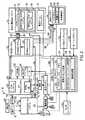
図1は、タービンベースのサービスシステム14に関連する炭化水素生成システム12を有するシステム10の1つの実施形態の概略図である。以下でより詳細に検討するように、タービンベースのサービスシステム14の種々の実施形態は、電力、機械出力、及び流体(例えば、排出ガス)などの種々のサービスを提供し、オイル及び/又はガスの生成又は取り出しを促進するよう構成される。図示の実施形態において、炭化水素生成システム12は、オイル/ガス抽出システム16及び原油二次回収(EOR)システム18を含み、これらは、地下リザーバ20(例えば、オイル、ガス、又は炭化水素リザーバ)に結合される。オイル/ガス抽出システム16は、オイルガス井戸26に結合された様々な坑外設備(クリスマスツリー又は生成ツリー24など)を含む。更に、井戸26は、地中32にある掘削ボア30を通って地下リザーバ20まで延びる1又は2以上の管体28を含むことができる。ツリー24は、地下リザーバ20との間で圧力を調節し流れを制御する、1又は2以上のバルブ、チョーク、分離スリーブ、噴出防止装置、及び種々の流れ制御部を含む。ツリー24は、一般に、地下リザーバ20の外への生成流体の流れを制御するのに使用されるが、EORシステム18は、1又は2以上の流体を地下リザーバ20内に注入することによりオイル又はガスの生成を増大させることができる。 FIG. 1 is a schematic diagram of one embodiment of a
従って、EORシステム18は、地中32にあるボア38を通って地下リザーバ20内に延びる1又は2以上の管体36を有する流体注入システム34を含むことができる。例えば、EORシステム18は、1又は2以上の流体40(ガス、蒸気、水、化学物質、又はこれらの何らかの組み合わせ)を流体注入システム34に送ることができる。例えば、以下でより詳細に検討するように、EORシステム18は、タービンベースのサービスシステム14に結合され、その結果、システム14は、排出ガス42(例えば、実質的に又は完全に酸素を伴わない)をEORシステム18に送り、注入流体40として用いることができるようになる。流体注入システム34は、矢印44で示されるように、1又は2以上の管体36を通って地下リザーバ20に流体40(例えば、排出ガス42)を送る。注入流体40は、オイル/ガス井戸26の管体28からオフセット距離46だけ離れた管体36を通って地下リザーバ20に流入する。従って、注入流体40は、地下リザーバ20内に配置されたオイル/ガス48を移動させ、矢印50で示されるように、炭化水素生成システム12の1又は2以上の管体28を通ってオイル/ガス48を上方に送り出す。以下でより詳細に検討するように、注入流体40は、タービンベースのサービスシステム14から生じた排出ガス42を含むことができ、タービンベースのサービスシステム14は、炭化水素生成システム12によって必要に応じて施設内で排出ガス42を発生させることができる。換言すると、タービンベースのシステム14は、1又は2以上のサービス(例えば、電力、機械出力、蒸気、水(例えば、脱塩水)と、炭化水素生成システム12により使用するための排出ガス(例えば、実質的に酸素を伴わない)とを同時に発生させ、これによりこのようなサービスの外部供給源への依存を低減又は排除することができる。 Accordingly, the
図示の実施形態において、タービンベースのサービスシステム14は、量論的排出ガス再循環(SEGR)ガスタービンシステム52及び排出ガス(EG)プロセスシステム54を含む。ガスタービンシステム52は、燃料リーン制御モード又は燃料リッチ制御モードのような、量論的燃焼運転モード(例えば、量論的制御モード)及び量論的燃焼運転モード(例えば、非量論的制御モード)で作動するよう構成することができる。量論的制御モードにおいては、燃焼は、全体的に、燃料及び酸化剤の実質的に化学量論比で生じ、これにより実質的に量論的燃焼を生じることになる。詳細には、量論的燃焼は、一般に、燃焼生成物が実質的に又は完全に未燃燃料及び酸化剤を含まないように、燃焼反応において燃料及び酸化剤の実質的に全てを消費することを伴う。量論的燃焼の1つの尺度は、当量比すなわちファイ(Φ)であり、量論的燃料/酸化剤比に対する実際の燃料/酸化剤比の割合である。1.0よりも大きい当量比は、燃料及び酸化剤の燃料リッチ燃焼をもたらし、他方、1.0よりも小さい当量比は、燃料及び酸化剤の燃料リーン燃焼をもたらす。対照的に、当量比1.0は、燃料リッチでもなく燃料リーンでもない燃焼をもたらし、従って、燃焼反応において燃料及び酸化剤の全てを実質的に消費する。開示された実施形態の文脈において、用語「量論的」又は「実質的に量論」とは、約0.95〜約1.05の当量比を指すことができる。しかしながら、開示された実施形態はまた、当量比1.0±0.01、0.02、0.03、0.04、0.05、又はそれ以上を含むことができる。この場合も同様に、タービンベースのサービスシステム14における燃料及び酸化剤の量論的燃焼は、残存する未燃燃料又は酸化剤が実質的に存在しない燃焼生成物又は排出ガスをもたらすことができる。例えば、排出ガス42は、1、2、3、4、又は5容積パーセント未満の酸化剤(例えば、酸素)、未燃燃料又は炭化水素(例えば、HC)、窒素酸化物(例えば、NOX)、一酸化炭素(CO)、硫黄酸化物(例えば、SOX)、水素、及び他の不完全燃焼生成物を有することができる。別の実施例によれば、排出ガス42は、約10、20、30、40、50、60、70、80、90、100、200、300、400、500、1000、2000、3000、4000、又は5000ppmv(百万分の1体積)未満の酸化剤(例えば、酸素)、未燃燃料又は炭化水素(例えば、HC)、窒素酸化物(例えば、NOX)、一酸化炭素(CO)、硫黄酸化物(例えば、SOX)、水素、及び他の不完全燃焼生成物を有することができる。しかしながら、開示された実施形態はまた、排出ガス42中の他の範囲の残留燃料、酸化剤、及び他のエミッションレベルを生成することができる。本明細書で使用される場合、用語「エミッション」、「エミッションレベル」、及び「エミッション目標」は、特定の燃焼生成物(例えば、NOX、CO、SOX、O2、N2、H2、HCs、その他)の濃度レベルを指すことができ、これらは、再循環されたガスストリーム、放出されたガスストリーム(例えば、大気中に排出された)、及び種々の目標システム(例えば、炭化水素生成システム12)において使用されるガスストリーム中に存在することができる。 In the illustrated embodiment, the turbine-based
SEGRガスタービンシステム52及びEGプロセスシステム54は、異なる実施形態における様々な構成要素を含むことができるが、図示のEGプロセスシステム54は、熱回収蒸気発生器(HRSG)56及び排出ガス再循環(EGR)システム58を含み、これらは、SEGRガスタービンシステム52から生じた排出ガス60を受け取り処理する。HRSG56は、1又は2以上の熱交換器、凝縮器、及び種々の熱回収設備を含むことができ、これらは全体として、排出ガス60からの熱を水ストリームに伝達して蒸気62を発生するよう機能する。蒸気62は、1又は2以上の蒸気タービン、EORシステム18、又は炭化水素生成システム12の他の何れかの部分において用いることができる。例えば、HRSG56は、低圧、中圧、及び/又は高圧の蒸気62を生成することができ、これらは、低圧、中圧、及び高圧蒸気タービン段又はEORシステム18の異なる用途に選択的に適用することができる。蒸気62に加えて、脱塩水のような処理水64は、HRSG56、EGRシステム58、及び/又はEGプロセスシステム54又はSEGRガスタービンシステム52の別の部分によって生成することができる。処理水64(例えば、脱塩水)は、内陸又は砂漠地帯などの水不足の領域において特に有用とすることができる。処理水64は、SEGRガスタービンシステム52内で燃料の燃焼を生じる大量の空気によって少なくとも部分的に生成することができる。蒸気62及び水64の施設内での生成は、多くの用途(炭化水素生成システム12を含む)で有益であるが、排出ガス42、60の施設内での生成は、SEGRガスタービンシステム52から生成される低酸素含有、高圧及び熱に起因して、EORシステム18にとって特に有益とすることができる。従って、HRSG56、EGRシステム58、及び/又はEGプロセスシステム54の別の部分は、排出ガス66をSEGRガスタービンシステム52に出力又は再循環すると同時に、排出ガス42を炭化水素生成システム12と共に使用するためにEORシステム18に送ることができる。同様に、排出ガス42は、炭化水素生成システム12のEORシステム18にて使用するためにSEGRガスタービンシステム52から直接(すなわち、EGプロセスシステム54を通過することなく)抽出することができる。 Although the SEGR
排出ガス再循環は、EGプロセスシステム54のEGRシステム58により処理される。例えば、EGRシステム58は、1又は2以上の導管、バルブ、ブロア、及び排出ガスプロセスシステム(例えば、フィルタ、粒子状物質除去ユニット、ガス分離ユニット、ガス精製ユニット、熱交換器、熱回収ユニット、除湿ユニット、触媒ユニット、化学物質注入ユニット、又はこれらの組み合わせ)、及び制御部を含み、排出ガス再循環経路に沿って出力(例えば、排出された排出ガス60)から入力(例えば、吸入された排出ガス66)まで排出ガスを再循環するようにする。図示の実施形態において、SEGRガスタービンシステム52は、1又は2以上の圧縮機を有する圧縮機セクションに排出ガス66を吸入させ、これにより排出ガス66を圧縮して、酸化剤68及び1又は2以上の燃料70の吸入と共に燃焼器セクションにおいて使用する。酸化剤68は、周囲空気、純酸素、酸素富化空気、貧酸素空気、酸素−窒素混合気、又は燃料70の燃焼を促進する何らかの好適な酸化剤を含むことができる。燃料70は、1又は2以上のガス燃料、液体燃料、又は何らかのこれらの組み合わせを含むことができる。例えば、燃料70は、天然ガス、液化天然ガス(LNG)、シンガス、メタン、エタン、プロパン、ブタン、ナフサ、ケロシン、ディーゼル燃料、エタノール、メタノール、バイオ燃料、又は何らかのこれらの組み合わせを含むことができる。 The exhaust gas recirculation is handled by the
SEGRガスタービンシステム52は、燃焼器セクションにおいて排出ガス66、酸化剤68、及び燃料70を混合して燃焼させ、これによりタービンセクションにおいて1又は2以上のタービン段を駆動する高温の燃焼ガス又は排出ガス60を発生する。特定の実施形態において、燃焼器セクションにおける各燃焼器は、1又は2以上の予混合燃料ノズル、1又は2以上の拡散燃料ノズル、又は何らかのこれらの組み合わせを含む。例えば、各予混合燃料ノズルは、燃料ノズルの内部で、及び/又は燃料ノズルの部分的に上流側で酸化剤68と燃料70を混合し、これにより予混合燃焼(例えば、予混合火炎)のため酸化剤−燃料混合気を燃料ノズルから燃焼ゾーンに注入するよう構成することができる。別の実施例によれば、各拡散燃料ノズルは、酸化剤68及び燃料70の流れを燃料ノズル内で分離し、これにより拡散燃焼(例えば、拡散火炎)のため酸化剤68及び燃料70を燃料ノズルから燃焼ゾーンに別個に注入するよう構成することができる。詳細には、拡散燃料ノズルによって提供される拡散燃焼は、初期燃焼のポイントすなわち火炎領域まで酸化剤68及び燃料70の混合を遅延させる。拡散燃料ノズルを利用する実施形態において、拡散火炎は、一般に、酸化剤68及び燃料70の別個のストリーム間(すなわち、酸化剤68及び燃料70が混合されるときに)の量論的組成点にて形成されるので、火炎安定性を向上させることができる。特定の実施形態において、1又は2以上の希釈剤(例えば、排出ガス60、蒸気、窒素、又は別の不活性ガス)は、拡散燃料ノズル又は予混合燃料ノズルの何れかにおいて酸化剤68、燃料70、又は両方と予混合することができる。加えて、1又は2以上の希釈剤(例えば、排出ガス60、蒸気、窒素、又は別の不活性ガス)は、各燃焼器内での燃焼点又はその下流側にて燃焼器内に注入することができる。これらの希釈剤を使用することにより、火炎(例えば、予混合火炎又は拡散火炎)の調質を助け、これにより一酸化窒素(NO)及び二酸化窒素(NO2)などのNOxエミッションの低減を助けることができる。火炎のタイプに関係なく、燃焼は、1又は2以上のタービン段を駆動するための高温燃焼ガス又は排出ガス60を生成する。各タービン段が排出ガス60によって駆動されると、SEGRガスタービンシステム52は、機械出力72及び/又は電気出力74(例えば、発電機を介して)を発生する。システム52はまた、排出ガス60を出力し、更に、水64を出力することができる。この場合も同様に、水64は、脱塩水などの処理水とすることができ、設備内又は設備外での様々な用途で有用とすることができる。 The SEGR
排出ガスの抽出はまた、1又は2以上の抽出ポイント76を用いてSEGRガスタービンシステム52により提供される。例えば、図示の実施形態は、抽出ポイント76から排出ガス42を受け取り、排出ガス42を処理し、次いで、種々の目標システムに排出ガス42を供給又は分配する排出ガス(EG)抽出システム80及び排出ガス(EG)処理システム82を有する排出ガス(EG)供給システム78を含む。目標システムは、EORシステム18、及び/又はパイプライン86、貯蔵タンク88、又は炭素隔離システム90などの他のシステムを含むことができる。EG抽出システム80は、1又は2以上の導管、バルブ、制御部、及び流れ分離装置を含むことができ、これらは、排出ガス42を酸化剤68、燃料70、及び他の汚染物質から隔離すると同時に、抽出した排出ガス42の温度、圧力、及び流量を制御する。EG処理システム82は、1又は2以上の熱交換器(例えば、熱回収蒸気発生器などの熱回収ユニット、凝縮器、冷却器、又はヒーター)、触媒システム(例えば、酸化触媒システム)、粒子状物質及び/又は水除去システム(例えば、ガス脱水ユニット、慣性力選別装置、凝集フィルタ、水不透過性フィルタ、及び他のフィルタ)、化学物質注入システム、溶剤ベース処理システム(例えば、吸収器、フラッシュタンク、その他)、炭素捕捉システム、ガス分離システム、ガス精製システム、及び/又は溶剤ベース処理システム、排出ガス圧縮機、これらの何れかの組み合わせを含むことができる。EG処理システム82のこれらのサブシステムにより、温度、圧力、流量、水分含有量(例えば、水分除去量)、粒子状物質含有量(例えば、粒子状物質除去量)、及びガス組成(例えば、CO2、N2、その他のパーセンテージ)の制御が可能となる。Exhaust gas extraction is also provided by the SEGR
抽出した排出ガス42は、目標システムに応じて、EG処理システム82の1又は2以上のサブシステムにより処理される。例えば、EG処理システム82は、炭素捕捉システム、ガス分離システム、ガス精製システム、及び/又は溶剤ベース処理システムを通じて排出ガス42の一部又は全てを配向することができ、種々の目標システムで使用するために炭素含有ガス(例えば、二酸化炭素)92及び/又は窒素(N2)を分離及び精製するよう制御される。例えば、EG処理システム82の実施形態は、ガス分離及び精製を実施し、第1のストリーム96、第2のストリーム97、及び第3のストリーム98のような排出ガス42の複数の異なるストリーム95を生成することができる。第1のストリーム96は、二酸化炭素リッチ及び/又は窒素希薄(例えば、CO2リッチ・N2希薄ストリーム)である第1の組成を有することができる。第2のストリーム97は、二酸化炭素及び/又は窒素(例えば、中間濃度CO2・N2ストリーム)の中間濃度レベルである第2の組成を有することができる。第3のストリーム98は、二酸化炭素希薄及び/又は窒素リッチ(例えば、CO2希薄・N2リッチストリーム)である第3の組成を有することができる。各ストリーム95(例えば、96、97、及び98)は、目標システムへのストリーム95の送出を促進するために、ガス脱水ユニット、フィル、ガス圧縮機、又はこれらの組み合わせを含むことができる。特定の実施形態において、CO2リッチ・N2希薄ストリーム96は、約70、75、80、85、90、95、96、97、98、又は99容積パーセントよりも大きいCO2純度又は濃度レベルと、約1、2、3、4、5、10、15、20、25、又は30容積パーセントよりも小さいN2純度又は濃度レベルとを有することができる。対照的に、CO2希薄・N2リッチストリーム98は、約1、2、3、4、5、10、15、20、25、又は30容積パーセントよりも小さいCO2純度又は濃度レベルと、約70、75、80、85、90、95、96、97、98、又は99容積パーセントよりも大きいN2純度又は濃度レベルとを有することができる。中間濃度CO2・N2ストリーム97は、約30〜70、35〜65、40〜60、又は45〜55容積パーセントのCO2純度又は濃度レベル及び/又はN2純度又は濃度レベルを有することができる。上述の範囲は、単に非限定的な実施例に過ぎず、CO2リッチ・N2希薄ストリーム96及びCO2希薄・N2リッチストリーム98は、EORシステム18及び他のシステム84と共に使用するのに特に好適とすることができる。しかしながら、これらのリッチ、希薄、又は中間濃度CO2ストリーム95は、単独で、又は種々の組み合わせでEORシステム18及び他のシステム84と共に使用することができる。例えば、EORシステム18及び他のシステム84(例えば、パイプライン86、貯蔵タンク88、及び炭素隔離システム90)は各々、1又は2以上のCO2リッチ・N2希薄ストリーム96、1又は2以上のCO2希薄・N2リッチストリーム98、1又は2以上の中間濃度CO2・N2ストリーム97、及び1又は2以上の未処理排出ガス42ストリーム(すなわち、EG処理システム82をバイパスした)を受け取ることができる。The extracted
EG抽出システム80は、圧縮機セクション、燃焼器セクション、及び/又はタービンセクションに沿った1又は2以上の抽出ポイント76にて排出ガス42を抽出し、排出ガス42が、好適な温度及び圧力でEORシステム18及び他のシステム84において使用できるようにする。EG抽出システム80及び/又はEG処理システム82はまた、EGプロセスシステム54との間で流体流(例えば、排出ガス42)を循環させることができる。例えば、EGプロセスシステム54を通過する排出ガス42の一部は、EORシステム18及び他のシステム84で使用するためにEG抽出システム80によって抽出することができる。特定の実施形態において、EG供給システム78及びEGプロセスシステム54は、独立し、又は互いに一体化することができ、従って、独立した又は共通のサブシステムを用いることができる。例えば、EG処理システム82は、EG供給システム78及びEGプロセスシステム54両方によって用いることができる。EGプロセスシステム54から抽出される排出ガス42は、EGプロセスシステム54における1又は2以上のガス処理段及びその後に続くEG処理システム82における1又は2以上の追加のガス処理段のような、複数のガス処理段を受けることができる。 The
各抽出ポイント76において、抽出した排出ガス42は、EGプロセスシステム54において実質的に量論的燃焼及び/又はガス処理に起因して、実質的に酸化剤68及び燃料70(例えば、未燃燃料又は炭化水素)が存在しない場合がある。更に、目標システムに応じて、抽出した排出ガス42は、EG供給システム78のEG処理システム82において更なる処理を受け、これにより何らかの残留する酸化剤68、燃料70、又は他の望ましくない燃焼生成物を更に低減することができる。例えば、EG処理システム82の処理の前又は後で、抽出した排出ガス42は、1、2、3、4、又は5容積パーセントよりも少ない酸化剤(例えば、酸素)、未燃燃料又は炭化水素(例えば、HC)、窒素酸化物(例えば、NOX)、一酸化炭素(CO)、硫黄酸化物(例えば、SOX)、水素、及び他の不完全燃焼生成物を有することができる。別の実施例によれば、EG処理システム82の処理の前又は後で、抽出した排出ガス42は、約10、20、30、40、50、60、70、80、90、100、200、300、400、500、1000、2000、3000、4000、又は5000ppmv(百万分の1体積)よりも少ない酸化剤(例えば、酸素)、未燃燃料又は炭化水素(例えば、HC)、窒素酸化物(例えば、NOX)、一酸化炭素(CO)、硫黄酸化物(例えば、SOX)、水素、及び他の不完全燃焼生成物を有することができる。従って、排出ガス42は、EORシステム18と共に使用するのに特に好適である。 At each
タービンシステム52のEGR作動は、具体的には、複数の位置76での排出ガス抽出を可能にする。例えば、システム52の圧縮機セクションを用いて、どのような酸化剤68もなしで排出ガス66を圧縮する(すなわち、排出ガス66の圧縮のみ)ことができ、その結果、酸化剤68及び燃料70の流入前に圧縮機セクション及び/又は燃焼器セクションから実質的に酸素を含まない排出ガス42を抽出することができるようになる。抽出ポイント76は、隣接する圧縮機段の間の段間ポートにて、圧縮機排出ケーシングに沿ったポートにて、燃焼器セクションにおける各燃焼器に沿ったポートにて、又はこれらの組み合わせに配置することができる。特定の実施形態において、排出ガス66は、燃焼器セクションにおける各燃焼器のヘッド端部部分及び/又は燃料ノズルに達するまでは、酸化剤68及び燃料70と混合しないようにすることができる。更に、1又は2以上の流れ分離器(例えば、壁、仕切り、バッフル、又は同様のもの)を用いて、酸化剤68及び燃料70を抽出ポイント76から隔離することができる。これらの流れ分離器を用いると、抽出ポイント76は、燃焼器セクションにおける各燃焼器の壁に沿って直接配置することができる。 The EGR operation of the
排出ガス66、酸化剤68、及び燃料70がヘッド端部部分を通って(例えば、燃料ノズルを通って)各燃焼器の燃焼部分(例えば、燃焼室)に流入すると、SEGRガスタービンシステム52は、排出ガス66、酸化剤68、及び燃料70の実質的に量論的燃焼をもたらすよう制御される。例えば、システム52は、約0.95〜約1.05の当量比を維持することができる。結果として、各燃焼器における排出ガス66、酸化剤68、及び燃料70の混合気の燃焼生成物は、実質的に酸素及び未燃燃料を含まない。従って、燃焼生成物(又は排出ガス)は、EORシステム18に送られる排出ガス42として使用するためにSEGRガスタービンシステム52のタービンセクションから抽出することができる。タービンセクションに沿って、抽出ポイント76は、隣接するタービン段の間の段間ポートなどの何れかのタービン段に配置することができる。従って、上述の抽出ポイント76の何れかを用いて、タービンベースのサービスシステム14は、排出ガス42を生成及び抽出し、炭化水素生成システム12(例えば、EORシステム18)に送出して、地下リザーバ20からのオイル/ガス48の生成に用いることができる。 As
図2は、タービンベースのサービスシステム14及び炭化水素生成システム12に結合された制御システム100を例示した、図1のシステム10の1つの実施形態の概略図である。図示の実施形態において、タービンベースのサービスシステム14は、複合サイクルシステム102を含み、該複合サイクルシステム102は、トッピングサイクルとしてSEGRガスタービンシステム52と、ボトミングサイクルとして蒸気タービン104と、排出ガス60から熱を回収して、蒸気タービン104を駆動するための蒸気62を発生させるHRSG56と、を含む。この場合も同様に、SEGRガスタービンシステム52は、排出ガス66、酸化剤68、及び燃料70を受け取って混合して、量論的燃焼(例えば、予混合及び/又は拡散火炎)をし、これにより排出ガス60機械出力72電気出力74、及び/又は水64を生成する。例えば、SEGRガスタービンシステム52は、発電機、酸化剤圧縮機(例えば、主空気圧縮機)、ギアボックス、ポンプ、炭化水素生成システム12の設備、又はこれらの組み合わせなどの1又は2以上の負荷又は機械装置106を駆動することができる。一部の実施形態において、機械装置106は、SEGRガスタービンシステム52と縦一列に配列された、発電機又は蒸気タービン(例えば、蒸気タービン104)などの他の駆動装置を含むことができる。従って、SEGRガスタービンシステム52SEGRガスタービンシステム52(及び何らかの追加の駆動装置)によって駆動される機械装置106の出力は、機械出力72及び電気出力74を含むことができる。機械出力72及び/又は電気出力74は、炭化水素生成システム12に動力を供給するために施設内で用いることができ、電気出力74は、送電網又はこれらの組み合わせに配電することができる。機械装置106の出力はまた、SEGRガスタービンシステム52の燃焼セクションに吸入するため、圧縮酸化剤68(例えば、空気又は酸素)などの圧縮流体を含むことができる。これらの出力(例えば、排出ガス60、機械出力72、電気出力74、及び/又は水64)の各々は、タービンベースのサービスシステム14の1つのサービスとみなすことができる。 FIG. 2 is a schematic diagram of one embodiment of the
SEGRガスタービンシステム52は、実質的に酸素を伴わない場合がある排出ガス42、60を生成し、該排出ガス42、60をEGプロセスシステム54及び/又はEG供給システム78に送る。EG供給システム78は、排出ガス42(例えば、ストリーム95)を処理して炭化水素生成システム12及び/又は他のシステム84に送給することができる。上記で検討したように、EGプロセスシステム54は、HRSG56及びEGRシステム58を含むことができる。HRSG56は、1又は2以上の熱交換器、凝縮器、及び種々の熱回収設備を含むことができ、これらを用いて排出ガス60から熱を回収して水108に伝達し、蒸気タービン104を駆動するための蒸気62を発生することができる。SEGRガスタービンシステム52と同様に、蒸気タービン104は、1又は2以上の負荷又は機械装置106を駆動し、これにより機械出力72及び電気出力74を生成することができる。図示の実施形態において、SEGRガスタービンシステム52及び蒸気タービン104は、縦一列の形態で配列されて、同じ機械装置106を駆動する。しかしながら、他の実施形態において、SEGRガスタービンシステム52及び蒸気タービン104は、異なる機械装置106を別個に駆動し、機械出力72及び/又は電気出力74を独立して生成することができる。蒸気タービン104がHRSG56からの蒸気62により駆動されると、蒸気62は、温度及び圧力が漸次的に低下する。従って、蒸気タービン104は、使用した蒸気62及び/又は水108をHRSG56に戻すよう再循環し、排出ガス60からの熱回収を介して追加の蒸気を発生させる。蒸気発生に加えて、HRSG56、EGRシステム58、及び/又はEGプロセスシステム54の別の部分は、水64、及び炭化水素生成システム12と共に用いるための排出ガス42、並びにSEGRガスタービンシステム52への入力として使用する排出ガス66を生成することができる。例えば、水64は、他の用途で使用するための脱塩水のような処理水64とすることができる。脱塩水は、水の利用性が低い領域で特に有用とすることができる。排出ガス60に関しては、EGプロセスシステム54の実施形態は、排出ガス60をHRSG56に通過させるかどうかに関係なく、EGRシステム58を通じて排出ガス60を再循環するよう構成することができる。 The SEGR
図示の実施形態において、SEGRガスタービンシステム52は、システム52の排出出口から排出入口まで延びる排出ガス再循環経路110を有する。排出ガス60は、経路110に沿って、図示の実施形態においてHRSG56及びEGRシステム58を含むEGプロセスシステム54を通過する。EGRシステム58は、経路110に沿って直列及び/又は並列配列で、1又は2以上の導管、バルブ、ブロア、ガス処理システム(例えば、フィルタ、粒子状物質除去ユニット、ガス分離ユニット、ガス精製ユニット、熱交換器、熱回収蒸気発生器などの熱回収ユニット、除湿ユニット、触媒ユニット、化学物質注入ユニット、又はこれらの組み合わせ)を含むことができる。このようなガス処理システムは更に、再循環ガスの物理的特性を変更することを目的とした何らかのガス取り扱い又はプロセス設備を含むことができる。換言すると、EGRシステム58は、システム52の排出ガス出口及び排出ガス入口間の排出ガス再循環経路110に沿って、何らかの流れ制御構成要素、圧力制御構成要素、温度制御構成要素、湿度制御構成要素、及びガス組成制御構成要素を含むことができる。従って、経路110に沿ってHRSG56を備えた実施形態において、HRSG56は、EGRシステム58の1つの構成要素とみなすことができる。しかしながら、特定の実施形態において、HRSG56は、排出ガス再循環経路110とは独立して排出ガス経路に沿って配置することができる。HRSG56がEGRシステム58に対して別個の経路に沿っているか、又は共通の経路に沿っているかに関係なく、HRSG56及びEGRシステム58は、排出ガス60を吸入して、再循環される排出ガス60、又はEG供給システム78(例えば、炭化水素生成システム12及び/又は他のシステム84のため)と共に使用するための排出ガス42、或いは別の出力の排出ガスを出力する。この場合も同様に、SEGRガスタービンシステム52は、排出ガス66、酸化剤68、及び燃料70(例えば、予混合火炎及び/又は拡散火炎)を吸入して混合し、量論的燃焼して、EGプロセスシステム54、炭化水素生成システム12、又は他のシステム84に分配するために実質的に酸素及び燃料を含まない排出ガス60を生成する。 In the illustrated embodiment, the SEGR
図1を参照して上述したように、炭化水素生成システム12は、地下リザーバ20からオイル/ガス井戸26を通るオイル/ガス48の回収又は生成を促進する様々な設備を含むことができる。例えば、炭化水素生成システム12は、流体注入システム34を有するEORシステム18を含むことができる。図示の実施形態において、流体注入システム34は、排出ガス注入EORシステム112及び蒸気注入EORシステム114を含む。流体注入システム34は、様々な供給源から流体を受け取ることができるが、図示の実施形態は、タービンベースのサービスシステム14から排出ガス42及び蒸気62を受け取ることができる。タービンベースのサービスシステム14により生成される排出ガス42及び/又は蒸気62はまた、他のオイル/ガスシステム116で使用するため炭化水素生成システム12に送ることができる。 As described above with reference to FIG. 1, the
排出ガス42及び蒸気62の量、品質、及び流れは、制御システム100により制御することができる。制御システム100は、タービンベースのサービスシステム14に完全に専用とすることができ、或いはまた、任意選択的に、炭化水素生成システム12及び/又は他のシステム84の制御を行うことができる。図示の実施形態において、制御システム100は、プロセッサ120、メモリ122、蒸気タービン制御部124、SEGRガスタービンシステム制御部126、及び機械制御部128を有するコントローラ118を含む。プロセッサ120は、タービンベースのサービスシステム14を制御するために単一のプロセッサ、又はトリプル冗長プロセッサのような2又は3以上の冗長プロセッサを含むことができる。メモリ122は、揮発性及び/又は不揮発性メモリを含むことができる。例えば、メモリ122は、1又は2以上のハードドライブ、フラッシュメモリ、リードオンリーメモリ、ランダムアクセスメモリ、又はこれらの組み合わせを含むことができる。制御部124、126、及び128は、ソフトウェア及び/又はハードウェア制御部を含むことができる。例えば、制御部124、126、及び128は、メモリ122上に格納されてプロセッサ120により実行可能な種々の命令又はコードを含むことができる。制御部124は、蒸気タービン104の作動を制御するよう構成され、SEGRガスタービンシステム制御部126は、システム52を制御するよう構成され、機械制御部128は、機械装置106を制御するよう構成される。従って、コントローラ118(例えば、制御部124、126、及び128)は、タービンベースのサービスシステム14の種々のサブシステムを協働させて、炭化水素生成システム12に排出ガス42の好適なストリームを提供するよう構成することができる。 The amount, quality, and flow of the
制御システム100の特定の実施形態において、図示され本明細書で記載される各要素(例えば、システム、サブシステム、及び構成要素)は、(例えば、このような要素の直接内部に、上流側に、又は下流側に)センサ及び制御デバイスのような、1又は2以上の工業用制御特徴要素を含み、これらは、工業用制御ネットワークを介してコントローラ118と共に互いに通信可能に結合される。例えば、各要素に関連する制御デバイスは、専用のデバイスコントローラ(例えば、プロセッサ、メモリ、及び制御命令を含む)、1又は2以上のアクチュエータ、バルブ、スイッチ、及び工業用制御機器を含むことができ、これらは、センサフィードバック130、コントローラ118からの制御信号、ユーザからの制御信号、又はこれらの組み合わせに基づいて制御を可能にする。従って、本明細書で記載される制御機能を何れも、コントローラ118、 各要素に関連する専用のデバイスコントローラ、又はこれらの組み合わせにより格納され及び/又は実行可能な制御命令を用いて実施することができる。 In certain embodiments of the
このような制御機能を可能にするために、制御システム100は、種々の制御部(例えば、制御部124、126、及び128)の実行で使用するセンサフィードバック130を得るために、システム10全体にわたって配置された1又は2以上のセンサを含む。例えば、センサフィードバック130は、SEGRガスタービンシステム52、機械装置106、EGプロセスシステム54、蒸気タービン104、炭化水素生成システム12、或いは、タービンベースのサービスシステム14又は炭化水素生成システム12にわたる他の何れかの構成要素にわたって配置されたセンサから取得することができる。例えば、センサフィードバック130は、温度フィードバック、圧力フィードバック、流量フィードバック、火炎温度フィードバック、燃焼ダイナミックスフィードバック、吸入酸化剤組成フィードバック、吸入燃料組成フィードバック、排出ガス組成フィードバック、機械出力72の出力レベル、電気出力74の出力レベル、排出ガス42、60の出力量、水64の出力量又は品質、又はこれらの組み合わせを含むことができる。例えば、センサフィードバック130は、SEGRガスタービンシステム52において量論的燃焼を可能にする排出ガス42、60の組成を含むことができる。例えば、センサフィードバック130は、酸化剤68の酸化剤供給経路に沿った1又は2以上の吸入酸化剤センサ、燃料70の燃料供給経路に沿った1又は2以上の吸入燃料センサ、及び排出ガス再循環経路110に沿って配置され及び/又はSEGRガスタービンシステム52内部に配置された1又は2以上の排出エミッションセンサからのフィードバックを含むことができる。吸入酸化剤センサ、吸入燃料センサ、及び排出エミッションセンサは、温度センサ、圧力センサ、流量センサ、及び組成センサを含むことができる。エミッションセンサは、窒素酸化物(例えば、NOxセンサ)、炭素酸化物(例えば、COセンサ及びCO2センサ)、硫黄酸化物(例えば、SOXセンサ)、水素(例えば、H2センサ)、酸素(例えば、O2センサ)、未燃炭化水素(例えば、HCセンサ)、又は他の不完全燃焼生成物、或いはこれらの組み合わせに対するセンサを含むことができる。In order to enable such control functions, the
このフィードバック130を用いて、制御システム100は、当量比を好適な範囲内、例えば、例えば、約0.95〜約1.05、約0.95〜約1.0、約1.0〜約1.05、又は実質的に1.0で維持するよう、(他の作動パラメータの中でも特に)SEGRガスタービンシステム52への排出ガス66、酸化剤68、及び/又は燃料70の吸入流れを調整(例えば、増大、減少、又は維持)することができる。例えば、制御システム100は、フィードバック130を分析して、排出エミッション(例えば、窒素酸化物、CO及びCO2などの炭素酸化物、硫黄酸化物、水素、酸素、未燃炭化水素、及び他の不完全燃焼生成物の濃度レベル)を監視し、及び/又は当量比を求め、次いで、排出エミッション(例えば、排出ガス42の濃度レベル)及び/又は当量比を調整するよう1又は2以上の構成要素を制御することができる。制御される構成要素は、限定ではないが、酸化剤68、燃料70、及び排出ガス66のための供給経路に沿ったバルブ;EGプロセスシステム54における酸化剤圧縮機、燃料ポンプ、又は何れかの構成要素;SEGRガスタービンシステム52の何れかの構成要素;又はこれらの組み合わせを含む、図示され図面を参照して説明される構成要素の何れかを含むことができる。制御される構成要素は、SEGRガスタービンシステム52内で燃焼をする酸化剤68、燃料70、及び排出ガス66の流量、温度、圧力、又はパーセンテージ(例えば、当量比)を調整(例えば、増大、減少、又は維持)することができる。制御される構成要素はまた、触媒ユニット(例えば、酸化触媒ユニット)、触媒ユニット(例えば、酸化燃料、熱、電気、その他)のための供給源、ガス精製及び/又は分離ユニット(例えば、溶剤ベース分離器、吸収器、フラッシュタンク、その他)、及び濾過ユニットなど、1又は2以上のガス処理システムを含むことができる。ガス処理システムは、排出ガス再循環経路110、通気経路(例えば、大気中に排出された)、又はEG供給システム78への抽出経路に沿った種々の排出エミッションの低減を助けることができる。Using this
特定の実施形態において、制御システム100は、フィードバック130を分析し、約10、20、30、40、50、100、200、300、400、500、1000、2000、3000、4000、5000、又は10000ppmv(百万分の1体積)未満など、エミッションレベル(例えば、排出ガス42の濃度レベル、60、95)を目標範囲に維持又は低減するよう、1又は2以上の構成要素を制御することができる。これらの目標範囲は、排出エミッション(例えば、窒素酸化物、一酸化炭素、硫黄酸化物、水素、酸素、未燃炭化水素、及び他の不完全燃焼生成物の濃度レベル)の各々に対して同じ又は異なることができる。例えば、当量比に応じて、制御システム100は、酸化剤(例えば、酸素)の排出エミッション(例えば、濃度レベル)を約10、20、30、40、50、60、70、80、90、100、250、500、750、又は1000ppmv未満の目標範囲内に、一酸化炭素(CO)の排出エミッション(例えば、濃度レベル)を約20、50、100、200、500、1000、2500、又は5000ppmv未満の目標範囲内に、及び窒素酸化物(NOX)の排出エミッション(例えば、濃度レベル)を約50、100、200、300、400、又は500ppmv未満の目標範囲内に選択的に制御することができる。実質的に量論的当量比で作動する特定の実施形態において、制御システム100は、酸化剤(例えば、酸素)の排出エミッション(例えば、濃度レベル)を約10、20、30、40、50、60、70、80、90、又は100ppmv未満の目標範囲内に、及び一酸化炭素(CO)の排出エミッション(例えば、濃度レベル)を約500、1000、2000、3000、4000、又は5000ppmv未満の目標範囲内に選択的に制御することができる。燃料リーン当量比(例えば、約0.95〜1.0)で作動する特定の実施形態において、制御システム100は、酸化剤(例えば、酸素)の排出エミッション(例えば、濃度レベル)を約500、600、700、800、900、1000、1100、1200、1300、1400、又は1500ppmv未満の目標範囲内に、一酸化炭素(CO)の排出エミッション(例えば、濃度レベル)を約10、20、30、40、50、60、70、80、90、100、150、又は200ppmvの目標範囲内に、及び窒素酸化物(例えば、NOX)の排出エミッション(例えば、濃度レベル)を約50、100、150、200、250、300、350、又は400ppmv未満の目標範囲内に選択的に制御することができる。上述の目標範囲は、単に実施例に過ぎず、開示された実施形態の範囲を限定するものではない。In certain embodiments, the
制御システム100はまた、ローカルインタフェース132及びリモートインタフェース134に結合することができる。例えば、ローカルインタフェース132は、タービンベースのサービスシステム14及び/又は炭化水素生成システム12にて施設内に配置されたコンピュータワークステーションを含むことができる。対照的に、リモートインタフェース134は、インターネット接続を通じてなど、タービンベースのサービスシステム14及び炭化水素生成システム12の施設外に配置されたコンピュータワークステーションを含むことができる。これらのインタフェース132及び134は、センサフィードバック130、作動パラメータ及びその他の1又は2以上のグラフィック表示を通じてなど、タービンベースのサービスシステム14の監視及び制御を可能にする。 The
この場合も同様に、上述のように、コントローラ118は、タービンベースのサービスシステム14の制御を可能にする様々な制御部124、126、及び128を含む。蒸気タービン制御部124は、センサフィードバック130を受け取り、蒸気タービン104の作動を可能にする制御コマンドを出力することができる。例えば、蒸気タービン制御部124は、HRSG56、機械装置106、蒸気62の経路に沿った温度及び圧力センサ、水108の経路に沿った温度及び圧力センサ、及び機械出力72及び電気出力74を示す種々のセンサからセンサフィードバック130を受け取ることができる。同様に、SEGRガスタービンシステム制御部126は、SEGRガスタービンシステム52、機械装置106、EGプロセスシステム54、又はこれらの組み合わせに沿って配置された1又は2以上のセンサからセンサフィードバック130を受け取ることができる。例えば、センサフィードバック130は、SEGRガスタービンシステム52の内部又は外部に配置された温度センサ、圧力センサ、クリアランスセンサ、振動センサ、火炎センサ、燃料組成センサ、排出ガス組成センサ、又はこれらの組み合わせから得ることができる。最後に、機械制御部128は、機械出力72及び電気出力74に関連する種々のセンサ並びに機械装置106内に配置されたセンサからセンサフィードバック130を受け取ることができる。これら制御部124、126、及び128の各々は、センサフィードバック130を用いて、タービンベースのサービスシステム14の作動を改善する。 Again, as described above, the
図示の実施形態において、SEGRガスタービンシステム制御部126は、EGプロセスシステム54、EG供給システム78、炭化水素生成システム12、及び/又は他のシステム84における排出ガス42、60、95の量及び品質を制御する命令を実行することができる。例えば、SEGRガスタービンシステム制御部126は、排出ガス60における酸化剤(例えば、酸素)及び/又は未燃燃料のレベルを排出ガス注入EORシステム112と共に使用するのに好適な閾値未満に維持することができる。特定の実施形態において、閾値レベルは、排出ガス42、60の容積で酸化剤(例えば、酸素)及び/又は未燃燃料が1、2、3、4、又は5パーセント未満とすることができ、或いは、酸化剤(例えば、酸素)及び/又は未燃燃料(及び他の排出エミッション)の閾値レベルが、排出ガス42、60中に約10、20、30、40、50、60、70、80、90、100、200、300、400、500、1000、2000、3000、4000、又は5000ppmv(百万分の1体積)未満とすることができる。別の実施例によれば、酸化剤(例えば、酸素)及び/又は未燃燃料のこれらの低レベルを達成するために、SEGRガスタービンシステム制御部126は、SEGRガスタービンシステム52での燃焼において約0.95〜約1.05の当量比を維持することができる。SEGRガスタービンシステム制御部126は、排出ガス42、60、95の温度、圧力、流量、及びガス組成を排出ガス注入EORシステム112、パイプライン86、貯蔵タンク88、及び炭素隔離システム90に好適な範囲内に維持するよう、EG抽出システム80及びEG処理システム82を制御することができる。上記で検討したように、EG処理システム82は、CO2リッチ・N2希薄ストリーム96、中間濃度CO2・N2ストリーム97、及びCO2希薄・N2リッチストリーム98のような1又は2以上のガスストリーム95内への排出ガス42を精製及び/又は分離するよう制御することができる。排出ガス42、60、及び95の制御に加えて、制御部124、126、及び128は、機械出力72を好適な出力範囲内に維持し、又は電気出力74を好適な周波数及び出力範囲内に維持するための1又は2以上の命令を実行することができる。 In the illustrated embodiment, the SEGR gas
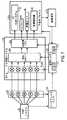
図3は、炭化水素生成システム12及び/又は他のシステム84と共に使用するためのSEGRガスタービンシステム52の詳細を更に例示した、システム10の実施形態の概略図である。図示の実施形態において、SEGRガスタービンシステム52は、EGプロセスシステム54に結合されたガスタービンエンジン150を含む。図示のガスタービンエンジン150は、圧縮機セクション152、燃焼器セクション154、及び膨張器セクション又はタービンセクション156を含む。圧縮機セクション152は、直列配列で配置された回転圧縮機ブレードの1〜20段のような1又は2以上の排出ガス圧縮機又は圧縮機段158を含む。同様に、燃焼器セクション154は、SEGRガスタービンシステム52の回転軸線162の周りで円周方向に配置された1〜20の燃焼器160のような1又は2以上の燃焼器160を含む。更に、各燃焼器160は、排出ガス66、酸化剤68、及び/又は燃料70を注入するよう構成された1又は2以上の燃料ノズル164を含むことができる。例えば、各燃焼器160のヘッド端部部分166は、1、2、3、4、5、6、又はそれ以上の燃料ノズル164を収容することができ、該燃料ノズルは、排出ガス66、酸化剤68、及び/又は燃料70のストリーム又は混合気を燃焼器160の燃焼部分168(例えば、燃焼室)に注入することができる。 FIG. 3 is a schematic diagram of an embodiment of the
燃料ノズル164は、予混合燃料ノズル164(例えば、酸化剤/燃料予混合火炎の生成のため酸化剤68及び燃料70を予混合するよう構成された)及び/又は拡散燃料ノズル164(例えば、酸化剤/燃料拡散火炎の生成のため酸化剤68及び燃料70の別個の流れを注入するよう構成された)のあらゆる組み合わせを含むことができる。予混合燃料ノズル164の実施形態は、燃焼室168における注入及び燃焼の前にノズル164内で酸化剤68及び燃料70を内部で混同するためのスワールベーン、混合チャンバ、又は他の特徴要素を含むことができる。予混合燃料ノズル164はまた、少なくとも一部が部分的に混合された酸化剤68及び燃料70を受け取ることができる。特定の実施形態において、各拡散燃料ノズル164は、注入ポイントまで酸化剤68及び燃料70の流れを隔離すると同時に、注入ポイントまで1又は2以上の希釈剤(例えば、排出ガス66、蒸気、窒素、又は別の不活性ガス)の流れを隔離することができる。他の実施形態において、各拡散燃料ノズル164は、注入ポイントまで酸化剤68及び燃料70の流れを隔離するが、注入ポイントの前に1又は2以上の希釈剤(例えば、排出ガス66、蒸気、窒素、又は別の不活性ガス)を酸化剤68及び/又は燃料70と部分的に混合することができる。加えて、1又は2以上の希釈剤(例えば、排出ガス66、蒸気、窒素、又は別の不活性ガス)は、燃焼ゾーンにて又はその下流側で燃焼器内(例えば、高温の燃焼生成物内)に注入され、これにより高温の燃焼生成物の温度を低下させ、NOX(例えば、NO及びNO2)のエミッションを低減するのを助けることができる。燃料ノズル164のタイプに関係なく、SEGRガスタービンシステム52は、酸化剤68及び燃料70の実質的に量論的燃焼を提供するよう制御することができる。 The
拡散燃料ノズル164を用いた拡散燃焼の実施形態において、燃料70及び酸化剤68は一般に、拡散火炎の上流側では混合せず、むしろ、燃料70及び酸化剤68は、火炎表面にて直接混合及び反応し、及び/又は火炎表面は、燃料70及び酸化剤68間の混合位置に存在する。詳細には、燃料70及び酸化剤68は、火炎表面(又は拡散境界/界面)に別個に接近し、次いで、火炎表面(又は拡散境界/界面)に沿って拡散(例えば、分子及び粘性拡散を介して)し、拡散火炎を発生する。燃料70及び酸化剤68は、この火炎表面(又は拡散境界/界面)に沿って実質的に量論比にあるものとすることができ、その結果、この火炎表面に沿ってより高い火炎温度(例えば、ピーク火炎温度)を生じることができる。量論的燃料/酸化剤比は一般に、燃料リーン又は燃料リッチの燃料/酸化剤比と比べて、高い火炎温度(例えば、ピーク火炎温度)をもたらす。結果として、拡散火炎は、予混合火炎よりも実質的により安定することができ、これは、燃料70及び酸化剤68の拡散が、火炎表面に沿った量論比(及びより高温)を維持するのを助けることに起因する。より高い火炎温度はまた、NOxエミッションのような排出エミッションをより多く生じる可能性があるが、開示の実施形態では、1又は2以上の希釈剤を用いて、燃料70及び酸化剤68のあらゆる予混合を尚も回避しながら、温度及びエミッションを制御することができる。例えば、開示された実施形態は、燃料70及び酸化剤68とは別個に(例えば、燃焼ポイントの後及び/又は拡散火炎から下流側で)1又は2以上の希釈剤を導入することができ、これにより、温度を低下させ、拡散火炎により生じたエミッションを低減するのを助けることができる。 In the diffusion combustion embodiment using the
作動時には、図示のように、圧縮機セクション152は、EGプロセスシステム54からの排出ガス66を受け取って圧縮し、次いで、圧縮した排出ガス170を燃焼器セクション154における燃焼器160の各々に出力する。各燃焼器160内で燃料70、酸化剤68、及び排出ガス170が燃焼すると、追加の排出ガス又は燃焼生成物172(すなわち、燃焼ガス)がタービンセクション156に送られる。圧縮機セクション152と同様に、タービンセクション156は、一連の回転タービンブレードを有することができる1又は2以上のタービン又はタービン段174を含む。ここで、これらのタービンブレードは、燃焼器セクション154において発生した燃焼生成物172により駆動され、これにより機械装置106に結合されたシャフト176の回転を駆動する。この場合も同様に、機械装置106は、タービンセクション156に結合された機械装置106、178及び/又は圧縮機セクション152に結合された機械装置106、180など、SEGRガスタービンシステム52の何れかの端部に結合された様々な機器を含むことができる。特定の実施形態において、機械装置106、178、180は、1又は2以上の発電機、酸化剤68用の酸化剤圧縮機、燃料70用の燃料ポンプ、ギアボックス、又はSEGRガスタービンシステム52 に結合された追加の駆動装置(例えば、蒸気タービン104、電気モータ、その他)を含むことができる。以下では、表1を参照しながら、非限定的な実施例を更に詳細に検討する。図示のように、タービンセクション156は、排出ガス60を出力し、排出ガス再循環経路110に沿ってタービンセクション156の排出ガス出口182から排出ガス入口184に向かって圧縮機セクション152内に再循環する。排出ガス再循環経路110に沿って、排出ガス60は、上記で詳細に検討したようにEGプロセスシステム54(例えば、HRSG56及び/又はEGRシステム58)を通過する。 In operation, as shown, the compressor section 152 receives and compresses
この場合も同様に、燃焼器セクション154における各燃焼器160は、加圧排出ガス170、酸化剤68、及び燃料70を受け取って混合し、量論的に燃焼して、追加の排出ガス又は燃焼生成物172を生成し、タービンセクション156を駆動する。特定の実施形態において、酸化剤68は、1又は2以上の酸化剤圧縮機(MOC)を有する主酸化剤圧縮(MOC)システム(例えば、主空気圧縮(MAC)システム)のような酸化剤圧縮システム186により圧縮される。酸化剤圧縮システム186は、駆動装置190に結合された酸化剤圧縮機188を含む。例えば、駆動装置190は、電気モータ、燃焼エンジン、又はこれらの組み合わせを含むことができる。特定の実施形態において、駆動装置190は、ガスタービンエンジン150のようなタービンエンジンとすることができる。従って、酸化剤圧縮システム186は、機械装置106の一体化部分とすることができる。換言すると、圧縮機188は、ガスタービンエンジン150のシャフト176により供給される機械出力72によって直接的又は間接的に駆動することができる。このような実施形態においては、圧縮機188は、タービンエンジン150からの出力に依存するので、駆動装置190は除外してもよい。しかしながら、1つよりも多い酸化剤圧縮機を利用する特定の実施形態において、第1の酸化剤圧縮機(例えば、低圧(LP)酸化剤圧縮機)は、駆動装置190により駆動することができるが、シャフト176は、第2の酸化剤圧縮機(例えば、高圧(HP)酸化剤圧縮機)を駆動し、或いは、その逆であってもよい。例えば、別の実施形態において、HP MOCは、駆動装置190により駆動され、LP酸化剤圧縮機は、シャフト176により駆動される。図示の実施形態において、酸化剤圧縮システム186は、機械装置106から分離される。これらの実施形態の各々において、圧縮システム186は、酸化剤68を燃料ノズル164及び燃焼器160に圧縮及び供給する。従って、機械装置106、178、180の一部又は全ては、圧縮システム186(例えば、圧縮機188及び/又は追加の圧縮機)の作動効率を向上させるように構成することができる。 Again, each combustor 160 in the
要素番号106A、106B、106C、106D、106E、及び106Fで示される機械装置106の様々な構成要素は、1又は2以上の直列配列、並列配列、又は直列配列と並列配列の何らかの組み合わせでシャフト176の軸線に沿って及び/又はシャフト176の軸線に平行に配置することができる。例えば、機械装置106、178、180(例えば、106Aから106F)は、任意の順序で、1又は2以上のギアボックス(例えば、平行シャフト、遊星ギアボックス)、1又は2以上の圧縮機(例えば、酸化剤圧縮機、EGブースタ圧縮機のようなブースタ圧縮機)、1又は2以上の発電ユニット(例えば、発電機)、1又は2以上の駆動装置(例えば、蒸気タービンエンジン、電気モータ)、熱交換ユニット(例えば、直接式又は間接式熱交換器)、クラッチ、又はこれらの組み合わせの何らかの直列及び/又は並列配列を含むことができる。圧縮機は、軸方向圧縮機、半径方向又は遠心式圧縮機、又はこれらの組み合わせを含むことができ、各々が1又は2以上の圧縮段を有する。熱交換器に関しては、直接式熱交換器は、ガス流を直接冷却するためにガス流(例えば、酸化剤流)に液体噴霧を注入する噴霧冷却器(例えば、噴霧中間冷却器)を含むことができる。間接式熱交換器は、冷却剤流(例えば、水、空気、冷媒、又は他の何れかの液体又は気体冷却剤)から流体流(例えば、酸化剤流)を分離するような、第1及び第2の流れを分離する少なくとも1つの壁(例えば、シェル及び管体熱交換器)を含むことができ、ここで冷却剤流は、どのような直接接触もなく流体流から熱を伝達する。間接式熱交換器の実施例は、中間冷却器熱交換器、及び熱回収蒸気発生器のような熱回収ユニットを含む。熱交換器はまた、ヒーターを含むことができる。以下でより詳細に検討するように、これらの機械構成要素の各々は、表1に記載される非限定的な実施例によって示される様々な組み合わせで用いることができる。 The various components of the
一般に、機械装置106、178、180は、例えば、システム186における1又は2以上の酸化剤圧縮機の作動速度を調整し、冷却を通じて酸化剤68の圧縮を促進させ、及び/又は余剰出力を抽出することによって、圧縮システム186の効率を向上させるよう構成することができる。開示された実施形態は、直列及び並列配列の機械装置106、178、180における上述の構成要素のあらゆる並び換えを含むことを意図しており、構成要素の1つ、2つ以上、又は全てがシャフト176から出力を得ており、或いは、全てが得ていない。以下で示すように、表1は、圧縮機及びタービンセクション152、156に近接して配置及び/又は結合された機械装置106、178、180の配列の幾つかの非限定的な実施例を示している。 In general, the
表1
表1において上記で示したように、冷却ユニットはCLRで表され、クラッチはCLUで表され、駆動装置はDRVで表され、ギアボックスはGBXで表され、発電機はGENで表され、加熱ユニットはHTRで表され、主酸化剤圧縮機ユニットはMOCで表され、低圧及び高圧変形形態はそれぞれLP MOC及びHP MOCで表され、蒸気発生器ユニットはSTGNで表されている。表1は、圧縮機セクション152又はタービンセクション156に向かって機械装置106、178、180を順次的に示しているが、表1はまた、逆順の機械装置106、178、180も包含することを意図している。表1において、2又は3以上の構成要素を含むあらゆる欄(セル)は、構成要素の並列配列を包含することを意図している。表1は、機械装置106、178、180の図示していない何らかの並び換えを排除することを意図するものではない。機械装置106、178、180のこれらの構成要素は、ガスタービンエンジン150に送られる温度、圧力、及び流量のフィードバック制御を可能にすることができる。以下でより詳細に検討するように、酸化剤68及び燃料70は、加圧排出ガス170の品質を劣化させるどのような酸化剤68又は燃料70も無しで、排出ガス170の分離及び抽出を可能にするよう特に選択された位置にてガスタービンエンジン150に供給することができる。 As indicated above in Table 1, the cooling unit is represented by CLR, the clutch is represented by CLU, the drive unit is represented by DRV, the gearbox is represented by GBX, the generator is represented by GEN, and the heating The unit is represented by HTR, the main oxidizer compressor unit is represented by MOC, the low pressure and high pressure variants are represented by LP MOC and HP MOC, respectively, and the steam generator unit is represented by STGN. Although Table 1 shows the
図3に示すように、EG供給システム78は、ガスタービンエンジン150と目標システム(例えば、炭化水素生成システム12及び他のシステム84)との間に配置される。詳細には、EG供給システム78(例えば、EG抽出システム(EGES)80)は、圧縮機セクション152、燃焼器セクション154、及び/又はタービンセクション156に沿った1又は2以上の抽出ポイント76にてガスタービンエンジン150に結合することができる。例えば、抽出ポイント76は、圧縮機段の間の2、3、4、5、6、7、8、9、又は10の段間抽出ポイント76のように、隣接する圧縮機段の間に配置することができる。これらの段間抽出ポイント76の各々は、抽出した排出ガス42の異なる温度及び圧力を提供する。同様に、抽出ポイント76は、タービン段の間の圧縮機段の間の2、3、4、5、6、7、8、9、又は10の段間抽出ポイント76のように、隣接するタービン段の間に配置することができる。これらの段間抽出ポイント76の各々は、抽出した排出ガス42の異なる温度及び圧力を提供する。別の実施例によれば、抽出ポイント76は、燃焼器セクション154全体にわたって複数の位置に配置することができ、これらは、異なる温度、圧力、流量、及びガス組成を提供することができる。これらの抽出ポイント76の各々は、EG抽出導管、1又は2以上のバルブ、センサ、及び制御部を含むことができ、これらは、抽出した排出ガス42のEG供給システム78への流れを選択的に制御するのに用いることができる。 As shown in FIG. 3, the
EG供給システム78によって分配される抽出した排出ガス42は、目標システム(例えば、炭化水素生成システム12及び他のシステム84)に好適な制御された組成を有する。例えば、これらの抽出ポイント76の各々において、排出ガス170は、酸化剤68及び燃料70の注入ポイント(又は流れ)から実質的に隔離することができる。換言すると、EG供給システム78は、どのような酸化剤68又は燃料70の追加も無く、排出ガス170をガスタービンエンジン150から抽出するよう特別に設計することができる。更に、燃焼器160の各々における量論的燃焼の観点で、抽出した排出ガス42は実質的に酸素及び燃料を含まないものとすることができる。EG供給システム78は、原油二次回収、炭素隔離、貯蔵、又は施設外の場所への輸送など、種々のプロセスで使用するために、抽出した排出ガス42を炭化水素生成システム12及び/又は他のシステム84に直接的又は間接的に送ることができる。しかしながら、特定の実施形態において、EG供給システム78は、目標システムと共に使用する前に、排出ガス42を更に処理するためにEG処理システム(EGTS)82を含む。例えば、EG処理システム82は、CO2リッチ・N2希薄ストリーム96、中間濃度CO2・N2ストリーム97、及びCO2希薄・N2リッチストリーム98などの1又は2以上のストリーム95への排出ガス42を精製及び/又は分離することができる。これらの処理された排出ガスストリーム95は、炭化水素生成システム12及び他のシステム84(例えば、パイプライン86、貯蔵タンク88、及び炭素隔離システム90)と共に個別に又は何らかの組み合わせで用いることができる。 The extracted
EG供給システム78において実施された排出ガスの処理と同様に、EGプロセスシステム54は、要素番号194、196、198、200、202、204、206、208、及び210により示されるような、複数の排出ガス(EG)処理構成要素192を含むことができる。これらのEG処理構成要素192(例えば、194〜210)は、1又は2以上の直列配列、並列配列、又は直列配列と並列配列の何らかの組み合わせで排出ガス再循環経路110に沿って配置することができる。例えば、EG処理構成要素192(例えば、194〜210)は、任意の順序で、1又は2以上の熱交換器(例えば、熱回収蒸気発生器などの熱回収ユニット、凝縮器、冷却器、又はヒーター)、触媒システム(例えば、酸化触媒システム)、粒子状物質及び/又は水除去システム(例えば、慣性力選別装置、凝集フィルタ、水不透過性フィルタ、及び他のフィルタ)、化学物質注入システム、溶剤ベース処理システム(例えば、吸収器、フラッシュタンク、その他)、炭素捕捉システム、ガス分離システム、ガス精製システム、及び/又は溶剤ベース処理システム、又はこれらの何れかの組み合わせを含むことができる。特定の実施形態において、触媒システムは、酸化触媒、一酸化炭素還元触媒、窒素酸化物還元触媒、アルミニウム酸化物、ジルコニウム酸化物、シリコーン酸化物、チタン酸化物、プラチナ酸化物、パラジウム酸化物、コバルト酸化物、又は混合金属酸化物、或いはこれらの組み合わせを含むことができる。開示された実施形態は、直列及び並列配列の上述の構成要素192のあらゆる並び換えを含むことを意図している。以下に示すように、表2は、排出ガス再循環経路110に沿った構成要素192の配列の幾つかの非限定的な実施例を示している。 Similar to the exhaust gas treatment performed in the
表2
表2において上記で示したように、触媒ユニットはCUで表され、酸化触媒ユニットはOCUで表され、ブースタブロアはBBで表され、熱交換器はHXで表され、熱回収ユニットはHRUで表され、熱回収蒸気発生器はHRSGで表され、凝縮器はCONDで表され、蒸気タービンはSTで表され、粒子状物質除去ユニットはPRUで表され、除湿ユニットはMRUで表され、フィルタはFILで表され、凝集フィルタはCFILで表され、水不透過性フィルタはWFILで表され、慣性力選別装置はINERで表され、希釈剤供給システム(例えば、蒸気、窒素、又は他の不活性ガス)はDILで表される。表2は、タービンセクション156の排出ガス出口182から圧縮機セクション152の排出ガス入口184に向かって構成要素192を順次的に示しているが、図示の構成要素192の逆順も包含することを意図している。表2において、2又は3以上の構成要素を含むあらゆる欄(セル)は、構成要素を備えた一体的ユニット、構成要素の並列配列、又はこれらの組み合わせを包含することを意図している。更に、表2において、HRU、HRSG、及びCONDはHEの実施例であり、HRSGは、HRUの実施例であり、COND、WFIL、及びCFILはWRUの実施例であり、INER、FIL、WFIL、及びCFILはPRUの実施例であり、WFIL及びCFILは、FILの実施例である。この場合も同様に、表2は、構成要素192の図示していない何らかの並び換えを排除することを意図するものではない。特定の実施形態において、図示の構成要素192(例えば、194〜210)は、HRSG56、EGRシステム58、又はこれらの組み合わせ内で部分的に又は完全に一体化することができる。これらのEG処理構成要素192は、温度、圧力、流量及びガス組成のフィードバック制御を可能にすると同時に、排出ガス60からの水分及び粒子状物質を除去することができる。更に、処理された排出ガス60は、EG供給システム78で使用するために1又は2以上の抽出ポイント76にて抽出され、及び/又は圧縮機セクション152の排出ガス入口184に再循環することができる。 As indicated above in Table 2, the catalyst unit is represented by CU, the oxidation catalyst unit is represented by OCU, the booster blower is represented by BB, the heat exchanger is represented by HX, and the heat recovery unit is represented by HRU. Heat recovery steam generator is represented by HRSG, condenser is represented by COND, steam turbine is represented by ST, particulate matter removal unit is represented by PRU, dehumidification unit is represented by MRU, filter Is represented by FIL, the agglomeration filter is represented by CFIL, the water impermeable filter is represented by WFIL, the inertial force sorter is represented by INER, and a diluent supply system (e.g., steam, nitrogen, or other impermeable filter). Active gas) is represented by DIL. Table 2 shows the
処理された再循環排出ガス66が圧縮機セクション152を通過すると、SEGRガスタービンシステム52は、1又は2以上の管路212(例えば、ブリード導管又はバイパス導管)に沿って加圧排出ガスの一部を抜き取ることができる。各管路212は、排出ガスを1又は2以上の熱交換器214(例えば、冷却ユニット)に送り、これによりSEGRガスタービンシステム52への再循環のために排出ガスを冷却することができる。例えば、熱交換器214を通過した後、冷却された排出ガスの一部は、タービンケーシング、タービンシュラウド、軸受、及び他の構成要素の冷却及び/又はシールのため管路212に沿ってタービンセクション156に送ることができる。このような実施形態において、SEGRガスタービンシステム52は、冷却及び/又はシール目的でタービンセクション156を通って何らかの酸化剤68(又は他の可能性のある汚染物質)を送らず、その結果、冷却された排出ガスの何らかの漏洩がタービンセクション156のタービン段を流動し駆動する高温の燃焼生成物(例えば、作動排出ガス)を汚染することはない。別の実施例によれば、熱交換器214を通過した後、冷却された排出ガスの一部は、管路216(例えば、戻り導管)に沿って圧縮機セクション152の上流側圧縮機段に送られ、これにより圧縮機セクション152による圧縮効率を向上させることができる。このような実施形態において、熱交換器214は、圧縮機セクション152における段間冷却ユニットとして構成することができる。このようにして、冷却された排出ガスは、SEGRガスタービンシステム52の作動効率を向上させるのを助けると同時に、排出ガスの純度(例えば、実質的に酸化剤及び燃料を含まない)を維持するのを助ける。 As the treated recirculated
図4は、図1〜3に示したシステム10の動作プロセス220の1つの実施形態のフローチャートである。特定の実施形態において、プロセス220は、コンピュータに実装されたプロセスとすることができ、メモリ122上に格納された1又は2以上の命令にアクセスして、図2に示すコントローラ118のプロセッサ120上で命令を実行する。例えば、プロセス220の各ステップは、図2を参照して説明された制御システム100のコントローラ118によって実行可能な命令を含むことができる。 FIG. 4 is a flowchart of one embodiment of the
プロセス220は、ブロック222により示されるように、図1〜3のSEGRガスタービンシステム52の始動モードを開始するステップで始まることができる。例えば、始動モードは、熱勾配、振動、及びクリアランス(例えば、回転部品と固定部品間の)を許容可能閾値内に維持するよう、SEGRガスタービンシステム52の漸次的な立ち上がりを含むことができる。例えば、始動モード222の間、プロセス220は、ブロック224により示されるように、加圧された酸化剤68を燃焼器セクション154の燃焼器160及び燃料ノズル164に供給し始めることができる。特定の実施形態において、圧縮された酸化剤は、圧縮空気、酸素、酸素富化空気、貧酸素空気、酸素−窒素混合気、又はこれらの組み合わせを含むことができる。例えば、酸化剤68は、図3に示す酸化剤圧縮システム186により圧縮することができる。プロセス220はまた、ブロック226により示されるように、始動モード222の間、燃焼器160及び燃料ノズル164に燃料を供給し始めることができる。始動モード222の間、プロセス220はまた、ブロック228により示されるように、燃焼器160及び燃料ノズル164に排出ガス(利用可能な)供給し始めることができる。例えば、燃料ノズル164は、1又は2以上の拡散火炎、予混合火炎、又は拡散火炎と予混合火炎 の組み合わせを生成することができる。始動モード222の間、ガスタービンエンジン156により生成される排出ガス60は、量及び/又は品質が不十分又は不安定になる可能性がある。従って、始動モードの間、プロセス220は、1又は2以上の貯蔵ユニット(例えば、貯蔵タンク88)、パイプライン86、他のSEGRガスタービンシステム52、又は他の排出ガス供給源から排出ガス66を供給することができる。
次いで、プロセス220は、ブロック230により示されるように、燃焼器160において圧縮された酸化剤、燃料、及び排出ガスの混合気を燃焼させて高温燃焼ガス172を生成することができる。詳細には、プロセス220は、燃焼器セクション154の燃焼器160において混合気の量論的燃焼(例えば、量論的拡散燃焼、予混合燃焼、又は両方)を可能にするよう、図2の制御システム100により制御することができる。しかしながら、始動モード222の間、混合気の量論的燃焼を維持することが困難となる可能性がある(及びひいては低レベルの酸化剤及び未燃燃料が高温燃焼ガス172中に存在する可能性がある)。結果として、始動モード222において、高温燃焼ガス172は、以下で更に詳細に検討するように、定常状態モード中よりも多くの量の残留酸化剤68及び燃料70を有する可能性がある。このため、プロセス220は、始動モードの間に高温燃焼ガス172中の残留酸化剤68及び燃料70を低減又は排除するための1又は2以上の制御命令を実行することができる。
次いで、プロセス220は、ブロック232によって示されるように、高温燃焼ガス172を用いてタービンセクション156を駆動する。例えば、高温燃焼ガス172は、タービンセクション156内に配置された1又は2以上のタービン段174を駆動することができる。タービンセクション156の下流側では、プロセス220は、ブロック234によって示されるように、最終タービン段174からの排出ガス60を処理することができる。例えば、排出ガス処理ステップ234は、濾過、何らかの残留酸化剤68及び/又は燃料70の触媒反応、化学的処理、HRSG56を用いた熱回収、及びその他を含むことができる。プロセス220はまた、ブロック236によって示されるように、SEGRガスタービンシステム52の圧縮機セクション152に排出ガス60の少なくとも一部を再循環することができる。例えば、排出ガス再循環ステップ236は、図1〜3に示すようにEGプロセスシステム54を有する排出ガス再循環経路110の通過を含むことができる。
次いで、再循環された排出ガス66は、ブロック238により示されるように、圧縮機セクション152において圧縮することができる。例えば、SEGRガスタービンシステム52は、圧縮機セクション152の1又は2以上の圧縮機段158において再循環された排出ガス66を順次的に圧縮することができる。続いて、加圧排出ガス170は、ブロック228により示されるように、燃焼器160及び燃料ノズル164に供給することができる。次いで、ブロック240によって示されるように、プロセス220が最終的に定常状態モードに移行するまで、ステップ230、232、234、236、及び238を繰り返すことができる。移行ステップ240になると、プロセス220は、引き続きステップ224〜238を実施することができるが、更に、ブロック242によって示されるように、EG供給システム78を介して排出ガス42を抽出し始めることができる。例えば、排出ガス42は、図3に示すように、圧縮機セクション152、燃焼器セクション154、及びタービンセクション156に沿った1又は2以上の抽出ポイント76から抽出することができる。次いで、プロセス220は、ブロック244によって示されるように、抽出した排出ガス42をEG供給システム78から炭化水素生成システム12に供給することができる。次に、炭化水素生成システム12は、ブロック246によって示されるように、原油二次回収のために排出ガス42を地中32に注入することができる。例えば、抽出した排出ガス42は、図1〜3に示されるEORシステム18の排出ガス注入EORシステム112によって用いることができる。 The
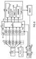
図5及び6は、EGRシステム58から排出ガスを抽出するための複数の抽出ポイント76を備えたシステム10の実施形態を示している。図5及び6に示すように、開示された実施形態は、ガスタービンシステム52及びEGプロセスシステム54を含む排出ガス再循環経路に沿ってこれら複数の抽出ポイント76(例えば、1、2、3、4、5、6、7、8、9、10、又はそれ以上のポイント)の1又は2以上から排出ガスを抽出することができる。例えば、抽出ポイント76は、圧縮機セクション152の各圧縮機段で又はその下流側での排出ガス抽出ポイント76、1又は2以上の燃焼器セクション154に関連する複数の排出ガス抽出ポイント76、1又は2以上のタービンセクション156の各タービン段で又はその下流側での排出ガス抽出ポイント76、及び/又は種々の排出ガスプロセス構成要素(例えば、触媒ユニット、熱回収ユニット又は熱回収蒸気発生器などの熱交換器、除湿ユニット、粒子状物質除去ユニット、ブロア、その他)で、又はその上流側で、もしくは下流側での1又は2以上の排出ガス抽出ポイント76を含むことができる。これらの抽出ポイント76の各々は、他の抽出ポイント76と実質的に等しい、より大きい、又はより小さいとすることができるガス組成、温度、圧力、及び/又は他の特性(すなわち、一般的に排出ガス特性)を有する排出ガスを抽出することができる。一部の実施形態において、抽出ポイント76は各々、1又は2以上の下流側プロセスに好適な排出ガス特性を有することができ、従って、各抽出ポイント76は、このような下流側プロセスにおいて独立して用いることができる。他の実施形態において、2又は3以上の抽出ポイントは、全体的に、1又は2以上の下流側プロセスにおいて組み合わせて又は独立して用いることができる。従って、下流側プロセスの要望に応じて、幾つかの抽出ポイント76を用いて、下流側プロセスに対して望ましい排出ガス特性(例えば、圧力、温度、ガス組成、その他)を得ることができる。 5 and 6 illustrate an embodiment of the
図5は、EGRシステム58から排出ガスを抽出するための複数の抽出ポイント76を更に例示した、図1〜3のシステム10の1つの実施形態の概略図である。上記で概略的に検討したように、EG供給システム78は、抽出ポイント76(例えば、1、2、3、4、5、6、7、8、9、10、又はそれ以上)の1又は2以上から排出ガスを受け取り、EG処理システム82において排出ガスを処理し、次いで、処理した排出ガスを1又は2以上の下流側プロセス250(例えば、1、2、3、4、5、6、7、8、9、10、又はそれ以上)に出力する。抽出ポイント76は、等しい又は異なる温度、圧力、ガス組成、又はこれらの組み合わせにて排出ガスを抽出することができる。これらの下流側プロセス250は、例えば、HC生成システム12又は処理された排出ガスが提供される他のシステム84(例えば、パイプライン86、貯蔵タンク88、炭素隔離システム90、その他)を含むことができる。EGRシステム58の本実施形態は、EGRシステム58の排出ガス再循環(EGR)経路252に沿って位置付けられた2又は3以上の抽出ポイント76を含む。EGR経路252は、ガスがEGRシステム58を流れる経路を表している。すなわち、ガスタービンシステム52、排出ガス再循環経路110、及びEGプロセスシステム54の各構成要素は、EGR経路252に沿って配置される。図示の実施形態において、EGR経路58は、圧縮機セクション152、燃焼器セクション154、タービンセクション156、熱交換器214、管路212、排出ガス再循環経路110、及びEGプロセスシステム54を含む。 FIG. 5 is a schematic diagram of one embodiment of the
上記で検討したように、EGプロセスシステム54は、排出ガスがタービンセクション156から圧縮機セクション152に流れるときに、排出ガスを処理するよう設計された幾つかの構成要素及びその組み合わせを含むことができる。これらの異なる構成要素及びそれらの特定用途は、上記で詳細に説明している。このようなEGプロセス構成要素の複数の実施可能な組み合わせは、表2に概略的に示されている。この点を考慮して、図示の実施形態は、EGプロセスシステム54内で排出ガスを処理するのに使用される構成要素の1つの実施可能な配列を示している。具体的には、図示の実施形態は、触媒ユニット(CU)251、熱交換器(HX)253(例えば、HRSG56を含む)、別のCU255、ブースタブロア(BB)257、水分除去システム(MRS)259、粒子除去システム(PRS)261、及び通気部263を含む。以下の検討は、EGプロセスシステム54の構成要素を含むことができるEGR経路252に沿った異なる位置からの抽出ポイント76の選択に関するものである。すなわち、EGR経路252に沿ったこのような抽出ポイント76の選択及び作動のために適用される技術は、図5に示したEGプロセスシステム構成要素の特定のタイプ又は構成に限定されない点を理解されたい。 As discussed above, the
2又は3以上の抽出ポイント76は、望ましい圧力で排出ガス66を提供するよう位置決め又は選択することができる。この望ましい圧力は、圧力上限閾値、圧力下限閾値、又はその両方(例えば、ある圧力範囲内)に基づいて定義することができる。例えば、各下流側プロセス250は、プロセスにより確立される最小圧力要求を有することができる。排出ガス66の抽出と下流側プロセス250への排出ガス66の提供との間で追加の圧縮を必要としないように、この最小圧力で又はこれを上回る圧力で排出ガス66を抽出することが望ましいとすることができる。これにより、圧縮ステップ又はハードウェア(例えば、ブースタ圧縮機)の追加が無いことに起因して、EG供給システム78が低コストで処理された排出ガスを下流側プロセス250に提供することが可能となる。 Two or more extraction points 76 can be positioned or selected to provide
EG供給システム78は、処理された排出ガスを1又は2以上の下流側プロセス250に提供し、望ましい物理的特性を有する排出ガスを各下流側プロセス250に送出することができる。一部の実施形態において、これは、EG供給システム78が望ましい圧力及び/又は望ましい温度で下流側プロセス250の1又は2以上に処理された排出ガスを提供することを含む。例えば、EG供給システム78は、各々が異なる圧力で複数の下流側プロセス250(例えば、2、3、4、5、6、7、8、9、10、又はそれ以上)に排出ガスを出力することができる。一部の実施形態において、供給システム78は、圧力要求(例えば、上限閾値、下限閾値、又は範囲)に適合するよう異なる圧力の排出ガスの2又は3以上(例えば、2、3、4、5、6、7、8、9、10、又はそれ以上)のストリームを組み合わせることによって、処理された排出ガスを単一の下流側プロセス250に出力することができる。他の実施形態において、EG供給システム78は、圧力要求及び温度要求(例えば、上限閾値、下限閾値、又は範囲)に適合するよう同じ圧力で異なる温度(又は他の何らかの特性)の排出ガスの2又は3以上(例えば、2、3、4、5、6、7、8、9、10、又はそれ以上)のストリームを組み合わせることによって、処理された排出ガスを単一の下流側プロセス250に出力することができる。更に別の実施形態において、EG供給システム78は、ガスタービンシステム52の作動状態に基づいて、異なる抽出ポイント76から異なる回数で各々取り出された排出ガスの2又は3以上のストリームを単一の下流側プロセス250に出力することができる。 The
図示の実施形態は、EGR経路252から抽出された排出ガスをEG供給システム78に提供することができる抽出ポイント76の複数の可能性のある位置を示している。本実施形態において、EGRシステム58のEGR経路252に沿って配置された抽出ポイント76の任意の数(例えば、2、3、4、5、10、15、20、又はそれ以上)が存在することができる。図5に示すように、抽出ポイント76の1又は2以上は、圧縮機セクション152、燃焼器セクション154、及び/又はタービンセクション156に沿った異なる位置に配置することができる。例えば、圧縮機セクション152の前方部分(例えば、排出ガス入口184の直ぐ下流側)において抽出ポイント254が図示されている。同様に、抽出ポイント256は、圧縮機セクション152の中間部分に配置することができ、抽出ポイント258は、圧縮機セクション152の排出部分に配置することができる。1つの実施形態において、圧縮機セクション152の各圧縮機段の下流側に位置する別個の抽出ポイント76が存在してもよい。例えば、圧縮機セクション152は、1〜30、5〜20、又は10〜15段を含むことができ、各段は関連する抽出ポイント76を有する。抽出ポイント260、262、及び264は、燃焼器セクション168に沿った異なる位置に配置することができ、抽出ポイント266、268、及び270は、タービンセクション170の前方、中間、及び後方部分に配置することができる。1つの実施形態において、タービンセクション156の各タービン段の下流側に位置する別個の抽出ポイント76が存在してもよい。例えば、タービンセクション156は、1〜30、5〜20、又は10〜15段を含むことができ、各段は関連する抽出ポイント76を有する。ガスタービンシステム52の構成要素において又は構成要素間に位置するより多くの又はより少ない抽出ポイント76が存在することができる。例えば、抽出ポイント272、274、276、及び278は、熱交換器214及び該熱交換器214を通って延びる管路212内の異なる位置に位置決めすることができる。加えて、抽出ポイント76は、図示の実施形態における又はEGプロセスシステム54内部の抽出ポイント280及び282のように、排出ガス再循環経路110に沿って配置することができる。抽出ポイント284、286、288、290、292、294、296、298、300、302、304、306、及び308は、図示の実施形態において、EGプロセスシステム54の構成要素251、253、255、257、259、261、及び263の各々内及び構成要素間に配置される。この場合も同様に、これらの構成要素は、図3のブロック194、196、198、200、202、204、206、208、及び210によって表すことができる構成要素の非限定的な実施例である。このような構成要素の他の組み合わせ及び配列(例えば、直列及び/又は並列)は、内部又は間に位置する抽出ポイント76を用いて実施することができる。他の何らかの数又は位置の抽出ポイント76を利用して、ガスタービンシステム52の作動状態及び/又は排出ガスの物理的特性に基づいて、EGR経路252から望ましい排出ガスを抽出することができる。 The illustrated embodiment shows multiple possible locations of extraction points 76 that can provide exhaust gas extracted from the
図1を参照して詳細に検討されるように、抽出された排出ガスは、EGRシステム58の量論的作動によって生じることが望ましいとすることができる。そのために、抽出ポイント76は各々、EGRシステム58において起こるあらゆる燃焼プロセス、処理、又は反応(例えば、触媒反応)の比較的下流側に配置することができる。具体的には、燃焼器セクション154に位置する抽出ポイント76(例えば、抽出ポイント260、262、及び264)は、燃焼部分168の一部ではなく隣接するケーシング(例えば、圧縮機排出ケーシング)に沿って配置することができる。結果として、抽出された排出ガスは、酸化剤68又は燃料70を僅かに含む、又は全く含まない場合がある。上記で検討したように、下流側プロセス250に出力される排出ガス中の酸化剤68及び燃料70の当量比に関する許容可能範囲が存在することができる。例えば、HC生成システム12の関連において、EORシステム18を介して地中に注入するために、最大濃度のCO2を排出ガスから分離することができるように、排出ガス中に過剰な酸化剤68又は燃料70を有さないことが望ましいとすることができる。 As discussed in detail with reference to FIG. 1, it may be desirable that the extracted exhaust gas be generated by the stoichiometric operation of the
EGRシステム58全体にわたって複数の抽出ポイント76を含めることにより、排出ガス出力を特定のプロセス要求に適合するように調整することが可能である。例えば、排出ガスは、異なる下流側プロセス250において、又はEGRシステム58の異なる動作モードの間に、異なる抽出ポイント76を介して抽出することができる。一部の実施形態において、下流側プロセス250は、抽出された排出ガスが排出ガス圧力、温度、ガス組成、又は他の特性の許容範囲内で供給される場合にのみ効果的に作動することができる。ガス組成は、二酸化炭素、一酸化炭素、窒素酸化物、硫黄酸化物、粒子状物質、未燃燃料、酸化剤(例えば、酸素)、水分、その他などの種々のガスのパーセント重量とすることができる。図5に示す抽出ポイント76の位置の各々は、EGRシステム58の動作モードに応じて、特定の温度、圧力、ガス組成、その他で排出ガスをEG供給システム78に提供することができる。例えば、ガスタービンシステム52(例えば、抽出ポイント254、256、258、260、262、264、266、268、又は270)から直接抽出された排出ガスは、ガスタービンシステム52を通る加圧ガス流に起因して、比較的高い圧力及び温度を有することができる。加えて、排出ガスが圧縮機セクション152の抽出ポイント254、256、及び258を流れると、例えば、1又は2以上の圧縮機段が排出ガスを漸次的に圧縮すると、排出ガスの温度及び圧力が増大することができる。同様に、排出ガスが燃焼器セクション154(例えば、燃焼に起因して)の抽出ポイント260、262、及び264を流れると、排出ガスの温度及び圧力が漸次的に増大することができる。排出ガスがタービンセクション156の抽出ポイント266、268、及び270を流れると、排出ガスが膨張してタービンセクション156における1又は2以上のタービン段を駆動するので、排出ガスの温度及び圧力が漸次的に減少することができる。 By including
EGプロセスシステム54(例えば、抽出ポイント284、286、288、290、292、294、296、298、300、302、304、306、及び308)から抽出された排出ガスは、EGプロセスシステム54の構成要素に応じて、比較的低い圧力で、ある広い範囲の温度及びガス組成を有することができる。図3を参照して詳細に上述したように、排出ガスがタービンセクション156から圧縮機セクション152に再循環されるときに、EGプロセスシステム54内で排出ガスを処理するあらゆる数の異なる構成要素が存在することができる。図5のEGプロセスシステム54における構成要素の配列は、排出ガス抽出の実施可能な組み合わせを説明する目的で例示的なものである。このような構成要素の他の組み合わせ又は配列も実施可能とすることができる。 Exhaust gases extracted from the EG process system 54 (eg, extraction points 284, 286, 288, 290, 292, 294, 296, 298, 300, 302, 304, 306, and 308) are configured in the
特定の実施形態において、(例えば、温度、圧力、濃度レベル、及び他の排出ガス特性に関して使用される場合)用語「低い」、「中間」、及び「高い」は、互いに対する比較の目的で用いることができる。例えば、中間の温度は、低い温度よりも少なくとも10〜500°C(又は1〜100パーセント)高いとすることができ、高い温度は、中間の温度よりも少なくとも10〜500°C(又は1〜100パーセント)高いとすることができる。一部の実施形態において、低い温度は、40°C未満の何れかの温度とみなすことができ、中間の温度は、40〜150°Cの何れかの温度とみなすことができ、高い温度は、150°Cを上回る何れかの温度とみなすことができる。同様に、中間の圧力は、低い圧力よりも少なくとも10〜200psi(又は1〜100パーセント)高いとすることができ、高い圧力は、中間の圧力よりも少なくとも10〜200psi(又は1〜100パーセント)高いとすることができる。一部の実施形態において、低い圧力は、30psi未満の何れかの圧力とみなすことができ、中間の圧力は、30〜100psiの何れかの圧力とみなすことができ、高い圧力は、100psiを上回る何れかの圧力とみなすことができる。更に、抽出ポイントに関して、同様又は実質的に等しい圧力での排出ガス抽出の記載は、約0〜10、0〜25、又は0〜50psi、又は圧力±約5、10、15、20、又は25psi、又は圧力±約0〜10、0〜5、又は 0〜2.5、又は0〜1パーセントの範囲を指すことができる。同様に、同様又は実質的に等しい温度での排出ガス抽出の記載は、約0〜200、0〜100、0〜50、又は0〜10°C、又は温度±約5、10、15、20、25、50、又は100°C、又は温度±約0〜10、0〜5、又は0〜2.5、又は0〜1パーセントの範囲を指すことができる。更に、排出ガス抽出ポイント(例えば、2、3、4、5、6、7、8、9、10、又はそれ以上の抽出ポイント)は、約1〜50、5〜25、又は15〜20psiの増分的圧力範囲、約1〜200、20〜100、又は30〜50°Cの増分的温度範囲、又はこれらの組み合わせでの排出ガスを必要とすることができ、各増分的範囲は、前述の範囲よりも大きい。このようにして、排出ガス抽出ポイントは、広範囲の温度、圧力、及び/又はガス組成を包含することができ、各抽出された排出ガスストリームは、種々の下流側プロセスにおいて独立して又は全体として用いることができる。 In certain embodiments, the terms “low”, “medium”, and “high” are used for comparison purposes relative to each other (eg, when used with respect to temperature, pressure, concentration level, and other exhaust gas characteristics). be able to. For example, the intermediate temperature can be at least 10-500 ° C. (or 1-100 percent) higher than the lower temperature, and the higher temperature is at least 10-500 ° C. (or 1--100 ° C.) than the intermediate temperature. 100 percent). In some embodiments, the low temperature can be considered as any temperature below 40 ° C, the intermediate temperature can be considered as any temperature between 40-150 ° C, and the high temperature is Any temperature above 150 ° C. can be considered. Similarly, the intermediate pressure can be at least 10 to 200 psi (or 1 to 100 percent) higher than the lower pressure, and the higher pressure is at least 10 to 200 psi (or 1 to 100 percent) than the intermediate pressure. Can be expensive. In some embodiments, the low pressure can be considered as any pressure below 30 psi, the intermediate pressure can be considered as any pressure between 30-100 psi, and the high pressure is above 100 psi. It can be regarded as any pressure. Further, with respect to extraction points, descriptions of exhaust gas extraction at similar or substantially equal pressures may be from about 0 to 10, 0 to 25, or 0 to 50 psi, or pressure ± about 5, 10, 15, 20, or 25 psi. Or pressure ± about 0 to 10, 0 to 5, or 0 to 2.5, or 0 to 1 percent. Similarly, the description of exhaust gas extraction at similar or substantially equal temperatures is about 0 to 200, 0 to 100, 0 to 50, or 0 to 10 ° C, or temperature ± about 5, 10, 15, 20 25, 50, or 100 ° C, or temperature ± about 0-10, 0-5, or 0-2.5, or 0-1 percent. In addition, exhaust gas extraction points (eg, 2, 3, 4, 5, 6, 7, 8, 9, 10, or more extraction points) are about 1-50, 5-25, or 15-20 psi. Exhaust gas in incremental pressure ranges, incremental temperature ranges of about 1 to 200, 20 to 100, or 30 to 50 ° C., or combinations thereof may be required, each incremental range being Greater than range. In this manner, exhaust gas extraction points can encompass a wide range of temperatures, pressures, and / or gas compositions, and each extracted exhaust gas stream can be independently or collectively in various downstream processes. Can be used.
抽出ポイント76の各々は、EGR経路252に沿って抽出ポイント76がどこに位置するかに基づいて、特定の範囲の圧力、温度、及びガス組成(例えば、互いに等しい、同様、又は異なる)で排出ガスをEG供給システム78に送ることができる。以下で示すように、表3は、図5の実施形態に示された抽出ポイント76の各々から抽出された排出ガスの出力特性の幾つかの非限定的な実施例を表している。表3には、異なる抽出ポイント76での様々な圧力及び温度のみが示されているが、特にEGプロセスシステム54(例えば、CU、MRS、PRS、その他)の組成に関して、排出ガス組成の変化も実施可能である点に留意されたい。 Each
表3
これらの抽出ポイント76の何れかは、下流側プロセス250において使用するために適切な範囲の特性(例えば、圧力、温度、及びガス組成)を有する排出ガスを提供するよう選択することができる。開示された実施形態においては複数の抽出ポイント76が存在するので、EGRシステム58からの抽出を複数の下流側プロセス250に同時に送り込むことが実施可能とすることができ、各下流側システムは、同様の又は異なる圧力、温度、及びガス組成要求を有する。 Any of these
一部の実施形態において、図示の実施形態におけるよりも少ない抽出ポイント76が存在する場合がある。このような事例では、2又は3以上(例えば、2、3、4、5、6、7、8、9、10、又はそれ以上)の既存の抽出ポイント76からの抽出を組み合わせて、単一の抽出では実施可能とはならない排出ガスを下流側プロセス250に提供することを可能とすることができる。排出ガス抽出の異なる組み合わせを利用して、処理された排出ガスを圧力、温度、ガス組成、及び他の特性の望ましい範囲内で1又は2以上の下流側プロセス250に処理された排出ガスを提供することができる。以下に示すように、表4は、所与の下流側プロセス250について望ましい排出ガス特性をもたらすことができる抽出ポイント76の組み合わせの一部の非限定的実施例を表している。 In some embodiments, there may be fewer extraction points 76 than in the illustrated embodiment. In such cases, a combination of extractions from two or more existing extraction points 76 (eg, 2, 3, 4, 5, 6, 7, 8, 9, 10, or more) can be combined into a single It may be possible to provide the
表4
上記で示すように、一部の組み合わせは、小さな圧力範囲及び大きな温度範囲、小さな温度範囲及び大きな圧力範囲、又は両方とも小さい又は大きい温度及び圧力範囲を有する排出ガスをもたらすことができる。他の組み合わせを利用して、構成要素(例えば、EGプロセスシステム 構成要素)の配列並びにEGRシステム58内の抽出ポイント76の数及び位置に基づいて、圧力及び温度の同じ又は異なる範囲を提供することができる。表3は、2つの抽出だけの組み合わせを示しているが、他の抽出数(例えば、3、4、5、6、又はそれ以上)を組み合わせて望ましい特性をもたらすことができる。 As indicated above, some combinations can result in exhaust gases having a small pressure range and a large temperature range, a small temperature range and a large pressure range, or both a small or large temperature and pressure range. Other combinations may be utilized to provide the same or different ranges of pressure and temperature based on the arrangement of components (eg, EG process system components) and the number and location of extraction points 76 in the
制御システム100は、抽出ポイント76を介した排出ガスの抽出を制御することができる。例えば、制御システム100は、抽出ポイント76の各々から通じたバルブを作動させ、EGRシステム58からの1又は2以上の抽出をEG供給システム78に選択的に提供することができる。以下で詳細に説明するようなこのようなバルブは、EG供給システム78におけるEGES80の一部とすることができる。制御システム100は、センサフィードバック130及び/又は制御信号310に基づいて、望ましい圧力、温度、及び/又はガス組成で下流側プロセス250の1又は2以上に排出ガスを提供するよう、EGES80を制御することができる。一部の実施形態において、例えば、制御システム100は、下流側プロセス250からの制御信号に基づいて、下流側プロセス250の圧力、温度、及び/又はガス組成要求(例えば、上限閾値、下限閾値、又は範囲)を決定することができる。これらの制御信号310は、オペレータ入力、システム入力、及び下流側プロセス250におけるセンサからのフィードバックに基づいて決定することができる。制御システム100はまた、EGRシステム58の抽出ポイント76の各々により利用可能な排出ガスの圧力、温度、ガス組成、又は他の特性を示すセンサフィードバック130を受け取ることができる。次いで、制御システム100は、望ましい温度、圧力、ガス組成、その他で排出ガスをEG供給システム78に提供するための適切な抽出ポイント76の組み合わせを決定し、これに応じたバルブ動作を制御する命令を実行することができる。 The
図6は、2つの燃焼器セクション154及び2つのタービンセクション156を有するガスタービンシステム52を示す、図1〜3のEGRシステム58の別の実施形態の概略図である。比較的上流側のタービンセクション156は、高圧タービンセクション330とすることができ、比較的下流側のタービンセクション156は、低圧タービンセクション332とすることができる。複数の燃焼器セクション154(例えば、上流側燃焼器セクション331及び下流側燃焼器セクション333)とタービンセクション156を使用することにより、ガスタービンシステム52のより効率的な作動を可能とすることができる。両方の燃焼器セクション154は、図示のように、同じ供給源から燃料70及び酸化剤68を受け取ることができる。しかしながら、他の実施形態において、燃焼器セクション154は、別個の供給源から燃料70及び/又は酸化剤68を受け取ることができる。複数の圧縮機セクションとタービンセクションを有するこのようなガスタービンシステム52の例示的な配列は、2012年4月12日に出願され、Wichmann他に付与された、名称「METHODS, SYSTEMS, AND APPARATUS RELATING TO COMBUSTION TURBINE POWER PLANTS WITH EXHAUST GAS RECIRCULATION」の米国特許出願シリアル番号13/445,003に記載されており、当該出願は、引用により全体が本明細書に組み込まれる。 FIG. 6 is a schematic diagram of another embodiment of the
図示の実施形態において、抽出ポイント76は、両方の燃焼器セクション154及び両方のタービンセクション156内に存在することができる。より具体的には、図5に示す抽出ポイント76に加えて、EGRシステム58は、追加の抽出ポイント334、336、338、340、342、及び344を含むことができる。これらの抽出ポイント334、336、338、340、342、及び344を流れる排出ガスは、上流側の燃焼器セクション154、331及び高圧のタービンセクション156、330に位置する対応する抽出ポイント260、262、264、266、268、及び270を流れる圧力よりも比較的低い圧力を有することができる。 In the illustrated embodiment, extraction points 76 can exist in both
一部の実施形態において、燃焼器セクション154のうちの1つにおいて生じる排出ガス、燃料、及び酸化剤の燃焼は、望ましい当量比(例えば、約0.95〜1.05)のものとすることができるが、他の燃焼器セクション154において生じる燃焼は、望ましい当量比のものでない場合がある。例えば、燃焼器セクション331は、当量比約1(例えば、量論的当量比)で作動することができるが、燃焼器セクション333は、燃料リッチ又は燃料リーン状態で作動することができ、或いは、その逆であってもよい。別の実施形態によれば、燃焼器セクション331は、1.0よりも大きい当量比(例えば、燃料リッチ)で作動し、これにより実質的に又は完全に酸化剤68(例えば、酸素)を消費することができ、他方、燃焼器セクション333は、1.0よりも小さい当量比(例えば、燃料リーン)で作動して、残りの燃料を(例えば、追加酸化剤68を加えることによって)消費することができる。このような事例では、EGRシステム58は、当量比に応じて燃焼器セクション154(例えば、331)又は燃焼器セクション154(例えば、333)にて又はその下流側に位置する抽出ポイント76(例えば、260、262、264、266、268、及び/又は270)のみを使用することが望ましいとすることができる。望ましい当量比(例えば、約0.95〜1.05、又は約1.0)で作動する燃焼器セクション154が(例えば、燃焼器セクション331から燃焼器セクション333に)切り換わると、制御システム100は、燃焼器セクション333の下流側で且つ燃焼器セクション331の上流側にある異なる抽出ポイント76(例えば、334、336、338、340、342、344、280、284、286、288、290、292、294、296、298、300、302、304、306、308、282、254、256、258、274、276、272、及び/又は278)を利用して、EGRシステム58から排出ガスを除去することができる。制御システム100は、センサフィードバック130を介してガスタービンシステム52の量論的作動の変化を検出することができる。センサフィードバック130は、燃焼器セクション154の一方又は両方から出力される排出ガスの組成を示し、或いは、燃焼器セクション154の各々に提供される酸化剤68及び燃料70の流量を示すことができる。 In some embodiments, the combustion of exhaust gas, fuel, and oxidant that occurs in one of the
上記で詳細に検討したように、HC生成システム12は、原油二次回収作業中に地下リザーバ20において使用される排出ガス中に過剰な燃料70又は酸化剤68が残らないように、当量比が約1の排出ガスで最も効果的に作動することができる。しかしながら、一部の実施形態において、下流側プロセス250(例えば、他のシステム84)の1又は2以上は、非量論的(例えば、燃料リッチ又は燃料リーン)燃焼によって生成される排出ガスを利用することができる。このような実施形態において、EGRシステム58は、異なる下流側プロセス250に向けた処理及び出力のため排出ガスの2又は3以上の別個の流れ(一部が量論的作動によって生成され、その他が非量論的作動による)をEG供給システム78に提供することが可能になる。従って、複数の抽出ポイント76を利用して、酸化剤68との及び燃料70との燃焼の当量比に対する異なる要求(例えば、異なるガス組成をもたらす)に対して、同じEGRシステム58から2又は3以上の下流側プロセス250に排出ガスを提供することができる。 As discussed in detail above, the
図7は、図3、5、及び6のEG供給システム78の1つの実施形態の概略図である。図示の実施形態において、EG供給システム78は、抽出ポイント76を介してEGRシステム58から受け取った排出ガスの複数の抽出を組み合わせるための混合ユニット350を含む。上述のように、EG供給システム78のEGES80は、バルブ352を含むことができ、該バルブは、開放時に、EGRシステム58の対応する抽出ポイント76からの排出ガスの抽出を可能にする。バルブ352の各々は、対応する抽出ポイント76を介して排出ガスの抽出をしない閉鎖位置を含む、2、3、4、5、又はそれ以上位置に制御可能とすることができる。一部の実施形態において、バルブ352は、連続的に制御可能とすることができ、その結果、制御システム100は、あらゆる望ましい開放量(例えば、完全開放と完全閉鎖の間)までバルブ352を作動させることができるようになる。 FIG. 7 is a schematic diagram of one embodiment of the
バルブ352は、図示の実施形態に示すように、対応する抽出ポイント76に対して遠位位置にて共に配置することができる。他の実施形態において、バルブ352は、EGRシステム58に沿ってそれぞれの抽出ポイント76の近傍又は直近に配置することができる。上記で述べたように、制御システム100は、所与の時間にて抽出ポイント76の1又は2以上から排出ガスを抽出するよう、バルブ352を作動させることができる。例えば、制御システム100は、制御信号を送信して、閉鎖位置から開放位置にバルブ352の1又は2以上を移動させ、これにより、選択した抽出ポイント76を介してEGRシステム58からEG供給システム78に排出ガスの抽出した流れを導入することができる。制御システム100は、下流側プロセス250の圧力、温度、ガス組成、又は他の要求(制御信号310を介して伝達される)に基づいて、及び利用可能な排出ガスの対応する特性(センサフィードバック130を介して伝達される)に基づいて、抽出ポイント76を選択することができる。混合ユニット350は、複数の抽出ポイント76からの異なる排出ガスストリームのための複数の混合チャンバを含むことができる。混合ユニット350は、処理された排出ガス(例えば、N2又はCO2)が下流側プロセス250の1又は2以上に送られる前に、処理(例えば、N2及びCO2の分離)のために排出ガスの組み合わされたストリームをEGTS82に供給することができる。1つの実施形態において、バルブ352は、抽出ポイント76のうちの1つにより利用可能な排出ガスを複数の下流側プロセス250に提供できるように、複数段のバルブを含むことができる。より具体的には、抽出ポイント76のうちの1つからの排出ガスは、2又は3以上の排出ガスストリームに分割して、別個の混合チャンバを介して1又は2以上の他の抽出と組み合わせ、下流側プロセス250のうちの2又は3以上に提供することができる。 The
図示の実施形態は、EGTS82の比較的上流側に位置する混合ユニット350を含み、排出ガスが、(例えば、EGTS82を介して)処理される前に(例えば、混合ユニット350を介して)組み合わされるようにする。しかしながら、他の実施形態において、複数の抽出ポイント76からの排出ガスを処理(例えば、EGTS82を介して)し、次いで、混合(例えば、混合ユニット350を介して)して、1又は2以上の組み合わされ処理されたガス流を生成することができる。図示されていないが、EG供給システム78は、混合ユニット350及びEGTS82に加えて、抽出ポイント76から下流側プロセス250に向かって排出ガスの流れを加圧するよう構成される圧縮機又はブロアを含むことができる。一部の実施形態において、このような圧縮機器は、抽出したガスを処理するEGTS82の一部として含めることができる。 The illustrated embodiment includes a
図8は、EG供給システム78の別の実施形態の概略図である。図示の実施形態において、EG供給システム78は、異なる抽出ポイント76から抽出された排出ガスを組み合わせるための混合ユニット350を含まない。代わりに、EG供給システム78は、排出ガスの複数の抽出を別個に処理し、処理された排出ガスストリームの各々を異なる下流側プロセス250に提供することができる。一部の実施形態において、抽出され処理された排出ガスの複数の異なるストリームは、同じ下流側プロセス250(例えば、HC生成システム12)に提供することができる。例えば、HC生成システム12は、EG供給システム78を介して提供されるN2又はCO2についての異なる圧力要求を各々が有する、複数のEORシステム18を含むことができる。従って、EGTS82は、抽出ポイント254及び256から取り込まれた排出ガスの2つのストリームからN2及びCO2を分離し、原油二次回収のため、N2及び/又はCO2の2つの別個のストリームをHC生成システム12に出力することができる。 FIG. 8 is a schematic diagram of another embodiment of an
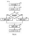
図9は、図5〜8のシステムを作動させる方法370の1つの実施形態のフローチャートである。本方法370は、制御システム100を介して実施することができる種々のブロックを含む。より具体的には、方法370は、プロセッサ120によって実行されて、方法370のステップの1又は2以上を実行することができる、コンピュータ又はソフトウェアプログラム(例えば、コード又は命令)として実施することができる。加えて、プログラム(例えば、コード又は命令)は、何らかの好適な製造物品内に格納することができ、該物品は、メモリ122、又は制御システム100の別のストレージ構成要素など、これらの命令又はルーチンを少なくともまとめて格納する少なくとも1つの有形の非一時的コンピュータ可読媒体を含む。用語「非一時的」とは、媒体が信号ではないことを示している。 FIG. 9 is a flowchart of one embodiment of a
本方法370は、SEGRガスタービンシステム52の始動モードで作動するステップを含む(ブロック372)。始動モード中、EGRシステム58は、抽出に望ましい速度又は圧力で排出ガスを再循環しない場合がある。加えて、始動モードのEGRシステム58は、下流側プロセス250に対する特定の閾値内にある圧力、温度、及び/又はガス組成を有する排出ガスを生成しない可能性がある。例えば、始動中、量論的燃焼を達成することが比較的困難な場合がある。従って、1又は2以上の抽出ポイント76を介してEGRシステム58から抽出される排出ガスを用いる代わりに、下流側プロセス250(例えば、HC生成システム12)は、他の供給源(例えば、別個の貯蔵タンク、パイプライン、又は化学物質生成プロセス、その他)から受け取った処理された排出ガス(例えば、N2又はCO2)を用いて作動することができる。例えば、ガスタービンシステム52の始動モード中、HC生成システム12は、貯蔵タンクからN2、CO2、又は排出ガスを受け取ることができ、ここでガスは、EOR用途のため最小圧力又はそれを上回る圧力で格納される。次いで、本方法370は、EGRシステム58を定常動作モードに移行させるステップ(ブロック374)を含む。この移行ステップは、EGR経路252を通って再利用される排出ガスの量が定常状態に達すると完了することができる。EGRシステム58の始動及び移行は、排出ガスのパラメータ(例えば、流量、圧力、温度、ガス組成、その他)を測定するためEGR経路252に沿って位置付けられたセンサを介して監視することができる。移行ステップはまた、N2、CO2、又は排出ガスの外部供給源を使用することから、EGRシステム58から排出ガスを抽出(例えば、バルブ352の1又は2以上を開放することにより)し、EGTS82を介して抽出された排出ガスからN2及びCO2を分離することに移行するステップを含むことができる。 The
一部の実施形態において、ガスタービンシステム52は、定常状態モードにある間異なる負荷で作動することができる。すなわち、ガスタービンシステム52は、該ガスタービンシステム52に接続された機械装置106の一部を作動させるのに十分な出力のみを提供しながら、定常状態モードに達することができる。これは、ガスタービンエンジン52に結合される機械装置106の全てが使用されている訳ではない場合に当てはまることができる。これは、低負荷運転又はターンダウン運転と呼ぶことができる。しかしながら、この同じガスタービンシステム52は、定常状態において全負荷能力でも作動することができる。この全負荷運転は、ガスタービンエンジンに結合された機械装置106の全てが利用されており、よって機械装置106を作動させるために燃焼によってより多くの出力が生成される場合を表すことができる。本方法370は、ガスタービンエンジン52が全負荷で又は低負荷で作動しているかどうかを判定するステップ(ブロック376)を含むことができる。このような判定は、センサフィードバック130又はEGRシステム58への幾つかのセンサ入力又はオペレータ入力に基づいて行うことができる。この判定に基づいて、本方法370は、全負荷運転中に第1の抽出ポイント76から排出ガスを抽出するステップ(ブロック378)と、低負荷運転中に第2の抽出ポイント76から排出ガスを抽出するステップ(ブロック380)とを含むことができる。全負荷運転中及び低負荷運転中に使用される異なる抽出ポイント76(例えば、第1及び第2の抽出ポイント76)は、下流側プロセス250に適切な圧力、温度、ガス組成、その他の特定の閾値又は範囲に適合するよう選択することができる。次に、本方法370は、原油二次回収を実施するために排出された排出ガスをHC生成システム12に供給することができる(ブロック382)。本方法370はまた、ガスタービンシステム52をシャットダウンするステップを含むことができる(ブロック384)。ガスタービンシステム52は、システム上にもはや負荷が存在しない場合、又はシステムが保守西部される場合にシャットダウンすることができる。シャットダウン中、システム10は、貯蔵タンク、パイプライン、その他などの他の排出ガス供給源を用いるよう再度移行することができる。 In some embodiments, the
定常状態モードの間、排出ガスは、ガスタービンシステム52上の負荷に基づいて異なる抽出ポイント76を介して抽出することができる。異なる抽出は、負荷に基づいて異なる時点で同じ下流側プロセス250(例えば、EOR用のHC生成システム12)に提供することができる。EGR経路252を通って流れる作動流体(例えば、排出ガス)は、全負荷で作動しているときに圧縮機セクション152から生じた最高圧力状態にあることができる。低負荷で作動しているときには、低負荷をサポートするのに使用されるガスタービンシステム52を通る質量流が少ないので、EGR経路252を通って流れる作動流体は、圧縮機セクション152を介してこのような高い圧力まで圧縮されない場合がある。EGRシステム58から引き出され、EG供給システム78を介して下流側プロセス250に提供される排出ガスの抽出圧力を維持することが望ましいとすることができる。従って、低負荷運転中には他の抽出ポイントよりも比較的高い圧力で抽出ポイントから排出ガスを抽出し、また、全負荷運転中には他の抽出ポイントよりも比較的低い圧力で抽出ポイントから排出ガスを抽出することが望ましいとすることができる。このようにして、システム10は、ガスタービンシステム52が異なる負荷で作動していても、抽出された排出ガスの圧力を一定に維持することができる。一般に、低負荷時に使用される抽出ポイント76は、全負荷時に使用される抽出ポイント76よりも燃焼器セクション154の入口により近くすることができる。以下に示すように、表5は、ガスタービンシステム52が異なる負荷で作動するときに下流側プロセス250に同じ特性をもたらすことができる、抽出ポイント76(図5及び6による)の組み合わせの一部の非限定的な実施例を示している。 During steady state mode, exhaust gases can be extracted through
表5
本開示の実施形態は、EGR経路252から再循環された排出ガスを抽出するための複数の抽出ポイント76を有するEGRシステム58に関する。最終的には、このような複数の抽出ポイント76により、EGRシステム58の単一の設置を介して、顧客が、高濃度のN2又はCO2を有する排出ガスを様々な供給要求に伴って1又は2以上の下流側プロセス250に提供することが可能となる。一部の実施形態において、EGRシステム58は、2つの抽出ポイント76を介して排出ガスを提供することができ、各抽出は、原油二次回収のため異なるHC生成システム12にN2又はCO2を提供する。具体的には、地下リザーバ20からオイルを除去するのに使用される際に、異なる最小圧力要求を有する2又は3以上の井戸位置は、同じEGRシステム58を用いて要求を満たすことができる。他の実施形態において、排出ガスの複数の抽出を組み合わせ、1又は2以上の下流側プロセス250の適切な圧力、温度、ガス組成、及び/又は他の要求に適合させることができる。更に他の実施形態において、複数の抽出ポイント76により、ガスタービンシステム52が異なる負荷で作動している際に、同じEGRシステム58が、一貫した圧力で下流側プロセス250に排出ガス抽出をもたらすことが可能となる。 Embodiments of the present disclosure relate to an
(補足説明)
本発明の実施形態は、ガスタービンエンジンのシステム及び方法を提供する。上記で記載された特徴の何れか又はその組み合わせは、好適なあらゆる組み合わせで利用することができる点に留意されたい。当然、このような組み合わせの全ての並び換えも現在企図される。例証として、以下の条項は、本開示の更なる説明として提供されるものである。(Supplementary explanation)
Embodiments of the present invention provide gas turbine engine systems and methods. It should be noted that any of the features described above or combinations thereof can be utilized in any suitable combination. Of course, all permutations of such combinations are now contemplated. By way of illustration, the following clauses are provided as a further explanation of the present disclosure.
実施形態1.システムは、タービン燃焼器と、タービン燃焼器からの燃焼生成物によって駆動されるタービンと、タービンからの排出ガスを圧縮してタービン燃焼器に送るよう構成された排出ガス圧縮機と、排出ガス圧縮機、タービン燃焼器、及びタービンを通って延びる排出ガス再循環(EGR)経路と、EGR経路に沿って配置された第1の排出ガス(EG)抽出ポートと、EGR経路に沿って配置された第2のEG抽出ポートと、を含む。 Embodiment 1. FIG. The system includes a turbine combustor, a turbine driven by combustion products from the turbine combustor, an exhaust gas compressor configured to compress exhaust gas from the turbine and send it to the turbine combustor, and exhaust gas compression An exhaust gas recirculation (EGR) path extending through the machine, turbine combustor, and turbine, a first exhaust gas (EG) extraction port positioned along the EGR path, and positioned along the EGR path A second EG extraction port.
実施形態2.第1のEG抽出ポートを介してEGR経路から排出ガスの第1の部分を受け取り、第2のEG抽出ポートを介してEGR経路から排出ガスの第2の部分を受け取り、受け取った排出ガスの少なくとも一部を下流側プロセスに出力する、よう構成された排出ガス(EG)供給システムを含む、実施形態1のシステム。 Embodiment 2. FIG. Receiving a first portion of the exhaust gas from the EGR path via the first EG extraction port, receiving a second portion of the exhaust gas from the EGR path via the second EG extraction port, and receiving at least one of the received exhaust gases The system of embodiment 1, comprising an exhaust gas (EG) supply system configured to output a portion to a downstream process.
実施形態3.EG供給システムが、排出ガスの第1の部分を第1の下流側プロセスに出力し、排出ガスの第2の部分を第2の下流側プロセスに出力するよう構成されている、前述の何れかの実施形態において定められたシステム。 Embodiment 3. FIG. Any of the foregoing, wherein the EG supply system is configured to output a first portion of exhaust gas to a first downstream process and output a second portion of exhaust gas to a second downstream process. The system defined in the embodiment.
実施形態4.EG供給システムが、排出ガスの第1及び第2の部分を組み合わせて、組み合わされた排出ガスを下流側プロセスに出力するよう構成されている、前述の何れかの実施形態において定められたシステム。 Embodiment 4 FIG. The system as defined in any of the previous embodiments, wherein the EG supply system is configured to combine the first and second portions of exhaust gas and output the combined exhaust gas to a downstream process.
実施形態5.EG供給システムが、第1の運転モード中に排出ガスの第1の部分を下流側プロセスに出力し、第2の運転モード中に排出ガスの第2の部分を下流側プロセスに出力するよう構成されている、前述の何れかの実施形態において定められたシステム。 Embodiment 5. FIG. An EG supply system configured to output a first portion of exhaust gas to a downstream process during a first mode of operation and to output a second portion of exhaust gas to a downstream process during a second mode of operation. A system as defined in any of the preceding embodiments.
実施形態6.排出ガスの特性を示すセンサフィードバックに基づいて、EG供給システムの作動を制御するよう構成されたコントローラを含む、前述の何れかの実施形態において定められたシステム。 Embodiment 6. FIG. A system as defined in any of the preceding embodiments, comprising a controller configured to control operation of the EG delivery system based on sensor feedback indicative of exhaust gas characteristics.
実施形態7.下流側プロセスが、炭化水素生成システム、パイプライン、貯蔵タンク、又は炭素隔離システムのうちの少なくとも1つを含む、前述の何れかの実施形態において定められたシステム。 Embodiment 7. FIG. The system as defined in any of the preceding embodiments, wherein the downstream process comprises at least one of a hydrocarbon production system, a pipeline, a storage tank, or a carbon sequestration system.
実施形態8.タービンと排出ガス圧縮器との間でEGR経路に沿って配置され且つ排出ガスを処理するよう構成された排出ガス(EG)処理システムを含む、前述の何れかの実施形態において定められたシステム。 Embodiment 8. FIG. A system as defined in any of the preceding embodiments, comprising an exhaust gas (EG) treatment system disposed along an EGR path between a turbine and an exhaust gas compressor and configured to process the exhaust gas.
実施形態9.第1又は第2のEG抽出ポートのうちの少なくとも1つがEG処理システムに結合される、前述の何れかの実施形態において定められたシステム。 Embodiment 9. FIG. The system as defined in any of the previous embodiments, wherein at least one of the first or second EG extraction ports is coupled to an EG processing system.
実施形態10.EG処理システムが、触媒ユニット、ブースタブロア、熱交換器、熱回収蒸気発生器、粒子状物質除去ユニット、除湿ユニット、又は通気部のうちの少なくとも1つを含む、前述の何れかの実施形態において定められたシステム。
実施形態11.第1又は第2のEG抽出ポートが、触媒ユニット、ブースタブロア、熱交換器、熱回収蒸気発生器、粒子状物質除去ユニット、除湿ユニット、又は通気部のうちの少なくとも1つにて、又はその上流側で、或いはその下流側でEG処理システムに結合される、前述の何れかの実施形態において定められたシステム。 Embodiment 11. FIG. The first or second EG extraction port is at least one of a catalyst unit, a booster blower, a heat exchanger, a heat recovery steam generator, a particulate matter removal unit, a dehumidification unit, or a vent, or A system as defined in any of the preceding embodiments, coupled upstream or downstream to an EG processing system.
実施形態12.第1又は第2のEG抽出ポートの少なくとも1つが、タービン燃焼器、タービン、又は排出ガス圧縮機に沿って配置される、前述の何れかの実施形態において定められたシステム。
実施形態13.第1及び第2のEG抽出ポートが、低圧、中圧、又は高圧、或いはこれらの組み合わせで排出ガスを抽出するよう構成される、前述の何れかの実施形態において定められたシステム。 Embodiment 13 FIG. The system as defined in any of the previous embodiments, wherein the first and second EG extraction ports are configured to extract exhaust gas at low pressure, medium pressure, or high pressure, or a combination thereof.
実施形態14.第1及び第2のEG抽出ポートが、低い温度、中間温度、又は高い温度、或いはこれらの組み合わせを有する排出ガスを抽出するよう構成される、前述の何れかの実施形態において定められたシステム。
実施形態15.第1及び第2のEG抽出ポートが、低い温度、中間温度、又は高い温度、或いはこれらの組み合わせを有する排出ガスを抽出するよう構成される、前述の何れかの実施形態において定められたシステム。 Embodiment 15. FIG. The system as defined in any preceding embodiment, wherein the first and second EG extraction ports are configured to extract exhaust gases having a low temperature, an intermediate temperature, or a high temperature, or a combination thereof.
実施形態16.第1及び第2のEG抽出ポートが、排出ガスの物理的特性に基づいて排出ガスを抽出するよう構成される、前述の何れかの実施形態において定められたシステム。
実施形態17.タービン燃焼器、タービン、及び排出ガス圧縮器を有するガスタービンエンジンを更に含む、前述の何れかの実施形態において定められたシステム。 Embodiment 17. FIG. The system as defined in any of the previous embodiments, further comprising a gas turbine engine having a turbine combustor, a turbine, and an exhaust gas compressor.
実施形態18.ガスタービンエンジンが、量論的排出ガス再循環(SEGR)ガスタービンエンジンである、前述の何れかの実施形態において定められたシステム。
実施形態19.タービン燃焼器が、燃料及び酸化剤の混合気を約0.95〜約1.05の当量比で燃焼するよう構成される、前述の何れかの実施形態において定められたシステム。 Embodiment 19. FIG. The system as defined in any of the preceding embodiments, wherein the turbine combustor is configured to combust the fuel and oxidant mixture at an equivalence ratio of about 0.95 to about 1.05.
実施形態20.制御システムを備えたシステムであって、制御システムが、排出ガス圧縮機、タービン燃焼器、及びタービンを通って延びた排出ガス再循環(EGR)経路の一部を通って流れる排出ガスの特性を示すセンサフィードバックを受け取り、センサフィードバックに少なくとも部分的に基づいて、EGR経路に沿って位置する複数の抽出ポートを通じた排出ガスの抽出を制御する、よう構成されている。
実施形態21.制御システムが、センサフィードバックに基づいて、望ましい特性を有する排出ガスの抽出を可能にする複数の抽出ポートの2又は3以上の組み合わせを決定し、2又は3以上の抽出ポートを介して排出ガスの抽出を制御する、よう構成されている、前述の何れかの実施形態において定められたシステム。 Embodiment 21. FIG. Based on sensor feedback, the control system determines two or more combinations of a plurality of extraction ports that allow extraction of the exhaust gas having the desired characteristics, and the exhaust gas is passed through the two or more extraction ports. A system as defined in any of the preceding embodiments, configured to control extraction.
実施形態22.排出ガス圧縮機、タービン燃焼器、及びタービンを有するガスタービンエンジンを含む、前述の何れかの実施形態において定められたシステム。
実施形態23.制御システムが、ガスタービンエンジンが全負荷又は低負荷の何れで作動しているかを判定し、ガスタービンエンジンが全負荷で作動しているときに第1の抽出ポートからの排出ガスの抽出を制御し、ガスタービンエンジンが低負荷で作動しているときに第2の抽出ポートからの排出ガスの抽出を制御する、よう構成される、前述の何れかの実施形態において定められたシステム。 Embodiment 23. FIG. A control system determines whether the gas turbine engine is operating at full load or low load, and controls the extraction of exhaust gas from the first extraction port when the gas turbine engine is operating at full load. And the system defined in any of the preceding embodiments configured to control extraction of exhaust gas from the second extraction port when the gas turbine engine is operating at low load.
実施形態24.制御システムが、センサフィードバックに基づいて、タービン燃焼器において量論的燃焼が生じているかどうかを判定し、量論的燃焼が生じているときには、タービン燃焼器の下流側に配置された抽出ポイントからの排出ガスの抽出を制御する、よう構成されている、前述の何れかの実施形態において定められたシステム。
実施形態25.タービン燃焼器が、燃料及び酸化剤の混合気を約0.95〜約1.05の当量比で燃焼するよう構成される、前述の何れかの実施形態において定められたシステム。 Embodiment 25. FIG. The system as defined in any of the preceding embodiments, wherein the turbine combustor is configured to combust the fuel and oxidant mixture at an equivalence ratio of about 0.95 to about 1.05.
実施形態26.タービン燃焼器が、燃料及び酸化剤の混合気を約0.99〜約1.01の当量比で燃焼するよう構成される、前述の何れかの実施形態において定められたシステム。
実施形態27.タービン燃焼器からの燃焼生成物を用いてタービンを駆動するステップと、排出ガス圧縮器においてタービンからの排出ガスを圧縮するステップと、排出ガス圧縮器からタービン燃焼器を通ってタービンへの流路に沿って排出ガスを送るステップと、流路に沿って配置された第1の抽出ポートを介して排出ガスを抽出するステップと、流路に沿って配置された第2の抽出ポートを介して排出ガスを抽出するステップと、を含む、方法。 Embodiment 27. FIG. Driving the turbine with combustion products from the turbine combustor, compressing exhaust gas from the turbine in the exhaust gas compressor, and a flow path from the exhaust gas compressor through the turbine combustor to the turbine A step of sending exhaust gas along the flow path, a step of extracting the exhaust gas via a first extraction port disposed along the flow path, and a second extraction port disposed along the flow path Extracting the exhaust gas.
実施形態28.処理された排出ガスを1又は2以上の下流側プロセスに出力するよう構成された排出ガス(EG)供給システムを介して抽出された排出ガスを処理するステップを含む、前述の何れかの実施形態において定められた方法。
実施形態29.タービン燃焼器内で排出ガスと燃料の混合気を燃焼させるステップを含む、前述の何れかの実施形態において定められた方法。 Embodiment 29. FIG. A method as defined in any of the preceding embodiments, comprising the step of combusting an exhaust gas and fuel mixture in a turbine combustor.
実施形態30.混合気が量論的に燃焼される、前述の何れかの実施形態において定められた方法。
実施形態31.燃料及び酸化剤の混合気を約0.95〜約1.05の当量比で燃焼させるステップを含む、前述の何れかの実施形態において定められた方法。 Embodiment 31. FIG. A method as defined in any of the preceding embodiments, comprising burning the fuel and oxidant mixture at an equivalent ratio of about 0.95 to about 1.05.
本明細書は、最良の形態を含む実施例を用いて本発明を開示し、更に、あらゆる当業者があらゆるデバイス又はシステムを実施及び利用すること及びあらゆる包含の方法を実施することを含む本発明を実施することを可能にする。本発明の特許保護される範囲は、請求項によって定義され、当業者であれば想起される他の実施例を含むことができる。このような他の実施例は、請求項の文言と差違のない構造要素を有する場合、或いは、請求項の文言と僅かな差違を有する均等な構造要素を含む場合には、本発明の範囲内にあるものとする。 This written description discloses the invention using examples, including the best mode, and further includes any person skilled in the art to make and use any device or system and practice any method of inclusion. It is possible to carry out. The patentable scope of the invention is defined by the claims, and may include other examples that occur to those skilled in the art. Such other embodiments are within the scope of the invention if they have structural elements that do not differ from the words of the claims, or if they contain equivalent structural elements that have slight differences from the words of the claims. It shall be in
Claims (28)
Translated fromJapanese前記タービン燃焼器からの燃焼生成物によって駆動されるタービンと、
前記タービンからの排出ガスを圧縮して前記タービン燃焼器に送るよう構成された排出ガス圧縮機と、
前記排出ガス圧縮機、前記タービン燃焼器、及び前記タービンを通って延びる排出ガス再循環(EGR)経路と、
前記EGR経路に沿って配置された第1の排出ガス(EG)抽出ポートと、
前記EGR経路に沿って配置された第2のEG抽出ポートと、を備えている、
ことを特徴とするシステム。A turbine combustor,
A turbine driven by combustion products from the turbine combustor;
An exhaust gas compressor configured to compress exhaust gas from the turbine and send it to the turbine combustor;
The exhaust gas compressor, the turbine combustor, and an exhaust gas recirculation (EGR) path extending through the turbine;
A first exhaust gas (EG) extraction port disposed along the EGR path;
A second EG extraction port disposed along the EGR path,
A system characterized by that.
請求項1に記載のシステム。Receiving a first portion of the exhaust gas from the EGR path via the first EG extraction port; receiving a second portion of the exhaust gas from the EGR path via the second EG extraction port; An exhaust gas (EG) supply system configured to output at least a portion of the received exhaust gas to a downstream process;
The system of claim 1.
請求項2に記載のシステム。The EG supply system is configured to output a first portion of the exhaust gas to a first downstream process and to output a second portion of the exhaust gas to a second downstream process;
The system according to claim 2.
請求項2に記載のシステム。The EG supply system is configured to combine the first and second portions of the exhaust gas to output the combined exhaust gas to the downstream process;
The system according to claim 2.
請求項2に記載のシステム。The EG supply system outputs a first portion of the exhaust gas to the downstream process during a first operating mode, and outputs a second portion of the exhaust gas to the downstream process during a second operating mode. Configured to output to,
The system according to claim 2.
請求項2に記載のシステム。A controller configured to control operation of the EG supply system based on sensor feedback indicative of characteristics of the exhaust gas;
The system according to claim 2.
請求項2に記載のシステム。The downstream process includes at least one of a hydrocarbon generation system, a pipeline, a storage tank, or a carbon sequestration system;
The system according to claim 2.
請求項1に記載のシステム。An exhaust gas (EG) processing system disposed along the EGR path between the turbine and the exhaust gas compressor and configured to process the exhaust gas;
The system of claim 1.
請求項8に記載のシステム。At least one of the first or second EG extraction ports is coupled to the EG processing system;
The system according to claim 8.
請求項8に記載のシステム。The EG treatment system includes at least one of a catalyst unit, a booster blower, a heat exchanger, a heat recovery steam generator, a particulate matter removal unit, a dehumidification unit, or a vent.
The system according to claim 8.
請求項10に記載のシステム。The first or second EG extraction port is at least one of the catalyst unit, booster blower, heat exchanger, heat recovery steam generator, particulate matter removal unit, dehumidification unit, or vent; Or coupled to the EG processing system upstream or downstream thereof,
The system according to claim 10.
請求項1に記載のシステム。At least one of the first or second EG extraction ports is disposed along the turbine combustor, the turbine, or the exhaust gas compressor;
The system of claim 1.
請求項1に記載のシステム。The first and second EG extraction ports are configured to extract the exhaust gas at low pressure, medium pressure, or high pressure, or a combination thereof;
The system of claim 1.
請求項13に記載のシステム。The first and second EG extraction ports are configured to extract the exhaust gas having a low temperature, an intermediate temperature, or a high temperature, or a combination thereof;
The system of claim 13.
請求項1に記載のシステム。The first and second EG extraction ports are configured to extract the exhaust gas having a low temperature, an intermediate temperature, or a high temperature, or a combination thereof;
The system of claim 1.
請求項1に記載のシステム。The first and second EG extraction ports are configured to extract the exhaust gas based on physical characteristics of the exhaust gas;
The system of claim 1.
請求項1に記載のシステム。Further comprising a gas turbine engine having the turbine combustor, the turbine, and the exhaust gas compressor;
The system of claim 1.
請求項17に記載のシステム。The gas turbine engine is a stoichiometric exhaust gas recirculation (SEGR) gas turbine engine;
The system of claim 17.
請求項18に記載のシステム。An exhaust gas extraction system coupled to the gas turbine engine; and a hydrocarbon generation system coupled to the exhaust gas extraction system.
The system of claim 18.
排出ガス圧縮機、タービン燃焼器、及びタービンを通って延びた排出ガス再循環(EGR)経路の一部を通って流れる排出ガスの特性を示すセンサフィードバックを受け取り、
前記センサフィードバックに少なくとも部分的に基づいて、前記EGR経路に沿って位置する複数の抽出ポートを通じた前記排出ガスの抽出を制御するよう構成されている、
ことを特徴とするシステム。A system with a control system,
Receiving sensor feedback indicative of the characteristics of the exhaust gas flowing through the exhaust gas compressor, the turbine combustor, and a portion of an exhaust gas recirculation (EGR) path extending through the turbine;
Configured to control extraction of the exhaust gas through a plurality of extraction ports located along the EGR path based at least in part on the sensor feedback;
A system characterized by that.
前記2又は3以上の抽出ポートを介して前記排出ガスの抽出を制御するよう構成されている、
請求項20に記載のシステム。Determining two or more combinations of the plurality of extraction ports that allow extraction of the exhaust gas having desirable characteristics based on the sensor feedback;
Configured to control the extraction of the exhaust gas through the two or more extraction ports;
The system according to claim 20.
請求項20に記載のシステム。A gas turbine engine having an exhaust gas compressor, a turbine combustor, and a turbine;
The system according to claim 20.
前記ガスタービンエンジンが全負荷で作動しているときに第1の抽出ポートからの前記排出ガスの抽出を制御し、
前記ガスタービンエンジンが低負荷で作動しているときに第2の抽出ポートからの前記排出ガスの抽出を制御するよう構成される、
請求項22に記載のシステム。Determining whether the gas turbine engine is operating at full load or low load;
Controlling the extraction of the exhaust gas from the first extraction port when the gas turbine engine is operating at full load;
Configured to control extraction of the exhaust gas from a second extraction port when the gas turbine engine is operating at low load;
The system according to claim 22.
量論的燃焼が生じているときには、前記タービン燃焼器の下流側に配置された抽出ポイントからの前記排出ガスの抽出を制御するよう構成されている、
請求項20に記載のシステム。Determining whether stoichiometric combustion is occurring in the turbine combustor based on the sensor feedback;
Configured to control extraction of the exhaust gas from extraction points located downstream of the turbine combustor when stoichiometric combustion is occurring;
The system according to claim 20.
排出ガス圧縮器において前記タービンからの排出ガスを圧縮するステップと、
前記排出ガス圧縮器から前記タービン燃焼器を通って前記タービンへの流路に沿って前記排出ガスを送るステップと、
前記流路に沿って配置された第1の抽出ポートを介して前記排出ガスを抽出するステップと、
前記流路に沿って配置された第2の抽出ポートを介して前記排出ガスを抽出するステップと、備えている、
ことを特徴とする方法。Driving the turbine with combustion products from a turbine combustor;
Compressing exhaust gas from the turbine in an exhaust gas compressor;
Sending the exhaust gas along a flow path from the exhaust gas compressor through the turbine combustor to the turbine;
Extracting the exhaust gas through a first extraction port disposed along the flow path;
Extracting the exhaust gas through a second extraction port disposed along the flow path; and
A method characterized by that.
請求項25記載の方法。Processing the extracted exhaust gas via an exhaust gas (EG) supply system configured to output the processed exhaust gas to one or more downstream processes;
26. The method of claim 25.
請求項25に記載の方法。Combusting the exhaust gas and fuel mixture in the turbine combustor;
26. The method of claim 25.
請求項27に記載の方法。The mixture is burned stoichiometrically;
28. The method of claim 27.
Applications Claiming Priority (5)
| Application Number | Priority Date | Filing Date | Title |
|---|---|---|---|
| US13/445,003US9353682B2 (en) | 2012-04-12 | 2012-04-12 | Methods, systems and apparatus relating to combustion turbine power plants with exhaust gas recirculation |
| US13/445,003 | 2012-04-12 | ||
| US201261747211P | 2012-12-28 | 2012-12-28 | |
| US61/747,211 | 2012-12-28 | ||
| PCT/US2013/036020WO2013155214A1 (en) | 2012-04-12 | 2013-04-10 | System and method for a stoichiometric exhaust gas recirculation gas turbine system |
Publications (1)
| Publication Number | Publication Date |
|---|---|
| JP2015518540Atrue JP2015518540A (en) | 2015-07-02 |
Family
ID=49328134
Family Applications (1)
| Application Number | Title | Priority Date | Filing Date |
|---|---|---|---|
| JP2015505883APendingJP2015518540A (en) | 2012-04-12 | 2013-04-10 | System and method for stoichiometric EGR gas turbine system |
Country Status (6)
| Country | Link |
|---|---|
| EP (1) | EP2836692B1 (en) |
| JP (1) | JP2015518540A (en) |
| CN (1) | CN104769255B (en) |
| AU (1) | AU2013245959B2 (en) |
| CA (1) | CA2881606C (en) |
| WO (1) | WO2013155214A1 (en) |
Cited By (1)
| Publication number | Priority date | Publication date | Assignee | Title |
|---|---|---|---|---|
| JP2023094664A (en)* | 2021-12-24 | 2023-07-06 | 三菱重工パワーインダストリー株式会社 | steam turbine system |
Families Citing this family (63)
| Publication number | Priority date | Publication date | Assignee | Title |
|---|---|---|---|---|
| EP2276559A4 (en) | 2008-03-28 | 2017-10-18 | Exxonmobil Upstream Research Company | Low emission power generation and hydrocarbon recovery systems and methods |
| WO2009120779A2 (en) | 2008-03-28 | 2009-10-01 | Exxonmobil Upstream Research Company | Low emission power generation and hydrocarbon recovery systems and methods |
| EA026915B1 (en) | 2008-10-14 | 2017-05-31 | Эксонмобил Апстрим Рисерч Компани | Methods and systems for controlling the products of combustion |
| EP2499332B1 (en) | 2009-11-12 | 2017-05-24 | Exxonmobil Upstream Research Company | Integrated system for power generation and method for low emission hydrocarbon recovery with power generation |
| MX354587B (en) | 2010-07-02 | 2018-03-12 | Exxonmobil Upstream Res Company Star | Stoichiometric combustion of enriched air with exhaust gas recirculation. |
| CA2801492C (en) | 2010-07-02 | 2017-09-26 | Exxonmobil Upstream Research Company | Stoichiometric combustion with exhaust gas recirculation and direct contact cooler |
| CN102971508B (en) | 2010-07-02 | 2016-06-01 | 埃克森美孚上游研究公司 | CO2 separation system and method for separating CO2 |
| TWI564475B (en) | 2010-07-02 | 2017-01-01 | 艾克頌美孚上游研究公司 | Low emission triple-cycle power generation systems and methods |
| TWI593872B (en) | 2011-03-22 | 2017-08-01 | 艾克頌美孚上游研究公司 | Integrated system and method of generating power |
| TWI563165B (en) | 2011-03-22 | 2016-12-21 | Exxonmobil Upstream Res Co | Power generation system and method for generating power |
| TWI564474B (en) | 2011-03-22 | 2017-01-01 | 艾克頌美孚上游研究公司 | Integrated systems for controlling stoichiometric combustion in turbine systems and methods of generating power using the same |
| TWI563166B (en) | 2011-03-22 | 2016-12-21 | Exxonmobil Upstream Res Co | Integrated generation systems and methods for generating power |
| US9810050B2 (en) | 2011-12-20 | 2017-11-07 | Exxonmobil Upstream Research Company | Enhanced coal-bed methane production |
| US9353682B2 (en) | 2012-04-12 | 2016-05-31 | General Electric Company | Methods, systems and apparatus relating to combustion turbine power plants with exhaust gas recirculation |
| US10273880B2 (en) | 2012-04-26 | 2019-04-30 | General Electric Company | System and method of recirculating exhaust gas for use in a plurality of flow paths in a gas turbine engine |
| US9784185B2 (en) | 2012-04-26 | 2017-10-10 | General Electric Company | System and method for cooling a gas turbine with an exhaust gas provided by the gas turbine |
| US9708977B2 (en) | 2012-12-28 | 2017-07-18 | General Electric Company | System and method for reheat in gas turbine with exhaust gas recirculation |
| US10215412B2 (en) | 2012-11-02 | 2019-02-26 | General Electric Company | System and method for load control with diffusion combustion in a stoichiometric exhaust gas recirculation gas turbine system |
| US9631815B2 (en) | 2012-12-28 | 2017-04-25 | General Electric Company | System and method for a turbine combustor |
| US9803865B2 (en) | 2012-12-28 | 2017-10-31 | General Electric Company | System and method for a turbine combustor |
| US10107495B2 (en) | 2012-11-02 | 2018-10-23 | General Electric Company | Gas turbine combustor control system for stoichiometric combustion in the presence of a diluent |
| US10161312B2 (en) | 2012-11-02 | 2018-12-25 | General Electric Company | System and method for diffusion combustion with fuel-diluent mixing in a stoichiometric exhaust gas recirculation gas turbine system |
| US9869279B2 (en) | 2012-11-02 | 2018-01-16 | General Electric Company | System and method for a multi-wall turbine combustor |
| US9599070B2 (en) | 2012-11-02 | 2017-03-21 | General Electric Company | System and method for oxidant compression in a stoichiometric exhaust gas recirculation gas turbine system |
| US9574496B2 (en) | 2012-12-28 | 2017-02-21 | General Electric Company | System and method for a turbine combustor |
| US9611756B2 (en) | 2012-11-02 | 2017-04-04 | General Electric Company | System and method for protecting components in a gas turbine engine with exhaust gas recirculation |
| US10208677B2 (en) | 2012-12-31 | 2019-02-19 | General Electric Company | Gas turbine load control system |
| US9581081B2 (en) | 2013-01-13 | 2017-02-28 | General Electric Company | System and method for protecting components in a gas turbine engine with exhaust gas recirculation |
| US9512759B2 (en) | 2013-02-06 | 2016-12-06 | General Electric Company | System and method for catalyst heat utilization for gas turbine with exhaust gas recirculation |
| TW201502356A (en) | 2013-02-21 | 2015-01-16 | Exxonmobil Upstream Res Co | Reducing oxygen in a gas turbine exhaust |
| US9938861B2 (en) | 2013-02-21 | 2018-04-10 | Exxonmobil Upstream Research Company | Fuel combusting method |
| WO2014133406A1 (en) | 2013-02-28 | 2014-09-04 | General Electric Company | System and method for a turbine combustor |
| US20140250945A1 (en) | 2013-03-08 | 2014-09-11 | Richard A. Huntington | Carbon Dioxide Recovery |
| CA2902479C (en) | 2013-03-08 | 2017-11-07 | Exxonmobil Upstream Research Company | Power generation and methane recovery from methane hydrates |
| US9618261B2 (en) | 2013-03-08 | 2017-04-11 | Exxonmobil Upstream Research Company | Power generation and LNG production |
| TW201500635A (en) | 2013-03-08 | 2015-01-01 | Exxonmobil Upstream Res Co | Processing exhaust for use in enhanced oil recovery |
| US9631542B2 (en) | 2013-06-28 | 2017-04-25 | General Electric Company | System and method for exhausting combustion gases from gas turbine engines |
| US9617914B2 (en) | 2013-06-28 | 2017-04-11 | General Electric Company | Systems and methods for monitoring gas turbine systems having exhaust gas recirculation |
| US9835089B2 (en) | 2013-06-28 | 2017-12-05 | General Electric Company | System and method for a fuel nozzle |
| TWI654368B (en) | 2013-06-28 | 2019-03-21 | 美商艾克頌美孚上游研究公司 | System, method and media for controlling exhaust gas flow in an exhaust gas recirculation gas turbine system |
| US9587510B2 (en) | 2013-07-30 | 2017-03-07 | General Electric Company | System and method for a gas turbine engine sensor |
| US9903588B2 (en) | 2013-07-30 | 2018-02-27 | General Electric Company | System and method for barrier in passage of combustor of gas turbine engine with exhaust gas recirculation |
| US9951658B2 (en) | 2013-07-31 | 2018-04-24 | General Electric Company | System and method for an oxidant heating system |
| US10030588B2 (en) | 2013-12-04 | 2018-07-24 | General Electric Company | Gas turbine combustor diagnostic system and method |
| US9752458B2 (en) | 2013-12-04 | 2017-09-05 | General Electric Company | System and method for a gas turbine engine |
| US10227920B2 (en) | 2014-01-15 | 2019-03-12 | General Electric Company | Gas turbine oxidant separation system |
| US9863267B2 (en)* | 2014-01-21 | 2018-01-09 | General Electric Company | System and method of control for a gas turbine engine |
| US9915200B2 (en) | 2014-01-21 | 2018-03-13 | General Electric Company | System and method for controlling the combustion process in a gas turbine operating with exhaust gas recirculation |
| US10079564B2 (en) | 2014-01-27 | 2018-09-18 | General Electric Company | System and method for a stoichiometric exhaust gas recirculation gas turbine system |
| US10047633B2 (en) | 2014-05-16 | 2018-08-14 | General Electric Company | Bearing housing |
| US9885290B2 (en) | 2014-06-30 | 2018-02-06 | General Electric Company | Erosion suppression system and method in an exhaust gas recirculation gas turbine system |
| US10655542B2 (en) | 2014-06-30 | 2020-05-19 | General Electric Company | Method and system for startup of gas turbine system drive trains with exhaust gas recirculation |
| US10060359B2 (en) | 2014-06-30 | 2018-08-28 | General Electric Company | Method and system for combustion control for gas turbine system with exhaust gas recirculation |
| US9819292B2 (en) | 2014-12-31 | 2017-11-14 | General Electric Company | Systems and methods to respond to grid overfrequency events for a stoichiometric exhaust recirculation gas turbine |
| US9869247B2 (en)* | 2014-12-31 | 2018-01-16 | General Electric Company | Systems and methods of estimating a combustion equivalence ratio in a gas turbine with exhaust gas recirculation |
| US10788212B2 (en) | 2015-01-12 | 2020-09-29 | General Electric Company | System and method for an oxidant passageway in a gas turbine system with exhaust gas recirculation |
| US10094566B2 (en) | 2015-02-04 | 2018-10-09 | General Electric Company | Systems and methods for high volumetric oxidant flow in gas turbine engine with exhaust gas recirculation |
| US10316746B2 (en) | 2015-02-04 | 2019-06-11 | General Electric Company | Turbine system with exhaust gas recirculation, separation and extraction |
| US10253690B2 (en) | 2015-02-04 | 2019-04-09 | General Electric Company | Turbine system with exhaust gas recirculation, separation and extraction |
| US10267270B2 (en) | 2015-02-06 | 2019-04-23 | General Electric Company | Systems and methods for carbon black production with a gas turbine engine having exhaust gas recirculation |
| US10145269B2 (en) | 2015-03-04 | 2018-12-04 | General Electric Company | System and method for cooling discharge flow |
| US10480792B2 (en) | 2015-03-06 | 2019-11-19 | General Electric Company | Fuel staging in a gas turbine engine |
| US10577982B2 (en)* | 2015-12-15 | 2020-03-03 | General Electric Company | Power plant with steam generation via turbine extraction and including a gas distribution manifold |
Citations (6)
| Publication number | Priority date | Publication date | Assignee | Title |
|---|---|---|---|---|
| JP2011102583A (en)* | 2009-11-10 | 2011-05-26 | General Electric Co <Ge> | Method and system for reducing influence on performance of turbomachine which operates extraction system |
| JP2011530033A (en)* | 2008-07-30 | 2011-12-15 | ゼネラル・エレクトリック・カンパニイ | System and method for operating a gas turbine engine with an alternative working fluid |
| WO2012003078A1 (en)* | 2010-07-02 | 2012-01-05 | Exxonmobil Upstream Research Company | Stoichiometric combustion with exhaust gas recirculation and direct contact cooler |
| US20120023960A1 (en)* | 2011-08-25 | 2012-02-02 | General Electric Company | Power plant and control method |
| WO2012018457A1 (en)* | 2010-08-06 | 2012-02-09 | Exxonmobil Upstream Research Company | Systems and methods for optimizing stoichiometric combustion |
| WO2012018458A1 (en)* | 2010-08-06 | 2012-02-09 | Exxonmobil Upstream Research Company | System and method for exhaust gas extraction |
Family Cites Families (4)
| Publication number | Priority date | Publication date | Assignee | Title |
|---|---|---|---|---|
| US7942008B2 (en)* | 2006-10-09 | 2011-05-17 | General Electric Company | Method and system for reducing power plant emissions |
| US8850789B2 (en)* | 2007-06-13 | 2014-10-07 | General Electric Company | Systems and methods for power generation with exhaust gas recirculation |
| US20090056342A1 (en)* | 2007-09-04 | 2009-03-05 | General Electric Company | Methods and Systems for Gas Turbine Part-Load Operating Conditions |
| US20090301054A1 (en)* | 2008-06-04 | 2009-12-10 | Simpson Stanley F | Turbine system having exhaust gas recirculation and reheat |
- 2013
- 2013-04-10AUAU2013245959Apatent/AU2013245959B2/ennot_activeCeased
- 2013-04-10CACA2881606Apatent/CA2881606C/ennot_activeExpired - Fee Related
- 2013-04-10JPJP2015505883Apatent/JP2015518540A/enactivePending
- 2013-04-10CNCN201380030789.9Apatent/CN104769255B/ennot_activeExpired - Fee Related
- 2013-04-10WOPCT/US2013/036020patent/WO2013155214A1/enactiveApplication Filing
- 2013-04-10EPEP13776352.0Apatent/EP2836692B1/enactiveActive
Patent Citations (6)
| Publication number | Priority date | Publication date | Assignee | Title |
|---|---|---|---|---|
| JP2011530033A (en)* | 2008-07-30 | 2011-12-15 | ゼネラル・エレクトリック・カンパニイ | System and method for operating a gas turbine engine with an alternative working fluid |
| JP2011102583A (en)* | 2009-11-10 | 2011-05-26 | General Electric Co <Ge> | Method and system for reducing influence on performance of turbomachine which operates extraction system |
| WO2012003078A1 (en)* | 2010-07-02 | 2012-01-05 | Exxonmobil Upstream Research Company | Stoichiometric combustion with exhaust gas recirculation and direct contact cooler |
| WO2012018457A1 (en)* | 2010-08-06 | 2012-02-09 | Exxonmobil Upstream Research Company | Systems and methods for optimizing stoichiometric combustion |
| WO2012018458A1 (en)* | 2010-08-06 | 2012-02-09 | Exxonmobil Upstream Research Company | System and method for exhaust gas extraction |
| US20120023960A1 (en)* | 2011-08-25 | 2012-02-02 | General Electric Company | Power plant and control method |
Cited By (1)
| Publication number | Priority date | Publication date | Assignee | Title |
|---|---|---|---|---|
| JP2023094664A (en)* | 2021-12-24 | 2023-07-06 | 三菱重工パワーインダストリー株式会社 | steam turbine system |
Also Published As
| Publication number | Publication date |
|---|---|
| EP2836692B1 (en) | 2020-02-19 |
| CN104769255B (en) | 2017-08-25 |
| CA2881606C (en) | 2017-07-04 |
| EP2836692A1 (en) | 2015-02-18 |
| EP2836692A4 (en) | 2015-12-30 |
| CN104769255A (en) | 2015-07-08 |
| AU2013245959B2 (en) | 2016-03-31 |
| WO2013155214A1 (en) | 2013-10-17 |
| AU2013245959A1 (en) | 2014-10-30 |
| CA2881606A1 (en) | 2013-10-17 |
Similar Documents
| Publication | Publication Date | Title |
|---|---|---|
| JP6336591B2 (en) | System and method for an oxidant heating system | |
| AU2017261468B2 (en) | System and method for oxidant compression in a stoichiometric exhaust gas recirculation gas turbine system | |
| JP2015518540A (en) | System and method for stoichiometric EGR gas turbine system | |
| US9708977B2 (en) | System and method for reheat in gas turbine with exhaust gas recirculation | |
| JP6452684B2 (en) | System and method for monitoring a gas turbine system having exhaust gas recirculation | |
| JP6321038B2 (en) | System and method for protecting components in a gas turbine engine with exhaust gas recirculation | |
| US9574496B2 (en) | System and method for a turbine combustor | |
| JP6532468B2 (en) | System and method for a gas turbine engine | |
| US20150033751A1 (en) | System and method for a water injection system | |
| US20150040574A1 (en) | System and method for a stoichiometric exhaust gas recirculation gas turbine system | |
| WO2014071118A1 (en) | System and method for reheat in gas turbine with exhaust gas recirculation | |
| JP2017503967A (en) | System and method for controlling a combustion process in a gas turbine operating with exhaust gas recirculation | |
| JP2016523344A (en) | System and method for controlling exhaust gas flow in an exhaust gas recirculation gas turbine system | |
| JP2016527439A (en) | System and method for controlling combustion and emissions in a gas turbine engine with exhaust gas recirculation | |
| JP2016502014A (en) | System and method for protecting components in a gas turbine engine with exhaust gas recirculation | |
| JP2016503859A (en) | Gas turbine load control system | |
| WO2014071063A1 (en) | System and method for a turbine combustor |
Legal Events
| Date | Code | Title | Description |
|---|---|---|---|
| A977 | Report on retrieval | Free format text:JAPANESE INTERMEDIATE CODE: A971007 Effective date:20151217 | |
| A131 | Notification of reasons for refusal | Free format text:JAPANESE INTERMEDIATE CODE: A131 Effective date:20160112 | |
| A601 | Written request for extension of time | Free format text:JAPANESE INTERMEDIATE CODE: A601 Effective date:20160412 | |
| A521 | Request for written amendment filed | Free format text:JAPANESE INTERMEDIATE CODE: A523 Effective date:20160711 | |
| A131 | Notification of reasons for refusal | Free format text:JAPANESE INTERMEDIATE CODE: A131 Effective date:20160831 | |
| A601 | Written request for extension of time | Free format text:JAPANESE INTERMEDIATE CODE: A601 Effective date:20161129 | |
| A601 | Written request for extension of time | Free format text:JAPANESE INTERMEDIATE CODE: A601 Effective date:20170130 | |
| A521 | Request for written amendment filed | Free format text:JAPANESE INTERMEDIATE CODE: A523 Effective date:20170224 | |
| RD04 | Notification of resignation of power of attorney | Free format text:JAPANESE INTERMEDIATE CODE: A7424 Effective date:20170417 | |
| A02 | Decision of refusal | Free format text:JAPANESE INTERMEDIATE CODE: A02 Effective date:20170705 |