JP2015518165A - Multi test paper cartridge - Google Patents
Multi test paper cartridgeDownload PDFInfo
- Publication number
- JP2015518165A JP2015518165AJP2015514980AJP2015514980AJP2015518165AJP 2015518165 AJP2015518165 AJP 2015518165AJP 2015514980 AJP2015514980 AJP 2015514980AJP 2015514980 AJP2015514980 AJP 2015514980AJP 2015518165 AJP2015518165 AJP 2015518165A
- Authority
- JP
- Japan
- Prior art keywords
- test
- take
- cartridge
- test paper
- extraction
- Prior art date
- Legal status (The legal status is an assumption and is not a legal conclusion. Google has not performed a legal analysis and makes no representation as to the accuracy of the status listed.)
- Granted
Links
Images


Classifications
- G—PHYSICS
- G01—MEASURING; TESTING
- G01N—INVESTIGATING OR ANALYSING MATERIALS BY DETERMINING THEIR CHEMICAL OR PHYSICAL PROPERTIES
- G01N33/00—Investigating or analysing materials by specific methods not covered by groups G01N1/00 - G01N31/00
- G01N33/48—Biological material, e.g. blood, urine; Haemocytometers
- G01N33/483—Physical analysis of biological material
- G01N33/487—Physical analysis of biological material of liquid biological material
- G01N33/4875—Details of handling test elements, e.g. dispensing or storage, not specific to a particular test method
- G01N33/48757—Test elements dispensed from a stack
- A—HUMAN NECESSITIES
- A61—MEDICAL OR VETERINARY SCIENCE; HYGIENE
- A61B—DIAGNOSIS; SURGERY; IDENTIFICATION
- A61B5/00—Measuring for diagnostic purposes; Identification of persons
- A61B5/145—Measuring characteristics of blood in vivo, e.g. gas concentration or pH-value ; Measuring characteristics of body fluids or tissues, e.g. interstitial fluid or cerebral tissue
- A61B5/14532—Measuring characteristics of blood in vivo, e.g. gas concentration or pH-value ; Measuring characteristics of body fluids or tissues, e.g. interstitial fluid or cerebral tissue for measuring glucose, e.g. by tissue impedance measurement
- A—HUMAN NECESSITIES
- A61—MEDICAL OR VETERINARY SCIENCE; HYGIENE
- A61B—DIAGNOSIS; SURGERY; IDENTIFICATION
- A61B5/00—Measuring for diagnostic purposes; Identification of persons
- A61B5/15—Devices for taking samples of blood
- A61B5/150007—Details
- A61B5/150015—Source of blood
- A61B5/150022—Source of blood for capillary blood or interstitial fluid
- A—HUMAN NECESSITIES
- A61—MEDICAL OR VETERINARY SCIENCE; HYGIENE
- A61B—DIAGNOSIS; SURGERY; IDENTIFICATION
- A61B5/00—Measuring for diagnostic purposes; Identification of persons
- A61B5/15—Devices for taking samples of blood
- A61B5/150007—Details
- A61B5/150358—Strips for collecting blood, e.g. absorbent
- A—HUMAN NECESSITIES
- A61—MEDICAL OR VETERINARY SCIENCE; HYGIENE
- A61B—DIAGNOSIS; SURGERY; IDENTIFICATION
- A61B5/00—Measuring for diagnostic purposes; Identification of persons
- A61B5/15—Devices for taking samples of blood
- A61B5/150007—Details
- A61B5/150374—Details of piercing elements or protective means for preventing accidental injuries by such piercing elements
- A61B5/150381—Design of piercing elements
- A61B5/150412—Pointed piercing elements, e.g. needles, lancets for piercing the skin
- A—HUMAN NECESSITIES
- A61—MEDICAL OR VETERINARY SCIENCE; HYGIENE
- A61B—DIAGNOSIS; SURGERY; IDENTIFICATION
- A61B5/00—Measuring for diagnostic purposes; Identification of persons
- A61B5/15—Devices for taking samples of blood
- A61B5/150007—Details
- A61B5/150374—Details of piercing elements or protective means for preventing accidental injuries by such piercing elements
- A61B5/150381—Design of piercing elements
- A61B5/150503—Single-ended needles
- A—HUMAN NECESSITIES
- A61—MEDICAL OR VETERINARY SCIENCE; HYGIENE
- A61B—DIAGNOSIS; SURGERY; IDENTIFICATION
- A61B5/00—Measuring for diagnostic purposes; Identification of persons
- A61B5/15—Devices for taking samples of blood
- A61B5/151—Devices specially adapted for taking samples of capillary blood, e.g. by lancets, needles or blades
- A61B5/15101—Details
- A61B5/15103—Piercing procedure
- A61B5/15107—Piercing being assisted by a triggering mechanism
- A61B5/15113—Manually triggered, i.e. the triggering requires a deliberate action by the user such as pressing a drive button
- A—HUMAN NECESSITIES
- A61—MEDICAL OR VETERINARY SCIENCE; HYGIENE
- A61B—DIAGNOSIS; SURGERY; IDENTIFICATION
- A61B5/00—Measuring for diagnostic purposes; Identification of persons
- A61B5/15—Devices for taking samples of blood
- A61B5/151—Devices specially adapted for taking samples of capillary blood, e.g. by lancets, needles or blades
- A61B5/15186—Devices loaded with a single lancet, i.e. a single lancet with or without a casing is loaded into a reusable drive device and then discarded after use; drive devices reloadable for multiple use
- A61B5/15188—Constructional features of reusable driving devices
- A61B5/1519—Constructional features of reusable driving devices comprising driving means, e.g. a spring, for propelling the piercing unit
- G—PHYSICS
- G01—MEASURING; TESTING
- G01N—INVESTIGATING OR ANALYSING MATERIALS BY DETERMINING THEIR CHEMICAL OR PHYSICAL PROPERTIES
- G01N33/00—Investigating or analysing materials by specific methods not covered by groups G01N1/00 - G01N31/00
- G01N33/48—Biological material, e.g. blood, urine; Haemocytometers
- G01N33/50—Chemical analysis of biological material, e.g. blood, urine; Testing involving biospecific ligand binding methods; Immunological testing
- G01N33/52—Use of compounds or compositions for colorimetric, spectrophotometric or fluorometric investigation, e.g. use of reagent paper and including single- and multilayer analytical elements
- G01N33/521—Single-layer analytical elements
- G—PHYSICS
- G01—MEASURING; TESTING
- G01N—INVESTIGATING OR ANALYSING MATERIALS BY DETERMINING THEIR CHEMICAL OR PHYSICAL PROPERTIES
- G01N33/00—Investigating or analysing materials by specific methods not covered by groups G01N1/00 - G01N31/00
- G01N33/48—Biological material, e.g. blood, urine; Haemocytometers
- G01N33/50—Chemical analysis of biological material, e.g. blood, urine; Testing involving biospecific ligand binding methods; Immunological testing
- G01N33/66—Chemical analysis of biological material, e.g. blood, urine; Testing involving biospecific ligand binding methods; Immunological testing involving blood sugars, e.g. galactose
- A—HUMAN NECESSITIES
- A61—MEDICAL OR VETERINARY SCIENCE; HYGIENE
- A61B—DIAGNOSIS; SURGERY; IDENTIFICATION
- A61B5/00—Measuring for diagnostic purposes; Identification of persons
- A61B5/15—Devices for taking samples of blood
- A61B5/150007—Details
- A61B5/150374—Details of piercing elements or protective means for preventing accidental injuries by such piercing elements
- A61B5/150534—Design of protective means for piercing elements for preventing accidental needle sticks, e.g. shields, caps, protectors, axially extensible sleeves, pivotable protective sleeves
- A61B5/150541—Breakable protectors, e.g. caps, shields or sleeves, i.e. protectors separated destructively, e.g. by breaking a connecting area
- A61B5/150549—Protectors removed by rotational movement, e.g. torsion or screwing
- A—HUMAN NECESSITIES
- A61—MEDICAL OR VETERINARY SCIENCE; HYGIENE
- A61B—DIAGNOSIS; SURGERY; IDENTIFICATION
- A61B5/00—Measuring for diagnostic purposes; Identification of persons
- A61B5/15—Devices for taking samples of blood
- A61B5/150007—Details
- A61B5/150374—Details of piercing elements or protective means for preventing accidental injuries by such piercing elements
- A61B5/150534—Design of protective means for piercing elements for preventing accidental needle sticks, e.g. shields, caps, protectors, axially extensible sleeves, pivotable protective sleeves
- A61B5/150694—Procedure for removing protection means at the time of piercing
- A61B5/150717—Procedure for removing protection means at the time of piercing manually removed
Landscapes
- Health & Medical Sciences (AREA)
- Life Sciences & Earth Sciences (AREA)
- Engineering & Computer Science (AREA)
- Biomedical Technology (AREA)
- Physics & Mathematics (AREA)
- Hematology (AREA)
- Molecular Biology (AREA)
- General Health & Medical Sciences (AREA)
- Pathology (AREA)
- Biophysics (AREA)
- Chemical & Material Sciences (AREA)
- Immunology (AREA)
- Heart & Thoracic Surgery (AREA)
- Animal Behavior & Ethology (AREA)
- Public Health (AREA)
- Veterinary Medicine (AREA)
- Medical Informatics (AREA)
- Surgery (AREA)
- Urology & Nephrology (AREA)
- Analytical Chemistry (AREA)
- Medicinal Chemistry (AREA)
- Food Science & Technology (AREA)
- Biochemistry (AREA)
- General Physics & Mathematics (AREA)
- Optics & Photonics (AREA)
- Biotechnology (AREA)
- Cell Biology (AREA)
- Microbiology (AREA)
- Dermatology (AREA)
- Emergency Medicine (AREA)
- Diabetes (AREA)
- Automatic Analysis And Handling Materials Therefor (AREA)
Abstract
Translated fromJapaneseDescription
Translated fromJapanese[関連出願の相互参照]
本出願は、2012年5月31に出願された米国仮特許出願第61/653,838号の出願日の利得を主張するものであり、この開示内容は、参照することによって、ここに含まれるものとする。[Cross-reference of related applications]
This application claims the filing date gain of US Provisional Patent Application No. 61 / 653,838, filed May 31, 2012, the disclosure of which is hereby incorporated by reference. Shall.
[発明の分野]
本発明は、流体監視装置および流体監視装置内に貯蔵された試験紙の分給に関する。[Field of the Invention]
The present invention relates to a fluid monitoring device and dispensing test paper stored in the fluid monitoring device.
血液の試料を迅速に取得し、該血液試料の分析を行うことが必要とされることがよくある。血液の試料を取得する必要がある一例として、ユーザーがユーザーの血糖レベルを監視するために頻繁に用いねばならない血糖値監視システムが挙げられる。 It is often necessary to obtain a blood sample quickly and to analyze the blood sample. An example of the need to obtain a blood sample is a blood glucose monitoring system that a user must frequently use to monitor the user's blood glucose level.
不規則な血糖濃度レベルを有する人々は、血糖濃度レベルを規則的に自己監視することが医学的に必要である。不規則な血糖レベルは、糖尿のような持病を含む種々の理由によってもたらされる可能性がある。血糖濃度レベルを監視する目的は、血糖濃度レベルを測定し、該レベルが高すぎるかまたは低すぎるかに基づいて、正しく対処し、該レベルを正常な範囲内に戻すことにある。正しい対処がなされなかった場合、深刻な悪影響がもたらされることがある。血糖レベルが余りにも低下している場合―低血糖症として知られる疾患を有する場合、人は、神経が昂ぶり、不安になり、また頭が混乱することがある。このような人の判断能力は、損なわれ、ついには、周りから見放されることもある。もし血糖レベルが余りにも高くなっている場合―高血糖症として知られる疾患を有する場合、人は、極めて健康を損なうことがある。低血糖症および高血糖症のいずれも、生命に関わる緊急疾患症状である可能性がある。 People with irregular blood glucose levels are medically required to regularly self-monitor blood glucose levels. Irregular blood glucose levels can be caused by a variety of reasons, including chronic diseases such as diabetes. The purpose of monitoring the blood glucose concentration level is to measure the blood glucose concentration level, take corrective action based on whether the level is too high or too low, and bring the level back into the normal range. If not properly addressed, it can have serious negative consequences. When blood sugar levels are too low—If you have a disease known as hypoglycemia, a person may feel nervous, anxious, and confused. Such a person's ability to make judgments is impaired and may eventually be overlooked. If blood sugar levels are too high-if you have a disease known as hyperglycemia, a person can be extremely healthier. Both hypoglycemia and hyperglycemia can be life-threatening emergency disease symptoms.
人の血糖レベルを監視する1つの方法は、携帯可能な手持ち式血糖試験装置を用いる方法である。これらの装置の携帯性によって、ユーザーは、どこにいても、血糖レベルを便利に試験することが可能である。糖分試験装置は、分析用血液を採血する試験紙を備えている。試験紙の一つの形式は、電気化学試験紙である。電気化学試験紙は、血液中の糖分と反応し、電気化学試験紙内に配置された電極において、ユーザーの血糖濃度に正比例する酸化電流を生じるようになっている。このような試験紙またはバイオセンサーは、特許文献1,2,3,4に記載されている。これらの文献の各々は、その全体がここに含まれるものとする。センサの他の形式は、光学的試験紙である。この試験紙は、ユーザーの血糖濃度レベルを表す熱量反応を生じさせるように設計された試薬を含んでいる。熱量反応は、試験装置に内蔵された分光計によって読み取られることになる。このような光学的試験紙は、特許文献5に記載されている。この文献は、参照することによって、その全体がここに含まれるものとなる。 One method of monitoring a person's blood glucose level is with a portable hand-held blood glucose testing device. The portability of these devices allows the user to conveniently test blood glucose levels wherever they are. The sugar content test apparatus includes a test paper for collecting blood for analysis. One type of test paper is an electrochemical test paper. The electrochemical test paper reacts with the sugar in the blood, and generates an oxidation current that is directly proportional to the blood glucose concentration of the user at the electrode disposed in the electrochemical test paper. Such test papers or biosensors are described in Patent Documents 1, 2, 3, and 4. Each of these documents is hereby incorporated in its entirety. Another type of sensor is an optical test strip. This test strip contains reagents designed to produce a calorimetric response representative of the user's blood glucose concentration level. The calorimetric response will be read by a spectrometer built into the test apparatus. Such an optical test paper is described in Patent Document 5. This document is hereby incorporated by reference in its entirety.
人の血糖レベルをチェックするために、突刺装置を用いて、一滴の血液が人の人差し指から得られ、該血液は、試験紙を用いて収集される。試験ユニット内に挿入された試験紙が血液の滴に接触する。試験紙は、毛細管現象によって、血液を試験紙の内側に吸引し、次いで、電気化学反応が試験ユニットによって測定され、これによって、血中糖分の濃度が決定される。いったん試験の結果が試験ユニットのディスプレイに表示されたなら、試験紙は、廃棄される。新しい試験ごとに、新しい試験紙が必要である。 To check a person's blood sugar level, a drop of blood is obtained from the person's index finger using a puncture device, and the blood is collected using a test strip. A test paper inserted in the test unit contacts the drop of blood. The test strip draws blood inside the test strip by capillary action, and then the electrochemical reaction is measured by the test unit, thereby determining the blood sugar concentration. Once the test results are displayed on the test unit display, the test strip is discarded. A new test strip is required for each new test.
図1および図2を参照すると、試験装置10の例および試験紙12のパッケージ30(「試験紙パック」)の例が、それぞれ、示されている。試験紙パック30は、試験装置10内に収納されるように設計されている。各試験の前に、血液の試料を収集するために、個々の試験紙12の収集領域14が、試験装置10内の機構によって、そのパッケージを通って押し出され、長孔16を通って試験装置10から延出されるようになっている。試験装置10は、試験紙12を前進させるためのスライダー18を備えている。図1において、試験紙12は、試験装置10から延出している状態で示されている。収集領域14は、試験装置10から延出しており、その一方、図1および図2に示されている試験紙12の対向端に配置された接触領域は、試験装置10の内側に残っている。接触領域は、糖分と試薬との反応によって電極に生じる酸化電流を測定するために、電極を試験装置10内に配置されたメーターに電気的に連結する端末を備えている。試験ユニットは、ディスプレイ20を備えている。 Referring to FIGS. 1 and 2, an example of a
図2を参照すると、試験紙12は、試験紙パック30内に配置された状態で示されている。試験紙パック30は、半径方向に配置された10枚のみの個々の区域(ブリスター)34を有する円形ディスク32から構成されている。ディスクは、アルミニウム箔/プラスチック・ラミネートから作製されており、このラミネートは、バースト箔カバー36によって、センサを周囲湿度および他のセンサから隔離するように、密封されている。各試験紙12は、区画34に隣接して配置された乾燥剤区画37内に配置された乾燥剤によって、乾燥状態に保たれている。 Referring to FIG. 2, the
試験紙を取り出すために、試験装置10内に配置された機構、例えば、ナイフが、ディスク32のハブに最も近い端において、バースト箔を通って個々の細長区画34内に押し込まれ、次いで、ブリスター34の周辺に向かって半径方向に移動される。これによって、ナイフは、該区域のセンサの接触領域38(魚のヒレ)に係合する。ナイフが半径方向に移動することによって、センサの先端が、バースト箔36および試験装置10の部分を通って押し出され、これによって、センサ12の収集領域14が完全に試験装置10の外に露出し、血液のような流体試験試料を受け取る準備が整うことになる。ここで、試験紙の基部と蓋との間の接合が、試験紙が箔36内から飛び出すときに生じるせん断力に耐えることが重要である。試験紙を使用するための準備を整えるこの方法は、特許文献6にさらに詳細に記載されている。この文献は、参照することによって、その全体がここに含まれるものとする。 To remove the test strip, a mechanism, such as a knife, disposed in the
試験装置10および試験紙パック30の操作態様および機械的態様のさらなる詳細は、特許文献6〜11にさらに詳細に示されている、これらの文献の各々は、参照することによって、その全体がここに含まれるものとする。 Further details of the operating and mechanical aspects of the
試験装置のこの平らなアレイに付随する欠点は、占有される面積が大きいことである。このような平らなアレイパッケージを内部に収容する試験装置の大きさによって、パッケージの大きさ(すなわち、試験紙の数)を制約され、これによって、パッケージごとの試験紙の数を増すことが困難になる。従って、多数の試験紙を貯蔵し、かつ取り出すことができる試験システムが依然として必要とされている。 A drawback associated with this flat array of test equipment is that it occupies a large area. The size of the test apparatus that accommodates such a flat array package constrains the size of the package (ie, the number of test strips), which makes it difficult to increase the number of test strips per package. become. Accordingly, there remains a need for a test system that can store and retrieve multiple test strips.
本明細書に開示されている実施形態の一態様によれば、試験紙にもたらされた体液試料を分析するための試験メーターは、開口を有する外側ハウジングと、外側ハウジングに隣接して配置されたアクチュエータと、外側ハウジングに隣接して配置された試験紙を取り出すためのカートリッジと、を備えている。カートリッジは、アクチュエータに接続された取出部材と、取出部材に向かって付勢される複数の積層された試験紙と、取出部材の少なくとも一部に隣接するカートリッジ外側ハウジングと、をさらに備えている。アクチュエータが作動するたびに、複数の積層された試験紙から一枚の試験紙を開口を通して移動させるように、取出部材が回転し、他の試験紙が取出部材に向かって付勢されるようになっている。 According to one aspect of the embodiments disclosed herein, a test meter for analyzing a body fluid sample provided on a test strip is disposed adjacent to the outer housing having an opening and the outer housing. And a cartridge for taking out a test paper disposed adjacent to the outer housing. The cartridge further includes a takeout member connected to the actuator, a plurality of stacked test papers biased toward the takeout member, and a cartridge outer housing adjacent to at least a portion of the takeout member. Each time the actuator is actuated, the take-out member rotates and the other test paper is urged toward the take-out member so that one test paper is moved from the plurality of stacked test papers through the opening. It has become.
代替的な一実施形態では、取出部材は、第1の端および第2の端を有する可撓性アームである。アクチュエータが作動したとき、取出部材は、一枚の試験紙を積層された試験紙の上を横切って開口を通るように移動させるようになっている。 In an alternative embodiment, the extraction member is a flexible arm having a first end and a second end. When the actuator is activated, the take-out member is adapted to move a sheet of test paper across the stacked test paper and through the opening.
一実施形態では、取出部材は、第1の端および第2の端を有している。第1の端は、試験紙に接触する自由端であり、第2の端は、固定端である。アクチュエータが作動したとき、自由端は、固定端を中心として回転するようになっている。 In one embodiment, the extraction member has a first end and a second end. The first end is a free end that contacts the test paper, and the second end is a fixed end. When the actuator is actuated, the free end rotates about the fixed end.
他の実施形態では、取出部材は、複数の積層された試験紙から一枚の試験紙を受け入れるための凹部を有する回転可能なブロックである。アクチュエータが作動したとき、ブロックが回転し、凹部内に受け入れた試験紙を試験紙の積層体から離れる方に移動させるようになっている。 In another embodiment, the extraction member is a rotatable block having a recess for receiving a single test paper from a plurality of stacked test papers. When the actuator is activated, the block rotates to move the test paper received in the recess away from the test paper stack.
他の実施形態では、取出部材および複数の試験紙は、外側ハウジング内に配置されている。 In other embodiments, the removal member and the plurality of test strips are disposed within the outer housing.
さらに他の実施形態では、取出部材のみが外側ハウジング内に配置されており、カートリッジは、外側ハウジングに接続されている。 In yet another embodiment, only the removal member is disposed within the outer housing and the cartridge is connected to the outer housing.
他の実施形態では、試験メーターは、取り出された試験紙が開口内に位置している間に、流体試料を分析することができるようになっている。 In other embodiments, the test meter is adapted to analyze the fluid sample while the removed test strip is located in the opening.
他の実施形態では、カートリッジは、外側ハウジングに接合された内部カートリッジハウジングをさらに備えている、カバーが、取出部材に接続され、かつ係合されていてもよい。カバーは、取出部材を移動させるようになっている。 In other embodiments, the cartridge further comprises an inner cartridge housing joined to the outer housing, the cover may be connected to and engaged with the extraction member. The cover moves the take-out member.
さらに他の実施形態では、カートリッジは、取出部材を受け入れかつ取出部材が通路内において第1の位置と第2の取出位置との間で移動することを可能にする経路をもたらすための通路をさらに備えている。 In still other embodiments, the cartridge further includes a passage for receiving a removal member and providing a path that allows the removal member to move between a first position and a second removal position within the passage. I have.
他の実施形態では、カートリッジは、外側ケーシングに取外し可能に接合されたカバーと、取出部材を収容するための内部カートリッジハウジングと、をさらに備えている。内部カートリッジハウジングは、複数の積層された試験紙を貯蔵するための試験紙貯蔵領域をさらに備えており、試験紙の各々は、互いに真っ直ぐに並んだ縁を有している。代替的に、積層された試験紙の各々は、外縁を有しており、外縁の各々は、試験紙貯蔵領域内において、互いに真っ直ぐに並んでいる。シールが、内部カートリッジハウジングと外側ハウジングとの間に延在していてもよい。 In another embodiment, the cartridge further comprises a cover that is removably joined to the outer casing, and an inner cartridge housing for receiving the removal member. The inner cartridge housing further includes a test strip storage area for storing a plurality of stacked test strips, each of the test strips having straight edges. Alternatively, each of the laminated test strips has an outer edge, and each of the outer edges is aligned straight with each other in the test strip storage area. A seal may extend between the inner cartridge housing and the outer housing.
本明細書に開示されている実施形態の他の態様において、試験紙に沈降した流体試料を試験するための方法は、試験メーター内に収容された取出部材を作動するステップと、試験紙の露出した部分に流体試料をもたらすステップと、該1つの試験紙の対向端が残っている間に流体試料を分析するステップと、他の試験紙を取出部材に向かって付勢するステップと、を含んでいる。作動するステップは、取出部材を静止位置から取出位置に移動させることを含んでいる。試験メーター内の試験紙の積層体内に貯蔵されて取出し部材に接触している1つの試験紙も、作動ステップ中に試験メーター内の開口に向かって移動するようになっている。該1つの試験紙が開口に向かって移動するとき、該試験紙の少なくとも1つの縁が露出し、該試験紙の対向縁が開口内に残るようになっている。 In another aspect of the embodiments disclosed herein, a method for testing a fluid sample that has settled on a test strip comprises the steps of: operating a retrieval member contained within the test meter; and exposing the test strip. Providing a fluid sample to the removed portion; analyzing the fluid sample while the opposite end of the one test strip remains; and urging the other test strip toward the removal member. It is out. Actuating includes moving the extraction member from the rest position to the extraction position. One test paper that is stored in a stack of test paper in the test meter and is in contact with the removal member is also adapted to move toward the opening in the test meter during the activation step. As the one test paper moves toward the opening, at least one edge of the test paper is exposed so that the opposite edge of the test paper remains in the opening.
代替的実施形態では、取出部材は、固定端および自由端を有する可動アームを備えている。自由端は、1つの試験紙に接触している。取出部材は、試験紙を第1の位置から第2の位置に移動させるとき、固定位置を中心として回転するようになっていてもよい。 In an alternative embodiment, the extraction member comprises a movable arm having a fixed end and a free end. The free end is in contact with one test paper. The take-out member may be configured to rotate around the fixed position when the test paper is moved from the first position to the second position.
他の実施形態では、取出部材は、試験紙を第1の位置から第2の位置に移動させることができる可動ブロックである。代替的に、可動ブロックは、1つの試験紙を受け入れるための凹部を有している。 In another embodiment, the take-out member is a movable block that can move the test paper from the first position to the second position. Alternatively, the movable block has a recess for receiving a single test strip.
さらに他の実施形態では、カートリッジは、アクチュエータに接続されたカバーをさらに備えており、取出部材は、カバーをさらに備えている。取出部材は、第1の端および第2の取出位置を有している。取出部材は、アクチュエータが作動するたびに、第1の位置と第2の位置との間で移動することができる可撓性アームである。 In yet another embodiment, the cartridge further comprises a cover connected to the actuator, and the removal member further comprises a cover. The extraction member has a first end and a second extraction position. The extraction member is a flexible arm that can move between a first position and a second position each time the actuator is actuated.
本明細書に開示されている実施形態の他の態様では、試験メーター内において用いられるカートリッジは、外側ケーシングと、外側ケーシングに取外し可能に接合されたカバーと、外側ケーシング内に着座した取出アセンブリと、を備えている。取出アセンブリは、複数の積層された試験紙を貯蔵するための試験紙貯蔵領域と、カバーに移動可能に接続されており、複数の試験紙の単一試験紙に接触するようになっている取出部材と、複数の積層された試験紙を取出部材に向かって移動させるための付勢部材と、をさらに備えている。試験紙の各々は、互いに真っ直ぐに並んでおり、取出部材は、第1の「静止」位置と第2の「取出」位置との間で回転するようになっている。取出部材は、カバーが取出アセンブリから離れる方に移動したとき、該1つの試験紙を開口を通して移動させるようになっている。 In another aspect of the embodiments disclosed herein, a cartridge for use in a test meter includes an outer casing, a cover removably joined to the outer casing, and an extraction assembly seated in the outer casing. It is equipped with. The take-out assembly is movably connected to a test strip storage area for storing a plurality of stacked test strips and a cover, and is arranged to contact a single test strip of the plurality of test strips. And a biasing member for moving the plurality of stacked test papers toward the take-out member. Each of the test strips are aligned straight with each other, and the removal member is adapted to rotate between a first “rest” position and a second “removal” position. The extraction member is adapted to move the one test strip through the opening when the cover moves away from the extraction assembly.
本明細書に開示されている実施形態のさらに他の態様によれば、試験紙にもたらされた体液試料を分析するための試験メーターは、開口を有する外側ハウジングと、外側ハウジングに隣接して配置されたアクチュエータと、開口を通して分給するための複数の積層された試験紙を貯蔵するためのカートリッジと、アクチュエータに移動可能に接続された取出部材と、を備えている。複数の積層された試験紙は、取出部材に向かって付勢されており、アクチュエータが作動するたびに、複数の積層された試験紙から一枚の試験紙を開口を通して移動させるように、取出部材が回転し、複数の積層された試験紙の他の試験紙が取出部材に向かって付勢されるようになっている。 According to yet another aspect of the embodiments disclosed herein, a test meter for analyzing a body fluid sample brought to a test strip includes an outer housing having an opening, and an adjacent to the outer housing. An actuator disposed; a cartridge for storing a plurality of stacked test strips for dispensing through the openings; and a take-out member movably connected to the actuator. The plurality of laminated test papers are urged toward the take-out member, and each time the actuator is operated, the take-out member moves the single test paper from the plurality of laminated test papers through the opening. Is rotated, and the other test papers of the plurality of laminated test papers are urged toward the take-out member.
この態様の代替的実施形態では、試験メーターは、第1の端および第2の端を有する可撓性アームである。アクチュエータが作動したとき、取出部材は、一枚の試験紙を複数の積層された試験紙の上を横切って外側ハウジングの開口を通るように移動させるようになっている。取出部材は、第1の端および第2の端を有していてもよい。取出部材の第1の端は、試験紙に接触する自由端であってもよく、第2の端は、固定端であってもよい。アクチュエータが作動したとき、自由端は、固定端を中心として回転するようになっていてもよい。 In an alternative embodiment of this aspect, the test meter is a flexible arm having a first end and a second end. When the actuator is actuated, the take-out member is adapted to move a sheet of test paper across a plurality of stacked test sheets and through the opening in the outer housing. The extraction member may have a first end and a second end. The first end of the take-out member may be a free end that contacts the test paper, and the second end may be a fixed end. When the actuator is activated, the free end may rotate about the fixed end.
この態様の他の代替的実施形態では、取出部材は、複数の積層された試験紙から一枚の試験紙を受け入れるための凹部を有する回転可能なブロックである。アクチュエータが作動したとき、ブロックが回転し、凹部内に受け入れた試験紙を試験紙の積層体から離れる方に移動させるようになっていてもよい。 In another alternative embodiment of this aspect, the extraction member is a rotatable block having a recess for receiving a single test paper from a plurality of stacked test papers. When the actuator is actuated, the block may be rotated to move the test paper received in the recess away from the test paper laminate.
他の実施形態では、取出部材および複数の試験紙は、外側ハウジング内に配置されている。代替的実施形態では、取出部材のみが外側ハウジング内に配置されており、カートリッジは、外側ハウジングに接続されている。 In other embodiments, the removal member and the plurality of test strips are disposed within the outer housing. In an alternative embodiment, only the removal member is disposed in the outer housing and the cartridge is connected to the outer housing.
代替的実施形態では、試験メーターは、取り出された試験紙が開口内に位置している間に、流体試料を分析することができるようになっている。 In an alternative embodiment, the test meter is capable of analyzing the fluid sample while the removed test strip is located within the opening.
他の実施形態では、カートリッジは、外側ハウジングに接合された内部カートリッジハウジングと、カバー要素と、通路と、をさらに備えていてもよい。カバー要素は、取出部材に係合された接続部を有していてもよい。代替的に、カバー要素は、外側ケーシングに取外し可能に接合されるようになっていてもよい。カバー要素は、取出部材を第1の位置と第2の位置との間で移動させるようになっていてもよい。通路は、取出部材を受け入れるように、かつ取出部材が通路内において第1の位置と第2の取出位置との間で移動することを可能にする経路をもたらすように、構成され、かつ配置されていてもよい。内部カートリッジハウジングは、複数の積層された試験紙を貯蔵するための試験紙貯蔵領域をさらに備えていてもよく、試験紙の各々は、互いに真っ直ぐに並んだ縁を有していてもよい。 In other embodiments, the cartridge may further comprise an inner cartridge housing joined to the outer housing, a cover element, and a passage. The cover element may have a connection engaged with the extraction member. Alternatively, the cover element may be removably joined to the outer casing. The cover element may be adapted to move the extraction member between a first position and a second position. The passage is configured and arranged to receive an extraction member and provide a path that allows the extraction member to move between a first position and a second extraction position within the passage. It may be. The inner cartridge housing may further comprise a test strip storage area for storing a plurality of stacked test strips, and each of the test strips may have edges that are aligned with each other.
他の実施形態では、積層された試験紙の各々は、外縁を有しており、外縁の各々は、試験紙貯蔵領域において、互いに真っ直ぐに並んでいる。 In other embodiments, each of the laminated test strips has an outer edge, and each of the outer edges is aligned straight with each other in the test strip storage area.
他の代替的実施形態では、シールが、内部カートリッジハウジングと外側ハウジングとの間に延在している。 In other alternative embodiments, a seal extends between the inner cartridge housing and the outer housing.
本明細書に開示されている実施形態の他の態様によれば、試験紙に沈降した流体試料を試験するための方法であって、試験メーター内に積層形態で収容された複数の試験紙の第1の試験紙を取出部材に向かって付勢するステップと、第1の試験紙を試験メーターの開口に向かって移動させるように、かつ一枚の試験紙の少なくとも1つの縁が試験メーターの開口を通って押し出され、試験紙の対向端が試験メーター内に残るように、取出部材を複数の試験紙を横切って移動させるステップと、試験紙の露出した部分に流体試料をもたらすステップと、一枚の試験紙の対向端が残っている間に流体試料を分析するステップと、 第1の試験紙が押し出された時点で、複数の試験紙の第2の試験紙を取出部材に向かって付勢するステップと、を含んでいる、方法が提供されている。 According to another aspect of an embodiment disclosed herein, a method for testing a fluid sample that has settled on a test strip, comprising: a plurality of test strips housed in a stacked form in a test meter; Urging the first test strip toward the removal member; moving the first test strip toward the opening of the test meter, and at least one edge of the test strip being at the test meter Moving the removal member across the plurality of test papers so that the opposite end of the test paper remains in the test meter, being pushed through the opening; and providing a fluid sample to the exposed portion of the test paper; Analyzing the fluid sample while the opposite ends of a sheet of test paper remain, and when the first test paper is pushed out, removing the second test paper of the plurality of test papers toward the removal member Energizing step, Are out, methods are provided.
代替的実施形態では、取出部材を移動させるステップは、取出部材を固定点を中心として回転させることを含んでいる。代替的に、移動させるステップは、試験紙を第1の位置から第2の位置に移動させることができる可動ブロックを回転させることを含んでいる。 In an alternate embodiment, moving the extraction member includes rotating the extraction member about a fixed point. Alternatively, the moving step includes rotating a movable block that can move the test strip from the first position to the second position.
他の代替的実施形態では、本方法は、取出部材を試験紙に接触させて配置するステップをさらに含んでいる。取出部材を移動させるステップは、取出部材の自由端が試験紙を移動させることを可能にするために、取出部材の固定端を固定点を中心として回転させることをさらに含んでいてもよい。代替的に、取出部材を移動させるステップは、可撓性アームを第1の位置と第2の位置との間で移動させることを含んでいてもよい。 In another alternative embodiment, the method further comprises the step of placing the removal member in contact with the test strip. The step of moving the extraction member may further include rotating the fixed end of the extraction member about the fixed point to allow the free end of the extraction member to move the test strip. Alternatively, the step of moving the extraction member may include moving the flexible arm between a first position and a second position.
本明細書に開示されている実施形態の他の態様によれば、試験メーター内に複数の積層された試験紙を貯蔵するためのカートリッジが提供されている。カートリッジは、外側ケーシングと、外側ケーシングに取外し可能に接合されたカバー要素と、外側ケーシング内に着座した取出アセンブリと、を備えている。取出アセンブリは、複数の積層された試験紙を貯蔵するための試験紙貯蔵領域および取出部材をさらに備えているとよい。試験紙の各々は、互いに真っ直ぐに並んだ対向縁を有しているとよい。取出部材は、カバーに移動可能に接続され、複数の試験紙の単一試験紙に接触するようになっているとよい。複数の積層された試験紙は、取出部材に向かって付勢されているとよく、取出部材は、第1の静止位置と第2の取出位置との間で回転するようになっているとよい。取出部材は、カバーが取出アセンブリから離れる方に移動したとき、一枚の試験紙を開口を通って移動させるようになっているとよい。取出部材は、第1の自由端および第2の固定端を有する細長部材であってもよく、取出部材は、第2の端を中心として移動するようになっていてもよい。 In accordance with another aspect of the embodiments disclosed herein, a cartridge is provided for storing a plurality of stacked test strips in a test meter. The cartridge includes an outer casing, a cover element removably joined to the outer casing, and an extraction assembly seated within the outer casing. The take-out assembly may further comprise a test strip storage area and a take-out member for storing a plurality of stacked test strips. Each of the test papers may have opposing edges that are aligned straight to each other. The take-out member may be movably connected to the cover and contact a single test paper of a plurality of test papers. The plurality of laminated test papers may be biased toward the takeout member, and the takeout member may be configured to rotate between the first stationary position and the second takeout position. . The take-out member may be adapted to move a sheet of test paper through the opening when the cover moves away from the take-out assembly. The take-out member may be an elongated member having a first free end and a second fixed end, and the take-out member may be moved around the second end.
代替的実施形態では、取出部材は、第1の自由端および第2の固定端を有する細長部材である。取出部材は、第2の端を中心として移動するようになっている。 In an alternative embodiment, the extraction member is an elongate member having a first free end and a second fixed end. The take-out member moves around the second end.
以下、本発明の種々の態様および種々の実施形態について詳細に説明する。しかし、この説明は、本発明を特定の態様または特定の実施形態に制限すると解釈されるべきではない。むしろ、当業者であれば、本発明の範囲内に含まれる多くの他の態様および実施形態も同様に認識するだろう。 Hereinafter, various aspects and various embodiments of the present invention will be described in detail. This description should not, however, be construed as limiting the invention to the specific aspects or specific embodiments. Rather, those skilled in the art will recognize many other aspects and embodiments that fall within the scope of the invention as well.
図面に示されている本発明の好ましい実施形態を説明するのに際して、明瞭化するために、特別の専門用語が用いられている。説明を目的として、本発明は、ここでは全般的に糖分試験メーターおよび試験紙に関して記述されることになる。しかし、本発明は、このように選択された特別の用語に制限されることを意図せず、各特別の用語は、同様の目的を達成するために同様に機能する全ての技術的等価物を含むことを理解されたい。ここに開示されるメーターは、他の種類の試料内の他の検体の濃度を測定するように考案された試験紙を含むことができる。例えば、試験紙は、代替的に、脂質状態(例えば、コレストロール、トリグリセリド、低密度リポタンパク質(LDL)、および高密度リポタンパク質(HDL))、微量アルブミン、ヘモグロビン、Alc、果糖、乳酸塩、ビリルビン、または他の検体を測定するようになっていてもよい。検体は、例えば、全血試料、血清試料、血漿試料、または皮質液(ISF)および尿のような体液の形態にあるとよい。 In describing the preferred embodiment of the invention illustrated in the drawings, specific terminology is employed for the sake of clarity. For purposes of illustration, the present invention will be described herein generally in terms of a sugar test meter and test strip. However, the present invention is not intended to be limited to the specific terms thus selected, and each special term includes all technical equivalents that function similarly to accomplish the same purpose. Please understand that. The meters disclosed herein can include test strips designed to measure the concentration of other analytes in other types of samples. For example, the test paper can alternatively be in the lipid state (eg, cholesterol, triglycerides, low density lipoprotein (LDL), and high density lipoprotein (HDL)), microalbumin, hemoglobin, Alc, fructose, lactate, bilirubin Alternatively, other specimens may be measured. The specimen may be in the form of a bodily fluid such as, for example, a whole blood sample, a serum sample, a plasma sample, or cortical fluid (ISF) and urine.
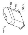
図3を参照すると、本発明の一実施形態によるマルチ試験紙メーターに用いられるカートリッジ100の斜視図が示されている。カートリッジ100は、カートリッジ100内の複数の試験紙またはバイオセンサーを貯蔵し、かつ個別に取り出すために用いられるものである。図示されているように、カートリッジ100は、細長い楕円形状を有しており、垂直方向上向きに延在している。 Referring to FIG. 3, a perspective view of a
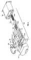
図4を参照すると、カートリッジ100の構成部品の分解斜視図が示されている。この実施形態では、カートリッジ100は、3つの主構成部品:カバー部122、取出アセンブリ130,および外側ハウジング150を備えている。以下、これらの構成部品の各々について、さらに詳細に説明する。 Referring to FIG. 4, an exploded perspective view of the components of the
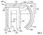
カートリッジ110のカバー部122が、図5〜図5Bに詳細に示されている。一実施形態では、カバー部122は、接続部材124を有する細長い丸形のキャップ(図4)である。接続部材124は、カバー部122から取出アセンブリ130に向かって延在している。開口128(図5A)が、接続部材124の下部、すなわち、カバー部122から取出アセンブリ130のより近くに延在している部分に配置されている。 The
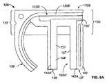
図5Aおよび図5Bを参照すると、空洞または凹部126が、カバー部122の内部に形成されている。図示されているように、空洞126を形成するために、カバー部122を構成する材料の厚みがカバー部122の周囲を囲んでいる。一実施形態では、カバー部122は、試験紙が取出アセンブリ130(図4)から取り出されるように取出アセンブリ130を作動させるように機能することができる。また、カバー部122は、取出アセンブリ130の内部がユーザーまたは外部雰囲気によって汚染されるのを防ぐために、取出アセンブリ130のOリング148と協働し、取出アセンブリ130に対して気密シールをもたらすのを助長するように機能するようになっているとよい。 Referring to FIGS. 5A and 5B, a cavity or
図4に示されている取出アセンブリ130を再び参照すると、取出アセンブリは、3つの主構成部品:第2の半体132Bに接合された第1の半体132Aを有する内部カートリッジハウジング129(図6)、取出部材140(図7)、および内部カートリッジハウジング129内に設けられたバネ付勢ブロック146(図7)を備えている。取出アセンブリ130は、複数の積層された試験紙160を貯蔵し、次いで、カートリッジ100内に貯蔵されたこれらの複数の試験紙160の各々を一度に一枚の割合で取り出すことができるようになっている。一実施形態では、取出アセンブリ130は、少なくとも45枚の試験紙を貯蔵することが可能である。しかし、どのような数の試験紙が取出アセンブリ130内に貯蔵されるようになっていてもよい。 Referring back to the
図4および図6を参照すると、取出アセンブリ130の内部カートリッジハウジング129の第1の半体132Aは、本体135、および本体135から離れる方に延在する第1、第2、および第3の突出脚137,138,139を有している。第1の突出脚137は、本体135から離れる方に垂直方向に延在しており、縁142Aを有する隆起部142を備えている。同様に、第2の突出脚138は、縁144Aを有する隆起部144を有している。縁142A,144Aは、複数の試験紙160を収容するための凹部133Aを形成している(図4)。第3の突出脚139も、本体135から離れる方に垂直方向に延在している。第3の突出脚139は、丸くなっており、取出部材140を受け入れるように構成され、かつ配置された通路133Bを備えている。通路133Bは、第3の脚139の第1の端139Aから本体135の長さを横切って延在し、本体135の開口1635で終端している。通路133Bは、取出部材140が通路内を移動するための経路をもたらすものである。 Referring to FIGS. 4 and 6, the
取出アセンブリ130は、図7、図7Aおよび図7Bに示されている取出部材140をさらに備えている。取出部材140は、その全体が丸く形作られている。図7および図7Aを最初に参照すると、取出部材140の前面図および前方斜視図が、それぞれ、示されている。図示されているように、取出部材140は、剛性のある第1端149および剛性のある第2の端149Aを有しているが、第1および第2の端149,149A間に延在しているアーム部146は、可撓性を有している。アーム部146の可撓性によって、取出部材140が通路133B内により容易に装着され、通路133B内をより容易に移動することが助長されることになる。図7Aに最もよく示されているが、第1の端149において、アーム部146は、Iビーム状の輪郭を有している。以下にさらに詳細に説明するように、Iビーム状輪郭の縁112は、アーム140が通路133Bの形状によって画定された予め選択された経路に沿って移動することを確実にするのに役立つことになる。 The
ヒンジ接続部が、取出部材140の第1の端149に設けられている。ヒンジ接続部は、ヒンジ本体151によって互いに分離された第1のヒンジアーム145Aおよび第2のヒンジアーム145Bを有している。取出部材140の第2の端149Aは、取出アセンブリ130内に貯蔵された試験紙160を取出アセンブリ130から取り出すためのフィンガー147を有している。図7Bを参照すると、フィンガー147は、3つの区域:前区域156、後区域154、および前区域154と後区域156との間に配置された中間区域158を備えることができる。前区域、中間区域、および後区域154,156,158の各々は、互いに異なる厚みを有しているとよい。図示されているように、中間区域158は、高さXを有する縁158Aを有している。高さXは、変更可能であるが、この実施形態では、試験紙の大きさと比例している。一例では、高さXは、ユーザーに分給される試験紙の高さよりもいくらか小さくなっている。例えば、もし試験紙が0.43mmの高さを有しているなら、縁158Aの高さXは、0.43mmよりもいくらか小さい値、例えば、0.35mmとすることができる。この実施形態は、一例しか提示していないこと、および試験紙のどのような大きさおよび試験紙の高さよりも小さい縁158Aのどのような高さXも、本発明の範囲内に含まれることを理解されたい。好ましい実施形態では、試験紙は、0.30mmから0.50mmの範囲内にあり、縁158Aの高さXは、0.29mmから0.49mmの範囲内にある。勿論、どのような大きさの試験センサおよび対応する縁158Aの高さXが用いられてもよいことを理解されたい。代替的実施形態では、この高さが試験紙の高さよりもいくらか大きいことが望ましい場合もある。 A hinge connection is provided at the
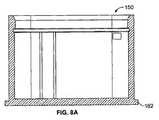
図8および図8Aを参照すると、外側ハウジング150の斜視断面図および断面図が示されている。この実施形態では、外側ハウジング150は、基部162およびバネハウジング164を備えている。外側ハウジング150の内部166は、主に取出アセンブリ130を収容するための中空ハウジングである。以下にさらに詳細に説明するように、第1の溝168が、取出アセンブリ130を収容するための内面172に沿って延在している。図8Bは、外側ハウジング150の内部166を見た外側ハウジング150の上面図である。 8 and 8A, a perspective sectional view and a sectional view of the
カートリッジ100の構成部品は、容易に一緒に組み立て可能である。取出アセンブリ130(図4、図6および図6A)を最初に参照すると、内部カートリッジハウジング129の第1および第2の半体132A,132Bが、一緒に接合されるとよい。半体132A,132Bを接合する前に、試験紙160および取出部材140がその内部に配置されるとよい。取出部材140は、内部カートリッジハウジング129を通って延在する通路内に配置されるとよい。試験紙160は、凹部133A内において、試験紙の縁の各々が互いに真っ直ぐに並ぶように長さ方向に配置されるとよい。いったん内部カートリッジハウジング129が完全に組み立てられたなら、Oリング148が、内部カートリッジハウジング129の組み立てられた第1および第2の半体132A,132Bの周りに延在する溝161内に配置されるとよい。Oリング148は、一般的に、シールを形成するのを助長するゴム材料から構成されている。また、カートリッジ100のカバー部122は、内部カートリッジハウジング129に接合されるとよい。 The components of the
次いで、組み合わされたカバー部122および内部カートリッジハウジング129は、外側ハウジング150内に配置されとよく、これによって、完成したカートリッジ100が形成されることになる。図示されているように、Oリング148は、カバー部122が閉位置にあるとき、カバー部122と協働し、気密シールをもたらすことになる。一実施形態では、カバー部122が外側ハウジング150に取外し可能に接合されたとき、Oリング148が圧縮されるようになっている。これは、内部カートリッジハウジング129内の試験紙の鮮度を延ばし、カートリッジ100内に収容されている間に貯蔵された試験紙が汚染される可能性を排除しないまでも最小限に抑える働きがある。さらに、この構成によって、内部カートリッジハウジング129内に貯蔵された複数の試験紙160の汚染を最小限に抑えると共に、非透湿環境を促進することができる。 The combined
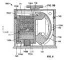
図9および図9Aを参照すると、組み立てられたカートリジ100の断面図およびカートリッジ100のカバー部122に接続された内部カートリッジハウジング129の斜視図が、それぞれ、示されている。試験紙160の積層体は、内部カートリッジハウジング129の第1の半体132A内に形成された凹部133A内に収容された状態で示されている。図示されているように、複数の試験紙160の各々は、長さ方向に配置され、かつ積層されている。従って、試験紙160の外縁の各々は、上下方向に位置合わせされている。試験紙160の長さLは、水平面に沿って延在しており、複数の試験紙160の各試験紙の高さまたは厚みTは、垂直方向に沿って延在している(図9)。多数の試験紙が取出アセンブリ130内に存在しているにも関わらず、カートリッジ100内に貯蔵された複数の試験紙の各々は、一度に一枚の割合で取出し可能になっている。この構造は、先行技術によるマルチ試験紙メーターによって必要とされているようなメーターへの試験紙の再充填の頻度を少なくするのに役立つことになる。また、この構造は、取出装置から同時に2枚以上の試験紙が取り出されるのを防ぐのにも役立つことになる。取出部材140およびバネ付勢ブロック146は、内部カートリッジハウジング129の第1の半体132Aまたは第2の半体132Bのいずれかの内部に配置されているとよい。 Referring to FIGS. 9 and 9A, a cross-sectional view of the assembled
バネ付勢ブロック146は、試験紙160の積層体の下方に位置しており、複数の試験紙160をカートリッジ100の(カバー部122に近い)上部に向かって、かつ凹部133Aの縁171(図6)に向かって付勢するようになっている。また、試験紙160は、縁158Aが試験紙160の積層体の1つの試験紙160Aの縁158’(図9B)に接触するように、取出部材140のフィンガー147に向かう方向に付勢されている。縁171は、試験紙160が垂直方向またはカバー部に向かう方向にさらに前進するのを防ぐものである。支持部材127(図6および図6A)が、凹部133A,133A’(図示せず)内の試験紙160を支持している。 The
可撓性の取出部材140が、通路133B(図6)および凹部133A内に配置された状態で示されている。取出部材140のアーム部146は、通路133Bの丸い脚部139(図6)内に配置されており、取出部材140のフィンガー147は、内部カートリッジ129の第1の半体132Aの本体135内に配置されている。図9Aに最もよく示されているように、取出部材140は、内部カートリッジハウジング129の第1および第2の半体132A,132Bの接合通路133A,133B’から形成された通路133に沿って移動することができる。アーム部146の縁112は、第1の半体132Aおよび第2の半体132Bの縁115(図9A)に沿って案内されるようになっており、これによって、取出部材140を通路133内に確保するのを助長している。 A
図9の拡大部を示す図9Bを参照すると、フィンガー147は、中間区域158の縁158A(図7B参照)が多数の試験紙160の積層体の1つの試験紙160Aの縁158’にごく隣接するように、配置されている。例えば、図示されているように、フィンガー147の縁158Aは、試験紙160Aの高さHよりもわずかに小さい高さXを有している。一実施形態では、フィンガー147の高さXは、試験紙160Aの高さHよりも0.15mm小さくなっている。フィンガー147の高さXを試験紙160の高さHよりも小さくすることによって、取出し装置から一度に一枚の試験紙のみが取り出されることが確実になる。勿論、他の実施形態では、フィンガー147の高さXは、試験紙160Aの高さより著しく小さくてもよいし、または等しくてもよい。 Referring to FIG. 9B, which shows an enlargement of FIG. 9, the
図9Bにも示されているように、試験紙通路165によって、一度に一枚の試験紙160Aが、該通路内および試験紙160Aが取り出される試験紙開口167を通って移動することができる。フィンガー通路163によって、取出部材140のフィンガー147は、試験紙を試験紙開口167を通って取り出すとき、フィンガー通路163を通って移動することができる。 As also shown in FIG. 9B, the
図4および図9Aを参照すると、カバー部122および取出アセンブリ130は、互いに接続されている。接続部材124は、取出アセンブリ130の内部カートリッジハウジング129の第1および第2の半体132A,132Bの上部に位置する細長開口171A,171B(図4)を貫通するようになっている。取出部材140の段付き部128Aが、接続部材124の該当する楕円開口128を貫通することになる。この実施形態では、第1のヒンジアーム145Aは、接続部材124に隣接しており、第2のヒンジアーム145Bは、接続部材124Bに隣接している。 Referring to FIGS. 4 and 9A, the
取出アセンブリ130およびカバー部122が互いに隣接するとき、ブロック146Aが、複数の試験紙160の最後の試験紙の下方に位置することになる。バネ146Bが、外側ハウジング150内に配置されているとよい。図9に最もよく示されているように、カートリッジ100は、完全に組み立てられた形態において、「静止(at rest)」位置にある。この位置において、バネ付勢ブロック146は、複数の試験紙160を内部カートリッジハウジング129の頂部またはハウジングの縁171に向かって付勢している。加えて、ヒンジ本体151の少なくとも一部が第3の脚139の下方に延在している。 When the
図10を参照すると、試験紙160の積層体から試験紙を取り出すために、取出部材140は、その「静止(at rest)」位置から「取出し(dispensing)」位置に移動しなければならない。力Fがカバー部122に加えられると、接続部材124も力を開口128(図5A)内の段付き部128A(図7A)に加え、段付き部128Aを開口128内において開口128の対向端に向かって移動させる。第1および第2のヒンジアーム145A,145Bが段付き部170を中心として回転し、これによって、取出部材140の運動が可能になる。取出部材140は、取出アセンブリ130の内部カートリッジハウジング129の第1および第2の半体132A,132Bの通路133A,133Bによって形成された通路133に沿ってまたは該通路133内を移動することになる。従って、取出部材140は、上方または垂直方向に移動すると共に、水平方向または試験紙と平行の方向に移動する。その結果、カバー122の上向き力Fによって、2つの方向の運動が生じることになる。 Referring to FIG. 10, in order to remove the test strip from the stack of
取出部材がその「静止」位置から「取出」位置に移動したとき、取出部材140のフィンガー147の縁158Aが試験紙160Aを試験紙160の積層体の上を横切ってかつ通路165に沿って移動させ、最終的に、試験紙160は、試験紙開口167を通って外に押し出される(図9B参照)。換言すれば、フィンガー147の縁158は、試験紙160Aを試験紙通路165に沿って押し、さらに試験紙開口167を通って外に押し出すようになっている。その結果、この試験紙160Aは、残りの試験紙から位置ずれし、これによって、次の試験紙160が繰り上がることになる。このように、カバー部122を外側ハウジング150から離れる方に移動させることによって、取出部材140を第1の位置または「静止」位置と第2の位置または「取出位置」との間で移動させることになる。静止位置は、取出部材140の本体151が第3の脚139の第1の端137に近く、取出部材140の縁158Aが試験紙160の積層体の試験紙160Aに隣接するときの位置である。「取出」位置は、取出部材140の本体151が通路135Bに沿って第3の脚139の第1の端137Aから離れる方に移動するように回転し、フィンガー147が通路167に沿って移動し、試験紙160Aを、試験紙開口167を通って押し出すときの位置である。 When the removal member moves from its “rest” position to the “removal” position, the
カートリジ100は、多数の試験を1つのカートリッジ100のみを用いて行うことを可能にするマルチ試験紙メーター内に組み込むことができる。1つの概略的な例では、図11に示されるように、カートリッジ100は、試験メーターのハウジング内に配置されるとよい。カートリッジ100のタブ111がハウジングに固定され、これによって、カートリッジ100の外側ハウジング150がカバー部122から離れる方に移動可能になっている。図示されているように、作動ボタン115および作動アーム116を備えるアクチュエータ104が、カートリッジ100のタブコネクター111に取り付けられているとよい。力が作動ボタン115に加えられると、外側ハウジング内に配置された取出アセンブリ130が作動し、外側ハウジング150がカバー部122から離れる方に移動する。これによって、取出部材140は、「静止」位置または第1の位置から「取出」位置または第2の位置に移動することになる。その結果、試験紙160Aがカートリッジ100の開口およびメーターハウジング109から取り出される。この例では、試験紙160Aは、すでに取り出されており、取出部材140は、カートリッジの開口の入口に近いその「取出」位置から、その「静止」位置に戻っている。従って、他の試験紙160Aを取り出す準備が整っていることになる。この例では、作動アーム116は、撃鉄解除部119にも接続されている。撃鉄解除部119は、突刺具121を撃鉄位置から解除し、突刺具121をメーターハウジングから突出させるようになっている。突刺具121は、指または他の体部分を突き刺し、流体試料を試験紙160Aにもたらすために用いられるものである。 The
前述の説明は、ここに開示された発明の一実施形態のみを例示したものであり、多数の代替的な実施形態が存在することを理解されたい。マルチ試験紙に用いられる他の代替的カートリッジが、図12〜図22Aに示されている。図12をまず参照すると、カートリッジ200の斜視図が示されている。カートリッジ200は、2つの端を有している。第1の端202は、略丸くなっており、第2の端204は、矩形になっている。 It should be understood that the foregoing description is only illustrative of one embodiment of the invention disclosed herein, and that many alternative embodiments exist. Another alternative cartridge for use with multiple test strips is shown in FIGS. 12-22A. Referring first to FIG. 12, a perspective view of the
図13を参照すると、図12の分解図が示されている。一実施形態では、カートリッジ200は、2つの主構成部品:取出アセンブリ210および取出アセンブリ210に取外し可能に接続された試験紙貯蔵ユニット230から構成されている。以下、これらの構成部品の各々についてさらに詳細に説明する。貯蔵ユニット230は、複数の試験紙260を貯蔵している。貯蔵ユニット230は、概して、外側貯蔵ハウジング232およびバネ付勢ブロック250から構成されている。 Referring to FIG. 13, an exploded view of FIG. 12 is shown. In one embodiment, the
外側貯蔵ハウジング232は、互いに接合された第1の半体232Aおよび第2の半体232Bからさらに構成されている。図14を参照すると、第1の半体232Aは、丸い縁、第1の開端234、および第2の閉端237を備える略矩形形状を有している。隆起通路235A,235Bが、第1の半体232Aの第1および第2の端234,237間に延在している。隆起通路235A,235Bは、それぞれ、隆起縁240,242を形成している。隆起縁240,242は、試験紙260およびバネ付勢ブロック250を収容するための内部凹部238を画定している。第1の端234において、通路235Aは、第1のストッパー236で終端しており、第2の通路235Bは、第2のストッパー236Aで終端している。第1のストッパー236は、内部通路縁239A、外側縁239E、および内部通路縁239Aと外側縁239Eとの間に延在する横縁239Cを備えている。同様に、第2のストッパー236Aは、内部通路縁239B、対向外側縁239、および内部通路縁239Bと対向外側縁239との間に延在する横縁239Dを備えている。また、内部表面縁238Aから下方に凹んだ取出棚244が設けられている。その結果、内部縁244Aが、内部表面238と取出棚244との間に延在している。 The
図14Aを参照すると、第1の半体232Aと相補的な第2の半体232Bが設けられている。第2の半体232Bは、第1の端234’および第2の端237’を備えている。加えて、第1および第2の通路235A’,235B’が第1および第2の端234’,237’間に延在しており、それぞれの隆起縁240’,242’を有している。内部凹部238’が、隆起縁240’,242’によって画定されており、隆起縁240’,242’間に空間を備えている。 Referring to FIG. 14A, a
試験紙貯蔵ユニット内に貯蔵された試験紙が汚染されないこと、および密封されたとき、複数の試験紙260を貯蔵するための非透湿環境をもたらすことを確実にするために、乾燥剤(図示せず)が第1および第2の半体232A,232B内に配置されているとよい。貯蔵ユニット230の第1の半体232Aおよび第2の半体232Bが互いに接合されると、第2の端237,237’が互いに真っ直ぐに並ぶことになる。第1の端では、第2の半体232Bの縁239Cが、第1の半体232Aの第2のストッパー238の縁239Bに当接することになる。同様に、第2の縁239Dが、第1の半体232Aの第1のストッパー236の縁239Aに当接することになる。加えて、第2の半体232Bの第2の縁239Dは、隆起縁239B,239Aに接合することになる。 To ensure that the test strips stored in the test strip storage unit are not contaminated and when sealed, provide a non-breathable environment for storing a plurality of test strips 260 (see FIG. (Not shown) may be disposed in the first and
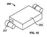
バネ付勢ブロック250は、図15、図15Aおよび図15Bに最もよく示されている。図示されているように、バネ付勢ブロック250は、略矩形の本体252から構成されている。第1のアーム254および第2のアーム256が、コネクター256から延在しており、コネクター256は、本体252の互いに対向する端253から延在している。この実施形態では、第1および第2のアーム254,256は、円形であり、第2の部分254Bの直径よりも小さい直径を有する第1の部分254Aから構成されている。棚257が、第1および第2の部分254A,254B間に形成されている。図15Bに示されているように、バネ261が、第1の部分254を覆って設けられており、棚257上に位置している。 The
図16および図16Aを参照すると、第1の半体232Aが、試験紙260およびバネ付勢ブロック250を含んでいる状態で示されている。図示されているように、アーム254は、第1および第2の通路235A,235B内に配置されており、これによって、試験紙260が貯蔵ユニット230から取り出されるとき、通路内を自在に移動することが可能である。第2の半体232Bは、周知の方法を用いて、第1の半体232Aの接合面231(図14)および第2の半体232Bの接合面231’に沿って、第1の半体232Aに接合されるとよい。 Referring to FIGS. 16 and 16A, the
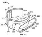
図13を再び参照すると、この実施形態では、取出アセンブリ210は、3つの主構成部品:カバー212、取出ハウジング214、および取出部材216から構成されている。図17および図17Aを参照すると、取出ハウジング214は、本体201を有するものとして示されている。本体201は、円形基部215を有している。半円形の第1の壁217が、基部215の一部の周りに延在しており、外側上面218および内部上面219を有している。縁220(図17)が外側上面218と内部上面219との間に延在しており、これによって、内部上面219が外側上面218から離間しており、棚を形成している。通路221が、内部上面219から基部215に延在している。コネクター203が、基部215の(半円壁が延在する部分と直接的に向き合った)部分に沿って延在している。コネクター203は、基部215から連続的に延在する表面205を有する楕円形開口を有している。第2の表面206が、コネクターの開口の口部に位置しており、垂直方向に延在する縁207が第1および第2の表面205,206間に延在するように、第1の表面205から離間している。第2の壁209がコネクター203の上面208から上方に延在している。 Referring again to FIG. 13, in this embodiment, the
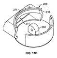
後方斜視図である図17Cに最もよく示されているように、壁209は、丸くなっており、円形基部215の形状または輪郭に似ている。壁209は、第1の外面211および第1の外面211から離間した第1の内面213も備えている。加えて、壁209は、取出ハウジング214の内部に面する通路をさらに備えている。この通路は、第1の壁217と向き合う壁209に沿って延在している。 As best shown in FIG. 17C, a rear perspective view, the
図17Bを参照すると、ポスト262が、取出ハウジング214内に配置されている。ポスト262は、本体201の基部215から離れる方に延在している。ポスト262は、該ポストを貫通する開口を備えている。 Referring to FIG. 17B, a
図18および図18Aを参照すると、取出部材216が示されている。取出部材216は、前面266、後面268、第1の横面270、および第2の横面272を備えている。開口274が、前面266と後面268との間に延在しており、前側ポスト276Aが前面266から離れる方に延在しており、後側ポスト276B(図示せず)が、後面268から離れる方に延在している。第1の横面270は、凹部278を備えている。縁280A,280B,280C,280Dが、試験紙を適所に保持するために用いられる支持部を形成している。 Referring to FIGS. 18 and 18A, the
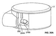
図19を参照して、カバー部212についてさらに説明する。前面図に示されているように、カバー部212は、丸い形状を有しており、取出ハウジング214の本体201内に装着されるように構成され、かつ配置されている。図19A、図19Bおよび図19Cに最もよく示されているように、壁284A〜284Dは、円形上部283から延在している。壁284C,284Dは、丸形状を有しており、円形上部283の形状に追従している。壁284A,284Bは、壁284C,284Dと交差する水平線部をなしている。腎臓形状の凹部282が、壁284A,284Bの各々を貫通しており、周縁282Aを有している。位置決めタブ285が、壁284Aの外面上に配置されている。 The
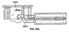
図13、図20および図20Aを参照すると、取出アセンブリ210を組み立てるために、取出部材216が、取出アセンブリハウジング214のポスト262(図17、図17Aおよび図17B)に固定されるようになっている。取出部材216の開口274は、ポスト262の開口262Aと真っ直ぐに並ぶことになる。次いで、ピン(図示せず)が開口262A,274に通され、開口262A,274内に固定される。これによって、取出部材216をポスト262を中心として回転することを可能にしながら、ポスト262に固定することができる。「静止」位置において、取出部材216の第1の横面270は、ハウジング214の開口271(図17)と向き合っている。次いで、カバー部212は、ハウジング214内に配置されるとよい。カバー部212は、カバー部212上のタブ285(図19および図19B)が取出ハウジングの通路221と真っ直ぐに並ぶように、配向されねばならない。図20を参照すると、カバー部212の腎臓状の開口282は、ポスト276A,276Bが腎臓状開口282内に確保されるように、ポスト276A,276Bを囲んで配置されることになる。これによって、カバー部212のポスト276A,276Bは、腎臓状開口282内において移動することができる。腎臓状開口282がポスト276A,276Bに関連付けられているので、カバー部212に上方向に加えられた力Fは、取出部材216を上方向に回転させることができ、これによって、前面270がカバー部212の方を向くことになる。 Referring to FIGS. 13, 20 and 20A, in order to assemble the
試験紙取出アセンブリ210を操作するために、貯蔵ユニット230が、コネクター203の開口271内に配置されるとよい。図21および図21Aを参照すると、取出部材216および貯蔵ユニット230の断面および「静止」位置にあるカートリッジ200の全体の断面が、それぞれ、示されている。貯蔵ユニット230が取出部材216に接合されると、該貯蔵ユニット230は、取出部材216に当接する。この「静止」位置では、試験紙260Aは、試験紙貯蔵ユニット230内に貯蔵された複数の試験紙260の前方に位置している。図示されているように、試験紙260は、縁227によって形成された凹部278内に着座している(図18参照)。取出部材216は、単一の試験紙のみが取出部材216内に嵌合し、これによって、一枚の試験紙のみを一度に分給可能とすることができる。 In order to operate the test
力Fがカバー部212に加えられると、ポスト276A,276B(図18)は、カバー部212に加えられた力によって移動し、これによって、腎臓状開口282の縁282Aがポスト276A,276Bを捕捉し、腎臓状開口282に沿ったポスト276A,276Bの運動を可能にする。取出部材216は、取出部材216を貫通するピン(図示せず)を中心として回転し、その結果、試験紙260Aは、その「静止」位置から取出位置に移動することになる。図22に最もよく示されているように、この位置において、試験紙260Aは、カバー部212と向き合っており、貯蔵ユニット230内のさらなる試験紙260が脱落しないように、取出部材の基部が貯蔵ユニット230を覆っている。次いで、試験紙は、当技術分野において知られているどのような従来の手段を用いて、カートリッジから取り出されてもよい。例えば、試験紙の取出しを可能にする追加的な開口がカバー部212に設けられていてもよい。代替的に、試験紙260Aがカバー部212の開口から外に押し出されるようになっていてもよい。 When force F is applied to the
カバー部212が解放されると、取出部材の前面270は、再び、試験紙230と向き合い、分給される次の試験紙を受け入れることになる。 When the
前述の実施形態のいずれにおいても、試験紙160,260をカートリッジ100の頂部または縁171または貯蔵ユニット230の棚244に向かって付勢するために、代替的な付勢部材または付勢手段が、バネのような弾性部材に代わって用いられてもよいことを理解されたい。代替的実施形態では、付勢部材の例として、カートリッジ100の外側ハウジング150の内部底面または試験紙ユニット230の外側ハウジング232に配置された第1の磁石と、試験紙160,260の積層体に取り付けられた第2の反発磁石が挙げられる。試験紙160,260の積層体は、第1の磁石および第2の磁石を互いに反発させる(互いに離れる方に押す)電磁気力を介して前方に付勢されることになる。他の代替的実施形態では、磁石は、電磁石と向き合って配置された対向磁極を有する強磁石を含んでいる。代替的に、電磁石および強磁石の組合せが用いられてもよい。 In any of the foregoing embodiments, an alternative biasing member or biasing means may be used to bias the
さらに他の実施形態では、付勢部材は、空圧システムを備えていてもよい。この空圧システムでは、圧縮ガスを用いて、試験紙160,260の積層体をカートリッジ100の頂部または縁171または貯蔵ユニット230の棚244に向かって付勢するようになっている。1つの代替的実施形態では、試験紙160,260の積層体が、ピストン−シリンダー構造におけるピストンの上側に配置され、カートリッジ100,200が、シリンダーとして機能するようになっている。ピストンの下方においてシリンダー内に吸入された圧縮ガスは、試験紙160,260をカートリジ100または貯蔵ユニット230に向かって付勢することになる。 In still other embodiments, the biasing member may comprise a pneumatic system. In this pneumatic system, compressed gas is used to bias the stack of
以下の番号が付されたパラグラフは、本開示の実施形態による特徴を記述するものである。 The following numbered paragraphs describe features according to embodiments of the present disclosure.
1.試験紙にもたらされた体液試料を分析するための試験メーターであって、
開口を有する外側ハウジングと、
前記外側ハウジングに隣接して配置されたアクチュエータと、
前記外側ハウジングに隣接して配置された試験紙を取り出すためのカートリッジであって、
前記アクチュエータに接続された取出部材と、
前記取出部材に向かって付勢された複数の積層された試験紙と、
前記取出部材の少なくとも一部に隣接するカートリッジ外側ハウジングと、
をさらに備えているカートリッジと、
を備えており、
前記アクチュエータが作動するたびに、前記複数の積層された試験紙から一枚の試験紙を前記開口を通して移動させるように、前記取出部材が回転し、他の試験紙が前記取出部材に向かって付勢されるようになっている、
試験メーター。1. A test meter for analyzing a body fluid sample brought to a test strip,
An outer housing having an opening;
An actuator disposed adjacent to the outer housing;
A cartridge for removing a test strip disposed adjacent to the outer housing,
An extraction member connected to the actuator;
A plurality of laminated test papers biased toward the take-out member;
A cartridge outer housing adjacent to at least a portion of the extraction member;
A cartridge further comprising:
With
Each time the actuator is actuated, the takeout member rotates so that one sheet of test paper is moved from the plurality of stacked test papers through the opening, and the other test paper is attached toward the takeout member. Has come to be,
Test meter.
2.前記取出部材は、第1の端および第2の端を有する可撓性アームであり、前記アクチュエータが作動したとき、前記取出部材は、一枚の試験紙を前記積層された試験紙の上を横切って前記開口を通るように移動させるようになっている、パラグラフ1に記載の試験メーター。 2. The take-out member is a flexible arm having a first end and a second end, and when the actuator is operated, the take-out member moves a sheet of test paper over the laminated test paper. A test meter according to paragraph 1, wherein said test meter is adapted to be moved across said opening.
3.前記取出部材は、第1の端および第2の端を有しており、前記第1の端は、前記試験紙に接触する自由端であり、前記第2の端は、固定端であり、前記アクチュエータが作動したとき、前記自由端は、前記固定端を中心として回転するようになっている、パラグラフ2に記載の試験メーター。 3. The extraction member has a first end and a second end, the first end is a free end that contacts the test paper, and the second end is a fixed end, The test meter of paragraph 2, wherein the free end rotates about the fixed end when the actuator is actuated.
4.前記取出部材は、前記複数の積層された試験紙から一枚の試験紙を受け入れるための凹部を有する回転可能なブロックであり、前記アクチュエータが作動したとき、前記ブロックが回転し、前記凹部内に受け入れた前記試験紙を前記試験紙の積層体から離れる方に移動させるようになっている、パラグラフ1に記載の試験メーター。 4). The take-out member is a rotatable block having a recess for receiving a single test paper from the plurality of stacked test papers. When the actuator is actuated, the block rotates, and is placed in the recess. A test meter according to paragraph 1 wherein the received test paper is adapted to move away from the test paper stack.
5.前記取出部材および前記複数の試験紙は、前記外側ハウジング内に配置されている、パラグラフ1に記載の試験メーター。 5. The test meter according to paragraph 1, wherein the take-out member and the plurality of test papers are disposed in the outer housing.
6.前記取出部材のみが前記外側ハウジング内に配置されており、前記カートリッジは、前記外側ハウジングに接続されている、パラグラフ1に記載の試験メーター。 6). The test meter of paragraph 1 wherein only the removal member is disposed within the outer housing and the cartridge is connected to the outer housing.
7.前記試験メーターは、前記取り出された試験紙が前記開口内に位置している間に、前記流体試料を分析することができるようになっている、パラグラフ1に記載の試験メーター。 7). The test meter of paragraph 1 wherein the test meter is configured to analyze the fluid sample while the removed test strip is positioned within the opening.
8.前記カートリッジは、前記外側ハウジングに接合された内部カートリッジハウジングと、前記取出部材に係合された接続部を有するカバーであって、前記取出部材を移動させるようになっているカバーと、をさらに備えている、パラグラフ1に記載の試験メーター。 8). The cartridge further includes an inner cartridge housing joined to the outer housing, and a cover having a connection portion engaged with the take-out member, the cover being adapted to move the take-out member. The test meter of paragraph 1, wherein
9.前記カートリッジは、前記取出部材を受け入れ、かつ前記取出部材が前記通路内において第1の位置と第2の取出位置との間で移動することを可能にする経路をもたらすための通路をさらに備えている、パラグラフ1に記載の試験メーター。 9. The cartridge further comprises a passage for receiving the removal member and providing a path that allows the removal member to move between a first position and a second removal position within the passage. The test meter of paragraph 1, wherein
10.前記カートリッジは、
前記外側ケーシングに取外し可能に接合されたカバーと、
前記取出部材を収容するための内部カートリッジハウジングであって、前記内部カートリッジハウジングは、前記複数の積層された試験紙を貯蔵するための試験紙貯蔵領域をさらに備えており、前記試験紙の各々は、互いに真っ直ぐに並んだ縁を有している、内部カートリッジハウジングと、
をさらに備えている、パラグラフ1に記載の試験メーター。10. The cartridge is
A cover removably joined to the outer casing;
An internal cartridge housing for accommodating the take-out member, wherein the internal cartridge housing further comprises a test paper storage area for storing the plurality of stacked test papers, each of the test papers being An inner cartridge housing having straight edges aligned with each other;
The test meter of paragraph 1, further comprising:
11.前記積層された試験紙の各々は、外縁を有しており、前記外縁の各々は、前記試験紙貯蔵領域内において、互いに真っ直ぐに並んでいる、パラグラフ10に記載の試験メーター。 11. 11. The test meter of
12.前記内部カートリッジハウジングと前記外側ハウジングとの間に延在するシールをさらに備えている、パラグラフ10に記載の試験メーター。 12 The test meter of
13.試験紙に沈降した流体試料を試験するための方法であって、
試験メーター内に収納された取出部材を、静止位置から取出位置に移動させるように、かつ前記試験メーター内の試験紙の積層体内に貯蔵されて前記取出部材に接触している一枚の試験紙を前記試験メーターの開口に向かって移動させるように、作動させるステップであって、前記一枚の試験紙が前記開口に向かって移動するとき、前記一枚の試験紙の少なくとも1つの縁が露出し、該試験紙の対向端が前記開口内に残るようになっている、ステップと、
前記試験紙の前記露出した部分に前記流体試料をもたらすステップと、
前記一枚の試験紙の対向端が残っている間に前記流体試料を分析するステップと、
他の試験紙を前記取出部材に向かって付勢するステップと、
を含んでいる、方法。13. A method for testing a fluid sample that has settled on a test strip, comprising:
A sheet of test paper that is stored in a stack of test paper in the test meter and is in contact with the take-out member so as to move the take-out member housed in the test meter from the stationary position to the take-out position Moving toward the opening of the test meter, wherein at least one edge of the sheet is exposed when the sheet moves toward the opening. And the opposite end of the test paper is left in the opening; and
Providing the fluid sample to the exposed portion of the test strip;
Analyzing the fluid sample while the opposite ends of the sheet of test paper remain;
Urging another test strip toward the take-out member;
Including the way.
14.前記取出部材は、固定端および自由端を有する可動アームを備えており、前記自由端は、前記1つの試験紙に接触している、パラグラフ13に記載の方法。 14 14. The method according to paragraph 13, wherein the extraction member comprises a movable arm having a fixed end and a free end, the free end contacting the one test strip.
15.前記取出部材は、前記試験紙を第1の位置から第2の位置に移動させるとき、固定点を中心として回転するようになっている、パラグラフ14に記載の方法。 15. 15. The method according to
16.前記取出部材は、前記試験紙を第1の位置から第2の位置に移動させることができる可動ブロックである、パラグラフ13に記載の方法。 16. 14. The method according to paragraph 13, wherein the take-out member is a movable block that can move the test paper from a first position to a second position.
17.前記ブロックは、1つの試験紙を受け入れるための凹部を有している、パラグラフ14に記載の方法。 17. 15. A method according to
18.前記カートリッジは、前記アクチュエータに接続されたカバーをさらに備えており、前記取出部材は、カバーをさらに備えており、前記取出部材は、第1の端および第2の取出端を有しており、前記取出部材は、前記アクチュエータが作動するたびに第1の位置と第2の位置との間で移動することができる可撓性アームである、パラグラフ13に記載の方法。 18. The cartridge further includes a cover connected to the actuator, the extraction member further includes a cover, and the extraction member has a first end and a second extraction end, 14. The method of paragraph 13 wherein the extraction member is a flexible arm that can move between a first position and a second position each time the actuator is actuated.
19.試験メーター内において用いられるカートリッジであって、
外側ケーシングと、
前記外側ケーシングに取外し可能に接合されたカバーと、
前記外側ケーシング内に着座した取出アセンブリであって、
前記複数の積層された試験紙を貯蔵するための試験紙貯蔵領域であって、前記試験紙の各々は、互いに真っ直ぐに並んだ縁を有している試験紙貯蔵領域と、
取出部材であって、前記カバーに移動可能に接続されており、前記複数の試験紙の単一試験紙に接触している取出部材と、
前記複数の積層された試験紙を前記取出部材に向かって移動させる付勢部材と、
をさらに備えている取出アセンブリと、
を備えており、
前記取出部材は、第1の静止位置と第2の取出位置との間で回転するようになっており、前記カバーが前記取出アセンブリから離れる方に移動したとき、前記一枚の試験紙を前記開口を通って移動させるようになっている、
カートリッジ。19. A cartridge used in a test meter,
An outer casing;
A cover removably joined to the outer casing;
An extraction assembly seated in the outer casing,
A test paper storage area for storing the plurality of laminated test papers, each of the test papers having a test paper storage area having straight edges with each other;
An extraction member that is movably connected to the cover and is in contact with a single test paper of the plurality of test papers;
A biasing member that moves the plurality of laminated test papers toward the take-out member;
An extraction assembly further comprising:
With
The take-out member rotates between a first stationary position and a second take-out position, and when the cover moves away from the take-out assembly, the sheet of test paper is removed from the take-out assembly. To move through the opening,
cartridge.
20.前記取出部材は、第1の自由端および第2の固定端を有する細長部材であり、前記取出部材は、前記第2の端を中心として移動するようになっている、パラグラフ19に記載のカートリッジ。 20. The cartridge according to paragraph 19, wherein the extraction member is an elongated member having a first free end and a second fixed end, and the extraction member is adapted to move about the second end. .
本明細書において検討した実施形態における前述の種々の特徴は、異なる方法によって組み合わされ、かつ提示されてもよいことを理解されたい。また、個々の実施形態に関連して記載した特徴は、本明細書において検討した他の実施形態と共有されてもよいことを理解されたい。 It should be understood that the various features described above in the embodiments discussed herein may be combined and presented in different ways. It should also be understood that features described in connection with individual embodiments may be shared with other embodiments discussed herein.
本発明をここでは特定の実施形態を参照して説明してきたが、これらの実施形態は、本発明の原理および用途の単なる例示にすぎないことを理解されたい。それ故、例示的実施形態に対して多数の修正がなされてもよいこと、および添付の請求項に記載されている本発明の精神および範囲から逸脱することなく、他の構成が考案されてもよいことを理解されたい。 Although the invention herein has been described with reference to particular embodiments, it is to be understood that these embodiments are merely illustrative of the principles and applications of the present invention. Thus, numerous modifications may be made to the exemplary embodiments and other arrangements may be devised without departing from the spirit and scope of the invention as set forth in the appended claims. Please understand that it is good.
Claims (20)
Translated fromJapanese開口を有する外側ハウジングと、
前記外側ハウジングに隣接して配置されたアクチュエータと、
前記開口を通して分給するための複数の積層された試験紙を貯蔵するためのカートリッジと、
前記アクチュエータに移動可能に接続された取出部材と、
を備えており、
前記複数の積層された試験紙は、前記取出部材に向かって付勢されており、
前記アクチュエータが作動するたびに、前記複数の積層された試験紙から一枚の試験紙を前記開口を通して移動させるように、前記取出部材が回転し、前記複数の積層された試験紙の他の試験紙が前記取出部材に向かって付勢されるようになっている、
試験メーター。A test meter for analyzing a body fluid sample brought to a test strip,
An outer housing having an opening;
An actuator disposed adjacent to the outer housing;
A cartridge for storing a plurality of stacked test strips for dispensing through the opening;
An extraction member movably connected to the actuator;
With
The plurality of laminated test papers are urged toward the take-out member,
Each time the actuator is actuated, the take-out member rotates so as to move a sheet of test paper from the plurality of stacked test papers through the opening, and another test of the plurality of stacked test papers. The paper is biased toward the take-out member,
Test meter.
前記外側ハウジングに接合された内部カートリッジハウジングと、
前記取出部材に係合された接続部を有するカバー要素と、
をさらに備えており、
前記カバー要素は、前記取出部材を第1の位置と第2の位置との間で移動させるようになっている、請求項1に記載の試験メーター。The cartridge is
An inner cartridge housing joined to the outer housing;
A cover element having a connection engaged with the extraction member;
Further comprising
The test meter of claim 1, wherein the cover element is adapted to move the extraction member between a first position and a second position.
前記外側ケーシングに取外し可能に接合されたカバー要素と、
前記取出部材を収容するための内部カートリッジハウジングであって、前記内部カートリッジハウジングは、前記複数の積層された試験紙を貯蔵するための試験紙貯蔵領域をさらに備えており、前記試験紙の各々は、互いに真っ直ぐに並んだ縁を有している、内部カートリッジハウジングと、
をさらに備えている、請求項1に記載の試験メーター。The cartridge is
A cover element removably joined to the outer casing;
An internal cartridge housing for accommodating the take-out member, wherein the internal cartridge housing further comprises a test paper storage area for storing the plurality of stacked test papers, each of the test papers being An inner cartridge housing having straight edges aligned with each other;
The test meter according to claim 1, further comprising:
試験メーター内に積層形態で収容された複数の試験紙の第1の試験紙を取出部材に向かって付勢するステップと、
前記第1の試験紙を前記試験メーターの開口に向かって移動させるように、かつ前記一枚の試験紙の少なくとも1つの縁が前記試験メーターの前記開口を通って押し出され、前記試験紙の対向端が前記試験メーター内に残るように、前記取出部材を前記複数の試験紙を横切って移動させるステップと、
前記試験紙の前記露出した部分に前記流体試料をもたらすステップと、
前記一枚の試験紙の対向端が残っている間に前記流体試料を分析するステップと、
前記第1の試験紙が押し出された時点で、前記複数の試験紙の第2の試験紙を前記取出部材に向かって付勢するステップと、
を含んでいる、方法。A method for testing a fluid sample that has settled on a test strip, comprising:
Urging the first test paper of the plurality of test papers accommodated in the test meter in a laminated form toward the take-out member;
The first test paper is moved toward the opening of the test meter, and at least one edge of the sheet of test paper is pushed through the opening of the test meter to face the test paper. Moving the removal member across the plurality of test strips such that an end remains in the test meter;
Providing the fluid sample to the exposed portion of the test strip;
Analyzing the fluid sample while the opposite ends of the sheet of test paper remain;
Urging the second test paper of the plurality of test papers toward the take-out member when the first test paper is pushed out;
Including the way.
外側ケーシングと、
前記外側ケーシングに取外し可能に接合されたカバー要素と、
前記外側ケーシング内に着座した取出アセンブリであって、
前記複数の積層された試験紙を貯蔵するための試験紙貯蔵領域であって、前記試験紙の各々は、互いに真っ直ぐに並んだ対向縁を有している、試験紙貯蔵領域と、
取出部材であって、前記カバーに移動可能に接続されており、前記複数の試験紙の単一試験紙に接触している取出部材と、
をさらに備えている取出アセンブリと、
を備えており、
前記複数の積層された試験紙は、前記取出部材に向かって付勢されており、
前記取出部材は、第1の静止位置と第2の取出位置との間で回転するようになっており、前記カバーが前記取出アセンブリから離れる方に移動したとき、前記一枚の試験紙を前記開口を通って移動させるようになっている、
カートリッジ。A cartridge for storing a plurality of stacked test strips in a test meter,
An outer casing;
A cover element removably joined to the outer casing;
An extraction assembly seated in the outer casing,
A test paper storage area for storing the plurality of laminated test papers, each of the test papers having opposing edges aligned straight to each other;
An extraction member that is movably connected to the cover and is in contact with a single test paper of the plurality of test papers;
An extraction assembly further comprising:
With
The plurality of laminated test papers are urged toward the take-out member,
The take-out member rotates between a first stationary position and a second take-out position, and when the cover moves away from the take-out assembly, the sheet of test paper is removed from the take-out assembly. To move through the opening,
cartridge.
Applications Claiming Priority (3)
| Application Number | Priority Date | Filing Date | Title |
|---|---|---|---|
| US201261653838P | 2012-05-31 | 2012-05-31 | |
| US61/653,838 | 2012-05-31 | ||
| PCT/US2012/072118WO2013180755A1 (en) | 2012-05-31 | 2012-12-28 | Multistrip cartridge |
Publications (3)
| Publication Number | Publication Date |
|---|---|
| JP2015518165Atrue JP2015518165A (en) | 2015-06-25 |
| JP2015518165A5 JP2015518165A5 (en) | 2016-02-12 |
| JP6148727B2 JP6148727B2 (en) | 2017-06-14 |
Family
ID=47559746
Family Applications (1)
| Application Number | Title | Priority Date | Filing Date |
|---|---|---|---|
| JP2015514980AExpired - Fee RelatedJP6148727B2 (en) | 2012-05-31 | 2012-12-28 | Multi test paper cartridge |
Country Status (6)
| Country | Link |
|---|---|
| US (3) | US9204829B2 (en) |
| EP (1) | EP2856155B1 (en) |
| JP (1) | JP6148727B2 (en) |
| CN (1) | CN104520709B (en) |
| CA (1) | CA2873410C (en) |
| WO (1) | WO2013180755A1 (en) |
Families Citing this family (19)
| Publication number | Priority date | Publication date | Assignee | Title |
|---|---|---|---|---|
| US8574510B2 (en) | 2009-09-30 | 2013-11-05 | Bayer Healthcare Llc | Stackable electrochemical analyte sensors, systems and methods including same |
| WO2013096268A1 (en) | 2011-12-20 | 2013-06-27 | Bayer Heal Thcare Llc | Linear, cartridge-based glucose measurement system |
| WO2013180755A1 (en) | 2012-05-31 | 2013-12-05 | Bayer Healthcare Llc | Multistrip cartridge |
| US8940540B2 (en)* | 2012-05-31 | 2015-01-27 | Bayer Healthcare Llc | Sensor storage and delivery system where the test sensors are individually foiled and arranged in a stack |
| US9383333B2 (en) | 2012-05-31 | 2016-07-05 | Ascensia Diabetes Care Holdings Ag | Replaceable multistrip cartridge and biosensor meter |
| JP6563892B2 (en) | 2013-03-11 | 2019-08-21 | アセンシア・ディアベティス・ケア・ホールディングス・アーゲー | Strip grabber |
| CA2904689A1 (en) | 2013-03-12 | 2014-10-09 | Bayer Healthcare Llc | Test strip meter with a mechanism for pushing the test strip against an optical reader |
| US9376708B2 (en) | 2013-03-13 | 2016-06-28 | Ascensia Diabetes Care Holdings Ag | Bottled glucose sensor with no handling |
| US10315833B2 (en)* | 2013-11-07 | 2019-06-11 | Accutec Blades, Inc. | Blade dispenser |
| WO2015195487A1 (en) | 2014-06-19 | 2015-12-23 | Bayer Healthcare Llc | Sensor clip for stacked sensor dispensing system, and system using the same |
| WO2016189497A1 (en)* | 2015-05-26 | 2016-12-01 | Michel Poirier | Modular medication dispensing system |
| US9932166B2 (en)* | 2015-08-11 | 2018-04-03 | Salt Mag LLC | Tablet dispenser for athletes |
| CN205257033U (en)* | 2015-12-10 | 2016-05-25 | 三诺生物传感股份有限公司 | Examination barrel |
| US10259642B2 (en)* | 2015-12-17 | 2019-04-16 | Accutec Blades, Inc. | Blade dispenser |
| CN105615897B (en)* | 2016-04-05 | 2018-12-18 | 京东方科技集团股份有限公司 | A kind of blood sugar monitor and its monitoring method |
| AT520530B1 (en)* | 2018-02-14 | 2019-05-15 | Pez Ag | Pill dispenser |
| US10945568B1 (en)* | 2019-09-17 | 2021-03-16 | Lianne Chase | Rubbing alcohol dispenser apparatus |
| CN114555231B (en)* | 2019-10-28 | 2024-07-19 | 美国西门子医学诊断股份有限公司 | Vibrating pipette tip and method for preventing pipette tip stiction |
| US11307193B1 (en) | 2019-12-10 | 2022-04-19 | Joshua Stanley | Glucose testing device with test strip dispenser |
Citations (4)
| Publication number | Priority date | Publication date | Assignee | Title |
|---|---|---|---|---|
| JP2006516328A (en)* | 2003-01-14 | 2006-06-29 | ハイポガード・リミテッド | Sensor providing device |
| JP2008001428A (en)* | 2006-05-09 | 2008-01-10 | Becton Dickinson & Co | Method and apparatus for dispensing diagnostic test strips |
| JP2008502901A (en)* | 2004-06-18 | 2008-01-31 | エフ ホフマン−ラ ロッシュ アクチェン ゲゼルシャフト | Flat article dispenser |
| JP2008544266A (en)* | 2005-06-22 | 2008-12-04 | エフ ホフマン−ラ ロッシュ アクチェン ゲゼルシャフト | Test equipment for determination of analyte concentration |
Family Cites Families (100)
| Publication number | Priority date | Publication date | Assignee | Title |
|---|---|---|---|---|
| US4217331A (en) | 1977-07-18 | 1980-08-12 | Coleco Industries, Inc. | Disposable float dispenser |
| JPS5433795A (en) | 1977-08-20 | 1979-03-12 | Japanese National Railways<Jnr> | Bank note treating system |
| JPS5433797A (en) | 1977-08-20 | 1979-03-12 | Japanese National Railways<Jnr> | Bank note treating system |
| US4223524A (en) | 1978-03-17 | 1980-09-23 | Citizen Watch Co., Ltd. | Quartz oscillation circuit for electronic timepieces |
| JPS6142107Y2 (en) | 1979-11-30 | 1986-11-29 | ||
| JPS6126933Y2 (en) | 1980-05-29 | 1986-08-12 | ||
| DE68924026T3 (en) | 1988-03-31 | 2008-01-10 | Matsushita Electric Industrial Co., Ltd., Kadoma | BIOSENSOR AND ITS MANUFACTURE. |
| DE59005928D1 (en) | 1989-11-21 | 1994-07-07 | Bayer Ag | Optical biosensor. |
| DE59410388D1 (en) | 1993-04-23 | 2004-10-21 | Roche Diagnostics Gmbh | Floppy disk with test elements arranged in a circle |
| ES2182836T3 (en) | 1993-11-12 | 2003-03-16 | Inverness Medical Switzerland | READING DEVICES FOR ANALYSIS STRIPS. |
| US5630986A (en) | 1995-01-13 | 1997-05-20 | Bayer Corporation | Dispensing instrument for fluid monitoring sensors |
| US5575403A (en) | 1995-01-13 | 1996-11-19 | Bayer Corporation | Dispensing instrument for fluid monitoring sensors |
| CA2170560C (en) | 1995-04-17 | 2005-10-25 | Joseph L. Moulton | Means of handling multiple sensors in a glucose monitoring instrument system |
| FR2733745B1 (en) | 1995-05-02 | 1997-07-04 | Asulab Sa | IMPROVED APPARATUS FOR THE DISTRIBUTION OF SUCCESSIVE AREAS OF A CONSUMABLE BAND |
| US5510266A (en) | 1995-05-05 | 1996-04-23 | Bayer Corporation | Method and apparatus of handling multiple sensors in a glucose monitoring instrument system |
| US5660791A (en) | 1996-06-06 | 1997-08-26 | Bayer Corporation | Fluid testing sensor for use in dispensing instrument |
| US5810199A (en) | 1996-06-10 | 1998-09-22 | Bayer Corporation | Dispensing instrument for fluid monitoring sensor |
| US5856195A (en) | 1996-10-30 | 1999-01-05 | Bayer Corporation | Method and apparatus for calibrating a sensor element |
| DE19715031A1 (en) | 1997-04-11 | 1998-10-15 | Boehringer Mannheim Gmbh | Magazine for storing test elements |
| US5759364A (en) | 1997-05-02 | 1998-06-02 | Bayer Corporation | Electrochemical biosensor |
| US5798031A (en) | 1997-05-12 | 1998-08-25 | Bayer Corporation | Electrochemical biosensor |
| AU753745B2 (en) | 1998-04-24 | 2002-10-24 | Roche Diagnostics Gmbh | Storage container for analytical devices |
| DE19840856B4 (en) | 1998-09-07 | 2008-04-10 | Roche Diagnostics Gmbh | System for obtaining a body fluid, lancet magazine, lancet, lancet set, lancing device and method for removing a lancet from a lancet magazine and use of the system |
| US6478158B2 (en) | 1998-09-30 | 2002-11-12 | Rayovac Corporation | Battery package with multiple support compartments |
| AU6210199A (en) | 1999-09-27 | 2001-04-30 | Hypoguard Limited | Test device |
| JP4621860B2 (en) | 2000-02-23 | 2011-01-26 | アークレイ株式会社 | Sensor cartridge, sensor supply device, and measurement device |
| US20020005799A1 (en)* | 2000-05-09 | 2002-01-17 | Beisner Henry Michaels | Adaptive filter to reduce multipath |
| US6428664B1 (en) | 2000-06-19 | 2002-08-06 | Roche Diagnostics Corporation | Biosensor |
| GB0017737D0 (en) | 2000-07-20 | 2000-09-06 | Hypoguard Limited | Test device |
| US7138089B2 (en) | 2000-07-20 | 2006-11-21 | Hypoguard Limited | Test device for analyzing blood glucose or other analytes in bodily fluids |
| US6827899B2 (en)* | 2000-08-30 | 2004-12-07 | Hypoguard Limited | Test device |
| GB0021219D0 (en) | 2000-08-30 | 2000-10-18 | Hypoguard Ltd | Test device |
| EP1328192B1 (en) | 2001-03-29 | 2011-01-05 | Lifescan Scotland Ltd | Integrated sample testing meter |
| JP4522014B2 (en) | 2001-04-18 | 2010-08-11 | パナソニック株式会社 | Biosensor sheet, biosensor cartridge, and biosensor dispensing device |
| US6988996B2 (en) | 2001-06-08 | 2006-01-24 | Roche Diagnostics Operatons, Inc. | Test media cassette for bodily fluid testing device |
| JP2003028794A (en) | 2001-07-17 | 2003-01-29 | Yoshiaki Sakamoto | Skin moisture content measurement device |
| US6997343B2 (en) | 2001-11-14 | 2006-02-14 | Hypoguard Limited | Sensor dispensing device |
| GB0127322D0 (en) | 2001-11-14 | 2002-01-02 | Hypoguard Ltd | Test device |
| US6908008B2 (en) | 2001-12-21 | 2005-06-21 | Lifescan, Inc. | Test device with means for storing and dispensing diagnostic strips |
| JP4256786B2 (en) | 2002-02-12 | 2009-04-22 | アークレイ株式会社 | measuring device |
| JP4332655B2 (en) | 2002-02-28 | 2009-09-16 | アークレイ株式会社 | Measuring device and measuring tool storage case |
| CA2419905C (en) | 2002-03-18 | 2016-01-05 | Bayer Healthcare, Llc | Storage cartridge for biosensors |
| JP4143753B2 (en) | 2002-04-05 | 2008-09-03 | アークレイ株式会社 | Analysis tool cartridge with take-out mechanism, and set of this and analyzer |
| JP4439198B2 (en) | 2002-04-19 | 2010-03-24 | パナソニック株式会社 | Biosensor cartridge and biosensor dispensing device |
| US7708701B2 (en) | 2002-04-19 | 2010-05-04 | Pelikan Technologies, Inc. | Method and apparatus for a multi-use body fluid sampling device |
| US8372016B2 (en) | 2002-04-19 | 2013-02-12 | Sanofi-Aventis Deutschland Gmbh | Method and apparatus for body fluid sampling and analyte sensing |
| US20030223906A1 (en) | 2002-06-03 | 2003-12-04 | Mcallister Devin | Test strip container system |
| EP1424040A1 (en) | 2002-11-26 | 2004-06-02 | Roche Diagnostics GmbH | Body fluid testing device |
| US7731900B2 (en) | 2002-11-26 | 2010-06-08 | Roche Diagnostics Operations, Inc. | Body fluid testing device |
| US7481777B2 (en) | 2006-01-05 | 2009-01-27 | Roche Diagnostics Operations, Inc. | Lancet integrated test element tape dispenser |
| US7264139B2 (en) | 2003-01-14 | 2007-09-04 | Hypoguard Limited | Sensor dispensing device |
| EP1635700B1 (en) | 2003-06-13 | 2016-03-09 | Sanofi-Aventis Deutschland GmbH | Apparatus for a point of care device |
| US7364699B2 (en) | 2003-06-18 | 2008-04-29 | Bayer Healthcare Llc | Containers for reading and handling diagnostic reagents and methods of using the same |
| EP1684634A2 (en) | 2003-11-12 | 2006-08-02 | Facet Technologies, LLC | Lancing device and multi-lancet cartridge |
| US7822454B1 (en) | 2005-01-03 | 2010-10-26 | Pelikan Technologies, Inc. | Fluid sampling device with improved analyte detecting member configuration |
| US8591436B2 (en) | 2004-04-30 | 2013-11-26 | Roche Diagnostics Operations, Inc. | Lancets for bodily fluid sampling supplied on a tape |
| US7909776B2 (en) | 2004-04-30 | 2011-03-22 | Roche Diagnostics Operations, Inc. | Lancets for bodily fluid sampling supplied on a tape |
| TW200613729A (en) | 2004-05-14 | 2006-05-01 | Bayer Healthcare Llc | Diagnostic test strip for collecting and detecting an analyte in a fluid sample and method for using same |
| US20060182656A1 (en) | 2004-06-18 | 2006-08-17 | Tom Funke | Dispenser for flattened articles |
| US7582262B2 (en)* | 2004-06-18 | 2009-09-01 | Roche Diagnostics Operations, Inc. | Dispenser for flattened articles |
| CA2853342C (en) | 2004-06-24 | 2017-07-11 | Bayer Healthcare Llc | Cartridge and sensor-dispensing instrument |
| US7512432B2 (en) | 2004-07-27 | 2009-03-31 | Abbott Laboratories | Sensor array |
| JP2008517297A (en) | 2004-10-20 | 2008-05-22 | バイエル・ヘルスケア・エルエルシー | Cartridge for holding and dispensing test sensors |
| US8691161B2 (en) | 2004-12-13 | 2014-04-08 | Bayer Healthcare Llc | Self-contained test sensor |
| EP1869456B1 (en) | 2004-12-13 | 2013-03-06 | Bayer HealthCare LLC | Sensor-dispensing instruments |
| CN101080633A (en) | 2004-12-17 | 2007-11-28 | 拜尔保健有限公司 | Disposable test sensor cartridge |
| CN2758773Y (en)* | 2004-12-28 | 2006-02-15 | 张庆东 | Test paper strip rotation type conveying device for urine analyzer |
| EP2426493B1 (en) | 2005-01-14 | 2018-10-03 | Ascensia Diabetes Care Holdings AG | Test sensor cartridges and sensor-dispensing instruments |
| DE602006014717D1 (en) | 2005-03-22 | 2010-07-15 | Bayer Healthcare Llc | CARTRIDGE WITH WHEEL FOR OPENING CLOSURE |
| EP1877778A1 (en) | 2005-03-22 | 2008-01-16 | Bayer HealthCare LLC | Packaging container for test sensors |
| US7913838B2 (en) | 2005-03-22 | 2011-03-29 | Bayer Healthcare Llc | Packaging container for test sensors |
| KR100691582B1 (en) | 2005-04-01 | 2007-03-09 | (주)에이치쓰리시스템 | Automatic blood glucose meter |
| EP1726951A1 (en) | 2005-05-24 | 2006-11-29 | F. Hoffman-la Roche AG | Cartridge for storing test elements |
| EP1726950A1 (en) | 2005-05-24 | 2006-11-29 | F. Hoffmann-La Roche Ag | Cartridge for storing test elements |
| AU2006261953B2 (en) | 2005-06-24 | 2012-02-23 | Board Of Regents, The University Of Texas System | Systems and methods including self-contained cartridges with detection systems and fluid delivery systems |
| US20070119710A1 (en) | 2005-11-28 | 2007-05-31 | Daniel Goldberger | Test substrate handling apparatus |
| US7922971B2 (en) | 2005-11-30 | 2011-04-12 | Abbott Diabetes Care Inc. | Integrated meter for analyzing biological samples |
| US8105244B2 (en) | 2005-11-30 | 2012-01-31 | Abbott Diabetes Care Inc. | Integrated sensor for analyzing biological samples |
| US7708702B2 (en) | 2006-01-26 | 2010-05-04 | Roche Diagnostics Operations, Inc. | Stack magazine system |
| EP1815785A1 (en) | 2006-02-02 | 2007-08-08 | Bioception B.V.i.o. | Cassette-tape formed diagnostic device for fluid diagnostic |
| CA2659075A1 (en) | 2006-06-23 | 2007-12-27 | F. Hoffmann-La Roche Ag | Packaging system |
| US9052305B2 (en)* | 2007-03-06 | 2015-06-09 | Lifescan, Inc. | Test strip dispenser |
| US20080217353A1 (en)* | 2007-03-06 | 2008-09-11 | Michael John Newman | Method of Dispensing A Test Strip |
| WO2008111937A1 (en) | 2007-03-12 | 2008-09-18 | Bayer Healthcare Llc | Analyte-testing instruments |
| EP2028488B1 (en) | 2007-08-02 | 2015-02-25 | F. Hoffmann-La Roche AG | Transfer unit for test elements |
| WO2009120664A2 (en) | 2008-03-25 | 2009-10-01 | 3M Innovative Properties Company | Test strip dispenser and interrogation device for optical monitoring of oil |
| US8124014B2 (en) | 2008-06-09 | 2012-02-28 | Bayer Healthcare Llc | Auto-calibration circuit or label and method of forming the same |
| EP2304019B1 (en) | 2008-07-16 | 2019-04-10 | EMD Millipore Corporation | A multitier cell culture system |
| EP2341829A4 (en) | 2008-10-03 | 2012-11-28 | Abbott Diabetes Care Inc | Integrated lancet and analyte testing apparatus |
| US8574510B2 (en) | 2009-09-30 | 2013-11-05 | Bayer Healthcare Llc | Stackable electrochemical analyte sensors, systems and methods including same |
| US8066957B2 (en) | 2009-12-23 | 2011-11-29 | Roche Diagnostics Operations, Inc. | Easy strip access primary container and methods of manufacturing and utilization thereof |
| JP5494272B2 (en) | 2010-06-18 | 2014-05-14 | 大日本印刷株式会社 | Plate-shaped object storage container |
| US20120082597A1 (en) | 2010-09-30 | 2012-04-05 | Abbott Diabetes Care Inc. | Analyte Test Strip Dispensers and Elastomeric Caps for Sealing the Dispensers |
| EP2466304A1 (en) | 2010-12-16 | 2012-06-20 | Roche Diagnostics GmbH | Test tape device |
| US9194837B2 (en) | 2011-08-24 | 2015-11-24 | Bayer Healthcare Llc | Analyte sensors and systems including retention tab and methods of manufacturing same |
| WO2013096268A1 (en) | 2011-12-20 | 2013-06-27 | Bayer Heal Thcare Llc | Linear, cartridge-based glucose measurement system |
| US9097700B2 (en) | 2011-12-29 | 2015-08-04 | Bayer Healthcare Llc | Glucose measurement system with high-capacity cartridge and capability of more frequent replenishment |
| US9383333B2 (en) | 2012-05-31 | 2016-07-05 | Ascensia Diabetes Care Holdings Ag | Replaceable multistrip cartridge and biosensor meter |
| WO2013180755A1 (en) | 2012-05-31 | 2013-12-05 | Bayer Healthcare Llc | Multistrip cartridge |
| CA2904689A1 (en) | 2013-03-12 | 2014-10-09 | Bayer Healthcare Llc | Test strip meter with a mechanism for pushing the test strip against an optical reader |
- 2012
- 2012-12-28WOPCT/US2012/072118patent/WO2013180755A1/enactiveApplication Filing
- 2012-12-28JPJP2015514980Apatent/JP6148727B2/ennot_activeExpired - Fee Related
- 2012-12-28CNCN201280073562.8Apatent/CN104520709B/ennot_activeExpired - Fee Related
- 2012-12-28EPEP12815978.7Apatent/EP2856155B1/ennot_activeNot-in-force
- 2012-12-28USUS13/730,436patent/US9204829B2/enactiveActive
- 2012-12-28CACA2873410Apatent/CA2873410C/ennot_activeExpired - Fee Related
- 2015
- 2015-11-17USUS14/943,416patent/US10324081B2/enactiveActive
- 2019
- 2019-05-07USUS16/405,901patent/US10753923B2/enactiveActive
Patent Citations (4)
| Publication number | Priority date | Publication date | Assignee | Title |
|---|---|---|---|---|
| JP2006516328A (en)* | 2003-01-14 | 2006-06-29 | ハイポガード・リミテッド | Sensor providing device |
| JP2008502901A (en)* | 2004-06-18 | 2008-01-31 | エフ ホフマン−ラ ロッシュ アクチェン ゲゼルシャフト | Flat article dispenser |
| JP2008544266A (en)* | 2005-06-22 | 2008-12-04 | エフ ホフマン−ラ ロッシュ アクチェン ゲゼルシャフト | Test equipment for determination of analyte concentration |
| JP2008001428A (en)* | 2006-05-09 | 2008-01-10 | Becton Dickinson & Co | Method and apparatus for dispensing diagnostic test strips |
Also Published As
| Publication number | Publication date |
|---|---|
| JP6148727B2 (en) | 2017-06-14 |
| US20190265226A1 (en) | 2019-08-29 |
| CA2873410A1 (en) | 2013-12-05 |
| US10324081B2 (en) | 2019-06-18 |
| EP2856155A1 (en) | 2015-04-08 |
| US9204829B2 (en) | 2015-12-08 |
| CA2873410C (en) | 2017-10-03 |
| CN104520709A (en) | 2015-04-15 |
| EP2856155B1 (en) | 2017-05-24 |
| WO2013180755A1 (en) | 2013-12-05 |
| US20160069859A1 (en) | 2016-03-10 |
| CN104520709B (en) | 2016-12-07 |
| US10753923B2 (en) | 2020-08-25 |
| US20130324822A1 (en) | 2013-12-05 |
Similar Documents
| Publication | Publication Date | Title |
|---|---|---|
| JP6148727B2 (en) | Multi test paper cartridge | |
| JP5085337B2 (en) | Sensor dispensing instrument | |
| CN101237815B (en) | Integrated Test System for Monitoring Body Fluids | |
| US7303726B2 (en) | Minimal procedure analyte test system | |
| JP5753173B2 (en) | Apparatus comprising an integral cartridge and method comprising assembling the integral cartridge | |
| RU2389019C2 (en) | Cartridge and device for delivery of sensors | |
| CN101116615A (en) | Lancet Wheel | |
| JP2008518204A (en) | Sensor-dispensing device and mechanism for pulling out the sensor | |
| US9097699B2 (en) | Sensor storage and delivery system where the test sensors are individually foiled and arranged in a stack | |
| JP2010521666A (en) | Single sensor meter system that does not require sensor operation and method using the same | |
| JP2010509589A (en) | Test sensor cartridge | |
| HK1125016B (en) | Minimal procedure analyte test system | |
| HK1057855B (en) | Minimal procedure analyte test system |
Legal Events
| Date | Code | Title | Description |
|---|---|---|---|
| A521 | Request for written amendment filed | Free format text:JAPANESE INTERMEDIATE CODE: A523 Effective date:20151214 | |
| A621 | Written request for application examination | Free format text:JAPANESE INTERMEDIATE CODE: A621 Effective date:20151214 | |
| A711 | Notification of change in applicant | Free format text:JAPANESE INTERMEDIATE CODE: A711 Effective date:20160608 | |
| A977 | Report on retrieval | Free format text:JAPANESE INTERMEDIATE CODE: A971007 Effective date:20161026 | |
| A131 | Notification of reasons for refusal | Free format text:JAPANESE INTERMEDIATE CODE: A131 Effective date:20161129 | |
| A521 | Request for written amendment filed | Free format text:JAPANESE INTERMEDIATE CODE: A523 Effective date:20170223 | |
| TRDD | Decision of grant or rejection written | ||
| A01 | Written decision to grant a patent or to grant a registration (utility model) | Free format text:JAPANESE INTERMEDIATE CODE: A01 Effective date:20170509 | |
| A61 | First payment of annual fees (during grant procedure) | Free format text:JAPANESE INTERMEDIATE CODE: A61 Effective date:20170519 | |
| R150 | Certificate of patent or registration of utility model | Ref document number:6148727 Country of ref document:JP Free format text:JAPANESE INTERMEDIATE CODE: R150 | |
| R250 | Receipt of annual fees | Free format text:JAPANESE INTERMEDIATE CODE: R250 | |
| LAPS | Cancellation because of no payment of annual fees |