JP2015517845A - Stent graft prosthesis for placement in the abdominal aorta - Google Patents
Stent graft prosthesis for placement in the abdominal aortaDownload PDFInfo
- Publication number
- JP2015517845A JP2015517845AJP2015508943AJP2015508943AJP2015517845AJP 2015517845 AJP2015517845 AJP 2015517845AJP 2015508943 AJP2015508943 AJP 2015508943AJP 2015508943 AJP2015508943 AJP 2015508943AJP 2015517845 AJP2015517845 AJP 2015517845A
- Authority
- JP
- Japan
- Prior art keywords
- stent
- prosthesis
- tubular body
- struts
- stent graft
- Prior art date
- Legal status (The legal status is an assumption and is not a legal conclusion. Google has not performed a legal analysis and makes no representation as to the accuracy of the status listed.)
- Pending
Links
Images


Classifications
- A—HUMAN NECESSITIES
- A61—MEDICAL OR VETERINARY SCIENCE; HYGIENE
- A61F—FILTERS IMPLANTABLE INTO BLOOD VESSELS; PROSTHESES; DEVICES PROVIDING PATENCY TO, OR PREVENTING COLLAPSING OF, TUBULAR STRUCTURES OF THE BODY, e.g. STENTS; ORTHOPAEDIC, NURSING OR CONTRACEPTIVE DEVICES; FOMENTATION; TREATMENT OR PROTECTION OF EYES OR EARS; BANDAGES, DRESSINGS OR ABSORBENT PADS; FIRST-AID KITS
- A61F2/00—Filters implantable into blood vessels; Prostheses, i.e. artificial substitutes or replacements for parts of the body; Appliances for connecting them with the body; Devices providing patency to, or preventing collapsing of, tubular structures of the body, e.g. stents
- A61F2/02—Prostheses implantable into the body
- A61F2/04—Hollow or tubular parts of organs, e.g. bladders, tracheae, bronchi or bile ducts
- A61F2/06—Blood vessels
- A61F2/07—Stent-grafts
- A—HUMAN NECESSITIES
- A61—MEDICAL OR VETERINARY SCIENCE; HYGIENE
- A61F—FILTERS IMPLANTABLE INTO BLOOD VESSELS; PROSTHESES; DEVICES PROVIDING PATENCY TO, OR PREVENTING COLLAPSING OF, TUBULAR STRUCTURES OF THE BODY, e.g. STENTS; ORTHOPAEDIC, NURSING OR CONTRACEPTIVE DEVICES; FOMENTATION; TREATMENT OR PROTECTION OF EYES OR EARS; BANDAGES, DRESSINGS OR ABSORBENT PADS; FIRST-AID KITS
- A61F2/00—Filters implantable into blood vessels; Prostheses, i.e. artificial substitutes or replacements for parts of the body; Appliances for connecting them with the body; Devices providing patency to, or preventing collapsing of, tubular structures of the body, e.g. stents
- A61F2/02—Prostheses implantable into the body
- A61F2/04—Hollow or tubular parts of organs, e.g. bladders, tracheae, bronchi or bile ducts
- A61F2/06—Blood vessels
- A61F2002/061—Blood vessels provided with means for allowing access to secondary lumens
- A—HUMAN NECESSITIES
- A61—MEDICAL OR VETERINARY SCIENCE; HYGIENE
- A61F—FILTERS IMPLANTABLE INTO BLOOD VESSELS; PROSTHESES; DEVICES PROVIDING PATENCY TO, OR PREVENTING COLLAPSING OF, TUBULAR STRUCTURES OF THE BODY, e.g. STENTS; ORTHOPAEDIC, NURSING OR CONTRACEPTIVE DEVICES; FOMENTATION; TREATMENT OR PROTECTION OF EYES OR EARS; BANDAGES, DRESSINGS OR ABSORBENT PADS; FIRST-AID KITS
- A61F2/00—Filters implantable into blood vessels; Prostheses, i.e. artificial substitutes or replacements for parts of the body; Appliances for connecting them with the body; Devices providing patency to, or preventing collapsing of, tubular structures of the body, e.g. stents
- A61F2/02—Prostheses implantable into the body
- A61F2/04—Hollow or tubular parts of organs, e.g. bladders, tracheae, bronchi or bile ducts
- A61F2/06—Blood vessels
- A61F2002/065—Y-shaped blood vessels
- A61F2002/067—Y-shaped blood vessels modular
- A—HUMAN NECESSITIES
- A61—MEDICAL OR VETERINARY SCIENCE; HYGIENE
- A61F—FILTERS IMPLANTABLE INTO BLOOD VESSELS; PROSTHESES; DEVICES PROVIDING PATENCY TO, OR PREVENTING COLLAPSING OF, TUBULAR STRUCTURES OF THE BODY, e.g. STENTS; ORTHOPAEDIC, NURSING OR CONTRACEPTIVE DEVICES; FOMENTATION; TREATMENT OR PROTECTION OF EYES OR EARS; BANDAGES, DRESSINGS OR ABSORBENT PADS; FIRST-AID KITS
- A61F2/00—Filters implantable into blood vessels; Prostheses, i.e. artificial substitutes or replacements for parts of the body; Appliances for connecting them with the body; Devices providing patency to, or preventing collapsing of, tubular structures of the body, e.g. stents
- A61F2/02—Prostheses implantable into the body
- A61F2/04—Hollow or tubular parts of organs, e.g. bladders, tracheae, bronchi or bile ducts
- A61F2/06—Blood vessels
- A61F2/07—Stent-grafts
- A61F2002/075—Stent-grafts the stent being loosely attached to the graft material, e.g. by stitching
- A—HUMAN NECESSITIES
- A61—MEDICAL OR VETERINARY SCIENCE; HYGIENE
- A61F—FILTERS IMPLANTABLE INTO BLOOD VESSELS; PROSTHESES; DEVICES PROVIDING PATENCY TO, OR PREVENTING COLLAPSING OF, TUBULAR STRUCTURES OF THE BODY, e.g. STENTS; ORTHOPAEDIC, NURSING OR CONTRACEPTIVE DEVICES; FOMENTATION; TREATMENT OR PROTECTION OF EYES OR EARS; BANDAGES, DRESSINGS OR ABSORBENT PADS; FIRST-AID KITS
- A61F2250/00—Special features of prostheses classified in groups A61F2/00 - A61F2/26 or A61F2/82 or A61F9/00 or A61F11/00 or subgroups thereof
- A61F2250/0014—Special features of prostheses classified in groups A61F2/00 - A61F2/26 or A61F2/82 or A61F9/00 or A61F11/00 or subgroups thereof having different values of a given property or geometrical feature, e.g. mechanical property or material property, at different locations within the same prosthesis
- A61F2250/0018—Special features of prostheses classified in groups A61F2/00 - A61F2/26 or A61F2/82 or A61F9/00 or A61F11/00 or subgroups thereof having different values of a given property or geometrical feature, e.g. mechanical property or material property, at different locations within the same prosthesis differing in elasticity, stiffness or compressibility
- A—HUMAN NECESSITIES
- A61—MEDICAL OR VETERINARY SCIENCE; HYGIENE
- A61F—FILTERS IMPLANTABLE INTO BLOOD VESSELS; PROSTHESES; DEVICES PROVIDING PATENCY TO, OR PREVENTING COLLAPSING OF, TUBULAR STRUCTURES OF THE BODY, e.g. STENTS; ORTHOPAEDIC, NURSING OR CONTRACEPTIVE DEVICES; FOMENTATION; TREATMENT OR PROTECTION OF EYES OR EARS; BANDAGES, DRESSINGS OR ABSORBENT PADS; FIRST-AID KITS
- A61F2250/00—Special features of prostheses classified in groups A61F2/00 - A61F2/26 or A61F2/82 or A61F9/00 or A61F11/00 or subgroups thereof
- A61F2250/0014—Special features of prostheses classified in groups A61F2/00 - A61F2/26 or A61F2/82 or A61F9/00 or A61F11/00 or subgroups thereof having different values of a given property or geometrical feature, e.g. mechanical property or material property, at different locations within the same prosthesis
- A61F2250/0029—Special features of prostheses classified in groups A61F2/00 - A61F2/26 or A61F2/82 or A61F9/00 or A61F11/00 or subgroups thereof having different values of a given property or geometrical feature, e.g. mechanical property or material property, at different locations within the same prosthesis differing in bending or flexure capacity
Landscapes
- Health & Medical Sciences (AREA)
- Gastroenterology & Hepatology (AREA)
- Pulmonology (AREA)
- Cardiology (AREA)
- Oral & Maxillofacial Surgery (AREA)
- Transplantation (AREA)
- Engineering & Computer Science (AREA)
- Biomedical Technology (AREA)
- Heart & Thoracic Surgery (AREA)
- Vascular Medicine (AREA)
- Life Sciences & Earth Sciences (AREA)
- Animal Behavior & Ethology (AREA)
- General Health & Medical Sciences (AREA)
- Public Health (AREA)
- Veterinary Medicine (AREA)
- Prostheses (AREA)
Abstract
Translated fromJapaneseDescription
Translated fromJapanese本発明は、概して、内腔内医療機器および処置に関し、より詳細には、腹部大動脈から延出する血管枝を有する腹部大動脈内に設置するために構成される内腔内補綴物またはグラフトに関する。 The present invention relates generally to intraluminal medical devices and procedures, and more particularly to an endoluminal prosthesis or graft configured for placement in an abdominal aorta having vascular branches extending from the abdominal aorta.
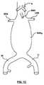
動脈瘤および解離の両方、またはいずれか一方は、血管内、最も典型的には、大動脈および末梢動脈内で、発生し得る。関係する大動脈の領域に応じて、動脈瘤は、血管分岐部を有する領域、またはより小さい動脈「枝」が延出する大動脈の区域に及び得る。腹部大動脈瘤は、横隔膜に対して遠位にある大動脈、例えば腎傍の大動脈、ならびにそこから出る腎動脈および上腸間膜動脈(SMA)を含む動脈枝に存在する動脈瘤を含む。腹部大動脈瘤は、大動脈壁における膨隆または弱化領域であり、その腎動脈に対する位置によって分類されることが多い。図1A〜図1Cを参照すると、説明の目的のために、様々なタイプの腹部大動脈瘤が示されている。図1A〜図1Cでは、大動脈分岐部まで下方に延びている大動脈Aの一部分が示されている。大動脈分岐部では、大動脈Aが、右腸骨動脈RIと左腸骨動脈LIとを含む、総腸骨動脈に分岐する。腹部大動脈の前面から生じる上腸間膜動脈(SMA)と同様に、右腎動脈RRAおよび左腎動脈LRAは、大動脈Aから延出する。図1Aでは、腎動脈下腹部大動脈瘤AAAIが、腎動脈に対して遠位に位置している。図1Bでは、傍腎動脈腹部大動脈瘤AAAJが、腎動脈に接近している、すなわち腎動脈を巻き込んではいないが腎動脈まで広がっている。図1Cでは、腎動脈上腹部大動脈瘤AAASが、腎動脈を巻き込んで、その上方にまで広がっている。Aneurysms and / or dissections can occur in blood vessels, most typically in the aorta and peripheral arteries. Depending on the area of the aorta involved, the aneurysm can span an area with vascular bifurcations or an area of the aorta where smaller arterial “branches” extend. An abdominal aortic aneurysm includes an aneurysm that resides in an arterial branch that includes the aorta distal to the diaphragm, eg, the pararenal aorta, and the renal and superior mesenteric arteries (SMA) that exit therefrom. Abdominal aortic aneurysms are bulging or weakened areas in the aortic wall and are often classified by their location relative to the renal arteries. With reference to FIGS. 1A-1C, various types of abdominal aortic aneurysms are shown for illustrative purposes. In FIGS. 1A-1C, a portion of aorta A is shown extending downward to the aortic bifurcation. At the aortic bifurcation, the aorta A branches to the common iliac artery including the right iliac artery RI and the left iliac artery LI. Similar to the superior mesenteric artery (SMA) originating from the front of the abdominal aorta, the right renal artery RRA and the left renal artery LRA extend from the aorta A. In Figure 1A, the renal arteries abdominal aortic aneurysm AAAI is located distal to the renal arteries. In FIG. 1B, the pararenal abdominal aortic aneurysm AAAJ is approaching the renal artery, ie, does not involve the renal artery but extends to the renal artery. In FIG. 1C, the renal artery superior abdominal aortic aneurysm AAAS involves the renal artery and extends up there.
一部の場合では、大動脈の動脈瘤領域は、内腔内に送達される管状空置機器を用いることによって、例えば、血管の動脈瘤部分にわたり血管内に設置されるステントグラフトによって、バイパスされて、大動脈を通って流れる血液へのさらなる露出から動脈瘤部分を閉鎖し得る。ステントグラフトは、胸部を切開することなく、通例、患者の鼠径部領域の切開部を通じて、動脈を通じて導入される特殊なカテーテルを用いて移植され得る。動脈瘤部位を、大動脈内または流体内腔内部において体内でバイパスするためにステントグラフトを使用することも課題がないわけではない。特に、重要な動脈枝がステントグラフトによって覆われないように、または閉塞されないように注意をしなければならないにもかかわらず、ステントグラフトは、大動脈壁に対してシールし、血液が動脈瘤部位を通過して流れるための血流補綴物を提供しなければならない。動脈瘤が動脈枝に直接隣接して位置する場合、大動脈からの動脈枝の起点を横断して部分的または完全に広がる場所にステントグラフトを留置して、動脈壁に対するステントグラフトのシールを確実にする必要性がある。 In some cases, the aneurysm region of the aorta is bypassed by using a tubular evacuation device delivered into the lumen, for example, by a stent graft placed in the blood vessel over the aneurysm portion of the blood vessel, The aneurysm portion may be closed from further exposure to blood flowing through it. The stent graft can be implanted with a special catheter that is introduced through the artery, typically through an incision in the patient's groin area, without incising the chest. The use of stent grafts to bypass aneurysm sites within the body within the aorta or fluid lumen is not without challenges. In particular, the stent graft seals against the aortic wall and blood passes through the aneurysm site, even though care must be taken that important arterial branches are not covered or occluded by the stent graft. Must provide a blood flow prosthesis for flow. If the aneurysm is located directly adjacent to the arterial branch, the stent graft must be placed in a location that extends partially or completely across the origin of the arterial branch from the aorta to ensure the stent graft seals against the artery wall There is sex.
側枝を収容するために、その側壁に開窓部または開口部を有する主血管ステントグラフトを利用してもよい。主血管ステントグラフトは、その開窓部が血管枝の口と整合するように位置づけられる。使用時には、1つまたは2つ以上の側面の開口部を有するステントグラフの近位端は、所定の位置に予め位置づけられ、かつしっかりと固定されて、留置される際に、その開窓部または開口部が、側枝内への血流の遮断または制限を回避するように置かれる。開窓部それ自体は、密封を形成しない、または、それを通って隣接する動脈側枝に血液が導かれ得る個別の補綴物(複数可)を含まない。結果として、開窓部の周囲のグラフト材料の縁部と隣接する血管壁との間において、主大動脈ステントグラフトの外面と周囲の大動脈壁との間の空間内への血液の漏出が生じやすい。同様な血液の漏出は、ステントグラフトの移植後の移動または動きによって生じ得、開窓部(複数可)と動脈枝(複数可)との間の不整合を生じ、動脈枝(複数可)内への血流障害をもたらし得る。 A main vessel stent graft having a fenestration or opening in its side wall may be utilized to accommodate the side branch. The main vessel stent graft is positioned so that its fenestration is aligned with the mouth of the vessel branch. In use, the proximal end of a stent graph having one or more lateral openings is pre-positioned in place and secured and deployed when deployed. The opening is positioned to avoid blocking or restricting blood flow into the side branch. The fenestration itself does not form a seal or include individual prosthesis (s) through which blood can be directed to the adjacent arterial branch. As a result, blood leaks easily into the space between the outer surface of the main aortic stent graft and the surrounding aortic wall between the edge of the graft material around the fenestration and the adjacent vessel wall. Similar blood leakage can be caused by movement or movement of the stent graft after implantation, resulting in misalignment between the fenestration (s) and the arterial branch (s) into the arterial branch (s). Can cause blood flow disturbance.
一部の場合では、主血管ステントグラフトは、しばしば血管枝ステントグラフトと呼ばれる別のステントグラフトによって補われる。血管枝ステントグラフトは、開窓部を通って血管枝内に留置されて、血管枝内への血流のための補綴物を提供する。血管枝ステントグラフトは、好ましくは、その場で、主血管ステントグラフトにシール状態で接続されて、それと主血管ステントグラフトとの間における望ましくない漏出を防止する。血管枝ステントグラフトと主血管ステントグラフトとの間のこの接続は、効果的にその場で作成するのが困難な場合があり、漏出の可能性がある部位である。 In some cases, the main vascular stent graft is supplemented by another stent graft, often referred to as a branch vessel stent graft. The branch vessel stent graft is placed in the vessel branch through the fenestration to provide a prosthesis for blood flow into the vessel branch. The branch vessel stent graft is preferably connected in situ to the main vessel stent graft in a sealed manner to prevent undesirable leakage between it and the main vessel stent graft. This connection between the branch vessel stent graft and the main vessel stent graft can be difficult to make effectively in situ and is a potential leak site.
図1Bに示される傍腎動脈腹部大動脈瘤、および図1Cに示される腎動脈上腹部大動脈瘤を処置する際に、特定の問題が生じる。いわゆるショートネックの腎動脈下動脈瘤を処置する際に、類似の問題が生じる。ショートネックの腎動脈下動脈瘤には、腎動脈と、腎動脈下動脈瘤の近位端との間にほんのわずかな長さ(すなわち、10mm未満)の動脈瘤化していない組織しか存在していない。しばしば、腹部大動脈瘤の血管内修復(EVAR)を可能にするには、通常、10〜15mmの長さの近位の腎動脈下ネックまたは動脈瘤化していない組織が必要とされる。傍腎動脈動脈瘤および腎動脈上動脈瘤が、腎動脈まで、またはその上方に広がることから、ステントグラフトを血管壁に対して留置およびシールさせるには不十分な動脈瘤化していない長さまたは大動脈のネックしか、腎動脈の遠位に(すなわち、末梢側または下流)存在しない。したがって、腎動脈の近位(すなわち、上方または上流)にステントグラフトの一部を留置する必要があり、これは、上腸間膜動脈(SMA)を考慮し、そこへの血流を閉塞または遮断しないようにする必要がある。患者の解剖学的構造のばらつきに起因して、ショートネックの腎動脈下、傍腎動脈、および腎動脈上の動脈瘤は、典型的には、開腹修復または特注の開窓型血管内ステントグラフトで処置される。特注のステントグラフトは、かなりのリードタイム、すなわち、6〜8週間を要し、設計および製造に費用がかかり過ぎる。 Certain problems arise when treating the pararenal abdominal aortic aneurysm shown in FIG. 1B and the suprarenal abdominal aortic aneurysm shown in FIG. 1C. Similar problems arise when treating so-called short neck subrenal aneurysms. In a short neck subrenal artery aneurysm, there is only a small length (ie, less than 10 mm) of unaneurized tissue between the renal artery and the proximal end of the subrenal artery aneurysm. Absent. Often, a proximal subrenal artery neck or non-aneurysmal tissue of 10-15 mm length is typically required to enable endovascular repair (EVAR) of an abdominal aortic aneurysm. An aneurysm length or aorta that is insufficient to place and seal the stent graft against the vessel wall because the pararenal and suprarenal aneurysms extend to or above the renal arteries There is only one neck at the distal (ie, distal or downstream) of the renal artery. It is therefore necessary to place a portion of the stent graft proximal (ie, above or upstream) of the renal artery, which considers the superior mesenteric artery (SMA) and occludes or blocks blood flow to it. It is necessary not to do. Due to variations in patient anatomy, aneurysms under the short-necked renal artery, pararenal artery, and renal artery are typically abdominal repair or a custom-made fenestration endovascular stent graft. Be treated. Custom stent grafts require considerable lead time, ie 6-8 weeks, and are too expensive to design and manufacture.
このように、当技術分野において、大動脈からの流れを、そこから出る腎動脈および上腸間膜動脈(SMA)などの血管枝内に導く必要がある腹部大動脈瘤を処置するために、ステントグラフト構造を改善する必要性がまだ存在する。 Thus, in the art, stent graft structures are used to treat abdominal aortic aneurysms that need to direct flow from the aorta into vascular branches such as the renal artery and superior mesenteric artery (SMA) exiting from it. There is still a need to improve.
本明細書の実施形態は、腹部大動脈に設置するために構成される自己拡張式の主血管ステントグラフトに関する。主血管ステントグラフトは、腹部大動脈内に設置するために構成される幹部分と、総腸骨動脈内に設置するために構成される分岐部分とを含む。幹部分は、アンカーステントとスカラップまたは頂部開口型開窓部を収容するシールステントとを有する近位端部と、主血管ステントグラフトと一緒に留置される血管枝補綴物を収容するために少なくとも1つの可変剛性のステントを有する腎動脈上胴部と、主血管ステントグラフトを腎動脈内に留置される血管枝補綴物に接続するための反対向きの連結部を有する枝接続部と、少なくとも1つの一様剛性のステントを有する腎動脈下胴部と、分岐部分内に移行するための移行部とを含む。 Embodiments herein relate to a self-expanding main vessel stent graft configured for placement in the abdominal aorta. The main vessel stent graft includes a trunk portion configured for placement in the abdominal aorta and a bifurcation portion configured for placement in the common iliac artery. The trunk portion has a proximal end having an anchor stent and a sealed stent that houses a scalloped or top-opening fenestration and at least one for receiving a branch vessel prosthesis that is deployed with the main vessel stent graft. At least one uniform, an upper torso of the renal artery having a variable stiffness stent, a branch connection having an opposing connection for connecting the main vessel stent graft to a branch vessel prosthesis placed in the renal artery It includes a lower torso of the renal artery having a rigid stent and a transition for transitioning into the bifurcation.
本明細書の実施形態はまた、血管内に移植するための補綴物に関し、これは、グラフト材料の管状体と、グラフト材料から除去されて、頂部開口型開窓部として管状体の第1の縁部から延出するスカラップとを含む。スカラップは、第1および第2の対向する側縁部と、その間に延在する底縁部とを含む。補綴物はまた、管状体に、その第1の縁部の遠位で、かつそれに隣接して連結される自己拡張式材料の正弦波パターンのリングを含む。リングは、複数のクラウンと複数のストラットとを、各クラウンが対向する一対のストラットの間に形成される状態で含み、さらに、スカラップの第1の側縁部のそばに延在する第1の長さの第1の長いストラットと、第2の長さの短いストラットであって、その間にスカラップの底縁部に対して遠位に延在するクラウンを有する、2本の短いストラットと、スカラップの第2の側縁部のそばに延在する第1の長さの第2の長いストラットとを含む、4本の連続するストラットを有する、一体型の細長い部分をさらに含む。第1の長さは、第2の長さよりも長い。 Embodiments herein also relate to a prosthesis for implantation in a blood vessel, which is a tubular body of graft material and is removed from the graft material and the first of the tubular body as a top opening fenestration. And scallops extending from the edge. The scallop includes first and second opposing side edges and a bottom edge extending therebetween. The prosthesis also includes a sinusoidal pattern ring of self-expanding material coupled to the tubular body distally and adjacent to its first edge. The ring includes a plurality of crowns and a plurality of struts, with each crown being formed between a pair of opposing struts, and a first extension extending near the first side edge of the scallop. Two short struts having a first long strut and a second short strut having a crown extending distally with respect to a bottom edge of the scallop therebetween, and a scallop And an integral elongated portion having four consecutive struts, including a second long strut of a first length extending near the second side edge. The first length is longer than the second length.
本発明の前述およびその他の特徴および利点は、添付の図面に示される本明細書の以下の実施形態の説明から明らかである。本明細書に組み込まれ、本明細書の一部を形成する添付の図面は、さらに、本発明の原理を説明し、当業者が本発明を実施および使用することを可能にするように機能する。図面は原寸に比例していない。 The foregoing and other features and advantages of the present invention will be apparent from the following description of embodiments of the specification, as illustrated in the accompanying drawings. The accompanying drawings, which are incorporated in and form a part of this specification, further illustrate the principles of the invention and function to enable those skilled in the art to make and use the invention. . The drawings are not to scale.
ここで、図面を参照して、本発明の具体的な実施形態を説明するが、図面において、同様の参照番号は、同一または機能的に類似の要素を指す。特に指示がない限り、本明細書において「遠位(distal)」および「近位(proximal)」の語は、血管構造内でステントグラフトシステムを用いる場合、心臓からの血流の方向を基準にして用いられ、「遠位」とは、心臓から遠くにある、または心臓から離れる方向にある装置部分を指し、「近位」とは、心臓の近くにある、または心臓に向かう方向にある装置部分を指す。さらに、以下の説明において「自己拡張式」の語は、本発明の補綴物の1つまたは2つ以上のステント構造に関して用いられ、構造が、機械的記憶を備えて、構造を圧縮または収縮された送達構造から拡張され留置された構造に戻し得る材料から成形または形成されるという意味を伝えることが意図される。網羅的なものではない例示的な自己拡張式材料には、ステンレススチール、ニッケルチタン合金またはニチノールなどの超弾性金属、様々なポリマー、またはニッケル、コバルト、クロム、またはその他の金属のベースメタルを有し得るいわゆる超合金が含まれる。機械的記憶は、熱処理によってワイヤまたはステント構造に与えられて、例えば、ステンレススチールにおいてばねの性質を獲得する、またはニチノールなどの感受性金属合金に形状記憶を設け得る。形状記憶特性を有するように作成され得る様々なポリマーはまた、本発明の実施形態において使用するのに好適であって、ポリノルボルネン、トランスポリイソプレン、スチレンブタジエン、およびポリウレタンなどのポリマーを含み得る。同様に、ポリL−D乳酸共重合体、オリゴカプロラクトン共重合体およびポリシクロオクチンは、別々に、またはその他の形状記憶ポリマーと共に用いられ得る。 DETAILED DESCRIPTION Specific embodiments of the present invention are now described with reference to the drawings, where like reference numbers indicate identical or functionally similar elements. Unless otherwise indicated, the terms “distal” and “proximal” are used herein to refer to the direction of blood flow from the heart when using a stent graft system within a vascular structure. As used, “distal” refers to the portion of the device that is far from or away from the heart, and “proximal” refers to the portion of the device that is near or toward the heart Point to. Furthermore, in the following description, the term “self-expanding” is used in reference to one or more stent structures of the prosthesis of the present invention, wherein the structure comprises mechanical memory and is compressed or contracted. It is intended to convey the meaning of being molded or formed from a material that can be expanded from the delivered structure back to the deployed structure. Exemplary self-expanding materials that are not exhaustive include superelastic metals such as stainless steel, nickel titanium alloys or nitinol, various polymers, or base metals of nickel, cobalt, chromium, or other metals. So called superalloys are included. Mechanical memory can be imparted to the wire or stent structure by heat treatment, for example, to acquire spring properties in stainless steel, or to provide shape memory in a sensitive metal alloy such as Nitinol. Various polymers that can be made to have shape memory properties are also suitable for use in embodiments of the present invention, and may include polymers such as polynorbornene, trans polyisoprene, styrene butadiene, and polyurethane. Similarly, the poly L-D lactic acid copolymer, oligocaprolactone copolymer and polycyclooctyne can be used separately or with other shape memory polymers.
以下の詳細な説明は、本来単なる例示であり、本発明または本発明の適用および用途を限定するものではない。本発明の説明は大動脈などの血管の処置の文脈にあるが、本発明はまた、有用であると考えられるすべてのその他の血管および身体通路において用いられ得る。さらに、上記の技術分野、背景、概要または以下の詳細な説明に提示されたいかなる明示的または黙示的理論にも制約されるものではない。 The following detailed description is merely exemplary in nature and is not intended to limit the invention or the application and uses of the invention. Although the description of the present invention is in the context of the treatment of blood vessels such as the aorta, the present invention can also be used in all other blood vessels and body passages deemed useful. Furthermore, there is no intention to be bound by any expressed or implied theory presented in the preceding technical field, background, brief summary or the following detailed description.
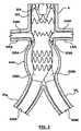
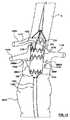
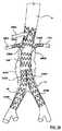
図2〜図5を参照すると、自己拡張式主血管ステントグラフト補綴物200は、腹部大動脈などの血管内に設置するために構成される。主血管ステントグラフト200は、既製の機器であり、換言すれば、特定の患者の解剖学的構造を対象とした特注の機器ではなく、これは、多様な患者の解剖学的構造において、ショートネックの腎動脈下、または傍腎動脈、または腎動脈上、あるいはこれらの組み合わせの動脈瘤を処置するように構成される。図2は、その留置または拡張された状態または構成で、主血管ステントグラフト200の側面図を示し、図3は、その留置または拡張された状態または構成で、例示的な血管枝ステントグラフト334の斜視図を示し、図4は、主血管ステントグラフト200から延出する血管枝ステントグラフト334A、334Bおよび肢部ステントグラフト439A、439Bを有する主血管ステントグラフト200の斜視図を示している。図5は、腹部大動脈瘤AAAを有する腹部大動脈に留置された主血管ステントグラフト200の断面図を示している。ここで、血管枝ステントグラフト334A、334Bは、主血管ステントグラフト200から延出して、腎動脈内に延出し、また、肢部ステントグラフト439A、439Bは、総腸骨動脈内に延出している。 2-5, a self-expanding main vessel
図2を参照すると、主血管ステントグラフト200は、第1または幹部分204と、第2または分岐部分220とを含む。実施形態では、分岐部分220は、幹部分204と一体的に、単一または一体の補綴物として形成される。別の実施形態では、分岐部分220は、幹部分204とは別個に形成された後、そこに連結され得る。図5に示されるように、その場留置される場合、幹部分204は、腹部大動脈内に設置するために構成され、分岐部分220は、左右の総腸骨動脈の大動脈分岐部の近位、またはこの上方に設置するために構成される。 Referring to FIG. 2, main
幹部分204は、内腔207を画定し、第1の縁部または端部203と、第2の縁部または端部205とを有する略管状体または略円筒体202を含む。管状体202は、任意の好適なグラフト材料、例えば、限定されるものではないが、低多孔性のポリエステル織物もしくは編物、DACRON素材、延伸ポリテトラフルオロエチレン、ポリウレタン、シリコーン、超高分子量ポリエチレン、またはその他の好適な材料から形成され得る。別の実施形態では、グラフト材料はまた、心膜などの天然素材または腸粘膜下組織などの膜状組織であり得る。 The
分岐部分220は、管状体202の第2の端部205から延在し、第1の管状脚部または延長部206Aと、第2の管状脚部または延長部206Bとを含む。脚部206A、206Bは、それぞれ、管状体202の内腔207と流体連通する内腔209A、209Bを画定する。分岐部分220が、幹部分204と一体的に、単一または一体の補綴物として形成される実施形態では、脚部206A、206Bは、管状体202と一体的に形成され、したがって、管状体202と同じグラフト材料から形成される。分岐部分220が、幹部分204とは別個に形成された後、そこに連結される別の実施形態では、脚部206A、206Bは、管状体202と同じグラフト材料または異なるグラフト材料で形成され得る。図示の実施形態では、脚部206A、206Bは、等しい長さであり、腹部大動脈に留置される場合、腹部大動脈内で前方および後方に向けられる。本明細書において図27を参照して詳述されるように、脚部206A、206Bを腹部大動脈内で前方および後方に向けることは、対側脚の挿管を容易にし、その一方で、経皮的侵入部位の選択に柔軟性を提供して、左または右の大腿動脈を介した送達システムの導入を可能にする。 The
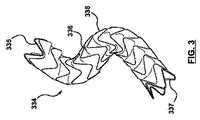
ここで図3を参照すると、主血管ステントグラフト200は、血流を方向づけし、腹部大動脈から出る血管枝に還流させる1つまたは2つ以上の血管枝ステントグラフト334と共に利用されるようになっている。血管枝ステントグラフト334は、内腔(図示せず)を画定し、第1の縁部または端部335と、第2の縁部または端部337とを有する略管状体または略円筒体336を含む。管状体336は、任意の好適なグラフト材料、例えば、限定されるものではないが、延伸ポリテトラフルオロエチレン、低多孔性のポリエステル織物もしくは編物、DACRON素材、ポリウレタン、シリコーン、超高分子量ポリエチレン、またはその他の好適な材料から形成され得る。血管枝ステントグラフト334はまた、少なくとも1つの径方向に圧縮可能なステントまたはスキャフォールド(scaffold)338を含み、これは、グラフト材料を支持するために管状体336に連結され、また身体管部の内壁(図示せず)との付着圧着状態へと自己拡張するように動作可能である。ステント338は、ニチノールなどの自己拡張式材料またはばね材料から構築され、十分な径方向のばね力および可撓性を有して、血管枝ステントグラフト334を血管内壁にぴったり合うように係合させて、過剰な漏出を回避し、動脈瘤の加圧を防ぐ、すなわち、漏出防止シールを提供する。管状体336の端部335、337は、スカラップ形にされて(scalloped)、グラフト材料が、端部335、337に隣接するステントの形状を概ねたどるようにし、それによって、余計なグラフト材料が折り畳まれたり、ねじれたり、束になったりするのを防止し得る。当業者には当然のことながら、血管枝ステントグラフト334は、単なる例示であり、主血管ステントグラフト200は、限定されるものではないが、バルーン拡張式ステントグラフトを含む、様々なその他の構成の血管枝ステントグラフトと共に利用され得る。 Referring now to FIG. 3, the main
図4の斜視図および図5のその場留置された主血管ステントグラフト200の断面図を参照すると、血管枝ステントグラフト334A、334Bは、主血管ステントグラフト200の連結部208A、208B内に送達され、留置されて、それぞれ、右腎動脈RRAおよび左腎動脈LRA内に延出する。主血管ステントグラフト200の漸次送達方法および対応する段階的な解放は、本明細書において図13〜図25を参照して詳述される。血管枝ステントグラフト334A、334Bに加えて、肢部ステントグラフト439A、439Bは、主血管ステントグラフト200の脚部206A、206B内に送達されて、それぞれ、右腸骨動脈IARおよび左腸骨動脈IALに延出し得る。肢部ステントグラフト439A、439Bは、総腸骨動脈内に留置されるように構成され、一般に、血管枝ステントグラフト334A、334Bに関して上述したように、そこに連結される少なくとも1つの径方向に圧縮可能なステントまたはスキャフォールドを有するグラフト材料の管状体を含む。With reference to the perspective view of FIG. 4 and the cross-sectional view of the in situ deployed main
説明の目的のために、主血管ステントグラフトの管状体202は、5つの一体型部分(portion or section)を有するとして本明細書に説明される。より具体的には、図2を再び参照すると、管状体202は、(1)アンカーステント222と管状体202から切り取られた、または除去されたスカラップ(scallop)224を収容するシールステント226とを有する近位端部210と、(2)少なくとも1つの可変剛性のステントまたはスキャフォールド228を有する腎動脈上胴部212と、(3)ステントグラフト補綴物200を、それぞれ右および左の腎動脈を収容するための血管枝補綴物334A、334B(図3〜図5に示す)に接続するための反対向きの連結部208A、208Bを有する枝接続部214と、(4)少なくとも1つの一様剛性のステントまたはスキャフォールド230を有する腎動脈下胴部216と、(5)分岐部分220内に移行するための少なくとも1つのステントまたはスキャフォールド232を有する移行部または遠位部218とを含む。管状体202の各部分は、本明細書において詳述される。 For illustrative purposes, the main vessel stent graft
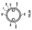
図6は、管状体202の近位端部210の拡大図またはズームイン図を示している。近位端部210は、径方向に圧縮可能なリングまたはスキャフォールドである、アンカーステント222を含み、身体管部の内壁(図示せず)との付着圧着状態へと自己拡張するように動作可能である。アンカーステント222は、ニチノールなどの自己拡張式材料またはばね材料から構築され、複数のクラウンまたは曲げ部623および複数のストラットまたは直線部621を、各クラウンが対向する一対のストラットの間に形成される状態で含む、正弦波パターンのリングである。実施形態では、アンカーステント222は、レーザ加工されたステントであり、結果として得られるストラットおよび曲げ部621、623は、矩形断面または略矩形断面を有する。別の実施形態では、アンカーステント222は、中実または中空で、円形の断面を有し得る単一の連続ワイヤから形成され得る。別の実施形態では、アンカーステント222を形成するワイヤの断面は、楕円、正方形、矩形、または任意のその他の好適な形状であり得る。アンカーステント222は、開いた網または自由な流れの構成でグラフト材料に連結されて、管状体202の第1の縁部203の外側またはこれを超えて延在する第1または最近位の一式のクラウン623Aと、管状体202の第1の縁部203に連結される第2または対向する一式のクラウン623Bとを有するようにする。クラウン623Bは、縫合または当業者に既知のその他の手段によって管状体202に連結される。図6に示される実施形態では、クラウン623Bは、管状体202の外表面に連結される。しかしながら、代替的に、クラウン623Bは、管状体202の内表面に連結される場合もある。未連結または自由なクラウン623Aは、ステントグラフト補綴物200がその場留置される際に、血管組織内に埋め込み、固定するための返し625を含み得る。実施形態では、アンカーステント222は、ミネソタ州ミネアポリスのMedtronic Incによって製造されたENDURANT(登録商標) II腎動脈上ステントである。 FIG. 6 shows an enlarged or zoomed-in view of the
管状体202の近位端部210はまた、管状体202のグラフト材料から切り取られた、または除去されたスカラップ224を含む。スカラップ224は、頂部開口型開窓部である。その場留置される際、スカラップ224は、上腸間膜動脈(SMA)の遠位の大動脈内に位置づけられ、SMAの口の周囲に延在する、またはこれを囲む、あるいはこれらの両方を行う。ショートネックの腎動脈下、または傍腎動脈、または腎動脈上、あるいはこれらの組み合わせの動脈瘤では、管状体202の第1の縁部203は、上腸間膜動脈(SMA)で、またはその付近で腹部大動脈内に留置される。上腸間膜動脈(SMA)内への血流の遮断を回避するために、ステントグラフト補綴物200は、腹部大動脈内に位置づけられる、または方向づけられて、スカラップ224が、上腸間膜動脈(SMA)の口の周囲に位置づけられ、管状体202のグラフト材料が、SMAの口を閉塞しないようにする。SMAのためのスカラップ224の存在は、ショートネックの腎動脈下、または傍腎動脈、または腎動脈上、あるいはこれらの組み合わせの動脈瘤で苦しむ患者のために、SMAに対して遠位の、十分な長さ、すなわち、10mm超の健常または動脈瘤化していない組織に対して、主血管ステントグラフト200が留置かつシールされるのを可能にする。 The
スカラップ224は、図6に示されるように、2本の略直線状の対向する側縁部646A、646Bを、その間に延在する略直線状の底縁部648と共に有し、概して矩形または長方形の形状を有し得る。ここで、縁部648の幅Wは、8〜12mmの間の範囲であり、縁部646A、646Bの長さLは、8〜12mmの間の範囲である。実施形態では、スカラップ224は、12mmの幅224および10mmの長さLを有する。当業者には理解されるように、「側(side)」および「底(bottom)」は、相対的な語であり、本明細書において説明の目的でのみ使用される。さらに、当業者には当然のことながら、スカラップ224の形状または構成は、それが上腸間膜動脈(SMA)を収容する限り、変化してもよい。例えば、直線状の対向する側縁部は、傾斜される、または互いに離れるように角度をつけられてもよいし、互いに平行であってもよく、側縁部および底縁部の両方、またはいずれか一方は、湾曲していてもよく、あるいはスカラップ224の角部は、丸みをつけられて、スカラップ224をU字構成にしてもよい。図6Aに示される実施形態では、U字形のワイヤ647は、例えば、グラフト材料をワイヤの上に折り曲げ、グラフト材料の上に折り曲げられた部分をそれ自体に縫合することによって、スカラップの縁部の周囲に配置され得る。一実施形態では、ワイヤ647は、スカラップ224をSMAの周囲に配置するのに役立つように、放射線不透過性材料から形成される。好適な放射線不透過性材料には、タンタル、チタン、白金、金、銀、パラジウム、イリジウムなどの、一般にX線透視法で視認可能な任意の比較的重い金属が含まれる。 The
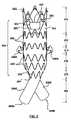
管状体202の近位端部210はまた、本明細書に詳述されるように、スカラップ224を収容するように構成され、患者への適用性を最大化する、シールステント226を含む。シールステント226は、径方向に圧縮可能なリングまたはスキャフォールドであり、これは、グラフト材料を支持するために管状体202に連結され、また身体管部の内壁(図示せず)との付着圧着状態へと自己拡張するように動作可能である。シールステント226は、ニチノールなどの自己拡張式材料またはばね材料から構築され、複数のクラウンまたは曲げ部744および複数のストラットまたは直線部742を、各クラウンが対向する一対のストラットの間に形成される状態で含む、正弦波パターンのリングである。シールステント226は、中実または中空で、円形の断面を有し得る単一の連続ワイヤから形成され得る。実施形態では、シールステント226を形成するワイヤは、0.011〜0.014インチの間の直径を有する。別の実施形態では、シールステント226を形成するワイヤの断面は、楕円、正方形、矩形、または任意のその他の好適な形状であり得る。シールステント226は、管状体202に、その第1の端部203およびアンカーステント222の近位で、かつそれに隣接して連結され、管状体202のグラフト材料によって被覆または裏打ちされる。シールステント226は、縫合または当業者に既知のその他の手段によって管状体202に連結される。図6に示される実施形態では、シールステント226は、管状体202の外表面に連結される。しかしながら、代替的に、シールステント226は、管状体202の内表面に連結される場合もある。ステントグラフト補綴物200が動脈瘤の処置に用いられる場合、シールステント226は、十分な径方向のばね力および可撓性を有して、管状体202の近位端部210を血管内壁にぴったり合うように係合させて、過剰な漏出を回避し、動脈瘤の加圧を防ぐ、すなわち、漏出防止シールを提供する。ステントグラフト補綴物200によって隔離された動脈瘤内へ、いくらかの血液またはその他の体液の漏出は起こり得るが、最適なシールは、動脈瘤の加圧およびその結果としての破裂の確率を低くする。 The
管状体202のグラフト材料から切り取られたスカラップ224を収容するために、シールステント226のストラットまたは直線部742の長さは、均一ではない。それどころか、シールステント226は、一体型の細長い部分740を含み、ここでは、ストラットのうちの少なくとも2つ742Bがストラット742Aに対して延長または引き伸ばされる。これにより、一体型の細長い部分740を除く、シールステント226の残りのストラットを、グラフト材料において、スカラップ224の周囲にシールを形成するように作り上げる。説明の目的のために、シールステント226を平らに展開して示す図7に示されるように、細長い部分740は、長−短−短−長のストラット構成またはパターンを有する。より具体的には、細長い部分740は、4本の連続するストラット、すなわち、第1の比較的長いストラット742B、2本の連続する比較的短いストラット742C、および第2の比較的長いストラット742Bを含む。一実施形態では、短いストラット742Cは、シールステント226のストラット742Aとほぼ同じ長さであるが、短いストラット742Cは、ストラット742Aよりも短い、または長いのであってもよい。図示の実施形態では、ストラット742Aは、それぞれ長さが同じである。本発明の別の実施形態(図示せず)では、ストラット742Aは、可変または異なる長さであり得る。長いストラット742Bのより長い長さは、スカラップ224の長さLおよび単一の短いストラット742Cの長さよりも大きい。実施形態では、長いストラット742Bの長さは、10〜12mmの間の範囲であり得、ストラット742Aおよびストラット742Cの長さは、4〜8mmの間の範囲であり得る。シールステント226の細長い部分740は、長いストラット742Bが、スカラップ224の対向する側縁部646A、646Bのそばに延在するまたは側面に位置し、また短いストラット742Cが、底縁部648の遠位に、またはその下方に延在する状態で、管状体202のスカラップ224の周囲に位置づけられる。2本の連続する比較的短いストラット742Cの間に延在するクラウン744Cは、スカラップ224の底縁部648の若干遠位、またはその下方で、管状体202に連結される。一実施形態では、クラウン744Cは、底縁部648の中点または中間に位置づけられる。細長い部分740は、シールステント226が、スカラップ224の縁部を血管内壁にぴったり合うように係合し、シールできるようにする。シールステント226の構成に起因して、ステントグラフト補綴物200は、ステントグラフトの従来の近位のシール領域にスカラップ224を含み得、それによって、シールの完全性を維持しながら、上腸間膜動脈(SMA)を収容する。 In order to accommodate
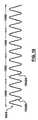
図8は、管状体202の腎動脈上胴部212の拡大図またはズームイン図を示している。腎動脈上胴部212は、少なくとも1つの可変剛性の胴部ステント228を有して、主血管ステントグラフト200の外表面に隣接して送達および留置される血管枝補綴物を収容する、またはその周囲に一致する。図8の実施形態では、ステントグラフト補綴物200は、一連の2本の独立した、または別個の可変剛性胴部ステント228を含む。2本の可変剛性胴部ステントで示されているが、当業者には当然のことながら、ステントグラフト補綴物200は、所望の腎動脈上胴部212の長さおよびその意図される適用の両方、またはいずれか一方に応じて、これよりも多数または少数の可変剛性胴部ステント228を含み得る。各可変剛性胴部ステント228は、径方向に圧縮可能なリングまたはスキャフォールドであり、これは、グラフト材料を支持するために管状体202に連結され、また身体管部の内壁(図示せず)との付着圧着状態へと自己拡張するように動作可能である。各可変剛性胴部ステント228は、ニチノールなどの自己拡張式材料またはばね材料から構築され、複数のクラウンまたは曲げ部944および複数のストラットまたは直線部942を、図9に示されるように、各クラウンが対向する一対のストラットの間に形成される状態で含む、正弦波パターンのリングである。可変剛性胴部ステント228は、中実または中空で、円形の断面を有し得る単一の連続ワイヤから形成され得る。実施形態では、可変剛性胴部ステント228を形成するワイヤは、0.011〜0.015インチの間の直径を有する。各可変剛性胴部ステント228は、シールステント226の遠位の管状体202に、その第1の端部203と反対向きの連結部208A、208Bとの間で連結される。各可変剛性胴部ステント228は、縫合または当業者に既知のその他の手段によって管状体202に連結される。図8に示される実施形態では、可変剛性胴部ステント228は、管状体202の外表面に連結される。しかしながら、代替的に、可変剛性胴部ステント228は、管状体202の内表面に連結される場合もある。可変剛性胴部ステント228は、十分な径方向のばね力および可撓性を有して、管状体202の腎動脈上胴部212を血管内壁にぴったり合うように係合させる。 FIG. 8 shows an enlarged or zoomed-in view of the superior renal artery
図5に示されるように、主血管ステントグラフト200の外表面に隣接して送達および留置される血管枝補綴物を収容するために、胴部ステント228の剛性または径方向の力は、その外周に沿って一様ではない。それどころか、胴部ステント228の径方向の力は、その外周に沿って変化する。より具体的には、可変剛性胴部ステント228は、残りのステントと比べて、より大きい可撓性およびより小さい径方向の力を有する2本の対向する領域または区域850を含む。説明の目的のために、可変剛性胴部ステント228を平らに展開して示す図9に最もよく示されているように、可変剛性胴部ステント228は、4つの連続する一体型領域または区域、すなわち、より大きい可撓性およびより小さい径方向の力の第1の区域850、より小さい可撓性およびより大きい径方向の力の第2の区域852、より大きい可撓性およびより小さい径方向の力の第3の区域850、およびより小さい可撓性およびより大きい径方向の力の第4の区域852を含む。このように、可変剛性胴部ステント228は、交互に並ぶ、または交替する可撓性の区域を含む。実施形態において、各区域は、胴部ステント228の外周360度のうちの約90度である。本明細書において用いられる「約90度」は、胴部ステントの外周の80および100度の間の範囲にある区域を含む。より大きい可撓性およびより小さい径方向の力の区域850は、連結部208A、208Bに対して、円周方向にほぼ整列し、長手方向にその近位に位置づけられる。本明細書において用いられる「円周方向にほぼ整列」は、連結部208A、208Bから45度から−45度で円周方向に整列した区域850を含む。血管枝補綴物が連結部を通ってその場送達および留置される際、血管枝補綴物は、主血管ステントグラフト200の外面に区域850で接触し、終端する。区域850がより大きい可撓性を有することから、区域850は、主血管ステントグラフト補綴物の径方向の力によって崩壊する、または圧壊されることなく、血管枝補綴物にぴったり合い、主血管ステントグラフトの隣、またはそばに、血管枝補綴物を長手方向に延在できるようになる。つまり、胴部ステント228の区域850は、血管枝補綴物の開存性を可能にする。このように、主血管ステントグラフト血管補綴物200が、大動脈A内に配置され、枝補綴物334A、334Bが、可変剛性胴部ステント228の区域850の隣、またはそばに配置されている図8Aに概略的に示されるように、胴部ステント228は、残りのステントにおいて高い径方向の力および付着圧着を維持しながら、交互に並ぶ、より低い径方向の力およびより大きい可撓性の区域に改良されて、血管枝補綴物334A、334Bをいっそうよく収容し得る。さらに、図8Aに示されるように、血管枝補綴物を緊密にぴったりと合わせることにより、主血管ステントグラフト200の開存性は最大化されて、そこを通る血流量を最大にできる。 As shown in FIG. 5, to accommodate a branch vessel prosthesis that is delivered and placed adjacent to the outer surface of the main
異なる可撓性および径方向の力を達成するために、区域850のストラット942Aは、区域852のストラット942Bよりも比較的長い。ストラット942Bと比べてストラット942Aを長くすることにより、区域850には、より小さい径方向の力およびより大きい可撓性が与えられる。それに対し、区域852の比較的短いストラット942Bは、より小さい可撓性であるがより大きい径方向の力を有して、区域852が、確実に身体管部の内壁に対してシールする。実施形態では、比較的短いストラット942Bの長さは、6〜7mmの間の範囲であり得、比較的長いストラット942Aの長さは、8.5〜9.5mmの間の範囲であり得る。 To achieve different flexibility and radial forces, struts 942A in
図10に示される本発明の別の実施形態では、可変剛性胴部ステント1028は、ストラットの厚さを変えることによって達成された交互に並ぶ可撓性の区域を有する。より具体的には、より可撓性の小さい区域1052のストラット1042Bは、より可撓性の大きい区域1050のストラット1042Aよりも厚い。より薄いストラット1042Aにより、区域1050には、より小さい径方向の力およびより大きい可撓性が与えられて、上述のように血管枝補綴物を収容し、他方、より厚いストラット1042Bにより、区域1052には、身体管部の内壁に対してシールするためのさらなる径方向の力が与えられる。実施形態では、比較的厚いストラット1042Bの厚さは、0.013〜0.018インチの間の範囲であり得、比較的薄いストラット942Aの厚さは、0.011〜0.013インチの間の範囲であり得る。実施形態では、各胴部ステント228は、薄いストラット1042Aの直径を有する単一の連続ワイヤから構築され得、より厚いストラット1042Bを有する区域1052は、連続ワイヤの上を摺動する一連の比較的短い管を介して形成される。別の実施形態では、各胴部ステント228は、区域850、852となる可変の厚さを有する単一の連続ワイヤから構築される。ストラット942A、942Bの長さは、可変剛性胴部ステント1028の外周の周囲で均一である。ステントの部分のその他の変形または修正が、異なる可撓性の区域を作成するために用いられてもよい。 In another embodiment of the invention shown in FIG. 10, the variable
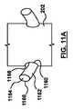
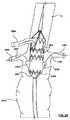
図11は、管状体202の枝接続部214の拡大図またはズームイン図を示している。枝接続部214は、ステントグラフト補綴物200を血管枝補綴物334(図3〜図5に示す)に接続するための、反対向きの連結部208A、208Bを含んで、それぞれ、右および左の腎動脈を収容する。説明の目的のためにステントが取り外してある図11Aの概略図をさらに参照すると、管状体202は、グラフト材料の側壁を通って形成された対向する開窓部または開口部1160を含む。開口部1160の形状は、円形または楕円形であり得る。 FIG. 11 shows an enlarged or zoomed-in view of the
連結部208A、208Bは、管状体202の開口部1160に対応して、主血管ステントグラフト200の外表面上に配置される。連結部208A、208Bは、略円筒形の形状であり、基部1166と上部1168とを有する、グラフト材料1162を含む。グラフト材料1162は、管状体202のグラフト材料と同じタイプのグラフト材料であり得る、または異なる材料であり得る。図示の実施形態では、連結部208A、208Bは、管状体202に取り付けられた別個の部分である。しかしながら、当業者には理解されるように、連結部208A、208Bは、管状体202の延長体として形成されてもよい。連結部208A、208Bは、形状を略円筒形として説明されているが、基部1166は、好適には、円形ではなく、楕円形である。基部1166は、例えば、限定としてではなく、約8〜10mmの長軸および約5〜8mmの短軸を有し得る。さらに、各連結部の長さは、約10〜15mmであり得、各連結部の上部1168の直径は、約5〜8mmであり得る。図11Bに示されるように、円形に成形されたワイヤまたはリング1167は、例えば、グラフト材料をリング1167の上に折り曲げ、グラフト材料の折り重ね部分をそれ自体に縫合することによって、上部1168および基部1166に配置され得る。一実施形態では、リング1167は、連結部208A、208Bを腎動脈に隣接して、またはその付近に配置するのに役立つように、放射線不透過性材料から形成される。好適な放射線不透過性材料には、タンタル、チタン、白金、金、銀、パラジウム、イリジウムなどの、一般にX線透視法で視認可能な任意の比較的重い金属が含まれる。 The connecting portions 208 </ b> A and 208 </ b> B are disposed on the outer surface of the main
図2および図11に示されるように、自己拡張式の支持ステントまたは正弦波状リング1170は、グラフト材料1162上に配置された後、連結され得る。支持ステント1170は、ニチノールなどの自己拡張式材料またはばね材料から構築され、複数のクラウンまたは曲げ部1144および複数のストラットまたは直線部1142を、各クラウンが対向する一対のストラットの間に形成される状態で含む、正弦波パターンのリングである。実施形態では、支持ステント1170は、4つの頂点を有するステントであり、したがって、8つのクラウン1144を含むが、当業者には明らかであるが、支持ステントは、より多くの、またはより少ないクラウンを含み得る。支持ステント1170は、縫合または当業者に既知のその他の手段によって、連結部208A、208Bの上部1168の遠位、または下部のグラフト材料1162に連結される。図11に示される実施形態において、支持ステント1170は、グラフト材料1162の外表面に結合される。しかしながら、代替として、支持ステント1170は、グラフト材料1162の内表面に結合されてもよい。支持ステント1170は、中実または中空で、円形の断面を有し得る単一の連続ワイヤから形成され得る。実施形態では、支持ステント1170を形成するワイヤは、0.006〜0.008インチの間の直径を有する。別の実施形態では、支持ステント1170を形成するワイヤの断面は、楕円、正方形、矩形、または任意のその他の好適な形状であり得る。支持ステント1170は、連結部208A、208Bによって画定される内腔1164が確実に開いているようにして、そこを通って血管枝補綴物が送達され得るようにし、それによって血管枝の挿管を容易にする。支持ステント1170はまた、留置の最中およびその後、連結部208A、208Bの上部1168を、右および左の腎動脈の口に向けて上昇する、または向ける、あるいはこれらの両方を行うように機能して、支持されていない材料が崩れてシール性能の問題に至ることが確実にないようにする。送達システムにある間に支持ステント1170の形状記憶材料内に蓄積されたエネルギーに起因して、連結部208A、208Bは、送達および留置中にスリーブ(送達システム)から解放される際に、主血管ステントグラフト200の管状体202から飛び出す、または離れる。これにより、送達システムから解放される際の連結部208A、208Bが束になったり、ねじれたり、崩れたり、裏返しになったりするのを防ぐ。 As shown in FIGS. 2 and 11, the self-expanding support stent or
図5に示されるように、連結部208A、208Bは、腎動脈の遠位にその場設置するために構成される。連結部208A、208Bの上部1168は、腎動脈の口に隣接してまたはその下方に設置するために構成されるが、上部1168は、口の内部には延出しない。連結部208A、208Bは、その長手方向の軸に対して直角な方向に十分に柔軟である。この可動性は、連結部208A、208Bの形状に起因しており、連結部208A、208Bを形成する際に、いくらかの余剰のグラフト材料1162を利用することによって、さらに改善され得る。主血管ステントグラフト補綴物200が腎動脈と円周方向に整列される必要はない。なぜなら、各連結部の上部1168は、枝ステントグラフト補綴物が、可変剛性胴部ステント228と共に、連結部208A、208Bと、そのそれぞれの腎動脈との間に接続部を提供する状態で、そのそれぞれの腎動脈の口の遠位および円周方向にずれた状態になることが可能であるためである。したがって、連結部208A、208Bは、腎動脈の口と、おおまかにまたはほぼ約円周方向に整列していることのみが求められる。本明細書において用いられる「円周方向にほぼ整列」は、それぞれ右および左の腎動脈から45度から−45度で円周方向に整列した連結部208A、208Bを含む。連結部208A、208Bを腎動脈の口に対して正確に位置づける必要性を排除したことによって、主血管ステントグラフト200は、ある範囲の解剖学的構造を有する数多くの患者で用いられ得る。これはまた、特注の開窓型機器に関する6〜8週のリードタイムを排除して、主血管ステントグラフト200が真に「既製」のやり方で多様な患者を処置できるようにする。さらに、主血管ステントグラフト200の送達および位置づけのプロセスは、改善される。 As shown in FIG. 5, the
血管枝補綴物334A、334Bが連結部208A、208Bの内腔1164を通ってそれぞれ、右および左の腎動脈内に送達および留置される際、連結部は、主血管ステントグラフト200の外面と、腹部大動脈の内壁との間に挟まれる。血管枝補綴物334A、334Bは、連結部の上部から外に、そして、それぞれ右および左腎動脈の中に延出する。可変剛性胴部ステント228のより柔軟な区域850は、その内部に拡張した血管枝補綴物334A、334Bを有する連結部208A、208Bにぴったり合う、またはこれに場所を譲り、それによって、図8Aに示されるように、その場留置の際、より狭い中間部または胴部を有する管状体202となる。その内部に拡張した血管枝補綴物334A、334Bを有する連結部208A、208Bの隣では、管状体202の外径は、減少させられる、または収縮させられる。 When the
図12は、管状体202の腎動脈下胴部216および移行部もしくは遠位部218、ならびに分岐部分220の拡大図またはズームイン図を示している。腎動脈下胴部216は、少なくとも1つの胴部ステント230を含む。実施形態では、胴部ステント230の剛性または径方向の力は、その外周に沿って一様であるが、このような一様な剛性/径方向の力は必須ではない。図12の実施形態では、ステントグラフト補綴物200は、2本の独立した、または別個の胴部ステント230を含む。2本の胴部ステント230で示されているが、当業者には当然のことながら、ステントグラフト補綴物200は、所望の腎動脈下胴部216の長さおよびその意図される適用の両方、またはいずれか一方に応じて、これよりも多数または少数の胴部ステント230を含み得る。各胴部ステント230は、径方向に圧縮可能なリングまたはスキャフォールドであり、これは、グラフト材料を支持するために管状体202に連結され、また自己拡張するように動作可能である。各胴部ステント230は、ニチノールなどの自己拡張式材料またはばね材料から構築され、複数のクラウンまたは曲げ部1244および複数のストラットまたは直線部1242を、図12に示されるように、各クラウンが対向する一対のストラットの間に形成される状態で含む、正弦波パターンのリングである。胴部ステント230は、中実または中空で、円形の断面を有し得る単一の連続ワイヤから形成され得る。実施形態では、胴部ステント230を形成するワイヤは、0.010〜0.013インチの間の直径を有する。別の実施形態では、胴部ステント230を形成するワイヤの断面は、楕円、正方形、矩形、または任意のその他の好適な形状であり得る。各胴部ステント230は、連結部208A、208Bの遠位の管状体202に連結される。各胴部ステント230は、縫合または当業者に既知のその他の手段によって管状体202に連結される。図12に示される実施形態では、胴部ステント230は、管状体202の外表面に連結される。しかしながら、代替的に、胴部ステント230は、管状体202の内表面に連結される場合もある。 FIG. 12 shows an enlarged or zoomed in view of the renal artery
移行部または遠位端部218は、少なくとも1つの胴部ステント232を含む。胴部ステント232が、管状体202が分岐部分220となる移行に合わせてあることを除いては、胴部ステント232は、胴部ステント230と類似している。本明細書に述べたように、図2を参照すると、分岐部分220は、管状体202の第2の端部205から延出する。図12の実施形態では、管状体202の第2の端部205は、分岐部分220の近位端よりも比較的大きい直径または幅を有し、したがって、胴部ステント232は、胴部ステント232の上部または近位端における第1の拡張直径D1から(図12Aに示す)、胴部ステント232の底部または遠位端における第2の拡張直径D2まで(図12Bに示す)減少する様々な拡張外径または幅を有する。図12A〜図12Bに示されるように、胴部ステント232は、好適には、円形ではなく、概して楕円形または長円形断面であるが、胴部ステント232は、円形であってもよい。別の実施形態では(図示せず)、管状体202の第2の端部205は、分岐部分220の近位端よりも比較的小さい直径または幅を有し、したがって、胴部ステント232は、胴部ステント232の上部または近位端から、胴部ステント232の底部または遠位端まで増加する様々な拡張外径を有する。さらに別の実施形態では(図示せず)、管状体202の第2の端部205は、分岐部分220の近位端とほぼ等しい直径を有し、したがって、胴部ステント232は、胴部ステント232の上部または近位端から、胴部ステント232の底部または遠位端まで一定の外径を有する。このように、分岐部分220の直径に対する主血管ステントグラフト200の直径に応じて、移行ステント232の外径は、増加する、減少する、または一定に留まり得る。 The transition or
図13〜図26は、主血管ステントグラフト200を腹部大動脈Aにおける標的部位に送達する方法、および血管枝ステントグラフトを腎動脈に送達する方法を概略的に示している。図13〜図26では、腎動脈の下方に広がるショートネックの腎動脈下腹部大動脈瘤AAAを有する、腹部大動脈Aの一部分が示されている。本発明の実施形態によるその他の方法では、主血管ステントグラフト200は、腎動脈に接近している、すなわち腎動脈を巻き込んではいないが腎動脈まで広がっている傍腎動脈腹部大動脈瘤、および、腎動脈を巻き込んで、その上方にまで広がっている腎動脈上腹部大動脈瘤を処置するために用いられ得る。上腸間膜動脈(SMA)と同様に、右腎動脈RRAおよび左腎動脈LRAは、大動脈Aから延出する。説明される留置方法は、主血管ステントグラフトの段階的または漸次解放であり、ここでは、血管枝ステントグラフトの腎動脈への送達は、主血管ステントグラフト200の完全留置に先立って行われる。 FIGS. 13-26 schematically illustrate a method of delivering a main
図13は、主血管ガイドワイヤ1384上を、腹部大動脈Aの標的部位まで進められた、その内部に圧縮された主血管ステントグラフト200を備える主血管送達システム1382を示している。ガイドワイヤ1384は、当技術分野で周知のように、一般に、大腿動脈内に挿入され、左腸骨動脈LIを通って、腹部大動脈まで送られる。送達システム1382の機能および構造は、本出願と同じ日付で出願された、Argentineらの米国特許出願第13/457,541号(代理人整理番号C00002527.USU1)、Maggardらの第13/457,535号(代理人整理番号C00002215.USU1)、Argentineらの第13/457,537号(代理人整理番号C00002202.USU1)およびMaggardらの第13/457,544号(代理人整理番号C00002217.USU1)に詳述されており、参照によりその全体が本明細書に組み込まれることから、その特定の特徴のみが本明細書に記載されて、主血管ステントグラフト200の留置を説明する。主送達システム1382および主血管ステントグラフト200の両方、またはいずれか一方の位置は、X線像で確認されてもよく、送達システム1382およびステントグラフト200の両方、またはいずれか一方は、当技術分野で周知の放射線不透過性マーカを含んでもよい。例えば、実施形態では、主血管ステントグラフト200の近位端部210および連結部208A、208Bの両方、またはいずれか一方は、放射線不透過性マーカを含んで、位置決めに役立ち得る。主血管ステントグラフト200は、送達システムのカテーテルシャフト1488(図14参照)上に取り付けられ、送達システムの外側送達シース1386が、主血管ステントグラフト200をその送達のために、圧縮された構成に被覆かつ拘束する。当業者には理解されるように、送達システム1382は、主血管ステントグラフト200の最終的な留置のために、先端捕捉機構の引き戻しによって最近位の一式のクラウンが解放されるまで、アンカーステント222の最近位の一式のクラウンを係合する、先端捕捉機構(図示せず)を含み得る。 FIG. 13 shows a main
図14は、主血管ステントグラフト200を留置するための第1または初期ステップを示しており、ここで、送達システム1382の外側送達シース1386が、引き戻されて、主血管ステントグラフト200の近位端部210を解放または除覆する。図14に示されるように、送達システムから最初に解放される際、近位端部210は、スカラップ224が上腸間膜動脈(SMA)の標的部位の遠位にあるように位置づけられ得る。あるいは、近位端部210は、スカラップ224がSMAと直接整合されるように位置づけられ得る。アンカーステント222の最近位の一式のクラウンは、送達システム1382の先端捕捉機構によって捕捉または拘束される。送達シース1386は、少なくともシールステント226を露出するように引き抜かれ、また連結部208A、208Bを超えて引き抜かれ得るが、脚部206A、206Bを含む少なくとも分岐部分220を依然として束縛する。図14の実施形態では、送達シース1386は、第1の可変剛性胴部ステント228を露出するように引き抜かれているとして示されている。伸縮自在の管1480と、スカラップ224を通って、またはその上に、あるいはこれらの両方で延出するアンカリングワイヤ1481とは、送達システム1382の部分であり、参照によりその全体が先に組み込まれた同時係属中のArgentineらの米国特許出願第13/457,541号(代理人整理番号C00002527.USU1)、Maggardらの第13/457,535号(代理人整理番号C00002215.USU1)、Argentineらの第13/457,537号(代理人整理番号C00002202.USU1)、およびMaggardらの第13/457,544号(代理人整理番号C00002217.USU1)に説明される挿管を助けることによって、SMAに対する主血管ステントグラフト200の位置決めに使用される。伸縮自在の管1480は、血管系内への導入前に、送達システムおよび主血管ステントグラフト200を通して、予め組み込まれている。より具体的には、伸縮自在の管1480は、ガイドワイヤを受容するように寸法決めされた内径を有する。伸縮自在の管1480は、主血管ステントグラフト200を介して、送達システムを通って延出し、主血管ステントグラフト200からスカラップ224を通って出る。ガイドワイヤ自体ではなく、伸縮自在の管1480を予め組み込むことによって、医師は、処置で使用されるガイドワイヤおよびカテーテルの組み合わせの特定の大きさまたは特性を選択し得る。 FIG. 14 shows a first or initial step for deploying the main
図15は、主血管ステントグラフトのスカラップ224を介し、SMAの口を用いるSMAの挿管を示しており、ここで、「挿管(cannulation)」および「挿管する(cannulate)」は、標的血管内へのガイドワイヤおよびガイドカテーテルの誘導に関して本明細書で用いられる語である。より具体的には、SMAに挿管するために、ガイドワイヤ1592は、送達システム1382の伸縮自在の管1480を通して挿入され、胸部大動脈内に至るまで進められる。次いで、伸縮自在の管1480は、送達システムから除去される。次いで、湾曲したガイドカテーテル1590は、留置ガイドワイヤ1593上を送達されて、SMAの口の近位となるようにする。次いで、ガイドワイヤ1593および湾曲したガイドカテーテル1590は共に、図15に示されるように、血管に挿管するために、オペレータによる操作によって用いられる。ガイドワイヤ1592およびカテーテル1590は、主血管ステントグラフト補綴物200、特に、スカラップ224の位置づけおよび整合状態を維持するために、残りの留置ステップの間、SMAを通して配置されたままであってもよい。 FIG. 15 shows SMA intubation using the SMA mouth through the main vessel
次いで、送達システム1382は、図16に示されるように、スカラップ224がSMAの口を囲う、またはこれと整合するまで進められる。先述のように、主血管ステントグラフト200の近位端部210は、放射線不透過性マーカを含んで、スカラップ224の位置決めに役立って、スカラップ224が上腸間膜動脈(SMA)の口の周囲に延在するようにし得る。例えば、図6Aを参照して上述したように、スカラップ224は、スカラップ224をSMAの周囲に配置するのに役立つように、放射線不透過性材料から形成されるU字形のワイヤを含み得る。
スカラップ224をSMAに整合することに加えて、図16はまた、主血管ステントグラフト200が、上述のように、これが先に留置されないように選択されていたとしても、主血管ステントグラフト200の連結部208A、208Bの下まで、送達シース1386から解放されていることを示している。送達シース1386からの連結部208A、208Bの解放はまた、上述の伸縮自在の管1480と同様に、血管系内への導入前に、送達システムおよび主血管ステントグラフト200を通して、予め組み込まれている伸縮自在の管1689A、1689Bを露出する。伸縮自在の管1689A、1689Bは、主血管ステントグラフト200を介して、送達システムを通って延出し、主血管ステントグラフト200において、それぞれ、連結部208A、208Bから出る。細長い伸縮自在の管1689A、1689Bの露出した端部は、それぞれ、腎動脈RRA、LRAに概してまたは大体整合する。アンカーステント222は、依然として、送達システム1382の先端捕捉機構によって捕捉または拘束されている。外側シース1386から解放される際、連結部208A、208Bは、腎動脈の遠位に位置づけられる。連結部208A、208Bの上部1168は、腎動脈の口に隣接して、またはその遠位に設置されるが、口の内部には延出しない。理解されるように、血管枝ステントグラフトは、連結部208A、208Bと腎動脈RRA、LRAとの間の間隙または距離を埋める。血管枝ステントグラフトの長さは、医師によって選択され得て、多様な患者の解剖学的構造を処置する能力を提供する。 In addition to aligning the
実施形態では、送達シース1386の引き抜き後、主血管ステントグラフト200の部分は、複数の周囲を拘束する縫合糸1679によって径方向に拘束される。周囲を拘束する縫合糸1679の機能および構造は、本出願と同じ日付で出願された、Pearsonらの米国特許出願第[割り当て予定;代理人整理番号C00002204.USU1]号に詳述されており、参照によりその全体が本明細書に組み込まれることから、特定の特徴のみが本明細書に記載されて、主血管ステントグラフト200の留置を説明する。周囲を拘束する縫合糸1679は、主血管ステントグラフト200の管状体202の周囲を拘束する、または締め上げて、主血管ステントグラフト200が、標的血管内腔よりも約40%から70%小さい拘束状態に保持されるようにする。図14〜図21では、主血管ステントグラフト200は、さほどではなく、周囲を拘束する縫合糸1679によって拘束されて示されている、すなわち、明確さおよび説明の目的のためだけに、部分的に拘束された主血管ステントグラフト200の状態が、上述した標的血管内腔よりも40%から70%小さい場合よりも大きい直径で示されている。周囲を拘束する縫合糸1679の使用は、挿管ステップに役立つように、処置の間、主血管ステントグラフト200が確実に位置を変えることができるようにする。さらに、周囲を拘束する縫合糸1679の使用は、径方向に拘束された主血管ステントグラフト200の外表面と、血管との間にさらなる空間を生み出して、本明細書で詳述するように、腎動脈への血管枝補綴物の送達および留置を可能にする。 In an embodiment, after withdrawal of
図17〜図20は、右腎動脈RRAおよび左腎動脈LRAの挿管を示す。初めに、ガイドワイヤ1794が、送達システム1382の伸縮自在の管1689Bを通して送達され、左腎動脈LRAの口内に運ばれた後、図18に示されるように、伸縮自在の管1689Bが、送達システム1382から除去される。その後、図18に示されるように、予め形成された湾曲した端部を有する管状シースまたはガイドカテーテル1895は、ワイヤ1794上を進められて、左腎動脈LRA内に延出する。次いで、ガイドワイヤ1794および湾曲したガイドカテーテル1895は共に、血管に挿管するために、オペレータによる操作によって用いられ、次いで、ワイヤ1794は、図19に示されるように、除去される。ガイドワイヤ1996は、左腎動脈LRA内に延出するまでシース1895の内腔を通って運ばれ、そこで、図19に示されるように、シース1895は、送達システム1382から除去される。左腎動脈LRAに挿管するために説明されたステップは、次いで、右腎動脈RRAに挿管するように繰り返され、これは、管状シースまたはガイドカテーテルの引き出しの最終ステップが行われて、ガイドワイヤ2097が右腎動脈RRA内に留置されたままとなるようにした後、図20に示されている。別の実施形態では,右腎動脈RRAは、左腎動脈LRAの前に挿管される場合もあるし、あるいは、挿管ステップは、右腎動脈RRAおよび左腎動脈LRAの両方同時に行われる場合もある。 17-20 show intubation of the right renal artery RRA and the left renal artery LRA. Initially, after the
この時点で、図21にさらに示されるように、送達シース1386は、引き抜かれて、主血管ステントグラフト200の全長を露出しなければならない。主血管ステントグラフト200は、周囲を拘束する縫合糸1679に起因して、部分的にしか拡張または留置されないままに留まり、アンカーステント222の最近位の一式のクラウンは、送達システム1382の先端捕捉機構によって捕捉または拘束される。図21に示されるように、送達システム1382は、周囲を拘束する縫合糸1679を解放するための1つまたは2つ以上のトリガワイヤ2177を有する捕捉機構2175を含む。さらに、図22には示されていないが、送達システム1382の中間部材部分は、送達システム1382を送達シース構成に再構成するために、除去されている。送達システム1382の遠位の捕捉機構2175、トリガワイヤ2177、および中間部材部分は、参照によりその全体が先に組み込まれたArgentineらの米国特許出願第13/457,541号(代理人整理番号C00002527.USU1)、Maggardらの第13/457,535号(代理人整理番号C00002215.USU1)、Argentineらの第13/457,537号(代理人整理番号C00002202.USU1)、およびMaggardらの第13/457,544号(代理人整理番号C00002217.USU1)に詳述される。 At this point, as further shown in FIG. 21, the
送達システム1382の中間部材部分の除去後、次いで、図21に示されるように、枝送達カテーテル2198A、2198Bは、それぞれ、ガイドワイヤ2097、1996上を進められる。本発明の実施形態で使用するために、枝送達カテーテル2198A、2198Bは、Medtronic IncのComplete SEステントを送達するのに用いたものと類似のステントグラフト送達システム、または任意のその他の同等な送達システムであり得る。枝送達カテーテル2198A、2198Bは、それぞれ、連結部208A、208Bを通って、右腎動脈RRAおよび左腎動脈LRA内に進められる。 After removal of the intermediate member portion of
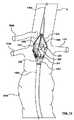
利用される場合、参照によりその全体が先に組み込まれた同時係属中のPearsonらの米国特許出願第[割り当て予定;代理人整理番号C00002204.USU1]号に十分に説明されているような、周囲を拘束する縫合糸1679は、ここで、捕捉機構2175のトリガワイヤ2177によって解放されて、アンカーステント222以外の主血管ステントグラフト200の自己拡張式ステントが、図22に示されるように、その完全に拡張した構成に戻ることができるようにする。次いで、アンカーステント222は、送達システム1382の先端捕捉機構から、大動脈との付着圧着状態へと解放され、それによって、主血管ステントグラフト200は、図23に示されるように、送達システム1382から自由な、完全に拡張または留置された構成になる。アンカーステント222が送達システム1382から解放されると、シールステント226は、完全に拡張し、本明細書に説明されるように、スカラップ224の縁部を大動脈の内壁にぴったり合うように係合し、シールする。 When utilized, co-pending Pearson et al. US Patent Application No. [assigned; Attorney Docket No. C00002204. The perimeter-constrained
次いで、血管枝ステントグラフト334A、334Bは、右腎動脈RRAおよび左腎動脈LRA内に留置され得る。図24は、血管枝ステントグラフト334A、334Bを示しており、これは、それぞれが留置され得るように、それらそれぞれの送達システムから解放されて、そのそれぞれの腎動脈から主血管ステントグラフト200のその連結部208A、208Bの中へ、またこれを通って延出して、その中に固定され、かつそれぞれの流体通路をその間に提供する。本発明の実施形態で使用するために、血管枝ステントグラフト334A、334Bは、自己拡張式のステント支持構造を有するグラフト材料の管であり、またMedtronic Incから入手可能なENDURANT(登録商標)ステントグラフトシステムで用いるために枝として好適な管状ステントグラフトなどの管状ステントグラフトであり得る。血管枝ステントグラフト334A、334Bが留置される際、これらは、主血管ステントグラフト200の外面に接触し、終端する。本明細書に説明されるように、主血管ステントグラフト200は、拡張した血管枝補綴物334A、334Bの隣またはそばに位置づけられる、より大きい可撓性の区域を含む、可変剛性胴部ステント228/1028を含み、これにより、主血管ステントグラフト200の一部分が拡張した血管枝補綴物にぴったり合うことが可能になる。このように、拡張した血管枝ステントグラフト334A、334Bは、比較的大きい補綴物によって崩壊する、または圧壊されることなく、主血管ステントグラフト200に隣接して、長手方向に延出する。可変剛性胴部ステント228/1028はまた、ステントの血管内壁に対するシールおよび付着圧着を維持するために、拡張した血管枝補綴物334A、334Bに整合していない、より小さい可撓性、およびより大きい径方向の力の区域を含む。血管枝ステントグラフト334A、334Bの留置後、枝送達カテーテル2198A、2198Bおよび送達システム1382は、血管系から引き出される。 The branch
肢部ステントグラフト439A、439Bは、主血管ステントグラフト200の脚部206A、206B内に送達および留置されて、図25に示されるように、それぞれ、右腸骨動脈RIおよび左腸骨動脈LIに延出し得る。本発明の実施形態で使用するために、肢部ステントグラフト439A、439Bは、自己拡張式のステント支持構造を有するグラフト材料の管であり、またMedtronic Incから入手可能なENDURANT(登録商標)タイプのステントグラフトに類似の管状ステントグラフトであってもよく、これは、同様にMedtronic Incから入手可能なENDURANT(登録商標)ステントグラフト送達システムに類似の送達システムによって、送達および留置される。先述のように、主血管ステントグラフト200の脚部206A、206Bは、腹部大動脈内で前方および後方に向けられる。この前方/後方の向きは、スカラップ224が後部側になる懸念なしに、初期の送達システムの挿入が、患者の左腸骨動脈LIまたは右腸骨動脈RIとなるのを可能にする。より具体的には、腹部大動脈およびそこから出る枝への到達は、一般に、大腿動脈および左腸骨動脈LIまたは右腸骨動脈RIを介して達成される。血管枝補綴物を導入するための対側肢または脚部への挿管または到達は、しばしば、難題、すなわち、比較的長い時間がかかること、医師にフラストレーションを起こさせること、さらなるX線透視の時間を要すること、およびより多くの失血の可能性をもたらす。しばしば、対側肢に挿管することは、動脈瘤嚢の後方側に位置する場合、最も困難である。SMAを収容するためにスカラップが前方に向けられた状態で、内側/外側構成で配置された脚部を有する主血管ステントグラフトでは、ユーザは、主血管ステントグラフトを左または右の大腿動脈から送達する必要があるが、どちらの動脈下を選択する選択肢はない。なぜなら、主血管ステントグラフトを組み立てる際、特注の機器を異なるまたは変わる同側肢で製作するのを防ぐために、同側肢が標準または既定であるためである。しかしながら、前方/後方構成に配置される脚部206A、206Bを有する主血管ステントグラフト200では、スカラップ224は、どちらの大腿動脈を通って主血管ステントグラフト200が送達されるかにかかわらず前方に位置し、ユーザは、同側肢を選択する選択肢を有する。主血管ステントグラフト200の後方脚部は、主ガイドワイヤ1384がそこを通る同側肢となるように選択される。なぜなら、対側肢は、動脈瘤嚢の前方側に位置する場合、挿管が容易であるためである。極端なねじれがグラフトにトルクをかける場合でさえ、主血管ステントグラフト200に沿って最大90度の屈曲角形成であっても、対側肢は、依然として常に前面に位置する。したがって、脚部206A、206Bの前方/後方構成は、有利にも、対側肢の挿管を容易にし、ワイヤの到達は、留置の初期段階から後方肢を通ってすでに提供されている。
本発明による様々な実施形態を説明してきたが、それらは説明および例示の目的で示されたに過ぎず、限定するものではないことを理解されたい。当業者には、本発明の精神および範囲を逸脱することなく、本発明において、形式および詳細の多様な変更を行い得ることが明らかであろう。したがって、本発明の範囲(breadth and scope)は、上述の例示的な実施形態のいずれにも限定されるべきではないが、添付の特許請求の範囲およびその均等物によってのみ定義されるべきである。また、本明細書で議論した各実施形態、および本明細書に引用された各引用文献の各特徴が、任意のその他の実施形態の特徴と組み合わせて使用され得ることも理解される。本明細書で議論したすべての特許および文献は、参照により、その全体が本明細書に援用される。 While various embodiments in accordance with the present invention have been described, it should be understood that they have been presented for purposes of illustration and illustration only and not limitation. It will be apparent to those skilled in the art that various modifications, in form and detail, can be made in the present invention without departing from the spirit and scope of the invention. Accordingly, the breadth and scope of the present invention should not be limited to any of the above-described exemplary embodiments, but should be defined only in accordance with the appended claims and their equivalents. . It is also understood that each embodiment discussed herein and each feature of each cited reference cited herein can be used in combination with the features of any other embodiment. All patents and documents discussed herein are hereby incorporated by reference in their entirety.
Claims (16)
Translated fromJapaneseグラフト材料の管状体と、
前記グラフト材料から除去されて、頂部開口型開窓部として前記管状体の第1の縁部から延出するスカラップであって、前記スカラップが、第1および第2の対向する側縁部とその間に延在する底縁部とを含む、スカラップと、
前記管状体に、その前記第1の縁部に隣接して連結されるステントであって、前記ステントが、複数のクラウンおよび複数のストラットを、各クラウンが対向する一対のストラットの間に形成される状態で含む、ステントとを備え、
前記ステントが、前記スカラップの前記第1の側縁部のそばに延在する第1の長いストラットと、前記スカラップの前記底縁部に対して遠位に延在するクラウンをその間に有する2本の短いストラットと、前記スカラップの前記第2の側縁部のそばに延在する第2の長いストラットとを含む、4本の連続するストラットを有する、一体型の細長い部分を含み、前記第1および第2の長いストラットが、前記2本の短いストラットよりも長い、血管内へ移植するための補綴物。A prosthesis for implantation into a blood vessel, wherein the prosthesis is
A tubular body of graft material;
A scallop removed from the graft material and extending from the first edge of the tubular body as a top opening fenestration, the scallop being between first and second opposing side edges A scallop including a bottom edge extending to the
A stent connected to the tubular body adjacent to the first edge, wherein the stent is formed with a plurality of crowns and a plurality of struts between a pair of struts facing each crown. Including a stent including,
Two stents having a first long strut extending near the first side edge of the scallop and a crown therebetween extending distally with respect to the bottom edge of the scallop. An integral elongate portion having four consecutive struts, including a first short strut and a second long strut extending near the second side edge of the scallop, And a prosthesis for implantation into a blood vessel in which the second long strut is longer than the two short struts.
前記管状体が、腹部大動脈内に設置するために構成され、前記第1および第2の管状脚部が、前記大動脈内の前方および後方に設置するために構成される、請求項1に記載の補綴物。A bifurcated portion having first and second tubular legs coupled to a second end of the tubular body, wherein the legs are in fluid communication with a lumen defined by the tubular body Further comprising a bifurcation portion,
The tubular body according to claim 1, wherein the tubular body is configured for placement within an abdominal aorta, and the first and second tubular legs are configured for placement forward and posterior within the aorta. Prosthesis.
第1の最近位の一式のクラウンが、前記管状体の前記第1の縁部を越えて延在し、第2の対向する一式のクラウンが、前記管状体の前記第1の縁部に連結される、請求項1に記載の補綴物。An anchor stent further comprising a plurality of crowns and a plurality of struts, each crown being formed between a pair of opposing struts;
A first closest set of crowns extends beyond the first edge of the tubular body, and a second opposing set of crowns connects to the first edge of the tubular body. The prosthesis of claim 1.
各連結部が、前記管状体に連結される基部と、前記管状体から離間した上部と、前記基部と前記上部との間に配置され、前記管状体によって画定される内腔と流体連通する連結部内腔とを含む、請求項1に記載の補綴物。Further comprising first and second oppositely connected portions extending outward from the tubular body;
Each connection is in fluid communication with a base connected to the tubular body, an upper portion spaced from the tubular body, and between the base and the upper portion and in fluid communication with a lumen defined by the tubular body The prosthesis according to claim 1, comprising a partial lumen.
前記可変剛性ステントが、前記連結部にほぼ円周方向に整列した少なくとも2つの比較的大きい可撓性の区域を含む、請求項12に記載の補綴物。A variable stiffness stent coupled to the tubular body proximate to the coupling portion;
The prosthesis of claim 12, wherein the variable stiffness stent includes at least two relatively large flexible sections that are generally circumferentially aligned with the connection.
Applications Claiming Priority (3)
| Application Number | Priority Date | Filing Date | Title |
|---|---|---|---|
| US13/458,209 | 2012-04-27 | ||
| US13/458,209US20130289701A1 (en) | 2012-04-27 | 2012-04-27 | Stent-graft prosthesis for placement in the abdominal aorta |
| PCT/US2013/026677WO2013162682A1 (en) | 2012-04-27 | 2013-02-19 | Stent-graft prosthesis for placement in the abdominal aorta |
Publications (1)
| Publication Number | Publication Date |
|---|---|
| JP2015517845Atrue JP2015517845A (en) | 2015-06-25 |
Family
ID=47750870
Family Applications (1)
| Application Number | Title | Priority Date | Filing Date |
|---|---|---|---|
| JP2015508943APendingJP2015517845A (en) | 2012-04-27 | 2013-02-19 | Stent graft prosthesis for placement in the abdominal aorta |
Country Status (5)
| Country | Link |
|---|---|
| US (1) | US20130289701A1 (en) |
| EP (1) | EP2841012A1 (en) |
| JP (1) | JP2015517845A (en) |
| CN (1) | CN104244866A (en) |
| WO (1) | WO2013162682A1 (en) |
Families Citing this family (24)
| Publication number | Priority date | Publication date | Assignee | Title |
|---|---|---|---|---|
| DE102012010687B4 (en)* | 2012-05-30 | 2021-08-19 | ADMEDES GmbH | A method for producing a body implant, an assembly comprising a guide wire and a body implant, and a medical instrument |
| FR3013209B1 (en)* | 2013-11-18 | 2017-04-21 | Claude Mialhe | ENDOVASCULAR PROSTHESIS FOR FITTING IN CHIMNEY |
| EP2915509A1 (en)* | 2014-03-05 | 2015-09-09 | Cardiatis S.A. | Stent assembly for thoracoabdominal bifurcated aneurysm repair |
| US9468545B2 (en)* | 2014-04-04 | 2016-10-18 | W. L. Gore & Associates, Inc. | Bifurcated graft device |
| CN104116577B (en)* | 2014-06-27 | 2017-07-14 | 先健科技(深圳)有限公司 | Branch type overlay film frame |
| JP2016031442A (en)* | 2014-07-29 | 2016-03-07 | プラス・ジャック株式会社 | Foldable temple, foldable temple core material, and sixfold type spectacle frame |
| US10959826B2 (en) | 2014-10-16 | 2021-03-30 | Cook Medical Technology LLC | Support structure for scalloped grafts |
| US10758387B2 (en) | 2014-10-16 | 2020-09-01 | Cook Medical Technologies Llc | Endovascular stent graft assembly and delivery device |
| CN105943046A (en)* | 2016-06-06 | 2016-09-21 | 任勇 | Tumor body impedance monitoring device and method based on abdominal aortic stent |
| WO2017222875A1 (en)* | 2016-06-21 | 2017-12-28 | Medtronic Vascular Inc. | Coated endovascular prostheses for aneurism treatment |
| EP3547959B1 (en)* | 2016-12-05 | 2024-10-23 | Medtronic Vascular Inc. | Modular aortic arch prosthetic assembly |
| EP3391853B1 (en)* | 2017-04-19 | 2019-11-20 | Cook Medical Technologies LLC | Support structure for scalloped grafts |
| CN109717986B (en)* | 2017-10-31 | 2021-07-02 | 上海微创心脉医疗科技股份有限公司 | Branch type tectorial membrane support and branch type tectorial membrane support system |
| US11284989B2 (en) | 2018-04-24 | 2022-03-29 | Medtronic Vascular, Inc. | Stent-graft prosthesis with pressure relief channels |
| CN108652787B (en)* | 2018-05-06 | 2020-05-22 | 王潇 | Covered stent for abdominal aortic aneurysm repair and using method thereof |
| FI3941392T3 (en) | 2019-03-20 | 2025-07-28 | Inqb8 Medical Tech Llc | Aortic dissection implant |
| EP4054481A4 (en)* | 2019-11-07 | 2023-12-13 | Jeko Metodiev Madjarov | Endograft with bristles |
| CN111407463B (en)* | 2020-03-19 | 2022-08-12 | 湖南埃普特医疗器械有限公司 | Covered stent system |
| AU2021359871B2 (en)* | 2020-10-18 | 2025-02-20 | W. L. Gore & Associates, Inc. | Devices and methods for treating occlusions |
| CN113876467B (en)* | 2021-12-08 | 2022-04-15 | 上海微创心脉医疗科技(集团)股份有限公司 | stent graft |
| CN115177401B (en)* | 2022-07-08 | 2023-04-14 | 李国剑 | Covered stent for abdominal aortic aneurysm |
| CN115517811B (en)* | 2022-11-01 | 2023-03-31 | 北京华脉泰科医疗器械股份有限公司 | Integrated stent artificial blood vessel and artificial blood vessel replacement kit |
| WO2024168255A1 (en)* | 2023-02-09 | 2024-08-15 | W. L. Gore & Associates, Inc. | Stent graft with features for side branch vessel perfusion |
| WO2025101628A1 (en)* | 2023-11-08 | 2025-05-15 | W. L. Gore & Associates, Inc. | Hybrid endoprosthesis system |
Family Cites Families (9)
| Publication number | Priority date | Publication date | Assignee | Title |
|---|---|---|---|---|
| AUPP083597A0 (en)* | 1997-12-10 | 1998-01-08 | William A Cook Australia Pty Ltd | Endoluminal aortic stents |
| US20070032852A1 (en)* | 2003-04-25 | 2007-02-08 | Medtronic Vascular, Inc. | Methods and Apparatus for Treatment of Aneurysms Adjacent to Branch Arteries |
| ATE392865T1 (en)* | 2003-10-10 | 2008-05-15 | Cook William A Australia | STENT IMPLANTS WITH WINDOWS |
| AU2005262541B2 (en)* | 2004-06-16 | 2011-04-21 | Cook Incorporated | Thoracic deployment device and stent graft |
| WO2006113501A1 (en)* | 2005-04-13 | 2006-10-26 | The Cleveland Clinic Foundation | Endoluminal prosthesis |
| AU2007240703C1 (en)* | 2006-04-19 | 2012-06-14 | Cleveland Clinic Foundation | Twin bifurcated stent graft |
| CN101283937B (en)* | 2008-05-21 | 2010-08-18 | 微创医疗器械(上海)有限公司 | Overlay film frame with an opening and bonding method of the overlay film frame |
| US8337546B2 (en)* | 2010-04-29 | 2012-12-25 | Medtronic Vascular, Inc. | Mobile external coupling for branch vessel connection |
| US8702786B2 (en)* | 2010-08-21 | 2014-04-22 | Cook Medical Technologies Llc | Prosthesis having pivoting fenestration |
- 2012
- 2012-04-27USUS13/458,209patent/US20130289701A1/ennot_activeAbandoned
- 2013
- 2013-02-19JPJP2015508943Apatent/JP2015517845A/enactivePending
- 2013-02-19WOPCT/US2013/026677patent/WO2013162682A1/enactiveApplication Filing
- 2013-02-19EPEP13706400.2Apatent/EP2841012A1/ennot_activeWithdrawn
- 2013-02-19CNCN201380021919.2Apatent/CN104244866A/enactivePending
Also Published As
| Publication number | Publication date |
|---|---|
| EP2841012A1 (en) | 2015-03-04 |
| WO2013162682A1 (en) | 2013-10-31 |
| CN104244866A (en) | 2014-12-24 |
| US20130289701A1 (en) | 2013-10-31 |
Similar Documents
| Publication | Publication Date | Title |
|---|---|---|
| JP6221141B2 (en) | Stent-graft prosthesis for placement in the abdominal aorta | |
| JP2015517845A (en) | Stent graft prosthesis for placement in the abdominal aorta | |
| US12364798B2 (en) | Anastomotic devices and methods | |
| JP6248308B2 (en) | Circumferentially constrained suture for stent graft | |
| CN104394800B (en) | De- stent graft arm and using method | |
| US6918926B2 (en) | System for transrenal/intraostial fixation of endovascular prosthesis | |
| JP5621093B2 (en) | Chest stent graft | |
| US20050171598A1 (en) | Aorta and branch vessel stent grafts and method | |
| JP2017074405A (en) | Intraluminal prosthesis having a modular branch and deployment method | |
| HK1181331B (en) | Anastomotic devices and methods | |
| HK1181331A (en) | Anastomotic devices and methods |