JP2015513471A - How to finish a sheet of material with a magnetorheological finish - Google Patents
How to finish a sheet of material with a magnetorheological finishDownload PDFInfo
- Publication number
- JP2015513471A JP2015513471AJP2014560006AJP2014560006AJP2015513471AJP 2015513471 AJP2015513471 AJP 2015513471AJP 2014560006 AJP2014560006 AJP 2014560006AJP 2014560006 AJP2014560006 AJP 2014560006AJP 2015513471 AJP2015513471 AJP 2015513471A
- Authority
- JP
- Japan
- Prior art keywords
- sheet
- edge
- glass
- finishing
- glass sheet
- Prior art date
- Legal status (The legal status is an assumption and is not a legal conclusion. Google has not performed a legal analysis and makes no representation as to the accuracy of the status listed.)
- Pending
Links
- 239000000463materialSubstances0.000titleclaimsabstractdescription116
- 239000011521glassSubstances0.000claimsabstractdescription172
- 238000000034methodMethods0.000claimsabstractdescription102
- 238000007688edgingMethods0.000claimsdescription20
- 230000002093peripheral effectEffects0.000claimsdescription5
- 238000005728strengtheningMethods0.000claimsdescription5
- 238000009966trimmingMethods0.000claimsdescription2
- 238000000926separation methodMethods0.000description55
- 238000002360preparation methodMethods0.000description25
- 239000002245particleSubstances0.000description24
- 238000003426chemical strengthening reactionMethods0.000description22
- 239000007788liquidSubstances0.000description20
- 239000012530fluidSubstances0.000description14
- 230000008569processEffects0.000description12
- 238000004519manufacturing processMethods0.000description11
- 239000003513alkaliSubstances0.000description9
- 238000000227grindingMethods0.000description9
- 238000005342ion exchangeMethods0.000description9
- 150000002500ionsChemical class0.000description9
- 239000006060molten glassSubstances0.000description8
- 238000012545processingMethods0.000description8
- 238000005498polishingMethods0.000description7
- 230000001681protective effectEffects0.000description7
- MCMNRKCIXSYSNV-UHFFFAOYSA-NZirconium dioxideChemical compoundO=[Zr]=OMCMNRKCIXSYSNV-UHFFFAOYSA-N0.000description6
- 150000001447alkali saltsChemical class0.000description6
- 239000003381stabilizerSubstances0.000description6
- 239000002253acidSubstances0.000description5
- VYPSYNLAJGMNEJ-UHFFFAOYSA-NSilicium dioxideChemical compoundO=[Si]=OVYPSYNLAJGMNEJ-UHFFFAOYSA-N0.000description4
- 238000010586diagramMethods0.000description4
- 238000005530etchingMethods0.000description4
- 238000007730finishing processMethods0.000description4
- XLYOFNOQVPJJNP-UHFFFAOYSA-NwaterSubstancesOXLYOFNOQVPJJNP-UHFFFAOYSA-N0.000description4
- LYCAIKOWRPUZTN-UHFFFAOYSA-NEthylene glycolChemical compoundOCCOLYCAIKOWRPUZTN-UHFFFAOYSA-N0.000description3
- XEEYBQQBJWHFJM-UHFFFAOYSA-NIronChemical compound[Fe]XEEYBQQBJWHFJM-UHFFFAOYSA-N0.000description3
- KWYUFKZDYYNOTN-UHFFFAOYSA-MPotassium hydroxideChemical compound[OH-].[K+]KWYUFKZDYYNOTN-UHFFFAOYSA-M0.000description3
- HEMHJVSKTPXQMS-UHFFFAOYSA-MSodium hydroxideChemical compound[OH-].[Na+]HEMHJVSKTPXQMS-UHFFFAOYSA-M0.000description3
- 239000003082abrasive agentSubstances0.000description3
- 229910001854alkali hydroxideInorganic materials0.000description3
- 150000008044alkali metal hydroxidesChemical class0.000description3
- PNEYBMLMFCGWSK-UHFFFAOYSA-Naluminium oxideInorganic materials[O-2].[O-2].[O-2].[Al+3].[Al+3]PNEYBMLMFCGWSK-UHFFFAOYSA-N0.000description3
- 230000015572biosynthetic processEffects0.000description3
- 238000005336crackingMethods0.000description3
- 230000007547defectEffects0.000description3
- 238000002844meltingMethods0.000description3
- 230000008018meltingEffects0.000description3
- 238000002156mixingMethods0.000description3
- 239000011734sodiumSubstances0.000description3
- 238000003860storageMethods0.000description3
- 239000004094surface-active agentSubstances0.000description3
- KRHYYFGTRYWZRS-UHFFFAOYSA-NFluoraneChemical compoundFKRHYYFGTRYWZRS-UHFFFAOYSA-N0.000description2
- UQSXHKLRYXJYBZ-UHFFFAOYSA-NIron oxideChemical compound[Fe]=OUQSXHKLRYXJYBZ-UHFFFAOYSA-N0.000description2
- PXHVJJICTQNCMI-UHFFFAOYSA-NNickelChemical compound[Ni]PXHVJJICTQNCMI-UHFFFAOYSA-N0.000description2
- QAOWNCQODCNURD-UHFFFAOYSA-NSulfuric acidChemical compoundOS(O)(=O)=OQAOWNCQODCNURD-UHFFFAOYSA-N0.000description2
- 230000008901benefitEffects0.000description2
- 150000001875compoundsChemical class0.000description2
- 230000007797corrosionEffects0.000description2
- 238000005260corrosionMethods0.000description2
- 239000003599detergentSubstances0.000description2
- 229910003460diamondInorganic materials0.000description2
- 239000010432diamondSubstances0.000description2
- 238000009826distributionMethods0.000description2
- 238000007654immersionMethods0.000description2
- 230000001788irregularEffects0.000description2
- 239000000696magnetic materialSubstances0.000description2
- 230000007246mechanismEffects0.000description2
- 229910052751metalInorganic materials0.000description2
- 239000002184metalSubstances0.000description2
- 230000035515penetrationEffects0.000description2
- HBMJWWWQQXIZIP-UHFFFAOYSA-Nsilicon carbideChemical compound[Si+]#[C-]HBMJWWWQQXIZIP-UHFFFAOYSA-N0.000description2
- 229910010271silicon carbideInorganic materials0.000description2
- 239000000377silicon dioxideSubstances0.000description2
- 239000007787solidSubstances0.000description2
- 239000002904solventSubstances0.000description2
- 239000000126substanceSubstances0.000description2
- 229910052582BNInorganic materials0.000description1
- PZNSFCLAULLKQX-UHFFFAOYSA-NBoron nitrideChemical compoundN#BPZNSFCLAULLKQX-UHFFFAOYSA-N0.000description1
- 229910000976Electrical steelInorganic materials0.000description1
- 244000043261Hevea brasiliensisSpecies0.000description1
- -1Li + and / or Na +Chemical class0.000description1
- 229910001209Low-carbon steelInorganic materials0.000description1
- 229910002651NO3Inorganic materials0.000description1
- NHNBFGGVMKEFGY-UHFFFAOYSA-NNitrateChemical compound[O-][N+]([O-])=ONHNBFGGVMKEFGY-UHFFFAOYSA-N0.000description1
- XUIMIQQOPSSXEZ-UHFFFAOYSA-NSiliconChemical compound[Si]XUIMIQQOPSSXEZ-UHFFFAOYSA-N0.000description1
- 150000007513acidsChemical class0.000description1
- 230000009286beneficial effectEffects0.000description1
- 229910001423beryllium ionInorganic materials0.000description1
- 229920005549butyl rubberPolymers0.000description1
- 229910001567cementiteInorganic materials0.000description1
- 239000000919ceramicSubstances0.000description1
- 229910000420cerium oxideInorganic materials0.000description1
- 230000008859changeEffects0.000description1
- 238000003486chemical etchingMethods0.000description1
- 229940090961chromium dioxideDrugs0.000description1
- IAQWMWUKBQPOIY-UHFFFAOYSA-Nchromium(4+);oxygen(2-)Chemical compound[O-2].[O-2].[Cr+4]IAQWMWUKBQPOIY-UHFFFAOYSA-N0.000description1
- AYTAKQFHWFYBMA-UHFFFAOYSA-Nchromium(IV) oxideInorganic materialsO=[Cr]=OAYTAKQFHWFYBMA-UHFFFAOYSA-N0.000description1
- 238000005352clarificationMethods0.000description1
- 239000010941cobaltSubstances0.000description1
- 229910017052cobaltInorganic materials0.000description1
- GUTLYIVDDKVIGB-UHFFFAOYSA-Ncobalt atomChemical compound[Co]GUTLYIVDDKVIGB-UHFFFAOYSA-N0.000description1
- 238000001816coolingMethods0.000description1
- 238000007598dipping methodMethods0.000description1
- 230000004927fusionEffects0.000description1
- 238000005816glass manufacturing processMethods0.000description1
- 230000009477glass transitionEffects0.000description1
- 239000002241glass-ceramicSubstances0.000description1
- 230000005484gravityEffects0.000description1
- 230000001939inductive effectEffects0.000description1
- 229910052742ironInorganic materials0.000description1
- 229910001337iron nitrideInorganic materials0.000description1
- 239000004973liquid crystal related substanceSubstances0.000description1
- 238000010297mechanical methods and processMethods0.000description1
- 230000005226mechanical processes and functionsEffects0.000description1
- 239000002480mineral oilSubstances0.000description1
- 235000010446mineral oilNutrition0.000description1
- 239000000203mixtureSubstances0.000description1
- 238000012986modificationMethods0.000description1
- 230000004048modificationEffects0.000description1
- 238000000465mouldingMethods0.000description1
- 239000002105nanoparticleSubstances0.000description1
- 229920003052natural elastomerPolymers0.000description1
- 229920001194natural rubberPolymers0.000description1
- 229910052759nickelInorganic materials0.000description1
- 239000003921oilSubstances0.000description1
- BMMGVYCKOGBVEV-UHFFFAOYSA-Noxo(oxoceriooxy)ceriumChemical compound[Ce]=O.O=[Ce]=OBMMGVYCKOGBVEV-UHFFFAOYSA-N0.000description1
- 230000010287polarizationEffects0.000description1
- 229920000642polymerPolymers0.000description1
- 229920001296polysiloxanePolymers0.000description1
- 229920002635polyurethanePolymers0.000description1
- 239000004814polyurethaneSubstances0.000description1
- FGIUAXJPYTZDNR-UHFFFAOYSA-Npotassium nitrateChemical compound[K+].[O-][N+]([O-])=OFGIUAXJPYTZDNR-UHFFFAOYSA-N0.000description1
- 239000008262pumiceSubstances0.000description1
- 230000003014reinforcing effectEffects0.000description1
- 238000000518rheometryMethods0.000description1
- 239000004065semiconductorSubstances0.000description1
- 239000010703siliconSubstances0.000description1
- 229910052710siliconInorganic materials0.000description1
- 239000007921spraySubstances0.000description1
- 238000004804windingMethods0.000description1
Images


Classifications
- B—PERFORMING OPERATIONS; TRANSPORTING
- B24—GRINDING; POLISHING
- B24B—MACHINES, DEVICES, OR PROCESSES FOR GRINDING OR POLISHING; DRESSING OR CONDITIONING OF ABRADING SURFACES; FEEDING OF GRINDING, POLISHING, OR LAPPING AGENTS
- B24B31/00—Machines or devices designed for polishing or abrading surfaces on work by means of tumbling apparatus or other apparatus in which the work and/or the abrasive material is loose; Accessories therefor
- B24B31/10—Machines or devices designed for polishing or abrading surfaces on work by means of tumbling apparatus or other apparatus in which the work and/or the abrasive material is loose; Accessories therefor involving other means for tumbling of work
- B24B31/112—Machines or devices designed for polishing or abrading surfaces on work by means of tumbling apparatus or other apparatus in which the work and/or the abrasive material is loose; Accessories therefor involving other means for tumbling of work using magnetically consolidated grinding powder, moved relatively to the workpiece under the influence of pressure
- B—PERFORMING OPERATIONS; TRANSPORTING
- B24—GRINDING; POLISHING
- B24B—MACHINES, DEVICES, OR PROCESSES FOR GRINDING OR POLISHING; DRESSING OR CONDITIONING OF ABRADING SURFACES; FEEDING OF GRINDING, POLISHING, OR LAPPING AGENTS
- B24B9/00—Machines or devices designed for grinding edges or bevels on work or for removing burrs; Accessories therefor
- B24B9/02—Machines or devices designed for grinding edges or bevels on work or for removing burrs; Accessories therefor characterised by a special design with respect to properties of materials specific to articles to be ground
- B24B9/06—Machines or devices designed for grinding edges or bevels on work or for removing burrs; Accessories therefor characterised by a special design with respect to properties of materials specific to articles to be ground of non-metallic inorganic material, e.g. stone, ceramics, porcelain
- B24B9/08—Machines or devices designed for grinding edges or bevels on work or for removing burrs; Accessories therefor characterised by a special design with respect to properties of materials specific to articles to be ground of non-metallic inorganic material, e.g. stone, ceramics, porcelain of glass
- B24B9/10—Machines or devices designed for grinding edges or bevels on work or for removing burrs; Accessories therefor characterised by a special design with respect to properties of materials specific to articles to be ground of non-metallic inorganic material, e.g. stone, ceramics, porcelain of glass of plate glass
Landscapes
- Engineering & Computer Science (AREA)
- Mechanical Engineering (AREA)
- Chemical & Material Sciences (AREA)
- Ceramic Engineering (AREA)
- Inorganic Chemistry (AREA)
- Surface Treatment Of Glass (AREA)
- Re-Forming, After-Treatment, Cutting And Transporting Of Glass Products (AREA)
- Grinding And Polishing Of Tertiary Curved Surfaces And Surfaces With Complex Shapes (AREA)
- Finish Polishing, Edge Sharpening, And Grinding By Specific Grinding Devices (AREA)
Abstract
Translated fromJapaneseDescription
Translated fromJapanese本出願は、米国特許法第119条の下で2012年2月29日に出願された仮特許出願第61/604,863号の優先権の利益を主張し、そして、米国特許法第120条の下で2012年12月20日に出願された特許出願第13/721,557号の優先権の利益を主張し、それらの内容が依拠されその全体が参照により本明細書に組み込まれる。 This application claims the benefit of priority of provisional patent application 61 / 604,863, filed February 29, 2012 under 35 USC 119, and 35 USC 120 Claims the benefit of priority of patent application 13 / 721,557, filed on December 20, 2012, the contents of which are relied upon and incorporated herein by reference in their entirety.
本発明は、材料のシートを仕上げる方法に関し、より具体的には、磁気レオロジー仕上げにより材料のシートの縁部を仕上げる方法に関する。 The present invention relates to a method for finishing a sheet of material, and more particularly to a method for finishing an edge of a sheet of material by magnetorheological finishing.
ディスプレイ品質のガラスシート等の材料のシートが様々な技術によって製造されることは知られている。一旦形成されると、ガラスシートは、典型的には、ガラスシートから縁部がトリミングされ、及び/又は特定のアプリケーションに対応するために、サイズを変更するためにガラスシートが分離されている。典型的な分離手法では、クラッキングに対して脆弱である望ましくない粗く鋭い縁部を招来することがある。 It is known that sheets of materials such as display quality glass sheets are produced by various techniques. Once formed, the glass sheet is typically trimmed at the edges from the glass sheet and / or separated to resize to accommodate a particular application. Typical separation techniques can result in undesirable rough and sharp edges that are vulnerable to cracking.
例示的な実施形態が示される添付の図面を参照して、実施例についてより詳細に説明する。可能な限り、同一の参照番号は同一又は同様の部品を指すために図面全体を通して使用される。しかし、実施態様は多くの異なる形態で具現化でき、本明細書に記載された実施形態に限定されると解釈されるべきではない。 Examples will be described in more detail with reference to the accompanying drawings, in which exemplary embodiments are shown. Wherever possible, the same reference numbers will be used throughout the drawings to refer to the same or like parts. However, embodiments may be embodied in many different forms and should not be construed as limited to the embodiments set forth herein;
発明の一態様においては、材料のシートを仕上げる方法は、第1の面及び第2の面を有する材料のシートであって、前記材料のシートの前記第1の面と前記第2の面との間の平均厚さが約50μm〜約500μmである前記材料のシートを準備するステップ(I)を含む。さらに、該材料のシートを仕上げる方法は、前記材料のシートの縁部を磁気レオロジー仕上げで仕上げるステップ(II)を含む。 In one aspect of the invention, a method of finishing a sheet of material is a sheet of material having a first side and a second side, the first side and the second side of the sheet of material. Providing (I) a sheet of said material having an average thickness between about 50 μm and about 500 μm. Further, the method for finishing the sheet of material comprises the step (II) of finishing the edges of the sheet of material with a magnetorheological finish.
前記一態様の一例においては、前記ステップ(I)は、ガラスシートとして前記材料のシートを提供する。 In one example of the one aspect, the step (I) provides a sheet of the material as a glass sheet.
前記一態様の他の一例においては、前記ステップ(I)は、約50〜約300μmの前記材料のシートの前記平均厚さを提供する。 In another example of the one aspect, step (I) provides the average thickness of the sheet of material from about 50 to about 300 μm.
前記一態様の更なる他の一例においては、前記ステップ(I)は、約75〜約200μmの前記材料のシートの前記平均厚さを提供する。 In yet another example of the aspect, step (I) provides the average thickness of the sheet of material from about 75 to about 200 μm.
前記一態様の更なる他の一例においては、前記ステップ(I)は、約75〜約150μmの前記材料のシートの前記平均厚さを提供する。 In yet another example of the aspect, step (I) provides the average thickness of the sheet of material from about 75 to about 150 μm.
前記一態様の更なる他の一例においては、前記ステップ(I)は、垂直軸に対して約+45度から−45度までの角度範囲内の所定配向での平面に沿って配置された前記材料のシートを提供する。 In yet another example of the aspect, the step (I) comprises the material disposed along a plane with a predetermined orientation within an angular range of about +45 degrees to -45 degrees with respect to the vertical axis. Provide a sheet of.
前記一態様の更なる他の一例においては、前記材料のシートの前記所定配向は前記ステップ(II)の間に維持される。 In yet another example of the aspect, the predetermined orientation of the sheet of material is maintained during step (II).
前記一態様の更なる他の一例においては、前記ステップ(I)は、前記第1の面と前記第2の面との間の前記材料のシートの周縁部に沿って延びる前記縁部を設ける。 In yet another example of the one aspect, the step (I) provides the edge extending along a peripheral edge of the sheet of material between the first surface and the second surface. .
前記一態様の更なる他の一例においては、前記仕上げる方法は、前記ステップ(II)の前に前記縁部を強化するステップを更に含む。 In yet another example of the one aspect, the finishing method further includes the step of reinforcing the edge prior to the step (II).
前記一態様の更なる他の一例においては、前記仕上げる方法は、前記ステップ(II)の前に前記縁部を設けるために前記材料のシートを分離するステップを更に含む。 In yet another example of the one aspect, the finishing method further includes separating the sheet of material to provide the edge prior to the step (II).
前記一態様の更なる他の一例においては、前記分離するステップを前記ステップ(I)の後に実行する。 In still another example of the one aspect, the separating step is performed after the step (I).
前記一態様の更なる他の一例においては、前記仕上げる方法は、前記分離するステップの後で且つ前記ステップ(II)の前に前記縁部を強化するステップを更に含む。 In yet another example of the one aspect, the finishing method further includes the step of strengthening the edge after the separating step and before the step (II).
前記一態様の更なる他の一例においては、前記仕上げる方法は、前記材料のシートを縁取りして前記ステップ(II)の前に前記縁部を設けるステップを更に含む。 In yet another example of the one aspect, the finishing method further includes edging the sheet of material to provide the edge prior to step (II).
前記一態様の更なる他の一例においては、前記縁取りするステップを前記ステップ(I)の後に実行する。 In still another example of the aspect, the step of trimming is performed after the step (I).
前記一態様の更なる他の一例においては、前記仕上げる方法は、前記材料のシートを縁取りするステップの前に前記材料のシートを分離するステップを更に含む。 In yet another example of the one aspect, the finishing method further includes separating the sheet of material prior to the step of edging the sheet of material.
前記一態様の更なる他の一例においては、前記仕上げる方法は、前記縁取りするステップの後で且つ前記ステップ(II)の前に前記縁部を強化するステップを更に含む。 In yet another example of the one aspect, the finishing method further includes strengthening the edge after the edging step and before the step (II).
発明の他の態様においては、第1の面と第2の面を有するガラスシートの縁部が前記第1の面と前記第2の面との間の前記ガラスシートの周縁部に沿って延びる、前記縁部を仕上げる方法が提供される。該仕上げる方法は、前記縁部を本質的に単一のステップにて仕上げる方法であって、全体の縁部が単一の磁気レオロジー仕上げステップ中に前記第1の面と前記第2の面との間に成形されるように、磁気レオロジー仕上げにより前記ガラスシートの前記縁部を仕上げるステップからなる。 In another aspect of the invention, an edge of a glass sheet having a first surface and a second surface extends along a peripheral edge of the glass sheet between the first surface and the second surface. A method of finishing the edge is provided. The finishing method is a method of finishing the edge essentially in a single step, wherein the entire edge is the first surface and the second surface during a single magnetorheological finishing step. And finishing the edge of the glass sheet by magnetorheological finishing.
前記態様おいては、ガラスシートの縁部を仕上げる方法は、
第1の面及び第2の面を有するガラスシートであって、前記ガラスシートの前記第1の面と前記第2の面との間の平均厚さが約50μm〜約500μmである前記ガラスシートを準備するステップ(I)と、前記ガラスシートの縁部を磁気レオロジー仕上げで仕上げるステップ(II)と、を含む。In the above aspect, the method of finishing the edge of the glass sheet is as follows:
A glass sheet having a first surface and a second surface, wherein an average thickness between the first surface and the second surface of the glass sheet is about 50 μm to about 500 μm. And (I) and (II) finishing the edge of the glass sheet with a magnetorheological finish.
前記態様の更なる他の一例においては、前記ステップ(II)中において、全体の縁部が単一の磁気レオロジー仕上げステップ中に前記第1の面と前記第2の面との間に成形される。 In yet another example of the aspect, during step (II), the entire edge is formed between the first and second surfaces during a single magnetorheological finishing step. The
前記態様の更なる他の一例においては、前記ステップ(I)は、約75〜約150μmの前記材料のシートの前記平均厚さを提供する。 In yet another example of the embodiment, step (I) provides the average thickness of the sheet of material from about 75 to about 150 μm.
これら及び他の態様は、以下の詳細な説明を添付の図面を参照しつつ読み取られたとき、より良く理解される。 These and other aspects are better understood when the following detailed description is read with reference to the accompanying drawings.
例示的な実施形態が示される添付の図面を参照しつつ実施例をより詳細に説明する。可能な限り、同一の参照番号は同一又は同様の部品を指すために図面全体を通して使用される。しかし、実施態様は多くの異なる形態で具現化でき、本明細書に記載された実施形態に限定されると解釈されるべきではない。 Examples will be described in more detail with reference to the accompanying drawings, in which exemplary embodiments are shown. Wherever possible, the same reference numbers will be used throughout the drawings to refer to the same or like parts. However, embodiments may be embodied in many different forms and should not be construed as limited to the embodiments set forth herein.
方法は、材料のシートを仕上げるために提供される。本発明の材料のシートは、ガラス、ガラスセラミック、セラミック、シリコン、半導体材料及びこれらの前述の材料の組み合わせ等の各種の材料を含むことができる。特定の一例では、材料のシートは、ディスプレイ品質のガラスシート等のガラスシートを含むことができる。かかるディスプレイ品質のガラスシートは透明であり、液晶表示装置及び/又は他の電子装置に組み込むことができる。材料のシートは例えば、上記の代替材料として他のガラスシート及び/又は他の材料を含んでもよいことが理解されるであろうが、本発明の例示的な方法はディスプレイ品質のガラスシート材料を含む材料のシートを参照して説明する。 A method is provided for finishing a sheet of material. Sheets of materials of the present invention can include various materials such as glass, glass ceramic, ceramic, silicon, semiconductor materials, and combinations of these aforementioned materials. In one particular example, the sheet of material can include a glass sheet, such as a display quality glass sheet. Such display quality glass sheets are transparent and can be incorporated into liquid crystal displays and / or other electronic devices. It will be appreciated that the sheet of material may include, for example, other glass sheets and / or other materials as alternative materials described above, but exemplary methods of the present invention include display quality glass sheet materials. The description will be made with reference to a sheet of the containing material.
ガラスシートは広い技術範囲により形成されてもよい。図1に示されるように、本開示の態様に従って使用できる例示的なガラス製造装置101の概略図が示される。例示的なガラス製造装置101は、他の形成装置が更なる実施例でも使用され得るが、ダウンドローフュージョン装置(down draw fusion apparatus)として示されている。 The glass sheet may be formed by a wide technical range. As shown in FIG. 1, a schematic diagram of an exemplary
ガラス製造装置101は、溶融容器103、清澄容器105、混合容器107、供給容器109、成形装置111、牽引ローラ装置113及び分離装置115を含むことができる。 The
溶融容器103は、矢印117によって示されるように溶融ガラスバッチ材料が導入されて溶融され、溶融ガラス119を形成する所である。清澄容器105は、溶融容器103から溶融ガラス119(この時点で示されていない)を受けて溶融ガラス119から気泡が除去される高温処理領域を有する。清澄容器105は、接続管121によって混合容器107へ接続される。混合容器107は、接続管123によって供給容器109へ接続される。供給容器109は、溶融ガラス119を、降下管125を通じて入口127を介して成形装置111内に供給する。 The
様々な形成装置が本開示の態様に従って使用可能である。例えば、図1に示されるように、成形装置111は、トラフ131に流入する溶融ガラス119を受ける開口129を含む。トラフ131からの溶融ガラス119は、次にオーバーフローして、形成装置111の根元133で一緒に融合する前に、二辺側132(片側を図1に示す)へ流れ落ちる。根元133では二辺側132が一緒になっており、溶融ガラス119の2つのオーバーフローは二辺側132ごとに流れ渡り、根元133で融合しガラスリボン106が下向きに引かれるようになっている。 A variety of forming devices can be used in accordance with aspects of the present disclosure. For example, as shown in FIG. 1, the forming
ガラスリボン106の一部は根元133で粘性ゾーン135に引き抜かれ、ガラスリボン106を、最終的な厚さに薄くすることが始められる。次に、ガラスリボン106の一部は粘性ゾーン135から固定ゾーン137内に引き出される。固定ゾーン137内において、ガラスリボン106の一部は、粘性状態から所望の輪郭を有する弾性状態に設定される。ガラスリボン106の一部は、その後、弾性ゾーン139にセットゾーン137から引き出される。弾性ゾーン139にて一度に、ガラスリボン106は、永久的にガラスリボン106の輪郭が変化することなく、限度内で、変形され得る。 A portion of the glass ribbon 106 is drawn at the
ガラスリボン106の一部が弾性ゾーン139に入った後、分離装置115は、時間をかけてガラスリボン106から分離された独立した複数のガラスシート141を順次供給できる。さらに、分離装置115は、さらに実施例にて設けてもよいが、分離装置115は、図示の移動アンビル機器(traveling anvil machine)を含んでもよい。 After a part of the glass ribbon 106 enters the
さらに図1に示されるように、ガラス製造装置101には、ガラスリボン106及び/又は分離されたガラスシート等のガラスシートをサポート支援する吸着カップ装置、空気軸受、又は他の支持装置としての支持装置143が設けられていてもよい。この応用のために、「ガラスシート」は、ガラスリボン及び/又はガラスリボンから分離される分離されたガラスシートを含むと考えることができる。本開示のガラスシートでの適用性と方法を議論する場合、該方法はガラスシートの様々な形態(例えば、ガラスリボン106、ガラスリボンから分離されたガラスシート141、又は他の技術によって形成されたガラスシート)で行われる方法であると解釈できることが理解される。 As further shown in FIG. 1, the
このように、本開示の様々な方法は分離されたガラスシート141に関して説明されているが、本開示の方法は、ガラスシートの他の形態(例えば、ガラスリボン106又は他の技術を用いて形成されたガラスシート)を用いて実行できることが理解される。 Thus, although the various methods of the present disclosure have been described with respect to
上述のようにガラスシートが他の技術によって形成され得るが、ガラスシートは先ず、例えばガラス製造装置を介してガラスリボン106として形成されることができる。図示のような移動アンビル機器等の分離装置115は、ガラスリボン106を分離されたガラスシート141に分離するために使用できる。移動アンビル機器それ自体は、第1の縁部141及び第2の縁部141bを作成でき、分離されたガラスリボン141の長さは、第1及び第2の縁部141a、141bの間に規定される。更なる例では、分離されたガラスリボン141の幅は、第1及び第2の縁部141a、141bの間で画定され得ることが理解される。さらに図1に示されるように、ガラス製造装置101は、ガラス製造装置101の一部であってもよい磁気レオロジー仕上げ装置145を含むが、さらに、実施例においてガラス製造装置101から下流の処理位置に設けられてもよい磁気レオロジー仕上げ装置145を含んでもよい。かかる例において、支持装置143は、第1及び/又は第2の縁部141a、141bが磁気レオロジー仕上げ装置145で仕上げられるように、分離されたガラスシート141を搬送するように操作され得る。一部の例では、支持装置143はガラスリボン106を支持して、続けて、以下により詳細に説明する図2−8に示す分離及び仕上げプロセス技術全体を通じて、分離されたガラスシート141を支持する。 Although the glass sheet can be formed by other techniques as described above, the glass sheet can first be formed as a glass ribbon 106, for example, via a glass manufacturing apparatus. A
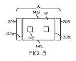
図2及び図3に示されるように、第1及び第2の縁部材201、203は、さらに、様々な技術によって除去されることができる。第2の縁部材の除去は、ガラス製造装置101でのガラスリボンの形成に起因する縁部材の厚みの不整合を除去するために望ましい場合がある。あるいは、類似の分離技術は、特定の用途に応じてより小さな複数枚のガラスシートへ分離されたガラスシートを分割するために使用されてもよい。図2及び図3には示されていないが、磁気レオロジー仕上げ装置145は、縁部材が除去されるステーションに設けられてもよい。例えば、磁気レオロジー仕上げ装置145は、図2に示されるように縁部材が除去される間に、第1及び第2の縁部141a、141bの一方又は両方を仕上げるために使用されてもよい。加えて又は代替的には、磁気レオロジー仕上げ装置145は、図3に示されるように、第2及び第3の縁部301a、301bの一方又は両方を仕上げるために使用されてもよい。 As shown in FIGS. 2 and 3, the first and
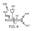
様々なガラス分離装置は、分離されたガラスシート141を残りの部分から第1及び第2の縁部材を分離するために、本開示の態様に従って使用できる。図2及び図4は1つだけのガラスの分離技術を示し、これは、分離されたガラスシート141の表面を加熱するように構成されたレーザー401と、分離されたガラスシート141の残りの部分から第1の縁部材201を分離する亀裂が伝播するように構成された液体冷却装置403とを含む第1分離装置205の使用を含むことができる。 Various glass separation devices can be used in accordance with aspects of the present disclosure to separate the separated
図2、図5及び図6は、分離経路に沿ってスコアライン209を作成できるスコアリング装置501を含む第2の分離装置207の他の例を示している。スコアラインの形成が一旦完了すると、ピボット部材601はスコアライン209の反対側上に当てられ、応力603が印加され、第2の縁部材203を、分離されたガラスシート141の残りの部分から離脱させることができる。 2, 5, and 6 show another example of the
図3に示されるように、第1及び第2の縁部材201、203が一旦除去されたとき、分離されたガラスシート141は第3の縁部301a及び第4の縁部301bを含み、ガラスリボン141の幅は第3の縁部301a及び第4の縁部301bの間にて画定される。これから、更なる例では、分離されたガラスリボン141の長さは第3及び第4の縁部301a、301bの間で画定され得ることが理解される。 As shown in FIG. 3, once the first and
移動アンビル機器(例えば、図1に示す分離装置151を参照)、第1分離装置205及び第2の分離装置207は、ガラスシートを分離するために使用され得る様々な可能な分離装置の単なる例である。使用される技術に関係なく、各縁部141a、141b、301a、301bは、ガラスシートの割れを受けやすい、望ましくない粗い/鋭い縁部分を含む場合がある。 Mobile anvil equipment (see eg separation device 151 shown in FIG. 1),
本開示の方法は、500μm以上の平均厚さの広い平均の厚さの範囲での材料のシート(例えば、ガラスリボン、分離されたガラスシート等を含むガラスシート)で使用できる。例えば、平均の厚さは、500μmを超える約2mmまでの範囲、例えば、約700μm〜約1.5mm、約900μm〜約1.2mm、約900μm〜約1.1mmである。 The methods of the present disclosure can be used with sheets of material (eg, glass sheets including glass ribbons, separated glass sheets, etc.) in a wide average thickness range with an average thickness of 500 μm or greater. For example, the average thickness ranges from greater than 500 μm to about 2 mm, such as from about 700 μm to about 1.5 mm, from about 900 μm to about 1.2 mm, from about 900 μm to about 1.1 mm.
望ましくない粗く鋭い縁部の除去は、脆く及び/又は比較的壊れやすい比較的薄いガラスシートに対しては複雑な作業になることがある。特定の性能特性を有する比較的薄いガラスシートへの除去の需要が高まっている。例えば、図4に示されるように、比較的薄い分離されたガラスシート141は、ガラスシートの第1の面405と第2の面407との間の平均厚さ「T」を有することができ、第1の面405と第2の面407との間の平均厚さは約500μm以下、例えば、約400μm以下、約300μm以下、約200μm以下、約100μm以下、約75μmである。一例においては、第1の面405と第2の面407との間の平均厚さ「T」は、約50μmから約500μmまでであり、例えば、約50μm〜約400μmや、約50μm〜約300μmや、約50μm〜約200μmや、約50μm〜約100μmや、約50μm〜約75μmや、約75μm〜約500μmや、約75μm〜約400μmや、約75μm〜約300μmや、約75μm〜約200μmや、約75μm〜約150μmや、約75μm〜約100μmや、約100μm〜約500μmや、約100μm〜約400μmや、約100μm〜約300μmや、約100μm〜約200μmである。薄い平均厚さ「T」を有するガラスシートを提供することは、性能特性を向上させるので、望ましい。 Undesirably rough and sharp edge removal can be a complex task for relatively thin glass sheets that are brittle and / or relatively fragile. There is an increasing demand for removal to relatively thin glass sheets with specific performance characteristics. For example, as shown in FIG. 4, a relatively thin
縁部141a、141b、301a、301bの仕上げステップは、磁気レオロジー仕上げ(MRF)技術を用いて縁部分を仕上げるステップを含むことができる。例えば、2011年5月20日に出願の米国特許出願第13/112,498号及び/又は2011年6月27日に出願の米国特許出願第13/169,499号に記載されたMRF装置及び/又は方法は、発明の態様に応じて開示に取り込まれる。2011年5月20日に出願された米国特許出願第13/112,498号及び第2011年6月27日に出願された米国特許出願第13/169,499号は、それぞれその全体が本明細書に参考として取り込まれる。 Finishing the
MRFは、ガラスシートを分離する際に生成される望ましくない粗く鋭い縁部等の損傷及び/又は欠陥を除去できる。MRFは、処理時間をも短縮し、及び/又は比較的薄いガラスシートの縁部分を仕上げる際に生じることがあるプロセスの複雑化を克服できる。例えば、MRFは比較的少ない材料を除去でき、所望仕上げの縁部輪郭を達成する。また、MRFは、比較的薄いガラスシートの比較的壊れやすい縁部を機械加工するために使用できる。さらに、MRFは、分離されたガラスシート141の平均厚さにかかわらず、処理時間を短縮するために使用可能である。 MRF can remove damage and / or defects such as unwanted rough and sharp edges that are created when separating glass sheets. MRF can also reduce processing time and / or overcome process complications that may occur when finishing the edge portion of a relatively thin glass sheet. For example, MRF can remove relatively little material and achieve a desired finished edge profile. MRF can also be used to machine relatively fragile edges of relatively thin glass sheets. Further, MRF can be used to reduce processing time regardless of the average thickness of the separated
MRFは、仕上げのために磁性流体(magnetorheological fluid)(以下、「MR流体」)と呼ばれる流体ベースの順応性ツールを使用している。MR流体は、液体ビヒクル中に懸濁したミクロンサイズの磁化可能粒子及びミクロンサイズ〜ナノサイズの研磨粒子を含むことができる。例えば、磁化可能粒子の大きさは、1μmから100μm以上の範囲、例えば、1μm〜150μm、例えば、5μm〜150μm、例えば、5μm〜100μm、例えば、5μm〜50μm、例えば、5μm〜25μm、例えば、10μm〜25μmの範囲内であってもよく、そして、研磨粒子の大きさは、15nm〜10μmの範囲内であってもよい。磁化可能粒子は、均一又は不均一な粒径分布と、同一又は異なる形状と、規則又は不規則的な形状とを有することができる。また、磁化可能粒子は、単一の磁化可能な材料又は磁化可能な異なる材料の組合せで作ることができる。磁化可能な材料の例としては、鉄、酸化鉄、窒化鉄、炭化鉄、カルボニル鉄、二酸化クロム、低炭素鋼、ケイ素鋼、ニッケル、コバルト、及びこれら先行する材料の組み合わせを含む。また、磁化可能な粒子は例えば、保護材料で又は保護材料内で被覆又はカプセル化されることができる。一実施形態において、保護材料は、化学的及び物理的に安定な液体ビヒクルであり、それは磁化可能な材料と化学的に反応しない材料である。適切な保護材料の例としては、ジルコニア、アルミナ、シリカ等が挙げられる。同様に、研磨粒子は、均一又は不均一な粒径分布と、同一又は異なる形状と、規則的又は不規則な形状とを有することができる。また、研磨粒子は、単一の非磁性材料又は異なる非磁性材料の組み合わせから作製され得る。研磨材の例としては、酸化セリウム、ダイヤモンド、炭化ケイ素、アルミナ、ジルコニア、及び前述の材料の組み合わせが挙げられる。他の研磨材料は、具体的にはこのリストに含まれていないが、表面を研磨するのに有用であることが知られていない研磨材料も使用できる。MR流体に含まれる液体ビヒクルは、水性又は非水性であってもよい。液体ビヒクルの例としては、鉱油、合成油、水、及びエチレングリコールが挙げられる。液体ビヒクルは、さらに磁化可能粒子、及び界面活性剤の腐食を抑制するために安定剤又は安定化剤を含んでもよい。 MRF uses a fluid-based compliant tool called magnetorheological fluid (hereinafter “MR fluid”) for finishing. The MR fluid can include micron sized magnetizable particles and micron to nano sized abrasive particles suspended in a liquid vehicle. For example, the size of the magnetizable particles ranges from 1 μm to 100 μm or more, such as 1 μm to 150 μm, such as 5 μm to 150 μm, such as 5 μm to 100 μm, such as 5 μm to 50 μm, such as 5 μm to 25 μm, such as 10 μm. It may be in the range of ˜25 μm, and the size of the abrasive particles may be in the range of 15 nm to 10 μm. The magnetizable particles can have a uniform or non-uniform particle size distribution, the same or different shapes, and regular or irregular shapes. Also, the magnetizable particles can be made of a single magnetizable material or a combination of different magnetizable materials. Examples of magnetizable materials include iron, iron oxide, iron nitride, iron carbide, carbonyl iron, chromium dioxide, low carbon steel, silicon steel, nickel, cobalt, and combinations of these preceding materials. Also, magnetizable particles can be coated or encapsulated, for example, with or within a protective material. In one embodiment, the protective material is a chemically and physically stable liquid vehicle that is a material that does not chemically react with the magnetizable material. Examples of suitable protective materials include zirconia, alumina, silica and the like. Similarly, abrasive particles can have a uniform or non-uniform particle size distribution, the same or different shapes, and regular or irregular shapes. Also, the abrasive particles can be made from a single non-magnetic material or a combination of different non-magnetic materials. Examples of abrasives include cerium oxide, diamond, silicon carbide, alumina, zirconia, and combinations of the aforementioned materials. Other abrasive materials are not specifically included in this list, but abrasive materials that are not known to be useful for polishing surfaces can also be used. The liquid vehicle contained in the MR fluid may be aqueous or non-aqueous. Examples of liquid vehicles include mineral oil, synthetic oil, water, and ethylene glycol. The liquid vehicle may further include magnetizable particles and stabilizers or stabilizers to inhibit corrosion of the surfactant.
別の実施形態では、仕上げの間にエッチングすることができるMR流体が準備される。エッチングMR流体は、エッチング剤を含む液体ビヒクル中に懸濁した磁化可能粒子と研磨粒子を含む。エッチング剤は、材料のシートの材料をエッチングすることが可能であり、材料のシートの材料に基づいて選択されるものである。液体ビヒクルはさらに、エッチング剤のための溶媒を含むことができる。液体ビヒクルはさらに、安定剤及び界面活性剤を含んでもよい。上述のように、液体ビヒクルは、前述のように水性又は非水性であってもよい。磁化可能粒子及び研磨粒子は、前述のように非エッチングMR流体のためである。上記のように磁化可能粒子は、保護材料で又は保護材料中で、例えば、被覆又はカプセル化されることができる。保護材料は、使用される場合、化学的に物理的に、液体ビヒクル中のエッチング剤及び他の物質の存在下で安定な材料である。保護材料は、磁化可能粒子と反応しない材料である。保護材料の適切な例は、ジルコニア及びシリカである。 In another embodiment, an MR fluid is provided that can be etched during finishing. The etching MR fluid includes magnetizable particles and abrasive particles suspended in a liquid vehicle containing an etchant. The etchant is capable of etching the material of the material sheet and is selected based on the material of the material sheet. The liquid vehicle can further include a solvent for the etchant. The liquid vehicle may further contain stabilizers and surfactants. As mentioned above, the liquid vehicle may be aqueous or non-aqueous as described above. The magnetizable particles and abrasive particles are for non-etched MR fluid as described above. As described above, the magnetizable particles can be coated or encapsulated with or in a protective material, for example. The protective material, when used, is a material that is chemically and physically stable in the presence of etchants and other substances in the liquid vehicle. The protective material is a material that does not react with the magnetizable particles. Suitable examples of protective materials are zirconia and silica.
一実施形態では、エッチングMR流体に含まれるエッチング剤は、5以下のpHを有する。一実施形態では、5以下のpHを有するエッチング剤は酸を含む。一実施形態では、エッチング剤が酸である。酸は、液体の形態で存在し得るか、適当な溶媒に溶解されてもよい。適切な酸の例としては、フッ化水素酸、硫酸が挙げられるがこれらに限定されない。液体ビヒクルは、例えば磁化可能粒子の腐食を抑制するために、安定剤、1種以上の安定化剤をさらに含んでもよい。液体ビヒクル中に使用される安定剤は酸の存在下、すなわち、より一般的にエッチング剤の存在下で、で安定であるべきである。 In one embodiment, the etchant included in the etching MR fluid has a pH of 5 or less. In one embodiment, the etchant having a pH of 5 or less comprises an acid. In one embodiment, the etchant is an acid. The acid may be present in liquid form or may be dissolved in a suitable solvent. Examples of suitable acids include, but are not limited to, hydrofluoric acid and sulfuric acid. The liquid vehicle may further include a stabilizer, one or more stabilizers, for example, to inhibit corrosion of the magnetizable particles. The stabilizer used in the liquid vehicle should be stable in the presence of acid, ie more generally in the presence of an etchant.
別の実施形態では、エッチングMR流体に含まれるエッチング剤は、pH10以上のpHを有する。一実施形態では、pH10以上のpHを有するエッチング剤は、アルカリ塩を含む。一実施形態ではエッチング剤はアルカリ塩である。かかるアルカリ塩の例としては、例えば、水酸化カリウム、水酸化ナトリウム等のアルカリ水酸化物を含むアルカリ水酸化物及び化合物が挙げられるが、これらに限定されない。アルカリ水酸化物を含有する洗剤は、例えば、液体ビヒクル中のアルカリ塩として使用可能である。液体ビヒクルは、界面活性剤及び洗剤に見られる他の材料等のアルカリ塩以外の他の材料を含んでもよい。 In another embodiment, the etchant included in the etching MR fluid has a pH of 10 or higher. In one embodiment, the etchant having a pH of 10 or higher includes an alkali salt. In one embodiment, the etchant is an alkali salt. Examples of such alkali salts include, but are not limited to, alkali hydroxides and compounds containing alkali hydroxides such as potassium hydroxide and sodium hydroxide. Detergents containing alkali hydroxides can be used, for example, as alkali salts in liquid vehicles. The liquid vehicle may contain other materials besides alkali salts, such as other materials found in surfactants and detergents.
図7は、本開示の態様に従ってMRFを実行するように構成された磁気レオロジー仕上げ装置145の側面概略図を示している。図示のように、MR流体はMRFリボン701の形態で支持体表面上に堆積される。典型的には、支持面は移動面であるが、支持面が固定面であってもよい。支持面は、様々な形状、例えば、球形、円筒形、又は平坦であってもよい。例示の目的のために、図7は、回転ホイール703上のMRFリボン701の側面図を示す。この場合、回転ホイール703の周囲表面705は、MRFリボン701の移動する円筒状の支持面を提供する。ノズル707は表面705のセグメントの一方端面にMRFリボン701を供給するために使用され、そして、ノズル709は表面705のセグメントの他方端面からMRFリボン701を収集するために使用される。MRF中、磁石711は、MRFリボン701に磁界を印加する。 FIG. 7 illustrates a side schematic view of a
印加された磁界は、磁化可能粒子に分極を誘導し、磁化可能粒子に流れを制限する鎖状構造や柱状構造を形成させる。これは、MRFリボン701の見かけの粘度を増加させ、液体状態から固体のような状態にMRFリボン701を変化させる。分離されたガラスシート141の縁部141a、141b、301a、301bは、固着したMRFリボン701と接触することによって仕上げられ、分離されたガラスシート141の縁部を固着したMRFリボン701に関して方向713に沿って並進移動する。縁部141a、141b、301a、301bとMRFリボン701との間の相対運動は、仕上げるべき縁部の全ての部分が固着したMRFリボン701と接触するようになされている。上述の範囲(例えば、約50μm〜約500μm)の比較的薄い平均厚さを有するガラスシートの場合、ガラスシートの第1の面405と第2の面407との間に延びる縁部141a、141b、301a、301bのセグメントのすべての部分は同時に仕上げられ、固着したMRFリボン701と接触できる。全体の縁部141a、141b、301a、301bそれ自体は、単一の磁気レオロジー仕上げステップ中に第1の面405と第2の面407との間に成形され得る。1つの特定の例では、単一の磁気レオロジー仕上げステップは、縁部の各々が固着したMRFリボン701上で仕上げられる単一の通過を含むことができる。例えば、図7に示されるように、第2の縁部141bの仕上げは、磁気レオロジー仕上げ装置145に相対する分離されたガラスシート141の1回の通過で実行されることができる。往復運動が必要でないように、ガラスシート141の各縁部141a、141b、301a、301bの仕上げは、縮小された処理時間で実行されることができる。 The applied magnetic field induces polarization in the magnetizable particles and causes the magnetizable particles to form a chain structure or a columnar structure that restricts the flow. This increases the apparent viscosity of the
一実施形態において、ガラスシート141の縁部141a、141b、301a、301bの1つ又は全ては、固着したMRFリボン701へそれぞれの縁部を浸漬することにより仕上げられることができる。仕上げプロセスはMRFを使用する単一の仕上げプロセスの項で既に説明しているが、複数のガラスシートは、単一の仕上げプロセスにて同時に研磨され得ることに留意すべきである。 In one embodiment, one or all of the
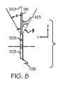
図8に示されるように、ガラスシートは、垂直軸に対して約+45度から−45度までの角度範囲内の所定配向での平面に沿って配置され得る。実際に図に示されるように、ガラスシート141は、縦軸801に平行な平面に沿って位置決めされる。更なる例ではガラスシートを、約45度の角度αと角度βとの間の任意の方向に配向させることができる。 As shown in FIG. 8, the glass sheets can be arranged along a plane with a predetermined orientation within an angular range of about +45 degrees to -45 degrees with respect to the vertical axis. As actually shown in the figure, the
MRFは、せん断によって仕上げられる表面からの材料を除去する。これは、機械的粉砕等の機械的プロセスに関連する破砕メカニズムとは対照的である。このメカニズムでは、MRFは、縁部の強度を低下させ得る縁部の新しい破砕部位を誘導することなく縁部から材料を除去する機会をもたらす。同時に、MRFは、縁部強度増加、すなわち第1の縁部強度から第2の縁部強度への増加をもたらす縁部から欠陥を除去する。また、流体ベースのMRFリボン701は、縁部分の形状に適合する能力を有し、例えば、縁部の湾曲又は輪郭の観点から、縁部のいかなる複雑さもなく、縁部の高品質仕上げの完了を導く。MRFは、いくつかのパラメータによって支配され、例えば、MR流体の粘度、移動する表面に供給されるMR流体の速度、移動表面の速度、磁場の強度、MRFリボンの高さ、MRFリボンに浸漬される縁部の深さ、及び材料が縁部から除去される速度によって支配される。 MRF removes material from surfaces that are finished by shear. This is in contrast to crushing mechanisms associated with mechanical processes such as mechanical grinding. In this mechanism, the MRF provides an opportunity to remove material from the edge without inducing a new fracture site at the edge that can reduce the strength of the edge. At the same time, the MRF removes defects from the edge that cause an edge strength increase, ie, an increase from the first edge strength to the second edge strength. The fluid-based
図9は、本開示の例示的な方法を示す第1の例示的フローチャートである。図9の様々な方法のすべては、第1の面と第2の面を有する材料のシートを準備する準備ステップ903での開始位置901で開始する。上述したように、一例においては、材料のシートは、ガラスリボン106等の第1の面405と第2の面407を有するガラスシートすなわち分離されたガラスシート141を含むことができる。本開示の方法は、500μm以上の平均厚さ等の平均厚さの広い範囲を有する材料のシート(例えば、ガラスリボン、分離されたガラスシート等からなるガラスシート)と一緒に使用できる。例えば、平均の厚さは500μm以上から約2mm、例えば、約700μm〜約1.5mmや、約900μm〜約1.2mmや、約900μm〜約1.1mmに設定することができる。更なる例において、本開示の方法では、約50μm〜約500μmの第1の面405と第2の面407との間の平均厚さ「T」、例えば、約50μm〜約300μmや、約75μm〜約200μmや、約75μm〜約150μmを有する材料のシートを使用できる。 FIG. 9 is a first exemplary flowchart illustrating an exemplary method of the present disclosure. All of the various methods of FIG. 9 begin at a starting
準備ステップ903は、製造プロセスにおける様々な相対的なタイミングで行われことができる。例えば、図1に示されるように、準備ステップ903は分離されたガラスシート141の形成の直後に実行されてもよい。別の例では、準備ステップ903は後の時に行われてもよい。例えば、分離されたガラスシート141は、シートがその後の処理のための準備ステップ903中に続けて設けられた別の場所に輸送されることができる。更なる例では、ガラスリボン106は、ストレージロール上に巻かれてもよい。このような状況では、提供するステップは、ストレージロール上にてガラスリボン106を巻取る前に実行され得る。かかる例では、リボンの縁部はストレージロールに巻かれる前にMRFで仕上げられてもよい。加えて又は代替的に、ガラスリボンの巻かれたものは、その後の所望の分離されたガラスシートへの分離のために別の場所に移送されることができる。かかる例では、準備ステップ903は、その後分離されたガラスシート141を処理するためにガラスリボンが巻き出されるように続けて実行され得る。 The preparation step 903 can be performed at various relative timings in the manufacturing process. For example, as shown in FIG. 1, the preparation step 903 may be performed immediately after the formation of the separated
矢印905に示されるように、方法は、準備ステップ903から、材料のシートを分離して縁部141a、141b、301a、301bを設ける分離ステップ907までのMRFで材料のシート縁部を仕上げる仕上げステップ919の前まで任意に実行され得る。必須ではないが、図9に示されるように、分離ステップ907は準備ステップ903の後に実行されてもよい。 As shown by
分離ステップ907は、多種多様な方法で実行されてもよい。例えば、分離は、機械的分離、レーザー分離、超音波分離又は他の分離技術によって行うことができる。図2及び図4に示される第1の分離装置205はレーザー分離装置の一例であるが、これは、縁部付近に機械的な欠陥を生成し得るものの、その後、レーザー401を用いて物品を熱的に横断させ、その後、水スプレー等の液体冷却装置403によって誘導される応力勾配を用いて物品を分離する。図2及び図5に示される第2の分離装置207は機械的分離装置の一例である。第2の分離装置207は、スコアリングホイール、ウォータージェット、又は研磨ウォータージェットを含むことができるコアリング装置501を含むことができる。そして、図6に示されるように、材料のシートはスコアラインに沿って分離されることができ、例えば、力603を印加してスコアラインに沿って縁部材を離脱させ得る。分離した後、単一の材料のシート又は複数の材料のシートが得られる。複数の材料のシートが生成される場合、材料のシートの1つ又は全てが処理されてもよい。
矢印909で示されるように、この方法は、その後、必要に応じて、分離ステップ907から材料のシートを縁取りする縁取りステップ911に進むことができる。実行された場合、材料のシートを縁取りする縁取りステップ911は、縁部から材料を除去することによって材料のシートの縁部の形状及び/又はテクスチャを変化させることができる。縁取りステップ911においては、任意のプロセス数で実行されることができる。例としては、砥粒加工、研磨材ジェット加工、化学エッチング、研磨、超音波、超音波研削、化学機械研磨が採用できるが、これらに限定されない。縁取りステップ911は、単一の材料除去プロセス又は一連の若しくはこれらの組み合わせの材料除去プロセスを含んでもよい。例えば、縁取りステップ911の一例は研削ステップの一連を含んでいてもよく、これにおいて、研削材のグリットサイズ等の研削パラメータは、各ステップの終わりに異なる縁取り結果を達成するために、一連のステップごとに変更される。 As indicated by
縁取りステップ911は、機械的粉砕、ラッピング、研磨の1つ以上とそれらの任意の組み合わせを含むことができる砥粒加工を含んでいてもよい。これらのプロセスは、それらが処理されている固体工具と表面との間の接触を伴う意味で、機械的である。研削、ラッピング及び研磨はそれぞれ、1つ又は複数のステップで達成できる。ラッピング研磨は遊離砥粒のプロセスであるが、研削は固定砥粒プロセスである。粉砕は、金属ホイールに結合した金属又はポリマー内に埋め込まれた研磨粒子を用いて達成できる。代替的に、研削は、研磨化合物からなる消耗ホイールを用いて達成できる。ラッピングでは、典型的には液体媒体中に懸濁された研磨粒子がラップと材料のシートの縁部との間に配置される。ラップ及び材料のシートの縁部との間の相対運動は、縁部から材料を摩耗させる。研磨中に、典型的には液体媒体中に懸濁された研磨粒子が、適合ソフトパッドやホイールを使用して材料のシートの縁部に当てられる。適合ソフトパッドやホイールは、ポリマー材料、例えば、ブチルゴム、シリコーン、ポリウレタン、天然ゴムから形成ができる。砥粒加工で使用される研磨剤は、例えば、アルミナ、炭化ケイ素、ダイヤモンド、立方晶窒化ホウ素、及び軽石から選択できる。 The edging
矢印913で示されるように、この方法は、その後、必要に応じて、縁取りステップ911から材料のシート(例えば、ガラスシート)の縁部分を化学的に処理して強化する化学強化ステップ915に進めることができる。一実施形態では、化学強化処理は、イオン交換プロセスである。イオン交換プロセスを実施するために、準備ステップ903で準備される物品は、イオン交換性材料で作られなければならない。典型的には、イオン交換材料は、Li+及び/又はNa+等の小さなアルカリイオンを有するアルカリ含有ガラスであり、該小さなアルカリイオンがイオン交換プロセス中に例えばK+のようなより大きなアルカリイオンと交換され得る。適切なイオン交換性ガラスの例は、米国特許出願の第11/888,213号、第12/277,573号、第12/392,577号、第12/393,241号及び第12/537,393号並びに米国仮特許出願の第61/235,767号及び第61/235,762号(これらは全てコーニング社に譲渡)に記載され、それらの内容は参照により本明細書に組み込まれる。これらのガラスは、比較的低い温度で少なくとも30μmの深さまでイオン交換されることができる。As indicated by
イオン交換処理は、例えば、米国特許第5,674,790号(アラウージョ、ロジャーJ.)に記載されている。そのプロセスは、典型的には、ガラスの転移温度を超えない高温度範囲で実行される。プロセスは、ガラス中のホストアルカリイオンよりも大きいイオンを有するアルカリ塩(通常は硝酸塩)を含む溶融浴中にガラスを浸漬することにより行われる。ホストアルカリイオンが大きいアルカリイオンと交換される。例えば、Na+を含むガラスは、溶融硝酸カリウム(KNO3)の浴に浸漬されてもよい。溶融浴中に存在する大きいK+はガラス中の小さいNa+に置き換えられる。小さなアルカリイオンによって以前に占有された部位における大きいアルカリイオンの存在は、ガラスの表面又は近傍の圧縮応力とガラス内部の張力とを生成する。ガラスは、溶融浴から取り出され、イオン交換プロセスの後に冷却される。イオン交換の深さ、すなわち、大きいアルカリイオンがガラスへの侵入する侵入深さは、例えば20μmから300μmのオーダーであり、典型的には40μm〜300μmであり、侵入深さはガラス組成及び浸漬時間によって制御される。The ion exchange process is described, for example, in US Pat. No. 5,674,790 (Araujo, Roger J.). The process is typically carried out in a high temperature range that does not exceed the glass transition temperature. The process is performed by immersing the glass in a molten bath containing an alkali salt (usually nitrate) having ions larger than the host alkali ions in the glass. Host alkali ions are exchanged for large alkali ions. For example, glass containing Na+ may be immersed in a bath of molten potassium nitrate (KNO3 ). Large K+ present in the molten bath is replaced by small Na+ in the glass. The presence of large alkali ions at sites previously occupied by small alkali ions creates compressive stresses in and near the glass surface and tension within the glass. The glass is removed from the molten bath and cooled after the ion exchange process. The depth of ion exchange, that is, the penetration depth at which large alkali ions penetrate into the glass is, for example, on the order of 20 μm to 300 μm, typically 40 μm to 300 μm. The penetration depth depends on the glass composition and immersion time. Controlled by.
矢印917で示されるように、この方法は、その後、材料のシート(例えば、ガラスシート)の縁部の化学強化ステップ915から、必要に応じて、磁気レオロジー仕上げ(MRF)によるシートの縁部分の仕上げステップ919に進めて実行されことができる。例えば、図8に示されるように、分離されたガラスシート141は、各縁部141a、141b、301a、301bに対して、磁気レオロジー仕上げ装置145に渡る分離されたガラスシート141の1回の通過中に、方向713に沿って移動させられ得る。 As indicated by
図8に示されるように、準備ステップ903では、所定の向きの平面に沿って材料のシートを配置することができ、前記所定の向きの平面は、重力の方向に沿って延びる垂直軸801に対して約+45度〜約−45度の角度範囲内に配置されるようになっており、各α及びβの角度は45度である。図8に示す例では、分離されたガラスシート141は、垂直軸801と分離されたガラスシート141の面との間の角度が0度であるような垂直軸801を含む平面に沿って垂直に配置されている。更なる例では、材料のシートの所定配向は、MRFで材料のシートの縁部を仕上げ加工する仕上げステップ919中に維持されることができる。 As shown in FIG. 8, in a preparation step 903, a sheet of material can be placed along a plane of predetermined orientation, the plane of predetermined orientation being on a vertical axis 801 extending along the direction of gravity. On the other hand, it is arranged within an angle range of about +45 degrees to about -45 degrees, and the angles of each α and β are 45 degrees. In the example shown in FIG. 8, the separated
図9のいくつかの例に示されるように、分離、縁取り及び/又は化学強化の様々なステップ907、911、915は、任意の順序で実行でき、そして、1つ以上のステップを省略してもよい。例えば、矢印921に示されるように、方法は、準備ステップ903から縁取りステップ911へ進んでもよく、これにより、分離ステップ907を省略できる。または、矢印923に示されるように、方法は、準備ステップ903から、材料のシート(例えば、ガラスシート)の縁部を強化する化学強化ステップ915へ進んでもよく、これにより、分離ステップ907及び縁取りステップ911を省略できる。またさらに、矢印925に示されるように、方法は、準備ステップ903から、材料のシートの縁部を仕上げる仕上げステップ919へ直接進んでもよく、これにより、分離ステップ907、縁取りステップ911及び化学強化ステップ915を省略できる。このように、本方法は、少なくとも準備ステップ903とMRFで材料のシートの縁部を仕上げる仕上げステップ919とから本質的に構成される。 As shown in some examples of FIG. 9, the
さらに図9に示されるように、分離ステップ907を実行した後、もし設けた場合、方法は、縁取りステップ911及び化学強化ステップ915の一方又は両方を代替的に省略できる。矢印927によって示されるように、例えば、本方法は分離ステップ907から化学強化ステップ915に進んでもよく、それによって縁取りステップ911を省略できる。矢印929で示されるように、別の例では、方法は、分離ステップ907からMRFによるシート材料の縁部の仕上げステップ919に進んでもよく、これにより、縁取りステップ911及び化学強化ステップ915の両方を省略できる。 As further shown in FIG. 9, after performing the
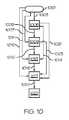
図10は、本開示の更なる例示的な方法を示す第2の例示的フローチャートを示す。図示のように、本方法は、開始位置1001から始まり、そして様々な経路に進むことができる。図10のいくつかの例や以下で説明するように、分離、縁取り及び/又は化学強化の様々なステップ1005、1009、1013は、任意の順序で実行でき、そして、1つ以上のステップを省略してもよい。 FIG. 10 shows a second exemplary flowchart illustrating a further exemplary method of the present disclosure. As shown, the method can begin at a
例えば、矢印1003に示されるように、方法は、開始位置1001から分離ステップ1005へ続けてもよい。あるいは、矢印1007に示されるように、方法は、開始位置1001から縁取りステップ1009へ続けてもよく、これにより、分離ステップ1005を省略できる。さらに、矢印1011に示されるように、方法は、開始位置1001から化学強化ステップ1013へ続けてもよく、これにより、分離ステップ1005及び縁取りステップ1009を省略できる。別の例において、矢印1015に示されるように、方法は、開始位置1001から準備ステップ1017へ続けてもよく、これにより、分離ステップ1005、縁取りステップ1009及び化学強化ステップ1013の全てを省略できる。更なる例では、矢印1008、1012、1016に示されるように、方法は、分離ステップ1005から、順次、縁取りステップ1009へ、化学強化ステップ1013へ、準備ステップ1017へ進んでもよい。このように、分離ステップ、縁取りステップ及び/又は化学強化ステップのいずれも、準備ステップの前に実行され得る。矢印1025によって示されるように、方法は、準備ステップ1017から、MRFでシート材料の縁部を仕上げするステップ1027へ直接進むことができる。 For example, as indicated by
さらに、分離ステップ1005は縁取りステップ1009及び/又は化学強化ステップ1013なしで実行できる。実際、矢印1019によって示されるように、この方法は、分離ステップ1005から化学強化ステップ1013に進んでもよく、それによって縁取りステップ1009を省略できる。さらに、矢印1021によって示されるように、方法は、分離ステップ1005から準備ステップ1017に進んでもよく、それによって、縁取りステップ1009と化学強化ステップ1013を省略できる。 Further, the separation step 1005 can be performed without the fringing step 1009 and / or the
さらに、縁取りステップ1009は、化学強化ステップ1013なしで実行できる。矢印1023によって示されるように、例えば、本方法は、縁取りステップ1009から準備ステップ1017に直接進んでもよく、それによって、化学強化ステップ1013を省略できる。 Further, the edging step 1009 can be performed without the
図9に示されるように、分離ステップ907、縁取りステップ911及び/又は化学強化ステップ915の一部又は全部は、準備ステップ903の後に実行され得る。更なる例では、ステップ907、911、915の一部又はすべては準備ステップの前に実行され得る。例えば、図10は、分離ステップ1005、縁取りステップ1009及び/又は化学強化ステップ1013のすべてが準備ステップ1017の前に実行され得ることを示す。図示していないが、更なる実施例においては、ステップ1005、1009、1013の任意の組み合わせは、準備ステップの前及び/又は後に実行されることができる。例えば、分離ステップ、縁取りステップ及び化学強化ステップのうちの1つ又は2つは、準備ステップの前に実行され、残りのステップ(複数可)が準備ステップの後に実行されてもよい。 As shown in FIG. 9, some or all of the
一例においては、ガラスシート(例えば、ガラスリボン、分離されたガラスシート等)の縁部141a、141b、301a、301bを仕上げる方法が提供される。ガラスシート141は第1の面405及び第2の面407を含むことができる。縁部は第1の面と第2の面との間のガラスシートの周縁部に沿って延びることができる。この方法は、MRFによりガラスシートの縁部141a、141b、301a、301bを仕上げる単一ステップ919、1027から本質的に構成されることができる。そのような例では、全体の縁部分は、単一MRFステップ中に、第1の面405及び第2の面407の間に成形されてもよい。 In one example, a method is provided for finishing
別の例では、ガラスシート(例えば、ガラスリボン、分離されたガラスシート等)の縁部141a、141b、301a、301bを仕上げる方法は、準備ステップ903、1017とMRFによりガラスシートの縁部を仕上げる仕上げステップ919、1027とから本質的に構成され得る。例えば、準備ステップ903、1017では、第1の面405と第2の面407を有するガラスシートを用意することができ、そこで、ガラスシートの第1の面と第2の面との間の平均厚さが約50〜約500μmである。一例では、ステップ919、1027において、全体の縁部分は、単一の磁気レオロジー仕上げステップ中に、第1の面と第2の面との間に成形される。 In another example, the method of finishing the
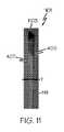
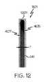
図11は、第1の面405及び407は、縁部分のMRFより先でガラスシートを分離した後に観察された、第1の面405及び第2の面407の間に約100μmの厚さ「T」を有する分離されたガラスシート141の縁部1101の拡大図を示す。図示のように、縁部1101は、ガラスシートの割れを受けやすい望ましくない鋭い縁部1103を含む。図12は、開示によって記載されたように6分間のMRFステップの後に見た縁部1101の同じく観測された拡大図を示す。図示のように、望ましくない鋭い縁部1103が除去され、滑らかな表面1201残され、これは第1の面405から第2の面407への全縁部に沿って滑らかな形状を有している。実際、滑らかな表面1201は、比較的少ない材料が除去され第1の面405から第2の面407に延びる丸みを帯びた凸形状を有している。 FIG. 11 shows that the
図12に示めされる薄いガラス(例えば100μm)の丸みを帯びた縁部輪郭は、軽量で携帯性のある薄いガラスを含む様々な製品の製造を容易にすることができる。MRFを含む仕上げステップを使用することで、レーザー分離や機械的分離される薄いガラスのための単一のステップ形状の縁部を提供することができる。仕上げステップとしてMRFを使用することは薄いガラスに対して一意に有益であり得る。なぜならば、図11及び図12からわずかに異なる長さを比較することによって、縁部から低堆積の除去が実証されているからである。このことは、合理的なサイクル時間を達成できる。 The rounded edge profile of thin glass (eg, 100 μm) shown in FIG. 12 can facilitate the manufacture of a variety of products including thin glass that is lightweight and portable. Using a finishing step that includes MRF can provide a single step-shaped edge for thin glass that is laser or mechanically separated. Using MRF as a finishing step can be uniquely beneficial for thin glass. This is because removal of low deposits from the edges has been demonstrated by comparing slightly different lengths from FIGS. This can achieve a reasonable cycle time.
また、様々な修正及び変更が本発明の精神及び特許請求される範囲から逸脱することなくなされ得ることは、当業者には明らかであろう。 It will be apparent to those skilled in the art that various modifications and variations can be made without departing from the spirit of the invention and the scope of the claims.
Claims (20)
Translated fromJapanese第1の面及び第2の面を有する材料のシートであって、前記材料のシートの前記第1の面と前記第2の面との間の平均厚さが約50μm〜約500μmである前記材料のシートを準備するステップ(I)と、
前記材料のシートの縁部を磁気レオロジー仕上げで仕上げるステップ(II)と、を含む方法。A method of finishing a sheet of material,
A sheet of material having a first surface and a second surface, wherein the average thickness between the first surface and the second surface of the sheet of material is about 50 μm to about 500 μm. Preparing a sheet of material (I);
Finishing the edges of the sheet of material with a magnetorheological finish (II).
前記縁部の全体が単一の磁気レオロジー仕上げステップ中に前記第1の面と前記第2の面との間に成形されるように、本質的に単一の磁気レオロジー仕上げにより前記ガラスシートの前記縁部を仕上げるステップから成る方法。A method of finishing the edge, wherein an edge of a glass sheet having a first surface and a second surface extends along a peripheral edge of the glass sheet between the first surface and the second surface. There,
The glass sheet essentially has a single magnetorheological finish so that the entire edge is formed between the first and second surfaces during a single magnetorheological finishing step. A method comprising the step of finishing said edge.
第1の面及び第2の面を有するガラスシートであって、前記ガラスシートの前記第1の面と前記第2の面との間の平均厚さが約50μm〜約500μmである前記ガラスシートを準備するステップ(I)と、
前記ガラスシートの縁部を磁気レオロジー仕上げで仕上げるステップ(II)と、から本質的に成る方法。A method of finishing the edge of a glass sheet,
A glass sheet having a first surface and a second surface, wherein an average thickness between the first surface and the second surface of the glass sheet is about 50 μm to about 500 μm. Preparing step (I);
Finishing the edge of said glass sheet with a magnetorheological finish (II).
Applications Claiming Priority (5)
| Application Number | Priority Date | Filing Date | Title |
|---|---|---|---|
| US201261604863P | 2012-02-29 | 2012-02-29 | |
| US61/604,863 | 2012-02-29 | ||
| US13/721,557US20130225049A1 (en) | 2012-02-29 | 2012-12-20 | Methods of Finishing a Sheet of Material With Magnetorheological Finishing |
| US13/721,557 | 2012-12-20 | ||
| PCT/US2013/028129WO2013130688A1 (en) | 2012-02-29 | 2013-02-28 | Methods of finishing a sheet of material with magnetorheological finishing |
Publications (1)
| Publication Number | Publication Date |
|---|---|
| JP2015513471Atrue JP2015513471A (en) | 2015-05-14 |
Family
ID=49003358
Family Applications (1)
| Application Number | Title | Priority Date | Filing Date |
|---|---|---|---|
| JP2014560006APendingJP2015513471A (en) | 2012-02-29 | 2013-02-28 | How to finish a sheet of material with a magnetorheological finish |
Country Status (7)
| Country | Link |
|---|---|
| US (1) | US20130225049A1 (en) |
| EP (1) | EP2819809A1 (en) |
| JP (1) | JP2015513471A (en) |
| KR (1) | KR20140136447A (en) |
| CN (1) | CN104136167A (en) |
| TW (1) | TW201347943A (en) |
| WO (1) | WO2013130688A1 (en) |
Families Citing this family (6)
| Publication number | Priority date | Publication date | Assignee | Title |
|---|---|---|---|---|
| US20130133366A1 (en)* | 2011-11-28 | 2013-05-30 | Gregory Scott Glaesemann | Methods of Improving Strength of Glass Articles |
| US9463548B2 (en) | 2015-03-05 | 2016-10-11 | Hamilton Sundstrand Corporation | Method and system for finishing component using abrasive media |
| US10710207B2 (en)* | 2015-08-14 | 2020-07-14 | The Texas A&M University System | Method and apparatus for performing targeted polishing via manipulation of magnetic-abrasive fluid |
| CN110170887B (en)* | 2019-06-19 | 2023-11-14 | 河北工业大学 | Laser and magnetorheological fluid coupling polishing device |
| CN111230720B (en)* | 2020-04-07 | 2020-11-13 | 台州学院 | A magnetorheological polishing knife |
| CN111745496B (en)* | 2020-07-20 | 2024-12-20 | 清远市尚泰超硬工具有限公司 | A knife head grinding machine |
Family Cites Families (10)
| Publication number | Priority date | Publication date | Assignee | Title |
|---|---|---|---|---|
| US5795212A (en)* | 1995-10-16 | 1998-08-18 | Byelocorp Scientific, Inc. | Deterministic magnetorheological finishing |
| JP3119358B1 (en)* | 1999-10-18 | 2000-12-18 | 株式会社石井表記 | Edge polishing equipment for semiconductor wafers |
| WO2002049082A2 (en)* | 2000-12-11 | 2002-06-20 | Rodel Holdings, Inc. | Process of shaping a semiconductor substrate and/or a lithographic mask |
| US7514016B2 (en)* | 2004-07-30 | 2009-04-07 | Hitachi Global Storage Technologies Netherlands, Bv | Methodology of chemical mechanical nanogrinding for ultra precision finishing of workpieces |
| JP5074745B2 (en)* | 2006-11-15 | 2012-11-14 | 古河電気工業株式会社 | Manufacturing method of glass substrate |
| KR101333479B1 (en)* | 2009-03-06 | 2013-11-26 | 퀘드 테크놀러지즈 인터내셔날, 인크. | System for magnetorheological finishing of a substrate |
| US9555516B2 (en)* | 2009-07-24 | 2017-01-31 | Corning Incorporated | Method for processing an edge of a glass plate |
| US8974268B2 (en)* | 2010-06-25 | 2015-03-10 | Corning Incorporated | Method of preparing an edge-strengthened article |
| US9102030B2 (en)* | 2010-07-09 | 2015-08-11 | Corning Incorporated | Edge finishing apparatus |
| US8986072B2 (en)* | 2011-05-26 | 2015-03-24 | Corning Incorporated | Methods of finishing an edge of a glass sheet |
- 2012
- 2012-12-20USUS13/721,557patent/US20130225049A1/ennot_activeAbandoned
- 2013
- 2013-02-26TWTW102106724Apatent/TW201347943A/enunknown
- 2013-02-28WOPCT/US2013/028129patent/WO2013130688A1/enactiveApplication Filing
- 2013-02-28JPJP2014560006Apatent/JP2015513471A/enactivePending
- 2013-02-28CNCN201380011521.0Apatent/CN104136167A/enactivePending
- 2013-02-28KRKR1020147025582Apatent/KR20140136447A/ennot_activeWithdrawn
- 2013-02-28EPEP13754803.8Apatent/EP2819809A1/ennot_activeWithdrawn
Also Published As
| Publication number | Publication date |
|---|---|
| CN104136167A (en) | 2014-11-05 |
| US20130225049A1 (en) | 2013-08-29 |
| WO2013130688A1 (en) | 2013-09-06 |
| TW201347943A (en) | 2013-12-01 |
| KR20140136447A (en) | 2014-11-28 |
| EP2819809A1 (en) | 2015-01-07 |
Similar Documents
| Publication | Publication Date | Title |
|---|---|---|
| US8974268B2 (en) | Method of preparing an edge-strengthened article | |
| JP2015513471A (en) | How to finish a sheet of material with a magnetorheological finish | |
| EP2958864B1 (en) | Method of manufacturing a thin glass pane | |
| US20190358765A1 (en) | Methods for strengthening edges of laminated glass articles and laminated glass articles formed therefrom | |
| KR20120103699A (en) | Separation of glass sheets from a laser-scored curved glass ribbon | |
| JP2009099249A (en) | Manufacturing method of glass substrate for magnetic disk and manufacturing method of magnetic disk | |
| JP5499159B2 (en) | Manufacturing method of glass blank, manufacturing method of magnetic recording medium substrate, and manufacturing method of magnetic recording medium | |
| JP6148345B2 (en) | Manufacturing method of non-magnetic substrate | |
| TWI637811B (en) | Method for manufacturing glass substrate and magnetic fluid for glass substrate honing | |
| JP5330307B2 (en) | Manufacturing method of glass blank, manufacturing method of magnetic recording medium substrate, and manufacturing method of magnetic recording medium | |
| JP6208565B2 (en) | Polishing carrier manufacturing method, magnetic disk substrate manufacturing method, and magnetic disk glass substrate manufacturing method | |
| JP5427673B2 (en) | Manufacturing method of glass blank, manufacturing method of magnetic recording medium substrate, and manufacturing method of magnetic recording medium | |
| US20100247976A1 (en) | Glass substrate for a magnetic disk and method of manufacturing the same | |
| JP6353524B2 (en) | Substrate manufacturing method | |
| JP2014065650A (en) | Method of producing glass substrate for magnetic disk and method of producing glass blank for magnetic disk | |
| JP6088534B2 (en) | Method for manufacturing glass substrate for information recording medium, method for manufacturing information recording medium, and disk-shaped glass substrate | |
| JP2013030268A5 (en) | ||
| JP2010257563A (en) | Glass substrate for magnetic disk and manufacturing method of the same |