JP2015512723A - Tissue thickness compensator - Google Patents
Tissue thickness compensatorDownload PDFInfo
- Publication number
- JP2015512723A JP2015512723AJP2015503502AJP2015503502AJP2015512723AJP 2015512723 AJP2015512723 AJP 2015512723AJP 2015503502 AJP2015503502 AJP 2015503502AJP 2015503502 AJP2015503502 AJP 2015503502AJP 2015512723 AJP2015512723 AJP 2015512723A
- Authority
- JP
- Japan
- Prior art keywords
- staple
- staple cartridge
- tissue thickness
- thickness compensator
- cartridge
- Prior art date
- Legal status (The legal status is an assumption and is not a legal conclusion. Google has not performed a legal analysis and makes no representation as to the accuracy of the status listed.)
- Granted
Links
Images


Classifications
- A—HUMAN NECESSITIES
- A61—MEDICAL OR VETERINARY SCIENCE; HYGIENE
- A61B—DIAGNOSIS; SURGERY; IDENTIFICATION
- A61B17/00—Surgical instruments, devices or methods
- A61B17/10—Surgical instruments, devices or methods for applying or removing wound clamps, e.g. containing only one clamp or staple; Wound clamp magazines
- A61B17/105—Wound clamp magazines
- A—HUMAN NECESSITIES
- A61—MEDICAL OR VETERINARY SCIENCE; HYGIENE
- A61B—DIAGNOSIS; SURGERY; IDENTIFICATION
- A61B17/00—Surgical instruments, devices or methods
- A61B17/064—Surgical staples, i.e. penetrating the tissue
- A61B17/0644—Surgical staples, i.e. penetrating the tissue penetrating the tissue, deformable to closed position
- A—HUMAN NECESSITIES
- A61—MEDICAL OR VETERINARY SCIENCE; HYGIENE
- A61B—DIAGNOSIS; SURGERY; IDENTIFICATION
- A61B17/00—Surgical instruments, devices or methods
- A61B17/064—Surgical staples, i.e. penetrating the tissue
- A61B17/0643—Surgical staples, i.e. penetrating the tissue with separate closing member, e.g. for interlocking with staple
- A—HUMAN NECESSITIES
- A61—MEDICAL OR VETERINARY SCIENCE; HYGIENE
- A61B—DIAGNOSIS; SURGERY; IDENTIFICATION
- A61B17/00—Surgical instruments, devices or methods
- A61B17/068—Surgical staplers, e.g. containing multiple staples or clamps
- A—HUMAN NECESSITIES
- A61—MEDICAL OR VETERINARY SCIENCE; HYGIENE
- A61B—DIAGNOSIS; SURGERY; IDENTIFICATION
- A61B17/00—Surgical instruments, devices or methods
- A61B17/068—Surgical staplers, e.g. containing multiple staples or clamps
- A61B17/0682—Surgical staplers, e.g. containing multiple staples or clamps for applying U-shaped staples or clamps, e.g. without a forming anvil
- A61B17/0686—Surgical staplers, e.g. containing multiple staples or clamps for applying U-shaped staples or clamps, e.g. without a forming anvil having a forming anvil staying below the tissue during stapling
- A—HUMAN NECESSITIES
- A61—MEDICAL OR VETERINARY SCIENCE; HYGIENE
- A61B—DIAGNOSIS; SURGERY; IDENTIFICATION
- A61B17/00—Surgical instruments, devices or methods
- A61B17/068—Surgical staplers, e.g. containing multiple staples or clamps
- A61B17/072—Surgical staplers, e.g. containing multiple staples or clamps for applying a row of staples in a single action, e.g. the staples being applied simultaneously
- A61B17/07207—Surgical staplers, e.g. containing multiple staples or clamps for applying a row of staples in a single action, e.g. the staples being applied simultaneously the staples being applied sequentially
- A—HUMAN NECESSITIES
- A61—MEDICAL OR VETERINARY SCIENCE; HYGIENE
- A61B—DIAGNOSIS; SURGERY; IDENTIFICATION
- A61B17/00—Surgical instruments, devices or methods
- A61B17/068—Surgical staplers, e.g. containing multiple staples or clamps
- A61B17/072—Surgical staplers, e.g. containing multiple staples or clamps for applying a row of staples in a single action, e.g. the staples being applied simultaneously
- A61B17/07292—Reinforcements for staple line, e.g. pledgets
- A—HUMAN NECESSITIES
- A61—MEDICAL OR VETERINARY SCIENCE; HYGIENE
- A61B—DIAGNOSIS; SURGERY; IDENTIFICATION
- A61B17/00—Surgical instruments, devices or methods
- A61B17/11—Surgical instruments, devices or methods for performing anastomosis; Buttons for anastomosis
- A61B17/115—Staplers for performing anastomosis, e.g. in a single operation
- A61B17/1155—Circular staplers comprising a plurality of staples
- A—HUMAN NECESSITIES
- A61—MEDICAL OR VETERINARY SCIENCE; HYGIENE
- A61B—DIAGNOSIS; SURGERY; IDENTIFICATION
- A61B17/00—Surgical instruments, devices or methods
- A61B17/28—Surgical forceps
- A61B17/29—Forceps for use in minimally invasive surgery
- A61B17/2909—Handles
- A—HUMAN NECESSITIES
- A61—MEDICAL OR VETERINARY SCIENCE; HYGIENE
- A61B—DIAGNOSIS; SURGERY; IDENTIFICATION
- A61B17/00—Surgical instruments, devices or methods
- A61B17/00491—Surgical glue applicators
- A—HUMAN NECESSITIES
- A61—MEDICAL OR VETERINARY SCIENCE; HYGIENE
- A61B—DIAGNOSIS; SURGERY; IDENTIFICATION
- A61B17/00—Surgical instruments, devices or methods
- A61B2017/00004—(bio)absorbable, (bio)resorbable or resorptive
- A—HUMAN NECESSITIES
- A61—MEDICAL OR VETERINARY SCIENCE; HYGIENE
- A61B—DIAGNOSIS; SURGERY; IDENTIFICATION
- A61B17/00—Surgical instruments, devices or methods
- A61B2017/00526—Methods of manufacturing
- A—HUMAN NECESSITIES
- A61—MEDICAL OR VETERINARY SCIENCE; HYGIENE
- A61B—DIAGNOSIS; SURGERY; IDENTIFICATION
- A61B17/00—Surgical instruments, devices or methods
- A61B2017/00526—Methods of manufacturing
- A61B2017/0053—Loading magazines or sutures into applying tools
- A—HUMAN NECESSITIES
- A61—MEDICAL OR VETERINARY SCIENCE; HYGIENE
- A61B—DIAGNOSIS; SURGERY; IDENTIFICATION
- A61B17/00—Surgical instruments, devices or methods
- A61B2017/00743—Type of operation; Specification of treatment sites
- A61B2017/00818—Treatment of the gastro-intestinal system
- A—HUMAN NECESSITIES
- A61—MEDICAL OR VETERINARY SCIENCE; HYGIENE
- A61B—DIAGNOSIS; SURGERY; IDENTIFICATION
- A61B17/00—Surgical instruments, devices or methods
- A61B2017/00831—Material properties
- A61B2017/00889—Material properties antimicrobial, disinfectant
- A—HUMAN NECESSITIES
- A61—MEDICAL OR VETERINARY SCIENCE; HYGIENE
- A61B—DIAGNOSIS; SURGERY; IDENTIFICATION
- A61B17/00—Surgical instruments, devices or methods
- A61B2017/00831—Material properties
- A61B2017/00951—Material properties adhesive
- A—HUMAN NECESSITIES
- A61—MEDICAL OR VETERINARY SCIENCE; HYGIENE
- A61B—DIAGNOSIS; SURGERY; IDENTIFICATION
- A61B17/00—Surgical instruments, devices or methods
- A61B17/064—Surgical staples, i.e. penetrating the tissue
- A61B2017/0641—Surgical staples, i.e. penetrating the tissue having at least three legs as part of one single body
- A—HUMAN NECESSITIES
- A61—MEDICAL OR VETERINARY SCIENCE; HYGIENE
- A61B—DIAGNOSIS; SURGERY; IDENTIFICATION
- A61B17/00—Surgical instruments, devices or methods
- A61B17/068—Surgical staplers, e.g. containing multiple staples or clamps
- A61B2017/0688—Packages or dispensers for surgical staplers
- A—HUMAN NECESSITIES
- A61—MEDICAL OR VETERINARY SCIENCE; HYGIENE
- A61B—DIAGNOSIS; SURGERY; IDENTIFICATION
- A61B17/00—Surgical instruments, devices or methods
- A61B17/068—Surgical staplers, e.g. containing multiple staples or clamps
- A61B17/072—Surgical staplers, e.g. containing multiple staples or clamps for applying a row of staples in a single action, e.g. the staples being applied simultaneously
- A61B2017/07214—Stapler heads
- A61B2017/07228—Arrangement of the staples
- A—HUMAN NECESSITIES
- A61—MEDICAL OR VETERINARY SCIENCE; HYGIENE
- A61B—DIAGNOSIS; SURGERY; IDENTIFICATION
- A61B17/00—Surgical instruments, devices or methods
- A61B17/068—Surgical staplers, e.g. containing multiple staples or clamps
- A61B17/072—Surgical staplers, e.g. containing multiple staples or clamps for applying a row of staples in a single action, e.g. the staples being applied simultaneously
- A61B2017/07214—Stapler heads
- A61B2017/07235—Stapler heads containing different staples, e.g. staples of different shapes, sizes or materials
- A—HUMAN NECESSITIES
- A61—MEDICAL OR VETERINARY SCIENCE; HYGIENE
- A61B—DIAGNOSIS; SURGERY; IDENTIFICATION
- A61B17/00—Surgical instruments, devices or methods
- A61B17/068—Surgical staplers, e.g. containing multiple staples or clamps
- A61B17/072—Surgical staplers, e.g. containing multiple staples or clamps for applying a row of staples in a single action, e.g. the staples being applied simultaneously
- A61B2017/07214—Stapler heads
- A61B2017/07242—Stapler heads achieving different staple heights during the same shot, e.g. using an anvil anvil having different heights or staples of different sizes
- A—HUMAN NECESSITIES
- A61—MEDICAL OR VETERINARY SCIENCE; HYGIENE
- A61B—DIAGNOSIS; SURGERY; IDENTIFICATION
- A61B17/00—Surgical instruments, devices or methods
- A61B17/068—Surgical staplers, e.g. containing multiple staples or clamps
- A61B17/072—Surgical staplers, e.g. containing multiple staples or clamps for applying a row of staples in a single action, e.g. the staples being applied simultaneously
- A61B2017/07214—Stapler heads
- A61B2017/07257—Stapler heads characterised by its anvil
- A61B2017/07264—Stapler heads characterised by its anvil characterised by its staple forming cavities, e.g. geometry or material
- A—HUMAN NECESSITIES
- A61—MEDICAL OR VETERINARY SCIENCE; HYGIENE
- A61B—DIAGNOSIS; SURGERY; IDENTIFICATION
- A61B17/00—Surgical instruments, devices or methods
- A61B17/068—Surgical staplers, e.g. containing multiple staples or clamps
- A61B17/072—Surgical staplers, e.g. containing multiple staples or clamps for applying a row of staples in a single action, e.g. the staples being applied simultaneously
- A61B2017/07214—Stapler heads
- A61B2017/07271—Stapler heads characterised by its cartridge
- A—HUMAN NECESSITIES
- A61—MEDICAL OR VETERINARY SCIENCE; HYGIENE
- A61B—DIAGNOSIS; SURGERY; IDENTIFICATION
- A61B17/00—Surgical instruments, devices or methods
- A61B17/068—Surgical staplers, e.g. containing multiple staples or clamps
- A61B17/072—Surgical staplers, e.g. containing multiple staples or clamps for applying a row of staples in a single action, e.g. the staples being applied simultaneously
- A61B2017/07214—Stapler heads
- A61B2017/07278—Stapler heads characterised by its sled or its staple holder
- A—HUMAN NECESSITIES
- A61—MEDICAL OR VETERINARY SCIENCE; HYGIENE
- A61B—DIAGNOSIS; SURGERY; IDENTIFICATION
- A61B17/00—Surgical instruments, devices or methods
- A61B17/28—Surgical forceps
- A61B17/29—Forceps for use in minimally invasive surgery
- A61B2017/2901—Details of shaft
- A61B2017/2908—Multiple segments connected by articulations
- A—HUMAN NECESSITIES
- A61—MEDICAL OR VETERINARY SCIENCE; HYGIENE
- A61B—DIAGNOSIS; SURGERY; IDENTIFICATION
- A61B17/00—Surgical instruments, devices or methods
- A61B17/28—Surgical forceps
- A61B17/29—Forceps for use in minimally invasive surgery
- A61B17/2909—Handles
- A61B2017/2912—Handles transmission of forces to actuating rod or piston
- A61B2017/2919—Handles transmission of forces to actuating rod or piston details of linkages or pivot points
- A—HUMAN NECESSITIES
- A61—MEDICAL OR VETERINARY SCIENCE; HYGIENE
- A61B—DIAGNOSIS; SURGERY; IDENTIFICATION
- A61B17/00—Surgical instruments, devices or methods
- A61B17/28—Surgical forceps
- A61B17/29—Forceps for use in minimally invasive surgery
- A61B17/2909—Handles
- A61B2017/2912—Handles transmission of forces to actuating rod or piston
- A61B2017/2923—Toothed members, e.g. rack and pinion
- A—HUMAN NECESSITIES
- A61—MEDICAL OR VETERINARY SCIENCE; HYGIENE
- A61B—DIAGNOSIS; SURGERY; IDENTIFICATION
- A61B17/00—Surgical instruments, devices or methods
- A61B17/28—Surgical forceps
- A61B17/29—Forceps for use in minimally invasive surgery
- A61B2017/2926—Details of heads or jaws
- A61B2017/2927—Details of heads or jaws the angular position of the head being adjustable with respect to the shaft
- A—HUMAN NECESSITIES
- A61—MEDICAL OR VETERINARY SCIENCE; HYGIENE
- A61B—DIAGNOSIS; SURGERY; IDENTIFICATION
- A61B17/00—Surgical instruments, devices or methods
- A61B17/28—Surgical forceps
- A61B17/29—Forceps for use in minimally invasive surgery
- A61B2017/2926—Details of heads or jaws
- A61B2017/2932—Transmission of forces to jaw members
- A61B2017/2933—Transmission of forces to jaw members camming or guiding means
- A61B2017/2936—Pins in guiding slots
- A—HUMAN NECESSITIES
- A61—MEDICAL OR VETERINARY SCIENCE; HYGIENE
- A61B—DIAGNOSIS; SURGERY; IDENTIFICATION
- A61B17/00—Surgical instruments, devices or methods
- A61B17/32—Surgical cutting instruments
- A61B2017/320052—Guides for cutting instruments
Landscapes
- Health & Medical Sciences (AREA)
- Life Sciences & Earth Sciences (AREA)
- Surgery (AREA)
- Heart & Thoracic Surgery (AREA)
- Engineering & Computer Science (AREA)
- Biomedical Technology (AREA)
- Nuclear Medicine, Radiotherapy & Molecular Imaging (AREA)
- Medical Informatics (AREA)
- Molecular Biology (AREA)
- Animal Behavior & Ethology (AREA)
- General Health & Medical Sciences (AREA)
- Public Health (AREA)
- Veterinary Medicine (AREA)
- Ophthalmology & Optometry (AREA)
- Surgical Instruments (AREA)
Abstract
Translated fromJapaneseDescription
Translated fromJapanese (関連出願の相互参照)
本非暫定的特許出願は、米国特許法第120条に基づく、2011年4月29日出願の米国特許出願第13/097,891号、表題「Tissue Thickness Compensator For A Surgical Stapler Comprising An Adjustable Anvil」(当該出願は、米国特許法第120条に基づく、2010年9月30日出願の米国特許出願第12/894,377号、表題「Selectively Orientable Implantable Fastener Cartridge」の一部継続出願である)の一部継続出願であり、この開示の全体が参照により本明細書に組み込まれる。(Cross-reference of related applications)
This non-provisional patent application is based on US Patent Act No. 120, US Patent Application No. 13 / 097,891, filed April 29, 2011, entitled “Tissue Thickness Compensator For A Surgical Stapler Completing An Adjustable”. (This application is a continuation-in-part of US patent application Ser. No. 12 / 894,377, filed Sep. 30, 2010, entitled “Selective Orientable Implantable Fastener Cartridge,” filed on Sep. 30, 2010, based on Section 120 of the US Patent Law.) This is a continuation-in-part application, the entire disclosure of which is incorporated herein by reference.
本発明は、外科用器具に関するものであり、様々な実施形態において、組織の切断及びステープル留めのために設計された、外科用切断及びステープル留め器具並びにステープルカートリッジに関する。 The present invention relates to surgical instruments and, in various embodiments, to surgical cutting and stapling instruments and staple cartridges designed for tissue cutting and stapling.
以下は、特許請求される又はされ得る本発明の実施形態の非包括的リストである。
1.外科用ステープラーであって、
複数のステープル空洞と、ステープル空洞内に位置付けられる複数のステープルと、を備える、カートリッジ本体を含むステープルカートリッジと、
カートリッジ本体と対向関係になるように構成されるアンビルであって、少なくとも1つのステープル形成表面を備える、アンビルと、
カートリッジ本体に取り外し可能に取り付けられる第1の組織厚さコンペンセーターであって、第1の厚さを構成する、第1の組織厚さコンペンセーターと、
アンビルに取り外し可能に取り付けられる第2の組織厚さコンペンセーターであって、第2の厚さを構成する、第2の組織厚さコンペンセーターと、を備え、第1及び第2の組織厚さコンペンセーターが、ステープル内に捕捉され、異なるステープル内に異なる圧縮高さを呈するように構成され、第1の厚さ及び第2の厚さの合計が、ステープル内で十分な組織厚さ補償を提供する最低厚さに少なくとも等しい、外科用ステープラー。
2.第1の組織厚さコンペンセーターが第1の未圧縮高さを画定し、第2の組織厚さコンペンセーターが第2の未圧縮高さを画定し、第1の未圧縮高さが第2の未圧縮高さと等しい、実施形態1に記載の外科用ステープラー。
3.第1の組織厚さコンペンセーターが第1の未圧縮高さを画定し、第2の組織厚さコンペンセーターが第2の未圧縮高さを画定し、第1の未圧縮高さが第2の未圧縮高さより大きい、実施形態1に記載の外科用ステープラー。
4.第1の組織厚さコンペンセーターが第1の未圧縮高さを画定し、第2の組織厚さコンペンセーターが第2の未圧縮高さを画定し、第2の未圧縮高さが第1の未圧縮高さより大きい、実施形態1に記載の外科用ステープラー。
5.アンビルが第1の係合機構を備え、第2の組織厚さコンペンセーターが第2の係合機構を更に備え、第1の係合機構及び第2の係合機構が互いに解放可能に係合するように構成される、実施形態1〜4のいずれか1つに記載の外科用ステープラー。
6.第1の係合機構が凸部を含み、第2の係合機構が凹部を含み、凸部が凹部を係合するように構成される、実施形態5に記載の外科用ステープラー。
7.凸部が少なくとも1つのリップを含み、凹部が少なくとも1つのスロットを含み、リップがスロットを係合するように構成される、実施形態6に記載の外科用ステープラー。
8.第1の組織厚さコンペンセーターが表面から延在するウィングを備え、アンビルが側面を画定し、ウィングがアンビルの側面を係合するように構成される、実施形態1〜7のいずれか1つに記載の外科用ステープラー。
9.第2の組織厚さコンペンセーターをアンビルに取り外し可能に接着するように構成される接着剤を更に含む、実施形態1〜8のいずれか1つに記載の外科用ステープラー。
10.第1の組織厚さコンペンセーターがフィルムに覆われたフォームを含み、フォームが抗菌ゲル及び生体液のうち少なくとも1つを含む、実施形態1〜9のいずれか1つに記載の外科用ステープラー。
11.第2の組織厚さコンペンセーターがフィルムに覆われたフォームを含み、フォームが抗菌ゲル及び生体液のうち少なくとも1つを含む、実施形態1〜10のいずれか1つに記載の外科用ステープラー。
12.第2の組織厚さコンペンセーターが第1の組織厚さコンペンセーターにヒンジにより取り付けられる、実施形態1〜11のいずれか1つに記載の外科用ステープラー。
13.外科用ステープラー用ステープルカートリッジであって、外科用ステープラーがアンビルを備え、ステープルカートリッジが、
複数のステープル空洞と、ステープル空洞内に位置付けられる複数のステープルと、を備える、カートリッジ本体であって、カートリッジ本体が、外科用ステープラー中で外科用ステープラーのアンビルと対向関係に位置付けられるように構成され、各ステープルが組織圧縮領域を画定する、カートリッジ本体と、
カートリッジ本体に対して位置付けられる第1の組織厚さコンペンセーターと、
アンビルに対して位置付けられるように構成される第2の組織厚さコンペンセーターと、を備え、第1及び第2の組織厚さコンペンセーターが、ステープル内に捕捉され、異なるステープル内に異なる圧縮高さを呈するように構成され、第1の組織厚さコンペンセーターが、ステープル内に捕捉された組織に対し第1の方向に第1の付勢力を加えるように構成され、第2の組織厚さコンペンセーターが、ステープル内に捕捉された組織に対し第2の方向に第2の付勢力を加えるように構成される、ステープルカートリッジ。
14.カートリッジ本体がデッキを更に備え、ステープル空洞がデッキ内に画定され、第1の組織厚さコンペンセーターがデッキの上部に位置付けられる、実施形態13に記載のステープルカートリッジ。
15.第2の組織厚さコンペンセーターが第1の組織厚さコンペンセーターにヒンジにより取り付けられる、実施形態13又は実施形態14に記載のステープルカートリッジ。
16.第1の組織厚さコンペンセーターが第1の未圧縮高さを画定し、第2の組織厚さコンペンセーターが第2の未圧縮高さを画定し、第1の未圧縮高さが第2の未圧縮高さと等しい、実施形態13〜15のいずれか1つに記載のステープルカートリッジ。
17.第1の組織厚さコンペンセーターが第1の未圧縮高さを画定し、第2の組織厚さコンペンセーターが第2の未圧縮高さを画定し、第1の未圧縮高さが第2の未圧縮高さと異なる、実施形態13〜15のいずれか1つに記載のステープルカートリッジ。
18.第2の組織厚さコンペンセーターがアンビル上の係合機構に係合するように構成される係合機構を更に含む、実施形態13〜17のいずれか1つに記載のステープルカートリッジ。
19.第1の組織厚さコンペンセーターが表面から延在するウィングを備え、ウィングがアンビルの側面を係合するように構成される、実施形態13〜18のいずれか1つに記載のステープルカートリッジ。
20.第2の組織厚さコンペンセーターをアンビルに取り外し可能に接着するように構成される接着剤を更に含む、実施形態13〜19のいずれか1つに記載のステープルカートリッジ。
21.第1の組織厚さコンペンセーターがフィルムに覆われたフォームを含み、フォームが抗菌ゲル及び生体液のうち少なくとも1つを含む、実施形態13〜20のいずれか1つに記載のステープルカートリッジ。
22.第2の付勢力の第2の方向が第1の付勢力の第1の方向と反対方向である、実施形態13〜21のいずれか1つに記載のステープルカートリッジ。
23.外科用ステープラーであって、
患者の体腔内組織をクランプするためのクランプ手段と、
クランプ手段によってクランプされた組織をステープリングするためのステープリング手段と、
クランプ手段によってクランプされた組織を圧縮するための組織厚さ補償手段であって、クランプされた組織と組織厚さ補償手段との合わせた厚さが実質的に一定であるようになっており、組織厚さ補償手段が組織とクランプ手段との中間に配置される、組織厚さ補償手段と、を含む、外科用ステープラー。The following is a non-exhaustive list of embodiments of the invention that may be claimed or may be made.
1. A surgical stapler,
A staple cartridge comprising a cartridge body comprising a plurality of staple cavities and a plurality of staples positioned within the staple cavities;
An anvil configured to face the cartridge body, the anvil comprising at least one staple forming surface;
A first tissue thickness compensator removably attached to the cartridge body, the first tissue thickness compensator comprising the first thickness;
A second tissue thickness compensator removably attached to the anvil, the second tissue thickness compensator comprising the second thickness, the first and second tissue thicknesses The compensator is configured to be captured in the staples and exhibit different compression heights in the different staples, and the sum of the first thickness and the second thickness provides sufficient tissue thickness compensation in the staples. Surgical stapler at least equal to the minimum thickness provided.
2. The first tissue thickness compensator defines a first uncompressed height, the second tissue thickness compensator defines a second uncompressed height, and the first uncompressed height is second. The surgical stapler according to
3. The first tissue thickness compensator defines a first uncompressed height, the second tissue thickness compensator defines a second uncompressed height, and the first uncompressed height is second. The surgical stapler according to
4). The first tissue thickness compensator defines a first uncompressed height, the second tissue thickness compensator defines a second uncompressed height, and the second uncompressed height is first. The surgical stapler according to
5. The anvil includes a first engagement mechanism, the second tissue thickness compensator further includes a second engagement mechanism, and the first engagement mechanism and the second engagement mechanism are releasably engaged with each other. The surgical stapler according to any one of embodiments 1-4, configured to:
6). The surgical stapler according to
7). The surgical stapler according to embodiment 6, wherein the convex portion includes at least one lip, the concave portion includes at least one slot, and the lip is configured to engage the slot.
8).
9. The surgical stapler according to any one of embodiments 1-8, further comprising an adhesive configured to releasably adhere the second tissue thickness compensator to the anvil.
10. The surgical stapler according to any one of embodiments 1-9, wherein the first tissue thickness compensator comprises a film-covered foam, and the foam comprises at least one of an antimicrobial gel and a biological fluid.
11. The surgical stapler according to any one of embodiments 1-10, wherein the second tissue thickness compensator comprises a film-covered foam, and the foam comprises at least one of an antimicrobial gel and a biological fluid.
12 The surgical stapler according to any one of embodiments 1-11, wherein the second tissue thickness compensator is hingedly attached to the first tissue thickness compensator.
13. A staple cartridge for a surgical stapler, wherein the surgical stapler comprises an anvil,
A cartridge body comprising a plurality of staple cavities and a plurality of staples positioned within the staple cavities, wherein the cartridge body is configured to be positioned in opposing relationship with an anvil of the surgical stapler in the surgical stapler. A cartridge body, wherein each staple defines a tissue compression region;
A first tissue thickness compensator positioned with respect to the cartridge body;
A second tissue thickness compensator configured to be positioned relative to the anvil, wherein the first and second tissue thickness compensators are captured in the staples and have different compression heights in the different staples. And a first tissue thickness compensator is configured to apply a first biasing force in a first direction against the tissue captured in the staple, and a second tissue thickness A staple cartridge, wherein the compensator is configured to apply a second biasing force in a second direction against tissue captured in the staple.
14 14. The staple cartridge of embodiment 13, wherein the cartridge body further comprises a deck, the staple cavity is defined in the deck, and the first tissue thickness compensator is positioned at the top of the deck.
15. The staple cartridge of embodiment 13 or
16. The first tissue thickness compensator defines a first uncompressed height, the second tissue thickness compensator defines a second uncompressed height, and the first uncompressed height is second. Embodiment 16. A staple cartridge according to any one of embodiments 13-15, which is equal to the uncompressed height of the cartridge.
17. The first tissue thickness compensator defines a first uncompressed height, the second tissue thickness compensator defines a second uncompressed height, and the first uncompressed height is second.
18. Embodiment 18. The staple cartridge of any one of embodiments 13-17, further comprising an engagement mechanism configured to engage the second tissue thickness compensator with an engagement mechanism on the anvil.
19. The staple cartridge according to any one of embodiments 13-18, wherein the first tissue thickness compensator comprises a wing extending from the surface, the wing configured to engage the side of the anvil.
20. The staple cartridge according to any one of embodiments 13-19, further comprising an adhesive configured to removably adhere the second tissue thickness compensator to the anvil.
21. The staple cartridge according to any one of embodiments 13-20, wherein the first tissue thickness compensator comprises a film-covered foam, the foam comprising at least one of an antimicrobial gel and a biological fluid.
22.
23. A surgical stapler,
Clamping means for clamping tissue in the body cavity of the patient;
Stapling means for stapling tissue clamped by the clamping means;
A tissue thickness compensation means for compressing the tissue clamped by the clamping means, wherein the combined thickness of the clamped tissue and the tissue thickness compensation means is substantially constant; A surgical stapler comprising: tissue thickness compensation means, wherein the tissue thickness compensation means is disposed intermediate the tissue and the clamping means.
本発明の特徴及び利点、並びにそれらを実現する方法は、本発明の実施形態の以下の説明文を添付の図面と併せて参照することでより明らかとなり、また発明自体のより深い理解が得られるであろう。
対応する参照符合は、複数の図面を通じて対応する部材を示す。本明細書において説明される例示は、一形態による本発明の特定の実施形態を例示し、このような例示は、いかなる方法によっても本発明の範囲を限定するものとして解釈されない。 Corresponding reference characters indicate corresponding parts throughout the several views. The illustrations described herein illustrate specific embodiments of the invention according to one aspect and such illustrations are not to be construed as limiting the scope of the invention in any way.
本出願の出願人はまた、以下に示す米国特許出願も所有し、それらのそれぞれの全内容が参照により本明細書に組み込まれる。
米国特許出願第12/894,311号、表題「SURGICAL INSTRUMENTS WITH RECONFIGURABLE SHAFT SEGMENTS」(代理人整理番号END6734USNP/100058)、
米国特許出願第12/894,340号、表題「SURGICAL STAPLE CARTRIDGES SUPPORTING NON−LINEARLY ARRANGED STAPLES AND SURGICAL STAPLING INSTRUMENTS WITH COMMON STAPLE−FORMING POCKETS」(代理人整理番号END6735USNP/100059)、
米国特許出願第12/894,327号、表題「JAW CLOSURE ARRANGEMENTS FOR SURGICAL INSTRUMENTS」(代理人整理番号END6736USNP/100060)、
米国特許出願第12/894,351号、表題「SURGICAL CUTTING AND FASTENING INSTRUMENTS WITH SEPARATE AND DISTINCT FASTENER DEPLOYMENT AND TISSUE CUTTING SYSTEMS」(代理人整理番号END6839USNP/100524)、
米国特許出願第12/894,338号、表題「IMPLANTABLE FASTENER CARTRIDGE HAVING A NON−UNIFORM ARRANGEMENT」(代理人整理番号END6840USNP/100525)、
米国特許出願第12/894,369号、表題「IMPLANTABLE FASTENER CARTRIDGE COMPRISING A SUPPORT RETAINER」(代理人整理番号END6841USNP/100526)、
米国特許出願第12/894,312号、表題「IMPLANTABLE FASTENER CARTRIDGE COMPRISING MULTIPLE LAYERS」(代理人整理番号END6842USNP/100527)、
米国特許出願第12/894,377号、表題「SELECTIVELY ORIENTABLE IMPLANTABLE FASTENER CARTRIDGE」(代理人整理番号END6843USNP/100528)、
米国特許出願第12/894,339号、表題「SURGICAL STAPLING INSTRUMENT WITH COMPACT ARTICULATION CONTROL ARRANGEMENT」(代理人整理番号END6847USNP/100532)、
米国特許出願第12/894,360号、表題「SURGICAL STAPLING INSTRUMENT WITH A VARIABLE STAPLE FORMING SYSTEM」(代理人整理番号END6848USNP/100533)、
米国特許出願第12/894,322号、表題「SURGICAL STAPLING INSTRUMENT WITH INTERCHANGEABLE STAPLE CARTRIDGE ARRANGEMENTS」(代理人整理番号END6849USNP/100534)、
米国特許出願第12/894,350号、表題「SURGICAL STAPLE CARTRIDGES WITH DETACHABLE SUPPORT STRUCTURES AND SURGICAL STAPLING INSTRUMENTS WITH SYSTEMS FOR PREVENTING ACTUATION MOTIONS WHEN A CARTRIDGE IS NOT PRESENT」(代理人整理番号END6855USNP/100540)、
米国特許出願第12/894,383号、表題「IMPLANTABLE FASTENER CARTRIDGE COMPRISING BIOABSORBABLE LAYERS」(代理人整理番号END6856USNP/100541)、
米国特許出願第12/894,389号、表題「COMPRESSIBLE FASTENER CARTRIDGE」(代理人整理番号END6857USNP/100542)、
米国特許出願第12/894,345号、表題「FASTENERS SUPPORTED BY A FASTENER CARTRIDGE SUPPORT」(代理人整理番号END6858USNP/100543)、
米国特許出願第12/894,306号、表題「COLLAPSIBLE FASTENER CARTRIDGE」(代理人整理番号END6859USNP/100544)、
米国特許出願第12/894,318号、表題「FASTENER SYSTEM COMPRISING A PLURALITY OF CONNECTED RETENTION MATRIX ELEMENTS」(代理人整理番号END6860USNP/100546)、
米国特許出願第12/894,330号、表題「FASTENER SYSTEM COMPRISING A RETENTION MATRIX AND AN ALIGNMENT MATRIX」(代理人整理番号END6861USNP/100547)、
米国特許出願第12/894,361号、表題「FASTENER SYSTEM COMPRISING A RETENTION MATRIX」(代理人整理番号END6862USNP/100548)、
米国特許出願第12/894,367号、表題「FASTENING INSTRUMENT FOR DEPLOYING A FASTENER SYSTEM COMPRISING A RETENTION MATRIX」(代理人整理番号END6863USNP/100549)、
米国特許出願第12/894,388号、表題「FASTENER SYSTEM COMPRISING A RETENTION MATRIX AND A COVER」(代理人整理番号END6864USNP/100550)、
米国特許出願第12/894,376号、表題「FASTENER SYSTEM COMPRISING A PLURALITY OF FASTENER CARTRIDGES」(代理人整理番号END6865USNP/100551)、
米国特許出願第13/097,865号、表題「SURGICAL STAPLER ANVIL COMPRISING A PLURALITY OF FORMING POCKETS」(代理人整理番号END6735USCIP1/100059CIP1)、
米国特許出願第13/097,936号、表題「TISSUE THICKNESS COMPENSATOR FOR A SURGICAL STAPLER」(代理人整理番号END6736USCIP1/100060CIP1)、
米国特許出願第13/097,954号、表題「STAPLE CARTRIDGE COMPRISING A VARIABLE THICKNESS COMPRESSIBLE PORTION」(代理人整理番号END6840USCIP1/100525CIP1)、
米国特許出願第13/097,856号、表題「STAPLE CARTRIDGE COMPRISING STAPLES POSITIONED WITHIN A COMPRESSIBLE PORTION THEREOF」(代理人整理番号END6841USCIP1/100526CIP1)、
米国特許出願第13/097,928号、表題「TISSUE THICKNESS COMPENSATOR COMPRISING DETACHABLE PORTIONS」(代理人整理番号END6842USCIP1/100527CIP1)、
米国特許出願第13/097,891号、表題「TISSUE THICKNESS COMPENSATOR FOR A SURGICAL STAPLER COMPRISING AN ADJUSTABLE ANVIL」(代理人整理番号END6843USCIP1/100528CIP1)、
米国特許出願第13/097,948号、表題「STAPLE CARTRIDGE COMPRISING AN ADJUSTABLE DISTAL PORTION」(代理人整理番号END6847USCIP1/100532CIP1)、
米国特許出願第13/097,907号、表題「COMPRESSIBLE STAPLE CARTRIDGE ASSEMBLY」(代理人整理番号END6848USCIP1/100533CIP1)、
米国特許出願第13/097,861号、表題「TISSUE THICKNESS COMPENSATOR COMPRISING PORTIONS HAVING DIFFERENT PROPERTIES」(代理人整理番号END6849USCIP1/100534CIP1)、
米国特許出願第13/097,869号、表題「STAPLE CARTRIDGE LOADING ASSEMBLY」(代理人整理番号END6855USCIP1/100540CIP1)、
米国特許出願第13/097,917号、表題「COMPRESSIBLE STAPLE CARTRIDGE COMPRISING ALIGNMENT MEMBERS」(代理人整理番号END6856USCIP1/100541CIP1)、
米国特許出願第13/097,873号、表題「STAPLE CARTRIDGE COMPRISING A RELEASABLE PORTION」(代理人整理番号END6857USCIP1/100542CIP1)、
米国特許出願第13/097,938号、表題「STAPLE CARTRIDGE COMPRISING COMPRESSIBLE DISTORTION RESISTANT COMPONENTS」(代理人整理番号END6858USCIP1/100543CIP1)、
米国特許出願第13/097,924号、表題「STAPLE CARTRIDGE COMPRISING A TISSUE THICKNESS COMPENSATOR」(代理人整理番号END6859USCIP1/100544CIP1)、
米国特許出願第13/242,029号、表題「SURGICAL STAPLER WITH FLOATING ANVIL」(代理人整理番号END6841USCIP2/100526CIP2)、
米国特許出願第13/242,066号、表題「CURVED END EFFECTOR FOR A STAPLING INSTRUMENT」(代理人整理番号END6841USCIP3/100526CIP3)、
米国特許出願第13/242,086号、表題「STAPLE CARTRIDGE INCLUDING COLLAPSIBLE DECK」(代理人整理番号END7020USNP/110374)、
米国特許出願第13/241,912号、表題「STAPLE CARTRIDGE INCLUDING COLLAPSIBLE DECK ARRANGEMENT」(代理人整理番号END7019USNP/110375)、
米国特許出願第13/241,922号、表題「SURGICAL STAPLER WITH STATIONARY STAPLE DRIVERS」(代理人整理番号END7013USNP/110377)、
米国特許出願第13/241,637号、表題「SURGICAL INSTRUMENT WITH TRIGGER ASSEMBLY FOR GENERATING MULTIPLE ACTUATION MOTIONS」(代理人整理番号END6888USNP3/110378)、及び
米国特許出願第13/241,629号、表題「SURGICAL INSTRUMENT WITH SELECTIVELY ARTICULATABLE END EFFECTOR」(代理人整理番号END6888USNP2/110379)。The applicant of this application also owns the following US patent applications, the entire contents of each of which are incorporated herein by reference:
US patent application Ser. No. 12 / 894,311, title “SURGICAL INSTRUMENTS WITH RECONFIGURE SHAFFT SEGMENTS” (Attorney Docket No. END 6734 USNP / 100058),
US Patent Application No. 12 / 894,340, Title “SURGICAL STAPLE CARTRIDGES SUPPORTING NON-LINEARLY ARRANGED STAPLES AND SURGICAL STAPLING INSTRUMENTS WITH COMMAND ST
US patent application Ser. No. 12 / 894,327, titled “JAW CLOSER ARRANGEMENTS FOR SURGITAL INSTRUMENTS” (Attorney Docket No. END6736USNP / 100060),
US patent application Ser. No. 12 / 894,351, title “SURGICAL CUTTING AND FASTENING INSTRUMENTS WITH SPARATE AND DISTINCT FASTENER DEPLOYMENT AND
US patent application Ser. No. 12 / 894,338, titled “IMPLANTABLE FASTENER CARTRIDGE HAVING A NON-UNIFORM ARRANGEMENT” (Attorney Docket No. END6840USNP / 100525),
US patent application Ser. No. 12 / 894,369, titled “IMPLANTABLE FASTNER CARTRIDGE COMPRISING A SUPPORT RETAINER” (Attorney Docket No. END6841USNP / 100526),
US patent application Ser. No. 12 / 894,312, titled “IMPLANTABLE FASTENER CARTRIDGE COMPRISING MULTIPLE LAYERS” (Attorney Docket No. END6842USNP / 100527),
US patent application Ser. No. 12 / 894,377, titled “SELECTIVELY ORIENTABLE IMPLANTABLE FASTENER CARTRIDGE” (Attorney Docket No. END6843USNP / 100528),
US patent application Ser. No. 12 / 894,339, titled “SURGICAL STAPLING INSTRUMENT WITH COMPACT ACTULATION CONTROL ARRANGEMENT” (Attorney Docket No. END6847USNP / 100532),
US patent application Ser. No. 12 / 894,360, titled “SURGICAL STAPLING INSTRUMENT WITH A VARIABLE STAPLE FORMING SYSTEM” (Attorney Docket No. END6848USNP / 100533),
US patent application Ser. No. 12 / 894,322, title “SURGICAL STAPLING INSTRUMENT WITH INTERCHANGABLE STARL CARTRIDGE ARRANGEMENTS” (Attorney Docket No. END6849USNP / 100534),
U.S. Patent Application No. 12 / 894,350, entitled "SURGICAL STAPLE CARTRIDGES WITH DETACHABLE SUPPORT STRUCTURES AND SURGICAL STAPLING INSTRUMENTS WITH SYSTEMS FOR PREVENTING ACTUATION MOTIONS WHEN A CARTRIDGE IS NOT PRESENT" (Attorney Docket No. END6855USNP / 100540),
US patent application Ser. No. 12 / 894,383, titled “IMPLANTABLE FASTENER CARTRIDGE COMPRISING BIO ABSORBABLE LAYERS” (Attorney Docket No. END6856USNP / 100541),
US patent application Ser. No. 12 / 894,389, titled “COMPRESSABLE FASTENER CARTRIDGE” (Attorney Docket No. END6857USNP / 100542),
US patent application Ser. No. 12 / 894,345, titled “FASTENERS SUPPORTED BY A FASTNER CARTRIDGE SUPPORT” (Attorney Docket No. END6858USNP / 100543),
US patent application Ser. No. 12 / 894,306, titled “COLLAPSIBLE FASTENER CARTRIDGE” (Attorney Docket No. END6859USNP / 100544),
US patent application Ser. No. 12 / 894,318, title “FASTENER SYSTEM COMPRISING A PLULARITY OF CONNECTED RETENTION MATRIX ELEMENTS” (Attorney Docket No. END6860USNP / 100546),
US patent application Ser. No. 12 / 894,330, titled “FASTENER SYSTEM COMPRISING A RETENTION MATRIX AND AN ALIGNMENT MATRIX” (Attorney Docket No. END6861USNP / 100547),
US patent application Ser. No. 12 / 894,361, titled “FASTENER SYSTEM COMPRISING A RETENTION MATRIX” (Attorney Docket No. END 6862 USNP / 100548),
US patent application Ser. No. 12 / 894,367, titled “FASTENING INSTRUMENT FOR DEPLOYING A FASTENER SYSTEM COMPRISING A RETENTION MATRIX” (Attorney Docket No. END 6863USNP / 100549),
US patent application Ser. No. 12 / 894,388, title “FASTENER SYSTEM COMPRISING A RETENTION MATRIX AND A COVER” (Attorney Docket No. END 6864 USNP / 100550),
US patent application Ser. No. 12 / 894,376, entitled “FASTENER SYSTEM COMPRISING A PLULARITY OF FASTENER CARTRIDGES” (Attorney Docket No. END6865USNP / 100551),
U.S. Patent Application No. 13 / 097,865, title "SURGICAL STAPLLER ANVIL COMPRISING A PLULARITY OF FORMING POCKETS" (Attorney Docket No. END6735 USCIP1 / 100059CIP1),
U.S. Patent Application No. 13 / 097,936, titled "TISSUE TICHKNESS COMPENSATOR FOR A SURGICAL STAPLER" (Attorney Docket No. END6736USCIP1 / 100060CIP1),
US Patent Application No. 13 / 097,954, title “STAPLE CARTRIDGE COMPRISING A VARIABLE THICKNESS COMPRESIBLE POTION” (Attorney Docket No. END6840USCIP1 / 100525CIP1),
US Patent Application No. 13 / 097,856, title “STAPLE CARTRIDGE COMPRISING STAPLES POSITIONED WITHIN COMPRESIBLE PORTION THEREOF” (Attorney Docket No. END6841USCIP1 / 100526CIP1),
US Patent Application No. 13 / 097,928, titled “TISSUE THICKNESS COMPENSOR COMPRISING DETACHABLE PORATIONS” (Attorney Docket No. END6842USCIP1 / 100527CIP1),
US Patent Application No. 13 / 097,891, entitled “TISSUE THICKNESS COMPENSATOR FOR A SURGICAL STAPLERS COMPRISING AN ADJUSTABLE ANVIL” (Attorney Docket No. END6843USCIP1 / 100528CIP1),
US Patent Application No. 13 / 097,948, titled “STAPLE CARTRIDGE COMPRISING AN ADJUSTABLE DISPORTION” (Attorney Docket No. END6847USCIP1 / 10032CIP1),
US Patent Application No. 13 / 097,907, titled “COMPRESSSIBLE STAPLE CARTRIDGE ASSEMBLY” (Attorney Docket No. END6848USCIP1 / 1003533CIP1),
US Patent Application No. 13 / 097,861, entitled “TISSUE THICKNESS COMPENSATOR COMPRISING PORTITIONS HAVING DIFFERENT PROPERITES” (Attorney Docket No. END6849USCIP1 / 10000534CIP1),
US Patent Application No. 13 / 097,869, entitled “STAPLE CARTRIDGE LOADING ASSEMBLY” (Attorney Docket No. END6855 USCIP1 / 100540CIP1),
U.S. Patent Application No. 13 / 097,917, titled "COMPRESSABLE STAPLE CARTRIDGE COMPRISING ALIGNMENT MEMBERS" (Attorney Docket No. END6856USCIP1 / 100541CIP1),
U.S. Patent Application No. 13 / 097,873, title "STAPLE CARTRIDGE COMPRISING A RELEASABLE POTION" (Attorney Docket No. END6857USCIP1 / 100542CIP1),
U.S. Patent Application No. 13 / 097,938, titled "STAPLE CARTRIDGE COMPRISING COMPRESIBLE DISTORTION RESISTANT COMPONENTS" (Attorney Docket No. END6858USCIP1 / 100543CIP1),
US Patent Application No. 13 / 097,924, entitled “STAPLE CARTRIDGE COMPRISING A TISSUE TICHKNESS COMPENSATOR” (Attorney Docket No. END6859USCIP1 / 100544CIP1),
US Patent Application No. 13 / 242,029, titled “SURGICAL STAPLER WITH FLOATING ANVIL” (Attorney Docket No. END6841USCIP2 / 100526CIP2),
US Patent Application No. 13 / 242,066, titled “CURVED END EFFECTOR FOR A STAPLING INSTRUMENT” (Attorney Docket No. END6841USCIP3 / 100526CIP3),
US Patent Application No. 13 / 242,086, titled “STAPLE CARTRIDGE INCLUDING COLLAPSIBLE DECK” (Attorney Docket No. END7020USNP / 110374),
US Patent Application No. 13 / 241,912, entitled “STAPLE CARTRIDGE INCLUDING COLLAPSIBLE DECK ARRANGEMENT” (Attorney Docket No. END7019 USNP / 110375),
US Patent Application No. 13 / 241,922, titled “SURGICAL STAPLIER WITH STATIONARY STAPLE DRIVERS” (Attorney Docket No. END7013USNP / 110377),
US Patent Application No. 13 / 241,637, Title “SURGICAL INSTRUMENT WITH TRIGGER ASSEMBLY FOR GENERATION MULTIPLE ACTUATION MOTIONS” (Attorney Docket Number END6888USNP3 / 110378), US Patent Application No. "WITH SELECTIVELY ARTICULABLE END EFFECTOR" (Attorney Docket Number END6888USNP2 / 110379).
本出願の出願人はまた、本明細書と同日に出願され、それらの全ての内容がそれぞれ、参照によって本明細書に組み込まれる、以下に示す米国特許出願も所有する。
米国特許出願第_______________号、表題「TISSUE THICKNESS COMPENSATOR COMPRISING A PLURALITY OF CAPSULES」(代理人整理番号END6864USCIP1/100550CIP1)、
米国特許出願第_______________号、表題「TISSUE THICKNESS COMPENSATOR COMPRISING A PLURALITY OF LAYERS」(代理人整理番号END6864USCIP2/100550CIP2)、
米国特許出願第_______________号、表題「EXPANDABLE TISSUE THICKNESS COMPENSATOR」(代理人整理番号END6843USCIP2/100528CIP2)、
米国特許出願第_______________号、表題「TISSUE THICKNESS COMPENSATOR COMPRISING A RESERVOIR」(代理人整理番号END6843USCIP3/100528CIP3)、
米国特許出願第_______________号、表題「RETAINER ASSEMBLY INCLUDING A TISSUE THICKNESS COMPENSATOR」(代理人整理番号END6843USCIP4/100528CIP4)、
米国特許出願第_______________号、表題「TISSUE THICKNESS COMPENSATOR COMPRISING AT LEAST ONE MEDICAMENT」(代理人整理番号END6843USCIP5/100528CIP5)、
米国特許出願第_______________号、表題「TISSUE THICKNESS COMPENSATOR COMPRISING CONTROLLED RELEASE AND EXPANSION」(代理人整理番号END6843USCIP6/100528CIP6)、
米国特許出願第_______________号、表題「TISSUE THICKNESS COMPENSATOR COMPRISING FIBERS TO PRODUCE A RESILIENT LOAD」(代理人整理番号END6843USCIP7/100528CIP7)、
米国特許出願第_______________号、表題「TISSUE THICKNESS COMPENSATOR COMPRISING STRUCTURE TO PRODUCE A RESILIENT LOAD」(代理人整理番号END6843USCIP8/100528CIP8)、
米国特許出願第_______________号、表題「TISSUE THICKNESS COMPENSATOR COMPRISING RESILIENT MEMBERS」(代理人整理番号END6843USCIP9/100528CIP9)、
米国特許出願第_______________号、表題「METHODS FOR FORMING TISSUE THICKNESS COMPENSATOR ARRANGEMENTS FOR SURGICAL STAPLERS」(代理人整理番号END6843USCIP10/100528CP10)、
米国特許出願第_______________号、表題「TISSUE THICKNESS COMPENSATORS」(代理人整理番号END6843USCIP11/100528CP11)、
米国特許出願第_______________号、表題「LAYERED TISSUE THICKNESS COMPENSATOR」(代理人整理番号END6843USCIP12/100528CP12)、
米国特許出願第_______________号、表題「TISSUE THICKNESS COMPENSATORS FOR CIRCULAR SURGICAL STAPLERS」(代理人整理番号END6843USCIP13/100528CP13)、
米国特許出願第_______________号、表題「TISSUE THICKNESS COMPENSATOR COMPRISING CAPSULES DEFINING A LOW PRESSURE ENVIRONMENT」(代理人整理番号END7100USNP/110601)、
米国特許出願第_______________号、表題「TISSUE THICKNESS COMPENSATOR COMPRISED OF A PLURALITY OF MATERIALS」(代理人整理番号END7101USNP/110602)、
米国特許出願第_______________号、表題「MOVABLE MEMBER FOR USE WITH A TISSUE THICKNESS COMPENSATOR」(代理人整理番号END7107USNP/110603)、
米国特許出願第_______________号、表題「TISSUE THICKNESS COMPENSATOR COMPRISING A PLURALITY OF MEDICAMENTS」(代理人整理番号END7102USNP/110604)、
米国特許出願第_______________号、表題「TISSUE THICKNESS COMPENSATOR AND METHOD FOR MAKING THE SAME」(代理人整理番号END7103USNP/110605)、
米国特許出願第_______________号、表題「TISSUE THICKNESS COMPENSATOR COMPRISING CHANNELS」(代理人整理番号END7104USNP/110606)、
米国特許出願第_______________号、表題「TISSUE THICKNESS COMPENSATOR COMPRISING TISSUE INGROWTH FEATURES」(代理人整理番号END7105USNP/110607)、及び
米国特許出願第_______________号、表題「DEVICES AND METHODS FOR ATTACHING TISSUE THICKNESS COMPENSATING MATERIALS TO SURGICAL STAPLING INSTRUMENTS」(代理人整理番号END7106USNP/110608)。The applicant of this application also owns the following US patent applications filed on the same day as this specification, the entire contents of each of which are hereby incorporated by reference:
U.S. Patent Application No. _______________, title "TISSUE THICKNESS COMPENSATOR COMPRISING A PLULARITY OF CAPSULES" (Attorney Docket No. END 6864USCIP1 / 100550CIP1),
U.S. Patent Application No. ____________________________________________________________________________, title "TISSUE THICKNESS COMPENSATOR COMPRISING A PLURALITY OF LAYERS" (attorney docket number END6864USCIP2 / 100550CIP2),
U.S. Patent Application No. ______________, title "EXPANDABLE TISSUE TICHKNESS COMPENSATOR" (Attorney Docket Number END6843USCIP2 / 100528CIP2),
U.S. Patent Application No. _________________________________________________________________________________, title “TISSUE THICKNESS COMPENSATOR COMPRISING A RESERVOIR” (Attorney Docket Number END6843USCIP3 / 100528CIP3),
US patent application No. __________________________________________________________________, RETAINER ASSEMBLY INCLUDING A TISSUE THICKNESS COMPENSATOR (Attorney Docket Number END6843USCIP4 / 100528CIP4)
U.S. Patent Application No. ____________________________________________________________________________, title "TISSUE THICKNESS COMPENSATOR COMPRISING AT LEAST ONE MEDIACAMENT"
U.S. Patent Application No. ______________, title "TISSUE THICKNESS COMPENSATOR COMPRISING CONTROLLED RELEASE AND EXPANSION" (Attorney Docket No. END6843USCIP6 / 100528CIP6),
U.S. Patent Application No. ______________, title "TISSUE THICKNESS COMPENSATOR COMPRISING FIBERS TO PRODUCE A RESILIENT LOAD" (Attorney Docket Number END6843USCIP7 / 100528CIP7)
US Patent Application No. ______________, title "TISSUE THICKNESS COMPENSATOR COMPRISING STRUCTURE TO PRODUCE A RESILIENT LOAD" (Attorney Docket No. END6843USCIP8 / 100528CIP8)
U.S. Patent Application No. __________________________________________________________________________title, TISSUE THICKNESS COMPENSATOR COMPRISING RESILIENT MEMBERS (Attorney Docket Number END6843USCIP9 / 100528CIP9),
US Patent Application No. ______________, title "METHODS FOR FORMING TISSUE THICKNESS COMPENSATOR ARRANGEMENTS FOR SURGICAL STAPLERS" (Attorney Docket Number END6843USCIP10 / 100528CP)
United States Patent Application No. ______________, title “TISSUE THICKNESS COMPENSATORS” (Attorney Docket Number END6843USCIP11 / 100528CP11),
U.S. Patent Application No. ______________, title "LAYERED TISSUE TICHKNESS COMPENSATOR" (Attorney Docket No. END6843USCIP12 / 100528CP12),
U.S. Patent Application No. ______________, title "TISSUE THICKNESS COMPENSATORS FOR CIRCULAR SURGICAL STAPLERS" (Attorney Docket No. END6843USCIP13 / 100528CP13),
U.S. Patent Application No. ______________, title "TISSUE THICKNESS COMPENSATOR COMPRISING CAPSULES DEFING A LOW PRESTURE ENVIRONMENT" (Attorney Docket Number END7100USNP / 110601)
U.S. Patent Application No. _______________, title "TISSUE THICKNESS COMPENSATOR COMPRISED OF A PLULARITY OF MATERIALS" (Attorney Docket No. END7101USNP / 110602),
U.S. Patent Application No. ______________, title "MOVABLE MEMBER FOR US WITH A TISSUE TICHKNESS COMPENSATOR" (Attorney Docket No. END7107USNP / 110603),
U.S. Patent Application No. _______________ No., entitled "TISSUE THICKNESS COMPENSATOR COMPRISING A PLURALITY OF MEDICAMENTS" (Attorney Docket No. END7102USNP / 110604),
United States Patent Application No. _____________________________________________________________________________, title "TISSUE THICKNESS COMPENSATOR AND METHOD FOR MAKING THE SAME"
U.S. Patent Application No. ______________, title “TISSUE THICKNESS COMPENSATOR COMPRISING CHANNELS” (Attorney Docket No. END7104USNP / 110606),
U.S. Patent Application No. _______________ No., entitled "TISSUE THICKNESS COMPENSATOR COMPRISING TISSUE INGROWTH FEATURES" (Attorney Docket No. END7105USNP / 110607), and U.S. Patent Application No. _______________ No., entitled "DEVICES AND METHODS FOR ATTACHING TISSUE THICKNESS COMPENSATING MATERIALS TO SURGICAL STAPLING INSTRUMENTS (Attorney Docket Number END7106USNP / 110608).
本明細書で開示される装置並びに方法の構造、機能、製造、及び使用の原理の全体的な理解が与えられるよう、特定の例示的実施形態について以下に説明する。これらの実施形態の1以上の例を添付図面に示す。当業者は、本明細書に具体的に記載され、添付の図面に示される装置及び方法が、非限定の代表的な実施形態であることを理解するであろう。1つの例示的な実施形態との関連において例示又は説明された特徴は、他の実施形態の特徴と組み合わせることができる。かかる修正及び変更は本発明の範囲内に含まれる。 Certain exemplary embodiments are described below to provide a general understanding of the principles of structure, function, manufacture, and use of the devices and methods disclosed herein. One or more examples of these embodiments are illustrated in the accompanying drawings. Those skilled in the art will appreciate that the devices and methods specifically described herein and illustrated in the accompanying drawings are non-limiting exemplary embodiments. Features illustrated or described in the context of one exemplary embodiment may be combined with features of other embodiments. Such modifications and variations are included within the scope of the present invention.
物品又は製品を製造、形成、ないしは別の方法で生産するための、本明細書に開示又は特許請求される任意の方法を使用して、当該物品又は製品の全部又は一部を製造、形成、ないしは別の方法で生産することができ、ここで、かかる方法を使用して、当該物品又は製品の一部を製造、形成、ないしは別の方法で生産し、物品又は製品の残部を、物品又は製品を製造、形成、ないしは別の方法で生産するための、本明細書に開示又は特許請求される任意の別の方法を使用することを含む、いずれの方法で生産でき、そのように生産された様々な部品を任意の方法で組み合わせてよい。同様に、本明細書に開示又は特許請求される任意の物品又は製品は、単独で、又は同様に開示され互換性があるいずれの別の物品若しくは製品の一体部分と組み合わせて、若しくは一体部分として、存在してよい。したがって、1つの物品、製品又は方法に関して図示又は記載される特定の特徴、構造、又は特性は、1つ以上の他の互換性のある物品、製品又は方法の特徴、構造、又は特性と、全体として又は部分的に、制限なしに組み合わせることができる。かかる修正及び変更は本発明の範囲内に含まれる。 Manufacture, form, or form all or part of the article or product using any method disclosed or claimed herein for making, forming, or otherwise producing the article or product. Or otherwise produced, wherein such a method is used to manufacture, form or otherwise produce a part of the article or product and the remainder of the article or product Can be produced and produced in any way, including using any other method disclosed or claimed herein to manufacture, form or otherwise produce the product. The various parts may be combined in any manner. Similarly, any article or product disclosed or claimed herein is independent or in combination with or as an integral part of any other article or product that is also disclosed and compatible. , May exist. Thus, a particular feature, structure, or characteristic illustrated or described with respect to one article, product, or method is generally a feature, structure, or characteristic of one or more other compatible articles, products, or methods. As or in part without limitation. Such modifications and variations are included within the scope of the present invention.
特定の図又は別のものに関して、本明細書において、本発明の特定の実施形態、又は特定の物品、製品若しくは方法は、特定の構造、特性又は特徴を含んでよいことが開示される場合、読者は、これらの構造、特性又は特徴が、当該物品、製品又は方法において、任意の互換性のある組み合わせで具現化され得ることを示すと理解するであろう。具体的には、かかる多くの任意の構造、特性又は特徴の開示は、互いの代替として開示される構造、特性又は特徴の場合を除いて、これらの構造、特性又は特徴の全ての組み合わせが開示されているとも理解されるものとする。かかる構造、特性又は特徴が互いの代替として開示される場合、これらの代替が互いの代用として開示されていると理解されるものとする。 When disclosed herein with respect to a particular figure or another, it is disclosed herein that a particular embodiment of the invention, or a particular article, product or method, may include a particular structure, property or feature. The reader will understand that these structures, properties or features may be embodied in any compatible combination in the article, product or method. Specifically, the disclosure of many such arbitrary structures, properties or features is intended to disclose all combinations of these structures, properties or features, except where disclosed as alternatives to each other. It is understood that Where such structures, characteristics or features are disclosed as alternatives to each other, it is to be understood that these alternatives are disclosed as alternatives to each other.
「近位」及び「遠位」という用語は、本明細書において、外科用器具のハンドル部分を操作する医師を基準にして用いられている。「近位」という用語は、医師に最も近い部分を指し、「遠位」という用語は、医師から離れた位置にある部分を指す。便宜上、及び明確性のために、「垂直」、「水平」、「上」、「下」などの、空間的用語は、本明細書では、図面に関連して使用し得ることが更に理解されよう。しかしながら、外科用器具は、多くの向き及び位置で使用されるものであり、これらの用語は、限定的及び/又は絶対的であることを意図したものではない。 The terms “proximal” and “distal” are used herein with reference to the physician operating the handle portion of the surgical instrument. The term “proximal” refers to the portion closest to the physician and the term “distal” refers to the portion that is remote from the physician. For convenience and clarity, it is further understood that spatial terms such as “vertical”, “horizontal”, “top”, “bottom” may be used herein in connection with the drawings. Like. However, surgical instruments are used in many orientations and positions, and these terms are not intended to be limiting and / or absolute.
腹腔鏡下及び最小侵襲の外科手技を実施するための様々な例示的な装置及び方法が提供される。しかしながら、本明細書で開示する様々な方法及び装置が、観血的外科手技に関連するものなど、多数の外科手技及び用途で用いられ得ることが、読者には容易に理解されよう。本明細書の「発明を実施するための最良の形態」を読み進むにつれて、読者は、本明細書に開示される様々な器具が、例えば、天然の開口部を通じて、組織に形成された切開又は穿刺穴を通じてなど、任意のやり方で体内に挿入され得ることを更に理解するであろう。これらの器具の実働部分すなわちエンドエフェクタ部分は、患者の体内に直接に挿入されてもよく、又は、外科用器具のエンドエフェクタ及び細長シャフトを進めることが可能な実働チャネルを有するアクセス装置を通じて挿入されてもよい。 Various exemplary devices and methods are provided for performing laparoscopic and minimally invasive surgical procedures. However, the reader will readily appreciate that the various methods and devices disclosed herein can be used in numerous surgical procedures and applications, such as those associated with open surgical procedures. As one proceeds with reading the “Best Mode for Carrying Out the Invention” herein, the reader will be aware that the various instruments disclosed herein may be incised or It will be further understood that it can be inserted into the body in any manner, such as through a puncture hole. The working or end effector portions of these instruments may be inserted directly into the patient's body or inserted through an access device having a working channel capable of advancing the end effector and elongated shaft of the surgical instrument. May be.
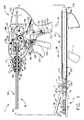
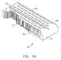
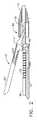
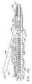
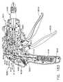
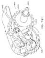
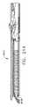
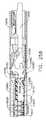
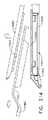
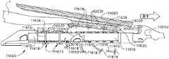
図面に戻り、図面では、同様の参照符号が、複数の図を通じて同様の構成要素を示している。図1は、いくつかの固有の利点を実施できる外科用器具10を示している。外科用ステープリング器具10は、これに動作可能に取り付けられた、様々な形状及び大きさのエンドエフェクタ12を操作及び/又は作動させるように設計される。例えば、図1〜1Eでは、エンドエフェクタ12は、エンドエフェクタ12の下方ジョー13を形成する細長チャネル14を含む。細長チャネル14は、「埋め込み可能な」ステープカートリッジ30を支持するように構成され、またエンドエフェクタ12の上方ジョー15として機能するアンビル20を動作可能に支持する。 Returning to the drawings, like reference numerals indicate like elements throughout the several views. FIG. 1 illustrates a
細長チャネル14は、例えば、300&400シリーズ、17−4&17−7ステンレススチール、チタンなどから作製されてもよく、離間した側壁16で形成されてもよい。アンビル20は、例えば、300&400シリーズ、17−4&17−7ステンレススチール、チタンなどから作製されてもよく、内部に形成される複数のステープル形成ポケット23を有する、一般的に22として標識される、ステープル形成下面を有し得る。図1B〜1Eを参照されたい。加えて、アンビル20は、そこから近位方向に突出する、二又の傾斜アセンブリ24を有する。アンビルピン26は、細長チャネル14の側壁16内の対応するスロット又は開口部18内に受容される、傾斜アセンブリ24の各側壁から突出し、ここに可動又は枢動可能に取り付けることを容易にする。 The
様々な形態の埋め込み可能なステープルカートリッジが、本明細書において開示される外科用器具で利用され得る。特定のステープルカートリッジ構成及び構造は、以下で更に詳細に記載される。しかしながら、図1Aでは、埋め込み可能なステープルカートリッジ30が示される。ステープルカートリッジ30は、内部に未形成金属ステープル32が並んでいる、例えば、酸化再生セルロース(「ORC」)又は生体吸収性フォームなどの圧縮可能な止血材料からなる、本体部分31を有する。ステープルが影響を受け、止血材料が導入及び配置処理中に活性化することを防ぐため、カートリッジ全体が、生分解性フィルム38、例えば、商標名PDS(登録商標)で販売されるポリジオキサノンフィルム、又はポリグリセロールセバケート(PGS)フィルム、又はPGA(商標Vicrylの商標名で販売されるポリグリコール酸)、PCL(ポリカプロラクトン)、PLA、若しくはPLLA(ポリ乳酸)、PHA(ポリヒドロキシアルカノエート)、PGCL(商標名Monocrylで販売されるポリグレカプロン25)、又はPGA、PCL、PLA、PDSの複合物(破裂するまでは不透過性である)から形成される他の生分解性フィルムで、コーティング又は被覆され得る。ステープルカートリッジ30の本体31は、図示されるように、細長チャネル14内に取り外し可能に支持されるような大きさであり、それによって、アンビル20がステープルカートリッジ30と接触する際に、内部の各ステープル32が、アンビル内の対応するステープル形成ポケット23と位置合わせされる。 Various forms of implantable staple cartridges may be utilized with the surgical instruments disclosed herein. Specific staple cartridge configurations and structures are described in further detail below. However, in FIG. 1A, an
使用中、一度エンドエフェクタ12が標的組織に隣接するように位置付けられると、エンドエフェクタ12は、ステープルカートリッジ30の上面36と、アンビル20のステープル形成表面22との間に、標的組織を捕捉又はクランプするように操作される。ステープル32は、細長チャネル14と実質的に平行な経路内でアンビル20を動かして、ステープル形成表面22、及びより具体的には内部のステープル形成ポケット23を、ステープルカートリッジ30の上面36と実質的に同時に接触されることによって形成される。アンビル20がステープルカートリッジ30内に動き続けると、ステープル32の脚部34はアンビル20内の対応するステープル形成ポケット23に接触して、ステープル脚部34を折り曲げ、ステープル32を「B字型」に形成するように機能する。アンビル20の細長チャネル14への移動は、ステープル32を更に圧縮して、所望の最終的に形成される高さ「FF」へと形成する。 In use, once the
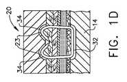
上記のステープル形成プロセスは、図1B〜1E内で一般的に示される。例えば図1Bは、アンビル20と埋め込み可能なステープルカートリッジ30の上面36との間に標的組織「T」を有する、エンドエフェクタ12を例示する。図1Cは、アンビル20の初期クランピング位置を例示し、アンビル20は標的組織「T」の上に閉鎖されて、アンビル20とステープルカートリッジ30の上面36との間に標的組織「T」をクランプする。図1Dは、初期ステープル形成を例示し、アンビル20はステープルカートリッジ30を圧縮しはじめ、それによってステープル32の脚部34は、アンビル20内のステープル形成ポケット23によって形成され始めている。図1Eは、明確性の目的のためにアンビル20が取り除かれた、標的組織「T」を貫通してその最終的な形成状態にある、ステープル32を例示する。一度ステープル32が標的組織「T」に形成及び締結されると、外科医はアンビル20を開放位置へと移動させて、エンドエフェクタ12が患者から引き抜かれる間、カートリッジ本体31及びステープル32が標的組織に固定されたままとなることを可能にする。エンドエフェクタ12は、2つのジョー13、15が一緒にクランピングされると、全てのステープルを同時に形成する。残っている「折り畳み式」本体材料31は、止血剤(ORC)及びステープルのライン補強部(PGA、PDS又は上記の他のいずれかのフィルム組成38)の両方として機能する。また、ステープル32は、形成中において、カートリッジ本体31を離れることはないため、ステープル32が形成中に不適切に形成される可能性は極小化される。本明細書において使用するとき、用語「埋め込み可能な」とは、ステープルに加えて、ステープルを支持するカートリッジ本体の材料もまた、患者内に留まり、最終的には患者の身体に吸収され得ることを意味する。そのような埋め込み可能なステープルカートリッジは、発射された後に全体がエンドエフェクタ内に位置したまま残る従来のカートリッジ構成とは区別される。 The above staple forming process is shown generally in FIGS. For example, FIG. 1B illustrates the
様々な実施において、エンドエフェクタ12は、ハンドルアセンブリ100から突出する細長シャフトアセンブリ40と連結されるように構成される。エンドエフェクタ12(閉鎖時)及び細長シャフトアセンブリ40は、同様の断面形状を有してもよく、トロカール管又は別の形状のアクセス器具内の作業チャネルを動作可能に通過するような大きさであり得る。本明細書において使用するとき、用語「動作可能に通過」とは、エンドエフェクタ及び細長シャフトアセンブリの少なくとも一部分が、チャネル又は管開口部を通じて挿入されるか、又は通過することができ、外科用ステープリング手技を完了するために必要性に応じて内部で操作され得ることを意味する。閉鎖位置にあるとき、エンドエフェクタ12のジョー13及び15は、ほぼ円形の断面形状をエンドエフェクタに与えることができ、その形状により、エンドエフェクタが円形の通路/開口部を通り抜けることが容易となる。しかしながら、本発明のエンドエフェクタ、並びに細長シャフトアセンブリは、考えられる限りでは、非円形の断面形状を有するアクセス通路及び開口部を通り抜けることができる他の断面形状を与えられ得る。したがって、閉鎖したエンドエフェクタの横断面の全体的な大きさは、エンドエフェクタを通すことが意図される通路又は開口部の大きさに関連付けられる。したがって、あるエンドエフェクタは例えば、「5mmの」エンドエフェクタと呼ばれてもよく、これは、直径が少なくとも約5mmである開口部をそのエンドエフェクタが動作可能に通り抜け得ることを意味する。 In various implementations, the
細長シャフトアセンブリ40は、閉鎖位置にあるときのエンドエフェクタ12の外径と実質的に同じである外径を有してもよい。例えば、5mmエンドエフェクタは、5mmの断面直径を有する、細長シャフトアセンブリ40と連結されてもよい。しかしながら、本発明の「発明を実施するための最良の形態」を読み進めると、本発明が、異なる大きさのエンドエフェクタに関連して有効に使用され得ることが明らかになる。例えば、10mmのエンドエフェクタが、5mmの横断面直径を有する細長シャフトに結合されてもよい。逆に、10mm以上のアクセス開口部又は経路が提供されるこれらの用途において、細長シャフトアセンブリ40は、10mm(又はそれ以上)の断面直径を有してもよいが、また5mm又は10mmのエンドエフェクタを作動させることもできる。したがって、外側シャフト40は、これに取り付けられる閉鎖したエンドエフェクタ12の外径と同じ、又はこれと異なる外径を有してもよい。 The
示されるように、細長シャフトアセンブリ40は、ハンドルアセンブリ100からほぼ直線上に遠位方向に延びて、長手方向軸A−A画定する。例えば、細長シャフトアセンブリ40は、約229〜406mm(9〜16インチ)の長さであってよい。しかし、細長シャフトアセンブリ40は他の長さで提供されてもよく、又はそれ自体にジョイントを有するか、若しくは別の方法で、下記に詳述するように、シャフト又はハンドルアセンブリの他の部分に対するエンドエフェクタ12の関節運動を可能にするように構成されてもよい。細長シャフトアセンブリ40は、ハンドルアセンブリ100からエンドエフェクタ12まで延びる、スパイン部材50を含む。エンドエフェクタ12の細長チャネル14の近位端は、そこから突出する一対の保持トラニオン17を有し、これはスパイン部材50の遠位端内に提供される、対応するトラニオン開口部又は受台52に受容される大きさであり、エンドエフェクタ12が、細長シャフトアセンブリ40に取り外し可能に連結されることを可能にする。スパイン部材50は、例えば、6061又は7075アルミニウム、ステンレススチール、チタンなどから作製されてもよい。 As shown, the
ハンドルアセンブリ100は、組み立てる目的のために、2つ以上の部品で作製され得る、ピストルグリップタイプのハウジングを含む。例えば、図示されるハンドルアセンブリ100は、右手ケース部材102、及び左手ケース部材を含み(図示なし)を含み、これらは、ポリマー又はプラスチック部材から作製され、互いに噛み合うように設計される。このような場合、部材は、スナップ機能、ペグ、及びその内側に成形又は形成されたソケットにより、及び/又は接着剤、ねじ等により貼り合わせることができる。脊椎部材50は、その上部に形成されたフランジ56を有する近位端54を有する。フランジ56は、各ケース部材102、104から内側に突出する噛み合うリブ108により形成される溝106内に回転可能に支持されるように構成される。このような構成は、スパイン部材50のハンドルアセンブリ100への取り付けを促進し、一方でスパイン部材50がハンドルアセンブリ100に対し、長手方向軸A−Aを中心に360°の起動で回転することを可能にする。 The
図1に更に見られるように、スパイン部材50は、ハンドルアセンブリ100に回転可能に取り付けられた、取り付けブッシング60を通過し、これによって支持される。取り付けブッシング60は、近位フランジ62、及び遠位フランジ64を有し、これらは、その間のハンドルアセンブリ100の鼻部分101を回転可能に受容するように構成される回転可能な溝65を画定する。このような構成は、取り付けブッシング60が、ハンドルアセンブリ100に対し、長手方向軸A−Aを中心に回転することを可能にする。スパイン部材50は、スパインピン66により、取り付けブッシング60に回転不可能にピン留めされている。加えて、回転ノブ70は、取り付けブッシング60に取り付けられる。例えば、回転ノブ70は、内部に取り付けブッシング60の一部分を受容するような大きさの中空の取り付けフランジ部分72を有する。回転ノブ70は、例えば、ガラス又は炭素充填ナイロン、ポリカーボネート、Ultem(登録商標)などから作製されてもよく、また同様にスパインピン66によって取り付けブッシング60に取り付けられる。加えて、内側に突出する保持フランジ74は、取り付けフランジ部分72上に形成され、取り付けブッシング60内に形成された放射状の溝68内に延びるように構成される。したがって、外科医は、回転ノブ70を把持し、これをハンドルアセンブリ100に対して回転させることによって、スパイン部材50(及びこれに取り付けられたエンドエフェクタ12)を長手方向軸A−Aを中心に、360°の経路で回転させてもよい。 As further seen in FIG. 1, the
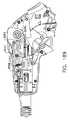
アンビル20は、アンビルばね21、及び/又は他の付勢構成によって開放位置に維持される。アンビル20は、一般的に109として指定される、発射システムによって、開放位置から様々な閉鎖又はクランピング及び発射位置へと、選択的に可動である。発射システム109は、中空発射管110を含む「発射部材」110を含む。中空発射管110は、スパイン部材50上で軸方向に可動であり、したがって、細長シャフトアセンブリ40の外部を形成する。発射管110は、ポリマー、又は他の好適な材料から作製されてもよく、発射システム109の発射ヨーク114に取り付けられる近位端を有してもよい。例えば、発射ヨーク114は、発射管110の近位端にオーバーモールドされてもよい。しかしながら、他の締結具配置が利用されてもよい。 The
図1に見られるように、発射ヨーク114は、ハンドルアセンブリ100内で軸方向に動くように構成された、支持カラー120内で回転可能に支持されてもよい。支持カラー120は、一対の横方向に延在するフィンを有し、これはそれぞれ、右手ケース部材及び左手ケース部材に形成される、フィンスロット内に摺動可能に受容されるような大きさである。したがって、支持カラー120はハンドルハウジング100内に軸方向に摺動可能であり得、一方で発射ヨーク114及び発射管110がこれに対して、長手方向軸A−Aを中心に回転することを可能にする。本発明によると、長手方向スロットが、発射管110を通じて提供され、スパインピン66が内部を通じてスパイン部材50内に延びることを可能にし、一方で、スパイン部材50上における発射管110の軸方向の移動を促進する。 As seen in FIG. 1, the
発射システム109は更に、スパイン部材50上の発射管110の軸方向の移動を制御するように機能する、発射トリガー130を更に含む。図1を参照されたい。発射管110を遠位方向、軸方向に移動させて、発射のためにアンビル20と相互作用させることは、ここでは「発射運動」と称される。図1に見られるように、発射トリガー130は枢動ピン132によってハンドルアセンブリ100に可動、又は枢動可能に連結されている。発射トリガー130を、ハンドルアセンブリ100のピストルグリップ部分107から、非作動の「解放」又は開始位置へと付勢するために、トーションばね135が利用される。図1に見られるように、発射トリガー130は、支持カラー120に可動に取り付けられた(ピン留めされた)発射リンク136に可動に取り付けられた(ピン留めされ)上部134を有する。したがって、発射位置(図1)から、ハンドルアセンブリ100のピストルグリップ部分107に隣接する終了位置への、発射トリガーの移動により、発射ヨーク114及び発射管110を遠位方向「DD」に移動させる。発射トリガー130のハンドルアセンブリ100のピストルグリップ部分107から離れる動き(トーションばね135の付勢により)により、発射ヨーク114及び発射管110は、スパイン部材50において近位方向「PD」に移動する。 The
本発明は、異なる大きさ及び構成の埋め込み可能なステープルカートリッジと共に利用することができる。例えば、外科用器具10は、第1発射アダプタ140と共に使用されるとき、埋め込み可能なステープルカートリッジ30を支持する、約20mm長さ(又は他の長さ)の、5mmエンドエフェクタ12と共に使用され得る。このようなエンドエフェクタの大きさは、例えば、比較的細かい切開、及び血管横切(transactions)を完成させるために、特に好適である。しかしながら、以下でより詳細に記載されるように、外科用器具10はまた、例えば、第1発射アダプタ140を第2発射アダプタと交換することにより、他の大きさのエンドエフェクタ及びステープルカートリッジと共に利用され得る。更なる選択肢として、細長シャフトアセンブリ40は、1つの形状又は大きさのエンドエフェクタのみに取り付けられるように構成され得る。 The present invention can be utilized with implantable staple cartridges of different sizes and configurations. For example, the
エンドエフェクタ12をスパイン部材50に取り外し可能に連結する1つの方法が説明される。連結プロセスは、細長チャネル14上の保持トラニオン17を、スパイン部材50のトラニオン受台52内に挿入することにより開始される。その後、外科医が発射トリガー130を、ハウジングアセンブリ100のピストルグリップ107の方に前進させ、発射管110及び第1発射アダプタ140を、細長チャネル14の近位端部分47を超えて遠位方向に前進させ、それによってトラニオン17をこれらの各受台52に保持する。トラニオン17を超える第1発射アダプタ140のこのような位置は、本明細書において「連結位置」と称される。本発明はまた、エンドエフェクタ12がスパイン部材50に取り付けられた後、発射トリガー130を適所に固定するために、エンドエフェクタ固定アセンブリを有し得る。 One method of removably coupling the
より具体的に、エンドエフェクタ固定アセンブリ160の一実施形態は、発射トリガー130の上部134内に可動に支持される、保持ピン162を含む。上記のように、発射管110は最初に、第1発射アダプタ140がエンドエフェクタ12の保持トラニオン17をスパイン部材50のトラニオン受台52内に保持する、連結位置へと、遠位方向に前進されなくてはならない。外科医は、発射トリガー130を開始位置からピストルグリップ107へと引くことによって、発射アダプタ140を連結位置へと遠位方向に前進させる。発射トリガー130が最初に作動されると、保持ピン162は、発射管110が第1発射アダプタ140を連結位置まで前進させるまで、遠位方向に動き、この連結位置の点において保持ピン162は、ケース部材内に形成される固定空洞164内に付勢される。所望により、保持ピン162が固定空洞164に入るとき、ピン162は、可聴「クリック音」、又は他の音を生じてもよく、またエンドエフェクタ12がスパイン部材50に「固定された」という触覚的指示を外科医に提供してもよい。加えて、外科医は、保持ピン162を固定空洞164から意図的に付勢しない限り、不注意により発射トリガー130を作動し続けて、ステープル32をエンドエフェクタ12内に形成し始めることはない。同様に、外科医が発射トリガー130を、これが連結位置にあるときに解放するとき、これは保持ピン162によってこの位置に保持され、発射トリガー130が開始位置に戻り、よってエンドエフェクタ12がスパイン部材50から解放するのを防ぐ。 More specifically, one embodiment of the end effector fixation assembly 160 includes a retaining
本発明は、ハンドルアセンブリ100に枢動可能に取り付けられた、発射システム固定ボタン137を更に含み得る。一形態において、発射システム固定ボタン137は、その遠位端上に形成されたラッチ138を有し、これは、発射解放ボタンが第1ラッチング位置にあるときに、発射ヨーク114と係合するように向けられる。図1に見られるように、ラッチばね139は、発射システム固定ボタン137を、第1ラッチング位置へと付勢するように機能する。様々な状況において、ラッチ138は、スパイン部材50上の発射ヨーク114の位置が、第1発射アダプタ140がアンビル20上のクランピング傾斜面28を遠位方向へと前進して上り始める点と対応する点において、発射ヨーク114と係合するように機能する。第1発射アダプタ140がクランピング傾斜面28を軸方向に前進して延びると、アンビル20が、そのステープル形成表面部分22がステープルカートリッジ30の上面36と実質的に平行となるようにして経路を移動する。 The present invention may further include a firing
エンドエフェクタ12がスパイン部材50と連結すると、ステープル形成プロセスは、発射システム固定ボタン137を最初に押圧することによって開始され、発射ヨーク114がスパイン部材50上で遠位方向に更に移動され、最終的にアンビル20をステープルカートリッジ30へと圧迫する。発射システム固定ボタン137を押圧した後、外科医は発射トリガー130をピストルグリップ107の方に作動し続け、それによって第1ステープルカラー140を、対応するステープル形成傾斜面29を登るように駆動し、アンビル20を、ステープルカートリッジ30内のステープル32と接触するように形成する。発射システム固定ボタン137は、外科医がプロセスに備えるまで、ステープル32の不注意による形成を防ぐ。この実施形態において、外科医は、発射トリガー130が更に作動されてステープル形成プロセスを開始する前に、発射システム固定ボタン137を押圧しなくてはならない。 When the
外科用器具10は、所望される場合、単に、所望により組織ステープリング装置として使用され得る。しかしながら、本発明はまた、一般的に170として指定される、組織切断システムを含み得る。少なくとも一形態において、組織切断システム170は、ナイフ部材172を含み、これは、ナイフ前進トリガー200を作動することによって、エンドエフェクタ12の近位端に隣接する非作動位置から、作動位置へと選択的に前進し得る。ナイフ部材172は、スパイン部材50内に可動に支持され、取り付けられ、ないしは別の方法によりナイフロッド180から突出する。ナイフ部材172は、例えば、38HRC超の硬度(Rockwell硬度Cスケール)を有する420又は440ステンレススチールから作製されてもよく、かつその遠位端174上に形成される組織切断縁部176を有し、アンビル20のスロット、及びステープルカートリッジ30の中央に配置されたスロット33を通じて摺動可能に延びて、エンドエフェクタ12内でクランプされた組織を通じて切断する。ナイフロッド180は、スパイン部材50を通って延在し、ナイフ伝達器と駆動可能に接合する近位端部分を有し、このナイフ伝達器はナイフ前進トリガー200に動作可能に取り付けられている。ナイフ前進トリガー200は、発射トリガー130を作動することなく、枢動するかないしは別の方法で作動できるように、枢動ピン132に取り付けられる。本発明によると、ナイフ前進トリガー200の作動が第1ナイフギア192も枢動させるように、第1ナイフギア192も枢動ピン132に取り付けられる。発射戻りばね202は、第1ナイフギア192とハンドルハウジング100との間に取り付けられて、ナイフ前進トリガー200を開始又は非作動位置に付勢する。 The
ナイフ伝達器は更に、第2ギアスピンドル上に回転可能に支持され、第1ナイフギア192と噛合係合する、第2ナイフギア194を含む。第2ナイフギア194は、第3ギアスピンドル上に支持される第3ナイフギア196と噛合係合する。第4ナイフギア198もまた、第3ギアスピンドル195に支持される。第4ナイフギア198は、ナイフロッド180の近位端上で一連の環状ギア歯又はリングと駆動しながら係合するように適合される。このような配置は、第4ナイフギア198がナイフロッド180を遠位方向「DD」、又は近位方向「PD」に軸方向に駆動することを可能にし、一方で、発射ロッド180が第4ナイフギア198に対して長手方向軸A−Aを中心に回転することを可能にする。したがって、外科医は、ナイフ前進トリガー200をハンドルアセンブリ100のピストルグリップ107の方に引くことによって、発射ロッド180を軸方向に前進させ、最終的にナイフ部材172を遠位方向に前進させることができる。 The knife transmitter further includes a
本発明は、更にナイフロックアウトシステム210を含み、これは、発射トリガー130が完全な発射済み位置に引かれるとき以外、ナイフ部材172の前進を防ぐ。このような特徴はしたがって、ステープルが組織内に最初に発射されるか形成されるとき以外、ナイフ前進システム170の作動を防ぐ。図1に見られるように、ナイフロックアウトシステム210の様々な実施は、ハンドルアセンブリ100のピストルグリップ部分107内に枢動可能に支持される、ナイフロックアウトバー211を含む。ナイフロックアウトバー211は、発射トリガー130が完全に発射位置にあるときに、発射トリガー130と係合するように適合される、作動端部212を有する。加えて、ナイフロックアウトバー211は、その他端に保持フック214を有し、これは第1切断ギア192上のラッチロッド216に引っ掛けるようにして係合するように適合される。ナイフ固定ばね218は、ナイフロックアウトバー211を、「固定」位置に付勢するように利用され、ここで保持フック214はラッチロッド216と係合した状態に維持され、それによって、発射トリガー130が完全に発射位置にある場合を除いてナイフ前進トリガー200の作動を防ぐ。 The present invention further includes a
ステープルが、標的組織内に「発射」(形成)された後、外科医は発射トリガー解放ボタン167を押圧して、発射トリガー130が、トーションばね135の付勢力により開始位置に戻ることを可能にし、これによりアンビル20はばね21の付勢力により開放位置に付勢される。開放位置にあるとき、外科医は、埋め込み可能なステープルカートリッジ30及びステープル32を後ろに残してエンドエフェクタ12を引いてもよい。エンドエフェクタが経路、作業チャネルなどを通じて挿入される用途において、外科医は、経路又は作業チャネルを通じてエンドエフェクタ12を後退できるようにするために、発射トリガー130を起動することによりアンビル20を閉鎖位置に戻す。しかしながら、ステープルの発射の後に外科医が標的組織を切断することを所望する場合、外科医はナイフ前進トリガー200を上記の方法で起動して、標的組織を通じてナイフバー172を、エンドエフェクタの端部まで駆動する。その後、外科医はナイフ前進トリガー200を解放し、これにより発射戻しばね202は、発射伝達器がナイフバー172を開始(非作動)位置に戻すことを可能にする。一度ナイフバー172が開始位置に戻ると、外科医はエンドエフェクタジョー13、15を開き、埋め込み可能なカートリッジ30を患者内で解放し、その後エンドエフェクタ12を患者から引き抜く。したがって、このような外科用器具は、比較的小さな作業チャネル及び経路を通じて挿入され得、一方で、外科医に、組織を切断せずにステープルを発射するか、又は所望によりまたステープルが発射された後に組織を切断する選択肢を提供する、小さい埋め込み可能ステープルカートリッジの使用を促進する。 After the staple has been “fired” (formed) into the target tissue, the surgeon presses the fire trigger release button 167 to allow the
本発明の様々な固有かつ新規の実施形態は、アンビルと接触する実質的に静的な位置にステープルを支持する、圧縮可能なステープルカートリッジを利用する。アンビルは未形成ステープルに対して駆動され、このとき、例えば達成されるステープル形成の度合いは、アンビルがどの程度までステープルに対して駆動されたかに依存する。このような構成は、外科医に、ステープルに適用される形成又は発射圧力の度合いを調節し、それによって最終的に形成されるステープルの高さを変更する能力を提供する。本発明の別のものでは、外科用ステープリング構成は、ステープルをアンビルに向かって持ち上げることができるステープル駆動要素を採用することができる。これらの詳細は後述される。 Various unique and novel embodiments of the present invention utilize a compressible staple cartridge that supports staples in a substantially static position in contact with the anvil. The anvil is driven against unformed staples, where, for example, the degree of staple formation achieved depends on how far the anvil is driven against the staples. Such a configuration provides the surgeon with the ability to adjust the degree of forming or firing pressure applied to the staples, thereby changing the height of the final formed staples. In another aspect of the present invention, the surgical stapling arrangement can employ a staple driving element that can lift the staples toward the anvil. Details of these will be described later.
所望により上記に関し、可動性アンビルに適用される発射運動の量は、発射トリガーの差動の度合いに依存する。例えば、外科医が部分的にのみ形成されたステープルを得ることを所望する場合、発射トリガーは、ピストルグリップ107の方に向かって内側に、部分的にのみ押圧される。更なるステープルの形成を得るため、外科医は単純に更に発射トリガーを圧縮し、これによりアンビルは、ステープルとより深く接触するように更に駆動される。本明細書において使用するとき、用語「接触する」とは、ステープル形成表面又はステープル形成ポケットがステープル脚部の端部と接触し、脚部を形成した位置へと形成又は屈曲させ始めたことを意味する。ステープル形成の度合いとは、ステープル脚部がどれだけ折り畳まれたかを指し、ひいては、上記のステープル形成高さに関連する。当業者は更に、アンビル20が、発射運動がそこに適用される際に、ステープルカートリッジと実質的に平行な関係で移動するため、ステープルが実質的に同時に、実質的に同じ形成高さで形成されることを理解する。 With regard to the above as desired, the amount of firing motion applied to the movable anvil depends on the differential degree of the firing trigger. For example, if the surgeon wants to obtain a partially formed staple, the firing trigger is only partially pressed inwardly toward the
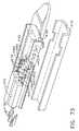
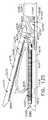
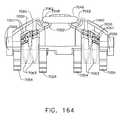
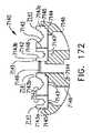
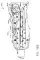
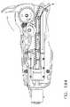
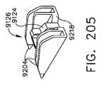
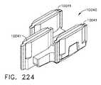
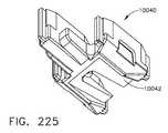
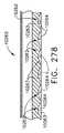
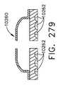
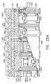
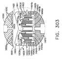
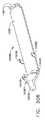
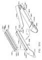
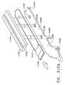
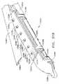
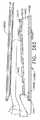
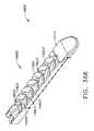
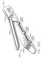
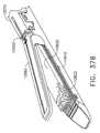
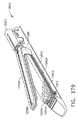
図2及び図3は、上記のエンドエフェクタ12’と同様の別のエンドエフェクタ12”を例示するが、ただしナイフバー172’に適合するように構成された、以下の差異を含むものとする。ナイフバー172’は、ナイフロッド180に連結されるか、又はこれから突出し、他の点においては、ナイフバー172に関連する上記の方法で操作される。しかしながら、本実施形態において、ナイフバー172’は、エンドエフェクタ12”の全長を横断するために十分な長さであり、したがって別個の遠位ナイフ部材はエンドエフェクタ12”で利用されない。ナイフバー172’は、その上に形成される、上方横断部材173’、及び下方横断部材175’を有する。上方横断部材173’は、アンビル20”の対応する細長スロット250を摺動自在に横断するように向けられ、下方横断部材175’は、エンドエフェクタ12”の細長チャネル14”の細長スロット252を横断するように向けられる。係合離脱スロット(図示なし)がまたアンビル20”内に提供され、それによりナイフバー172’が薄いエンドエフェクタ12”と共に終了位置に駆動されるとき、上方横断部材173’は対応するスロットを通じて降下し、アンビル20”が開放位置へと移動して、ステープリング及び切断された組織と係合離脱する。アンビル20”は、その他の点においては上記のアンビル20と同一であり得、細長チャネル14”はその他の点においては、上記の細長チャネル14と同一であり得る。 2 and 3 illustrate another
これらの実施形態において、アンビル20”は、ばね又は他の開口部構成(図示なし)によって、完全に開放位置(図2)に付勢される。アンビル20”は、上記の方法により、発射アダプタ150の軸方向の移動によって、開放位置と、完全にクランプした位置との間で移動する。一度発射アダプタ150が完全にクランプした位置(図3)まで前進すると、外科医は次にナイフバー172”を上記の方法で遠位方向に前進させてもよい。外科医がエンドエフェクタを、組織を操作するための把持装置として使用すると、発射アダプタは近位方向に移動されて、アンビル20”が細長チャネル14”から離れるように移動することを可能にする(図4に破線で表される)。この実施形態において、ナイフバー172”が遠位方向に移動すると、上方横断部材173’、及び下方横断部材175’は、アンビル20”及び細長チャネル14”を一緒に引き、ナイフバー172”がエンドエフェクタ12”を通じて遠位方向に前進するに伴い、所望のステープル形成を達成する。図5を参照されたい。したがって、この実施形態において、ステープル形成は組織切断と同時に生じるが、ステープル自体は、ナイフバー172”が遠位方向に駆動される際に順次形成されてもよい。 In these embodiments, the
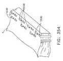
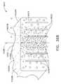
本発明の様々な外科用ステープルカートリッジ、及び外科用器具の固有かつ新規の特徴は、これらのカートリッジのステープルが1つ以上の線形又は非線形のラインに構成されることを可能にする。複数のこのようなステープルのラインは、内部を通じて組織切断部材を受容するために、ステープルカートリッジ内に中央に配置された、細長スロットの両側に提供されてもよい。一構成において、例えば、1つのライン上のステープルは、ステープルの隣接するラインのステープルと実質的に平行であるが、ここからオフセットされていてもよい。更なる選択肢として、1つ以上のステープルのラインは、非線形の性質を有してもよい。すなわち、ステープルのラインの少なくとも1つのステープルの基部は、同じステープルのラインの他のステープルの基部と、実質的に横方向である、軸に沿って延びてもよい。例えば、以下でより詳細に記載されるように、別の方法としては、細長スロットの各側のステープルのラインは、ジグザグの外観を有し得る。このような非線形のステープル構成は、従来のステープルカートリッジにおいて利用された様々な線形ステープル構成よりも少ないステープルでより良好な組織締結の結果を得ることがある。 The unique and novel features of the various surgical staple cartridges and surgical instruments of the present invention allow the staples of these cartridges to be configured in one or more linear or non-linear lines. A plurality of such staple lines may be provided on either side of the elongated slot centrally disposed within the staple cartridge for receiving a tissue cutting member therethrough. In one configuration, for example, staples on one line are substantially parallel to staples on adjacent lines of staples, but may be offset therefrom. As a further option, one or more staple lines may have non-linear properties. That is, the base of at least one staple in the staple line may extend along an axis that is substantially transverse to the other staple base in the same staple line. For example, as described in more detail below, alternatively, the staple lines on each side of the elongated slot may have a zigzag appearance. Such a non-linear staple configuration may yield better tissue fastening results with fewer staples than the various linear staple configurations utilized in conventional staple cartridges.
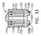
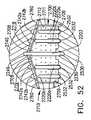
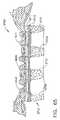
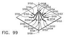
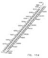
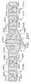
図6は、エンドエフェクタ実施形態612’の外科用ステープルカートリッジ実施形態900の使用を例示する。図6及び図7に見られるように、外科用ステープルカートリッジ900の実施形態は、近位端903を通じて遠位端905に隣接する領域まで延びる、中央に配置された細長スロット904を有する、カートリッジ本体902を有する。細長スロット904は、上記の方法による組織切断操作中において、ナイフ本体が内部を通じて軸方向に移動することを可能にするように構成される。カートリッジ本体902は、圧縮可能な止血材料、例えば、酸化再生セルロース(「ORC」)、又は例えば、PGA(商標名Vicrylで販売されるポリグリコール酸)、PCL(ポリカプロラクトン)、PLA若しくはPLLA(ポリ乳酸)、PDS(ポリジオキサノン)、PHA(ポリヒドロキシアルカノエート)、PGCL(商標名Monocrylで販売されるポリグレカプロン25)若しくはPGA、PCL、PLA及びPDSの複合物から作製される生体吸収性フォームからなり、この中で未形成ステープル922のライン920、930が支持される。しかしながら、カートリッジ本体902は、所望の向きで未形成ステープル922を支持するように機能する他の材料から作製されてもよく、これらは、アンビル910’がこれらと接触する際に圧縮され得る。ステープルカートリッジ900は、埋め込み可能であり、ステープリング手術が完了した後に、ステープリングした組織に取り付けられたまま残される。ステープル922が影響を受け、止血材料が導入及び配置処理中に活性化することを防ぐため、カートリッジ900全体が、生分解性フィルム906、例えば、商標名PDS(登録商標)で販売されるポリジオキサノンフィルム、又はポリグリセロールセバケート(PGS)フィルム、又は例えば、PGA(商標Vicrylの商標名で販売されるポリグリコール酸)、PCL(ポリカプロラクトン)、PLA、若しくはPLLA(ポリ乳酸)、PHA(ポリヒドロキシアルカノエート)、PGCL(商標名Monocrylで販売されるポリグレカプロン25)、又はPGA、PCL、PLA、PDSの複合物(破裂するまでは不透過性である)から作製される他の生分解性フィルムで、コーティング又は被覆され得る。ステープルカートリッジ900のカートリッジ本体902は、エンドエフェクタ612’の細長チャネル内に取り外し可能に支持されるような大きさである。 FIG. 6 illustrates the use of the surgical
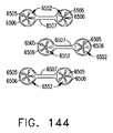
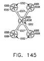
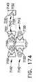
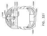
図6、10及び11において、外科用ステープルカートリッジ900は、細長スロット904の一方の横方向側部907のステープル922の第1ライン920、及び細長スロット904の他方の横方向側部909のステープル922の第2ライン930を動作可能に支持する。ステープル922は、例えば、チタン、チタン合金(例えば、6AI−4Vチタン、3al−2.5Vチタン)、ステンレススチールなどの金属材料から作製されてもよく、ステープル基部924、及びそこから突出する2つの起立するステープル脚部926を有する。各ステープル脚部926は、上部に形成された組織貫通先端部928を有し得る。ステープル922の第1ライン920において、少なくとも1つのステープル922のステープル基部924は、別のステープル922のステープル基部と重複する。好ましくは、各ステープル922のステープル基部924は、第1ステープルのライン920の各端部上の最後のステープル922の基部924を除き、2つの隣接するステープル922のステープル基部924と重複する。図10を参照されたい。したがって、第1ステープルのライン920は、実質的に非線形の形状である。より具体的に、上から見ると、第1ステープルのライン920は、実質的にジグザグの外観を有する。 6, 10, and 11, the surgical
図9に見られるように、アンビル90は、ポケット912を形成する2つの連続的な長手方向ステープルを有し、それぞれは、ステープル922の第1ライン920の形状に対応する実質的にジグザグの形状を有し、それにより、アンビル910がステープル922と形成接触する際に、その脚部926が図11に示されるように形成される。したがって、1つのステープルの遠位脚部が、長手方向に続く次のステープルの近位脚部と、同じポケットを共有する。このような構成は、更にステープル自体が相互作用する(例えば、互いに折り畳まれる)点まで、より密度の高いポケットパターンを可能にする。従来のステープルポケット構成において、一般的に、1組のポケットから次の組まで、0.13〜0.38mm(0.005〜0.015インチ)の金属/間隔が存在するべきである。本発明の実施形態は、しかしながら、1つのステープルが次のステープルと係合するため、例えば、0〜0.5mm(0〜0.02インチ)の連動/重複(本質的には、−0.5mm(−0.020インチ))の離間構成を有する。このような構成は、同じ空間に、15〜30%多いステープルを可能にする。更に、ステープルが連結するとき、ステープルの複数の横方向の列に対する必要性がより少ない。従来の構成は、一般的に組織切断線の両側に3つの列を利用し、血液が通過し得る開いた経路の存在を防止する。連結ステープルのラインは、血液が通過し得る経路を残す可能性がより低い。本発明の様々な連結ステープル構成により提供される別の利益は、改善された「破裂強度」に関連し、これはステープルのラインを引き裂いて開くために必要な力の量に関連する。 As seen in FIG. 9, the anvil 90 has two continuous longitudinal staples that form a
別のステープル形成ポケット構成は、共通のステープル形成ポケットを含み得る。本明細書において使用するとき、用語「共通のステープル形成ポケット」は、形成される各ステープルの各脚部に対して別個の形成ポケットが提供された従来的なアンビル設計とは異なり、1つの形成ポケットが、ステープルの単一のライン内で全てのステープルを形成し得ることを意味する。 Another staple forming pocket configuration may include a common staple forming pocket. As used herein, the term “common staple forming pocket” refers to one formation unlike conventional anvil designs in which a separate forming pocket is provided for each leg of each staple to be formed. A pocket means that all staples can be formed within a single line of staples.
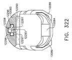
図12は、基部924’が、基部924’のより狭い重複を促進する、オフセット部分929を有する、更に別のステープル実施形態922’を例示する。上記のように、ステープルカートリッジ900は、細長スロット904の第2の横方向側部909上に支持される、ステープル922の第2ライン930を有する。ステープル922の第2ライン930は、ステープル922の第1ライン920と実質的に同一である。したがって、アンビル910は、内部で形成接触する、ステープルの第2ライン930と対応する、第2の共通ステープル形成ポケット912を有する。しかしながら、別の方法として、ステープル922の第2ライン930は、ステープルの第1ライン920と、形状、及び恐らくはステープルの数において異なる場合がある。 FIG. 12 illustrates yet another staple embodiment 922 ', where the base 924' has an offset
図8は、内部に支持されるステープル922のライン920’、930’を除き、上記のステープルカートリッジ900と実質的に同一である、外科用ステープルカートリッジ900’を例示する。例えば、この実施形態において、ステープル922のライン920’は、少なくとも1つのステープル基部924の基軸S−Sが、少なくとも1つの他の隣接するステープル922のステープル基部924の基軸S−Sと実質的に横方向であるようにして互いに配置される。ステープルのこのような規定のパターンは、上から見た際に、実質的にジグザグの構成を含む。図13において、ステープル922の各基部924は更に、図示されるように上部にオーバーモールドされる、基部支持部材927を有してよい。基部支持部材927は、例えば、ポリエーテルエーテルケトン「PEEK」などの非吸収性プラスチック、又は、例えば、ポリグリコール酸「PGA」、ポリ乳酸「PLA」又は「PLLA」、ポリジオキサノン「PDS」、PCL(ポリカプロラクトン)、PHA(ポリヒドロキシアルカノエート)、PGCL(商標名Monocrylで販売されるポリグレカプロン25)、若しくはPGS、PDS、PLA、PGA及びPCLの様々な複合混合物などの吸収性プラスチックから作製されてもよい。基部支持部材927は、ステープル自体を重複させることなく、ステープルの間の連結を促進する。したがって、このような構成は、ステープルの脚部を互いに重複させることなく、「B」字型、又は反転した「W」字型の形状を形成することができる。しかしながら、クラウンは、基部支持部材によって接続され、よってこれらは重複するステープルとして機能する。このような構成は、組み合わされたポケットが、各脚部のために、2つの別個の経路を有することを可能にする。 FIG. 8 illustrates a surgical staple cartridge 900 'that is substantially identical to the
図14では、ステープルのライン920”を利用し、ここで隣接するステープル922の脚部926は、成形ないしは別の方法でこれに取り付けられた連結部分929によって互いに連結される。各連結部分929は、例えば、ポリエーテルエーテルケトン「PEEK」、又はポリグリコール酸「PGA」、ポリ乳酸「PLA」又は「PLLA」、ポリジオキサノン「PDS」、PCL(ポリカプロラクトン)、PHA(ポリヒドロキシアルカノエート)、PGCL(ポリグレカプロン25、商標名Monocrylから販売)、若しくはPGS、PDS、PLA、PGA及びPCLの様々な複合混合物、などの吸収性プラスチックから作製されてもよい。このようなステープルのライン920”は、上から見た際に、実質的にジグザグの外観を有する。様々な外科用ステープルカートリッジ実施形態900、900’が、エンドエフェクタ612’との使用に関連して説明されてきたが、ステープリングカートリッジ900、900’は、本明細書において先に記載された他の様々なエンドエフェクタ及び外科用器具と共に効果的に利用され得ることが理解され、アンビルが移動してステープルと形成接触する際に、所望の量のステープル形成を達成するために、これらの器具のアンビル内に、適切なステープル形成ポケット構成が提供される。 In FIG. 14, a
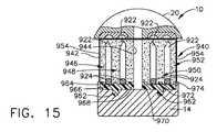
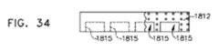
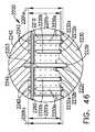
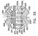
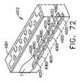
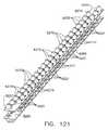
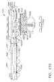
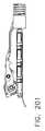
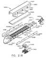
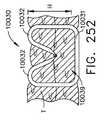
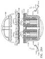
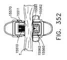
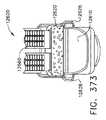
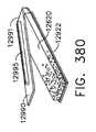
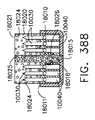
図15及び図16は、外科用器具10の細長チャネル14内に支持される別の外科用ステープルカートリッジ940実施形態を例示する。外科用ステープルカートリッジ940は、内部を通じて少なくとも部分的に延びる、中央に配置された細長スロット944を有する、カートリッジ本体942を含む。細長スロット944は、上記の方法による組織切断操作中において、外科用器具10のナイフ本体が内部を通じて軸方向に移動することを可能にするように構成される。カートリッジ本体942は、未形成ステープル922のライン946、948、950、952が内部に支持される、上記又は下記の種類の、例えば酸化再生セルロース(「ORC」)、又は生分解性フォームなど、圧縮可能な止血材料からなる。ステープル922が影響を受け、止血材料が導入及び配置処理中に活性化することを防ぐため、カートリッジ940全体が、生分解性フィルム954、例えば、商標名PDS(登録商標)で販売されるポリジオキサノンフィルム、又はポリグリセロールセバケート(PGS)フィルム、又は例えば、PGA(商標Vicrylの商標名で販売されるポリグリコール酸)、PCL(ポリカプロラクトン)、PLA、若しくはPLLA(ポリ乳酸)、PHA(ポリヒドロキシアルカノエート)、PGCL(商標名Monocrylで販売されるポリグレカプロン25)、又はPGA、PCL、PLA、PDSの複合物(破裂するまでは不透過性である)から作製される他の生分解性フィルムで、コーティング又は被覆され得る。 15 and 16 illustrate another surgical
図15では、カートリッジ940は更に、カートリッジ本体942に連結される、カートリッジ支持部材960を更に含む。カートリッジ支持部材960は、例えば、チタン、ステンレススチール、アルミニウム、これらの合金などの剛体材料から作製されてもよく、かつカートリッジ本体942内に部分的に埋め込まれてもよい。カートリッジ支持部材960は、例えば、フィルム954によって適所に保持されてもよい。別の方法としては、限定的な結合が所望される場合、2つの構成要素を一緒に「接着」するために、シアノアクリレート(cyanoacylate)の断続的な使用が用いられる。更なる選択肢として、カートリッジ本体942は、加熱されて、カートリッジ支持部材960に「溶接」又は「融着」され得る。細長チャネル14と係合するために、カートリッジ支持部材960は、カートリッジ本体942の下側表面の少なくとも一部分を形成する。カートリッジ支持部材960は、カートリッジ支持部材960を細長チャネル14に解放可能に連結するために、そこから突出する1つ以上のスナップ機構962を有する。カートリッジ支持部材960を細長チャネル14に解放可能に連結するために、他の形態のスナップ機構/締結配置が利用され得る。 In FIG. 15, the
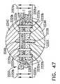
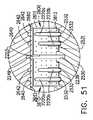
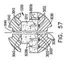
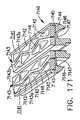
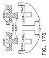
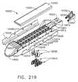
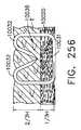
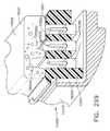
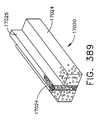
カートリッジ支持部材960は、上部に形成された、一連の支持隆起部964、966、968、970、972、974、976を有し、図15に示されるように、ステープルのライン946、948、950、952のステープル922の基部924にいくつかの横方向の支持を提供する。したがって、支持隆起部は、ステープルのラインと実質的に同一の広がりを持つ。図17は、ステープル922に追加的な横方向の支持を提供するために、各支持隆起部964、966、968、970、972、976から突出する、起立フィン部分978、979、980、981、982、983を含むことを除き、カートリッジ940と実質的に同一である、別のステープルカートリッジ実施形態940’を例示する。フィン部分は、カートリッジ支持部材960と一体的に形成されてもよく、カートリッジの高さの約1/2以下の高さを有する。したがって、例えば、フォームを支持する起立機構は、フォームの最大圧縮高さよりも上に延びることができない。したがって、例えば、発射される際にその元の高さの1/3まで圧縮するようにカートリッジが設計されると、フィンは、非圧縮高さの66%から、非圧縮高さの10%までもの範囲に及ぶ。 The
使用中、上記のように、一度ステープル922がアンビル20との接触により形成されると、アンビル20が解放されて、エンドエフェクタ12がステープリングされた組織から引かれる。エンドエフェクタ12がステープリングされた組織から引かれると、カートリッジ本体942は、ステープリングされた組織に締結されたままであり、その後細長チャネル14と連結されたままであるカートリッジ支持部材960から分離される。カートリッジ支持部材960は、カートリッジ本体942を含む材料の色、並びに細長チャネル14の色と異なる色を備える。このような構成は、エンドエフェクタ内にステープルカートリッジが存在しないことを示す、容易に認識可能な指示を外科医にもたらす。したがって、外科医は、不注意により、最初に内部に新しいステープルカートリッジを挿入することなく、エンドエフェクタを再挿入/使用しようとすることがない。そのため、外科医は、新しいステープルカートリッジ940のカートリッジ支持部材960が内部に配置されることを可能にするため、カートリッジ支持部材960のスナップ機構を細長チャネル14から単純に分離する。ステープルカートリッジ940、940’を、外科用器具10との関連において説明してきたが、本発明の趣旨及び範囲から逸脱することなく、本明細書に開示される他の外科用器具の多くと効果的に利用されてもよいことが理解される。 In use, as described above, once the staple 922 is formed by contact with the
本発明によると、ステープルカートリッジは、カートリッジ本体、及びカートリッジ本体内に収容される複数のステープルを含み得る。使用中、ステープルカートリッジは、手術部位に組み込まれ、処理される組織の側に組み込まれ得る。加えて、ステープル形成アンビルは、組織の反対側に位置し得る。アンビルは、第1ジョーにより保持され得、ステープルカートリッジは、第2ジョーによって保持され得、第1ジョー及び/又は第2ジョーは互いに向かって移動し得る。一度ステープルカートリッジ及びアンビルが組織に対して位置付けられると、ステープルがステープルカートリッジ本体から発射され得、ステープルが組織を貫通してスープル形成アンビルと接触し得る。一度ステープルがステープルカートリッジ本体から展開されると、ステープルカートリッジ本体がその後、手術部位から取り除かれてもよい。ステープルカートリッジ又はステープルカートリッジの少なくとも一部分が、ステープルと共に埋め込まれ得る。例えば、以下でより詳細に記載されるように、ステープルカートリッジは、アンビルが開放位置から閉鎖位置へと移動するときに、アンビルにより圧縮、圧壊、及び/又は折り畳まれ得る、カートリッジ本体を含み得る。カートリッジ本体が圧縮、圧壊及び/又は折り畳みされるとき、カートリッジ本体内に位置付けられるステープルは、アンビルによって変形され得る。あるいは、ステープルカートリッジを支持するジョーは、アンビルに向かい、閉鎖位置へと移動し得る。いずれにせよ、ステープルは、これらが少なくとも部分的にカートリッジ本体内に位置付けられるときに、変形され得る。いくつかの場合では、ステープルは、ステープルカートリッジから発射されなくてもよく、一方で別の場合では、ステープルは、カートリッジ本体の一部分と共に、ステープルカートリッジから発射され得る。 According to the present invention, a staple cartridge can include a cartridge body and a plurality of staples housed within the cartridge body. In use, the staple cartridge can be incorporated at the surgical site and on the side of the tissue to be processed. In addition, the staple forming anvil may be located on the opposite side of the tissue. The anvil can be held by the first jaw, the staple cartridge can be held by the second jaw, and the first jaw and / or the second jaw can move toward each other. Once the staple cartridge and anvil are positioned with respect to the tissue, the staple can be fired from the staple cartridge body and the staple can penetrate the tissue and contact the spleating anvil. Once the staples are deployed from the staple cartridge body, the staple cartridge body may then be removed from the surgical site. The staple cartridge or at least a portion of the staple cartridge can be embedded with the staples. For example, as described in more detail below, a staple cartridge can include a cartridge body that can be compressed, crushed, and / or folded by the anvil as the anvil moves from an open position to a closed position. When the cartridge body is compressed, crushed and / or folded, staples positioned within the cartridge body can be deformed by the anvil. Alternatively, the jaws that support the staple cartridge can move toward the anvil and into the closed position. In any case, the staples can be deformed when they are at least partially positioned within the cartridge body. In some cases, the staples may not be fired from the staple cartridge, while in other cases, the staples may be fired from the staple cartridge along with a portion of the cartridge body.
ここで図18A〜18Dを参照し、例えば、ステープルカートリッジ1000などの圧縮可能なステープルカートリッジは、圧縮可能な、埋め込み可能なカートリッジ本体1010、及び、加えて、圧縮可能なカートリッジ本体1010内に位置付けられる、複数のステープル1020を含んでもよいが、図18A〜18Dでは、1つのステープル1020のみが示されている。図18Aは、ステープルカートリッジ支持体、又はステープルカートリッジチャネル1030によって支持されるカートリッジ1000を例示し、ステープルカートリッジ1000は、非圧縮状態で例示される。このような非圧縮状態において、アンビル1040は、組織Tと接触してもしなくてもよい。使用中、アンビル1040は、図18Bに見られるように、開放位置から組織Tへと接触させ、組織Tを、カートリッジ本体1010に対して位置付けるように移動してもよい。図18Bを再び参照し、アンビル1040は、組織Tをステープルカートリッジ本体1010の組織接触表面1019に対して位置付けることができるが、ステープルカートリッジ本体1010は、このような時点において、圧縮力又は圧力を(受けたとしても)ほとんど受けないことがあり、ステープル1020は、未形成又は未発射状態にあり得る。図18A及び図18Bに例示されるように、ステープルカートリッジ本体1010は、1つ以上の層を含む場合があり、ステープル1020のステープル脚部1021は、これらの層を通じて上方に延びる場合がある。カートリッジ本体1010は、第1層1011、第2層1012、第3層1013を含む場合があり、第2層1012は、第1層1011と第3層1013及び第4層1014との中間に位置付けられてもよく、第3層1013は、第2層1012と第4層1014との中間に位置付けられてもよい。ステープル1020の基部1022は、第4層1014の空洞1015内に位置付けられてもよく、ステープル脚部1021は、例えば基部1022から第4層1014、第3層1013、及び第2層1012を通じて上方に延在してもよい。所望により、各変形可能な脚部1021は、先端部、例えば、鋭利な先端部1023を含んでもよく、これは、例えば、ステープルカートリッジ1000が非圧縮状態にあるときに、第2層1012内に位置付けられてもよい。例えば、先端部1023は、第1層1011内に及び/又はこれを通じて延在しない場合があり、先端部1023は、ステープルカートリッジ1000が非圧縮状態にあるときに、組織接触表面1019を通じて突出しない場合がある。ステープルカートリッジが非圧縮状態にあるときに、鋭利な先端部1023は、第3層1013、及び/又は他の任意の好適な層内に位置付けられてもよい。別の方法としては、ステープルカートリッジのカートリッジ本体は、例えば、3層以下、又は5層以上など、任意の好適な数の層を有してもよい。 Referring now to FIGS. 18A-18D, a compressible staple cartridge, such as, for example, a
所望により、以下でより詳細に記載されるように、第1層1011は、例えば、ポリジオキサノン(PDS)及び/又はポリグリコール酸(PGA)などのバットレス材料及び/又はプラスチック材料からなることがあり、第2層1012は、例えば、酸化再生セルロース(ORC)などの生体吸収性フォーム材料及び/又は圧縮可能な止血材料から構成されることがある。所望により、1つ以上の第1層1011、第2層1012、第3層1013、及び第4層1014は、ステープルカートリッジ本体1010内にステープル1020を保持してもよく、加えて、ステープル1020を、互いに位置合わせした状態に維持してもよい。第3層1013は、バットレス材料、つまり高度に非圧縮性又は非弾性の材料から構成される場合があり、これはステープル1020のステープル脚部1021を互いに対して適所に保持するように構成され得る。更に、第3層1013の両側に配置される、第2層1012及び第4層1014は、第2層1012及び第4層1014が、圧縮可能なフォーム又は弾性材料を含み得るにもかかわらず、ステープル1020の移動を安定化又は低減することができる。ステープル脚部1021のステープル先端部1023は、少なくとも一部分が第1層1011内に埋め込まれていてもよい。例えば、第1層1011及び第3層1013は、協調して、かつしっかりと、ステープル脚部1021を適所に保持するように構成され得る。第1層1011及び第3層1013はそれぞれ、生体吸収性プラスチックのシート、例えば、商標名Vicrylで販売されるポリグリコール酸(PGA)、ポリ乳酸(PLA又はPLLA)、ポリジオキサノン(PDS)、ポリヒドロキシアルカノエート(PHA)、商標名Monocrylで販売されるポリグレカプロン25(PGCL)、ポリカプロラクトン(PCL)、並びに/又はPGA、PLA、PDS、PHA、PGCL及び/若しくはPCLの複合物から構成されてよく、第2層1012及び第4層1014はそれぞれ、少なくとも1つの止血材料又は止血剤から構成されてよい。 If desired, as described in more detail below, the
第1層1011は、圧縮可能であり得、第2層1012は、第1層1011よりも実質的に圧縮可能である。例えば、第2層1012は、第1層1011の約2倍圧縮可能、約3倍圧縮可能、約4倍圧縮可能、約5倍圧縮可能、及び/又は約10倍圧縮可能であり得る。換言すると、第2層1012は、所定の力により第1層1011の約2倍、約3倍、約4倍、約5倍、及び/又は約10倍圧縮し得る。第2層1012は、第1層1011の、例えば約2倍〜約10倍圧縮可能であり得る。第2層1012は、内部に画定される複数の空隙を含むことがあり、第2層1012における空隙の量及び/又は大きさは、第2層1012の所望の圧縮性を提供するために制御され得る。上記と同様に、第3層1013は圧縮可能である場合があり、第4層1014は、第3層1013よりも実質的に圧縮可能であり得る。例えば、第4層1014は、第3層1013の約2倍圧縮可能、約3倍圧縮可能、約4倍圧縮可能、約5倍圧縮可能、及び/又は約10倍圧縮可能であり得る。換言すると、第4層1014は、所定の力により第3層1013の約2倍、約3倍、約4倍、約5倍、及び/又は約10倍圧縮し得る。第4層1014は、第3層1013の、例えば約2倍〜約10倍圧縮可能であり得る。第4層1014は、内部に画定される複数の空隙を含むことがあり、第4層1014における空隙の量及び/又は大きさは、第4層1014の所望の圧縮性を提供するために制御され得る。様々な状況において、カートリッジ本体の圧縮性、又はカートリッジ本体層は、圧縮率(すなわち、所定量の力において層が圧縮される距離)という観点で表現され得る。例えば、高い圧縮率を有する層は、層に適用される所定量の圧縮力において、より低い圧縮率を有する層と比較して、より大きな距離だけ圧縮する。すなわち、第2層1012は、第1層1011よりも高い圧縮率を有することがあり、同様に第4層1014は、第3層1013よりも高い圧縮率を有することがある。第2層1012及び第4層1014は、同じ材料から構成される場合があり、同じ圧縮率を含む場合がある。第2層1012及び第4層1014は、異なる圧縮率を有する材料から構成される場合がある。同様に第1層1011及び第3層1013は、同じ材料を含むことがあり、同じ圧縮率を含む場合がある。第1層1011及び第3層1013は、異なる圧縮率を有する材料から構成される場合がある。 The
図18Cに例示されるように、アンビル1040が閉鎖位置に移動すると、アンビル1040は、組織Tに接触し、組織T及びステープルカートリッジ1000に圧縮力を適用することができる。このような状況において、アンビル1040は、カートリッジ本体1010の上側表面又は組織接触表面1019を、ステープルカートリッジ支持体1030に向かって下方に押すことができる。ステープルカートリッジ支持体1030は、カートリッジ支持表面1031を含むことができ、これは、ステープルカートリッジ1000がカートリッジ支持表面1031と、アンビル1040の組織接触表面1041との間で圧縮される際に、ステープルカートリッジ1000を支持するように構成され得る。アンビル1040により適用される圧力により、カートリッジ本体1010は圧縮され得、アンビル1040がステープル1020と接触し得る。より具体的には、カートリッジ本体1010の圧縮、及び組織接触表面1019の下方移動により、ステープル脚部1021の先端部1023がカートリッジ本体1010の第1層1011を貫通し、組織Tを貫通し、アンビル1040の形成ポケット1042内に入ることがある。カートリッジ本体1010が、アンビル1040によって更に圧縮されると、先端部1023は形成ポケット1042を画定する壁部に接触することができ、結果として脚部1021は例えば、図18Cに例示されるように、変形するか、内側に湾曲し得る。やはり図18Cに見られるように、ステープル脚部1021が変形すると、ステープル1020の基部1022は、ステープルカートリッジ支持体1030と接触するか、又はこれによって支持され得る。所望により、以下により詳細に記載されるように、ステープルカートリッジ支持体1030は、例えば、ステープル支持溝、スロット又はトラフ1032などの複数の支持機構を含むことができ、これらは、ステープル1020が変形される際に、ステープル1020のステープル1020又は少なくとも基部1022を支持するように構成され得る。また図18Cに例示されるように、第4層1014の空洞1015は、ステープルカートリッジ本体1010に適用された圧縮力の結果として折り畳まれ得る。空洞1015に加えて、ステープルカートリッジ本体1010は、1つ以上の空隙、例えば空隙1016を更に含むことがあり、これは、内部に位置付けられたステープルの一部分を含んでも、含まなくてもよく、これは、カートリッジ本体1010が折り畳まれることを可能にするように構成され得る。空洞1015及び/又は空隙1016は、空洞及び/又は壁部を画定する壁部が下方に屈曲して、カートリッジ支持表面1031と接触し、並びに/又は、空洞及び/若しくは空隙の下に位置付けられるカートリッジ本体1010の層と接触するようにして、潰れるように構成され得る。 As illustrated in FIG. 18C, when the
図18B及び図18Cを比較すると、第2層1012及び第4層1014が、アンビル1040によって適用される圧縮圧力によって実質的に圧縮されていることが明らかである。第1層1011及び第3層1013が同様に圧縮されたことが認識され得る。アンビル1040がその閉鎖位置に移動されると、アンビル1040は、組織接触表面1019をステープルカートリッジ支持体1030に向かって下方に押すことによって、カートリッジ本体1010を更に圧縮し続けてもよい。図18Dに例示されるように、カートリッジ本体1010が更に圧縮されると、アンビル1040は、ステープル1020を、これらの完全に形成された形状に変形し得る。図18Dを参照し、各ステープル1020の脚部1021は、変形可能な脚部1021と基部1022との間に、組織T、第1層1011、第2層1012、第3層1013、及び第4層1014の少なくとも一部分を捕捉するため、各ステープル1020の基部1022の方に向かって下方に変形され得る。図18C及び図18Dを比較すると、第2層1012及び第4層1014が、アンビル1040によって適合される圧縮圧力によって実質的に圧縮されていることが明らかである。同様に、図18C及び図18Dを比較した際に、第1層1011及び第3層1013が更に圧縮されたことに留意し得る。ステープル1020が完全に又は少なくとも十分に形成された後、アンビル1040が組織Tから離れるように持ち上げられる場合があり、ステープルカートリッジ1030が、ステープルカートリッジ1000から離れるように動かされる、及び/又はこれから分離されることがある。図18Dに示されるように、上記の結果として、カートリッジ本体1010は、ステープル1020と共に埋め込まれ得る。様々な状況において、埋め込まれたカートリッジ本体1010は、ステープルのラインに沿って組織を支持し得る。いくつかの状況において、埋め込まれたカートリッジ本体1010内に含まれる止血剤及び/又は他の任意の好適な治療用薬剤は、時間と共に組織を治療し得る。上記のように、止血剤は、ステープリング及び/又は切開された組織の出血を低減させ得る一方で、結合剤又は組織接着剤は、時間と共に組織に強度をもたらし得る。埋め込まれたカートリッジ本体1010は、例えば、ORC(酸化再生セルロース)、タンパク質マトリックス、商標名Vircylで販売されるポリグリコール酸(PGA)、ポリ乳酸(PLA又はPLLA)、ポリジオキサノン(PDS)、ポリヒドロキシアルカノエート(PHA)、商標名Monocrylで販売されるポリグレカプロン25(PGCL)、ポリカプロラクトン(PCL)、並びに/又はPGA、PLA、PDS、PHA、PGCL及び/若しくはPCLの複合物などの材料から構成され得る。いくつかの状況において、カートリッジ本体1010は、抗生物質及び/又は抗菌剤物質、例えば、コロイド状銀及び/又はトリクロサンを含んでもよく、これらは、手術部位における感染の可能性を低減させることができる。 Comparing FIGS. 18B and 18C, it is clear that the
カートリッジ本体1010の層は、互いに接続され得る。例えば、フィブリン及び/又はタンパク質ヒドロゲルなどの少なくとも1つの接着剤を使用して、第2層1012が第1層1011に接着されてもよく、第3層1013が第2層1012に接着されてもよく、第4層1014が第3層1013に接着されてもよい。例示されないが、カートリッジ本体1010の層は、連結機械機構によって互いに連結され得る。例えば、第1層1011及び第2層1012はそれぞれ、例えば、さね継ぎ構成及び/又はあり継手構成などの、対応する連結機構を含み得る。同様に、第2層1012及び第3層1013はそれぞれ、対応する連結機構を含む場合があり、一方で第3層1013及び第4層1014はそれぞれ、対応する連結機構を含み得る。例示されないが、ステープリングカートリッジ1000は、例えば、カートリッジ本体1010の1つ以上の層を通じて延び得る1つ以上のリベットを含み得る。例えば、各リベットは、第1層1011と隣接するように位置付けられる第1端部、つまりヘッド、及び、第4層1014と隣接するように位置付けられる、このリベットの第2端部によって組み立てられるか、又は形成され得る第2ヘッドを含み得る。カートリッジ本体1010の圧縮可能な性質により、リベットはカートリッジ本体1010を圧縮してもよく、これにより、リベットのヘッドは、例えば、カートリッジ本体1010の組織接触表面1019、及び/又は下側表面1018に対して陥没していることがある。例えば、リベットは、例えば、商標名Vicrylで販売されるポリグリコール酸(PGA)、ポリ乳酸(PLA又はPLLA)、ポリジオキサノン(PDS)、ポリヒドロキシアルカノエート(PHA)、商標名Monocrylで販売されるポリグレカプロン25(PGCL)、ポリカプロラクトン(PCL)、並びに/又はPGA、PLA、PDS、PHA、PGCL及び/若しくはPCLの複合物などの生体吸収性材料を含み得る。カートリッジ本体1010の層は、内部に含まれるステープル1020によって以外は、互いに接続されないことがある。例えば、ステープル脚部1021と、カートリッジ本体1010との間の摩擦係合は、カートリッジ本体1010の層を一緒に保持することができ、一度ステープルが形成されると、層はステープル1020内に捕捉され得る。ステープル脚部1021の少なくとも一部分は、非平坦化表面又は非平坦なコーティングを含むことができ、これは、ステープル1020とカートリッジ本体1010との間の摩擦力を高め得る。 The layers of the
上記のように、外科用器具は、ステープルカートリッジ1030を含む第1ジョー、及びアンビル1040を含む第2ジョーを含み得る。所望により、以下でより詳細に記載されるように、ステープルカートリッジ1000は、1つ以上の保持機構を含んでもよく、これはステープルカートリッジ支持体1030と係合するように構成されてもよく、結果として、ステープルカートリッジ1000をステープルカートリッジ支持体1030に解放可能に保持する。ステープルカートリッジ1000は、例えば、フィブリン及び/又はタンパク質ヒドロゲルなどの少なくとも1つの接着剤によって、ステープルカートリッジ支持体1030に接着され得る。使用中、少なくとも1つの状況において、特に腹腔鏡及び/又は内視鏡手術において、例えば、第2ジョーは第1ジョーと反対側の閉鎖位置に移動され得、それによって第1及び第2ジョーがトロカールを通じて手術部位に挿入され得る。例えば、トロカールは、約5mmの孔又はカニューレを画定する場合があり、これを通じて第1及び第2ジョーが挿入され得る。第2ジョーは、開放位置と閉鎖位置との中間の部分的に閉鎖した位置に移動することができ、これは、ステープルカートリッジ本体1010内に含まれるステープル1020を変形することなく、トロカールを通じて第1及び第2ジョーが挿入されることを可能にし得る。例えば、第2ジョーがその部分的に閉じた中間位置にあるとき、アンビル1040は圧縮力をステープルカートリッジ本体1010にかけない場合があり、一方、第2ジョーが部分的に閉じた中間位置にあるとき、アンビル1040はステープルカートリッジ本体1010を圧縮し得る。アンビル1040が、そのような中間位置にあるときに、ステープルカートリッジ本体1010を圧縮し得るにもかかわらず、アンビル1040は、アンビル1040がステープル1020と接触するために、及び/又はステープル1020がアンビル1040によって変形されるために、ステープルカートリッジ本体1010を十分に圧縮しないことがある。一度第1及び第2ジョーが、トロカールを通じて手術部位に挿入されると、第2ジョーはもう一度開放されることがあり、アンビル1040及びステープルカートリッジ1000は、上記のように標的組織に対して位置付けられることがある。 As described above, the surgical instrument may include a first jaw that includes a
ここで図19A〜19Dを参照すると、外科用ステープラーのエンドエフェクタは、アンビル1140とステープルカートリッジ支持体1130との中間に位置付けられた埋め込み可能なステープルカートリッジ1100を含み得る。上記と同様に、アンビル1140は、組織接触表面1141を含むことがあり、ステープルカートリッジ1100は、組織接触表面1119を含むことがあり、ステープルカートリッジ支持体1130は支持表面1131を含むことがあり、これはステープルカートリッジ1100を支持するように構成されている。図19Aを参照し、アンビル1140は、ステープルカートリッジ1100を変形することなく、ステープルカートリッジ1100の組織接触表面1119に対して組織Tを位置付けるために使用され得、アンビル1140がこのような位置にあるとき、組織接触表面1141は、ステープルカートリッジ支持表面1131から距離1101aで位置付けられ得、組織接触表面1119は、ステープルカートリッジ支持表面1131から距離1102aで位置付けられ得る。その後、アンビル1140がステープルカートリッジ支持体1130に向かって移動され、図19Bを参照すると、アンビル1140は、ステープルカートリッジ1100の上側表面又は組織接触表面1119を下方に押し、カートリッジ本体1110の第1層1111及び第2層1112を圧縮することができる。図19Bを参照し、層1111及び1112が圧縮されると、第2層1112が圧壊し、ステープル1120の脚部1121が、第1層1111を通過して組織T内に貫通し得る。例えば、ステープル1120は第2層1112のステープル空洞又は空隙1115内に少なくとも一部分が位置付けられ得、第2層1112が圧縮されると、ステープル空洞1115が折り畳まれ、結果として、第2層1112がステープル1120の周囲で折り畳まれる。第2層1112は、カバー部分1116を含んでもよく、これはステープル空洞1115上に延在し、かつステープル空洞1115を包囲するか又は少なくとも一部分を包囲し得る。図19Bは、ステープル空洞1115内へと下方に圧壊される、カバー部分1116を例示する。第2層1112は、1つ以上の弱化部分を含んでもよく、これは第2層1112が折り畳まれるのを促進し得る。所望により、このような弱化部分は、例えば、刻んだ線、穿孔、及び/又は薄い断面を含んでもよく、これはカートリッジ本体1110の制御された折り畳みを促進し得る。第1層1111は、1つ以上の弱化部分を含んでもよく、これは、第1層1111を通じたステープル脚部1121の貫通を促進し得る。所望により、このような弱化部分は、例えば、刻んだ線、穿孔、及び/又は薄い断面を含んでもよく、これはステープル脚部1121と位置合わせされるか又は少なくとも実質的に位置合わせされ得る。 Referring now to FIGS. 19A-19D, the surgical stapler end effector may include an
図19Aを再び参照し、アンビル1140が、部分的に閉じた、発射していない位置にあるとき、アンビル1140は、カートリッジ支持表面1131から、その間に空隙が画定されるように、距離1101aで位置付けられ得る。空隙はステープルカートリッジ高さ1102aを有するステープルカートリッジ1100、及び組織Tで充填され得る。図19Bを再び参照し、アンビル1140が下方に移動されてステープルカートリッジ1100を圧縮すると、組織接触表面1141とカートリッジ支持表面1131との間の距離は、距離1101aよりも短い距離1101bによって画定され得る。様々な状況において、距離1101bにより画定される、アンビル1140の組織接触表面1141と、カートリッジ支持表面1131との間の空隙は、元々の変形していないステープルカートリッジ高さ1102aよりも大きいことがある。ここで図19Cを参照し、アンビル1140がカートリッジ支持表面1131により近く移動されると、第2層1112は、折り畳み続け、ステープル脚部1121と形成ポケット1142との間の距離は減少し得る。同様に、組織接触表面1141とカートリッジ支持表面1131との間の距離は、距離1101cまで減少することがあり、これは、元の変形してないカートリッジ高さ1102aより大きい、これと等しい、又はこれより小さいことがある。図19Dを参照し、アンビル1140は、ステープル1120が完全に形成された又は少なくとも所望の高さまで形成された、最終的な、発射位置まで移動され得る。このような位置において、アンビル1140の組織接触表面1141は、カートリッジ支持表面1131から距離1101dの距離であり得、距離1101dは、元の変形していないカートリッジ高さ1102aより短い場合がある。また図19Dに例示されるように、ステープル空洞1115は、完全に又は少なくとも実質的に、折り畳まれており、ステープル1120は完全に又は少なくとも実質的に、折り畳まれた第2層1112によって囲まれる。様々な状況において、アンビル1140はその後、ステープルカートリッジ1100から離れるように動く場合がある。一度アンビル1140がステープルカートリッジ1100から係合離脱すると、カートリッジ本体1110は、様々な位置において(すなわち、例えばステープル1120に隣接するステープルの中間の位置)、少なくとも部分的に再拡張し得る。圧壊したカートリッジ本体1110は、弾性的に再拡張しないことがある。形成されたステープル1120及び、加えて、隣接するステープル1120の中間に位置付けられるカートリッジ本体1110は、組織Tに圧力、つまり圧縮力をかけることがあり、これは様々な治療的効果を提供し得る。 Referring back to FIG. 19A, when the
上記のように、図19Aを再び参照すると、各ステープル1120は、そこから延びるステープル脚部1121を含み得る。ステープル1120は、2つのステープル脚部1121を含むものとして示されるが、1つのステープル脚部、又はあるいは2つを超えるステープル脚部、例えば、3つのステープル脚部、又は4つのステープル脚部を含む様々なステープルが使用される場合がある。図19Aに例示されるように、各ステープル脚部1121は、ステープル1120が第2層1112内に固定されるように、カートリッジ本体1110の第2層1112内に埋め込まれ得る。ステープル1120は、ステープル脚部1121の先端部1123が、基部1122の前に空洞1115内に入るようにして、カートリッジ本体1110のステープル空洞1115内に挿入されることがある。先端部1123が、空洞1115内に挿入された後、先端部1123は、カバー部分1116に押し込まれて、第2層1112を切開する。ステープル1120は、ステープル1120が第2層1112に対して動かないか、又は少なくとも実質的に動かないように、第2層1112内の十分な深さに据え付けられ得る。ステープル1120は、基部1122がステープル空洞1115内に位置付けられるか又は埋め込まれるように、第2層1112内の十分な深さに据え付けられ得る。別の方法としては、基部1122は、第2層1112内に位置付けられないか、又は埋め込まれない場合もある。再度図19Aを参照すると、基部1122は、カートリッジ本体1110の下側表面1118の下に延びてもよい。基部1122は、カートリッジ支持表面1130上に位置し得るか、又はこれに対して直接位置付けられ得る。カートリッジ支持表面1130は、ここから貫通して延在するか、及び/又は内部に画定される支持機構を備える場合があり、例えば、ステープル1120の基部1122は、以下でより詳細に記載されるように、ステープルカートリッジ支持体1130内の、例えば1つ以上の支持溝、スロット、又はトラフ1132内に位置付けられるか、これによって支持され得る。 As described above, referring again to FIG. 19A, each staple 1120 may include a
上記に加え、図20を参照すると、ステープル1120の基部1122は、ステープルカートリッジ支持体1130の支持表面1131に対して直接配置し得る。所望により、ステープル基部1122が円形又は弓状の下側表面1124を含む場合を含み、例えば、ステープル基部1122は、ステープルカートリッジ支持表面1131に沿って移動又は摺動し得る。このような摺動は、アンビル1140がステープル形成プロセス中に、ステープル脚部1121の先端部1123に対して押し付けられる際に生じ得る。上記のように、かつ図21をここで参照すると、ステープルカートリッジ支持体1130は、内部に1つ以上の支持スロット1132を含むことができ、これは、ステープル基部1122とカートリッジ支持表面1131との間の相対移動を排除するか又は少なくとも低減するように構成され得る。例えば、各支持スロット1132は、内部に位置付けられたステープルの下側表面の輪郭と適合するか、又は少なくとも実質的に適合する、表面輪郭によって画定され得る。例えば、図21に示される基部1122の下側表面1124は、円形又は少なくとも実質的に円形の表面を含む場合があり、支持スロット1132はまた、円形の又は少なくとも実質的に円形の表面を含み得る。例えば、スロット1132を画定する表面は、下側表面1124を画定する曲率半径を超える又はこれと等しい、曲率半径によって画定され得る。スロット1132は、ステープル1120と、ステープルカートリッジ支持体1130との間の相対的な摺動運動を防ぐ又は低減することを補助し得るが、スロット1132はまたステープル1120とステープルカートリッジ支持体1130との間の回転運動もまた防ぐか又は低減するように構成され得る。より具体的には、スロット1132は、例えば、ステープル1120が、変形する際に回転するか又は捻れることがないように、ステープル1120の軸1129を中心とした回転を防ぐか又は低減するため、基部1122を緊密に受容するように構成され得る。 In addition to the above, referring to FIG. 20, the
上記に加え、各ステープル1120は、丸い、又は少なくとも実質的に丸いワイヤから形成され得る。各ステープルの脚部及び基部は、例えば、矩形の断面など、非円形の断面を有するワイヤから形成されることがある。例えば、ステープルカートリッジ支持体1130は、例えば、このようなステープルの基部を受容するように構成された矩形のスロットなどの、対応する非円形のスロットを含み得る。ここでは図22を参照すると、各ステープル1120は、例えば、基部1122にオーバーモールドされた、クラウン1125などのクラウンを含むことができ、各クラウン1125は、ステープルカートリッジ支持体1130内の支持スロット内に位置付けられ得る。例えば、各クラウン1125は、例えば正方形及び/又は矩形の断面を備える場合があり、これは例えば、ステープルカートリッジ支持体1130内の正方形及び/又は矩形のスロット1134内に受容されるように構成され得る。クラウン1125は、例えば、商標名Vicrylで販売されるポリグリコール酸(PGA)、ポリ乳酸(PLA又はPLLA)、ポリジオキサノン(PDS)、ポリヒドロキシアルカノエート(PHA)、商標名Monocrylで販売されるポリグレカプロン25(PGCL)、ポリカプロラクトン(PCL)、並びに/又はPGA、PLA、PDS、PHA、PGCL及び/若しくはPCLの複合物などの生体吸収性プラスチックから構成される場合があり、例えば、射出成形プロセスによって、ステープル1120の基部1122の周囲に形成され得る。様々なクラウン及び様々なクラウンを形成する方法は、2006年9月29日に出願された、米国特許出願第11/541,123号、表題「SURGICAL STAPLES HAVING COMPRESSIBLE OR CRUSHABLE MEMBERS FOR SECURING TISSUE THEREIN AND STAPLING INSTRUMENTS FOR DEPLOYING THE SAME」に開示され、その全開時は、本明細書において参照として組み込まれる。再び図22を参照し、スロット1134は、クラウン1125をスロット1134に挿入することを促進するように構成され得る、導入部又はベベル1135を更に含み得る。ステープル1120の基部及び/又はクラウンは、ステープルカートリッジ1100が、ステープルカートリッジ支持体1130に組み立てられる際に、スロット1134内に位置付けられることがある。ステープル1120のクラウン1125は、ステープルカートリッジ1100が、ステープルカートリッジ支持体1130に組み立てられる際に、スロット1134に位置合わせされることがある。例えば、クラウン1125は、圧縮力がステープル脚部1121にかけられ、ステープル1120の基部及び/又はクラウンが、スロット1134内へと下方に押されるまで、スロット1134に入らないことがある。 In addition to the above, each staple 1120 may be formed from round or at least substantially round wire. The legs and base of each staple may be formed from a wire having a non-circular cross section, for example, a rectangular cross section. For example, the
ここで図23及び図24を参照すると、例えば、ステープルカートリッジ1200などのステープルカートリッジは、外層1211及び内層1212を含む、圧縮可能な、埋め込み可能なカートリッジ本体1210を含む場合がある。上記と同様に、ステープルカートリッジ1200は、カートリッジ本体1210内に位置付けられた、複数のステープル1220を含む場合がある。所望により、各ステープル1220は、基部1222及びそこから延びる1つ以上のステープル脚部1221を含み得る。例えば、ステープル脚部1221は、内層1212に挿入され、例えば、ステープル1220の基部1222が、内層1212の下側表面1218と当接する、及び/又は隣接するように位置付けられるような深さに据え付けられ得る。図23及び図24では、内層1212は、ステープル1220の一部分を受容するように構成されたステープル空洞を含まず、別の方法としては、内層1212は、このようなステープル空洞を含み得る。上記に加え、内層1212は、例えば、生体吸収性フォーム及び/又は酸化再生セルロース(ORC)などの、圧縮可能な材料を含む場合があり、これは、カートリッジ本体1210が圧縮負荷がそこにかかる際に折り畳まれることを可能にするように構成され得る。内層1212は、例えば、ポリ乳酸(PLA)及び/又はポリグリコール酸(PGA)を含む凍結乾燥フォームから構成される場合がある。ORCは、商標名Surgicelで市販され得て、緩く編まれた(外科用スポンジのような)ファブリック、(コットンボールのような)緩い繊維、及び/又はフォームを備え得る。内層1212は、例えば、水で活性化すること及び/又は患者の体液によって活性化することが可能な、そこに包含されている及び/又はそこに塗布されている、例えば凍結乾燥トロンビン及び/又はフィブリンのような、薬剤を含む材料から構成され得る。例えば、凍結乾燥トロンビン及び/又はフィブリンを、例えばVicryl(PGA)マトリックス上に保持し得る。しかし、特定の状況では、ステープルカートリッジ1200が、例えば患者の体内の手術部位に挿入されたときに、活性化可能な薬剤が、意図せずして活性化され得る。再度図23及び図24を参照すると、外層1211は、水不透過性、又は少なくとも実質的に水不透過性の材料から構成され得、それによりカートリッジ本体1210が圧縮されてステープル脚部が外層1211を貫通した後、及び/又は外層1211が何らかの様式により切開された後まで、液体が内層1212と接触しないか、又は少なくとも実質的に接触しない。外層1211は、例えば、ポリジオキサノン(PDS)、及び/又はポリグリコール酸(PGA)などのバットレス材料及び/又はプラスチック材料から構成され得る。外層1211は、内層1212及びステープル1220を囲むラップを含み得る。より具体的には、ステープル1220は、内層1212内に挿入されることがあり、外層1211は、内層1212及びステープル1220を含むサブアセンブリの周囲に巻かれ、その後封止され得る。 Referring now to FIGS. 23 and 24, for example, a staple cartridge such as
ここで図25及び図26を参照すると、例えば、ステープルカートリッジ1300などのステープルカートリッジは、外層1311及び内層1312を含む、圧縮可能な、埋め込み可能なカートリッジ本体1310を含む場合がある。上記と同様に、ステープルカートリッジ1300は、カートリッジ本体1310内に位置付けられる、ステープル1320を更に含む場合があり、各ステープル1320は、基部1322、及びそこから延びる1つ以上の脚部1321を含む場合がある。ステープルカートリッジ1200と同様に、ステープル1320の基部1322は、内層1312の下側表面1318の下に延びる場合があり、外層1311が基部1322を囲み得る。例えば、外層1311は、外層1311が基部1322の輪郭に適合するように、各ステープル基部1322を包囲するように、十分に可撓性であり得る。別の方法としては、再度図24を参照すると、外層1211は、これが各基部1222に適合することなく、基部1222の周囲に延びるように、十分に剛性であり得る。いずれにせよ、外層1311は、ステープル1320の基部1322と、例えば、ステープルカートリッジ1300を支持する支持表面1031又は1131などの、ステープルカートリッジ支持表面との中間に位置付けられることがある。例えば、外層1311は、基部1322と、例えば、ステープルカートリッジ支持表面内に画定される、スロット1032又は1132などの支持スロットとの中間に位置付けられることがある。例えば、上記に加え、外層1311は、基部1322の移動を制限し、並びに/又は基部1322と、ステープルカートリッジ支持表面及び/若しくは支持スロットとの間の摩擦係数を、その間の相対的な移動を低減させるため、増加させるように構成され得る。別の方法としては、ここで図27及び図28を参照すると、例えば、ステープルカートリッジ1400などのステープルカートリッジの外層が、内部に位置付けられたステープルを全体的に囲まないことがある。例えば、圧縮可能な、埋め込み可能なカートリッジ本体1410の外層1411は、ステープル1420のステープル脚部1421が、カートリッジ本体1410内に挿入される前に、内層1412に組み立てられ得る。上記の結果として、ステープル1420の基部1422は、外層1411の外側に延びてもよく、例えば、基部1422は、例えばステープルカートリッジ支持表面1031又は1131内の支持スロット1032又は1132内に直接位置付けられることがある。ステープル脚部1421は、これらが内部を通じて挿入される際に、外層1411を切開してもよい。様々な状況において、ステープル脚部1421によって生成される孔は、ステープル脚部1421と外層1411との間で流体が(漏れたとしても)ほとんど漏れないように、ステープル脚部1421を緊密に囲むことがあり、これは、ステープルカートリッジ本体1410内に収容される薬剤が、時期尚早に活性化され、及び/又はカートリッジ本体1410から漏れる可能性を低減するか、又はこれを防ぐことがある。 Referring now to FIGS. 25 and 26, for example, a staple cartridge such as
上記のように、図23及び図24を再度参照すると、ステープル1220の脚部1221は、カートリッジ本体1210内に埋め込まれることがあり、ステープル1220の基部1222が、内層1212の下側表面1218から外側に延びることがある。上記に加え、内層1212は、ステープル1220を受容するように構成されたステープル空洞を含む場合がある。別の方法としては、ここで図29及び図30を参照すると、例えば、ステープルカートリッジ1500などのステープルカートリッジは、内部にステープル1520の少なくとも一部分を受容するように構成され得る、ステープル空洞1515を含む、圧縮可能な、埋め込み可能なカートリッジ本体1510を含み得る。例えば、ステープル1520のステープル脚部1521の上側部分は、内層1512内に埋め込まれてもよく、一方で、ステープル脚部1521の下側部分、及び基部1522は、ステープル空洞1515内に位置付けられてもよい。基部1522は、ステープル空洞1515内に全体的に位置付けられてもよく、基部1522は、少なくともその一部分が、内層1512の下側表面1518の下に延びてもよい。上記と同様に、外層1511は、内層1512及び内部に位置付けられたステープル1520を包囲してもよい。別の方法としては、ここで図31を参照すると、ステープルカートリッジ1600は、圧縮可能な、埋め込み可能なカートリッジ本体1610内のステープル空洞1615内に位置付けられたステープル1620を含んでもよく、ステープル1620の少なくとも一部分が外層1611によって囲まれない。例えば、各ステープル1620は、内層1612内に少なくとも一部分が埋め込まれたステープル脚部1621、及び加えて、外層1611の周囲で外側に延在する基部1622を備える場合がある。 As described above, referring again to FIGS. 23 and 24, the
ここで図32及び図33を参照すると、例えば、ステープルカートリッジ1700などのステープルカートリッジは、圧縮可能な、埋め込み可能なカートリッジ本体1710、及び少なくとも一部分がカートリッジ本体1710内に位置付けられた、複数のステープル1720を含み得る。カートリッジ本体1710は、外層1711、内層1712、及び加えて、ステープル1720をカートリッジ本体1710内の適所に位置合わせ及び/又は保持するように構成され得る、位置合わせマトリックス1740を含み得る。内層1712は、内部に位置合わせマトリックス1740を受容するように構成され得る、凹部1741を含み得る。位置合わせマトリックス1140は、凹部1741内に圧力嵌めされ得るか、及び/ないしは別の方法により、例えば、フィブリン及び/又はタンパク質ヒドロゲルなどの少なくとも1つの接着剤を使用して、内層1712に好適に固定され得る。凹部1741は、位置合わせマトリックス1740の下側表面1742が、内層1712の下側表面1718と位置合わせされるか又は少なくとも実質的に位置合わせされるように、構成され得る。位置合わせマトリックスの下側表面1742は、第2層1712の下側表面1718に対して陥没し得る、及び/又はここから延在し得る。所望により、各ステープル1720は、基部1722、及び基部1722から延びる1つ以上の脚部1721を含む場合があり、ステープル脚部1721の少なくとも一部分が位置合わせマトリックス1740を通じて延びることがある。位置合わせマトリックス1740は、例えば、内部を通じて延びる複数の孔及び/又はスロットを更に含む場合があり、これは、内部にステープル脚部1721を受容するように構成され得る。例えば、ステープル脚部1721と孔の側壁との間に(あったとして)ほとんど相対移動が存在しないように、各孔は、ステープル脚部1721を緊密に受容するように構成される場合がある。位置合わせマトリックス孔は、位置合わせマトリックス1740を通じて全体的に貫通して延在することがあり、ステープル脚部1721は、ステープル脚部1721がこれを通じて押される際に、位置合わせマトリックス1740を切開することを必要とする場合がある。 Referring now to FIGS. 32 and 33, for example, a staple cartridge such as
位置合わせマトリックス1740は、内層1712及び/又は外層1711よりも剛性であるか、又はより圧縮可能でない、成形されたプラスチック本体から構成される場合がある。例えば、位置合わせマトリックス1740は、プラスチック材料及び/又は他の任意の好適な材料、例えば、ポリジオキサノン(PDS)及び/又はポリグリコール酸(PGA)などから構成される場合がある。位置合わせマトリックス1740は、内層1712に組み合わされる場合があり、ステープル脚部1721は、その後、位置合わせマトリックス1740を通じて挿入され、内層1712に埋め込まれる場合がある。位置合わせマトリックス1740の下側表面1742は、例えば、1つ以上の溝、スロット又はトラフを含む場合があり、これは、ステープル1720の基部1722の少なくとも一部分を受容するように構成され得る。上記と同様に外層1711は、その後、内層1712、位置合わせマトリックス1740、及びステープル1720を含む、サブアセンブリの周囲に配置される場合がある。あるいは、外層1711は、内層1712及び位置合わせマトリックス1740を含む、サブアセンブリの周囲に配置される場合があり、ステープル1720はその後、外層1711、位置合わせマトリックス1740、及び内層1712を通じて挿入され得る。いずれにせよ、上記の結果として、内層1712、位置合わせマトリックス1740、及び/又は外層1711は、上記のようにこれらがアンビルによって変形されるまで及び/又はその後に適所にステープル1720を保持するように構成され得る。例えば、位置合わせマトリックス1740は、ステープルカートリッジ1700が患者内に埋め込まれる前に、ステープル1720を適所に保持するように機能し、加えて、ステープルカートリッジ1700が埋め込まれた後に、ステープルのラインに沿って組織を固定するように機能し得る。ステープル1720は、例えば、内層1712及び/又は外層1711内に埋め込まれることなく、位置合わせマトリックス1740内に固定され得る。 The
ここで図34〜40を参照すると、例えば、ステープルカートリッジ1800などの、ステープルカートリッジは、内層1812を圧縮し、例えば、ステープル1820などのステープルを内層1812内に挿入し、内層1812を外層1811で包むことによって組み立てることができる。主に図34を参照すると、圧縮可能な内層1812が、内部に画定される複数のステープル空洞1815を含むものとして例示されるが、内層1812が上記のステープル空洞を含まない代替手段が構想され得る。図35を参照し、圧縮可能な内層1812は、移送プレート1850及び支持プレート1860の中間に位置付けられ、かつその、それぞれの圧縮表面1852と1862との間で圧縮され得る。図35に例示されるように、内層1812の上側表面及び下側表面は、これに対応して、互いに圧縮されることがあり、内層1812は横方向外側に膨らむことがある。内層1812は、例えば、その元々の高さの約1/3の高さまで圧縮されることがあり、例えば、その圧縮状態において約1.5mm(0.06インチ)〜約2.0mm(0.08インチ)の高さ、つまり厚さを有し得る。また図35に例示されるように、移送プレート1850は、複数のステープルウェル1853内に位置付けられた、例えば、ステープル1820などの、複数のステープルを更に含み得る。加えて、移送プレート1850は、複数のドライバ1851を更に含むことができ、これは、ステープル1820を上方に、ステープルウェル1853の外側に押すように構成され得る。図36を参照し、ドライバ1851は、ステープル1820のステープル脚部1821を、圧縮された内層1812を通じて圧縮された内層1812の内部に押すために使用され得る。ドライバ1851は、その上側表面が、ステープル1820が移送プレート1850のステープルウェル1853から完全に展開された際に、移送プレート1850の圧縮表面1852と、同一平面になるか、又は少なくとも同一平面に近くなるように構成される。これも図36に例示されるように、支持プレート1860は複数の受容孔1861を含むことがあり、これはステープル脚部1821、又は少なくともステープル脚部1821の先端部を、これらが内層1812を通じて押された後に、受容するように構成され得る。受容孔1861などは、内層1812がステープル1820の高さよりも低い高さまで圧縮され、したがって、ステープル1820がステープルウェル1853から完全に排出された際に、ステープル脚部1821が圧縮された内層1812の上側表面から突出し得ることを必要とされ得る。内層1812は、ステープル1820の高さよりも高い高さまで圧縮されてもよく、その結果、支持プレート1860の受容孔1861は不必要であり得る。 Referring now to FIGS. 34-40, a staple cartridge, such as, for example, a
ステープル1820が内層1812内に挿入された後、図37を参照すると、支持プレート1860は、内層1812を減圧させるために、移送プレート1850から遠ざかるように移動され得る。このような状況において、内層1812は、弾性的にその元の高さ、又は少なくとも元の高さに近い非圧縮高さまで弾力的に再拡張し得る。内層1812が再拡張すると、内層1812の高さは、これがステープル1820の高さを超えるように増加することがあり、それによりステープル1820のステープル脚部1821は、内層1812の上側表面からもはや突出しない。様々な実施形態により、受容孔1861は、少なくとも、脚部1821が受容孔1861内にもはや位置付けられないように、支持プレート1860が十分に離れるように移動されるまで、適所にステープル脚部1821を保持するように構成され得る。このような状況において、受容孔1861は、内層1812内で、これが再拡張する際に、ステープル1820の相対的位置合わせを維持することを補助し得る。様々な状況において、内層1812及び内部に位置付けられたステープル1820は、サブアセンブリ1801を含む場合があり、これは例えば、図38を参照すると、外層1811内に挿入され得る。例えば、外層1811は、内部に画定された空洞1802を備える場合があり、これは、内部にサブアセンブリ1801を受容するように構成され得る。様々な状況において、例えば、プライヤ1855などのツールが、外層1811をサブアセンブリ1801上に引くために利用され得る。ここで図39を参照し、一度サブアセンブリ1801が外層1811内に十分に位置付けられると、外層1811が封止され得る。外層1811は、その一部分への熱エネルギーの適用を利用して封止され得る。より具体的には、外層1811は、プラスチック材料から構成される場合があり、外層1811の開放端部は、外層1811の開放端部の外辺部を一緒に結合及び/又は封止するために、1つ以上の熱要素又はアイロン1856により熱かしめされ得る。例えば、ここで図40を参照すると、外層1811の超過部分1857は、取り除かれてもよく、ステープルカートリッジ1800はその後、本明細書に記載されるように使用され得る。 After the
上記のように、ステープルカートリッジは、ステープルカートリッジ取り付け部分内に位置付けられ、及び/又はこれに固定され得る。ここで図41及び図42を参照すると、ステープルカートリッジ取り付け部分は、例えば、ステープルカートリッジチャネル1930などの、ステープルカートリッジを含む場合があり、これは、内部に例えば、ステープルカートリッジ1900などのステープルカートリッジの少なくとも一部分を受容するように構成され得る。ステープルカートリッジチャネル1930は、底部支持表面1931、第1横方向支持壁部1940、及び第2横方向支持壁部1941を含み得る。使用中、ステープルカートリッジ1900は、ステープルカートリッジ1900が、底部支持表面1931に対して及び/又はこれに隣接するように位置付けられ、第1横方向支持壁部1940と第2横方向支持壁部1941との中間に位置付けられるように、ステープルカートリッジチャネル1930内に位置付けられ得る。第1横方向支持壁部1940及び第2横方向支持壁部1941は、その間に横方向空隙を画定し得る。例えば、ステープルカートリッジ1900は、支持壁部1940と1941との間で画定される横方向空隙と同じである及び/又はこれより広い横方向幅1903を備える場合があり、ステープルカートリッジ1900の圧縮可能な、埋め込み可能なカートリッジ本体1910が、壁部1940と1941との間にしっかりと適合し得る。ステープルカートリッジ1900の横方向幅1903は、第1側壁1940と第2側壁1941との間に画定される空隙よりも短くてよい。所望により、壁部1940及び1941、並びに底部支持表面1931の少なくとも一部分は、スタンピングした金属チャネルによって画定される場合があり、又は別の方法としては、横方向支持壁部1940及び/又は横方向支持壁部1941の少なくとも一部分が、例えば、エラストマー材などの可撓性材料から構成される場合がある。主に図41を参照し、ステープルカートリッジチャネル1930の第1側壁1940及び第2側壁1941はそれぞれ、底部支持表面1931から上方に延びる剛性部分1933、及び剛性部分1933から上方に延びる可撓性部分1934から構成され得る。 As described above, the staple cartridge may be positioned within and / or secured to the staple cartridge mounting portion. Referring now to FIGS. 41 and 42, the staple cartridge mounting portion may include a staple cartridge, such as, for example, a
上記に加え、ステープルカートリッジ1900のカートリッジ本体1910は、例えば、第1層1911、及び第2層1912などの1つ以上の圧縮可能な層を含み得る。カートリッジ本体1910が、上記のように、アンビルによって下方支持表面1931に対して圧縮される場合、カートリッジ本体1910の側部が横方向に伸張し得る。ステープルカートリッジ1930が剛性の側壁を含む場合、カートリッジ本体1910の横方向の伸張は、剛性の側壁によって防がれるか、又は少なくとも制限され得、結果として、かなりの量の、内部圧力又は応力が、カートリッジ本体1910内で生じ得る。ステープルカートリッジ1930の少なくとも一部が可撓性側壁を含む場合、可撓性側壁は、横方向に屈曲し、カートリッジ本体1910の側部が横方向に伸張することを可能にし、それによってカートリッジ本体1910内で生じる内部圧力又は応力を低減する。カートリッジチャネルが横方向側壁を含まない、つまりステープルカートリッジよりも比較的短い横方向側壁を含む場合、ステープルカートリッジの側部は、阻害されずに、又は少なくとも実質的に阻害されずに横方向に伸張し得る。いずれにせよ、ここで図42を参照し、ステープルカートリッジチャネル2030は、横方向側壁2040及び2041を含む場合があり、これらは、例えば、エラストマー材などの可撓性材料から全体的に構成され得る。ステープルカートリッジ2030は、ステープルカートリッジチャネル2030の底部支持表面2031の側部に沿って延びる横方向スロット2033を更に含む場合があり、これは、内部に横方向側部2040及び2041の少なくとも一部分を受容し、固定するように構成され得る。横方向側壁2040及び2041は、スナップ嵌め及び/又は圧力嵌め構成によりスロット2033内に固定され得て、一方、横方向側壁2040及び2041は、1つ以上の接着剤によってスロット2033内に固定され得る。側壁2040及び2041は、使用中に底部支持表面2031から分離可能であり得る。いずれにせよ、圧縮可能な、埋め込み可能なカートリッジ本体2010は、カートリッジ本体2010がステープル2020と共に埋め込まれるときに、横方向側壁2040及び2041から分離、及び/又は係合離脱し得る。 In addition to the above, the
ここで図43を参照すると、外科用器具は、シャフト2150、及びシャフト2150の遠位端から延びるエンドエフェクタを含み得る。エンドエフェクタは、上記と同様に、ステープルカートリッジチャネル2130、開放位置と閉鎖位置との間で可動なアンビル2140、及びステープルカートリッジチャネル2130とアンビル2140との中間に位置付けられ得るステープルカートリッジ2100を含み得る。また上記と同様に、ステープルカートリッジ2100は、圧縮可能な、埋め込み可能なカートリッジ本体2110、及びカートリッジ本体内2110に位置付けられる、複数のステープル2120を含み得る。ステープルカートリッジチャネル2130は、1)ステープルカートリッジ2100がそこに位置付けられ得る底部支持表面2131、2)遠位端2135、及び3)近位端2136を含み得る。図43に例示されるように、ステープルカートリッジ2100は、ステープルカートリッジチャネル2130の遠位端2135内に位置付けることができる、第1端部2105と、ステープルカートリッジチャネル2130の近位端2136に位置付けることができる第2端部2106とを含み得る。ステープルカートリッジチャネル2130の遠位端2135は、例えば、保持壁部2137などの少なくとも1つの遠位保持機構を備える場合があり、及び同様に、近位端2136は、例えば、保持壁部2138などの少なくとも1つの近位保持機構を含み得る。例えば、遠位保持壁部2137及び近位保持壁部2138は、その間に空隙を画定することがあり、これは、ステープルカートリッジ2100の長さと同等以下であり得、それによって、ステープルカートリッジ2100は、ステープルカートリッジ2100が内部に挿入されるときに、ステープルカートリッジチャネル2130内にしっかりと適合し得る。 Referring now to FIG. 43, a surgical instrument can include a
図23及び図24を再度参照すると、例えば、ステープルカートリッジ1200などのステープルカートリッジは、平坦な、又は少なくとも実質的に平坦な、組織接触表面1219を含み得る。例えば、ステープルカートリッジ1200のステープルカートリッジ本体1210は、第1高さ、つまり厚さ1207によって画定され得る第1端部1205と、第2高さ、つまり厚さ1208によって画定され得る第2端部1206と、を含むことがあり、第1高さ1207は、第2高さ1208と同等であるか、又は少なくとも実質的に同等であり得る。カートリッジ本体1210は、一定の又は少なくとも実質的に一定の、第1端部1205と第2端部1206との間の高さ、つまり厚さを含み得る。例えば、組織接触表面1219は、カートリッジ本体1210の下側表面1218と平行であるか、又は少なくとも実質的に平行であり得る。再び図43を参照すると、ステープルカートリッジ2100のカートリッジ本体2110の第1端部2105は、第2端部2106の第2高さ2108とは異なる第1高さ2107により画定され得る。例示されるように、第1高さ2107は、第2高さ2108よりも大きいが、別の方法としては、第2高さ2108は、第1高さ2107よりも大きいことがある。カートリッジ本体2110の高さは、第1端部2105と第2端部2106との間で直線的に及び/又は幾何級数的に減少し得る。例えば、第1端部2105と第2端部2106との間に延在する、組織接触表面2119は、その間に画定される角度に沿って向けられてもよい。例えば、組織接触表面2119は、カートリッジ本体2110の下側表面2118と、及び/又はステープルカートリッジチャネル2130の支持表面2131と平行でないことがある。 Referring again to FIGS. 23 and 24, for example, a staple cartridge, such as
再び、図43及び図44を参照すると、アンビル2140は、組織接触表面2141を備える場合があり、これは、図44に例示されるように、アンビル2140が閉鎖位置にあるときに、ステープルカートリッジチャネル2130の支持表面2131と平行であり得るか、又は少なくとも実質的に平行であり得る。アンビル2140が、閉鎖位置にあるとき、アンビル2140は、第1端部2105のより高い高さ、及び第2端部2106のより低い高さにより、ステープルカートリッジ2100の第1端部2105を、第2端部2106よりも圧縮するように構成され得る。組織接触表面2119と2141との中間に位置付けられる組織Tが一定の、又は少なくとも実質的に一定の厚さを有する状況を含む、いくつかの実施形態において、組織Tとカートリッジ2100との間に生じる圧力は、エンドエフェクタの遠位端において、エンドエフェクタの近位端におけるよりも大きい場合がある。より具体的に、アンビル2140とステープルカートリッジ2100との間の組織Tが実質的に一定の厚さを有する場合、アンビル2140の遠位端2145と、ステープルカートリッジ2100の第1端部2105との中間に位置付けられる組織Tは、アンビル2140の近位端2146と、ステープルカートリッジ2100の第2端部2106との中間に位置付けられる組織Tよりも圧縮されている場合がある。圧力勾配がエンドエフェクタの近位端と遠位端との間の組織T内に生成され得る。より具体的には、アンビル2140とステープルカートリッジ2100との間の組織Tが実質的に一定の厚さを有し、ステープルカートリッジ2100の高さがエンドエフェクタの遠位端から近位端へと直線的に減少する際、組織T内の圧力は、エンドエフェクタの遠位端から、エンドエフェクタの近位端まで直線的に減少し得る。同様に、アンビル2140とステープルカートリッジ2100との間の組織Tが実質的に一定の厚さを有し、ステープルカートリッジ2100の高さがエンドエフェクタの遠位端から近位端へと幾何級数的に減少する際、組織T内の圧力は、エンドエフェクタの遠位端から、エンドエフェクタの近位端まで幾何級数的に減少し得る。 Referring again to FIGS. 43 and 44, the
図43を再び参照すると、ステープルカートリッジ2100とアンビル2140との中間に位置付けられる組織Tは、全体を通じて一定の厚さを有さないことがある。少なくとも1つのこのような状況において、アンビル2140の近位端2146と、ステープルカートリッジ2100の第2端部2106との間に位置付けられる組織Tは、アンビル2140の遠位端2145と、ステープルカートリッジ2100の第1端部2105との間に位置付けられる組織Tよりも厚い場合がある。このような状況において、結果として、より厚い組織Tは、ステープルカートリッジ2100のより短い近位端2106の上に一般的に位置付けられてもよく、より薄い組織Tは、より高い遠位端2105の上に一般的に位置付けられてもよい。図44に例示されるように、使用中、シャフト2150の発射カラー2152は、発射カラー2152がアンビル2140のカム位置2143に係合し、アンビル2140を、ステープルカートリッジ2100の方に回転させるようにして、シャフトスパイン2151に沿って遠位方向に前進することができる。一度アンビル2140が完全に閉鎖した位置へと回転すると、組織Tは、組織接触表面2119と2141との間で圧縮されてもよく、ステープルカートリッジ2100の高さがエンドエフェクタの近位端と遠位端との間で一定でないことがあるにもかかわらず、組織Tに適用される圧力又は圧縮力はこれにわたって、一定であるか、少なくとも実質的に一定であり得る。より具体的に、より薄い組織Tはステープルカートリッジ2100のより高い高さと関連することがあり、より厚い組織Tは、ステープルカートリッジ2100のより短い高さと関連することがあるため、組織T及びステープルカートリッジ2100の累積又は合計高さは、エンドエフェクタの近位端と遠位端との間で、一定又は少なくとも実質的に一定であり得、結果として、アンビル2140によるこの累積高さの圧縮は、これにわたって一定、又は少なくとも実質的に一定であり得る。 Referring again to FIG. 43, the tissue T positioned intermediate the
再度図43及び図44を参照すると、ステープルカートリッジ2100は、非対称的構成を含み得る。例えば、ステープルカートリッジ2100の、その第1端部2105における高さは例えば、ステープルカートリッジ2100のその第2端部2106における高さよりも高い場合がある。ステープルカートリッジ2100及び/又はステープルカートリッジチャネル2130は、1つ以上の位置合わせ及び/又は保持機構を含む場合があり、これは、ステープルカートリッジ2100が、ステープルカートリッジチャネル2130内において一方向(すなわち、第1端部2105がステープルカートリッジ2130の遠位端2135に位置付けられ、第2端部2106が近位端2136に位置付けられるような方向)でのみ位置付けられ得ることを確実にするように構成され得る。別の方法としては、ステープルカートリッジ2100及び/又はステープルカートリッジチャネル2130は、1つ以上の位置合わせ及び/又は保持機構を含む場合があり、これは、ステープルカートリッジ2100が、ステープルカートリッジチャネル2130内において、2つ以上の向きで位置付けられることを可能にするように構成され得る。例えば、図45を参照し、ステープルカートリッジ2100は、ステープルカートリッジ2100の第1端部2105がステープルカートリッジチャネル2130の近位端2136内に位置付けられ得、第2端部2106が遠位端2135内に位置付けられ得るようにして、ステープルカートリッジチャネル2130内に位置付けられ得る。所望により、結果として、ステープルカートリッジ2100のより短い高さが、遠位保持壁部2137の近位に位置付けられ、ステープルカートリッジ2100のより高い高さが、近位保持壁部2138の近位に位置付けられる場合がある。例えば、ステープルカートリッジ2100は、エンドエフェクタの遠位端内においてより厚い部分を有し、エンドエフェクタの近位端内においてより薄い部分を有する、組織Tに一定の、又は少なくとも実質的に一定のクランプ圧力を適用するように、好適に構成され得る。ステープルカートリッジ2100は例えば、ステープルカートリッジチャネル2130内で選択的に向けられることがある。例えば、ステープルカートリッジ2100の位置合わせ及び/又は保持機構は対称であり得、外科医は、ステープルカートリッジチャネル2130内のステープルカートリッジ2100を、例えば、図43及び図45に示される向きで選択的に配置することができる。 Referring again to FIGS. 43 and 44, the
上記に加え、埋め込み可能なカートリッジ本体2110は、長手方向軸2109を含む場合があり、これは、ステープルカートリッジ2100がステープルカートリッジチャネル2130内に位置付けられる際に、エンドエフェクタの近位端と遠位端との間に延びることがある。カートリッジ本体2110の厚さは、第1端部2105と、第2端部2106との間で、長手方向軸2109に沿って概して減少し得る、及び/又は概して増加し得る。例えば、下側表面2118と組織接触表面2119との間の距離又は高さは、第1端部2105と、第2端部2106との間で概して減少する及び/又は概して増加し得る。カートリッジ本体2110の厚さは、長手方向軸2109に沿って増加し、かつ減少する。例えば、カートリッジ本体2110の厚さは、厚さが増加する1つ以上の部分、及び厚さが減少し得る1つ以上の部分を含み得る。ステープルカートリッジ2100は、内部に位置付けられた複数のステープル2120を含み得る。使用中、上記のように、ステープル2120は、アンビル2140が閉鎖位置に動かされる際に、変形され得る。各ステープル2120は、同じ又は少なくとも実質的に同じ高さを有し得る。例えば、ステープルの高さは、例えば、ステープルの基部の底部から、ステープルの最も高い脚部の頂部、つまり先端部まで測定され得る。 In addition to the above, the
ステープルカートリッジ内のステープルは、異なるステープル高さを有し得る。例えば、ステープルカートリッジは、圧縮可能なカートリッジ本体の第1部分内に位置付けられた第1ステープル高さを有する第1群のステープルと、圧縮可能なカートリッジ本体の第2部分内に位置付けられた第2ステープル高さを有する第2群のステープルとを含み得る。第1ステープル高さは、第2ステープル高さよりも高いことがあり、第1群のステープルが、ステープルカートリッジ2100の第1端部2105に位置付けられ得る一方で、第2群のステープルは、第2端部2106に位置付けられ得る。あるいは、より高い第1群のステープルは、ステープルカートリッジ2100の第2端部2106に位置付けられることがあり、ステープルのより短い第2端部は、第1端部2105に位置付けられることがある。複数のステープル群(各群は、異なるステープル高さを有する)が使用され得る。中間的なステープル高さを有する第3群は、カートリッジ本体2110内において、第1群のステープルと第2群のステープルとの中間に位置付けられる場合がある。所望により、ステープルカートリッジ内のステープル列内の各ステープルは、異なるステープル高さを含み得る。ステープル列内の最も高いステープルは、ステープル列の第1端部内に位置付けられる場合があり、最も短いステープルは、ステープル列の反対側の端部に位置付けられる場合がある。例えば、最も高いステープルと、最も短いステープルとの中間に位置付けられるステープルは、例えば、最も高いステープルと、最も短いステープルとの間でステープル高さが下降するように構成され得る。 The staples in the staple cartridge can have different staple heights. For example, the staple cartridge includes a first group of staples having a first staple height positioned within the first portion of the compressible cartridge body and a second position positioned within the second portion of the compressible cartridge body. And a second group of staples having a staple height. The first staple height may be higher than the second staple height, and the first group of staples may be positioned at the
ここで図46を参照すると、外科用ステープラーのエンドエフェクタは、アンビル2240と、ステープルカートリッジチャネル2230と、ステープルカートリッジチャネル2230によって支持されるステープルカートリッジ2200と、を含む場合がある。ステープルカートリッジ2200は、圧縮可能な、埋め込み可能なカートリッジ本体2210、並びに例えば、内部に位置付けられる、複数のステープル、例えば、ステープル2220a、及びステープル2220bを含み得る。ステープルカートリッジチャネル2230は、カートリッジ支持表面2231、並びに例えば、内部に画定される、複数のステープル支持スロット、例えば、支持スロット2232a、及び2232bを含み得る。例えば、ステープルカートリッジ2200は、2つの外側列のステープル2220a、及び2つの内側列のステープル2220bを含む場合があり、支持スロット2232aは、ステープル2220aを支持するように構成され得、支持スロット2232bは、ステープル2220bを支持するように構成され得る。図46及び図47を参照し、アンビル2240は、内部に画定される複数のステープル形成ポケット2242を含む場合があり、これは、アンビル2240がステープルカートリッジ2200の方に動かされる場合に、ステープル2220a及び2220bを受容及び変形するように構成され得る。例えば、支持スロット2232aの下側表面は、ステープル形成ポケット2242の上側表面から第1距離2201aだけ離れている場合があり、一方で支持スロット2232bの下側表面は、ステープル形成ポケット2242の上側表面から第2距離2201bだけ離れていることがある。例えば、支持スロット2232bは、支持表面2231内に画定される、隆起ステップにより、アンビル2240の近くに位置付けられる。異なる距離2201a及び2201bにより、外側列のステープル2220a、及び内側列のステープル2220bは、異なる形成される高さへと変形され得る。様々な状況において、異なる形成された高さへと変形されたステープルは、ステープリングされた組織Tに対して異なるクランプ圧力又は力を適用することができる。上記に加え、ステープルは、異なる未形成ステープル高さで開始することができる。例えば、図46を再び参照すると、外側ステープル2220aは、内側ステープル2220bの、初期の未形成高さよりも高い、初期の未形成高さを有し得る。図46及び図47を参照し、外側ステープル2220aよりも短い、未形成高さを有する、内側ステープル2220bはまた、外側ステープル2220bよりも低い形成高さを有し得る。別の方法としては、内側ステープル2220bは、外側ステープル2220aよりも高い未形成高さを有し得るが、外側ステープル2220aよりも低い変形されたステープル高さを有する。 Referring now to FIG. 46, the surgical stapler end effector may include an
上記に加え、アンビル2240は、カートリッジ本体2210を圧縮し、ステープル2220a及び2220bを変形するために、図47に例示されるように、閉鎖位置に動かされる場合がある。例えば、図46及び図47に示されるエンドエフェクタを含む外科用ステープラーは、更に切断部材を含む場合があり、これはアンビル2240とステープルカートリッジ2200との中間に位置付けられる組織Tを横切するように構成され得る。例えば、アンビル2240、ステープルカートリッジチャネル2230、及び/又はステープルカートリッジ2200は、内部に切断部材を摺動可能に受容するように構成されたスロットを画定し得る。より具体的に、アンビル2240はスロット部分2249を含む場合があり、ステープルカートリッジ2230は、スロット部分2239を含む場合があり、ステープルカートリッジ2200は、アンビル2240が閉鎖した、又は少なくとも実質的に閉鎖した位置にある際に、互いに位置合わせされるか、又は少なくとも実質的に位置合わせされ得る、スロット部分2203を含み得る。切断部材は、アンビル2240が閉鎖し、ステープル2220a、2220bが変形された後に、エンドエフェクタの近位端からエンドエフェクタの遠位端の方へと動かされ得る。切断部材は、ステープル変形プロセスとは別個に動かされ得る。切断部材は、ステープルが変形されるのと同時に、前進させられることがある。いずれにせよ、切断部材は、内側列のステープル2220bの中間に位置付けられた経路に沿って、組織を切開するように構成され得る。 In addition to the above, the
所望により、図47に例示されるように、内側ステープル2220bは、外側ステープル2220aよりも低い高さまで形成されることができ、内側ステープル2220bは、切断部材によって生成される切断線に隣接する組織により大きさクランプ圧力又は力を適用することができる。例えば、内側ステープル2220bによって生成されるより大きなクランプ圧力又は力は、切開した組織Tからの出血の低減などの、様々な治療的効果をもたらすことがあり、一方で、外側ステープル2220aによって生成されるより小さいクランプ圧力は、ステープリングされた組織内に可撓性を提供し得る。再度図46及び図47を参照すると、アンビル2240は、例えば、これに取り付けられた、バットレス材料2260など、少なくとも一片のバットレス材料を更に含む場合がある。例えば、ステープル2220a、2220bの脚部は、ステープルカートリッジ2200がアンビル2240により圧縮される際に、バットレス材料2260を切開し、及び/又はバットレス材料2260内の孔を通過し、その後、アンビル2240のステープル形成ポケット2242と接触するように構成され得る。ステープル2220a、2220bの脚部が変形されると、脚部がバットレス材料2260と再び接触し、及び/又はこれを切開し得る。様々な実施形態において、バットレス材料2260は、ステープリングされる組織の止血を改善し及び/又は強度を提供することができる。 If desired, as illustrated in FIG. 47, the
再度図46及び図47を参照すると、カートリッジ本体2210の下側表面は、ステップ付きの輪郭を備える場合があり、これは、カートリッジ支持表面2231のステップ付きの輪郭と、適合するか又は少なくとも実質的に適合する。カートリッジ本体2210の下側表面は、カートリッジ支持表面2231の輪郭と適合するか、又は少なくとも実質的に適合するように変形し得る。ここで図48を参照すると、例えば、図46に示されるエンドエフェクタと同様のエンドエフェクタは、内部に位置付けられたステープルカートリッジ2300を含み得る。ステープルカートリッジ2300は、内層2312及び外層2311を含む、圧縮可能な、埋め込み可能な本体2310を備える場合があり、上記に加えて外層2311は、水不透過性材料から構成される場合がある。外層2311は、ステープル2220a、2220bの周囲に延在する場合があり、それぞれ、ステープル2220a、2220bと、支持スロット2232a、2232bとの中間に位置付けられる場合がある。ここで図49を参照すると、例えば、図46に示されるエンドエフェクタと同様のエンドエフェクタは、内部に位置付けられたステープルカートリッジ2400を含み得る。ステープルカートリッジ2300と同様に、ステープルカートリッジ2400の、圧縮可能な、埋め込み可能なカートリッジ本体2410は、内層2412及び外層2411を含み得るが、カートリッジ本体2410は、内部に切断部材スロットを含まないことがある。例えば、切断部材は、これがステープルカートリッジを通じて前進する際に、例えば、内層2412及び/又は外層2411を切開することを必要とされることがある。 Referring again to FIGS. 46 and 47, the lower surface of the
ここで図50を参照すると、外科用ステープラーのエンドエフェクタは、アンビル2540と、ステープルカートリッジチャネル2530と、ステープルカートリッジチャネル2530内に位置するステープルカートリッジ2500と、を含む場合がある。上記と同様に、ステープルカートリッジ2500は、圧縮可能な、埋め込み可能なカートリッジ本体2510、外側列のステープル2220a、及び内側列のステープル2220bを含む場合がある。ステープルカートリッジチャネル2530は、平坦な、又は少なくとも実質的に平坦なカートリッジ支持表面2531、及び内部に画定されるステープル支持スロット2532を含む場合がある。アンビル2540は、ステップ付き表面2541、及び内部に画定される、複数のステープル形成ポケット、例えば、形成ポケット2542a及び2542bを含む場合がある。上記と同様に、形成ポケット2542a及び支持スロット2532はその間に、形成ポケット2452bと、支持スロット2532との間の距離よりも大きな距離を画定し得る。アンビル2540は、アンビル2540のステップ付き表面2541に取り付けられた、一片のバットレス材料2560を更に含む場合がある。例えば、バットレス材料2560は、ステップ付き表面2541と一致するか、少なくとも実質的に一致し得る。バットレス材料2560は、例えば、フィブリン及び/又はタンパク質ヒドロゲルなどの、少なくとも1つの接着剤によって、表面2541に取り外し可能に取り付けられ得る。カートリッジ本体2510はまた、ステップ付き輪郭を含むことができ、これは例えば、アンビル2540のステップ付き表面2541と平行であるか、又は少なくとも実質的に平行である。より具体的には、アンビル2540は、ステープルカートリッジ2500まで延びるステップ2548を含む場合があり、ステップ2548は、カートリッジ本体2510から延びる、ステップ2508のステップ高さと同等であるか、又は少なくとも実質的に同等であるステップ高さを含み得る。例えば、上記の結果として、第1ステープル2220a内に捕捉され得る、圧縮可能なカートリッジ本体2510の量は、例えば、第2ステープル2220b内に捕捉され得る圧縮可能なカートリッジ本体2510の量と異なる場合がある。 Referring now to FIG. 50, the surgical stapler end effector may include an
ここで図51を参照すると、エンドエフェクタは、アンビル2640と、ステープルカートリッジチャネル2530と、その間に位置付けられたステープルカートリッジ2600と、を含み得る。ステープルカートリッジ2600は、内層2612、外層2611、並びにその間に位置付けられたステープル2220a及び2200bなどの複数のステープルを含む、圧縮可能な、埋め込み可能なカートリッジ本体2610を含み得る。アンビル2640は、表面2641に複数のステープル形成ポケット2642を備える場合があり、かつステープルカートリッジチャネル2530は、支持表面2531内に画定された複数のステープル形成スロット2532を含み得る。図51に例示されるように、アンビル表面2641は、カートリッジ支持表面2531と平行又は実質的に平行であり得、各形成ポケット2642は、反対の、対応するステープル支持スロット2532から、等距離又は少なくとも実質的に等距離に位置付けられ得る。ステープルカートリッジ2600は、同じ、又は少なくとも実質的に同じ、初期の未形成ステープル高さ、及び加えて、同じ又は少なくとも実質的に同じ形成されたステープル高さを有する、ステープルを含み得る。ステープルの外側列はステープル2220aを含むことができ、ステープルの内側列はステープル2220bを含むことができ、上記のように、ステープル2220a及び2220bは、異なる未形成ステープル高さを有し得る。アンビル2640が、ステープルカートリッジ2600に向かって閉鎖位置へと動かされるとき、ステープル2220a及び2220bは、これらが同じ、又は少なくとも実質的に同じ形成されたステープル高さを有するようにして、形成され得る。例えば、上記の結果として、形成された外側ステープル2220a、及び内側ステープル2220bは、同じ又は少なくとも実質的に同じ、内部に収容される圧縮可能なカートリッジ本体2610の量を有してもよいが、外側ステープル2220aが、内側ステープル2220bよりも高い未形成ステープル高さを有しながらも、同じ形成されたステープル高さを有するため、外側ステープル2220aにおいて、例えば内側ステープル2220bよりも高いクランプ圧力が生成され得る。 Referring now to FIG. 51, the end effector can include an
ここで図52を参照すると、外科用ステープラーのエンドエフェクタは、アンビル2740と、ステープルカートリッジチャネル2530と、ステープルカートリッジチャネル2530内に位置するステープルカートリッジ2700と、を含む場合がある。上記と同様に、ステープルカートリッジ2700は、内層2712、外層2711、並びに、例えば、内部に位置付けられたステープル2220a及び2220bなどの、複数のステープルを含む、圧縮可能な、埋め込み可能なステープルカートリッジ本体2710を含み得る。カートリッジ本体2710の厚さは、その幅にわたって変化し得る。例えば、カートリッジ本体2710は、中央部分2708及び側部2709を含む場合があり、中央部分2708は、側部2709の厚さよりも大きな厚さを含み得る。カートリッジ本体2710の最も厚い部分は、中央部分2708に位置する場合があり、カートリッジ本体2710の最も薄い部分は、側部2709に位置する場合がある。例えば、カートリッジ本体2710の厚さは、中央部分2708と側部2709との間で段階的に減少し得る。カートリッジ本体2710の厚さが、中央部分2708と側部2709との間で直線的に及び/又は幾何学的に減少し得る。例えば、カートリッジ本体2710の組織接触表面2719は、中央部分2708から側部2709に向かって下方に傾斜している2つの傾いた、つまり角度を有する表面を含む場合がある。アンビル2740は、傾斜した組織接触表面2719と平行であるか、又は少なくとも実質的に平行である、2つの傾いた、つまり角度を有する表面を含み得る。アンビル2740は、アンビル2740の傾いた表面に取り付けられた、少なくとも一片のバットレス材料2760を更に含む場合がある。 Referring now to FIG. 52, the surgical stapler end effector may include an
上記に加え、ステープルカートリッジ2700内の内側列のステープルは、より高いステープル2220aを含むことができ、外側列のステープルは、より短いステープル2220bを含み得る。より高いステープル2220aは、より厚い中央部分2708内、及び/又はこれに隣接するように位置付けられることがあり、一方でステープル2220bは、側部2709内及び/又はこれに隣接するように位置付けられることがある。例えば、上記の結果として、より高いステープル2220aは、より短いステープル2220bよりも、埋め込み可能なカートリッジ本体2710の材料をより多く捕捉し得る。このような状況は、ステープル2220bよりも大きなクランプ圧力を組織Tに適用する、ステープル2220aを生じ得る。ステープル形成ポケット2742a及び2742bの傾斜した構成により、より高いステープル2220aは、より短いステープル2220bよりも、カートリッジ本体2710の材料を内部により多く捕捉し得るにもかかわらず、より高いステープル2220aは、より短いステープル2220bよりも、より高い形成されたステープル高さを有し得る。ステープル2220a及び2220bによって捕捉される組織内において、所望のクランプ圧力を達成するために、このような検討が行われ、結果として、ステープル2220a内のクランプ圧力は、例えば、ステープル2220bによって組織に適用されるクランプ圧力よりも大きいか、少ないか、又は同等であり得る。図52に例示されるエンドエフェクタに対する選択肢として、より短いステープル2220bは、カートリッジ本体2710のより厚い中央部分2708内、及び/又はこれに隣接するように配置され得て、より高いステープル2220aは、より薄い側部2709内、及び/又はこれに隣接するように配置され得る。更に、ステープルカートリッジ2700が、ステープルの内側列及び外側列を含むものとして示されるにもかかわらず、ステープルカートリッジ2700は、例えば、ステープルの内側列と外側列との中間に位置付けられるステープル列などの、追加的なステープル列を含み得る。例えば、中間ステープル列は、例えば、ステープル2220a及び2220bの未形成ステープル高さの中間の未形成ステープル高さ、並びに、ステープル2220a及び2220bの形成されたステープル高さの中間の形成されたステープル高さを有する、ステープルを含み得る。 In addition to the above, the inner rows of staples in
ここで図53を参照すると、外科用ステープラーのエンドエフェクタは、アンビル2840と、ステープルカートリッジチャネル2530と、ステープルカートリッジチャネル2530内に位置するステープルカートリッジ2800と、を含む場合がある。上記と同様に、ステープルカートリッジ2800は、内層2812、外層2811、並びに、例えば、内部に位置付けられたステープル2220a及び2220bなどの、複数のステープルを含む、圧縮可能な、埋め込み可能なステープルカートリッジ本体2810を含み得る。カートリッジ本体2810の厚さは、その幅にわたって変化し得る。例えば、カートリッジ本体2810は、中央部分2808及び側部2809を含む場合があり、中央部分2808は、側部2809の厚さよりも小さな厚さを含み得る。カートリッジ本体2810の最も薄い部分は、中央部分2808に位置する場合があり、カートリッジ本体2810の最も厚い部分は、側部2809に位置する場合がある。例えば、カートリッジ本体2810の厚さは、中央部分2808と側部2809との間で段階的に減少し得る。カートリッジ本体2810の厚さは、中央部分2808と側部2809との間で直線的に及び/又は幾何学的に増加し得る。例えば、カートリッジ本体2810の組織接触表面2819は、中央部分2808から側部2809に向かって上方に傾斜している2つの傾いた、つまり角度を有する表面を含み得る。アンビル2840は、傾斜した組織接触表面2819と平行であるか、又は少なくとも実質的に平行である、2つの傾いた、つまり角度を有する表面を含み得る。アンビル2840は、アンビル2840の傾いた表面に取り付けられた、少なくとも一片のバットレス材料2860を更に含む場合がある。上記に加え、ステープルカートリッジ2800内の外側列のステープルは、より高いステープル2220aを含むことができ、内側列のステープルは、より短いステープル2220bを含み得る。より高いステープル2220aは、より厚い側部2809内、及び/又はこれに隣接するように位置付けられることがあり、一方でステープル2220bは、中央部分2808内及び/又はこれに隣接するように位置付けられることがある。例えば、上記の結果として、より高いステープル2220aは、より短いステープル2220bよりも、埋め込み可能なカートリッジ本体2810の材料をより多く捕捉し得る。 Referring now to FIG. 53, the surgical stapler end effector may include an
例えば、図46に関連して先に記載されたように、ステープルカートリッジチャネル2230は、アンビル2240に対して異なる高さでステープル2220a及び2220bを支持するように構成され得る、ステップ付き支持表面2231を含み得る。ステープルカートリッジチャネル2230は、金属を含んでもよく、支持表面2231内のステップは、例えば、研削操作によって支持表面2231に形成されてもよい。ここで図54を参照すると、外科用器具のエンドエフェクタは、内部に位置付けられた、支持インサート2935を含む、ステープルカートリッジチャネル2930を含み得る。より具体的には、ステープルカートリッジチャネル2930は、これが、例えば、平坦な、又は少なくとも実質的に平坦な支持表面2931を有するようにして形成され得て、これは、ステープルカートリッジ2200のステープル2220a及び2220bを異なる高さで支持するためのステップ付き表面を含む、インサート2935を支持するものとして構成され得る。例えば、インサート2935は、支持表面2931に対して位置付けられ得る、平坦な又は少なくとも実質的に平面な下側表面を含み得る。インサート2935は、支持スロット、溝又はトラフ2932a及び2932bを更に含む場合があり、これらはそれぞれ、ステープル2220a及び2220bを異なる高さで支持するように構成され得る。上記と同様に、インサート2935は、内部に画定されたナイフスロット2939を含む場合があり、これは、切断部材が内部を通過することを可能にするように構成され得る。ステープルカートリッジチャネル2930は、支持インサート2935と同じ材料又はこれと異なる材料を含み得る。ステープルカートリッジチャネル2930及び支持インサート2935は両方とも、例えば、金属から構成される場合があり、一方で別の方法としては、ステープルカートリッジチャネル2930は、例えば、金属から構成されてもよく、支持インサート2935は例えば、プラスチックから構成されてもよい。支持インサート2935は、ステープルカートリッジチャネル2930に締結され及び/又はこれに溶接され得る。支持インサート2935は、ステープルカートリッジチャネル2930にスナップ嵌め及び/又は圧力嵌めされ得る。支持インサート2935は、接着剤を使用して、ステープルカートリッジチャネル2930に固定され得る。 For example, as described above in connection with FIG. 46, the
図55をここで参照すると、外科用ステープラーのエンドエフェクタは、アンビル3040と、ステープルカートリッジチャネル3030と、ステープルカートリッジチャネル3030内に位置する圧縮可能な、埋め込み可能なステープルカートリッジ3000と、を備える場合がある。上記と同様に、アンビル3040は、内部に画定された複数のステープル形成ポケット3042、及び内部に切断部材を摺動自在に受容するように構成され得るナイフスロット3049を含む場合がある。上記と同様に、ステープルカートリッジチャネル3030は、内部に画定された複数のステープル支持スロット3032、及びやはり内部に切断部材を摺動自在に受容するように構成され得るナイフスロット3039を含む場合がある。ステープルカートリッジ3000は、第1層3011と、第2層3012と、例えば内部に位置付けられたステープル3020a及び3020bなどの、複数のステープルと、を含む場合がある。ステープル3020aは、ステープル3020bの未形成ステープル高さよりも高い、未形成ステープル高さを含み得る。第1層3011は、第1圧縮可能材料から構成される場合があり、第2層3012は、第2圧縮可能材料から構成される場合がある。第1圧縮可能材料は、第2圧縮可能材料よりも高い速さで圧縮される場合があり、一方、第1圧縮可能材料は、第2圧縮可能材料よりも低い速度で圧縮される場合もある。第1圧縮可能材料は、第1ばね定数を含み得る弾性材料を含むことができ、第2圧縮可能材料は、第1ばね定数とは異なる第2ばね定数を含み得る、弾性材料を含み得る。第1圧縮可能材料は、第2圧縮可能材料のばね定数よりも高いばね定数を含み得る。第1圧縮可能材料は、第2圧縮可能材料のばね定数よりも低いばね定数を含み得る。第1圧縮可能層は、第1剛性を含む場合があり、第2圧縮可能層は、第2剛性を含む場合があり、第1剛性は、第2剛性とは異なる。第1圧縮可能層は、第2圧縮可能層の剛性よりも大きい剛性を含む場合がある。第1圧縮可能層は、第2圧縮可能層の剛性よりも小さい剛性を含む場合がある。 Referring now to FIG. 55, the surgical stapler end effector may comprise an
図55を再び参照すると、ステープルカートリッジ3000の第2層3012は、その幅にわたって一定の、又は少なくとも実質的に一定の厚さを含む場合がある。第1層3011は、その幅にわたって変動する厚さを含み得る。例えば、第1層3011は、例えば、中央部分などの、カートリッジ本体3010の中央部分において、カートリッジ3010の厚さを増加させ得る、1つ以上のステップ3008を含み得る。再び図55を参照すると、より短いステープル3020bは、ステップ3008(すなわち、カートリッジ本体3010のより厚い部分)に位置付けられるか又はこれと位置合わせされることがあり、より高いステープル3020aは、カートリッジ本体3010のより薄い部分に位置付けられるか、これと位置合わせされ得る。所望により、カートリッジ本体3010のより厚い部分及びより薄い部分の結果として、カートリッジ本体3010の剛性は、ステープルの内側列3020bに沿って、ステープル3020aの外側列よりも高い場合がある。第1層3011は、第2層3012に接続され得る。例えば、第1層3011及び第2層3012は、層3011及び3012を一緒に保持し得る、連結機構を含み得る。第1層3011は、第1ラミネートを含む場合があり、第2層3012は、第2ラミネートを含む場合があり、第1ラミネートは、1つ以上の接着剤により第2ラミネートに接着され得る。ステープルカートリッジ3000は、内部に切断部材を摺動自在に受容するように構成され得る、ナイフスロット3003を含み得る。 Referring again to FIG. 55, the
ここで図56を参照すると、ステープルカートリッジ3100は、単一層の圧縮可能材料、及び加えて、例えば、内部に配置されたステープル3020bなどの複数のステープルを含む、圧縮可能な、埋め込み可能なカートリッジ本体3110を含み得る。カートリッジ本体3110の厚さは、その幅にわたって変化し得る。例えば、カートリッジ本体3110は、その側部に沿って延びるステップ3108を含み得る。ここで図57を参照すると、ステープルカートリッジ3200は、単一層の圧縮可能材料、及び加えて、例えば、内部に配置されたステープル3020bなどの複数のステープルを含む、圧縮可能な、埋め込み可能なカートリッジ本体3210を含み得る。カートリッジ本体3210の厚さは、その幅にわたって変化し得る。例えば、カートリッジ本体3210は、その中央部分に沿って延びるステップ3208を含み得る。ここで図58を参照すると、ステープルカートリッジ3300は、圧縮可能な、埋め込み可能なカートリッジ本体3310を備える場合があり、上記と同様に、カートリッジ本体3310の厚さは、その幅にわたって変動し得る。カートリッジ本体3310の厚さは、カートリッジ本体3310の側部と中央部分との間で幾何級数的に増加し得る。例えば、カートリッジ本体3310の厚さは、弓状又は湾曲した輪郭によって画定されることがあり、弓状又は湾曲した組織接触表面3319を備える場合がある。カートリッジ本体3310の厚さ、及び組織接触表面3319の輪郭は、例えば、1つの曲率半径、あるいは別の方法としてはいくつかの曲率半径によって画定され得る。ここで図59を参照すると、ステープルカートリッジ3400は、圧縮可能な、埋め込み可能なカートリッジ本体3410を含む場合があり、カートリッジ本体3410の厚さは、カートリッジ本体3410の側部と中央部分との間で直線的に、又は少なくとも実質的に直線的に増加し得る。 Referring now to FIG. 56, a
ここで図60を参照すると、ステープルカートリッジ3500は、圧縮可能な、埋め込み可能なカートリッジ本体3510、及び内部に位置付けられる、複数のステープル3520を含み得る。埋め込み可能な本体3510は、第1内層3512、第2内層3513、及び外層3511を含み得る。第1内層3512は第1厚さを備える場合があり、第2内層3513は、第2厚さを備える場合があり、第2内層3513は、第1層3512よりも厚い場合がある。あるいは、第1内層3512は、第2内層3513よりも厚い場合がある。更なる選択肢として、第1内層3512は、第2内層3513と、同じ又は実質的に同じ、厚さを有し得る。いくつかの実施形態において、各ステープル3520は、基部3522と、基部3522から延在する1つ以上の変形可能な脚部3521と、を含み得る。所望により、各脚部3521は、第1内層3511内に埋め込まれた先端部3523を備える場合があり、加えて、ステープル3520の各基部3522は、第2内層3512内に埋め込まれ得る。第1内層3512及び/又は第2層3513は、内部に保存された少なくとも1つの薬剤を含む場合があり、外層3511は、第1内層3512及び第2内層3513を封入し、かつ封止する場合があり、外層3511がステープル3520によって穿孔される後まで、薬剤はステープルカートリッジ本体3510から流出しない。より具体的に、上記に加え、アンビルは、ステープルカートリッジ3500の組織接触表面3519に対して位置付けられた組織に対して下方に押し付けられることがあり、それによりカートリッジ本体3510が圧縮されて表面3519が、下方に、少なくとも部分的にステープル先端部3523の下に動かされ、先端部3523が外層3511を破裂させるか又は穿孔する。外層3511がステープル脚部3521によって破断された後、少なくとも1つの薬剤Mが、ステープル脚部3521の周囲のカートリッジ本体3510から流出し得る。様々な状況において、カートリッジ本体3510の追加的な圧縮は、図61に例示される、カートリッジ本体3510の追加的な薬剤Mを絞り出す。 Referring now to FIG. 60, a
再度図60を参照すると、外層3511は、水不透過性の、又は少なくとも実質的に不透過性のラップを含んでもよく、これは1)薬剤がステープルカートリッジ3500から時期尚早に流出するのを防ぎ、2)手術部位の流体が、ステープルカートリッジ3500に時期尚早に流入するのを防ぐように、構成され得る。第1内層3512は、内部に保存又は吸収される第1薬剤を含むことができて、第2内層3513は、内部に保存又は吸収された第2薬剤を含むことができ、第2薬剤は、第1薬剤と異なり得る。外層3511の破断を生じる、カートリッジ本体3510の最初の圧縮は一般的に、第1薬剤を第1内層3512から搾り出すことができ、その後カートリッジ本体3510の圧縮が、一般的に第2薬剤を第2内層3513から搾り出すことができる。しかしながら、このような場合において、第1薬剤及び第2薬剤の一部分が同時に搾り出されてもよいが、最初に搾り出される薬剤の大部分が第1薬剤を含むことがあり、その後搾り出される薬剤の大部分が、第2薬剤を含む場合がある。上記に加え、第1内層3512は、第2内層3513よりも多くの圧縮可能材料を含むことができ、それにより後の圧縮力又は圧力よりも低い場合がある、最初の圧縮力又は圧力が、第1内層3512内において、第2内層3513よりも大きい最初の屈曲を生じ得る。第1内層3512内のこのようなより大きな最初の屈曲により、第1薬剤が第1内層3512から、第2内層3513からの第2薬剤よりも、多く搾り出される。第1内層3512は、第2内層3513よりも多孔質及び/又は可撓性であり得る。例えば、第1内層3512は、内部に画定された複数の孔、つまり空隙3508を備える場合があり、第2内層3513は、内部に画定された複数の孔、つまり空隙3509を備える場合があり、孔3508は、第1内層3512内の第1薬剤を保存するように構成され得、孔3509は、第2内層3513内の第2薬剤を保存するように構成され得る。第1内層3512内の孔3508、及び第2内層3513内の孔3509の大きさ及び密度は、本明細書において所望の結果をもたらすために選択され得る。 Referring again to FIG. 60, the
再度図60及び図61を参照すると、外層3511、第1内層3512、及び/又は第2内層3513は、生体吸収性材料から構成され得る。第1内層3512は、第1生体吸収性材料を含んでもよく、第2内層3513は、第2生体吸収性材料を含んでもよく、外層3511は、第3生体吸収性材料を含んでもよく、第1生体吸収性材料、第2生体吸収性材料、及び/又は第3生体吸収性材料は、異なる材料を含んでもよい。第1生体吸収性材料は、第1速度において生体吸収されてもよく、第2生体吸収性材料は、第2速度で生体吸収されてもよく、第3生体吸収性材料は、第3速度で生体吸収されてもよく、第1速度、第2速度及び/又は第3速度は異なる場合がある。例えば、材料が特定の速度で生体吸収されるとき、このような速度は、単位時間において患者の身体により吸収される材料の質量として定義され得る。既知であるように、異なる患者の身体は、異なる材料を異なる速度で吸収することがあり、したがってこのような速度は、このようなばらつきを考慮するために、平均速度として表され得る。いずれにせよ、より速い速度とは、より遅い速度に比べ、単位時間において、より多くの質量が生体吸収され得るような速度である。再度図60及び図61を参照すると、第1内層3512及び/又は第2内層3513は、外層3511を含む材料よりも早く生体吸収する材料から構成される場合がある。例えば、第1内層3512及び/又は第2内層3513は、生体吸収性フォーム、組織封止材、及び/又は、例えば、酸化再生セルロース(ORC)などの止血材料から構成される場合があり、外層3511は、バットレス材料並びに/又は例えば、ポリグリコール酸(PGA)(商標名Vicrylで市販される)、ポリ乳酸(PLA又はPLLA)、ポリジオキサン(PDS)、ポリヒドロキシアルカノエート(PHA)、ポリグレカプロン25(PGCL)(商標名Monocrylで市販される)、ポリカプロラクトン(PCL)、及び/又はPGA、PLA、PDS、PHA、PGCL及び/又はPCLの複合物などのプラスチック材料から構成される場合がある。このような場合、第1内層3512及び/又は第2内層3513は、即座に組織を治療することができ、例えば組織からの出血を低減することができ、外層3514は、長期の構造的支持をもたらすことができ、より遅い速度で生体吸収され得る。 Referring again to FIGS. 60 and 61, the
上記に加えて、外層3511の生体吸収性のより遅い速度により、外層3511は、ステープルのライン内の組織を、これが治癒するに伴って、強化又は構造的に補強することができる。第1内層3512及び第2内層3513の一方が、他方よりも早く生体吸収され得る材料を含むことができ、その結果、層の一方が治療用物質の初期放出をもたらすことができ、他方の層が、同じ治療用物質及び/又は異なる治療用物質の持続放出をもたらすことができる。例えば、治療用物質が層3512、3513から放出され得る速度は、薬剤が吸収又は分散される基材層の生体吸収性に応じ得る。例えば、第1内層3512を含む基材は、第2内層3513を含む基材よりも早く生体吸収されることがあり、結果として、薬剤は、例えば、第2層3513よりも早く、第1内層3512から放出され得る。所望により、本明細書において記載されるように、カートリッジ本体3510の層3511、3512及び3513の1つ以上が、例えば、フィブリン及び/又はタンパク質ヒドロゲルなどの、少なくとも1つの接着剤によって互いに接着され得る。接着剤は、水溶性であってよく、ステープルカートリッジ3500が埋め込まれる際に、及び/又はその少し後に、層間の接続を解放するように構成され得る。例えば、接着剤は、外層3511、第1内層3512及び/又は第2内層3513よりも早く生体吸収するように構成され得る。 In addition to the above, the slower rate of bioabsorbability of the
ここで図62及び図63を参照すると、例えば、ステープルカートリッジ3600などのステープルカートリッジは、圧縮可能な第1層3611と、第1層3611に取り付けられた第2層3612と、第2層3612に取り付けられた取り外し可能な圧縮可能層3613と、を含む、カートリッジ本体3610を備える場合がある。例えば、第1層3611は、圧縮可能なフォーム材料を含む場合があり、第2層3612は、1つ以上の接着剤を使用して、第1層3611に接着されたラミネート材料を含む場合があり、第3層3613は、例えば、1つ以上の接着剤を使用して、第2層3612に取り外し可能に取り付けられた圧縮可能なフォーム材料を含み得る。ステープルカートリッジ3600は、カートリッジ本体3610内に位置付けられた、例えば、ステープル3620などの、複数のステープルを更に含み得る。例えば、各ステープル3620は、第3層3613内に位置付けられた基部3622、及び基部3622から第2層3612を通じて、例えば第1層3611へと上方に延びる1つ以上の変形可能な脚部3621を含み得る。上記に加え、使用中、ステープルカートリッジ本体3610の上側表面3619は、ステープル脚部3621が、上側表面3619及び標的組織を通じて、貫通し、アンビルと接触するまで、アンビルにより下方に押され得る。ステープル脚部3621が、十分に変形された後、アンビルはステープルカートリッジ3600から、その圧縮可能な層が少なくとも部分的に再拡張されるように、離すように動かされ得る。様々な状況において、組織を通じたステープルの挿入は、組織の出血を生じる場合がある。第3層3613は、例えば、タンパク質ヒドロゲルなどの、吸収性材料から構成される場合があり、これは、ステープリングされた組織から血液を回収することができる。上記に加え、又はその代わりに、第3層3613は、止血物質及び/又は組織封止材、例えば、凍結乾燥トロンビン及び/又はフィブリンを含む場合があり、これは、組織からの流血を低減するように構成され得る。第3層3613は、第1層3611及び第2層3612に構造的支持を提供する場合があり、第3層3613は、生体吸収性材料及び/又は非生体吸収性材料からなることがある。いずれにせよ、第3層3613は、ステープルカートリッジ3610が埋め込まれた後に、第2層3612から分離される場合がある。第3層3613が埋め込み可能な品質の材料を含む場合、外科医は、カートリッジ本体3610の第3層3613を取り除くかどうかを選択することができる。第3層3613は、第2層3612から1つの断片としてとり除かれるように構成され得る。 Referring now to FIGS. 62 and 63, a staple cartridge, such as, for example, a
第1層3611は、第1フォーム材料を含む場合があり、第3層3613は、第1フォーム材料とは異なり得る第2フォーム材料を含む場合がある。第1フォーム材料は、第1密度を含む場合があり、第2フォーム材料は、第2密度を有する場合があり、第1密度は、第2密度と異なる場合がある。例えば、第2密度は、第1密度よりも高い場合があり、結果として、第3層3613は第1層3611より圧縮性が低く、又はより低い圧縮率を有する場合がある。別の方法としては、第1密度は、第2密度よりも高い場合があり、結果として、第1層3611は第3層3613より圧縮性が低く、又はより低い圧縮率を有する場合がある。ここで図64及び図65を参照すると、ステープルカートリッジ3600と同様に、ステープルカートリッジ3700は、第1圧縮可能フォーム層3711、第1層3711に取り付けられた第2層3712、及び第2層3712に取り外し可能に取り付けられた分離可能な第3圧縮可能フォーム層3713を含む、カートリッジ本体3710を含み得る。例えば、第3層3713は、複数のステープル受容スロット、つまり切り欠き部3709を含む場合があり、これらはそれぞれ、内部に、例えばステープル基部3622などの、ステープル3620の少なくとも一部分を受容するように構成され得る。ステープル3620は、ステープル受容スロット3709内で摺動するように構成され得て、又は換言すると、第3層3713は、ステープルカートリッジ3700が標的組織に対して位置付けられ、アンビルによって圧縮される際に、ステープル3620に対して摺動するように構成され得る。受容スロット3709は、ステープル3620と、受容スロット3709の側壁との間に隙間が存在するように構成され得る。例えば、図64及び図65に例示されるように、上記の結果として、ステープル3620は、ステープル3620が変形されるときに、内部に第3層3713の一部分を捕捉しないことがある。第2層3712に隣接する、ステープル受容スロット3709の端部は、第3層3713の一部分によって閉鎖されることがあり、結果として、第3層3713の少なくとも一部分が、ステープル3620内に、これらが変形する際に捕捉され得る。いずれにせよ、第3層3713は例えば、1つ以上の穿孔及び/又は刻んだ線3708を含む場合があり、これは、図64に例示されるように、第3層3713が、2つ以上の断片として、第2層3712から取り除かれることを可能にするように構成され得る。図64において、第3層3713の断片の1つが、ツール3755から取り除かれるものとして例示される。穿孔3708は、第1列のステープルと、第2列のステープルとの中間に位置付けられたラインに沿って配置され得る。 The
再度図64及び図65を参照すると、ステープル3620の基部3622は、受容スロット3709内に位置付けられる場合があり、受容スロット3709の側壁は、ステープル脚部3621と接触して、これらを適所に開放可能に保持するように構成され得る。例示されないが、第3層3713は、ステープルのライン内のステープルの全てを囲む、細長スロットを含む場合がある。例えば、4つのステープル列を例えば含むステープルカートリッジは、ステープルカートリッジの底層内の各ステープル列と位置合わせされた細長スロットを含み得る。上記に加え、ステープルカートリッジ3600及び/又はステープルカートリッジ3700の少なくとも一部分が、患者内の埋め込まれる場合があり、ステープルカートリッジの少なくとも一部分が、患者から取り外し可能であってもよい。再度図64及び図65を参照すると、第1層3711及び第2層3712は、ステープル3620内に捕捉される場合があり、かつ、ステープル3620と共に埋め込まれる場合があり、一方第3層3713は、任意により、ステープルカートリッジ3700から取り除かれるか、又はここから分離される場合がある。様々な状況において、埋め込まれたステープルカートリッジの一部分の除去は、様々な治療的効果をもたらし得る、患者の身体が再吸収すべき物質の量を低減することができる。例えば、ステープルカートリッジの一部分が腹腔鏡3755によって、分離され、取り除かれる場合、分離されたステープルカートリッジ部分は、例えば、5mmの孔を有するトロカールなどの、トロカールを通じて手術部位から取り除かれ得る。カートリッジ本体は、取り除かれ得る、2つ以上の層を含む場合がある。例えば、カートリッジ本体3710は、第4層を含む場合があり、カートリッジ本体3710の第3層3713は、止血材料を含む場合があり、第4層は、支持層を含む場合がある。例えば、外科医は支持層を取り除き、その後例えば、止血層を取り除くかどうか選択することができる。 Referring again to FIGS. 64 and 65, the
ここで図66を参照すると、例えば、ステープルカートリッジ3800などのステープルカートリッジは、外層3811及び内層3812を含む、カートリッジ本体3810を含み得る。内層3812は、圧縮可能なフォーム材料から構成される場合があり、外層3811は、少なくともその一部分が、内層3812の周囲に巻かれる場合がある。外層3811は、内層3812の第1側部上に位置付けられるように構成された第1部分3811a、及び内層3812の第2側部上に位置付けられるように構成された第2部分3811bを備える場合があり、第1部分3811a及び第2部分3811bは、例えば、ヒンジ3809などの可撓性ヒンジによって接続され得る。例えば、フィブリン及び/又はタンパク質ヒドロゲルなどの例えば少なくとも1つの接着剤は、そこに外層3811の部分を固定するために、内層3812の第1側部及び/又は第2側部に適用され得る。外層3811は、そこから延びる1つ以上の締結部材を含む場合がある。例えば、外層3811は、圧縮可能な内層3812内に位置し得る、外層3811の一方の側部から延在する、複数の変形可能な脚部3821を備える場合がある。例えば、脚部3821は、内層3812の第2側部から突出され得ず、一方別の方法としては、脚部3821は、内層3812から少なくとも一部分が突出され得る。圧縮可能なカートリッジ本体3810が使用中に圧縮される際、脚部3821は、内層3812、及び外層3811の第2部分3811bを貫通するように構成され得る。外層3811の第2部分3811bは、ステープル脚部3821を受容するように構成され得る、内部に画定された、例えば孔3808などの、孔を含み得る。ステープルカートリッジ3800の少なくとも一部が、内部に切断部材を摺動可能に受容するように構成され得る、ナイフスロット3803を備える場合がある。例えば、ナイフスロット3803は、カートリッジ本体3810の厚さを通じて全体的に延在することがなく、結果として、切断部材は、カートリッジ本体3810を、これに対して動かす際に切開することがある。 Referring now to FIG. 66, for example, a staple cartridge such as
ここで図67を参照すると、ステープルカートリッジ3900は、ステープルカートリッジ3800と同様に、内層3812及び外層3811を含むカートリッジ本体3910を含むことができ、外層3811は、内層3812の第1側部に隣接するように位置付けられた第1部分3811a、及び内層3812の第2側部に隣接するように位置付けられた第2部分3811bを含み得る。上記と同様に、外層3811は、そこから延在する1つ以上の締結部材を含み得る。例えば、外層3811は、圧縮可能な内層3812内に位置し得る、外層3811の一方の側部から延在する、複数の変形可能な脚部3921を備える場合がある。各変形可能な脚部3921は、そこから突出する少なくとも1つのフック、つまり返し部3923を備える場合があり、これは、外層3811の第2部分3811bと係合するように構成される場合があり、結果として、内層3812の外層3811を保持する。例えば、返し部3923は、内層3812の第2側部から突出し、外層3811の第2部分3811bの孔3808を貫通して延在するように構成される場合があり、それによって返し部3923は、外層3811の外側表面と係合して、外層3811を内層3812に固定することができる。ステープルカートリッジ3900を構成するために、内層3812は少なくとも一部分が圧縮されて、そこから返し部を突出させ、孔3808に入れる。例えば、ステープルカートリッジ3900は、例えば、これがステープルカートリッジに挿入される際に少なくとも一部分が事前に圧縮されてもよい。上記に加え、脚部3921の少なくとも一部分が、外層3811の第1部分3811a内に埋め込まれる場合があり、外層3811は、例えば、ポリジオキサノン(PDS)及び/又はポリグリコール酸(PGA)などのプラスチック材料を含む場合があり、プラスチック材料は、脚部3921の少なくとも一部分の周囲でオーバーモールドされることがある。 Referring now to FIG. 67, the
ここで図68〜72を参照すると、例えば、ステープルカートリッジ4000などのステープルカートリッジは、圧縮可能な第1層4011及び第2層4012を含む、カートリッジ本体4010、加えて、カートリッジ本体4010内に位置付けられた複数のステープル4020を含む場合がある。図70を参照すると、各ステープル4020は、基部4022、及び基部4022から延びる少なくとも1つの変形可能な脚部4023を含み得る。図68を参照すると、ステープルカートリッジ4000は、ステープルカートリッジチャネル4030と、外科用ステープラーのエンドエフェクタのアンビル4040との間に位置付けられることがあり、カートリッジ本体4010の第2層4012及び/又はステープル4020の基部4022は、ステープルカートリッジチャネル4030に対して位置付けられ得る。ここで図69を参照すると、第2層4012は、プレジット支持フレーム4061によって互いに接続されたプレジットの層4060を含み得る。例えば、プレジット4060及びプレジット支持フレーム4061は、例えば、ポリグリコール酸(PGA)などの、成形されたプラスチック材料を含む場合がある。各プレジット4060は、図70及び図71において例示されるように、内部を通じて延びるステープル脚部4021を受容するように構成され得る、1つ以上の孔又はスロット4062を含む場合がある。各プレジット4060は、ステープル4020の基部4022を受容するように構成され得る、内部に画定された受容スロット4063を更に含む場合がある。再び図69を参照すると、プレジット4060及び/又はプレジット支持フレーム(fame)4061は、複数の刻み線、穿孔などを備える場合があり、これは、プレジット4060が、所望の位置において、プレジット支持フレーム4061から分離されるようになることを可能にするような、構成であり得る。同様に、図71を参照し、1つ以上のプレジット4060は、例えば、穿孔及び/又は刻み線4064を含む線に沿って互いに接続され得る。使用中、圧縮可能なフォーム層4011は、標的組織Tに対して位置付けられる場合があり、カートリッジ本体4010は、アンビル4040がステープル4020を変形し得るように、アンビル4040によって圧縮される場合がある。ステープル4020が変形されると、各ステープル4020のステープル脚部4021が、組織T、第1層4011の一部分、及びプレジット4060を、変形されたステープル内に捕捉し得る。例えば、ステープルカートリッジチャネル4030が、埋め込まれたステープルカートリッジ4060から離れるように動かされると、プレジット支持フレーム4061は、プレジット4060から分離される場合があり、及び/又はプレジット4060が互いに取り外される場合がある。いくつかの状況において、プレジット4060は、上記のようにステープル4020がアンビル4040によって変形される際に、フレーム4061から、及び/又は互いに分離される場合がある。 Referring now to FIGS. 68-72, a staple cartridge, such as, for example, a
本明細書において記載されるように、ステープルカートリッジのステープルは、アンビルが閉鎖位置に動かされるときに、アンビルによって完全に形成され得る。別の方法としては、ここで図73〜76を参照すると、例えば、ステープルカートリッジ4100などのステープルカートリッジのステープルは、アンビルが閉鎖位置へと動くときにアンビルによって、加えて、ステープルを閉鎖したアンビルの方へ動かすステープルドライバシステムによって、変形され得る。ステープルカートリッジ4100は、例えば、フォーム材料、及び圧縮可能なカートリッジ本体4110内に少なくとも一部分が位置付けられた、複数のステープル4120を含み得る、圧縮可能なカートリッジ本体4110を含み得る。ステープルドライバシステムは、ドライバホルダー4160、ドライバホルダー4160内に位置付けられた複数のステープルドライバ4162、及びドライバホルダー4160内にステープルドライバ4162を保持するように構成され得るステープルカートリッジパン4180を含み得る。例えば、ステープルドライバ4162は、ドライバホルダー4160の1つ以上のスロット4163内に位置付けられることがあり、スロット4163の側壁は、ステープルドライバ4162をアンビルに向かって上方に案内することを補助し得る。ステープル4120は、ステープルドライバ4162によってスロット4163内に支持されることがあり、ステープル4120は、ステープル4120及びステープルドライバ4162がこれらの未発射位置にある際に、スロット4163内に完全に位置付けられることがある。別の方法としては、ステープル4120の少なくとも一部分は、ステープル4120及びステープルドライバ4162がこれらの未発射位置にあるときに、スロット4163の開放端部4161を通じて上方に延び得る。例えば、ここで主に図74を参照すると、ステープル4120の基部は、ドライバホルダー4160内に位置付けられることがあり、ステープル4120の先端部は、圧縮可能なカートリッジ本体4110内に埋め込まれることがある。ステープル4120の高さの約1/3がドライバホルダー4160内に位置付けられる場合があり、ステープル4120の約2/3が、カートリッジ本体4110内に位置付けられることがある。図73Aを参照すると、ステープルカートリッジ4100は、例えば、カートリッジ本体4110及びドライバホルダー4160を囲む、水透過性ラップ、つまり膜4111を更に含む場合がある。 As described herein, the staples of the staple cartridge can be completely formed by the anvil when the anvil is moved to the closed position. Alternatively, referring now to FIGS. 73-76, staples of a staple cartridge, such as, for example,
使用中、ステープルカートリッジ4100は、例えば、ステープルカートリッジチャネル内に位置付けられることがあり、アンビルは、ステープルカートリッジ4100に向かって閉鎖位置へと動かされ得る。アンビルは、アンビルがその閉鎖位置に動かされるときに、圧縮可能なカートリッジ本体4110と接触し、かつこれを圧縮することができる。アンビルは、アンビルがその閉鎖位置にあるときに、ステープル4120に接触しなくてもよい。アンビルは、アンビルがその閉鎖位置に動かされる際に、ステープル4120の脚部に接触し、少なくとも部分的にステープル4120を変形させてもよい。いずれにせよ、ステープルカートリッジ4100は、1つ以上のスレッド4170を更に含むことがあり、これは、ステープルカートリッジ4100内で長手方向に前進させられることがあり、それによって、スレッド4170は、連続的にステープルドライバ4162と係合し、ステープルドライバ4162及びステープル4120をアンビルの方に動かすことができる。スレッド4170は、ステープルカートリッジパン4180と、ステープルドライバ4162との間で摺動し得る。アンビルの閉鎖によりステープル4120の形成プロセスが開始した場合、ステープル4120のアンビルに向かう上方への移動は、形成プロセスを完了し、ステープル4120をこれらの完全に形成した、又は少なくとも所望の高さへと変形させることができる。アンビルの閉鎖によりステープル4120を変形させていない場合、ステープル4120のアンビルの方への上方への移動は、形成プロセスを開始及び完了し、ステープル4120をこれらの完全に形成した、又は少なくとも所望の高さへと変形させることができる。スレッド4170は、ステープルカートリッジ4100の近位端から、ステープルカートリッジ4100の遠位端まで前進することができ、それによって、ステープルカートリッジ4100の近位端内に位置付けられるステープル4120は、ステープルカートリッジ4100の遠位端に位置付けられるステープル4120が完全に形成される前に、完全に形成される。図75を参照すると、スレッド4170は、それぞれ、少なくとも1つの角度付き、つまり傾いた表面4711を含むことができ、これは、図76に例示されるように、ステープルドライバ4162の下を摺動し、ステープルドライバ4162を持ち上げるように構成され得る。 In use, the
上記に加え、ステープル4120は、組織Tの少なくとも一部分、及びステープルカートリッジ4100の圧縮可能なカートリッジ本体4110の少なくとも一部分を内部に捕捉するために、形成され得る。ステープル4120が形成された後、外科用ステープラーのアンビル及びステープルカートリッジチャネル4130は、埋め込まれたステープルカートリッジ4100から離れるように動かされ得る。様々な状況において、カートリッジパン4180は、ステープルカートリッジチャネル4130としっかりと固定され得、その結果、カートリッジパン4180は、ステープルカートリッジチャネル4130が、埋め込まれたカートリッジ本体4110から引き離される際に、圧縮可能なカートリッジ本体4110から取り外され得る。再度図73を参照すると、カートリッジパン4180は、その間にカートリッジ本体4110が取り外し可能に位置付けられ得る、対向する側壁4181を含む場合がある。例えば、圧縮可能なカートリッジ本体4110は、カートリッジ本体4110が側壁4181の間で、使用中にその間に取り外し可能に保持され、カートリッジパン4180が引き離される際にカートリッジパン4180から解放可能に係合離脱されるように、圧縮され得る。例えば、ドライバホルダー4160は、カートリッジパン4180を手術部位から取り外すときに、ドライバホルダー4160、ドライバ4162、及び/又はスレッド4170が、カートリッジパン4180内に留まり得るようにして、カートリッジパン4180内に接続され得る。ドライバ4162は、ドライバホルダー4160から排出されて、手術部位に残されることができる。例えば、ドライバ4162は、例えば商標名Vircylで販売されるポリグリコール酸(PGA)、ポリ乳酸(PLA又はPLLA)、ポリジオキサノン(PDS)、ポリヒドロキシアルカノエート(PHA)、商標名Monocrylで販売されるポリグレカプロン25(PGCL)、ポリカプロラクトン(PCL)、並びに/又はPGA、PLA、PDS、PHA、PGCL及び/若しくはPCLの複合物などの生体吸収性材料を含み得る。ドライバ4162は、ドライバ4162が、ステープル4120と共に配備されるように、ステープル4120に取り付けられることができる。例えば、各ドライバ4162は、例えば、ステープル4120の基部を受容するように構成されたトラフを備える場合があり、トラフは、圧力嵌め及び/又はスナップ嵌めの方法により、ステープル基部を受容するように構成され得る。 In addition to the above, the
更に上記に加え、ドライバホルダー4160及び/又はスレッド4170は、カートリッジパン4180から排出され得る。例えば、スレッド4170は、カートリッジパン4180と、ドライバホルダー4160との間で摺動する場合があり、それにより、スレッド4170がステープルドライバ4162及びステープル4120を上方に駆動するためにスレッド4170が前進する際に、スレッド4170がドライバホルダー4160も同様に、カートリッジパン4180の外側に上方へと移動させることができる。例えば、ドライバホルダー4160及び/又はスレッド4170は、例えば、商標名Vicrylで販売されるポリグリコール酸(PGA)、ポリ乳酸(PLA又はPLLA)、ポリジオキサノン(PDS)、ポリヒドロキシアルカノエート(PHA)、商標名Monocrylで販売されるポリグレカプロン25(PGCL)、ポリカプロラクトン(PCL)、並びに/又はPGA、PLA、PDS、PHA、PGCL及び/若しくはPCLの複合物などの生体吸収性材料を含み得る。スレッド4170は、ドライブバー、つまり切断部材に一体的に形成される及び/又はこれに取り付けられる場合があり、これはステープルカートリッジ4100を通じてスレッド4170を押す。このような場合、スレッド4170は、カートリッジパン4180から排出されなくてもよく、外科用ステープラーと共に留まってもよいが、スレッド4170がドライブバーに取り付けられていない場合、スレッド4170は、手術部位に残ってもよい。いずれにせよ、上記に加え、カートリッジ本体4110の圧縮性は、ステープルのアンビルが閉じるときにカートリッジ本体4110が圧縮又は収縮し得る際に、より厚いステープルカートリッジが、外科用ステープラーのエンドエフェクタ内で使用されることを可能にし得る。アンビルの閉鎖の際に少なくとも一部分が変形されるステープルの結果として、例えば、約4.6mm(0.18インチ)のステープル高さを有するステープルなどのより高いステープルが使用される場合があり、約3.0mm(0.12インチ)のステープル高さが圧縮可能な層4110内に位置付けられる場合があり、圧縮可能な層4110は、例えば、約3.6mm(0.14インチ)の非圧縮高さを有し得る。 Further to the above,
ここで図77〜80を参照すると、例えば、ステープルカートリッジ4200などのステープルカートリッジは、圧縮可能なカートリッジ本体4210、内部に位置付けられた複数のステープル4220、及び複数の可撓性横方向支持部材4234を含み得る。ここで図78を参照すると、ステープルカートリッジ4200は、アンビル4240とステープルカートリッジチャネル4230との中間に位置付けられることがあり、横方向支持部材4234は、ステープルカートリッジチャネル4230に取り付けられる場合がある。図79に例示されるように、アンビル4240が下方に動かされてカートリッジ本体4210を圧縮し、少なくとも部分的にステープル4220を変形させるとき、カートリッジ本体4210の側部は、横方向に膨らんで横方向支持部材4234を外側に押すことがある。例えば、横方向支持部材4234は、カートリッジ本体4210に取り付けられることがあり、上記のようにカートリッジ本体4210が横方向に膨らむときに、横方向支持部材4234は、図79に例示されるように、カートリッジ本体4210が分離され得る。横方向支持部材4234は、例えばフィブリン及び/又はタンパク質ヒドロゲルなどの少なくとも1つの接着剤を使用して、カートリッジ本体4210に接着され得る。上記と同様に、アンビル4240の閉鎖は、部分的にのみステープル4220を変形させることがあり、ステープル4220の形成は、図80に例示されるようにステープルカートリッジ4200を通じた1つ以上のスレッド4270の前進によって完成される場合がある。ここで図82及び図83を参照すると、スレッド4270は、切断部材4280によって、ステープルカートリッジ4200の近位端から、ステープルカートリッジ4200の遠位端へと、前進させることができる。例えば、切断部材4280は、切断要素、つまりナイフ4283を含むことがあり、これは、組織T及び/又は圧縮可能なカートリッジ本体4210によって前進することができる。切断部材4280は、カム部材4282を含むことができ、これは、ジョー4230及び4240の外側表面に沿って移動し、ジョーを適所に移動又は保持することができる。所望により、上記の結果として、ステープル4220は、組織Tが切開されるのと同時に、又は少なくとも実質的に同時に、これらの最終的な形状へと形成され得る。例えば、スレッド4270は、ナイフ4283に対して遠位方向に位置付けられることがあり、それにより組織Tは、例えば、組織の処置部分が完全にステープリングしたときにのみ切開される。 Referring now to FIGS. 77-80, for example, a staple cartridge, such as
再び図82及び図83を参照すると、スレッド4270は、切断部材4280によって一緒に前進する、別個の摺動可能な部材を含み得る。例えば、スレッド4270は、ステープルカートリッジ4200内に収容されることができ、切断部材4280は発射バー4281によってステープルカートリッジ4200内に前進させられることができ、それによって切断部材4280がスレッド4270に係合し、スレッド4270を遠位方向に前進させる。スレッド4270は、互いに接続され得る。いずれにせよ、各スレッド4270は、角度を有する表面又はカム4271を含む場合があり、これは、ステープル列内で位置合わせされたステープル4220を持ち上げるように構成され得る。角度を有する表面4271は、切断部材4280と一体的に形成され得る。再び図82及び図83を参照すると、少なくとも一実施形態において、各ステープル4200は、基部、基部から延在する少なくとも1つの変形可能部材、並びに基部及び/又はステープル4200の変形可能部材の少なくとも一部分の周囲にオーバーモールドされた及び/又は位置付けられた、クラウン4229を備える場合がある。所望により、このようなクラウン4229は、例えば、スレッド4270によって直接駆動されるように構成され得る。より具体的には、ステープル4220のクラウン4229は、スレッド4270の角度を有する表面4271が下方で摺動し、その間にステープルドライバが位置付けられることなく、クラウン4229と直接接触するように構成される。このような場合、各クラウン4229は、少なくとも1つの協働する角度を有する、つまり傾いた表面を備える場合があり、これはスレッド4270の角度を有する表面4271と係合することがあり、スレッド4270がステープル4220の下で摺動する際に、協働する角度を有する表面がステープル4220を上方に駆動し得る。 Referring again to FIGS. 82 and 83, the
ここで図81を参照すると、例えば、ステープルカートリッジ4300などのステープルカートリッジは、圧縮可能な本体4310及び圧縮可能な本体4310内に位置付けられる複数のステープル4320を備える場合がある。上記と同様に、ステープルカートリッジ4300は、可撓性の横方向の支持体4334を含む場合があり、これらは、ステープルカートリッジチャネルに取り付けられ及び/又は圧縮可能な本体4310に接着され得る。上記に加え、可撓性横方向支持体4334は、横方向支持体4334を一緒に保持するように構成され得る、1つ以上の支材、又は接続部材4335によって一緒に接続され得る。使用中、接続部材4335は、横方向の支持体4334が、カートリッジ本体4310から時期尚早に分離されることを防ぐか、又は少なくとも抑制するように構成され得る。接続部材4335は、ステープルカートリッジ4300がアンビルによって圧縮された後に、横方向支持体4334を一緒に保持するように構成され得る。このような場合、横方向支持体4334は、カートリッジ本体4310の横方向部分の、横方向への膨らみ、又は変位に抵抗することがある。例えば、切断部材4280などの切断部材は、切断部材4280が、カートリッジ本体4310内で遠位方向に動く際に、接続部材4335を横切るように構成され得る。例えば、切断部材4280は、アンビルに対してステープル4320を形成するために、例えば、スレッド4270などの1つ以上のスレッドを遠位方向に押すように構成され得る。切断部材4280が切断部材4335を、この接続部材4335に隣接するステープル4320が、完全に形成されるか、又は少なくとも所望の高さに形成されるまで、横切しないように、スレッド4270は、切断部材4283を導くことができる。様々な状況において、接続部材4335は、横方向支持体4334と協働して、圧縮可能なカートリッジ本体4310の横方向の移動を防ぐか又は少なくとも低減することができ、かつ同時に、カートリッジ本体4310内に位置付けられたステープル4320の横方向の移動を防ぐか、又は少なくとも低減することができる。いくつかの状況において、接続部材4335は、ステープル4320を、これらが変形されるまで適所に保持することができ、接続部材4335はその後カートリッジ本体4310の横方向部分を解放するために切断され得る。上記のように、横方向支持体4334は、ステープルカートリッジチャネルに接続される場合があり、結果として、ステープルカートリッジ4300が埋め込まれた後に、ステープルカートリッジチャネルと共に、手術部位から取り外され得る。横方向支持体4334は、埋め込み可能な材料を含む場合があり、手術部位に残される場合がある。接続部材4335は、カートリッジ本体4310と組織Tとの中間に位置付けられることがあり、接続部材4335が横方向支持体4334から分離された後に、接続部材4335は、患者の中に埋め込まれたままであり得る。例えば、接続部材4335は、埋め込み可能な材料を含む場合があり、接続部材4335は、例えば、横方向支持体4334と同じ材料を含み得る。接続部材4335及び/又は横方向支持体4334は、商標名Vicrylで販売されるポリグリコール酸(PGA)、ポリ乳酸(PLA又はPLLA)、ポリジオキサノン(PDS)、ポリヒドロキシアルカノエート(PHA)、商標名Monocrylで販売されるポリグレカプロン25(PGCL)、ポリカプロラクトン(PCL)、並びに/又はPGA、PLA、PDS、PHA、PGCL及び/若しくはPCLの複合物などの可撓性生体吸収性材料を含み得る。本発明によると、接続部材は、横方向支持体4334を接続する材料のシートを含む場合がある。ステープルカートリッジは、カートリッジ本体4310の上側表面にわたって延びる接続部材と、加えてカートリッジ本体4310の下側表面の周囲に延びる接続部材とを含み得る。 Referring now to FIG. 81, for example, a staple cartridge such as
ここで図84を参照すると、ステープルカートリッジは、例えばステープル4420などのステープルを含む場合があり、これは、クラウン部分に挿入されたワイヤ部分を含み得る。ワイヤ部分は、例えば、チタン及び/若しくはステンレススチールなどの金属、並びに/又は、例えば、ポリジオキサノン(PDS)及び/若しくはポリグリコール酸(PGA)などのプラスチックから構成され得る。クラウン部分は、例えば、チタン及び/若しくはステンレススチールなどの金属、並びに/又は、例えば、ポリジオキサノン(PDS)及び/若しくはポリグリコール酸(PGA)などのプラスチックから構成され得る。各ステープル4420のワイヤ部分は、基部4422及び基部4422から延在する変形可能な脚部4421を備える場合があり、各ステープル4420のクラウン部分は、基部4422の少なくとも一部分を内部に受容するように構成され得る、クラウン4429を備え得る。ここで図85A〜85Cを参照し、各ステープル4420の部分を組み立てるために、ワイヤ部分の脚部4421が、クラウン4429の開口部4426内に挿入される場合があり、開口部4426は、脚部4421を基部チャンバ4427に案内するように構成され得る。ワイヤ部分は更に、脚部4421が基部チャンバ4427を出て、ワイヤ部分の基部4422が基部チャンバ4427内に入るように、クラウン4429内に挿入され得る。例えば、ステープル脚部4421が、上方向、又は少なくとも実質的に上方向を向くようにして、基部4422が基部チャンバ4427に入る際に、クラウン4429内でワイヤ部分が回転するように、基部チャンバ4427は構成され得る。再び図84を参照すると、クラウン4429は、内部にステープル脚部4421を受容するように構成され得る、出口孔4425を備える場合がある。 Referring now to FIG. 84, a staple cartridge may include staples, such as
上記に加え、外科用ステープラーは、ステープルカートリッジ4400及びステープルカートリッジチャネル4430を横切り、カートリッジ本体4410内に受容されたステープル4420をアンビルの方に動かすように構成されたスレッド4470を備える場合がある。様々な状況において、スレッド4470は、カートリッジ本体4410及びステープル4420を埋め込むために、ステープルカートリッジチャネル4430の近位端から、カートリッジチャネル4430の遠位端へと動かされる場合がある。いくつかの状況において、スレッド4470は、カートリッジチャネル4430の近位端に後退するか又は戻される場合があり、別のステープルカートリッジ4400は、カートリッジチャネル4430内に挿入される場合がある。一度新しいステープルカートリッジ4400が、カートリッジチャネル4430内に位置付けられると、スレッド4470は、再び遠位方向に前進し得る。外科用ステープラーは、新しいステープルカートリッジ4400がカートリッジチャネル4430内に位置付けられることなく、スレッド4470が遠位方向に再び前進することを防ぎ得る、1つ以上のロックアウト機構を備える場合がある。例えば、再び図84を参照すると、ステープルカートリッジチャネル4430は、スレッド4470の遠位方向の動きを防ぐか、又は少なくとも制限するように構成され得る、ロックアウト肩部4439を含み得る。より具体的に、スレッド4470は、ステープルカートリッジ4400内で、最近位ステープル4420の間で延びる、持ち上げ機構4428によって、スレッド4470が肩部4439の上で少なくとも部分的に上方に持ち上げられない限り、肩部4439に隣接するように構成され得る。換言すれば、新しいステープルカートリッジ4400内の最近位ステープル4420の存在がない限り、ステープル4470は前進することができない。したがって、拡張したステープルカートリッジ4400がカートリッジチャネル4430内に存在するとき、又はステープルカートリッジ4400が、カートリッジチャネル4430内に全く存在しない場合、スレッド4470は、カートリッジチャネル4430内で前進し得ない。 In addition to the above, the surgical stapler may include a
図86を参照し、上記に加え、例えば、ステープルカートリッジ4500などのステープルカートリッジは、ステープルカートリッジチャネル4530内に位置付けられる場合があり、圧縮カートリッジ本体4510、カートリッジ本体4510内に位置付けられた複数のステープル4520、及びカートリッジパン又は保持具4580を含み得る。圧縮可能なカートリッジ本体4510は、外層4511及び内層4512を含む場合があり、外層4511は、内層4512を封止しながら閉鎖し得る。例えば、外層4511は、内層4512とカートリッジパン4580との間で延びることがある。外層4511は、内層4512を部分的にのみ囲む場合があり、例えば、外層4511及びカートリッジパン4580は、協働して、内層4512を包囲するか、又は少なくとも実質的に包囲する場合がある。上記に加え、ステープル4520は、カートリッジパン4580により支持される場合があり、カートリッジパン4580は、ステープル4520を支持するように構成された1つ以上のステープル支持チャネルを含み得る。カートリッジパン4580は、カートリッジ本体4510に取り付けられることがあり、カートリッジ本体4510は、カートリッジパン4580の対向する側壁の間で横方向に圧縮され得る。カートリッジパン4580の側壁は、カートリッジ本体4510を横方向に支持することができ、例えば、カートリッジパン4580は、下方支持体4583からカートリッジ本体4510まで上方に延びる1つ以上の壁部、つまりフィン4582を含み得る。例えば、カートリッジ本体4510は、1つ以上のスロット、つまりチャネルを含む場合があり、これらはその内部で壁部4582を受容する、及び/又はこれと連結するように構成され得る。壁部4582は、カートリッジ本体4510を通じて部分的に又はほぼ全体的に延び得る。例えば、壁部4582は、ステープルの第1列4520と、ステープルの第2列4520との間で、ステープルカートリッジ4500を通じて長手方向に延びる場合がある。 Referring to FIG. 86, in addition to the above, a staple cartridge such as, for example, staple cartridge 4500 may be positioned within
カートリッジ本体4510及び/又はカートリッジパン4580は、協働する保持機構を含むことができ、これらは、カートリッジパン4580とカートリッジ本体4510との間にスナップ嵌めを提供し得る。ステープルカートリッジ4500は、カートリッジチャネル4530内に位置付けられる場合があり、それによってカートリッジパン4580は、カートリッジチャネル4530に対して位置付けられるか、及び/又はこれに取り付けられる。カートリッジパン4580は、カートリッジチャネル4530に分離可能に連結される場合があり、それにより、ステープルカートリッジ4500がアンビル4540によって圧縮されて、ステープル4520が変形された後、カートリッジパン4580は、カートリッジチャネル4530から分離されることがあり、カートリッジ本体4510と共に埋め込まれることがある。例えば、カートリッジパン4580は、例えば商標名Vicrylで販売されるポリグリコール酸(PGA)、ポリ乳酸(PLA又はPLLA)、ポリジオキサノン(PDS)、ポリヒドロキシアルカノエート(PHA)、商標名Monocrylで販売されるポリグレカプロン25(PGCL)、ポリカプロラクトン(PCL)、並びに/又はPGA、PLA、PDS、PHA、PGCL及び/若しくはPCLの複合物などの生体吸収性材料を含み得る。外科用ステープラーは、ステープルカートリッジチャネル4530と、カートリッジパン4580上の底部駆動表面との中間で摺動され得る、発射機構及び/又はドライバを更に備える場合があり、これは、カートリッジパン4580を、カートリッジチャネル4530から持ち上げるか、又は排出するように構成され得る。いくつかの実施形態において、カートリッジ本体4510は、カートリッジパン4580に分離可能に連結されることがあり、それによって、ステープルカートリッジ4500がアンビル4540によって圧縮され、ステープル4520が変形された後にカートリッジ本体4510がカートリッジパン4580から分離され得る。例えば、カートリッジパン4580は、カートリッジチャネル4530としっかりと係合したままであり、それにより、カートリッジパン4580は、カートリッジチャネル4530と共に手術部位から取り外される。外科用ステープラーは、ステープルカートリッジパン4580と、カートリッジパン4510上の底部駆動表面との中間で摺動され得る、発射機構及び/又はドライバを更に含む場合があり、これは、カートリッジ本体4510を、カートリッジパン4580から持ち上げるか、又は排出するように構成され得る。例えば、ステープルカートリッジ4500は、カートリッジパン4580とステープル4520との中間に位置付けられたステープルドライバを更に含む場合があり、それにより、発射機構が遠位方向に摺動する際に、ステープルドライバ及びステープル4520がアンビルに向かって上方に駆動され得る。例えば、ステープルドライバは、少なくとも一部分が圧縮可能なカートリッジ本体4510内に埋め込まれ得る。 The
所望により、上記と同様に、ステープルカートリッジ4500は、未発射ステープルカートリッジ4500がステープルカートリッジチャネル4530内に位置付けられない限り、切断部材の遠位方向の移動を防ぐか又は少なくとも制限するように構成され得る、ロックアウト機構を備え得る。ステープルカートリッジパン4580は、例えば、ステープルカートリッジチャネル4530内で切断部材を上方に、かつ固定表面の上に持ち上げる、表面を備える場合がある。カートリッジパン4580を含むステープルカートリッジ4500が、カートリッジチャネル4530内に存在しない場合、切断部材は前進し得ない。ステープルカートリッジ4500内の最近位ステープル、及び/又は他の任意の好適なステープルは、固定表面の上で切断部材を十分に持ち上げることができる、持ち上げ表面を含み得る。上記に加え、又はその代わりに、ステープルカートリッジ4500の様々な部分が、異なる色を有する材料を含み得る。このような場合、外科医は未発射及び/又は発射したステープルカートリッジが、ステープルカートリッジチャネル4530内に存在するときに、これを視覚的に特定することができる場合がある。例えば、カートリッジ本体4510の外層4511は、第1の色を有することがあり、カートリッジパン4580は、第2の色を有することがあり、ステープルカートリッジチャネル4530は、第3の色を有することがある。外科医が第1の色を見るとき、外科医は未発射のカートリッジ4500がステープルカートリッジチャネル4530内に存在することを知ることがあり、外科医が第2の色を見るとき、外科医は、発射したカートリッジ4500がステープルカートリッジチャネル4530内に存在し、残っているカートリッジパン4580が取り外される必要があることを知ることがあり、外科医が第3の色を見るとき、外科医は、ステープルカートリッジ4500のいずれの部分も、カートリッジチャネル4530内に残っていないことを知ることがある。 If desired, as described above, the staple cartridge 4500 can be configured to prevent or at least limit distal movement of the cutting member unless the unfired staple cartridge 4500 is positioned within the
ここで図87を参照すると、例えば、ステープルカートリッジ4600などのステープルカートリッジは、圧縮可能な、埋め込み可能なカートリッジ本体4610、及び内部に位置付けられた複数のステープル4620を含む場合がある。カートリッジ本体4610は、外層4611、及び内層4612を含む場合がある。内層4612は、内部に画定された、複数のポケット、例えば、ポケット、つまり空洞4615を含む場合があり、これは、カートリッジ本体4610の折り畳みを促進し得る。例えば、内層4612は、波形状又は蜂の巣状の格子を備える場合があり、圧縮力又は圧力が一定の閾値を超えない限りにおいて、圧縮力又は圧力に耐えるように構成され得る。閾値を超えていないとき、内層4612は、適用される圧縮力又は圧力に対して、線形又は少なくとも実質的に線形の割合で変形し得る。圧縮力又は圧力が閾値を超えた後、内層4612は、圧縮負荷の結果として、突然、大きな屈曲及び折り畳み、又は座屈を被る場合がある。内層4612の格子は、一緒に接続され得る複数の副層4612aを含み得る。各副層4612aは、複数の交互のわだち及び隆起部、つまり波形部を含むことができ、これは、隣接する副層4612aの交互のわだち及び隆起部と位置合わせされ得る。例えば、第1副層4612aのわだちが、第2副層4612aの隆起部と隣接するように位置付けられる場合があり、同様に、第1副層4612aの隆起部は、第2副層4612aのわだちと隣接するように位置付けられ得る。隣接する副層4612aは、例えば、フィブリン及び/又はタンパク質ヒドロゲルなどの少なくとも1つの接着剤によって、互いに及び/又は外層4611に接着され得る。図88は、カートリッジ本体4610に対して組織Tを捕捉及び保持するために、カートリッジ本体4610が折り畳まれ、ステープル4620が変形した後の、ステープルカートリッジ4600を例示する。 Referring now to FIG. 87, for example, a staple cartridge, such as
ここで図89〜91を参照すると、例えば、ステープルカートリッジ4700などのステープルカートリッジは、圧縮可能な、埋め込み可能なカートリッジ本体4710、及びカートリッジ本体4710内に位置付けられる複数のステープル4720を備え得る。上記と同様に、カートリッジ本体4710は、外層4711及び内層4712を含む場合があり、内層4712は、複数の副層4712aを含み得る。上記と同様に、各副層4712aは、交互のわだち4717及び隆起部4718を含む場合があり、これらはその間にポケット又は空洞4715を画定するために、互いに位置合わせされ得る。例えば、わだち4717及び/又は隆起部4718は、互いに平行であり及び/又は長手方向軸4709と平行である軸に沿って延在し得る。ステープル4720は、互いに平行であり及び/又は長手方向軸4709と平行である軸に沿って延在し得る複数のステープル列内に位置合わせされることがある。別の方法としては、図87及び図88を再度参照すると、カートリッジ本体4600内に収容されるステープル4620は、副層4612aのわだち及び隆起部によって画定される軸に対して横方向又は垂直である、軸に沿って延びることがある。図89〜91を再び参照し、ステープル4720は、わだち4717及び隆起部4718を通じて延びることがあり、ステープル4720と副層4712aとの間の摩擦力が、カートリッジ本体4710内のステープル4720を保持し得る。複数の副層4712aは、バットレス材料及び/又はプラスチック材料、例えば、ポリジオキサノン(PDS)及び/又はポリグリコール酸(PGA)などを含む場合があり、これは、例えば、図89及び図90に例示されるように、ステープル4720を例えば直立向きに保持し及び/又はステープル4720を、互いに対して位置合わせするように構成され得る。図91は、カートリッジ本体4700に対して組織Tを捕捉及び保持するために、カートリッジ本体4710が折り畳まれ、ステープル4720が変形した後の、ステープルカートリッジ4710を例示する。 Referring now to FIGS. 89-91, for example, a staple cartridge such as
再び図89〜91を参照すると、カートリッジ本体4710は、これが圧縮されるときに、弾性的又は弾力的に折り畳み得る。例えば、わだち4717及び隆起部4718によって各副層4712a内で形成される波形部は、カートリッジ本体4710が圧縮されたときに平坦化するか、又は少なくとも実質的に平坦化され得、これは、その間に画定される空洞4715を折り畳むか、又は少なくとも実質的に折り畳み得る。様々な状況において、カートリッジ本体4710又はカートリッジ本体4710の少なくとも部分が、圧縮力又は圧力が、カートリッジ本体4710から取り外された後に弾力的又は弾性的に再拡張し得る。例えば、カートリッジ本体4710が圧縮されるときに、隣接する副層4712aのわだち4717と隆起部4718との間の接続が、無傷又は実質的に無傷のままであり得て、その結果、圧縮力がカートリッジ本体4710から取り外された後に、副層4712aは、これら自体を互いから離すように付勢し、結果としてカートリッジ本体4710を少なくとも部分的に再拡張し得る。カートリッジ本体4710は、これが圧縮されたときに、塑性的に変形又は圧壊することがあり、その結果、カートリッジ本体4710は、圧縮力又は圧力がカートリッジ本体4710から取り外された後に再拡張しないことがある。ここで図92を参照すると、例えば、ステープルカートリッジ4800などのステープルカートリッジは、外層4811及び内層4812を備え、圧壊可能なカートリッジ本体4810を備える場合があり、内層4812は、内部に画定された複数のポケット、つまり空洞4815を有する、波形状で、蜂の巣状の格子を備える場合がある。内層4812の格子を画定する壁部は、1つ以上の弱化した、つまり薄い断面4819を備えることがあり、これらは、カートリッジ本体4810が圧縮される際に、格子を画定する壁部が破断することを可能にするように構成され得る。このような状況において、カートリッジ本体4810は、ステープルカートリッジ4800が埋め込まれる際に圧壊し得る。 Referring again to FIGS. 89-91, the
ここで図93〜95を参照すると、例えば、ステープルカートリッジ4900などのステープルカートリッジは、外層4911、及び例えば外層4911の上側部分と下側部分との中間に位置付けられる複数の折り畳み可能な要素4912を含むカートリッジ本体4910を含み得る。主に図93及び図94を参照し、ステープルカートリッジ4900は、複数のステープル4920を更に含む場合があり、各ステープル4920は、折り畳み可能な要素4912内に位置付けられることがある。より具体的に、各折り畳み可能な要素4912は、第1部分4912a、第2部分4012b、及び第3部分4012cを含む場合があり、これらは協働して内部に空洞4915を画定し、これはステープル4920を受容するように構成される。上記に加え、使用中、ステープルカートリッジ4900は、ステープルカートリッジチャネル内に位置付けられ、カートリッジ本体4910を圧縮するために、組織接触表面4919に圧縮力が適用され得る。組織接触表面4919が下方に動かされると、折り畳み可能な要素4912が折り畳まれ得る。このような状況において、折り畳み可能要素4912の第2部分4912bは、対応する第1部分4912aへと折り畳まれることができ、同様に、各折り畳み可能な要素4912の第3部分4912cは、対応する第2部分4912bに折り畳まれることができる。カートリッジ本体4910が圧縮され、折り畳み可能な要素4912が折り畳まれるとき、折り畳み可能な要素4912内に位置付けられるステープル4920は、図95に例示されるように変形され得る。各折り畳み可能な要素4912の第2部分4912bは、対応する第1部分4912a内に摩擦しながら係合及び/又は圧力嵌めされることがあり、それによって、一度折り畳み可能な要素4912に適用される圧縮力が、第1部分4912a及び第2部分4912bをその延長位置(図94)に保持する保持力を超えると、第1部分4912a及び第2部分4912bは、互いに対して摺動し始める。同様に、各折り畳み可能な要素4912の第3部分4912cは、対応する第2部分4912b内に摩擦しながら係合及び/又は圧力嵌めされることがあり、それによって、一度折り畳み可能な要素4912に適用される圧縮力が、第2部分4912b及び第3部分4912cをその延長位置(図94)に保持する保持力を超えると、第2部分4912b及び第3部分4912cは、互いに対して摺動し始める。 93-95, a staple cartridge, such as, for example,
本明細書において記載されるように、ステープルカートリッジは、内部に複数のステープルを備えることができる。所望により、このようなステープルは、2つのステープル脚部を有する実質的にU字型の構成に変形される金属ワイヤから構成されることがある。ステープルが、3つ以上のステープル脚部を有する、一緒に結合された2つ以上のワイヤなどの異なる構成を備え得る、選択肢が構想される。ステープルを形成するために使用されるワイヤは、丸い、又は少なくとも実質的に丸い断面を含み得る。ステープルワイヤは、例えば、正方形及び/又は矩形の断面などの、他の任意の好適な断面を含み得る。ステープルは、プラスチックワイヤを含み得る。ステープルは、プラスチックコーティングされた金属ワイヤを含み得る。本発明によると、カートリッジは、ステープルに加えて、又はその代わりに、任意の好適な種類の締結具を含み得る。例えば、このような締結具は、アンビルと係合する際に折られ得る、枢動可能なアームを含み得る。二部構成締結具も利用され得る。例えば、ステープルカートリッジは、複数の第1締結部分を含む場合があり、アンビルは、アンビルがステープルカートリッジに対して圧縮される際に、第1締結部分に接続される、複数の第2締結部分を含む場合がある。上記のように、スレッド又はドライバは、ステープルの形成プロセスを完了するために、ステープルカートリッジ内で前進し得る。スレッド又はドライバは、1つ以上の形成部材を、内部に位置付けられた、対向するステープルカートリッジ及びステープル又は締結具と係合するように、下方に動かすために、アンビル内で前進し得る。 As described herein, a staple cartridge can have a plurality of staples therein. If desired, such staples may be comprised of a metal wire that is deformed into a substantially U-shaped configuration having two staple legs. Options are envisioned where the staple may comprise different configurations such as two or more wires joined together having three or more staple legs. The wire used to form the staples may be round or at least include a substantially round cross section. The staple wire may include any other suitable cross section, such as, for example, a square and / or rectangular cross section. The staple may include a plastic wire. Staples can include plastic-coated metal wires. According to the present invention, the cartridge may include any suitable type of fastener in addition to or instead of staples. For example, such fasteners can include a pivotable arm that can be folded upon engagement with an anvil. Two-part fasteners can also be utilized. For example, the staple cartridge may include a plurality of first fastening portions, and the anvil includes a plurality of second fastening portions that are connected to the first fastening portions when the anvil is compressed against the staple cartridge. May include. As described above, the thread or driver may be advanced within the staple cartridge to complete the staple forming process. The sled or driver may be advanced within the anvil to move one or more forming members downwardly to engage opposing staple cartridges and staples or fasteners positioned therein.
本明細書において記載されるように、ステープルカートリッジは、内部に保存された4列のステープルを含み得る。4列のステープルは、2つの内側ステープル列、及び2つの外側ステープル列に構成され得る。例えば、内側ステープル及び外側ステープル列は、ステープルカートリッジ内の切断部材、つまりナイフ、スロットの第1側部に位置付けられることがあり、同様に、内側ステープル列及び外側ステープル列は、切断部材、つまりナイフ、スロットの第2側部に位置付けられることがある。ステープルカートリッジは、切断部材スロットを備えない場合があるが、このようなステープルカートリッジは、ステープルカートリッジスロットの代わりに、切断部材によって切開されるように構成された指定部分を備え得る。内側ステープル列は、ステープルカートリッジ内において、これらが切断部材スロットから均等に、又は少なくとも実質的に均等に離間するように配置され得る。同様に、外側ステープル列は、ステープルカートリッジ内において、これらが切断部材スロットから均等に、又は少なくとも実質的に均等に離間するように配置され得る。本発明によると、ステープルカートリッジは、ステープルカートリッジ内に保存された5列以上、又は3列以下のステープルを備え得る。ステープルカートリッジは、6列のステープルを含み得る。例えば、ステープルカートリッジは、切断部材スロットの第1側部に3列のステープルを含み、切断部材スロットの第2側部に3列のステープルを含む。ステープルカートリッジは、奇数のステープル列を備える。例えば、ステープルカートリッジは、切断部材スロットの第1側部に2列のステープルを含み、切断部材スロットの第2側部に3列のステープルを含む。ステープル列は、同じ又は少なくとも実質的に同じ、未形成ステープル高さを有するステープルを含み得る。別の方法としては、1つ以上のステープル列は、他のステープルとは異なる未形成ステープル高さを有するステープルを含み得る。例えば、切断部材スロットの第1側部のステープルは、第1の未形成高さを有する場合があり、切断部材スロットの第2側部のステープルは、第2の未形成高さを有する場合があり、これは、例えば、第1高さとは異なる。 As described herein, a staple cartridge can include four rows of staples stored therein. The four rows of staples can be configured into two inner staple rows and two outer staple rows. For example, the inner staple row and the outer staple row may be positioned on the first side of the cutting member, i.e., knife, slot, in the staple cartridge; , May be positioned on the second side of the slot. Staple cartridges may not include a cutting member slot, but such a staple cartridge may include a designated portion configured to be incised by a cutting member instead of a staple cartridge slot. The inner staple rows may be arranged within the staple cartridge such that they are evenly or at least substantially evenly spaced from the cutting member slots. Similarly, the outer staple rows may be arranged within the staple cartridge such that they are evenly or at least substantially evenly spaced from the cutting member slots. According to the present invention, the staple cartridge may comprise 5 rows or more, or 3 rows or less of staples stored in the staple cartridge. The staple cartridge can include six rows of staples. For example, the staple cartridge includes three rows of staples on the first side of the cutting member slot and three rows of staples on the second side of the cutting member slot. The staple cartridge includes an odd number of staple rows. For example, the staple cartridge includes two rows of staples on the first side of the cutting member slot and three rows of staples on the second side of the cutting member slot. The staple rows may include staples having the same or at least substantially the same unformed staple height. Alternatively, one or more staple rows can include staples having unformed staple heights different from other staples. For example, the staples on the first side of the cutting member slot may have a first unformed height and the staples on the second side of the cutting member slot may have a second unformed height. Yes, this is different from the first height, for example.
ここで図96A〜96Dを参照すると、外科用ステープラーのエンドエフェクタは、例えば、ステープルカートリッジチャネル5030などのカートリッジ取り付け部分、例えば、ステープルカートリッジ5000などの、ステープルカートリッジチャネル5030内に取り外し可能に位置付けられた締結カートリッジ、並びに、ステープルカートリッジ5000及びステープルカートリッジチャネル5030の反対側に位置付けられた、ジョー5040を含み得る。ステープルカートリッジ5000は、圧縮可能な本体5010、及び複数のステープル5020、並びに/又は少なくとも一部分が圧縮可能な本体5010内に位置付けられた、他の任意の好適な締結具を含み得る。例えば、各ステープル5020は、基部5022、及び加えて、基部5022から上方に延びる脚部5021を含むことができ、脚部5021の少なくとも一部分が、カートリッジ本体5010内に埋め込まれることがある。圧縮可能な本体5010は、上側表面、つまり組織接触表面5019、及び下側表面5018を含むことができ、下側表面5018は、ステープルカートリッジチャネル5030の支持表面5031に対して位置付けられるか、これによって支持され得る。上記と同様に、支持表面5031は、例えば、内部に画定された複数の支持スロット5032(図96D)を含むことができ、これは、ステープル5020の基部5022を受容して支持するように構成され得る。外科用ステープラーのエンドエフェクタは、例えば、保持マトリックス5050などの保持マトリックスを更に含む場合があり、これは、ステープル5020と係合し、その間に組織を捕捉するように構成され得る。例えば、保持マトリックス5050は、ジョー5040に取り外し可能に取り付けられ得る。使用中、一度カートリッジ5000が、ステープルカートリッジチャネル5030内に位置付けられると、ジョー5040及びこれに取り付けられる保持マトリックス5050は、ステープルカートリッジ5000及びステープルカートリッジチャネル5030へと動かされ得る。ジョー5040は、ジョー5040及びステープルカートリッジチャネル5030が、ジョー5040が閉鎖する際に、互いに対して平行、又は少なくとも実質的に平行なままであるように、軸5099に沿って下方に動かされ得る。より具体的には、例えば、ジョー5040は、ジョー5040がステープルカートリッジ5000の方に動く際に、保持マトリックス5050の組織接触表面5051が、ステープルカートリッジ5000の組織接触表面5019と平行又は少なくとも実質的に平行であるような方法で閉鎖され得る。 Referring now to FIGS. 96A-96D, the end effector of the surgical stapler is removably positioned within a cartridge mounting portion such as, for example, a
ここで図96Aを参照すると、保持マトリックス5050は、保持マトリックス5050がジョー5040に取り付けられる際に、保持マトリックス5050とジョー5040との間に、ほとんど(あるとしても)相対移動が存在しないように、ジョー5040に分離可能に固定され得る。ジョー5040は、保持マトリックス5050を適所に保持するように構成され得る、1つ以上の保持機構を備え得る。例えば、保持マトリックス5050は、ジョー5040内にスナップ嵌め及び/又は圧力嵌めされ得る。保持マトリックス5050は、少なくとも1つの接着剤を使用して、ジョー5040に接着され得る。いずれにせよ、ジョー5040は、保持マトリックス5050が組織Tと接触し、組織Tがステープルカートリッジ5000の組織接触表面5019に対して位置付けられるような位置に動かされ得る。組織Tがジョー5040によってステープルカートリッジ5000に対して位置付けられるとき、ステープルカートリッジ5000の圧縮本体5010は、ジョー5040によって圧縮されても、されなくてもよい。いずれにせよ、ステープル5200の脚部5021は、図96Aに例示されるように、ステープルカートリッジ5000の組織接触表面5019を通じて突出しないことがある。更に、図96Aにも例示されるように、ジョー5040は、保持マトリックス5050とステープル5020を係合させることなく、圧縮可能な本体5010に対して組織Tを保持し得る。これらによって、外科医は、例えば組織Tを損傷することなく、手術部位内でエンドエフェクタの望ましい位置を達成するために、ジョー5040を複数回開閉することができる。ただし、カートリッジ本体5010がアンビル5040によって圧縮される前に、ステープル先端部5023が組織接触表面5019から突出し得る選択肢も構想される。ここで図96Bを参照し、一度エンドエフェクタが好適に位置付けられると、ジョー5040は、ステープルカートリッジチャネル5030に向かって下方に動かされることがあり、それによって圧縮可能な本体5010は、アンビル5040によって圧縮され、組織接触表面5019は、ステープル5020に対して下方に押される。組織接触表面5019が下方に押されると、ステープル脚部5021の先端部5023が組織接触表面5019を貫通し、更に組織Tの少なくとも一部に貫通し得る。そのような状況において、保持マトリックス5050はステープル5020の上に配置することができ、これによって保持マトリックス5050の保持孔5052が、ステープル脚部5021の先端部5023と揃い、あるいは少なくとも実質的に揃うようにできる。 Referring now to FIG. 96A, the
ここで図96Cを参照し、保持マトリックス5050が軸5099に沿って下方に押されると、ステープル5020のステープル脚部5021は、保持孔5052内に入り得る。ステープル脚部5021は、保持孔5052の側壁と係合し得る。以下でより詳細に記載されるように、保持マトリックス5050は、ステープル脚部5021と係合し得る、保持孔5052内及び/又は周囲に延びる、1つ以上の保持部材を含み得る。いずれにせよ、ステープル脚部5021は、保持孔5052内に保持される場合がある。様々な状況において、ステープル脚部5021の先端部5023は、保持孔5052内に入る場合があり、孔5052の保持部材及び/又は側壁と摩擦しながら係合することがある。保持マトリックス5050が、ステープル5020の基部5022の方に押されると、ステープル脚部5021は、側壁及び/又は保持部材に対して摺動し得る。上記の結果、ステープル脚部5021と、保持マトリックス5050との間に摺動摩擦力が生じる場合があり、このような摺動摩擦力は、保持マトリックス5050のステープル5020への挿入に抵抗し得る。保持マトリックス5050と、ステープル5020との間の摺動摩擦力は、ステープル5020のステープル脚部5021に沿って保持マトリックス5050が下方に摺動する際に一定であるか、又は少なくとも実質的に一定であり得る。例えば、ステープル脚部5021、保持孔5052、並びに/又は保持孔5052内に及び/若しくは周囲に延びる保持部材の形状のばらつきにより、保持マトリックス5050がステープル脚部5021に沿って下方に摺動する際に、摺動摩擦力は増加及び/又は低減することがある。保持マトリックス5050のステープル5020への挿入はまた、ステープルカートリッジ5000の圧縮可能な本体5010により抵抗を受け得る。より具体的に、圧縮可能な本体5010は、例えば、弾性材料を含む場合があり、これは保持マトリックス5050に抵抗力を適用することがあり、これは圧縮可能な本体5010の圧縮距離が増加するに伴って増加する。例えば、カートリッジ本体5010によって生じる抵抗力の増加は、カートリッジ本体5010の圧縮距離に直線的に比例、又は少なくとも実質的に直線的に比例し得る。カートリッジ本体5010により生じる抵抗力の増加は、カートリッジ本体5010の圧縮距離に対して幾何級数的に比例し得る。 Referring now to FIG. 96C, when the
上記に加え、上記の抵抗及び摩擦力を克服するために、十分な発射力が、ジョー5040及び保持マトリックス5050に適用される場合がある。使用中、保持マトリックス5050は、ステープル5020に対して、任意の好適な深さに配置され得る。保持マトリックス5050は、組織の2つ以上の層を一緒に固定し、組織内に圧縮力又は圧力を生成するために、ステープル5020の基部5022に対してある深さで配置され得る。様々な状況において、保持マトリックス5050及びステープル5020を含むシステムは、外科医が、保持マトリックス5050が配置される深さを選択することによって、組織に適用される圧縮力又は圧力の量を選択することを可能にし得る。保持マトリックス5050は、保持マトリックス5050が支持スロット5032の底部から一定の深さ5011だけ離れて配置されるまで、ステープル5020のステープル基部5022に向かって下方に押されることがあり、より短い深さ5011は、組織Tに適用されるより低い圧縮力又は圧力を生じ得るより高い深さ5011よりも、組織Tに適用されるより高い圧縮力又は圧力を生じることがある。組織Tに適用される圧縮力又は圧力は、保持マトリックス5050が配置される深さ5011に対して線形に比例するか、又は少なくとも実質的に線形に比例し得る。様々な状況において、組織Tに適用される圧縮力又は圧力は、保持マトリックス5050とステープルカートリッジ5020との間に位置付けられる、組織Tの厚さに依存する場合がある。より具体的に、所定の距離5011において、より厚い組織Tの存在は、より薄い組織Tよりも高い圧縮力又は圧力を生じ得る。 In addition to the above, sufficient firing force may be applied to the
上記に加え、様々な実施形態において、外科医は、エンドエフェクタ内に位置付けられた、より厚い及び/又はより薄い組織を考慮し、組織の厚さにかかわらず組織Tに一定の、又は所定の圧力を適用するために、保持マトリックス5050が配置される深さを調節することができる。例えば、組織内において、同じ又は実質的に同じ圧縮圧力を達成するために、外科医は保持マトリックス5050を、より薄い組織Tを締結する際にはより短い深さ5011に、又はより厚い組織Tを締結する際にはより高い深さ5011に配置することができる。上記に加え、外科医は、保持マトリックス5050とステープルカートリッジ5010との間に位置付けられた組織Tに適用する圧縮圧力の量を選択的に決定することができる。様々な状況において、組織に第1圧縮圧力を適用するために、外科医は保持マトリックス5050をステープル5020と係合させ、保持マトリックス5050を、ステープル5020の基部5022から第1距離だけ離れるように位置付けることができる。外科医は代替的に、組織に第1圧力よりも高い第2圧縮圧力を適用するために、第1距離よりも短い、第2距離だけ基部5022から離れた場所に、保持マトリックス5050を位置付けることができる。外科医は代替的に、組織に第2圧力よりも高い第3圧縮圧力を適用するために、第2距離よりも短い、第3距離だけ基部5022から離れた場所に、保持マトリックス5050を位置付けることができる。保持マトリックス5050及びステープル5020を備える締結システムは、外科医が標的組織に広範な圧縮圧力を適用することを可能にするように構成され得る。 In addition to the above, in various embodiments, the surgeon considers thicker and / or thinner tissue positioned within the end effector, and a constant or predetermined pressure on the tissue T regardless of tissue thickness. In order to apply, the depth at which the
ここで図96Dを参照すると、ステープル脚部5021は、ステープル脚部先端部5023が、保持マトリックス5050の上側表面の上に延びるように、保持マトリックス5050を通じて挿入され得る。再び図96Cを参照すると、ジョー5040は更に、内部に画定される隙間孔5042を含むことができ、これは、ステープル脚部先端部5023が保持マトリックス5050内の保持孔5052を通過する際に、ステープル脚部先端部5023を受容するように構成され得る。例えば、隙間孔5042は、脚部5021がジョー5040と接触しないように、保持孔5052と位置合わせされ得る。隙間孔5042は、保持マトリックス5050が配置される距離にかかわらず、ステープル脚部5021がジョー5040と接触しないように十分な深さを有し得る。ここで図96Dを参照し、保持マトリックス5050がステープル5020と係合して望ましい位置に納まった後、ステープルカートリッジチャネル5030とジョー5040が動いて組織Tから離れることができる。より具体的には、ステープルカートリッジチャネル5030が、埋め込まれたステープルカートリッジ5000から離れることができ、アンビル5040が、埋め込まれた保持マトリックス5050から離れることができる。ジョー5040が保持マトリックス5050から取り除かれ、ステープル支持体5032がステープル基部5022から取り除かれる場合、保持マトリックス5050と基部5022の底部との間の距離5011は、ジョー5040及びステープルカートリッジチャネル5030がもはやそこに支持を提供していないにもかかわらず、維持され得る。圧縮されたカートリッジ本体5010及び/又は圧縮された組織Tによって保持マトリックス5050に対して付加される付勢力にもかかわらず、ステープル脚部5021と保持マトリックス5050との間の静摩擦力は、保持マトリックス5050を定位置に維持するのに十分であり得る。例えば、カートリッジ本体5010は弾性材料から構成されることができ、これは圧縮されると、保持マトリックス5050及びステープル5020に対して弾性付勢力を、保持マトリックス5050とステープル5020を押し分けようとするように適用し得るが、そのような動きはステープル脚部5021と保持マトリックス5050との間の摩擦係合に対抗する。 Referring now to FIG. 96D, the
所望により、上記のように、保持マトリックスは複数の保持孔を含む場合があり、各保持孔は、内部に締結具脚部を受容するように構成され得る。ここで図97を参照すると、保持マトリックス5150の一部分がそこに例示され、これは、外辺部5156によって画定される保持孔5152を含み得る。孔5152の外辺部5156は、円形の、又は少なくとも実質的に円形の輪郭、及び/又は他の任意の好適な輪郭を含み得る。保持マトリックス5150は、例えば、保持部材5153などの1つ以上の保持部材を備える場合があり、これは、孔5152内に延在し、締結具脚部が内部を通じて挿入される際に、締結具脚部と係合するように構成され得る。例えば、各保持部材5153は、中央軸5159に向かって、すなわち、孔5152の中央に向かって内側に延びる、カンチレバーを含み得る。所望により、各カンチレバーは、保持マトリックス本体5158に取り付けられた第1端部、及び保持孔5152の外辺部5156を形成する第2端部を含む場合がある。保持孔5152の外辺部5156は、第1直径、つまり幅によって画定される場合があり、締結具脚部は、第2直径、つまり幅によって画定される場合があり、第2直径は、第1直径よりも大きい場合がある。例えば、締結具脚部が内部を通じて挿入される際に、保持孔5152の直径を増加させるために、締結具脚部は、保持部材5153の1つ以上と接触して、これらを屈曲させるように構成され得る。上記に加え、締結具脚部は、保持孔5152の外辺部5156よりも大きい外辺部を画定する場合があり、これにより締結具脚部は、締結具脚部が内部に挿入される際に、外辺部5156を拡張することができる。 If desired, as described above, the retention matrix may include a plurality of retention holes, and each retention hole may be configured to receive a fastener leg therein. Referring now to FIG. 97, a portion of the
図97を再度参照すると、孔5152は、変形可能部材5153によって画定される場合があり、各変形可能部材5153は、他の変形可能部材5153に対して、又はこれと別個に屈曲するように構成され得る。例えば、隣接する変形可能部材5153は、各変形可能部材5153が他のものに対して屈曲することを可能にするように構成され得る、スロット5154によって分離され得る。各スロット5154は、保持マトリックス本体5158内の第1端部5155、保持孔5152内に開く第2端部、及び第1端部5155と第2端部との間で延在する、一定の又は少なくとも実質的に一定の幅を含み得る。別の方法としては、各スロット5154の幅は、一定でないことがあり、各スロット5154は、その第1端部と第2端部との間で幅を増加及び/又は減少させることがある。スロット5154の第1端部5155は、円形部分などの、拡大部分を含むことができ、これは、1)保持マトリックス本体5158に取り付けられた、変形可能部材5153の基部に歪み解放を、及び2)変形可能部材5153の可撓性を増加させるための手段を提供し得る。変形可能部材5153、及び/又はスロット5154の形状は、変形可能部材5153に、所望の可撓性を提供するように選択され得る。例えば、スロット5154は、より短い長さを有する変形可能部材5153よりも、より可撓性であり得るより長い変形可能部材5153を生じるために、長くされてもよい。各変形可能部材5153の幅は、その所望の可撓性を提供するように選択され得る。より具体的に、より薄い幅を有する変形可能部材は、より厚い幅を有する変形可能部材よりもより可撓性であり得る。図97を再度参照すると、保持マトリックス本体5158に取り付けられた、変形可能部材5153のカンチレバーの第1端部は、カンチレバーの第2端部よりも幅が広い場合がある。例えば、カンチレバーは、その第1端部と第2端部との間で、直線的又は実質的に直線的な様式でテーパ状になっていることがある。 Referring again to FIG. 97, the
再び図97を参照すると、保持マトリックス本体5158は、組織接触表面5151、及び上側表面5157を有する平坦な、又は少なくとも実質的に平坦な材料のシートを備える場合がある。例えば、組織接触表面5151及び上側表面5157は、互いに平行であるか、又は少なくとも実質的に平行であり得る。所望により、各変形可能部材5153は、第1部分5153a及び第2部分5153bを備える場合があり、第1部分5153aは、第1方向で延在することがあり、第2部分5153bは異なる、つまり第2の方向に延在することがある。例えば、保持マトリックス本体5158は平面を画定することがあり、変形可能部材5153の第1部分5153aは、このような平面内に位置し得る。変形可能部材5153の第2部分5153bは、第1部分5153aに対して角度を成すように延在することがある。例えば、第2部分5153bは、保持マトリックス本体5158の上側表面5157から離れる方向を向くように延びることがあり、第2部分5153bは、保持孔5152の中央軸5159の方に収束することがある。いずれにせよ、第2部分5153bは、締結具脚部が内部を通じて挿入される際に、中央軸5159から離れるように屈曲するように構成され得る。ステープル5020のステープル脚部5021が、保持孔5152内に挿入される場合、変形可能部材5153は、ステープル5120の基部5122から一般的に離れる方向で変形することができる。結果として、変形可能部材5153は、ステープル脚部5021が挿入される方向と同じ、又は少なくとも実質的に同じ、一般的な方向において屈曲し得る。 Referring again to FIG. 97, the
再び図BDを参照すると、変形可能部材5153の第2部分5153bはそれぞれ、例えば、鋭利な先端部を備える場合があり、これはステープル脚部5021が内部に挿入される際にステープル脚部5021に対して摺動するように構成され得る。第2先端部5153bの鋭利な先端部はまた、ステープル脚部5021が反対方向(すなわち、ステープル脚部5021を保持孔5052から取り除く方向)で引かれる場合に、ステープル脚部5021と噛み合うように構成され得る。いくつかの実施形態において、第2部分5153bは、90°超である角度でステープル脚部5021の側部に対してある角度で傾斜する場合があり、その結果、第2部分5153bは、ステープル脚部5021がステープル脚部5021を保持孔5052から引く傾向がある力を経験する際に、ステープル脚部5021の側部に穴を掘るか、又は入り込むことがある。ステープル脚部5021は、例えばその表面に、陥没部及び/又は凹部、例えば微小陥没部を含むことができ、これは例えば内部に変形可能部材5053の先端部を受容するように構成され得る。例えば、変形可能部材5053の先端部は、引き出し力がステープル脚部5021に適用される際に、ステープル脚部5021の陥没部に適合し、これに入り込むことができる。所望により、第2部分5153bをステープル脚部5021内に入り込ませた結果として、ステープル脚部5021を保持孔5022から取り除くために働く力は、単に第2部分5153bをステープル脚部5021内へとより深く配置させ、ステープル脚部5021を取り除くために必要な力を増加させ得る。更に、第2部分5153bの上方への傾斜により、第2部分5153bは、保持孔5152内のステープル脚部5021の挿入をより可能にし、かつステープル脚部5021の引き抜きにより抵抗することがある。結果として、ステープル脚部5021を保持孔5022内に挿入するために必要な力は、ステープル脚部5021を保持孔5022から取り外すために必要な力よりも小さいことがある。ステープル脚部5021を保持孔5022から取り外すために必要な力は、例えば、ステープル脚部5021を保持孔5022に挿入するために必要な力よりも約50%大きいことがある。あるいは、ステープル脚部5021を取り外すために必要な力は、例えばステープル脚部5021を挿入するために必要な力よりも約10%〜約100%大きい場合がある。ステープル脚部5021を取り外すために必要な力は、例えば、ステープル脚部5021を挿入するために必要な力よりも約100%、約150%、約200%、及び/又は約200%超大きいことがある。 Referring again to FIG. BD, each of the
再び図97を参照すると、第2部分5153bは、孔5152の周囲で周囲方向に配置され、その間にポケットを画定することがある。より具体的に、第2部分5153bは、ポケット5160を画定することがあり、これは、保持孔5152に挿入される際に、締結脚部の先端部を受容するように構成される場合がある。変形可能部材5153の第2部分5153bは、環状、又は少なくとも実質的に環状の輪郭を備える場合があり、これは協働して、例えばポケット1560の環状、又は少なくとも実質的に環状の輪郭を画定することがある。例えば、第2部分5153bは、円錐形又は円錐台形のポケットを画定し得る。ポケットは、好適な数の変形可能部材、例えば、4つの変形可能部材5153(図97)、6つの変形可能部材5153(図98)、又は8つの変形可能部材5153(図99)によって画定し得る。ここで図100を参照すると、例えば保持マトリックス5250などの、保持マトリックスの変形可能部材は、角錐形状、又は少なくとも実質的に角錐形状を形成し得る。本発明によると、保持マトリックス5250は、保持孔5252などの複数の保持孔を含む場合があり、例えばこれは、外辺部5256によって画定され得る。外辺部5256は、多角形又は少なくとも実質的に多角形の輪郭、及び/又は他の任意の好適な輪郭を含む場合がある。保持マトリックス5250は、例えば、保持部材5253などの1つ以上の保持部材を備える場合があり、これは、孔5252内に延在し、締結具脚部が内部を通じて挿入される際に、締結具脚部と係合するように構成され得る。例えば、各保持部材5253は、中央軸5259に向かって、すなわち、孔5252の中央に向かって内側に延びる、カンチレバーを含み得る。所望により、各カンチレバーは、保持マトリックス本体5258に取り付けられた第1端部、及び保持孔5252の外辺部5256を形成する第1端部を含む場合がある。保持孔5252の外辺部5256は、第1直径、つまり幅によって画定される場合があり、締結具脚部は、第2直径、つまり幅によって画定される場合があり、第2直径は、第1直径よりも大きい場合がある。例えば、締結具脚部が内部を通じて挿入される際に、保持孔5252の直径を増加させるために、締結具脚部は、保持部材5253の1つ以上と接触して、これらを屈曲させるように構成され得る。上記に加え、締結具脚部は、保持孔5252の外辺部5256よりも大きい外辺部を画定する場合があり、これにより締結具脚部は、締結具脚部が内部に挿入される際に、外辺部5256を拡張することができる。 Referring again to FIG. 97, the
図100を再度参照すると、孔5252は、変形可能部材5253によって画定される場合があり、各変形可能部材5253は、他の変形可能部材5253に対して、又はこれと別個に屈曲するように構成され得る。例えば、隣接する変形可能部材5253は、各変形可能部材5253が他のものに対して屈曲することを可能にするように構成され得る、スロット5254によって分離され得る。保持マトリックス本体5258は、組織接触表面5251及び上側表面5257を有する、平坦な、又は少なくとも実質的に平坦な材料のシートを含み得る。例えば、組織接触表面5251及び上側表面5257は、互いに平行であるか、又は少なくとも実質的に平行であり得る。所望により、各変形可能部材5253は、第1部分5253a及び第2部分5253bを備える場合があり、第1部分5253aは、第1方向で延在することがあり、第2部分5253bは異なる、つまり第2の方向に延在することがある。例えば、保持マトリックス本体5258は平面を画定することがあり、変形可能部材5253の第1部分5253aは、このような平面内に位置し得る。変形可能部材5253の第2部分5253bは、第1部分5253aに対して角度を成すように延在することがある。例えば、第2部分5253bは、保持マトリックス本体5258の上側表面5257から離れる方向を向くように延びることがあり、第2部分5253bは、保持孔5252の中央軸5259の方に収束することがある。いずれにせよ、第2部分5253bは、締結具脚部が内部を通じて挿入される際に、中央軸5259から離れるように屈曲するように構成され得る。再び図100を参照すると、第2部分5253bは、孔5252の周囲で周囲方向に配置され、その間にポケットを画定することがある。より具体的に、第2部分5253bは、締結具脚部の先端部を、これが保持孔5252に挿入される際に受容するように構成され得る、ポケットを画定し得る。変形可能部材5253の第2部分5253bは例えば、多角形の、又は少なくとも実質的に多角形のポケットを画定し得る。ポケットは例えば、正方形を画定し得る4つの変形可能部材5253(図100)、六角形を画定し得る6つの変形可能部材5253(図101)、又は八角形を画定し得る8つの変形可能部材5253(図102)などの、好適な数の変形可能部材により画定され得る。 Referring again to FIG. 100, the
ここで図103を参照すると、例えば、保持マトリックス5350などの保持マトリックスは、例えば、チタン及び/又はステンレススチールなどの、平坦な、又は少なくとも実質的に平坦な材料のシートから形成され得る。例えば、複数の孔5352は、1つ以上のスタンピングプロセスにより、保持マトリックス5350の本体5358内に形成され得る。材料のシートが、スタンピングダイ内に位置付けられる場合があり、これは、作動されると、スロット5354、スロット5354の孔5355、及び/又は保持孔5352の外辺部5356を形成するために、材料のいくつかの部分を型抜きすることができる。スタンピングダイはまた、変形可能部材5353を好適な構成に曲げるように構成され得る。例えば、スタンピングダイは、第2部分5353bを、しわライン5353cに沿って、第1部分5353aに対して上方に変形することができる。ここで図104を参照すると、例えば、保持マトリックス5450などの保持マトリックスは、複数の保持孔5452を含む場合がある。上記と同様に、各保持孔5452の外辺部5456は、スロット又はスリット5454によって隔てられる複数の変形可能部材5453によって画定され得る。例えば、各変形可能部材5453の全体は、上方に曲げられることがあり、変形可能部材5453を含むカンチレバーの自由端は、外辺部5456を画定し得る。保持マトリックス5450は、保持孔5452を囲むか、少なくとも実質的に囲む、複数の孔5455を含み得る。例えば、孔5455は、変形可能部材5453のカンチレバーの固定端によって画定される外辺部を囲むか又はこれを包囲する、円形の配列に配置される場合がある。各孔5455は、円形、又は少なくとも実質的に円形の外辺部及び/又は他の任意の好適な外辺部を含み得る。使用中、孔5455は、1)保持マトリックス本体5458に取り付けられた変形可能部材5453の基部に歪み解放を、及び2)変形可能部材5453の可撓性を増加させるための手段を、提供することができる。所望により、より大きな孔5455は、より小さい孔5455と比較して、より多くの可撓性を変形可能部材5453にもたらすことができる。更に、変形可能部材5453により近い孔5455は、より遠い孔5455と比較して、より多くの可撓性を提供し得る。 Referring now to FIG. 103, a retention matrix such as, for example,
ここで図105を参照すると、例えば、保持マトリックス5550などの保持マトリックスは、複数の保持孔5552を含む場合がある。各保持孔5552は、細長い円形の、又は少なくとも実質的に円形の端部5555を有する、細長スロット5554を含む場合がある。例えば、端部5555は、スロット5554よりも広い直径により画定され得る。細長スロット5554及び端部5555は、長手方向軸5559に沿って位置付けられ、及び/又はこれにそって中央にあわせられ得る。スロット5554及び端部5555は、2つの対向するタブ5553を画定することができ、これらは、締結具脚部が内部を通じて挿入される際に、締結具脚部に係合し、屈曲するように構成され得る。より大きな外辺部又は直径を有する端部5555は、より長いタブ5553を画定することができ、これは、より小さい外辺部又は直径を有する端部5555によって画定されるタブ5553よりも可撓性であり得る。端部5555は、例えば同じ外辺部及び直径を有し、各タブ5553は、長手方向軸5559と垂直であるか、又は少なくとも実質的に垂直な、軸を中心に対称であり得る。あるいは、端部5555は、異なる外辺部及び/又は直径を有する場合があり、各タブ5553は、その軸を中心に対称であり得ない。例えば、タブ5553は、締結具脚部が保持孔5552を通じて挿入される際に、これらの軸を中心に捩れてもよい。ここで図106を参照すると、例えば、保持マトリックス5650などの保持マトリックスは、複数の保持孔5652を含む場合がある。各保持孔5652は、細長い円形の、又は少なくとも実質的に円形の端部5655を有する、細長スロット5654を含む場合がある。例えば、細長スロット5654及び端部5655は、長手方向軸5659に沿って位置付けられ、及び/又はこれに沿って中央にあわせられ得る。所望により、各端部5655は、スロット5654の幅と同じ又は少なくとも実質的に同じ、直径によって画定される場合がある。 Referring now to FIG. 105, for example, a retention matrix such as
ここで図107を参照すると、例えば、保持マトリックス5750などの保持マトリックスは、複数の保持孔5752を含む場合がある。各保持孔5752は、細長端部5755を有する、例えば、スロット5754などの、複数のスロットを含み得る。例えば、スロット5754及び端部5755は、長手方向軸5759に沿って位置付けられる、及び/又はこれに沿って中央に合わされる場合がある。軸5759は、互いに垂直又は横方向である方向に延びる場合がある。スロット5754及び端部5755は、例えば、4つのタブ5753を画定することができ、これは、締結具脚部が、保持孔5752を通じて挿入されるときに、締結具脚部と係合し、屈曲するように構成され得る。各タブ5753は、三角形、又は少なくとも実質的に三角形の構成(例えば、正三角形など)を含み得る。別の方法としては、ここで図108を参照すると、例えば、保持マトリックス5850などの保持マトリックスは、複数の保持孔5852を含む場合がある。各保持孔5852は、端部5855を含む、例えばスロット5854などの複数のスロットを含む場合があり、スロット5854及び端部5855は、長手方向軸5859に沿って位置付けられる、及び/又は中央に合わせられる場合がある。軸5859は、互いに垂直又は横方向である方向に延びる場合がある。スロット5854及び端部5855は、タブ5853を画定し得る場合があり、これは、締結具脚部が、保持孔5852を通じて挿入されるときに、締結具脚部と係合し、屈曲するように構成され得る。各タブ5853は、弓状の輪郭を含み得る。より具体的に、各タブ5853は、締結具脚部と接触するように構成され得る、図105に示された先のとがった端部に相対する、湾曲した端部を含み得る。 Referring now to FIG. 107, for example, a retention matrix such as
ここで図109を参照すると、例えば、保持マトリックス5950などの保持マトリックスは、複数の保持孔5952を含む場合がある。各保持孔5952は、例えば、スロット5954などの複数のスロットを含む場合があり、各スロット5954は、軸5959に沿って延びる及び/又はこれに沿って中央に合わせられる場合がある。軸5959は、例えば互いに横方向であり、軸5959は、全ての軸5959が保持孔5952の中央を通じて延在し、互いに等間隔、又は少なくとも実質的に等間隔で離間するように構成され得る。各スロット5954は、保持孔5952の中央に面する開放端部、及びスロット5954の反対側の端部に、第2の、つまり閉鎖した端部5955を含み得る。上記と同様に、スロット5954及び端部5955は、例えば、3つのタブ5953を画定することがあり、これは、締結具脚部が保持孔5952に挿入される際に、締結具脚部と係合して屈曲するように構成され得る。所望により、各タブ5953は、スロット5954の隣接する端部5955の間に延在する弓状の構成を含み得る。ここで図110を参照すると、例えば、保持マトリックス6050などの保持マトリックスは、複数の保持孔6052を含む場合がある。各保持孔6052はタブ6053を含む場合があり、これは、締結具脚部が保持孔6052に挿入される際に締結具脚部と係合し、屈曲するように構成される場合がある。例えば、タブ6053は、保持マトリックス本体6058に固定された基部、及び締結具脚部に接触するように構成され得る、弓状又は湾曲した輪郭6056を含む自由端を含み得る。締結具脚部は、丸いワイヤを含むステープル脚部であり得、湾曲した輪郭6056は、丸いワイヤの湾曲した外側表面と適合するか、又は少なくとも実質的に適合するように構成され得る。 Referring now to FIG. 109, for example, a retention matrix such as
図110を再び参照すると、保持マトリックス本体6058は、複数のスロット6054及び孔6055を含む場合があり、これらは保持孔6052のタブ6053及び様々な部分を画定するように構成され得る。タブ6053は、平行な又は少なくとも実質的に平行な側部を含む矩形の構成を含み得る。ここで図111を参照すると、例えば、保持マトリックス6150などの保持マトリックスは、複数の保持孔6152を含む場合がある。各保持孔6152はタブ6153を含む場合があり、これは、締結具脚部が保持孔6152に挿入される際に締結具脚部と係合し、屈曲するように構成される場合がある。例えば、タブ6153は、保持マトリックス本体6158に固定された基部、及び締結具脚部に接触するように構成され得る、弓状又は湾曲した輪郭6156を含む自由端を含み得る。保持マトリックス本体6158は、複数のスロット6154及び孔6155を含む場合があり、これらは保持孔6152のタブ6153及び様々な部分を画定するように構成され得る。タブ6153は、弓状の側部を含む、テーパ状の構成を含み得る。例えば、タブ6153は、例えば、基部が自由端よりも広くなるようにして、テーパ状の形状であり得る。 Referring again to FIG. 110, the retention matrix body 6058 may include a plurality of
所望により、上記のように、締結システムは、保持マトリックスの複数の保持孔を通じて挿入される、ステープル脚部を含む、複数のステープルを含む場合がある。以下でより詳細に記載されるように、ステープルは、第1ジョーに保持され得、保持マトリックスは第2ジョーに保持され得、第1ジョー及び第2ジョーの少なくとも一方が、互いに対して動かされ得る。様々な状況において、第1ジョー内に位置付けられるステープルは内部に固定され得、それによって保持マトリックスがステープル脚部と係合する際に、ステープル脚部は保持孔と位置合わせされる。図112及び図113を参照すると、例えば外科用ステープラーの第1ジョー内に位置付けられるステープルカートリッジ6200、及び例えば外科用ステープラーの第2ジョー内に位置付けられる、保持マトリックス6250を含む場合がある。上記に加え、図119及び図120を参照し、保持マトリックス6250は複数の保持孔6252を含む場合があり、各保持孔6252は、1つ以上の屈曲可能な部材6253により画定される外辺部6256を含み得る。例えば、上記に加え、各孔6252を画定する屈曲可能部材6253は、ポケット6201を画定し得る。所望により、各ポケット6201は例えば、湾曲した及び/又は凹状の表面を備える場合があり、これは例えば、ステープル脚部が保持孔6252とずれ、屈曲可能部材6253及び/又は組織接触表面6251と最初に接触する場合に、ステープル脚部の先端部を孔6252に案内するように構成され得る。 If desired, as described above, the fastening system may include a plurality of staples including staple legs that are inserted through a plurality of retention holes in the retention matrix. As described in more detail below, the staple can be held in the first jaw, the holding matrix can be held in the second jaw, and at least one of the first jaw and the second jaw can be moved relative to each other. obtain. In various situations, staples positioned within the first jaw can be secured therein such that the staple legs are aligned with the retention holes as the retention matrix engages the staple legs. 112 and 113 may include a
上記に加え、締結システムは、保持孔6252を通じて、保持マトリックス6250内に挿入され得る、ステープル脚部6221を含む、複数のステープル6220を更に含み得る。例えば、各ステープル6220は、そこから上方にステープル脚部6221が延び得る、基部6222を含む、例えば実質的にU字型の構成を含み得る。ここで図115及び図116を参照すると、保持マトリックス6250内の保持孔6252は、例えば、2つの平行な、又は少なくとも実質的に平行な縦列に構成される場合があり、これは、保持マトリックスの長手方向軸に沿って、又はこれと平行に延びる場合がある。第1列の保持孔6252は、第2列の保持孔6252に対してオフセットされているか、又は食い違っている。例えば、各ステープル6220は、第1列の保持孔6252に位置付けられた第1ステープル脚部6221、及び第2列の保持孔6252に位置付けられた第2ステープル脚部6221を備える場合があり、結果として、基部6222は、保持マトリックス6250の長手方向軸と横方向の方向に延在し得る。例えば、ステープル6220は、互いに平行であるか、又は少なくとも実質的に平行であり得る。より具体的に、例えば、ステープル6220aの基部6222aは、ステープル6220bの基部6222bと平行、又は少なくとも実質的に平行であり、これは、ステープル6220cの基部6222cと平行又は少なくとも実質的に平行である。ステープル6220aのステープル脚部6221aは平面を画定することがあり、これはステープル6220bのステープル脚部6221bにより画定される平面と平行又は少なくとも実質的に平行であり、この平面は例えば、ステープル6220cのステープル脚部6221により画定される平面と平行であるか、又は少なくとも実質的に平行であり得る。 In addition to the above, the fastening system can further include a plurality of
ここで図112及び図114を参照すると、ステープルカートリッジ6200は、複数のステープル6220、並びに加えて、例えば、ステープル6220を位置合わせするように構成され得る、スロット、溝及び/又は孔などの複数の位置合わせガイドを含む、位置合わせマトリックス6260を含み得る。様々な実施形態において、位置合わせマトリックス6260は、保持マトリックス6250がステープル脚部6221と係合する前に、ステープル6220のステープル脚部6221が、保持マトリックス6250の保持孔6252と位置合わせされるように構成され得る。ここで図117及び図118を参照すると、位置合わせマトリックス6260は、複数の位置合わせ孔6262を備える場合があり、これは、ステープル6220のステープル脚部6221を緊密に受容するように構成され得る。例えば、各ステープル6220は、基部6222及び基部6222から延在する2つのステープル脚部6221を備える場合があり、ステープル6220の基部6222は、保持マトリックス6260の下側表面6264の周囲に延在する場合があり、ステープル脚部6221は、位置合わせ孔6262を通じて上方に延在する場合がある。各位置合わせ孔6262は、円形、又は少なくとも実質的に円形であり得、内部を貫通して延在するステープル脚部6221の直径に等しいか、又は僅かに大きい直径によって画定され得る。位置合わせマトリックス6260は、位置合わせマトリックス6260の上側表面6261から上方に延在し、位置合わせ孔6262を囲むか、又は少なくとも部分的に囲み得る複数の隆起部材6263を更に備え得る。隆起部材6263は、より長い位置合わせ孔6262を提供することがあり、様々な状況において、より長い孔6262はステープル脚部6221の位置合わせに対し、より短い孔6262よりも、多くの制御を提供することができる。 112 and 114, the
使用中、ステープルカートリッジ6200を支持する第1ジョーは、ステープリングされる組織の一方の側に位置付けられることがあり、保持マトリックス6250を支持する第2ジョーは、組織の他方の側に位置付けられることがある。ジョーが組織に対して好適に位置付けられると、第2ジョー及び保持マトリックス6250は、ステープルカートリッジ6200の方に動かされることがある。ステープル脚部6221が、保持マトリックス6250の保持孔6252を通じて挿入されると、保持マトリックス6250の組織接触表面、つまり下側表面6251が、組織と接触し、組織を、位置合わせマトリックス6260の組織接触表面、つまり上側表面6261に対して押し付ける。別の方法としては、以下でより詳細に記載されるように、ステープルカートリッジ6200は、例えば、位置合わせマトリックス6260の上側表面6261の上に位置付けられた圧縮可能なカートリッジ本体を更に備える場合があり、これは、組織と接触する場合がある。図114及び図118を再び参照すると、位置合わせマトリックス6260は、内部に画定された1つ以上の孔6203を更に備える場合があり、これは、位置合わせマトリックス6260が組織に対して位置付けられるときに、内部に組織の一部分を受容するように構成され得る。圧縮可能なカートリッジ本体が、位置合わせマトリックス6260上、及び/又はこれに対して位置付けられる場合、カートリッジ本体が圧縮される際に、圧縮可能なカートリッジ本体の一部分が孔6203内に入る場合がある。同様に、保持マトリックス6250が、複数の孔6202を含む場合があり、これは、保持マトリックス6250が組織に対して位置付けられるときに、内部に組織の少なくとも一部分を受容するように構成され得る。 In use, the first jaw supporting the
上記に加え、ステープル6220のステープル脚部6221が、保持マトリックス6250の保持孔6252を通じて挿入されるとき、ステープル脚部6221の先端部は、保持マトリックス6250の上側表面6257から上方に突出し得る。上記のように、様々な実施形態において、ステープル脚部6221の先端部は、これらが、保持孔6252を通じて挿入された後に曲がらずに留まることがある。ここで図121〜124を参照すると、ステープルカートリッジ6200及び保持マトリックス6250を含む締結システムは、複数の保護キャップ、つまりカバー、例えばキャップ6270などを更に含む場合があり、これらは、保持マトリックス6250上に突出するステープル脚部6221と組み合わせられる。所望により、各キャップ6270は、ステープル脚部6221の鋭利な端部を全体的に又は少なくとも部分的に被覆することがあり、これにより鋭利な端部は、これに隣接して位置付けられる組織に接触しない。ここで図124を参照すると、各キャップ6270は、内部に画定された孔6271を含むことができ、これは、内部にステープル脚部6221の先端部を緊密に受容するように構成され得る。キャップ6270は、例えば、シリコーン、ポリイソプレン、サノプレン、及び/又は天然ゴムなどの、エラストマー材を含む場合がある。孔6271は、内部に挿入されたステープル脚部6221の外辺部又は直径よりも小さい外辺部又は直径を含み得る。例えば、保護キャップ6270内の、孔6271は、内部にステープル脚部6221を受容するために拡張し得る。あるいは、キャップ6270は、孔を含まないことがあり、ステープル脚部6221の先端部は、脚部6221が内部に挿入される際に、キャップ6270を切開するように構成され得る。いずれにせよ、各キャップ6270は、キャップ6270の基部6272が、保持マトリックス6250の上側表面6257に隣接するか、又はこれに隣接するように位置付けられるまで、ステープル脚部6221上に据え付けられ得る。様々な状況において、キャップ6270は、これらが容易にそこから外れないように、ステープル脚部6221の先端部上にぴったりと配置されるように、構成され得る。各キャップ6270は例えば、円錐、又は少なくとも実質的に円錐の外側表面を備え得る。キャップ6270は、例えば、略放物線状、又は少なくとも実質的に略放物線状の外側表面を含む形状など、任意の好適な形状を含み得る。 In addition to the above, when the
例えば、上記の締結システムは、例えば、図125〜127に示される外科用ステープラーを使用して配備し得る。エンドエフェクタは、内部にステープルカートリッジ6200を支持するように構成され得る第1ジョー、又はステープルカートリッジチャネル6230と、保持マトリックス6250及び複数の保護キャップ6270を支持するように構成され得る第2ジョー6240とを備え得る。開放構成の第2ジョー6240を例示する図125を主に参照し、組織Tが、保持マトリックス6250とステープルカートリッジ6200との中間に位置付けられるようにして、ジョー6230及び6240が組織Tに対して位置付けられる場合がある。所望により、上記のように、ステープルカートリッジ6200は、内部にステープル6220及び位置合わせマトリックス6260が位置付けられる、例えばカートリッジ本体6210などの圧縮可能カートリッジ本体を更に含む場合がある。例えば、組織Tは、カートリッジ本体6210の上側表面に対して位置付けられ得る。第2ジョー6240は、複数の保護キャップ6270を受容するように構成された、複数の凹部又は孔6245と、加えて、保持マトリックス6250をキャップ6270上の適所に保持するように構成され得る1つ以上の保持機構又は保持具とを含み得る。例えば、保持マトリックス6250は、孔6245内にキャップ6270を保持するように構成され得る。ここで図137を参照すると、各孔6245は、キャップ6270の一部分又は全体を内部に受容するように構成され得る。孔6245は、例えば、キャップ6270が、圧力嵌め及び/又はスナップ嵌め構成の少なくとも一方により内部に固定され得るように、十分な大きさ及び構成であり得る。少なくとも1つの接着剤は、キャップ6270を孔6245内に固定するために使用され得る。例えば、このような接着剤は、キャップ6270がステープル脚部6221と係合し、第2ジョー6240が埋め込まれた締結アセンブリから離された後に、キャップ6270が第2ジョー6240から取り外され得るように、選択され得る。ここで図138を参照すると、第2ジョー6240は、少なくとも1つのカバーシート6246を更に含むことができ、これは第2ジョー6240に組み合わされ得て、孔6245内でキャップ6270にわたって延び、これを保持することができる。例えば、カバーシート6246の少なくとも一部分が、例えば、少なくとも1つの接着剤を使用して、ジョー6240に固定され得る。使用中、カバーシート6246は、エンドエフェクタが手術部位に挿入される前に、ジョー6240から少なくとも部分的に取り外されることがある。カバーシート6246は、例えば、PDS及び/又はPGAなどの埋め込み可能な材料から構成される場合があり、これは、ステープル脚部6221が保持マトリックス6250から現れる際に、ステープル脚部6221によって切開され得る。例えば、カバーシート6246は、カバー6270と保持マトリックス6250の中間の締結システムに固定され得る。 For example, the fastening system described above may be deployed using, for example, a surgical stapler shown in FIGS. The end effector may include a first jaw or
上記に加え、ここで図126を参照し、ジョー6240は、開放位置から、組織Tが保持マトリックス6250及びカートリッジ本体6210に対して位置付けられる、閉鎖位置へと動かされる場合がある。このような位置において、保持マトリックス6250は、未だステープル6220と係合されないことがある。ジョー6240は、アクチュエーター6235によって、その開放位置とその閉鎖位置との間を動かされ得る。例えば、ジョー6240は、遠位ピン6243及びここから延びる近位ピン6244を含むことができ、遠位ピン6243は、カートリッジチャネル6230内に画定される遠位スロット6233内において垂直に、又は少なくとも実質的に垂直に摺動することができ、近位ピン6244はまた、やはりステープルカートリッジチャネル6230内で画定される近位スロット6234内で垂直に、又は少なくとも実質的に垂直に摺動し得る。図126に例示されるように、使用中、アクチュエーター6235は、ピン6243及び6244を、これらの各スロット6233及び6234の上端部内に駆動するために、近位方向に後退し得る。例えば、アクチュエーター6235は、遠位駆動スロット6236及び近位駆動スロット6237を含む場合があり、駆動スロット6236及び6237の側壁は、遠位ピン6243及び近位ピン6244とそれぞれ接触し、アクチュエーター6235が近位方向に動くと、ピン6243及び6244を上方に駆動するように構成され得る。より具体的に、アクチュエーター6235が近位方向に動くと、遠位ピン6243は、遠位駆動スロット6236の傾いた第1部分6236aを摺動して上り、中間的な又は第2部分6236bへと入り、同様に、近位ピン6244は、遠位駆動スロット6237の傾いた第1部分6237aを摺動して上り、中間的な又は第2部分6237bへと入り得る。ピン6243及び6244が両方とも上方に動くと、ジョー6240は、組織Tに向かって下方に、閉鎖位置へと回転し得る。 In addition to the above, referring now to FIG. 126, the
上記に加え、ここで図127を参照し、アクチュエーター6235は、第2ジョー6240を第1ジョー6230に向かって下方に押し、カートリッジ本体6210を圧縮し、かつ保持マトリックス6250及び複数の保護キャップ6270をステープル6220のステープル脚部と係合させるために、近位方向に更に引かれ得る。例えば、アクチュエーター6235の追加的な近位方向への移動により、駆動スロット6236及び6237の側壁が、ピン6243及び6244とそれぞれ接触し、ピン6243及び6244をそれぞれ、スロット6233及び6234の底端部の方へと下方に駆動する。このような状況において、アクチュエーター6235は、近位方向に引かれる場合があり、それにより、1)遠位ピン6243が駆動スロット6236の第2部分6236bを出て、傾いた第3部分6236cに入り、同様に、近位ピン6244が駆動スロット6237の第2部分6237bから出て、傾いた第3部分6237cに入る。ピン6243及び6244が両方とも下方に動かされると、第2ジョー6240は、第1ジョー6230に向かって、発射位置へと下方に動くことがある。例えば、第2ジョー6240が下方に動かされることがあり、保持マトリックス6250は、カートリッジ本体6210の上側表面と平行若しくは少なくとも実質的に平行に、及び/又は位置合わせマトリックス6260と平行若しくは少なくとも実質的に平行なままである。いずれにせよ、図129に例示されるように、一度保持マトリックス6250及び保護キャップ6270がステープル6220のステープル脚部6221と係合すると、第2ジョー6240は、開放位置、又は少なくとも実質的に開放位置に戻る場合がある。例えば、アクチュエーター6235は遠位方向に押され、ピン6243及び6244を、それぞれスロット6233及び6234の頂端部に駆動し、これはその後、ピンが一度各駆動スロット6236及び6237の中間部分6236b及び6237bを通過すると、スロット6233及び6234の底端部に向かって下方に駆動される。図128に例示されるように、一度第2ジョー6240が開放されると、第1ジョー6230は、埋め込まれたステープルカートリッジ6200から分離される場合があり、第1ジョー6230及び第2ジョー6240は、埋め込まれた締結アセンブリから取り外され得る。 In addition to the above, referring now to FIG. 127, the
再び、図127を参照すると、保持マトリックス6250及びキャップ6270は、ステープル脚部6221に係合しているが、ピン6243及び6244は、これらのスロット6233及び6234の最も底部に配置されるものとして例示されていないことに読者は気付くであろう。このような状況は、厚い組織Tが保持マトリックス6250とカートリッジ本体6210との間に位置付けられる際に生じ得る。ここで図130を参照し、より薄い組織Tが保持マトリックス6250とカートリッジ本体6210との間に位置付けられる状況において、ピン6243及び6244は、図132に例示されるように、これらの対応するスロット6233及び6234内へと更に下方に駆動され得る。一般的に、例えば、アクチュエーター6235は近位方向に引かれ、上記及び図130〜132に例示される経過によりピン6243及び6244を上方及び下方に駆動し、より薄い組織Tにより、保持マトリックス6250及び保護キャップ6270は、図133及び図134に例示されるように、ステープル6220のステープル脚部6221上に更に駆動され得る。所望により、保持マトリックス6250により可能となる調節可能性の結果として、エンドエフェクタ内に捕捉される組織が厚いか薄いかにかかわらず、同じ、又は少なくとも実質的に同じ圧縮圧力が締結された組織内で得られる。保持マトリックス6250によって可能となる調節可能性は、外科医が、保持マトリックス6250が配置される深さを選択することによって、組織に対してより大きな圧縮圧力を適用するか、又はより小さな圧縮圧力を適用するかを選択できるようにする。例えば、保持マトリックス6250がステープル脚部6221に据え付けられ得る範囲は、例えば、スロット6233及び6234の長さ又は範囲によって決定され得る。 Referring again to FIG. 127, the
所望により、上記のように、保護キャップ6270は、例えば、柔らかい、つまり可撓性材料から構成される場合があり、これは、ステープル脚部6221の端部を把持するように構成され得る。保護キャップ6270は、生体吸収性プラスチック、商標名Vicrylで販売されるポリグリコール酸(PGA)、ポリ乳酸(PLA又はPLLA)、ポリジオキサノン(PDS)、ポリヒドロキシアルカノエート(PHA)、商標名Monocrylで販売されるポリグレカプロン25(PGCL)、ポリカプロラクトン(PCL)、並びに/又はPGA、PLA、PDS、PHA、PGCL及び/若しくはPCLの複合物、並びに/あるいは、例えばチタン及び/又はステンレススチールなどの生体適合性金属から構成され得る。図124に例示されるように、各キャップ6270は、他のキャップ6270に接続されていない場合がある。あるいは、1つ以上のキャップ6270は、保持マトリックス6250に取り付けられる場合がある。例えば、キャップ6270は、例えば、少なくとも1つの接着剤によって保持マトリックス6250に接続されることができ、キャップ6270の孔6271は、保持マトリックス6270内の保持孔6252と位置合わせされるか、又は少なくとも実質的に位置合わせされ得る。ここで図135を参照すると、例えばキャップ6370などの保護キャップは、内側空洞、つまりドーム6374を画定する場合があり、これは例えば、内部にステープル脚部6221の先端部を受容するように構成され得る。例えば、キャップ6370は、底部6372、及び底部6372を貫通して延在する孔6371を備える場合がある。孔6371は、1つ以上の屈曲可能部材6373によって画定される場合があり、これは、ステープル脚部6221が内部を通じて挿入される際に屈曲するように構成され得る。例えば、2つ以上のキャップ6370は、一緒に接続されてキャップ6370の配列を形成し得る。例えば、ここで図136を参照すると、複数のキャップ6370は、材料のシート6375によって一緒に接続され得る。シート6375は、キャップ6370の所望の配置及び/又は位置合わせを維持するために、十分に剛性であり得る。キャップ6370は、例えばチタン及び/又はステンレススチールなどの生体適合性金属から構成される場合があり、シート6375は、生体吸収性プラスチック、商標名Vicrylで販売されるポリグリコール酸(PGA)、ポリ乳酸(PLA又はPLLA)、ポリジオキサノン(PDS)、ポリヒドロキシアルカノエート(PHA)、商標名Monocrylで販売されるポリグレカプロン25(PGCL)、ポリカプロラクトン(PCL)、並びに/又はPGA、PLA、PDS、PHA、PGCL及び/若しくはPCLの複合物などから構成される場合がある。本発明によると、シート6375は、例えば、内部に保存及び/又は分散されるコロイド状銀及び/又はトリクロサン、などの抗菌剤を含む、生体吸収性材料を含む場合があり、これらは例えば、シート6375が生体吸収される際に放出され得る。 If desired, as described above, the
上記に加え、シート6375は、例えば、射出成形プロセスを利用して、キャップ6370の周囲で射出成形され得、それによってキャップ6370は、シート6375内に埋め込まれる。シート6375は、例えば、射出成形プロセスを使用して成形される場合があり、孔6376は、射出成形プロセス中、及び/又は射出成形プロセスの後に、スタンピングプロセスを使用して、シート6375に形成され得る。いずれにせよ、キャップ6370は、圧力嵌め及び/若しくはスナップ嵌め接続、並びに/又は少なくとも1つの接着剤を利用して、孔6376に挿入され、固定される場合がある。各キャップ6370は、キャップ6370の外辺部を囲むか、少なくとも部分的に囲む、環状の溝を備える場合があり、これは、内部に孔6376の外辺部を受容するように構成され得る。シート6375は、可撓性の及び/又は柔軟な材料から構成される場合があり、これは、キャップ6370内の相対移動を可能にし得る。例えば、可撓性シート6375は、例えば、ゴム、プラスチック及び/又はシリコーン材料から構成される場合があり、キャップ6370は、例えば、金属などの剛性材料から構成される場合がある。例えば、上記と同様に、可撓性材料がキャップ6370の周囲に成形され得る。キャップ6370は例えば、事前に成形したシート6375内に押し込まれ得る。所望の剛性度のシート6375を提供するために、可撓性材料のデュロメーター硬度が選択され得る。シート6375は、これが可撓性バンドを含むように構成され得る。いずれにせよ、シート6375は、複数のキャップ6370が、エンドエフェクタ内で同時に位置付けられる及び/又は位置合わせされる場合に、キャップ6370をエンドエフェクタに組み合わせることを容易にし得る。更に、キャップ6370を接続するシート6375は、一度埋め込まれると、例えば、ステープルのラインに沿った組織を強化又は補強することができる。キャップ6370を接続するシートに加えて、又はその代わりに、キャップ6370は、複数のリンクによって一緒に接続され得る。例えば、このようなリンクは、可撓性であり得、キャップ6370間の相対移動を可能にし得る。 In addition to the above, the
ここで図139及び図140を参照すると、例えば、キャップ6470などの保護キャップは、形成表面を含むことがあり、これはステープル脚部の先端部を変形するために構成され得る。例えば、キャップ6470は、内部を貫通して延在する孔6471を含み得る、基部6472を備える場合がある。孔6471は、例えば、ステープル脚部6221などのステープル脚部を、内部に緊密に受容するように構成され得る。孔6471は、ステープル脚部6221の直径又は外辺部と同等以上であり得る、直径又は外辺部によって画定され得る。キャップ6470は、空洞、つまりドーム6474を更に含む場合があり、これは、ステープル脚部6221の先端部が、キャップ6470に挿入される際にこれを受容するように構成され得る。主に図140を参照し、キャップ6470は、アンビル又は形成表面6473を更に含む場合があり、これは、ステープル脚部6221を屈曲及び変形するように構成され得る。様々な状況において、形成表面6473は、例えば、湾曲している及び/又は凹状である場合があり、ステープル脚部6221がキャップ6470に挿入される際にこれを湾曲させるように構成され得る。ステープル脚部6221は、孔6471を通じてこれが引き抜かれないように十分に変形することがあり、結果としてキャップ6470は、ステープル脚部6221に固定され得る。例えば、キャップ6470の基部6472は、孔6471の周囲に延びるリップを画定することができ、変形されたステープル脚部6221が空洞6474から取り外されることを防ぐことができる。様々な状況において、上記の結果として、1つ以上のキャップ6470は、例えば、保持マトリックス6250などの保持マトリックスが、ステープル6220から後退するか又は係合離脱することを防ぐか又は抑制する場合がある。所望により、例示されないが、キャップ6470は、対称的に、又は少なくとも実質的に対称的に形成され得、孔6471は、キャップ6470を通じて延びる中央軸6479に沿って位置し得る。別の方法としては、図139を再び参照すると、孔6471は、中央軸6479に対してオフセットされる場合がある。例えば、オフセット孔6471は、上記の中央に合わせた孔6471を含む実施形態において生じ得るように、形成表面6473の中央と接触する代わりに、ステープル脚部6221が形成表面6473の側部に接触し、形成表面6473のもう一方の側部の方へと湾曲することを可能にし得る。 Referring now to FIGS. 139 and 140, for example, a protective cap, such as
所望により、上記のように、例えば保持マトリックス6250などの保持マトリックスは、シート材料及びそこから延在する複数の保持孔6252を含む場合がある。保持マトリックス6250を含むシート材料は、剛性又は実質的に非可撓性であり得る。あるいは、保持マトリックスは、保持マトリックス要素、保持マトリックス要素を接続する複数の可撓性コネクター又はリンクの配列を含む場合がある。ここで図141を参照すると、保持マトリックス6550又は保持マトリックスの一部分は、1つ以上の接続リンク6507によって一緒に接続され得る複数の要素本体6505を含み得る。各要素本体6505は、内部に保持孔6552を画定する、複数の変形可能部材6553を備える場合がある。要素本体6505及び保持マトリックス6550の接続リンク6507は、一体的に形成される場合があり、材料の一体型の部品を備える場合がある。保持マトリックス6550は、例えば、チタン及び/又はステンレススチールなどの、金属材料から、例えば、スタンピング又はキャスティングされ得る。保持マトリックス6550は、プラスチック、例えば、ポリエーテルエーテルケトン(PEEK)、商標名Proleneで販売されるポリプロピレン、ポリエステル、商標名Ethibond及びMersileneで販売されるポリエチレンテレフタレート、ポリフッ化ビニリデン、ポリフッ化ビニリデン−co−ヘキサフルオロプロピレン、商標名Pronovaで販売されるポリヘキサフルオロプロピレン−VDF、並びに/又は、商標名Ethilon & Nurolonで販売される、長鎖脂肪酸ポリマーナイロン6及びナイロン6,6などから構成される場合があり、かつ例えば、射出成形プロセスによって形成され得る。要素本体6505は、接続リンク6507で一体的に形成されない場合がある。本発明によると、複数の単一の要素本体6505が作製され、これがその後一緒に接続されて、保持マトリックス内に埋め込まれる場合がある。例えば、要素本体6505は、例えば、チタン及び/又はステンレススチールなどの金属材料からスタンピングされて、プラスチック射出成形型に入れられ、プラスチック材料が成形型に射出されて、1)要素本体6505を囲むか又は少なくとも実質的に囲むリム6506、及び2)リム6506から延びる接続リンク6507を形成し得る。別の方法としては、複数のリム6506内に画定される孔を含む1つ以上のコネクター格子が形成されることができ、このような孔はそれぞれ、内部に要素本体6505を受容するように構成され得る。各要素本体6505は、円形の又は少なくとも実質的に円形の外側外辺部を含む場合があり、同様に各リム6506は、内部に円形の、又は少なくとも実質的に円形の孔を画定する場合があり、孔の直径は、要素本体6505の直径と同等か、又はそれより小さい場合がある。例えば、要素本体6505は、リム6505の孔内に圧力嵌めされるか、又は埋め込まれ得る。要素本体6505は、少なくとも1つの接着剤を利用して、孔内に固定され得る。 If desired, as described above, a retention matrix, such as
上記に加え、例えば、図142〜145に例示されるように、保持マトリックスは、複数の要素本体6505、及び要素本体6505を任意の好適な配列で接続し得る複数の接続リンク6507を備える場合がある。配列のパターンとは関係なく、接続リンク6507は、要素本体6505及び保持孔6552が、互いに対して動かすことを可能にするように構成され得る。例えば、要素本体6505の格子、及び保持マトリックス6550を含む接続リンク6507は、一度組織と係合すると、組織内での少なくともいくらかの移動を可能にしつつ、同時にそのより大きな移動に抵抗するように、伸張、捻り、収縮及び/又は別の方法により屈折するように構成され得る。所望により、各接続リンク6507は、保持マトリックス6550がマトリックス保持要素6505の中間で屈折することを可能にするために、伸張、捻り及び/又は収縮するように構成された可撓性部材を含み得る。再び図141を参照し、リム6506から延びる各リンク6507は、要素本体6505及び/又はリム6506の幅よりも狭い幅によって画定され得る。図142〜145を参照すると、1つ以上のリンク6507は、例えば、隣接する要素本体6506の間の直線に沿って延びる、直線部分を含む場合がある。例えば、各リンク6507は、第1リム6506に取り付けられた第1端部、及び第2リム6506に取り付けられた第2端部を備える場合がある。再度図141を参照すると、2つ以上のリンク6507が互いに接続される場合がある。例えば、2つ以上のリンク6507は、例えば、中間ヒンジ6509で接続され得る。ヒンジ6509は、例えば、接続されたリンク6507が互いに対して動くことを可能にし得る、リンク6507の断面厚さと比較して、1つ以上の方向における断面厚さの低減を含み得る。保持マトリックス6550は、ヒンジ6508を更に含むことができ、これは、リンク6507をリム6506に接続して、リンク6507とリム6506との間の相対移動を可能にし得る。ヒンジ6509と同様に、ヒンジ6508は、例えば、リンク6507の断面厚さと比較して、1つ以上の方向における断面厚さの低減を含む場合がある。 In addition to the above, for example, as illustrated in FIGS. 142-145, the retention matrix may comprise a plurality of
上記に加え、接続リンク6507は、異なる方向に延在する場合がある。例えば、第1リンク6507は、第1方向に延び、第2リンク6507は第2方向に延び、第1方向は、第2方向とは異なる場合がある。第1リンク6507は、第1ラインに沿って延びる場合があり、第2リンク6507は、第2ラインに沿って延びる場合があり、第1ライン及び第2ラインは、例えば、約30°、約45°、約60°、及び/又は約90°などの角度で互いに交差する場合がある。ヒンジ6508及び/又はヒンジ6509は、リビングヒンジを含むことができ、これはリンク6507が、破断することなく、互いに対して何度も移動することを可能にする。ヒンジ6508及び/又はヒンジ6509は、脆い、つまり容易に破断する部分を備える場合があり、これは、屈折しすぎる及び/又は屈折を繰り返しすぎると、破断し得る。例えば、このような脆い部分は、保持マトリックス6550の1つ以上の部分が、保持マトリックス6550の別の部分から破断して離れることを可能にし得る。例えば、ヒンジ6508及び/又はヒンジ6509は、保持マトリックス6550の他の部分よりも切開が容易な、保持マトリックス6550の区分を含む場合がある。より具体的に、埋め込まれた保持マトリックス及び埋め込まれた保持マトリックスによって締結される組織は多くの場合において、様々な理由により、切断部材によって切開されることがあり得、かつこのような横切を促進するために、ヒンジ6508及び/又はヒンジ6509は、例えば、それを通じて切断部材がより容易に保持マトリックス6550を通過し得る、通路又は薄い区分を提供し得る。上記に加え、接続リンク6507は、例えば、内部に画定される1つ以上の圧印機構又は材料据込みを備える場合があり、これは、接続リンク6507の曲げ、破断、及び/又は切開を促進することができる。 In addition to the above, the
本発明によると、保持マトリックスは例えば、マトリックス要素本体6505などの、複数の保持マトリックス要素を備える場合があり、これは、可撓性シート又はバンド材料内に埋め込まれてもよい。可撓性シート材料は、例えばシリコーンなどの生体吸収性のエラストマー材から形成される場合があり、可撓性シートは、内部に画定される複数の孔を有して作製され得る。例えば、個体の可撓性シートが成形され得、可撓性シートに複数の孔が穿孔され得る。あるいは、可撓性シートが成形され得て、成形プロセス中に、内部に画定される孔が形成され得る。いずれにせよ、例えば、保持マトリックス要素6505は、可撓性シート内に挿入及び保持され得る。別の方法としては、上記と同様に、可撓性シートは、マトリックス要素6505の周囲に形成され得る。可撓性シートは、例えば、織布メッシュ、及び/又は他の任意の好適な材料を含む場合がある。上記に加え、このような織布メッシュは、容易に横切され得る。 According to the present invention, the retention matrix may comprise a plurality of retention matrix elements, such as
ここで図146及び図147を参照すると、例えば、保持マトリックス6250などの保持マトリックスを含む締結システムは、例えば、カバー6670などのカバーを更に含む場合があり、これは、ステープル脚部6221が保持マトリックス6250の上側表面6257を超えて延びる際に、その先端部を被覆することができる。カバー6670は、保持マトリックス6250に取り付けられることがある。カバー6670、及び/又は保持マトリックス6250は、保持機構を含む場合があり、これは、カバー6670を保持マトリックス6250に保持するように構成され得る。カバー6670を保持マトリックス6250に接着させるために、少なくとも1つの接着剤が使用され得る。カバー6670は、単一層を含み得るが、以下でより詳細に記載されるように、カバー6670は、2つの層を含むものとして例示されている。主に図147を参照すると、ステープル脚部6221の先端部は、カバー6670の下側表面6673を貫通して延在する場合があるが、カバー6670は、ステープル先端部がカバー6670の上側表面6675を通じて延在しないように、十分な厚さを備え得る。例えば、結果として、ステープル脚部6221の先端部は、カバー6670から突出しないことがある。カバー6670は、複数の層を含む場合がある。例えば、カバー6670は、第1層6671及び第2層6672を含む場合がある。第1層6671及び第2層6672は、互いに取り付けられることがあり、第2層6672は、第1層6671に接着された、下側表面6676を含む場合がある。第1層6671及び第2層6672は、異なる厚さを備える場合があるが、これらは同じ厚さを備える場合もある。第1層6671及び第2層6672は、実質的に同じ幅及び/又は長さを備え得る。別の方法としては、層6671及び6672は、異なる幅及び/又は長さを含み得る。 Referring now to FIGS. 146 and 147, a fastening system that includes a retention matrix, such as
上記に加え、第1層6671は、例えば、圧縮可能なフォーム、メッシュ材料、及び/又はヒドロゲルから構成される場合があり、これはステープル脚部6211によって切開され得る。第2層6672は、例えば、PGA及び/若しくはPDSなどのより硬い材料又はスキン、並びに/又は任意の好適なバットレス材料を含む場合がある。例えば、ステープル脚部6221は、第1層6671を貫通するように構成されることができるが、ステープル脚部6221は、第2層6672を貫通することができないことがある。第2層6672は、十分な弾力性及び/又は強靭性を有する材料から構成される場合があり、これは、第2層6672がステープル脚部6221と接触し、及びこれにより変位されるが、ステープル脚部6221のステープル先端部によって切開されないか又は僅かにのみ切開されることを可能にする。例示されないが、カバーは3層以上を含む場合があり、このような層の1つ以上が、貫通に抵抗し得る。使用中、例えば、保持マトリックス6250は、締結される組織に対して位置付けられ、下方に押されることがあり、それによってステープル6220のステープル脚部6221が、組織T及び保持マトリックス6250の保持孔6252を通じて押され、カバー6270の第1層6271内に入る。ステープル脚部6221の先端部は、カバー6270の第2層6272に入らないか、又は少なくとも実質的に入らないことがある。図146に例示されるように、保持マトリックス6250が好適に位置付けられた後、ジョー6240が開放され、カバー6670及び保持マトリックス6250は、ジョー6240から分離されることがある。図146に例示されるように、ジョー6640は、2つ以上の保持マトリックス6250及びカバー6670を保持するように構成され得る。例えば、ジョー6640は2つのチャネル6679を含むことができ、これらはそれぞれ内部のカバー6670と、その上に位置付けられる保持マトリックス6250を受容するように構成され得て、各保持マトリックス6250の組織接触表面6251は、ジョー6240の底部から下方に位置する。例えば、保持マトリックス6250及びカバー6270は、ナイフスロット6678の各側において、ジョー6640内に収容される。使用中、保持マトリックス6250及びカバー6670は、同時に、及び/又は、例えば、これにわたって位置付けられる、カートリッジ6200などの対向するステープルカートリッジに対して同じ深さに展開される場合がある。その後、締結された組織は、ナイフスロット6678を横断する切断部材によって切断線に沿って切開され得、ジョー6640がその後再び開放され得る。カバー6670は、保持マトリックス6250に取り付けられないことがある。例えば、カバー6670は、チャネル6679に位置付けられることがあり、ジョー6640に固定され得る保持マトリックス6250によってチャネル6679に保持される場合がある。各保持マトリックス6250は、これらの各カバー6670よりも広い及び/又は長いことがあり、それによって保持マトリックス6250は、カバー6670の全体を適所に保持することができる。各保持マトリックス6250は、例えば、これらの各カバー6670と同じ幅及び/又は長さを含む場合がある。 In addition to the above, the
所望により、上記のように、締結システムは、材料層を含む場合があり、これは、例えば、保持マトリックス6250などの保持マトリックスに取り付けられる場合がある。ここで図150を参照すると、材料層6870は、保持マトリックス6250の下側表面6251に取り付けられ得る。層6870及び/又は保持マトリックス6250は、保持機構を含む場合があり、これは、層6870を保持マトリックス6250に保持するように構成され得る。カバー6870を保持マトリックス6250に接着させるために、少なくとも1つの接着剤が使用され得る。いずれにせよ、層6870は、下側表面又は組織接触表面6873を含む場合があり、これは、保持マトリックス6250がステープル6220に向かって下方に動かされ、保持孔6252をステープル脚部6221と係合させるときに、組織Tと接触するように構成され得る。例えば、層6870は、例えば生体吸収性フォームなどの圧縮可能材料から構成される場合があり、これが保持マトリックス6250の下側表面6251と組織Tとの間で圧縮され得る。層6870は、その内部に保存及び/又は吸収された少なくとも1つの薬剤を更に含むことができ、層6870が圧縮されるとこの層6870からこの薬剤が搾り出される。少なくとも1つの実施形態において、薬剤は、少なくとも1つの組織封止材、止血剤、並びに/又は、例えば、イオン化銀、及び/若しくはトリクロサンなどの抗菌物質を含み得る。層6870の圧縮は、層6870から薬剤を絞り出すことができ、それにより組織Tの表面の全体、又は少なくとも多くの部分が、薬剤によって被覆される。更に、層6870が圧縮され、ステープル脚部6221が組織T及び層6870を貫通すると、薬剤がステープル脚部6221から流れ落ち、例えば、ステープル脚部6221によって切開されたばかりの組織を治療し得る。保持マトリックス6250の本体は、例えば、チタン及び/又はステンレススチールなどの生体適合性材料を含む第1層を含んでもよく、底層6870は、例えば、酸化再生セルロース(ORC)、フィブリン及び/若しくはトロンビンなどの生物学的に活性の薬剤(液状又は乾燥凍結のいずれか)、グリセリン、吸収性ブタゼラチン(煙又はフォーム状)、並びに/又は、例えばイオン化銀及び/若しくはトリクロサンなどの抗菌剤、といった生体吸収性材料を含む第2層を含んでもよい。追加的な生体適合性材料は、Surgicel Nu−Knit、Surgicel Fibrillar、コラーゲン/ORC(組み込まれたコラーゲンマトリックスとの複合であり、商標名Promogranで市販されている)、ポリグリコール酸(PGA)(商標名Vicrylで市販されている)、ポリ乳酸(PLA又はPLLA)、ポリジオキサノン(PDS)、ポリヒドロキシアルカノエート(PHA)、ポリグレカプロン25(PGCL)(商標名Monocrylで市販される)、ポリカプロラクトン(PCL)、及び/又はPGA、PLA、PDS、PHA、PGCL及び/又はPCLの複合物を含み得る。図150においては1つの層6870のみが例示されるが、任意の好適な数の層が使用され得る。第1薬剤を含む第1層が保持マトリックス6250に取り付けられ得、第2の、つまり異なる薬剤を含む第2層が、第1層に取り付けられ得る。例えば、複数の層を使用でき、各層は、内部に受容される異なる薬剤及び/又は異なる薬剤の組み合わせを含む場合がある。 If desired, as described above, the fastening system may include a layer of material that may be attached to a retention matrix, such as, for example,
ここで図148を参照すると、締結システムは、保持マトリックス6250の下側表面6251に取り付けられた、材料層6770を備える場合がある。層6770及び/又は保持マトリックス6250は、保持機構を含む場合があり、これは、層6770を保持マトリックス6250に保持するように構成され得る。層6770を保持マトリックス6250に接着させるために、少なくとも1つの接着剤が使用され得る。いずれにせよ、層6770は、下側表面又は組織接触表面6773を含む場合があり、これは、保持マトリックス6250がステープル6220に向かって下方に動かされ、保持孔6252をステープル脚部6221と係合させるときに、組織Tと接触するように構成され得る。例えば、層6770は、例えば生体吸収性フォームなどの圧縮可能材料から構成される場合があり、これが保持マトリックス6250の表面6251と組織Tとの間で圧縮され得る。層6770は更に1つ以上の封入部、つまりセル6774を備える場合があり、これは内部に少なくとも1つの薬剤を保存するように構成することができる。図149を参照すると、封入部6774は、保持孔6252と位置合わせされるか、少なくとも実質的に位置合わせされ、それによりステープル脚部6221が組織T及び層6770を通じて押される際に、ステープル脚部6221が、封入部6774を穿刺及び/又は別の方法で破裂させることができる。封入部6774が破裂した後、封入部6774内に保存されていた少なくとも1つの薬剤Mが組織Tへと流出し得る。例えば、薬剤Mはステープル脚部6221を流れ落ちるか又は伝って落ちる液体を含んでよく、ステープル脚部によって切開されたばかりの組織Tを治療する。上記の結果として、封入部6774内に保存された薬剤は、組織に対して局所的な治療を提供する。シート6770の封入部6774は、内部に保存された異なる薬剤を含み得る。例えば、封入部6774の第1群は、内部に保存された、第1薬剤又は薬剤の第1の組み合わせを含む場合があり、封入部の第2群は、内部に保存された異なる薬剤、又は異なる薬剤の組み合わせを含む場合がある。層6770は、可撓性シリコーンシートを含む場合があり、封入部6774は、シリコーンシートに空隙をもたらすことができる。例えば、シリコーンシートは、互いに取り付けられ得る2つの層を含む場合があり、封入部6774は、2つの層の間で画定され得る。層6770は、1つ以上の薄い区分、つまり弱化部分、例えば、部分的穿孔などを備える場合があり、これは、脚部6221による、層6770の切開、及び封入部6774の破裂を促進する場合がある。封入部6774の少なくとも一部分が、ドーム6777内に配置できて、ドーム6777は、シート6770から上方に延び得る。例えば、ドーム6777及び/又は封入部6774の少なくとも一部分が、保持マトリックス6250内に形成されたポケット6201内に位置付けられ得る。封入部6774は、互いに接続されていない別個のセルを含む場合がある。あるいは、封入部6774の1つ以上が、例えば、層6770を通じて延びる1つ以上の経路、導管及び/又はチャネルを通じて互いに流体連通し得る。2010年8月24日に発行された、米国特許番号第7,780,685号、表題「ADHESIVE AND MECHANICAL FASTENER」は、本明細書において参照としてその全体を組み込まれる。 Referring now to FIG. 148, the fastening system may comprise a
上記に加え、内部にカートリッジ本体、ステープル、及び/又は位置合わせマトリックスを含むステープルカートリッジが、エンドエフェクタの第1ジョー内に充填され得、同様に保持マトリックス及び/又は1つ以上のカバーが、エンドエフェクタの第2ジョー内に充填され得る。ここで図151を参照すると、例えば、カートリッジ充填器6990などの器具が、2つ以上の締結カートリッジを同時にエンドエフェクタ内に挿入するために使用され得る。カートリッジ充填器6990は、ハンドル6991及びカートリッジキャリア6992を備える場合があり、カートリッジキャリア6992は、そこにステープルカートリッジ6200のカートリッジ本体6210を保持するように構成された第1保持部分と、加えて、カートリッジ本体6980を保持するように構成された第2保持部分と、を備える場合があり、この第2部分は、例えば1)内部に複数の保護キャップ6270を、2)その下側表面に沿って保持マトリックス6250を支持する。第1保持部分及び第2保持部分は、それぞれ、カートリッジ本体6210及び6980を解放可能に係合させるように構成された、1つ以上の保持部材を含む場合がある。図152及び図153を参照し、エンドエフェクタは、第1又は底部ジョー6230と、第2又は頂部ジョー6940を含む場合があり、ステープルカートリッジ6200は、第1ジョー6230に充填され得、カートリッジ本体6980は、第2ジョー6940に充填され得る。様々な状況において、頂部ジョー6940は、アクチュエーター6235によって開放位置(図152)から閉鎖位置(図153)に回転される場合があり、アクチュエーター6235の動作は、先に記載されており、簡潔さのためにここで繰り返さない。ここで図153を参照し、一度頂部ジョー6940がその閉鎖位置にくると、カートリッジキャリア6992の遠位端6993は、エンドエフェクタに挿入される場合があり、それによりステープルカートリッジ6200は、第1ジョー6930の遠位端6938を通じて、第1ジョー6230内の第1取り付け部分又はチャネル6939へと摺動する。同様に、カートリッジキャリア6992の遠位端6993は、エンドエフェクタ内に挿入される場合があり、それによりカートリッジ本体6980は、第2ジョー6940の遠位端6948を通じて、第2ジョー6940内の第2取り付け部分又はチャネル6949へと摺動される。カートリッジ充填器6990のハンドル6991を保持する、外科医又は他の医師は、ステープルカートリッジ6200及びカートリッジ本体6980を、それぞれチャネル6939及び6949を通じて、ステープルカートリッジ6200及びカートリッジ本体6980が完全に内部に位置するまで、押すことができる。 In addition to the above, a staple cartridge that includes a cartridge body, staples, and / or alignment matrix therein may be loaded into the first jaw of the end effector, as well as the retention matrix and / or one or more covers may be the end. It can be filled into the second jaw of the effector. Referring now to FIG. 151, an instrument such as, for example, a
ステープルカートリッジ6200及びステープル本体6980が位置付けられると、以下でより詳細に記載されるように、ステープルカートリッジ6200及びカートリッジ本体6980はそれぞれ、これらの各ジョー6230及び6940内の1つ以上の保持位置に係合することができる。いずれにせよ、ここで図154を参照すると、一度ステープルカートリッジ6200及びカートリッジ本体6980が位置付けられると、カートリッジ充填器6990がステープルカートリッジ6200から分離され得、かつカートリッジ本体6980がエンドエフェクタから取り外される。例えば、第1ジョー6230内にステープルカートリッジ6200を保持する保持力は、ステープルカートリッジ6200をカートリッジキャリア6992に保持する保持力よりも大きく、それにより、カートリッジキャリア6992がエンドエフェクタから遠位方向に引き出される際に、ステープルカートリッジ6200は、第1ジョー6230の後ろに残り得る。同様に、カートリッジ本体6980を第2ジョー6940内に保持する保持力は、カートリッジ本体6940をカートリッジキャリア6992に保持する保持力よりも高い場合があり、カートリッジキャリア6992がエンドエフェクタから遠位方向に引き出される際に、カートリッジ本体6940は、第2ジョー6940の後ろに残る場合がある。一度カートリッジ充填器6990がエンドエフェクタから取り外されると、充填された第1ジョー6230及び充填された第2ジョー6940は、ステープリングされる組織Tに対して位置付けられ得る。ここで図155を参照し、第2ジョー6940は、カートリッジ本体6980によって保持される保持マトリックス6250及び複数の保護キャップ6270を、ステープルカートリッジ6200内に位置付けられたステープル6220と係合させるため、開放位置(図154)から発射位置(図155)へと動かされる。 Once the
ここで図156及び図157を参照し、第2ジョー6940は、再び開放され、複数の保護キャップ6270及び保持マトリックス6250は、カートリッジ本体6980から分離され得、それによってキャップ6270及び保持マトリックス6250は、組織T及びステープルカートリッジ6200と係合したままであり得る。カートリッジ本体6980は、複数のキャップ6270が取り外し可能に位置付けられ得る複数のポケットと、そこに保持マトリックス6250を取り外し可能に保持するように構成された1つ以上の保持スロットとを含む。カートリッジ本体6980と係合した第2ジョー6940の保持部材が、第2ジョー6940が開放された後に、第2ジョー6940内にカートリッジ本体6980を保持し得る。カートリッジ本体6980は、第2ジョー6940が開放される際に破断するように構成され得て、それにより、カートリッジ本体6980の一部分が、キャップ6270及び保持マトリックス6250と共に埋め込まれ、カートリッジ本体6980の一部分が第2ジョー6940内に残る。同様に、図156及び157を参照し、カートリッジ本体6210と係合した第1ジョー6230の保持部材が、第2ジョー6940が開放された後に、第1ジョー6230内にカートリッジ本体6210を保持し得る。カートリッジ本体6210は、第1ジョー6230が埋め込まれたカートリッジ6200から引き離される際に破断するように構成され得、それによってカートリッジ本体6210の一部分がステープル6220及び位置合わせマトリックス6260と共に埋め込まれ、カートリッジ本体6210の一部分が第1ジョー6230内に残る。ここで図158〜160を参照すると、例えば、ステープルカートリッジ6900などのステープルカートリッジは、カートリッジ本体6910の長さに沿って延びる1つ以上の長手方向保持スロット6913を含む場合があり、これは、例えば、ステープルカートリッジ6900がジョー6930内に挿入される際に、内部においてジョー6930から延びる1つ以上の長手方向保持レール6916を受容するように構成され得る。使用中、保持スロット6913の端部が、ステープルカートリッジ6900が例えば、保持チャネル6939の遠位端6938を通じて摺動する前に、保持レール6916の遠位端と位置合わせされ得る。 Referring now to FIGS. 156 and 157, the
再び図160を参照すると、ジョー6940は、2つの保持チャネル6949を含む場合があり、各保持チャネル6949は、複数のキャップ6270及び保持マトリックス6250を内部に含むカートリッジ本体6980を受容するように構成され得る。各カートリッジ本体6980は、1つ以上の長手方向保持肩部6917を含む場合があり、これらは、カートリッジ本体6980が、ジョー6940内のこれらの対応する保持チャネル6949内に挿入される際に、第2ジョー6940の1つ以上の長手方向保持レール6918に沿って摺動するように構成され得る。保持レール6918及び保持肩部6917は、カートリッジ本体6980が、内部に保存されるキャップ6270及び保持マトリックス6250から分離される際に、協働してカートリッジ本体6980を第2ジョー6940内に保持し得る。ここで図159を参照すると、第2ジョー6940は、そこから延在する1つ以上の遠位突起部、つまり保持部材6915を更に含む場合があり、これはカートリッジ本体6980をこれらの対応する保持チャネル内に取り外し可能に固定するように構成され得る。例えば、第2ジョー6940は、カートリッジ本体6980がチャネル6949内に挿入される際に、各カートリッジ本体6980が突起部6915の周囲で屈曲し得るようにして、各保持チャネル6949に対して構成され、位置付けられた、遠位突起部6915を備える場合があり、カートリッジ本体6915がチャネル6949内に完全に位置付けられるちょうどその際に、カートリッジ本体6980の遠位端が突起部6915を超えてその上で嵌る。上記のように、カートリッジ本体6980を、これらが使用された後に取り外すため、カートリッジ本体6980が突起部6915の上で引き戻され、保持チャネル6949から取り外され得る。上記と同様に、第1ジョー6930は、そこから延びる1つ以上の遠位保持突起部6914を含む場合があり、これは、ステープルカートリッジ6900が完全に配置された際に、カートリッジ本体6910の1つ以上の保持溝又はスロット6912に受容されるように構成され得る(図158)。 Referring again to FIG. 160, the
上記に加え、内部位置付けられた複数の第1締結具を含む第1締結カートリッジは、外科用締結装置の第1ジョー内に位置付けられることがあり、内部に位置付けられた複数の第2締結具を含む第2締結カートリッジは、外科用締結装置の第2ジョー内に位置付けられる場合がある。使用中、第1締結具と第2締結具とを係合させ、組織をその間に固定するために、第1ジョー及び/又は第2ジョーは、互いに対して動かされ得る。第1締結カートリッジ、及び第2締結カートリッジは、第1締結具が第2締結具と係合する際に、互いに係合され得る。第1締結カートリッジの本体は、第1圧縮可能材料を含む場合があり、第2締結カートリッジの本体は、第2圧縮可能材料を含む場合があり、第1本体及び/又は第2本体は、締結される組織に対して圧縮される場合がある。組織が締結された後、第1ジョーは、埋め込まれた第1締結カートリッジから動かされる場合があり、第2ジョーは、埋め込まれた締結カートリッジから動かされる場合がある。その後、第1ジョーは、別の第1締結カートリッジなどを再充填される場合があり、第2ジョーは、別の第2締結カートリッジなどを再充填される場合があり、外科用締結器具が再使用され得る。ステープルが使用され得る場合、例えば、互いに係合する際に、一緒に固定される二部構成締結具などの、他の種類の締結具を含む選択肢が構想される。例えば、第1締結カートリッジは、第1締結具部分を保存するための第1保存部分を含むことができ、第2締結カートリッジは、第2締結具部分を保存するための第2保存部分を含みことができる。本明細書に記載される締結システムは、任意の好適な種類の材料及び/又は形状を含む締結具を使用し得る。締結具は貫通部材を備え得る。このような貫通部材は、例えば、ポリマー、複合物、及び/又は多層基材を含む場合がある。多層基材の例は、エラストマー又はポリマーコーティングを有するワイヤ又はシート基材であり得る。貫通部材が、接続部材に対して垂直、又は少なくとも実質的に垂直に向けられるように形成された薄いシートであり得る。貫通部材は、矩形の輪郭の、半円形の輪郭、及び/又は任意のビーム輪郭を含む場合がある。本明細書に記載される締結具は、例えば、ワイヤ押出プロセスなどの任意の好適なプロセスを使用して製造され得る。別の可能性は、中空の貫通部材を生じるための、微細繊維化の使用である。これらの貫通部材は、ワイヤ押出プロセスとは異なるプロセスで作製される場合があり、材料の組み合わせを使用する場合がある。 In addition to the above, a first fastening cartridge including a plurality of first fasteners positioned therein may be positioned within a first jaw of a surgical fastening device, and includes a plurality of second fasteners positioned therein. The containing second fastening cartridge may be positioned within the second jaw of the surgical fastening device. In use, the first jaw and / or the second jaw can be moved relative to each other to engage the first fastener and the second fastener and secure the tissue therebetween. The first fastening cartridge and the second fastening cartridge can be engaged with each other when the first fastener is engaged with the second fastener. The body of the first fastening cartridge may include a first compressible material, the body of the second fastening cartridge may include a second compressible material, and the first body and / or the second body may be fastened. May be compressed against tissue. After the tissue is tightened, the first jaw may be moved from the implanted first fastening cartridge and the second jaw may be moved from the implanted fastening cartridge. Thereafter, the first jaw may be refilled with another first fastening cartridge or the like, the second jaw may be refilled with another second fastening cartridge or the like, and the surgical fastener is refilled. Can be used. Where staples can be used, options including other types of fasteners are envisioned, such as, for example, two-part fasteners that are secured together when engaged with each other. For example, the first fastening cartridge can include a first storage portion for storing the first fastener portion, and the second fastening cartridge includes a second storage portion for storing the second fastener portion. be able to. The fastening system described herein may use fasteners that include any suitable type of material and / or shape. The fastener may comprise a penetrating member. Such penetrating members may include, for example, polymers, composites, and / or multilayer substrates. An example of a multilayer substrate can be a wire or sheet substrate having an elastomer or polymer coating. The penetrating member may be a thin sheet formed to be oriented perpendicularly or at least substantially perpendicular to the connecting member. The penetrating member may include a rectangular profile, a semi-circular profile, and / or any beam profile. The fasteners described herein can be manufactured using any suitable process, such as, for example, a wire extrusion process. Another possibility is the use of microfibrosis to produce a hollow penetrating member. These penetrating members may be made by a process different from the wire extrusion process and may use a combination of materials.
上記のように、保持マトリックスを通じて突出するステープル脚部の先端部は、1つ以上のキャップ及び/又はカバーによって被覆され得る。ステープル脚部の先端部は、これらが保持マトリックスを通じて挿入された後に、変形され得る。保持マトリックスを保持するジョーは、保持孔の上に位置付けられる及び/又はこれと位置合わせされるアンビルポケットを更に含む場合があり、これらは、ステープル脚部が保持マトリックスの上に突出する際に、これらを変形させるように構成され得る。各ステープルのステープル脚部は、例えば、互いに向かって内側に、及び/又はステープルの中心に向かって歪曲させられ得る。あるいは、ステープルの1つ以上のステープル脚部は、他のステープル脚部から離れるように、及び/又はステープルの中央から離れるように外側に歪曲させられる場合がある。所望により、ステープル脚部が歪曲させられる方向とは無関係に、ステープル脚部の先端部は、保持マトリックスの本体と接触することができ、ステープルによって締結された組織に再び入らないことがある。保持マトリックスを通過した後のステープル脚部の変形は、保持マトリックスを適所に固定し得る。 As noted above, the tips of the staple legs that protrude through the retention matrix can be covered by one or more caps and / or covers. The tips of the staple legs can be deformed after they are inserted through the retaining matrix. The jaws that retain the retention matrix may further include an anvil pocket that is positioned over and / or aligned with the retention holes, as these staple legs protrude above the retention matrix. These can be configured to deform. The staple legs of each staple may be distorted, for example, inward toward each other and / or toward the center of the staple. Alternatively, one or more staple legs of the staple may be distorted outwardly away from the other staple legs and / or away from the center of the staple. If desired, regardless of the direction in which the staple legs are distorted, the tips of the staple legs can contact the body of the retention matrix and may not reenter the tissue fastened by the staples. Deformation of the staple legs after passing through the retention matrix can secure the retention matrix in place.
ここで図161及び図162を参照すると、例えば、外科用ステープラー7000などの外科用ステープリング器具は、第1ジョー7030及び第2ジョー7040を含むことができ、第2ジョー7040は、アクチュエーター6235の動きによって、第1ジョー7030に向かい、及びこれから離れるように動き得る。アクチュエーター6235の動作は上記の通りであり、簡潔さのためにここで繰り返すことはしない。第1ジョー7030は、遠位端7031及び近位端7032を含むことができ、第1ジョー7030は、遠位端7031と近位端7032との間に延びるチャネルを画定することができ、これは、ステープルカートリッジを受容するように構成される。例示目的のため、このようなステープルカートリッジのカートリッジ本体は、図161に示されないが、このようなステープルカートリッジは、カートリッジ本体、カートリッジ本体内に位置付けられるステープル6220、及びステープル6220の下に位置付けられるステープルドライバ7012を含む場合がある。明確性のために図161では例示されないが、第2ジョー7040は、ステープル6220の上で、例えば、保持マトリックス6250などの保持マトリックスを保持し、及び/又は、上記のように、保持マトリックスをステープル6220の脚部と係合させるように動かすように構成され得る。外科用ステープラー7000は、第1ジョー7030内に位置付けられるスレッド7010を更に含むことができ、これは例えば、第1ジョー7030の遠位端7031から近位端7032の方へと摺動することができ、ステープルドライバ7012及び上部に支持されるステープル6220を、保持マトリックス及び第2ジョー7040の方に持ち上げる。別の方法としては、スレッド7010は、例えば、ステープル6020を配備するために、近位端7032から遠位端7031に向かって動かされ得る。スレッド7010は、1つ以上の傾斜した傾斜面、つまりカム7011を含む場合があり、これらは、ステープルドライバ7012の下で摺動し、ステープルドライバ7012を情報に持ち上げるように構成され得る。外科用ステープラー7000は更に、スレッド7010に動作可能に連結された、引く又は押すためのロッドを備える場合があり、これは、例えばハンドル上に位置するアクチュエーター、及び/又は外科用ステープラー7000のシャフトによって近位方向及び/又は遠位方向に動かされうる。 Referring now to FIGS. 161 and 162, a surgical stapling instrument, such as, for example, a
再び図161を参照すると、外科用ステープラー7000の第2ジョー7040は、フレーム7041、遠位端7048、及び遠位端7048の反対側に位置付けられた近位端7049を含み得る。第2ジョー7040は、更に、フレーム7041の長手方向軸に沿って延びる、例えば、ガイドレール7045及び7046などの、1つ以上のガイドレールを含むガイドシステムを更に含む場合があり、これは、以下でより詳細に記載されるように、ステープル6220のステープル脚部6221が保持マトリックスを通過した後に、ステープル6220のステープル脚部と係合し、変形し得る1つ以上のアンビル又はカムを案内するように構成され得る。例えば、ガイドレール7045及び7046は、例えば、フレーム7041の上側部分又は表面に沿って、遠位ポスト7047の周囲から戻ってフレーム7041の上側部分又は表面に沿って延びるガイドワイヤ、つまりケーブルを含み得る。所望により、上記のように、かつここで主に図163及び図165を主に参照すると、第2ジョー7040は更に、例えば、第1アンビル7050及び第2アンビル7060などの、1つ以上のアンビル又はカムを更に含む場合があり、これは、ステープル6220の脚部が、保持マトリックスを通過した後に、これらを変形させるために、第2ジョー7040に沿って長手方向に動く場合がある。外科用ステープラー7000は更に、第1アンビル7050に接続された及び/又は動作可能に連結された、第1アンビルドライバ又はアクチュエーター7051を更に含む場合があり、これは、第1アンビル7050を近位方向に引く、及び/又は第1アンビル7050を遠位方向に押すように構成され得る。同様に、外科用ステープラー7000は更に、第2アンビル7060に接続された及び/又は動作可能に連結された、第2アンビルドライバ又はアクチュエーターを更に備える場合があり、これは、第2アンビル7060を遠位方向に押す、及び/又は第2アンビル7060を近位方向に引くように構成され得る。第1アンビル7050はガイドスロット7052を含むことができ、第2アンビル7060はガイドスロット7062を含むことができ、これらはそれぞれ、内部にガイドレール7045又はガイドレール7046を摺動可能に受容するように構成され得る。例えば、ガイドレール7045及び7046は、ガイドスロット7052及び7062内に緊密に受容され得、それによってその間の相対的な横方向の、つまり横から横への移動が防がれるか、又は少なくとも制限される。 Referring again to FIG. 161, the
上記に加え、第1アンビル7050は、近位方向に引かれ得て、第2アンビル7060は遠位方向に引かれ得る。図161を参照すると、ガイドレール7045及び7046、並びに遠位ポスト7047は、第2アンビル7060を遠位方向に引き、及び/又は第2アンビル7060を近位方向に引くように構成された滑車システムを含み得る。例えば、ガイドレール7045及びガイドレール7046は、遠位ポスト7047の周囲に延在する、連続的なワイヤ又はケーブルを備える場合があり、連続的なワイヤの一部分が、ワイヤを遠位ポスト7047で周回するように引かれ得る。例えば、ガイドレール7046は、第2アンビル7060に取り付けられることがあり、それにより、連続的なケーブルが第1方向に周回されるときに、第2アンビル7060は、ジョー7040の遠位端7048に向かって遠位方向に引かれることができ、連続的なケーブルが第2の、つまり反対の方向に周回するとき、第2アンビル7060は、近位端7049に向かって近位方向に引かれ得る。ここで図163を参照すると、ガイドレール7046は、ガイドスロット7062内に固定される場合があり、それによりその間に牽引力が伝達され得る。例えば、ガイドレール7045は、別のガイドスロット7062内を摺動するように構成され得る。第1アンビル7050は、第2アンビル7060と別個に動作することがあり、滑車システム及び第1アンビル7050内に画定されるガイドスロット7052は、その間の相対移動が可能にされるように、ガイドレール7045及び7046を摺動可能に受容するように構成され得る。ガイドレール7045及び7046を含む連続的なケーブルは、上方ジョー7040の開閉に適合するように、十分に可撓性であり得る。連続的なケーブルはまた、第2アンビル7060の下方ジョー7030に向かう、及びこれから離れる垂直運動に適合するために十分に可撓性であり得、これは以下でより詳細に記載される。 In addition to the above, the
図163及び図165を再び参照すると、アンビル7050は、そこから延びるカム従動部7055を含む場合があり、これは第2ジョー7040のフレーム7041内に画定される、例えばカムスロット7070(図166)などの1つ以上のカムスロット又はガイドスロット内に位置するように構成され得る。より具体的には、フレーム7041は、フレーム7041の第1側部に沿って長手方向に延びる第1カムスロット7070、及びフレーム7041の第2の、つまり反対側の側部に沿って長手方向に延びる第2カム7070を含む場合があり、第1アンビル7050の第1側部から延びるカム従動部7055は、第1カムスロット7070内に位置する場合があり、第1アンビル7050の第2側部から延びるカム従動部7055は、第2カムスロット7070内に位置する場合がある。例えば、各カムスロット7070の輪郭は、同一又は少なくとも実質的に同一であり得、互いに位置合わせされるか、又は少なくとも実質的に位置合わせされる場合がある。同様に、第2アンビル7060は、そこから延在するカム従動部7065を備える場合があり、これは第2ジョー7040のフレーム7041内に画定されるカムスロット7070(図166)内に位置するように構成され得る。より具体的には、第2アンビル7060の第1側部から延びるカム従動部7065は、第1カムスロット7070内に位置する場合があり、第2アンビル7060の第2側部から延びるカム従動部7065は、第2カムスロット7070内に位置し得る。使用中、第1アンビル7050のカム従動部7055、及び第2アンビル7060のカム従動部7065は、カムスロット7070内で摺動することができ、それによって第1アンビル7050及び第2アンビル7060が近位方向に引かれ及び/又は遠位方向に押される際に、第1アンビル7050及び第2アンビル7060は、カムスロット7070の輪郭に従う。所望により、以下でより詳細に記載されるように、各カムスロット7070は、複数の平行部又は上部7071、及び複数のドライバ又は下部7072を含むことができ、これは、アンビル7050及び7060が長手方向に動かされる(すなわち、フレーム7041の遠位端7048と近位端7049との間で)のと同時に、アンビル7050及び7060を垂直方向に動かすように(すなわち、下方ジョー7030に向かって、及びこれから離れるように)構成され得る。 Referring again to FIGS. 163 and 165, the
図166を参照し、外科用ステープラー7000が未発射状態にあるとき、第1アンビル7050は、フレーム7041の遠位端7048に位置付けられる場合があり、第2アンビル7060は、フレーム7041の近位端7049に位置付けられる場合があり、更にここで図167を参照し、外科用ステープラー7000が未発射状態にあるとき、第1ジョー7030内に位置付けられたステープル6220はまだ組織Tに挿入されていないことがあり、及び/又は保持マトリックスはその上に位置付けられている。使用中、ここで図168を参照し、ステープル6220は、ステープルドライバ7012によってステープルカートリッジのステープル空洞7033内で上方に駆動される場合があり、加えて、第1アンビル7050は、ステープル6220のステープル脚部6221に係合するために、フレーム7041の遠位端7048から遠位端7049へと近位方向に動かされる場合がある。ステープル6220は、第1アンビル7050がそのステープル脚部6221と係合する前に上方に駆動され得る。所望により、全てのステープル6220は、第1アンビル7050がステープル脚部6221と接触するように前進させられる前に、スレッド7010によって上方に配備されてもよく、あるいは、スレッド7010は、第1アンビル7050が近位方向に動かされるのと同時に近位方向に動かされてもよいが、スレッド7010は、ステープル6220を第1アンビル7050の前方に配備するために、第1アンビル7050を十分に導くことがある。所望により、図168に例示されるように、カムスロット7070は、第1カム7050が平行部又は上部を通過する際に、第1カム7050の例えば、形成又はカム表面7053及び7054などの形成表面が、ステープル脚部6221の少なくとも一部と接触し得るように、構成及び配置され得る。様々な実施形態において、第1アンビル7050のカム従動部7055はそれぞれ、カムスロット7070の平行部7071内に位置付けられ得、それによって形成表面7053及び7054は、隆起部分にあり、ステープル脚部6221は、アンビル7050が平行部においてそこを通過する際に部分的にのみ変形される。図169に例示されるように、第1カム7050は、カムスロット7070に沿って更に動かれる際に、第1アンビル7050のカム従動部7055は、カムスロット7070の駆動された又はより低い部分7072へと駆動される場合があり、それにより形成表面7053及び7054は、ステープル脚部6021をこれらの最終的に形成された構成へと駆動するために、ステープル脚部6021に向かって垂直に下方に動く。その後、第1アンビル7050は、カムスロット7070に沿って更に前進すると、第1アンビル7050は、カムスロット7070の平行部7071の別の組へと垂直に上方に駆動され得る。図168及び図169に例示されるように、読者には、第1アンビル7050がステープル脚部のいくつかとのみ係合し、他のものとはしない場合があることがわかるであろう。例えば、第1アンビル7050は、例えば、ステープル6220の遠位ステープル脚部6221を含むステープル脚部の群のみを変形させるように構成され得る。例えば、第1アンビル7050は、遠位ステープル脚部6221をステープル6220の中心に向かって変形させるように構成され得る。所望により、各近位ステープル脚部6221は、第1アンビル7050と2度、(すなわち、第1形成表面7053、及び第1形成表面7053と位置合わせされた第2形成表面7054と)接触し得る。例えば、第1形成表面7053は、第1アンビル7050が平行部又は上部にある際に、遠位ステープル脚部6221を部分的に変形された構成へと変形させることができ、第2形成表面7054は、第1アンビル7050が駆動部又は下部へと移動される際に、遠位ステープル脚部6221を完全に形成された構成へと変形することができる。ここで図163及び図164を参照すると、ステープル脚部6221が2つ以上の列又はラインに構成される際に、ステープル6220の遠位ステープル脚部6221を変形させるために、第1アンビル7050は、複数の第1形成表面7053及び複数の第2形成表面7054を含む場合がある。所望により、以下でより詳細に記載されるように、ステープル6020の近位ステープル脚部6221は、例えば、第2アンビル7060によって変形され得る。 Referring to FIG. 166, when the
上記に加え、第1アンビル7050は、ステープル6220の遠位ステープル脚部6221全てを変形させるために、フレーム7041の遠位端7048から近位端7049へと動かされる場合がある。読者が気付くように、第1アンビル7050は、変形していない近位ステープル脚部6221に対して上下に動かすことができ、かつそのような相対移動に適合するために、第1アンビル7050は1つ以上の隙間スロット7057(図165)を含む場合があり、これは、第1アンビル7050が遠位ステープル脚部6221を曲げる際に、曲がっていない近位ステープル脚部6221を受容するように構成され得る。同様に、図163を再び参照し、第2アンビル7060は、上記のように、アンビル7050がその平行部と駆動部との間で動かされる際に、上下に動く、第1カムアクチュエーター7051の垂直移動に適合されるように構成され得る、隙間スロット7067を含む場合がある。全ての遠位ステープル脚部6221が曲げられた後、第2アンビル7060は、アンビルアクチュエーター7061により、フレーム7041の近位端7049から、遠位端7048へと動かされ得る。ここで図170を参照し、上記と同様に、第2アンビル7060のカム従動部7065は、カムスロット7070内で摺動することができ、近位ステープル脚部6221を、例えば、ステープル6220の中央に向かって内側に変形させるために、第2アンビル7060は、平行部又は上部と、駆動部又は下部との間で動かされ得る。上記と同様に、第2アンビル7060は、複数の第1形成又はカム表面7063と、複数の第2形成又はカム表面7064とを含む場合があり、これらはそれぞれ、近位ステープル脚部6021の1つ以上を少なくとも部分的に変形させ、及び/又は完全に変形させるように構成され得る。図164を再び参照し、第2アンビル7060は、複数の第1形成表面7063、及び複数の第2の形成表面7064を含む場合があり、これらは、例えば、複数の列又はラインに配置された、ステープル6220の近位ステープル脚部6221を変形させるように構成され得る。また図164に例示されるように、第2アンビル7060の第1形成表面7063及び第2形成表面7064は、第1アンビル7050の第1形成表面7053及び第2形成表面7054と位置合わせされないことがあり、結果としてステープル6220の近位脚部6221は、ステープル6220の遠位脚部6221とは異なる列又はラインに位置付けられることがある。読者が気付くように、第2アンビル7060は、第2アンビル7060が遠位方向に動かされる際に、第1アンビル7050を押すことがある。例えば、第2アンビル7060は、フレーム7041の遠位端7048内に第1アンビル7050を押し戻し、それにより第1アンビル7050は、その最初の未発射位置へと戻され得る。ステープル6220の近位ステープル脚部6221の全てが変形された後、第2アンビル7060は、その最初の又は未発射位置へと近位方向に後退し、戻され得る。このようにして、外科用ステープラー7000をもう一度使用するために、新しいステープルカートリッジが第1ジョー7030内に位置付けられ、新しい保持マトリックスが第2ジョー7040内に位置付けられ得るように、外科用ステープル7000はリセットされ得る。 In addition to the above, the
所望により、上記のように、外科用ステープラーは、横方向において複数のステープルの脚部に係合するように、長手方向に移動し得る2つ以上のアンビルを含む場合がある。外科用ステープラーは、第1群のステープル脚部を変形させるために、例えば近位方向に、第2群のステープル脚部を変形させるために、例えば遠位方向に動かされる、アンビルを備え得る。例えば、このようなアンビルは、例えば、近位方向に向く形成表面、及び遠位方向に向く形成表面を備え得る。 If desired, as described above, the surgical stapler may include two or more anvils that can move longitudinally to engage the legs of the plurality of staples in the lateral direction. The surgical stapler may comprise an anvil that is moved, for example, in a distal direction, to deform a first group of staple legs, for example, in a proximal direction, to deform a second group of staple legs, for example. For example, such an anvil may comprise, for example, a forming surface facing proximally and a forming surface facing distally.
ここで図171を参照すると、例えば、アンビル7140などのアンビルは、下側表面又は組織接触表面7141、及び内部に画定される複数の形成ポケット7142を含む場合がある。アンビル7140は、例えば、ポケットプレート7143などの、2つ以上のプレートを備える場合があり、これは、フレーム7144に溶接され得る。例えば、各ポケットプレート7143は、フレーム7144のプレートチャネル7145内に位置付けられ、長手方向の溶接7147を形成するために、フレーム7144を貫通して延在する溶接スロット7146を通じてフレーム7144に溶接され得る。様々な状況において、長手方向の溶接7147は、溶接スロット7146の全長に沿って延びる連続的な溶接と、その長さに沿って延びる、一連の離間した点溶接とを含む場合がある。所望により、各ポケットプレート7143は、互いに溶接された、2つ以上のプレート部分を含み得る。例えば、各ポケットプレート7143は、第1プレート部分7143a及び第2プレート部分7143bを備える場合があり、これらは、シーム7148に沿って一緒に溶接される場合がある。各プレート7143の第1プレート部分7143a及び第2プレート部分7143bは、プレート7143がフレーム7144内のプレートチャネル7145に溶接される前に一緒に溶接され得る。例えば、第1プレート部分7143a及び第2プレート部分7143bは、例えば、図171に例示される歯付き輪郭などの協働する輪郭を含む場合があり、これらは、互いに適合して緊密なシーム7148を形成し得る。各プレート7143は、例えば、プレートチャネル7145の深さよりも高いことがある、約0.5mm(.02インチ)の高さを含む場合があり、それによってその組織接触表面7141は、アンビル7040のフレーム7044から延びる。ここで図172を参照すると、プレート7143は、例えば、プレート7143の遠位端における少なくとも1つの溶接7149によって一緒に接続され得る。 Referring now to FIG. 171, for example, an anvil such as
図171及び図172に例示されるように、各ポケットプレート7143は、内部に画定される複数の形成ポケット7142を含み得る。形成ポケット7142は例えば、研削プロセス及び/又は電極焼成プロセスなどの、任意の好適な製造プロセスによって、プレート7143内に形成され得る。ここで図173及び図174を参照すると、各形成ポケット7142は、最初に深いウェル7150を形成し、その後、深いウェル7150を囲む、弓状の又は湾曲した表面7151を形成し、かつその後、湾曲した表面7151内にステープル脚部ガイド溝7152を形成することによって製造され得る。別の方法としては、これらの工程を任意の好適な順序で行ってもよい。ここで図175を参照すると、ステープル形成ポケット7142は、形成ポケットの内縁部7153が、一定の又は少なくとも実質的に一定の空隙7154によって隔てられるように、形成され得る。例えば、空隙7154は、例えば、約0.2mm(.008インチ)であり得る。更に、例えば、形成ポケット7142は、2つ以上の列又はラインに沿って配置でき、その中央線は、一定又は少なくとも実質的に一定の間隔7155によって隔てられ得る。例えば、中央線の間の間隔7155は、例えば、約0.89mm(.035インチ)であり得る。図175を再び参照すると、各形成ポケット7142は、狭い幅7156と広い幅7157との間で先細になる場合がある。例えば、狭い幅7156は、例えば約1.1mm(.045インチ)であり、広い幅7157は、約1.9mm(.075インチ)であり得る。プレート7143は、フレーム7144と同じ材料を含む場合がある。例えば、プレート7143及びフレーム7144は両方とも、例えば、300シリーズ若しくは400シリーズステンレススチールなどの、ステンレススチール、及び/又は、例えばチタンから構成される場合がある。別の方法としては、プレート7143及びフレーム7144は、異なる材料を含む場合がある。例えば、プレート7143は、例えば、セラミック材料を含む場合があり、フレーム7144は、例えばステンレススチール及び/又はチタンなどを含む場合がある。使用される材料により、様々な実施形態において、例えば、上記の溶接プロセスに加えて、又はその代わりに、プレート7143をフレーム7144内に固定するために少なくとも1つの鑞着プロセスが使用され得る。 As illustrated in FIGS. 171 and 172, each
ここで図176〜178を参照すると、アンビル7240は、フレーム7244、及びフレーム7244に挿入され得る複数のポケットプレート7243を備える場合がある。上記と同様に、各ポケットプレート7243は、内部に画定される複数の形成ポケット7242を含む場合がある。アンビルフレーム7244は、内部に画定された保持スロット7246を含むことができ、これらはそれぞれ、ポケットプレート7243から延びる保持レール7247を受容するように構成され得る。ポケットプレート7243をアンビルフレーム7244に組み合わせるため、各保持スロット7246が内部のポケットプレート7243の保持レール7247を受容し得るように、保持スロット7246を広げるため、図177に例示されるように、アンビルフレーム7244の側壁7245は、外側に屈折するか又は広がってもよい。一度保持レール7247が保持スロット7246内に位置付けられると、側壁7245は、図178に例示されるように、解放される場合があり、それによって、フレーム7244がその非屈曲状態へと弾力的に収縮する及び/又は戻ることを可能にする。このような状況において、保持スロット7246は収縮し、かつそれによって内部に保持レール7247を捕捉し得る。保持レール7247及び/又は保持スロット7246は、1つ以上の協働するテーパ状表面を含む場合があり、これは、屈折した保持スロット7246が解放された後、保持スロット7246内に保持レール7247を保持し得る、テーパ固定係合を形成し得る。上記と同様に、ポケットプレート7243は、フレーム7244と同じ材料、又はこれとは異なる材料を含む場合がある。例えば、プレート7243は、例えば、セラミック材料を含む場合があり、フレーム7244は、例えばステンレススチール及び/又はチタンなどを含む場合がある。使用される材料により、様々な状況において、プレート7243をフレーム7244内に固定するために、少なくとも1つの鑞着プロセス、及び/又は少なくとも1つの溶接プロセスが使用され得る。 Referring now to FIGS. 176-178, the anvil 7240 may comprise a
図179及び180において、外科用ステープリング及び切断器具8010はアンビル8014を含む場合があり、これは細長ステープルチャネル8016への枢動可能取り付けを中心に繰り返し開閉することができる。ステープル適用アセンブリ8012はアンビル8014とチャネル8016を含み、このアセンブリ8012の近位側が細長シャフト8018に近位側に取り付けられて実施部分8022を形成し得る。ステープル適用アセンブリ8012が閉じているとき、又は少なくとも実質的に閉じているとき、実施部分8022は、トロカールにステープル適用アセンブリ8012を挿入するのに好適な、十分に小さな断面を呈し得る。アセンブリ8012は、シャフト8018に接続されたハンドル8020によって操作することができる。このハンドル8020は、例えば、細長シャフト8018とステープル適用アセンブリ8012とをシャフト8018の長手方向軸を中心に回転させる回転ノブ8030などのような、ユーザー制御を含み得る。閉鎖トリガー8026は、ピストルグリップ8036の前で、ハンドルハウジング8154を横断して横方向に係合する閉鎖トリガーピン8152(図181)を中心に枢軸旋回することができ、これを押圧することでステープル適用アセンブリ8012を閉じることができる。本発明によると、詳しくは後述されるように、閉鎖トリガー8026がクランプされたとき、閉鎖解放ボタン8038はハンドル8020上の外側にあってもよく、これにより解放ボタン8038を押圧して閉鎖トリガー8026のクランプを解除して、ステープル適用アセンブリ8012を開くことができる。発射トリガー8034は、閉鎖トリガー8026の前で枢軸旋回することができ、これによりステープル適用アセンブリ8012に、その中にクランプされた組織の切断とステープルを同時に行わせることができる。様々な状況において、詳しくは後述されるように、発射トリガー8034を用いて複数の発射ストロークを利用し、ストローク1回につき、外科医の手がかける必要な力の量を低減することができる。ハンドル8020は、回転可能な右及び/又は左インジケーターホイール8040、8041(図181)を含んでもよく、これが発射の進行を示し得る。例えば、発射全行程は、発射トリガー8034の発射全ストローク3回分を必要としてよく、よってインジケーターホイール8040、8041は、発射トリガー8034の各ストローク当たり3分の1回転まで回転し得る。詳しくは後述されるように、手動発射解放レバー8042は、望ましい場合、発射全行程が完了する前に発射システムを後退させることができ、これに加えて、発射解放レバー8042は、発射システムが固着及び/又は失敗した場合に、外科医又は他の医師が、発射システムを後退させることを可能にする。 In FIGS. 179 and 180, the surgical stapling and cutting
図179及び181を参照すると、細長シャフト8018は長手方向に回帰する閉鎖管8024を含む外側構造を含んでいてよく、これが、ハンドル8020の閉鎖トリガー8026の近位方向押圧に応答して、アンビル8014を閉鎖位置方向へと枢軸旋回させ得る。細長チャネル8018は、閉鎖管8024の内部にあるフレーム8028(図181)によってハンドル8020に接続され得る。フレーム8028は回転可能にハンドル8020に対して係合していてよく、これにより回転ノブ8030(図179)の回転が、実施部分8022を回転させることができる。図181を特に参照し、回転ノブ8030は2つの半シェルから構成されていてよく、これらは1つ以上の内向き突起8031を含み得、これが、閉鎖管8024内の1つ以上の細長側面開口部8070を通って延在し、フレーム8028と係合することが可能である。上記の結果、回転ノブ8030とフレーム8028は一緒、又は同期的に回転することができ、これによりノブ8030の回転位置が、実施部分8022の回転位置を決定する。長い開口部8070の長手方向長さは、閉鎖管8024の長手方向の閉鎖方向の動きと開放方向の動きを可能にするのに十分な長さである。閉鎖管8024の閉じる動きの生成に関して、主に図181及び183を参照すると、閉鎖トリガー8026の上部分8160は、閉鎖リンク8164を介して閉鎖ヨーク8162に向かって押すことができる。閉鎖リンク8164は閉鎖ヨークピン8166によってその遠位側が閉鎖ヨーク8162に枢動可能に取り付けられており、また閉鎖リンクピン8168によってその近位側が枢動可能に取り付けられている。閉鎖トリガー8026は、閉鎖トリガー張力ばね8246によって開放位置に付勢され得、このばねは近位側が閉鎖トリガー8026の上部分8160と、右半分及び左半分のシェル8156、8158によって形成されるハンドルハウジング8154とに接続されている。張力ばね8246によって適用された張力は、ヨーク8162、閉鎖リンク8164、及び閉鎖管8024を遠位方向に前進させるために閉鎖トリガー8026に適用される閉鎖力によって打ち負かされ得る。 With reference to FIGS. 179 and 181, the
上記のように閉鎖トリガー8026が作動又は押圧される際、閉鎖解放ボタン8038は、外科医又は他の医師が、望ましい場合に閉鎖解放ボタン8038を押して、閉鎖トリガー8026及び他の外科用器具を、非作動状態へと戻すことを可能にすることができる。閉鎖解放ボタン8038は中央外側旋回軸8173によって枢軸旋回するロッキングアーム8172に接続され得、これにより、解放ボタン8038とロッキングアーム8172との間で動きが伝達され得る。図181を再び参照すると、圧縮ばね8174は閉鎖解放ボタン8038を近位側に(すなわち、右から見たときに中央外側旋回軸8173を中心として時計方向に)付勢することができ、閉鎖トリガー8026の上部分8160は、後部ノッチ8171を備えた近位稜8170を含み得る。閉鎖トリガー8026が押圧されると、枢軸旋回ロッキングアーム8172が近位稜8170の上に乗り、閉鎖トリガー8026が完全に押圧された位置に達すると、後部ノッチ8171が枢軸旋回ロッキングアーム8172の下になり、後部ノッチ8171内に落下して後部ノッチ8171に対して、圧縮ばね8174の付勢力の下でロックされる。この時点で、閉鎖解放ボタン8038を手動押圧すると、枢軸旋回ロッキングアーム8172を上方向に回転させ、後部ノッチ8171から外れ、これによって閉鎖トリガー8026がアンロックされ、閉鎖トリガー8026が、クランプされていない位置に戻ることができる。 When the
閉鎖トリガー8026が近位側でクランプされると、上述のように、発射ロッド8032をハンドル8020から遠位方向に前進させるために、発射トリガー8034がピストルグリップ8036に向かって引っ張られ得る。発射トリガー8034は横方向に横切る発射トリガーピン8202を中心に枢軸旋回することができ、かつハンドル8020の右半分及び左半分のシェル8156、8158と係合している。発射トリガー8034は、作動されると、リンクされている伝達発射機構8150を前進させ得る。リンクされている伝達発射機構8150は、ばね8184によって後退された未発射位置へと付勢され、詳しくは後述されるように、このばねは第1に、ハンドル8020のピストルグリップ8036に取り付けられ、第2に、リンクされている伝達発射機構8150のリンクの1つに取り付けられる。ばね8184は、ハウジング8154に接続された不動端8186と、スチールバンド8192の近位端8190に接続された移動端8188とを含み得る。スチールバンド8192の遠位側端8194は、複数のリンク8196a〜8196dの前側リンク8196a上の取り付け機構8195に取り付けることができる。連結ラック8200は可撓性であってよく、これによりピストルグリップ8036側に容易に後退させてハンドル8020の長さを最小化する一方、まっすぐで剛性のラックアセンブリを形成することができ、これが発射ロッド8032に対して及び/又はこれを通して、顕著な発射力を伝達することができる。詳しくは後述されるように、発射トリガー8034は、発射トリガー8034の第1作動中に第1リンク8196aと係合し、発射トリガー8034の第2作動中に第2リンク8196bと係合し、発射トリガー8034の第3作動中に第3リンク8196cと係合し、及び発射トリガー8034の第4作動中に第4リンク8196dと係合することができ、発射トリガー8034の各作動により、連結ラック8200を遠位側に増分量前進させることができる。上記に加え、発射トリガー1034の複数のストロークが左右のインジケーターゲージホイール1040、1041を回転させ、これにより、連結ラック8200が前進した距離を示すことができる。 Once the
ここで図181及び183を参照すると、後退防止機構8250は、発射ストロークの合間に、張力/圧縮併用ばね8184が、連結ラック8200を後退させるのを防ぐことができる。本発明によると、連結スライドチューブ8131は第1リンク8196aに隣接し、発射ロッド8032に接続して、発射運動を伝達する。発射ロッド8032は、フレーム8028の近位端から近位側に出て、後退防止プレート8266の貫通穴8408を通って延在する。貫通穴8408は、垂直に整合しているときに発射ロッド8032を摺動的に受容するが、傾いているときには拘束するような寸法にされている。下側タブアタッチメント8271はフレーム8028の近位端の下側リップから近位側に延び、後退防止プレート8266の下側エッジの孔8296を通って延在する。この下側タブアタッチメント8271は、後退防止プレート8266の下側部分フレーム8028に近接するよう引っ張り、これによりこの後退防止プレート8266は、発射ロッド8032が遠位側に前進したときに垂直になり、発射ロッド8032が後退しようと試みると、上部後側を拘束状態に傾けることができる。後退防止圧縮ばね8264はフレーム8028の近位端によって遠位方向に拘束され、後退防止プレート8266の上部を近位方向に支えて、この後退防止プレート8266をロック状態に付勢している。ばねの付勢に対抗して、後退防止カムチューブ8268が連結スライドチューブ8131を摺動可能に包囲し、後退防止プレート8266を支える。後退防止カムチューブ8268に取り付けられた、近位側に突出している後退防止ヨーク8256は、閉鎖ヨーク8162の上を覆って延在する。 Referring now to FIGS. 181 and 183, the
図181を参照し、リンクトリガーによる自動後退機8289が、外科用ステープリング及び切断器具8010に組み込まれており、全発射行程の終わりにナイフを後退させる。この際、遠位リンク8196dにはタング8290が含まれ、これは、遠位リンク8196dが、閉鎖ヨーク8162内に形成されたラックチャネル8291(図181)内に前進すると、上向きに突出する。このタング8290は後退防止リリースレバー8248(図186)上の下側近位カム8292を起動するよう整列される。図186及び187を特に参照すると、右半分及び左半分のシェル8156、8158内に形成された構造が、後退防止リリースレバー8248の動きを拘束する。右半分及び左半分のシェル8156、8158の間にそれぞれ形成されたピン受容部8296と円形ピン8293が、後退防止リリースレバー8248内に形成された長手方向細長孔8294を通って下側近位カム8292の遠位側に受容され、これにより、長手方向の並進と共に円形ピン8293を中心とする回転が可能になる。右半分シェル8156において、近位側開放チャネル8295には、近位側水平部8295aが含まれ、この部分は、後退防止リリースレバー8248の近位端近くで右向き後側ピン8297(図187)を受容する、上方及び遠位に角度がつけられた部分8295bと連通しており、これにより、後退防止リリースレバー8248が並進運動の最も遠位の部分に達したときに、上向きの回転を付与する。後退防止リリースレバー8248の近位側にある、右半分シェル8156内に形成されたブロック構造は、近位側開放チャネル8295内の右向き後側ピン8297を維持するよう組み立てられると、その近位側の動きを阻止する。 Referring to FIG. 181, a link trigger
上記に対して更に、図187及び188に示すように、後退防止リリースレバー8248の遠位端8254はこれにより遠位側及び下向きに付勢され、右向き前側ピン8298がこれによって右半分シェル8156内に形成された遠位側開放ステップ構造8299内に落とされ、これは、右向き前側ピン8298と長手方向細長孔8294との間の後退防止リリースレバー8248に上の左向きフック8301に引っ掛けられた圧縮ばね8300(図188)によってこの係合に付勢されている。圧縮ばね8300のもう一方の端は、閉鎖ヨーク8266の直上の、より近位側で下側の位置にある、右半分シェル8156内に形成されたフック8302(図186、188、189)に取り付けられている。圧縮ばね8300はこのようにして、後退防止リリースレバー8248の遠位端8254を下向き及び後ろ側に引っ張り、これにより、遠位側に前進したときに、右向き前側ピン8298が遠位側開放ステップ構造8299内に固定される。よって、図189を参照し、いったん外されると、後退防止リリースレバー8248が前進したまま後退防止プレート8266を垂直に保持し、よって、連結ラック8200を後退させることができる。エンドエフェクタ8012のクランプを外して、これにより閉鎖ヨーク8266が後退すると、閉鎖ヨーク8266上の、上向きに突出しているリセットタング8303が、後退防止リリースレバー8248の下側遠位カム8305に接触し、右向き前側ピン8298を持ち上げて遠位側開放ステップ構造8299から出し、これにより、後退防止圧縮ばね8264が後退防止カムチューブ8268と後退防止リリースレバー8248を近位側に押して、それらの後退位置にすることができる(図186)。 Further to the above, as shown in FIGS. 187 and 188, the
ここで図179及び189を参照すると、発射トリガー8034は、任意の好適な方法で、連結ラック8200に操作可能に係合させることができる。図180及び185を特に参照し、発射トリガー8034は、ハウジング8154に接続された発射トリガーピン8202を中心に枢軸旋回する。発射トリガー8034の上側部分8204は、発射トリガー8034がピストルグリップ8036の方へと押圧されると、発射トリガーピン8202を中心に遠位方向に動き、発射トリガー8034の上側部分8204とハウジング8154との間で近位側に接続された、近位方向に定置された発射トリガー張力ばね8206(図181)を伸張する。発射トリガー8034の上側部分8204は、ばねで付勢された側面つめ機構8210を介して、毎回の発射トリガー押圧の間、連結ラック8200を係合する。発射トリガーが解放されると、この側面つめ機構が、連結ラック8200から外れ、発射トリガーが非押圧(未発射)位置に戻ることができる。使用中、リンク8196a〜8196dのそれぞれにおいて、近位側及び右側に向いた斜面8284によって形成されている、傾斜面右側トラックが、側面つめアセンブリ8285によって係合される。特に、つめスライド8270(図181及び183)は、右下及び左下ガイド8272を有し、これらはそれぞれ、ラックチャネル8291の下の閉鎖ヨーク8266内に形成された左側トラック8274(図181)と、ラックチャネル8291に平行でラックチャネルカバー8277に取り付けられている閉鎖ヨーク8276内の右側トラック8275とに、それぞれ摺動し、ここでチャネルカバー8277は、つめスライド8270の行程に対して遠位側の閉鎖ヨーク8266内で、ラックチャネル8291の右向き開放部分を閉じる。図181、182、及び185において、圧縮ばね8278は、閉鎖ヨークレール8276の上の上側近位位置にあるフック8279と、つめスライド8270の遠位右側にあるフック8280との間に取り付けられており、これが、つめスライド8270を近位側に引っ張って、発射トリガー8034の上側部分8204に接触させた状態にしている。 Referring now to FIGS. 179 and 189, the
図181を特に参照し、つめブロック8318は、垂直後方ピン8320を中心に枢軸旋回するつめスライド8270の上に乗っており、このピンはつめブロック8318とつめスライド8230の左近位角を貫通している。キックアウトブロック凹部8322が、垂直ピン8236により枢動可能にピン止めされているキックアウトブロック8324を受容するよう、ブロック8318の上面の遠位部分に形成されており、このピンの下側先端は、つめスライド8270の上面のつめばね凹部8328内へと延在している。つめばね凹部8328内のつめばね8330は、垂直前側ピン8326の右側に延び、つめブロック8318を、上から見て時計方向に回転するよう付勢し、傾斜した右側トラック8282に係合させる。キックアウトブロック凹部8322内の小さなコイルばね8322は、キックアウトブロック8324を、上から見て時計方向に回転するよう付勢し、その近位端は、ラックチャネル8291の上の閉鎖ヨーク8266内に形成された凹凸のあるリップ8334に接触するよう付勢されている。図184に示すように、小さなコイルばね8332よりも、つめばね8330の方がより強い機械的利点を有しているため、このことは、つめブロック8318が、時計方向に回転したキックアウトブロック8324と係合する傾向になることを意味する。図185において、発射トリガー8034が完全に押圧され、解放され始めると、つめスライド8270が後退する際に、キックアウトブロック8324が、凹凸のあるリップ8334内の隆起部8336に当たり、キックアウトブロック8324を上から見て時計方向に回転させ、これによってつめブロック8318を、連結ラック8200との係合から追い出す。キックアウトブロック凹部8322の形状により、キックアウトブロック8324の時計方向回転が停止して、凹凸のあるリップ8334に対して垂直の向きになり、完全後退の間中、この外れた状態を維持し、これによりラチェットノイズを解消する。 With particular reference to FIG. 181,
図181、183、190、及び195において、外科用ステープリング及び切断器具8010は、発射機構の手動解放、手動後退を提供し、及び1つのバージョン(図196〜202)では更に、完全発射行程の最後に自動後退を実施する、手動後退機構8500を含み得る。ここで図181、190、及び191を参照し、特に、前側アイドラーギア8220は、連結ラック8200の歯のある左上側表面8222に係合し、このとき前側アイドラーギア8220は、小さな右側ラチェットギア8231を有する後側アイドラーギア8230にも係合する。前側アイドラーギア8220と後側アイドラーギア8230は、それぞれ前側アイドラー軸8232と後側アイドラー軸8234の上で、ハンドルハウジング8154に回動可能に接続されている。後側軸8232の両端はそれぞれハウジング右半分シェルと左半分シェル8156、8158を貫通して延在し、左右のインジケーターゲージホイール8040、8041に取り付けられているため、後側軸8234がハンドルハウジング8154内で自由にスピンし後側ギア8230へのキー係合を有していることにより、インジケーターゲージホイール8040、8041が後側ギア8230と共に回転する。連結ラック8200とアイドラーギア8220と後側ギア8230との間のギアの関係は、歯状上方表面8222が好適な強さの歯寸法を有し、連結した伝送発射機構8150の完全な発射移動中に後側ギア8230が1回転未満回転するように、有利に選択され得る。発射行程又は進行を視覚的に示すギア機構8502に加えて、ギア機構8502は更に、ナイフを手動で後退させるのに使用することもできる。後側アイドラーギア8230の小さな右側ラチェットギア8231は、手動後退レバー8042のハブ8506内に延在し、特にハブ8506を二分する、垂直長手方向に揃えて位置合わせされたスロット8508(図190)に位置合わせされる。ハブ8506の横貫通穴8510は、上側凹部8512と連通している。前側部分8514は、近位側に導かれるロックつめ8516を受容するよう形作られ、このロックつめは、上側凹部8512の遠位端に形成された右向き横方向ピン8518を中心に枢軸旋回する。後側部分8520は、L字型ばねタブ8522を受容するよう形作られ、これがロックつめ8516を下方向に付勢し、右側の小さなラチェットギア8231に係合させる。保持構造8524(図186及び193)は右半分シェル8156から上側凹部8512内に突出しており、手動後退レバー8042が下りているときは、右側の小さなラチェットギア8231に係合しないようにロックつめ8516を上に保持する(図193)。コイルばね8525(図181)は、手動後退レバー8042を下方向に付勢する。 In FIGS. 181, 183, 190, and 195, the surgical stapling and cutting
使用中、図192及び193に示されるように、張力/圧縮併用ばね8184は、遠位側に配置された連結ラックとの接続が外れた状態になり得る。図194及び195において、手動後退レバー8042が上がると、ロックつめ8516が時計方向に回転し、保持構造8524により保持されなくなり、小さな右側ラチェットギア8231に係合し、後側アイドラーギア8230を左から見て時計方向に回転させる。よって、前側アイドラーギア8220は反時計方向に動き、連結ラック8200を後退させる。加えて、右側にカーブした稜8510が、ハブ8506から突出し、後退防止リリースレバー8248と接触して遠位方向に動かすような寸法にされており、これにより、手動後退レバー8042が回転すると、後退防止機構8250が解放される。 In use, as shown in FIGS. 192 and 193, the combined tension /
図196〜202において、外科用ステープリング及び切断器具8010a用の自動後退機構8600には、完全発射行程の最後に、歯8602を有する前側アイドラーギア8220aに入り、この歯は、3回の発射ストロークに対応するほぼ完全な1回転を行った後、ブロック8608に当たるまで、カムホイール8606内の円形溝8604内で動くような、自動後退が組み込まれ得る。そのような状況において、右側稜8610は上方向に回転されて下側カム凹部8612に接触し、後退防止リリースレバー8248aを遠位方向に動かす。図197を特に参照すると、後退防止リリースレバー8248aには、前述のように作動する遠位端8254が含まれる。右半分及び左半分のシェル8156、8158に形成された円形ピン8293とピン受容部8296は、下側カム8192の後側の後退防止リリースレバー8248a内に形成された、概ね矩形の孔8294aを通って受容され、これにより、後退防止リリースレバー8248aの遠位端8254の長手方向並進と下向きのロック運動とが可能になる。右半分シェル8156において、水平近位開放チャネル8295aが、後退防止リリースレバー8248aの近位端近くの右向き後側ピン8297を受容する。 In FIGS. 196-202, the
操作中、発射前に、図198、198Aにおいて、連結ラック8200と後退防止カムチューブ8268は後退位置にあり、後退防止圧縮ばね8264が近位側で後退防止プレート8266に接触して、後退防止機構8250を固定している。自動後退機構8600は、後退防止リリースレバー8248aが、前側アイドラーギア8220aに接触するリンク8196aで後退された状態の初期状態である。歯8602は、反時計方向に進行する円形溝8604の全行程で、歯8602のすぐ近位側に右向き稜8610がある状態で、6時の位置にある。図199、199Aにおいて、1回の発射ストロークにより、1つの遠位リンク8196bを前進させ、前側アイドラーギア8220aに接触させる。歯8602は、静止カムホイール8606の円形溝8604を通って3分の1回転進行する。図200、200Aにおいて、第2の発射ストロークにより、もう1つのリンク8196cを前進させ、前側アイドラーギア8220aに接触させる。歯8602は、静止カムホイール8606の円形溝8604を通って3分の2回転進行する。図201、201Aにおいて、第3の発射ストロークにより、1つの遠位リンク8196dを前進させ、前側アイドラーギア8220aに接触させる。歯8602は円形溝8604を完全に1回転してブロック8608に接触し、カムホイール8606の反時計方向回転(右から見たときに)を開始し、右向き稜8608を後退防止リリースレバー8248aに接触させる。図202において、後退防止リリースレバー8248aは、それに応答して遠位側に動き、右向き前側ピン8298を遠位側開放ステップ構造8299に固定し、後退防止機構8250を解放する。同様の外科用ステープリング器具が、米国特許番号第7,083,075号(2006年8月1日発行)に開示されており、その開示全体が参照により本明細書に組み込まれる。 In operation, prior to firing, in FIGS. 198 and 198A, the
図203を参照すると、外科用ステープリング器具9010のステープル適用アセンブリ9012は、シャフトフレーム9070に対してシャフト9016を長手方向に下げるよう伝達される2つの異なる動きによって、組織上にクランプし、ステープルを駆動し、組織を切断する機能を達成する。このシャフトフレーム9070は、外科用ステープリング器具のハンドルに近位側が取り付けられ、長手方向軸を中心に回転するよう連結されている。外科用ステープリング及び切断用器具の例示的なマルチストロークハンドルは、その開示の全体が参照により本明細書に組み込まれている、同時係属かつ共同出願の米国特許出願「SURGICAL STAPLING INSTRUMENT INCORPORATING A MULTISTROKE FIRING POSITION INDICATOR AND RETRACTION MECHANISM」、第10/374,026号に詳細が記述されている。本発明と共通する他の適用では、単一発射ストロークを組み込むことができ、例えば、同時係属かつ共同出願の米国特許出願「SURGICAL STAPLING INSTRUMENT HAVING SEPARATE DISTINCT CLOSING AND FIRING SYSTEMS」、第10/441,632号に記述されており、この開示の全体が参照により本明細書に組み込まれる。 Referring to FIG. 203, the
図204を特に参照すると、シャフトフレーム9070の遠位端が、ステープルチャネル9018に取り付けられている。アンビル9022は、ステープルチャネル9018の近位端9074内に枢動可能に受容される近位枢動端9072を有し、これはシャフトフレーム9070との係合のすぐ遠位側である。アンビル9022が下向きに枢軸旋回すると、アンビル9022が、組織接触表面9028を動かし、相対するステープルカートリッジに向かってポケット9026を形成し、これについては下記に詳述される。アンビル9022の枢動端9072には、近位側であるが、ステープルチャネル9018との枢動可能な取付よりも遠位側にある、閉鎖機構9076が含まれる。よって、閉鎖管9078は、その遠位端にこの閉鎖機構9076と係合する馬蹄形孔9080が含まれ、上述と同様に、閉鎖トリガーに応じてシャフトフレーム9070の上を摺動しながら、閉鎖管9078の、近位側長手方向運動中にアンビル9022に対する開放運動と、遠位側長手方向運動中にアンビル9022に対する閉鎖運動とを選択的に付与する。シャフトフレーム9070は、長手方向に往復する2ピースのナイフ及び発射バー9090を介して、ハンドルからの発射運動を包含しガイドする。特に、シャフトフレーム9070には、長手方向に往復する2ピースのナイフ及び発射バー9090の近位部分を受容する長手方向発射バースロット9092が含まれ、具体的にはラミネート先細発射バー9094が含まれる。ラミネート先細発射バー9094は、固体の発射バー及び/又はその他の好適な材料で置き換えられ得ることが理解されよう。 With particular reference to FIG. 204, the distal end of the
Eビーム9102は、2ピースのナイフ及び発射バー9090の遠位部分であり、これは別々の閉鎖と発射を促進し、また発射中に細長ステープルチャネル9018からのアンビル9022の間隔あけを促進する。特に図204及び205を参照すると、鑞付け又は接着剤などの任意の取付処理に加えて、ナイフ及び発射バー9090は、Eビーム9102内に近位側に形成されたメスの垂直取付孔9104で形成され、これが、ラミネート先細発射バー9094により遠位側に置かれる、対応するオスの取付部材9106を受容し、これにより、それぞれの部分が、それぞれ異なる機能に好適な選択された材料及びプロセスで形成される(例えば強度、可撓性、摩擦)。Eビーム9102は、一対の上側ピン9110、一対の中間ピン9112、及び下側ピン又は脚部9114を形成するのに好適な材料特性を有し、かつ鋭い刃先9116を得ることができるような材料で、有利なように形成され得る。加えて、刃先9116の各垂直端を支えて保持している、一体形成され近位側に突出している上側ガイド9118及び中間ガイド9120は更に、切断の前に組織を鋭い刃先9116の方へガイドするのを補助する組織準備エリア9122を画定する。中間ガイド9120は更に、ウェッジスレッド9126(図206)の段付き中央部材9124を支えることによりステープル適用器具9012を係合かつ発射するのに使用され、詳しくは後述されるように、ステープル適用アセンブリ9012によるステープル形成を行う。これらの形状(例えば上側ピン9110、中間ピン9112及び下側脚9114)をEビーム9102と共に一体形成することで、複数の部品を組み立てた場合に比べ、互いに対しての許容誤差を小さくして製造することが促進され、これによって、ステープル適用アセンブリ9012の、発射中の望ましい動作及び/又は様々なロックアウト機能との効果的な相互作用が確実になる。 The
図207及び208において、ステープル適用アセンブリ9012は開いた状態で、Eビーム9102は完全に後退した状態で示されている。組立中、Eビーム9102の下側脚9114は、ステープルチャネル9018内の広がった穴9130を通ってこの中に落ち、次にEビーム9102が前進し、これによってEビーム9102が、ステープルチャネル9018内に形成された下側トラック9132に沿って遠位側に摺動する。特に、下側トラック9132には、ステープルチャネル9018の下側表面の広がったスロット9134として開放している狭いスロット9133が含まれ、これは図208及び209に特に示すように、広がった穴9130と連通した、横断面における逆T字型を形成する。いったん組み立てると、ラミネート先細発射バー9094に近位側が連結されたコンポーネントにより、下側脚9114が再び近位側に移動して広がった穴9130に入り係合を外すことは許さない。図210を参照し、ラミネート先細発射バー9094は、ステープル適用アセンブリ9012をトロカールを通して挿入することを促進する。特に、完全に後退したときに、より遠位で下側の突起9136がEビーム9102を持ち上げる。これは、ステープルチャネル9018内の広がった穴9130の近位側エッジに、上向きにカムが係合する点の、下向き突起9136の配置によって達成される。ここで図211を参照し、ラミネート先細発射バー9094は更に、特定のロックアウト機構の操作を強化し、このような機構は、発射行程の最初の部分の間にシャフトフレーム9070によって下向きに付勢される、より近位側の上向き突起9138を含めることによって、ステープルチャネル9018に組み込まれ得る。特に、横方向バー9140は、シャフトフレーム9070内の一対の矩形孔9142の間で画定される(図204)。横方向バー9140を包むクリップばね9144が、長手方向発射バースロット9092から遠位側に突出しているラミネート先細発射バー9094の一部分を下向きに付勢し、これにより、適切な場合に、特定の有利なロックアウト機構が確実に係合される。この付勢は、上向き突起9138がクリップばね9144に接触するとき、発射行程の一部だけに対していっそう際立ち、又はいっそう制限される。 In FIGS. 207 and 208, the
図207及び208において、Eビーム9102は、アンビル9022の枢動近位端近くのアンビルポケット9150内で、Eビーム9102の上側ピン9110によって後退される。下向きの開放垂直アンビルスロット9152(図203)は、アンビル9022内で横方向に広げてアンビル内部トラック9154にし、発射中にこれが遠位側に前進する際、図210及び211に示すように、ステープルチャネル9018からのアンビル9022の間隔を積極的にあけて、Eビーム9102の上側ピン9110を捕捉する。よって、Eビーム9102が後退した状態で、外科医は、ステープルと切断のために中に捕捉した組織の配置と向きに満足するまで、繰り返して、ステープル適用アセンブリ9012を開閉することができ、しかも、Eビーム9102は、直径が小さく、それに対応して剛性が低減したステープル適用アセンブリ9012にであっても、組織の適切な配置を支援する。図203、204、206、207、209、及び215において、ステープル適用アセンブリ9012が、ウェッジスレッド9126を含む交換可能ステープルカートリッジ9020と共に示されている。長手方向に整列した平行な複数の下向き開放ウェッジスロット9202(図209)は、ウェッジスレッド9126に一体化されたそれぞれのウェッジ9204を受容する。図209〜211において、ウェッジスレッド9126は複数のステープルドライバ9206に上向きにカム係合し、このドライバはステープルドライバ凹部9208内で垂直に摺動可能である。この例示バージョンにおいて、各ステープルドライバ9206には、2本の垂直の尖った突起があり、それぞれが、それぞれのステープル穴9210又は空洞9024内へと上向きに移動して、ステープル9023を上向きに押し出して変形させ、アンビル9022のステープル形成表面9214(図211)に対して収まるようにする。中央発射凹部9216(図204)は、ステープルチャネル9018に近接するステープルカートリッジ9020内で画定されており、これによりウェッジスレッド9126の下部水平部分9218(図206)と、Eビーム9102の中間ピン9112との通過が可能になる。特に、ステープルカートリッジトレイ9220(図204、209)がポリマー製ステープルカートリッジ本体9222に取り付けられてその下側にあり、このポリマー製ステープルカートリッジ本体は、それ自体に形成されたステープルドライバ凹部9208、ステープル穴9210、及び中央発射凹部9216を有する。ステープル9023がこれによりいずれかの側に形成されると、鋭い刃先9116が、最も遠位の端のみを除き、ステープルカートリッジ9020の長手方向軸を通過するスロット9230を垂直に通って入り込む。 In FIGS. 207 and 208, E-beam 9102 is retracted by
図211に示すように、ステープル適用アセンブリ9012の発射は、2ピースのナイフ及び発射バー9090を、下向き突起9136がEビーム上の中間ガイド9120を上側及び後側にカム係合するまで、近位側に引くことで開始され、これによって、図203及び207に示すように、アンビル9022が開いているときに、新しいステープルカートリッジ9020がステープルチャネル9018に挿入される。図212において、2ピースのナイフ及び発射バー9090は、小さな距離だけ遠位側に前進しており、これにより、ラミネート先細発射バー9094の上向き突起9138に対するクリップばね9144の付勢力の下で、下向き突起9136が下側トラック9132の広がった穴9130の中に落ちる。中間ガイド9120が、ウェッジスレッド9126の段付き中央部材9124の上に乗ることにより、更なる下向き回転を防ぎ、これにより、Eビームの中間ピン9112を、中央発射凹部9216内に保持する。図213において、2ピースのナイフ及び発射バー9090が遠位方向に発射されており、ウェッジスレッド9126が前進してステープル9023を形成させている一方、アンビル9022と、鋭い刃先9116を有するステープルカートリッジ9020との間に挟まれた組織9242を切断する。その後、図214において、2ピースのナイフ及び発射バー9090を後退させ、ウェッジスレッド9126を遠位側に配置されたまま残す。図215において、中間ピン9112は、ステープルチャネル9018内に形成されたロックアウト凹部9240内に平行移動して下りることができる(図208、211も参照)。このようにして、ウェッジスレッド9126(図215には図示なし)が近位側に配置されていない状態(すなわち、ステープルカートリッジ9020又は使用済みステープルカートリッジ9020がない状態)のときに、中間ピン9112がロックアウト凹部9240の遠位エッジに当たる際に、手術者は触覚的指標を受け取ることができる。同様の外科用ステープリング器具が、米国特許番号第7,380,696号(2008年6月3日発行)に開示されており、その開示全体が参照により本明細書に組み込まれる。 As shown in FIG. 211, firing of the
所望により、上述のように、ステープルカートリッジは、内部に画定された複数のステープル空洞を有するカートリッジ本体を含み得る。カートリッジ本体は、デッキ及びデッキ上表面を含み得、各ステープル空洞は、デッキ表面に開口部を画定し得る。上述のように、ステープルは、そこから発射されるまでの間、カートリッジ本体内に保存されるように、各ステープル空洞内に配置することができる。ステープルは、カートリッジ本体から発射される前に、ステープルがデッキ表面の上に突出しないように、カートリッジ本体内に受容され得る。ステープルはデッキ表面の下に配置されているため、そのような場合、ステープルの損傷及び/又は標的組織に時期尚早に接触する可能性を低減することができる。様々な状況において、ステープルは、カートリッジ本体から突出していない未発射位置と、カートリッジ本体から出現して、ステープルカートリッジに相対して配置されているアンビルに接触することができる発射済み位置との間で、移動することができる。アンビル、及び/又はアンビル内に画定されている形成ポケットは、デッキ表面の上の所定距離に配置することができ、これにより、ステープルがカートリッジ本体から配備される際に、ステープルが所定の形成高さに変形される。いくつかの状況において、アンビルとステープルカートリッジとの間に捕捉された組織の厚さは変化する可能性があり、その結果、より厚い組織が特定のステープル内に捕捉されることがある一方、より薄い組織が他の特定のステープル内に捕捉されることがある。いずれの場合においても、ステープルによって組織にかかるクランプ圧力又はクランプ力は、ステープルによって変化する可能性があり、あるいは、例えば、ステープル列の一方の端にあるステープルと、そのステープル列の他方の端にあるステープルとの間で変わる可能性がある。特定の状況において、アンビルとステープルカートリッジデッキとの間の隙間は、ステープルが各ステープル内に所定の最低クランプ圧力を適用するように制御することができる。しかしながら、いくつかのそのような状況において、異なるステープル内でクランプ圧力の顕著な変動が依然として存在し得る。 If desired, as described above, a staple cartridge can include a cartridge body having a plurality of staple cavities defined therein. The cartridge body can include a deck and a deck upper surface, and each staple cavity can define an opening in the deck surface. As described above, staples can be placed in each staple cavity such that they are stored in the cartridge body until fired therefrom. The staples can be received within the cartridge body before firing from the cartridge body so that the staples do not protrude above the deck surface. Since the staples are located below the deck surface, in such cases, the damage to the staples and / or the possibility of premature contact with the target tissue can be reduced. In various situations, the staple is between an unfired position that does not protrude from the cartridge body and a fired position that emerges from the cartridge body and can contact an anvil that is positioned relative to the staple cartridge. Can move. The anvil, and / or the forming pocket defined within the anvil, can be located at a predetermined distance above the deck surface so that when the staple is deployed from the cartridge body, the staple has a predetermined forming height. It will be transformed. In some situations, the thickness of the tissue captured between the anvil and the staple cartridge can vary, so that thicker tissue may be captured within a particular staple, while more Thin tissue may be trapped within other specific staples. In any case, the clamping pressure or clamping force exerted on the tissue by the staples can vary with the staples, or, for example, at one end of a staple row and the other end of the staple row. There is a possibility of changing between certain staples. In certain circumstances, the gap between the anvil and the staple cartridge deck can be controlled such that the staples apply a predetermined minimum clamping pressure within each staple. However, in some such situations, there may still be significant fluctuations in clamping pressure within different staples.
本明細書に記述されるように、ステープルカートリッジは、ステープルカートリッジから配備されるステープル内に捕捉される組織の厚さに関して補償を行う手段を備え得る。図216を参照すると、例えばステープルカートリッジ10000などのステープルカートリッジは、例えば、支持部分10010などの剛性の第1部分と、例えば、組織厚さコンペンセーター10020などの圧縮可能な第2部分と、を含み得る。主に図218を参照すると、支持部分10010は、カートリッジ本体と、デッキ上側表面10011と、複数のステープル空洞10012と、を備え得、上記と同様に、各ステープル空洞10012はデッキ表面10011に開口部を画定し得る。例えばステープル10030は、各ステープル空洞10012内に取り外し可能に配置することができる。例えば、図245を主に参照し、かつ詳しくは後述されるように、各ステープル10030は、基部10031と、基部10031から延びる1つ以上の脚部10032と、を含み得る。ステープル10030が配備される前に、これも詳しくは後述されるように、ステープル10030の基部10031は、支持部分10010内に配置されているステープルドライバによって支持されることができ、同時に、ステープル10030の脚部10032は、ステープル空洞10012内に少なくとも部分的に収容され得る。ステープル10030は、脚部10032が組織厚さコンペンセーター10020を通って動き、組織厚さコンペンセーター10020の上側表面を貫通し、組織Tに入り込み、ステープルカートリッジ10000に相対して配置されるアンビルに接触するように、未発射位置と発射済み位置との間に配備することができる。脚部10032がアンビルに当たって変形されると、各ステープル10030の脚部10032が、各ステープル10030内で、組織厚さコンペンセーター10020の一部と組織Tの一部とを捕捉し、この組織に圧縮力をかけることができる。上記に対して更に、各ステープル10030の脚部10032は、ステープルの基部10031に向かって下向きに変形して、ステープル捕捉領域10039を形成することができ、組織Tと組織厚さコンペンセーター10020が捕捉され得る。様々な状況において、ステープル捕捉領域10039は、変形した脚部10032の内側表面と、基部10031の内側表面との間で画定され得る。ステープルの捕捉領域の大きさは、例えば脚の長さ、脚の直径、基部の幅、及び/又は脚の変形の程度などのいくつかの要素に依存し得る。 As described herein, the staple cartridge may comprise means for compensating for the thickness of tissue captured within the staple deployed from the staple cartridge. Referring to FIG. 216, a staple cartridge, such as
これまでは、外科医はしばしば、ステープルを適用する組織に対して適切なステープル高さを有する適切なステープルを選択する必要があった。例えば外科医は、厚い組織に使用するには長いステープルを選択し、薄い組織に使用するには短いステープルを選択することができた。しかしながらいくつかの状況において、ステープルが適用される組織は均一な厚さを有しておらず、ステープルによっては、望ましい発射形状を達成することができなかった。例えば、図250は、薄い組織に使用された長いステープルを示す。ここで図251を参照し、組織厚さコンペンセーター(例えば組織厚さコンペンセーター10020)を薄い組織に使用した場合、大きなステープルであっても、望ましい発射形状を形成することができる。 In the past, surgeons often had to select appropriate staples having the appropriate staple height for the tissue to which they were applied. For example, a surgeon could select long staples for use with thick tissue and short staples for use with thin tissue. However, in some situations, the tissue to which the staples are applied does not have a uniform thickness and some staples have not been able to achieve the desired firing shape. For example, FIG. 250 shows a long staple used for thin tissue. Referring now to FIG. 251, when a tissue thickness compensator (eg, tissue thickness compensator 10020) is used for thin tissue, even a large staple can form the desired firing shape.
組織厚さコンペンセーターの圧縮性のおかげで、組織厚さコンペンセーターは、各ステープル内に捕捉された組織の厚さを補償することができる。より具体的には、ここで図245及び246を参照すると、組織厚さコンペンセーター(例えば組織厚さコンペンセーター10020)は、ステープル捕捉領域10039内に捕捉された組織の厚さ及び/又はタイプに応じて、各ステープル10030のステープル捕捉領域10039のより大きな部分及び/又はより小さな部分を占めることができる。例えば、より薄い組織Tがステープル10030内に捕捉された場合、組織厚さコンペンセーター10020は、より厚い組織Tがそのステープル10030内に捕捉された場合に比べ、ステープル捕捉領域10039のより大きな部分を占めることができる。これに対応して、より厚い組織Tがステープル10030内に捕捉された場合、組織厚さコンペンセーター10020は、より薄い組織Tがそのステープル10030内に捕捉された場合に比べ、ステープル捕捉領域10039の中で、より小さな部分を占めることができる。このようにして、組織厚さコンペンセーターは、より薄い組織及び/又はより厚い組織を補償することができ、ステープル内に捕捉された組織厚さとは無関係に、又は少なくとも実質的に無関係に、圧縮圧力を組織に適用することができる。上記に加え、組織厚さコンペンセーター10020は、異なるステープル10030内に捕捉された組織の様々なタイプ又は圧縮性を、補償することができる。ここで図246を参照すると、組織厚さコンペンセーター10020は、管Vを含み得る脈管組織Tに対して圧縮力を適用することができ、その結果、圧縮性のより低い管Vを通る血流を制限する一方、周囲の組織Tに対して望ましい圧縮圧力を適用することができる。様々な状況において、上記に対して更に、組織厚さコンペンセーター10020はまた、形成不良ステープルをも補償することができる。図247を参照すると、様々なステープル10030の形成不良により、そのようなステープル内で画定される、より大きなステープル捕捉領域10039が生じることがある。組織厚さコンペンセーター10020の弾力性のおかげで、ここで図248を参照すると、形成不良ステープル10030内に配置された組織厚さコンペンセーター10020は、そのような形成不良ステープル10030内に画定されたステープル捕捉領域10039が増大している場合であっても、依然として組織Tに十分な圧縮圧力を適用することができる。様々な状況において、例えば、隣接するステープル10030の中間にある組織厚さコンペンセーター10020は、形成不良ステープル10030を取り囲む適正形成ステープル10030により、組織Tに対して付勢することができ、その結果、周囲の組織、及び/又は形成不良ステープル10030内に捕捉された組織に対して、圧縮圧力を適用することができる。様々な状況において、組織厚さコンペンセーターは、例えば石灰化、線維性領域、及び/又は以前にステープル又は治療が行われた組織などによって生じ得る、異なる組織密度を補償することができる。 Thanks to the compressibility of the tissue thickness compensator, the tissue thickness compensator can compensate for the thickness of the tissue captured within each staple. More specifically, referring now to FIGS. 245 and 246, a tissue thickness compensator (eg, tissue thickness compensator 10020) can vary in thickness and / or type of tissue captured within the
本発明によると、固定された、つまり変更不能な組織間隔は、支持部分とアンビルとの間で画定することができ、その結果、ステープルは、ステープル内に捕捉された組織の厚さにかかわらず、所定の高さに変形され得る。組織厚さコンペンセーターをこのような場合に使用すると、組織厚さコンペンセーターが、アンビルと支持部分ステープルカートリッジとの間に捕捉された組織に対して適合することができ、この組織厚さコンペンセーターの弾力性のおかげで、組織厚さコンペンセーターが追加の圧縮圧力を組織に対して適用することができる。ここで図252〜257を参照すると、ステープル10030が、所定の高さHに形成されている。図252に関して、組織厚さコンペンセーターは使用されておらず、組織Tがステープル捕捉領域10039の全体を占めている。図259に関して、組織厚さコンペンセーター10020の一部がステープル10030内に捕捉され、組織Tを圧縮し、ステープル捕捉領域10039の少なくとも一部分を占めている。ここで図254を参照すると、薄い組織Tがステープル10030内に捕捉されている。この実施形態において、例えば、圧縮された組織Tは約2/9Hの高さを有し、圧縮された組織厚さコンペンセーター10020は約7/9Hの高さを有する。ここで図255を参照し、中間の厚さを有する組織Tが、ステープル10030内に捕捉されている。この実施形態において、例えば、圧縮された組織Tは約4/9Hの高さを有し、圧縮された組織厚さコンペンセーター10020は約5/9Hの高さを有する。ここで図256を参照し、中間の厚さを有する組織Tが、ステープル10030内に捕捉されている。この実施形態において、例えば、圧縮された組織Tは約2/3Hの高さを有し、圧縮された組織厚さコンペンセーター10020は約1/3Hの高さを有する。ここで図255を参照すると、厚い組織Tがステープル10030内に捕捉されている。この実施形態において、例えば、圧縮された組織Tは約8/9Hの高さを有し、圧縮された組織厚さコンペンセーター10020は約1/9Hの高さを有する。様々な状況において、この組織厚さコンペンセーターは、例えば、ステープル捕捉高さの約10%、ステープル捕捉高さの約20%、ステープル捕捉高さの約30%、ステープル捕捉高さの約40%、ステープル捕捉高さの約50%、ステープル捕捉高さの約60%、ステープル捕捉高さの約70%、ステープル捕捉高さの約80%、及び/又はステープル捕捉高さの約90%を含む圧縮高さを含み得る。 According to the present invention, a fixed or unalterable tissue spacing can be defined between the support portion and the anvil so that the staples are independent of the thickness of the tissue captured within the staples. , It can be deformed to a predetermined height. When the tissue thickness compensator is used in such a case, the tissue thickness compensator can be adapted to the tissue captured between the anvil and the support portion staple cartridge, the tissue thickness compensator. Thanks to its elasticity, the tissue thickness compensator can apply additional compression pressure to the tissue. Referring now to FIGS. 252 to 257, the
ステープル10030は任意の好適な未形成高さを備え得る。ステープル10030は、例えば約2mm〜約4.8mmの未形成高さを含み得る。ステープル10030は、例えば約2.0mm、約2.5mm、約3.0mm、約3.4mm、約3.5mm、約3.8mm、約4.0mm、約4.1mm、及び/又は約4.8mmの未形成高さを含み得る。ステープルが変形され得る高さHは、支持部分10010のデッキ表面10011と、それに相対するアンビルとの間の距離によって規定され得る。デッキ表面10011とアンビルの組織接触表面との間の距離は、例えば約2.5mm(0.097インチ)であり得る。高さHは、アンビル内に画定される形成ポケットの深さによっても規定され得る。形成ポケットは、例えば、組織接触表面から測定される深さを有し得る。所望により、詳しくは後述されるように、ステープルカートリッジ10000は更にステープルドライバを備え得、これはステープル10030をアンビルに向かって持ち上げることができ、ステープルをデッキ表面10011の上に持ち上げる、つまり「オーバードライブさせる」ことができる。このような場合、ステープル10030が形成される高さHは、ステープル10030がオーバードライブされる距離によっても規定され得る。例えば、ステープル10030は、例えば約0.71mm(.028インチ)オーバードライブされることがあり、これによりステープル10030が例えば約4.80mm(0.189インチ)の高さに形成され得る。ステープル10030は例えば、約0.8mm、約1.0mm、約1.5mm、約1.8mm、約2.0mm、及び/又は約2.25mmの高さに形成され得る。ステープルは例えば、約2.25mm〜約3.0mmの高さに形成され得る。上記に対して更に、ステープルのステープル捕捉領域の高さは、ステープルの形成高さと、そのステープルを構成するワイヤの幅(又は直径)とによって決定され得る。ステープル10030のステープル捕捉領域10039の高さは、ステープルの形成高さHから、ワイヤの直径幅の2倍を引いたものとなり得る。ステープルワイヤは、例えば、約0.23mm(0.0089インチ)の直径を含み得る。ステープルワイヤは、例えば、約0.18mm(0.0069インチ)〜約0.30mm(0.0119インチ)の直径を含み得る。例えば、ステープル10030の形成された高さHは、約4.8mm(0.189インチ)であってもよく、ステープルワイヤ直径は約0.23mm(0.0089インチ)であってもよく、これによりステープル捕捉高さは、例えば約4.34mm(0.171インチ)となる。
上記に加え、組織厚さコンペンセーターは、未圧縮、つまり配備前の高さを有し、複数の圧縮高さの1つに変形されるように構成され得る。組織厚さコンペンセーターは、例えば約3.18mm(0.125インチ)の未圧縮高さを備え得る。組織厚さコンペンセーターは、例えば約2.0mm(0.080インチ)以上の未圧縮高さを備え得る。組織厚さコンペンセーターは、ステープルの未発射高さよりも高い、未圧縮、つまり配備前高さを備え得る。組織厚さコンペンセーターの未圧縮、つまり配備前高さは、未発射のステープル高さよりも、例えば、約10%、約20%、約30%、約40%、約50%、約60%、約70%、約80%、約90%、及び/又は約100%高くてもよい。組織厚さコンペンセーターの未圧縮、つまり配備前高さは、例えば、未発射のステープル高さよりも、最高約100%高くてもよい。組織厚さコンペンセーターの未圧縮、つまり配備前高さは、例えば、未発射のステープル高さよりも、100%以上高くてもよい。組織厚さコンペンセーターは、ステープルの未発射高さに等しい未圧縮高さを備え得る。組織厚さコンペンセーターは、ステープルの未発射高さより低い未圧縮高さを備え得る。厚さコンペンセーターの未圧縮、つまり配備前高さは、例えば、ステープルの未発射高さよりも、約10%、約20%、約30%、約40%、約50%、約60%、約70%、約80%、及び/又は約90%小さくてもよい。圧縮可能な第2部分は、ステープル適用される組織Tの未圧縮高さよりも高い、未圧縮高さを有し得る。組織厚さコンペンセーターは、ステープル適用される組織Tの未圧縮高さに等しい未圧縮高さを有し得る。組織厚さコンペンセーターは、ステープル適用される組織Tの未圧縮高さよりも低い未圧縮高さを有し得る。 In addition to the above, the tissue thickness compensator can be configured to be uncompressed, that is, having a height prior to deployment, and deformed to one of a plurality of compressed heights. The tissue thickness compensator may comprise an uncompressed height of, for example, about 3.18 mm (0.125 inch). The tissue thickness compensator may comprise an uncompressed height of, for example, about 2.0 mm (0.080 inches) or greater. The tissue thickness compensator may comprise an uncompressed or pre-deployment height that is higher than the unfired height of the staples. The uncompressed or pre-deployment height of the tissue thickness compensator is, for example, about 10%, about 20%, about 30%, about 40%, about 50%, about 60%, than the unfired staple height. About 70%, about 80%, about 90%, and / or about 100% higher. The uncompressed or pre-deployment height of the tissue thickness compensator may be, for example, up to about 100% higher than the unfired staple height. The uncompressed, i.e., pre-deployment height, tissue thickness compensator may be, for example, 100% higher than the unfired staple height. The tissue thickness compensator may comprise an uncompressed height equal to the unfired height of the staple. The tissue thickness compensator may comprise an uncompressed height that is less than the unfired height of the staple. The uncompressed or pre-deployment height of the thickness compensator is, for example, about 10%, about 20%, about 30%, about 40%, about 50%, about 60%, about the unfired height of the staple. It may be 70%, about 80%, and / or about 90% smaller. The compressible second portion may have an uncompressed height that is higher than the uncompressed height of the tissue T to be stapled. The tissue thickness compensator may have an uncompressed height equal to the uncompressed height of the tissue T to be stapled. The tissue thickness compensator may have an uncompressed height that is lower than the uncompressed height of the tissue T to be stapled.
上述のように、組織厚さコンペンセーターは、ステープル内に捕捉される組織が厚いか薄いかにかかわらず、複数の形成されたステープル内に圧縮され得る。例えば、ステープルのライン、つまり列内のステープルは、各ステープルのステープル捕捉領域が例えば、約2.0mmの高さを含むように変形され得、組織Tと組織厚さコンペンセーターが、この高さ内に圧縮され得る。特定の状況において、例えば、組織Tは、ステープル捕捉領域内に約1.75mmの圧縮高さを含み得る一方、組織厚さコンペンセーターは、ステープル捕捉領域内に約0.25mmの圧縮高さを含み得、これによって合計で約2.0mmのステープル捕捉領域高さとなる。特定の状況において、例えば、組織Tは、ステープル捕捉領域内に約1.50mmの圧縮高さを含み得る一方、組織厚さコンペンセーターは、ステープル捕捉領域内に約0.50mmの圧縮高さを含み得、これによって合計で約2.0mmのステープル捕捉領域高さとなる。特定の状況において、例えば、組織Tは、ステープル捕捉領域内に約1.25mmの圧縮高さを含み得る一方、組織厚さコンペンセーターは、ステープル捕捉領域内に約0.75mmの圧縮高さを含み得、これによって合計で約2.0mmのステープル捕捉領域高さとなる。特定の状況において、例えば、組織Tは、ステープル捕捉領域内に約1.0mmの圧縮高さを含み得る一方、組織厚さコンペンセーターは、ステープル捕捉領域内に約1.0mmの圧縮高さを含み得、これによって合計で約2.0mmのステープル捕捉領域高さとなる。特定の状況において、例えば、組織Tは、ステープル捕捉領域内に約0.75mmの圧縮高さを含み得る一方、組織厚さコンペンセーターは、ステープル捕捉領域内に約1.25mmの圧縮高さを含み得、これによって合計で約2.0mmのステープル捕捉領域高さとなる。特定の状況において、例えば、組織Tは、ステープル捕捉領域内に約1.50mmの圧縮高さを含み得る一方、組織厚さコンペンセーターは、ステープル捕捉領域内に約0.50mmの圧縮高さを含み得、これによって合計で約2.0mmのステープル捕捉領域高さとなる。特定の状況において、例えば、組織Tは、ステープル捕捉領域内に約0.25mmの圧縮高さを含み得る一方、組織厚さコンペンセーターは、ステープル捕捉領域内に約1.75mmの圧縮高さを含み得、これによって合計で約2.0mmのステープル捕捉領域高さとなる。 As described above, the tissue thickness compensator can be compressed into a plurality of formed staples regardless of whether the tissue captured in the staples is thick or thin. For example, the staple lines, or staples in a row, can be deformed such that the staple capture area of each staple includes, for example, a height of about 2.0 mm, and the tissue T and tissue thickness compensator are at this height. Can be compressed within. In certain circumstances, for example, tissue T may include a compressed height of about 1.75 mm in the staple capture area, while a tissue thickness compensator has a compressed height of about 0.25 mm in the staple capture area. This can result in a staple capture area height of about 2.0 mm in total. In certain circumstances, for example, tissue T may include a compressed height of about 1.50 mm in the staple capture region, while a tissue thickness compensator has a compressed height of about 0.50 mm in the staple capture region. This can result in a staple capture area height of about 2.0 mm in total. In certain circumstances, for example, tissue T may include a compressed height of about 1.25 mm in the staple capture region, while a tissue thickness compensator has a compressed height of about 0.75 mm in the staple capture region. This can result in a staple capture area height of about 2.0 mm in total. In certain circumstances, for example, tissue T may include a compressed height of about 1.0 mm in the staple capture region, while a tissue thickness compensator has a compressed height of about 1.0 mm in the staple capture region. This can result in a staple capture area height of about 2.0 mm in total. In certain circumstances, for example, tissue T may include a compressed height of about 0.75 mm in the staple capture region, while a tissue thickness compensator has a compressed height of about 1.25 mm in the staple capture region. This can result in a staple capture area height of about 2.0 mm in total. In certain circumstances, for example, tissue T may include a compressed height of about 1.50 mm in the staple capture region, while a tissue thickness compensator has a compressed height of about 0.50 mm in the staple capture region. This can result in a staple capture area height of about 2.0 mm in total. In certain circumstances, for example, tissue T may include a compressed height of about 0.25 mm in the staple capture region, while a tissue thickness compensator has a compressed height of about 1.75 mm in the staple capture region. This can result in a staple capture area height of about 2.0 mm in total.
上記に加え、組織厚さコンペンセーターは、ステープルの発射済み高さよりも低い未圧縮高さを含み得る。組織厚さコンペンセーターは、ステープルの発射済み高さに等しい未圧縮高さを含み得る。組織厚さコンペンセーターは、ステープルの発射済み高さより高い未圧縮高さを含み得る。例えば、組織厚さコンペンセーターの未圧縮高さは例えば、形成されたステープル高さの約110%、形成されたステープル高さの約120%、形成されたステープル高さの約130%、形成されたステープル高さの約140%、形成されたステープル高さの約150%、形成されたステープル高さの約160%、形成されたステープル高さの約170%、形成されたステープル高さの約180%、形成されたステープル高さの約190%、及び/又は、例えば形成されたステープル高さの約200%の厚さを備え得る。組織厚さコンペンセーターは、ステープルの発射済み高さよりも2倍以上高い未圧縮高さを含み得る。組織厚さコンペンセーターは例えば、形成されたステープル高さの約85%〜約150%の圧縮高さを含み得る。所望により、上述のように、組織厚さコンペンセーターは、未圧縮厚さと圧縮済み厚さとの間まで圧縮され得る。組織厚さコンペンセーターの圧縮済み厚さは例えば、未圧縮厚さの約10%、未圧縮厚さの約20%、未圧縮厚さの約30%、未圧縮厚さの約40%、未圧縮厚さの約50%、未圧縮厚さの約60%、未圧縮厚さの約70%、未圧縮厚さの約80%、及び/又は未圧縮厚さの約90%であり得る。組織厚さコンペンセーターの未圧縮厚さは例えば、圧縮済み厚さの約2倍、約10倍、約50倍、及び/又は約100倍であり得る。組織厚さコンペンセーターの圧縮済み厚さは、未圧縮厚さの約60%〜約99%であり得る。組織厚さコンペンセーターの未圧縮厚さは、圧縮済み厚さより少なくとも50%厚くてもよい。組織厚さコンペンセーターの未圧縮厚さは、圧縮済み厚さより最高100倍厚くてもよい。圧縮可能な第2部分は、弾性、又は少なくとも部分的に弾性であってもよく、ステープルの変形した脚部に対して組織Tを付勢し得る。例えば、圧縮可能な第2部分は、組織Tをステープルの脚部に対して押し付けるために、組織Tとステープルの基部との間で弾力的に膨張し得る。詳しくは後述されるように、組織厚さコンペンセーターは組織Tと変形されたステープル脚部との中間に配置され得る。様々な状況において、上記の結果、組織厚さコンペンセーターは、ステープル捕捉領域内の任意の隙間を埋めるように構成することができる。 In addition to the above, the tissue thickness compensator can include an uncompressed height that is less than the fired height of the staple. The tissue thickness compensator can include an uncompressed height equal to the fired height of the staple. The tissue thickness compensator can include an uncompressed height that is higher than the fired height of the staples. For example, the uncompressed height of the tissue thickness compensator is formed, for example, about 110% of the formed staple height, about 120% of the formed staple height, about 130% of the formed staple height. About 140% of the formed staple height, about 150% of the formed staple height, about 160% of the formed staple height, about 170% of the formed staple height, about about the formed staple height. It may comprise a thickness of 180%, about 190% of the formed staple height, and / or about 200% of the formed staple height, for example. The tissue thickness compensator can include an uncompressed height that is at least twice as high as the fired height of the staple. The tissue thickness compensator can include, for example, a compressed height of about 85% to about 150% of the formed staple height. If desired, the tissue thickness compensator can be compressed to between an uncompressed thickness and a compressed thickness, as described above. The compressed thickness of the tissue thickness compensator is, for example, about 10% of the uncompressed thickness, about 20% of the uncompressed thickness, about 30% of the uncompressed thickness, about 40% of the uncompressed thickness, It may be about 50% of the compressed thickness, about 60% of the uncompressed thickness, about 70% of the uncompressed thickness, about 80% of the uncompressed thickness, and / or about 90% of the uncompressed thickness. The uncompressed thickness of the tissue thickness compensator can be, for example, about 2 times, about 10 times, about 50 times, and / or about 100 times the compressed thickness. The compressed thickness of the tissue thickness compensator can be about 60% to about 99% of the uncompressed thickness. The uncompressed thickness of the tissue thickness compensator may be at least 50% thicker than the compressed thickness. The uncompressed thickness of the tissue thickness compensator may be up to 100 times thicker than the compressed thickness. The compressible second portion may be elastic or at least partially elastic and may bias the tissue T against the deformed leg of the staple. For example, the compressible second portion may elastically expand between the tissue T and the staple base to press the tissue T against the staple legs. As will be described in detail below, the tissue thickness compensator can be placed intermediate the tissue T and the deformed staple legs. In various situations, as a result of the above, the tissue thickness compensator can be configured to fill any gaps in the staple capture region.
組織厚さコンペンセーターは、ポリマー組成物を含み得る。このポリマー組成物は、1つ以上の合成ポリマー及び/又は1つ以上の非合成ポリマーを含み得る。この合成ポリマーは、吸収性合成ポリマー及び/又は非吸収性合成ポリマーを含み得る。ポリマー組成物は例えば、生体適合性フォームを含み得る。生体適合性フォームには例えば、多孔質連続気泡フォーム、及び/又は多孔質独立気泡フォームが含まれ得る。生体適合性フォームは均一の孔形態を有していてよく、あるいは勾配のある孔形態(すなわち、フォームの厚さにわたって一方向に、小さい孔から大きい孔へと徐々に大きくなる)を有していてもよい。ポリマー組成物は、多孔質スカフォールド、多孔質マトリックス、ゲルマトリックス、ヒドロゲルマトリックス、溶液マトリックス、繊維状マトリックス、管状マトリックス、複合体マトリックス、膜状マトリックス、生体安定性ポリマー、及び生分解性ポリマー、及びこれらの組み合わせのうち1つ以上を含み得る。例えば、組織厚さコンペンセーターは、繊維状マトリックスにより補強されたフォームを含んでもよく、また、体液の存在下で膨張して組織に更に圧力を提供する追加のヒドロゲル層を有するフォームを含んでもよい。本発明によると、組織厚さコンペンセーターは、更に材料の上のコーティングから構成されてもよく、及び/又は体液の存在下で膨張して組織に更に圧縮力を提供する第2若しくは第3の層を含んでもよい。そのような層は、例えば、合成及び/又は天然由来の材料であり得るヒドロゲルであってよく、かつ、生体耐久性及び/又は生分解性であってもよい。組織厚さコンペンセーターは、追加の可撓性、剛性、及び/又は強度を提供し得る、例えば、繊維性不織布材料又は繊維性メッシュタイプ要素で強化され得る。本発明によると、組織厚さコンペンセーターは、多孔質形態を有し、これは例えば、一方の表面に小さい孔、もう一方の表面により大きい孔を備えた勾配構造を呈する。そのような形態は、成長中の組織又は止血処置用に、より最適であり得る。更に、この勾配は、様々な生体吸収性プロフィールと共に構成することもできる。短期的な吸収プロフィールは、止血対処のために好ましいことがあり、一方、長期的な吸収プロフィールは、漏れを生じずにより良い組織治癒を行い得る。 The tissue thickness compensator can include a polymer composition. The polymer composition can include one or more synthetic polymers and / or one or more non-synthetic polymers. The synthetic polymer may include an absorbable synthetic polymer and / or a non-absorbable synthetic polymer. The polymer composition can include, for example, a biocompatible foam. Biocompatible foams can include, for example, porous open cell foams and / or porous closed cell foams. The biocompatible foam may have a uniform pore morphology or a gradient pore morphology (ie, gradually increasing from small to large pores in one direction across the thickness of the foam). May be. The polymer composition comprises a porous scaffold, a porous matrix, a gel matrix, a hydrogel matrix, a solution matrix, a fibrous matrix, a tubular matrix, a composite matrix, a membrane matrix, a biostable polymer, a biodegradable polymer, and these One or more of the combinations may be included. For example, a tissue thickness compensator may include a foam reinforced with a fibrous matrix and may include a foam with an additional hydrogel layer that expands in the presence of body fluid to provide more pressure to the tissue. . According to the present invention, the tissue thickness compensator may further comprise a coating on the material and / or a second or third that expands in the presence of body fluid to provide further compressive force to the tissue. Layers may be included. Such a layer may be, for example, a hydrogel that may be a synthetic and / or naturally derived material, and may be biodurable and / or biodegradable. The tissue thickness compensator can be reinforced with, for example, a fibrous nonwoven material or a fibrous mesh type element, which can provide additional flexibility, stiffness, and / or strength. According to the present invention, the tissue thickness compensator has a porous morphology, which exhibits, for example, a gradient structure with small pores on one surface and larger pores on the other surface. Such a form may be more optimal for growing tissue or hemostasis treatment. Furthermore, this gradient can be configured with various bioabsorbable profiles. A short-term absorption profile may be preferable for hemostasis management, while a long-term absorption profile may provide better tissue healing without leaks.
非合成ポリマーの例には、凍結乾燥した多糖類、糖たんぱく、エラスチン、プロテオグリカン、ゼラチン、コラーゲン、及び酸化再生セルロースが挙げられるがこれらに限定されない。合成吸収性ポリマーの例には、ポリ(乳酸)(PLA)、ポリ(L−乳酸)(PLLA)、ポリカプロラクトン(PCL)、ポリグリコール酸(PGA)、ポリ(トリメチレンカーボネート)(TMC)、ポリエチレンテレフタレート(PET)、ポリヒドロキシアルカノエート(PHA)、グリコリドとε−カプロラクトンのコポリマー(PGCL)、グリコリドとトリメチレンカーボネートのコポリマー、ポリ(グリセロールセバケート)(PGS)、ポリジオキサノン、ポリ(オルトエステル)、ポリ無水物、多糖類、ポリ(エステル−アミド)、チロシン系ポリアリレート、チロシン系ポリイミノカーボネート、チロシン系ポリカーボネート、ポリ(D,L−ラクチド−ウレタン)、ポリ(B−ヒドロキシブチレート)、ポリ(E−カプロラクトン)、ポリエチレングリコール(PEG)、ポリ[ビス(カルボキシラトフェノキシ)ホスファゼン]、ポリ(アミノ酸)、擬似ポリ(アミノ酸)、吸収性ポリウレタン、及びこれらの組み合わせが挙げられるがこれらに限定されない。ポリマー組成物には例えば、PLLAのポリマー組成物が約50重量%〜約90重量%、PCLのポリマー組成物が約50重量%〜約10重量%含まれ得る。ポリマー組成物には例えば、PLLAが約70重量%、PCLが約30重量%含まれ得る。ポリマー組成物には例えば、PGAのポリマー組成物が約55重量%〜約85重量%、PCLのポリマー組成物が15重量%〜45重量%含まれ得る。ポリマー組成物には例えば、PGAが約65重量%、PCLが約35重量%含まれ得る。ポリマー組成物には例えば、PGAのポリマー組成物が約90重量%〜約95重量%、PLAのポリマー組成物が約5重量%〜約10重量%含まれ得る。 Examples of non-synthetic polymers include, but are not limited to, lyophilized polysaccharides, glycoproteins, elastin, proteoglycans, gelatin, collagen, and oxidized regenerated cellulose. Examples of synthetic absorbent polymers include poly (lactic acid) (PLA), poly (L-lactic acid) (PLLA), polycaprolactone (PCL), polyglycolic acid (PGA), poly (trimethylene carbonate) (TMC), Polyethylene terephthalate (PET), polyhydroxyalkanoate (PHA), copolymer of glycolide and ε-caprolactone (PGCL), copolymer of glycolide and trimethylene carbonate, poly (glycerol sebacate) (PGS), polydioxanone, poly (orthoester) , Polyanhydrides, polysaccharides, poly (ester-amides), tyrosine-based polyarylate, tyrosine-based polyiminocarbonate, tyrosine-based polycarbonate, poly (D, L-lactide-urethane), poly (B-hydroxybutyrate), Poly (E- Caprolactone), polyethylene glycol (PEG), poly [bis (carboxymethyl Lato phenoxy) phosphazene], poly (amino acids), pseudo-poly (amino acids), absorbent polyurethane, and combinations thereof without limitation. The polymer composition may include, for example, about 50% to about 90% by weight of the PLLA polymer composition and about 50% to about 10% by weight of the PCL polymer composition. The polymer composition may include, for example, about 70% PLLA and about 30% PCL. The polymer composition may include, for example, about 55% to about 85% by weight of the PGA polymer composition and 15% to 45% by weight of the PCL polymer composition. The polymer composition may include, for example, about 65% by weight of PGA and about 35% by weight of PCL. The polymer composition may include, for example, about 90% to about 95% by weight of the polymer composition of PGA and about 5% to about 10% by weight of the polymer composition of PLA.
合成吸収性ポリマーは、生体吸収性で生体適合性のエラストマーコポリマーを含み得る。適した生体吸収性、生体適合性のエラストマーコポリマーは、イプシロン−カプロラクトンとグリコリドとのコポリマー(好ましくは、イプシロン−カプロラクトン対グリコリドのモル比が、約30:70〜約70:30、好ましくは35:65〜約65:35、より好ましくは45:55〜35:65);イプシロン−カプロラクトンとラクチド(L−ラクチド、D−ラクチド、これらの配合物、又は乳酸コポリマーを含む)とのエラストマーコポリマー(好ましくは、イプシロン−カプロラクトン対ラクチドのモル比が、約35:65〜約65:35、より好ましくは45:55〜30:70);p−ジオキサノン(1,4−ジオキサン−2−オン)とラクチド(L−ラクチド、D−ラクチド、及び乳酸を含む)とのエラストマーコポリマー(好ましくは、p−ジオキサノン対ラクチドのモル比が、約40:60〜約60:40);イプシロン−カプロラクトンとp−ジオキサノンとのエラストマーコポリマー(好ましくは、イプシロン−カプロラクトン対p−ジオキサノンのモル比が、約30:70〜約70:30);p−ジオキサノンと炭酸トリメチレンとのエラストマーコポリマー(好ましくは、p−ジオキサノン対炭酸トリメチレンのモル比が、約30:70〜約70:30);炭酸トリメチレンとグリコリドとのエラストマーコポリマー(好ましくは、炭酸トリメチレン対グリコリドのモル比が、約30:70〜約70:30);炭酸トリメチレンとラクチド(L−ラクチド、D−ラクチド、これらの配合物、又は乳酸コポリマーを含む)とのエラストマーコポリマー(好ましくは、炭酸トリメチレン対ラクチドのモル比が、約30:70〜約70:30)及びこれらの配合物が挙げられるが、これらに限定されない。エラストマーコポリマーは、グリコリドとイプシロン−カプロラクトンとのコポリマーであり得る。別の方法としては、エラストマーコポリマーは、ラクチドとイプシロン−カプロラクトンとのコポリマーである。 Synthetic absorbable polymers can include bioabsorbable and biocompatible elastomeric copolymers. Suitable bioabsorbable, biocompatible elastomer copolymers are copolymers of epsilon-caprolactone and glycolide (preferably having a molar ratio of epsilon-caprolactone to glycolide of from about 30:70 to about 70:30, preferably 35: 65 to about 65:35, more preferably 45:55 to 35:65); elastomeric copolymers of epsilon-caprolactone and lactide (including L-lactide, D-lactide, blends thereof, or lactic acid copolymers) (preferably Is a molar ratio of epsilon-caprolactone to lactide of about 35:65 to about 65:35, more preferably 45:55 to 30:70); p-dioxanone (1,4-dioxane-2-one) and lactide Elastomer copoly with L-lactide, D-lactide, and lactic acid -(Preferably a molar ratio of p-dioxanone to lactide of about 40:60 to about 60:40); an elastomeric copolymer of epsilon-caprolactone and p-dioxanone (preferably a mole of epsilon-caprolactone to p-dioxanone. A ratio of about 30:70 to about 70:30); an elastomeric copolymer of p-dioxanone and trimethylene carbonate (preferably a molar ratio of p-dioxanone to trimethylene carbonate of about 30:70 to about 70:30); An elastomeric copolymer of trimethylene carbonate and glycolide (preferably the molar ratio of trimethylene carbonate to glycolide is about 30:70 to about 70:30); trimethylene carbonate and lactide (L-lactide, D-lactide, blends thereof) Or elastomeric copolymer with lactic acid copolymer) (Preferably, the molar ratio of trimethylene carbonate to-lactide is from about 30:70 to about 70:30) and although these formulations include, but are not limited to. The elastomeric copolymer can be a copolymer of glycolide and epsilon-caprolactone. Alternatively, the elastomeric copolymer is a copolymer of lactide and epsilon-caprolactone.
米国特許番号第5,468,253号「ELASTOMERIC MEDICAL DEVICE」(1995年11月21日発行)、及び同第6,325,810号「FOAM BUTTRESS FOR STAPLING APPARATUS」(2001年12月4日)に開示されており、そのそれぞれの全体が参照により本明細書に組み込まれる。 US Patent No. 5,468,253 “ELASTOMERIC MEDICAL DEVICE” (issued November 21, 1995) and US Pat. No. 6,325,810 “FOAM BUTTRESS FOR STAPLING APPARATUS” (December 4, 2001) Each of which is incorporated herein by reference in its entirety.
合成吸収性ポリマーは例えば、90/10ポリ(グリコリド−L−ラクチド)コポリマー(Ethicon、Inc.から商品名VICRYL(ポリグラクチン(polyglactic)910)として市販)、ポリグリコリド(American Cyanamid Co.から商品名DEXONとして市販)、ポリジオキサノン(Ethicon、Inc.から商品名PDSとして市販)、ポリ(グリコリド−トリメチレンカーボネート)ランダムブロックコポリマー(American Cyanamid Co.から商品名MAXONとして市販)、75/25ポリ(グリコリド−E−カプロラクトン−ポリグレカプロン(poliglecaprolactone)25)コポリマー(Ethiconから商品名MONOCRYLとして市販)のうち1つ以上を含み得る。 Synthetic absorbent polymers are, for example, 90/10 poly (glycolide-L-lactide) copolymer (commercially available from Ethicon, Inc. under the trade name VICRYL (polyglactic 910)), polyglycolide (trade name DEXON from American Cyanamid Co.). , Polydioxanone (commercially available from Ethicon, Inc. under the trade name PDS), poly (glycolide-trimethylene carbonate) random block copolymer (commercially available from American Cyanamid Co. as trade name MAXON), 75/25 poly (glycolide-E -One or more of caprolactone-poliglecaprolactone 25) copolymer (commercially available from Ethicon under the trade name MONOCRYL).
合成非吸収性ポリマーの例としては、発泡ポリウレタン、ポリプロピレン(PP)、ポリエチレン(PE)、ポリカーボネート、ポリアミド(例えばナイロン)、ポリ塩化ビニル(PVC)、ポリメチルメタクリレート(PMMA)、ポリスチレン(PS)、ポリエステル、ポリエーテルエーテルケトン(PEEK)、ポリテトラフルオロエチレン(PTFE)、ポリトリフルオロクロロエチレン(PTFCE)、ポリフッ化ビニル(PVF)、フッ素化エチレンプロピレン(FEP)、ポリアセタール、ポリスルホン、及びこれらの組み合わせが挙げられるがこれらに限定されない。合成非吸収性ポリマーには、例えばシリコーン、ポリイソプレン、及びゴムなどの発泡エラストマー及び多孔質エラストマーが挙げられ得るがこれらに限定されない。合成ポリマーは、W.L.Gore & Associates,Inc.から商品名GORE−TEX Soft Tissue Patchで市販されている拡大ポリテトラフルオロエチレン、及び、Polyganicsから商品名NASOPOREで市販されているco−ポリエーテルエステルウレタン発泡体を含み得る。 Examples of synthetic non-absorbable polymers include foamed polyurethane, polypropylene (PP), polyethylene (PE), polycarbonate, polyamide (eg nylon), polyvinyl chloride (PVC), polymethyl methacrylate (PMMA), polystyrene (PS), Polyester, polyetheretherketone (PEEK), polytetrafluoroethylene (PTFE), polytrifluorochloroethylene (PTFCCE), polyvinyl fluoride (PVF), fluorinated ethylene propylene (FEP), polyacetal, polysulfone, and combinations thereof However, it is not limited to these. Synthetic non-absorbable polymers can include, but are not limited to, foamed elastomers and porous elastomers such as, for example, silicone, polyisoprene, and rubber. Synthetic polymers are described in W.W. L. Gore & Associates, Inc. Expanded polytetrafluoroethylene commercially available under the trade name GORE-TEX Soft Tissue Patch, and co-polyether ester urethane foams available under the trade name NASOPORE from Polyganics.
組織厚さコンペンセーターのポリマー組成物は、例えば、パーセント有孔率、孔サイズ、及び/又は硬度によって特性付けられ得る。ポリマー組成物は例えば、約30体積%〜約99体積%のパーセント有孔率を有し得る。ポリマー組成物は例えば、約60体積%〜約98体積%のパーセント有孔率を有し得る。ポリマー組成物は例えば、約85体積%〜約97体積%のパーセント有孔率を有し得る。ポリマー組成物は例えば、約70重量%のPLLAと約30重量%のPCLを含み得、例えば約90体積%の有孔率を有し得る。例えば、その結果、ポリマー組成物は約10体積%のコポリマーを含み得る。ポリマー組成物は例えば、約65重量%のPGAと約35重量%のPCLを含み得、例えば、約93体積%〜約95体積%の有孔率を有し得る。ポリマー組成物は、85体積%超の有孔率を有し得る。ポリマー組成物は、例えば、約5マイクロメートル〜約2000マイクロメートルの孔サイズを有し得る。ポリマー組成物は、例えば、約10マイクロメートル〜約100マイクロメートルの孔サイズを有し得る。例えば、ポリマー組成物は例えば、PGAとPCLのコポリマーを含み得る。ポリマー組成物は、例えば、約100マイクロメートル〜約1000マイクロメートルの孔サイズを有し得る。例えば、ポリマー組成物は例えば、PLLAとPCLのコポリマーを含み得る。特定の態様により、ポリマー組成物の硬度は、ショア硬度で表わすことができ、これは例えばショアデュロメーターなどのデュロメーターで測定される、材料の恒久的な陥凹に対する抵抗として定義され得る。所与の材料のデュロメーター値を評価するために、ASTM手順D2240−00「Standard Test Method for Rubber Property−Durometer Hardness」に従って、デュロメーターインデンターフットで、材料に対して圧力が適用される。デュロメーターインデンターフットは、例えば15秒間などの十分な時間、材料に対して適用してよく、この測定値が適切な目盛で取得される。使用する目盛のタイプに応じて、インデンターフットが材料に完全に貫入したときに読取り値0が得られ、材料に対する貫入が起こらなかった場合に読取り値100が得られる。この読取り値は無次元である。デュロメーター硬度は、ASTM D2240−00に従って、例えばタイプA及び/又はタイプOOなどの任意の好適な目盛に従って測定され得る。組織厚さコンペンセーターのポリマー組成物は、例えば約4A〜約16AのショアA硬度値を有し得、これはショアOO範囲で約45 OO〜約65 OOである。例えば、ポリマー組成物は例えば、PLLA/PCLコポリマー又はPGA/PCLコポリマーを含み得る。組織厚さコンペンセーターのポリマー組成物は、15A未満のショアA硬度値を有し得る。組織厚さコンペンセーターのポリマー組成物は、10A未満のショアA硬度値を有し得る。組織厚さコンペンセーターのポリマー組成物は、5A未満のショアA硬度値を有し得る。ポリマー材料は例えば、約35 OO〜約75 OOのショアOO組成物値を有し得る。 The polymer composition of the tissue thickness compensator can be characterized, for example, by percent porosity, pore size, and / or hardness. The polymer composition can have, for example, a percent porosity of about 30% to about 99% by volume. The polymer composition can have, for example, a percent porosity of about 60% to about 98% by volume. The polymer composition can have, for example, a percent porosity of about 85% to about 97% by volume. The polymer composition can include, for example, about 70% by weight PLLA and about 30% by weight PCL, for example, can have a porosity of about 90% by volume. For example, as a result, the polymer composition may comprise about 10% by volume copolymer. The polymer composition can include, for example, about 65% by weight PGA and about 35% by weight PCL, for example, can have a porosity of about 93% to about 95% by volume. The polymer composition may have a porosity greater than 85% by volume. The polymer composition can have a pore size of, for example, from about 5 micrometers to about 2000 micrometers. The polymer composition can have a pore size of, for example, from about 10 micrometers to about 100 micrometers. For example, the polymer composition can include, for example, a copolymer of PGA and PCL. The polymer composition can have, for example, a pore size of about 100 micrometers to about 1000 micrometers. For example, the polymer composition can include, for example, a copolymer of PLLA and PCL. According to a particular embodiment, the hardness of the polymer composition can be expressed in terms of Shore hardness, which can be defined as the resistance to permanent depression of the material as measured, for example, by a durometer such as a Shore durometer. In order to evaluate the durometer value of a given material, pressure is applied to the material at the durometer indenter foot according to ASTM procedure D2240-00 “Standard Test Method for Rubber Property-Durometer Hardness”. The durometer indenter foot may be applied to the material for a sufficient amount of time, for example 15 seconds, and this measurement is taken on an appropriate scale. Depending on the type of scale used, a reading of 0 is obtained when the indenter foot is fully penetrated into the material and a reading of 100 is obtained when no penetration into the material has occurred. This reading is dimensionless. The durometer hardness can be measured according to ASTM D2240-00, for example, according to any suitable scale, such as type A and / or type OO. The polymer composition of the tissue thickness compensator can have a Shore A hardness value of, for example, about 4A to about 16A, which is about 45 OO to about 65 OO in the Shore OO range. For example, the polymer composition may include, for example, PLLA / PCL copolymer or PGA / PCL copolymer. The polymer composition of the tissue thickness compensator can have a Shore A hardness value of less than 15A. The polymer composition of the tissue thickness compensator can have a Shore A hardness value of less than 10A. The polymer composition of the tissue thickness compensator can have a Shore A hardness value of less than 5A. The polymeric material can have, for example, a Shore OO composition value of about 35 OO to about 75 OO.
ポリマー組成物は、上述の特性のうち少なくとも2つを有し得る。ポリマー組成物は、上述の特性のうち少なくとも3つを有し得る。ポリマー組成物は、85体積%〜97体積%の有孔率、5マイクロメートル〜2000マイクロメートルの孔サイズ、及び4A〜16AのショアA硬度、及び45 OO〜65 OOのショアOO硬度値を有し得る。ポリマー組成物は例えば、70重量%のPLLAポリマー組成物と30重量%のPCLポリマー組成物を含み、90体積%の有孔率、100マイクロメートル〜1000マイクロメートルの孔サイズ、並びに4A〜16AのショアA硬度、及び45 OO〜65 OOのショアOO硬度値を有し得る。ポリマー組成物は例えば、65重量%のPGAポリマー組成物と35重量%のPCLポリマー組成物を含み、93体積%〜95体積%の有孔率、10マイクロメートル〜100マイクロメートルの孔サイズ、並びに4A〜16AのショアA硬度値、及び45 OO〜65 OOのショアOO硬度値を有し得る。 The polymer composition may have at least two of the properties described above. The polymer composition may have at least three of the properties described above. The polymer composition has a porosity of 85% to 97% by volume, a pore size of 5 micrometers to 2000 micrometers, and a Shore A hardness of 4A to 16A, and a Shore OO hardness value of 45 OO to 65 OO. Can do. The polymer composition includes, for example, 70% by weight PLLA polymer composition and 30% by weight PCL polymer composition, 90% by volume porosity, 100 micrometer to 1000 micrometer pore size, and 4A to 16A. It may have a Shore A hardness and a Shore OO hardness value of 45 OO to 65 OO. The polymer composition includes, for example, 65% by weight PGA polymer composition and 35% by weight PCL polymer composition, with a porosity of 93% to 95% by volume, a pore size of 10 micrometers to 100 micrometers, and It can have a Shore A hardness value of 4A to 16A and a Shore OO hardness value of 45 OO to 65 OO.
ポリマー組成物は、製薬的活性薬剤を含み得る。ポリマー組成物は、治療有効量の製薬的活性薬剤を放出し得る。製薬的活性薬剤は、ポリマー組成物が脱着/吸着される際に放出され得る。製薬的活性薬剤は、そのポリマー組成物の上又は中を通過する液体(例えば、血液など)の中に放出され得る。製薬的活性薬剤の例としては、止血薬剤及び薬剤(例えばフィブリン、トロンビン、及び酸化再生セルロース(ORC))、抗炎症薬(例えばジクロフェナク、アスピリン、ナプロキセン、スリンダク、及びヒドロコルチゾン)、抗生物質及び抗菌薬剤又は薬剤(例えば、トリクロサン、銀イオン、アンピシリン、ゲンタマイシン、ポリミキシンB、クロラムフェニコール)、並びに抗癌剤(例えばシスプラチン、ミトマイシン、アドリアマイシン)が挙げられ得るがこれらに限定されない。 The polymer composition can include a pharmaceutically active agent. The polymer composition can release a therapeutically effective amount of the pharmaceutically active agent. The pharmaceutically active agent can be released as the polymer composition is desorbed / adsorbed. The pharmaceutically active agent can be released into a liquid (eg, blood, etc.) that passes over or through the polymer composition. Examples of pharmaceutically active agents include hemostatic agents and agents (eg, fibrin, thrombin, and oxidized regenerated cellulose (ORC)), anti-inflammatory agents (eg, diclofenac, aspirin, naproxen, sulindac, and hydrocortisone), antibiotics and antibacterial agents Or drugs (eg, triclosan, silver ion, ampicillin, gentamicin, polymyxin B, chloramphenicol), as well as anti-cancer agents (eg, cisplatin, mitomycin, adriamycin).
ここで図216を参照すると、例えば、ステープルカートリッジ10000などのステープルカートリッジは、支持部分10010と圧縮可能な組織厚さコンペンセーター10020とを含み得る。ここで図218〜220を参照すると、支持部分10010は、支持部分10010内に画定されたデッキ表面10011及び複数のステープル空洞10012を含み得る。各ステープル空洞10012は、例えば、その中にステープル(例えばステープル10030)を取り外し可能に保管するような寸法で構成され得る。ステープルカートリッジ10000は更に、複数のステープルドライバ10040を含み得、これはそれぞれ、ステープル10030とステープルドライバ10040が未発射位置にあるときに、ステープル空洞10012内に1つ以上のステープル10030を支持するように構成することができる。例えば、図224及び225を主に参照すると、各ステープルドライバ10040は、例えば、1つ以上の受台(又はトラフ)10041を含み得、これはステープルを支持し、かつステープル10030とステープルドライバ10040との間の相対移動を制限するように構成することができる。再び図218を参照すると、ステープルカートリッジ10000は、ステープル発射スレッド10050を更に含み得、これは、ステープルドライバ10040とステープル10030とを、それらの未発射位置から、ステープルカートリッジ10000に相対して配置されているアンビルに向かって連続的に持ち上げるために、ステープルカートリッジの近位端10001から遠位端10002へと動くことができる。図218及び220を主に参照すると、各ステープル10030は、基部10031と、基部10031から延在する1つ以上の脚部10032とを含み得、各ステープルは例えば、実質的にU字型及び実質的にV字型のうち少なくとも1つであり得る。ステープル10030は、ステープル10030が未発射位置にあるときに、ステープル脚部10032の先端部が支持部分10010のデッキ表面10011に対して引っ込んでいるように構成することができる。ステープル10030は、ステープル10030が未発射位置にあるときに、ステープル脚部10032の先端部が支持部分10010のデッキ表面10011に対して同一面であるように構成することができる。ステープル10030は、ステープル10030が未発射位置にあるときに、ステープル脚部10032の先端部、又はステープル脚部10032の少なくとも一部が、支持部分10010のデッキ表面10011の上に延出するように構成することができる。このような場合、ステープル脚部10032は、ステープル10030が未発射位置にあるときに、組織厚さコンペンセーター10020内に延出し、この中に埋め込まれ得る。例えば、ステープル脚部10032は例えば、デッキ表面10011の上に約1.9mm(0.075インチ)延出し得る。ステープル脚部10032は例えば、デッキ表面10011の上に約0.64mm(0.025インチ)〜約3.18mm(0.125インチ)の距離だけ延出し得る。上記に加え、組織厚さコンペンセーター10020は例えば、約2.0mm(0.08インチ)〜約3.18mm(0.125インチ)の未圧縮厚さを備え得る。 Referring now to FIG. 216, for example, a staple cartridge such as
使用中、上記に対して更に、図233を主に参照すると、アンビル(例えばアンビル10060)は、ステープルカートリッジ10000に相対する閉鎖位置に動くことができる。詳しくは後述されるように、アンビル10060は、組織厚さコンペンセーター10020に対するように組織を配置することができ、かつ、組織厚さコンペンセーター10020を、例えば、支持部分10010のデッキ表面10011に対して圧縮することができる。アンビル10060が好適に配置されると、図233にも示されているように、ステープル10030を配備することができる。所望により、前述のように、ステープル発射スレッド10050は、図234に示すように、ステープルカートリッジ10000の近位端10001から、遠位端10002に向かって動くことができる。スレッド10050が前進すると、スレッド10050がステープルドライバ10040に接触して、ステープルドライバ10040をステープル空洞10012内で上方向に持ち上げる。スレッド10050とステープルドライバ10040はそれぞれ、1つ以上の傾斜面(つまり斜め面)を備え得、これが協働して、ステープルドライバ10040を未発射位置から上側に動かすことができる。例えば、図221〜225を参照すると、各ステープルドライバ10040は、少なくとも1つの斜め面10042を含み得、スレッド10050は、1つ以上の斜め面10052を含み得、これは、スレッド10050がステープルカートリッジ内で遠位方向に前進する際に、斜め面10052が斜め面10042の下を摺動できるように構成され得る。ステープルドライバ10040がそれぞれのステープル空洞10012内で上側に持ち上げられると、ステープルドライバ10040がステープル10030を上側に持ち上げ、これによりステープル10030がステープルデッキ10011の開口部を通ってステープル空洞10012から上に現われることができる。代表的な発射シーケンス中に、図227〜229を主に参照すると、スレッド10050は最初にステープル10030aに接触し、ステープル10030aを上に持ち上げ始めることができる。スレッド10050が更に遠位方向に前進すると、スレッド10050が順に、ステープル10030b、10030c、10030d、10030e、及び10030f、及び他の後続ステープルを、更に持ち上げ始めることができる。図229に示すように、スレッド10050はステープル10030を上方向に駆動することができ、これによりステープル脚部10032が相対するアンビルに接触し、望ましい形状に変形され、支持部分10010から発射される。様々な状況において、スレッド10030は、発射シーケンスの一部として同時に、いくつかのステープルを上側に動かすことができる。図229に示す発射シーケンスに関して、ステープル10030a及び10030bは、完全に発射済みの位置に動かされ、支持部分10010から発射されており、ステープル10030c及び10030dは発射が進行中で、少なくとも部分的に支持部分10010内に収容されており、ステープル10030e及び10030fはまだ未発射位置にある。 In use, and with reference primarily to FIG. 233, the anvil (eg, anvil 10060) can be moved to a closed position relative to the
前述のように、図235を参照し、ステープル10030のステープル脚部10032は、ステープル10030が未発射位置にあるときに、支持部分10010のデッキ表面10011の上に延出し得る。更に、図229に示されるこの発射シーケンスに関して、ステープル10030e及び10030fは未発射位置に図示されており、そのステープル脚部10032は、デッキ表面10011の上に出て、組織厚さコンペンセーター10020内に延出している。ステープル10030が未発射位置にあるときには、ステープル脚部10032の先端部、又はステープル脚部10032のいずれの部分も、組織厚さコンペンセーター10020の組織接触上側表面10021を貫通して突出することはできない。ステープル10030が未発射位置から発射済み位置へと動くと、図229に示すように、ステープル脚部の先端が、組織接触表面10032を貫通して突出し得る。ステープル脚部10032の先端部は鋭利な先端部を備え得、これが組織厚さコンペンセーター10020を切開し貫入することができる。組織厚さコンペンセーター10020は複数の孔を含み得、これはステープル脚部10032を受容して、ステープル脚部10032が組織厚さコンペンセーター10020に対して相対的に摺動することができるように構成され得る。支持部分10010は更に、デッキ表面10011から延出する複数のガイド10013を含み得る。ガイド10013は、デッキ表面10011内のステープル空洞開口部に隣接して配置することができ、これによりステープル脚部10032は、ガイド10013により少なくとも部分的に支持され得る。ガイド10013は、ステープル空洞開口部の近位端及び/又は遠位端に配置され得る。本発明によると、第1のガイド10013は、各ステープル空洞開口部の第1端部に配置することができ、第2のガイド10013は、各ステープル空洞開口部の第2端部に配置することができ、これにより各第1のガイド10013は、ステープル10030の第1ステープル脚部10032を支持することができ、各第2のガイド10013は、ステープルの第2ステープル脚部10032を支持することができる。図235を参照すると、各ガイド10013は、例えば溝10016などの溝又はスロットを含み得、この中にステープル脚部10032が摺動可能に収容され得る。所望により、各ガイド10013は、デッキ表面10011から延出し得る滑り止め、突起、及び/又はスパイクを含んでよく、これが組織厚さコンペンセーター10020内に延びることができる。詳しくは後述されるように、滑り止め、突起、及び/又はスパイクは、組織厚さコンペンセーター10020と支持部分10010との間の相対移動を低減させることができる。ステープル脚部10032の先端部は、ガイド10013内に配置することができ、ステープル10030が未発射位置にあるときに、ガイド10013の上側表面の上に延びることはできない。例えば、ガイド10013はガイド高さを画定し、ステープル10030は未発射位置にあるときにこのガイド高さを超えて延びることはできない。 As described above, referring to FIG. 235, the
本発明によると、例えば、組織厚さコンペンセーター10020などの組織厚さコンペンセーターは、1枚のシート材料から構成され得る。組織厚さコンペンセーターは、支持部分10010のデッキ上側表面10011全体を覆うことができる、あるいは、デッキ表面10011全体よりも小さい領域を覆うことができる、1枚の連続シート材料を含み得る。シート材料は、支持部分10010のステープル空洞開口部を覆うことができる一方、別の方法としては、シート材料は開口部を含み得、これはステープル空洞開口部と整合、又は少なくとも部分的に整合させることができる。本発明によると、組織厚さコンペンセーターは、複数層の材料から構成され得る。ここで図217を参照すると、組織厚さコンペンセーターは、圧縮可能コアと、その圧縮可能コアを包むラップとを備え得る。ラップ10022は、圧縮可能コアを支持部分10010に対して解放可能に保持するように構成され得る。例えば、支持部分10010は、そこから延出する、例えば突起10014(図220)などの1つ以上の突起を含み、これは、ラップ10022内に画定された、例えば孔10024などの1つ以上の孔及び/又はスロット内に受容され得る。突起10014と孔10024は、突起10014がラップ10022を支持部分10010に対して固定できるように構成され得る。突起10014の端部は、例えば、熱かしめ工程などによって変形させることができ、これにより突起10014の端部を大きくし、その結果、ラップ10022と支持部分10010との間の相対移動を制限することができる。図217に示すように、ラップ10022は1つ以上の穿孔10025を含み、これがラップ10022を支持部分10010から剥がすのを促進し得る。ここで図226を参照し、組織厚さコンペンセーターは、複数の孔10223を備えるラップ10222を含み得、孔10223は、支持部分10010のステープル空洞開口部に整合、又は少なくとも部分的に整合し得る。組織厚さコンペンセーターのコアも、孔を備え得、これらは、ラップ10222の孔10223に整合、又は少なくとも部分的に整合し得る。別の方法としては、組織厚さコンペンセーターのコアは連続体を備え得、これは、連続体がデッキ表面10011のステープル空洞開口部を覆うように、孔10223の下側に延在させることができる。 According to the present invention, a tissue thickness compensator, such as, for example, a
所望により、上述のように、組織厚さコンペンセーターは、圧縮可能コアを支持部分10010に対して解放可能に保持しているラップを含み得る。例えば、図218を参照すると、ステープルカートリッジは更に保持クリップ10026を備え得、これは、ラップ及び圧縮可能コアが、支持部分10010から時期尚早に外れるのを阻止するように構成することができる。所望により、各保持クリップ10026は孔10028を含み得、これは、支持部分10010から延びる突起10014を受容し、これにより保持クリップ10026が支持部分10010に保持され得るように構成され得る。保持クリップ10026は、それぞれ、少なくとも1つの皿状部分10027を備え得、これは支持部分10010の下側に延在し、ステープルドライバ10040を支持部分10010内に支持し、保持することができる。上述のように、組織厚さコンペンセーターは、ステープル10030によって支持部分10010に取り外し可能に取り付けることができる。より具体的には、これも上述のように、ステープル10030が未発射位置にあるときに、ステープル10030の脚部が組織厚さコンペンセーター10020内に延びることができ、その結果、組織厚さコンペンセーター10020を支持部分10010に解放可能に保持することができる。ステープル10030の脚部は、各ステープル空洞10012の側壁と接触状態にあり得、ステープル脚部10032と側壁との間の摩擦のおかげで、ステープル10030がステープルカートリッジ10000から配備されるまでの間、ステープル10030と組織厚さコンペンセーター10020が定位置に保持され得る。ステープル10030が配備されたとき、組織厚さコンペンセーター10020は、ステープル10030内に捕捉され、ステープル適用された組織Tに対して保持され得る。次にアンビルが開放位置に動いて組織Tを解放すると、組織に固定されている支持部分10010が組織厚さコンペンセーター10020から離れるように動くことができる。接着剤を使用して、組織厚さコンペンセーター10020を支持部分10010に取り外し可能に保持することができる。接着剤の第1成分をデッキ表面10011上に配置し、接着剤の第2成分を組織厚さコンペンセーター10020上に配置することができる、2成分接着剤を使用することができ、これにより、組織厚さコンペンセーター10020がデッキ表面10011に相対して配置されたときに、第1成分が第2成分と接触して接着剤を活性化させ、組織厚さコンペンセーター10020を支持部分10010に対して分離可能に結合させることができる。所望により、任意の他の好適な手段を使用して、組織厚さコンペンセーターをステープルカートリッジの支持部分に分離可能に保持することができる。 If desired, as described above, the tissue thickness compensator can include a wrap that releasably holds the compressible core against the
上記に加え、スレッド10050を近位端10001から遠位端10002に前進させて、ステープルカートリッジ10000内に受容されているステープル10030全てを完全に配備させることができる。ここで図258〜262を参照すると、スレッド10050は、外科用ステープラーの発射部材、つまりナイフバー10052によって、支持部分10010内の長手方向空洞10016内で遠位方向に前進することができる。使用中、ステープルカートリッジ10000は、外科用ステープラーのジョー内のステープルカートリッジチャネル(例えばステープルカートリッジチャネル10070)に挿入され、これにより、図258に示すように、発射部材10052が前進してスレッド10050に接触することができる。スレッド10050が発射部材10052によって遠位方向に前進すると、スレッド10050が最も近位側のステープルドライバ(又はドライバ10040)に接触でき、上述のように、カートリッジ本体10010からステープル10030を発射又は発出させることができる。図258に示すように、発射部材10052は更に刃先10053を含み得、ステープル10030が発射されると、これが、支持部分10010内のナイフスロットを通って遠位方向に前進し得る。本発明によると、対応するナイフスロットは、ステープルカートリッジ10000に相対して配置されるアンビルを通って延在することができ、これにより、刃先10053がアンビルと支持部分10010との間に延在し、その間にある組織及び組織厚さコンペンセーターを切断することができる。様々な状況において、スレッド10050は、図260に示すように、スレッド10050がステープルカートリッジ10000の遠位端10002に達するまで、発射部材10052により遠位側に前進することができる。その時点において、発射部材10052は近位側に後退させることができる。スレッド10050は、発射部材10052で近位側に後退させることができるが、ここで図261を参照すると、スレッド10050は、発射部材10052が後退したときに、ステープルカートリッジ10000の遠位端10002側に残され得る。発射部材10052が十分に後退すると、アンビルが再び開き、組織厚さコンペンセーター10020が支持部分10010から離れ、消費されたステープルカートリッジ10000の残りの非インプラント部分(支持部分10010を含む)が、ステープルカートリッジチャネル10070から除去され得る。 In addition to the above, the
消費されたステープルカートリッジ10000がステープルカートリッジチャネルから除去された後、上記に対して更に、新しいステープルカートリッジ10000、又は任意の他の好適なステープルカートリッジを、ステープルカートリッジチャネル10070に挿入することができる。上記に加え、ステープルカートリッジチャネル10070、発射部材10052、及び/又はステープルカートリッジ10000は、協働機能を構成することができ、これは、ステープルカートリッジチャネル10070内に配置される新しい、つまり未発射のステープルカートリッジ10000なしに、2回目、つまり後続して発射部材10052が遠位側に前進するのを阻止することができる。より具体的には、再び図258を参照すると、発射部材10052が前進してスレッド10050に接触し、スレッド10050が近位側の未発射位置にあるとき、発射部材10052の支持ノーズ10055は、スレッド10050の支持棚部10056の上及び/又は上方に配置することができ、これにより、発射部材10052が十分に上側の位置に保持され、発射部材10052から延びるロック(又はビーム)10054が、ステープルカートリッジチャネル内に画定されるロック凹部内に落ちるのを防ぐことができる。ロック10054がロック凹部に落ちない場合、そのような状況において、ロック10054は、発射部材10052が前進する際に、ロック凹部の遠位側側壁10057に接しない。発射部材10052がスレッド10050を遠位側に押すと、発射部材10052は、支持棚部10056の上に乗った支持ノーズ10055のおかげで、上側の発射位置に支持され得る。発射部材10052がスレッド10050に対して後退されると、前述のように、かつ図261に示すように、支持ノーズ10055がスレッド10050の支持棚部10056の上に乗った状態ではなくなり、発射部材10052がその上側位置から下に向かって落ち得る。例えば、外科用ステープルは、ばね10058、及び/又は任意の他の好適な付勢要素を含み得、これは、発射部材10052を下側位置に付勢するように構成され得る。発射部材10052がいったん完全に後退すると、図262に示すように、発射部材10052は使用済みステープルカートリッジ10000を通って再び遠位方向に前進することはできない。より具体的には、スレッド10050は、操作シーケンスのこの時点において、ステープルカートリッジ10000の遠位端10002に残されているため、発射部材10052は、スレッド10050によって上位置に保持されることができない。よって、前述のように、発射部材10052が再び、ステープルカートリッジの交換なしに前進された場合、ロックビーム10054がロック凹部の側壁10057に接触し、これにより発射部材10052がステープルカートリッジ10000に対して再び遠位方向に前進するのを妨げる。換言すれば、使用済みステープルカートリッジ10000を新しいステープルカートリッジと交換すれば、その新しいステープルカートリッジは近位側に配置されたスレッド10050を有し、これが発射部材10052を上側位置に保持することができ、発射部材10052が再び遠位方向に前進するのが可能になる。 After the consumed
上述のように、スレッド10050は、支持部分10010からステープル10030を発射するために、第1の未発射位置と、第2の発射済み位置との間で、ステープルドライバ10040を動かすように構成することができる。ステープル10030が支持部分10010から発射された後、ステープルドライバ10040は、ステープル空洞10012内に受容され得る。支持部分10010は1つ以上の保持機構を構成することができ、これは、ステープルドライバ10040がステープル空洞10012から発射され又は脱落するのを阻止するように構成され得る。別の方法としては、スレッド10050は、支持部分10010からステープルドライバ10040がステープル10030と共に発射するように構成することができる。例えば、ステープルドライバ10040は、例えばUltemなどの生体吸収性及び/又は生体適合性の材料から構成され得る。ステープルドライバは、ステープル10030に取り付けることができる。例えば、ステープルドライバは、ドライバがステープルと一体成形されるように、各ステープル10030の基部の上及び/又は周囲に成形することができる。米国特許出願番号第11/541,123号「SURGICAL STAPLES HAVING COMPRESSIBLE OR CRUSHABLE MEMBERS FOR SECURING TISSUE THEREIN AND STAPLING INSTRUMENTS FOR DEPLOYING THE SAME」(2006年9月29日出願)が、参照により全体が本明細書に組み込まれる。 As described above, the
様々な状況において、上記に対して更に、圧縮可能な組織厚さコンペンセーターは、ステープルカートリッジの下の剛性支持部分に対して、動き、ねじれ、及び/又は屈曲することができる。支持部分、及び/又は任意の他の好適なステープルカートリッジの部分は、組織厚さコンペンセーターと支持部分との間での相対移動を制限するように構成された1つ以上の機構を含み得る。上述のように、ステープル10030の少なくとも一部分が、支持部分10010のデッキ表面10011の上に延びていてよく、特定の状況において、ここで図263及び264を参照し、例えば、組織厚さコンペンセーター10120にかけられた横方向の力は、ステープル10030及び/又は支持部分10010から延びる滑り止め10013による抵抗を受ける。様々な状況において、ステープル10030は、ステープル空洞10012内で傾き及び/又は屈曲することができる一方、組織厚さコンペンセーター10120の横方向の動きに抵抗し、ステープル空洞10012とステープル10030は、ステープル10030の脚部10032と、相対するアンビル10060内の形成ポケット10062との間の相対的な整合を維持するような寸法と構成にすることができ、これによりステープル10000は、ステープル形成プロセス中に適切に形成される。ステープル10030及び/又は滑り止め10013は、図264に示すように、組織厚さコンペンセーター10020内の横方向ひずみを阻止又は少なくとも制限するように構成することができる。例えば、ステープル10030及び/又は滑り止め10013は、例えば、硬化するか、あるいは、組織厚さコンペンセーターの第2の、つまり下側表面10029に対する、第1の、つまり組織接触側表面10021の、横方向及び/又は長手方向の動きを制限するように構成することができる。ステープルカートリッジ、及び/又はステープルカートリッジが配置されるステープルカートリッジチャネルは、少なくとも1つのひずみ最小化部材を含むことができ、これは上側に延在して、組織厚さコンペンセーターの横方向及び/又は長手方向の動き、あるいはひずみを、制限することができる。前述のように、組織厚さコンペンセーターを少なくとも部分的に包むラップも、組織厚さコンペンセーターの横方向及び/又は長手方向の動き、あるいはひずみを、防止し、あるいは少なくとも制限することができる。 In various situations, in addition to the above, the compressible tissue thickness compensator can move, twist and / or bend relative to the rigid support portion under the staple cartridge. The support portion, and / or any other suitable staple cartridge portion, may include one or more features configured to limit relative movement between the tissue thickness compensator and the support portion. As described above, at least a portion of the
再び図263及び264を参照すると、例えば、組織厚さコンペンセーター10120などの組織厚さコンペンセーターは、コア10128と被覆10122を備え得る。被覆10122と圧縮可能コア10128は、異なる材料から構成することができ、またあるいは、同じ材料から構成することもできる。いずれの場合でも、被覆10122はコア10128よりも高い密度を有し得る。被覆10122が組織厚さコンペンセーター10120の上面を構成する状況において、ステープル脚部10032の先端は、被覆10122内に埋め込まれ得る。被覆が組織厚さコンペンセーター10120の下側を含む場合、ステープル脚部10032は、被覆を貫通して延び、コア内に入ることができる。いずれの場合でも、組織厚さコンペンセーターの被覆は、ステープル脚部10032をアンビル10060の形成ポケット10062と整合させて保持するのに役立ち得る。被覆10122は、例えば、コア10128の密度より約10%高い密度、コア10128の密度より約20%高い密度、コア10128の密度より約30%高い密度、コア10128の密度より約40%高い密度、コア10128の密度より約50%高い密度、コア10128の密度より約60%高い密度、コア10128の密度より約70%高い密度、コア10128の密度より約80%高い密度、コア10128の密度より約90%高い密度、及び/又はコア10128の密度より約100%高い密度を有し得る。被覆10122は、例えば、コア10128の密度より高く、かつコア10128の密度の2倍より低い密度を有し得る。被覆10122は、例えば、コア10128の密度の2倍を超える密度を有し得る。上記に加え、被覆10122とコア10128は、同時に形成又は製造することができる。例えば、本明細書に開示される任意の好適な材料を含む液体を、皿又は型に流し込み、液体が固化する際に、この液体が被膜又は層を形成することができ、これが材料の他の部分よりも高い密度を有し得る。所望により、材料内の複数層は、1つ以上の後続の材料層をすでに固化した層の上に流し込むプロセスを利用することによって、形成することができる。2層以上の層を、例えば、接着剤で互いに接着することができる。2層以上の層を、例えば、1つ以上の締結具及び/又は1つ以上の機械的連結機構によって、互いに取り付けることができる。例えば、隣接する層は、例えば、1つ以上のあり継手で合わせて接合することができる。被覆は、液体の流れを妨げ、又は少なくとも制限することができるような、密封表面を備え得る。被覆は、例えば、多孔性連続気泡構造を備え得る。 Referring again to FIGS. 263 and 264, a tissue thickness compensator, such as, for example,
上記に加え、被覆は組織厚さコンペンセーターから切り出され得る。組織厚さコンペンセーターは、より大きな材料ブロックから切り出し、これにより組織厚さコンペンセーターが被覆を含まないようにすることができる。例えば、組織厚さコンペンセーターは、例えば、大きな孔を含んだ均質な、又は少なくとも実質的に均質な材料から構成され得る。 In addition to the above, the coating can be cut from a tissue thickness compensator. The tissue thickness compensator can be cut from a larger block of material so that the tissue thickness compensator does not include a coating. For example, the tissue thickness compensator can be composed of a homogeneous or at least substantially homogeneous material, including, for example, large pores.
本発明によると、ステープルカートリッジは、それぞれが内部に配置されたステープルを含む複数のステープル空洞を含み得、ステープル空洞は複数の列に配列することができ、かつ、ステープルカートリッジに相対して配置されたアンビルは、ステープルカートリッジ内のステープル空洞に対応する複数の形成ポケットを含み得る。換言すれば、アンビルは、複数の形成ポケット列を含み得、各形成ポケットは、ステープルカートリッジ内のステープル空洞に相対して配置され得る。所望により、各形成ポケットは、ステープル10030のステープル脚部10032を受容するように構成された2つの形成カップを備え得、各形成カップは、例えば、ステープル脚部10032を受容し、他のステープル脚部10032に向かってステープル脚部10032を形成又は屈曲させるように構成される。様々な状況において、脚部10032は、形成カップから外れ、又は適切に入らないことがあり、その結果、ステープル脚部10032は発射シーケンス中に形成不良となることがある。本明細書に記述されるように、アンビルは、形成ポケットの配列又はグリッドを備え得、これらはそれぞれ、ステープル脚部を受容して形成するように構成される。例えば、形成ポケットの配列は、ステープルカートリッジ内に含まれるステープルの数を超える、一定量の形成ポケットを含み得る。ステープルカートリッジは、例えば、長手方向に6列のステープル空洞を含み得、アンビルは、6列のステープル空洞に整合した6列の形成ポケットを含み得、加えて、形成ポケットの列の中間に配置された形成ポケットも含み得る。例えば、アンビルの一方の面において、アンビルは、第1列のステープル空洞の上に配置することができる第1列の形成ポケットと、第1列のステープル空洞に隣接する第2列のステープル空洞の上に配置することができる第2列の形成ポケットとを含み、加えて、第1列の形成ポケットと第2列の形成ポケットとの中間に配置された1列の形成ポケットを含み得る。ここで図276〜279を参照すると、アンビル10260は、6列の形成ポケット10261を含み得、これはステープルカートリッジ10200内のステープル空洞の対応する6列の上に配置されるように構成され得る。例えば、形成ポケット10262の中間列は、形成ポケット10261の列の中間及び/又はこれに隣接して配置され得る。ここで図277、278、及び280を参照すると、各形成ポケット10261及び10262は、2つの形成カップを含み得、各形成カップは、ステープル脚部10032を近位側に形成又は屈曲するように構成し得る遠位部分10263と、ステープル脚部10032を遠位側に形成又は屈曲するように構成し得る近位部分10264と、を含み得る。様々なその他の状況において、ステープル10030は、様々な他の方法で形成することができる。例えば、ステープル10030は、一方の脚部10032を外向きに形成し、もう一方の脚部10032を内向きに形成するよう形成することができ(図281)、あるいは、両方の脚部10032を外向きに形成することができ(図282)、これらは例えば、(1)ステープル脚部10032がどの形成カップに入るか、(2)脚部10032が各形成カップの近位部分10263に入るか遠位部分10064に入るか、によって変わる。 According to the present invention, a staple cartridge can include a plurality of staple cavities, each including a staple disposed therein, the staple cavities can be arranged in a plurality of rows and disposed relative to the staple cartridge. The anvil can include a plurality of forming pockets corresponding to staple cavities in the staple cartridge. In other words, the anvil can include a plurality of forming pocket rows, and each forming pocket can be disposed relative to a staple cavity in the staple cartridge. If desired, each forming pocket may comprise two forming cups configured to receive
上記に加え、各形成ポケット10261及び/又は形成ポケット10262は、例えば、三角形又は菱形形状を有し得る。形成ポケットの各遠位部分10263及び/又は各近位部分10264は、三角形形状を有し得、例えば、遠位部分10263と近位部分10264の三角形形状は、頂点が互いに反対を向くように配置することができる。アンビルは、例えば、実質的に正方形の形成ポケットの配列を含み得る。例えば、各正方形形成ポケットの形成表面は、正方形の辺の間に延在する弓状表面を備え得る。アンビルは、例えば、円形又は球形のくぼみの配列を含み得る。上記に加え、形成ポケット10261は、1本以上の線に沿って配置することができ、同様に、形成ポケット10262も1本以上の線に沿って配置することができる。別の方法としては、形成ポケット10261及び/又は形成ポケット10262は、1つ以上の円形列に配列することができる。例えば、形成ポケット10261は主円周に沿って配列することができ、形成ポケット10262は別の円周に沿って配列することができる。主円周と別の円周は同心円であり得、又は少なくともほぼ同心円であり得る。例えば、形成ポケット10262は、主円周に対して内側の径方向に配置された内側円周に沿って配置することができ、及び/又は、主円周に対して外側の径方向に配置された外側円周に沿って配置することができる。主円周は、主直径によって画定することができ、内側円周は内側直径によって画定することができ、また外側円周は外側直径によって画定することができる。例えば、内側直径は主直径よりも短くてもよく、外側直径は主直径よりも長くてもよい。 In addition to the above, each forming
所望により、上述のように、アンビルは、開放位置から閉鎖位置まで移動し、例えば、組織厚さコンペンセーター10020などのステープルカートリッジの組織厚さコンペンセーターに対して、組織を圧縮することができる。様々な状況において、組織厚さコンペンセーターは、組織厚さコンペンセーターが組織に対して配置されるより前に、ステープルカートリッジの支持部分に隣接して配置することができる。組織厚さコンペンセーター10020は、アンビルが閉鎖位置に移動する前に、支持部分10018に接する位置にあり得る。組織厚さコンペンセーター10020は、組織厚さコンペンセーター10020と支持部分10018との間に空隙が存在するような位置に配置することができる。例えば、アンビルは、組織厚さコンペンセーター10020が支持部分10018に接するまで、組織及び組織厚さコンペンセーター10020を下にずらすことができ、そのような時点で、アンビルは閉鎖位置に移動して、組織内に圧縮をもたらすことができる。アンビルとステープルカートリッジとの間の組織の配置に外科医が満足しない場合には、外科医はアンビルを開き、アンビルとステープルカートリッジの位置を調整し、アンビルを再び閉じることができる。組織に対するステープルカートリッジのそのような配置と再配置のおかげで、様々な状況において、例えば、組織厚さコンペンセーター10020の遠位端が、支持部分10010から外れることがある。いくつかのそのような状況において、組織厚さコンペンセーター10020の遠位端は、組織に接触し、支持部分10010から剥がれ、又は支持部分に対して巻き込まれることがあり得る。所望により、詳しくは後述されるように、ステープルカートリッジは、組織厚さコンペンセーターを、ステープルカートリッジの下の支持部分に対して、解放可能に保持するように構成された、1つ以上の機能を備え得る。 If desired, as described above, the anvil can be moved from the open position to the closed position to compress tissue against a tissue thickness compensator of a staple cartridge, such as a
ここで図265を参照すると、ステープルカートリッジ10300は、支持部分10310と、支持部分10310により支持される組織厚さコンペンセーター10320と、組織厚さコンペンセーター10320の遠位端10325を定位置に解放可能に保持するように構成されたノーズ10303を備えた遠位端10302と、を備え得る。ノーズ10303は、組織厚さコンペンセーター10320の遠位端10325を受容するように構成されたスロット10305を含み得る。遠位端10325は、スロット10305内で圧縮又はくさびで締めることができ、これにより遠位端10325は、ステープルカートリッジ10300が組織に対して配置される際に、定位置に保持され得る。例えば、スロット10305は、支持部分10310のデッキ表面10311に対して平行、又は少なくとも実質的に平行である方向に向き得る。スロット10305は、デッキ表面10311に対して水平であり得る。別の方法としては、ここで図266を参照すると、ステープルカートリッジ10400は、支持部分と、支持部分により支持される組織厚さコンペンセーター10420と、組織厚さコンペンセーター10420の遠位端10425を定位置に解放可能に保持するように構成されたノーズ10403を備えた遠位端10402と、を備え得る。遠位端10425は、そこから延出する突起を備え得、ノーズ10403は、この遠位端10425の突起を受容するように構成された垂直スロット10405を備え得る。遠位端10425、及び/又はそこから延出する突起は、スロット10405内で圧縮又はくさびで締めることができ、これにより遠位端10425は、ステープルカートリッジ10400が組織に対して配置される際に、定位置に保持され得る。組織厚さコンペンセーター10420は、例えば、スロット10429などのスロットを含み得、これはその中にノーズ10403の少なくとも一部分を受容するように構成され得る。スロット10405は、支持部分のデッキ表面10411に対して垂直、又は少なくとも実質的に垂直である方向に向き得る。ここで図267を参照すると、ステープルカートリッジ10500は、支持部分と、支持部分により支持される組織厚さコンペンセーター10520と、組織厚さコンペンセーター10520の遠位端10525を定位置に解放可能に保持するように構成されたノーズを備えた遠位端10502と、を含み得る。ノーズは、組織厚さコンペンセーター10520の遠位端10525を受容するように構成された垂直スロット10505を備え得る。遠位端10525は、スロット10505内で圧縮又はくさびで締めることができ、これにより遠位端10525は、ステープルカートリッジ10500が組織に対して配置される際に、定位置に保持され得る。 Referring now to FIG. 265, the
再び図265を参照すると、組織厚さコンペンセーター10320は、上側表面10324を備え得、これはノーズ10303の上側表面10304の上に配置することができる。組織厚さコンペンセーターの上側表面がステープルカートリッジのノーズの上に配置される別の例が、図238に示されており、例えば、組織厚さコンペンセーター10720の上側表面10721は、ノーズ10003の上側表面10004の上に配置される。使用中、再び図265を参照すると、組織はノーズ10303の上側表面10304の上を摺動することができ、またいくつかの状況において、組織は組織厚さコンペンセーター10320の遠位端10325に接することができ、組織厚さコンペンセーター10320に対して力をかける可能性があり、支持部分10310から組織厚さコンペンセーター10320を剥離させる傾向をもたらす。この剥離力は、ノーズ10303内でくさびにより締め付けられた遠位端10325の部分によって抵抗され得る。いかなる場合でも、組織がいったん、ステープルカートリッジ13000に対して好適に配置されると、アンビルを回転させて閉鎖位置にし、支持部分10310に対して、組織と組織厚さコンペンセーター10320とを圧縮することができる。例えば、アンビルは、ノーズ10303の上側表面10304に接触する位置へと回転することができ、この結果、アンビルが更に回転することが阻止され得る。様々な状況において、組織厚さコンペンセーター10320の上側表面10324がノーズ10303の上側表面10304の上に配置されることにより、例えば、上側表面10324は、アンビルが閉じる際に支持部分10310に向かって下側に押され、またある状況において、上側表面10324は、ノーズ10303の上側表面10304の下に押され得る。ステープルカートリッジ10300内に収容されているステープルが配備され、組織厚さコンペンセーター10320が切断されると、本明細書に記述されるように、支持部分10310とノーズ10303が組織厚さコンペンセーター10320から離れる方向に動くことができ、これにより組織厚さコンペンセーター10320の遠位端10325がスロット10305から滑り出ることができる。 Referring again to FIG. 265, the
上述のように、アンビル(例えばアンビル10060)は、回転して閉鎖位置になることができ、ここでアンビル10060はステープルカートリッジ(例えばステープルカートリッジ10000)のノーズ上側表面10004に接触する。いったんアンビルが閉鎖位置に達すると、組織厚さコンペンセーター(例えば組織厚さコンペンセーター10020)が圧縮される程度は、特に、組織厚さコンペンセーターの未圧縮厚さ又は高さと、組織の厚さとに依存する。ここで図236及び237を参照し、組織厚さコンペンセーター10920は、ノーズ10003の上側表面10004に対して同一面である、又は少なくとも実質的に同一面である、上側表面を含み得る。このような場合、組織厚さコンペンセーター10920の上側表面は、ノーズ10003の上側表面10004の下に押され得る。ここで図241及び242を参照し、組織厚さコンペンセーター(例えば組織厚さコンペンセーター10820)は、組織厚さコンペンセーター10820が組織Tとアンビル10060によって圧縮される前に、ノーズ上側表面10004の下に配置される上側表面10821を含み得る。組織Tが比較的薄い状況において、図239及び240に示すように、組織厚さコンペンセーター10920は、比較的小さな圧縮をもたらし得る。ここで図241及び242を参照し、組織厚さコンペンセーター10820は、組織Tが比較的厚い場合に、より大きな圧縮をもたらし得る。組織Tが薄い部分とより厚い部分の両方を有する状況において、図243及び244に示すように、例えば、組織厚さコンペンセーター10820は、より厚い組織Tの下に配置されたときはより大量に圧縮され得、より薄い組織Tの下に配置されたときはより少なく圧縮され得る。このようにして、上述のように、組織厚さコンペンセーターは、異なる組織厚さについて補償することができる。 As described above, the anvil (eg, anvil 10060) can be rotated to the closed position, where the
ここで図268〜270を参照すると、外科用ステープリング器具は、(1)ステープルカートリッジ16600を受容するように構成されたカートリッジチャネル16670と、(2)カートリッジチャネル16670に枢動可能に連結されたアンビル16660と、を備え得る。ステープルカートリッジ16600は、支持部分16610と、組織厚さコンペンセーター16620とを含み得、組織厚さコンペンセーター16620の遠位端16625は、ステープルカートリッジ16600の遠位端16602で、ノーズ16603により、支持部分16610に解放可能に保持され得る。ノーズ16603はスロット16605を含み得、可撓性材料から構成され得る。使用中、主に図269を参照すると、ノーズ16603は、スロット16605の開口部を拡張するため、下側に曲げることができる。ノーズ16603は、ノッチ又は切り欠き部16606を備え得、これはノーズ16603が下側に曲がれるように構成され得る。いかなる場合でも、様々な状況において、スロット16605の拡張された開口部によって、組織厚さコンペンセーター16620の遠位端16625をスロット16605に挿入するのが容易になる。組織厚さコンペンセーター16620がいったん好適に配置されると、ノーズ16603が解放され、ノーズ16603を構成する材料の弾性のおかげで、ノーズ16603は、屈曲されていない状態へと戻るか、少なくとも実質的に戻ることができ、図270に示すように、デッキ表面16611に対して組織厚さコンペンセーター16620の遠位端16625が挟み込まれる。使用中、上記と同様に、支持部分16610がステープルされた組織から離れるよう移動すると、遠位端16625はスロット16605から引き抜かれ得る。様々な状況において、可撓性ノーズ16603は、組織厚さコンペンセーター16620が支持部分16610から外れる際に、屈曲するように構成することができる。再び図270を参照すると、組織厚さコンペンセーター16620は、ノーズ16603の上側表面16604に整合している、又は少なくとも実質的に整合している、上側表面16621を含み得る。 Referring now to FIGS. 268-270, a surgical stapling instrument includes (1) a
図271を参照すると、外科用ステープリング器具は、(1)ステープルカートリッジ10700を受容するように構成されたチャネル10770と、(2)チャネル10770に回転可能に連結されたアンビル10760と、を含み得る。ステープルカートリッジ10700は、支持部分10710と組織厚さコンペンセーター10720と、を含み得る。組織厚さコンペンセーター10720は、支持部分10710に摺動して重なることができるノーズソックス10703によって定位置に保持され得る。主に図272を参照すると、ノーズソックス10703は1つ以上の側面スロット10707を含み得、これは、例えば、支持部分10710に沿って延在する1本以上の取付レールを取り外し可能に受容するように構成することができる。組織厚さコンペンセーター10720は、側面スロット10707の中間に配置され得る。ノーズソックス10703は更に、遠位端10702と、遠位端10702に画定された空洞10706とを備え得、空洞10706はまた、例えば、支持部分10710の少なくとも一部を受容するように構成され得る。使用中、ノーズソックス10703は、遠位側から近位側への方向に、支持部分10710の上に滑らせることができる。組織厚さコンペンセーター10720は、ノーズソックス10703に取り外し可能に取り付けることができ、これにより、ステープルが組織厚さコンペンセーター10720を通って発射された後、支持部分10710とノーズソックス10703が組織厚さコンペンセーター10720から離れるよう動く際に、組織厚さコンペンセーター10720をノーズソックス10703から外すことができる。組織厚さコンペンセーター10720の上側表面10721は、ノーズ10703の上側表面10704の下に配置され得る。 With reference to FIG. 271, a surgical stapling instrument may include (1) a
ここで図273及び274を参照すると、外科用ステープリング器具は、(1)ステープルカートリッジ11000を受容するように構成されたステープルカートリッジチャネル11070と、(2)チャネル11070に回転可能に連結されたアンビル11060と、を備え得る。ステープルカートリッジ11000は、支持部分11010と組織厚さコンペンセーター11020とを含み得る。組織厚さコンペンセーター11020は、支持部分11010のデッキ11011から延びる1本以上の長手方向レール11019によって定位置に保持され得る。長手方向レール11019は、組織厚さコンペンセーター11020内に埋め込むことができる。主に図274を参照すると、組織厚さコンペンセーター11020は長手方向凹部11029を備え得、これは長手方向レール11019を受容するように構成され得る。例えば、凹部11029は、例えば、圧力嵌め配置でレール11019を受容するような寸法及び構成にすることができる。そのような機構は、上記に対して更に、組織厚さコンペンセーター11020と支持部分11010との間の相対的横方向の動きを阻止、又は少なくとも制限するように構成することができ、更に、例えば、支持部分11010からの組織厚さコンペンセーター11020の時期尚早の解放を制限することができる。ここで図275を参照すると、外科用ステープリング器具は、(1)ステープルカートリッジ11100を受容するように構成されたステープルカートリッジチャネル11170と、(2)チャネル11170に回転可能に連結されたアンビル11160と、を備え得る。ステープルカートリッジ11100は、支持部分11110と組織厚さコンペンセーター11120とを含み得る。組織厚さコンペンセーター11120は、支持部分11110のデッキ11111から延在するスパイク、つまり歯11119の、1本以上の長手方向列によって、定位置に保持され得る。スパイク11119の長手方向列は、組織厚さコンペンセーター11120内に埋め込むことができる。 Referring now to FIGS. 273 and 274, a surgical stapling instrument includes (1) a
図273に関して、上記に加え、ステープルカートリッジ11000の組織厚さコンペンセーター11020は、その中に画定されたステープル空洞10012からステープルが発射される際に、支持部分11010から連続的に解放され得る。より具体的には、上記に対して更に、ステープル空洞10012内に配置されたステープルが、ステープルカートリッジ11000の近位端11001とステープルカートリッジ11000の遠位端11002との間で連続的に発射され得、これによって、ステープルが発射される際に、ステープルが組織厚さコンペンセーター11020に対して上向きの付勢力を適用し、これが組織厚さコンペンセーター11020を押してレール11019から外すよう作用する。そのような状況において、組織厚さコンペンセーター11020の近位端11006は、ステープルが最も近位側のステープル空洞10012から発射される際に、支持部分11010から解放され得る。すると、ステープルがステープルカートリッジ11000の近位端11001と遠位端11002との間で支持部分11010から連続的に発射される際に、組織厚さコンペンセーター11020が、支持部分11010から連続的に解放され得る。最も遠位側のステープル空洞10012内に配置されたステープルが支持部分11010から発射されるとき、組織厚さコンペンセーター11020の遠位端11007が支持部分11010から解放され得る。図275に関して、組織厚さコンペンセーター11120は、ステープルがステープルカートリッジの近位端11101と遠位端11102との間から連続的に発射される際に、支持部分11110から延びるスパイク1119から連続的に解放され得る。 With respect to FIG. 273, in addition, the
前述のように、組織厚さコンペンセーターは、ステープルが支持部分から連続的に発射されて組織厚さコンペンセーターに接触する際に、ステープルカートリッジの支持部分から連続的に解放され得る。例えば、ステープル脚部10032などのステープルの脚部は、支持部分から組織厚さコンペンセーターを解放することなく、組織厚さコンペンセーターを貫通することができる。このような場合、組織厚さコンペンセーターは、例えば、基部10031などのステープルの基部が組織厚さコンペンセーターに接触して上側に押し上げるまで、支持部分に係合したままになり得る。所望により、しかしながら、支持部分から延びる滑り止め及び/又はその他の保持機構が、例えば、支持部分からの組織厚さコンペンセーターの解放に対抗し得る。詳しくは後述されるように、ステープルがステープルカートリッジから連続的に発射される際に、支持部分は、支持部分から組織厚さコンペンセーターを連続的に解放するように構成され得る保持機構を含み得る。ここで図283を参照すると、ステープルカートリッジ(例えばステープルカートリッジ11200)は、組織厚さコンペンセーター11220(図284)を支持部分11210に解放可能に保持するように構成することができる保持機構11213を備えた支持部分11210を含み得る。例えば、保持機構11213は、各ステープル空洞11212の端部に配置することができ、各保持機構11213は、それ自体の中に画定され、ステープル10030のステープル脚部10032を摺動可能に受容するように構成されたガイド溝11216を備え得る。このような場合、ステープル脚部10032と保持機構11213は両方とも、組織厚さコンペンセーター11220を支持部分11210に解放可能に保持するように構成することができる。使用中、ここで図284を参照すると、上述のように、支持部分11210内に収容されたステープルドライバ10040は、スレッド10050によって上向きに駆動されてよく、ステープルドライバ10040は、保持機構11213に接触し、支持部分11210から保持機構11213を少なくとも部分的に外し、保持機構11213をステープル10030及びステープル空洞11212から外側に離すよう移動させるように構成することができる。図284に示すように、保持機構11213が、支持部分11210から外れるか、及び/又は外側に動かされた場合、保持機構11213は組織厚さコンペンセーター11220をもはや支持部分11210に対して保持することはできなくなり、その結果、組織厚さコンペンセーター11220は支持部分11210から解放され得る。上記と同様に、組織厚さコンペンセーター11220は、ステープル10030がステープルカートリッジからアンビル(例えばアンビル11260)に向かって連続的に発射される際、支持部分11210から連続的に解放され得る。例えば、ステープルドライバ10040の上側表面が、支持部分11210のデッキ表面11211と同一平面上、又は少なくとも実質的に同一平面上となった場合、ステープルドライバ10040は、保持機構11213に接触し得る。このような場合、ステープル10030が完全に形成又は完全に発射された形状に形成されると同時に、及び/又はその直前に、組織厚さコンペンセーター11220は、支持部分11210から解放され得る。例えば、主に図285を参照すると、ドライバ10040はオーバードライブすることができ、これによってデッキ表面11211の上方に押されて、ステープル10030を完全に形成し、オーバードライブのプロセス中に、保持機構11213を突破して支持部分11210から離れる。再び図284を参照すると、保持機構11213は、外側に外れるか動かされる前に、ステープル空洞11212内に延出し(又は張り出し)てもよく、これにより、ドライバ10040がデッキ表面11211に到達すると同時に、ドライバ10040は保持機構11213に接触できる。いかなる場合でも、組織厚さコンペンセーター11220がいったん支持部分11210から解放されると、ここで図285を参照すると、支持部分11210は、埋め込まれた組織厚さコンペンセーター11220から離れるよう動かすことができる。 As previously described, the tissue thickness compensator can be continuously released from the support portion of the staple cartridge as the staples are continuously fired from the support portion and contact the tissue thickness compensator. For example, a staple leg, such as
上述のように、ステープルカートリッジの圧縮可能な組織厚さコンペンセーターは、ステープルがステープルカートリッジから発射又は配備されると、ステープルカートリッジの支持部分又はカートリッジ本体から、連続的に解放され得る。様々な状況において、そのような解放は、支持部分から組織厚さコンペンセーターを連続的に放つことを含み得、ある状況において、組織厚さコンペンセーターの支持部分からの完全な離脱は、アンビルが開いて、埋め込まれた組織厚さコンペンセーターから支持部分が離れるよう移動するまでは起こらない。ここで図289を参照すると、例えば、ステープルカートリッジ11300などのステープルカートリッジは、支持部分11310に解放可能に保持されている組織厚さコンペンセーター11320を備え得る。支持部分11310は、そこから延在する複数の保持部材11313を含み得、これは、組織厚さコンペンセーター11320の長手方向側面を支持部分11310に解放可能に圧縮して保持するように構成される。例えば、各保持部材11313は、内向きのチャネル又はスロット11316を備え得、これは、その中に組織厚さコンペンセーター11320の長手方向側面を受容するように構成され得る。様々な状況において、複数の保持部材11313は、支持部分11310の第1長手方向側面に沿って延在することができ、複数の保持部材11313は、支持部分11310の第2長手方向側面に沿って延在することができ、特定の状況において、保持部材11313は、組織厚さコンペンセーター11320と支持部分11310との間の相対的な横方向の動きを阻止又は少なくとも制限するように構成することができ、更に加えて、組織厚さコンペンセーター11320が支持部分11310から時期尚早に解放されるのを阻止又は少なくとも制限することができる。保持部材11313は支持部分11310と共に一体成形することができ、図290を参照すると、保持部材11313は、支持部分11310から離脱又は少なくとも部分的に離脱するように構成することができ、これによって、例えば図291に示すように、組織厚さコンペンセーター11320が支持部分11310から離脱することができる。例えばアンビル11360などのアンビルは、組織厚さコンペンセーター11320を圧縮するように構成することができ、更に、組織厚さコンペンセーター11320内に生じた圧力に応じて、組織厚さコンペンセーター11320が横方向に膨張して、保持部材11313を組織厚さコンペンセーター11320から少なくとも部分的に離脱させ、又は外すことができる。上述のように、アンビル11360及びステープルカートリッジ11300を通るナイフ部材の前進によって、その中に含まれるステープルを配備することができ、同時に、アンビル11360とステープルカートリッジ11300を互いに近づけるよう押し込み、これが組織厚さコンペンセーター11320への追加の圧縮圧力を適用することができ、よって、ナイフ部材がステープルカートリッジ11300を通過する際に保持部材11313が連続的に離脱され得る。 As described above, the compressible tissue thickness compensator of the staple cartridge can be continuously released from the staple cartridge support portion or cartridge body as the staple is fired or deployed from the staple cartridge. In various situations, such release may include continuously releasing the tissue thickness compensator from the support portion, and in certain situations, complete disengagement of the tissue thickness compensator from the support portion may cause the anvil to It does not occur until it has been opened and the support portion has moved away from the embedded tissue thickness compensator. Referring now to FIG. 289, for example, a staple cartridge, such as
ここで図292〜294を参照すると、例えば、ステープルカートリッジ11400などのステープルカートリッジは、支持部分11410に取り外し可能に取り付けられた組織厚さコンペンセーター11420を備え得る。ステープルカートリッジ11400は、1本以上の保持バー11413を含み得、これは組織厚さコンペンセーター11420の長手方向側面をデッキ表面11411に対して保持するように構成され得る。例えば、各保持バー11413は、相対するアーム11418を含み得、この間にチャネル11416を画定することができる。このような場合、アーム11418の一方が組織厚さコンペンセーター11420の上に延びるように構成することができ、もう一方のアーム11418が、支持部分11410から延びるリップ11419の下に延びるように構成され得る。主に図292を参照すると、各保持バー11413のチャネル11416は、ステープルカートリッジ11400を使用する前に、組織厚さコンペンセーター11420の長手方向側面に対して圧縮力を適用するような寸法及び構成にすることができる。使用中、主に図293を参照すると、ステープルカートリッジ11400は、ステープルカートリッジチャネル内に配置することができ、ステープルカートリッジ11400がいったん好適に配置されると、アンビル(例えばアンビル11460)は、組織厚さコンペンセーター11420を圧縮できる位置に動かすことができる。上記と同様に、組織厚さコンペンセーター11420は、圧縮されると、横方向又は外側に膨張し、その結果、保持バー11413をステープルカートリッジ11400から外すことができる。アンビル11460を閉鎖すると、保持バー11413をステープルカートリッジから外すことはなく、又は完全に外すことはない。例えば、上記の、発射バーをステープルカートリッジ11400を通して前進させることにより、支持部分11410からステープル10030を配備することができ、同時に、アンビル11460とステープルカートリッジ11400を互いに近づけるよう押し込んで、組織厚さコンペンセーター11420に対する圧縮力を適用し、これは、組織厚さコンペンセーター11420を横方向に膨張させて保持バー11413をステープルカートリッジ11400から外すのに十分である。保持バー11413がステープルカートリッジ11400から一旦外れると、図294を参照すると、支持部分11410が、埋め込まれた組織厚さコンペンセーター11420から離れるよう移動でき、手術部位から除去され得る。別の方法としては、ここで図295を参照すると、ステープルカートリッジ11400’は保持バー11413’を備え得、これは上記と同様に、そこから延在するアーム11418’を備え得る。例えば、各アーム11418’は、ウェッジロック斜面11417’を含み得、これはステープルカートリッジ11400’に保持バー11413’を解放可能に引っ掛けるように構成され得る。より具体的には、ステープルカートリッジ11400’の支持部分11410’は、アンダーカット11419’を備え得、これはウェッジロック斜面11417’と協働して、保持バー11413’をステープルカートリッジ11400に対して解放可能に保持し、かつ組織厚さコンペンセーター11420が支持部分11410’から時期尚早に外れるのを防ぐように構成され得る。使用中、上記と同様に、例えば、十分な圧縮力が組織厚さコンペンセーター11420に適用されたとき、保持バー11413’はステープルカートリッジ11400’から外れることができる。 Referring now to FIGS. 292-294, for example, a staple cartridge, such as
様々な状況において、上述のように、また再び図259及び260を参照し、ステープルカートリッジ10000のスレッド10050と、外科用ステープリング器具の発射部材10052は、ステープルカートリッジ10000の近位端10001からステープルカートリッジ10000の遠位端10002(図219)へと移動でき、これによりステープル10030が支持部分10010から配備される。少なくとも1つのそのような状況において、各ステープル10030は、未発射位置から発射済み位置へと移動でき、支持部分10010から発射されて、アンビル10060とステープルカートリッジ10000との間に配置されている組織に対して、組織厚さコンペンセーター10020を全体に捕捉することができる。特定の状況において、外科医はステープル10030全部をステープルカートリッジ10000から発射する必要はない場合があり、外科医は、ステープルカートリッジ10000の近位端10001と遠位端10002との中間にある点においてスレッド10050と発射バー10052の進行を止めることがある。そのような状況において、組織厚さコンペンセーター10020は、組織Tに部分的にのみ埋め込むことができ、組織厚さコンペンセーター10020の埋め込まれていない部分を支持部分10010から外すために、外科医は、支持部分10010を、部分的に埋め込まれている組織厚さコンペンセーター10020から引っ張って離し、これにより埋め込まれていない部分を支持部分10010から剥離又は引き剥がすことができる。これらは様々な状況において好適であるが、改善が図300〜302に示されており、例えば組織厚さコンペンセーター11520などの、ステープルカートリッジ11500の組織厚さコンペンセーターは、互いに外せるように構成できる複数の接続されたセグメントを含み得る。例えば、組織厚さコンペンセーター11520には、第1の、つまり最も近位側のセグメント11520a、第1セグメント11520aに取り外し可能に接続された第2セグメント11520b、第2セグメント11520bに取り外し可能に接続された第3セグメント11520c、第3セグメント11520cに取り外し可能に接続された第4セグメント11520d、及び第4セグメント11520dに取り外し可能に接続された第5セグメント11520e、が含まれ得る。組織厚さコンペンセーター11520は、任意の2つの隣接するセグメント11520a〜11520eの中間に配置された、少なくとも1つの薄い部分11529を備え得、これは、組織厚さコンペンセーターセグメントが互いに分離できる所定の断裂点、つまり分離点を画定するように構成できる。組織厚さコンペンセーターは、穿孔、薄い部分、及び/又はその他の、組織厚さコンペンセーター内に分離点を形成する任意の他の手段の、任意の好適な配列を含み得る。主に図301を参照すると、アンビル11560は閉鎖位置で示されており、発射部材10052はステープルカートリッジ11500内を部分的に前進した状態で示されており、これにより、第1セグメント11520a、第2セグメント11520b、及び第3セグメント11520cの下にあるステープル10030が発射されて、組織Tに対する組織厚さコンペンセーター11520を捕捉する。そのような位置において、例えば、発射部材10052は、まだ第4セグメント11520d及び第5セグメント11520eの下にあるステープル10030を配備するところまで前進していない。ここで図302を参照すると、アンビル11560は開放位置に移動しており、ステープルカートリッジ11500の支持部分11510は、埋め込まれている組織厚さコンペンセーター11520の部分から離れるよう移動されている。図302に示すように、第3セグメント11520cと第4セグメント11520dとの中間にある薄い部分11529(図300)によって、組織厚さコンペンセーター11520の埋め込まれていない部分を、埋め込まれた部分から分離することが可能になる。 In various situations, as described above and with reference again to FIGS. 259 and 260, the
上記に加え、ステープルカートリッジは、組織厚さコンペンセーターをステープルカートリッジの支持部分に対して解放可能に保持するように構成された複数の締結具を含み得る。支持部分は、例えば、デッキ表面に画定された複数の孔を含み、締結具が組織厚さコンペンセーターを貫通して延び、支持部分孔内に解放可能に保持され得る。使用中、締結具は、ステープルが支持部分から連続的に発射される際に、支持部分から連続的に解放され得る。例えば、締結具は組織厚さコンペンセーターと共に埋め込むことができ、例えば、締結具は少なくとも1つの生体吸収性材料から構成され得る。組織厚さコンペンセーターが少なくとも部分的に埋め込まれた後、埋め込まれた組織厚さコンペンセーターから支持部分が離れるように移動すると、締結具は支持部分から外れることができる。ここで図323〜325を参照すると、例えば、ステープルカートリッジ11600などのステープルカートリッジは、複数の締結具11613によって支持部分11610に解放可能に取り付けられた組織厚さコンペンセーター11620を備え得る。各締結具11613は、組織厚さコンペンセーター11620内に埋め込まれ及び/又はその他の方法で係合されている第1端部11618と、支持部分11610に係合している第2端部11618と、第1端部11618を第2端部11618に接続しているコネクター11616と、を含み得る。締結具11613は、支持部分11610内に画定されたナイフスロット11615を貫通して延在し得る。使用中、上述の発射部材10052は、支持部分11610のナイフスロット11615を通ってナイフエッジを動かし、締結具11613を切断することができ、これにより、組織厚さコンペンセーター11620を支持部分11610から解放することができる。例えば、発射バー10052は、ステープルカートリッジ11600の近位端11601からステープルカートリッジ11600の遠位端11602へと前進させることができ、これによって、前述のように、(1)スレッド10050を遠位側に前進させ、連続的にステープル10030を発射させ、(2)締結具11613を連続的に切断及び/又は破壊し、組織厚さコンペンセーター11620を支持部分11610から連続的に解放する。上記と同様に、例えば、組織厚さコンペンセーター11620は、複数の分解可能なセグメント11620a〜11620eを備え得、これらはそれぞれ、例えば1つ以上の締結具11613によって支持部分11610に対して保持され得る。発射部材10052がステープルカートリッジ11600の近位端11601と遠位端11602との中間で停止した場合、アンビル11660が開き、支持部分11610が組織Tから離れるように動いた後(図325に示される)、締結具11613が支持部分11610に対して組織厚さコンペンセーター11620の埋め込まれていない部分を保持するのを支援する(図324)。上記に加え、発射部材10052の刃先10053は、締結具11613を切断及び/又は破壊するように構成され得る。別の方法としては、ここで図327及び328を参照すると、例えば、スレッド11650などのステープル配備スレッドは、スレッド11650がステープルカートリッジ11600を横切る際に締結具11613のコネクター11616を切断するように構成可能な、ナイフエッジ11653を備え得る。例えば、各コネクター11616は、締結具11613のT字端11618の間に延在する円柱状部材を含み得、ナイフエッジ11653は、例えば円柱状コネクター11616を受容するように構成され得る凹形状11653を含み得る。 In addition to the above, the staple cartridge may include a plurality of fasteners configured to releasably hold the tissue thickness compensator relative to the support portion of the staple cartridge. The support portion may include, for example, a plurality of holes defined in the deck surface, with fasteners extending through the tissue thickness compensator and releasably retained within the support portion holes. In use, the fastener can be continuously released from the support portion as the staples are fired continuously from the support portion. For example, the fastener can be implanted with a tissue thickness compensator, for example, the fastener can be composed of at least one bioabsorbable material. After the tissue thickness compensator is at least partially implanted, the fastener can be removed from the support portion when the support portion moves away from the implanted tissue thickness compensator. Referring now to FIGS. 323-325, for example, a staple cartridge, such as
前述のように、ステープルカートリッジは、外科用ステープリング器具のステープルカートリッジチャネルに搭載することができる。様々な状況において、外科医又は他の医師が、ステープルカートリッジに下向きの力をかけて、ステープルカートリッジを定位置にロックすることで、ステープルカートリッジをステープルカートリッジチャネルに挿入することができる。いくつかのそのような状況において、例えば、医師が親指をステープルカートリッジの上側表面に置いて、そのような下向きの力をかけることができる。ステープルカートリッジの上側表面は、組織厚さコンペンセーターの上側表面を含み得、上述のように、組織厚さコンペンセーターは圧縮可能であり得、組織厚さコンペンセーターに下向きの力をかけると、支持部分内に保管されているステープルの先端部に医師の親指が接触する程度まで、組織厚さコンペンセーターが圧縮され得る。本発明によると、ステープルカートリッジアプリケーターを利用して、ステープルカートリッジをステープルカートリッジチャネルに挿入することができ、これは、医師がステープルカートリッジ内のステープルに触れる可能性を阻止するか、少なくとも制限するように構成され得る。ステープルカートリッジがステープルカートリッジチャネル内に好適に配置された後、詳しくは後述されるように、アプリケーターはステープルカートリッジから取り外すことができる。 As previously mentioned, the staple cartridge can be mounted in a staple cartridge channel of a surgical stapling instrument. In various situations, a surgeon or other physician can apply a downward force to the staple cartridge to lock the staple cartridge in place to insert the staple cartridge into the staple cartridge channel. In some such situations, for example, a physician can place such a downward force by placing a thumb on the upper surface of the staple cartridge. The upper surface of the staple cartridge can include the upper surface of the tissue thickness compensator, and as described above, the tissue thickness compensator can be compressible and support when a downward force is applied to the tissue thickness compensator. The tissue thickness compensator can be compressed to the extent that the physician's thumb contacts the tips of the staples stored in the section. In accordance with the present invention, a staple cartridge applicator can be utilized to insert a staple cartridge into a staple cartridge channel, so as to prevent or at least limit the possibility of a physician touching the staples in the staple cartridge. Can be configured. After the staple cartridge is suitably placed in the staple cartridge channel, the applicator can be removed from the staple cartridge, as will be described in detail below.
ここで図305及び306を参照すると、ステープルカートリッジアプリケーターは、例えば、カバー10080などの剛性のカバーを備え得、これはステープルカートリッジ10000に取り付けることができる。上記に対して更に、カバー10080は、ステープルカートリッジ10000がステープルカートリッジチャネルに挿入されたときに、ステープルカートリッジ10000内に配置されているステープル10030の先端に、例えば、医師の親指が触れる可能性を阻止するか、少なくとも抑制するように構成され得る。ここで図307及び308を参照すると、カバー10080は、組織厚さコンペンセーター10020の、上側表面10021の上、又は少なくとも上側表面10021の一部分の上に延在することができ、これには、(1)組織厚さコンペンセーター10020の上に延在及び/又は接し得る下側表面10081と、(2)医師が下向きの力をかけるための押圧表面を提供できる上側表面10082と、が含まれ得る。使用中、医師はカバー10080のハンドル部分10084を握り、ステープルカートリッジ10000の支持部分10010をステープルカートリッジチャネルに整合させ、ステープルカートリッジ10000をステープルカートリッジチャネル内に少なくとも部分的に挿入することができる。この後、医師は、カバー10880の上側表面10082に下向きの力をかけ、支持部分10010に直接下向きの力が伝達し得ることによって、ステープルカートリッジ10000をステープルカートリッジチャネル内に完全に収めることができる。例えば、カバー10080は近位側支持体10087を含み得、これは下側に延びて支持部分のデッキ表面10011に接触することができる。カバー10080は更に、ノーズ10003に接するように構成できる遠位側支持部分10083を備え得る。下向きの力がカバー10080にかかると、この下向きの力は近位側支持体10087及び/又は遠位側支持部分10083を介して伝達され、この下向きの力が、組織厚さコンペンセーター10020を介して支持部分10010に伝達されることはないか、又は少なくとも実質的に伝達されることはない。様々な状況において、上記の結果、医師は組織厚さコンペンセーター10020に直接接触することはない。また上記の結果、ステープルカートリッジ10000がステープルカートリッジチャネルに挿入される際、カバー10080は、組織厚さコンペンセーター10020を圧縮することはなく、又は少なくとも実質的に圧縮することはない。本発明によると、カバーは、任意の好適な数の支持体を含むことができ、これらは、下向きの力を組織厚さコンペンセーターを介して伝達することなく、又は少なくとも実質的に伝達することなしに、下向きの力を支持部分に伝達するように構成される。支持体は、組織厚さコンペンセーターの遠位端、近位端、及び/又は長手方向側面の周囲に延在し得る。支持体は組織厚さコンペンセーターを貫通して延在し得る。例えば、支持体は組織厚さコンペンセーター内の孔を通って延在し、支持部分のデッキに接することができる。支持体の少なくともいくつかは、下向きの力がカバーにかかる前はデッキに接触できないが、カバーは、支持体が支持部分のデッキに接触するまで、下向きに屈曲又は動くように構成することができる。そのような点において、カバーの下向きの屈曲又は動きは、更に屈曲しないよう、妨げるか、又は少なくとも実質的に妨げることができる。 Referring now to FIGS. 305 and 306, the staple cartridge applicator can comprise a rigid cover, such as, for example,
上述のように、カバー10080はステープルカートリッジ10000に取り付けることができ、ステープルカートリッジ10000の位置を操作するのに使用することができる。カバー10080は、任意の好適な数のグリップ部材を含むことができ、これは例えば、ステープルカートリッジ10000の支持部分10010に対してカバー10080を解放可能に保持するように構成することができる。例えば、カバー10080は更に、例えば、ラッチアーム10088及び/又は10089などの1つ以上の保持部材を含み得る。ラッチアーム10089はノーズ10003の側面周囲に延在し、かつノーズ10003の下側表面10009(図306)に係合するように構成することができる。同様に、ラッチアーム10088は支持部分10010のロック突起10008の側面周囲に延在し、ロック突起10008の下側表面と係合することができる。これらのラッチアームは、ステープルが支持部分10010内に保管されるゾーン又は領域の上に、カバー10080を配置するように構成され得る。いかなる場合でも、ステープルカートリッジ10000がいったん好適に配置されると、カバー10080はステープルカートリッジ10000から取り外すことができる。医師は、カバー10080の遠位端をステープルカートリッジ10000の遠位端10002から外すために、ハンドル10084に上向きの持ち上げ力をかけることができる。ハンドル10084が上側に持ち上げられると、ラッチアーム10088及び10089は外側に屈曲でき、これによりラッチアーム10088及び10089はそれぞれ、ロック突起10008とノーズ10003の回りで屈曲することができる。この後、カバー10080の近位端を、ステープルカートリッジの近位端10001から離すよう持ち上げることができ、カバー10080をステープルカートリッジ10000から離れるよう動かすことができる。 As described above, the
ここで図309及び310を参照すると、例えばステープルカートリッジアプリケーター10680などのステープルカートリッジアプリケーターは、例えばステープルカートリッジ10600などのステープルカートリッジを、ステープルカートリッジチャネル内で配置することに加え、例えば組織厚さコンペンセーター10690などの上側組織厚さコンペンセーターを、アンビルに対して配置するように構成することができる。上記と同様に、アプリケーター10680はラッチアーム10688を含み得、これはステープルカートリッジ10600の支持部分10610から延びるロック突起10608と解放可能に係合することができ、これによってアプリケーター10680は、ステープルカートリッジ10600の組織厚さコンペンセーター10620の上の位置に保持され得る。上側組織厚さコンペンセーター10690は、ステープルカートリッジアプリケーター10680に取り外し可能に取り付けることができ、これによって、例えば、アンビル10060などの外科用器具のアンビルが、アプリケーター10680上で閉じ、組織厚さコンペンセーター10690に係合し、組織厚さコンペンセーター10690をアプリケーター10680から外すことができる。組織厚さコンペンセーター10690及び/又はアンビル10060は、1つ以上の保持機構を含み得、これは組織厚さコンペンセーター10690をアンビル10060に対して解放可能に保持するように構成することができる。例えば、組織厚さコンペンセーター10690は長手方向レール10695を含み得、これは例えば、組織厚さコンペンセーター10690の上側表面10691から延びて、アンビル10060内に画定された長手方向ナイフスロット10065内に受容され得る。組織厚さコンペンセーター10690と長手方向レール10695は、例えば、本特許出願に記述されているもののような、任意の好適な圧縮可能材料から構成されることができ、例えば、長手方向レール10695は、例えば、ナイフスロット10065内で圧縮及び/又は締め付けられ得る。アンビル10060がいったん組織厚さコンペンセーター10690内で係合すると、アンビル10060は開放位置に戻ることができ、そのような状況において、組織厚さコンペンセーター10690はアプリケーター10680から外れることができる。この後、アプリケーター10680はステープルカートリッジ10600から外すことができ、これによってアンビル10060とステープルカートリッジ10600は、ステープル及び/又は切断される予定の組織に対して配置することができる。使用中、ステープル配備スレッド(例えばスレッド10050(図236))は、発射部材10052(図236)によってステープルカートリッジ10600を通って遠位側に前進し、例えば、これにより、上記で概説したようにステープルがステープルカートリッジ10060から発射される。ステープルが変形されると、各ステープルが、組織の上側表面に対する組織厚さコンペンセーター10690の一部と、組織の下側表面に対する組織厚さコンペンセーター10620の一部とを捕捉することができる。同時に、発射部材10052は、組織厚さコンペンセーター10620及び/又は組織厚さコンペンセーター10690を通ってナイフエッジ10053(図236)を前進させることができ、ここで、長手方向レール10695を切断し組織厚さコンペンセーター10690をアンビル10060から連続的に外すために、ナイフエッジ10053はレール10695を通って前進することができる。ステープルを配備した後、アンビル10060を再び開放し、埋め込まれた組織厚さコンペンセーター10690から離れるよう移動することができ、同様に、ステープルカートリッジ10600の支持部分10610が、埋め込まれた組織厚さコンペンセーター10620から離れるよう移動することができる。上記に加え、組織厚さコンペンセーター10620及び/又は組織厚さコンペンセーター10690は、複数の分解可能セグメントを備え得、これは、組織厚さコンペンセーター10620及び10690の一部のみがステープルによって埋め込まれている場合に、互いに分離できるように構成され得る。 Referring now to FIGS. 309 and 310, a staple cartridge applicator, such as a
上記に加え、アプリケーター10680は1つ以上の保持機構を備え得、これは組織厚さコンペンセーター10690をアプリケーター10680に対して解放可能に保持するように構成され得る。例えば、主に図310を参照すると、アプリケーター10680は長手方向保持レール10685を備え得、これは例えば、組織厚さコンペンセーター10690の下側表面10692内に画定された長手方向保持スロット10694に圧力嵌め方式で受容されるように構成することができる。様々な状況において、保持レール10685と保持スロット10694は、上述のように、アンビル10060によって十分な上向きの持ち上げ力が組織厚さコンペンセーター10690に掛けられるまで、組織厚さコンペンセーター10690をアプリケーター10680に対して保持するように構成され得る。例えば、アプリケーター10680から延びる保持レール10685は更に、保持レール10685の近位端と遠位端に配置されたエンドストップ10686を含み得、これは、組織厚さコンペンセーター10690とアプリケーター10680との間の相対的長手方向の動きを阻止又は少なくとも制限するように構成することができる。再び図310を参照すると、例えば、長手方向接着剤ストリップ10693などの1つ以上の接着剤を、組織厚さコンペンセーター10690の接触表面10691に配置することができ、これにより、アンビル10060が組織厚さコンペンセーター10690に接触するとき、上述のように、接着剤が組織厚さコンペンセーター10690をアンビル10060に対して解放可能に接合することができる。所望により、例えば、上述の圧縮可能な保持機構に加えて、又はその代わりに、1つ以上の接着剤を利用することができる。1つ以上の接着剤を利用して、組織厚さコンペンセーターをステープルカートリッジアプリケーターに対して解放可能に保持することができる。ここで図310Aを参照すると、カバー10080は、例えば、1つ以上の接着剤パッド12185を含み得、これは、例えば組織厚さコンペンセーター12190などの上側組織厚さコンペンセーターを、カバー10080の上側表面10082に解放可能に保持するように構成できる。例えば、上記と同様に、アンビルは、組織厚さコンペンセーター12190に対して閉じ、組織厚さコンペンセーター12190の長手方向保持レール12195に係合することができる。解放機構を、組織厚さコンペンセーター12190とカバー10080との中間に配置することができ、これを利用して、組織厚さコンペンセーター12190をカバー10080に保持している接着剤結合を破壊し、組織厚さコンペンセーター12190をカバー10080から外すことができる。解放機構はプルタブ12196とループ12197を備え得、ループ12197は、プルタブ12196に取り付けられた第1及び第2端部を備え得る。ループ12197は縫合糸を含み得、例えば、これは接着剤パッド12185を取り囲む外周を画定することができ、これにより、プルタブ12196が遠位方向に引っ張られると、縫合糸が組織厚さコンペンセーター12190とカバー10080との間で摺動し、組織パッド12185に接触することができる。そのような状況において、縫合糸は、例えば、接着剤パッド12185を組織厚さコンペンセーター12190から分離すること、接着剤パッド12185をカバー10080から分離すること、及び/又は接着剤パッド12185を切断することのうち、少なくとも1つを行うことができる。 In addition to the above, the
ここで図311を参照すると、ステープルカートリッジは支持部分10710を備え得、例えば、これは上記と同様に、それ自体を貫通して延在する長手方向ナイフスロット10715を備え得る。例えば、ステープルカートリッジアプリケーター(例えばアプリケーター10780)は、長手方向保持及び整合部材10786を含み得、これが支持部分10710内のナイフスロット10715に延び得る。保持部材10786は、例えば圧力嵌め方式で、ナイフスロット10715の側壁に係合するように構成することができ、これによりアプリケーター10780は、支持部分10710に対して解放可能に保持され得る。所望により、図示されていないが、組織厚さコンペンセーターの第1部分は保持部材10786の第1側部に配置することができ、組織厚さコンペンセーターの第2部分は、保持部材10786の相対する第2側部に配置することができる。上記と同様に、組織厚さコンペンセーターの第1及び第2部分は、例えば、保持部材10013を介してステープルカートリッジの支持部分10710に取り付けることができる。また上記と同様に、上側組織厚さコンペンセーター10790は、アプリケーター10780の搭載表面10782から延びる長手方向保持部材10785を介して、アプリケーター10780に取り外し可能に取り付けることができ、保持部材10785は、例えば、組織厚さコンペンセーター10790の下側表面10792に画定された長手方向スロット10794に解放可能に押し嵌めすることができる。所望により、また上記と同様に、組織厚さコンペンセーター10790は更に、組織厚さコンペンセーター10790の上側表面10791から延在する長手方向保持部材10795を備え得、これは、アンビル10060内に画定される長手方向ナイフスロット10065に解放可能に保持され得る。例えば、長手方向保持部材10795は、下側部分より大きい上側部分を含むくさび形断面を含み得、下側部分は例えば、保持部材10795を組織厚さコンペンセーター10790に取り付けることができる。 Referring now to FIG. 311, the staple cartridge can include a
ここで図312及び313を参照すると、支持部分10810と組織厚さコンペンセーター10820を含むステープルカートリッジ10800は、例えば、ステープルカートリッジアプリケーター10880と共にステープルカートリッジチャネルに搭載することができる。上記と同様に、ステープルカートリッジアプリケーター10880は、例えば、アンビル(例えばアンビル10060)に対して上側組織厚さコンペンセーター10890を配置するように構成することができ、これにより、アンビル10060が閉じているとき、アンビル10060が組織厚さコンペンセーター10890に接触して係合できる。組織厚さコンペンセーター10890は、組織厚さコンペンセーター10890の上側表面10891から延びる複数の保持脚部10895を含み得、これは、アンビル10060と係合し、アンビル10060に対して組織厚さコンペンセーター10890を解放可能に保持するように構成できる。例えば、脚部10895は長手方向の列に配列することができ、各脚部10895は、アンビル10060内に画定されたナイフスロット10065に入って係合するように構成された少なくとも1つの足部を含み得る。脚部10895のうちいくつかの足部は一方向に延在してもよく、他の足部は別の方向に延在していてもよい。いくつかの足部は、反対方向に延在してもよい。いかなる場合でも、アンビル10060が組織厚さコンペンセーター10890といったん係合すると、ここで図313及び314を参照すると、アンビル10060が再び開き、医師はステープルカートリッジアプリケーター10880を、組織厚さコンペンセーター10820及び10890から離すよう動かすことができる。この後、図314Aを参照し、上側組織厚さコンペンセーター10890は標的組織と組織厚さコンペンセーター10820の第1側面に配置することができ、これは下側組織厚さコンペンセーターを含み得、組織の第2側面に配置することができる。組織厚さコンペンセーター10820及び10890が好適に配置された後、ここで図314Bを参照すると、発射部材のナイフエッジ(例えばナイフエッジ10053)は、組織及び組織厚さコンペンセーターを通って前進することができる。ここで図318を参照すると、例えばアプリケーター12280などのステープルカートリッジアプリケーターは、その上に分離可能に取り付けられた組織厚さコンペンセーター12290を含み得、これは、上記と同様に、図319に示すように、ステープルカートリッジチャネルに挿入され、アンビル10060が閉鎖位置に移動すると、アンビル10060によって係合され得る。例えば、組織厚さコンペンセーター12290は、組織厚さコンペンセーター12290の上側表面12291から上向きに延びる複数の保持部材12295を含み得、各保持部材12295は複数の可撓性脚部12296を含み得、これらはアンビル10060内のナイフスロット10065に挿入されるように構成することができる。主に図321及び322を参照すると、各保持部材12295の可撓性脚部12296が、隙間12298によって分離されていてよく、これにより、脚部12296がナイフスロット10065に挿入されると、脚部12296が内側に屈曲し、可撓性脚部12296の膨張した足部がナイフスロット10065を通過した後、弾性的に外側に戻ることができる。可撓性脚部12296の膨張した足部が、アンビル10060内に画定された相対する保持リップ12997の向こう側に屈曲でき、脚部12296とリップ12297との相互作用の結果、組織厚さコンペンセーター12290がアンビル10060に保持され得る。その後、ステープルカートリッジアプリケーター12280は、図320に示すように、組織厚さコンペンセーター12290から離れるよう動かすことができる。使用中、組織厚さコンペンセーター12290が、ステープルカートリッジ10000から配備されたステープルによって組織に対していったん埋め込まれると、例えば、アンビル10060が再び開くことができ、更に、アンビル10060が、埋め込まれた組織厚さコンペンセーター12290から離れるよう動かされると、保持部材12995の脚部12296が内側に屈曲し、これによりナイフスロット10065から引き抜かれ得る。 Referring now to FIGS. 312 and 313, a
ここで図315及び316を参照すると、例えば、組織厚さコンペンセーター11990などの組織厚さコンペンセーターは、例えば、アンビル11960などのアンビルに長手方向に搭載され得る。より具体的には、組織厚さコンペンセーター11990は1本以上の長手方向レール11995を備え得、これは、アンビル11960のナイフスロット11965の遠位側開口部に挿入してから、組織厚さコンペンセーター11990がアンビル11960内に適正に収まるまで、近位側に押し込むことができる。例えば、各レール11995は、長手方向保持足部11996を備え得、これは例えば、ナイフスロット11965を少なくとも部分的に画定している長手方向保持リップ11997の向こう側に配置することができる。図316に示すように、足部11996は、ナイフスロット11965の反対側に配置される保持リップ11997の向こう側に配置するために、反対方向に延ばすことができる。本発明によると、長手方向空隙11998は、レール11995の間に画定され得、これは、組織厚さコンペンセーター11990がアンビル11960から外れた時に、レール11995が互いに内側に向かって屈曲できるように構成され得る。ここで図317を参照すると、例えば、組織厚さコンペンセーター12090などの組織厚さコンペンセーターは、1本以上のロックアーム12098を備え得、これは、例えば、アンビル12060などのアンビルの側面に回り込んで延在し得る。使用中、ロックアーム12098はアンビル12060に係合し、組織厚さコンペンセーター12090をアンビル12060に対して解放可能に保持することができる。例えば、アンビル12060は1つ以上のノッチ、又は例えばロックショルダー12097を含み得、これはそれぞれ、ロックアーム12098から延びる足部を受容するように構成することができる。使用中、組織厚さコンペンセーター12090が少なくとも部分的に埋め込まれた後、アンビル12060が組織厚さコンペンセーター12090から離れたときに、アーム12098は外側に屈曲してアンビル12060から外れることができる。 Referring now to FIGS. 315 and 316, for example, a tissue thickness compensator, such as tissue thickness compensator 111990, can be longitudinally mounted on an anvil, such as an
上述のように、外科用ステープリング器具は、ステープルカートリッジと、ステープルカートリッジチャネルに回転可能に連結されたアンビルと、アンビル及びステープルカートリッジチャネルに対して移動可能なナイフエッジを含む発射部材とを受容するように構成された、ステープルカートリッジチャネルを含み得る。使用中、ステープルカートリッジはステープルカートリッジチャネル内に配置され、ステープルカートリッジが少なくとも部分的に消費された後、ステープルカートリッジをステープルカートリッジチャネルから取り出し、新しいステープルカートリッジに交換することができる。例えば、外科用ステープリング器具のステープルカートリッジチャネル、アンビル、及び/又は発射部材は、交換用ステープルカートリッジと共に再使用することができる。別の方法としては、ステープルカートリッジは、使い捨て搭載ユニットアセンブリの一部を含むことができ、これには、ステープルカートリッジチャネル、アンビル、及び/又は発射部材が含まれ得、例えば、これは、使い捨て搭載ユニットアセンブリの交換の一環として、ステープルカートリッジと共に交換することができる。特定の使い捨て搭載ユニットアセンブリは、米国特許出願第12/031,817号、表題「END EFFECTOR COUPLING ARRANGEMENTS FOR A SURGICAL CUTTING AND STAPLING INSTRUMENT」(2008年2月15日出願)に開示されており、この開示全体が参照により本明細書に組み込まれる。ここで図370を参照すると、使い捨て搭載ユニット(例えば使い捨て搭載ユニット12500)は、支持部分12510、支持部分12510に回転可能に接続されたアンビル12560、及び支持部分12510から延びる細長シャフト12570を含み得る。本明細書に記述されるステープルカートリッジと同様、支持部分12510は、複数のステープル空洞10012と、例えば各ステープル空洞10012に配置されたステープル(例えばステープル10030)とを含み得る。使い捨て搭載ユニット12500は更に発射部材12552を含み得、これは、図370に示す開放位置から閉鎖位置へとアンビル12560を動かすために、遠位方向に前進させることができる。使い捨て搭載ユニット12500は更に、支持部分12510の上に配置又はこれに取り付けられた組織厚さコンペンセーター12520を含み得、アンビル12560が閉鎖位置にあるときに、アンビル12560は組織厚さコンペンセーター12520に相対するよう配置することができ、いくつかの場合、アンビル12560が閉鎖位置にあるとき、アンビル12560は少なくとも部分的に組織厚さコンペンセーター12520を圧縮することができる。いずれの場合でも、発射部材12552は、支持部分12510からステープルを発射するために、更に前進させることができる。ステープルが発射されると、そのステープルはアンビル12560によって変形され、その中に組織厚さコンペンセーター12520の少なくとも一部分を捕らえることができる。その後、発射部材12552を近位側に後退させることができ、アンビル12560は再び開き、支持部分12510は、埋め込まれた組織厚さコンペンセーター12520から離れるよう移動され得る。 As described above, a surgical stapling instrument receives a staple cartridge, an anvil rotatably coupled to the staple cartridge channel, and a firing member that includes a knife edge movable relative to the anvil and the staple cartridge channel. A staple cartridge channel configured as described above. In use, the staple cartridge is disposed within the staple cartridge channel, and after the staple cartridge is at least partially consumed, the staple cartridge can be removed from the staple cartridge channel and replaced with a new staple cartridge. For example, the staple cartridge channel, anvil, and / or firing member of a surgical stapling instrument can be reused with a replacement staple cartridge. Alternatively, the staple cartridge can include a portion of a disposable loading unit assembly, which can include a staple cartridge channel, an anvil, and / or a firing member, eg, a disposable loading unit. As part of the replacement of the unit assembly, it can be replaced with the staple cartridge. A specific disposable mounting unit assembly is disclosed in US patent application Ser. No. 12 / 031,817, entitled “END EFFECTOR COUPLING ARRANGEMENTS FOR A SURGICAL CUTING AND STAPLING INSTRUMENT” (filed Feb. 15, 2008). The entirety of which is incorporated herein by reference. Referring now to FIG. 370, a disposable loading unit (eg, disposable loading unit 12500) can include a
上記に加え、組織厚さコンペンセーター12520は、支持部分12510に分離可能に取り付けることができる。例えば、支持部分12510は、その各側面に取り付けられた長手方向保持レール12526を含み得、各レール12526は、1つ以上の孔12528を含み得、これはその中に組織厚さコンペンセーター12520の少なくとも一部分を受容するように構成され得る。組織厚さコンペンセーター12520がいったん、少なくとも部分的に埋め込まれると、支持部分12510が除去され、組織厚さコンペンセーター12520を孔12528から引き出すことができる。ここで図371〜373を参照すると、使い捨て搭載ユニット12600は、支持部分12610、その支持部分12610に分離可能に取り付けられた組織厚さコンペンセーター12620、及び、組織厚さコンペンセーター12620の下に延在しかつ組織厚さコンペンセーター12620を支持部分12610に取り付けるように構成され得る1本以上の保持レール12626を含み得る。各保持レール12626は、例えば複数の保持フック12628を含み得、これは、例えば支持部分12610内に画定される保持スロット12614を介して、支持部分12610に係合され得る。使用中、例えば、組織厚さコンペンセーター12620は、組織厚さコンペンセーター12620が少なくとも部分的に埋め込まれ、かつ支持部分12610が組織厚さコンペンセーター12620から離れるよう動かされた後、保持レール12626から外れるように構成され得る。ここで図374〜376を参照すると、使い捨て搭載ユニット12700は、1本以上の保持レール12726を備え得、これはそれぞれ、組織厚さコンペンセーター12720の下に延在し得る下側バー12725と、組織厚さコンペンセーター12620の上側表面12621の上に延在し得る上側バー12727と、を備え得る。組織厚さコンペンセーター12620は、上側バー12727と下側バー12725との間で少なくとも部分的に圧縮され得、これにより、保持レール12726が、組織厚さコンペンセーター12620を支持部分12610に対して解放可能に保持することができる。例えば、各保持レール12726は、1本以上の保持フック12728を備え得、これが支持部分12610に係合して保持レール12726を支持部分12610に保持することができる。 In addition to the above, the
ここで図377及び378を参照すると、使い捨て搭載ユニット12800は保持部材12822を含み得、これは組織厚さコンペンセーター12620を支持部分12610に取り付けるように構成することができる。例えば、保持部材12822は、支持部分のデッキ表面12611に対して配置されるシート材料を含み得、組織厚さコンペンセーター12620が、例えば、少なくとも1つの接着剤によって、このシート材料に取り付けられ得る。保持部材12822は更に、支持部分12610内に画定されたナイフスロット12615内に下向きに延びるように構成された長手方向保持レール12825を含み得る。例えば、保持レール12825は、ナイフスロット12615の側壁間で圧縮されるような寸法及び構成にすることができる。使用中、発射部材12552は、発射部材12552が遠位側に前進して組織厚さコンペンセーター12620と保持レール12825を長手方向に切断する際に、ナイフスロット12615を通過することができるナイフエッジを含み得る。また、使用中、支持部分12610から発射されたステープルは、保持部材12822、組織厚さコンペンセーター12820、及び、組織厚さコンペンセーター12820とアンビル12560との間に配置された組織を、貫通することができる。保持部材12822は、生体適合性及び/又は生体吸収性材料から構成することができる。保持部材12822は、組織厚さコンペンセーター12620の下にある組織厚さコンペンセーターを含むよう、十分に圧縮可能な材料から構成することができる。ここで図379〜381を参照すると、使い捨て搭載ユニット12900は、支持部分12610に取り外し可能に取り付けられ得る下側部分12922と、アンビル12560に取り外し可能に取り付けられ得る上側部分12990と、下側部分12922と上側部分12990を接続する可撓性継手12991とを備えた、搭載アセンブリを備え得る。上記と同様に、長手方向保持レール12825は、下側部分12922から下向きに延びて、支持部分12610内に画定されたナイフスロット12615内に入るようになっていてよく、これにより、下側部分12922が支持部分12610に対して解放可能に保持され得る。同様に、長手方向保持レール12995は、上側部分12990から上向きに延びて、アンビル12560内に画定されたナイフスロット内に入るようになっていてよく、これにより、上側部分12990がアンビル12560に対して解放可能に保持され得る。図380及び381に示すように、組織厚さコンペンセーター12620は搭載アセンブリの下側部分12922に取り付けることができ、組織厚さコンペンセーター12620を支持部分12610に対して配置するために、医師は、上側部分12990と下側部分12922を互いに近づけるよう曲げて、アンビル12560と支持部分12610との間に搭載アセンブリを配置し、曲げた搭載アセンブリを解放することで、弾性的に膨張させて上側部分12990をアンビル12560に対して付勢し、下側部分12922を支持部分12610に対して付勢することができる。ここで図382〜384を参照すると、搭載アセンブリは更に、それ自体から延在する、例えば、ラッチフック12994などの1本以上のラッチフックを備え得、これは、上側部分12990をアンビル12560に対して解放可能に接続し、及び/又は下側部分12922を支持部分12610に対して解放可能に接続するように構成することができる。 Referring now to FIGS. 377 and 378, the
ここで図385を参照すると、使い捨て搭載ユニット15900は、例えば、アンビル15960とステープルカートリッジチャネル15970を含み得、ステープルカートリッジチャネル15970はアンビル15960に対して回転することができる。例えば、アンビル15960は、回転できなくてもよい。組織は、アンビル15960とステープルカートリッジチャネル15970との間に配置することができ、その後、ステープルカートリッジチャネル15970を組織に向かって回転させ、組織をアンビルに対してクランプすることができる。例えば、使い捨て搭載ユニット15900は更に、組織に接触するように構成され得る組織厚さコンペンセーター15920を備え得る。 Referring now to FIG. 385, the
前述のように、また図332を参照すると、ステープルカートリッジ(例えばステープルカートリッジ10000)は、支持部分10010及び組織厚さコンペンセーター10020を含み得、複数のステープル10030は少なくとも部分的に支持部分10010に保管され得、ステープル10030が未発射位置にあるときに、組織厚さコンペンセーター10020内に延在することができる。ステープル10030が未発射位置にあるときに、ステープル10030の先端部は組織厚さコンペンセーター10020から突出しない。ステープル10030がステープルドライバ10040によって、未発射位置から発射済み位置へと動かされると、前述のように、ステープル10030の先端は、組織厚さコンペンセーター10020を貫通でき、及び/又は上側層又は被覆10022を貫通できる。別の方法としては、ステープル10030が未発射位置にあるときに、ステープル10030の先端部は、組織厚さコンペンセーター10020の上側表面及び/又は被覆10022を通って突出できる。いずれの場合でも、ステープル10030は、配備される前に支持部分10010から上向きに延出しているため、上述のように、支持部分に対して傾き及び/又は屈曲することがある。ここで図329を参照すると、例えばステープルカートリッジ13000などのステープルカートリッジは、複数のガイド部材又は保持具を含み得、これは、ステープルカートリッジ13000の支持部分13010とその中に配置されるステープルの先端部との間の相対移動を制限するように構成できる。主に図330を参照すると、ステープルカートリッジ13000は、支持部分13010に取り付けられた組織厚さコンペンセーター13020を含み得、加えて、組織厚さコンペンセーター13020の上側表面13021に取り付けられた複数のプレジット13022を含み得る。所望により、各プレジット13022は、その中に画定された複数の孔13029を備え得、これはその中のステープル13030の脚部13022を摺動可能に受容及び/又はガイドするように構成され得る。孔に加え、又はその代わりに、プレジットは、スロット、ガイド、及び/又は溝などの、任意の好適な開口部を含み得、これらは脚部13022を摺動可能に受容及び/又はガイドするように構成され得る。図330に示すように、ステープル脚部13032の先端部は、ステープル13030が未発射位置にあるときに、孔13029内に配置され得る。例えば、ステープル脚部13032の先端部は、ステープルが未発射位置にあるときに、プレジット13022の上に突出し得る。ステープル脚部13032の先端部は、ステープル13030が未発射位置にあるときに、プレジット13022のすぐ下にあってもよく、これにより、ステープル13030が組織厚さコンペンセーター13020を通って上に移動すると、ステープル脚部13032がプレジット13022の孔13029に入り、その中を摺動することができる。いかなる場合でも、ステープル13030の脚部13032がプレジット内に配置されたとき、ステープル脚部13032の横方向及び/又は長手方向の動きは、ステープル13030が配備されるときにステープル脚部13032の上向きの動きを妨げることなく、制限することができる。ステープル13030が配備されると、ここで図331を参照すると、ステープル脚部13032はプレジット13022を通って上向きに摺動し、組織Tに侵入し、ステープルカートリッジ13030に相対して配置されているアンビルに接触し、下向きに変形されて、その中にある組織Tと組織厚さコンペンセーター13030とを捕捉することができる。 As described above and with reference to FIG. 332, a staple cartridge (eg, staple cartridge 10000) can include a
上記に加え、プレジット13022は、例えば少なくとも1つの生体適合性及び/又は生体吸収性接着剤を利用して、組織厚さコンペンセーター13020に取り付けることができる。プレジット13022、及び/又は各プレジットから延在する保持部材は、組織厚さコンペンセーター13020内に少なくとも部分的に埋め込まれ得る。例えば、組織厚さコンペンセーター13020はその中に画定されたポケットを含み、これはプレジット13022を少なくとも部分的に受容するように構成され得る。組織厚さコンペンセーター13020は、成形製造工程中に、プレジット13022を一体成形又はその周囲に成形することができる。プレジット13022は、互いに独立して動くことができる個別の保持具を有し得る。主に図330を参照すると、各プレジット13022は、連結及び/又はキー係合機能を含み得、これは、プレジット13022間の相対的な横方向及び長手方向の動きを可能にし、かつある程度制限するように構成することができる。例えば、各プレジット13022は、突起13026と1つ以上の凹部13027とを含み得、例えば、第1プレジット13022の突起13026は、隣接する第2及び第3のプレジット13022の凹部13027の中に、かつ/又はこれに対して整合して、配置することができる。所望により、隣接するプレジット13022の間には空隙があってもよく、これによって、プレジット13022が、隣接するプレジット13022に接触するまで、互いに相対的に移動又は摺動することができる。プレジット13022はゆるやかに相互連結させることができる。プレジット13022は分離可能に連結させることができる。例えば、プレジット13022は、相互連結されたプレジットのシートとして製造することができ、十分な力がシートにかかると、1つ以上のプレジット13022が破断して他のプレジットから離れ得る。再び図329を参照すると、プレジット13022の第1シート13024は、長手方向スロット13025の第1側部上に配置することができ、プレジット13022の第2シート13024は、スロット13025の第2側部上に配置することができる。上記に加え、組織厚さコンペンセーター13020を貫通して延びる長手方向スロット13025は、発射部材のナイフエッジが組織厚さコンペンセーター13020を通るのを促進し、かつ、発射部材が通過する際、発射部材がシート13024に対して圧縮力をかけてプレジット13022の少なくともいくつかを分離又はバラバラにするように、構成することができる。 In addition to the above, the
プレジット13022は、例えば、生体適合性及び/又は生体吸収性プラスチックから構成され得る。プレジット13022は、例えば、固体材料、準固体材料、及び/又は可撓性材料から構成され得る。プレジット13022は組織厚さコンペンセーター内に埋め込まれ得、これによりプレジット13022は組織厚さコンペンセーターと共に動くことができる。例えば、プレジット13022は十分に可撓性であり得、これにより組織厚さコンペンセーターの上側表面と共に屈曲することができる。プレジット13022は組織厚さコンペンセーター内に埋め込まれたままになるように構成することができるが、一方、プレジット13022は、組織厚さコンペンセーターから飛び出し、又は外れるように構成することができる。プレジット13022は、組織厚さコンペンセーターの上側表面に対して同一面である上側表面を含み得る。プレジット13022の上側表面は、組織厚さコンペンセーターの上側表面より上及び/又は下に配置され得る。プレジット13022の上側表面は、組織厚さコンペンセーターの上側表面を見たときに見えるように配置することができ、一方、別の方法としては、プレジット13022の上側表面は例えば、組織厚さコンペンセーターの層の下に配置することができる。例えば、組織厚さコンペンセーターの上側表面に、ガイド機構を成形することができる。例えば、組織厚さコンペンセーターは、複合材料から構成されてはならず、例えば、一体型の材料を含み得る。 The
ここで図338を参照すると、ステープルカートリッジは、例えば、組織厚さコンペンセーター13620と、被覆、つまり上側層13621とを含み得る。例えば、1つ以上のプレジット又は保持具13622は、例えば、被覆13621内に埋め込むことができる。各保持具13622は、その中に画定された1つ以上の孔13629を備え得、これは、図338に示すように、ステープル13030が未発射位置にあるときに、ステープル13030のステープル脚部13032をその中に受容するように構成することができる。使用中、上記に対して更に、例えば、ステープル13030が未発射位置から発射済み位置まで動くとき、ステープル13030の基部13031が組織厚さコンペンセーター13620に接し、プレジット13622の下側表面に対して組織厚さコンペンセーター13620の少なくとも一部を圧縮するまで、ステープル脚部10032は、孔13629を通って摺動することができる。ここで図333を参照すると、ステープルカートリッジは、例えば、組織厚さコンペンセーター13120と、被覆、つまり上側層13122とを含み得る。例えば、組織厚さコンペンセーター13120は円錐形隆起、突起、及び/又は突出部13128を含み得、例えば、これは組織厚さコンペンセーター13120の上側表面13121から上向きに延出し得る。この突起13128は、図333に示すように、ステープル13030が未発射位置にあるときに、ステープル13030のステープル脚部13032の先端を受容し包み込むように構成され得る。上側層13122も、円錐形隆起、突起、及び/又は突出部13129を含み得、これらは突起13128と整合、又は少なくとも実質的に整合し得る。使用中、ステープル脚部10032は突起13128及び13129に貫通し、組織厚さコンペンセーター13120から出現し得る。ここで図337を参照すると、ステープルカートリッジは、例えば、組織厚さコンペンセーター13520と、被覆、つまり上側層13522とを含み得る。例えば、被覆13522は、円錐形隆起、突起、及び/又は突出部13529を含み得、例えば、これは組織厚さコンペンセーター13520の上側表面13521から上向きに延出し得る。上記と同様に、突起13529は、図337に示すように、ステープル13030が未発射位置にあるときに、ステープル13030のステープル脚部13032の先端を受容し包み込むように構成され得る。使用中、ステープル脚部10032は突起13529に貫通し、被覆13522から出現し得る。 Referring now to FIG. 338, a staple cartridge can include, for example, a
ここで図334を参照すると、ステープルカートリッジは、例えば、組織厚さコンペンセーター13220と、被覆、つまり上側層13222とを含み得る。例えば、組織厚さコンペンセーター13220は、円錐形くぼみ及び/又は凹部13128を含み得、例えば、これは組織厚さコンペンセーター13220の上側表面13221に下向きに延在し得る。図334に示すように、ステープル脚部13032の先端部は、ステープル13030が未発射位置にあるときに、凹部13128を貫通して延在し得る。上側層13222も、円錐形くぼみ及び/又は凹部13229を備え得、これらは凹部13228と整合、又は少なくとも実質的に整合し得る。ここで図335を参照すると、ステープルカートリッジは、例えば、組織厚さコンペンセーター13320と、被覆、つまり上側層13322とを含み得る。例えば、被覆13320は、厚い部分13329を含み得、これは組織厚さコンペンセーター13320の上側表面13321内に下向きに延出し得る。様々な状況において、図335に示すように、この厚い部分13329は、ステープル13030が未発射位置にあるときに、ステープル13030のステープル脚部13032の少なくとも一部を受容するように構成することができる。このような場合、厚い部分13329は、ステープル脚部13032を定位置に保持することができ、これにより脚部13032は、組織厚さコンペンセーター13320に相対して配置されるアンビルのステープル形成ポケットと整合、又は少なくとも実質的に整合し得る。ここで図336を参照すると、ステープルカートリッジは、例えば、組織厚さコンペンセーター13420と、被覆、つまり上側層13422とを含み得る。例えば、被覆13422は厚い部分13429を備え得、これは組織厚さコンペンセーター13420の上側表面13421内に上向きに延出し得る。様々な状況において、図336に示すように、この厚い部分13429は、ステープル13030が未発射位置にあるときに、ステープル13030のステープル脚部13032の少なくとも一部を受容するように構成することができる。このような場合、厚い部分13429は、ステープル脚部13032を定位置に保持することができ、これにより脚部13032は、組織厚さコンペンセーター13420に相対して配置されるアンビルのステープル形成ポケットと整合、又は少なくとも実質的に整合し得る。 Referring now to FIG. 334, a staple cartridge can include, for example, a
ここで図339及び340を参照すると、ステープルカートリッジは、例えば、組織厚さコンペンセーター13720と、被覆、つまり上側層13721とを備え得る。例えば、組織厚さコンペンセーター13720は角錐形及び/又は階段状隆起、突起及び/又は突出部13728を備え得、例えば、これは組織厚さコンペンセーター13720の上側表面13721から上向きに延出し得る。この突起13728は、図340に示すように、ステープル13030が未発射位置にあるときに、ステープル13030のステープル脚部13032の先端を受容し包み込むように構成され得る。同様に、上側層13721は、角錐形及び/又は階段状隆起、突起及び/又は突出部13729を含み得、これらは突起13728と整合、又は少なくとも実質的に整合し得る。被覆13721は更に、突起13729から上向きに延出する1つ以上の歯13727を含み、これは上側層13721に対して配置された組織を係合し、かつ、組織、上側層13721、及び/又はステープル脚部13032の先端部の間の相対的な横方向及び/又は長手方向の動きを阻止するか、又は少なくとも制限するように構成することができる。使用中、ステープル脚部13032は、ステープル13030が未発射位置から発射済み位置へと動く際に、突起13728及び13729に貫入し、組織厚さコンペンセーター13720から出現することができる。ここで図341及び342を参照すると、ステープルカートリッジは、例えば、組織厚さコンペンセーター13820と、被覆、つまり上側層13821とを含み得る。例えば、組織厚さコンペンセーター13820は角錐形及び/又は階段状隆起、突起及び/又は突出部13828を含み得、例えば、これは組織厚さコンペンセーター13820の上側表面13821から上向きに延出し得る。この突起13828は、図342に示すように、ステープル13030が未発射位置にあるときに、ステープル13030のステープル脚部13032の先端を受容し包み込むように構成され得る。同様に、上側層13821は、角錐形及び/又は階段状隆起、突起及び/又は突出部13829を含み得、これらは突起13828と整合、又は少なくとも実質的に整合し得る。上側層13821は更に、組織厚さコンペンセーター13820内に向かって下向きに延びる1つ以上の歯13827を含み得、これは例えば、上側層13821と組織厚さコンペンセーター13820との間の相対的な横方向及び/又は長手方向の動きを阻止するか、又は少なくとも制限するように構成することができる。使用中、ステープル脚部10032は、ステープル13030が未発射位置から発射済み位置へと動く際に、突起13828及び13829に貫入し、組織厚さコンペンセーター13820から出現することができる。 Referring now to FIGS. 339 and 340, the staple cartridge can comprise, for example, a
ここで図343を参照すると、例えば、組織厚さコンペンセーター13920などのステープルカートリッジは組織厚さコンペンセーターを備え得、これはその中に画定された稜13923と谷13924を備え、谷13924は稜13923の間に画定され得る。所望により、各稜13923は同じ高さ、実質的に同じ高さ、又は異なる高さを有し得る。同様に、各谷13924は同じ深さ、実質的に同じ深さ、又は異なる深さを有し得る。本発明によると、複数のステープル13030は、組織厚さコンペンセーター13920内に少なくとも部分的に保管されていてよく、これによりステープル13030の先端部が稜13923内に配置されるようにすることができる。例えば、例えばステープル13030が未発射位置に保管されているときに、ステープル13030のステープル脚部13032は、組織厚さコンペンセーター13920、及び/又は組織厚さコンペンセーター13920に取り付けられている被覆(又は上側層)13921から突出することはない。稜13923及び/又は谷13924は、ステープルカートリッジの横断方向に延在し得る。例えば、ステープルカートリッジは長手方向ナイフスロットを含み得、稜13923と谷13924は、ナイフスロットに対して横断方向及び/又は垂直方向に延在し得る。様々な状況において、稜13923は、ステープル13030が未発射位置から発射済み位置へと移動するまで、ステープル脚部13032の先端を定位置に保持するように構成することができる。ここで図344を参照すると、組織厚さコンペンセーター、及び/又は組織厚さコンペンセーターを覆う被覆は、長手方向の稜及び/又は谷を含み得る。例えば、組織厚さコンペンセーターは、稜14023及び谷14024により画定される上側表面を含み、谷14024は、例えば、稜14023の間に画定され得る。組織厚さコンペンセーターは被覆14021を備え得、これは、ステープル脚部13032を受容するようそれぞれ構成され得る、内部に画定された複数の孔14029を備え得る。孔14029は稜14023の中に画定することができ、ステープル脚部13032の先端部は、稜14029の頂点14028より下に配置され得、頂点14028と同一面に配置され得、及び/又は頂点14028より上に配置され得る。上記に加え、又は上記の代わりに、孔14029は例えば、谷14024の中に画定することができる。各孔は、例えばエンボス加工によって取り囲まれ、又は少なくとも部分的に取り囲まれており、孔を取り囲む被覆及び/又は組織厚さコンペンセーターを補強することができる。いかなる場合でも、上記に対して更に、被覆14021は、例えば少なくとも1つの接着剤を含む任意の好適な方法で、組織厚さコンペンセーターに取り付けることができる。 Referring now to FIG. 343, for example, a staple cartridge, such as a
上述のように、再び図233を参照し、外科用ステープリング器具は、アンビル(例えばアンビル10060)を含み得、これは、例えば、ステープルカートリッジ10000の組織厚さコンペンセーター10020に対して組織Tを圧縮するために、開放位置と閉鎖位置との間で動かすことができる。様々な状況において、アンビル10060は、ステープルカートリッジ10000の何らかの部分、及び/又は、ステープルカートリッジ10000が配置されるチャネルの何らかの部分によって、下向きの動きが停止されるまで、ステープルカートリッジ10000に向かって回転することができる。少なくとも1つのそのような状況において、アンビル10060は、下向きの動きがステープルカートリッジ10000のノーズ10003、及び/又は、ノーズ10003とステープルカートリッジ10000の中間に配置された組織Tによって抵抗を受けるまで、下向きに回転することができる。いくつかの状況において、アンビル10060は、組織Tがステープル10030の先端に接触できるよう、組織厚さコンペンセーター10020を十分に圧縮し得る。特定の状況において、組織Tの厚さによっては、アンビル10060は組織厚さコンペンセーター10020を十分に圧縮することができ、これによってアンビル10060は、アンビル10060が完全に閉鎖位置に達する時までに、ステープル10030と接触する。換言すれば、そのような状況において、アンビル10060は、発射部材10052がステープルカートリッジ10000内を前進してステープル10030を発射させるより前に、ステープル10030を変形し得る。そのような状況はある場合において許容できる場合があるが、ここで図358及び359を参照すると、遠位側隙間設定エレメント(例えば、エレメント10059)を利用して、発射バー10052がステープルカートリッジ10000内を前進する前にアンビル10060が閉じることができる距離を制限することができる選択肢が構想される。エレメント10059は、組織厚さコンペンセーター10020の上側表面10021から上向きに延在していてもよく、これにより、組織Tがエレメント10059に対して圧縮され、その間に抵抗力が生じる際に、アンビル10060の下方移動を止めることができる。使用中、上述のように、発射部材10052はステープルカートリッジ10000の中を、ステープルカートリッジ10000の遠位端10002に向かって遠位方向に前進することができ、これにより、ステープル10030を支持部分10010から発射させる。同時に、発射部材10052はアンビル10060に係合でき、支持部分10010のデッキ表面10011(図218)からの望ましい距離で、形成されるステープル10030の上にアンビル10060を配置することができる。このようにして、発射部材10052がアンビル10060の組織接触表面とデッキ表面10011との間の距離又は隙間を特定の位置で制御することができ、この特定の位置は、発射部材10052が遠位方向に前進する際に、遠位方向に前進させることができる。様々な状況において、この隙間距離は、組織厚さコンペンセーター10020の遠位端で隙間設定エレメント10059により制御又は規定されるアンビル10060とデッキ表面10011との間の隙間よりも、短いことがある。ここで図359を参照すると、発射部材10052のナイフエッジ10053は、発射部材10052が組織厚さコンペンセーター10020の遠位端に達するときに、遠位側隙間設定エレメント10059を横断するように構成することができ、これにより、エレメント10059が横断した後、発射部材10052がアンビル10060を支持部分10010に向かって下向きに引っ張り、ステープル10030をステープルカートリッジ10000の遠位端で発射する際の望ましい隙間高さまでこの隙間を閉じる。別の方法としては、遠位側隙間設定エレメントは、発射部材がステープルカートリッジの遠位端に近づくと潰れるように構成することができる。例えば、遠位側隙間設定エレメントは、上述のようにアンビルに対して抵抗力を提供し得る柱を含み得、これは、発射部材がステープルカートリッジの遠位端に近づいて、隙間設定エレメントの座屈強度に達すると、突然座屈し得る。この座屈力は、例えば、約44N(10lbf)であり得る。隙間設定エレメントは、例えば、所定量を超える力が隙間設定エレメントにかかったときに、支持部分のデッキ内に下向きに落ちるように構成することができる。遠位側隙間は、ステープルカートリッジのノーズによって制御することができる。例えば、アンビル10060の下方移動は、発射部材がカートリッジの遠位端に達するまでの間、ノーズによって制御され得、発射部材がカートリッジの遠位端に達する時点で、ノーズにかかる圧縮力によってノーズを潰すことができる。ノーズは空洞壁によって画定される空洞を有し得、これにより、適用される圧縮力が所定の力を超えると、この空洞が潰れるようにすることができる。例えば、空洞は、折り畳み式壁部によって画定され得る。 As described above, referring again to FIG. 233, the surgical stapling instrument may include an anvil (eg, anvil 10060), which, for example, provides tissue T against
所望により、上述のように、例えばアンビル10060などのアンビルは、アンビルとステープルカートリッジの支持部分との間の組織厚さコンペンセーターを圧縮するために、開放位置と閉鎖位置との間で動くことができる。特定の状況において、ここで図360及び361を参照すると、ステープルカートリッジの組織厚さコンペンセーター(例えばステープルカートリッジ14100の組織厚さコンペンセーター14120)は、組織厚さコンペンセーター14120がステープルカートリッジ14100の支持部分14110に対して圧縮されるとき、横方向及び/又は長手方向に膨張し得る。組織厚さコンペンセーター14120の端部及び/又は側面は、支持部分14110及び/又はアンビル10060によって拘束されておらず、その結果、組織厚さコンペンセーター14120は、組織厚さコンペンセーター14120内に、圧縮圧力、又は少なくとも望ましくない圧縮圧力を生成することなく、これらの方向に膨張することができる。このような場合、組織厚さコンペンセーター14120を通過する、例えば、発射部材10052(図236)などの発射部材は、例えば、組織厚さコンペンセーター14120内の望ましくない圧縮圧力によって、過度に妨げられることがない。別の方法としては、再び図360を参照すると、組織厚さコンペンセーター14120の遠位端14125は、例えば、ステープルカートリッジ14100のノーズ14103によって拘束され得る。この特定の実施形態において、上記と同様に、組織厚さコンペンセーター14120が時期尚早に支持部分14110から外れる可能性を低減するために、組織厚さコンペンセーター14120の遠位端14125を、ノーズ14103によって拘束ることができる。いかなる場合でも、上記の結果、遠位端14125内に大きな内部圧力が生じ得、これが、特に発射部材10052が遠位端14125に達したときに、発射部材10052の前進を妨げることができる。より具体的には、特定の状況において、発射部材10052は、組織厚さコンペンセーター14120を横断する際に、組織厚さコンペンセーター14120を押し、かき分け、及び/又は遠位方向にずらすことができ、その結果、組織厚さコンペンセーター14120の遠位端14125内に更に大きな内部圧力が生じ得る。組織厚さコンペンセーター14120内のこの圧力を少なくとも部分的に散逸させるために、ノーズ14103は可撓性材料から構成することができ、これによりノーズ14103は例えば遠位方向に屈曲することができ、組織厚さコンペンセーター14120のために追加のスペースを生み出すことができる。ここで図362及び363を参照すると、ステープルカートリッジのノーズは、遠位方向に摺動できる部分を含み得る。より具体的には、ステープルカートリッジ14200のノーズ14203は、ノーズ14203に摺動可能に接続され得る摺動可能部分14204を含み得、これにより、アンビル10060が閉じるか、及び/又は発射部材10052がステープルカートリッジの遠位端14200に前進するとき、摺動可能部分14204が遠位方向に摺動し、組織厚さコンペンセーター14200のために追加の余地をつくりだし、その中の内部圧力を少なくとも部分的に緩和することができる。ノーズ14203と摺動可能部分14204のうちいずれか一方が、1本以上のレールを備え得、ノーズ14203と摺動可能部分14204のうちもう一方が、そのレールを摺動可能に受容するように構成された1本以上のチャネルを備え得る。例えば、チャネルとレールは、例えば、長手方向の遠位側経路への摺動可能部分14204の動きを協働的に制限するよう成すことができる。 Optionally, as described above, an anvil, such as
様々な状況において、上記に対して更に、特定のステープル、例えばステープルカートリッジ内で最も遠位側のステープルは、ステープルカートリッジ内の近位側のステープルよりも、より大きな部分の組織厚さコンペンセーターを捕捉し得る。そのような状況において、その結果、遠位側ステープル内には、近位側ステープルに比べ、大きなクランプ圧力が捕捉された組織にかかる可能性がある。このような状況は、上述のように、組織厚さコンペンセーターが実質的に均一の厚さを有する実質的に均質な材料から構成されていたとしても、使用中に、組織厚さコンペンセーターの少なくとも一部が遠位側にずれた場合、及び/又は遠位側に集まった場合に起こり得る。様々な状況において、特定のステープルが、他のステープルよりも、組織に対してより高いクランプ圧力をかけることが望ましい場合があり、支持部分及び/又は組織厚さコンペンセーターは、どのステープルが組織に対してより高いクランプ圧力をかけ得るか、また、どのステープルが組織に対してより低いクランプ圧力をかけ得るかを制御できるよう、構築かつ配置することができる。ここで図364を参照し、ステープルカートリッジ14300は支持部分14310と、それに加えて、支持部分14310のデッキ表面14311に配置された組織厚さコンペンセーター14320とを含み得る。平坦な、又は少なくとも実質的に平坦なデッキ表面を有する支持部分14310を含む、本出願に開示されている他の実施形態と比較して、デッキ表面14311は、支持部分14310の遠位端14305と近位端14306との間で上り勾配及び/又は下り勾配であり得る。支持部分14310のデッキ表面14311は、近位端14306でのデッキ高さよりも低い遠位端14305でのデッキ高さを有し得る。例えば、ステープルカートリッジ14300の遠位端でのステープル10030は、近位端のステープル10030よりも、デッキ表面14311からより長い距離離れて上に延在し得る。別の方法としては、支持部分のデッキ表面は、近位端での高さよりも高い遠位端での高さを備え得る。再び図364を参照し、組織厚さコンペンセーター14320は、その長手方向長さに沿って異なる厚さを有し得る。組織厚さコンペンセーター14320は、例えば、近位端14326での厚さよりも厚い遠位端14325での厚さを備え得る。例えば、組織厚さコンペンセーター14322は、支持部分14310の上り勾配又は下り勾配のデッキ表面14311に合わせ、又は少なくとも実質的に合わせて、上り勾配又は下り勾配になり得る、下側表面14322を備え得る。その結果、組織厚さコンペンセーター14320の上側(又は組織接触)表面14321は、平坦、又は少なくとも実質的に平坦な、組織Tを配置し得る表面を含み得る。いかなる場合でも、組織厚さコンペンセーター14320が遠位端14325でより厚い場合、遠位側ステープル10030は近位側ステープル10030に比べ、内部により大きな部分の組織厚さコンペンセーター14320を捕捉することができ、その結果、特にアンビル10060とデッキ表面14311との間の隙間距離がステープルカートリッジの近位端と遠位端で一定である場合、又は少なくとも実質的に一定である場合に、遠位側ステープル10030は組織Tに対してより大きな圧縮力をかけることができる。しかしながら特定の状況において、アンビル10060は完全な閉鎖位置に達しないことがあり、その結果、アンビル10060とデッキ表面14311との間の隙間距離は、ステープルカートリッジ14300の近位端よりも遠位端でより大きくなり得る。様々な状況において、遠位側ステープル10030は完全に形成されないことがあり、その結果、遠位側ステープル10030は、望ましいクランプ圧力を組織Tにかけることができなくなり得る。組織厚さコンペンセーターがステープルカートリッジの遠位端で厚くなっている場合、組織厚さコンペンセーターは、ステープルの形成不足を補償し、組織Tに十分な圧力をかけることができる。 In various situations, in addition to the above, certain staples, such as the most distal staple in a staple cartridge, may have a larger portion of tissue thickness compensator than the proximal staple in the staple cartridge. Can be captured. In such a situation, the result is that a greater clamping pressure can be applied to the captured tissue in the distal staple as compared to the proximal staple. Such a situation may occur as described above, even though the tissue thickness compensator is composed of a substantially homogenous material having a substantially uniform thickness. This can occur if at least a portion is displaced distally and / or gathered distally. In various situations, it may be desirable for certain staples to exert a higher clamping pressure on the tissue than other staples, and the support portion and / or tissue thickness compensator can determine which staples are applied to the tissue. It can be constructed and arranged to control whether higher clamping pressures can be applied to the staples and which staples can apply lower clamping pressures to the tissue. Referring now to FIG. 364, the
ここで図365を参照すると、例えばステープルカートリッジ14400などのステープルカートリッジは、支持部分14410と、それに加えて、支持部分14410のデッキ表面14411上に配置された組織厚さコンペンセーター14420とを含み得る。上記と同様に、デッキ表面14411は、上り勾配及び/又は下り勾配であり得、これにより、例えば、支持部分14410の遠位端14405は、近位端14406でのデッキ高さよりも低いデッキ高さを有し得る。組織厚さコンペンセーター14420は、その長さに沿って均一、又は少なくとも実質的に均一の厚さを含み得、その結果、組織厚さコンペンセーター14420の上側、つまり組織接触表面14421は、デッキ表面14411の外形と平行、又は少なくとも実質的に平行であり得る。ステープルカートリッジ14400のステープル10030は、ステープル10030が未発射位置にあるときに、組織厚さコンペンセーター14420及び支持部分14410内に完全に埋め込まれ得る。ステープルカートリッジ14400の近位端に配置されているステープル10030は、ステープル10030が未発射位置にあるときに、組織厚さコンペンセーター14420及び支持部分14410内に完全に埋め込まれている場合があり、一方、デッキ14411と上側表面14421の下り勾配により、特定のステープル10030(ステープルカートリッジ14400の遠位端にあるステープル10030を含む)の先端部は、ステープル10030が未発射位置にあるときに、組織厚さコンペンセーター14420の上側表面14421を貫通して突出し得る。 Referring now to FIG. 365, a staple cartridge, such as
所望により、上述のように、組織厚さコンペンセーターは単一材料から構成され得、組織厚さコンペンセーター全体が、同じ、又は少なくとも実質的に同じ、例えば、密度、剛性、ばね定数、デュロメーター硬度、及び/又は弾性などの材料特性を全体にわたって有し得る。別の方法としては、ここで図368を参照すると、例えば組織厚さコンペンセーター14520などの組織厚さコンペンセーターは、複数の材料又は材料層を含み得る。組織厚さコンペンセーター14520は、第1(中央)層14520aと、第1層14520aの相対する面に取り付けられている第2(中間)層14520bと、各第2層14520bそれぞれに取り付けられている第3(外側)層14520cとを備え得る。中間層14520bは、少なくとも1つの接着剤を用いて中央層14520aに取り付けることができ、同様に、外側層14520cは、少なくとも1つの接着剤を用いて第2層14520に取り付けることができる。接着剤に加えて、又はその代わりに、層14520a〜14520cは、例えば1つ以上の連結機構及び/又は締結具によって合わせて保持することができる。いかなる場合でも、内側層14520aは、第1群の材料特性を有する第1材料から構成することができ、中間層14520bは、第2群の材料特性を有する第2材料から構成することができ、かつ外側層14520cは、第3群の材料特性を有する第3材料から構成することができる。これらの材料特性群には、例えば密度、剛性、ばね定数、デュロメーター硬度、及び/又は弾性が挙げられ得る。ステープルカートリッジは例えば、6列のステープル10030を備え得、ステープル10030の列は、例えば、各外側層14520cと各内側層14520bに、少なくとも部分的に配置することができ、2列のステープル10030が、内側層14520aに、少なくとも部分的に配置することができる。使用中、上記と同様に、ステープル10030は、ステープルカートリッジから発射され得る。ステープル10030のステープル脚部10032が組織厚さコンペンセーター14520の上側表面14521を貫通し、アンビルにより上側表面14521に対して配置されている組織を貫通することができ、次にアンビルに接触して、脚部10032が変形され、ステープル10030内の組織厚さコンペンセーター14520と組織を捕捉することができる。また上記と同様に、発射部材がステープルカートリッジを通って前進する際、組織厚さコンペンセーター14520を発射部材が横断し得る。例えば、発射部材は、例えば、内側層14520aと、軸14529によって画定される経路に沿った組織と、を横断することができる。 If desired, as described above, the tissue thickness compensator can be composed of a single material, and the entire tissue thickness compensator is the same, or at least substantially the same, eg, density, stiffness, spring constant, durometer hardness. And / or may have material properties throughout such as elasticity. Alternatively, referring now to FIG. 368, a tissue thickness compensator, such as, for example,
上記に加え、内側層14520a内に配置されたステープル10030の列は、横断された組織の端に最も近いステープル列を備え得る。これに対応して、外側層14520c内に配置されたステープル10030の列は、横断された組織の端から最も遠いステープル列を含み得る。例えば、内側層14520aを含む第1材料は、中間層14520bを含む第2材料の密度よりも高い密度を有し得、同様に、第2材料の密度は、外側層14520cを含む第3材料の密度よりも高い場合があり得る。様々な状況において、その結果、中間層14520b及び外側層14520c内に配置されたステープル10030内に生じる圧縮力に比べて、内側層14520a内に配置されたステープル10030内の方に、より大きな圧縮力が生じ得る。同様に、例えば、外側層14520c内に配置されたステープル10030内に生じる圧縮力に比べて、中間層14520b内に配置されたステープル10030内の方に、より大きな圧縮力が生じ得る。別の方法としては、例えば、内側層14520aを含む第1材料は、中間層14520bを含む第2材料の密度よりも低い密度を有し得、同様に、第2材料の密度は、外側層14520cを含む第3材料の密度よりも低い場合があり得る。様々な状況において、その結果、中間層14520b及び内側層14520a内に配置されたステープル10030内に生じる圧縮力に比べて、外側層14520c内に配置されたステープル10030内の方に、より大きな圧縮力が生じ得る。同様に、例えば、内側層14520a内に配置されたステープル10030内に生じる圧縮力に比べて、中間層14520b内に配置されたステープル10030内の方に、より大きな圧縮力が生じ得る。別の方法としては、任意の他の好適な層配置、材料、及び/又は材料特性を利用することができる。いかなる場合でも、組織厚さコンペンセーター14520の層14520a〜14520cは、埋め込まれた後に互いに取り付けられたままになるように構成され得る。組織厚さコンペンセーター14520の層14520a〜14520cは、埋め込まれた後に互いに分離されるように構成され得る。例えば、層14520a〜14520cは、1種以上の生体吸収性接着剤を利用して合わせて接合することができ、これは最初に層を一緒に保持することができ、時間経過後に層が互いに解放されるようにすることができる。 In addition to the above, the row of
上述のように、ステープルカートリッジの組織厚さコンペンセーター(例えば組織厚さコンペンセーター14520)は、複数の長手方向層を含み得る。別の方法としては、ここで図369を参照すると、ステープルカートリッジは、例えば、組織厚さコンペンセーター14620などの組織厚さコンペンセーターを備え得、これは複数の水平層を備え得る。例えば、組織厚さコンペンセーター14620は、第1(下側)層14620a、下側層14620aに取り付けられた第2(中間)層14620b、及び中間層14620bに取り付けられた第3(上側)層14620cを含み得る。第1層14620aは、例えば、平坦又は実質的に平坦な下側表面14626aと、三角形又は角錐形の上側表面14625aと、を含み得る。例えば、第2層14620bは三角形又は角錐形の下側表面14626bを有し得、これは第1層14620aの上側表面14625aに平行でこれに接するように構成され得る。上記と同様に、第2層14620bは三角形又は角錐形の上側表面14625bを含み得、これは例えば、第3層14620cの三角形又は角錐形の下側表面14626cに平行でこれに接し得る。第3層の上側表面14626cは、平坦、又は少なくとも実質的に平坦な、組織接触表面14621を備え得る。また上記と同様に、組織厚さコンペンセーター14620は、内部に6列のステープル(例えばステープル10030)を少なくとも部分的に保管するように構成することができ、発射部材は、例えば、軸14629を通って延びる経路に沿って最も内側の2列のステープルの間にある組織厚さコンペンセーター14620を横断することができる。上記と同様に、各層14620a、14620b、及び14620cは、異なる材料特性を有し得る異なる材料から構成することができ、層14620a〜14620cの三角形又は角錐形の形状の結果、組織厚さコンペンセーター14620が内部の様々な場所で全体に異なる特性を有し得る。例えば、最も外側の列のステープル10030は、内部に第1層14620aより多くの第3層14620cを捕捉することができ、一方、最も内側の列のステープル10030は、第1層14620aよりも少ない第3層14620cを捕捉することができ、その結果、組織厚さコンペンセーター14620は、例えば、組織厚さコンペンセーター14620は、全体にわたる厚さが同じ、又は少なくとも実質的に同じであるにもかかわらず、最も内側のステープル10030内に捕捉される組織とは異なった程度で、最も外側のステープル10030内に捕捉された組織を圧縮することができる。 As described above, the tissue thickness compensator (eg, tissue thickness compensator 14520) of the staple cartridge can include a plurality of longitudinal layers. Alternatively, referring now to FIG. 369, the staple cartridge can comprise a tissue thickness compensator, such as, for example, a
ここで図286を参照すると、ステープルカートリッジの組織厚さコンペンセーター(例えば、ステープルカートリッジ14700の組織厚さコンペンセーター14720)は、例えば、それ自体の中に画定される空隙、ポケット、チャネル、及び/又は溝を備え得、これにより組織厚さコンペンセーター14720の厚さが変わり得る。例えば、組織厚さコンペンセーター14720は、ステープルカートリッジ14700の支持部分14710のデッキ表面14711に対して配置することができ、これにより、組織厚さコンペンセーター14720の下側表面14722内に画定された空隙14723は、特定のステープル空洞10012に重なるが、他の場所には重ならない状態になり得る。空隙14723は、例えば、支持部分14710のナイフスロット14715を横切って、ナイフスロット14715に対して垂直で、及び/又はナイフスロット14715に平行で、延在し得る。空隙14723は、組織厚さコンペンセーター14720の下側表面14722におけるトレッドパターンを画定し得る。いかなる場合でも、ステープル(例えばステープル10030)が支持部分14710から配備されるとき、ここで図287及び288を参照すると、特定のステープル10030は、空隙14723を含む領域内の組織厚さコンペンセーター14720を捕捉することができる一方、他のステープル10030は、空隙14723の中間に配置された領域内の組織厚さコンペンセーター14720を捕捉し得る。上記に加え、又は上記に代わり、組織厚さコンペンセーター14720は、例えば、上側(組織接触)表面14721の中に画定される空隙、ポケット、チャネル、及び/又は溝を含み得る。ここで図366及び367を参照すると、ステープルカートリッジ14800は、組織厚さコンペンセーター14820を含み得、これには、組織厚さコンペンセーター14820の上側表面14821から上向き方向、中央溝14825に向かって内側方向、及び/又はステープルカートリッジの遠位端14800に向かって遠位方向のうち少なくとも1つの方向に延びる、複数のトレッド14823が含まれ得る。例えば、トレッド14823は、チャネル、スロット、及び/又は溝(例えば、チャネル14824)によって分離され得る。様々な状況において、上記の結果、組織厚さコンペンセーターの全体的厚さは、ステープル列の間で変化し、及び/又はステープル列内のステープル間で変化し得る。特定の状況において、トレッド(又は厚い部分)は、組織厚さコンペンセーターが圧縮されたときに、望ましい方向(例えば内向き方向)に流れるよう構築及び配置することができる。 Referring now to FIG. 286, the tissue thickness compensator of the staple cartridge (eg, the
ここで図303を参照すると、例えば、ステープルカートリッジ14900などのステープルカートリッジは、支持部分14910と、それに加えて、支持部分14910に対して配置された組織厚さコンペンセーター14920とを備え得る。上記と同様に、支持部分14910は、支持部分14910内に少なくとも部分的に配置されたステープル(例えばステープル10030)を、ステープルカートリッジ14900に相対して配置されたアンビル(例えばアンビル10060)に向かって持ち上げるために、ステープル配備スレッドにより上に持ち上げることができるステープルドライバを含み得る。支持部分14910は、例えば、6列のステープル空洞(例えば、外側2列のステープル空洞、内側2列のステープル空洞、及び内側列と外側列の中間に配列された中間2列のステープル空洞)を備え得、アンビル10060は、ステープル空洞に整合、又は少なくとも実質的に整合した、6列の形成ポケット10062を備え得る。ステープル空洞の内側列には、その中に配置されたステープルドライバ14940aが含まれ得、ステープル空洞の中間列には、その中に配置されたステープルドライバ14940bが含まれ得、ステープル空洞の外側列には、その中に配置されたステープルドライバ14940cが含まれ得、ステープルドライバ14940aはそれぞれ、ステープル10030を支えるように構成された受台14949aを含み得、ステープルドライバ14940bはそれぞれ、ステープル10030を支えるように構成された受台14949bを含み得、ステープルドライバ14940cはそれぞれ、ステープル10030を支えるように構成された受台14949cを含み得る。未発射位置において、すなわち、ステープルドライバ14940a〜14940cが、支持部分14910の下側に延在するドライバ支持台14926の上にあるとき、ステープルドライバ14940aの受台14949aは、ステープルドライバ14940bの受台14949b及びステープルドライバ14940cの受台14949cよりも、アンビル10060の近くに配置され得る。そのような位置において、第1形成距離は、受台14949aと、受台14949aの上に配置された形成ポケット10062との間で画定することができ、第2形成距離は、受台14949bと、受台14949bの上に配置された形成ポケット10062との間で画定することができ、第3形成距離は、受台14949cと、受台14949cの上に配置された形成ポケット10062との間で画定することができ、例えば、第1形成距離は第2形成距離よりも短いことがあり、また第2形成距離は第3形成距離よりも短いことがある。ステープルドライバ14940a〜14940cがその未発射位置(図303)から発射済み位置へと移動するとき、各ステープルドライバ14940a〜14940cは、ステープル配備スレッドによりアンビル10060に向かって等距離、又は少なくとも実質的に等距離、上に移動することができ、これにより、第1ドライバ14940aはそれぞれのステープル10030を第1形成高さへと駆動し、第2ドライバ14940bはそれぞれのステープル10030を第2形成高さへと駆動し、第3ドライバ14940cはそれぞれのステープル10030を第3形成高さへと駆動し、例えば、第1形成高さは第2形成高さより短いことがあり、第2形成高さは第3形成高さより短いことがある。様々な選択肢が構想され、第1ステープルドライバ14940aは第1距離分上に移動し、第2ステープルドライバ14940bは第2距離分上に移動し、第3ステープルドライバ14940cは第3距離分上に移動し、第1距離、第2距離、及び第3距離のうち1つ以上が異なり得る。 Referring now to FIG. 303, for example, a staple cartridge, such as
再び図303を参照すると、支持部分14910のデッキ表面14911は、アンビル10060の組織接触表面10061に対する高さが変わり得る。この高さの変動は横方向に生じることがあり、例えば、内側列のステープル空洞を取り囲むデッキ表面14911の高さは、外側列のステープル空洞を取り囲むデッキ表面14911の高さよりも高いことがある。組織厚さコンペンセーター14920の下側表面14922は、支持部分14910のデッキ表面14911に対して平行か、又は少なくとも実質的に平行であるように構成され得る。上記に加え、組織厚さコンペンセーター14920は、厚さも変わることがあり、組織厚さコンペンセーター14920の上側、つまり組織接触表面14921は、その外側、つまり横方向縁部から内側に向かって傾斜し得る。例えば、上記の結果、組織厚さコンペンセーター14920は、例えば、内側列のステープル空洞の上に配置された領域で薄く、外側列のステープル空洞の上に配置された領域で厚くなり得る。ここで図304を参照すると、支持部分15010のデッキ表面は、例えば、階段状デッキ表面を備え得、例えば、階段状表面の最も高い段は、内側列のステープル空洞を取り囲むことができ、階段状表面の最も低い段は、外側列のステープル空洞を取り囲むことができる。例えば、中間高さを有する段は、中間列のステープル空洞を取り囲み得る。例えば、組織厚さコンペンセーター15020などの組織厚さコンペンセーターは、下側表面を含み得、これは、支持部分15010のデッキ表面に平行でこれに接し得る。組織厚さコンペンセーターの上側、つまり組織接触表面15021は、例えば、弓状、放物線状、及び/又は曲面表面を備え得、これは、例えばステープルカートリッジ15000の中心に整合した頂点、又は少なくとも実質的に整合した頂点を備えて、例えば組織厚さコンペンセーター15020の第1横方向側部から組織厚さコンペンセーター15020の第2横方向側部へと延在し得る。ここで図299を参照すると、ステープルカートリッジ15300は、例えば、支持部分15310と、その支持部分15310内に画定されたステープル空洞内に移動可能に配置された複数のステープルドライバ15340と、支持部分15310のデッキ表面15311の上方に配置された組織厚さコンペンセーター15320と、を含み得る。ステープルカートリッジ15300は更に、1つ以上の下側皿状部分15326を含み得、これは支持部分15310に取り付けられて、支持部分15310の下側を回って延在し、未発射位置にあるドライバ15340、及びステープル15330を支持することができる。ステープル配備スレッドがステープルカートリッジを通って前進すると、スレッドが組織厚さコンペンセーター15320を通してステープルドライバ15340とステープル15330を上に持ち上げる際に、スレッドも、下側皿状部分15326によって支持され得る。組織厚さコンペンセーター15320は、内側列のステープル空洞の上に配置された第1(内側)部分15322a、中間列のステープル空洞の上に配置された第2(中間)部分15322b、及びステープル空洞列の上に配置された第3(外側)部分15322cを含み得、例えば、内側部分15322aは中間部分15322bより厚いことがあり、中間部分15322bは外側部分15322cより厚いことがある。組織厚さコンペンセーター15320は、例えば、その中に画定された長手方向チャネルを含み得、これは組織厚さコンペンセーター15320のより薄い部分15322b及び15322cを形成し得る。別の方法としては、長手方向チャネルは、組織厚さコンペンセーターの上側表面及び/又は下側表面内に画定することができる。組織厚さコンペンセーター15320の上側表面15321は、例えば、平坦な、又は少なくとも実質的に平坦な表面を含み得る。 Referring again to FIG. 303, the deck surface 14911 of the
ここで図296を参照すると、ステープルカートリッジは、例えば組織厚さコンペンセーター15120などの組織厚さコンペンセーターを含み得、これは異なる厚さを有する複数の部分を含み得る。組織厚さコンペンセーター15120は、第1厚さを有し得る第1(内側)部分15122aと、それぞれ第2厚さを有し得、第1部分15122aから延在する第2(中間)部分15122bと、それぞれ第3厚さを有し得、第2部分15122bから延在する第3(外側)部分15122cと、を含み得る。例えば、第3厚さは、第2厚さよりも厚いことがあり、例えば、第2厚さは、第1厚さよりも厚いことがあるが、ただし、任意の好適な厚さを利用できる。組織厚さコンペンセーター15120の部分15122a〜15122cは、異なる厚さを有する段を備え得る。上記と同様に、ステープルカートリッジは、いくつかの列のステープル10030と、ステープル10030を異なる形成高さに変形できる、異なる高さを有する複数のステープルドライバと、を含み得る。また上記と同様に、ステープルカートリッジは、それ自体の上に支持されているステープル10030を第1形成高さに駆動することができる第1ステープルドライバ15140aと、それ自体の上に支持されているステープル10030を第2形成高さに駆動することができる第2ステープルドライバ15140bと、それ自体の上に支持されているステープル10030を第3形成高さに駆動することができる第3ステープルドライバ15140cと、を含み得、例えば、第1形成高さは第2形成高さより短いことがあり、第2形成高さは第3形成高さより短いことがある。所望により、図296に示すように、各ステープル10030は、同じ、又は実質的に同じ未形成の、つまり未発射高さを備え得る。別の方法としては、ここで図296Aを参照すると、第1ドライバ15140a、第2ドライバ15140b、及び/又は第3ドライバ15140cは、異なる未形成高さを有するステープルを支持し得る。例えば、第1ステープルドライバ15140aは第1未形成高さを有するステープル15130aを支持することができ、第2ステープルドライバ15140bは第2未形成高さを有するステープル15130bを支持することができ、第3ステープルドライバ15140cは第3未形成高さを有するステープル15130cを支持することができ、例えば、第1未形成高さは第2未形成高さより短いことがあり、第2未形成高さは第3未形成高さより短いことがある。再び図296Aを参照すると、ステープル15130a、15130b、及び/又は15130cの先端部は、同じ平面内、又は少なくとも実質的に同じ平面内にあり得、一方、別の方法としては、ステープル15130a、15130b、及び/又は15130cの先端部は、同じ平面内になくてもよい。ここで図297を参照すると、上述のように、ステープルカートリッジには、ステープル15130a、15130b、及び15130cによって組織Tに埋め込まれ得る、異なる厚さを有する複数の部分を有する組織厚さコンペンセーター15220が含まれ得る。ここで図298を参照すると、ステープル15130a、15130b、及び/又は15130cは、異なる形成高さに変形することができ、第1ステープル15130aは第1形成高さに変形され得、第2ステープル15130bは第2形成高さに変形され得、第3ステープル15130cは第3形成高さに変形され得、例えば、第1形成高さは第2形成高さより短いことがあり、第2形成高さは第3形成高さより短いことがある。他の選択肢が構想され、ステープル15130a、15130b、及び15130cは、任意の好適な形成高さ及び/又は任意の相対的な形成高さに形成することができる。 Referring now to FIG. 296, the staple cartridge can include a tissue thickness compensator, such as, for example, a
所望により、上述のように、外科用ステープリング器具のアンビルは、開放位置と閉鎖位置との間を動くことができる。そのような状況において、アンビルの組織接触表面は、アンビルが閉鎖位置に移動する際に、その最終(形成)位置に移動され得る。アンビルがいったん閉鎖位置になると、組織接触表面はもはや調整不能になり得る。別の方法としては、ここで図351を参照すると、例えば外科用ステープラー15500などの外科用ステープラーは、アンビルチャネル15560と、そのアンビルチャネル15560内に配置される調整可能な組織接触アンビル調整プレート15561と、を含み得る。このような場合、アンビルプレート15561は、アンビルプレート15561に相対して配置されるステープルカートリッジに対して、アンビルプレート15561の組織接触表面の位置を調整するため、アンビルチャネル15560内で上下させることができる。外科用ステープラー15500は、調整スライド15564を備え得、これは、図356及び357を参照すると、アンビルプレート15561とステープルカートリッジとの間の距離を制御するために、アンビルチャネル15560とアンビルプレート15561の中間で摺動し得る。再び図351及び352を参照すると、外科用ステープラー15500は更に、調整スライド15564に連結されたアクチュエーター15562を備え得、これは、調整スライド15564を近位側に摺動させるために近位側に摺動され、及び/又は調整スライド15564を遠位側に摺動させるために遠位側に摺動され得る。再び図356及び357を参照すると、アクチュエーター15562は、アンビルプレート15561を2つ以上のそれぞれの位置の間で調整するために、2つ以上の定義済み位置の間で摺動させることができる。そのような定義済み位置は、例えば、外科用ステープラー15500上に目印15563(図351)として印をつけることができる。図357を参照すると、調整スライド15564は複数の支持表面(例えば、第1支持表面15565a、第2支持表面15565b、及び第3支持表面15565c)を備え得、これは、アンビルプレート15561を第1位置に配置するために、アンビルプレート15561の裏側で、複数のプレート配置表面(例えば、第1配置表面15569a、第2配置表面15569b、及び第3配置表面15569c)とそれぞれ整合させることができる。アンビルプレート15561を第2位置に配置するために、例えば、アンビルプレート15561の配置表面15569a〜15569cに対して、スライド15564の支持表面15565a〜15565cを再整合させるために、アクチュエーター15562とスライド15564を近位側に摺動させることができる。より具体的には、図356を参照すると、スライド15564は遠位側に摺動させることができ、これにより、アンビルプレート15561をステープルカートリッジに近づけるために、スライド15564の第1支持表面15565aを、アンビルプレート15561の第2配置表面15569bの向こう側に配置することができ、また、スライド15564の第2支持表面15565bを、アンビルプレート15561の第3配置表面15569cの向こう側に配置することができる。アンビルプレート15561が第1位置から第2位置へと移動されるとき、そのような状況において、調整可能アンビルプレート15561は、アンビルプレート15561とステープルカートリッジとの間に配置されている組織Tを更に圧縮することができる。上記に加え、アンビルプレート15561を調整して、アンビルプレート15561内に画定されている形成ポケットがステープルカートリッジに近づき及び/又は離れるよう動くことによって、ステープルの形成高さは、ステープルカートリッジに対するアンビルプレート15561の位置によって制御され得る。上記では2つの位置のみについて検討したが、スライド15564は、アンビルプレート15561をステープルカートリッジに近づけ及び/又は離すよう動かすのに、好適な数の位置に摺動させることができる。いかなる場合でも、アンビルプレート15561がいったん好適に配置されると、ステープル配備スレッド15550をステープルカートリッジ内で遠位方向に摺動させることができ、これによって、図354に示すように、アンビルプレート15561に向かってステープルドライバ15540とステープル15530を持ち上げ、組織Tにステープルを行うことができる。同様の外科用ステープラーが、米国特許出願番号第13/036,647号「SURGICAL STAPLING INSTRUMENT」(2011年2月28日出願)に開示されており、この開示の全体が参照により本明細書に組み込まれる。 If desired, as described above, the anvil of the surgical stapling instrument can move between an open position and a closed position. In such a situation, the tissue contacting surface of the anvil can be moved to its final (forming) position as the anvil moves to the closed position. Once the anvil is in the closed position, the tissue contacting surface can no longer be adjusted. Alternatively, referring now to FIG. 351, a surgical stapler, such as, for example,
ここで図353を参照すると、ステープルカートリッジは、外科用ステープラー15500のステープルカートリッジチャネル15570内に配置することができ、これは、例えば組織厚さコンペンセーター15520などの組織厚さコンペンセーターを備え得る。アンビルプレート15561がステープルカートリッジに向かって移動すると、上述のように、アンビルプレート15561は、アンビルプレート15561と組織厚さコンペンセーター15520の中間に配置された、組織厚さコンペンセーター15520及び/又は組織Tを圧縮することができる。ステープル15530がステープルカートリッジから配備されると、図355を参照すると、ステープル15530は、組織Tに対して組織厚さコンペンセーターを圧縮し、埋め込むことができる。所望により、アンビルプレート15561がスライド15564に対して配置され、組織がまだアンビルプレート15561と組織厚さコンペンセーター15520との間に配置されていない場合、アンビルプレート15561が第1位置にあるときの組織厚さコンペンセーター15520の上側表面15521とアンビルプレート15561との間に、空隙が画定され得る。アンビルプレート15561が第2位置に移動されると、アンビルプレート15561が組織厚さコンペンセーター15520に接触し得る。別の方法としては、アンビルプレート15561がスライド15564に対して配置され、組織がまだアンビルプレート15561と組織厚さコンペンセーター15520との間に配置されていない場合、アンビルプレート15561が第1位置及び/又は第2位置にあるときの組織厚さコンペンセーター15520の上側表面15521とアンビルプレート15561との間に、空隙が画定され得る。例えば、アンビルプレート15561は、組織厚さコンペンセーター15520と接触し得ない。別の方法としては、アンビルプレート15561がスライド15564に対して配置され、組織がまだアンビルプレート15561と組織厚さコンペンセーター15520との間に配置されていない場合、例えば、アンビルプレート15561が第1位置及び/又は第2位置のいずれにあるかにかかわらず、アンビルプレート15561は、組織厚さコンペンセーター15520の上側表面15521に接触し得る。本明細書ではアンビルプレート15611の2つの位置のみについて記述されているが、アンビルプレート15611は、任意の好適な数の位置に配置することができる。 Referring now to FIG. 353, the staple cartridge can be disposed within the
所望により、上記の結果、外科用ステープリング器具はステープルの形成高さを調整するための手段を備え得、これは、様々な状況において、異なる組織厚さの補償を行うことができる。加えて、外科用ステープリング器具は、例えば、異なる組織厚さ及び/又は組織内の厚さ偏差について補償するための他の手段を含み得る。例えば、アンビルプレート15561は、ステープルの形成(発射済み)高さを増加させるため、相対するステープルカートリッジから上向きに、つまり離れるように調整することができる。同様に、アンビルプレート15561は、ステープルの形成(発射済み)高さを減少させるため、相対するステープルカートリッジから下向きに、又は近づくように調整することができる。アンビルプレート15561の調整には、例えば、アンビルプレート15561内に画定される形成ポケットと、ステープルドライバの発射済み高さ、又はより具体的には例えば、ステープルドライバ受台の発射済み高さとの間の空隙を調整することができる。より厚い及び/又は薄い組織のために、ステープルの形成高さを調整するそのような機能を伴っていても、例えば、組織厚さコンペンセーターは更に、より厚い及び/又は薄い組織の補償を行うことができ、及び/又は、上述のように、組織内の厚さ偏差を補償することができる。このような場合、外科医には、同じ外科用ステープリング器具内で、いくつかの補償手段が提供され得る。 If desired, as a result of the above, the surgical stapling instrument may comprise means for adjusting the forming height of the staples, which can provide compensation for different tissue thicknesses in various situations. In addition, the surgical stapling instrument may include other means, for example, to compensate for different tissue thicknesses and / or thickness variations within the tissue. For example, the
上述のように、外科用ステープリング器具は、ステープル空洞とステープルの線形配列を有するステープルカートリッジを利用することができ、発射部材はステープルカートリッジを通って遠位側に前進し、ステープル空洞からステープルを配備することができる。ステープルカートリッジは、曲線であるステープル空洞及びステープルの列を備え得る。ここで図345及び346を参照すると、例えば、ステープラー15600などの外科用ステープリング器具は、円形又は環状の支持部分15610内に画定された1つ以上の円形又は環状のステープル空洞列を備え得る。そのような円形ステープル列は、例えば、内側ステープル空洞15612の円形列と、外側ステープル空洞15613の円形列とを含み得る。例えば、ステープル空洞の円形列は、ステープラー15600内に画定された円形又は環状の孔15615を取り囲むことができ、これが、その中に移動可能に配置される円形又は環状のナイフを受容し得る。使用中、組織は支持部分15610のデッキ表面15611に対して配置され、アンビル(図示なし)は、孔15615を通って延在する及び/又はこの中に配置されるアクチュエーターを介して外科用ステープラー15600に組み入れることができ、これによって、アクチュエーターが作動すると、アンビルが支持部分15610に向かってクランプされ、デッキ表面15611に対して組織を圧縮することができる。組織が十分に圧縮されると、ステープル空洞15612及び15613内に配置されたステープルが、支持部分15610から発射されて組織を貫通し、これにより、ステープルがアンビルに接触でき、その中に組織を捕捉するのに十分なように変形され得る。ステープルが発射される際、及び/又はステープルが発射された後、円形ナイフが前進して、組織を切断する。その後、アンビルが支持部分15610から離れ、及び/又は外科用ステープラー15600から外れることができ、これによりアンビルと外科用ステープラー15600を、手術部位から除去することができる。そのような外科用ステープラー15600とそのような外科的技法は、例えば、大腸の2つの部分を接合するのに利用することができる。様々な状況において、大腸の部分を一緒に保持しながら組織を治癒させ、同時に、大腸の各部分を弾性的に膨張させるよう、円形ステープルラインを構成することができる。類似の外科用ステープリング器具及び外科的技法が、米国特許第5,285,945号「SURGICAL ANASTOMOSIS STAPLING INSTRUMENT」(1994年2月15日発行)に開示されており、この開示全体が参照により本明細書に組み込まれる。 As described above, the surgical stapling instrument can utilize a staple cartridge having a linear array of staple cavities and staples, and the firing member is advanced distally through the staple cartridge to remove staples from the staple cavities. Can be deployed. The staple cartridge may comprise staple cavities and rows of staples that are curved. Referring now to FIGS. 345 and 346, for example, a surgical stapling instrument, such as
上記に加え、組織厚さコンペンセーターは、例えば、外科用ステープラー15600の支持部分15610に対して配置され得るか、及び/又はこれに対して取り付けられ得る。組織厚さコンペンセーターは、例えば、内径と外径を含む円形又は環状のリング材料から構成され得る。特定の状況において、組織は、このリング材料に対して配置することができ、アンビルを使って組織を支持部分15610に向かって移動させると、組織厚さコンペンセーターが、組織とデッキ表面15611との間で圧縮され得る。使用中、ステープルは組織厚さコンペンセーターと組織を貫通して発射することができ、これによりステープルはアンビルに接触してその発射位置で変形され、ステープル内に組織及び組織厚さコンペンセーターの一部を捕捉することができる。様々な状況において、上記に対して更に、組織厚さコンペンセーターを含むリング材料は、ステープルラインを取り囲む大腸の部分が膨張できるよう、十分に弾力性でなければならない。再び図345及び346を参照すると、可撓性組織厚さコンペンセーター15620は、例えば、円形又は環状の可撓性内側リング15624を備え得、例えば、これは、円形又は環状の孔15625を画定し得る。内側リング15624は、外科用ステープラー15600から配備されたステープル内に捕捉されないように構成され得、すなわちむしろ、内側リング15624は、ステープル空洞15612の内側列に対して半径方向内側に配置され得る。例えば、組織厚さコンペンセーター15620は、それ自体から延在する複数のタグ(例えば、内側タグ15622及び外側タグ15623)を備え得、これにより、タグは、ステープルが変形されるときにステープル内に少なくとも部分的に捕捉され得る。より具体的には、主に図345を参照すると、各内側タグ15622は、外科用ステープラー15600内に画定されたステープル空洞15612の上に配置されるヘッド部を含み得、ヘッド部は、例えば、ネック部15626によって内側リング15624に取り付けることができ、また同様に、各外側タグ15623は、外科用ステープラー15600内に画定されたステープル空洞15613の上に配置されるヘッド部を含み得、ヘッド部は、例えば、ネック部156267によって内側リング15624に取り付けることができる。内側タグ15622と外側タグ15623のヘッド部は、例えば円形、卵形、及び/又は楕円形など、任意の好適な形状を含み得る。ネック部15626及び/又は15627も、任意の好適な形状を含み得、外側タグ15623のヘッド部を内側リング15624に接続するネック部15627は、支持部分15610の隣接する内側ステープル空洞15612の間に延在するように構成することができ、これによってネック部15627は、内側ステープル空洞15612から配備されたステープル内には捕捉されない。 In addition to the above, the tissue thickness compensator can be disposed and / or attached to the
ここで図347及び348を参照すると、可撓性組織厚さコンペンセーター15720は、例えば、円形又は環状の可撓性外側リング15724を備え得る。外側リング15724は、外科用ステープラー15600から配備されたステープル内に捕捉されないように構成され得、すなわちむしろ、外側リング15724は、ステープル空洞15613の外側列に対して半径方向外側に配置され得る。例えば、組織厚さコンペンセーター15720は、それ自体から延在する複数のタグ(例えば、内側タグ15622及び外側タグ15623)を備え得、これにより、タグは、ステープルが変形されるときにステープル内に少なくとも部分的に捕捉され得る。より具体的には、主に図347を参照すると、各内側タグ15622は、外科用ステープラー15600内に画定されたステープル空洞15612の上に配置されるヘッド部を含み得、ヘッド部は、例えば、ネック部15726によって外側リング15724に取り付けることができ、また同様に、各外側タグ15623は、外科用ステープラー15600内に画定されたステープル空洞15613の上に配置されるヘッド部を含み得、ヘッド部は、例えば、ネック部15727によって外側リング15724に取り付けることができる。内側タグ15622と外側タグ15623のヘッド部は、例えば円形、卵形、及び/又は楕円形など、任意の好適な形状を含み得る。ネック部15726及び/又は15727も、任意の好適な形状を備え得、内側タグ15622のヘッド部を外側リング15724に接続するネック部15726は、隣接する外側ステープル空洞15613の間に延在するように構成することができ、これによってネック部15726は、外側ステープル空洞15613から配備されたステープル内には捕捉されない。別の方法としては、組織厚さコンペンセーターは、円形又は環状の可撓性内側リング、円形又は環状の可撓性外側リング、及び、これに加えて、内側リング及び/又は外側リングに接続できる複数のタグを含み得る。特定のタグを内側リングに接続し、特定の他のタグを外側リングに接続することができる。少なくともいくつかのタグが、内側リングと外側リングの両方に接続できる。いかなる場合でも、上記に対して更に、埋め込まれた組織の膨張及び/又は収縮に対処するために、組織厚さコンペンセーター15620の内側リング15624、組織厚さコンペンセーター15720の外側リング15724、及び/又は他の任意の好適な組織厚さコンペンセーターを、弾性的に膨張及び/又は収縮するように構成することができる。更に、円形又は環状支持リングを含む様々な実施形態が本明細書で記述されているが、組織厚さコンペンセーターは、タグを接続するための任意の好適な形状の支持構造を含み得る。上記に加え、アンビルと支持部分との間に捕捉された組織を切断するために、外科用ステープラーによって前進された円形ナイフは、バットレス材料も切断し得る。例えば、ナイフは、例えばネック部を切断することによって、内側支持リングとタグを分離することができる。 Referring now to FIGS. 347 and 348, the flexible
上記に加え、組織厚さコンペンセーターは、分解可能及び/又は相対的に移動可能な部分を備え得、これは、埋め込まれた組織の動きに対処するために、組織厚さコンペンセーターが膨張及び/又は収縮できるように構成し得る。ここで図349及び350を参照すると、円形又は環状の組織厚さコンペンセーター15820は、外科用ステープラー15600のデッキ表面15611に対して配置され、及び/又はこれによって支持され得、組織に対して埋め込まれたものであるためこれは未膨張位置に保持され得る(図349)。組織厚さコンペンセーター15820が埋め込まれた後、組織厚さコンペンセーター15820は、図350に示すように、外側に膨張するように構成され得る。組織厚さコンペンセーター15820は、例えば、内側リング15824によって一緒に接続され得る複数の弓状部分15822を備え得る。弓状部分15822はシーム15828によって互いに分離され得る。別の方法としては、弓状部分15822は互いに接続することができ、例えば、穿孔を配置することにより、弓状部分15822を互いに分離させることができる。いずれの場合でも、弓状部分15822はそれぞれ、連結機構(例えば突起15826及びノッチ15823)を含み得、これが協働して、組織厚さコンペンセーター15820が埋め込まれる前の、弓状部分15822間の相対移動を制限することができる。上記に対して更に、各弓状部分15822は、1つ以上のコネクター15827で内側リング15824に接続することができ、例えばこれは、弓状部分15822を定位置で解放可能に保持するように構成することができる。支持部分15610に保管されているステープル(例えばステープル10030)が組織に対して組織厚さコンペンセーター15620を埋め込むのに利用された後、主に図350を参照すると、コネクター15827は、内側リング15824から分離することができ、これにより組織厚さコンペンセーター15820が少なくとも部分的に膨張して、下にある組織内の動きに対応できる。様々な状況において、弓状部分15822のすべてが内側リング15824から取り外せる一方、他の状況においては、弓状部分15822の一部だけが内側リング15824から取り外すことができる。別の方法としては、弓状部分15822は可撓性部分によって接続することができ、これにより、弓状部分15822が互いに相対的に動くことができるが、互いに分離されることはない。例えば、可撓性部分はその中にステープルを受容することはなく、弓状部分15822の相対移動に対処するために伸縮するように構成することができる。図349及び350では、組織厚さコンペンセーター15820は、例えば、8つの弓状部分15822を含み得る。別の方法としては、組織厚さコンペンセーターは、任意の好適な数の弓状部分、例えば、2つ以上の弓状部分を備え得る。 In addition to the above, the tissue thickness compensator may comprise a degradable and / or relatively displaceable portion that allows the tissue thickness compensator to expand and to accommodate movement of the implanted tissue. It may be configured to be able to contract. Referring now to FIGS. 349 and 350, a circular or annular
上記に対して更に、組織厚さコンペンセーター15620、15720、及び/又は15820は、例えば、外科用器具15600のアンビルと支持部分15610の間に捕捉された、より厚い及び/又はより薄い組織に対して、補償するように構成することができる。所望により、上記と同様に、ステープルの形成、つまり発射済み高さは、アンビルを支持部分15610に近づけ及び/又は遠ざける移動によって調整することができる。より具体的には、アンビルを支持部分15610に近づくように移動させて、ステープルの形成高さを減少させることができ、一方、アンビルを支持部分15610から遠ざけるよう移動させて、ステープルの形成高さを増加させることができる。そのような場合、その結果、外科医は、厚い組織に対応するためにアンビルを支持部分15610から離すように調整し、薄い組織に対応するためにアンビルを支持部分15610に近づけるように調整することができる。様々なその他の状況において、外科医は、より薄い及び/又は厚い組織に対処するために、アンビルを全く調整せず、組織厚さコンペンセーターに頼るように判断することができる。所望により、その結果、外科用器具15600は、異なる組織厚さ及び/又は組織厚さの変動に対する補償のために、少なくとも2つの手段を含み得る。 Further to the above,
所望により、上述のように、組織厚さコンペンセーターは、ステープルカートリッジの支持部分に取り付けることができる。組織厚さコンペンセーターの下側表面は、フック層又はループ層のうち一方を含み得、支持部分のデッキ表面は、フック層又はループ層のうちもう一方を含み得る。例えば、このフックとループは互いに係合し、組織厚さコンペンセーターを支持部分に解放可能に保持するように構成することができる。所望により、各フックは、例えば、ネック部から延在する膨張したヘッド部を備え得る。例えば、ループを含む複数のパッドを、組織厚さコンペンセーターの下側表面に接着することができ、一方、フックを含む複数のパッドを、支持部分のデッキ表面に接着することができる。支持部分は、例えば、1つ以上の孔及び/又は凹部を含み得、これはフック及び/又はループを含みその中にインサートを受容するように構成することができる。上記に加え、又は上記に代わり、組織厚さコンペンセーターは、例えば、そのようなフック・ループの面ファスナー配列を利用してアンビルに取り外し可能に取り付けることができる。フック及びループは、例えば繊維性表面を備え得る。 If desired, the tissue thickness compensator can be attached to the support portion of the staple cartridge, as described above. The lower surface of the tissue thickness compensator can include one of a hook layer or a loop layer, and the deck surface of the support portion can include the other of the hook layer or the loop layer. For example, the hook and loop may be configured to engage each other and releasably hold the tissue thickness compensator to the support portion. If desired, each hook may comprise, for example, an inflated head portion extending from the neck portion. For example, multiple pads including loops can be bonded to the lower surface of the tissue thickness compensator, while multiple pads including hooks can be bonded to the deck surface of the support portion. The support portion can include, for example, one or more holes and / or recesses, which can be configured to include hooks and / or loops and receive inserts therein. Additionally or alternatively, the tissue thickness compensator can be removably attached to the anvil utilizing, for example, such hook and loop hook-and-loop arrangements. The hooks and loops can comprise, for example, a fibrous surface.
所望により、上述のように、ステープルカートリッジは、支持部分と、その支持部分に取り付けられた組織厚さコンペンセーターとを備え得る。これも上述のように、支持部分は、その中に切断部材を受容するように構成された長手方向スロットを備え得、また、組織厚さコンペンセーターは、長手方向スロット内に保持され得る保持部材を備え得る。ここで図386を参照すると、ステープルカートリッジ16000は、デッキ表面16010と長手方向スロット16011を含む支持部分16015を含み得る。ステープルカートリッジ16000は更に、デッキ表面16011の上方に配置された組織厚さコンペンセーター16020を含み得る。組織厚さコンペンセーター16020は長手方向保持部材16025を含み得、これは下向きに延びて長手方向スロット16015に入る。例えば、保持部材16025はスロット16015に押し嵌めることができ、これにより、保持部材16025とスロット16015との間の相互作用によって、支持部分16010と組織厚さコンペンセーター16020との間の相対移動に抵抗することができる。組織厚さコンペンセーター16020の本体は、第1材料から構成することができ、保持部材16025は、第2の、つまり異なる材料から構成することができる。組織厚さコンペンセーター16020の本体は、第1デュロメーター硬度を有する材料から構成することができ、保持部材16025は、第2デュロメーター硬度を有する材料から構成することができ、例えば、第2デュロメーター硬度は第1デュロメーター硬度よりも高いことがある。使用中、ステープル10030はステープルドライバ10040によって上に押し上げることができ、これによりステープル10030の先端部が組織厚さコンペンセーター16020の本体を貫通し、組織接触表面16021から出現し、標的組織に対して、少なくとも一部の組織厚さコンペンセーター16020を捕捉することができる。本発明によると、スロット16015を通過する切断部材は、ステープル10030が配備される際に、保持部材16025を横断することができる。組織厚さコンペンセーター16020がいったん埋め込まれると、保持部材16025をスロット16015から引き出すことができる。組織厚さコンペンセーター16020の本体は、保持部材16025から分離するように構成することができる。 If desired, as described above, the staple cartridge can include a support portion and a tissue thickness compensator attached to the support portion. As also described above, the support portion can include a longitudinal slot configured to receive a cutting member therein, and the tissue thickness compensator can be retained within the longitudinal slot. Can be provided. Referring now to FIG. 386, the
ここで図387及び389を参照し、ステープルカートリッジ17000は、デッキ表面17011と長手方向スロット17015を含む支持部分17010を含み得る。ステープルカートリッジ17000は更に、デッキ表面17011の上方に配置された組織厚さコンペンセーター17020を含み得る。組織厚さコンペンセーター17020は長手方向保持部17025を含み得、これは下向きに延びて長手方向スロット17015に入る。例えば、保持部材17025はスロット17015に押し嵌めることができ、これにより、保持部材17025とスロット17015との間の相互作用によって、支持部分17010と組織厚さコンペンセーター17020との間の相対移動に抵抗することができる。保持部材17025は、その上側表面17021に向かって組織厚さコンペンセーター17020全体を貫通して延び、組織厚さコンペンセーター17020の本体部分17024は、保持部材17025の相対する側に取り付けることができる。例えば、保持部材17025は、例えば、組織厚さコンペンセーター17020の横方向偏向に抵抗するように構成することもできる。本体部分17024は第1材料から構成することができ、保持部材17025は、第2の、つまり異なる材料から構成することができる。本体部分17024は第1デュロメーター硬度を有する材料から構成することができ、保持部材17025は、第2デュロメーター硬度を有する材料から構成することができ、例えば、第2デュロメーター硬度は第1デュロメーター硬度よりも高いことがある。上記に加え、スロット17015を通過する切断部材は、ステープル10030が配備される際に、保持部材17025を横断することができる。組織厚さコンペンセーター17020がいったん埋め込まれると、保持部材17025をスロット17015から引き出すことができる。本体部分17024は、保持部材17025から分離するように構成することができる。 Referring now to FIGS. 387 and 389, the
ここで図388を参照し、ステープルカートリッジ18000は、デッキ表面18011と長手方向スロット18015を含む支持部分18010を含み得る。ステープルカートリッジ18000更に、デッキ表面18011の上方に配置された組織厚さコンペンセーター18020を含み得る。組織厚さコンペンセーター18020は長手方向保持部材18025を含み得、これは下向きに延びて長手方向スロット18015に入る。例えば、保持部材18025はスロット18015に押し嵌めることができ、これにより、保持部材18025とスロット18015との間の相互作用によって、支持部分18010と組織厚さコンペンセーター18020との間の相対移動に抵抗することができる。保持部材18025は、その上側表面18021に向かって組織厚さコンペンセーター18020全体を貫通して延在し、組織厚さコンペンセーター18020の本体部分18024は、保持部材18025の相対する側に取り付けることができる。保持部材18025は、拡大部分18026を含み得、これがスロット18015内に画定された空洞18016内に受容され得る。例えば、拡大部分18026は、スロット18015からの保持部材18025の脱出に抵抗し得る。 Referring now to FIG. 388, the staple cartridge 18000 can include a
ここで図390〜393を参照すると、外科用器具19000において使用する組織厚さコンペンセーターアセンブリ19300は、第1の組織厚さコンペンセーター19302と、第2の組織厚さコンペンセーター19304と、ヒンジ部19306と、を備え得る。外科用器具19000は、例えば、外科用切断ステープリング器具を含み得る。第1の組織厚さコンペンセーター19302は、外科用器具19000のアンビル19100に対して位置付けられ得、第2の組織厚さコンペンセーター19304は、外科用器具19000のステープルカートリッジ19200に対して位置付けられ得る。第1の組織厚さコンペンセーター19302及び第2の組織厚さコンペンセーター19304は、ヒンジ部19306によって互いに連結され得る。ヒンジ部19306は、第2の組織厚さコンペンセーター19304に対して第1の組織厚さコンペンセーター19302を位置付け得る。ヒンジ部19306は更に、第1の組織厚さコンペンセーター19302が、第2の組織厚さコンペンセーター19304に対してヒンジ部19306を軸として回転できるようにもし得る。ヒンジ部19306は、第1の組織厚さコンペンセーター19302が、第2の組織厚さコンペンセーター19304に対してヒンジ部19306を軸として回転できるように屈曲できる、弾性材料を含む。 Referring now to FIGS. 390-393, a tissue
上記に加え、組織厚さコンペンセーターアセンブリ19300は、弛緩配置と屈曲配置との間を移動できる。組織厚さコンペンセーターアセンブリ19300が弛緩配置にあるとき、組織厚さコンペンセーターアセンブリ19300は、アンビル19100とステープルカートリッジ19200との間に画定される角度以上の、第1の組織厚さコンペンセーター19302と第2の組織厚さコンペンセーター19302との間の角度を画定できる。このような場合では、アンビル19100とステープルカートリッジ19200との間に組織厚さコンペンセーターアセンブリ19300を位置付けるために、組織厚さコンペンセーターアセンブリ19300はヒンジ部19306に対して屈曲できる。組織厚さコンペンセーターアセンブリ19300が外科用器具19000内に位置付けられた後、組織厚さコンペンセーターアセンブリ19300は解放され、組織厚さコンペンセーターアセンブリ19300による、第1の組織厚さコンペンセーター19302のアンビル19100に対する、かつ第2の組織厚さコンペンセーター19304のステープルカートリッジ19200に対する、再開放及び位置付けを可能にできる。あるいは、組織厚さコンペンセーターアセンブリ19300は、アンビル19100とステープルカートリッジ19200との間に画定される角度未満の、第1の組織厚さコンペンセーター19302と第2の組織厚さコンペンセーター19304との間の角度を画定できる。例えば、組織厚さコンペンセーターアセンブリ19300は、弛緩配置にある外科用器具19000内のステープルカートリッジ19200上に装着できる。その後、アンビル19100を閉鎖位置まで移動し得る。様々な状況において、その結果、アンビル19100は第1の組織厚さコンペンセーター19302に接し、組織厚さコンペンセーターアセンブリ19300を屈曲配置まで移動し得る。 In addition to the above, the tissue
言いかえれば、ヒンジ部19306は、第1の組織厚さコンペンセーター19302と第2の組織厚さコンペンセーター19304との間の弛緩状態角度を画定し得る形状を備える。第1の組織厚さコンペンセーター19302及び/又は第2の組織厚さコンペンセーター19304に力が加えられると、ヒンジ部19306が屈曲し、第1の組織厚さコンペンセーター19302と第2の組織厚さコンペンセーター19304との間の弛緩状態角度を異なる角度に変更できる。力が除かれると、ヒンジ19306は、第1の組織厚さコンペンセーター19302及び第2の組織厚さコンペンセーター19304を弛緩状態角度に戻し得る。本発明によると、アセンブリ19300が弛緩状態角度にあるとき、アンビル19100と第1の組織厚さコンペンセーター19302との間に間隙が存在し得る。このような場合では、アンビル19100を閉鎖位置に向けて動かして、第1の組織厚さコンペンセーター19302に接触できる。弛緩状態角度により、第1の組織厚さコンペンセーター19302をアンビル19100と接触するように付勢でき、これにより、例えば第1の組織厚さコンペンセーター19302とアンビル19100との間に間隙がないようにする。所望により、この結果、ヒンジ部19306の付勢により、例えばアンビル19100と位置合わせされて接触するように第1の組織厚さコンペンセーター19306が押され得るため、第1の組織厚さコンペンセーター19302をアンビル19100に取り付けるのに接着剤を必要とすることがない。 In other words, the
図392を参照すると、ヒンジ部19306は間隙、つまり開口部19310を備え得る。所望により、組織厚さコンペンセーターアセンブリ19300が外科用器具19000に装着されると、間隙19310は、図392に示される外科用器具19000のスロット19104などの切れ刃スロットと位置合わせされ得る。間隙19310は、切れ刃が、第1の組織厚さコンペンセーター19302、第2の組織厚さコンペンセーター19304、及び/又はヒンジ部19306を通過するのに要するエネルギーを低減し得る。第1の組織厚さコンペンセーター19302の表面19303は上部に接着剤を含んでよく、これは、第1の組織厚さコンペンセーター19302をアンビル19100の表面19102に取り付けるように構成され得る。第2の組織厚さコンペンセーター19304の表面19305は上部に接着剤を含んでよく、これは、第2の組織厚さコンペンセーター19304をステープルカートリッジ19200の表面19202に取り付けるように構成され得る。図393を参照すると、ステープルカートリッジ19200が外科用器具19000に取り付けられるとき、組織厚さコンペンセーターアセンブリ19300のヒンジ部19306は、第1の組織厚さコンペンセーター19302をアンビル19100に対して位置合わせし得る。 Referring to FIG. 392, the
図390に示されるように、第1の組織厚さコンペンセーター19302は、第1の未圧縮厚さt1を画定し、第2の組織厚さコンペンセーター19304は、第2の未圧縮厚さt2を画定する。第1の未圧縮厚さt1及び第2の未圧縮厚さt2を合計すると、総未圧縮厚さtTを画定する。例えば、第1の未圧縮厚さt1は総未圧縮厚さtTの50%でよく、第2の未圧縮厚さも総未圧縮厚さtTの50%でよい。あるいは、第1の未圧縮厚さt1は総未圧縮厚さtTの50%超であり得る。例えば、第1の未圧縮厚さt1は総未圧縮厚さtTの約60%、70%、80%、又は90%であり得る。あるいは、第1の未圧縮厚さt1は総未圧縮厚さtTの50%未満であり得る。例えば、第1の未圧縮厚さt1は総未圧縮厚さtTの約40%、30%、20%、又は10%であり得る。第2の未圧縮厚さt2は総未圧縮厚さtTの残部を構成する。例えば、第1の未圧縮厚さt1が総未圧縮厚さtTの70%に等しい場合、第2の未圧縮厚さt2は総未圧縮厚さtTの30%に等しくなり得る。図390では、第1の組織厚さコンペンセーター及び第2の組織厚さコンペンセーターは、互いに接触して、つまり当接して位置合わせされた状態で配置され得る。このような位置では、相対未圧縮厚さは容易に特定され得る。しかしながら、これらの間に間隙が画定される場合でも、第1の組織厚さコンペンセーター及び第2の組織厚さコンペンセーターの相対未圧縮厚さを評価して関連付けることができる。As shown in FIG. 390, the first
図391を参照すると、第1の組織厚さコンペンセーター19302及び第2の組織厚さコンペンセーター19304は圧縮され、ステープリングされる患者組織Tの様々な厚さに対応し得る。図391は、患者組織T、第1の組織厚さコンペンセーター19302、及び第2の組織厚さコンペンセーター19304を通って延在する、第1ステープル19204a、第2ステープル19204b、及び第3ステープル19204cを示す。図391は、第3ステープル19204cに隣接する患者組織Tよりも厚い、第1ステープル19204aに隣接する患者組織Tについても示す。この結果、第3ステープル19204cにおいて、又はその内部よりも、第1ステープル19204aにおいて、又はその内部で、第1の組織厚さコンペンセーター19302及び第2の組織厚さコンペンセーター19304がより圧縮される。異なるステープル19204a、19204b、及び19204cにおいて第1の組織厚さコンペンセーター19302及び第2の組織厚さコンペンセーター19304の圧縮度が変わることによって、各ステープルにおける第1の組織厚さコンペンセーター19302、第2の組織厚さコンペンセーター19304、及び患者組織Tの総厚さを、実質的に同じにすることを可能にし得る。 Referring to FIG. 391, the first
本明細書で述べるように、2つ以上の組織厚さコンペンセーターを利用して、ステープリングされる組織に対する組織厚さ補償を提供し得る。様々な状況において、特定の外科用手技に対して、最低程度又は所望の程度の組織厚さ補償が必要とされ、又は所望され得る。様々な状況において、組織厚さコンペンセーターによってもたらされる総合組織厚さ補償が、この最低の、又は所望の組織厚さ補償と等しい、又はこれを超える限り、最低組織厚さ補償が、アンビル系組織厚さコンペンセーターによって、ステープルカートリッジ系組織厚さコンペンセーターによって、又は両方によってもたらされるかどうかは重要ではない場合がある。これを考慮すると、第1の組織厚さコンペンセーターは最低の、又は所望の組織厚さ補償の第1割合を構成でき、第2の組織厚さコンペンセーターは最低の、又は所望の組織厚さ補償の第2割合を構成でき、第1割合及び第2割合の合計が、最低の、又は所望の組織厚さ補償と等しいか、これを超える。例えば、第1の組織厚さコンペンセーターが第1の未圧縮高さを構成でき、第2の組織厚さコンペンセーターが第2の未圧縮高さを構成でき、第1の未圧縮高さ及び第2の未圧縮高さの合計が、最低の、又は所望の組織厚さ補償と等しいか、これを超え得る。 As described herein, more than one tissue thickness compensator may be utilized to provide tissue thickness compensation for the tissue being stapled. In various situations, a minimum or desired degree of tissue thickness compensation may be required or desired for a particular surgical procedure. In various situations, as long as the total tissue thickness compensation provided by the tissue thickness compensator is equal to or exceeds this minimum or desired tissue thickness compensation, the minimum tissue thickness compensation is an anvil tissue. Whether it is provided by the thickness compensator, by the staple cartridge-based tissue thickness compensator, or both, may not be significant. In view of this, the first tissue thickness compensator can constitute the first proportion of the minimum or desired tissue thickness compensation, and the second tissue thickness compensator can be the lowest or desired tissue thickness. A second rate of compensation can be configured, and the sum of the first rate and the second rate equals or exceeds the minimum or desired tissue thickness compensation. For example, a first tissue thickness compensator can constitute a first uncompressed height, a second tissue thickness compensator can constitute a second uncompressed height, and the first uncompressed height and The sum of the second uncompressed height may be equal to or greater than the minimum or desired tissue thickness compensation.
上記に加え、第1の組織厚さコンペンセーターは第1材料から構成でき、第2の組織厚さコンペンセーターは第2の、つまり異なる材料から構成できる。例えば、第1材料及び第2材料は異なる圧縮特性を有してよい。第1材料の第1の厚さ及び第2材料の第2の厚さは、材料の圧縮特性を考慮して選択され得る。例えば、第1材料は第1バネ剛性を構成でき、第2材料は第2バネ剛性を構成でき、第1の組織厚さコンペンセーター及び第2の組織厚さコンペンセーターを合わせて、総バネ剛性を画定し得る。特定の、又は所望の総バネ剛性に到達するため、第1の組織厚さコンペンセーターの第1の厚さ及び第2の組織厚さコンペンセーターの第2の厚さは、第1及び第2の組織厚さコンペンセーターを合わせた効果によって、例えば所望の総バネ剛性に達するように選択され得る。 In addition to the above, the first tissue thickness compensator can be constructed from a first material and the second tissue thickness compensator can be constructed from a second, or different material. For example, the first material and the second material may have different compression characteristics. The first thickness of the first material and the second thickness of the second material can be selected in view of the compressive properties of the material. For example, the first material can comprise a first spring stiffness, the second material can comprise a second spring stiffness, and the combined first tissue thickness compensator and second tissue thickness compensator can provide a total spring stiffness. Can be defined. In order to reach a specific or desired total spring stiffness, the first thickness of the first tissue thickness compensator and the second thickness of the second tissue thickness compensator are the first and second Depending on the combined effects of different tissue thickness compensators, for example, a desired total spring stiffness can be selected.
図394〜397を参照すると、組織厚さコンペンセーターアセンブリ19400は、第1の組織厚さコンペンセーター19402と、第2の組織厚さコンペンセーター19404と、ヒンジ部19406と、第1の組織厚さコンペンセーター19402から延在する隆起した稜19408と、を備え得る。隆起した稜19408は、図392に示されるアンビル19100内にスロット19104を係合し得る。隆起した稜19408は、アンビル19100内のスロット19104よりわずかに大きい寸法であってよく、これにより、隆起した稜19408が圧縮してスロット19104に適合し得る。隆起した稜19408の圧縮により、アンビル19100内のスロット19104中に隆起した稜19408を保持できる。隆起した稜19408は上部に接着剤を含み得る。また、第2の組織厚さコンペンセーター19404も、ステープルカートリッジ内のスロットに係合し得る隆起した稜を備え得る。 Referring to FIGS. 394-397, a tissue
図398を参照すると、組織厚さコンペンセーターアセンブリ19500は、第1の組織厚さコンペンセーター19502と、第2の組織厚さコンペンセーター19504と、ヒンジ部19506と、リップ19514とテーパ状末端部19516とを備える隆起した稜19512と、を備え得る。隆起した稜19512は、外科用装置のアンビル内の、例えば図314A及び314Bに示すスロット10065などのスロットに係合し得る。テーパ状末端部19516は隆起した稜19512をスロット10065に導くことができ、隆起した稜19512のリップ19514は、スロット10065内を横方向に延在し得る。この結果、第1の組織厚さコンペンセーター19502はアンビルに対して保持され得る。 Referring to FIG. 398, a tissue
図399を参照すると、組織厚さコンペンセーターアセンブリ19600は、第1の組織厚さコンペンセーター19602と、第2の組織厚さコンペンセーター19604と、ヒンジ部19606と、第1の組織厚さコンペンセーター19602の側面から延在するウィング19612と、を備え得る。ウィング19612は、図392に示されるアンビル19100の側面19120及び19122などの、アンビルの側面を係合し得る。ウィング19612は、側面19120と19122との間に画定されるアンビル19100の横寸法よりわずかに小さい程度で離間され得る。この結果、ウィング19612及び第1の組織厚さコンペンセーター19602は伸張し、アンビル19100の側面19120及び19122の周囲に適合し得る。第1の組織厚さコンペンセーター19602及びウィング19612の伸張によって、第1の組織厚さコンペンセーター19602をアンビル19100に対して保持し得る。ウィング19612は、アンビル19100の側面19120及び19122に接着する接着剤を含み得る。ウィング19612は、第1の組織厚さコンペンセーター19602を、アンビル19100に対して横方向に位置合わせし得る。 Referring to FIG. 399, a tissue
図400を参照すると、組織厚さコンペンセーターアセンブリ19700は、第1の組織厚さコンペンセーター19702と、第2の組織厚さコンペンセーター19704と、ヒンジ部19706と、第1の組織厚さコンペンセーター19702内の覆い19720と、を備え得る。覆い19720は、例えば抗菌ゲル、凝固剤、抗炎症剤及び/又は他の好適な生物学的薬剤を含んでよい。覆い19720は、フィルムを突き刺す外科用器具19000のステープル、フィルムを切断する外科用器具19000のナイフによって、及び/又は例えばフィルムを溶解する液体と接触させることによって、開放される材料のフィルムを構成し得る。覆い19720は、生物学的薬剤が保持される第1の組織厚さコンペンセーター19702の領域を構成し得る。覆い19720は、第1の組織厚さコンペンセーター19702全体を包含し得る。第2の組織厚さコンペンセーター19704は、例えば第1の組織厚さコンペンセーター19704中の覆い19720と類似する覆いを含み得る。 Referring to FIG. 400, a tissue
本明細書に開示される組織厚さコンペンセーターアセンブリは、保持具を用いて、外科用切断ステープリング器具のアンビル及びステープルカートリッジ上に装着され得る。組織厚さコンペンセーターアセンブリは、外科用器具に取り付けられる交換用エンドエフェクタアセンブリ、つまり使い捨て装着ユニットの一部として提供され得る。図401〜403を参照すると、交換用エンドエフェクタアセンブリ19800は、本体19850と、アンビル19810と、ステープルカートリッジ19820と、組織厚さコンペンセーターアセンブリ19830と、を備え得る。組織厚さコンペンセーターアセンブリ19830は、アンビル19810に対して位置付けられる第1の組織厚さコンペンセーター19832と、ステープルカートリッジ19820に対して位置付けられる第2の組織厚さコンペンセーター19834と、を備え得る。本体19850は、外科用器具に取り付けられるように構成される、近位端19840を備え得る。使用する際、例えば外科医、看護師、及び/又は技師は、交換用エンドエフェクタアセンブリ19800を外科用器具の末端部と係合し得る。このような係合によって、交換用エンドエフェクタアセンブリ19800を外科用器具に物理的に取り付けることができ、エンドエフェクタアセンブリ内の発射部材を外科用器具の発射部材と動作可能に連結することもできる。例えば、カートリッジ19820中のアンビル19810、切れ刃及び/又はステープル発射スレッドは、外科用器具中の1つ以上のアクチュエーターに動作可能に連結され得る。 The tissue thickness compensator assembly disclosed herein can be mounted on the anvil and staple cartridge of a surgical cutting stapling instrument using a retainer. The tissue thickness compensator assembly can be provided as part of a replacement end effector assembly or disposable mounting unit that is attached to a surgical instrument. Referring to FIGS. 401-403, a replacement
本発明によると、組織厚さコンペンセーターアセンブリは交換用エンドエフェクタアセンブリの一部として提供され得、交換用エンドエフェクタアセンブリは、製造施設、つまり製造環境内で製造され得る。かかる環境では、製造施設は、組織厚さコンペンセーターアセンブリの組織厚さコンペンセーターを外科用器具のエンドエフェクタに対して位置合わせするための代替手段を有している場合があるため、組織厚さコンペンセーターアセンブリは位置合わせ機構を必要としない場合がある。例えば、製造施設の環境において、鋳型、フレーム、ジグ及び/又は同様のものを使用して、エンドエフェクタに対する組織厚さコンペンセーターアセンブリの位置決めを補佐し得る。エンドエフェクタに対して組織厚さコンペンセーターアセンブリを正確に位置決めできるロボット装置も使用できる。図404〜406は、図403及び404に示す交換用エンドエフェクタアセンブリ19800と多くの点で類似し得、組織厚さコンペンセーターアセンブリ19830上に示される位置合わせ機構を含まなくてよい組織厚さコンペンセーター19932及び19934を備え得る、交換用エンドエフェクタアセンブリ19900を示す。組織厚さコンペンセーター19932及び19934は、コネクター、つまり例えば組織厚さコンペンセーターアセンブリ19830のヒンジ部19836のようなヒンジ部を備えなくてよい。 In accordance with the present invention, the tissue thickness compensator assembly can be provided as part of a replacement end effector assembly, which can be manufactured within a manufacturing facility, ie, a manufacturing environment. In such an environment, the manufacturing facility may have an alternative means for aligning the tissue thickness compensator of the tissue thickness compensator assembly with respect to the end effector of the surgical instrument. The compensator assembly may not require an alignment mechanism. For example, a mold, frame, jig, and / or the like may be used in a manufacturing facility environment to assist in positioning the tissue thickness compensator assembly relative to the end effector. A robotic device that can accurately position the tissue thickness compensator assembly relative to the end effector can also be used. 404-406 may be similar in many respects to the replacement
上記に加え、異なる未圧縮厚さを有する様々な組織厚さコンペンセーターを含むキットが提供され得る。例えば、外科医は、キットから複数の組織厚さコンペンセーターを選択でき、選択した組織厚さコンペンセーターの未圧縮厚さの合計が所望の総未圧縮厚さ以上であってよい。例えば、外科医は、組織厚さコンペンセーターの総未圧縮厚さが、ある外科用手技について特定程度以上であることが必要であり得ることを判定してよく、所望の厚さを提供する1つ以上の組織厚さコンペンセーターをキットから選択できる。外科医は、所望の総未圧縮厚さを提供する単一の組織厚さコンペンセーターを、又は別の方法としては、組み合わせて所望の総未圧縮厚さを提供する2つ以上の組織厚さコンペンセーターを選択してよい。 In addition to the above, kits can be provided that include various tissue thickness compensators having different uncompressed thicknesses. For example, the surgeon can select multiple tissue thickness compensators from the kit, and the total uncompressed thickness of the selected tissue thickness compensators can be greater than or equal to the desired total uncompressed thickness. For example, the surgeon may determine that the total uncompressed thickness of the tissue thickness compensator may need to be above a certain level for a surgical procedure, providing one that provides the desired thickness. The above tissue thickness compensator can be selected from the kit. The surgeon may use a single tissue thickness compensator that provides the desired total uncompressed thickness, or alternatively, two or more tissue thickness compensators that combine to provide the desired total uncompressed thickness. You may choose a sweater.
上記に加え、組織厚さコンペンセーターは、生体適合性材料から構成され得る。フォームなどの生体適合性材料は、粘着付与剤、界面活性剤、充填剤、架橋剤、色素、染料、酸化防止剤、及び他の安定剤及び/又はこれらの組み合わせを含み、フォーム所望の特性を提供してよい。生体適合性フォームは界面活性剤を含んでよい。界面活性剤は、材料の表面に適用され得る、及び/又は材料内に分散され得る。いかなる特定の理論に束縛されるものではないが、生体適合性材料に適用された界面活性剤は、材料に接する液体の表面張力を下げる場合がある。例えば、界面活性剤は、材料に接する水の表面張力を下げ、材料中への水の浸透を促進する場合がある。水は触媒として作用し得る。界面活性剤は、材料の親水性を高め得る。 In addition to the above, the tissue thickness compensator can be constructed from a biocompatible material. Biocompatible materials such as foams include tackifiers, surfactants, fillers, crosslinkers, pigments, dyes, antioxidants, and other stabilizers and / or combinations thereof to provide the desired properties of the foam. May be provided. The biocompatible foam may include a surfactant. The surfactant can be applied to the surface of the material and / or can be dispersed within the material. Without being bound to any particular theory, a surfactant applied to a biocompatible material may reduce the surface tension of the liquid in contact with the material. For example, a surfactant may reduce the surface tension of water in contact with the material and promote water penetration into the material. Water can act as a catalyst. Surfactants can increase the hydrophilicity of the material.
界面活性剤は、アニオン性界面活性剤、カチオン性界面活性剤、及び/又は非イオン性界面活性剤が含まれ得る。例示の界面活性剤として、ポリアクリル酸、メタロース、メチルセルロース、エチルセルロース、プロピルセルロース、ヒドロキシエチルセルロース、カルボキシメチルセルロース、ポリオキシエチレンセチルエーテル、ポリオキシエチレンラウリルエーテル、ポリオキシエチレンオクチルエーテル、ポリオキシエチレンオクチルフェニルエーテル、ポリオキシエチレンオレイルエーテル、ポリオキシエチレンソルビタンモノラウレート、ポリオキシエチレンステアリルエーテル、ポリオキシエチレンノニルフェニルエーテル、ジアルキルフェノキシポリ(エチレンオキシ)エタノール、及びポリオキサマー、及びこれらの組み合わせが挙げられるが、これらに限定されない。界面活性剤は、ポリエチレングリコール及びポリプロピレングリコールのコポリマーを含み得る。界面活性剤は、リン脂質界面活性剤を含んでよい。リン脂質界面活性剤は、抗菌安定化特性をもたらし、及び/又は生体適合性材料中に他の材料を分散できる。 Surfactants can include anionic surfactants, cationic surfactants, and / or nonionic surfactants. Exemplary surfactants include polyacrylic acid, metalose, methylcellulose, ethylcellulose, propylcellulose, hydroxyethylcellulose, carboxymethylcellulose, polyoxyethylene cetyl ether, polyoxyethylene lauryl ether, polyoxyethylene octyl ether, polyoxyethylene octylphenyl ether , Polyoxyethylene oleyl ether, polyoxyethylene sorbitan monolaurate, polyoxyethylene stearyl ether, polyoxyethylene nonylphenyl ether, dialkylphenoxypoly (ethyleneoxy) ethanol, and polyoxamers, and combinations thereof, It is not limited to. Surfactants can include copolymers of polyethylene glycol and polypropylene glycol. The surfactant may include a phospholipid surfactant. Phospholipid surfactants provide antimicrobial stabilizing properties and / or can disperse other materials in the biocompatible material.
組織厚さコンペンセーターは少なくとも1つの薬剤を含んでよい。組織厚さコンペンセーターは、本明細書に記載の1つ以上の天然材料、非合成材料、及び/又は合成材料を含んでよい。組織厚さコンペンセーターは、ゼラチン、コラーゲン、ヒアルロン酸、酸化再生セルロース、ポリグリコール酸、ポリカプロラクトン、ポリ乳酸(polyactic acid)、ポリジオキサノン、ポリヒドロキシアルカノエート、ポリグレカプロン、及びこれらの組み合わせを含む、生体適合性フォームを含んでよい。組織厚さコンペンセーターは、少なくとも1つの薬剤を含むフィルムを含んでよい。組織厚さコンペンセーターは、少なくとも1つの薬剤を含む生分解性フィルムを含んでよい。薬剤は、液体、ゲル、及び/又は粉末を含んでよい。薬剤は、例えば、シスプラチン、マイトマイシン、及び/又はアドリアマイシンなどの抗癌剤を含んでよい。 The tissue thickness compensator may include at least one drug. The tissue thickness compensator may include one or more natural materials, non-synthetic materials, and / or synthetic materials as described herein. The tissue thickness compensator includes gelatin, collagen, hyaluronic acid, oxidized regenerated cellulose, polyglycolic acid, polycaprolactone, polyactic acid, polydioxanone, polyhydroxyalkanoate, polygrecapron, and combinations thereof, Biocompatible foams may be included. The tissue thickness compensator may include a film that includes at least one drug. The tissue thickness compensator may include a biodegradable film that includes at least one drug. The medicament may include a liquid, a gel, and / or a powder. The agent may include an anticancer agent such as, for example, cisplatin, mitomycin, and / or adriamycin.
組織厚さコンペンセーターは、生分解性材料を含み、生分解性材料が分解するとき少なくとも1つの薬剤の制御溶出をもたらしてよい。生分解性材料が例えば活性化流体などの活性剤に接触すると、生分解性材料は、分解でき、腐食でき、又は構造的一体性を失う。活性化流体は、例えば、生理食塩水又は任意のその他電解質溶液を含んでよい。生分解性材料は、噴霧、浸漬、及び/又ははけ塗りが挙げられるが、これらに限定されない従来手法によって、活性化流体に接触できる。使用中、例えば、外科医は、少なくとも1つの薬剤を含む組織厚さコンペンセーターを備えるエンドエフェクタ及び/又はステープルカートリッジを、塩化ナトリウム、塩化カルシウム、及び/又は塩化カリウムなどの塩溶液を含む活性化流体中に浸漬できる。組織厚さコンペンセーターが分解すると、組織厚さコンペンセーターは薬剤を放出し得る。組織厚さコンペンセーターからの薬剤の溶出は、素早い初期溶出速度及びより遅い持続溶出速度を特徴とすることができる。 The tissue thickness compensator includes a biodegradable material and may provide controlled elution of at least one drug when the biodegradable material degrades. When the biodegradable material comes into contact with an activator, such as an activation fluid, the biodegradable material can degrade, corrode, or lose structural integrity. The activation fluid may include, for example, saline or any other electrolyte solution. The biodegradable material can be contacted with the activated fluid by conventional techniques including, but not limited to, spraying, dipping, and / or brushing. In use, for example, a surgeon may replace an end effector and / or staple cartridge with a tissue thickness compensator containing at least one agent with an activating fluid containing a salt solution such as sodium chloride, calcium chloride, and / or potassium chloride. Can be immersed in. As the tissue thickness compensator breaks down, the tissue thickness compensator can release the drug. Elution of the drug from the tissue thickness compensator can be characterized by a fast initial dissolution rate and a slower sustained dissolution rate.
本発明によると、組織厚さコンペンセーターは、例えば、酸化剤を含み得る生体適合性材料から構成され得る。酸化剤は、有機過酸及び/又は無機過酸であってよい。酸化剤の例として、過酸化水素、過酸化尿素、過酸化カルシウム、及び過酸化マグネシウム、並びに過炭酸ナトリウムが挙げられ得るが、これらに限定されない酸化剤は、例えば、過酸化水素、次亜塩素酸、次亜塩素酸塩、次亜ヨウ素酸塩(hypocodites)、及び過炭酸塩などの、過酸素系酸化剤及び次亜ハロゲン酸系酸化剤を含んでよい。酸化剤は、例えば、亜塩素酸ナトリウム、次亜塩素酸ナトリウム、及び過ホウ酸ナトリウムなどの亜塩素酸アルカリ金属、次亜塩素酸塩、及び過ホウ酸塩を含んでよい。酸化剤は、バナジン酸塩を含んでよい。酸化剤は、アスコルビン酸を含んでよい。酸化剤は、活性酸素生成剤を含んでよい。本発明によると、組織スカフォールドは、酸化剤を含む生体適合性材料を含んでよい。 In accordance with the present invention, the tissue thickness compensator can be composed of a biocompatible material that can include, for example, an oxidizing agent. The oxidizing agent may be an organic peracid and / or an inorganic peracid. Examples of oxidizing agents may include, but are not limited to, hydrogen peroxide, urea peroxide, calcium peroxide, and magnesium peroxide, and sodium percarbonate, such as, but not limited to, hydrogen peroxide, hypochlorite Peroxygen and hypohalous oxidants such as acids, hypochlorites, hypocodites, and percarbonates may be included. Oxidizing agents may include, for example, alkali metal chlorites such as sodium chlorite, sodium hypochlorite, and sodium perborate, hypochlorites, and perborate. The oxidizing agent may include vanadate. The oxidizing agent may include ascorbic acid. The oxidizing agent may include an active oxygen generator. According to the present invention, the tissue scaffold may include a biocompatible material that includes an oxidizing agent.
生体適合性材料は、液体、ゲル、及び/又は粉末を含んでよい。酸化剤は、例えばマイクロ粒子及び/又はナノ粒子を含んでよい。例えば、酸化剤は、マイクロ粒子及び/又はナノ粒子に粉砕されてよい。酸化剤をポリマー溶液中に懸濁することによって、酸化剤を生体適合性材料中に組み込んでよい。酸化剤は、凍結乾燥(lyophylization)プロセス中に生体適合性材料中に組み込んでよい。凍結乾燥後、接触時に組織と相互作用するために、生体適合性材料のセル壁部に付着させてよい。酸化剤は、生体適合性材料に化学的に結合されなくてよい。過炭酸塩の乾燥粉末(power)を生体適合性フォーム内に埋め込み、酸素の持続放出によって遅延性の生物学的効果をもたらしてよい。過炭酸塩の乾燥粉末を不織布構造中のポリマー繊維内に埋め込み、酸素の持続放出によって遅延性の生物学的効果をもたらしてよい。生体適合性材料は、酸化剤と、例えば、ドキシサイクリン及びアスコルビン酸などの薬剤と、を含んでよい。 The biocompatible material may include a liquid, a gel, and / or a powder. The oxidizing agent may include, for example, microparticles and / or nanoparticles. For example, the oxidizing agent may be pulverized into microparticles and / or nanoparticles. The oxidant may be incorporated into the biocompatible material by suspending the oxidant in the polymer solution. The oxidizing agent may be incorporated into the biocompatible material during the lyophylization process. After lyophilization, it may be attached to the cell wall of the biocompatible material in order to interact with the tissue upon contact. The oxidizing agent may not be chemically bonded to the biocompatible material. A percarbonate dry power may be embedded in the biocompatible foam to provide a delayed biological effect by sustained release of oxygen. A percarbonate dry powder may be embedded within polymer fibers in a nonwoven structure to provide a delayed biological effect by sustained release of oxygen. The biocompatible material may include an oxidizing agent and agents such as doxycycline and ascorbic acid.
生体適合性材料は、速放性酸化剤及び/又はより遅い持続放出酸化剤を含んでよい。生体適合性材料からの酸化剤の溶出は、素早い初期溶出速度及びより遅い持続溶出速度を特徴とすることができる。酸化剤が例えば水などの体液に接触すると、酸化剤は酸素を発生し得る。体液の例として、血液、血漿、腹水、脳脊髄液、尿、リンパ液、関節液、硝子体液、唾液、胃腸管腔内容物、及び/又は胆汁が挙げられ得るが、これらに限定されない。いかなる特定の理論に束縛されるものではないが、酸化剤は、細胞死の抑制、組織生存率の改善、並びに/又は、切開及び/若しくはステープリング中に損傷され得る組織と組織の機械的強度の維持を行う場合がある。 The biocompatible material may include a fast release oxidant and / or a slower sustained release oxidant. The elution of the oxidant from the biocompatible material can be characterized by a fast initial dissolution rate and a slower sustained dissolution rate. When the oxidant comes in contact with body fluids such as water, the oxidant can generate oxygen. Examples of body fluids can include, but are not limited to, blood, plasma, ascites, cerebrospinal fluid, urine, lymph, joint fluid, vitreous humor, saliva, gastrointestinal lumen contents, and / or bile. Without being bound to any particular theory, oxidizing agents inhibit cell death, improve tissue viability, and / or tissue and tissue mechanical strength that can be damaged during incision and / or stapling. May be maintained.
生体適合性材料は、少なくとも1つのマイクロ粒子及び/又はナノ粒子を含んでよい。生体適合性材料は、本明細書に記載の1つ以上の天然材料、非合成材料、及び合成材料を含んでよい。生体適合性材料は、約10nm〜約100nm及び/又は約10μm〜約100μm、例えば45〜50nm及び/又は45〜50μmなどの平均直径を有する粒子を含んでよい。生体適合性材料は、内部に埋め込まれた少なくとも1つのマイクロ粒子及び/又はナノ粒子を含む生体適合性フォームを含んでよい。マイクロ粒子及び/又はナノ粒子は、生体適合性材料に化学的に結合されなくてよい。マイクロ粒子及び/又はナノ粒子は、薬剤の制御放出をもたらしてよい。マイクロ粒子及び/又はナノ粒子は、少なくとも1つの薬剤を含んでよい。マイクロ粒子及び/又はナノ粒子は、例えば止血剤、抗菌剤、及び/又は酸化剤を含んでよい。組織厚さコンペンセーターは、酸化再生セルロースを含む止血剤、ドキシサイクリン(doxycline)及び/若しくはゲンタマイシンを含む抗菌剤、並びに/又は過炭酸塩(percarbant)を含む酸化剤を含む、生体適合性フォームを含んでよい。マイクロ粒子及び/又はナノ粒子は、例えば最大3日間の薬剤の制御放出をもたらしてよい。 The biocompatible material may include at least one microparticle and / or nanoparticle. Biocompatible materials may include one or more natural materials, non-synthetic materials, and synthetic materials as described herein. The biocompatible material may comprise particles having an average diameter of about 10 nm to about 100 nm and / or about 10 μm to about 100 μm, such as 45-50 nm and / or 45-50 μm. The biocompatible material may comprise a biocompatible foam comprising at least one microparticle and / or nanoparticle embedded therein. Microparticles and / or nanoparticles may not be chemically bonded to the biocompatible material. Microparticles and / or nanoparticles may provide controlled release of the drug. The microparticle and / or nanoparticle may comprise at least one drug. The microparticles and / or nanoparticles may include, for example, hemostatic agents, antibacterial agents, and / or oxidizing agents. The tissue thickness compensator comprises a biocompatible foam comprising a hemostatic agent comprising oxidized regenerated cellulose, an antibacterial agent comprising doxycline and / or gentamicin, and / or an oxidizing agent comprising percarbonate. It's okay. The microparticles and / or nanoparticles may provide controlled release of the drug for up to 3 days, for example.
マイクロ粒子及び/又はナノ粒子は、製造プロセス中に生体適合性材料内に埋め込まれてよい。例えば、例えばPGA/PCLなどの生体適合性ポリマーは、例えばジオキサンなどの溶媒と接触して、混合物を形成してよい。生体適合性ポリマーは粉砕されて粒子を形成してよい。ORC粒子を含む、又は含まない乾燥粒子が混合物と接触し、懸濁液を形成してよい。懸濁液を凍結乾燥し、内部に埋め込まれた乾燥粒子及び/又はORC粒子を有するPGA/PCLを含む、生体適合性フォームを形成してよい。 The microparticles and / or nanoparticles may be embedded within the biocompatible material during the manufacturing process. For example, a biocompatible polymer such as PGA / PCL may be contacted with a solvent such as dioxane to form a mixture. The biocompatible polymer may be pulverized to form particles. Dry particles with or without ORC particles may come into contact with the mixture to form a suspension. The suspension may be lyophilized to form a biocompatible foam comprising PGA / PCL with dry and / or ORC particles embedded therein.
本明細書に開示される組織厚さコンペンセーター、つまり層は、例えば吸収性ポリマーから構成され得る。組織厚さコンペンセーターは、例えば、フォーム、フィルム、繊維性織布、繊維性不織布PGA、PGA/PCL(ポリ(グリコール酸−co−カプロラクトン))、PLA/PCL(ポリ(乳酸−co−ポリカプロラクトン))、PLLA/PCL、PGA/TMC(ポリ(グリコール酸−co−トリメチレンカーボネート))、PDS、PEPBO又は他の吸収性ポリウレタン、ポリエステル、ポリカーボネート、ポリオルトエステル、ポリ無水物、ポリエステルアミド、及び/又はポリオキサエステルから構成され得る。本発明によると、組織厚さコンペンセーターは、例えば、PGA/PLA(ポリ(グリコール酸−co−乳酸))及び/又はPDS/PLA(ポリ(p−ジオキサノン−co−乳酸))から構成され得る。本発明によると、組織厚さコンペンセーターは、例えば有機物質から構成され得る。組織厚さコンペンセーターは、例えば、カルボキシメチルセルロース、アルギン酸ナトリウム、架橋ヒアルロン酸、及び/又は酸化再生セルロースから構成され得る。本発明によると、組織厚さコンペンセーターは、例えば、3〜7のショアA値(30〜50のショアOO値)の範囲で最大剛性がショアA値15(ショアOO値65)のデュロメーター硬度を有し得る。組織厚さコンペンセーターは、例えば、13N(3lbf)負荷において40%の圧縮、27N(6lbf)負荷において60%の圧縮、及び/又は89N(20lbf)負荷において80%の圧縮を起こし得る。例えば、空気、窒素、二酸化炭素、及び/又は酸素などの1種以上の気体を、組織厚さコンペンセーターに通気する、及び/又はコンペンセーター内に含めてもよい。組織厚さコンペンセーターは内部にビーズを含み得、これは、組織厚さコンペンセーターを含む材料剛性の約50%〜約75%を構成する。 The tissue thickness compensator, i.e., layer, disclosed herein can be comprised of, for example, an absorbent polymer. The tissue thickness compensator is, for example, foam, film, fibrous woven fabric, fibrous nonwoven fabric PGA, PGA / PCL (poly (glycolic acid-co-caprolactone)), PLA / PCL (poly (lactic acid-co-polycaprolactone). )), PLLA / PCL, PGA / TMC (poly (glycolic acid-co-trimethylene carbonate)), PDS, PEPBO or other absorbent polyurethane, polyester, polycarbonate, polyorthoester, polyanhydride, polyesteramide, and / Or may be composed of a polyoxaester. According to the present invention, the tissue thickness compensator can be composed of, for example, PGA / PLA (poly (glycolic acid-co-lactic acid)) and / or PDS / PLA (poly (p-dioxanone-co-lactic acid)). . According to the present invention, the tissue thickness compensator can be composed of, for example, an organic material. The tissue thickness compensator can be composed of, for example, carboxymethylcellulose, sodium alginate, crosslinked hyaluronic acid, and / or oxidized regenerated cellulose. According to the present invention, the tissue thickness compensator has, for example, a durometer hardness with a maximum stiffness of Shore A value 15 (Shore OO value 65) in the range of Shore A value of 3-7 (Shore OO value of 30-50). Can have. The tissue thickness compensator may, for example, cause 40% compression at 13N (3 lbf) load, 60% compression at 27N (6 lbf) load, and / or 80% compression at 89N (20 lbf) load. For example, one or more gases, such as air, nitrogen, carbon dioxide, and / or oxygen, may be vented to and / or included in the tissue thickness compensator. The tissue thickness compensator can include beads therein, which constitute about 50% to about 75% of the material stiffness including the tissue thickness compensator.
本発明によると、組織厚さコンペンセーターは、例えば、ヒアルロン酸、栄養素、フィブリン、トロンビン、多血小板血漿、スルファサラジン(Azulfidine(登録商標)、5ASA+スルファピリジンジアゾ結合、プロドラッグ、結腸細菌(アゾレダクターゼ))、メサラミン(5ASA、遅延放出向けの異なるプロドラッグ構造)、asacol(登録商標)(5ASA+Eudragit−Sコーティング、pH>7(コーティング溶解))、Pentasa(登録商標)(5ASA+エチルセルロースコーティング、時間/pH依存性持続放出)、Mesasal(登録商標)(5ASA+Eudragit−Lコーティング、pH>6)、オルサラジン(5ASA+5ASA−結腸細菌(アゾレダクターゼ))、バルサラジド(5ASA+4アミノベンゾイル−B−アラニン)、結腸細菌(アゾレダクターゼ))、顆粒状メサラミン、Lialda(メサラミンの遅延かつSR製剤)、HMPL−004(TNFα、インターロイキン−1β、及び核カッパB活性化を阻害し得る生薬混合物)、CCX282−B(腸粘膜へのTリンパ球輸送を妨害する経口ケモカイン受容体拮抗薬)、リファキシミン(非吸収性広域スペクトル抗生物質)、インフリキシマブ,マウスキメラ(chymieric)(TNFαに対するモノクローナル抗体、既存治療で効果が不十分な中等度/重度の管腔及びフィステル形成を伴うクローン病の成人/小児患者における、徴候/症状の軽減及び臨床的寛解の維持に対して承認)、アダリムマブ,全ヒトIgG1(抗TNFαモノクローナル抗体、既存治療で効果が不十分な中等度/重度の活動期クローン病の成人患者、又はインフリキシマブ不耐性となった成人患者における、クローン病の徴候/症状の軽減、並びに、臨床的寛解の誘発及び維持に対して承認)、セルトリズマブペゴール(pegoll),ヒト化抗TNF FAB’(ポリエチレングリコールに結合したモノクローナル抗体フラグメント、既存治療で効果が不十分な中等度/重度の病態の成人患者における、クローン病の徴候/症状の軽減、並びに、反応の誘発及び維持に対して承認)、ナタリズマブ,初の非TNFα阻害剤(クローン病に対して承認された生物学的化合物)、ヒト化モノクローナルIgG4抗体(α−4インテグリンに対する抗体、従来のクローン病治療及びTNFα阻害剤で効果が不十分な、又はこれらに対して不耐性の、炎症所見を有する中等度/重度の病態の患者における、臨床的反応及び寛解の誘発及び維持に対してFDA承認)、インフリキシマブと投与される可能性がある併用免疫調節剤、アザチオプリン6−メルカプトプリン(プリン合成阻害剤、プロドラッグ)、メトトレキサート(テトラヒドロ葉酸合成に関与するジヒドロ葉酸レダクターゼ(DHFR)酵素に結合し、全てのプリン合成を阻害)、アロプリノール及びチオプリン(Thioprine)療法、PPI、治癒ラインを保護する制酸剤向けH2、C−Diff用Flagyl、バンコマイシン(糞便移植治療、プロバイオティクス、正常な腔内細菌叢の再増殖)、及び/又はリファキシミン(細菌異常増殖の治療(特に肝性脳症)、消化管に吸収されず腔内細菌に対する作用を伴う)を含んでよい。 According to the present invention, the tissue thickness compensator is, for example, hyaluronic acid, nutrients, fibrin, thrombin, platelet rich plasma, sulfasalazine (Azulfidine®, 5ASA + sulfapyridine diazo linkage, prodrug, colon bacteria (azoreductase) )), Mesalamine (5ASA, different prodrug structures for delayed release), asacol® (5ASA + Eudragit-S coating, pH> 7 (coating dissolution)), Pentasa® (5ASA + ethylcellulose coating, time / pH Dependent sustained release), Messaal® (5ASA + Eudragit-L coating, pH> 6), olsalazine (5ASA + 5ASA-colon bacteria (azoreductase)), balsala (5ASA + 4 aminobenzoyl-B-alanine), colonic bacteria (azoreductase)), granular mesalamine, Lialda (mesalamine delayed and SR formulation), HMPL-004 (TNFα, interleukin-1β, and nuclear kappa B activation , CCX282-B (an oral chemokine receptor antagonist that interferes with T lymphocyte transport to the intestinal mucosa), rifaximin (a non-absorbable broad spectrum antibiotic), infliximab, mouse chimeric (chymieric) Monoclonal antibody against TNFα, approved for relief of signs / symptoms and maintenance of clinical remission in adult / pediatric patients with Crohn's disease with moderate / severe lumen and fistula formation that are ineffective with existing treatments) Adalimumab, all human IgG1 (anti-TNFα monoclonal antibody, Reducing signs / symptoms of Crohn's disease and inducing and maintaining clinical remission in adults with moderate / severe active Crohn's disease who are ineffective with existing therapies or who have become intolerant to infliximab Approved), Sertolizumab pegol, humanized anti-TNF FAB '(monoclonal antibody fragment conjugated to polyethylene glycol, in adult patients with moderate / severe conditions that are inadequate with existing therapies, Approved for the reduction of signs / symptoms of Crohn's disease and the induction and maintenance of responses), natalizumab, the first non-TNFα inhibitor (a biological compound approved for Crohn's disease), humanized monoclonal IgG4 antibody (Antibodies against α-4 integrin, conventional Crohn's disease treatment and TNFα inhibitors are insufficient or FDA approved for the induction and maintenance of clinical response and remission in patients with moderate / severe pathology with intolerance and inflammatory findings), combined immunomodulators that may be administered with infliximab, Azathioprine 6-mercaptopurine (purine synthesis inhibitor, prodrug), methotrexate (binds to dihydrofolate reductase (DHFR) enzyme involved in tetrahydrofolate synthesis and inhibits all purine synthesis), allopurinol and thiopurine (Thioprine) therapy, PPI, H2 for antacids that protect the healing line, Flagyl for C-Diff, vancomycin (fecal transplantation therapy, probiotics, normal luminal flora regrowth), and / or rifaximin (treatment of bacterial overgrowth) (Especially hepatic encephalopathy), which is not absorbed into the digestive tract and has an effect on intraluminal bacteria May be included.
本明細書に記述されるように、組織厚さコンペンセーターは、例えば、ステープルカートリッジから発射されるステープル内に捕捉された、及び/又はステープルのライン内に収容された、組織の様々な厚さを補い得る。別の言い方をすれば、ステープルのライン内の特定のステープルは、組織の厚い部分を捕捉でき、一方ステープルのライン内の別のステープルは、組織の薄い部分を捕捉できる。このような状況において、組織厚さコンペンセーターは、ステープル内の異なる高さ又は厚さを想定でき、捕捉された組織が厚いか薄いかにかかわらず、ステープル内に捕捉された組織に圧縮力を加えることができる。本発明によると、組織厚さコンペンセーターは、組織の様々な硬さを補い得る。例えば、ステープルのライン内の特定のステープルは、大きく圧縮可能な組織の部分を捕捉でき、一方ステープルのライン内の別のステープルは、より小さく圧縮可能な組織の部分を捕捉できる。このような状況において、組織厚さコンペンセーターは、例えば、圧縮性が低い、つまり硬度が大きい、捕捉された組織を有するステープル内においてより低い高さを、同様に、圧縮性が高い、つまり硬度が小さい、捕捉された組織を有するステープル内においてより高い高さを想定するように構成され得る。いかなる場合でも、例えば、様々な組織厚さ及び/又は様々な組織硬度を補うかどうかにかかわらず、組織厚さコンペンセーターは、例えば「組織コンペンセーター」と、及び/又は、「コンペンセーター」と称し得る。 As described herein, tissue thickness compensators can vary in thickness of tissue, for example, captured within staples fired from a staple cartridge and / or contained within a line of staples. Can be supplemented. In other words, a particular staple in the staple line can capture a thick portion of tissue, while another staple in the staple line can capture a thin portion of tissue. In such a situation, the tissue thickness compensator can assume different heights or thicknesses within the staple and applies compressive force to the tissue captured within the staple, regardless of whether the captured tissue is thick or thin. be able to. According to the present invention, the tissue thickness compensator can compensate for the varying hardness of the tissue. For example, a particular staple in a staple line can capture a large compressible portion of tissue, while another staple in a staple line can capture a smaller compressible portion of tissue. In such situations, the tissue thickness compensator, for example, has a lower height in staples with captured tissue, which is less compressible, i.e., more rigid, as well as more compressible, i.e. hardness. Can be configured to assume a higher height in staples with small, captured tissue. In any case, a tissue thickness compensator is, for example, “tissue compensator” and / or “compensator”, regardless of whether it compensates for different tissue thicknesses and / or different tissue hardnesses. You can call it.
本明細書において開示される装置は、1回の使用の後に処分されるような設計とするか、又は複数回使用されるような設計とすることができる。しかしながら、いずれの場合も、装置は少なくとも1回の使用後、再使用のために再調整されることができる。再調整は、装置の分解工程、これに続く洗浄工程又は特定部品の交換工程、及びその後の再組み付け工程の任意の組み合わせを含むことができる。詳細には、装置は分解可能であり、装置の任意の数の特定の部品又は部材を、任意の組み合わせで選択的に交換又は取り外すことができる。特定の部材の洗浄及び/又は交換に際し、装置を再調整施設において、あるいは外科手術の直前に手術チームによって再組み付けしてからその後の使用に供することができる。当業者であれば、装置の再調整に、分解、洗浄/交換、及び再組み付けのための様々な技術を利用できる点は認識されるであろう。このような技術の使用、及びその結果として得られる再調整された装置は、全て、本出願の範囲内にある。 The devices disclosed herein can be designed to be disposed of after a single use, or designed to be used multiple times. In either case, however, the device can be reconditioned for reuse after at least one use. Reconditioning can include any combination of equipment disassembly steps, subsequent cleaning steps or specific part replacement steps, and subsequent reassembly steps. In particular, the device can be disassembled, and any number of the particular parts or members of the device can be selectively replaced or removed in any combination. Upon cleaning and / or replacement of particular members, the device can be reassembled at a reconditioning facility or by a surgical team immediately prior to a surgical procedure and then used for subsequent use. One skilled in the art will recognize that various techniques for disassembly, cleaning / replacement, and reassembly can be used to recondition the device. The use of such techniques, and the resulting reconditioned device, are all within the scope of this application.
好ましくは、本明細書で説明した本発明は、外科手術の前に処理される。まず、新しい又は使用済みの器具を得て、必要に応じて洗浄する。次に、器具を滅菌することができる。1つの滅菌法では、プラスチック又はTYVEKバッグなどの閉鎖かつ密封された容器に器具を入れる。次いで容器及び器具を、ガンマ線、X線又は高エネルギー電子線などの、容器を貫通することができる放射線野の中に置く。この放射線によって器具上及び容器内の細菌が殺菌される。滅菌された器具は、その後、無菌容器内で保管することができる。密封容器は医療施設において開封されるまで器具を無菌状態に保つ。 Preferably, the invention described herein is processed before surgery. First, a new or used instrument is obtained and cleaned as necessary. The instrument can then be sterilized. In one sterilization method, the instrument is placed in a closed and sealed container such as a plastic or TYVEK bag. The container and instrument are then placed in a field of radiation that can penetrate the container, such as gamma radiation, x-rays, or high energy electron beams. This radiation kills bacteria on the instrument and in the container. The sterilized instrument can then be stored in a sterile container. The sealed container keeps the instrument sterile until it is opened in the medical facility.
全体又は部分において、本明細書に参照により組み込まれると称されるいずれの特許公報又は他の開示物も、組み込まれた事物が現行の定義、記載、又は本開示に記載されている他の開示物と矛盾しない範囲でのみ本明細書に組み込まれる。このように、また必要な範囲で、本明細書に明確に記載される開示は、参照により本明細書に組み込まれるあらゆる矛盾する内容に優先するものとする。本明細書に参照により援用するものとされているが既存の定義、見解、又は本明細書に記載された他の開示内容と矛盾するすべての内容、又はそれらの部分は、援用された内容と既存の開示内容との間にあくまで矛盾が生じない範囲でのみ援用するものとする。 Any patent publication or other disclosure referred to herein, in whole or in part, is incorporated into the current definition, description, or other disclosure that is incorporated herein by reference. Incorporated in this specification only to the extent that they do not conflict with objects. As such, and to the extent necessary, the disclosure expressly set forth herein shall supersede any inconsistent content incorporated herein by reference. All content, or portions thereof, which is incorporated herein by reference but which contradicts existing definitions, views, or other disclosures contained herein, is incorporated herein by reference. It shall be incorporated only to the extent that no contradiction arises between the existing disclosure content.
以上、本発明を例示的な構成を有するものとして説明したが、本発明は本開示の趣旨及び範囲内で更に改変することができる。したがって、本出願はその一般的原理を利用した本発明のあらゆる変形、使用又は適応を網羅するものとする。更に、本出願は、本発明が関連する技術分野における公知の、又は従来の実施に含まれるところの本開示からの発展形を網羅するものとする。 While the present invention has been described as having an exemplary configuration, the present invention can be further modified within the spirit and scope of the present disclosure. This application is therefore intended to cover any variations, uses, or adaptations of the invention using its general principles. Furthermore, this application is intended to cover developments from the present disclosure as known in the art to which this invention pertains or which are included in conventional practice.
〔実施の態様〕
(1) 外科用ステープラーであって、
複数のステープル空洞と、該ステープル空洞内に位置付けられる複数のステープルと、を備える、カートリッジ本体を含むステープルカートリッジと、
前記カートリッジ本体と対向関係になるように構成されるアンビルであって、少なくとも1つのステープル形成表面を備える、アンビルと、
前記カートリッジ本体に取り外し可能に取り付けられる第1の組織厚さコンペンセーターであって、第1の厚さを構成する、第1の組織厚さコンペンセーターと、
前記アンビルに取り外し可能に取り付けられる第2の組織厚さコンペンセーターであって、第2の厚さを構成する、第2の組織厚さコンペンセーターと、を備え、前記第1の組織厚さコンペンセーター及び第2の組織厚さコンペンセーターが、前記ステープル内に捕捉され、異なるステープル内に異なる圧縮高さを呈するように構成され、前記第1の厚さ及び第2の厚さの合計が、前記ステープル内で十分な組織厚さ補償を提供する最低厚さに少なくとも等しい、外科用ステープラー。
(2) 前記第1の組織厚さコンペンセーターが第1の未圧縮高さを画定し、前記第2の組織厚さコンペンセーターが第2の未圧縮高さを画定し、前記第1の未圧縮高さが前記第2の未圧縮高さと等しい、実施態様1に記載の外科用ステープラー。
(3) 前記第1の組織厚さコンペンセーターが第1の未圧縮高さを画定し、前記第2の組織厚さコンペンセーターが第2の未圧縮高さを画定し、前記第1の未圧縮高さが前記第2の未圧縮高さより大きい、実施態様1に記載の外科用ステープラー。
(4) 前記第1の組織厚さコンペンセーターが第1の未圧縮高さを画定し、前記第2の組織厚さコンペンセーターが第2の未圧縮高さを画定し、前記第2の未圧縮高さが前記第1の未圧縮高さより大きい、実施態様1に記載の外科用ステープラー。
(5) 前記アンビルが第1の係合機構を備え、前記第2の組織厚さコンペンセーターが第2の係合機構を更に備え、前記第1の係合機構及び前記第2の係合機構が互いに解放可能に係合するように構成される、実施態様1〜4のいずれかに記載の外科用ステープラー。Embodiment
(1) a surgical stapler,
A staple cartridge including a cartridge body comprising a plurality of staple cavities and a plurality of staples positioned within the staple cavities;
An anvil configured to face the cartridge body, the anvil comprising at least one staple forming surface;
A first tissue thickness compensator that is removably attached to the cartridge body, the first tissue thickness compensator comprising the first thickness;
A second tissue thickness compensator removably attached to the anvil, the second tissue thickness compensator comprising a second thickness, the first tissue thickness compensator A sweater and a second tissue thickness compensator are configured to be captured in the staple and exhibit different compression heights in different staples, the sum of the first thickness and the second thickness being: A surgical stapler at least equal to a minimum thickness that provides sufficient tissue thickness compensation within the staple.
(2) the first tissue thickness compensator defines a first uncompressed height, the second tissue thickness compensator defines a second uncompressed height, and the first uncompressed height The surgical stapler according to
(3) The first tissue thickness compensator defines a first uncompressed height, the second tissue thickness compensator defines a second uncompressed height, and the first uncompressed height The surgical stapler according to
(4) the first tissue thickness compensator defines a first uncompressed height, the second tissue thickness compensator defines a second uncompressed height, and the second uncompressed height; The surgical stapler according to
(5) The anvil includes a first engagement mechanism, the second tissue thickness compensator further includes a second engagement mechanism, and the first engagement mechanism and the second engagement mechanism. The surgical stapler according to any of embodiments 1-4, wherein the surgical staplers are configured to releasably engage one another.
(6) 前記第1の係合機構が凸部を含み、前記第2の係合機構が凹部を含み、前記凸部が前記凹部を係合するように構成される、実施態様5に記載の外科用ステープラー。
(7) 前記凸部が少なくとも1つのリップを含み、前記凹部が少なくとも1つのスロットを含み、前記リップが前記スロットを係合するように構成される、実施態様6に記載の外科用ステープラー。
(8) 前記第1の組織厚さコンペンセーターが表面から延在するウィングを備え、前記アンビルが側面を画定し、前記ウィングが前記アンビルの前記側面を係合するように構成される、実施態様1〜7のいずれかに記載の外科用ステープラー。
(9) 前記第2の組織厚さコンペンセーターを前記アンビルに取り外し可能に接着するように構成される接着剤を更に含む、実施態様1〜8のいずれかに記載の外科用ステープラー。
(10) 前記第1の組織厚さコンペンセーターがフィルムに覆われたフォームを含み、該フォームが抗菌ゲル及び生体液のうち少なくとも1つを含む、実施態様1〜9のいずれかに記載の外科用ステープラー。(6) The embodiment according to
The surgical stapler according to claim 6, wherein the convex portion includes at least one lip, the concave portion includes at least one slot, and the lip is configured to engage the slot.
(8) The embodiment wherein the first tissue thickness compensator comprises a wing extending from a surface, wherein the anvil defines a side and the wing is configured to engage the side of the anvil. The surgical stapler according to any one of 1 to 7.
The surgical stapler according to any of embodiments 1-8, further comprising an adhesive configured to removably adhere the second tissue thickness compensator to the anvil.
(10) The surgery according to any of embodiments 1-9, wherein the first tissue thickness compensator comprises a film-covered foam, the foam comprising at least one of an antimicrobial gel and a biological fluid. Stapler.
(11) 前記第2の組織厚さコンペンセーターがフィルムに覆われたフォームを含み、該フォームが抗菌ゲル及び生体液のうち少なくとも1つを含む、実施態様1〜10のいずれかに記載の外科用ステープラー。
(12) 前記第2の組織厚さコンペンセーターが前記第1の組織厚さコンペンセーターにヒンジにより取り付けられる、実施態様1〜11のいずれかに記載の外科用ステープラー。
(13) 外科用ステープラー用のステープルカートリッジであって、前記外科用ステープラーがアンビルを備え、前記ステープルカートリッジが、
複数のステープル空洞と、該ステープル空洞内に位置付けられる複数のステープルと、を備える、カートリッジ本体であって、該カートリッジ本体が、前記外科用ステープラー中で前記外科用ステープラーの前記アンビルと対向関係に位置付けられるように構成され、前記各ステープルが組織圧縮領域を画定する、カートリッジ本体と、
前記カートリッジ本体に対して位置付けられる第1の組織厚さコンペンセーターと、
前記アンビルに対して位置付けられるように構成される第2の組織厚さコンペンセーターと、を備え、前記第1の組織厚さコンペンセーター及び第2の組織厚さコンペンセーターが、前記ステープル内に捕捉され、異なるステープル内に異なる圧縮高さを呈するように構成され、前記第1の組織厚さコンペンセーターが、前記ステープル内に捕捉された組織に対し第1の方向に第1の付勢力を加えるように構成され、前記第2の組織厚さコンペンセーターが、前記ステープル内に捕捉された前記組織に対し第2の方向に第2の付勢力を加えるように構成される、ステープルカートリッジ。
(14) 前記カートリッジ本体がデッキを更に備え、前記ステープル空洞が前記デッキ内に画定され、前記第1の組織厚さコンペンセーターが前記デッキの上部に位置付けられる、実施態様13に記載のステープルカートリッジ。
(15) 前記第2の組織厚さコンペンセーターが前記第1の組織厚さコンペンセーターにヒンジにより取り付けられる、実施態様13又は実施態様14に記載のステープルカートリッジ。(11) The surgery according to any of embodiments 1-10, wherein the second tissue thickness compensator comprises a film-covered foam, the foam comprising at least one of an antimicrobial gel and a biological fluid. Stapler.
(12) The surgical stapler according to any of embodiments 1-11, wherein the second tissue thickness compensator is attached to the first tissue thickness compensator by a hinge.
(13) A staple cartridge for a surgical stapler, wherein the surgical stapler includes an anvil, and the staple cartridge includes:
A cartridge body comprising a plurality of staple cavities and a plurality of staples positioned within the staple cavities, wherein the cartridge body is positioned in opposing relationship with the anvil of the surgical stapler in the surgical stapler. A cartridge body configured such that each staple defines a tissue compression region;
A first tissue thickness compensator positioned with respect to the cartridge body;
A second tissue thickness compensator configured to be positioned relative to the anvil, wherein the first tissue thickness compensator and the second tissue thickness compensator are captured within the staples And configured to exhibit different compressed heights in different staples, wherein the first tissue thickness compensator applies a first biasing force in a first direction against the tissue captured in the staples A staple cartridge configured as described above, wherein the second tissue thickness compensator is configured to apply a second biasing force in a second direction against the tissue captured in the staple.
14. The staple cartridge of claim 13, wherein the cartridge body further comprises a deck, the staple cavity is defined in the deck, and the first tissue thickness compensator is positioned at the top of the deck.
(15) The staple cartridge of embodiment 13 or
(16) 前記第1の組織厚さコンペンセーターが第1の未圧縮高さを画定し、前記第2の組織厚さコンペンセーターが第2の未圧縮高さを画定し、前記第1の未圧縮高さが前記第2の未圧縮高さと等しい、実施態様13〜15のいずれかに記載のステープルカートリッジ。
(17) 前記第1の組織厚さコンペンセーターが第1の未圧縮高さを画定し、前記第2の組織厚さコンペンセーターが第2の未圧縮高さを画定し、前記第1の未圧縮高さが前記第2の未圧縮高さと異なる、実施態様13〜15のいずれかに記載のステープルカートリッジ。
(18) 前記第2の組織厚さコンペンセーターが前記アンビル上の係合機構に係合するように構成される係合機構を更に含む、実施態様13〜17のいずれかに記載のステープルカートリッジ。
(19) 前記第1の組織厚さコンペンセーターが表面から延在するウィングを備え、該ウィングが前記アンビルの側面を係合するように構成される、実施態様13〜18のいずれかに記載のステープルカートリッジ。
(20) 前記第2の組織厚さコンペンセーターを前記アンビルに取り外し可能に接着するように構成される接着剤を更に含む、実施態様13〜19のいずれかに記載のステープルカートリッジ。(16) The first tissue thickness compensator defines a first uncompressed height, the second tissue thickness compensator defines a second uncompressed height, and the first uncompressed height Embodiment 16. A staple cartridge according to any of embodiments 13-15, wherein the compressed height is equal to the second uncompressed height.
(17) The first tissue thickness compensator defines a first uncompressed height, the second tissue thickness compensator defines a second uncompressed height, and the first uncompressed height Embodiment 16. The staple cartridge according to any of embodiments 13-15, wherein the compressed height is different from the second uncompressed height.
18. The staple cartridge of any of embodiments 13-17, further comprising an engagement mechanism configured to engage the second tissue thickness compensator with an engagement mechanism on the anvil.
19. The embodiment of any of embodiments 13-18, wherein the first tissue thickness compensator comprises a wing extending from a surface, the wing configured to engage a side of the anvil. Staple cartridge.
20. The staple cartridge of any of embodiments 13-19, further comprising an adhesive configured to releasably adhere the second tissue thickness compensator to the anvil.
(21) 前記第1の組織厚さコンペンセーターがフィルムに覆われたフォームを含み、該フォームが抗菌ゲル及び生体液のうち少なくとも1つを含む、実施態様13〜20のいずれかに記載のステープルカートリッジ。
(22) 前記第2の付勢力の前記第2の方向が前記第1の付勢力の前記第1の方向と反対方向である、実施態様13〜21のいずれかに記載のステープルカートリッジ。
(23) 外科用ステープラーであって、
患者の体腔内の組織をクランプするためのクランプ手段と、
該クランプ手段によってクランプされた前記組織をステープリングするためのステープリング手段と、
前記クランプ手段によってクランプされた前記組織を圧縮するための組織厚さ補償手段であって、前記クランプされた組織と前記組織厚さ補償手段との合わせた厚さが実質的に一定であるようになっており、前記組織厚さ補償手段が前記組織と前記クランプ手段との中間に配置される、組織厚さ補償手段と、を含む、外科用ステープラー。(21) The staple according to any of embodiments 13-20, wherein the first tissue thickness compensator comprises a film-covered foam, the foam comprising at least one of an antimicrobial gel and a biological fluid. cartridge.
(22) The staple cartridge according to any one of embodiments 13 to 21, wherein the second direction of the second biasing force is opposite to the first direction of the first biasing force.
(23) a surgical stapler,
Clamping means for clamping tissue in the body cavity of the patient;
Stapling means for stapling the tissue clamped by the clamping means;
Tissue thickness compensation means for compressing the tissue clamped by the clamping means, such that the combined thickness of the clamped tissue and the tissue thickness compensation means is substantially constant A surgical stapler comprising: tissue thickness compensating means, wherein the tissue thickness compensating means is disposed intermediate the tissue and the clamping means.
Claims (23)
Translated fromJapanese複数のステープル空洞と、該ステープル空洞内に位置付けられる複数のステープルと、を備える、カートリッジ本体を含むステープルカートリッジと、
前記カートリッジ本体と対向関係になるように構成されるアンビルであって、少なくとも1つのステープル形成表面を備える、アンビルと、
前記カートリッジ本体に取り外し可能に取り付けられる第1の組織厚さコンペンセーターであって、第1の厚さを構成する、第1の組織厚さコンペンセーターと、
前記アンビルに取り外し可能に取り付けられる第2の組織厚さコンペンセーターであって、第2の厚さを構成する、第2の組織厚さコンペンセーターと、を備え、前記第1の組織厚さコンペンセーター及び第2の組織厚さコンペンセーターが、前記ステープル内に捕捉され、異なるステープル内に異なる圧縮高さを呈するように構成され、前記第1の厚さ及び第2の厚さの合計が、前記ステープル内で十分な組織厚さ補償を提供する最低厚さに少なくとも等しい、外科用ステープラー。A surgical stapler,
A staple cartridge including a cartridge body comprising a plurality of staple cavities and a plurality of staples positioned within the staple cavities;
An anvil configured to face the cartridge body, the anvil comprising at least one staple forming surface;
A first tissue thickness compensator that is removably attached to the cartridge body, the first tissue thickness compensator comprising the first thickness;
A second tissue thickness compensator removably attached to the anvil, the second tissue thickness compensator comprising a second thickness, the first tissue thickness compensator A sweater and a second tissue thickness compensator are configured to be captured in the staple and exhibit different compression heights in different staples, the sum of the first thickness and the second thickness being: A surgical stapler at least equal to a minimum thickness that provides sufficient tissue thickness compensation within the staple.
複数のステープル空洞と、該ステープル空洞内に位置付けられる複数のステープルと、を備える、カートリッジ本体であって、該カートリッジ本体が、前記外科用ステープラー中で前記外科用ステープラーの前記アンビルと対向関係に位置付けられるように構成され、前記各ステープルが組織圧縮領域を画定する、カートリッジ本体と、
前記カートリッジ本体に対して位置付けられる第1の組織厚さコンペンセーターと、
前記アンビルに対して位置付けられるように構成される第2の組織厚さコンペンセーターと、を備え、前記第1の組織厚さコンペンセーター及び第2の組織厚さコンペンセーターが、前記ステープル内に捕捉され、異なるステープル内に異なる圧縮高さを呈するように構成され、前記第1の組織厚さコンペンセーターが、前記ステープル内に捕捉された組織に対し第1の方向に第1の付勢力を加えるように構成され、前記第2の組織厚さコンペンセーターが、前記ステープル内に捕捉された前記組織に対し第2の方向に第2の付勢力を加えるように構成される、ステープルカートリッジ。A staple cartridge for a surgical stapler, wherein the surgical stapler comprises an anvil, the staple cartridge comprising:
A cartridge body comprising a plurality of staple cavities and a plurality of staples positioned within the staple cavities, wherein the cartridge body is positioned in opposing relationship with the anvil of the surgical stapler in the surgical stapler. A cartridge body configured such that each staple defines a tissue compression region;
A first tissue thickness compensator positioned with respect to the cartridge body;
A second tissue thickness compensator configured to be positioned relative to the anvil, wherein the first tissue thickness compensator and the second tissue thickness compensator are captured within the staples And configured to exhibit different compressed heights in different staples, wherein the first tissue thickness compensator applies a first biasing force in a first direction against the tissue captured in the staples A staple cartridge configured as described above, wherein the second tissue thickness compensator is configured to apply a second biasing force in a second direction against the tissue captured in the staple.
患者の体腔内の組織をクランプするためのクランプ手段と、
該クランプ手段によってクランプされた前記組織をステープリングするためのステープリング手段と、
前記クランプ手段によってクランプされた前記組織を圧縮するための組織厚さ補償手段であって、前記クランプされた組織と前記組織厚さ補償手段との合わせた厚さが実質的に一定であるようになっており、前記組織厚さ補償手段が前記組織と前記クランプ手段との中間に配置される、組織厚さ補償手段と、を含む、外科用ステープラー。A surgical stapler,
Clamping means for clamping tissue in the body cavity of the patient;
Stapling means for stapling the tissue clamped by the clamping means;
Tissue thickness compensation means for compressing the tissue clamped by the clamping means, such that the combined thickness of the clamped tissue and the tissue thickness compensation means is substantially constant A surgical stapler comprising: tissue thickness compensating means, wherein the tissue thickness compensating means is disposed intermediate the tissue and the clamping means.
Applications Claiming Priority (3)
| Application Number | Priority Date | Filing Date | Title |
|---|---|---|---|
| US13/433,167US9220501B2 (en) | 2010-09-30 | 2012-03-28 | Tissue thickness compensators |
| US13/433,167 | 2012-03-28 | ||
| PCT/US2013/034031WO2013148789A1 (en) | 2012-03-28 | 2013-03-27 | Tissue thickness compensators |
Publications (2)
| Publication Number | Publication Date |
|---|---|
| JP2015512723Atrue JP2015512723A (en) | 2015-04-30 |
| JP6290171B2 JP6290171B2 (en) | 2018-03-07 |
Family
ID=48047839
Family Applications (1)
| Application Number | Title | Priority Date | Filing Date |
|---|---|---|---|
| JP2015503502AActiveJP6290171B2 (en) | 2012-03-28 | 2013-03-27 | Tissue thickness compensator |
Country Status (8)
| Country | Link |
|---|---|
| US (2) | US9220501B2 (en) |
| EP (2) | EP2644122B1 (en) |
| JP (1) | JP6290171B2 (en) |
| CN (1) | CN104321026B (en) |
| BR (1) | BR112014024303B1 (en) |
| MX (1) | MX353031B (en) |
| RU (1) | RU2627626C2 (en) |
| WO (1) | WO2013148789A1 (en) |
Cited By (1)
| Publication number | Priority date | Publication date | Assignee | Title |
|---|---|---|---|---|
| US20220079593A1 (en)* | 2020-09-16 | 2022-03-17 | Ethicon Llc | Method of applying buttress to end effector of surgical stapler |
Families Citing this family (752)
| Publication number | Priority date | Publication date | Assignee | Title |
|---|---|---|---|---|
| US5865361A (en) | 1997-09-23 | 1999-02-02 | United States Surgical Corporation | Surgical stapling apparatus |
| US9060770B2 (en) | 2003-05-20 | 2015-06-23 | Ethicon Endo-Surgery, Inc. | Robotically-driven surgical instrument with E-beam driver |
| US20070084897A1 (en) | 2003-05-20 | 2007-04-19 | Shelton Frederick E Iv | Articulating surgical stapling instrument incorporating a two-piece e-beam firing mechanism |
| US8905977B2 (en) | 2004-07-28 | 2014-12-09 | Ethicon Endo-Surgery, Inc. | Surgical stapling instrument having an electroactive polymer actuated medical substance dispenser |
| US11890012B2 (en) | 2004-07-28 | 2024-02-06 | Cilag Gmbh International | Staple cartridge comprising cartridge body and attached support |
| US11998198B2 (en) | 2004-07-28 | 2024-06-04 | Cilag Gmbh International | Surgical stapling instrument incorporating a two-piece E-beam firing mechanism |
| US8215531B2 (en) | 2004-07-28 | 2012-07-10 | Ethicon Endo-Surgery, Inc. | Surgical stapling instrument having a medical substance dispenser |
| US9072535B2 (en) | 2011-05-27 | 2015-07-07 | Ethicon Endo-Surgery, Inc. | Surgical stapling instruments with rotatable staple deployment arrangements |
| US7934630B2 (en) | 2005-08-31 | 2011-05-03 | Ethicon Endo-Surgery, Inc. | Staple cartridges for forming staples having differing formed staple heights |
| US9237891B2 (en) | 2005-08-31 | 2016-01-19 | Ethicon Endo-Surgery, Inc. | Robotically-controlled surgical stapling devices that produce formed staples having different lengths |
| US11246590B2 (en) | 2005-08-31 | 2022-02-15 | Cilag Gmbh International | Staple cartridge including staple drivers having different unfired heights |
| US11484312B2 (en) | 2005-08-31 | 2022-11-01 | Cilag Gmbh International | Staple cartridge comprising a staple driver arrangement |
| US7673781B2 (en) | 2005-08-31 | 2010-03-09 | Ethicon Endo-Surgery, Inc. | Surgical stapling device with staple driver that supports multiple wire diameter staples |
| US8800838B2 (en) | 2005-08-31 | 2014-08-12 | Ethicon Endo-Surgery, Inc. | Robotically-controlled cable-based surgical end effectors |
| US7669746B2 (en) | 2005-08-31 | 2010-03-02 | Ethicon Endo-Surgery, Inc. | Staple cartridges for forming staples having differing formed staple heights |
| US10159482B2 (en) | 2005-08-31 | 2018-12-25 | Ethicon Llc | Fastener cartridge assembly comprising a fixed anvil and different staple heights |
| US20070106317A1 (en) | 2005-11-09 | 2007-05-10 | Shelton Frederick E Iv | Hydraulically and electrically actuated articulation joints for surgical instruments |
| US7753904B2 (en) | 2006-01-31 | 2010-07-13 | Ethicon Endo-Surgery, Inc. | Endoscopic surgical instrument with a handle that can articulate with respect to the shaft |
| US20110295295A1 (en) | 2006-01-31 | 2011-12-01 | Ethicon Endo-Surgery, Inc. | Robotically-controlled surgical instrument having recording capabilities |
| US7845537B2 (en) | 2006-01-31 | 2010-12-07 | Ethicon Endo-Surgery, Inc. | Surgical instrument having recording capabilities |
| US11793518B2 (en) | 2006-01-31 | 2023-10-24 | Cilag Gmbh International | Powered surgical instruments with firing system lockout arrangements |
| US20120292367A1 (en) | 2006-01-31 | 2012-11-22 | Ethicon Endo-Surgery, Inc. | Robotically-controlled end effector |
| US20110024477A1 (en) | 2009-02-06 | 2011-02-03 | Hall Steven G | Driven Surgical Stapler Improvements |
| US11278279B2 (en) | 2006-01-31 | 2022-03-22 | Cilag Gmbh International | Surgical instrument assembly |
| US8708213B2 (en) | 2006-01-31 | 2014-04-29 | Ethicon Endo-Surgery, Inc. | Surgical instrument having a feedback system |
| US9861359B2 (en) | 2006-01-31 | 2018-01-09 | Ethicon Llc | Powered surgical instruments with firing system lockout arrangements |
| US8186555B2 (en) | 2006-01-31 | 2012-05-29 | Ethicon Endo-Surgery, Inc. | Motor-driven surgical cutting and fastening instrument with mechanical closure system |
| US8161977B2 (en) | 2006-01-31 | 2012-04-24 | Ethicon Endo-Surgery, Inc. | Accessing data stored in a memory of a surgical instrument |
| US11224427B2 (en) | 2006-01-31 | 2022-01-18 | Cilag Gmbh International | Surgical stapling system including a console and retraction assembly |
| US8820603B2 (en) | 2006-01-31 | 2014-09-02 | Ethicon Endo-Surgery, Inc. | Accessing data stored in a memory of a surgical instrument |
| US8763879B2 (en) | 2006-01-31 | 2014-07-01 | Ethicon Endo-Surgery, Inc. | Accessing data stored in a memory of surgical instrument |
| US8236010B2 (en) | 2006-03-23 | 2012-08-07 | Ethicon Endo-Surgery, Inc. | Surgical fastener and cutter with mimicking end effector |
| US8992422B2 (en) | 2006-03-23 | 2015-03-31 | Ethicon Endo-Surgery, Inc. | Robotically-controlled endoscopic accessory channel |
| EP2015681B1 (en) | 2006-05-03 | 2018-03-28 | Datascope Corp. | Tissue closure device |
| US8322455B2 (en) | 2006-06-27 | 2012-12-04 | Ethicon Endo-Surgery, Inc. | Manually driven surgical cutting and fastening instrument |
| US7506791B2 (en) | 2006-09-29 | 2009-03-24 | Ethicon Endo-Surgery, Inc. | Surgical stapling instrument with mechanical mechanism for limiting maximum tissue compression |
| US10568652B2 (en) | 2006-09-29 | 2020-02-25 | Ethicon Llc | Surgical staples having attached drivers of different heights and stapling instruments for deploying the same |
| US10130359B2 (en) | 2006-09-29 | 2018-11-20 | Ethicon Llc | Method for forming a staple |
| US11980366B2 (en) | 2006-10-03 | 2024-05-14 | Cilag Gmbh International | Surgical instrument |
| US8584921B2 (en) | 2006-10-06 | 2013-11-19 | Covidien Lp | Surgical instrument with articulating tool assembly |
| US8684253B2 (en) | 2007-01-10 | 2014-04-01 | Ethicon Endo-Surgery, Inc. | Surgical instrument with wireless communication between a control unit of a robotic system and remote sensor |
| US11291441B2 (en) | 2007-01-10 | 2022-04-05 | Cilag Gmbh International | Surgical instrument with wireless communication between control unit and remote sensor |
| US8459520B2 (en) | 2007-01-10 | 2013-06-11 | Ethicon Endo-Surgery, Inc. | Surgical instrument with wireless communication between control unit and remote sensor |
| US8652120B2 (en) | 2007-01-10 | 2014-02-18 | Ethicon Endo-Surgery, Inc. | Surgical instrument with wireless communication between control unit and sensor transponders |
| US8632535B2 (en) | 2007-01-10 | 2014-01-21 | Ethicon Endo-Surgery, Inc. | Interlock and surgical instrument including same |
| US20080169333A1 (en) | 2007-01-11 | 2008-07-17 | Shelton Frederick E | Surgical stapler end effector with tapered distal end |
| US11039836B2 (en) | 2007-01-11 | 2021-06-22 | Cilag Gmbh International | Staple cartridge for use with a surgical stapling instrument |
| US7673782B2 (en) | 2007-03-15 | 2010-03-09 | Ethicon Endo-Surgery, Inc. | Surgical stapling instrument having a releasable buttress material |
| US8893946B2 (en) | 2007-03-28 | 2014-11-25 | Ethicon Endo-Surgery, Inc. | Laparoscopic tissue thickness and clamp load measuring devices |
| US8534528B2 (en) | 2007-06-04 | 2013-09-17 | Ethicon Endo-Surgery, Inc. | Surgical instrument having a multiple rate directional switching mechanism |
| US7832408B2 (en) | 2007-06-04 | 2010-11-16 | Ethicon Endo-Surgery, Inc. | Surgical instrument having a directional switching mechanism |
| US11564682B2 (en) | 2007-06-04 | 2023-01-31 | Cilag Gmbh International | Surgical stapler device |
| US8931682B2 (en) | 2007-06-04 | 2015-01-13 | Ethicon Endo-Surgery, Inc. | Robotically-controlled shaft based rotary drive systems for surgical instruments |
| US7753245B2 (en) | 2007-06-22 | 2010-07-13 | Ethicon Endo-Surgery, Inc. | Surgical stapling instruments |
| US8408439B2 (en) | 2007-06-22 | 2013-04-02 | Ethicon Endo-Surgery, Inc. | Surgical stapling instrument with an articulatable end effector |
| US11849941B2 (en) | 2007-06-29 | 2023-12-26 | Cilag Gmbh International | Staple cartridge having staple cavities extending at a transverse angle relative to a longitudinal cartridge axis |
| US8061576B2 (en) | 2007-08-31 | 2011-11-22 | Tyco Healthcare Group Lp | Surgical instrument |
| US8561870B2 (en) | 2008-02-13 | 2013-10-22 | Ethicon Endo-Surgery, Inc. | Surgical stapling instrument |
| US7766209B2 (en) | 2008-02-13 | 2010-08-03 | Ethicon Endo-Surgery, Inc. | Surgical stapling instrument with improved firing trigger arrangement |
| US8540133B2 (en) | 2008-09-19 | 2013-09-24 | Ethicon Endo-Surgery, Inc. | Staple cartridge |
| US8453908B2 (en) | 2008-02-13 | 2013-06-04 | Ethicon Endo-Surgery, Inc. | Surgical stapling instrument with improved firing trigger arrangement |
| US7793812B2 (en) | 2008-02-14 | 2010-09-14 | Ethicon Endo-Surgery, Inc. | Disposable motor-driven loading unit for use with a surgical cutting and stapling apparatus |
| US9179912B2 (en) | 2008-02-14 | 2015-11-10 | Ethicon Endo-Surgery, Inc. | Robotically-controlled motorized surgical cutting and fastening instrument |
| US7866527B2 (en) | 2008-02-14 | 2011-01-11 | Ethicon Endo-Surgery, Inc. | Surgical stapling apparatus with interlockable firing system |
| US8459525B2 (en) | 2008-02-14 | 2013-06-11 | Ethicon Endo-Sugery, Inc. | Motorized surgical cutting and fastening instrument having a magnetic drive train torque limiting device |
| US8584919B2 (en) | 2008-02-14 | 2013-11-19 | Ethicon Endo-Sugery, Inc. | Surgical stapling apparatus with load-sensitive firing mechanism |
| US8573465B2 (en) | 2008-02-14 | 2013-11-05 | Ethicon Endo-Surgery, Inc. | Robotically-controlled surgical end effector system with rotary actuated closure systems |
| US11986183B2 (en) | 2008-02-14 | 2024-05-21 | Cilag Gmbh International | Surgical cutting and fastening instrument comprising a plurality of sensors to measure an electrical parameter |
| JP5410110B2 (en) | 2008-02-14 | 2014-02-05 | エシコン・エンド−サージェリィ・インコーポレイテッド | Surgical cutting / fixing instrument with RF electrode |
| US8636736B2 (en) | 2008-02-14 | 2014-01-28 | Ethicon Endo-Surgery, Inc. | Motorized surgical cutting and fastening instrument |
| US8622274B2 (en) | 2008-02-14 | 2014-01-07 | Ethicon Endo-Surgery, Inc. | Motorized cutting and fastening instrument having control circuit for optimizing battery usage |
| US7819298B2 (en) | 2008-02-14 | 2010-10-26 | Ethicon Endo-Surgery, Inc. | Surgical stapling apparatus with control features operable with one hand |
| US8758391B2 (en) | 2008-02-14 | 2014-06-24 | Ethicon Endo-Surgery, Inc. | Interchangeable tools for surgical instruments |
| US8657174B2 (en) | 2008-02-14 | 2014-02-25 | Ethicon Endo-Surgery, Inc. | Motorized surgical cutting and fastening instrument having handle based power source |
| US8752749B2 (en) | 2008-02-14 | 2014-06-17 | Ethicon Endo-Surgery, Inc. | Robotically-controlled disposable motor-driven loading unit |
| US9585657B2 (en) | 2008-02-15 | 2017-03-07 | Ethicon Endo-Surgery, Llc | Actuator for releasing a layer of material from a surgical end effector |
| US11272927B2 (en) | 2008-02-15 | 2022-03-15 | Cilag Gmbh International | Layer arrangements for surgical staple cartridges |
| US8608044B2 (en) | 2008-02-15 | 2013-12-17 | Ethicon Endo-Surgery, Inc. | Feedback and lockout mechanism for surgical instrument |
| US20090206131A1 (en) | 2008-02-15 | 2009-08-20 | Ethicon Endo-Surgery, Inc. | End effector coupling arrangements for a surgical cutting and stapling instrument |
| PL3476312T3 (en) | 2008-09-19 | 2024-03-11 | Ethicon Llc | Surgical stapler with apparatus for adjusting staple height |
| US7954686B2 (en) | 2008-09-19 | 2011-06-07 | Ethicon Endo-Surgery, Inc. | Surgical stapler with apparatus for adjusting staple height |
| US11648005B2 (en) | 2008-09-23 | 2023-05-16 | Cilag Gmbh International | Robotically-controlled motorized surgical instrument with an end effector |
| US8210411B2 (en) | 2008-09-23 | 2012-07-03 | Ethicon Endo-Surgery, Inc. | Motor-driven surgical cutting instrument |
| US9005230B2 (en) | 2008-09-23 | 2015-04-14 | Ethicon Endo-Surgery, Inc. | Motorized surgical instrument |
| US9050083B2 (en) | 2008-09-23 | 2015-06-09 | Ethicon Endo-Surgery, Inc. | Motorized surgical instrument |
| US7988028B2 (en) | 2008-09-23 | 2011-08-02 | Tyco Healthcare Group Lp | Surgical instrument having an asymmetric dynamic clamping member |
| US9386983B2 (en) | 2008-09-23 | 2016-07-12 | Ethicon Endo-Surgery, Llc | Robotically-controlled motorized surgical instrument |
| US8628544B2 (en) | 2008-09-23 | 2014-01-14 | Covidien Lp | Knife bar for surgical instrument |
| US8608045B2 (en) | 2008-10-10 | 2013-12-17 | Ethicon Endo-Sugery, Inc. | Powered surgical cutting and stapling apparatus with manually retractable firing system |
| US8397971B2 (en) | 2009-02-05 | 2013-03-19 | Ethicon Endo-Surgery, Inc. | Sterilizable surgical instrument |
| US8414577B2 (en) | 2009-02-05 | 2013-04-09 | Ethicon Endo-Surgery, Inc. | Surgical instruments and components for use in sterile environments |
| US8517239B2 (en) | 2009-02-05 | 2013-08-27 | Ethicon Endo-Surgery, Inc. | Surgical stapling instrument comprising a magnetic element driver |
| US8444036B2 (en) | 2009-02-06 | 2013-05-21 | Ethicon Endo-Surgery, Inc. | Motor driven surgical fastener device with mechanisms for adjusting a tissue gap within the end effector |
| RU2525225C2 (en) | 2009-02-06 | 2014-08-10 | Этикон Эндо-Серджери, Инк. | Improvement of drive surgical suturing instrument |
| US8453907B2 (en) | 2009-02-06 | 2013-06-04 | Ethicon Endo-Surgery, Inc. | Motor driven surgical fastener device with cutting member reversing mechanism |
| US20110114697A1 (en) | 2009-11-19 | 2011-05-19 | Ethicon Endo-Surgery, Inc. | Circular stapler introducer with multi-lumen sheath |
| US8851354B2 (en) | 2009-12-24 | 2014-10-07 | Ethicon Endo-Surgery, Inc. | Surgical cutting instrument that analyzes tissue thickness |
| US8220688B2 (en) | 2009-12-24 | 2012-07-17 | Ethicon Endo-Surgery, Inc. | Motor-driven surgical cutting instrument with electric actuator directional control assembly |
| US8608046B2 (en) | 2010-01-07 | 2013-12-17 | Ethicon Endo-Surgery, Inc. | Test device for a surgical tool |
| US8783543B2 (en) | 2010-07-30 | 2014-07-22 | Ethicon Endo-Surgery, Inc. | Tissue acquisition arrangements and methods for surgical stapling devices |
| US8801734B2 (en) | 2010-07-30 | 2014-08-12 | Ethicon Endo-Surgery, Inc. | Circular stapling instruments with secondary cutting arrangements and methods of using same |
| US8360296B2 (en) | 2010-09-09 | 2013-01-29 | Ethicon Endo-Surgery, Inc. | Surgical stapling head assembly with firing lockout for a surgical stapler |
| US9289212B2 (en) | 2010-09-17 | 2016-03-22 | Ethicon Endo-Surgery, Inc. | Surgical instruments and batteries for surgical instruments |
| US8632525B2 (en) | 2010-09-17 | 2014-01-21 | Ethicon Endo-Surgery, Inc. | Power control arrangements for surgical instruments and batteries |
| US20120078244A1 (en) | 2010-09-24 | 2012-03-29 | Worrell Barry C | Control features for articulating surgical device |
| US8733613B2 (en) | 2010-09-29 | 2014-05-27 | Ethicon Endo-Surgery, Inc. | Staple cartridge |
| US12213666B2 (en) | 2010-09-30 | 2025-02-04 | Cilag Gmbh International | Tissue thickness compensator comprising layers |
| US9220501B2 (en)* | 2010-09-30 | 2015-12-29 | Ethicon Endo-Surgery, Inc. | Tissue thickness compensators |
| US9113862B2 (en) | 2010-09-30 | 2015-08-25 | Ethicon Endo-Surgery, Inc. | Surgical stapling instrument with a variable staple forming system |
| US12364466B2 (en) | 2010-09-30 | 2025-07-22 | Cilag Gmbh International | Implantable layer comprising a plurality of layers |
| US9332974B2 (en) | 2010-09-30 | 2016-05-10 | Ethicon Endo-Surgery, Llc | Layered tissue thickness compensator |
| US9277919B2 (en) | 2010-09-30 | 2016-03-08 | Ethicon Endo-Surgery, Llc | Tissue thickness compensator comprising fibers to produce a resilient load |
| US9016542B2 (en) | 2010-09-30 | 2015-04-28 | Ethicon Endo-Surgery, Inc. | Staple cartridge comprising compressible distortion resistant components |
| US10945731B2 (en) | 2010-09-30 | 2021-03-16 | Ethicon Llc | Tissue thickness compensator comprising controlled release and expansion |
| US9351730B2 (en) | 2011-04-29 | 2016-05-31 | Ethicon Endo-Surgery, Llc | Tissue thickness compensator comprising channels |
| US9314246B2 (en) | 2010-09-30 | 2016-04-19 | Ethicon Endo-Surgery, Llc | Tissue stapler having a thickness compensator incorporating an anti-inflammatory agent |
| US9055941B2 (en) | 2011-09-23 | 2015-06-16 | Ethicon Endo-Surgery, Inc. | Staple cartridge including collapsible deck |
| US9232941B2 (en) | 2010-09-30 | 2016-01-12 | Ethicon Endo-Surgery, Inc. | Tissue thickness compensator comprising a reservoir |
| US8893949B2 (en) | 2010-09-30 | 2014-11-25 | Ethicon Endo-Surgery, Inc. | Surgical stapler with floating anvil |
| US11298125B2 (en) | 2010-09-30 | 2022-04-12 | Cilag Gmbh International | Tissue stapler having a thickness compensator |
| US9788834B2 (en) | 2010-09-30 | 2017-10-17 | Ethicon Llc | Layer comprising deployable attachment members |
| US9386988B2 (en) | 2010-09-30 | 2016-07-12 | Ethicon End-Surgery, LLC | Retainer assembly including a tissue thickness compensator |
| RU2013119928A (en) | 2010-09-30 | 2014-11-10 | Этикон Эндо-Серджери, Инк. | A STAPLING SYSTEM CONTAINING A RETAINING MATRIX AND A LEVELING MATRIX |
| US9307989B2 (en) | 2012-03-28 | 2016-04-12 | Ethicon Endo-Surgery, Llc | Tissue stapler having a thickness compensator incorportating a hydrophobic agent |
| US9301753B2 (en) | 2010-09-30 | 2016-04-05 | Ethicon Endo-Surgery, Llc | Expandable tissue thickness compensator |
| US9301752B2 (en) | 2010-09-30 | 2016-04-05 | Ethicon Endo-Surgery, Llc | Tissue thickness compensator comprising a plurality of capsules |
| US11812965B2 (en) | 2010-09-30 | 2023-11-14 | Cilag Gmbh International | Layer of material for a surgical end effector |
| US9364233B2 (en) | 2010-09-30 | 2016-06-14 | Ethicon Endo-Surgery, Llc | Tissue thickness compensators for circular surgical staplers |
| US9629814B2 (en) | 2010-09-30 | 2017-04-25 | Ethicon Endo-Surgery, Llc | Tissue thickness compensator configured to redistribute compressive forces |
| US11925354B2 (en) | 2010-09-30 | 2024-03-12 | Cilag Gmbh International | Staple cartridge comprising staples positioned within a compressible portion thereof |
| US8695866B2 (en) | 2010-10-01 | 2014-04-15 | Ethicon Endo-Surgery, Inc. | Surgical instrument having a power control circuit |
| US9211122B2 (en) | 2011-03-14 | 2015-12-15 | Ethicon Endo-Surgery, Inc. | Surgical access devices with anvil introduction and specimen retrieval structures |
| US8926598B2 (en) | 2011-03-15 | 2015-01-06 | Ethicon Endo-Surgery, Inc. | Surgical instruments with articulatable and rotatable end effector |
| US9044229B2 (en) | 2011-03-15 | 2015-06-02 | Ethicon Endo-Surgery, Inc. | Surgical fastener instruments |
| US8800841B2 (en) | 2011-03-15 | 2014-08-12 | Ethicon Endo-Surgery, Inc. | Surgical staple cartridges |
| AU2012250197B2 (en) | 2011-04-29 | 2017-08-10 | Ethicon Endo-Surgery, Inc. | Staple cartridge comprising staples positioned within a compressible portion thereof |
| US11207064B2 (en) | 2011-05-27 | 2021-12-28 | Cilag Gmbh International | Automated end effector component reloading system for use with a robotic system |
| US8833632B2 (en) | 2011-09-06 | 2014-09-16 | Ethicon Endo-Surgery, Inc. | Firing member displacement system for a stapling instrument |
| US9050084B2 (en) | 2011-09-23 | 2015-06-09 | Ethicon Endo-Surgery, Inc. | Staple cartridge including collapsible deck arrangement |
| US8740036B2 (en) | 2011-12-01 | 2014-06-03 | Covidien Lp | Surgical instrument with actuator spring arm |
| US9044230B2 (en) | 2012-02-13 | 2015-06-02 | Ethicon Endo-Surgery, Inc. | Surgical cutting and fastening instrument with apparatus for determining cartridge and firing motion status |
| US9078653B2 (en) | 2012-03-26 | 2015-07-14 | Ethicon Endo-Surgery, Inc. | Surgical stapling device with lockout system for preventing actuation in the absence of an installed staple cartridge |
| MX358135B (en) | 2012-03-28 | 2018-08-06 | Ethicon Endo Surgery Inc | Tissue thickness compensator comprising a plurality of layers. |
| BR112014024098B1 (en) | 2012-03-28 | 2021-05-25 | Ethicon Endo-Surgery, Inc. | staple cartridge |
| US9198662B2 (en) | 2012-03-28 | 2015-12-01 | Ethicon Endo-Surgery, Inc. | Tissue thickness compensator having improved visibility |
| JP6224070B2 (en) | 2012-03-28 | 2017-11-01 | エシコン・エンド−サージェリィ・インコーポレイテッドEthicon Endo−Surgery,Inc. | Retainer assembly including tissue thickness compensator |
| US9101358B2 (en) | 2012-06-15 | 2015-08-11 | Ethicon Endo-Surgery, Inc. | Articulatable surgical instrument comprising a firing drive |
| JP6290201B2 (en) | 2012-06-28 | 2018-03-07 | エシコン・エンド−サージェリィ・インコーポレイテッドEthicon Endo−Surgery,Inc. | Lockout for empty clip cartridge |
| US11278284B2 (en) | 2012-06-28 | 2022-03-22 | Cilag Gmbh International | Rotary drive arrangements for surgical instruments |
| US8747238B2 (en) | 2012-06-28 | 2014-06-10 | Ethicon Endo-Surgery, Inc. | Rotary drive shaft assemblies for surgical instruments with articulatable end effectors |
| US9072536B2 (en) | 2012-06-28 | 2015-07-07 | Ethicon Endo-Surgery, Inc. | Differential locking arrangements for rotary powered surgical instruments |
| US9101385B2 (en) | 2012-06-28 | 2015-08-11 | Ethicon Endo-Surgery, Inc. | Electrode connections for rotary driven surgical tools |
| US20140001231A1 (en) | 2012-06-28 | 2014-01-02 | Ethicon Endo-Surgery, Inc. | Firing system lockout arrangements for surgical instruments |
| US20140005718A1 (en) | 2012-06-28 | 2014-01-02 | Ethicon Endo-Surgery, Inc. | Multi-functional powered surgical device with external dissection features |
| US9028494B2 (en) | 2012-06-28 | 2015-05-12 | Ethicon Endo-Surgery, Inc. | Interchangeable end effector coupling arrangement |
| US9282974B2 (en) | 2012-06-28 | 2016-03-15 | Ethicon Endo-Surgery, Llc | Empty clip cartridge lockout |
| US9119657B2 (en) | 2012-06-28 | 2015-09-01 | Ethicon Endo-Surgery, Inc. | Rotary actuatable closure arrangement for surgical end effector |
| US9408606B2 (en) | 2012-06-28 | 2016-08-09 | Ethicon Endo-Surgery, Llc | Robotically powered surgical device with manually-actuatable reversing system |
| US12383267B2 (en) | 2012-06-28 | 2025-08-12 | Cilag Gmbh International | Robotically powered surgical device with manually-actuatable reversing system |
| US9125662B2 (en) | 2012-06-28 | 2015-09-08 | Ethicon Endo-Surgery, Inc. | Multi-axis articulating and rotating surgical tools |
| US9289256B2 (en) | 2012-06-28 | 2016-03-22 | Ethicon Endo-Surgery, Llc | Surgical end effectors having angled tissue-contacting surfaces |
| US9561038B2 (en) | 2012-06-28 | 2017-02-07 | Ethicon Endo-Surgery, Llc | Interchangeable clip applier |
| BR112014032776B1 (en) | 2012-06-28 | 2021-09-08 | Ethicon Endo-Surgery, Inc | SURGICAL INSTRUMENT SYSTEM AND SURGICAL KIT FOR USE WITH A SURGICAL INSTRUMENT SYSTEM |
| US9386985B2 (en) | 2012-10-15 | 2016-07-12 | Ethicon Endo-Surgery, Llc | Surgical cutting instrument |
| CN105120771B (en) | 2013-02-08 | 2018-07-24 | 伊西康内外科公司 | Multi-thickness for surgical stapling device can plant layer |
| US20140224857A1 (en) | 2013-02-08 | 2014-08-14 | Ethicon Endo-Surgery, Inc. | Staple cartridge comprising a compressible portion |
| US9386984B2 (en) | 2013-02-08 | 2016-07-12 | Ethicon Endo-Surgery, Llc | Staple cartridge comprising a releasable cover |
| US10092292B2 (en) | 2013-02-28 | 2018-10-09 | Ethicon Llc | Staple forming features for surgical stapling instrument |
| RU2672520C2 (en) | 2013-03-01 | 2018-11-15 | Этикон Эндо-Серджери, Инк. | Hingedly turnable surgical instruments with conducting ways for signal transfer |
| BR112015021082B1 (en) | 2013-03-01 | 2022-05-10 | Ethicon Endo-Surgery, Inc | surgical instrument |
| US9468438B2 (en) | 2013-03-01 | 2016-10-18 | Eticon Endo-Surgery, LLC | Sensor straightened end effector during removal through trocar |
| US9814463B2 (en) | 2013-03-13 | 2017-11-14 | Covidien Lp | Surgical stapling apparatus |
| US12161322B2 (en) | 2013-03-13 | 2024-12-10 | Covidien Lp | Surgical stapling apparatus |
| US9345481B2 (en) | 2013-03-13 | 2016-05-24 | Ethicon Endo-Surgery, Llc | Staple cartridge tissue thickness sensor system |
| US9668729B2 (en) | 2013-03-13 | 2017-06-06 | Covidien Lp | Surgical stapling apparatus |
| US9717498B2 (en) | 2013-03-13 | 2017-08-01 | Covidien Lp | Surgical stapling apparatus |
| US9629628B2 (en) | 2013-03-13 | 2017-04-25 | Covidien Lp | Surgical stapling apparatus |
| US9808244B2 (en) | 2013-03-14 | 2017-11-07 | Ethicon Llc | Sensor arrangements for absolute positioning system for surgical instruments |
| EP2967564B1 (en)* | 2013-03-14 | 2018-09-12 | Applied Medical Resources Corporation | Surgical stapler with partial pockets |
| US9629629B2 (en) | 2013-03-14 | 2017-04-25 | Ethicon Endo-Surgey, LLC | Control systems for surgical instruments |
| US20140291379A1 (en) | 2013-03-27 | 2014-10-02 | Ethicon Endo-Surgery, Inc. | Tissue thickness compensator comprising a cutting member path |
| US9572577B2 (en) | 2013-03-27 | 2017-02-21 | Ethicon Endo-Surgery, Llc | Fastener cartridge comprising a tissue thickness compensator including openings therein |
| US9795384B2 (en) | 2013-03-27 | 2017-10-24 | Ethicon Llc | Fastener cartridge comprising a tissue thickness compensator and a gap setting element |
| US9332984B2 (en) | 2013-03-27 | 2016-05-10 | Ethicon Endo-Surgery, Llc | Fastener cartridge assemblies |
| US9826976B2 (en) | 2013-04-16 | 2017-11-28 | Ethicon Llc | Motor driven surgical instruments with lockable dual drive shafts |
| BR112015026109B1 (en) | 2013-04-16 | 2022-02-22 | Ethicon Endo-Surgery, Inc | surgical instrument |
| US9574644B2 (en) | 2013-05-30 | 2017-02-21 | Ethicon Endo-Surgery, Llc | Power module for use with a surgical instrument |
| US9775609B2 (en) | 2013-08-23 | 2017-10-03 | Ethicon Llc | Tamper proof circuit for surgical instrument battery pack |
| MX369362B (en) | 2013-08-23 | 2019-11-06 | Ethicon Endo Surgery Llc | Firing member retraction devices for powered surgical instruments. |
| US9662108B2 (en) | 2013-08-30 | 2017-05-30 | Covidien Lp | Surgical stapling apparatus |
| US20140171986A1 (en) | 2013-09-13 | 2014-06-19 | Ethicon Endo-Surgery, Inc. | Surgical Clip Having Comliant Portion |
| JP6366708B2 (en) | 2013-11-04 | 2018-08-01 | コヴィディエン リミテッド パートナーシップ | Surgical fastener application device |
| CN105682567B (en) | 2013-11-04 | 2021-09-10 | 柯惠Lp公司 | Surgical fastener applying apparatus |
| CN105682568B (en) | 2013-11-04 | 2018-10-23 | 柯惠Lp公司 | Surgical fasteners bringing device |
| WO2015077356A1 (en) | 2013-11-19 | 2015-05-28 | Wheeler William K | Fastener applicator with interlock |
| US9867613B2 (en) | 2013-12-19 | 2018-01-16 | Covidien Lp | Surgical staples and end effectors for deploying the same |
| US20150173749A1 (en) | 2013-12-23 | 2015-06-25 | Ethicon Endo-Surgery, Inc. | Surgical staples and staple cartridges |
| US9724092B2 (en) | 2013-12-23 | 2017-08-08 | Ethicon Llc | Modular surgical instruments |
| US9839428B2 (en) | 2013-12-23 | 2017-12-12 | Ethicon Llc | Surgical cutting and stapling instruments with independent jaw control features |
| US9642620B2 (en) | 2013-12-23 | 2017-05-09 | Ethicon Endo-Surgery, Llc | Surgical cutting and stapling instruments with articulatable end effectors |
| US20150173756A1 (en) | 2013-12-23 | 2015-06-25 | Ethicon Endo-Surgery, Inc. | Surgical cutting and stapling methods |
| US9681870B2 (en) | 2013-12-23 | 2017-06-20 | Ethicon Llc | Articulatable surgical instruments with separate and distinct closing and firing systems |
| EP3087928A4 (en)* | 2013-12-27 | 2017-11-08 | Olympus Corporation | Treatment tool handle and treatment tool |
| US9962161B2 (en) | 2014-02-12 | 2018-05-08 | Ethicon Llc | Deliverable surgical instrument |
| US9848874B2 (en) | 2014-02-14 | 2017-12-26 | Covidien Lp | Small diameter endoscopic stapler |
| US20140166724A1 (en)* | 2014-02-24 | 2014-06-19 | Ethicon Endo-Surgery, Inc. | Staple cartridge including a barbed staple |
| JP6462004B2 (en) | 2014-02-24 | 2019-01-30 | エシコン エルエルシー | Fastening system with launcher lockout |
| BR112016021943B1 (en) | 2014-03-26 | 2022-06-14 | Ethicon Endo-Surgery, Llc | SURGICAL INSTRUMENT FOR USE BY AN OPERATOR IN A SURGICAL PROCEDURE |
| US10004497B2 (en) | 2014-03-26 | 2018-06-26 | Ethicon Llc | Interface systems for use with surgical instruments |
| US20150272580A1 (en) | 2014-03-26 | 2015-10-01 | Ethicon Endo-Surgery, Inc. | Verification of number of battery exchanges/procedure count |
| US9913642B2 (en) | 2014-03-26 | 2018-03-13 | Ethicon Llc | Surgical instrument comprising a sensor system |
| US12232723B2 (en) | 2014-03-26 | 2025-02-25 | Cilag Gmbh International | Systems and methods for controlling a segmented circuit |
| US10013049B2 (en) | 2014-03-26 | 2018-07-03 | Ethicon Llc | Power management through sleep options of segmented circuit and wake up control |
| US9757126B2 (en) | 2014-03-31 | 2017-09-12 | Covidien Lp | Surgical stapling apparatus with firing lockout mechanism |
| US10470768B2 (en) | 2014-04-16 | 2019-11-12 | Ethicon Llc | Fastener cartridge including a layer attached thereto |
| CN106456176B (en) | 2014-04-16 | 2019-06-28 | 伊西康内外科有限责任公司 | Fastener Cartridge Including Extensions With Different Configurations |
| BR112016023825B1 (en) | 2014-04-16 | 2022-08-02 | Ethicon Endo-Surgery, Llc | STAPLE CARTRIDGE FOR USE WITH A SURGICAL STAPLER AND STAPLE CARTRIDGE FOR USE WITH A SURGICAL INSTRUMENT |
| US20150297225A1 (en) | 2014-04-16 | 2015-10-22 | Ethicon Endo-Surgery, Inc. | Fastener cartridges including extensions having different configurations |
| CN106456159B (en) | 2014-04-16 | 2019-03-08 | 伊西康内外科有限责任公司 | Fastener Cartridge Assembly and Nail Retainer Cover Arrangement |
| US10327764B2 (en) | 2014-09-26 | 2019-06-25 | Ethicon Llc | Method for creating a flexible staple line |
| US9668733B2 (en) | 2014-04-21 | 2017-06-06 | Covidien Lp | Stapling device with features to prevent inadvertent firing of staples |
| US11712230B2 (en)* | 2014-05-02 | 2023-08-01 | W. L. Gore & Associates, Inc. | Occluder and anastomosis devices |
| US10363040B2 (en) | 2014-05-02 | 2019-07-30 | W. L. Gore & Associates, Inc. | Anastomosis devices |
| US11439396B2 (en) | 2014-05-02 | 2022-09-13 | W. L. Gore & Associates, Inc. | Occluder and anastomosis devices |
| US9861366B2 (en) | 2014-05-06 | 2018-01-09 | Covidien Lp | Ejecting assembly for a surgical stapler |
| EP3142569B1 (en) | 2014-05-15 | 2023-12-27 | Covidien LP | Surgical fastener applying apparatus |
| US10610226B2 (en) | 2014-06-10 | 2020-04-07 | Ethicon Endo-Surgery, Inc. | Methods and devices for sealing stapled tissue |
| US10045781B2 (en) | 2014-06-13 | 2018-08-14 | Ethicon Llc | Closure lockout systems for surgical instruments |
| US9730694B2 (en)* | 2014-07-01 | 2017-08-15 | Covidien Lp | Loading unit including shipping assembly |
| US9788835B2 (en) | 2014-09-02 | 2017-10-17 | Ethicon Llc | Devices and methods for facilitating ejection of surgical fasteners from cartridges |
| US9943312B2 (en)* | 2014-09-02 | 2018-04-17 | Ethicon Llc | Methods and devices for locking a surgical device based on loading of a fastener cartridge in the surgical device |
| BR112017004361B1 (en) | 2014-09-05 | 2023-04-11 | Ethicon Llc | ELECTRONIC SYSTEM FOR A SURGICAL INSTRUMENT |
| US11311294B2 (en) | 2014-09-05 | 2022-04-26 | Cilag Gmbh International | Powered medical device including measurement of closure state of jaws |
| US10135242B2 (en) | 2014-09-05 | 2018-11-20 | Ethicon Llc | Smart cartridge wake up operation and data retention |
| US10105142B2 (en) | 2014-09-18 | 2018-10-23 | Ethicon Llc | Surgical stapler with plurality of cutting elements |
| CN107427300B (en) | 2014-09-26 | 2020-12-04 | 伊西康有限责任公司 | Surgical suture buttresses and auxiliary materials |
| US11523821B2 (en) | 2014-09-26 | 2022-12-13 | Cilag Gmbh International | Method for creating a flexible staple line |
| MX394500B (en)* | 2014-09-26 | 2025-03-21 | Ethicon Llc | SURGICAL STAPLE AND DRIVER ARRANGEMENTS FOR STAPLE CARTRIDGES. |
| US10076325B2 (en) | 2014-10-13 | 2018-09-18 | Ethicon Llc | Surgical stapling apparatus comprising a tissue stop |
| US9924944B2 (en) | 2014-10-16 | 2018-03-27 | Ethicon Llc | Staple cartridge comprising an adjunct material |
| US11141153B2 (en) | 2014-10-29 | 2021-10-12 | Cilag Gmbh International | Staple cartridges comprising driver arrangements |
| US10517594B2 (en) | 2014-10-29 | 2019-12-31 | Ethicon Llc | Cartridge assemblies for surgical staplers |
| US9844376B2 (en) | 2014-11-06 | 2017-12-19 | Ethicon Llc | Staple cartridge comprising a releasable adjunct material |
| US10736636B2 (en) | 2014-12-10 | 2020-08-11 | Ethicon Llc | Articulatable surgical instrument system |
| US9943309B2 (en) | 2014-12-18 | 2018-04-17 | Ethicon Llc | Surgical instruments with articulatable end effectors and movable firing beam support arrangements |
| US10085748B2 (en) | 2014-12-18 | 2018-10-02 | Ethicon Llc | Locking arrangements for detachable shaft assemblies with articulatable surgical end effectors |
| US10117649B2 (en) | 2014-12-18 | 2018-11-06 | Ethicon Llc | Surgical instrument assembly comprising a lockable articulation system |
| US9844374B2 (en) | 2014-12-18 | 2017-12-19 | Ethicon Llc | Surgical instrument systems comprising an articulatable end effector and means for adjusting the firing stroke of a firing member |
| US9844375B2 (en) | 2014-12-18 | 2017-12-19 | Ethicon Llc | Drive arrangements for articulatable surgical instruments |
| US10188385B2 (en) | 2014-12-18 | 2019-01-29 | Ethicon Llc | Surgical instrument system comprising lockable systems |
| MX389118B (en) | 2014-12-18 | 2025-03-20 | Ethicon Llc | SURGICAL INSTRUMENT WITH AN ANVIL THAT CAN BE SELECTIVELY MOVED ON A DISCRETE, NON-MOBILE AXIS RELATIVE TO A STAPLE CARTRIDGE. |
| US9987000B2 (en) | 2014-12-18 | 2018-06-05 | Ethicon Llc | Surgical instrument assembly comprising a flexible articulation system |
| US9999759B2 (en) | 2015-01-15 | 2018-06-19 | Ethicon, Inc. | Linear staplers having resorbable microneedles containing active agents |
| US10792042B2 (en) | 2015-01-15 | 2020-10-06 | Ethicon, Inc. | Circular staplers having resorbable microneedles containing active agents |
| US10039545B2 (en) | 2015-02-23 | 2018-08-07 | Covidien Lp | Double fire stapling |
| US10085749B2 (en) | 2015-02-26 | 2018-10-02 | Covidien Lp | Surgical apparatus with conductor strain relief |
| US10285698B2 (en) | 2015-02-26 | 2019-05-14 | Covidien Lp | Surgical apparatus |
| US9993258B2 (en) | 2015-02-27 | 2018-06-12 | Ethicon Llc | Adaptable surgical instrument handle |
| US10180463B2 (en) | 2015-02-27 | 2019-01-15 | Ethicon Llc | Surgical apparatus configured to assess whether a performance parameter of the surgical apparatus is within an acceptable performance band |
| US10159483B2 (en) | 2015-02-27 | 2018-12-25 | Ethicon Llc | Surgical apparatus configured to track an end-of-life parameter |
| US11154301B2 (en) | 2015-02-27 | 2021-10-26 | Cilag Gmbh International | Modular stapling assembly |
| US9895148B2 (en) | 2015-03-06 | 2018-02-20 | Ethicon Endo-Surgery, Llc | Monitoring speed control and precision incrementing of motor for powered surgical instruments |
| US9924961B2 (en) | 2015-03-06 | 2018-03-27 | Ethicon Endo-Surgery, Llc | Interactive feedback system for powered surgical instruments |
| US10045776B2 (en) | 2015-03-06 | 2018-08-14 | Ethicon Llc | Control techniques and sub-processor contained within modular shaft with select control processing from handle |
| US10548504B2 (en) | 2015-03-06 | 2020-02-04 | Ethicon Llc | Overlaid multi sensor radio frequency (RF) electrode system to measure tissue compression |
| US10617412B2 (en) | 2015-03-06 | 2020-04-14 | Ethicon Llc | System for detecting the mis-insertion of a staple cartridge into a surgical stapler |
| US9808246B2 (en) | 2015-03-06 | 2017-11-07 | Ethicon Endo-Surgery, Llc | Method of operating a powered surgical instrument |
| US9993248B2 (en) | 2015-03-06 | 2018-06-12 | Ethicon Endo-Surgery, Llc | Smart sensors with local signal processing |
| US10245033B2 (en) | 2015-03-06 | 2019-04-02 | Ethicon Llc | Surgical instrument comprising a lockable battery housing |
| US9901342B2 (en) | 2015-03-06 | 2018-02-27 | Ethicon Endo-Surgery, Llc | Signal and power communication system positioned on a rotatable shaft |
| US10687806B2 (en) | 2015-03-06 | 2020-06-23 | Ethicon Llc | Adaptive tissue compression techniques to adjust closure rates for multiple tissue types |
| JP2020121162A (en) | 2015-03-06 | 2020-08-13 | エシコン エルエルシーEthicon LLC | Time dependent evaluation of sensor data to determine stability element, creep element and viscoelastic element of measurement |
| US10441279B2 (en) | 2015-03-06 | 2019-10-15 | Ethicon Llc | Multiple level thresholds to modify operation of powered surgical instruments |
| US9918717B2 (en) | 2015-03-18 | 2018-03-20 | Covidien Lp | Pivot mechanism for surgical device |
| US10433844B2 (en) | 2015-03-31 | 2019-10-08 | Ethicon Llc | Surgical instrument with selectively disengageable threaded drive systems |
| US10463368B2 (en) | 2015-04-10 | 2019-11-05 | Covidien Lp | Endoscopic stapler |
| US10117650B2 (en) | 2015-05-05 | 2018-11-06 | Covidien Lp | Adapter assembly and loading units for surgical stapling devices |
| US10299789B2 (en) | 2015-05-05 | 2019-05-28 | Covidie LP | Adapter assembly for surgical stapling devices |
| US10039532B2 (en) | 2015-05-06 | 2018-08-07 | Covidien Lp | Surgical instrument with articulation assembly |
| CN107635481B (en) | 2015-05-25 | 2021-01-05 | 柯惠有限合伙公司 | Minor diameter surgical suturing device |
| US10172615B2 (en) | 2015-05-27 | 2019-01-08 | Covidien Lp | Multi-fire push rod stapling device |
| US10349941B2 (en) | 2015-05-27 | 2019-07-16 | Covidien Lp | Multi-fire lead screw stapling device |
| US10154841B2 (en) | 2015-06-18 | 2018-12-18 | Ethicon Llc | Surgical stapling instruments with lockout arrangements for preventing firing system actuation when a cartridge is spent or missing |
| US10548599B2 (en) | 2015-07-20 | 2020-02-04 | Covidien Lp | Endoscopic stapler and staple |
| US9987012B2 (en) | 2015-07-21 | 2018-06-05 | Covidien Lp | Small diameter cartridge design for a surgical stapling instrument |
| US10064622B2 (en) | 2015-07-29 | 2018-09-04 | Covidien Lp | Surgical stapling loading unit with stroke counter and lockout |
| US10045782B2 (en) | 2015-07-30 | 2018-08-14 | Covidien Lp | Surgical stapling loading unit with stroke counter and lockout |
| US10835249B2 (en) | 2015-08-17 | 2020-11-17 | Ethicon Llc | Implantable layers for a surgical instrument |
| US10342542B2 (en)* | 2015-08-24 | 2019-07-09 | Ethicon Llc | Surgical stapler buttress applicator with end effector actuated release mechanism |
| US11039832B2 (en) | 2015-08-24 | 2021-06-22 | Cilag Gmbh International | Surgical stapler buttress applicator with spent staple cartridge lockout |
| US10639039B2 (en) | 2015-08-24 | 2020-05-05 | Ethicon Llc | Surgical stapler buttress applicator with multi-zone platform for pressure focused release |
| US10342532B2 (en) | 2015-08-24 | 2019-07-09 | Ethicon Llc | Surgical stapler buttress applicator with multi-point actuated release mechanism |
| US10166023B2 (en) | 2015-08-24 | 2019-01-01 | Ethicon Llc | Method of applying a buttress to a surgical stapler end effector |
| US10349940B2 (en) | 2015-08-24 | 2019-07-16 | Ethicon Llc | Surgical stapler buttress applicator with state indicator |
| RU2725081C2 (en) | 2015-08-26 | 2020-06-29 | ЭТИКОН ЭлЭлСи | Strips with surgical staples allowing the presence of staples with variable properties and providing simple loading of the cartridge |
| MX2018002392A (en) | 2015-08-26 | 2018-08-01 | Ethicon Llc | Staple cartridge assembly comprising various tissue compression gaps and staple forming gaps. |
| MX2022009705A (en) | 2015-08-26 | 2022-11-07 | Ethicon Llc | Surgical staples comprising hardness variations for improved fastening of tissue. |
| US10980538B2 (en) | 2015-08-26 | 2021-04-20 | Ethicon Llc | Surgical stapling configurations for curved and circular stapling instruments |
| US10569071B2 (en) | 2015-08-31 | 2020-02-25 | Ethicon Llc | Medicant eluting adjuncts and methods of using medicant eluting adjuncts |
| US10213520B2 (en)* | 2015-08-31 | 2019-02-26 | Ethicon Llc | Surgical adjuncts having medicants controllably releasable therefrom |
| US9937283B2 (en)* | 2015-08-31 | 2018-04-10 | Ethicon Endo-Surgery, Llc | Adjunct material to provide drug elution from vessels |
| US10238390B2 (en) | 2015-09-02 | 2019-03-26 | Ethicon Llc | Surgical staple cartridges with driver arrangements for establishing herringbone staple patterns |
| MX2022006189A (en) | 2015-09-02 | 2022-06-16 | Ethicon Llc | Surgical staple configurations with camming surfaces located between portions supporting surgical staples. |
| US10105139B2 (en) | 2015-09-23 | 2018-10-23 | Ethicon Llc | Surgical stapler having downstream current-based motor control |
| US10238386B2 (en) | 2015-09-23 | 2019-03-26 | Ethicon Llc | Surgical stapler having motor control based on an electrical parameter related to a motor current |
| US10363036B2 (en) | 2015-09-23 | 2019-07-30 | Ethicon Llc | Surgical stapler having force-based motor control |
| US10085751B2 (en) | 2015-09-23 | 2018-10-02 | Ethicon Llc | Surgical stapler having temperature-based motor control |
| US10076326B2 (en) | 2015-09-23 | 2018-09-18 | Ethicon Llc | Surgical stapler having current mirror-based motor control |
| US10327769B2 (en) | 2015-09-23 | 2019-06-25 | Ethicon Llc | Surgical stapler having motor control based on a drive system component |
| US10299878B2 (en) | 2015-09-25 | 2019-05-28 | Ethicon Llc | Implantable adjunct systems for determining adjunct skew |
| US10980539B2 (en) | 2015-09-30 | 2021-04-20 | Ethicon Llc | Implantable adjunct comprising bonded layers |
| US10478188B2 (en)* | 2015-09-30 | 2019-11-19 | Ethicon Llc | Implantable layer comprising a constricted configuration |
| US10433846B2 (en) | 2015-09-30 | 2019-10-08 | Ethicon Llc | Compressible adjunct with crossing spacer fibers |
| US11890015B2 (en) | 2015-09-30 | 2024-02-06 | Cilag Gmbh International | Compressible adjunct with crossing spacer fibers |
| US10213204B2 (en) | 2015-10-02 | 2019-02-26 | Covidien Lp | Micro surgical instrument and loading unit for use therewith |
| US10772632B2 (en) | 2015-10-28 | 2020-09-15 | Covidien Lp | Surgical stapling device with triple leg staples |
| US10595864B2 (en) | 2015-11-24 | 2020-03-24 | Covidien Lp | Adapter assembly for interconnecting electromechanical surgical devices and surgical loading units, and surgical systems thereof |
| US10111660B2 (en) | 2015-12-03 | 2018-10-30 | Covidien Lp | Surgical stapler flexible distal tip |
| US10743901B2 (en)* | 2015-12-29 | 2020-08-18 | Ethicon Llc | Snap fit clamp pad for ultrasonic surgical instrument |
| US10265068B2 (en) | 2015-12-30 | 2019-04-23 | Ethicon Llc | Surgical instruments with separable motors and motor control circuits |
| US10368865B2 (en) | 2015-12-30 | 2019-08-06 | Ethicon Llc | Mechanisms for compensating for drivetrain failure in powered surgical instruments |
| US10292704B2 (en) | 2015-12-30 | 2019-05-21 | Ethicon Llc | Mechanisms for compensating for battery pack failure in powered surgical instruments |
| US10966717B2 (en) | 2016-01-07 | 2021-04-06 | Covidien Lp | Surgical fastener apparatus |
| US10660623B2 (en) | 2016-01-15 | 2020-05-26 | Covidien Lp | Centering mechanism for articulation joint |
| US10413291B2 (en) | 2016-02-09 | 2019-09-17 | Ethicon Llc | Surgical instrument articulation mechanism with slotted secondary constraint |
| US11213293B2 (en) | 2016-02-09 | 2022-01-04 | Cilag Gmbh International | Articulatable surgical instruments with single articulation link arrangements |
| BR112018016098B1 (en) | 2016-02-09 | 2023-02-23 | Ethicon Llc | SURGICAL INSTRUMENT |
| US10349937B2 (en) | 2016-02-10 | 2019-07-16 | Covidien Lp | Surgical stapler with articulation locking mechanism |
| US10420559B2 (en) | 2016-02-11 | 2019-09-24 | Covidien Lp | Surgical stapler with small diameter endoscopic portion |
| US11224426B2 (en) | 2016-02-12 | 2022-01-18 | Cilag Gmbh International | Mechanisms for compensating for drivetrain failure in powered surgical instruments |
| US10258331B2 (en) | 2016-02-12 | 2019-04-16 | Ethicon Llc | Mechanisms for compensating for drivetrain failure in powered surgical instruments |
| US10448948B2 (en) | 2016-02-12 | 2019-10-22 | Ethicon Llc | Mechanisms for compensating for drivetrain failure in powered surgical instruments |
| US10631858B2 (en)* | 2016-03-17 | 2020-04-28 | Intuitive Surgical Operations, Inc. | Stapler with cable-driven advanceable clamping element and distal pulley |
| US11284890B2 (en) | 2016-04-01 | 2022-03-29 | Cilag Gmbh International | Circular stapling system comprising an incisable tissue support |
| US10420552B2 (en) | 2016-04-01 | 2019-09-24 | Ethicon Llc | Surgical stapling system configured to provide selective cutting of tissue |
| JP7010838B2 (en) | 2016-04-01 | 2022-01-26 | エシコン エルエルシー | Surgical staple fasteners |
| US10531874B2 (en) | 2016-04-01 | 2020-01-14 | Ethicon Llc | Surgical cutting and stapling end effector with anvil concentric drive member |
| US10617413B2 (en) | 2016-04-01 | 2020-04-14 | Ethicon Llc | Closure system arrangements for surgical cutting and stapling devices with separate and distinct firing shafts |
| US10413297B2 (en) | 2016-04-01 | 2019-09-17 | Ethicon Llc | Surgical stapling system configured to apply annular rows of staples having different heights |
| US10357247B2 (en) | 2016-04-15 | 2019-07-23 | Ethicon Llc | Surgical instrument with multiple program responses during a firing motion |
| US11179150B2 (en) | 2016-04-15 | 2021-11-23 | Cilag Gmbh International | Systems and methods for controlling a surgical stapling and cutting instrument |
| US10405859B2 (en) | 2016-04-15 | 2019-09-10 | Ethicon Llc | Surgical instrument with adjustable stop/start control during a firing motion |
| US10335145B2 (en) | 2016-04-15 | 2019-07-02 | Ethicon Llc | Modular surgical instrument with configurable operating mode |
| US10492783B2 (en) | 2016-04-15 | 2019-12-03 | Ethicon, Llc | Surgical instrument with improved stop/start control during a firing motion |
| US11607239B2 (en) | 2016-04-15 | 2023-03-21 | Cilag Gmbh International | Systems and methods for controlling a surgical stapling and cutting instrument |
| US10456137B2 (en) | 2016-04-15 | 2019-10-29 | Ethicon Llc | Staple formation detection mechanisms |
| US10828028B2 (en) | 2016-04-15 | 2020-11-10 | Ethicon Llc | Surgical instrument with multiple program responses during a firing motion |
| US10426467B2 (en) | 2016-04-15 | 2019-10-01 | Ethicon Llc | Surgical instrument with detection sensors |
| US10363037B2 (en) | 2016-04-18 | 2019-07-30 | Ethicon Llc | Surgical instrument system comprising a magnetic lockout |
| US11317917B2 (en) | 2016-04-18 | 2022-05-03 | Cilag Gmbh International | Surgical stapling system comprising a lockable firing assembly |
| US20170296173A1 (en) | 2016-04-18 | 2017-10-19 | Ethicon Endo-Surgery, Llc | Method for operating a surgical instrument |
| US10258337B2 (en) | 2016-04-20 | 2019-04-16 | Ethicon Llc | Surgical staple cartridge with severed tissue edge adjunct |
| US10561419B2 (en) | 2016-05-04 | 2020-02-18 | Covidien Lp | Powered end effector assembly with pivotable channel |
| US11065022B2 (en) | 2016-05-17 | 2021-07-20 | Covidien Lp | Cutting member for a surgical instrument |
| US10893863B2 (en) | 2016-06-24 | 2021-01-19 | Ethicon Llc | Staple cartridge comprising offset longitudinal staple rows |
| USD850617S1 (en) | 2016-06-24 | 2019-06-04 | Ethicon Llc | Surgical fastener cartridge |
| JP6980705B2 (en) | 2016-06-24 | 2021-12-15 | エシコン エルエルシーEthicon LLC | Stapling system for use with wire staples and punched staples |
| JP6957532B2 (en) | 2016-06-24 | 2021-11-02 | エシコン エルエルシーEthicon LLC | Staple cartridges including wire staples and punched staples |
| USD822206S1 (en) | 2016-06-24 | 2018-07-03 | Ethicon Llc | Surgical fastener |
| USD847989S1 (en) | 2016-06-24 | 2019-05-07 | Ethicon Llc | Surgical fastener cartridge |
| USD826405S1 (en) | 2016-06-24 | 2018-08-21 | Ethicon Llc | Surgical fastener |
| US10500000B2 (en) | 2016-08-16 | 2019-12-10 | Ethicon Llc | Surgical tool with manual control of end effector jaws |
| US10707531B1 (en) | 2016-09-27 | 2020-07-07 | New Dominion Enterprises Inc. | All-inorganic solvents for electrolytes |
| US11642126B2 (en) | 2016-11-04 | 2023-05-09 | Covidien Lp | Surgical stapling apparatus with tissue pockets |
| US10631857B2 (en) | 2016-11-04 | 2020-04-28 | Covidien Lp | Loading unit for surgical instruments with low profile pushers |
| US10492784B2 (en) | 2016-11-08 | 2019-12-03 | Covidien Lp | Surgical tool assembly with compact firing assembly |
| US10463371B2 (en) | 2016-11-29 | 2019-11-05 | Covidien Lp | Reload assembly with spent reload indicator |
| JP7010956B2 (en) | 2016-12-21 | 2022-01-26 | エシコン エルエルシー | How to staple tissue |
| US11419606B2 (en) | 2016-12-21 | 2022-08-23 | Cilag Gmbh International | Shaft assembly comprising a clutch configured to adapt the output of a rotary firing member to two different systems |
| US10813638B2 (en) | 2016-12-21 | 2020-10-27 | Ethicon Llc | Surgical end effectors with expandable tissue stop arrangements |
| US11090048B2 (en) | 2016-12-21 | 2021-08-17 | Cilag Gmbh International | Method for resetting a fuse of a surgical instrument shaft |
| US10898186B2 (en) | 2016-12-21 | 2021-01-26 | Ethicon Llc | Staple forming pocket arrangements comprising primary sidewalls and pocket sidewalls |
| US10568625B2 (en) | 2016-12-21 | 2020-02-25 | Ethicon Llc | Staple cartridges and arrangements of staples and staple cavities therein |
| US11134942B2 (en) | 2016-12-21 | 2021-10-05 | Cilag Gmbh International | Surgical stapling instruments and staple-forming anvils |
| JP2020501815A (en) | 2016-12-21 | 2020-01-23 | エシコン エルエルシーEthicon LLC | Surgical stapling system |
| US20180168648A1 (en) | 2016-12-21 | 2018-06-21 | Ethicon Endo-Surgery, Llc | Durability features for end effectors and firing assemblies of surgical stapling instruments |
| CN110114016B (en)* | 2016-12-21 | 2022-08-09 | 爱惜康有限责任公司 | Anvil with knife slot width |
| US20180168625A1 (en) | 2016-12-21 | 2018-06-21 | Ethicon Endo-Surgery, Llc | Surgical stapling instruments with smart staple cartridges |
| US20180168615A1 (en) | 2016-12-21 | 2018-06-21 | Ethicon Endo-Surgery, Llc | Method of deforming staples from two different types of staple cartridges with the same surgical stapling instrument |
| JP7010957B2 (en) | 2016-12-21 | 2022-01-26 | エシコン エルエルシー | Shaft assembly with lockout |
| US10980536B2 (en) | 2016-12-21 | 2021-04-20 | Ethicon Llc | No-cartridge and spent cartridge lockout arrangements for surgical staplers |
| MX2019007295A (en) | 2016-12-21 | 2019-10-15 | Ethicon Llc | Surgical instrument system comprising an end effector lockout and a firing assembly lockout. |
| US10758229B2 (en) | 2016-12-21 | 2020-09-01 | Ethicon Llc | Surgical instrument comprising improved jaw control |
| US11684367B2 (en) | 2016-12-21 | 2023-06-27 | Cilag Gmbh International | Stepped assembly having and end-of-life indicator |
| US10695055B2 (en) | 2016-12-21 | 2020-06-30 | Ethicon Llc | Firing assembly comprising a lockout |
| US10945727B2 (en) | 2016-12-21 | 2021-03-16 | Ethicon Llc | Staple cartridge with deformable driver retention features |
| US10973516B2 (en) | 2016-12-21 | 2021-04-13 | Ethicon Llc | Surgical end effectors and adaptable firing members therefor |
| US10687810B2 (en) | 2016-12-21 | 2020-06-23 | Ethicon Llc | Stepped staple cartridge with tissue retention and gap setting features |
| US10582928B2 (en) | 2016-12-21 | 2020-03-10 | Ethicon Llc | Articulation lock arrangements for locking an end effector in an articulated position in response to actuation of a jaw closure system |
| US10542982B2 (en) | 2016-12-21 | 2020-01-28 | Ethicon Llc | Shaft assembly comprising first and second articulation lockouts |
| US10426471B2 (en) | 2016-12-21 | 2019-10-01 | Ethicon Llc | Surgical instrument with multiple failure response modes |
| JP6983893B2 (en) | 2016-12-21 | 2021-12-17 | エシコン エルエルシーEthicon LLC | Lockout configuration for surgical end effectors and replaceable tool assemblies |
| US10485543B2 (en)* | 2016-12-21 | 2019-11-26 | Ethicon Llc | Anvil having a knife slot width |
| US10993715B2 (en) | 2016-12-21 | 2021-05-04 | Ethicon Llc | Staple cartridge comprising staples with different clamping breadths |
| JP6992071B2 (en)* | 2016-12-21 | 2022-01-13 | エシコン エルエルシー | Surgical instruments with improved jaw control |
| CN110087565A (en) | 2016-12-21 | 2019-08-02 | 爱惜康有限责任公司 | Surgical stapling system |
| US10709901B2 (en) | 2017-01-05 | 2020-07-14 | Covidien Lp | Implantable fasteners, applicators, and methods for brachytherapy |
| US10952767B2 (en) | 2017-02-06 | 2021-03-23 | Covidien Lp | Connector clip for securing an introducer to a surgical fastener applying apparatus |
| US20180235625A1 (en)* | 2017-02-17 | 2018-08-23 | Ethicon Llc | End effector with adjunct materials |
| US10869663B2 (en)* | 2017-02-17 | 2020-12-22 | Ethicon Llc | End effector configured to mate with adjunct materials |
| US10716564B2 (en) | 2017-02-17 | 2020-07-21 | Ethicon Llc | Stapling adjunct attachment |
| US20180235618A1 (en) | 2017-02-22 | 2018-08-23 | Covidien Lp | Loading unit for surgical instruments with low profile pushers |
| US10849621B2 (en) | 2017-02-23 | 2020-12-01 | Covidien Lp | Surgical stapler with small diameter endoscopic portion |
| US11350915B2 (en) | 2017-02-23 | 2022-06-07 | Covidien Lp | Surgical stapler with small diameter endoscopic portion |
| US10299790B2 (en) | 2017-03-03 | 2019-05-28 | Covidien Lp | Adapter with centering mechanism for articulation joint |
| US10660641B2 (en) | 2017-03-16 | 2020-05-26 | Covidien Lp | Adapter with centering mechanism for articulation joint |
| US11724075B2 (en) | 2017-04-18 | 2023-08-15 | W. L. Gore & Associates, Inc. | Deployment constraining sheath that enables staged deployment by device section |
| US10603035B2 (en) | 2017-05-02 | 2020-03-31 | Covidien Lp | Surgical loading unit including an articulating end effector |
| US11324502B2 (en) | 2017-05-02 | 2022-05-10 | Covidien Lp | Surgical loading unit including an articulating end effector |
| US10524784B2 (en) | 2017-05-05 | 2020-01-07 | Covidien Lp | Surgical staples with expandable backspan |
| US10390826B2 (en) | 2017-05-08 | 2019-08-27 | Covidien Lp | Surgical stapling device with elongated tool assembly and methods of use |
| US10420551B2 (en) | 2017-05-30 | 2019-09-24 | Covidien Lp | Authentication and information system for reusable surgical instruments |
| US10478185B2 (en) | 2017-06-02 | 2019-11-19 | Covidien Lp | Tool assembly with minimal dead space |
| US10881396B2 (en) | 2017-06-20 | 2021-01-05 | Ethicon Llc | Surgical instrument with variable duration trigger arrangement |
| US10779820B2 (en) | 2017-06-20 | 2020-09-22 | Ethicon Llc | Systems and methods for controlling motor speed according to user input for a surgical instrument |
| US10624633B2 (en) | 2017-06-20 | 2020-04-21 | Ethicon Llc | Systems and methods for controlling motor velocity of a surgical stapling and cutting instrument |
| US11517325B2 (en) | 2017-06-20 | 2022-12-06 | Cilag Gmbh International | Closed loop feedback control of motor velocity of a surgical stapling and cutting instrument based on measured displacement distance traveled over a specified time interval |
| USD879809S1 (en) | 2017-06-20 | 2020-03-31 | Ethicon Llc | Display panel with changeable graphical user interface |
| US10327767B2 (en) | 2017-06-20 | 2019-06-25 | Ethicon Llc | Control of motor velocity of a surgical stapling and cutting instrument based on angle of articulation |
| US11071554B2 (en) | 2017-06-20 | 2021-07-27 | Cilag Gmbh International | Closed loop feedback control of motor velocity of a surgical stapling and cutting instrument based on magnitude of velocity error measurements |
| US11090046B2 (en) | 2017-06-20 | 2021-08-17 | Cilag Gmbh International | Systems and methods for controlling displacement member motion of a surgical stapling and cutting instrument |
| US10888321B2 (en) | 2017-06-20 | 2021-01-12 | Ethicon Llc | Systems and methods for controlling velocity of a displacement member of a surgical stapling and cutting instrument |
| USD890784S1 (en) | 2017-06-20 | 2020-07-21 | Ethicon Llc | Display panel with changeable graphical user interface |
| USD879808S1 (en) | 2017-06-20 | 2020-03-31 | Ethicon Llc | Display panel with graphical user interface |
| US10881399B2 (en) | 2017-06-20 | 2021-01-05 | Ethicon Llc | Techniques for adaptive control of motor velocity of a surgical stapling and cutting instrument |
| US10980537B2 (en) | 2017-06-20 | 2021-04-20 | Ethicon Llc | Closed loop feedback control of motor velocity of a surgical stapling and cutting instrument based on measured time over a specified number of shaft rotations |
| US10646220B2 (en) | 2017-06-20 | 2020-05-12 | Ethicon Llc | Systems and methods for controlling displacement member velocity for a surgical instrument |
| US10813639B2 (en) | 2017-06-20 | 2020-10-27 | Ethicon Llc | Closed loop feedback control of motor velocity of a surgical stapling and cutting instrument based on system conditions |
| US11382638B2 (en) | 2017-06-20 | 2022-07-12 | Cilag Gmbh International | Closed loop feedback control of motor velocity of a surgical stapling and cutting instrument based on measured time over a specified displacement distance |
| US10390841B2 (en) | 2017-06-20 | 2019-08-27 | Ethicon Llc | Control of motor velocity of a surgical stapling and cutting instrument based on angle of articulation |
| US10307170B2 (en) | 2017-06-20 | 2019-06-04 | Ethicon Llc | Method for closed loop control of motor velocity of a surgical stapling and cutting instrument |
| US11653914B2 (en) | 2017-06-20 | 2023-05-23 | Cilag Gmbh International | Systems and methods for controlling motor velocity of a surgical stapling and cutting instrument according to articulation angle of end effector |
| US10368864B2 (en) | 2017-06-20 | 2019-08-06 | Ethicon Llc | Systems and methods for controlling displaying motor velocity for a surgical instrument |
| US11266405B2 (en) | 2017-06-27 | 2022-03-08 | Cilag Gmbh International | Surgical anvil manufacturing methods |
| US10772629B2 (en) | 2017-06-27 | 2020-09-15 | Ethicon Llc | Surgical anvil arrangements |
| US11324503B2 (en) | 2017-06-27 | 2022-05-10 | Cilag Gmbh International | Surgical firing member arrangements |
| US11090049B2 (en) | 2017-06-27 | 2021-08-17 | Cilag Gmbh International | Staple forming pocket arrangements |
| US10993716B2 (en) | 2017-06-27 | 2021-05-04 | Ethicon Llc | Surgical anvil arrangements |
| US10856869B2 (en) | 2017-06-27 | 2020-12-08 | Ethicon Llc | Surgical anvil arrangements |
| US10758232B2 (en) | 2017-06-28 | 2020-09-01 | Ethicon Llc | Surgical instrument with positive jaw opening features |
| US10903685B2 (en) | 2017-06-28 | 2021-01-26 | Ethicon Llc | Surgical shaft assemblies with slip ring assemblies forming capacitive channels |
| US11259805B2 (en) | 2017-06-28 | 2022-03-01 | Cilag Gmbh International | Surgical instrument comprising firing member supports |
| US11564686B2 (en) | 2017-06-28 | 2023-01-31 | Cilag Gmbh International | Surgical shaft assemblies with flexible interfaces |
| US11246592B2 (en) | 2017-06-28 | 2022-02-15 | Cilag Gmbh International | Surgical instrument comprising an articulation system lockable to a frame |
| USD869655S1 (en) | 2017-06-28 | 2019-12-10 | Ethicon Llc | Surgical fastener cartridge |
| US10716614B2 (en) | 2017-06-28 | 2020-07-21 | Ethicon Llc | Surgical shaft assemblies with slip ring assemblies with increased contact pressure |
| US10765427B2 (en) | 2017-06-28 | 2020-09-08 | Ethicon Llc | Method for articulating a surgical instrument |
| US11484310B2 (en) | 2017-06-28 | 2022-11-01 | Cilag Gmbh International | Surgical instrument comprising a shaft including a closure tube profile |
| US10211586B2 (en) | 2017-06-28 | 2019-02-19 | Ethicon Llc | Surgical shaft assemblies with watertight housings |
| EP3420947B1 (en) | 2017-06-28 | 2022-05-25 | Cilag GmbH International | Surgical instrument comprising selectively actuatable rotatable couplers |
| USD854151S1 (en) | 2017-06-28 | 2019-07-16 | Ethicon Llc | Surgical instrument shaft |
| USD851762S1 (en) | 2017-06-28 | 2019-06-18 | Ethicon Llc | Anvil |
| USD906355S1 (en) | 2017-06-28 | 2020-12-29 | Ethicon Llc | Display screen or portion thereof with a graphical user interface for a surgical instrument |
| US11007022B2 (en) | 2017-06-29 | 2021-05-18 | Ethicon Llc | Closed loop velocity control techniques based on sensed tissue parameters for robotic surgical instrument |
| US10398434B2 (en) | 2017-06-29 | 2019-09-03 | Ethicon Llc | Closed loop velocity control of closure member for robotic surgical instrument |
| US10258418B2 (en) | 2017-06-29 | 2019-04-16 | Ethicon Llc | System for controlling articulation forces |
| US10898183B2 (en) | 2017-06-29 | 2021-01-26 | Ethicon Llc | Robotic surgical instrument with closed loop feedback techniques for advancement of closure member during firing |
| US10932772B2 (en) | 2017-06-29 | 2021-03-02 | Ethicon Llc | Methods for closed loop velocity control for robotic surgical instrument |
| US11974742B2 (en) | 2017-08-03 | 2024-05-07 | Cilag Gmbh International | Surgical system comprising an articulation bailout |
| US11471155B2 (en) | 2017-08-03 | 2022-10-18 | Cilag Gmbh International | Surgical system bailout |
| US11304695B2 (en) | 2017-08-03 | 2022-04-19 | Cilag Gmbh International | Surgical system shaft interconnection |
| US11944300B2 (en) | 2017-08-03 | 2024-04-02 | Cilag Gmbh International | Method for operating a surgical system bailout |
| US10912562B2 (en)* | 2017-08-14 | 2021-02-09 | Standard Bariatrics, Inc. | End effectors, surgical stapling devices, and methods of using same |
| US10624636B2 (en) | 2017-08-23 | 2020-04-21 | Covidien Lp | Surgical stapling device with floating staple cartridge |
| US10806452B2 (en) | 2017-08-24 | 2020-10-20 | Covidien Lp | Loading unit for a surgical stapling instrument |
| US10765429B2 (en) | 2017-09-29 | 2020-09-08 | Ethicon Llc | Systems and methods for providing alerts according to the operational state of a surgical instrument |
| USD907647S1 (en) | 2017-09-29 | 2021-01-12 | Ethicon Llc | Display screen or portion thereof with animated graphical user interface |
| USD917500S1 (en) | 2017-09-29 | 2021-04-27 | Ethicon Llc | Display screen or portion thereof with graphical user interface |
| US10796471B2 (en) | 2017-09-29 | 2020-10-06 | Ethicon Llc | Systems and methods of displaying a knife position for a surgical instrument |
| US10729501B2 (en) | 2017-09-29 | 2020-08-04 | Ethicon Llc | Systems and methods for language selection of a surgical instrument |
| US11399829B2 (en) | 2017-09-29 | 2022-08-02 | Cilag Gmbh International | Systems and methods of initiating a power shutdown mode for a surgical instrument |
| USD907648S1 (en) | 2017-09-29 | 2021-01-12 | Ethicon Llc | Display screen or portion thereof with animated graphical user interface |
| US10743872B2 (en) | 2017-09-29 | 2020-08-18 | Ethicon Llc | System and methods for controlling a display of a surgical instrument |
| US11090075B2 (en) | 2017-10-30 | 2021-08-17 | Cilag Gmbh International | Articulation features for surgical end effector |
| US11134944B2 (en) | 2017-10-30 | 2021-10-05 | Cilag Gmbh International | Surgical stapler knife motion controls |
| US10842490B2 (en) | 2017-10-31 | 2020-11-24 | Ethicon Llc | Cartridge body design with force reduction based on firing completion |
| US10779903B2 (en) | 2017-10-31 | 2020-09-22 | Ethicon Llc | Positive shaft rotation lock activated by jaw closure |
| US10925603B2 (en) | 2017-11-14 | 2021-02-23 | Covidien Lp | Reload with articulation stabilization system |
| US10863987B2 (en) | 2017-11-16 | 2020-12-15 | Covidien Lp | Surgical instrument with imaging device |
| US10779825B2 (en) | 2017-12-15 | 2020-09-22 | Ethicon Llc | Adapters with end effector position sensing and control arrangements for use in connection with electromechanical surgical instruments |
| US10779826B2 (en) | 2017-12-15 | 2020-09-22 | Ethicon Llc | Methods of operating surgical end effectors |
| US10869666B2 (en) | 2017-12-15 | 2020-12-22 | Ethicon Llc | Adapters with control systems for controlling multiple motors of an electromechanical surgical instrument |
| US11006955B2 (en) | 2017-12-15 | 2021-05-18 | Ethicon Llc | End effectors with positive jaw opening features for use with adapters for electromechanical surgical instruments |
| US10743874B2 (en) | 2017-12-15 | 2020-08-18 | Ethicon Llc | Sealed adapters for use with electromechanical surgical instruments |
| US10743875B2 (en) | 2017-12-15 | 2020-08-18 | Ethicon Llc | Surgical end effectors with jaw stiffener arrangements configured to permit monitoring of firing member |
| US10966718B2 (en) | 2017-12-15 | 2021-04-06 | Ethicon Llc | Dynamic clamping assemblies with improved wear characteristics for use in connection with electromechanical surgical instruments |
| US11197670B2 (en) | 2017-12-15 | 2021-12-14 | Cilag Gmbh International | Surgical end effectors with pivotal jaws configured to touch at their respective distal ends when fully closed |
| US10828033B2 (en) | 2017-12-15 | 2020-11-10 | Ethicon Llc | Handheld electromechanical surgical instruments with improved motor control arrangements for positioning components of an adapter coupled thereto |
| US11033267B2 (en) | 2017-12-15 | 2021-06-15 | Ethicon Llc | Systems and methods of controlling a clamping member firing rate of a surgical instrument |
| US10687813B2 (en) | 2017-12-15 | 2020-06-23 | Ethicon Llc | Adapters with firing stroke sensing arrangements for use in connection with electromechanical surgical instruments |
| US11071543B2 (en) | 2017-12-15 | 2021-07-27 | Cilag Gmbh International | Surgical end effectors with clamping assemblies configured to increase jaw aperture ranges |
| US10835330B2 (en) | 2017-12-19 | 2020-11-17 | Ethicon Llc | Method for determining the position of a rotatable jaw of a surgical instrument attachment assembly |
| US11020112B2 (en) | 2017-12-19 | 2021-06-01 | Ethicon Llc | Surgical tools configured for interchangeable use with different controller interfaces |
| US10729509B2 (en) | 2017-12-19 | 2020-08-04 | Ethicon Llc | Surgical instrument comprising closure and firing locking mechanism |
| USD910847S1 (en) | 2017-12-19 | 2021-02-16 | Ethicon Llc | Surgical instrument assembly |
| US10716565B2 (en) | 2017-12-19 | 2020-07-21 | Ethicon Llc | Surgical instruments with dual articulation drivers |
| US11045270B2 (en) | 2017-12-19 | 2021-06-29 | Cilag Gmbh International | Robotic attachment comprising exterior drive actuator |
| US12336705B2 (en) | 2017-12-21 | 2025-06-24 | Cilag Gmbh International | Continuous use self-propelled stapling instrument |
| US11129680B2 (en) | 2017-12-21 | 2021-09-28 | Cilag Gmbh International | Surgical instrument comprising a projector |
| US11076853B2 (en) | 2017-12-21 | 2021-08-03 | Cilag Gmbh International | Systems and methods of displaying a knife position during transection for a surgical instrument |
| US11179151B2 (en) | 2017-12-21 | 2021-11-23 | Cilag Gmbh International | Surgical instrument comprising a display |
| US11311290B2 (en) | 2017-12-21 | 2022-04-26 | Cilag Gmbh International | Surgical instrument comprising an end effector dampener |
| WO2019130351A1 (en)* | 2017-12-28 | 2019-07-04 | Indian Institute Of Technology Bombay | A laparoscopic surgical instrument with interchangeable modular heads |
| US10945732B2 (en) | 2018-01-17 | 2021-03-16 | Covidien Lp | Surgical stapler with self-returning assembly |
| US11065000B2 (en)* | 2018-02-22 | 2021-07-20 | Covidien Lp | Surgical buttresses for surgical stapling apparatus |
| CA3090020A1 (en) | 2018-03-02 | 2019-09-06 | Covidien Lp | Surgical stapling instrument |
| JP7348199B2 (en) | 2018-03-28 | 2023-09-20 | データスコープ コーポレイション | Device for atrial appendage exclusion |
| US10849622B2 (en) | 2018-06-21 | 2020-12-01 | Covidien Lp | Articulated stapling with fire lock |
| US10736631B2 (en) | 2018-08-07 | 2020-08-11 | Covidien Lp | End effector with staple cartridge ejector |
| US10912559B2 (en) | 2018-08-20 | 2021-02-09 | Ethicon Llc | Reinforced deformable anvil tip for surgical stapler anvil |
| US10779821B2 (en) | 2018-08-20 | 2020-09-22 | Ethicon Llc | Surgical stapler anvils with tissue stop features configured to avoid tissue pinch |
| US11253256B2 (en) | 2018-08-20 | 2022-02-22 | Cilag Gmbh International | Articulatable motor powered surgical instruments with dedicated articulation motor arrangements |
| USD914878S1 (en) | 2018-08-20 | 2021-03-30 | Ethicon Llc | Surgical instrument anvil |
| US11207065B2 (en) | 2018-08-20 | 2021-12-28 | Cilag Gmbh International | Method for fabricating surgical stapler anvils |
| US11083458B2 (en) | 2018-08-20 | 2021-08-10 | Cilag Gmbh International | Powered surgical instruments with clutching arrangements to convert linear drive motions to rotary drive motions |
| US11291440B2 (en) | 2018-08-20 | 2022-04-05 | Cilag Gmbh International | Method for operating a powered articulatable surgical instrument |
| US20200054321A1 (en) | 2018-08-20 | 2020-02-20 | Ethicon Llc | Surgical instruments with progressive jaw closure arrangements |
| US11039834B2 (en) | 2018-08-20 | 2021-06-22 | Cilag Gmbh International | Surgical stapler anvils with staple directing protrusions and tissue stability features |
| US10842492B2 (en) | 2018-08-20 | 2020-11-24 | Ethicon Llc | Powered articulatable surgical instruments with clutching and locking arrangements for linking an articulation drive system to a firing drive system |
| US11045192B2 (en) | 2018-08-20 | 2021-06-29 | Cilag Gmbh International | Fabricating techniques for surgical stapler anvils |
| US11324501B2 (en) | 2018-08-20 | 2022-05-10 | Cilag Gmbh International | Surgical stapling devices with improved closure members |
| US10856870B2 (en) | 2018-08-20 | 2020-12-08 | Ethicon Llc | Switching arrangements for motor powered articulatable surgical instruments |
| US10849620B2 (en) | 2018-09-14 | 2020-12-01 | Covidien Lp | Connector mechanisms for surgical stapling instruments |
| US11510669B2 (en) | 2020-09-29 | 2022-11-29 | Covidien Lp | Hand-held surgical instruments |
| US11090051B2 (en) | 2018-10-23 | 2021-08-17 | Covidien Lp | Surgical stapling device with floating staple cartridge |
| US11197673B2 (en) | 2018-10-30 | 2021-12-14 | Covidien Lp | Surgical stapling instruments and end effector assemblies thereof |
| US10912563B2 (en) | 2019-01-02 | 2021-02-09 | Covidien Lp | Stapling device including tool assembly stabilizing member |
| US11344297B2 (en) | 2019-02-28 | 2022-05-31 | Covidien Lp | Surgical stapling device with independently movable jaws |
| US11259808B2 (en) | 2019-03-13 | 2022-03-01 | Covidien Lp | Tool assemblies with a gap locking member |
| US11147551B2 (en) | 2019-03-25 | 2021-10-19 | Cilag Gmbh International | Firing drive arrangements for surgical systems |
| US11147553B2 (en) | 2019-03-25 | 2021-10-19 | Cilag Gmbh International | Firing drive arrangements for surgical systems |
| US11172929B2 (en) | 2019-03-25 | 2021-11-16 | Cilag Gmbh International | Articulation drive arrangements for surgical systems |
| US11696761B2 (en) | 2019-03-25 | 2023-07-11 | Cilag Gmbh International | Firing drive arrangements for surgical systems |
| US11284892B2 (en) | 2019-04-02 | 2022-03-29 | Covidien Lp | Loading unit and adapter with modified coupling assembly |
| US11284893B2 (en) | 2019-04-02 | 2022-03-29 | Covidien Lp | Stapling device with articulating tool assembly |
| US11241228B2 (en) | 2019-04-05 | 2022-02-08 | Covidien Lp | Surgical instrument including an adapter assembly and an articulating surgical loading unit |
| US11648009B2 (en) | 2019-04-30 | 2023-05-16 | Cilag Gmbh International | Rotatable jaw tip for a surgical instrument |
| US11903581B2 (en) | 2019-04-30 | 2024-02-20 | Cilag Gmbh International | Methods for stapling tissue using a surgical instrument |
| US11471157B2 (en) | 2019-04-30 | 2022-10-18 | Cilag Gmbh International | Articulation control mapping for a surgical instrument |
| US11452528B2 (en) | 2019-04-30 | 2022-09-27 | Cilag Gmbh International | Articulation actuators for a surgical instrument |
| US11432816B2 (en) | 2019-04-30 | 2022-09-06 | Cilag Gmbh International | Articulation pin for a surgical instrument |
| US11253254B2 (en) | 2019-04-30 | 2022-02-22 | Cilag Gmbh International | Shaft rotation actuator on a surgical instrument |
| US20200345359A1 (en) | 2019-04-30 | 2020-11-05 | Ethicon Llc | Tissue stop for a surgical instrument |
| US11426251B2 (en) | 2019-04-30 | 2022-08-30 | Cilag Gmbh International | Articulation directional lights on a surgical instrument |
| US11051807B2 (en) | 2019-06-28 | 2021-07-06 | Cilag Gmbh International | Packaging assembly including a particulate trap |
| US11464601B2 (en) | 2019-06-28 | 2022-10-11 | Cilag Gmbh International | Surgical instrument comprising an RFID system for tracking a movable component |
| US11224497B2 (en) | 2019-06-28 | 2022-01-18 | Cilag Gmbh International | Surgical systems with multiple RFID tags |
| US11426167B2 (en) | 2019-06-28 | 2022-08-30 | Cilag Gmbh International | Mechanisms for proper anvil attachment surgical stapling head assembly |
| US11298132B2 (en) | 2019-06-28 | 2022-04-12 | Cilag GmbH Inlernational | Staple cartridge including a honeycomb extension |
| US12004740B2 (en) | 2019-06-28 | 2024-06-11 | Cilag Gmbh International | Surgical stapling system having an information decryption protocol |
| US11219455B2 (en) | 2019-06-28 | 2022-01-11 | Cilag Gmbh International | Surgical instrument including a lockout key |
| US11627959B2 (en) | 2019-06-28 | 2023-04-18 | Cilag Gmbh International | Surgical instruments including manual and powered system lockouts |
| US11638587B2 (en) | 2019-06-28 | 2023-05-02 | Cilag Gmbh International | RFID identification systems for surgical instruments |
| US11684434B2 (en) | 2019-06-28 | 2023-06-27 | Cilag Gmbh International | Surgical RFID assemblies for instrument operational setting control |
| US11497492B2 (en) | 2019-06-28 | 2022-11-15 | Cilag Gmbh International | Surgical instrument including an articulation lock |
| US11298127B2 (en) | 2019-06-28 | 2022-04-12 | Cilag GmbH Interational | Surgical stapling system having a lockout mechanism for an incompatible cartridge |
| US11246678B2 (en) | 2019-06-28 | 2022-02-15 | Cilag Gmbh International | Surgical stapling system having a frangible RFID tag |
| US11478241B2 (en) | 2019-06-28 | 2022-10-25 | Cilag Gmbh International | Staple cartridge including projections |
| US11523822B2 (en) | 2019-06-28 | 2022-12-13 | Cilag Gmbh International | Battery pack including a circuit interrupter |
| US11376098B2 (en) | 2019-06-28 | 2022-07-05 | Cilag Gmbh International | Surgical instrument system comprising an RFID system |
| US11660163B2 (en) | 2019-06-28 | 2023-05-30 | Cilag Gmbh International | Surgical system with RFID tags for updating motor assembly parameters |
| US11291451B2 (en) | 2019-06-28 | 2022-04-05 | Cilag Gmbh International | Surgical instrument with battery compatibility verification functionality |
| US11399837B2 (en) | 2019-06-28 | 2022-08-02 | Cilag Gmbh International | Mechanisms for motor control adjustments of a motorized surgical instrument |
| US11259803B2 (en) | 2019-06-28 | 2022-03-01 | Cilag Gmbh International | Surgical stapling system having an information encryption protocol |
| US11553971B2 (en) | 2019-06-28 | 2023-01-17 | Cilag Gmbh International | Surgical RFID assemblies for display and communication |
| US11771419B2 (en) | 2019-06-28 | 2023-10-03 | Cilag Gmbh International | Packaging for a replaceable component of a surgical stapling system |
| US11241235B2 (en) | 2019-06-28 | 2022-02-08 | Cilag Gmbh International | Method of using multiple RFID chips with a surgical assembly |
| US11224424B2 (en) | 2019-08-02 | 2022-01-18 | Covidien Lp | Linear stapling device with vertically movable knife |
| US11406385B2 (en) | 2019-10-11 | 2022-08-09 | Covidien Lp | Stapling device with a gap locking member |
| US11123068B2 (en) | 2019-11-08 | 2021-09-21 | Covidien Lp | Surgical staple cartridge |
| US11974743B2 (en) | 2019-12-02 | 2024-05-07 | Covidien Lp | Linear stapling device with a gap locking member |
| US11707274B2 (en) | 2019-12-06 | 2023-07-25 | Covidien Lp | Articulating mechanism for surgical instrument |
| US11109862B2 (en) | 2019-12-12 | 2021-09-07 | Covidien Lp | Surgical stapling device with flexible shaft |
| US12383260B2 (en) | 2019-12-13 | 2025-08-12 | Covidien Lp | Surgical stapler with universal tip reload |
| US11737747B2 (en) | 2019-12-17 | 2023-08-29 | Covidien Lp | Hand-held surgical instruments |
| US11576672B2 (en) | 2019-12-19 | 2023-02-14 | Cilag Gmbh International | Surgical instrument comprising a closure system including a closure member and an opening member driven by a drive screw |
| US11559304B2 (en) | 2019-12-19 | 2023-01-24 | Cilag Gmbh International | Surgical instrument comprising a rapid closure mechanism |
| US11304696B2 (en) | 2019-12-19 | 2022-04-19 | Cilag Gmbh International | Surgical instrument comprising a powered articulation system |
| US11931033B2 (en) | 2019-12-19 | 2024-03-19 | Cilag Gmbh International | Staple cartridge comprising a latch lockout |
| US11446029B2 (en) | 2019-12-19 | 2022-09-20 | Cilag Gmbh International | Staple cartridge comprising projections extending from a curved deck surface |
| US12035913B2 (en) | 2019-12-19 | 2024-07-16 | Cilag Gmbh International | Staple cartridge comprising a deployable knife |
| US11234698B2 (en) | 2019-12-19 | 2022-02-01 | Cilag Gmbh International | Stapling system comprising a clamp lockout and a firing lockout |
| US11844520B2 (en) | 2019-12-19 | 2023-12-19 | Cilag Gmbh International | Staple cartridge comprising driver retention members |
| US11529137B2 (en) | 2019-12-19 | 2022-12-20 | Cilag Gmbh International | Staple cartridge comprising driver retention members |
| US11464512B2 (en) | 2019-12-19 | 2022-10-11 | Cilag Gmbh International | Staple cartridge comprising a curved deck surface |
| US11701111B2 (en) | 2019-12-19 | 2023-07-18 | Cilag Gmbh International | Method for operating a surgical stapling instrument |
| US11911032B2 (en) | 2019-12-19 | 2024-02-27 | Cilag Gmbh International | Staple cartridge comprising a seating cam |
| US11291447B2 (en) | 2019-12-19 | 2022-04-05 | Cilag Gmbh International | Stapling instrument comprising independent jaw closing and staple firing systems |
| US11607219B2 (en) | 2019-12-19 | 2023-03-21 | Cilag Gmbh International | Staple cartridge comprising a detachable tissue cutting knife |
| US11529139B2 (en) | 2019-12-19 | 2022-12-20 | Cilag Gmbh International | Motor driven surgical instrument |
| US11504122B2 (en) | 2019-12-19 | 2022-11-22 | Cilag Gmbh International | Surgical instrument comprising a nested firing member |
| US11278282B2 (en) | 2020-01-31 | 2022-03-22 | Covidien Lp | Stapling device with selective cutting |
| US11452524B2 (en) | 2020-01-31 | 2022-09-27 | Covidien Lp | Surgical stapling device with lockout |
| US12156651B2 (en) | 2020-02-03 | 2024-12-03 | Covidien Lp | Surgical stapling device |
| CN115103642A (en) | 2020-02-14 | 2022-09-23 | 柯惠有限合伙公司 | surgical stapler |
| JP2023523507A (en) | 2020-02-14 | 2023-06-06 | コヴィディエン リミテッド パートナーシップ | A cartridge holder for surgical staples and having ridges on the peripheral wall for gripping tissue |
| US11344301B2 (en) | 2020-03-02 | 2022-05-31 | Covidien Lp | Surgical stapling device with replaceable reload assembly |
| US11344302B2 (en) | 2020-03-05 | 2022-05-31 | Covidien Lp | Articulation mechanism for surgical stapling device |
| US11707278B2 (en) | 2020-03-06 | 2023-07-25 | Covidien Lp | Surgical stapler tool assembly to minimize bleeding |
| US11246593B2 (en) | 2020-03-06 | 2022-02-15 | Covidien Lp | Staple cartridge |
| US11357505B2 (en) | 2020-03-10 | 2022-06-14 | Covidien Lp | Surgical stapling apparatus with firing lockout mechanism |
| US11317911B2 (en) | 2020-03-10 | 2022-05-03 | Covidien Lp | Tool assembly with replaceable cartridge assembly |
| US11406383B2 (en) | 2020-03-17 | 2022-08-09 | Covidien Lp | Fire assisted powered EGIA handle |
| US12108953B2 (en) | 2020-03-24 | 2024-10-08 | Covidien Lp | Surgical stapling device with replaceable staple cartridge |
| US11426159B2 (en) | 2020-04-01 | 2022-08-30 | Covidien Lp | Sled detection device |
| US11331098B2 (en) | 2020-04-01 | 2022-05-17 | Covidien Lp | Sled detection device |
| US11504117B2 (en) | 2020-04-02 | 2022-11-22 | Covidien Lp | Hand-held surgical instruments |
| US11937794B2 (en) | 2020-05-11 | 2024-03-26 | Covidien Lp | Powered handle assembly for surgical devices |
| US11406387B2 (en) | 2020-05-12 | 2022-08-09 | Covidien Lp | Surgical stapling device with replaceable staple cartridge |
| US11191537B1 (en) | 2020-05-12 | 2021-12-07 | Covidien Lp | Stapling device with continuously parallel jaws |
| US11534167B2 (en) | 2020-05-28 | 2022-12-27 | Covidien Lp | Electrotaxis-conducive stapling |
| USD976401S1 (en) | 2020-06-02 | 2023-01-24 | Cilag Gmbh International | Staple cartridge |
| USD967421S1 (en) | 2020-06-02 | 2022-10-18 | Cilag Gmbh International | Staple cartridge |
| USD975851S1 (en) | 2020-06-02 | 2023-01-17 | Cilag Gmbh International | Staple cartridge |
| USD975278S1 (en) | 2020-06-02 | 2023-01-10 | Cilag Gmbh International | Staple cartridge |
| USD974560S1 (en) | 2020-06-02 | 2023-01-03 | Cilag Gmbh International | Staple cartridge |
| USD966512S1 (en) | 2020-06-02 | 2022-10-11 | Cilag Gmbh International | Staple cartridge |
| USD975850S1 (en) | 2020-06-02 | 2023-01-17 | Cilag Gmbh International | Staple cartridge |
| US11191538B1 (en) | 2020-06-08 | 2021-12-07 | Covidien Lp | Surgical stapling device with parallel jaw closure |
| US11844517B2 (en) | 2020-06-25 | 2023-12-19 | Covidien Lp | Linear stapling device with continuously parallel jaws |
| US11324500B2 (en) | 2020-06-30 | 2022-05-10 | Covidien Lp | Surgical stapling device |
| US12023027B2 (en) | 2020-07-02 | 2024-07-02 | Covidien Lp | Surgical stapling device with compressible staple cartridge |
| US11517305B2 (en) | 2020-07-09 | 2022-12-06 | Covidien Lp | Contoured staple pusher |
| US11446028B2 (en) | 2020-07-09 | 2022-09-20 | Covidien Lp | Tool assembly with pivotable clamping beam |
| US12349902B2 (en) | 2020-07-09 | 2025-07-08 | Covidien Lp | Powered handle assembly for surgical devices |
| EP4185215A4 (en) | 2020-07-21 | 2024-04-03 | Covidien LP | Shipping cover for staple cartridge |
| US11871925B2 (en) | 2020-07-28 | 2024-01-16 | Cilag Gmbh International | Surgical instruments with dual spherical articulation joint arrangements |
| US11266402B2 (en) | 2020-07-30 | 2022-03-08 | Covidien Lp | Sensing curved tip for surgical stapling instruments |
| US11439392B2 (en) | 2020-08-03 | 2022-09-13 | Covidien Lp | Surgical stapling device and fastener for pathological exam |
| US11395654B2 (en) | 2020-08-07 | 2022-07-26 | Covidien Lp | Surgical stapling device with articulation braking assembly |
| US11602342B2 (en) | 2020-08-27 | 2023-03-14 | Covidien Lp | Surgical stapling device with laser probe |
| US11766261B2 (en) | 2020-09-16 | 2023-09-26 | Cilag Gmbh International | Apparatus and method to apply buttress to end effector of surgical stapler via fixed base |
| US11419605B2 (en) | 2020-09-16 | 2022-08-23 | Cilag Gmbh International | Apparatus and method to close end effector of surgical stapler onto buttress |
| US11413040B2 (en) | 2020-09-16 | 2022-08-16 | Cilag Gmbh International | Apparatus and method to apply buttress to end effector of surgical stapler with authentication |
| US11678878B2 (en) | 2020-09-16 | 2023-06-20 | Covidien Lp | Articulation mechanism for surgical stapling device |
| US11564683B2 (en)* | 2020-09-16 | 2023-01-31 | Cilag Gmbh International | Apparatus and method to apply buttress to end effector of surgical stapler via driven member |
| US11452523B2 (en) | 2020-09-16 | 2022-09-27 | Cilag Gmbh International | Apparatus and method to apply buttresses separately to jaws of end effector of surgical stapler |
| US11559306B2 (en) | 2020-09-16 | 2023-01-24 | Cilag Gmbh International | Apparatus and method to detect full seating of buttress applicator in end effector of surgical stapler |
| US11660092B2 (en) | 2020-09-29 | 2023-05-30 | Covidien Lp | Adapter for securing loading units to handle assemblies of surgical stapling instruments |
| US11406384B2 (en) | 2020-10-05 | 2022-08-09 | Covidien Lp | Stapling device with drive assembly stop member |
| US11576674B2 (en) | 2020-10-06 | 2023-02-14 | Covidien Lp | Surgical stapling device with articulation lock assembly |
| USD980425S1 (en) | 2020-10-29 | 2023-03-07 | Cilag Gmbh International | Surgical instrument assembly |
| US12053175B2 (en) | 2020-10-29 | 2024-08-06 | Cilag Gmbh International | Surgical instrument comprising a stowed closure actuator stop |
| US11717289B2 (en) | 2020-10-29 | 2023-08-08 | Cilag Gmbh International | Surgical instrument comprising an indicator which indicates that an articulation drive is actuatable |
| US11896217B2 (en) | 2020-10-29 | 2024-02-13 | Cilag Gmbh International | Surgical instrument comprising an articulation lock |
| US11617577B2 (en) | 2020-10-29 | 2023-04-04 | Cilag Gmbh International | Surgical instrument comprising a sensor configured to sense whether an articulation drive of the surgical instrument is actuatable |
| US11452526B2 (en) | 2020-10-29 | 2022-09-27 | Cilag Gmbh International | Surgical instrument comprising a staged voltage regulation start-up system |
| USD1013170S1 (en) | 2020-10-29 | 2024-01-30 | Cilag Gmbh International | Surgical instrument assembly |
| US11931025B2 (en) | 2020-10-29 | 2024-03-19 | Cilag Gmbh International | Surgical instrument comprising a releasable closure drive lock |
| US11844518B2 (en) | 2020-10-29 | 2023-12-19 | Cilag Gmbh International | Method for operating a surgical instrument |
| US11517390B2 (en) | 2020-10-29 | 2022-12-06 | Cilag Gmbh International | Surgical instrument comprising a limited travel switch |
| US11779330B2 (en) | 2020-10-29 | 2023-10-10 | Cilag Gmbh International | Surgical instrument comprising a jaw alignment system |
| US11534259B2 (en) | 2020-10-29 | 2022-12-27 | Cilag Gmbh International | Surgical instrument comprising an articulation indicator |
| US11890007B2 (en) | 2020-11-18 | 2024-02-06 | Covidien Lp | Stapling device with flex cable and tensioning mechanism |
| US11849943B2 (en) | 2020-12-02 | 2023-12-26 | Cilag Gmbh International | Surgical instrument with cartridge release mechanisms |
| US11890010B2 (en) | 2020-12-02 | 2024-02-06 | Cllag GmbH International | Dual-sided reinforced reload for surgical instruments |
| US11653920B2 (en) | 2020-12-02 | 2023-05-23 | Cilag Gmbh International | Powered surgical instruments with communication interfaces through sterile barrier |
| US11678882B2 (en) | 2020-12-02 | 2023-06-20 | Cilag Gmbh International | Surgical instruments with interactive features to remedy incidental sled movements |
| US11627960B2 (en) | 2020-12-02 | 2023-04-18 | Cilag Gmbh International | Powered surgical instruments with smart reload with separately attachable exteriorly mounted wiring connections |
| US11737751B2 (en) | 2020-12-02 | 2023-08-29 | Cilag Gmbh International | Devices and methods of managing energy dissipated within sterile barriers of surgical instrument housings |
| US11944296B2 (en) | 2020-12-02 | 2024-04-02 | Cilag Gmbh International | Powered surgical instruments with external connectors |
| US11744581B2 (en) | 2020-12-02 | 2023-09-05 | Cilag Gmbh International | Powered surgical instruments with multi-phase tissue treatment |
| US11653915B2 (en) | 2020-12-02 | 2023-05-23 | Cilag Gmbh International | Surgical instruments with sled location detection and adjustment features |
| US11737774B2 (en) | 2020-12-04 | 2023-08-29 | Covidien Lp | Surgical instrument with articulation assembly |
| US11819200B2 (en) | 2020-12-15 | 2023-11-21 | Covidien Lp | Surgical instrument with articulation assembly |
| US11553914B2 (en) | 2020-12-22 | 2023-01-17 | Covidien Lp | Surgical stapling device with parallel jaw closure |
| WO2022140080A1 (en) | 2020-12-23 | 2022-06-30 | Covidien Lp | Surgical instrument including a decoupling mechanism |
| US11744582B2 (en) | 2021-01-05 | 2023-09-05 | Covidien Lp | Surgical stapling device with firing lockout mechanism |
| US11759206B2 (en) | 2021-01-05 | 2023-09-19 | Covidien Lp | Surgical stapling device with firing lockout mechanism |
| US11517313B2 (en) | 2021-01-27 | 2022-12-06 | Covidien Lp | Surgical stapling device with laminated drive member |
| US11759207B2 (en) | 2021-01-27 | 2023-09-19 | Covidien Lp | Surgical stapling apparatus with adjustable height clamping member |
| US11751869B2 (en) | 2021-02-26 | 2023-09-12 | Cilag Gmbh International | Monitoring of multiple sensors over time to detect moving characteristics of tissue |
| US11723657B2 (en) | 2021-02-26 | 2023-08-15 | Cilag Gmbh International | Adjustable communication based on available bandwidth and power capacity |
| US11980362B2 (en) | 2021-02-26 | 2024-05-14 | Cilag Gmbh International | Surgical instrument system comprising a power transfer coil |
| US12324580B2 (en) | 2021-02-26 | 2025-06-10 | Cilag Gmbh International | Method of powering and communicating with a staple cartridge |
| US11793514B2 (en) | 2021-02-26 | 2023-10-24 | Cilag Gmbh International | Staple cartridge comprising sensor array which may be embedded in cartridge body |
| US11730473B2 (en) | 2021-02-26 | 2023-08-22 | Cilag Gmbh International | Monitoring of manufacturing life-cycle |
| US11696757B2 (en) | 2021-02-26 | 2023-07-11 | Cilag Gmbh International | Monitoring of internal systems to detect and track cartridge motion status |
| US12108951B2 (en) | 2021-02-26 | 2024-10-08 | Cilag Gmbh International | Staple cartridge comprising a sensing array and a temperature control system |
| US11950777B2 (en) | 2021-02-26 | 2024-04-09 | Cilag Gmbh International | Staple cartridge comprising an information access control system |
| US11950779B2 (en) | 2021-02-26 | 2024-04-09 | Cilag Gmbh International | Method of powering and communicating with a staple cartridge |
| US11925349B2 (en) | 2021-02-26 | 2024-03-12 | Cilag Gmbh International | Adjustment to transfer parameters to improve available power |
| US11812964B2 (en) | 2021-02-26 | 2023-11-14 | Cilag Gmbh International | Staple cartridge comprising a power management circuit |
| US11701113B2 (en) | 2021-02-26 | 2023-07-18 | Cilag Gmbh International | Stapling instrument comprising a separate power antenna and a data transfer antenna |
| US11744583B2 (en) | 2021-02-26 | 2023-09-05 | Cilag Gmbh International | Distal communication array to tune frequency of RF systems |
| US11749877B2 (en) | 2021-02-26 | 2023-09-05 | Cilag Gmbh International | Stapling instrument comprising a signal antenna |
| US11717300B2 (en) | 2021-03-11 | 2023-08-08 | Covidien Lp | Surgical stapling apparatus with integrated visualization |
| US11826042B2 (en) | 2021-03-22 | 2023-11-28 | Cilag Gmbh International | Surgical instrument comprising a firing drive including a selectable leverage mechanism |
| US11759202B2 (en) | 2021-03-22 | 2023-09-19 | Cilag Gmbh International | Staple cartridge comprising an implantable layer |
| US11737749B2 (en) | 2021-03-22 | 2023-08-29 | Cilag Gmbh International | Surgical stapling instrument comprising a retraction system |
| US11826012B2 (en) | 2021-03-22 | 2023-11-28 | Cilag Gmbh International | Stapling instrument comprising a pulsed motor-driven firing rack |
| US11806011B2 (en) | 2021-03-22 | 2023-11-07 | Cilag Gmbh International | Stapling instrument comprising tissue compression systems |
| US11717291B2 (en) | 2021-03-22 | 2023-08-08 | Cilag Gmbh International | Staple cartridge comprising staples configured to apply different tissue compression |
| US11723658B2 (en) | 2021-03-22 | 2023-08-15 | Cilag Gmbh International | Staple cartridge comprising a firing lockout |
| US11849944B2 (en) | 2021-03-24 | 2023-12-26 | Cilag Gmbh International | Drivers for fastener cartridge assemblies having rotary drive screws |
| US11786239B2 (en) | 2021-03-24 | 2023-10-17 | Cilag Gmbh International | Surgical instrument articulation joint arrangements comprising multiple moving linkage features |
| US11793516B2 (en) | 2021-03-24 | 2023-10-24 | Cilag Gmbh International | Surgical staple cartridge comprising longitudinal support beam |
| US11857183B2 (en) | 2021-03-24 | 2024-01-02 | Cilag Gmbh International | Stapling assembly components having metal substrates and plastic bodies |
| US11896218B2 (en) | 2021-03-24 | 2024-02-13 | Cilag Gmbh International | Method of using a powered stapling device |
| US12102323B2 (en) | 2021-03-24 | 2024-10-01 | Cilag Gmbh International | Rotary-driven surgical stapling assembly comprising a floatable component |
| US11944336B2 (en) | 2021-03-24 | 2024-04-02 | Cilag Gmbh International | Joint arrangements for multi-planar alignment and support of operational drive shafts in articulatable surgical instruments |
| US11896219B2 (en) | 2021-03-24 | 2024-02-13 | Cilag Gmbh International | Mating features between drivers and underside of a cartridge deck |
| US11832816B2 (en) | 2021-03-24 | 2023-12-05 | Cilag Gmbh International | Surgical stapling assembly comprising nonplanar staples and planar staples |
| US11849945B2 (en) | 2021-03-24 | 2023-12-26 | Cilag Gmbh International | Rotary-driven surgical stapling assembly comprising eccentrically driven firing member |
| US11786243B2 (en) | 2021-03-24 | 2023-10-17 | Cilag Gmbh International | Firing members having flexible portions for adapting to a load during a surgical firing stroke |
| US11903582B2 (en) | 2021-03-24 | 2024-02-20 | Cilag Gmbh International | Leveraging surfaces for cartridge installation |
| US11744603B2 (en) | 2021-03-24 | 2023-09-05 | Cilag Gmbh International | Multi-axis pivot joints for surgical instruments and methods for manufacturing same |
| US11974750B2 (en) | 2021-03-26 | 2024-05-07 | Covidien Lp | Surgical staple cartridge |
| US11497495B2 (en) | 2021-03-31 | 2022-11-15 | Covidien Lp | Continuous stapler strip for use with a surgical stapling device |
| US11666330B2 (en) | 2021-04-05 | 2023-06-06 | Covidien Lp | Surgical stapling device with lockout mechanism |
| US11576670B2 (en) | 2021-05-06 | 2023-02-14 | Covidien Lp | Surgical stapling device with optimized drive assembly |
| US20220354487A1 (en)* | 2021-05-10 | 2022-11-10 | Cilag Gmbh International | Method for implementing a staple system |
| US11812956B2 (en) | 2021-05-18 | 2023-11-14 | Covidien Lp | Dual firing radial stapling device |
| US11696755B2 (en) | 2021-05-19 | 2023-07-11 | Covidien Lp | Surgical stapling device with reload assembly removal lockout |
| CN117337154A (en) | 2021-05-21 | 2024-01-02 | 柯惠有限合伙公司 | Articulated assemblies for surgical devices |
| US11771423B2 (en) | 2021-05-25 | 2023-10-03 | Covidien Lp | Powered stapling device with manual retraction |
| US11510673B1 (en) | 2021-05-25 | 2022-11-29 | Covidien Lp | Powered stapling device with manual retraction |
| US11701119B2 (en) | 2021-05-26 | 2023-07-18 | Covidien Lp | Powered stapling device with rack release |
| US11826047B2 (en) | 2021-05-28 | 2023-11-28 | Cilag Gmbh International | Stapling instrument comprising jaw mounts |
| US11576675B2 (en) | 2021-06-07 | 2023-02-14 | Covidien Lp | Staple cartridge with knife |
| US11707275B2 (en) | 2021-06-29 | 2023-07-25 | Covidien Lp | Asymmetrical surgical stapling device |
| US11617579B2 (en) | 2021-06-29 | 2023-04-04 | Covidien Lp | Ultra low profile surgical stapling instrument for tissue resections |
| US11602344B2 (en) | 2021-06-30 | 2023-03-14 | Covidien Lp | Surgical stapling apparatus with firing lockout assembly |
| US11540831B1 (en) | 2021-08-12 | 2023-01-03 | Covidien Lp | Staple cartridge with actuation sled detection |
| US11779334B2 (en) | 2021-08-19 | 2023-10-10 | Covidien Lp | Surgical stapling device including a manual retraction assembly |
| US11707277B2 (en) | 2021-08-20 | 2023-07-25 | Covidien Lp | Articulating surgical stapling apparatus with pivotable knife bar guide assembly |
| US12023028B2 (en) | 2021-08-20 | 2024-07-02 | Covidien Lp | Articulating surgical stapling apparatus with pivotable knife bar guide assembly |
| US11576671B1 (en) | 2021-08-20 | 2023-02-14 | Covidien Lp | Small diameter linear surgical stapling apparatus |
| US11864761B2 (en) | 2021-09-14 | 2024-01-09 | Covidien Lp | Surgical instrument with illumination mechanism |
| US11653922B2 (en) | 2021-09-29 | 2023-05-23 | Covidien Lp | Surgical stapling device with firing lockout mechanism |
| US11660094B2 (en) | 2021-09-29 | 2023-05-30 | Covidien Lp | Surgical fastening instrument with two-part surgical fasteners |
| US11849949B2 (en) | 2021-09-30 | 2023-12-26 | Covidien Lp | Surgical stapling device with firing lockout member |
| US11717299B2 (en)* | 2021-10-12 | 2023-08-08 | Covidien Lp | Surgical stapling device with probiotics |
| US12035909B2 (en) | 2021-10-13 | 2024-07-16 | Covidien Lp | Surgical stapling device with firing lockout mechanism |
| US11877745B2 (en) | 2021-10-18 | 2024-01-23 | Cilag Gmbh International | Surgical stapling assembly having longitudinally-repeating staple leg clusters |
| US11957337B2 (en) | 2021-10-18 | 2024-04-16 | Cilag Gmbh International | Surgical stapling assembly with offset ramped drive surfaces |
| US12279845B2 (en) | 2021-10-18 | 2025-04-22 | Cilag Gmbh International | Cable-driven actuation system for robotic surgical tool attachment |
| US12239317B2 (en) | 2021-10-18 | 2025-03-04 | Cilag Gmbh International | Anvil comprising an arrangement of forming pockets proximal to tissue stop |
| US11980363B2 (en) | 2021-10-18 | 2024-05-14 | Cilag Gmbh International | Row-to-row staple array variations |
| US12251105B2 (en) | 2021-10-20 | 2025-03-18 | Cilag Gmbh International | Lockout arrangements for surgical instruments |
| US11937816B2 (en) | 2021-10-28 | 2024-03-26 | Cilag Gmbh International | Electrical lead arrangements for surgical instruments |
| US12432790B2 (en) | 2021-10-28 | 2025-09-30 | Cilag Gmbh International | Method and device for transmitting UART communications over a security short range wireless communication |
| US12089841B2 (en) | 2021-10-28 | 2024-09-17 | Cilag CmbH International | Staple cartridge identification systems |
| US12268389B2 (en) | 2021-11-12 | 2025-04-08 | Covidien Lp | Surgical stapling device with firing lockout |
| US12295577B2 (en)* | 2022-03-25 | 2025-05-13 | Cilag Gmbh International | Tissue cushion adjuncts for surgical stapler end effector |
| US12082834B2 (en) | 2022-03-25 | 2024-09-10 | Cilag Gmbh International | Tissue cushion adjunct with staple leg support features for surgical stapler end effector |
| US12114882B2 (en) | 2022-03-25 | 2024-10-15 | Cilag Gmbh International | Surgical stapler features for stapling variable thickness tissue |
| US12161331B2 (en) | 2022-03-25 | 2024-12-10 | Cilag Gmbh International | Thermally formed tissue cushion adjunct for surgical stapler end effector |
| US12349933B2 (en) | 2022-03-25 | 2025-07-08 | Cilag Gmbh International | Tissue cushion adjunct for surgical stapler end effector |
| US12137905B2 (en) | 2022-05-16 | 2024-11-12 | Covidien Lp | Gas-powered continuous feed surgical fastening device |
| US12193666B2 (en) | 2022-05-27 | 2025-01-14 | Covidien Lp | Replaceable staple cartridge with retractable knife |
| US20240423618A1 (en) | 2023-06-22 | 2024-12-26 | Cilag Gmbh International | Modified surgical adjuncts and stapling assemblies |
Citations (8)
| Publication number | Priority date | Publication date | Assignee | Title |
|---|---|---|---|---|
| US5397324A (en)* | 1993-03-10 | 1995-03-14 | Carroll; Brendan J. | Surgical stapler instrument and method for vascular hemostasis |
| JPH10512469A (en)* | 1995-01-19 | 1998-12-02 | ユーン,インバエ | Surgical stapling system and method for applying staples from multiple staple cartridges |
| JP2001037763A (en)* | 1999-06-30 | 2001-02-13 | Ethicon Inc | Foaming material for staple application device |
| JP2001286477A (en)* | 2000-02-29 | 2001-10-16 | Ethicon Inc | Surgical buttress and surgical stapling apparatus |
| JP2008307393A (en)* | 2007-06-18 | 2008-12-25 | Tyco Healthcare Group Lp | Interlocking buttress material retention system |
| JP2009000531A (en)* | 2007-06-22 | 2009-01-08 | Tyco Healthcare Group Lp | Detachable buttress material retention systems for use with surgical stapling device |
| JP2009006137A (en)* | 2007-06-27 | 2009-01-15 | Tyco Healthcare Group Lp | Buttress and surgical stapling apparatus |
| JP2009189847A (en)* | 2008-02-15 | 2009-08-27 | Ethicon Endo Surgery Inc | Package for attaching a support to a surgical stapling instrument |
Family Cites Families (3017)
| Publication number | Priority date | Publication date | Assignee | Title |
|---|---|---|---|---|
| US66052A (en) | 1867-06-25 | smith | ||
| US1314601A (en) | 1919-09-02 | Flexible shaft | ||
| DE273689C (en) | 1913-08-07 | 1914-05-08 | ||
| US1306107A (en) | 1919-06-10 | Assigotob to amebxcak | ||
| US662587A (en) | 1900-05-18 | 1900-11-27 | Charles Chandler Blake | Insulated support for electric conductors. |
| US670748A (en) | 1900-10-25 | 1901-03-26 | Paul Weddeler | Flexible shafting. |
| US951393A (en) | 1909-04-06 | 1910-03-08 | John N Hahn | Staple. |
| FR459743A (en) | 1912-09-14 | 1913-11-12 | Bariquant Et Marre Des Atel | Flexible transmission |
| US1677337A (en) | 1924-09-27 | 1928-07-17 | Thomas E Grove | Antrum drill |
| US1794907A (en) | 1929-07-19 | 1931-03-03 | Joseph N Kelly | Worm and gear |
| US2037727A (en) | 1934-12-27 | 1936-04-21 | United Shoe Machinery Corp | Fastening |
| US2132295A (en) | 1937-05-05 | 1938-10-04 | Hawkins Earl | Stapling device |
| US2211117A (en) | 1937-09-06 | 1940-08-13 | Rieter Joh Jacob & Cie Ag | Device for drawing rovings in speeders and spinning machines |
| US2161632A (en) | 1937-12-20 | 1939-06-06 | Martin L Nattenheimer | Fastening device |
| US2214870A (en) | 1938-08-10 | 1940-09-17 | William J West | Siding cutter |
| US2320523A (en) | 1940-09-13 | 1943-06-01 | Chandler & Price Co | Dampening roll for printing presses |
| US2329440A (en) | 1941-04-02 | 1943-09-14 | Bocjl Corp | Fastener |
| US2318379A (en) | 1941-04-17 | 1943-05-04 | Walter S Davis | Suture package |
| US2441096A (en) | 1944-09-04 | 1948-05-04 | Singer Mfg Co | Control means for portable electric tools |
| US2448741A (en) | 1945-04-25 | 1948-09-07 | American Cystoscope Makers Inc | Endoscopic surgical instrument |
| US2578686A (en) | 1945-04-27 | 1951-12-18 | Tubing Appliance Co Inc | Open-sided-socket ratchet wrench |
| US2450527A (en) | 1945-10-27 | 1948-10-05 | P & V Quicklocking Co | Semiautomatic coupling |
| US2526902A (en) | 1947-07-31 | 1950-10-24 | Norman C Rublee | Insulating staple |
| US2527256A (en) | 1947-11-07 | 1950-10-24 | Earle R Jackson | Connector for brushes, brooms, and the like |
| FR999646A (en) | 1949-11-16 | 1952-02-04 | Cable clamp device | |
| US2674149A (en) | 1952-03-01 | 1954-04-06 | Jerry S Benson | Multiple pronged fastener device with spreading means |
| US2711461A (en) | 1953-12-24 | 1955-06-21 | Singer Mfg Co | Portable electric tool handle assemblies |
| US2804848A (en) | 1954-09-30 | 1957-09-03 | Chicago Pneumatic Tool Co | Drilling apparatus |
| FR1112936A (en) | 1954-10-20 | 1956-03-20 | Electric motor and three-speed control enclosed in a sheath | |
| US2887004A (en) | 1954-11-04 | 1959-05-19 | William H Stewart | Staple having flat depressed head with reinforcing ridge |
| US2808482A (en) | 1956-04-12 | 1957-10-01 | Miniature Switch Corp | Toggle switch construction |
| US2853074A (en) | 1956-06-15 | 1958-09-23 | Edward A Olson | Stapling instrument for surgical purposes |
| US2959974A (en) | 1958-05-28 | 1960-11-15 | Melvin H Emrick | Forward and reverse friction drive tapping attachment |
| DE1775926U (en) | 1958-06-11 | 1958-10-16 | Rudolf W Dipl Ing Ihmig | BALLPOINT REFILL. |
| US3032769A (en) | 1959-08-18 | 1962-05-08 | John R Palmer | Method of making a bracket |
| US3078465A (en) | 1959-09-09 | 1963-02-26 | Bobrov Boris Sergueevitch | Instrument for stitching gastric stump |
| GB939929A (en) | 1959-10-30 | 1963-10-16 | Vasilii Fedotovich Goodov | Instrument for stitching blood vessels, intestines, bronchi and other soft tissues |
| US3079606A (en) | 1960-01-04 | 1963-03-05 | Bobrov Boris Sergeevich | Instrument for placing lateral gastrointestinal anastomoses |
| US3075062A (en) | 1960-02-02 | 1963-01-22 | J B T Instr Inc | Toggle switch |
| SU143738A1 (en) | 1960-06-15 | 1960-11-30 | А.А. Стрекопытов | Method of suturing lung tissue by double-sided immersion sutures |
| US3204731A (en) | 1961-05-26 | 1965-09-07 | Gardner Denver Co | Positive engaging jaw clutch or brake |
| US3196869A (en) | 1962-06-13 | 1965-07-27 | William M Scholl | Buttress pad and method of making the same |
| US3166072A (en) | 1962-10-22 | 1965-01-19 | Jr John T Sullivan | Barbed clips |
| US3181708A (en) | 1963-05-27 | 1965-05-04 | Symington Wayne Corp | Automatic coupler |
| US3266494A (en) | 1963-08-26 | 1966-08-16 | Possis Machine Corp | Powered forceps |
| US3317105A (en) | 1964-03-25 | 1967-05-02 | Niiex Khirurgicheskoi Apparatu | Instrument for placing lateral intestinal anastomoses |
| US3269630A (en) | 1964-04-30 | 1966-08-30 | Fleischer Harry | Stapling instrument |
| US3317103A (en) | 1965-05-03 | 1967-05-02 | Cullen | Apparatus for handling hose or similar elongate members |
| US3275211A (en) | 1965-05-10 | 1966-09-27 | United States Surgical Corp | Surgical stapler with replaceable cartridge |
| US3357296A (en) | 1965-05-14 | 1967-12-12 | Keuneth W Lefever | Staple fastener |
| GB1210522A (en) | 1966-10-10 | 1970-10-28 | United States Surgical Corp | Instrument for placing lateral gastro-intestinal anastomoses |
| US3490675A (en) | 1966-10-10 | 1970-01-20 | United States Surgical Corp | Instrument for placing lateral gastrointestinal anastomoses |
| US3494533A (en) | 1966-10-10 | 1970-02-10 | United States Surgical Corp | Surgical stapler for stitching body organs |
| US3499591A (en) | 1967-06-23 | 1970-03-10 | United States Surgical Corp | Instrument for placing lateral gastro-intestinal anastomoses |
| US3503396A (en) | 1967-09-21 | 1970-03-31 | American Hospital Supply Corp | Atraumatic surgical clamp |
| GB1217159A (en) | 1967-12-05 | 1970-12-31 | Coventry Gauge & Tool Co Ltd | Torque limiting device |
| US3583393A (en) | 1967-12-26 | 1971-06-08 | Olympus Optical Co | Bendable tube assembly |
| JPS4711908Y1 (en) | 1968-01-18 | 1972-05-02 | ||
| DE1775926A1 (en) | 1968-08-28 | 1972-01-27 | Ver Deutsche Metallwerke Ag | Verfaerkungen for plastic Bowden cable guide hoses without wire reinforcement |
| US3568675A (en) | 1968-08-30 | 1971-03-09 | Clyde B Harvey | Fistula and penetrating wound dressing |
| US3551987A (en) | 1968-09-12 | 1971-01-05 | Jack E Wilkinson | Stapling clamp for gastrointestinal surgery |
| US3640317A (en) | 1969-03-21 | 1972-02-08 | Jack Panfili | Clip for closing fragile stuffed casings |
| US3572159A (en) | 1969-06-12 | 1971-03-23 | Teleflex Inc | Motion transmitting remote control assembly |
| US3643851A (en) | 1969-08-25 | 1972-02-22 | United States Surgical Corp | Skin stapler |
| US3709221A (en) | 1969-11-21 | 1973-01-09 | Pall Corp | Microporous nonadherent surgical dressing |
| US3598943A (en) | 1969-12-01 | 1971-08-10 | Illinois Tool Works | Actuator assembly for toggle switch |
| US3744495A (en) | 1970-01-02 | 1973-07-10 | M Johnson | Method of securing prolapsed vagina in cattle |
| US3608549A (en) | 1970-01-15 | 1971-09-28 | Merrill Edward Wilson | Method of administering drugs and capsule therefor |
| US3662939A (en) | 1970-02-26 | 1972-05-16 | United States Surgical Corp | Surgical stapler for skin and fascia |
| FR2084475A5 (en) | 1970-03-16 | 1971-12-17 | Brumlik George | |
| US3695646A (en) | 1970-06-18 | 1972-10-03 | Metal Matic Inc | Ball and socket pipe joint with clip spring |
| US3661666A (en) | 1970-08-06 | 1972-05-09 | Philip Morris Inc | Method for making swab applicators |
| US3740994A (en) | 1970-10-13 | 1973-06-26 | Surgical Corp | Three stage medical instrument |
| US3717294A (en) | 1970-12-14 | 1973-02-20 | Surgical Corp | Cartridge and powering instrument for stapling skin and fascia |
| US3799151A (en) | 1970-12-21 | 1974-03-26 | Olympus Optical Co | Controllably bendable tube of an endoscope |
| US3746002A (en) | 1971-04-29 | 1973-07-17 | J Haller | Atraumatic surgical clamp |
| CA960189A (en) | 1971-07-12 | 1974-12-31 | Hilti Aktiengesellschaft | Nail holder assembly |
| US3851196A (en) | 1971-09-08 | 1974-11-26 | Xynetics Inc | Plural axis linear motor structure |
| US3734207A (en) | 1971-12-27 | 1973-05-22 | M Fishbein | Battery powered orthopedic cutting tool |
| US3751902A (en) | 1972-02-22 | 1973-08-14 | Emhart Corp | Apparatus for installing insulation on a staple |
| US3940844A (en) | 1972-02-22 | 1976-03-02 | Pci Group, Inc. | Method of installing an insulating sleeve on a staple |
| US4198734A (en) | 1972-04-04 | 1980-04-22 | Brumlik George C | Self-gripping devices with flexible self-gripping means and method |
| GB1339394A (en) | 1972-04-06 | 1973-12-05 | Vnii Khirurgicheskoi Apparatur | Dies for surgical stapling instruments |
| US3819100A (en) | 1972-09-29 | 1974-06-25 | United States Surgical Corp | Surgical stapling instrument |
| USRE28932E (en) | 1972-09-29 | 1976-08-17 | United States Surgical Corporation | Surgical stapling instrument |
| US3892228A (en) | 1972-10-06 | 1975-07-01 | Olympus Optical Co | Apparatus for adjusting the flexing of the bending section of an endoscope |
| US3821919A (en) | 1972-11-10 | 1974-07-02 | Illinois Tool Works | Staple |
| SU511939A1 (en) | 1973-07-13 | 1976-04-30 | Центральная Научно-Исследовательская Лаборатория При 4-М Главном Управлении | Apparatus for imposing arcuate suture on the greater curvature of the stomach |
| JPS5033988U (en) | 1973-07-21 | 1975-04-11 | ||
| US3885491A (en) | 1973-12-21 | 1975-05-27 | Illinois Tool Works | Locking staple |
| JPS543B2 (en) | 1974-02-28 | 1979-01-05 | ||
| US4169990A (en) | 1974-06-24 | 1979-10-02 | General Electric Company | Electronically commutated motor |
| US3894174A (en) | 1974-07-03 | 1975-07-08 | Emhart Corp | Insulated staple and method of making the same |
| US3955581A (en) | 1974-10-18 | 1976-05-11 | United States Surgical Corporation | Three-stage surgical instrument |
| US4129059A (en) | 1974-11-07 | 1978-12-12 | Eck William F Van | Staple-type fastener |
| US3950686A (en) | 1974-12-11 | 1976-04-13 | Trw Inc. | Series redundant drive system |
| SU566574A1 (en) | 1975-05-04 | 1977-07-30 | Всесоюзный научно-исследовательский и испытательный институт медицинской техники | Apparatus for applying linear agraffe suture on organs and tissue |
| US4060089A (en) | 1975-09-03 | 1977-11-29 | United States Surgical Corporation | Surgical fastening method and device therefor |
| US4054108A (en) | 1976-08-02 | 1977-10-18 | General Motors Corporation | Internal combustion engine |
| US4226242A (en) | 1977-09-13 | 1980-10-07 | United States Surgical Corporation | Repeating hemostatic clip applying instruments and multi-clip cartridges therefor |
| SU674747A1 (en) | 1976-11-24 | 1979-07-25 | Всесоюзный научно-исследовательский и испытательный институт медицинской техники | Apparatus for mechanical suturing of tissues |
| DE2700491C2 (en) | 1977-01-07 | 1979-01-11 | Draegerwerk Ag, 2400 Luebeck | Throttle device for fluids |
| FR2446509A1 (en) | 1977-04-29 | 1980-08-08 | Garret Roger | PROGRAMMER |
| US4304236A (en) | 1977-05-26 | 1981-12-08 | United States Surgical Corporation | Stapling instrument having an anvil-carrying part of particular geometric shape |
| US4573468A (en) | 1977-05-26 | 1986-03-04 | United States Surgical Corporation | Hollow body organ stapling instrument and disposable cartridge employing relief vents |
| CA1124605A (en) | 1977-08-05 | 1982-06-01 | Charles H. Klieman | Surgical stapler |
| US4900303A (en) | 1978-03-10 | 1990-02-13 | Lemelson Jerome H | Dispensing catheter and method |
| US4321002A (en) | 1978-03-27 | 1982-03-23 | Minnesota Mining And Manufacturing Company | Medical stapling device |
| US4207898A (en) | 1978-03-27 | 1980-06-17 | Senco Products, Inc. | Intralumenal anastomosis surgical stapling instrument |
| US4274304A (en) | 1978-03-29 | 1981-06-23 | Cooper Industries, Inc. | In-line reversing mechanism |
| SU1036324A1 (en) | 1978-03-31 | 1983-08-23 | Всесоюзный научно-исследовательский и испытательный институт медицинской техники | Surgical suturing device |
| US4198982A (en) | 1978-03-31 | 1980-04-22 | Memorial Hospital For Cancer And Allied Diseases | Surgical stapling instrument and method |
| GB2024012B (en) | 1978-04-10 | 1982-07-28 | Johnson & Johnson | Oxygen-generating surgical dressing |
| DE2839990C2 (en) | 1978-09-14 | 1980-05-14 | Audi Nsu Auto Union Ag, 7107 Neckarsulm | Method for remelt hardening the surface of a workpiece rotating about its axis of rotation, which surface is at a different distance from the axis of rotation |
| SE419421B (en) | 1979-03-16 | 1981-08-03 | Ove Larson | RESIDENTIAL ARM IN SPECIAL ROBOT ARM |
| SU886900A1 (en) | 1979-03-26 | 1981-12-07 | Всесоюзный научно-исследовательский и испытательный институт медицинской техники | Surgical apparatus for applying line sutures |
| US4340331A (en) | 1979-03-26 | 1982-07-20 | Savino Dominick J | Staple and anviless stapling apparatus therefor |
| US4512038A (en) | 1979-04-27 | 1985-04-23 | University Of Medicine And Dentistry Of New Jersey | Bio-absorbable composite tissue scaffold |
| US4261244A (en) | 1979-05-14 | 1981-04-14 | Senco Products, Inc. | Surgical staple |
| US4272662A (en) | 1979-05-21 | 1981-06-09 | C & K Components, Inc. | Toggle switch with shaped wire spring contact |
| US4275813A (en) | 1979-06-04 | 1981-06-30 | United States Surgical Corporation | Coherent surgical staple array |
| JPS5611235A (en) | 1979-07-09 | 1981-02-04 | Hitachi Chem Co Ltd | Molding method for thermosetting resin composition |
| US4272002A (en) | 1979-07-23 | 1981-06-09 | Lawrence M. Smith | Internal surgical stapler |
| US4296654A (en) | 1979-08-20 | 1981-10-27 | Mercer Albert E | Adjustable angled socket wrench extension |
| US4250436A (en) | 1979-09-24 | 1981-02-10 | The Singer Company | Motor braking arrangement and method |
| SU1022703A1 (en) | 1979-12-20 | 1983-06-15 | Всесоюзный научно-исследовательский и испытательный институт медицинской техники | Device for correcting and fixing vertebral column of patients ill with scoliosis surgical apparatus for applying compression sutures |
| US4429695A (en) | 1980-02-05 | 1984-02-07 | United States Surgical Corporation | Surgical instruments |
| AU534210B2 (en) | 1980-02-05 | 1984-01-12 | United States Surgical Corporation | Surgical staples |
| US4396139A (en) | 1980-02-15 | 1983-08-02 | Technalytics, Inc. | Surgical stapling system, apparatus and staple |
| US4317451A (en) | 1980-02-19 | 1982-03-02 | Ethicon, Inc. | Plastic surgical staple |
| US4289133A (en) | 1980-02-28 | 1981-09-15 | Senco Products, Inc. | Cut-through backup washer for the scalpel of an intraluminal surgical stapling instrument |
| US4428376A (en) | 1980-05-02 | 1984-01-31 | Ethicon Inc. | Plastic surgical staple |
| US4331277A (en) | 1980-05-23 | 1982-05-25 | United States Surgical Corporation | Self-contained gas powered surgical stapler |
| JPS571523A (en) | 1980-06-03 | 1982-01-06 | Matsushita Electric Ind Co Ltd | Bending method for metallic sheet |
| US4380312A (en) | 1980-07-17 | 1983-04-19 | Minnesota Mining And Manufacturing Company | Stapling tool |
| US4606343A (en) | 1980-08-18 | 1986-08-19 | United States Surgical Corporation | Self-powered surgical fastening instrument |
| US4328839A (en) | 1980-09-19 | 1982-05-11 | Drilling Development, Inc. | Flexible drill pipe |
| US4353371A (en) | 1980-09-24 | 1982-10-12 | Cosman Eric R | Longitudinally, side-biting, bipolar coagulating, surgical instrument |
| DE3036217C2 (en) | 1980-09-25 | 1986-12-18 | Siemens AG, 1000 Berlin und 8000 München | Remote-controlled medical device |
| US4349028A (en) | 1980-10-03 | 1982-09-14 | United States Surgical Corporation | Surgical stapling apparatus having self-contained pneumatic system for completing manually initiated motion sequence |
| AU542936B2 (en) | 1980-10-17 | 1985-03-28 | United States Surgical Corporation | Self centering staple |
| JPS5778844A (en) | 1980-11-04 | 1982-05-17 | Kogyo Gijutsuin | Lasre knife |
| US4500024A (en) | 1980-11-19 | 1985-02-19 | Ethicon, Inc. | Multiple clip applier |
| US4347450A (en) | 1980-12-10 | 1982-08-31 | Colligan Wallace M | Portable power tool |
| US4451743A (en) | 1980-12-29 | 1984-05-29 | Citizen Watch Company Limited | DC-to-DC Voltage converter |
| US4382326A (en) | 1981-01-19 | 1983-05-10 | Minnesota Mining & Manufacturing Company | Staple supporting and staple removing strip |
| US4409057A (en) | 1981-01-19 | 1983-10-11 | Minnesota Mining & Manufacturing Company | Staple supporting and removing strip |
| US4379457A (en) | 1981-02-17 | 1983-04-12 | United States Surgical Corporation | Indicator for surgical stapler |
| SU1009439A1 (en) | 1981-03-24 | 1983-04-07 | Предприятие П/Я Р-6094 | Surgical suturing device for application of anastomosis on digestive tract |
| US4526174A (en) | 1981-03-27 | 1985-07-02 | Minnesota Mining And Manufacturing Company | Staple and cartridge for use in a tissue stapling device and a tissue closing method |
| SU982676A1 (en) | 1981-04-07 | 1982-12-23 | Всесоюзный научно-исследовательский и испытательный институт медицинской техники | Surgical cramp |
| DE3115192C2 (en) | 1981-04-15 | 1983-05-19 | Christian Prof. Dr.med. 2400 Lübeck Krüger | Medical instrument |
| US4383634A (en) | 1981-05-26 | 1983-05-17 | United States Surgical Corporation | Surgical stapler apparatus with pivotally mounted actuator assemblies |
| US4485816A (en) | 1981-06-25 | 1984-12-04 | Alchemia | Shape-memory surgical staple apparatus and method for use in surgical suturing |
| FR2509490B1 (en) | 1981-07-09 | 1985-02-22 | Tractel Sa | RELEASE MECHANISM FOR TRACTION EQUIPMENT ACTING ON A CABLE THROUGH IT |
| US4486928A (en) | 1981-07-09 | 1984-12-11 | Magnavox Government And Industrial Electronics Company | Apparatus for tool storage and selection |
| US4373147A (en) | 1981-07-23 | 1983-02-08 | General Signal Corporation | Torque compensated electric motor |
| US4475679A (en) | 1981-08-07 | 1984-10-09 | Fleury Jr George J | Multi-staple cartridge for surgical staplers |
| US4632290A (en) | 1981-08-17 | 1986-12-30 | United States Surgical Corporation | Surgical stapler apparatus |
| US4576167A (en) | 1981-09-03 | 1986-03-18 | United States Surgical Corporation | Surgical stapler apparatus with curved shaft |
| JPS5844033A (en) | 1981-09-11 | 1983-03-14 | 富士写真光機株式会社 | Adaptor type treating tool introducing apparatus for endoscope |
| US4402445A (en) | 1981-10-09 | 1983-09-06 | United States Surgical Corporation | Surgical fastener and means for applying same |
| JPS5861747A (en) | 1981-10-08 | 1983-04-12 | 馬渕 健一 | Beauty tool |
| EP0077526B1 (en) | 1981-10-15 | 1987-09-16 | Olympus Optical Co., Ltd. | Endoscope system with an electric bending mechanism |
| US4809695A (en) | 1981-10-21 | 1989-03-07 | Owen M. Gwathmey | Suturing assembly and method |
| US4416276A (en) | 1981-10-26 | 1983-11-22 | Valleylab, Inc. | Adaptive, return electrode monitoring system |
| US4415112A (en) | 1981-10-27 | 1983-11-15 | United States Surgical Corporation | Surgical stapling assembly having resiliently mounted anvil |
| US4442964A (en) | 1981-12-07 | 1984-04-17 | Senco Products, Inc. | Pressure sensitive and working-gap controlled surgical stapling instrument |
| US4448194A (en) | 1982-02-03 | 1984-05-15 | Ethicon, Inc. | Full stroke compelling mechanism for surgical instrument with drum drive |
| DE3204532C2 (en) | 1982-02-10 | 1983-12-08 | B. Braun Melsungen Ag, 3508 Melsungen | Surgical skin staple |
| SU1114405A1 (en) | 1982-02-23 | 1984-09-23 | Всесоюзный научно-исследовательский и испытательный институт медицинской техники | Surgical suturing apparatus for placing compression anastomoses on the organs of digestive tract |
| DE3210466A1 (en) | 1982-03-22 | 1983-09-29 | Peter Dipl.-Kfm. Dr. 6230 Frankfurt Gschaider | Method and device for carrying out handling processes |
| US4408692A (en) | 1982-04-12 | 1983-10-11 | The Kendall Company | Sterile cover for instrument |
| US4664305A (en) | 1982-05-04 | 1987-05-12 | Blake Joseph W Iii | Surgical stapler |
| US4485817A (en) | 1982-05-28 | 1984-12-04 | United States Surgical Corporation | Surgical stapler apparatus with flexible shaft |
| US4473077A (en) | 1982-05-28 | 1984-09-25 | United States Surgical Corporation | Surgical stapler apparatus with flexible shaft |
| US4467805A (en) | 1982-08-25 | 1984-08-28 | Mamoru Fukuda | Skin closure stapling device for surgical procedures |
| US4488523A (en) | 1982-09-24 | 1984-12-18 | United States Surgical Corporation | Flexible, hydraulically actuated device for applying surgical fasteners |
| US4604786A (en) | 1982-11-05 | 1986-08-12 | The Grigoleit Company | Method of making a composite article including a body having a decorative metal plate attached thereto |
| US4790225A (en) | 1982-11-24 | 1988-12-13 | Panduit Corp. | Dispenser of discrete cable ties provided on a continuous ribbon of cable ties |
| US4676245A (en) | 1983-02-09 | 1987-06-30 | Mamoru Fukuda | Interlocking surgical staple assembly |
| JPS59163608A (en) | 1983-03-08 | 1984-09-14 | Hitachi Koki Co Ltd | jigsaw |
| JPS59168848A (en) | 1983-03-11 | 1984-09-22 | エチコン・インコ−ポレ−テツド | Antiseptic surgical apparatus made of nonmetal having affinity to organism |
| US4652820A (en) | 1983-03-23 | 1987-03-24 | North American Philips Corporation | Combined position sensor and magnetic motor or bearing |
| US4506671A (en) | 1983-03-30 | 1985-03-26 | United States Surgical Corporation | Apparatus for applying two-part surgical fasteners |
| GB2138298B (en) | 1983-04-21 | 1986-11-05 | Hundon Forge Ltd | Pellet implanter |
| US4522327A (en) | 1983-05-18 | 1985-06-11 | United States Surgical Corporation | Surgical fastener applying apparatus |
| US4527724A (en) | 1983-06-10 | 1985-07-09 | Senmed, Inc. | Disposable linear surgical stapling instrument |
| US4573469A (en) | 1983-06-20 | 1986-03-04 | Ethicon, Inc. | Two-piece tissue fastener with coinable leg staple and retaining receiver and method and instrument for applying same |
| US4693248A (en) | 1983-06-20 | 1987-09-15 | Ethicon, Inc. | Two-piece tissue fastener with deformable retaining receiver |
| US4532927A (en) | 1983-06-20 | 1985-08-06 | Ethicon, Inc. | Two-piece tissue fastener with non-reentry bent leg staple and retaining receiver |
| US4531522A (en) | 1983-06-20 | 1985-07-30 | Ethicon, Inc. | Two-piece tissue fastener with locking top and method for applying same |
| US4548202A (en) | 1983-06-20 | 1985-10-22 | Ethicon, Inc. | Mesh tissue fasteners |
| GR81919B (en) | 1983-06-20 | 1984-12-12 | Ethicon Inc | |
| SU1175891A1 (en) | 1983-08-16 | 1985-08-30 | Предприятие П/Я А-7840 | Device for moulding articles |
| US4944443A (en) | 1988-04-22 | 1990-07-31 | Innovative Surgical Devices, Inc. | Surgical suturing instrument and method |
| US4669647A (en) | 1983-08-26 | 1987-06-02 | Technalytics, Inc. | Surgical stapler |
| US4667674A (en) | 1983-10-04 | 1987-05-26 | United States Surgical Corporation | Surgical fastener exhibiting improved hemostasis |
| US4530453A (en) | 1983-10-04 | 1985-07-23 | United States Surgical Corporation | Surgical fastener applying apparatus |
| US4589416A (en) | 1983-10-04 | 1986-05-20 | United States Surgical Corporation | Surgical fastener retainer member assembly |
| US4505414A (en) | 1983-10-12 | 1985-03-19 | Filipi Charles J | Expandable anvil surgical stapler |
| US4610383A (en) | 1983-10-14 | 1986-09-09 | Senmed, Inc. | Disposable linear surgical stapler |
| US4571213A (en) | 1983-11-17 | 1986-02-18 | Nikko Co., Ltd. | Direction-converting device for a toy car |
| US4565109A (en) | 1983-12-27 | 1986-01-21 | Tsay Chi Chour | Instantaneous direction changing rotation mechanism |
| JPS60137406U (en) | 1984-02-24 | 1985-09-11 | シ−アイ化成株式会社 | magnetic sheet |
| US4600037A (en) | 1984-03-19 | 1986-07-15 | Texas Eastern Drilling Systems, Inc. | Flexible drill pipe |
| US4612933A (en) | 1984-03-30 | 1986-09-23 | Senmed, Inc. | Multiple-load cartridge assembly for a linear surgical stapling instrument |
| US4619391A (en) | 1984-04-18 | 1986-10-28 | Acme United Corporation | Surgical stapling instrument |
| US4607638A (en) | 1984-04-20 | 1986-08-26 | Design Standards Corporation | Surgical staples |
| US5002553A (en) | 1984-05-14 | 1991-03-26 | Surgical Systems & Instruments, Inc. | Atherectomy system with a clutch |
| US5464013A (en) | 1984-05-25 | 1995-11-07 | Lemelson; Jerome H. | Medical scanning and treatment system and method |
| GB8417562D0 (en) | 1984-07-10 | 1984-08-15 | Surgical Design Services | Fasteners |
| US4605004A (en) | 1984-07-16 | 1986-08-12 | Ethicon, Inc. | Surgical instrument for applying fasteners said instrument including force supporting means (case IV) |
| IN165375B (en) | 1984-07-16 | 1989-10-07 | Ethicon Inc | |
| US4741336A (en) | 1984-07-16 | 1988-05-03 | Ethicon, Inc. | Shaped staples and slotted receivers (case VII) |
| US4585153A (en) | 1984-07-16 | 1986-04-29 | Ethicon, Inc. | Surgical instrument for applying two-piece fasteners comprising frictionally held U-shaped staples and receivers (Case III) |
| US4591085A (en) | 1984-07-16 | 1986-05-27 | Ethicon, Inc. | Surgical instrument for applying fasteners, said instrument having an improved trigger interlocking mechanism (Case VI) |
| US4655222A (en) | 1984-07-30 | 1987-04-07 | Ethicon, Inc. | Coated surgical staple |
| US4754909A (en) | 1984-08-09 | 1988-07-05 | Barker John M | Flexible stapler |
| US4671445A (en) | 1984-08-09 | 1987-06-09 | Baxter Travenol Laboratories, Inc. | Flexible surgical stapler assembly |
| IL73079A (en) | 1984-09-26 | 1989-01-31 | Porat Michael | Gripper means for medical instruments |
| US4580712A (en) | 1984-10-19 | 1986-04-08 | United States Surgical Corporation | Surgical fastener applying apparatus with progressive application of fastener |
| US4566620A (en) | 1984-10-19 | 1986-01-28 | United States Surgical Corporation | Articulated surgical fastener applying apparatus |
| US4608981A (en) | 1984-10-19 | 1986-09-02 | Senmed, Inc. | Surgical stapling instrument with staple height adjusting mechanism |
| US4573622A (en) | 1984-10-19 | 1986-03-04 | United States Surgical Corporation | Surgical fastener applying apparatus with variable fastener arrays |
| US4605001A (en) | 1984-10-19 | 1986-08-12 | Senmed, Inc. | Surgical stapling instrument with dual staple height mechanism |
| US4633874A (en) | 1984-10-19 | 1987-01-06 | Senmed, Inc. | Surgical stapling instrument with jaw latching mechanism and disposable staple cartridge |
| US4767044A (en) | 1984-10-19 | 1988-08-30 | United States Surgical Corporation | Surgical fastener applying apparatus |
| US4787387A (en) | 1984-11-08 | 1988-11-29 | American Cyanamid Company | Surgical closure element |
| US4646722A (en) | 1984-12-10 | 1987-03-03 | Opielab, Inc. | Protective endoscope sheath and method of installing same |
| US4641076A (en) | 1985-01-23 | 1987-02-03 | Hall Surgical-Division Of Zimmer, Inc. | Method and apparatus for sterilizing and charging batteries |
| US4705038A (en) | 1985-01-23 | 1987-11-10 | Dyonics, Inc. | Surgical system for powered instruments |
| US4569469A (en) | 1985-02-15 | 1986-02-11 | Minnesota Mining And Manufacturing Company | Bone stapler cartridge |
| JPS635697Y2 (en) | 1985-04-04 | 1988-02-17 | ||
| US5012411A (en) | 1985-07-23 | 1991-04-30 | Charles J. Policastro | Apparatus for monitoring, storing and transmitting detected physiological information |
| US4665916A (en) | 1985-08-09 | 1987-05-19 | United States Surgical Corporation | Surgical stapler apparatus |
| US4643731A (en) | 1985-08-16 | 1987-02-17 | Alza Corporation | Means for providing instant agent from agent dispensing system |
| US4750488A (en) | 1986-05-19 | 1988-06-14 | Sonomed Technology, Inc. | Vibration apparatus preferably for endoscopic ultrasonic aspirator |
| US4750902A (en) | 1985-08-28 | 1988-06-14 | Sonomed Technology, Inc. | Endoscopic ultrasonic aspirators |
| US4728020A (en) | 1985-08-30 | 1988-03-01 | United States Surgical Corporation | Articulated surgical fastener applying apparatus |
| CH670753A5 (en) | 1985-09-10 | 1989-07-14 | Vnii Ispytatel Med Tech | |
| SU1377053A1 (en) | 1985-10-02 | 1988-02-28 | В. Г. Сахаутдинов, Р. А. Талипов, Р. М. Халиков и 3. X. Гарифуллин | Surgical suturing apparatus |
| US4610250A (en) | 1985-10-08 | 1986-09-09 | United States Surgical Corporation | Two-part surgical fastener for fascia wound approximation |
| US4715520A (en) | 1985-10-10 | 1987-12-29 | United States Surgical Corporation | Surgical fastener applying apparatus with tissue edge control |
| US4729260A (en) | 1985-12-06 | 1988-03-08 | Desoutter Limited | Two speed gearbox |
| SU1333319A2 (en) | 1985-12-10 | 1987-08-30 | Петрозаводский государственный университет им.О.В.Куусинена | Suture appliance for hollow organs |
| US4634419A (en) | 1985-12-13 | 1987-01-06 | Cooper Lasersonics, Inc. | Angulated ultrasonic surgical handpieces and method for their production |
| FR2593905B1 (en) | 1986-02-03 | 1990-05-25 | France Etat Armement | DESTRUCTIBLE IGNITER FOR PROPELLANT CHARGES |
| US4728876A (en) | 1986-02-19 | 1988-03-01 | Minnesota Mining And Manufacturing Company | Orthopedic drive assembly |
| US4662555A (en) | 1986-03-11 | 1987-05-05 | Edward Weck & Company, Inc. | Surgical stapler |
| US4700703A (en) | 1986-03-27 | 1987-10-20 | Semion Resnick | Cartridge assembly for a surgical stapling instrument |
| US4903697A (en) | 1986-03-27 | 1990-02-27 | Semion Resnick | Cartridge assembly for a surgical stapling instrument |
| US4827911A (en) | 1986-04-02 | 1989-05-09 | Cooper Lasersonics, Inc. | Method and apparatus for ultrasonic surgical fragmentation and removal of tissue |
| US4988334A (en) | 1986-04-09 | 1991-01-29 | Valleylab, Inc. | Ultrasonic surgical system with aspiration tubulation connector |
| US4747820A (en) | 1986-04-09 | 1988-05-31 | Cooper Lasersonics, Inc. | Irrigation/aspiration manifold and fittings for ultrasonic surgical aspiration system |
| JPS62170011U (en) | 1986-04-16 | 1987-10-28 | ||
| US4817847A (en) | 1986-04-21 | 1989-04-04 | Finanzaktiengesellschaft Globe Control | Instrument and a procedure for performing an anastomosis |
| SU1561964A1 (en) | 1986-04-24 | 1990-05-07 | Благовещенский государственный медицинский институт | Surgical suturing apparatus |
| US4691703A (en) | 1986-04-25 | 1987-09-08 | Board Of Regents, University Of Washington | Thermal cautery system |
| FR2598905B1 (en) | 1986-05-22 | 1993-08-13 | Chevalier Jean Michel | DEVICE FOR INTERRUPTING THE CIRCULATION OF A FLUID IN A FLEXIBLE WALL CONDUIT, IN PARTICULAR A HOLLOW VISCERE AND CLIP ASSEMBLY COMPRISING THIS DEVICE |
| US4709120A (en) | 1986-06-06 | 1987-11-24 | Pearson Dean C | Underground utility equipment vault |
| US5190544A (en) | 1986-06-23 | 1993-03-02 | Pfizer Hospital Products Group, Inc. | Modular femoral fixation system |
| US4727308A (en) | 1986-08-28 | 1988-02-23 | International Business Machines Corporation | FET power converter with reduced switching loss |
| US4743214A (en) | 1986-09-03 | 1988-05-10 | Tai Cheng Yang | Steering control for toy electric vehicles |
| US4875486A (en) | 1986-09-04 | 1989-10-24 | Advanced Techtronics, Inc. | Instrument and method for non-invasive in vivo testing for body fluid constituents |
| US4890613A (en) | 1986-09-19 | 1990-01-02 | Ethicon, Inc. | Two piece internal organ fastener |
| US4893622A (en) | 1986-10-17 | 1990-01-16 | United States Surgical Corporation | Method of stapling tubular body organs |
| US4752024A (en) | 1986-10-17 | 1988-06-21 | Green David T | Surgical fastener and surgical stapling apparatus |
| US4933843A (en) | 1986-11-06 | 1990-06-12 | Storz Instrument Company | Control system for ophthalmic surgical instruments |
| JPH0755222B2 (en) | 1986-12-12 | 1995-06-14 | オリンパス光学工業株式会社 | Treatment tool |
| SE457680B (en) | 1987-01-15 | 1989-01-16 | Toecksfors Verkstads Ab | ELECTRONIC SWITCH INCLUDING ONE IN A MUCH MOVABLE MANUAL |
| US4865030A (en) | 1987-01-21 | 1989-09-12 | American Medical Systems, Inc. | Apparatus for removal of objects from body passages |
| CA1322314C (en) | 1987-02-10 | 1993-09-21 | Paul Mulhauser | Venous cuff applicator |
| US4873977A (en) | 1987-02-11 | 1989-10-17 | Odis L. Avant | Stapling method and apparatus for vesicle-urethral re-anastomosis following retropubic prostatectomy and other tubular anastomosis |
| US4719917A (en) | 1987-02-17 | 1988-01-19 | Minnesota Mining And Manufacturing Company | Surgical staple |
| US5217478A (en) | 1987-02-18 | 1993-06-08 | Linvatec Corporation | Arthroscopic surgical instrument drive system |
| DE3709067A1 (en) | 1987-03-19 | 1988-09-29 | Ewald Hensler | Medical, especially surgical, instrument |
| US4777780A (en) | 1987-04-21 | 1988-10-18 | United States Surgical Corporation | Method for forming a sealed sterile package |
| US4730726A (en) | 1987-04-21 | 1988-03-15 | United States Surgical Corporation | Sealed sterile package |
| US4941623A (en) | 1987-05-12 | 1990-07-17 | United States Surgical Corporation | Stapling process and device for use on the mesentery of the abdomen |
| US5542949A (en) | 1987-05-14 | 1996-08-06 | Yoon; Inbae | Multifunctional clip applier instrument |
| US5285944A (en) | 1987-05-26 | 1994-02-15 | United States Surgical Corporation | Surgical stapler apparatus |
| US4844068A (en) | 1987-06-05 | 1989-07-04 | Ethicon, Inc. | Bariatric surgical instrument |
| US4848637A (en) | 1987-06-11 | 1989-07-18 | Pruitt J Crayton | Staple device for use on the mesenteries of the abdomen |
| US4930503A (en) | 1987-06-11 | 1990-06-05 | Pruitt J Crayton | Stapling process and device for use on the mesenteries of the abdomen |
| US5027834A (en) | 1987-06-11 | 1991-07-02 | United States Surgical Corporation | Stapling process for use on the mesenteries of the abdomen |
| US4773420A (en) | 1987-06-22 | 1988-09-27 | U.S. Surgical Corporation | Purse string applicator |
| DE3723310A1 (en) | 1987-07-15 | 1989-01-26 | John Urquhart | PHARMACEUTICAL PREPARATION AND METHOD FOR THE PRODUCTION THEREOF |
| US5158567A (en) | 1987-09-02 | 1992-10-27 | United States Surgical Corporation | One-piece surgical staple |
| US4821939A (en) | 1987-09-02 | 1989-04-18 | United States Surgical Corporation | Staple cartridge and an anvilless surgical stapler |
| SU1509051A1 (en) | 1987-09-14 | 1989-09-23 | Институт прикладной физики АН СССР | Appliance for suturing organs |
| US5015227A (en) | 1987-09-30 | 1991-05-14 | Valleylab Inc. | Apparatus for providing enhanced tissue fragmentation and/or hemostasis |
| US4931047A (en) | 1987-09-30 | 1990-06-05 | Cavitron, Inc. | Method and apparatus for providing enhanced tissue fragmentation and/or hemostasis |
| US4805617A (en) | 1987-11-05 | 1989-02-21 | Ethicon, Inc. | Surgical fastening systems made from polymeric materials |
| US4830855A (en) | 1987-11-13 | 1989-05-16 | Landec Labs, Inc. | Temperature-controlled active agent dispenser |
| US5106627A (en) | 1987-11-17 | 1992-04-21 | Brown University Research Foundation | Neurological therapy devices |
| US5018515A (en) | 1987-12-14 | 1991-05-28 | The Kendall Company | See through absorbent dressing |
| US4834720A (en) | 1987-12-24 | 1989-05-30 | Becton, Dickinson And Company | Implantable port septum |
| US4951860A (en) | 1987-12-28 | 1990-08-28 | Edward Weck & Co. | Method and apparatus for storing, dispensing and applying surgical staples |
| US4819853A (en) | 1987-12-31 | 1989-04-11 | United States Surgical Corporation | Surgical fastener cartridge |
| US5100420A (en) | 1989-07-18 | 1992-03-31 | United States Surgical Corporation | Apparatus and method for applying surgical clips in laparoscopic or endoscopic procedures |
| US5084057A (en) | 1989-07-18 | 1992-01-28 | United States Surgical Corporation | Apparatus and method for applying surgical clips in laparoscopic or endoscopic procedures |
| US5383881A (en) | 1989-07-18 | 1995-01-24 | United States Surgical Corporation | Safety device for use with endoscopic instrumentation |
| GB8800909D0 (en) | 1988-01-15 | 1988-02-17 | Ethicon Inc | Gas powered surgical stapler |
| JPH01182196A (en) | 1988-01-18 | 1989-07-20 | Sanshin Ind Co Ltd | Auxiliary shift device |
| FR2628488B1 (en) | 1988-03-14 | 1990-12-28 | Ecia Equip Composants Ind Auto | QUICK ATTACHMENT OF THE IMPROVED BAYONET TYPE |
| US4805823A (en) | 1988-03-18 | 1989-02-21 | Ethicon, Inc. | Pocket configuration for internal organ staplers |
| US4856078A (en) | 1988-03-23 | 1989-08-08 | Zenith Electronics Corporation | DC fan speed control |
| US4880015A (en) | 1988-06-03 | 1989-11-14 | Nierman David M | Biopsy forceps |
| US5185717A (en) | 1988-08-05 | 1993-02-09 | Ryoichi Mori | Tamper resistant module having logical elements arranged in multiple layers on the outer surface of a substrate to protect stored information |
| US5444113A (en) | 1988-08-08 | 1995-08-22 | Ecopol, Llc | End use applications of biodegradable polymers |
| US5024671A (en) | 1988-09-19 | 1991-06-18 | Baxter International Inc. | Microporous vascular graft |
| US5071052A (en) | 1988-09-22 | 1991-12-10 | United States Surgical Corporation | Surgical fastening apparatus with activation lockout |
| US4869415A (en) | 1988-09-26 | 1989-09-26 | Ethicon, Inc. | Energy storage means for a surgical stapler |
| CA1308782C (en) | 1988-10-13 | 1992-10-13 | Gyrus Medical Limited | Screening and monitoring instrument |
| US4892244A (en) | 1988-11-07 | 1990-01-09 | Ethicon, Inc. | Surgical stapler cartridge lockout device |
| DE68924692T2 (en) | 1988-11-11 | 1996-04-25 | United States Surgical Corp | Surgical instrument. |
| US5197648A (en) | 1988-11-29 | 1993-03-30 | Gingold Bruce S | Surgical stapling apparatus |
| US4915100A (en) | 1988-12-19 | 1990-04-10 | United States Surgical Corporation | Surgical stapler apparatus with tissue shield |
| US4986808A (en) | 1988-12-20 | 1991-01-22 | Valleylab, Inc. | Magnetostrictive transducer |
| US4978333A (en) | 1988-12-20 | 1990-12-18 | Valleylab, Inc. | Resonator for surgical handpiece |
| US5098360A (en) | 1988-12-26 | 1992-03-24 | Tochigifujisangyo Kabushiki Kaisha | Differential gear with limited slip and locking mechanism |
| US5108368A (en) | 1990-01-04 | 1992-04-28 | Pilot Cardiovascular System, Inc. | Steerable medical device |
| US5111987A (en) | 1989-01-23 | 1992-05-12 | Moeinzadeh Manssour H | Semi-disposable surgical stapler |
| GB8902470D0 (en) | 1989-02-03 | 1989-03-22 | Alberta Ltd 357306 | Leg exerciser |
| US5061269A (en) | 1989-02-07 | 1991-10-29 | Joseph J. Berke | Surgical rongeur power grip structure and method |
| EP0389102B1 (en) | 1989-02-22 | 1995-05-10 | United States Surgical Corporation | Skin fastener |
| US4930674A (en) | 1989-02-24 | 1990-06-05 | Abiomed, Inc. | Surgical stapler |
| US5186711A (en) | 1989-03-07 | 1993-02-16 | Albert Einstein College Of Medicine Of Yeshiva University | Hemostasis apparatus and method |
| US5522817A (en) | 1989-03-31 | 1996-06-04 | United States Surgical Corporation | Absorbable surgical fastener with bone penetrating elements |
| US5062563A (en) | 1989-04-10 | 1991-11-05 | United States Surgical Corporation | Fascia stapler |
| US5104397A (en) | 1989-04-14 | 1992-04-14 | Codman & Shurtleff, Inc. | Multi-position latching mechanism for forceps |
| US5009661A (en) | 1989-04-24 | 1991-04-23 | Michelson Gary K | Protective mechanism for surgical rongeurs |
| SU1708312A1 (en) | 1989-05-16 | 1992-01-30 | Всесоюзный научно-исследовательский и испытательный институт медицинской техники | Surgical apparatus for suturing bone tissue |
| US5222976A (en) | 1989-05-16 | 1993-06-29 | Inbae Yoon | Suture devices particularly useful in endoscopic surgery |
| US5040715B1 (en) | 1989-05-26 | 1994-04-05 | United States Surgical Corp | Apparatus and method for placing staples in laparoscopic or endoscopic procedures |
| US5318221A (en) | 1989-05-26 | 1994-06-07 | United States Surgical Corporation | Apparatus and method for placing staples in laparoscopic or endoscopic procedures |
| US4978049A (en) | 1989-05-26 | 1990-12-18 | United States Surgical Corporation | Three staple drive member |
| US5106008A (en) | 1989-05-26 | 1992-04-21 | United States Surgical Corporation | Locking mechanism for a surgical fastening apparatus |
| US4955959A (en) | 1989-05-26 | 1990-09-11 | United States Surgical Corporation | Locking mechanism for a surgical fastening apparatus |
| US5413268A (en) | 1989-05-26 | 1995-05-09 | United States Surgical Corporation | Apparatus and method for placing stables in laparoscopic or endoscopic procedures |
| US5505363A (en) | 1989-05-26 | 1996-04-09 | United States Surgical Corporation | Surgical staples with plated anvils |
| US5031814A (en) | 1989-05-26 | 1991-07-16 | United States Surgical Corporation | Locking mechanism for surgical fastening apparatus |
| US5035040A (en) | 1989-05-30 | 1991-07-30 | Duo-Fast Corporation | Hog ring fastener, tool and methods |
| US4932960A (en) | 1989-09-01 | 1990-06-12 | United States Surgical Corporation | Absorbable surgical fastener |
| US5155941A (en) | 1989-09-18 | 1992-10-20 | Olympus Optical Co., Ltd. | Industrial endoscope system having a rotary treatment member |
| US4965709A (en) | 1989-09-25 | 1990-10-23 | General Electric Company | Switching converter with pseudo-resonant DC link |
| CH677728A5 (en) | 1989-10-17 | 1991-06-28 | Bieffe Medital Sa | |
| US5264218A (en) | 1989-10-25 | 1993-11-23 | C. R. Bard, Inc. | Modifiable, semi-permeable, wound dressing |
| US5239981A (en) | 1989-11-16 | 1993-08-31 | Effner Biomet Gmbh | Film covering to protect a surgical instrument and an endoscope to be used with the film covering |
| JPH0737603Y2 (en) | 1989-11-30 | 1995-08-30 | 晴夫 高瀬 | Surgical suture instrument |
| JPH0527929Y2 (en) | 1989-12-19 | 1993-07-16 | ||
| US5156609A (en) | 1989-12-26 | 1992-10-20 | Nakao Naomi L | Endoscopic stapling device and method |
| US5195968A (en) | 1990-02-02 | 1993-03-23 | Ingemar Lundquist | Catheter steering mechanism |
| US6033378A (en) | 1990-02-02 | 2000-03-07 | Ep Technologies, Inc. | Catheter steering mechanism |
| AU7082091A (en) | 1990-02-13 | 1991-08-15 | Ethicon Inc. | Rotating head skin stapler |
| US5100042A (en) | 1990-03-05 | 1992-03-31 | United States Surgical Corporation | Surgical fastener apparatus |
| US5217457A (en) | 1990-03-15 | 1993-06-08 | Valleylab Inc. | Enhanced electrosurgical apparatus |
| US5088997A (en) | 1990-03-15 | 1992-02-18 | Valleylab, Inc. | Gas coagulation device |
| US5244462A (en) | 1990-03-15 | 1993-09-14 | Valleylab Inc. | Electrosurgical apparatus |
| US5014899A (en) | 1990-03-30 | 1991-05-14 | United States Surgical Corporation | Surgical stapling apparatus |
| SU1722476A1 (en) | 1990-04-02 | 1992-03-30 | Свердловский Филиал Научно-Производственного Объединения "Фтизиопульмонология" | Appliance for temporary occlusion of tubular organs |
| US5005754A (en) | 1990-04-04 | 1991-04-09 | Ethicon, Inc. | Bladder and mandrel for use with surgical stapler |
| US5002543A (en) | 1990-04-09 | 1991-03-26 | Bradshaw Anthony J | Steerable intramedullary fracture reduction device |
| US5343391A (en) | 1990-04-10 | 1994-08-30 | Mushabac David R | Device for obtaining three dimensional contour data and for operating on a patient and related method |
| US5124990A (en) | 1990-05-08 | 1992-06-23 | Caterpillar Inc. | Diagnostic hardware for serial datalink |
| US5454378A (en) | 1993-02-11 | 1995-10-03 | Symbiosis Corporation | Biopsy forceps having a detachable proximal handle and distal jaws |
| US5086401A (en) | 1990-05-11 | 1992-02-04 | International Business Machines Corporation | Image-directed robotic system for precise robotic surgery including redundant consistency checking |
| US5290271A (en) | 1990-05-14 | 1994-03-01 | Jernberg Gary R | Surgical implant and method for controlled release of chemotherapeutic agents |
| US5116349A (en) | 1990-05-23 | 1992-05-26 | United States Surgical Corporation | Surgical fastener apparatus |
| US5074454A (en) | 1990-06-04 | 1991-12-24 | Peters Ronald L | Surgical stapler |
| US5342395A (en) | 1990-07-06 | 1994-08-30 | American Cyanamid Co. | Absorbable surgical repair devices |
| SU1752361A1 (en) | 1990-07-10 | 1992-08-07 | Производственное Объединение "Челябинский Тракторный Завод Им.В.И.Ленина" | Surgical sutural material |
| RU2008830C1 (en) | 1990-07-13 | 1994-03-15 | Константин Алексеевич Додонов | Electrosurgical apparatus |
| US5163598A (en) | 1990-07-23 | 1992-11-17 | Rudolph Peters | Sternum stapling apparatus |
| US5234447A (en) | 1990-08-28 | 1993-08-10 | Robert L. Kaster | Side-to-end vascular anastomotic staple apparatus |
| US5094247A (en) | 1990-08-31 | 1992-03-10 | Cordis Corporation | Biopsy forceps with handle having a flexible coupling |
| US5389102A (en) | 1990-09-13 | 1995-02-14 | United States Surgical Corporation | Apparatus and method for subcuticular stapling of body tissue |
| US5253793A (en) | 1990-09-17 | 1993-10-19 | United States Surgical Corporation | Apparatus for applying two-part surgical fasteners |
| US5156315A (en) | 1990-09-17 | 1992-10-20 | United States Surgical Corporation | Arcuate apparatus for applying two-part surgical fasteners |
| US5156614A (en) | 1990-09-17 | 1992-10-20 | United States Surgical Corporation | Apparatus for applying two-part surgical fasteners |
| US5653373A (en) | 1990-09-17 | 1997-08-05 | United States Surgical Corporation | Arcuate apparatus for applying two-part surgical fasteners |
| US5391183A (en) | 1990-09-21 | 1995-02-21 | Datascope Investment Corp | Device and method sealing puncture wounds |
| US5080556A (en) | 1990-09-28 | 1992-01-14 | General Electric Company | Thermal seal for a gas turbine spacer disc |
| US5104025A (en) | 1990-09-28 | 1992-04-14 | Ethicon, Inc. | Intraluminal anastomotic surgical stapler with detached anvil |
| EP0484677B2 (en) | 1990-10-05 | 2000-07-05 | United States Surgical Corporation | Apparatus for placing staples in laparoscopic or endoscopic procedures |
| US5088979A (en) | 1990-10-11 | 1992-02-18 | Wilson-Cook Medical Inc. | Method for esophageal invagination and devices useful therein |
| US5042707A (en) | 1990-10-16 | 1991-08-27 | Taheri Syde A | Intravascular stapler, and method of operating same |
| USD330699S (en) | 1990-10-19 | 1992-11-03 | W. W. Cross, Inc. | Insulated staple |
| FR2668361A1 (en) | 1990-10-30 | 1992-04-30 | Mai Christian | OSTEOSYNTHESIS CLIP AND PLATE WITH SELF-RETENTIVE DYNAMIC COMPRESSION. |
| US5344454A (en) | 1991-07-24 | 1994-09-06 | Baxter International Inc. | Closed porous chambers for implanting tissue in a host |
| US5658307A (en) | 1990-11-07 | 1997-08-19 | Exconde; Primo D. | Method of using a surgical dissector instrument |
| US5129570A (en) | 1990-11-30 | 1992-07-14 | Ethicon, Inc. | Surgical stapler |
| CA2055943C (en) | 1990-12-06 | 2003-09-23 | Daniel P. Rodak | Surgical fastening apparatus with locking mechanism |
| US5470009A (en) | 1990-12-06 | 1995-11-28 | United States Surgical Corporation | Surgical fastening apparatus with locking mechanism |
| USRE36720E (en) | 1990-12-13 | 2000-05-30 | United States Surgical Corporation | Apparatus and method for applying latchless surgical clips |
| US5209747A (en) | 1990-12-13 | 1993-05-11 | Knoepfler Dennis J | Adjustable angle medical forceps |
| US7384417B2 (en) | 1990-12-14 | 2008-06-10 | Cucin Robert L | Air-powered tissue-aspiration instrument system employing curved bipolar-type electro-cauterizing dual cannula assembly |
| US5122156A (en) | 1990-12-14 | 1992-06-16 | United States Surgical Corporation | Apparatus for securement and attachment of body organs |
| BR9107241A (en) | 1990-12-18 | 1994-02-16 | Minnesota Mining & Mfg | CLAMP CARTRIDGE SET ADAPTED FOR USE IN A SURGICAL STAPLER |
| US5083695A (en) | 1990-12-18 | 1992-01-28 | Minnesota Mining And Manufacturing Company | Stapler and firing device |
| US5141144A (en) | 1990-12-18 | 1992-08-25 | Minnesota Mining And Manufacturing Company | Stapler and firing device |
| CA2055985A1 (en) | 1990-12-20 | 1992-06-21 | Daniel Shichman | Fascia clip |
| US5354303A (en) | 1991-01-09 | 1994-10-11 | Endomedix Corporation | Devices for enclosing, manipulating, debulking and removing tissue through minimal incisions |
| US5222963A (en) | 1991-01-17 | 1993-06-29 | Ethicon, Inc. | Pull-through circular anastomosic intraluminal stapler with absorbable fastener means |
| US5188111A (en) | 1991-01-18 | 1993-02-23 | Catheter Research, Inc. | Device for seeking an area of interest within a body |
| CA2060635A1 (en) | 1991-02-12 | 1992-08-13 | Keith D'alessio | Bioabsorbable medical implants |
| DE4104755A1 (en) | 1991-02-15 | 1992-08-20 | Heidmueller Harald | SURGICAL INSTRUMENT |
| AU1102192A (en) | 1991-02-19 | 1992-08-27 | Ethicon Inc. | Surgical staple for insertion into tissue |
| US5571285A (en) | 1991-02-19 | 1996-11-05 | Ethicon, Inc. | Surgical staple for insertion into tissue |
| US5219111A (en) | 1991-03-11 | 1993-06-15 | Ethicon, Inc. | Pneumatically actuated linear stapling device |
| US5445155A (en) | 1991-03-13 | 1995-08-29 | Scimed Life Systems Incorporated | Intravascular imaging apparatus and methods for use and manufacture |
| CA2061885A1 (en) | 1991-03-14 | 1992-09-15 | David T. Green | Approximating apparatus for surgical jaw structure |
| US5336232A (en) | 1991-03-14 | 1994-08-09 | United States Surgical Corporation | Approximating apparatus for surgical jaw structure and method of using the same |
| US5217453A (en) | 1991-03-18 | 1993-06-08 | Wilk Peter J | Automated surgical system and apparatus |
| US5170925A (en) | 1991-03-18 | 1992-12-15 | Ethicon, Inc. | Laparoscopic stapler with knife means |
| SU1814161A1 (en) | 1991-03-19 | 1993-05-07 | Penzen Nii Elektronno Mekh Pri | Electric motor |
| US5171253A (en) | 1991-03-22 | 1992-12-15 | Klieman Charles H | Velcro-like closure system with absorbable suture materials for absorbable hemostatic clips and surgical strips |
| US5065929A (en) | 1991-04-01 | 1991-11-19 | Ethicon, Inc. | Surgical stapler with locking means |
| US5470010A (en) | 1991-04-04 | 1995-11-28 | Ethicon, Inc. | Multiple fire endoscopic stapling mechanism |
| US5171247A (en) | 1991-04-04 | 1992-12-15 | Ethicon, Inc. | Endoscopic multiple ligating clip applier with rotating shaft |
| US5171249A (en) | 1991-04-04 | 1992-12-15 | Ethicon, Inc. | Endoscopic multiple ligating clip applier |
| US5246156A (en) | 1991-09-12 | 1993-09-21 | Ethicon, Inc. | Multiple fire endoscopic stapling mechanism |
| JPH05208014A (en) | 1991-04-10 | 1993-08-20 | Olympus Optical Co Ltd | Treating tool |
| US5297714A (en) | 1991-04-17 | 1994-03-29 | Ethicon, Inc. | Surgical staple with modified "B" shaped configuration |
| US5339799A (en) | 1991-04-23 | 1994-08-23 | Olympus Optical Co., Ltd. | Medical system for reproducing a state of contact of the treatment section in the operation unit |
| US5257713A (en) | 1991-05-07 | 1993-11-02 | United States Surgical Corporation | Surgical fastening device |
| US5413267A (en) | 1991-05-14 | 1995-05-09 | United States Surgical Corporation | Surgical stapler with spent cartridge sensing and lockout means |
| US5137198A (en) | 1991-05-16 | 1992-08-11 | Ethicon, Inc. | Fast closure device for linear surgical stapling instrument |
| DE4116343A1 (en) | 1991-05-18 | 1992-11-19 | Bosch Gmbh Robert | HAND-MADE ELECTRIC TOOL, ESPECIALLY DRILLING MACHINE |
| FI93607C (en) | 1991-05-24 | 1995-05-10 | John Koivukangas | Cutting Remedy |
| JP2581082Y2 (en) | 1991-05-24 | 1998-09-17 | 三洋電機株式会社 | Battery device |
| US5190517A (en) | 1991-06-06 | 1993-03-02 | Valleylab Inc. | Electrosurgical and ultrasonic surgical system |
| US5221036A (en) | 1991-06-11 | 1993-06-22 | Haruo Takase | Surgical stapler |
| US5190560A (en) | 1991-06-20 | 1993-03-02 | Woods John B | Instrument for ligation and castration |
| US5262678A (en) | 1991-06-21 | 1993-11-16 | Lutron Electronics Co., Inc. | Wallbox-mountable switch and dimmer |
| US5268622A (en) | 1991-06-27 | 1993-12-07 | Stryker Corporation | DC powered surgical handpiece having a motor control circuit |
| US5207697A (en) | 1991-06-27 | 1993-05-04 | Stryker Corporation | Battery powered surgical handpiece |
| US5735290A (en) | 1993-02-22 | 1998-04-07 | Heartport, Inc. | Methods and systems for performing thoracoscopic coronary bypass and other procedures |
| US5391180A (en) | 1991-08-05 | 1995-02-21 | United States Surgical Corporation | Articulating endoscopic surgical apparatus |
| US5383888A (en) | 1992-02-12 | 1995-01-24 | United States Surgical Corporation | Articulating endoscopic surgical apparatus |
| AU2063592A (en) | 1991-08-09 | 1993-02-11 | Emerson Electric Co. | Cordless power tool |
| US5282829A (en) | 1991-08-15 | 1994-02-01 | United States Surgical Corporation | Hollow body implants |
| GR920100358A (en) | 1991-08-23 | 1993-06-07 | Ethicon Inc | Surgical anastomosis stapling instrument. |
| US5350104A (en) | 1991-08-23 | 1994-09-27 | Ethicon, Inc. | Sealing means for endoscopic surgical anastomosis stapling instrument |
| US5333773A (en) | 1991-08-23 | 1994-08-02 | Ethicon, Inc. | Sealing means for endoscopic surgical anastomosis stapling instrument |
| US5259835A (en) | 1991-08-29 | 1993-11-09 | Tri-Point Medical L.P. | Wound closure means and method using flowable adhesive |
| US5263973A (en) | 1991-08-30 | 1993-11-23 | Cook Melvin S | Surgical stapling method |
| US5142932A (en) | 1991-09-04 | 1992-09-01 | The United States Of America As Represented By The Administrator Of The National Aeronautics And Space Administration | Flexible robotic arm |
| US5200280A (en) | 1991-09-05 | 1993-04-06 | Black & Decker Inc. | Terminal cover for a battery pack |
| IT1251206B (en) | 1991-09-18 | 1995-05-04 | Magneti Marelli Spa | ELECTRICAL SYSTEM OF A MOTOR VEHICLE, INCLUDING AT LEAST A SUPER CAPACITOR. |
| US5476479A (en) | 1991-09-26 | 1995-12-19 | United States Surgical Corporation | Handle for endoscopic surgical instruments and jaw structure |
| US5431654A (en) | 1991-09-30 | 1995-07-11 | Stryker Corporation | Bone cement injector |
| US5697909A (en) | 1992-01-07 | 1997-12-16 | Arthrocare Corporation | Methods and apparatus for surgical cutting |
| US5275608A (en) | 1991-10-16 | 1994-01-04 | Implemed, Inc. | Generic endoscopic instrument |
| CA2075141C (en) | 1991-10-17 | 1998-06-30 | Donald A. Morin | Anvil for surgical staplers |
| US5443198A (en) | 1991-10-18 | 1995-08-22 | United States Surgical Corporation | Surgical fastener applying apparatus |
| CA2075227C (en) | 1991-10-18 | 2004-02-10 | Robert J. Geiste | Surgical fastening apparatus with shipping interlock |
| CA2078794C (en) | 1991-10-18 | 1998-10-06 | Frank J. Viola | Locking device for an apparatus for applying surgical fasteners |
| US5326013A (en) | 1991-10-18 | 1994-07-05 | United States Surgical Corporation | Self contained gas powered surgical apparatus |
| US5474223A (en) | 1991-10-18 | 1995-12-12 | United States Surgical Corporation | Surgical fastener applying apparatus |
| US5497933A (en) | 1991-10-18 | 1996-03-12 | United States Surgical Corporation | Apparatus and method for applying surgical staples to attach an object to body tissue |
| US5478003A (en) | 1991-10-18 | 1995-12-26 | United States Surgical Corporation | Surgical apparatus |
| US5711472A (en) | 1991-10-18 | 1998-01-27 | United States Surgical Corporation | Self contained gas powered surgical apparatus |
| US5397046A (en) | 1991-10-18 | 1995-03-14 | United States Surgical Corporation | Lockout mechanism for surgical apparatus |
| US5307976A (en) | 1991-10-18 | 1994-05-03 | Ethicon, Inc. | Linear stapling mechanism with cutting means |
| US5332142A (en) | 1991-10-18 | 1994-07-26 | Ethicon, Inc. | Linear stapling mechanism with cutting means |
| US5312023A (en) | 1991-10-18 | 1994-05-17 | United States Surgical Corporation | Self contained gas powered surgical apparatus |
| US6250532B1 (en) | 1991-10-18 | 2001-06-26 | United States Surgical Corporation | Surgical stapling apparatus |
| US5289963A (en) | 1991-10-18 | 1994-03-01 | United States Surgical Corporation | Apparatus and method for applying surgical staples to attach an object to body tissue |
| AU657364B2 (en) | 1991-10-18 | 1995-03-09 | United States Surgical Corporation | Self contained gas powered surgical apparatus |
| US5364001A (en) | 1991-10-18 | 1994-11-15 | United States Surgical Corporation | Self contained gas powered surgical apparatus |
| US5395312A (en) | 1991-10-18 | 1995-03-07 | Desai; Ashvin | Surgical tool |
| US5579978A (en) | 1991-10-18 | 1996-12-03 | United States Surgical Corporation | Apparatus for applying surgical fasteners |
| US5431322A (en) | 1991-10-18 | 1995-07-11 | United States Surgical Corporation | Self contained gas powered surgical apparatus |
| AU660712B2 (en) | 1991-10-18 | 1995-07-06 | United States Surgical Corporation | Apparatus for applying surgical fasteners |
| US5366134A (en) | 1991-10-18 | 1994-11-22 | United States Surgical Corporation | Surgical fastening apparatus |
| CA2079756A1 (en) | 1991-10-18 | 1993-04-19 | David T. Green | Apparatus for applying surgical fasteners |
| US5197649A (en) | 1991-10-29 | 1993-03-30 | The Trustees Of Columbia University In The City Of New York | Gastrointestinal endoscoptic stapler |
| EP0540461A1 (en) | 1991-10-29 | 1993-05-05 | SULZER Medizinaltechnik AG | Sterile puncturing apparatus for blood vessels with non-sterile ultrasound probe and device for preparing the apparatus |
| US5240163A (en) | 1991-10-30 | 1993-08-31 | American Cyanamid Company | Linear surgical stapling instrument |
| US5350400A (en) | 1991-10-30 | 1994-09-27 | American Cyanamid Company | Malleable, bioabsorbable, plastic staple; and method and apparatus for deforming such staple |
| JPH05123325A (en) | 1991-11-01 | 1993-05-21 | Olympus Optical Co Ltd | Treating tool |
| US5713896A (en) | 1991-11-01 | 1998-02-03 | Medical Scientific, Inc. | Impedance feedback electrosurgical system |
| US5531744A (en) | 1991-11-01 | 1996-07-02 | Medical Scientific, Inc. | Alternative current pathways for bipolar surgical cutting tool |
| US5665085A (en) | 1991-11-01 | 1997-09-09 | Medical Scientific, Inc. | Electrosurgical cutting tool |
| US5395034A (en) | 1991-11-07 | 1995-03-07 | American Cyanamid Co. | Linear surgical stapling instrument |
| CA2106410C (en) | 1991-11-08 | 2004-07-06 | Stuart D. Edwards | Ablation electrode with insulated temperature sensing elements |
| US5439467A (en) | 1991-12-03 | 1995-08-08 | Vesica Medical, Inc. | Suture passer |
| US5458579A (en) | 1991-12-31 | 1995-10-17 | Technalytics, Inc. | Mechanical trocar insertion apparatus |
| WO1993013704A1 (en) | 1992-01-09 | 1993-07-22 | Endomedix Corporation | Bi-directional miniscope |
| US5383880A (en) | 1992-01-17 | 1995-01-24 | Ethicon, Inc. | Endoscopic surgical system with sensing means |
| US5433721A (en) | 1992-01-17 | 1995-07-18 | Ethicon, Inc. | Endoscopic instrument having a torsionally stiff drive shaft for applying fasteners to tissue |
| CA2128606C (en) | 1992-01-21 | 2008-07-22 | Philip S. Green | Teleoperator system and method with telepresence |
| US6963792B1 (en) | 1992-01-21 | 2005-11-08 | Sri International | Surgical method |
| DE9290164U1 (en) | 1992-01-21 | 1994-09-15 | Valleylab, Inc., Boulder, Col. | Electrosurgical control for a trocar |
| US5284128A (en) | 1992-01-24 | 1994-02-08 | Applied Medical Resources Corporation | Surgical manipulator |
| DE9290173U1 (en) | 1992-02-07 | 1994-10-27 | Valleylab, Inc., Boulder, Col. | Ultrasonic surgical device |
| US5271543A (en) | 1992-02-07 | 1993-12-21 | Ethicon, Inc. | Surgical anastomosis stapling instrument with flexible support shaft and anvil adjusting mechanism |
| WO1993015648A1 (en) | 1992-02-07 | 1993-08-19 | Wilk Peter J | Endoscope with disposable insertion member |
| US5348259A (en) | 1992-02-10 | 1994-09-20 | Massachusetts Institute Of Technology | Flexible, articulable column |
| US5514157A (en) | 1992-02-12 | 1996-05-07 | United States Surgical Corporation | Articulating endoscopic surgical apparatus |
| US5626595A (en) | 1992-02-14 | 1997-05-06 | Automated Medical Instruments, Inc. | Automated surgical instrument |
| US5282806A (en) | 1992-08-21 | 1994-02-01 | Habley Medical Technology Corporation | Endoscopic surgical instrument having a removable, rotatable, end effector assembly |
| CA2089999A1 (en) | 1992-02-24 | 1993-08-25 | H. Jonathan Tovey | Resilient arm mesh deployer |
| US5658238A (en) | 1992-02-25 | 1997-08-19 | Olympus Optical Co., Ltd. | Endoscope apparatus capable of being switched to a mode in which a curvature operating lever is returned and to a mode in which the curvature operating lever is not returned |
| US5352235A (en) | 1992-03-16 | 1994-10-04 | Tibor Koros | Laparoscopic grasper and cutter |
| GR1002537B (en) | 1992-03-30 | 1997-01-27 | Ethicon Inc. | Surgical staple for insertion into tissue. |
| US5484095A (en) | 1992-03-31 | 1996-01-16 | United States Surgical Corporation | Apparatus for endoscopically applying staples individually to body tissue |
| US5281216A (en) | 1992-03-31 | 1994-01-25 | Valleylab, Inc. | Electrosurgical bipolar treating apparatus |
| US5223675A (en) | 1992-04-02 | 1993-06-29 | Taft Anthony W | Cable fastener |
| US5314424A (en) | 1992-04-06 | 1994-05-24 | United States Surgical Corporation | Surgical instrument locking mechanism |
| US5411481A (en) | 1992-04-08 | 1995-05-02 | American Cyanamid Co. | Surgical purse string suturing instrument and method |
| US5563481A (en) | 1992-04-13 | 1996-10-08 | Smith & Nephew Endoscopy, Inc. | Brushless motor |
| FR2689749B1 (en) | 1992-04-13 | 1994-07-22 | Toledano Haviv | FLEXIBLE SURGICAL STAPLING INSTRUMENT FOR CIRCULAR ANASTOMOSES. |
| US5314466A (en) | 1992-04-13 | 1994-05-24 | Ep Technologies, Inc. | Articulated unidirectional microwave antenna systems for cardiac ablation |
| WO1993020886A1 (en) | 1992-04-13 | 1993-10-28 | Ep Technologies, Inc. | Articulated systems for cardiac ablation |
| US5236440A (en) | 1992-04-14 | 1993-08-17 | American Cyanamid Company | Surgical fastener |
| US5355897A (en) | 1992-04-16 | 1994-10-18 | Ethicon, Inc. | Method of performing a pyloroplasty/pylorectomy using a stapler having a shield |
| US5417203A (en) | 1992-04-23 | 1995-05-23 | United States Surgical Corporation | Articulating endoscopic surgical apparatus |
| GR1002336B (en) | 1992-05-06 | 1996-05-21 | Ethicon Inc. | Endoscopic surgical apparatus capable of ligation and division. |
| US5242457A (en) | 1992-05-08 | 1993-09-07 | Ethicon, Inc. | Surgical instrument and staples for applying purse string sutures |
| US5211655A (en) | 1992-05-08 | 1993-05-18 | Hasson Harrith M | Multiple use forceps for endoscopy |
| US5484451A (en) | 1992-05-08 | 1996-01-16 | Ethicon, Inc. | Endoscopic surgical instrument and staples for applying purse string sutures |
| US5389098A (en) | 1992-05-19 | 1995-02-14 | Olympus Optical Co., Ltd. | Surgical device for stapling and/or fastening body tissues |
| US5344059A (en) | 1992-05-19 | 1994-09-06 | United States Surgical Corporation | Surgical apparatus and anvil delivery system therefor |
| JPH0630945A (en) | 1992-05-19 | 1994-02-08 | Olympus Optical Co Ltd | Suturing apparatus |
| US5197966A (en) | 1992-05-22 | 1993-03-30 | Sommerkamp T Greg | Radiodorsal buttress blade plate implant for repairing distal radius fractures |
| US5192288A (en) | 1992-05-26 | 1993-03-09 | Origin Medsystems, Inc. | Surgical clip applier |
| JPH0647050A (en) | 1992-06-04 | 1994-02-22 | Olympus Optical Co Ltd | Tissue suture and ligature device |
| US5906625A (en) | 1992-06-04 | 1999-05-25 | Olympus Optical Co., Ltd. | Tissue-fixing surgical instrument, tissue-fixing device, and method of fixing tissue |
| US5658300A (en) | 1992-06-04 | 1997-08-19 | Olympus Optical Co., Ltd. | Tissue fixing surgical instrument, tissue-fixing device, and method of fixing tissues |
| JP3442423B2 (en) | 1992-06-05 | 2003-09-02 | 積水化学工業株式会社 | Simple corset and simple corset stuck body |
| US5279416A (en) | 1992-06-05 | 1994-01-18 | Edward Weck Incorporated | Ligating device cartridge with separable retainer |
| US7928281B2 (en) | 1992-06-19 | 2011-04-19 | Arizant Technologies Llc | Wound covering |
| US5263629A (en) | 1992-06-29 | 1993-11-23 | Ethicon, Inc. | Method and apparatus for achieving hemostasis along a staple line |
| US5258012A (en) | 1992-06-30 | 1993-11-02 | Ethicon, Inc. | Surgical fasteners |
| US5258009A (en) | 1992-06-30 | 1993-11-02 | American Cyanamid Company | Malleable, bioabsorbable,plastic staple having a knotted configuration; and method and apparatus for deforming such staple |
| US5221281A (en) | 1992-06-30 | 1993-06-22 | Valleylab Inc. | Electrosurgical tubular trocar |
| US5368606A (en) | 1992-07-02 | 1994-11-29 | Marlow Surgical Technologies, Inc. | Endoscopic instrument system |
| US5222975A (en) | 1992-07-13 | 1993-06-29 | Lawrence Crainich | Surgical staples |
| US5360428A (en) | 1992-07-22 | 1994-11-01 | Hutchinson Jr William B | Laparoscopic instrument with electrical cutting wires |
| US5511564A (en) | 1992-07-29 | 1996-04-30 | Valleylab Inc. | Laparoscopic stretching instrument and associated method |
| US5762458A (en) | 1996-02-20 | 1998-06-09 | Computer Motion, Inc. | Method and apparatus for performing minimally invasive cardiac procedures |
| US5657429A (en) | 1992-08-10 | 1997-08-12 | Computer Motion, Inc. | Automated endoscope system optimal positioning |
| DE4228909C2 (en) | 1992-08-28 | 1994-06-09 | Ethicon Gmbh | Endoscopic instrument for the application of ligature binders and ligature binders |
| JP3421038B2 (en) | 1992-09-01 | 2003-06-30 | エドウィン エル アデアー, | Sterilizable endoscope having a detachable disposable tube assembly |
| US5630782A (en) | 1992-09-01 | 1997-05-20 | Adair; Edwin L. | Sterilizable endoscope with separable auxiliary assembly |
| CA2104345A1 (en) | 1992-09-02 | 1994-03-03 | David T. Green | Surgical clamp apparatus |
| US5368215A (en) | 1992-09-08 | 1994-11-29 | United States Surgical Corporation | Surgical apparatus and detachable anvil rod therefor |
| US5285381A (en) | 1992-09-09 | 1994-02-08 | Vanderbilt University | Multiple control-point control system and method of use |
| US5485952A (en) | 1992-09-23 | 1996-01-23 | United States Surgical Corporation | Apparatus for applying surgical fasteners |
| US5465819A (en) | 1992-09-29 | 1995-11-14 | Borg-Warner Automotive, Inc. | Power transmitting assembly |
| US5423471A (en) | 1992-10-02 | 1995-06-13 | United States Surgical Corporation | Apparatus for applying two-part surgical fasteners in laparoscopic or endoscopic procedures |
| US5569161A (en) | 1992-10-08 | 1996-10-29 | Wendell V. Ebling | Endoscope with sterile sleeve |
| US5330502A (en) | 1992-10-09 | 1994-07-19 | Ethicon, Inc. | Rotational endoscopic mechanism with jointed drive mechanism |
| US5662662A (en) | 1992-10-09 | 1997-09-02 | Ethicon Endo-Surgery, Inc. | Surgical instrument and method |
| US5601224A (en) | 1992-10-09 | 1997-02-11 | Ethicon, Inc. | Surgical instrument |
| US5381943A (en) | 1992-10-09 | 1995-01-17 | Ethicon, Inc. | Endoscopic surgical stapling instrument with pivotable and rotatable staple cartridge |
| US5431323A (en) | 1992-10-09 | 1995-07-11 | Ethicon, Inc. | Endoscopic surgical instrument with pivotable and rotatable staple cartridge |
| US5626587A (en) | 1992-10-09 | 1997-05-06 | Ethicon Endo-Surgery, Inc. | Method for operating a surgical instrument |
| US5374277A (en) | 1992-10-09 | 1994-12-20 | Ethicon, Inc. | Surgical instrument |
| US5350391A (en) | 1992-10-19 | 1994-09-27 | Benedetto Iacovelli | Laparoscopic instruments |
| US5718548A (en) | 1992-10-20 | 1998-02-17 | Clipmaster Corporation Pty Ltd | Staple assembly |
| CA2108605A1 (en) | 1992-10-21 | 1994-04-22 | Nagabhushanam Totakura | Bioabsorbable foam pledget |
| US5309927A (en) | 1992-10-22 | 1994-05-10 | Ethicon, Inc. | Circular stapler tissue retention spring method |
| US5259366A (en) | 1992-11-03 | 1993-11-09 | Boris Reydel | Method of using a catheter-sleeve assembly for an endoscope |
| US5409498A (en) | 1992-11-05 | 1995-04-25 | Ethicon, Inc. | Rotatable articulating endoscopic fastening instrument |
| GB2272159A (en) | 1992-11-10 | 1994-05-11 | Andreas G Constantinides | Surgical/diagnostic aid |
| IL103737A (en) | 1992-11-13 | 1997-02-18 | Technion Res & Dev Foundation | Stapler device particularly useful in medical suturing |
| US5441483A (en) | 1992-11-16 | 1995-08-15 | Avitall; Boaz | Catheter deflection control |
| US5389104A (en) | 1992-11-18 | 1995-02-14 | Symbiosis Corporation | Arthroscopic surgical instruments |
| US5346504A (en) | 1992-11-19 | 1994-09-13 | Ethicon, Inc. | Intraluminal manipulator with a head having articulating links |
| AU672227B2 (en) | 1992-11-30 | 1996-09-26 | Sherwood Services Ag | An ultrasonic surgical handpiece and an energy initiator to maintain the vibration and linear dynamics |
| US5372602A (en) | 1992-11-30 | 1994-12-13 | Device For Vascular Intervention, Inc. | Method of removing plaque using catheter cutter with torque control |
| US5333422A (en) | 1992-12-02 | 1994-08-02 | The United States Of America As Represented By The United States Department Of Energy | Lightweight extendable and retractable pole |
| US5356006A (en) | 1992-12-16 | 1994-10-18 | Ethicon, Inc. | Sterile package for surgical devices |
| US5330487A (en) | 1992-12-17 | 1994-07-19 | Tfi Acquistion Corp. | Drive mechanism for surgical instruments |
| US5558671A (en) | 1993-07-22 | 1996-09-24 | Yates; David C. | Impedance feedback monitor for electrosurgical instrument |
| US5403312A (en) | 1993-07-22 | 1995-04-04 | Ethicon, Inc. | Electrosurgical hemostatic device |
| US5807393A (en) | 1992-12-22 | 1998-09-15 | Ethicon Endo-Surgery, Inc. | Surgical tissue treating device with locking mechanism |
| FR2699806B1 (en) | 1992-12-30 | 1995-03-24 | Duthoit Francois | Instrument, intended in particular to allow the extraction of pathological venous sections such as varicose veins. |
| US5342361A (en) | 1993-01-14 | 1994-08-30 | Yuan Hansen A | Dual tier spinal locking and retrieving system and instrumentation for administering such system percutaneously |
| US5468253A (en) | 1993-01-21 | 1995-11-21 | Ethicon, Inc. | Elastomeric medical device |
| US5358510A (en) | 1993-01-26 | 1994-10-25 | Ethicon, Inc. | Two part surgical fastener |
| CA2114282A1 (en) | 1993-01-28 | 1994-07-29 | Lothar Schilder | Multi-layered implant |
| US5336229A (en) | 1993-02-09 | 1994-08-09 | Laparomed Corporation | Dual ligating and dividing apparatus |
| US5304204A (en) | 1993-02-09 | 1994-04-19 | Ethicon, Inc. | Receiverless surgical fasteners |
| US5383895A (en) | 1993-02-10 | 1995-01-24 | Unisurge, Inc. | Endoscopic surgical grasper and method |
| US5342381A (en) | 1993-02-11 | 1994-08-30 | Everest Medical Corporation | Combination bipolar scissors and forceps instrument |
| JPH06237937A (en) | 1993-02-12 | 1994-08-30 | Olympus Optical Co Ltd | Suturing device for surgery |
| JPH08502438A (en) | 1993-02-22 | 1996-03-19 | ヴァリーラブ・インコーポレーテッド | Laparoscopic distraction tension retractor device and method |
| JP2672713B2 (en) | 1993-03-02 | 1997-11-05 | ホロビーム インコーポレイティド | Surgical equipment |
| US5342396A (en) | 1993-03-02 | 1994-08-30 | Cook Melvin S | Staples |
| DE4306786C1 (en) | 1993-03-04 | 1994-02-10 | Wolfgang Daum | Hand-type surgical manipulator for areas hard to reach - has distal components actuated by fingers via Bowden cables |
| US5360305A (en) | 1993-03-19 | 1994-11-01 | Duo-Fast Corporation | Clinch staples and method of manufacturing and applying clinch staples |
| US5312329A (en) | 1993-04-07 | 1994-05-17 | Valleylab Inc. | Piezo ultrasonic and electrosurgical handpiece |
| US5370645A (en) | 1993-04-19 | 1994-12-06 | Valleylab Inc. | Electrosurgical processor and method of use |
| USD352780S (en) | 1993-04-19 | 1994-11-22 | Valleylab Inc. | Combined suction, irrigation and electrosurgical handle |
| US5540375A (en) | 1993-04-20 | 1996-07-30 | United States Surgical Corporation | Endoscopic stapler |
| DE69406845T2 (en) | 1993-04-20 | 1998-04-09 | United States Surgical Corp | Surgical stapling instrument |
| US5467911A (en) | 1993-04-27 | 1995-11-21 | Olympus Optical Co., Ltd. | Surgical device for stapling and fastening body tissues |
| DE69403271T2 (en) | 1993-04-27 | 1997-09-18 | American Cyanamid Co | Automatic laparoscopic applicator for ligation clips |
| US5431668A (en) | 1993-04-29 | 1995-07-11 | Ethicon, Inc. | Ligating clip applier |
| US5464300A (en) | 1993-04-29 | 1995-11-07 | Crainich; Lawrence | Medical instrument and coupling apparatus for same |
| US5407293A (en) | 1993-04-29 | 1995-04-18 | Crainich; Lawrence | Coupling apparatus for medical instrument |
| US5447265A (en) | 1993-04-30 | 1995-09-05 | Minnesota Mining And Manufacturing Company | Laparoscopic surgical instrument with a mechanism for preventing its entry into the abdominal cavity once it is depleted and removed from the abdominal cavity |
| US6716232B1 (en) | 1993-04-30 | 2004-04-06 | United States Surgical Corporation | Surgical instrument having an articulated jaw structure and a detachable knife |
| ES2122282T3 (en) | 1993-04-30 | 1998-12-16 | United States Surgical Corp | SURGICAL INSTRUMENT THAT HAS AN ARTICULATED JAW STRUCTURE. |
| GB9309142D0 (en) | 1993-05-04 | 1993-06-16 | Gyrus Medical Ltd | Laparoscopic instrument |
| US5364003A (en) | 1993-05-05 | 1994-11-15 | Ethicon Endo-Surgery | Staple cartridge for a surgical stapler |
| US5415334A (en) | 1993-05-05 | 1995-05-16 | Ethicon Endo-Surgery | Surgical stapler and staple cartridge |
| US5449370A (en) | 1993-05-12 | 1995-09-12 | Ethicon, Inc. | Blunt tipped ultrasonic trocar |
| US5352229A (en) | 1993-05-12 | 1994-10-04 | Marlowe Goble E | Arbor press staple and washer and method for its use |
| EP0699053B1 (en) | 1993-05-14 | 1999-03-17 | Sri International | Surgical apparatus |
| US5360392A (en) | 1993-05-14 | 1994-11-01 | Northeast Orthotics & Prosthetics, Inc. | Method of forming a scoliosis brace |
| US5549621A (en) | 1993-05-14 | 1996-08-27 | Byron C. Sutherland | Apparatus and method for performing vertical banded gastroplasty |
| US6406472B1 (en) | 1993-05-14 | 2002-06-18 | Sri International, Inc. | Remote center positioner |
| JPH06327684A (en) | 1993-05-19 | 1994-11-29 | Olympus Optical Co Ltd | Surgical suture instrument |
| CA2124109A1 (en) | 1993-05-24 | 1994-11-25 | Mark T. Byrne | Endoscopic surgical instrument with electromagnetic sensor |
| US5381649A (en) | 1993-06-04 | 1995-01-17 | Webb; Stephen A. | Medical staple forming die and punch |
| US5341724A (en) | 1993-06-28 | 1994-08-30 | Bronislav Vatel | Pneumatic telescoping cylinder and method |
| GB9314391D0 (en) | 1993-07-12 | 1993-08-25 | Gyrus Medical Ltd | A radio frequency oscillator and an electrosurgical generator incorporating such an oscillator |
| US5478354A (en) | 1993-07-14 | 1995-12-26 | United States Surgical Corporation | Wound closing apparatus and method |
| DE9310601U1 (en) | 1993-07-15 | 1993-09-02 | Siemens AG, 80333 München | Cassette for holding medical, in particular dental, instruments |
| US5501654A (en) | 1993-07-15 | 1996-03-26 | Ethicon, Inc. | Endoscopic instrument having articulating element |
| US5805140A (en) | 1993-07-16 | 1998-09-08 | Immersion Corporation | High bandwidth force feedback interface using voice coils and flexures |
| US5792165A (en) | 1993-07-21 | 1998-08-11 | Charles H. Klieman | Endoscopic instrument with detachable end effector |
| ATE209875T1 (en) | 1993-07-21 | 2001-12-15 | Charles H Klieman | SURGICAL INSTRUMENT FOR ENDOSCOPIC AND GENERAL OPERATIONS |
| US5582617A (en) | 1993-07-21 | 1996-12-10 | Charles H. Klieman | Surgical instrument for endoscopic and general surgery |
| GR940100335A (en) | 1993-07-22 | 1996-05-22 | Ethicon Inc. | Electrosurgical device for placing staples. |
| US5810811A (en) | 1993-07-22 | 1998-09-22 | Ethicon Endo-Surgery, Inc. | Electrosurgical hemostatic device |
| US5709680A (en) | 1993-07-22 | 1998-01-20 | Ethicon Endo-Surgery, Inc. | Electrosurgical hemostatic device |
| US5817093A (en) | 1993-07-22 | 1998-10-06 | Ethicon Endo-Surgery, Inc. | Impedance feedback monitor with query electrode for electrosurgical instrument |
| US5688270A (en) | 1993-07-22 | 1997-11-18 | Ethicon Endo-Surgery,Inc. | Electrosurgical hemostatic device with recessed and/or offset electrodes |
| US5693051A (en) | 1993-07-22 | 1997-12-02 | Ethicon Endo-Surgery, Inc. | Electrosurgical hemostatic device with adaptive electrodes |
| US5372596A (en) | 1993-07-27 | 1994-12-13 | Valleylab Inc. | Apparatus for leakage control and method for its use |
| JPH079622U (en) | 1993-07-27 | 1995-02-10 | 和光化成工業株式会社 | Vehicle sun visor holder structure |
| US5441494A (en) | 1993-07-29 | 1995-08-15 | Ethicon, Inc. | Manipulable hand for laparoscopy |
| US5503320A (en) | 1993-08-19 | 1996-04-02 | United States Surgical Corporation | Surgical apparatus with indicator |
| US5447417A (en) | 1993-08-31 | 1995-09-05 | Valleylab Inc. | Self-adjusting pump head and safety manifold cartridge for a peristaltic pump |
| US5441193A (en) | 1993-09-23 | 1995-08-15 | United States Surgical Corporation | Surgical fastener applying apparatus with resilient film |
| CA2133159A1 (en) | 1993-09-30 | 1995-03-31 | Eric J. Butterfield | Surgical instrument having improved manipulating means |
| US5405344A (en) | 1993-09-30 | 1995-04-11 | Ethicon, Inc. | Articulable socket joint assembly for an endoscopic instrument for surgical fastner track therefor |
| US5542594A (en) | 1993-10-06 | 1996-08-06 | United States Surgical Corporation | Surgical stapling apparatus with biocompatible surgical fabric |
| US5439155A (en) | 1993-10-07 | 1995-08-08 | United States Surgical Corporation | Cartridge for surgical fastener applying apparatus |
| US5496312A (en) | 1993-10-07 | 1996-03-05 | Valleylab Inc. | Impedance and temperature generator control |
| CA2132917C (en) | 1993-10-07 | 2004-12-14 | John Charles Robertson | Circular anastomosis device |
| US6210403B1 (en) | 1993-10-07 | 2001-04-03 | Sherwood Services Ag | Automatic control for energy from an electrosurgical generator |
| US5725554A (en) | 1993-10-08 | 1998-03-10 | Richard-Allan Medical Industries, Inc. | Surgical staple and stapler |
| US5562682A (en) | 1993-10-08 | 1996-10-08 | Richard-Allan Medical Industries, Inc. | Surgical Instrument with adjustable arms |
| US5560532A (en) | 1993-10-08 | 1996-10-01 | United States Surgical Corporation | Apparatus and method for applying surgical staples to body tissue |
| US5487499A (en) | 1993-10-08 | 1996-01-30 | United States Surgical Corporation | Surgical apparatus for applying surgical fasteners including a counter |
| RU2098025C1 (en) | 1993-10-11 | 1997-12-10 | Аркадий Вениаминович Дубровский | Rotary device |
| US5556416A (en) | 1993-10-12 | 1996-09-17 | Valleylab, Inc. | Endoscopic instrument |
| US5571100B1 (en) | 1993-11-01 | 1998-01-06 | Gyrus Medical Ltd | Electrosurgical apparatus |
| GB9322464D0 (en) | 1993-11-01 | 1993-12-22 | Gyrus Medical Ltd | Electrosurgical apparatus |
| JP3414455B2 (en) | 1993-11-02 | 2003-06-09 | オリンパス光学工業株式会社 | Suture device |
| US5376095A (en) | 1993-11-04 | 1994-12-27 | Ethicon Endo-Surgery | Endoscopic multi-fire flat stapler with low profile |
| US5531305A (en) | 1993-11-05 | 1996-07-02 | Borg-Warner Automotive, Inc. | Synchronizer clutch assembly for multiple ratio gearing |
| US5562690A (en) | 1993-11-12 | 1996-10-08 | United States Surgical Corporation | Apparatus and method for performing compressional anastomoses |
| US5503635A (en) | 1993-11-12 | 1996-04-02 | United States Surgical Corporation | Apparatus and method for performing compressional anastomoses |
| US5449355A (en) | 1993-11-24 | 1995-09-12 | Valleylab Inc. | Retrograde tissue splitter and method |
| DE4340707C2 (en) | 1993-11-30 | 1997-03-27 | Wolf Gmbh Richard | manipulator |
| US5514129A (en) | 1993-12-03 | 1996-05-07 | Valleylab Inc. | Automatic bipolar control for an electrosurgical generator |
| US5405073A (en) | 1993-12-06 | 1995-04-11 | Ethicon, Inc. | Flexible support shaft assembly |
| US5465894A (en) | 1993-12-06 | 1995-11-14 | Ethicon, Inc. | Surgical stapling instrument with articulated stapling head assembly on rotatable and flexible support shaft |
| US5743456A (en) | 1993-12-16 | 1998-04-28 | Stryker Corporation | Hand actuable surgical handpiece |
| US5422567A (en) | 1993-12-27 | 1995-06-06 | Valleylab Inc. | High frequency power measurement |
| WO1995017855A1 (en) | 1993-12-30 | 1995-07-06 | Valleylab, Inc. | Bipolar ultrasonic surgery |
| US5441191A (en) | 1993-12-30 | 1995-08-15 | Linden; Gerald E. | Indicating "staples low" in a paper stapler |
| US5782397A (en) | 1994-01-04 | 1998-07-21 | Alpha Surgical Technologies, Inc. | Stapling device |
| US5437681A (en) | 1994-01-13 | 1995-08-01 | Suturtek Inc. | Suturing instrument with thread management |
| US5382247A (en) | 1994-01-21 | 1995-01-17 | Valleylab Inc. | Technique for electrosurgical tips and method of manufacture and use |
| US5452837A (en) | 1994-01-21 | 1995-09-26 | Ethicon Endo-Surgery, Inc. | Surgical stapler with tissue gripping ridge |
| JP2925036B2 (en) | 1994-01-31 | 1999-07-26 | ヴァリーラブ・インコーポレーテッド | Telescopic telescopic bipolar electrode for non-invasive therapy |
| US5487500A (en) | 1994-02-03 | 1996-01-30 | Ethicon Endo-Surgery, Inc. | Surgical stapler instrument |
| US5597107A (en) | 1994-02-03 | 1997-01-28 | Ethicon Endo-Surgery, Inc. | Surgical stapler instrument |
| US5465895A (en) | 1994-02-03 | 1995-11-14 | Ethicon Endo-Surgery, Inc. | Surgical stapler instrument |
| US5452836A (en) | 1994-02-07 | 1995-09-26 | Ethicon Endo-Surgery, Inc. | Surgical stapling instrument with improved jaw closure and staple firing actuator mechanism |
| US5527320A (en) | 1994-02-10 | 1996-06-18 | Pilling Weck Inc. | Surgical clip applying instrument |
| US5503638A (en) | 1994-02-10 | 1996-04-02 | Bio-Vascular, Inc. | Soft tissue stapling buttress |
| US5413107A (en) | 1994-02-16 | 1995-05-09 | Tetrad Corporation | Ultrasonic probe having articulated structure and rotatable transducer head |
| US5507773A (en) | 1994-02-18 | 1996-04-16 | Ethicon Endo-Surgery | Cable-actuated jaw assembly for surgical instruments |
| JPH0833642A (en) | 1994-02-25 | 1996-02-06 | Ethicon Endo Surgery Inc | Improved anvil receiving port for surgical stapler |
| WO1995023557A1 (en) | 1994-03-01 | 1995-09-08 | United States Surgical Corporation | Surgical stapler with anvil sensor and lockout |
| CA2143560C (en) | 1994-03-02 | 2007-01-16 | Mark Fogelberg | Sterile occlusion fasteners and instrument and method for their placement |
| DE9404459U1 (en) | 1994-03-16 | 1994-07-14 | Chr. Renz GmbH & Co, 73540 Heubach | Device for packaging binding elements |
| CA2144211C (en) | 1994-03-16 | 2005-05-24 | David T. Green | Surgical instruments useful for endoscopic spinal procedures |
| US5484398A (en) | 1994-03-17 | 1996-01-16 | Valleylab Inc. | Methods of making and using ultrasonic handpiece |
| JP3421117B2 (en) | 1994-03-17 | 2003-06-30 | テルモ株式会社 | Surgical instruments |
| RU2052979C1 (en) | 1994-03-22 | 1996-01-27 | Товарищество с ограниченной ответственностью "Дипы" ЛТД | Apparatus for application of clamping clips and magazine for suturing staples or clamping clips |
| US5472442A (en) | 1994-03-23 | 1995-12-05 | Valleylab Inc. | Moveable switchable electrosurgical handpiece |
| US5860581A (en) | 1994-03-24 | 1999-01-19 | United States Surgical Corporation | Anvil for circular stapler |
| US5541376A (en) | 1994-03-28 | 1996-07-30 | Valleylab Inc | Switch and connector |
| CA2145723A1 (en) | 1994-03-30 | 1995-10-01 | Steven W. Hamblin | Surgical stapling instrument with remotely articulated stapling head assembly on rotatable support shaft |
| US5695524A (en) | 1994-04-05 | 1997-12-09 | Tracor Aerospace, Inc. | Constant width, adjustable grip, staple apparatus and method |
| US5715987A (en) | 1994-04-05 | 1998-02-10 | Tracor Incorporated | Constant width, adjustable grip, staple apparatus and method |
| CA2144818C (en) | 1994-04-07 | 2006-07-11 | Henry Bolanos | Graduated anvil for surgical stapling instruments |
| US5415335A (en) | 1994-04-07 | 1995-05-16 | Ethicon Endo-Surgery | Surgical stapler cartridge containing lockout mechanism |
| US5653677A (en) | 1994-04-12 | 1997-08-05 | Fuji Photo Optical Co. Ltd | Electronic endoscope apparatus with imaging unit separable therefrom |
| JPH07285089A (en) | 1994-04-14 | 1995-10-31 | Mitsubishi Heavy Ind Ltd | Pentadactylic hand arm mechanism |
| US5529235A (en) | 1994-04-28 | 1996-06-25 | Ethicon Endo-Surgery, Inc. | Identification device for surgical instrument |
| US5470007A (en) | 1994-05-02 | 1995-11-28 | Minnesota Mining And Manufacturing Company | Laparoscopic stapler with overload sensor and interlock |
| US5489058A (en) | 1994-05-02 | 1996-02-06 | Minnesota Mining And Manufacturing Company | Surgical stapler with mechanisms for reducing the firing force |
| US5628446A (en) | 1994-05-05 | 1997-05-13 | United States Surgical Corporation | Self-contained powered surgical apparatus |
| US5474566A (en) | 1994-05-05 | 1995-12-12 | United States Surgical Corporation | Self-contained powered surgical apparatus |
| CA2148667A1 (en) | 1994-05-05 | 1995-11-06 | Carlo A. Mililli | Self-contained powered surgical apparatus |
| US5843021A (en) | 1994-05-09 | 1998-12-01 | Somnus Medical Technologies, Inc. | Cell necrosis apparatus |
| US5480409A (en) | 1994-05-10 | 1996-01-02 | Riza; Erol D. | Laparoscopic surgical instrument |
| US5782749A (en) | 1994-05-10 | 1998-07-21 | Riza; Erol D. | Laparoscopic surgical instrument with adjustable grip |
| US6704210B1 (en) | 1994-05-20 | 2004-03-09 | Medtronic, Inc. | Bioprothesis film strip for surgical stapler and method of attaching the same |
| US5454827A (en) | 1994-05-24 | 1995-10-03 | Aust; Gilbert M. | Surgical instrument |
| USRE38335E1 (en) | 1994-05-24 | 2003-11-25 | Endius Incorporated | Surgical instrument |
| ES2135012T3 (en) | 1994-05-30 | 1999-10-16 | Canon Kk | RECHARGEABLE BATTERIES. |
| US5814057A (en) | 1994-06-03 | 1998-09-29 | Gunze Limited | Supporting element for staple region |
| GB9411429D0 (en) | 1994-06-08 | 1994-07-27 | Seton Healthcare Group Plc | Wound dressings |
| US5553675A (en) | 1994-06-10 | 1996-09-10 | Minnesota Mining And Manufacturing Company | Orthopedic surgical device |
| US5522831A (en) | 1994-06-13 | 1996-06-04 | Dennis R. Sleister | Incising trocar and cannula assembly |
| US5473204A (en) | 1994-06-16 | 1995-12-05 | Temple; Thomas D. | Time delay switch |
| US5732872A (en) | 1994-06-17 | 1998-03-31 | Heartport, Inc. | Surgical stapling instrument |
| US5746224A (en) | 1994-06-24 | 1998-05-05 | Somnus Medical Technologies, Inc. | Method for ablating turbinates |
| US5807376A (en) | 1994-06-24 | 1998-09-15 | United States Surgical Corporation | Apparatus and method for performing surgical tasks during laparoscopic procedures |
| US5558665A (en) | 1994-06-24 | 1996-09-24 | Archimedes Surgical, Inc. | Surgical instrument and method for intraluminal retraction of an anatomic structure |
| DE4422621C1 (en) | 1994-06-28 | 1995-08-31 | Aesculap Ag | Surgical instrument for gripping, transporting or fixing objects |
| GB9413070D0 (en) | 1994-06-29 | 1994-08-17 | Gyrus Medical Ltd | Electrosurgical apparatus |
| US5551622A (en) | 1994-07-13 | 1996-09-03 | Yoon; Inbae | Surgical stapler |
| US5623582A (en) | 1994-07-14 | 1997-04-22 | Immersion Human Interface Corporation | Computer interface or control input device for laparoscopic surgical instrument and other elongated mechanical objects |
| US5533521A (en) | 1994-07-15 | 1996-07-09 | United States Surgical Corporation | Interchangeable tissue measuring device |
| US5629577A (en) | 1994-07-15 | 1997-05-13 | Micro Medical Devices | Miniature linear motion actuator |
| US5712460A (en) | 1994-07-19 | 1998-01-27 | Linvatec Corporation | Multi-function surgical device control system |
| DE9412228U1 (en) | 1994-07-28 | 1994-09-22 | Loctite Europa E.E.I.G. (E.W.I.V.), 85748 Garching | Peristaltic pump for precise dosing of small amounts of liquid |
| AU694225B2 (en) | 1994-08-02 | 1998-07-16 | Ethicon Endo-Surgery, Inc. | Ultrasonic hemostatic and cutting instrument |
| US5507426A (en) | 1994-08-05 | 1996-04-16 | United States Surgical Corporation | Apparatus for applying surgical fasteners |
| EP0699418A1 (en) | 1994-08-05 | 1996-03-06 | United States Surgical Corporation | Self-contained powered surgical apparatus |
| US5779130A (en) | 1994-08-05 | 1998-07-14 | United States Surgical Corporation | Self-contained powered surgical apparatus |
| US5509916A (en) | 1994-08-12 | 1996-04-23 | Valleylab Inc. | Laser-assisted electrosurgery system |
| US5480089A (en) | 1994-08-19 | 1996-01-02 | United States Surgical Corporation | Surgical stapler apparatus with improved staple pockets |
| CA2146508C (en) | 1994-08-25 | 2006-11-14 | Robert H. Schnut | Anvil for circular stapler |
| US6120433A (en) | 1994-09-01 | 2000-09-19 | Olympus Optical Co., Ltd. | Surgical manipulator system |
| US5569284A (en) | 1994-09-23 | 1996-10-29 | United States Surgical Corporation | Morcellator |
| US5609601A (en) | 1994-09-23 | 1997-03-11 | United States Surgical Corporation | Endoscopic surgical apparatus with rotation lock |
| US5916225A (en) | 1994-09-29 | 1999-06-29 | Surgical Sense, Inc. | Hernia mesh patch |
| DE4434864C2 (en) | 1994-09-29 | 1997-06-19 | United States Surgical Corp | Surgical staple applicator with interchangeable staple magazine |
| US5571116A (en) | 1994-10-02 | 1996-11-05 | United States Surgical Corporation | Non-invasive treatment of gastroesophageal reflux disease |
| US5685474A (en) | 1994-10-04 | 1997-11-11 | United States Surgical Corporation | Tactile indicator for surgical instrument |
| US5901895A (en) | 1994-10-05 | 1999-05-11 | United States Surgical Corporation | Articulating apparatus for applying surgical fasteners to body tissue |
| US5797538A (en) | 1994-10-05 | 1998-08-25 | United States Surgical Corporation | Articulating apparatus for applying surgical fasteners to body tissue |
| US5540374A (en) | 1994-10-06 | 1996-07-30 | Minnesota Mining And Manufacturing Company | Bone stapler cartridge |
| EP0705571A1 (en) | 1994-10-07 | 1996-04-10 | United States Surgical Corporation | Self-contained powered surgical apparatus |
| US5575805A (en) | 1994-10-07 | 1996-11-19 | Li Medical Technologies, Inc. | Variable tip-pressure surgical grasper |
| US5571090A (en) | 1994-10-07 | 1996-11-05 | United States Surgical Corporation | Vascular suturing apparatus |
| CN1163558A (en) | 1994-10-11 | 1997-10-29 | 查尔斯·H·克利曼 | Endoscopic instrument with detachable end effector |
| US5718714A (en) | 1994-10-11 | 1998-02-17 | Circon Corporation | Surgical instrument with removable shaft assembly |
| US5591170A (en) | 1994-10-14 | 1997-01-07 | Genesis Orthopedics | Intramedullary bone cutting saw |
| AU706434B2 (en) | 1994-10-18 | 1999-06-17 | Ethicon Inc. | Injectable liquid copolymers for soft tissue repair and augmentation |
| US5599852A (en) | 1994-10-18 | 1997-02-04 | Ethicon, Inc. | Injectable microdispersions for soft tissue repair and augmentation |
| US5549627A (en) | 1994-10-21 | 1996-08-27 | Kieturakis; Maciej J. | Surgical instruments and method for applying progressive intracorporeal traction |
| US5575789A (en) | 1994-10-27 | 1996-11-19 | Valleylab Inc. | Energizable surgical tool safety device and method |
| US5549637A (en) | 1994-11-10 | 1996-08-27 | Crainich; Lawrence | Articulated medical instrument |
| US5891558A (en) | 1994-11-22 | 1999-04-06 | Tissue Engineering, Inc. | Biopolymer foams for use in tissue repair and reconstruction |
| US6206897B1 (en) | 1994-12-02 | 2001-03-27 | Ethicon, Inc. | Enhanced visualization of the latching mechanism of latching surgical devices |
| US5868760A (en) | 1994-12-07 | 1999-02-09 | Mcguckin, Jr.; James F. | Method and apparatus for endolumenally resectioning tissue |
| US7235089B1 (en) | 1994-12-07 | 2007-06-26 | Boston Scientific Corporation | Surgical apparatus and method |
| US5636779A (en) | 1994-12-13 | 1997-06-10 | United States Surgical Corporation | Apparatus for applying surgical fasteners |
| US5988479A (en) | 1994-12-13 | 1999-11-23 | United States Surgical Corporation | Apparatus for applying surgical fasteners |
| US5569270A (en) | 1994-12-13 | 1996-10-29 | Weng; Edward E. | Laparoscopic surgical instrument |
| JPH08164141A (en) | 1994-12-13 | 1996-06-25 | Olympus Optical Co Ltd | Treating tool |
| US5704534A (en) | 1994-12-19 | 1998-01-06 | Ethicon Endo-Surgery, Inc. | Articulation assembly for surgical instruments |
| US5632432A (en) | 1994-12-19 | 1997-05-27 | Ethicon Endo-Surgery, Inc. | Surgical instrument |
| US5713505A (en) | 1996-05-13 | 1998-02-03 | Ethicon Endo-Surgery, Inc. | Articulation transmission mechanism for surgical instruments |
| US5628743A (en) | 1994-12-21 | 1997-05-13 | Valleylab Inc. | Dual mode ultrasonic surgical apparatus |
| US5613966A (en) | 1994-12-21 | 1997-03-25 | Valleylab Inc | System and method for accessory rate control |
| GB9425781D0 (en) | 1994-12-21 | 1995-02-22 | Gyrus Medical Ltd | Electrosurgical instrument |
| AU701320B2 (en) | 1994-12-22 | 1999-01-28 | Ethicon Endo-Surgery, Inc. | Impedance feedback monitor with query electrode for electrosurgical instrument |
| US5620452A (en) | 1994-12-22 | 1997-04-15 | Yoon; Inbae | Surgical clip with ductile tissue penetrating members |
| US5695494A (en) | 1994-12-22 | 1997-12-09 | Valleylab Inc | Rem output stage topology |
| US5713895A (en) | 1994-12-30 | 1998-02-03 | Valleylab Inc | Partially coated electrodes |
| US5466020A (en) | 1994-12-30 | 1995-11-14 | Valleylab Inc. | Bayonet connector for surgical handpiece |
| US6430298B1 (en) | 1995-01-13 | 2002-08-06 | Lonnie Joe Kettl | Microphone mounting structure for a sound amplifying respirator and/or bubble suit |
| CA2210517A1 (en) | 1995-02-03 | 1996-08-08 | Valleylab, Inc. | Electrosurgical aspirator combined with a pencil |
| USD372086S (en) | 1995-02-03 | 1996-07-23 | Valleylab Inc. | Aspirator attachment for a surgical device |
| US5669907A (en) | 1995-02-10 | 1997-09-23 | Valleylab Inc. | Plasma enhanced bipolar electrosurgical system |
| US5695504A (en) | 1995-02-24 | 1997-12-09 | Heartport, Inc. | Devices and methods for performing a vascular anastomosis |
| US6213999B1 (en) | 1995-03-07 | 2001-04-10 | Sherwood Services Ag | Surgical gas plasma ignition apparatus and method |
| US5669904A (en) | 1995-03-07 | 1997-09-23 | Valleylab Inc. | Surgical gas plasma ignition apparatus and method |
| US5735445A (en) | 1995-03-07 | 1998-04-07 | United States Surgical Corporation | Surgical stapler |
| DE19509115C2 (en) | 1995-03-16 | 1997-11-27 | Deutsche Forsch Luft Raumfahrt | Surgical device for preparing an anastomosis using minimally invasive surgical techniques |
| DE19509116C2 (en) | 1995-03-16 | 2000-01-05 | Deutsch Zentr Luft & Raumfahrt | Flexible structure |
| US5575799A (en) | 1995-03-30 | 1996-11-19 | United States Surgical Corporation | Articulating surgical apparatus |
| US5599350A (en) | 1995-04-03 | 1997-02-04 | Ethicon Endo-Surgery, Inc. | Electrosurgical clamping device with coagulation feedback |
| US5618307A (en) | 1995-04-03 | 1997-04-08 | Heartport, Inc. | Clamp assembly and method of use |
| US5619992A (en) | 1995-04-06 | 1997-04-15 | Guthrie; Robert B. | Methods and apparatus for inhibiting contamination of reusable pulse oximetry sensors |
| US6056735A (en) | 1996-04-04 | 2000-05-02 | Olympus Optical Co., Ltd. | Ultrasound treatment system |
| US5624452A (en) | 1995-04-07 | 1997-04-29 | Ethicon Endo-Surgery, Inc. | Hemostatic surgical cutting or stapling instrument |
| JPH08289895A (en) | 1995-04-21 | 1996-11-05 | Olympus Optical Co Ltd | Suture device |
| JPH10513390A (en) | 1995-04-21 | 1998-12-22 | ダブリュ.エル.ゴア アンド アソシエイツ,インコーポレイティド | Surgical pledget dispensing and feeding system |
| US5553765A (en) | 1995-04-28 | 1996-09-10 | Ethicon Endo-Surgery, Inc. | Surgical stapler with improved operating lever mounting arrangement |
| JP3526487B2 (en) | 1995-05-08 | 2004-05-17 | 株式会社伊垣医療設計 | Medical sutures |
| JP3795100B2 (en) | 1995-05-08 | 2006-07-12 | 株式会社伊垣医療設計 | Medical suture material |
| AU5741296A (en) | 1995-05-12 | 1996-11-29 | Rodney C. Perkins | Translumenal circumferential injector |
| US6123241A (en) | 1995-05-23 | 2000-09-26 | Applied Tool Development Corporation | Internal combustion powered tool |
| US5630540A (en) | 1995-05-24 | 1997-05-20 | United States Surgical Corporation | Surgical staple and staple drive member |
| US5678748A (en) | 1995-05-24 | 1997-10-21 | Vir Engineering | Surgical stapler with improved safety mechanism |
| WO1996039086A1 (en) | 1995-06-06 | 1996-12-12 | Valleylab Inc. | Power control for an electrosurgical generator |
| US5720744A (en) | 1995-06-06 | 1998-02-24 | Valleylab Inc | Control system for neurosurgery |
| US5599344A (en) | 1995-06-06 | 1997-02-04 | Valleylab Inc. | Control apparatus for electrosurgical generator power output |
| JPH10506564A (en) | 1995-06-06 | 1998-06-30 | ヴァリーラブ・インコーポレーテッド | Digital waveform generation for electrosurgical generators |
| US5628745A (en) | 1995-06-06 | 1997-05-13 | Bek; Robin B. | Exit spark control for an electrosurgical generator |
| US5814038A (en) | 1995-06-07 | 1998-09-29 | Sri International | Surgical manipulator for a telerobotic system |
| US5649956A (en) | 1995-06-07 | 1997-07-22 | Sri International | System and method for releasably holding a surgical instrument |
| FR2735350B1 (en) | 1995-06-15 | 1997-12-26 | Maurice Lanzoni | DEVICE FOR DEVELOPING EFFORTS OF A CUTTER |
| US5849011A (en) | 1995-06-19 | 1998-12-15 | Vidamed, Inc. | Medical device with trigger actuation assembly |
| US6015406A (en) | 1996-01-09 | 2000-01-18 | Gyrus Medical Limited | Electrosurgical instrument |
| GB9604770D0 (en) | 1995-06-23 | 1996-05-08 | Gyrus Medical Ltd | An electrosurgical generator and system |
| EP1025807B1 (en) | 1995-06-23 | 2004-12-08 | Gyrus Medical Limited | An electrosurgical instrument |
| GB9526627D0 (en) | 1995-12-29 | 1996-02-28 | Gyrus Medical Ltd | An electrosurgical instrument and an electrosurgical electrode assembly |
| KR19990028365A (en) | 1995-06-23 | 1999-04-15 | 니겔 마크 고블 | Electrosurgical surgical instruments |
| US6293942B1 (en) | 1995-06-23 | 2001-09-25 | Gyrus Medical Limited | Electrosurgical generator method |
| GB9600377D0 (en) | 1996-01-09 | 1996-03-13 | Gyrus Medical Ltd | Electrosurgical instrument |
| US6780180B1 (en) | 1995-06-23 | 2004-08-24 | Gyrus Medical Limited | Electrosurgical instrument |
| US5902312A (en) | 1995-07-03 | 1999-05-11 | Frater; Dirk A. | System for mounting bolster material on tissue staplers |
| US5878607A (en) | 1995-07-06 | 1999-03-09 | Johnson & Johnson Professional, Inc. | Surgical cast cutter |
| USRE38708E1 (en) | 1995-07-11 | 2005-03-01 | United States Surgical Corporation | Disposable loading unit for surgical stapler |
| US5752644A (en) | 1995-07-11 | 1998-05-19 | United States Surgical Corporation | Disposable loading unit for surgical stapler |
| US5591187A (en) | 1995-07-14 | 1997-01-07 | Dekel; Moshe | Laparoscopic tissue retrieval device and method |
| US5706998A (en) | 1995-07-17 | 1998-01-13 | United States Surgical Corporation | Surgical stapler with alignment pin locking mechanism |
| AU6499596A (en) | 1995-07-18 | 1997-02-18 | Edwards, Garland U. | Flexible shaft |
| US6447518B1 (en) | 1995-07-18 | 2002-09-10 | William R. Krause | Flexible shaft components |
| US5702409A (en) | 1995-07-21 | 1997-12-30 | W. L. Gore & Associates, Inc. | Device and method for reinforcing surgical staples |
| US5810855A (en) | 1995-07-21 | 1998-09-22 | Gore Enterprise Holdings, Inc. | Endoscopic device and method for reinforcing surgical staples |
| US6023638A (en) | 1995-07-28 | 2000-02-08 | Scimed Life Systems, Inc. | System and method for conducting electrophysiological testing using high-voltage energy pulses to stun tissue |
| US5810846A (en) | 1995-08-03 | 1998-09-22 | United States Surgical Corporation | Vascular hole closure |
| US5549583A (en) | 1995-08-04 | 1996-08-27 | Adam Spence Corporation | Surgical connector |
| US5611709A (en) | 1995-08-10 | 1997-03-18 | Valleylab Inc | Method and assembly of member and terminal |
| US5718359A (en) | 1995-08-14 | 1998-02-17 | United States Of America Surgical Corporation | Surgical stapler with lockout mechanism |
| US5715988A (en) | 1995-08-14 | 1998-02-10 | United States Surgical Corporation | Surgical stapler with lockout mechanism |
| US5839639A (en) | 1995-08-17 | 1998-11-24 | Lasersurge, Inc. | Collapsible anvil assembly and applicator instrument |
| US5931853A (en) | 1995-08-25 | 1999-08-03 | Mcewen; James A. | Physiologic tourniquet with safety circuit |
| US5762256A (en) | 1995-08-28 | 1998-06-09 | United States Surgical Corporation | Surgical stapler |
| US5782396A (en) | 1995-08-28 | 1998-07-21 | United States Surgical Corporation | Surgical stapler |
| US6032849A (en) | 1995-08-28 | 2000-03-07 | United States Surgical | Surgical stapler |
| US5574431A (en) | 1995-08-29 | 1996-11-12 | Checkpoint Systems, Inc. | Deactivateable security tag |
| US5667526A (en) | 1995-09-07 | 1997-09-16 | Levin; John M. | Tissue retaining clamp |
| DE19534112A1 (en) | 1995-09-14 | 1997-03-20 | Wolf Gmbh Richard | Endoscopic instrument with steerable distal end |
| US5814055A (en) | 1995-09-19 | 1998-09-29 | Ethicon Endo-Surgery, Inc. | Surgical clamping mechanism |
| US5827271A (en) | 1995-09-19 | 1998-10-27 | Valleylab | Energy delivery system for vessel sealing |
| US5776130A (en) | 1995-09-19 | 1998-07-07 | Valleylab, Inc. | Vascular tissue sealing pressure control |
| US5704087A (en) | 1995-09-19 | 1998-01-06 | Strub; Richard | Dental care apparatus and technique |
| US5797959A (en) | 1995-09-21 | 1998-08-25 | United States Surgical Corporation | Surgical apparatus with articulating jaw structure |
| US5772659A (en) | 1995-09-26 | 1998-06-30 | Valleylab Inc. | Electrosurgical generator power control circuit and method |
| US5702387A (en) | 1995-09-27 | 1997-12-30 | Valleylab Inc | Coated electrosurgical electrode |
| US5732821A (en) | 1995-09-28 | 1998-03-31 | Biomet, Inc. | System for sterilizing medical devices |
| US5707392A (en) | 1995-09-29 | 1998-01-13 | Symbiosis Corporation | Hermaphroditic stamped forceps jaw for disposable endoscopic biopsy forceps and method of making the same |
| US5796188A (en) | 1995-10-05 | 1998-08-18 | Xomed Surgical Products, Inc. | Battery-powered medical instrument with power booster |
| US5809441A (en) | 1995-10-19 | 1998-09-15 | Case Corporation | Apparatus and method of neutral start control of a power transmission |
| US5653721A (en) | 1995-10-19 | 1997-08-05 | Ethicon Endo-Surgery, Inc. | Override mechanism for an actuator on a surgical instrument |
| US5697542A (en) | 1995-10-19 | 1997-12-16 | Ethicon Endo-Surgery, Inc. | Endoscopic surgical stapler with compact profile |
| US5997552A (en) | 1995-10-20 | 1999-12-07 | United States Surgical Corporation | Meniscal fastener applying device |
| US5700270A (en) | 1995-10-20 | 1997-12-23 | United States Surgical Corporation | Surgical clip applier |
| GB9521772D0 (en) | 1995-10-24 | 1996-01-03 | Gyrus Medical Ltd | An electrosurgical instrument |
| CA2188738A1 (en) | 1995-10-27 | 1997-04-28 | Lisa W. Heaton | Surgical stapler having interchangeable loading units |
| US5651491A (en) | 1995-10-27 | 1997-07-29 | United States Surgical Corporation | Surgical stapler having interchangeable loading units |
| US5941442A (en) | 1995-10-27 | 1999-08-24 | United States Surgical | Surgical stapler |
| US5827298A (en) | 1995-11-17 | 1998-10-27 | Innovasive Devices, Inc. | Surgical fastening system and method for using the same |
| US5860953A (en) | 1995-11-21 | 1999-01-19 | Catheter Imaging Systems, Inc. | Steerable catheter having disposable module and sterilizable handle and method of connecting same |
| US5658281A (en) | 1995-12-04 | 1997-08-19 | Valleylab Inc | Bipolar electrosurgical scissors and method of manufacture |
| US5971916A (en) | 1995-12-27 | 1999-10-26 | Koren; Arie | Video camera cover |
| BR9612395A (en) | 1995-12-29 | 1999-07-13 | Gyrus Medical Ltd | Electrosurgical instrument and an electrosurgical electrode set |
| US6090106A (en) | 1996-01-09 | 2000-07-18 | Gyrus Medical Limited | Electrosurgical instrument |
| US6013076A (en) | 1996-01-09 | 2000-01-11 | Gyrus Medical Limited | Electrosurgical instrument |
| GB9600354D0 (en) | 1996-01-09 | 1996-03-13 | Gyrus Medical Ltd | Electrosurgical instrument |
| US5755717A (en) | 1996-01-16 | 1998-05-26 | Ethicon Endo-Surgery, Inc. | Electrosurgical clamping device with improved coagulation feedback |
| US5738648A (en) | 1996-01-23 | 1998-04-14 | Valleylab Inc | Method and apparatus for a valve and irrigator |
| US6015417A (en) | 1996-01-25 | 2000-01-18 | Reynolds, Jr.; Walker | Surgical fastener |
| DE19603889C2 (en) | 1996-02-03 | 1999-05-06 | Aesculap Ag & Co Kg | Surgical application device |
| US5624398A (en) | 1996-02-08 | 1997-04-29 | Symbiosis Corporation | Endoscopic robotic surgical tools and methods |
| GB9602580D0 (en) | 1996-02-08 | 1996-04-10 | Dual Voltage Ltd | Plastics flexible core |
| US5620289A (en) | 1996-02-09 | 1997-04-15 | Curry; Rinda M. | Colored staples |
| US5749889A (en) | 1996-02-13 | 1998-05-12 | Imagyn Medical, Inc. | Method and apparatus for performing biopsy |
| WO1997029680A1 (en) | 1996-02-13 | 1997-08-21 | Imagyn Medical, Inc. | Surgical access device and method of constructing same |
| US5713128A (en) | 1996-02-16 | 1998-02-03 | Valleylab Inc | Electrosurgical pad apparatus and method of manufacture |
| US6436107B1 (en) | 1996-02-20 | 2002-08-20 | Computer Motion, Inc. | Method and apparatus for performing minimally invasive surgical procedures |
| US6063095A (en) | 1996-02-20 | 2000-05-16 | Computer Motion, Inc. | Method and apparatus for performing minimally invasive surgical procedures |
| US5855583A (en) | 1996-02-20 | 1999-01-05 | Computer Motion, Inc. | Method and apparatus for performing minimally invasive cardiac procedures |
| US5725536A (en) | 1996-02-20 | 1998-03-10 | Richard-Allen Medical Industries, Inc. | Articulated surgical instrument with improved articulation control mechanism |
| US5894843A (en) | 1996-02-20 | 1999-04-20 | Cardiothoracic Systems, Inc. | Surgical method for stabilizing the beating heart during coronary artery bypass graft surgery |
| US5820009A (en) | 1996-02-20 | 1998-10-13 | Richard-Allan Medical Industries, Inc. | Articulated surgical instrument with improved jaw closure mechanism |
| US6010054A (en) | 1996-02-20 | 2000-01-04 | Imagyn Medical Technologies | Linear stapling instrument with improved staple cartridge |
| US5762255A (en) | 1996-02-20 | 1998-06-09 | Richard-Allan Medical Industries, Inc. | Surgical instrument with improvement safety lockout mechanisms |
| US5797537A (en) | 1996-02-20 | 1998-08-25 | Richard-Allan Medical Industries, Inc. | Articulated surgical instrument with improved firing mechanism |
| US5891160A (en) | 1996-02-23 | 1999-04-06 | Cardiovascular Technologies, Llc | Fastener delivery and deployment mechanism and method for placing the fastener in minimally invasive surgery |
| US5716370A (en) | 1996-02-23 | 1998-02-10 | Williamson, Iv; Warren | Means for replacing a heart valve in a minimally invasive manner |
| US5800379A (en) | 1996-02-23 | 1998-09-01 | Sommus Medical Technologies, Inc. | Method for ablating interior sections of the tongue |
| US6099537A (en) | 1996-02-26 | 2000-08-08 | Olympus Optical Co., Ltd. | Medical treatment instrument |
| US5810721A (en) | 1996-03-04 | 1998-09-22 | Heartport, Inc. | Soft tissue retractor and method for providing surgical access |
| US5673842A (en) | 1996-03-05 | 1997-10-07 | Ethicon Endo-Surgery | Surgical stapler with locking mechanism |
| US5605272A (en) | 1996-03-12 | 1997-02-25 | Ethicon Endo-Surgery, Inc. | Trigger mechanism for surgical instruments |
| US5697543A (en) | 1996-03-12 | 1997-12-16 | Ethicon Endo-Surgery, Inc. | Linear stapler with improved firing stroke |
| US5810240A (en) | 1996-03-15 | 1998-09-22 | United States Surgical Corporation | Surgical fastener applying device |
| IL117607A0 (en) | 1996-03-21 | 1996-07-23 | Dev Of Advanced Medical Produc | Surgical stapler and method of surgical fastening |
| WO1997035533A1 (en) | 1996-03-25 | 1997-10-02 | Enrico Nicolo | Surgical mesh prosthetic material and methods of use |
| US5747953A (en) | 1996-03-29 | 1998-05-05 | Stryker Corporation | Cordless, battery operated surical tool |
| US5785232A (en) | 1996-04-17 | 1998-07-28 | Vir Engineering | Surgical stapler |
| US5728121A (en) | 1996-04-17 | 1998-03-17 | Teleflex Medical, Inc. | Surgical grasper devices |
| US6149660A (en) | 1996-04-22 | 2000-11-21 | Vnus Medical Technologies, Inc. | Method and apparatus for delivery of an appliance in a vessel |
| US5836503A (en) | 1996-04-22 | 1998-11-17 | United States Surgical Corporation | Insertion device for surgical apparatus |
| JP3791856B2 (en) | 1996-04-26 | 2006-06-28 | オリンパス株式会社 | Medical suture device |
| US6050472A (en) | 1996-04-26 | 2000-04-18 | Olympus Optical Co., Ltd. | Surgical anastomosis stapler |
| US5928137A (en) | 1996-05-03 | 1999-07-27 | Green; Philip S. | System and method for endoscopic imaging and endosurgery |
| US5741305A (en) | 1996-05-06 | 1998-04-21 | Physio-Control Corporation | Keyed self-latching battery pack for a portable defibrillator |
| DE19618291A1 (en) | 1996-05-07 | 1998-01-29 | Storz Karl Gmbh & Co | Instrument with a bendable handle |
| US5823066A (en) | 1996-05-13 | 1998-10-20 | Ethicon Endo-Surgery, Inc. | Articulation transmission mechanism for surgical instruments |
| US5792135A (en) | 1996-05-20 | 1998-08-11 | Intuitive Surgical, Inc. | Articulated surgical instrument for performing minimally invasive surgery with enhanced dexterity and sensitivity |
| US5772379A (en) | 1996-05-24 | 1998-06-30 | Evensen; Kenneth | Self-filling staple fastener |
| US6119913A (en) | 1996-06-14 | 2000-09-19 | Boston Scientific Corporation | Endoscopic stapler |
| GB2314274A (en) | 1996-06-20 | 1997-12-24 | Gyrus Medical Ltd | Electrode construction for an electrosurgical instrument |
| US5735874A (en) | 1996-06-21 | 1998-04-07 | Ethicon Endo-Surgery, Inc. | Variable position handle locking mechanism |
| US6911916B1 (en) | 1996-06-24 | 2005-06-28 | The Cleveland Clinic Foundation | Method and apparatus for accessing medical data over a network |
| US5782748A (en) | 1996-07-10 | 1998-07-21 | Symbiosis Corporation | Endoscopic surgical instruments having detachable proximal and distal portions |
| US5702408A (en) | 1996-07-17 | 1997-12-30 | Ethicon Endo-Surgery, Inc. | Articulating surgical instrument |
| US6083234A (en) | 1996-07-23 | 2000-07-04 | Surgical Dynamics, Inc. | Anastomosis instrument and method |
| US6024748A (en) | 1996-07-23 | 2000-02-15 | United States Surgical Corporation | Singleshot anastomosis instrument with detachable loading unit and method |
| US6440146B2 (en) | 1996-07-23 | 2002-08-27 | United States Surgical Corporation | Anastomosis instrument and method |
| US5785647A (en) | 1996-07-31 | 1998-07-28 | United States Surgical Corporation | Surgical instruments useful for spinal surgery |
| US5830598A (en) | 1996-08-15 | 1998-11-03 | Ericsson Inc. | Battery pack incorporating battery pack contact assembly and method |
| US6017354A (en) | 1996-08-15 | 2000-01-25 | Stryker Corporation | Integrated system for powered surgical tools |
| USD393067S (en) | 1996-08-27 | 1998-03-31 | Valleylab Inc. | Electrosurgical pencil |
| US5873885A (en) | 1996-08-29 | 1999-02-23 | Storz Instrument Company | Surgical handpiece |
| US5997528A (en) | 1996-08-29 | 1999-12-07 | Bausch & Lomb Surgical, Inc. | Surgical system providing automatic reconfiguration |
| US6065679A (en) | 1996-09-06 | 2000-05-23 | Ivi Checkmate Inc. | Modular transaction terminal |
| US6364888B1 (en) | 1996-09-09 | 2002-04-02 | Intuitive Surgical, Inc. | Alignment of master and slave in a minimally invasive surgical apparatus |
| US5730758A (en) | 1996-09-12 | 1998-03-24 | Allgeyer; Dean O. | Staple and staple applicator for use in skin fixation of catheters |
| US20050143769A1 (en) | 2002-08-19 | 2005-06-30 | White Jeffrey S. | Ultrasonic dissector |
| US5833696A (en) | 1996-10-03 | 1998-11-10 | United States Surgical Corporation | Apparatus for applying surgical clips |
| US6109500A (en) | 1996-10-04 | 2000-08-29 | United States Surgical Corporation | Lockout mechanism for a surgical stapler |
| US5843132A (en) | 1996-10-07 | 1998-12-01 | Ilvento; Joseph P. | Self-contained, self-powered temporary intravenous pacing catheter assembly |
| US5904647A (en) | 1996-10-08 | 1999-05-18 | Asahi Kogyo Kabushiki Kaisha | Treatment accessories for an endoscope |
| JP3091420B2 (en) | 1996-10-18 | 2000-09-25 | 株式会社貝印刃物開発センター | Endoscope treatment tool |
| US5752965A (en) | 1996-10-21 | 1998-05-19 | Bio-Vascular, Inc. | Apparatus and method for producing a reinforced surgical fastener suture line |
| US5769892A (en) | 1996-10-22 | 1998-06-23 | Mitroflow International Inc. | Surgical stapler sleeve for reinforcing staple lines |
| US6162537A (en) | 1996-11-12 | 2000-12-19 | Solutia Inc. | Implantable fibers and medical articles |
| US6165184A (en) | 1996-11-18 | 2000-12-26 | Smith & Nephew, Inc. | Systems methods and instruments for minimally invasive surgery |
| BR9714740A (en) | 1996-11-18 | 2002-01-02 | Univ Massachusetts | Systems, methods and instruments for minimized penetration surgery |
| US6159224A (en) | 1996-11-27 | 2000-12-12 | Yoon; Inbae | Multiple needle suturing instrument and method |
| US6165188A (en) | 1996-12-02 | 2000-12-26 | Angiotrax, Inc. | Apparatus for percutaneously performing myocardial revascularization having controlled cutting depth and methods of use |
| US5899915A (en) | 1996-12-02 | 1999-05-04 | Angiotrax, Inc. | Apparatus and method for intraoperatively performing surgery |
| US6162211A (en) | 1996-12-05 | 2000-12-19 | Thermolase Corporation | Skin enhancement using laser light |
| CA2224366C (en) | 1996-12-11 | 2006-10-31 | Ethicon, Inc. | Meniscal repair device |
| US9050119B2 (en) | 2005-12-20 | 2015-06-09 | Intuitive Surgical Operations, Inc. | Cable tensioning in a robotic surgical system |
| US6331181B1 (en) | 1998-12-08 | 2001-12-18 | Intuitive Surgical, Inc. | Surgical robotic tools, data architecture, and use |
| US6132368A (en) | 1996-12-12 | 2000-10-17 | Intuitive Surgical, Inc. | Multi-component telepresence system and method |
| GB9626512D0 (en) | 1996-12-20 | 1997-02-05 | Gyrus Medical Ltd | An improved electrosurgical generator and system |
| US6063098A (en) | 1996-12-23 | 2000-05-16 | Houser; Kevin | Articulable ultrasonic surgical apparatus |
| US5849023A (en) | 1996-12-27 | 1998-12-15 | Mericle; Robert William | Disposable remote flexible drive cutting apparatus |
| US6074401A (en) | 1997-01-09 | 2000-06-13 | Coalescent Surgical, Inc. | Pinned retainer surgical fasteners, instruments and methods for minimally invasive vascular and endoscopic surgery |
| US5931847A (en) | 1997-01-09 | 1999-08-03 | Ethicon Endo-Surgery, Inc. | Surgical cutting instrument with improved cutting edge |
| US5769748A (en) | 1997-01-16 | 1998-06-23 | Hughes Electronics Corporation | Gimbal employing differential combination of offset drives |
| US6485667B1 (en) | 1997-01-17 | 2002-11-26 | Rayonier Products And Financial Services Company | Process for making a soft, strong, absorbent material for use in absorbent articles |
| US5784934A (en) | 1997-01-30 | 1998-07-28 | Shinano Pneumatic Industries, Inc. | Ratchet wrench with pivotable head |
| US5908402A (en) | 1997-02-03 | 1999-06-01 | Valleylab | Method and apparatus for detecting tube occlusion in argon electrosurgery system |
| US6376971B1 (en) | 1997-02-07 | 2002-04-23 | Sri International | Electroactive polymer electrodes |
| US6545384B1 (en) | 1997-02-07 | 2003-04-08 | Sri International | Electroactive polymer devices |
| DE19707373C1 (en) | 1997-02-25 | 1998-02-05 | Storz Karl Gmbh & Co | Releasable connection of two tube shaft instruments or instrument parts |
| CA2283392C (en) | 1997-03-05 | 2009-06-30 | The Trustees Of Columbia University In The City Of New York | Electrothermal device for sealing and joining or cutting tissue |
| US5810821A (en) | 1997-03-28 | 1998-09-22 | Biomet Inc. | Bone fixation screw system |
| WO1998043543A1 (en) | 1997-03-31 | 1998-10-08 | Kabushikikaisha Igaki Iryo Sekkei | Suture retaining member for use in medical treatment |
| US6050172A (en) | 1997-04-04 | 2000-04-18 | Emhart Glass S.A. | Pneumatically operated mechanism |
| US5846254A (en) | 1997-04-08 | 1998-12-08 | Ethicon Endo-Surgery, Inc. | Surgical instrument for forming a knot |
| US5843169A (en) | 1997-04-08 | 1998-12-01 | Taheri; Syde A. | Apparatus and method for stapling graft material to a blood vessel wall while preserving the patency of orifices |
| US6033399A (en) | 1997-04-09 | 2000-03-07 | Valleylab, Inc. | Electrosurgical generator with adaptive power control |
| RU2144791C1 (en) | 1997-04-14 | 2000-01-27 | Дубровский Аркадий Вениаминович | Gently sloping turning device |
| TW473600B (en) | 1997-04-15 | 2002-01-21 | Swagelok Co | Tube fitting, rear ferrule for a two ferrule tube fitting and ferrule for a tube fitting and a non-flared tube fitting |
| US5919198A (en) | 1997-04-17 | 1999-07-06 | Ethicon Endo-Surgery, Inc. | Disposable cartridge with drivers |
| GB9708268D0 (en) | 1997-04-24 | 1997-06-18 | Gyrus Medical Ltd | An electrosurgical instrument |
| US5893878A (en) | 1997-04-24 | 1999-04-13 | Pierce; Javin | Micro traumatic tissue manipulator apparatus |
| US6017358A (en) | 1997-05-01 | 2000-01-25 | Inbae Yoon | Surgical instrument with multiple rotatably mounted offset end effectors |
| US6037724A (en) | 1997-05-01 | 2000-03-14 | Osteomed Corporation | Electronic controlled surgical power tool |
| US6867248B1 (en) | 1997-05-12 | 2005-03-15 | Metabolix, Inc. | Polyhydroxyalkanoate compositions having controlled degradation rates |
| USH1904H (en) | 1997-05-14 | 2000-10-03 | Ethicon Endo-Surgery, Inc. | Electrosurgical hemostatic method and device |
| USH2037H1 (en) | 1997-05-14 | 2002-07-02 | David C. Yates | Electrosurgical hemostatic device including an anvil |
| DE19721076A1 (en) | 1997-05-20 | 1998-11-26 | Trw Repa Gmbh | Method for producing a rope section with a fastening element for a vehicle occupant restraint system, and rope section produced with this method |
| US5817091A (en) | 1997-05-20 | 1998-10-06 | Medical Scientific, Inc. | Electrosurgical device having a visible indicator |
| US5899914A (en) | 1997-06-11 | 1999-05-04 | Endius Incorporated | Surgical instrument |
| US6231565B1 (en) | 1997-06-18 | 2001-05-15 | United States Surgical Corporation | Robotic arm DLUs for performing surgical tasks |
| US5947996A (en) | 1997-06-23 | 1999-09-07 | Medicor Corporation | Yoke for surgical instrument |
| US5951552A (en) | 1997-06-30 | 1999-09-14 | Ethicon Endo-Surgery, Inc. | Capacitively coupled cordless electrosurgical instrument |
| US7021878B1 (en) | 1997-07-03 | 2006-04-04 | Trackers Company | Categorizing fasteners and construction connectors using visual identifiers |
| US6049145A (en) | 1997-07-07 | 2000-04-11 | Motorola, Inc. | Tamper proof safety circuit |
| FR2765794B1 (en) | 1997-07-11 | 1999-09-03 | Joel Bardeau | DRAINAGE DEVICE, PARTICULARLY FOR COVERING |
| US6338737B1 (en) | 1997-07-17 | 2002-01-15 | Haviv Toledano | Flexible annular stapler for closed surgery of hollow organs |
| US7278994B2 (en) | 1997-07-18 | 2007-10-09 | Gyrus Medical Limited | Electrosurgical instrument |
| GB2327352A (en) | 1997-07-18 | 1999-01-27 | Gyrus Medical Ltd | Electrosurgical instrument |
| US6923803B2 (en) | 1999-01-15 | 2005-08-02 | Gyrus Medical Limited | Electrosurgical system and method |
| US5937951A (en) | 1997-07-18 | 1999-08-17 | Ethicon Endo-Surgery, Inc. | Skin stapler with rack and pinion staple feed mechanism |
| GB9900964D0 (en) | 1999-01-15 | 1999-03-10 | Gyrus Medical Ltd | An electrosurgical system |
| AU731398B2 (en) | 1997-07-18 | 2001-03-29 | Gyrus Medical Limited | An electrosurgical instrument |
| WO1999003409A1 (en) | 1997-07-18 | 1999-01-28 | Gyrus Medical Limited | An electrosurgical instrument |
| WO1999003408A1 (en) | 1997-07-18 | 1999-01-28 | Gyrus Medical Limited | An electrosurgical instrument |
| US5948030A (en) | 1997-07-25 | 1999-09-07 | General Motors Corporation | Steering angle determaination method and apparatus |
| AU8586298A (en) | 1997-07-25 | 1999-02-16 | University Of Massachusetts | Designed protein pores as components for biosensors |
| DE69824545T2 (en) | 1997-07-29 | 2005-06-16 | Thomas & Betts International, Inc., Wilmington | DEVICE FOR DISTRIBUTING CABLE TIES |
| JP3811291B2 (en) | 1998-07-02 | 2006-08-16 | オリンパス株式会社 | Endoscope system |
| US5878938A (en) | 1997-08-11 | 1999-03-09 | Ethicon Endo-Surgery, Inc. | Surgical stapler with improved locking mechanism |
| US5904702A (en) | 1997-08-14 | 1999-05-18 | University Of Massachusetts | Instrument for thoracic surgical procedures |
| US6024764A (en) | 1997-08-19 | 2000-02-15 | Intermedics, Inc. | Apparatus for imparting physician-determined shapes to implantable tubular devices |
| AUPO889497A0 (en) | 1997-09-01 | 1997-09-25 | N.J. Phillips Pty. Limited | An applicator |
| US6267761B1 (en) | 1997-09-09 | 2001-07-31 | Sherwood Services Ag | Apparatus and method for sealing and cutting tissue |
| WO1999012488A1 (en) | 1997-09-10 | 1999-03-18 | Sherwood Services Ag | Bipolar instrument for vessel fusion |
| AU9478498A (en) | 1997-09-11 | 1999-03-29 | Genzyme Corporation | Articulating endoscopic implant rotator surgical apparatus and method for using same |
| EP2362286B1 (en) | 1997-09-19 | 2015-09-02 | Massachusetts Institute Of Technology | Robotic apparatus |
| US6017356A (en) | 1997-09-19 | 2000-01-25 | Ethicon Endo-Surgery Inc. | Method for using a trocar for penetration and skin incision |
| US20040236352A1 (en) | 1997-09-22 | 2004-11-25 | Yulun Wang | Method and apparatus for performing minimally invasive cardiac procedures |
| US5865361A (en) | 1997-09-23 | 1999-02-02 | United States Surgical Corporation | Surgical stapling apparatus |
| US5921956A (en) | 1997-09-24 | 1999-07-13 | Smith & Nephew, Inc. | Surgical instrument |
| GB2329840C (en) | 1997-10-03 | 2007-10-05 | Johnson & Johnson Medical | Biopolymer sponge tubes |
| US5944172A (en) | 1997-10-06 | 1999-08-31 | Allen-Bradley Company, Llc | Biasing assembly for a switching device |
| US5984949A (en) | 1997-10-06 | 1999-11-16 | Levin; John M. | Tissue hooks and tools for applying same |
| US6293941B1 (en) | 1997-10-06 | 2001-09-25 | Somnus Medical Technologies, Inc. | Method and apparatus for impedance measurement in a multi-channel electro-surgical generator |
| US5893835A (en) | 1997-10-10 | 1999-04-13 | Ethicon Endo-Surgery, Inc. | Ultrasonic clamp coagulator apparatus having dual rotational positioning |
| US6171316B1 (en) | 1997-10-10 | 2001-01-09 | Origin Medsystems, Inc. | Endoscopic surgical instrument for rotational manipulation |
| US5947984A (en) | 1997-10-10 | 1999-09-07 | Ethicon Endo-Surger, Inc. | Ultrasonic clamp coagulator apparatus having force limiting clamping mechanism |
| US6241723B1 (en) | 1997-10-15 | 2001-06-05 | Team Medical Llc | Electrosurgical system |
| US6117148A (en) | 1997-10-17 | 2000-09-12 | Ravo; Biagio | Intraluminal anastomotic device |
| US6511468B1 (en) | 1997-10-17 | 2003-01-28 | Micro Therapeutics, Inc. | Device and method for controlling injection of liquid embolic composition |
| US6224617B1 (en) | 1997-10-17 | 2001-05-01 | Angiotrax, Inc. | Methods and apparatus for defibrillating a heart refractory to electrical stimuli |
| US5903117A (en) | 1997-10-28 | 1999-05-11 | Xomed Surgical Products, Inc. | Method and adaptor for connecting a powered surgical instrument to a medical console |
| JP4121615B2 (en) | 1997-10-31 | 2008-07-23 | オリンパス株式会社 | Endoscope |
| US6086600A (en) | 1997-11-03 | 2000-07-11 | Symbiosis Corporation | Flexible endoscopic surgical instrument for invagination and fundoplication |
| US6050996A (en) | 1997-11-12 | 2000-04-18 | Sherwood Services Ag | Bipolar electrosurgical instrument with replaceable electrodes |
| US6187003B1 (en) | 1997-11-12 | 2001-02-13 | Sherwood Services Ag | Bipolar electrosurgical instrument for sealing vessels |
| US6228083B1 (en) | 1997-11-14 | 2001-05-08 | Sherwood Services Ag | Laparoscopic bipolar electrosurgical instrument |
| US6010513A (en) | 1997-11-26 | 2000-01-04 | Bionx Implants Oy | Device for installing a tissue fastener |
| US6273876B1 (en) | 1997-12-05 | 2001-08-14 | Intratherapeutics, Inc. | Catheter segments having circumferential supports with axial projection |
| US6068627A (en) | 1997-12-10 | 2000-05-30 | Valleylab, Inc. | Smart recognition apparatus and method |
| US6171330B1 (en) | 1997-12-15 | 2001-01-09 | Sofradim Production | Pneumatic surgical instrument for the distribution and placement of connecting or fastening means |
| ES2227877T3 (en) | 1997-12-16 | 2005-04-01 | B. Braun Celsa | MEDICAL SET FOR THE TREATMENT OF AN ANATOMICAL CONDUCT AFFECTION. |
| US6472784B2 (en) | 1997-12-16 | 2002-10-29 | Fred N. Miekka | Methods and apparatus for increasing power of permanent magnet motors |
| EP0923907A1 (en) | 1997-12-19 | 1999-06-23 | Gyrus Medical Limited | An electrosurgical instrument |
| US6154946A (en) | 1998-01-05 | 2000-12-05 | Elmhurst Research, Inc. | Method for the manufacture of very high pressure vessels to survive high cycle fatigue loading |
| US6033427A (en) | 1998-01-07 | 2000-03-07 | Lee; Benjamin I. | Method and device for percutaneous sealing of internal puncture sites |
| US6156056A (en) | 1998-01-09 | 2000-12-05 | Ethicon, Inc. | Suture buttress |
| US6620166B1 (en) | 1998-01-09 | 2003-09-16 | Ethicon, Inc. | Suture buttress system |
| US6245081B1 (en) | 1998-01-09 | 2001-06-12 | Steven M. Bowman | Suture buttress |
| GB2336214A (en) | 1998-01-16 | 1999-10-13 | David William Taylor | Preventionof multiple use of limited use devices |
| US6096074A (en) | 1998-01-27 | 2000-08-01 | United States Surgical | Stapling apparatus and method for heart valve replacement |
| US6228454B1 (en) | 1998-02-02 | 2001-05-08 | Fort James Corporation | Sheet material having weakness zones and a system for dispensing the material |
| US6296640B1 (en) | 1998-02-06 | 2001-10-02 | Ethicon Endo-Surgery, Inc. | RF bipolar end effector for use in electrosurgical instruments |
| US6165175A (en) | 1999-02-02 | 2000-12-26 | Ethicon Endo-Surgery, Inc. | RF bipolar mesentery takedown device including improved bipolar end effector |
| US7052499B2 (en) | 1998-02-18 | 2006-05-30 | Walter Lorenz Surgical, Inc. | Method and apparatus for bone fracture fixation |
| US6645201B1 (en) | 1998-02-19 | 2003-11-11 | Curon Medical, Inc. | Systems and methods for treating dysfunctions in the intestines and rectum |
| US20020095175A1 (en) | 1998-02-24 | 2002-07-18 | Brock David L. | Flexible instrument |
| US7090683B2 (en) | 1998-02-24 | 2006-08-15 | Hansen Medical, Inc. | Flexible instrument |
| US7789875B2 (en) | 1998-02-24 | 2010-09-07 | Hansen Medical, Inc. | Surgical instruments |
| US20020128661A1 (en) | 1998-02-24 | 2002-09-12 | Brock David L. | Surgical instrument |
| RU2141279C1 (en) | 1998-03-11 | 1999-11-20 | Кондратюк Георгий Константинович | Multipurpose attachment |
| US6099551A (en) | 1998-03-12 | 2000-08-08 | Shelhigh, Inc. | Pericardial strip and stapler assembly for dividing and sealing visceral tissues and method of use thereof |
| US6042601A (en) | 1998-03-18 | 2000-03-28 | United States Surgical Corporation | Apparatus for vascular hole closure |
| US6592538B1 (en) | 1998-03-20 | 2003-07-15 | New York Society For The Ruptured And Crippled Maintaining The Hospital For Special Surgery | Dynamic orthopedic braces |
| GB9807303D0 (en) | 1998-04-03 | 1998-06-03 | Gyrus Medical Ltd | An electrode assembly for an electrosurgical instrument |
| AU3157599A (en) | 1998-03-26 | 1999-10-18 | Gyrus Medical Limited | An electrosurgical instrument |
| GB2335858A (en) | 1998-04-03 | 1999-10-06 | Gyrus Medical Ltd | Resectoscope having pivoting electrode assembly |
| US6249076B1 (en) | 1998-04-14 | 2001-06-19 | Massachusetts Institute Of Technology | Conducting polymer actuator |
| US6047861A (en) | 1998-04-15 | 2000-04-11 | Vir Engineering, Inc. | Two component fluid dispenser |
| US6450989B2 (en) | 1998-04-27 | 2002-09-17 | Artemis Medical, Inc. | Dilating and support apparatus with disease inhibitors and methods for use |
| US6003517A (en) | 1998-04-30 | 1999-12-21 | Ethicon Endo-Surgery, Inc. | Method for using an electrosurgical device on lung tissue |
| US6558378B2 (en) | 1998-05-05 | 2003-05-06 | Cardiac Pacemakers, Inc. | RF ablation system and method having automatic temperature control |
| US6171305B1 (en) | 1998-05-05 | 2001-01-09 | Cardiac Pacemakers, Inc. | RF ablation apparatus and method having high output impedance drivers |
| US6517566B1 (en) | 1998-05-11 | 2003-02-11 | Surgical Connections, Inc. | Devices and methods for treating e.g. urinary stress incontinence |
| US6062360A (en) | 1998-05-13 | 2000-05-16 | Brunswick Corporation | Synchronizer for a gear shift mechanism for a marine propulsion system |
| US6165929A (en) | 1998-05-18 | 2000-12-26 | Phillips Petroleum Company | Compositions that can produce polymers |
| US20050283188A1 (en) | 1998-05-29 | 2005-12-22 | By-Pass, Inc. | Vascular closure device |
| US6309403B1 (en) | 1998-06-01 | 2001-10-30 | Board Of Trustees Operating Michigan State University | Dexterous articulated linkage for surgical applications |
| JP3331172B2 (en) | 1998-06-12 | 2002-10-07 | 旭光学工業株式会社 | Endoscope foreign matter collection tool |
| US6601749B2 (en) | 1998-06-19 | 2003-08-05 | Scimed Life Systems, Inc. | Multi fire full thickness resectioning device |
| US6585144B2 (en) | 1998-06-19 | 2003-07-01 | Acimed Life Systems, Inc. | Integrated surgical staple retainer for a full thickness resectioning device |
| US6126058A (en) | 1998-06-19 | 2000-10-03 | Scimed Life Systems, Inc. | Method and device for full thickness resectioning of an organ |
| US6478210B2 (en) | 2000-10-25 | 2002-11-12 | Scimed Life Systems, Inc. | Method and device for full thickness resectioning of an organ |
| US6629630B2 (en) | 1998-06-19 | 2003-10-07 | Scimed Life Systems, Inc. | Non-circular resection device and endoscope |
| US6018227A (en) | 1998-06-22 | 2000-01-25 | Stryker Corporation | Battery charger especially useful with sterilizable, rechargeable battery packs |
| US5941890A (en) | 1998-06-26 | 1999-08-24 | Ethicon Endo-Surgery, Inc. | Implantable surgical marker |
| US6066132A (en) | 1998-06-30 | 2000-05-23 | Ethicon, Inc. | Articulating endometrial ablation device |
| US6228098B1 (en) | 1998-07-10 | 2001-05-08 | General Surgical Innovations, Inc. | Apparatus and method for surgical fastening |
| JP3806518B2 (en) | 1998-07-17 | 2006-08-09 | オリンパス株式会社 | Endoscopic treatment device |
| US6352503B1 (en) | 1998-07-17 | 2002-03-05 | Olympus Optical Co., Ltd. | Endoscopic surgery apparatus |
| US5977746A (en) | 1998-07-21 | 1999-11-02 | Stryker Corporation | Rechargeable battery pack and method for manufacturing same |
| JP2000055752A (en) | 1998-08-03 | 2000-02-25 | Kayaba Ind Co Ltd | Torque detector |
| WO2000007503A1 (en) | 1998-08-04 | 2000-02-17 | Intuitive Surgical, Inc. | Manipulator positioning linkage for robotic surgery |
| US6818018B1 (en) | 1998-08-14 | 2004-11-16 | Incept Llc | In situ polymerizable hydrogels |
| DE19836950B4 (en) | 1998-08-17 | 2004-09-02 | Deutsches Zentrum für Luft- und Raumfahrt e.V. | Surgical instrument in the form of a suturing device |
| US6554798B1 (en) | 1998-08-18 | 2003-04-29 | Medtronic Minimed, Inc. | External infusion device with remote programming, bolus estimator and/or vibration alarm capabilities |
| US6131790A (en) | 1998-09-02 | 2000-10-17 | Piraka; Hadi A. | Surgical stapler and cartridge |
| FR2783429B1 (en) | 1998-09-18 | 2002-04-12 | Imedex Biomateriaux | BICOMPOSITE COLLAGENIC MATERIAL, ITS OBTAINING PROCESS AND ITS THERAPEUTIC APPLICATIONS |
| JP3766552B2 (en) | 1998-10-01 | 2006-04-12 | 富士写真フイルム株式会社 | Film unit with lens with data imprinting device |
| US6245084B1 (en) | 1998-10-20 | 2001-06-12 | Promex, Inc. | System for controlling a motor driven surgical cutting instrument |
| US5951574A (en) | 1998-10-23 | 1999-09-14 | Ethicon Endo-Surgery, Inc. | Multiple clip applier having a split feeding mechanism |
| AU756626B2 (en) | 1998-10-23 | 2003-01-16 | Covidien Ag | Open vessel sealing forceps with disposable electrodes |
| WO2000024322A1 (en) | 1998-10-23 | 2000-05-04 | Applied Medical Resources Corporation | Surgical grasper with inserts and method of using same |
| JP4164235B2 (en) | 1998-10-23 | 2008-10-15 | コビディエン アクチェンゲゼルシャフト | Endoscopic bipolar electrosurgical forceps |
| US7137980B2 (en) | 1998-10-23 | 2006-11-21 | Sherwood Services Ag | Method and system for controlling output of RF medical generator |
| US6270508B1 (en) | 1998-10-26 | 2001-08-07 | Charles H. Klieman | End effector and instrument for endoscopic and general surgery needle control |
| DE19851291A1 (en) | 1998-11-06 | 2000-01-05 | Siemens Ag | Data input unit suitable for use in operating theatre |
| US6398726B1 (en) | 1998-11-20 | 2002-06-04 | Intuitive Surgical, Inc. | Stabilizer for robotic beating-heart surgery |
| US6659939B2 (en) | 1998-11-20 | 2003-12-09 | Intuitive Surgical, Inc. | Cooperative minimally invasive telesurgical system |
| US6459926B1 (en) | 1998-11-20 | 2002-10-01 | Intuitive Surgical, Inc. | Repositioning and reorientation of master/slave relationship in minimally invasive telesurgery |
| US6102271A (en) | 1998-11-23 | 2000-08-15 | Ethicon Endo-Surgery, Inc. | Circular stapler for hemorrhoidal surgery |
| US6200330B1 (en) | 1998-11-23 | 2001-03-13 | Theodore V. Benderev | Systems for securing sutures, grafts and soft tissue to bone and periosteum |
| JP2000171730A (en) | 1998-12-08 | 2000-06-23 | Olympus Optical Co Ltd | Battery type portable endoscopic device |
| JP4233656B2 (en) | 1998-12-11 | 2009-03-04 | ジョンソン・エンド・ジョンソン株式会社 | Automatic anastomosis instrument and guide balloon attachable to the anastomosis instrument |
| US6828902B2 (en) | 1998-12-14 | 2004-12-07 | Soundcraft, Inc. | Wireless data input to RFID reader |
| US6126670A (en) | 1998-12-16 | 2000-10-03 | Medtronic, Inc. | Cordless surgical handpiece with disposable battery; and method |
| DE19858512C1 (en) | 1998-12-18 | 2000-05-25 | Storz Karl Gmbh & Co Kg | Bipolar medical instrument for minimally invasive surgery for endoscopic operations; has mutually insulated leads passing through tubular shaft to conductor elements on linked jaw parts |
| US7001380B2 (en) | 1999-01-15 | 2006-02-21 | Gyrus Medical Limited | Electrosurgical system and method |
| US20040030333A1 (en) | 1999-01-15 | 2004-02-12 | Gyrus Medical Ltd. | Electrosurgical system and method |
| US6554861B2 (en) | 1999-01-19 | 2003-04-29 | Gyrus Ent L.L.C. | Otologic prosthesis |
| US6394998B1 (en) | 1999-01-22 | 2002-05-28 | Intuitive Surgical, Inc. | Surgical tools for use in minimally invasive telesurgical applications |
| US8529588B2 (en) | 1999-01-25 | 2013-09-10 | Applied Medical Resources Corporation | Multiple clip applier apparatus and method |
| DE19905085A1 (en) | 1999-01-29 | 2000-08-03 | Black & Decker Inc N D Ges D S | Battery operated, hand-held power tool |
| US6387113B1 (en) | 1999-02-02 | 2002-05-14 | Biomet, Inc. | Method and apparatus for repairing a torn meniscus |
| US6174309B1 (en) | 1999-02-11 | 2001-01-16 | Medical Scientific, Inc. | Seal & cut electrosurgical instrument |
| DE19906191A1 (en) | 1999-02-15 | 2000-08-17 | Ingo F Herrmann | Mouldable endoscope for transmitting light and images with supplementary device has non-round cross section along longitudinal section for inserting in human or animal body opening |
| US6295888B1 (en) | 1999-02-16 | 2001-10-02 | Shimano Inc. | Gear indicator for a bicycle |
| US6083242A (en) | 1999-02-17 | 2000-07-04 | Holobeam, Inc. | Surgical staples with deformation zones of non-uniform cross section |
| US6065919A (en) | 1999-02-18 | 2000-05-23 | Peck; Philip D. | Self-tapping screw with an improved thread design |
| US6806808B1 (en) | 1999-02-26 | 2004-10-19 | Sri International | Wireless event-recording device with identification codes |
| US6582427B1 (en) | 1999-03-05 | 2003-06-24 | Gyrus Medical Limited | Electrosurgery system |
| US20020022836A1 (en) | 1999-03-05 | 2002-02-21 | Gyrus Medical Limited | Electrosurgery system |
| GB9905211D0 (en) | 1999-03-05 | 1999-04-28 | Gyrus Medical Ltd | Electrosurgery system and instrument |
| GB9905210D0 (en) | 1999-03-05 | 1999-04-28 | Gyrus Medical Ltd | Electrosurgical system |
| US6666875B1 (en) | 1999-03-05 | 2003-12-23 | Olympus Optical Co., Ltd. | Surgical apparatus permitting recharge of battery-driven surgical instrument in noncontact state |
| US6398781B1 (en) | 1999-03-05 | 2002-06-04 | Gyrus Medical Limited | Electrosurgery system |
| GB9905209D0 (en) | 1999-03-05 | 1999-04-28 | Gyrus Medical Ltd | Electrosurgery system |
| US6190386B1 (en) | 1999-03-09 | 2001-02-20 | Everest Medical Corporation | Electrosurgical forceps with needle electrodes |
| US6179776B1 (en) | 1999-03-12 | 2001-01-30 | Scimed Life Systems, Inc. | Controllable endoscopic sheath apparatus and related method of use |
| US6159146A (en) | 1999-03-12 | 2000-12-12 | El Gazayerli; Mohamed Mounir | Method and apparatus for minimally-invasive fundoplication |
| US6512360B1 (en) | 1999-03-15 | 2003-01-28 | Amiteq Co., Ltd | Self-induction-type stroke sensor |
| DE19912038C1 (en) | 1999-03-17 | 2001-01-25 | Storz Karl Gmbh & Co Kg | Handle for a medical instrument |
| CA2368470C (en) | 1999-03-25 | 2011-05-17 | Metabolix, Inc. | Medical devices and applications of polyhydroxyalkanoate polymers |
| US6086544A (en) | 1999-03-31 | 2000-07-11 | Ethicon Endo-Surgery, Inc. | Control apparatus for an automated surgical biopsy device |
| AU4187800A (en) | 1999-03-31 | 2000-10-16 | Peter L. Rosenblatt | Systems and methods for soft tissue reconstruction |
| US6120462A (en) | 1999-03-31 | 2000-09-19 | Ethicon Endo-Surgery, Inc. | Control method for an automated surgical biopsy device |
| US6416486B1 (en) | 1999-03-31 | 2002-07-09 | Ethicon Endo-Surgery, Inc. | Ultrasonic surgical device having an embedding surface and a coagulating surface |
| JP2000287987A (en) | 1999-04-01 | 2000-10-17 | Olympus Optical Co Ltd | Chargeable battery type medical treatment apparatus |
| DE19915291A1 (en) | 1999-04-03 | 2000-10-05 | Gardena Kress & Kastner Gmbh | Pipe connector comprises two connecting sections and locking sleeve which can be slid back to undo joint, sleeve and one part of the coupling having stops which fit into sockets on other part to lock connector together |
| US6228084B1 (en) | 1999-04-06 | 2001-05-08 | Kirwan Surgical Products, Inc. | Electro-surgical forceps having recessed irrigation channel |
| US6182673B1 (en) | 1999-04-12 | 2001-02-06 | Mike Kindermann Marketing/Vertriebs Gmbh | Dump facility for cassette sewage tanks |
| US6308089B1 (en) | 1999-04-14 | 2001-10-23 | O.B. Scientific, Inc. | Limited use medical probe |
| US6248117B1 (en) | 1999-04-16 | 2001-06-19 | Vital Access Corp | Anastomosis apparatus for use in intraluminally directed vascular anastomosis |
| US6689153B1 (en) | 1999-04-16 | 2004-02-10 | Orthopaedic Biosystems Ltd, Inc. | Methods and apparatus for a coated anchoring device and/or suture |
| US6319510B1 (en) | 1999-04-20 | 2001-11-20 | Alayne Yates | Gum pad for delivery of medication to mucosal tissues |
| US6325805B1 (en) | 1999-04-23 | 2001-12-04 | Sdgi Holdings, Inc. | Shape memory alloy staple |
| US6181105B1 (en) | 1999-04-26 | 2001-01-30 | Exonix Corporation | Self contained transportable power source maintenance and charge |
| US6383201B1 (en) | 1999-05-14 | 2002-05-07 | Tennison S. Dong | Surgical prosthesis for repairing a hernia |
| JP4503725B2 (en) | 1999-05-17 | 2010-07-14 | オリンパス株式会社 | Endoscopic treatment device |
| US6921412B1 (en) | 1999-05-18 | 2005-07-26 | Cryolife, Inc. | Self-supporting, shaped, three-dimensional biopolymeric materials and methods |
| GB9911956D0 (en) | 1999-05-21 | 1999-07-21 | Gyrus Medical Ltd | Electrosurgery system and method |
| GB9911954D0 (en) | 1999-05-21 | 1999-07-21 | Gyrus Medical Ltd | Electrosurgery system and instrument |
| US6547786B1 (en) | 1999-05-21 | 2003-04-15 | Gyrus Medical | Electrosurgery system and instrument |
| US6762339B1 (en) | 1999-05-21 | 2004-07-13 | 3M Innovative Properties Company | Hydrophilic polypropylene fibers having antimicrobial activity |
| US6454781B1 (en) | 1999-05-26 | 2002-09-24 | Ethicon Endo-Surgery, Inc. | Feedback control in an ultrasonic surgical instrument for improved tissue effects |
| DE19924311A1 (en) | 1999-05-27 | 2000-11-30 | Walter A Rau | Clip cutting device to cut body tissue and place staple on at least one side of cut line; has clamp head with staples and pressure plate part, with collagen and fibrin fleece underlay covering staples |
| GB9912625D0 (en) | 1999-05-28 | 1999-07-28 | Gyrus Medical Ltd | An electrosurgical generator and system |
| US6409724B1 (en) | 1999-05-28 | 2002-06-25 | Gyrus Medical Limited | Electrosurgical instrument |
| GB9912627D0 (en) | 1999-05-28 | 1999-07-28 | Gyrus Medical Ltd | An electrosurgical instrument |
| US6315184B1 (en) | 1999-06-02 | 2001-11-13 | Powermed, Inc. | Stapling device for use with an electromechanical driver device for use with anastomosing, stapling, and resecting instruments |
| US6491201B1 (en) | 2000-02-22 | 2002-12-10 | Power Medical Interventions, Inc. | Fluid delivery mechanism for use with anastomosing, stapling, and resecting instruments |
| US6443973B1 (en) | 1999-06-02 | 2002-09-03 | Power Medical Interventions, Inc. | Electromechanical driver device for use with anastomosing, stapling, and resecting instruments |
| US7695485B2 (en) | 2001-11-30 | 2010-04-13 | Power Medical Interventions, Llc | Surgical device |
| US6981941B2 (en) | 1999-06-02 | 2006-01-03 | Power Medical Interventions | Electro-mechanical surgical device |
| US8241322B2 (en) | 2005-07-27 | 2012-08-14 | Tyco Healthcare Group Lp | Surgical device |
| US7951071B2 (en) | 1999-06-02 | 2011-05-31 | Tyco Healthcare Group Lp | Moisture-detecting shaft for use with an electro-mechanical surgical device |
| US8025199B2 (en) | 2004-02-23 | 2011-09-27 | Tyco Healthcare Group Lp | Surgical cutting and stapling device |
| US7032798B2 (en) | 1999-06-02 | 2006-04-25 | Power Medical Interventions, Inc. | Electro-mechanical surgical device |
| US6793652B1 (en) | 1999-06-02 | 2004-09-21 | Power Medical Interventions, Inc. | Electro-mechanical surgical device |
| US6716233B1 (en) | 1999-06-02 | 2004-04-06 | Power Medical Interventions, Inc. | Electromechanical driver and remote surgical instrument attachment having computer assisted control capabilities |
| US6264087B1 (en) | 1999-07-12 | 2001-07-24 | Powermed, Inc. | Expanding parallel jaw device for use with an electromechanical driver device |
| US6517565B1 (en) | 1999-06-02 | 2003-02-11 | Power Medical Interventions, Inc. | Carriage assembly for controlling a steering wire steering mechanism within a flexible shaft |
| US6223833B1 (en) | 1999-06-03 | 2001-05-01 | One World Technologies, Inc. | Spindle lock and chipping mechanism for hammer drill |
| EP1058177A1 (en) | 1999-06-04 | 2000-12-06 | Alps Electric Co., Ltd. | Input device for game machine |
| GB9913652D0 (en) | 1999-06-11 | 1999-08-11 | Gyrus Medical Ltd | An electrosurgical generator |
| SE519023C2 (en) | 1999-06-21 | 2002-12-23 | Micromuscle Ab | Catheter-borne microsurgical tool kit |
| US7637905B2 (en) | 2003-01-15 | 2009-12-29 | Usgi Medical, Inc. | Endoluminal tool deployment system |
| FR2795301B1 (en) | 1999-06-25 | 2001-08-31 | Prec | ENDOSCOPIC SURGERY INSTRUMENT |
| US6257351B1 (en) | 1999-06-29 | 2001-07-10 | Microaire Surgical Instruments, Inc. | Powered surgical instrument having locking systems and a clutch mechanism |
| US6488196B1 (en) | 1999-06-30 | 2002-12-03 | Axya Medical, Inc. | Surgical stapler and method of applying plastic staples to body tissue |
| US6175290B1 (en) | 1999-06-30 | 2001-01-16 | Gt Development Corporation | Contactless stalk mounted control switch |
| US6355699B1 (en) | 1999-06-30 | 2002-03-12 | Ethicon, Inc. | Process for manufacturing biomedical foams |
| US6333029B1 (en) | 1999-06-30 | 2001-12-25 | Ethicon, Inc. | Porous tissue scaffoldings for the repair of regeneration of tissue |
| US6104304A (en) | 1999-07-06 | 2000-08-15 | Conexant Systems, Inc. | Self-test and status reporting system for microcontroller-controlled devices |
| JP3293802B2 (en) | 1999-07-07 | 2002-06-17 | エスエムシー株式会社 | Chuck with position detection function |
| US6117158A (en) | 1999-07-07 | 2000-09-12 | Ethicon Endo-Surgery, Inc. | Ratchet release mechanism for hand held instruments |
| US6168605B1 (en) | 1999-07-08 | 2001-01-02 | Ethicon Endo-Surgery, Inc. | Curved laparoscopic scissor having arcs of curvature |
| JP2001035827A (en) | 1999-07-16 | 2001-02-09 | Memc Kk | High concentration ozone water, preparation method thereof and cleaning method using the same |
| US6436110B2 (en) | 1999-07-23 | 2002-08-20 | Ethicon, Inc. | Method of securing a graft using a graft fixation device |
| US6402766B2 (en) | 1999-07-23 | 2002-06-11 | Ethicon, Inc. | Graft fixation device combination |
| US7303570B2 (en) | 1999-07-28 | 2007-12-04 | Cardica, Inc. | Anastomosis tool having a connector holder |
| US6391038B2 (en) | 1999-07-28 | 2002-05-21 | Cardica, Inc. | Anastomosis system and method for controlling a tissue site |
| US7285131B1 (en) | 1999-07-28 | 2007-10-23 | Cardica, Inc. | System for performing anastomosis |
| US7682368B1 (en) | 1999-07-28 | 2010-03-23 | Cardica, Inc. | Anastomosis tool actuated with stored energy |
| US7063712B2 (en) | 2001-04-27 | 2006-06-20 | Cardica, Inc. | Anastomosis method |
| US7766924B1 (en) | 1999-07-28 | 2010-08-03 | Cardica, Inc. | System for performing anastomosis |
| DE19935904C1 (en) | 1999-07-30 | 2001-07-12 | Karlsruhe Forschzent | Applicator tip of a surgical applicator for placing clips / clips for the connection of tissue |
| US6527785B2 (en) | 1999-08-03 | 2003-03-04 | Onux Medical, Inc. | Surgical suturing instrument and method of use |
| US6788018B1 (en) | 1999-08-03 | 2004-09-07 | Intuitive Surgical, Inc. | Ceiling and floor mounted surgical robot set-up arms |
| CA2380111A1 (en) | 1999-08-03 | 2001-02-08 | Smith & Nephew, Inc. | Controlled release implantable devices |
| AU6519100A (en) | 1999-08-05 | 2001-03-05 | Biocardia, Inc. | A system and method for delivering thermally sensitive and reverse-thermal gelation matrials |
| IT1307263B1 (en) | 1999-08-05 | 2001-10-30 | Sorin Biomedica Cardio Spa | ANGIOPLASTIC STENT WITH RESTENOSIS ANTAGONIST ACTION, RELATED KIT AND COMPONENTS. |
| EP1206254A1 (en) | 1999-08-06 | 2002-05-22 | The Board Of Regents, The University Of Texas System | Drug releasing biodegradable fiber implant |
| US6611793B1 (en) | 1999-09-07 | 2003-08-26 | Scimed Life Systems, Inc. | Systems and methods to identify and disable re-use single use devices based on detecting environmental changes |
| DE50014373D1 (en) | 1999-09-09 | 2007-07-12 | Tuebingen Scient Medical Gmbh | SURGICAL INSTRUMENT FOR MINIMALLY INVASIVE INTERVENTIONS |
| US7662161B2 (en) | 1999-09-13 | 2010-02-16 | Rex Medical, L.P | Vascular hole closure device |
| US7267679B2 (en) | 1999-09-13 | 2007-09-11 | Rex Medical, L.P | Vascular hole closure device |
| US7075770B1 (en) | 1999-09-17 | 2006-07-11 | Taser International, Inc. | Less lethal weapons and methods for halting locomotion |
| US6636412B2 (en) | 1999-09-17 | 2003-10-21 | Taser International, Inc. | Hand-held stun gun for incapacitating a human target |
| US6356072B1 (en) | 1999-09-24 | 2002-03-12 | Jacob Chass | Hall effect sensor of displacement of magnetic core |
| US6358224B1 (en) | 1999-09-24 | 2002-03-19 | Tyco Healthcare Group Lp | Irrigation system for endoscopic surgery |
| JP2001087272A (en) | 1999-09-24 | 2001-04-03 | Motoko Iwabuchi | Automatic suturing unit for excising living body tissue |
| CA2322061A1 (en) | 1999-10-05 | 2001-04-05 | Anil K. Nalagatla | Stapling instrument having two staple forming surfaces |
| US7887535B2 (en) | 1999-10-18 | 2011-02-15 | Covidien Ag | Vessel sealing wave jaw |
| US6320123B1 (en) | 1999-10-20 | 2001-11-20 | Steven S. Reimers | System and method for shielding electrical components from electromagnetic waves |
| US6780151B2 (en) | 1999-10-26 | 2004-08-24 | Acmi Corporation | Flexible ureteropyeloscope |
| US6749560B1 (en) | 1999-10-26 | 2004-06-15 | Circon Corporation | Endoscope shaft with slotted tube |
| US6471659B2 (en) | 1999-12-27 | 2002-10-29 | Neothermia Corporation | Minimally invasive intact recovery of tissue |
| EP1095627A1 (en) | 1999-10-27 | 2001-05-02 | Everest Medical Corporation | Electrosurgical probe for surface treatment |
| DE19951940C2 (en) | 1999-10-28 | 2001-11-29 | Karlsruhe Forschzent | Clamping device that can be used endoscopically |
| DE19954497C1 (en) | 1999-11-11 | 2001-04-19 | Norbert Lemke | Electrical apparatus operating device for use in sterile area uses magnetic field device within sterile device cooperating with magnetic field sensor outside sterile area |
| US6666846B1 (en) | 1999-11-12 | 2003-12-23 | Edwards Lifesciences Corporation | Medical device introducer and obturator and methods of use |
| GB9927338D0 (en) | 1999-11-18 | 2000-01-12 | Gyrus Medical Ltd | Electrosurgical system |
| US6324339B1 (en) | 1999-11-29 | 2001-11-27 | Eveready Battery Company, Inc. | Battery pack including input and output waveform modification capability |
| US6494896B1 (en) | 1999-11-30 | 2002-12-17 | Closure Medical Corporation | Applicator for laparoscopic or endoscopic surgery |
| US6184655B1 (en) | 1999-12-10 | 2001-02-06 | Stryker Corporation | Battery charging system with internal power manager |
| US6352532B1 (en) | 1999-12-14 | 2002-03-05 | Ethicon Endo-Surgery, Inc. | Active load control of ultrasonic surgical instruments |
| US6736825B2 (en) | 1999-12-14 | 2004-05-18 | Integrated Vascular Interventional Technologies, L C (Ivit Lc) | Paired expandable anastomosis devices and related methods |
| TW429637B (en) | 1999-12-17 | 2001-04-11 | Synergy Scientech Corp | Electrical energy storage device |
| US6428487B1 (en) | 1999-12-17 | 2002-08-06 | Ethicon Endo-Surgery, Inc. | Surgical biopsy system with remote control for selecting an operational mode |
| US6432065B1 (en) | 1999-12-17 | 2002-08-13 | Ethicon Endo-Surgery, Inc. | Method for using a surgical biopsy system with remote control for selecting and operational mode |
| US6197042B1 (en) | 2000-01-05 | 2001-03-06 | Medical Technology Group, Inc. | Vascular sheath with puncture site closure apparatus and methods of use |
| US6942674B2 (en) | 2000-01-05 | 2005-09-13 | Integrated Vascular Systems, Inc. | Apparatus and methods for delivering a closure device |
| RU2181566C2 (en) | 2000-01-10 | 2002-04-27 | Дубровский Аркадий Вениаминович | Controllable pivoting mechanism |
| US20030205029A1 (en) | 2000-01-20 | 2003-11-06 | Chapolini Robert J. | Method and apparatus for introducing a non-sterile component into a sterile device |
| HU225908B1 (en) | 2000-01-24 | 2007-12-28 | Ethicon Endo Surgery Europe | Surgical circular stapling head |
| US6193129B1 (en) | 2000-01-24 | 2001-02-27 | Ethicon Endo-Surgery, Inc. | Cutting blade for a surgical anastomosis stapling instrument |
| US6429611B1 (en) | 2000-01-28 | 2002-08-06 | Hui Li | Rotary and linear motor |
| DE10004264C2 (en) | 2000-02-01 | 2002-06-13 | Storz Karl Gmbh & Co Kg | Device for the intracorporeal, minimally invasive treatment of a patient |
| KR20020081295A (en) | 2000-02-04 | 2002-10-26 | 이매진 메디칼 테크놀로지즈 캘리포니아, 인코포레이티드. | Surgical clip applier |
| US20040068307A1 (en) | 2000-02-08 | 2004-04-08 | Gyrus Medical Limited | Surgical instrument |
| GB0223348D0 (en) | 2002-10-08 | 2002-11-13 | Gyrus Medical Ltd | A surgical instrument |
| US6758846B2 (en) | 2000-02-08 | 2004-07-06 | Gyrus Medical Limited | Electrosurgical instrument and an electrosurgery system including such an instrument |
| US20040181219A1 (en) | 2000-02-08 | 2004-09-16 | Gyrus Medical Limited | Electrosurgical instrument and an electrosugery system including such an instrument |
| GB0002849D0 (en) | 2000-02-08 | 2000-03-29 | Gyrus Medical Ltd | An electrosurgical instrument and an electosurgery system including such an instrument |
| US7963964B2 (en) | 2000-02-10 | 2011-06-21 | Santilli Albert N | Surgical clamp assembly with electrodes |
| US6911033B2 (en) | 2001-08-21 | 2005-06-28 | Microline Pentax Inc. | Medical clip applying device |
| US6306149B1 (en) | 2000-02-15 | 2001-10-23 | Microline, Inc. | Medical clip device with cyclical pusher mechanism |
| US6589164B1 (en) | 2000-02-15 | 2003-07-08 | Transvascular, Inc. | Sterility barriers for insertion of non-sterile apparatus into catheters or other medical devices |
| US6569171B2 (en) | 2001-02-28 | 2003-05-27 | Microline, Inc. | Safety locking mechanism for a medical clip device |
| DE10007919C2 (en) | 2000-02-21 | 2003-07-17 | Wolf Gmbh Richard | Forceps for free preparation of tissue in a body cavity |
| JP4447196B2 (en) | 2000-02-22 | 2010-04-07 | パワー メディカル インターベンションズ, エルエルシー | Telesurgical instrument attachment with electromechanical driver and computer control capability |
| US7335199B2 (en) | 2000-02-22 | 2008-02-26 | Rhytec Limited | Tissue resurfacing |
| US6723091B2 (en) | 2000-02-22 | 2004-04-20 | Gyrus Medical Limited | Tissue resurfacing |
| US7770773B2 (en) | 2005-07-27 | 2010-08-10 | Power Medical Interventions, Llc | Surgical device |
| GB0004179D0 (en) | 2000-02-22 | 2000-04-12 | Gyrus Medical Ltd | Tissue resurfacing |
| US8016855B2 (en) | 2002-01-08 | 2011-09-13 | Tyco Healthcare Group Lp | Surgical device |
| US6533157B1 (en) | 2000-02-22 | 2003-03-18 | Power Medical Interventions, Inc. | Tissue stapling attachment for use with an electromechanical driver device |
| US6629974B2 (en) | 2000-02-22 | 2003-10-07 | Gyrus Medical Limited | Tissue treatment method |
| US6488197B1 (en) | 2000-02-22 | 2002-12-03 | Power Medical Interventions, Inc. | Fluid delivery device for use with anastomosing resecting and stapling instruments |
| US6582441B1 (en) | 2000-02-24 | 2003-06-24 | Advanced Bionics Corporation | Surgical insertion tool |
| US20010025183A1 (en) | 2000-02-25 | 2001-09-27 | Ramin Shahidi | Methods and apparatuses for maintaining a trajectory in sterotaxi for tracking a target inside a body |
| DE60136862D1 (en) | 2000-03-06 | 2009-01-15 | Tyco Healthcare | DEVICE FOR IMPLEMENTING A BYPASS IN THE DIGESTING SYSTEM |
| US6423079B1 (en) | 2000-03-07 | 2002-07-23 | Blake, Iii Joseph W | Repeating multi-clip applier |
| US6663623B1 (en) | 2000-03-13 | 2003-12-16 | Olympus Optical Co., Ltd. | Electric surgical operation apparatus |
| US6510854B2 (en) | 2000-03-16 | 2003-01-28 | Gyrus Medical Limited | Method of treatment of prostatic adenoma |
| JP4477280B2 (en) | 2000-03-16 | 2010-06-09 | メディガス リミテッド | Gastric fistula wall forming device |
| US7819799B2 (en) | 2000-03-16 | 2010-10-26 | Immersion Medical, Inc. | System and method for controlling force applied to and manipulation of medical instruments |
| IL139788A (en) | 2000-11-20 | 2006-10-05 | Minelu Zonnenschein | Stapler for endoscopes |
| US6770070B1 (en) | 2000-03-17 | 2004-08-03 | Rita Medical Systems, Inc. | Lung treatment apparatus and method |
| JP2001276091A (en) | 2000-03-29 | 2001-10-09 | Toshiba Corp | Medical manipulator |
| JP4723156B2 (en) | 2000-03-31 | 2011-07-13 | アンジオ ダイナミクス インコーポレイテッド | Tissue biopsy and treatment equipment |
| US6984203B2 (en) | 2000-04-03 | 2006-01-10 | Neoguide Systems, Inc. | Endoscope with adjacently positioned guiding apparatus |
| US6858005B2 (en) | 2000-04-03 | 2005-02-22 | Neo Guide Systems, Inc. | Tendon-driven endoscope and methods of insertion |
| US6837846B2 (en) | 2000-04-03 | 2005-01-04 | Neo Guide Systems, Inc. | Endoscope having a guide tube |
| US8888688B2 (en) | 2000-04-03 | 2014-11-18 | Intuitive Surgical Operations, Inc. | Connector device for a controllable instrument |
| WO2005018428A2 (en) | 2000-04-03 | 2005-03-03 | Neoguide Systems, Inc. | Activated polymer articulated instruments and methods of insertion |
| US6517528B1 (en) | 2000-04-13 | 2003-02-11 | Scimed Life Systems, Inc. | Magnetic catheter drive shaft clutch |
| US6905498B2 (en) | 2000-04-27 | 2005-06-14 | Atricure Inc. | Transmural ablation device with EKG sensor and pacing electrode |
| DE60111517T2 (en) | 2000-04-27 | 2006-05-11 | Medtronic, Inc., Minneapolis | VIBRATION-SENSITIVE ABLATION DEVICE |
| RU2187249C2 (en) | 2000-04-27 | 2002-08-20 | Общество с ограниченной ответственностью "ЭНДОМЕДИУМ+" | Surgical instrument |
| US6387114B2 (en) | 2000-04-28 | 2002-05-14 | Scimed Life Systems, Inc. | Gastrointestinal compression clips |
| DE10058796A1 (en) | 2000-05-09 | 2001-11-15 | Heidelberger Druckmasch Ag | Saddle stitcher with separate drives |
| US6305891B1 (en) | 2000-05-15 | 2001-10-23 | Mark S. Burlingame | Fastening device and a spacer, and a method of using the same |
| US7510566B2 (en) | 2000-05-19 | 2009-03-31 | Coapt Systems, Inc. | Multi-point tissue tension distribution device and method, a chin lift variation |
| US6485503B2 (en) | 2000-05-19 | 2002-11-26 | Coapt Systems, Inc. | Multi-point tissue tension distribution device, a brow and face lift variation, and a method of tissue approximation using the device |
| US6419695B1 (en) | 2000-05-22 | 2002-07-16 | Shlomo Gabbay | Cardiac prosthesis for helping improve operation of a heart valve |
| US6805273B2 (en) | 2002-11-04 | 2004-10-19 | Federico Bilotti | Surgical stapling instrument |
| DE10026683C2 (en) | 2000-05-30 | 2003-07-10 | Ethicon Endo Surgery Europe | Surgical stapling device |
| US6602262B2 (en) | 2000-06-02 | 2003-08-05 | Scimed Life Systems, Inc. | Medical device having linear to rotation control |
| AU2001275511A1 (en) | 2000-06-07 | 2001-12-17 | Stereotaxis, Inc. | Guide for medical devices |
| US6492785B1 (en) | 2000-06-27 | 2002-12-10 | Deere & Company | Variable current limit control for vehicle electric drive system |
| DE10031436A1 (en) | 2000-06-28 | 2002-01-10 | Alexander Von Fuchs | Anti-slip protection for a housing head of medical instruments |
| US6863694B1 (en) | 2000-07-03 | 2005-03-08 | Osteotech, Inc. | Osteogenic implants derived from bone |
| JP3789733B2 (en) | 2000-07-06 | 2006-06-28 | アルプス電気株式会社 | Compound operation switch |
| JP3897962B2 (en) | 2000-07-19 | 2007-03-28 | 株式会社モリタ製作所 | Identification-type instrument body, identification-type adapter, identification-type tube, and medical device using these |
| EP2005914B1 (en) | 2000-07-20 | 2012-04-04 | CareFusion 2200, Inc. | Hand-actuated articulating surgical tool |
| EP1303222A1 (en) | 2000-07-21 | 2003-04-23 | Atropos Limited | A cannula |
| US6494882B1 (en) | 2000-07-25 | 2002-12-17 | Verimetra, Inc. | Cutting instrument having integrated sensors |
| JP2004520865A (en) | 2000-07-25 | 2004-07-15 | リタ メディカル システムズ インコーポレイテッド | Apparatus for tumor detection and treatment using localized impedance measurements |
| US6392854B1 (en) | 2000-07-27 | 2002-05-21 | Motorola, Inc. | Method and system for testing continuity of a motor and associated drive circuitry |
| US6585664B2 (en) | 2000-08-02 | 2003-07-01 | Ethicon Endo-Surgery, Inc. | Calibration method for an automated surgical biopsy device |
| US8366787B2 (en) | 2000-08-04 | 2013-02-05 | Depuy Products, Inc. | Hybrid biologic-synthetic bioabsorbable scaffolds |
| JP2002051974A (en) | 2000-08-14 | 2002-02-19 | Fuji Photo Optical Co Ltd | Endoscope manipulator |
| AU2001288462A1 (en) | 2000-08-30 | 2002-03-13 | Cerebral Vascular Applications Inc. | Medical instrument |
| US20040093024A1 (en) | 2000-09-01 | 2004-05-13 | James Lousararian | Advanced wound site management systems and methods |
| US6767356B2 (en) | 2000-09-01 | 2004-07-27 | Angiolink Corporation | Advanced wound site management systems and methods |
| GB0021799D0 (en) | 2000-09-05 | 2000-10-18 | Gyrus Medical Ltd | Electrosurgery system |
| AU2001288945A1 (en) | 2000-09-07 | 2002-03-22 | Eva Arkin | Fluorescent surgical device |
| JP2002078674A (en) | 2000-09-08 | 2002-03-19 | Fuji Photo Optical Co Ltd | Curved surface structure of endoscope |
| DE60144328D1 (en) | 2000-09-08 | 2011-05-12 | Abbott Vascular Inc | Surgical clamp |
| US6712773B1 (en) | 2000-09-11 | 2004-03-30 | Tyco Healthcare Group Lp | Biopsy system |
| JP4297603B2 (en) | 2000-09-19 | 2009-07-15 | 株式会社トップ | Surgical stapler |
| WO2002026143A1 (en) | 2000-09-27 | 2002-04-04 | Applied Medical Resources | Surgical apparatus with detachable handle assembly |
| JP4014792B2 (en) | 2000-09-29 | 2007-11-28 | 株式会社東芝 | manipulator |
| BR0017336B1 (en) | 2000-10-04 | 2008-11-18 | device for supplying electric power to an electric pen, electric pen for use with such a device as well as device with such an electric pen. | |
| US6817508B1 (en) | 2000-10-13 | 2004-11-16 | Tyco Healthcare Group, Lp | Surgical stapling device |
| WO2003079909A2 (en) | 2002-03-19 | 2003-10-02 | Tyco Healthcare Group, Lp | Surgical fastener applying apparatus |
| US7055730B2 (en) | 2000-10-13 | 2006-06-06 | Tyco Healthcare Group Lp | Surgical fastener applying apparatus |
| US7407076B2 (en) | 2000-10-13 | 2008-08-05 | Tyco Healthcare Group Lp | Surgical stapling device |
| US7334717B2 (en) | 2001-10-05 | 2008-02-26 | Tyco Healthcare Group Lp | Surgical fastener applying apparatus |
| US7485124B2 (en) | 2000-10-19 | 2009-02-03 | Ethicon Endo-Surgery, Inc. | Surgical instrument having a fastener delivery mechanism |
| US6773438B1 (en) | 2000-10-19 | 2004-08-10 | Ethicon Endo-Surgery | Surgical instrument having a rotary lockout mechanism |
| US6551333B2 (en) | 2000-10-19 | 2003-04-22 | Ethicon Endo-Surgery, Inc. | Method for attaching hernia mesh |
| US20040267310A1 (en) | 2000-10-20 | 2004-12-30 | Racenet David C | Directionally biased staple and anvil assembly for forming the staple |
| AU2002234140A1 (en) | 2000-10-20 | 2002-05-06 | Onux Medical, Inc. | Surgical suturing instrument and method of use |
| US7273483B2 (en) | 2000-10-20 | 2007-09-25 | Ethicon Endo-Surgery, Inc. | Apparatus and method for alerting generator functions in an ultrasonic surgical system |
| US6945981B2 (en) | 2000-10-20 | 2005-09-20 | Ethicon-Endo Surgery, Inc. | Finger operated switch for controlling a surgical handpiece |
| US6908472B2 (en) | 2000-10-20 | 2005-06-21 | Ethicon Endo-Surgery, Inc. | Apparatus and method for altering generator functions in an ultrasonic surgical system |
| US6500176B1 (en) | 2000-10-23 | 2002-12-31 | Csaba Truckai | Electrosurgical systems and techniques for sealing tissue |
| US6913608B2 (en) | 2000-10-23 | 2005-07-05 | Viacor, Inc. | Automated annular plication for mitral valve repair |
| US6656177B2 (en) | 2000-10-23 | 2003-12-02 | Csaba Truckai | Electrosurgical systems and techniques for sealing tissue |
| US6605090B1 (en) | 2000-10-25 | 2003-08-12 | Sdgi Holdings, Inc. | Non-metallic implant devices and intra-operative methods for assembly and fixation |
| US6793661B2 (en) | 2000-10-30 | 2004-09-21 | Vision Sciences, Inc. | Endoscopic sheath assemblies having longitudinal expansion inhibiting mechanisms |
| GB0026586D0 (en) | 2000-10-31 | 2000-12-13 | Gyrus Medical Ltd | An electrosurgical system |
| US20030139741A1 (en) | 2000-10-31 | 2003-07-24 | Gyrus Medical Limited | Surgical instrument |
| US6843789B2 (en) | 2000-10-31 | 2005-01-18 | Gyrus Medical Limited | Electrosurgical system |
| US6893435B2 (en) | 2000-10-31 | 2005-05-17 | Gyrus Medical Limited | Electrosurgical system |
| FR2815842B1 (en) | 2000-10-31 | 2003-05-09 | Assist Publ Hopitaux De Paris | MECHANICAL STAPLER FOR RECTUM SURGERY |
| JP2002143078A (en) | 2000-11-08 | 2002-05-21 | Olympus Optical Co Ltd | Outside tube for endoscope |
| US6498480B1 (en) | 2000-11-22 | 2002-12-24 | Wabash Technologies, Inc. | Magnetic non-contacting rotary transducer |
| US6821282B2 (en) | 2000-11-27 | 2004-11-23 | Scimed Life Systems, Inc. | Full thickness resection device control handle |
| US8286845B2 (en) | 2000-11-27 | 2012-10-16 | Boston Scientific Scimed, Inc. | Full thickness resection device control handle |
| JP2002159500A (en) | 2000-11-28 | 2002-06-04 | Koseki Ika Kk | Ligament fixing system |
| US7081114B2 (en) | 2000-11-29 | 2006-07-25 | St. Jude Medical, Atrial Fibrillation Division, Inc. | Electrophysiology/ablation catheter having lariat configuration of variable radius |
| JP2002170622A (en) | 2000-11-30 | 2002-06-14 | Sumitomo Wiring Syst Ltd | Connector |
| US6398795B1 (en) | 2000-11-30 | 2002-06-04 | Scimed Life Systems, Inc. | Stapling and cutting in resectioning for full thickness resection devices |
| US6439446B1 (en) | 2000-12-01 | 2002-08-27 | Stephen J. Perry | Safety lockout for actuator shaft |
| US6569085B2 (en) | 2001-08-16 | 2003-05-27 | Syntheon, Llc | Methods and apparatus for delivering a medical instrument over an endoscope while the endoscope is in a body lumen |
| US6588931B2 (en) | 2000-12-07 | 2003-07-08 | Delphi Technologies, Inc. | Temperature sensor with flexible circuit substrate |
| ES2326467T3 (en) | 2000-12-08 | 2009-10-13 | Osteotech, Inc. | IMPLANT FOR ORTHOPEDIC APPLICATIONS. |
| US20020127265A1 (en) | 2000-12-21 | 2002-09-12 | Bowman Steven M. | Use of reinforced foam implants with enhanced integrity for soft tissue repair and regeneration |
| US6406440B1 (en) | 2000-12-21 | 2002-06-18 | Ethicon Endo-Surgery, Inc. | Specimen retrieval bag |
| US6503259B2 (en) | 2000-12-27 | 2003-01-07 | Ethicon, Inc. | Expandable anastomotic device |
| US6840938B1 (en) | 2000-12-29 | 2005-01-11 | Intuitive Surgical, Inc. | Bipolar cauterizing instrument |
| US7041868B2 (en) | 2000-12-29 | 2006-05-09 | Kimberly-Clark Worldwide, Inc. | Bioabsorbable wound dressing |
| DE60218814T2 (en) | 2001-01-03 | 2007-12-06 | Santa Fe Science and Technology, Inc., Santa Fe | STABLE, CONJUGATED POLYMER-CONTAINING ELECTROCHROMIC DEVICES WITH IONIC LIQUIDS |
| US6482200B2 (en) | 2001-01-03 | 2002-11-19 | Ronald D. Shippert | Cautery apparatus and method |
| US20020133131A1 (en) | 2001-01-09 | 2002-09-19 | Krishnakumar Rangachari | Absorbent material incorporating synthetic fibers and process for making the material |
| IL156876A0 (en) | 2001-01-11 | 2004-02-08 | Given Imaging Ltd | Device and system for in-vivo procedures |
| US6439439B1 (en) | 2001-01-12 | 2002-08-27 | Telios Orthopedic Systems, Inc. | Bone cement delivery apparatus and hand-held fluent material dispensing apparatus |
| JP4121730B2 (en) | 2001-01-19 | 2008-07-23 | 富士通コンポーネント株式会社 | Pointing device and portable information device |
| US6695774B2 (en) | 2001-01-19 | 2004-02-24 | Endactive, Inc. | Apparatus and method for controlling endoscopic instruments |
| EP1357844B1 (en) | 2001-01-24 | 2008-06-25 | Tyco Healthcare Group Lp | Anastomosis instrument and method for performing same |
| US6626834B2 (en) | 2001-01-25 | 2003-09-30 | Shane Dunne | Spiral scanner with electronic control |
| US20020134811A1 (en) | 2001-01-29 | 2002-09-26 | Senco Products, Inc. | Multi-mode power tool utilizing attachment |
| US20020103494A1 (en) | 2001-01-31 | 2002-08-01 | Pacey John Allen | Percutaneous cannula delvery system for hernia patch |
| US6835199B2 (en) | 2001-01-31 | 2004-12-28 | Rex Medical, L.P. | Apparatus and method for resectioning gastro-esophageal tissue |
| US8313496B2 (en) | 2001-02-02 | 2012-11-20 | Lsi Solutions, Inc. | System for endoscopic suturing |
| US6997931B2 (en) | 2001-02-02 | 2006-02-14 | Lsi Solutions, Inc. | System for endoscopic suturing |
| JP3939158B2 (en) | 2001-02-06 | 2007-07-04 | オリンパス株式会社 | Endoscope device |
| US6723109B2 (en) | 2001-02-07 | 2004-04-20 | Karl Storz Endoscopy-America, Inc. | Deployable surgical clamp with delivery/retrieval device and actuator |
| US7699835B2 (en) | 2001-02-15 | 2010-04-20 | Hansen Medical, Inc. | Robotically controlled surgical instruments |
| US20030135204A1 (en) | 2001-02-15 | 2003-07-17 | Endo Via Medical, Inc. | Robotically controlled medical instrument with a flexible section |
| US7766894B2 (en) | 2001-02-15 | 2010-08-03 | Hansen Medical, Inc. | Coaxial catheter system |
| AU2002251958A1 (en) | 2001-02-15 | 2002-09-04 | Brock Rogers Surgical, Inc. | Surgical master/slave system |
| DE10108732A1 (en) | 2001-02-23 | 2002-09-05 | Philips Corp Intellectual Pty | Device with a magnetic position sensor |
| US6533784B2 (en) | 2001-02-24 | 2003-03-18 | Csaba Truckai | Electrosurgical working end for transecting and sealing tissue |
| WO2002067798A1 (en) | 2001-02-26 | 2002-09-06 | Ntero Surgical, Inc. | System and method for reducing post-surgical complications |
| DE60224990T2 (en) | 2001-02-27 | 2009-02-05 | Tyco Healthcare Group Lp, Norwalk | EXTERNAL MIXING ARRANGEMENT |
| US7139016B2 (en) | 2001-02-28 | 2006-11-21 | Eastman Kodak Company | Intra-oral camera system with chair-mounted display |
| US6682527B2 (en) | 2001-03-13 | 2004-01-27 | Perfect Surgical Techniques, Inc. | Method and system for heating tissue with a bipolar instrument |
| US20020135474A1 (en) | 2001-03-21 | 2002-09-26 | Sylliassen Douglas G. | Method and device for sensor-based power management of a consumer electronic device |
| JP2002282269A (en) | 2001-03-28 | 2002-10-02 | Gc Corp | Pin for fixing dental tissue regenerated membrane |
| US7097644B2 (en) | 2001-03-30 | 2006-08-29 | Ethicon Endo-Surgery, Inc. | Medical device with improved wall construction |
| US20030181900A1 (en) | 2002-03-25 | 2003-09-25 | Long Gary L. | Endoscopic ablation system with a plurality of electrodes |
| US6769590B2 (en) | 2001-04-02 | 2004-08-03 | Susan E. Vresh | Luminal anastomotic device and method |
| US6605669B2 (en) | 2001-04-03 | 2003-08-12 | E. I. Du Pont De Nemours And Company | Radiation-curable coating compounds |
| EP2397080B1 (en) | 2001-04-03 | 2018-08-01 | Covidien LP | Surgical stapling device |
| US7090673B2 (en) | 2001-04-06 | 2006-08-15 | Sherwood Services Ag | Vessel sealer and divider |
| ES2262639T3 (en) | 2001-04-06 | 2006-12-01 | Sherwood Services Ag | SHUTTER AND DIVIDER OF GLASSES WITH BUMPER MEMBERS N OCONDUCTIVES. |
| DE10117597C1 (en) | 2001-04-07 | 2002-11-28 | Itt Mfg Enterprises Inc | Switch |
| US6638285B2 (en) | 2001-04-16 | 2003-10-28 | Shlomo Gabbay | Biological tissue strip and system and method to seal tissue |
| JP2002314298A (en) | 2001-04-18 | 2002-10-25 | Matsushita Electric Ind Co Ltd | Electronic component mounting equipment |
| US7824401B2 (en) | 2004-10-08 | 2010-11-02 | Intuitive Surgical Operations, Inc. | Robotic tool with wristed monopolar electrosurgical end effectors |
| US6783524B2 (en) | 2001-04-19 | 2004-08-31 | Intuitive Surgical, Inc. | Robotic surgical tool with ultrasound cauterizing and cutting instrument |
| US6994708B2 (en) | 2001-04-19 | 2006-02-07 | Intuitive Surgical | Robotic tool with monopolar electro-surgical scissors |
| WO2002085254A1 (en) | 2001-04-20 | 2002-10-31 | The Research Foundation Of State University Of Newyork | Apparatus and method for fixation of vascular grafts |
| ATE551955T1 (en) | 2001-04-20 | 2012-04-15 | Tyco Healthcare | SURGICAL DEVICE HAVING BIPOLAR OR ULTRASONIC FEATURES |
| US20040110439A1 (en) | 2001-04-20 | 2004-06-10 | Chaikof Elliot L | Native protein mimetic fibers, fiber networks and fabrics for medical use |
| IL158527A0 (en) | 2001-04-26 | 2004-05-12 | Control Delivery Sys Inc | Sustained release drug delivery system containing codrugs |
| US20020188170A1 (en) | 2001-04-27 | 2002-12-12 | Santamore William P. | Prevention of myocardial infarction induced ventricular expansion and remodeling |
| US6535764B2 (en) | 2001-05-01 | 2003-03-18 | Intrapace, Inc. | Gastric treatment and diagnosis device and method |
| US6913579B2 (en) | 2001-05-01 | 2005-07-05 | Surgrx, Inc. | Electrosurgical working end and method for obtaining tissue samples for biopsy |
| DE10121305A1 (en) | 2001-05-02 | 2002-12-12 | Ethicon Endo Surgery Europe | Surgical instrument |
| US6503257B2 (en) | 2001-05-07 | 2003-01-07 | Ethicon Endo-Surgery, Inc. | Method for releasing buttress material attached to a surgical fastening device |
| US6656193B2 (en) | 2001-05-07 | 2003-12-02 | Ethicon Endo-Surgery, Inc. | Device for attachment of buttress material to a surgical fastening device |
| US7160296B2 (en) | 2001-05-10 | 2007-01-09 | Rita Medical Systems, Inc. | Tissue ablation apparatus and method |
| US6827725B2 (en) | 2001-05-10 | 2004-12-07 | Gyrus Medical Limited | Surgical instrument |
| US6630047B2 (en) | 2001-05-21 | 2003-10-07 | 3M Innovative Properties Company | Fluoropolymer bonding composition and method |
| US20050010158A1 (en) | 2001-05-24 | 2005-01-13 | Brugger James M. | Drop-in blood treatment cartridge with filter |
| DE50214070D1 (en) | 2001-06-07 | 2010-01-21 | Kaltenbach & Voigt | MEDICAL OR DENTAL MEDICINE INSTRUMENT AND / OR SUPPLY APPARATUS AND / OR CARE INSTRUMENT FOR THE MEDICAL OR DENTAL MEDICINE INSTRUMENT |
| IES20010547A2 (en) | 2001-06-07 | 2002-12-11 | Christy Cummins | Surgical Staple |
| US7371403B2 (en) | 2002-06-14 | 2008-05-13 | Providence Health System-Oregon | Wound dressing and method for controlling severe, life-threatening bleeding |
| DE20121753U1 (en) | 2001-06-15 | 2003-04-17 | BEMA GmbH + Co. KG Endochirurgische Instrumente, 78576 Emmingen-Liptingen | Handle for a surgical instrument comprises a locking device having a sliding element attached to one handle part and axially moving in a clamping housing attached to the other handle part |
| AU2002315397A1 (en) | 2001-06-20 | 2003-01-08 | Power Medical Interventions, Inc. | A method and system for integrated medical tracking |
| CA2814279C (en) | 2001-06-22 | 2015-12-29 | Tyco Healthcare Group Lp | Electro-mechanical surgical device with data memory unit |
| US6726706B2 (en) | 2001-06-26 | 2004-04-27 | Steven Dominguez | Suture tape and method for use |
| AU2002322374B2 (en) | 2001-06-29 | 2006-10-26 | Intuitive Surgical, Inc. | Platform link wrist mechanism |
| US20050182298A1 (en) | 2002-12-06 | 2005-08-18 | Intuitive Surgical Inc. | Cardiac tissue ablation instrument with flexible wrist |
| US6817974B2 (en) | 2001-06-29 | 2004-11-16 | Intuitive Surgical, Inc. | Surgical tool having positively positionable tendon-actuated multi-disk wrist joint |
| US20060178556A1 (en) | 2001-06-29 | 2006-08-10 | Intuitive Surgical, Inc. | Articulate and swapable endoscope for a surgical robot |
| US20040243147A1 (en) | 2001-07-03 | 2004-12-02 | Lipow Kenneth I. | Surgical robot and robotic controller |
| CN2488482Y (en) | 2001-07-05 | 2002-05-01 | 天津市华志计算机应用有限公司 | Joint locking mechanism for mechanical arm |
| CA2451102C (en) | 2001-07-09 | 2009-09-15 | Tyco Healthcare Group Lp | Right angle clip applier apparatus and method |
| AU2002313694B2 (en) | 2001-07-16 | 2007-08-30 | Depuy Products, Inc. | Cartilage repair apparatus and method |
| IL144446A0 (en) | 2001-07-19 | 2002-05-23 | Prochon Biotech Ltd | Plasma protein matrices and methods for their preparation |
| DE50109817D1 (en) | 2001-07-19 | 2006-06-22 | Hilti Ag | Bolt setting tool with setting depth control |
| DE20112837U1 (en) | 2001-08-02 | 2001-10-04 | Aesculap AG & Co. KG, 78532 Tuttlingen | Forceps or tweezers shaped surgical instrument |
| WO2003013374A1 (en) | 2001-08-06 | 2003-02-20 | Penn State Research Foundation | Multifunctional tool and method for minimally invasive surgery |
| JP4235105B2 (en) | 2001-08-07 | 2009-03-11 | 並木精密宝石株式会社 | Magnetic microencoder and micromotor |
| DE60216676T2 (en) | 2001-08-07 | 2007-10-04 | Universitair Medisch Centrum Utrecht | Device for connecting a surgical device with a stable base |
| EP2314233B1 (en) | 2001-08-08 | 2013-06-12 | Stryker Corporation | A surgical tool system with an intermediate attachment located between the handpiece and an accessory or an implant, the attachment able to transmit energy from the handpiece to the accessory or the implant and the transmission of data signals from the accessory or implant to the handpiece |
| DE10139153A1 (en) | 2001-08-09 | 2003-02-27 | Ingo F Herrmann | Disposable endoscope sheath |
| IES20010748A2 (en) | 2001-08-09 | 2003-02-19 | Christy Cummins | Surgical Stapling Device and Method |
| US6592608B2 (en) | 2001-12-07 | 2003-07-15 | Biopsy Sciences, Llc | Bioabsorbable sealant |
| JP3926119B2 (en) | 2001-08-10 | 2007-06-06 | 株式会社東芝 | Medical manipulator |
| US6705503B1 (en) | 2001-08-20 | 2004-03-16 | Tricord Solutions, Inc. | Electrical motor driven nail gun |
| US6692507B2 (en) | 2001-08-23 | 2004-02-17 | Scimed Life Systems, Inc. | Impermanent biocompatible fastener |
| US7563862B2 (en) | 2001-08-24 | 2009-07-21 | Neuren Pharmaceuticals Limited | Neural regeneration peptides and methods for their use in treatment of brain damage |
| GB0425051D0 (en) | 2004-11-12 | 2004-12-15 | Gyrus Medical Ltd | Electrosurgical generator and system |
| US7282048B2 (en) | 2001-08-27 | 2007-10-16 | Gyrus Medical Limited | Electrosurgical generator and system |
| US6929641B2 (en) | 2001-08-27 | 2005-08-16 | Gyrus Medical Limited | Electrosurgical system |
| US6966907B2 (en) | 2001-08-27 | 2005-11-22 | Gyrus Medical Limited | Electrosurgical generator and system |
| US7344532B2 (en) | 2001-08-27 | 2008-03-18 | Gyrus Medical Limited | Electrosurgical generator and system |
| US6808525B2 (en) | 2001-08-27 | 2004-10-26 | Gyrus Medical, Inc. | Bipolar electrosurgical hook probe for cutting and coagulating tissue |
| WO2004078051A2 (en) | 2001-08-27 | 2004-09-16 | Gyrus Medial Limited | Electrosurgical system |
| EP1287788B1 (en) | 2001-08-27 | 2011-04-20 | Gyrus Medical Limited | Electrosurgical system |
| US6629988B2 (en) | 2001-08-28 | 2003-10-07 | Ethicon, Inc. | Composite staple for completing an anastomosis |
| US6755338B2 (en) | 2001-08-29 | 2004-06-29 | Cerebral Vascular Applications, Inc. | Medical instrument |
| NL1018874C2 (en) | 2001-09-03 | 2003-03-05 | Michel Petronella Hub Vleugels | Surgical instrument. |
| US6747121B2 (en) | 2001-09-05 | 2004-06-08 | Synthes (Usa) | Poly(L-lactide-co-glycolide) copolymers, methods for making and using same, and devices containing same |
| JP2003070804A (en) | 2001-09-05 | 2003-03-11 | Olympus Optical Co Ltd | Remote medical support system |
| US6802843B2 (en) | 2001-09-13 | 2004-10-12 | Csaba Truckai | Electrosurgical working end with resistive gradient electrodes |
| US6773409B2 (en) | 2001-09-19 | 2004-08-10 | Surgrx Llc | Surgical system for applying ultrasonic energy to tissue |
| GB2379878B (en) | 2001-09-21 | 2004-11-10 | Gyrus Medical Ltd | Electrosurgical system and method |
| US6587750B2 (en) | 2001-09-25 | 2003-07-01 | Intuitive Surgical, Inc. | Removable infinite roll master grip handle and touch sensor for robotic surgery |
| DE10147145C2 (en) | 2001-09-25 | 2003-12-18 | Kunz Reiner | Multi-function instrument for micro-invasive surgery |
| JP3557186B2 (en) | 2001-09-26 | 2004-08-25 | 三洋電機株式会社 | DC-DC converter |
| US6578751B2 (en) | 2001-09-26 | 2003-06-17 | Scimed Life Systems, Inc. | Method of sequentially firing staples using springs and a rotary or linear shutter |
| US7108701B2 (en) | 2001-09-28 | 2006-09-19 | Ethicon, Inc. | Drug releasing anastomosis devices and methods for treating anastomotic sites |
| JP4450622B2 (en) | 2001-09-28 | 2010-04-14 | アンジオ ダイナミクス インコーポレイテッド | Impedance-controlled tissue peeling device and method |
| SE523684C2 (en) | 2001-10-04 | 2004-05-11 | Isaberg Rapid Ab | Control device for a drive motor in a stapler |
| JP4245480B2 (en) | 2001-10-05 | 2009-03-25 | タイコ ヘルスケア グループ エルピー | Surgical stapling apparatus and method |
| US6770027B2 (en) | 2001-10-05 | 2004-08-03 | Scimed Life Systems, Inc. | Robotic endoscope with wireless interface |
| EP1434571B1 (en) | 2001-10-05 | 2005-05-11 | SurModics, Inc. | Particle immobilized coatings and uses thereof |
| EP1432358B1 (en) | 2001-10-05 | 2015-08-12 | Covidien LP | Surgical stapling device |
| US6835173B2 (en) | 2001-10-05 | 2004-12-28 | Scimed Life Systems, Inc. | Robotic endoscope |
| US7070597B2 (en) | 2001-10-18 | 2006-07-04 | Surgrx, Inc. | Electrosurgical working end for controlled energy delivery |
| US6929644B2 (en) | 2001-10-22 | 2005-08-16 | Surgrx Inc. | Electrosurgical jaw structure for controlled energy delivery |
| US7464847B2 (en) | 2005-06-03 | 2008-12-16 | Tyco Healthcare Group Lp | Surgical stapler with timer and feedback display |
| US10285694B2 (en) | 2001-10-20 | 2019-05-14 | Covidien Lp | Surgical stapler with timer and feedback display |
| US7041102B2 (en) | 2001-10-22 | 2006-05-09 | Surgrx, Inc. | Electrosurgical working end with replaceable cartridges |
| US6770072B1 (en) | 2001-10-22 | 2004-08-03 | Surgrx, Inc. | Electrosurgical jaw structure for controlled energy delivery |
| US20030216732A1 (en) | 2002-05-20 | 2003-11-20 | Csaba Truckai | Medical instrument with thermochromic or piezochromic surface indicators |
| US6905497B2 (en) | 2001-10-22 | 2005-06-14 | Surgrx, Inc. | Jaw structure for electrosurgical instrument |
| US7083619B2 (en) | 2001-10-22 | 2006-08-01 | Surgrx, Inc. | Electrosurgical instrument and method of use |
| US6926716B2 (en) | 2001-11-09 | 2005-08-09 | Surgrx Inc. | Electrosurgical instrument |
| US7011657B2 (en) | 2001-10-22 | 2006-03-14 | Surgrx, Inc. | Jaw structure for electrosurgical instrument and method of use |
| US7125409B2 (en) | 2001-10-22 | 2006-10-24 | Surgrx, Inc. | Electrosurgical working end for controlled energy delivery |
| US20060020336A1 (en) | 2001-10-23 | 2006-01-26 | Liddicoat John R | Automated annular plication for mitral valve repair |
| WO2003054849A1 (en) | 2001-10-23 | 2003-07-03 | Immersion Corporation | Method of using tactile feedback to deliver silent status information to a user of an electronic device |
| FR2831417B1 (en) | 2001-10-30 | 2004-08-06 | Eurosurgical | SURGICAL INSTRUMENT |
| JP2003135473A (en) | 2001-11-01 | 2003-05-13 | Mizuho Co Ltd | Active forceps for endoscopic surgery |
| US8089509B2 (en) | 2001-11-09 | 2012-01-03 | Karl Storz Imaging, Inc. | Programmable camera control unit with updatable program |
| US6716223B2 (en) | 2001-11-09 | 2004-04-06 | Micrus Corporation | Reloadable sheath for catheter system for deploying vasoocclusive devices |
| US6471106B1 (en) | 2001-11-15 | 2002-10-29 | Intellectual Property Llc | Apparatus and method for restricting the discharge of fasteners from a tool |
| JP2003164066A (en) | 2001-11-21 | 2003-06-06 | Hitachi Koki Co Ltd | Battery pack |
| US6605078B2 (en) | 2001-11-26 | 2003-08-12 | Scimed Life Systems, Inc. | Full thickness resection device |
| DE10158246C1 (en) | 2001-11-28 | 2003-08-21 | Ethicon Endo Surgery Europe | Surgical stapling instrument |
| US6671185B2 (en) | 2001-11-28 | 2003-12-30 | Landon Duval | Intelligent fasteners |
| DE60238362D1 (en) | 2001-11-29 | 2010-12-30 | Max Co Ltd | Electric stapler |
| EP1453432B1 (en) | 2001-12-04 | 2012-08-01 | Tyco Healthcare Group LP | System and method for calibrating a surgical instrument |
| US7591818B2 (en) | 2001-12-04 | 2009-09-22 | Endoscopic Technologies, Inc. | Cardiac ablation devices and methods |
| US7542807B2 (en) | 2001-12-04 | 2009-06-02 | Endoscopic Technologies, Inc. | Conduction block verification probe and method of use |
| US7331968B2 (en) | 2004-06-14 | 2008-02-19 | Ethicon Endo-Surgery, Inc. | Endoscopic clip applier with threaded clip |
| US7918867B2 (en) | 2001-12-07 | 2011-04-05 | Abbott Laboratories | Suture trimmer |
| GB2383006A (en) | 2001-12-13 | 2003-06-18 | Black & Decker Inc | Mechanism for use in a power tool and a power tool including such a mechanism |
| US6723087B2 (en) | 2001-12-14 | 2004-04-20 | Medtronic, Inc. | Apparatus and method for performing surgery on a patient |
| US7122028B2 (en) | 2001-12-19 | 2006-10-17 | Allegiance Corporation | Reconfiguration surgical apparatus |
| US6974462B2 (en) | 2001-12-19 | 2005-12-13 | Boston Scientific Scimed, Inc. | Surgical anchor implantation device |
| US6939358B2 (en) | 2001-12-20 | 2005-09-06 | Gore Enterprise Holdings, Inc. | Apparatus and method for applying reinforcement material to a surgical stapler |
| US7729742B2 (en) | 2001-12-21 | 2010-06-01 | Biosense, Inc. | Wireless position sensor |
| EP1465555B1 (en) | 2001-12-21 | 2015-05-06 | QuickRing Medical Technologies Ltd. | Implantation system for annuloplasty rings |
| RU2225170C2 (en) | 2001-12-25 | 2004-03-10 | Дубровский Аркадий Вениаминович | Instrument having rotation device |
| US20060264929A1 (en) | 2001-12-27 | 2006-11-23 | Gyrus Group Plc | Surgical system |
| JP4313205B2 (en) | 2001-12-27 | 2009-08-12 | ジラス メディカル リミティド | Surgical instruments |
| GB0425842D0 (en) | 2004-11-24 | 2004-12-29 | Gyrus Group Plc | An electrosurgical instrument |
| GB0130975D0 (en) | 2001-12-27 | 2002-02-13 | Gyrus Group Plc | A surgical instrument |
| US6942662B2 (en) | 2001-12-27 | 2005-09-13 | Gyrus Group Plc | Surgical Instrument |
| US6729119B2 (en) | 2001-12-28 | 2004-05-04 | The Schnipke Family Limited Liability Company | Robotic loader for surgical stapling cartridge |
| US6913594B2 (en) | 2001-12-31 | 2005-07-05 | Biosense Webster, Inc. | Dual-function catheter handle |
| US6602252B2 (en) | 2002-01-03 | 2003-08-05 | Starion Instruments Corporation | Combined dissecting, cauterizing, and stapling device |
| US6740030B2 (en) | 2002-01-04 | 2004-05-25 | Vision Sciences, Inc. | Endoscope assemblies having working channels with reduced bending and stretching resistance |
| AU2003205148A1 (en) | 2002-01-16 | 2003-09-02 | Eva Corporation | Catheter hand-piece apparatus and method of using the same |
| DE60335080D1 (en) | 2002-01-16 | 2011-01-05 | Toyota Motor Co Ltd | TESTING PROCEDURE, STORAGE MEDIUM, PROGRAM, DRIVE |
| US6869435B2 (en) | 2002-01-17 | 2005-03-22 | Blake, Iii John W | Repeating multi-clip applier |
| US6676660B2 (en) | 2002-01-23 | 2004-01-13 | Ethicon Endo-Surgery, Inc. | Feedback light apparatus and method for use with an electrosurgical instrument |
| DE10203282A1 (en) | 2002-01-29 | 2003-08-21 | Behrens Ag Friedrich Joh | Fasteners and process for its manufacture |
| EP1478263B1 (en) | 2002-01-30 | 2011-03-09 | Tyco Healthcare Group LP | Surgical imaging device |
| US7530985B2 (en) | 2002-01-30 | 2009-05-12 | Olympus Corporation | Endoscopic suturing system |
| US7501198B2 (en) | 2002-02-07 | 2009-03-10 | Linvatec Corporation | Sterile transfer battery container |
| JP2005516714A (en) | 2002-02-13 | 2005-06-09 | アプライド メディカル リソーシーズ コーポレイション | Tissue melting / welding apparatus and method |
| EP1336392A1 (en) | 2002-02-14 | 2003-08-20 | John S. Geis | Body vessel support and catheter system |
| US7494499B2 (en) | 2002-02-15 | 2009-02-24 | Olympus Corporation | Surgical therapeutic instrument |
| US7427607B2 (en) | 2002-02-20 | 2008-09-23 | Next21 K.K. | Drug administration method |
| US7400752B2 (en) | 2002-02-21 | 2008-07-15 | Alcon Manufacturing, Ltd. | Video overlay system for surgical apparatus |
| US6646307B1 (en) | 2002-02-21 | 2003-11-11 | Advanced Micro Devices, Inc. | MOSFET having a double gate |
| US7831292B2 (en) | 2002-03-06 | 2010-11-09 | Mako Surgical Corp. | Guidance system and method for surgical procedures with improved feedback |
| US7289139B2 (en) | 2002-03-12 | 2007-10-30 | Karl Storz Imaging, Inc. | Endoscope reader |
| GB0206208D0 (en) | 2002-03-15 | 2002-05-01 | Gyrus Medical Ltd | A surgical instrument |
| USD478665S1 (en) | 2002-03-22 | 2003-08-19 | Gyrus Ent L.L.C. | Disposable trigger |
| USD478986S1 (en) | 2002-03-22 | 2003-08-26 | Gyrus Ent L.L.C. | Surgical tool |
| USD484596S1 (en) | 2002-03-22 | 2003-12-30 | Gyrus Ent L.L.C. | Surgical tool blade holder |
| USD484595S1 (en) | 2002-03-22 | 2003-12-30 | Gyrus Ent L.L.C. | Surgical tool blade holder |
| USD484243S1 (en) | 2002-03-22 | 2003-12-23 | Gyrus Ent L.L.C. | Surgical tool blade holder |
| USD484977S1 (en) | 2002-03-22 | 2004-01-06 | Gyrus Ent L.L.C. | Surgical tool blade holder |
| US7247161B2 (en) | 2002-03-22 | 2007-07-24 | Gyrus Ent L.L.C. | Powered surgical apparatus, method of manufacturing powered surgical apparatus, and method of using powered surgical apparatus |
| JP4071642B2 (en) | 2002-03-25 | 2008-04-02 | 株式会社リコー | Paper processing apparatus and image forming system |
| US7137981B2 (en) | 2002-03-25 | 2006-11-21 | Ethicon Endo-Surgery, Inc. | Endoscopic ablation system with a distally mounted image sensor |
| US7128748B2 (en) | 2002-03-26 | 2006-10-31 | Synovis Life Technologies, Inc. | Circular stapler buttress combination |
| JP2003300416A (en) | 2002-04-10 | 2003-10-21 | Kyowa Sangyo Kk | Sun visor for vehicles |
| US7070083B2 (en) | 2002-04-11 | 2006-07-04 | Tyco Healthcare Group Lp | Surgical stapling apparatus including an anvil and cartridge each having cooperating mating surfaces |
| WO2003088854A1 (en) | 2002-04-15 | 2003-10-30 | Tyco Healthcare Group, Lp | Instrument introducer |
| CA2479765C (en)* | 2002-04-15 | 2009-01-27 | Cook Biotech Incorporated | Apparatus and method for producing a reinforced surgical staple line |
| EP2298187B1 (en) | 2002-04-16 | 2017-06-07 | Covidien LP | Surgical stapler and method |
| US8241308B2 (en) | 2002-04-24 | 2012-08-14 | Boston Scientific Scimed, Inc. | Tissue fastening devices and processes that promote tissue adhesion |
| WO2003090630A2 (en) | 2002-04-25 | 2003-11-06 | Tyco Healthcare Group, Lp | Surgical instruments including micro-electromechanical systems (mems) |
| US7101394B2 (en) | 2002-05-02 | 2006-09-05 | Boston Scientific Scimed, Inc. | Energetically-controlled delivery of biologically active material from an implanted medical device |
| US7674270B2 (en) | 2002-05-02 | 2010-03-09 | Laparocision, Inc | Apparatus for positioning a medical instrument |
| CN1457139A (en) | 2002-05-08 | 2003-11-19 | 精工爱普生株式会社 | Stabilized voltage swtich supply with overpressure output protective circuit and electronic device |
| AU2003224567A1 (en) | 2002-05-08 | 2003-11-11 | Radi Medical Systems Ab | Dissolvable medical sealing device |
| US7044350B2 (en) | 2002-05-09 | 2006-05-16 | Toshiyuki Kameyama | Cartridge for stapler and stapler |
| JP4316491B2 (en) | 2002-05-10 | 2009-08-19 | タイコ ヘルスケア グループ エルピー | Wound closure material applicator and stapler |
| US6736854B2 (en) | 2002-05-10 | 2004-05-18 | C. R. Bard, Inc. | Prosthetic repair fabric with erosion resistant edge |
| AU2003230359B2 (en) | 2002-05-10 | 2008-11-13 | Covidien Lp | Electrosurgical stapling apparatus |
| EP2292151B1 (en) | 2002-05-10 | 2014-08-27 | Covidien LP | Surgical stapling apparatus having a wound closure material applicator assembly |
| AU2003234551A1 (en) | 2002-05-13 | 2003-11-11 | Tyco Healthcare Group, Lp | Surgical stapler and disposable loading unit having different size staples |
| US20040254455A1 (en) | 2002-05-15 | 2004-12-16 | Iddan Gavriel J. | Magneic switch for use in a system that includes an in-vivo device, and method of use thereof |
| US7967839B2 (en) | 2002-05-20 | 2011-06-28 | Rocky Mountain Biosystems, Inc. | Electromagnetic treatment of tissues and cells |
| US6638297B1 (en) | 2002-05-30 | 2003-10-28 | Ethicon Endo-Surgery, Inc. | Surgical staple |
| US6543456B1 (en) | 2002-05-31 | 2003-04-08 | Ethicon Endo-Surgery, Inc. | Method for minimally invasive surgery in the digestive system |
| US7004174B2 (en) | 2002-05-31 | 2006-02-28 | Neothermia Corporation | Electrosurgery with infiltration anesthesia |
| US6769594B2 (en) | 2002-05-31 | 2004-08-03 | Tyco Healthcare Group, Lp | End-to-end anastomosis instrument and method for performing same |
| US7056330B2 (en) | 2002-05-31 | 2006-06-06 | Ethicon Endo-Surgery, Inc. | Method for applying tissue fastener |
| US6861142B1 (en) | 2002-06-06 | 2005-03-01 | Hills, Inc. | Controlling the dissolution of dissolvable polymer components in plural component fibers |
| US20050137454A1 (en) | 2002-06-13 | 2005-06-23 | Usgi Medical Corp. | Shape lockable apparatus and method for advancing an instrument through unsupported anatomy |
| US7166133B2 (en) | 2002-06-13 | 2007-01-23 | Kensey Nash Corporation | Devices and methods for treating defects in the tissue of a living being |
| US6790173B2 (en) | 2002-06-13 | 2004-09-14 | Usgi Medical, Inc. | Shape lockable apparatus and method for advancing an instrument through unsupported anatomy |
| CA2489727C (en) | 2002-06-14 | 2011-04-26 | Power Medical Interventions, Inc. | Surgical device |
| EP1719461B1 (en) | 2002-06-17 | 2009-06-03 | Tyco Healthcare Group Lp | Annular support structures |
| EP1515645B1 (en) | 2002-06-17 | 2006-08-16 | Tyco Healthcare Group Lp | Annular support structures |
| US7063671B2 (en) | 2002-06-21 | 2006-06-20 | Boston Scientific Scimed, Inc. | Electronically activated capture device |
| US6635838B1 (en) | 2002-06-24 | 2003-10-21 | Brent A. Kornelson | Switch actuating device and method of mounting same |
| US7112214B2 (en) | 2002-06-25 | 2006-09-26 | Incisive Surgical, Inc. | Dynamic bioabsorbable fastener for use in wound closure |
| GB2390024B (en) | 2002-06-27 | 2005-09-21 | Gyrus Medical Ltd | Electrosurgical system |
| US7220260B2 (en) | 2002-06-27 | 2007-05-22 | Gyrus Medical Limited | Electrosurgical system |
| US7699856B2 (en) | 2002-06-27 | 2010-04-20 | Van Wyk Robert A | Method, apparatus, and kit for thermal suture cutting |
| US8287561B2 (en) | 2002-06-28 | 2012-10-16 | Boston Scientific Scimed, Inc. | Balloon-type actuator for surgical applications |
| US7033356B2 (en) | 2002-07-02 | 2006-04-25 | Gyrus Medical, Inc. | Bipolar electrosurgical instrument for cutting desiccating and sealing tissue |
| US20040006340A1 (en) | 2002-07-02 | 2004-01-08 | Gyrus Medical, Inc. | Bipolar electrosurgical instrument for cutting, desiccating and sealing tissue |
| US6932218B2 (en) | 2002-07-03 | 2005-08-23 | Monica Rich Kosann Photography Llc | Folding photo case |
| EP1646320B1 (en) | 2002-07-03 | 2009-02-25 | Abbott Vascular Inc | Surgical stapling device |
| US20040006335A1 (en) | 2002-07-08 | 2004-01-08 | Garrison Lawrence L. | Cauterizing surgical saw |
| US7029439B2 (en) | 2002-07-09 | 2006-04-18 | Welch Allyn, Inc. | Medical diagnostic instrument |
| US20060089535A1 (en) | 2002-07-11 | 2006-04-27 | Dan Raz | Piston-actuated endoscopic steering system |
| US20040006860A1 (en) | 2002-07-15 | 2004-01-15 | Haytayan Harry M. | Method and apparatus for attaching structural components with fasteners |
| US7769427B2 (en) | 2002-07-16 | 2010-08-03 | Magnetics, Inc. | Apparatus and method for catheter guidance control and imaging |
| IL150853A0 (en) | 2002-07-22 | 2003-02-12 | Niti Medical Technologies Ltd | Imppoved intussusception and anastomosis apparatus |
| US7074880B2 (en) | 2002-07-22 | 2006-07-11 | Aspen Aerogels, Inc. | Polyimide aerogels, carbon aerogels, and metal carbide aerogels and methods of making same |
| JP4046569B2 (en) | 2002-07-30 | 2008-02-13 | オリンパス株式会社 | Surgical instrument |
| US8016881B2 (en) | 2002-07-31 | 2011-09-13 | Icon Interventional Systems, Inc. | Sutures and surgical staples for anastamoses, wound closures, and surgical closures |
| WO2004011037A2 (en) | 2002-07-31 | 2004-02-05 | Tyco Heathcare Group, Lp | Tool member cover and cover deployment device |
| US7179223B2 (en) | 2002-08-06 | 2007-02-20 | Olympus Optical Co., Ltd. | Endoscope apparatus having an internal channel |
| US6969395B2 (en) | 2002-08-07 | 2005-11-29 | Boston Scientific Scimed, Inc. | Electroactive polymer actuated medical devices |
| US9271753B2 (en) | 2002-08-08 | 2016-03-01 | Atropos Limited | Surgical device |
| AU2003257309A1 (en) | 2002-08-13 | 2004-02-25 | Microbotics Corporation | Microsurgical robot system |
| EP1531750B1 (en) | 2002-08-28 | 2014-08-27 | Heribert Schmid | Dental treatment system |
| US20040044364A1 (en) | 2002-08-29 | 2004-03-04 | Devries Robert | Tissue fasteners and related deployment systems and methods |
| US6981978B2 (en) | 2002-08-30 | 2006-01-03 | Satiety, Inc. | Methods and devices for maintaining a space occupying device in a relatively fixed location within a stomach |
| US7223230B2 (en) | 2002-09-06 | 2007-05-29 | C. R. Bard, Inc. | External endoscopic accessory control system |
| US8298161B2 (en) | 2002-09-12 | 2012-10-30 | Intuitive Surgical Operations, Inc. | Shape-transferring cannula system and method of use |
| GB0221707D0 (en) | 2002-09-18 | 2002-10-30 | Gyrus Medical Ltd | Electrical system |
| US7001408B2 (en) | 2002-09-20 | 2006-02-21 | Ethicon Endo-Surgery,Inc. | Surgical device with expandable member |
| US8454628B2 (en) | 2002-09-20 | 2013-06-04 | Syntheon, Llc | Surgical fastener aligning instrument particularly for transoral treatment of gastroesophageal reflux disease |
| US7256695B2 (en) | 2002-09-23 | 2007-08-14 | Microstrain, Inc. | Remotely powered and remotely interrogated wireless digital sensor telemetry system |
| WO2004028402A2 (en) | 2002-09-26 | 2004-04-08 | Bioaccess, Inc. | Orthopedic medical device with unitary components |
| AU2002368279A1 (en) | 2002-09-27 | 2004-05-04 | Aesculap Ag And Co. Kg | Set of instruments for performing a surgical operation |
| WO2004028585A2 (en) | 2002-09-30 | 2004-04-08 | Sightline Technologies Ltd. | Piston-actuated endoscopic tool |
| US7326203B2 (en) | 2002-09-30 | 2008-02-05 | Depuy Acromed, Inc. | Device for advancing a functional element through tissue |
| US7087054B2 (en) | 2002-10-01 | 2006-08-08 | Surgrx, Inc. | Electrosurgical instrument and method of use |
| US20040068224A1 (en) | 2002-10-02 | 2004-04-08 | Couvillon Lucien Alfred | Electroactive polymer actuated medication infusion pumps |
| US20040068161A1 (en) | 2002-10-02 | 2004-04-08 | Couvillon Lucien Alfred | Thrombolysis catheter |
| JP4049217B2 (en) | 2002-10-02 | 2008-02-20 | イーメックス株式会社 | Conductive polymer molded article and apparatus using laminate |
| AU2003279854B2 (en) | 2002-10-04 | 2008-12-18 | Covidien Lp | Tool assembly for a surgical stapling device |
| CA2500785C (en) | 2002-10-04 | 2011-04-26 | Philip C. Roy | Pneumatic powered surgical stapling device |
| JP4422027B2 (en) | 2002-10-04 | 2010-02-24 | タイコ ヘルスケア グループ エルピー | Surgical stapling device |
| ES2730694T3 (en) | 2002-10-04 | 2019-11-12 | Covidien Lp | Surgical stapler with universal joint and prior tissue support |
| ES2289334T3 (en) | 2002-10-04 | 2008-02-01 | Tyco Healthcare Group Lp | TOOL ASSEMBLY FOR SURGICAL STAPLING DEVICE. |
| US20040070369A1 (en) | 2002-10-11 | 2004-04-15 | Makita Corporation | Adapters for battery chargers |
| US6958035B2 (en) | 2002-10-15 | 2005-10-25 | Dusa Pharmaceuticals, Inc | Medical device sheath apparatus and method of making and using same |
| US7023159B2 (en) | 2002-10-18 | 2006-04-04 | Black & Decker Inc. | Method and device for braking a motor |
| US8100872B2 (en) | 2002-10-23 | 2012-01-24 | Tyco Healthcare Group Lp | Medical dressing containing antimicrobial agent |
| JP4086621B2 (en) | 2002-10-28 | 2008-05-14 | 株式会社トップ | Surgical instrument handle structure |
| US6923093B2 (en) | 2002-10-29 | 2005-08-02 | Rizwan Ullah | Tool drive system |
| US7083620B2 (en) | 2002-10-30 | 2006-08-01 | Medtronic, Inc. | Electrosurgical hemostat |
| US8070743B2 (en) | 2002-11-01 | 2011-12-06 | Valentx, Inc. | Devices and methods for attaching an endolumenal gastrointestinal implant |
| US7037344B2 (en) | 2002-11-01 | 2006-05-02 | Valentx, Inc. | Apparatus and methods for treatment of morbid obesity |
| US20090149871A9 (en) | 2002-11-01 | 2009-06-11 | Jonathan Kagan | Devices and methods for treating morbid obesity |
| CA2505743A1 (en) | 2002-11-14 | 2004-06-03 | Ethicon Endo-Surgery, Inc. | Methods and devices for detecting tissue cells |
| DE10253572A1 (en) | 2002-11-15 | 2004-07-29 | Vega Grieshaber Kg | Wireless communication |
| US20050256452A1 (en) | 2002-11-15 | 2005-11-17 | Demarchi Thomas | Steerable vascular sheath |
| US7211092B2 (en) | 2002-11-19 | 2007-05-01 | Pilling Weck Incorporated | Automated-feed surgical clip applier and related methods |
| CN1486667A (en) | 2002-11-22 | 2004-04-07 | Endoscope system with disposable sheath | |
| US20040101822A1 (en) | 2002-11-26 | 2004-05-27 | Ulrich Wiesner | Fluorescent silica-based nanoparticles |
| DE10257760A1 (en) | 2002-11-26 | 2004-06-17 | Stefan Koscher | Surgical instrument |
| US20040102783A1 (en) | 2002-11-27 | 2004-05-27 | Sutterlin Chester E. | Powered Kerrison-like Rongeur system |
| CA2507803C (en) | 2002-11-29 | 2012-12-04 | John R. Liddicoat | Apparatus and method for manipulating tissue |
| US7386365B2 (en) | 2004-05-04 | 2008-06-10 | Intuitive Surgical, Inc. | Tool grip calibration for robotic surgery |
| KR100803798B1 (en) | 2002-12-16 | 2008-02-14 | 군제 가부시키가이샤 | Medical film |
| EP1572009A2 (en) | 2002-12-17 | 2005-09-14 | Applied Medical Resources Corporation | Surgical staple-clip and applier |
| US7119534B2 (en) | 2002-12-18 | 2006-10-10 | Koninklijke Philips Electronics N.V. | Magnetic position sensor |
| US20040147909A1 (en) | 2002-12-20 | 2004-07-29 | Gyrus Ent L.L.C. | Surgical instrument |
| US7343920B2 (en) | 2002-12-20 | 2008-03-18 | Toby E Bruce | Connective tissue repair system |
| US7348763B1 (en) | 2002-12-20 | 2008-03-25 | Linvatec Corporation | Method for utilizing temperature to determine a battery state |
| US7249267B2 (en) | 2002-12-21 | 2007-07-24 | Power-One, Inc. | Method and system for communicating filter compensation coefficients for a digital power control system |
| US7131445B2 (en) | 2002-12-23 | 2006-11-07 | Gyrus Medical Limited | Electrosurgical method and apparatus |
| GB0230055D0 (en) | 2002-12-23 | 2003-01-29 | Gyrus Medical Ltd | Electrosurgical method and apparatus |
| US6931830B2 (en) | 2002-12-23 | 2005-08-23 | Chase Liao | Method of forming a wire package |
| GB0426648D0 (en) | 2004-12-03 | 2005-01-05 | Gyrus Medical Ltd | An electrosurgical generator |
| US7195627B2 (en) | 2003-01-09 | 2007-03-27 | Gyrus Medical Limited | Electrosurgical generator |
| CN1323649C (en) | 2003-01-09 | 2007-07-04 | 盖拉斯医疗有限公司 | electrosurgical generator |
| US7287682B1 (en) | 2003-01-20 | 2007-10-30 | Hazem Ezzat | Surgical device and method |
| US20040143297A1 (en) | 2003-01-21 | 2004-07-22 | Maynard Ramsey | Advanced automatic external defibrillator powered by alternative and optionally multiple electrical power sources and a new business method for single use AED distribution and refurbishment |
| US6821284B2 (en) | 2003-01-22 | 2004-11-23 | Novare Surgical Systems, Inc. | Surgical clamp inserts with micro-tractive surfaces |
| US6960220B2 (en) | 2003-01-22 | 2005-11-01 | Cardia, Inc. | Hoop design for occlusion device |
| US20040225186A1 (en) | 2003-01-29 | 2004-11-11 | Horne Guy E. | Composite flexible endoscope insertion shaft with tubular substructure |
| US7341591B2 (en) | 2003-01-30 | 2008-03-11 | Depuy Spine, Inc. | Anterior buttress staple |
| EP1442720A1 (en) | 2003-01-31 | 2004-08-04 | Tre Esse Progettazione Biomedica S.r.l | Apparatus for the maneuvering of flexible catheters in the human cardiovascular system |
| JP2004229976A (en) | 2003-01-31 | 2004-08-19 | Nippon Zeon Co Ltd | Forceps type electric treatment instrument |
| US7041196B2 (en) | 2003-02-06 | 2006-05-09 | The Procter & Gamble Company | Process for making a fibrous structure comprising cellulosic and synthetic fibers |
| US7067038B2 (en) | 2003-02-06 | 2006-06-27 | The Procter & Gamble Company | Process for making unitary fibrous structure comprising randomly distributed cellulosic fibers and non-randomly distributed synthetic fibers |
| EP2196288B1 (en) | 2003-02-07 | 2011-11-23 | MAX Kabushiki Kaisha | Staple Refill, Stapler |
| DE602004015729D1 (en) | 2003-02-11 | 2008-09-25 | Olympus Corp | ABOUT TUBE |
| EP2293316B1 (en) | 2003-02-14 | 2012-04-04 | Mapper Lithography IP B.V. | Dispenser cathode |
| CN100442622C (en) | 2003-02-18 | 2008-12-10 | 美商波特-凯博公司 | Over current protective amperage control for battery of electric tool |
| US20040167572A1 (en) | 2003-02-20 | 2004-08-26 | Roth Noah M. | Coated medical devices |
| US7083615B2 (en) | 2003-02-24 | 2006-08-01 | Intuitive Surgical Inc | Surgical tool having electrocautery energy supply conductor with inhibited current leakage |
| EP2604216B1 (en) | 2003-02-25 | 2018-08-22 | Tria Beauty, Inc. | Self-contained, diode-laser-based dermatologic treatment apparatus |
| JP4231707B2 (en) | 2003-02-25 | 2009-03-04 | オリンパス株式会社 | Capsule medical device |
| US7476237B2 (en) | 2003-02-27 | 2009-01-13 | Olympus Corporation | Surgical instrument |
| WO2004078236A2 (en) | 2003-03-04 | 2004-09-16 | Norton Healthcare Limited | Medicament dispensing device with a display indicative of the state of an internal medicament reservoir |
| AU2004216886B9 (en) | 2003-03-05 | 2010-02-25 | Gyrus Medical Limited | Electrosurgical generator and system |
| IL154814A0 (en) | 2003-03-09 | 2003-10-31 | Edward G Shifrin | Sternal closure system, method and apparatus therefor |
| US7126879B2 (en) | 2003-03-10 | 2006-10-24 | Healthtrac Systems, Inc. | Medication package and method |
| US20060064086A1 (en) | 2003-03-13 | 2006-03-23 | Darren Odom | Bipolar forceps with multiple electrode array end effector assembly |
| EP1603452B1 (en) | 2003-03-17 | 2017-05-17 | Covidien LP | Endoscopic tissue removal apparatus |
| EP1620936A2 (en) | 2003-03-17 | 2006-02-01 | Virginia Tech Intellectual Properties, Inc. | Apparatus and method that prevent flux reversal in the stator back material of a two-phase srm (tpsrm) |
| US20060041188A1 (en) | 2003-03-25 | 2006-02-23 | Dirusso Carlo A | Flexible endoscope |
| US20040193189A1 (en) | 2003-03-25 | 2004-09-30 | Kortenbach Juergen A. | Passive surgical clip |
| US7559449B2 (en) | 2003-03-26 | 2009-07-14 | Tyco Healthcare Group Lp | Energy stored in spring with controlled release |
| DE10314072B4 (en) | 2003-03-28 | 2009-01-15 | Aesculap Ag | Surgical instrument |
| JP3752494B2 (en) | 2003-03-31 | 2006-03-08 | 株式会社東芝 | Master-slave manipulator, control device and control method thereof |
| US7295893B2 (en) | 2003-03-31 | 2007-11-13 | Kabushiki Kaisha Toshiba | Manipulator and its control apparatus and method |
| JP3944108B2 (en) | 2003-03-31 | 2007-07-11 | 株式会社東芝 | Power transmission mechanism and manipulator for medical manipulator |
| DE10330604A1 (en) | 2003-04-01 | 2004-10-28 | Tuebingen Scientific Surgical Products Gmbh | Surgical instrument |
| US7591783B2 (en) | 2003-04-01 | 2009-09-22 | Boston Scientific Scimed, Inc. | Articulation joint for video endoscope |
| DE10314827B3 (en) | 2003-04-01 | 2004-04-22 | Tuebingen Scientific Surgical Products Gmbh | Surgical instrument used in minimal invasive surgery comprises an effector-operating gear train having a push bar displaceably arranged in a tubular shaft and lying in contact with a push bolt interacting with an engaging element |
| DE10324844A1 (en) | 2003-04-01 | 2004-12-23 | Tuebingen Scientific Surgical Products Gmbh | Surgical instrument with instrument handle and zero point adjustment |
| US20040243163A1 (en) | 2003-04-02 | 2004-12-02 | Gyrus Ent L.L.C | Surgical instrument |
| US20040199181A1 (en) | 2003-04-02 | 2004-10-07 | Knodel Bryan D. | Surgical device for anastomosis |
| US20070010702A1 (en) | 2003-04-08 | 2007-01-11 | Xingwu Wang | Medical device with low magnetic susceptibility |
| US20050116673A1 (en) | 2003-04-18 | 2005-06-02 | Rensselaer Polytechnic Institute | Methods and systems for controlling the operation of a tool |
| US8377029B2 (en) | 2003-04-23 | 2013-02-19 | Otsuka Pharmaceutical Factory, Inc. | Drug solution filling plastic ampoule and process for producing the same |
| CA2523270A1 (en) | 2003-04-25 | 2004-11-11 | Applied Medical Resources Corporation | Steerable kink-resistant sheath |
| US7241283B2 (en) | 2003-04-25 | 2007-07-10 | Ad-Tech Medical Instrument Corp. | Method for intracranial catheter treatment of brain tissue |
| US20040243151A1 (en) | 2003-04-29 | 2004-12-02 | Demmy Todd L. | Surgical stapling device with dissecting tip |
| US8714429B2 (en) | 2003-04-29 | 2014-05-06 | Covidien Lp | Dissecting tip for surgical stapler |
| RU32984U1 (en) | 2003-04-30 | 2003-10-10 | Институт экспериментальной ветеринарии Сибири и Дальнего Востока СО РАСХН | CUTIMETER |
| US7160299B2 (en) | 2003-05-01 | 2007-01-09 | Sherwood Services Ag | Method of fusing biomaterials with radiofrequency energy |
| US8128624B2 (en) | 2003-05-01 | 2012-03-06 | Covidien Ag | Electrosurgical instrument that directs energy delivery and protects adjacent tissue |
| JP4391762B2 (en) | 2003-05-08 | 2009-12-24 | オリンパス株式会社 | Surgical instrument |
| AU2003243219B2 (en) | 2003-05-09 | 2009-10-29 | Covidien Lp | Anastomotic staple with fluid dispensing capillary |
| US7615003B2 (en) | 2005-05-13 | 2009-11-10 | Ethicon Endo-Surgery, Inc. | Track for medical devices |
| US7431694B2 (en) | 2003-05-16 | 2008-10-07 | Ethicon Endo-Surgery, Inc. | Method of guiding medical devices |
| US7815565B2 (en) | 2003-05-16 | 2010-10-19 | Ethicon Endo-Surgery, Inc. | Endcap for use with an endoscope |
| US7286850B2 (en) | 2003-05-20 | 2007-10-23 | Agere Systems Inc. | Wireless communication module system and method for performing a wireless communication |
| US7380695B2 (en) | 2003-05-20 | 2008-06-03 | Ethicon Endo-Surgery, Inc. | Surgical stapling instrument having a single lockout mechanism for prevention of firing |
| US7140528B2 (en) | 2003-05-20 | 2006-11-28 | Ethicon Endo-Surgery, Inc. | Surgical stapling instrument having an electroactive polymer actuated single lockout mechanism for prevention of firing |
| US6978921B2 (en) | 2003-05-20 | 2005-12-27 | Ethicon Endo-Surgery, Inc. | Surgical stapling instrument incorporating an E-beam firing mechanism |
| US20070084897A1 (en) | 2003-05-20 | 2007-04-19 | Shelton Frederick E Iv | Articulating surgical stapling instrument incorporating a two-piece e-beam firing mechanism |
| US6988649B2 (en) | 2003-05-20 | 2006-01-24 | Ethicon Endo-Surgery, Inc. | Surgical stapling instrument having a spent cartridge lockout |
| US7143923B2 (en) | 2003-05-20 | 2006-12-05 | Ethicon Endo-Surgery, Inc. | Surgical stapling instrument having a firing lockout for an unclosed anvil |
| US7044352B2 (en) | 2003-05-20 | 2006-05-16 | Ethicon Endo-Surgery, Inc. | Surgical stapling instrument having a single lockout mechanism for prevention of firing |
| US20070010838A1 (en) | 2003-05-20 | 2007-01-11 | Shelton Frederick E Iv | Surgical stapling instrument having a firing lockout for an unclosed anvil |
| US7380696B2 (en) | 2003-05-20 | 2008-06-03 | Ethicon Endo-Surgery, Inc. | Articulating surgical stapling instrument incorporating a two-piece E-beam firing mechanism |
| US9060770B2 (en) | 2003-05-20 | 2015-06-23 | Ethicon Endo-Surgery, Inc. | Robotically-driven surgical instrument with E-beam driver |
| US7090637B2 (en) | 2003-05-23 | 2006-08-15 | Novare Surgical Systems, Inc. | Articulating mechanism for remote manipulation of a surgical or diagnostic tool |
| US8100824B2 (en) | 2003-05-23 | 2012-01-24 | Intuitive Surgical Operations, Inc. | Tool with articulation lock |
| US6921397B2 (en) | 2003-05-27 | 2005-07-26 | Cardia, Inc. | Flexible delivery device |
| US6965183B2 (en) | 2003-05-27 | 2005-11-15 | Pratt & Whitney Canada Corp. | Architecture for electric machine |
| US7413563B2 (en) | 2003-05-27 | 2008-08-19 | Cardia, Inc. | Flexible medical device |
| US7583063B2 (en) | 2003-05-27 | 2009-09-01 | Pratt & Whitney Canada Corp. | Architecture for electric machine |
| DE10325393B3 (en) | 2003-05-28 | 2005-01-05 | Karl Storz Gmbh & Co. Kg | retractor |
| JP3521910B1 (en) | 2003-05-29 | 2004-04-26 | 清輝 司馬 | External forceps channel device for endoscope |
| US7346344B2 (en) | 2003-05-30 | 2008-03-18 | Aol Llc, A Delaware Limited Liability Company | Identity-based wireless device configuration |
| US20040247415A1 (en) | 2003-06-04 | 2004-12-09 | Mangone Peter G. | Slotted fastener and fastening method |
| US8007511B2 (en) | 2003-06-06 | 2011-08-30 | Hansen Medical, Inc. | Surgical instrument design |
| US7043852B2 (en) | 2003-06-09 | 2006-05-16 | Mitutoyo Corporation | Measuring instrument |
| DE10326677A1 (en) | 2003-06-13 | 2005-01-20 | Zf Friedrichshafen Ag | planetary gear |
| US7597693B2 (en) | 2003-06-13 | 2009-10-06 | Covidien Ag | Vessel sealer and divider for use with small trocars and cannulas |
| US20060052825A1 (en) | 2003-06-16 | 2006-03-09 | Ransick Mark H | Surgical implant alloy |
| US20040254590A1 (en) | 2003-06-16 | 2004-12-16 | Hoffman Gary H. | Method and instrument for the performance of stapled anastamoses |
| US7905902B2 (en) | 2003-06-16 | 2011-03-15 | Ethicon Endo-Surgery, Inc. | Surgical implant with preferential corrosion zone |
| US20040260315A1 (en) | 2003-06-17 | 2004-12-23 | Dell Jeffrey R. | Expandable tissue support member and method of forming the support member |
| EP2474272B1 (en) | 2003-06-17 | 2020-11-04 | Covidien LP | Surgical stapling device |
| US7494039B2 (en) | 2003-06-17 | 2009-02-24 | Tyco Healthcare Group Lp | Surgical stapling device |
| WO2004112652A2 (en) | 2003-06-20 | 2004-12-29 | Medtronic Vascular, Inc. | Device, system, and method for contracting tissue in a mammalian body |
| EP1635712B1 (en) | 2003-06-20 | 2015-09-30 | Covidien LP | Surgical stapling device |
| SE526852C2 (en) | 2003-06-26 | 2005-11-08 | Kongsberg Automotive Ab | Method and arrangement for controlling DC motor |
| DE10328934B4 (en) | 2003-06-27 | 2005-06-02 | Christoph Zepf | Motor drive for surgical instruments |
| JP2005013573A (en) | 2003-06-27 | 2005-01-20 | Olympus Corp | Electronic endoscope system |
| US8226715B2 (en) | 2003-06-30 | 2012-07-24 | Depuy Mitek, Inc. | Scaffold for connective tissue repair |
| US6998816B2 (en) | 2003-06-30 | 2006-02-14 | Sony Electronics Inc. | System and method for reducing external battery capacity requirement for a wireless card |
| US7126303B2 (en) | 2003-07-08 | 2006-10-24 | Board Of Regents Of The University Of Nebraska | Robot for surgical applications |
| US20050010213A1 (en) | 2003-07-08 | 2005-01-13 | Depuy Spine, Inc. | Attachment mechanism for surgical instrument |
| US6981628B2 (en) | 2003-07-09 | 2006-01-03 | Ethicon Endo-Surgery, Inc. | Surgical instrument with a lateral-moving articulation control |
| US7055731B2 (en) | 2003-07-09 | 2006-06-06 | Ethicon Endo-Surgery Inc. | Surgical stapling instrument incorporating a tapered firing bar for increased flexibility around the articulation joint |
| US7213736B2 (en) | 2003-07-09 | 2007-05-08 | Ethicon Endo-Surgery, Inc. | Surgical stapling instrument incorporating an electroactive polymer actuated firing bar track through an articulation joint |
| US7111769B2 (en) | 2003-07-09 | 2006-09-26 | Ethicon Endo-Surgery, Inc. | Surgical instrument incorporating an articulation mechanism having rotation about the longitudinal axis |
| US6964363B2 (en) | 2003-07-09 | 2005-11-15 | Ethicon Endo-Surgery, Inc. | Surgical stapling instrument having articulation joint support plates for supporting a firing bar |
| US6786382B1 (en) | 2003-07-09 | 2004-09-07 | Ethicon Endo-Surgery, Inc. | Surgical stapling instrument incorporating an articulation joint for a firing bar track |
| US7066879B2 (en) | 2003-07-15 | 2006-06-27 | The Trustees Of Columbia University In The City Of New York | Insertable device and system for minimal access procedure |
| US7931695B2 (en) | 2003-07-15 | 2011-04-26 | Kensey Nash Corporation | Compliant osteosynthesis fixation plate |
| CA2531909C (en) | 2003-07-16 | 2011-02-15 | Tyco Healthcare Group Lp | Surgical stapling device with tissue tensioner |
| ATE482656T1 (en) | 2003-07-17 | 2010-10-15 | Gunze Kk | SEAM REINFORCEMENT MATERIAL FOR AN AUTOMATIC SEWING DEVICE |
| US7183737B2 (en) | 2003-07-17 | 2007-02-27 | Asmo Co., Ltd. | Motor control device and motor control method |
| US7712182B2 (en) | 2003-07-25 | 2010-05-11 | Milwaukee Electric Tool Corporation | Air flow-producing device, such as a vacuum cleaner or a blower |
| US20050032511A1 (en) | 2003-08-07 | 2005-02-10 | Cardiac Pacemakers, Inc. | Wireless firmware download to an external device |
| US7686201B2 (en) | 2003-09-01 | 2010-03-30 | Tyco Healthcare Group Lp | Circular stapler for hemorrhoid operations |
| CA2439536A1 (en) | 2003-09-04 | 2005-03-04 | Jacek Krzyzanowski | Variations of biopsy jaw and clevis and method of manufacture |
| JP4190983B2 (en) | 2003-09-04 | 2008-12-03 | ジョンソン・エンド・ジョンソン株式会社 | Staple device |
| US20050059997A1 (en) | 2003-09-17 | 2005-03-17 | Bauman Ann M. | Circular stapler buttress |
| US7547312B2 (en) | 2003-09-17 | 2009-06-16 | Gore Enterprise Holdings, Inc. | Circular stapler buttress |
| US6905057B2 (en) | 2003-09-29 | 2005-06-14 | Ethicon Endo-Surgery, Inc. | Surgical stapling instrument incorporating a firing mechanism having a linked rack transmission |
| US7364061B2 (en) | 2003-09-29 | 2008-04-29 | Ethicon Endo-Surgery, Inc. | Surgical stapling instrument incorporating a multistroke firing position indicator and retraction mechanism |
| US7094202B2 (en) | 2003-09-29 | 2006-08-22 | Ethicon Endo-Surgery, Inc. | Method of operating an endoscopic device with one hand |
| US7434715B2 (en) | 2003-09-29 | 2008-10-14 | Ethicon Endo-Surgery, Inc. | Surgical stapling instrument having multistroke firing with opening lockout |
| US7303108B2 (en) | 2003-09-29 | 2007-12-04 | Ethicon Endo-Surgery, Inc. | Surgical stapling instrument incorporating a multi-stroke firing mechanism with a flexible rack |
| US7000819B2 (en) | 2003-09-29 | 2006-02-21 | Ethicon Endo-Surgery, Inc. | Surgical stapling instrument having multistroke firing incorporating a traction-biased ratcheting mechanism |
| US6959852B2 (en) | 2003-09-29 | 2005-11-01 | Ethicon Endo-Surgery, Inc. | Surgical stapling instrument with multistroke firing incorporating an anti-backup mechanism |
| US7083075B2 (en) | 2003-09-29 | 2006-08-01 | Ethicon Endo-Surgery, Inc. | Multi-stroke mechanism with automatic end of stroke retraction |
| US20050070929A1 (en) | 2003-09-30 | 2005-03-31 | Dalessandro David A. | Apparatus and method for attaching a surgical buttress to a stapling apparatus |
| US20050075561A1 (en) | 2003-10-01 | 2005-04-07 | Lucent Medical Systems, Inc. | Method and apparatus for indicating an encountered obstacle during insertion of a medical device |
| US7556647B2 (en) | 2003-10-08 | 2009-07-07 | Arbor Surgical Technologies, Inc. | Attachment device and methods of using the same |
| US7914543B2 (en) | 2003-10-14 | 2011-03-29 | Satiety, Inc. | Single fold device for tissue fixation |
| US7533906B2 (en) | 2003-10-14 | 2009-05-19 | Water Pik, Inc. | Rotatable and pivotable connector |
| US7097650B2 (en) | 2003-10-14 | 2006-08-29 | Satiety, Inc. | System for tissue approximation and fixation |
| US7029435B2 (en) | 2003-10-16 | 2006-04-18 | Granit Medical Innovation, Llc | Endoscope having multiple working segments |
| US9113880B2 (en) | 2007-10-05 | 2015-08-25 | Covidien Lp | Internal backbone structural chassis for a surgical device |
| US8968276B2 (en) | 2007-09-21 | 2015-03-03 | Covidien Lp | Hand held surgical handle assembly, surgical adapters for use between surgical handle assembly and surgical end effectors, and methods of use |
| US9055943B2 (en) | 2007-09-21 | 2015-06-16 | Covidien Lp | Hand held surgical handle assembly, surgical adapters for use between surgical handle assembly and surgical end effectors, and methods of use |
| US7296722B2 (en) | 2003-10-17 | 2007-11-20 | Tyco Healthcare Group Lp | Surgical fastener applying apparatus with controlled beam deflection |
| EP1680028B1 (en) | 2003-10-17 | 2012-01-25 | Tyco Healthcare Group LP | Surgical stapling device |
| US10588629B2 (en) | 2009-11-20 | 2020-03-17 | Covidien Lp | Surgical console and hand-held surgical device |
| US8806973B2 (en) | 2009-12-02 | 2014-08-19 | Covidien Lp | Adapters for use between surgical handle assembly and surgical end effector |
| US8770459B2 (en) | 2003-10-17 | 2014-07-08 | Covidien Lp | Surgical stapling device with independent tip rotation |
| US10105140B2 (en) | 2009-11-20 | 2018-10-23 | Covidien Lp | Surgical console and hand-held surgical device |
| US20090090763A1 (en) | 2007-10-05 | 2009-04-09 | Tyco Healthcare Group Lp | Powered surgical stapling device |
| US20050090817A1 (en) | 2003-10-22 | 2005-04-28 | Scimed Life Systems, Inc. | Bendable endoscopic bipolar device |
| US20050214318A1 (en) | 2003-10-23 | 2005-09-29 | Nmk Research, Llc | Immunogenic composition and method of developing a vaccine based on fusion protein |
| CA2542849C (en) | 2003-10-23 | 2013-08-20 | Sherwood Services Ag | Redundant temperature monitoring in electrosurgical systems for safety mitigation |
| US7147650B2 (en) | 2003-10-30 | 2006-12-12 | Woojin Lee | Surgical instrument |
| US7686826B2 (en) | 2003-10-30 | 2010-03-30 | Cambridge Endoscopic Devices, Inc. | Surgical instrument |
| DE602004015134D1 (en) | 2003-10-30 | 2008-08-28 | Mcneil Ppc Inc | VACUUM ARTICLES WITH METAL-LOADED NANOTEILES |
| US7338513B2 (en) | 2003-10-30 | 2008-03-04 | Cambridge Endoscopic Devices, Inc. | Surgical instrument |
| US7842028B2 (en) | 2005-04-14 | 2010-11-30 | Cambridge Endoscopic Devices, Inc. | Surgical instrument guide device |
| JP2005131164A (en) | 2003-10-31 | 2005-05-26 | Olympus Corp | External channel for endoscope |
| JP2005131173A (en) | 2003-10-31 | 2005-05-26 | Olympus Corp | Externally mounted channel for endoscope |
| JP2005131212A (en) | 2003-10-31 | 2005-05-26 | Olympus Corp | External channel for endoscope and endoscope device |
| JP2005131211A (en) | 2003-10-31 | 2005-05-26 | Olympus Corp | Externally mounted channel for endoscope |
| JP2005131163A (en) | 2003-10-31 | 2005-05-26 | Olympus Corp | External channel for endoscope |
| US20050096683A1 (en) | 2003-11-01 | 2005-05-05 | Medtronic, Inc. | Using thinner laminations to reduce operating temperature in a high speed hand-held surgical power tool |
| JP2005137423A (en) | 2003-11-04 | 2005-06-02 | Olympus Corp | External channel for endoscope and branch member for external channel |
| US7397364B2 (en) | 2003-11-11 | 2008-07-08 | Biosense Webster, Inc. | Digital wireless position sensor |
| JP4614965B2 (en) | 2003-11-12 | 2011-01-19 | アプライド メディカル リソーシーズ コーポレイション | Overmold gripping jaw |
| US8122128B2 (en) | 2003-11-18 | 2012-02-21 | Burke Ii Robert M | System for regulating access to and distributing content in a network |
| DE10353846A1 (en) | 2003-11-18 | 2005-06-16 | Maquet Gmbh & Co. Kg | Method of preparation of equipment intended for the performance of medical or surgical procedures |
| JP4594612B2 (en) | 2003-11-27 | 2010-12-08 | オリンパス株式会社 | Insertion aid |
| GB0327904D0 (en) | 2003-12-02 | 2004-01-07 | Qinetiq Ltd | Gear change mechanism |
| US8389588B2 (en) | 2003-12-04 | 2013-03-05 | Kensey Nash Corporation | Bi-phasic compressed porous reinforcement materials suitable for implant |
| GB2408936B (en) | 2003-12-09 | 2007-07-18 | Gyrus Group Plc | A surgical instrument |
| US7439354B2 (en) | 2003-12-11 | 2008-10-21 | E.I. Du Pont De Nemours And Company | Process for preparing amide acetals |
| EP1723475A4 (en) | 2003-12-12 | 2009-03-25 | Dce Aprilis Inc | Methods and apparatus for the fixing of holographic media in holographic data storage systems |
| MXPA06006362A (en) | 2003-12-12 | 2006-08-23 | Automated Merchandising System | Adjustable storage rack for a vending machine. |
| US20050131457A1 (en) | 2003-12-15 | 2005-06-16 | Ethicon, Inc. | Variable stiffness shaft |
| US8221424B2 (en) | 2004-12-20 | 2012-07-17 | Spinascope, Inc. | Surgical instrument for orthopedic surgery |
| JP4552435B2 (en) | 2003-12-22 | 2010-09-29 | 住友化学株式会社 | Oxime production method |
| US7742036B2 (en) | 2003-12-22 | 2010-06-22 | Immersion Corporation | System and method for controlling haptic devices having multiple operational modes |
| JP4398716B2 (en) | 2003-12-24 | 2010-01-13 | 呉羽テック株式会社 | Highly stretchable nonwoven fabric provided with a clear embossed pattern and method for producing the same |
| US8590764B2 (en) | 2003-12-24 | 2013-11-26 | Boston Scientific Scimed, Inc. | Circumferential full thickness resectioning device |
| CN1634601A (en) | 2003-12-26 | 2005-07-06 | 吉林省中立实业有限公司 | Method for sterilizing medical appliance |
| US20050139636A1 (en) | 2003-12-30 | 2005-06-30 | Schwemberger Richard F. | Replaceable cartridge module for a surgical stapling and cutting instrument |
| US7204404B2 (en) | 2003-12-30 | 2007-04-17 | Ethicon Endo-Surgery, Inc. | Slotted pins guiding knife in a curved cutter stapler |
| US7766207B2 (en) | 2003-12-30 | 2010-08-03 | Ethicon Endo-Surgery, Inc. | Articulating curved cutter stapler |
| US20050143759A1 (en) | 2003-12-30 | 2005-06-30 | Kelly William D. | Curved cutter stapler shaped for male pelvis |
| US7207472B2 (en) | 2003-12-30 | 2007-04-24 | Ethicon Endo-Surgery, Inc. | Cartridge with locking knife for a curved cutter stapler |
| US7134587B2 (en) | 2003-12-30 | 2006-11-14 | Ethicon Endo-Surgery, Inc. | Knife retraction arm for a curved cutter stapler |
| US6988650B2 (en) | 2003-12-30 | 2006-01-24 | Ethicon Endo-Surgery, Inc. | Retaining pin lever advancement mechanism for a curved cutter stapler |
| US7147140B2 (en) | 2003-12-30 | 2006-12-12 | Ethicon Endo - Surgery, Inc. | Cartridge retainer for a curved cutter stapler |
| US7549563B2 (en) | 2003-12-30 | 2009-06-23 | Ethicon Endo-Surgery, Inc. | Rotating curved cutter stapler |
| US7147139B2 (en) | 2003-12-30 | 2006-12-12 | Ethicon Endo-Surgery, Inc | Closure plate lockout for a curved cutter stapler |
| US6995729B2 (en) | 2004-01-09 | 2006-02-07 | Biosense Webster, Inc. | Transponder with overlapping coil antennas on a common core |
| TWI228850B (en) | 2004-01-14 | 2005-03-01 | Asia Optical Co Inc | Laser driver circuit for burst mode and making method thereof |
| GB2410161B (en) | 2004-01-16 | 2008-09-03 | Btg Int Ltd | Method and system for calculating and verifying the integrity of data in data transmission system |
| US7146191B2 (en) | 2004-01-16 | 2006-12-05 | United States Thermoelectric Consortium | Wireless communications apparatus and method |
| US7219980B2 (en) | 2004-01-21 | 2007-05-22 | Silverbrook Research Pty Ltd | Printhead assembly with removable cover |
| US20050171522A1 (en) | 2004-01-30 | 2005-08-04 | Christopherson Mark A. | Transurethral needle ablation system with needle position indicator |
| US7204835B2 (en) | 2004-02-02 | 2007-04-17 | Gyrus Medical, Inc. | Surgical instrument |
| DE102004005709A1 (en) | 2004-02-05 | 2005-08-25 | Polydiagnost Gmbh | Endoscope with a flexible probe |
| GB0403020D0 (en) | 2004-02-11 | 2004-03-17 | Pa Consulting Services | Portable charging device |
| US20100191292A1 (en) | 2004-02-17 | 2010-07-29 | Demeo Joseph | Oriented polymer implantable device and process for making same |
| US7886952B2 (en) | 2004-02-17 | 2011-02-15 | Tyco Healthcare Group Lp | Surgical stapling apparatus with locking mechanism |
| ES2285587T3 (en) | 2004-02-17 | 2007-11-16 | Tyco Healthcare Group Lp | SURGICAL ENGRAVING DEVICE WITH LOCKING MECHANISM. |
| ES2285586T3 (en) | 2004-02-17 | 2007-11-16 | Tyco Healthcare Group Lp | SURGICAL ENGRAVING DEVICE WITH LOCKING MECHANISM. |
| US7097089B2 (en) | 2004-02-17 | 2006-08-29 | Tyco Healthcare Group Lp | Surgical stapling apparatus with locking mechanism |
| DE602005001328T2 (en) | 2004-02-17 | 2008-02-14 | Tyco Healthcare Group Lp, Norwalk | Surgical stapler |
| GB2429651C (en) | 2004-02-17 | 2009-03-25 | Cook Biotech Inc | Medical devices and methods useful for applying bolster material |
| US6953138B1 (en) | 2004-02-18 | 2005-10-11 | Frank W. Dworak | Surgical stapler anvil with nested staple forming pockets |
| US20050187545A1 (en) | 2004-02-20 | 2005-08-25 | Hooven Michael D. | Magnetic catheter ablation device and method |
| US8046049B2 (en) | 2004-02-23 | 2011-10-25 | Biosense Webster, Inc. | Robotically guided catheter |
| GB2411527B (en) | 2004-02-26 | 2006-06-28 | Itt Mfg Enterprises Inc | Electrical connector |
| JP2005279253A (en) | 2004-03-02 | 2005-10-13 | Olympus Corp | Endoscope |
| US20060100610A1 (en) | 2004-03-05 | 2006-05-11 | Wallace Daniel T | Methods using a robotic catheter system |
| WO2005087128A1 (en) | 2004-03-05 | 2005-09-22 | Hansen Medical, Inc. | Robotic catheter system |
| WO2005084556A1 (en) | 2004-03-10 | 2005-09-15 | Olympus Corporation | Treatment tool for surgery |
| JP4610934B2 (en) | 2004-06-03 | 2011-01-12 | オリンパス株式会社 | Surgical instrument |
| US7066944B2 (en) | 2004-03-11 | 2006-06-27 | Laufer Michael D | Surgical fastening system |
| GB2412232A (en) | 2004-03-15 | 2005-09-21 | Ims Nanofabrication Gmbh | Particle-optical projection system |
| ES2400050T3 (en) | 2004-03-19 | 2013-04-05 | Covidien Lp | Anvil set with improved cutting ring |
| US8181840B2 (en) | 2004-03-19 | 2012-05-22 | Tyco Healthcare Group Lp | Tissue tensioner assembly and approximation mechanism for surgical stapling device |
| JP4727158B2 (en) | 2004-03-23 | 2011-07-20 | オリンパス株式会社 | Endoscope system |
| TWI234339B (en) | 2004-03-25 | 2005-06-11 | Richtek Techohnology Corp | High-efficiency voltage transformer |
| JP3721408B2 (en) | 2004-04-06 | 2005-11-30 | 国立大学法人 岡山大学 | Brain ischemia monitoring monitor |
| US7036680B1 (en) | 2004-04-07 | 2006-05-02 | Avery Dennison Corporation | Device for dispensing plastic fasteners |
| JP2005296412A (en) | 2004-04-13 | 2005-10-27 | Olympus Corp | Endoscopic treatment apparatus |
| WO2006033671A2 (en) | 2004-04-15 | 2006-03-30 | Wilson-Cook Medical Inc. | Endoscopic surgical access devices and methods of articulating an external accessory channel |
| US6960107B1 (en) | 2004-04-16 | 2005-11-01 | Brunswick Corporation | Marine transmission with a cone clutch used for direct transfer of torque |
| US7758612B2 (en) | 2004-04-27 | 2010-07-20 | Tyco Healthcare Group Lp | Surgery delivery device and mesh anchor |
| US7377918B2 (en) | 2004-04-28 | 2008-05-27 | Gyrus Medical Limited | Electrosurgical method and apparatus |
| US7098794B2 (en) | 2004-04-30 | 2006-08-29 | Kimberly-Clark Worldwide, Inc. | Deactivating a data tag for user privacy or tamper-evident packaging |
| CA2562096A1 (en) | 2004-05-03 | 2005-11-24 | Ams Research Corporation | Surgical implants and related methods |
| CA2563426C (en) | 2004-05-05 | 2013-12-24 | Direct Flow Medical, Inc. | Unstented heart valve with formed in place support structure |
| US7736374B2 (en) | 2004-05-07 | 2010-06-15 | Usgi Medical, Inc. | Tissue manipulation and securement system |
| US8333764B2 (en) | 2004-05-12 | 2012-12-18 | Medtronic, Inc. | Device and method for determining tissue thickness and creating cardiac ablation lesions |
| JP2005328882A (en) | 2004-05-18 | 2005-12-02 | Olympus Corp | Treatment instrument for endoscope, and endoscopic system |
| US7260431B2 (en) | 2004-05-20 | 2007-08-21 | Cardiac Pacemakers, Inc. | Combined remodeling control therapy and anti-remodeling therapy by implantable cardiac device |
| GB2414185A (en) | 2004-05-20 | 2005-11-23 | Gyrus Medical Ltd | Morcellating device using cutting electrodes on end-face of tube |
| JP2005335432A (en) | 2004-05-24 | 2005-12-08 | Nissan Motor Co Ltd | Rear wheel steering control device |
| IES20040368A2 (en) | 2004-05-25 | 2005-11-30 | James E Coleman | Surgical stapler |
| US7828808B2 (en) | 2004-06-07 | 2010-11-09 | Novare Surgical Systems, Inc. | Link systems and articulation mechanisms for remote manipulation of surgical or diagnostic tools |
| DE102004027850A1 (en) | 2004-06-08 | 2006-01-05 | Henke-Sass Wolf Gmbh | Bendable section of an introducer tube of an endoscope and method for its manufacture |
| GB2415140A (en) | 2004-06-18 | 2005-12-21 | Gyrus Medical Ltd | A surgical instrument |
| US7059508B2 (en) | 2004-06-30 | 2006-06-13 | Ethicon Endo-Surgery, Inc. | Surgical stapling instrument incorporating an uneven multistroke firing mechanism having a rotary transmission |
| EP1614394A3 (en) | 2004-07-02 | 2006-11-02 | Discus Dental Impressions Inc. | Support system for dentistry |
| US7443547B2 (en) | 2004-07-03 | 2008-10-28 | Science Forge, Inc. | Portable electronic faxing, scanning, copying, and printing device |
| US7485133B2 (en) | 2004-07-14 | 2009-02-03 | Warsaw Orthopedic, Inc. | Force diffusion spinal hook |
| US20060020258A1 (en) | 2004-07-20 | 2006-01-26 | Medtronic, Inc. | Surgical apparatus with a manually actuatable assembly and a method of operating same |
| US20090078736A1 (en) | 2004-07-26 | 2009-03-26 | Van Lue Stephen J | Surgical stapler with magnetically secured components |
| RU42750U1 (en) | 2004-07-26 | 2004-12-20 | Альбертин Сергей Викторович | DEVICE FOR DOSED SUBMISSION OF SUBSTANCES |
| US8057508B2 (en) | 2004-07-28 | 2011-11-15 | Ethicon Endo-Surgery, Inc. | Surgical instrument incorporating an electrically actuated articulation locking mechanism |
| US7879070B2 (en) | 2004-07-28 | 2011-02-01 | Ethicon Endo-Surgery, Inc. | Electroactive polymer-based actuation mechanism for grasper |
| US7506790B2 (en) | 2004-07-28 | 2009-03-24 | Ethicon Endo-Surgery, Inc. | Surgical instrument incorporating an electrically actuated articulation mechanism |
| US7410086B2 (en) | 2004-07-28 | 2008-08-12 | Ethicon Endo-Surgery, Inc. | Electroactive polymer-based actuation mechanism for circular stapler |
| US7857183B2 (en) | 2004-07-28 | 2010-12-28 | Ethicon Endo-Surgery, Inc. | Surgical instrument incorporating an electrically actuated articulation mechanism |
| CA2512948C (en) | 2004-07-28 | 2013-10-01 | Ethicon Endo-Surgery, Inc. | Surgical stapling instrument having an electroactive polymer actuated medical substance dispenser |
| US7407077B2 (en) | 2004-07-28 | 2008-08-05 | Ethicon Endo-Surgery, Inc. | Electroactive polymer-based actuation mechanism for linear surgical stapler |
| US7354447B2 (en) | 2005-11-10 | 2008-04-08 | Ethicon Endo-Surgery, Inc. | Disposable loading unit and surgical instruments including same |
| US7143925B2 (en) | 2004-07-28 | 2006-12-05 | Ethicon Endo-Surgery, Inc. | Surgical instrument incorporating EAP blocking lockout mechanism |
| US7143926B2 (en) | 2005-02-07 | 2006-12-05 | Ethicon Endo-Surgery, Inc. | Surgical stapling instrument incorporating a multi-stroke firing mechanism with return spring rotary manual retraction system |
| US7513408B2 (en) | 2004-07-28 | 2009-04-07 | Ethicon Endo-Surgery, Inc. | Multiple firing stroke surgical instrument incorporating electroactive polymer anti-backup mechanism |
| US7147138B2 (en) | 2004-07-28 | 2006-12-12 | Ethicon Endo-Surgery, Inc. | Surgical stapling instrument having an electroactive polymer actuated buttress deployment mechanism |
| AU2005203215B2 (en) | 2004-07-28 | 2011-06-09 | Ethicon Endo-Surgery, Inc. | Surgical instrument incorporating an electrically actuated pivoting articulation mechanism |
| US8905977B2 (en) | 2004-07-28 | 2014-12-09 | Ethicon Endo-Surgery, Inc. | Surgical stapling instrument having an electroactive polymer actuated medical substance dispenser |
| US7407074B2 (en) | 2004-07-28 | 2008-08-05 | Ethicon Endo-Surgery, Inc. | Electroactive polymer-based actuation mechanism for multi-fire surgical fastening instrument |
| US9072535B2 (en) | 2011-05-27 | 2015-07-07 | Ethicon Endo-Surgery, Inc. | Surgical stapling instruments with rotatable staple deployment arrangements |
| US7487899B2 (en) | 2004-07-28 | 2009-02-10 | Ethicon Endo-Surgery, Inc. | Surgical instrument incorporating EAP complete firing system lockout mechanism |
| US8215531B2 (en) | 2004-07-28 | 2012-07-10 | Ethicon Endo-Surgery, Inc. | Surgical stapling instrument having a medical substance dispenser |
| US20060025812A1 (en) | 2004-07-28 | 2006-02-02 | Ethicon Endo-Surgery, Inc. | Surgical instrument incorporating an electrically actuated pivoting articulation mechanism |
| DE202004012389U1 (en) | 2004-07-30 | 2004-09-30 | Aesculap Ag & Co. Kg | Surgical machine has brushless electric motor with space vector pulse width modulation control using rotor position sensing by reverse EMF during coil disconnection |
| US7210609B2 (en) | 2004-07-30 | 2007-05-01 | Tools For Surgery, Llc | Stapling apparatus having a curved anvil and driver |
| EP1774037B1 (en) | 2004-08-06 | 2011-05-11 | Genentech, Inc. | Assays and methods using biomarkers |
| CN2716900Y (en) | 2004-08-09 | 2005-08-10 | 陈永 | Novel feeling mouse |
| AU2005277448B2 (en) | 2004-08-17 | 2011-04-21 | Covidien Lp | Stapling support structures |
| EP1778752B1 (en) | 2004-08-19 | 2012-02-15 | Tyco Healthcare Group LP | Water-swellable copolymers and articles and coating made therefrom |
| JP4064384B2 (en) | 2004-08-23 | 2008-03-19 | 本田技研工業株式会社 | Vehicle container holding structure |
| US7182239B1 (en) | 2004-08-27 | 2007-02-27 | Myers Stephan R | Segmented introducer device for a circular surgical stapler |
| DE102004042886A1 (en) | 2004-09-04 | 2006-03-30 | Roche Diagnostics Gmbh | Lancet device for creating a puncture wound |
| US7128254B2 (en) | 2004-09-07 | 2006-10-31 | Ethicon Endo-Surgery, Inc. | Surgical stapling instrument incorporating a multistroke firing mechanism having a rotary slip-clutch transmission |
| KR100646762B1 (en) | 2004-09-10 | 2006-11-23 | 인하대학교 산학협력단 | Surgical staples and surgical anastomosis device having the same |
| CA2579606C (en) | 2004-09-10 | 2012-04-17 | Ethicon Endo-Surgery, Inc. | Surgical stapling instrument |
| US7391164B2 (en) | 2004-09-15 | 2008-06-24 | Research In Motion Limited | Visual notification methods for candy-bar type cellphones |
| JP2006081687A (en) | 2004-09-15 | 2006-03-30 | Max Co Ltd | Medical stapler |
| GB0519252D0 (en) | 2005-09-21 | 2005-10-26 | Dezac Ltd | Laser hair removal device |
| US7336184B2 (en) | 2004-09-24 | 2008-02-26 | Intel Corporation | Inertially controlled switch and RFID tag |
| JP5047797B2 (en) | 2004-09-30 | 2012-10-10 | コヴァロン・テクノロジーズ・インコーポレーテッド | Non-adhesive elastic gelatin matrix |
| US20120016239A1 (en) | 2004-10-06 | 2012-01-19 | Guided Therapy Systems, Llc | Systems for cosmetic treatment |
| FR2876020B1 (en) | 2004-10-06 | 2007-03-09 | Sofradim Production Sa | APPARATUS FOR STORAGE, DISTRIBUTION AND INSTALLATION OF SURGICAL ATTACHES |
| CA2809110A1 (en) | 2004-10-08 | 2006-04-20 | Tyco Healthcare Group Lp | Apparatus for applying surgical clips |
| US7819886B2 (en) | 2004-10-08 | 2010-10-26 | Tyco Healthcare Group Lp | Endoscopic surgical clip applier |
| US8409222B2 (en) | 2004-10-08 | 2013-04-02 | Covidien Lp | Endoscopic surgical clip applier |
| WO2006044581A2 (en) | 2004-10-13 | 2006-04-27 | Medtronic, Inc. | Single-use transurethral needle ablation device |
| US7857813B2 (en) | 2006-08-29 | 2010-12-28 | Baxano, Inc. | Tissue access guidewire system and method |
| US8372094B2 (en) | 2004-10-15 | 2013-02-12 | Covidien Lp | Seal element for anastomosis |
| US8257356B2 (en) | 2004-10-15 | 2012-09-04 | Baxano, Inc. | Guidewire exchange systems to treat spinal stenosis |
| ES2748926T3 (en) | 2004-10-18 | 2020-03-18 | Covidien Lp | Surgical fixings coated with wound treatment materials |
| WO2006044799A2 (en) | 2004-10-18 | 2006-04-27 | Tyco Healthcare Group, Lp | Extraluminal sealant applicator and method |
| US7717313B2 (en) | 2004-10-18 | 2010-05-18 | Tyco Healthcare Group Lp | Surgical apparatus and structure for applying sprayable wound treatment material |
| US7845536B2 (en) | 2004-10-18 | 2010-12-07 | Tyco Healthcare Group Lp | Annular adhesive structure |
| US7823592B2 (en) | 2004-10-18 | 2010-11-02 | Tyco Healthcare Group Lp | Annular adhesive structure |
| US7938307B2 (en) | 2004-10-18 | 2011-05-10 | Tyco Healthcare Group Lp | Support structures and methods of using the same |
| US7922743B2 (en) | 2004-10-18 | 2011-04-12 | Tyco Healthcare Group Lp | Structure for applying sprayable wound treatment material |
| CA2583800C (en) | 2004-10-18 | 2013-12-10 | Tyco Healthcare Group Lp | Apparatus for applying wound treatment material using tissue-penetrating needles |
| CN201515238U (en) | 2004-10-18 | 2010-06-23 | 布莱克和戴克公司 | Cordless power tool system and battery pack for cordless power tool system |
| US7455682B2 (en) | 2004-10-18 | 2008-11-25 | Tyco Healthcare Group Lp | Structure containing wound treatment material |
| CN101137402B (en) | 2004-10-20 | 2012-01-11 | 伊西康公司 | Reinforced absorbable multilayered fabric for use in medical devices and its preparation thereof |
| US20060087746A1 (en) | 2004-10-22 | 2006-04-27 | Kenneth Lipow | Remote augmented motor-sensory interface for surgery |
| US20060086032A1 (en) | 2004-10-27 | 2006-04-27 | Joseph Valencic | Weapon and input device to record information |
| ATE479387T1 (en) | 2004-11-02 | 2010-09-15 | Medtronic Inc | TECHNIQUES FOR USER-ACTIVATED DATA RETENTION IN AN IMPLANTABLE MEDICAL DEVICE |
| KR20060046933A (en) | 2004-11-12 | 2006-05-18 | 노틸러스효성 주식회사 | Pinpad module protector |
| CN2738962Y (en) | 2004-11-15 | 2005-11-09 | 胡建坤 | Electric shaver and electric shaver with charger |
| US7182763B2 (en) | 2004-11-23 | 2007-02-27 | Instrasurgical, Llc | Wound closure device |
| GB0425843D0 (en) | 2004-11-24 | 2004-12-29 | Gyrus Group Plc | An electrosurgical instrument |
| CA2526541C (en) | 2004-12-01 | 2013-09-03 | Tyco Healthcare Group Lp | Novel biomaterial drug delivery and surface modification compositions |
| US7328829B2 (en) | 2004-12-13 | 2008-02-12 | Niti Medical Technologies Ltd. | Palm size surgical stapler for single hand operation |
| US7121446B2 (en) | 2004-12-13 | 2006-10-17 | Niti Medical Technologies Ltd. | Palm-size surgical stapler for single hand operation |
| US7568619B2 (en) | 2004-12-15 | 2009-08-04 | Alcon, Inc. | System and method for identifying and controlling ophthalmic surgical devices and components |
| US7896869B2 (en) | 2004-12-29 | 2011-03-01 | Depuy Products, Inc. | System and method for ensuring proper medical instrument use in an operating room |
| US20060142772A1 (en) | 2004-12-29 | 2006-06-29 | Ralph James D | Surgical fasteners and related implant devices having bioabsorbable components |
| US7611474B2 (en) | 2004-12-29 | 2009-11-03 | Ethicon Endo-Surgery, Inc. | Core sampling biopsy device with short coupled MRI-compatible driver |
| US7419321B2 (en) | 2005-01-05 | 2008-09-02 | Misha Tereschouk | Hand applicator of encapsulated liquids |
| US20060161185A1 (en) | 2005-01-14 | 2006-07-20 | Usgi Medical Inc. | Methods and apparatus for transmitting force to an end effector over an elongate member |
| US7686804B2 (en) | 2005-01-14 | 2010-03-30 | Covidien Ag | Vessel sealer and divider with rotating sealer and cutter |
| EP1847225B1 (en) | 2005-01-26 | 2011-12-21 | Suzhou Touchstone International Medical Science Co., Ltd. | Surgical stapler having a stapling head with a rotatable cutter |
| US20060167471A1 (en) | 2005-01-27 | 2006-07-27 | Vector Surgical | Surgical marker |
| US20060173470A1 (en) | 2005-01-31 | 2006-08-03 | Oray B N | Surgical fastener buttress material |
| WO2006085389A1 (en) | 2005-02-09 | 2006-08-17 | Johnson & Johnson Kabushiki Kaisha | Stapling instrument |
| EP1690638A1 (en) | 2005-02-09 | 2006-08-16 | BLACK & DECKER INC. | Power tool gear-train and torque overload clutch therefor |
| JP2006218129A (en) | 2005-02-10 | 2006-08-24 | Olympus Corp | Surgery supporting system |
| GB2423199B (en) | 2005-02-11 | 2009-05-13 | Pa Consulting Services | Power supply systems for electrical devices |
| US7780054B2 (en) | 2005-02-18 | 2010-08-24 | Ethicon Endo-Surgery, Inc. | Surgical instrument with laterally moved shaft actuator coupled to pivoting articulation joint |
| US7559450B2 (en) | 2005-02-18 | 2009-07-14 | Ethicon Endo-Surgery, Inc. | Surgical instrument incorporating a fluid transfer controlled articulation mechanism |
| US7784662B2 (en) | 2005-02-18 | 2010-08-31 | Ethicon Endo-Surgery, Inc. | Surgical instrument with articulating shaft with single pivot closure and double pivot frame ground |
| US20060289602A1 (en) | 2005-06-23 | 2006-12-28 | Ethicon Endo-Surgery, Inc. | Surgical instrument with articulating shaft with double pivot closure and single pivot frame ground |
| US7654431B2 (en) | 2005-02-18 | 2010-02-02 | Ethicon Endo-Surgery, Inc. | Surgical instrument with guided laterally moving articulation member |
| US7559452B2 (en) | 2005-02-18 | 2009-07-14 | Ethicon Endo-Surgery, Inc. | Surgical instrument having fluid actuated opposing jaws |
| US7674263B2 (en) | 2005-03-04 | 2010-03-09 | Gyrus Ent, L.L.C. | Surgical instrument and method |
| US7699846B2 (en) | 2005-03-04 | 2010-04-20 | Gyrus Ent L.L.C. | Surgical instrument and method |
| US20060217729A1 (en) | 2005-03-09 | 2006-09-28 | Brasseler Usa Medical Llc | Surgical apparatus and tools for same |
| US20060206100A1 (en) | 2005-03-09 | 2006-09-14 | Brasseler Usa Medical Llc | Surgical apparatus and power module for same, and a method of preparing a surgical apparatus |
| US20060201989A1 (en) | 2005-03-11 | 2006-09-14 | Ojeda Herminio F | Surgical anvil and system for deploying the same |
| AU2012200178B2 (en) | 2005-03-15 | 2013-07-11 | Covidien Lp | Anastomosis composite gasket |
| US7942890B2 (en) | 2005-03-15 | 2011-05-17 | Tyco Healthcare Group Lp | Anastomosis composite gasket |
| US9364229B2 (en) | 2005-03-15 | 2016-06-14 | Covidien Lp | Circular anastomosis structures |
| US20070203510A1 (en) | 2006-02-28 | 2007-08-30 | Bettuchi Michael J | Annular disk for reduction of anastomotic tension and methods of using the same |
| US7784663B2 (en) | 2005-03-17 | 2010-08-31 | Ethicon Endo-Surgery, Inc. | Surgical stapling instrument having load sensing control circuitry |
| WO2006100658A2 (en) | 2005-03-22 | 2006-09-28 | Atropos Limited | A surgical instrument |
| US20060252993A1 (en) | 2005-03-23 | 2006-11-09 | Freed David I | Medical devices and systems |
| US7918848B2 (en) | 2005-03-25 | 2011-04-05 | Maquet Cardiovascular, Llc | Tissue welding and cutting apparatus and method |
| ATE543455T1 (en) | 2005-03-29 | 2012-02-15 | Toshiba Kk | MANIPULATOR |
| US9138226B2 (en) | 2005-03-30 | 2015-09-22 | Covidien Lp | Cartridge assembly for a surgical stapling device |
| JP4857585B2 (en) | 2005-04-04 | 2012-01-18 | 日立工機株式会社 | Cordless power tool |
| US7780055B2 (en) | 2005-04-06 | 2010-08-24 | Tyco Healthcare Group Lp | Loading unit having drive assembly locking mechanism |
| US7211979B2 (en) | 2005-04-13 | 2007-05-01 | The Broad Of Trustees Of The Leland Stanford Junior University | Torque-position transformer for task control of position controlled robots |
| US7731724B2 (en) | 2005-04-14 | 2010-06-08 | Ethicon Endo-Surgery, Inc. | Surgical clip advancement and alignment mechanism |
| US8038686B2 (en) | 2005-04-14 | 2011-10-18 | Ethicon Endo-Surgery, Inc. | Clip applier configured to prevent clip fallout |
| US7699860B2 (en) | 2005-04-14 | 2010-04-20 | Ethicon Endo-Surgery, Inc. | Surgical clip |
| US7297149B2 (en) | 2005-04-14 | 2007-11-20 | Ethicon Endo-Surgery, Inc. | Surgical clip applier methods |
| US9204830B2 (en) | 2005-04-15 | 2015-12-08 | Surgisense Corporation | Surgical instruments with sensors for detecting tissue properties, and system using such instruments |
| US7837694B2 (en) | 2005-04-28 | 2010-11-23 | Warsaw Orthopedic, Inc. | Method and apparatus for surgical instrument identification |
| US20060244460A1 (en) | 2005-04-29 | 2006-11-02 | Weaver Jeffrey S | System and method for battery management |
| US8084001B2 (en) | 2005-05-02 | 2011-12-27 | Cornell Research Foundation, Inc. | Photoluminescent silica-based sensors and methods of use |
| DE102005020377B4 (en) | 2005-05-02 | 2021-08-12 | Robert Bosch Gmbh | Method for operating an electric machine tool |
| US20100016888A1 (en) | 2005-05-05 | 2010-01-21 | Allison Calabrese | Surgical Gasket |
| US20090177226A1 (en) | 2005-05-05 | 2009-07-09 | Jon Reinprecht | Bioabsorbable Surgical Compositions |
| US20100100124A1 (en) | 2005-05-05 | 2010-04-22 | Tyco Healthcare Group Lp | Bioabsorbable surgical composition |
| US7418078B2 (en) | 2005-05-06 | 2008-08-26 | Siemens Medical Solutions Usa, Inc. | Spot-size effect reduction |
| US7806871B2 (en) | 2005-05-09 | 2010-10-05 | Boston Scientific Scimed, Inc. | Method and device for tissue removal and for delivery of a therapeutic agent or bulking agent |
| US20060258904A1 (en) | 2005-05-13 | 2006-11-16 | David Stefanchik | Feeding tube and track |
| US7648457B2 (en) | 2005-05-13 | 2010-01-19 | Ethicon Endo-Surgery, Inc. | Method of positioning a device on an endoscope |
| US8108072B2 (en) | 2007-09-30 | 2012-01-31 | Intuitive Surgical Operations, Inc. | Methods and systems for robotic instrument tool tracking with adaptive fusion of kinematics information and image information |
| SG127831A1 (en) | 2005-05-17 | 2006-12-29 | Ethicon Endo Surgery Inc | Surgical stapler having a plastic closure plate |
| US20060265031A1 (en) | 2005-05-20 | 2006-11-23 | Medtronic, Inc. | Operation indicator for a portable therapy delivery device |
| US8157815B2 (en) | 2005-05-20 | 2012-04-17 | Neotract, Inc. | Integrated handle assembly for anchor delivery system |
| EP1883358B1 (en) | 2005-05-25 | 2009-12-02 | Gyrus Medical, Inc. | A surgical instrument |
| US20060271042A1 (en) | 2005-05-26 | 2006-11-30 | Gyrus Medical, Inc. | Cutting and coagulating electrosurgical forceps having cam controlled jaw closure |
| DE202005009061U1 (en) | 2005-05-31 | 2006-10-12 | Karl Storz Gmbh & Co. Kg | Clip and clip setter for closing blood vessels |
| JP2006334029A (en) | 2005-05-31 | 2006-12-14 | Olympus Medical Systems Corp | Surgical surgical device |
| US20060291981A1 (en) | 2005-06-02 | 2006-12-28 | Viola Frank J | Expandable backspan staple |
| CA2549209C (en) | 2005-06-02 | 2014-03-25 | Tyco Healthcare Group Lp | Multiple coil staple and staple applier |
| US7717312B2 (en) | 2005-06-03 | 2010-05-18 | Tyco Healthcare Group Lp | Surgical instruments employing sensors |
| US7909191B2 (en) | 2005-06-03 | 2011-03-22 | Greatbatch Ltd. | Connectable instrument trays for creating a modular case |
| CA2609970C (en) | 2005-06-03 | 2014-08-12 | Tyco Healthcare Group Lp | Battery powered surgical instrument |
| AU2006344427B2 (en) | 2005-06-03 | 2012-03-01 | Covidien Lp | Surgical stapler with timer and feedback display |
| MX2007015387A (en) | 2005-06-06 | 2008-02-19 | Lutron Electronics Co | Method and apparatus for quiet variable motor speed control. |
| US7265374B2 (en) | 2005-06-10 | 2007-09-04 | Arima Computer Corporation | Light emitting semiconductor device |
| US7295907B2 (en) | 2005-06-14 | 2007-11-13 | Trw Automotive U.S. Llc | Recovery of calibrated center steering position after loss of battery power |
| EP1736112B1 (en) | 2005-06-20 | 2011-08-17 | Heribert Schmid | Medical device |
| EP2241270B1 (en) | 2005-06-28 | 2012-10-10 | Stryker Corporation | Control assembly for a motorized surgical tool that contains a sensor that monitors the state of the motor rotor |
| US20070005002A1 (en) | 2005-06-30 | 2007-01-04 | Intuitive Surgical Inc. | Robotic surgical instruments for irrigation, aspiration, and blowing |
| US8573462B2 (en) | 2006-05-19 | 2013-11-05 | Ethicon Endo-Surgery, Inc. | Electrical surgical instrument with optimized power supply and drive |
| JP4336386B2 (en) | 2005-07-26 | 2009-09-30 | エシコン エンド−サージェリー,インク. | Surgical stapling and cutting device and method of using the device |
| US8679154B2 (en) | 2007-01-12 | 2014-03-25 | Ethicon Endo-Surgery, Inc. | Adjustable compression staple and method for stapling with adjustable compression |
| US7959050B2 (en) | 2005-07-26 | 2011-06-14 | Ethicon Endo-Surgery, Inc | Electrically self-powered surgical instrument with manual release |
| US8579176B2 (en) | 2005-07-26 | 2013-11-12 | Ethicon Endo-Surgery, Inc. | Surgical stapling and cutting device and method for using the device |
| US8627995B2 (en) | 2006-05-19 | 2014-01-14 | Ethicon Endo-Sugery, Inc. | Electrically self-powered surgical instrument with cryptographic identification of interchangeable part |
| US7479608B2 (en) | 2006-05-19 | 2009-01-20 | Ethicon Endo-Surgery, Inc. | Force switch |
| US8627993B2 (en) | 2007-02-12 | 2014-01-14 | Ethicon Endo-Surgery, Inc. | Active braking electrical surgical instrument and method for braking such an instrument |
| WO2007014354A2 (en) | 2005-07-27 | 2007-02-01 | Power Medical Interventions, Inc. | Staple pocket arrangement for surgical stapler |
| CN101495046B (en) | 2005-07-27 | 2012-12-12 | Tyco医疗健康集团 | e.g. shafts for electromechanical surgical equipment |
| US7655288B2 (en) | 2005-07-29 | 2010-02-02 | Gore Enterprise Holdings, Inc. | Composite self-cohered web materials |
| US20070026039A1 (en) | 2005-07-29 | 2007-02-01 | Drumheller Paul D | Composite self-cohered web materials |
| US20070027551A1 (en) | 2005-07-29 | 2007-02-01 | Farnsworth Ted R | Composite self-cohered web materials |
| US8048503B2 (en) | 2005-07-29 | 2011-11-01 | Gore Enterprise Holdings, Inc. | Highly porous self-cohered web materials |
| US20070026040A1 (en) | 2005-07-29 | 2007-02-01 | Crawley Jerald M | Composite self-cohered web materials |
| US20070155010A1 (en) | 2005-07-29 | 2007-07-05 | Farnsworth Ted R | Highly porous self-cohered fibrous tissue engineering scaffold |
| US7655584B2 (en) | 2005-07-29 | 2010-02-02 | Gore Enterprise Holdings, Inc. | Highly porous self-cohered web materials |
| US20070027468A1 (en) | 2005-08-01 | 2007-02-01 | Wales Kenneth S | Surgical instrument with an articulating shaft locking mechanism |
| US7641092B2 (en) | 2005-08-05 | 2010-01-05 | Ethicon Endo - Surgery, Inc. | Swing gate for device lockout in a curved cutter stapler |
| US7559937B2 (en) | 2005-08-09 | 2009-07-14 | Towertech Research Group | Surgical fastener apparatus and reinforcing material |
| US7407075B2 (en) | 2005-08-15 | 2008-08-05 | Tyco Healthcare Group Lp | Staple cartridge having multiple staple sizes for a surgical stapling instrument |
| US7401721B2 (en) | 2005-08-15 | 2008-07-22 | Tyco Healthcare Group Lp | Surgical stapling instruments including a cartridge having multiple staple sizes |
| US8579178B2 (en) | 2005-08-15 | 2013-11-12 | Covidien Lp | Surgical stapling instruments including a cartridge having multiple staples sizes |
| US7398908B2 (en) | 2005-08-15 | 2008-07-15 | Tyco Healthcare Group Lp | Surgical stapling instruments including a cartridge having multiple staple sizes |
| US7388484B2 (en) | 2005-08-16 | 2008-06-17 | Honeywell International Inc. | Conductive tamper switch for security devices |
| DE102005038919A1 (en) | 2005-08-17 | 2007-03-15 | BSH Bosch und Siemens Hausgeräte GmbH | Electric motor kitchen appliance with electrical or electronic interlock |
| US8657814B2 (en) | 2005-08-22 | 2014-02-25 | Medtronic Ablation Frontiers Llc | User interface for tissue ablation system |
| US7828794B2 (en) | 2005-08-25 | 2010-11-09 | Covidien Ag | Handheld electrosurgical apparatus for controlling operating room equipment |
| US20070049950A1 (en) | 2005-08-25 | 2007-03-01 | Microline Pentax Inc. | Medical clip applying device |
| US10159482B2 (en) | 2005-08-31 | 2018-12-25 | Ethicon Llc | Fastener cartridge assembly comprising a fixed anvil and different staple heights |
| US8800838B2 (en) | 2005-08-31 | 2014-08-12 | Ethicon Endo-Surgery, Inc. | Robotically-controlled cable-based surgical end effectors |
| US7669746B2 (en) | 2005-08-31 | 2010-03-02 | Ethicon Endo-Surgery, Inc. | Staple cartridges for forming staples having differing formed staple heights |
| US7500979B2 (en) | 2005-08-31 | 2009-03-10 | Ethicon Endo-Surgery, Inc. | Surgical stapling device with multiple stacked actuator wedge cams for driving staple drivers |
| US7934630B2 (en) | 2005-08-31 | 2011-05-03 | Ethicon Endo-Surgery, Inc. | Staple cartridges for forming staples having differing formed staple heights |
| US7673781B2 (en) | 2005-08-31 | 2010-03-09 | Ethicon Endo-Surgery, Inc. | Surgical stapling device with staple driver that supports multiple wire diameter staples |
| US9237891B2 (en) | 2005-08-31 | 2016-01-19 | Ethicon Endo-Surgery, Inc. | Robotically-controlled surgical stapling devices that produce formed staples having different lengths |
| US20070051375A1 (en) | 2005-09-06 | 2007-03-08 | Milliman Keith L | Instrument introducer |
| US7778004B2 (en) | 2005-09-13 | 2010-08-17 | Taser International, Inc. | Systems and methods for modular electronic weaponry |
| JP2009507617A (en) | 2005-09-14 | 2009-02-26 | ネオガイド システムズ, インコーポレイテッド | Method and apparatus for performing transluminal and other operations |
| US7407078B2 (en) | 2005-09-21 | 2008-08-05 | Ehthicon Endo-Surgery, Inc. | Surgical stapling instrument having force controlled spacing end effector |
| US7467740B2 (en) | 2005-09-21 | 2008-12-23 | Ethicon Endo-Surgery, Inc. | Surgical stapling instruments having flexible channel and anvil features for adjustable staple heights |
| EP1767163A1 (en) | 2005-09-22 | 2007-03-28 | Sherwood Services AG | Bipolar forceps with multiple electrode array end effector assembly |
| US7691106B2 (en) | 2005-09-23 | 2010-04-06 | Synvasive Technology, Inc. | Transverse acting surgical saw blade |
| US7451904B2 (en) | 2005-09-26 | 2008-11-18 | Ethicon Endo-Surgery, Inc. | Surgical stapling instrument having end effector gripping surfaces |
| US7357287B2 (en) | 2005-09-29 | 2008-04-15 | Ethicon Endo-Surgery, Inc. | Surgical stapling instrument having preloaded firing assistance mechanism |
| US8079950B2 (en) | 2005-09-29 | 2011-12-20 | Intuitive Surgical Operations, Inc. | Autofocus and/or autoscaling in telesurgery |
| US7722607B2 (en) | 2005-09-30 | 2010-05-25 | Covidien Ag | In-line vessel sealer and divider |
| AU2006222753B2 (en) | 2005-09-30 | 2012-09-27 | Ethicon Endo-Surgery, Inc. | Electroactive polymer-based actuation mechanism for linear surgical stapler |
| US9055942B2 (en) | 2005-10-03 | 2015-06-16 | Boston Scienctific Scimed, Inc. | Endoscopic plication devices and methods |
| US20070078484A1 (en) | 2005-10-03 | 2007-04-05 | Joseph Talarico | Gentle touch surgical instrument and method of using same |
| US20080190989A1 (en) | 2005-10-03 | 2008-08-14 | Crews Samuel T | Endoscopic plication device and method |
| US7635074B2 (en) | 2005-10-04 | 2009-12-22 | Tyco Healthcare Group Lp | Staple drive assembly |
| US7641091B2 (en) | 2005-10-04 | 2010-01-05 | Tyco Healthcare Group Lp | Staple drive assembly |
| CA2563147C (en) | 2005-10-14 | 2014-09-23 | Tyco Healthcare Group Lp | Surgical stapling device |
| US20070244471A1 (en) | 2005-10-21 | 2007-10-18 | Don Malackowski | System and method for managing the operation of a battery powered surgical tool and the battery used to power the tool |
| DE602006018510D1 (en) | 2005-10-21 | 2011-01-05 | Stryker Corp | SYSTEM AND METHOD FOR RECHARGING A HARSH ENVIRONMENT EXPOSED BATTERY |
| US8080004B2 (en) | 2005-10-26 | 2011-12-20 | Earl Downey | Laparoscopic surgical instrument |
| US7656131B2 (en) | 2005-10-31 | 2010-02-02 | Black & Decker Inc. | Methods of charging battery packs for cordless power tool systems |
| EP2919295B1 (en) | 2005-10-31 | 2018-08-29 | Black & Decker, Inc. | Method of arranging the components of a battery pack |
| CN101030709A (en) | 2005-11-01 | 2007-09-05 | 布莱克和戴克公司 | Recharging battery group and operation system |
| US20070102472A1 (en) | 2005-11-04 | 2007-05-10 | Ethicon Endo-Surgery, Inc. | Electrosurgical stapling instrument with disposable severing / stapling unit |
| US7328828B2 (en) | 2005-11-04 | 2008-02-12 | Ethicon Endo-Surgery, Inc, | Lockout mechanisms and surgical instruments including same |
| US7673783B2 (en) | 2005-11-04 | 2010-03-09 | Ethicon Endo-Surgery, Inc. | Surgical stapling instruments structured for delivery of medical agents |
| US7607557B2 (en) | 2005-11-04 | 2009-10-27 | Ethicon Endo-Surgery, Inc. | Surgical stapling instruments structured for pump-assisted delivery of medical agents |
| US20070106113A1 (en) | 2005-11-07 | 2007-05-10 | Biagio Ravo | Combination endoscopic operative delivery system |
| US7799039B2 (en) | 2005-11-09 | 2010-09-21 | Ethicon Endo-Surgery, Inc. | Surgical instrument having a hydraulically actuated end effector |
| US7673780B2 (en) | 2005-11-09 | 2010-03-09 | Ethicon Endo-Surgery, Inc. | Articulation joint with improved moment arm extension for articulating an end effector of a surgical instrument |
| US20070106317A1 (en) | 2005-11-09 | 2007-05-10 | Shelton Frederick E Iv | Hydraulically and electrically actuated articulation joints for surgical instruments |
| CN2868212Y (en) | 2005-11-11 | 2007-02-14 | 钟李宽 | Random-replaceable laparoscope surgical forceps |
| CN101351236B (en) | 2005-11-15 | 2013-05-29 | 约翰霍普金斯大学 | An active sleeve for biosensing and surgery |
| US7651017B2 (en) | 2005-11-23 | 2010-01-26 | Ethicon Endo-Surgery, Inc. | Surgical stapler with a bendable end effector |
| US7896895B2 (en) | 2005-11-23 | 2011-03-01 | Ethicon Endo-Surgery, Inc. | Surgical clip and applier device and method of use |
| US7246734B2 (en) | 2005-12-05 | 2007-07-24 | Ethicon Endo-Surgery, Inc. | Rotary hydraulic pump actuated multi-stroke surgical instrument |
| US20070135686A1 (en) | 2005-12-14 | 2007-06-14 | Pruitt John C Jr | Tools and methods for epicardial access |
| RU61114U1 (en) | 2005-12-23 | 2007-02-27 | Мирзакарим Санакулович Норбеков | DEVICE FOR THE DEVELOPMENT OF BRAIN ACTIVITY |
| US20100145146A1 (en) | 2005-12-28 | 2010-06-10 | Envisionier Medical Technologies, Inc. | Endoscopic digital recording system with removable screen and storage device |
| WO2007074430A1 (en) | 2005-12-28 | 2007-07-05 | Given Imaging Ltd. | Device, system and method for activation of an in vivo device |
| US7930065B2 (en) | 2005-12-30 | 2011-04-19 | Intuitive Surgical Operations, Inc. | Robotic surgery system including position sensors using fiber bragg gratings |
| US7553173B2 (en) | 2005-12-30 | 2009-06-30 | Click, Inc. | Vehicle connector lockout apparatus and method of using same |
| US7481824B2 (en) | 2005-12-30 | 2009-01-27 | Ethicon Endo-Surgery, Inc. | Surgical instrument with bending articulation controlled articulation pivot joint |
| US8628518B2 (en) | 2005-12-30 | 2014-01-14 | Intuitive Surgical Operations, Inc. | Wireless force sensor on a distal portion of a surgical instrument and method |
| US7955257B2 (en) | 2006-01-05 | 2011-06-07 | Depuy Spine, Inc. | Non-rigid surgical retractor |
| US7670334B2 (en) | 2006-01-10 | 2010-03-02 | Ethicon Endo-Surgery, Inc. | Surgical instrument having an articulating end effector |
| US20120064483A1 (en) | 2010-09-13 | 2012-03-15 | Kevin Lint | Hard-wired and wireless system with footswitch for operating a dental or medical treatment apparatus |
| US8147485B2 (en) | 2006-01-24 | 2012-04-03 | Covidien Ag | System and method for tissue sealing |
| US20070173813A1 (en) | 2006-01-24 | 2007-07-26 | Sherwood Services Ag | System and method for tissue sealing |
| CA2574934C (en) | 2006-01-24 | 2015-12-29 | Sherwood Services Ag | System and method for closed loop monitoring of monopolar electrosurgical apparatus |
| US20070198039A1 (en) | 2006-01-27 | 2007-08-23 | Wilson-Cook Medical, Inc. | Intragastric device for treating obesity |
| CA2854625C (en) | 2006-01-27 | 2017-01-24 | Suturtek Incorporated | Apparatus and method for tissue closure |
| US7845537B2 (en) | 2006-01-31 | 2010-12-07 | Ethicon Endo-Surgery, Inc. | Surgical instrument having recording capabilities |
| US7464849B2 (en) | 2006-01-31 | 2008-12-16 | Ethicon Endo-Surgery, Inc. | Electro-mechanical surgical instrument with closure system and anvil alignment components |
| US7753904B2 (en) | 2006-01-31 | 2010-07-13 | Ethicon Endo-Surgery, Inc. | Endoscopic surgical instrument with a handle that can articulate with respect to the shaft |
| US9861359B2 (en) | 2006-01-31 | 2018-01-09 | Ethicon Llc | Powered surgical instruments with firing system lockout arrangements |
| US7568603B2 (en) | 2006-01-31 | 2009-08-04 | Ethicon Endo-Surgery, Inc. | Motor-driven surgical cutting and fastening instrument with articulatable end effector |
| US7770775B2 (en) | 2006-01-31 | 2010-08-10 | Ethicon Endo-Surgery, Inc. | Motor-driven surgical cutting and fastening instrument with adaptive user feedback |
| US7891531B1 (en) | 2006-01-31 | 2011-02-22 | Ward Gary L | Sub-miniature surgical staple cartridge |
| US20120292367A1 (en) | 2006-01-31 | 2012-11-22 | Ethicon Endo-Surgery, Inc. | Robotically-controlled end effector |
| US20070175955A1 (en) | 2006-01-31 | 2007-08-02 | Shelton Frederick E Iv | Surgical cutting and fastening instrument with closure trigger locking mechanism |
| US7644848B2 (en) | 2006-01-31 | 2010-01-12 | Ethicon Endo-Surgery, Inc. | Electronic lockouts and surgical instrument including same |
| US20110024477A1 (en) | 2009-02-06 | 2011-02-03 | Hall Steven G | Driven Surgical Stapler Improvements |
| US8820603B2 (en) | 2006-01-31 | 2014-09-02 | Ethicon Endo-Surgery, Inc. | Accessing data stored in a memory of a surgical instrument |
| US8763879B2 (en) | 2006-01-31 | 2014-07-01 | Ethicon Endo-Surgery, Inc. | Accessing data stored in a memory of surgical instrument |
| US8186555B2 (en) | 2006-01-31 | 2012-05-29 | Ethicon Endo-Surgery, Inc. | Motor-driven surgical cutting and fastening instrument with mechanical closure system |
| US8161977B2 (en) | 2006-01-31 | 2012-04-24 | Ethicon Endo-Surgery, Inc. | Accessing data stored in a memory of a surgical instrument |
| US7416101B2 (en) | 2006-01-31 | 2008-08-26 | Ethicon Endo-Surgery, Inc. | Motor-driven surgical cutting and fastening instrument with loading force feedback |
| US8708213B2 (en) | 2006-01-31 | 2014-04-29 | Ethicon Endo-Surgery, Inc. | Surgical instrument having a feedback system |
| US7766210B2 (en) | 2006-01-31 | 2010-08-03 | Ethicon Endo-Surgery, Inc. | Motor-driven surgical cutting and fastening instrument with user feedback system |
| US7575144B2 (en) | 2006-01-31 | 2009-08-18 | Ethicon Endo-Surgery, Inc. | Surgical fastener and cutter with single cable actuator |
| US7422139B2 (en) | 2006-01-31 | 2008-09-09 | Ethicon Endo-Surgery, Inc. | Motor-driven surgical cutting fastening instrument with tactile position feedback |
| US20070175950A1 (en) | 2006-01-31 | 2007-08-02 | Shelton Frederick E Iv | Disposable staple cartridge having an anvil with tissue locator for use with a surgical cutting and fastening instrument and modular end effector system therefor |
| US20110295295A1 (en) | 2006-01-31 | 2011-12-01 | Ethicon Endo-Surgery, Inc. | Robotically-controlled surgical instrument having recording capabilities |
| US20070175951A1 (en) | 2006-01-31 | 2007-08-02 | Shelton Frederick E Iv | Gearing selector for a powered surgical cutting and fastening instrument |
| US7464846B2 (en) | 2006-01-31 | 2008-12-16 | Ethicon Endo-Surgery, Inc. | Surgical instrument having a removable battery |
| US7422138B2 (en) | 2006-02-01 | 2008-09-09 | Ethicon Endo-Surgery, Inc. | Elliptical intraluminal surgical stapler for anastomosis |
| US9629626B2 (en) | 2006-02-02 | 2017-04-25 | Covidien Lp | Mechanically tuned buttress material to assist with proper formation of surgical element in diseased tissue |
| EP1837041A1 (en) | 2006-03-20 | 2007-09-26 | Tissuemed Limited | Tissue-adhesive materials |
| EP1815950A1 (en) | 2006-02-03 | 2007-08-08 | The European Atomic Energy Community (EURATOM), represented by the European Commission | Robotic surgical system for performing minimally invasive medical procedures |
| US20070185545A1 (en) | 2006-02-06 | 2007-08-09 | Medtronic Emergency Response Systems, Inc. | Post-download patient data protection in a medical device |
| CN102600548A (en) | 2006-02-09 | 2012-07-25 | 阿德兰斯研究学院有限公司 | Apparatus and methods for delivering fluid and material to a subject |
| WO2007095005A1 (en) | 2006-02-10 | 2007-08-23 | Z-Medica Corporation | Agents and devices for providing blood clotting functions to wounds |
| CN201263101Y (en) | 2006-02-20 | 2009-06-24 | 布莱克和戴克公司 | DC motor with double commutator strip set and selectable series/parallel connection adjacent coil |
| US7955380B2 (en) | 2006-03-17 | 2011-06-07 | Medtronic Vascular, Inc. | Prosthesis fixation apparatus and methods |
| US7771396B2 (en) | 2006-03-22 | 2010-08-10 | Ethicon Endo-Surgery, Inc. | Intubation device for enteral feeding |
| US8236010B2 (en) | 2006-03-23 | 2012-08-07 | Ethicon Endo-Surgery, Inc. | Surgical fastener and cutter with mimicking end effector |
| US8721630B2 (en) | 2006-03-23 | 2014-05-13 | Ethicon Endo-Surgery, Inc. | Methods and devices for controlling articulation |
| US8992422B2 (en) | 2006-03-23 | 2015-03-31 | Ethicon Endo-Surgery, Inc. | Robotically-controlled endoscopic accessory channel |
| US20110163146A1 (en) | 2006-03-23 | 2011-07-07 | Ortiz Mark S | Surgical Stapling And Cuttting Device |
| JP4689511B2 (en) | 2006-03-24 | 2011-05-25 | 株式会社エヌ・ティ・ティ・ドコモ | Portable base station equipment |
| US9675375B2 (en) | 2006-03-29 | 2017-06-13 | Ethicon Llc | Ultrasonic surgical system and method |
| EP2007466A4 (en) | 2006-03-31 | 2012-01-18 | Automated Medical Instr Inc | System and method for advancing, orienting, and immobilizing on internal body tissue a catheter or other therapeutic device |
| US7836400B2 (en) | 2006-03-31 | 2010-11-16 | Research In Motion Limited | Snooze support for event reminders |
| US20090020958A1 (en) | 2006-03-31 | 2009-01-22 | Soul David F | Methods and apparatus for operating an internal combustion engine |
| JP4102409B2 (en) | 2006-04-03 | 2008-06-18 | オリンパス株式会社 | Suture and ligature applier |
| US20100081883A1 (en) | 2008-09-30 | 2010-04-01 | Ethicon Endo-Surgery, Inc. | Methods and devices for performing gastroplasties using a multiple port access device |
| MX2008012555A (en) | 2006-04-11 | 2008-10-14 | Tyco Healthcare | Wound dressings with anti-microbial and zinc-containing agents. |
| US7741273B2 (en) | 2006-04-13 | 2010-06-22 | Warsaw Orthopedic, Inc. | Drug depot implant designs |
| US20070243227A1 (en) | 2006-04-14 | 2007-10-18 | Michael Gertner | Coatings for surgical staplers |
| US20070246505A1 (en) | 2006-04-24 | 2007-10-25 | Medical Ventures Inc. | Surgical buttress assemblies and methods of uses thereof |
| US7650185B2 (en) | 2006-04-25 | 2010-01-19 | Cardiac Pacemakers, Inc. | System and method for walking an implantable medical device from a sleep state |
| US7278563B1 (en) | 2006-04-25 | 2007-10-09 | Green David T | Surgical instrument for progressively stapling and incising tissue |
| JP4566943B2 (en) | 2006-04-26 | 2010-10-20 | 株式会社マキタ | Charger |
| JP2009535161A (en) | 2006-04-29 | 2009-10-01 | ボード・オブ・リージエンツ,ザ・ユニバーシテイ・オブ・テキサス・システム | Device for use in transmural and intraluminal surgery |
| EP2015681B1 (en) | 2006-05-03 | 2018-03-28 | Datascope Corp. | Tissue closure device |
| WO2007129121A1 (en) | 2006-05-08 | 2007-11-15 | Tayside Health Board | Device and method for improved surgical suturing |
| JP4829005B2 (en) | 2006-05-12 | 2011-11-30 | テルモ株式会社 | manipulator |
| EP2018248B1 (en) | 2006-05-19 | 2015-11-04 | Applied Medical Resources Corporation | Surgical stapler |
| EP2486862B1 (en) | 2006-05-19 | 2019-03-27 | Ethicon Endo-Surgery, Inc. | Electrical surgical instrument |
| US8105350B2 (en) | 2006-05-23 | 2012-01-31 | Cambridge Endoscopic Devices, Inc. | Surgical instrument |
| US20070275035A1 (en) | 2006-05-24 | 2007-11-29 | Microchips, Inc. | Minimally Invasive Medical Implant Devices for Controlled Drug Delivery |
| US20070276409A1 (en) | 2006-05-25 | 2007-11-29 | Ethicon Endo-Surgery, Inc. | Endoscopic gastric restriction methods and devices |
| WO2007138571A2 (en) | 2006-06-01 | 2007-12-06 | Mor Research Applications Ltd. | Membrane augmentation, such as of for treatment of cardiac valves, and fastening devices for membrane augmentation |
| US7530984B2 (en) | 2006-06-05 | 2009-05-12 | Medigus Ltd. | Transgastric method for carrying out a partial fundoplication |
| US7615067B2 (en) | 2006-06-05 | 2009-11-10 | Cambridge Endoscopic Devices, Inc. | Surgical instrument |
| IL176133A0 (en) | 2006-06-05 | 2006-10-05 | Medigus Ltd | Stapler |
| US20070286892A1 (en) | 2006-06-13 | 2007-12-13 | Uri Herzberg | Compositions and methods for preventing or reducing postoperative ileus and gastric stasis in mammals |
| US8551076B2 (en) | 2006-06-13 | 2013-10-08 | Intuitive Surgical Operations, Inc. | Retrograde instrument |
| DE202007003114U1 (en) | 2006-06-13 | 2007-06-21 | Olympus Winter & Ibe Gmbh | Medical forceps has a removable tool that fits into a retaining sleeve that has a snap action element that prevents rotation |
| KR101477133B1 (en) | 2006-06-13 | 2014-12-29 | 인튜어티브 서지컬 인코포레이티드 | Minimally invasive surgical system |
| US9561045B2 (en) | 2006-06-13 | 2017-02-07 | Intuitive Surgical Operations, Inc. | Tool with rotation lock |
| EP2040635A1 (en) | 2006-06-14 | 2009-04-01 | MacDonald Dettwiler & Associates Inc. | Surgical manipulator with right-angle pulley drive mechanisms |
| EP2035723A4 (en) | 2006-06-20 | 2011-11-30 | Aortx Inc | Torque shaft and torque drive |
| DE502006006482C5 (en) | 2006-06-21 | 2017-08-17 | Steffpa Gmbh | DEVICE FOR INTRODUCING AND POSITIONING SURGICAL INSTRUMENTS |
| US8322455B2 (en) | 2006-06-27 | 2012-12-04 | Ethicon Endo-Surgery, Inc. | Manually driven surgical cutting and fastening instrument |
| US20080200835A1 (en) | 2006-06-30 | 2008-08-21 | Monson Gavin M | Energy Biopsy Device for Tissue Penetration and Hemostasis |
| US20080003196A1 (en) | 2006-06-30 | 2008-01-03 | Jonn Jerry Y | Absorbable cyanoacrylate compositions |
| US7391173B2 (en) | 2006-06-30 | 2008-06-24 | Intuitive Surgical, Inc | Mechanically decoupled capstan drive |
| CN101500630B (en) | 2006-07-03 | 2012-05-30 | 诺沃-诺迪斯克有限公司 | Coupling for an injection device |
| DE602006010845D1 (en) | 2006-07-07 | 2010-01-14 | Ethicon Endo Surgery Inc | Surgical stapling device |
| US7776037B2 (en) | 2006-07-07 | 2010-08-17 | Covidien Ag | System and method for controlling electrode gap during tissue sealing |
| US7993360B2 (en) | 2006-07-11 | 2011-08-09 | Arthrex, Inc. | Rotary shaver with improved connection between flexible and rigid rotatable tubes |
| CA2592221C (en) | 2006-07-11 | 2014-10-07 | Tyco Healthcare Group Lp | Skin staples with thermal properties |
| DE102006031971A1 (en) | 2006-07-11 | 2008-01-17 | Karl Storz Gmbh & Co. Kg | Medical instrument |
| IL176889A0 (en) | 2006-07-16 | 2006-10-31 | Medigus Ltd | Devices and methods for treating morbid obesity |
| US7431189B2 (en) | 2006-08-02 | 2008-10-07 | Ethicon Endo-Surgery, Inc. | Pneumatically powered surgical cutting and fastening instrument with mechanical linkage coupling end effector and trigger motion |
| US20080029574A1 (en) | 2006-08-02 | 2008-02-07 | Shelton Frederick E | Pneumatically powered surgical cutting and fastening instrument with actuator at distal end |
| US7740159B2 (en) | 2006-08-02 | 2010-06-22 | Ethicon Endo-Surgery, Inc. | Pneumatically powered surgical cutting and fastening instrument with a variable control of the actuating rate of firing with mechanical power assist |
| US20080030170A1 (en) | 2006-08-03 | 2008-02-07 | Bruno Dacquay | Safety charging system for surgical hand piece |
| JP4755047B2 (en) | 2006-08-08 | 2011-08-24 | テルモ株式会社 | Working mechanism and manipulator |
| WO2008021969A2 (en) | 2006-08-09 | 2008-02-21 | Coherex Medical, Inc. | Methods, systems and devices for reducing the size of an internal tissue opening |
| US8271179B2 (en) | 2006-08-14 | 2012-09-18 | Honeywell International Inc. | System and method for aiding airdrop computations |
| US7708758B2 (en) | 2006-08-16 | 2010-05-04 | Cambridge Endoscopic Devices, Inc. | Surgical instrument |
| US20080042861A1 (en) | 2006-08-16 | 2008-02-21 | Bruno Dacquay | Safety battery meter system for surgical hand piece |
| US7674253B2 (en) | 2006-08-18 | 2010-03-09 | Kensey Nash Corporation | Catheter for conducting a procedure within a lumen, duct or organ of a living being |
| US20080051833A1 (en) | 2006-08-25 | 2008-02-28 | Vincent Gramuglia | Suture passer and method of passing suture material |
| DE102006041951B4 (en) | 2006-08-30 | 2022-05-05 | Deltatech Controls Usa, Llc | Switch |
| US8323789B2 (en) | 2006-08-31 | 2012-12-04 | Cambridge Enterprise Limited | Nanomaterial polymer compositions and uses thereof |
| US20080071328A1 (en) | 2006-09-06 | 2008-03-20 | Medtronic, Inc. | Initiating medical system communications |
| US8982195B2 (en) | 2006-09-07 | 2015-03-17 | Abbott Medical Optics Inc. | Digital video capture system and method with customizable graphical overlay |
| US20080065153A1 (en) | 2006-09-08 | 2008-03-13 | Warsaw Orthopedic, Inc. | Surgical staple |
| US8794496B2 (en) | 2006-09-11 | 2014-08-05 | Covidien Lp | Rotating knob locking mechanism for surgical stapling device |
| US7648519B2 (en) | 2006-09-13 | 2010-01-19 | Cambridge Endoscopic Devices, Inc. | Surgical instrument |
| US7780663B2 (en) | 2006-09-22 | 2010-08-24 | Ethicon Endo-Surgery, Inc. | End effector coatings for electrosurgical instruments |
| US20080082114A1 (en) | 2006-09-29 | 2008-04-03 | Mckenna Robert H | Adhesive Mechanical Fastener for Lumen Creation Utilizing Tissue Necrosing Means |
| US10568652B2 (en) | 2006-09-29 | 2020-02-25 | Ethicon Llc | Surgical staples having attached drivers of different heights and stapling instruments for deploying the same |
| US10130359B2 (en) | 2006-09-29 | 2018-11-20 | Ethicon Llc | Method for forming a staple |
| US20100133317A1 (en) | 2006-09-29 | 2010-06-03 | Shelton Iv Frederick E | Motor-Driven Surgical Cutting And Fastening Instrument with Tactile Position Feedback |
| US20110087276A1 (en) | 2009-10-09 | 2011-04-14 | Ethicon Endo-Surgery, Inc. | Method for forming a staple |
| US7506791B2 (en) | 2006-09-29 | 2009-03-24 | Ethicon Endo-Surgery, Inc. | Surgical stapling instrument with mechanical mechanism for limiting maximum tissue compression |
| US8708210B2 (en) | 2006-10-05 | 2014-04-29 | Covidien Lp | Method and force-limiting handle mechanism for a surgical instrument |
| JP5481194B2 (en) | 2006-10-05 | 2014-04-23 | コヴィディエン リミテッド パートナーシップ | Flexible endoscopic suturing device |
| US7481348B2 (en) | 2006-10-06 | 2009-01-27 | Tyco Healthcare Group Lp | Surgical instrument with articulating tool assembly |
| JP5225996B2 (en) | 2006-10-06 | 2013-07-03 | タイコ ヘルスケア グループ リミテッド パートナーシップ | Endoscopic vessel sealer and divider with flexible articulation shaft |
| US7866525B2 (en) | 2006-10-06 | 2011-01-11 | Tyco Healthcare Group Lp | Surgical instrument having a plastic surface |
| US20080085296A1 (en) | 2006-10-06 | 2008-04-10 | Powell Darrel M | Methods for reduction of post operative ileus. |
| US8807414B2 (en) | 2006-10-06 | 2014-08-19 | Covidien Lp | System and method for non-contact electronic articulation sensing |
| US8733614B2 (en) | 2006-10-06 | 2014-05-27 | Covidien Lp | End effector identification by mechanical features |
| US8584921B2 (en) | 2006-10-06 | 2013-11-19 | Covidien Lp | Surgical instrument with articulating tool assembly |
| EP1908422B1 (en) | 2006-10-06 | 2009-07-08 | Ethicon Endo-Surgery, Inc. | Improvements relating to an anastomotic ring applier |
| US20080086078A1 (en) | 2006-10-06 | 2008-04-10 | Powell Darrel M | Devices for reduction of post operative ileus |
| US7967178B2 (en) | 2006-10-06 | 2011-06-28 | Tyco Healthcare Group Lp | Grasping jaw mechanism |
| US8475453B2 (en) | 2006-10-06 | 2013-07-02 | Covidien Lp | Endoscopic vessel sealer and divider having a flexible articulating shaft |
| DE102006047882B3 (en) | 2006-10-10 | 2007-08-02 | Rasmussen Gmbh | Pluggable connection arrangement for hose and pipe or tube, uses leaf-spring ring for latching into annular groove |
| ATE470399T1 (en) | 2006-10-13 | 2010-06-15 | Terumo Corp | MANIPULATOR |
| CA2605135C (en) | 2006-10-17 | 2014-12-30 | Tyco Healthcare Group Lp | Apparatus for applying surgical clips |
| US8226635B2 (en) | 2006-10-23 | 2012-07-24 | Boston Scientific Scimed, Inc. | Device for circulating heated fluid |
| US8157793B2 (en) | 2006-10-25 | 2012-04-17 | Terumo Kabushiki Kaisha | Manipulator for medical use |
| JP5085996B2 (en) | 2006-10-25 | 2012-11-28 | テルモ株式会社 | Manipulator system |
| JP5198014B2 (en) | 2006-10-25 | 2013-05-15 | テルモ株式会社 | Medical manipulator |
| US8028883B2 (en) | 2006-10-26 | 2011-10-04 | Tyco Healthcare Group Lp | Methods of using shape memory alloys for buttress attachment |
| US7828854B2 (en) | 2006-10-31 | 2010-11-09 | Ethicon, Inc. | Implantable repair device |
| US20080129253A1 (en) | 2006-11-03 | 2008-06-05 | Advanced Desalination Inc. | Battery energy reclamation apparatus and method thereby |
| JP2008114339A (en) | 2006-11-06 | 2008-05-22 | Terumo Corp | manipulator |
| US7946453B2 (en) | 2006-11-09 | 2011-05-24 | Ethicon Endo-Surgery, Inc. | Surgical band fluid media dispenser |
| US7780685B2 (en) | 2006-11-09 | 2010-08-24 | Ethicon Endo-Surgery, Inc. | Adhesive and mechanical fastener |
| US7708180B2 (en) | 2006-11-09 | 2010-05-04 | Ethicon Endo-Surgery, Inc. | Surgical fastening device with initiator impregnation of a matrix or buttress to improve adhesive application |
| US8834498B2 (en) | 2006-11-10 | 2014-09-16 | Ethicon Endo-Surgery, Inc. | Method and device for effecting anastomosis of hollow organ structures using adhesive and fasteners |
| US7721930B2 (en) | 2006-11-10 | 2010-05-25 | Thicon Endo-Surgery, Inc. | Disposable cartridge with adhesive for use with a stapling device |
| US20080114250A1 (en) | 2006-11-10 | 2008-05-15 | Penrith Corporation | Transducer array imaging system |
| US20080140159A1 (en) | 2006-12-06 | 2008-06-12 | Transoma Medical, Inc. | Implantable device for monitoring biological signals |
| US8114100B2 (en) | 2006-12-06 | 2012-02-14 | Ethicon Endo-Surgery, Inc. | Safety fastener for tissue apposition |
| WO2008073362A2 (en) | 2006-12-08 | 2008-06-19 | Bovie Medical | Forceps for performing endoscopic surgery |
| US7434716B2 (en) | 2006-12-21 | 2008-10-14 | Tyco Healthcare Group Lp | Staple driver for articulating surgical stapler |
| PL2094173T3 (en) | 2006-12-21 | 2016-09-30 | Disposable vitrectomy handpiece | |
| US7721931B2 (en) | 2007-01-10 | 2010-05-25 | Ethicon Endo-Surgery, Inc. | Prevention of cartridge reuse in a surgical instrument |
| US8652120B2 (en) | 2007-01-10 | 2014-02-18 | Ethicon Endo-Surgery, Inc. | Surgical instrument with wireless communication between control unit and sensor transponders |
| US8684253B2 (en) | 2007-01-10 | 2014-04-01 | Ethicon Endo-Surgery, Inc. | Surgical instrument with wireless communication between a control unit of a robotic system and remote sensor |
| US8459520B2 (en) | 2007-01-10 | 2013-06-11 | Ethicon Endo-Surgery, Inc. | Surgical instrument with wireless communication between control unit and remote sensor |
| US7738971B2 (en) | 2007-01-10 | 2010-06-15 | Ethicon Endo-Surgery, Inc. | Post-sterilization programming of surgical instruments |
| US20110174861A1 (en) | 2007-01-10 | 2011-07-21 | Shelton Iv Frederick E | Surgical Instrument With Wireless Communication Between Control Unit and Remote Sensor |
| US8632535B2 (en) | 2007-01-10 | 2014-01-21 | Ethicon Endo-Surgery, Inc. | Interlock and surgical instrument including same |
| US7954682B2 (en) | 2007-01-10 | 2011-06-07 | Ethicon Endo-Surgery, Inc. | Surgical instrument with elements to communicate between control unit and end effector |
| US7721936B2 (en) | 2007-01-10 | 2010-05-25 | Ethicon Endo-Surgery, Inc. | Interlock and surgical instrument including same |
| US7900805B2 (en) | 2007-01-10 | 2011-03-08 | Ethicon Endo-Surgery, Inc. | Surgical instrument with enhanced battery performance |
| US20080169328A1 (en) | 2007-01-11 | 2008-07-17 | Shelton Frederick E | Buttress material for use with a surgical stapler |
| US20080169333A1 (en) | 2007-01-11 | 2008-07-17 | Shelton Frederick E | Surgical stapler end effector with tapered distal end |
| WO2008089404A2 (en) | 2007-01-19 | 2008-07-24 | Synovis Life Technologies, Inc. | Circular stapler anvil introducer |
| US7753246B2 (en) | 2007-01-31 | 2010-07-13 | Tyco Healthcare Group Lp | Surgical instrument with replaceable loading unit |
| US7789883B2 (en) | 2007-02-14 | 2010-09-07 | Olympus Medical Systems Corp. | Curative treatment system, curative treatment device, and treatment method for living tissue using energy |
| US20080249536A1 (en) | 2007-02-15 | 2008-10-09 | Hansen Medical, Inc. | Interface assembly for controlling orientation of robotically controlled medical instrument |
| US20080200933A1 (en) | 2007-02-15 | 2008-08-21 | Bakos Gregory J | Surgical devices and methods for forming an anastomosis between organs by gaining access thereto through a natural orifice in the body |
| US20080200762A1 (en) | 2007-02-16 | 2008-08-21 | Stokes Michael J | Flexible endoscope shapelock |
| US7682367B2 (en) | 2007-02-28 | 2010-03-23 | Tyco Healthcare Group Lp | Surgical stapling apparatus |
| CA2678889A1 (en) | 2007-03-06 | 2008-09-12 | Tyco Healthcare Group Lp | Wound closure material |
| EP3087929B1 (en) | 2007-03-06 | 2020-04-29 | Covidien LP | Surgical stapling apparatus |
| US9888924B2 (en) | 2007-03-06 | 2018-02-13 | Covidien Lp | Wound closure material |
| US8011550B2 (en) | 2009-03-31 | 2011-09-06 | Tyco Healthcare Group Lp | Surgical stapling apparatus |
| US8011555B2 (en) | 2007-03-06 | 2011-09-06 | Tyco Healthcare Group Lp | Surgical stapling apparatus |
| US20100076489A1 (en) | 2007-03-06 | 2010-03-25 | Joshua Stopek | Wound closure material |
| US20100318085A1 (en) | 2007-03-13 | 2010-12-16 | Smith & Nephew, Inc. | Internal fixation devices |
| US20110016960A1 (en) | 2007-03-13 | 2011-01-27 | Franck Debrailly | Device For Detecting Angular Position, Electric Motor, Steering Column And Reduction Gear |
| US7422136B1 (en) | 2007-03-15 | 2008-09-09 | Tyco Healthcare Group Lp | Powered surgical stapling device |
| US7673782B2 (en) | 2007-03-15 | 2010-03-09 | Ethicon Endo-Surgery, Inc. | Surgical stapling instrument having a releasable buttress material |
| US7431188B1 (en) | 2007-03-15 | 2008-10-07 | Tyco Healthcare Group Lp | Surgical stapling apparatus with powered articulation |
| CA2681186C (en) | 2007-03-22 | 2015-07-21 | Tyco Healthcare Group Lp | Apparatus for forming variable height surgical fasteners |
| US8608745B2 (en) | 2007-03-26 | 2013-12-17 | DePuy Synthes Products, LLC | System, apparatus, and method for cutting bone during an orthopaedic surgical procedure |
| EP2157920B1 (en) | 2007-03-26 | 2017-09-27 | Covidien LP | Endoscopic surgical clip applier |
| US8056787B2 (en) | 2007-03-28 | 2011-11-15 | Ethicon Endo-Surgery, Inc. | Surgical stapling and cutting instrument with travel-indicating retraction member |
| US8893946B2 (en) | 2007-03-28 | 2014-11-25 | Ethicon Endo-Surgery, Inc. | Laparoscopic tissue thickness and clamp load measuring devices |
| US7490749B2 (en) | 2007-03-28 | 2009-02-17 | Ethicon Endo-Surgery, Inc. | Surgical stapling and cutting instrument with manually retractable firing member |
| US8377044B2 (en) | 2007-03-30 | 2013-02-19 | Ethicon Endo-Surgery, Inc. | Detachable end effectors |
| US7923144B2 (en) | 2007-03-31 | 2011-04-12 | Tesla Motors, Inc. | Tunable frangible battery pack system |
| JP5006093B2 (en) | 2007-04-03 | 2012-08-22 | テルモ株式会社 | Manipulator system and control device |
| US20080249608A1 (en) | 2007-04-04 | 2008-10-09 | Vipul Dave | Bioabsorbable Polymer, Bioabsorbable Composite Stents |
| FR2914554B1 (en) | 2007-04-05 | 2009-07-17 | Germitec Soc Par Actions Simpl | METHOD OF MONITORING THE USE OF A MEDICAL DEVICE. |
| US8951274B2 (en) | 2007-04-06 | 2015-02-10 | Hologic, Inc. | Methods of high rate, low profile tissue removal |
| US8006885B2 (en) | 2007-04-09 | 2011-08-30 | Tyco Healthcare Group Lp | Surgical stapling apparatus with powered retraction |
| EP2144660A4 (en) | 2007-04-09 | 2016-05-04 | Creative Surgical Llc | FRAME DEVICE |
| CN102327136B (en) | 2007-04-11 | 2014-04-23 | 柯惠Lp公司 | Surgical clip applier |
| US7950560B2 (en) | 2007-04-13 | 2011-05-31 | Tyco Healthcare Group Lp | Powered surgical instrument |
| US20080255413A1 (en) | 2007-04-13 | 2008-10-16 | Michael Zemlok | Powered surgical instrument |
| US8800837B2 (en) | 2007-04-13 | 2014-08-12 | Covidien Lp | Powered surgical instrument |
| US7708182B2 (en) | 2007-04-17 | 2010-05-04 | Tyco Healthcare Group Lp | Flexible endoluminal surgical instrument |
| CN101765414B (en) | 2007-04-20 | 2013-09-25 | 多汉尼眼科研究所 | Independent surgical center |
| EP1986123A1 (en) | 2007-04-27 | 2008-10-29 | Italdata Ingegneria Dell'Idea S.p.A. | Data survey device, integrated with an anti-tamper system |
| US7823760B2 (en) | 2007-05-01 | 2010-11-02 | Tyco Healthcare Group Lp | Powered surgical stapling device platform |
| US20080281171A1 (en) | 2007-05-08 | 2008-11-13 | Abbott Diabetes Care, Inc. | Analyte monitoring system and methods |
| JP4348714B2 (en) | 2007-05-10 | 2009-10-21 | シャープ株式会社 | Data transmission system and data transmission method |
| US7931660B2 (en) | 2007-05-10 | 2011-04-26 | Tyco Healthcare Group Lp | Powered tacker instrument |
| CA2691269C (en) | 2007-05-12 | 2016-04-12 | Barosense, Inc. | Devices and methods for stomach partitioning |
| US7810691B2 (en) | 2007-05-16 | 2010-10-12 | The Invention Science Fund I, Llc | Gentle touch surgical stapler |
| US7823761B2 (en) | 2007-05-16 | 2010-11-02 | The Invention Science Fund I, Llc | Maneuverable surgical stapler |
| US7832611B2 (en) | 2007-05-16 | 2010-11-16 | The Invention Science Fund I, Llc | Steerable surgical stapler |
| US9545258B2 (en) | 2007-05-17 | 2017-01-17 | Boston Scientific Scimed, Inc. | Tissue aperture securing and sealing apparatuses and related methods of use |
| US8910846B2 (en) | 2007-05-17 | 2014-12-16 | Covidien Lp | Gear driven knife drive mechanism |
| US8038045B2 (en) | 2007-05-25 | 2011-10-18 | Tyco Healthcare Group Lp | Staple buttress retention system |
| US7798386B2 (en) | 2007-05-30 | 2010-09-21 | Ethicon Endo-Surgery, Inc. | Surgical instrument articulation joint cover |
| US20080297287A1 (en) | 2007-05-30 | 2008-12-04 | Magnetecs, Inc. | Magnetic linear actuator for deployable catheter tools |
| US7810693B2 (en) | 2007-05-30 | 2010-10-12 | Ethicon Endo-Surgery, Inc. | Surgical stapling and cutting instrument with articulatable end effector |
| US7549564B2 (en) | 2007-06-22 | 2009-06-23 | Ethicon Endo-Surgery, Inc. | Surgical stapling instrument with an articulating end effector |
| US8740937B2 (en) | 2007-05-31 | 2014-06-03 | Cook Medical Technologies Llc | Suture lock |
| US20080296346A1 (en) | 2007-05-31 | 2008-12-04 | Shelton Iv Frederick E | Pneumatically powered surgical cutting and fastening instrument with electrical control and recording mechanisms |
| US8157145B2 (en) | 2007-05-31 | 2012-04-17 | Ethicon Endo-Surgery, Inc. | Pneumatically powered surgical cutting and fastening instrument with electrical feedback |
| US8534528B2 (en) | 2007-06-04 | 2013-09-17 | Ethicon Endo-Surgery, Inc. | Surgical instrument having a multiple rate directional switching mechanism |
| US7905380B2 (en) | 2007-06-04 | 2011-03-15 | Ethicon Endo-Surgery, Inc. | Surgical instrument having a multiple rate directional switching mechanism |
| US7819299B2 (en) | 2007-06-04 | 2010-10-26 | Ethicon Endo-Surgery, Inc. | Surgical instrument having a common trigger for actuating an end effector closing system and a staple firing system |
| US8931682B2 (en) | 2007-06-04 | 2015-01-13 | Ethicon Endo-Surgery, Inc. | Robotically-controlled shaft based rotary drive systems for surgical instruments |
| US7832408B2 (en) | 2007-06-04 | 2010-11-16 | Ethicon Endo-Surgery, Inc. | Surgical instrument having a directional switching mechanism |
| US9096033B2 (en) | 2007-06-13 | 2015-08-04 | Intuitive Surgical Operations, Inc. | Surgical system instrument sterile adapter |
| US7731072B2 (en) | 2007-06-18 | 2010-06-08 | Ethicon Endo-Surgery, Inc. | Surgical stapling and cutting instrument with improved anvil opening features |
| US7950561B2 (en)* | 2007-06-18 | 2011-05-31 | Tyco Healthcare Group Lp | Structure for attachment of buttress material to anvils and cartridges of surgical staplers |
| US7597229B2 (en) | 2007-06-22 | 2009-10-06 | Ethicon Endo-Surgery, Inc. | End effector closure system for a surgical stapling instrument |
| US7658311B2 (en) | 2007-06-22 | 2010-02-09 | Ethicon Endo-Surgery, Inc. | Surgical stapling instrument with a geared return mechanism |
| US7604150B2 (en) | 2007-06-22 | 2009-10-20 | Ethicon Endo-Surgery, Inc. | Surgical stapling instrument with an anti-back up mechanism |
| US8408439B2 (en) | 2007-06-22 | 2013-04-02 | Ethicon Endo-Surgery, Inc. | Surgical stapling instrument with an articulatable end effector |
| US7753245B2 (en) | 2007-06-22 | 2010-07-13 | Ethicon Endo-Surgery, Inc. | Surgical stapling instruments |
| US7441685B1 (en) | 2007-06-22 | 2008-10-28 | Ethicon Endo-Surgery, Inc. | Surgical stapling instrument with a return mechanism |
| US20090004455A1 (en) | 2007-06-27 | 2009-01-01 | Philippe Gravagna | Reinforced composite implant |
| CN101873834B (en) | 2007-06-29 | 2012-12-05 | 伊西康内外科公司 | Washer for use with a surgical stapling instrument |
| DE102007031008A1 (en) | 2007-07-04 | 2009-01-08 | Braun Gmbh | Device with electrical device and charging station |
| US7600663B2 (en) | 2007-07-05 | 2009-10-13 | Green David T | Apparatus for stapling and incising tissue |
| US8758366B2 (en) | 2007-07-09 | 2014-06-24 | Neotract, Inc. | Multi-actuating trigger anchor delivery system |
| US9492278B2 (en) | 2007-07-10 | 2016-11-15 | Warsaw Orthopedic, Inc. | Delivery system |
| US8348972B2 (en) | 2007-07-11 | 2013-01-08 | Covidien Lp | Surgical staple with augmented compression area |
| JP2009028157A (en) | 2007-07-25 | 2009-02-12 | Terumo Corp | Medical manipulator system |
| US8430898B2 (en) | 2007-07-31 | 2013-04-30 | Ethicon Endo-Surgery, Inc. | Ultrasonic surgical instruments |
| US7787256B2 (en) | 2007-08-10 | 2010-08-31 | Gore Enterprise Holdings, Inc. | Tamper respondent system |
| WO2009023745A1 (en) | 2007-08-14 | 2009-02-19 | The Regents Of The University Of California | Mesocellular oxide foams as hemostatic compositions and methods of use |
| EP2626030A3 (en) | 2007-08-14 | 2017-03-08 | Koninklijke Philips N.V. | Robotic instrument systems and methods utilizing optical fiber sensors |
| US20090048589A1 (en) | 2007-08-14 | 2009-02-19 | Tomoyuki Takashino | Treatment device and treatment method for living tissue |
| CA2695619C (en) | 2007-08-15 | 2015-11-24 | Board Of Regents Of The University Of Nebraska | Modular and cooperative medical devices and related systems and methods |
| US7556185B2 (en) | 2007-08-15 | 2009-07-07 | Tyco Healthcare Group Lp | Surgical instrument with flexible drive mechanism |
| US9005238B2 (en) | 2007-08-23 | 2015-04-14 | Covidien Lp | Endoscopic surgical devices |
| US7967181B2 (en) | 2007-08-29 | 2011-06-28 | Tyco Healthcare Group Lp | Rotary knife cutting systems |
| US7624902B2 (en) | 2007-08-31 | 2009-12-01 | Tyco Healthcare Group Lp | Surgical stapling apparatus |
| US8579897B2 (en) | 2007-11-21 | 2013-11-12 | Ethicon Endo-Surgery, Inc. | Bipolar forceps |
| US8061576B2 (en) | 2007-08-31 | 2011-11-22 | Tyco Healthcare Group Lp | Surgical instrument |
| US8262655B2 (en) | 2007-11-21 | 2012-09-11 | Ethicon Endo-Surgery, Inc. | Bipolar forceps |
| US7988026B2 (en) | 2007-09-06 | 2011-08-02 | Cardica, Inc. | Endocutter with staple feed |
| US8257386B2 (en) | 2007-09-11 | 2012-09-04 | Cambridge Endoscopic Devices, Inc. | Surgical instrument |
| US8556151B2 (en) | 2007-09-11 | 2013-10-15 | Covidien Lp | Articulating joint for surgical instruments |
| US8317790B2 (en) | 2007-09-14 | 2012-11-27 | W. L. Gore & Associates, Inc. | Surgical staple line reinforcements |
| EP2039302A3 (en) | 2007-09-18 | 2009-06-10 | Ethicon Endo-Surgery, Inc. | Devices for reduction of post operative ileus |
| US20090076506A1 (en) | 2007-09-18 | 2009-03-19 | Surgrx, Inc. | Electrosurgical instrument and method |
| AU2008302043B2 (en) | 2007-09-21 | 2013-06-27 | Covidien Lp | Surgical device |
| US9023014B2 (en) | 2007-09-21 | 2015-05-05 | Covidien Lp | Quick connect assembly for use between surgical handle assembly and surgical accessories |
| CN102793571B (en) | 2007-09-21 | 2014-12-17 | 柯惠Lp公司 | Surgical device |
| US9597080B2 (en) | 2007-09-24 | 2017-03-21 | Covidien Lp | Insertion shroud for surgical instrument |
| US8678263B2 (en) | 2007-09-24 | 2014-03-25 | Covidien Lp | Materials delivery system for stapling device |
| US8721666B2 (en) | 2007-09-26 | 2014-05-13 | Ethicon, Inc. | Method of facial reconstructive surgery using a self-anchoring tissue lifting device |
| US20090088659A1 (en) | 2007-09-27 | 2009-04-02 | Immersion Corporation | Biological Sensing With Haptic Feedback |
| US7703653B2 (en) | 2007-09-28 | 2010-04-27 | Tyco Healthcare Group Lp | Articulation mechanism for surgical instrument |
| US9050120B2 (en) | 2007-09-30 | 2015-06-09 | Intuitive Surgical Operations, Inc. | Apparatus and method of user interface with alternate tool mode for robotic surgical tools |
| US8285367B2 (en) | 2007-10-05 | 2012-10-09 | The Invention Science Fund I, Llc | Vasculature and lymphatic system imaging and ablation associated with a reservoir |
| US8517241B2 (en) | 2010-04-16 | 2013-08-27 | Covidien Lp | Hand-held surgical devices |
| US10500309B2 (en) | 2007-10-05 | 2019-12-10 | Cook Biotech Incorporated | Absorbable adhesives and their formulation for use in medical applications |
| US20130214025A1 (en) | 2007-10-05 | 2013-08-22 | Covidien Lp | Powered surgical stapling device |
| US8960520B2 (en) | 2007-10-05 | 2015-02-24 | Covidien Lp | Method and apparatus for determining parameters of linear motion in a surgical instrument |
| US8967443B2 (en) | 2007-10-05 | 2015-03-03 | Covidien Lp | Method and apparatus for determining parameters of linear motion in a surgical instrument |
| US8012170B2 (en) | 2009-04-27 | 2011-09-06 | Tyco Healthcare Group Lp | Device and method for controlling compression of tissue |
| EP2044888B1 (en) | 2007-10-05 | 2016-12-07 | Covidien LP | Articulation mechanism for a surgical instrument |
| US20110022032A1 (en) | 2007-10-05 | 2011-01-27 | Tyco Healthcare Group Lp | Battery ejection design for a surgical device |
| AU2008311321B2 (en) | 2007-10-08 | 2012-11-08 | W. L. Gore & Associates, Inc. | Apparatus for supplying surgical staple line reinforcement |
| US20120289979A1 (en) | 2007-10-08 | 2012-11-15 | Sherif Eskaros | Apparatus for Supplying Surgical Staple Line Reinforcement |
| US8044536B2 (en) | 2007-10-10 | 2011-10-25 | Ams Research Corporation | Powering devices having low and high voltage circuits |
| US20090099579A1 (en) | 2007-10-16 | 2009-04-16 | Tyco Healthcare Group Lp | Self-adherent implants and methods of preparation |
| EP2995276B1 (en) | 2007-10-17 | 2017-07-05 | Davol, Inc. | Fixating means between a mesh and mesh deployment means especially useful for hernia repair surgeries |
| US7945792B2 (en) | 2007-10-17 | 2011-05-17 | Spansion Llc | Tamper reactive memory device to secure data from tamper attacks |
| US8142425B2 (en) | 2007-10-30 | 2012-03-27 | Hemostatix Medical Techs, LLC | Hemostatic surgical blade, system and method of blade manufacture |
| US7922063B2 (en) | 2007-10-31 | 2011-04-12 | Tyco Healthcare Group, Lp | Powered surgical instrument |
| JP5364255B2 (en) | 2007-10-31 | 2013-12-11 | テルモ株式会社 | Medical manipulator |
| AU2008318560B2 (en) | 2007-10-31 | 2014-12-04 | Cardinal Health 529, Llc | Method of making a vascular closure device |
| US7954687B2 (en) | 2007-11-06 | 2011-06-07 | Tyco Healthcare Group Lp | Coated surgical staples and an illuminated staple cartridge for a surgical stapling instrument |
| JP2009115640A (en) | 2007-11-07 | 2009-05-28 | Honda Motor Co Ltd | Navigation device |
| RU2010123052A (en) | 2007-11-08 | 2011-12-20 | Сеапро Инк. (Ca) | AVENANTRAMID COMPOSITIONS |
| US8425600B2 (en) | 2007-11-14 | 2013-04-23 | G. Patrick Maxwell | Interfaced medical implant assembly |
| US8125168B2 (en) | 2007-11-19 | 2012-02-28 | Honeywell International Inc. | Motor having controllable torque |
| EP2214612B1 (en) | 2007-11-21 | 2019-05-01 | Smith & Nephew PLC | Wound dressing |
| GB0722820D0 (en) | 2007-11-21 | 2008-01-02 | Smith & Nephew | Vacuum assisted wound dressing |
| ES2715605T3 (en) | 2007-11-21 | 2019-06-05 | Smith & Nephew | Wound dressing |
| WO2009067649A2 (en) | 2007-11-21 | 2009-05-28 | Ethicon Endo-Surgery, Inc. | Bipolar forceps having a cutting element |
| US8457757B2 (en) | 2007-11-26 | 2013-06-04 | Micro Transponder, Inc. | Implantable transponder systems and methods |
| US20090143855A1 (en) | 2007-11-29 | 2009-06-04 | Boston Scientific Scimed, Inc. | Medical Device Including Drug-Loaded Fibers |
| JP5377944B2 (en) | 2007-11-30 | 2013-12-25 | 住友ベークライト株式会社 | Gastrostomy sheath, sheathed dilator, gastrostomy sheath with insertion aid, gastrostomy catheter kit |
| US20090143800A1 (en) | 2007-12-03 | 2009-06-04 | Derek Dee Deville | Cordless Hand-Held Ultrasonic Cautery Cutting Device |
| US8061014B2 (en) | 2007-12-03 | 2011-11-22 | Covidien Ag | Method of assembling a cordless hand-held ultrasonic cautery cutting device |
| US7772720B2 (en) | 2007-12-03 | 2010-08-10 | Spx Corporation | Supercapacitor and charger for secondary power |
| US8663262B2 (en) | 2007-12-03 | 2014-03-04 | Covidien Ag | Battery assembly for battery-powered surgical instruments |
| US9107690B2 (en) | 2007-12-03 | 2015-08-18 | Covidien Ag | Battery-powered hand-held ultrasonic surgical cautery cutting device |
| US8334468B2 (en) | 2008-11-06 | 2012-12-18 | Covidien Ag | Method of switching a cordless hand-held ultrasonic cautery cutting device |
| US9314261B2 (en) | 2007-12-03 | 2016-04-19 | Covidien Ag | Battery-powered hand-held ultrasonic surgical cautery cutting device |
| JP5235394B2 (en) | 2007-12-06 | 2013-07-10 | 株式会社ハーモニック・エイディ | Switchable rotary drive |
| WO2009073815A1 (en) | 2007-12-06 | 2009-06-11 | Cpair, Inc. | Cpr system with feed back instruction |
| US8319002B2 (en) | 2007-12-06 | 2012-11-27 | Nanosys, Inc. | Nanostructure-enhanced platelet binding and hemostatic structures |
| US8180458B2 (en) | 2007-12-17 | 2012-05-15 | Thermage, Inc. | Method and apparatus for digital signal processing for radio frequency surgery measurements |
| US20090171147A1 (en) | 2007-12-31 | 2009-07-02 | Woojin Lee | Surgical instrument |
| TWI348086B (en) | 2008-01-02 | 2011-09-01 | Mstar Semiconductor Inc | Dc power converter and mode-switching method |
| US8727199B2 (en) | 2008-01-03 | 2014-05-20 | Covidien Lp | Surgical stapler |
| EP2240083B8 (en) | 2008-01-10 | 2015-08-19 | Covidien LP | Imaging system for a surgical device |
| US8647258B2 (en) | 2008-01-10 | 2014-02-11 | Covidien Lp | Apparatus for endoscopic procedures |
| US8031069B2 (en) | 2008-01-14 | 2011-10-04 | Oded Yair Cohn | Electronic security seal and system |
| WO2009091497A2 (en) | 2008-01-16 | 2009-07-23 | John Hyoung Kim | Minimally invasive surgical instrument |
| WO2009097468A2 (en) | 2008-01-29 | 2009-08-06 | Kliman Gilbert H | Drug delivery devices, kits and methods therefor |
| US8006365B2 (en) | 2008-01-30 | 2011-08-30 | Easylap Ltd. | Device and method for applying rotary tacks |
| CN101219648B (en) | 2008-01-31 | 2010-12-08 | 北京经纬恒润科技有限公司 | Car lamp steering driving mechanism |
| US20090198272A1 (en) | 2008-02-06 | 2009-08-06 | Lawrence Kerver | Method and apparatus for articulating the wrist of a laparoscopic grasping instrument |
| US8453908B2 (en) | 2008-02-13 | 2013-06-04 | Ethicon Endo-Surgery, Inc. | Surgical stapling instrument with improved firing trigger arrangement |
| US8540133B2 (en) | 2008-09-19 | 2013-09-24 | Ethicon Endo-Surgery, Inc. | Staple cartridge |
| US8561870B2 (en) | 2008-02-13 | 2013-10-22 | Ethicon Endo-Surgery, Inc. | Surgical stapling instrument |
| US7766209B2 (en) | 2008-02-13 | 2010-08-03 | Ethicon Endo-Surgery, Inc. | Surgical stapling instrument with improved firing trigger arrangement |
| US9179912B2 (en) | 2008-02-14 | 2015-11-10 | Ethicon Endo-Surgery, Inc. | Robotically-controlled motorized surgical cutting and fastening instrument |
| US8459525B2 (en) | 2008-02-14 | 2013-06-11 | Ethicon Endo-Sugery, Inc. | Motorized surgical cutting and fastening instrument having a magnetic drive train torque limiting device |
| US8657174B2 (en) | 2008-02-14 | 2014-02-25 | Ethicon Endo-Surgery, Inc. | Motorized surgical cutting and fastening instrument having handle based power source |
| US8573465B2 (en) | 2008-02-14 | 2013-11-05 | Ethicon Endo-Surgery, Inc. | Robotically-controlled surgical end effector system with rotary actuated closure systems |
| US8636736B2 (en) | 2008-02-14 | 2014-01-28 | Ethicon Endo-Surgery, Inc. | Motorized surgical cutting and fastening instrument |
| JP5496520B2 (en) | 2008-02-14 | 2014-05-21 | エシコン・エンド−サージェリィ・インコーポレイテッド | Motorized cutting and fastening device with control circuit to optimize battery use |
| US7861906B2 (en) | 2008-02-14 | 2011-01-04 | Ethicon Endo-Surgery, Inc. | Surgical stapling apparatus with articulatable components |
| US7819298B2 (en) | 2008-02-14 | 2010-10-26 | Ethicon Endo-Surgery, Inc. | Surgical stapling apparatus with control features operable with one hand |
| JP5410110B2 (en) | 2008-02-14 | 2014-02-05 | エシコン・エンド−サージェリィ・インコーポレイテッド | Surgical cutting / fixing instrument with RF electrode |
| US7793812B2 (en) | 2008-02-14 | 2010-09-14 | Ethicon Endo-Surgery, Inc. | Disposable motor-driven loading unit for use with a surgical cutting and stapling apparatus |
| US20090206133A1 (en) | 2008-02-14 | 2009-08-20 | Ethicon Endo-Surgery, Inc. | Articulatable loading units for surgical stapling and cutting instruments |
| US8752749B2 (en) | 2008-02-14 | 2014-06-17 | Ethicon Endo-Surgery, Inc. | Robotically-controlled disposable motor-driven loading unit |
| US8584919B2 (en) | 2008-02-14 | 2013-11-19 | Ethicon Endo-Sugery, Inc. | Surgical stapling apparatus with load-sensitive firing mechanism |
| US7819297B2 (en) | 2008-02-14 | 2010-10-26 | Ethicon Endo-Surgery, Inc. | Surgical stapling apparatus with reprocessible handle assembly |
| US8622274B2 (en) | 2008-02-14 | 2014-01-07 | Ethicon Endo-Surgery, Inc. | Motorized cutting and fastening instrument having control circuit for optimizing battery usage |
| US7866527B2 (en) | 2008-02-14 | 2011-01-11 | Ethicon Endo-Surgery, Inc. | Surgical stapling apparatus with interlockable firing system |
| US7857185B2 (en) | 2008-02-14 | 2010-12-28 | Ethicon Endo-Surgery, Inc. | Disposable loading unit for surgical stapling apparatus |
| US8758391B2 (en) | 2008-02-14 | 2014-06-24 | Ethicon Endo-Surgery, Inc. | Interchangeable tools for surgical instruments |
| US7819296B2 (en) | 2008-02-14 | 2010-10-26 | Ethicon Endo-Surgery, Inc. | Surgical stapling apparatus with retractable firing systems |
| US7810692B2 (en) | 2008-02-14 | 2010-10-12 | Ethicon Endo-Surgery, Inc. | Disposable loading unit with firing indicator |
| US7913891B2 (en) | 2008-02-14 | 2011-03-29 | Ethicon Endo-Surgery, Inc. | Disposable loading unit with user feedback features and surgical instrument for use therewith |
| US9585657B2 (en) | 2008-02-15 | 2017-03-07 | Ethicon Endo-Surgery, Llc | Actuator for releasing a layer of material from a surgical end effector |
| US7980443B2 (en) | 2008-02-15 | 2011-07-19 | Ethicon Endo-Surgery, Inc. | End effectors for a surgical cutting and stapling instrument |
| US20090206137A1 (en) | 2008-02-15 | 2009-08-20 | Ethicon Endo-Surgery, Inc. | Disposable loading units for a surgical cutting and stapling instrument |
| US8608044B2 (en) | 2008-02-15 | 2013-12-17 | Ethicon Endo-Surgery, Inc. | Feedback and lockout mechanism for surgical instrument |
| US7959051B2 (en) | 2008-02-15 | 2011-06-14 | Ethicon Endo-Surgery, Inc. | Closure systems for a surgical cutting and stapling instrument |
| US20090206131A1 (en) | 2008-02-15 | 2009-08-20 | Ethicon Endo-Surgery, Inc. | End effector coupling arrangements for a surgical cutting and stapling instrument |
| US8398673B2 (en) | 2008-02-15 | 2013-03-19 | Surgical Innovations V.O.F. | Surgical instrument for grasping and cutting tissue |
| US11272927B2 (en) | 2008-02-15 | 2022-03-15 | Cilag Gmbh International | Layer arrangements for surgical staple cartridges |
| ATE554706T1 (en) | 2008-03-11 | 2012-05-15 | Toyota Motor Co Ltd | SLEEP CONTROL DEVICE AND CONTROL METHOD THEREOF |
| US20090234273A1 (en) | 2008-03-17 | 2009-09-17 | Alfred Intoccia | Surgical trocar with feedback |
| US8020741B2 (en) | 2008-03-18 | 2011-09-20 | Barosense, Inc. | Endoscopic stapling devices and methods |
| US8328802B2 (en) | 2008-03-19 | 2012-12-11 | Covidien Ag | Cordless medical cauterization and cutting device |
| US8491581B2 (en) | 2008-03-19 | 2013-07-23 | Covidien Ag | Method for powering a surgical instrument |
| US8136713B2 (en) | 2008-03-25 | 2012-03-20 | Tyco Healthcare Group Lp | Surgical stapling instrument having transducer effecting vibrations |
| US20090247901A1 (en) | 2008-03-25 | 2009-10-01 | Brian Zimmer | Latching side removal spacer |
| US20090242610A1 (en) | 2008-03-26 | 2009-10-01 | Shelton Iv Frederick E | Disposable loading unit and surgical instruments including same |
| US8317744B2 (en) | 2008-03-27 | 2012-11-27 | St. Jude Medical, Atrial Fibrillation Division, Inc. | Robotic catheter manipulator assembly |
| US20090247368A1 (en) | 2008-03-31 | 2009-10-01 | Boson Technology Co., Ltd. | Sports health care apparatus with physiological monitoring function |
| US9895813B2 (en) | 2008-03-31 | 2018-02-20 | Intuitive Surgical Operations, Inc. | Force and torque sensing in a surgical robot setup arm |
| US7886743B2 (en) | 2008-03-31 | 2011-02-15 | Intuitive Surgical Operations, Inc. | Sterile drape interface for robotic surgical instrument |
| ES2442241T3 (en) | 2008-03-31 | 2014-02-10 | Applied Medical Resources Corporation | Electrosurgical system with a switching mechanism |
| JP5301867B2 (en) | 2008-04-07 | 2013-09-25 | オリンパスメディカルシステムズ株式会社 | Medical manipulator system |
| DE102008018158A1 (en) | 2008-04-10 | 2009-10-15 | Aesculap Ag | Ligature clip magazine and bearing body for use in this |
| US8100310B2 (en) | 2008-04-14 | 2012-01-24 | Tyco Healthcare Group Lp | Variable compression surgical fastener apparatus |
| US20090255974A1 (en) | 2008-04-14 | 2009-10-15 | Tyco Healthcare Group Lp | Single loop surgical fastener apparatus for applying variable compression |
| US8231041B2 (en) | 2008-04-14 | 2012-07-31 | Tyco Healthcare Group Lp | Variable compression surgical fastener cartridge |
| US8231040B2 (en) | 2008-04-14 | 2012-07-31 | Tyco Healthcare Group Lp | Variable compression surgical fastener cartridge |
| US7926691B2 (en) | 2008-04-14 | 2011-04-19 | Tyco Healthcare Group, L.P. | Variable compression surgical fastener cartridge |
| US8170241B2 (en) | 2008-04-17 | 2012-05-01 | Intouch Technologies, Inc. | Mobile tele-presence system with a microphone system |
| US8021375B2 (en) | 2008-04-21 | 2011-09-20 | Conmed Corporation | Surgical clip applicator |
| US20090262078A1 (en) | 2008-04-21 | 2009-10-22 | David Pizzi | Cellular phone with special sensor functions |
| US8028884B2 (en) | 2008-04-22 | 2011-10-04 | Tyco Healthcare Group Lp | Cartridge for applying varying amounts of tissue compression |
| US7997468B2 (en) | 2008-05-05 | 2011-08-16 | Tyco Healthcare Group Lp | Surgical instrument with clamp |
| EP2502595B1 (en) | 2008-05-05 | 2014-10-01 | Stryker Corporation | Control console for a surgical tool, the console capable of reading data from a memory integral with the tool from the console terminals over which power is sourced to the tool |
| US8091756B2 (en) | 2008-05-09 | 2012-01-10 | Tyco Healthcare Group Lp | Varying tissue compression using take-up component |
| US8464922B2 (en) | 2008-05-09 | 2013-06-18 | Covidien Lp | Variable compression surgical fastener cartridge |
| US9016541B2 (en) | 2008-05-09 | 2015-04-28 | Covidien Lp | Varying tissue compression with an anvil configuration |
| US8967446B2 (en) | 2008-05-09 | 2015-03-03 | Covidien Lp | Variable compression surgical fastener cartridge |
| US8186556B2 (en) | 2008-05-09 | 2012-05-29 | Tyco Healthcare Group Lp | Variable compression surgical fastener apparatus |
| US8795308B2 (en) | 2008-05-09 | 2014-08-05 | Elmer Valin | Laparoscopic gastric and intestinal trocar |
| US8308659B2 (en) | 2008-05-09 | 2012-11-13 | Greatbatch Ltd. | Bi-directional sheath deflection mechanism |
| US8409079B2 (en) | 2008-05-14 | 2013-04-02 | Olympus Medical Systems Corp. | Electric bending operation device and medical treatment system including electric bending operation device |
| US8273404B2 (en) | 2008-05-19 | 2012-09-25 | Cordis Corporation | Extraction of solvents from drug containing polymer reservoirs |
| US20090290016A1 (en) | 2008-05-20 | 2009-11-26 | Hoya Corporation | Endoscope system |
| DE112009001239T5 (en) | 2008-05-21 | 2011-04-07 | Cook Biotech, Inc., West Lafayette | Apparatus and methods for attaching reinforcing materials to surgical fasteners |
| US7922061B2 (en) | 2008-05-21 | 2011-04-12 | Ethicon Endo-Surgery, Inc. | Surgical instrument with automatically reconfigurable articulating end effector |
| US8179705B2 (en) | 2008-05-27 | 2012-05-15 | Power-One, Inc. | Apparatus and method of optimizing power system efficiency using a power loss model |
| US8016176B2 (en) | 2008-06-04 | 2011-09-13 | Tyco Healthcare Group, Lp | Surgical stapling instrument with independent sequential firing |
| US20090306639A1 (en) | 2008-06-06 | 2009-12-10 | Galil Medical Ltd. | Cryoprobe incorporating electronic module, and system utilizing same |
| US8701959B2 (en) | 2008-06-06 | 2014-04-22 | Covidien Lp | Mechanically pivoting cartridge channel for surgical instrument |
| US7942303B2 (en) | 2008-06-06 | 2011-05-17 | Tyco Healthcare Group Lp | Knife lockout mechanisms for surgical instrument |
| BRPI0915375B8 (en) | 2008-06-12 | 2021-06-22 | Ethicon Endo Surgery Inc | surgical stapler for installing staples in fabrics |
| US8267951B2 (en) | 2008-06-12 | 2012-09-18 | Ncontact Surgical, Inc. | Dissecting cannula and methods of use thereof |
| US8007513B2 (en) | 2008-06-12 | 2011-08-30 | Ethicon Endo-Surgery, Inc. | Partially reusable surgical stapler |
| EP2303353B1 (en) | 2008-06-12 | 2018-01-10 | Ramot at Tel-Aviv University Ltd. | Drug-eluting medical devices |
| US8628545B2 (en) | 2008-06-13 | 2014-01-14 | Covidien Lp | Endoscopic stitching devices |
| US20140100558A1 (en) | 2012-10-05 | 2014-04-10 | Gregory P. Schmitz | Micro-articulated surgical instruments using micro gear actuation |
| US8235948B2 (en) | 2008-06-27 | 2012-08-07 | Interrad Medical, Inc. | System for anchoring medical devices |
| US8011551B2 (en) | 2008-07-01 | 2011-09-06 | Tyco Healthcare Group Lp | Retraction mechanism with clutch-less drive for use with a surgical apparatus |
| US8888792B2 (en) | 2008-07-14 | 2014-11-18 | Ethicon Endo-Surgery, Inc. | Tissue apposition clip application devices and methods |
| US9204923B2 (en) | 2008-07-16 | 2015-12-08 | Intuitive Surgical Operations, Inc. | Medical instrument electronically energized using drive cables |
| US8074858B2 (en) | 2008-07-17 | 2011-12-13 | Tyco Healthcare Group Lp | Surgical retraction mechanism |
| US20110088921A1 (en) | 2008-07-25 | 2011-04-21 | Sylvain Forgues | Pneumatic hand tool rotational speed control method and portable apparatus |
| US20100023024A1 (en) | 2008-07-25 | 2010-01-28 | Zeiner Mark S | Reloadable laparoscopic fastener deploying device with disposable cartridge for use in a gastric volume reduction procedure |
| US8968355B2 (en) | 2008-08-04 | 2015-03-03 | Covidien Lp | Articulating surgical device |
| US8801752B2 (en) | 2008-08-04 | 2014-08-12 | Covidien Lp | Articulating surgical device |
| US8058771B2 (en) | 2008-08-06 | 2011-11-15 | Ethicon Endo-Surgery, Inc. | Ultrasonic device for cutting and coagulating with stepped output |
| US20100036370A1 (en) | 2008-08-07 | 2010-02-11 | Al Mirel | Electrosurgical instrument jaw structure with cutting tip |
| US8109426B2 (en) | 2008-08-12 | 2012-02-07 | Tyco Healthcare Group Lp | Surgical tilt anvil assembly |
| US8211125B2 (en) | 2008-08-15 | 2012-07-03 | Ethicon Endo-Surgery, Inc. | Sterile appliance delivery device for endoscopic procedures |
| US8465475B2 (en) | 2008-08-18 | 2013-06-18 | Intuitive Surgical Operations, Inc. | Instrument with multiple articulation locks |
| US8532747B2 (en) | 2008-08-22 | 2013-09-10 | Devicor Medical Products, Inc. | Biopsy marker delivery device |
| US8465502B2 (en) | 2008-08-25 | 2013-06-18 | Covidien Lp | Surgical clip applier and method of assembly |
| US8409223B2 (en) | 2008-08-29 | 2013-04-02 | Covidien Lp | Endoscopic surgical clip applier with clip retention |
| US9358015B2 (en) | 2008-08-29 | 2016-06-07 | Covidien Lp | Endoscopic surgical clip applier with wedge plate |
| US20100051668A1 (en) | 2008-09-03 | 2010-03-04 | Milliman Keith L | Surgical instrument with indicator |
| US8113405B2 (en) | 2008-09-03 | 2012-02-14 | Tyco Healthcare Group, Lp | Surgical instrument with indicator |
| WO2010028332A2 (en) | 2008-09-08 | 2010-03-11 | Mayo Foundation For Medical Education And Research | Devices, kits and methods for surgical fastening |
| US8808294B2 (en) | 2008-09-09 | 2014-08-19 | William Casey Fox | Method and apparatus for a multiple transition temperature implant |
| US8047236B2 (en) | 2008-09-12 | 2011-11-01 | Boston Scientific Scimed, Inc. | Flexible conduit with locking element |
| US20100069942A1 (en) | 2008-09-18 | 2010-03-18 | Ethicon Endo-Surgery, Inc. | Surgical instrument with apparatus for measuring elapsed time between actions |
| US8083120B2 (en) | 2008-09-18 | 2011-12-27 | Ethicon Endo-Surgery, Inc. | End effector for use with a surgical cutting and stapling instrument |
| US7837080B2 (en) | 2008-09-18 | 2010-11-23 | Ethicon Endo-Surgery, Inc. | Surgical stapling instrument with device for indicating when the instrument has cut through tissue |
| BRPI0904975B1 (en) | 2008-09-19 | 2019-09-10 | Ethicon Endo Surgery Inc | surgical stapler |
| US7954686B2 (en) | 2008-09-19 | 2011-06-07 | Ethicon Endo-Surgery, Inc. | Surgical stapler with apparatus for adjusting staple height |
| BRPI0903919B8 (en) | 2008-09-19 | 2021-06-22 | Ethicon Endo Surgery Inc | staple cartridge and surgical stapler |
| US8360298B2 (en) | 2008-09-23 | 2013-01-29 | Covidien Lp | Surgical instrument and loading unit for use therewith |
| US9386983B2 (en) | 2008-09-23 | 2016-07-12 | Ethicon Endo-Surgery, Llc | Robotically-controlled motorized surgical instrument |
| US9005230B2 (en) | 2008-09-23 | 2015-04-14 | Ethicon Endo-Surgery, Inc. | Motorized surgical instrument |
| US8210411B2 (en) | 2008-09-23 | 2012-07-03 | Ethicon Endo-Surgery, Inc. | Motor-driven surgical cutting instrument |
| US9050083B2 (en) | 2008-09-23 | 2015-06-09 | Ethicon Endo-Surgery, Inc. | Motorized surgical instrument |
| US7896214B2 (en) | 2008-09-23 | 2011-03-01 | Tyco Healthcare Group Lp | Tissue stop for surgical instrument |
| US7988028B2 (en) | 2008-09-23 | 2011-08-02 | Tyco Healthcare Group Lp | Surgical instrument having an asymmetric dynamic clamping member |
| JP2010075242A (en) | 2008-09-24 | 2010-04-08 | Terumo Corp | Medical manipulator |
| US9259274B2 (en) | 2008-09-30 | 2016-02-16 | Intuitive Surgical Operations, Inc. | Passive preload and capstan drive for surgical instruments |
| JP5475262B2 (en) | 2008-10-01 | 2014-04-16 | テルモ株式会社 | Medical manipulator |
| US8608045B2 (en) | 2008-10-10 | 2013-12-17 | Ethicon Endo-Sugery, Inc. | Powered surgical cutting and stapling apparatus with manually retractable firing system |
| US8020743B2 (en) | 2008-10-15 | 2011-09-20 | Ethicon Endo-Surgery, Inc. | Powered articulatable surgical cutting and fastening instrument with flexible drive member |
| JP2010098844A (en) | 2008-10-16 | 2010-04-30 | Toyota Motor Corp | Power supply system of vehicle |
| US7918377B2 (en) | 2008-10-16 | 2011-04-05 | Ethicon Endo-Surgery, Inc. | Surgical stapling instrument with apparatus for providing anvil position feedback |
| US9889230B2 (en) | 2008-10-17 | 2018-02-13 | Covidien Lp | Hemostatic implant |
| US8063619B2 (en) | 2008-10-20 | 2011-11-22 | Dell Products L.P. | System and method for powering an information handling system in multiple power states |
| US8996165B2 (en) | 2008-10-21 | 2015-03-31 | Intouch Technologies, Inc. | Telepresence robot with a camera boom |
| US9370341B2 (en) | 2008-10-23 | 2016-06-21 | Covidien Lp | Surgical retrieval apparatus |
| US8028833B1 (en) | 2008-10-27 | 2011-10-04 | Clark Patricia G | Container for lipsticks, allowing quick color identification |
| CN101721236A (en)* | 2008-10-29 | 2010-06-09 | 苏州天臣国际医疗科技有限公司 | Surgical cutting and binding apparatus |
| KR101075363B1 (en) | 2008-10-31 | 2011-10-19 | 정창욱 | Surgical Robot System Having Tool for Minimally Invasive Surgery |
| US8231042B2 (en) | 2008-11-06 | 2012-07-31 | Tyco Healthcare Group Lp | Surgical stapler |
| US9119898B2 (en) | 2008-11-07 | 2015-09-01 | Sofradim Production | Medical implant including a 3D mesh of oxidized cellulose and a collagen sponge |
| US7934631B2 (en) | 2008-11-10 | 2011-05-03 | Barosense, Inc. | Multi-fire stapling systems and methods for delivering arrays of staples |
| US8657821B2 (en) | 2008-11-14 | 2014-02-25 | Revascular Therapeutics Inc. | Method and system for reversibly controlled drilling of luminal occlusions |
| JP5212039B2 (en) | 2008-11-18 | 2013-06-19 | 宇部興産株式会社 | Fiber mixed papermaking board and manufacturing method thereof |
| US7886951B2 (en) | 2008-11-24 | 2011-02-15 | Tyco Healthcare Group Lp | Pouch used to deliver medication when ruptured |
| GB0822110D0 (en) | 2008-12-03 | 2009-01-07 | Angiomed Ag | Catheter sheath for implant delivery |
| US8034363B2 (en) | 2008-12-11 | 2011-10-11 | Advanced Technologies And Regenerative Medicine, Llc. | Sustained release systems of ascorbic acid phosphate |
| US20100331856A1 (en) | 2008-12-12 | 2010-12-30 | Hansen Medical Inc. | Multiple flexible and steerable elongate instruments for minimally invasive operations |
| US8060250B2 (en) | 2008-12-15 | 2011-11-15 | GM Global Technology Operations LLC | Joint-space impedance control for tendon-driven manipulators |
| US20100147921A1 (en) | 2008-12-16 | 2010-06-17 | Lee Olson | Surgical Apparatus Including Surgical Buttress |
| US8770460B2 (en) | 2008-12-23 | 2014-07-08 | George E. Belzer | Shield for surgical stapler and method of use |
| US8245594B2 (en) | 2008-12-23 | 2012-08-21 | Intuitive Surgical Operations, Inc. | Roll joint and method for a surgical apparatus |
| US8281974B2 (en) | 2009-01-14 | 2012-10-09 | Tyco Healthcare, Group LP | Surgical stapler with suture locator |
| US20100180711A1 (en) | 2009-01-19 | 2010-07-22 | Comau, Inc. | Robotic end effector system and method |
| US20110278343A1 (en) | 2009-01-29 | 2011-11-17 | Cardica, Inc. | Clamping of Hybrid Surgical Instrument |
| US8228048B2 (en) | 2009-01-30 | 2012-07-24 | Hewlett-Packard Development Company, L.P. | Method and system of regulating voltages |
| US8037591B2 (en) | 2009-02-02 | 2011-10-18 | Ethicon Endo-Surgery, Inc. | Surgical scissors |
| US8523900B2 (en) | 2009-02-03 | 2013-09-03 | Terumo Kabushiki Kaisha | Medical manipulator |
| US8485413B2 (en) | 2009-02-05 | 2013-07-16 | Ethicon Endo-Surgery, Inc. | Surgical stapling instrument comprising an articulation joint |
| US8517239B2 (en) | 2009-02-05 | 2013-08-27 | Ethicon Endo-Surgery, Inc. | Surgical stapling instrument comprising a magnetic element driver |
| US8397971B2 (en) | 2009-02-05 | 2013-03-19 | Ethicon Endo-Surgery, Inc. | Sterilizable surgical instrument |
| US8414577B2 (en) | 2009-02-05 | 2013-04-09 | Ethicon Endo-Surgery, Inc. | Surgical instruments and components for use in sterile environments |
| US20100193566A1 (en) | 2009-02-05 | 2010-08-05 | Ethicon Endo-Surgery, Inc. | Surgical stapling instrument |
| US20110024478A1 (en) | 2009-02-06 | 2011-02-03 | Shelton Iv Frederick E | Driven Surgical Stapler Improvements |
| US8444036B2 (en) | 2009-02-06 | 2013-05-21 | Ethicon Endo-Surgery, Inc. | Motor driven surgical fastener device with mechanisms for adjusting a tissue gap within the end effector |
| US8453907B2 (en) | 2009-02-06 | 2013-06-04 | Ethicon Endo-Surgery, Inc. | Motor driven surgical fastener device with cutting member reversing mechanism |
| RU2525225C2 (en) | 2009-02-06 | 2014-08-10 | Этикон Эндо-Серджери, Инк. | Improvement of drive surgical suturing instrument |
| US8245899B2 (en) | 2009-02-06 | 2012-08-21 | Ethicon Endo-Surgery, Inc. | Driven surgical stapler improvements |
| EP2395941B1 (en) | 2009-02-11 | 2017-01-11 | Nanyang Technological University | Multi-layered surgical prosthesis |
| US8708211B2 (en) | 2009-02-12 | 2014-04-29 | Covidien Lp | Powered surgical instrument with secondary circuit board |
| US20100204717A1 (en) | 2009-02-12 | 2010-08-12 | Cardica, Inc. | Surgical Device for Multiple Clip Application |
| FR2942212B1 (en) | 2009-02-16 | 2016-03-18 | Valois Sas | PACKAGING ASSEMBLY |
| US20100298636A1 (en) | 2009-02-19 | 2010-11-25 | Salvatore Castro | Flexible rigidizing instruments |
| US8393516B2 (en) | 2009-02-26 | 2013-03-12 | Covidien Lp | Surgical stapling apparatus with curved cartridge and anvil assemblies |
| US20130066304A1 (en) | 2009-02-27 | 2013-03-14 | Modular Surgical, Inc. | Apparatus and methods for hybrid endoscopic and laparoscopic surgery |
| US8356740B1 (en) | 2009-03-09 | 2013-01-22 | Cardica, Inc. | Controlling compression applied to tissue by surgical tool |
| US7918376B1 (en) | 2009-03-09 | 2011-04-05 | Cardica, Inc. | Articulated surgical instrument |
| US8317071B1 (en) | 2009-03-09 | 2012-11-27 | Cardica, Inc. | Endocutter with auto-feed buttress |
| US8066167B2 (en) | 2009-03-23 | 2011-11-29 | Ethicon Endo-Surgery, Inc. | Circular surgical stapling instrument with anvil locking system |
| US20100249497A1 (en) | 2009-03-30 | 2010-09-30 | Peine William J | Surgical instrument |
| US8092443B2 (en) | 2009-03-30 | 2012-01-10 | Medtronic, Inc. | Element for implantation with medical device |
| US8110208B1 (en) | 2009-03-30 | 2012-02-07 | Biolife, L.L.C. | Hemostatic compositions for arresting blood flow from an open wound or surgical site |
| US7967179B2 (en) | 2009-03-31 | 2011-06-28 | Tyco Healthcare Group Lp | Center cinch and release of buttress material |
| US8016178B2 (en) | 2009-03-31 | 2011-09-13 | Tyco Healthcare Group Lp | Surgical stapling apparatus |
| US7988027B2 (en) | 2009-03-31 | 2011-08-02 | Tyco Healthcare Group Lp | Crimp and release of suture holding buttress material |
| US8348126B2 (en) | 2009-03-31 | 2013-01-08 | Covidien Lp | Crimp and release of suture holding buttress material |
| US8945163B2 (en) | 2009-04-01 | 2015-02-03 | Ethicon Endo-Surgery, Inc. | Methods and devices for cutting and fastening tissue |
| AU2010232921B2 (en) | 2009-04-03 | 2016-04-28 | The Board Of Trustees Of The Leland Stanford Junior University | Surgical device and method |
| US8257251B2 (en) | 2009-04-08 | 2012-09-04 | Ethicon Endo-Surgery, Inc. | Methods and devices for providing access into a body cavity |
| US8444549B2 (en) | 2009-04-16 | 2013-05-21 | Covidien Lp | Self-steering endoscopic device |
| US20100274160A1 (en) | 2009-04-22 | 2010-10-28 | Chie Yachi | Switching structure and surgical equipment |
| WO2010121356A1 (en) | 2009-04-24 | 2010-10-28 | Storefront.Com Online Inc. | Automated battery and data delivery system |
| EP2424448A4 (en) | 2009-04-27 | 2015-03-04 | Intersect Ent Inc | Devices and methods for treating pain associated with tonsillectomies |
| US8365975B1 (en) | 2009-05-05 | 2013-02-05 | Cardica, Inc. | Cam-controlled knife for surgical instrument |
| US8167898B1 (en) | 2009-05-05 | 2012-05-01 | Cardica, Inc. | Flexible cutter for surgical stapler |
| US9038881B1 (en) | 2009-05-05 | 2015-05-26 | Cardica, Inc. | Feeder belt actuation mechanism for true multi-fire surgical stapler |
| US8328064B2 (en) | 2009-05-06 | 2012-12-11 | Covidien Lp | Pin locking mechanism for a surgical instrument |
| US8523881B2 (en) | 2010-07-26 | 2013-09-03 | Valtech Cardio, Ltd. | Multiple anchor delivery tool |
| US8127976B2 (en) | 2009-05-08 | 2012-03-06 | Tyco Healthcare Group Lp | Stapler cartridge and channel interlock |
| US20100292540A1 (en) | 2009-05-12 | 2010-11-18 | Hess Christopher J | Surgical retractor and method |
| US8308043B2 (en) | 2009-05-19 | 2012-11-13 | Covidien Lp | Recognition of interchangeable component of a device |
| US8418909B2 (en) | 2009-06-02 | 2013-04-16 | Covidien Lp | Surgical instrument and method for performing a resection |
| US8056789B1 (en) | 2009-06-03 | 2011-11-15 | Cardica, Inc. | Staple and feeder belt configurations for surgical stapler |
| US8132706B2 (en) | 2009-06-05 | 2012-03-13 | Tyco Healthcare Group Lp | Surgical stapling apparatus having articulation mechanism |
| US9086875B2 (en) | 2009-06-05 | 2015-07-21 | Qualcomm Incorporated | Controlling power consumption of a mobile device based on gesture recognition |
| CH701320B1 (en) | 2009-06-16 | 2013-10-15 | Frii S A | A device for resection treatments / endoscopic tissue removal. |
| US8827134B2 (en) | 2009-06-19 | 2014-09-09 | Covidien Lp | Flexible surgical stapler with motor in the head |
| US9463260B2 (en) | 2009-06-29 | 2016-10-11 | Covidien Lp | Self-sealing compositions |
| US8784404B2 (en) | 2009-06-29 | 2014-07-22 | Carefusion 2200, Inc. | Flexible wrist-type element and methods of manufacture and use thereof |
| KR101180665B1 (en) | 2009-07-03 | 2012-09-07 | 주식회사 이턴 | Hybrid surgical robot system and control method thereof |
| CN101940844A (en) | 2009-07-03 | 2011-01-12 | 林翠琼 | Analog dog tail oscillator |
| US8276802B2 (en) | 2009-07-11 | 2012-10-02 | Tyco Healthcare Group Lp | Surgical instrument with double cartridge and anvil assemblies |
| US8146790B2 (en) | 2009-07-11 | 2012-04-03 | Tyco Healthcare Group Lp | Surgical instrument with safety mechanism |
| CN102497827B (en) | 2009-07-15 | 2016-06-01 | 伊西康内外科公司 | Electrosurgical generator for ultrasonic surgical instrument |
| US20110011916A1 (en) | 2009-07-16 | 2011-01-20 | New York University | Anastomosis device |
| US8328062B2 (en) | 2009-07-21 | 2012-12-11 | Covidien Lp | Surgical instrument with curvilinear tissue-contacting surfaces |
| US8205779B2 (en) | 2009-07-23 | 2012-06-26 | Tyco Healthcare Group Lp | Surgical stapler with tactile feedback system |
| US20110021871A1 (en) | 2009-07-27 | 2011-01-27 | Gerry Berkelaar | Laparoscopic surgical instrument |
| US20110025311A1 (en) | 2009-07-29 | 2011-02-03 | Logitech Europe S.A. | Magnetic rotary system for input devices |
| FR2948594B1 (en) | 2009-07-31 | 2012-07-20 | Dexterite Surgical | ERGONOMIC AND SEMI-AUTOMATIC MANIPULATOR AND INSTRUMENT APPLICATIONS FOR MINI-INVASIVE SURGERY |
| US8968358B2 (en) | 2009-08-05 | 2015-03-03 | Covidien Lp | Blunt tissue dissection surgical instrument jaw designs |
| US10383629B2 (en) | 2009-08-10 | 2019-08-20 | Covidien Lp | System and method for preventing reprocessing of a powered surgical instrument |
| US20110036891A1 (en) | 2009-08-11 | 2011-02-17 | Tyco Healthcare Group Lp | Surgical stapler with visual positional indicator |
| US8276801B2 (en) | 2011-02-01 | 2012-10-02 | Tyco Healthcare Group Lp | Surgical stapling apparatus |
| US8360299B2 (en) | 2009-08-11 | 2013-01-29 | Covidien Lp | Surgical stapling apparatus |
| US8955732B2 (en) | 2009-08-11 | 2015-02-17 | Covidien Lp | Surgical stapling apparatus |
| US20110046667A1 (en) | 2009-08-17 | 2011-02-24 | Patrick John Culligan | Apparatus for housing a plurality of needles and method of use therefor |
| US8733612B2 (en) | 2009-08-17 | 2014-05-27 | Covidien Lp | Safety method for powered surgical instruments |
| US8342378B2 (en) | 2009-08-17 | 2013-01-01 | Covidien Lp | One handed stapler |
| US9265500B2 (en) | 2009-08-19 | 2016-02-23 | Covidien Lp | Surgical staple |
| US8162965B2 (en) | 2009-09-09 | 2012-04-24 | Tyco Healthcare Group Lp | Low profile cutting assembly with a return spring |
| US9168144B2 (en) | 2009-09-14 | 2015-10-27 | Evgeny Rivin | Prosthesis for replacement of cartilage |
| DE102009041329A1 (en) | 2009-09-15 | 2011-03-24 | Celon Ag Medical Instruments | Combined Ultrasonic and HF Surgical System |
| US8470355B2 (en) | 2009-10-01 | 2013-06-25 | Covidien Lp | Mesh implant |
| WO2011041571A2 (en) | 2009-10-01 | 2011-04-07 | Kardium Inc. | Medical device, kit and method for constricting tissue or a bodily orifice, for example, a mitral valve |
| US8970507B2 (en) | 2009-10-02 | 2015-03-03 | Blackberry Limited | Method of waking up and a portable electronic device configured to perform the same |
| US8430892B2 (en) | 2009-10-06 | 2013-04-30 | Covidien Lp | Surgical clip applier having a wireless clip counter |
| WO2011044343A2 (en) | 2009-10-09 | 2011-04-14 | Ethicon Endo-Surgery, Inc. | Surgical instrument |
| US9168054B2 (en) | 2009-10-09 | 2015-10-27 | Ethicon Endo-Surgery, Inc. | Surgical generator for ultrasonic and electrosurgical devices |
| US8152041B2 (en) | 2009-10-14 | 2012-04-10 | Tyco Healthcare Group Lp | Varying tissue compression aided by elastic members |
| US20150231409A1 (en) | 2009-10-15 | 2015-08-20 | Covidien Lp | Buttress brachytherapy and integrated staple line markers for margin identification |
| US9610080B2 (en) | 2009-10-15 | 2017-04-04 | Covidien Lp | Staple line reinforcement for anvil and cartridge |
| US9693772B2 (en) | 2009-10-15 | 2017-07-04 | Covidien Lp | Staple line reinforcement for anvil and cartridge |
| US8157151B2 (en)* | 2009-10-15 | 2012-04-17 | Tyco Healthcare Group Lp | Staple line reinforcement for anvil and cartridge |
| US8322590B2 (en) | 2009-10-28 | 2012-12-04 | Covidien Lp | Surgical stapling instrument |
| JPWO2011052391A1 (en) | 2009-10-28 | 2013-03-21 | オリンパスメディカルシステムズ株式会社 | Medical device |
| US8413872B2 (en) | 2009-10-28 | 2013-04-09 | Covidien Lp | Surgical fastening apparatus |
| US8430292B2 (en) | 2009-10-28 | 2013-04-30 | Covidien Lp | Surgical fastening apparatus |
| US8398633B2 (en) | 2009-10-30 | 2013-03-19 | Covidien Lp | Jaw roll joint |
| US20110112517A1 (en) | 2009-11-06 | 2011-05-12 | Peine Willliam J | Surgical instrument |
| US8162138B2 (en) | 2009-11-09 | 2012-04-24 | Containmed, Inc. | Universal surgical fastener sterilization caddy |
| EP2467065B1 (en) | 2009-11-13 | 2020-01-08 | Intuitive Surgical Operations, Inc. | End effector with redundant closing mechanisms |
| EP2498710B1 (en) | 2009-11-13 | 2018-05-16 | Intuitive Surgical Operations, Inc. | Motor interface for parallel drive shafts within an independently rotating member |
| US20110114697A1 (en) | 2009-11-19 | 2011-05-19 | Ethicon Endo-Surgery, Inc. | Circular stapler introducer with multi-lumen sheath |
| US8136712B2 (en) | 2009-12-10 | 2012-03-20 | Ethicon Endo-Surgery, Inc. | Surgical stapler with discrete staple height adjustment and tactile feedback |
| US8220688B2 (en) | 2009-12-24 | 2012-07-17 | Ethicon Endo-Surgery, Inc. | Motor-driven surgical cutting instrument with electric actuator directional control assembly |
| US8851354B2 (en) | 2009-12-24 | 2014-10-07 | Ethicon Endo-Surgery, Inc. | Surgical cutting instrument that analyzes tissue thickness |
| US8267300B2 (en) | 2009-12-30 | 2012-09-18 | Ethicon Endo-Surgery, Inc. | Dampening device for endoscopic surgical stapler |
| US8714430B2 (en) | 2009-12-31 | 2014-05-06 | Covidien Lp | Indicator for surgical stapler |
| US8608046B2 (en) | 2010-01-07 | 2013-12-17 | Ethicon Endo-Surgery, Inc. | Test device for a surgical tool |
| US20110173536A1 (en) | 2010-01-12 | 2011-07-14 | Mark Allan Payne | System and method for facilitating on-site stain removal |
| US8313509B2 (en) | 2010-01-19 | 2012-11-20 | Covidien Lp | Suture and retainer assembly and SULU |
| AU2011341678B2 (en) | 2010-01-21 | 2014-12-11 | OrthAlign, Inc. | Systems and methods for joint replacement |
| CN102811675B (en) | 2010-01-22 | 2016-01-20 | 奥林巴斯株式会社 | Treatment instrument for treatment, treatment device for treatment, and treatment method for treatment |
| ES2662543T3 (en) | 2010-01-26 | 2018-04-06 | Artack Medical (2013) Ltd. | Articulated medical instrument |
| US8328061B2 (en) | 2010-02-02 | 2012-12-11 | Covidien Lp | Surgical instrument for joining tissue |
| US9510925B2 (en) | 2010-02-02 | 2016-12-06 | Covidien Lp | Surgical meshes |
| WO2011097634A1 (en) | 2010-02-08 | 2011-08-11 | On Demand Therapeutics, Inc. | Low-permeability, laser-activated drug delivery device |
| JP5432761B2 (en) | 2010-02-12 | 2014-03-05 | 株式会社マキタ | Electric tool powered by multiple battery packs |
| US20110199225A1 (en) | 2010-02-15 | 2011-08-18 | Honeywell International Inc. | Use of token switch to indicate unauthorized manipulation of a protected device |
| CN101779977B (en) | 2010-02-25 | 2011-12-14 | 上海创亿医疗器械技术有限公司 | Nail bin for surgical linear cut stapler |
| US8403945B2 (en) | 2010-02-25 | 2013-03-26 | Covidien Lp | Articulating endoscopic surgical clip applier |
| US8403832B2 (en) | 2010-02-26 | 2013-03-26 | Covidien Lp | Drive mechanism for articulation of a surgical instrument |
| US20110218550A1 (en) | 2010-03-08 | 2011-09-08 | Tyco Healthcare Group Lp | System and method for determining and adjusting positioning and orientation of a surgical device |
| AU2011200961B2 (en) | 2010-03-12 | 2014-05-29 | Covidien Lp | Method and apparatus for determining parameters of linear motion in a surgical instrument |
| US8575880B2 (en) | 2010-03-17 | 2013-11-05 | Alan Lyndon Grantz | Direct current motor with independently driven and switchable stators |
| US8696665B2 (en) | 2010-03-26 | 2014-04-15 | Ethicon Endo-Surgery, Inc. | Surgical cutting and sealing instrument with reduced firing force |
| US20110241597A1 (en) | 2010-03-30 | 2011-10-06 | Lin Engineering | H-bridge drive circuit for step motor control |
| US8894654B2 (en) | 2010-03-31 | 2014-11-25 | Smart Medical Devices, Inc. | Depth controllable and measurable medical driver devices and methods of use |
| US20120265220A1 (en) | 2010-04-06 | 2012-10-18 | Pavel Menn | Articulating Steerable Clip Applier for Laparoscopic Procedures |
| US8348127B2 (en) | 2010-04-07 | 2013-01-08 | Covidien Lp | Surgical fastener applying apparatus |
| US8662370B2 (en) | 2010-04-08 | 2014-03-04 | Hidehisa Thomas Takei | Introducer system and assembly for surgical staplers |
| US8961504B2 (en) | 2010-04-09 | 2015-02-24 | Covidien Lp | Optical hydrology arrays and system and method for monitoring water displacement during treatment of patient tissue |
| EP2377477B1 (en) | 2010-04-14 | 2012-05-30 | Tuebingen Scientific Medical GmbH | Surgical instrument with elastically moveable instrument head |
| CA2797582C (en) | 2010-04-29 | 2018-04-10 | Ethicon, Llc | High-density self-retaining sutures, manufacturing equipment and methods |
| US20110276083A1 (en) | 2010-05-07 | 2011-11-10 | Ethicon Endo-Surgery, Inc. | Bendable shaft for handle positioning |
| US20110275901A1 (en) | 2010-05-07 | 2011-11-10 | Ethicon Endo-Surgery, Inc. | Laparoscopic devices with articulating end effectors |
| US8464925B2 (en) | 2010-05-11 | 2013-06-18 | Ethicon Endo-Surgery, Inc. | Methods and apparatus for delivering tissue treatment compositions to stapled tissue |
| US8646674B2 (en) | 2010-05-11 | 2014-02-11 | Ethicon Endo-Surgery, Inc. | Methods and apparatus for delivering tissue treatment compositions to stapled tissue |
| US8685020B2 (en) | 2010-05-17 | 2014-04-01 | Ethicon Endo-Surgery, Inc. | Surgical instruments and end effectors therefor |
| US20110293690A1 (en) | 2010-05-27 | 2011-12-01 | Tyco Healthcare Group Lp | Biodegradable Polymer Encapsulated Microsphere Particulate Film and Method of Making Thereof |
| KR101095099B1 (en) | 2010-06-07 | 2011-12-16 | 삼성전기주식회사 | Flat vibration motor |
| US8795276B2 (en) | 2010-06-09 | 2014-08-05 | Ethicon Endo-Surgery, Inc. | Electrosurgical instrument employing a plurality of electrodes |
| US8825164B2 (en) | 2010-06-11 | 2014-09-02 | Enteromedics Inc. | Neural modulation devices and methods |
| US20110313894A1 (en) | 2010-06-18 | 2011-12-22 | Dye Alan W | System and Method for Surgical Pack Manufacture, Monitoring, and Tracking |
| US8596515B2 (en) | 2010-06-18 | 2013-12-03 | Covidien Lp | Staple position sensor system |
| US8302323B2 (en) | 2010-06-21 | 2012-11-06 | Confluent Surgical, Inc. | Hemostatic patch |
| US8366559B2 (en) | 2010-06-23 | 2013-02-05 | Lenkbar, Llc | Cannulated flexible drive shaft |
| US9028495B2 (en) | 2010-06-23 | 2015-05-12 | Covidien Lp | Surgical instrument with a separable coaxial joint |
| US20110315413A1 (en) | 2010-06-25 | 2011-12-29 | Mako Surgical Corp. | Kit-Of Parts for Multi-Functional Tool, Drive Unit, and Operating Members |
| US20120004636A1 (en) | 2010-07-02 | 2012-01-05 | Denny Lo | Hemostatic fibrous material |
| WO2012006306A2 (en) | 2010-07-08 | 2012-01-12 | Ethicon Endo-Surgery, Inc. | Surgical instrument comprising an articulatable end effector |
| US9149324B2 (en) | 2010-07-08 | 2015-10-06 | Ethicon Endo-Surgery, Inc. | Surgical instrument comprising an articulatable end effector |
| US20120016413A1 (en) | 2010-07-14 | 2012-01-19 | Ethicon Endo-Surgery, Inc. | Surgical fastening devices comprising rivets |
| US8453906B2 (en) | 2010-07-14 | 2013-06-04 | Ethicon Endo-Surgery, Inc. | Surgical instruments with electrodes |
| US8439246B1 (en) | 2010-07-20 | 2013-05-14 | Cardica, Inc. | Surgical stapler with cartridge-adjustable clamp gap |
| US8840609B2 (en) | 2010-07-23 | 2014-09-23 | Conmed Corporation | Tissue fusion system and method of performing a functional verification test |
| US8968337B2 (en) | 2010-07-28 | 2015-03-03 | Covidien Lp | Articulating clip applier |
| US8789740B2 (en) | 2010-07-30 | 2014-07-29 | Ethicon Endo-Surgery, Inc. | Linear cutting and stapling device with selectively disengageable cutting member |
| US8801734B2 (en) | 2010-07-30 | 2014-08-12 | Ethicon Endo-Surgery, Inc. | Circular stapling instruments with secondary cutting arrangements and methods of using same |
| US8783543B2 (en) | 2010-07-30 | 2014-07-22 | Ethicon Endo-Surgery, Inc. | Tissue acquisition arrangements and methods for surgical stapling devices |
| CN102378503A (en) | 2010-08-06 | 2012-03-14 | 鸿富锦精密工业(深圳)有限公司 | Electronic device combination |
| US8852199B2 (en) | 2010-08-06 | 2014-10-07 | Abyrx, Inc. | Method and device for handling bone adhesives |
| CN101912284B (en) | 2010-08-13 | 2012-07-18 | 李东瑞 | Arc-shaped cutting anastomat |
| US8360296B2 (en) | 2010-09-09 | 2013-01-29 | Ethicon Endo-Surgery, Inc. | Surgical stapling head assembly with firing lockout for a surgical stapler |
| US8632525B2 (en) | 2010-09-17 | 2014-01-21 | Ethicon Endo-Surgery, Inc. | Power control arrangements for surgical instruments and batteries |
| US9289212B2 (en) | 2010-09-17 | 2016-03-22 | Ethicon Endo-Surgery, Inc. | Surgical instruments and batteries for surgical instruments |
| US9220559B2 (en) | 2010-09-24 | 2015-12-29 | Ethicon Endo-Surgery, Inc. | Articulation joint features for articulating surgical device |
| US20130131651A1 (en) | 2010-09-24 | 2013-05-23 | Ethicon Endo-Surgery, Inc. | Features providing linear actuation through articulation joint in surgical instrument |
| US20120078244A1 (en) | 2010-09-24 | 2012-03-29 | Worrell Barry C | Control features for articulating surgical device |
| DK2621339T3 (en) | 2010-09-29 | 2020-02-24 | Dexcom Inc | ADVANCED SYSTEM FOR CONTINUOUS ANALYTICAL MONITORING |
| US8733613B2 (en) | 2010-09-29 | 2014-05-27 | Ethicon Endo-Surgery, Inc. | Staple cartridge |
| RU2013119928A (en) | 2010-09-30 | 2014-11-10 | Этикон Эндо-Серджери, Инк. | A STAPLING SYSTEM CONTAINING A RETAINING MATRIX AND A LEVELING MATRIX |
| US8893949B2 (en) | 2010-09-30 | 2014-11-25 | Ethicon Endo-Surgery, Inc. | Surgical stapler with floating anvil |
| US9788834B2 (en) | 2010-09-30 | 2017-10-17 | Ethicon Llc | Layer comprising deployable attachment members |
| US9364233B2 (en) | 2010-09-30 | 2016-06-14 | Ethicon Endo-Surgery, Llc | Tissue thickness compensators for circular surgical staplers |
| US9307989B2 (en) | 2012-03-28 | 2016-04-12 | Ethicon Endo-Surgery, Llc | Tissue stapler having a thickness compensator incorportating a hydrophobic agent |
| US9629814B2 (en) | 2010-09-30 | 2017-04-25 | Ethicon Endo-Surgery, Llc | Tissue thickness compensator configured to redistribute compressive forces |
| US9277919B2 (en) | 2010-09-30 | 2016-03-08 | Ethicon Endo-Surgery, Llc | Tissue thickness compensator comprising fibers to produce a resilient load |
| US9314246B2 (en) | 2010-09-30 | 2016-04-19 | Ethicon Endo-Surgery, Llc | Tissue stapler having a thickness compensator incorporating an anti-inflammatory agent |
| US9113862B2 (en) | 2010-09-30 | 2015-08-25 | Ethicon Endo-Surgery, Inc. | Surgical stapling instrument with a variable staple forming system |
| US9386988B2 (en) | 2010-09-30 | 2016-07-12 | Ethicon End-Surgery, LLC | Retainer assembly including a tissue thickness compensator |
| US9332974B2 (en) | 2010-09-30 | 2016-05-10 | Ethicon Endo-Surgery, Llc | Layered tissue thickness compensator |
| US9232941B2 (en) | 2010-09-30 | 2016-01-12 | Ethicon Endo-Surgery, Inc. | Tissue thickness compensator comprising a reservoir |
| US20120248169A1 (en) | 2010-09-30 | 2012-10-04 | Ethicon Endo-Surgery, Inc. | Methods for forming tissue thickness compensator arrangements for surgical staplers |
| US9220501B2 (en)* | 2010-09-30 | 2015-12-29 | Ethicon Endo-Surgery, Inc. | Tissue thickness compensators |
| US9301753B2 (en) | 2010-09-30 | 2016-04-05 | Ethicon Endo-Surgery, Llc | Expandable tissue thickness compensator |
| US9055941B2 (en) | 2011-09-23 | 2015-06-16 | Ethicon Endo-Surgery, Inc. | Staple cartridge including collapsible deck |
| US9351730B2 (en) | 2011-04-29 | 2016-05-31 | Ethicon Endo-Surgery, Llc | Tissue thickness compensator comprising channels |
| US9301752B2 (en) | 2010-09-30 | 2016-04-05 | Ethicon Endo-Surgery, Llc | Tissue thickness compensator comprising a plurality of capsules |
| US9016542B2 (en) | 2010-09-30 | 2015-04-28 | Ethicon Endo-Surgery, Inc. | Staple cartridge comprising compressible distortion resistant components |
| USD650074S1 (en) | 2010-10-01 | 2011-12-06 | Ethicon Endo-Surgery, Inc. | Surgical instrument |
| US8979890B2 (en) | 2010-10-01 | 2015-03-17 | Ethicon Endo-Surgery, Inc. | Surgical instrument with jaw member |
| EP2621390A2 (en) | 2010-10-01 | 2013-08-07 | Ethicon Endo-Surgery, Inc. | Surgical instrument with jaw member |
| US8695866B2 (en) | 2010-10-01 | 2014-04-15 | Ethicon Endo-Surgery, Inc. | Surgical instrument having a power control circuit |
| JP5636247B2 (en) | 2010-10-06 | 2014-12-03 | Hoya株式会社 | Electronic endoscope processor and electronic endoscope apparatus |
| US20120109186A1 (en) | 2010-10-29 | 2012-05-03 | Parrott David A | Articulating laparoscopic surgical instruments |
| US8568425B2 (en) | 2010-11-01 | 2013-10-29 | Covidien Lp | Wire spool for passing of wire through a rotational coupling |
| US8292150B2 (en) | 2010-11-02 | 2012-10-23 | Tyco Healthcare Group Lp | Adapter for powered surgical devices |
| US9011471B2 (en) | 2010-11-05 | 2015-04-21 | Ethicon Endo-Surgery, Inc. | Surgical instrument with pivoting coupling to modular shaft and end effector |
| US9782214B2 (en) | 2010-11-05 | 2017-10-10 | Ethicon Llc | Surgical instrument with sensor and powered control |
| US9510895B2 (en) | 2010-11-05 | 2016-12-06 | Ethicon Endo-Surgery, Llc | Surgical instrument with modular shaft and end effector |
| US9161803B2 (en) | 2010-11-05 | 2015-10-20 | Ethicon Endo-Surgery, Inc. | Motor driven electrosurgical device with mechanical and electrical feedback |
| US20120116265A1 (en) | 2010-11-05 | 2012-05-10 | Houser Kevin L | Surgical instrument with charging devices |
| US9039720B2 (en) | 2010-11-05 | 2015-05-26 | Ethicon Endo-Surgery, Inc. | Surgical instrument with ratcheting rotatable shaft |
| US9072523B2 (en) | 2010-11-05 | 2015-07-07 | Ethicon Endo-Surgery, Inc. | Medical device with feature for sterile acceptance of non-sterile reusable component |
| EP2640301B1 (en) | 2010-11-15 | 2016-03-30 | Intuitive Surgical Operations, Inc. | Decoupling instrument shaft roll and end effector actuation in a surgical instrument |
| US8480703B2 (en) | 2010-11-19 | 2013-07-09 | Covidien Lp | Surgical device |
| US20120175398A1 (en) | 2010-11-22 | 2012-07-12 | Mayo Foundation For Medical Education And Research | Stapling apparatus and methods of assembling or operating the same |
| US8679093B2 (en) | 2010-11-23 | 2014-03-25 | Microchips, Inc. | Multi-dose drug delivery device and method |
| US8523043B2 (en) | 2010-12-07 | 2013-09-03 | Immersion Corporation | Surgical stapler having haptic feedback |
| CN102038532A (en) | 2010-12-07 | 2011-05-04 | 苏州天臣国际医疗科技有限公司 | Nail bin assembly |
| US8348130B2 (en) | 2010-12-10 | 2013-01-08 | Covidien Lp | Surgical apparatus including surgical buttress |
| CN201949071U (en) | 2010-12-10 | 2011-08-31 | 苏州天臣国际医疗科技有限公司 | Linear type cutting suturing device |
| US8540735B2 (en) | 2010-12-16 | 2013-09-24 | Apollo Endosurgery, Inc. | Endoscopic suture cinch system |
| US8936614B2 (en) | 2010-12-30 | 2015-01-20 | Covidien Lp | Combined unilateral/bilateral jaws on a surgical instrument |
| DE102012100086A1 (en) | 2011-01-07 | 2012-08-02 | Z-Medical Gmbh & Co. Kg | Surgical instrument |
| WO2012097342A1 (en) | 2011-01-14 | 2012-07-19 | Transenterix, Inc. | Surgical stapling device and method |
| US9084602B2 (en) | 2011-01-26 | 2015-07-21 | Covidien Lp | Buttress film with hemostatic action for surgical stapling apparatus |
| US8336754B2 (en) | 2011-02-04 | 2012-12-25 | Covidien Lp | Locking articulation mechanism for surgical stapler |
| KR102359695B1 (en) | 2011-02-15 | 2022-02-09 | 인튜어티브 서지컬 오퍼레이션즈 인코포레이티드 | Systems for detecting clamping or firing failure |
| US9216062B2 (en) | 2011-02-15 | 2015-12-22 | Intuitive Surgical Operations, Inc. | Seals and sealing methods for a surgical instrument having an articulated end effector actuated by a drive shaft |
| US9393017B2 (en) | 2011-02-15 | 2016-07-19 | Intuitive Surgical Operations, Inc. | Methods and systems for detecting staple cartridge misfire or failure |
| JP6518403B2 (en) | 2011-02-18 | 2019-05-22 | インテュイティブ サージカル オペレーションズ, インコーポレイテッド | Fusion and cutting surgical instruments and related methods |
| BR112013021042B1 (en) | 2011-02-18 | 2021-08-17 | DePuy Synthes Products, LLC | MANUAL TOOL |
| US8968340B2 (en) | 2011-02-23 | 2015-03-03 | Covidien Lp | Single actuating jaw flexible endolumenal stitching device |
| US8479968B2 (en) | 2011-03-10 | 2013-07-09 | Covidien Lp | Surgical instrument buttress attachment |
| US9211122B2 (en) | 2011-03-14 | 2015-12-15 | Ethicon Endo-Surgery, Inc. | Surgical access devices with anvil introduction and specimen retrieval structures |
| US8926598B2 (en) | 2011-03-15 | 2015-01-06 | Ethicon Endo-Surgery, Inc. | Surgical instruments with articulatable and rotatable end effector |
| US8800841B2 (en) | 2011-03-15 | 2014-08-12 | Ethicon Endo-Surgery, Inc. | Surgical staple cartridges |
| US8540131B2 (en) | 2011-03-15 | 2013-09-24 | Ethicon Endo-Surgery, Inc. | Surgical staple cartridges with tissue tethers for manipulating divided tissue and methods of using same |
| US8857693B2 (en) | 2011-03-15 | 2014-10-14 | Ethicon Endo-Surgery, Inc. | Surgical instruments with lockable articulating end effector |
| US9044229B2 (en) | 2011-03-15 | 2015-06-02 | Ethicon Endo-Surgery, Inc. | Surgical fastener instruments |
| US20120234895A1 (en) | 2011-03-15 | 2012-09-20 | Ethicon Endo-Surgery, Inc. | Surgical staple cartridges and end effectors with vessel measurement arrangements |
| WO2012127462A1 (en) | 2011-03-22 | 2012-09-27 | Human Extensions Ltd. | Motorized surgical instruments |
| US10729458B2 (en) | 2011-03-30 | 2020-08-04 | Covidien Lp | Ultrasonic surgical instruments |
| WO2012141679A1 (en) | 2011-04-11 | 2012-10-18 | Hassan Chandra | Surgical technique(s) and/or device(s) |
| CA2774751C (en) | 2011-04-15 | 2018-11-06 | Covidien Ag | Battery powered hand-held ultrasonic surgical cautery cutting device |
| US9655615B2 (en) | 2011-04-19 | 2017-05-23 | Dextera Surgical Inc. | Active wedge and I-beam for surgical stapler |
| US20140039549A1 (en) | 2011-04-21 | 2014-02-06 | Novogate Medical Ltd | Tissue closure device and method of deliver and uses thereof |
| US8789737B2 (en) | 2011-04-27 | 2014-07-29 | Covidien Lp | Circular stapler and staple line reinforcement material |
| AU2012250197B2 (en) | 2011-04-29 | 2017-08-10 | Ethicon Endo-Surgery, Inc. | Staple cartridge comprising staples positioned within a compressible portion thereof |
| AU2012201645B2 (en) | 2011-04-29 | 2015-04-16 | Covidien Lp | Surgical stapling apparatus |
| US9820741B2 (en) | 2011-05-12 | 2017-11-21 | Covidien Lp | Replaceable staple cartridge |
| US8852185B2 (en) | 2011-05-19 | 2014-10-07 | Covidien Lp | Apparatus for performing an electrosurgical procedure |
| WO2012160163A1 (en) | 2011-05-25 | 2012-11-29 | Sanofi-Aventis Deutschland Gmbh | Medicament delivery device with cap |
| US10542978B2 (en) | 2011-05-27 | 2020-01-28 | Covidien Lp | Method of internally potting or sealing a handheld medical device |
| WO2012166817A2 (en) | 2011-05-31 | 2012-12-06 | Intuitive Surgical Operations, Inc. | Surgical instrument with single drive input for two end effector mechanisms |
| KR102109615B1 (en) | 2011-05-31 | 2020-05-12 | 인튜어티브 서지컬 오퍼레이션즈 인코포레이티드 | Positive control of robotic surgical instrument end effector |
| US9913694B2 (en) | 2011-05-31 | 2018-03-13 | Intuitive Surgical Operations, Inc. | Grip force control in a robotic surgical instrument |
| US8963714B2 (en) | 2011-06-24 | 2015-02-24 | Abbvie Inc. | Tamper-evident packaging |
| US20130012983A1 (en) | 2011-07-08 | 2013-01-10 | Tyco Healthcare Group Lp | Surgical Instrument with Flexible Shaft |
| EP2734121A2 (en) | 2011-07-11 | 2014-05-28 | Agile Endosurgery, Inc. | Articulated surgical tool |
| WO2013009252A2 (en) | 2011-07-11 | 2013-01-17 | Medical Vision Research & Development Ab | Status control for electrically powered surgical tool systems |
| US8758235B2 (en) | 2011-07-13 | 2014-06-24 | Cook Medical Technologies Llc | Foldable surgical retractor |
| US8960521B2 (en) | 2011-07-15 | 2015-02-24 | Covidien Lp | Loose staples removal system |
| US8603135B2 (en) | 2011-07-20 | 2013-12-10 | Covidien Lp | Articulating surgical apparatus |
| US8574263B2 (en) | 2011-07-20 | 2013-11-05 | Covidien Lp | Coaxial coil lock |
| CN103891089B (en) | 2011-07-26 | 2016-10-12 | 睿能创意公司 | Apparatus, method and article for authentication, security and control of electric power storage devices such as batteries |
| TWI485572B (en) | 2011-07-26 | 2015-05-21 | 睿能創意公司 | Apparatus, method and article for physical preservation of power storage devices in vehicles |
| US10512459B2 (en) | 2011-07-27 | 2019-12-24 | William Casey Fox | Bone staple, instrument and method of use and manufacturing |
| US8998059B2 (en) | 2011-08-01 | 2015-04-07 | Ethicon Endo-Surgery, Inc. | Adjunct therapy device having driver with cavity for hemostatic agent |
| US9492170B2 (en) | 2011-08-10 | 2016-11-15 | Ethicon Endo-Surgery, Inc. | Device for applying adjunct in endoscopic procedure |
| US8956342B1 (en) | 2011-09-01 | 2015-02-17 | Microaire Surgical Instruments Llc | Method and device for ergonomically and ambidextrously operable surgical device |
| US9707043B2 (en) | 2011-09-02 | 2017-07-18 | Stryker Corporation | Surgical instrument including housing, a cutting accessory that extends from the housing and actuators that establish the position of the cutting accessory relative to the housing |
| US8833632B2 (en) | 2011-09-06 | 2014-09-16 | Ethicon Endo-Surgery, Inc. | Firing member displacement system for a stapling instrument |
| US9099863B2 (en) | 2011-09-09 | 2015-08-04 | Covidien Lp | Surgical generator and related method for mitigating overcurrent conditions |
| EP2755549A1 (en) | 2011-09-13 | 2014-07-23 | Dose Medical Corporation | Intraocular physiological sensor |
| US8679098B2 (en) | 2011-09-13 | 2014-03-25 | Covidien Lp | Rotation knobs for surgical instruments |
| US9999408B2 (en) | 2011-09-14 | 2018-06-19 | Ethicon Endo-Surgery, Inc. | Surgical instrument with fluid fillable buttress |
| US20130068816A1 (en) | 2011-09-15 | 2013-03-21 | Venkataramanan Mandakolathur Vasudevan | Surgical instrument and buttress material |
| US8814025B2 (en) | 2011-09-15 | 2014-08-26 | Ethicon Endo-Surgery, Inc. | Fibrin pad matrix with suspended heat activated beads of adhesive |
| US9393018B2 (en) | 2011-09-22 | 2016-07-19 | Ethicon Endo-Surgery, Inc. | Surgical staple assembly with hemostatic feature |
| US9050084B2 (en) | 2011-09-23 | 2015-06-09 | Ethicon Endo-Surgery, Inc. | Staple cartridge including collapsible deck arrangement |
| US8899464B2 (en) | 2011-10-03 | 2014-12-02 | Ethicon Endo-Surgery, Inc. | Attachment of surgical staple buttress to cartridge |
| US9089326B2 (en) | 2011-10-07 | 2015-07-28 | Ethicon Endo-Surgery, Inc. | Dual staple cartridge for surgical stapler |
| US8585721B2 (en) | 2011-10-12 | 2013-11-19 | Covidien Lp | Mesh fixation system |
| DE102011084499A1 (en) | 2011-10-14 | 2013-04-18 | Robert Bosch Gmbh | tool attachment |
| US9333025B2 (en) | 2011-10-24 | 2016-05-10 | Ethicon Endo-Surgery, Llc | Battery initialization clip |
| US20130098970A1 (en) | 2011-10-25 | 2013-04-25 | David Racenet | Surgical Apparatus and Method for Endoluminal Surgery |
| US9480492B2 (en) | 2011-10-25 | 2016-11-01 | Covidien Lp | Apparatus for endoscopic procedures |
| US9016539B2 (en) | 2011-10-25 | 2015-04-28 | Covidien Lp | Multi-use loading unit |
| US8672206B2 (en) | 2011-10-25 | 2014-03-18 | Covidien Lp | Apparatus for endoscopic procedures |
| US8657177B2 (en) | 2011-10-25 | 2014-02-25 | Covidien Lp | Surgical apparatus and method for endoscopic surgery |
| US8418908B1 (en) | 2011-10-26 | 2013-04-16 | Covidien Lp | Staple feeding and forming apparatus |
| US9675351B2 (en) | 2011-10-26 | 2017-06-13 | Covidien Lp | Buttress release from surgical stapler by knife pushing |
| US9364231B2 (en) | 2011-10-27 | 2016-06-14 | Covidien Lp | System and method of using simulation reload to optimize staple formation |
| US8584920B2 (en) | 2011-11-04 | 2013-11-19 | Covidien Lp | Surgical stapling apparatus including releasable buttress |
| WO2013063674A1 (en) | 2011-11-04 | 2013-05-10 | Titan Medical Inc. | Apparatus and method for controlling an end-effector assembly |
| US8622855B2 (en) | 2011-11-07 | 2014-01-07 | Hunter's Manufacturing Company, Inc. | Nock device for bow |
| US9486213B2 (en) | 2011-11-14 | 2016-11-08 | Thd Lap Ltd. | Drive mechanism for articulating tacker |
| CN111281457B (en) | 2011-11-15 | 2023-10-20 | 直观外科手术操作公司 | Surgical instrument with retracting blade |
| US8968312B2 (en) | 2011-11-16 | 2015-03-03 | Covidien Lp | Surgical device with powered articulation wrist rotation |
| US9113885B2 (en) | 2011-12-14 | 2015-08-25 | Covidien Lp | Buttress assembly for use with surgical stapling device |
| US9010608B2 (en) | 2011-12-14 | 2015-04-21 | Covidien Lp | Releasable buttress retention on a surgical stapler |
| US8967448B2 (en) | 2011-12-14 | 2015-03-03 | Covidien Lp | Surgical stapling apparatus including buttress attachment via tabs |
| US9351731B2 (en) | 2011-12-14 | 2016-05-31 | Covidien Lp | Surgical stapling apparatus including releasable surgical buttress |
| US9237892B2 (en) | 2011-12-14 | 2016-01-19 | Covidien Lp | Buttress attachment to the cartridge surface |
| CA2796525A1 (en) | 2011-12-23 | 2013-06-23 | Covidien Lp | Apparatus for endoscopic procedures |
| US9220502B2 (en) | 2011-12-28 | 2015-12-29 | Covidien Lp | Staple formation recognition for a surgical device |
| CN202397539U (en) | 2011-12-29 | 2012-08-29 | 瑞奇外科器械(中国)有限公司 | Surgical suturing machine and suturing nail drive thereof |
| US9186148B2 (en) | 2012-01-05 | 2015-11-17 | Ethicon Endo-Surgery, Inc. | Tissue stapler anvil feature to prevent premature jaw opening |
| US8894647B2 (en) | 2012-01-13 | 2014-11-25 | Covidien Lp | System and method for performing surgical procedures with a reusable instrument module |
| WO2013116869A1 (en) | 2012-02-02 | 2013-08-08 | Transenterix, Inc. | Mechanized multi-instrument surgical system |
| WO2013119545A1 (en) | 2012-02-10 | 2013-08-15 | Ethicon-Endo Surgery, Inc. | Robotically controlled surgical instrument |
| US9044230B2 (en) | 2012-02-13 | 2015-06-02 | Ethicon Endo-Surgery, Inc. | Surgical cutting and fastening instrument with apparatus for determining cartridge and firing motion status |
| US8820606B2 (en) | 2012-02-24 | 2014-09-02 | Covidien Lp | Buttress retention system for linear endostaplers |
| US20130231661A1 (en) | 2012-03-01 | 2013-09-05 | Hasan M. Sh. Sh. Alshemari | Electrosurgical midline clamping scissors |
| KR101965892B1 (en) | 2012-03-05 | 2019-04-08 | 삼성디스플레이 주식회사 | DC-DC Converter and Organic Light Emitting Display Device Using the same |
| US8752264B2 (en) | 2012-03-06 | 2014-06-17 | Covidien Lp | Surgical tissue sealer |
| US9078653B2 (en) | 2012-03-26 | 2015-07-14 | Ethicon Endo-Surgery, Inc. | Surgical stapling device with lockout system for preventing actuation in the absence of an installed staple cartridge |
| US20130256373A1 (en) | 2012-03-28 | 2013-10-03 | Ethicon Endo-Surgery, Inc. | Devices and methods for attaching tissue thickness compensating materials to surgical stapling instruments |
| US9198662B2 (en) | 2012-03-28 | 2015-12-01 | Ethicon Endo-Surgery, Inc. | Tissue thickness compensator having improved visibility |
| BR112014024098B1 (en) | 2012-03-28 | 2021-05-25 | Ethicon Endo-Surgery, Inc. | staple cartridge |
| JP6224070B2 (en) | 2012-03-28 | 2017-11-01 | エシコン・エンド−サージェリィ・インコーポレイテッドEthicon Endo−Surgery,Inc. | Retainer assembly including tissue thickness compensator |
| CA2809613C (en) | 2012-04-09 | 2019-11-12 | Covidien Lp | Surgical fastener applying apparatus |
| US9113887B2 (en) | 2012-04-10 | 2015-08-25 | Covidien Lp | Electrosurgical generator |
| AU2013201994B2 (en) | 2012-04-11 | 2017-09-07 | Covidien Lp | Apparatus for endoscopic procedures |
| DE102012207707A1 (en) | 2012-05-09 | 2013-11-28 | Deutsches Zentrum für Luft- und Raumfahrt e.V. | Minimally invasive instrument for robotic surgery |
| US9597104B2 (en) | 2012-06-01 | 2017-03-21 | Covidien Lp | Handheld surgical handle assembly, surgical adapters for use between surgical handle assembly and surgical end effectors, and methods of use |
| US9868198B2 (en) | 2012-06-01 | 2018-01-16 | Covidien Lp | Hand held surgical handle assembly, surgical adapters for use between surgical handle assembly and surgical loading units, and methods of use |
| US9101358B2 (en) | 2012-06-15 | 2015-08-11 | Ethicon Endo-Surgery, Inc. | Articulatable surgical instrument comprising a firing drive |
| US9364220B2 (en) | 2012-06-19 | 2016-06-14 | Covidien Lp | Apparatus for endoscopic procedures |
| US9289256B2 (en) | 2012-06-28 | 2016-03-22 | Ethicon Endo-Surgery, Llc | Surgical end effectors having angled tissue-contacting surfaces |
| US9101385B2 (en) | 2012-06-28 | 2015-08-11 | Ethicon Endo-Surgery, Inc. | Electrode connections for rotary driven surgical tools |
| US9072536B2 (en) | 2012-06-28 | 2015-07-07 | Ethicon Endo-Surgery, Inc. | Differential locking arrangements for rotary powered surgical instruments |
| US9561038B2 (en) | 2012-06-28 | 2017-02-07 | Ethicon Endo-Surgery, Llc | Interchangeable clip applier |
| US9028494B2 (en) | 2012-06-28 | 2015-05-12 | Ethicon Endo-Surgery, Inc. | Interchangeable end effector coupling arrangement |
| US20140005718A1 (en) | 2012-06-28 | 2014-01-02 | Ethicon Endo-Surgery, Inc. | Multi-functional powered surgical device with external dissection features |
| US20140005640A1 (en) | 2012-06-28 | 2014-01-02 | Ethicon Endo-Surgery, Inc. | Surgical end effector jaw and electrode configurations |
| US8747238B2 (en) | 2012-06-28 | 2014-06-10 | Ethicon Endo-Surgery, Inc. | Rotary drive shaft assemblies for surgical instruments with articulatable end effectors |
| US9408606B2 (en) | 2012-06-28 | 2016-08-09 | Ethicon Endo-Surgery, Llc | Robotically powered surgical device with manually-actuatable reversing system |
| US9125662B2 (en) | 2012-06-28 | 2015-09-08 | Ethicon Endo-Surgery, Inc. | Multi-axis articulating and rotating surgical tools |
| US9282974B2 (en) | 2012-06-28 | 2016-03-15 | Ethicon Endo-Surgery, Llc | Empty clip cartridge lockout |
| US20140001231A1 (en) | 2012-06-28 | 2014-01-02 | Ethicon Endo-Surgery, Inc. | Firing system lockout arrangements for surgical instruments |
| US9119657B2 (en) | 2012-06-28 | 2015-09-01 | Ethicon Endo-Surgery, Inc. | Rotary actuatable closure arrangement for surgical end effector |
| US9820768B2 (en) | 2012-06-29 | 2017-11-21 | Ethicon Llc | Ultrasonic surgical instruments with control mechanisms |
| US9408622B2 (en) | 2012-06-29 | 2016-08-09 | Ethicon Endo-Surgery, Llc | Surgical instruments with articulating shafts |
| US20140005702A1 (en) | 2012-06-29 | 2014-01-02 | Ethicon Endo-Surgery, Inc. | Ultrasonic surgical instruments with distally positioned transducers |
| US9839480B2 (en) | 2012-07-09 | 2017-12-12 | Covidien Lp | Surgical adapter assemblies for use between surgical handle assembly and surgical end effectors |
| US10492814B2 (en) | 2012-07-09 | 2019-12-03 | Covidien Lp | Apparatus for endoscopic procedures |
| US9955965B2 (en) | 2012-07-09 | 2018-05-01 | Covidien Lp | Switch block control assembly of a medical device |
| WO2014010998A1 (en) | 2012-07-13 | 2014-01-16 | Samsung Electronics Co., Ltd. | Method for transmitting and receiving data between memo layer and application and electronic device using the same |
| US9402604B2 (en) | 2012-07-20 | 2016-08-02 | Covidien Lp | Apparatus for endoscopic procedures |
| US20140048580A1 (en) | 2012-08-20 | 2014-02-20 | Covidien Lp | Buttress attachment features for surgical stapling apparatus |
| US9131957B2 (en) | 2012-09-12 | 2015-09-15 | Gyrus Acmi, Inc. | Automatic tool marking |
| US9526564B2 (en) | 2012-10-08 | 2016-12-27 | Covidien Lp | Electric stapler device |
| US9161753B2 (en) | 2012-10-10 | 2015-10-20 | Covidien Lp | Buttress fixation for a circular stapler |
| US9386985B2 (en) | 2012-10-15 | 2016-07-12 | Ethicon Endo-Surgery, Llc | Surgical cutting instrument |
| US9421014B2 (en) | 2012-10-18 | 2016-08-23 | Covidien Lp | Loading unit velocity and position feedback |
| US9192384B2 (en) | 2012-11-09 | 2015-11-24 | Covidien Lp | Recessed groove for better suture retention |
| US9289207B2 (en) | 2012-11-29 | 2016-03-22 | Ethicon Endo-Surgery, Llc | Surgical staple with integral pledget for tip deflection |
| US9295466B2 (en) | 2012-11-30 | 2016-03-29 | Covidien Lp | Surgical apparatus including surgical buttress |
| US9050100B2 (en) | 2012-12-10 | 2015-06-09 | Ethicon Endo-Surgery, Inc. | Surgical instrument with feedback at end effector |
| CN103908318B (en) | 2012-12-29 | 2016-02-10 | 苏州天臣国际医疗科技有限公司 | Anvil pull rod |
| US9433420B2 (en) | 2013-01-23 | 2016-09-06 | Covidien Lp | Surgical apparatus including surgical buttress |
| US10918364B2 (en) | 2013-01-24 | 2021-02-16 | Covidien Lp | Intelligent adapter assembly for use with an electromechanical surgical system |
| US9149325B2 (en) | 2013-01-25 | 2015-10-06 | Ethicon Endo-Surgery, Inc. | End effector with compliant clamping jaw |
| CN105120771B (en) | 2013-02-08 | 2018-07-24 | 伊西康内外科公司 | Multi-thickness for surgical stapling device can plant layer |
| US9386984B2 (en) | 2013-02-08 | 2016-07-12 | Ethicon Endo-Surgery, Llc | Staple cartridge comprising a releasable cover |
| US20140224857A1 (en) | 2013-02-08 | 2014-08-14 | Ethicon Endo-Surgery, Inc. | Staple cartridge comprising a compressible portion |
| US9839421B2 (en) | 2013-02-28 | 2017-12-12 | Ethicon Llc | Jaw closure feature for end effector of surgical instrument |
| US9795379B2 (en) | 2013-02-28 | 2017-10-24 | Ethicon Llc | Surgical instrument with multi-diameter shaft |
| BR112015021082B1 (en) | 2013-03-01 | 2022-05-10 | Ethicon Endo-Surgery, Inc | surgical instrument |
| US9468438B2 (en) | 2013-03-01 | 2016-10-18 | Eticon Endo-Surgery, LLC | Sensor straightened end effector during removal through trocar |
| US9345481B2 (en) | 2013-03-13 | 2016-05-24 | Ethicon Endo-Surgery, Llc | Staple cartridge tissue thickness sensor system |
| US9668729B2 (en) | 2013-03-13 | 2017-06-06 | Covidien Lp | Surgical stapling apparatus |
| US9492189B2 (en) | 2013-03-13 | 2016-11-15 | Covidien Lp | Apparatus for endoscopic procedures |
| US9808244B2 (en) | 2013-03-14 | 2017-11-07 | Ethicon Llc | Sensor arrangements for absolute positioning system for surgical instruments |
| US9629629B2 (en) | 2013-03-14 | 2017-04-25 | Ethicon Endo-Surgey, LLC | Control systems for surgical instruments |
| US20140263558A1 (en) | 2013-03-15 | 2014-09-18 | Cardica, Inc. | Extended curved tip for surgical apparatus |
| KR102526549B1 (en) | 2013-03-15 | 2023-04-27 | 어플라이드 메디컬 리소시스 코포레이션 | Surgical stapler having actuation mechanism with rotatable shaft |
| US20140291379A1 (en) | 2013-03-27 | 2014-10-02 | Ethicon Endo-Surgery, Inc. | Tissue thickness compensator comprising a cutting member path |
| US9332984B2 (en) | 2013-03-27 | 2016-05-10 | Ethicon Endo-Surgery, Llc | Fastener cartridge assemblies |
| US9572577B2 (en) | 2013-03-27 | 2017-02-21 | Ethicon Endo-Surgery, Llc | Fastener cartridge comprising a tissue thickness compensator including openings therein |
| US9795384B2 (en) | 2013-03-27 | 2017-10-24 | Ethicon Llc | Fastener cartridge comprising a tissue thickness compensator and a gap setting element |
| US9826976B2 (en) | 2013-04-16 | 2017-11-28 | Ethicon Llc | Motor driven surgical instruments with lockable dual drive shafts |
| ES2799580T3 (en) | 2013-05-15 | 2020-12-18 | Aesculap Ag | Stapling and cutting surgical apparatus |
| US9574644B2 (en) | 2013-05-30 | 2017-02-21 | Ethicon Endo-Surgery, Llc | Power module for use with a surgical instrument |
| TWM473838U (en) | 2013-06-19 | 2014-03-11 | Mouldex Co Ltd | Rotary medical connector |
| US9757129B2 (en) | 2013-07-08 | 2017-09-12 | Covidien Lp | Coupling member configured for use with surgical devices |
| US9775609B2 (en) | 2013-08-23 | 2017-10-03 | Ethicon Llc | Tamper proof circuit for surgical instrument battery pack |
| WO2015025493A1 (en) | 2013-08-23 | 2015-02-26 | 日本電産コパル電子株式会社 | Damping mechanism |
| US9662108B2 (en) | 2013-08-30 | 2017-05-30 | Covidien Lp | Surgical stapling apparatus |
| US20140018832A1 (en) | 2013-09-13 | 2014-01-16 | Ethicon Endo-Surgery, Inc. | Method For Applying A Surgical Clip Having A Compliant Portion |
| JP6007357B2 (en) | 2013-11-18 | 2016-10-12 | 日信工業株式会社 | Electronic control device and vehicle brake fluid pressure control device |
| US20150173756A1 (en) | 2013-12-23 | 2015-06-25 | Ethicon Endo-Surgery, Inc. | Surgical cutting and stapling methods |
| US20150173749A1 (en) | 2013-12-23 | 2015-06-25 | Ethicon Endo-Surgery, Inc. | Surgical staples and staple cartridges |
| US9681870B2 (en) | 2013-12-23 | 2017-06-20 | Ethicon Llc | Articulatable surgical instruments with separate and distinct closing and firing systems |
| US9642620B2 (en) | 2013-12-23 | 2017-05-09 | Ethicon Endo-Surgery, Llc | Surgical cutting and stapling instruments with articulatable end effectors |
| US20150173789A1 (en) | 2013-12-23 | 2015-06-25 | Ethicon Endo-Surgery, Inc. | Surgical instruments with articulatable shaft arrangements |
| US9839428B2 (en) | 2013-12-23 | 2017-12-12 | Ethicon Llc | Surgical cutting and stapling instruments with independent jaw control features |
| US9724092B2 (en) | 2013-12-23 | 2017-08-08 | Ethicon Llc | Modular surgical instruments |
| US9962161B2 (en) | 2014-02-12 | 2018-05-08 | Ethicon Llc | Deliverable surgical instrument |
| US20140166724A1 (en) | 2014-02-24 | 2014-06-19 | Ethicon Endo-Surgery, Inc. | Staple cartridge including a barbed staple |
| US9913642B2 (en) | 2014-03-26 | 2018-03-13 | Ethicon Llc | Surgical instrument comprising a sensor system |
| US10013049B2 (en) | 2014-03-26 | 2018-07-03 | Ethicon Llc | Power management through sleep options of segmented circuit and wake up control |
| US10004497B2 (en) | 2014-03-26 | 2018-06-26 | Ethicon Llc | Interface systems for use with surgical instruments |
| US20150272580A1 (en) | 2014-03-26 | 2015-10-01 | Ethicon Endo-Surgery, Inc. | Verification of number of battery exchanges/procedure count |
| CN106163445B (en) | 2014-03-31 | 2019-11-29 | 直观外科手术操作公司 | Surgical instruments with switchable drives |
| US10327764B2 (en) | 2014-09-26 | 2019-06-25 | Ethicon Llc | Method for creating a flexible staple line |
| US10470768B2 (en) | 2014-04-16 | 2019-11-12 | Ethicon Llc | Fastener cartridge including a layer attached thereto |
| US20150297225A1 (en) | 2014-04-16 | 2015-10-22 | Ethicon Endo-Surgery, Inc. | Fastener cartridges including extensions having different configurations |
| US10045781B2 (en) | 2014-06-13 | 2018-08-14 | Ethicon Llc | Closure lockout systems for surgical instruments |
| US9926775B2 (en) | 2014-07-02 | 2018-03-27 | Chevron U.S.A. Inc. | Process for mercury removal |
| US10135242B2 (en) | 2014-09-05 | 2018-11-20 | Ethicon Llc | Smart cartridge wake up operation and data retention |
| US20160069449A1 (en) | 2014-09-08 | 2016-03-10 | Nidec Copal Electronics Corporation | Thin-type gear motor and muscle force assisting device using thin-type gear motor |
| US10076325B2 (en) | 2014-10-13 | 2018-09-18 | Ethicon Llc | Surgical stapling apparatus comprising a tissue stop |
| US9924944B2 (en) | 2014-10-16 | 2018-03-27 | Ethicon Llc | Staple cartridge comprising an adjunct material |
| US10517594B2 (en) | 2014-10-29 | 2019-12-31 | Ethicon Llc | Cartridge assemblies for surgical staplers |
| US11141153B2 (en) | 2014-10-29 | 2021-10-12 | Cilag Gmbh International | Staple cartridges comprising driver arrangements |
| US10736636B2 (en) | 2014-12-10 | 2020-08-11 | Ethicon Llc | Articulatable surgical instrument system |
| US9987000B2 (en) | 2014-12-18 | 2018-06-05 | Ethicon Llc | Surgical instrument assembly comprising a flexible articulation system |
| US10117649B2 (en) | 2014-12-18 | 2018-11-06 | Ethicon Llc | Surgical instrument assembly comprising a lockable articulation system |
| US9943309B2 (en) | 2014-12-18 | 2018-04-17 | Ethicon Llc | Surgical instruments with articulatable end effectors and movable firing beam support arrangements |
| US10188385B2 (en) | 2014-12-18 | 2019-01-29 | Ethicon Llc | Surgical instrument system comprising lockable systems |
| US10085748B2 (en) | 2014-12-18 | 2018-10-02 | Ethicon Llc | Locking arrangements for detachable shaft assemblies with articulatable surgical end effectors |
| US9844374B2 (en) | 2014-12-18 | 2017-12-19 | Ethicon Llc | Surgical instrument systems comprising an articulatable end effector and means for adjusting the firing stroke of a firing member |
| US9844375B2 (en) | 2014-12-18 | 2017-12-19 | Ethicon Llc | Drive arrangements for articulatable surgical instruments |
| US10180463B2 (en) | 2015-02-27 | 2019-01-15 | Ethicon Llc | Surgical apparatus configured to assess whether a performance parameter of the surgical apparatus is within an acceptable performance band |
| US9993258B2 (en) | 2015-02-27 | 2018-06-12 | Ethicon Llc | Adaptable surgical instrument handle |
| US10159483B2 (en) | 2015-02-27 | 2018-12-25 | Ethicon Llc | Surgical apparatus configured to track an end-of-life parameter |
| US10045776B2 (en) | 2015-03-06 | 2018-08-14 | Ethicon Llc | Control techniques and sub-processor contained within modular shaft with select control processing from handle |
| US10245033B2 (en) | 2015-03-06 | 2019-04-02 | Ethicon Llc | Surgical instrument comprising a lockable battery housing |
| US10687806B2 (en) | 2015-03-06 | 2020-06-23 | Ethicon Llc | Adaptive tissue compression techniques to adjust closure rates for multiple tissue types |
| US9993248B2 (en) | 2015-03-06 | 2018-06-12 | Ethicon Endo-Surgery, Llc | Smart sensors with local signal processing |
| US10617412B2 (en) | 2015-03-06 | 2020-04-14 | Ethicon Llc | System for detecting the mis-insertion of a staple cartridge into a surgical stapler |
| US10548504B2 (en) | 2015-03-06 | 2020-02-04 | Ethicon Llc | Overlaid multi sensor radio frequency (RF) electrode system to measure tissue compression |
| US9808246B2 (en) | 2015-03-06 | 2017-11-07 | Ethicon Endo-Surgery, Llc | Method of operating a powered surgical instrument |
| US9895148B2 (en) | 2015-03-06 | 2018-02-20 | Ethicon Endo-Surgery, Llc | Monitoring speed control and precision incrementing of motor for powered surgical instruments |
| US9924961B2 (en) | 2015-03-06 | 2018-03-27 | Ethicon Endo-Surgery, Llc | Interactive feedback system for powered surgical instruments |
| US9901342B2 (en) | 2015-03-06 | 2018-02-27 | Ethicon Endo-Surgery, Llc | Signal and power communication system positioned on a rotatable shaft |
| US10441279B2 (en) | 2015-03-06 | 2019-10-15 | Ethicon Llc | Multiple level thresholds to modify operation of powered surgical instruments |
| US10433844B2 (en) | 2015-03-31 | 2019-10-08 | Ethicon Llc | Surgical instrument with selectively disengageable threaded drive systems |
- 2012
- 2012-03-28USUS13/433,167patent/US9220501B2/enactiveActive
- 2013
- 2013-03-27EPEP13161481.0Apatent/EP2644122B1/enactiveActive
- 2013-03-27EPEP21161619.8Apatent/EP3888566A1/enactivePending
- 2013-03-27JPJP2015503502Apatent/JP6290171B2/enactiveActive
- 2013-03-27MXMX2014011675Apatent/MX353031B/enactiveIP Right Grant
- 2013-03-27RURU2014143259Apatent/RU2627626C2/ennot_activeIP Right Cessation
- 2013-03-27CNCN201380028654.9Apatent/CN104321026B/enactiveActive
- 2013-03-27BRBR112014024303-4Apatent/BR112014024303B1/enactiveIP Right Grant
- 2013-03-27WOPCT/US2013/034031patent/WO2013148789A1/enactiveApplication Filing
- 2015
- 2015-12-28USUS14/980,239patent/US9833242B2/enactiveActive
Patent Citations (8)
| Publication number | Priority date | Publication date | Assignee | Title |
|---|---|---|---|---|
| US5397324A (en)* | 1993-03-10 | 1995-03-14 | Carroll; Brendan J. | Surgical stapler instrument and method for vascular hemostasis |
| JPH10512469A (en)* | 1995-01-19 | 1998-12-02 | ユーン,インバエ | Surgical stapling system and method for applying staples from multiple staple cartridges |
| JP2001037763A (en)* | 1999-06-30 | 2001-02-13 | Ethicon Inc | Foaming material for staple application device |
| JP2001286477A (en)* | 2000-02-29 | 2001-10-16 | Ethicon Inc | Surgical buttress and surgical stapling apparatus |
| JP2008307393A (en)* | 2007-06-18 | 2008-12-25 | Tyco Healthcare Group Lp | Interlocking buttress material retention system |
| JP2009000531A (en)* | 2007-06-22 | 2009-01-08 | Tyco Healthcare Group Lp | Detachable buttress material retention systems for use with surgical stapling device |
| JP2009006137A (en)* | 2007-06-27 | 2009-01-15 | Tyco Healthcare Group Lp | Buttress and surgical stapling apparatus |
| JP2009189847A (en)* | 2008-02-15 | 2009-08-27 | Ethicon Endo Surgery Inc | Package for attaching a support to a surgical stapling instrument |
Cited By (2)
| Publication number | Priority date | Publication date | Assignee | Title |
|---|---|---|---|---|
| US20220079593A1 (en)* | 2020-09-16 | 2022-03-17 | Ethicon Llc | Method of applying buttress to end effector of surgical stapler |
| US11660093B2 (en)* | 2020-09-16 | 2023-05-30 | Cilag Gmbh International | Method of applying buttress to end effector of surgical stapler |
Also Published As
| Publication number | Publication date |
|---|---|
| CN104321026B (en) | 2017-03-01 |
| BR112014024303A2 (en) | 2017-06-20 |
| WO2013148789A1 (en) | 2013-10-03 |
| RU2627626C2 (en) | 2017-08-09 |
| US20160220254A1 (en) | 2016-08-04 |
| RU2014143259A (en) | 2016-05-20 |
| CN104321026A (en) | 2015-01-28 |
| MX353031B (en) | 2017-12-18 |
| JP6290171B2 (en) | 2018-03-07 |
| MX2014011675A (en) | 2015-02-13 |
| BR112014024303B1 (en) | 2022-05-17 |
| EP2644122A1 (en) | 2013-10-02 |
| EP3888566A1 (en) | 2021-10-06 |
| US9220501B2 (en) | 2015-12-29 |
| EP2644122B1 (en) | 2021-03-10 |
| US9833242B2 (en) | 2017-12-05 |
| US20120241503A1 (en) | 2012-09-27 |
Similar Documents
| Publication | Publication Date | Title |
|---|---|---|
| JP6290171B2 (en) | Tissue thickness compensator | |
| JP6305978B2 (en) | Tissue thickness compensator for surgical circular staplers | |
| JP6352241B2 (en) | Tissue thickness compensator with reservoir | |
| JP6321251B2 (en) | Staple cartridge containing tissue thickness compensator | |
| JP6374040B2 (en) | Compressible staple cartridge assembly | |
| JP6224070B2 (en) | Retainer assembly including tissue thickness compensator | |
| JP6165737B2 (en) | Curved end effector for stapling instruments | |
| JP6033847B2 (en) | Tissue thickness compensator for surgical staplers | |
| JP6026509B2 (en) | Staple cartridge including staples disposed within a compressible portion of the staple cartridge itself | |
| JP6033848B2 (en) | Staple cartridge mounting assembly | |
| JP6081465B2 (en) | Staple cartridge including a deck structure that can be crushed | |
| JP6033846B2 (en) | Surgical stapler anvil including multiple forming pockets | |
| JP6009543B2 (en) | Staple cartridge including a compressible strain resistant component | |
| JP2015516195A (en) | Method of forming a tissue thickness compensator configuration for a surgical stapler | |
| JP2015513959A (en) | Layered tissue thickness compensator | |
| JP6042413B2 (en) | Tissue thickness compensator with removable part | |
| JP6211674B2 (en) | Compressible staple cartridge including alignment member | |
| JP2017124181A (en) | Tissue thickness compensator comprising portions having different properties |
Legal Events
| Date | Code | Title | Description |
|---|---|---|---|
| A621 | Written request for application examination | Free format text:JAPANESE INTERMEDIATE CODE: A621 Effective date:20160325 | |
| A131 | Notification of reasons for refusal | Free format text:JAPANESE INTERMEDIATE CODE: A131 Effective date:20170124 | |
| A977 | Report on retrieval | Free format text:JAPANESE INTERMEDIATE CODE: A971007 Effective date:20170120 | |
| A521 | Request for written amendment filed | Free format text:JAPANESE INTERMEDIATE CODE: A523 Effective date:20170328 | |
| A02 | Decision of refusal | Free format text:JAPANESE INTERMEDIATE CODE: A02 Effective date:20170704 | |
| A521 | Request for written amendment filed | Free format text:JAPANESE INTERMEDIATE CODE: A523 Effective date:20171020 | |
| A911 | Transfer to examiner for re-examination before appeal (zenchi) | Free format text:JAPANESE INTERMEDIATE CODE: A911 Effective date:20171030 | |
| A131 | Notification of reasons for refusal | Free format text:JAPANESE INTERMEDIATE CODE: A131 Effective date:20171128 | |
| A521 | Request for written amendment filed | Free format text:JAPANESE INTERMEDIATE CODE: A523 Effective date:20171214 | |
| TRDD | Decision of grant or rejection written | ||
| A01 | Written decision to grant a patent or to grant a registration (utility model) | Free format text:JAPANESE INTERMEDIATE CODE: A01 Effective date:20180109 | |
| A61 | First payment of annual fees (during grant procedure) | Free format text:JAPANESE INTERMEDIATE CODE: A61 Effective date:20180207 | |
| R150 | Certificate of patent or registration of utility model | Ref document number:6290171 Country of ref document:JP Free format text:JAPANESE INTERMEDIATE CODE: R150 | |
| R250 | Receipt of annual fees | Free format text:JAPANESE INTERMEDIATE CODE: R250 | |
| R250 | Receipt of annual fees | Free format text:JAPANESE INTERMEDIATE CODE: R250 | |
| R250 | Receipt of annual fees | Free format text:JAPANESE INTERMEDIATE CODE: R250 | |
| R250 | Receipt of annual fees | Free format text:JAPANESE INTERMEDIATE CODE: R250 | |
| R250 | Receipt of annual fees | Free format text:JAPANESE INTERMEDIATE CODE: R250 |