JP2015511511A - Glenoid implants using patient-specific instruments - Google Patents
Glenoid implants using patient-specific instrumentsDownload PDFInfo
- Publication number
- JP2015511511A JP2015511511AJP2015502026AJP2015502026AJP2015511511AJP 2015511511 AJP2015511511 AJP 2015511511AJP 2015502026 AJP2015502026 AJP 2015502026AJP 2015502026 AJP2015502026 AJP 2015502026AJP 2015511511 AJP2015511511 AJP 2015511511A
- Authority
- JP
- Japan
- Prior art keywords
- pin
- patient
- glenoid
- shaft
- slot
- Prior art date
- Legal status (The legal status is an assumption and is not a legal conclusion. Google has not performed a legal analysis and makes no representation as to the accuracy of the status listed.)
- Granted
Links
- 241001653121GlenoidesSpecies0.000titleclaimsdescription83
- 239000007943implantSubstances0.000titleclaimsdescription72
- 210000000988bone and boneAnatomy0.000claimsabstractdescription24
- 210000001991scapulaAnatomy0.000claimsdescription46
- 238000000034methodMethods0.000claimsdescription35
- 238000003780insertionMethods0.000claimsdescription10
- 230000037431insertionEffects0.000claimsdescription10
- 238000012545processingMethods0.000claimsdescription7
- 230000000007visual effectEffects0.000claimsdescription4
- 230000000295complement effectEffects0.000claimsdescription2
- 230000008878couplingEffects0.000claims2
- 238000010168coupling processMethods0.000claims2
- 238000005859coupling reactionMethods0.000claims2
- 238000005553drillingMethods0.000description10
- 210000002758humerusAnatomy0.000description9
- 238000011882arthroplastyMethods0.000description7
- 239000000463materialSubstances0.000description6
- 210000000323shoulder jointAnatomy0.000description5
- 238000001356surgical procedureMethods0.000description5
- 230000001276controlling effectEffects0.000description3
- 230000000875corresponding effectEffects0.000description3
- 210000004872soft tissueAnatomy0.000description3
- 238000012790confirmationMethods0.000description2
- 210000003041ligamentAnatomy0.000description2
- 239000002184metalSubstances0.000description2
- 210000003739neckAnatomy0.000description2
- 0CCC(CC1)(CC(C(*)C2)[C@](C)C3)C2C13*=CChemical compoundCCC(CC1)(CC(C(*)C2)[C@](C)C3)C2C13*=C0.000description1
- 239000004568cementSubstances0.000description1
- 238000002591computed tomographyMethods0.000description1
- 230000002079cooperative effectEffects0.000description1
- 238000005516engineering processMethods0.000description1
- 210000004095humeral headAnatomy0.000description1
- 238000002513implantationMethods0.000description1
- 238000003754machiningMethods0.000description1
- 238000004519manufacturing processMethods0.000description1
- 230000013011matingEffects0.000description1
- 238000005259measurementMethods0.000description1
- 210000005036nerveAnatomy0.000description1
- 230000035515penetrationEffects0.000description1
- 210000002435tendonAnatomy0.000description1
Images


Classifications
- A—HUMAN NECESSITIES
- A61—MEDICAL OR VETERINARY SCIENCE; HYGIENE
- A61B—DIAGNOSIS; SURGERY; IDENTIFICATION
- A61B17/00—Surgical instruments, devices or methods
- A61B17/56—Surgical instruments or methods for treatment of bones or joints; Devices specially adapted therefor
- A61B17/58—Surgical instruments or methods for treatment of bones or joints; Devices specially adapted therefor for osteosynthesis, e.g. bone plates, screws or setting implements
- A61B17/88—Osteosynthesis instruments; Methods or means for implanting or extracting internal or external fixation devices
- A61B17/8897—Guide wires or guide pins
- A—HUMAN NECESSITIES
- A61—MEDICAL OR VETERINARY SCIENCE; HYGIENE
- A61F—FILTERS IMPLANTABLE INTO BLOOD VESSELS; PROSTHESES; DEVICES PROVIDING PATENCY TO, OR PREVENTING COLLAPSING OF, TUBULAR STRUCTURES OF THE BODY, e.g. STENTS; ORTHOPAEDIC, NURSING OR CONTRACEPTIVE DEVICES; FOMENTATION; TREATMENT OR PROTECTION OF EYES OR EARS; BANDAGES, DRESSINGS OR ABSORBENT PADS; FIRST-AID KITS
- A61F2/00—Filters implantable into blood vessels; Prostheses, i.e. artificial substitutes or replacements for parts of the body; Appliances for connecting them with the body; Devices providing patency to, or preventing collapsing of, tubular structures of the body, e.g. stents
- A61F2/02—Prostheses implantable into the body
- A61F2/30—Joints
- A61F2/40—Joints for shoulders
- A61F2/4081—Glenoid components, e.g. cups
- A—HUMAN NECESSITIES
- A61—MEDICAL OR VETERINARY SCIENCE; HYGIENE
- A61B—DIAGNOSIS; SURGERY; IDENTIFICATION
- A61B17/00—Surgical instruments, devices or methods
- A61B17/16—Instruments for performing osteoclasis; Drills or chisels for bones; Trepans
- A61B17/1662—Instruments for performing osteoclasis; Drills or chisels for bones; Trepans for particular parts of the body
- A61B17/1684—Instruments for performing osteoclasis; Drills or chisels for bones; Trepans for particular parts of the body for the shoulder
- A—HUMAN NECESSITIES
- A61—MEDICAL OR VETERINARY SCIENCE; HYGIENE
- A61B—DIAGNOSIS; SURGERY; IDENTIFICATION
- A61B17/00—Surgical instruments, devices or methods
- A61B17/16—Instruments for performing osteoclasis; Drills or chisels for bones; Trepans
- A61B17/17—Guides or aligning means for drills, mills, pins or wires
- A61B17/1739—Guides or aligning means for drills, mills, pins or wires specially adapted for particular parts of the body
- A61B17/1778—Guides or aligning means for drills, mills, pins or wires specially adapted for particular parts of the body for the shoulder
- A—HUMAN NECESSITIES
- A61—MEDICAL OR VETERINARY SCIENCE; HYGIENE
- A61B—DIAGNOSIS; SURGERY; IDENTIFICATION
- A61B17/00—Surgical instruments, devices or methods
- A61B17/56—Surgical instruments or methods for treatment of bones or joints; Devices specially adapted therefor
- A61B17/58—Surgical instruments or methods for treatment of bones or joints; Devices specially adapted therefor for osteosynthesis, e.g. bone plates, screws or setting implements
- A61B17/88—Osteosynthesis instruments; Methods or means for implanting or extracting internal or external fixation devices
- A61B17/90—Guides therefor
- A—HUMAN NECESSITIES
- A61—MEDICAL OR VETERINARY SCIENCE; HYGIENE
- A61B—DIAGNOSIS; SURGERY; IDENTIFICATION
- A61B17/00—Surgical instruments, devices or methods
- A61B17/56—Surgical instruments or methods for treatment of bones or joints; Devices specially adapted therefor
- A61B17/58—Surgical instruments or methods for treatment of bones or joints; Devices specially adapted therefor for osteosynthesis, e.g. bone plates, screws or setting implements
- A61B17/88—Osteosynthesis instruments; Methods or means for implanting or extracting internal or external fixation devices
- A61B17/92—Impactors or extractors, e.g. for removing intramedullary devices
- A—HUMAN NECESSITIES
- A61—MEDICAL OR VETERINARY SCIENCE; HYGIENE
- A61B—DIAGNOSIS; SURGERY; IDENTIFICATION
- A61B34/00—Computer-aided surgery; Manipulators or robots specially adapted for use in surgery
- A61B34/10—Computer-aided planning, simulation or modelling of surgical operations
- A—HUMAN NECESSITIES
- A61—MEDICAL OR VETERINARY SCIENCE; HYGIENE
- A61F—FILTERS IMPLANTABLE INTO BLOOD VESSELS; PROSTHESES; DEVICES PROVIDING PATENCY TO, OR PREVENTING COLLAPSING OF, TUBULAR STRUCTURES OF THE BODY, e.g. STENTS; ORTHOPAEDIC, NURSING OR CONTRACEPTIVE DEVICES; FOMENTATION; TREATMENT OR PROTECTION OF EYES OR EARS; BANDAGES, DRESSINGS OR ABSORBENT PADS; FIRST-AID KITS
- A61F2/00—Filters implantable into blood vessels; Prostheses, i.e. artificial substitutes or replacements for parts of the body; Appliances for connecting them with the body; Devices providing patency to, or preventing collapsing of, tubular structures of the body, e.g. stents
- A61F2/02—Prostheses implantable into the body
- A61F2/30—Joints
- A61F2/40—Joints for shoulders
- A—HUMAN NECESSITIES
- A61—MEDICAL OR VETERINARY SCIENCE; HYGIENE
- A61F—FILTERS IMPLANTABLE INTO BLOOD VESSELS; PROSTHESES; DEVICES PROVIDING PATENCY TO, OR PREVENTING COLLAPSING OF, TUBULAR STRUCTURES OF THE BODY, e.g. STENTS; ORTHOPAEDIC, NURSING OR CONTRACEPTIVE DEVICES; FOMENTATION; TREATMENT OR PROTECTION OF EYES OR EARS; BANDAGES, DRESSINGS OR ABSORBENT PADS; FIRST-AID KITS
- A61F2/00—Filters implantable into blood vessels; Prostheses, i.e. artificial substitutes or replacements for parts of the body; Appliances for connecting them with the body; Devices providing patency to, or preventing collapsing of, tubular structures of the body, e.g. stents
- A61F2/02—Prostheses implantable into the body
- A61F2/30—Joints
- A61F2/46—Special tools for implanting artificial joints
- A61F2/4603—Special tools for implanting artificial joints for insertion or extraction of endoprosthetic joints or of accessories thereof
- A61F2/4612—Special tools for implanting artificial joints for insertion or extraction of endoprosthetic joints or of accessories thereof of shoulders
- A—HUMAN NECESSITIES
- A61—MEDICAL OR VETERINARY SCIENCE; HYGIENE
- A61B—DIAGNOSIS; SURGERY; IDENTIFICATION
- A61B17/00—Surgical instruments, devices or methods
- A61B17/56—Surgical instruments or methods for treatment of bones or joints; Devices specially adapted therefor
- A61B2017/568—Surgical instruments or methods for treatment of bones or joints; Devices specially adapted therefor produced with shape and dimensions specific for an individual patient
- A—HUMAN NECESSITIES
- A61—MEDICAL OR VETERINARY SCIENCE; HYGIENE
- A61B—DIAGNOSIS; SURGERY; IDENTIFICATION
- A61B34/00—Computer-aided surgery; Manipulators or robots specially adapted for use in surgery
- A61B34/10—Computer-aided planning, simulation or modelling of surgical operations
- A61B2034/101—Computer-aided simulation of surgical operations
- A61B2034/105—Modelling of the patient, e.g. for ligaments or bones
- A—HUMAN NECESSITIES
- A61—MEDICAL OR VETERINARY SCIENCE; HYGIENE
- A61F—FILTERS IMPLANTABLE INTO BLOOD VESSELS; PROSTHESES; DEVICES PROVIDING PATENCY TO, OR PREVENTING COLLAPSING OF, TUBULAR STRUCTURES OF THE BODY, e.g. STENTS; ORTHOPAEDIC, NURSING OR CONTRACEPTIVE DEVICES; FOMENTATION; TREATMENT OR PROTECTION OF EYES OR EARS; BANDAGES, DRESSINGS OR ABSORBENT PADS; FIRST-AID KITS
- A61F2/00—Filters implantable into blood vessels; Prostheses, i.e. artificial substitutes or replacements for parts of the body; Appliances for connecting them with the body; Devices providing patency to, or preventing collapsing of, tubular structures of the body, e.g. stents
- A61F2/02—Prostheses implantable into the body
- A61F2/30—Joints
- A61F2/30721—Accessories
- A61F2/30734—Modular inserts, sleeves or augments, e.g. placed on proximal part of stem for fixation purposes or wedges for bridging a bone defect
- A61F2002/30736—Augments or augmentation pieces, e.g. wedges or blocks for bridging a bone defect
- A—HUMAN NECESSITIES
- A61—MEDICAL OR VETERINARY SCIENCE; HYGIENE
- A61F—FILTERS IMPLANTABLE INTO BLOOD VESSELS; PROSTHESES; DEVICES PROVIDING PATENCY TO, OR PREVENTING COLLAPSING OF, TUBULAR STRUCTURES OF THE BODY, e.g. STENTS; ORTHOPAEDIC, NURSING OR CONTRACEPTIVE DEVICES; FOMENTATION; TREATMENT OR PROTECTION OF EYES OR EARS; BANDAGES, DRESSINGS OR ABSORBENT PADS; FIRST-AID KITS
- A61F2/00—Filters implantable into blood vessels; Prostheses, i.e. artificial substitutes or replacements for parts of the body; Appliances for connecting them with the body; Devices providing patency to, or preventing collapsing of, tubular structures of the body, e.g. stents
- A61F2/02—Prostheses implantable into the body
- A61F2/30—Joints
- A61F2/40—Joints for shoulders
- A61F2002/4011—Joints for shoulders including proximal or total replacement of the humerus
- A—HUMAN NECESSITIES
- A61—MEDICAL OR VETERINARY SCIENCE; HYGIENE
- A61F—FILTERS IMPLANTABLE INTO BLOOD VESSELS; PROSTHESES; DEVICES PROVIDING PATENCY TO, OR PREVENTING COLLAPSING OF, TUBULAR STRUCTURES OF THE BODY, e.g. STENTS; ORTHOPAEDIC, NURSING OR CONTRACEPTIVE DEVICES; FOMENTATION; TREATMENT OR PROTECTION OF EYES OR EARS; BANDAGES, DRESSINGS OR ABSORBENT PADS; FIRST-AID KITS
- A61F2/00—Filters implantable into blood vessels; Prostheses, i.e. artificial substitutes or replacements for parts of the body; Appliances for connecting them with the body; Devices providing patency to, or preventing collapsing of, tubular structures of the body, e.g. stents
- A61F2/02—Prostheses implantable into the body
- A61F2/30—Joints
- A61F2/40—Joints for shoulders
- A61F2/4081—Glenoid components, e.g. cups
- A61F2002/4085—Glenoid components, e.g. cups having a convex shape, e.g. hemispherical heads
Landscapes
- Health & Medical Sciences (AREA)
- Life Sciences & Earth Sciences (AREA)
- Surgery (AREA)
- Orthopedic Medicine & Surgery (AREA)
- Engineering & Computer Science (AREA)
- Animal Behavior & Ethology (AREA)
- Heart & Thoracic Surgery (AREA)
- General Health & Medical Sciences (AREA)
- Public Health (AREA)
- Veterinary Medicine (AREA)
- Biomedical Technology (AREA)
- Medical Informatics (AREA)
- Molecular Biology (AREA)
- Nuclear Medicine, Radiotherapy & Molecular Imaging (AREA)
- Oral & Maxillofacial Surgery (AREA)
- Dentistry (AREA)
- Transplantation (AREA)
- Cardiology (AREA)
- Vascular Medicine (AREA)
- Robotics (AREA)
- Physical Education & Sports Medicine (AREA)
- Surgical Instruments (AREA)
- Prostheses (AREA)
Abstract
Translated fromJapaneseDescription
Translated fromJapanese本願は、肩関節置換術(shoulder replacement)に関し、より具体的には、例えば肩関節全置換術(total shoulder replacement)における関節窩インプラント肩関節術、及び当該手術で使われる患者特有の器具(patient specific instrumentation)(PSI)に関する。 The present application relates to shoulder replacement, and more specifically, for example, glenoid implant shoulder arthroplasty in total shoulder replacement, and patient-specific instruments used in the surgery (patient specific instrumentation) (PSI).
肩関節術におけるインプラントの使用はよく知られている。このような肩関節術では、肩関節を再現するために、肩甲骨(すなわちショルダーブレード)の関節窩(glenoid)部分及び/又は上腕骨にインプラントコンポーネントを設置する。肩甲骨にインプラントを設置する場合、通常は、関節窩(glenoid cavity)(英語ではglenoid又はglenoid fossaとも呼ばれる)にインプラントを設置する。関節窩とは、解剖学的肩部において上腕骨頭部を受け入れる窪みである。関節窩でインプラントを使用する場合、インプラントのベース部は関節窩内に位置し、ねじ等の留め具、又はセメント及び/又は固定ペグ若しくはキール(keel)を使用してインプラントベース部を関節窩に固定できる。 The use of implants in shoulder arthroplasty is well known. In such shoulder arthroplasty, an implant component is placed in the glenoid portion of the scapula (ie, shoulder blade) and / or the humerus to recreate the shoulder joint. When placing an implant on the scapula, the implant is usually placed in a glenoid cavity (also referred to in English as glenoid or glenoid fossa). The glenoid fossa is a depression that receives the humeral head at the anatomical shoulder. When using an implant in a glenoid, the base of the implant is located in the glenoid and the implant base is placed in the glenoid using fasteners such as screws, or cement and / or a fixed peg or keel. Can be fixed.
関節窩にインプラントを設置する際の難題の1つは、インプラントの位置決めに関連する。靱帯及び同様の軟組織が存在することから、肩甲骨に対する上腕骨の正常な生体力学的運動を最大限に再現するように、インプラントの位置決めを計画しなければならない。別の難題の1つは、インプラントを肩甲骨に固定する留め具の位置決めに関連する。実際、肩甲骨は薄い骨であり、周囲は軟組織に囲まれている。インプラントを肩甲骨にしっかり固定するには、ねじが骨材料内の充分奥深くに存在しなければならない。しかし、外科医が望まない限り、軟組織(例えば神経、靱帯、腱等)を損傷しないようにするため、ねじは、骨面を貫通してはならない。 One of the challenges in installing an implant in the glenoid is related to the positioning of the implant. Due to the presence of ligaments and similar soft tissue, the positioning of the implant must be planned to maximize the reproduction of the normal biomechanical movement of the humerus relative to the scapula. Another challenge relates to positioning the fasteners that secure the implant to the scapula. In fact, the scapula is a thin bone that is surrounded by soft tissue. To secure the implant to the scapula, the screw must be deep enough in the bone material. However, unless the surgeon wants, the screw should not penetrate the bone surface to avoid damaging soft tissue (eg nerves, ligaments, tendons, etc.).
患者特有の器具(以下「PSI」)は、各患者専用に作られる器具の作成に関する。通常、画像を用いたデータからPSIを製造して、骨の幾何学的配置をモデル化する。したがって、PSIは、予測可能な形で骨と接触し得る表面を有するので、骨の表面と一致する接触面が個別に製造される。したがって、肩関節術においてPSI技術を使用することが望ましいと考えられる。 Patient-specific instruments (hereinafter “PSI”) relate to the creation of instruments that are made specifically for each patient. Typically, PSI is produced from data using images to model bone geometry. Thus, since the PSI has a surface that can come into contact with the bone in a predictable manner, a contact surface that matches the surface of the bone is produced individually. Therefore, it may be desirable to use PSI technology in shoulder joint surgery.
したがって、本開示の目的は、患者特有の器具を使って関節窩インプラント術を実施する方法を提供することである。 Accordingly, it is an object of the present disclosure to provide a method for performing glenoid implants using patient specific instruments.
本開示のさらなる目的は、関節窩インプラント術のための患者特有の器具を提供することである。 A further object of the present disclosure is to provide a patient specific instrument for glenoid implants.
したがって、本発明の一態様によれば、骨の中にピンを配置するためのピン配置器具が提供され、このピン配置器具は、計画された位置に骨を受け入れるために器具の側面方向に開いているフックのような部分を有する解剖学的接触面と、解剖学的接触面に接続し、器具の長手方向に少なくとも1つのガイドスロットを形成するドリルガイドと(この少なくとも1つのガイドスロットは、その全長に渡ってドリルガイド内に側方開口部を有し、側方開口部を通過したピンが骨内に配置された状態で、器具を上記側面方向へと側方に引き抜くことを可能にする)、上記長手方向を通じて、計画されたはめあいで上記ガイドスロットに取り外し可能に配置された少なくとも1つのブッシュと(このブッシュは、ガイドスロットと共に配列された(aligned with)貫通穴を形成し、ピン配置のためブッシュがガイドスロット内にある時に上記長手方向に伸びるピンを受け入れるようになっている)、を備える。 Thus, according to one aspect of the present invention, a pin placement instrument for placing a pin in a bone is provided that opens in a lateral direction of the instrument to receive the bone in a planned location. An anatomical contact surface having a hook-like portion, a drill guide connected to the anatomical contact surface and forming at least one guide slot in the longitudinal direction of the instrument (the at least one guide slot is It has a side opening in the drill guide over its entire length, and it is possible to pull out the instrument sideways in the above lateral direction with the pin passing through the side opening placed in the bone And at least one bushing removably disposed in the guide slot with a planned fit throughout the longitudinal direction (the bushing being arranged with the guide slot (a ligned with) to form a through hole and to receive the longitudinally extending pin when the bushing is in the guide slot for pin placement).
さらに、本開示の態様によれば、ドリルガイドは2つの上記ガイドスロットを備える。 Furthermore, according to an aspect of the present disclosure, the drill guide includes two guide slots.
さらに追加して、本開示の態様によれば、上記2つのガイドスロットは互いに平行である。 In addition, according to aspects of the present disclosure, the two guide slots are parallel to each other.
さらに追加して、本開示の態様によれば、上記少なくとも1つのブッシュは、ガイドスロット内に配置されている時に長手方向の動きを制限するための突き合わせ端部を有する。 In addition, according to aspects of the present disclosure, the at least one bushing has a butt end for limiting longitudinal movement when disposed within the guide slot.
さらに追加して、本開示の態様によれば、ドリルガイド内にソケットがあり、遠位操作のためのハンドルを受け入れるようになっている。 In addition, according to aspects of the present disclosure, there is a socket in the drill guide for receiving a handle for distal manipulation.
さらに追加して、本開示の態様によれば、ガイドスロットとブッシュのそれぞれの組に少なくとも1つの上記ピンが提供され、このブッシュはピン上でスライド係合する。 In addition, according to aspects of the present disclosure, at least one of the pins is provided in each guide slot and bushing pair, and the bushing is in sliding engagement on the pin.
さらに追加して、本開示の態様によれば、フックのような部分の表面は、概して上記長手方向に対して横断している(transverse)。 In addition, according to aspects of the present disclosure, the surface of the hook-like portion is generally transverse to the longitudinal direction.
さらに追加して、本開示の態様によれば、フックのような部分は、患者の解剖学的モデル(anatomical model)に基づく当該患者特有の表面を少なくとも1つ有する。 In addition, according to aspects of the present disclosure, the hook-like portion has at least one patient-specific surface based on the patient's anatomical model.
さらに追加して、本開示の態様によれば、患者の解剖学的モデルは肩甲骨の解剖学的モデルであり、上記少なくとも1つの患者固有の表面は、肩甲骨ヘッド(scapula head)及び関節窩ネック(glenoid neck)のうちの少なくとも1つの形状に対して相補的である。 In addition, according to aspects of the present disclosure, the anatomical model of the patient is an anatomical model of the scapula, and the at least one patient-specific surface includes a scapula head and a glenoid fossa It is complementary to the shape of at least one of the glenoid necks.
さらに追加して、本開示の態様によれば、上記少なくとも1つのガイドスロットは、インプラントの所定の中心(planned center)と、烏口(coracoid)と共に配列された関節窩縁に隣接する位置と、烏口のベース部と、のうちの少なくとも1つと長手方向に共に配列される。 In addition, according to aspects of the present disclosure, the at least one guide slot includes a predetermined center of the implant, a location adjacent to the glenoid margin arranged with the coracoid, And at least one of the base portions of the base portion are arranged together in the longitudinal direction.
したがって、本開示の別の一態様によれば、関節窩を再表面化する方法も提供され、この方法は、少なくとも2つのピンスロットを有する患者特有の器具を得ることと、患者特有の器具のピンスロットを、肩甲骨に固定された第1ピンに亘り(over)設置することと、カニューレ挿入リーマ(cannulated reamer)を、関節窩に固定された第2ピンに亘り設置することと、患者特有の器具のシャフトスロットを、カニューレ挿入リーマのシャフトに亘り設置して、シャフトスロットとカニューレ挿入リーマのシャフトの間に結合部を形成し、カニューレ挿入リーマが第2ピンに沿って並進運動するのを可能にすることと、患者特有の器具及びピンに案内されたカニューレ挿入リーマを用いて関節窩をリーマ処理することと、を含む。 Thus, according to another aspect of the present disclosure, a method for resurfacing the glenoid is also provided, the method comprising obtaining a patient-specific instrument having at least two pin slots and a patient-specific instrument pin. Placing a slot over a first pin secured to the scapula; placing a cannulated reamer across a second pin secured to the glenoid; and patient-specific The instrument shaft slot can be placed across the shaft of the cannula reamer to form a connection between the shaft slot and the shaft of the cannula reamer, allowing the cannula reamer to translate along the second pin And reaming the glenoid with a patient-specific instrument and pin-guided cannulated reamer.
さらに、本開示のこの別の態様によれば、患者特有の器具を得ることは、関節窩から患者特有の距離に関節窩から遠位のシャフトスロットの端部を有する個別器具を得ることを含み、カニューレ挿入リーマのシャフト上のストッパーがシャフトスロットの端部に当たったら、リーマ処理を停止することをさらに含む。 Further in accordance with this other aspect of the present disclosure, obtaining a patient specific instrument includes obtaining an individual instrument having a shaft slot end distal from the glenoid at a patient specific distance from the glenoid. The method further includes stopping the reaming process when the stopper on the shaft of the cannulated reamer hits the end of the shaft slot.
さらに追加して、本開示の態様によれば、上記方法は、計画上のリーマ処理深さに応じた患者特有の距離にシャフト上ストッパーを備えたカニューレ挿入リーマを得ることを含む。 In addition, according to aspects of the present disclosure, the method includes obtaining a cannulated reamer with an on-shaft stopper at a patient-specific distance depending on the planned reamer processing depth.
さらに追加して、本開示の態様によれば、患者特有の器具のシャフトスロットをカニューレ挿入リーマのシャフトに亘り設置することは、カニューレ挿入リーマのシャフトがシャフトスロットの側方開口部を介してシャフトスロットに受け入れられるように、患者特有の器具を第1ピンの周りで回転させることを含む。 In addition, according to aspects of the present disclosure, placing the patient-specific instrument shaft slot across the shaft of the cannula insertion reamer is such that the shaft of the cannula insertion reamer is routed through the side opening of the shaft slot. Rotating the patient-specific instrument about the first pin to be received in the slot.
本開示のさらに別の一態様によれば、再表面化された関節窩内にインプラントを位置決めする方法が提供され、この方法は、少なくとも1つのピンスロットを有する患者特有の器具を得ることと、患者特有の器具のピンスロットを、肩甲骨に固定されたピンに亘り設置することと、インパクターのシャフトが再表面化済み関節窩と共に配列されるように、患者特有の器具のガイドブラケットにインパクターのシャフトを設置し、シャフトとガイドブラケットの間に並進結合部が形成されて、シャフトがガイドブラケットに沿って並進運動することを可能にすることと、インパクターの自由端にインプラントを設置することと、患者特有の器具及びピンに案内されてインプラントを再表面化済み関節窩に押し込むことと、を含む。 According to yet another aspect of the present disclosure, a method for positioning an implant in a resurfaced glenoid is provided, the method comprising obtaining a patient-specific instrument having at least one pin slot; Position the impactor on the patient-specific instrument guide bracket so that the instrument-specific pin slot is placed over the pin fixed to the scapula and the impactor shaft is aligned with the resurfaced glenoid. Installing a shaft and forming a translational connection between the shaft and the guide bracket to allow the shaft to translate along the guide bracket; and installing an implant at the free end of the impactor; Pushing the implant into the resurfaced glenoid guided by patient-specific instruments and pins.
さらに追加して、本開示の態様によれば、患者特有の器具を得ることは、再表面化済み関節窩に対するインプラント内の貫通穴の向きが、インプラントの貫通穴に受け入れられるねじの計画上の位置決めに応じた向きになるように、ガイドブラケットの患者特有の向きを得ることを含む。 In addition, in accordance with aspects of the present disclosure, obtaining a patient-specific device is the planned positioning of a screw in which the orientation of the through hole in the implant relative to the resurfaced glenoid is received in the through hole of the implant Obtaining a patient-specific orientation of the guide bracket so as to be oriented in accordance with
さらに追加して、本開示の態様によれば、上記方法は、再表面化済み関節窩に押し込まれたインプラントにおいてドリルガイドを位置決めすることをさらに含み、このドリルガイドは、ピンの方向を指す位置に置かれた視覚ポインターを含む。 In addition, according to aspects of the present disclosure, the method further includes positioning a drill guide in the implant that is pushed into the resurfaced glenoid, the drill guide being in a position that points in the direction of the pin. Contains a placed visual pointer.
さらに追加して、本開示の態様によれば、患者特有の器具及びピンに案内されてインプラントを再表面化済み関節窩に押し込むことは、単一の並進自由度でインプラントを動かすことを含む。 In addition, in accordance with aspects of the present disclosure, pushing the implant into the resurfaced glenoid guided by patient-specific instruments and pins includes moving the implant with a single translational degree of freedom.
図面類、より特定的には図1を参照すると、10に、肩甲骨に関節窩インプラントを固定する方法が示されている(すなわち肩甲骨)。この方法を実施するには、図2〜13を参照して、種々の患者特有の器具(以下PSIと称する)を使用する。例として、図2は、リバース型肩関節全形成術における、関節窩半球状ヘッドインプラントのベース部の位置決めを描いている。しかし、代わりに方法10を使用して、解剖肩関節全置換術で行われているように関節窩にカップインプラントを固定してもよい。 Referring to the drawings, and more particularly to FIG. 1, at 10, a method of securing a glenoid implant to the scapula is shown (ie, scapula). To implement this method, various patient-specific instruments (hereinafter referred to as PSI) are used with reference to FIGS. As an example, FIG. 2 depicts the positioning of the base of a glenoid hemispherical head implant in reverse shoulder total arthroplasty. However, alternatively,
図1のステップ11に従って、仮想肩関節形成術の計画を作成する。この計画作成ステップでは、モデルインプラントとそのコンポーネント群と共に、種々の肩関節構造を三次元モデルとして示す。これらの3Dモデルは通常、手術前画像(例えばCTスキャン、MRI等)の処理結果であるため、患者の骨を精密かつ正確に表す。 A virtual shoulder arthroplasty plan is created according to step 11 of FIG. In this planning step, various shoulder joint structures are shown as a three-dimensional model together with the model implant and its component group. These 3D models are usually the result of processing pre-operative images (eg, CT scan, MRI, etc.) and therefore represent the patient's bones precisely and accurately.
計画作成ステップ中、オペレーターは、様々な種類及び寸法のインプラントを選択でき、インプラントとそのコンポーネントを肩甲骨と上腕骨のどこに配置するかを対話形式で計画できる。関節窩インプラントの場合、その位置と向きには、関節窩インプラントを肩甲骨に固定するねじの位置と向きの仮想提示が含まれ得る。ねじは縦長であり、関節窩の内側の肩甲骨が薄いことから、関節窩インプラントの位置に関する仮想計画は、通常、骨材料を貫通しないねじの向きと深さを見出すことを目的とする。 During the planning step, the operator can select different types and sizes of implants and interactively plan where to place the implant and its components on the scapula and humerus. In the case of a glenoid implant, the position and orientation may include a virtual presentation of the position and orientation of the screw that secures the glenoid implant to the scapula. Since the screw is vertically long and the scapula inside the glenoid is thin, the virtual plan for the position of the glenoid implant is usually aimed at finding the direction and depth of the screw that does not penetrate the bone material.
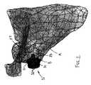
例えば、図2は、ボールヘッド型(すなわち半球状ヘッド20A)のインプラント20の部品群(図14にも同部品が示されている)を有する患者の肩甲骨Aのモデルを示している。インプラント20はベースプレート21を備える。ベースプレート21は金属製のタイプであり、再表面化後の関節窩C(図9)に接着され、装着される。例えば、骨梁のような(trabecular-like)医療グレード金属をベースプレート21に使用してよい。ベースプレート21の下側からペグ22が突き出て、関節窩Bに開けられた穴に収容される。ねじ23もベースプレート21の下側から突き出て、インプラント20を肩甲骨Aに繋止する。これらの部品は概して一体式であるため、本体25はベースプレート21に固定されている。本体25は、インプラント20と半球状ボールヘッドの間のインターフェースであり、この半球状ボールヘッドは、上腕骨又は上腕骨上のインプラントに接する表面を形成する。したがって、ねじ23が貫通穴26を通過している状態で、本体25及びベースプレート21内で貫通穴26が同時に形成される。 For example, FIG. 2 shows a model of a patient's scapula A having a group of components of a ball head type (ie, hemispherical head 20A) implant 20 (also shown in FIG. 14). The
方法10のステップ12〜17は、ステップ11の仮想肩関節形成術計画を再現するように、外科医又はオペレーターを手引きして骨組織変更を実施するのに使われる。ゆえに、方法10のステップ12〜17は、仮想計画と実質的に同様に関節窩インプラントを設置させる目的で実施する。 Steps 12-17 of
ステップ12に従い、仮想計画作成から得たデータを用いてPSIを作成する。PSIについては下記でさらに詳しく述べる。仮想計画作成の結果として求められるPSIを精密かつ正確に表現する限り、PSIには任意の適切な製造方法及び材料を用いてよい。ステップ12のPSI作成は、仮想肩関節形成術の計画作成ステップ11でも使用した画像データを用いて、手術前に実施する。解剖学的データの他の供給源(例えば、手術前に得た手動骨測定値)も使用してよい。計画作成ステップを通じて取得できる他の情報の1つとして、必要なグラフトの生成がある。インプラントと肩甲骨の間にグラフトウェッジ(graft wedge)が必要とされる場合があり、したがって計画作成ステップにより、図15に示すような必要なグラフトのモデルを定義でき、加えて、仮想計画作成において計算される所定の幾何学的配置のグラフトウェッジB1を形成するためのPSIツールを定義できる。グラフトウェッジB1は、インプラント20と機械処理後の関節窩Cの間の位置に置かれることになる。浅い関節窩C(すなわち完全なカウンターボア形状を持たない関節窩C)に制限された肩甲骨では、グラフトの使用が必要とされ得る。ゆえにグラフトウェッジB1は、図15に示される通り、関節窩Cと共に、インプラント20に対する取付面を形成することになる。 According to step 12, a PSI is created using data obtained from the virtual plan creation. PSI is described in more detail below. Any appropriate manufacturing method and material may be used for the PSI as long as the PSI required as a result of the virtual planning is accurately and accurately expressed. The PSI creation in
ステップ13〜17は手術中に実施する。肩関節を露出し、肩甲骨A(図2)から上腕骨を脱臼させ、切除し、及び/又は分離した後、ステップ13〜17を実施する。 Steps 13-17 are performed during the operation. Steps 13-17 are performed after the shoulder joint is exposed and the humerus is dislocated, resected and / or separated from the scapula A (FIG. 2).
ステップ13(図1)に従い、PSIを用いて一対のピンを肩甲骨Aに配置する。図3及び4を共に参照すると、30にピン配置PSIの概要が示されている。ピン配置PSI 30は、解剖学的接触面31を備える。解剖学的接触面31は、肩甲骨ヘッドの両側及び/又は関節窩Bのネックを中に受け入れられるように、側方が開いたフックのような形状を有する。PSIに従って、解剖学的接触面31は、当該患者の対応する肩甲骨面と一致するように製造された接触面(複数可)32を有する。したがって、ピン配置PSI 30の位置決めは、肩甲骨A側の対応する一致面を見出す接触面32に案内される。 According to step 13 (FIG. 1), a pair of pins is placed on the scapula A using PSI. Referring to FIGS. 3 and 4 together, 30 shows an overview of the pinout PSI. The
ピン配置PSI 30は、ドリルガイド33をさらに備える。ドリルガイド33は、ステップ11の仮想計画(図1)に応じて、解剖学的接触面31に対して位置決めされる。ドリルガイド33は、一対の円筒形の切り抜き部すなわちスロット34を有し、スロット34は、特に、関節窩B内でのピンのドリリングを案内する位置及び向きにされる(すなわち、スロット34はPSI 30の長手方向に伸びる)。一実施形態によれば、側方開口部35により側方からスロット34にアクセスできるので、ピンを側方からスロット34に挿入することができる。ピン配置PSI 30の操作を容易にする目的で、ソケット36又は同様のコネクターをドリルガイド33内に形成してもよい。例えば、ピン配置PSI 30を遠位で操作するため、ソケット36を介して細長いツールをピン配置PSI 30に接続してよい。 The
図4及び5に共に示されている通り、ピン40を差し込んで肩甲骨Aに穴開けする。ピン40に、計画されたはめあい(例えば精密なはめあい)で受け入れられるスリーブ41(別名ブッシュ)を設けてよく、この場合、スリーブ41はスロット34で中心に位置決めされた貫通穴を有するので、ピン40は、スロット34内で確実に軸方向の中心に置かれる。さらに、スリーブ41は、ピン40の関節窩内の挿入深さを制御するための突き合わせ端部42を備えてよい。また、ピン40に目盛りを付けるなど、ピン40の挿入深さを制御するための任意の適切な方法も考えられる。 A
手術中、ハンドル43をソケット36に接続し(図3及び4)、ピン配置PSI 30を骨の計画上の位置へと側方に動かすことにより、解剖学的接触面31を用いてピン配置PSI 30を関節窩B上に設置して、ピン配置PSI 30を肩甲骨A上に確実に正しく位置付ける。スリーブ41の付いたピン40を、側方開口部35を介してピン配置PSIのスロット34に挿入し、ピン40を差し込んで関節窩Bに穴開けしてよく、又は、スロット34にスリーブ/ブッシュ41を配置してからピン40を中に通してもよい。ピン40が適切に肩甲骨Aに挿入されたら、スリーブ41をピン40の端部からスライドさせて外すことによりスリーブ41を引き抜いてよく(図5)、これにより、ピン配置PSI 30を側方に動かして肩甲骨Aから除去できる。解剖学的接触面31のフックのような部分の表面は、概してドリルガイド33の長手方向に対して横断する。側方開口部35が存在することにより、ピン40が側方開口部35を通過するので、PSI 30を側方に引き抜くのに困難を来すことなく、解剖学的接触面31のフックのような部分との間の良好な接触面が得られる。 During surgery, the
図示されている実施形態によれば、ピン40の一方は、予測される再表面化済み関節窩Cの中心にあり、他方のピン40は、烏口又は烏口ベース部と共に配列される関節窩縁に隣接する位置にある。他の位置も考えられる。例示目的で、図16に、肩甲骨Aに対するピン配置PSI 30の企図される位置を概略で示す。 According to the illustrated embodiment, one of the
図1を参照すると、ステップ14の深部穴開け及び/又は関節窩Bの表面リーマ処理は、ピン40及び適切なPSIを用いて行う。図6及び7を共に参照すると、60にリーマ処理PSIの概要が示されている。リーマ処理PSI 60は第1チューブ61を有し、この第1チューブ61は、ピン40の一方にスライドしてかぶさる寸法にされたピンスロット62を有し、これにより、共に円筒形結合部を形成する。第1チューブ61の一方の端は、肩甲骨Aと接する突き合わせ部63を形成する。スペーシングアーム64は、第1チューブ61から側方に伸びて、その自由端に第2チューブ65を有する。第2チューブもシャフトスロット66を備え、このシャフトスロット66は、側方開口部67を介してアクセス可能であり、側方開口部67を用いてリーマ処理PSI 60を回転させると、ピン40がシャフトスロット66に入る。リーマ処理PSI 60は各患者に固有であるため、ピンスロット62とシャフトスロット66の間は、ピン40同士の間隔に合うように所定の距離が空けられている。したがって、図7に示すように、第1チューブ61がスライドして一方のピン40にかぶさると、他方のピン40は、第2チューブ65のシャフトスロット66の中に入る向きにされ得る。 Referring to FIG. 1, the deep drilling and / or surface reaming of the glenoid B in
ステップ14にピン40の位置の確認を含めてよいことが指摘される。リーマ処理PSI 60はピン40を受け入れるように製作されるので、中央に位置付けられたピン40は、第2チューブ65において軸方向の中心に位置するはずである。中心がずれていると、ピン40の位置決めが不適切であると指摘される場合があり、このような指摘の結果、ステップ13を見直し、ピン40の位置を変更することがあり得る。 It is pointed out that
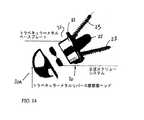
したがって、図8を参照すると、並進運動するピン40に同軸上に案内されるように、カニューレ挿入リーマ80を、シャフトスロット66の中にあるピン40に取り付けてよい。リーマ80は、関節窩Bに計画上の直径を再表面化するように選択されたリーマ端部81を有する。リーマ端部81はシャフト82の端に位置する。シャフト82は、リーマ処理PSI 60のシャフトスロット66に受け入れられるサイズにされて、並進結合部を形成する。さらに、リーマ端部81は、リーマ処理PSI 60との付き合わせにより形成される深さまで、インプラント20のペグ22(図2)を受け入れるのに充分な直径の穴を開けてもよい。あるいは、ペグ用の穴開けを別途行ってもよい。したがって、カニューレ挿入リーマ80に入ったピン40と、シャフト82及びシャフトスロット66間の協同作用との組み合わせにより、特定の所望の深さまで確実に関節窩Bがリーマ処理される。シャフト82は、スライドさせるかカチッとはめ込むことによりシャフトスロット66に入る。さらに図8を参照すると、シャフト82の端部にストッパー83を取り付けてよい。ストッパー83がリーマ処理PSI 60と協同することにより、関節窩Bへのリーマ80の貫通深さが制限され、その結果、表面リーマ処理及び任意の深部穴開け(図2のペグ22用に別途実施する場合)の深さが確実に計画通りの深さになる。 Thus, referring to FIG. 8, a cannula reamer 80 may be attached to the
両方のピン40を使用すると、リーマ処理PSI 60が支えられ、かつカニューレ挿入リーマ80の動きが案内されることが観察される。両方のピン40を使用することにより、単一のピン40よりも、ピン40/PSI 60アセンブリの構造的完全性が高まる。しかしながら、カニューレ挿入リーマ80、リーマ処理された関節窩Bと共に、例えば単一のピン40を使用するなど、他の構成を使用することも考えられる。 Using both
図9に示す通り、関節窩Bのリーマ処理が完了して、ペグ穴Dを有する再表面化された関節窩Cが形成されたら、ピン40と一緒に深部穴開けPSI 60を除去してよい。図示していないが、下記で説明するように、再表面化された関節窩Cにない方のピン40を留置することが所望される場合もある。ウェッジグラフトB1を使用する場合は(図15)、再表面化済み関節窩Cに隣接する、関節窩Bの適切な位置にウェッジグラフトB1を取り付ける。オペレーターがウェッジグラフトB1を適切な向きにする上で、烏口側のピン40を用いて案内することができる。ウェッジグラフトB1を関節窩Bに融合させてもよく、その場合、ねじ23により、インプラント20とウェッジグラフトB1の両方を関節窩Bに固定する。 As shown in FIG. 9, once the reaming of the glenoid B has been completed to form a resurfaced glenoid C with peg holes D, the
図1を参照すると、ピンのいずれか一方と、インプラント20を正しい向きにするためのPSIを用いて、ステップ15のインプラント20の打ち込み(impact)を実施する。より具体的には、インプラント20の向きは、ねじ23の位置決めに影響を及ぼす(図2)。ゆえに、ステップ11の仮想計画を再現するには、貫通穴26がねじ23の計画上の挿入位置と共に配列されるように、インプラント20を正しい方向に向けなければならない。 Referring to FIG. 1, the
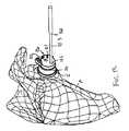
図10及び11を共に参照すると、打ち込みガイドPSIの概要が100に示されている。打ち込みガイドPSI 100は、ピンスロット102の付いたチューブ101を備える。ピンスロット102は、残っているピン40を受け入れて、共に円筒形結合部を形成するサイズにされる。チューブの(任意の形状/幾何学的配置との)突き合わせ端部は、周辺の骨面に寄り掛かるように成形された患者特有の接触面を有し得るので、チューブ101が骨に当たったときにPSIが回転するのを防止できる。チューブ101から側方にアーム104が突き出ている。アーム104の自由端にガイドブラケット105があり、このガイドブラケット105を使ってインパクターツール110の動きが案内される。より具体的には、ガイドブラケット105は、インパクターツール110のシャフト111を中に受け入れるための側方開口部を有し、共に滑り結合部を形成する。 Referring to FIGS. 10 and 11 together, an overview of the driving guide PSI is shown at 100. The driving
インパクターツール110は、インプラント20の貫通穴26(図2)に受け入れられる間隔の空いた一対のペグの付いた従来型のものでよい。インパクターツール110のシャフト111の端部にあるこれらのペグの位置に応じて、ガイドブラケット105を特定の方向に向け、これにより、仮想計画作成ステップ11(図1)に従ってインプラント20の貫通穴26の位置決めを制御する。 The
ゆえに、図11のアセンブリを用いて、インプラント20を再表面化済み関節窩Cに挿入することができる。インプラント20と再表面化済み関節窩Cの形状が一致している結果、打ち込み中にインプラント20が自動的に中心に配置され得る(したがって、突き合わせ端部103位置で患者特有の面のアラインメントを実施する必要がない)。しかしながら、PSI 100及びインパクターツール110により、貫通穴26が計画通りに位置した状態で、インプラント20が再表面化済み関節窩Cに完全に挿入することが概ね確保される。この時点で、インプラント20を再表面化済み関節窩Cに残して、PSI 100をインパクターツール110と共に除去してよい。 Thus, the
図1のステップ16に従い、後続のねじ23の挿入のため、計画通りに関節窩にアンカー穴を開けてよい。図12及び13を参照すると、ドリルガイドPSI 120は、インプラント本体25の対応する窪みに受け入れられるサイズにされた本体121を有する。ドリルガイドPSI 120の本体121内に、一対のドリルガイド穴122が形成されている。ドリルガイド穴122は、特に、案内シリンダー122Aがインプラント20内で貫通穴26の軸線上の延長に沿うような位置及び向きにされる(図2)。さらに、案内シリンダー122Aの直径は概ね先細りになり、その中心にドリルビット123が置かれ、その結果、ドリルビット123とドリルガイド穴122の間の潜在的な遊びを低減している。ドリルガイドPSI 120の本体121に使用する材料として、ドリルビット123による損傷を受けないような材料を選択してもよい。図13に示すように、穴開け深さを制御し計画通りのアンカー穴深さに達するようにするため、ドリルビット123にストッパー124を設けてよい。別の方法として、ドリルビット123に目盛りを付けて深さを制御するなどの方法も考えられる。アンカー穴を開ける作業が完了したら、ドリルガイドPSI 120を除去してよい。図12に示すように、ドリルガイドPSI 120は視覚ポインター125を備えていてもよい。視覚ポインター125は、残っているピンを指し示す目的で、ドリルガイドPSI 120内に患者ごとに個別に形成してよい。したがって、このポインターは、確実に所望の位置に穴開けするための追加の確認ステップを表す。 According to step 16 of FIG. 1, an anchor hole may be drilled in the glenoid as planned for
図1のステップ17に従い、ねじ23(又は同様の留め具)でインプラント20を肩甲骨Aに固定してよく、これにより図2の仮想計画が再現される。次に、従来型のステップを実施して肩関節術を完成させる。 According to step 17 of FIG. 1, the
方法10に図15のグラフトB1を作成するステップを含めてよいことが指摘される。上腕骨の表面を再建する必要があることから、方法10のこのステップに、例えば上腕骨から骨材料を除去するためのPSIツールを設けることを含めてよい。しかしながら、上腕骨又は他の骨から除去されるグラフトB1は、単に円筒形状であり得るので、適切な直径の標準の円筒形リーマを使用してよい。図15に示すグラフトB1は楔形であるため、グラフトB1の斜面を機械加工するための適切なPSIを作成してよい。 It is pointed out that
上記の方法及びシステムは、特定の順序で実施される特定のステップを参照して説明し表示されているが、本開示の教示内容から逸脱することなしに、これらのステップを組み合わせ、細分し、又は順序変更して同等の方法を形成することができる。したがって、上記ステップの順序及びグループ化は本開示の制限事項ではない。 Although the methods and systems described above are described and illustrated with reference to specific steps performed in a specific order, these steps may be combined, subdivided, and without departing from the teachings of the present disclosure, Or the order can be changed to form an equivalent method. Accordingly, the order and grouping of the above steps is not a limitation of the present disclosure.
Claims (18)
Translated fromJapanese所定の位置で骨を中に受け入れるために当該ピン配置器具の側方に開かれているフックのような部分を有する解剖学的接触面と、
該解剖学的接触面に接続され、当該ピン配置器具の長手方向に少なくとも1つのガイドスロットを形成するドリルガイドであって、少なくとも1つの前記ガイドスロットが、該ガイドスロットの全長に亘り当該ドリルガイド内に側方開口部を有し、前記骨の中に配置された前記ピンを前記側方開口部から通過させて、前記側方への当該ピン配置器具の側方引き出しを可能とするドリルガイドと、
前記長手方向に所定のはめあいで前記ガイドスロット内に取り外し可能に配置された少なくとも1つのブッシュであって、前記ブッシュがピン配置のため前記ガイドスロット内にあるときに、前記ガイドスロットと共に配列された貫通穴を形成し、且つ、前記長手方向に延びる前記ピンを受け入れるように構成されたブッシュと、を具備するピン配置器具。A pin placement device for placing a pin in a bone,
An anatomical contact surface having a hook-like portion open to the side of the pin placement instrument to receive the bone therein in place;
A drill guide connected to the anatomical contact surface and forming at least one guide slot in a longitudinal direction of the pin placement instrument, wherein the at least one guide slot extends over the entire length of the guide slot. A drill guide having a side opening therein and allowing the pin disposed in the bone to pass through the side opening and allowing the pin placement instrument to be pulled out to the side. When,
At least one bushing removably disposed within the guide slot with a predetermined fit in the longitudinal direction, wherein the bushing is arranged with the guide slot when the bushing is within the guide slot for pin placement And a bushing configured to receive the pin extending through the longitudinal direction and extending in the longitudinal direction.
少なくとも2つのピンスロットを有する患者特有の器具を得ることと、
肩甲骨に固定された第1ピンに亘り前記患者特有の器具のピンスロットを設置することと、
前記関節窩に固定された第2ピンに亘りカニューレ挿入リーマを設置することと、
前記カニューレ挿入リーマのシャフトに亘り前記患者特有の器具のシャフトスロットを設置し、前記シャフトスロットと前記カニューレ挿入リーマの前記シャフトとの間に、前記第2ピンに沿った前記カニューレ挿入リーマの並進運動を可能とする結合部を形成することと、
前記患者特有の器具及び前記ピンによって案内されたときに前記カニューレ挿入リーマを用いて前記関節窩にリーマ処理をすることと、を含む方法。A method for resurfacing the glenoid,
Obtaining a patient-specific device having at least two pin slots;
Installing a pin slot for the patient-specific instrument over a first pin secured to the scapula;
Installing a cannulated reamer over a second pin secured to the glenoid;
Placing a shaft slot of the patient-specific instrument across the shaft of the cannula insertion reamer, and translational movement of the cannula insertion reamer along the second pin between the shaft slot and the shaft of the cannula insertion reamer Forming a coupling part that enables
Reaming the glenoid with the cannulated reamer when guided by the patient-specific instrument and the pin.
少なくとも1つのピンスロットを有する患者特有の器具を得ることと、
肩甲骨に固定されたピンに亘り前記患者特有の器具の前記ピンスロットを設置することと、
シャフトが前記再表面化された関節窩と共に配列されるように、前記患者特有の器具のガイドブラケット内にインパクターの前記シャフトを設置し、前記シャフトと前記ガイドブラケットとの間に、前記ガイドブラケットに沿った前記シャフトの並進運動を可能とする並進結合部が形成されるようにすることと、
前記インパクターの自由端において前記インプラントを設置することと、
前記患者特有の器具及び前記ピンによって案内されたときに、前記再表面化された関節窩へと前記インプラントを押しこむことと、を含む方法。A method for placing an implant in a resurfaced glenoid, comprising:
Obtaining a patient-specific device having at least one pin slot;
Installing the pin slot of the patient-specific instrument across a pin secured to the scapula;
The shaft of the impactor is installed in a guide bracket of the patient-specific device so that the shaft is aligned with the resurfaced glenoid, and the guide bracket is placed between the shaft and the guide bracket. A translational coupling is formed that allows translational movement of the shaft along;
Installing the implant at the free end of the impactor;
Pushing the implant into the resurfaced glenoid when guided by the patient-specific instrument and the pin.
Applications Claiming Priority (7)
| Application Number | Priority Date | Filing Date | Title |
|---|---|---|---|
| US201261616623P | 2012-03-28 | 2012-03-28 | |
| US61/616,623 | 2012-03-28 | ||
| US201261659272P | 2012-06-13 | 2012-06-13 | |
| US61/659,272 | 2012-06-13 | ||
| US201261675955P | 2012-07-26 | 2012-07-26 | |
| US61/675,955 | 2012-07-26 | ||
| PCT/CA2013/050253WO2013142998A1 (en) | 2012-03-28 | 2013-03-28 | Glenoid implant surgery using patient specific instrumentation |
Related Child Applications (1)
| Application Number | Title | Priority Date | Filing Date |
|---|---|---|---|
| JP2017122421ADivisionJP6483758B2 (en) | 2012-03-28 | 2017-06-22 | Glenoid implants using patient-specific instruments |
Publications (3)
| Publication Number | Publication Date |
|---|---|
| JP2015511511Atrue JP2015511511A (en) | 2015-04-20 |
| JP2015511511A5 JP2015511511A5 (en) | 2016-04-21 |
| JP6166775B2 JP6166775B2 (en) | 2017-07-19 |
Family
ID=49258018
Family Applications (3)
| Application Number | Title | Priority Date | Filing Date |
|---|---|---|---|
| JP2015502026AActiveJP6166775B2 (en) | 2012-03-28 | 2013-03-28 | Glenoid implants using patient-specific instruments |
| JP2017122421AActiveJP6483758B2 (en) | 2012-03-28 | 2017-06-22 | Glenoid implants using patient-specific instruments |
| JP2019024550APendingJP2019084381A (en) | 2012-03-28 | 2019-02-14 | Glenoid cavity implant surgery using patient specific instrumentation |
Family Applications After (2)
| Application Number | Title | Priority Date | Filing Date |
|---|---|---|---|
| JP2017122421AActiveJP6483758B2 (en) | 2012-03-28 | 2017-06-22 | Glenoid implants using patient-specific instruments |
| JP2019024550APendingJP2019084381A (en) | 2012-03-28 | 2019-02-14 | Glenoid cavity implant surgery using patient specific instrumentation |
Country Status (7)
| Country | Link |
|---|---|
| US (3) | US10543100B2 (en) |
| EP (2) | EP2830521B1 (en) |
| JP (3) | JP6166775B2 (en) |
| CN (1) | CN104203134B (en) |
| CA (3) | CA2866395C (en) |
| ES (1) | ES2637823T3 (en) |
| WO (1) | WO2013142998A1 (en) |
Cited By (1)
| Publication number | Priority date | Publication date | Assignee | Title |
|---|---|---|---|---|
| JP2022533835A (en)* | 2019-05-20 | 2022-07-26 | ホウメディカ・オステオニクス・コーポレイション | Automated Planning for Shoulder Stabilization Surgery |
Families Citing this family (58)
| Publication number | Priority date | Publication date | Assignee | Title |
|---|---|---|---|---|
| US8388624B2 (en) | 2003-02-24 | 2013-03-05 | Arthrosurface Incorporated | Trochlear resurfacing system and method |
| WO2006004885A2 (en) | 2004-06-28 | 2006-01-12 | Arthrosurface, Inc. | System for articular surface replacement |
| US9358029B2 (en) | 2006-12-11 | 2016-06-07 | Arthrosurface Incorporated | Retrograde resection apparatus and method |
| FR2932674B1 (en) | 2008-06-20 | 2011-11-18 | Tornier Sa | METHOD FOR MODELING A GLENOIDAL SURFACE OF AN OMOPLATE, DEVICE FOR IMPLANTING A GLENOIDAL COMPONENT OF A SHOULDER PROSTHESIS, AND METHOD FOR MANUFACTURING SUCH COMPOUND |
| GB0819635D0 (en)* | 2008-10-27 | 2008-12-03 | Auron Invest Ltd | A composition for the treatment of hypertension |
| WO2010121250A1 (en) | 2009-04-17 | 2010-10-21 | Arthrosurface Incorporated | Glenoid resurfacing system and method |
| US10945743B2 (en) | 2009-04-17 | 2021-03-16 | Arthrosurface Incorporated | Glenoid repair system and methods of use thereof |
| FR2955247B1 (en) | 2010-01-21 | 2013-04-26 | Tornier Sa | GLENOIDAL COMPONENT OF SHOULDER PROSTHESIS |
| EP2542165A4 (en) | 2010-03-05 | 2015-10-07 | Arthrosurface Inc | Tibial resurfacing system and method |
| FR2971144A1 (en) | 2011-02-08 | 2012-08-10 | Tornier Sa | GLENOIDAL IMPLANT FOR SHOULDER PROSTHESIS AND SURGICAL KIT |
| US9301812B2 (en) | 2011-10-27 | 2016-04-05 | Biomet Manufacturing, Llc | Methods for patient-specific shoulder arthroplasty |
| US9451973B2 (en)* | 2011-10-27 | 2016-09-27 | Biomet Manufacturing, Llc | Patient specific glenoid guide |
| WO2013062848A1 (en) | 2011-10-27 | 2013-05-02 | Biomet Manufacturing Corporation | Patient-specific glenoid guides |
| EP2804565B1 (en) | 2011-12-22 | 2018-03-07 | Arthrosurface Incorporated | System for bone fixation |
| WO2014008126A1 (en) | 2012-07-03 | 2014-01-09 | Arthrosurface Incorporated | System and method for joint resurfacing and repair |
| US9839438B2 (en)* | 2013-03-11 | 2017-12-12 | Biomet Manufacturing, Llc | Patient-specific glenoid guide with a reusable guide holder |
| US9492200B2 (en) | 2013-04-16 | 2016-11-15 | Arthrosurface Incorporated | Suture system and method |
| US9173665B2 (en)* | 2013-09-06 | 2015-11-03 | Zimmer, Inc. | Patient-specific surgical guide for intra-operative production of patient-specific augment |
| EP3057524B1 (en)* | 2013-10-10 | 2019-11-20 | Imascap | Method for designing and producing a shoulder surgery guide |
| CA2927811C (en)* | 2013-10-17 | 2022-07-05 | Imascap Sas | Methods, systems and devices for pre-operatively planned glenoid placement guides and uses thereof |
| EP3925574A1 (en) | 2013-11-08 | 2021-12-22 | Imascap | Pre-operatively planned adaptive glenoid implants and method for planning its design |
| US10405993B2 (en) | 2013-11-13 | 2019-09-10 | Tornier Sas | Shoulder patient specific instrument |
| WO2015103090A1 (en) | 2014-01-03 | 2015-07-09 | Tornier, Inc. | Reverse shoulder systems |
| US11607319B2 (en) | 2014-03-07 | 2023-03-21 | Arthrosurface Incorporated | System and method for repairing articular surfaces |
| US9931219B2 (en) | 2014-03-07 | 2018-04-03 | Arthrosurface Incorporated | Implant and anchor assembly |
| US10624748B2 (en) | 2014-03-07 | 2020-04-21 | Arthrosurface Incorporated | System and method for repairing articular surfaces |
| US9681960B2 (en) | 2014-05-16 | 2017-06-20 | Howmedica Osteonics Corp. | Guides for fracture system |
| US10575968B2 (en) | 2014-05-16 | 2020-03-03 | Howmedica Osteonics Corp. | Guides for fracture system |
| US10070873B2 (en) | 2014-06-30 | 2018-09-11 | Tornier, Inc. | Device for maintaining alignment of a cannulated shaft over a guide pin |
| CN107405109B (en)* | 2015-03-10 | 2021-07-16 | 史密夫和内修有限公司 | Open LATARJET procedure for correcting anterior lower glenoid bone loss |
| GB201504122D0 (en)* | 2015-03-11 | 2015-04-22 | Imp Innovations Ltd | Patient-specific surgical guide |
| EP3273878B1 (en)* | 2015-03-24 | 2025-02-26 | Arthrosurface Incorporated | Glenoid repair system |
| EP3273917B1 (en)* | 2015-03-25 | 2020-02-12 | Orthosoft ULC | Glenosphere-implant positioning device |
| WO2016149824A1 (en)* | 2015-03-25 | 2016-09-29 | Orthosoft Inc. | Method and system for assisting implant placement in thin bones such as scapula |
| CA2983650C (en)* | 2015-04-24 | 2021-03-16 | Biomet Manufacturing, Llc | Patient-specific augmented glenoid systems and methods |
| US10722374B2 (en) | 2015-05-05 | 2020-07-28 | Tornier, Inc. | Convertible glenoid implant |
| US10271858B2 (en)* | 2015-05-28 | 2019-04-30 | Zimmer, Inc. | Patient-specific bone grafting system and method |
| US10426624B2 (en) | 2015-06-02 | 2019-10-01 | Zimmer, Inc. | Glenosphere guide tool |
| AU2016290962B2 (en)* | 2015-07-08 | 2021-04-08 | Zimmer, Inc. | Patient-specific instrumentation for implant revision surgery |
| EP3389513A1 (en) | 2015-12-16 | 2018-10-24 | Tornier, Inc. | Patient specific instruments and methods for joint prosthesis |
| WO2018009794A1 (en) | 2016-07-08 | 2018-01-11 | Biomet Manufacturing, Llc | Reverse shoulder pre-operative planning |
| US9737313B1 (en) | 2016-11-07 | 2017-08-22 | Roger C. Sohn | Shoulder reamer devices, systems including the same, and related methods |
| WO2018213094A1 (en)* | 2017-05-19 | 2018-11-22 | Biomet Manufacturing, Llc | Implant assembly tools |
| EP3651664A1 (en) | 2017-07-11 | 2020-05-20 | Tornier, Inc. | Guides and instruments for improving accuracy of glenoid implant placement |
| US10959742B2 (en) | 2017-07-11 | 2021-03-30 | Tornier, Inc. | Patient specific humeral cutting guides |
| US11160663B2 (en) | 2017-08-04 | 2021-11-02 | Arthrosurface Incorporated | Multicomponent articular surface implant |
| WO2019079104A2 (en) | 2017-10-16 | 2019-04-25 | Imascap Sas | Shoulder implants and methods of use and assembly |
| AU2018389761B2 (en)* | 2017-12-22 | 2021-04-22 | Medacta International Sa | Cutting guide for periacetabular osteotomy and kit for periacetabular osteotomy |
| CA3087066A1 (en) | 2017-12-29 | 2019-07-04 | Tornier, Inc. | Patient specific humeral implant components |
| WO2020033911A1 (en)* | 2018-08-10 | 2020-02-13 | Tornier, Inc. | Guides and instruments for improving accuracy of glenoid implant placement |
| CN111493972B (en)* | 2019-01-30 | 2024-07-12 | 北京大学第三医院(北京大学第三临床医学院) | Bone drill sighting device |
| WO2020186099A1 (en) | 2019-03-12 | 2020-09-17 | Arthrosurface Incorporated | Humeral and glenoid articular surface implant systems and methods |
| JP7257546B2 (en) | 2019-05-13 | 2023-04-13 | ハウメディカ オステオニクス コーポレイション | Glenoid baseplate and implant assembly |
| EP3982848A1 (en) | 2019-08-09 | 2022-04-20 | Howmedica Osteonics Corp. | Apparatuses and methods for implanting glenoid prostheses |
| CN112315581B (en)* | 2020-09-29 | 2022-05-06 | 上海霖晏医疗科技有限公司 | Method and device for determining pedicle screw feeding point |
| KR102558805B1 (en)* | 2021-07-29 | 2023-07-25 | 애니메디솔루션 주식회사 | Pin guide and screw guide for artificial shoulder joint surgery |
| KR102624485B1 (en)* | 2023-07-12 | 2024-01-15 | (주)시안솔루션 | Method for designing patient-specific guidance, program and server thereof |
| CN118873233B (en)* | 2024-08-27 | 2025-01-28 | 常州市妇幼保健院 | Clavicle and coracoid bone tunnel alignment and wire passing device |
Citations (8)
| Publication number | Priority date | Publication date | Assignee | Title |
|---|---|---|---|---|
| US5030219A (en)* | 1990-01-22 | 1991-07-09 | Boehringer Mannheim Corporation | Glenoid component installation tools |
| US20060079963A1 (en)* | 2004-10-07 | 2006-04-13 | Regan Hansen | Semiconstrained shoulder prosthetic for treatment of rotator cuff arthropathy |
| US20070288030A1 (en)* | 2006-06-09 | 2007-12-13 | Biomet Manufacturing Corp. | Patient Specific Knee Alignment Guide And Associated Method |
| US20090099567A1 (en)* | 2007-09-30 | 2009-04-16 | Eric Zajac | Customized Patient-Specific Bone Cutting Blocks |
| JP2010531187A (en)* | 2007-06-25 | 2010-09-24 | デピュー インターナショナル リミテッド | Surgical instruments |
| US20110029088A1 (en)* | 2009-07-31 | 2011-02-03 | Zimmer, Gmbh | Glenoid alignment tool |
| JP2011517996A (en)* | 2008-04-16 | 2011-06-23 | バイオメット・マニュファクチャリング・コーポレイション | Implant modified according to patient and related method |
| WO2011110374A1 (en)* | 2010-03-10 | 2011-09-15 | Depuy Orthopadie Gmbh | Orthopaedic instrument |
Family Cites Families (183)
| Publication number | Priority date | Publication date | Assignee | Title |
|---|---|---|---|---|
| US4841975A (en) | 1987-04-15 | 1989-06-27 | Cemax, Inc. | Preoperative planning of bone cuts and joint replacement using radiant energy scan imaging |
| US5098383A (en) | 1990-02-08 | 1992-03-24 | Artifax Ltd. | Device for orienting appliances, prostheses, and instrumentation in medical procedures and methods of making same |
| DE69319587T2 (en) | 1992-02-20 | 1999-04-01 | Synvasive Technology, Inc., El Dorado Hills, Calif. | SURGICAL CUTTING BLOCK |
| US5342369A (en)* | 1992-09-11 | 1994-08-30 | The Board Of Regents Of The University Of Washington | System for repair of bankart lesions |
| US5354300A (en)* | 1993-01-15 | 1994-10-11 | Depuy Inc. | Drill guide apparatus for installing a transverse pin |
| US5330468A (en)* | 1993-10-12 | 1994-07-19 | Burkhart Stephen S | Drill guide device for arthroscopic surgery |
| BE1008372A3 (en) | 1994-04-19 | 1996-04-02 | Materialise Nv | METHOD FOR MANUFACTURING A perfected MEDICAL MODEL BASED ON DIGITAL IMAGE INFORMATION OF A BODY. |
| US5489310A (en)* | 1994-06-27 | 1996-02-06 | Mikhail; W. E. Michael | Universal glenoid shoulder prosthesis and method for implanting |
| US5682886A (en) | 1995-12-26 | 1997-11-04 | Musculographics Inc | Computer-assisted surgical system |
| US5769856A (en)* | 1996-06-24 | 1998-06-23 | Osteonics Corp. | Drill guide and implant method |
| US8545569B2 (en) | 2001-05-25 | 2013-10-01 | Conformis, Inc. | Patient selectable knee arthroplasty devices |
| US20070233269A1 (en) | 2001-05-25 | 2007-10-04 | Conformis, Inc. | Interpositional Joint Implant |
| US7534263B2 (en) | 2001-05-25 | 2009-05-19 | Conformis, Inc. | Surgical tools facilitating increased accuracy, speed and simplicity in performing joint arthroplasty |
| US20110071645A1 (en) | 2009-02-25 | 2011-03-24 | Ray Bojarski | Patient-adapted and improved articular implants, designs and related guide tools |
| US8480754B2 (en) | 2001-05-25 | 2013-07-09 | Conformis, Inc. | Patient-adapted and improved articular implants, designs and related guide tools |
| US20030055502A1 (en) | 2001-05-25 | 2003-03-20 | Philipp Lang | Methods and compositions for articular resurfacing |
| US8771365B2 (en) | 2009-02-25 | 2014-07-08 | Conformis, Inc. | Patient-adapted and improved orthopedic implants, designs, and related tools |
| US20110071802A1 (en) | 2009-02-25 | 2011-03-24 | Ray Bojarski | Patient-adapted and improved articular implants, designs and related guide tools |
| US8617242B2 (en) | 2001-05-25 | 2013-12-31 | Conformis, Inc. | Implant device and method for manufacture |
| US8083745B2 (en) | 2001-05-25 | 2011-12-27 | Conformis, Inc. | Surgical tools for arthroplasty |
| US7618451B2 (en) | 2001-05-25 | 2009-11-17 | Conformis, Inc. | Patient selectable joint arthroplasty devices and surgical tools facilitating increased accuracy, speed and simplicity in performing total and partial joint arthroplasty |
| US20090222103A1 (en) | 2001-05-25 | 2009-09-03 | Conformis, Inc. | Articular Implants Providing Lower Adjacent Cartilage Wear |
| US8882847B2 (en) | 2001-05-25 | 2014-11-11 | Conformis, Inc. | Patient selectable knee joint arthroplasty devices |
| US8735773B2 (en) | 2007-02-14 | 2014-05-27 | Conformis, Inc. | Implant device and method for manufacture |
| US20070100462A1 (en) | 2001-05-25 | 2007-05-03 | Conformis, Inc | Joint Arthroplasty Devices |
| US9603711B2 (en) | 2001-05-25 | 2017-03-28 | Conformis, Inc. | Patient-adapted and improved articular implants, designs and related guide tools |
| US7468075B2 (en) | 2001-05-25 | 2008-12-23 | Conformis, Inc. | Methods and compositions for articular repair |
| US8556983B2 (en) | 2001-05-25 | 2013-10-15 | Conformis, Inc. | Patient-adapted and improved orthopedic implants, designs and related tools |
| US5916219A (en) | 1997-02-10 | 1999-06-29 | Matsuno; Shigeo | Tibial plateau resection guide |
| US6379386B1 (en)* | 1997-09-09 | 2002-04-30 | Stryker Technologies Corporation | Anatomic glenoid shoulder prosthesis together with methods and tools for implanting same |
| ATE274844T1 (en)* | 1998-04-09 | 2004-09-15 | Sdgi Holdings Inc | VERTEBRATE BODY DISTRACTOR |
| US6428541B1 (en) | 1998-04-09 | 2002-08-06 | Sdgi Holdings, Inc. | Method and instrumentation for vertebral interbody fusion |
| US7635390B1 (en) | 2000-01-14 | 2009-12-22 | Marctec, Llc | Joint replacement component having a modular articulating surface |
| US8439926B2 (en) | 2001-05-25 | 2013-05-14 | Conformis, Inc. | Patient selectable joint arthroplasty devices and surgical tools |
| WO2013155501A1 (en) | 2012-04-13 | 2013-10-17 | Conformis, Inc. | Patient adapted joint arthroplasty devices, surgical tools and methods of use |
| US20130211531A1 (en) | 2001-05-25 | 2013-08-15 | Conformis, Inc. | Patient-adapted and improved articular implants, designs and related guide tools |
| AU2007202573A1 (en) | 2001-05-25 | 2007-06-28 | Conformis, Inc. | Methods and compositions for articular resurfacing |
| US6364910B1 (en)* | 2001-07-11 | 2002-04-02 | Biomet, Inc. | Method and apparatus for use of a glenoid component |
| US8801720B2 (en) | 2002-05-15 | 2014-08-12 | Otismed Corporation | Total joint arthroplasty system |
| US8965075B2 (en) | 2002-09-16 | 2015-02-24 | Imatx, Inc. | System and method for predicting future fractures |
| CN1728976A (en) | 2002-10-07 | 2006-02-01 | 康复米斯公司 | Minimally invasive joint implant with 3-dimensional geometry matching the articular surfaces |
| JP2006501977A (en) | 2002-10-07 | 2006-01-19 | コンフォーミス・インコーポレイテッド | Minimally invasive joint implant with a three-dimensional profile that conforms to the joint surface |
| JP2006505366A (en) | 2002-11-07 | 2006-02-16 | コンフォーミス・インコーポレイテッド | Method of determining meniscus size and shape and devised treatment |
| AU2003298919A1 (en) | 2002-12-04 | 2004-06-23 | Conformis, Inc. | Fusion of multiple imaging planes for isotropic imaging in mri and quantitative image analysis using isotropic or near-isotropic imaging |
| US7201756B2 (en)* | 2003-03-24 | 2007-04-10 | Herbert Earl Ross | Device and method to assist in arthroscopic repair of detached connective tissue |
| US20050043805A1 (en)* | 2003-08-11 | 2005-02-24 | Chudik Steven C. | Devices and methods used for shoulder replacement |
| AU2011203237B2 (en) | 2003-11-25 | 2012-06-14 | Conformis, Inc. | Patient selectable knee joint arthroplasty devices |
| US8175683B2 (en) | 2003-12-30 | 2012-05-08 | Depuy Products, Inc. | System and method of designing and manufacturing customized instrumentation for accurate implantation of prosthesis by utilizing computed tomography data |
| US20060111722A1 (en) | 2004-11-19 | 2006-05-25 | Hacene Bouadi | Surgical cutting tool |
| WO2007062079A2 (en) | 2005-11-21 | 2007-05-31 | Philipp Lang | Devices and methods for treating facet joints, uncovertebral joints, costovertebral joints and other joints |
| EP1951136A1 (en) | 2005-11-23 | 2008-08-06 | Conformis, Inc. | Implant grasper |
| US7357057B2 (en) | 2006-01-06 | 2008-04-15 | Tung-Lung Chiang | Paper cutter |
| US7854768B2 (en)* | 2006-01-20 | 2010-12-21 | Zimmer Technology, Inc. | Shoulder arthroplasty system |
| CN105030296A (en) | 2006-02-06 | 2015-11-11 | 康复米斯公司 | Patient selectable joint arthroplasty devices and surgical tools |
| US8623026B2 (en) | 2006-02-06 | 2014-01-07 | Conformis, Inc. | Patient selectable joint arthroplasty devices and surgical tools incorporating anatomical relief |
| US9808262B2 (en) | 2006-02-15 | 2017-11-07 | Howmedica Osteonics Corporation | Arthroplasty devices and related methods |
| CA2642615A1 (en) | 2006-02-15 | 2007-08-30 | Otismed Corp | Arthroplasty jigs and related methods |
| US8377066B2 (en) | 2006-02-27 | 2013-02-19 | Biomet Manufacturing Corp. | Patient-specific elbow guides and associated methods |
| US8133234B2 (en) | 2006-02-27 | 2012-03-13 | Biomet Manufacturing Corp. | Patient specific acetabular guide and method |
| US20110172672A1 (en) | 2006-02-27 | 2011-07-14 | Biomet Manufacturing Corp. | Instrument with transparent portion for use with patient-specific alignment guide |
| US9339278B2 (en) | 2006-02-27 | 2016-05-17 | Biomet Manufacturing, Llc | Patient-specific acetabular guides and associated instruments |
| US8591516B2 (en) | 2006-02-27 | 2013-11-26 | Biomet Manufacturing, Llc | Patient-specific orthopedic instruments |
| US9289253B2 (en) | 2006-02-27 | 2016-03-22 | Biomet Manufacturing, Llc | Patient-specific shoulder guide |
| US8608748B2 (en) | 2006-02-27 | 2013-12-17 | Biomet Manufacturing, Llc | Patient specific guides |
| US8241293B2 (en) | 2006-02-27 | 2012-08-14 | Biomet Manufacturing Corp. | Patient specific high tibia osteotomy |
| US8535387B2 (en) | 2006-02-27 | 2013-09-17 | Biomet Manufacturing, Llc | Patient-specific tools and implants |
| US9173661B2 (en) | 2006-02-27 | 2015-11-03 | Biomet Manufacturing, Llc | Patient specific alignment guide with cutting surface and laser indicator |
| US8603180B2 (en) | 2006-02-27 | 2013-12-10 | Biomet Manufacturing, Llc | Patient-specific acetabular alignment guides |
| US8608749B2 (en) | 2006-02-27 | 2013-12-17 | Biomet Manufacturing, Llc | Patient-specific acetabular guides and associated instruments |
| US8864769B2 (en) | 2006-02-27 | 2014-10-21 | Biomet Manufacturing, Llc | Alignment guides with patient-specific anchoring elements |
| US8298237B2 (en) | 2006-06-09 | 2012-10-30 | Biomet Manufacturing Corp. | Patient-specific alignment guide for multiple incisions |
| US8282646B2 (en) | 2006-02-27 | 2012-10-09 | Biomet Manufacturing Corp. | Patient specific knee alignment guide and associated method |
| US8070752B2 (en) | 2006-02-27 | 2011-12-06 | Biomet Manufacturing Corp. | Patient specific alignment guide and inter-operative adjustment |
| US9113971B2 (en) | 2006-02-27 | 2015-08-25 | Biomet Manufacturing, Llc | Femoral acetabular impingement guide |
| US10278711B2 (en) | 2006-02-27 | 2019-05-07 | Biomet Manufacturing, Llc | Patient-specific femoral guide |
| US8858561B2 (en) | 2006-06-09 | 2014-10-14 | Blomet Manufacturing, LLC | Patient-specific alignment guide |
| AU2007226924A1 (en) | 2006-03-21 | 2007-09-27 | Conformis, Inc. | Interpositional joint implant |
| US8460302B2 (en) | 2006-12-18 | 2013-06-11 | Otismed Corporation | Arthroplasty devices and related methods |
| WO2008112996A1 (en) | 2007-03-14 | 2008-09-18 | Conformis, Inc. | Surgical tools for arthroplasty |
| GB2447702A (en) | 2007-03-23 | 2008-09-24 | Univ Leeds | Surgical bone cutting template |
| CN101742972B (en) | 2007-05-14 | 2015-01-07 | 金斯顿女王大学 | Patient-specific surgical guidance tool and method of use |
| WO2008157412A2 (en) | 2007-06-13 | 2008-12-24 | Conformis, Inc. | Surgical cutting guide |
| US8460303B2 (en) | 2007-10-25 | 2013-06-11 | Otismed Corporation | Arthroplasty systems and devices, and related methods |
| EP2397094B1 (en) | 2007-11-02 | 2013-06-26 | Biomet C.V. | Elbow fracture fixation system |
| US10582934B2 (en) | 2007-11-27 | 2020-03-10 | Howmedica Osteonics Corporation | Generating MRI images usable for the creation of 3D bone models employed to make customized arthroplasty jigs |
| US8545509B2 (en) | 2007-12-18 | 2013-10-01 | Otismed Corporation | Arthroplasty system and related methods |
| US8715291B2 (en) | 2007-12-18 | 2014-05-06 | Otismed Corporation | Arthroplasty system and related methods |
| US8617171B2 (en) | 2007-12-18 | 2013-12-31 | Otismed Corporation | Preoperatively planning an arthroplasty procedure and generating a corresponding patient specific arthroplasty resection guide |
| US8480679B2 (en) | 2008-04-29 | 2013-07-09 | Otismed Corporation | Generation of a computerized bone model representative of a pre-degenerated state and useable in the design and manufacture of arthroplasty devices |
| US8221430B2 (en) | 2007-12-18 | 2012-07-17 | Otismed Corporation | System and method for manufacturing arthroplasty jigs |
| US8737700B2 (en) | 2007-12-18 | 2014-05-27 | Otismed Corporation | Preoperatively planning an arthroplasty procedure and generating a corresponding patient specific arthroplasty resection guide |
| US8777875B2 (en) | 2008-07-23 | 2014-07-15 | Otismed Corporation | System and method for manufacturing arthroplasty jigs having improved mating accuracy |
| US8160345B2 (en) | 2008-04-30 | 2012-04-17 | Otismed Corporation | System and method for image segmentation in generating computer models of a joint to undergo arthroplasty |
| GB0803514D0 (en) | 2008-02-27 | 2008-04-02 | Depuy Int Ltd | Customised surgical apparatus |
| US8734455B2 (en) | 2008-02-29 | 2014-05-27 | Otismed Corporation | Hip resurfacing surgical guide tool |
| ES2649813T3 (en) | 2008-03-03 | 2018-01-15 | Smith & Nephew, Inc. | Specific low profile patient cutting blocks for a knee joint |
| EP2262448A4 (en)* | 2008-03-03 | 2014-03-26 | Arthrosurface Inc | Bone resurfacing system and method |
| AU2009221773B2 (en) | 2008-03-05 | 2015-03-05 | Conformis, Inc. | Edge-matched articular implant |
| WO2009111626A2 (en) | 2008-03-05 | 2009-09-11 | Conformis, Inc. | Implants for altering wear patterns of articular surfaces |
| WO2009111639A1 (en) | 2008-03-05 | 2009-09-11 | Conformis, Inc. | Patient selectable joint arthroplasty devices and surgical tools |
| WO2009140294A1 (en) | 2008-05-12 | 2009-11-19 | Conformis, Inc. | Devices and methods for treatment of facet and other joints |
| CN201227321Y (en)* | 2008-06-27 | 2009-04-29 | 魏朋建 | Simple steel-wire fixation conductor |
| US8617175B2 (en) | 2008-12-16 | 2013-12-31 | Otismed Corporation | Unicompartmental customized arthroplasty cutting jigs and methods of making the same |
| US8078440B2 (en) | 2008-09-19 | 2011-12-13 | Smith & Nephew, Inc. | Operatively tuning implants for increased performance |
| US8992538B2 (en) | 2008-09-30 | 2015-03-31 | DePuy Synthes Products, Inc. | Customized patient-specific acetabular orthopaedic surgical instrument and method of use and fabrication |
| US20100185202A1 (en) | 2009-01-16 | 2010-07-22 | Lester Mark B | Customized patient-specific patella resectioning guide |
| US20100217399A1 (en)* | 2009-02-22 | 2010-08-26 | Groh Gordon I | Base plate system for shoulder arthroplasty and method of using the same |
| WO2010099231A2 (en) | 2009-02-24 | 2010-09-02 | Conformis, Inc. | Automated systems for manufacturing patient-specific orthopedic implants and instrumentation |
| US9017334B2 (en) | 2009-02-24 | 2015-04-28 | Microport Orthopedics Holdings Inc. | Patient specific surgical guide locator and mount |
| US20100217270A1 (en) | 2009-02-25 | 2010-08-26 | Conformis, Inc. | Integrated Production of Patient-Specific Implants and Instrumentation |
| BRPI1008729B1 (en) | 2009-02-25 | 2022-02-22 | Conformis, Inc | Pre-primary joint implant component for the repair of a patient's joint and method of producing a joint implant component for a single patient in need of a joint implant replacement procedure |
| US8337503B2 (en) | 2009-04-13 | 2012-12-25 | George John Lian | Custom radiographically designed cutting guides and instruments for use in total ankle replacement surgery |
| SG10201401326SA (en) | 2009-04-16 | 2014-10-30 | Conformis Inc | Patient-specific joint arthroplasty devices for ligament repair |
| RU2011148292A (en) | 2009-05-07 | 2013-06-20 | Смит Энд Нефью, Инк. | RELATED PATIENT FEATURES GUIDE DEVICE FOR PROXIMAL FEM DIVISION |
| US8449552B2 (en) | 2009-06-04 | 2013-05-28 | Quantum Surgical | Surgical drill guide with awl and method of use |
| WO2010145769A1 (en) | 2009-06-17 | 2010-12-23 | Universität Bern | Methods and devices for patient-specific acetabular component alignment in total hip arthroplasty |
| CN102458270A (en) | 2009-06-24 | 2012-05-16 | 定制Med整形(私人)有限公司 | A positioning guide and a bone cutting guide system |
| US8414591B2 (en) | 2009-07-17 | 2013-04-09 | Materialise N.V. | Surgical guiding tool, methods for manufacture and uses thereof |
| CN201453365U (en)* | 2009-07-31 | 2010-05-12 | 张英泽 | Acromioclavicular joint fixation guider |
| DE102009028503B4 (en) | 2009-08-13 | 2013-11-14 | Biomet Manufacturing Corp. | Resection template for the resection of bones, method for producing such a resection template and operation set for performing knee joint surgery |
| US8876830B2 (en) | 2009-08-13 | 2014-11-04 | Zimmer, Inc. | Virtual implant placement in the OR |
| SG178836A1 (en) | 2009-08-26 | 2012-04-27 | Conformis Inc | Patient-specific orthopedic implants and models |
| ES2588231T3 (en) | 2009-09-10 | 2016-10-31 | Exactech Inc. | Alignment guides for use in computer-assisted orthopedic surgery to prepare a bone element for an implant |
| CA2778057C (en) | 2009-10-29 | 2019-02-19 | Zimmer, Inc. | Patient-specific mill guide |
| AU2010315099B2 (en) | 2009-11-04 | 2014-08-21 | Conformis, Inc. | Patient-adapted and improved orthopedic implants, designs and related tools |
| WO2011060536A1 (en)* | 2009-11-17 | 2011-05-26 | Queen's University At Kingston | Patient-specific guide for acetabular cup placement |
| CA2782137A1 (en) | 2009-12-11 | 2011-06-16 | Conformis, Inc. | Patient-specific and patient-engineered orthopedic implants |
| MX336464B (en) | 2009-12-18 | 2016-01-20 | Conformis Inc | Patient-adapted and improved orthopedic implants, designs and related tools. |
| US8556901B2 (en)* | 2009-12-31 | 2013-10-15 | DePuy Synthes Products, LLC | Reciprocating rasps for use in an orthopaedic surgical procedure |
| US8506569B2 (en)* | 2009-12-31 | 2013-08-13 | DePuy Synthes Products, LLC | Reciprocating rasps for use in an orthopaedic surgical procedure |
| US8632547B2 (en) | 2010-02-26 | 2014-01-21 | Biomet Sports Medicine, Llc | Patient-specific osteotomy devices and methods |
| US9066727B2 (en) | 2010-03-04 | 2015-06-30 | Materialise Nv | Patient-specific computed tomography guides |
| US9579106B2 (en) | 2010-03-31 | 2017-02-28 | New York Society For The Relief Of The Ruptured And Crippled, Maintaining The Hospital For Special Surgery | Shoulder arthroplasty instrumentation |
| US9386994B2 (en) | 2010-06-11 | 2016-07-12 | Smith & Nephew, Inc. | Patient-matched instruments |
| WO2011153645A2 (en) | 2010-06-11 | 2011-12-15 | Sunnybrook Health Sciences Center | Method of forming patient-specific implant |
| EP2582328B1 (en) | 2010-06-18 | 2017-09-13 | Howmedica Osteonics Corp. | Patient-specific total hip arthroplasty |
| US8808302B2 (en) | 2010-08-12 | 2014-08-19 | DePuy Synthes Products, LLC | Customized patient-specific acetabular orthopaedic surgical instrument and method of use and fabrication |
| KR20130137157A (en)* | 2010-08-16 | 2013-12-16 | 스미스 앤드 네퓨, 인크. | Patient-matched tissue guide for placing a surgical device |
| CA2810233C (en) | 2010-09-07 | 2018-09-25 | The Cleveland Clinic Foundation | Positioning apparatus and method for a prosthetic implant |
| US9271744B2 (en) | 2010-09-29 | 2016-03-01 | Biomet Manufacturing, Llc | Patient-specific guide for partial acetabular socket replacement |
| US8617170B2 (en) | 2010-09-29 | 2013-12-31 | DePuy Synthes Products, LLC | Customized patient-specific computer controlled cutting system and method |
| US20120276509A1 (en) | 2010-10-29 | 2012-11-01 | The Cleveland Clinic Foundation | System of preoperative planning and provision of patient-specific surgical aids |
| US9717508B2 (en) | 2010-10-29 | 2017-08-01 | The Cleveland Clinic Foundation | System of preoperative planning and provision of patient-specific surgical aids |
| CA3054709C (en)* | 2010-10-29 | 2022-04-12 | The Cleveland Clinic Foundation | System and method for association of a guiding aid with a patient tissue |
| FR2967047B1 (en)* | 2010-11-05 | 2013-09-20 | Aston Medical | JIG FOR INSTALLING A SHOULDER PROSTHESIS ON A GLEN |
| BE1019572A5 (en) | 2010-11-10 | 2012-08-07 | Materialise Nv | OPTIMIZED METHODS FOR THE PRODUCTION OF PATIENT-SPECIFIC MEDICAL TOOLS. |
| EP2637578A1 (en) | 2010-11-11 | 2013-09-18 | Zimmer, Inc. | Patient-specific instruments for total hip arthroplasty |
| US8486076B2 (en)* | 2011-01-28 | 2013-07-16 | DePuy Synthes Products, LLC | Oscillating rasp for use in an orthopaedic surgical procedure |
| WO2012112694A2 (en) | 2011-02-15 | 2012-08-23 | Conformis, Inc. | Medeling, analyzing and using anatomical data for patient-adapted implants. designs, tools and surgical procedures |
| US9186154B2 (en) | 2011-03-17 | 2015-11-17 | Zimmer, Inc. | Patient-specific instruments for total ankle arthroplasty |
| US9226830B2 (en)* | 2011-03-18 | 2016-01-05 | DePuy Synthes Products, Inc. | Device and method for retroversion correction for shoulder arthroplasty |
| US9820758B2 (en)* | 2011-03-18 | 2017-11-21 | DePuy Synthes Products, Inc. | Combination reamer/drill bit for shoulder arthoplasty |
| US8715289B2 (en) | 2011-04-15 | 2014-05-06 | Biomet Manufacturing, Llc | Patient-specific numerically controlled instrument |
| US9675400B2 (en) | 2011-04-19 | 2017-06-13 | Biomet Manufacturing, Llc | Patient-specific fracture fixation instrumentation and method |
| US8668700B2 (en) | 2011-04-29 | 2014-03-11 | Biomet Manufacturing, Llc | Patient-specific convertible guides |
| US20140142578A1 (en)* | 2011-07-12 | 2014-05-22 | Materialise N.V. | Surgical instrument for the positioning of an alignment element |
| EP2739251A4 (en) | 2011-08-03 | 2015-07-29 | Conformis Inc | Automated design, selection, manufacturing and implantation of patient-adapted and improved articular implants, designs and related guide tools |
| EP2744453A4 (en) | 2011-08-15 | 2015-10-28 | Conformis Inc | Revision systems, tools and methods for revising joint arthroplasty implants |
| WO2013041622A1 (en) | 2011-09-21 | 2013-03-28 | Materialise N.V. | Contour lock guides |
| HK1199808A1 (en) | 2011-10-14 | 2015-07-24 | Conformis, Inc. | Methods and systems for identification, assessment, modeling, and repair of anatomical disparities in joint replacement |
| US9451973B2 (en)* | 2011-10-27 | 2016-09-27 | Biomet Manufacturing, Llc | Patient specific glenoid guide |
| KR20130046337A (en)* | 2011-10-27 | 2013-05-07 | 삼성전자주식회사 | Multi-view device and contol method thereof, display apparatus and contol method thereof, and display system |
| EP3248553B1 (en) | 2011-10-28 | 2021-03-10 | Materialise N.V. | Shoulder guides |
| US20130338673A1 (en) | 2011-10-28 | 2013-12-19 | Louis Keppler | Shoulder base plate coverage and stability |
| US20130184713A1 (en) | 2011-12-23 | 2013-07-18 | Conformis, Inc. | Anatomical Alignment Systems and Methods |
| WO2013119865A1 (en) | 2012-02-07 | 2013-08-15 | Conformis Inc | Joint arthroplasty devices, systems, and methods |
| US20130211410A1 (en) | 2012-02-07 | 2013-08-15 | Conformis, Inc. | Patella Resection Instrument Guide Having Optional Patient-Specific Features |
| US20140371866A1 (en) | 2012-02-07 | 2014-12-18 | Conformis, Inc. | Tibial implant devices, systems, and methods |
| HK1203805A1 (en) | 2012-03-02 | 2015-11-06 | Conformis, Inc. | Patient-adapted posterior stabilized knee implants, designs and related methods and tools |
| CA2873224A1 (en) | 2012-04-06 | 2013-10-10 | Conformis, Inc. | Advanced methods, techniques, devices, and systems for cruciate retaining knee implants |
| EP2836168B1 (en) | 2012-04-13 | 2016-09-28 | ConforMIS, Inc. | Methods for additive manufacturing of implant components |
| US9486226B2 (en) | 2012-04-18 | 2016-11-08 | Conformis, Inc. | Tibial guides, tools, and techniques for resecting the tibial plateau |
| US20130289570A1 (en) | 2012-04-27 | 2013-10-31 | Conformis, Inc. | Tibial Template and Punch System, Tools and Methods for Preparing the Tibia |
| US20130297031A1 (en) | 2012-05-02 | 2013-11-07 | Conformis, Inc. | Patient specific instruments and related methods for joint replacement |
| US9675471B2 (en) | 2012-06-11 | 2017-06-13 | Conformis, Inc. | Devices, techniques and methods for assessing joint spacing, balancing soft tissues and obtaining desired kinematics for joint implant components |
| US20160199198A1 (en) | 2012-07-03 | 2016-07-14 | Conformis, Inc. | Devices, Systems, and Methods for Impacting Joint Implant Components |
| US20150223941A1 (en) | 2012-08-27 | 2015-08-13 | Conformis, Inc. | Methods, Devices and Techniques for Improved Placement and Fixation of Shoulder Implant Components |
| JP2015532858A (en) | 2012-09-21 | 2015-11-16 | コンフォーミス・インコーポレイテッドConforMIS, Inc. | Method and system for optimizing the design and manufacture of implant components using solid freeform manufacturing |
| US9839438B2 (en)* | 2013-03-11 | 2017-12-12 | Biomet Manufacturing, Llc | Patient-specific glenoid guide with a reusable guide holder |
| US9044330B2 (en)* | 2013-03-12 | 2015-06-02 | DePuy Synthes Products, Inc. | System and method for implanting a secondary glenoid prosthesis |
| EP2996635B1 (en)* | 2013-03-27 | 2018-09-26 | Materialise N.V. | Customized surgical guide |
| US9615839B2 (en)* | 2014-03-18 | 2017-04-11 | Howmedica Osteonics Corp. | Shape-fit glenoid reaming systems and methods |
| US10959742B2 (en)* | 2017-07-11 | 2021-03-30 | Tornier, Inc. | Patient specific humeral cutting guides |
- 2013
- 2013-03-28JPJP2015502026Apatent/JP6166775B2/enactiveActive
- 2013-03-28EPEP13768750.5Apatent/EP2830521B1/enactiveActive
- 2013-03-28WOPCT/CA2013/050253patent/WO2013142998A1/enactiveApplication Filing
- 2013-03-28CNCN201380016223.0Apatent/CN104203134B/enactiveActive
- 2013-03-28CACA2866395Apatent/CA2866395C/enactiveActive
- 2013-03-28USUS14/386,620patent/US10543100B2/enactiveActive
- 2013-03-28CACA3072704Apatent/CA3072704C/enactiveActive
- 2013-03-28ESES13768750.5Tpatent/ES2637823T3/enactiveActive
- 2013-03-28EPEP17178147.9Apatent/EP3251620B1/enactiveActive
- 2013-03-28CACA3072716Apatent/CA3072716C/enactiveActive
- 2017
- 2017-06-22JPJP2017122421Apatent/JP6483758B2/enactiveActive
- 2019
- 2019-02-14JPJP2019024550Apatent/JP2019084381A/enactivePending
- 2020
- 2020-01-07USUS16/736,122patent/US11432934B2/enactiveActive
- 2022
- 2022-08-03USUS17/880,302patent/US20230061695A1/enactivePending
Patent Citations (8)
| Publication number | Priority date | Publication date | Assignee | Title |
|---|---|---|---|---|
| US5030219A (en)* | 1990-01-22 | 1991-07-09 | Boehringer Mannheim Corporation | Glenoid component installation tools |
| US20060079963A1 (en)* | 2004-10-07 | 2006-04-13 | Regan Hansen | Semiconstrained shoulder prosthetic for treatment of rotator cuff arthropathy |
| US20070288030A1 (en)* | 2006-06-09 | 2007-12-13 | Biomet Manufacturing Corp. | Patient Specific Knee Alignment Guide And Associated Method |
| JP2010531187A (en)* | 2007-06-25 | 2010-09-24 | デピュー インターナショナル リミテッド | Surgical instruments |
| US20090099567A1 (en)* | 2007-09-30 | 2009-04-16 | Eric Zajac | Customized Patient-Specific Bone Cutting Blocks |
| JP2011517996A (en)* | 2008-04-16 | 2011-06-23 | バイオメット・マニュファクチャリング・コーポレイション | Implant modified according to patient and related method |
| US20110029088A1 (en)* | 2009-07-31 | 2011-02-03 | Zimmer, Gmbh | Glenoid alignment tool |
| WO2011110374A1 (en)* | 2010-03-10 | 2011-09-15 | Depuy Orthopadie Gmbh | Orthopaedic instrument |
Cited By (3)
| Publication number | Priority date | Publication date | Assignee | Title |
|---|---|---|---|---|
| JP2022533835A (en)* | 2019-05-20 | 2022-07-26 | ホウメディカ・オステオニクス・コーポレイション | Automated Planning for Shoulder Stabilization Surgery |
| JP7434365B2 (en) | 2019-05-20 | 2024-02-20 | ホウメディカ・オステオニクス・コーポレイション | Automatic planning of shoulder stability surgery |
| US12303207B2 (en) | 2019-05-20 | 2025-05-20 | Howmedica Osteonics Corp. | Automated planning of shoulder stability enhancement surgeries |
Also Published As
| Publication number | Publication date |
|---|---|
| EP3251620B1 (en) | 2021-04-14 |
| JP2019084381A (en) | 2019-06-06 |
| EP3251620A1 (en) | 2017-12-06 |
| JP2017159151A (en) | 2017-09-14 |
| CN104203134B (en) | 2017-06-20 |
| CA3072716C (en) | 2022-03-22 |
| CA3072704A1 (en) | 2013-10-03 |
| CN104203134A (en) | 2014-12-10 |
| US11432934B2 (en) | 2022-09-06 |
| EP2830521B1 (en) | 2017-08-02 |
| CA3072704C (en) | 2022-03-22 |
| US20150073424A1 (en) | 2015-03-12 |
| EP2830521A4 (en) | 2015-11-25 |
| JP6166775B2 (en) | 2017-07-19 |
| US20230061695A1 (en) | 2023-03-02 |
| US20200138586A1 (en) | 2020-05-07 |
| CA3072716A1 (en) | 2013-10-03 |
| EP2830521A1 (en) | 2015-02-04 |
| CA2866395C (en) | 2020-11-10 |
| ES2637823T3 (en) | 2017-10-17 |
| CA2866395A1 (en) | 2013-10-03 |
| JP6483758B2 (en) | 2019-03-13 |
| WO2013142998A1 (en) | 2013-10-03 |
| US10543100B2 (en) | 2020-01-28 |
Similar Documents
| Publication | Publication Date | Title |
|---|---|---|
| JP6483758B2 (en) | Glenoid implants using patient-specific instruments | |
| US11020128B2 (en) | Patient-specific bone grafting system and method | |
| US9211128B2 (en) | Devices and methods for hip replacement | |
| US9125702B2 (en) | Acetabular drill pin | |
| CN113520511B (en) | Device and method for posterior resection in robotic-assisted partial knee replacement | |
| JP5866306B2 (en) | Shoulder replacement instrument | |
| WO2021026029A1 (en) | Shoulder reaming guide with checking feature | |
| JP2013132519A (en) | Guide instrument for hip replacement arthroplasty |
Legal Events
| Date | Code | Title | Description |
|---|---|---|---|
| A521 | Request for written amendment filed | Free format text:JAPANESE INTERMEDIATE CODE: A523 Effective date:20160301 | |
| A621 | Written request for application examination | Free format text:JAPANESE INTERMEDIATE CODE: A621 Effective date:20160301 | |
| A131 | Notification of reasons for refusal | Free format text:JAPANESE INTERMEDIATE CODE: A131 Effective date:20161129 | |
| A521 | Request for written amendment filed | Free format text:JAPANESE INTERMEDIATE CODE: A523 Effective date:20170228 | |
| TRDD | Decision of grant or rejection written | ||
| A01 | Written decision to grant a patent or to grant a registration (utility model) | Free format text:JAPANESE INTERMEDIATE CODE: A01 Effective date:20170425 | |
| A601 | Written request for extension of time | Free format text:JAPANESE INTERMEDIATE CODE: A601 Effective date:20170525 | |
| A61 | First payment of annual fees (during grant procedure) | Free format text:JAPANESE INTERMEDIATE CODE: A61 Effective date:20170623 | |
| R150 | Certificate of patent or registration of utility model | Ref document number:6166775 Country of ref document:JP Free format text:JAPANESE INTERMEDIATE CODE: R150 | |
| S533 | Written request for registration of change of name | Free format text:JAPANESE INTERMEDIATE CODE: R313533 | |
| R350 | Written notification of registration of transfer | Free format text:JAPANESE INTERMEDIATE CODE: R350 | |
| R250 | Receipt of annual fees | Free format text:JAPANESE INTERMEDIATE CODE: R250 | |
| R250 | Receipt of annual fees | Free format text:JAPANESE INTERMEDIATE CODE: R250 | |
| R250 | Receipt of annual fees | Free format text:JAPANESE INTERMEDIATE CODE: R250 | |
| R250 | Receipt of annual fees | Free format text:JAPANESE INTERMEDIATE CODE: R250 | |
| R250 | Receipt of annual fees | Free format text:JAPANESE INTERMEDIATE CODE: R250 | |
| R250 | Receipt of annual fees | Free format text:JAPANESE INTERMEDIATE CODE: R250 |