JP2015507953A - Bone plate for elastic osteosynthesis - Google Patents
Bone plate for elastic osteosynthesisDownload PDFInfo
- Publication number
- JP2015507953A JP2015507953AJP2014555748AJP2014555748AJP2015507953AJP 2015507953 AJP2015507953 AJP 2015507953AJP 2014555748 AJP2014555748 AJP 2014555748AJP 2014555748 AJP2014555748 AJP 2014555748AJP 2015507953 AJP2015507953 AJP 2015507953A
- Authority
- JP
- Japan
- Prior art keywords
- bone
- plate
- sliding element
- spring
- elastic
- Prior art date
- Legal status (The legal status is an assumption and is not a legal conclusion. Google has not performed a legal analysis and makes no representation as to the accuracy of the status listed.)
- Granted
Links
Images


Classifications
- A—HUMAN NECESSITIES
- A61—MEDICAL OR VETERINARY SCIENCE; HYGIENE
- A61B—DIAGNOSIS; SURGERY; IDENTIFICATION
- A61B17/00—Surgical instruments, devices or methods
- A61B17/56—Surgical instruments or methods for treatment of bones or joints; Devices specially adapted therefor
- A61B17/58—Surgical instruments or methods for treatment of bones or joints; Devices specially adapted therefor for osteosynthesis, e.g. bone plates, screws or setting implements
- A61B17/68—Internal fixation devices, including fasteners and spinal fixators, even if a part thereof projects from the skin
- A61B17/80—Cortical plates, i.e. bone plates; Instruments for holding or positioning cortical plates, or for compressing bones attached to cortical plates
- A61B17/8033—Cortical plates, i.e. bone plates; Instruments for holding or positioning cortical plates, or for compressing bones attached to cortical plates having indirect contact with screw heads, or having contact with screw heads maintained with the aid of additional components, e.g. nuts, wedges or head covers
- A61B17/8047—Cortical plates, i.e. bone plates; Instruments for holding or positioning cortical plates, or for compressing bones attached to cortical plates having indirect contact with screw heads, or having contact with screw heads maintained with the aid of additional components, e.g. nuts, wedges or head covers wherein the additional element surrounds the screw head in the plate hole
- A—HUMAN NECESSITIES
- A61—MEDICAL OR VETERINARY SCIENCE; HYGIENE
- A61B—DIAGNOSIS; SURGERY; IDENTIFICATION
- A61B17/00—Surgical instruments, devices or methods
- A61B17/56—Surgical instruments or methods for treatment of bones or joints; Devices specially adapted therefor
- A61B17/58—Surgical instruments or methods for treatment of bones or joints; Devices specially adapted therefor for osteosynthesis, e.g. bone plates, screws or setting implements
- A61B17/68—Internal fixation devices, including fasteners and spinal fixators, even if a part thereof projects from the skin
- A61B17/80—Cortical plates, i.e. bone plates; Instruments for holding or positioning cortical plates, or for compressing bones attached to cortical plates
- A61B17/8028—Cushions, i.e. elements forming interface between bone plate and bone
- A—HUMAN NECESSITIES
- A61—MEDICAL OR VETERINARY SCIENCE; HYGIENE
- A61B—DIAGNOSIS; SURGERY; IDENTIFICATION
- A61B17/00—Surgical instruments, devices or methods
- A61B17/56—Surgical instruments or methods for treatment of bones or joints; Devices specially adapted therefor
- A61B17/58—Surgical instruments or methods for treatment of bones or joints; Devices specially adapted therefor for osteosynthesis, e.g. bone plates, screws or setting implements
- A61B17/68—Internal fixation devices, including fasteners and spinal fixators, even if a part thereof projects from the skin
- A61B17/80—Cortical plates, i.e. bone plates; Instruments for holding or positioning cortical plates, or for compressing bones attached to cortical plates
- A61B17/8052—Cortical plates, i.e. bone plates; Instruments for holding or positioning cortical plates, or for compressing bones attached to cortical plates immobilised relative to screws by interlocking form of the heads and plate holes, e.g. conical or threaded
- A—HUMAN NECESSITIES
- A61—MEDICAL OR VETERINARY SCIENCE; HYGIENE
- A61B—DIAGNOSIS; SURGERY; IDENTIFICATION
- A61B17/00—Surgical instruments, devices or methods
- A61B17/56—Surgical instruments or methods for treatment of bones or joints; Devices specially adapted therefor
- A61B17/58—Surgical instruments or methods for treatment of bones or joints; Devices specially adapted therefor for osteosynthesis, e.g. bone plates, screws or setting implements
- A61B17/68—Internal fixation devices, including fasteners and spinal fixators, even if a part thereof projects from the skin
- A61B17/80—Cortical plates, i.e. bone plates; Instruments for holding or positioning cortical plates, or for compressing bones attached to cortical plates
- A61B17/808—Instruments for holding or positioning bone plates, or for adjusting screw-to-plate locking mechanisms
- A—HUMAN NECESSITIES
- A61—MEDICAL OR VETERINARY SCIENCE; HYGIENE
- A61B—DIAGNOSIS; SURGERY; IDENTIFICATION
- A61B17/00—Surgical instruments, devices or methods
- A61B17/56—Surgical instruments or methods for treatment of bones or joints; Devices specially adapted therefor
- A61B17/58—Surgical instruments or methods for treatment of bones or joints; Devices specially adapted therefor for osteosynthesis, e.g. bone plates, screws or setting implements
- A61B17/68—Internal fixation devices, including fasteners and spinal fixators, even if a part thereof projects from the skin
- A61B17/84—Fasteners therefor or fasteners being internal fixation devices
- A61B17/86—Pins or screws or threaded wires; nuts therefor
- A—HUMAN NECESSITIES
- A61—MEDICAL OR VETERINARY SCIENCE; HYGIENE
- A61B—DIAGNOSIS; SURGERY; IDENTIFICATION
- A61B90/00—Instruments, implements or accessories specially adapted for surgery or diagnosis and not covered by any of the groups A61B1/00 - A61B50/00, e.g. for luxation treatment or for protecting wound edges
- A61B90/06—Measuring instruments not otherwise provided for
- A—HUMAN NECESSITIES
- A61—MEDICAL OR VETERINARY SCIENCE; HYGIENE
- A61B—DIAGNOSIS; SURGERY; IDENTIFICATION
- A61B17/00—Surgical instruments, devices or methods
- A61B17/56—Surgical instruments or methods for treatment of bones or joints; Devices specially adapted therefor
- A61B17/58—Surgical instruments or methods for treatment of bones or joints; Devices specially adapted therefor for osteosynthesis, e.g. bone plates, screws or setting implements
- A61B17/68—Internal fixation devices, including fasteners and spinal fixators, even if a part thereof projects from the skin
- A61B17/80—Cortical plates, i.e. bone plates; Instruments for holding or positioning cortical plates, or for compressing bones attached to cortical plates
- A61B17/8052—Cortical plates, i.e. bone plates; Instruments for holding or positioning cortical plates, or for compressing bones attached to cortical plates immobilised relative to screws by interlocking form of the heads and plate holes, e.g. conical or threaded
- A61B17/8057—Cortical plates, i.e. bone plates; Instruments for holding or positioning cortical plates, or for compressing bones attached to cortical plates immobilised relative to screws by interlocking form of the heads and plate holes, e.g. conical or threaded the interlocking form comprising a thread
- A—HUMAN NECESSITIES
- A61—MEDICAL OR VETERINARY SCIENCE; HYGIENE
- A61B—DIAGNOSIS; SURGERY; IDENTIFICATION
- A61B17/00—Surgical instruments, devices or methods
- A61B2017/00017—Electrical control of surgical instruments
- A61B2017/00221—Electrical control of surgical instruments with wireless transmission of data, e.g. by infrared radiation or radiowaves
- A—HUMAN NECESSITIES
- A61—MEDICAL OR VETERINARY SCIENCE; HYGIENE
- A61B—DIAGNOSIS; SURGERY; IDENTIFICATION
- A61B17/00—Surgical instruments, devices or methods
- A61B2017/00831—Material properties
- A61B2017/00862—Material properties elastic or resilient
- A—HUMAN NECESSITIES
- A61—MEDICAL OR VETERINARY SCIENCE; HYGIENE
- A61B—DIAGNOSIS; SURGERY; IDENTIFICATION
- A61B90/00—Instruments, implements or accessories specially adapted for surgery or diagnosis and not covered by any of the groups A61B1/00 - A61B50/00, e.g. for luxation treatment or for protecting wound edges
- A61B90/06—Measuring instruments not otherwise provided for
- A61B2090/064—Measuring instruments not otherwise provided for for measuring force, pressure or mechanical tension
- A61B2090/065—Measuring instruments not otherwise provided for for measuring force, pressure or mechanical tension for measuring contact or contact pressure
- A—HUMAN NECESSITIES
- A61—MEDICAL OR VETERINARY SCIENCE; HYGIENE
- A61B—DIAGNOSIS; SURGERY; IDENTIFICATION
- A61B90/00—Instruments, implements or accessories specially adapted for surgery or diagnosis and not covered by any of the groups A61B1/00 - A61B50/00, e.g. for luxation treatment or for protecting wound edges
- A61B90/06—Measuring instruments not otherwise provided for
- A61B2090/064—Measuring instruments not otherwise provided for for measuring force, pressure or mechanical tension
- A61B2090/066—Measuring instruments not otherwise provided for for measuring force, pressure or mechanical tension for measuring torque
- A—HUMAN NECESSITIES
- A61—MEDICAL OR VETERINARY SCIENCE; HYGIENE
- A61B—DIAGNOSIS; SURGERY; IDENTIFICATION
- A61B2560/00—Constructional details of operational features of apparatus; Accessories for medical measuring apparatus
- A61B2560/02—Operational features
- A61B2560/0204—Operational features of power management
- A61B2560/0214—Operational features of power management of power generation or supply
- A61B2560/0219—Operational features of power management of power generation or supply of externally powered implanted units
- A—HUMAN NECESSITIES
- A61—MEDICAL OR VETERINARY SCIENCE; HYGIENE
- A61B—DIAGNOSIS; SURGERY; IDENTIFICATION
- A61B2562/00—Details of sensors; Constructional details of sensor housings or probes; Accessories for sensors
- A61B2562/02—Details of sensors specially adapted for in-vivo measurements
- A61B2562/0219—Inertial sensors, e.g. accelerometers, gyroscopes, tilt switches
Landscapes
- Health & Medical Sciences (AREA)
- Orthopedic Medicine & Surgery (AREA)
- Surgery (AREA)
- Life Sciences & Earth Sciences (AREA)
- Heart & Thoracic Surgery (AREA)
- Veterinary Medicine (AREA)
- Engineering & Computer Science (AREA)
- Biomedical Technology (AREA)
- Nuclear Medicine, Radiotherapy & Molecular Imaging (AREA)
- Medical Informatics (AREA)
- Molecular Biology (AREA)
- Animal Behavior & Ethology (AREA)
- General Health & Medical Sciences (AREA)
- Public Health (AREA)
- Neurology (AREA)
- Oral & Maxillofacial Surgery (AREA)
- Pathology (AREA)
- Surgical Instruments (AREA)
Abstract
Translated fromJapaneseDescription
Translated fromJapanese本出願は、2012年2月3日付けで出願された米国仮出願第61/594,560号、及び2013年1月31日付けで出願された米国特許出願第13/755,493号の優先権を主張するものであり、上記明細書の開示内容は参照することにより本明細書中に組み入れられる。 This application is priority to US Provisional Application No. 61 / 594,560, filed February 3, 2012, and US Patent Application No. 13 / 755,493, filed January 31, 2013. The disclosure of the above specification is incorporated herein by reference.
本明細書中の実施態様は大まかに述べるならば、骨折した骨を固定するための器具に関する。具体的には、本開示は骨折部位を弾性的に固定する骨プレートに関する。このような弾性固定は、骨折部位における小さな運動を可能にすることによって、骨折仮骨(callus)の形成による自然骨折治癒を促進する。 Embodiments herein generally relate to instruments for fixing fractured bones. Specifically, the present disclosure relates to a bone plate that elastically fixes a fracture site. Such elastic fixation promotes natural fracture healing by forming a callus by allowing small movements at the fracture site.
骨折部位を安定化するための骨接合プレートは骨ねじを用いて適用されるのが典型的である。従来から、骨ねじが骨表面上にプレートを押し付けることにより、安定した固定が可能になる。最近では、ロック式プレートが導入されており、ロック式プレートは、典型的には、対応するねじ山付きねじヘッドを有するロック式ねじを、ポジティブに角度安定的に固定するためのねじ山付き受容穴を有している。これらロック式プレート構造は、特に弱い骨粗鬆症の骨において、従来の非ロック式構造よりも耐久性のある固定を可能にする。 The osteosynthesis plate for stabilizing the fracture site is typically applied using bone screws. Conventionally, a bone screw presses the plate onto the bone surface, thereby enabling stable fixation. Recently, locking plates have been introduced, which typically have a threaded receiver for positively angle-locking locking screws with corresponding threaded screw heads. Has a hole. These locking plate structures allow a more durable fixation than conventional non-locking structures, especially in weak osteoporotic bones.
しかしながら、ロックされたプレートの構造における内在的な剛性は、2つの臨床上の難題を引き起こす。第一に、これは骨内の荷重分布を変化させることがある。このことは、プレートに隣接する荷重遮蔽領域内で骨吸収を招くか、又はインプラントで誘発された応力集中に起因する骨折を引き起こすおそれがある。第二に、骨接合プレート構造の高い剛性は、骨片間の相対変位を抑制するが、しかしこのような骨片間の相互運動は、仮骨形成による自然の骨折治癒カスケードを促進するために重要である。従って、過度に高剛性のロック式プレート構造は骨折治癒を遅延又は阻止するおそれがあり、このことはまた、インプラントの破損又は骨内のねじ固定の損失を招くおそれもある。 However, the inherent stiffness in the locked plate structure poses two clinical challenges. First, this can change the load distribution in the bone. This can lead to bone resorption within the load shielding area adjacent to the plate or can cause fractures due to stress concentrations induced by the implant. Secondly, the high stiffness of the osteosynthesis plate structure suppresses the relative displacement between the bone fragments, but this mutual movement between the bone fragments is to promote the natural fracture healing cascade by callus formation is important. Thus, an overly stiff locking plate structure can delay or prevent fracture healing, which can also lead to implant failure or loss of screw fixation in the bone.
添付の図面及び添付の特許請求の範囲と併せて、以下の詳細な説明により実施態様を容易に理解することができる。実施態様は一例として示すものであって、添付の図面に限定するものでは決してない。 The embodiments can be readily understood by the following detailed description in conjunction with the accompanying drawings and appended claims. The embodiments are shown by way of example and are in no way limited to the attached drawings.
以下の詳細な説明では、その一部を形成する添付の図面を参照する。図面には、実施態様が一例として示されている。他の実施態様を利用し、本発明の範囲を逸脱することなしに構造的又は論理的変更を加え得ることは言うまでもない。従って以下の詳細な説明は、制限的な意味でとらえるべきではなく、実施態様は添付の特許請求の範囲及びこれらと同等のものによって定義される。 In the following detailed description, reference is made to the accompanying drawings, which form a part hereof. In the drawings, an embodiment is shown as an example. It will be appreciated that other embodiments may be utilized and structural or logical changes may be made without departing from the scope of the present invention. The following detailed description is, therefore, not to be taken in a limiting sense, and the embodiments are defined by the appended claims and their equivalents.
実施態様の理解に役立つように、種々の作業を複数の別々の作業として順に説明することがあるが、説明の順序はこれらの作業が順序に依存して行われることを暗示すると解釈してはならない。 To assist in understanding the embodiments, the various operations may be described in turn as a plurality of separate operations, but the order of description should be interpreted as implying that these operations are performed in order. Don't be.
上方/下方、後/前、及び上部/下部のような視点に基づく記述を用いて説明することがある。このような記述は検討を容易にするために用いるに過ぎず、開示された実施態様の適用を制限するものではない。 The description may be made using descriptions based on viewpoints such as up / down, back / front, and top / bottom. Such descriptions are merely used to facilitate the discussion and are not intended to limit the application of the disclosed embodiments.
「連結される(coupled)」及び「結合される(connected)」という用語をこれらの派生語とともに使用することがある。言うまでもなく、これらの用語は互いに同義語として意図されるものではない。具体的な実施態様では、「結合される(connected)」は2つ又は3つ以上のエレメントが直接に物理的又は電気的に互いに接触していることを示すために使用し得る。「連結される(coupled)」は2つ又は3つ以上のエレメントが直接に物理的又は電気的に接触していることを意味することがある。しかし「連結される(coupled)」は、2つ又は3つ以上のエレメントが直接に互いに接触しているのではなく、互いに協働又は相互作用することを意味することもある。 The terms “coupled” and “connected” may be used with these derivatives. Needless to say, these terms are not intended as synonyms for each other. In a specific embodiment, “connected” may be used to indicate that two or more elements are in direct physical or electrical contact with each other. “Coupled” may mean that two or more elements are in direct physical or electrical contact. However, “coupled” may mean that two or more elements are not in direct contact with each other, but cooperate or interact with each other.
説明を目的として、「A/B」の形、又は「A及び/又はB」の形の言い回しは(A)、(B)、又は(A及びB)を意味する。説明を目的として、「A,B,及びCのうちの少なくとも1つ」の形の言い回しは、(A),(B),(C),(A及びB),(A及びC),(B及びC),又は(A,B及びC)を意味する。説明を目的として、「(A)B」の形の言い回しは、(B)又は(AB)を意味し、すなわちAは任意のエレメントである。 For purposes of explanation, the phrase “A / B” or “A and / or B” refers to (A), (B), or (A and B). For the purpose of explanation, a phrase of the form “at least one of A, B, and C” is (A), (B), (C), (A and B), (A and C), ( B and C) or (A, B and C). For purposes of explanation, a phrase in the form “(A) B” means (B) or (AB), ie, A is an optional element.
説明では、「実施態様(embodiment又はembodiments)」という用語を使用することがあり、これは、同一の又は異なる実施態様のうちの1つ又は2つ以上を意味する。さらに、実施態様に関連して使用される「含む(comprising)」、「含む(including)」、及び「有する(having)」などは同義であり、一般に「オープン」な用語として意図される(例えば「含む(including)」という用語は、「制限されることなく含む」として解釈されるべきであり、「有する(having)」という用語は「少なくとも有する」として解釈されるべきであり、「含む(includes)」という用語は、「制限されることなく含む」ものとして解釈されるべきである)。 In the description, the term “embodiment” or “embodiments” may be used, which means one or more of the same or different embodiments. Further, “comprising”, “including”, “having” and the like used in connection with embodiments are synonymous and are generally intended as “open” terms (eg, The term `` including '' should be construed as `` including without limitation '', the term `` having '' should be construed as `` at least having '' and `` including ( The term "includes" is to be interpreted as "including without limitation").
本明細書中の任意の複数形及び/又は単数形の用語の使用に関して、当業者であれば、文脈及び/又は用途に応じて単数形から複数形へ、且つ/又は単数形から複数形へ変えることができる。種々の単数形/複数形置換は、明確にするために明示することがある。 With respect to the use of any plural and / or singular terms herein, one of ordinary skill in the art may singular to plural and / or singular to plural depending on the context and / or application. Can be changed. Various singular / plural permutations may be specified for clarity.
種々の実施態様において、骨折部位を弾性的に固定するための方法、装置、及びシステムが提供される。 In various embodiments, methods, devices, and systems are provided for elastically fixing a fracture site.
本明細書中の実施態様は、骨折部位の安定な固定を可能にする骨接合プレートであって、仮骨形成による骨折治癒を刺激するように、骨プレートの長手方向軸線に沿った弾性的動的運動を許容する一方で、骨折部位の他の全ての方向における安定性を維持する、骨接合プレートを提供する。 Embodiments herein are osteosynthesis plates that allow for stable fixation of a fracture site, wherein elastic movement along the longitudinal axis of the bone plate is provided to stimulate fracture healing due to callus formation. An osteosynthesis plate is provided that allows static movement while maintaining stability in all other directions of the fracture site.
図1は、細長いプレート穴2を備えた長円形骨プレート1を示す上面図であり、プレート穴は互い違いの(staggered)パターンを成して、概ね長手方向プレート軸線に沿って配列されている。骨プレート1の表面の下方に摺動要素3が位置していて、摺動要素3のねじ山付き貫通穴4が、骨プレート1の細長いプレート穴2と一致している。摺動要素3は、対応するねじ山付きの骨ファスナと係合するためのねじ山付き貫通穴4を有している。貫通穴4は骨プレート1の上面に対してほぼ垂直に配向されていてよい。貫通穴4は、また、プレートの長手方向中央線に向かって角度付けされて、互い違い状/オフセット状のねじ穴内へ挿入された骨ファスナが、プレートの連結された骨部分の中央部に向かって方向付け/角度付けされるようになっていてもよい。図3及び10を参照されたい。 FIG. 1 is a top view showing an
図2は、骨プレート1、及び摺動要素3のねじ山付き貫通穴4を示す横方向断面図である。貫通穴4は骨プレート1の凸状の上面に対してほぼ垂直に配向されている。摺動要素3は概ね棒状であり、方形断面を有している。他の実施態様では他の断面形状、例えば正方形、楕円形、湾曲形、又はプレートの断面形状に近似する湾曲方形を用いてよい。摺動要素は、任意の医学的に許容し得る材料、例えばチタン又はステンレス鋼のような金属を具備してよい。摺動要素3は対応する形状を有する凹部5内に配置されている。凹部はプレート底面6に延び、そしてプレートの曲げ強度を維持するためにプレート上面7を貫通することなしに、プレート上面7に向かって延びている。図2に示されているように、摺動要素のための凹部はプレート底面まで延び、そして摺動要素は続いてプレート内で底部カバー9によって保持されている。凹部5を低摩擦部材8でライニングすることによって、摺動要素3と凹部5との間の摩擦及び摩耗を低減する。低摩擦部材は任意の医学的に許容可能な材料、例えばポリマー、例えばPEEK(ポリエーテルエーテルケトン)であってよい。低摩擦係数の他の模範的生体適合性ポリマー、例えばUHMWPE(超高分子量ポリエチレン)を使用してもよい。或いは、摺動要素と凹部との間の空間を、超弾性界面を提供するシリコーン誘導体で充填してもよい。超弾性界面は摩擦を低減し、且つ/又は凹部内の摺動要素の弾性的な遊動状態での支持(suspend)を可能にするのに役立つことができる。 FIG. 2 is a transverse sectional view showing the
摺動要素3は底部カバー9によってプレート1内部に保持されている。底部カバー9は、摺動要素の挿入後、レーザー溶接、プレス嵌め、又は同等の信頼性の高い結合手段によってプレート1に堅固に結合される。従って摺動要素3は、骨プレート1の長手方向軸線に対して垂直のスライダ運動を防止するように、骨プレート1内部に拘束される。摺動要素3は、ロック式骨ねじ11で骨部分10に連結されてく、ロック式骨ねじ11は、ねじ山付きねじ軸部12とねじ山付きねじヘッド13とを有するねじであってよい(図3参照)。好ましい1つのロック式ねじは、ねじヘッド13及びねじ軸部12において同じねじ山外径及びねじ山ピッチを有する。ねじヘッド13及びねじ軸部12は同じピッチを有し、すなわち巻き付くらせんの勾配が同じであるが、ねじ軸部12は単一のらせんを有し且つねじヘッド13はコア直径の周りに同時に巻き付く3つのらせんを有する。このような構成は、ねじ軸部12と比較してねじヘッド13のより大きいコア直径を可能にし、ねじ山をより緻密に見せる。このような構成はまた、ねじ軸部がねじ挿入時に一貫して摺動要素3のねじ山付き穴14内に係合されるという利点を有する。従ってこの構成は、骨表面に摺動要素又は骨プレートを押し付ける必要なしに、骨表面の上方から所与の高さで摺動要素3を骨部分10に堅固に結合するための手段を提供する。この構成はさらに、ねじヘッド13が、摺動要素3内に係合するのではなく摺動要素3に押し付けられるのを防止する。ねじヘッド13のエンドキャップ15によって、摺動要素3内に骨ねじをポジティブにロックすることが可能になり、エンドキャップ15は摺動要素3の上面に押し付けられる。 The sliding
図4は貫通穴14の別の実施態様であって、摺動要素に設けられたねじ山付き穴14が円錐形であるものを示している。これは、摺動要素3内に対応するねじ山付きの円錐形ねじヘッドをポジティブにロックすることを可能にする。 FIG. 4 shows another embodiment of the through
図5は、摺動要素3が見えるようにするために底部カバー9のない状態で、骨プレート1を示す底面図である。摺動要素3の長手方向寸法は凹部5の対応する長手方向寸法よりも短い。長手方向寸法のこのような差は、プレート1に対する摺動要素3の許容し得る軸方向運動を決定する。この制御された軸方向運動範囲は0.2〜2mm、好ましくは0.3〜1mmである。ばね要素22、例えばばね22は、1〜100N、好ましくは5〜50Nの有効ばねプレロードを加えることによって、摺動要素3を定義された静止位置に付勢する。摺動要素3がばね要素22のプレロードに抗して力を加えると、プレートに対する摺動要素の相対運動(骨プレートの長手方向軸に沿った直線運動)が開始される。力が取り除かれると、摺動要素3はばね力によってその静止位置に戻る。ばね要素にプレロードを加える一例は下記の通りである。ばね要素にプレロードを加えるために、組み立て中、摺動要素及び/又はばね要素を骨プレート内に挿入する前、又は挿入するときに、ばね要素を圧縮する。 FIG. 5 is a bottom view showing the
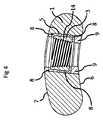
図6はばね要素の別の実施態様であって、一連の細長いばねフィンガ23及びチャネル24によって、ばね要素が(別個のばねとは異なり)摺動要素3内に組み込まれるか、又はその一部であるものを示している。チャネル24は摺動要素3の一部を弾性ばね要素に転換する。 FIG. 6 shows another embodiment of the spring element, in which the spring element is integrated into the sliding element 3 (as opposed to a separate spring) or part thereof by a series of
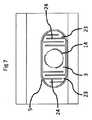
図7はばね要素のさらに別の実施態様であって、チャネル24が摺動要素3の互いに対向する側において導入されるものを示している。チャネル24は、摺動要素3の互いに対向する側を弾性ばね要素に転換し、これらの弾性ばね要素は、凹部5内のねじ山付きねじ穴14を弾性的に遊動状態で支持し、ねじ山付きねじ穴14が、荷重を加えられていないその中央位置から双方向に並進運動するのを可能にする。 FIG. 7 shows a further embodiment of the spring element, in which the
図8は、摺動要素3の実施態様を、円筒形の骨区分10に固定された骨ねじ11と連携させた状態で示す長手方向断面図である。ばね22が、摺動要素3内の円筒形穴17内に埋め込まれている。凹部5が低摩擦層8でライニングされている。プレート1が骨表面18上に押し付けられない形態で、ロック式ねじ11が摺動要素3を固定している。非ロック式ねじを使用する別の実施態様では、プレートは骨表面上に押し付けられてよい。 FIG. 8 is a longitudinal cross-sectional view showing an embodiment of the sliding
図9は、円筒形骨10の対応する2つの区分に骨ねじ11によって弾性的に固定された骨プレート1を示す断面図である。摺動要素3内のばね22が骨折部位19に向かって配置されている。従って、骨区分10に作用する外部圧縮力が加えられると、プレート1に対する摺動要素3の並進/運動が引き起こされる。このことは、プレート1の長手方向軸線に対して平行な骨セグメント10の並進運動を引き起こす。この並進運動は、骨折部位19の表面間の対称運動を、制御された運動限度内で発生させることになる。骨折部位の運動量は、プレート1の凹部5内部のスライダ並進運動の最大範囲によって制御される。従って、ばね要素の剛性及びプレロードに基づいて、100〜1000N、好ましくは200〜800Nである所定の閾値を超過する外部圧縮力が、プレート内部の摺動要素3の更なる運動をもたらすことはない。ばね要素のプレロード及び剛性が十分に小さいように選択されているならば、過剰なプレートの曲げを防止するのに十分に低い外部圧縮力が加えられたときに最大許容変位に達することになり、さもなければ摺動要素3の凹部内部での過剰な摩擦、摩耗、又は引っかかりを導くおそれがある。 FIG. 9 is a cross-sectional view showing the
弾性的に遊動状態で支持された摺動要素によって骨プレートを骨に弾性的に連結することは、骨折した骨の1つ又は2つの骨区分に適用されてよく、これに対して、他の骨区分は、標準的な骨ファスナ、例えば非ロック式又はロック式ねじを使用して、同一の骨プレートに固定されてもよい。 Elastically coupling the bone plate to the bone by means of a sliding element supported in an elastically free state may be applied to one or two bone sections of the fractured bone, whereas other The bone sections may be secured to the same bone plate using standard bone fasteners, such as non-locking or locking screws.
図10は、骨プレート1を円筒形の骨10と連携した状態で示す断面図である。ここでは、プレート1は複数の非共線状の骨ペグ20で骨10に固定されている。骨ペグ20はねじ山付きヘッド21を有しており、摺動要素3の対応するねじ山付きの貫通穴14内にポジティブにロックされている。骨ペグ20は、骨内の多平面固定のための平滑な軸部25を有している。平滑な軸部は、ペグ長手方向軸線の方向で摺動要素3に作用する力の伝達を防止する。 FIG. 10 is a cross-sectional view showing the
図11は、骨プレート1を、摺動要素3のねじ山付き貫通穴14を通って示す横方向断面図である。摺動要素3は凹部5内で少なくとも部分的に包囲されている。所定の実施態様では、摺動要素は上部及び底部で、そしてプレート中央に向かって包囲されているが、しかし所定の実施態様では側方で実際に露出されている。摺動要素を1つの側で開いたままにしておくことにより、摺動要素を所定の場所に投入することができ、そしてシリコーンを成形することができるので、摺動要素に被さるようにプレートを溶接する必要がなくなる。この実施態様では、凹部5は骨プレート1の側方を通して形成され、プレート底面6まで延び、そしてプレート上面7に向かって延びている。摺動要素3はエラストマールーメン26によって凹部5内に遊動状態で支持されている。エラストマールーメン26は、凹部5の部分及び/又は摺動要素3の部分に選択的に結合することによって、骨プレート1に対する摺動要素3の所期の弾性拘束に影響を与えることができる。例えば、一つの実施態様において、摺動要素3の表面27は、エラストマールーメン又は弾性材料に結合される。図11は、摺動要素が運動に抗して束縛されている状況を示している。メタル・オン・メタル収縮、及び摩耗を防止するのに加えて、摺動要素のこのような弾性的な閉じ込めは、特にねじが摺動要素内のねじ穴の軸線に対して正確には平行でない状態で挿入される場合に、ねじ山付きねじヘッドを摺動要素内に係合させるのを容易にする。 FIG. 11 is a transverse cross-sectional view showing the
図12は、ねじ山付き貫通穴14を有する摺動要素3が見えるようにするために底部のない状態で、骨プレート1を示す底面図である。摺動要素3はエラストマールーメン26によって、骨プレート1の側方に形成された凹部5内で包囲されている。エラストマールーメン26は、長手方向運動を優先的に可能にする。この図が示す実施態様では、摺動要素3の長手方向寸法は凹部5の対応する長手方向寸法よりも短い。長手方向寸法のこのような差は、プレート1に対する摺動要素3の許容し得る運動を決定する。この制御された運動範囲は0.1〜2mm、好ましくは0.3〜1mmである。図示した実施態様の場合、摺動要素3は骨プレート1の外面までは延びていない。図12は、摺動要素3のエッジと凹部領域5との間のエラストマー26を示している。他の実施態様では、エラストマーは、摺動要素3を包囲又は収容するエラストマールーメン26である。 FIG. 12 is a bottom view showing the
図13は、上面7と、ねじ山付き貫通穴14を含む摺動要素3とを有する骨プレート1を示す三次元図である。この図は、「骨プレートの側方」(すなわち上面ではなく、また骨に面する表面でもない)に形成された凹部を示しており、ここを通って摺動要素3及びエラストマールーメン26を挿入することができる。 FIG. 13 is a three-dimensional view showing a
図14は、骨プレート1の底面6を超えて突出する摺動要素3を示している。ねじ山付き貫通穴14を備えた摺動要素3は凹部5内に位置している。エラストマールーメン26は、摺動要素3を取り囲んだ状態で示されている。この図は内部の摺動要素3が骨プレートの側方の空洞(すなわち骨に面した表面又は上面に設けられたのではない空洞)内で少なくとも部分的に包囲されていることを示している。この図は、底面の下方に延びるスライダの一部を示すように構成されている。空洞はプレートの側方にまだある。摺動要素3の表面27はエラストマールーメン又は弾性材料に接合されている。 FIG. 14 shows the sliding
一つの実施態様では、外面と、骨に面する表面とを有する骨プレートであって、骨プレートは内部摺動要素を含んでおり、各摺動要素は、骨ねじ又はペグのためのねじ山付き受容穴を含んでおり、骨ねじ又はペグは対応するねじ山付きヘッドを有している、骨プレートが提供される。摺動要素は、プレートの長手方向軸線に対して平行に、制御された状態で変位させられるが、しかしプレートの長手方向軸線に対して垂直な変位に抗して実質的に拘束される。ねじ山付きヘッドを有する骨ねじは、骨プレートを骨表面に押し付けることなしに、ねじ山付き受容穴に堅固に固定されることができる。従って、骨プレートの長手方向軸線に対して平行に、制御された状態で変位する能力を維持しながら、骨区分を骨プレートに確実に固定することができる。変位量は、骨プレート内部の摺動要素の運動限度によって制御される。 In one embodiment, a bone plate having an outer surface and a bone-facing surface, the bone plate including internal sliding elements, each sliding element being a thread for a bone screw or peg. A bone plate is provided that includes a threaded receiving hole, wherein the bone screw or peg has a corresponding threaded head. The sliding element is displaced in a controlled manner parallel to the longitudinal axis of the plate, but is substantially constrained against displacement perpendicular to the longitudinal axis of the plate. A bone screw having a threaded head can be firmly fixed in the threaded receiving hole without pressing the bone plate against the bone surface. Thus, the bone section can be securely fixed to the bone plate while maintaining the ability to be displaced in a controlled manner parallel to the longitudinal axis of the bone plate. The amount of displacement is controlled by the movement limit of the sliding element inside the bone plate.
摺動要素は概ね棒状であり、方形断面を有している。他の実施態様では他の断面形状、例えば正方形、楕円形、湾曲形、又はプレートの断面形状に近似する湾曲方形を用いてよい。摺動要素はプレートの凹部内に適合するようにサイズ設定して成形することが必要なだけであり、所期の運動量を可能にするようにサイズ設定される。摺動要素は、任意の医学的に許容し得る材料、例えばチタン又はステンレス鋼のような金属を具備している。 The sliding element is generally rod-shaped and has a square cross section. Other embodiments may use other cross-sectional shapes, such as squares, ellipses, curved shapes, or curved squares that approximate the cross-sectional shape of the plate. The sliding element only needs to be sized and shaped to fit within the recess of the plate and is sized to allow the desired momentum. The sliding element comprises any medically acceptable material, for example a metal such as titanium or stainless steel.
摺動要素はばね要素によってプレート内において弾性的に遊動状態で支持することができ、ばね要素は、プレートの長手方向に作用する荷重に応答して、プレートに対する摺動要素の並進運動量を決定する。この弾性遊動支持は、プレート・骨固定構造の重量負荷に応答して、骨プレートに固定された隣接する骨区分間の動的運動を可能にする。ばね要素は摺動要素とは別個のばねであってよく、或いはばね要素は摺動要素の一部であってもよい。他の実施態様では、ばね要素はエラストマー材料である。 The sliding element can be elastically supported in the plate by a spring element, which determines the translational momentum of the sliding element relative to the plate in response to a load acting in the longitudinal direction of the plate. . This elastic free support allows dynamic movement between adjacent bone sections secured to the bone plate in response to the weight load of the plate-bone fixation structure. The spring element may be a separate spring from the sliding element, or the spring element may be part of the sliding element. In other embodiments, the spring element is an elastomeric material.
荷重応答性の摺動要素を介して骨をプレートに弾性的に固定することにより、骨折部位の制御された対称的な運動が可能になる。このような運動は、仮骨形成による骨折治癒を促進することが知られている。さらに、弾性固定は、固定点間の荷重分布を改善し、このことは応力集中を低減し、これにより構造の強度を向上させる。弾性固定はさらに、骨吸収、及び過度に剛性の固定構造に起因する応力遮蔽によってもたらされる小孔形成を低減する。 Elastically securing the bone to the plate via a load-responsive sliding element allows controlled symmetrical movement of the fracture site. Such exercise is known to promote fracture healing due to callus formation. In addition, elastic fixation improves the load distribution between the fixation points, which reduces stress concentration and thereby increases the strength of the structure. Elastic fixation further reduces stoma formation caused by bone resorption and stress shielding due to overly rigid fixation structures.
弾性固定はエラストマーの使用によって実現してよい。エラストマーは、骨プレートに対する摺動要素の所期弾性拘束に影響を与えるために、前記プレート又は摺動要素表面の少なくとも一部にポジティブに付着することができる。 Elastic fixation may be achieved by the use of an elastomer. The elastomer can be positively attached to at least a portion of the plate or sliding element surface to affect the desired elastic restraint of the sliding element relative to the bone plate.
特定の実施態様では、エラストマーは、ボイド(例えばエアポケット)を有さないか、又はボイドをほとんど有さない。他の実施態様では、エラストマーはボイドを有しており、これらのボイドは、エラストマーの圧縮性を高めることによって、システムの有効剛性をさらに低減することができる。 In certain embodiments, the elastomer has little or no voids (eg, air pockets). In other embodiments, the elastomer has voids, which can further reduce the effective stiffness of the system by increasing the compressibility of the elastomer.
エラストマーは、医学的に適していればいかなるエラストマーであってもよく、例えばシリコーンであるがこれに限定するものではない。特定の実施態様では、エラストマーの弾性率が0.1〜50MPaである。これにより、所期量の運動/弾性が可能になる。特定の実施態様では、エラストマー材料の弾性率及び構成がエラストマー内部で異なっていてもよい。例えばこれは、2つの異なるエラストマーを使用する場合、又はエラストマーの異なる厚さ又は粘度を使用する場合に当てはまる。 The elastomer may be any elastomer that is medically suitable, for example, silicone, but is not limited thereto. In a particular embodiment, the elastomer has an elastic modulus of 0.1 to 50 MPa. This allows the desired amount of motion / elasticity. In certain embodiments, the modulus and configuration of the elastomeric material may vary within the elastomer. This is the case, for example, when using two different elastomers or when using different thicknesses or viscosities of elastomers.
特定の実施態様では、エラストマーは摺動要素を取り囲む又は収容するエラストマールーメンを含む。他の実施態様では、エラストマーは摺動要素と凹部壁との間に位置する。 In certain embodiments, the elastomer includes an elastomeric lumen that surrounds or houses the sliding element. In other embodiments, the elastomer is located between the sliding element and the recessed wall.
特定の実施態様では、摺動要素は単独エレメントとして又はエラストマールーメンと連結した状態で取り外し可能であってよい。換言すれば、特定の実施態様では、摺動要素をプレート内に組み付け、そしてシリコーンを成形することによってこれらを結合する。他の実施態様では、シリコーンを摺動要素上に外部から成形して結合し、次いでその構成部分をプレート内に押し込む。この場合、この構成部分はプレートには結合されない。「ローディングされていない」モジュール骨プレートの別の実施態様では、外科医は弾性摺動要素、非弾性ロック式エレメント、又は非ロック式エレメントを挿入することができる。 In certain embodiments, the sliding element may be removable as a single element or coupled with an elastomeric lumen. In other words, in a particular embodiment, the sliding elements are assembled into the plate and bonded together by molding silicone. In another embodiment, silicone is externally molded and bonded onto the sliding element and then its components are pushed into the plate. In this case, this component is not coupled to the plate. In another embodiment of the “unloaded” modular bone plate, the surgeon can insert an elastic sliding element, an inelastic locking element, or an unlocking element.
特定の実施態様において、プレート内の摺動要素の弾性遊動支持は、2つ又は3つ以上のばね要素によって達成され、これらのばね要素は、プレートの長手方向の荷重に応答した、プレートに対する摺動要素の双方向並進運動量を決定する。 In a particular embodiment, the elastic free support of the sliding elements in the plate is achieved by two or more spring elements, which are slid against the plate in response to the longitudinal loading of the plate. Determine the bidirectional translational momentum of the moving element.
特定の実施態様では、ばね要素は別個のばねを具備している。特定の実施態様では、ばね要素は、摺動要素の一部である弾性構造又は材料によって形成された一体型ばねを具備する。 In certain embodiments, the spring element comprises a separate spring. In certain embodiments, the spring element comprises an integral spring formed by an elastic structure or material that is part of the sliding element.
特定の実施態様では、ばね要素は、摺動要素に隣接するプレート区分の一部である弾性構造又は材料によって形成された一体型ばねを具備する。 In certain embodiments, the spring element comprises an integral spring formed by an elastic structure or material that is part of the plate section adjacent to the sliding element.
特定の実施態様では、ばね要素は、摺動要素(図12で符号3として示されている)とプレート(1)との間に取り付けられた弾性材料(エラストマー)によって形成される。 In a particular embodiment, the spring element is formed by an elastic material (elastomer) attached between the sliding element (indicated as 3 in FIG. 12) and the plate (1).
特定の実施態様では、ばね要素は、摺動要素を収容するか又は取り囲む弾性材料(エラストマー)ルーメンによって形成される。例えば、エラストマーは凹部壁と摺動要素のエッジとの間ではなく、摺動要素の上部及び下部にも設けられる。 In a particular embodiment, the spring element is formed by an elastic material (elastomer) lumen that houses or surrounds the sliding element. For example, the elastomer is not provided between the recess wall and the edge of the sliding element, but also at the top and bottom of the sliding element.
一つの実施態様では、摺動要素は2つ又は3つ以上のばね要素(例えば図7に示されたもの)の間に遊動状態で支持されている。このような形態は、2つの対向方向における弾性変位を可能にする。図7が示す実施態様では、2つのばね要素が摺動要素と一体的である。別の実施態様では、ばね要素は摺動要素とは別個のものであってよい。別の実施態様では、ばね要素は別個のばね要素と一体型ばね要素との組み合わせであってよい。他の実施態様では、ばね要素はエラストマー又はエラストマールーメンであってよい。他の実施態様では、ばね要素、例えば別個のばねとエラストマーとの組み合わせであってよい。例えば摺動要素の一方の側が(別個又は一体型の)ばねを有することができ、そして摺動要素の他方の側では、ばね要素はエラストマーであってよい。 In one embodiment, the sliding element is supported in an idle state between two or more spring elements (eg, those shown in FIG. 7). Such a configuration allows elastic displacement in two opposing directions. In the embodiment shown in FIG. 7, the two spring elements are integral with the sliding element. In another embodiment, the spring element may be separate from the sliding element. In another embodiment, the spring element may be a combination of a separate spring element and an integral spring element. In other embodiments, the spring element may be an elastomer or an elastomer lumen. In other embodiments, it may be a spring element, for example a combination of a separate spring and an elastomer. For example, one side of the sliding element can have a spring (separate or integral) and on the other side of the sliding element the spring element can be elastomeric.
特定の実施態様では、別個又は一体型のばね要素と、エラストマーばね要素とが組み合わされていてよい。例えば別個及び/又は一体型のばね要素及び摺動要素はエラストマールーメンによって取り囲まれていてよい。或いは、別個又は一体型のばね要素と、凹部壁と摺動要素との間に位置するエラストマー材料とが組み合わされていてよい。 In certain embodiments, separate or integral spring elements and elastomeric spring elements may be combined. For example, separate and / or integral spring elements and sliding elements may be surrounded by an elastomeric lumen. Alternatively, a separate or integral spring element may be combined with an elastomeric material located between the recessed wall and the sliding element.
特定の実施態様では、プレート内の摺動要素の弾性遊動支持は、定義された静止位置で各摺動要素を保持するばね要素によって達成され、そしてばね要素は、プレートの長手方向に加えられた荷重に応答して、プレートに対する各摺動要素の単方向並進運動量を決定する。 In a particular embodiment, the elastic free support of the sliding elements in the plate is achieved by spring elements that hold each sliding element in a defined rest position, and the spring elements are applied in the longitudinal direction of the plate In response to the load, the unidirectional translational momentum of each sliding element relative to the plate is determined.
特定の実施態様では、骨折プレートは、2つ以上(特定の実施態様では2つ以上、そして特定の実施態様では3つ以上)の貫通穴を具備しており、それぞれの貫通穴は摺動要素とばね要素とを有している。特定の実施態様では、骨折プレートは全て同じ形状及び同じ材料の摺動要素とばね要素とを有している。特定の実施態様では、骨折プレートは異なる形状及び異なる材料の摺動要素、及び/又は異なるばね要素を有している。例えば、所定のプレート区分は別個のばね要素を有してよく、他のプレート区分は摺動要素と一体的なばね要素を有してよく、そして他のプレート区分はエラストマー材料ばね要素を有してよく、又は他のプレート領域は別個のばね要素、一体型ばね要素、及び/又は弾性材料ばね要素の組み合わせを採用してよい。 In certain embodiments, the fracture plate comprises two or more (two or more in certain embodiments and three or more in certain embodiments) through holes, each through hole being a sliding element. And a spring element. In a particular embodiment, the fracture plates all have sliding elements and spring elements of the same shape and material. In certain embodiments, the fracture plate has sliding elements of different shapes and materials and / or different spring elements. For example, a given plate section may have a separate spring element, another plate section may have a spring element integral with the sliding element, and the other plate section may have an elastomeric material spring element. Alternatively, other plate regions may employ a combination of separate spring elements, integral spring elements, and / or elastic material spring elements.
別の実施態様では、摺動要素を定義された静止位置に保持するために単一のばね要素が使用される。このことは、骨ねじの挿入中、摺動要素の安定な位置を保証する。続いて、固定構造に荷重(例えば患者が、骨折した骨に体重又は力を加えるときに生じる荷重)が加えられると、摺動要素の運動が開始される。運動の開始はばね要素のプレロードによって決定されてよい。荷重を取り除くと、摺動要素はその定義された静止位置に戻る。 In another embodiment, a single spring element is used to hold the sliding element in a defined stationary position. This ensures a stable position of the sliding element during the insertion of the bone screw. Subsequently, when a load is applied to the fixed structure (eg, a load that occurs when a patient applies weight or force to a fractured bone), movement of the sliding element is initiated. The onset of movement may be determined by preloading the spring element. When the load is removed, the sliding element returns to its defined rest position.
別の実施態様では、摺動要素は低摩擦層、例えばポリマー膜内に部分的又は完全に埋め込まれてよい。このような構成は摺動要素とプレートとの間の摩擦及び摩耗を低減する。 In another embodiment, the sliding element may be partially or fully embedded in a low friction layer, such as a polymer film. Such a configuration reduces friction and wear between the sliding element and the plate.
別の実施態様では、摺動要素及び対応する固定穴は、互い違い配列で形成されている。例えば図1、3及び10を参照されたい。直線に沿って配置された摺動要素と比較して、この互い違い状の固定は、ねじり荷重を加えられたときの固定構造の安定化を増大させる。 In another embodiment, the sliding elements and corresponding fixing holes are formed in a staggered arrangement. See, for example, FIGS. Compared to sliding elements arranged along a straight line, this staggered fixation increases the stabilization of the fixation structure when subjected to a torsional load.
特定の実施態様では、受容穴が非ロック式骨ねじで骨表面上に押し付けられるときにプレートを骨表面の上方に持ち上げるために、1つ又は2つ以上の摺動要素がプレートの骨に面する表面を超えて延びており、非ロック式骨ねじが、摺動要素の弾性遊動支持と相俟って、プレートと骨表面との制御された相対運動を可能にする。図14を参照されたい。 In certain embodiments, one or more sliding elements face the bone of the plate to lift the plate above the bone surface when the receiving hole is pressed onto the bone surface with a non-locking bone screw. The non-locking bone screw, coupled with the elastic free support of the sliding element, allows controlled relative movement of the plate and the bone surface. See FIG.
特定の実施態様では、内部摺動要素はプレートの側方に設けられた空洞内部で少なくとも部分的に包囲されている。図11は、プレートの側方の空洞内部で包囲された摺動要素を示している。 In a particular embodiment, the internal sliding element is at least partially enclosed within a cavity provided on the side of the plate. FIG. 11 shows the sliding element enclosed within a cavity on the side of the plate.
別の実施態様では、摺動要素内のねじ山付き受容穴は円錐形である。これは、摺動要素3に対応するねじ山付きの円錐形ねじヘッドをポジティブにロックすることを可能にする。 In another embodiment, the threaded receiving hole in the sliding element is conical. This makes it possible to positively lock the threaded conical screw head corresponding to the sliding
別の実施態様では、摺動要素内のねじ山付き受容穴は円筒形であり、ねじヘッド及びねじ軸部において同じねじ山外径及びねじ山ピッチを有する骨ねじと併せて使用される。このことの利点は、ねじ軸部がねじ挿入時に一貫して摺動要素のねじ山付き穴内に係合されることである。この実施態様は、ねじヘッドが摺動要素に押し付けられるのを防止する。また、摺動要素のねじ山付き穴内にねじヘッドが容易に係合することを保証することによって、骨プレート内部の摺動要素にプレロードが加えられるのも防止する。 In another embodiment, the threaded receiving hole in the sliding element is cylindrical and is used in conjunction with a bone screw having the same thread outer diameter and thread pitch at the screw head and screw shank. The advantage of this is that the screw shank is consistently engaged in the threaded hole of the sliding element during screw insertion. This embodiment prevents the screw head from being pressed against the sliding element. It also prevents preloading of the sliding elements inside the bone plate by ensuring that the screw head easily engages in the threaded holes of the sliding elements.
特定の実施態様では、複数の骨ねじがある(例えば図3及び9参照)。特定の実施態様では、装置はさらに、ねじ山付きヘッドと平滑なペグ軸部とを有する1つ又は2つ以上の非共線状骨ペグを含む(例えば図10参照)。別の実施態様では、摺動要素のねじ山付き穴とポジティブに係合するねじ山付きヘッドを備えたペグを使用して、1つ又は2つ以上の摺動要素を骨に結合してよい。ロック式ねじの代わりにロック式ペグを使用すると、プレート内部の摺動要素にプレロードが加えられるリスクが低減される。固定強度を向上させるために、ロック式ペグを多平面形態で挿入してよい。摺動要素の少なくとも2つのねじ山付き穴は、共線状でない中心軸線を有している。 In certain embodiments, there are multiple bone screws (see, eg, FIGS. 3 and 9). In certain embodiments, the device further includes one or more non-collinear bone pegs having a threaded head and a smooth peg shank (see, eg, FIG. 10). In another embodiment, a peg with a threaded head that positively engages the threaded hole of the sliding element may be used to couple one or more sliding elements to the bone. . Using a locking peg instead of a locking screw reduces the risk of preloading the sliding elements inside the plate. In order to improve the fixing strength, the locking peg may be inserted in a multi-planar form. At least two threaded holes of the sliding element have a central axis that is not collinear.
特定の実施態様では、プレートはねじ山付き及び/又はねじ山無しのねじ穴を内蔵している。 In certain embodiments, the plate incorporates threaded and / or unthreaded screw holes.
別の実施態様では、特定の骨プレート区分内にだけ摺動要素を配置する一方、別の骨プレート区分は、(業界において使用されているように)ねじ山付き及び/又はねじ山無しのねじ穴を有していてよい。一つの実施態様では、ばね要素及び摺動要素は1プレート区分内に配置されているのに対して、別のプレート区分は、ばね要素及び摺動要素なしのねじ山付き及び/又はねじ山無しの穴を有している。(業界において使用されているような)ばね要素及び摺動要素を有さない標準的なねじ山付き穴又は標準的なねじ山無しの穴(本明細書中及び特許請求の範囲では静的受容穴と呼ぶ)を備えた骨プレート区分は、骨表面に対するプレートの圧縮及び剛性固定を許容するのに対して、摺動要素/ばね要素を有する骨区分は、対応する骨区分の弾性固定を可能にする。このような弾性固定は、固定構造の間欠的な荷重に応答した骨片間運動を達成する能力を維持する。例えば、骨折部位の一方の側で、骨プレートはばね要素及び摺動要素を使用した弾性遊動支持装置を含んでいてよく、これに対して骨折部位の他方の側における対応する骨区分では、骨プレートは静的受容穴を含む(そして弾性遊動支持装置を含まない)。また特定の実施態様では、摺動要素/ばね要素及び静的受容穴は、同じ骨プレート区分内で一緒に使用することもできる。例えば、1つの穴おきに静的受容穴が存在してよい(そして他の穴は弾性遊動支持貫通穴である)。他の実施態様では、(摺動要素とばね要素とを使用する)弾性遊動支持装置と、静的受容穴とが混合されている。このような混合の状態は、骨折部位を横切る骨プレート全体を通して同じであってよい。他の実施態様では、静的受容穴と弾性遊動支持装置との混合状態はプレート内部で変化してよい。例えば骨折部位の一方の側はより多くの弾性遊動支持装置と、より少ない静的受容穴とを有していてよく、これに対して骨折部位の他方の側には、弾性遊動支持装置よりも多くの静的受容穴があってよい。換言すれば、骨プレートの異なる部分が、種々異なるそれぞれの組み合わせを用いてよい。 In another embodiment, the sliding element is placed only within a particular bone plate section, while another bone plate section is threaded and / or unthreaded (as used in the industry). It may have a hole. In one embodiment, the spring element and the sliding element are arranged in one plate section, whereas another plate section is threaded and / or unthreaded without the spring element and sliding element. It has a hole. Standard threaded holes or standard unthreaded holes without spring and sliding elements (as used in the industry) (in this specification and in the claims static acceptance) Bone plate sections with holes) allow compression and rigid fixation of the plate to the bone surface, whereas bone sections with sliding / spring elements allow elastic fixation of the corresponding bone sections To. Such elastic fixation maintains the ability to achieve bone fragment movement in response to intermittent loading of the fixed structure. For example, on one side of the fracture site, the bone plate may include an elastic floating support device using spring elements and sliding elements, whereas in the corresponding bone section on the other side of the fracture site, the bone The plate includes a static receiving hole (and does not include an elastic floating support). In certain embodiments, the sliding element / spring element and the static receiving hole can also be used together in the same bone plate section. For example, every other hole may have a static receiving hole (and the other hole is an elastic floating support through hole). In another embodiment, an elastic floating support device (using sliding elements and spring elements) and a static receiving hole are mixed. Such a mixing condition may be the same throughout the bone plate across the fracture site. In other embodiments, the mixing state of the static receiving hole and the elastic floating support device may vary within the plate. For example, one side of the fracture site may have more elastic floating support devices and fewer static receiving holes, whereas the other side of the fracture site may have more elastic floating support devices. There may be many static receiving holes. In other words, different portions of the bone plate may use different combinations.
別の実施態様では、摺動要素と1つ又は2つ以上のねじ穴とを同じプレート区分内で組み合わせてよい。このことは、標準的な非ロック式ねじを使用した骨表面へのプレートの一時的な固定を可能にし、これにより、摺動要素内へのロック式ねじの取り付けを容易にする。 In another embodiment, the sliding element and one or more screw holes may be combined in the same plate section. This allows a temporary fixation of the plate to the bone surface using standard non-locking screws, thereby facilitating the mounting of the locking screws in the sliding element.
本発明はまた、可撓性プレートを使用して骨折部位を固定する方法を提供する。特定の実施態様では、この方法は、骨折した骨部分を概ね整列させ、そして、骨プレート内に弾性的に遊動状態で支持された複数の摺動要素内に設けられた受容穴に堅固に結合する複数の骨ファスナによって、骨折部位を横切るように骨プレートを取り付けることを含む。摺動要素は、骨プレートの長手方向軸線に対して平行な、制御された並進運動を可能にする一方、骨プレートの長手方向軸線に対して垂直な変位を実質的に防止するように構成されている。骨ねじは、骨プレート又は摺動要素を骨表面上に押し付けることなしに、摺動要素に堅固に固定される。 The present invention also provides a method of fixing a fracture site using a flexible plate. In certain embodiments, the method generally aligns the fractured bone portions and firmly couples into receiving holes provided in a plurality of sliding elements that are elastically and freely supported in the bone plate. Attaching a bone plate across the fracture site with a plurality of bone fasteners. The sliding element is configured to allow controlled translational movement parallel to the longitudinal axis of the bone plate while substantially preventing displacement perpendicular to the longitudinal axis of the bone plate. ing. The bone screw is firmly fixed to the sliding element without pressing the bone plate or the sliding element onto the bone surface.
特定の実施態様では、受容穴は、骨プレートの長手方向軸線に沿った骨プレートに対する並進運動を優先的に許容する一方、骨プレートの上面又は骨に面する表面に対して垂直方向の、1つ又は2つ以上の受容穴の運動を実質的に拘束するように遊動状態で支持される。 In certain embodiments, the receiving holes preferentially allow translational movement relative to the bone plate along the longitudinal axis of the bone plate, while being perpendicular to the upper surface of the bone plate or the bone-facing surface. One or more receiving holes are supported in an idle state so as to substantially constrain movement of the receiving holes.
特定の実施態様では、ばね要素が、荷重が加えられていないときには骨プレートに対してニュートラルな位置に受容穴を遊動状態で支持する弾性ばねとして作用し、この弾性ばねは、荷重の付与に応答して受容穴が骨プレートに対して制御された状態で弾性的に並進運動することを可能にする。 In a particular embodiment, the spring element acts as an elastic spring that loosely supports the receiving hole in a neutral position relative to the bone plate when no load is applied, the elastic spring responding to the application of the load. This allows the receiving hole to be elastically translated with respect to the bone plate.
特定の実施態様では、可撓性エレメントは、固定構造の安定性を向上させるために、骨プレートと骨部分との間の衝撃荷重の伝達を減衰する、 In certain embodiments, the flexible element damps the transmission of impact loads between the bone plate and the bone portion to improve the stability of the fixation structure.
特定の実施態様では、可撓性エレメントは、単一の骨区分と連携する複数の固定エレメント間の荷重伝達分布を改善する。標準的な静的プレートを用いた場合、整列が完全ではないことから、1つのねじが残りのねじよりも大きい荷重を加えられるのが典型的である。本発明の弾性遊動支持装置(弾性的に遊動状態で支持される摺動要素)を使用すると、ねじが変位を許されるので荷重が全てのねじにわたって分配され、そして弾性エレメントはこの荷重を均等にする。 In certain embodiments, the flexible element improves the load transfer distribution between multiple fixation elements associated with a single bone segment. When using a standard static plate, one screw can typically be loaded more than the rest of the screws because the alignment is not perfect. With the elastic floating support device of the present invention (sliding element supported elastically in a floating state), the screws are allowed to displace so that the load is distributed over all the screws and the elastic elements distribute this load evenly. To do.
特定の実施態様では、可撓性エレメントは、表面摩耗及び材料疲労を低減するために、受容穴と骨プレートとの少なくとも部分的な直接接触を防止する。 In certain embodiments, the flexible element prevents at least partial direct contact between the receiving hole and the bone plate to reduce surface wear and material fatigue.
特定の実施態様では、2つ又は3つ以上の受容穴及び骨プレートの弾性遊動支持が骨折部位の一方の側で実施されるのに対して、対応する骨区分は静的受容穴に取り付けられる。 In certain embodiments, two or more receiving holes and elastic free support of the bone plate is performed on one side of the fracture site, while the corresponding bone segment is attached to the static receiving hole. .
特定の実施態様では、2つ又は3つ以上の受容穴及び骨プレートの弾性遊動支持が骨折部位の両方の側で実施される。 In certain embodiments, two or more receiving holes and elastic free support of the bone plate are performed on both sides of the fracture site.
特定の実施態様では、2つ又は3つ以上の受容穴及び骨プレートの弾性遊動支持が、静的受容穴を有する骨プレート構造と比較して、固定構造の軸方向剛性を約40〜90%だけ大幅に低減するのを可能にする。 In certain embodiments, two or more receiving holes and elastic free support of the bone plate provides an axial stiffness of the fixed structure of about 40-90% compared to a bone plate structure having static receiving holes. Only allows to significantly reduce.
特定の実施態様では、1つ又は2つ以上の可撓性エレメントが変位、圧力、又は荷重を測定するためのセンサを含み、センサは、骨折治癒の進行を評価するための手段として、受信エレメントと骨プレートとの間の荷重伝達の存在又は規模を捕捉する。例えばセンサは、骨が治癒したときにそのことを見極めるのを補助するように埋め込むことができる。例えば、センサが変位を測定する場合、骨の治癒に伴って、部分の変位が時間とともに少なくなると予期される。センサが荷重を測定する場合、プレート上の荷重が骨の治癒に伴って減少すると予期される。 In certain embodiments, one or more flexible elements include a sensor for measuring displacement, pressure, or load, the sensor as a receiving element as a means for assessing the progress of fracture healing. Capture the presence or magnitude of load transfer between the bone plate and the bone plate. For example, the sensor can be implanted to help determine when the bone has healed. For example, if the sensor measures displacement, it is expected that the displacement of the portion will decrease with time as the bone heals. If the sensor measures the load, it is expected that the load on the plate will decrease as the bone heals.
特定の実施態様では、エラストマー材料がエラストマールーメンを含み、可撓性エレメントのうちの1つ又は2つ以上のエレメントのエラストマールーメンが、前記センサに過渡電力を供給するためのエネルギー生成手段を含む。 In certain embodiments, the elastomeric material includes an elastomeric lumen, and the elastomeric lumen of one or more of the flexible elements includes energy generating means for providing transient power to the sensor.
特定の実施態様を本明細書に例示し説明してきたが、当業者には明らかなように、同じ目的を達成するように計算された種々様々な別の実施態様及び/又は同等の実施態様を、図示して説明した実施態様と、範囲を逸脱することなしに置き換えることができる。当業者には明らかなように、実施態様を種々様々な方法で実施することができる。本出願は本明細書中で論じた実施態様の改変形又は変更形にも範囲が及ぶように意図される。従って、実施態様は特許請求の範囲及びこれと同等のものによってのみ限定されることが明らかに意図される。 While specific embodiments have been illustrated and described herein, it will be apparent to those skilled in the art that a variety of different and / or equivalent embodiments calculated to accomplish the same purpose may be used. The embodiments shown and described can be replaced without departing from the scope. As will be apparent to those skilled in the art, embodiments can be implemented in a wide variety of ways. This application is intended to cover any variations or modifications of the embodiments discussed herein. Therefore, it is manifestly intended that embodiments be limited only by the claims and the equivalents thereof.
Claims (41)
Translated fromJapanese前記骨プレートは1つまたは2つ以上の摺動要素を含んでおり、各摺動要素は、骨ねじのための1つ又は2つ以上のねじ山付き受容穴を含んでおり、前記骨ねじは、該受容穴内に固定的な角度でロック可能な対応するねじ山付きヘッドを有しており、
前記1つまたは2つ以上の摺動要素は、前記プレートの長手方向軸線に対して平行に、制御された状態で変位させられるが、前記プレートの長手方向軸線に対して垂直な変位に抗して実質的に拘束され、
前記1つまたは2つ以上の摺動要素は、前記骨プレート又は摺動要素を骨表面に押し付けることなしに前記骨ねじに堅固に固定されるように形成されている、器具。An instrument comprising a fracture site fixation plate having an outer surface and a surface facing the bone,
The bone plate includes one or more sliding elements, each sliding element including one or more threaded receiving holes for bone screws, the bone screw Has a corresponding threaded head that can be locked at a fixed angle within the receiving hole;
The one or more sliding elements are displaced in a controlled manner parallel to the longitudinal axis of the plate but resist displacement perpendicular to the longitudinal axis of the plate. Are essentially restrained,
The instrument, wherein the one or more sliding elements are configured to be firmly fixed to the bone screw without pressing the bone plate or sliding element against the bone surface.
骨折した骨部分を概ね整列させることと、
骨折部位を横切るように固定構造を取り付けることとを含み、
前記固定構造は上面と、骨に面する表面とを有する骨プレートを含み、該骨プレートは1つ又は2つ以上の受容穴と、弾性的に遊動状態で支持された複数の摺動要素とを有しており、前記固定は、当該骨ファスナを前記骨プレートに結合する複数の骨ファスナを使用することを含み、前記骨ファスナは、前記骨プレート内に弾性的に遊動状態で支持された摺動要素内に設けられた前記受容穴内に配置され、
前記摺動要素は、前記骨プレートの長手方向軸線に対して平行な、制御された並進運動を可能にする一方、前記骨プレートの長手方向軸線に対して垂直な変位を実質的に防止するように構成されており、前記骨ファスナは、前記骨プレート又は摺動要素を骨表面上に押し付けることなしに、前記摺動要素に堅固に固定され、
前記弾性遊動支持が2つ又は3つ以上のばね要素によってもたらされる、骨折部位を可撓性プレートで固定する方法。A method of fixing a fracture site with a flexible plate,
Aligning the fractured bone part generally,
Attaching a fixation structure across the fracture site,
The fixation structure includes a bone plate having an upper surface and a bone-facing surface, the bone plate including one or more receiving holes and a plurality of sliding elements supported in an elastically loose state The fixation includes using a plurality of bone fasteners that couple the bone fastener to the bone plate, the bone fastener being elastically supported in the bone plate Arranged in the receiving hole provided in the sliding element,
The sliding element allows a controlled translational movement parallel to the longitudinal axis of the bone plate, while substantially preventing displacement perpendicular to the longitudinal axis of the bone plate. The bone fastener is rigidly secured to the sliding element without pressing the bone plate or sliding element onto the bone surface;
A method of fixing a fracture site with a flexible plate, wherein the elastic free support is provided by two or more spring elements.
Applications Claiming Priority (5)
| Application Number | Priority Date | Filing Date | Title |
|---|---|---|---|
| US201261594560P | 2012-02-03 | 2012-02-03 | |
| US61/594,560 | 2012-02-03 | ||
| US13/755,493US9295508B2 (en) | 2012-02-03 | 2013-01-31 | Bone plate for elastic osteosynthesis |
| US13/755,493 | 2013-01-31 | ||
| PCT/US2013/024336WO2013116642A1 (en) | 2012-02-03 | 2013-02-01 | Bone place for elastic osteosynthesis |
Related Child Applications (1)
| Application Number | Title | Priority Date | Filing Date |
|---|---|---|---|
| JP2017234039ADivisionJP2018064962A (en) | 2012-02-03 | 2017-12-06 | Bone plate for elastic osteosynthesis |
Publications (3)
| Publication Number | Publication Date |
|---|---|
| JP2015507953Atrue JP2015507953A (en) | 2015-03-16 |
| JP2015507953A5 JP2015507953A5 (en) | 2016-03-17 |
| JP6559959B2 JP6559959B2 (en) | 2019-08-14 |
Family
ID=48903564
Family Applications (2)
| Application Number | Title | Priority Date | Filing Date |
|---|---|---|---|
| JP2014555748AActiveJP6559959B2 (en) | 2012-02-03 | 2013-02-01 | Bone plate for elastic osteosynthesis |
| JP2017234039APendingJP2018064962A (en) | 2012-02-03 | 2017-12-06 | Bone plate for elastic osteosynthesis |
Family Applications After (1)
| Application Number | Title | Priority Date | Filing Date |
|---|---|---|---|
| JP2017234039APendingJP2018064962A (en) | 2012-02-03 | 2017-12-06 | Bone plate for elastic osteosynthesis |
Country Status (7)
| Country | Link |
|---|---|
| US (4) | US9295508B2 (en) |
| EP (1) | EP2811928B1 (en) |
| JP (2) | JP6559959B2 (en) |
| CN (2) | CN104135953B (en) |
| AU (2) | AU2013214894B2 (en) |
| CA (1) | CA2863597C (en) |
| WO (1) | WO2013116642A1 (en) |
Cited By (6)
| Publication number | Priority date | Publication date | Assignee | Title |
|---|---|---|---|---|
| US9295508B2 (en) | 2012-02-03 | 2016-03-29 | Zimmer, Inc. | Bone plate for elastic osteosynthesis |
| US9510879B2 (en) | 2010-06-23 | 2016-12-06 | Zimmer, Inc. | Flexible plate fixation of bone fractures |
| JP2017521189A (en)* | 2014-07-25 | 2017-08-03 | ジンマー,インコーポレイティド | Flexible plate fixation of fracture |
| US9763713B2 (en) | 2010-06-23 | 2017-09-19 | Zimmer, Inc. | Flexible plate fixation of bone fractures |
| JP2021528200A (en)* | 2018-06-29 | 2021-10-21 | パイオニア サージカル テクノロジー インコーポレイテッド | Bone plate system |
| US11324538B2 (en) | 2019-12-04 | 2022-05-10 | Biomet Manufacturing, Llc | Active bone plate |
Families Citing this family (26)
| Publication number | Priority date | Publication date | Assignee | Title |
|---|---|---|---|---|
| KR101781790B1 (en)* | 2010-07-21 | 2017-09-26 | 신세스 게엠바하 | Device for osteosynthesis |
| US9433451B2 (en) | 2013-12-09 | 2016-09-06 | Acumed Llc | Hip fixation system with a compliant fixation element |
| US10080596B2 (en) | 2013-12-09 | 2018-09-25 | Acumed Llc | Hip fixation with load-controlled dynamization |
| ES2805053T3 (en) | 2013-12-09 | 2021-02-10 | Acumed Llc | Nail-based elastic hip fixation system |
| US9526542B2 (en) | 2014-05-07 | 2016-12-27 | Acumed Llc | Hip fixation with load-controlled dynamization |
| US9463055B2 (en) | 2013-12-09 | 2016-10-11 | Acumed Llc | Plate-based compliant hip fixation system |
| EP2957247A1 (en)* | 2014-04-22 | 2015-12-23 | Stryker European Holdings I, LLC | Plates with countersinks |
| US10478238B2 (en) | 2014-12-02 | 2019-11-19 | Activortho, Inc. | Active compression devices, methods of assembly and methods of use |
| US10123831B2 (en) | 2015-03-03 | 2018-11-13 | Pioneer Surgical Technology, Inc. | Bone compression device and method |
| US10449003B2 (en)* | 2015-05-29 | 2019-10-22 | The Penn State Research Foundation | Individualized preoperative planning system and method |
| PL3416575T3 (en)* | 2016-02-19 | 2020-06-01 | 41Medical Ag | Device for bone fixation |
| US11224467B2 (en) | 2016-02-26 | 2022-01-18 | Activortho, Inc. | Active compression apparatus, methods of assembly and methods of use |
| CA3015902A1 (en) | 2016-02-26 | 2017-08-31 | Activortho, Inc. | Active compression apparatus, methods of assembly and methods of use |
| CN108210049A (en)* | 2016-12-09 | 2018-06-29 | 上海市浦东医院 | New type auto locking and pressurizing steel plate |
| CN108210051A (en)* | 2016-12-14 | 2018-06-29 | 创生医疗器械(中国)有限公司 | T-shaped bone plate |
| US11925475B2 (en) | 2019-06-28 | 2024-03-12 | Orthosensor Inc. | Orthopedic system for pre-operative, intra-operative, and post-operative assessment |
| EP4009892B1 (en) | 2019-08-06 | 2025-04-30 | Paragon 28, Inc. | Dynamic bone plate |
| US11877779B2 (en) | 2020-03-26 | 2024-01-23 | Xtant Medical Holdings, Inc. | Bone plate system |
| US11571333B2 (en)* | 2020-05-18 | 2023-02-07 | Refocus Group, Inc. | Apparatus and method for securing ocular tissue and providing surgical tool positioning points |
| CN111658116B (en)* | 2020-07-02 | 2025-09-16 | 董谢平 | Bone fracture plate capable of automatically converting from firm fixation to elastic fixation |
| CN112120775B (en)* | 2020-09-26 | 2025-07-15 | 河南科科生物科技有限公司 | A split elastic pressure regulating steel plate |
| CN112656501B (en)* | 2020-09-26 | 2025-09-09 | 河南科科生物科技有限公司 | Integral elastic voltage regulating steel plate |
| CN112494129B (en)* | 2020-09-26 | 2025-07-08 | 河南科科生物科技有限公司 | Integral type pressure regulating steel sheet |
| CN113262032B (en)* | 2021-06-17 | 2024-10-22 | 北京爱康宜诚医疗器材有限公司 | Bone fixing plate and bone fixing plate assembly with same |
| US12220156B2 (en) | 2022-05-26 | 2025-02-11 | DePuy Synthes Products, Inc. | Orthopedic implant and method of use thereof |
| WO2024107980A1 (en)* | 2022-11-16 | 2024-05-23 | The Penn State Research Foundation | Compliant bone plate for fracture fixation |
Citations (8)
| Publication number | Priority date | Publication date | Assignee | Title |
|---|---|---|---|---|
| FR2634368A1 (en)* | 1988-07-20 | 1990-01-26 | Massaad Raymond | Functional fixation device for osteosynthesis using a slide plate |
| US4943292A (en)* | 1989-11-08 | 1990-07-24 | National Research Council Of Canada | Plate for broken bone fixation |
| US6540746B1 (en)* | 1999-09-30 | 2003-04-01 | Sulzer Orthopedics Ltd. | Bone plate for splinting a fracture at a bone with a plurality of bone screws |
| JP2009501575A (en)* | 2005-07-13 | 2009-01-22 | アキュームド・エルエルシー | Bone plate with movable locking element |
| WO2010037984A1 (en)* | 2008-10-02 | 2010-04-08 | Memometal Technologies | Orthopedic implant in the form of a plate to be fixed between two bone parts |
| JP2010521274A (en)* | 2007-03-22 | 2010-06-24 | シンセス ゲゼルシャフト ミット ベシュレンクテル ハフツング | Bone plate |
| WO2010111350A1 (en)* | 2009-03-24 | 2010-09-30 | Stabiliz Orthopedics, LLC | Orthopedic fixation device with bioresorbable layer |
| US20110319942A1 (en)* | 2010-06-23 | 2011-12-29 | Apex Biomedical Company Llc | Flexible plate fixation of bone fractures |
Family Cites Families (119)
| Publication number | Priority date | Publication date | Assignee | Title |
|---|---|---|---|---|
| FR742618A (en) | 1933-03-10 | |||
| US2406832A (en) | 1945-03-05 | 1946-09-03 | Mervyn G Hardinge | Fracture plate |
| US2580821A (en) | 1950-10-21 | 1952-01-01 | Nicola Toufick | Spring impactor bone plate |
| GB1405091A (en) | 1971-08-19 | 1975-09-03 | Nat Res Dev | Orthopaedic fracutre fixing device |
| DE2438669C3 (en) | 1974-08-12 | 1978-10-05 | Bezold Geb. Graefin Von Sponeck, Margarete Von, 8035 Gauting | Osteosynthesis plate |
| US4338296A (en) | 1979-10-16 | 1982-07-06 | Smithkline-Rit | Influenza virus and process of producing a vaccine therefrom |
| US4361153A (en) | 1980-05-27 | 1982-11-30 | Cordis Corporation | Implant telemetry system |
| US4743260A (en) | 1985-06-10 | 1988-05-10 | Burton Charles V | Method for a flexible stabilization system for a vertebral column |
| US4905679A (en) | 1988-02-22 | 1990-03-06 | M P Operation, Inc. | Bone fracture reduction device and method of internal fixation of bone fractures |
| DE4128332A1 (en) | 1991-08-27 | 1993-03-04 | Man Ceramics Gmbh | SPINE BONE REPLACEMENT |
| CA2132832C (en) | 1993-01-25 | 2001-08-14 | Synthes Ag | Lock washer for bone plate osteosynthesis |
| JPH08506751A (en) | 1993-02-16 | 1996-07-23 | ミクハイル,ダブリュ.イー.マイクル | Orthopedic reconstruction plate |
| US5423816A (en) | 1993-07-29 | 1995-06-13 | Lin; Chih I. | Intervertebral locking device |
| US5468242A (en) | 1993-11-19 | 1995-11-21 | Leibinger Gmbh | Form-fitting mesh implant |
| US5578036A (en) | 1993-12-06 | 1996-11-26 | Stone; Kevin T. | Method and apparatus for fixation of bone during surgical procedures |
| US5681311A (en) | 1994-09-15 | 1997-10-28 | Smith & Nephew, Inc. | Osteosynthesis apparatus |
| CA2189744C (en) | 1995-03-27 | 2003-09-16 | Gilbert Talos | Bone plate |
| US5578034A (en) | 1995-06-07 | 1996-11-26 | Danek Medical, Inc. | Apparatus for preventing screw backout in a bone plate fixation system |
| US5743913A (en) | 1997-04-02 | 1998-04-28 | Wellisz; Tadeusz Z. | Readily expansible bone fixation plate |
| US5984925A (en) | 1997-07-30 | 1999-11-16 | Cross Medical Products, Inc. | Longitudinally adjustable bone plates and method for use thereof |
| US6093188A (en) | 1997-11-10 | 2000-07-25 | Murray; William M. | Adjustable bone fixation plate |
| ATE256432T1 (en) | 1998-05-19 | 2004-01-15 | Synthes Ag | OSTEOSYNTHETIC IMPLANT WITH EMBEDDED JOINT CONNECTION |
| US6206882B1 (en) | 1999-03-30 | 2001-03-27 | Surgical Dynamics Inc. | Plating system for the spine |
| JP4094174B2 (en) | 1999-06-04 | 2008-06-04 | 株式会社ルネサステクノロジ | Manufacturing method of semiconductor device |
| US20030229348A1 (en) | 2000-05-25 | 2003-12-11 | Sevrain Lionel C. | Auxiliary vertebrae connecting device |
| US6558734B2 (en) | 2001-02-09 | 2003-05-06 | Medtronic, Inc. | Methods for modifying surfaces of articles |
| CA2452977C (en) | 2001-03-08 | 2013-07-16 | The Trustees Of The University Of Pennsylvania | Facially amphiphilic polymers as anti-infective agents |
| FI115382B (en) | 2001-04-03 | 2005-04-29 | Inion Ltd | Implant |
| IL162363A0 (en) | 2001-12-07 | 2005-11-20 | Mathys Medizinaltechnik Ag | Damping element |
| US20040019353A1 (en) | 2002-02-01 | 2004-01-29 | Freid James M. | Spinal plate system for stabilizing a portion of a spine |
| US20050090825A1 (en) | 2002-02-15 | 2005-04-28 | Medartis Ag | Bone plate |
| US20050096657A1 (en) | 2002-02-26 | 2005-05-05 | Alex Autericque | Osteosynthesis or arthrodesis material comprising a bony plate |
| US20050288668A1 (en) | 2002-06-24 | 2005-12-29 | Bernhard Brinkhaus | Spinal column support system |
| US20040097937A1 (en) | 2002-11-19 | 2004-05-20 | Sandi Pike | Orthopedic bone plate |
| AU2003294414B2 (en) | 2002-11-19 | 2009-03-12 | Acumed Llc | Deformable bone plates |
| US7811312B2 (en) | 2002-12-04 | 2010-10-12 | Morphographics, Lc | Bone alignment implant and method of use |
| US7914561B2 (en) | 2002-12-31 | 2011-03-29 | Depuy Spine, Inc. | Resilient bone plate and screw system allowing bi-directional assembly |
| US7048739B2 (en) | 2002-12-31 | 2006-05-23 | Depuy Spine, Inc. | Bone plate and resilient screw system allowing bi-directional assembly |
| US7175624B2 (en) | 2002-12-31 | 2007-02-13 | Depuy Spine, Inc. | Bone plate and screw system allowing bi-directional assembly |
| US7341591B2 (en) | 2003-01-30 | 2008-03-11 | Depuy Spine, Inc. | Anterior buttress staple |
| ITTO20030034U1 (en) | 2003-02-28 | 2004-09-01 | Vese Silvana | PLATE OF OSTEOSYNTHESIS |
| US20040193155A1 (en)* | 2003-03-27 | 2004-09-30 | Hand Innovations, Inc. | Fracture fixation plate with particular plate hole and fastener engagement and methods of using the same |
| US6986771B2 (en) | 2003-05-23 | 2006-01-17 | Globus Medical, Inc. | Spine stabilization system |
| DE10326643A1 (en) | 2003-06-11 | 2004-12-30 | Mückter, Helmut, Dr. med. Dipl.-Ing. | Osteosynthesis plate or comparable implant with ball sleeve |
| FR2857526B1 (en) | 2003-07-08 | 2005-10-07 | Atmel Nantes Sa | DEVICE FOR COMPARING TWO WORDS OF N BITS EACH |
| US7412653B2 (en) | 2003-11-06 | 2008-08-12 | Universal Electronics, Inc. | Remote control having a display with multi-function EL segments |
| CA2546050C (en) | 2003-11-18 | 2012-08-28 | Synthes Gmbh | Osteosynthesis plate set |
| US20050208095A1 (en) | 2003-11-20 | 2005-09-22 | Angiotech International Ag | Polymer compositions and methods for their use |
| US7806914B2 (en) | 2003-12-31 | 2010-10-05 | Spine Wave, Inc. | Dynamic spinal stabilization system |
| EP1708629A4 (en) | 2004-01-08 | 2011-08-17 | David Mark Allison | Bone fixing device |
| DE102004006501A1 (en)* | 2004-02-10 | 2005-09-01 | Charité-Universitätsmedizin Berlin | Component and method for assembling an implant assembly |
| US20050216008A1 (en) | 2004-03-24 | 2005-09-29 | Zwirnmann Ralph F | Bone fixation implants |
| US7833256B2 (en) | 2004-04-16 | 2010-11-16 | Biedermann Motech Gmbh | Elastic element for the use in a stabilization device for bones and vertebrae and method for the manufacture of such elastic element |
| US7572282B2 (en) | 2004-04-23 | 2009-08-11 | Depuy Spine Sarl | Spinal fixation plates and plate extensions |
| US7887587B2 (en) | 2004-06-04 | 2011-02-15 | Synthes Usa, Llc | Soft tissue spacer |
| JP4874970B2 (en)* | 2004-06-07 | 2012-02-15 | ジンテス ゲゼルシャフト ミット ベシュレンクテル ハフツング | Orthopedic implant with sensor |
| US20060058796A1 (en) | 2004-09-14 | 2006-03-16 | Hartdegen Vernon R | Compression brace |
| US20060116682A1 (en) | 2004-11-18 | 2006-06-01 | Longo Marc N | Surgical implant and methods of making and using the same |
| US7591840B2 (en) | 2005-01-21 | 2009-09-22 | Loubert Suddaby | Orthopedic fusion plate having both active and passive subsidence controlling features |
| US8197523B2 (en) | 2005-02-15 | 2012-06-12 | Apex Biomedical Company, Llc | Bone screw for positive locking but flexible engagement to a bone |
| EP1693013A1 (en) | 2005-02-22 | 2006-08-23 | Kyon | Plate and screws for treatment of bone fractures |
| US7621942B2 (en) | 2005-03-21 | 2009-11-24 | Zimmer Spine, Inc. | Variable geometry occipital fixation plate |
| US7749257B2 (en) | 2005-04-12 | 2010-07-06 | Robert J. Medoff | Bearing plate for use in fracture fixation having a spherical bearing hole with yielding expandability |
| US7452370B2 (en) | 2005-04-29 | 2008-11-18 | Warsaw Orthopedic, Inc | Apparatus for retaining a bone anchor in a bone plate and method for use thereof |
| US20060247638A1 (en) | 2005-04-29 | 2006-11-02 | Sdgi Holdings, Inc. | Composite spinal fixation systems |
| AU2006282828B2 (en) | 2005-08-23 | 2013-01-31 | Smith & Nephew, Inc | Telemetric orthopaedic implant |
| CN101291634A (en)* | 2005-08-23 | 2008-10-22 | 史密夫和内修有限公司 | Telemetric Orthopedic Implants |
| DE102005045739A1 (en) | 2005-09-23 | 2007-04-19 | Universitätsklinikum Freiburg | osteosynthesis |
| EP1928333B1 (en) | 2005-09-30 | 2009-06-10 | Aesculap AG | Occipitocervical fixation system |
| AU2005338325A1 (en) | 2005-11-16 | 2007-05-24 | Synthes Gmbh | A through hole for bone fixation device |
| US20070118127A1 (en) | 2005-11-22 | 2007-05-24 | Depuy Spine, Inc. | Implant fixation methods and apparatus |
| US7641675B2 (en) | 2006-03-08 | 2010-01-05 | Warsaw Orthopedic, Inc. | Flexible bone plates and methods for dynamic spinal stabilization |
| WO2007108074A1 (en) | 2006-03-17 | 2007-09-27 | Saga University | Bone graft plate |
| FR2900326B1 (en) | 2006-04-27 | 2008-07-04 | Medicrea Technologies | OSTEOSYNTHESIS PLATE |
| US8512385B2 (en) | 2006-07-07 | 2013-08-20 | Swiss Pro Orthopedic Sa | Bone plate with complex, adjacent holes joined by a bend relief zone |
| US8172842B2 (en) | 2006-07-31 | 2012-05-08 | Orthopaedic International, Inc. | Cervical plate system having an insertable rotating element |
| US7842037B2 (en) | 2006-09-27 | 2010-11-30 | Dupuy Products, Inc. | Flexible bone fixation device |
| US8066750B2 (en) | 2006-10-06 | 2011-11-29 | Warsaw Orthopedic, Inc | Port structures for non-rigid bone plates |
| US20080147122A1 (en) | 2006-10-12 | 2008-06-19 | Jackson Roger P | Dynamic stabilization connecting member with molded inner segment and surrounding external elastomer |
| US20080097445A1 (en)* | 2006-10-23 | 2008-04-24 | Weinstein Robert B | Bone fixation system |
| US20080147125A1 (en) | 2006-12-12 | 2008-06-19 | Dennis Colleran | Active Settling Plate and Method of Use |
| US20080275509A1 (en) | 2007-05-01 | 2008-11-06 | Exploramed Nc4, Inc. | Mounts for implantable extra-articular systems |
| US8043333B2 (en) | 2007-06-08 | 2011-10-25 | Synthes Usa, Llc | Dynamic stabilization system |
| US8309521B2 (en) | 2007-06-19 | 2012-11-13 | Zimmer, Inc. | Spacer with a coating thereon for use with an implant device |
| US8623019B2 (en)* | 2007-07-03 | 2014-01-07 | Pioneer Surgical Technology, Inc. | Bone plate system |
| US20090043341A1 (en) | 2007-08-09 | 2009-02-12 | Aesculap, Inc. | Dynamic extension plate for anterior cervical fusion and method of installation |
| US8348976B2 (en) | 2007-08-27 | 2013-01-08 | Kyphon Sarl | Spinous-process implants and methods of using the same |
| WO2009039430A1 (en) | 2007-09-19 | 2009-03-26 | Stout Medical Group, L.P. | Implantable support device and method of use |
| BRPI0818349A2 (en) | 2007-10-12 | 2015-04-07 | Synthes Gmbh | Reconstruction device |
| EP2397094B1 (en) | 2007-11-02 | 2013-06-26 | Biomet C.V. | Elbow fracture fixation system |
| US20090125067A1 (en) | 2007-11-08 | 2009-05-14 | Depuy Spine, Inc. | In-line occipital plate and method of use |
| US8303633B2 (en) | 2007-12-13 | 2012-11-06 | K2M, Inc. | Dynamic anterior vertebral plate |
| US8114141B2 (en) | 2007-12-17 | 2012-02-14 | Synthes Usa, Llc | Dynamic bone fixation element and method of using the same |
| CA2726412A1 (en) | 2008-06-19 | 2009-12-23 | Moximed, Inc. | Implantable brace for providing joint support |
| USD603507S1 (en) | 2008-07-03 | 2009-11-03 | Theken Spine, Llc | Cervical plate |
| USD603511S1 (en) | 2008-07-03 | 2009-11-03 | Theken Spine, Llc | Cervical plate |
| USD603505S1 (en) | 2008-07-03 | 2009-11-03 | Theken Spine, Llc | Cervical plate |
| USD603963S1 (en) | 2008-07-03 | 2009-11-10 | Theken Spine, Llc | Cervical plate |
| USD603508S1 (en) | 2008-07-03 | 2009-11-03 | Theken Spine, Llc | Cervical plate |
| USD603504S1 (en) | 2008-07-03 | 2009-11-03 | Theken Spine, Llc | Cervical plate |
| USD603962S1 (en) | 2008-07-03 | 2009-11-10 | Theken Spine, Llc | Cervical plate |
| USD603961S1 (en) | 2008-07-03 | 2009-11-10 | Theken Spine, Llc | Cervical plate |
| USD603964S1 (en) | 2008-07-03 | 2009-11-10 | Theken Spine, Llc | Cervical plate |
| USD603503S1 (en) | 2008-07-03 | 2009-11-03 | Theken Spine, Llc | Cervical plate |
| USD603510S1 (en) | 2008-07-03 | 2009-11-03 | Theken Spine, Llc | Cervical plate |
| US8226695B2 (en) | 2008-10-10 | 2012-07-24 | K2M, Inc. | Occipital plate for cervical fixation |
| US8444679B2 (en) | 2008-11-24 | 2013-05-21 | Mbd Medical Llc | Clavicle plate and screws |
| US8403966B2 (en) | 2008-11-24 | 2013-03-26 | Mbd Medical Llc | Clavicle plate and screws |
| US20100217327A1 (en) | 2009-02-24 | 2010-08-26 | Vancelette David W | Plate and system for lateral treatment of a fracture of the calcaneus |
| WO2010132252A1 (en) | 2009-05-12 | 2010-11-18 | Synthes Usa, Llc | Readjustable locking plate hole |
| GB0911697D0 (en) | 2009-07-06 | 2009-08-19 | Smith & Nephew | Methods and devices for monitoring fractures |
| US8574271B2 (en) | 2009-07-29 | 2013-11-05 | Paul Andrew Glazer | Fixation plate screw retention |
| US8790379B2 (en) | 2010-06-23 | 2014-07-29 | Zimmer, Inc. | Flexible plate fixation of bone fractures |
| KR101781790B1 (en) | 2010-07-21 | 2017-09-26 | 신세스 게엠바하 | Device for osteosynthesis |
| US20140379090A1 (en) | 2011-08-08 | 2014-12-25 | Ecole Polytechnique Federale De Lausanne (Epfl) | In-vivo condition monitoring of metallic implants by electrochemical techniques |
| US20160074082A1 (en) | 2011-10-20 | 2016-03-17 | Stryker Trauma Sa | Flexible locked plate fixation |
| US9295508B2 (en) | 2012-02-03 | 2016-03-29 | Zimmer, Inc. | Bone plate for elastic osteosynthesis |
| EP2789303A1 (en) | 2013-04-12 | 2014-10-15 | Zimmer GmbH | Implantable insert sleeve |
| AU2015292319B2 (en) | 2014-07-25 | 2018-09-13 | Zimmer, Inc. | Flexible plate fixation of bone fractures |
- 2013
- 2013-01-31USUS13/755,493patent/US9295508B2/enactiveActive
- 2013-02-01AUAU2013214894Apatent/AU2013214894B2/enactiveActive
- 2013-02-01JPJP2014555748Apatent/JP6559959B2/enactiveActive
- 2013-02-01EPEP13743819.8Apatent/EP2811928B1/enactiveActive
- 2013-02-01CACA2863597Apatent/CA2863597C/enactiveActive
- 2013-02-01CNCN201380011448.7Apatent/CN104135953B/enactiveActive
- 2013-02-01CNCN201810151451.3Apatent/CN108186101A/enactivePending
- 2013-02-01WOPCT/US2013/024336patent/WO2013116642A1/enactiveApplication Filing
- 2015
- 2015-07-24USUS14/808,773patent/US10070905B2/enactiveActive
- 2016
- 2016-02-19USUS15/047,702patent/US9700361B2/enactiveActive
- 2017
- 2017-06-07USUS15/616,608patent/US10022168B2/enactiveActive
- 2017-07-07AUAU2017204637Apatent/AU2017204637B2/enactiveActive
- 2017-12-06JPJP2017234039Apatent/JP2018064962A/enactivePending
Patent Citations (8)
| Publication number | Priority date | Publication date | Assignee | Title |
|---|---|---|---|---|
| FR2634368A1 (en)* | 1988-07-20 | 1990-01-26 | Massaad Raymond | Functional fixation device for osteosynthesis using a slide plate |
| US4943292A (en)* | 1989-11-08 | 1990-07-24 | National Research Council Of Canada | Plate for broken bone fixation |
| US6540746B1 (en)* | 1999-09-30 | 2003-04-01 | Sulzer Orthopedics Ltd. | Bone plate for splinting a fracture at a bone with a plurality of bone screws |
| JP2009501575A (en)* | 2005-07-13 | 2009-01-22 | アキュームド・エルエルシー | Bone plate with movable locking element |
| JP2010521274A (en)* | 2007-03-22 | 2010-06-24 | シンセス ゲゼルシャフト ミット ベシュレンクテル ハフツング | Bone plate |
| WO2010037984A1 (en)* | 2008-10-02 | 2010-04-08 | Memometal Technologies | Orthopedic implant in the form of a plate to be fixed between two bone parts |
| WO2010111350A1 (en)* | 2009-03-24 | 2010-09-30 | Stabiliz Orthopedics, LLC | Orthopedic fixation device with bioresorbable layer |
| US20110319942A1 (en)* | 2010-06-23 | 2011-12-29 | Apex Biomedical Company Llc | Flexible plate fixation of bone fractures |
Cited By (14)
| Publication number | Priority date | Publication date | Assignee | Title |
|---|---|---|---|---|
| US10507049B2 (en) | 2010-06-23 | 2019-12-17 | Zimmer, Inc. | Flexible plate fixation of bone fractures |
| US9510879B2 (en) | 2010-06-23 | 2016-12-06 | Zimmer, Inc. | Flexible plate fixation of bone fractures |
| US11406433B2 (en) | 2010-06-23 | 2022-08-09 | Zimmer, Inc. | Flexible plate fixation of bone fractures |
| US10716605B2 (en) | 2010-06-23 | 2020-07-21 | Zimmer, Inc. | Flexible plate fixation of bone fractures |
| US9763713B2 (en) | 2010-06-23 | 2017-09-19 | Zimmer, Inc. | Flexible plate fixation of bone fractures |
| US9788873B2 (en) | 2010-06-23 | 2017-10-17 | Zimmer, Inc. | Flexible plate fixation of bone fractures |
| US10022168B2 (en) | 2012-02-03 | 2018-07-17 | Zimmer, Inc. | Bone plate for elastic osteosynthesis |
| US10070905B2 (en) | 2012-02-03 | 2018-09-11 | Zimmer, Inc. | Flexible plate fixation of bone fractures |
| US9295508B2 (en) | 2012-02-03 | 2016-03-29 | Zimmer, Inc. | Bone plate for elastic osteosynthesis |
| US9700361B2 (en) | 2012-02-03 | 2017-07-11 | Zimmer, Inc. | Bone plate for elastic osteosynthesis |
| JP2017521189A (en)* | 2014-07-25 | 2017-08-03 | ジンマー,インコーポレイティド | Flexible plate fixation of fracture |
| JP2021528200A (en)* | 2018-06-29 | 2021-10-21 | パイオニア サージカル テクノロジー インコーポレイテッド | Bone plate system |
| JP7382976B2 (en) | 2018-06-29 | 2023-11-17 | パイオニア サージカル テクノロジー インコーポレイテッド | bone plate system |
| US11324538B2 (en) | 2019-12-04 | 2022-05-10 | Biomet Manufacturing, Llc | Active bone plate |
Also Published As
| Publication number | Publication date |
|---|---|
| US10070905B2 (en) | 2018-09-11 |
| US20170273728A1 (en) | 2017-09-28 |
| CN104135953A (en) | 2014-11-05 |
| EP2811928A1 (en) | 2014-12-17 |
| US10022168B2 (en) | 2018-07-17 |
| US9295508B2 (en) | 2016-03-29 |
| AU2013214894A1 (en) | 2014-09-25 |
| WO2013116642A1 (en) | 2013-08-08 |
| EP2811928A4 (en) | 2015-12-09 |
| US20150327896A1 (en) | 2015-11-19 |
| EP2811928B1 (en) | 2020-04-01 |
| CA2863597A1 (en) | 2013-08-08 |
| AU2013214894B2 (en) | 2017-04-20 |
| CA2863597C (en) | 2018-09-11 |
| US20160166293A1 (en) | 2016-06-16 |
| US9700361B2 (en) | 2017-07-11 |
| JP2018064962A (en) | 2018-04-26 |
| AU2017204637B2 (en) | 2019-01-03 |
| CN108186101A (en) | 2018-06-22 |
| AU2017204637A1 (en) | 2017-07-27 |
| JP6559959B2 (en) | 2019-08-14 |
| US20130204304A1 (en) | 2013-08-08 |
| CN104135953B (en) | 2018-03-30 |
Similar Documents
| Publication | Publication Date | Title |
|---|---|---|
| JP6559959B2 (en) | Bone plate for elastic osteosynthesis | |
| US9763716B2 (en) | Bone plate with a transfixation screw hole | |
| EP3179942B1 (en) | Flexible plate fixation of bone fractures | |
| US8728126B2 (en) | Bone fixation system and method | |
| US8257404B2 (en) | Bone plate with dynamic compression | |
| US20120310289A1 (en) | Flexible plate fixation of bone fractures | |
| US20130150902A1 (en) | Blocked bone plate and screw provided with a threaded conic or parabolic head and arrangement comprising an implant and respective insertion method of said implant to a bone tissue | |
| EP3481314B1 (en) | Chest wall repair device | |
| KR20020076270A (en) | Bone plate | |
| JP2018524101A (en) | Bone fragment fixation device | |
| US20040210228A1 (en) | System for fixation of fractures comprising an elastic chassis | |
| KR20180070675A (en) | An osteosynthesis plate containing the osteosynthesis plate and the plate | |
| CN109922741B (en) | Foot sole bone fusion plate | |
| WO2013086594A1 (en) | Blocked bone plate and screw provided with a threaded conic or parabolic head and arrangement comprising an implant and respective insertion method of said implant to a bone tissue |
Legal Events
| Date | Code | Title | Description |
|---|---|---|---|
| A521 | Request for written amendment filed | Free format text:JAPANESE INTERMEDIATE CODE: A523 Effective date:20160129 | |
| A621 | Written request for application examination | Free format text:JAPANESE INTERMEDIATE CODE: A621 Effective date:20160129 | |
| A131 | Notification of reasons for refusal | Free format text:JAPANESE INTERMEDIATE CODE: A131 Effective date:20161115 | |
| A521 | Request for written amendment filed | Free format text:JAPANESE INTERMEDIATE CODE: A523 Effective date:20170215 | |
| A02 | Decision of refusal | Free format text:JAPANESE INTERMEDIATE CODE: A02 Effective date:20170808 | |
| A61 | First payment of annual fees (during grant procedure) | Free format text:JAPANESE INTERMEDIATE CODE: A61 Effective date:20190718 | |
| R150 | Certificate of patent or registration of utility model | Ref document number:6559959 Country of ref document:JP Free format text:JAPANESE INTERMEDIATE CODE: R150 | |
| R250 | Receipt of annual fees | Free format text:JAPANESE INTERMEDIATE CODE: R250 | |
| R250 | Receipt of annual fees | Free format text:JAPANESE INTERMEDIATE CODE: R250 | |
| R250 | Receipt of annual fees | Free format text:JAPANESE INTERMEDIATE CODE: R250 | |
| R250 | Receipt of annual fees | Free format text:JAPANESE INTERMEDIATE CODE: R250 |