JP2015505933A - Airborne turbomachinery fan casing acoustic protection fluid discharge vibration damping strip - Google Patents
Airborne turbomachinery fan casing acoustic protection fluid discharge vibration damping stripDownload PDFInfo
- Publication number
- JP2015505933A JP2015505933AJP2014546618AJP2014546618AJP2015505933AJP 2015505933 AJP2015505933 AJP 2015505933AJP 2014546618 AJP2014546618 AJP 2014546618AJP 2014546618 AJP2014546618 AJP 2014546618AJP 2015505933 AJP2015505933 AJP 2015505933A
- Authority
- JP
- Japan
- Prior art keywords
- damping
- opposite edges
- strip
- fan casing
- edge
- Prior art date
- Legal status (The legal status is an assumption and is not a legal conclusion. Google has not performed a legal analysis and makes no representation as to the accuracy of the status listed.)
- Granted
Links
- 238000013016dampingMethods0.000titleclaimsabstractdescription29
- 239000012530fluidSubstances0.000titledescription5
- 239000007788liquidSubstances0.000claimsabstractdescription30
- 238000011144upstream manufacturingMethods0.000claimsabstractdescription18
- 230000005484gravityEffects0.000claimsabstractdescription16
- 239000013536elastomeric materialSubstances0.000claimsdescription4
- 238000003825pressingMethods0.000claimsdescription2
- 238000009434installationMethods0.000description4
- 239000003350keroseneSubstances0.000description4
- 230000007774longtermEffects0.000description3
- 230000014759maintenance of locationEffects0.000description2
- 230000001681protective effectEffects0.000description2
- 230000002411adverseEffects0.000description1
- 230000001627detrimental effectEffects0.000description1
- 230000005284excitationEffects0.000description1
- 238000004519manufacturing processMethods0.000description1
- 239000000463materialSubstances0.000description1
- 238000005297material degradation processMethods0.000description1
- 238000012986modificationMethods0.000description1
- 230000004048modificationEffects0.000description1
- 238000002360preparation methodMethods0.000description1
Images


Classifications
- F—MECHANICAL ENGINEERING; LIGHTING; HEATING; WEAPONS; BLASTING
- F04—POSITIVE - DISPLACEMENT MACHINES FOR LIQUIDS; PUMPS FOR LIQUIDS OR ELASTIC FLUIDS
- F04D—NON-POSITIVE-DISPLACEMENT PUMPS
- F04D29/00—Details, component parts, or accessories
- F04D29/66—Combating cavitation, whirls, noise, vibration or the like; Balancing
- F04D29/661—Combating cavitation, whirls, noise, vibration or the like; Balancing especially adapted for elastic fluid pumps
- F04D29/668—Combating cavitation, whirls, noise, vibration or the like; Balancing especially adapted for elastic fluid pumps damping or preventing mechanical vibrations
- B—PERFORMING OPERATIONS; TRANSPORTING
- B64—AIRCRAFT; AVIATION; COSMONAUTICS
- B64D—EQUIPMENT FOR FITTING IN OR TO AIRCRAFT; FLIGHT SUITS; PARACHUTES; ARRANGEMENT OR MOUNTING OF POWER PLANTS OR PROPULSION TRANSMISSIONS IN AIRCRAFT
- B64D33/00—Arrangement in aircraft of power plant parts or auxiliaries not otherwise provided for
- B64D33/02—Arrangement in aircraft of power plant parts or auxiliaries not otherwise provided for of combustion air intakes
- F—MECHANICAL ENGINEERING; LIGHTING; HEATING; WEAPONS; BLASTING
- F01—MACHINES OR ENGINES IN GENERAL; ENGINE PLANTS IN GENERAL; STEAM ENGINES
- F01D—NON-POSITIVE DISPLACEMENT MACHINES OR ENGINES, e.g. STEAM TURBINES
- F01D25/00—Component parts, details, or accessories, not provided for in, or of interest apart from, other groups
- F01D25/32—Collecting of condensation water; Drainage ; Removing solid particles
- F—MECHANICAL ENGINEERING; LIGHTING; HEATING; WEAPONS; BLASTING
- F02—COMBUSTION ENGINES; HOT-GAS OR COMBUSTION-PRODUCT ENGINE PLANTS
- F02C—GAS-TURBINE PLANTS; AIR INTAKES FOR JET-PROPULSION PLANTS; CONTROLLING FUEL SUPPLY IN AIR-BREATHING JET-PROPULSION PLANTS
- F02C7/00—Features, components parts, details or accessories, not provided for in, or of interest apart form groups F02C1/00 - F02C6/00; Air intakes for jet-propulsion plants
- F02C7/04—Air intakes for gas-turbine plants or jet-propulsion plants
- F02C7/045—Air intakes for gas-turbine plants or jet-propulsion plants having provisions for noise suppression
- F—MECHANICAL ENGINEERING; LIGHTING; HEATING; WEAPONS; BLASTING
- F04—POSITIVE - DISPLACEMENT MACHINES FOR LIQUIDS; PUMPS FOR LIQUIDS OR ELASTIC FLUIDS
- F04D—NON-POSITIVE-DISPLACEMENT PUMPS
- F04D19/00—Axial-flow pumps
- F04D19/002—Axial flow fans
- F—MECHANICAL ENGINEERING; LIGHTING; HEATING; WEAPONS; BLASTING
- F04—POSITIVE - DISPLACEMENT MACHINES FOR LIQUIDS; PUMPS FOR LIQUIDS OR ELASTIC FLUIDS
- F04D—NON-POSITIVE-DISPLACEMENT PUMPS
- F04D29/00—Details, component parts, or accessories
- F04D29/66—Combating cavitation, whirls, noise, vibration or the like; Balancing
- F04D29/661—Combating cavitation, whirls, noise, vibration or the like; Balancing especially adapted for elastic fluid pumps
- F04D29/663—Sound attenuation
- B—PERFORMING OPERATIONS; TRANSPORTING
- B64—AIRCRAFT; AVIATION; COSMONAUTICS
- B64D—EQUIPMENT FOR FITTING IN OR TO AIRCRAFT; FLIGHT SUITS; PARACHUTES; ARRANGEMENT OR MOUNTING OF POWER PLANTS OR PROPULSION TRANSMISSIONS IN AIRCRAFT
- B64D33/00—Arrangement in aircraft of power plant parts or auxiliaries not otherwise provided for
- B64D33/02—Arrangement in aircraft of power plant parts or auxiliaries not otherwise provided for of combustion air intakes
- B64D2033/0206—Arrangement in aircraft of power plant parts or auxiliaries not otherwise provided for of combustion air intakes comprising noise reduction means, e.g. acoustic liners
Landscapes
- Engineering & Computer Science (AREA)
- Chemical & Material Sciences (AREA)
- Combustion & Propulsion (AREA)
- Mechanical Engineering (AREA)
- General Engineering & Computer Science (AREA)
- Aviation & Aerospace Engineering (AREA)
- Structures Of Non-Positive Displacement Pumps (AREA)
- Soundproofing, Sound Blocking, And Sound Damping (AREA)
- Vibration Prevention Devices (AREA)
Abstract
Translated fromJapaneseDescription
Translated fromJapanese本発明は、航空機ターボ機械ファンケーシングの内側の音響防護の取り付けに関する。より詳細には、本発明は、ファンケーシングと音響パネルとの間に設けられる振動減衰ストリップに関する。 The present invention relates to the installation of acoustic protection inside an aircraft turbomachine fan casing. More particularly, the present invention relates to a vibration damping strip provided between a fan casing and an acoustic panel.
本発明は、ファンケーシングを備えた任意のタイプの航空機、特にターボジェットエンジンに適用することができる。 The invention is applicable to any type of aircraft with a fan casing, in particular a turbojet engine.
現在のターボジェットエンジンにおいては、音響防護パネルは、通常、エンジン軸線を中心としてファンケーシングの内部表面に組み立てられる。組立ては、通常、パネルをケーシングにねじ止めすることによって行われる。 In current turbojet engines, the acoustic protection panel is usually assembled on the internal surface of the fan casing about the engine axis. Assembly is usually done by screwing the panel to the casing.
しかしながら、音響パネルのいくつかの固定ねじの破損の危険が確認されている。破損の場合は、ジェットに放出されるねじ頭部が、吸込み後にファン羽根に高損傷を引き起こし得る。確認された主要な原因の中に、音響パネルの基本モードとファン羽根の励振との間の一致によって生じる強い振動応力がある。ねじに伝達されるこれらの強い応力は、ねじの弛緩をもたらし、上記で説明したように、さらに場合によっては破損に至るまで強い摩耗を起こしやすい。 However, the risk of breakage of some fixing screws of the acoustic panel has been identified. In the event of a break, the screw head that is ejected into the jet can cause high damage to the fan blades after inhalation. Among the major causes identified is the strong vibrational stress caused by the agreement between the acoustic panel fundamental mode and the fan blade excitation. These strong stresses transmitted to the screw result in loosening of the screw and, as explained above, are also prone to strong wear in some cases until failure.
この問題に対処するために、振動レベルを低減するために振動減衰ストリップを導入することが提案されている。通常エラストマー材料で作られるこれらのストリップは、これらのストリップが圧縮されると、パネル試験で測定された振動レベルを著しく減衰させるという利点を有する。 In order to address this problem, it has been proposed to introduce vibration damping strips to reduce the vibration level. These strips, usually made of an elastomeric material, have the advantage of significantly dampening the vibration level measured in the panel test when these strips are compressed.
しかしながら、選択された材料は、長期間浸されると油および灯油などの液体との接触に敏感である場合がある。さらに、この種の液体との長期の接触により、材料の劣化および/または実現された減衰の効率損失の危険が生じ得る。しかし、音響パネルがあるファンケーシングの上流領域では、漏れの場合には、油または灯油の流れが実際に起こり得る。 However, selected materials may be sensitive to contact with liquids such as oil and kerosene when soaked for extended periods of time. Furthermore, long-term contact with this type of liquid can create a risk of material degradation and / or loss of efficiency of the realized attenuation. However, in the upstream region of the fan casing where the acoustic panel is located, in the case of a leak, an oil or kerosene flow can actually occur.
通常、これらの流体は、ファンケーシングの低い部分に流れ落ちて、次にケーシングの6時の方向に配置されるドレン管によって排出されるべきである。 Normally, these fluids should flow down into the lower part of the fan casing and then be drained by a drain tube arranged in the 6 o'clock direction of the casing.
エンジンの長手方向軸線の方向にストリップを方向付けることを考慮すると、この場合これらの液体の保持がストリップのいくつかの端縁で考えられ、これは、有害な長期の接触を引き起こしやすい。 Considering the orientation of the strip in the direction of the longitudinal axis of the engine, the retention of these liquids in this case is considered at some edges of the strip, which is likely to cause harmful long-term contact.
この欠点に対処するために、液体を排出するようにストリップに横方向溝を作るような異なる別法が提案されている。 In order to address this drawback, different alternatives have been proposed, such as creating a transverse groove in the strip to discharge liquid.
しかしながら、これらの溝の存在は、ケーシングとの接触領域を減少させるのに加えて、ストリップを脆化させる場合があり、それにより、効率の低下がもたらされる。他方では、これらの溝の存在はまた、圧縮される場合にストリップの剛性を低下させる場合があり、また、これは、それらの減衰能力に不利な影響を与えやすい。最後に、この解決策の場合は、液体保持領域が溝の間で端縁に残る。その結果として、この解決策は、十分満足できるとは限らない。 However, the presence of these grooves, in addition to reducing the contact area with the casing, may cause the strip to become brittle, which results in a reduction in efficiency. On the other hand, the presence of these grooves can also reduce the stiffness of the strip when compressed, and this tends to adversely affect their damping capacity. Finally, in this solution, the liquid holding area remains at the edge between the grooves. As a result, this solution is not always satisfactory.
本発明の目的は、従来技術のシステムに対して、上記で述べた欠点を少なくとも部分的に克服することである。 The object of the present invention is to at least partially overcome the drawbacks mentioned above over prior art systems.
そのためには、第1に、本発明の1つの目的は、ファンケーシングの長手方向軸線と同じになるように中心軸線上に心出しされるフェルールセクタを形成する音響防護パネルを備える、航空機ターボ機械のファンケーシング用の音響防護装置であり、また、一方の側で音響防護パネルの外部表面に押し付けられ、他方の側でファンケーシングの内部表面に押し付けられるための1つまたは複数の振動減衰ストリップを備え、各減衰ストリップが、中心軸線の方向に沿って互いから間隔を置いて配置される上流側端部および下流側端部をそれぞれ有する2つの対縁を有する装置、を提供することである。 To that end, firstly, one object of the present invention is an aircraft turbomachine comprising an acoustic protection panel forming a ferrule sector centered on a central axis to be the same as the longitudinal axis of the fan casing One or more vibration damping strips for pressing against the outer surface of the sound protection panel on one side and against the inner surface of the fan casing on the other side. And a device having two opposing edges, each having an upstream end and a downstream end, each attenuating strip being spaced apart from each other along the direction of the central axis.
本発明によれば、減衰ストリップのうちの少なくとも1つの2つの対向端縁のうちの少なくとも1つは、この端縁に存在する液体がその上流側端部および下流側端部のどちらかまたは両方に向かって重力によって流れることができるように形成される。 According to the invention, at least one of the two opposing edges of at least one of the damping strips has a liquid present at this edge, either or both of its upstream and downstream edges. It is formed so that it can flow by gravity.
したがって、本発明は、油または灯油のようなこの種の液体によって濡れやすい対縁のどちらかまたは両方の端部に向かって液体を排出することができる、簡単で高性能な解決策を提供する。 Thus, the present invention provides a simple and high performance solution that allows liquid to be discharged towards either or both ends of the opposite edge that are easily wetted by such liquids such as oil or kerosene. .
簡単な重力現象によって可能にされる、端縁を離れたこの排出の後に、流体は、ファンケーシングの上へこれの低い部分に流れ落ちることができ、または、そこで流体は、ケーシングの6時の方向に配置されるドレン管によって優先的に排出される。 After this discharge off the edge, enabled by a simple gravity phenomenon, the fluid can flow down into the lower part of this onto the fan casing, or where the fluid is in the 6 o'clock direction of the casing Is drained preferentially by a drain pipe arranged in
したがって、減衰ストリップは、それらの端縁での液体の長期保持によってもはや劣化しそうもなく、それにより、高性能な減衰機能を長時間保つことができるようになる。 Thus, the damping strips are no longer likely to deteriorate due to the long-term retention of liquid at their edges, thereby allowing a high performance damping function to be maintained for a long time.
好ましくは、本発明に特定される構成は、ケーシングのより低い表面に重力によって滴下する流体を集めやすい各ストリップの各端縁に設けられ、これは、通常、バンド毎に単一の端縁であり、これは、上方へ方向付けられる。 Preferably, the configuration specified in the present invention is provided at each edge of each strip that tends to collect fluid dripping by gravity onto the lower surface of the casing, which is usually a single edge per band. Yes, this is directed upwards.
好ましくは、減衰ストリップのうちの少なくとも1つの両方の対縁のうちの少なくとも1つは、この部分に存在する液体がその上流側端部および下流側端部のどちらかまたは両方に向かって重力によって流れることができるように、中心軸線に対して傾斜される少なくとも1つの部分を有する。傾斜した部分は、好ましくは平面であるが、あるいは、湾曲されることもできる。ここに、当該各端縁は、ただ1つの傾斜した部分のみを含むことができ、好ましくは端縁全体を構成する。 Preferably, at least one of the opposite edges of at least one of the damping strips is such that the liquid present in this part is forced by gravity towards either or both of its upstream end and downstream end. In order to be able to flow, it has at least one portion that is inclined with respect to the central axis. The inclined portion is preferably planar, but can alternatively be curved. Here, each said edge can comprise only one inclined part and preferably constitutes the entire edge.
減衰ストリップのうちの少なくとも1つの2つの対縁のうちの少なくとも1つは、中心軸線の方向に2つの連続する部分から成り、両方の部分のそれぞれは、両方の部分のそれぞれに存在する液体がそれぞれ上流側端部および下流側端部に向かって重力によって流れることができるように、中心軸線に沿って傾斜されることが好ましい。これにより、液体を、当該端縁の上流側端部および下流側端部の両方に向かって分配することができるようになり、その端部のうちの1つにおいて起こり得る液体のオーバーフロー、およびジェットの中に溢れ出ることが可能になる。ストリップの両方の端部の上に流れを均等に分配するために、下向きに開いたVの形で配置される2つの傾斜した部分は対称であってもよい。 At least one of the two opposite edges of the at least one of the damping strips consists of two consecutive parts in the direction of the central axis, each of which is a liquid present in each of both parts. It is preferable to be inclined along the central axis so that it can flow by gravity toward the upstream end and the downstream end, respectively. This allows liquid to be distributed towards both the upstream and downstream ends of the edge, a liquid overflow that can occur at one of the ends, and a jet It is possible to overflow into the inside. In order to evenly distribute the flow over both ends of the strip, the two slanted portions arranged in the form of a V opening downwards may be symmetrical.
これに関しては、両方の端縁部分の間に形成される角度は、好ましくは1°と15°との間、より好ましくは1°と3°との間である。これらの値の範囲の場合、妥協に達し、それにより、重力による良好な液体の流れも、その隣接要素とのストリップの接触領域の減少が無視できることも可能になった。 In this regard, the angle formed between both edge portions is preferably between 1 ° and 15 °, more preferably between 1 ° and 3 °. In the range of these values, a compromise has been reached, which allows a good liquid flow due to gravity and negligible reduction of the contact area of the strip with its adjacent elements.
上記で説明したように、両方の端縁部分は、同じ長さにあり、対称に配置される。 As explained above, both edge portions are of the same length and are arranged symmetrically.
好ましくは、減衰ストリップのうちの少なくとも1つは、2つの逆にした取り付け位置で音響パネルに取り付け可能であるように形成され、前記2つの対縁の位置は、それぞれ逆にされ、両方の取り付け位置のそれぞれにおいて、前記減衰ストリップの2つの対縁のうちの少なくとも1つは、この端縁に存在する液体がその上流側端部および下流側端部のどちらかまたは両方に向かって重力によって流れることができるように形成される。 Preferably, at least one of the attenuating strips is formed so that it can be attached to the acoustic panel in two inverted mounting positions, the two opposite edge positions being reversed each, both mounting In each of the positions, at least one of the two opposite edges of the damping strip is such that the liquid present at this edge flows by gravity towards either or both of its upstream end and downstream end. Can be formed.
両方の取り付け方向において、上方に方向付けられた端縁である液体を集めやすい端縁は、それの排出に備えるように液体をこの端縁のどちらかまたは両方の端部まで重力によって導くことができるので、この解決策により、取り付け間違いの場合にはストリップへの有害な結果が回避される。 In both mounting directions, the edge that is liable to collect liquid, which is an upwardly directed edge, guides the liquid by gravity to either or both ends of this edge in preparation for its discharge. So this solution avoids the detrimental consequences to the strip in the event of a misplacement.
同じように、およびさらに、起こり得る取り付け間違いの場合にはバンドへの有害な結果を回避するために、減衰ストリップのうちの少なくとも1つは、2つの対縁の間に配置される第1の対称面を有する。好ましくは、ストリップはすべて同一の形状を有し、それにより、やはり取り付けがさらに簡単になる。 Similarly, and in addition, in order to avoid harmful consequences to the band in the event of a possible mis-installation, at least one of the attenuation strips is arranged between the two opposite edges. It has a plane of symmetry. Preferably, the strips all have the same shape, which again makes installation easier.
より好ましくは、減衰ストリップのうちの少なくとも1つは、両方の対縁を通過する第2の対称面を有し、前記第1および第2の対称面は、それらの間で直交し、また、これが実質的に平坦な表面を有する場合にはストリップ面に直交することが好ましい。 More preferably, at least one of the attenuating strips has a second plane of symmetry passing through both opposite edges, the first and second planes of symmetry being orthogonal between them, and If it has a substantially flat surface, it is preferably perpendicular to the strip surface.
最後に、上記で説明したように、各減衰ストリップは、エラストマー材料で作られることが好ましい。 Finally, as explained above, each damping strip is preferably made of an elastomeric material.
また、本発明の他の目的は、その内部表面が上記で説明したような少なくとも1つの音響防護装置で被覆されるファンケーシングを備える、航空機ターボ機械前部を提供することである。 It is another object of the present invention to provide an aircraft turbomachine front comprising a fan casing whose inner surface is covered with at least one acoustic protection device as described above.
本発明のさらなる利点および特徴は、下記の非限定的な詳細な説明でより明らかになるであろう。 Further advantages and features of the present invention will become more apparent in the non-limiting detailed description below.
この説明は、添付の図面に関して行われる。 This description is made with reference to the accompanying drawings.
まず第1に図1に関して、好ましくは二流式ツインスプールタイプの、航空機ターボジェットエンジンの前部の一構成部分であることを意図したファンケーシング1が示されている。 Referring first to FIG. 1, there is shown a
ケーシングは、従来のフェルール形状を呈し、長手方向軸線2は、ターボジェットエンジンアセンブリの長手方向軸線に対応する。 The casing has a conventional ferrule shape and the
その上流側端部において、ケーシング1aの内部表面1aには、複数の音響防護装置4が備え付けられ、そのうちの1つのみが図1に示されている。 At its upstream end, the
この装置4は、長手方向軸線4と同じになるように中心軸線上に心出しされるフェルールセクタを形成する音響防護パネル6を含む。防護装置がすべてケーシングに取り付けられると、円周方向に沿って互いに連続的に配置されるそれらのパネル6は、共に内部音響防護リングを形成する。 The
パネル6は、好ましくはケーシングにねじ止めすることによって組み立てられ、固定ねじ8が、ジェットの流線形流れを乱さないようにパネルの中に隠されて取り付けられる。 The
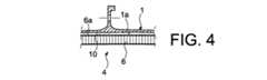
また、装置2は、一方の側でパネル6の外部表面6aに押し付けられ、他方の側でケーシング1の内部表面1aに押し付けられるように1つまたは複数の振動減衰ストリップ10を備える。 The
円周方向に沿って互いから間隔を置いて配置されるストリップ10は、エラストマー材料で作られる。これらは、通常、軸線2に平行に方向付けられ、すなわち、これらは、この軸線に平行なそれらの長さ、および同じ軸線2に直交するそれらの幅を有する。示された好ましい実施形態においては、各ストリップ10は、少ない幅を有し、それにより、実質的に平面の形状を保つことができるようになるが、あるいは、本発明の範囲から逸脱することなく湾曲されることもできる。 The
図3は、ねじ8によってケーシング1に組み立てられるパネル6を示しているが、図4は、表面1aおよび表面6aの両方の間の減衰ストリップ10のうちの1つの介在の位置を示しており、その間でこのストリップは、その振動減衰機能を与えるように圧縮される。 FIG. 3 shows the
図5および図6は、ストリップ10のうちの1つ、ならびにケーシング上のその構成をより正確に示している。これに関しては、取り付けをより容易にするために、装置4のストリップ10はすべて、同一であるように設けられることが留意される。 5 and 6 show more precisely one of the
ここで、ストリップ10は、軸線2に直交し、かつ長手方向端縁4と呼ばれる2つの最も長い対縁の間を通過する正中面に対応する、第1の対称面12を有する。他方では、ストリップ10はまた、第1の面12に直交し、かつ横断方向端縁18と呼ばれる最も短い2つの対縁の間を通過する正中面に対応する、第2の対称面16を有する。面12、16は共に、ストリップ10の面に直交し、その横断方向端縁18は、第1の面12に平行である。その結果として、図6に示される側面図では、端縁18は垂直な端縁と考えられる。 Here, the
本発明の特徴のうちの1つは、長手方向端縁14の形状にあり、これは、長手方向軸線2の方向に沿って方向付けられず、またそれ自体、使用時に水平に方向付けられる。実際に、各長手方向端縁14は、互いに対して傾斜され、かつそれぞれ実質的に平面の、同じ軸線2の方向に2つの連続する部分14a、14bから成ることによって、中心軸線2の方向に沿って互いから間隔を置いて配置される上流側端部と下流側端部との間に延びる。実質的に同一の長さの長手方向端縁14a、14bの両方の部分は、好ましくは1°と3°との間の角度を形成する。 One of the features of the present invention is the shape of the
減衰ストリップ10は、2つの逆にした取り付け位置でパネル6に取り付け可能であるように形成され、両方の対向長手方向端縁14の位置はそれぞれ逆にされ、すなわち、両方の位置のうちの1つにおいて、端縁のうちの1つは、通常上方に方向付けられるが、これは、他の位置において下方に方向付けられることが留意される。適応された取り付け方向にかかわらず、第1の対称面14に沿ったストリップ10の対称性のため、ストリップは、パネル6上に同じ構成を有する。したがって、両方の取り付け方向において、上方に方向付けられた端縁である液体の漏れを集めやすい長手方向端縁14は、液体の排出を可能にするように液体をこの端縁の両方の端部まで重力によって導くことができるので、取り付け間違いは起こり得ない。 The attenuating
実際に、使用時に水平に方向付けられる中心軸線2に沿って傾斜されることによって、2つの端縁部分14a、14bのそれぞれは、集められた液体、たとえば油および/または灯油の漏れをこれがまとめられる縁端部まで重力によって導くことができる。換言すれば、いったんケーシングの内部表面1aに流れる液体が上方に方向付けられた長手方向端縁14に付着されると、これは、同じ端縁、パネルの外部表面6aとケーシングの内部表面1aとの間に閉じ込められることによって、この端縁の上流側端部または下流側端部まで重力によって流れる。横断方向上流側または下流側端縁18に到達した後に、次いで液体は、両方の表面1aと表面6aとの間を送風機ケーシングの低い部分に流れ落ちて、次にケーシング1の6時の方向に配置されるドレン管(図示せず)を通して排出され得る。 In fact, by tilting along the
それぞれの上方に方向付けられた端縁14は、水平方向に対するその傾斜(複数可)によって、減衰ストリップ10から遠い方の液体の漏れの排出を可能にするファセット/リムに当該。 Each upwardly directed
図7は、ストリップ10を製作する別法を示しており、本明細書においては、それぞれは概ね平行四辺形の形状をとり、各長手方向端縁14は、縁端部のうちの1つ、本明細書においては下流側端部まで液体の流出専用の傾斜を形成するように、中心軸線2に対して傾斜される単一部分から成る。 FIG. 7 shows an alternative method of making the
もちろん、単に非限定的な例としてちょうど説明した本発明について、さまざまな改変が当業者によって行われ得る。 Of course, various modifications may be made by those skilled in the art to the present invention which has just been described as a non-limiting example.
Claims (10)
Translated fromJapanese減衰ストリップ(10)のうちの少なくとも1つの2つの対縁(14)のうちの少なくとも1つは、この端縁に存在する液体がその上流側端部および下流側端部のどちらかまたは両方に向かって重力によって流れることができるように形成されることを特徴とする、装置。Acoustic protection for a fan casing (1) of an aircraft turbomachine, comprising an acoustic protection panel (6) forming a ferrule sector centered on the central axis (2) to be the same as the longitudinal axis of the fan casing One or more vibration damping for the device (4) and for pressing against the outer surface (6a) of the sound protection panel on one side and against the inner surface (1a) of the fan casing on the other side Two opposite edges each comprising a strip (10), each damping strip (10) having an upstream end and a downstream end spaced apart from each other along the direction of the central axis (2) A device having (14),
At least one of the two opposite edges (14) of at least one of the damping strips (10) has a liquid present at this edge at either or both of its upstream and downstream ends. A device, characterized in that it is configured to be able to flow by gravity.
Applications Claiming Priority (3)
| Application Number | Priority Date | Filing Date | Title |
|---|---|---|---|
| FR1161819 | 2011-12-16 | ||
| FR1161819AFR2984429B1 (en) | 2011-12-16 | 2011-12-16 | VIBRATION DAMPING BANDS WITH FLUID EXHAUST, FOR ACOUSTIC PROTECTION OF AIRCRAFT TURBOMACHINE BLOWER HOUSING |
| PCT/FR2012/052938WO2013088088A1 (en) | 2011-12-16 | 2012-12-14 | Fluid discharge vibration damping strips for acoustic protection of aircraft turbomachine fan casing |
Publications (2)
| Publication Number | Publication Date |
|---|---|
| JP2015505933Atrue JP2015505933A (en) | 2015-02-26 |
| JP6042905B2 JP6042905B2 (en) | 2016-12-14 |
Family
ID=47559556
Family Applications (1)
| Application Number | Title | Priority Date | Filing Date |
|---|---|---|---|
| JP2014546618AActiveJP6042905B2 (en) | 2011-12-16 | 2012-12-14 | Airborne turbomachinery fan casing acoustic protection fluid discharge vibration damping strip |
Country Status (9)
| Country | Link |
|---|---|
| US (1) | US9631640B2 (en) |
| EP (1) | EP2800906B1 (en) |
| JP (1) | JP6042905B2 (en) |
| CN (1) | CN103998791B (en) |
| BR (1) | BR112014014436B1 (en) |
| CA (1) | CA2858165C (en) |
| FR (1) | FR2984429B1 (en) |
| RU (1) | RU2607688C2 (en) |
| WO (1) | WO2013088088A1 (en) |
Families Citing this family (1)
| Publication number | Priority date | Publication date | Assignee | Title |
|---|---|---|---|---|
| EP2940251B1 (en)* | 2014-04-28 | 2019-06-12 | Rolls-Royce Corporation | Fan containment case |
Citations (3)
| Publication number | Priority date | Publication date | Assignee | Title |
|---|---|---|---|---|
| US3542152A (en)* | 1968-04-08 | 1970-11-24 | Gen Electric | Sound suppression panel |
| JPS5698534A (en)* | 1979-12-18 | 1981-08-08 | United Technologies Corp | Sound insulating structure |
| JPS639401U (en)* | 1986-07-04 | 1988-01-22 |
Family Cites Families (16)
| Publication number | Priority date | Publication date | Assignee | Title |
|---|---|---|---|---|
| US4293053A (en)* | 1979-12-18 | 1981-10-06 | United Technologies Corporation | Sound absorbing structure |
| US4751979A (en)* | 1985-05-16 | 1988-06-21 | Airborne Express, Inc. | Engine noise suppression kit for the nacelles of a jet aircraft |
| US4926963A (en)* | 1987-10-06 | 1990-05-22 | Uas Support, Inc. | Sound attenuating laminate for jet aircraft engines |
| FR2752392B1 (en)* | 1996-08-14 | 1999-04-23 | Hispano Suiza Sa | VENTILATED HONEYCOMB SANDWICH PANEL AND VENTILATION METHOD FOR SUCH A PANEL |
| DE69722345T2 (en)* | 1996-10-21 | 2004-02-26 | United Technologies Corp. (N.D.Ges.D. Staates Delaware), Hartford | Guide grille for the flow path of a gas turbine |
| US6637186B1 (en)* | 1997-11-11 | 2003-10-28 | United Technologies Corporation | Fan case liner |
| RU2148732C1 (en)* | 1998-05-05 | 2000-05-10 | Открытое акционерное общество Самарский научно-технический комплекс им. Н.Д. Кузнецова | Turbo-machine stage |
| US7018172B2 (en)* | 2003-12-22 | 2006-03-28 | United Technologies Corporation | Airfoil surface impedance modification for noise reduction in turbofan engines |
| US7331421B2 (en)* | 2005-03-30 | 2008-02-19 | The Boeing Company | Flow restrictors for aircraft inlet acoustic treatments, and associated systems and methods |
| US7866440B2 (en)* | 2006-07-21 | 2011-01-11 | Rohr, Inc. | System for joining acoustic cellular panel sections in edge-to-edge relation |
| FR2908737B1 (en)* | 2006-11-16 | 2009-12-04 | Airbus France | ACOUSTIC COATING FOR AIRCRAFT INCORPORATING A JELLY EFFECT FROST TREATMENT SYSTEM. |
| FR2912780B1 (en)* | 2007-02-20 | 2012-03-02 | Airbus France | COATING FOR ACOUSTIC TREATMENT INCORPORATING AN ALVEOLAR STRUCTURE WITH A COMPLEX SHAPE |
| US8028802B2 (en)* | 2008-06-30 | 2011-10-04 | General Electric Company | Method and system for damped acoustic panels |
| FR2943624B1 (en) | 2009-03-27 | 2011-04-15 | Airbus France | AIRCRAFT NACELLE COMPRISING AN ENHANCED EXTERIOR WALL |
| FR2945074B1 (en) | 2009-04-29 | 2011-06-03 | Snecma | REINFORCED BLOW OF BREATHING BLADE |
| AU2010281317A1 (en) | 2009-08-04 | 2012-02-23 | Gan Systems Inc. | Island matrixed gallium nitride microwave and power switching transistors |
- 2011
- 2011-12-16FRFR1161819Apatent/FR2984429B1/enactiveActive
- 2012
- 2012-12-14RURU2014129011Apatent/RU2607688C2/enactive
- 2012-12-14BRBR112014014436-2Apatent/BR112014014436B1/enactiveIP Right Grant
- 2012-12-14JPJP2014546618Apatent/JP6042905B2/enactiveActive
- 2012-12-14USUS14/363,898patent/US9631640B2/enactiveActive
- 2012-12-14CACA2858165Apatent/CA2858165C/enactiveActive
- 2012-12-14CNCN201280060814.3Apatent/CN103998791B/enactiveActive
- 2012-12-14EPEP12815744.3Apatent/EP2800906B1/enactiveActive
- 2012-12-14WOPCT/FR2012/052938patent/WO2013088088A1/enactiveApplication Filing
Patent Citations (3)
| Publication number | Priority date | Publication date | Assignee | Title |
|---|---|---|---|---|
| US3542152A (en)* | 1968-04-08 | 1970-11-24 | Gen Electric | Sound suppression panel |
| JPS5698534A (en)* | 1979-12-18 | 1981-08-08 | United Technologies Corp | Sound insulating structure |
| JPS639401U (en)* | 1986-07-04 | 1988-01-22 |
Also Published As
| Publication number | Publication date |
|---|---|
| JP6042905B2 (en) | 2016-12-14 |
| CA2858165A1 (en) | 2013-06-20 |
| FR2984429A1 (en) | 2013-06-21 |
| RU2014129011A (en) | 2016-02-10 |
| US9631640B2 (en) | 2017-04-25 |
| WO2013088088A1 (en) | 2013-06-20 |
| CN103998791A (en) | 2014-08-20 |
| BR112014014436B1 (en) | 2021-03-16 |
| RU2607688C2 (en) | 2017-01-10 |
| EP2800906A1 (en) | 2014-11-12 |
| CA2858165C (en) | 2019-07-02 |
| EP2800906B1 (en) | 2016-05-25 |
| US20140369816A1 (en) | 2014-12-18 |
| CN103998791B (en) | 2016-08-17 |
| FR2984429B1 (en) | 2014-02-14 |
| BR112014014436A2 (en) | 2017-06-13 |
Similar Documents
| Publication | Publication Date | Title |
|---|---|---|
| US7270517B2 (en) | Turbine blade with vibration damper | |
| CN101802367B (en) | Gas turbine intake muffler | |
| CA2966182C (en) | Liner assembly, engine housing, and methods of assembling the same | |
| RU2494017C2 (en) | Wave attenuation panel arranged between engine and aircraft nacelle air intake | |
| JP6723994B2 (en) | Heat exchange and noise reduction panel for turbine engine and turbine engine | |
| US8794926B2 (en) | Turbine blade with improved aerodynamic performance | |
| US8157507B1 (en) | Damped stator assembly | |
| RU2015155884A (en) | SILENT DISCHARGE | |
| CA3059947C (en) | Trailing member to reduce pressure drop across a duct mounted sound attenuating baffle | |
| JP6042905B2 (en) | Airborne turbomachinery fan casing acoustic protection fluid discharge vibration damping strip | |
| US20180258957A1 (en) | Asymmetric multi degree of freedom flutter damper | |
| CA2851745C (en) | Fan with sound-insulated fan housing | |
| EP2271830B1 (en) | Fairing for a gas turbine engine | |
| RU2715428C2 (en) | Ventilation device | |
| CN104633371B (en) | Sound reduces system | |
| CN111228900A (en) | air purifier | |
| CN115234374B (en) | A jet precooling structure for the inlet of an aerospace aircraft engine | |
| KR20120001835U (en) | Duct Silencer For Ship | |
| JP2016081058A (en) | Thermoacoustic protective structure for rotary machine |
Legal Events
| Date | Code | Title | Description |
|---|---|---|---|
| A621 | Written request for application examination | Free format text:JAPANESE INTERMEDIATE CODE: A621 Effective date:20151110 | |
| A977 | Report on retrieval | Free format text:JAPANESE INTERMEDIATE CODE: A971007 Effective date:20160812 | |
| A131 | Notification of reasons for refusal | Free format text:JAPANESE INTERMEDIATE CODE: A131 Effective date:20160823 | |
| A521 | Request for written amendment filed | Free format text:JAPANESE INTERMEDIATE CODE: A523 Effective date:20161004 | |
| TRDD | Decision of grant or rejection written | ||
| A01 | Written decision to grant a patent or to grant a registration (utility model) | Free format text:JAPANESE INTERMEDIATE CODE: A01 Effective date:20161101 | |
| A61 | First payment of annual fees (during grant procedure) | Free format text:JAPANESE INTERMEDIATE CODE: A61 Effective date:20161110 | |
| R150 | Certificate of patent or registration of utility model | Ref document number:6042905 Country of ref document:JP Free format text:JAPANESE INTERMEDIATE CODE: R150 | |
| R250 | Receipt of annual fees | Free format text:JAPANESE INTERMEDIATE CODE: R250 | |
| R250 | Receipt of annual fees | Free format text:JAPANESE INTERMEDIATE CODE: R250 | |
| R250 | Receipt of annual fees | Free format text:JAPANESE INTERMEDIATE CODE: R250 | |
| R250 | Receipt of annual fees | Free format text:JAPANESE INTERMEDIATE CODE: R250 | |
| R250 | Receipt of annual fees | Free format text:JAPANESE INTERMEDIATE CODE: R250 |