JP2015503960A - Self-sealing catheter - Google Patents
Self-sealing catheterDownload PDFInfo
- Publication number
- JP2015503960A JP2015503960AJP2014548839AJP2014548839AJP2015503960AJP 2015503960 AJP2015503960 AJP 2015503960AJP 2014548839 AJP2014548839 AJP 2014548839AJP 2014548839 AJP2014548839 AJP 2014548839AJP 2015503960 AJP2015503960 AJP 2015503960A
- Authority
- JP
- Japan
- Prior art keywords
- catheter
- puncture
- lumen
- removal
- tip
- Prior art date
- Legal status (The legal status is an assumption and is not a legal conclusion. Google has not performed a legal analysis and makes no representation as to the accuracy of the status listed.)
- Pending
Links
Images


Classifications
- A—HUMAN NECESSITIES
- A61—MEDICAL OR VETERINARY SCIENCE; HYGIENE
- A61B—DIAGNOSIS; SURGERY; IDENTIFICATION
- A61B17/00—Surgical instruments, devices or methods
- A61B17/0057—Implements for plugging an opening in the wall of a hollow or tubular organ, e.g. for sealing a vessel puncture or closing a cardiac septal defect
- A—HUMAN NECESSITIES
- A61—MEDICAL OR VETERINARY SCIENCE; HYGIENE
- A61B—DIAGNOSIS; SURGERY; IDENTIFICATION
- A61B17/00—Surgical instruments, devices or methods
- A61B17/12—Surgical instruments, devices or methods for ligaturing or otherwise compressing tubular parts of the body, e.g. blood vessels or umbilical cord
- A61B17/12022—Occluding by internal devices, e.g. balloons or releasable wires
- A61B17/12099—Occluding by internal devices, e.g. balloons or releasable wires characterised by the location of the occluder
- A61B17/12109—Occluding by internal devices, e.g. balloons or releasable wires characterised by the location of the occluder in a blood vessel
- A61B17/12113—Occluding by internal devices, e.g. balloons or releasable wires characterised by the location of the occluder in a blood vessel within an aneurysm
- A—HUMAN NECESSITIES
- A61—MEDICAL OR VETERINARY SCIENCE; HYGIENE
- A61B—DIAGNOSIS; SURGERY; IDENTIFICATION
- A61B17/00—Surgical instruments, devices or methods
- A61B17/12—Surgical instruments, devices or methods for ligaturing or otherwise compressing tubular parts of the body, e.g. blood vessels or umbilical cord
- A61B17/12022—Occluding by internal devices, e.g. balloons or releasable wires
- A61B17/12131—Occluding by internal devices, e.g. balloons or releasable wires characterised by the type of occluding device
- A61B17/12181—Occluding by internal devices, e.g. balloons or releasable wires characterised by the type of occluding device formed by fluidized, gelatinous or cellular remodelable materials, e.g. embolic liquids, foams or extracellular matrices
- A61B17/1219—Occluding by internal devices, e.g. balloons or releasable wires characterised by the type of occluding device formed by fluidized, gelatinous or cellular remodelable materials, e.g. embolic liquids, foams or extracellular matrices expandable in contact with liquids
- A—HUMAN NECESSITIES
- A61—MEDICAL OR VETERINARY SCIENCE; HYGIENE
- A61M—DEVICES FOR INTRODUCING MEDIA INTO, OR ONTO, THE BODY; DEVICES FOR TRANSDUCING BODY MEDIA OR FOR TAKING MEDIA FROM THE BODY; DEVICES FOR PRODUCING OR ENDING SLEEP OR STUPOR
- A61M25/00—Catheters; Hollow probes
- A—HUMAN NECESSITIES
- A61—MEDICAL OR VETERINARY SCIENCE; HYGIENE
- A61M—DEVICES FOR INTRODUCING MEDIA INTO, OR ONTO, THE BODY; DEVICES FOR TRANSDUCING BODY MEDIA OR FOR TAKING MEDIA FROM THE BODY; DEVICES FOR PRODUCING OR ENDING SLEEP OR STUPOR
- A61M25/00—Catheters; Hollow probes
- A61M25/0067—Catheters; Hollow probes characterised by the distal end, e.g. tips
- A61M25/0082—Catheter tip comprising a tool
- A61M25/0084—Catheter tip comprising a tool being one or more injection needles
- A—HUMAN NECESSITIES
- A61—MEDICAL OR VETERINARY SCIENCE; HYGIENE
- A61B—DIAGNOSIS; SURGERY; IDENTIFICATION
- A61B17/00—Surgical instruments, devices or methods
- A61B17/00491—Surgical glue applicators
- A—HUMAN NECESSITIES
- A61—MEDICAL OR VETERINARY SCIENCE; HYGIENE
- A61B—DIAGNOSIS; SURGERY; IDENTIFICATION
- A61B17/00—Surgical instruments, devices or methods
- A61B17/12—Surgical instruments, devices or methods for ligaturing or otherwise compressing tubular parts of the body, e.g. blood vessels or umbilical cord
- A61B17/12022—Occluding by internal devices, e.g. balloons or releasable wires
- A61B17/12131—Occluding by internal devices, e.g. balloons or releasable wires characterised by the type of occluding device
- A61B17/12181—Occluding by internal devices, e.g. balloons or releasable wires characterised by the type of occluding device formed by fluidized, gelatinous or cellular remodelable materials, e.g. embolic liquids, foams or extracellular matrices
- A61B17/12186—Occluding by internal devices, e.g. balloons or releasable wires characterised by the type of occluding device formed by fluidized, gelatinous or cellular remodelable materials, e.g. embolic liquids, foams or extracellular matrices liquid materials adapted to be injected
- A—HUMAN NECESSITIES
- A61—MEDICAL OR VETERINARY SCIENCE; HYGIENE
- A61B—DIAGNOSIS; SURGERY; IDENTIFICATION
- A61B17/00—Surgical instruments, devices or methods
- A61B2017/00004—(bio)absorbable, (bio)resorbable or resorptive
- A—HUMAN NECESSITIES
- A61—MEDICAL OR VETERINARY SCIENCE; HYGIENE
- A61B—DIAGNOSIS; SURGERY; IDENTIFICATION
- A61B17/00—Surgical instruments, devices or methods
- A61B17/00234—Surgical instruments, devices or methods for minimally invasive surgery
- A61B2017/00349—Needle-like instruments having hook or barb-like gripping means, e.g. for grasping suture or tissue
- A—HUMAN NECESSITIES
- A61—MEDICAL OR VETERINARY SCIENCE; HYGIENE
- A61B—DIAGNOSIS; SURGERY; IDENTIFICATION
- A61B17/00—Surgical instruments, devices or methods
- A61B17/0057—Implements for plugging an opening in the wall of a hollow or tubular organ, e.g. for sealing a vessel puncture or closing a cardiac septal defect
- A61B2017/00646—Type of implements
- A61B2017/0065—Type of implements the implement being an adhesive
- A—HUMAN NECESSITIES
- A61—MEDICAL OR VETERINARY SCIENCE; HYGIENE
- A61B—DIAGNOSIS; SURGERY; IDENTIFICATION
- A61B17/00—Surgical instruments, devices or methods
- A61B17/0057—Implements for plugging an opening in the wall of a hollow or tubular organ, e.g. for sealing a vessel puncture or closing a cardiac septal defect
- A61B2017/00646—Type of implements
- A61B2017/00654—Type of implements entirely comprised between the two sides of the opening
- A—HUMAN NECESSITIES
- A61—MEDICAL OR VETERINARY SCIENCE; HYGIENE
- A61B—DIAGNOSIS; SURGERY; IDENTIFICATION
- A61B17/00—Surgical instruments, devices or methods
- A61B17/0057—Implements for plugging an opening in the wall of a hollow or tubular organ, e.g. for sealing a vessel puncture or closing a cardiac septal defect
- A61B2017/00646—Type of implements
- A61B2017/00659—Type of implements located only on one side of the opening
- A—HUMAN NECESSITIES
- A61—MEDICAL OR VETERINARY SCIENCE; HYGIENE
- A61B—DIAGNOSIS; SURGERY; IDENTIFICATION
- A61B17/00—Surgical instruments, devices or methods
- A61B2017/00831—Material properties
- A61B2017/00893—Material properties pharmaceutically effective
- A—HUMAN NECESSITIES
- A61—MEDICAL OR VETERINARY SCIENCE; HYGIENE
- A61B—DIAGNOSIS; SURGERY; IDENTIFICATION
- A61B17/00—Surgical instruments, devices or methods
- A61B17/12—Surgical instruments, devices or methods for ligaturing or otherwise compressing tubular parts of the body, e.g. blood vessels or umbilical cord
- A61B17/12022—Occluding by internal devices, e.g. balloons or releasable wires
- A61B2017/1205—Introduction devices
- A61B2017/12054—Details concerning the detachment of the occluding device from the introduction device
- A61B2017/12059—Joint of soluble material
- A—HUMAN NECESSITIES
- A61—MEDICAL OR VETERINARY SCIENCE; HYGIENE
- A61B—DIAGNOSIS; SURGERY; IDENTIFICATION
- A61B90/00—Instruments, implements or accessories specially adapted for surgery or diagnosis and not covered by any of the groups A61B1/00 - A61B50/00, e.g. for luxation treatment or for protecting wound edges
- A61B90/03—Automatic limiting or abutting means, e.g. for safety
- A61B2090/037—Automatic limiting or abutting means, e.g. for safety with a frangible part, e.g. by reduced diameter
- A—HUMAN NECESSITIES
- A61—MEDICAL OR VETERINARY SCIENCE; HYGIENE
- A61M—DEVICES FOR INTRODUCING MEDIA INTO, OR ONTO, THE BODY; DEVICES FOR TRANSDUCING BODY MEDIA OR FOR TAKING MEDIA FROM THE BODY; DEVICES FOR PRODUCING OR ENDING SLEEP OR STUPOR
- A61M25/00—Catheters; Hollow probes
- A61M25/0021—Catheters; Hollow probes characterised by the form of the tubing
- A61M25/0023—Catheters; Hollow probes characterised by the form of the tubing by the form of the lumen, e.g. cross-section, variable diameter
- A61M25/0026—Multi-lumen catheters with stationary elements
- A61M25/003—Multi-lumen catheters with stationary elements characterized by features relating to least one lumen located at the distal part of the catheter, e.g. filters, plugs or valves
- A—HUMAN NECESSITIES
- A61—MEDICAL OR VETERINARY SCIENCE; HYGIENE
- A61M—DEVICES FOR INTRODUCING MEDIA INTO, OR ONTO, THE BODY; DEVICES FOR TRANSDUCING BODY MEDIA OR FOR TAKING MEDIA FROM THE BODY; DEVICES FOR PRODUCING OR ENDING SLEEP OR STUPOR
- A61M25/00—Catheters; Hollow probes
- A61M25/0067—Catheters; Hollow probes characterised by the distal end, e.g. tips
- A61M25/0082—Catheter tip comprising a tool
Landscapes
- Health & Medical Sciences (AREA)
- Life Sciences & Earth Sciences (AREA)
- Surgery (AREA)
- Animal Behavior & Ethology (AREA)
- Public Health (AREA)
- Veterinary Medicine (AREA)
- General Health & Medical Sciences (AREA)
- Engineering & Computer Science (AREA)
- Biomedical Technology (AREA)
- Heart & Thoracic Surgery (AREA)
- Molecular Biology (AREA)
- Medical Informatics (AREA)
- Nuclear Medicine, Radiotherapy & Molecular Imaging (AREA)
- Vascular Medicine (AREA)
- Reproductive Health (AREA)
- Anesthesiology (AREA)
- Biophysics (AREA)
- Pulmonology (AREA)
- Hematology (AREA)
- Cardiology (AREA)
- Neurosurgery (AREA)
- Surgical Instruments (AREA)
- Materials For Medical Uses (AREA)
- Pharmaceuticals Containing Other Organic And Inorganic Compounds (AREA)
Abstract
Translated fromJapaneseDescription
Translated fromJapanese 関連出願への相互参照
本願は、それぞれの内容の全体が参照により本開示に組み込まれる2011年12月21日に出願された米国特許仮出願第61/578,627号及び2012年7月6日に出願された第61/668,955号の35U.S.C.§119(e)に基づく利益を主張するものである。CROSS REFERENCE TO RELATED APPLICATIONS This application is a US Provisional Application No. 61 / 578,627 filed Dec. 21, 2011 and Jul. 6, 2012, each of which is incorporated herein by reference in its entirety. No. 61 / 668,955, 35 U.S. S. C. Claims the benefit under §119 (e).
開示されるのは、血管壁を穿通する及び穿通後の壁をシールするのに有用なセルフシールカテーテルである。こうしたカテーテルは、穿通部位の近傍の血管外組織に部位特異的薬剤を送達するのに特に有用である。こうした部位は、再狭窄しやすい血管構造に隣接する組織、又は出血性脳卒中、虚血などの結果として損傷を受けることがある組織を含む。こうしたカテーテルを用いる方法も開示される。 Disclosed are self-sealing catheters useful for penetrating the vessel wall and sealing the wall after penetration. Such catheters are particularly useful for delivering site-specific drugs to extravascular tissue in the vicinity of the penetration site. Such sites include tissue adjacent to vascular structures that are prone to restenosis or tissue that can be damaged as a result of hemorrhagic stroke, ischemia, and the like. A method of using such a catheter is also disclosed.
血管疾患は、血管の破裂又は詰まりを含む破局的な結果にしばしばつながる。血管疾患の一例は、弱くなった血管構造から形成される動脈瘤である。脳に存在するとき、動脈瘤の破裂は出血性脳卒中と呼ばれ、こうした卒中はすべての卒中のうちの約20パーセントを占める。(avm.ucsf.edu/patient_info/WhatIsAStroke/)。これらの卒中は、脳虚血に頭蓋への血液の放出が随伴するので治療するのが非常に難しい。そのように放出された血液は炎症を引き起こし、虚血と相まって高レベルの神経損傷を来たし、多くの場合、患者の病的状態を招く。 Vascular diseases often lead to catastrophic consequences including rupture or clogging of blood vessels. An example of a vascular disease is an aneurysm formed from weakened vasculature. When present in the brain, aneurysm rupture is called a hemorrhagic stroke, and these strokes account for about 20 percent of all strokes. (Avm.ucsf.edu/patient_info/WhatIsAstroke/). These strokes are very difficult to treat because cerebral ischemia is accompanied by the release of blood to the skull. The blood so released causes inflammation and, in combination with ischemia, results in high levels of nerve damage, often resulting in patient morbidity.
血管疾患の別の例は動脈プラークの蓄積であり、これは血小板の凝集又はプラークの断片化と組み合わされたときに、結果的に完全な血管の詰まりを生じ、これは虚血発作と相関関係がある。虚血が冠状系にあるとき、一般的な結果は心停止(心臓発作)である。このような場合、こうした虚血発作後の当面の課題は、発作の直後に損傷を受けた組織に生じる以後の炎症である。こうした炎症の治療は、最初の虚血性傷害(ischemic insult)よりも、生存のためにしばしばより重要であり、最初の傷害後数時間以内に行われる。炎症の即時の発症は、全身性抗炎症薬の使用に対して禁忌を示す。上記の場合、組織の迅速な治療は、脳機能の喪失、冠状組織死、又は再狭窄などのダメージを最小にする。 Another example of vascular disease is the accumulation of arterial plaque, which, when combined with platelet aggregation or plaque fragmentation, results in complete vascular clogging, which correlates with ischemic stroke There is. When ischemia is in the coronary system, a common result is cardiac arrest (heart attack). In such cases, the immediate challenge after such an ischemic attack is subsequent inflammation that occurs in the damaged tissue immediately after the attack. Treatment of such inflammation is often more important for survival than the initial ischemic injury and occurs within hours after the initial injury. The immediate onset of inflammation is contraindicated for the use of systemic anti-inflammatory drugs. In these cases, rapid treatment of tissue minimizes damage such as loss of brain function, coronary tissue death, or restenosis.
虚血性事象の前に動脈プラークが診断されるときにさらに別の血管問題が生じる。このような場合、ステント留置と組み合わされたバルーン血管形成が1つの従来の療法である。この手法の一般的な副作用は、血管形成術によって血管内皮に引き起こされた損傷から生じる血管形成手法の部位での炎症にある程度起因する再狭窄である。再狭窄を抑制する現在の処置は薬剤溶出ステントを含み、この場合、薬剤はゆっくりと放出される。いくつかの場合には効果的であるものの、こうしたステントは、病変血管構造の全体を覆わないワイヤメッシュであり、それらは完全に効果的というわけではない。さらに、ステントが、血液が常に流れている状態の非静的環境の血管壁上に留置される際に、放出されるあらゆる薬剤が、再狭窄の可能性がある部位からすぐに運び去られてしまいがちである。 Yet another vascular problem arises when arterial plaque is diagnosed prior to an ischemic event. In such cases, balloon angioplasty combined with stent placement is one conventional therapy. A common side effect of this approach is restenosis due in part to inflammation at the site of the angioplasty procedure resulting from damage caused to the vascular endothelium by angioplasty. Current treatments to suppress restenosis include drug eluting stents, where the drug is released slowly. Although effective in some cases, such stents are wire meshes that do not cover the entire diseased vasculature and they are not completely effective. Furthermore, when the stent is placed on a blood vessel wall in a non-static environment where blood is constantly flowing, any drug that is released is quickly carried away from the site of potential restenosis. It tends to end up.
上記を考慮して、病変血管構造に隣接する、好ましくは血管壁の外側にある組織に薬剤を効果的に送達する必要性が継続している。そうすることの明らかな難しさのうちの1つは、不必要な出血又は血管破裂を引き起こさずに血管内皮を穿通する必要があることである。 In view of the above, there is a continuing need to effectively deliver drugs to tissues adjacent to the diseased vasculature, preferably outside the vessel wall. One of the obvious difficulties in doing so is the need to penetrate the vascular endothelium without causing unnecessary bleeding or vascular rupture.
本開示は、いくつかの実施形態では、血管壁を穿刺することができるセルフシールカテーテル装置に向けられる。一実施形態では、こうしたカテーテルは、損傷又はさらなる損傷のリスクがある組織に薬剤を直接送達することができる。カテーテルは、血管壁を横断することができる穿刺チップを有する穿刺装置を備える。カテーテルは、穿刺部位を通した出血が最小になるように穿刺部位での創傷をセルフシールする手段をさらに提供する。好ましくは、カテーテルは、血管壁を穿刺した後で組織に薬剤を送達することができる。 The present disclosure is directed, in some embodiments, to a self-sealing catheter device that can puncture a vessel wall. In one embodiment, such a catheter can deliver the drug directly to tissue at risk of injury or further damage. The catheter comprises a puncture device having a puncture tip that can traverse the vessel wall. The catheter further provides a means for self-sealing the wound at the puncture site so that bleeding through the puncture site is minimized. Preferably, the catheter is capable of delivering the drug to the tissue after puncturing the vessel wall.
したがって、一実施形態では、近位端及び遠位端を備え、且つ近位端から遠位端にわたる少なくとも1つの管腔を有する、セルフシールカテーテルであって、管腔が、管腔内に滑動可能に係合できる穿刺装置を備え、前記穿刺装置が、その遠位端にセルフシール穿刺チップを備え、前記チップが、血管壁を穿通することができ、さらに、穿刺チップが、随意的に、チップによって穿刺される部位に薬剤を送達することができる、セルフシールカテーテルが提供される。1つの好ましい実施形態では、穿刺チップは、創傷部位の血管壁の近傍に創傷をシールする層を形成することによって穿刺創傷をシールすることができる。1つの好ましい実施形態では、層は、血管構造を通る血流の妨害を最小にするように血管構造穿刺部位の組織側に配置される生物適合性層である。 Thus, in one embodiment, a self-sealing catheter having a proximal end and a distal end and having at least one lumen extending from the proximal end to the distal end, wherein the lumen is slid into the lumen A puncture device that can be engagably engaged, the puncture device comprising a self-sealing puncture tip at a distal end thereof, wherein the tip can penetrate the vessel wall, and optionally the puncture tip comprises: A self-sealing catheter is provided that can deliver the drug to the site punctured by the tip. In one preferred embodiment, the puncture tip can seal the puncture wound by forming a layer that seals the wound near the vessel wall at the wound site. In one preferred embodiment, the layer is a biocompatible layer disposed on the tissue side of the vascular structure puncture site so as to minimize blockage of blood flow through the vasculature.
別の実施形態では、近位端及び遠位端を備え、且つ近位端から遠位端にわたる少なくとも2つの管腔を有するカテーテルであって、第1の管腔が、動脈瘤などの血管部位に、前記部位の中への血流を阻止/抑制するために塞栓性組成物又は装置を送達するように寸法設定され、第2の管腔が、前記管腔内に滑動可能に係合できる穿刺装置を備え、前記装置がその遠位端に穿刺チップを備え、チップが血管壁を穿通することができ、さらに、穿刺チップが前記チップによって穿刺される部位に薬剤を送達することができる、カテーテルが提供される。この実施形態では、穿刺部位のセルフシールは、自然凝固が結果的にシールすることになるように塞栓性組成物を通じた血流の阻止によって生じる。 In another embodiment, a catheter having a proximal end and a distal end and having at least two lumens extending from the proximal end to the distal end, wherein the first lumen is a vascular site, such as an aneurysm And is dimensioned to deliver an embolic composition or device to prevent / suppress blood flow into the site, and a second lumen can be slidably engaged within the lumen. Comprising a puncture device, the device comprising a puncture tip at its distal end, the tip can penetrate the blood vessel wall, and the puncture tip can deliver a drug to the site punctured by the tip; A catheter is provided. In this embodiment, the self-sealing of the puncture site is caused by the blockage of blood flow through the embolic composition so that spontaneous coagulation will result in a seal.
いずれの実施形態においても、穿刺チップはセルフシール式である。セルフシールチップのさらなる例は、チップが血管壁を穿刺した後で平坦化して穿刺創傷の近傍に面を形成することができるものを含む。こうした実施形態では、チップは、Z軸に沿った細長い部分からZ軸上の平たい部分に進むが、穿刺部位をシールするようにX軸及びY軸上を延びる。代替的に、チップは、血管構造の穿通時に穿刺創傷の近傍に穿刺部位をシールする平坦化した面を形成するようにカラーが開く様態でカテーテルの先端部の近傍に随意的な伸張可能なカラーを含むことができる。好ましい実施形態では、カラーは、1つ以上の薬剤を含む生物適合性の膨張可能な材料で作製される。 In any embodiment, the puncture tip is self-sealing. Further examples of self-sealing tips include those that can be flattened after the tip has punctured the vessel wall to form a surface in the vicinity of the puncture wound. In such an embodiment, the tip advances from an elongated portion along the Z axis to a flat portion on the Z axis but extends on the X and Y axes to seal the puncture site. Alternatively, the tip is an optional stretchable collar near the tip of the catheter in a manner that the collar opens to form a flattened surface that seals the puncture site near the puncture wound upon penetration of the vascular structure Can be included. In preferred embodiments, the collar is made of a biocompatible inflatable material that includes one or more agents.
別の実施形態は、カテーテルであって、カテーテルの長さにわたる管腔を備え、管腔が前記管腔の長さに沿って滑動可能に係合できる穿刺装置を収容し、前記穿刺装置がヘッド部、ネック部、ステム部を備え、前記ヘッド部が、穿刺装置の遠位端にあり、その遠位端で細くなって穿刺チップを形成するベースを備え、ベースが、ヘッド部が管腔内に沿って動くように寸法設定された断面を有し、用いられるまでカテーテルの管腔内にはめ込まれていることができ、ネック部が、ヘッド部のベースの幅及び穿刺装置のステム部の幅によって画定される場合の凹部を備え、凹部が膨張可能な材料を保持し、膨張可能な材料が、カテーテル壁の管腔内にあるときに膨張することを防止され、カテーテル壁から解放されるときに膨張してカラーを形成する、カテーテルを提供する。 Another embodiment is a catheter containing a puncture device comprising a lumen over the length of the catheter, the lumen being slidably engageable along the length of the lumen, wherein the puncture device is a head , A neck portion, and a stem portion, and the head portion is provided at a distal end of the puncture device, and includes a base that narrows at the distal end to form a puncture tip, and the base portion is in the lumen. Having a cross-section dimensioned to move along, and can be fitted into the lumen of the catheter until used, with the neck portion being the width of the base portion of the head portion and the stem portion of the puncture device When the inflatable material holds the inflatable material and is prevented from inflating and being released from the catheter wall when in the lumen of the catheter wall. Expands to form a collar That, to provide a catheter.
1つの好ましい実施形態では、穿刺装置は、カテーテルの遠位部を近位部から分離するために、少なくとも1つの定められた取り外しポイントを含む。 In one preferred embodiment, the puncture device includes at least one defined removal point for separating the distal portion of the catheter from the proximal portion.
1つの好ましい実施形態では、穿刺装置は、装置の長さに延び、且つ穿刺チップの中に及び穿刺チップを通して薬剤を送達することができる、内部管腔を含む。別の好ましい実施形態では、穿刺チップのヘッド部は、穿刺装置にわたる管腔と連通する1つ以上の孔を含む。これらの孔はマイクロチャネルを形成し、該マイクロチャネルを通して、例えば、チップが血管壁を穿刺すると、組織の中へのカテーテルを通した薬剤の送達が可能となる。代替的に、ヘッド部がコラーゲンなどの生分解性材料を含む場合、ヘッド部の迅速な分解を容易にするために穿刺装置の遠位部の取り外しの前の最後のステップとしてコラゲナーゼの導入を含めることができる。このような場合、マイクロチャネルは、分解を容易にするためにコラゲナーゼ溶液がヘッド部に浸透することを可能にする。 In one preferred embodiment, the lancing device includes an internal lumen that can extend the length of the device and deliver a drug into and through the lancing tip. In another preferred embodiment, the head portion of the puncture tip includes one or more holes that communicate with the lumen across the puncture device. These holes form a microchannel through which the drug can be delivered through the catheter, eg, when the tip punctures the vessel wall. Alternatively, if the head portion includes a biodegradable material such as collagen, include the introduction of collagenase as the last step prior to removal of the distal portion of the lancing device to facilitate rapid degradation of the head portion be able to. In such a case, the microchannel allows the collagenase solution to penetrate the head to facilitate degradation.
別の実施形態では、穿刺チップは、外側チップ部と、外側チップ内に収容される内側の球形の又は丸みのある送達ユニットとの2つの構成部品を備える。外側チップ部は、組織に薬剤を送達するために球形の又は丸みのある送達ユニットを露出するように内側送達ユニットから解放可能に係合される。例えば、外側チップは、穿刺装置の残部との制限された量の粘着性によって定位置に保持されるコラーゲン又は他の生分解性材料の薄いシェルとすることができる。チップが外れるまで穿刺装置の管腔を通して押される水性溶液によって、外側チップに高い圧力をかけることができる。すでに述べたように、水性溶液は、チップの分解を容易にするために酵素を含有することができる。 In another embodiment, the puncture tip comprises two components: an outer tip portion and an inner spherical or rounded delivery unit housed within the outer tip. The outer tip portion is releasably engaged from the inner delivery unit to expose a spherical or rounded delivery unit for delivering medication to the tissue. For example, the outer tip can be a thin shell of collagen or other biodegradable material that is held in place by a limited amount of adhesion with the remainder of the lancing device. High pressure can be applied to the outer tip by an aqueous solution that is pushed through the lumen of the lancing device until the tip is released. As already mentioned, the aqueous solution can contain enzymes to facilitate chip degradation.
穿刺チップが外れると、基礎をなす球形の又は丸みのある送達ユニットは、薬剤を送達するように作用するであろう。このような場合、送達ユニットは、穿刺後に組織を破ることなく目標領域への薬剤の送達を誘導するように操作できるように、エッジを含まないように設計される。 When the puncture tip is removed, the underlying spherical or rounded delivery unit will act to deliver the drug. In such cases, the delivery unit is designed to include no edges so that it can be manipulated to guide the delivery of the drug to the target area without damaging the tissue after puncture.
一実施形態では、穿刺チップは、生分解性材料で作製される。別の実施形態では、カラーは、随意的に生分解性材料で作製される。さらに別の実施形態では、ヘッド部の残部は、生分解性材料で作製される。 In one embodiment, the puncture tip is made of a biodegradable material. In another embodiment, the collar is optionally made of a biodegradable material. In yet another embodiment, the remainder of the head portion is made of a biodegradable material.
別の実施形態では、膨張可能なカラー又は膨張可能な材料は、随意的に血管壁に密封シールを形成するようにカテーテルのネックの垂直部分に結合される。例えば、カラーの部分は、カラーがネックの一体部品となるように、接着剤、熱溶融などによって穿刺ユニットのネックの表面に結合することができる。さらにまた、膨張可能なカラーは、穿刺部位の上の大面積を覆うように主として水平面内に膨張するように形成することができる。 In another embodiment, an inflatable collar or inflatable material is optionally coupled to the vertical portion of the catheter neck so as to form a hermetic seal on the vessel wall. For example, the collar portion can be bonded to the surface of the neck of the puncture unit by adhesive, hot melt, etc. so that the collar is an integral part of the neck. Furthermore, the inflatable collar can be formed to expand primarily in a horizontal plane so as to cover a large area above the puncture site.
さらに別の実施形態では、カテーテルのチップは、管腔がDMSO、エタノールなどの生物適合性溶媒と接触することによってすぐに閉鎖されることを可能にする生物適合性ポリマーを含む。接触すると、生物適合性材料は、管腔の中に部分的に溶解して管腔を封鎖する。ポリマー材料は、臨床医が管腔の閉鎖を監視できるようにその中に組み込まれる造影剤を含有することができる。 In yet another embodiment, the catheter tip includes a biocompatible polymer that allows the lumen to be immediately closed by contact with a biocompatible solvent such as DMSO, ethanol, and the like. Upon contact, the biocompatible material partially dissolves into the lumen and seals the lumen. The polymeric material can contain a contrast agent incorporated therein so that the clinician can monitor lumen closure.
組成物及び方法が説明される前に、本開示は、説明される特定の方法論、プロトコル、及び装置に、これらが変化し得るため、限定されないことが理解される。本明細書で用いられる用語は、本開示の特定の実施形態を説明することを意図され、付属の請求項に記載の本開示の範囲を決して限定することを意図されないことも理解される。 Before the compositions and methods are described, it is understood that the present disclosure is not limited to the particular methodologies, protocols, and devices described as these may vary. It is also understood that the terminology used herein is intended to describe specific embodiments of the present disclosure and is in no way intended to limit the scope of the present disclosure as set forth in the appended claims.
他に定めのない限り、本明細書で用いられるすべての技術用語及び科学用語は、本開示が属する技術分野の当業者によって通常理解されるのと同じ意味をもつ。本明細書で説明されるのと類似の又は等しい任意の方法及び材料を本開示の実施及び試験に用いることができるが、好ましい方法、装置、及び材料がここで説明される。本明細書で挙げられたすべての技術刊行物及び特許公開は、それらの全体が参照により本明細書に組み込まれる。本明細書でのいかなる記載も、先行開示のために本開示が当該開示に実際よりも前の日付で権利付与されないことを認めるものとして解釈されない。 Unless defined otherwise, all technical and scientific terms used herein have the same meaning as commonly understood by one of ordinary skill in the art to which this disclosure belongs. Although any methods and materials similar or equivalent to those described herein can be used in the practice or testing of the present disclosure, the preferred methods, devices, and materials are now described. All technical publications and patent publications mentioned herein are hereby incorporated by reference in their entirety. Nothing herein is to be construed as an admission that the disclosure is not entitled to an earlier date than an actual disclosure by virtue of prior disclosure.
数値指定の前に「約」という語が置かれるとき、これは(+)又は(−)10%、5%、又は1%だけ変化する。「約」が、例えばmgの、ある量の前に用いられるとき、これは、重量値が(+)又は(−)10%、5%、又は1%変化し得ることを示す。 When the word “about” is placed before a numerical designation, this changes by (+) or (−) 10%, 5%, or 1%. When “about” is used before an amount, eg mg, this indicates that the weight value can vary by (+) or (−) 10%, 5%, or 1%.
定義
本開示に係る、本明細書で用いられる場合の、以下の用語は、他に明示的に記載される場合を除き、以下の意味で定義される。Definitions As used herein, the following terms in accordance with this disclosure aredefined with the following meanings, unless explicitly stated otherwise.
本明細書及び請求項で用いられる場合の単数形の冠詞(「a」、「an」、及び「the」)は、文脈上他の意味に明白に規定される場合を除き複数形の言及を含む。例えば、「細胞」という用語は、それらの混合物を含む複数の細胞を含む。 The singular articles (“a”, “an”, and “the”) as used in the specification and claims refer to the plural unless the context clearly dictates otherwise. Including. For example, the term “cell” includes a plurality of cells, including mixtures thereof.
本明細書で用いられる場合の「備える、含む(comprising)」という用語は、組成物及び方法が列挙される要素を含むが他を除外しないことを意味することを意図される。組成物及び方法を定義するのに用いられるときの「本質的に〜からなる」は、組み合わせへのあらゆる本質的有意性のある他の要素を除外することを意味するものとする。例えば、本明細書で定義される要素から本質的になる組成物は、特許請求される本開示の基本的特徴及び新規な特徴に著しく影響を及ぼさない他の要素を除外しないであろう。「〜からなる」は、列挙される微量以上の他の成分及び実質的な方法ステップを除外することを意味するものとする。これらの移行用語のそれぞれによって定義される実施形態は本開示の範囲内である。 As used herein, the term “comprising” is intended to mean that the compositions and methods include the elements listed, but do not exclude others. “Consisting essentially of” when used to define compositions and methods is intended to mean excluding other elements of any intrinsic significance to the combination. For example, a composition consisting essentially of the elements defined herein will not exclude other elements that do not significantly affect the basic and novel characteristics of the claimed disclosure. “Consisting of” shall mean excluding more than trace amounts of other ingredients and substantial method steps recited. Embodiments defined by each of these transition terms are within the scope of this disclosure.
本明細書で用いられる場合の「セルフシール」という用語は、穿刺装置によってなされる血管構造の穿刺が、自然血栓形成及び/又は塞栓性組成物と組み合わされたときに結果的に限られた量の血液が穿刺創傷を通過する又はまったく通過しない状態で創傷をシールするように穿刺を通じた出血の量を制限することを意味する。好ましくは、シールは、穿刺の約5分以内に、より好ましくは穿刺の約1分以内に生じるであろう。 As used herein, the term “self-sealing” refers to the limited amount of vascular structure puncture made by a puncture device when combined with spontaneous thrombus formation and / or embolic composition. Is meant to limit the amount of bleeding through the puncture to seal the wound with or without any blood passing through the puncture wound. Preferably, the seal will occur within about 5 minutes of puncture, more preferably within about 1 minute of puncture.
「滑動可能に係合できる」という用語は、穿刺装置がカテーテルの管腔内で前方と逆方向との両方に容易に動くことができることを意味する。 The term “slidably engageable” means that the lancing device can easily move in both the forward and reverse directions within the lumen of the catheter.
セルフシールカテーテル装置
本開示は、1つ以上の管腔を有するカテーテルを提供し、前記管腔のうちの少なくとも1つの中に、管腔にわたる、適切なときに血管壁又は動脈壁を穿刺する(例えば、動脈内から動脈外の方向に)ことができる、滑動可能に係合できる穿刺装置が存在する。一実施形態では、穿刺は、穿刺された血管部位に隣接する組織に薬剤を送達する又は組織から材料を除去するために動脈内から動脈外の方向である。本開示のカテーテルは、血管壁にわたる出血を抑制するために穿刺創傷のセルフシールを提供する。Self-Seal Catheter Device The present disclosure provides a catheter having one or more lumens, and punctures a vessel wall or an arterial wall, as appropriate, across at least one of the lumens. For example, there are slidably engageable lancing devices that can (eg, from inside the artery to outside the artery). In one embodiment, the puncture is in the direction from inside the artery to outside the artery to deliver the drug to or remove material from the tissue adjacent to the punctured blood vessel site. The catheter of the present disclosure provides a self-sealing of the puncture wound to suppress bleeding across the vessel wall.
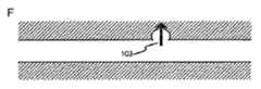
図1を参照すると、図1A〜図1Dに示す場合の本開示の一実施形態は、開放されている近位端120及び遠位端130を有する管腔112を画定する内壁101を有するカテーテル(図示せず)を提供する。管腔112は、その中に滑動可能に係合できる穿刺装置102を収容する。穿刺装置は、カテーテルチップ104と、チップ104を穿刺装置102の残りのステム109に接続するネック部103とを有する。穿刺チップ(104)は、動脈の内部の血管壁を穿刺することができる。 Referring to FIG. 1, one embodiment of the present disclosure as shown in FIGS. 1A-1D is a catheter having an
穿刺装置102並びにカテーテルの遠位端は、カテーテルが血管構造の蛇行領域を移動することを可能にする周知の可撓性構成部品で作製される。こうしたカテーテル及び構成部品の例は、例えば、米国特許第5,704,926号、第6,500,147号、第6,171,294号、及び第5,961,510号で見られる。いくつかの態様では、カテーテル又は穿刺装置は、滑動を容易にするポリマーで被覆される。こうしたポリマーは当該技術分野では公知である。例えば、米国特許第7,060,372号を参照されたい。 The lancing
図1B〜図1Fは、穿刺装置の遠位部の可撓性を示す。これは、臨床医がカテーテルのチップ及び穿刺装置を血管構造内の適切な位置105に位置合わせすることを可能にする。具体的には、図1B〜図1Dに示すように、穿刺装置は、チップ104及びベース103を有するヘッド部103を含む。穿刺装置がカテーテル内壁101によって画定される管腔112の中に閉じ込められているとき、該壁は穿刺装置を実質的にまっすぐに保つ。穿刺装置がカテーテル壁から延長される場合、穿刺装置の遠位端の可撓性は、臨床医が該端をカテーテルから独立して動かすことを可能にする。 1B-1F show the flexibility of the distal portion of the lancing device. This allows the clinician to align the catheter tip and puncture device with the
1つの態様では、穿刺チップのベース103は、プロセスを開始するために図1Dに示すように開くことができ、この場合、チップは、比較的平坦な面に変換され、穿刺装置が後退させられる際に、穿刺創傷の上にシール面を形成するであろう。一実施形態では、チップは、順方向に動いているときには閉じたままとなり、逆方向に動かされるときに、特に圧力下にあるときに平坦な面に膨張するであろう。代替的に、チップは、配置後に穿刺装置にわたる管腔を通してチップ領域に噴射することができるDMSO、エタノール、乳酸エチルなどの適合性のある溶媒の使用により溶解可能なシールによってその剛性の形態に維持することができる。溶解されると、チップは傘を開くのによく似た様態で開いて平坦面になるであろう。 In one aspect, the
一実施形態では、穿刺装置自体はまた、シールが溶解されると血管構造の外側に薬剤を送達することを可能にする管腔を含む。別の実施形態では、穿刺装置のチップは、チップが生分解するのに伴って薬剤がゆっくりと放出されるように薬剤又は薬剤の混合物を含浸される。 In one embodiment, the puncture device itself also includes a lumen that allows delivery of the drug outside the vasculature once the seal is dissolved. In another embodiment, the tip of the lancing device is impregnated with a drug or mixture of drugs so that the drug is slowly released as the chip biodegrades.
図1E及び図1Fは、穿刺装置が、動脈瘤が破裂しない又はさらに破裂しないように動脈瘤をわたる、別の実施形態を示す。この実施形態では、穿刺チップが動脈瘤の壁105の付近に位置決めされる。第2のカテーテル(図示せず)が、動脈瘤の中への血流が著しく抑制される又は止められるように動脈瘤の中に塞栓性組成物を送達する。第2のカテーテルが除去された後で、本開示のカテーテルの穿刺チップが、血管壁を穿刺する及び薬剤を送達するために動かされる。塞栓性組成物が血流を阻止したので、こうした穿刺は、穿刺部位での最小限の出血を伴って又は出血を伴わずに達成することができる。穿刺が完了すると、穿刺装置は、単に後向きの力をかけることによって実質的に除去することができ、この力が、穿刺装置及びカテーテル自体を所定の取り外しポイント(例えば、108)で壊すことになる。血管構造の中に残る穿刺チップの部分は、時間が経つにつれて、残っているチップの残骸がなくなるように、生分解性となるであろう。適切な塞栓性組成物は、当該技術分野では周知であり、白金コイル、並びにシアノアクリレート又はONYX(登録商標)塞栓性調製物(米国カリフォルニア州アービンのCovidienから入手可能)などのインビボ硬化組成物を含む。 1E and 1F show another embodiment where the lancing device spans the aneurysm so that the aneurysm does not rupture or even rupture. In this embodiment, the puncture tip is positioned near the
1つの態様では、血管壁は、無傷であるが穿刺チップによって穿刺される。別の態様では、血管に形成される穿刺の大きさは、組織の中で膨張して血管壁上の開口部をシールするときのカラー(図1D及び図1E)よりも小さいであろう。 In one aspect, the vessel wall is punctured with a puncture tip that is intact. In another aspect, the size of the puncture formed in the blood vessel will be smaller than the collar (FIGS. 1D and 1E) when it expands in the tissue to seal the opening on the vessel wall.
いくつかの態様では、穿刺装置は、穿刺チップの近傍のポイント(例えば、108)で壊れることができる(又は取り外し可能である)。1つの態様では、取り外しポイントは、ヘッド部(103)上にあるか又はこれの近隣にある。別の態様では、取り外しポイントは穿刺チップよりも下にある。穿刺チップが血管壁を穿通し、これをシールすると、穿刺装置は、カテーテル及び穿刺装置の大部分を血管部位から除去できるように取り外しポイントで壊れることができる(図1F)。 In some aspects, the lancing device can break (or be removable) at a point (eg, 108) in the vicinity of the lancing tip. In one aspect, the removal point is on or near the head portion (103). In another aspect, the removal point is below the puncture tip. As the puncture tip penetrates and seals the vessel wall, the puncture device can break at the removal point so that most of the catheter and puncture device can be removed from the vascular site (FIG. 1F).
いくつかの態様では、穿刺チップ及び/又はカラーは薬剤を含み、該薬剤は、穿刺チップ及び随意的なカラーが血管壁の背後の組織の中に入れられると組織に放出することができる。組織への送達に適する薬剤の種類は以下で説明される。 In some aspects, the puncture tip and / or collar includes a drug that can be released into the tissue when the puncture tip and optional collar are placed into the tissue behind the vessel wall. Types of drugs suitable for delivery to the tissue are described below.
1つの態様では、穿刺装置のヘッド部又は取り外しポイントの遠位端の部分は、生分解性材料で作製される。したがって、ヘッド部又は取り外しポイントの遠位にある穿刺装置の部分は、患者の体内で徐々に分解することになるので血管部位に安全に残すことができる。 In one aspect, the head portion of the lancing device or the distal end portion of the removal point is made of a biodegradable material. Thus, the portion of the puncture device that is distal to the head or removal point will be gradually degraded in the patient's body and can be safely left at the vascular site.
医学的利用に適するものを含む「生分解性材料」は当該技術分野では公知である。例えば、Ikada及びTsuji著、「Biodegradable polyesters for medical and ecological applications」、Macromol.Rapid Commun.、21:117−32(2000)は、生体内で安全に分解する、したがって本開示の目的に適する生分解性材料であるポリマーをレビューしている。1つの態様では、生分解性材料は、セルロース、デンプン、アルギン酸塩、キチン(キトサン)、ヒアルロン酸、及びヒアルロン酸などの多糖類;コラーゲン(ゼラチン)及びアルブミンなどのタンパク質;ポリ(3−ヒドロキシアルカノエート)などのポリエステル;又はポリ(エチレンスクシナート)、ポリ(ブチレンテレフタレート)、ポリグリコリド、ポリラクチド、ポリ(ε−カプロラクトン(carpolactone))、ポリ(ブチレンテレフタレート)、ポリ(ビニルアルコール)、ポリ(エステルカーボネート)、ポリアンハイドライド、ポリホスファゼン、及びポリ(オルトエステル)などの合成ポリマーから選択される。特定の態様では、生分解性材料はコラーゲンである。 “Biodegradable materials”, including those suitable for medical use, are known in the art. For example, Ikada and Tsuji, “Biodegrable polyesters for medical and ecological applications”, Macromol. Rapid Commun. 21: 117-32 (2000) review a polymer that is a biodegradable material that degrades safely in vivo and is therefore suitable for the purposes of this disclosure. In one aspect, the biodegradable material is a polysaccharide such as cellulose, starch, alginate, chitin (chitosan), hyaluronic acid, and hyaluronic acid; a protein such as collagen (gelatin) and albumin; a poly (3-hydroxyalkano Polyester) such as poly (ethylene succinate), poly (butylene terephthalate), polyglycolide, polylactide, poly (ε-caprolactone), poly (butylene terephthalate), poly (vinyl alcohol), poly (vinyl alcohol) Selected from synthetic polymers such as ester carbonates), polyanhydrides, polyphosphazenes, and poly (orthoesters). In certain embodiments, the biodegradable material is collagen.
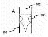
本開示のカテーテル装置の別の実施形態が図2に示される。図1のカテーテルと同様に、図2のカテーテル装置は、カテーテルの中の管腔を画定するカテーテル内壁(101)を有する。管腔内にあるのは滑動可能な穿刺装置102である。 Another embodiment of the catheter device of the present disclosure is shown in FIG. Similar to the catheter of FIG. 1, the catheter device of FIG. 2 has a catheter inner wall (101) that defines a lumen in the catheter. Within the lumen is a
図2Aは、カテーテル内壁(101)によって画定される管腔内に引っ込められた穿刺装置102を示し、穿刺装置の遠位端は、チップ104を取り囲むカラー203を含み、カラーのすぐ近位にあるのは、穿刺装置のための、随意的にカテーテルのための定められた破壊ポイント又は取り外しポイント204である。図2B及び図2Cは、カテーテルの遠位端から突き出るがカテーテルの境界内にカラーを保持する異なる段階での穿刺チップを示す。図2Dは、カラー203がカテーテルの遠位端を越えて延びることを許された後に、膨張して「O」リングの形状を形成することを示す。図2Dはまた、壊れると穿刺ステム及び穿刺チップの残部が「O−リング」と協調的に相互作用して穿刺創傷をシールすることを示す。 FIG. 2A shows the lancing
カラー203は、組織の流体と接触すると膨張することになる膨張可能なスポンジ、脱水ヒドロゲルなどのあらゆる膨張可能な材料で作製することができる。代替的に、カラーに通じる別個の管腔を、他の方法では起こることがある浸透圧性ショックを低減させるために、血管壁を通るとカラーに水を送達するのに用いることができる。膨張するカラーのまた別の形態は、管腔を通してバルーンに空気を単に注入することによって血管壁通過後に膨張することができる膨張可能バルーンである。 The
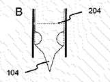
1つの態様では、カテーテルの穿刺チップ(104)は、カテーテルが血管壁を穿通する(図3)ことを可能にする膨張可能なカラーを有し、組織に入るとカラーが膨張して血管壁をシールする。カラーの膨張は、1つの態様では、カラーを血管壁に接した状態で僅かに後ろに引っぱることによってもたらされる。 In one aspect, the catheter's puncture tip (104) has an inflatable collar that allows the catheter to penetrate the vessel wall (FIG. 3) and the collar expands to enter the vessel wall as it enters the tissue. Seal. In one aspect, color expansion is effected by pulling the collar slightly back in contact with the vessel wall.
いくつかの態様では、穿刺装置は、穿刺チップの近傍のポイントで取り外し可能である。穿刺チップが血管壁を穿通し、これをシールすると、カテーテル及び/又は穿刺装置は、穿刺装置及びカテーテルの大部分を血管部位から除去できるように所定の取り外し可能ポイントで壊れることができる。上述のように、穿刺チップは薬剤を含むことができ、該薬剤は、穿刺チップが血管壁の背後の組織の中に入れられると組織に放出することができる。いくつかの態様では、組織(310)は、投薬を必要とする疾患のある状態又は未病の状態である(図3)。組織への送達に適する薬剤の種類は以下で説明される。1つの態様では、穿刺チップは生分解性材料で作製される。 In some aspects, the lancing device is removable at a point proximate to the lancing tip. As the puncture tip penetrates and seals the vessel wall, the catheter and / or puncture device can break at a predetermined removable point so that the puncture device and most of the catheter can be removed from the vascular site. As described above, the puncture tip can include a drug that can be released into the tissue when the puncture tip is placed into the tissue behind the vessel wall. In some embodiments, the tissue (310) is in a diseased or unaffected state that requires medication (FIG. 3). Types of drugs suitable for delivery to the tissue are described below. In one aspect, the puncture tip is made of a biodegradable material.
いくつかの態様では、好ましくは水性溶液として薬剤を送達する、穿刺装置を通る別個の管腔が提供される。チップは、薬剤の多方向の流れを提供するために、管腔がチップを通して及びチップの外側を延びる複数のマイクロチャネルを含むようにチップで分かれるように構成することができる。さらに、チップがコラーゲンなどの生分解性材料を含む場合、薬剤の送達後に、必要に応じてチップの管腔の分解及び閉鎖を容易にするために、コラゲナーゼを含有する水性溶液を管腔に流すことができる。チップに有用な他の組合せは、脂質/リパーゼ、セルロース/セルラーゼなどを含む。 In some embodiments, a separate lumen is provided through the puncture device that delivers the drug, preferably as an aqueous solution. The chip can be configured to separate at the chip such that the lumen includes a plurality of microchannels extending through the chip and outside the chip to provide a multi-directional flow of drug. Furthermore, if the chip includes a biodegradable material such as collagen, an aqueous solution containing collagenase is flowed into the lumen after drug delivery to facilitate degradation and closure of the chip lumen as needed. be able to. Other combinations useful for the chip include lipid / lipase, cellulose / cellulase and the like.
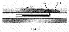
図4は、本開示のカテーテル装置のさらに別の実施形態を示す。図4のカテーテル装置は、管腔を画定するカテーテル壁(401)を有する。管腔は穿刺装置413を収容する。穿刺装置(413)は、3つの部分、すなわち、ヘッド部(410)、ネック部(411)、及びステム部(409)を備える。 FIG. 4 illustrates yet another embodiment of the catheter device of the present disclosure. The catheter device of FIG. 4 has a catheter wall (401) that defines a lumen. The lumen houses the
ヘッド部(410)は、無傷であるか又は破裂部又は開口部(407)を有する血管壁(406)をわたることができる鋭い遠位端である穿刺チップ(404)を有する。ネック部は、膨張可能な材料(414)を保持するために表面上に凹部(405)を有する。この実施形態では、凹部は、凹部の特定の形状は重要ではないことを示す図2の楕円形の壁とは対照的に、四角形の壁によって画定される。 The head portion (410) has a piercing tip (404) that is intact or can have a sharp distal end that can cross the vessel wall (406) with a rupture or opening (407). The neck has a recess (405) on the surface to hold the expandable material (414). In this embodiment, the recess is defined by a square wall, as opposed to the oval wall of FIG. 2, which indicates that the particular shape of the recess is not important.
さらに、穿刺装置は、カテーテル壁との接触からの圧力によってカテーテルがカテーテル壁内に閉じ込められているときに膨張可能な材料が凹部内に保持されるように、カテーテル壁の内部によって形成された管腔と相補する外形を有する(図4B及び図4C)。しかしながら、膨張可能な材料がカテーテル壁の外にあるとき、膨張可能な材料は膨張してカテーテルの周りにカラーを形成し、該カラーは血管開口部をシールするのに有用である(図4D〜図4E)。 Furthermore, the puncture device is a tube formed by the interior of the catheter wall so that the expandable material is retained in the recess when the catheter is confined within the catheter wall by pressure from contact with the catheter wall. It has an external shape that is complementary to the cavity (FIGS. 4B and 4C). However, when the inflatable material is outside the catheter wall, the inflatable material expands to form a collar around the catheter, which collar is useful for sealing the vascular opening (FIGS. 4D-D). FIG. 4E).
1つの態様では、膨張可能な材料はリングを形成する。別の態様では、膨張可能な材料は、2つ以上の別個の部品としてネック部の周りに配置される。例えば、膨張可能な材料が2つの部品を含むとき、下側の部品は、穿刺部位を通した出血を抑制するために凝集剤又はグルーを含浸することができ、一方、上側の部品は適切な薬剤を含浸することができる。 In one aspect, the expandable material forms a ring. In another aspect, the inflatable material is placed around the neck as two or more separate pieces. For example, when the inflatable material includes two parts, the lower part can be impregnated with a flocculant or glue to prevent bleeding through the puncture site, while the upper part is suitable. Can be impregnated with drug.
1つの態様では、穿刺装置はその内部に管腔(413)を備える。管腔は、いくつかの態様では、カテーテルのヘッド部の内部に配置される拡大端(403)を有する。拡大端は、1つの態様では、管腔から薬剤を放出するための複数の穿孔を有する。いくつかの態様では、拡大端は、空気又は液体材料を管腔を通して拡大端の中に押すことによってさらに拡大することができる。これは、拡大端のサイズを、カラーとシールを形成するためにカラーと相補するように設計することができるので、特に重要である。代替的に、カラーを採用しない本開示の装置では、拡大端は、穿刺創傷をふさぐために後退させることができる。 In one aspect, the lancing device comprises a lumen (413) therein. The lumen, in some aspects, has an enlarged end (403) disposed within the catheter head. The enlarged end, in one aspect, has a plurality of perforations for releasing the drug from the lumen. In some aspects, the enlarged end can be further enlarged by pushing air or liquid material through the lumen and into the enlarged end. This is particularly important because the size of the enlarged end can be designed to complement the collar to form a collar and seal. Alternatively, in devices of the present disclosure that do not employ a collar, the enlarged end can be retracted to close the puncture wound.
1つの態様では、穿刺装置のヘッド部はチップの残りから取り外し可能である。1つの態様では、ヘッド部は、管腔の拡大端を拡大することによって穿刺装置のネック部から取り外される(図4E)。別の態様では、ヘッド部は、側部からの力によって穿刺装置のネック部から取り外される(図4F)。1つの態様では、ヘッド部は生分解性である。 In one aspect, the puncture device head is removable from the rest of the tip. In one aspect, the head is removed from the neck of the lancing device by enlarging the enlarged end of the lumen (FIG. 4E). In another aspect, the head portion is removed from the neck portion of the lancing device by force from the side (FIG. 4F). In one aspect, the head portion is biodegradable.
いくつかの態様では、穿刺装置のネック部はまた、ネック部の少なくとも一部が血管壁に入り、膨張可能な材料が血管壁の開口部をシールするときに、血管の開口部へのシールとして役立つネック部を残して、カテーテルと穿刺装置のステム部を血管部位から除去することができるように、チップの残りから取り外し可能である(図4F)。したがって、いくつかの態様では、穿刺装置のネック部は生分解性材料で作製される。 In some aspects, the neck of the puncture device also serves as a seal to the vessel opening when at least a portion of the neck enters the vessel wall and the inflatable material seals the vessel wall opening. It can be removed from the rest of the tip (Figure 4F), leaving a useful neck so that the stem of the catheter and puncture device can be removed from the vascular site. Thus, in some aspects, the neck of the lancing device is made of a biodegradable material.
いくつかの態様では、管腔の拡大端は、血管壁の背後の組織(408)に送達するための薬剤を含む。送達できる薬剤の例が以下に提供される。 In some aspects, the enlarged end of the lumen includes an agent for delivery to tissue (408) behind the vessel wall. Examples of agents that can be delivered are provided below.
取り外し可能な穿刺チップを有するカテーテル装置
一実施形態では、所定のポイントで外れる能力を有するカテーテル及び穿刺装置も提供される。別の実施形態では、カテーテルは、少なくとも1つの事前に位置決めされた取り外し機構を有する。カテーテルは、1つ以上の事前に位置決めされた取り外しポイントを必要とする任意のカテーテルとすることができる。カテーテルの取り外し機構は、穿刺装置に関して定義されるのと同じである。別の態様では、カテーテルは、1つ以上の取り外し機構と共に少なくとも2つの異なる取り外しポイントを有する。別の態様では、少なくとも2つの異なる取り外し機構は、(a)抜去力によって取り外すこと、(b)ねじれによって取り外すこと、(c)部品を接続するのに用いられる接着剤を溶解させることによって取り外すこと、又は同じタイプの機構で、しかし異なる量の力、異なる方向の力、又は異なるタイプのグルー又は溶媒で取り外すことから選択される。1つの態様では、異なる機構は、異なる強さ又は方向の力を含み、又は、(a)相補的な凹部の中に取り外し可能に係合される凸部、(b)抜去力によって取り外し可能な接合部、(c)ねじれ力によって取り外し可能な接合部、及び(d)溶媒によって取り外し可能なグルーでの接合部からなる群から選択される。種々のタイプの取り外し機構が上記で説明されており、他のものは以下でさらに提供される。In one embodiment of thecatheter device having a removable puncture tip, a catheter and puncture device having the ability todetach at a predetermined point are also provided. In another embodiment, the catheter has at least one pre-positioned removal mechanism. The catheter can be any catheter that requires one or more pre-positioned removal points. The catheter removal mechanism is the same as defined for the lancing device. In another aspect, the catheter has at least two different removal points with one or more removal mechanisms. In another aspect, the at least two different removal mechanisms are (a) removed by removal force, (b) removed by twist, (c) removed by dissolving the adhesive used to connect the parts. Or with the same type of mechanism, but with different amounts of force, different directions of force, or removal with different types of glue or solvent. In one aspect, the different mechanisms include forces of different strengths or directions, or (a) a protrusion removably engaged in a complementary recess, (b) removable by an extraction force. It is selected from the group consisting of a joint, (c) a joint that can be removed by a twisting force, and (d) a joint in a glue that can be removed by a solvent. Various types of removal mechanisms are described above, others are further provided below.
これらの取り外し機構は当該技術分野では公知のもののいずれかとの相補的なものであり、カテーテル、穿刺装置、及びこれらの組合せに用いることができることが理解される。 It will be appreciated that these removal mechanisms are complementary to any known in the art and can be used in catheters, lancing devices, and combinations thereof.
図5に示される一実施形態では、少なくとも2つの異なる取り外し機構は、所定の後向きの力によって取り外せるように穿刺装置の部品を組み合わせることによって作製することができる。図5では、穿刺装置の遠位端501は、凸部507及び凹部511を通じて近位端502と合致される。この実施形態では、凸部507は、その圧力の下で遠位端と近位端が分離するように定められた後向きの圧力の下で変形可能である。さらに、別の態様では、例えば、塞栓物(embolic mass)への入り込みに起因して第1の部位がアクセス不能になる場合に第2の部位を分離のために確実に用いることができるようにするために、第2の随意的な合致部位が提供される。 In one embodiment shown in FIG. 5, at least two different removal mechanisms can be made by combining the parts of the lancing device so that they can be removed by a predetermined backward force. In FIG. 5, the
こうした実施形態では、第2の部位を分離するのに必要な後向きの圧力は、分離を制御できるように第1の部位よりも高くなるように調整される。代替的に、第2の部位は、第1の部位から分離するための直交手段を有することができる。例えば、第2の部位は、継続するねじれによって取り外される穿刺装置の脆弱部とすることができる。つまり、穿刺チップ及び第1の取り外し部位が例えば塞栓物によって定位置にロックされる場合に、近位端からの穿刺部位のねじれが第2の部位に応力を誘起して取り外しをもたらすように穿刺装置の一部がロックされる。 In such embodiments, the backward pressure required to separate the second site is adjusted to be higher than the first site so that the separation can be controlled. Alternatively, the second part can have orthogonal means for separating from the first part. For example, the second site can be a fragile portion of the puncture device that is removed by continued twisting. In other words, when the puncture tip and the first removal site are locked in place by, for example, an embolus, the puncture is performed such that twisting of the puncture site from the proximal end induces stress on the second site to cause removal. Part of the device is locked.
別の実施形態では、臨床医がどこで装置が分離したかを確かめることができるようにするために、金属バンド(図示せず)を穿刺装置の異なるポイントに含めることができる。 In another embodiment, a metal band (not shown) can be included at different points on the lancing device to allow the clinician to see where the device has separated.
代替的に、所望の部位で分離するのに必要な力を容易に確認できるように定められた度合いの接着性を有するグルー又は他の接着機構の使用によって、目標とされる分離を達成することができる。分離のために複数の部位が望まれるとき、異なる接着性のグルーを用いることだけが必要とされる。 Alternatively, to achieve the targeted separation by using a glue or other bonding mechanism with a defined degree of adhesion so that the force required to separate at the desired site can be easily identified. Can do. When multiple sites are desired for separation, it is only necessary to use different adhesive glues.
薬剤
本開示のカテーテル装置の種々の実施形態では、カテーテル、穿刺チップ、又はチップのカテーテルの管腔に、血管部位での組織に送達するための薬剤が装填される。薬剤は、血管部位での病変又は状態を治療する、又は破裂の治癒を容易にするのに有用なことがある。Drugs In various embodiments of the catheter devices of the present disclosure, the catheter, puncture tip, or the catheter lumen of the tip is loaded with a drug for delivery to tissue at the vascular site. The agent may be useful to treat a lesion or condition at a vascular site or to facilitate the healing of a rupture.
1つの態様では、薬剤は抗炎症薬を含む。抗炎症薬の限定ではない例は、グルココルチコイドなどのステロイド、及びイブプロフェン、フェノプロフェン、アスピリン、メフェナム酸、ニメスリド、及びリコフェロン、及びその組合せを含む非ステロイド性抗炎症薬(NSAID)を含む。 In one aspect, the drug comprises an anti-inflammatory drug. Non-limiting examples of anti-inflammatory drugs include steroids such as glucocorticoids and non-steroidal anti-inflammatory drugs (NSAIDs) including ibuprofen, fenoprofen, aspirin, mefenamic acid, nimesulide, and lycoferon, and combinations thereof.
別の態様では、薬剤は、限定はされないが、ゼオライト、トロンビングルー、フィブリングルー、デスモプレシン、凝固因子濃縮物、トラネキサム酸、アミノカプロン酸、及びアプロチニンなどの止血薬(thrombotic agent)を含む。 In another aspect, the drug includes, but is not limited to, zeolites, thrombin, fibrin glue, desmopressin, coagulation factor concentrate, tranexamic acid, aminocaproic acid, and thrombotic agents such as aprotinin.
また別の態様では、薬剤は鎮痛剤を含む。市販の鎮痛剤は、例えば、Tylenol(登録商標)、Advil(登録商標)、Aleve(登録商標)、Mortin(登録商標)、及びExcedrin(登録商標)を含む。 In another aspect, the medicament comprises an analgesic. Commercially available analgesics include, for example, Tylanol (R), Advil (R), Aleve (R), Mortin (R), and Excerin (R).
さらに別の態様では、薬剤は、限定はされないが、とりわけ、ナイトロジェンマスタード、ニトロソウレア、エチレンイミン、アルカンスルホネート、テトラジン、白金化合物、ピリミジン類似物質、プリン類似物質、代謝拮抗剤、葉酸類似物質、アントラサイクリン、タキサン、ビンカアルカロイド、トポイソメラーゼ阻害剤、及びホルモン剤などの抗癌剤を含む。 In yet another aspect, the agent includes, but is not limited to, nitrogen mustard, nitrosourea, ethyleneimine, alkanesulfonate, tetrazine, platinum compound, pyrimidine analog, purine analog, antimetabolite, folic acid analog, Includes anticancer agents such as anthracyclines, taxanes, vinca alkaloids, topoisomerase inhibitors, and hormonal agents.
1つの態様では、抗癌剤は、アクチノマイシン−D(Actinomycin−D)、アルケラン(Alkeran)、Ara−C、アナストロゾール(Anastrozole)、BiCNU、ビカルタミド(Bicalutamide)、ブレオマイシン(Bleomycin)、ブスルファン(Busulfan)、カペシタビン(Capecitabine)、カルボプラチン(Carboplatin)、カルボプラチナ(Carboplatinum)、カルムスチン(Carmustine)、CCNU、クロラムブシル(Chlorambucil)、シスプラチン(Cisplatin)、クラドリビン(Cladribine)、CPT−11、シクロホスファミド(Cyclophosphamide)、シタラビン(Cytarabine)、シトシンアラビノシド(Cytosine arabinoside)、シトキサン(Cytoxan)、ダカルバジン(Dacarbazine)、ダクチノマイシン(Dactinomycin)、ダウノルビシン(Daunorubicin)、デキスラゾキサン(Dexrazoxane)、ドセタキセル(Docetaxel)、ドキソルビシン(Doxorubicin)、DTIC、エピルビシン(Epirubicin)、エチレンイミン(Ethyleneimine)、エトポシド(Etoposide)、フロクスウリジン(Floxuridine)、フルダラビン(Fludarabine)、フルオロウラシル(Fluorouracil)、フルタミド(Flutamide)、ホテムスチン(Fotemustine)、ゲムシタビン(Gemcitabine)、ヘキサメチルアミン(Hexamethylamine)、ヒドロキシ尿素(Hydroxyurea)、イダルビシン(Idarubicin)、イホスファミド(Ifosfamide)、イリノテカン(Irinotecan)、ロムスチン(Lomustine)、メクロレタミン(Mechlorethamine)、メルファラン(Melphalan)、メルカプトプリン(Mercaptopurine)、メトトレキサート(Methotrexate)、マイトマイシン(Mitomycin)、ミトーテン(Mitotane)、ミトザントロン(Mitoxantrone)、オキサリプラチン(Oxaliplatin)、パクリタキセル(Paclitaxel)、パミドロナート(Pamidronate)、ペントスタチン(Pentostatin)、プリカマイシン(Plicamycin)、プロカルバジン(Procarbazine)、ステロイド(Steroids)、ストレプトゾシン(Streptozocin)、STI−571、ストレプトゾシン(Streptozocin)、タモキシフェン(Tamoxifen)、テモゾロミド(Temozolomide)、テニポシド(Teniposide)、テトラジン(Tetrazine)、チオグアニン(Thioguanine)、チオテパ(Thiotepa)、トムデックス(Tomudex)、トポテカン(Topotecan)、トレオスルファン(Treosulphan)、トリメトレキサート(Trimetrexate)、ビンブラスチン(Vinblastine)、ビンクリスチン(Vincristine)、ビンデシン(Vindesine)、ビノレルビン(Vinorelbine)、VP−16、及びゼローダ(Xeloda)などの小分子薬である。 In one aspect, the anti-cancer agent is actinomycin-D, Alkeran, Ara-C, Anastrozole, BiCNU, Bicalutamide, Bleomycin, ulsulfane, ulsulfane B , Capecitabine, carboplatin, carboplatinum, carmustine, CCNU, chlorambucil, cisplatin (Ciplatin), cisplatin (Ciplatin) Cytarabine Cytarabine, Cytosine arabinoside, Cytoxan, Dacarbazine, Dactinomycin, etal, Drazoxane, xane , Epirubicin, Ethyleneimine, Etoposide, Floxuridine, Fludarabine, Fluorouracil, Flutamide, Flutamide Temustine (Fotemustine), Gemcitabine, Hexamethylamine (Hexamethylamine), Hydroxyurea, Idarubicin, Ifosfamide, Irinotemine, Irinotemine (Melphalan), mercaptopurine, methotrexate, mitomycin, mitotane, mitoxantrone, oxaliplatin, oxaliplatin, oxaliplatin Ritaxel (Pacritaxel), Pamidronate (Pamidronate), Pentostatin (Pentostatin), Plicamicin (Plicamycin), Procarbazine (Procarbazine), Steroids (Steroids), Streptozocin (Streptozocin), Stryptozocin, Srtitozocin, Stryptozocin Tamoxifen, temozolomide, teniposide, tetrazine, thioguanine, thiotepa, tomudex, topote, topote an,), trimetrexate (Trimetrexate), vinblastine (vinblastine), vincristine (vincristine), vindesine (Vindesine), vinorelbine (Vinorelbine), VP-16, and small molecule drugs such as Xeloda (Xeloda).
別の態様では、本開示のカテーテル装置は、生物学的抗癌剤を送達するのに適しており、その例は、ハーセプチン(Herceptin)、リツキシマブ(Rituximab)、アスパラギナーゼ(Asparaginase)、セツキシマブ(Cetuximab)、ブレンツキシマブベドチン(Brentuximab vedotin)、カナキヌマブ(Canakinumab)、デノスマブ(Denosumab)、ゲンツズマブ(Gemtuzumab)、イブリツモマブチウキセタン(Ibritumomab tiuxetan)、ムロモナブ−CD3(Muromonab−CD3)、オファツムマブ(Ofatumumab)、パニツムマブ(Panitumumab)、トシツモマブ(Tositumomab)、及びトラスツズマブ(Trastuzumab)を含む。 In another aspect, the catheter devices of the present disclosure are suitable for delivering biological anticancer agents, examples of which include Herceptin, Rituximab, Asparaginase, Cetuximab, Tuximab vedotin (Brentuximab vedotin), Canakinumab (Canakinumab), Denosumab (Denosumab), Gentuzumab (Gemtuzumab), Ibritumomab timuset (Ibritumomab) Panitumumab), Tositumomab, and And trastuzumab.
特定の態様では、本開示のカテーテルは、脳腫瘍を治療するために脳に抗癌剤を送達するのに用いることができる。脳腫瘍患者のための抗癌剤の選択は、患者の年齢、カルノフスキー(Karnofsky)スコア、及び患者が受けたあらゆる以前の療法を含むいくつかの因子に依存する。www.neurooncology.ucla.edu/Performance/GlioblastomaMultiforme.aspxで、カリフォルニア大学ロサンゼルス校は、脳腫瘍を治療するのに適する抗新生物薬のリストを公開しており、そのリストを以下の表1に再現する。
いくつかの態様では、薬剤は、上記のいずれか又はそれらの組合せから選択される1、又は2、又は3、又は4、又は5つ以上の薬を含む。 In some embodiments, the medicament comprises one or two, or three, or four, or five or more drugs selected from any of the above or combinations thereof.
方法
カテーテル装置及びチップを用いる方法も提供される。いくつかの方法は、例えば、図1、図3、及び図4に示されるように、装置の説明から明らかである。Methods are also provided using catheter devices and tips. Some methods are apparent from the description of the apparatus, as shown, for example, in FIGS.
一般に、本開示は、血管壁上の開口部をシールする目的で血管壁を穿通する及び/又は穿通部位の周りの組織に薬剤を送達するための方法を提供する。この方法は、いくつかの態様では、カテーテルを血管部位に配置することと、血管壁を通して移動させるためにカテーテルから穿刺チップを延長することとを含む。血管壁の背後の組織の中に入ると、カテーテルは開口部をシールする。 In general, the present disclosure provides a method for penetrating a blood vessel wall and / or delivering a drug to tissue around the penetration site for the purpose of sealing an opening on the blood vessel wall. The method includes, in some aspects, placing the catheter at the vascular site and extending the puncture tip from the catheter for movement through the vessel wall. Upon entering the tissue behind the vessel wall, the catheter seals the opening.
さらに、カテーテルは、薬剤を含む又は血管部位で組織に薬剤を送達するための管腔又は別のチップを随伴することができる。薬剤の送達によって達成される結果は薬剤の種類から明らかである。例えば、方法は、卒中の間に生じる情報を処理する、動脈瘤破裂をシールする、痛みを緩和する、又は癌を治療するのに有用なことがある。 In addition, the catheter can be accompanied by a lumen or another tip for containing the drug or delivering the drug to the tissue at the vascular site. The results achieved by drug delivery are evident from the drug type. For example, the method may be useful for processing information that occurs during a stroke, sealing aneurysm rupture, relieving pain, or treating cancer.
特定の実施形態では、本開示のカテーテル装置は、卒中、動脈瘤破裂、及び脳腫瘍などの脳の状態を治療するのに有用であることが考慮される。したがって、本開示の1つの態様は、脳腫瘍を治療するための方法を提供する。こうした方法の利点は、血液脳関門(BBB)を通して薬剤を送達するのに実行可能な戦略への一定の必要性があるので当業者にはすぐに分かるであろう。本開示のカテーテルを用いて、この関連で、BBBを通して薬剤を直接送達し、これによりこうした困難を克服する。 In certain embodiments, it is contemplated that the catheter devices of the present disclosure are useful for treating brain conditions such as stroke, aneurysm rupture, and brain tumors. Accordingly, one aspect of the present disclosure provides a method for treating brain tumors. The advantages of such methods will be readily apparent to those skilled in the art as there is a certain need for a viable strategy for delivering drugs across the blood brain barrier (BBB). In this regard, the presently disclosed catheters are used to deliver drugs directly through the BBB, thereby overcoming these difficulties.
さらに、カテーテルの一部を取り外し可能、生物適合性、及び生分解性とすることができるので、本開示は、安全に血管の開口部をシールする及び薬剤を送達するための方法を提供する。 Further, the present disclosure provides a method for safely sealing a vascular opening and delivering a drug, since a portion of the catheter can be removable, biocompatible, and biodegradable.
加えて、一実施形態では、本開示は、血管部位での開口部をシールするための方法であって、
血管部位にカテーテルを配置することと、
この場合、カテーテルは、近位端及び遠位端を備え、且つ近位端から遠位端にわたる少なくとも1つの管腔を有し、
この場合、管腔は、その遠位の穿刺チップと、ネック部と、その近位端のステムとを備える伸張可能な穿刺装置を備え、
この場合、穿刺装置のネック部は、穿刺開口部に入ると膨張して開口部の周りにシールを形成するカラーを備え、
カラーが膨張して開口部をシールするように穿刺チップ及びネックを血管壁を通して延長するために穿刺装置を延長することと、
を含む方法を提供する。In addition, in one embodiment, the present disclosure is a method for sealing an opening at a vascular site comprising:
Placing a catheter at the vascular site;
In this case, the catheter has a proximal end and a distal end and has at least one lumen extending from the proximal end to the distal end;
In this case, the lumen comprises an extensible puncture device comprising its distal puncture tip, a neck and a stem at its proximal end,
In this case, the neck of the puncture device includes a collar that expands upon entering the puncture opening and forms a seal around the opening,
Extending the lancing device to extend the lancing tip and neck through the vessel wall so that the collar expands and seals the opening;
A method comprising:
1つの態様では、血管部位は動脈瘤を有する。別の態様では、穿刺装置は血管部位に薬剤を送達することができ、したがって、この方法は、血管部位に薬剤を送達することを含むことができる。 In one aspect, the vascular site has an aneurysm. In another aspect, the lancing device can deliver a drug to the vascular site, and thus the method can include delivering the drug to the vascular site.
別の態様では、方法は、血管部位からカテーテル及びカテーテルの近位の穿刺装置の一部を除去するために穿刺装置の遠位端を取り外すことをさらに含む。特定の態様では、穿刺装置の遠位端は生分解性である。 In another aspect, the method further includes removing the distal end of the puncture device to remove the catheter and a portion of the puncture device proximal to the catheter from the vascular site. In certain aspects, the distal end of the lancing device is biodegradable.
別の実施形態では、カテーテルは、動脈瘤破裂部に塞栓性組成物を送達するのに用いることができる管腔を有する。これは図1Eに示され、カテーテルの穿刺チップは、血管壁の背後の組織に薬剤を送達することができ、カテーテルの管腔は、バルーンに充填するために塞栓薬を送達するのに用いることができる。 In another embodiment, the catheter has a lumen that can be used to deliver an embolic composition to the ruptured aneurysm. This is shown in FIG. 1E, where the catheter puncture tip can deliver the drug to the tissue behind the vessel wall and the catheter lumen can be used to deliver the embolic agent to fill the balloon. Can do.
したがって、本開示の一実施形態は、動脈瘤の破裂に起因する患者の出血性脳卒中を治療するための方法であって、
第1のカテーテルをその遠位端が動脈瘤嚢の近傍又は動脈瘤嚢の中にあるように患者に挿入することと、この場合、カテーテルは、内部に滑動可能に係合される穿刺装置を有する管腔を備え、前記装置は、その遠位端に穿刺チップ及び近位端にステムを有し、さらに、穿刺チップ又はその近傍の領域は、チップによって穿刺される部位に薬剤を送達することができ、
第2のカテーテルをその遠位端が動脈瘤嚢の近傍又は動脈瘤嚢の中にあるように患者に挿入することと、この場合、カテーテルは、近位端及び遠位端を備え、且つ近位端から遠位端にわたる少なくとも1つの管腔を有し、管腔は、血管部位に塞栓性組成物又は材料を送達するように寸法設定され、
動脈瘤の中への血流を阻止するために動脈瘤嚢に塞栓性組成物又は材料を充填することと、
穿刺装置の穿刺チップで血管壁を穿刺することと、
穿刺チップによって穿刺される部位に薬剤を送達することと、
を含む方法を提供する。Accordingly, one embodiment of the present disclosure is a method for treating a hemorrhagic stroke in a patient due to an aneurysm rupture comprising:
Inserting the first catheter into the patient with its distal end in the vicinity of or in the aneurysm sac, wherein the catheter has a puncture device slidably engaged therein; The device has a puncture tip at its distal end and a stem at its proximal end, and the puncture tip or nearby region delivers the drug to the site punctured by the tip Can
Inserting the second catheter into the patient such that its distal end is near or in the aneurysm sac, wherein the catheter comprises a proximal end and a distal end; Having at least one lumen extending from the distal end to the distal end, the lumen being dimensioned to deliver an embolic composition or material to the vascular site;
Filling the aneurysm sac with an embolic composition or material to prevent blood flow into the aneurysm;
Puncturing the blood vessel wall with the puncture tip of the puncture device;
Delivering the drug to the site punctured by the puncture tip;
A method comprising:
「塞栓薬(embolic agent)」は、血管部位に塞栓を導入することによって血管の閉塞を引き起こす。限定ではない例は、n−ブチル−2−シアノアクリレート及びエチオドール(ethiodol)などの液体塞栓薬と、エタノール、オレイン酸エタノールアミン、及びソトラデコル(sotradecol)などの硬化薬と、ゲルフォーム(gelfoam)、ポリビニルアルコール(PVA)、及びアクリルゲル化ミクロスフェアなどの微粒子塞栓薬と、コイル及びバルーン並びにONYX(登録商標)などの機械的閉塞装置を含む。適切な薬剤は上記で説明される。 “Embolic agents” cause occlusion of blood vessels by introducing emboli into the vascular site. Non-limiting examples include liquid embolic agents such as n-butyl-2-cyanoacrylate and etiodol, sclerosing agents such as ethanol, ethanolamine oleate, and sotradecol, gelfoam, Includes fine particle embolic agents such as polyvinyl alcohol (PVA) and acrylic gelled microspheres, and mechanical occlusion devices such as coils and balloons and ONYX®. Suitable drugs are described above.
本開示は上記の実施形態と併せて説明されているが、上記の説明及び例は本開示の範囲を制限するのではなく例証することを意図されていることが理解される。本開示の範囲内の他の態様、利点、及び修正は本開示に関係のある当業者には明らかであろう。 While this disclosure has been described in conjunction with the above embodiments, it is understood that the above description and examples are intended to illustrate rather than limit the scope of the disclosure. Other aspects, advantages, and modifications within the scope of this disclosure will be apparent to those skilled in the art to which this disclosure relates.
Claims (10)
Translated fromJapaneseApplications Claiming Priority (5)
| Application Number | Priority Date | Filing Date | Title |
|---|---|---|---|
| US201161578627P | 2011-12-21 | 2011-12-21 | |
| US61/578,627 | 2011-12-21 | ||
| US201261668955P | 2012-07-06 | 2012-07-06 | |
| US61/668,955 | 2012-07-06 | ||
| PCT/US2012/070646WO2013096463A1 (en) | 2011-12-21 | 2012-12-19 | Self-sealing catheters |
Publications (2)
| Publication Number | Publication Date |
|---|---|
| JP2015503960Atrue JP2015503960A (en) | 2015-02-05 |
| JP2015503960A5 JP2015503960A5 (en) | 2016-02-12 |
Family
ID=48669454
Family Applications (1)
| Application Number | Title | Priority Date | Filing Date |
|---|---|---|---|
| JP2014548839APendingJP2015503960A (en) | 2011-12-21 | 2012-12-19 | Self-sealing catheter |
Country Status (5)
| Country | Link |
|---|---|
| US (1) | US20130184660A1 (en) |
| EP (1) | EP2793990A4 (en) |
| JP (1) | JP2015503960A (en) |
| EA (1) | EA201491258A1 (en) |
| WO (1) | WO2013096463A1 (en) |
Families Citing this family (8)
| Publication number | Priority date | Publication date | Assignee | Title |
|---|---|---|---|---|
| EP3984556B8 (en) | 2012-06-14 | 2025-07-09 | Microvention, Inc. | Polymeric treatment compositions |
| EP2906254B1 (en) | 2012-10-15 | 2020-01-08 | Microvention, Inc. | Polymeric treatment compositions |
| WO2015095798A1 (en) | 2013-12-20 | 2015-06-25 | Microvention, Inc. | Catheter system |
| WO2015179710A1 (en) | 2014-05-22 | 2015-11-26 | Conkwest, Inc. | Treating solid tumours with nk-92 cells applied by microcatheter |
| AU2017218115B2 (en) | 2016-02-10 | 2020-03-05 | Microvention, Inc. | Devices for vascular occlusion |
| US10368874B2 (en) | 2016-08-26 | 2019-08-06 | Microvention, Inc. | Embolic compositions |
| WO2019074965A1 (en) | 2017-10-09 | 2019-04-18 | Microvention, Inc. | Radioactive liquid embolic |
| EP3932335A1 (en)* | 2020-07-01 | 2022-01-05 | Bansal, Aakanksha | A device for treatment of anastomotic leak |
Citations (4)
| Publication number | Priority date | Publication date | Assignee | Title |
|---|---|---|---|---|
| JP2000507838A (en)* | 1995-09-15 | 2000-06-27 | サブキュー インコーポレイテッド | Apparatus and method for percutaneously sealing a vascular puncture |
| JP2002501778A (en)* | 1998-01-30 | 2002-01-22 | セント ジュード メディカル カーディオバスキュラー グループ, インコーポレイテッド | Medical implant connector or plug structures and methods of making and installing them |
| JP2005000683A (en)* | 2004-09-21 | 2005-01-06 | Shu-Tyun Ri | Closing system for flexible tissue |
| JP2009172273A (en)* | 2008-01-28 | 2009-08-06 | Asahikawa Medical College | Blood flow blocking catheter |
Family Cites Families (16)
| Publication number | Priority date | Publication date | Assignee | Title |
|---|---|---|---|---|
| US5292332A (en)* | 1992-07-27 | 1994-03-08 | Lee Benjamin I | Methods and device for percutanceous sealing of arterial puncture sites |
| US5261889A (en)* | 1992-11-24 | 1993-11-16 | Boston Scientific Corporation | Injection therapy catheter |
| US5562631A (en)* | 1995-06-07 | 1996-10-08 | Johnson & Johnson Medical, Inc. | Catheter arrangement with interlocking sequenced guarding members for protecting cannula |
| US6071300A (en)* | 1995-09-15 | 2000-06-06 | Sub-Q Inc. | Apparatus and method for percutaneous sealing of blood vessel punctures |
| US5797920A (en)* | 1996-06-14 | 1998-08-25 | Beth Israel Deaconess Medical Center | Catheter apparatus and method using a shape-memory alloy cuff for creating a bypass graft in-vivo |
| US5875782A (en)* | 1996-11-14 | 1999-03-02 | Cardiothoracic Systems, Inc. | Methods and devices for minimally invasive coronary artery revascularization on a beating heart without cardiopulmonary bypass |
| US20030191496A1 (en)* | 1997-03-12 | 2003-10-09 | Neomend, Inc. | Vascular sealing device with microwave antenna |
| US6896682B1 (en)* | 2000-11-14 | 2005-05-24 | Biomedical Engineering Solutions, Inc. | Method and system for internal ligation of tubular structures |
| US20040225279A1 (en)* | 2001-06-01 | 2004-11-11 | Jean Raymond | Detachable tip microcatheter for use of liquid embolic agents |
| ES2185500B1 (en)* | 2001-09-14 | 2004-11-16 | Pedro Acha Gandarias | CATHETER AND METHOD OF USE. |
| US6932804B2 (en)* | 2003-01-21 | 2005-08-23 | The Regents Of The University Of California | System and method for forming a non-ablative cardiac conduction block |
| US7691086B2 (en)* | 2005-06-14 | 2010-04-06 | Tengiz Tkebuchava | Catheter for introduction of medications to the tissues of a heart or other organ |
| JP5253170B2 (en)* | 2005-10-05 | 2013-07-31 | ローマ リンダ ユニヴァーシティ メディカル センター | Vascular wound closure device and method |
| RU66184U1 (en)* | 2007-03-15 | 2007-09-10 | Государственное учреждение здравоохранения Центр организации специализированной медицинской помощи "Челябинский государственный институт лазерной хирургии" | DEVICE FOR CONNECTING LASER RADIATION TO TISSUES |
| JP5174891B2 (en)* | 2007-04-27 | 2013-04-03 | シーヴィ デヴァイシズ,エルエルシー | Devices, systems, and methods for accessing the epicardial surface of the heart |
| US8016799B2 (en)* | 2008-04-22 | 2011-09-13 | Medtronic Vascular, Inc. | Catheter having a detachable tip |
- 2012
- 2012-12-19EPEP12859513.9Apatent/EP2793990A4/ennot_activeWithdrawn
- 2012-12-19WOPCT/US2012/070646patent/WO2013096463A1/enactiveApplication Filing
- 2012-12-19USUS13/720,682patent/US20130184660A1/ennot_activeAbandoned
- 2012-12-19JPJP2014548839Apatent/JP2015503960A/enactivePending
- 2012-12-19EAEA201491258Apatent/EA201491258A1/enunknown
Patent Citations (4)
| Publication number | Priority date | Publication date | Assignee | Title |
|---|---|---|---|---|
| JP2000507838A (en)* | 1995-09-15 | 2000-06-27 | サブキュー インコーポレイテッド | Apparatus and method for percutaneously sealing a vascular puncture |
| JP2002501778A (en)* | 1998-01-30 | 2002-01-22 | セント ジュード メディカル カーディオバスキュラー グループ, インコーポレイテッド | Medical implant connector or plug structures and methods of making and installing them |
| JP2005000683A (en)* | 2004-09-21 | 2005-01-06 | Shu-Tyun Ri | Closing system for flexible tissue |
| JP2009172273A (en)* | 2008-01-28 | 2009-08-06 | Asahikawa Medical College | Blood flow blocking catheter |
Also Published As
| Publication number | Publication date |
|---|---|
| US20130184660A1 (en) | 2013-07-18 |
| EP2793990A1 (en) | 2014-10-29 |
| EP2793990A4 (en) | 2016-03-02 |
| EA201491258A1 (en) | 2015-01-30 |
| WO2013096463A1 (en) | 2013-06-27 |
Similar Documents
| Publication | Publication Date | Title |
|---|---|---|
| JP2015503960A (en) | Self-sealing catheter | |
| JP5512653B2 (en) | Medical intraluminal connection device | |
| US9687262B2 (en) | Methods and devices for treating vulnerable plaque | |
| US20250099220A1 (en) | Endovascular devices and methods with filtering elements | |
| US11116867B1 (en) | Resorbable embolization spheres | |
| DE69931170T2 (en) | KIT FOR THE IN-SITU PRODUCTION OF CHEMICALLY-LINKED MECHANICAL BARRIER OR COVER STRUCTURES FOR A POINTER IN A BLOOD VESSEL | |
| US8062282B2 (en) | Methods and apparatus for temporarily occluding body openings | |
| US9427233B2 (en) | Vascular occlusion devices and methods | |
| JP2016104212A (en) | Blood flow restoration and thrombus management | |
| AU2015255277A1 (en) | Systems and methods for supporting or occluding a physiological opening or cavity | |
| CA2492702C (en) | Apparatus for sealing punctures in blood vessels | |
| US11259820B2 (en) | Methods and devices to ameliorate vascular obstruction | |
| JPH05507010A (en) | Treatment of artery walls damaged during angioplasty | |
| CN104093369A (en) | Device and treatment for removing embolism in biological vessels | |
| JP2012523290A (en) | Tissue suturing device, transfer device and system, kit and method therefor | |
| US20220378452A1 (en) | Catheter delivered endovascular devices | |
| CN1780591A (en) | Method and device for treating patent foramen ovale | |
| EP4119063B1 (en) | Clot retrieval system | |
| US12369932B2 (en) | Methods and devices to ameliorate vascular obstruction | |
| WO2024091496A1 (en) | Systems and methods for removing a hydrogel implant from a body lumen | |
| HK40063417A (en) | Expandable body device | |
| JP2021024802A (en) | Embolic agent, therapeutic catheter, and treatment method |
Legal Events
| Date | Code | Title | Description |
|---|---|---|---|
| A711 | Notification of change in applicant | Free format text:JAPANESE INTERMEDIATE CODE: A711 Effective date:20141112 | |
| A521 | Request for written amendment filed | Free format text:JAPANESE INTERMEDIATE CODE: A821 Effective date:20141112 | |
| A521 | Request for written amendment filed | Free format text:JAPANESE INTERMEDIATE CODE: A523 Effective date:20151218 | |
| A621 | Written request for application examination | Free format text:JAPANESE INTERMEDIATE CODE: A621 Effective date:20151218 | |
| A131 | Notification of reasons for refusal | Free format text:JAPANESE INTERMEDIATE CODE: A131 Effective date:20160906 | |
| A02 | Decision of refusal | Free format text:JAPANESE INTERMEDIATE CODE: A02 Effective date:20170328 |