JP2015503344A - Method of filter assembly for smoking articles - Google Patents
Method of filter assembly for smoking articlesDownload PDFInfo
- Publication number
- JP2015503344A JP2015503344AJP2014550318AJP2014550318AJP2015503344AJP 2015503344 AJP2015503344 AJP 2015503344AJP 2014550318 AJP2014550318 AJP 2014550318AJP 2014550318 AJP2014550318 AJP 2014550318AJP 2015503344 AJP2015503344 AJP 2015503344A
- Authority
- JP
- Japan
- Prior art keywords
- filter
- hot melt
- plug wrap
- melt adhesive
- cigarette
- Prior art date
- Legal status (The legal status is an assumption and is not a legal conclusion. Google has not performed a legal analysis and makes no representation as to the accuracy of the status listed.)
- Pending
Links
- 238000000034methodMethods0.000titleclaimsabstractdescription59
- 230000000391smoking effectEffects0.000titleclaimsabstractdescription36
- 239000000463materialSubstances0.000claimsabstractdescription251
- 239000004831Hot glueSubstances0.000claimsabstractdescription43
- 230000004888barrier functionEffects0.000claimsabstractdescription24
- 239000012530fluidSubstances0.000claimsabstractdescription9
- 235000019504cigarettesNutrition0.000claimsdescription103
- 239000000853adhesiveSubstances0.000claimsdescription56
- 230000001070adhesive effectEffects0.000claimsdescription56
- 241000208125NicotianaSpecies0.000claimsdescription55
- 235000002637Nicotiana tabacumNutrition0.000claimsdescription55
- 239000012943hotmeltSubstances0.000claimsdescription27
- 239000002775capsuleSubstances0.000claimsdescription26
- 230000009969flowable effectEffects0.000claimsdescription18
- 238000005520cutting processMethods0.000claimsdescription12
- 239000000796flavoring agentSubstances0.000claimsdescription10
- 235000019634flavorsNutrition0.000claimsdescription8
- 238000004891communicationMethods0.000claimsdescription6
- 229920002472StarchPolymers0.000claimsdescription4
- 239000008107starchSubstances0.000claimsdescription4
- 235000019698starchNutrition0.000claimsdescription4
- 239000000835fiberSubstances0.000claimsdescription2
- 238000004519manufacturing processMethods0.000abstractdescription30
- 230000007246mechanismEffects0.000abstractdescription27
- 239000003463adsorbentSubstances0.000description25
- 239000000779smokeSubstances0.000description20
- 239000003570airSubstances0.000description19
- 239000005022packaging materialSubstances0.000description16
- SMEGJBVQLJJKKX-HOTMZDKISA-N[(2R,3S,4S,5R,6R)-5-acetyloxy-3,4,6-trihydroxyoxan-2-yl]methyl acetateChemical compoundCC(=O)OC[C@@H]1[C@H]([C@@H]([C@H]([C@@H](O1)O)OC(=O)C)O)OSMEGJBVQLJJKKX-HOTMZDKISA-N0.000description14
- 239000003292glueSubstances0.000description14
- 229940081735acetylcelluloseDrugs0.000description13
- 229920002301cellulose acetatePolymers0.000description13
- 239000002131composite materialSubstances0.000description13
- 238000004806packaging method and processMethods0.000description12
- 238000012545processingMethods0.000description12
- 238000003780insertionMethods0.000description11
- 230000037431insertionEffects0.000description11
- 239000010410layerSubstances0.000description11
- 239000002245particleSubstances0.000description11
- 239000007788liquidSubstances0.000description10
- URAYPUMNDPQOKB-UHFFFAOYSA-NtriacetinChemical compoundCC(=O)OCC(OC(C)=O)COC(C)=OURAYPUMNDPQOKB-UHFFFAOYSA-N0.000description10
- OKTJSMMVPCPJKN-UHFFFAOYSA-NCarbonChemical compound[C]OKTJSMMVPCPJKN-UHFFFAOYSA-N0.000description9
- 238000012546transferMethods0.000description9
- 238000010790dilutionMethods0.000description8
- 239000012895dilutionSubstances0.000description8
- -1polyol esterChemical class0.000description8
- 239000012876carrier materialSubstances0.000description6
- 239000000126substanceSubstances0.000description6
- 238000013461designMethods0.000description5
- 239000000945fillerSubstances0.000description5
- 239000001087glyceryl triacetateSubstances0.000description5
- 235000013773glyceryl triacetateNutrition0.000description5
- 239000000203mixtureSubstances0.000description5
- 239000008188pelletSubstances0.000description5
- 230000008569processEffects0.000description5
- 229960002622triacetinDrugs0.000description5
- 238000011144upstream manufacturingMethods0.000description5
- 238000005034decorationMethods0.000description4
- 235000013355food flavoring agentNutrition0.000description4
- 235000019264food flavour enhancerNutrition0.000description4
- 230000002093peripheral effectEffects0.000description4
- 238000007789sealingMethods0.000description4
- 241001391944Commicarpus scandensSpecies0.000description3
- 239000004743PolypropyleneSubstances0.000description3
- DNIAPMSPPWPWGF-UHFFFAOYSA-NPropylene glycolChemical compoundCC(O)CODNIAPMSPPWPWGF-UHFFFAOYSA-N0.000description3
- 230000002411adverseEffects0.000description3
- 239000003575carbonaceous materialSubstances0.000description3
- 230000008859changeEffects0.000description3
- 238000001816coolingMethods0.000description3
- 238000005516engineering processMethods0.000description3
- 239000006260foamSubstances0.000description3
- 230000001788irregularEffects0.000description3
- 239000004014plasticizerSubstances0.000description3
- 229920000642polymerPolymers0.000description3
- 229920001155polypropylenePolymers0.000description3
- 230000001953sensory effectEffects0.000description3
- 238000003860storageMethods0.000description3
- 239000004097EU approved flavor enhancerSubstances0.000description2
- 239000004372Polyvinyl alcoholSubstances0.000description2
- 230000015572biosynthetic processEffects0.000description2
- 238000004140cleaningMethods0.000description2
- 239000011248coating agentSubstances0.000description2
- 238000000576coating methodMethods0.000description2
- 150000001875compoundsChemical class0.000description2
- 230000002596correlated effectEffects0.000description2
- 230000009977dual effectEffects0.000description2
- 238000009472formulationMethods0.000description2
- 239000000499gelSubstances0.000description2
- 239000004615ingredientSubstances0.000description2
- 239000003456ion exchange resinSubstances0.000description2
- 229920003303ion-exchange polymerPolymers0.000description2
- 239000002808molecular sieveSubstances0.000description2
- 229920005862polyolPolymers0.000description2
- 229920002451polyvinyl alcoholPolymers0.000description2
- 150000003839saltsChemical class0.000description2
- URGAHOPLAPQHLN-UHFFFAOYSA-Nsodium aluminosilicateChemical compound[Na+].[Al+3].[O-][Si]([O-])=O.[O-][Si]([O-])=OURGAHOPLAPQHLN-UHFFFAOYSA-N0.000description2
- XXUZFRDUEGQHOV-UHFFFAOYSA-Jstrontium ranelateChemical compound[Sr+2].[Sr+2].[O-]C(=O)CN(CC([O-])=O)C=1SC(C([O-])=O)=C(CC([O-])=O)C=1C#NXXUZFRDUEGQHOV-UHFFFAOYSA-J0.000description2
- XLYOFNOQVPJJNP-UHFFFAOYSA-NwaterSubstancesOXLYOFNOQVPJJNP-UHFFFAOYSA-N0.000description2
- NOOLISFMXDJSKH-UTLUCORTSA-N(+)-NeomentholChemical groupCC(C)[C@@H]1CC[C@@H](C)C[C@@H]1ONOOLISFMXDJSKH-UTLUCORTSA-N0.000description1
- 241000282836Camelus dromedariusSpecies0.000description1
- 229920002134Carboxymethyl cellulosePolymers0.000description1
- NOOLISFMXDJSKH-UHFFFAOYSA-NDL-mentholNatural productsCC(C)C1CCC(C)CC1ONOOLISFMXDJSKH-UHFFFAOYSA-N0.000description1
- 108010010803GelatinProteins0.000description1
- 229920002153Hydroxypropyl cellulosePolymers0.000description1
- 239000004373PullulanSubstances0.000description1
- 229920001218PullulanPolymers0.000description1
- VYPSYNLAJGMNEJ-UHFFFAOYSA-NSilicium dioxideChemical compoundO=[Si]=OVYPSYNLAJGMNEJ-UHFFFAOYSA-N0.000description1
- 239000002250absorbentSubstances0.000description1
- 230000002745absorbentEffects0.000description1
- 230000001133accelerationEffects0.000description1
- 239000000654additiveSubstances0.000description1
- 239000012790adhesive layerSubstances0.000description1
- 239000000783alginic acidSubstances0.000description1
- 235000010443alginic acidNutrition0.000description1
- 229920000615alginic acidPolymers0.000description1
- 229960001126alginic acidDrugs0.000description1
- 150000004781alginic acidsChemical class0.000description1
- 229910052783alkali metalInorganic materials0.000description1
- PNEYBMLMFCGWSK-UHFFFAOYSA-Naluminium oxideInorganic materials[O-2].[O-2].[O-2].[Al+3].[Al+3]PNEYBMLMFCGWSK-UHFFFAOYSA-N0.000description1
- 239000012080ambient airSubstances0.000description1
- 239000011324beadSubstances0.000description1
- 229910052799carbonInorganic materials0.000description1
- 239000001768carboxy methyl celluloseSubstances0.000description1
- 235000010948carboxy methyl celluloseNutrition0.000description1
- 239000008112carboxymethyl-celluloseSubstances0.000description1
- 239000000679carrageenanSubstances0.000description1
- 235000010418carrageenanNutrition0.000description1
- 229920001525carrageenanPolymers0.000description1
- 229940113118carrageenanDrugs0.000description1
- 239000000969carrierSubstances0.000description1
- 238000006243chemical reactionMethods0.000description1
- 239000008199coating compositionSubstances0.000description1
- 238000007906compressionMethods0.000description1
- 230000006835compressionEffects0.000description1
- 230000003750conditioning effectEffects0.000description1
- 238000010276constructionMethods0.000description1
- 238000013270controlled releaseMethods0.000description1
- 230000000875corresponding effectEffects0.000description1
- 230000008878couplingEffects0.000description1
- 238000010168coupling processMethods0.000description1
- 238000005859coupling reactionMethods0.000description1
- 230000003247decreasing effectEffects0.000description1
- 238000003113dilution methodMethods0.000description1
- 239000006185dispersionSubstances0.000description1
- 230000000694effectsEffects0.000description1
- 239000008393encapsulating agentSubstances0.000description1
- 238000001914filtrationMethods0.000description1
- 239000005454flavour additiveSubstances0.000description1
- 239000008273gelatinSubstances0.000description1
- 229920000159gelatinPolymers0.000description1
- 235000019322gelatineNutrition0.000description1
- 235000011852gelatine dessertsNutrition0.000description1
- 239000001863hydroxypropyl celluloseSubstances0.000description1
- 235000010977hydroxypropyl celluloseNutrition0.000description1
- 238000007689inspectionMethods0.000description1
- 238000005304joiningMethods0.000description1
- 238000002386leachingMethods0.000description1
- 238000012423maintenanceMethods0.000description1
- 239000000155meltSubstances0.000description1
- 229940041616mentholDrugs0.000description1
- 230000005012migrationEffects0.000description1
- 238000013508migrationMethods0.000description1
- 230000003287optical effectEffects0.000description1
- 238000012856packingMethods0.000description1
- 239000013618particulate matterSubstances0.000description1
- 230000000737periodic effectEffects0.000description1
- 229920000747poly(lactic acid)Polymers0.000description1
- 239000004626polylactic acidSubstances0.000description1
- 229920000098polyolefinPolymers0.000description1
- 150000003077polyolsChemical class0.000description1
- 239000011118polyvinyl acetateSubstances0.000description1
- 229920002689polyvinyl acetatePolymers0.000description1
- 230000002028prematureEffects0.000description1
- 238000007639printingMethods0.000description1
- 235000019423pullulanNutrition0.000description1
- 238000000197pyrolysisMethods0.000description1
- 238000005096rolling processMethods0.000description1
- 238000007493shaping processMethods0.000description1
- 239000000741silica gelSubstances0.000description1
- 229910002027silica gelInorganic materials0.000description1
- 235000002639sodium chlorideNutrition0.000description1
- 239000000243solutionSubstances0.000description1
- 239000004628starch-based polymerSubstances0.000description1
- 229920003179starch-based polymerPolymers0.000description1
- 238000009423ventilationMethods0.000description1
- 239000010457zeoliteSubstances0.000description1
- UHVMMEOXYDMDKI-JKYCWFKZSA-Lzinc;1-(5-cyanopyridin-2-yl)-3-[(1s,2s)-2-(6-fluoro-2-hydroxy-3-propanoylphenyl)cyclopropyl]urea;diacetateChemical compound[Zn+2].CC([O-])=O.CC([O-])=O.CCC(=O)C1=CC=C(F)C([C@H]2[C@H](C2)NC(=O)NC=2N=CC(=CC=2)C#N)=C1OUHVMMEOXYDMDKI-JKYCWFKZSA-L0.000description1
Images


Classifications
- A—HUMAN NECESSITIES
- A24—TOBACCO; CIGARS; CIGARETTES; SIMULATED SMOKING DEVICES; SMOKERS' REQUISITES
- A24C—MACHINES FOR MAKING CIGARS OR CIGARETTES
- A24C5/00—Making cigarettes; Making tipping materials for, or attaching filters or mouthpieces to, cigars or cigarettes
- A24C5/47—Attaching filters or mouthpieces to cigars or cigarettes, e.g. inserting filters into cigarettes or their mouthpieces
- A24C5/471—Attaching filters or mouthpieces to cigars or cigarettes, e.g. inserting filters into cigarettes or their mouthpieces by means of a connecting band
- A24C5/472—Applying adhesives to the connecting band
- A—HUMAN NECESSITIES
- A24—TOBACCO; CIGARS; CIGARETTES; SIMULATED SMOKING DEVICES; SMOKERS' REQUISITES
- A24D—CIGARS; CIGARETTES; TOBACCO SMOKE FILTERS; MOUTHPIECES FOR CIGARS OR CIGARETTES; MANUFACTURE OF TOBACCO SMOKE FILTERS OR MOUTHPIECES
- A24D3/00—Tobacco smoke filters, e.g. filter-tips, filtering inserts; Filters specially adapted for simulated smoking devices; Mouthpieces for cigars or cigarettes
- A24D3/04—Tobacco smoke filters characterised by their shape or structure
- A24D3/048—Tobacco smoke filters characterised by their shape or structure containing additives
Landscapes
- Cigarettes, Filters, And Manufacturing Of Filters (AREA)
Abstract
Translated fromJapaneseDescription
Translated fromJapanese本発明は、タバコから作られた、またはこれに由来する製品、あるいは別途タバコを組み込んだ製品に関し、人間による消費を対象としている。本発明の特定の実施形態は、風味放出フィルタ成分を含む喫煙品に関する。より具体的には、本発明の実施形態は、フィルタ包装に関する構造、方法、および装置、ならびに喫煙品の製造中に使用されるチッピング(フィルタをタバコロッドと組み合わせる)方法に関する。 The present invention relates to products made from or derived from tobacco, or products incorporating tobacco separately, intended for human consumption. Certain embodiments of the invention relate to smoking articles that include a flavor release filter component. More specifically, embodiments of the present invention relate to structures, methods and devices relating to filter packaging, and chipping (combining filters with tobacco rods) methods used during the manufacture of smoking articles.
紙巻きタバコなどの一般的な喫煙品は、実質的に円筒形のロッド状構造を有し、包装紙によって包囲され、それによっていわゆる「喫煙ロッド」または「タバコロッド」を形成する、刻みタバコ(たとえば、細断フィラー形態の)などの喫煙材のチャージ、ロール、またはカラムを含む。通常、紙巻きタバコは、タバコロッドと端部を突き合わせて直線状に揃えられた円筒形のフィルタ要素を有する。一般的に、フィルタ要素は、トリアセチンを用いて可塑化されたアセチルセルローストウを含み、トウは「プラグラップ」として知られる紙材料によって囲まれる。紙巻きタバコは、多数のセグメントを有するフィルタ要素を組み込むことができ、セグメントの1つには活性炭粒子を含むことができる。たとえば、各々が参照によって本明細書に組み込まれる、Veluzの米国特許第6,537,186号明細書、Banerjeaの国際公開第2006/064371号パンフレット、およびColeman IIIの米国特許出願公開第2007/0056600号明細書を参照されたい。一般的に、フィルタ要素は、「チッピング紙」として知られる囲み包装材料を用いて、タバコロッドの一端に取り付けられる。取り込まれた主流煙を周囲空気で希釈するために、チッピング材料およびプラグラップを穿孔することも、望ましくなってきた。紙巻きタバコおよびその様々な成分の説明は、Tobacco Production,Chemistry and Technology,Davisら(Eds.)(1999)に示されている。紙巻きタバコは、その一端に点火してタバコロッドを燃やすことで、喫煙者によって利用される。すると喫煙者は、紙巻きタバコの反対端(たとえば、フィルタ末端)から吸い込むことによって、主流煙を口中に受ける。 A typical smoking article, such as a cigarette, has a substantially cylindrical rod-like structure and is surrounded by wrapping paper, thereby forming a so-called “smoking rod” or “tobacco rod” (for example, chopped tobacco) Including a charge, roll, or column of smoking material (such as in the form of shredded filler). Cigarettes typically have a cylindrical filter element that is aligned in a straight line with the end of the tobacco rod butted. Generally, the filter element comprises acetylcellulose tow plasticized with triacetin, which is surrounded by a paper material known as “plug wrap”. Cigarettes can incorporate filter elements having multiple segments, and one of the segments can include activated carbon particles. For example, Veluz, US Pat. No. 6,537,186, Banerjea, WO 2006/064371, and Coleman III, US Patent Application Publication No. 2007/0056600, each incorporated herein by reference. Please refer to the specification. Typically, the filter element is attached to one end of the tobacco rod using an encasement material known as “tipping paper”. It has also become desirable to perforate the chipping material and plug wrap to dilute the captured mainstream smoke with ambient air. A description of cigarettes and their various components is given in Tobacco Production, Chemistry and Technology, Davis et al. (Eds.) (1999). Cigarettes are used by smokers by igniting one end and burning a tobacco rod. The smoker then receives mainstream smoke in his mouth by inhaling from the opposite end of the cigarette (eg, the filter end).
紙巻きタバコ煙の官能特性は、タバコに添加物を適用することによって、および/または別途紙巻きタバコの様々な成分に風味付け材料を組み込むことによって、増強されることが可能である。たとえば、Leffingwellら,Tobacco Flavoring for Smoking Products,R.J.Reynolds Tobacco Company(1972)を参照されたい。たとえば、タバコ風味付け添加物の一種はメンソールである。Borschke,Rec.Adv.Tob.Sci.,19,p.47−70,1993を参照のこと。紙巻きタバコの官能特性を変更するために提案された様々な方法は、これらの紙巻きタバコの主流煙に風味を添加するために使用されてもよい、特定のフィルタ要素を含む。Jupeらの米国特許第6,761,174号明細書は、紙巻きタバコフィルタ内への吸着材および風味放出材料の配置を提案している。Xueらの米国特許第6,584,979号明細書は、小粒径吸着材/吸収材を含有する繊維のフィルタ内への配置を提案している。参照により本明細書に組み込まれる、Dubeらの米国特許第4,941,486号明細書、およびGreen,Jr.らの米国特許第4,862,905号明細書は、各紙巻きタバコフィルタ内に風味含有ペレットを配置する方式および方法を提案している。風味付け剤を組み込んだその他の代表的なタイプの紙巻きタバコフィルタは、Tiggelbeckらの米国特許第3,972,335号明細書、Owens,Jrの米国特許第4,082,098号明細書、Bynreの米国特許第4,281,671号明細書、Woodsらの米国特許第4,729,391号明細書、Pryorらの米国特許第4,768,526号明細書、Thesingらの米国特許第5,012,829号明細書、Riversの米国特許第5,387,285号明細書、およびLanier,Jr.らの米国特許第7,074,170号明細書に明記されており、その各々は参照により本明細書に組み込まれる。また、参照により本明細書に組み込まれる、Dubeらの米国特許第7,836,895号明細書に明記される背景技術の章で論じられる紙巻きタバコフィルタ技術のタイプも、参照されたい。 The sensory properties of cigarette smoke can be enhanced by applying additives to the tobacco and / or by separately incorporating flavoring materials into various components of the cigarette. For example, Leffingwell et al., Tobacco Flavoring for Smoke Products, R.A. J. et al. See Reynolds Tobacco Company (1972). For example, one type of tobacco flavoring additive is menthol. Borschke, Rec. Adv. Tob. Sci. , 19, p. 47-70, 1993. Various methods proposed for altering the sensory characteristics of cigarettes include specific filter elements that may be used to add flavor to the mainstream smoke of these cigarettes. US Pat. No. 6,761,174 to Jupe et al. Proposes the placement of adsorbent and flavor release materials within a cigarette filter. Xue et al., US Pat. No. 6,584,979, proposes placement of fibers containing small particle size adsorbent / absorbent material in a filter. Dube et al., US Pat. No. 4,941,486, and Green, Jr., which are incorporated herein by reference. U.S. Pat. No. 4,862,905 proposes a method and method for placing flavor-containing pellets within each cigarette filter. Other representative types of cigarette filters incorporating flavoring agents are disclosed in Tiggelbeck et al. US Pat. No. 3,972,335, Owens, Jr. US Pat. No. 4,082,098, Bynre U.S. Pat. No. 4,281,671, Woods et al. U.S. Pat. No. 4,729,391, Pryor et al. U.S. Pat. No. 4,768,526, Thesing et al. U.S. Pat. , 012,829, Rivers US Pat. No. 5,387,285, and Lanier, Jr. U.S. Pat. No. 7,074,170, each of which is incorporated herein by reference. See also the type of cigarette filter technology discussed in the Background section specified in US Pat. No. 7,836,895 to Dube et al., Which is incorporated herein by reference.
特定の設計特性を有するフィルタ要素を含むフィルタ付き紙巻きタバコを提供することによって実現されるような、喫煙者の喫煙体験を増強する能力を喫煙者に提供することが、非常に望ましいだろう。つまり、フィルタ要素が美的に心地よいように採用されたフィルタ成分を含む紙巻きタバコを提供することが、望ましいだろう。変更または別途制御されることができる選択された設計特性を含むこのようなフィルタ要素を提供することもまた、望ましいだろう。加えて、その紙巻きタバコによって生成された主流煙の官能特性を(たとえば主流煙に風味付けすることによって)増強することが可能な、紙巻きタバコ用のフィルタ要素を提供することも、望ましいだろう。フィルタ内に設けられた風味増強剤は、フィルタの周囲に設けられたプラグラップおよび/またはチッピング材料を流動性材料が通過するのを防止するために1つ以上の障壁構造を設けることが望ましくなるように、液体またはその他の流動性組成物を含んでもよい。 It would be highly desirable to provide the smoker with the ability to enhance the smoker's smoking experience, as realized by providing a filtered cigarette that includes a filter element having specific design characteristics. That is, it would be desirable to provide a cigarette that includes a filter component that is employed so that the filter element is aesthetically pleasing. It would also be desirable to provide such a filter element that includes selected design characteristics that can be altered or otherwise controlled. In addition, it would also be desirable to provide a filter element for cigarettes that can enhance the sensory characteristics of the mainstream smoke produced by the cigarette (eg, by flavoring the mainstream smoke). The flavor enhancer provided in the filter desirably provides one or more barrier structures to prevent the flowable material from passing through the plug wrap and / or chipping material provided around the filter. As such, it may contain a liquid or other flowable composition.
上記およびその他の必要性は、紙巻きタバコなどの喫煙品の製造で使用するためのフィルタロッドを製造する装置および方法を提供する、本明細書に開示される実施形態によって満たされる。フィルタロッドは、このようなロッドの各々が、含有されていてユーザによって放出されてもよい1つ以上の風味増強剤を含むように、製造されてもよい。このような材料を含有するフィルタロッドには、風味増強剤がプラグラップを通過する可能性を防止または少なくとも最小化する、フィルタトウと包絡的なプラグラップとの間のホットメルト接着剤の障壁層が設けられてもよい。風味増強剤を含有してもしなくてもよいフィルタロッドは、保守を最小限に抑えて製造効率を増加する、チッピング材料に接着剤を効果的に提供する改良されたチッピングプロセスを用いて巻きタバコロッドに組み立てられることが可能である。 These and other needs are met by the embodiments disclosed herein that provide an apparatus and method for manufacturing a filter rod for use in the manufacture of smoking articles such as cigarettes. Filter rods may be manufactured such that each such rod includes one or more flavor enhancers that may be contained and released by the user. Filter rods containing such materials include a hot melt adhesive barrier layer between the filter tow and the enveloping plug wrap that prevents or at least minimizes the possibility of flavor enhancers passing through the plug wrap. May be provided. Filter rods, which may or may not contain a flavor enhancer, are cigarettes using an improved chipping process that effectively provides an adhesive to the chipping material that minimizes maintenance and increases manufacturing efficiency It can be assembled to a rod.
図面を参照して、実施形態が記載される。実施形態の様々な要素の関係性および機能は、以下の詳細な説明を参照して、より良く理解されるだろう。しかしながら実施形態は、図面に示されるものに限定されない。図面は必ずしも縮尺通りではなく、場合により、たとえば従来の製造および組み立てなど、本発明の実施形態の理解に必要ではない詳細が省略されてもよいことは、理解されるべきである。 Embodiments will be described with reference to the drawings. The relationships and functions of the various elements of the embodiments will be better understood with reference to the following detailed description. However, the embodiments are not limited to those shown in the drawings. It should be understood that the drawings are not necessarily to scale and in some cases details not necessary for an understanding of embodiments of the present invention may be omitted, such as conventional manufacturing and assembly.
様々な実施形態が、以下により完全に記載される。しかしながら本発明は、多くの異なる形態で実現されてもよく、本明細書に明記される実施形態に限定されると解釈されるべきではない。むしろ、これらの実施形態は、本開示が徹底的かつ完璧となるように、そして本発明の範囲を当業者に完全に伝えるように、提供される。本明細書および請求項において使用される際に、単数形の「a」、「an」、および「the」は、文脈において別途明確に記載しない限り、複数の対象物を含む。「乾燥重量パーセント」または「乾燥重量建て」の言及は、乾燥成分(すなわち、水を除く全ての成分)に基づく重量を指す。 Various embodiments are described more fully below. However, the invention may be implemented in many different forms and should not be construed as limited to the embodiments set forth herein. Rather, these embodiments are provided so that this disclosure will be thorough and complete, and will fully convey the scope of the invention to those skilled in the art. As used herein in the specification and in the claims, the singular forms “a”, “an”, and “the” include plural objects unless the context clearly dictates otherwise. Reference to “dry weight percent” or “dry weight denominated” refers to weight based on dry ingredients (ie, all ingredients except water).
紙巻きタバコ174の形態の一般的な喫煙品が、図1を参照して示されている。紙巻きタバコ174は、本発明の囲み包装材料190内に収容された、喫煙用フィラー材料188のチャージまたはロールの全体的に円筒形のロッド186を含む。ロッド186は従来、「タバコロッド」と称される。タバコロッドの末端は、喫煙用フィラー材料を露出するために開放されている。タバコロッド186の一端は点火末端195であり、他方の末端にはフィルタ要素100が示されている。紙巻きタバコ174は、包装材料190上に印刷された1つの任意の帯102を示しており、この帯は、紙巻きタバコの長手軸に対して横断方向に、紙巻きタバコロッドを完全に囲む。つまり、帯102は、紙巻きタバコ174の長手軸に対する断面領域を提供する。帯102は、包装材料190の内表面(すなわち、喫煙用フィラー材料に対向している)に適用されてもよく、あるいは包装材料190の外表面に適用されてもよい。図1に示される紙巻きタバコ174は1つの帯を有する包装材料を有しているものの、紙巻きタバコは2つ、3つ、またはそれ以上の離間した帯を有する包装材料を含むこともできる。帯102は、被覆包装紙部分の点火可能性に影響を及ぼす、水性被覆製剤を含んでもよい。 A typical smoking article in the form of a
紙巻きタバコ174は通常、フィルタ要素およびタバコロッドが互いに当接して端部を突き合わせて軸方向に直線状に揃えられるように、タバコロッド186の一端に隣接するフィルタ要素100またはその他の適切なマウスピースを含む。フィルタ要素100は一般的に円筒形の形状を有し、その直径は基本的にタバコロッドの直径と等しい。フィルタ要素の末端は、空気および煙の通り抜けを許すように開放している。フィルタ要素100は、囲みプラグラップ材料106でその長手方向延在表面に沿って被覆された、フィルタ材料105(たとえば、可塑化アセチルセルローストウ)を含む。フィルタ要素100は、2つ以上のフィルタセグメント、および/またはその中に組み込まれた風味添加物を有することができる。 The
フィルタ要素100は、フィルタ要素の全長およびタバコロッドの隣接領域の両方を囲むチッピング材料108によって、タバコロッド186に取り付けられている。チッピング材料108の内表面は、適切な接着剤を用いてプラグラップ106の外表面およびタバコロッドの包装材料190の外表面に固定されている。通気または空気希釈された喫煙品には、その各々がチッピング材料および下層のプラグラップを通じて延在する、一連の穿孔110などの空気希釈手段が設けられてもよい。
特定のタイプの喫煙品は、易破壊性カプセルなどの物体を組み込んだ、フィルタ要素を含んでもよい。このようなフィルタ要素の様々な構成要素、ならびにこのようなフィルタ要素を製造するための機器および技術は、たとえば、その各々が参照により本明細書に組み込まれる、Thomasらの米国特許第7,479,098号明細書、Dealの米国特許第7,833,146号明細書、Dubeらの米国特許第7,836,895号明細書、Stokesらの米国特許第7,972,254号明細書、Faggの米国特許公開第2008/0142028号明細書、Hartmannらの米国特許公開第2009/0050163号明細書、Thomasらの米国特許公開第2009/0090372号明細書、Prestiaらの米国特許公開第2010/0184576号明細書、Barnesらの米国特許公開第2010/0236561号明細書、Ilievらの米国特許公開第2011/0053745号明細書、およびKimの国際公開第03/009711号パンフレットに明記されている。例示的なカプセルは、R.J.Reynolds Tobacco CompanyよりCamel Crushのブランド名で販売されている紙巻きタバコで商業的に採用されているタイプである。 Certain types of smoking articles may include a filter element that incorporates an object, such as a frangible capsule. The various components of such filter elements, and the equipment and techniques for manufacturing such filter elements are described, for example, in Thomas et al. US Pat. No. 7,479, each of which is incorporated herein by reference. , 098, Deal US Pat. No. 7,833,146, Dube et al US Pat. No. 7,836,895, Stokes et al US Pat. No. 7,972,254, US Patent Publication No. 2008/0142028 to Fagg, US Publication No. 2009/0050163 to Hartmann et al., US Patent Publication No. 2009/0090372 to Thomas et al., US Patent Publication No. 2010/0090 to Prestia et al. No. 0184576, Barnes et al., US Patent Publication No. 2010/023. 561 Pat are specified Iliev et al., U.S. Pat. Publication No. 2011/0053745, and in WO 03/009711 pamphlet of Kim. Exemplary capsules are R.I. J. et al. This type is commercially used in cigarettes sold under the brand name Camel Crush from Reynolds Tobacco Company.
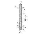
いくつかの例において、フィルタ要素26は図2に示されるように構成されてもよく、ここでフィルタは、タバコロッド12の一端に隣接して位置する第一フィルタセグメント32を含む。第一フィルタセグメント32は、フィルタ材料40(たとえば、トリアセチンなどの可塑剤を含浸したアセチルセルローストウ)を含む。別の例では、フィルタ要素26は、図3に示されるように、セグメントに分割されなくてもよい。引き続き図2を参照すると、第一セグメントのフィルタ材料40内には、ここでは物体/物質50と表される、風味の作動可能な開放のために構成された、吸着性材料/粒子または物体(たとえば、易破裂性または易破壊性カプセル)が挿入されてもよい。炭素質材料が吸着性材料50として使用される特定の実施形態において、炭素質材料の少なくとも一部、および通常は実質的に炭素質材料の全てが、有効量のポリオールエステル(たとえば、トリアセチン)とポリオール(たとえば、プロピレングリコール)との混合物と密接に接触している。望ましければ、フィルタ要素はまた、フィルタ全体を通る主流煙の性質を変化させる能力を有するその他の成分を組み込むことも可能である。たとえば、参照により本明細書に組み込まれる、Figlarらの米国特許公開第2004/0237984号明細書、Schluterらの米国特許公開第2005/0268925号明細書、Luanらの米国特許公開第2006/0130861号明細書、およびLuanらの米国特許公開第2006/0174899号明細書を参照されたい。 In some examples, the
フィルタ要素26は、第一セグメント32に対して長手方向に設けられ、紙巻きタバコ10の極口端部に位置する、第二フィルタセグメント36も所有してよい。第二フィルタセグメント36は、その長手方向延在表面に沿って囲みプラグラップ材料28で包装された、フィルタ材料48(たとえば、トリアセチンなどの可塑剤を含浸したアセチルセルローストウ)を含む。第二フィルタセグメント36は、実質的に吸着材および易破壊性または易破裂性カプセルを含まなくてもよく、これはフィルタ要素26の極口端部を見たときにこのような添加物が見えないことを意味する。 The
フィルタ要素26は、外側プラグラップ28の層によってその外周または長手方向周囲に沿って囲まれている。外側プラグラップ28は、結合した2セグメントフィルタ要素を提供するように、第一フィルタセグメント32および第二フィルタセグメント36の各々の上を覆う。
フィルタ要素26は、フィルタ要素26の全長およびタバコロッド12の隣接領域の両方を囲むチッピング材料46(たとえば、本質的に空気不透過性のチッピング紙)を用いてタバコロッド12に取り付けられている。チッピング材料46の内表面は、適切な接着剤を用いて、プラグラップ28の外表面およびタバコロッドの包装材料16の外表面に、しっかりと固定されており、したがってフィルタ要素およびタバコロッドは互いに接続されている。参照により本明細書に組み込まれる、Dubeらの米国特許公開第2008/0029111号明細書に明記されるチッピング材料および構成も参照のこと。 The
通気または空気希釈喫煙品には、その各々がチッピング材料およびプラグラップを通じて延在する、一連の穿孔30などの任意の空気希釈機構が設けられてもよい。図3に示される任意の穿孔30は、たとえばレーザ穿孔法など、当業者にとって周知の様々な手法によって作成可能である。あるいは、いわゆるオフライン空気希釈法が使用されることも可能である(たとえば、多孔紙プラグラップおよび予備穿孔チッピング紙の使用を通じて)。空気希釈または通気される紙巻きタバコでは、空気希釈または通気の量または程度が異なってもよい。多くの場合、空気希釈紙巻きタバコの空気希釈の量は約10パーセントより多く、通常は約20パーセントより多く、しばしば約30パーセントより多く、場合により約40パーセントより多い。通常、空気希釈紙巻きタバコの空気希釈の上限は約80パーセント未満であり、しばしば約70パーセント未満である。本明細書において使用される際に、用語「空気希釈」は、紙巻きタバコを通じて引き込まれて紙巻きタバコの極口端部分から出る空気および煙および総体積に対する、空気希釈手段を通じて引き込まれる空気の体積の比率(パーセンテージで表される)である。 The vented or air diluted smoking article may be provided with any air dilution mechanism, such as a series of perforations 30, each extending through a tipping material and a plug wrap. The optional perforation 30 shown in FIG. 3 can be created by various techniques well known to those skilled in the art, such as laser perforation. Alternatively, so-called off-line air dilution methods can be used (eg, through the use of perforated paper plug wrap and pre-perforated chipping paper). For cigarettes that are air diluted or ventilated, the amount or degree of air dilution or ventilation may vary. In many cases, the amount of air dilution in an air diluted cigarette is greater than about 10 percent, usually greater than about 20 percent, often greater than about 30 percent, and sometimes greater than about 40 percent. Typically, the upper limit of air dilution for air diluted cigarettes is less than about 80 percent and often less than about 70 percent. As used herein, the term “air dilution” refers to the volume of air drawn through the air dilution means relative to the air and smoke drawn through the cigarette and exiting from the extreme end portion of the cigarette and the total volume. Ratio (expressed as a percentage).
使用中、喫煙者は、マッチまたはタバコ用ライターを使用して、紙巻きタバコ10の点火末端18に点火する。こうして、喫煙材12は燃え始める。紙巻きタバコ10の口端部20は、喫煙者の唇に配置される。燃えている喫煙材12によって生成された熱分解生成物(たとえば、タバコの煙の成分)は、紙巻きタバコ10を通じて、フィルタ要素26を通じて、喫煙者の口中に引き込まれる。引き込みの間、主流煙の特定量の特定の気体成分が主流煙から除去され、あるいはフィルタ要素26内で中和されてもよい。炭素質フィルタ成分(たとえば、活性炭粒子)などの吸着性材料を組み込んだフィルタは、広範なタバコ主流煙気相成分を捕捉する能力を有する。望ましければ、喫煙体験の前、最中、または後に、喫煙者は任意でフィルタ要素を押しつぶしてもよい。その結果、フィルタ内の易破壊性カプセルの少なくとも一部が破壊され、したがってその中に収容された風味剤を放出することができるが、これは粒子および/または液状であってもよい。 In use, the smoker ignites the
代表的な紙巻きタバコ10の寸法は様々であってもよい。好適な紙巻きタバコはロッド形状であり、約7.5mmの寸法を有することができ(たとえば、約20mmから約27mm、しばしば約22.5mmから約25mmの外周)、そして約70mmから約120mm、しばしば約80mmから約100mmの全長を有することができる。フィルタ要素30の長さは異なってもよい。一般的なフィルタ要素は約15mmから約40mm、しばしば約20mmから約35mmの全長を有することができる。一般的な二重セグメントフィルタ要素では、下流または口端部フィルタセグメントはしばしば約10mmから約20mmの長さを有し、上流またはタバコロッド端フィルタセグメントはしばしば約10mmから約20mmの長さを有する。 The dimensions of a
図2に示されるように、本発明によって形成されてもよい1つのフィルタ要素26は、複数の長手方向延在セグメントを含む。各セグメントは異なる性質を有することができ、主流煙からの粒状物質および/または気相化合物のろ過または吸着が可能な様々な物質を含んでもよい。通常、本発明の様々な態様のフィルタ要素は、2から6セグメント、多くの場合は2から4セグメントを含む。いくつかの例において、フィルタ要素26は口端部セグメントおよびタバコ端セグメントを含んでもよく、タバコ端セグメントは分散した吸着性材料50および風味剤52を含む。 As shown in FIG. 2, one
図2に示されるようにフィルタ要素は、吸着性材料/粒子またはその他の物体50を組み込んでもよい。吸着性材料50は、高度な特異性を伴わずに煙の成分を吸着することが可能な比較的大きい表面積を備える物質、またはイオン交換樹脂など、より高い特異性を伴って特定の化合物を吸着する物質であってもよい。例示的なタイプの吸着性材料は、活性炭、分子篩(たとえば、ゼオライトおよび炭素分子篩)、粘土、イオン交換樹脂、活性アルミナ、シリカゲル、海泡石、およびこれらの組み合わせを含んでもよい。フィルタ要素を通過する主流煙の特性または性質を変化させる能力を有する、いずれの吸着性材料、または材料の混合物が使用されてもよい。 As shown in FIG. 2, the filter element may incorporate an adsorbent material / particle or
たとえば図3に示されるように、吸着材またはその他の材料は、フィルタ要素26(または複数のフィルタ要素26を形成するためのその長手切断の前の連続フィルタロッド)内のキャリア55に含まれてもよい。適切なキャリア材55の選択は、たとえば、今や「捕らえられた」吸着性材料をフィルタ要素26内により効果的かつ効率的に挿入することによって、改良された製造を容易にするだろう。つまり吸着性材料(または別の非吸着性材料)は、フィルタ要素26内への挿入時にキャリア材55によって担持される。いくつかの実施形態において、キャリア材55は、たとえばペレット、カプセル、チューブ、連続長尺構造、連続ストリップ、ストランド、またはフィルタ要素26内への挿入を容易にするように所望の物質を受容および「閉じ込めておく」ことが可能な類似の構造の形態であってもよい。いくつかの実施形態において、個別のまたは複数の形態のキャリア55が、フィルタ要素26内に挿入されてもよい。たとえば、個別のまたは複数のカプセル、チューブ、ペレットなど、あるいはそれらの組み合わせが、異なる実施形態の様々な態様にしたがってフィルタ要素26内に挿入されてもよい。一実施形態において、キャリア55は、(たとえば、流体、ゲル、またはその他流動性の形態の風味材料を含んでもよい)流動性材料を収容する易破裂性または別途易破壊性カプセルとして、実現されてもよい。様々な実施形態は、参照により本明細書に組み込まれる、Nelsonらの米国特許第7,740,019号明細書、Dubeらの米国特許第7,794,665号明細書、およびAndresenらの米国特許公開第2009/0288667号明細書に開示された方法および構造を含んでもよい。 For example, as shown in FIG. 3, an adsorbent or other material is contained in a
フィルタ材料の連続ロッド内へのキャリア55の挿入の後、そこに収容された吸着材またはその他の材料は、キャリアからフィルタ材料内へ放出されてもよい。たとえば、キャリア55は、吸着性材料50がフィルタ要素を通じて引き込まれた主流煙に対して所望の効果を有することが可能なようにフィルタ材料内に吸着性材料50を放出および/または分散させるように、溶解、崩壊、分解、または別途破壊されてもよい。フィルタ材料内への吸着性材料の放出は、連続ロッドがフィルタセグメント(たとえば、フィルタ要素26)に切断される前、または後に行われてもよい。このような放出は、製造プロセスの間に行われることが可能であり、あるいはいくつかの例において、喫煙品を喫煙する前に喫煙者によって実行されてもよい。いくつかの例において、様々な形態の吸着材またはその他の材料(すなわちストランド、ビード、ペレット、カプセル、またはこれらの組み合わせ)が、キャリア材55として独立気泡フォーム内に設けられてもよく、一旦フィルタ要素20内に挿入されると、フォームを壊して吸着材またはその他の閉じ込められた物質をそこから放出するために、放射または加熱されてもよい。あるいは、キャリア材55は連続気泡フォームを含んでもよく、たとえば物体がフィルタ要素20内に挿入されると、吸着性材料50を放出するために空気および/または物理的力が使用されてもよい。これらまたはその他の実施形態において、キャリア材55は、たとえば水溶性またはその他の液体可溶性ポリマーで形成され、吸着材またはその他の材料(たとえば風味材料など)を担持するように構成された、易破壊性カプセル、「カプセルインカプセル」、またはストランドの形態で提供されてもよい。このような可溶性ポリマーは、たとえば、ポリ乳酸、ポリビニルアルコール(PVA)、デンプンおよび/またはデンプン系ポリマー、カラギーナン、ポリビニルアセテート、ヒドロキシプロピルセルロース、プルラン、カルボキシメチルセルロースおよびその塩(すなわち、アルカリ金属塩)、アルギン酸およびその塩、ゼラチン、および/またはその他いずれか適切なポリマーまたはこれらの組み合わせを含んでもよい。 After insertion of the
放出可能吸着材またはその他の材料のカプセルまたはその他易破壊性容器50および/または55が提供される実施形態において、このような材料は、液体またはその他流動性の形態であってもよい。このような実施形態において、放出された材料が、それを含有するフィルタ材料の上を覆うプラグラップおよびチッピング紙(たとえば、ユーザの唇、指、またはその他の外部物体に直接接触する可能性のあるところ)を通じて逃げ、浸出、または別途移動する可能性を低下させることが、望ましいだろう。いくつかの製品では、この目的のために特殊な液体障壁プラグラップ紙が使用されている。しかしながら、いくつかの液体障壁プラグラップ紙は、標準的なプラグラップよりも高コストであるかも知れない。少なくともこの理由のため、標準プラグラップ紙材料を使用する低コストソリューションを提供することが、望ましいだろう。 In embodiments where a releasable adsorbent or other material capsule or other
実際、そうすることで、(i)破裂したカプセルまたはその他の容器からの材料に対する有効な障壁が、やはりフィルタ材料の周りに標準プラグラップを接着させるホットメルト材料によって形成されてもよいこと、および(ii)ホットメルト障壁接着剤の方法の実施が、少なくとも障壁プラグラップ材料と同じくらい効果的にカプセル材料がプラグラップを通過するのを防止するフィルタアセンブリを提供してもよいことを、備えることができる。この結果、流体障壁プラグラップ材料と比較して、コスト削減できるだろう。 Indeed, in doing so, (i) an effective barrier to material from a ruptured capsule or other container may be formed by a hot melt material that also adheres a standard plug wrap around the filter material, and (Ii) implementing the hot melt barrier adhesive method may provide a filter assembly that prevents the encapsulant from passing through the plug wrap at least as effectively as the barrier plug wrap material. Can do. This will result in cost savings compared to fluid barrier plug wrap materials.
一実施形態において、接着剤および/またはホットメルト材料は、フィルタ材料40と被覆しているプラグラップ28との間の表面界面の全て、ほぼ全て、または大部分に、(たとえばプラグラップがそれによってフィルタ材料に適用および接着されてフィルタプラグを形成する前にプラグラップに塗布することによって)塗布されてもよい。接着剤および/またはホットメルト材料はこのため、流動性材料がフィルタ40の上を覆うプラグラップおよびチッピング材料を通じて逃げ、浸出、または別途移動するのに対して接着剤の障壁層29(実寸よりはるかに大きく図3に示される)を同時に提供しながら、フィルタ40にプラグラップ28を接着させるという二重の目的に役立つだろう。接着剤および/またはその他の材料の塗布に一般的に適している方法、材料、および機構は、参照により本明細書に組み込まれる、Maiwaldらの米国特許第7,237,557号明細書に開示されている。 In one embodiment, the adhesive and / or hot melt material is applied to all, nearly all, or most of the surface interface between the
一般的な紙巻きタバコでは、プラグラップ28とフィルタ材料40との間の表面界面は多くの場合、不連続接着層のみを有する。液体またはその他の流動性材料を放出するように構成された易破壊性カプセルを組み込んだ紙巻きタバコにおいて、この構造は、液体またはその他の流動性材料がプラグラップおよびチッピング材料まで、およびこれらを通じて、紙巻きタバコの外側まで移動するのを効果的に防止する障壁を形成するには、不十分となることが多い。しかしながら、ここに開示されている方法に合わせてホットメルト材料を塗布することで、液体またはその他の流動性材料に対する有効な障壁を提供することができる。 In a typical cigarette, the surface interface between the
適切な接着剤および/またはホットメルト材料は、たとえば、ナショナルスターチコード10110160番の材料を含んでもよい。 Suitable adhesives and / or hot melt materials may include, for example, National Starch Code 10110160 material.
接着剤および/またはホットメルト材料は、界面表面全体にわたって塗布されてもよい。一方または両方が各々、外向きフィルタ表面、フィルタ対向プラグラップ表面、または両方に塗布されてもよい。一般的に、材料をプラグラップに塗布することが好ましいだろう。特定の実施形態において、接着剤および/またはホットメルト材料をチッピング材料に塗布することも有用であろう。塗布は、界面表面全体または(たとえばフィルタ材料、プラグラップ、またはチッピング材料の)いずれかの全表面を覆う必要はない。接着剤および/またはホットメルト材料は、1つ以上の規則的または不規則パターン、パッチ、継目、帯、または表面被覆を提供するその他いずれかの方式で、塗布されてもよい。特定の実施形態において、接着剤および/またはホットメルト材料は、ローラからの「印刷型」転写によって塗布されてもよい。しかしながら、流量、体積、および配置を正確に制御できるノズルを介して接着剤および/またはホットメルト材料を塗布することによって、特定の利点が得られるだろう。ノズルの機械的および/またはデジタル制御は、材料の細心の計量(たとえば、パルス化またはその他の制御された放出など)を提供するために使用されてもよい。接着剤(たとえば、グルー、ホットメルト)のオンラインまたはオフライン塗布に使用されてもよい装置の一例は、Baumer Xmelt HHSである。 The adhesive and / or hot melt material may be applied over the entire interfacial surface. One or both may each be applied to the outward filter surface, the filter-facing plug wrap surface, or both. In general, it will be preferable to apply the material to the plug wrap. In certain embodiments, it may also be useful to apply an adhesive and / or hot melt material to the chipping material. The application need not cover the entire interfacial surface or any entire surface (eg, filter material, plug wrap, or chipping material). The adhesive and / or hot melt material may be applied in one or more regular or irregular patterns, patches, seams, bands, or any other manner that provides a surface coating. In certain embodiments, the adhesive and / or hot melt material may be applied by “printing” transfer from a roller. However, certain advantages may be obtained by applying adhesives and / or hot melt materials through nozzles that can accurately control flow rate, volume, and placement. Mechanical and / or digital control of the nozzle may be used to provide meticulous metering of material (eg, pulsing or other controlled release). One example of an apparatus that may be used for on-line or off-line application of adhesives (eg glue, hot melt) is Baumer Xmelt HHS.
接着剤および/またはホットメルト材料はフィルタ形成中に塗布されてもよく、あるいはフィルタ材料外側とプラグラップのフィルタ対向表面との間の材料の配置を可能にする、より早いかまたは遅い段階で塗布されてもよい。ノズルによる材料の配置は、プラグラップ、チッピング材料、および/またはその他の喫煙品部品に接着剤および/または接着型材料を塗布するために使用可能なプリンタ型ローラ配置を超える特定の利点を提供するだろう。たとえば、(たとえば温度変化、粘度変化、またはその他の要因による早期硬化に基づいて)材料がローラの上に蓄積され、洗浄/調整のための停止時間を必要とするかも知れない。反対に、ローラを洗浄または交換するよりも効率的にノズルを加熱し、その開口径を変更し、さらにノズルヘッドを交換する能力は、当業者によって理解される利点を提供するだろう。 Adhesives and / or hot melt materials may be applied during filter formation, or applied earlier or later to allow placement of the material between the filter material exterior and the filter facing surface of the plug wrap. May be. The placement of the material by the nozzle provides certain advantages over a printer-type roller arrangement that can be used to apply adhesive and / or adhesive-type material to plug wrap, chipping material, and / or other smoking article parts. right. For example, material may accumulate on the rollers (eg, based on premature curing due to temperature changes, viscosity changes, or other factors) and may require downtime for cleaning / conditioning. Conversely, the ability to heat a nozzle, change its aperture diameter, and replace the nozzle head more efficiently than cleaning or replacing a roller will provide advantages understood by those skilled in the art.
ホットメルト材料塗布の正確な制御は、ノズルを流れる材料を、ノズルを通過して供給される紙の速度と能動的に相関させる、コンピュータおよび/または機械的制御を用いて達成可能であり、好ましくはこうして実施される。具体的には、回転エンコーダがホットメルト分注器(たとえば、Baumer hhs)と連絡する組み立て機械(たとえば、Hauni Max80およびKDF2)の紙供給部に回転エンコーダが設けられてもよく、プラグラップ紙のリボンまたはその他の形状の供給源がノズルを通り過ぎて方向づけられる速度と相関して、所望の障壁形成層を提供するためにノズルを通るホットメルト材料の流れを増加または減少させる。このように、表面塗布の密度(たとえば、単位面積当たりの接着剤グラム数)、ならびに塗布される総量が、注意深く制御されることが可能である。好ましくは、有効な障壁として役立つことになるプラグラップを(ホットメルト材料を塗布することによって)処理するときに、全体的に連続する層が形成される。好適に連続する層は、プラグラップ上に連続層として塗布されてもよく、あるいはこれは、パターン形成されているかまたはされていない、しかし完成または準完成フィルタを形成するためにカプセル含有フィルタ材料の周りに処理済みプラグラップが適用されるときにフィルタ材料とプラグラップとの間に連続的で有効な障壁層を形成するように構成されている、不連続層として提供されてもよい。 Accurate control of hot melt material application can be achieved using a computer and / or mechanical control that actively correlates the material flowing through the nozzle with the speed of paper fed through the nozzle, preferably Is implemented in this way. Specifically, a rotary encoder may be provided in the paper supply section of an assembly machine (eg, Hauni Max80 and KDF2) where the rotary encoder communicates with a hot melt dispenser (eg, Baumer hhs). Correlating with the rate at which the ribbon or other shaped source is directed past the nozzle, the flow of hot melt material through the nozzle is increased or decreased to provide the desired barrier-forming layer. In this way, the density of the surface application (eg, grams of adhesive per unit area), as well as the total amount applied, can be carefully controlled. Preferably, a generally continuous layer is formed when processing the plug wrap (by applying hot melt material) that will serve as an effective barrier. A suitably continuous layer may be applied as a continuous layer on the plug wrap, or it may be patterned or not, but of capsule-containing filter material to form a finished or semi-finished filter. It may be provided as a discontinuous layer configured to form a continuous and effective barrier layer between the filter material and the plug wrap when the treated plug wrap is applied around.
有効な障壁では、標準プラグラップ材料1リニアメータあたり、約1.8から約2.2グラムのホットメルトが塗布されてもよい。一実施形態において、有効な障壁層は、標準プラグラップ材料1リニアメータ当たり約2グラムのホットメルトを塗布することによって形成されてもよく、ここで障壁は、フィルタを形成するためにプラグラップが組み立てられるときに形成される(たとえば、アセチルセルロースのコアを備える一般的な忠実円筒形フィルタ、または別のフィルタ材料であって、この方法の好適な使用法は、フィルタ材料中へのユーザ作動放出向けに構成された、流動性風味材またはその他の材料を放出可能に収容する易破壊性カプセルまたはその他の易破壊性容器を収容するフィルタを伴う)。たとえば、ホットメルト接着剤は、単一ノズルを介して帯状パターンで、ほぼ一定の表面密度で塗布されてもよい。 An effective barrier may apply about 1.8 to about 2.2 grams of hot melt per linear meter of standard plug wrap material. In one embodiment, an effective barrier layer may be formed by applying about 2 grams of hot melt per linear meter of standard plug wrap material, where the barrier is plug wrap to form a filter. A preferred faithful cylindrical filter with an acetylcellulose core, or another filter material, formed when assembled (e.g., a user-actuated release into the filter material). With a filter containing a breakable capsule or other breakable container releasably containing a flowable flavoring material or other material configured for the For example, the hot melt adhesive may be applied in a strip pattern with a substantially constant surface density through a single nozzle.
言い換えると、紙巻きタバコフィルタアセンブリの方法は、略円筒形本体の中に紙巻きタバコフィルタ材料を組み込むステップと、フィルタ対向表面を含むプラグラップ材料のリボンを提供するステップと、それを通じてホットメルト接着剤が分注される(たとえばドット、直線、らせん、および/またはその他の規則的または不規則パターンの塗布/分注として)少なくとも1つのノズルを含むホットメルト接着剤アプリケータを通り過ぎてプラグラップ材料を方向づけるステップと、少なくとも1つのノズルを介して第一所定処理量のホットメルト接着剤をプラグラップ材料のフィルタ対向表面に塗布するステップと、ホットメルト接着剤で処理されたプラグラップ材料のフィルタ対向表面がフィルタ材料に向けられるように、フィルタ材料の周りにプラグラップ材料を組み立てるステップと、を含んでもよく、塗布された第一所定量のホットメルト接着剤は、放出されたホットメルト接着剤の量を、プラグラップ材料が少なくとも1つのノズルを通り過ぎて方向づけられる速度と相関させるエンコーダによって動的に決定されてもよく、ここでエンコーダは、プラグラップ材料がホットメルトアプリケータを通り過ぎて方向づけられる速度を監視するようにプラグラップ材料(またはその源)と連絡し、ホットメルト接着剤アプリケータとも連絡しており、組み立てられたプラグラップおよびフィルタ材料の間のホットメルト接着剤は、フィルタ材料からプラグラップまでの流体の通過に対する有効な障壁を形成する。その後、プラグラップ被覆フィルタ材料は紙巻きタバコフィルタを形成するために一定間隔に切断され、その後紙巻きタバコを形成するために(たとえばチッピング紙の適用によって)巻きタバコロッドと組み上げられてもよい。 In other words, the method of cigarette filter assembly includes incorporating a cigarette filter material into a generally cylindrical body, providing a ribbon of plug wrap material including a filter facing surface, through which a hot melt adhesive is provided. Directing the plug wrap material past a hot melt adhesive applicator that includes at least one nozzle to be dispensed (eg, as application / dispensing of dots, lines, spirals, and / or other regular or irregular patterns) Applying a first predetermined throughput of hot melt adhesive to the filter facing surface of the plug wrap material through at least one nozzle; and a filter facing surface of the plug wrap material treated with the hot melt adhesive. Filter to be directed to the filter material Assembling the plug wrap material around the material, wherein the applied first predetermined amount of hot melt adhesive determines the amount of hot melt adhesive released and the plug wrap material is at least one nozzle. May be determined dynamically by an encoder that correlates with the speed directed past the plug wrap material (or its plug-in) to monitor the speed at which the plug wrap material is directed past the hot melt applicator. The hot melt adhesive between the assembled plug wrap and the filter material provides an effective barrier to the passage of fluid from the filter material to the plug wrap. Form. Thereafter, the plug wrap coated filter material may be cut at regular intervals to form a cigarette filter and then assembled with a cigarette rod to form a cigarette (eg, by application of tipping paper).
紙巻きタバコロッドは通常、従来の自動紙巻きタバコロッド製造機などの、紙巻きタバコ製造機を使用して製造される。例示的な紙巻きタバコロッド製造機は、Molins PLCまたはHauni−Werke Korber&Co.KGより販売されているタイプである。たとえば、MkX(Molins PLCより販売)またはPROTOS(Hauni−Werke Korber&Co.KGより販売)として知られるタイプの紙巻きタバコロッド製造機が採用されてもよい。PROTOS紙巻きタバコ製造機の説明は、参照により本明細書に組み込まれる、Brandらの米国特許第4,474,190号明細書の5段48行目から8段3行目に記載されている。紙巻きタバコの製造に適したタイプの機器は、その各々が参照により本明細書に組み込まれる、La Hueの米国特許第4,781,203号明細書、Holznagelの米国特許第4,844,100号明細書、Holmesらの米国特許第5,156,169号明細書、Myracle,Jr.らの米国特許第5,191,906号明細書、Blauらの米国特許第6,647,870号明細書、Kitaoらの米国特許第6,848,449号明細書、Kitaoらの米国特許第6,904,917号明細書、Hartmanの米国特許第7,210,486号明細書、Hancockらの米国特許第7,275,548号明細書、Barnesらの米国特許第7,281,540号明細書、およびFitzgeraldらの米国特許第7,234,471号明細書にも明記されている。 Cigarette rods are typically manufactured using a cigarette making machine, such as a conventional automatic cigarette rod making machine. Exemplary cigarette rod making machines are Molins PLC or Hauni-Werke Korber & Co. This is a type sold by KG. For example, a cigarette rod making machine of the type known as MkX (sold by Molins PLC) or PROTOS (sold by Hauni-Werke Korber & Co. KG) may be employed. A description of the PROTOS cigarette making machine is described in Brand 5, et al., U.S. Pat. No. 4,474,190, line 5,
従来の自動紙巻きタバコ製造機の構成要素および動作は、紙巻きタバコ製造機設計および動作の当業者にとって容易に明らかとなるだろう。たとえば、いくつかの種類の煙突、タバコフィラー供給機器、吸着コンベヤシステム、および装飾システムの構成要素および動作の説明は、その各々が参照により本明細書に組み込まれる、Molinsらの米国特許第3,288,147号明細書、Heitmannらの米国特許第3,915,176号明細書、Frankの米国特許第4,291,713号明細書、Rudszinatの米国特許第4,574,816号明細書、Heitmannらの米国特許第4,736,754号明細書、Pinckらの米国特許第4,878,506号明細書、Heitmannの米国特許第5,060,665号明細書、Keritsisらの米国特許第5,012,823号明細書、Faggらの米国特許第6,360,751号明細書、およびMullerの米国特許公開第2003/0136419号明細書に明記されている。本明細書に明記されるタイプの自動紙巻きタバコ製造機は、所望の長さの成形喫煙ロッドに再分割されることが可能な、成形連続紙巻きタバコロッドまたは喫煙ロッドを提供する。 The components and operation of a conventional automatic cigarette maker will be readily apparent to those skilled in the art of cigarette maker design and operation. For example, a description of the components and operation of several types of chimneys, tobacco filler supply equipment, suction conveyor systems, and decoration systems are described in US Pat. No. 3, Molins et al., Each of which is incorporated herein by reference. 288,147, Heitmann et al. U.S. Pat. No. 3,915,176, Frank U.S. Pat. No. 4,291,713, Rudszinat U.S. Pat. No. 4,574,816, US Pat. No. 4,736,754 to Heitmann et al., US Pat. No. 4,878,506 to Pinck et al., US Pat. No. 5,060,665 to Heitmann et al., US Pat. US Pat. No. 5,012,823, US Pat. No. 6,360,751 to Fagg et al. It is specified in U.S. Patent Publication No. 2003/0136419 fine Muller. An automatic cigarette making machine of the type specified herein provides a shaped continuous cigarette rod or smoking rod that can be subdivided into shaped smoking rods of a desired length.
本発明によって製造されるフィルタロッドから提供されるフィルタ要素を組み込んだフィルタ付き紙巻きタバコは、伝統的なタイプの紙巻きタバコ製造法を用いて製造されることが可能である。たとえば、フィルタ付き紙巻きタバコの製造に従来使用されている一般的な形式または構成のものである、いわゆる「シックスアップ」フィルタロッド、「フォーアップ」フィルタロッド、および「ツーアップ」フィルタロッドは、Hauni−Werke Korber&Co.KGからLab MAX、MAX、MAX SまたはMAX80として入手可能なチッピング装置など、従来型の、または適切に改造された紙巻きタバコロッド取り扱い装置を用いて、取り扱われることが可能である。たとえば、その各々が参照により本明細書に組み込まれる、Erdmannらの米国特許第3,308,600号明細書、Heitmannらの米国特許第4,281,670号明細書、Reulandらの米国特許第4,280,187号明細書、Vosらの米国特許第6,229,115号明細書、Holmesの米国特許第7,435,585号明細書、Maiwaldらの米国特許第7,237,557号明細書、およびRead Jr.らの米国特許第7,296,578号明細書に明記されるタイプの装置も、参照されたい。これらのタイプの装置の動作は、自動紙巻きタバコ製造の当業者にとって容易に明らかとなるだろう。 Filtered cigarettes incorporating filter elements provided from filter rods made in accordance with the present invention can be manufactured using traditional types of cigarette manufacturing methods. For example, so-called “six-up” filter rods, “four-up” filter rods, and “two-up” filter rods, of the common type or configuration conventionally used in the manufacture of filtered cigarettes, are Hauni -Werke Korber & Co. It can be handled using a conventional or appropriately modified cigarette rod handling device such as a chipping device available from KG as Lab MAX, MAX, MAX S or MAX80. For example, Erdmann et al., U.S. Pat. No. 3,308,600, Heitmann et al., U.S. Pat. No. 4,281,670, Reuland et al., U.S. Pat. US Pat. No. 4,280,187, Vos et al. US Pat. No. 6,229,115, Holmes US Pat. No. 7,435,585, Maiwald et al. US Pat. No. 7,237,557. Description, and Read Jr. See also the apparatus of the type specified in U.S. Pat. No. 7,296,578. The operation of these types of devices will be readily apparent to those skilled in the art of automated cigarette manufacture.
本発明によって製造される紙巻きタバコフィルタロッドは多重セグメントフィルタロッドを提供するために使用されることが可能である。このような多重セグメントフィルタロッドは、多重セグメントフィルタ要素を含むフィルタ付き紙巻きタバコの製造に採用されることが可能である。2セグメントフィルタ要素の一例は、一端に活性炭粒子を組み込んだ第一円筒形セグメント(たとえば「ダルメシアン」タイプのフィルタセグメント)、および本発明の実施形態によって製造されたフィルタロッドから製造された第二円筒形セグメントを含む、フィルタ要素である。多重セグメントフィルタロッドの製造は、多重セグメント紙巻きタバコフィルタ構成要素を提供するために採用されてきたタイプのロッド成形ユニットを使用して、実行されることが可能である。多重セグメント紙巻きタバコフィルタロッドは、ドイツ、ハンブルクのHauni−Werke Korber&Co.KGからMulfiのブランド名で入手可能な紙巻きタバコフィルタロッド製造装置を使用して、製造されることが可能である。 The cigarette filter rod produced according to the present invention can be used to provide a multi-segment filter rod. Such multi-segment filter rods can be employed in the manufacture of filtered cigarettes that include multi-segment filter elements. An example of a two-segment filter element is a first cylindrical segment (eg, a “Dalmatian” type filter segment) incorporating activated carbon particles at one end, and a second cylinder manufactured from a filter rod manufactured in accordance with an embodiment of the present invention. A filter element that includes a shape segment. The manufacture of multi-segment filter rods can be performed using a type of rod forming unit that has been employed to provide multi-segment cigarette filter components. Multi-segment cigarette filter rods are available from Hauni-Werke Korber & Co., Hamburg, Germany. It can be manufactured using a cigarette filter rod manufacturing device available from KG under the brand name Mulfi.
タバコのタイプ、タバコ配合、最外層およびケーシング材料、配合充填密度;タバコロッド用紙包装材料のタイプ、チッピング材料のタイプ、および空気希釈レベルを含む様々なタイプの紙巻きタバコ構成要素が、採用されてもよい。たとえば、参照により本明細書に組み込まれる、Gentryの米国特許第5,220,930号明細書、Krakerの米国特許第6,779,530号明細書、Ashcraftらの米国特許第7,237,559号明細書、Thomasらの米国特許第7,565,818号明細書、Nestorらの米国特許公開第2005/0066986号明細書、およびOglesbyの米国特許公開第2007/0246055号明細書に明記される、様々な代表的タイプの紙巻きタバコ構成要素、ならびに様々な紙巻きタバコ設計、形式、構成、および特性を参照されたい。 Various types of cigarette components may be employed, including tobacco type, tobacco formulation, outermost layer and casing material, formulation packing density; tobacco rod paper packaging material type, chipping material type, and air dilution level Good. For example, Gentry US Pat. No. 5,220,930, Kraker US Pat. No. 6,779,530, Ashcraft et al. US Pat. No. 7,237,559, incorporated herein by reference. US Patent No. 7,565,818 to Thomas et al., US Patent Publication No. 2005/0066986 to Nestor et al., And US Patent Publication No. 2007/0246055 to Oglesby. See various representative types of cigarette components, as well as various cigarette designs, formats, configurations, and characteristics.
フィルタロッドは、ロッド作成装置を用いて本発明の実施形態にしたがって製造されることが可能であり、例示的なロッド作成装置はロッド成形ユニットを含む。代表的なロッド成形ユニットは、Hauni−Werke Korber&Co.KGよりKDF−2およびKDF−3Eとして、ならびにInternational Tobacco MachineryよりPolaris−ITM Filter Makerとして、入手可能である。アセチルセルロースフィラメント状トウなどのフィルタ材料は通常、従来のフィルタトウ処理ユニットを用いて処理される。たとえば、フィルタトウは、バッセルジェット法またはねじ付きロール法を用いてブルーム状に固められることが可能である。例示的なトウ処理ユニットは、ノースカロライナ州ウィンストンセーラムのArjay Equipment Corp.によって供給されるE−60として販売されてきた。その他の例示的なトウ処理ユニットは、Hauni−Werke Korber&Co.KGよりAF−2、AF−3、およびAF−4として、ならびにInternational Tobacco MachineryよりCandor−ITM Tow Processorとして、販売されてきた。当業者にとって周知のような、その他のタイプの市販のトウ処理機器が採用されることも可能である。ギャザー紙、不織ポリプロピレンウェブ、または細断ウェブのギャザーストランドなどのその他のタイプのフィルタ材料は、Pryorらの米国特許第4,807,809号明細書およびRakerの米国特許第5,025,814号明細書に明記されるタイプの材料、機器、および技術を用いて提供されることが可能である。加えて、フィルタ材料供給ユニットおよびフィルタ作成ユニットを動作させる代表的な方式および方法は、Bynreの米国特許第4,281,671号明細書、Green,Jr.らの米国特許第4,850,301号明細書、Green,Jr.らの米国特許第4,862,905号明細書、Siemsらの米国特許第5,060,664号明細書、Riversの米国特許第5,387,285号明細書、およびLanier,Jr.らの米国特許第7,074,170号明細書に明記されている。 The filter rod can be manufactured in accordance with an embodiment of the present invention using a rod making device, and the exemplary rod making device includes a rod forming unit. A typical rod forming unit is Hauni-Werke Korber & Co. Available from KG as KDF-2 and KDF-3E, and from International Tobacco Machinery as Polaris-ITM Filter Maker. Filter materials such as acetylcellulose filamentous tow are typically processed using conventional filter tow processing units. For example, the filter tow can be consolidated into a bloom using the Bessel jet method or the threaded roll method. An exemplary tow processing unit is Arjay Equipment Corp. of Winston Salem, NC. Sold as E-60. Other exemplary tow processing units are Hauni-Werke Korber & Co. It has been sold by AF as AF-2, AF-3, and AF-4 and by International Tobacco Machinery as the Candor-ITM Tow Processor. Other types of commercially available tow processing equipment can be employed as is well known to those skilled in the art. Other types of filter materials such as gathered paper, non-woven polypropylene webs, or gathered strands of shredded webs are described in Pryor et al. US Pat. No. 4,807,809 and Raker US Pat. No. 5,025,814. Can be provided using materials, equipment, and techniques of the type specified in the specification. In addition, exemplary schemes and methods for operating the filter material supply unit and filter making unit are disclosed in Bynre US Pat. No. 4,281,671, Green, Jr. U.S. Pat. No. 4,850,301, Green, Jr. U.S. Pat. No. 4,862,905, Siems et al. U.S. Pat. No. 5,060,664, Rivers U.S. Pat. No. 5,387,285, and Lanier, Jr. U.S. Pat. No. 7,074,170.
フィルタ作成装置の使用中に、連続長またはウェブのフィルタ材料が、収納用ベール、ボビンなどの源から供給される。連続長のフィルタ材料は、ロッド成形ユニットの収集領域を通じて引っ張られる。収集領域は、舌または角構成、収集じょうご構成、詰め物または搬送ジェット構成、あるいはその他適切なタイプまたは組み合わせの収集機構を有することができる。舌は、フィルタ材料の円筒形複合材の本質的に円筒形の(すなわち、ロッド状の)形状へのさらなる収集、圧縮、変換、または成形を提供し、これによってフィルタ材料の連続的に延在するストランドまたはフィラメントは、本質的にそのように形成された円筒の長手軸に沿って延在する。 During use of the filter production device, a continuous length or web of filter material is supplied from a source such as a storage bale or bobbin. A continuous length of filter material is pulled through the collection area of the rod forming unit. The collection area may have a tongue or horn configuration, a collection funnel configuration, a stuffing or transport jet configuration, or any other suitable type or combination of collection mechanisms. The tongue provides further collection, compression, conversion, or shaping of the cylindrical composite of filter material into an essentially cylindrical (ie, rod-like) shape, thereby continuously extending the filter material The strands or filaments that run essentially extend along the longitudinal axis of the cylinder so formed.
円筒形複合材として圧縮されたフィルタ材料は、装飾領域内にさらに受容される。つまり、円筒形複合材は、エンドレス装飾コンベヤベルトを含む包装機構内に供給される。装飾コンベヤベルトは、包装機構を通じて円筒形複合材を搬送するように、リボンホイールまたは協働ドラムなどの前進機構(図示せず)を用いて、連続的に長手方向に前進させられる。包装機構は、連続包装ロッドを製造するために、有孔または無孔紙プラグラップのウェブなどの包装材料のリボンを、円筒形複合材の外表面に提供および適用する。 Filter material compressed as a cylindrical composite is further received within the decorative region. That is, the cylindrical composite is fed into a packaging mechanism that includes an endless decorative conveyor belt. The decorative conveyor belt is continuously advanced longitudinally using an advancement mechanism (not shown), such as a ribbon wheel or cooperating drum, to convey the cylindrical composite through the packaging mechanism. The packaging mechanism provides and applies a ribbon of packaging material, such as a perforated or non-perforated paper plug wrap web, to the outer surface of the cylindrical composite to produce a continuous packaging rod.
包装材料のストリップまたはウェブは、回転ボビンまたはその他の適切な源から提供される。包装材料は、ボビンから引き出され、一連の案内ローラ上に向けられ、ロッド成形ユニットの包装機構に進入する。エンドレス装飾コンベヤベルトは、円筒形複合材の周りに包装材料を被せるかまたは包みながら、包装材料のストリップおよび円筒形複合材の両方を、包装機構を通じて長手方向に延在するように下流に搬送する。 The strip or web of packaging material is provided from a rotating bobbin or other suitable source. The packaging material is withdrawn from the bobbin, directed onto a series of guide rollers, and enters the packaging mechanism of the rod forming unit. The endless decorative conveyor belt conveys both the strip of packaging material and the cylindrical composite downstream to extend longitudinally through the packaging mechanism while covering or wrapping the packaging material around the cylindrical composite. .
包装材料の重複する周縁部によって形成される継目は、包装材料がフィルタ材料用の管状容器を形成することができるようにするため、アプリケータ領域において塗布される接着剤(たとえば、ホットメルト接着剤)を有する。あるいは、ホットメルト接着剤は、包装機構の装飾領域内への包装材料の進入のすぐ上流に塗布されてもよい。接着剤は、接着剤の迅速な硬化を生じるために、冷却棒を使用して冷却されてもよい。連続包装ロッドの提供において、様々なその他の封止機構およびその他のタイプの接着剤が採用され得ることは、理解される。このように、プラグラップの連続供給を供給し、連続供給されたフィルタ材料が集まった複合材の長手方向周囲を囲み、こうしてプラグラップによって囲まれた連続フィルタロッドを形成する方式または方法が、提供される。 The seam formed by the overlapping peripheral edges of the wrapping material allows the adhesive to be applied in the applicator area (eg hot melt adhesive) so that the wrapping material can form a tubular container for the filter material. ). Alternatively, the hot melt adhesive may be applied immediately upstream of the packaging material entry into the decorative area of the packaging mechanism. The adhesive may be cooled using a cooling rod to cause rapid curing of the adhesive. It will be appreciated that various other sealing mechanisms and other types of adhesives may be employed in providing a continuous wrap rod. Thus, a system or method is provided that provides a continuous supply of plug wrap and surrounds the longitudinal circumference of the composite material where the continuously supplied filter material is gathered, thus forming a continuous filter rod surrounded by the plug wrap. Is done.
連続包装ロッドは封止機構から通過して、切断アセンブリを用いて所望の所定長で一定間隔に再分割(たとえば切断)されるが、これは回転カッターとして、よく研がれたナイフ、またはその他の適切なロッド切断または再分割機構を含む。切断アセンブリはロッドの断面形状を平坦化させたり別途悪影響を及ぼしたりしないことが、特に望ましい。このように、フィルタ作成ユニットに供給されるフィルタ材料は連続ロッドとして形成され、これはロッド切断アセンブリを用いて、複数のフィルタロッドまたはロッド部分に再分割される。連続する、または複数のロッド部分は、トレイ、回転収集ドラム、搬送システム、またはその他の適切な収集機構を用いて、さらなる使用のために収集される。所望される場合は、ロッド部分は紙巻きタバコ製造機に直接運ばれることができる。 The continuous wrapping rod passes from the sealing mechanism and is subdivided (eg, cut) at a desired predetermined length using a cutting assembly, which is a rotary cutter, a well-honed knife, or other Including appropriate rod cutting or subdivision mechanisms. It is particularly desirable that the cutting assembly does not flatten or otherwise adversely affect the rod cross-sectional shape. Thus, the filter material supplied to the filter making unit is formed as a continuous rod, which is subdivided into a plurality of filter rods or rod sections using a rod cutting assembly. The continuous or multiple rod portions are collected for further use using a tray, rotating collection drum, transport system, or other suitable collection mechanism. If desired, the rod portion can be transported directly to the cigarette making machine.
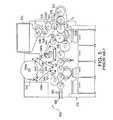
フィルタ作成方法の上記説明は、図4を参照して理解されてもよく、これは球状、カプセル状、円筒形などの物体(すなわちペレット)、またはストリップ、スレッド、またはその他の形状を含むその他の適切な形状の物体を各々が組み込んだ、フィルタロッドまたはフィルタロッド部分が、フィルタロッド作成装置210を用いて製造可能であることを示している。例示的なフィルタロッド作成装置210(たとえば、Hauni−Werke Korber&Co.KGより入手可能なKDF−2ユニット)は、連続長のフィルタ材料40を処理して連続フィルタロッドにするのに適しているロッド成形ユニット212を含んでもよい(図示しないが、当該技術分野において周知であり、たとえばその各々が参照により本明細書に組み込まれる、Sebastianらの米国特許公開第2011/0180084号明細書およびStokesの米国特許第7,972,254号明細書を参照して容易に理解される)。連続長またはウェブのフィルタ材料は、収納用ベール、ボビン、糸巻きなどの源から供給される。一般的に、フィルタ材料40はフィルタ材料処理ユニット218を用いて処理され、フィルタ材料の連続ロッドを形成するためにロッド成形ユニット212を通される。物体挿入ユニット214は、カプセルまたはその他の物体(図示せず)を連続長のフィルタ材料または連続フィルタロッド内に配置/挿入するために、ロッド成形ユニット212に結合されてもよい。連続フィルタロッドはその後、より大きい装飾および処理アセンブリ222内のロッド切断アセンブリを用いて、各々が物体のうちの少なくとも1つを内部に有する複数のロッド部分に再分割されることが可能である。一連のまたは複数のロッド部分はその後、トレイ、回転収集ドラム、搬送システムなどであってもよい収集装置内でのさらなる処理のため、収集されてもよい。望ましければ、ロッド部分は紙巻きタバコ製造機まで直接搬送されることが可能である。このようにして、各々が100mmの長さの、500を超えるロッド部分が、毎分製造されることが可能である。 The above description of the filter creation method may be understood with reference to FIG. 4, which may be spherical, capsule, cylindrical, etc. objects (ie pellets), or other shapes including strips, threads, or other shapes It shows that filter rods or filter rod portions, each incorporating an appropriately shaped object, can be manufactured using the filter
フィルタ材料40は異なってもよく、紙巻きタバコ用のタバコ煙フィルタを提供するために採用されることが可能な、いずれのタイプの材料であってもよい。アセチルセルローストウ、ギャザーアセチルセルロースウェブ、ポリプロピレントウ、ギャザーアセチルセルロースウェブ、ギャザー紙、再構成タバコのストランドなど、伝統的な紙巻きタバコフィルタ材料が使用されてもよい。アセチルセルロース、ポリプロピレンなどのポリオレフィン、などのフィラメント状トウが、いくつかの実施形態において好まれる場合がある。適切なフィルタロッドを提供することができる好適なフィルタ材料の1つは、フィラメント当たり3デニールで合計40,000デニールを有するアセチルセルローストウである。別の例として、フィラメント当たり3デニールで合計35,000デニールを有するアセチルセルローストウが、適切なフィルタロッドを提供することができる。別の例として、フィラメント当たり8デニールで合計40,000デニールを有するアセチルセルローストウが、適切なフィルタロッドを提供することができる。さらなる例としては、Neurathの米国特許第3,424,172号明細書、Cohenらの米国特許第4,811,745号明細書、Hillらの米国特許第4,925,602号明細書、Takegawaらの米国特許第5,225,277号明細書、およびArzonicoらの米国特許第5,271,419号明細書に明記されるタイプのフィルタ材料を参照されたい。 The
アセチルセルロースなどのフィラメント状トウは、ノースカロライナ州ウィンストンセーラムのArjay Equipment Corp.によって供給される購入可能なE−60など、従来のフィルタトウ処理ユニット218を使用して処理されてもよい。当業者にとって周知のような、その他のタイプの購入可能なトウ処理機器も、同様に使用されてよい。通常、トリアセチンなどの可塑剤が、周知の技術を用いて伝統的な量だけフィラメント状トウに適用される。フィルタ要素の構築に適したその他の材料は、紙巻きタバコフィルタ設計および製造の当業者にとって自明であろう。 Filamentous tows such as acetylcellulose are available from Arjay Equipment Corp. of Winston Salem, NC. May be processed using a conventional filter
連続長のフィルタ材料40は、円筒形複合材を形成するために、アセンブリ222のギャザー(装飾)領域内に方向づけられる。円筒形複合材の中に圧縮されたフィルタ材料40は、連続フィルタロッドを形成するためにロッド成形ユニット212内に連続的に受容される。上記で記されたように、連続フィルタロッドの形成と併せて、物体(たとえば流動性材料を収容する易破壊性カプセル)は、このフィルタ材料が連続フィルタロッドとして成形されているときに、および/またはフィルタ材料が連続フィルタロッドとして成形された後に(すなわち、ロッド成形ユニット212に沿った(またはその上流または下流の)いずれかの点で)、フィルタ材料の長さに沿って、およびそのウェブの中に、挿入されてもよい。しかしながら、物体はまた、プロセス中の別の点でフィルタ材料内に導入されてもよく、この例示的な実施形態はその点に関して限定することは意図されない。物体を連続フィルタロッド内に挿入するために、ロッド成形ユニット212は、物体挿入ユニット214の上流に設けられた、要素分割機構(図示せず)を含んでもよい。いくつかの例において、要素分割機構は物体挿入ユニット214(またはそのいずれかの部分)そのものに含まれてもよい。 The continuous length of
円筒形複合材は、包装、処理、および切断アセンブリ222内に供給されるが、これはエンドレス装飾コンベヤベルト、またはその他の装飾機構を含んでもよい。装飾コンベヤベルトは、アセンブリを通じてフィルタ材料40の円筒形複合材を搬送する。アセンブリ222の包装機構部分は、連続包装フィルタロッドを製造するために、円筒形複合材の外表面に処理済みプラグラップ材料45のストリップを提供する。 Cylindrical composites are fed into the packaging, processing, and cutting
一般的に、プラグラップ45のストリップまたはウェブは、回転ボビン242から供給される。プラグラップは、ボビン(またはバックアップボビン242a)から引き出され、一連の案内ローラ上に向けられ、ボビンとそのバックアップとの間の供給の途切れない継続を維持するシームレス供給アセンブリ230を通過する。シームレス供給アセンブリ230または装置210の上または中のその他の場所には、プラグラップ45の供給速度を機械的におよび/または電子的に検出する、回転エンコーダ237またはその他の装置が備えられてもよい。回転エンコーダ237は模式的に示されているが、しかし当業者は、その機能性を提供する装置が装置210の中および/または上の何カ所にでも位置してよいことを、理解するだろう。本装置210において、装置237は、プラグラップが移動する速度をプラグラップが測定するためにプラグラップまたは供給機構要素と連絡しており、ホットメルトが所望の量およびパターンで適用されるようにホットメルトの量がアプリケータによってプラグラップが通過する早さと相関するように、アプリケータ290と連絡(たとえば、電子的および/または機械的連絡)していることが、非常に好ましい。 Generally, the strip or web of
プラグラップ45はホットメルト接着剤アプリケータ290を通り過ぎて方向づけられるが、これはホットメルト接着剤のアプリケータユニット292および供給容器294を含む。アプリケータ290(たとえば、Baumer hhs Xmelt装置として実現されてもよい)は、ホットメルト接着剤の精密に制御された分散/塗布を、少なくとも1つのノズルを通じて(組み立て済みフィルタプラグ内のフィルタ材料に対向する表面を含む)プラグラップ45の面上に提供する。アプリケータ290は好ましくは、プラグラップが所望のパターンおよび密度で一定の被膜を受けるように、プラグラップが供給される速度と適用されるホットメルト接着剤の量が相関されるように、回転エンコーダまたはその他の装置237と連絡している。好適なパターンの1つは帯であり、これは下層のカプセルに揃えて位置決めされてもよく、および/またはプラグラップ表面のほぼ全部を被覆してもよい;前記帯またはその他のパターンは、単一のノズルによって提供されてもよい。言い換えると、塗布される第一所定量のホットメルト接着剤は、放出されたホットメルト接着剤の量を、プラグラップ材料45が少なくとも1つのアプリケータノズルを通り過ぎて方向づけられる速度と(アプリケータ290を用いて)相関させる、エンコーダまたはその他の装置237によって動的に決定されてもよく、ここでエンコーダは、プラグラップ材料がホットメルトアプリケータを通り過ぎて方向づけられる速度を監視するようにプラグラップ材料と連絡し、ホットメルト接着剤アプリケータ290とも連絡している。最も好ましくは、ホットメルト接着剤は、(たとえば液体、ゲル、またはその他の流体/流動性材料を保持する1つ以上の易破壊性カプセルを包含するフィルタ内の)フィルタ材料からプラグラップまでおよび/またはこれを通る流体の通過に対する有効な障壁を形成する(塗布時および/またはフィルタ材料に対して押圧され/組み付けられたときのいずれかに全面を覆うような)パターンおよび量で塗布される。その後、処理済みプラグラップ45は、接着剤を冷却するために冷却棒297の上に方向づけられ、その後アセンブリ222に方向づけられ、そこで、当該技術分野において一般的に使用されるのと類似または同一の方式で完了してもよい、装飾およびその他の処理/組み立てステップの間に、フィルタ材料の周りに適用される。
包装材料の重複する周縁部によって形成される継目は、包装材料がフィルタ材料用の管状容器を形成できるように、アプリケータ領域244に塗布される接着剤(たとえば、グルー、ホットメルト接着剤)を含んでもよい。あるいは、ホットメルト接着剤は場合により、包装機構234またはブロック230の装飾内への包装材料の進入のすぐ上流に塗布されてもよい。接着剤は、接着剤の迅速な硬化を生じるために、冷却棒246を使用して冷却されることが可能である。連続包装ロッドの提供において、様々なその他の封止機構およびその他のタイプの接着剤が採用され得ることは、理解される。 The seam formed by the overlapping peripheral edges of the wrapping material provides an adhesive (eg, glue, hot melt adhesive) applied to the applicator region 244 so that the wrapping material can form a tubular container for the filter material. May be included. Alternatively, the hot melt adhesive may optionally be applied immediately upstream of the packaging material entry into the decoration of the packaging mechanism 234 or block 230. The adhesive can be cooled using cooling rods 246 to cause rapid curing of the adhesive. It will be appreciated that various other sealing mechanisms and other types of adhesives may be employed in providing a continuous wrap rod.
一態様において、第一所定量のホットメルト接着剤は、プラグラップフィルタ対向表面上の少なくとも1つの所定箇所に、少なくとも1つのノズルを介して塗布されてもよく、ここで第一所定量のホットメルトは、プラグラップ材料45をフィルタ材料40に接着させるのに十分である。第二所定量のホットメルトまたはその他の接着剤は、少なくとも1つのノズルを介して第二の少なくとも1つの所定箇所に塗布されてもよい。所定箇所は、継目線またはプラグラップ表面上のその他の領域またはパターンを含んでもよい。紙巻きタバコ/フィルタアセンブリの方法の別の実施形態において、接着剤は、少なくとも1つのノズルを介してフィルタ材料40の表面に塗布されてもよい。 In one aspect, the first predetermined amount of hot melt adhesive may be applied to at least one predetermined location on the plug wrap filter facing surface via at least one nozzle, wherein the first predetermined amount of hot melt adhesive is The melt is sufficient to adhere the
特定の実施形態において、接着剤配置の第一および/または第二所定量および所定箇所は、プラグラップ材料45とフィルタ40との間に障壁を形成するように構成されてもよい。流動性材料を放出するように構成された易破壊性カプセルまたはその他の物体を含むフィルタの実施形態において、形成された障壁は、流動性材料がフラグラップまでおよび/またはこれを通じて浸出、逃げ、流出、または別途移動するのを防止するように、構成されてもよい。所定箇所は、プラグラップの全表面積の全てまたはそれよりも少ない面積を覆うパターンで構成されてもよい。たとえば、パターンは易破壊性カプセルの周りに向けられたプラグラップの表面積上にわたって設けられてもよく、プラグラップを通る流動性材料の通過を防止するように構成されてもよい。 In certain embodiments, the first and / or second predetermined amount and predetermined location of the adhesive arrangement may be configured to form a barrier between the
連続包装ロッドは封止機構から通過して、アセンブリ222の切断部分を用いて所望の所定長で一定間隔に再分割(たとえば切断)されるが、これは回転カッターとして、よく研がれたナイフ、またはその他の適切なロッド切断または再分割機構を含む。切断アセンブリはロッドの断面形状を平坦化させたり別途悪影響を及ぼしたりしないことが、特に望ましい。切断アセンブリが所望の点で連続ロッドを切断する速度は、可調整機械歯車列(図示せず)またはその他の適切な機構を通じて制御されてもよい。第一および第二物体がフィルタ材料/連続フィルタロッドの連続ウェブ内に挿入される速度は、ロッド製造機の動作速度と直接的な関係にある。 The continuous wrapping rod passes from the sealing mechanism and is subdivided (eg, cut) into the desired predetermined length and at regular intervals using the cut portion of the
物体挿入ユニット214は、ロッド作成装置の駆動アセンブリと直接駆動関係になるように噛み合うことができる。あるいは、物体挿入ユニット214は、ロッド成形ユニットの駆動アセンブリと同期して、物体挿入箇所がずれた場合に挿入ユニット駆動アセンブリを調整するための物体検査機構と結合することによってフィードバック制御される、直接駆動モータを有することができる。物体挿入の速度とロッド製造機との関係性を鑑みて、本発明の実施形態はまた、フィルタ材料内への物体配置に悪影響を及ぼさずにロッド製造機の製造速度を増加させることも、対象とする。 The
たとえば紙巻きタバコなどの喫煙品の組み立て中に接着剤がチッピング材料をプラグラップ45および/またはフィルタ材料40に取り付けるための所定の量および箇所を適用するために、同じかまたは異なる装置および方法が使用されてもよい。 The same or different equipment and methods are used to apply a predetermined amount and location for attaching the tipping material to the
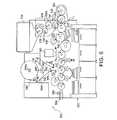
図5は、従来技術によるフィルタチッピング機500を示している。この機械は、紙巻きタバコ製造機と直接的に結合されてもよい。上記で参照されたものに加えて、参照により本明細書に組み込まれる、Hancockらの米国特許第7,117,871号明細書を参照して、フィルタ紙巻きタバコを製造する方法および装置も理解されるだろう。当該技術分野において周知の方法および構成要素は、本開示の範囲内で、当業者によって本明細書に記載される方法と一体化するように容易に組み込まれることは、理解されるだろう。先に記載されたフィルタ製造プロセス、および以下に記載されるチッピングプロセスの間、「ツーアップ」構成が一般的に使用される。つまり、2倍長のフィルタプラグが形成され、次に巻きタバコロッドが各末端に取り付けられ、その後こうして形成された「ツーアップ」紙巻きタバコは2本の紙巻きタバコを形成するためにその長さの中間で切断される。「ツーアップ」の介在およびこの製造方法は当該技術分野において理解され、たとえば参照により本明細書に組み込まれるRead,Jr.らの米国特許第7,296,578号明細書を参照して理解される。 FIG. 5 shows a
図5に示されるように、タバコロッド作成機のドラム型列形成コンベヤ523は、フィルタチッピング機500のフレーム530内に実装されており、紙巻きタバコロッドを2つの個別の回転ドラム型アセンブリコンベヤ532まで送達する。コンベヤ532はタバコロッドを、回転ドラム型アセンブリコンベヤ533の連続長手溝内に送達する。コンベヤ532とコンベヤ533との間の転送ステーションが、T1に示されている。コンベヤ532は、転送ステーションT1に到達するアセンブリコンベヤ533の各長手溝が2つのタバコロッド(1つは第一アセンブリコンベヤ532から、もう1つは第二アセンブリコンベヤ533から)を受容するように、異なる速度で駆動され、および/または異なる距離を通じてタバコロッドのそれぞれの列を転送してもよい。「ツーアップ」構成を用いる製造実施形態において、コンベヤ523の長手溝内の2列のタバコロッドの間の軸方向距離は好ましくは、アセンブリコンベヤ533の長手溝内のタバコロッドペアが、少なくとも2倍の単位長さのフィルタプラグの長さに等しい幅(図5の平面に対して直角と見なされる)を有する間隙によって、互いに分離されるようになっている。 As shown in FIG. 5, the drum
フレーム530は、フィルタロッドセクション(たとえば、図4を参照して記載されたフィルタロッド作成機またはその他のフィルタロッド作成機によって提供される)の供給のためのマガジン534をさらに支持する。セクションは、その軸が図5の平面に対して直角となるように、マガジン534内に積み重ねられる。マガジン534は、マガジン534からフィルタロッドセクションを引き出して、一連の別のローラ部品を介してこれらを回転ドラム型加速コンベヤ541に転送する周辺長手溝を有する、回転ドラム型切断コンベヤ536の一部を受容する出口を有し、これは連続フィルタプラグをアセンブリコンベヤ533の連続長手溝内に挿入する。このような挿入が行われる転送ステーションは、T2で示されている。各フィルタプラグは、同軸方向に隣接するタバコロッドの間の間隙内に配置されるように、挿入される。
アセンブリコンベヤ533は、それぞれのフィルタプラグの隣り合う末端と実際に接触するようにタバコロッドを軸方向に移動させる、2つの固定凝縮カム533Aの間でそれぞれ3つの同軸ロッド状製品のグループを前進させる(このようなグループの各々は、単位長さの2つの巻きタバコロッド、およびタバコロッドの間の2倍単位長さのフィルタプラグを含む)。こうして凝縮されたグループは、回転ドラム型転送コンベヤ542の連続長手溝内に送達される。 The
フレーム530は、チッピング材料のリール544、544a用の2つのスピンドル544’、544a’を、さらに支持する。リール544は、使用中または終わりかけのリールである;そこに保管されたウェブ543は2つの前進ロール546によって引き出され、その連続的な増分は巻き付け具547の上に通されてもよい。リール44a上に保管されている新しいウェブ543’’の先端は、接合ステーションSPLに位置しており、好ましくは終わりかけのリール544の直径が所定値まで減少したときに使用中のウェブ543の隣接部分に自動的に取り付けられる。新しいウェブの先端を使用中のウェブに取り付けるために接合ステーションSPLで使用されることが可能な装置は、当該技術分野において周知であり、一般的に使用されている。
使用中のウェブ543の先端は、ここでは転送コンベヤ542に隣接するサクションドラム549として示されている、回転コンベヤの小孔周囲表面に接着する。前進ロール546のニップからサクションホイール549の周囲表面への移動の間、チッピング材料ウェブ543の連続的増分は、チッピング材料ウェブ543の片側を適切な接着剤で被覆するためにローラ548aを使用するペースタユニット548に沿って前進する。ウェブ543はその後一定間隔に切断され、好ましくはチッピング材料543の接着剤被覆側が対応するフィルタプラグおよび単位長さタバコロッドの隣接する末端部に接着するような方式で、転送コンベヤ542上の同軸ロッド状製品の連続グループに取り付けられる。その後、組み立てられた喫煙品は、ローラコンベヤユニット63、66まで搬送されて、機械500から出ることができる。 The tip of the
図5に示される従来技術によるシステム500は、30年以上の(そしてまだ続いている)その継続的な使用によって証明されるように、おおむね効率的かつ有効である。しかしながら、本発明者らは、著しい利点を提供し、長年にわたるがまだ達成されない必要性を解決する改良を、開発した。従来技術によるシステム500では、チッピング材料543に接着剤を塗布するために使用されるローラ548aは、しばしば製造環境中に存在する様々な粒子および物質を捕集する。これらの粒子および物質の存在は、いくつかの方法で動作の効率に影響を及ぼす可能性がある。チッピング紙543は、ローラに接着するようになり、および/または接着剤被覆ローラの粒子および物質との接触によって別途損傷を受ける可能性がある。接着剤はチッピング材料543に均一かつ効果的に塗布されない可能性があり、その結果、組み立てられた喫煙品が不良となるかも知れない(チッピング材料は、巻きタバコロッドおよび/または巻きフィルタプラグに適切に固定されないため)。これらまたはその他の結果を回避するため、システム500はローラ548aが洗浄および/または交換され得るように、定期的に停止されなければならない。これは製造ライン全体の製造を事実上停止し、停止時間は生産量の減少および(関連する人員および機械類の)生産性の低下に対してかなりコストがかかる可能性がある。 The
この需要を解決するために、ペースタアセンブリ548と交換するためにコールドグルーアプリケータが使用されてもよい。グルーアプリケータ銃648はペースタアセンブリ548と置き換えて図6に示されており、チッピング紙適用システム500のその他全ての構成要素は、図5を参照して上述されたのと同じままである。当然ながら、システム500に関連付けられたその他の構成要素および方法ステップは、ここに開示されている実施形態の範囲から逸脱することなく変更されてもよいことは、理解されるべきである。 To solve this demand, a cold glue applicator may be used to replace the
グルーアプリケータ648は、たとえばDF−500−5−SP(Baumer hhsより入手可能)として実現されてもよい。グルーアプリケータ648は、チッピング紙43’’の表面にグルーを塗布するために実装されてもよい。アプリケータ648は少なくとも1つの精密に制御されたノズル649を含み、これはチッピング材料43’’に接着剤を提供することになる。ノズル649を通る接着剤の流れは、最も好ましくは精密に制御されて、チッピング材料がノズルを通り過ぎて方向づけられる速度と相関させられる。当業者が本開示を参照して理解するように、これはたとえば回転エンコーダまたはその他の装置を用いて、電子的および/または機械的に達成される。このようにして、上述のホットメルト法と同様に、接着剤の流量は、チッピング材料が少なくとも1つのノズルを高速で通過するときに増加し、実質的に均一かつ効果的な量の接着剤がチッピング材料表面上に提供されることを確実にするためにより低速で移動するときに、減少することが可能である。ノズルは全体的に固定されていても移動可能であってもよい(これはまた上述のホットメルトアプリケータにも該当する)。接着剤は、均一または不均一なパターンで塗布されてもよく、最も好ましくは、チッピング材料を一端でフィルタプラグにそして他端で巻きタバコロッドに接着するのに効果的な量および箇所で表面に分注され、喫煙品を形成するためにこれらを効果的に接続する。好適な一実施形態は、単一のノズルによって塗布される接着剤の帯を含む。
これを実現するために、コールドグルー接着剤は、約0.7mg/cm2から約0.8mg/cm2の平均表面密度で塗布されてもよく、いくつかの実施形態では約0.72mg/cm2から約0.81mg/cm2の範囲であり、一実施形態では約0.75mg/cm2の平均表面密度を含む。言い換えると、接着剤は、チッピング紙材料1リニアメータ当たり約7から約8mgの密度で塗布されてもよく、一実施形態はチッピング紙材料1リニアメータ当たり約7.5mgの密度を含む。To accomplish this, the cold glue adhesive may be applied at an average surface density of about 0.7 mg / cm2 to about 0.8 mg / cm2 , and in some embodiments about 0.72 mg / cm2. It ranges from cm2 to about 0.81 mg / cm2, in one embodiment comprises an average surface density of about 0.75 mg / cm2. In other words, the adhesive may be applied at a density of about 7 to about 8 mg per linear meter of chipping paper material, and one embodiment includes a density of about 7.5 mg per linear meter of chipping paper material.
この実施形態を使用するチッピング方法は、少なくとも1つのフィルタプラグおよび少なくとも1つの巻きタバコロッドを提供するステップと、取付表面を含むチッピング材料のリボンを提供するステップと、それを通じて接着剤が分注される(たとえばドット、直線、らせん、および/またはその他の規則的または不規則パターンの塗布/分注として)少なくとも1つの精密に制御されたノズルを含む接着剤アプリケータを通り過ぎてチッピング材料を方向づけるステップと、少なくとも1つのノズルを介して第一所定処理量の接着剤(たとえば、コールドグルー)をチッピング材料の取付表面に塗布するステップと、チッピング材料の取付表面がプラグおよびロッドを接触および接続させるように、フィルタプラグおよび少なくとも1つのタバコロッドの周りにチッピング材料を組み立てるステップと、を含み、塗布される第一所定量の接着剤は、放出された接着剤の量を、チッピング材料が少なくとも1つのノズルを通り過ぎて方向づけられる速度と相関させるエンコーダデバイスによって動的に決定されてもよく、ここでエンコーダは、チッピング材料が接着剤アプリケータを通り過ぎて方向づけられる速度を監視するようにチッピング材料と連絡し、接着剤アプリケータとも連絡している。この連絡は、電子的にまたは機械的に実現されてもよい(たとえば、その運動が材料の通過に関係している1つ以上のスピンドルとのリンク機構またはセンサを用いて、光学センサを用いて)。 A chipping method using this embodiment includes providing at least one filter plug and at least one cigarette rod, providing a ribbon of chipping material including a mounting surface, through which an adhesive is dispensed. Directing the chipping material past an adhesive applicator including at least one precisely controlled nozzle (eg, as application / dispensing of dots, straight lines, spirals, and / or other regular or irregular patterns) Applying a first predetermined throughput of adhesive (eg, cold glue) to the mounting surface of the chipping material via at least one nozzle, such that the mounting surface of the chipping material contacts and connects the plug and rod. A filter plug and at least one Assembling a tipping material around the tobacco rod, wherein the first predetermined amount of adhesive applied is a rate at which the tipping material is directed past the at least one nozzle; It may be determined dynamically by the correlating encoder device, where the encoder communicates with the chipping material to monitor the rate at which the chipping material is directed past the adhesive applicator and also communicates with the adhesive applicator. ing. This communication may be accomplished electronically or mechanically (eg, using an optical sensor, using a linkage or sensor with one or more spindles whose movement is related to the passage of material). ).
適切なコールドグルー接着剤は、たとえば、ナショナルスターチコード20001812番の材料を含んでもよい。 A suitable cold glue adhesive may include, for example, National Starch Code No. 20001812 material.
グルーアプリケータ648は、粒子またはその他の物質がチッピング紙材料に塗布されるグルーを汚染するのを防止する、全体的に閉鎖された環境で提供されてもよい。これはまた、接着剤の有効性を最大化するためにグルーの温度および粘度を所望の範囲内に維持するための温度制御も含んでよい。当業者は、これを実現するために、本開示を参照して、様々な構造および機構を容易に理解するだろう。彼らはまた、この方法が、製造効率を改善するために、長年にわたるがまだ達成されない当該技術分野における必要性を解決することも、理解するだろう。具体的には、ノズル塗布コールドグルー接着剤は、(数十年にわたって使用されている方法であった)ローラ塗布接着剤よりも、塗布の量および箇所について注意深い制御されることが可能である。これは、コスト削減および材料保存効率につながるかも知れない。加えて、ここに開示されている方法およびシステムは、粒子で汚染された接着剤ローラを洗浄するための定期的な製造の停止の必要性を排除するだろう(この粒子は、有効な接着剤の塗布を低減したり、チッピング紙を損傷したりする可能性がある)。 The
本開示(組み込まれた技術を含む)を参照して容易に理解されるであろう一態様において、少なくとも1つのフィルタプラグを含むアセンブリ方法は「ツーアップ」フィルタプラグを含んでもよく、ここで少なくとも1つの巻きタバコロッドは2つのタバコロッドを含み、2つのタバコロッドの各々は少なくとも1つのフィルタプラグの反対端に取り付けられる。このような方法において、チッピング紙材料は、フィルタプラグの全長を包絡的に取り囲んでもよく、フィルタプラグとの各々の取付を形成するのに十分な2つのタバコロッドの各々の部分を被覆する。このような方法は一般的に、2つの喫煙品を形成するために少なくとも1つのフィルタプラグの中央部を切断するステップを、さらに含んでもよい。 In one aspect that will be readily understood with reference to the present disclosure (including incorporated techniques), an assembly method that includes at least one filter plug may include a “two-up” filter plug, where at least One cigarette rod includes two tobacco rods, each of which is attached to the opposite end of at least one filter plug. In such a method, the tipping paper material may envelop the entire length of the filter plug, covering each portion of the two tobacco rods sufficient to form each attachment with the filter plug. Such a method may generally further comprise cutting the central portion of at least one filter plug to form two smoking articles.
当業者は、異なる実施形態について本明細書に記載される特徴が、本明細書に提示される請求項の範囲内に含まれるままで、互いにおよび/または周知のまたはさらに開発される技術と組み合わせられてもよいことを含む、本明細書に明確に記載されない実施形態が本開示および請求項の範囲内で実践されてもよいことを、理解するだろう。本開示および請求項は、喫煙品構成部品を作成するための方法および機械類、ならびに方法および/または機械を使用して作られる喫煙品を含むように、意図される。本明細書において特異的な用語が採用されるが、これらは一般的かつ説明的な意味においてのみ使用されており、限定目的のためではない。したがって、上記の詳細な説明は、限定的ではなく説明的であると見なされるように意図される。そして、全ての同等物を含む以下の請求項は、本発明の精神および範囲を定義するように意図されることが、理解されるべきである。さらに、先に記載された利点は、必ずしも記載された実施形態の利点の全てではなく、必ずしも記載された利点の全てが本発明のいずれの実施形態を用いても達成されると期待されるものでもない。 Those skilled in the art will recognize that the features described herein for different embodiments remain within the scope of the claims presented herein, in combination with each other and / or with known or further developed techniques. It will be understood that embodiments not specifically described herein may be practiced within the scope of the disclosure and claims, including what may be done. The present disclosure and claims are intended to include methods and machinery for making smoking article components, and smoking articles made using the method and / or machine. Although specific terms are employed herein, they are used in a general and descriptive sense only and not for purposes of limitation. Accordingly, the above detailed description is intended to be considered illustrative rather than limiting. It is to be understood that the following claims, including all equivalents, are intended to define the spirit and scope of the present invention. Moreover, the advantages described above are not necessarily all of the advantages of the described embodiments, and all of the described advantages are expected to be achieved using any embodiment of the present invention. not.
Claims (15)
Translated fromJapanese略円筒形本体の中に紙巻きタバコフィルタ材料を組み込むステップと、
フィルタ対向表面を含むプラグラップ材料のリボンを提供するステップと、
それを通じてホットメルト接着剤が分注される少なくとも1つのノズルを含むホットメルト接着剤アプリケータを通り過ぎてプラグラップ材料を方向づけるステップと、
少なくとも1つのノズルを介して第一所定量のホットメルト接着剤をプラグラップ材料のフィルタ対向表面に塗布するステップと、
ホットメルト接着剤で処理されたプラグラップ材料のフィルタ対向表面がフィルタ材料に向けられるように、フィルタ材料の周りにプラグラップ材料を組み立てるステップと、を含み、
組み立てられたプラグラップとフィルタ材料との間のホットメルト接着剤は、フィルタ材料からプラグラップまでの流体の通過に対する有効な障壁を形成する、方法。A method of cigarette filter assembly comprising:
Incorporating a cigarette filter material into the generally cylindrical body;
Providing a ribbon of plug wrap material including a filter facing surface;
Directing the plug wrap material past a hot melt adhesive applicator including at least one nozzle through which the hot melt adhesive is dispensed;
Applying a first predetermined amount of hot melt adhesive to the filter facing surface of the plug wrap material via at least one nozzle;
Assembling the plug wrap material around the filter material such that the filter facing surface of the hot wrap adhesive treated plug wrap material is directed to the filter material;
The method wherein the hot melt adhesive between the assembled plug wrap and the filter material forms an effective barrier to the passage of fluid from the filter material to the plug wrap.
流動性材料を放出するように構成された筒型本体内に少なくとも1つの易破壊性カプセルを含み、前記カプセルはフィルタ材料の繊維の間に配置されている、略円筒形本体の中に紙巻きタバコフィルタ材料を組み込むステップと、
プラグラップのフィルタ対向表面がフィルタ材料と接触しているところで、フィルタ材料の周りにプラグラップ材料を組み立てるステップと、
プラグラップフィルタ対向表面上で流動性材料に対する流体耐性障壁を形成するのに効果的なパターンで、少なくとも1つのノズルを介して第一所定量のホットメルト接着剤材料を塗布するステップと、を含む方法。A method of a cigarette assembly for a capsule-mounted cigarette, comprising:
A cigarette in a generally cylindrical body comprising at least one frangible capsule in a cylindrical body configured to release flowable material, the capsule being disposed between fibers of the filter material Incorporating the filter material;
Assembling the plug wrap material around the filter material where the filter facing surface of the plug wrap is in contact with the filter material;
Applying a first predetermined amount of hot melt adhesive material through at least one nozzle in a pattern effective to form a fluid resistant barrier to the flowable material on the plug wrap filter facing surface. Method.
Applications Claiming Priority (3)
| Application Number | Priority Date | Filing Date | Title |
|---|---|---|---|
| US13/338,647US20130167851A1 (en) | 2011-12-28 | 2011-12-28 | Method of filter assembly for smoking article |
| US13/338,647 | 2011-12-28 | ||
| PCT/US2012/069083WO2013101457A1 (en) | 2011-12-28 | 2012-12-12 | Method of filter assembly for smoking article |
Publications (1)
| Publication Number | Publication Date |
|---|---|
| JP2015503344Atrue JP2015503344A (en) | 2015-02-02 |
Family
ID=47430132
Family Applications (1)
| Application Number | Title | Priority Date | Filing Date |
|---|---|---|---|
| JP2014550318APendingJP2015503344A (en) | 2011-12-28 | 2012-12-12 | Method of filter assembly for smoking articles |
Country Status (5)
| Country | Link |
|---|---|
| US (1) | US20130167851A1 (en) |
| EP (1) | EP2797441A1 (en) |
| JP (1) | JP2015503344A (en) |
| CN (1) | CN104066344A (en) |
| WO (1) | WO2013101457A1 (en) |
Cited By (1)
| Publication number | Priority date | Publication date | Assignee | Title |
|---|---|---|---|---|
| RU2730574C1 (en)* | 2019-11-13 | 2020-08-24 | Игорь Анатольевич Зыков | Therapeutic cigarette and method for simulating tobacco smoking |
Families Citing this family (16)
| Publication number | Priority date | Publication date | Assignee | Title |
|---|---|---|---|---|
| US8262550B2 (en)* | 2009-03-19 | 2012-09-11 | R. J. Reynolds Tobacco Company | Apparatus for inserting objects into a filter component of a smoking article |
| UA116449C2 (en) | 2012-08-06 | 2018-03-26 | Філіп Морріс Продактс С.А. | Method of forming smoking articles with mouth end cavities |
| AT513412B1 (en) | 2012-09-17 | 2014-07-15 | Tannpapier Gmbh | Tipping paper |
| CN103919278A (en)* | 2014-03-11 | 2014-07-16 | 河南中烟工业有限责任公司 | Processing method for regulating flavor of filter-tip cigarettes |
| WO2015140769A1 (en)* | 2014-03-21 | 2015-09-24 | G.D Societa' Per Azioni | Machine and method for producing substantially cylindrical articles of the tobacco processing industry |
| DE102014116742B3 (en)* | 2014-09-08 | 2015-07-16 | Smc System Management Consulting Gmbh | Method and device for producing an inhaler and inhaler |
| KR102523284B1 (en)* | 2014-10-20 | 2023-04-20 | 필립모리스 프로덕츠 에스.에이. | Hydrophobic plug wrap |
| AR108880A1 (en) | 2016-06-27 | 2018-10-03 | Philip Morris Products Sa | ARTICLE TO SMOKE WITH ADJUSTMENT OF COMBINED VENTILATION AND FILTRATION EFFICIENCY |
| US20180271144A1 (en)* | 2017-03-23 | 2018-09-27 | Shrujal Patel | Smoking wrapper/filter combination |
| US10492522B2 (en) | 2017-05-03 | 2019-12-03 | R.J. Reynolds Tobacco Company | Flavored menthol-containing objects for application to smoking article components |
| CN107259639B (en)* | 2017-07-28 | 2019-10-01 | 四川三联新材料有限公司 | A smoking product and its manufacturing method |
| US11248898B2 (en) | 2019-08-23 | 2022-02-15 | Rj Reynolds Tobacco Company | Roll fed material measurement device |
| US11369136B2 (en) | 2020-02-04 | 2022-06-28 | R.J. Reynolds Tobacco Company | Apparatus and method for filling rods with beaded substrate |
| US20210259301A1 (en) | 2020-02-21 | 2021-08-26 | Santa Fe Natural Tobacco Company, Inc. | Heated seam pump |
| IT202100007067A1 (en)* | 2021-03-24 | 2022-09-24 | Gd Spa | METHOD FOR THE CREATION OF A PRODUCT OF THE TOBACCO INDUSTRY AND RELATED MACHINE |
| GB202119094D0 (en)* | 2021-12-29 | 2022-02-09 | Nicoventures Trading Ltd | A component for a delivery system and a method and apparatus for manufacturing a component for a delivery system |
Family Cites Families (84)
| Publication number | Priority date | Publication date | Assignee | Title |
|---|---|---|---|---|
| NL252242A (en) | 1959-06-03 | |||
| GB1042141A (en) | 1961-08-18 | 1966-09-14 | Korber Kurt | Apparatus for automatically delivering cigaretes or other rod-like articles into containers |
| DE1300854B (en) | 1965-05-14 | 1969-08-07 | Reemtsma H F & Ph | Filters for cigarettes |
| DE2232892A1 (en) | 1972-07-05 | 1974-01-24 | Hauni Werke Koerber & Co Kg | DEVICE FOR ENCLOSING AN ENDLESS RAND OF TOBACCO |
| US3972335A (en) | 1972-09-20 | 1976-08-03 | Calgon Corporation | Mentholated cigarette filter |
| US4082098A (en) | 1976-10-28 | 1978-04-04 | Olin Corporation | Flavored cigarette |
| DE2703288A1 (en) | 1977-01-27 | 1978-08-03 | Hauni Werke Koerber & Co Kg | METHOD AND DEVICE FOR SEALING A SEAM IN A STRANDED PRODUCT OF THE TOBACCO-PROCESSING INDUSTRY |
| US4281670A (en) | 1977-06-13 | 1981-08-04 | Hauni-Werke Korber & Co. Kg | Apparatus for increasing the permeability of wrapping material for rod-shaped smokers products |
| GB2020158B (en) | 1978-04-21 | 1982-11-24 | Cigarette Components Ltd | Production of tobacco smoke filters |
| DE2842461A1 (en) | 1978-09-29 | 1980-04-10 | Hauni Werke Koerber & Co Kg | METHOD AND ARRANGEMENT FOR DETECTING AND LOCALIZING MALFUNCTIONS ON MACHINE PRODUCING ROD-SHAPED SMOKE ARTICLES |
| US4474190A (en) | 1981-03-21 | 1984-10-02 | Hauni-Werke Korber & Co. Kg | Method and apparatus for regulating the operation of machines for the production of cigarettes or the like |
| DE3345608A1 (en) | 1983-02-04 | 1984-08-09 | Hauni-Werke Körber & Co KG, 2050 Hamburg | METHOD AND DEVICE FOR MAKING ROD-SHAPED ITEMS OF THE TOBACCO-PROCESSING INDUSTRY |
| US4768526A (en) | 1983-06-02 | 1988-09-06 | R. J. Reynolds Tobacco Company | Tobacco smoke filters |
| IT1178561B (en) | 1983-10-12 | 1987-09-09 | Hauni Werke Koerber & Co Kg | PROCEDURE AND DEVICE FOR FORMING A LIST OF TOBACCO, AND CIGARETTES PRODUCED THROUGH A LODGING OF SUCH A TYPE |
| US5012823A (en) | 1984-08-03 | 1991-05-07 | Philip Morris Incorporated | Tobacco processing |
| US4781203A (en) | 1985-05-15 | 1988-11-01 | Hue Paul D | Method and apparatus for making self-extinguishing cigarette |
| US4729391A (en) | 1985-11-14 | 1988-03-08 | R. J. Reynolds Tobacco Company | Microporous materials in cigarette filter construction |
| US4715390A (en) | 1985-11-19 | 1987-12-29 | Philip Morris Incorporated | Matrix entrapment of flavorings for smoking articles |
| US4941486A (en) | 1986-02-10 | 1990-07-17 | Dube Michael F | Cigarette having sidestream aroma |
| DE3631227C2 (en) | 1986-09-13 | 1994-09-01 | Hauni Werke Koerber & Co Kg | Method and device for making cigarettes |
| IT1235463B (en) | 1986-11-28 | 1992-07-30 | Hauni Werke Koerber & Co Kg | PROCEDURE AND DEVICE TO PRODUCE A LODGING OF FIBERS FROM THE TOBACCO PROCESSING INDUSTRY |
| US5025814A (en) | 1987-05-12 | 1991-06-25 | R. J. Reynolds Tobacco Company | Cigarette filters containing strands of tobacco-containing materials |
| US4862905A (en) | 1987-06-15 | 1989-09-05 | R. J. Reynolds Tobacco Company | Rods containing pelletized material |
| DE3725364A1 (en) | 1987-07-31 | 1989-02-09 | Hauni Werke Koerber & Co Kg | METHOD AND ARRANGEMENT FOR MAKING A STRAND OF FIBERS OF TOBACCO OR ANOTHER SMOKEABLE MATERIAL |
| US4811745A (en) | 1988-02-04 | 1989-03-14 | Hercules Incorporated | Method and device for control of by-products from cigarette smoke |
| US4807809A (en) | 1988-02-12 | 1989-02-28 | R. J. Reynolds Tobacco Company | Rod making apparatus for smoking article manufacture |
| US4850301A (en) | 1988-04-04 | 1989-07-25 | R. J. Reynolds Tobacco Company | Apparatus for applying liquid additives to a continuous, multifilament tow |
| US5271419A (en) | 1989-09-29 | 1993-12-21 | R. J. Reynolds Tobacco Company | Cigarette |
| US4925602A (en) | 1988-08-10 | 1990-05-15 | Filter Materials Limited | Method for improving the crimping of polyolefin filter tow |
| JP2947574B2 (en) | 1989-11-17 | 1999-09-13 | ダイセル化学工業株式会社 | High crimp elasticity acetate tow and method for producing the same |
| DE4006843C2 (en) | 1990-03-05 | 2001-10-18 | Hauni Werke Koerber & Co Kg | Format for a strand machine for the manufacture of smoking articles or filter rods |
| US5191906A (en) | 1990-10-30 | 1993-03-09 | Philip Morris Incorporated | Process for making wrappers for smoking articles which modify the burn rate of the smoking article |
| US5156169A (en) | 1990-11-06 | 1992-10-20 | R. J. Reynolds Tobacco Company | Apparatus for making cigarettes |
| US5220930A (en) | 1992-02-26 | 1993-06-22 | R. J. Reynolds Tobacco Company | Cigarette with wrapper having additive package |
| US5387285A (en) | 1992-06-02 | 1995-02-07 | R. J. Reynolds Tobacco Company | Apparatus for injecting a fluid into filter tow |
| AU6974794A (en)* | 1994-06-17 | 1996-01-15 | Rothmans International Services Limited | Cigarette filter rod elements and cigarettes incorporating such filter rod elements |
| DE19722799A1 (en) | 1997-05-30 | 1998-12-03 | Hauni Maschinenbau Ag | Method for processing a strip and arrangement in a filter attachment machine |
| US6360751B1 (en) | 1999-12-01 | 2002-03-26 | R. J. Reynolds Tobacco Company | Asymmetrical trimmer disk apparatus |
| US7435585B2 (en) | 2000-01-03 | 2008-10-14 | University Of Pennsylvania | Auto-stimulating cells and methods for making and using the same |
| MY128157A (en) | 2000-04-20 | 2007-01-31 | Philip Morris Prod | High efficiency cigarette filters having shaped micro cavity fibers impregnated with adsorbent or absorbent materials |
| EP1147716B1 (en)* | 2000-04-20 | 2006-11-15 | Hauni Maschinenbau AG | Device for gluing a wrapping material on a rod-shaped article in the tobacco industry |
| US6537186B1 (en) | 2000-07-05 | 2003-03-25 | Baumgartner Papiers S.A. | Process and apparatus for high-speed filling of composite cigarette filters |
| EP1321048B1 (en) | 2000-08-29 | 2006-11-15 | Japan Tobacco Inc. | Method of manufacturing a low fire-spreading smoking article |
| DK1329165T3 (en) | 2000-09-08 | 2006-03-06 | Japan Tobacco Inc | Method and apparatus for making small flame spread cigarettes |
| JP3941384B2 (en) | 2000-12-05 | 2007-07-04 | アイダエンジニアリング株式会社 | DRIVE DEVICE AND SLIDE DRIVE DEVICE AND METHOD FOR PRESS MACHINE |
| EA004840B1 (en) | 2001-02-22 | 2004-08-26 | Филип Моррис Продактс Инк. | Cigarette and filter with downstream flavor addition |
| RU2264766C2 (en)* | 2001-05-30 | 2005-11-27 | Джапан Тобакко Инк. | Filtering device for cigarette and method for manufacturing the same |
| US7275548B2 (en) | 2001-06-27 | 2007-10-02 | R.J. Reynolds Tobacco Company | Equipment for manufacturing cigarettes |
| KR20030009800A (en) | 2001-07-24 | 2003-02-05 | 김진희 | Taste changeable tobacco |
| US20030066539A1 (en) | 2001-08-01 | 2003-04-10 | Figlar James N. | Cigarette Filter |
| DE10202847A1 (en) | 2002-01-24 | 2003-08-07 | Hauni Maschinenbau Ag | Entry finger of a format device |
| DE10205055A1 (en) | 2002-02-07 | 2003-08-14 | Hauni Maschinenbau Ag | Method and device for conveying an enveloping strip in a machine of the tobacco processing industry |
| US7074170B2 (en) | 2002-03-29 | 2006-07-11 | Philip Morris Usa Inc. | Method and apparatus for making cigarette filters with a centrally located flavored element |
| US7234471B2 (en) | 2003-10-09 | 2007-06-26 | R. J. Reynolds Tobacco Company | Cigarette and wrapping materials therefor |
| US7117871B2 (en) | 2002-12-20 | 2006-10-10 | R.J. Reynolds Tobacco Company | Methods for manufacturing cigarettes |
| US7281540B2 (en) | 2002-12-20 | 2007-10-16 | R.J. Reynolds Tobacco Company | Equipment and methods for manufacturing cigarettes |
| GB0310034D0 (en)* | 2003-04-30 | 2003-06-04 | British American Tobacco Co | Improvements relating to material application to rod wrappers |
| US7836895B2 (en) | 2003-06-23 | 2010-11-23 | R. J. Reynolds Tobacco Company | Filtered cigarette incorporating a breakable capsule |
| US7115085B2 (en) | 2003-09-12 | 2006-10-03 | R.J. Reynolds Tobacco Company | Method and apparatus for incorporating objects into cigarette filters |
| US20050066986A1 (en) | 2003-09-30 | 2005-03-31 | Nestor Timothy Brian | Smokable rod for a cigarette |
| US7240678B2 (en)* | 2003-09-30 | 2007-07-10 | R. J. Reynolds Tobacco Company | Filtered cigarette incorporating an adsorbent material |
| US8381738B2 (en) | 2003-12-22 | 2013-02-26 | Philip Morris Usa Inc. | Composite materials and their use in smoking articles |
| US7296578B2 (en) | 2004-03-04 | 2007-11-20 | R.J. Reynolds Tobacco Company | Equipment and methods for manufacturing cigarettes |
| CN100478967C (en)* | 2004-04-30 | 2009-04-15 | 诺信公司 | Methods for regulating the placement of fluid dispensed from an applicator onto a workpiece |
| US20050268925A1 (en) | 2004-06-03 | 2005-12-08 | Brown & Williamson Tobacco Corporation | Application of mesoporous molecular sieves as selective smoke filtration additives |
| US20070261706A1 (en) | 2004-12-15 | 2007-11-15 | Ashesh Banerjea | Cigarette with carbon on tow filter |
| US8408216B2 (en) | 2004-12-22 | 2013-04-02 | Philip Morris Usa Inc. | Flavor carrier for use in smoking articles |
| US20060137700A1 (en)* | 2004-12-27 | 2006-06-29 | Lie-Zhong Gong | Triacetin resistant hot melt adhesive |
| US7878962B2 (en)* | 2005-05-03 | 2011-02-01 | Philip Morris Usa Inc. | Cigarettes and filter subassemblies with squeezable flavor capsule and methods of manufacture |
| WO2006136197A1 (en) | 2005-06-21 | 2006-12-28 | V. Mane Fils | Smoking device incorporating a breakable capsule, breakable capsule and process for manufacturing said capsule |
| US20070056600A1 (en) | 2005-09-14 | 2007-03-15 | R. J. Reynolds Tobacco Company | Filtered smoking article |
| US7479098B2 (en) | 2005-09-23 | 2009-01-20 | R. J. Reynolds Tobacco Company | Equipment for insertion of objects into smoking articles |
| US7794665B2 (en) | 2006-07-17 | 2010-09-14 | Industrial Technology Research Institute | Fluidic device |
| US7740019B2 (en) | 2006-08-02 | 2010-06-22 | R.J. Reynolds Tobacco Company, Inc. | Equipment and associated method for insertion of material into cigarette filters |
| US7789089B2 (en) | 2006-08-04 | 2010-09-07 | R. J. Reynolds Tobacco Company | Filtered cigarette possessing tipping material |
| US8739802B2 (en) | 2006-10-02 | 2014-06-03 | R.J. Reynolds Tobacco Company | Filtered cigarette |
| US7972254B2 (en) | 2007-06-11 | 2011-07-05 | R.J. Reynolds Tobacco Company | Apparatus for inserting objects into a filter component of a smoking article, and associated method |
| US8079369B2 (en) | 2008-05-21 | 2011-12-20 | R.J. Reynolds Tobacco Company | Method of forming a cigarette filter rod member |
| EP2375923B1 (en) | 2008-11-14 | 2018-03-28 | Philip Morris Products S.A. | Method and apparatus for introducing objects into a smoking article |
| US8262550B2 (en) | 2009-03-19 | 2012-09-11 | R. J. Reynolds Tobacco Company | Apparatus for inserting objects into a filter component of a smoking article |
| US8303474B2 (en) | 2009-08-31 | 2012-11-06 | Aiger Group Ag | Apparatus and method for insertion of capsules into filter tows |
| US20110180084A1 (en) | 2010-01-27 | 2011-07-28 | R.J. Reynolds Tobacco Company | Apparatus and associated method for forming a filter component of a smoking article |
| UA102660C2 (en)* | 2010-03-25 | 2013-07-25 | Джапан Тобакко Инк. | Cigarette filter with a capsule and a cigarette with such a filter |
| US8671951B2 (en)* | 2010-03-26 | 2014-03-18 | Philip Morris Usa Inc. | Methods of manufacturing cigarettes and filter subassemblies with squeezable flavor capsule |
- 2011
- 2011-12-28USUS13/338,647patent/US20130167851A1/ennot_activeAbandoned
- 2012
- 2012-12-12EPEP12806299.9Apatent/EP2797441A1/ennot_activeWithdrawn
- 2012-12-12CNCN201280067792.3Apatent/CN104066344A/enactivePending
- 2012-12-12JPJP2014550318Apatent/JP2015503344A/enactivePending
- 2012-12-12WOPCT/US2012/069083patent/WO2013101457A1/enactiveApplication Filing
Cited By (1)
| Publication number | Priority date | Publication date | Assignee | Title |
|---|---|---|---|---|
| RU2730574C1 (en)* | 2019-11-13 | 2020-08-24 | Игорь Анатольевич Зыков | Therapeutic cigarette and method for simulating tobacco smoking |
Also Published As
| Publication number | Publication date |
|---|---|
| CN104066344A (en) | 2014-09-24 |
| EP2797441A1 (en) | 2014-11-05 |
| WO2013101457A1 (en) | 2013-07-04 |
| US20130167851A1 (en) | 2013-07-04 |
Similar Documents
| Publication | Publication Date | Title |
|---|---|---|
| JP2015503344A (en) | Method of filter assembly for smoking articles | |
| US11383477B2 (en) | Equipment for insertion of objects into smoking articles | |
| US20130167849A1 (en) | Method of tipping for smoking article | |
| US9247770B2 (en) | Method of forming a rod for use in the manufacture of cigarette filters | |
| US8308623B2 (en) | Apparatus for enhancing a filter component of a smoking article, and associated method | |
| EP2249670B1 (en) | System for analyzing a filter element associated with a smoking article, and associated method | |
| US20110190105A1 (en) | Fluid Encapsulation | |
| US20110180084A1 (en) | Apparatus and associated method for forming a filter component of a smoking article | |
| US11388927B2 (en) | Cigarette filter object insertion apparatus and associated method |