JP2015232550A - Sensor body, manufacturing method of sensor body, and sensor cartridge - Google Patents
Sensor body, manufacturing method of sensor body, and sensor cartridgeDownload PDFInfo
- Publication number
- JP2015232550A JP2015232550AJP2015078424AJP2015078424AJP2015232550AJP 2015232550 AJP2015232550 AJP 2015232550AJP 2015078424 AJP2015078424 AJP 2015078424AJP 2015078424 AJP2015078424 AJP 2015078424AJP 2015232550 AJP2015232550 AJP 2015232550A
- Authority
- JP
- Japan
- Prior art keywords
- film
- sensor
- mount
- sensor body
- slider
- Prior art date
- Legal status (The legal status is an assumption and is not a legal conclusion. Google has not performed a legal analysis and makes no representation as to the accuracy of the status listed.)
- Pending
Links
Images


Classifications
- G—PHYSICS
- G01—MEASURING; TESTING
- G01N—INVESTIGATING OR ANALYSING MATERIALS BY DETERMINING THEIR CHEMICAL OR PHYSICAL PROPERTIES
- G01N33/00—Investigating or analysing materials by specific methods not covered by groups G01N1/00 - G01N31/00
- G01N33/48—Biological material, e.g. blood, urine; Haemocytometers
- G01N33/483—Physical analysis of biological material
- G01N33/487—Physical analysis of biological material of liquid biological material
- G01N33/4875—Details of handling test elements, e.g. dispensing or storage, not specific to a particular test method
- G01N33/48764—Test tape taken off a spool
- B—PERFORMING OPERATIONS; TRANSPORTING
- B01—PHYSICAL OR CHEMICAL PROCESSES OR APPARATUS IN GENERAL
- B01L—CHEMICAL OR PHYSICAL LABORATORY APPARATUS FOR GENERAL USE
- B01L3/00—Containers or dishes for laboratory use, e.g. laboratory glassware; Droppers
- B01L3/50—Containers for the purpose of retaining a material to be analysed, e.g. test tubes
- B—PERFORMING OPERATIONS; TRANSPORTING
- B32—LAYERED PRODUCTS
- B32B—LAYERED PRODUCTS, i.e. PRODUCTS BUILT-UP OF STRATA OF FLAT OR NON-FLAT, e.g. CELLULAR OR HONEYCOMB, FORM
- B32B37/00—Methods or apparatus for laminating, e.g. by curing or by ultrasonic bonding
- B32B37/14—Methods or apparatus for laminating, e.g. by curing or by ultrasonic bonding characterised by the properties of the layers
- B32B37/16—Methods or apparatus for laminating, e.g. by curing or by ultrasonic bonding characterised by the properties of the layers with all layers existing as coherent layers before laminating
- B32B37/22—Methods or apparatus for laminating, e.g. by curing or by ultrasonic bonding characterised by the properties of the layers with all layers existing as coherent layers before laminating involving the assembly of both discrete and continuous layers
- B—PERFORMING OPERATIONS; TRANSPORTING
- B32—LAYERED PRODUCTS
- B32B—LAYERED PRODUCTS, i.e. PRODUCTS BUILT-UP OF STRATA OF FLAT OR NON-FLAT, e.g. CELLULAR OR HONEYCOMB, FORM
- B32B38/00—Ancillary operations in connection with laminating processes
- B32B38/0004—Cutting, tearing or severing, e.g. bursting; Cutter details
- C—CHEMISTRY; METALLURGY
- C12—BIOCHEMISTRY; BEER; SPIRITS; WINE; VINEGAR; MICROBIOLOGY; ENZYMOLOGY; MUTATION OR GENETIC ENGINEERING
- C12Q—MEASURING OR TESTING PROCESSES INVOLVING ENZYMES, NUCLEIC ACIDS OR MICROORGANISMS; COMPOSITIONS OR TEST PAPERS THEREFOR; PROCESSES OF PREPARING SUCH COMPOSITIONS; CONDITION-RESPONSIVE CONTROL IN MICROBIOLOGICAL OR ENZYMOLOGICAL PROCESSES
- C12Q1/00—Measuring or testing processes involving enzymes, nucleic acids or microorganisms; Compositions therefor; Processes of preparing such compositions
- C12Q1/54—Measuring or testing processes involving enzymes, nucleic acids or microorganisms; Compositions therefor; Processes of preparing such compositions involving glucose or galactose
- B—PERFORMING OPERATIONS; TRANSPORTING
- B01—PHYSICAL OR CHEMICAL PROCESSES OR APPARATUS IN GENERAL
- B01L—CHEMICAL OR PHYSICAL LABORATORY APPARATUS FOR GENERAL USE
- B01L2200/00—Solutions for specific problems relating to chemical or physical laboratory apparatus
- B01L2200/10—Integrating sample preparation and analysis in single entity, e.g. lab-on-a-chip concept
- B—PERFORMING OPERATIONS; TRANSPORTING
- B01—PHYSICAL OR CHEMICAL PROCESSES OR APPARATUS IN GENERAL
- B01L—CHEMICAL OR PHYSICAL LABORATORY APPARATUS FOR GENERAL USE
- B01L2200/00—Solutions for specific problems relating to chemical or physical laboratory apparatus
- B01L2200/12—Specific details about manufacturing devices
- B—PERFORMING OPERATIONS; TRANSPORTING
- B01—PHYSICAL OR CHEMICAL PROCESSES OR APPARATUS IN GENERAL
- B01L—CHEMICAL OR PHYSICAL LABORATORY APPARATUS FOR GENERAL USE
- B01L2300/00—Additional constructional details
- B01L2300/06—Auxiliary integrated devices, integrated components
- B01L2300/0609—Holders integrated in container to position an object
- B—PERFORMING OPERATIONS; TRANSPORTING
- B01—PHYSICAL OR CHEMICAL PROCESSES OR APPARATUS IN GENERAL
- B01L—CHEMICAL OR PHYSICAL LABORATORY APPARATUS FOR GENERAL USE
- B01L2300/00—Additional constructional details
- B01L2300/06—Auxiliary integrated devices, integrated components
- B01L2300/0627—Sensor or part of a sensor is integrated
- B01L2300/0663—Whole sensors
- B—PERFORMING OPERATIONS; TRANSPORTING
- B01—PHYSICAL OR CHEMICAL PROCESSES OR APPARATUS IN GENERAL
- B01L—CHEMICAL OR PHYSICAL LABORATORY APPARATUS FOR GENERAL USE
- B01L2300/00—Additional constructional details
- B01L2300/08—Geometry, shape and general structure
- B01L2300/0803—Disc shape
- B—PERFORMING OPERATIONS; TRANSPORTING
- B01—PHYSICAL OR CHEMICAL PROCESSES OR APPARATUS IN GENERAL
- B01L—CHEMICAL OR PHYSICAL LABORATORY APPARATUS FOR GENERAL USE
- B01L2300/00—Additional constructional details
- B01L2300/08—Geometry, shape and general structure
- B01L2300/0809—Geometry, shape and general structure rectangular shaped
- B01L2300/0819—Microarrays; Biochips
- B—PERFORMING OPERATIONS; TRANSPORTING
- B01—PHYSICAL OR CHEMICAL PROCESSES OR APPARATUS IN GENERAL
- B01L—CHEMICAL OR PHYSICAL LABORATORY APPARATUS FOR GENERAL USE
- B01L2300/00—Additional constructional details
- B01L2300/08—Geometry, shape and general structure
- B01L2300/0887—Laminated structure
- B—PERFORMING OPERATIONS; TRANSPORTING
- B01—PHYSICAL OR CHEMICAL PROCESSES OR APPARATUS IN GENERAL
- B01L—CHEMICAL OR PHYSICAL LABORATORY APPARATUS FOR GENERAL USE
- B01L2300/00—Additional constructional details
- B01L2300/16—Surface properties and coatings
- B—PERFORMING OPERATIONS; TRANSPORTING
- B01—PHYSICAL OR CHEMICAL PROCESSES OR APPARATUS IN GENERAL
- B01L—CHEMICAL OR PHYSICAL LABORATORY APPARATUS FOR GENERAL USE
- B01L2300/00—Additional constructional details
- B01L2300/16—Surface properties and coatings
- B01L2300/161—Control and use of surface tension forces, e.g. hydrophobic, hydrophilic
- B—PERFORMING OPERATIONS; TRANSPORTING
- B32—LAYERED PRODUCTS
- B32B—LAYERED PRODUCTS, i.e. PRODUCTS BUILT-UP OF STRATA OF FLAT OR NON-FLAT, e.g. CELLULAR OR HONEYCOMB, FORM
- B32B2535/00—Medical equipment, e.g. bandage, prostheses or catheter
- Y—GENERAL TAGGING OF NEW TECHNOLOGICAL DEVELOPMENTS; GENERAL TAGGING OF CROSS-SECTIONAL TECHNOLOGIES SPANNING OVER SEVERAL SECTIONS OF THE IPC; TECHNICAL SUBJECTS COVERED BY FORMER USPC CROSS-REFERENCE ART COLLECTIONS [XRACs] AND DIGESTS
- Y10—TECHNICAL SUBJECTS COVERED BY FORMER USPC
- Y10T—TECHNICAL SUBJECTS COVERED BY FORMER US CLASSIFICATION
- Y10T156/00—Adhesive bonding and miscellaneous chemical manufacture
- Y10T156/10—Methods of surface bonding and/or assembly therefor
- Y10T156/1052—Methods of surface bonding and/or assembly therefor with cutting, punching, tearing or severing
- Y10T156/1082—Partial cutting bonded sandwich [e.g., grooving or incising]
Landscapes
- Health & Medical Sciences (AREA)
- Engineering & Computer Science (AREA)
- Life Sciences & Earth Sciences (AREA)
- Chemical & Material Sciences (AREA)
- Biomedical Technology (AREA)
- Physics & Mathematics (AREA)
- General Health & Medical Sciences (AREA)
- Analytical Chemistry (AREA)
- Organic Chemistry (AREA)
- Biophysics (AREA)
- Hematology (AREA)
- Molecular Biology (AREA)
- Biochemistry (AREA)
- Immunology (AREA)
- Zoology (AREA)
- Proteomics, Peptides & Aminoacids (AREA)
- Wood Science & Technology (AREA)
- Pathology (AREA)
- Food Science & Technology (AREA)
- General Physics & Mathematics (AREA)
- Medicinal Chemistry (AREA)
- Optics & Photonics (AREA)
- Urology & Nephrology (AREA)
- Bioinformatics & Cheminformatics (AREA)
- Microbiology (AREA)
- Biotechnology (AREA)
- Emergency Medicine (AREA)
- General Engineering & Computer Science (AREA)
- Genetics & Genomics (AREA)
- Clinical Laboratory Science (AREA)
- Chemical Kinetics & Catalysis (AREA)
- Automatic Analysis And Handling Materials Therefor (AREA)
- Investigating Or Analysing Biological Materials (AREA)
- Photometry And Measurement Of Optical Pulse Characteristics (AREA)
- Facsimile Heads (AREA)
- Investigating Or Analysing Materials By The Use Of Chemical Reactions (AREA)
Abstract
Description
Translated fromJapanese本発明は、センサ体とセンサ体の製造方法とセンサカートリッジとに、関する。 The present invention relates to a sensor body, a method for manufacturing the sensor body, and a sensor cartridge.
センサを用いて血糖値等血液成分を測定する装置として、複数の試験用センサを貼り付けられたシールテープを内蔵したカートリッジをセットして使用する装置(例えば、特許文献1)が知られている。また、各センサチップの裁断、個片化を効率良く行えるようにしたセンサチップ連結体(特許文献2)も知られている。 As a device for measuring blood components such as blood glucose level using a sensor, a device (for example, Patent Document 1) using a cartridge containing a seal tape with a plurality of test sensors attached is known. . Also known is a sensor chip assembly (Patent Document 2) that can efficiently cut and divide each sensor chip.
ただし、センサが取り出し易く、製造が容易なセンサ体は、未だ開発されていないのが現状である。 However, a sensor body that is easy to take out and easy to manufacture has not been developed yet.
本発明は、上記現状に鑑みなされたものであり、本発明の第1の課題は、センサが取り出し易く、製造が容易なセンサ体を提供することにある。 This invention is made | formed in view of the said present condition, and the 1st subject of this invention is providing a sensor body which a sensor is easy to take out and is easy to manufacture.
また、本発明の第2の課題は、センサが取り出し易いセンサ体を容易に製造できるセンサ体の製造方法を提供することにある。 Moreover, the 2nd subject of this invention is providing the manufacturing method of the sensor body which can manufacture easily the sensor body which a sensor is easy to take out.
また、本発明の第3の課題は、センサが取り出し易い、安価に製造できるセンサカートリッジを提供することにある。 A third object of the present invention is to provide a sensor cartridge that can be easily taken out and can be manufactured at low cost.
上記第1の課題を解決するために、本発明のセンサ体は、テープ状の台紙フィルムと、前記台紙フィルムの一方の面上に接着された複数のフィルム状センサとを、含み、前後の各フィルム状センサは前記台紙フィルムの長さ方向において所定距離離間しており、各フィルム状センサの幅長さは台紙フィルムの幅長さより、所定量短くなっている構成を有する。 In order to solve the first problem, a sensor body of the present invention includes a tape-like mount film and a plurality of film-like sensors bonded on one surface of the mount film, The film sensors are separated by a predetermined distance in the length direction of the mount film, and the width length of each film sensor is shorter than the width length of the mount film by a predetermined amount.
すなわち、本発明のセンサ体の台紙フィルム上には、複数のフィルム状センサが、隣接する各2フィルム状センサ間が所定距離離間するように、接着されている。従って、本発明のセンサ体からのフィルム状センサの取り出しは、台紙フィルム上に隙間無く複数のフィルム状センサが接着されたセンサ体よりも容易なものとなる。 That is, on the mount film of the sensor body of the present invention, a plurality of film sensors are bonded so that two adjacent film sensors are separated by a predetermined distance. Therefore, the film-shaped sensor can be easily taken out from the sensor body of the present invention as compared with the sensor body in which a plurality of film-shaped sensors are bonded to the mount film without any gaps.
また、本発明のセンサ体の各フィルム状センサの幅長さは台紙フィルムの幅長さより所定量短くなっている。従って、本発明のセンサ体を製造するために、複数のフィルム状センサを含む積層体と台紙フィルムとが接着層(接着/粘着材からなる層、両面テープのような層等)により接着された構造を形成し、当該構造中の積層体の各フィルム状センサの境界部分を積層体側から接着層までハーフカットした場合、当該構造中の積層体のフィルム状センサ以外の部分が繋がっている状態が形成されることになる。一方、各フィルム状センサの幅長さが台紙フィルムの幅長さと等しいセンサ体に関する上記構造をハーフカッ
トした場合、台紙フィルム上に複数のフィルム状センサと複数のフィルム状センサではないフィルム状部とが存在している状態が形成されることになる。The width length of each film sensor of the sensor body of the present invention is shorter than the width length of the mount film by a predetermined amount. Therefore, in order to manufacture the sensor body of the present invention, a laminate including a plurality of film-like sensors and a backing film are bonded by an adhesive layer (a layer made of an adhesive / adhesive material, a layer such as a double-sided tape). When the structure is formed and the boundary part of each film-like sensor of the laminate in the structure is half-cut from the laminate side to the adhesive layer, the part other than the film-like sensor of the laminate in the structure is connected. Will be formed. On the other hand, when the above-mentioned structure relating to the sensor body in which the width of each film sensor is equal to the width of the mount film is half-cut, a plurality of film sensors and a plurality of film sensors other than the film sensors are mounted on the mount film. A state in which there exists is formed.
そして、台紙フィルム上の複数箇所にフィルム状センサではないフィルム状部分が残っていると、台紙フィルムからのフィルム状センサの取り出し時にフィルム状部分も取り出されてしまうことがある。従って、台紙フィルム上の各フィルム状部分は取り除くことが必要であるが、台紙フィルム上に残っているフィルム状センサではない部分が繋がっている場合、当該部分を台紙フィルムから取り除かなくても、当該部分が邪魔にならない形で台紙フィルムからフィルム状センサを取り出すことが出来る。従って、本発明のセンサ体は、『ハーフカット後、各フィルム状部分の除去が必要なセンサ体』よりも、ハーフカット後に積層体のフィルム状センサ以外の部分を除去しなくても良い分、製造が容易なものとなっていると言うことが出来る。また、複数のフィルム状部分の除去工程よりも、繋がっている部分の除去工程の方が容易に行える。従って、フィルム状センサ以外の部分がないタイプの本発明のセンサ体も、『ハーフカット後、各フィルム状部分の除去が必要なセンサ体』よりも、製造が容易なものとなっていると言うことが出来る。 If film-like portions that are not film-like sensors remain at a plurality of locations on the mount film, the film-like portions may also be taken out when the film-like sensor is taken out from the mount film. Therefore, it is necessary to remove each film-like portion on the mount film, but when a portion that is not a film-like sensor remaining on the mount film is connected, even if the portion is not removed from the mount film, The film-like sensor can be taken out from the mount film in such a way that the portion does not get in the way. Therefore, the sensor body of the present invention does not need to remove portions other than the film sensor of the laminated body after half-cutting than `` sensor body that requires removal of each film-like part after half-cutting '', It can be said that manufacture is easy. Moreover, the removal process of the connected part can be performed more easily than the removal process of the plurality of film-like parts. Therefore, the sensor body of the present invention having no part other than the film-like sensor is also said to be easier to manufacture than “a sensor body that requires removal of each film-like part after half-cutting”. I can do it.
本発明のセンサ体は、『前記台紙フィルムの、或るフィルム状センサの端部下の部分を、前記一方の面とは異なる方の面である裏面を内側に向けた姿勢で前記センサ体の長手方向に所定曲率以下の曲率で湾曲させると、当該フィルム状センサの前記端部が前記台紙フィルムから剥がれるように』構成しておくことが出来る。換言すれば、本発明のセンサ体を、所定方向に曲げれば、フィルム状センサの一部を台紙フィルムから剥がせるものとして構成しておくことが出来る。そして、フィルム状センサの一部が台紙フィルムから剥がれれば、剥がれた部分を利用することにより、簡単な機構でフィルム状センサをセンサ体から取り出すことが出来る。従って、本発明のセンサ体を、フィルム状センサの一部を台紙フィルムから剥がせるものとして構成しておけば、センサ体を使用する測定装置の構成を簡単なものとすることが出来ることになる。 The sensor body according to the present invention is described as follows: “A longitudinal portion of the sensor body in a posture in which a part of the mount film below the end of a certain film-like sensor is directed to the back surface, which is a surface different from the one surface. It can be configured such that the end of the film-like sensor is peeled off from the mount film when curved in a direction with a curvature equal to or less than a predetermined curvature. In other words, if the sensor body of the present invention is bent in a predetermined direction, a part of the film sensor can be peeled off from the mount film. And if a part of film-like sensor peels from a mount film, a film-like sensor can be taken out from a sensor body with a simple mechanism by using the peeled part. Therefore, if the sensor body of the present invention is configured so that a part of the film-like sensor can be peeled off from the mount film, the configuration of the measuring apparatus using the sensor body can be simplified. .
本発明のセンサ体を実現(製造)する際には、フィルム状センサが水分(湿度)により劣化するのを抑止できるようにするために、台紙フィルムに吸湿性を持たせておいても良い。 When the sensor body of the present invention is realized (manufactured), the mount film may be provided with a hygroscopic property in order to prevent the film sensor from being deteriorated by moisture (humidity).
また、本発明のセンサ体に、『各フィルム状センサが、対向する2端部に凹部又は凸部が設けられているセンサであり、各フィルム状センサが、前記台紙フィルムの一方の面上の前記中央部分に、凹部又は凸部が設けられている各端部が前記台紙フィルムの長手方向とほぼ平行となるように接着されている』構成を採用しておくことも出来る。尚、このような構成を採用しておいた場合、各フィルム状センサに存在する凹部又は凸部を、フィルム状センサのセンサ体からの取り出しに利用できることになる。従って、上記構成を採用しておけば、測定装置によるフィルム状センサの取り出しがより容易なセンサ体を得ることが出来る。 Further, in the sensor body of the present invention, “each film sensor is a sensor in which a concave portion or a convex portion is provided at two opposing ends, and each film sensor is on one surface of the mount film. It is also possible to adopt a configuration in which each end portion provided with a concave portion or a convex portion is bonded to the central portion so as to be substantially parallel to the longitudinal direction of the mount film. In addition, when such a structure is employ | adopted, the recessed part or convex part which exists in each film-like sensor can be utilized for taking out from the sensor body of a film-like sensor. Therefore, if the above configuration is adopted, a sensor body in which the film sensor can be easily taken out by the measuring device can be obtained.
また、本発明のセンサ体の製造方法では、台紙フィルム上に、複数のフィルム状センサを含む連続した積層体との間を、接着層にて接着しセンサ体を形成する工程と、前記センサ体の各フィルム状センサの境界部分を前記積層体側から少なくとも前記接着層までハーフカットする工程とを用いて製造される。そして、各フィルム状センサの境界部分が、接着層までハーフカットされていれば、センサ体を曲げることなどにより各フィルム状センサを台紙フィルムから簡単に剥がすことが出来る。従って、本発明のセンサ体の製造方法は、各フィルム状センサが台紙フィルムから剥がれ易いセンサ体を製造できる方法となっていると言うことが出来る。尚、本発明のセンサ体の製造方法にて製造されるセンサ体は、積層体のフィルム状センサではない部分が台紙フィルム上に残っているものであっても良く、当該部分が台紙フィルム上に残っていないものであっても良い。また、"ハーフカ
ットする工程"は、『前記センサ体の各フィルム状センサの境界部分を前記積層体側から
前記台紙フィルムをハーフカットする』工程であっても良い。In the method for producing a sensor body of the present invention, the sensor body is formed by bonding an adhesive layer between a continuous laminate including a plurality of film-like sensors on a mount film, and the sensor body. And a step of half-cutting the boundary portion of each film-shaped sensor from the laminate side to at least the adhesive layer. And if the boundary part of each film-like sensor is half-cut to the adhesive layer, each film-like sensor can be easily peeled off from the backing film by bending the sensor body. Therefore, it can be said that the manufacturing method of the sensor body of the present invention is a method capable of manufacturing a sensor body in which each film sensor is easily peeled off from the mount film. In addition, the sensor body manufactured by the manufacturing method of the sensor body of the present invention may be a part of the laminate that is not a film-like sensor remaining on the mount film, and the part is on the mount film. It may be one that does not remain. The “half-cutting step” may be a “half-cutting of the backing film from the laminated body side at the boundary part of each film sensor of the sensor body”.
また、上記した第3の課題を解決するために、本発明では、センサカートリッジが、『請求項1から3のいずれか一項に記載のセンサ体が巻回されたリールと、前記リールをその内部に収容した、前記リールに巻回された前記センサ体が通過可能なセンサ突出口と、前記センサ体の前記台紙フィルムが通過可能なフィルム収容口とを有するケースであって、前記リールから巻き解かれた前記センサ体が、前記台紙フィルムの裏面を前記フィルム収容口方向に向けた姿勢で前記センサ突出口に挿入されたケースと、前記ケース内に収容された、前記ケース外から回転させることが可能な回転体であって、前記台紙フィルムの裏面を前記フィルム収容口方向に向けた前記姿勢で前記センサ突出口に挿入され、前記センサ突出口近傍の部分で前記フィルム状センサが取り外されてから前記フィルム収容口を介して前記ケース内に戻った前記センサ体を、前記リールに巻回された前記センサ体が巻き解かれる方向に駆動する回転体と、を備え、前記センサ突出口と前記フィルム収容口との間に存在する前記ケースの部分が、それに沿って前記台紙フィルムを曲げると、前記台紙フィルムの少なくとも一部が前記所定曲率以下の曲率で湾曲する形状を有する』ものとされる。 In order to solve the above third problem, in the present invention, a sensor cartridge includes: a reel on which the sensor body according to any one of claims 1 to 3 is wound; A case having a sensor protrusion port that can be passed through the sensor body wound around the reel and a film storage port through which the mount film of the sensor body can pass, The unraveled sensor body is rotated from outside the case, housed in the case, and a case inserted into the sensor projecting port with the back surface of the mount film directed toward the film housing port. A rotating body that can be inserted into the sensor projecting port in the posture with the back surface of the mount film directed toward the film housing port, and the flange is located at a portion near the sensor projecting port. A rotating body that drives the sensor body that has returned to the case through the film accommodating port after the rum-shaped sensor is removed in a direction in which the sensor body wound around the reel is unwound. When the portion of the case that exists between the sensor projection port and the film storage port bends the mount film along the portion, at least a part of the mount film is curved with a curvature equal to or less than the predetermined curvature. It is said to have.
すなわち、本発明のセンサカートリッジには、本発明のセンサ体が含まれる。そして、本発明のセンサ体は、上記したように、その製造が容易なものとなっている。従って、本発明のセンサカートリッジは、センサ体の製造が容易な分(センサ体の製造に必要な工程数が少ない分)、安価に製造できるものとなっていることになる。また、本発明のセンサカートリッジは、回転体を回転させると、フィルム状センサの端部が台紙フィルムから剥がれてケース(ケースのセンサ突出口)から突出する構成を有している。そして、フィルム状センサの一部がケースから突出すれば、突出した部分を利用することにより、簡単な機構でフィルム状センサをセンサ体から取り出すことが出来る。従って、本発明のセンサカートリッジは、簡単な構成の測定装置でセンサを取り出せるものとなっていると言うことが出来る。 That is, the sensor cartridge of the present invention includes the sensor body of the present invention. The sensor body of the present invention is easy to manufacture as described above. Therefore, the sensor cartridge of the present invention can be manufactured at low cost because the sensor body can be easily manufactured (the number of processes required for manufacturing the sensor body is small). The sensor cartridge of the present invention has a configuration in which when the rotating body is rotated, the end of the film-like sensor is peeled off from the mount film and protrudes from the case (the sensor protruding port of the case). And if a part of film-shaped sensor protrudes from a case, a film-shaped sensor can be taken out from a sensor body with a simple mechanism by utilizing the protruding part. Therefore, it can be said that the sensor cartridge of the present invention can be taken out by a measuring device having a simple configuration.
本発明のセンサカートリッジを実現するに際しては、リールに巻かれたセンサ体の最外周部分のフィルム状センサの台紙フィルムからの剥がれを抑止できるようにするために、『前記リールに、前記センサ体が、前記台紙フィルムの前記一方の面が内側を向く姿勢で巻回されている』ようにしておくことが好ましい。 In realizing the sensor cartridge of the present invention, in order to prevent the outermost peripheral portion of the sensor body wound around the reel from being peeled off from the mount film of the film-like sensor, “the sensor body is attached to the reel. It is preferable that the one surface of the mount film is wound in a posture facing the inside ”.
本発明によれば、センサが取り出し易く、製造が容易なセンサ体、センサが取り出し易いセンサ体を容易に製造できるセンサ体の製造方法、センサが取り出し易い、安価に製造できるセンサカートリッジを提供することが出来る。 According to the present invention, there are provided a sensor body that can be easily taken out and easily manufactured, a method for manufacturing a sensor body that can easily produce a sensor body that can be easily taken out, and a sensor cartridge that can be easily taken out and can be produced at low cost. I can do it.
《第1実施形態》
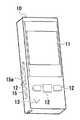
図1に、本発明の第1実施形態に係る測定装置の外観を示す。<< First Embodiment >>
In FIG. 1, the external appearance of the measuring apparatus which concerns on 1st Embodiment of this invention is shown.
本実施形態に係る測定装置は、センサカートリッジをセットして使用する血糖値測定装置である。図1に示してあるように、測定装置は、筐体10、筐体10の前面(図1における手前側の面)に配設されたLCD(Liquid Crystal Display)11、3つの押しボタンスイッチ12及びスピーカ13を備えている。また、測定装置は、筐体10の側面に配置されているスライダーノブ15aを操作することにより、スライダーノブ15aと共に上下にスライドするスライダー15を備えている。 The measurement apparatus according to the present embodiment is a blood sugar level measurement apparatus that is used by setting a sensor cartridge. As shown in FIG. 1, the measuring apparatus includes a
まず、図2〜図5を用いて、測定装置にセットされるセンサカートリッジ30の構成を説明する。尚、これらの図のうち、図2は、センサカートリッジ30がセットされている測定装置の、厚さ方向に直交する面(スライダーノブ15aのほぼ中央を通る面)で切った要部断面図である。図3は、センサカートリッジ30内に収容される、センサ体40が巻回されたリールハブ32の外観図である。図4Aは、フィルム状センサ45の構成例の説明図であり、図4Bは、センサ体40の構成例の断面図であり、図4Cは、センサ体40の上面図である。図5は、センサカートリッジ30の、図2と同じ側から見た外観図である。 First, the configuration of the
図2に示した断面図から明らかなように、センサカートリッジ30は、センサ体40が巻回されているリールハブ32をケース31内に収容したものである。測定装置の筐体1
0には、センサカートリッジ30を収容するためのカートリッジ収容部10aが設けられている。As apparent from the cross-sectional view shown in FIG. 2, the
0 includes a
センサ体40(図3)は、複数の小型なフィルム状センサ45が、台紙フィルム41上に接着強度が比較的に弱い材料にて台紙フィルム41の長さ方向に等間隔に接着されているテープ状部材である。センサ体40の、フィルム状センサ45が配置されていない部分には、フィルム状センサ45の配置間隔(隣接する各2つのフィルム状センサ45の中心間の間隔;以下、センサ配置間隔と表記する)と同間隔で、角丸長方形状の孔42が設けられている。 The sensor body 40 (FIG. 3) is a tape in which a plurality of
センサ体40の台紙フィルム41は、柔軟で比較的に延びにくいフィルムであれば良い。従って、台紙フィルム41としては、樹脂フィルム、2種以上の樹脂フィルムの積層体、樹脂フィルムと金属フィルムの積層体、樹脂フィルムに金属線等を埋め込んだもの等を使用することが出来る。ただし、台紙フィルム41は、フィルム状センサ45の水分による劣化を抑止できるようにするために、吸湿性を有するものであってもよい。その場合には、台紙フィルム41を、吸湿性物質を含む材質(吸湿性フィルムと他のフィルムとの積層体等)で形成することが好ましい。 The
台紙フィルム41上に配置される各フィルム状センサ45は、例えば、図4Aに模式的に示してあるような構成を有するセンサである。すなわち、フィルム状センサ45は、例えば、グルコースと反応する酵素や電子受容体等を保持する酵素膜57と、酸化還元電位もしくは酸化還元電流を検出するための複数の電極56a及び56bとが形成されている基板55上に、U字状のスペーサ58を介して貫通孔59aが設けられているカバー59を積層した、その先端部に点着された血液を酵素膜に供給するための流路68が基板55、スペーサ58及びカバー59により画定されているセンサである。 Each film-
センサカートリッジ30には、センサ体40として、フィルム状センサ45の配置面側が、凸となるように曲げると、フィルム状センサ45が台紙フィルム41から剥がれるものが使用される。より具体的には、センサ体40としては、或るフィルム状センサ45が配置されている部分をフィルム状センサ45の配置面側が凸となるように所定曲率以下の曲率で湾曲させると、湾曲させた部分上に配置されているフィルム状センサ45の端部に、台紙フィルム41との間の接着力を超える曲げ応力が発生するものが使用される。 As the
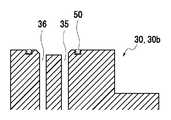
上記のような仕様を満たすセンサ体40は、例えば、図4B及び図4Cに示した構成を採用することにより製造することが出来る。すなわち、フィルム状センサ45として、電極等を形成した、基板55としてのPET(polyethylene terephthalate)シート上に、スペーサ58としての両面シートテープとカバー59としての親水性フィルムとを積層したものを使用する。また、台紙フィルム41として、乾燥剤シート(吸湿性シート)41b上に基材シート(例えばPETシート)41aを積層したものを使用し、フィルム状センサ45と台紙フィルム41との間の接着に、粘着シート(例えばEasy peelシート)4
5aを使用する。The
Use 5a.
図4B及び図4Cに示した構成を有するセンサ体40は、フィルム状センサ45間にもフィルムが存在している積層体を形成した後、粘着シートよりも上側の不要な部分(フィルム状センサ45間の部分)を粘着シートの途中までハーフカットして除去してから孔42を形成する(又は、孔42を形成してから、粘着シートよりも上側の不要な部分を、粘着シートの途中までハーフカットして除去する)ことにより製造することが出来る。なお、ハーフカットは、ピナクル刃やトムソン刃や金型、もしくは、レーザーカッター等で行うことが出来る。 In the
そして、本実施形態に係るセンサ体40は、図3から明らかなように、各フィルム状センサ45の幅が台紙フィルム41の幅よりも狭く、且つ、各フィルム状センサ45が台紙フィルム41の幅方向の中央部に配置されたものとなっている。従って、このセンサ体40は、不要な部分をハーフカットにより一括して除去することにより、製造することが出来る。 As is apparent from FIG. 3, the
センサ体40が巻回されるリールハブ32(図2及び図3)は、ドーナッツ状の2つのフランジ32bの中央の開口部間を、筒状部32aによってセンサ体40の幅よりも僅かに広い間隔で接続した部材である。 The reel hub 32 (FIGS. 2 and 3) around which the
このリールハブ32は、カートリッジ30の組み立て時に、センサ体40が巻回された状態でケース31内に収容されるものである。具体的には、ケース31には、ケース31の厚さ方向(図2の紙面に垂直な方向)に延びた、リールハブ32の筒状部32aの内径よりも僅かに小さな外径を有するリールハブ取付軸が設けられている。そして、リールハブ32は、カートリッジ30の組み立て時に、筒状部32aの周囲にセンサ体40を巻回した後、筒状部32a内にリールハブ取付軸を挿入する形でケース31内に収容されるものとなっている。 The
尚、フィルム状センサ45が設けられている面を外側に向けた形でセンサ体40をリールハブ32に巻回すると、測定装置の振動等に因り、リールハブ32に巻回されているセンサ体40の最外周部分のフィルム状センサ45が台紙フィルム41から剥がれてしまう虞がある。そのため、センサ体40のリールハブ32への巻回は、図3に示してあるように、フィルム状センサ45が設けられている面を内側に向けた形で行っておくことが好ましい。また、図3には、台紙フィルム41の先端までフィルム状センサ45が設けられているセンサ体40を示してあるが、カートリッジ30に組み込まれるリールハブ32に巻回されているセンサ体40は、先端側の所定長の部分(以下、リード部と表記する)に、フィルム状センサ45が配設されておらず、センサ配置間隔で孔42が形成されているものである。 If the
ケース31(図2)の、リールハブ取付軸の周りには、リールハブ32の、ケース31と対向する側のフランジ32bに設けられている突起と係合することにより、センサ体40を巻き取る方向へのリールハブ32の回転を抑止する複数の突起が設けられている。 Around the reel hub mounting shaft of the case 31 (FIG. 2), the
ケース31には、ケース31の厚さ方向に延びたローラ取付軸も設けられている。そして、ケース31内には、複数のピンがその外側面に等間隔に配置された円筒形状を有するローラ34が、ローラ取付軸を中心に回転可能なように収容されている。 The
上記したセンサ体40の孔42(図3)は、このローラ34のピンが入り込む孔である。従って、ローラ34の直径及びローラ34の外側面に配置されるピン数と、センサ配置間隔とは、各ピンがセンサ体40の各孔42に入るように定められる。 The hole 42 (FIG. 3) of the
ローラ34の図2における手前側には、ローラ34と共に回転する、図5に示したよう形状の嵌合部38が設けられている。 On the front side in FIG. 2 of the
すなわち、ローラ34の手前側には、中心側に向かって突出している部分を有する円形状の凹部38aが形成されている嵌合部38が設けられている。そして、センサカートリッジ30のケース31の、当該嵌合部38と対向する部分には、開口部が設けられている。 That is, on the front side of the
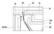
さらに、図2に示してあるように、ケース31の、スライダー15側を向いた側壁の先
端側の部分には、フィルム状センサ45が通る形状の開口部であるセンサ取出口35と、台紙フィルム41が通る形状の開口部であるフィルム回収口36とが、フィルム状センサ45の長さよりも短い間隔で、設けられている。また、ケース31の側壁形状は、"セン
サ取出口35とフィルム回収口36とそれらの間に存在する側壁部分"(以下、センサカ
ートリッジ30のポート部と表記する)が他の部分よりも少し内側に凹むように定められている。さらに、センサ突出口35とフィルム収容口36との間に存在するケース31の側壁部分は、それに沿ってセンサ体40の台紙フィルム41を曲げると、台紙フィルム41の少なくとも一部が、上記した所定曲率以下の曲率(台紙フィルム41からフィルム状センサ45の一部が剥がれる曲率)で湾曲する形状を有している。Further, as shown in FIG. 2, a
ケース31内には、ケース31の厚さ方向に延びた曲面壁39も設けられている。この曲面壁39の形状は、図2に示してあるように、曲面壁39が設けられていない部分から入ってくるセンサ体40(台紙フィルム41)が、曲面壁39により画定されるフィルム収容空間内に渦を巻いた形で収容されることになるように、定められている。 A
そして、センサカートリッジ30内のセンサ体40は、センサ取出口35及びフィルム回収口36を通過し、ローラ34の外周面に沿って巻き取られた後、フィルム収容空間内に回収される。なお、使用開始前のセンサカートリッジ30では、上記したリード部がフィルム収容空間内におさまっている。 The
以下、本実施形態に係る測定装置の構成及び機能を説明する。 Hereinafter, the configuration and function of the measurement apparatus according to the present embodiment will be described.
本実施形態に係る測定装置は、待機時は(血糖値の測定時以外は)、スライダーノブ15aが、図1に示した位置(以下、待機位置と表記する)、つまりスライダー可動範囲の中央付近に位置する。そして、本実施形態に係る測定装置は、図6(A)に示してあるように、スライダーノブ15aを、最も上側の位置(以下、センサ取出位置と表記する)、つまりスライダー可動範囲の一端付近に一旦スライドさせてから、図6(B)に示しあるように最も下側の位置(以下、測定位置と表記する)、つまりスライダー可動範囲の筐体10の開口部に近い端にスライドさせれば、スライダー15及び補助スライダー18が、それらの先端部分の間にフィルム状センサ45を挟んだ状態で、筐体10に設けられている開口部(以下、スライダー突出口と表記する)から突出するように構成されている。 In the measurement apparatus according to the present embodiment, the
まず、スライダーノブ15aをセンサ取出位置にスライドさせた場合に機能する測定装置の機械的な構成を説明する。 First, the mechanical configuration of the measuring apparatus that functions when the
図7に、本実施形態に係る測定装置の、前面近傍の前面に平行な断面図を示す。
図示してあるように、測定装置は、仕切板51、複合歯車52、爪部53、駆動歯車54を備える。仕切板51は、その裏面(図7にて見えていない側の面)側にセンサカートリッジ30がセットされる板状部材である。駆動歯車54は、その回転軸を中心に回転可能なように仕切板51に対して固定されている歯車である。この駆動歯車54の回転軸は、筐体10内にセットされているセンサカートリッジ30のローラ34の嵌合部38と中心が一致する位置に、仕切版51を貫通する形で設けられている。また、駆動歯車54の回転軸は、センサカートリッジ30がセットされると、センサカートリッジ30のローラ34の嵌合部38(図5参照)と嵌合する形状を有している。FIG. 7 shows a cross-sectional view of the measuring apparatus according to the present embodiment parallel to the front surface in the vicinity of the front surface.
As illustrated, the measuring device includes a
複合歯車52は、通常の歯車52aと爪車52bとを回転中心を合わせて重ねた歯車である。複合歯車52は、仕切板51に対して回転可能に固定されている。また、複合歯車52の回転軸の位置は、歯車52aが駆動歯車54とかみ合うように定められている。爪部53は、スライダー15に対して固定されている部材である。この爪部53は、スライダー15が待機位置に位置しているときに、複合歯車52の爪車52bとかみ合う形状の
先端部53aを有している。The
そして、本実施形態に係る測定装置の各部の形状及び/又はスライダー15の待機位置から取出完了位置(測定位置)までの移動距離は、以下の2条件を満たすように、定められている。
[条件1]スライダー15がセンサ取出位置まで移動すると、センサ取出口35上にスライダー15が存在しない状態となる。
[条件2]スライダー15が待機位置からセンサ取出位置まで移動した場合における『ローラ34のラジアン単位の回転角×ローラ34の半径』が、センサ体40のセンサ配置間隔(センサ体40の、隣接する各2フィルム状センサ45間の中心間隔)と一致する。Then, the shape of each part of the measurement apparatus according to the present embodiment and / or the movement distance from the standby position of the
[Condition 1] When the
[Condition 2] When the
要するに、図8に示してあるように、スライダーノブ15aの操作によりスライダー15が待機位置からセンサ取出位置まで移動すると、複合歯車52は、時計回りに回転し、駆動歯車54は、反時計回りに回転する。また、駆動歯車54の回転軸は、ローラ34の嵌合部38と嵌合しているため、ローラ34が、駆動歯車54と同じ角度だけ反時計回りに回転する。従って、スライダー15が待機位置からセンサ取出位置まで移動した場合における『ローラ34のラジアン単位の回転角×ローラ34の半径』が、センサ体40のセンサ配置間隔と一致するように各部の形状等を定めておけば、センサカートリッジ30内のセンサ体40を、図9に示してある矢印方向、すなわち、各フィルム状センサ45がセンサ取出口35側に進む方向に、"センサ配置間隔"分だけ送ることが出来る。 In short, as shown in FIG. 8, when the
そして、センサ体40は、フィルム状センサ45の配置面側が凸となるように曲がると、フィルム状センサ45が台紙フィルム41から剥がれる。従って、センサ体40が"セ
ンサ配置間隔"分だけ送られ、送られた部分の台紙フィルム41がセンサ取出口35の出
口近傍でおよそ90度曲がると、その曲がった部分に貼り付けられていた、フィルム状センサ45の部分が、台紙フィルム41から剥がれる。そして、その結果として、図9や図10に示したように、フィルム状センサ45がセンサ取出口35から突出することになる。When the
ただし、フィルム状センサ45がセンサ取出口35から突出したときに、スライダー15がセンサ取出口35上に位置していると、センサ取出口35から突出しているフィルム状センサ45をスライダー15によって搬送することができない。そのため、上記条件1も満たすように、測定装置の各部の形状等が定められているのである。 However, if the
次に、スライダーノブ15aをセンサ取出位置から測定位置にスライドさせた場合に機能する測定装置の機械的な構成を説明する。 Next, the mechanical configuration of the measuring apparatus that functions when the
図11に、スライダー15の上面側(スライダーノブ15aが設けられている面側)から見た外観図を示す。また、図12に、スライダー15の下面側から見た外観図を示す。 FIG. 11 shows an external view of the
図12に示してあるように、スライダー15の先端部分の中央には、センサカートリッジ30のセンサ取出口35から突出しているフィルム状センサ45を前方に押し出すための2つの突起16bが設けられている。また、図11、図12に示してあるように、スライダー15の先端部分の両側には、補助スライダー18の先端部分に設けられている構造と嵌合する形状の構造16aが設けられている。ここで、補助スライダー18は、スライダー15が待機位置と測定位置との間に位置している場合に限り、スライダー15と共に移動するように、筐体10内に配設されている。 As shown in FIG. 12, two
補助スライダー18の先端部分には、構造16aと係合する上記構造に加えて、フィルム状センサ45をスライダー15の先端部分との間に挟み込むための構造も設けられてい
る。スライダーノブ15aの操作によりスライダー15がセンサ取出位置から測定位置へ移動した場合、まず、スライダー15の2つの突起16bによりフィルム状センサ45が前方に押し出される。次いで、スライダー15の先端部分に設けられている構造16aと補助スライダー18の先端部分に設けられている構造とが嵌合することにより、フィルム状センサ45がスライダー15の先端部分と補助スライダー18の先端部分との間に挟まれている状態であって、補助スライダー18がスライダー15と共に移動する状態が形成される。そして、その状態のまま、スライダー15及び補助スライダー18がスライダーノブ15aの測定位置までのスライドが完了したときに、図6(B)に示したように、フィルム状センサ45がスライダー15と補助スライダー18により保持される。In addition to the above-described structure that engages with the
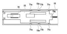
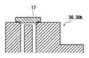
また、図11及び図12に示してあるように、スライダー15は、先端側(各図における左側)が上下動可能なように形成された撓み部15cを備えている。この撓み部15cの先端側の下面には、封止用ゴム17が取り付けられている。撓み部15cの位置及び形状と封止用ゴム17の形状は、図13に示してあるように、少なくとも、スライダー15が待機位置に位置しているときに、封止用ゴム17がセンサカートリッジ30のポート部(センサ取出口35とフィルム回収口36とそれらの間の側壁とからなる部分)上に位置するように、定められる。尚、封止用ゴム17の形状は、平板状であっても良いが、センサカートリッジ30のポート部の形状と同じ形状又は類似した形状であることが好ましい。 Further, as shown in FIGS. 11 and 12, the
図11に示してあるように、撓み部15c上面の、封止用ゴム17のほぼ中心に対応する部分には、円錐台状の突出部15dが設けられている。また、スライダー15の末端側(図11における右側)の中央部分には、孔15gが設けられており、スライダー15の幅方向の各側面には、幅方向に突出した突出部15eが設けられている。スライダー15には、各突出部15eをスライダー15の幅方向に変位しやすくするための開口部15fも設けられている。 As shown in FIG. 11, a truncated cone-shaped
図14に示してあるように、スライダー15の孔15gと筐体10内の特定箇所との間は、コイルスプリングにより接続されている。また、筐体10内には、図14に示したような位置に、3組の突出部71x(x=a〜c)が設けられている。すなわち、筐体10内には、スライダー15の1組の突出部15eと係合することにより、コイルスプリングによって付勢されているスライダー15を測定位置で止めるための1組の突出部71aが設けられている。また、筐体10内には、スライダー15の1組の突出部15eと係合することにより、スライダー15を待機位置で止めるための1組の突出部71b、及び、スライダー15の1組の突出部15eと係合することにより、スライダー15をセンサ取出位置で止めるための1組の突出部71cも設けられている。 As shown in FIG. 14, the
さらに、筐体10の内面の、待機位置に位置しているスライダー15の突出部15dと対向する部分には、突出部15dを、センサカートリッジ30のポート部方向に押し下げるための付勢手段(図14では、板バネ)72が設けられている。既に説明したように、突出部15dの裏側には、封止用ゴム17が設けられている。従って、スライダー15が待機位置に位置している場合、センサカートリッジ30のポート部が封止用ゴム17により封止されることになる。 Furthermore, a biasing means for pushing down the
また、図15に示してあるように、測定装置の筐体10のスライダー突出口(スライダー15及び補助スライダー18が突出する開口部)の近傍には、廃棄用ピン60と回転軸61と回転部材62と付勢部材63とを含むセンサ廃棄機構が設けられている。このセンサ廃棄機構の回転軸61は、筐体10に対して固定された、スライダー15の幅方向と平行な回転軸である。回転部材62は、回転軸61を中心に回転する部材である。廃棄用ピン60は、回転軸61と直交するように回転部材62に対して固定された棒状部材である
。付勢部材63(図15では、コイルスプリング)は、回転部材62を介して、廃棄用ピン60を、廃棄用ピン60が筐体10の下面に平行となる方向に付勢する部材である。Further, as shown in FIG. 15, a
図15に示してあるように、センサ廃棄機構の廃棄用ピン60の長さは、筐体10の下面と平行になっている場合に、スライダー15と補助スライダー18との間に挟まれた状態でフィルム状センサ45が移動する平面と交差するように定められている。また、廃棄用ピン60の長さは、スライダー15の各部(2つの突起16bの間に存在する部分等;図12参照)とは接触しないようにも定められている。さらに、補助スライダー18の先端部分には、廃棄用ピン60が通る溝が形成されている。 As shown in FIG. 15, the length of the
要するに、このセンサ廃棄機構の廃棄用ピン60は、スライダー突出口からフィルム状センサ45が出てきた場合、フィルム状センサ45に押されて倒れて(矢印65参照)、その先端がフィルム状センサ45の下面を摺動する状態となる。ただし、廃棄用ピン60は、付勢部材63により付勢されている。そのため、フィルム状センサ45が通過してしまえば、廃棄用ピン60は立ち上がり(矢印66参照)、その結果として、廃棄用ピン60の先端が、補助スライダー18及びスライダー15内に入っている状態が形成される。この状態で、スライダー15を待機位置に戻す操作がなされると、スライダー15の位置が待機位置となる前に、測定に使用したフィルム状センサ45が廃棄用ピン60と当接する。そして、廃棄用ピン60と当接するとフィルム状センサ45は移動できない状態となるが、スライダー15及び補助スライダー18は、廃棄用ピン60が立っていてもスライド可能である。従って、上記センサ廃棄機構を備えた本実施形態に係る測定装置では、血糖値の測定後、スライダーノブ15aの位置を待機位置に戻すだけで、使用済みのフィルム状センサ45を破棄できることになる。 In short, the
次に、測定装置の電気的な構成を説明する。 Next, the electrical configuration of the measuring apparatus will be described.
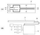
本実施形態に係る測定装置の電気的な構成(回路構成)は、既存の血糖値等測定装置と同様のものである。ただし、実施形態に係る測定装置は、移動するスライダー15の先にフィルム状センサ45が接続される装置となっている。そのため、スライダー15には、フィルム状センサ45の各電極を、測定装置内の制御ユニット14の対応する電極と接続するための配線等が形成される。例えば、フィルム状センサ45が2つの電極を備えたものである場合、図16(A)に模式的に示したように、スライダー15の下面には、フィルム状センサ45の各電極に接触させる電極81、測定装置内の制御ユニット14(図10(B))と接続される電極82、電極81・82間を接続する配線83が形成される。ここで、制御ユニット14とは、フィルム状センサ45に関する酸化還元電位を測定する処理や、測定結果から血糖値を算出する処理や、LCD11(図示略)やスピーカ13を制御する処理を行う、プロセッサ(ワンチップマイコン等)が用いられた回路のことである。尚、スライダー15の下面への電極・配線の形成は、導電性材料をスライダー15の下面に印刷することによっても、インモールド成形を利用して行うこと(スライダー15と各電極・配線とを一体成形してしまうこと)や、導電性材料をスライダー15の上面に印刷することによって行うことが出来る。また、電極81としては、板バネ式の電極や、ピンプローブを用いることも出来る。 The electrical configuration (circuit configuration) of the measuring apparatus according to this embodiment is the same as that of an existing measuring apparatus such as blood glucose level. However, the measuring apparatus according to the embodiment is an apparatus in which the
そして、本実施形態に係る測定装置は、スライダー15の装置内での位置が変わるものであるので、各電極82と制御ユニット14とをリード線にて接続しておくと、リード線が、測定装置内の部材に絡まって切断してしまうことが考えられる。そのため、図16(B)に模式的に示したように、各電極82と制御ユニット14との間の接続は、フレキシブルプリント基板84等を用いておくことが好ましい。 In the measuring apparatus according to the present embodiment, the position of the
また、スライダー15の各配線83(又は電極82)を、スライダー15の長さ方向に
平行な部分が長いものとし、配線83(又は電極82)毎に、スライダー15の位置に因らず、その配線83(又は電極82)と接触するように、筐体側電極を筐体10に対して固定し、筐体10に対して固定した各筐体側電極と制御ユニット14との間をケーブル等で電気的に接続しておいても良い。さらに、スライダー15の各配線83又は電極82の長さ及び各筐体側電極の位置を、スライダー15が測定位置の近傍に位置している場合に限り、各配線83又は電極82と各筐体側電極とが接触するようにしておくことも出来る。In addition, each wiring 83 (or electrode 82) of the
以上、説明したように、本実施形態に係る測定装置にセットされるセンサカートリッジ30内のリールハブ32には、各フィルム状センサ45が台紙フィルム41の幅方向の各端部を除いた中央部分に配置されているものであるが故に、簡単に製造できるセンサ体40が用いられている。また、センサ体40は、台紙フィルム41の、或るフィルム状センサ45の端部下の部分を、台紙フィルム41の裏面を内側に向けた姿勢でセンサ体40の長手方向に所定曲率以下の曲率で湾曲させると、当該フィルム状センサ45の上記端部が台紙フィルム41から剥がれるように構成されている。また、センサ突出口35とフィルム収容口36との間に存在するケース31の壁部は、それに沿ってセンサ体40の台紙フィルム41を曲げると、台紙フィルム41の少なくとも一部が上記所定曲率以下の曲率で湾曲する形状を有している。従って、センサカートリッジ30のローラ34を回転させると、上記したように、センサ突出口35近傍でフィルム状センサ45の一部が台紙フィルム41から剥がれてセンサカートリッジ30(センサ突出口35)から突出する。 As described above, each
そして、センサカートリッジ30からその一部が突出しているフィルム状センサ45は、簡単な機構でセンサカートリッジ30から取り出すことが出来る。そのため、本実施形態に測定装置が、上記したような簡単な構成(部品数の少ない構成)を有するものとなっているのである。 Then, the
以下、図17を用いて、第1実施形態に係る測定装置にセットするものとして開発したセンサカートリッジ30bの構成を、センサカートリッジ30と異なる部分を中心に説明する。 Hereinafter, the configuration of the sensor cartridge 30b developed as set in the measurement apparatus according to the first embodiment will be described with reference to FIG.
図17と図2とを比較すれば明らかなように、センサカートリッジ30bは、センサカートリッジ30のローラ34を、ローラ34a及びローラ34bに置き換えた構成を有している。 As apparent from a comparison between FIG. 17 and FIG. 2, the sensor cartridge 30b has a configuration in which the
ローラ34aは、複数のピンが外側面に設けられていないローラである。ローラ34bは、ローラ34aに台紙フィルム41を圧着させるための所謂ピンチローラである。 The
要するに、このセンサカートリッジ30bは、センサ体40として、孔42(図3)が設けられていないものを使用できる構成を有している。従って、センサカートリッジ30bは、センサカートリッジ30と同様の作用効果を奏するものであると共に、孔42を形成する工程が不要な分、センサカートリッジ30よりも安価に製造できるものとなっていると言うことが出来る。 In short, the sensor cartridge 30b has a configuration in which a
《第2実施形態》
以下、本発明の第2実施形態に係る測定装置の構成を、上記した第1実施形態に係る測定装置と異なる部分を中心に説明する。<< Second Embodiment >>
Hereinafter, the configuration of the measurement apparatus according to the second embodiment of the present invention will be described with a focus on differences from the measurement apparatus according to the first embodiment described above.
本発明の第2実施形態に係る測定装置にセットされる第2実施形態に係るセンサカートリッジは、センサカートリッジ30b(図17)内のセンサ体40を、図18に示した構成を有するセンサ体40bに置き換えたものである。そして、本発明の第2実施形態に係
る測定装置は、スライダー15の先端部分の形状のみが、第1実施形態に係る測定装置と異なる装置として構成されている。The sensor cartridge according to the second embodiment set in the measuring apparatus according to the second embodiment of the present invention is configured such that the
すなわち、図18に示してあるように、第2実施形態に係るセンサカートリッジ内のセンサ体40bは、幅方向の両縁部の中央部分よりも少し先端側によった部分に突出部46を設けた複数のフィルム状センサ45bを、各フィルム状センサ45bの幅方向が台紙フィルム41の幅方向と平行となるように、台紙フィルム41上に接着したものとなっている。 That is, as shown in FIG. 18, the
各フィルム状センサ45bがそのような形状を有しているため、第2実施形態に係るセンサカートリッジのセンサ取出口35からは、フィルム状センサ45bが、各突出部46が台紙フィルム41から剥がれている状態(つまり、各突出部46の下端下に、部材を挿入できる状態)で突出する。 Since each film-shaped
そして、センサ取出口35から突出しているフィルム状センサ45bの各突出部46の下端下に部材が挿入されるようにしておけば、スライダー15の形状や各部の位置関係が製造誤差等により設計上の形状や設計上の位置関係と多少異なっていても、その一部が台紙フィルム41に張り付いているフィルム状センサ45bを台紙フィルム41から剥がしてスライダー15に保持させることが出来る。 If a member is inserted below the lower end of each projecting
そのため、本実施形態に係る測定装置のスライダー15は、センサ取出口35から突出したフィルム状センサ45bの両突出部46の下端と係合することによりフィルム状センサ45bを台紙フィルム41から剥がして保持できるように、その先端部分の形状を設計したものとなっている。 Therefore, the
《変形形態》
上記した各種技術は、様々な変形を行えるものである。例えば、図18に示したセンサ体40bを、図3に示したセンサ体40のように、センサ配置間隔で孔42が開けられたものに変形することが出来る。また、各センサカートリッジ内に、乾燥剤を含めておくことも出来る。<Deformation>
The various techniques described above can be modified in various ways. For example, the
第1,第2実施形態に係る測定装置は、スライダー15と補助スライダー18との間に挟まれた状態でフィルム状センサ45が突出する装置であったが、各測定装置を、補助スライダー18がない装置に変形することも出来る。尚、各測定装置の補助スライダー18がない装置への変形は、例えば、以下の構成を採用することにより実現できる。スライダー15の先端部分に、フィルム状センサ45を挿入することにより、フィルム状センサ45を固定できると共にフィルム状センサ45と制御ユニット14との間を電気的に接続できるコネクタを設けておく。また、スライダー15の先端部分(コネクタ近傍の部分)に可撓性を持たせておく。そして、センサ取出口35上の通過時にスライダー15の先端部分をセンサカートリッジ30方向に移動させるための付勢機構を測定装置に設けておく。 The measuring device according to the first and second embodiments is a device in which the
封止ゴム17によるセンサカートリッジ30、30bの封止(密閉)がより良好に行われるようにするために、図19に模式的に示してあるように、センサカートリッジ30、30bのポート部を囲むように、閉曲線状の弾性部材50を配設しておいても良い。 In order to perform better sealing (sealing) of the
さらに、センサカートリッジ30、30bの封止がより良好に行われるようにするために、図20に模式的に示してあるように、封止ゴム17として、センサカートリッジ30、30bのポート部と嵌合する形状のものを採用しておいても良い、ただし、嵌合する部分の長さが過度に長いと、スライダー15をスライドさせにくくなる。そのため、上記のような形状の封止ゴム17を採用する場合には、嵌合する部分の長さが過度に長くならな
いようにしておくことが好ましい。Further, in order to perform better sealing of the
また、上記したセンサ体(40、40b)は、フィルム状センサ45以外の部分を、ハーフカット後に除去したものであったが、当該部分は、連続しているが故にセンサ体を曲げても台紙フィルム41から剥がれない。そして、台紙フィルム41から剥がれない部分は、フィルム状センサ45のセンサ体からの取り出しの邪魔にならないので、センサ体として、フィルム状センサ45以外の部分を除去したものではなく、粘着シートの途中までのハーフカットが完了した段階のもの(フィルム状センサ45以外の部分の除去が行わないもの)を、使用しても良い。 In addition, the sensor body (40, 40b) described above was obtained by removing portions other than the
また、上記した各測定装置/センサカートリッジから、幾つかの機能を取り除いておくことも出来る。各測定装置/センサカートリッジを、血液ではない測定対象物に関する何らかの物理量を測定するための装置/カートリッジに変形しても良いことは、当然のことである。 Also, some functions can be removed from each of the measuring devices / sensor cartridges described above. It goes without saying that each measuring device / sensor cartridge may be transformed into a device / cartridge for measuring some physical quantity relating to a measuring object that is not blood.
センサ体40の変形例について説明する。図21は、センサ体の変形例の断面図である。図22は、センサ体の変形例の上面図である。上記の実施形態のセンサ体40は、図4B、図4Cに示した構成の代わりに、図21、図22に示した構成であってもよい。図21及び図22のようにここで示すセンサ体40の変形例では、台紙フィルム41に接着されているフィルム状センサ45が、防湿のためにカバーフィルム91で被覆されている。フィルム状センサ45を被覆しているカバーフィルム91は、下から順に、粘着シート92、基材シート93及び乾燥剤シート94を積層したものである。カバーフィルム91の粘着シート92は、フィルム状センサ45の上面に、接着されている。さらに、カバーフィルム91の粘着シート92の外周縁は、フィルム状センサ45を被覆する状態で、台紙フィルム41のフィルム状センサ45が接着されている面に、接着されている。フィルム状センサ45はカバーフィルム91と台紙フィルム41とによって密封されていることによって、フィルム状センサ45が外気と接触しない。フィルム状センサ45が外気に接触しないことで、防湿効果がある。図22に示すように、各フィルム状センサ45は、それぞれ1つのカバーフィルム91で被覆されている。図22の例では、カバーフィルム91の平面形状は矩形状であるが、カバーフィルム91の平面形状は図22に示すものに限定されず、フィルム状センサ45を被覆できる形状であればよい。カバーフィルム91の厚さは、例えば、10μmから100μmである。 A modification of the
カバーフィルム91の基材シート93及び乾燥剤シート94の材料は、それぞれ、台紙フィルム41の基材シート41a及び乾燥剤シート41bの材料と同様のものである。カバーフィルム91の粘着シート92の材料は、粘着シート45aの材料と同様のものである。カバーフィルム91の基材シート93の材料がタック性のあるフィルムである場合、カバーフィルム91の粘着シート92は使用されなくてもよい。この場合、基材シート93は、直接、フィルム状センサ45及び台紙フィルム41に接着されている。また、カバーフィルム91は、乾燥剤シート94を省略されてもよい。 The materials of the
カバーフィルム91は、フィルム状センサ45が台紙フィルム41から剥がれる際に、フィルム状センサ45とともに台紙フィルム41から剥がれる。フィルム状センサ45が台紙フィルム41から剥がれる際、カバーフィルム91はフィルム状センサ45に接着した状態のままとなる。また、カバーフィルム91は、その一部分が台紙フィルム41と強力に接着されてもよい。この場合、フィルム状センサ45が台紙フィルム41から剥がれる際に、カバーフィルム91は、フィルム状センサ45から剥がれ、台紙フィルム41とともに回収される。 The
上記の例では、カバーフィルム91は1つのフィルム状センサ45に対して1つのカバ
ーフィルム91が用意されたが、カバーフィルム91が台紙フィルム41と同様の形状をしており、1つのカバーフィルム91が複数のフィルム状センサ45を被覆する構成であってもよい。In the above example, one
10 筐体
10a カートリッジ収容部
11 LCD
12 ボタンスイッチ
13 スピーカ
14 制御ユニット
15 スライダー
15a スライダーノブ
17 封止用ゴム
18 補助スライダー
30、30b センサカートリッジ
31 ケース
32 リールハブ
35 センサ取出口
36 フィルム回収口
40、40b センサ体
41 台紙フィルム
45、45b フィルム状センサ
91 カバーフィルム10
12
Claims (10)
Translated fromJapanese前記台紙フィルムの一方の面上に接着された複数のフィルム状センサとを、含み、
前後の各フィルム状センサは前記台紙フィルムの長さ方向において所定距離離間しており、各フィルム状センサの幅長さは台紙フィルムの幅長さより、所定量短くなっている
ことを特徴とするセンサ体。A tape-like mount film,
A plurality of film sensors bonded on one side of the mount film,
The front and rear film sensors are separated from each other by a predetermined distance in the length direction of the mount film, and the width length of each film sensor is shorter by a predetermined amount than the width length of the mount film. body.
ことを特徴とする請求項1に記載のセンサ体。With the curvature below the predetermined curvature in the longitudinal direction of the sensor body in a posture in which the back surface, which is the surface different from the one surface, is directed inward on the part of the mount film below the end of a certain film-like sensor. The sensor body according to claim 1, wherein the sensor body is configured such that when bent, the end of the film-shaped sensor is peeled off from the mount film.
ことを特徴とする請求項1又は2に記載のセンサ体。The sensor board according to claim 1, wherein the mount film has hygroscopicity.
各フィルム状センサが、前記台紙フィルムの一方の面上の前記中央部分に、凹部又は凸部が設けられている各端部が前記台紙フィルムの長手方向とほぼ平行となるように接着されている
ことを特徴とする請求項1から3のいずれか一項に記載のセンサ体。Each film-like sensor is a sensor in which a concave portion or a convex portion is provided at two opposite ends,
Each film-like sensor is bonded to the central portion on one surface of the mount film so that each end provided with a recess or a projection is substantially parallel to the longitudinal direction of the mount film. The sensor body according to any one of claims 1 to 3, wherein:
ことを特徴とする請求項1から4のいずれか一項に記載のセンサ体。The sensor body according to any one of claims 1 to 4, further comprising a cover film adhered to the one surface of the mount film in a state of covering the film sensor.
ことを特徴とする請求項5のいずれか一項に記載のセンサ体。The sensor film according to claim 5, wherein the cover film has a hygroscopic property.
前記センサ体の各フィルム状センサの境界部分を前記積層体側から少なくとも前記接着層までハーフカットする工程と、
を特徴とするセンサ体の製造方法。A process of forming a sensor body by bonding an adhesive layer between a continuous laminate including a plurality of film-like sensors on a backing film;
A step of half-cutting the boundary part of each film sensor of the sensor body from the laminated body side to at least the adhesive layer;
A method for manufacturing a sensor body.
請求項7に記載のセンサ体の製造方法。The step of half-cutting half-cuts the backing film from the laminated body side at the boundary part of each film-like sensor of the sensor body,
The manufacturing method of the sensor body of Claim 7.
前記リールをその内部に収容した、前記リールに巻回された前記センサ体が通過可能なセンサ突出口と、前記センサ体の前記台紙フィルムが通過可能なフィルム収容口とを有するケースであって、前記リールから巻き解かれた前記センサ体が、前記台紙フィルムの裏面を前記フィルム収容口方向に向けた姿勢で前記センサ突出口に挿入されたケースと、
前記ケース内に収容された、前記ケース外から回転させることが可能な回転体であって、前記台紙フィルムの裏面を前記フィルム収容口方向に向けた前記姿勢で前記センサ突出口に挿入され、前記センサ突出口近傍の部分で前記フィルム状センサが取り外されてから前記フィルム収容口を介して前記ケース内に戻った前記センサ体を、前記リールに巻回さ
れた前記センサ体が巻き解かれる方向に駆動する回転体と、
を備え、
前記センサ突出口と前記フィルム収容口との間に存在する前記ケースの部分が、それに沿って前記台紙フィルムを曲げると、前記台紙フィルムの少なくとも一部が前記所定曲率以下の曲率で湾曲する形状を有することを特徴とするセンサカートリッジ。A reel around which the sensor body according to any one of claims 1 to 6 is wound;
A case having a sensor projecting port through which the sensor body wound around the reel can pass, and a film housing port through which the mount film of the sensor body can pass, the reel being housed therein, A case where the sensor body unwound from the reel is inserted into the sensor projecting port in a posture in which the back surface of the mount film is directed toward the film housing port;
A rotating body housed in the case and capable of rotating from outside the case, wherein the back surface of the mount film is inserted into the sensor projecting port in the posture toward the film housing port direction, After the film sensor is removed at a portion near the sensor projection opening, the sensor body that has returned to the case through the film accommodation opening is unwound in the direction in which the sensor body wound around the reel is unwound. A rotating body to be driven;
With
When the portion of the case that exists between the sensor projection port and the film storage port bends the mount film along the portion, at least a part of the mount film is curved with a curvature equal to or less than the predetermined curvature. A sensor cartridge comprising:
Priority Applications (4)
| Application Number | Priority Date | Filing Date | Title |
|---|---|---|---|
| JP2015078424AJP2015232550A (en) | 2014-05-13 | 2015-04-07 | Sensor body, manufacturing method of sensor body, and sensor cartridge |
| US14/710,486US9597681B2 (en) | 2014-05-13 | 2015-05-12 | Sensor element, method for manufacturing sensor element, and sensor cartridge |
| CN201510242415.4ACN105092667B (en) | 2014-05-13 | 2015-05-13 | Sensor body, the manufacturing method of sensor body and sensor box |
| EP15167667.3AEP2952892A3 (en) | 2014-05-13 | 2015-05-13 | Sensor element, method for manufacturing sensor element, and sensor cartridge |
Applications Claiming Priority (3)
| Application Number | Priority Date | Filing Date | Title |
|---|---|---|---|
| JP2014099807 | 2014-05-13 | ||
| JP2014099807 | 2014-05-13 | ||
| JP2015078424AJP2015232550A (en) | 2014-05-13 | 2015-04-07 | Sensor body, manufacturing method of sensor body, and sensor cartridge |
Publications (1)
| Publication Number | Publication Date |
|---|---|
| JP2015232550Atrue JP2015232550A (en) | 2015-12-24 |
Family
ID=53264475
Family Applications (1)
| Application Number | Title | Priority Date | Filing Date |
|---|---|---|---|
| JP2015078424APendingJP2015232550A (en) | 2014-05-13 | 2015-04-07 | Sensor body, manufacturing method of sensor body, and sensor cartridge |
Country Status (4)
| Country | Link |
|---|---|
| US (1) | US9597681B2 (en) |
| EP (1) | EP2952892A3 (en) |
| JP (1) | JP2015232550A (en) |
| CN (1) | CN105092667B (en) |
Families Citing this family (6)
| Publication number | Priority date | Publication date | Assignee | Title |
|---|---|---|---|---|
| US10684209B1 (en)* | 2015-03-06 | 2020-06-16 | Scanit Technologies, Inc. | Particle collection media cartridge with tensioning mechanism |
| USD816863S1 (en)* | 2017-03-23 | 2018-05-01 | Bonraybio Co., Ltd. | Test strip |
| USD831224S1 (en)* | 2017-03-23 | 2018-10-16 | Bonraybio Co., Ltd. | Test strip |
| CN109682982B (en)* | 2017-10-17 | 2023-09-01 | 许兵 | Intelligent closestool with urine automatic detection and self-cleaning functions |
| PT3732482T (en) | 2017-12-28 | 2022-04-07 | Delaval Holding Ab | TAPE FOR ANALYSIS OF BIOMARKERS FROM A SAMPLE OF MILK |
| US12247941B2 (en)* | 2019-11-21 | 2025-03-11 | Medtronic Minimed, Inc. | Glucose biosensor encasement, glucose biosensor package, and method |
Citations (10)
| Publication number | Priority date | Publication date | Assignee | Title |
|---|---|---|---|---|
| JPH0777528A (en)* | 1993-08-05 | 1995-03-20 | Boehringer Mannheim Gmbh | Device and method for analyzing sample liquid |
| JP2003513279A (en)* | 1999-11-04 | 2003-04-08 | セラセンス、インク. | Small volume in vitro analyte sensor and related methods |
| JP2004354388A (en)* | 2003-05-29 | 2004-12-16 | Bayer Healthcare Llc | Test sensor and its manufacturing method |
| JP2005321402A (en)* | 2004-05-07 | 2005-11-17 | F Hoffmann-La Roche Ag | Method and apparatus for producing analysis tape for liquid sample |
| JP2006201126A (en)* | 2005-01-24 | 2006-08-03 | Sumitomo Electric Ind Ltd | Sensor chip assembly and manufacturing method thereof |
| JP2009150905A (en)* | 2002-05-23 | 2009-07-09 | Arkray Inc | Analytical tool pack and analyzer |
| US20090263854A1 (en)* | 2008-04-21 | 2009-10-22 | Quidel Corporation | Integrated assay device and housing |
| US20120094369A1 (en)* | 2009-03-31 | 2012-04-19 | James Richard Jackson | Test Material, Cassette and Meter for Using the Test Material |
| WO2013038691A1 (en)* | 2011-09-14 | 2013-03-21 | パナソニック株式会社 | Biological information detection sensor supply device |
| JP2015215310A (en)* | 2014-05-13 | 2015-12-03 | アークレイ株式会社 | Measuring apparatus and operation method of the same |
Family Cites Families (1)
| Publication number | Priority date | Publication date | Assignee | Title |
|---|---|---|---|---|
| WO2009076247A1 (en) | 2007-12-10 | 2009-06-18 | Bayer Healthcare Llc | Integrated fluid analyte meter system |
- 2015
- 2015-04-07JPJP2015078424Apatent/JP2015232550A/enactivePending
- 2015-05-12USUS14/710,486patent/US9597681B2/enactiveActive
- 2015-05-13EPEP15167667.3Apatent/EP2952892A3/ennot_activeWithdrawn
- 2015-05-13CNCN201510242415.4Apatent/CN105092667B/enactiveActive
Patent Citations (10)
| Publication number | Priority date | Publication date | Assignee | Title |
|---|---|---|---|---|
| JPH0777528A (en)* | 1993-08-05 | 1995-03-20 | Boehringer Mannheim Gmbh | Device and method for analyzing sample liquid |
| JP2003513279A (en)* | 1999-11-04 | 2003-04-08 | セラセンス、インク. | Small volume in vitro analyte sensor and related methods |
| JP2009150905A (en)* | 2002-05-23 | 2009-07-09 | Arkray Inc | Analytical tool pack and analyzer |
| JP2004354388A (en)* | 2003-05-29 | 2004-12-16 | Bayer Healthcare Llc | Test sensor and its manufacturing method |
| JP2005321402A (en)* | 2004-05-07 | 2005-11-17 | F Hoffmann-La Roche Ag | Method and apparatus for producing analysis tape for liquid sample |
| JP2006201126A (en)* | 2005-01-24 | 2006-08-03 | Sumitomo Electric Ind Ltd | Sensor chip assembly and manufacturing method thereof |
| US20090263854A1 (en)* | 2008-04-21 | 2009-10-22 | Quidel Corporation | Integrated assay device and housing |
| US20120094369A1 (en)* | 2009-03-31 | 2012-04-19 | James Richard Jackson | Test Material, Cassette and Meter for Using the Test Material |
| WO2013038691A1 (en)* | 2011-09-14 | 2013-03-21 | パナソニック株式会社 | Biological information detection sensor supply device |
| JP2015215310A (en)* | 2014-05-13 | 2015-12-03 | アークレイ株式会社 | Measuring apparatus and operation method of the same |
Also Published As
| Publication number | Publication date |
|---|---|
| CN105092667B (en) | 2019-02-22 |
| US20150328632A1 (en) | 2015-11-19 |
| EP2952892A2 (en) | 2015-12-09 |
| CN105092667A (en) | 2015-11-25 |
| EP2952892A3 (en) | 2016-03-02 |
| US9597681B2 (en) | 2017-03-21 |
Similar Documents
| Publication | Publication Date | Title |
|---|---|---|
| JP2015232550A (en) | Sensor body, manufacturing method of sensor body, and sensor cartridge | |
| CN108962300B (en) | Electronic device | |
| JPWO2009011137A1 (en) | Blood test equipment | |
| JP6451799B2 (en) | Foreign object detection sensor fixing method and foreign object detection sensor fixing structure | |
| JP4522014B2 (en) | Biosensor sheet, biosensor cartridge, and biosensor dispensing device | |
| KR101940349B1 (en) | Reel for adhesive tape, tape roll, packaging, use of reel as reel for adhesive tape for winding adhesive tape, and method for manufacturing reel for adhesive tape | |
| JP6291342B2 (en) | Measuring device and method of operating measuring device | |
| WO2019150621A1 (en) | Tip member of insertion device | |
| JP6677452B2 (en) | measuring device | |
| JP5899636B2 (en) | Biosensor, biosensor cartridge, measuring apparatus and measuring method | |
| US10234414B2 (en) | Measurement apparatus, and method for operating measurement apparatus | |
| CN101686814B (en) | Body fluid collecting circuit board | |
| EP2944949A1 (en) | Measurement apparatus, and method for operating measurement apparatus | |
| EP2275035A1 (en) | Body-liquid sampling circuit board, its manufacturing method and its using method, and biosensor having the body-liquid sampling circuit board | |
| JP4665135B2 (en) | Biosensor manufacturing method | |
| JP6989638B2 (en) | Hard disk drive | |
| WO2009116314A1 (en) | Circuit board for collecting body fluid, method of manufacturing the board, method for use of the board, and biosensor | |
| US20100234764A1 (en) | System for measuring components in living body, kit for micropore forming device, and marking member | |
| JP2016178153A (en) | Lead-out structure of fpc, image display device, and imaging device | |
| JP6660577B2 (en) | Tablet management device | |
| CN104185445B (en) | Test member box | |
| JP4649594B2 (en) | Biosensor and manufacturing method thereof | |
| JP2008089776A (en) | Display apparatus | |
| CN213924605U (en) | Adhesive film | |
| CN111103926B (en) | Electronic equipment |
Legal Events
| Date | Code | Title | Description |
|---|---|---|---|
| A621 | Written request for application examination | Free format text:JAPANESE INTERMEDIATE CODE: A621 Effective date:20171027 | |
| A977 | Report on retrieval | Free format text:JAPANESE INTERMEDIATE CODE: A971007 Effective date:20180731 | |
| A131 | Notification of reasons for refusal | Free format text:JAPANESE INTERMEDIATE CODE: A131 Effective date:20180814 | |
| A02 | Decision of refusal | Free format text:JAPANESE INTERMEDIATE CODE: A02 Effective date:20190305 |