JP2015231659A - Robot device - Google Patents
Robot deviceDownload PDFInfo
- Publication number
- JP2015231659A JP2015231659AJP2014120154AJP2014120154AJP2015231659AJP 2015231659 AJP2015231659 AJP 2015231659AJP 2014120154 AJP2014120154 AJP 2014120154AJP 2014120154 AJP2014120154 AJP 2014120154AJP 2015231659 AJP2015231659 AJP 2015231659A
- Authority
- JP
- Japan
- Prior art keywords
- speed
- robot
- robot arm
- state
- stop
- Prior art date
- Legal status (The legal status is an assumption and is not a legal conclusion. Google has not performed a legal analysis and makes no representation as to the accuracy of the status listed.)
- Pending
Links
Images


Landscapes
- Manipulator (AREA)
Abstract
Translated fromJapaneseDescription
Translated fromJapanese本発明は、ジョグ操作可能な操作手段の操作に応じて制御装置がロボットアームの動作を制御するロボット装置に関するものである。 The present invention relates to a robot apparatus in which a control device controls the operation of a robot arm in accordance with an operation of an operation means capable of jog operation.
産業用のロボット装置に、自動実行させる動作をプログラミングする場合、操作端末からの手動動作に応じて、ロボット装置を現在の位置姿勢から次の位置姿勢にロボット装置を動作させる教示操作が行われる。この種の用途に用いられる操作端末はティーチングペンダントなどと呼ばれ、例えば3次元の各座標軸方向に沿った(あるいは各軸廻りの)移動を指示する操作ボタンが設けられている。 When programming an operation to be automatically executed in an industrial robot apparatus, a teaching operation for operating the robot apparatus from the current position / posture to the next position / posture is performed according to a manual operation from the operation terminal. An operation terminal used for this type of application is called a teaching pendant or the like, and is provided with an operation button for instructing movement along (or around) each of the three-dimensional coordinate axes.
このような操作ボタンは、ジョグ(連続)操作が可能な、いわゆるジョグボタンのような操作手段として操作端末に実装されることが多い。このような操作手段は、例えばON操作またはOFF操作の入力状態を生成するスイッチを用いた押しボタンのような形態で実装される。 Such an operation button is often mounted on an operation terminal as an operation means such as a so-called jog button capable of jog (continuous) operation. Such an operation means is mounted in a form such as a push button using a switch that generates an input state of ON operation or OFF operation, for example.
この種のジョグボタンは、例えば続けて操作(押下)され、ON状態が生成されている間、割り当てられた操作機能を連続して入力するよう構成される。ロボット装置の操作端末の場合には、ジョグボタンがジョグ(連続)操作されている間、例えばロボットアームの基準部位をそのボタンに割り当てられた方向に連続的に動作させる、いわゆるジョグ(連続)動作が行われる。また、この種の操作端末では、XYZの3次元の各座標軸方向に沿った(あるいは各軸廻りの)移動をそれぞれ指示するジョグボタンが設けられることがある。また、これらのジョグボタンは、同時操作可能であって、その複合操作によって所望の軌道でロボット装置を動作させるよう構成されることがある。 This type of jog button is configured to continuously input the assigned operation function while it is operated (pressed) continuously and the ON state is generated, for example. In the case of an operation terminal of a robot apparatus, while the jog button is being jog (continuously) operated, for example, a so-called jog (continuous) operation that continuously moves the reference portion of the robot arm in the direction assigned to the button is performed. Is done. Also, this type of operation terminal may be provided with a jog button for instructing movement along (or around) each of the three-dimensional coordinate axes of XYZ. In addition, these jog buttons can be operated at the same time, and may be configured to operate the robot apparatus in a desired trajectory by the combined operation.
さらに、この種の操作端末では、ロボット装置を移動させる時の速度は、数値入力などにより指定する他、手動操作によって速度を変更するための速度変更ボタンのような操作手段が設けられることがある。速度変更ボタンは、例えば、設定速度を上げるため、あるいは下げるための2つのボタンから構成され、このボタンも多くの場合ジョグ操作によって連続的にロボット装置の設定速度を変更できるよう構成される。速度変更ボタンは、例えば次のような操作方式によって用いられる。現在の位置姿勢と目標の位置姿勢が比較的遠く、作業者がロボット装置を素早く動作させたい場合には、操作端末に設けられた速度変更ボタンにより設定速度を上げた後(あるいは上げながら)、ジョグボタンによりロボット装置の動作を指示する。また、ロボット装置が目標の位置姿勢に近づいた場合は、目標の位置姿勢へ確実に動作させるために、速度変更ボタンにより設定速度を下げた後、ジョグボタンによりロボットの動作を指示する。 Further, in this type of operation terminal, the speed at which the robot apparatus is moved is designated by numerical input or the like, and operation means such as a speed change button for changing the speed by manual operation may be provided. . The speed change button includes, for example, two buttons for increasing or decreasing the set speed. In many cases, this button is also configured so that the set speed of the robot apparatus can be continuously changed by a jog operation. The speed change button is used by the following operation method, for example. If the current position / posture and target position / posture are relatively far and the operator wants to operate the robotic device quickly, after increasing (or increasing) the set speed with the speed change button provided on the operation terminal, The operation of the robot device is instructed by the jog button. Further, when the robot apparatus approaches the target position and orientation, the robot is instructed to operate with the jog button after the set speed is lowered with the speed change button in order to reliably move to the target position and orientation.
一方、この種の操作端末を用いたロボット装置の教示作業は、ロボット装置が確実に所期の動作を行っているかを確認するために目視確認しながら行わなければならない。しかしながら、上記のように移動指示を行うジョグボタンの複合操作と、速度変更ボタンによる速度調節の組み合わせにより教示操作を行う構成では、その教示操作はかなり複雑である。例えば、教示操作と同時にロボット装置の速度設定およびその確認のために、表示を視認し、かつ操作ボタンを押し間違えないよう、操作端末にも度々視線を移す必要がある。このように、旧来のロボット装置の教示作業は複数の対象に注意を払いながらの複雑な操作が要求されるものであり、手際よく、迅速にこなすのはそれほど容易ではなく、結果として教示作業に多くの時間かかる問題があった。 On the other hand, the teaching operation of the robot apparatus using this type of operation terminal must be performed while visually confirming in order to confirm whether the robot apparatus is surely performing the intended operation. However, in the configuration in which the teaching operation is performed by the combination of the combined operation of the jog button for instructing the movement as described above and the speed adjustment by the speed change button, the teaching operation is quite complicated. For example, in order to set the speed and confirm the speed of the robot apparatus at the same time as the teaching operation, it is often necessary to move the line of sight to the operation terminal so that the display is visually confirmed and the operation button is not pressed by mistake. As described above, the teaching work of the conventional robot apparatus requires a complicated operation while paying attention to a plurality of objects, and it is not so easy to perform skillfully and quickly. There was a problem that took a lot of time.
そこで、従来より、ロボット装置の教示作業を効率化するためジョグボタンの入力パターンにより異なる動作速度制御を選択できるようにした制御装置(例えば下記の特許文献1)が提案されている。また、第1および2のボタンの操作の組み合わせで加速および減速を選択できるようにしたロボット移動制御装置(例えば下記の特許文献2)も提案されている。 Therefore, conventionally, a control device (for example,
上記の特許文献1に開示された技術では、ジョグボタンの押下時間によって形成される入力パターンに応じて、加速動作、等速動作の他、微少ステップ動作を選択することができる。その一方で、例えば等速動作を選択するには一度ジョグボタンから指を離し、再度押下する、といった作業が必要であり、入力パターンが複雑である。このため、誤入力防止のために作業者にはより慎重な作業が求められ、状況によっては手動で速度設定を変更しなければならなくなる場合も考えられる。また、目的の操作によっては、上記のようにボタンから指を離し、再度押下する、といったシーケンスが必要であり、これによりロボット装置の動作がワンテンポ遅れてしまう場合もある。 According to the technique disclosed in
一方、特許文献2に開示された技術は、2つの操作ボタンの組合せによって、ジョグ操作において加速のみならず減速も行えるようになっている。例えば、第1のボタンの連続操作によって加速を行い、減速を行う場合には第2のボタンを同時に操作する。特許文献2の場合は、目的の操作によっては2つのボタンの同時操作が必要になる、という複雑さがある。特に、デッドマン(3ポジション)スイッチが設けられる場合には、3つのボタンを同時押下しなければならない場面も生じ、やはり作業者の負担が大きい、という問題がある。 On the other hand, the technique disclosed in
上記のように、従来技術は、限られたキーで速度調節を含む複雑な手動操作を行えるよう考えられたものが多い。確かに、ロボット装置の教示操作では、少なくとも速度、移動方向および移動量などのパラメータを同時に制御する必要がある。しかしながら、上記の従来技術はいずれもこれら複数のパラメータを全て手動操作させることを意図していて、特に操作端末のみならずロボットアームの動作も確認しつつ行う教示作業を容易にすることには成功していない。 As described above, many of the conventional techniques have been conceived so that complicated manual operations including speed adjustment can be performed with limited keys. Certainly, in the teaching operation of the robot apparatus, it is necessary to simultaneously control at least parameters such as speed, moving direction and moving amount. However, each of the above prior arts is intended to manually operate all these parameters, and in particular, it has succeeded in facilitating teaching work while checking not only the operation terminal but also the operation of the robot arm. Not done.
なお、以上では、ロボット装置の教示操作に用いられる操作手段として、「ボタン」の呼称を持つものを例示したが、上述の問題は、そのような操作手段がレバーやスライドスイッチのような形態を有する場合にも共通するものである。 In the above, as the operation means used for the teaching operation of the robot apparatus, an example having the name of “button” is illustrated. However, the above problem is that such an operation means has a form such as a lever or a slide switch. This is also common in the case of having.
本発明の課題は、上記の問題に鑑み、ジョグ操作可能な操作手段を介して教示操作を行う場合、例えばロボット制御に係るパラメータを自動的に制御することにより、ロボット装置の教示操作を容易に行えるようにすることにある。例えば、ジョグ操作可能な操作手段を介して教示操作を行う場合、ロボット装置の速度を操作状況に応じて自動的に制御できるようにし、ロボット装置の教示操作を容易に行えるようにすることにある。 In view of the above problems, an object of the present invention is to facilitate teaching operation of a robot apparatus by automatically controlling parameters related to robot control, for example, when teaching operation is performed via an operation means capable of jog operation. It is to be able to do it. For example, when teaching operation is performed via an operation means capable of jog operation, the speed of the robot apparatus can be automatically controlled according to the operation status, and the teaching operation of the robot apparatus can be easily performed. .
上記課題を解決するため、本発明においては、ON操作またはOFF操作の入力状態を生成するスイッチにより構成された操作手段の入力状態に応じてロボットアームの動作を制御する制御装置を備え、前記制御装置が前記操作手段のON操作が継続している間は前記ロボットアームを動作状態に制御し、前記操作手段のOFF操作に応じて前記ロボットアームを停止状態に移行させるロボット装置において、前記操作手段のOFF操作により前記ロボットアームを動作状態から停止状態に移行させる直前の前記ロボットアームの停止前動作速度を記憶する記憶部を設け、前記制御装置は、前記操作手段のON操作により前記ロボットアームを停止状態から動作状態に移行させる場合、当該の動作状態における前記ロボットアームの初速を前記停止前動作速度に応じて決定する構成を採用した。 In order to solve the above-described problems, the present invention includes a control device that controls the operation of a robot arm according to the input state of an operation means configured by a switch that generates an input state of an ON operation or an OFF operation. In the robot apparatus which controls the robot arm to an operating state while the apparatus continues the ON operation of the operating means, and moves the robot arm to a stop state in response to the OFF operation of the operating means, the operating means A storage unit is provided for storing an operation speed before stopping the robot arm immediately before the robot arm is shifted from the operation state to the stop state by an OFF operation of the robot arm, and the control device moves the robot arm by the ON operation of the operation means. When shifting from a stopped state to an operating state, the initial speed of the robot arm in the operating state is Adopting a configuration determined according to the stop before the operation speed.
あるいはさらに、前記操作手段がOFF操作とされ、その後、再度、ON操作とされるまでの前記操作手段の入力状態がOFF操作である解放時間を計測する計時装置を有し、前記初速を前記停止前動作速度に応じて決定する場合、前記制御装置は、前記停止前動作速度に対して前記計時装置で計測された前記解放時間の長さに応じて定まる比率を有する速度値に前記初速を制御する構成を採用した。 Alternatively, it further includes a timing device for measuring a release time in which the input state of the operation means is an OFF operation until the operation means is turned off and then turned on again, and the initial speed is stopped. When determining according to the previous operation speed, the control device controls the initial speed to a speed value having a ratio determined according to the length of the release time measured by the timing device with respect to the operation speed before stop. The configuration to adopt was adopted.
上記の特徴的な構成により、本発明によれば、ジョグ操作可能な操作手段を介して教示操作を行う場合、直前のロボットアームの停止前動作速度に応じてロボット装置の速度を自動的に制御でき、教示操作の負担を大きく軽減することができる。また、前記停止前動作速度に対して、直前の操作手段の解放時間に応じて定まる比率を有する速度値にジョグ動作の初速を制御することにより、直前のジョグ操作に近い操作感覚を形成できる、という優れた効果がある。 With the above-described characteristic configuration, according to the present invention, when teaching operation is performed via an operation means capable of jog operation, the speed of the robot apparatus is automatically controlled according to the immediately preceding operation speed of the robot arm before stopping. And the burden of teaching operation can be greatly reduced. Further, by controlling the initial speed of the jog operation to a speed value having a ratio determined according to the release time of the immediately preceding operation means with respect to the operation speed before stopping, an operation feeling close to the immediately preceding jog operation can be formed. There is an excellent effect.
以下、図面に示す実施例に基づき、発明を実施するための好ましい形態につき詳細に説明する。 Hereinafter, preferred embodiments for carrying out the invention will be described in detail based on the embodiments shown in the drawings.
図1は、本発明を実施したロボット装置の全体構成を示している。図1において、ロボットアーム1は、例えば6軸(関節)の垂直多関節ロボットアームであって、その各関節は各関節についてそれぞれ設けられたサーボモータをサーボ制御することにより所望の位置姿勢に制御することができる。 FIG. 1 shows the overall configuration of a robot apparatus embodying the present invention. In FIG. 1, a
ロボットアーム1の動作は、ロボット制御装置2により制御される。ロボット制御装置2には、操作端末3が接続され、この操作端末3の手動操作を介してロボットアーム1の動作をプログラミングすることができる。ロボットアーム1の基準位置(例えばアーム先端のツール装着面など)を所望の軌跡で移動させる動作のプログラミングは、操作端末3によって軌跡上の教示点を順次指定することによって行われる。この教示点は、例えば、ロボットアーム1を現在の位置姿勢から、操作端末3の手動操作によって移動させる動作を介して指定することができる。 The operation of the
ロボットアーム1は、例えば、基台201上に架装されたそれぞれ6つの回転関節を有する6自由度マニプレータとして構成される。ロボットアーム1の各関節はこれら各関節内部に配置された駆動源によってロボット制御装置2により指定された角度に制御することができ、これによってロボットアーム1を所望の位置姿勢に制御することができる。ロボットアーム1の各関節を駆動する駆動源としては、サーボモータなどが用いられる。 The
ロボットアーム1の先端には、作業対象のワーク200を把持するためのツールとして、グリッパ202が設けられる。グリッパ202の先端部には、ワーク200をハンドリングするためのフィンガー(爪)が設けられる。グリッパ202の内部にはフィンガーを開閉するアクチュエータが設けられる。このアクチュエータは、モータやソレノイドなどの他、空気圧や油圧方式の任意のアクチュエータによって構成される。グリッパ202は、ワーク200を特定の作業位置に搬入、搬出したり、もしくは把持したワーク200を別のワークに組み付けたりする目的でロボットアームの先端に装着される。なお、ロボットアーム1の先端に配置されるツールは、上記のグリッパに限定されず、他の任意の機能を有するエンドエフェクタであってよい。 A
図2は図1のロボットアーム1、ロボット制御装置2、および操作端末3から成るロボット装置の制御系の基本構成を示している。 FIG. 2 shows a basic configuration of a control system of the robot apparatus including the
図2において、ロボット制御装置2の主制御部は、汎用マイクロプロセッサなどから成るCPU501により構成される。CPU501には当該のロボット装置全体を制御するプログラムを格納したROM502、CPU501のワークエリアとして用いられるRAM503が接続される。また、各種の制御データの入出力に用いられる記憶装置として、外部記憶装置504を設けることがある。この外部記憶装置504は、例えば固定式または着脱式のHDD、SSD、フラッシュメモリなどから構成することができる。外部記憶装置504が着脱式の記憶メディアを用いる場合、その記憶メディアは例えばロボットアーム1の教示(プログラミング)内容や、ROM502のプログラムを更新する制御データの入出力に用いることができる。 In FIG. 2, the main control unit of the
上記各部は不図示の内部バスによって接続される。また、CPU501は任意のインターフェース規格に基づき構成されたインターフェース回路505を介して操作端末3と通信することにより、操作端末3の操作状態を入力することができる。また、CPU501はIEEE−802.3など、所定のネットワーク規格に基づき構成されたインターフェース回路506を介して基幹LAN30と通信することができる。基幹LAN30には、例えば本実施例のロボット装置と協働して動作する他のロボット装置などを接続することができる。 The above units are connected by an internal bus (not shown). Further, the
また、CPU501には、操作端末3の操作ボタン103(後述)の連続(ジョグ)操作入力を処理するための時間計測手段(図4の11)としてRTC(リアルタイムクロック)507が接続されている。 Further, an RTC (real time clock) 507 is connected to the
図2では、ロボットアーム1の構成部材として、ロボットアーム1の各関節に設けられた6軸分のサーボモータ7a、7b…7fを示してある(グリッパ202の系は図示を省略)。各サーボモータ7a、7b…7fを駆動制御するサーボ制御回路6は、ロボット制御装置2のドライバ508と接続されている。ドライバ508は後述の図4のサーボ制御15を実現する駆動回路から構成される。CPU501は、操作端末3の操作入力に応じてドライバ508を介してロボットアーム1の各サーボモータ7a、7b…7fを駆動制御することができる。 2,
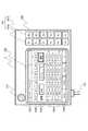
図3は、図1および図2の操作端末3の操作面の構成を示している。操作端末3は、ロボット制御装置2に対してロボット装置の動作を制御する制御情報を送信し、例えばロボットアーム1は、ロボット制御装置2の制御に従って各関節を動作させる。 FIG. 3 shows the configuration of the operation surface of the
図3において、操作端末3はロボット装置(図1のロボットアーム1、グリッパ202)の動作やプログラム状態に関する諸情報を表示するための表示部102を有する。この表示部102の左上には、非常停止ボタン131が配置されている。また、操作端末3の下部から、ロボット制御装置2と接続するためのケーブル132が導出されている。 3, the
操作端末3の表示部102は、例えば液晶表示器とタッチセンサなどを用いたタッチパネルなどから構成することができる。この場合、表示部102はロボットの動作やプログラム状態に関する情報表示の他、表示上に画成されたタッチキーの操作によって、ロボットの教示操作を行う操作入力手段(の一部)を構成する。表示部102は、ロボットの現在位置あるいは現在姿勢、ロボット教示時の移動の速度あるいはステップ送り時の移動量、教示済の動作ポイントの位置あるいは姿勢などを含むロボットの動作に関する情報を表示することができる。 The
例えば、表示部102のうち、表示領域1024は、設定済みの(あるいはこれから設定される)教示点におけるX、Y、Zの3次元座標値(ないし各軸軸上の移動量)と、該3次元座標軸廻りにおける回転移動の量(RX、RY、RZ)の表示に用いられる。また、表示領域1022は、特に現在設定中の教示点、または現在のロボットアーム1の状態に対応したX、Y、Zの3次元座標値(ないし各軸軸上の移動量)と、該3次元座標軸廻りにおける回転移動の量(RX、RY、RZ)の表示などに用いられる。また、表示部102の上部および下部の表示領域1021、1025は、例えばファンクションキー部で、これら表示領域1021、1025に画成される複数のファンクションキーは動作状態に応じて異なる設定入力に切り換えられる。また、中央の表示領域1023は、現在のジョグ(連続)移動速度(またはステップ操作量など)、ロボットの現在の操作対象部位の表示などに用いられる。また、図3の状態では、表示領域1023の右側には、教示点などの登録に用いられる登録キーが表示されている。 For example, in the
なお、図3の表示部102の表示状態はあくまでもロボット装置の状態や操作端末3の特定の操作状態に対応した一例に過ぎない。表示部102をタッチパネルなどにより構成する場合には、当然ロボット装置の状態や操作端末3の特定の操作状態に応じて表示部102の表示の全部または一部は図3とは異なる状態に制御される場合がある。このような表示部102の表示の様式や、表示部102がタッチパネルなどにより構成される場合の操作方式に関しては当業者が任意に変更可能な設計事項である。 Note that the display state of the
図3の操作端末3では、教示点のX、Y、Zの3次元座標や、あるいは教示点への移動を行わせる時に操作対象のロボットアームの関節と方向を指示するために用いられる操作ボタン103が設けられている。この操作ボタン103は、例えば各座標軸上の正方向入力を指定するボタン103a(X+、Y+、Z+、RX+、RY+、RZ+)と、負(逆)方向入力を指定するボタン103b(X−、Y−、Z−、RX−、RY−、RZ−)から構成する。操作端末3の操作ボタン103は、X、Y、Zの3次元座標系における(ロボット基準部位の)位置、および各座標軸廻りの回転移動を制御するのに用いられるもので、本実施例では連続(ジョグ)操作が可能に構成される。 In the
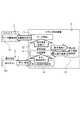
図4は本実施例の操作入力制御の概要を示している。図4は、図1〜図3のロボット制御装置の制御系を構成する機能をブロック図として示しており、図1〜図3のハードウェアに相当する部材には同一符号を付してある。 FIG. 4 shows an outline of the operation input control of this embodiment. FIG. 4 is a block diagram showing functions constituting the control system of the robot control apparatus of FIGS. 1 to 3, and members corresponding to the hardware of FIGS. 1 to 3 are denoted by the same reference numerals.
図4において、ロボット制御装置2の主たる制御機能は、ボタン解放時間計測11、停止前動作速度記憶部12、速度制御13、初速演算14、サーボ制御15の各機能から構成されている。これらの制御機能によって、ジョグ操作される操作端末3の操作ボタン103の押下および解放状態に応じてロボットアーム1のサーボ駆動系31を制御する。サーボ駆動系31は、図2のサーボ制御回路6、およびサーボモータ7a〜7fに相当する。一方、サーボ制御15の機能は、例えばCPU501のソフトウェアによって構成され、速度制御13によって決定された動作速度VCの情報を、ロボットアーム1のサーボ駆動系31の各軸を駆動する動作指令に分解する。 In FIG. 4, the main control functions of the
また、速度制御13の機能は例えば図2のCPU501が実行するソフトウェアによって実現される。速度制御13の機能によって、サーボ制御15(図2のドライバ508に該当)に送られる動作速度VCが生成される。その場合、本実施例では、操作端末3の操作ボタン103の連続(ジョグ)操作による加速制御が行われるとともに、操作ボタン103の押下直後の初速Vsが初速演算14によって決定される。 The function of the
初速Vsは、初速演算14の機能によって、前回の操作ボタン103の連続(ジョグ)操作の際の停止前動作速度Vlと、今回の操作ボタン103押下までに経過したボタン解放時間Trによって決定される。停止前動作速度Vlとしては、停止前動作速度記憶部12に格納された値が用いられる。停止前動作速度記憶部12は例えば図2のRAM503上に割り当てられたメモリ領域により構成される。停止前動作速度記憶部12の記憶内容(V)は、速度制御13によって生成されサーボ制御15(508)に与えられる動作速度VCの値に応じてジョグ操作が連続している間、随時更新される。 The initial speed Vs is determined by the function of the
ボタン解放時間計測11の機能は、例えば図2のRTC507の計時情報を利用して実現される。このボタン解放時間計測11により、前回の操作ボタン103の連続(ジョグ)操作が停止してから、今回の操作ボタン103押下までに経過したボタン解放時間Trが測定される。 The function of the button
速度制御13のソフトウェア(制御手順)は、例えば後述の図5および図8に示すように構成することができる。ここで、図5および図8の具体的な制御手順を説明する前に、図6および7を参照して本実施例における操作ボタン103の連続(ジョグ)操作時の速度制御の概要につき説明する。 The software (control procedure) of the
図6は、下部に操作端末3の操作ボタン103のジョグ操作(P1、P2…P6)を、また、上部にその操作に対応するロボットアーム1のジョグ動作(G1、G2…G6)のにおける動作速度の変化様子を横軸に時間を取って同期的に示している。 6 shows a jog operation (P1, P2,... P6) of the
本実施例では、最初のジョグ操作(P1)に対応するジョグ動作(G1)は、初期状態で(あるいは後述の閾値Trtを超えるボタン解放時間Tr経過後に)行われるジョグ動作である。 In this embodiment, the jog operation (G1) corresponding to the first jog operation (P1) is a jog operation performed in an initial state (or after a button release time Tr exceeding a threshold value Trt described later).
最初のジョグ動作(G1)が開始された後、操作ボタン103が解放されるまでの間、ロボットアーム1の動作状態が継続される。そのときのロボットアーム1の動作速度(V)は、速度制御13(後述の図7のステップS8)により決定される。ジョグ動作(G1)の最初の区間では、動作速度(V)は、例えば、予め定められた加速度で単調に増加させる。この加速区間では、例えばロボットアーム1を構成する機構上の制限により可能な範囲の加速度よりも小さい加速度でロボットアーム1を動作させる。ジョグ動作(G1)の加速区間には定速区間が続く。この定速区間は、動作速度(V)が、例えば機構上の制限により可能な上限の最大速度Vmaxに到達することにより形成され、図示の例では、それ以降この最大速度Vmaxが維持される。 The operation state of the
後述の制御手順から明らかなように、ジョグ動作(G1)の前半のように(緩やかな)加速区間を含む制御は、ロボット装置の初期状態において最初に行われるロボット動作で行う。また、ジョグ動作(G1)の前半のように(緩やかな)加速区間を含む制御は、ジョグ操作が行なわれないボタン解放時間(Tr)が所定時間以上続いた場合にも実行される。ジョグ動作(G1)のように、まず(緩やかな)加速区間からロボットアーム1を動作させれば、一連の動作状態が低速から始まるため、ロボットアーム1の突然の高速動作を防ぎ、ロボットアーム1に不都合な動作を行わせてしまうのを防止できる。 As will be apparent from the control procedure described later, the control including the (slow) acceleration section as in the first half of the jog operation (G1) is performed by the robot operation first performed in the initial state of the robot apparatus. The control including the (slow) acceleration section as in the first half of the jog operation (G1) is also executed when the button release time (Tr) during which the jog operation is not performed continues for a predetermined time or more. If the
また、ジョグ動作(G1)の後半の定速区間では、ロボットアーム1は高速(例えば最大速度Vmax)で等速動作を行う。これにより、目標の位置姿勢が離れている場合でも、高速動作によって素早く、目標の位置姿勢に近付けることができる。 Further, in the constant speed section in the latter half of the jog operation (G1), the
例えば、ジョグ動作(G1)の操作端末3の操作ボタン103の解放が検出されると、本実施例では停止前動作速度記憶部12に停止前動作速度Vlとして最終のロボット動作速度(V)を記憶する。そして、ロボットアーム1を動作状態から停止状態へと変化させ、次のジョグ操作までのボタン解放時間Trを計測する(ボタン解放時間計測11)。後述の制御手順に示すように、このボタン解放時間Trは、停止前動作速度記憶部12に記憶した停止前動作速度Vlとともに後続のジョグ動作(G2)の初速(Vs)を制御するのに用いられる。 For example, when the release of the
図6に示すようにジョグ動作(G1)の後、操作ボタン103を押下すると、次のジョグ動作(G2)が開始される。この時、停止状態から動作状態へと変化する際のロボットアーム1の初速(Vs)は、停止前動作速度Vlと、ボタン解放時間Trに基づき決定する(初速演算14)。 As shown in FIG. 6, when the
後述の制御手順に示すように、ボタン解放時間Trが後述の閾値Trtよりも短い場合、つまり、短いインターバルで続けて操作ボタン103のジョグ操作が起きた場合、ロボットアーム1の初速は停止前動作速度Vlに応じて制御する。図6のジョグ動作(G1)〜ジョグ動作(G2)の遷移はこの時の動作に相当する。ここでは、停止前動作速度Vlにボタン解放時間Trの長さに応じて定まる比率を乗じて得た速度値に初速Vsを制御する。 As shown in a control procedure to be described later, when the button release time Tr is shorter than a threshold value Trt to be described later, that is, when the jog operation of the
図6に示した操作(動作)例は、ロボットアーム1の現在の位置姿勢と目標の位置姿勢が大きく離れていない場合のものである。すなわち、図6に示した操作(動作)は、ジョグ動作(G2)以降の操作は、それまでの高速なアーム移動によって、ロボットアーム1が目標の位置姿勢に近づいた場合に行われる。ジョグ動作(G2)以降の操作のように、高速状態から、短いインターバルでジョグ動作を繰り返し(G2、G3、G4…)行うことは、目標の位置姿勢の手前から、少しづつ目標の位置姿勢まで近づけて行くことを意味する。 The operation (movement) example shown in FIG. 6 is for the case where the current position and orientation of the
従来装置でも、このような操作はしばしば行われるが、従来では各ジョグ動作(G2、G3、G4…)の初速は例えば一定に決められている。これに対して、本実施例では、例えばロボットアーム1が既に高速状態(G1)に達している場合には、次のような初速演算を行う。すなわち、前回のジョグ動作の停止前動作速度Vlにボタン解放時間Trの長さに応じて定まる比率、特に今回の動作状態の初速Vsが停止前動作速度Vlよりも小さくなるような比率を乗じて得た速度値に初速Vsを制御する。この初速制御は、後述の図7、図8において、ボタン解放時間Trが後述の閾値Trtよりも短い場合の初速制御に相当する。 Even in the conventional apparatus, such an operation is often performed, but in the past, the initial speed of each jog operation (G2, G3, G4,...) Is, for example, fixed. In contrast, in this embodiment, for example, when the
図6では、ジョグ動作(G1)に続き、短いインターバルでジョグ動作(G2、G3、G4…)が複数回繰り返し行われている。このような状況においては、上記の初速制御の繰り返しによって、後続の各ジョグ動作(G2、G3、G4…)ではその初速(Vs)は除々に小さくなっていく。 In FIG. 6, following the jog operation (G1), the jog operation (G2, G3, G4...) Is repeatedly performed a plurality of times at short intervals. In such a situation, the initial speed (Vs) gradually decreases in each subsequent jog operation (G2, G3, G4...) By repeating the initial speed control.
また、停止前動作速度Vlに乗じる前回のジョグ動作における停止前動作速度Vlよりも小さくなるような比率は、図7、図8(特にステップS53)に示すように、ボタン解放時間Trの長さに応じて決定される。ボタン解放時間Trの長さは、もちろん図6の各ジョグ動作(G1、G2、G3、G4…)のインターバルに相当する。そして、例えば、2つのジョグ動作(G2、G3)では、初速(Vs)の停止前動作速度Vlに対する減少比率は一定である。 Further, the ratio that is smaller than the pre-stop operation speed Vl in the previous jog operation multiplied by the pre-stop operation speed Vl is the length of the button release time Tr as shown in FIGS. 7 and 8 (particularly step S53). It is decided according to. The length of the button release time Tr naturally corresponds to the interval of each jog operation (G1, G2, G3, G4...) In FIG. For example, in the two jog operations (G2, G3), the reduction ratio of the initial speed (Vs) to the pre-stop operation speed Vl is constant.
ここでもし破線で示したジョグ動作(G4)が実際に実行された場合、その直前の停止前動作速度Vlはジョグ動作(G2、G3)の場合とほぼ同じになる。すなわち、ジョグ動作(G4)の初速(Vs)の停止前動作速度Vlに対する減少比率はジョグ動作(G2、G3)の場合とほぼ同じに制御される。これに対して、破線で示したジョグ動作(G4)が実行されなかった場合には、ジョグ動作(G5)までのボタン解放時間Trが長くなる。このため、ジョグ動作(G5)の初速(Vs)の停止前動作速度Vlに対する減少比率はジョグ動作(G2、G3)の場合よりも大きくなる。 Here, when the jog operation (G4) indicated by the broken line is actually executed, the operation speed V1 before the stop immediately before that is almost the same as that of the jog operation (G2, G3). That is, the reduction ratio of the initial speed (Vs) of the jog operation (G4) to the pre-stop operation speed Vl is controlled to be substantially the same as in the jog operation (G2, G3). On the other hand, when the jog operation (G4) indicated by the broken line is not executed, the button release time Tr until the jog operation (G5) becomes longer. For this reason, the reduction ratio of the initial speed (Vs) of the jog operation (G5) to the pre-stop operation speed Vl is larger than that of the jog operation (G2, G3).
また、ジョグ動作(G5)からジョグ動作(G6)までのボタン解放時間Trも、例えばジョグ動作(G2)とジョグ動作(G3)のインターバルよりも長い。この場合も、ジョグ動作(G6)の初速(Vs)の停止前動作速度Vlに対する減少比率はジョグ動作(G2、G3)の減少比率よりも大きくなる。 The button release time Tr from the jog operation (G5) to the jog operation (G6) is also longer than, for example, the interval between the jog operation (G2) and the jog operation (G3). Also in this case, the reduction ratio of the initial speed (Vs) of the jog operation (G6) to the pre-stop operation speed Vl is larger than the reduction ratio of the jog operation (G2, G3).
以上のように、本実施例によれば、図6において、例えばロボットアーム1が既に高速状態(G1)に達した後、特に速度制御のための操作を明示的に行わなくても、ロボットアーム1の速度制御を自動的に行える。すなわち、目標の位置姿勢の手前から、少しづつ目標の位置姿勢まで近づけて行くような教示操作においては、初速減速とその後の加速を繰り返しながら、全体としては動作速度を徐々に自動的に減少させることができる。従って、目的の位置姿勢に近づくにつれてロボットアーム1の動作速度を自動的に減少させることができ、目的の位置姿勢に確実にロボットを停止させる教示操作が極めて容易になる。 As described above, according to the present embodiment, in FIG. 6, for example, after the
なお、本実施例は、上記のジョグ動作(G2)以降の波形に明らかなように、動作指令に対するロボットアーム1の応答性が高いこと、すなわちアームの動作状態と停止状態が切り替わる際の速度が瞬時に変化できることを前提としている。しかしながら、もちろん、ジョグ動作(G2)以降の動作速度の波形は誇張した図示であると考えてもよい。ジョグ動作(G2)以降の各動作速度の波形の初期の部分に、例えば機構上の制限によって定まる加速度を持つ加速期間が含まれる場合でも同等の制御を行える。その場合、上記の初速(Vs)として説明した速度は、(例えば機構上必要な)その加速期間の後に到達すべき初期の目標速度として取り扱うことにより上記と同等の制御を行える。 In this embodiment, as apparent from the waveforms after the jog operation (G2), the
また、振動を抑えることを目的とした加減速の制御方法として、速度変化を急峻ではなく滑らかにする速度制御など、種々の速度制御が公知である。このような特別な目的で行う速度制御を図6の各ジョグ動作(G1、G2…)に組み合わせることができるのはいうまでもない。 Also, as a method for controlling acceleration / deceleration for the purpose of suppressing vibrations, various speed controls such as a speed control that makes a speed change smooth rather than steep are known. Needless to say, speed control performed for such a special purpose can be combined with each jog operation (G1, G2,...) Of FIG.
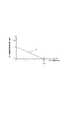
ここで、図7に1つのジョグ操作に応じて実行される上記のロボットアーム1の動作状態における初速(Vs)制御を行うための特性例を示す。 Here, FIG. 7 shows a characteristic example for performing the initial speed (Vs) control in the operation state of the
図7は、ロボットアーム1のジョグ動作において、初速(Vs)を決定する場合に停止前動作速度(Vl)に乗じる比率の特性の一例を示している。図7では、この比率を今回のジョグ動作の初速(Vs)と前回のジョグ動作の停止前動作速度(Vl)の比率として示してある。この初速/停止前動作速度比Vrは、波形Cで示すようにボタン解放時間(Tr)の長さに応じて変化するよう設定される。 FIG. 7 shows an example of the characteristic of the ratio by which the operating speed (Vl) before stop is multiplied when the initial speed (Vs) is determined in the jog operation of the
図7の縦軸は、停止前動作速度記憶部12に記憶した停止前動作速度(Vl)に対する初速(Vs)の比、この初速/停止前動作速度比Vrを示している。また、横軸は、ボタン解放時間計測(11)にて計測された今回のジョグ操作直前のボタン解放時間Trを示している。 The vertical axis in FIG. 7 indicates the ratio of the initial speed (Vs) to the pre-stop operation speed (Vl) stored in the pre-stop operation
図7の初速/停止前動作速度比Vrの波形Cは、ボタン解放時間Trが閾値Trt以上に長いか、あるいはそれよりも短いかによって異なる特性としてある。図7の例では、閾値TrtはTrt=15(秒)に設定してある。 The waveform C of the initial speed / pre-operation speed ratio Vr in FIG. 7 has different characteristics depending on whether the button release time Tr is longer than or shorter than the threshold value Trt. In the example of FIG. 7, the threshold value Trt is set to Trt = 15 (seconds).
図7の例では、ボタン解放時間Trが閾値Trtより短い、すなわち短かいインターバルで複数のジョグ操作が繰り返される場合は、ボタン解放時間Trが長くなるにつれて初速/停止前動作速度比Vrが小さくなる。すなわち、図7の初速/停止前動作速度比Vrは、ボタン解放時間Trが長くなるにつれて停止前動作速度(Vl)の65%〜0%(ないし0%に近い比率)の範囲で初速(Vs)が小さくなるように設定されている。 In the example of FIG. 7, when the button release time Tr is shorter than the threshold value Trt, that is, when a plurality of jog operations are repeated at a short interval, the initial speed / pre-operation speed ratio Vr decreases as the button release time Tr increases. . That is, the initial speed / pre-stop operation speed ratio Vr in FIG. 7 is within the range of 65% to 0% (or a ratio close to 0%) of the pre-stop operation speed (Vl) as the button release time Tr increases. ) Is set to be small.
また、ボタン解放時間Trが閾値Trt以上の場合には、初速/停止前動作速度比Vrは、ボタン解放時間Trに拘らず、初速(Vs)が停止前動作速度(Vl)の0%(ないし0%に近い比率としてもよい)に制御される。この初速/停止前動作速度比Vr=0の場合の処理例については後述する。 When the button release time Tr is equal to or greater than the threshold value Trt, the initial speed / pre-operation speed ratio Vr is 0% of the pre-stop operation speed (Vl), regardless of the button release time Tr. (The ratio may be close to 0%). An example of processing when the initial speed / pre-stop operating speed ratio Vr = 0 will be described later.
次に図5および図8を参照して、本実施例におけるロボット装置のジョグ動作を制御する制御手順を詳細に説明する。図示の手順はCPU501の制御プログラムとして例えばROM502に格納しておくことができる。 Next, a control procedure for controlling the jog operation of the robot apparatus according to the present embodiment will be described in detail with reference to FIGS. The illustrated procedure can be stored in, for example, the
ステップS1では、初回のジョグ動作のために、RAM503の停止前動作速度記憶部12に停止前動作速度として、予め低速度Vminを設定しておく。また、ステップS2では、初回のジョグ動作のために、RTC507を用いて、ボタン解放時間計測11を開始する。 In step S1, a low speed Vmin is set in advance as the pre-stop operation speed in the pre-stop operation
ステップS3では、操作ボタン103が押下されるのを待つ。操作ボタン103が押下されない間はステップS3を繰り返し、操作ボタン103が押下されるとステップS4に移行する。 In step S3, it waits for the
操作ボタン103が押下されるとステップS4において、ボタン解放時間計測11によって、今回、操作ボタン103が押下されるまでに操作ボタン103が押下されずにいた時間、すなわち、ボタン解放時間Trを取得する。 When the
ステップS5では、ボタン解放時間Trと、RAM503の停止前動作速度記憶部12に記憶されている停止前動作速度Vlに基づき、後述の図8に示すような演算を行い、ロボットアーム1を動作させる際の初速Vsを決定する。ステップS5中に示した関数的な表現Fs(Vl,Tr)は、後述の図8に示す初速演算に対応する。 In step S5, based on the button release time Tr and the pre-stop operating speed Vl stored in the pre-stop operating
ステップS6では、ステップS5で決定した初速Vsに従い、ドライバ508のサーボ制御(15)機能を介してロボットアーム1の各関節を制御する。これにより、ロボットアーム1のジョグ動作が開始される。この時の送り量(距離)は、ごく単純に表現するならば、V*ΔTと表現できる。ここで、ΔTはジョグ送りを制御するクロックの周期などに対応する微小区間の長さ、Vは微小区間においてCPU501による速度制御13で決定された速度である。 In step S6, each joint of the
ステップS7では、操作ボタン103が解放されたかどうかを確認する。ここで操作ボタン103が押下状態のままであればステップS8に進み、操作ボタン103が解放状態に変化していればステップS10に移行する。 In step S7, it is confirmed whether or not the
ステップS8では、CPU501の速度制御13により、ジョグ動作速度Vを更新する。これは加速または変化なしのいずれかである。操作ボタン103のジョグ操作が続いている間、図6に示したように、押下時間(T)に応じてロボットアーム1の動作速度Vを制御される。すなわち、最大速度Vmaxに到達するまでの間、押下時間に応じて動作速度Vが増加するような加速制御が行われる。この動作速度Vを決定する制御は、ステップS8中にFv(V,Vs,T)のような関数表現として示してある。 In step S8, the jog operation speed V is updated by the
ステップS9では、上記の微小区間(ΔT)において、決定された動作速度Vでサーボ制御15を行い、ロボットアーム1の軸送りを行う。この時の送り量の関数表現は、上記同様のV*ΔTである。これにより、ロボットアーム1は動作状態のまま維持され、その後、ステップS7に復帰する。 In step S9,
一方、ステップS7で操作ボタン103の押下が終っている場合、まず、ステップS10において現在の動作速度Vを用いてRAM503の停止前動作速度記憶部12の停止前動作速度Vlを更新する。続いて、ステップS11ではロボットアーム1の軸送りを停止させる。これにより、ロボットアーム1のジョグ動作が停止し、ロボットアーム1は停止状態に移行する。 On the other hand, when the pressing of the
ステップS12では、操作ボタン103の解放に応じ、新たにボタン解放時間Trの計測を開始するため、ボタン解放時間計測11をリセットし再度開始し、ステップS3に復帰する。 In step S12, in response to the release of the
上記ステップS5において、新たなジョグ操作に基づき開始されるロボットアーム1のジョグ動作における初速Vsの演算は、例えば図8に示すように構成することができる。 In step S5, the calculation of the initial speed Vs in the jog operation of the
図8のステップS51では、ボタン解放時間計測11の機能により計時されている今回のジョグ操作の直前のボタン解放時間Trが所定の閾値Trt(例えば数秒〜上記の15秒程度)以上であるか否かを判定する。この判定が肯定された場合にはステップS52へ、否定された場合にはステップS53に進む。 In step S51 of FIG. 8, whether or not the button release time Tr immediately before the current jog operation, which is timed by the function of the button
ステップS51でボタン解放時間Trが閾値Trt以上である場合は、ステップS52において、図7で説明した初速/停止前動作速度比Vrを0(%)とする。一方、ボタン解放時間Trが閾値Trtより小さい場合には、ステップS53において初速/停止前動作速度比VrをVr=C(Tr)のような関数によって決定する。この関数表現(C)は、図7の閾値Trtよりも左側において初速/停止前動作速度比Vrを決定する波形Cのカーブに該当する。 If the button release time Tr is greater than or equal to the threshold value Trt in step S51, the initial speed / pre-operation speed ratio Vr described in FIG. 7 is set to 0 (%) in step S52. On the other hand, if the button release time Tr is smaller than the threshold value Trt, the initial speed / pre-operation speed ratio Vr is determined by a function such as Vr = C (Tr) in step S53. This function expression (C) corresponds to a curve of a waveform C that determines the initial speed / pre-operation speed ratio Vr on the left side of the threshold value Trt in FIG.
ステップS52またはS53の後、ステップS54では、初速VsをRAM503の停止前動作速度記憶部12から読み出した前回のジョグ操作における停止前動作速度Vlと初速/停止前動作速度比Vrに基づき決定する。ここでは、初速Vsは、停止前動作速度Vlと初速/停止前動作速度比Vrの積として、すなわち、Vs=Vl*Vrとして求める。なお、ステップS52で、初速/停止前動作速度比Vrが0(%)とされている場合には、Vl*Vr=0となるが、上述の最低速度Vminとして0を用いる場合にはこれでよい。もし、最低速度Vminの値に0以外の値を用いる場合、例えば初速Vsに対してVmin*(1−Vr)を補正として追加する、すなわち初速Vs=Vl*Vr+Vmin*(1−Vr)と計算すればよい。より簡素に、例えばステップS54において計算した初速Vs=Vl*VrがVmin未満(Vs<Vmin)となっているか否かを調べ、Vmin未満の場合には初速Vsとして予め定められているVminの値を設定するよう制御してもよい。 After step S52 or S53, in step S54, the initial speed Vs is determined based on the pre-stop operating speed Vl and the initial speed / pre-stop operating speed ratio Vr in the previous jog operation read from the pre-stop operating
なお、上記の初速の演算により、あるジョグ動作の初速Vsが最低速度Vminとなる場合(ステップS52)には、例えば図6のジョグ動作(G1)のように、緩やかな加速期間を先頭に含む速度制御を行うようにしておけばよい。 When the initial speed Vs of a certain jog operation becomes the minimum speed Vmin by the above initial speed calculation (step S52), for example, as shown in the jog operation (G1) of FIG. Speed control should be performed.
以上のように、本実施例によれば、操作ボタン103のジョグ操作に応じてロボットアーム1をジョグ動作させる場合に、ロボットアーム1の動作状態における速度、特にその初速を自動的に制御することができる。 As described above, according to the present embodiment, when the
すなわち、ロボットアーム1の停止前動作速度Vlを記憶する記憶部として停止前動作速度記憶部12を設け、アームを停止状態から動作状態に移行させる場合、当該の動作状態におけるアームの初速を停止前動作速度Vlに応じて制御する。その場合、ボタン解放時間Trを計測する計時装置としてRTC507を設け、停止前動作速度Vlにボタン解放時間Trの長さに応じて定まる比率を乗じて得た速度値に初速Vsを制御する。例えば、ロボットアーム1が既に高速状態(G1)に達している場合には、今回の動作状態の初速Vsが停止前動作速度Vlよりも小さくなるような比率を乗じて得た速度値に初速Vsを制御する。 In other words, when the pre-stop operation
以上のような制御により、目標の位置姿勢の手前から、少しづつ目標の位置姿勢まで近づけて行くような教示操作において、初速減速とその後の加速を繰り返しながら、全体としては動作速度を徐々に自動的に減少させることができる。従って、目的の位置姿勢に近づくにつれてロボットアーム1の動作速度を自動的に減少させることができ、目的の位置姿勢に確実にロボットを停止させる教示操作が極めて容易になる。 With the control described above, in the teaching operation that gradually approaches the target position and orientation from the target position and orientation, the operation speed is gradually automatically increased as the whole while repeating the initial speed deceleration and the subsequent acceleration. Can be reduced. Therefore, the operation speed of the
また、本実施例では、ボタン解放時間Trが所定の閾値Trtよりも長い場合には、上記のような速度制御をリセットするようになっている。すなわち、ボタン解放時間Trが所定の閾値Trtよりも長い場合、一連の動作開始時には速度が低速から開始されるため、ロボットアーム1の突然の高速動作を防ぎ、ロボットアーム1に不都合な動作を行わせてしまうのを防止できる。 In the present embodiment, when the button release time Tr is longer than the predetermined threshold value Trt, the speed control as described above is reset. That is, when the button release time Tr is longer than the predetermined threshold value Trt, the speed starts from a low speed at the start of a series of operations, so that sudden high speed operation of the
なお、以上では、入力状態に応じてロボットアームの動作を制御するためのON操作またはOFF操作の入力状態を生成するスイッチにより構成された操作手段として、図3に示したような押しボタン構成の操作ボタン103を例示した。しかしながら、そのような操作手段がレバーやスライドスイッチのような形態を有する場合でも上述の構成を実施できるのはいうまでもない。 Note that, in the above, the push button configuration as shown in FIG. 3 is used as the operation means constituted by the switch for generating the input state of the ON operation or the OFF operation for controlling the operation of the robot arm according to the input state. The
また、このような操作手段(操作ボタン103)は必ずしもロボット制御装置2に接続された操作端末3(ティーチングペンダントなど)に配置される必要はない。このようなジョグ操作可能な操作手段(操作ボタン103)は、ロボット制御装置2に直接設けられていてもよく、また、ロボットアーム1の一部、例えばその架台部などに配置されていてもよい。あるいは、基幹LAN30などのネットワークを介して遠隔位置に配置された携帯端末やコンピュータ端末などの制御装置上に設けられている場合でも、上述と同様の構成を実施できるのはいうまでもない。 Further, such an operation means (operation button 103) is not necessarily arranged on the operation terminal 3 (such as a teaching pendant) connected to the
なお、以上では、図6のように例えばロボットアーム1が既に高速(ないし定速)状態に達した後に行う初速制御によって、全体としては除々にロボットアーム1を減速させていく例につき説明した。このような速度制御は、目標の位置姿勢の手前から、少しづつ目標の位置姿勢まで近づけて行くような教示操作を意図したものである。 In the above, an example in which the
しかしながら、上述とほぼ同様の制御によって、減速ではなくロボットアーム1を加速させるような初速制御を行ってもよい。例えば、図6のジョグ動作(G1)では、その最初の部分に緩やかな加速区間を配置している。この区間の加速度は、例えば機構の上限よりもかなり緩い加速度としているが、このような緩やかな加速区間において、上述と同様の制御によって、短いインターバルでジョグ動作が繰り返された場合に初速が大きくなっていくよう制御することができる。すなわち、ボタン解放時間Trに応じて、今回の動作状態の初速Vsが停止前動作速度Vlよりも大きくなるような比率を乗じて初速Vsを求めるのである。 However, initial speed control may be performed by accelerating the
このような初速Vsの「加速」特性を設定する初速/停止前動作速度比Vrの特性は、例えば図7の波形Cを上方に平行移動し、閾値Trtまでは165%〜100%の範囲で変化し、閾値Trt以降は0%が維持されるような波形(以下、C’という)である。そして、短いインターバルでジョグ操作が行なわれた(ボタン解放時間Trが短い)場合、ロボットアーム1が既に高速(ないし定速)状態に達していれば先述の通り、波形Cの初速/停止前動作速度比Vrを採用する。また、ロボットアーム1が加速中である場合には上記の波形C’の初速/停止前動作速度比Vrを採用する。このように、波形CまたはC’の初速/停止前動作速度比Vrのいずれを用いるかは、例えば次のように図8のステップS53で決定する。 The initial speed / pre-operation speed ratio Vr characteristic for setting the “acceleration” characteristic of the initial speed Vs is, for example, parallel movement of the waveform C in FIG. The waveform changes and is maintained at 0% after the threshold value Trt (hereinafter referred to as C ′). When the jog operation is performed at a short interval (the button release time Tr is short), if the
すなわち、図8のステップS53において、図6のジョグ動作(G1)の前半のように加速中か、それとも高速(ないし定速)状態に達しているかを判定する。そして、加速中ならVr=C’(Tr)、高速(ないし定速)状態であれば先述の通りVr=C(Tr)の初速/停止前動作速度比を設定する。ボタン解放時間Trが閾値Trt以上の場合の制御(図8のステップS52、S54)は上述と同様に実行する。これにより、ボタン解放時間Trが閾値Trtより長い場合には、上述同様、最低速度Vminからの加速を行う制御が行われる。 That is, in step S53 of FIG. 8, it is determined whether the vehicle is accelerating as in the first half of the jog operation (G1) of FIG. 6 or has reached a high speed (or constant speed) state. Then, an initial speed / pre-stop operation speed ratio of Vr = C ′ (Tr) is set during acceleration, and Vr = C (Tr) is set as described above in a high speed (or constant speed) state. Control when the button release time Tr is equal to or greater than the threshold value Trt (steps S52 and S54 in FIG. 8) is performed in the same manner as described above. As a result, when the button release time Tr is longer than the threshold value Trt, the control for accelerating from the minimum speed Vmin is performed as described above.
このような制御によって、例えば図6のジョグ動作(G1)の最初の部分に配置した緩やかな加速区間において、短いインターバルでジョグ操作を行うことによって、より急速にロボットアーム1を加速することができる。これにより、作業者の熟練度や、作業の都合に応じて、必要ならばデフォルトの初期加速度よりも急速な加速度によってロボットアーム1を加速することができる。 By such a control, for example, the
本発明は、操作手段の操作に応じて制御装置がロボットアームの動作を制御する種々のロボット装置において実施することができる。上述の実施例では、操作手段として操作端末3に設けられた操作ボタン103を例示したが、このような操作手段は、ロボット制御装置2や基台201に直接設けられていてもよく、また他の情報端末に設けられていてもよい。本発明の制御は、例えばロボット制御装置2のCPUのような演算手段によって実行される。従って上述した機能を実現するソフトウェアのプログラムを記録した記録媒体を画像検査装置に供給し、上記演算手段が記録媒体に格納されたプログラムを読み出し実行することによって達成されるよう構成することができる。この場合、記録媒体から読み出されたプログラム自体が上述した実施形態の機能を実現することになり、プログラム自体はもちろん、そのプログラムを記録した記録媒体は本発明を構成することになる。 The present invention can be implemented in various robot devices in which the control device controls the operation of the robot arm in accordance with the operation of the operation means. In the above-described embodiment, the
また、上記実施例では、コンピュータ読み取り可能な記録媒体がROM502や外部記憶装置504などの記憶デバイスであるものとして説明したが、本発明は上記実施例で例示した形態だけに限定されるものではない。例えば、本発明を実施するためのプログラムは、コンピュータ読み取り可能な記録媒体であれば、いかなる記録媒体に記録されていてもよい。例えば、プログラムを供給するための記録媒体としては、着脱式のHDDやSSD、光学ディスク、各種フラッシュメモリデバイスなど、任意の外部記憶デバイスを用いることができるのはいうまでもない。このような各種記憶デバイスは、本発明を構成するプログラムが格納されていれば、本発明のコンピュータ読み取り可能な記録媒体を構成することになる。 In the above-described embodiment, the computer-readable recording medium is described as a storage device such as the
1…ロボットアーム、2…ロボット制御装置、3…操作端末、103…操作ボタン、501…CPU、502…ROM、503…RAM、507…RTC。 DESCRIPTION OF
Claims (6)
Translated fromJapanese前記操作手段のOFF操作により前記ロボットアームを動作状態から停止状態に移行させる直前の前記ロボットアームの停止前動作速度を記憶する記憶部を設け、
前記制御装置は、前記操作手段のON操作により前記ロボットアームを停止状態から動作状態に移行させる場合、当該の動作状態における前記ロボットアームの初速を前記停止前動作速度に応じて決定することを特徴とするロボット装置。A control device that controls the operation of the robot arm according to the input state of the operation means configured by a switch that generates an input state of the ON operation or the OFF operation is provided, and the control device continues the ON operation of the operation means. In the robot apparatus that controls the robot arm to an operating state while the robot arm is in operation and shifts the robot arm to a stop state in response to an OFF operation of the operation means.
A storage unit is provided for storing an operation speed before stop of the robot arm immediately before the robot arm is shifted from an operation state to a stop state by an OFF operation of the operation means;
The control device determines an initial speed of the robot arm in the operation state according to the operation speed before the stop when the robot arm is shifted from the stop state to the operation state by the ON operation of the operation means. A robot device.
Priority Applications (1)
| Application Number | Priority Date | Filing Date | Title |
|---|---|---|---|
| JP2014120154AJP2015231659A (en) | 2014-06-11 | 2014-06-11 | Robot device |
Applications Claiming Priority (1)
| Application Number | Priority Date | Filing Date | Title |
|---|---|---|---|
| JP2014120154AJP2015231659A (en) | 2014-06-11 | 2014-06-11 | Robot device |
Publications (1)
| Publication Number | Publication Date |
|---|---|
| JP2015231659Atrue JP2015231659A (en) | 2015-12-24 |
Family
ID=54933490
Family Applications (1)
| Application Number | Title | Priority Date | Filing Date |
|---|---|---|---|
| JP2014120154APendingJP2015231659A (en) | 2014-06-11 | 2014-06-11 | Robot device |
Country Status (1)
| Country | Link |
|---|---|
| JP (1) | JP2015231659A (en) |
Cited By (5)
| Publication number | Priority date | Publication date | Assignee | Title |
|---|---|---|---|---|
| CN108009624A (en)* | 2017-12-14 | 2018-05-08 | 深圳狗尾草智能科技有限公司 | Machine man memory construction method and device |
| JP2020168686A (en)* | 2019-04-04 | 2020-10-15 | キヤノン株式会社 | Robot hands, robot devices, production systems, article manufacturing methods, control methods, and input devices |
| CN111843986A (en)* | 2019-04-26 | 2020-10-30 | 发那科株式会社 | Robot teaching device |
| CN111844085A (en)* | 2019-04-26 | 2020-10-30 | 发那科株式会社 | Robot teaching device |
| KR20240085917A (en)* | 2022-12-07 | 2024-06-18 | 한국생산기술연구원 | Meal Assistant Robot with Customized Speed Control Function |
- 2014
- 2014-06-11JPJP2014120154Apatent/JP2015231659A/enactivePending
Cited By (11)
| Publication number | Priority date | Publication date | Assignee | Title |
|---|---|---|---|---|
| CN108009624A (en)* | 2017-12-14 | 2018-05-08 | 深圳狗尾草智能科技有限公司 | Machine man memory construction method and device |
| JP2020168686A (en)* | 2019-04-04 | 2020-10-15 | キヤノン株式会社 | Robot hands, robot devices, production systems, article manufacturing methods, control methods, and input devices |
| JP7313868B2 (en) | 2019-04-04 | 2023-07-25 | キヤノン株式会社 | ROBOT HAND, ROBOT SYSTEM, PRODUCTION SYSTEM, PRODUCT MANUFACTURING METHOD, CONTROL METHOD, TERMINAL DEVICE, CONTROL PROGRAM, AND RECORDING MEDIUM |
| CN111843986A (en)* | 2019-04-26 | 2020-10-30 | 发那科株式会社 | Robot teaching device |
| CN111844085A (en)* | 2019-04-26 | 2020-10-30 | 发那科株式会社 | Robot teaching device |
| JP2020184117A (en)* | 2019-04-26 | 2020-11-12 | ファナック株式会社 | Robot instruction device |
| JP6993382B2 (en) | 2019-04-26 | 2022-02-04 | ファナック株式会社 | Robot teaching device |
| US11580972B2 (en) | 2019-04-26 | 2023-02-14 | Fanuc Corporation | Robot teaching device |
| CN111844085B (en)* | 2019-04-26 | 2024-05-28 | 发那科株式会社 | Robot teaching device |
| KR20240085917A (en)* | 2022-12-07 | 2024-06-18 | 한국생산기술연구원 | Meal Assistant Robot with Customized Speed Control Function |
| KR102844271B1 (en)* | 2022-12-07 | 2025-08-12 | 한국생산기술연구원 | Meal Assistant Robot with Customized Speed Control Function |
Similar Documents
| Publication | Publication Date | Title |
|---|---|---|
| JP3841439B2 (en) | Robot jog feed method | |
| JP6619395B2 (en) | Robot system and robot teaching method | |
| KR102031232B1 (en) | Robot system | |
| JP7049069B2 (en) | Robot system and control method of robot system | |
| CN102239454B (en) | Method and device for inputting commands in a control device of a manipulator | |
| JP4544145B2 (en) | Robot interference avoidance method and robot | |
| JP2015231659A (en) | Robot device | |
| US12138786B2 (en) | Teaching device, teaching method, and recording medium | |
| US10315305B2 (en) | Robot control apparatus which displays operation program including state of additional axis | |
| JP7208443B2 (en) | A control device capable of receiving direct teaching operations, a teaching device, and a computer program for the control device | |
| JP6904759B2 (en) | Robot movement speed control device and method | |
| WO1989008878A1 (en) | Method of controlling tool attitude of a robot | |
| JP2018069361A (en) | Force control coordinate axis setting device, robot, and force control coordinate axis setting method | |
| JPH077305B2 (en) | Robot direct teaching apparatus and direct teaching method | |
| JP3409090B2 (en) | Robot start / stop device | |
| JP2009078308A (en) | Robot direct teaching device | |
| JPH08267381A (en) | Robot manual feed controller | |
| JPS6329811A (en) | Multi-arm control device | |
| JP2016000439A (en) | Robot device | |
| JP7172485B2 (en) | robot controller | |
| JP6471446B2 (en) | Robot operation device, robot system, and robot operation program | |
| JPH04297904A (en) | robot | |
| KR102004228B1 (en) | The universal high speed/precision controller for six axis manipulator | |
| CN118742419A (en) | For guiding through programmed robotic systems | |
| JPH0550388A (en) | Industrial robots |