JP2015230892A - Battery module, power storage device, power storage system, electronic apparatus, electric vehicle and power system - Google Patents
Battery module, power storage device, power storage system, electronic apparatus, electric vehicle and power systemDownload PDFInfo
- Publication number
- JP2015230892A JP2015230892AJP2014118322AJP2014118322AJP2015230892AJP 2015230892 AJP2015230892 AJP 2015230892AJP 2014118322 AJP2014118322 AJP 2014118322AJP 2014118322 AJP2014118322 AJP 2014118322AJP 2015230892 AJP2015230892 AJP 2015230892A
- Authority
- JP
- Japan
- Prior art keywords
- battery
- battery module
- power
- battery cell
- close contact
- Prior art date
- Legal status (The legal status is an assumption and is not a legal conclusion. Google has not performed a legal analysis and makes no representation as to the accuracy of the status listed.)
- Pending
Links
Images


Classifications
- B—PERFORMING OPERATIONS; TRANSPORTING
- B60—VEHICLES IN GENERAL
- B60K—ARRANGEMENT OR MOUNTING OF PROPULSION UNITS OR OF TRANSMISSIONS IN VEHICLES; ARRANGEMENT OR MOUNTING OF PLURAL DIVERSE PRIME-MOVERS IN VEHICLES; AUXILIARY DRIVES FOR VEHICLES; INSTRUMENTATION OR DASHBOARDS FOR VEHICLES; ARRANGEMENTS IN CONNECTION WITH COOLING, AIR INTAKE, GAS EXHAUST OR FUEL SUPPLY OF PROPULSION UNITS IN VEHICLES
- B60K1/00—Arrangement or mounting of electrical propulsion units
- B60K1/04—Arrangement or mounting of electrical propulsion units of the electric storage means for propulsion
- H—ELECTRICITY
- H01—ELECTRIC ELEMENTS
- H01M—PROCESSES OR MEANS, e.g. BATTERIES, FOR THE DIRECT CONVERSION OF CHEMICAL ENERGY INTO ELECTRICAL ENERGY
- H01M50/00—Constructional details or processes of manufacture of the non-active parts of electrochemical cells other than fuel cells, e.g. hybrid cells
- H01M50/20—Mountings; Secondary casings or frames; Racks, modules or packs; Suspension devices; Shock absorbers; Transport or carrying devices; Holders
- B—PERFORMING OPERATIONS; TRANSPORTING
- B60—VEHICLES IN GENERAL
- B60K—ARRANGEMENT OR MOUNTING OF PROPULSION UNITS OR OF TRANSMISSIONS IN VEHICLES; ARRANGEMENT OR MOUNTING OF PLURAL DIVERSE PRIME-MOVERS IN VEHICLES; AUXILIARY DRIVES FOR VEHICLES; INSTRUMENTATION OR DASHBOARDS FOR VEHICLES; ARRANGEMENTS IN CONNECTION WITH COOLING, AIR INTAKE, GAS EXHAUST OR FUEL SUPPLY OF PROPULSION UNITS IN VEHICLES
- B60K6/00—Arrangement or mounting of plural diverse prime-movers for mutual or common propulsion, e.g. hybrid propulsion systems comprising electric motors and internal combustion engines
- B60K6/20—Arrangement or mounting of plural diverse prime-movers for mutual or common propulsion, e.g. hybrid propulsion systems comprising electric motors and internal combustion engines the prime-movers consisting of electric motors and internal combustion engines, e.g. HEVs
- B60K6/42—Arrangement or mounting of plural diverse prime-movers for mutual or common propulsion, e.g. hybrid propulsion systems comprising electric motors and internal combustion engines the prime-movers consisting of electric motors and internal combustion engines, e.g. HEVs characterised by the architecture of the hybrid electric vehicle
- B60K6/46—Series type
- H—ELECTRICITY
- H01—ELECTRIC ELEMENTS
- H01M—PROCESSES OR MEANS, e.g. BATTERIES, FOR THE DIRECT CONVERSION OF CHEMICAL ENERGY INTO ELECTRICAL ENERGY
- H01M50/00—Constructional details or processes of manufacture of the non-active parts of electrochemical cells other than fuel cells, e.g. hybrid cells
- H01M50/20—Mountings; Secondary casings or frames; Racks, modules or packs; Suspension devices; Shock absorbers; Transport or carrying devices; Holders
- H01M50/204—Racks, modules or packs for multiple batteries or multiple cells
- H01M50/207—Racks, modules or packs for multiple batteries or multiple cells characterised by their shape
- H01M50/211—Racks, modules or packs for multiple batteries or multiple cells characterised by their shape adapted for pouch cells
- H—ELECTRICITY
- H01—ELECTRIC ELEMENTS
- H01M—PROCESSES OR MEANS, e.g. BATTERIES, FOR THE DIRECT CONVERSION OF CHEMICAL ENERGY INTO ELECTRICAL ENERGY
- H01M50/00—Constructional details or processes of manufacture of the non-active parts of electrochemical cells other than fuel cells, e.g. hybrid cells
- H01M50/20—Mountings; Secondary casings or frames; Racks, modules or packs; Suspension devices; Shock absorbers; Transport or carrying devices; Holders
- H01M50/233—Mountings; Secondary casings or frames; Racks, modules or packs; Suspension devices; Shock absorbers; Transport or carrying devices; Holders characterised by physical properties of casings or racks, e.g. dimensions
- H01M50/24—Mountings; Secondary casings or frames; Racks, modules or packs; Suspension devices; Shock absorbers; Transport or carrying devices; Holders characterised by physical properties of casings or racks, e.g. dimensions adapted for protecting batteries from their environment, e.g. from corrosion
- H—ELECTRICITY
- H01—ELECTRIC ELEMENTS
- H01M—PROCESSES OR MEANS, e.g. BATTERIES, FOR THE DIRECT CONVERSION OF CHEMICAL ENERGY INTO ELECTRICAL ENERGY
- H01M50/00—Constructional details or processes of manufacture of the non-active parts of electrochemical cells other than fuel cells, e.g. hybrid cells
- H01M50/20—Mountings; Secondary casings or frames; Racks, modules or packs; Suspension devices; Shock absorbers; Transport or carrying devices; Holders
- H01M50/262—Mountings; Secondary casings or frames; Racks, modules or packs; Suspension devices; Shock absorbers; Transport or carrying devices; Holders with fastening means, e.g. locks
- H01M50/264—Mountings; Secondary casings or frames; Racks, modules or packs; Suspension devices; Shock absorbers; Transport or carrying devices; Holders with fastening means, e.g. locks for cells or batteries, e.g. straps, tie rods or peripheral frames
- H—ELECTRICITY
- H01—ELECTRIC ELEMENTS
- H01M—PROCESSES OR MEANS, e.g. BATTERIES, FOR THE DIRECT CONVERSION OF CHEMICAL ENERGY INTO ELECTRICAL ENERGY
- H01M50/00—Constructional details or processes of manufacture of the non-active parts of electrochemical cells other than fuel cells, e.g. hybrid cells
- H01M50/20—Mountings; Secondary casings or frames; Racks, modules or packs; Suspension devices; Shock absorbers; Transport or carrying devices; Holders
- H01M50/289—Mountings; Secondary casings or frames; Racks, modules or packs; Suspension devices; Shock absorbers; Transport or carrying devices; Holders characterised by spacing elements or positioning means within frames, racks or packs
- H01M50/291—Mountings; Secondary casings or frames; Racks, modules or packs; Suspension devices; Shock absorbers; Transport or carrying devices; Holders characterised by spacing elements or positioning means within frames, racks or packs characterised by their shape
- H—ELECTRICITY
- H01—ELECTRIC ELEMENTS
- H01M—PROCESSES OR MEANS, e.g. BATTERIES, FOR THE DIRECT CONVERSION OF CHEMICAL ENERGY INTO ELECTRICAL ENERGY
- H01M50/00—Constructional details or processes of manufacture of the non-active parts of electrochemical cells other than fuel cells, e.g. hybrid cells
- H01M50/50—Current conducting connections for cells or batteries
- H01M50/502—Interconnectors for connecting terminals of adjacent batteries; Interconnectors for connecting cells outside a battery casing
- H01M50/503—Interconnectors for connecting terminals of adjacent batteries; Interconnectors for connecting cells outside a battery casing characterised by the shape of the interconnectors
- B—PERFORMING OPERATIONS; TRANSPORTING
- B60—VEHICLES IN GENERAL
- B60L—PROPULSION OF ELECTRICALLY-PROPELLED VEHICLES; SUPPLYING ELECTRIC POWER FOR AUXILIARY EQUIPMENT OF ELECTRICALLY-PROPELLED VEHICLES; ELECTRODYNAMIC BRAKE SYSTEMS FOR VEHICLES IN GENERAL; MAGNETIC SUSPENSION OR LEVITATION FOR VEHICLES; MONITORING OPERATING VARIABLES OF ELECTRICALLY-PROPELLED VEHICLES; ELECTRIC SAFETY DEVICES FOR ELECTRICALLY-PROPELLED VEHICLES
- B60L50/00—Electric propulsion with power supplied within the vehicle
- B60L50/50—Electric propulsion with power supplied within the vehicle using propulsion power supplied by batteries or fuel cells
- B60L50/60—Electric propulsion with power supplied within the vehicle using propulsion power supplied by batteries or fuel cells using power supplied by batteries
- B60L50/64—Constructional details of batteries specially adapted for electric vehicles
- H—ELECTRICITY
- H01—ELECTRIC ELEMENTS
- H01M—PROCESSES OR MEANS, e.g. BATTERIES, FOR THE DIRECT CONVERSION OF CHEMICAL ENERGY INTO ELECTRICAL ENERGY
- H01M2220/00—Batteries for particular applications
- H01M2220/10—Batteries in stationary systems, e.g. emergency power source in plant
- H—ELECTRICITY
- H01—ELECTRIC ELEMENTS
- H01M—PROCESSES OR MEANS, e.g. BATTERIES, FOR THE DIRECT CONVERSION OF CHEMICAL ENERGY INTO ELECTRICAL ENERGY
- H01M2220/00—Batteries for particular applications
- H01M2220/20—Batteries in motive systems, e.g. vehicle, ship, plane
- H—ELECTRICITY
- H01—ELECTRIC ELEMENTS
- H01M—PROCESSES OR MEANS, e.g. BATTERIES, FOR THE DIRECT CONVERSION OF CHEMICAL ENERGY INTO ELECTRICAL ENERGY
- H01M2220/00—Batteries for particular applications
- H01M2220/30—Batteries in portable systems, e.g. mobile phone, laptop
- Y—GENERAL TAGGING OF NEW TECHNOLOGICAL DEVELOPMENTS; GENERAL TAGGING OF CROSS-SECTIONAL TECHNOLOGIES SPANNING OVER SEVERAL SECTIONS OF THE IPC; TECHNICAL SUBJECTS COVERED BY FORMER USPC CROSS-REFERENCE ART COLLECTIONS [XRACs] AND DIGESTS
- Y02—TECHNOLOGIES OR APPLICATIONS FOR MITIGATION OR ADAPTATION AGAINST CLIMATE CHANGE
- Y02E—REDUCTION OF GREENHOUSE GAS [GHG] EMISSIONS, RELATED TO ENERGY GENERATION, TRANSMISSION OR DISTRIBUTION
- Y02E60/00—Enabling technologies; Technologies with a potential or indirect contribution to GHG emissions mitigation
- Y02E60/10—Energy storage using batteries
- Y—GENERAL TAGGING OF NEW TECHNOLOGICAL DEVELOPMENTS; GENERAL TAGGING OF CROSS-SECTIONAL TECHNOLOGIES SPANNING OVER SEVERAL SECTIONS OF THE IPC; TECHNICAL SUBJECTS COVERED BY FORMER USPC CROSS-REFERENCE ART COLLECTIONS [XRACs] AND DIGESTS
- Y02—TECHNOLOGIES OR APPLICATIONS FOR MITIGATION OR ADAPTATION AGAINST CLIMATE CHANGE
- Y02T—CLIMATE CHANGE MITIGATION TECHNOLOGIES RELATED TO TRANSPORTATION
- Y02T10/00—Road transport of goods or passengers
- Y02T10/60—Other road transportation technologies with climate change mitigation effect
- Y02T10/70—Energy storage systems for electromobility, e.g. batteries
Landscapes
- Chemical & Material Sciences (AREA)
- Chemical Kinetics & Catalysis (AREA)
- Electrochemistry (AREA)
- General Chemical & Material Sciences (AREA)
- Engineering & Computer Science (AREA)
- Transportation (AREA)
- Mechanical Engineering (AREA)
- Combustion & Propulsion (AREA)
- Life Sciences & Earth Sciences (AREA)
- Sustainable Development (AREA)
- Sustainable Energy (AREA)
- Power Engineering (AREA)
- Connection Of Batteries Or Terminals (AREA)
- Battery Mounting, Suspending (AREA)
- Hybrid Electric Vehicles (AREA)
- Arrangement Or Mounting Of Propulsion Units For Vehicles (AREA)
Abstract
Description
Translated fromJapanese本技術は、電池モジュール、蓄電装置、蓄電システム、電子機器、電動車両および電力システムに関する。 The present technology relates to a battery module, a power storage device, a power storage system, an electronic device, an electric vehicle, and a power system.
近年、リチウムイオン二次電池は、電気自動車や蓄電用等産業用向けに普及し始めている。軽量化、省スペース化という観点から、車の鉛蓄電池をリチウムイオン二次電池に置き換える市場が増えつつある。リチウムイオン二次電池を自動車等に用いる際には、振動や衝撃対策のために様々な固定方法がとられている。 In recent years, lithium ion secondary batteries have begun to spread for industrial use such as electric vehicles and power storage. From the viewpoint of weight reduction and space saving, the market for replacing lead-acid batteries in cars with lithium ion secondary batteries is increasing. When a lithium ion secondary battery is used in an automobile or the like, various fixing methods are taken for measures against vibration and impact.
例えば特許文献1には、端子がバスバーに接合された複数のセルユニットを、各セルユニットの高さを調整して固定させるためのロッドにより固定する構成が開示されており、これにより、端子に応力が生じるのを防止することで信頼性、耐久性を向上させている。 For example,
例えば特許文献2には、棒状部材の端面と端面の間に端子板を挟みこんで組電池を固定する構造が開示されている。 For example, Patent Document 2 discloses a structure in which a battery pack is fixed by inserting a terminal plate between end faces of a rod-shaped member.
電池モジュールでは、電池セル間の接続の長期信頼性を向上することが求められている。 Battery modules are required to improve the long-term reliability of connection between battery cells.
したがって、本技術の目的は、電池セル間の接続の長期信頼性を向上することができる電池モジュール、並びに、これを備えた蓄電装置、蓄電システム、電子機器、電動車両および電力システムを提供することにある。 Therefore, an object of the present technology is to provide a battery module that can improve long-term reliability of connection between battery cells, and a power storage device, a power storage system, an electronic device, an electric vehicle, and a power system including the battery module. It is in.
上述した課題を解決するために、本技術は、積層された複数の電池ユニットを少なくとも含む積層体と、積層体を貫通する絶縁性棒状体と、積層体を貫通した絶縁性棒状体の両端から積層体を締め付ける締め付け部とを備え、電池ユニットは、複数の電池セルと、両端面の間を貫通する第1の孔が形成された連結部を有し、且つ、複数の電池セルが保持される電池支持体と、第2の孔が形成され、且つ、連結部の両端面のうちの一方または他方の端面に密接される密接部および電池セルの電極タブに接合される接合部を含む導電性部材とを有し、絶縁性棒状体が、積層された複数のユニットの第1の孔および第2の孔を通り、積層方向に沿った直線上に位置する複数の電池ユニットの連結部および密接部を貫通し、締め付け部によって積層体が締め付けられて複数の電池ユニットが締結され、隣り合う電池ユニットの導電性部材の密接部が互いに密接されて、隣り合う電池ユニット間が電気的に接続された電池モジュールである。 In order to solve the above-described problem, the present technology provides a laminated body including at least a plurality of laminated battery units, an insulating rod-like body penetrating the laminated body, and both ends of the insulating rod-like body penetrating the laminated body. The battery unit includes a plurality of battery cells and a connection part in which a first hole penetrating between both end faces is formed, and the plurality of battery cells are held. A battery support, a second hole, and a conductive portion including a close contact portion that is in close contact with one or the other end surface of the connection portion and a joint portion that is bonded to the electrode tab of the battery cell. A connecting portion of a plurality of battery units positioned on a straight line along the stacking direction through the first hole and the second hole of the plurality of stacked units. Laminate through the tight part and tightening part Is clamped by a plurality of battery units is fastened, is tightly close portions of the conductive members of the battery unit adjacent to each other, between the adjacent cell units are electrically connected battery modules.
本技術の蓄電装置、蓄電システム、電子機器、電動車両および電力システムは、上述の電池モジュールを備えるものである。 A power storage device, a power storage system, an electronic device, an electric vehicle, and a power system according to the present technology include the above-described battery module.
本技術によれば、電池セル間の接続の長期信頼性を向上することができる。 According to the present technology, long-term reliability of connection between battery cells can be improved.
(技術的背景)
まず、本技術の理解を容易にするため、本技術の技術的背景について説明する。複数の電池セルを含む電池モジュールでは、体積エネルギー密度を向上するために電池以外の部品が占有する体積を減らす必要がある。このため、部品の小型化、部品点数の削減が求められている。(Technical background)
First, in order to facilitate understanding of the present technology, the technical background of the present technology will be described. In a battery module including a plurality of battery cells, it is necessary to reduce the volume occupied by components other than the battery in order to improve the volume energy density. For this reason, downsizing of parts and reduction of the number of parts are required.
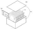
典型的な電池モジュールでは、電池セル間を接続するバスバー同士をボルトで接続する方法が、一般的に使用されている。典型的な電池モジュールの構成例の概略を説明する。図1は、典型的な電池モジュールの構成例を示す分解斜視図である。図2は、典型的な電池モジュールの構成例の一部を拡大した斜視図である。図3は、ユニットバスバーによる接続前の隣接する2つの電池ユニットの状態を拡大した斜視図である。 In a typical battery module, a method of connecting bus bars for connecting battery cells with bolts is generally used. An outline of a configuration example of a typical battery module will be described. FIG. 1 is an exploded perspective view showing a configuration example of a typical battery module. FIG. 2 is an enlarged perspective view of a part of a configuration example of a typical battery module. FIG. 3 is an enlarged perspective view of the state of two adjacent battery units before connection by the unit bus bar.
図1〜図3に示すように、電池モジュール200は、エンドプレート201および202の間に、複数の電池ユニット210から構成された電池セル群203’が配置される。 As shown in FIGS. 1 to 3, in the
電池セル群203’の各電池ユニット210の一側面には、隣接する電池ユニット210間を接続するための、例えば銅、アルミニウム等からなる導電性部材(以下、ユニットバスバーと称される)214が取り付けられている。ユニットバスバー214は、所望の電池接続を実現するように、複数の電池ユニット210に跨がって取り付けられる。図3に示すように隣り合った集電部211がユニットバスバー214によって接続されている。ユニットバスバー214の孔にフローティングボルト212を通してナットで締め付けることによりユニットバスバー214が取り付けられる。 On one side surface of each
誤挿入防止用カバー221が、電池セル群203’の手前側の側面に対して被装される。誤挿入防止用カバー221は、ユニットバスバー214の位置を規定するものであり、ユニットバスバー214の誤挿入を防止するために設けられる。 A
上述の電池モジュール200では、ボルトのトルク管理により接続部分の接触抵抗を低減させる方法が一般的に適用されている。しかしながら、バスバーの数が多くなった場合には、これに伴いバスバー同士を接続するためのボルト数も増加するため管理することが困難であった。 In the
上述の電池モジュール200では、電池ユニット210を並べて、ユニットバスバー214で集電部211同士を接続する構造を採用している。しかしながら、隣り合った集電部211の面のズレによりユニットバスバー214の安定した面接触が難しくなっていた。また、ユニットバスバー214では、大電流を用いる為、薄肉化等によって柔軟性を持たせることが困難であった。 The
上述の電池モジュール200では、組み付け時にユニットバスバー214を誤挿入すると誤った接続によりショート等の致命的な問題が発生していた。その防止方法の一つとして、別部品の誤挿入防止用カバー221等を用いていた。しかしながら、誤挿入防止用カバー221が適切な位置からずれている場合等、ショートが発生する可能性を排除できない状況であった。 In the
上述の電池モジュール200では、スタットボルト等のリジット構造を採用した場合、振動時にボルトの根元に応力が集中してボルトがせん断することがあり、解決策としてフローティングボルト212を用いる方法が一般的であった。しかしながら、この方法を採用した場合には、構造が複雑になりコストアップの要因の一つとなっていた。 In the
以下、本技術の実施の形態について図面を参照して説明する。なお、説明は、以下の順序で行う。
1.第1の実施の形態(電池モジュールの第1の例)
2.第2の実施の形態(電池モジュールの第2の例)
3.他の実施の形態(変形例)
4.応用例
なお、以下に説明する実施の形態等は本技術の好適な具体例であり、本技術の内容がこれらの実施の形態等に限定されるものではない。また、本明細書に記載された効果はあくまで例示であって限定されるものではなく、また例示した効果と異なる効果が存在することを否定するものではない。Hereinafter, embodiments of the present technology will be described with reference to the drawings. The description will be given in the following order.
1. First embodiment (first example of battery module)
2. Second embodiment (second example of battery module)
3. Other embodiment (modification)
4). Application Examples Note that the embodiments described below are suitable specific examples of the present technology, and the contents of the present technology are not limited to these embodiments. Moreover, the effect described in this specification is an illustration to the last, is not limited, and does not deny that the effect different from the illustrated effect exists.
1.第1の実施の形態
(電池モジュールの構成)
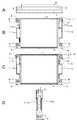
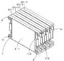
本技術の第1の実施の形態による電池モジュールの構成例について説明する。図4は、電池モジュールの構成例を示す斜視図である。1. First Embodiment (Configuration of Battery Module)
A configuration example of the battery module according to the first embodiment of the present technology will be described. FIG. 4 is a perspective view showing a configuration example of the battery module.
図4に示すように、電池モジュール100は、エンドプレート101およびエンドプレート102の間に電池セル群103が配置された構成を有する。 As shown in FIG. 4, the
(エンドプレート)
エンドプレート101およびエンドプレート102は、例えば、アルミニウム、鉄等の金属の板、または、これを形状加工したもの等で構成されている。エンドプレート101およびエンドプレート102のそれぞれの4隅には、シャフト106を貫通させるための孔7が形成されている。(end plate)
The
(電池セル群)
電池セル群103は、複数の電池セルがそれぞれ電池支持体(以下、ブラケットと称する)に収納された電池ユニット20が、複数個積層されたものである。第1の実施の形態では、例えば2個の電池セルが各ブラケット1内に収納される。ブラケット1は、例えば、合成樹脂の成型品である。電池セル群103は、8個の電池ユニット20−1〜20−8(すなわち、16個の電池セル)が水平方向に積層されたものである。なお、個々の電池ユニットを区別する必要がないときは、単に電池ユニット20と称する。図4では図示を省略するが、電池セル群103の底面側には、8個のブラケット1のそれぞれから導出され、L字状に折り曲げられた伝熱プレート108が露出している。この伝熱プレート108が冷却モジュール(図示せず)と接触し、電池セルで発生する熱を、例えば、冷却モジュール等に伝達し、放熱させている。なお、伝熱プレート108および冷却モジュールを省略した構成としてもよい。(Battery cell group)
The
(電池ユニット)
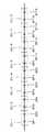
電池セル群103を構成する単位である電池ユニット20について説明する。図5は、電池ユニットの斜視図である。図6A〜図6Dは、電池ユニットの底面図、正面図、背面図、右側面図である。(Battery unit)
The
図5および図6A〜図6Dに示すように、電池ユニット20は、2個の電池セル4−1および電池セル4−2と、2個の電池セル4−1および電池セル4−2とが収納されるブラケット1と、伝熱プレート2とを備える。また、電池ユニット20の両側面のそれぞれに対して、導電性部材である第1のバスバー113および第2のバスバー114が取り付けられている。なお、電池セルを個々に区別する必要がない場合には、電池セル4と称する。電池セル4は、例えば、略直方体状、扁平状等の形状を有する。電池セル4の表面の中の最も面積の大きい面を主面と称する。 As shown in FIGS. 5 and 6A to 6D, the
(ブラケット)
ブラケット1は、例えば、絶縁材(合成樹脂等)からなる。ブラケット1は、例えば、合成樹脂の成型品である。インサート成型によって、ブラケット1と一体にアルミニウム等の金属の伝熱プレート2が形成されている。インサート成型は、金型内に埋め込み対象であるインサート品(ここでは、伝熱プレート2、下記の絶縁カラー8)を装填した後、成型機に樹脂を注入し、インサート品を溶融樹脂で包み込んで固化させ、樹脂とインサート品とを一体化する成型方法である。なお、インサート成型によってブラケット1と第1のバスバー113および第2のバスバー114とが一体に形成されていてもよい。この場合、省スペース化が可能になり、電池容量の向上に寄与できる。また、伝熱プレート2を省略した構成としてもよい。(bracket)
The
ブラケット1は、略直方体状の外形を有し、ブラケット1の右側面の両端部のそれぞれには、連結部9が突設されている。同様に、ブラケット1の左側面の両端部のそれぞれには、連結部9が突設されている。これらの4つの連結部9のそれぞれには、連結部9の両端面(正面側の面および背面側の面)の間を貫通する孔7が形成されている。孔7を形成するために、連結部9には中空を有する管状の絶縁性部材として絶縁カラー8が内設されている。例えば、絶縁カラー8はインサート成型によってブラケット1と一体に形成され、絶縁カラー8の中空が連結部9に形成される孔7となる。絶縁カラー8を内設することによって、環境温度の変化による膨張収縮時の影響が少なくなる。絶縁カラー8の材料としては、例えば、アルミナ等のセラミックス等の絶縁材料が挙げられる。 The
ブラケット1の正面および背面のそれぞれには、1組の電池セル4−1および電池セル4−2のそれぞれが収納される空間からなる収納部が形成されている。例えば、収納部は、凹状に形成された略直方体状の空間である。収納部の深さは、電池セル4の主面が突出しないように、電池セル4の厚さより大きくされていることが好ましい。収納部の底面は、例えば、開口を有するように枠状に形成された絶縁材(ブラケット1)に固着された伝熱プレート2を含む。1組の収納部は、伝熱プレート2および絶縁材からなる底面を中心面として略対称となるように形成される。 Each of the front surface and the back surface of the
伝熱プレート2は、ブラケット1の中央の開口に位置し、電池セル4の貼り付け面を構成する。さらに、伝熱プレート2の端部がブラケット1の外方に突出され、ブラケット1の側面に沿うように、ほぼL字状に折り曲げられ、折り曲げ部2aが形成される。折り曲げ部2aの幅は、電池ユニット20の幅の1.5倍よりやや小とされている。したがって、折り曲げ部2aの先端が電池ユニット20の幅より突出している。図示は省略するが伝熱プレート2の折り曲げ部2aが冷却モジュールの冷却面と接触される。冷却モジュールは、例えば、水冷式または空冷式の冷却装置等である。 The heat transfer plate 2 is located in the central opening of the
図6A〜図6Dに示す例では、伝熱プレート2の一端をL字状に折り曲げている。なお、伝熱プレート2の他端も同様にブラケット1より外方へ突出させて同様に、L字状に折り曲げても良い。さらに、先端が両側に延びる断面T字状もしくはH字状としても良い。 In the example shown in FIGS. 6A to 6D, one end of the heat transfer plate 2 is bent into an L shape. Similarly, the other end of the heat transfer plate 2 may be protruded outward from the
伝熱プレート2に対して電池セル4−1および電池セル4−2の主面がブラケット1と一体の伝熱プレート2の面に対して密着される。図示は省略するが、伝熱プレート2と電池セル4−1の主面との間には、熱伝導粘着シートが介在されていてもよい。同様に、伝熱プレート2と電池セル4−2の主面との間には、熱伝導粘着シートが介在されていてもよい。 The main surfaces of the battery cell 4-1 and the battery cell 4-2 are in close contact with the surface of the heat transfer plate 2 integrated with the
電池セル4−1および電池セル4−2のそれぞれの両側面から正負極の電極タブ111が導出されている。電池セル4−1および電池セル4−2のブラケット1への取り付けの向きによって、電極タブ111の正負の極性が変化する。図6Bおよび図6Cに示すように、電池セル4−1の正極タブ111aと電池セル4−2の負極タブ111bとが、ブラケット1の一方の側面側から突出されている。電池セル4−1の負極タブ111bと電池セル4−2の正極タブ111aとが、ブラケット1の他方の側面側から突出されている。なお、正極タブ111aと負極タブ111bとを個々に区別する必要がない場合には、電極タブ111と称している。 Positive and
(電池セルの構成)
図7Aは、本技術に使用できる電池セル4の外観を示す略線図である。電池セル4は、非水電解質電池等であり、例えばリチウムイオン二次電池等である。図7Bは、電池セル4の構成を示す略線図である。なお、図7は、図7Aに示す電池セル4の底面および上面を反転させた場合の構成を示している。図7Cは、電池セル4の外観底面側を示す略線図である。電池セル4は、電池素子121と、電池素子121を収容する外装材122とを備える。(Battery cell configuration)
FIG. 7A is a schematic diagram illustrating an appearance of a
外装材122は、電池素子121を収容する第1外装部122Aと、電池素子121を覆う蓋として機能する第2外装部122Bとから構成されている。外装材122と電池素子121とが密着していることが好ましい。 The
電池素子121は、略矩形状の正極と、この正極と対向して配された略矩形状の負極とが、セパレータを介して交互に積層された積層型電極構造を有している。また、電池素子121からは、複数枚の正極とそれぞれ電気的に接続された正極集電体露出部と、複数枚の負極とそれぞれ電気的に接続された負極集電体露出部とが引き出されている。正極集電体露出部および負極集電体露出部には、それぞれ正極タブ111aおよび負極タブ111bが接続されている。 The
このような電池素子121は、外装材122にて外装されており、正極タブ111aおよび負極タブ111bは、外装材122の封止部から電池セル4の外部に導出されている。外装材122は、少なくとも一方の面、または両面に予め深絞り加工が施されることにより凹部123が形成され、この凹部123に電池素子121が収納される。図7Bでは、外装材122を構成する第1外装部122Aに凹部123が形成されており、電池素子121はこの凹部123に収納される。 Such a
そして、第2外装部122Bが凹部123の開口を覆うように配置され、凹部123の開口の周囲が溶着等により接着されることにより封止される。正極タブ111aおよび負極タブ111bは、対向する2方向から導出されている。 And the 2nd
外装材122としては、フィルム状の外装材等を用いることができる。フィルム状の外装材としては、例えば、ナイロンフィルム、アルミニウム箔およびポリエチレンフィルムがこの順に貼り合わされたアルミラミネートフィルム等のように、金属箔からなる金属層の両面に樹脂層を設けた構成を有するものが挙げられる。 As the
外装材122の一例としては、例えば、外側樹脂層/金属層/内側樹脂層の積層構造を有するものが挙げられる。外装材122は、例えば、内側樹脂層が電池素子と対向するように、2枚の矩形型のアルミラミネートフィルムの外縁部同士が融着または接着剤によって互いに接着された構造を有している。外側樹脂層および内側樹脂層は、それぞれ複数層で構成されてもよい。 As an example of the
金属層を構成する金属材料としては、耐透湿性のバリア膜としての機能を備えていれば良く、アルミニウム(Al)箔、ステンレス(SUS)箔、ニッケル(Ni)箔およびメッキを施した鉄(Fe)箔等を使用することができる。なかでも、薄く軽量で加工性に優れるアルミニウム箔を好適に用いることが好ましい。特に、加工性の点から、例えば焼きなまし処理済みのアルミニウム(JIS A8021P−O)、(JIS A8079P−O)または(JIS A1N30−O)等を用いるのが好ましい。 The metal material constituting the metal layer only needs to have a function as a moisture-permeable barrier film, and includes aluminum (Al) foil, stainless steel (SUS) foil, nickel (Ni) foil, and plated iron ( Fe) foil or the like can be used. Especially, it is preferable to use the aluminum foil which is thin and lightweight and excellent in workability. In particular, from the viewpoint of workability, for example, annealed aluminum (JIS A8021P-O), (JIS A8079P-O), or (JIS A1N30-O) is preferably used.
金属層の厚みは、典型的には、例えば、30μm以上150μm以下とすることが好ましい。30μm未満の場合、材料強度が低減する傾向にある。また、150μmを超えた場合、加工が著しく困難になるとともに、ラミネートフィルムの厚さが増してしまい、非水電解質電池の体積効率が低減する傾向にある。 The thickness of the metal layer is typically preferably 30 μm or more and 150 μm or less, for example. When the thickness is less than 30 μm, the material strength tends to decrease. Moreover, when it exceeds 150 micrometers, while processing becomes remarkably difficult, the thickness of a laminate film will increase and it exists in the tendency for the volumetric efficiency of a nonaqueous electrolyte battery to reduce.
内側樹脂層は、熱で溶けて互いに融着する部分であり、ポリエチレン(PE)、無軸延伸ポリプロピレン(CPP)、ポリエチレンテレフタレート(PET)、低密度ポリエチレン(LDPE)、高密度ポリエチレン(HDPE)、直鎖状低密度ポリエチレン(LLDPE)等が使用可能であり、これらから複数種類選択して用いることも可能である。 The inner resin layer is a part that is melted by heat and fused to each other, such as polyethylene (PE), non-axially oriented polypropylene (CPP), polyethylene terephthalate (PET), low density polyethylene (LDPE), high density polyethylene (HDPE), Linear low density polyethylene (LLDPE) or the like can be used, and a plurality of these can be selected and used.
外側樹脂層としては、外観の美しさや強靱さ、柔軟性等からポリオレフィン系樹脂、ポリアミド系樹脂、ポリイミド系樹脂、ポリエステル等が用いられる。具体的には、ナイロン(Ny)、ポリエチレンテレフタレート(PET)、ポリエチレンナフタレート(PEN)、ポリブチレンテレフタレート(PBT)、ポリブチレンナフタレート(PBN)が用いられ、これらから複数種類選択して用いることも可能である。 As the outer resin layer, polyolefin-based resin, polyamide-based resin, polyimide-based resin, polyester, or the like is used because of its beautiful appearance, toughness, flexibility, and the like. Specifically, nylon (Ny), polyethylene terephthalate (PET), polyethylene naphthalate (PEN), polybutylene terephthalate (PBT), and polybutylene naphthalate (PBN) are used. Is also possible.
外装材122は、上記した積層構造を有するアルミラミネートフィルムに代えて、他の積層構造を有するラミネートフィルムによって構成されていてもよいし、ポリプロピレン等の高分子フィルムまたは金属フィルム等のフィルム状の外装材によって構成されていてもよい。 The
なお、本技術に適用できる電池セルの構成は、上述したものに限定されない。例えばセパレータを長尺の帯状に形成してつづら折りにより折り畳み、正極および負極を折り畳んだセパレータの間に挟み込むことにより積層した構成にしても良い。さらに、正極タブおよび負極タブが取り付けられた巻回電極体をフィルム状の外装材の内部に収容した構成にしても良い。 In addition, the structure of the battery cell applicable to this technique is not limited to what was mentioned above. For example, the separator may be formed in a long band shape, folded by zigzag folding, and stacked by sandwiching the positive electrode and the negative electrode between the folded separators. Furthermore, you may make it the structure which accommodated the winding electrode body to which the positive electrode tab and the negative electrode tab were attached in the inside of a film-form exterior material.
(バスバー)
図8Aは、第1のバスバーの構成例を示す斜視図であり、図8Bは、第2のバスバーの構成例を示す斜視図である。第1のバスバー113は、隣り合う電池ユニット20間を電気的に接続する銅、アルミ等の導電性材料からなる導電性部材である。第2のバスバー114は、1つの電池ユニット20を構成する2つの電池セル4間を電気的に接続する銅、アルミ等からなる導電性材料からなる導電性部材である。(Bus bar)
FIG. 8A is a perspective view illustrating a configuration example of the first bus bar, and FIG. 8B is a perspective view illustrating a configuration example of the second bus bar. The
(第1のバスバー)
図8Aに示すように、第1のバスバー113は、少なくとも接合部113bと、密接部113aとを有する導電性板状体である。接合部113bは、外側の面が少なくとも電池セル4の電極タブ111と接合される部分である。密接部113aは、外側の面と反対側の内側の面がブラケット1の連結部9に密接されると共に、外側の面が他の第1のバスバー113の密接部113aの外側の面と密接される部分である。(First bus bar)
As shown in FIG. 8A, the
2つの第1のバスバー113の密接部113aのそれぞれが連結部9の両端面のそれぞれに密接され、2つの密接部113aが連結部9を挟んでブラケット1に取り付けられる。密接部113aには、連結部9に設けられた孔7と略同じ大きさの孔113cが設けられている。1組の第1のバスバー113がブラケット1に取り付けられた状態では、連結部9および連結部9を挟んだ密接部113aをシャフト106が貫通できるようにするため、1組の密接部113aの孔113cと連結部9の孔7との位置が積層方向に沿った直線上に合わされる。 Each of the
図8Aに示す第1のバスバー113の一例は、矩形の板状体の長手方向の略中央部に段差を有するように2カ所略直角に折り曲げた折り曲げ部を有する導電性板状体である。 An example of the
この折り曲げ部を有する導電性板状体は、例えば、密接部113aとして一の折り曲げ部から長手方向の一端にわたる矩形の平面形状を有する部分と、接合部として他の折り曲げ部から長手方向の他端にわたる矩形の平面形状を有する部分と、一の折り曲げ部と他の折り曲げ部との間の矩形の平面形状を有する部分とを有するものである。 For example, the conductive plate-like body having the bent portion includes a portion having a rectangular planar shape extending from one bent portion to one end in the longitudinal direction as the
(第2のバスバー)
図8Bに示すように、第2のバスバー114は、1つの電池ユニット20を構成する一方の電池セル4−1の電極タブ111と接合される第1の接合部114aと、他方の電池セル4−2の電極タブ111と接合される第2の接合部114bとを少なくとも有する導電性板状体である。(Second bus bar)
As shown in FIG. 8B, the
図8Bに示す第2のバスバー114の一例は、例えば、底部と、第1の接合部114aおよび第2の接合部114bとして、底部の両端部の少なくとも一部にそれぞれ立設された互いに対向する一組の壁部とを含む導電性板状体である。 In the example of the
(電池セル間および電池ユニット間の接続構造)
複数の電池ユニット20を積層し、電池セル4を直列および/または並列に電気的に接続して電池セル群103が構成される。このような構成は、例えば、高出力、高容量のバッテリを必要とする電動車両等に適用される。(Connection structure between battery cells and between battery units)
A plurality of
図4に示した電池モジュール100の一例では、図9に示すように、電池ユニット20−1は、電池セルBT1および電池セルBT2を含む。電池ユニット20−2は、電池セルBT3および電池セルBT4を含む。電池ユニット20−3は、電池セルBT5および電池セルBT6を含む。電池ユニット20−4は、電池セルBT7および電池セルBT8を含む。電池ユニット20−5は、電池セルBT9および電池セルBT10を含む。電池ユニット20−6は、電池セルBT11および電池セルBT12を含む。電池ユニット20−7は、電池セルBT13および電池セルBT14を含む。電池ユニット20−8は、電池セルBT15および電池セルBT16を含む。 In the example of the
積層方向に隣接する電池ユニット20間は、密接部113aが互いに密接される1組の第1のバスバー113によって、電気的に接続され、1つの電池ユニット20内の1組の電池セル4は、1つの第2のバスバー114によって電気的に接続される。これにより、16個の電池セルBT1〜BT16が直列に電気的に接続され電池セル群103が構成される。なお、電池セルBT1〜BT16の接続構成は、この例に限定されるものではない。 The
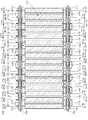
複数の電池セルの接続構造について、電池セル群103のうちの4つの電池ユニット20−1〜電池ユニット20−4の接続構造を例に挙げて説明する。なお、電池ユニット20−5〜20−8も同様の接続構造を有し、電池ユニット20−4および電池ユニット20−5間も同様の接続構造を有する。図10は、積層および接続されている4つの電池ユニットを示す斜視図である。図11Aは、図10に示す4つの電池ユニットの手前側の側面を示す略線図であり、図11Bは図10に示す4つの電池ユニットの奧側の側面を示す略線図である。 A connection structure of a plurality of battery cells will be described by taking a connection structure of four battery units 20-1 to 20-4 in the
電池ユニット20−1の一方の側面には、1組の第1のバスバー113が、ブラケット1を介して互いに対向するように取り付けられている。一方の第1のバスバー113の接合部113bは、電池セルBT1の負極タブ111b(−極)に接合され、(−)の極性を有する密接部113aは、電池ユニット20−1のブラケット1の連結部9の正面側に密接される。他方の第1のバスバー113の接合部113bは、電池セルBT2の正極タブ111a(+極)に接合され、(+)の極性を有する密接部113aは、電池ユニット20−1のブラケット1の連結部9の背面側に密接される。 A set of first bus bars 113 are attached to one side surface of the battery unit 20-1 so as to face each other via the
電池ユニット20−1の他方の側面には、1つの第2のバスバー114が取り付けられている。電池ユニット20−1の第2のバスバー114の第1の接合部114aに対して、電池セルBT1の正極タブ111a(+極)が接合され、第2のバスバー114の第2の接合部114bに対して、電池セルBT2の負極タブ111b(−極)が接合される。これにより、電池セルBT1と電池セルBT2とが、直列に接続される。 One
電池ユニット20−2の一方の側面には、1組の第1のバスバー113が、ブラケット1を介して互いに対向するように取り付けられている。一方の第1のバスバー113の接合部113bは、電池セルBT3の負極タブ111b(−極)に接合され、(−)の極性を有する密接部113aは、電池ユニット20−2のブラケット1の連結部9の正面側に密接される。また、一方の第1のバスバー113の(−)の極性を有する密接部113aは、電池ユニット20−1に取り付けられた他方の第1のバスバーの、電池ユニット20−1のブラケット1の連結部9の背面側に密接された(+)の極性を有する密接部113aと密接される。これにより、電池セルBT2と電池セルBT3とが、直列に接続される。他方の第1のバスバー113の接合部113bは、電池セルBT4の正極タブ111a(+極)に接合され、(+)の極性を有する密接部113aは、電池ユニット20−1のブラケット1の連結部9の背面側の面に密接される。 A pair of first bus bars 113 are attached to one side surface of the battery unit 20-2 so as to face each other via the
電池ユニット20−2の他方の側面には、1つの第2のバスバー114が取り付けられている。電池ユニット20−2の第2のバスバー114の第1の接合部114aに対して、電池セルBT3の正極タブ111a(+極)が接合され、第2のバスバー114の第2の接合部114bに対して、電池セルBT4の負極タブ111b(−極)が接合される。これにより、電池セルBT3と電池セルBT4とが、直列に接続される。 One
電池ユニット20−3の一方の側面には、1組の第1のバスバー113が、ブラケット1を介して互いに対向するように取り付けられている。一方の第1のバスバー113の接合部113bは、電池セルBT5の負極タブ111b(−極)に接合され、(−)の極性を有する密接部113aは、電池ユニット20−3のブラケット1の連結部9の正面側に密接される。また、一方の第1のバスバー113の(−)の極性を有する密接部113aは、電池ユニット20−2に取り付けられた他方の第1のバスバーの、電池ユニット20−2のブラケット1の連結部9の背面側に密接された(+)の極性を有する密接部113aと密接される。これにより、電池セルBT4と電池セルBT5とが、直列に接続される。他方の第1のバスバー113の接合部113bは、電池セルBT6の正極タブ111a(+極)に接合され、(+)の極性を有する密接部113aは、電池ユニット20−2のブラケット1の連結部9の背面側の面に密接される。 A set of first bus bars 113 is attached to one side surface of the battery unit 20-3 so as to face each other via the
電池ユニット20−3の他方の側面には、1つの第2のバスバー114が取り付けられている。電池ユニット20−3の第2のバスバー114の第1の接合部114aに対して、電池セルBT5の正極タブ111a(+極)が接合され、第2のバスバー114の第2の接合部114bに対して、電池セルBT6の負極タブ111b(−極)が接合される。これにより、電池セルBT5と電池セルBT6とが、直列に接続される。 One
電池ユニット20−4の一方の側面には、1組の第1のバスバー113が、ブラケット1を介して互いに対向するように取り付けられている。一方の第1のバスバー113の接合部113bは、電池セルBT7の負極タブ111b(−極)に接合され、(−)の極性を有する密接部113aは、電池ユニット20−4のブラケット1の連結部9の正面側に密接される。また、一方の第1のバスバー113の(−)の極性を有する密接部113aは、電池ユニット20−3に取り付けられた他方の第1のバスバーの、電池ユニット20−3のブラケット1の連結部9の背面側に密接された(+)の極性を有する密接部113aと密接される。これにより、電池セルBT6と電池セルBT7とが、直列に接続される。他方の第1のバスバー113の接合部113bは、電池セルBT8の正極タブ111a(+極)に接合され、(+)の極性を有する密接部113aは、電池ユニット20−3のブラケット1の連結部9の背面側の面に密接される。 A set of first bus bars 113 are attached to one side surface of the battery unit 20-4 so as to face each other with the
電池ユニット20−4の他方の側面には、1つの第2のバスバー114が取り付けられている。電池ユニット20−4の第2のバスバー114の第1の接合部114aに対して、電池セルBT7の正極タブ111a(+極)が接合され、第2のバスバー114の第2の接合部114bに対して、電池セルBT8の負極タブ111b(−極)が接合される。これにより、電池セルBT7と電池セルBT8とが、直列に接続される。 One
(複数の電池ユニットの固定)
図12は、電池モジュールの構成例の概略を示す側面図である。水平方向に積層された積層体を構成するエンドプレート101およびエンドプレート102、並びに電池セル群103を構成する積層された複数の電池ユニット20−1〜20−8が、締結部材であるシャフト106およびナット107により締め付けられることにより締結される。図12に示すように、エンドプレート101およびエンドプレート102、並びに電池セル群103の4隅に形成された孔のそれぞれにシャフト106を通し、4隅を貫通したシャフト106の両端部からナット107で締め付けることにより、電池セル群103を構成する積層された複数の電池ユニット20−1〜20−8が締結される。これにより、複数の電池ユニット20−1〜20−8は一体的に固定される。なお、4隅のうちの1隅を貫通する1本のシャフト106が、複数の電池ユニット20−1〜20−8の連結部9の両端面の間を貫通する孔7、および、密接部113aの孔113cを通り、積層方向に沿った直線上に位置する複数の電池ユニットの連結部9および連結部9を挟む密接部113a、エンドプレート101およびエンドプレート102を貫通する。(Fix multiple battery units)
FIG. 12 is a side view illustrating an outline of a configuration example of the battery module. The
本技術の電池モジュール100では、隣り合う電池ユニット20の第1のバスバー113の密接部113aが積層方向に沿った直線上に位置し、これらの密接部113aが互いに面接触することで、バスバー同士の安定した面接触を実現できる。これに対して、典型的な電池モジュール(例えば、上述した図1に示す電池モジュール200)では、電池ユニット210を並べてユニットバスバー214で集電部211同士を接続する場合、隣り合った集電部211の面のズレによりユニットバスバー214の安定した面接触が難しくなっていた。また、ユニットバスバー214には大電流を用いるため、薄肉化等によって柔軟性を持たせることが困難であった。 In the
本技術の電池モジュールでは、積層された複数の電池ユニット20に設けられた孔にシャフト106を通し、積層された複数の電池ユニット20を貫通したシャフト106の両端部をナット107で締め付けることで、積層された複数の電池ユニット20を締結する。これにより、隣り合う電池ユニット20のバスバー同士の密接面に対して、均等に締め付ける力を加えることができる。これにより、セルバランスが崩れる要因の一つである接触抵抗のばらつきを抑制することができる。これに対して、図1に示すような典型的な電池モジュール200では、電池ユニット20間を接続する複数のユニットバスバー214のそれぞれを個別に締め付けるため、締め付け力のばらつきが接触抵抗のばらつきにつながっており、セルバランスが崩れる要因の一つになっている。また、シャフト106に生じる軸力を規定して管理することにより、ユニットバスバー214の接触抵抗の一括管理が可能となり、ユニットバスバー214同士を一定の圧力で面接触した状態で固定することにより長期間のユニットバスバー214間の導通を確保できる。その結果、電池セル4間の接続の長期信頼性を向上することができる。 In the battery module of the present technology, the
(シャフト)
シャフト106としては、例えば、金属材料からなる棒を少なくとも1層以上の絶縁層で被覆した棒状体等の絶縁性棒状体を用いることができる。シャフト106の両端部には、締め付け部であるナット107等がねじ込まれるネジ部等が設けられている。絶縁層としては、絶縁性の樹脂層等が挙げられる。シャフト106としては、金属材料からなる棒を2層以上の絶縁層で被覆した、2層以上の絶縁層を有する棒状体が好ましい。振動、衝撃等により絶縁層が破壊されるのを抑制できるからである。2層以上の絶縁層を有する棒状体の一例としては、金属棒と、金属棒を被覆する第1の絶縁層と、第1の絶縁層をさらに被覆する第2の絶縁層とを備える2層の絶縁層を有する棒状体等が挙げられる。2層の絶縁層を有する棒状体としては、例えば、金属棒に対して絶縁材を塗布することにより形成した塗布絶縁膜と、塗布絶縁膜を被覆するチューブ状の絶縁材とを有する棒状体等が挙げられる。なお、ナット107は絶縁性を有するものであることが好ましい。このようなナット107としては、金属を絶縁材料で被覆して形成したナット等が挙げられる。(shaft)
As the
2.第2の実施の形態
本技術の第2の実施の形態による電池モジュールの構成例について説明する。図13は、本技術の第2の実施の形態による電池モジュールの構成例の概略を示す上面図である。図14は、本技術の第2の実施の形態による電池モジュールの構成例の概略を示す断面図である。2. Second Embodiment A configuration example of a battery module according to a second embodiment of the present technology will be described. FIG. 13 is a top view illustrating an outline of a configuration example of the battery module according to the second embodiment of the present technology. FIG. 14 is a cross-sectional view illustrating an outline of a configuration example of the battery module according to the second embodiment of the present technology.
図13および図14に示すように、電池モジュール100’は、電池セル群103’を備える。電池セル群103’は、8個の電池ユニット20−1’〜20−8’(すなわち、16個の電池セル)が、積層されたものである。なお、個々の電池ユニットを区別する必要がないときは、単に電池ユニット20’と称する。 As shown in FIGS. 13 and 14, the
ブラケット1’は、連結部9の代わりに以下の構成を有する点以外は第1の実施の形態のブラケット1と同様である。ブラケット1’の両側端部の中央のそれぞれには、ブラケット1’を厚み方向にシャフト106が貫通する孔が形成されている。孔を形成するために、導通カラー119または絶縁カラー118がインサート成型によってブラケット1と一体に形成されている。導通カラー119は、中空を有する管状の導電性部材である。絶縁カラー118は、第1の実施の形態の絶縁カラー8と同様である。 The
本技術の第2の実施の形態による電池モジュール100’では、電池セル4間を接続する部品である導通カラー119をブラケット1’にインサート成型することにより省スペースとなり、電池モジュールに対する電池容量の向上が可能となる。これに対して、図1に示した典型的な電池モジュール200では、接続に必要な部品を別部品としてボルト等で締結しており、部品点数が多くなってしまう。 In the
(電池セル)
電池セル4は、電極タブ111に孔が設けられた構成を有すること以外は第1の実施の形態で説明した電池セル4と同様である。(Battery cell)
The
(電池セル間および電池ユニット間の接続構造)
複数の電池ユニット20’を積層し、電池セル4を直列および/または並列に電気的に接続して電池セル群103’が構成される。(Connection structure between battery cells and between battery units)
A plurality of
本技術の第2の実施の形態による電池ユニット20’の一例では、16個の電池セルBT1〜BT16を直列に電気的に接続して電池セル群103’が構成される。なお、電池セルBT1〜BT16の接続構成は、この例に限定されるものではない。 In an example of the
複数の電池セル4の接続構造について、電池セル群103’のうちの4つの電池ユニット20−1’〜電池ユニット20−4’の接続構造を例に挙げて説明する。なお、電池ユニット20−5’〜20−8’も同様の接続構造を有し、電池ユニット20−4’と電池ユニット20−5’間の接続も同様の接続構造を有する。 The connection structure of the plurality of
電池セル群103’では、電池ユニット20’間が導通カラー119によって接続され、同様に、電池ユニット内の2つの電池セル4も導通カラー119によって接続される。これにより、電池セル群103’に含まれる電池セルBT1〜電池セルBT16が、直列に電気的に接続されている。なお、第1の実施の形態と同様、各電池ユニット20’には2つの電池セル4が収納されている。すなわち、電池ユニット20−1’は、電池セルBT1および電池セルBT2を含む。電池ユニット20−2’は、電池セルBT3および電池セルBT4を含む。電池ユニット20−3’は、電池セルBT5および電池セルBT6を含む。電池ユニット20−4’は、電池セルBT7および電池セルBT8を含む。電池ユニット20−5’は、電池セルBT9および電池セルBT10を含む。電池ユニット20−6’は、電池セルBT11および電池セルBT12を含む。電池ユニット20−7’は、電池セルBT13および電池セルBT14を含む。電池ユニット20−8’は、電池セルBT15および電池セルBT16を含む。 In the
電池ユニット20−1’の一側端部の略中央部には、ブラケット1’内に内設された絶縁カラー118の両端面が露出されている。電池ユニット20−1’の他側端部の略中央部には、ブラケット1’内に内設された導通カラー119の両端面が露出されている。電池ユニット20−1’の露出された絶縁カラー118の一端面に対して、電池セルBT1の負極タブ111b(−極)が密接され、露出された絶縁カラー118の他端面に対して、電池セルBT2の正極タブ111a(+極)が密接される。電池ユニット20−1’の露出された導通カラー119の一端面に対して、電池セルBT1の正極タブ111a(+極)が密接され、導通カラー119の他端面に対して、電池セルBT2の負極タブ111b(−極)が密接される。これにより、電池セルBT1と電池セルBT2とが、直列に接続される。 At both ends of one end of the battery unit 20-1 ', both end surfaces of the insulating
電池ユニット20−1’に含まれる電池セルBT2の正極タブ111a(+極)と、電池ユニット20−2’に含まれる電池セルBT3の負極タブ111b(−極)との間には、導通カラー119が狭設されている。電池ユニット20−1’に含まれる電池セルBT2の負極タブ111b(−極)と、電池ユニット20−2’に含まれる電池セルBT3の正極タブ111a(+極)との間には、絶縁カラー118が狭設されている。 Between the
電池セルBT2と電池セルBT3との間に狭設された導通カラー119の一端面に対して、電池セルBT2の正極タブ111a(+極)が密接され、導通カラー119の他端面に、電池セルBT3の負極タブ111b(−極)が密接される。これにより、電池セルBT2と電池セルBT3とが、直列に接続される。 The
電池ユニット20−2’の一側端部の略中央部には、ブラケット1’内に内設された絶縁カラー118の両端面が露出されている。電池ユニット20−2’の他側端部の略中央部には、ブラケット1’内に内設された導通カラー119の両端面が露出されている。電池ユニット20−2’の露出された絶縁カラー118の一端面に対して、電池セルBT3の負極タブ111b(−極)が密接され、露出された絶縁カラー118の他端面に対して、電池セルBT4の正極タブ111a(+極)が密接される。電池ユニット20−2’の露出された導通カラー119の一端面に対して、電池セルBT3の正極タブ111a(+極)が密接され、導通カラー119の他端面に対して、電池セルBT4の負極タブ111b(−極)が密接される。これにより、電池セルBT3と電池セルBT4とが、直列に接続される。 At both ends of one end of the battery unit 20-2 ', both end surfaces of the insulating
電池ユニット20−2’に含まれる電池セルBT4の正極タブ111a(+極)と、電池ユニット20−3’に含まれる電池セルBT5の負極タブ111b(−極)との間には、導通カラー119が狭設されている。電池ユニット20−2’に含まれる電池セルBT4の負極タブ111b(−極)と、電池ユニット20−3’に含まれる電池セルBT5の正極タブ111a(+極)との間には、絶縁カラー118が狭設されている。 Between the
電池セルBT4と電池セルBT5との間に狭設された導通カラー119の一端面に対して、電池セルBT4の正極タブ111a(+極)が密接され、導通カラー119の他端面に、電池セルBT5の負極タブ111b(−極)が密接される。これにより、電池セルBT4と電池セルBT5とが、直列に接続される。 The
電池ユニット20−3’の一側端部の略中央部には、ブラケット1’内に内設された絶縁カラー118の両端面が露出されている。電池ユニット20−3’の他側端部の略中央部には、ブラケット1’内に内設された導通カラー119の両端面が露出されている。電池ユニット20−3’の露出された絶縁カラー118の一端面に対して、電池セルBT5の負極タブ111b(−極)が密接され、露出された絶縁カラー118の他端面に対して、電池セルBT6の正極タブ111a(+極)が密接される。電池ユニット20−3’の露出された導通カラー119の一端面に対して、電池セルBT5の正極タブ111a(+極)が密接され、導通カラー119の他端面に対して、電池セルBT6の負極タブ111b(−極)が密接される。これにより、電池セルBT5と電池セルBT6とが、直列に接続される。 At both ends of one side of the battery unit 20-3 ', both end surfaces of the insulating
電池ユニット20−3’に含まれる電池セルBT6の正極タブ111a(+極)と、電池ユニット20−4’に含まれる電池セルBT7の負極タブ111b(−極)との間には、導通カラー119が狭設されている。電池ユニット20−3’に含まれる電池セルBT6の負極タブ111b(−極)と、電池ユニット20−4’に含まれる電池セルBT7の正極タブ111a(+極)との間には、絶縁カラー118が狭設されている。 Between the
電池セルBT6と電池セルBT7との間に狭設された導通カラー119の一端面に対して、電池セルBT6の正極タブ111a(+極)が密接され、導通カラー119の他端面に、電池セルBT7の負極タブ111b(−極)が密接される。これにより、電池セルBT6と電池セルBT7とが、直列に接続される。 The
電池ユニット20−4’の一側端部の略中央部には、ブラケット1’内に内設された絶縁カラー118の両端面が露出されている。電池ユニット20−4’の他側端部の略中央部には、ブラケット1’内に内設された導通カラー119の両端面が露出されている。電池ユニット20−4’の露出された絶縁カラー118の一端面に対して、電池セルBT7の負極タブ111b(−極)が密接され、露出された絶縁カラー118の他端面に対して、電池セルBT8の正極タブ111a(+極)が密接される。電池ユニット20−4’の露出された導通カラー119の一端面に対して、電池セルBT7の正極タブ111a(+極)が密接され、導通カラー119の他端面に対して、電池セルBT8の負極タブ111b(−極)が密接される。これにより、電池セルBT7と電池セルBT8とが、直列に接続される。 At both ends of one end of the battery unit 20-4 ', both end surfaces of the insulating
(複数の電池ユニットの固定)
電池セル群103’の両側端部の略中央部の形成された孔のそれぞれに、シャフト106を通し、積層された複数の電池ユニット20’を貫通するシャフト106の両端部からナット107で締め付けることにより、電池セル群103’を構成する積層された複数の電池ユニット20−1’〜20−8’が締結される。なお、第1の実施の形態同様、エンドプレート101およびエンドプレート102の間に電池セル群103’を配置して、これらを締結した構成としてもよい。(Fix multiple battery units)
The
3.他の実施の形態
本技術は、上述した本技術の実施の形態に限定されるものでは無く、本技術の要旨を逸脱しない範囲内で様々な変形や応用が可能である。3. Other Embodiments The present technology is not limited to the above-described embodiments of the present technology, and various modifications and applications are possible without departing from the gist of the present technology.
例えば、上述の実施の形態において挙げた数値、構造、形状、材料、原料、製造プロセス等はあくまでも例に過ぎず、必要に応じてこれらと異なる数値、構造、形状、材料、原料、製造プロセス等を用いてもよい。 For example, the numerical values, structures, shapes, materials, raw materials, manufacturing processes, and the like given in the above-described embodiments are merely examples, and numerical values, structures, shapes, materials, raw materials, manufacturing processes, etc. that are different from these as necessary. May be used.
また、上述の実施の形態の構成、方法、工程、形状、材料および数値等は、本技術の主旨を逸脱しない限り、互いに組み合わせることが可能である。 The configurations, methods, steps, shapes, materials, numerical values, and the like of the above-described embodiments can be combined with each other without departing from the gist of the present technology.
本技術は、以下の構成とることができる。
[1]
積層された複数の電池ユニットを少なくとも含む積層体と、
該積層体を貫通する絶縁性棒状体と、
前記積層体を貫通した該絶縁性棒状体の両端から前記積層体を締め付ける締め付け部と
を備え、
前記電池ユニットは、複数の電池セルと、
両端面の間を貫通する第1の孔が形成された連結部を有し、且つ、前記複数の電池セルが保持される電池支持体と、
第2の孔が形成され、且つ、前記連結部の前記両端面のうちの一方または他方の端面に密接される密接部および前記電池セルの電極タブに接合される接合部を含む導電性部材と
を有し、
前記絶縁性棒状体が、積層された前記複数のユニットの前記第1の孔および前記第2の孔を通り、積層方向に沿った直線上に位置する前記複数の電池ユニットの前記連結部および前記密接部を貫通し、前記締め付け部によって前記積層体が締め付けられて前記複数の電池ユニットが締結され、隣り合う前記電池ユニットの前記導電性部材の前記密接部が互いに密接されて、隣り合う前記電池ユニット間が電気的に接続された電池モジュール。
[2]
前記電池ユニットは、前記導電性部材を2つ備え、
一方の導電性部材の前記密接部を前記連結部の前記両端面のうちの一方の端面に密接させ、他方の導電性部材の前記密接部を前記連結部の前記両端面のうちの他方の端面に密接させて、前記2つの導電性部材の前記密接部で前記連結部を挟む[1]に記載の電池モジュール。
[3]
前記電池支持体に対して前記導電性部材がインサート成型された[1]〜[2]の何れかに記載の電池モジュール。
[4]
前記電池支持体は、前記連結部に内設された、前記第1の孔を形成する中空を有する管状の絶縁性部材をさらに有する[1]〜[3]の何れかに記載の電池モジュール。
[5]
前記電池支持体に対して、前記絶縁性部材がインサート成型された[4]に記載の電池モジュール。
[6]
前記導電性部材は、導電性板状体である[1]〜[5]の何れかに記載の電池モジュール。
[7]
前記絶縁性棒状体は、金属材料からなる棒を2層以上の絶縁層で被覆した棒状体である[1]〜[6]の何れかに記載の電池モジュール。
[8]
前記絶縁性棒状体は、金属材料からなる棒と、該金属材料からなる棒を被覆する第1の絶縁層と、該第1の絶縁層をさらに被覆する第2の絶縁層とを備え、
前記第1の絶縁層は、絶縁膜であり、
前記第2の絶縁層は、チューブ状の絶縁材である[1]〜[7]の何れかに記載の電池モジュール。
[9]
前記絶縁性棒状体は、両端部にネジ部を有し、
前記締め付け部は、前記ネジ部にねじ込まれるナットである[1]〜[8]の何れかに記載の電池モジュール。
[10]
前記積層体は、第3の孔を有するエンドプレートを2つさらに含み、
前記2つのエンドプレートの間に、前記複数の電池ユニットが配置され、
前記絶縁性棒状体が、前記2つのエンドプレートの第3の孔を通って前記2つのエンドプレートを貫通する[1]〜[9]の何れかに記載の電池モジュール。
[11]
前記電池支持体は、略直方体状の外形を有し、一側面の両端部のそれぞれに前記連結部が突設され、他側面の両端部のそれぞれに前記連結部が突設された[1]〜[10]の何れかに記載の電池モジュール。
[12]
[1]〜[11]の何れかに記載の電池モジュールを備えた蓄電装置。
[13]
[1]〜[11]の何れかに記載の電池モジュールが再生可能エネルギーから発電を行う発電装置によって充電される蓄電システム。
[14]
[1]〜[11]の何れかに記載の電池モジュールを有し、前記電池モジュールに接続される電子機器に電力を供給する蓄電システム。
[15]
[1]〜[11]の何れかに記載の電池モジュールから、電力の供給を受ける電子機器。
[16]
[1]〜[11]の何れかに記載の電池モジュールから、電力の供給を受けて車両の駆動力に変換する変換装置と、前記電池モジュールに関する情報に基づいて車両制御に関する情報処理を行なう制御装置とを有する電動車両。
[17]
他の機器とネットワークを介して信号を送受信する電力情報送受信部とを備え、
前記電力情報送受信部が受信した情報に基づき、[1]〜[11]の何れかに記載の電池モジュールの充放電制御を行う電力システム。
[18]
[1]〜[11]の何れかに記載の電池モジュールから、電力の供給を受け、または発電装置または電力網から前記電池モジュールに電力を供給する電力システム。The present technology can take the following configurations.
[1]
A laminate including at least a plurality of laminated battery units;
An insulating rod-like body penetrating the laminate;
A tightening portion for tightening the laminate from both ends of the insulating rod-like body penetrating the laminate,
The battery unit includes a plurality of battery cells,
A battery support having a connecting portion formed with a first hole penetrating between both end faces, and holding the plurality of battery cells;
A conductive member having a second hole formed therein, a close contact portion in close contact with one or the other end surface of the connecting portion, and a joint portion bonded to the electrode tab of the battery cell; Have
The insulative rod-like body passes through the first hole and the second hole of the plurality of stacked units and is positioned on a straight line along the stacking direction. The stacked body is tightened by the tightening portion, the plurality of battery units are fastened, and the close contact portions of the conductive members of the adjacent battery units are in close contact with each other, so that the adjacent batteries pass. A battery module in which units are electrically connected.
[2]
The battery unit includes two conductive members,
The close contact portion of one conductive member is brought into close contact with one end surface of the both end surfaces of the connecting portion, and the close contact portion of the other conductive member is connected to the other end surface of the both end surfaces of the connecting portion. The battery module according to [1], wherein the connecting portion is sandwiched between the two close contact portions of the two conductive members.
[3]
The battery module according to any one of [1] to [2], wherein the conductive member is insert-molded with respect to the battery support.
[4]
The battery module according to any one of [1] to [3], wherein the battery support further includes a tubular insulating member provided in the connection portion and having a hollow that forms the first hole.
[5]
The battery module according to [4], wherein the insulating member is insert-molded with respect to the battery support.
[6]
The battery module according to any one of [1] to [5], wherein the conductive member is a conductive plate-like body.
[7]
The battery module according to any one of [1] to [6], wherein the insulating rod-shaped body is a rod-shaped body in which a rod made of a metal material is covered with two or more insulating layers.
[8]
The insulating rod-shaped body includes a rod made of a metal material, a first insulating layer that covers the rod made of the metal material, and a second insulating layer that further covers the first insulating layer,
The first insulating layer is an insulating film;
The battery module according to any one of [1] to [7], wherein the second insulating layer is a tubular insulating material.
[9]
The insulating rod-like body has screw portions at both ends,
The battery module according to any one of [1] to [8], wherein the tightening portion is a nut screwed into the screw portion.
[10]
The laminate further includes two end plates having third holes,
The plurality of battery units are disposed between the two end plates,
The battery module according to any one of [1] to [9], wherein the insulating rod-like body passes through the two end plates through a third hole of the two end plates.
[11]
The battery support body has a substantially rectangular parallelepiped outer shape, and the connection portions project from both end portions on one side surface, and the connection portions project from both end portions on the other side surface [1]. -Battery module in any one of [10].
[12]
A power storage device comprising the battery module according to any one of [1] to [11].
[13]
A power storage system in which the battery module according to any one of [1] to [11] is charged by a power generation device that generates power from renewable energy.
[14]
A power storage system that includes the battery module according to any one of [1] to [11] and supplies power to an electronic device connected to the battery module.
[15]
The electronic device which receives supply of electric power from the battery module in any one of [1]-[11].
[16]
[1] to [11] The battery module according to any one of [11] to [11], a converter that receives supply of electric power and converts it into a driving force of the vehicle, and a control that performs information processing related to vehicle control based on information related to the battery module. An electric vehicle having the apparatus.
[17]
A power information transmitting / receiving unit that transmits and receives signals to and from other devices via a network;
The electric power system which performs charging / discharging control of the battery module in any one of [1]-[11] based on the information which the said electric power information transmission / reception part received.
[18]
[1] A power system that receives supply of power from the battery module according to any one of [11] or supplies power to the battery module from a power generation device or a power network.
4.応用例
以下、電池モジュールの応用例について説明する。なお、電池モジュールの応用例は、以下に説明する応用例に限られることはない。4). Application Examples Hereinafter, application examples of the battery module will be described. In addition, the application example of a battery module is not restricted to the application example demonstrated below.
上述した本技術の電池モジュールは、例えば電子機器や電動車両等の機器に搭載または電力を供給するために使用することができる。本技術は、上述した電池モジュールが再生可能エネルギーから発電を行う発電装置によって充電される蓄電システムである。本技術は、上述した電池モジュールを有し、電池モジュールに接続される電子機器に電力を供給する蓄電システムである。本技術は、上述した電池モジュールから、電力の供給を受ける電子機器である。これらの電子機器および電力システムは、例えば住宅の電力供給システムとして実施される。さらに、外部の電力供給網と協働して電力の効率的な供給を図るシステムとして実施される。さらに、本技術は、上述した電池モジュールから、電力の供給を受けて車両の駆動力に変換する変換装置と、電池モジュールに関する情報に基づいて車両制御に関する情報処理を行なう制御装置とを有する電動車両である。本技術は、他の機器とネットワークを介して信号を送受信する電力情報送受信部とを備え、電力情報送受信部が受信した情報に基づき、上述した電池モジュールの充放電制御を行う電力システムである。本技術は、上述した電池モジュールから、電力の供給を受け、または発電装置または電力網から電池モジュールに電力を供給する電力システムである。 The battery module of the present technology described above can be used for mounting or supplying power to a device such as an electronic device or an electric vehicle. The present technology is a power storage system in which the above-described battery module is charged by a power generation device that generates power from renewable energy. The present technology is a power storage system that includes the above-described battery module and supplies power to an electronic device connected to the battery module. The present technology is an electronic device that is supplied with electric power from the battery module described above. These electronic devices and power systems are implemented as, for example, residential power supply systems. Further, the present invention is implemented as a system for efficiently supplying power in cooperation with an external power supply network. Furthermore, the present technology provides an electric vehicle that includes a conversion device that receives supply of electric power from the battery module described above and converts it into a driving force of the vehicle, and a control device that performs information processing related to vehicle control based on information related to the battery module. It is. The present technology is a power system that includes a power information transmission / reception unit that transmits / receives a signal to / from another device via a network, and performs charge / discharge control of the above-described battery module based on information received by the power information transmission / reception unit. The present technology is a power system that receives supply of power from the battery module described above or supplies power to the battery module from a power generation device or a power network.
電子機器として、例えばノート型パソコン、ビデオムービー、デジタルスチルカメラ、電子書籍、ゲーム機、ナビゲーションシステム、電動工具、冷蔵庫、エアコン、テレビ、ステレオ、温水器、電子レンジ、食器洗い器、洗濯機、乾燥器、照明機器、医療機器、ロボット、ロードコンディショナー、信号機等が挙げられる。 Electronic devices such as notebook computers, video movies, digital still cameras, e-books, game machines, navigation systems, electric tools, refrigerators, air conditioners, TVs, stereos, water heaters, microwave ovens, dishwashers, washing machines, dryers Lighting equipment, medical equipment, robots, road conditioners, traffic lights, and the like.
また、電動車両としては鉄道車両、ゴルフカート、電動カート、電気自動車(ハイブリッド自動車を含む)等が挙げられ、これらの駆動用電源または補助用電源として用いられる。 Further, examples of the electric vehicle include a railway vehicle, a golf cart, an electric cart, an electric vehicle (including a hybrid vehicle), and the like, and these are used as a driving power source or an auxiliary power source.
「応用例としての蓄電装置の例」
電池モジュールを備えた蓄電装置の一例としては、例えば、図15に示す構成の蓄電装置等が挙げられる。図15に示すように、蓄電装置150の外装ケース131内には、電池モジュール100と、電池モジュール100の充放電等を制御するための制御回路ブロック等が搭載された回路基板132等が収容されている。"Example of power storage device as an application example"
As an example of the power storage device including the battery module, for example, a power storage device having a configuration illustrated in FIG. As shown in FIG. 15, a
「応用例としての住宅における蓄電システム」
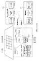
本技術を住宅用の蓄電システムに適用した例について、図16を参照して説明する。例えば住宅301用の蓄電システム300においては、火力発電302a、原子力発電302b、水力発電302c等の集中型電力系統302から電力網309、情報網312、スマートメータ307、パワーハブ308等を介し、電力が蓄電装置303に供給される。これと共に、発電装置304等の独立電源から電力が蓄電装置303に供給される。蓄電装置303に供給された電力が蓄電される。蓄電装置303を使用して、住宅301で使用する電力が給電される。住宅301に限らずビルに関しても同様の蓄電システムを使用できる。"Storage system in a house as an application example"
An example in which the present technology is applied to a residential power storage system will be described with reference to FIG. For example, in a power storage system 300 for a house 301, power is stored from a
住宅301には、発電装置304、電力消費装置305、蓄電装置303、各装置を制御する制御装置310、スマートメータ307、各種情報を取得するセンサー311が設けられている。各装置は、電力網309および情報網312によって接続されている。発電装置304として、太陽電池、燃料電池等が利用され、発電した電力が電力消費装置305および/または蓄電装置303に供給される。電力消費装置305は、冷蔵庫305a、空調装置(エアコン)305b、テレビジョン受信機(テレビ)305c、風呂(バス)305d等である。さらに、電力消費装置305には、電動車両306が含まれる。電動車両306は、電気自動車306a、ハイブリッドカー306b、電気バイク306cである。 The house 301 is provided with a power generation device 304, a
蓄電装置303に対して、上述した本技術の電池モジュールが適用される。蓄電装置303は、二次電池またはキャパシタから構成されている。例えば、リチウムイオン電池によって構成されている。リチウムイオン電池は、定置型であっても、電動車両306で使用されるものでも良い。スマートメータ307は、商用電力の使用量を測定し、測定された使用量を、電力会社に送信する機能を備えている。電力網309は、直流給電、交流給電、非接触給電の何れか一つまたは複数を組み合わせても良い。 The battery module of the present technology described above is applied to the
各種のセンサー311は、例えば人感センサー、照度センサー、物体検知センサー、消費電力センサー、振動センサー、接触センサー、温度センサー、赤外線センサー等である。各種センサー311により取得された情報は、制御装置310に送信される。センサー311からの情報によって、気象の状態、人の状態等が把握されて電力消費装置305を自動的に制御してエネルギー消費を最小とすることができる。さらに、制御装置310は、住宅301に関する情報をインターネットを介して外部の電力会社等に送信することができる。 The
パワーハブ308によって、電力線の分岐、直流交流変換等の処理がなされる。制御装置310と接続される情報網312の通信方式としては、UART(Universal Asynchronous Receiver-Transceiver:非同期シリアル通信用送受信回路)等の通信インターフェースを使う方法、Bluetooth、ZigBee、Wi−Fi等の無線通信規格によるセンサーネットワークを利用する方法がある。Bluetooth方式は、マルチメディア通信に適用され、一対多接続の通信を行うことができる。ZigBeeは、IEEE(Institute of Electrical and Electronics Engineers) 802.15.4の物理層を使用するものである。IEEE802.15.4は、PAN(Personal Area Network) またはW(Wireless)PANと呼ばれる短距離無線ネットワーク規格の名称である。 The
制御装置310は、外部のサーバ313と接続されている。このサーバ313は、住宅301、電力会社、サービスプロバイダーの何れかによって管理されていても良い。サーバ313が送受信する情報は、たとえば、消費電力情報、生活パターン情報、電力料金、天気情報、天災情報、電力取引に関する情報である。これらの情報は、家庭内の電力消費装置(たとえばテレビジョン受信機)から送受信しても良いが、家庭外の装置(たとえば、携帯電話機等)から送受信しても良い。これらの情報は、表示機能を持つ機器、たとえば、テレビジョン受信機、携帯電話機、PDA(Personal Digital Assistants)等に、表示されても良い。 The
各部を制御する制御装置310は、CPU(Central Processing Unit )、RAM(Random Access Memory)、ROM(Read Only Memory)等で構成され、この例では、蓄電装置303に格納されている。制御装置310は、蓄電装置303、発電装置304、電力消費装置305、各種センサー311、サーバ313と情報網312により接続され、例えば、商用電力の使用量と、発電量とを調整する機能を有している。なお、その他にも、電力市場で電力取引を行う機能等を備えていても良い。 A
以上のように、電力が火力発電302a、原子力発電302b、水力発電302c等の集中型電力系統302のみならず、発電装置304(太陽光発電、風力発電)の発電電力を蓄電装置303に蓄えることができる。したがって、発電装置304の発電電力が変動しても、外部に送出する電力量を一定にしたり、または、必要なだけ放電するといった制御を行うことができる。例えば、太陽光発電で得られた電力を蓄電装置303に蓄えると共に、夜間は料金が安い深夜電力を蓄電装置303に蓄え、昼間の料金が高い時間帯に蓄電装置303によって蓄電した電力を放電して利用するといった使い方もできる。 As described above, the power is stored not only in the
なお、この例では、制御装置310が蓄電装置303内に格納される例を説明したが、スマートメータ307内に格納されても良いし、単独で構成されていても良い。さらに、蓄電システム300は、集合住宅における複数の家庭を対象として用いられてもよいし、複数の戸建て住宅を対象として用いられてもよい。 In this example, the example in which the
「応用例としての車両における蓄電システム」
本技術を車両用の蓄電システムに適用した例について、図17を参照して説明する。図17に、本技術が適用されるシリーズハイブリッドシステムを採用するハイブリッド車両の構成の一例を概略的に示す。シリーズハイブリッドシステムはエンジンで動かす発電機で発電された電力、あるいはそれを電池に一旦貯めておいた電力を用いて、電力駆動力変換装置で走行する車である。"Vehicle power storage system as an application example"
An example in which the present technology is applied to a power storage system for a vehicle will be described with reference to FIG. FIG. 17 schematically shows an example of the configuration of a hybrid vehicle that employs a series hybrid system to which the present technology is applied. The series hybrid system is a vehicle that runs on a power driving force conversion device using electric power generated by a generator driven by an engine or electric power once stored in a battery.
このハイブリッド車両400には、エンジン401、発電機402、電力駆動力変換装置403、駆動輪404a、駆動輪404b、車輪405a、車輪405b、バッテリ408、車両制御装置409、各種センサ410、充電口411が搭載されている。バッテリ408に対して、上述した本技術の電池モジュールが適用される。 The
ハイブリッド車両400は、電力駆動力変換装置403を動力源として走行する。電力駆動力変換装置403の一例は、モータである。バッテリ408の電力によって電力駆動力変換装置403が作動し、この電力駆動力変換装置403の回転力が駆動輪404a、404bに伝達される。なお、必要な個所に直流−交流(DC−AC)あるいは逆変換(AC−DC変換)を用いることによって、電力駆動力変換装置403が交流モータでも直流モータでも適用可能である。各種センサ410は、車両制御装置409を介してエンジン回転数を制御したり、図示しないスロットルバルブの開度(スロットル開度)を制御したりする。各種センサ410には、速度センサ、加速度センサ、エンジン回転数センサ等が含まれる。 The
エンジン401の回転力は発電機402に伝えられ、その回転力によって発電機402により生成された電力をバッテリ408に蓄積することが可能である。 The rotational force of the
図示しない制動機構によりハイブリッド車両が減速すると、その減速時の抵抗力が電力駆動力変換装置403に回転力として加わり、この回転力によって電力駆動力変換装置403により生成された回生電力がバッテリ408に蓄積される。 When the hybrid vehicle decelerates by a braking mechanism (not shown), the resistance force at the time of deceleration is applied as a rotational force to the power driving
バッテリ408は、ハイブリッド車両の外部の電源に接続されることで、その外部電源から充電口411を入力口として電力供給を受け、受けた電力を蓄積することも可能である。 The
図示しないが、二次電池に関する情報に基づいて車両制御に関する情報処理を行なう情報処理装置を備えていても良い。このような情報処理装置としては、例えば、電池の残容量に関する情報に基づき、電池残容量表示を行う情報処理装置等がある。 Although not shown, an information processing apparatus that performs information processing related to vehicle control based on information related to the secondary battery may be provided. As such an information processing apparatus, for example, there is an information processing apparatus that displays a remaining battery capacity based on information on the remaining battery capacity.
なお、以上は、エンジンで動かす発電機で発電された電力、或いはそれを電池に一旦貯めておいた電力を用いて、モーターで走行するシリーズハイブリッド車を例として説明した。しかしながら、エンジンとモーターの出力が何れも駆動源とし、エンジンのみで走行、モーターのみで走行、エンジンとモーター走行という3つの方式を適宜切り替えて使用するパラレルハイブリッド車に対しても本技術は有効に適用可能である。さらに、エンジンを用いず駆動モータのみによる駆動で走行する所謂、電動車両に対しても本技術は有効に適用可能である。 In the above description, a series hybrid vehicle that runs on a motor using electric power generated by a generator that is driven by an engine or electric power that is temporarily stored in a battery has been described as an example. However, this technology is also effective for parallel hybrid vehicles that use both the engine and motor outputs as the drive source and switch between the three modes of running with the engine alone, running with the motor alone, and engine running with the motor. Applicable. Furthermore, the present technology can be effectively applied to a so-called electric vehicle that travels only by a drive motor without using an engine.
1、1’・・・ブラケット、2・・・伝熱プレート、2a・・・折り曲げ部、4・・・電池セル、4−1、4−2・・・電池セル、7・・・孔、8・・・絶縁カラー、9・・・連結部、20・・・電池ユニット、20’・・・電池ユニット、20−1〜20−8、20−1’〜20−8’・・・電池ユニット、90・・・外装ケース、100、100’・・・電池モジュール、101・・・エンドプレート、102・・・エンドプレート、103、103’ ・・・電池セル群、106・・・シャフト、107・・・ナット、108・・・伝熱プレート、111・・・電極タブ、111a・・・正極タブ、111b・・・負極タブ、113・・・第1のバスバー、114・・・第2のバスバー、118・・・絶縁カラー、119・・・導通カラー、121・・・電池素子、122・・・外装材、122A・・・第1外装部、122B・・・第2外装部、123・・・凹部、300・・・蓄電システム、301・・・住宅、302・・・集中型電力系統、302a・・・火力発電、302b・・・原子力発電、302c・・・水力発電、303・・・蓄電装置、304・・・発電装置、305・・・電力消費装置、305a・・・冷蔵庫、306・・・電動車両、306a・・・電気自動車、306b・・・ハイブリッドカー、306c・・・電気バイク、307・・・スマートメータ、308・・・パワーハブ、309・・・電力網、310・・・制御装置、311・・・センサー、312・・・情報網、313・・・サーバ、400・・・ハイブリッド車両、401・・・エンジン、402・・・発電機、403・・・電力駆動力変換装置、404a・・・駆動輪、404b・・・駆動輪、405a・・・車輪、405b・・・車輪、408・・・バッテリ、409・・・車両制御装置、410・・・センサ、411・・・充電口 DESCRIPTION OF
Claims (18)
Translated fromJapanese該積層体を貫通する絶縁性棒状体と、
前記積層体を貫通した該絶縁性棒状体の両端から前記積層体を締め付ける締め付け部と
を備え、
前記電池ユニットは、複数の電池セルと、
両端面の間を貫通する第1の孔が形成された連結部を有し、且つ、前記複数の電池セルが保持される電池支持体と、
第2の孔が形成され、且つ、前記連結部の前記両端面のうちの一方または他方の端面に密接される密接部および前記電池セルの電極タブに接合される接合部を含む導電性部材と
を有し、
前記絶縁性棒状体が、積層された前記複数のユニットの前記第1の孔および前記第2の孔を通り、積層方向に沿った直線上に位置する前記複数の電池ユニットの前記連結部および前記密接部を貫通し、前記締め付け部によって前記積層体が締め付けられて前記複数の電池ユニットが締結され、隣り合う前記電池ユニットの前記導電性部材の前記密接部が互いに密接されて、隣り合う前記電池ユニット間が電気的に接続された電池モジュール。A laminate including at least a plurality of laminated battery units;
An insulating rod-like body penetrating the laminate;
A tightening portion for tightening the laminate from both ends of the insulating rod-like body penetrating the laminate,
The battery unit includes a plurality of battery cells,
A battery support having a connecting portion formed with a first hole penetrating between both end faces, and holding the plurality of battery cells;
A conductive member having a second hole formed therein, a close contact portion in close contact with one or the other end surface of the connecting portion, and a joint portion bonded to the electrode tab of the battery cell; Have
The insulative rod-like body passes through the first hole and the second hole of the plurality of stacked units and is positioned on a straight line along the stacking direction. The stacked body is tightened by the tightening portion, the plurality of battery units are fastened, and the close contact portions of the conductive members of the adjacent battery units are in close contact with each other, so that the adjacent batteries pass. A battery module in which units are electrically connected.
一方の導電性部材の前記密接部を前記連結部の前記両端面のうちの一方の端面に密接させ、他方の導電性部材の前記密接部を前記連結部の前記両端面のうちの他方の端面に密接させて、前記2つの導電性部材の前記密接部で前記連結部を挟む請求項1に記載の電池モジュール。The battery unit includes two conductive members,
The close contact portion of one conductive member is brought into close contact with one end surface of the both end surfaces of the connecting portion, and the close contact portion of the other conductive member is connected to the other end surface of the both end surfaces of the connecting portion. The battery module according to claim 1, wherein the connection portion is sandwiched between the two conductive members in close contact with each other.
前記第1の絶縁層は、絶縁膜であり、
前記第2の絶縁層は、チューブ状の絶縁材である請求項1に記載の電池モジュール。The insulating rod-shaped body includes a rod made of a metal material, a first insulating layer that covers the rod made of the metal material, and a second insulating layer that further covers the first insulating layer,
The first insulating layer is an insulating film;
The battery module according to claim 1, wherein the second insulating layer is a tubular insulating material.
前記締め付け部は、前記ネジ部にねじ込まれるナットである請求項1に記載の電池モジュール。The insulating rod-like body has screw portions at both ends,
The battery module according to claim 1, wherein the tightening portion is a nut screwed into the screw portion.
前記2つのエンドプレートの間に、前記複数の電池ユニットが配置され、
前記絶縁性棒状体が、前記2つのエンドプレートの第3の孔を通って前記2つのエンドプレートを貫通する請求項1に記載の電池モジュール。The laminate further includes two end plates having third holes,
The plurality of battery units are disposed between the two end plates,
The battery module according to claim 1, wherein the insulating rod-like body passes through the two end plates through a third hole of the two end plates.
前記電力情報送受信部が受信した情報に基づき、請求項1に記載の電池モジュールの充放電制御を行う電力システム。A power information transmitting / receiving unit that transmits and receives signals to and from other devices via a network;
The electric power system which performs charging / discharging control of the battery module of Claim 1 based on the information which the said electric power information transmission / reception part received.
Priority Applications (7)
| Application Number | Priority Date | Filing Date | Title |
|---|---|---|---|
| JP2014118322AJP2015230892A (en) | 2014-06-09 | 2014-06-09 | Battery module, power storage device, power storage system, electronic apparatus, electric vehicle and power system |
| CN201580030251.7ACN106463671B (en) | 2014-06-09 | 2015-03-18 | Battery modules, power storage devices, power storage systems, electronic devices, electric vehicles, and power systems |
| KR1020167033085AKR102091907B1 (en) | 2014-06-09 | 2015-03-18 | Battery module, electricity storage device, electricity storage system, electronic instrument, electric vehicle, and electric power system |
| US15/309,540US10637018B2 (en) | 2014-06-09 | 2015-03-18 | Battery module, electricity storage device, electricity storage system, electronic device, electric-powered vehicle, and power system |
| EP15807573.9AEP3154105B1 (en) | 2014-06-09 | 2015-03-18 | Battery module, electricity storage device, electricity storage system, electronic instrument, electric vehicle, and electric power system |
| PCT/JP2015/001496WO2015190018A1 (en) | 2014-06-09 | 2015-03-18 | Battery module, electricity storage device, electricity storage system, electronic instrument, electric vehicle, and electric power system |
| CA2951202ACA2951202C (en) | 2014-06-09 | 2015-03-18 | Battery module, electricity storage device, electricity storage system, electronic device, electric-powered vehicle, and power system |
Applications Claiming Priority (1)
| Application Number | Priority Date | Filing Date | Title |
|---|---|---|---|
| JP2014118322AJP2015230892A (en) | 2014-06-09 | 2014-06-09 | Battery module, power storage device, power storage system, electronic apparatus, electric vehicle and power system |
Publications (1)
| Publication Number | Publication Date |
|---|---|
| JP2015230892Atrue JP2015230892A (en) | 2015-12-21 |
Family
ID=54833138
Family Applications (1)
| Application Number | Title | Priority Date | Filing Date |
|---|---|---|---|
| JP2014118322APendingJP2015230892A (en) | 2014-06-09 | 2014-06-09 | Battery module, power storage device, power storage system, electronic apparatus, electric vehicle and power system |
Country Status (7)
| Country | Link |
|---|---|
| US (1) | US10637018B2 (en) |
| EP (1) | EP3154105B1 (en) |
| JP (1) | JP2015230892A (en) |
| KR (1) | KR102091907B1 (en) |
| CN (1) | CN106463671B (en) |
| CA (1) | CA2951202C (en) |
| WO (1) | WO2015190018A1 (en) |
Cited By (5)
| Publication number | Priority date | Publication date | Assignee | Title |
|---|---|---|---|---|
| JP2016091917A (en)* | 2014-11-10 | 2016-05-23 | 株式会社豊田自動織機 | Battery module |
| KR20180092412A (en)* | 2017-02-09 | 2018-08-20 | 에이치엘그린파워 주식회사 | Battery module having a transformable serial-parallel connection structure and Method for assembling the same |
| JP2019169427A (en)* | 2018-03-26 | 2019-10-03 | Tdk株式会社 | Battery module |
| JP2021121521A (en)* | 2020-01-31 | 2021-08-26 | トヨタ自動車株式会社 | Power storage device and vehicle |
| US12431593B2 (en) | 2020-08-21 | 2025-09-30 | Lg Energy Solution, Ltd. | Battery module, battery pack including the same and method of manufacturing battery pack |
Families Citing this family (13)
| Publication number | Priority date | Publication date | Assignee | Title |
|---|---|---|---|---|
| JP6413637B2 (en)* | 2014-10-30 | 2018-10-31 | 株式会社オートネットワーク技術研究所 | Power storage unit |
| CN108140775B (en)* | 2015-10-28 | 2020-11-03 | 株式会社自动网络技术研究所 | Connection structure of battery module and electrical equipment |
| EP3611818B1 (en)* | 2017-04-14 | 2024-09-25 | Murata Manufacturing Co., Ltd. | Charging device, charging method, secondary battery, battery pack, electric vehicle, electricity storage device, electronic device, and electricity storage system |
| CN107887564A (en)* | 2017-12-08 | 2018-04-06 | 华霆(合肥)动力技术有限公司 | Battery modules and battery modules system |
| KR102259416B1 (en)* | 2017-12-14 | 2021-06-01 | 주식회사 엘지에너지솔루션 | Battery Module Having Bus bar Assembly |
| CN107978713A (en)* | 2017-12-30 | 2018-05-01 | 华霆(合肥)动力技术有限公司 | Soft-package battery module and supply unit |
| FR3090182B1 (en)* | 2018-12-14 | 2021-01-01 | Valeo Siemens Eautomotive France Sas | Electrical equipment comprising an insulating film folded back on itself |
| US11855292B2 (en) | 2019-04-17 | 2023-12-26 | Cardiac Pacemakers, Inc. | Busbar connection for multiplate battery |
| CN110071304A (en)* | 2019-04-23 | 2019-07-30 | 深圳市雄韬电源科技股份有限公司 | Fuel cell and preparation method thereof |
| CN115464381A (en)* | 2021-06-10 | 2022-12-13 | 标致雪铁龙汽车股份有限公司 | Screw member fastening system and screw member fastening method for battery module |
| CN114497786B (en)* | 2022-02-22 | 2023-06-16 | 广东能源集团科学技术研究院有限公司 | Battery rack for container type energy storage power station and management method thereof |
| CN114883722B (en)* | 2022-03-28 | 2024-12-13 | 东莞新能安科技有限公司 | Battery pack and power-using device |
| FR3148868A1 (en)* | 2023-05-16 | 2024-11-22 | Safran Electrical & Power | Battery comprising at least one stack of electric cells and associated assembly method |
Family Cites Families (20)
| Publication number | Priority date | Publication date | Assignee | Title |
|---|---|---|---|---|
| US7395282B1 (en)* | 1999-07-15 | 2008-07-01 | Commvault Systems, Inc. | Hierarchical backup and retrieval system |
| JP3912201B2 (en) | 2002-06-26 | 2007-05-09 | 日産自動車株式会社 | Cell module |
| JP3767526B2 (en)* | 2002-07-09 | 2006-04-19 | 日産自動車株式会社 | Battery assembly |
| WO2005036679A1 (en)* | 2003-10-14 | 2005-04-21 | Lg Chem, Ltd. | Cartridge-type lithium ion polymer battery pack |
| JP4274014B2 (en) | 2004-03-18 | 2009-06-03 | 日産自動車株式会社 | Conductive member and battery pack |
| JP4832018B2 (en) | 2005-07-22 | 2011-12-07 | トヨタ自動車株式会社 | Assembled battery |
| CN1945893B (en)* | 2006-10-25 | 2010-05-12 | 上海万宏动力能源有限公司 | Unit type accumulator group for mixed power vehicle with cooling device |
| JP5305837B2 (en)* | 2008-10-30 | 2013-10-02 | 株式会社東芝 | Battery module |
| DE102009005124A1 (en)* | 2009-01-19 | 2010-07-29 | Li-Tec Battery Gmbh | Electrochemical energy storage device |
| KR101041153B1 (en)* | 2009-03-04 | 2011-06-13 | 에스비리모티브 주식회사 | Secondary Battery and Its Module |
| DE102009013346A1 (en) | 2009-03-16 | 2010-09-30 | Li-Tec Battery Gmbh | Electric energy storage device with flat cells and spacers |
| JP5481970B2 (en) | 2009-06-30 | 2014-04-23 | 日産自動車株式会社 | Battery module and manufacturing method thereof |
| JP5626852B2 (en) | 2010-05-19 | 2014-11-19 | Necエナジーデバイス株式会社 | Power supply |
| JP5537409B2 (en)* | 2010-12-27 | 2014-07-02 | 株式会社オートネットワーク技術研究所 | Battery module manufacturing method |
| JP2013012458A (en)* | 2011-05-27 | 2013-01-17 | Sony Corp | Battery unit, battery module, power storage system, electronic device, power system, and electric vehicle |
| JP5776345B2 (en) | 2011-06-09 | 2015-09-09 | ソニー株式会社 | Battery module, electronic device, power system and electric vehicle |
| US8609276B2 (en)* | 2011-06-23 | 2013-12-17 | Samsung Sdi Co., Ltd. | Battery pack |
| JP2013037914A (en) | 2011-08-08 | 2013-02-21 | Daiwa Can Co Ltd | Battery module |
| US10355329B2 (en) | 2012-03-27 | 2019-07-16 | Murata Manufacturing Co., Ltd. | Battery unit, battery module, power storage system, electronic device, power system, and electric vehicle |
| JP5987462B2 (en) | 2012-05-11 | 2016-09-07 | 株式会社デンソー | Battery unit |
- 2014
- 2014-06-09JPJP2014118322Apatent/JP2015230892A/enactivePending
- 2015
- 2015-03-18WOPCT/JP2015/001496patent/WO2015190018A1/enactiveApplication Filing
- 2015-03-18USUS15/309,540patent/US10637018B2/enactiveActive
- 2015-03-18CNCN201580030251.7Apatent/CN106463671B/enactiveActive
- 2015-03-18EPEP15807573.9Apatent/EP3154105B1/enactiveActive
- 2015-03-18KRKR1020167033085Apatent/KR102091907B1/enactiveActive
- 2015-03-18CACA2951202Apatent/CA2951202C/enactiveActive
Cited By (6)
| Publication number | Priority date | Publication date | Assignee | Title |
|---|---|---|---|---|
| JP2016091917A (en)* | 2014-11-10 | 2016-05-23 | 株式会社豊田自動織機 | Battery module |
| KR20180092412A (en)* | 2017-02-09 | 2018-08-20 | 에이치엘그린파워 주식회사 | Battery module having a transformable serial-parallel connection structure and Method for assembling the same |
| KR102657580B1 (en)* | 2017-02-09 | 2024-04-15 | 에이치그린파워 주식회사 | Battery module having a transformable serial-parallel connection structure and Method for assembling the same |
| JP2019169427A (en)* | 2018-03-26 | 2019-10-03 | Tdk株式会社 | Battery module |
| JP2021121521A (en)* | 2020-01-31 | 2021-08-26 | トヨタ自動車株式会社 | Power storage device and vehicle |
| US12431593B2 (en) | 2020-08-21 | 2025-09-30 | Lg Energy Solution, Ltd. | Battery module, battery pack including the same and method of manufacturing battery pack |
Also Published As
| Publication number | Publication date |
|---|---|
| CA2951202C (en) | 2021-03-16 |
| KR20170016831A (en) | 2017-02-14 |
| CA2951202A1 (en) | 2015-12-17 |
| US10637018B2 (en) | 2020-04-28 |
| CN106463671A (en) | 2017-02-22 |
| EP3154105A4 (en) | 2017-12-06 |
| EP3154105B1 (en) | 2020-04-29 |
| US20170141366A1 (en) | 2017-05-18 |
| EP3154105A1 (en) | 2017-04-12 |
| CN106463671B (en) | 2019-08-02 |
| WO2015190018A1 (en) | 2015-12-17 |
| KR102091907B1 (en) | 2020-03-20 |
Similar Documents
| Publication | Publication Date | Title |
|---|---|---|
| WO2015190018A1 (en) | Battery module, electricity storage device, electricity storage system, electronic instrument, electric vehicle, and electric power system | |
| JP6065906B2 (en) | Battery module, power storage system, electronic device, power system, and electric vehicle | |
| US10862083B2 (en) | Battery unit, battery module, power storage system, electronic device, electric power system, and electric vehicle | |
| JP5776345B2 (en) | Battery module, electronic device, power system and electric vehicle | |
| US10734617B2 (en) | Battery module, power tool, and electronic apparatus | |
| JP6860022B2 (en) | Battery packs, electronics, vehicles, power tools and power storage systems | |
| JP6741075B2 (en) | Battery pack | |
| KR20130034596A (en) | Battery holder, battery receiving case, battery pack, electricity accumulation system, electronic instrument, electric vehicle, and electric power system | |
| US20200365950A1 (en) | Battery block, battery pack device, power system, and electric vehicle | |
| JP2017511963A (en) | Battery module including voltage sensing member having receptacle structure | |
| JP6269865B2 (en) | Battery unit, battery module, power storage system, electronic device, power system, and electric vehicle |