Movatterモバイル変換


[0]ホーム

URL:


JP2015227901A - Image pickup apparatus - Google Patents

Image pickup apparatus
Download PDF

Info

Publication number
JP2015227901A
JP2015227901AJP2014101708AJP2014101708AJP2015227901AJP 2015227901 AJP2015227901 AJP 2015227901AJP 2014101708 AJP2014101708 AJP 2014101708AJP 2014101708 AJP2014101708 AJP 2014101708AJP 2015227901 AJP2015227901 AJP 2015227901A
Authority
JP
Japan
Prior art keywords
state
viewfinder
unit
main body
control unit
Prior art date
Legal status (The legal status is an assumption and is not a legal conclusion. Google has not performed a legal analysis and makes no representation as to the accuracy of the status listed.)
Pending
Application number
JP2014101708A
Other languages
Japanese (ja)
Inventor
真由子 佐藤
Mayuko Sato
真由子 佐藤
文一 畠中
Bunichi Hatanaka
文一 畠中
利行 皆見
Toshiyuki Minami
利行 皆見
Current Assignee (The listed assignees may be inaccurate. Google has not performed a legal analysis and makes no representation or warranty as to the accuracy of the list.)
Sony Corp
Original Assignee
Sony Corp
Priority date (The priority date is an assumption and is not a legal conclusion. Google has not performed a legal analysis and makes no representation as to the accuracy of the date listed.)
Filing date
Publication date
Application filed by Sony CorpfiledCriticalSony Corp
Priority to JP2014101708ApriorityCriticalpatent/JP2015227901A/en
Priority to PCT/JP2015/002299prioritypatent/WO2015170467A1/en
Priority to US15/307,658prioritypatent/US10241382B2/en
Publication of JP2015227901ApublicationCriticalpatent/JP2015227901A/en
Pendinglegal-statusCriticalCurrent

Links

Images

Classifications

Landscapes

Abstract

PROBLEM TO BE SOLVED: To provide an image pickup apparatus excellent in operability.SOLUTION: There is provided an image pickup apparatus including: a main body provided with an image pickup section; a viewfinder capable of performing state transition between a housed state in which the viewfinder is housed in the main body and a usage state in which the viewfinder projects from the main body; a first detection section configured to detect use of the viewfinder unit by a user; and a control section configured to turn on or turn off the first detection section based on the state transition.

Description

Translated fromJapanese

本開示は、ビューファインダを備えた撮像装置に関する。  The present disclosure relates to an imaging apparatus including a viewfinder.

従来、携帯時の小型化を考慮してビューファインダを本体に沿わせて折り畳み可能、または本体内部に収納可能とした撮像装置が提案されている(例えば、特許文献1または2参照。)。使用者はビューファインダを手前に引き出して使用するようになっている。  Conventionally, an imaging apparatus has been proposed in which a viewfinder can be folded along a main body or stored inside the main body in consideration of downsizing when being carried (for example, seePatent Document 1 or 2). The user pulls out the viewfinder and uses it.

特開昭60−121431号公報JP-A-60-121431特開2001−268402号公報JP 2001-268402 A

しかしながら、最近では、さらなる全体構成の小型化と共に操作性の向上が求められている。  However, recently, there has been a demand for improved operability along with further downsizing of the overall configuration.

本開示はかかる問題点に鑑みてなされたもので、その目的は、操作性に優れた撮像装置を提供することにある。  The present disclosure has been made in view of such problems, and an object thereof is to provide an imaging apparatus having excellent operability.

本開示の一実施形態としての撮像装置は、撮像部が設けられた本体と、この本体に収納された収納状態と本体から突出した使用状態との間における状態移行が可能なビューファインダと、そのビューファインダが使用者により使用されていることを検出する第1の検出部と、状態移行に応じて第1の検出部のオンまたは第1の検出部のオフを行う制御部とを備えたものである。  An imaging apparatus according to an embodiment of the present disclosure includes a main body provided with an imaging unit, a viewfinder capable of transitioning between a storage state stored in the main body and a use state protruding from the main body, A first detection unit that detects that the viewfinder is being used by a user, and a control unit that turns on the first detection unit or turns off the first detection unit according to a state transition. It is.

本開示の一実施形態としての撮像装置では、ビューファインダの状態移行に応じて、ビューファインダが使用者により使用されていることを検出する第1の検出部のオンまたはオフが制御部により実行される。このため、使用者は、ビューファインダの状態移行の操作とは別の操作として第1の検出部のオンまたはオフの操作を改めて行う必要がない。  In the imaging apparatus according to the embodiment of the present disclosure, the control unit executes on or off of the first detection unit that detects that the viewfinder is being used by the user in accordance with the state transition of the viewfinder. The For this reason, the user does not need to perform the operation of turning on or off the first detection unit as an operation different from the operation for changing the state of the viewfinder.

本開示の一実施形態としての撮像装置によれば、操作性が向上し、使用者による円滑な撮影が可能となる。なお、本開示の効果はこれに限定されるものではなく、以下の記載のいずれの効果であってもよい。  According to the imaging apparatus as an embodiment of the present disclosure, operability is improved, and smooth shooting by the user is possible. In addition, the effect of this indication is not limited to this, Any effect of the following description may be sufficient.

本開示の一実施の形態に係る撮像装置の外観を表す斜視図である。It is a perspective view showing the appearance of the imaging device concerning one embodiment of this indication.図1に示した撮像装置の外観を表す他の斜視図である。It is another perspective view showing the external appearance of the imaging device shown in FIG.図1に示した撮像装置を表す正面図である。It is a front view showing the imaging device shown in FIG.図1に示した撮像装置において、本体からビューファインダを上方へ突出させた状態を表す斜視図である。FIG. 2 is a perspective view illustrating a state in which a viewfinder protrudes upward from a main body in the imaging apparatus illustrated in FIG. 1.図1に示した撮像装置において、本体からビューファインダを上方へ突出させた状態を表す他の斜視図である。In the imaging device shown in FIG. 1, it is another perspective view showing the state which protruded the viewfinder upwards from the main body.図1に示した撮像装置の、使用状態におけるビューファインダを表す斜視図である。FIG. 2 is a perspective view illustrating a viewfinder in a use state of the imaging apparatus illustrated in FIG. 1.図1に示した撮像装置の、使用状態におけるビューファインダを表す他の斜視図である。It is another perspective view showing the viewfinder in the use state of the imaging device shown in FIG.図1に示した撮像装置におけるビューファインダの収納状態での構成を表す斜視図である。FIG. 2 is a perspective view illustrating a configuration of the viewfinder in the storage state in the imaging apparatus illustrated in FIG. 1.図1に示した撮像装置におけるビューファインダの使用状態での構成を表す斜視図である。FIG. 2 is a perspective view illustrating a configuration in a use state of a viewfinder in the imaging apparatus illustrated in FIG. 1.図8に示したビューファインダユニットの収納状態における構成を表す正面図および側面図である。It is the front view and side view showing the structure in the accommodation state of the viewfinder unit shown in FIG.図8に示したビューファインダユニットの使用状態における構成を表す側面図である。It is a side view showing the structure in the use condition of the viewfinder unit shown in FIG.図1に示した撮像装置における変形例としてのビューファインダの収納状態での概略構成を表す側面図である。It is a side view showing the schematic structure in the accommodation state of the viewfinder as a modification in the imaging device shown in FIG.図11Aに示したビューファインダの使用状態における概略構成を表す側面図である。It is a side view showing the schematic structure in the use condition of the viewfinder shown in FIG. 11A.図1に示した撮像装置において、表示部の表示面を被写体側に向けた状態を表す斜視図である。FIG. 2 is a perspective view illustrating a state in which the display surface of the display unit faces the subject side in the imaging apparatus illustrated in FIG. 1.図1に示した撮像装置の要部を拡大して表す斜視図である。It is a perspective view which expands and represents the principal part of the imaging device shown in FIG.図13Aに示したアイセンサを含む断面を拡大して表す断面図である。It is sectional drawing which expands and represents the cross section containing the eye sensor shown to FIG. 13A.図1に示した撮像装置の概略構成を表すブロック図である。It is a block diagram showing schematic structure of the imaging device shown in FIG.第1の実施の形態に係る撮像装置において実行される処理を表すフォローチャートである。It is a follow chart showing the process performed in the imaging device which concerns on 1st Embodiment.第2の実施の形態に係る撮像装置において実行される処理を表すフォローチャートである。It is a follow chart showing the process performed in the imaging device which concerns on 2nd Embodiment.図16Aに示した一部の処理を詳細に表すフローチャートである。It is a flowchart showing a part of process shown to FIG. 16A in detail.図16Aに示したフローチャートの変形例である。It is a modification of the flowchart shown to FIG. 16A.第3の実施の形態に係る撮像装置において実行される処理を表すフォローチャートである。It is a follow chart showing the process performed in the imaging device which concerns on 3rd Embodiment.図17Aに続く処理を表すフローチャートである。It is a flowchart showing the process following FIG. 17A.

以下、本開示の実施の形態について図面を参照して詳細に説明する。なお、説明は以下の順序で行う。
1.第1の実施の形態(ビューファインダの状態移行に応じて電源のオン・オフ動作を行うようにした撮像装置)
2.第2の実施の形態(ビューファインダの状態移行に応じて表示部の表示動作等を行うようにした撮像装置)
3.第3の実施の形態(ビューファインダの状態移行に応じてアイセンサのオン・オフ動作を行うようにした撮像装置)
Hereinafter, embodiments of the present disclosure will be described in detail with reference to the drawings. The description will be given in the following order.
1. First embodiment (an image pickup apparatus configured to perform a power on / off operation in accordance with a viewfinder state transition)
2. Second embodiment (an image pickup apparatus that performs a display operation or the like of a display unit in accordance with a state transition of a viewfinder)
3. Third embodiment (an image pickup apparatus configured to perform an on / off operation of an eye sensor in accordance with a state transition of a viewfinder)

<第1の実施の形態>
[1.撮像装置1の構成]
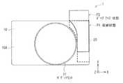
図1〜図3を主に参照して本開示の第1の実施の形態に係る撮像装置1の基本構成について説明する。図1は、本開示の第1の実施の形態に係る撮像装置1を前方から眺めた外観構成を表したものである。図2は、撮像装置1を後方から眺めた外観構成を表したものである。図3は、図1に示した撮像装置1を表す正面図である。
<First Embodiment>
[1. Configuration of Imaging Device 1]
The basic configuration of theimaging apparatus 1 according to the first embodiment of the present disclosure will be described mainly with reference to FIGS. FIG. 1 illustrates an external configuration of theimaging apparatus 1 according to the first embodiment of the present disclosure as viewed from the front. FIG. 2 illustrates an external configuration of theimaging device 1 viewed from the rear. FIG. 3 is a front view showing theimaging device 1 shown in FIG.

撮像装置1は小型デジタル一眼カメラであり、例えば、本体10と、ビューファインダ20と、撮像レンズユニット30とを備えている。ビューファインダ20は、本体10に収納された収納状態P1(図3)と、本体10から外部へ突出(露出)した使用状態P3(後出)との間における状態移行が可能なものである。なお、図3では、収納状態P1にあるビューファインダ20を破線で示し、収納状態P1から使用状態P3に至る途中のポップアップ状態P2にあるビューファインダ20を実線で示している。ビューファインダ20については後に詳述する。この撮像装置1では、後出の制御部6により、ビューファインダ20の状態移行に応じて電源オンの動作および電源オフの動作の少なくとも一方を実行するモードの選択を行うようになっている。  Theimaging device 1 is a small digital single-lens camera, and includes, for example, amain body 10, aviewfinder 20, and animaging lens unit 30. Theviewfinder 20 is capable of state transition between a storage state P1 (FIG. 3) stored in themain body 10 and a use state P3 (explained later) protruding (exposed) from themain body 10 to the outside. In FIG. 3, theviewfinder 20 in the storage state P1 is indicated by a broken line, and theviewfinder 20 in the pop-up state P2 on the way from the storage state P1 to the use state P3 is indicated by a solid line. Theviewfinder 20 will be described in detail later. In theimaging apparatus 1, thecontrol unit 6 described later selects a mode for executing at least one of a power-on operation and a power-off operation in accordance with the state transition of theviewfinder 20.

以下の説明では、本体10の前後方向Zにおいて、レンズ側(被写体側)を前方とし表示部側(像側)を後方とする。なお、前後方向Zは、本体10に接続されるレンズ(図示せず)の光軸方向と同じである。また、本体10の左右方向をX方向とし、左右は本体10の後方から前方を向いた状態で表す。本体10の上下方向をY方向とする。  In the following description, in the front-rear direction Z of themain body 10, the lens side (subject side) is the front and the display unit side (image side) is the rear. The front-rear direction Z is the same as the optical axis direction of a lens (not shown) connected to themain body 10. Further, the left-right direction of themain body 10 is defined as the X direction, and the left and right are expressed from the rear side of themain body 10 toward the front side. The vertical direction of themain body 10 is defined as the Y direction.

本体10は、例えば直方体の形状を有しており、前面10Aにボディマウント11が設けられ、内部に撮像素子2Aおよび画像信号処理部3(いずれも後出)などが収納されている。本体10の背面10Bには、表示部12が設けられている。  Themain body 10 has, for example, a rectangular parallelepiped shape, abody mount 11 is provided on thefront surface 10A, and animage sensor 2A and an image signal processing unit 3 (both described later) are accommodated therein. Adisplay unit 12 is provided on theback surface 10 </ b> B of themain body 10.

ボディマウント11は、本体10と交換式の撮像レンズユニット30との機械的または電気的な接続を行うものであり、ユーザは用途に合わせてレンズを選択して本体10に接続可能となっている。撮像レンズユニット30は、1以上のレンズ30Aを収容するレンズ鏡筒30Bと、そのレンズ鏡筒30Bの周囲に設けられたレンズリング30C,30Dとを有している。レンズリング30C,30Dは、例えば絞り値やシャッタースピード、撮影モードなどの手動での設定、またはフォーカシングもしくはズーミングの手動操作を行うためのメカキーであり、入力部8(後出)の一部を構成する。なお、レンズリングの数は特に限定されない。レンズリングを設けなくともよい。  The body mount 11 performs mechanical or electrical connection between themain body 10 and the exchangeableimaging lens unit 30, and the user can select a lens according to the application and connect it to themain body 10. . Theimaging lens unit 30 includes alens barrel 30B that houses one ormore lenses 30A, and lens rings 30C and 30D provided around thelens barrel 30B. The lens rings 30C and 30D are mechanical keys for manually setting, for example, an aperture value, a shutter speed, a shooting mode, or a manual operation of focusing or zooming, and constitute a part of the input unit 8 (described later). To do. The number of lens rings is not particularly limited. It is not necessary to provide a lens ring.

撮像素子2Aは、撮像レンズユニット30などと共に撮像部2(後出)を構成し、撮像レンズユニット30を通して被写体像を受光面に結像させて光電変換により電気信号を生成するものである。撮像素子2Aとしては、CCD(Charge Coupled Device)やCMOS(Complementary Metal Oxide Semiconductor)イメージセンサなどが用いられる。  Theimaging device 2A constitutes the imaging unit 2 (described later) together with theimaging lens unit 30 and the like, and forms an object image on the light receiving surface through theimaging lens unit 30 and generates an electrical signal by photoelectric conversion. As theimaging device 2A, a charge coupled device (CCD), a complementary metal oxide semiconductor (CMOS) image sensor, or the like is used.

表示部12は、撮像レンズユニット30を通して得られる撮像中のスルー画像、本体10の内部の記憶媒体7A(後出)などに記録された画像、または電池残量もしくは撮影条件などの各種情報を表示面12Aに表示するものである。撮影条件としては、例えばシャッタースピード、絞り値、fナンバー、水平度、あるいはフラッシュの有無などが挙げられる。また、表示部12はタッチパネル部(図示せず)を有し、ユーザーインターフェース画像などの操作画像を表示し、タッチパネルとして機能するものであってもよい。表示部12は、例えば液晶パネル(LCD)や有機EL(Electro Luminescence)パネルなどにより構成されている。後に詳述するように、表示部12は本体10に対して回転可能に接続されていてもよい。また、制御部6により、例えばビューファインダ20の状態移行に応じて表示部12の表示動作の開始または終了が行われる。  Thedisplay unit 12 displays a through image during imaging obtained through theimaging lens unit 30, an image recorded on thestorage medium 7 </ b> A (described later) in themain body 10, or various information such as a remaining battery level or imaging conditions. It is displayed on thesurface 12A. Examples of shooting conditions include shutter speed, aperture value, f-number, level, or presence / absence of flash. Thedisplay unit 12 may have a touch panel unit (not shown), display an operation image such as a user interface image, and function as a touch panel. Thedisplay unit 12 is configured by, for example, a liquid crystal panel (LCD) or an organic EL (Electro Luminescence) panel. As will be described in detail later, thedisplay unit 12 may be rotatably connected to themain body 10. Thecontrol unit 6 starts or ends the display operation of thedisplay unit 12 according to, for example, the state transition of theviewfinder 20.

ビューファインダ20は、撮影される像を目視確認して構図設定やピント合わせ等を行うためのものであり、例えば光学ビューファインダ(OVF:Optical View Finder)または電子ビューファインダ(EVF:Electronic View Finder)により構成されている。電子ビューファインダである場合、ビューファインダ20は、覗き窓21(図1から図3には図示せず、後出の図7参照。)の奥に、例えば接眼レンズ(図示せず)と液晶パネルや有機ELパネルなどの表示画面(図示せず)とを有する。ビューファインダ20における表示画面には、撮像中のスルー画像のほか、電池残量や撮影条件(例えばシャッタースピード、絞り値、fナンバー、水平度、フラッシュの有無)などの各種情報が表示される。ビューファインダ20における表示画面には、表示部12に表示されるものと同一のものが表示されてもよいし、異なるものが表示されてもよい。ビューファインダ20の表示画面には、制御部6により、例えば表示部12に表示される複数の情報のうちの一部の情報のみを表示させるようにしてもよい。また、制御部6により、例えばビューファインダ20の状態移行に応じてビューファインダ20の表示動作などを起動させるようにしてもよい。  Theviewfinder 20 is used for visually confirming a photographed image and performing composition setting, focusing, and the like. For example, an optical viewfinder (OVF) or an electronic viewfinder (EVF) is used. It is comprised by. In the case of an electronic viewfinder, theviewfinder 20 has, for example, an eyepiece (not shown) and a liquid crystal panel in the back of the observation window 21 (not shown in FIGS. 1 to 3, see FIG. 7 described later). And a display screen (not shown) such as an organic EL panel. The display screen in theviewfinder 20 displays various information such as the remaining battery level and shooting conditions (for example, shutter speed, aperture value, f-number, horizontality, presence / absence of flash) in addition to the through image being captured. On the display screen in theviewfinder 20, the same display as that displayed on thedisplay unit 12 may be displayed, or a different display may be displayed. On the display screen of theviewfinder 20, thecontrol unit 6 may display only a part of the plurality of information displayed on thedisplay unit 12, for example. Thecontrol unit 6 may activate the display operation of theviewfinder 20 according to the state transition of theviewfinder 20, for example.

ビューファインダ20の構成について、図1から図3に加え、図4から図7を参照してさらに説明する。図4は、本体10からビューファインダ20を上方へ突出させたポップアップ状態P2の撮像装置1を前方から眺めた場合の外観斜視図であり、図5は、その状態の撮像装置1を後方から眺めた場合の外観斜視図である。また、図6,図7は、それぞれ使用状態P3におけるビューファインダ20を前方または後方から眺めた場合の斜視図である。ビューファインダ20は、収納状態P1とポップアップ状態P2と使用状態P3との3つの状態を取りうる。収納状態P1とは、ビューファインダ20が本体10に収納された状態であり、すなわちビューファインダ20を使用者(撮像者)が使用しない状態である。なお、図1〜図3では、ビューファインダ20の全体が本体10の内部に完全に収容された状態を示しているが、ビューファインダ20の一部が露出していてもよい。ポップアップ状態P2は、ビューファインダ20全体が本体10から上方へ大きく突出した状態をいう。ポップアップ状態P2では、収納状態P1と比較してビューファインダ20におけるより多くの部分が本体10から外へ露出している。また、使用状態P3は、ビューファインダ20を使用者(撮像者)が使用するにあたって適切な状態をいい、ポップアップ状態P2からビューファインダ20の一部である可動部222(後出)が本体部221(後出)の後方へ稼働(進出)した状態をいう。この使用状態P3では、使用者に、ビューファインダ20の内部に設けられた表示画面の画像がぼやけずに明確に視認される。上記のように、ビューファインダ20は、収納状態P1と本体10外に突出した使用状態P3との間の状態移行の際、二以上の方向(上下方向および前後方向)に移動可能である。これにより、撮像装置1の全体構成が小型化されている。  The configuration of theviewfinder 20 will be further described with reference to FIGS. 4 to 7 in addition to FIGS. 4 is an external perspective view of theimaging device 1 in the pop-up state P2 with theviewfinder 20 protruding upward from themain body 10 when viewed from the front, and FIG. 5 is a view of theimaging device 1 in that state from the rear. FIG. 6 and 7 are perspective views when theviewfinder 20 in the use state P3 is viewed from the front or the rear. Theviewfinder 20 can take three states: a storage state P1, a pop-up state P2, and a use state P3. The storage state P1 is a state in which theviewfinder 20 is stored in themain body 10, that is, a state in which the user (imager) does not use theviewfinder 20. 1 to 3 show a state in which theentire viewfinder 20 is completely accommodated in themain body 10, but a part of theviewfinder 20 may be exposed. The pop-up state P2 refers to a state in which theentire viewfinder 20 protrudes greatly from themain body 10 upward. In the pop-up state P2, more parts in theviewfinder 20 are exposed to the outside than themain body 10 as compared with the storage state P1. The use state P3 is an appropriate state for the user (imager) to use theviewfinder 20, and the movable unit 222 (described later) which is a part of theviewfinder 20 from the pop-up state P2 is themain body unit 221. It means the state of operation (advancement) behind (after). In this use state P3, the user can clearly see the image on the display screen provided in theviewfinder 20 without blurring. As described above, theviewfinder 20 is movable in two or more directions (vertical direction and front-rear direction) during the state transition between the housed state P1 and the use state P3 protruding out of themain body 10. Thereby, the whole structure of theimaging device 1 is reduced in size.

ビューファインダ20は、収納状態P1(図1から図3参照。)から、例えば図4および図5に示したように本体10の上方(矢印A1の方向)に伸長し、ポップアップ状態P2に至る。ビューファインダ20は、ポップアップ状態P2から、さらに図6および図7に示したように可動部222が本体10の後方(矢印A2の方向)に進出して使用状態P3に至る。ビューファインダ20を本体10の上方に伸長させることにより、覗き窓21は本体10の上方に位置する。これにより、ビューファインダ20が鏡筒や表示部12の上方に位置する通常のデジタル一眼カメラの構成に近付け、使用者にとっての使いやすさを向上させることが可能となる。また、ビューファインダ20の一部を本体10の後方に進出させることにより、眼までのクリアランスを小さくし、遮光性を高めることが可能となる。  Theviewfinder 20 extends from the housed state P1 (see FIGS. 1 to 3) to the upper side of the main body 10 (in the direction of the arrow A1) as shown in FIGS. 4 and 5, for example, and reaches the pop-up state P2. In theviewfinder 20, from the pop-up state P2, as shown in FIGS. 6 and 7, themovable part 222 advances further to the back of the main body 10 (in the direction of the arrow A2) and reaches the use state P3. By extending theviewfinder 20 above themain body 10, theviewing window 21 is positioned above themain body 10. As a result, theviewfinder 20 can be brought close to the configuration of a normal digital single-lens camera positioned above the lens barrel and thedisplay unit 12, and the ease of use for the user can be improved. Further, by moving a part of theviewfinder 20 to the rear of themain body 10, it is possible to reduce the clearance to the eyes and improve the light shielding property.

ビューファインダ20の本体10の後方への進出量としては、例えば、ビューファインダ20の接眼面22Aが本体10の背面10B(表示部12)よりも後方に突出することが好ましい。これにより、眼とのクリアランスが小さくなると共に、使用者の鼻が表示部12に当たってしまうおそれが小さくなり、使いやすさが向上するからである。  As an amount of theviewfinder 20 moving backward to themain body 10, for example, theeyepiece surface 22 </ b> A of theviewfinder 20 is preferably protruded rearward from theback surface 10 </ b> B (display unit 12) of themain body 10. As a result, the clearance with the eye is reduced, the possibility that the user's nose hits thedisplay unit 12 is reduced, and the usability is improved.

本体10は、上面10Cに、ビューファインダ20が本体10に出入りする開口部13を有することが好ましい。これにより、ビューファインダ20が本体10に出入りする開口部21を本体10の背面10B以外に設けることが可能となり、鏡筒の大口径化、表示部12の大画面化への対応が容易になる。ちなみに、開口部13を本体10の背面10Bに設ける場合には、本体10のサイズを大きくするか、あるいは本体10のサイズを同じにするなら、鏡筒は小さくなり、それにより倍率は低く、明るさは暗く、撮像素子のサイズも小さくなる。また、表示部12のサイズも小さくなる。  Themain body 10 preferably has anopening 13 through which theviewfinder 20 enters and exits themain body 10 on theupper surface 10C. As a result, it is possible to provide anopening 21 through which theviewfinder 20 enters and exits themain body 10 other than theback surface 10B of themain body 10, and it becomes easy to cope with a larger diameter of the lens barrel and a larger screen of thedisplay unit 12. . Incidentally, in the case where theopening 13 is provided on theback surface 10B of themain body 10, if the size of themain body 10 is increased or the size of themain body 10 is the same, the lens barrel becomes smaller, thereby reducing the magnification and brightness. It is dark and the size of the image sensor is small. Further, the size of thedisplay unit 12 is also reduced.

なお、図1から図3に示した開口部13の位置は、例えば通常のデジタル一眼カメラではストロボが配置される場所である。本実施の形態ではストロボ14の配置を変更し、開口部13よりも中央寄りの位置に配置している。  Note that the position of theopening 13 shown in FIGS. 1 to 3 is a place where a strobe is disposed in a normal digital single-lens camera, for example. In the present embodiment, the arrangement of thestrobe 14 is changed and arranged at a position closer to the center than theopening 13.

ビューファインダ20は、上述した図3に示したように、ボディマウント11と重ならない位置に設けられていることが好ましい。これにより、ビューファインダ20と鏡筒との干渉を回避することが可能となる。なお、ビューファインダ20は、背面視において表示部12と重なっていてもよい。  As shown in FIG. 3 described above, theviewfinder 20 is preferably provided at a position that does not overlap thebody mount 11. Thereby, it is possible to avoid interference between theviewfinder 20 and the lens barrel. Note that theviewfinder 20 may overlap thedisplay unit 12 in the rear view.

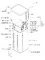
ビューファインダ20の詳細な構成について、図1から図7に加え、図8から図10A,10Bを参照してさらに説明する。図8は、図1〜図3に示した収納状態P1におけるビューファインダ20の外観を表す斜視図である。図9は、図4〜図7に示したポップアップ状態P2および使用状態P3におけるビューファインダ20の外観を表す斜視図である。図10Aは、図8に示したビューファインダユニット22の、収納状態P1およびポップアップ状態P2における構成を表す正面図および側面図である。図10Bは、図8に示したビューファインダユニット22の、使用状態P3における外観を表す側面図である。  The detailed configuration of theviewfinder 20 will be further described with reference to FIGS. 8 to 10A and 10B in addition to FIGS. FIG. 8 is a perspective view showing the appearance of theviewfinder 20 in the storage state P1 shown in FIGS. FIG. 9 is a perspective view showing an appearance of theviewfinder 20 in the pop-up state P2 and the use state P3 shown in FIGS. 10A is a front view and a side view showing the configuration of theviewfinder unit 22 shown in FIG. 8 in the storage state P1 and the pop-up state P2. FIG. 10B is a side view showing the appearance of theviewfinder unit 22 shown in FIG. 8 in the usage state P3.

ビューファインダ20は、例えば、ビューファインダユニット22と、化粧部材23と、第1移動機構24と、第2移動機構25(図10Aおよび図10B参照。)と、視度調整部26(図6、図7および図9参照)とを有している。  Theviewfinder 20 includes, for example, aviewfinder unit 22, adecorative member 23, afirst movement mechanism 24, a second movement mechanism 25 (see FIGS. 10A and 10B), and a diopter adjustment unit 26 (FIG. 6, FIG. 6). 7 and 9).

ビューファインダユニット22は、ポップアップ状態P2および使用状態P3において本体10の外部に露出する部分であり、例えば、本体10に対して上方向へ伸長する本体部221と、この本体部221に対して後方へ伸長する可動部222とを有する。上述した覗き窓21(図5および図7参照。)と、覗き窓21の奥に設けられた接眼レンズおよび表示画面(いずれも図示せず)とを有している。  Theviewfinder unit 22 is a portion exposed to the outside of themain body 10 in the pop-up state P2 and the use state P3. For example, themain body portion 221 that extends upward with respect to themain body 10 and the rear portion with respect to themain body portion 221 And amovable part 222 extending to the right. It has the above-described viewing window 21 (see FIGS. 5 and 7), and an eyepiece and a display screen (both not shown) provided at the back of theviewing window 21.

化粧部材23は、ビューファインダユニット22の覗き窓21以外の側面および背面を被覆し、ビューファインダ20および撮像装置1の外観を整えるものである。化粧部材23は、例えば、上面化粧部材23Aと、側面化粧部材23Bとを有している。上面化粧部材23Aは、ビューファインダ20が収納状態P1にある場合には本体10の上面10Cの外装部材の一部を構成する。側面化粧部材23Bは、ビューファインダ20がポップアップ状態P2および使用状態P3にある場合にビューファインダユニット22の側面および背面を被覆している。  Thedecorative member 23 covers the side surface and the back surface of theviewfinder unit 22 other than theviewing window 21 and adjusts the appearance of theviewfinder 20 and theimaging device 1. Thedecorative member 23 includes, for example, an upperdecorative member 23A and a sidedecorative member 23B. The upper facedecorative member 23A constitutes a part of the exterior member of theupper face 10C of themain body 10 when theviewfinder 20 is in the housed state P1. The sidedecorative member 23B covers the side and back surfaces of theviewfinder unit 22 when theviewfinder 20 is in the pop-up state P2 and the use state P3.

側面化粧部材23Bは、ボディマウント11を回避する切欠き23Cを有していることが好ましい。これにより、図3に示したように、ビューファインダ20を、ボディマウント11を回避して配置することが可能となる。  The sidedecorative member 23 </ b> B preferably has anotch 23 </ b> C that avoids thebody mount 11. Thereby, as shown in FIG. 3, theviewfinder 20 can be arranged avoiding thebody mount 11.

第1移動機構24は、ビューファインダユニット22を本体10の上方に持ち上げるものであり、例えば、機械的移動機構により構成されている。具体的には、第1移動機構24は、ベースフレーム31と、スライドフレーム32と、第1弾性部材33と、掛止機構34とを有している。ベースフレーム31およびスライドフレーム32は、スライドフレーム32がベースフレーム31に挿通された二重筒構造をなしている。なお、ベースフレーム31およびスライドフレーム32の内部は空洞になっており、ストロボ14の電池などを収納可能となっていることが好ましい。  The first movingmechanism 24 lifts theviewfinder unit 22 above themain body 10 and is configured by, for example, a mechanical moving mechanism. Specifically, the first movingmechanism 24 includes abase frame 31, aslide frame 32, a firstelastic member 33, and a latching mechanism 34. Thebase frame 31 and theslide frame 32 have a double cylinder structure in which theslide frame 32 is inserted through thebase frame 31. In addition, it is preferable that the inside of thebase frame 31 and theslide frame 32 is hollow, and the battery of theflash 14 etc. can be accommodated.

ベースフレーム31は、例えば、金属板などよりなるベースフレーム本体31Aと、突出部31Bと、回動規制部31Cと、押さえ部31Dとを有している。ベースフレーム本体31Aは、例えば、本体10に固定されている。また、ベースフレーム本体31Aには、第1弾性部材33の一端部33Aが固定されている。さらに、ベースフレーム本体31Aには、第1弾性部材33の他端部33Bの移動範囲を規定する長孔31Eが設けられている。突出部31Bは、掛止機構34を保持する部分であり、回動規制部31Cおよび押さえ部31Dと一体的に構成されている。回動規制部31Cは、掛止機構34の回動範囲を規制するものであり、掛止機構34のガイド溝34B内に設けられている。押さえ部31Dは、掛止機構34の鉤部34Cがスライドフレーム32の孔32Bから脱落するのを抑制するものである。  Thebase frame 31 includes a base framemain body 31A made of, for example, a metal plate, a protruding portion 31B, a rotation restricting portion 31C, and apressing portion 31D. The base framemain body 31A is fixed to themain body 10, for example. In addition, oneend 33A of the firstelastic member 33 is fixed to the base framemain body 31A. Further, the base framemain body 31A is provided with along hole 31E that defines the movement range of theother end 33B of the firstelastic member 33. The protruding portion 31B is a portion that holds the latch mechanism 34, and is configured integrally with the rotation restricting portion 31C and thepressing portion 31D. Therotation restricting portion 31 </ b> C restricts the rotation range of the latching mechanism 34 and is provided in the guide groove 34 </ b> B of the latching mechanism 34. The holdingportion 31D is configured to prevent thecollar portion 34C of the latching mechanism 34 from falling off from thehole 32B of theslide frame 32.

スライドフレーム32は、例えば、金属板などよりなるスライドフレーム本体32Aと、孔32Bとを有している。スライドフレーム本体32Aは、ねじ32C(図9参照。)によりビューファインダユニット22を覆う化粧部材23に固定されている。孔32Bは、掛止機構34の鉤部34Cを受容することにより、ビューファインダ20を収納状態P1に保持するものである。  Theslide frame 32 has a slide framemain body 32A made of, for example, a metal plate and ahole 32B. The slide framemain body 32A is fixed to adecorative member 23 that covers theviewfinder unit 22 by screws 32C (see FIG. 9). Thehole 32 </ b> B holds theviewfinder 20 in the housed state P <b> 1 by receiving the collar portion 34 </ b> C of the latching mechanism 34.

第1弾性部材33は、ベースフレーム31とスライドフレーム32との間に設けられ、スライドフレーム32を上方に付勢するものである。第1弾性部材33は、例えば、ばねにより構成されていることが好ましい。ばねの種類は特に限定されないが、例えば、引張コイルばね、または、ねじりコイルばねにより構成されていることが好ましい。第1弾性部材33の一端部33Aは、ベースフレーム31のベースフレーム本体31Aに固定され、第1弾性部材33の他端部33Bはスライドフレーム32のスライドフレーム本体32Aに固定されている。  The firstelastic member 33 is provided between thebase frame 31 and theslide frame 32 and biases theslide frame 32 upward. The firstelastic member 33 is preferably constituted by a spring, for example. Although the kind of spring is not specifically limited, For example, it is preferable that it is comprised by the tension coil spring or the torsion coil spring. Oneend 33A of the firstelastic member 33 is fixed to the base framemain body 31A of thebase frame 31, and theother end 33B of the firstelastic member 33 is fixed to the slide framemain body 32A of theslide frame 32.

掛止機構34は、スライドフレーム32の上方への移動を規制するものであり、例えば、取付部34Aと、ガイド溝34Bと、鉤部34Cと、受け部34Dとを有している。取付部34Aは、ベースフレーム31の突出部31Bに回動可能に取り付けられている。ガイド溝34Bは、掛止機構34の回動範囲を規定するものである。ガイド溝34B内には、ベースフレーム31の回動規制部31Cが設けられている。鉤部34Cは、取付部34Aの一か所から下方に向けて延長されている。鉤部34Cがスライドフレーム32の孔32Bに掛合することにより、ビューファインダ20が収納状態P1に保持されるようになっている。受け部34Dは、本体10の側面10Dに設けられたビューファインダ操作部(ボタン)10Eを保持する部分である。非使用時には、ビューファインダ操作部10Eが受け部34Dに保持されることにより取付部34Aの回動が規制され、鉤部34Cがスライドフレーム32の孔32Bに掛止した状態が維持される。使用時には、使用者がビューファインダ操作部10Eをスライドさせると、ビューファインダ操作部10Eが受け部34Dから外れることにより、取付部34Aが回動し、鉤部34Cがスライドフレーム32の孔32Bから外れるようになっている。  The latch mechanism 34 regulates the upward movement of theslide frame 32, and includes, for example, an attachment portion 34A, aguide groove 34B, aflange portion 34C, and a receiving portion 34D. The attachment portion 34A is rotatably attached to the protruding portion 31B of thebase frame 31. The guide groove 34 </ b> B defines a rotation range of the latch mechanism 34. A rotation restricting portion 31C for thebase frame 31 is provided in theguide groove 34B. Thecollar portion 34C is extended downward from one place of the attachment portion 34A. When theflange 34C is engaged with thehole 32B of theslide frame 32, theviewfinder 20 is held in the storage state P1. The receiving portion 34D is a portion that holds a viewfinder operation portion (button) 10E provided on the side surface 10D of themain body 10. When not in use, theviewfinder operating portion 10E is held by the receiving portion 34D, whereby the rotation of the attachment portion 34A is restricted, and the state where thecollar portion 34C is hooked in thehole 32B of theslide frame 32 is maintained. In use, when the user slides theviewfinder operation section 10E, theviewfinder operation section 10E is detached from the receiving section 34D, whereby the attachment section 34A is rotated and thecollar section 34C is detached from thehole 32B of theslide frame 32. It is like that.

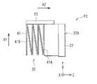
第2移動機構25は、ビューファインダユニット22の可動部222を本体10の後方に進出させるものであり、例えば機械的移動機構により構成されている。具体的には、第2移動機構25は、図10および図11に示したように、第2弾性部材41を有している。第2弾性部材41は、ビューファインダユニット22と化粧部材23との間に設けられ、ビューファインダユニット22を後方(Z方向)に付勢するものである。第2弾性部材41は、例えば、ばねにより構成されていることが好ましい。ばねの種類は特に限定されないが、例えば、異形圧縮ばねにより構成されていることが好ましい。第2弾性部材41の一端部41Aは、ビューファインダユニット22の背面に固定され、第2弾性部材41の他端部41Bは化粧部材23に固定されている。非使用時には、ビューファインダユニット22は、本体10の背面10Bにより押さえられており、第2弾性部材41の付勢力による移動が抑制されていることが好ましい。  Thesecond moving mechanism 25 moves themovable part 222 of theviewfinder unit 22 to the rear of themain body 10 and is configured by, for example, a mechanical moving mechanism. Specifically, the second movingmechanism 25 has a secondelastic member 41 as shown in FIGS. 10 and 11. The secondelastic member 41 is provided between theviewfinder unit 22 and thedecorative member 23, and biases theviewfinder unit 22 rearward (Z direction). The secondelastic member 41 is preferably constituted by a spring, for example. Although the kind of spring is not specifically limited, For example, it is preferable that it is comprised by the unusual shaped compression spring. Oneend 41 </ b> A of the secondelastic member 41 is fixed to the back surface of theviewfinder unit 22, and theother end 41 </ b> B of the secondelastic member 41 is fixed to thedecorative member 23. When not in use, theviewfinder unit 22 is preferably held by theback surface 10 </ b> B of themain body 10, and movement by the urging force of the secondelastic member 41 is preferably suppressed.

なお、第2移動機構25すなわち第2弾性部材41を省略し、使用者がビューファインダユニット22の可動部222を手で後方に引き出すようにすることも可能である。  Note that the second movingmechanism 25, that is, the secondelastic member 41 may be omitted, and the user may pull out themovable portion 222 of theviewfinder unit 22 backward by hand.

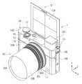
また、上記の説明では、ビューファインダ20を本体10の上方に伸長させる動作を機械的移動機構である第1移動機構24を用いて行うようにした。しかしながら、図11Aおよび図11Bに示した変形例としての撮像装置1Aのように、第1移動機構24の代わりに電気的移動機構27を用いることも可能である。  In the above description, the operation of extending theviewfinder 20 above themain body 10 is performed using the first movingmechanism 24 that is a mechanical moving mechanism. However, it is also possible to use theelectric movement mechanism 27 instead of thefirst movement mechanism 24 as in theimaging apparatus 1A as a modification example shown in FIGS. 11A and 11B.

撮像装置1Aは、例えば、ビューファインダユニット22と、電気的移動機構27とを有している。電気的移動機構27は、ビューファインダユニット22を本体10の上方に持ち上げるものであり、例えば、ベースフレーム51と、スライドフレーム52と、ラック53と、モータ54とを有している。ベースフレーム51およびスライドフレーム52は、スライドフレーム52がベースフレーム51に挿通された二重筒構造をなしている。なお、ベースフレーム51およびスライドフレーム52の内部は空洞になっており、ストロボ14の電池などを収納可能となっていることが好ましい。ラック53は、スライドフレーム52に設けられている。モータ54は、ベースフレーム51に固定され、ラック53に噛み合うウォームギア54Aを有している。  Theimaging device 1A includes, for example, aviewfinder unit 22 and anelectric movement mechanism 27. Theelectrical movement mechanism 27 is for lifting theviewfinder unit 22 above themain body 10 and includes, for example, abase frame 51, aslide frame 52, arack 53, and amotor 54. Thebase frame 51 and theslide frame 52 have a double cylinder structure in which theslide frame 52 is inserted through thebase frame 51. In addition, it is preferable that the inside of thebase frame 51 and theslide frame 52 is hollow, and the battery of thestrobe 14 can be accommodated. Therack 53 is provided on theslide frame 52. Themotor 54 has aworm gear 54 </ b> A that is fixed to thebase frame 51 and meshes with therack 53.

非使用時には、ビューファインダ20は、本体10内の収納状態P1となっている(図1ないし図3参照。)。使用時には、使用者が本体10に設けられたビューファインダ操作部(図示せず)を操作することでモータ54が回転する。モータ54の回転軸に取り付けられたウォームギア54Aとラック53とが噛み合っていることから、ラック53がスライドする(図11B参照。)。これにより、スライドフレーム52が本体10の上方に移動し、ビューファインダユニット22が本体10外にポップアップする(図4および図5参照)。上昇したスライドフレーム52およびビューファインダユニット22は、ウォームギア54Aのセルフロックにより、ポップアップした位置で保持され、ポップアップ状態P2が維持される。  When not in use, theviewfinder 20 is stored in the main body 10 (see FIGS. 1 to 3). In use, themotor 54 is rotated by the user operating a viewfinder operation unit (not shown) provided in themain body 10. Since theworm gear 54A attached to the rotating shaft of themotor 54 and therack 53 are engaged with each other, therack 53 slides (see FIG. 11B). As a result, theslide frame 52 moves above themain body 10 and theviewfinder unit 22 pops up outside the main body 10 (see FIGS. 4 and 5). The raisedslide frame 52 andviewfinder unit 22 are held in the popped-up position by the self-locking of theworm gear 54A, and the pop-up state P2 is maintained.

ポップアップ状態P2では、第2弾性部材41の付勢力による可動部222の後方への移動は、本体10の外装部材の背面10Bにより抑制されている(図11A参照。)。しかしながら、ビューファインダユニット22が本体10外に進出すると、第2弾性部材41の付勢力により可動部222が本体10の後方に進出し、使用状態P3に至る(図11B参照。)。以上により、全自動でビューファインダ20が収納状態P1から使用状態P3へ状態移行させることができる。  In the pop-up state P2, the backward movement of themovable portion 222 due to the urging force of the secondelastic member 41 is suppressed by theback surface 10B of the exterior member of the main body 10 (see FIG. 11A). However, when theviewfinder unit 22 advances to the outside of themain body 10, themovable portion 222 advances to the rear of themain body 10 due to the urging force of the secondelastic member 41 and reaches the use state P3 (see FIG. 11B). As described above, theviewfinder 20 can shift the state from the storage state P1 to the use state P3 fully automatically.

視度調整部26は、使用者の視力に合わせてビューファインダ20の度数を調整するための操作部(レバー、つまみ、ダイヤル等)である。視度調整部26は、例えばビューファインダ20のビューファインダユニット22の上面に設けられている。また、視度調整部26は、収納状態P1およびポップアップ状態P2では化粧部材23の上面化粧部材23Aに覆い隠されている(図1から図3参照。)。これに対し、使用状態P3では化粧部材23の上面化粧部材23Aから外部へ露出して操作可能となる(図6および図7参照。)。このように視度調整部26へのアクセスを限定することにより、意図せず視度調整部26が操作されて設定変更されてしまうことを避けることが可能となる。また、視度調整部26のビューファインダユニット22の上面からの突出量が小さくなり、ビューファインダ20を使用状態P3からポップアップ状態P2または収納状態P1に復帰させても設定がリセットされるおそれが小さくなる。よって、使用の都度、視度調整部26を調整し直す煩雑さを省き、使用者の利便性を高めることが可能となる。なお、視度調整部26は、機械式の操作部に限定されず、電子式の操作部であってもよい。その場合、例えば制御部6の内部の記憶部(図示せず)に使用者に応じた視度調整のデータが格納されるようにしてもよい。そのような視度調整のデータの格納は、例えば撮影動作の際、レリーズボタン16(後出)が押下されることでなされるようにしてもよい。  Thediopter adjustment unit 26 is an operation unit (lever, knob, dial, etc.) for adjusting the power of theviewfinder 20 in accordance with the visual acuity of the user. Thediopter adjustment unit 26 is provided on the upper surface of theviewfinder unit 22 of theviewfinder 20, for example. Further, thediopter adjustment unit 26 is covered with the upperdecorative member 23A of thedecorative member 23 in the housed state P1 and the pop-up state P2 (see FIGS. 1 to 3). On the other hand, in the use state P3, it is exposed to the outside from the upper facedecorative member 23A of thedecorative member 23 and can be operated (see FIGS. 6 and 7). By limiting access to thediopter adjustment unit 26 in this way, it is possible to avoid unintentionally operating thediopter adjustment unit 26 and changing settings. Further, the amount of protrusion of thediopter adjustment unit 26 from the upper surface of theviewfinder unit 22 is reduced, and the possibility that the setting is reset even when theviewfinder 20 is returned from the use state P3 to the pop-up state P2 or the storage state P1 is small. Become. Therefore, it is possible to save the trouble of re-adjusting thediopter adjustment unit 26 every time it is used, and to improve the convenience for the user. Thediopter adjustment unit 26 is not limited to a mechanical operation unit, and may be an electronic operation unit. In this case, for example, diopter adjustment data corresponding to the user may be stored in a storage unit (not shown) inside thecontrol unit 6. Such storage of diopter adjustment data may be performed, for example, by pressing the release button 16 (described later) during a photographing operation.

表示部12は、先に述べたように、本体10に対して回転可能に設けられており、その表示面12Aを前方に向けることができる(図12参照)。図12に示した状態は使用者が使用者自身を被写体として撮像を行う自分撮りモードに対応する。  As described above, thedisplay unit 12 is provided so as to be rotatable with respect to themain body 10, and thedisplay surface 12A can be directed forward (see FIG. 12). The state shown in FIG. 12 corresponds to a self-shooting mode in which the user takes an image of the user himself as a subject.

本体10の上面10Cには、入力部8の一部を構成する電源ボタン15、レリーズボタン16およびモード設定ダイヤル17がさらに設けられている。電源ボタン15は、撮像装置1の全体の電源オンの動作および電源オフの動作を行うものである。レリーズボタン16は、撮影動作を行うためのものであり、例えば半押し状態および全押し状態の2つの状態を検出可能な2段階検出ボタンである。レリーズボタン16が半押し状態になると、被写体に関する記録用画像(本撮影画像)を取得するための準備動作が行われる。ここでいう準備動作とは、例えば、AF(Automatic Focus)制御動作、AE(Automatic Exposure)制御動作等である。また、レリーズボタン16がさらに押し込まれて全押し状態になると、本撮影画像の撮影動作が行われる。撮影動作とは、撮像素子2Aを用いて被写体像に関する露光動作を行い、その露光動作によって得られた画像信号に所定の画像処理を施す一連の動作である。また、モード設定ダイヤル17は、撮像装置1の各種の動作モードの設定動作を行うものである。ここでいう撮像装置1の動作モードとしては、撮影モード、撮影した画像を再生する再生モード、および外部機器との間でデータ交信を行う通信モード等が挙げられる。  Apower button 15, arelease button 16, and amode setting dial 17 that constitute a part of the input unit 8 are further provided on theupper surface 10 </ b> C of themain body 10. Thepower button 15 is for performing the power-on operation and the power-off operation of theentire imaging apparatus 1. Therelease button 16 is for performing a photographing operation, and is, for example, a two-stage detection button that can detect two states of a half-pressed state and a fully-pressed state. When therelease button 16 is pressed halfway, a preparatory operation for acquiring a recording image (main photographed image) related to the subject is performed. Here, the preparation operation is, for example, an AF (Automatic Focus) control operation, an AE (Automatic Exposure) control operation, or the like. In addition, when therelease button 16 is further pushed down to the fully depressed state, a photographing operation for the actual photographed image is performed. The photographing operation is a series of operations for performing an exposure operation on a subject image using theimage sensor 2A and performing predetermined image processing on an image signal obtained by the exposure operation. Themode setting dial 17 is used to set various operation modes of theimaging apparatus 1. Examples of the operation mode of theimaging apparatus 1 include a shooting mode, a playback mode for playing back a captured image, and a communication mode for performing data communication with an external device.

撮像装置1は、例えば本体10の背面10Bにおけるビューファインダ20の近辺にアイセンサ60を備えていてもよい。アイセンサ60は、例えば磁気センサによって、使用者(撮像者)がビューファインダ20を覗いているか否かを検知するものであり、表示部12による表示とビューファインダ20による表示とを切り替えるものである。例えばアイセンサ60が使用者の眼の接近を検知した場合、表示部12の表示面12Aには画像が表示されなくなる。表示面12Aに画像が表示された状態のままでは、ビューファインダ20の覗き窓21を覗く使用者の眼に表示面12Aからの画像光が入射してしまい、ビューファインダ20の内部の表示画面の視認の妨げとなるからである。  Theimaging device 1 may include aneye sensor 60 in the vicinity of theviewfinder 20 on theback surface 10B of themain body 10, for example. Theeye sensor 60 detects, for example, whether or not the user (imager) is looking through theviewfinder 20 by using a magnetic sensor, and switches between display by thedisplay unit 12 and display by theviewfinder 20. For example, when theeye sensor 60 detects the approach of the user's eyes, no image is displayed on thedisplay surface 12 </ b> A of thedisplay unit 12. If the image is displayed on thedisplay surface 12A, the image light from thedisplay surface 12A is incident on the user's eye looking into theviewing window 21 of theviewfinder 20, and the display screen inside theviewfinder 20 is displayed. This is because it hinders visual recognition.

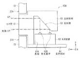
なお、撮像装置1は、アイセンサ60の代わりに、例えば図13A,13Bに示したように使用位置P3にあるビューファインダ20における覗き窓21の近傍にアイセンサ60Aを備えていてもよい。図13Aは撮像装置1の覗き窓21の近傍を拡大して表す斜視図であり、図13Bは、アイセンサ60Aの断面構成を表したものである。アイセンサ60Aは、例えば、センサ窓61と、センサ装置62と、反射部材63とを有している。センサ装置62は、センサ窓61に対して垂直に設置されている。反射部材63は、センサ窓61とセンサ装置62との間の光路LPに設けられている。これにより、撮像装置1の小型化が可能となっている。センサ窓61は、例えば、ビューファインダ20の接眼面22A(例えば、覗き窓21の周囲の領域、図13Aでは例えば左下方)に設けられている。このようにアイセンサ60Aをビューファインダ20に設けることにより、眼に近い位置にアイセンサ60Aを設置し、検知精度を高めることが可能となる。また、収納状態P1ではアイセンサ60Aが本体10内に隠れた状態となり、誤操作のおそれが小さくなる。  Note that theimaging apparatus 1 may include aneye sensor 60A in the vicinity of theviewing window 21 in theviewfinder 20 at the use position P3 as shown in FIGS. 13A and 13B, for example, instead of theeye sensor 60. FIG. 13A is an enlarged perspective view showing the vicinity of theviewing window 21 of theimaging apparatus 1, and FIG. 13B shows a cross-sectional configuration of theeye sensor 60A. Theeye sensor 60A includes, for example, a sensor window 61, a sensor device 62, and a reflecting member 63. The sensor device 62 is installed perpendicular to the sensor window 61. The reflection member 63 is provided in the optical path LP between the sensor window 61 and the sensor device 62. Thereby, size reduction of theimaging device 1 is possible. The sensor window 61 is provided, for example, on theeyepiece 22A of the viewfinder 20 (for example, a region around theviewing window 21, for example, lower left in FIG. 13A). By providing theeye sensor 60A in theviewfinder 20 in this way, it is possible to install theeye sensor 60A at a position close to the eye and improve detection accuracy. Further, in the storage state P1, theeye sensor 60A is hidden in themain body 10, and the risk of erroneous operation is reduced.

センサ装置62は、例えば、基板62A上に受光素子62Bを有し、支持部材64上に実装されている。センサ窓61を透過した入射光の光量変化を受光素子62Bが検出することにより、使用者の眼の接近の有無を検知するようになっている。  The sensor device 62 has, for example, alight receiving element 62B on asubstrate 62A and is mounted on asupport member 64. The light receiving element 62 </ b> B detects a change in the amount of incident light transmitted through the sensor window 61, thereby detecting whether or not the user's eyes are approaching.

反射部材63は、鏡面で光を反射する反射面63Aを有しており、これにより光の進路を変更するものである。反射部材63は、図13Bに示したようにセンサ窓61と一体の部材として設けられていてもよいし、センサ窓61とは別の部材として設けられていてもよい。  The reflecting member 63 has a reflecting surface 63A that reflects light on a mirror surface, and thereby changes the path of light. The reflection member 63 may be provided as a member integral with the sensor window 61 as illustrated in FIG. 13B, or may be provided as a member different from the sensor window 61.

図14は、撮像装置1の全体構成を示すブロック図である。撮像装置1は、表示部12およびビューファインダ20のほか、撮像部2、画像信号処理部3、エンコード/デコード部4、画像メモリ5、制御部6、スピーカ6A、モータ6B、記録/再生部7、入力部8および検出部9A,9Bを有する。撮像レンズユニット30は撮像部2に含まれる。  FIG. 14 is a block diagram illustrating the overall configuration of theimaging apparatus 1. In addition to thedisplay unit 12 and theviewfinder 20, theimaging device 1 includes an imaging unit 2, an imagesignal processing unit 3, an encoding /decoding unit 4, animage memory 5, acontrol unit 6, a speaker 6A, a motor 6B, and a recording / reproducingunit 7. And an input unit 8 anddetection units 9A and 9B. Theimaging lens unit 30 is included in the imaging unit 2.

撮像部2は、撮影画像データを取得する機構である。撮像部2は、撮像レンズユニット30のほか、例えば撮像素子2A、前処理部2B、タイミングジェネレータ2Cおよび駆動部2Dなどを有する。撮像素子2Aは、タイミングジェネレータ2Cから出力されるタイミング信号に基づいて駆動され、被写体からの入射光を光電変換して電荷量に変換し、アナログ撮像信号として出力する。撮像素子2Aから出力されるアナログ撮像信号は前処理部2Bに出力される。前処理部2Bは、撮像素子2Aにより得られたアナログ撮像信号についてゲイン調整や波形整形を行うサンプルホールド/AGC(Automatic Gain Control)回路やビデオA/Dコンバータなどを含む。タイミングジェネレータ2Cは、制御部6の指令に従い撮像素子2Aに対してタイミング信号を出力するものである。また、駆動部2Dは、制御部6による制御に基づき、撮像レンズユニット30におけるフォーカシング、ズーミング、シャッタースピード調整および絞り調整などを行うものである。  The imaging unit 2 is a mechanism that acquires captured image data. In addition to theimaging lens unit 30, the imaging unit 2 includes, for example, animaging element 2A, apreprocessing unit 2B, a timing generator 2C, and adriving unit 2D. Theimage sensor 2A is driven based on the timing signal output from the timing generator 2C, photoelectrically converts incident light from the subject, converts it into a charge amount, and outputs it as an analog image signal. The analog imaging signal output from theimaging element 2A is output to thepreprocessing unit 2B. Thepreprocessing unit 2B includes a sample hold / AGC (Automatic Gain Control) circuit, a video A / D converter, and the like that perform gain adjustment and waveform shaping on the analog imaging signal obtained by theimaging device 2A. The timing generator 2 </ b> C outputs a timing signal to the image sensor 2 </ b> A according to a command from thecontrol unit 6. Thedrive unit 2D performs focusing, zooming, shutter speed adjustment, aperture adjustment, and the like in theimaging lens unit 30 based on control by thecontrol unit 6.

画像信号処理部3は、撮像部2により得られた撮影画像データに対し、各種の画像信号処理、例えば階調補正処理、シェーディング補正処理、高域補正(輪郭補正)処理、あるいは手ぶれ補正処理などを施すものである。  The imagesignal processing unit 3 performs various types of image signal processing, such as gradation correction processing, shading correction processing, high-frequency correction (contour correction) processing, or camera shake correction processing, on the captured image data obtained by the imaging unit 2. Is to be applied.

エンコード/デコード部4は、画像信号処理部3による画像信号処理の施された撮影画像データについての圧縮処理、および圧縮され撮影画像データの伸張処理を行う。静止画については、例えばJPEG(Joint Photographic Experts Group)形式などの所定の静止画形式による圧縮処理および伸張処理を行う。一方、動画については、例えばMPEG(Moving Picture Experts Group)形式などの所定の動画形式による圧縮処理および伸張処理を行う。  The encoding /decoding unit 4 performs compression processing on the captured image data that has been subjected to image signal processing by the imagesignal processing unit 3, and decompression processing of the compressed captured image data. For still images, compression processing and decompression processing are performed in a predetermined still image format such as JPEG (Joint Photographic Experts Group) format. On the other hand, the moving image is subjected to compression processing and decompression processing in a predetermined moving image format such as MPEG (Moving Picture Experts Group) format.

画像メモリ5は、揮発性メモリ、例えば、DRAM(Dynamic Random Access Memory)で構成されるバッファメモリであり、前処理部2B、画像信号処理部3およびエンコード/デコード部4によって所定の処理が施された画像データを一時的に蓄えておくものである。  Theimage memory 5 is a volatile memory, for example, a buffer memory composed of DRAM (Dynamic Random Access Memory), and is subjected to predetermined processing by thepreprocessing unit 2B, the imagesignal processing unit 3, and the encoding /decoding unit 4. The stored image data is temporarily stored.

制御部6は、例えばCPU(Central Processing Unit)、RAM(Random Access Memory)およびROM(Read-Only Memory)などから構成されている。ROMには、CPUにより読み込まれ動作されるプログラムなどが記憶されている。RAMは、CPUのワークメモリとして用いられる。CPUは、ROMに記憶されたプログラムに従い様々な処理を実行してコマンドの発行を行うことによって撮像装置1全体の制御を行う。  Thecontrol unit 6 includes, for example, a CPU (Central Processing Unit), a RAM (Random Access Memory), a ROM (Read-Only Memory), and the like. The ROM stores a program that is read and operated by the CPU. The RAM is used as a work memory for the CPU. The CPU controls theentire imaging apparatus 1 by executing various processes in accordance with programs stored in the ROM and issuing commands.

記録/再生部7は、例えばフラッシュメモリなどの半導体メモリ、または、磁気ディスク、光ディスク、光磁気ディスクなどの記録媒体7Aと、メディアドライブ7Bとを有する。メディアドライブ7Bは、制御部6による制御に基づき、エンコード/デコード部4で得られた静止画形式または動画形式の圧縮撮影画像データの記録媒体7Aへの記録と、その記録媒体7Aに記録された圧縮撮影画像データの各種データの再生(読み出し)とを行う。  The recording / reproducingunit 7 includes a semiconductor memory such as a flash memory, or a recording medium 7A such as a magnetic disk, an optical disk, and a magneto-optical disk, and a media drive 7B. Based on the control by thecontrol unit 6, the media drive 7B records the still image format or moving image format compressed photographed image data obtained by the encoding /decoding unit 4 on the recording medium 7A and the recording medium 7A. Various data of the compressed photographed image data is reproduced (read).

入力部8は使用者が撮像装置1に対する各種操作入力を行う部分であり、例えば表示部12に含まれるタッチパネル部や、本体10に設けられた電源ボタン15、レリーズボタン16およびモード設定ダイヤル17、あるいは撮像レンズユニット30に設けられたレンズリング30C,30Dなどである。入力部8は、使用者の入力操作を検出し、その入力操作に応じた情報(操作入力情報)を制御部6に伝達する。  The input unit 8 is a part where a user performs various operation inputs to theimaging device 1. For example, a touch panel unit included in thedisplay unit 12, apower button 15 provided on themain body 10, arelease button 16 and amode setting dial 17, Alternatively, lens rings 30 </ b> C and 30 </ b> D provided in theimaging lens unit 30. The input unit 8 detects a user's input operation and transmits information (operation input information) corresponding to the input operation to thecontrol unit 6.

検出部9Aは、表示部12の回転を検出するセンサを有しており、表示部12が図1〜図7に示した通常撮影状態にあるか、または図12に示した反転状態にあるかの検出を行うものである。すなわち検出部9Aは、表示部12が第1の回転状態(表示面12Aが後方を向いている通常撮影状態)および第2の回転状態(表示面12Aが前方を向いている反転状態)のいずれであるかを検出するものである。一方、検出部9Bは、ビューファインダ20が収納状態P1と使用状態P3との間のどの状態にあるのかを検出するものである。検出部9A,9Bとしては、機械的方法、電磁的方法、あるいは光学的方法を利用したセンサが適用される。検出部9Aにより、表示部12が自分撮り状態にある(反転位置にある)と検出された場合、制御部6は、アイセンサ60の動作停止を実行するモードの選択を行うようになっている。  The detection unit 9A includes a sensor that detects the rotation of thedisplay unit 12. Whether thedisplay unit 12 is in the normal photographing state illustrated in FIGS. 1 to 7 or in the inverted state illustrated in FIG. Is detected. In other words, the detection unit 9A includes either the first rotation state (the normal photographing state where thedisplay surface 12A faces rearward) or the second rotation state (the inverted state where thedisplay surface 12A faces frontward). It is what detects whether it is. On the other hand, thedetection unit 9B detects which state theviewfinder 20 is in between the storage state P1 and the use state P3. Sensors using a mechanical method, an electromagnetic method, or an optical method are applied as thedetection units 9A and 9B. When the detection unit 9A detects that thedisplay unit 12 is in the self-portrait state (in the reverse position), thecontrol unit 6 selects a mode in which the operation of theeye sensor 60 is stopped.

[2.撮像装置1による撮影動作]
この撮像装置1は、例えば図15に示したように動作する。図15は、撮像装置1の起動から停止までの一連の動作の流れを表す第1のフローチャートである。撮像装置1では、制御部6により、ビューファインダ20の状態移行に応じて電源オンの動作および電源オフの動作の少なくとも一方を実行するモードの選択が可能となっている。例えば、制御部6は、ビューファインダ20が収納状態P1から使用状態P3へ移行する際に電源オンの動作を実行し、あるいは、ビューファインダ20が使用状態P3から収納状態P1への移行する際に電源オフを行う。なお、図15に示した処理は、制御部6が、例えばROMなどに記憶されたプログラムに従って実行する。
[2. Shooting operation by imaging device 1]
Theimaging device 1 operates as shown in FIG. 15, for example. FIG. 15 is a first flowchart showing a flow of a series of operations from starting to stopping of theimaging apparatus 1. In theimaging apparatus 1, thecontrol unit 6 can select a mode for executing at least one of a power-on operation and a power-off operation in accordance with the state transition of theviewfinder 20. For example, thecontrol unit 6 performs a power-on operation when theviewfinder 20 shifts from the storage state P1 to the use state P3, or when theviewfinder 20 shifts from the use state P3 to the storage state P1. Turn off the power. Note that the processing shown in FIG. 15 is executed by thecontrol unit 6 according to a program stored in, for example, a ROM.

非使用時には、ビューファインダ20は、本体10の収納状態P1に収まっている(図1から図3参照。)。このとき、ビューファインダ操作部10Eが掛止機構34の受け部34Dに保持されていることにより、掛止機構34の取付部34Aの回動が規制され、掛止機構34の鉤部34Cがスライドフレーム32の孔32Bに掛合した状態が維持されている(図8参照。)。  When not in use, theviewfinder 20 is in the storage state P1 of the main body 10 (see FIGS. 1 to 3). At this time, since theviewfinder operation unit 10E is held by the receiving portion 34D of the latching mechanism 34, the rotation of the mounting portion 34A of the latching mechanism 34 is restricted, and theflange 34C of the latching mechanism 34 slides. The state of being engaged with thehole 32B of theframe 32 is maintained (see FIG. 8).

撮像装置1の撮影動作を行うにあたっては、まず、ビューファインダ20について、本体10に収納された収納状態P1からポップアップ状態P2への状態移行であるポップアップ動作を開始する。すなわち、ビューファインダ操作部10Eをスライドさせ、ビューファインダユニット22を本体10からポップアップさせる。より詳細には、ビューファインダ操作部10Eをスライドさせることで、ビューファインダ操作部10Eが掛止機構34の受け部34Dから外れ、掛止機構34の取付部34Aが回動する。これにより、掛止機構34の鉤部34Cがスライドフレーム32の孔32Bから脱出する(図9参照。)。その結果、第1弾性部材33の付勢力によりスライドフレーム32が本体10の上方に移動し、ビューファインダユニット22が本体10外にポップアップする(図4および図5参照)。ここで検出部9Bにより、収納状態P1からポップアップ状態P2への状態移行が開始されたかどうか、すなわちビューファインダ20が収納状態P1からポップアップ状態P2へ向けて動き始めたか否かを判別する(ステップS101)。収納状態P1からポップアップ状態P2への状態移行の開始が検出された場合には電源がオンされているかどうか判別する(ステップS102)。収納状態P1からポップアップ状態P2への状態移行の開始が検出されなかった場合は再度ステップS101を行う。  In performing the photographing operation of theimaging apparatus 1, first, theviewfinder 20 starts a pop-up operation that is a state transition from the housed state P1 housed in themain body 10 to the pop-up state P2. That is, theviewfinder operation unit 10E is slid to pop up theviewfinder unit 22 from themain body 10. More specifically, by sliding theviewfinder operation section 10E, theviewfinder operation section 10E is detached from the receiving section 34D of the latch mechanism 34, and the attachment section 34A of the latch mechanism 34 is rotated. Thereby, thecollar part 34C of the latching mechanism 34 escapes from thehole 32B of the slide frame 32 (refer FIG. 9). As a result, theslide frame 32 moves upward of themain body 10 by the urging force of the firstelastic member 33, and theviewfinder unit 22 pops up outside the main body 10 (see FIGS. 4 and 5). Here, thedetection unit 9B determines whether or not the state transition from the storage state P1 to the pop-up state P2 is started, that is, whether or not theviewfinder 20 starts to move from the storage state P1 to the pop-up state P2 (step S101). ). When the start of the state transition from the storage state P1 to the pop-up state P2 is detected, it is determined whether or not the power is turned on (step S102). When the start of the state transition from the storage state P1 to the pop-up state P2 is not detected, step S101 is performed again.

ステップS102において、電源ボタン15により既に電源オンされていると判別した場合にはビューファインダ20の表示画面を起動(ステップS103)し、所定の情報やスルー画像を表示する。この際、併せてビューファインダ20をポップアップ状態P2から使用状態P3へ移行させる。ここでは第2移動機構25を利用して、ビューファインダユニット22の可動部222を本体10の後方に進出させてもよいし、可動部222を手で後方に引き出すようにしてもよい。すなわち、第1移動機構24および第2移動機構25の双方を利用して、収納状態P1から使用状態P3への状態移行を全自動で行うようにしてもよいし、第2移動機構25を利用せずに一部を手動で行うようにしてもよい。ステップS102において電源オンされていないと判別した場合には電源オンを行い(ステップS104)、さらにステップS103の処理を行う。なお、制御部6は、電源ボタン15により電源オンの動作が行われた際、ビューファインダ20が収納状態P1またはポップアップ状態P2にあるときは表示部12のみの表示動作を実行させるとよい。一方、電源ボタン15により電源オンの動作が行われた際、ビューファインダ20が使用状態P3にあるときは、表示部12およびビューファインダ20の表示画面の双方の表示動作を実行させるようにしてもよい。その際、ビューファインダ20の表示画面には、制御部6により、例えば表示部12に表示される複数の情報のうちの一部の情報のみを表示させるようにしてもよい。  If it is determined in step S102 that the power is already turned on by thepower button 15, the display screen of theviewfinder 20 is activated (step S103), and predetermined information and a through image are displayed. At this time, theviewfinder 20 is also shifted from the pop-up state P2 to the use state P3. Here, using the second movingmechanism 25, themovable part 222 of theviewfinder unit 22 may be advanced to the rear of themain body 10, or themovable part 222 may be pulled out by hand. That is, using both the first movingmechanism 24 and the second movingmechanism 25, the state transition from the storage state P1 to the use state P3 may be performed automatically, or the second movingmechanism 25 is used. You may make it carry out one part manually. If it is determined in step S102 that the power is not turned on, the power is turned on (step S104), and the process of step S103 is further performed. When the power-on operation is performed by thepower button 15, thecontrol unit 6 may execute the display operation of only thedisplay unit 12 when theviewfinder 20 is in the storage state P1 or the pop-up state P2. On the other hand, when thepower button 15 is turned on and theviewfinder 20 is in the use state P3, the display operation of both thedisplay unit 12 and the display screen of theviewfinder 20 may be executed. Good. At that time, on the display screen of theviewfinder 20, for example, only a part of the plurality of pieces of information displayed on thedisplay unit 12 may be displayed by thecontrol unit 6.

そののち、制御部6は撮影モードの選択をし、またはその撮影モードの実行を指令する(ステップS105)。撮影モードとしては、例えば自分撮りモードおよび通常撮像モードに大別され、それぞれ静止画撮像モードおよび動画撮像モードを有する。  After that, thecontrol unit 6 selects a shooting mode or instructs execution of the shooting mode (step S105). The shooting modes are roughly classified into, for example, a self-shooting mode and a normal shooting mode, and have a still image shooting mode and a moving image shooting mode, respectively.

続いて、ビューファインダ20について、使用状態P3からポップアップ状態P2に移行させたのち、さらにポップアップ状態P2から収納状態P1への状態移行を開始する。すなわち、ビューファインダユニット22の可動部222を前方へ押して化粧部材23に隠れるようにしたのち、ビューファインダユニット22および化粧部材23を下方へ押すことにより本体10の内部へ収納する。この使用状態P3から収納状態P1への状態移行の際に、制御部6により、ビューファインダ20の表示動作等の機能を終了させてもよい。この際、検出部9Bにより、例えばポップアップ状態P2から収納状態P1への状態移行が開始されたかどうか、すなわちビューファインダ20がポップアップ状態P2から収納状態P1へ向けて動き始めたか否かを判別する(ステップS106)。ポップアップ状態P2から収納状態P1への状態移行の開始が検出された場合には、電源がオフされているかどうか判別する(ステップS107)。ポップアップ状態P2から収納状態P1への状態移行の開始が検出されなかった場合は再度ステップS106を行う。  Subsequently, after theviewfinder 20 is shifted from the use state P3 to the pop-up state P2, the state transition from the pop-up state P2 to the storage state P1 is started. That is, after themovable part 222 of theviewfinder unit 22 is pushed forward so as to be hidden by thedecorative member 23, theviewfinder unit 22 and thedecorative member 23 are pushed downward to be housed inside themain body 10. In the state transition from the use state P3 to the storage state P1, thecontrol unit 6 may terminate functions such as the display operation of theviewfinder 20. At this time, thedetection unit 9B determines, for example, whether or not the state transition from the pop-up state P2 to the storage state P1 is started, that is, whether or not theviewfinder 20 starts to move from the pop-up state P2 to the storage state P1 ( Step S106). When the start of the state transition from the pop-up state P2 to the storage state P1 is detected, it is determined whether or not the power is turned off (step S107). If the start of the state transition from the pop-up state P2 to the storage state P1 is not detected, step S106 is performed again.

ステップS107において、電源ボタン15により既に電源がオフされていると判別した場合にはそのまま一連の動作が終了する。電源がオフされていないと判別した場合には電源オフを行うことで一連の動作が終了する(ステップS108)。なお、制御部6は、ビューファインダ20を使用状態P3から収納状態P1へと状態移行させたのち、電源をオフせずに撮影モードを継続し、あるいは省電力モード(スリープモード)に移行するようにしてもよい。  In step S107, when it is determined that the power has already been turned off by thepower button 15, the series of operations is finished as it is. When it is determined that the power is not turned off, the series of operations is completed by turning off the power (step S108). Thecontrol unit 6 changes the state of theviewfinder 20 from the use state P3 to the storage state P1, and then continues the shooting mode without turning off the power, or shifts to the power saving mode (sleep mode). It may be.

図15では、制御部6は、収納状態P1からポップアップ状態P2への移行開始をトリガーとして電源オンを行い、ポップアップ状態P2から収納状態P1への移行開始をトリガーとして電源オフを行うようにしたが、本技術では以下のようにしてもよい。例えば、電源オンを、以下の<1>から<3>のいずれかの検出をトリガーとして行うようにしてもよい。
<1>収納状態P1からポップアップ状態P2への移行が完了したこと。すなわち、ビューファインダ20が収納状態P1から移動してポップアップ状態P2へ到達したこと。
<2>ポップアップ状態P2から使用状態P3への移行を開始したこと。すなわち、ビューファインダユニット22の可動部222が本体部221の後方へ動き始めたこと。
<3>ポップアップ状態P2から使用状態P3への移行が完了したこと。すなわち、ビューファインダユニット22の可動部222が本体部221の後方への移動を完了することで、ビューファインダ20が使用状態P3へ到達したこと。
同様に、電源オフを、以下の<4>から<6>のいずれかの検出をトリガーとして行うようにしてもよい。
<4>ポップアップ状態P2から収納状態P1への移行が完了したこと。すなわち、ビューファインダ20がポップアップ状態P2から移動して収納状態P1へ到達したこと。
<5>使用状態P3からポップアップ状態P2への移行を開始したこと。すなわち、ビューファインダユニット22の可動部222が本体部221へ向けて前方へ動き始めたこと。
<6>使用状態P3からポップアップ状態P2への移行が完了したこと。すなわち、ビューファインダユニット22の可動部222が本体部221へ向かう前方への移動を完了することで、ビューファインダ20がポップアップ状態P2へ到達したこと。
In FIG. 15, thecontrol unit 6 turns on the power using the transition start from the storage state P1 to the pop-up state P2 as a trigger, and turns off the power using the start of transition from the pop-up state P2 to the storage state P1. In the present technology, the following may be performed. For example, the power may be turned on using the following detection of <1> to <3> as a trigger.
<1> The transition from the storage state P1 to the pop-up state P2 is completed. That is, theviewfinder 20 has moved from the storage state P1 and has reached the pop-up state P2.
<2> Start of transition from the pop-up state P2 to the use state P3. That is, themovable part 222 of theviewfinder unit 22 starts to move rearward of themain body part 221.
<3> The transition from the pop-up state P2 to the use state P3 is completed. That is, theviewfinder 20 has reached the use state P3 when themovable part 222 of theviewfinder unit 22 completes the rearward movement of themain body part 221.
Similarly, the power-off may be performed with the detection of any one of <4> to <6> below as a trigger.
<4> The transition from the pop-up state P2 to the storage state P1 is completed. That is, theviewfinder 20 has moved from the pop-up state P2 and has reached the storage state P1.
<5> Start of transition from the use state P3 to the pop-up state P2. That is, themovable part 222 of theviewfinder unit 22 starts to move forward toward themain body part 221.
<6> The transition from the use state P3 to the pop-up state P2 is completed. That is, theviewfinder 20 has reached the pop-up state P2 when themovable part 222 of theviewfinder unit 22 completes the forward movement toward themain body part 221.

[3.撮像装置1の作用効果]
このように、撮像装置1では、ビューファインダ20の状態移行に応じて電源オンの動作および電源オフの動作が制御部6により実行される。このため、使用者は、電源オンの動作および電源オフの動作を、例えば電源ボタン15の操作により改めて行う必要がない。したがって、この撮像装置1によれば、操作性が向上し、使用者による円滑な撮影が可能となる。
[3. Effect of Imaging Device 1]
As described above, in theimaging apparatus 1, the power-on operation and the power-off operation are executed by thecontrol unit 6 in accordance with the state transition of theviewfinder 20. Therefore, the user does not need to perform the power-on operation and the power-off operation again by operating thepower button 15, for example. Therefore, according to theimaging apparatus 1, the operability is improved and smooth shooting by the user is possible.

また、撮像装置1では、ビューファインダ20を、本体10内に収納された収納状態P1と本体10外に突出した使用状態P3との間で、二以上の方向に移動可能としている。よって、ビューファインダ20が本体10に出入りする開口部13を本体10の背面10B以外に設けることが可能となり、鏡筒の大口径化、表示部12の大画面化に対応しつつ本体10を小型化することが可能となる。  Further, in theimaging apparatus 1, theviewfinder 20 can be moved in two or more directions between a storage state P <b> 1 stored in themain body 10 and a use state P <b> 3 protruding outside themain body 10. Accordingly, theopening 13 through which theviewfinder 20 enters and exits themain body 10 can be provided in addition to theback surface 10B of themain body 10, and themain body 10 can be reduced in size while corresponding to the increase in the diameter of the lens barrel and the increase in the screen of thedisplay section 12. Can be realized.

<第2の実施の形態>
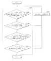
撮像装置1の撮影動作を行う際には、制御部6が、ビューファインダユニット22における可動部222の状態移行に応じて各種の出力動作を行うようにしてもよい。具体的には、撮像装置1は、例えば図16A,16Bに示したように動作するようにしてもよい。図16Aは、撮像装置1の起動から停止までの一連の動作の流れを表す第2のフローチャートである。図16Bは、図16Aの一部の処理(ステップS203)をより詳細に示したフローチャートである。撮像装置1では、制御部6により、ビューファインダユニット22の可動部222の状態移行に応じて各種の出力動作を行うモードの選択が可能となっている。ここでいう各種の出力動作とは、例えば警告表示、警告音の発生または警告振動などである。上記以外の点は実質的に上記第1の実施の形態と同様であるので説明を省略する。なお、図16A,16Bに示した処理についても、制御部6が、例えばROMなどに記憶されたプログラムに従って実行する。
<Second Embodiment>
When performing the shooting operation of theimaging apparatus 1, thecontrol unit 6 may perform various output operations in accordance with the state transition of themovable unit 222 in theviewfinder unit 22. Specifically, theimaging device 1 may operate as shown in FIGS. 16A and 16B, for example. FIG. 16A is a second flowchart showing a flow of a series of operations from starting to stopping of theimaging apparatus 1. FIG. 16B is a flowchart showing a part of the process (step S203) of FIG. 16A in more detail. In theimaging apparatus 1, thecontrol unit 6 can select a mode in which various output operations are performed according to the state transition of themovable unit 222 of theviewfinder unit 22. The various output operations referred to here are, for example, warning display, generation of warning sound, or warning vibration. Since points other than the above are substantially the same as those of the first embodiment, description thereof will be omitted. 16A and 16B is also executed by thecontrol unit 6 according to a program stored in, for example, a ROM.

撮像装置1の撮影動作を行うにあたっては、まず、電源ボタン15を押下するなどして電源オンを行う(ステップS201)。あるいは、上記第1の実施の形態と同様に、ビューファインダ20についての収納状態P1と使用状態P3との間における状態移行に応じて電源オンを行うようにしてもよい。その場合、制御部6は、収納状態P1から使用状態P3へ至るまでの任意のタイミングで電源オンを行うことができる。次に、ビューファインダ20の表示画面を起動し、所定の情報やスルー画像を表示する(ステップS202)。この際、併せて表示部12の表示動作の開始を実行してもよい。ビューファインダ20の表示画面には、撮像中のスルー画像のほか、電池残量や撮影条件(例えばシャッタースピード、絞り値、fナンバー、水平度、フラッシュの有無)などの各種情報が表示される。表示部12には、さらにより多くの情報を表示するようにしてもよい。また、表示部12には、撮像中のスルー画像を表示せず、文字、図形もしくは記号などによる情報のみを表示するようにしてもよい。また、ビューファインダ20の表示画面には、例えば表示部12に表示される複数の情報のうちの一部の情報のみを表示させるようにしてもよい。  In performing the photographing operation of theimaging apparatus 1, first, the power is turned on by pressing the power button 15 (step S201). Alternatively, as in the first embodiment, the power may be turned on according to the state transition between the storage state P1 and the use state P3 of theviewfinder 20. In that case, thecontrol unit 6 can turn on the power at an arbitrary timing from the storage state P1 to the use state P3. Next, the display screen of theviewfinder 20 is activated and predetermined information and a through image are displayed (step S202). At this time, the display operation of thedisplay unit 12 may be started together. On the display screen of theviewfinder 20, various information such as the remaining battery level and shooting conditions (for example, shutter speed, aperture value, f-number, horizontality, presence / absence of flash) are displayed in addition to the through image being captured. You may make it display much more information on thedisplay part 12. FIG. In addition, thedisplay unit 12 may display only information using characters, figures, symbols, or the like without displaying the through image being captured. Further, on the display screen of theviewfinder 20, for example, only some information of a plurality of information displayed on thedisplay unit 12 may be displayed.

次に、ビューファインダ20が使用状態P3にあるか否かを判別する(ステップS203)。ビューファインダ20が使用状態P3でない場合としては、可動部222が本体部221の後方への移動、すなわち引き出し動作が開始されていない場合や、可動部222が本体部221から後方への移動を開始したものの、引き出された可動部222の位置が適切でない場合が挙げられる。あるいは、収納状態P1から使用状態P3への全自動での状態移行がなされる途中で、その状態移行の動作が停止してしまう場合も想定される。すなわち、ポップアップ動作の途中でビューファインダ20が例えば開口部13の内面に引っかかり、上方への移動を停止してしまう場合や本体部221から引き出された可動部222が機械的摩擦等により途中で移動を停止してしまう場合などである。これらの場合、覗き窓21を覗くことができたとしても、ビューファインダ20の内部に設けられた表示画面の画像はぼやけた状態となる。  Next, it is determined whether or not theviewfinder 20 is in the use state P3 (step S203). When theviewfinder 20 is not in the use state P3, themovable part 222 moves backward from themain body part 221, that is, when the pulling-out operation is not started, or themovable part 222 starts moving backward from themain body part 221. However, there may be a case where the position of the drawnmovable part 222 is not appropriate. Alternatively, it may be assumed that the state transition operation stops while the state transition is automatically performed from the storage state P1 to the use state P3. That is, in the middle of the pop-up operation, for example, when theviewfinder 20 is caught on the inner surface of theopening 13 and stops moving upward, or themovable part 222 pulled out from themain body 221 moves in the middle due to mechanical friction or the like. For example. In these cases, the image on the display screen provided in theviewfinder 20 is blurred even if the user can look into theviewing window 21.

ステップS203では、具体的には図16Bに示したステップS203AからステップS203Dの処理が行われる。まず、ビューファインダ20が収納状態P1からポップアップ状態P2への移動、すなわちポップアップ動作を開始したか否かを判別する(ステップS203A)。ステップS203Aにおいてポップアップ動作を開始したと判別した場合には、ビューファインダ20がポップアップ状態P2へ到達したか否かを判別する(ステップS203B)。一方、ステップS203Aにおいてポップアップ動作を開始していないと判別した場合は、例えば使用者がビューファインダ操作部10Eの操作を失念しているものと考えられる。あるいは、ビューファインダ操作部10Eの操作を適切に行ったものの、何らかの機構上のトラブルによりビューファインダ20が動いていないものと考えられる。いずれにせよ、そのままではビューファインダ20の使用ができない状態なので、その場合には例えば表示部12にその旨を警告表示(ステップS204)し、再度、ステップS203Aに戻る。  In step S203, specifically, the processing from step S203A to step S203D shown in FIG. 16B is performed. First, it is determined whether or not theviewfinder 20 has started the movement from the stored state P1 to the pop-up state P2, that is, the pop-up operation (step S203A). If it is determined in step S203A that the pop-up operation has started, it is determined whether or not theviewfinder 20 has reached the pop-up state P2 (step S203B). On the other hand, if it is determined in step S203A that the pop-up operation has not started, it is considered that the user has forgotten the operation of theviewfinder operation unit 10E, for example. Alternatively, although theviewfinder operation unit 10E is appropriately operated, it is considered that theviewfinder 20 is not moved due to some mechanical trouble. In any case, since theviewfinder 20 cannot be used as it is, in that case, for example, a warning is displayed on the display unit 12 (step S204), and the process returns to step S203A again.

ステップS203Bにおいてビューファインダ20がポップアップ状態P2へ到達したと判別した場合には、さらに、ビューファインダ20がポップアップ状態P2から使用状態P3への移動を開始したか否かを判別する(ステップS203C)。一方、ステップS203Bにおいてビューファインダ20がポップアップ状態P2へ到達していないと判別した場合は、例えば使用者がビューファインダ操作部10Eの操作を適切に行ったものの、何らかの機構上のトラブルによりビューファインダ20が適切な位置までポップアップしていないものと考えられる。そのままではビューファインダ20の使用ができない状態なので、その場合にも例えば表示部12にその旨を警告表示(ステップS204)し、再度、ステップS203A(またはステップS203B)に戻る。  If it is determined in step S203B that theviewfinder 20 has reached the pop-up state P2, it is further determined whether or not theviewfinder 20 has started moving from the pop-up state P2 to the use state P3 (step S203C). On the other hand, if it is determined in step S203B that theviewfinder 20 has not reached the pop-up state P2, for example, the user has appropriately operated theviewfinder operation unit 10E, but theviewfinder 20 has some mechanical trouble. Is not popping up to the proper position. Since theviewfinder 20 cannot be used as it is, thedisplay unit 12 also displays a warning to that effect (step S204) and returns to step S203A (or step S203B) again.

ステップS203Cにおいてビューファインダ20がポップアップ状態P2から使用状態P3への移動を開始したと判別した場合には、ビューファインダ20が使用状態P3へ到達したか否かを判別する(ステップS203D)。一方、ステップS203Cにおいてビューファインダ20がポップアップ状態P2から使用状態P3への移動を開始していないと判別した場合は、例えば使用者が可動部222の引き出し動作を行うのを失念しているものと考えられる。そのままではビューファインダ20の内部の表示画面がぼやけて視認されることとなるので、その場合にも例えば表示部12にその旨を警告表示(ステップS204)し、再度、ステップS203A(またはステップS203C)に戻る。  If it is determined in step S203C that theviewfinder 20 has started moving from the pop-up state P2 to the use state P3, it is determined whether or not theviewfinder 20 has reached the use state P3 (step S203D). On the other hand, if it is determined in step S203C that theviewfinder 20 has not started moving from the pop-up state P2 to the use state P3, for example, the user has forgotten to perform the pull-out operation of themovable portion 222. Conceivable. If this is the case, the display screen inside theviewfinder 20 will be visually perceived in a blurred manner. In this case as well, for example, a warning is displayed on the display unit 12 (step S204), and step S203A (or step S203C) is performed again. Return to.

ステップS203Dにおいてビューファインダ20が使用状態P3へ到達したと判別した場合には、ステップS203が完了する。一方、ステップS203Dにおいてビューファインダ20が使用状態P3にないと判別した場合は、例えば使用者が可動部222の引き出し動作を開始したものの、適切な位置まで引き出し動作を行わなかったものと考えられる。そのままではビューファインダ20の内部の表示画面がぼやけて視認されることとなるので、その場合にも表示部12にその旨を警告表示(ステップS204)し、再度、ステップS203A(またはステップS203D)に戻る。  If it is determined in step S203D that theviewfinder 20 has reached the use state P3, step S203 is completed. On the other hand, if it is determined in step S203D that theviewfinder 20 is not in the use state P3, for example, it is considered that the user has started the pulling operation of themovable portion 222 but has not performed the pulling operation to an appropriate position. If this is the case, the display screen inside theviewfinder 20 will be visually perceived in a blurred manner. In such a case as well, a warning is displayed on the display unit 12 (step S204), and again in step S203A (or step S203D). Return.

ステップS204では、表示部12での警告表示のほか、または表示部12での警告表示と併せて、本体10に設けたスピーカ6A(図14)に警告音を発生させ、または本体10に設けたモータ6B(図14)に警告振動をさせるようにしてもよい。あるいは、ステップS204では、表示部12での警告表示を行わず、警告音の発生および警告振動のうちの少なくとも一方を実行するようにしてもよい。  In step S204, in addition to the warning display on thedisplay unit 12, or together with the warning display on thedisplay unit 12, a warning sound is generated on the speaker 6A (FIG. 14) provided on themain body 10 or provided on themain body 10. A warning vibration may be caused in the motor 6B (FIG. 14). Alternatively, in step S204, at least one of the generation of the warning sound and the warning vibration may be executed without performing the warning display on thedisplay unit 12.

ステップS203が完了したのち、制御部6は動作モードの選択をし、またはその動作モードの実行を指令する(ステップS205)。撮影モードとしては、例えば静止画撮像モードおよび動画撮像モードがある。  After step S203 is completed, thecontrol unit 6 selects an operation mode or instructs execution of the operation mode (step S205). Examples of the shooting mode include a still image capturing mode and a moving image capturing mode.

続いて、ビューファインダ20を、使用状態P3からポップアップ状態P2を経由して本体10に収納された収納状態P1へと状態移行させる(ステップS206)。すなわち、ビューファインダユニット22を前方へ押し、化粧部材23に隠れるようにしたのち、ビューファインダユニット22および化粧部材23を下方へ押すことにより本体10の内部へ収納する。この使用状態P3から収納状態P1への状態移行の際に、制御部6により、ビューファインダ20の表示動作等の機能を終了させてもよい。  Subsequently, the state of theviewfinder 20 is changed from the use state P3 to the storage state P1 stored in themain body 10 via the pop-up state P2 (step S206). That is, after theviewfinder unit 22 is pushed forward and hidden behind thedecorative member 23, theviewfinder unit 22 and thedecorative member 23 are pushed downward to be housed inside themain body 10. In the state transition from the use state P3 to the storage state P1, thecontrol unit 6 may terminate functions such as the display operation of theviewfinder 20.

次に、制御部6により、電源がオフされているか否かを判別し(ステップS207)、電源ボタン15の操作により既に電源がオフされていると判別した場合にはそのまま一連の動作が終了する。電源がオフされていないと判別した場合には電源のオフを行うことで一連の動作が終了する(ステップS208)。なお、制御部6は、ビューファインダ20を、使用状態P3から収納状態P1へと状態移行させたのち、電源をオフせずに撮影モードを継続し、あるいは省電力モード(スリープモード)に移行するようにしてもよい。  Next, thecontrol unit 6 determines whether or not the power is turned off (step S207). When it is determined that the power is already turned off by operating thepower button 15, the series of operations is finished as it is. . When it is determined that the power is not turned off, the power supply is turned off to complete a series of operations (step S208). Thecontrol unit 6 changes the state of theviewfinder 20 from the use state P3 to the storage state P1, and then continues the shooting mode without turning off the power, or shifts to the power saving mode (sleep mode). You may do it.

このように、本実施の形態では、ビューファインダ20の状態移行に応じて制御部6により各種の出力動作が実行される。このため、使用者は、ビューファインダ20が適正な使用状態にあるか否かについて瞬時に認識することができる。したがって、本実施の形態によれば、操作性が向上し、使用者による円滑な撮影が可能となる。  Thus, in the present embodiment, various output operations are executed by thecontrol unit 6 in accordance with the state transition of theviewfinder 20. Therefore, the user can instantly recognize whether or not theviewfinder 20 is in an appropriate usage state. Therefore, according to the present embodiment, operability is improved and smooth shooting by the user is possible.

なお、本実施の形態では、電源ボタン15を押下するなどして電源をオンするようにしたが(ステップS201)、第1の実施の形態と同様に、ビューファインダ20の収納状態P1から使用状態P3への移行の際に電源のオンを実行するようにしてもよい。  In this embodiment, the power is turned on by pressing thepower button 15 or the like (step S201). However, as in the first embodiment, theviewfinder 20 is changed from the housed state P1 to the used state. The power may be turned on at the time of shifting to P3.

また、本実施の形態では、例えば図16Cに示した変形例としてのフローチャートのように、ステップS202とステップS203との順序を入れ替えてもよい。すなわち、電源オン(ステップS201)ののち、ビューファインダ20が使用状態P3にあることを確認(ステップS203)してからビューファインダ20の表示画面を起動するようにしてもよい(ステップS202)。  Further, in the present embodiment, the order of step S202 and step S203 may be interchanged, for example, as in a flowchart as a modified example illustrated in FIG. 16C. That is, after the power is turned on (step S201), it is possible to activate the display screen of theviewfinder 20 after confirming that theviewfinder 20 is in the use state P3 (step S203) (step S202).

<第3の実施の形態>
撮像装置1の撮影動作を行う際には、制御部6が、ビューファインダ20の状態移行に応じてアイセンサ60の起動および動作停止を行うようにしてもよい。具体的には、撮像装置1は、例えば図17A,17Bに示したように動作するようにしてもよい。図17A,17Bは、撮像装置1の起動から停止までの一連の動作の流れを表す第3のフローチャートである。上記以外の点は実質的に上記第1の実施の形態と同様であるので説明を省略する。なお、図17A,17Bに示した処理についても、制御部6が、例えばROMなどに記憶されたプログラムに従って実行する。
<Third Embodiment>
When performing the shooting operation of theimaging apparatus 1, thecontrol unit 6 may start and stop theeye sensor 60 in accordance with the state transition of theviewfinder 20. Specifically, theimaging device 1 may operate as shown in FIGS. 17A and 17B, for example. 17A and 17B are third flowcharts showing a flow of a series of operations from starting to stopping of theimaging apparatus 1. Since points other than the above are substantially the same as those of the first embodiment, description thereof will be omitted. Note that thecontrol unit 6 also executes the processing illustrated in FIGS. 17A and 17B according to a program stored in, for example, a ROM.

本実施の形態では、制御部6により、ビューファインダユニット22の状態移行に応じてアイセンサ60のオンおよびオフの少なくとも一方を実行するモードの選択を行うようになっている。さらに、制御部6は、アイセンサ60によりビューファインダ20が使用者により使用されていることが検知された場合とそれ以外の場合とで、複数のメカキーの機能の割り当てを変更してもよい。ここでいう、アイセンサ60によりビューファインダ20が使用者により使用されていることが検知された場合とは、ビューファインダ20の覗き窓21に使用者の眼が接近したことが検知された場合である。また、複数のメカキーの機能割り当ての変更とは、例えばレンズ鏡筒30Bの周囲に設けられたレンズリング30C,30Dの機能を、ビューファインダ20の覗き窓21を使用者が覗いているか否かにより変更することをいう。より具体的には、例えば覗き窓21を使用者が覗いていない場合にはレンズリング30Cをシャッタースピードの設定を行う操作部として機能させ、覗き窓21を使用者が覗いている場合にはレンズリング30Cをフォーカシングを行う操作部として機能させるようにしてもよい。なお、複数のメカキーの機能の割り当ての態様はこれに限定されるものではない。  In the present embodiment, thecontrol unit 6 selects a mode for executing at least one of ON and OFF of theeye sensor 60 in accordance with the state transition of theviewfinder unit 22. Further, thecontrol unit 6 may change the assignment of the functions of the plurality of mechanical keys depending on whether theeye sensor 60 detects that theviewfinder 20 is used by the user or not. The case where theeye sensor 60 detects that theviewfinder 20 is being used by the user is a case where it is detected that the user's eyes have approached theviewing window 21 of theviewfinder 20. . The change in the function assignment of the plurality of mechanical keys is, for example, whether or not the function of the lens rings 30C and 30D provided around thelens barrel 30B is looking through theviewing window 21 of theviewfinder 20. It means changing. More specifically, for example, when the user is not looking through theviewing window 21, thelens ring 30C functions as an operation unit for setting the shutter speed, and when the user is looking through theviewing window 21, thelens ring 30C is used. Thering 30C may function as an operation unit that performs focusing. In addition, the mode of assigning the functions of the plurality of mechanical keys is not limited to this.

撮像装置1の撮影動作を行うにあたっては、まず、ビューファインダ20について、本体10に収納された収納状態P1からポップアップ状態P2への状態移行を開始する。すなわち、ビューファインダ操作部10Eをスライドさせ、ビューファインダユニット22を本体10からポップアップさせる。
ここで検出部9Bにより、収納状態P1からポップアップ状態P2への状態移行が開始されたかどうか、すなわちビューファインダ20が収納状態P1からポップアップ状態P2へ向けて動き始めたか否かを判別する(ステップS301)。収納状態P1からポップアップ状態P2への状態移行の開始が検出された場合には電源がオンされているかどうか判別する(ステップS302)。収納状態P1からポップアップ状態P2への状態移行の開始が検出されなかった場合は再度ステップS301を行う。
In performing the photographing operation of theimaging apparatus 1, first, theviewfinder 20 starts to shift from the housed state P1 housed in themain body 10 to the pop-up state P2. That is, theviewfinder operation unit 10E is slid to pop up theviewfinder unit 22 from themain body 10.
Here, thedetection unit 9B determines whether or not the state transition from the storage state P1 to the pop-up state P2 is started, that is, whether or not theviewfinder 20 starts to move from the storage state P1 to the pop-up state P2 (step S301). ). When the start of the state transition from the storage state P1 to the pop-up state P2 is detected, it is determined whether or not the power is turned on (step S302). If the start of the state transition from the storage state P1 to the pop-up state P2 is not detected, step S301 is performed again.

ステップS302において、電源ボタン15により既に電源オンされていると判別した場合にはビューファインダ20の表示画面を起動(ステップS303)し、所定の情報やスルー画像を表示する。この際、併せてビューファインダ20をポップアップ状態P2から使用状態P3へ移行させる。ステップS302において電源オンされていないと判別した場合には電源オンを行い(ステップS304)、さらにステップS303の処理を行う。なお、制御部6は、電源ボタン15により電源オンが行われた際、ビューファインダ20が使用状態P3にないときは表示部12のみの表示動作を実行させるとよい。また、ビューファインダ20の収納状態P1から使用状態P3への移行の際(収納状態P1から使用状態P3へ至る間のいずれかのタイミングで)自動で電源オンを行うようにしてもよい。さらに、ビューファインダ20の表示画面には、例えば表示部12に表示される複数の情報のうちの一部の情報のみを表示させるようにしてもよい。  If it is determined in step S302 that the power is already turned on by thepower button 15, the display screen of theviewfinder 20 is activated (step S303), and predetermined information and a through image are displayed. At this time, theviewfinder 20 is also shifted from the pop-up state P2 to the use state P3. If it is determined in step S302 that the power is not turned on, the power is turned on (step S304), and the process of step S303 is further performed. Note that when the power is turned on by thepower button 15, thecontrol unit 6 may execute the display operation of only thedisplay unit 12 when theviewfinder 20 is not in the use state P3. Further, when theviewfinder 20 is shifted from the storage state P1 to the use state P3, the power may be automatically turned on (at any timing from the storage state P1 to the use state P3). Further, on the display screen of theviewfinder 20, for example, only some information of a plurality of information displayed on thedisplay unit 12 may be displayed.

続いて制御部6は、アイセンサ60をオンしたのち(ステップS305)、使用者が覗き窓21を覗いているかどうかをアイセンサ60により判別する(ステップS306)。使用者が覗き窓21を覗いていると判別した場合には表示部12の表示面12Aの表示をオフする(ステップS307)。そののち、撮影モードの選択をし、またはその撮影モードの実行を指令する(ステップS308)。次に、検出部9Aにより、表示部12が図1〜図7に示した第1の回転状態(通常撮影状態)であるか、図12に示した第2の回転状態(反転状態)であるかの検出を行う(ステップS309)。そこで表示部12が反転状態であると判別した場合、制御部6はアイセンサ60をオフする(ステップS310)。アイセンサ60が機能した状態では、表示部12の接近が使用者の眼の接近と誤認され、表示部12の表示面12Aが消灯してしまう。その結果、自分撮りを行う使用者が表示面12Aに表示されるべきスルー画像を視認することができなくなってしまうからである。  Subsequently, after theeye sensor 60 is turned on (step S305), thecontrol unit 6 determines whether or not the user is looking through theviewing window 21 by using the eye sensor 60 (step S306). If it is determined that the user is looking through theviewing window 21, the display on thedisplay surface 12A of thedisplay unit 12 is turned off (step S307). After that, the photographing mode is selected or execution of the photographing mode is instructed (step S308). Next, thedisplay unit 12 is in the first rotation state (normal photographing state) shown in FIGS. 1 to 7 or the second rotation state (reversed state) shown in FIG. Is detected (step S309). Therefore, when it is determined that thedisplay unit 12 is in the inverted state, thecontrol unit 6 turns off the eye sensor 60 (step S310). In a state where theeye sensor 60 is functioning, the approach of thedisplay unit 12 is mistaken as the approach of the user's eyes, and thedisplay surface 12A of thedisplay unit 12 is turned off. As a result, a user taking a self-portrait cannot view a through image to be displayed on thedisplay surface 12A.

続いて、ビューファインダ20について、使用状態P3からポップアップ状態P2に移行させたのち、さらにポップアップ状態P2から収納状態P1への状態移行を開始する。すなわち、ビューファインダユニット22の可動部222を前方へ押して化粧部材23に隠れるようにしたのち、ビューファインダユニット22および化粧部材23を下方へ押すことにより本体10の内部へ収納する。この使用状態P3から収納状態P1への状態移行の際に、制御部6により、ビューファインダ20の表示動作等の機能を終了させてもよい。この際、検出部9Bにより、例えばポップアップ状態P2から収納状態P1への状態移行が開始されたかどうか、すなわちビューファインダ20がポップアップ状態P2から収納状態P1へ向けて動き始めたか否かを判別する(ステップS311)。ポップアップ状態P2から収納状態P1への状態移行の開始が検出された場合には、アイセンサがオンされているかどうか判別する(ステップS312)。ポップアップ状態P2から収納状態P1への状態移行の開始が検出されなかった場合は再度ステップS311を行う。  Subsequently, after theviewfinder 20 is shifted from the use state P3 to the pop-up state P2, the state transition from the pop-up state P2 to the storage state P1 is started. That is, after themovable part 222 of theviewfinder unit 22 is pushed forward so as to be hidden by thedecorative member 23, theviewfinder unit 22 and thedecorative member 23 are pushed downward to be housed inside themain body 10. In the state transition from the use state P3 to the storage state P1, thecontrol unit 6 may terminate functions such as the display operation of theviewfinder 20. At this time, thedetection unit 9B determines, for example, whether or not the state transition from the pop-up state P2 to the storage state P1 is started, that is, whether or not theviewfinder 20 starts to move from the pop-up state P2 to the storage state P1 ( Step S311). If the start of the state transition from the pop-up state P2 to the storage state P1 is detected, it is determined whether or not the eye sensor is turned on (step S312). If the start of the state transition from the pop-up state P2 to the storage state P1 is not detected, step S311 is performed again.

ステップS312においてアイセンサ60がオンであると判別した場合にはアイセンサ60をオフする(ステップS313)。最後に、電源がオフされているかどうか判別する(ステップS314)。電源ボタン15の操作により既に電源がオフされていると判別した場合にはそのまま一連の動作が終了する。電源がオフされていないと判別した場合には電源オフを行うことで一連の動作が終了する(ステップS315)なお、制御部6は、ビューファインダ20をポップアップ状態P2から収納状態P1へと状態移行させたのち、またはアイセンサ60をオフしたのち、電源をオフせずに撮影モードを継続し、あるいは省電力モード(スリープモード)に移行するようにしてもよい。  If it is determined in step S312 that theeye sensor 60 is on, theeye sensor 60 is turned off (step S313). Finally, it is determined whether or not the power is turned off (step S314). When it is determined that the power has already been turned off by operating thepower button 15, the series of operations ends as it is. If it is determined that the power is not turned off, the power supply is turned off to end the series of operations (step S315). Note that thecontrol unit 6 changes the state of theviewfinder 20 from the pop-up state P2 to the storage state P1. After the image sensor is turned off or after theeye sensor 60 is turned off, the photographing mode may be continued without turning off the power, or the mode may be shifted to the power saving mode (sleep mode).

なお、制御部6は、電源ボタン15により電源オンの動作が行われた際、ビューファインダ20が使用状態P3にないときは表示部12のみの表示動作を実行させてもよい。一方、電源ボタン15により電源オンの動作が行われた際、ビューファインダ20が使用状態P3にあるときは表示部12およびビューファインダ20の双方の表示動作を実行させるようにしてもよい。  In addition, when the power-on operation is performed by thepower button 15, thecontrol unit 6 may execute the display operation of only thedisplay unit 12 when theviewfinder 20 is not in the use state P <b> 3. On the other hand, when thepower button 15 is turned on, when theviewfinder 20 is in the usage state P3, the display operation of both thedisplay unit 12 and theviewfinder 20 may be executed.

このように、本実施の形態では、ビューファインダ20の状態移行に応じてアイセンサ60のオンおよびオフの処理が制御部6により実行される。このため、使用者は、ビューファインダ20の状態移行の操作とは別の操作としてアイセンサ60のオンおよびオフの操作を改めて行う必要がない。したがって、本実施の形態によれば、操作性が向上し、使用者による円滑な撮影が可能となる。  As described above, in the present embodiment, thecontrol unit 6 performs on / off processing of theeye sensor 60 in accordance with the state transition of theviewfinder 20. For this reason, the user does not need to perform the on / off operation of theeye sensor 60 as an operation different from the operation of changing the state of theviewfinder 20. Therefore, according to the present embodiment, operability is improved and smooth shooting by the user is possible.

図17A,17Bでは、制御部6は、収納状態P1からポップアップ状態P2への移行開始をトリガーとして電源オン、ビューファインダ20の表示画面の起動およびアイセンサ60のオンを行うようにした。また、ポップアップ状態P2から収納状態P1への移行開始をトリガーとしてアイセンサ60のオフおよび電源オフを行うようにした。しかしながら、本技術では以下のようにしてもよい。例えば、電源オン、ビューファインダ20の表示画面の起動およびアイセンサ60のオンを、以下の<1>から<3>のいずれかの検出をトリガーとして行うようにしてもよい。
<1>収納状態P1からポップアップ状態P2への移行が完了したこと。すなわち、ビューファインダ20が収納状態P1から移動してポップアップ状態P2へ到達したこと。
<2>ポップアップ状態P2から使用状態P3への移行を開始したこと。すなわち、ビューファインダユニット22の可動部222が本体部221の後方へ動き始めたこと。
<3>ポップアップ状態P2から使用状態P3への移行が完了したこと。すなわち、ビューファインダユニット22の可動部222が本体部221の後方への移動を完了することで、ビューファインダ20が使用状態P3へ到達したこと。
同様に、アイセンサ60のオフおよび電源オフを、以下の<4>から<6>のいずれかの検出をトリガーとして行うようにしてもよい。
<4>ポップアップ状態P2から収納状態P1への移行が完了したこと。すなわち、ビューファインダ20がポップアップ状態P2から移動して収納状態P1へ到達したこと。
<5>使用状態P3からポップアップ状態P2への移行を開始したこと。すなわち、ビューファインダユニット22の可動部222が本体部221へ向けて前方へ動き始めたこと。
<6>使用状態P3からポップアップ状態P2への移行が完了したこと。すなわち、ビューファインダユニット22の可動部222が本体部221へ向かう前方への移動を完了することで、ビューファインダ20がポップアップ状態P2へ到達したこと。
In FIGS. 17A and 17B, thecontrol unit 6 is configured to turn on the power, start up the display screen of theviewfinder 20, and turn on theeye sensor 60, triggered by the start of the transition from the storage state P1 to the pop-up state P2. In addition, theeye sensor 60 is turned off and the power is turned off using the start of the transition from the pop-up state P2 to the storage state P1 as a trigger. However, the present technology may be configured as follows. For example, the power-on, the activation of the display screen of theviewfinder 20, and the turning on of theeye sensor 60 may be performed using the following detections <1> to <3> as triggers.
<1> The transition from the storage state P1 to the pop-up state P2 is completed. That is, theviewfinder 20 has moved from the storage state P1 and has reached the pop-up state P2.
<2> Start of transition from the pop-up state P2 to the use state P3. That is, themovable part 222 of theviewfinder unit 22 starts to move rearward of themain body part 221.
<3> The transition from the pop-up state P2 to the use state P3 is completed. That is, theviewfinder 20 has reached the use state P3 when themovable part 222 of theviewfinder unit 22 completes the rearward movement of themain body part 221.
Similarly, theeye sensor 60 may be turned off and the power may be turned off using the following detection of <4> to <6> as a trigger.
<4> The transition from the pop-up state P2 to the storage state P1 is completed. That is, theviewfinder 20 has moved from the pop-up state P2 and has reached the storage state P1.
<5> Start of transition from the use state P3 to the pop-up state P2. That is, themovable part 222 of theviewfinder unit 22 starts to move forward toward themain body part 221.
<6> The transition from the use state P3 to the pop-up state P2 is completed. That is, theviewfinder 20 has reached the pop-up state P2 when themovable part 222 of theviewfinder unit 22 completes the forward movement toward themain body part 221.

以上、実施の形態を挙げて本開示を説明したが、本開示は上記実施の形態に限定されるものではなく、種々の変形が可能である。例えば、第1移動機構24、第2移動機構25、電気的移動機構27の構成は、上記実施の形態で説明した例に限られず、他の構成を有していてもよい。  While the present disclosure has been described with reference to the embodiment, the present disclosure is not limited to the above embodiment, and various modifications can be made. For example, the configurations of the first movingmechanism 24, the second movingmechanism 25, and the electric movingmechanism 27 are not limited to the examples described in the above embodiment, and may have other configurations.

また、例えば、上記実施の形態では、ビューファインダ20が本体10の上方および後方の二方向に可動な場合について説明した。しかしながら、ビューファインダ20は二方向に限らず三方向以上に可動とすることも可能である。また、ビューファインダ20の動く方向や経路は特に限定されず、例えば縦位置撮影の場合には本体10の横方向(X方向)に突出したのち本体10の後方(Z方向)に進出するようにすることも可能である。  Further, for example, in the above-described embodiment, the case where theviewfinder 20 is movable in two directions above and behind themain body 10 has been described. However, theviewfinder 20 can be made movable not only in two directions but also in three or more directions. In addition, the moving direction and path of theviewfinder 20 are not particularly limited. For example, in the case of vertical position shooting, after projecting in the horizontal direction (X direction) of themain body 10, theviewfinder 20 moves backward (Z direction). It is also possible to do.

また、上記実施の形態では、本体10で撮像された画像を本体10に付属する表示部12に表示するようにした場合について説明したが、表示部12に代えてスマートフォン(多機能携帯電話)のディスプレイやパーソナルコンピュータのモニタを用いることも可能である。  Moreover, although the said embodiment demonstrated the case where the image imaged with themain body 10 was displayed on thedisplay part 12 attached to themain body 10, it replaces with thedisplay part 12 and is a smart phone (multifunctional mobile phone). It is also possible to use a display or a monitor of a personal computer.

また、例えば、上記実施の形態において説明した各構成要素の形状、寸法および材料などは限定されるものではなく、他の形状、寸法および材料としてもよい。  In addition, for example, the shape, size, and material of each component described in the above embodiment are not limited, and other shapes, sizes, and materials may be used.

また、例えば、上記実施の形態では、撮像装置1の構成を具体的に挙げて説明したが、全ての構成要素を備える必要はなく、また、他の構成要素を更に備えていてもよい。  For example, in the above-described embodiment, the configuration of theimaging apparatus 1 has been specifically described. However, it is not necessary to include all the components, and other components may be further included.

なお、本明細書中に記載された効果はあくまで例示であってその記載に限定されるものではなく、他の効果があってもよい。また、本技術は以下のような構成を取り得るものである。
(1)
撮像部が設けられた本体と、
前記本体に収納された収納状態と前記本体から突出した使用状態との間における状態移行が可能なビューファインダと、
前記ビューファインダが使用者により使用されていることを検出する第1の検出部と、
前記状態移行に応じて前記第1の検出部のオンまたは前記第1の検出部のオフを行う制御部と
を備えた撮像装置。
(2)
前記ビューファインダは、前記状態移行の際に二以上の方向に移動する
上記(1)記載の撮像装置。
(3)
前記ビューファインダは、
本体部と、前記本体部に対して移動可能な可動部とを有し、
前記収納状態から前記本体部が前記筐体の上方へ突出したポップアップ状態へ移行したのち、前記ポップアップ状態から前記可動部が前記本体部の後方へ進出することにより前記使用状態に移行する
上記(2)記載の撮像装置。
(4)
前記制御部は、前記収納状態から前記ポップアップ状態へ移行する際に前記第1の検出部のオンを行う
上記(3)記載の撮像装置。
(5)
前記制御部は、前記収納状態から前記ポップアップ状態への移行開始または移行完了と共に前記第1の検出部のオンを行う
上記(4)記載の撮像装置。
(6)
前記制御部は、前記ポップアップ状態から前記使用状態への移行開始または移行完了と共に前記第1の検出部のオンを行う
上記(4)または(5)に記載の撮像装置。
(7)
前記制御部は、前記ポップアップ状態から前記収納状態へ移行する際に前記第1の検出部のオフを行う
上記(3)から(6)のいずれか1つに記載の撮像装置。
(8)
前記制御部は、前記使用状態から前記ポップアップ状態への移行開始または移行完了と共に前記第1の検出部のオフを行う
上記(7)記載の撮像装置。
(9)
前記制御部は、前記ポップアップ状態から前記収納状態への移行開始または移行完了と共に前記第1の検出部のオフを行う
上記(7)または(8)に記載の撮像装置。
(10)
複数のメカキーをさらに備え、
前記制御部は、前記第1の検出部により前記ビューファインダが使用者により使用されていることが検出された場合とそれ以外の場合とで、前記複数のメカキーの機能の割り当てを変更する
上記(1)から(9)のいずれか1つに記載の撮像装置。
(11)
前記本体に対して回転可能に設けられた表示部と、
前記表示部の回転を検出する第2の検出部と
をさらに備え、
前記制御部は、前記第2の検出部により前記表示部の回転が検出された場合に、前記第1の検出部の動作停止を実行するモードの選択を行う
上記(1)から(10)のいずれか1つに記載の撮像装置。
(12)
前記制御部は、前記状態移行に応じて電源オンまたは電源オフをさらに行う
上記(1)記載の撮像装置。
(13)
表示部をさらに備え、
前記制御部は、前記状態移行に応じて前記表示部の表示動作の開始または終了を行う
上記(1)記載の撮像装置。
(14)
前記ビューファインダは電子ビューファインダであり、
前記制御部は、前記表示部に複数の情報を表示させ、前記電子ビューファインダに前記複数の情報のうちの一部の情報を表示させる
上記(13)記載の撮像装置。
(15)
前記ビューファインダは電子ビューファインダであり、
前記制御部は、前記収納状態から前記使用状態への移行の際に前記電子ビューファインダの動作を起動させる
上記(1)から(14)のいずれか1つに記載の撮像装置。
(16)
前記ビューファインダは電子ビューファインダであり、
前記制御部は、前記使用状態から前記収納状態への移行の際に前記電子ビューファインダの動作を停止させる
上記(1)から(15)のいずれか1つに記載の撮像装置。
(17)
前記制御部は、前記収納状態から前記使用状態への移行の際に電源オンを行う
上記(1)から(16)のいずれか1つに記載の撮像装置。
(18)
前記制御部は、前記使用状態から前記収納状態への移行の際に電源オフを行う
上記(1)から(17)のいずれか1つに記載の撮像装置。
(19)
表示部と、電源オンを行う電源ボタンとをさらに備え、
前記ビューファインダは電子ビューファインダであり、
前記制御部は、前記電源ボタンにより電源オンが行われた際、前記電子ビューファインダが前記収納状態にあるときは前記表示部のみに表示動作を実行させ、前記電子ビューファインダが前記使用状態にあるときは前記表示部および前記電子ビューファインダの双方に表示動作を実行させる
上記(1)から(18)のいずれか1つに記載の撮像装置。
(20)
記憶部をさらに備え、
前記ビューファインダは、本体部と、前記本体部に対して移動可能な可動部と、観察者に応じた視度調整を行う視度調整部とを有し、
前記記憶部には、前記視度調整部による前記使用者に応じた視度調整のデータが格納される
上記(1)から(19)のいずれか1つに記載の撮像装置。
In addition, the effect described in this specification is an illustration to the last, and is not limited to the description, There may exist another effect. Moreover, this technique can take the following structures.
(1)
A main body provided with an imaging unit;
A viewfinder capable of state transition between a storage state stored in the main body and a use state protruding from the main body;
A first detection unit for detecting that the viewfinder is used by a user;
An imaging apparatus comprising: a control unit that turns on the first detection unit or turns off the first detection unit in accordance with the state transition.
(2)
The viewfinder moves in two or more directions during the state transition. The imaging apparatus according to (1) above.
(3)
The viewfinder is
A main body part and a movable part movable relative to the main body part;
After shifting from the stored state to the pop-up state in which the main body portion protrudes upward from the housing, the movable portion moves from the pop-up state to the rear of the main body portion to shift to the use state. The imaging device described in the above.
(4)
The imaging device according to (3), wherein the control unit turns on the first detection unit when shifting from the stored state to the pop-up state.
(5)
The imaging device according to (4), wherein the control unit turns on the first detection unit when the transition from the stored state to the pop-up state is started or completed.
(6)
The imaging device according to (4) or (5), wherein the control unit turns on the first detection unit when the transition from the pop-up state to the use state starts or when the transition is completed.
(7)
The controller according to any one of (3) to (6), wherein the control unit turns off the first detection unit when shifting from the pop-up state to the storage state.
(8)
The imaging device according to (7), wherein the control unit turns off the first detection unit when the transition from the use state to the pop-up state is started or completed.
(9)
The imaging device according to (7) or (8), wherein the control unit turns off the first detection unit when the transition from the pop-up state to the storage state starts or when the transition is completed.
(10)
Further equipped with a plurality of mechanical keys,
The control unit changes the function assignment of the plurality of mechanical keys depending on whether the first detection unit detects that the viewfinder is being used by a user or not. The imaging apparatus according to any one of 1) to (9).
(11)
A display unit rotatably provided with respect to the main body;
A second detection unit that detects rotation of the display unit;
When the rotation of the display unit is detected by the second detection unit, the control unit selects a mode in which the operation of the first detection unit is stopped. (1) to (10) The imaging device according to any one of the above.
(12)
The imaging device according to (1), wherein the control unit further performs power on or power off according to the state transition.
(13)
A display unit;
The said control part starts or complete | finishes the display operation | movement of the said display part according to the said state transition. The imaging device of the said (1) description.
(14)
The viewfinder is an electronic viewfinder,
The imaging device according to (13), wherein the control unit causes the display unit to display a plurality of pieces of information and causes the electronic viewfinder to display a part of the plurality of pieces of information.
(15)
The viewfinder is an electronic viewfinder,
The imaging device according to any one of (1) to (14), wherein the control unit activates the operation of the electronic viewfinder when the storage state is shifted to the use state.
(16)
The viewfinder is an electronic viewfinder,
The imaging device according to any one of (1) to (15), wherein the control unit stops the operation of the electronic viewfinder when the use state is shifted to the housed state.
(17)
The imaging unit according to any one of (1) to (16), wherein the control unit performs power-on when the storage state is shifted to the use state.
(18)
The imaging unit according to any one of (1) to (17), wherein the control unit performs power-off when shifting from the use state to the housed state.
(19)
A display unit and a power button for turning on the power;
The viewfinder is an electronic viewfinder,
When the power is turned on by the power button, the control unit causes the display unit to execute a display operation when the electronic viewfinder is in the retracted state, and the electronic viewfinder is in the use state. The imaging apparatus according to any one of (1) to (18), wherein the display operation is performed by both the display unit and the electronic viewfinder.
(20)
A storage unit;
The viewfinder includes a main body part, a movable part movable with respect to the main body part, and a diopter adjustment part that performs diopter adjustment according to an observer,
The storage unit stores diopter adjustment data according to the user by the diopter adjustment unit. The imaging apparatus according to any one of (1) to (19).

1,1A…撮像装置、2…撮像部、2A…撮像素子、3…画像信号処理部、4…エンコード/デコード部、5…画像メモリ、6…制御部、7…記録/再生部、8…入力部、9A,9B…検出部、10…本体、10A…前面、10B…背面、10C…上面、10D…側面、10E…ビューファインダ操作部、11…ボディマウント、12…表示部、13…開口部、14…ストロボ、15…電源ボタン、16…レリーズボタン、17…モード設定ダイヤル、20…ビューファインダ、21…覗き窓、22…ビューファインダユニット、221…可動部、222…本体部、22A…接眼面、23…化粧部材、24…第1移動機構、25…第2移動機構、26…視度調整部、27…電気的移動機構、30…撮像レンズユニット、30A…レンズ、30B…レンズ鏡筒、30C,30D…レンズリング、31,51…ベースフレーム、32,52…スライドフレーム、33…第1弾性部材、34…掛止部材、41…第2弾性部材、53…ラック、54…モータ、54A…ウォームギア、60,60A…アイセンサ、P1…収納状態、P2…ポップアップ状態、P3…使用状態。  DESCRIPTION OFSYMBOLS 1,1A ... Imaging device, 2 ... Imaging part, 2A ... Imaging element, 3 ... Image signal processing part, 4 ... Encoding / decoding part, 5 ... Image memory, 6 ... Control part, 7 ... Recording / reproducing part, 8 ... Input unit, 9A, 9B ... detection unit, 10 ... main body, 10A ... front surface, 10B ... rear surface, 10C ... upper surface, 10D ... side surface, 10E ... viewfinder operation unit, 11 ... body mount, 12 ... display unit, 13 ... opening 14 ... Strobe, 15 ... Power button, 16 ... Release button, 17 ... Mode setting dial, 20 ... Viewfinder, 21 ... Viewing window, 22 ... Viewfinder unit, 221 ... Movable part, 222 ... Main part, 22A ... Eyepiece surface, 23 ... makeup member, 24 ... first movement mechanism, 25 ... second movement mechanism, 26 ... diopter adjustment unit, 27 ... electric movement mechanism, 30 ... imaging lens unit, 30A ... lens, 30 ... lens barrel, 30C, 30D ... lens ring, 31, 51 ... base frame, 32, 52 ... slide frame, 33 ... first elastic member, 34 ... latching member, 41 ... second elastic member, 53 ... rack, 54 ... motor, 54A ... worm gear, 60, 60A ... eye sensor, P1 ... storage state, P2 ... pop-up state, P3 ... use state.

Claims (20)

Translated fromJapanese
撮像部が設けられた本体と、
前記本体に収納された収納状態と前記本体から突出した使用状態との間における状態移行が可能なビューファインダと、
前記ビューファインダが使用者により使用されていることを検出する第1の検出部と、
前記状態移行に応じて前記第1の検出部のオンまたは前記第1の検出部のオフを行う制御部と
を備えた撮像装置。
A main body provided with an imaging unit;
A viewfinder capable of state transition between a storage state stored in the main body and a use state protruding from the main body;
A first detection unit for detecting that the viewfinder is used by a user;
An imaging apparatus comprising: a control unit that turns on the first detection unit or turns off the first detection unit in accordance with the state transition.
前記ビューファインダは、前記状態移行の際に二以上の方向に移動する
請求項1記載の撮像装置。
The imaging apparatus according to claim 1, wherein the viewfinder moves in two or more directions during the state transition.
前記ビューファインダは、
本体部と、前記本体部に対して移動可能な可動部とを有し、
前記収納状態から前記本体部が前記筐体の上方へ突出したポップアップ状態へ移行したのち、前記ポップアップ状態から前記可動部が前記本体部の後方へ進出することにより前記使用状態に移行する
請求項2記載の撮像装置。
The viewfinder is
A main body part and a movable part movable relative to the main body part;
The transition from the stored state to the pop-up state in which the main body portion protrudes upward from the housing is performed, and then the movable portion moves from the pop-up state to the rear of the main body portion to shift to the use state. The imaging device described.
前記制御部は、前記収納状態から前記ポップアップ状態へ移行する際に前記第1の検出部のオンを行う
請求項3記載の撮像装置。
The imaging device according to claim 3, wherein the control unit turns on the first detection unit when shifting from the stored state to the pop-up state.
前記制御部は、前記収納状態から前記ポップアップ状態への移行開始または移行完了と共に前記第1の検出部のオンを行う
請求項4記載の撮像装置。
The imaging device according to claim 4, wherein the control unit turns on the first detection unit when the transition from the stored state to the pop-up state is started or completed.
前記制御部は、前記ポップアップ状態から前記使用状態への移行開始または移行完了と共に前記第1の検出部のオンを行う
請求項4記載の撮像装置。
The imaging apparatus according to claim 4, wherein the control unit turns on the first detection unit when the transition from the pop-up state to the use state starts or when the transition is completed.
前記制御部は、前記ポップアップ状態から前記収納状態へ移行する際に前記第1の検出部のオフを行う
請求項3記載の撮像装置。
The imaging device according to claim 3, wherein the control unit turns off the first detection unit when shifting from the pop-up state to the storage state.
前記制御部は、前記使用状態から前記ポップアップ状態への移行開始または移行完了と共に前記第1の検出部のオフを行う
請求項7記載の撮像装置。
The imaging apparatus according to claim 7, wherein the control unit turns off the first detection unit when the transition from the use state to the pop-up state is started or completed.
前記制御部は、前記ポップアップ状態から前記収納状態への移行開始または移行完了と共に前記第1の検出部のオフを行う
請求項7記載の撮像装置。
The imaging apparatus according to claim 7, wherein the control unit turns off the first detection unit when the transition from the pop-up state to the storage state starts or completes.
複数のメカキーをさらに備え、
前記制御部は、前記第1の検出部により前記ビューファインダが使用者により使用されていることが検出された場合とそれ以外の場合とで、前記複数のメカキーの機能の割り当てを変更する
請求項1記載の撮像装置。
Further equipped with a plurality of mechanical keys,
The control unit changes the function assignment of the plurality of mechanical keys depending on whether the first detection unit detects that the viewfinder is used by a user or not. The imaging apparatus according to 1.
前記本体に対して回転可能に設けられた表示部と、
前記表示部の回転を検出する第2の検出部と
をさらに備え、
前記制御部は、前記第2の検出部により前記表示部の回転が検出された場合に、前記第1の検出部の動作停止を実行するモードの選択を行う
請求項1記載の撮像装置。
A display unit rotatably provided with respect to the main body;
A second detection unit that detects rotation of the display unit;
The imaging apparatus according to claim 1, wherein the control unit selects a mode in which the operation of the first detection unit is stopped when rotation of the display unit is detected by the second detection unit.
前記制御部は、前記状態移行に応じて電源オンまたは電源オフをさらに行う
請求項1記載の撮像装置。
The imaging device according to claim 1, wherein the control unit further performs power on or power off according to the state transition.
表示部をさらに備え、
前記制御部は、前記状態移行に応じて前記表示部の表示動作の開始または終了を行う
請求項1記載の撮像装置。
A display unit;
The imaging device according to claim 1, wherein the control unit starts or ends the display operation of the display unit in accordance with the state transition.
前記ビューファインダは電子ビューファインダであり、
前記制御部は、前記表示部に複数の情報を表示させ、前記電子ビューファインダに前記複数の情報のうちの一部の情報を表示させる
請求項13記載の撮像装置。
The viewfinder is an electronic viewfinder,
The imaging device according to claim 13, wherein the control unit displays a plurality of information on the display unit and displays a part of the plurality of information on the electronic viewfinder.
前記ビューファインダは電子ビューファインダであり、
前記制御部は、前記収納状態から前記使用状態への移行の際に前記電子ビューファインダの動作を起動させる
請求項1記載の撮像装置。
The viewfinder is an electronic viewfinder,
The imaging apparatus according to claim 1, wherein the control unit activates the operation of the electronic viewfinder when the storage state is shifted to the use state.
前記ビューファインダは電子ビューファインダであり、
前記制御部は、前記使用状態から前記収納状態への移行の際に前記電子ビューファインダの動作を停止させる
請求項1記載の撮像装置。
The viewfinder is an electronic viewfinder,
The imaging apparatus according to claim 1, wherein the control unit stops the operation of the electronic viewfinder at the time of transition from the use state to the storage state.
前記制御部は、前記収納状態から前記使用状態への移行の際に電源オンを行う
請求項1記載の撮像装置。
The imaging device according to claim 1, wherein the control unit performs power-on when the storage state is shifted to the use state.
前記制御部は、前記使用状態から前記収納状態への移行の際に電源オフを行う
請求項1記載の撮像装置。
The imaging device according to claim 1, wherein the control unit turns off the power when the usage state is shifted to the storage state.
表示部と、電源オンを行う電源ボタンとをさらに備え、
前記ビューファインダは電子ビューファインダであり、
前記制御部は、前記電源ボタンにより電源オンが行われた際、前記電子ビューファインダが前記収納状態にあるときは前記表示部のみに表示動作を実行させ、前記電子ビューファインダが前記使用状態にあるときは前記表示部および前記電子ビューファインダの双方に表示動作を実行させる
請求項1記載の撮像装置。
A display unit and a power button for turning on the power;
The viewfinder is an electronic viewfinder,
When the power is turned on by the power button, the control unit causes the display unit to execute a display operation when the electronic viewfinder is in the retracted state, and the electronic viewfinder is in the use state. The imaging apparatus according to claim 1, wherein a display operation is executed by both the display unit and the electronic viewfinder.
記憶部をさらに備え、
前記ビューファインダは、本体部と、前記本体部に対して移動可能な可動部と、観察者に応じた視度調整を行う視度調整部とを有し、
前記記憶部には、前記視度調整部による前記使用者に応じた視度調整のデータが格納される
請求項1記載の撮像装置。
A storage unit;
The viewfinder includes a main body part, a movable part movable with respect to the main body part, and a diopter adjustment part that performs diopter adjustment according to an observer,
The imaging device according to claim 1, wherein diopter adjustment data corresponding to the user by the diopter adjustment unit is stored in the storage unit.
JP2014101708A2014-05-082014-05-15Image pickup apparatusPendingJP2015227901A (en)

Priority Applications (3)

Application NumberPriority DateFiling DateTitle
JP2014101708AJP2015227901A (en)2014-05-082014-05-15Image pickup apparatus
PCT/JP2015/002299WO2015170467A1 (en)2014-05-082015-04-30Image pickup apparatus
US15/307,658US10241382B2 (en)2014-05-082015-04-30State transitions of viewfinder in image pickup apparatus

Applications Claiming Priority (3)

Application NumberPriority DateFiling DateTitle
JP20140970472014-05-08
JP2014101708AJP2015227901A (en)2014-05-082014-05-15Image pickup apparatus

Publications (1)

Publication NumberPublication Date
JP2015227901Atrue JP2015227901A (en)2015-12-17

Family

ID=53268849

Family Applications (1)

Application NumberTitlePriority DateFiling Date
JP2014101708APendingJP2015227901A (en)2014-05-082014-05-15Image pickup apparatus

Country Status (3)

CountryLink
US (1)US10241382B2 (en)
JP (1)JP2015227901A (en)
WO (1)WO2015170467A1 (en)

Cited By (7)

* Cited by examiner, † Cited by third party
Publication numberPriority datePublication dateAssigneeTitle
US10623616B2 (en)2017-11-242020-04-14Panasonic Intellectual Property Management Co., Ltd.Imaging apparatus
JP2020086060A (en)*2018-11-212020-06-04キヤノン株式会社Imaging device
JP2020091406A (en)*2018-12-062020-06-11キヤノン株式会社Imaging apparatus
JP2020112637A (en)*2019-01-102020-07-27キヤノン株式会社 Imaging device
US10805544B2 (en)2018-09-262020-10-13Canon Kabushiki KaishaImage pickup apparatus equipped with plurality of display devices
US10911648B2 (en)2018-09-272021-02-02Canon Kabushiki KaishaImage pickup apparatus equipped with electronic viewfinder
US11838612B2 (en)2020-12-172023-12-05Canon Kabushiki KaishaElectronic apparatus

Families Citing this family (1)

* Cited by examiner, † Cited by third party
Publication numberPriority datePublication dateAssigneeTitle
JP7187236B2 (en)*2018-10-032022-12-12キヤノン株式会社 Image observation device and imaging device

Family Cites Families (15)

* Cited by examiner, † Cited by third party
Publication numberPriority datePublication dateAssigneeTitle
JPS60121431A (en)1983-12-061985-06-28Fuji Photo Film Co LtdFolding camera of finder pop-up type
US7133608B1 (en)*1995-06-082006-11-07Minolta Co., Ltd.Camera
DE29510157U1 (en)1995-06-221995-08-31Kodak Ag, 70327 Stuttgart Camera with movable optical sports finder
JP2001268402A (en)2000-03-172001-09-28Canon Inc Viewfinder device
JP4665304B2 (en)2000-11-172011-04-06株式会社ニコン Vibration reduction camera
KR100412485B1 (en)*2001-06-222003-12-31삼성전자주식회사Automatically ejectable Viewfinder of photographing apparatus and phtographing apparatus therewith
JP2004208028A (en)*2002-12-252004-07-22Minolta Co LtdImaging device
US7697827B2 (en)*2005-10-172010-04-13Konicek Jeffrey CUser-friendlier interfaces for a camera
JP2008268726A (en)*2007-04-242008-11-06Canon IncPhotographing device
JP5457217B2 (en)*2010-02-022014-04-02オリンパスイメージング株式会社 camera
JP2012023723A (en)*2010-06-182012-02-02Panasonic CorpImaging apparatus
JP5364846B2 (en)*2010-06-282013-12-11パナソニック株式会社 IMAGING DEVICE, IMAGING DEVICE CONTROL METHOD, AND PROGRAM USED FOR CONTROL METHOD
US8976110B2 (en)*2011-10-272015-03-10Tobii Technology AbPower management in an eye-tracking system
JP5970937B2 (en)2012-04-252016-08-17ソニー株式会社 Display control apparatus and display control method
JP6128919B2 (en)*2013-04-012017-05-17キヤノン株式会社 Display control apparatus and control method thereof

Cited By (11)

* Cited by examiner, † Cited by third party
Publication numberPriority datePublication dateAssigneeTitle
US10623616B2 (en)2017-11-242020-04-14Panasonic Intellectual Property Management Co., Ltd.Imaging apparatus
US10805544B2 (en)2018-09-262020-10-13Canon Kabushiki KaishaImage pickup apparatus equipped with plurality of display devices
US10911648B2 (en)2018-09-272021-02-02Canon Kabushiki KaishaImage pickup apparatus equipped with electronic viewfinder
JP2020086060A (en)*2018-11-212020-06-04キヤノン株式会社Imaging device
US10969656B2 (en)2018-11-212021-04-06Canon Kabushiki KaishaElectronic apparatus including movable display section
JP7207967B2 (en)2018-11-212023-01-18キヤノン株式会社 electronic device
JP2020091406A (en)*2018-12-062020-06-11キヤノン株式会社Imaging apparatus
JP7224883B2 (en)2018-12-062023-02-20キヤノン株式会社 Imaging device
JP2020112637A (en)*2019-01-102020-07-27キヤノン株式会社 Imaging device
US11272083B2 (en)2019-01-102022-03-08Canon Kabushiki KaishaImage pickup apparatus
US11838612B2 (en)2020-12-172023-12-05Canon Kabushiki KaishaElectronic apparatus

Also Published As

Publication numberPublication date
WO2015170467A1 (en)2015-11-12
US10241382B2 (en)2019-03-26
US20170045805A1 (en)2017-02-16

Similar Documents

PublicationPublication DateTitle
JP6635028B2 (en) Imaging device
JP2015227901A (en)Image pickup apparatus
JP2015227902A (en)Image pickup apparatus
JP4884417B2 (en) Portable electronic device and control method thereof
US20090185064A1 (en)Image-pickup apparatus and display controlling method for image-pickup apparatus
JP2010164926A (en)Shake correction mechanism, and imaging apparatus
JP4743868B2 (en) Image recording device
US10136051B2 (en)Imaging apparatus for imaging during panning imaging when a self-timer is set to on
JP4971117B2 (en) IMAGING DEVICE AND IMAGING DEVICE CONTROL METHOD
US7616236B2 (en)Control method used by digital image processing apparatus
CN107040717B (en)Image pickup control device and control method thereof
JP2010128162A (en)Water-proof camera, water-proof case, and digital camera
JP4534176B2 (en) Electronic camera
JP5207635B2 (en) Imaging device
JP6859385B2 (en) Imaging device, its control method, and its program
JP2007096455A (en) Imaging device
JP2008032932A (en) Imaging device
JP5572564B2 (en) Imaging apparatus and display control method thereof
JP2008076511A (en) Imaging device
JP5773606B2 (en) Imaging device
JP2007178453A (en) Imaging apparatus and imaging method
KR101058017B1 (en) Method of controlling menu display of digital shooting device and digital shooting device employing this method
JP2006262211A (en) Digital still camera and imaging method thereof
JP2008164685A (en) Camera with zoom function
JP2008176049A (en) Lens barrel and photographing apparatus

[8]ページ先頭

©2009-2025 Movatter.jp