JP2015221209A - Device and method for measuring skin moisture - Google Patents
Device and method for measuring skin moistureDownload PDFInfo
- Publication number
- JP2015221209A JP2015221209AJP2015103368AJP2015103368AJP2015221209AJP 2015221209 AJP2015221209 AJP 2015221209AJP 2015103368 AJP2015103368 AJP 2015103368AJP 2015103368 AJP2015103368 AJP 2015103368AJP 2015221209 AJP2015221209 AJP 2015221209A
- Authority
- JP
- Japan
- Prior art keywords
- moisture
- cooling unit
- skin
- temperature
- sensor
- Prior art date
- Legal status (The legal status is an assumption and is not a legal conclusion. Google has not performed a legal analysis and makes no representation as to the accuracy of the status listed.)
- Granted
Links
- 238000000034methodMethods0.000titleclaimsdescription46
- 238000001816coolingMethods0.000claimsabstractdescription139
- 238000003860storageMethods0.000claimsdescription14
- 230000008859changeEffects0.000claimsdescription9
- 230000008591skin barrier functionEffects0.000claimsdescription6
- 239000003990capacitorSubstances0.000claimsdescription5
- 238000004519manufacturing processMethods0.000claimsdescription5
- 230000008878couplingEffects0.000claims2
- 238000010168coupling processMethods0.000claims2
- 238000005859coupling reactionMethods0.000claims2
- 238000005516engineering processMethods0.000abstractdescription4
- 238000005259measurementMethods0.000description18
- 238000010586diagramMethods0.000description14
- 210000001061foreheadAnatomy0.000description14
- 238000004891communicationMethods0.000description8
- 230000006870functionEffects0.000description8
- XLYOFNOQVPJJNP-UHFFFAOYSA-NwaterSubstancesOXLYOFNOQVPJJNP-UHFFFAOYSA-N0.000description7
- 239000004698PolyethyleneSubstances0.000description5
- -1polyethylenePolymers0.000description5
- 229920000573polyethylenePolymers0.000description5
- 230000009471actionEffects0.000description4
- 230000006855networkingEffects0.000description4
- 239000000523sampleSubstances0.000description4
- 238000004590computer programMethods0.000description3
- 239000002537cosmeticSubstances0.000description3
- 238000012986modificationMethods0.000description3
- 230000004048modificationEffects0.000description3
- 230000002093peripheral effectEffects0.000description3
- 230000004044responseEffects0.000description3
- 238000009833condensationMethods0.000description2
- 230000005494condensationEffects0.000description2
- 238000010924continuous productionMethods0.000description2
- 230000008569processEffects0.000description2
- 238000007789sealingMethods0.000description2
- 230000036559skin healthEffects0.000description2
- 238000009736wettingMethods0.000description2
- 239000004925Acrylic resinSubstances0.000description1
- 229920000178Acrylic resinPolymers0.000description1
- 241001465754MetazoaSpecies0.000description1
- 241000699670Mus sp.Species0.000description1
- 230000003796beautyEffects0.000description1
- 239000003153chemical reaction reagentSubstances0.000description1
- 150000001875compoundsChemical class0.000description1
- 238000010276constructionMethods0.000description1
- 230000003247decreasing effectEffects0.000description1
- 238000009792diffusion processMethods0.000description1
- 239000003822epoxy resinSubstances0.000description1
- 238000001704evaporationMethods0.000description1
- 230000008020evaporationEffects0.000description1
- 239000000835fiberSubstances0.000description1
- LNEPOXFFQSENCJ-UHFFFAOYSA-NhaloperidolChemical compoundC1CC(O)(C=2C=CC(Cl)=CC=2)CCN1CCCC(=O)C1=CC=C(F)C=C1LNEPOXFFQSENCJ-UHFFFAOYSA-N0.000description1
- 230000036541healthEffects0.000description1
- 239000004973liquid crystal related substanceSubstances0.000description1
- 239000000696magnetic materialSubstances0.000description1
- 239000000463materialSubstances0.000description1
- 230000007246mechanismEffects0.000description1
- 239000000203mixtureSubstances0.000description1
- 239000003607modifierSubstances0.000description1
- 239000003921oilSubstances0.000description1
- 230000003287optical effectEffects0.000description1
- 230000000704physical effectEffects0.000description1
- 229920000647polyepoxidePolymers0.000description1
- 238000002360preparation methodMethods0.000description1
- 230000005855radiationEffects0.000description1
- 150000003839saltsChemical class0.000description1
- 239000004065semiconductorSubstances0.000description1
- 229920002379silicone rubberPolymers0.000description1
- 230000037380skin damageEffects0.000description1
- 239000007787solidSubstances0.000description1
- 239000000126substanceSubstances0.000description1
- 238000012360testing methodMethods0.000description1
- 230000000699topical effectEffects0.000description1
- 230000007704transitionEffects0.000description1
Images


Classifications
- A—HUMAN NECESSITIES
- A61—MEDICAL OR VETERINARY SCIENCE; HYGIENE
- A61B—DIAGNOSIS; SURGERY; IDENTIFICATION
- A61B5/00—Measuring for diagnostic purposes; Identification of persons
- A61B5/44—Detecting, measuring or recording for evaluating the integumentary system, e.g. skin, hair or nails
- A61B5/441—Skin evaluation, e.g. for skin disorder diagnosis
- A61B5/443—Evaluating skin constituents, e.g. elastin, melanin, water
- A—HUMAN NECESSITIES
- A61—MEDICAL OR VETERINARY SCIENCE; HYGIENE
- A61B—DIAGNOSIS; SURGERY; IDENTIFICATION
- A61B10/00—Instruments for taking body samples for diagnostic purposes; Other methods or instruments for diagnosis, e.g. for vaccination diagnosis, sex determination or ovulation-period determination; Throat striking implements
- A61B10/0045—Devices for taking samples of body liquids
- A61B10/0064—Devices for taking samples of body liquids for taking sweat or sebum samples
- A—HUMAN NECESSITIES
- A61—MEDICAL OR VETERINARY SCIENCE; HYGIENE
- A61B—DIAGNOSIS; SURGERY; IDENTIFICATION
- A61B2562/00—Details of sensors; Constructional details of sensor housings or probes; Accessories for sensors
- A61B2562/02—Details of sensors specially adapted for in-vivo measurements
- A61B2562/029—Humidity sensors
- A—HUMAN NECESSITIES
- A61—MEDICAL OR VETERINARY SCIENCE; HYGIENE
- A61B—DIAGNOSIS; SURGERY; IDENTIFICATION
- A61B5/00—Measuring for diagnostic purposes; Identification of persons
- A61B5/05—Detecting, measuring or recording for diagnosis by means of electric currents or magnetic fields; Measuring using microwaves or radio waves
- A61B5/053—Measuring electrical impedance or conductance of a portion of the body
- A61B5/0537—Measuring body composition by impedance, e.g. tissue hydration or fat content
- A—HUMAN NECESSITIES
- A61—MEDICAL OR VETERINARY SCIENCE; HYGIENE
- A61B—DIAGNOSIS; SURGERY; IDENTIFICATION
- A61B5/00—Measuring for diagnostic purposes; Identification of persons
- A61B5/42—Detecting, measuring or recording for evaluating the gastrointestinal, the endocrine or the exocrine systems
- A61B5/4261—Evaluating exocrine secretion production
- A61B5/4266—Evaluating exocrine secretion production sweat secretion
Landscapes
- Health & Medical Sciences (AREA)
- Life Sciences & Earth Sciences (AREA)
- Heart & Thoracic Surgery (AREA)
- Surgery (AREA)
- Biophysics (AREA)
- Pathology (AREA)
- Engineering & Computer Science (AREA)
- Biomedical Technology (AREA)
- Dermatology (AREA)
- Medical Informatics (AREA)
- Molecular Biology (AREA)
- Physics & Mathematics (AREA)
- Animal Behavior & Ethology (AREA)
- General Health & Medical Sciences (AREA)
- Public Health (AREA)
- Veterinary Medicine (AREA)
- Measuring And Recording Apparatus For Diagnosis (AREA)
- Nuclear Medicine, Radiotherapy & Molecular Imaging (AREA)
- Radiology & Medical Imaging (AREA)
Abstract
Description
Translated fromJapanese本明細書に一般に記載される技術は、皮膚中の水分を測定することに関する。 The techniques generally described herein relate to measuring moisture in the skin.
本明細書において別段の指示がない場合は、本節に記載する手法は、本出願の特許請求の範囲に対する先行技術ではなく、また本節に含まれることによって先行技術であると認められるものではない。 Unless otherwise indicated herein, the techniques described in this section are not prior art to the claims of this application and are not admitted to be prior art by inclusion in this section.
ヒトまたは動物の皮膚は吸湿性および透過性を有し、したがって、水は身体の内側から皮膚を通り拡散および蒸発を介して周囲雰囲気中へと移動するか、または、皮膚は周囲雰囲気から水分を吸収することができる。皮膚美容製品への曝露および太陽からの紫外線放射への曝露によって皮膚が損傷すると皮膚の水分を保持する能力が低下し得るので、皮膚の吸湿特性は皮膚の健康上および美容上の問題を決定付ける。したがって、皮膚の全体的な健康状態または皮膚中の水分含有量を判定し、このことによって皮膚の健康を維持または改善するための考えられる美容上の選択肢およびスキンケアの選択肢を評価できるように、皮膚水分含有量または補水レベルを精確に測定することが重要である。また、補水状態の測定は、スキンケア製品の調製、有効性の主張の支援、および有効性試験を含むあらゆる美容用途にとって望ましいであろう。 Human or animal skin is hygroscopic and permeable, so water travels from the inside of the body through the skin through diffusion and evaporation to the ambient atmosphere, or the skin draws moisture from the ambient atmosphere. Can be absorbed. Skin hygroscopic properties determine skin health and cosmetic problems, as skin damage due to exposure to skin beauty products and exposure to ultraviolet radiation from the sun can reduce the ability to retain skin moisture . Therefore, the skin can be determined so that the overall health of the skin or the moisture content in the skin can be determined, thereby evaluating possible cosmetic and skin care options for maintaining or improving skin health. It is important to accurately measure the water content or rehydration level. Also, rehydration measurements may be desirable for any cosmetic application, including skin care product preparation, effectiveness claim support, and efficacy testing.
皮膚中の補水レベルを検出するための皮膚水分測定装置が開発されており、これは様々な技法を利用している。1つの例としての方法は、誘電性媒体の静電容量を測定する。この方法は、皮膚表面の補水状態が高精度コンデンサの静電容量を変化させることに起因する、誘電率の変化を測定する。静電容量の測定は短い時間期間で行うことができ、また皮膚中の物質(たとえば、塩または局所塗布製品の残留物)によって影響されない場合がある。 Skin moisture measuring devices have been developed to detect rehydration levels in the skin, which utilize various techniques. One example method measures the capacitance of a dielectric medium. This method measures the change in dielectric constant due to the water replenishment condition on the skin surface changing the capacitance of the high precision capacitor. Capacitance measurements can be made in a short period of time and may not be affected by substances in the skin (eg, salt or residue of topical application product).
しかし、既述の測定は皮膚に取り付けられた電極または探針によって行われ、このことは皮膚にストレスを与える場合がある。さらに、この方法は、満足のいく水分測定の精度を提供するものの、費用が高く、また個々の使用者にとって持ち運び可能な大きさで実施されない場合がある。 However, the measurements described are made with electrodes or probes attached to the skin, which can stress the skin. Further, while this method provides satisfactory moisture measurement accuracy, it is expensive and may not be performed in a size that is portable to an individual user.
いくつかの例では、本明細書に記載の皮膚水分を測定するように構成される装置は、細長いエンクロージャと、入口と、水分センサと、冷却ユニットとを含み得る。細長いエンクロージャは、第1の端部および第2の端部を有し得る。入口は、細長いエンクロージャの第1の端部に配置され得、また皮膚と接触状態となるように、かつ皮膚から発散する水分を受容するように構成され得る。水分センサは、細長いエンクロージャの内側で第1の端部と第2の端部との間に配置され得、また水分の量を検出するように構成され得る。冷却ユニットは、細長いエンクロージャの第2の端部に配置され得、また水分を冷却し凝結させるように構成され得る。 In some examples, an apparatus configured to measure skin moisture described herein may include an elongated enclosure, an inlet, a moisture sensor, and a cooling unit. The elongate enclosure can have a first end and a second end. The inlet may be disposed at the first end of the elongate enclosure and may be configured to be in contact with the skin and receive moisture emanating from the skin. The moisture sensor may be disposed between the first end and the second end inside the elongated enclosure and may be configured to detect the amount of moisture. The cooling unit may be disposed at the second end of the elongated enclosure and may be configured to cool and condense moisture.
いくつかの例では、皮膚水分の測定の方法が記載される。例としての方法は、皮膚水分測定装置の細長いエンクロージャの第1の端部に配置された入口を通して皮膚から発散する水分を受容することを含み得る。水分の量は、細長いエンクロージャの内側で第1の端部と第2の反対側の端部との間に配置された水分センサによって検出され得る。水分は、細長いエンクロージャの第2の端部に配置された冷却ユニットによって冷却され凝結させられ得る。 In some examples, methods for measuring skin moisture are described. An exemplary method may include receiving moisture emanating from the skin through an inlet located at the first end of the elongate enclosure of the skin moisture measuring device. The amount of moisture can be detected by a moisture sensor disposed between the first end and the second opposite end inside the elongated enclosure. The moisture can be cooled and condensed by a cooling unit located at the second end of the elongated enclosure.
いくつかの例では、皮膚水分測定装置によって動作可能なプログラムを格納するように適合され得るコンピュータ可読格納媒体が記載される。皮膚水分測定装置は、本明細書にさらに記載するような様々な特徴を含み得る。プログラムは、皮膚水分測定装置の細長いエンクロージャの第1の端部に配置された入口を通して皮膚から発散する水分を受容するための、および、細長いエンクロージャの内側で第1の端部と第2の反対側の端部との間に配置された水分センサによって水分の量を検出するための、1つまたは複数の命令を含み得る。プログラムは、細長いエンクロージャの第2の端部に配置された冷却ユニットによって水分を冷却し凝結させるための1つまたは複数の命令をさらに含み得る。 In some examples, a computer readable storage medium is described that may be adapted to store a program operable by a skin moisture measuring device. The skin moisture measuring device may include various features as further described herein. The program is for receiving moisture emanating from the skin through an inlet located at the first end of the elongate enclosure of the skin moisture measuring device, and second opposite the first end inside the elongate enclosure. One or more instructions may be included for detecting the amount of moisture by a moisture sensor disposed between the side ends. The program may further include one or more instructions for cooling and condensing moisture by a cooling unit disposed at the second end of the elongated enclosure.
いくつかの例では、皮膚水分測定装置の製造の方法が記載される。例としての方法は、第1の端部、第2の端部、および第1の端部に配置された入口を有する、細長いエンクロージャを用意することを含み得、入口は皮膚と接触状態となるように、かつ皮膚から発散する水分を受容するように構成され得る。水分センサは、細長いエンクロージャの内側で第1の端部と第2の端部との間に配設され得、水分センサは水分の量を検出するように構成され得る。冷却ユニットは第2の端部に配設され得、冷却ユニットは水分を冷却し凝結させるように構成され得る。 In some examples, a method of manufacturing a skin moisture measuring device is described. An exemplary method may include providing an elongated enclosure having a first end, a second end, and an inlet disposed at the first end, the inlet being in contact with the skin. And can be configured to receive moisture emanating from the skin. The moisture sensor may be disposed between the first end and the second end inside the elongate enclosure, and the moisture sensor may be configured to detect the amount of moisture. A cooling unit may be disposed at the second end, and the cooling unit may be configured to cool and condense moisture.
先の要約は例示的なものに過ぎず、いかなる点においても限定的であることは意図されていない。上記の例示的な態様、実施形態、および特徴に加えて、さらなる態様、実施形態、および特徴が、図面および以下の詳細な説明を参照することによって明らかになるであろう。 The foregoing summary is illustrative only and is not intended to be limiting in any way. In addition to the illustrative aspects, embodiments, and features described above, further aspects, embodiments, and features will become apparent by reference to the drawings and the following detailed description.
本開示の先のおよび他の特徴は、添付の図面と併せて解釈すると、以下の説明および添付の特許請求の範囲から、より十分に明らかになるであろう。これらの図面は、本開示によるいくつかの実施形態のみを示しており、したがって、その範囲を限定するものと見なされるべきでないことを理解して、本開示は添付の図面の使用によってさらに具体的かつ詳細に記載される。 The foregoing and other features of the present disclosure will become more fully apparent from the following description and appended claims when taken in conjunction with the accompanying drawings. It is understood that these drawings depict only some embodiments according to the present disclosure and therefore should not be considered as limiting the scope thereof, the present disclosure is more specifically illustrated by the use of the accompanying drawings. And will be described in detail.
これらの図面は全て、本明細書に記載の少なくともいくつかの実施形態に従って構成されている。 All of these drawings are configured in accordance with at least some embodiments described herein.
以下の詳細な説明では、本明細書の一部を形成する添付の図面を参照する。図面では、文脈により別段の規定がない限りは、同様の記号は典型的には同様の構成要素を識別する。詳細な説明、図面、および特許請求の範囲に記載する例示的な実施形態は、限定的であることを意図していない。本明細書に提示する主題の精神および範囲から逸脱することなく、他の実施形態が利用され得、また、他の変更がなされ得る。本明細書に一般に記載し、また図面に例示するような本開示の態様が、多種多様な異なる構成で配置、置換、組み合わせ、分離、および設計可能であり、これらの全てが本明細書において明示的に企図されることが、容易に理解されるであろう。 In the following detailed description, reference is made to the accompanying drawings, which form a part hereof. In the drawings, similar symbols typically identify similar components, unless context dictates otherwise. The illustrative embodiments described in the detailed description, drawings, and claims are not meant to be limiting. Other embodiments may be utilized and other changes may be made without departing from the spirit and scope of the subject matter presented herein. The aspects of the present disclosure as generally described herein and illustrated in the drawings may be arranged, substituted, combined, separated, and designed in a wide variety of different configurations, all of which are expressly set forth herein. It will be readily understood that it is intended.
本開示は、一般に、とりわけ、皮膚中の水分を測定することに関する方法、機器、システム、装置、およびコンピュータプログラム製品に向けられる。 The present disclosure is generally directed to methods, apparatus, systems, devices, and computer program products that relate, inter alia, to measuring moisture in the skin.
簡潔に述べると、皮膚水分測定装置を使用して皮膚水分を測定するための技術が一般に記載される。本明細書に記載する例としての装置およびシステムは、細長いエンクロージャ、入口、水分センサ、および/または冷却ユニットのうちの1つまたは複数を含み得る。冷却ユニットはたとえば熱電冷却器であり得る。入口は、細長いエンクロージャの第1の端部に配置され得、また皮膚と接触状態となるように、かつ皮膚から発散する水分を受容するように構成され得る。水分センサは、細長いエンクロージャの内側で第1の端部と第2の端部との間に配置され得、また水分の量を検出するように構成され得る。検出された水分の量は、皮膚からの水分損失の程度または皮膚バリア機能の状態を示し得る。さらに、冷却ユニットは細長いエンクロージャの第2の端部に配置され得、また水分を冷却し凝結させるように構成され得る。いくつかの実施形態では、水分センサに隣接する雰囲気の第1の温度および冷却ユニットに隣接する雰囲気の第2の温度が検出され得る。また、検出された第1および第2の温度に応じて、冷却ユニットは、第1の温度と第2の温度との間で実質的に一定の温度差を維持するように制御され得る。 Briefly, techniques for measuring skin moisture using a skin moisture measuring device are generally described. The example devices and systems described herein may include one or more of an elongated enclosure, an inlet, a moisture sensor, and / or a cooling unit. The cooling unit can be, for example, a thermoelectric cooler. The inlet may be disposed at the first end of the elongate enclosure and may be configured to be in contact with the skin and receive moisture emanating from the skin. The moisture sensor may be disposed between the first end and the second end inside the elongated enclosure and may be configured to detect the amount of moisture. The amount of water detected can indicate the degree of water loss from the skin or the state of skin barrier function. Further, the cooling unit may be disposed at the second end of the elongated enclosure and may be configured to cool and condense moisture. In some embodiments, a first temperature of the atmosphere adjacent to the moisture sensor and a second temperature of the atmosphere adjacent to the cooling unit may be detected. Also, depending on the detected first and second temperatures, the cooling unit can be controlled to maintain a substantially constant temperature difference between the first temperature and the second temperature.
図1は、本明細書に記載の少なくともいくつかの実施形態に従って配置され、皮膚から発散する水分を測定するように構成された、例としての皮膚水分測定装置の図を概略的に示す。描かれているように、皮膚水分測定装置100は、細長いエンクロージャ120、水分センサ130、および/または冷却ユニット140のうちの1つまたは複数を含み得る。 FIG. 1 schematically illustrates a diagram of an example skin moisture measuring device arranged in accordance with at least some embodiments described herein and configured to measure moisture emanating from the skin. As depicted, the skin
いくつかの実施形態では、細長いエンクロージャ120は、入口150が配置され得、かつ皮膚110と接触状態となるように構成され得る、第1の端部122を有し得る。さらに、細長いエンクロージャ120は、冷却ユニット140が配置され得る、第1の端部122の反対側の第2の端部124を有し得る。水分センサ130は、細長いエンクロージャ120の内側で第1の端部122と第2の端部124との間に配置され得る。 In some embodiments, the
動作時、入口150は、皮膚110から発散する水分160を受容するように構成され得る。皮膚110と皮膚110よりも低い温度を有する冷却ユニット140との間に温度勾配が存在するので、皮膚110から発散する水分160は、皮膚110から冷却ユニット140への方向に流れることができる。一方で、水分センサ130は、水分センサ130を通って流れているまたはその近くを流れている水分160の量を検出し得る。さらに、冷却ユニット140は、水分センサ130に面する冷却ユニット140の表面に達している水分160を(図1に170で示されるように)冷却し凝結させるように構成され得る。 In operation, the
いくつかの実施形態では、水分センサ130に隣接する雰囲気の第1の温度を検出することができ、一方で、冷却ユニット140に隣接する雰囲気の第2の温度を検出することができる。また、第1および第2の温度の検出に応じて、冷却ユニット140は、第1および第2の温度の間で実質的に一定の温度差(または勾配)を維持するように制御され得る。たとえば、冷却ユニット140は、水分センサ130に面する冷却ユニット140の第2の表面142から冷却ユニット140の第1の表面144へと熱を伝達して、その結果、第2の表面142が第1の表面144よりも温度が低くなるように構成された、ペルチェ冷却器などの熱電冷却器であってよい。この構成では、水分センサ130によって測定される水分の量は、皮膚110での水分発散の速度に応じて変化し得る。 In some embodiments, a first temperature of the atmosphere adjacent to the
いくつかの実施形態では、水分センサ130によって検出される水分の量は、皮膚110からの水分損失の程度を示し得る。いくつかの他の実施形態では、水分センサ130によって検出される水分の量は、皮膚バリア機能の状態を示し得る。 In some embodiments, the amount of moisture detected by the
図2は、本明細書に記載の少なくともいくつかの実施形態に従って配置され、皮膚から発散する水分を測定するように構成された、別の例としての皮膚水分測定装置のブロック図を概略的に示す。また図3は、本明細書に記載の少なくともいくつかの実施形態に従って配置された、皮膚に取り付けられた例としての皮膚水分測定装置の外観を概略的に示す。描かれているように、皮膚水分測定装置200は、細長いエンクロージャ210、水分センサ220、および/または冷却ユニット240のうちの1つまたは複数を含み得る。 FIG. 2 schematically illustrates a block diagram of another example skin moisture measuring device arranged in accordance with at least some embodiments described herein and configured to measure moisture emanating from the skin. Show. FIG. 3 also schematically illustrates the appearance of an example skin moisture measuring device attached to the skin, arranged in accordance with at least some embodiments described herein. As depicted, the skin
いくつかの実施形態では、細長いエンクロージャ210は、入口216が配置され得る第1の端部212を有し得る。さらに、細長いエンクロージャ210は、冷却ユニット240が配置され得る、第1の端部212の反対側の第2の端部214を有し得る。たとえば、冷却ユニット240は、水分センサ220に面する冷却ユニット240の第2の表面242から冷却ユニット240の第1の表面244へと熱を伝達して、その結果、第2の表面242が第1の表面244よりも温度が低くなるように構成された、ペルチェ冷却器などの熱電冷却器であってよい。水分センサ220は、細長いエンクロージャ210の内側で第1の端部212と第2の端部214との間に配置され得る。皮膚水分測定装置200は、水分センサ220のところにまたはそのごく近くに配置された第1の温度センサ230と、冷却ユニット240のところにまたはそのごく近くに配置された第2の温度センサ250とをさらに含み得る。 In some embodiments, the
いくつかの実施形態では、皮膚水分測定装置200は、冷却ユニット240から生成された熱を放散させるように構成されたヒートシンク260をさらに含み得る。より具体的には、ヒートシンク260の一方の側面を水分センサ220の反対側の冷却ユニット240の第1の表面244に取り付けることができ、一方で、ヒートシンク260の他方の側面を細長いエンクロージャ270に結合することができる。冷却ファン280は、細長いエンクロージャ270の内側に配設され得、かつモータ282によってヒートシンク260に向かう空気流を生み出すように駆動されるように構成され得る。さらに、1つまたは複数の空気取入口272は、冷却ファン280のごく近くで細長いエンクロージャ270の表面上に形成され得る。 In some embodiments, the skin
いくつかの実施形態では、皮膚水分測定装置200は、水分センサ220、第1の温度センサ230、冷却ユニット240、第2の温度センサ250、冷却ファン280、および/またはモータ282、および/または出力ユニット292を含む、皮膚水分測定装置200の電気的および機械的要素/ユニットの動作を制御するように構成された、制御器290をさらに含み得る。たとえば、出力ユニット292は、LCD(液晶ディスプレイ)であってよく、また水分センサ220によって検出された水分の量を報告するように構成され得る。皮膚水分測定装置200は、水分センサ220、第1の温度センサ230、冷却ユニット240、第2の温度センサ250、冷却ファン280およびモータ282、制御器290、ならびに/または出力ユニット292を含む、皮膚水分測定装置200の電気的および機械的要素/ユニットを動作させるための電力を供給するように構成された、電力供給部294(たとえば、充電式のバッテリ)をさらに含み得る。 In some embodiments, skin
動作時、入口216は、皮膚310と接触状態となり、また皮膚310から発散する水分を受容することが可能である。皮膚310と皮膚310よりも低い温度を有する冷却ユニット240との間に温度勾配が存在するので、皮膚310から発散する水分は、皮膚310から冷却ユニット240への方向に流れることができる。一方で、水分センサ220は、水分センサ220を通って流れているまたはその近くを流れている水分の量を検出し得る。さらに、冷却ユニット240は、水分センサ220に面する表面に達している水分を冷却し凝結させ得る。 In operation, the
いくつかの実施形態では、ペルチェ冷却器などの熱電冷却器が冷却ユニット240として使用され得る。この場合、冷却ユニット240が冷却ユニット240の第2の表面242から第1の表面244へと熱を伝達している間に、ヒートシンク260は冷却ユニット240の第1の表面244から生成された熱を放散させることができる。また、冷却効率をさらに高めるために、冷却ファン280は、ヒートシンク260に向かう空気流を生み出すことができ、その間、細長いエンクロージャ270の外側から空気取入口272を通して空気が導入され得る。 In some embodiments, a thermoelectric cooler such as a Peltier cooler may be used as the
さらに、第1の温度センサ230は水分センサ220に隣接する雰囲気の第1の温度を検出することができ、一方で、第2の温度センサ250は冷却ユニット240に隣接する雰囲気の第2の温度を検出することができる。第1および第2の温度の検出に応じて、制御器290は、第1および第2の温度の間で実質的に一定の温度差を維持するように冷却ユニット240を制御し得る。水分センサ220によって測定される水分の量を、出力ユニット292を介してユーザに報告することができ、出力ユニット292は皮膚310からの水分発散の速度に応じて変化する測定された水分の量を表示し得る。 Further, the
いくつかの実施形態では、水分センサ220によって検出される水分の量は、皮膚310からの水分損失の程度を示し得る。いくつかの他の実施形態では、水分センサ220によって検出される水分の量は、皮膚バリア機能の状態を示し得る。 In some embodiments, the amount of moisture detected by the
図4は、本明細書に記載の少なくともいくつかの実施形態に従って配置された、図2に示すような例としての皮膚水分測定装置のより詳細なブロック図を概略的に示す。特に、図4は、水分センサ220、第1の温度センサ230、冷却ユニット240、第2の温度センサ250、および制御器290を含む、皮膚水分測定装置200の一部のより詳細なブロック図を示す。 FIG. 4 schematically illustrates a more detailed block diagram of an exemplary skin moisture measuring device as shown in FIG. 2, arranged in accordance with at least some embodiments described herein. In particular, FIG. 4 shows a more detailed block diagram of a portion of the skin
図4に例示するように、水分センサ220は、周波数カウンタ222、発振器224、および/もしくはコンデンサ226のうちの1つまたは複数を含み得る。コンデンサ226は、水分センサ220によって受容された水分の量に従って静電容量を変化させるように構成され得る。発振器224は、静電容量の変化を電圧信号に変換するように構成され得る。さらに、周波数カウンタ222は、電圧信号の周波数を判定するように構成され得る。いくつかの実施形態では、水分センサ220は、対応する湿潤率のために測定される電圧信号の周波数と関連付けられた湿潤率(または水分含有量)のリストを含む、ルックアップテーブルをさらに含み得る。そのようなルックアップテーブルは、水分センサ220の内部メモリ(図示せず)に事前に格納され得る。 As illustrated in FIG. 4, the
動作時、水分センサ220は、皮膚から発散している水分の量を検出し得る。より具体的には、コンデンサ226は、水分センサ220によって受容された水分の量に従ってその静電容量を変化させ得る。発振器224は次いで静電容量の変化を電圧信号に変換し得る。さらに、周波数カウンタ222が電圧信号の周波数を判定するとき、水分センサ220は、ルックアップテーブル中の判定された周波数と関連付けられた湿潤率を判定し得る。一方で、冷却ユニット240は、水分センサ220に面する冷却ユニット240の表面に達している水分を冷却し凝結させ得る。 In operation, the
さらに、第1の温度センサ230は水分センサ220に隣接する雰囲気の第1の温度を検出することができ、一方で、第2の温度センサ250は冷却ユニット240に隣接する雰囲気の第2の温度を検出することができる。検出された第1および第2の温度は、制御器290に送信され得る。第1および第2の温度に応じて、制御器290は、冷却ユニット240の冷却効率を制御し得、このことにより第1および第2の温度の間で実質的に一定の温度差を維持し得る。 Further, the
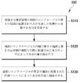
図5は、皮膚水分を測定するように適合された方法の、例としてのフロー図を例示する。図5の例としての方法500は、たとえば、皮膚中の水分を測定するように適合されたプロセッサを含むコンピューティングデバイスを使用して実施され得る。 FIG. 5 illustrates an example flow diagram of a method adapted to measure skin moisture. The
方法500は、ブロックS510、S520、および/またはS530のうちの1つまたは複数によって例示されるような、1つもしくは複数の動作、アクション、または機能を含み得る。別個のブロックとして例示されているが、様々なブロックは、所望の実施態様に応じて、追加のブロックとなるように分割可能であり、より少ないブロックとなるように組み合わせ可能であり、または削除可能である。いくつかのさらなる例では、記載する様々なブロックは、連続した過程の代わりに並行した過程として、またはこれらの組み合わせとして、実施され得る。方法500は、ブロックS510、「皮膚水分測定装置の細長いエンクロージャの第1の端部に配置された入口を通して皮膚から発散する水分を受容する」から開始してよい。
ブロックS510で、皮膚から発散する水分は、皮膚水分測定装置の細長いエンクロージャの第1の端部に配置された入口を通して受容され得る。図1に描くように、入口150は、皮膚水分測定装置100の細長いエンクロージャ120の第1の端部122に配置され得る。入口150は、皮膚110から発散する水分160を受容し得る。皮膚110と皮膚110よりも低い温度を有する冷却ユニット140との間に温度勾配が存在するので、皮膚110から発散する水分160は、皮膚110から冷却ユニット140への方向に流れることができる。ブロックS510の後にブロックS520、「細長いエンクロージャの内側で第1の端部と第2の反対側の端部との間に配置された水分センサによって水分の量を検出する」が続いてよい。 In block S510, moisture emanating from the skin may be received through an inlet located at the first end of the elongate enclosure of the skin moisture measuring device. As depicted in FIG. 1, the
ブロックS520で、水分の量は、細長いエンクロージャの内側で第1の端部と第2の反対側の端部との間に配置された水分センサによって検出され得る。図1に例示するように、水分センサ130は、細長いエンクロージャ120の内側で第1の端部122と第2の端部124との間に配置され得る。水分センサ130は、水分センサ130を通ってまたはその近くを流れている水分160の量を検出し得る。ブロックS520の後にブロックS530、「細長いエンクロージャの第2の端部に配置された冷却ユニットによって水分を冷却し凝結させる」が続いてよい。 At block S520, the amount of moisture may be detected by a moisture sensor disposed between the first end and the second opposite end inside the elongate enclosure. As illustrated in FIG. 1, the
ブロックS530で、水分は、細長いエンクロージャの第2の端部に配置された冷却ユニットによって冷却され凝結させられ得る。図1に例示するように、冷却ユニット140は、細長いエンクロージャ120の内側で第1の端部122の反対側の第2の端部124に配置され得る。冷却ユニット140は、水分センサ130に面する冷却ユニット140の表面に達している水分160を冷却し凝結させ得る。 At block S530, the moisture can be cooled and condensed by a cooling unit located at the second end of the elongated enclosure. As illustrated in FIG. 1, the
いくつかの実施形態では、水分センサに隣接する雰囲気の第1の温度を検出することができ、一方で、冷却ユニットに隣接する雰囲気の第2の温度を検出することができる。第1および第2の温度の検出に応じて、冷却ユニットは、制御器(たとえば、図2の制御器290)によって、第1および第2の温度の間で実質的に一定の温度差を維持するように制御され得る。たとえば、冷却ユニットは、水分センサに面する冷却ユニットの第2の表面から冷却ユニットの第1の表面へと熱を伝達して、その結果、第2の表面が第1の表面よりも温度が低くなるように構成された、ペルチェ冷却器などの熱電冷却器であってよい。 In some embodiments, a first temperature of the atmosphere adjacent to the moisture sensor can be detected while a second temperature of the atmosphere adjacent to the cooling unit can be detected. In response to detecting the first and second temperatures, the cooling unit maintains a substantially constant temperature difference between the first and second temperatures by a controller (eg,
いくつかの実施形態では、皮膚からの水分損失の程度は、水分センサによって検出された水分の量から判定され得る。いくつかの他の実施形態では、皮膚バリア機能の状態は、水分センサによって検出された水分の量から判定され得る。 In some embodiments, the degree of moisture loss from the skin can be determined from the amount of moisture detected by the moisture sensor. In some other embodiments, the state of the skin barrier function can be determined from the amount of moisture detected by the moisture sensor.
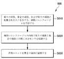
図6は、本明細書に記載の少なくともいくつかの実施形態に従って配置され、皮膚水分測定装置を製造するように適合された方法の、例としてのフロー図を例示する。図6の例としての方法600は、たとえば、皮膚水分測定装置の製造を制御するように適合されたプロセッサを含むコンピューティングデバイスを使用して実施され得る。 FIG. 6 illustrates an example flow diagram of a method that is arranged in accordance with at least some embodiments described herein and adapted to manufacture a skin moisture measuring device. The
方法600は、ブロックS610、S620、および/またはS630のうちの1つまたは複数によって例示されるような、1つもしくは複数の動作、アクション、または機能を含み得る。別個のブロックとして例示されているが、様々なブロックは、所望の実施態様に応じて、追加のブロックとなるように分割可能であり、より少ないブロックとなるように組み合わせ可能であり、または削除可能である。いくつかのさらなる例では、記載する様々なブロックは、連続した過程の代わりに並行した過程として、またはこれらの組み合わせとして、実施され得る。方法600は、ブロックS610、「第1の端部、第2の端部、および第1の端部に配置された入口を有する、細長いエンクロージャを用意する」から開始してよい。
ブロックS610で、細長いエンクロージャは、第1の端部、第2の端部、および第1の端部に配置された入口を有するように用意され得る。図2および3に例示するように、細長いエンクロージャ210は、入口216が配置され得る第1の端部212、および第1の端部212の反対側の第2の端部214を有するように用意され得る。入口216は、皮膚310と接触状態となり、かつ皮膚310から発散する水分を受容するように構成され得る。ブロックS610の後にブロックS620、「細長いエンクロージャの内側で第1の端部と第2の端部との間に水分センサを配設する」が続いてよい。 At block S610, an elongate enclosure can be prepared having a first end, a second end, and an inlet disposed at the first end. As illustrated in FIGS. 2 and 3, the
ブロックS620で、水分センサは、細長いエンクロージャの内側で第1の端部と第2の端部との間に配設され得る。 図2および3に例示するように、水分センサ220は、細長いエンクロージャ210の内側で第1の端部212と第2の端部214との間に配置され得る。水分センサ220は、皮膚310から流れている水分の量を検出するように構成され得る。ブロックS620の後にブロックS630、「第2の端部に冷却ユニットを配設する」が続いてよい。 At block S620, the moisture sensor may be disposed between the first end and the second end inside the elongated enclosure. As illustrated in FIGS. 2 and 3, the
ブロックS630で、冷却ユニットは第2の端部に配設され得る。図2および3に例示するように、冷却ユニット240は、細長いエンクロージャ210の第2の端部214に配置され得る。たとえば、冷却ユニット240は、水分センサ220に面する冷却ユニット240の第2の表面242から冷却ユニット240の第1の表面244へと熱を伝達して、その結果、第2の表面242が第1の表面244よりも温度が低くなるように構成された、ペルチェ冷却器などの熱電冷却器であってよい。 At block S630, the cooling unit may be disposed at the second end. As illustrated in FIGS. 2 and 3, the
いくつかの実施形態では、第1の温度センサ230などの第1の温度センサは、水分センサのごく近くに配設することができ、この場合第1の温度センサは、水分センサに隣接する雰囲気の第1の温度を検出するように構成され得る。また、第2の温度センサ250などの第2の温度センサは、冷却ユニットのごく近くに配設することができ、この場合第2の温度センサは、冷却ユニットに隣接する雰囲気の第2の温度を検出するように構成され得る。制御器290などの制御器は冷却ユニットに結合され得、ここで制御器は第1の温度と第2の温度との間で実質的に一定の温度差を維持するように冷却ユニットを制御するように構成され得る。 In some embodiments, a first temperature sensor, such as
いくつかの実施形態では、ヒートシンク260などのヒートシンクは、水分センサの反対側の冷却ユニットの第1の表面に取り付けることができ、この場合ヒートシンクは冷却ユニットから生成された熱を放散させるように構成され得る。さらに、冷却ファン280などの冷却ファンは、ヒートシンクのごく近くに配設され得、この場合冷却ファンは、ヒートシンクに向かう空気流を生み出すように構成され得る。加えて、取入口272などの1つまたは複数の空気取入口は、冷却ファンのごく近くで細長いエンクロージャの表面上に形成され得る。 In some embodiments, a heat sink, such as
いくつかの実施形態では、出力ユニット292などの出力ユニットは、細長いエンクロージャの表面上に配設され得、この場合出力ユニットは、水分センサによって検出された水分の量を報告するように構成され得る。加えて、電力供給部294などの電力供給部は、水分センサおよび冷却ユニットに結合され得、この場合電力供給部は、水分センサおよび冷却ユニットを動作させるための電力を供給するように構成され得る。 In some embodiments, an output unit, such as
本開示に照らして、当業者は、本明細書に開示する本方法および他の方法に関して、それらの方法において実行される機能が異なる順序で実施され得ることを諒解するであろう。さらに、概説したステップおよび動作は例としてのみ提供されており、また、これらのステップおよび動作のうちのいくつかは、開示する実施形態の本質から逸脱することなく、任意選択とすることができ、より少ないステップおよび動作となるように組み合わせ可能であり、または追加のステップおよび動作となるように拡張可能である。 In light of this disclosure, one of ordinary skill in the art will appreciate that the functions performed in these methods can be performed in a different order with respect to the methods and other methods disclosed herein. Furthermore, the outlined steps and operations are provided as examples only, and some of these steps and operations may be optional without departing from the essence of the disclosed embodiments, It can be combined to result in fewer steps and actions, or can be expanded to result in additional steps and actions.
図7は、本明細書に記載の少なくともいくつかの実施形態に従って配置された、皮膚水分を測定するための方法を実施するように構成され得る例としてのコンピューティングシステムを例示する、概略的なブロック図を示す。図7に描くように、コンピュータ700は、プロセッサ710、メモリ720、および1つまたは複数のドライブ730を含み得る。コンピュータ700は、従来型のコンピュータシステム、組み込み型制御コンピュータ、ラップトップ、またはサーバコンピュータ、モバイルデバイス、セットトップボックス、キオスク、車両情報システム、携帯電話、カスタマイズした機械、または他のハードウェアプラットフォームとして実装され得る。 FIG. 7 is a schematic illustrating an example computing system that can be configured to perform a method for measuring skin moisture, arranged in accordance with at least some embodiments described herein. A block diagram is shown. As depicted in FIG. 7, the
ドライブ730およびそれらの関連付けられたコンピュータ格納媒体は、コンピュータ可読命令、データ構造、プログラムモジュール、およびコンピュータ700に関する他のデータの格納を実現し得る。ドライブ730は、皮膚水分測定システム740、オペレーティングシステム(OS)750、およびアプリケーションプログラム760を含み得る。皮膚水分測定システム740は、図1から6に関して上記したような方法で皮膚水分測定装置を制御するように適合され得る。 The
コンピュータ700は、ユーザがコマンドおよびデータを入力できるユーザ入力装置780をさらに含み得る。入力装置は、電子デジタイザ、カメラ、マイクロフォン、キーボード、および、マウス、トラックボール、またはタッチパッドと一般に呼ばれるポインティング装置を含み得る。他の入力装置は、ジョイスティック、ゲームパッド、衛星放送受信用アンテナ、スキャナなどを含み得る。
これらのおよび他の入力装置は、システムバスに結合されるユーザ入力インターフェースを通してプロセッサ710に結合され得るが、パラレルポート、ゲームポート、またはユニバーサルシリアルバス(USB)などの、他のインターフェースおよびバス構造によって結合されてもよい。コンピュータ700などのコンピュータは、出力周辺インターフェース785などを通して結合され得る、表示装置などの他の周辺出力装置も含み得る。 These and other input devices may be coupled to the
コンピュータ700は、ネットワークインターフェース790に結合されたリモートコンピュータなどの1つまたは複数のコンピュータへの論理接続を使用する、ネットワーク化された環境で動作し得る。リモートコンピュータは、パーソナルコンピュータ、サーバ、ルータ、ネットワークPC、ピアデバイス、または他の一般的なネットワークノードであってよく、またコンピュータ700に関連して上記した要素のうちの多くまたは全てを含み得る。
ネットワーキング環境は、オフィス、企業のワイドエリアネットワーク(WAN)、ローカルエリアネットワーク(LAN)、イントラネット、およびインターネットにおいて一般的なものである。LANまたはWLANネットワーキング環境で使用される場合、コンピュータ700は、ネットワークインターフェース790またはアダプタを通してLANに結合され得る。WANネットワーキング環境で使用される場合、コンピュータ700は、通常、インターネットまたはネットワーク795などのWANを介して通信を確立するためのモデムまたは他の手段を含む。WANは、インターネット、例示したネットワーク795、様々な他のネットワーク、またはこれらの任意の組み合わせを含み得る。コンピュータ間で通信のリンク、リング、メッシュ、バス、クラウド、またはネットワークを確立する他の機構も使用できることが諒解されよう。 Networking environments are commonplace in offices, corporate wide area networks (WANs), local area networks (LANs), intranets, and the Internet. When used in a LAN or WLAN networking environment, the
いくつかの実施形態では、コンピュータ700はネットワーキング環境に結合され得る。コンピュータ700は、ドライブ730と関連付けられた1つもしくは複数の物理的コンピュータ可読格納媒体または他の格納装置の、1つまたは複数のインスタンスを含み得る。システムバスは、プロセッサ710がコードおよび/またはデータをコンピュータ可読格納媒体へと/から書き込む/読み取ることを可能にし得る。媒体は、限定するものではないが、半導体、磁性材料、光学媒体、電気的ストレージ、電気化学的ストレージ、または任意の他のそのような格納技術を含む、任意の好適な技術を使用して実装される格納要素の形態の機器を表し得る。媒体は、RAM、ROM、フラッシュかまたは他の種類の揮発性もしくは不揮発性メモリ技術として特徴付けられる、メモリ720と関連付けられた構成要素を表し得る。媒体は、2次ストレージを表すこともでき、それは格納装置730として実施され、またはそれ以外の様式で実施される。ハードドライブの実施態様は、ソリッドステートとして特徴付けられ得るか、または磁気的に符号化された情報を格納する回転する媒体を含み得る。 In some embodiments,
プロセッサ710は、個別にまたは集合的に任意の数の状態をとり得る、任意の数のトランジスタまたは他の回路素子から構築され得る。より具体的には、プロセッサ710は、状態機械または有限状態機械として動作し得る。そのような機械は、実行可能命令をロードすることによって第2の機械または特定の機械に変化させられ得る。これらのコンピュータ実行可能命令は、プロセッサ710が状態間でどのように遷移するかを指定することによってプロセッサ710を変化させ、このことによりプロセッサ710を構成するトランジスタまたは他の回路素子を第1の機械から第2の機械へと変化させ得る。それぞれ機械の状態は、ユーザ入力装置780、ネットワークインターフェース790、他の周辺機器、他のインターフェース、または1つもしくは複数のユーザもしくはアクタから、入力を受け取ることによっても変化させられ得る。またいずれの機械も、プリンタ、スピーカ、ビデオディスプレイ、またはこれら以外の、様々な出力装置の状態または様々な物理特性を変化させることができる。 The
図8は、本明細書に記載の少なくともいくつかの実施形態による、皮膚水分を測定するために利用され得るコンピュータプログラム製品を例示する。プログラム製品800は信号担持媒体802を含み得る。信号担持媒体802は、たとえばプロセッサによって実行されるときに、図1から6に関して上記した機能性を提供し得る1つまたは複数の命令804を含み得る。例として、命令804は、以下のうちの少なくとも1つを含み得る:皮膚水分測定装置の細長いエンクロージャの第1の端部に配置された入口を通して皮膚から発散する水分を受容するための1つまたは複数の命令;細長いエンクロージャの内側で第1の端部と第2の反対側の端部との間に配置された水分センサによって水分の量を検出するための1つまたは複数の命令;あるいは細長いエンクロージャの第2の端部に配置された冷却ユニットによって水分を冷却し凝結させるための1つまたは複数の命令。したがって、たとえば、図1から4を参照すると、皮膚水分測定装置100または200は、命令804に応答して図5に示すブロックの1つまたは複数を担い得る。 FIG. 8 illustrates a computer program product that can be utilized to measure skin moisture according to at least some embodiments described herein.
いくつかの実施態様では、信号担持媒体802は、限定するものではないが、ハードディスクドライブ、コンパクトディスク(CD)、デジタルビデオディスク(DVD)、デジタルテープ、メモリ、等などの、コンピュータ可読媒体806を包含し得る。いくつかの実施態様では、信号担持媒体802は、限定するものではないが、メモリ、読み取り/書き込み(R/W)CD、R/W DVD、等などの、記録可能媒体808を包含し得る。いくつかの実施態様では、信号担持媒体802は、限定するものではないが、デジタル通信媒体および/またはアナログ通信媒体(たとえば、光ファイバケーブル、導波路、有線通信リンク、無線通信リンク、等)などの、通信媒体810を包含し得る。したがって、たとえば、プログラム製品800は、RF信号担持媒体802によって皮膚水分測定装置100または200の1つまたは複数のモジュールに搬送可能であり、この場合信号担持媒体802は、無線通信媒体810(たとえば、IEEE 802.11規格に準拠した無線通信媒体)によって搬送される。 In some implementations, the signal-bearing
本開示は、例示として提供されており、いかなる点においても限定的であることは意図されていない、以下の例を参照することにより、一層容易に理解されるであろう。 The present disclosure will be more readily understood by reference to the following examples, which are provided by way of illustration and are not intended to be limiting in any respect.
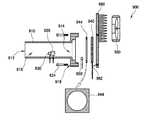
皮膚水分測定装置の構築
1つの実験例では、皮膚水分測定装置は上の実施形態に従って構築された。図9Aは、本明細書に記載の少なくともいくつかの実施形態に従って配置され、皮膚から発散する水分を測定するように構成された、分解された状態の、例としての皮膚水分測定装置の要素または部品を例示する。図9Aに例示され、また以下で記載される全ての要素または部品は、皮膚水分測定装置100または200の対応する要素/部品と同様の構成および/または機能を有し得る。Construction of a skin moisture measuring device In one experimental example, a skin moisture measuring device was constructed according to the above embodiment. FIG. 9A illustrates an element of an exemplary skin moisture measuring device in a disassembled state, arranged according to at least some embodiments described herein, and configured to measure moisture emanating from the skin or The part is illustrated. All the elements or parts illustrated in FIG. 9A and described below may have a similar configuration and / or function as the corresponding elements / parts of the skin
アクリル樹脂で製作された細長いエンクロージャ910が用意された。細長いエンクロージャ910は、入口916が配置される第1の端部912と、冷却ユニット940(たとえば、ペルチェ冷却器)が配置されることになる、第1の端部912の反対側の第2の端部914とを有する。水分センサ920は、細長いエンクロージャ910の内側で第1の端部912と第2の端部914との間に配置された。さらに、第1の温度センサ930は、水分センサ920のごく近くに配置された。 An
細長いエンクロージャ910は次いで、細長いエンクロージャ910とヒートシンク960との間に冷却ユニット940を挿置した状態で、(第2の端部914に形成された)穴918および(ヒートシンク960に形成された)穴962を通してネジ924(またはボルト)を固定することによって、ヒートシンク960に取り付けられた。細長いエンクロージャ910をヒートシンク960に気密に取り付けるために、細長いエンクロージャ910の第2の端部914と冷却ユニット940との間に、シリコンエラストマ材料で製作された封止部材944が挿置された。さらに、第2の温度センサ950が、冷却ユニット940の反対側の封止部材944の一方側に配置された。最後に、ヒートシンク960に向かう空気流を生み出すように、冷却ファン980が配設された。 The
図9Bは、本明細書に記載の少なくともいくつかの実施形態に従って配置され、図9Aの要素または部品から組み立てられた、皮膚から発散する水分を測定するように構成された、例としての皮膚水分測定装置を例示する。より具体的には、図9Bは、図9Aを参照して上記したような様式で組み立てられた皮膚水分測定装置900を示す。 FIG. 9B is an example skin moisture, arranged according to at least some embodiments described herein, configured to measure moisture emanating from the skin, assembled from the elements or parts of FIG. 9A. A measurement apparatus is illustrated. More specifically, FIG. 9B shows a skin
皮膚水分測定装置900の部品または要素を組み立てた後で、センサ920、930、および950ならびに冷却ユニット940と制御器および電力供給部(図示せず)との間の電気的接続のための配線が、細長いエンクロージャ910の側方表面上の穴を通して敷設された。さらに、センサ920および930からの配線を細長いエンクロージャ910の側方表面に固定するために、エポキシ樹脂922および932が追加して配設された。 After assembling the parts or elements of the skin
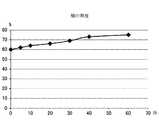
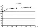
皮膚水分測定装置を使用して乾燥した皮膚および補水された皮膚の水分含有量を測定する。1つの実験例では、人体のいくつかの部位の湿度(または水分含有量)は、上の実施形態に従って製造された皮膚水分測定装置を使用することによって測定された。図10Aから10Dは、本明細書に記載の少なくともいくつかの実施形態に従って配置された、皮膚水分測定装置によって測定された頬、掌、額、およびポリエチレンフィルムの湿度をそれぞれ示すグラフを例示する。 Measure the moisture content of dry and rehydrated skin using a skin moisture meter. In one experimental example, the humidity (or moisture content) of several parts of the human body was measured by using a skin moisture measuring device manufactured according to the above embodiment. FIGS. 10A through 10D illustrate graphs showing cheek, palm, forehead, and polyethylene film humidity, respectively, as measured by a skin moisture measuring device, arranged in accordance with at least some embodiments described herein.
この実施例では、図1から4および9Aおよび9Bに例示された構成に従って、皮膚水分測定装置が実施された。水分測定が、頬、掌、額、およびポリエチレンフィルムのそれぞれに関して、摂氏26度の温度および60%の湿度を有する環境で、約60秒間行われた。また、皮膚水分測定装置の冷却ユニットは、(第1および第2の温度センサによって測定された)第1および第2の温度の間の差が約摂氏10度に維持されるように制御された。 In this example, a skin moisture measuring device was implemented according to the configuration illustrated in FIGS. 1-4 and 9A and 9B. Moisture measurements were made for about 60 seconds in an environment having a temperature of 26 degrees Celsius and 60% humidity for each of the cheeks, palms, forehead, and polyethylene film. Also, the cooling unit of the skin moisture measuring device was controlled so that the difference between the first and second temperatures (measured by the first and second temperature sensors) was maintained at about 10 degrees Celsius. .
図10Aおよび10Bに示すように、頬および掌の表面で測定された水分含有量は、(約60秒であった)測定期間中、実質的に一定の様式で増加した。測定されたデータから、頬および掌から相当な速度で水分が発散したこと、およびしたがって、発散速度が冷却ユニットによる水分凝結の速度を上回ったことが想定される。 As shown in FIGS. 10A and 10B, the moisture content measured at the cheek and palm surfaces increased in a substantially constant manner during the measurement period (which was approximately 60 seconds). From the measured data, it is assumed that moisture has shed from the cheek and palm at a significant rate, and thus the divergence rate has exceeded the rate of moisture condensation by the cooling unit.
他方で、図10Cに例示するように、額の表面で測定された水分含有量は、測定期間中、60%より僅かに大きい値に留まった。このことは額における発散速度が人体のその他の部位(たとえば、頬および掌)よりも著しく低かったことを示し得るが、このことはおそらく、額から水分が発散するのを妨げる、額を覆う油に起因する。 On the other hand, as illustrated in FIG. 10C, the moisture content measured on the surface of the forehead remained slightly above 60% during the measurement period. This may indicate that the rate of divergence at the forehead was significantly lower than other parts of the human body (eg, cheeks and palms), which is probably an oil covering the forehead that prevents moisture from escaping from the forehead caused by.
さらに、図10Dは、皮膚水分測定装置の入口がポリエチレンフィルムによって気密に覆われたときの、皮膚水分測定装置によって測定された水分含有量を示すグラフを例示する。この場合、ポリエチレンフィルムから水分は発散しておらず、一方で、皮膚水分測定装置のエンクロージャの内側に残る水分は冷却ユニットによって引き続き凝結させられた。したがって、例示するように、測定された水分含有量は、測定期間中、約60%から約50%へと徐々に減少した。 Further, FIG. 10D illustrates a graph showing the moisture content measured by the skin moisture measuring device when the entrance of the skin moisture measuring device is airtightly covered with the polyethylene film. In this case, no moisture was emitted from the polyethylene film, while the moisture remaining inside the enclosure of the skin moisture measuring device was subsequently condensed by the cooling unit. Thus, as illustrated, the measured water content gradually decreased from about 60% to about 50% during the measurement period.
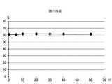
別の実験例では、乾燥状態および通常状態における頬および額の湿度(または水分含有量)は、上の実施形態に従って製造された皮膚水分測定装置を使用することによって測定された。図11Aから11Dは、本明細書に記載の少なくともいくつかの実施形態に従って配置された、皮膚水分測定装置によって測定された、乾燥状態および通常状態における頬および額の湿度をそれぞれ示すグラフを例示する。 In another experimental example, the cheek and forehead humidity (or moisture content) in dry and normal conditions was measured by using a skin moisture measuring device manufactured according to the above embodiment. FIGS. 11A-11D illustrate graphs showing cheek and forehead humidity in dry and normal conditions, respectively, as measured by a skin moisture measuring device, arranged in accordance with at least some embodiments described herein. .
この実施例では、水分測定は、乾燥状態(たとえば、摂氏21度の温度および45%の湿度を有する環境)ならびに通常状態(たとえば、摂氏21度の温度および51%の湿度を有する環境)において、頬および額のそれぞれに関して、約60秒間行われた。また、皮膚水分測定装置の冷却ユニットは、(第1および第2の温度センサによって測定された)第1および第2の温度の間の差が約摂氏10度に維持されるように制御された。 In this example, the moisture measurement is performed in a dry state (eg, an environment having a temperature of 21 degrees Celsius and 45% humidity) and in a normal state (eg, an environment having a temperature of 21 degrees Celsius and 51% humidity). It took about 60 seconds for each cheek and forehead. Also, the cooling unit of the skin moisture measuring device was controlled so that the difference between the first and second temperatures (measured by the first and second temperature sensors) was maintained at about 10 degrees Celsius. .
図11Aおよび11Bに示すように、乾燥状態において頬および額の表面で測定された水分含有量は、(約60秒間であった)測定期間の初期段階において急速に増加し、その後期段階においてゆっくりと増加した。測定されたデータから、乾燥状態において頬および額から相当な速度で水分が発散したこと、およびしたがって、発散速度が冷却ユニットによる水分凝結の速度を上回ったことが想定される。 As shown in FIGS. 11A and 11B, the moisture content measured at the cheek and forehead surfaces in the dry state increased rapidly in the early stages of the measurement period (which was about 60 seconds) and slowly in the later stages. And increased. From the measured data, it is assumed that moisture has shed from the cheeks and forehead at a significant rate in the dry state, and thus the divergence rate has exceeded the rate of moisture condensation by the cooling unit.
他方で、図11Cおよび11Dに示すように、頬および額の表面で通常状態において測定された水分含有量は、測定期間中、50%から60%の範囲内の値に留まった。このことは、通常状態における発散速度が乾燥状態における発散速度よりも著しく低かったことを示し得る。 On the other hand, as shown in FIGS. 11C and 11D, the moisture content measured in the normal state on the cheek and forehead surfaces remained in the range of 50% to 60% during the measurement period. This may indicate that the divergence rate in the normal state was significantly lower than the divergence rate in the dry state.
上記したように、本開示のいくつかの実施形態による皮膚水分測定装置は、従来の皮膚水分測定装置と比較して費用効果の高い様式で、個々のユーザにとって持ち運び可能な大きさで製造され得る。さらに、皮膚に取り付けられた電極または探針を使用して静電容量測定を行う従来の装置と対照的に、本開示による皮膚水分測定装置は、電極または探針が皮膚に取り付けられることを何ら必要としないので、皮膚に対するストレスを低減し得る。さらに、本開示による皮膚水分測定装置は、皮膚の広い領域から発散する水分を測定し得るが、一方従来の装置は、そのような場合に水分を検出するために、複数の電極または探針を必要とする場合がある。 As noted above, skin moisture measuring devices according to some embodiments of the present disclosure can be manufactured in a cost effective manner compared to conventional skin moisture measuring devices and in a portable size for an individual user. . Further, in contrast to conventional devices that perform capacitance measurements using electrodes or probes attached to the skin, the skin moisture measuring device according to the present disclosure does not allow electrodes or probes to be attached to the skin. Since it is not necessary, the stress on the skin can be reduced. Further, the skin moisture measuring device according to the present disclosure can measure moisture emanating from a large area of the skin, whereas conventional devices use multiple electrodes or probes to detect moisture in such cases. You may need it.
本開示は本出願に記載の特定の実施形態に関して限定されるべきではなく、これらの実施形態は様々な態様を例示するものとして意図される。当業者には明らかであろうように、多くの修正および変更が、その精神および範囲から逸脱することなくなされ得る。本開示の範囲内にある機能的に等価な方法および機器が、本明細書に列挙したものに加えて、先の説明から当業者には明らかであろう。そのような修正および変更は、添付の特許請求の範囲の範囲内にあることが意図される。本開示は、添付の特許請求の範囲の用語、およびかかる特許請求の範囲にとって等価物と認められるものの全範囲によってのみ限定されるべきである。本開示が特定の方法、試薬、化合物、組成物、または生物系に限定されず、これらが当然変化し得ることが理解されるべきである。本明細書で使用される専門用語が特定の実施形態について記載することのみを目的とするものであり、限定的であることを意図されていないことも理解されるべきである。 The present disclosure should not be limited with respect to the specific embodiments described in the present application, which are intended to illustrate various aspects. Many modifications and variations can be made without departing from its spirit and scope, as will be apparent to those skilled in the art. Functionally equivalent methods and apparatus within the scope of the present disclosure will be apparent to those skilled in the art from the foregoing description, in addition to those listed herein. Such modifications and changes are intended to fall within the scope of the appended claims. The present disclosure should be limited only by the terms of the appended claims and the full scope of what is deemed to be equivalent to such claims. It is to be understood that this disclosure is not limited to particular methods, reagents, compounds, compositions, or biological systems, which can of course vary. It should also be understood that the terminology used herein is for the purpose of describing particular embodiments only and is not intended to be limiting.
本明細書に記載された主題は、様々なコンポーネントをしばしば例示しており、これらのコンポーネントは、他の様々なコンポーネントに包含されるか、または他の様々なコンポーネントに接続される。そのように図示されたアーキテクチャは、単に例に過ぎず、実際には、同じ機能を実現する多くの他のアーキテクチャが実装可能であることが理解されよう。概念的な意味で、同じ機能を実現するコンポーネントの任意の構成は、所望の機能が実現されるように効果的に「関連付け」される。したがって、特定の機能を実現するために組み合わされた、本明細書における任意の2つのコンポーネントは、アーキテクチャまたは中間のコンポーネントにかかわらず、所望の機能が実現されるように、お互いに「関連付け」されていると見ることができる。同様に、そのように関連付けされた任意の2つのコンポーネントは、所望の機能を実現するために、互いに「動作可能に接続」または「動作可能に結合」されていると見なすこともでき、そのように関連付け可能な任意の2つのコンポーネントは、所望の機能を実現するために、互いに「動作可能に結合できる」と見なすこともできる。動作可能に結合できる場合の具体例には、物理的にかみ合わせ可能な、および/もしくは物理的に相互作用するコンポーネント、ならびに/またはワイヤレスに相互作用可能な、および/もしくはワイヤレスに相互作用するコンポーネント、ならびに/または論理的に相互作用する、および/もしくは論理的に相互作用可能なコンポーネントが含まれるが、それらに限定されない。 The subject matter described herein often illustrates various components, which are encompassed by or otherwise connected to various other components. It will be appreciated that the architecture so illustrated is merely an example, and in practice many other architectures that implement the same functionality can be implemented. In a conceptual sense, any configuration of components that achieve the same function is effectively “associated” to achieve the desired function. Thus, any two components herein combined to achieve a particular function are “associated” with each other so that the desired function is achieved, regardless of architecture or intermediate components. You can see that. Similarly, any two components so associated may be considered “operably connected” or “operably coupled” to each other to achieve the desired functionality, and as such Any two components that can be associated with can also be considered "operably coupled" to each other to achieve the desired functionality. Examples where it can be operatively coupled include physically interlockable and / or physically interacting components, and / or wirelessly interacting and / or wirelessly interacting components, And / or components that interact logically and / or logically interact with each other.
本明細書における実質的に全ての複数形および/または単数形の用語の使用に対して、当業者は、状況および/または用途に適切なように、複数形から単数形に、および/または単数形から複数形に変換することができる。様々な単数形/複数形の置き換えは、理解しやすいように、本明細書で明確に説明することができる。 For the use of substantially all plural and / or singular terms herein, those skilled in the art will recognize from the plural to the singular and / or singular as appropriate to the situation and / or application. You can convert from shape to plural. Various singular / plural permutations can be clearly described herein for ease of understanding.
通常、本明細書において、特に添付の特許請求の範囲(たとえば、添付の特許請求の範囲の本体部)において使用される用語は、全体を通じて「オープンな(open)」用語として意図されていることが、当業者には理解されよう(たとえば、用語「含む(including)」は、「含むがそれに限定されない(including but not limited to)」と解釈されるべきであり、用語「有する(having)」は、「少なくとも有する(having at least)」と解釈されるべきであり、用語「含む(includes)」は、「含むがそれに限定されない(includes but is not limited to)」と解釈されるべきである、など)。導入される請求項で具体的な数の記載が意図される場合、そのような意図は、当該請求項において明示的に記載されることになり、そのような記載がない場合、そのような意図は存在しないことが、当業者にはさらに理解されよう。たとえば、理解の一助として、添付の特許請求の範囲は、導入句「少なくとも1つの(at least one)」および「1つまたは複数の(one or more)」を使用して請求項の記載を導くことを含む場合がある。しかし、そのような句の使用は、同一の請求項が、導入句「1つまたは複数の」または「少なくとも1つの」および「a」または「an」などの不定冠詞を含む場合であっても、不定冠詞「a」または「an」による請求項の記載の導入が、そのように導入される請求項の記載を含む任意の特定の請求項を、単に1つのそのような記載を含む実施形態に限定する、ということを示唆していると解釈されるべきではない(たとえば、「a」および/または「an」は、「少なくとも1つの」または「1つまたは複数の」を意味すると解釈されるべきである)。同じことが、請求項の記載を導入するのに使用される定冠詞の使用にも当てはまる。また、導入される請求項の記載で具体的な数が明示的に記載されている場合でも、そのような記載は、少なくとも記載された数を意味すると解釈されるべきであることが、当業者には理解されよう(たとえば、他の修飾語なしでの「2つの記載(two recitations)」の単なる記載は、少なくとも2つの記載、または2つ以上の記載を意味する)。さらに、「A、BおよびC、などの少なくとも1つ」に類似の慣例表現が使用されている事例では、通常、そのような構文は、当業者がその慣例表現を理解するであろう意味で意図されている(たとえば、「A、B、およびCの少なくとも1つを有するシステム」は、Aのみ、Bのみ、Cのみ、AおよびBを共に、AおよびCを共に、BおよびCを共に、ならびに/またはA、B、およびCを共に、などを有するシステムを含むが、それに限定されない)。「A、B、またはC、などの少なくとも1つ」に類似の慣例表現が使用されている事例では、通常、そのような構文は、当業者がその慣例表現を理解するであろう意味で意図されている(たとえば、「A、B、またはCの少なくとも1つを有するシステム」は、Aのみ、Bのみ、Cのみ、AおよびBを共に、AおよびCを共に、BおよびCを共に、ならびに/またはA、B、およびCを共に、などを有するシステムを含むが、それに限定されない)。2つ以上の代替用語を提示する事実上いかなる離接する語および/または句も、明細書、特許請求の範囲、または図面のどこにあっても、当該用語の一方(one of the terms)、当該用語のいずれか(either of the terms)、または両方の用語(both terms)を含む可能性を企図すると理解されるべきであることが、当業者にはさらに理解されよう。たとえば、句「AまたはB」は、「A」または「B」あるいは「AおよびB」の可能性を含むことが理解されよう。 In general, terms used herein, particularly in the appended claims (eg, the body of the appended claims), are intended throughout as “open” terms. Will be understood by those skilled in the art (eg, the term “including” should be construed as “including but not limited to” and the term “having”). Should be interpreted as “having at least,” and the term “includes” should be interpreted as “including but not limited to”. ,Such). Where a specific number of statements is intended in the claims to be introduced, such intentions will be explicitly stated in the claims, and in the absence of such statements, such intentions It will be further appreciated by those skilled in the art that is not present. For example, as an aid to understanding, the appended claims use the introductory phrases “at least one” and “one or more” to guide the claim description. May include that. However, the use of such phrases may be used even if the same claim contains indefinite articles such as the introductory phrases “one or more” or “at least one” and “a” or “an”. Embodiments in which the introduction of a claim statement by the indefinite article "a" or "an" includes any particular claim, including the claim description so introduced, is merely one such description. (Eg, “a” and / or “an” should be construed to mean “at least one” or “one or more”). Should be). The same applies to the use of definite articles used to introduce claim recitations. Further, even if a specific number is explicitly stated in the description of the claim to be introduced, it should be understood that such a description should be interpreted to mean at least the number stated. (For example, the mere description of “two descriptions” without other modifiers means at least two descriptions, or two or more descriptions). Further, in cases where a conventional expression similar to “at least one of A, B and C, etc.” is used, such syntax usually means that one skilled in the art would understand the conventional expression. Contemplated (eg, “a system having at least one of A, B, and C” means A only, B only, C only, A and B together, A and C together, B and C together And / or systems having both A, B, and C together, etc.). In cases where a customary expression similar to “at least one of A, B, or C, etc.” is used, such syntax is usually intended in the sense that one skilled in the art would understand the customary expression. (Eg, “a system having at least one of A, B, or C” includes A only, B only, C only, A and B together, A and C together, B and C together, And / or systems having both A, B, and C together, etc.). Any disjunctive word and / or phrase that presents two or more alternative terms may be either one of the terms, anywhere in the specification, claims, or drawings. It will be further understood by those skilled in the art that it should be understood that the possibility of including either of the terms (both terms), or both of them. For example, it will be understood that the phrase “A or B” includes the possibilities of “A” or “B” or “A and B”.
加えて、本開示の特徴または態様がマーカッシュグループによって記載される場合、本開示がこのことによってマーカッシュグループの任意の個々の要素または要素のサブグループによっても記載されることを当業者は認識するであろう。 In addition, if a feature or aspect of the present disclosure is described by a Markush group, those skilled in the art will recognize that the present disclosure is thereby described by any individual element or sub-group of elements. I will.
当業者には理解されようが、書面による説明を提供する観点からなど、ありとあらゆる目的に関して、本明細書に開示する全ての範囲は、そのありとあらゆる可能な下位範囲および下位範囲の組み合わせもまた包含する。列挙された範囲はいずれも、少なくとも二等分、三等分、四等分、五等分、十等分、等に分解されている同じ範囲について十分に記載しまたそれらを可能にするものとして、容易に認識され得る。非限定的な例として、本明細書で検討する各範囲は、下3分の1、中3分の1、および上3分の1、等に容易に分解され得る。同様に当業者には理解されようが、「最大」、「少なくとも」などの全ての言語は、挙げられた数を含み、また上で検討したような下位範囲に後から分解され得る範囲を指す。最後に、当業者には理解されようが、範囲は個々の各要素を含む。 As will be appreciated by those skilled in the art, for any and all purposes, such as from the perspective of providing a written description, all ranges disclosed herein also include all possible subranges and combinations of subranges. All listed ranges should be sufficient to describe and enable the same ranges that have been broken down into at least bisected, bisected, quasi, quas, quas, etc. Can be easily recognized. As a non-limiting example, each range discussed herein can be easily broken down into the lower third, middle third, upper third, and so on. Similarly, as will be appreciated by those skilled in the art, all languages such as “maximum”, “at least”, etc., include the listed numbers and refer to ranges that can be later decomposed into sub-ranges as discussed above. . Finally, as will be appreciated by those skilled in the art, the range includes each individual element.
以上から、本開示の様々な実施形態が本明細書において例示の目的で記載されていること、および、本開示の範囲および精神から逸脱することなく様々な修正がなされ得ることが諒解されるであろう。したがって、本明細書に開示する様々な実施形態は限定的であることを意図しておらず、その真の範囲および精神は以下の特許請求の範囲によって示されている。 From the foregoing, it will be appreciated that various embodiments of the present disclosure have been described herein for purposes of illustration and that various modifications can be made without departing from the scope and spirit of the present disclosure. I will. Accordingly, the various embodiments disclosed herein are not intended to be limiting, the true scope and spirit of which is set forth by the following claims.
Claims (27)
Translated fromJapanese皮膚と接触状態となるように、かつ前記皮膚から発散する水分を受容するように構成され、前記第1の端部に配置された入口と、
前記細長いエンクロージャの内側で前記第1の端部と前記第2の端部との間に配置され、前記水分の量を検出するように構成された水分センサと、
前記第2の端部に配置され、前記水分を冷却し凝結させるように構成された冷却ユニットと、
を備える皮膚水分測定装置。An elongated enclosure having a first end and a second end;
An inlet configured to be in contact with the skin and to receive moisture emanating from the skin and disposed at the first end;
A moisture sensor disposed between the first end and the second end inside the elongate enclosure and configured to detect the amount of moisture;
A cooling unit disposed at the second end and configured to cool and condense the moisture;
A skin moisture measuring device.
前記冷却ユニットのごく近くに配置され、前記冷却ユニットに隣接する雰囲気の第2の温度を検出するように構成された第2の温度センサと、
前記第1の温度と前記第2の温度との間で実質的に一定の温度差を維持するように前記冷却ユニットを制御するように構成された制御器と、
をさらに備える、請求項1に記載の装置。A first temperature sensor disposed in close proximity to the moisture sensor and configured to detect a first temperature of an atmosphere adjacent to the moisture sensor;
A second temperature sensor disposed in close proximity to the cooling unit and configured to detect a second temperature of an atmosphere adjacent to the cooling unit;
A controller configured to control the cooling unit to maintain a substantially constant temperature difference between the first temperature and the second temperature;
The apparatus of claim 1, further comprising:
前記ヒートシンクは前記冷却ユニットから生成された熱を放散させるように構成される、
請求項1に記載の装置。A heat sink attached to the first surface of the cooling unit opposite the moisture sensor;
The heat sink is configured to dissipate heat generated from the cooling unit;
The apparatus of claim 1.
をさらに備える、請求項3に記載の装置。The apparatus of claim 3, further comprising a cooling fan configured to create an air flow toward the heat sink.
をさらに備える、請求項4に記載の装置。The apparatus of claim 4, further comprising one or more air intakes formed on a surface of the elongated enclosure in close proximity to the cooling fan.
をさらに備える、請求項1に記載の装置。The apparatus of claim 1, further comprising an output unit configured to report the amount of the moisture detected by the moisture sensor.
をさらに備える、請求項1に記載の装置。The apparatus according to claim 1, further comprising: a power supply unit configured to supply power for operating the moisture sensor and the cooling unit.
前記水分の前記量に従って静電容量を変化させるように構成されたコンデンサと、
前記静電容量の前記変化を電圧信号に変換するように構成された発振器と、
前記電圧信号の周波数を判定するように構成された周波数カウンタと、
を備える、請求項1に記載の装置。The moisture sensor is
A capacitor configured to change capacitance according to the amount of moisture;
An oscillator configured to convert the change in the capacitance into a voltage signal;
A frequency counter configured to determine a frequency of the voltage signal;
The apparatus of claim 1, comprising:
前記細長いエンクロージャの内側で前記第1の端部と第2の反対側の端部との間に配置された水分センサによって前記水分の量を検出することと、
前記細長いエンクロージャの前記第2の端部に配置された冷却ユニットによって前記水分を冷却し凝結させることと、
を含む、皮膚水分を測定する方法。Receiving moisture emanating from the skin through an inlet located at the first end of the elongate enclosure of the skin moisture measuring device;
Detecting the amount of moisture by a moisture sensor disposed within the elongated enclosure between the first end and a second opposite end;
Cooling and condensing the moisture by a cooling unit disposed at the second end of the elongated enclosure;
A method for measuring skin moisture, comprising:
前記冷却ユニットのごく近くに配置された第2の温度センサによって前記冷却ユニットに隣接する雰囲気の第2の温度を検出することと、
制御器によって、前記第1の温度と前記第2の温度との間で実質的に一定の温度差を維持するように前記冷却ユニットを制御することと、
をさらに含む、請求項12に記載の方法。Detecting a first temperature of an atmosphere adjacent to the moisture sensor by a first temperature sensor disposed in close proximity to the moisture sensor;
Detecting a second temperature of the atmosphere adjacent to the cooling unit by a second temperature sensor disposed in close proximity to the cooling unit;
Controlling the cooling unit by a controller to maintain a substantially constant temperature difference between the first temperature and the second temperature;
The method of claim 12, further comprising:
をさらに含む、請求項12に記載の方法。The method of claim 12, further comprising dissipating heat generated from the cooling unit by a heat sink attached to a first surface of the cooling unit opposite the moisture sensor.
をさらに含む、請求項14に記載の方法。The method of claim 14, further comprising: creating an air flow toward the heat sink by a cooling fan.
をさらに含む、請求項12に記載の方法。The method of claim 12, further comprising: reporting by the output unit the amount of moisture detected by the moisture sensor.
皮膚水分測定装置の細長いエンクロージャの第1の端部に配置された入口を通して皮膚から発散する水分を受容する、
前記細長いエンクロージャの内側で前記第1の端部と第2の反対側の端部との間に配置された水分センサによって前記水分の量を検出する、および
前記細長いエンクロージャの前記第2の端部に配置された冷却ユニットによって前記水分を冷却し凝結させるための、1つまたは複数の命令を備える、
非一時的なコンピュータ可読格納媒体。A non-transitory computer-readable storage medium storing a program operable by a skin moisture measuring device, wherein the program is
Receiving moisture emanating from the skin through an inlet located at the first end of the elongate enclosure of the skin moisture measuring device;
Detecting the amount of moisture by a moisture sensor disposed between the first end and a second opposite end inside the elongate enclosure; and the second end of the elongate enclosure Comprising one or more instructions for cooling and condensing the moisture by a cooling unit disposed in
A non-transitory computer-readable storage medium.
前記水分の量を検出するように構成された水分センサを、前記細長いエンクロージャの内側で前記第1の端部と前記第2の端部との間に配設することと、
前記水分を冷却し凝結させるように構成された冷却ユニットを前記第2の端部に配設することと、
を含む、皮膚水分測定装置を製造する方法。Providing an elongated enclosure having a first end, a second end, and an inlet disposed at the first end, wherein the inlet is in contact with the skin; and Preparing to receive moisture emanating from the skin; and
A moisture sensor configured to detect the amount of moisture is disposed between the first end and the second end inside the elongated enclosure;
Providing a cooling unit at the second end configured to cool and condense the moisture;
A method for manufacturing a skin moisture measuring device.
前記冷却ユニットに隣接する雰囲気の第2の温度を検出するように構成された第2の温度センサを、前記冷却ユニットのごく近くに配設することと、
前記第1の温度と前記第2の温度との間で実質的に一定の温度差を維持するように前記冷却ユニットを制御するように構成された制御器を、前記冷却ユニットに結合することと、
をさらに含む、請求項21に記載の方法。Disposing a first temperature sensor configured to detect a first temperature of an atmosphere adjacent to the moisture sensor in close proximity to the moisture sensor;
Disposing a second temperature sensor configured to detect a second temperature of the atmosphere adjacent to the cooling unit in close proximity to the cooling unit;
Coupling to the cooling unit a controller configured to control the cooling unit to maintain a substantially constant temperature difference between the first temperature and the second temperature; ,
The method of claim 21, further comprising:
前記ヒートシンクは前記冷却ユニットから生成された熱を放散させるように構成される、請求項21に記載の方法。Attaching a heat sink to the first surface of the cooling unit opposite the moisture sensor;
The method of claim 21, wherein the heat sink is configured to dissipate heat generated from the cooling unit.
前記冷却ファンは前記ヒートシンクに向かう空気流を生み出すように構成される、
請求項23に記載の方法。Further comprising disposing a cooling fan in close proximity to the heat sink;
The cooling fan is configured to create an air flow toward the heat sink;
24. The method of claim 23.
前記出力ユニットは前記水分センサによって検出された前記水分の前記量を報告するように構成される、
請求項21に記載の方法。Further comprising disposing an output unit on a surface of the elongated enclosure;
The output unit is configured to report the amount of the moisture detected by the moisture sensor;
The method of claim 21.
前記電力供給部は前記水分センサおよび前記冷却ユニットを動作させるための電力を供給するように構成される、
請求項21に記載の方法。Further comprising coupling a power supply to the moisture sensor and the cooling unit;
The power supply unit is configured to supply power for operating the moisture sensor and the cooling unit;
The method of claim 21.
Applications Claiming Priority (2)
| Application Number | Priority Date | Filing Date | Title |
|---|---|---|---|
| US14/284,579 | 2014-05-22 | ||
| US14/284,579US9907506B2 (en) | 2014-05-22 | 2014-05-22 | Devices and methods for measuring skin moisture |
Publications (2)
| Publication Number | Publication Date |
|---|---|
| JP2015221209Atrue JP2015221209A (en) | 2015-12-10 |
| JP6192681B2 JP6192681B2 (en) | 2017-09-06 |
Family
ID=54555193
Family Applications (1)
| Application Number | Title | Priority Date | Filing Date |
|---|---|---|---|
| JP2015103368AExpired - Fee RelatedJP6192681B2 (en) | 2014-05-22 | 2015-05-21 | Apparatus and method for measuring skin moisture |
Country Status (3)
| Country | Link |
|---|---|
| US (1) | US9907506B2 (en) |
| JP (1) | JP6192681B2 (en) |
| KR (1) | KR101718812B1 (en) |
Families Citing this family (8)
| Publication number | Priority date | Publication date | Assignee | Title |
|---|---|---|---|---|
| KR101863185B1 (en) | 2016-07-18 | 2018-06-04 | 주식회사 지파워 | Apparatus for measuring transepidermal water loss using gradient revise function and skin moisture management system using the same |
| KR101894932B1 (en) | 2016-07-18 | 2018-09-05 | 주식회사 지파워 | Skin contact type care apparatus using measuring skin moisture function and measuring transepidermal water loss function |
| KR101894930B1 (en) | 2016-07-18 | 2018-09-05 | 주식회사 지파워 | Apparatus for measuring transepidermal water loss and skin management system using the same |
| US12102443B2 (en) | 2016-07-18 | 2024-10-01 | Gpower Inc. | Device for measuring transepidermal water loss and skin care system using same |
| KR101894931B1 (en) | 2016-07-18 | 2018-09-05 | 주식회사 지파워 | Apparatus for measuring transepidermal water loss with circulating function and skin moisture management system using the same |
| US12070322B2 (en)* | 2018-01-30 | 2024-08-27 | Shiseido Company, Ltd. | Method for determining skin condition based on thermal sensitivity in skin |
| KR102241449B1 (en) | 2018-11-16 | 2021-04-19 | 주식회사 지파워 | Device for measuring transepidermal water loss |
| US20240252099A1 (en)* | 2023-02-01 | 2024-08-01 | The Regents Of The University Of Michigan | Transepidermal Water Loss Measurement Device |
Citations (3)
| Publication number | Priority date | Publication date | Assignee | Title |
|---|---|---|---|---|
| US6439028B1 (en)* | 1998-07-10 | 2002-08-27 | South Bank University Enterprises Limited | Method and equipment for measuring vapor flux from surfaces |
| JP2006198321A (en)* | 2005-01-24 | 2006-08-03 | Hitachi Ltd | Blood glucose level measuring device |
| JP2014014425A (en)* | 2012-07-06 | 2014-01-30 | Panasonic Corp | Portable terminal |
Family Cites Families (3)
| Publication number | Priority date | Publication date | Assignee | Title |
|---|---|---|---|---|
| JP2001204693A (en) | 2000-01-27 | 2001-07-31 | Kao Corp | Moisture loss measurement device |
| DE10033620A1 (en)* | 2000-07-11 | 2002-01-31 | Testo Gmbh & Co Kg | Device and method for determining the moisture in gases |
| US20080022935A1 (en)* | 2006-07-20 | 2008-01-31 | Hyperion Innovations, Inc. | Padding for pets with integrated heating, cooling, or a combination of heating and cooling |
- 2014
- 2014-05-22USUS14/284,579patent/US9907506B2/ennot_activeExpired - Fee Related
- 2015
- 2015-05-21JPJP2015103368Apatent/JP6192681B2/ennot_activeExpired - Fee Related
- 2015-05-22KRKR1020150071622Apatent/KR101718812B1/ennot_activeExpired - Fee Related
Patent Citations (3)
| Publication number | Priority date | Publication date | Assignee | Title |
|---|---|---|---|---|
| US6439028B1 (en)* | 1998-07-10 | 2002-08-27 | South Bank University Enterprises Limited | Method and equipment for measuring vapor flux from surfaces |
| JP2006198321A (en)* | 2005-01-24 | 2006-08-03 | Hitachi Ltd | Blood glucose level measuring device |
| JP2014014425A (en)* | 2012-07-06 | 2014-01-30 | Panasonic Corp | Portable terminal |
Also Published As
| Publication number | Publication date |
|---|---|
| US20150335279A1 (en) | 2015-11-26 |
| JP6192681B2 (en) | 2017-09-06 |
| KR20150135142A (en) | 2015-12-02 |
| KR101718812B1 (en) | 2017-03-22 |
| US9907506B2 (en) | 2018-03-06 |
Similar Documents
| Publication | Publication Date | Title |
|---|---|---|
| JP6192681B2 (en) | Apparatus and method for measuring skin moisture | |
| US11464137B2 (en) | Active control for two-phase cooling | |
| KR102650704B1 (en) | Molecular Diagnostic Assay System | |
| Liu et al. | Wall climbing robot using electrostatic adhesion force generated by flexible interdigital electrodes | |
| KR102513948B1 (en) | Temporal temperature sensor position offset error correction | |
| CN107579429B (en) | Semiconductor laser and temperature control method thereof | |
| US11054329B2 (en) | Electronic devices having pressure sensors with heaters | |
| TW201403464A (en) | Core-level dynamic voltage and frequency scaling in a chip multiprocessor | |
| US20160044824A1 (en) | Liquid-vapor phase change thermal interface material | |
| RU2691056C2 (en) | Computer device having a spectral-selective radiation emission device | |
| JP6926185B2 (en) | Circuits and methods that provide calibration for temperature relaxation in computing devices | |
| TW201514669A (en) | Monitoring surface temperature of devices | |
| US9855004B2 (en) | Devices and methods for measuring hair condition | |
| TW201350007A (en) | Heat dissipation features, electronic devices incorporating heat dissipation features, and methods of making heat dissipation features | |
| ES2971807T3 (en) | On-chip thermometer for superconducting quantum computing devices | |
| US20160187927A1 (en) | Direct attach dock cooling leveraging maximum silicon junction temperature control | |
| US8008934B2 (en) | Burn-in system for electronic devices | |
| Tsai et al. | Thermal analyses and measurements of low-cost COP package for high-power LED | |
| Pastor et al. | Seduce: a testbed for research on thermal and power management in datacenters | |
| Ranchagoda et al. | Implementation of an external intelligent cooling system for laptops using TECs | |
| US20240248456A1 (en) | Systems and methods for smart power and fan speed control | |
| WO2016028295A1 (en) | Electronic device for determining external temperature | |
| KR102463535B1 (en) | Computing module connected to electronic apparatus and operating method thereof | |
| Khalid et al. | Laptop cooling pad temperature monitoring system | |
| Gektin et al. | Characterizing bulk thermal conductivity and interface contact resistance effects of thermal interface materials in electronic cooling applications |
Legal Events
| Date | Code | Title | Description |
|---|---|---|---|
| RD03 | Notification of appointment of power of attorney | Free format text:JAPANESE INTERMEDIATE CODE: A7423 Effective date:20160304 | |
| RD04 | Notification of resignation of power of attorney | Free format text:JAPANESE INTERMEDIATE CODE: A7424 Effective date:20160309 | |
| A977 | Report on retrieval | Free format text:JAPANESE INTERMEDIATE CODE: A971007 Effective date:20160520 | |
| A131 | Notification of reasons for refusal | Free format text:JAPANESE INTERMEDIATE CODE: A131 Effective date:20160606 | |
| A521 | Request for written amendment filed | Free format text:JAPANESE INTERMEDIATE CODE: A523 Effective date:20160830 | |
| A131 | Notification of reasons for refusal | Free format text:JAPANESE INTERMEDIATE CODE: A131 Effective date:20161202 | |
| A521 | Request for written amendment filed | Free format text:JAPANESE INTERMEDIATE CODE: A523 Effective date:20170222 | |
| TRDD | Decision of grant or rejection written | ||
| A01 | Written decision to grant a patent or to grant a registration (utility model) | Free format text:JAPANESE INTERMEDIATE CODE: A01 Effective date:20170711 | |
| A61 | First payment of annual fees (during grant procedure) | Free format text:JAPANESE INTERMEDIATE CODE: A61 Effective date:20170808 | |
| R150 | Certificate of patent or registration of utility model | Ref document number:6192681 Country of ref document:JP Free format text:JAPANESE INTERMEDIATE CODE: R150 | |
| LAPS | Cancellation because of no payment of annual fees |