JP2015220835A - Power converter - Google Patents
Power converterDownload PDFInfo
- Publication number
- JP2015220835A JP2015220835AJP2014102038AJP2014102038AJP2015220835AJP 2015220835 AJP2015220835 AJP 2015220835AJP 2014102038 AJP2014102038 AJP 2014102038AJP 2014102038 AJP2014102038 AJP 2014102038AJP 2015220835 AJP2015220835 AJP 2015220835A
- Authority
- JP
- Japan
- Prior art keywords
- frequency
- unit
- power
- gain
- harmonic distortion
- Prior art date
- Legal status (The legal status is an assumption and is not a legal conclusion. Google has not performed a legal analysis and makes no representation as to the accuracy of the status listed.)
- Granted
Links
Images


Landscapes
- Supply And Distribution Of Alternating Current (AREA)
- Inverter Devices (AREA)
Abstract
Description
Translated fromJapanese本発明は、電力変換装置に関する。 The present invention relates to a power conversion device.
従来から、商用電力系統に連系する電力変換装置には、商用電力系統の停電時において、自身を商用電力系統から確実に解列させることを目的として、単独運転防止機能が具備されている。 Conventionally, a power converter connected to a commercial power system has been provided with an independent operation prevention function for the purpose of reliably disconnecting itself from the commercial power system in the event of a power failure in the commercial power system.
なお、上記に関連する従来技術の一例としては、本願出願人による特許文献1を挙げることができる。 As an example of the related art related to the above,
また、PV(photovoltaic)システム用PCS(power conditioning system)の新連系規程を定める非特許文献1には、能動的単独運転検出を行うための共通技術として、周波数フィードバック機能が提案されている。 Further, Non-Patent
周波数フィードバック機能とは、PCSの動作周波数に生じる変動に基づいて無効電力注入を行い、動作周波数の変動を助長する機能である。PCSが単独運転状態に移行した場合に、PCS出力と需要家負荷がアンバランスであれば、PCSの動作周波数に意図しない変動が生じる。このとき、周波数フィードバック機能による無効電力注入を行えば、動作周波数の変動を助長することができるので、この変動を捉えてPCSの単独運転を検出することが可能となる。 The frequency feedback function is a function of injecting reactive power based on fluctuations occurring in the operating frequency of the PCS and promoting fluctuations in the operating frequency. When the PCS shifts to the single operation state, if the PCS output and the customer load are unbalanced, unintended fluctuations occur in the operating frequency of the PCS. At this time, if reactive power injection is performed by the frequency feedback function, fluctuations in the operating frequency can be promoted, so that it is possible to detect a single operation of the PCS by capturing this fluctuation.
しかしながら、上記従来技術では、単独運転状態でない定常時の場合でも、系統周波数のふらつきが生じると、周波数フィードバック機能により、多くの無効電力が不要に出力される場合があった(即ち、出力電流の周波数が不安定になる場合があった)。また、不要な無効電力の出力を抑えるために、周波数フィードバックのフィードバックゲイン(周波数偏差に対して注入無効電力を演算するゲイン)を抑えると、単独運転状態時の動作周波数の発散が遅くなるために、高速な単独運転の検出に不利となる。 However, in the above-described prior art, even when the system frequency fluctuates even in a steady state that is not in an isolated operation state, a lot of reactive power may be output unnecessarily by the frequency feedback function (that is, the output current The frequency may become unstable.) In addition, if the feedback gain of the frequency feedback (gain that calculates the injection reactive power with respect to the frequency deviation) is suppressed to suppress the output of unnecessary reactive power, the divergence of the operating frequency during the single operation state is delayed. This is disadvantageous for detecting high-speed isolated operation.
上記問題点に鑑み、本発明は、単独運転状態でない定常時は不要な無効電力の出力を抑え、且つ単独運転状態時は単独運転の検出を高速に行うことができる電力変換装置を提供することを目的とする。 In view of the above problems, the present invention provides a power conversion device that can suppress unnecessary reactive power output in a steady state that is not in an isolated operation state, and that can detect an isolated operation at high speed in an isolated operation state. With the goal.
上記目的を達成するために本発明の一態様に係る電力変換装置は、
直流電力を交流電力に変換して商用電力系統に系統連系させる電力変換部と、
系統周波数を計測する系統周波数計測部と、
前記系統周波数をモニタして単独運転を検出する単独運転検出部と、
前記系統周波数の偏差に応じた無効電力を注入することで前記系統周波数の周波数変化を促す周波数フィードバック部と、
電圧高調波歪の急増の有無を判定する判定部と、
前記判定部による判定結果に応じて前記周波数フィードバック部のフィードバックゲインを切替えて設定するゲイン設定部と、
を備える構成としている(第1の構成)。In order to achieve the above object, a power converter according to an aspect of the present invention is provided.
A power conversion unit that converts DC power into AC power and interconnects it with a commercial power system;
A system frequency measurement unit for measuring the system frequency;
An isolated operation detection unit that detects the isolated operation by monitoring the system frequency,
A frequency feedback unit that promotes a frequency change of the system frequency by injecting reactive power according to the deviation of the system frequency;
A determination unit for determining whether or not there is a sudden increase in voltage harmonic distortion;
A gain setting unit that switches and sets a feedback gain of the frequency feedback unit according to a determination result by the determination unit;
(First configuration).
また、上記第1の構成において、前記ゲイン設定部は、前記判定部により電圧高調波歪の急増があったと判定された場合、第1のゲインを設定し、そうでない場合は、周波数偏差の全領域において前記第1のゲイン以下であり、且つ少なくとも一部の周波数偏差領域において前記第1のゲインより低くしている第2のゲインを設定することとしてもよい(第2の構成)。 In the first configuration, the gain setting unit sets the first gain when the determination unit determines that there is a sudden increase in voltage harmonic distortion; otherwise, the gain setting unit sets the entire frequency deviation. A second gain that is equal to or lower than the first gain in the region and lower than the first gain in at least a part of the frequency deviation region may be set (second configuration).
また、上記第1または第2の構成において、電圧高調波歪の急増が検出されたときに無効電力をステップ注入することで強制的に前記系統周波数の偏差を生じさせる無効電力ステップ注入部を更に備えることとしてもよい(第3の構成)。 In the first or second configuration, the reactive power step injection unit that forcibly generates the deviation of the system frequency by step-injecting reactive power when a sudden increase in voltage harmonic distortion is detected is further provided. It is good also as providing (3rd structure).
また、上記第3の構成において、前記判定部による前記電圧高調波歪急増の判定条件は、前記無効電力ステップ注入部に関する前記電圧高調波歪急増の判定条件よりも緩和していることとしてもよい(第4の構成)。 Further, in the third configuration, the determination condition of the voltage harmonic distortion rapid increase by the determination unit may be more relaxed than the determination condition of the voltage harmonic distortion rapid increase related to the reactive power step injection unit. (Fourth configuration).
また、本発明の一態様に係る分散型電源は、直流電源と、前記直流電源から入力される直流電力を交流電力に変換して商用電力系統に系統連系させる上記第1〜第4のいずれかの構成から成る電力変換装置と、を備えることとしている。 A distributed power source according to one aspect of the present invention includes a DC power source and any one of the first to fourth methods described above that converts DC power input from the DC power source into AC power and grid-connects to a commercial power system. And a power conversion device configured as described above.
本発明の電力変換装置によると、単独運転状態でない定常時は不要な無効電力の出力を抑え、且つ単独運転状態時は単独運転の検出を高速に行うことができる。 According to the power conversion device of the present invention, it is possible to suppress unnecessary reactive power output in a steady state that is not in an isolated operation state, and to detect an isolated operation at high speed in an isolated operation state.
<第1実施形態>
集中連系対応可能な単独運転検出方法である能動的単独運転検出方式が最近知られているが、概要は次のとおりである。特徴的な機能として、系統周波数の偏差から注入する無効電力を演算して周波数シフトを促す機能(周波数フィードバック機能)と、分散型電源の出力電力と系統負荷の消費電力が平衡した状態において意図的に周波数変化を発生させる機能(無効電力ステップ注入機能)を備えており、単独運転の高速検出が可能、不要動作がない、他方式との相互干渉がない、能動信号による系統への影響が小さいなどの特長を持つ。このような単独運転検出方式を「能動的単独運転検出方式(ステップ注入付き周波数フィードバック方式)」と呼び、その内容を詳細に説明する。<First Embodiment>
An active islanding detection method, which is an islanding operation detection method capable of cooperating with a centralized interconnection, has been known recently. The outline is as follows. Characteristic functions include a function (frequency feedback function) that promotes frequency shift by calculating reactive power injected from system frequency deviation, and intentional in a state where the output power of the distributed power source and the power consumption of the system load are balanced. Is equipped with a function to generate frequency changes (reactive power step injection function), capable of high-speed detection of isolated operation, no unnecessary operation, no mutual interference with other systems, and small influence on system by active signal With features such as. Such an isolated operation detection method is referred to as an “active isolated operation detection method (frequency feedback method with step injection)”, and its contents will be described in detail.
図1は、本発明の一実施形態に係る上記能動的単独運転方式を採用したパワーコンディショナ(以下、PCS[power conditioning system]と呼ぶ)の全体ブロック図である。本構成例のPCS100(電力変換装置の一例)は、系統周波数計測部110と、周波数フィードバック部120と、無効電力ステップ注入部130と、単独運転検出部140と、電流制御処理部150と、インバータ部160と、を有する。 FIG. 1 is an overall block diagram of a power conditioner (hereinafter referred to as a PCS [power conditioning system]) employing the above active islanding system according to an embodiment of the present invention. The PCS 100 (an example of a power conversion device) of this configuration example includes a system
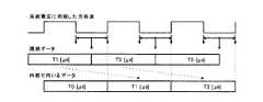
系統周波数計測部110は、周波数偏差の演算に用いる系統周波数を計測する計測部であり、周波数検出回路111と、周波数計測処理部112と、位相差計測同期処理部113と、を含む。図2は、系統周波数(周期)計測のアルゴリズムを示す図である。 The system
周波数検出回路111は、系統電圧に同期した方形波信号を生成して周波数計測処理部112に出力する(図2の上段を参照)。周波数検出回路111は、ハードウェア部として実装される。 The
周波数計測処理部112は、周波数検出回路111から入力される方形波信号を監視して系統電圧の周期データ(周波数データ)を計測する(図2の中段を参照)。より具体的に述べると、周波数計測処理部112は、方形波信号の立下りエッジから立上りエッジまでをカウントしたときの中間値と、次の立下りエッジから立上りエッジまでをカウントしたときの中間値との差分を周期データ(周波数データ)として取得する。周波数計測処理部112は、系統周波数の計測に十分な分解能(例えば2.5MHz以上(400ns以下)を備えている。周波数計測処理部112は、ソフトウェア部として実装される。 The frequency
位相差計測同期処理部113は、周波数計測処理部112で計測された周期データ(周波数データ)を方形波信号の立上りエッジで同期化する(図2の下段を参照)。位相差計測同期処理部113は、ソフトウェア部として実装される。 The phase difference measurement
周波数フィードバック部120は、移動平均処理により算出された系統周波数の周波数偏差(周期偏差)から注入する無効電力を演算して周波数シフトを促す制御部であり、第1移動平均算出部121と、第2移動平均算出部122と、周波数偏差算出部123と、無効電力注入量算出部124と、加算部125と、を含む。 The
第1移動平均算出部121は、系統周波数(系統周期)の第1移動平均値を算出する。第1移動平均算出部121は、ソフトウェア部として実装される。 The first moving
第2移動平均算出部122は、系統周波数(系統周期)の第2移動平均値を算出する。第2移動平均算出部122は、ソフトウェア部として実装される。 The second moving
周波数偏差算出部123は、第1移動平均値と第2移動平均値との差分から系統周波数の周波数偏差(周期偏差)を算出する。周波数偏差算出部123は、ソフトウェア部として実装される。 The frequency
図3は、周波数偏差演算のイメージ図であり、図4は、移動平均値の更新イメージ図である。周波数偏差の演算に用いられる周期データは、系統電圧の1周期毎に更新される。周波数偏差の演算に用いられる移動平均値は、時間t1毎(例えばt1=5ms)に更新され、周波数偏差の演算自体も時間t1毎に行われる。なお、時間t1は、商用電力系統の周波数(50Hz/60Hz)に依ることなく一律とされている。第1移動平均値(最近周期)としては、最新周期の取得タイミングを終点として時間t2(例えばt2=40ms)分の移動平均値が用いられる。一方、第2移動平均値(過去周期)としては、最新周期の取得タイミングから時間t3(例えばt3=200ms)だけ過去に遡ったタイミングを終点として時間t4(例えばt4=80ms)分の移動平均値が用いられる。 FIG. 3 is an image diagram of frequency deviation calculation, and FIG. 4 is an update image diagram of a moving average value. Period data used for calculating the frequency deviation is updated for each period of the system voltage. The moving average value used for the calculation of the frequency deviation is updated every time t1 (for example, t1 = 5 ms), and the calculation of the frequency deviation itself is also performed every time t1. The time t1 is uniform without depending on the frequency (50 Hz / 60 Hz) of the commercial power system. As the first moving average value (most recent cycle), a moving average value for time t2 (for example, t2 = 40 ms) is used with the acquisition timing of the latest cycle as an end point. On the other hand, as the second moving average value (past cycle), the moving average value for the time t4 (for example, t4 = 80 ms) with the timing retroactive from the acquisition timing of the latest cycle by the time t3 (for example, t3 = 200 ms) as the end point. Is used.
無効電力注入量算出部124は、周波数偏差算出部123で算出された周波数偏差(周期偏差)に応じて注入する無効電力を算出する。無効電力注入量算出部124は、ソフトウェア部として実装される。 The reactive power injection
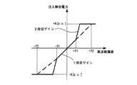
図5は、周波数偏差−注入無効電力特性を示す図である。本図で示したように、無効電力注入量算出部124は、周波数偏差が±f[Hz](例えばf=0.01Hz(±4.0μs@50Hz、±2.8μs@60Hz)を境にして無効電力演算のゲインを変える(1段目ゲイン及び2段目ゲイン)。なお、注入する無効電力の上下限値は±A[p.u.](例えばA=0.25)に設定されている。ここで、p.u.[per unit]は、単位法で基準値(定格容量)に対する比を表す際に用いられる記号である。例えば、基準値(定格容量)が4kWである場合、±0.25p.u.=±1kW(無効電力であれば±1kVar)となる。 FIG. 5 is a diagram showing frequency deviation-injection reactive power characteristics. As shown in this figure, the reactive power injection
また、図5において、特性を実線と破線により示しているのは、ゲインを切替え可能となっているからであり、これについては後で詳述する。 In FIG. 5, the characteristic is indicated by a solid line and a broken line because the gain can be switched. This will be described in detail later.
加算部125は、無効電力注入量算出部124で算出された無効電力の注入量と、後出のステップ注入量算出部136で算出された無効電力のステップ注入量を足し合わせて、電流制御処理部150に伝達する。加算部125は、ソフトウェア部として実装される。 The
無効電力ステップ注入部130は、PCS100の単独運転時にPCS100の出力電力と負荷装置の消費電力が平衡して系統周波数の偏差が微小となる条件下において、周波数シフトを促すために無効電力をステップ注入する制御部であり、基本波電圧計測回路131と、高調波電圧計測回路132と、基本波電圧算出部133と、高調波歪算出部134と、ステップ注入発生条件判定部135と、ステップ注入量算出部136と、を含む。 The reactive power
基本波電圧計測回路131は、PCS100の出力電流に含まれる基本波成分を基本波電圧として計測する。基本波電圧計測回路131は、ハードウェア部として実装される。 The fundamental wave
高調波電圧計測回路132は、PCS100の出力電流に含まれる高調波成分を高調波電圧として計測する。高調波電圧計測回路132は、ハードウェア部として実装される。 The harmonic
基本波電圧算出部133は、基本波電圧の変化量を算出する。基本波電圧算出部133は、ソフトウェア部として実装される。 The fundamental wave
高調波歪算出部134は、電圧高調波歪の変化量を算出する。電圧高調波歪の演算には、二次〜七次以上の高調波が用いられる。高調波歪算出部134は、ソフトウェア部として実装される。 The harmonic
ステップ注入発生条件判定部135は、基本波電圧算出部133及び高調波歪算出部134の出力に応じてステップ注入発生条件が満足されたか否かを判定する。より具体的に述べると、ステップ注入発生条件判定部135は、周波数偏差が所定の微小範囲内(例えば±0.01Hz以内)であり、且つ、基本波電圧または電圧高調波歪の変化量が所定の条件を満たしたときに、ステップ注入の必要が生じたと判定する。ステップ注入発生条件判定部133は、ソフトウェア部として実装される。 The step injection generation
図6は、ステップ注入発生の第1条件(基本波電圧変動)を説明するための図である。図6の例において、Miは直近からiサイクル前の基本波電圧を示しており、Mavrは3サイクル前から5サイクル前までの3個の平均値を示している。基本波電圧算出部133では、例えば、基本波電圧の変化量(M0−Mavr)が算出され、ステップ注入発生条件判定部135では、当該変化量が所定の閾値を超えた場合に基本波電圧の変動が生じたと判定される。 FIG. 6 is a diagram for explaining a first condition (fundamental voltage fluctuation) for occurrence of step injection. In the example of FIG. 6, Mi indicates the fundamental wave voltage i cycles before the latest, and Mavr indicates the average value of three from 3 cycles before to 5 cycles before. For example, the fundamental wave
図7はステップ注入発生の第2条件(電圧高調波歪変動)を説明するための図である。図7の例において、Niは直近からiサイクル前の二次〜七次の全高調波歪THD[total harmonic distortion]を示しており、N0は直近の値、Navrは3サイクル前から5サイクル前までの3個の平均値を示している。高調波歪算出部134では、例えば、電圧高調波歪の変化量(N0−Navr)が算出され、ステップ注入発生条件判定部135では、当該変化量が所定の閾値を超えた場合に電圧高調波歪が急増したと判定される。 FIG. 7 is a diagram for explaining a second condition (voltage harmonic distortion fluctuation) for occurrence of step injection. In the example of FIG. 7, Ni represents the second to seventh total harmonic distortion THD [total harmonic distortion] i cycles before the latest, N0 is the latest value, and Navr is 3 cycles to 5 cycles before. The average value of up to three is shown. For example, the harmonic
ステップ注入量算出部136は、ステップ注入発生条件判定部135の判定結果に応じて無効電力のステップ注入量を算出する。注入時間は、所定のサイクル数以下(例えば3サイクル以下)とされている。注入量には所定の上限値(例えば0.1p.u.)が定められている。無効電力は、PCS100から見て電流位相を遅らせる方向(周波数を低下させる方向)に注入される。無効電力のステップ注入は、先述の条件が満たされてから系統周波数(周期)の半サイクル以内に行われる。ステップ注入量算出部136は、ソフトウェア部として実装される。 The step injection
単独運転検出部140は、系統周波数の変化によって単独運転発生の有無を判定する制御部であり、能動的単独運転検出部141と、受動的単独運転検出部142と、を含む。 The isolated
電流制御処理部150は、系統周波数計測部110の出力に基づいて同期処理を行いつつ、適切な無効電力を注入するようにインバータ部160の電流制御を行う。 The current
インバータ部160は、直流電源(例えばPVパネル)から供給される直流電力を交流電力に変換して商用電力系統PWに系統連系させる電力変換部である。 The
なお、図1では、上記の構成要素をハードウェア部(CPU以外)とソフトウェア部(CPU)に分割した例を示しているが、分割の境界はこれに限定されるものではない。 Although FIG. 1 shows an example in which the above-described components are divided into a hardware part (other than the CPU) and a software part (CPU), the division boundary is not limited to this.
ここで、PCS100は、更に、高調波電圧計測回路171と、高調波歪算出部172を備えている。高調波電圧計測回路171は、PCS100の出力電流に含まれる高調波成分を高調波電圧として計測する。高調波電圧計測回路171は、ハードウェア部として実装される。 Here, the
高調波歪算出部172は、電圧高調波歪の変化量を算出する。電圧高調波歪の演算には、二次〜七次以上の高調波が用いられる。高調波歪算出部172は、ソフトウェア部として実装される。高調波歪算出部172は、先述した図7に示すように、例えば、電圧高調波歪の変化量(N0−Navr)(N0:直近の全高調波歪THD、Navr:3サイクル前から5サイクル前までの3個のTHD平均値)を算出する。 The harmonic
そして、無効電力注入量算出部124は、高調波歪算出部172によって算出された上記の電圧高調波歪の変化量に応じて無効電力演算のゲイン(フィードバックゲイン)を切替える。より具体的には、電圧高調波歪の変化量が所定の閾値を超えている場合は、図5に示す周波数偏差−注入無効電力特性における実線で示したゲイン(第1のゲイン)にフィードバックゲインを設定する。このゲイン設定は、数周期間のみ行う。 Then, the reactive power injection
一方、電圧高調波歪の変化量が上記所定の閾値以下である場合は、図5における破線で示したゲイン(第2のゲイン)にフィードバックゲインを設定する。破線に示したゲインは、周波数偏差の全領域において実線で示したゲイン以下であるが、マイナス側からプラス側にかける一部の周波数偏差領域において実線で示したゲインより低くしている(破線の1段目ゲイン及び2段目ゲインの部分)。 On the other hand, when the amount of change in voltage harmonic distortion is equal to or less than the predetermined threshold, the feedback gain is set to the gain (second gain) indicated by the broken line in FIG. The gain indicated by the broken line is equal to or lower than the gain indicated by the solid line in the entire region of the frequency deviation, but is lower than the gain indicated by the solid line in a part of the frequency deviation region from the minus side to the plus side (the broken line). 1st stage gain and 2nd stage gain).
ここで、商用電力系統PWが停電し、PCS100が単独運転状態となった場合、PCS100と商用電力系統PWの間に位置する柱上トランス(不図示)で発生する高調波電流が負荷装置のインピーダンスや柱上トランスのインピーダンスに向けて流れるので、インバータ出力に電圧高調波が発生する。 Here, when the commercial power system PW fails and the
PCS100が単独運転状態になって電圧高調波歪が急増すると、高調波歪算出部172により算出される電圧高調波歪の変化量が所定の閾値を超えるので、無効電力注入算出部124は、第1のゲイン(図5の実線)にフィードバックゲインを設定する。このとき、PCS出力と負荷装置の消費電力がアンバランスであれば、系統周波数に変化が生じる。従って、周波数フィードバック部120は、周波数偏差と設定された第1のゲインに基づいて無効電力を注入し、周波数シフトを助長させる。そして、能動的単独運転検出部141は、周波数の発散を検出することで、単独運転を検出する。第1のゲインは高めに設定されるので、無効電力が多く注入され、周波数の発散が促され、単独運転検出を高速に行うことができる。 When the
また、商用電力系統PWと系統連系している定常時では、電圧高調波はインバータ出力に発生しないので、高調波歪算出部172により算出される電圧高調波歪の変化量が所定の閾値以下となり、無効電力注入算出部124は、第2のゲイン(図5の破線)にフィードバックゲインを設定する。このとき、系統周波数にふらつきが生じた場合、周波数偏差と第2のゲインに基づき無効電力が注入されることになるが、第2のゲインは低めに設定されているので、不要な無効電力注入を抑えることができる。 Further, since voltage harmonics are not generated in the inverter output at the time of grid connection with the commercial power system PW, the amount of change in voltage harmonic distortion calculated by the harmonic
このように、本実施形態であれば、単独運転状態でない定常時は不要な無効電力の出力を抑え、且つ単独運転状態時は単独運転の検出を高速に行うことができる。 As described above, according to this embodiment, it is possible to suppress unnecessary reactive power output in a steady state that is not in an isolated operation state, and to detect an isolated operation at a high speed in an isolated operation state.
また、単独運転状態時にPCS出力と負荷装置の消費電力がバランスされている場合は、系統周波数の変化が微小となるが、電圧高調波歪が急増するため、高調波歪算出部134により算出される電圧高調波歪の変化量が所定の閾値を超える。これにより、ステップ注入発生条件判定部135の判定結果に応じてステップ注入量算出部136によって、無効電力がステップ注入される。このとき、電圧高調波歪の急増の検出によって、無効電力注入量算出部124はフィードバックゲインを第1のゲインに設定する。従って、系統周波数の周波数発散が促されることとなり、高速な単独運転検出が可能となる。 In addition, when the PCS output and the power consumption of the load device are balanced in the single operation state, the change in the system frequency becomes small, but the voltage harmonic distortion increases rapidly, so that the harmonic
なお、単独運転状態時に電圧高調波歪の急増の度合いが弱い場合があり、この場合、無効電力ステップ注入部130により電圧高調波歪の急増を検出できず、無効電力のステップ注入機能が無効となる。しかしながら、無効電力注入量算出部124における高調波判定の閾値は、ステップ注入発生条件判定部135における閾値に比べて低めに設定しているので、無効電力注入量算出部124では上記のような場合でも電圧高調波歪の急増を検出でき、フィードバックゲインは第1のゲインに設定される。高めである第1のゲインによって周波数の発散が促され、高速な単独運転検出が可能となる。 In some cases, the degree of sudden increase in voltage harmonic distortion may be weak during the single operation state. In this case, the reactive power
このような能動的単独運転検出方式を採用したPCS100であれば、単独運転状態に陥ったPCS100を遅滞なく(例えば単独運転発生から規定値である0.2s以内に)高速に停止することが可能となる。 If the
<第2実施形態>
上記第1実施形態では無効電力注入量算出部124によって設定されるフィードバックゲインとして図5で示したものを例として挙げたが、フィードバックゲインはこの他にも様々な形態を採りうる。Second Embodiment
In the first embodiment, the feedback gain set by the reactive power injection
例えば、図8で示すように、第2のゲイン(破線)の一部が第1のゲイン(実線)の1段目の部分に重なっていてもよい。そして、図8では、第2のゲインは、この重なった直線部から両端へ第1のゲインの限界値(±A[p.u.])に交わるまで延長されている(+f1〜+f2、及び−f1〜−f2の領域)。従って、この第2のゲインの延長部は第1のゲインよりも値が低くなる部分となる。 For example, as shown in FIG. 8, a part of the second gain (broken line) may overlap the first stage part of the first gain (solid line). In FIG. 8, the second gain is extended from the overlapped linear portion to both ends until the first gain limit value (± A [pu]) is crossed (+ f1 to + f2 and −f1 to + f1). -F2 region). Therefore, the extended portion of the second gain is a portion whose value is lower than that of the first gain.
また、他の例として、フィードバックゲインの一部を曲線状に構成してもよい。例えば、図5において、1段目ゲインと2段目ゲインを曲線状に構成してもよい。 As another example, a part of the feedback gain may be configured in a curved shape. For example, in FIG. 5, the first-stage gain and the second-stage gain may be configured in a curved shape.
<第3実施形態>
上記第1実施形態において、無効電力注入量算出部124ではステップ注入発生条件判定部135よりも、算出された電圧高調波歪の変化量に対する閾値を低くすることで、電圧高調波歪急増の判定条件を緩和している。このような判定条件の緩和は、他の手法でも可能である。<Third Embodiment>
In the first embodiment, the reactive power injection
例えば、ステップ注入発生条件判定部135と無効電力注入量算出部124とで判定の閾値は同じ値とする。そして、高調波歪算出部134では、例えば図7に示したように、直近の全高調波歪THD(N0)と、3サイクル前〜5サイクル前までのTHD平均値(Navr)の差分をとることにより電圧高調波歪の変化量を算出する。また、高調波歪算出部172は、直近の全高調波歪THD(N0)と、6サイクル前〜8サイクル前までのTHD平均値(即ち上記3サイクル前〜5サイクル前よりも過去)の差分をとることにより電圧高調波歪の変化量を算出する。つまり、同じ閾値でも電圧高調波歪の変化量をとる期間を長くすることで、電圧高調波歪急増の判定条件を緩和している。 For example, the threshold value for determination is the same for the step injection generation
以上、本発明の実施形態について説明したが、本発明の趣旨の範囲内であれば、実施形態は種々の変形が可能である。 As mentioned above, although embodiment of this invention was described, if it is in the range of the meaning of this invention, embodiment may be variously deformed.
例えば本発明は、太陽電池モジュール(直流電源の一例)とPCSから成る分散型電源以外の分散型電源にも広く適用可能である(太陽電池以外の自然エネルギー発電手段、燃料電池、蓄電池を用いた分散型電源等)。 For example, the present invention can be widely applied to a distributed power source other than a distributed power source composed of a solar cell module (an example of a DC power source) and a PCS (using a natural energy power generation means other than a solar cell, a fuel cell, and a storage battery). Distributed power supply etc.).
100 PCS
110 系統周波数計測部
120 周波数フィードバック部
130 無効電力ステップ注入部
140 単独運転検出部
150 電流制御処理部
160 インバータ部
171 高調波電圧計測回路
172 高調波歪算出部
PW 商用電力系統100 PCS
DESCRIPTION OF
Claims (5)
Translated fromJapanese系統周波数を計測する系統周波数計測部と、
前記系統周波数をモニタして単独運転を検出する単独運転検出部と、
前記系統周波数の偏差に応じた無効電力を注入することで前記系統周波数の周波数変化を促す周波数フィードバック部と、
電圧高調波歪の急増の有無を判定する判定部と、
前記判定部による判定結果に応じて前記周波数フィードバック部のフィードバックゲインを切替えて設定するゲイン設定部と、
を備える電力変換装置。A power conversion unit that converts DC power into AC power and interconnects it with a commercial power system;
A system frequency measurement unit for measuring the system frequency;
An isolated operation detection unit that detects the isolated operation by monitoring the system frequency,
A frequency feedback unit that promotes a frequency change of the system frequency by injecting reactive power according to the deviation of the system frequency;
A determination unit for determining whether or not there is a sudden increase in voltage harmonic distortion;
A gain setting unit that switches and sets a feedback gain of the frequency feedback unit according to a determination result by the determination unit;
A power conversion device comprising:
Priority Applications (1)
| Application Number | Priority Date | Filing Date | Title |
|---|---|---|---|
| JP2014102038AJP6374213B2 (en) | 2014-05-16 | 2014-05-16 | Power converter |
Applications Claiming Priority (1)
| Application Number | Priority Date | Filing Date | Title |
|---|---|---|---|
| JP2014102038AJP6374213B2 (en) | 2014-05-16 | 2014-05-16 | Power converter |
Publications (2)
| Publication Number | Publication Date |
|---|---|
| JP2015220835Atrue JP2015220835A (en) | 2015-12-07 |
| JP6374213B2 JP6374213B2 (en) | 2018-08-15 |
Family
ID=54779833
Family Applications (1)
| Application Number | Title | Priority Date | Filing Date |
|---|---|---|---|
| JP2014102038AActiveJP6374213B2 (en) | 2014-05-16 | 2014-05-16 | Power converter |
Country Status (1)
| Country | Link |
|---|---|
| JP (1) | JP6374213B2 (en) |
Cited By (11)
| Publication number | Priority date | Publication date | Assignee | Title |
|---|---|---|---|---|
| JP2017127044A (en)* | 2016-01-12 | 2017-07-20 | 富士電機株式会社 | Isolated operation detector |
| JP2017189041A (en)* | 2016-04-06 | 2017-10-12 | 三菱電機株式会社 | Power Conditioner |
| JP2018064328A (en)* | 2016-10-11 | 2018-04-19 | シャープ株式会社 | Power converter and control method thereof |
| JP2018068014A (en)* | 2016-10-18 | 2018-04-26 | シャープ株式会社 | Isolated operation detection device and power conditioner |
| JP2019193318A (en)* | 2018-04-18 | 2019-10-31 | 新電元工業株式会社 | Harmonic measuring apparatus and individual operation detecting method using the same, individual operation detecting apparatus and distributed power supply system |
| JP2019193407A (en)* | 2018-04-24 | 2019-10-31 | 新電元工業株式会社 | Islanding operation detection method, islanding operation detection device, and distributed power supply system |
| JP2020145835A (en)* | 2019-03-06 | 2020-09-10 | パナソニックIpマネジメント株式会社 | Power conversion device |
| JP2020202733A (en)* | 2019-06-13 | 2020-12-17 | シャープ株式会社 | Inverter device |
| JP2022047353A (en)* | 2020-09-11 | 2022-03-24 | 株式会社東芝 | Electronic devices and methods |
| WO2024162003A1 (en)* | 2023-02-03 | 2024-08-08 | 株式会社デンソー | Power command conversion device, power command conversion method, and power command conversion program |
| WO2024162002A1 (en)* | 2023-02-03 | 2024-08-08 | 株式会社デンソー | Power factor control device, power factor control method, and power factor control program |
Citations (4)
| Publication number | Priority date | Publication date | Assignee | Title |
|---|---|---|---|---|
| JPH06311653A (en)* | 1993-04-22 | 1994-11-04 | Toshiba F Ee Syst Eng Kk | Inverter grid interconnection protection method and device |
| JPH07322506A (en)* | 1994-05-25 | 1995-12-08 | Sanyo Electric Co Ltd | Detection operation of single operation |
| JP2009044910A (en)* | 2007-08-10 | 2009-02-26 | Omron Corp | Method for detecting isolated operation, contrl device, device for detecting isolated operation, and distributed power supply system |
| JP2012044815A (en)* | 2010-08-20 | 2012-03-01 | Toshiba Corp | Individual operation detector and individual operation detection method |
- 2014
- 2014-05-16JPJP2014102038Apatent/JP6374213B2/enactiveActive
Patent Citations (4)
| Publication number | Priority date | Publication date | Assignee | Title |
|---|---|---|---|---|
| JPH06311653A (en)* | 1993-04-22 | 1994-11-04 | Toshiba F Ee Syst Eng Kk | Inverter grid interconnection protection method and device |
| JPH07322506A (en)* | 1994-05-25 | 1995-12-08 | Sanyo Electric Co Ltd | Detection operation of single operation |
| JP2009044910A (en)* | 2007-08-10 | 2009-02-26 | Omron Corp | Method for detecting isolated operation, contrl device, device for detecting isolated operation, and distributed power supply system |
| JP2012044815A (en)* | 2010-08-20 | 2012-03-01 | Toshiba Corp | Individual operation detector and individual operation detection method |
Cited By (16)
| Publication number | Priority date | Publication date | Assignee | Title |
|---|---|---|---|---|
| JP2017127044A (en)* | 2016-01-12 | 2017-07-20 | 富士電機株式会社 | Isolated operation detector |
| JP2017189041A (en)* | 2016-04-06 | 2017-10-12 | 三菱電機株式会社 | Power Conditioner |
| JP2018064328A (en)* | 2016-10-11 | 2018-04-19 | シャープ株式会社 | Power converter and control method thereof |
| JP2018068014A (en)* | 2016-10-18 | 2018-04-26 | シャープ株式会社 | Isolated operation detection device and power conditioner |
| JP2019193318A (en)* | 2018-04-18 | 2019-10-31 | 新電元工業株式会社 | Harmonic measuring apparatus and individual operation detecting method using the same, individual operation detecting apparatus and distributed power supply system |
| JP7131945B2 (en) | 2018-04-18 | 2022-09-06 | 新電元工業株式会社 | HARMONIC MEASURING DEVICE, ITS ISLANDING OPERATION DETECTION METHOD USING THE SAME, ISLANDING OPERATION DETECTION DEVICE, AND DISTRIBUTED POWER SUPPLY SYSTEM |
| JP7023168B2 (en) | 2018-04-24 | 2022-02-21 | 新電元工業株式会社 | Independent operation detection method, isolated operation detection device and distributed power supply system |
| JP2019193407A (en)* | 2018-04-24 | 2019-10-31 | 新電元工業株式会社 | Islanding operation detection method, islanding operation detection device, and distributed power supply system |
| JP2020145835A (en)* | 2019-03-06 | 2020-09-10 | パナソニックIpマネジメント株式会社 | Power conversion device |
| JP7190662B2 (en) | 2019-03-06 | 2022-12-16 | パナソニックIpマネジメント株式会社 | power converter |
| JP2020202733A (en)* | 2019-06-13 | 2020-12-17 | シャープ株式会社 | Inverter device |
| JP7503369B2 (en) | 2019-06-13 | 2024-06-20 | シャープ株式会社 | Inverter Device |
| JP2022047353A (en)* | 2020-09-11 | 2022-03-24 | 株式会社東芝 | Electronic devices and methods |
| JP7402138B2 (en) | 2020-09-11 | 2023-12-20 | 株式会社東芝 | Electronic devices and methods |
| WO2024162003A1 (en)* | 2023-02-03 | 2024-08-08 | 株式会社デンソー | Power command conversion device, power command conversion method, and power command conversion program |
| WO2024162002A1 (en)* | 2023-02-03 | 2024-08-08 | 株式会社デンソー | Power factor control device, power factor control method, and power factor control program |
Also Published As
| Publication number | Publication date |
|---|---|
| JP6374213B2 (en) | 2018-08-15 |
Similar Documents
| Publication | Publication Date | Title |
|---|---|---|
| JP6374213B2 (en) | Power converter | |
| JP5893057B2 (en) | Isolated operation detection device and isolated operation detection method | |
| JP6200196B2 (en) | Inverter device | |
| US9977094B2 (en) | Islanding operation detection and islanding operation detection method | |
| JP2017123781A5 (en) | ||
| JP6065273B2 (en) | Isolated operation detection device and detection method | |
| CN104734176B (en) | A kind of island detection method and device | |
| JP7055998B2 (en) | Static VAR compensator and control method of the device | |
| US8203813B2 (en) | Distributed power supply system | |
| US8928178B2 (en) | Isolated operation detection device | |
| JP6599804B2 (en) | Power conversion apparatus and control method thereof | |
| JP2014003743A (en) | Islanding operation detection method and islanding operation detection device | |
| US10892623B2 (en) | Method for detecting islanding condition for a DC/AC converter apparatus and a DC/AC converter apparatus thereof | |
| JP5502558B2 (en) | Isolated operation detection device, isolated operation detection method, and grid-connected inverter system provided with an isolated operation detection device | |
| JP2012026836A (en) | Frequency detection method for distributed power source and system interconnection protection apparatus | |
| JP5155364B2 (en) | Method of detecting phase jump of distributed power source and system interconnection protection device | |
| JP6898719B2 (en) | Power converter and its control method | |
| JP6228854B2 (en) | Power converter, load device, and control method | |
| JP2017022800A (en) | Isolated operation detection device, isolated operation detection method, and grid interconnection system | |
| JP6574725B2 (en) | Power converter and isolated operation detection method | |
| JP7068619B2 (en) | Independent operation detection device, grid interconnection inverter and independent operation detection method | |
| JP7503369B2 (en) | Inverter Device | |
| JP2015223037A (en) | Power conversion device and solar power generation system using the same | |
| JP2013243879A (en) | Individual operation detection circuit, individual operation detection method, and system interconnection inverter device including individual operation detection circuit | |
| JP2016073035A (en) | Ac power supply device and instantaneous voltage fluctuation detection method thereof |
Legal Events
| Date | Code | Title | Description |
|---|---|---|---|
| A621 | Written request for application examination | Free format text:JAPANESE INTERMEDIATE CODE: A621 Effective date:20170323 | |
| A977 | Report on retrieval | Free format text:JAPANESE INTERMEDIATE CODE: A971007 Effective date:20180126 | |
| A131 | Notification of reasons for refusal | Free format text:JAPANESE INTERMEDIATE CODE: A131 Effective date:20180220 | |
| A521 | Request for written amendment filed | Free format text:JAPANESE INTERMEDIATE CODE: A523 Effective date:20180423 | |
| RD03 | Notification of appointment of power of attorney | Free format text:JAPANESE INTERMEDIATE CODE: A7423 Effective date:20180423 | |
| TRDD | Decision of grant or rejection written | ||
| A01 | Written decision to grant a patent or to grant a registration (utility model) | Free format text:JAPANESE INTERMEDIATE CODE: A01 Effective date:20180626 | |
| A61 | First payment of annual fees (during grant procedure) | Free format text:JAPANESE INTERMEDIATE CODE: A61 Effective date:20180719 | |
| R150 | Certificate of patent or registration of utility model | Ref document number:6374213 Country of ref document:JP Free format text:JAPANESE INTERMEDIATE CODE: R150 |