JP2015217112A - Mobile radiography apparatus and mobile radiation generation apparatus - Google Patents
Mobile radiography apparatus and mobile radiation generation apparatusDownload PDFInfo
- Publication number
- JP2015217112A JP2015217112AJP2014102586AJP2014102586AJP2015217112AJP 2015217112 AJP2015217112 AJP 2015217112AJP 2014102586 AJP2014102586 AJP 2014102586AJP 2014102586 AJP2014102586 AJP 2014102586AJP 2015217112 AJP2015217112 AJP 2015217112A
- Authority
- JP
- Japan
- Prior art keywords
- antenna
- unit
- mobile
- radiation
- connector
- Prior art date
- Legal status (The legal status is an assumption and is not a legal conclusion. Google has not performed a legal analysis and makes no representation as to the accuracy of the status listed.)
- Withdrawn
Links
Images


Classifications
- A—HUMAN NECESSITIES
- A61—MEDICAL OR VETERINARY SCIENCE; HYGIENE
- A61B—DIAGNOSIS; SURGERY; IDENTIFICATION
- A61B6/00—Apparatus or devices for radiation diagnosis; Apparatus or devices for radiation diagnosis combined with radiation therapy equipment
- A61B6/56—Details of data transmission or power supply, e.g. use of slip rings
- A—HUMAN NECESSITIES
- A61—MEDICAL OR VETERINARY SCIENCE; HYGIENE
- A61B—DIAGNOSIS; SURGERY; IDENTIFICATION
- A61B6/00—Apparatus or devices for radiation diagnosis; Apparatus or devices for radiation diagnosis combined with radiation therapy equipment
- A61B6/44—Constructional features of apparatus for radiation diagnosis
- A61B6/4405—Constructional features of apparatus for radiation diagnosis the apparatus being movable or portable, e.g. handheld or mounted on a trolley
- A—HUMAN NECESSITIES
- A61—MEDICAL OR VETERINARY SCIENCE; HYGIENE
- A61B—DIAGNOSIS; SURGERY; IDENTIFICATION
- A61B6/00—Apparatus or devices for radiation diagnosis; Apparatus or devices for radiation diagnosis combined with radiation therapy equipment
- A61B6/44—Constructional features of apparatus for radiation diagnosis
- A61B6/4411—Constructional features of apparatus for radiation diagnosis the apparatus being modular
- A—HUMAN NECESSITIES
- A61—MEDICAL OR VETERINARY SCIENCE; HYGIENE
- A61B—DIAGNOSIS; SURGERY; IDENTIFICATION
- A61B6/00—Apparatus or devices for radiation diagnosis; Apparatus or devices for radiation diagnosis combined with radiation therapy equipment
- A61B6/44—Constructional features of apparatus for radiation diagnosis
- A61B6/4429—Constructional features of apparatus for radiation diagnosis related to the mounting of source units and detector units
- A61B6/4435—Constructional features of apparatus for radiation diagnosis related to the mounting of source units and detector units the source unit and the detector unit being coupled by a rigid structure
- A—HUMAN NECESSITIES
- A61—MEDICAL OR VETERINARY SCIENCE; HYGIENE
- A61B—DIAGNOSIS; SURGERY; IDENTIFICATION
- A61B6/00—Apparatus or devices for radiation diagnosis; Apparatus or devices for radiation diagnosis combined with radiation therapy equipment
- A61B6/44—Constructional features of apparatus for radiation diagnosis
- A61B6/4429—Constructional features of apparatus for radiation diagnosis related to the mounting of source units and detector units
- A61B6/4458—Constructional features of apparatus for radiation diagnosis related to the mounting of source units and detector units the source unit or the detector unit being attached to robotic arms
- A—HUMAN NECESSITIES
- A61—MEDICAL OR VETERINARY SCIENCE; HYGIENE
- A61B—DIAGNOSIS; SURGERY; IDENTIFICATION
- A61B6/00—Apparatus or devices for radiation diagnosis; Apparatus or devices for radiation diagnosis combined with radiation therapy equipment
- A61B6/56—Details of data transmission or power supply, e.g. use of slip rings
- A61B6/563—Details of data transmission or power supply, e.g. use of slip rings involving image data transmission via a network
- A—HUMAN NECESSITIES
- A61—MEDICAL OR VETERINARY SCIENCE; HYGIENE
- A61B—DIAGNOSIS; SURGERY; IDENTIFICATION
- A61B6/00—Apparatus or devices for radiation diagnosis; Apparatus or devices for radiation diagnosis combined with radiation therapy equipment
- A61B6/42—Arrangements for detecting radiation specially adapted for radiation diagnosis
- A61B6/4208—Arrangements for detecting radiation specially adapted for radiation diagnosis characterised by using a particular type of detector
- A61B6/4233—Arrangements for detecting radiation specially adapted for radiation diagnosis characterised by using a particular type of detector using matrix detectors
- A—HUMAN NECESSITIES
- A61—MEDICAL OR VETERINARY SCIENCE; HYGIENE
- A61B—DIAGNOSIS; SURGERY; IDENTIFICATION
- A61B6/00—Apparatus or devices for radiation diagnosis; Apparatus or devices for radiation diagnosis combined with radiation therapy equipment
- A61B6/46—Arrangements for interfacing with the operator or the patient
- A61B6/467—Arrangements for interfacing with the operator or the patient characterised by special input means
Landscapes
- Health & Medical Sciences (AREA)
- Life Sciences & Earth Sciences (AREA)
- Engineering & Computer Science (AREA)
- Medical Informatics (AREA)
- Radiology & Medical Imaging (AREA)
- Molecular Biology (AREA)
- Biophysics (AREA)
- Nuclear Medicine, Radiotherapy & Molecular Imaging (AREA)
- Optics & Photonics (AREA)
- Pathology (AREA)
- Physics & Mathematics (AREA)
- Biomedical Technology (AREA)
- Heart & Thoracic Surgery (AREA)
- High Energy & Nuclear Physics (AREA)
- Surgery (AREA)
- Animal Behavior & Ethology (AREA)
- General Health & Medical Sciences (AREA)
- Public Health (AREA)
- Veterinary Medicine (AREA)
- Computer Networks & Wireless Communication (AREA)
- Automation & Control Theory (AREA)
- Robotics (AREA)
- Apparatus For Radiation Diagnosis (AREA)
Abstract
Translated fromJapaneseDescription
Translated fromJapanese本発明は、無線通信可能な移動型放射線撮影装置及び移動型放射線発生用装置に関する。 The present invention relates to a mobile radiation imaging apparatus and a mobile radiation generation apparatus capable of wireless communication.
特許文献1や特許文献2には、移動可能な移動型放射線撮影装置が開示されている。回診型放射線撮影装置は、例えば病院内で移動することが困難な患者や移動させることができない患者に対して用いられる。移動型放射線発生用装置は、例えば来院が困難な患者の自宅で行う在宅診療や救急出動先における応急処置において用いられる。また、特許文献3には、無線通信可能なFPD(Flat Panel Detector)が開示されている。さらに特許文献4には、移動型放射線撮影装置において無線通信可能なFPDを用いた場合に、安定した無線通信を行うための移動型放射線撮影装置が開示されている。安定した無線通信とは、無線通信が接続できない、接続しても通信が切れやすい、無線通信のデータ転送速度が落ちる、といった問題が発生しないことを意味する。
ところで、放射線撮影装置において、複数のアンテナは、移動型放射線撮影装置の内部または表面の決められた位置に設けられる。特許文献4には、表示装置の下方やベース・ユニットの底部の近くに複数のアンテナを配置する構成が開示されている。しかしながら、このような構成では、アンテナ位置が限定されるため、複数のアンテナが設けられる構成であっても、安定した無線通信の確保するのが難しい。このような課題は、移動型放射線撮影装置のみならず、移動型放射線発生用装置においても生じ得る。 By the way, in the radiographic apparatus, the plurality of antennas are provided at predetermined positions inside or on the surface of the mobile radiographic apparatus.
上記実情に鑑み、本発明は、移動型放射線撮影装置及び移動型放射線発生用装置において、安定した無線通信を行いながら放射線撮影が可能な移動型放射線撮影装置及び移動型放射線発生用装置を提供することを目的とする。 In view of the above circumstances, the present invention provides a mobile radiation imaging apparatus and a mobile radiation generation apparatus capable of performing radiography while performing stable wireless communication in the mobile radiation imaging apparatus and the mobile radiation generation apparatus. For the purpose.
前記課題を解決するため、本発明の移動型放射線撮影装置及び移動型放射線発生用装置は、無線通信機能を有する移動型放射線撮影装置であって、無線通信用の外部アンテナを着脱できるコネクタ部を有することを特徴とする。 In order to solve the above problems, a mobile radiography apparatus and a mobile radiation generation apparatus according to the present invention are mobile radiography apparatuses having a wireless communication function, and include a connector portion to which an external antenna for wireless communication can be attached and detached. It is characterized by having.
本発明によれば、無線通信機能を有する移動型放射線撮影装置及び移動型放射線発生用装置において、安定した無線通信を行いなが放射線撮影が出来るようになる。 ADVANTAGE OF THE INVENTION According to this invention, in the mobile radiography apparatus and mobile radiation generation apparatus which have a radio | wireless communication function, radiography can be performed while performing stable radio | wireless communication.
(第1の実施形態)
まず、本発明の第1の実施形態について説明する。第1の実施形態においては、移動型放射線撮影装置として、無線通信機能を有する移動型放射線撮影装置を例に示す。また、無線通信の方式の例として、規格IEEE802.11で規定されている無線LANを示す。(First embodiment)
First, a first embodiment of the present invention will be described. In the first embodiment, a mobile radiation imaging apparatus having a wireless communication function is shown as an example of the mobile radiation imaging apparatus. As an example of a wireless communication system, a wireless LAN defined by the standard IEEE 802.11 is shown.
図1は、本実施形態に係る移動型放射線撮影装置1aの概略構成と、この移動型放射線撮影装置1aの使用時の状態とを模式的に示すブロック図である。放射線撮影には、移動型放射線撮影装置1aと、この移動型放射線撮影装置1aと無線通信可能なFPD5とが用いられる。図1においては、病室内のベッド801に寝ている被検者Mの放射線撮影を行う場合の例を示す。また、移動型放射線撮影装置1aは、HIS(Hospital Information System)、RIS(Radiology Information System)、又はPACS(Picture Archiving and Communication Systems)などといった病院内ネットワーク9に、無線LANでアクセスすることができる。 FIG. 1 is a block diagram schematically showing a schematic configuration of a mobile
移動型放射線撮影装置1aは、台車部11と、支柱部12と、伸縮可能なアーム部13と、放射線源が設けられる放射線発生部14とで構成される。台車部11は、後輪111と前輪112とが回転可能に設けられるフレーム113と、フレーム113の上側に設けられる箱型の筐体114とで構成される。支柱部12は、台車部11のフレーム113に支持されている。アーム部13は、放射線発生部14を支持する。アーム部13は、支柱部12に支持されており、水平方向に延伸可能な構成を有する。放射線発生部14は、不図示の放射線源(例えば放射線管球)が内蔵されるハウジングと、放射線源が発する放射線の照射野を絞るコリメータとを含んで構成される。なお、説明の便宜上、移動型放射線撮影装置1aにおいて、支柱部12が設けられる側(図1においては左側)を前側と称し、その反対側(図1においては右側)を後側と称する。 The mobile
台車部11の筐体114には、ハンドル115とアーム固定部116とが設けられる。ハンドル115は、使用者等が移動型放射線撮影装置1aを移動させるために用いる部分である。ハンドル115は例えば台車部11の筐体114の後部に設けられる。アーム固定部116は、放射線発生部14を収納する際にアーム部13を縮めた状態で固定する部分であり、例えば台車部11の筐体114の上部に設けられる。 The
台車部11の筐体114の内部には、制御部21と、無線LANのアクセスポイント22が設けられる。制御部21は、移動型放射線撮影装置1aを制御する。無線LANのアクセスポイント22は、無線LANと有線LANとを相互接続する。そして、制御部21とアクセスポイント22とは、有線LANで接続される。また、制御部21は、後述するアンテナ情報を記憶する記憶部211を有している。 A
台車部11の筐体114の上部には、操作部の例であるGUI23が設けられる。操作部の例であるGUI23は、使用者等による操作や、撮影した放射線源画像などの画像や各種情報の表示に用いられる。使用者等は、GUI23に表示される情報を確認し、GUI23を操作することにより、放射線撮影のパラメータの設定を行うことができる。GUI23は、表示パネルとタッチパネルとで構成されるタッチパネル型GUI(Graphical User Interface)が適用される。GUI23は、例えばDVI(Digital Visual Interface)によって、制御部21と信号を送受信可能に有線接続される。 A
移動型放射線撮影装置1aの複数の箇所には、無線通信用の外部アンテナ4a,4b(後述)を着脱できるコネクタ部31,32,33が設けられる。本実施形態では、移動型放射線撮影装置1aの3箇所にコネクタ部31,32,33が設けられる構成を示す。ここでは、コネクタ部31が放射線発生部14に設けられ、コネクタ部32がアーム部13に設けられ、コネクタ部33が台車部11に設けられる構成を示す。また、図1においては、コネクタ部31とコネクタ部33には無線通信用の外部アンテナ4a,4bが取り付けられ、コネクタ部32には無線通信用の外部アンテナが取り付けられていない状態を示す。ただし、移動型放射線撮影装置1aの1箇所以上にコネクタ部31,32,33が設けられる構成であればよく、コネクタ部31,32,33の数は限定されるものではない。これらのコネクタ部31,32,33には、例えば同軸ケーブルのコネクタが適用される。そしてこれらのコネクタ部31,32,33は、無線LANのアクセスポイント22と、例えば同軸ケーブル24などによって有線接続されている。なお、図1においては、同軸ケーブル24が支柱部12とアーム部13の内部に配策される構成を示すが、同軸ケーブル24の配策の経路は図1に示す経路に限定されるものではない。このほか、台車部11には、着脱可能な外部アンテナ4a,4bを収納するアンテナ収納部117が設けられる。図1においては、外部アンテナ4a,4bがアンテナ収納部117に収納されている状態を示している。
ここで、1箇所以上のコネクタ部31,32,33に着脱可能な無線通信用の外部アンテナ4a,4bの例について、図2を参照して説明する。図2は、コネクタ部31,32,33に着脱可能な無線通信用の外部アンテナの例を示す図である。具体的には、図2(a)は、無指向性アンテナの例であり、かつケーブル無しアンテナの例であるダイポールアンテナ4aを示す。図2(b)は、指向性アンテナの例であり、かつケーブル付きアンテナの例であるダイバーシティアンテナ4bを示す。ダイポールアンテナ4aは、コネクタ部41とアンテナ部42とからなる。コネクタ部41は、コネクタ部31,32,33に着脱可能な部分であり、例えば同軸ケーブルのコネクタが適用される。アンテナ部42は、矢印A方向に動かすことによって、コネクタ部41に対して角度を変えることができる。ダイバーシティアンテナ4bは、コネクタ部41と、アンテナ部43と、ケーブル部44と、固定部45とからなる。固定部45には、例えば磁石が埋め込まれており、磁石の磁力により移動型放射線撮影装置1aの任意の位置に固定することができる。ダイバーシティアンテナ4bにおいて、コネクタ部41とアンテナ部43とは、可撓性を有するケーブル部44で接続されている。そして、これらの外部アンテナ4a,4bは、コネクタ部41を介して、移動型放射線撮影装置1aの複数の箇所に設けられる任意のコネクタ部31,32,33に選択的に着脱可能である。 Here, an example of the
なお、着脱可能な外部アンテナ4a,4bは、図2に示すダイポールアンテナ4aとダイバーシティアンテナ4bに限定されるものではない。例えば、規格IEEE802.11が定める無線LANの規格には、2.4GHzや5GHz帯の電波を利用した方式が存在する。このため、この無線LANの規格においては、2.4GHzに対応するアンテナと、5GHz帯に対応するアンテナと、2.4GHzと5GHz帯の両方に対応するアンテナとが存在する。そこで、外部アンテナ4a,4bの構成は、移動型放射線撮影装置1aが対応する無線LANの方式に合わせて適宜選択すればよい。また、無指向性アンテナであるか有指向性アンテナであるか、ケーブル無しアンテナであるかケーブル付きアンテナであるかは、適宜選択できる。 The detachable
FPD5は、外部アンテナ4a,4bを介して制御部21と無線LANで無線通信する。そしてFPD5は、撮影した放射線画像の画像データを、無線LANによって制御部21に転送する。制御部21は、FPD5から放射線画像の画像データを受信すると、受信した画像データに画像処理等を施し、GUI23に表示する。ここで、制御部21は、撮影した放射線画像の画像データに、病室番号、病室内のベッド位置、患者情報、撮影条件、撮影部位情報等の情報を付加する。さらに制御部21は、撮影した放射線画像の画像データに、前述の情報に加え、アンテナ情報を付加する。放射線画像の画像データに付加するアンテナ情報には、無線LANの周波数と、チャンネルと、無線の電波強度情報と、外部アンテナ4a,4bが取付られたコネクタ部31,32,33の位置情報、種類と、外部アンテナ4a,4bの向きとが含まれる。 The
その後、使用者等は、例えば撮影した放射線画像に問題ないと判断した場合には、GUI23を用い、撮影した放射線画像の画像データをPACS等に転送する操作を行う。制御部21は、使用者等によるこの操作に応じて、撮影した放射線画像の画像データを、無線LANを用い、外部アンテナ4a,4bとアンテナ91とを介してPACS等の病院内ネットワーク9に転送する。 Thereafter, when the user or the like determines that there is no problem with the captured radiographic image, for example, the user performs an operation of transferring the image data of the captured radiographic image to the PACS or the like using the
ここで、無線LANの通信状態が安定する無線LANの周波数と、チャンネルと、無線LANの電波強度情報の設定方法の例について説明する。ここでは、規格IEEE802.11.bによる無線LAN通信の例を示す。規格IEEE802.11.bによる無線LAN通信においては、使用される周波数帯域が2.4GHzであり、使用可能なチャンネルがCH1〜CH14の14チャンネルである。そして、各チャンネルの帯域は5MHzずつ離れている。また、1つの無線LANにおいて22MHzの帯域を使用する。このため、複数の無線LANが干渉しないようにするためには、少なくとも5チャンネル離して通信するとよい。 Here, an example of a setting method of the wireless LAN frequency, the channel, and the radio wave strength information of the wireless LAN where the wireless LAN communication state is stabilized will be described. Here, the standard IEEE 802.11. An example of wireless LAN communication by b is shown. Standard IEEE 802.11. In the wireless LAN communication by b, the used frequency band is 2.4 GHz, and the usable channels are 14 channels of CH1 to CH14. The bandwidth of each channel is 5 MHz apart. In addition, a 22 MHz band is used in one wireless LAN. For this reason, in order to prevent a plurality of wireless LANs from interfering with each other, it is preferable to communicate at least 5 channels apart.
使用者等は、着脱可能な外部アンテナ4a,4bのコネクタ部41を、複数の箇所に設けられるコネクタ部31,32,33のいずれかに取り付ける。また、使用者等は、移動型放射線撮影装置1aの支柱部12と伸縮可能なアーム部13とを操作し、放射線発生部14を、放射線画像の撮影を行う位置に移動させる。さらに、使用者等は、FPD5を放射線発生部14から見て被検者Mの反対側(被検者Mを透過した放射線が入射する位置)に設置する。そして、使用者等は、GUI23に対し、移動型放射線撮影装置1aの周辺の無線電波強度を測定する操作を行う。制御部21は、この操作を検出すると、アクセスポイント22に対して、各チャンネルの電波強度とESSID(Extended Service Set Identifier)を測定するように指示する。アクセスポイント22は、各チャンネルの電波強度とESSIDを測定し、その結果を制御部21に返す。制御部21は、測定結果をGUI23に表示する。そして制御部21は、これら一連の処理を周期的に繰り返す。 The user or the like attaches the
図3は、各チャンネルの無線LANの電波強度の測定結果の例を示す図であり、GUI23に表示された状態を示す図である。GUI23の画面上において、横軸はチャンネルを示し、縦軸は電波強度を示す。ここでは、縦軸の数字が大きいほど、アクセスポイント22が受信できる電波強度が強いことを示す。「MOBILID」はFPD5のESSID名を示し、「HOSPID01」は病院内ネットワーク9と接続する場合のESSID名を示す。また、「OTHER01」、「OTHER02」、「OTHER03」は、移動型放射線撮影装置1aやFPD5や病院内ネットワーク9とは無関係な無線装置のESSID名を示す。図3に示す例では、移動型放射線撮影装置1aがFPD5と無線LAN通信を行う時の中心チャンネルがCH7であり、電波強度の測定結果は−45dBmである例を示す。移動型放射線撮影装置1aが病院内ネットワーク9と無線LAN通信を行う時の中心チャンネルはCH11であり、電波強度の測定結果は−60dBmである例を示す。他の無線装置「OTHER01」の中心チャンネルはCH3であり、電波強度の測定結果は−80dBmである例を示す。「OTHER02」の中心チャンネルはCH4であり、電波強度の測定結果は−90dBmである例を示す。「OTHER03」の中心チャンネルはCH9であり、電波強度の測定結果は−85dBmである例を示す。 FIG. 3 is a diagram illustrating an example of a measurement result of the radio field intensity of the wireless LAN of each channel, and is a diagram illustrating a state displayed on the
ここでは、例として、2箇所のコネクタ部31,33のそれぞれに、2つの外部アンテナ4a,4bのそれぞれが取り付けられており、残りの1箇所のコネクタ部32には外部アンテナ4a,4bは取り付けられていないものとする。取り付けられている外部アンテナ4a,4bの向きが変えられると、GUI23に表示される各チャンネルの無線LANの電波強度の測定結果も変化する。そこで、使用者等は、放射線撮影に関係ない他の無線装置の電波強度が高い場合には、2箇所のコネクタ部31,33のそれぞれに取り付けられる2つの外部アンテナ4a,4b一方または両方の位置や向きを変える。これにより、他の無線装置の電波強度を小さくできる。また、図1に示したように、2つの外部アンテナ4a,4bでは十分な電波強度が得られず、無線通信が安定しない場合には、使用者等は、さらに別の外部アンテナ4a,4bを、空いているコネクタ部32に取り付けてもよい。これらの外部アンテナ4a,4bは、スムーズな放射線撮影の妨げにならない位置に自由に配置することができる。 Here, as an example, two
使用者等は、GUI23に表示される電波強度の測定結果を見ながら、外部アンテナ4a,4bの種類、外部アンテナ4a,4bの位置、外部アンテナ4a,4bの向き等を、任意に設定できる。このため、使用者等は、無線LANの状態が安定するように、外部アンテナ4a,4bの種類、外部アンテナ4a,4bの位置、外部アンテナ4a,4bの向き等を設定する。そして、無線LANの状態が安定する設定が完了した場合には、使用者等は、設定を記憶する操作をGUI23に対して行う。そうすると、制御部21は、無線LANの状態が安定する無線LANの周波数、チャンネル、無線の電波強度情報を記憶部211に記憶する。 The user or the like can arbitrarily set the type of the
使用者等は、外部アンテナ4a,4bの位置や向きの設定の完了した場合には、コネクタ位置情報、取り付けたアンテナの種類情報、アンテナの向き情報を、GUI23を用いて設定できる。ここで、これらの設定方法について、図4を参照して説明する。図4は、アンテナ情報を設定する際にGUI23に表示される画面の一例である。使用者等は、GUI23に表示されるこの画面を用いて、外部アンテナ4a,4bを取り付けたコネクタ部31,32,33の位置情報、取り付けた外部アンテナ4a,4bの種類情報、向き情報を設定する。ここでは、コネクタ部31に無指向性アンテナの例であるダイポールアンテナ4aが取り付けられ、コネクタ部33に指向性アンテナの例であるダイバーシティアンテナ4bが取り付けられた場合を示して説明する。図4に示すように、制御部21は、GUI23に、移動型放射線撮影装置1aの簡略した上面視平面図である撮影装置オブジェクト231を表示する。さらに、制御部21は、GUI23の左上部に回転を示す矢印アイコン232,233を表示し、右上部には外部アンテナアイコン234,235を表示し、左下部にはCancelボタン236を表示し、右下部にはOKボタン237を表示する。 When the setting of the positions and orientations of the
使用者等により矢印アイコン232が選択されると(矢印アイコン232へのタッチを検出すると)、制御部21は、撮影装置オブジェクト231を右回りに回転させる。また、矢印アイコン233が選択されると(矢印アイコン233へのタッチを検出すると)、撮影装置オブジェクト231を見る視点を下の方に移動させていく。そのため、使用者等が矢印アイコン233を選択し続けると、移動型放射線撮影装置1aの側面が徐々に見えるようになる。 When the
外部アンテナアイコン234,235は、それぞれ図2で説明したダイポールアンテナ4aとダイバーシティアンテナ4bに対応する。また、外部アンテナアイコン234,235の黒丸部は、外部アンテナ4a,4bのコネクタ部41を示す。使用者等により右上の外部アンテナアイコン234が選択されてドラッグされると、制御部21は、使用者等によるドラッグに応じて、外部アンテナアイコン234を移動させる。外部アンテナアイコン234の黒丸部がコネクタ部31の位置までドラッグされると、制御部21は、コネクタ部31にダイポールアンテナ4aのコネクタ部41が取り付けられたものと認識する。そして、外部アンテナアイコン234が再び選択され、さらに矢印Bの方向に回転させるドラッグ操作を検出すると、制御部21は、外部アンテナアイコン234を回転させる。そして、制御部21は、この回転させるドラッグ操作が終了した時点における外部アンテナアイコン234の向きを、取り付けられたダイポールアンテナ4aのアンテナ部42の向きであると認識する。したがって、使用者等は、外部アンテナアイコン234をドラッグすることにより、ダイポールアンテナ4aを取り付けたコネクタ部31と、取り付けたダイポールアンテナ4aの向きを、制御部21に認識させることができる。同様に、外部アンテナアイコン235が選択されてコネクタ部32の位置にドラッグされると、制御部21は、ダイバーシティアンテナ4bがコネクタ部32に取り付けれたものと認識する。 The
左下部に表示されているCancelボタン236が選択されると(タッチされると)、制御部21は、上記の操作および認識を取り消す。このため、使用者等は、操作を誤った場合には、Cancelボタン236を選択することによって、誤った操作をキャンセルすることができる。OKボタン237が選択されると、制御部21は、外部アンテナ4a,4bを取り付けたコネクタ部31,32,33の位置情報と、取り付けた外部アンテナの種類情報と、向き情報とを、記憶部211に記憶する。このため、使用者等は、GUI23上で外部アンテナ4a,4bを設定する操作を完了した場合は、OKボタン237を選択することによって、設定を確定できる。 When the Cancel
その後、制御部21は、使用者等による撮影指示の操作を検出すると、放射線画像の撮影を実行する。そして、制御部21は、撮影した放射線画像の画像データに、病室番号、病室内のベッド位置、患者情報、撮影条件、撮影部位情報等を付加する。さらに制御部21は、撮影した放射線画像の画像データに、これらの情報に加え、アンテナ情報を付加する。アンテナ情報には、無線LANの周波数、チャンネル、無線の電波強度情報、着脱可能な外部アンテナ4a,4bを取り付けたコネクタ部31,32,33の位置情報、取り付けた外部アンテナ4a,4bの種類、外部アンテナ4a,4bの向き情報が含まれる。そして、制御部21は、これらの情報を付加した画像データを、記憶部211に記憶する。また、使用者等の操作があれば、制御部21は、前記の情報が付加された放射線画像の画像データを、PACS等の病院内ネットワーク9に、無線LANで転送する。 Thereafter, when detecting an operation of an imaging instruction by a user or the like, the
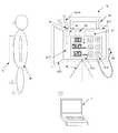
図5は、移動型放射線撮影装置1aの移動時の状態を模式的に示す図であり、図5(a)は側面図、図5(b)は平面図である。移動型放射線撮影装置1aの移動時には、使用者等は、支柱部12を後側に回転させ、アーム部13および放射線発生部14を後側に向ける。そして、アーム部13を縮めて降下させ、アーム固定部116に固定する。また、移動型放射線撮影装置1aには、FPD5を収納するFPD収納部118が設けられている。使用者等は、移動型放射線撮影装置1aの移動時には、このFPD収納部118にFPD5を収納しておく。図5においては、FPD5が台車部11のFPD収納部118に収納された状態を示している。また、図5においては、1つの外部アンテナ4a,4bがコネクタ部33に取り付けられ、2つの外部アンテナ4a,4bがアンテナ収納部117に収納されている状態を示している。なお、外部アンテナ4a,4bを着脱可能なコネクタ部31,32,33は、アーム部13がアーム固定部116に固定されている状態であっても外部アンテナ4a,4bを着脱できる位置に設けられる。 5A and 5B are diagrams schematically illustrating a state of the mobile
通常、使用者等は、GUI23を操作し、移動型放射線撮影装置1aを用いて放射線撮影を行う病室、病室内のベッドの位置、被検者情報、撮影部位情報等の情報を、病院内ネットワークから受信して表示させる。そして、使用者等はハンドル115を操作して、移動型放射線撮影装置1aを、放射線撮影を行う場所に移動させる。外部アンテナ4a,4bがアンテナ収納部117に収納されていると、外部アンテナ4a,4bによって移動型放射線撮影装置1aのスムーズな移動が妨げられることがない。また、外部アンテナ4a,4bは任意の位置に配置できるから、コネクタ部31,32,33に取り付けられた状態であっても、移動型放射線撮影装置1aのスムーズな移動を妨げない位置に配置できる。 In general, a user or the like operates a
使用者等は、移動型放射線撮影装置1aを撮影対象の被検者Mのベッドの近傍に移動させると、以前にこのベッドで撮影した時のアンテナ情報をGUI23に表示させる操作を行う。制御部21は、この操作に応じて、病院内ネットワーク9から無線LANを通じ、以前にこのベッドで撮影を行った際のアンテナ情報を読み出し、GUI23に表示する。前述のとおり、アンテナ情報には、無線LANの周波数、チャンネル、無線の電波強度情報、着脱可能な外部アンテナを取り付けたコネクタ部の位置情報、取り付けたアンテナの種類、アンテナの向きの情報が含まれる(図3と図4参照)。このため、使用者等は、GUI23に表示される情報を見ながら、以前にこのベッドで放射線撮影を行った時と同じ設定(使用する外部アンテナ4a,4b、外部アンテナ4a,4bの位置および向き、取り付けるコネクタ部31,32,33)を容易に再現できる。そして、記憶部211には、安定して無線通信を行える設定が記憶されているから、使用者等は、安定して無線通信を行える設定を容易に構築(再現)できる。また、上述のとおり、移動型放射線撮影装置1aの移動時は、着脱可能な外部アンテナ4a,4bを取り外しておくことができるために、移動型放射線撮影装置1aのスムーズな移動が妨げられることがない。 When the user or the like moves the mobile
ここで、制御部21の構成例について、簡単に説明する。制御部21は、CPUとRAMとROMとを有するコンピュータが適用される。ROMには、移動型放射線撮影装置1aを制御するためのコンピュータプログラムが格納されている。そして、CPUはROMからこのコンピュータプログラムを読み出し、RAMに展開して実行する。これにより、このコンピュータが制御部21として機能して移動型放射線撮影装置1aの各部を制御し、上述の処理および動作が実現する。ここで、RAMが記憶部211として機能する。なお、移動型放射線撮影装置1aがさらに記憶デバイスを有し、移動型放射線撮影装置1aを制御するためのコンピュータプログラムがこの記憶デバイスにコンピュータ読み取り可能に格納される構成であってもよい。この場合には、この記憶デバイスが記憶部211として機能する構成であってもよい。 Here, a configuration example of the
以上説明したとおり、外部アンテナ4a,4bが1箇所以上のコネクタ部31,32,33に着脱可能であると、電波状態が安定な状態で無線LAN通信を行うことができる。また、移動型放射線撮影装置1aの移動時や放射線撮影操作時には、外部アンテナ4a,4bがスムーズな移動や放射線撮影操作の妨げにならないようにできる。さらに、制御部21の記憶部211にアンテナ情報を記憶できるために、使用者等は、制御部21の記憶部211に記憶させたアンテナ情報をGUI23に表示させることによって、以前に放射線撮影を行った時の無線LANの通信状況を簡単に再現できる。特に、安定して無線通信を行える設定を記憶部211に記憶させておくことにより、安定して無線通信を行える設定を容易に構築(再現)できる。 As described above, when the
なお、本実施形態では、無線通信に使用するアンテナが全て着脱可能な外部アンテナ4a,4bである構成を例示して説明したが、本発明はこのような構成に限定されるものではない。例えば、複数のアンテナの一部に、着脱可能でないアンテナが含まれていてもよい。移動型放射線撮影装置1aは、着脱できないアンテナ119と、外部アンテナ4a,4bを着脱可能なコネクタ部31,32,33とが設けられる構成であってもよい。図6は、このような移動型放射線撮影装置1aの概略構成を示すブロック図である。図6に示す移動型放射線撮影装置1aの複数の箇所には、コネクタ部31,32,32が設けられる。また、移動型放射線撮影装置1aには、着脱できないアンテナ119が設けられる。使用者等は、必要に応じて、外部アンテナ4a,4bをこれらのコネクタ部31,32,33に着脱可能に取り付けできる。 In the present embodiment, the configuration in which the antennas used for wireless communication are all detachable
また、本発明は、前述の実施形態に限定されるものではない。無線通信として、規格IEEE802.11で規定されている無線LANを例示して説明したが、無線通信の方式や規格は限定されるものではない。アンテナを用いる無線通信であれば、その他の無線通信であってもよい。外部アンテナ4a,4bを着脱可能なコネクタ部31,32,33の数は3つに限定されるものではない。コネクタ部は1箇所以上に設けられる構成であればよく、2箇所以上に設けられる構成であることが好ましい。このため、1箇所または2箇所に設けられる構成であってもよく、4箇所以上に設けられる構成であってもよい。着脱可能な外部アンテナは、ダイポールアンテナ4aとダイバーシティアンテナ4bに限定されない。外部アンテナ4a,4bには、各種の無指向性アンテナや指向性アンテナが適用できる。また、外部アンテナ4a,4bは、ケーブル付きアンテナであってもよく、ケーブル無しアンテナであってもよい。例えば、無指向性アンテナでかつケーブル付きアンテナとして、小型のケーブル付きのモノポールアンテナなどが適用できる。無線LANのアクセスポイント22の数は1つに限定されるものではない。2つ以上のアクセスポイント22が設けられる構成であってもよい。移動型放射線撮影装置1aの移動場所(放射線撮影を行う場所)は、被検者Mがいる病室に限定されるものではなく、例えば手術室や救急病室でもよい。 Further, the present invention is not limited to the above-described embodiment. Although the wireless LAN defined by the standard IEEE 802.11 has been described as an example of the wireless communication, the wireless communication method and standard are not limited. Other wireless communication may be used as long as the wireless communication uses an antenna. The number of
画像データに付加されるアンテナ情報は、無線LANの周波数、チャンネル、無線の電波強度情報、外部アンテナ4a,4bが取り付けられたコネクタ部31,32,33の位置情報および種類、外部アンテナ4a,4bの向きに限定されるものではない。これらの複数の情報の一部であってもよい。アンテナ情報は、撮影した放射線画像の画像データに付加される構成に限定されるものではない。例えば、制御部21は、アンテナ情報を画像データとは別個独立したデータとして管理してもよい。アンテナ情報において、着脱可能な外部アンテナ4a,4bが取り付けられるコネクタ部31,32,33の位置情報および種類、外部アンテナ4a,4bの向きの設定は、GUI23を用いて設定する構成に限定されるものではない。例えば、取り付けられた外部アンテナ4a,4bの向きを測る目盛がコネクタ部31,32,33の近傍に設けられており、使用者等がそのメモリの値を読み取ってGUI23を用いて入力する構成であってもよい。 The antenna information added to the image data includes the wireless LAN frequency, channel, wireless radio wave intensity information, position information and types of the
(第2の実施形態)
次に、本発明の第2の実施形態について説明する。なお、第1の実施形態と共通の構成については同じ符号を付し、説明を省略する。第2の実施形態においては、無線LAN機能を有する移動型放射線発生用装置1bを示す。図7は、第2の実施形態に係る移動型放射線発生用装置1bの概略構成を示すブロック図である。なお、以下の説明では、放射線撮影は在宅で行うものとして説明する。(Second Embodiment)
Next, a second embodiment of the present invention will be described. In addition, the same code | symbol is attached | subjected about the same structure as 1st Embodiment, and description is abbreviate | omitted. In the second embodiment, a mobile
移動型放射線発生用装置1bは、放射線発生装置6を備えている。また、放射線撮影では、無線通信可能なFPD5と、ポータブル型コンピュータ(以下、「PC7」と記す)が用いられる。FPD5とPC7とは、不図示の無線通信機能とアンテナを内蔵しており、無線通信可能である。放射線発生装置6は、放射線源が設けられる放射線発生部61と、放射線発生部61を固定する三脚62と、放射線を照射する操作部材である放射線照射スイッチ63とを有する。放射線発生部61は、放射線源である不図示の放射線管球を収容するハウジング611と、放射線照射野を絞るコリメータ612とで構成される。図7においては、点線で囲まれる部分が放射線発生部61を示す。ハウジング611の表面には、表示部618と、操作部の例である設定部613と、コネクタ部34とが設けられる。表示部618は、撮影条件を表示する。設定部613は、撮影条件を設定するための操作部の例である。コネクタ部34には無線通信用の外部アンテナ4a,4bが着脱可能である。図7においては、無線通信用の外部アンテナとして、ダイポールアンテナ4a(図2(a)参照)がコネクタ部34に着脱可能に取り付けられている状態を示す。ハウジング611の内部には、放射線発生部61を制御する制御部21と、無線LANのアクセスポイント22と、無線通信用の内蔵アンテナ617とが設けられる。制御部21は、アクセスポイント22と有線LANで接続している。アクセスポイント22は、内蔵アンテナ617およびコネクタ部34と、同軸ケーブル等で有線接続されている。三脚62は、放射線発生部61を固定する固定部材の一例である。なお、放射線発生部61を固定できるのであれば、三脚62に限定されるものではない。要は、移動型放射線発生用装置1bは、放射線発生部61を固定できる固定部材を有する構成であればよい。 The mobile
放射線撮影を行う場合、使用者等は、三脚62やコリメータ612を操作して、移動型放射線発生用装置1bを、被検者Mの撮影部位に放射線を照射できる位置に配置する。また、使用者等は、被検者Mを透過した放射線が入射する位置にFPD5を配置する。この状態で使用者等は、アンテナ情報を制御部21の記憶部211に記憶させる。アンテナ情報には、無線LANの周波数と、チャンネルと、無線の電波強度情報と、着脱可能な外部アンテナ4a,4bを取り付けたコネクタ部34の位置情報と、取り付けた外部アンテナ4a,4bの種類と、外部アンテナ4a,4bの向きとが含まれる。なお、ここでは、移動型放射線発生用装置1bに1箇所のコネクタ部34が設けられる構成を示すが、コネクタ部34の数は限定されない。1箇所以上にコネクタ部34が設けられる構成であればよい。 When performing radiography, the user or the like operates the
ここで、アンテナ情報の記憶について説明する。使用者等は、PC7を操作し、各チャンネルの無線LANの電波強度測定するように指示する。制御部21は、各チャンネルの無線LANの電波強度測定をするように指示されると、アクセスポイント22を制御して、各チャンネルの無線LANの電波強度を測定し、その結果をPC7に返す。制御部21は、このような処理を定期的に繰り返し実行する。 Here, storage of antenna information will be described. The user or the like operates the
図8は、PC7が受け取った各チャンネルの無線LANの電波強度をテーブル化した一例を示す。PC7は、このようなテーブルをそのディスプレイに表示する。このテーブルの「チャンネル」と「ESSID」は、受信した電波強度が最も大きい所の無線LANのチャンネルとESSID名を示す。「dBm」はそのチャンネルの電波強度を示す。「PORT01」はFPD5と、移動型放射線発生用装置1bと、PC7とが無線LAN通信する時のESSID名を示す。「OTHER10」と「OTHER11」と「OTHER12」と「OTHER13」は、FPD5と、移動型放射線発生用装置1bと、PC7と関係がない無線装置のESSID名を示す。また、図8のテーブルをグラフ化すると、図3に示すようなグラフが得られる。 FIG. 8 shows an example in which the wireless LAN radio field intensity of each channel received by the
そして、使用者等により外部アンテナ4a,4bの向きが変更されると、テーブルの各チャンネルの無線LANの電波強度が変化する。「PORT01」の電波強度が十分に強い場合には、使用者等は、外部アンテナ4a,4bをコネクタ部34から取り外してもよい。この場合には、内蔵アンテナ617だけで無線LAN通信を行うことになる。一方、外部アンテナ4a,4bを取り付けた状態でPORT01の電波強度が弱ければ、図2に示すダイバーシティアンテナ4bのアンテナをコネクタ部34に取り付ければよい。そして、使用者等は、外部アンテナ4a,4bの種類と向きを、安定して無線通信を行えるように設定する。その後、使用者等は、図8に示した無線LANの周波数、チャンネル、無線の電波強度情報をPC7に記憶させる。また、既に図4で説明したように、使用者等は、外部アンテナ4a,4bを取り付けたコネクタ部34の位置情報、取り付けた外部アンテナ4a,4bの種類情報や向き情報を、PC7に記憶させる。 When the direction of the
次に被検者情報と撮影条件の設定について説明する。使用者等はPC7を介して、被検者情報や被検者が住む住宅、撮影部位、撮影条件等の設定操作を行う。使用者等により撮影条件の設定操作が行われると、PC7は、移動型放射線発生用装置1bと無線通信を行い、移動型放射線発生用装置1bの撮影条件を設定する。そして、制御部21は、設定された撮影条件を表示部618に表示する。使用者等は、移動型放射線発生用装置1bに設定された撮影条件を変更したい場合は、設定部613を操作する。そうすると、制御部21は、表示部618に表示されている撮影条件を操作に応じて変更する。さらに、移動型放射線発生用装置1bとPC7は無線LAN通信を行い、制御部21は、設定部613の操作によって変更された撮影条件を、PC7に通知する。 Next, setting of subject information and imaging conditions will be described. The user or the like performs setting operations such as the subject information, the house where the subject lives, the imaging region, the imaging condition, and the like via the
使用者等は、被検者情報と撮影条件の設定操作を終えると、放射線撮影の操作を行う。すなわち、使用者等は、被検者Mを見ながらタイミングの良い時に放射線照射スイッチ63を押す。そうすると、制御部21は、放射線発生部61を制御して、放射線源から放射線を照射する。FPD5は、被検者Mを透過した放射線を検知して放射線画像の画像データを生成し、生成した放射線画像の画像データを、無線LANを介してPC7に転送する。PC7はFPD5が撮影した放射線画像の画像データを受信すると、受信した画像データに対して画像処理等を施し、そのディスプレイに表示する。さらに、使用者等は、撮影した放射線画像に問題なければ、放射線画像の画像データに、被検者情報、被検者が住む住宅の住所、撮影部位、撮影条件等の情報と、アンテナ情報と付加する操作を行う。アンテナ情報には、無線LANの周波数、チャンネル、無線の電波強度情報、着脱可能な外部アンテナ4a,4bを取り付けたコネクタ部34の位置情報、取り付けた外部アンテナ4a,4bの種類、外部アンテナ4a,4bの向きが含まれる。そして、PC7は、これらの情報を付加した放射線画像の画像データを、内蔵する記憶媒体に記憶(保存)する。 When the user finishes the setting operation of the subject information and the imaging conditions, the user performs the radiation imaging operation. That is, the user or the like presses the
使用者等は、放射線撮影を行った後に病院等に戻ると、PC7を病院内ネットワーク9に接続し、撮影した放射線画像の画像データをPACS等に転送する。このため、使用者等は、同じ被検者を次に放射線撮影する場合には、以前撮影した放射線画像や放射線画像の画像データに含まれる付加情報を、病院内ネットワーク9からPC7にダウンロードして参照することができる。そのため、2回目以降は、簡単に着脱可能な外部アンテナ4a,4bの設定ができる。 When the user or the like returns to the hospital or the like after performing radiation imaging, the user connects the
なお、第2の実施形態においては、移動型放射線発生用装置1bが無線LANのアクセスポイント22を有する構成を示したが、このような構成に限定されるものではない。例えば、図9に示すように、移動型放射線発生用装置1bが、無線LANのアクセスポイント22を有さず、通信制御部25とアンテナ切換え部26を有する構成であってもよい。通信制御部25は、アクセスポイント22に代わり、内蔵アンテナ617または外部アンテナ4a、4bを介して行う無線通信を制御する。通信制御部25には、例えば、各種無線通信モジュールが適用できる。アンテナ切換え部26は、通信制御部25の制御にしたがって、内蔵アンテナ617と外部アンテナ4a,4bの切換えを行う。すなわち、アンテナ切換え部26は、外部アンテナ4a,4bが取り付けられている場合には、外部アンテナ4a,4bを選択して無線通信を行い、外部アンテナ4a,4bが取り付けられていない場合には、内蔵アンテナ617を選択する。また、アンテナ切換え部27は、PCからの制御にしたがい、外部アンテナ4a,4bと内蔵アンテナ617のうち、安定して無線通信を行うことができる方を選択してもよい。さらに、外部アンテナ4a,4bが取り付けられていても無線通信が十分に安定しない場合には、アンテナ切換え部26は、外部アンテナ4a,4bと内蔵アンテナ617の両方を無線通信に使用するように切換えてもよい。なお、無線LANのアクセスポイント22はPC7と有線接続している構成であってもよい。また、放射線撮影は在宅で行うとして説明してきたが、それに限定されるものではなく、救急出動先における応急処置等でも適用できる。 In the second embodiment, the mobile
以上、本発明の実施形態について説明したが、上記実施形態は、何れも本発明を実施するにあたっての具体化の例を示したものに過ぎず、これらによって本発明の技術的範囲が限定的に解釈されてはならないものである。すなわち、本発明はその技術思想、又はその主要な特徴から逸脱することなく、様々な形で実施することができる。 As mentioned above, although embodiment of this invention was described, all the said embodiment showed only the example of actualization in implementing this invention, and the technical scope of this invention is limited by these. It should not be interpreted. That is, the present invention can be implemented in various forms without departing from the technical idea or the main features thereof.
例えば、前記実施形態では、無線通信機能を有する移動型放射線撮影装置として、無線LANにより通信可能な移動型放射線撮影装置と移動型放射線発生用装置を示したが、本発明はこれらの放射線撮影装置に限定されない。また、無線通信方式も、無線LANに限定されるものではない。本発明は、無線通信機能を有する移動型放射線撮影装置であれば、種類を問わずに適用可能である。 For example, in the above-described embodiment, a mobile radiation imaging apparatus and a mobile radiation generation apparatus that can communicate with each other by a wireless LAN are shown as mobile radiation imaging apparatuses having a wireless communication function. It is not limited to. Also, the wireless communication method is not limited to the wireless LAN. The present invention can be applied to any type of mobile radiography apparatus having a wireless communication function.
本発明は、無線通信可能な移動型放射線撮装置に好適な技術である。特に、医療用の移動型放射線撮装置や、工業用の非破壊検査装置としての放射線撮影装置に好適である。そして、本発明によれば、外部アンテナが操作や移動の妨げにならず、かつ、安定した無線通信を行うことができる。さらに、2回目以降の放射線撮影時に前回の無線通信環境の再現が容易になる。 The present invention is a technique suitable for a mobile radiography apparatus capable of wireless communication. In particular, it is suitable for a mobile radiographic apparatus for medical use and a radiographic apparatus as an industrial nondestructive inspection apparatus. According to the present invention, the external antenna does not hinder operation or movement, and stable wireless communication can be performed. Furthermore, the previous wireless communication environment can be easily reproduced at the second and subsequent radiation imaging.
1a:移動型放射線撮影装置
1b:移動型放射線発生用装置
11:台車部
12:支柱部
13:アーム部
14:放射線発生部
31,32,33,34:外部アンテナを着脱可能なコネクタ部
4a,4b:着脱可能な外部アンテナ
5:FPD
7:ポータブル式コンピュータ
61:放射線発生部
617:内蔵アンテナ1a: Mobile
7: Portable computer 61: Radiation generator 617: Built-in antenna
Claims (10)
Translated fromJapanese無線通信用の外部アンテナを着脱できるコネクタ部を有することを特徴とする移動型放射線撮影装置。A mobile radiography apparatus having a wireless communication function,
A mobile radiation imaging apparatus comprising a connector portion to which an external antenna for wireless communication can be attached and detached.
前記コネクタ部は、前記放射線発生部と、前記アーム部と、前記支柱部と、前記台車部の少なくとも1箇所以上に設けられることを特徴とする請求項1に記載の移動型放射線撮影装置。The mobile radiography apparatus includes a radiation generation unit provided with a radiation source, an arm unit that supports the radiation generation unit, a support unit that supports the arm unit, and supports the support unit and is operated by a user. And a carriage unit provided with an operation unit to perform,
The mobile radiation imaging apparatus according to claim 1, wherein the connector part is provided in at least one place of the radiation generating part, the arm part, the column part, and the carriage part.
前記コネクタ部は、前記アンテナ切換え部と有線接続されており、前記アンテナ切換え部は前記通信制御部と有線接続されていることを特徴とする請求項1に記載の移動型放射線撮影装置。A communication control unit and an antenna switching unit;
The mobile radiation imaging apparatus according to claim 1, wherein the connector unit is wired to the antenna switching unit, and the antenna switching unit is wired to the communication control unit.
前記コネクタ部は、前記アクセスポイントと有線接続されていることを特徴とする請求項1から3のいずれか1項に記載の移動型放射線撮影装置。It further has an access point for wireless communication,
The mobile radiation imaging apparatus according to claim 1, wherein the connector unit is connected to the access point by wire.
無指向性アンテナまたは指向性アンテナであることを特徴とする請求項1から4のいずれか1項に記載の移動型放射線撮影装置。The external antenna detachable from the connector part is
The mobile radiation imaging apparatus according to claim 1, wherein the mobile radiation imaging apparatus is an omnidirectional antenna or a directional antenna.
ケーブル付きまたはケーブル無しアンテナであることを特徴とする請求項1から4のいずれか1項に記載の移動型放射線撮影装置。The external antenna detachable from the connector part is
The mobile radiographic apparatus according to any one of claims 1 to 4, wherein the mobile radiographic apparatus is a antenna with or without a cable.
設定した前記アンテナ情報を記憶する記憶手段と、
前記設定したアンテナ情報又は記憶した前記アンテナ情報を表示する表示手段と、
をさらに有することを特徴とする請求項1から6のいずれか1項に記載の移動型放射線撮影装置。Means for setting antenna information including at least one of position information of the connector to which the external antenna is attached, a type of the external antenna attached, and a direction of the attached external antenna;
Storage means for storing the set antenna information;
Display means for displaying the set antenna information or the stored antenna information;
The mobile radiographic apparatus according to claim 1, further comprising:
測定した電波強度を記憶する記憶手段と、
前記測定した電波強度または記憶した電波強度を表示する表示手段と、
をさらに有することを特徴とする請求項1から6のいずれか1項に記載の移動型放射線撮影装置。Means for measuring radio wave intensity of wireless communication in a state where the external antenna is attached to the connector part;
Storage means for storing the measured radio field intensity;
Display means for displaying the measured radio field intensity or the stored radio field intensity;
The mobile radiographic apparatus according to claim 1, further comprising:
放射線源が設けられる放射線発生部と、無線通信用の外部アンテナを着脱できるコネクタ部とを有し、
前記コネクタ部は、前記放射線発生部の少なくとも1箇所以上に設けられることを特徴とする移動型放射線発生用装置。A mobile radiation generating device having a wireless communication function,
A radiation generating unit provided with a radiation source, and a connector unit to which an external antenna for wireless communication can be attached and detached;
The mobile radiation generating apparatus, wherein the connector part is provided in at least one place of the radiation generating part.
Priority Applications (2)
| Application Number | Priority Date | Filing Date | Title |
|---|---|---|---|
| JP2014102586AJP2015217112A (en) | 2014-05-16 | 2014-05-16 | Mobile radiography apparatus and mobile radiation generation apparatus |
| US14/711,666US9561013B2 (en) | 2014-05-16 | 2015-05-13 | Movable radiographing apparatus and movable radiation generating apparatus having wireless communication |
Applications Claiming Priority (1)
| Application Number | Priority Date | Filing Date | Title |
|---|---|---|---|
| JP2014102586AJP2015217112A (en) | 2014-05-16 | 2014-05-16 | Mobile radiography apparatus and mobile radiation generation apparatus |
Publications (1)
| Publication Number | Publication Date |
|---|---|
| JP2015217112Atrue JP2015217112A (en) | 2015-12-07 |
Family
ID=54537547
Family Applications (1)
| Application Number | Title | Priority Date | Filing Date |
|---|---|---|---|
| JP2014102586AWithdrawnJP2015217112A (en) | 2014-05-16 | 2014-05-16 | Mobile radiography apparatus and mobile radiation generation apparatus |
Country Status (2)
| Country | Link |
|---|---|
| US (1) | US9561013B2 (en) |
| JP (1) | JP2015217112A (en) |
Cited By (1)
| Publication number | Priority date | Publication date | Assignee | Title |
|---|---|---|---|---|
| JP2022164096A (en)* | 2021-04-15 | 2022-10-27 | 富士フイルム株式会社 | Movable type radiographic apparatus |
Families Citing this family (393)
| Publication number | Priority date | Publication date | Assignee | Title |
|---|---|---|---|---|
| US20070084897A1 (en) | 2003-05-20 | 2007-04-19 | Shelton Frederick E Iv | Articulating surgical stapling instrument incorporating a two-piece e-beam firing mechanism |
| US9060770B2 (en) | 2003-05-20 | 2015-06-23 | Ethicon Endo-Surgery, Inc. | Robotically-driven surgical instrument with E-beam driver |
| US11890012B2 (en) | 2004-07-28 | 2024-02-06 | Cilag Gmbh International | Staple cartridge comprising cartridge body and attached support |
| US8215531B2 (en) | 2004-07-28 | 2012-07-10 | Ethicon Endo-Surgery, Inc. | Surgical stapling instrument having a medical substance dispenser |
| US9072535B2 (en) | 2011-05-27 | 2015-07-07 | Ethicon Endo-Surgery, Inc. | Surgical stapling instruments with rotatable staple deployment arrangements |
| US11998198B2 (en) | 2004-07-28 | 2024-06-04 | Cilag Gmbh International | Surgical stapling instrument incorporating a two-piece E-beam firing mechanism |
| US11484312B2 (en) | 2005-08-31 | 2022-11-01 | Cilag Gmbh International | Staple cartridge comprising a staple driver arrangement |
| US7934630B2 (en) | 2005-08-31 | 2011-05-03 | Ethicon Endo-Surgery, Inc. | Staple cartridges for forming staples having differing formed staple heights |
| US9237891B2 (en) | 2005-08-31 | 2016-01-19 | Ethicon Endo-Surgery, Inc. | Robotically-controlled surgical stapling devices that produce formed staples having different lengths |
| US7669746B2 (en) | 2005-08-31 | 2010-03-02 | Ethicon Endo-Surgery, Inc. | Staple cartridges for forming staples having differing formed staple heights |
| US11246590B2 (en) | 2005-08-31 | 2022-02-15 | Cilag Gmbh International | Staple cartridge including staple drivers having different unfired heights |
| US10159482B2 (en) | 2005-08-31 | 2018-12-25 | Ethicon Llc | Fastener cartridge assembly comprising a fixed anvil and different staple heights |
| US20070106317A1 (en) | 2005-11-09 | 2007-05-10 | Shelton Frederick E Iv | Hydraulically and electrically actuated articulation joints for surgical instruments |
| US7845537B2 (en) | 2006-01-31 | 2010-12-07 | Ethicon Endo-Surgery, Inc. | Surgical instrument having recording capabilities |
| US20120292367A1 (en) | 2006-01-31 | 2012-11-22 | Ethicon Endo-Surgery, Inc. | Robotically-controlled end effector |
| US8708213B2 (en) | 2006-01-31 | 2014-04-29 | Ethicon Endo-Surgery, Inc. | Surgical instrument having a feedback system |
| US20110024477A1 (en) | 2009-02-06 | 2011-02-03 | Hall Steven G | Driven Surgical Stapler Improvements |
| US8186555B2 (en) | 2006-01-31 | 2012-05-29 | Ethicon Endo-Surgery, Inc. | Motor-driven surgical cutting and fastening instrument with mechanical closure system |
| US8820603B2 (en) | 2006-01-31 | 2014-09-02 | Ethicon Endo-Surgery, Inc. | Accessing data stored in a memory of a surgical instrument |
| US11793518B2 (en) | 2006-01-31 | 2023-10-24 | Cilag Gmbh International | Powered surgical instruments with firing system lockout arrangements |
| US20110295295A1 (en) | 2006-01-31 | 2011-12-01 | Ethicon Endo-Surgery, Inc. | Robotically-controlled surgical instrument having recording capabilities |
| US7753904B2 (en) | 2006-01-31 | 2010-07-13 | Ethicon Endo-Surgery, Inc. | Endoscopic surgical instrument with a handle that can articulate with respect to the shaft |
| US11278279B2 (en) | 2006-01-31 | 2022-03-22 | Cilag Gmbh International | Surgical instrument assembly |
| US11224427B2 (en) | 2006-01-31 | 2022-01-18 | Cilag Gmbh International | Surgical stapling system including a console and retraction assembly |
| US8992422B2 (en) | 2006-03-23 | 2015-03-31 | Ethicon Endo-Surgery, Inc. | Robotically-controlled endoscopic accessory channel |
| US8322455B2 (en) | 2006-06-27 | 2012-12-04 | Ethicon Endo-Surgery, Inc. | Manually driven surgical cutting and fastening instrument |
| US10568652B2 (en) | 2006-09-29 | 2020-02-25 | Ethicon Llc | Surgical staples having attached drivers of different heights and stapling instruments for deploying the same |
| US11980366B2 (en) | 2006-10-03 | 2024-05-14 | Cilag Gmbh International | Surgical instrument |
| US8684253B2 (en) | 2007-01-10 | 2014-04-01 | Ethicon Endo-Surgery, Inc. | Surgical instrument with wireless communication between a control unit of a robotic system and remote sensor |
| US11291441B2 (en) | 2007-01-10 | 2022-04-05 | Cilag Gmbh International | Surgical instrument with wireless communication between control unit and remote sensor |
| US8632535B2 (en) | 2007-01-10 | 2014-01-21 | Ethicon Endo-Surgery, Inc. | Interlock and surgical instrument including same |
| US20080169333A1 (en) | 2007-01-11 | 2008-07-17 | Shelton Frederick E | Surgical stapler end effector with tapered distal end |
| US11039836B2 (en) | 2007-01-11 | 2021-06-22 | Cilag Gmbh International | Staple cartridge for use with a surgical stapling instrument |
| US7673782B2 (en) | 2007-03-15 | 2010-03-09 | Ethicon Endo-Surgery, Inc. | Surgical stapling instrument having a releasable buttress material |
| US8931682B2 (en) | 2007-06-04 | 2015-01-13 | Ethicon Endo-Surgery, Inc. | Robotically-controlled shaft based rotary drive systems for surgical instruments |
| US11564682B2 (en) | 2007-06-04 | 2023-01-31 | Cilag Gmbh International | Surgical stapler device |
| US7753245B2 (en) | 2007-06-22 | 2010-07-13 | Ethicon Endo-Surgery, Inc. | Surgical stapling instruments |
| US11849941B2 (en) | 2007-06-29 | 2023-12-26 | Cilag Gmbh International | Staple cartridge having staple cavities extending at a transverse angle relative to a longitudinal cartridge axis |
| US8573465B2 (en) | 2008-02-14 | 2013-11-05 | Ethicon Endo-Surgery, Inc. | Robotically-controlled surgical end effector system with rotary actuated closure systems |
| US8758391B2 (en) | 2008-02-14 | 2014-06-24 | Ethicon Endo-Surgery, Inc. | Interchangeable tools for surgical instruments |
| US7819298B2 (en) | 2008-02-14 | 2010-10-26 | Ethicon Endo-Surgery, Inc. | Surgical stapling apparatus with control features operable with one hand |
| US8636736B2 (en) | 2008-02-14 | 2014-01-28 | Ethicon Endo-Surgery, Inc. | Motorized surgical cutting and fastening instrument |
| US11986183B2 (en) | 2008-02-14 | 2024-05-21 | Cilag Gmbh International | Surgical cutting and fastening instrument comprising a plurality of sensors to measure an electrical parameter |
| US7866527B2 (en) | 2008-02-14 | 2011-01-11 | Ethicon Endo-Surgery, Inc. | Surgical stapling apparatus with interlockable firing system |
| JP5410110B2 (en) | 2008-02-14 | 2014-02-05 | エシコン・エンド−サージェリィ・インコーポレイテッド | Surgical cutting / fixing instrument with RF electrode |
| US9179912B2 (en) | 2008-02-14 | 2015-11-10 | Ethicon Endo-Surgery, Inc. | Robotically-controlled motorized surgical cutting and fastening instrument |
| US9585657B2 (en) | 2008-02-15 | 2017-03-07 | Ethicon Endo-Surgery, Llc | Actuator for releasing a layer of material from a surgical end effector |
| US8210411B2 (en) | 2008-09-23 | 2012-07-03 | Ethicon Endo-Surgery, Inc. | Motor-driven surgical cutting instrument |
| US11648005B2 (en) | 2008-09-23 | 2023-05-16 | Cilag Gmbh International | Robotically-controlled motorized surgical instrument with an end effector |
| US9005230B2 (en) | 2008-09-23 | 2015-04-14 | Ethicon Endo-Surgery, Inc. | Motorized surgical instrument |
| US9386983B2 (en) | 2008-09-23 | 2016-07-12 | Ethicon Endo-Surgery, Llc | Robotically-controlled motorized surgical instrument |
| US8608045B2 (en) | 2008-10-10 | 2013-12-17 | Ethicon Endo-Sugery, Inc. | Powered surgical cutting and stapling apparatus with manually retractable firing system |
| US8517239B2 (en) | 2009-02-05 | 2013-08-27 | Ethicon Endo-Surgery, Inc. | Surgical stapling instrument comprising a magnetic element driver |
| RU2525225C2 (en) | 2009-02-06 | 2014-08-10 | Этикон Эндо-Серджери, Инк. | Improvement of drive surgical suturing instrument |
| US8851354B2 (en) | 2009-12-24 | 2014-10-07 | Ethicon Endo-Surgery, Inc. | Surgical cutting instrument that analyzes tissue thickness |
| US8220688B2 (en) | 2009-12-24 | 2012-07-17 | Ethicon Endo-Surgery, Inc. | Motor-driven surgical cutting instrument with electric actuator directional control assembly |
| US8783543B2 (en) | 2010-07-30 | 2014-07-22 | Ethicon Endo-Surgery, Inc. | Tissue acquisition arrangements and methods for surgical stapling devices |
| US9016542B2 (en) | 2010-09-30 | 2015-04-28 | Ethicon Endo-Surgery, Inc. | Staple cartridge comprising compressible distortion resistant components |
| US11298125B2 (en) | 2010-09-30 | 2022-04-12 | Cilag Gmbh International | Tissue stapler having a thickness compensator |
| US9788834B2 (en) | 2010-09-30 | 2017-10-17 | Ethicon Llc | Layer comprising deployable attachment members |
| US9386988B2 (en) | 2010-09-30 | 2016-07-12 | Ethicon End-Surgery, LLC | Retainer assembly including a tissue thickness compensator |
| US12213666B2 (en) | 2010-09-30 | 2025-02-04 | Cilag Gmbh International | Tissue thickness compensator comprising layers |
| US11925354B2 (en) | 2010-09-30 | 2024-03-12 | Cilag Gmbh International | Staple cartridge comprising staples positioned within a compressible portion thereof |
| US11812965B2 (en) | 2010-09-30 | 2023-11-14 | Cilag Gmbh International | Layer of material for a surgical end effector |
| US9351730B2 (en) | 2011-04-29 | 2016-05-31 | Ethicon Endo-Surgery, Llc | Tissue thickness compensator comprising channels |
| US10945731B2 (en) | 2010-09-30 | 2021-03-16 | Ethicon Llc | Tissue thickness compensator comprising controlled release and expansion |
| US9629814B2 (en) | 2010-09-30 | 2017-04-25 | Ethicon Endo-Surgery, Llc | Tissue thickness compensator configured to redistribute compressive forces |
| US8695866B2 (en) | 2010-10-01 | 2014-04-15 | Ethicon Endo-Surgery, Inc. | Surgical instrument having a power control circuit |
| AU2012250197B2 (en) | 2011-04-29 | 2017-08-10 | Ethicon Endo-Surgery, Inc. | Staple cartridge comprising staples positioned within a compressible portion thereof |
| US11207064B2 (en) | 2011-05-27 | 2021-12-28 | Cilag Gmbh International | Automated end effector component reloading system for use with a robotic system |
| US9044230B2 (en) | 2012-02-13 | 2015-06-02 | Ethicon Endo-Surgery, Inc. | Surgical cutting and fastening instrument with apparatus for determining cartridge and firing motion status |
| JP6224070B2 (en) | 2012-03-28 | 2017-11-01 | エシコン・エンド−サージェリィ・インコーポレイテッドEthicon Endo−Surgery,Inc. | Retainer assembly including tissue thickness compensator |
| BR112014024098B1 (en) | 2012-03-28 | 2021-05-25 | Ethicon Endo-Surgery, Inc. | staple cartridge |
| MX358135B (en) | 2012-03-28 | 2018-08-06 | Ethicon Endo Surgery Inc | Tissue thickness compensator comprising a plurality of layers. |
| US9101358B2 (en) | 2012-06-15 | 2015-08-11 | Ethicon Endo-Surgery, Inc. | Articulatable surgical instrument comprising a firing drive |
| US9408606B2 (en) | 2012-06-28 | 2016-08-09 | Ethicon Endo-Surgery, Llc | Robotically powered surgical device with manually-actuatable reversing system |
| US20140001231A1 (en) | 2012-06-28 | 2014-01-02 | Ethicon Endo-Surgery, Inc. | Firing system lockout arrangements for surgical instruments |
| US9282974B2 (en) | 2012-06-28 | 2016-03-15 | Ethicon Endo-Surgery, Llc | Empty clip cartridge lockout |
| BR112014032776B1 (en) | 2012-06-28 | 2021-09-08 | Ethicon Endo-Surgery, Inc | SURGICAL INSTRUMENT SYSTEM AND SURGICAL KIT FOR USE WITH A SURGICAL INSTRUMENT SYSTEM |
| JP6290201B2 (en) | 2012-06-28 | 2018-03-07 | エシコン・エンド−サージェリィ・インコーポレイテッドEthicon Endo−Surgery,Inc. | Lockout for empty clip cartridge |
| US9289256B2 (en) | 2012-06-28 | 2016-03-22 | Ethicon Endo-Surgery, Llc | Surgical end effectors having angled tissue-contacting surfaces |
| US11278284B2 (en) | 2012-06-28 | 2022-03-22 | Cilag Gmbh International | Rotary drive arrangements for surgical instruments |
| US12383267B2 (en) | 2012-06-28 | 2025-08-12 | Cilag Gmbh International | Robotically powered surgical device with manually-actuatable reversing system |
| RU2672520C2 (en) | 2013-03-01 | 2018-11-15 | Этикон Эндо-Серджери, Инк. | Hingedly turnable surgical instruments with conducting ways for signal transfer |
| BR112015021082B1 (en) | 2013-03-01 | 2022-05-10 | Ethicon Endo-Surgery, Inc | surgical instrument |
| US9808244B2 (en) | 2013-03-14 | 2017-11-07 | Ethicon Llc | Sensor arrangements for absolute positioning system for surgical instruments |
| US9629629B2 (en) | 2013-03-14 | 2017-04-25 | Ethicon Endo-Surgey, LLC | Control systems for surgical instruments |
| US9826976B2 (en) | 2013-04-16 | 2017-11-28 | Ethicon Llc | Motor driven surgical instruments with lockable dual drive shafts |
| BR112015026109B1 (en) | 2013-04-16 | 2022-02-22 | Ethicon Endo-Surgery, Inc | surgical instrument |
| MX369362B (en) | 2013-08-23 | 2019-11-06 | Ethicon Endo Surgery Llc | Firing member retraction devices for powered surgical instruments. |
| US9775609B2 (en) | 2013-08-23 | 2017-10-03 | Ethicon Llc | Tamper proof circuit for surgical instrument battery pack |
| US9962161B2 (en) | 2014-02-12 | 2018-05-08 | Ethicon Llc | Deliverable surgical instrument |
| BR112016021943B1 (en) | 2014-03-26 | 2022-06-14 | Ethicon Endo-Surgery, Llc | SURGICAL INSTRUMENT FOR USE BY AN OPERATOR IN A SURGICAL PROCEDURE |
| US10013049B2 (en) | 2014-03-26 | 2018-07-03 | Ethicon Llc | Power management through sleep options of segmented circuit and wake up control |
| US12232723B2 (en) | 2014-03-26 | 2025-02-25 | Cilag Gmbh International | Systems and methods for controlling a segmented circuit |
| US20150272580A1 (en) | 2014-03-26 | 2015-10-01 | Ethicon Endo-Surgery, Inc. | Verification of number of battery exchanges/procedure count |
| US10004497B2 (en) | 2014-03-26 | 2018-06-26 | Ethicon Llc | Interface systems for use with surgical instruments |
| CN106456159B (en) | 2014-04-16 | 2019-03-08 | 伊西康内外科有限责任公司 | Fastener Cartridge Assembly and Nail Retainer Cover Arrangement |
| CN106456176B (en) | 2014-04-16 | 2019-06-28 | 伊西康内外科有限责任公司 | Fastener Cartridge Including Extensions With Different Configurations |
| US10470768B2 (en) | 2014-04-16 | 2019-11-12 | Ethicon Llc | Fastener cartridge including a layer attached thereto |
| US20150297225A1 (en) | 2014-04-16 | 2015-10-22 | Ethicon Endo-Surgery, Inc. | Fastener cartridges including extensions having different configurations |
| US10327764B2 (en) | 2014-09-26 | 2019-06-25 | Ethicon Llc | Method for creating a flexible staple line |
| BR112016023825B1 (en) | 2014-04-16 | 2022-08-02 | Ethicon Endo-Surgery, Llc | STAPLE CARTRIDGE FOR USE WITH A SURGICAL STAPLER AND STAPLE CARTRIDGE FOR USE WITH A SURGICAL INSTRUMENT |
| BR112017004361B1 (en) | 2014-09-05 | 2023-04-11 | Ethicon Llc | ELECTRONIC SYSTEM FOR A SURGICAL INSTRUMENT |
| US11311294B2 (en) | 2014-09-05 | 2022-04-26 | Cilag Gmbh International | Powered medical device including measurement of closure state of jaws |
| US10135242B2 (en) | 2014-09-05 | 2018-11-20 | Ethicon Llc | Smart cartridge wake up operation and data retention |
| US10105142B2 (en) | 2014-09-18 | 2018-10-23 | Ethicon Llc | Surgical stapler with plurality of cutting elements |
| CN107427300B (en) | 2014-09-26 | 2020-12-04 | 伊西康有限责任公司 | Surgical suture buttresses and auxiliary materials |
| US11523821B2 (en) | 2014-09-26 | 2022-12-13 | Cilag Gmbh International | Method for creating a flexible staple line |
| US10076325B2 (en) | 2014-10-13 | 2018-09-18 | Ethicon Llc | Surgical stapling apparatus comprising a tissue stop |
| US9924944B2 (en) | 2014-10-16 | 2018-03-27 | Ethicon Llc | Staple cartridge comprising an adjunct material |
| US11141153B2 (en) | 2014-10-29 | 2021-10-12 | Cilag Gmbh International | Staple cartridges comprising driver arrangements |
| US10517594B2 (en) | 2014-10-29 | 2019-12-31 | Ethicon Llc | Cartridge assemblies for surgical staplers |
| US9844376B2 (en) | 2014-11-06 | 2017-12-19 | Ethicon Llc | Staple cartridge comprising a releasable adjunct material |
| US10736636B2 (en) | 2014-12-10 | 2020-08-11 | Ethicon Llc | Articulatable surgical instrument system |
| MX389118B (en) | 2014-12-18 | 2025-03-20 | Ethicon Llc | SURGICAL INSTRUMENT WITH AN ANVIL THAT CAN BE SELECTIVELY MOVED ON A DISCRETE, NON-MOBILE AXIS RELATIVE TO A STAPLE CARTRIDGE. |
| US9943309B2 (en) | 2014-12-18 | 2018-04-17 | Ethicon Llc | Surgical instruments with articulatable end effectors and movable firing beam support arrangements |
| US9844375B2 (en) | 2014-12-18 | 2017-12-19 | Ethicon Llc | Drive arrangements for articulatable surgical instruments |
| US9987000B2 (en) | 2014-12-18 | 2018-06-05 | Ethicon Llc | Surgical instrument assembly comprising a flexible articulation system |
| US9844374B2 (en) | 2014-12-18 | 2017-12-19 | Ethicon Llc | Surgical instrument systems comprising an articulatable end effector and means for adjusting the firing stroke of a firing member |
| US10085748B2 (en) | 2014-12-18 | 2018-10-02 | Ethicon Llc | Locking arrangements for detachable shaft assemblies with articulatable surgical end effectors |
| US11154301B2 (en) | 2015-02-27 | 2021-10-26 | Cilag Gmbh International | Modular stapling assembly |
| US10548504B2 (en) | 2015-03-06 | 2020-02-04 | Ethicon Llc | Overlaid multi sensor radio frequency (RF) electrode system to measure tissue compression |
| JP2020121162A (en) | 2015-03-06 | 2020-08-13 | エシコン エルエルシーEthicon LLC | Time dependent evaluation of sensor data to determine stability element, creep element and viscoelastic element of measurement |
| US9901342B2 (en) | 2015-03-06 | 2018-02-27 | Ethicon Endo-Surgery, Llc | Signal and power communication system positioned on a rotatable shaft |
| US10245033B2 (en) | 2015-03-06 | 2019-04-02 | Ethicon Llc | Surgical instrument comprising a lockable battery housing |
| US9993248B2 (en) | 2015-03-06 | 2018-06-12 | Ethicon Endo-Surgery, Llc | Smart sensors with local signal processing |
| US10441279B2 (en) | 2015-03-06 | 2019-10-15 | Ethicon Llc | Multiple level thresholds to modify operation of powered surgical instruments |
| US10687806B2 (en) | 2015-03-06 | 2020-06-23 | Ethicon Llc | Adaptive tissue compression techniques to adjust closure rates for multiple tissue types |
| US10617412B2 (en) | 2015-03-06 | 2020-04-14 | Ethicon Llc | System for detecting the mis-insertion of a staple cartridge into a surgical stapler |
| US10433844B2 (en) | 2015-03-31 | 2019-10-08 | Ethicon Llc | Surgical instrument with selectively disengageable threaded drive systems |
| JP6145899B2 (en)* | 2015-07-16 | 2017-06-14 | 富士フイルム株式会社 | Radiation imaging equipment |
| JP6479987B2 (en)* | 2015-07-27 | 2019-03-06 | 富士フイルム株式会社 | Radiation irradiation equipment |
| JP6134992B2 (en)* | 2015-07-31 | 2017-05-31 | 富士フイルム株式会社 | Radiation irradiation equipment |
| US10835249B2 (en) | 2015-08-17 | 2020-11-17 | Ethicon Llc | Implantable layers for a surgical instrument |
| US10238386B2 (en) | 2015-09-23 | 2019-03-26 | Ethicon Llc | Surgical stapler having motor control based on an electrical parameter related to a motor current |
| US10105139B2 (en) | 2015-09-23 | 2018-10-23 | Ethicon Llc | Surgical stapler having downstream current-based motor control |
| US10299878B2 (en) | 2015-09-25 | 2019-05-28 | Ethicon Llc | Implantable adjunct systems for determining adjunct skew |
| US10478188B2 (en) | 2015-09-30 | 2019-11-19 | Ethicon Llc | Implantable layer comprising a constricted configuration |
| US11890015B2 (en) | 2015-09-30 | 2024-02-06 | Cilag Gmbh International | Compressible adjunct with crossing spacer fibers |
| US10980539B2 (en) | 2015-09-30 | 2021-04-20 | Ethicon Llc | Implantable adjunct comprising bonded layers |
| US10433846B2 (en) | 2015-09-30 | 2019-10-08 | Ethicon Llc | Compressible adjunct with crossing spacer fibers |
| US10265068B2 (en) | 2015-12-30 | 2019-04-23 | Ethicon Llc | Surgical instruments with separable motors and motor control circuits |
| US10292704B2 (en) | 2015-12-30 | 2019-05-21 | Ethicon Llc | Mechanisms for compensating for battery pack failure in powered surgical instruments |
| US10368865B2 (en) | 2015-12-30 | 2019-08-06 | Ethicon Llc | Mechanisms for compensating for drivetrain failure in powered surgical instruments |
| BR112018016098B1 (en) | 2016-02-09 | 2023-02-23 | Ethicon Llc | SURGICAL INSTRUMENT |
| US11213293B2 (en) | 2016-02-09 | 2022-01-04 | Cilag Gmbh International | Articulatable surgical instruments with single articulation link arrangements |
| US11224426B2 (en) | 2016-02-12 | 2022-01-18 | Cilag Gmbh International | Mechanisms for compensating for drivetrain failure in powered surgical instruments |
| US10448948B2 (en) | 2016-02-12 | 2019-10-22 | Ethicon Llc | Mechanisms for compensating for drivetrain failure in powered surgical instruments |
| US10617413B2 (en) | 2016-04-01 | 2020-04-14 | Ethicon Llc | Closure system arrangements for surgical cutting and stapling devices with separate and distinct firing shafts |
| US10828028B2 (en) | 2016-04-15 | 2020-11-10 | Ethicon Llc | Surgical instrument with multiple program responses during a firing motion |
| US10492783B2 (en) | 2016-04-15 | 2019-12-03 | Ethicon, Llc | Surgical instrument with improved stop/start control during a firing motion |
| US10357247B2 (en) | 2016-04-15 | 2019-07-23 | Ethicon Llc | Surgical instrument with multiple program responses during a firing motion |
| US10335145B2 (en) | 2016-04-15 | 2019-07-02 | Ethicon Llc | Modular surgical instrument with configurable operating mode |
| US10456137B2 (en) | 2016-04-15 | 2019-10-29 | Ethicon Llc | Staple formation detection mechanisms |
| US11179150B2 (en) | 2016-04-15 | 2021-11-23 | Cilag Gmbh International | Systems and methods for controlling a surgical stapling and cutting instrument |
| US10426467B2 (en) | 2016-04-15 | 2019-10-01 | Ethicon Llc | Surgical instrument with detection sensors |
| US11607239B2 (en) | 2016-04-15 | 2023-03-21 | Cilag Gmbh International | Systems and methods for controlling a surgical stapling and cutting instrument |
| US11317917B2 (en) | 2016-04-18 | 2022-05-03 | Cilag Gmbh International | Surgical stapling system comprising a lockable firing assembly |
| US10363037B2 (en) | 2016-04-18 | 2019-07-30 | Ethicon Llc | Surgical instrument system comprising a magnetic lockout |
| US20170296173A1 (en) | 2016-04-18 | 2017-10-19 | Ethicon Endo-Surgery, Llc | Method for operating a surgical instrument |
| US10500000B2 (en) | 2016-08-16 | 2019-12-10 | Ethicon Llc | Surgical tool with manual control of end effector jaws |
| US11090048B2 (en) | 2016-12-21 | 2021-08-17 | Cilag Gmbh International | Method for resetting a fuse of a surgical instrument shaft |
| US10758229B2 (en) | 2016-12-21 | 2020-09-01 | Ethicon Llc | Surgical instrument comprising improved jaw control |
| US10568625B2 (en) | 2016-12-21 | 2020-02-25 | Ethicon Llc | Staple cartridges and arrangements of staples and staple cavities therein |
| US20180168615A1 (en) | 2016-12-21 | 2018-06-21 | Ethicon Endo-Surgery, Llc | Method of deforming staples from two different types of staple cartridges with the same surgical stapling instrument |
| US10695055B2 (en) | 2016-12-21 | 2020-06-30 | Ethicon Llc | Firing assembly comprising a lockout |
| JP7010957B2 (en) | 2016-12-21 | 2022-01-26 | エシコン エルエルシー | Shaft assembly with lockout |
| JP6983893B2 (en) | 2016-12-21 | 2021-12-17 | エシコン エルエルシーEthicon LLC | Lockout configuration for surgical end effectors and replaceable tool assemblies |
| CN110087565A (en) | 2016-12-21 | 2019-08-02 | 爱惜康有限责任公司 | Surgical stapling system |
| US11419606B2 (en) | 2016-12-21 | 2022-08-23 | Cilag Gmbh International | Shaft assembly comprising a clutch configured to adapt the output of a rotary firing member to two different systems |
| US10813638B2 (en) | 2016-12-21 | 2020-10-27 | Ethicon Llc | Surgical end effectors with expandable tissue stop arrangements |
| US10980536B2 (en) | 2016-12-21 | 2021-04-20 | Ethicon Llc | No-cartridge and spent cartridge lockout arrangements for surgical staplers |
| JP2020501815A (en) | 2016-12-21 | 2020-01-23 | エシコン エルエルシーEthicon LLC | Surgical stapling system |
| US10973516B2 (en) | 2016-12-21 | 2021-04-13 | Ethicon Llc | Surgical end effectors and adaptable firing members therefor |
| US20180168625A1 (en) | 2016-12-21 | 2018-06-21 | Ethicon Endo-Surgery, Llc | Surgical stapling instruments with smart staple cartridges |
| US10898186B2 (en) | 2016-12-21 | 2021-01-26 | Ethicon Llc | Staple forming pocket arrangements comprising primary sidewalls and pocket sidewalls |
| US10542982B2 (en) | 2016-12-21 | 2020-01-28 | Ethicon Llc | Shaft assembly comprising first and second articulation lockouts |
| US10582928B2 (en) | 2016-12-21 | 2020-03-10 | Ethicon Llc | Articulation lock arrangements for locking an end effector in an articulated position in response to actuation of a jaw closure system |
| JP7010956B2 (en) | 2016-12-21 | 2022-01-26 | エシコン エルエルシー | How to staple tissue |
| US11134942B2 (en) | 2016-12-21 | 2021-10-05 | Cilag Gmbh International | Surgical stapling instruments and staple-forming anvils |
| US10485543B2 (en) | 2016-12-21 | 2019-11-26 | Ethicon Llc | Anvil having a knife slot width |
| MX2019007295A (en) | 2016-12-21 | 2019-10-15 | Ethicon Llc | Surgical instrument system comprising an end effector lockout and a firing assembly lockout. |
| US10779820B2 (en) | 2017-06-20 | 2020-09-22 | Ethicon Llc | Systems and methods for controlling motor speed according to user input for a surgical instrument |
| US10881396B2 (en) | 2017-06-20 | 2021-01-05 | Ethicon Llc | Surgical instrument with variable duration trigger arrangement |
| US11090046B2 (en) | 2017-06-20 | 2021-08-17 | Cilag Gmbh International | Systems and methods for controlling displacement member motion of a surgical stapling and cutting instrument |
| USD879808S1 (en) | 2017-06-20 | 2020-03-31 | Ethicon Llc | Display panel with graphical user interface |
| US10307170B2 (en) | 2017-06-20 | 2019-06-04 | Ethicon Llc | Method for closed loop control of motor velocity of a surgical stapling and cutting instrument |
| US11071554B2 (en) | 2017-06-20 | 2021-07-27 | Cilag Gmbh International | Closed loop feedback control of motor velocity of a surgical stapling and cutting instrument based on magnitude of velocity error measurements |
| USD879809S1 (en) | 2017-06-20 | 2020-03-31 | Ethicon Llc | Display panel with changeable graphical user interface |
| US10624633B2 (en) | 2017-06-20 | 2020-04-21 | Ethicon Llc | Systems and methods for controlling motor velocity of a surgical stapling and cutting instrument |
| US10881399B2 (en) | 2017-06-20 | 2021-01-05 | Ethicon Llc | Techniques for adaptive control of motor velocity of a surgical stapling and cutting instrument |
| USD890784S1 (en) | 2017-06-20 | 2020-07-21 | Ethicon Llc | Display panel with changeable graphical user interface |
| US10813639B2 (en) | 2017-06-20 | 2020-10-27 | Ethicon Llc | Closed loop feedback control of motor velocity of a surgical stapling and cutting instrument based on system conditions |
| US10980537B2 (en) | 2017-06-20 | 2021-04-20 | Ethicon Llc | Closed loop feedback control of motor velocity of a surgical stapling and cutting instrument based on measured time over a specified number of shaft rotations |
| US11653914B2 (en) | 2017-06-20 | 2023-05-23 | Cilag Gmbh International | Systems and methods for controlling motor velocity of a surgical stapling and cutting instrument according to articulation angle of end effector |
| US10646220B2 (en) | 2017-06-20 | 2020-05-12 | Ethicon Llc | Systems and methods for controlling displacement member velocity for a surgical instrument |
| US11382638B2 (en) | 2017-06-20 | 2022-07-12 | Cilag Gmbh International | Closed loop feedback control of motor velocity of a surgical stapling and cutting instrument based on measured time over a specified displacement distance |
| US11517325B2 (en) | 2017-06-20 | 2022-12-06 | Cilag Gmbh International | Closed loop feedback control of motor velocity of a surgical stapling and cutting instrument based on measured displacement distance traveled over a specified time interval |
| US10888321B2 (en) | 2017-06-20 | 2021-01-12 | Ethicon Llc | Systems and methods for controlling velocity of a displacement member of a surgical stapling and cutting instrument |
| US11090049B2 (en) | 2017-06-27 | 2021-08-17 | Cilag Gmbh International | Staple forming pocket arrangements |
| US11324503B2 (en) | 2017-06-27 | 2022-05-10 | Cilag Gmbh International | Surgical firing member arrangements |
| US10856869B2 (en) | 2017-06-27 | 2020-12-08 | Ethicon Llc | Surgical anvil arrangements |
| US10993716B2 (en) | 2017-06-27 | 2021-05-04 | Ethicon Llc | Surgical anvil arrangements |
| US10772629B2 (en) | 2017-06-27 | 2020-09-15 | Ethicon Llc | Surgical anvil arrangements |
| US11266405B2 (en) | 2017-06-27 | 2022-03-08 | Cilag Gmbh International | Surgical anvil manufacturing methods |
| US10758232B2 (en) | 2017-06-28 | 2020-09-01 | Ethicon Llc | Surgical instrument with positive jaw opening features |
| US11564686B2 (en) | 2017-06-28 | 2023-01-31 | Cilag Gmbh International | Surgical shaft assemblies with flexible interfaces |
| US11246592B2 (en) | 2017-06-28 | 2022-02-15 | Cilag Gmbh International | Surgical instrument comprising an articulation system lockable to a frame |
| USD906355S1 (en) | 2017-06-28 | 2020-12-29 | Ethicon Llc | Display screen or portion thereof with a graphical user interface for a surgical instrument |
| US10765427B2 (en) | 2017-06-28 | 2020-09-08 | Ethicon Llc | Method for articulating a surgical instrument |
| US10903685B2 (en) | 2017-06-28 | 2021-01-26 | Ethicon Llc | Surgical shaft assemblies with slip ring assemblies forming capacitive channels |
| US11259805B2 (en) | 2017-06-28 | 2022-03-01 | Cilag Gmbh International | Surgical instrument comprising firing member supports |
| EP3420947B1 (en) | 2017-06-28 | 2022-05-25 | Cilag GmbH International | Surgical instrument comprising selectively actuatable rotatable couplers |
| US10716614B2 (en) | 2017-06-28 | 2020-07-21 | Ethicon Llc | Surgical shaft assemblies with slip ring assemblies with increased contact pressure |
| US11484310B2 (en) | 2017-06-28 | 2022-11-01 | Cilag Gmbh International | Surgical instrument comprising a shaft including a closure tube profile |
| US11007022B2 (en) | 2017-06-29 | 2021-05-18 | Ethicon Llc | Closed loop velocity control techniques based on sensed tissue parameters for robotic surgical instrument |
| US10932772B2 (en) | 2017-06-29 | 2021-03-02 | Ethicon Llc | Methods for closed loop velocity control for robotic surgical instrument |
| US10898183B2 (en) | 2017-06-29 | 2021-01-26 | Ethicon Llc | Robotic surgical instrument with closed loop feedback techniques for advancement of closure member during firing |
| US11944300B2 (en) | 2017-08-03 | 2024-04-02 | Cilag Gmbh International | Method for operating a surgical system bailout |
| US11974742B2 (en) | 2017-08-03 | 2024-05-07 | Cilag Gmbh International | Surgical system comprising an articulation bailout |
| US11471155B2 (en) | 2017-08-03 | 2022-10-18 | Cilag Gmbh International | Surgical system bailout |
| US11304695B2 (en) | 2017-08-03 | 2022-04-19 | Cilag Gmbh International | Surgical system shaft interconnection |
| US11399829B2 (en) | 2017-09-29 | 2022-08-02 | Cilag Gmbh International | Systems and methods of initiating a power shutdown mode for a surgical instrument |
| USD907648S1 (en) | 2017-09-29 | 2021-01-12 | Ethicon Llc | Display screen or portion thereof with animated graphical user interface |
| USD907647S1 (en) | 2017-09-29 | 2021-01-12 | Ethicon Llc | Display screen or portion thereof with animated graphical user interface |
| USD917500S1 (en) | 2017-09-29 | 2021-04-27 | Ethicon Llc | Display screen or portion thereof with graphical user interface |
| US10743872B2 (en) | 2017-09-29 | 2020-08-18 | Ethicon Llc | System and methods for controlling a display of a surgical instrument |
| US10765429B2 (en) | 2017-09-29 | 2020-09-08 | Ethicon Llc | Systems and methods for providing alerts according to the operational state of a surgical instrument |
| US11134944B2 (en) | 2017-10-30 | 2021-10-05 | Cilag Gmbh International | Surgical stapler knife motion controls |
| US11090075B2 (en) | 2017-10-30 | 2021-08-17 | Cilag Gmbh International | Articulation features for surgical end effector |
| US10779903B2 (en) | 2017-10-31 | 2020-09-22 | Ethicon Llc | Positive shaft rotation lock activated by jaw closure |
| US10842490B2 (en) | 2017-10-31 | 2020-11-24 | Ethicon Llc | Cartridge body design with force reduction based on firing completion |
| US10743874B2 (en) | 2017-12-15 | 2020-08-18 | Ethicon Llc | Sealed adapters for use with electromechanical surgical instruments |
| US10779826B2 (en) | 2017-12-15 | 2020-09-22 | Ethicon Llc | Methods of operating surgical end effectors |
| US10779825B2 (en) | 2017-12-15 | 2020-09-22 | Ethicon Llc | Adapters with end effector position sensing and control arrangements for use in connection with electromechanical surgical instruments |
| US11006955B2 (en) | 2017-12-15 | 2021-05-18 | Ethicon Llc | End effectors with positive jaw opening features for use with adapters for electromechanical surgical instruments |
| US11071543B2 (en) | 2017-12-15 | 2021-07-27 | Cilag Gmbh International | Surgical end effectors with clamping assemblies configured to increase jaw aperture ranges |
| US10687813B2 (en) | 2017-12-15 | 2020-06-23 | Ethicon Llc | Adapters with firing stroke sensing arrangements for use in connection with electromechanical surgical instruments |
| US11197670B2 (en) | 2017-12-15 | 2021-12-14 | Cilag Gmbh International | Surgical end effectors with pivotal jaws configured to touch at their respective distal ends when fully closed |
| US10869666B2 (en) | 2017-12-15 | 2020-12-22 | Ethicon Llc | Adapters with control systems for controlling multiple motors of an electromechanical surgical instrument |
| US10966718B2 (en) | 2017-12-15 | 2021-04-06 | Ethicon Llc | Dynamic clamping assemblies with improved wear characteristics for use in connection with electromechanical surgical instruments |
| US10743875B2 (en) | 2017-12-15 | 2020-08-18 | Ethicon Llc | Surgical end effectors with jaw stiffener arrangements configured to permit monitoring of firing member |
| US10828033B2 (en) | 2017-12-15 | 2020-11-10 | Ethicon Llc | Handheld electromechanical surgical instruments with improved motor control arrangements for positioning components of an adapter coupled thereto |
| US11033267B2 (en) | 2017-12-15 | 2021-06-15 | Ethicon Llc | Systems and methods of controlling a clamping member firing rate of a surgical instrument |
| US10835330B2 (en) | 2017-12-19 | 2020-11-17 | Ethicon Llc | Method for determining the position of a rotatable jaw of a surgical instrument attachment assembly |
| US10716565B2 (en) | 2017-12-19 | 2020-07-21 | Ethicon Llc | Surgical instruments with dual articulation drivers |
| US11020112B2 (en) | 2017-12-19 | 2021-06-01 | Ethicon Llc | Surgical tools configured for interchangeable use with different controller interfaces |
| USD910847S1 (en) | 2017-12-19 | 2021-02-16 | Ethicon Llc | Surgical instrument assembly |
| US10729509B2 (en) | 2017-12-19 | 2020-08-04 | Ethicon Llc | Surgical instrument comprising closure and firing locking mechanism |
| US11045270B2 (en) | 2017-12-19 | 2021-06-29 | Cilag Gmbh International | Robotic attachment comprising exterior drive actuator |
| US11179151B2 (en) | 2017-12-21 | 2021-11-23 | Cilag Gmbh International | Surgical instrument comprising a display |
| US12336705B2 (en) | 2017-12-21 | 2025-06-24 | Cilag Gmbh International | Continuous use self-propelled stapling instrument |
| US11311290B2 (en) | 2017-12-21 | 2022-04-26 | Cilag Gmbh International | Surgical instrument comprising an end effector dampener |
| US11129680B2 (en) | 2017-12-21 | 2021-09-28 | Cilag Gmbh International | Surgical instrument comprising a projector |
| US11076853B2 (en) | 2017-12-21 | 2021-08-03 | Cilag Gmbh International | Systems and methods of displaying a knife position during transection for a surgical instrument |
| EP3598947B1 (en) | 2018-07-26 | 2020-08-26 | Siemens Healthcare GmbH | X-ray arrangement with multiple x-ray devices and method for operating an x-ray arrangement |
| US10856870B2 (en) | 2018-08-20 | 2020-12-08 | Ethicon Llc | Switching arrangements for motor powered articulatable surgical instruments |
| US11207065B2 (en) | 2018-08-20 | 2021-12-28 | Cilag Gmbh International | Method for fabricating surgical stapler anvils |
| US11253256B2 (en) | 2018-08-20 | 2022-02-22 | Cilag Gmbh International | Articulatable motor powered surgical instruments with dedicated articulation motor arrangements |
| USD914878S1 (en) | 2018-08-20 | 2021-03-30 | Ethicon Llc | Surgical instrument anvil |
| US11324501B2 (en) | 2018-08-20 | 2022-05-10 | Cilag Gmbh International | Surgical stapling devices with improved closure members |
| US11045192B2 (en) | 2018-08-20 | 2021-06-29 | Cilag Gmbh International | Fabricating techniques for surgical stapler anvils |
| US10842492B2 (en) | 2018-08-20 | 2020-11-24 | Ethicon Llc | Powered articulatable surgical instruments with clutching and locking arrangements for linking an articulation drive system to a firing drive system |
| US10912559B2 (en) | 2018-08-20 | 2021-02-09 | Ethicon Llc | Reinforced deformable anvil tip for surgical stapler anvil |
| US11039834B2 (en) | 2018-08-20 | 2021-06-22 | Cilag Gmbh International | Surgical stapler anvils with staple directing protrusions and tissue stability features |
| US10779821B2 (en) | 2018-08-20 | 2020-09-22 | Ethicon Llc | Surgical stapler anvils with tissue stop features configured to avoid tissue pinch |
| US11291440B2 (en) | 2018-08-20 | 2022-04-05 | Cilag Gmbh International | Method for operating a powered articulatable surgical instrument |
| US20200054321A1 (en) | 2018-08-20 | 2020-02-20 | Ethicon Llc | Surgical instruments with progressive jaw closure arrangements |
| US11083458B2 (en) | 2018-08-20 | 2021-08-10 | Cilag Gmbh International | Powered surgical instruments with clutching arrangements to convert linear drive motions to rotary drive motions |
| US11696761B2 (en) | 2019-03-25 | 2023-07-11 | Cilag Gmbh International | Firing drive arrangements for surgical systems |
| US11147553B2 (en) | 2019-03-25 | 2021-10-19 | Cilag Gmbh International | Firing drive arrangements for surgical systems |
| US11172929B2 (en) | 2019-03-25 | 2021-11-16 | Cilag Gmbh International | Articulation drive arrangements for surgical systems |
| US11147551B2 (en) | 2019-03-25 | 2021-10-19 | Cilag Gmbh International | Firing drive arrangements for surgical systems |
| US11903581B2 (en) | 2019-04-30 | 2024-02-20 | Cilag Gmbh International | Methods for stapling tissue using a surgical instrument |
| US11253254B2 (en) | 2019-04-30 | 2022-02-22 | Cilag Gmbh International | Shaft rotation actuator on a surgical instrument |
| US11471157B2 (en) | 2019-04-30 | 2022-10-18 | Cilag Gmbh International | Articulation control mapping for a surgical instrument |
| US11452528B2 (en) | 2019-04-30 | 2022-09-27 | Cilag Gmbh International | Articulation actuators for a surgical instrument |
| US11432816B2 (en) | 2019-04-30 | 2022-09-06 | Cilag Gmbh International | Articulation pin for a surgical instrument |
| US11426251B2 (en) | 2019-04-30 | 2022-08-30 | Cilag Gmbh International | Articulation directional lights on a surgical instrument |
| US11648009B2 (en) | 2019-04-30 | 2023-05-16 | Cilag Gmbh International | Rotatable jaw tip for a surgical instrument |
| US11553971B2 (en) | 2019-06-28 | 2023-01-17 | Cilag Gmbh International | Surgical RFID assemblies for display and communication |
| US11523822B2 (en) | 2019-06-28 | 2022-12-13 | Cilag Gmbh International | Battery pack including a circuit interrupter |
| US11478241B2 (en) | 2019-06-28 | 2022-10-25 | Cilag Gmbh International | Staple cartridge including projections |
| US11224497B2 (en) | 2019-06-28 | 2022-01-18 | Cilag Gmbh International | Surgical systems with multiple RFID tags |
| US11464601B2 (en) | 2019-06-28 | 2022-10-11 | Cilag Gmbh International | Surgical instrument comprising an RFID system for tracking a movable component |
| US11627959B2 (en) | 2019-06-28 | 2023-04-18 | Cilag Gmbh International | Surgical instruments including manual and powered system lockouts |
| US11298132B2 (en) | 2019-06-28 | 2022-04-12 | Cilag GmbH Inlernational | Staple cartridge including a honeycomb extension |
| US11660163B2 (en) | 2019-06-28 | 2023-05-30 | Cilag Gmbh International | Surgical system with RFID tags for updating motor assembly parameters |
| US11399837B2 (en) | 2019-06-28 | 2022-08-02 | Cilag Gmbh International | Mechanisms for motor control adjustments of a motorized surgical instrument |
| US11771419B2 (en) | 2019-06-28 | 2023-10-03 | Cilag Gmbh International | Packaging for a replaceable component of a surgical stapling system |
| US11219455B2 (en) | 2019-06-28 | 2022-01-11 | Cilag Gmbh International | Surgical instrument including a lockout key |
| US11497492B2 (en) | 2019-06-28 | 2022-11-15 | Cilag Gmbh International | Surgical instrument including an articulation lock |
| US11684434B2 (en) | 2019-06-28 | 2023-06-27 | Cilag Gmbh International | Surgical RFID assemblies for instrument operational setting control |
| US11246678B2 (en) | 2019-06-28 | 2022-02-15 | Cilag Gmbh International | Surgical stapling system having a frangible RFID tag |
| US12004740B2 (en) | 2019-06-28 | 2024-06-11 | Cilag Gmbh International | Surgical stapling system having an information decryption protocol |
| US11638587B2 (en) | 2019-06-28 | 2023-05-02 | Cilag Gmbh International | RFID identification systems for surgical instruments |
| US11259803B2 (en) | 2019-06-28 | 2022-03-01 | Cilag Gmbh International | Surgical stapling system having an information encryption protocol |
| US11426167B2 (en) | 2019-06-28 | 2022-08-30 | Cilag Gmbh International | Mechanisms for proper anvil attachment surgical stapling head assembly |
| US11298127B2 (en) | 2019-06-28 | 2022-04-12 | Cilag GmbH Interational | Surgical stapling system having a lockout mechanism for an incompatible cartridge |
| US11241235B2 (en) | 2019-06-28 | 2022-02-08 | Cilag Gmbh International | Method of using multiple RFID chips with a surgical assembly |
| US11376098B2 (en) | 2019-06-28 | 2022-07-05 | Cilag Gmbh International | Surgical instrument system comprising an RFID system |
| US11051807B2 (en) | 2019-06-28 | 2021-07-06 | Cilag Gmbh International | Packaging assembly including a particulate trap |
| US11291451B2 (en) | 2019-06-28 | 2022-04-05 | Cilag Gmbh International | Surgical instrument with battery compatibility verification functionality |
| US11607219B2 (en) | 2019-12-19 | 2023-03-21 | Cilag Gmbh International | Staple cartridge comprising a detachable tissue cutting knife |
| US11559304B2 (en) | 2019-12-19 | 2023-01-24 | Cilag Gmbh International | Surgical instrument comprising a rapid closure mechanism |
| US11291447B2 (en) | 2019-12-19 | 2022-04-05 | Cilag Gmbh International | Stapling instrument comprising independent jaw closing and staple firing systems |
| US11576672B2 (en) | 2019-12-19 | 2023-02-14 | Cilag Gmbh International | Surgical instrument comprising a closure system including a closure member and an opening member driven by a drive screw |
| US11446029B2 (en) | 2019-12-19 | 2022-09-20 | Cilag Gmbh International | Staple cartridge comprising projections extending from a curved deck surface |
| US11504122B2 (en) | 2019-12-19 | 2022-11-22 | Cilag Gmbh International | Surgical instrument comprising a nested firing member |
| US11529139B2 (en) | 2019-12-19 | 2022-12-20 | Cilag Gmbh International | Motor driven surgical instrument |
| US11234698B2 (en) | 2019-12-19 | 2022-02-01 | Cilag Gmbh International | Stapling system comprising a clamp lockout and a firing lockout |
| US11931033B2 (en) | 2019-12-19 | 2024-03-19 | Cilag Gmbh International | Staple cartridge comprising a latch lockout |
| US11911032B2 (en) | 2019-12-19 | 2024-02-27 | Cilag Gmbh International | Staple cartridge comprising a seating cam |
| US12035913B2 (en) | 2019-12-19 | 2024-07-16 | Cilag Gmbh International | Staple cartridge comprising a deployable knife |
| US11529137B2 (en) | 2019-12-19 | 2022-12-20 | Cilag Gmbh International | Staple cartridge comprising driver retention members |
| US11844520B2 (en) | 2019-12-19 | 2023-12-19 | Cilag Gmbh International | Staple cartridge comprising driver retention members |
| US11304696B2 (en) | 2019-12-19 | 2022-04-19 | Cilag Gmbh International | Surgical instrument comprising a powered articulation system |
| US11701111B2 (en) | 2019-12-19 | 2023-07-18 | Cilag Gmbh International | Method for operating a surgical stapling instrument |
| US11464512B2 (en) | 2019-12-19 | 2022-10-11 | Cilag Gmbh International | Staple cartridge comprising a curved deck surface |
| USD974560S1 (en) | 2020-06-02 | 2023-01-03 | Cilag Gmbh International | Staple cartridge |
| USD967421S1 (en) | 2020-06-02 | 2022-10-18 | Cilag Gmbh International | Staple cartridge |
| USD975850S1 (en) | 2020-06-02 | 2023-01-17 | Cilag Gmbh International | Staple cartridge |
| USD976401S1 (en) | 2020-06-02 | 2023-01-24 | Cilag Gmbh International | Staple cartridge |
| USD975851S1 (en) | 2020-06-02 | 2023-01-17 | Cilag Gmbh International | Staple cartridge |
| USD966512S1 (en) | 2020-06-02 | 2022-10-11 | Cilag Gmbh International | Staple cartridge |
| USD975278S1 (en) | 2020-06-02 | 2023-01-10 | Cilag Gmbh International | Staple cartridge |
| US11871925B2 (en) | 2020-07-28 | 2024-01-16 | Cilag Gmbh International | Surgical instruments with dual spherical articulation joint arrangements |
| US11717289B2 (en) | 2020-10-29 | 2023-08-08 | Cilag Gmbh International | Surgical instrument comprising an indicator which indicates that an articulation drive is actuatable |
| US11844518B2 (en) | 2020-10-29 | 2023-12-19 | Cilag Gmbh International | Method for operating a surgical instrument |
| US11517390B2 (en) | 2020-10-29 | 2022-12-06 | Cilag Gmbh International | Surgical instrument comprising a limited travel switch |
| US11534259B2 (en) | 2020-10-29 | 2022-12-27 | Cilag Gmbh International | Surgical instrument comprising an articulation indicator |
| USD1013170S1 (en) | 2020-10-29 | 2024-01-30 | Cilag Gmbh International | Surgical instrument assembly |
| US11779330B2 (en) | 2020-10-29 | 2023-10-10 | Cilag Gmbh International | Surgical instrument comprising a jaw alignment system |
| US12053175B2 (en) | 2020-10-29 | 2024-08-06 | Cilag Gmbh International | Surgical instrument comprising a stowed closure actuator stop |
| US11896217B2 (en) | 2020-10-29 | 2024-02-13 | Cilag Gmbh International | Surgical instrument comprising an articulation lock |
| US11931025B2 (en) | 2020-10-29 | 2024-03-19 | Cilag Gmbh International | Surgical instrument comprising a releasable closure drive lock |
| USD980425S1 (en) | 2020-10-29 | 2023-03-07 | Cilag Gmbh International | Surgical instrument assembly |
| US11452526B2 (en) | 2020-10-29 | 2022-09-27 | Cilag Gmbh International | Surgical instrument comprising a staged voltage regulation start-up system |
| US11617577B2 (en) | 2020-10-29 | 2023-04-04 | Cilag Gmbh International | Surgical instrument comprising a sensor configured to sense whether an articulation drive of the surgical instrument is actuatable |
| US11944296B2 (en) | 2020-12-02 | 2024-04-02 | Cilag Gmbh International | Powered surgical instruments with external connectors |
| US11744581B2 (en) | 2020-12-02 | 2023-09-05 | Cilag Gmbh International | Powered surgical instruments with multi-phase tissue treatment |
| US11653920B2 (en) | 2020-12-02 | 2023-05-23 | Cilag Gmbh International | Powered surgical instruments with communication interfaces through sterile barrier |
| US11627960B2 (en) | 2020-12-02 | 2023-04-18 | Cilag Gmbh International | Powered surgical instruments with smart reload with separately attachable exteriorly mounted wiring connections |
| US11678882B2 (en) | 2020-12-02 | 2023-06-20 | Cilag Gmbh International | Surgical instruments with interactive features to remedy incidental sled movements |
| US11653915B2 (en) | 2020-12-02 | 2023-05-23 | Cilag Gmbh International | Surgical instruments with sled location detection and adjustment features |
| US11849943B2 (en) | 2020-12-02 | 2023-12-26 | Cilag Gmbh International | Surgical instrument with cartridge release mechanisms |
| US11737751B2 (en) | 2020-12-02 | 2023-08-29 | Cilag Gmbh International | Devices and methods of managing energy dissipated within sterile barriers of surgical instrument housings |
| US11890010B2 (en) | 2020-12-02 | 2024-02-06 | Cllag GmbH International | Dual-sided reinforced reload for surgical instruments |
| US11749877B2 (en) | 2021-02-26 | 2023-09-05 | Cilag Gmbh International | Stapling instrument comprising a signal antenna |
| US11812964B2 (en) | 2021-02-26 | 2023-11-14 | Cilag Gmbh International | Staple cartridge comprising a power management circuit |
| US11980362B2 (en) | 2021-02-26 | 2024-05-14 | Cilag Gmbh International | Surgical instrument system comprising a power transfer coil |
| US11925349B2 (en) | 2021-02-26 | 2024-03-12 | Cilag Gmbh International | Adjustment to transfer parameters to improve available power |
| US11950777B2 (en) | 2021-02-26 | 2024-04-09 | Cilag Gmbh International | Staple cartridge comprising an information access control system |
| US11701113B2 (en) | 2021-02-26 | 2023-07-18 | Cilag Gmbh International | Stapling instrument comprising a separate power antenna and a data transfer antenna |
| US11723657B2 (en) | 2021-02-26 | 2023-08-15 | Cilag Gmbh International | Adjustable communication based on available bandwidth and power capacity |
| US12108951B2 (en) | 2021-02-26 | 2024-10-08 | Cilag Gmbh International | Staple cartridge comprising a sensing array and a temperature control system |
| US11950779B2 (en) | 2021-02-26 | 2024-04-09 | Cilag Gmbh International | Method of powering and communicating with a staple cartridge |
| US11793514B2 (en) | 2021-02-26 | 2023-10-24 | Cilag Gmbh International | Staple cartridge comprising sensor array which may be embedded in cartridge body |
| US11696757B2 (en) | 2021-02-26 | 2023-07-11 | Cilag Gmbh International | Monitoring of internal systems to detect and track cartridge motion status |
| US11744583B2 (en) | 2021-02-26 | 2023-09-05 | Cilag Gmbh International | Distal communication array to tune frequency of RF systems |
| US11730473B2 (en) | 2021-02-26 | 2023-08-22 | Cilag Gmbh International | Monitoring of manufacturing life-cycle |
| US11751869B2 (en) | 2021-02-26 | 2023-09-12 | Cilag Gmbh International | Monitoring of multiple sensors over time to detect moving characteristics of tissue |
| US12324580B2 (en) | 2021-02-26 | 2025-06-10 | Cilag Gmbh International | Method of powering and communicating with a staple cartridge |
| JP7631027B2 (en)* | 2021-03-01 | 2025-02-18 | キヤノン株式会社 | Radiation imaging apparatus, data processing apparatus, radiation imaging system, and method for controlling radiation imaging system |
| US11806011B2 (en) | 2021-03-22 | 2023-11-07 | Cilag Gmbh International | Stapling instrument comprising tissue compression systems |
| US11826042B2 (en) | 2021-03-22 | 2023-11-28 | Cilag Gmbh International | Surgical instrument comprising a firing drive including a selectable leverage mechanism |
| US11723658B2 (en) | 2021-03-22 | 2023-08-15 | Cilag Gmbh International | Staple cartridge comprising a firing lockout |
| US11826012B2 (en) | 2021-03-22 | 2023-11-28 | Cilag Gmbh International | Stapling instrument comprising a pulsed motor-driven firing rack |
| US11717291B2 (en) | 2021-03-22 | 2023-08-08 | Cilag Gmbh International | Staple cartridge comprising staples configured to apply different tissue compression |
| US11759202B2 (en) | 2021-03-22 | 2023-09-19 | Cilag Gmbh International | Staple cartridge comprising an implantable layer |
| US11737749B2 (en) | 2021-03-22 | 2023-08-29 | Cilag Gmbh International | Surgical stapling instrument comprising a retraction system |
| US11857183B2 (en) | 2021-03-24 | 2024-01-02 | Cilag Gmbh International | Stapling assembly components having metal substrates and plastic bodies |
| US11849944B2 (en) | 2021-03-24 | 2023-12-26 | Cilag Gmbh International | Drivers for fastener cartridge assemblies having rotary drive screws |
| US11793516B2 (en) | 2021-03-24 | 2023-10-24 | Cilag Gmbh International | Surgical staple cartridge comprising longitudinal support beam |
| US11832816B2 (en) | 2021-03-24 | 2023-12-05 | Cilag Gmbh International | Surgical stapling assembly comprising nonplanar staples and planar staples |
| US11903582B2 (en) | 2021-03-24 | 2024-02-20 | Cilag Gmbh International | Leveraging surfaces for cartridge installation |
| US11786243B2 (en) | 2021-03-24 | 2023-10-17 | Cilag Gmbh International | Firing members having flexible portions for adapting to a load during a surgical firing stroke |
| US11896218B2 (en) | 2021-03-24 | 2024-02-13 | Cilag Gmbh International | Method of using a powered stapling device |
| US11944336B2 (en) | 2021-03-24 | 2024-04-02 | Cilag Gmbh International | Joint arrangements for multi-planar alignment and support of operational drive shafts in articulatable surgical instruments |
| US11896219B2 (en) | 2021-03-24 | 2024-02-13 | Cilag Gmbh International | Mating features between drivers and underside of a cartridge deck |
| US11744603B2 (en) | 2021-03-24 | 2023-09-05 | Cilag Gmbh International | Multi-axis pivot joints for surgical instruments and methods for manufacturing same |
| US11849945B2 (en) | 2021-03-24 | 2023-12-26 | Cilag Gmbh International | Rotary-driven surgical stapling assembly comprising eccentrically driven firing member |
| US11786239B2 (en) | 2021-03-24 | 2023-10-17 | Cilag Gmbh International | Surgical instrument articulation joint arrangements comprising multiple moving linkage features |
| US12102323B2 (en) | 2021-03-24 | 2024-10-01 | Cilag Gmbh International | Rotary-driven surgical stapling assembly comprising a floatable component |
| US11826047B2 (en) | 2021-05-28 | 2023-11-28 | Cilag Gmbh International | Stapling instrument comprising jaw mounts |
| US11980363B2 (en) | 2021-10-18 | 2024-05-14 | Cilag Gmbh International | Row-to-row staple array variations |
| US12239317B2 (en) | 2021-10-18 | 2025-03-04 | Cilag Gmbh International | Anvil comprising an arrangement of forming pockets proximal to tissue stop |
| US11957337B2 (en) | 2021-10-18 | 2024-04-16 | Cilag Gmbh International | Surgical stapling assembly with offset ramped drive surfaces |
| US11877745B2 (en) | 2021-10-18 | 2024-01-23 | Cilag Gmbh International | Surgical stapling assembly having longitudinally-repeating staple leg clusters |
| US12432790B2 (en) | 2021-10-28 | 2025-09-30 | Cilag Gmbh International | Method and device for transmitting UART communications over a security short range wireless communication |
| US11937816B2 (en) | 2021-10-28 | 2024-03-26 | Cilag Gmbh International | Electrical lead arrangements for surgical instruments |
| US12089841B2 (en) | 2021-10-28 | 2024-09-17 | Cilag CmbH International | Staple cartridge identification systems |
Family Cites Families (7)
| Publication number | Priority date | Publication date | Assignee | Title |
|---|---|---|---|---|
| JP2001224579A (en) | 2000-02-15 | 2001-08-21 | Hitachi Medical Corp | X-ray equipment |
| JP5063227B2 (en)* | 2007-07-09 | 2012-10-31 | キヤノン株式会社 | Imaging control device, control method therefor, and program |
| US8194823B2 (en)* | 2007-07-24 | 2012-06-05 | Fujifilm Corporation | X-ray image capturing and interpretation system with cassette and mobile X-ray image capturing apparatus |
| JP2011056170A (en) | 2009-09-14 | 2011-03-24 | Fujifilm Corp | Radiographic system and method of controlling the same |
| US8976931B2 (en)* | 2010-04-13 | 2015-03-10 | Carestream Health, Inc. | Mobile radiography imaging apparatus using prior related images before current image exposure and methods for same |
| JP5152353B2 (en) | 2011-02-03 | 2013-02-27 | 株式会社島津製作所 | Mobile X-ray imaging device |
| US20130010928A1 (en) | 2011-07-08 | 2013-01-10 | General Electric Company | System for wireless communication with multiple antennas in a medical imaging system |
- 2014
- 2014-05-16JPJP2014102586Apatent/JP2015217112A/ennot_activeWithdrawn
- 2015
- 2015-05-13USUS14/711,666patent/US9561013B2/ennot_activeExpired - Fee Related
Cited By (2)
| Publication number | Priority date | Publication date | Assignee | Title |
|---|---|---|---|---|
| JP2022164096A (en)* | 2021-04-15 | 2022-10-27 | 富士フイルム株式会社 | Movable type radiographic apparatus |
| JP7674135B2 (en) | 2021-04-15 | 2025-05-09 | 富士フイルム株式会社 | Mobile radiography equipment |
Also Published As
| Publication number | Publication date |
|---|---|
| US9561013B2 (en) | 2017-02-07 |
| US20150327833A1 (en) | 2015-11-19 |
Similar Documents
| Publication | Publication Date | Title |
|---|---|---|
| JP2015217112A (en) | Mobile radiography apparatus and mobile radiation generation apparatus | |
| CN102258376B (en) | Handheld x-ray system interface with tracking feature | |
| US9295438B2 (en) | Movable X-ray generation apparatus | |
| CN102258374B (en) | Handheld x-ray system image viewing system and method | |
| EP2974660B1 (en) | X-ray detector | |
| JP2011098170A (en) | Radiation imaging system and relay station selection method | |
| JP2014188082A (en) | Portable console terminal | |
| JP2016189064A5 (en) | Electronic device, electronic device control method, program, and wireless communication system | |
| CN102860873A (en) | System for wireless communication with multiple antennas in a medical imaging system | |
| WO2012070084A1 (en) | Mobile x-ray imaging apparatus | |
| US8666023B2 (en) | Radiation imaging apparatus | |
| US8649482B2 (en) | X-ray imaging apparatus | |
| JP4631591B2 (en) | Imaging information management system for mobile X-ray imaging apparatus | |
| JP4867670B2 (en) | Round-trip X-ray equipment | |
| US10853450B2 (en) | Radiographing apparatus, radiographing system, radiographing method, and program | |
| JP2017143940A (en) | Radiation imaging system | |
| JP2016022338A (en) | Radiation imaging system, radiation imaging apparatus, control method thereof, and program | |
| JP6840812B2 (en) | Radiation equipment, radiography system, control method and program of radiography system | |
| JP2014166556A (en) | Radiation imaging system and method for selecting repeater | |
| JP2016189968A (en) | Radiation imaging control apparatus, radiation imaging apparatus, and program | |
| JP7087053B2 (en) | Radiography equipment, radiography system, radiography method, and program | |
| CN204158408U (en) | A kind of human-computer interaction device of CT machine and CT machine | |
| JP2017225592A (en) | Radiographic imaging system | |
| CN106264577A (en) | The expanding unit of mobile X-ray apparatus and the method for the mobile X-ray apparatus of extension | |
| JP7690430B2 (en) | CONTROL DEVICE, RADIATION IMAGING DEVICE, AND RADIATION IMAGING SYSTEM |
Legal Events
| Date | Code | Title | Description |
|---|---|---|---|
| A621 | Written request for application examination | Free format text:JAPANESE INTERMEDIATE CODE: A621 Effective date:20170511 | |
| A761 | Written withdrawal of application | Free format text:JAPANESE INTERMEDIATE CODE: A761 Effective date:20170913 |