JP2015210880A - lighting equipment - Google Patents
lighting equipmentDownload PDFInfo
- Publication number
- JP2015210880A JP2015210880AJP2014090431AJP2014090431AJP2015210880AJP 2015210880 AJP2015210880 AJP 2015210880AJP 2014090431 AJP2014090431 AJP 2014090431AJP 2014090431 AJP2014090431 AJP 2014090431AJP 2015210880 AJP2015210880 AJP 2015210880A
- Authority
- JP
- Japan
- Prior art keywords
- power supply
- supply unit
- lamp body
- substrate
- lighting fixture
- Prior art date
- Legal status (The legal status is an assumption and is not a legal conclusion. Google has not performed a legal analysis and makes no representation as to the accuracy of the status listed.)
- Pending
Links
- 230000001154acute effectEffects0.000claimsabstractdescription4
- 239000000758substrateSubstances0.000claimsdescription57
- 230000017525heat dissipationEffects0.000claimsdescription21
- 239000004020conductorSubstances0.000claimsdescription19
- 238000012856packingMethods0.000claimsdescription18
- 230000005489elastic deformationEffects0.000claimsdescription4
- 230000005855radiationEffects0.000abstractdescription4
- 210000000078clawAnatomy0.000description10
- 239000011810insulating materialSubstances0.000description7
- 229910052782aluminiumInorganic materials0.000description4
- XAGFODPZIPBFFR-UHFFFAOYSA-NaluminiumChemical compound[Al]XAGFODPZIPBFFR-UHFFFAOYSA-N0.000description4
- 229920003002synthetic resinPolymers0.000description4
- 239000000057synthetic resinSubstances0.000description4
- 238000004512die castingMethods0.000description3
- 239000000463materialSubstances0.000description3
- 230000002093peripheral effectEffects0.000description3
- 238000012360testing methodMethods0.000description3
- OAICVXFJPJFONN-UHFFFAOYSA-NPhosphorusChemical compound[P]OAICVXFJPJFONN-UHFFFAOYSA-N0.000description2
- 238000013459approachMethods0.000description2
- 238000005452bendingMethods0.000description2
- 239000011248coating agentSubstances0.000description2
- 238000000576coating methodMethods0.000description2
- 238000004519manufacturing processMethods0.000description2
- 238000000034methodMethods0.000description2
- 238000003825pressingMethods0.000description2
- 230000000630rising effectEffects0.000description2
- 229920003051synthetic elastomerPolymers0.000description2
- 239000005061synthetic rubberSubstances0.000description2
- 229910001335Galvanized steelInorganic materials0.000description1
- 238000005520cutting processMethods0.000description1
- 230000000694effectsEffects0.000description1
- 230000005684electric fieldEffects0.000description1
- 239000008397galvanized steelSubstances0.000description1
- 238000009413insulationMethods0.000description1
- 229910052751metalInorganic materials0.000description1
- 239000002184metalSubstances0.000description1
- 238000004806packaging method and processMethods0.000description1
- 238000012552reviewMethods0.000description1
- 239000010935stainless steelSubstances0.000description1
- 229910001220stainless steelInorganic materials0.000description1
Images


Landscapes
- Arrangement Of Elements, Cooling, Sealing, Or The Like Of Lighting Devices (AREA)
- Non-Portable Lighting Devices Or Systems Thereof (AREA)
Abstract
Description
Translated fromJapanese本発明は、埋込型の照明器具に関する。 The present invention relates to an embedded lighting fixture.
ダウンライトのような埋込型の照明器具は、取付面(例えば、天井)に形成された埋込穴に挿入されて固定される。特許文献1には、埋込型の照明器具の一例が開示されている。この照明器具は、光源を有する灯具本体と、光源に電力を供給する電源ユニットとを備える。 An embedded luminaire such as a downlight is fixed by being inserted into an embedded hole formed in a mounting surface (for example, a ceiling). Patent Document 1 discloses an example of an embedded lighting fixture. This luminaire includes a lamp body having a light source and a power supply unit that supplies power to the light source.
灯具本体の上面にはヒートシンクが取り付けられており、ヒートシンクは、光源及び/又は電源ユニットから発する熱を放熱する。電源ユニットの一端はヒートシンクに取り付けられており、電源ユニットは灯具本体から側方に向けて延出している。ヒートシンクはアルミダイカスト製で、複数の放熱フィンを有する。 A heat sink is attached to the upper surface of the lamp body, and the heat sink radiates heat generated from the light source and / or the power supply unit. One end of the power supply unit is attached to the heat sink, and the power supply unit extends from the lamp body toward the side. The heat sink is made of aluminum die casting and has a plurality of heat radiation fins.
近年、照明器具の取付スペースの削減や照明器具の取り付けやすさの向上のために、埋込型の照明器具の小型化が要求されている。特許文献1のような構造を有する照明器具では、電源ユニットの灯具本体への取り付け方法や、ヒートシンクの構造等について、見直しの余地がある。 In recent years, in order to reduce the mounting space of the lighting fixture and improve the ease of mounting the lighting fixture, it is required to reduce the size of the embedded lighting fixture. In the lighting fixture which has a structure like patent document 1, there is room for review about the attachment method to the lamp main body of a power supply unit, the structure of a heat sink, etc.
本発明は上記課題に鑑みて創案されたものであり、その目的は、小型化を図った埋込型の照明器具を提供することにある。 The present invention has been made in view of the above problems, and an object of the present invention is to provide an embedded lighting apparatus that is miniaturized.
本願に開示する照明器具は、取付面に埋め込む照明器具であって、光源を有する灯具本体と、前記光源に電力を供給する電源ユニットとを備え、前記灯具本体と前記電源ユニットとは、前記取付面に直交する方向に重なるように配置されている。 A lighting fixture disclosed in the present application is a lighting fixture embedded in a mounting surface, and includes a lamp main body having a light source, and a power supply unit that supplies power to the light source, and the lamp main body and the power supply unit are attached to the mounting fixture. It arrange | positions so that it may overlap in the direction orthogonal to a surface.
本願に開示する照明器具において、前記灯具本体は、前記光源及び/又は前記電源ユニットから発する熱を放熱する板状の放熱部材を有し、前記電源ユニットと前記灯具本体とは、前記放熱部材を介して前記放熱部材の厚み方向に重なるように配置されていることが好ましい。 In the lighting fixture disclosed in the present application, the lamp body includes a plate-like heat radiating member that radiates heat generated from the light source and / or the power supply unit, and the power supply unit and the lamp body include the heat radiating member. It is preferable that the heat dissipating member is disposed so as to overlap in the thickness direction.
本願に開示する照明器具において、前記電源ユニットは、筐体を有するとともに、前記筐体の一端側が前記灯具本体上に位置するように配置され、前記一端側の端面は、前記取付面に直交する方向に対して傾斜するとともに、前記筐体の外面のうち、前記灯具本体に対向する面に対して鋭角を成していることが好ましい。 In the lighting fixture disclosed in the present application, the power supply unit includes a housing, and is disposed so that one end side of the housing is positioned on the lamp body, and the end surface on the one end side is orthogonal to the mounting surface. It is preferable to incline with respect to the direction and to form an acute angle with respect to a surface of the outer surface of the housing that faces the lamp body.
本願に開示する照明器具において、前記電源ユニットと前記灯具本体との少なくとも一方が突起を有し、前記電源ユニットと前記灯具本体とは、前記突起を介して当接していることが好ましい。 In the lighting fixture disclosed in the present application, it is preferable that at least one of the power supply unit and the lamp body has a protrusion, and the power supply unit and the lamp body are in contact with each other via the protrusion.
本願に開示する照明器具において、前記電源ユニットと前記灯具本体とは空隙を介して重なるように配置されていることが好ましい。 In the lighting fixture disclosed in the present application, it is preferable that the power supply unit and the lamp body are arranged so as to overlap with each other via a gap.
本願に開示する照明器具において、前記電源ユニットは、第1係合部を有し、前記灯具本体は、前記第1係合部と係合する第2係合部を有し、前記第1係合部と前記第2係合部とが係合した状態で、前記電源ユニットが1つの締結部材によって前記灯具本体に固定されることが好ましい。 In the lighting fixture disclosed in the present application, the power supply unit includes a first engagement portion, the lamp body includes a second engagement portion that engages with the first engagement portion, and the first engagement portion. It is preferable that the power supply unit is fixed to the lamp body by one fastening member in a state where the joint portion and the second engagement portion are engaged.
本願に開示する照明器具において、前記灯具本体は、前記取付面に形成された埋込穴に係脱自在に係合する取付バネと、前記埋込穴の開口部の周囲に圧接されるパッキンとを備え、前記取付バネは、前記灯具本体が前記埋込穴に挿入された状態で前記埋込穴に当接して弾性変形し、前記パッキンは、前記取付バネの弾性変形を許容する切欠きを有することが好ましい。 In the lighting fixture disclosed in the present application, the lamp body includes a mounting spring that is detachably engaged with an embedded hole formed in the mounting surface, and a packing that is press-contacted around the opening of the embedded hole. The mounting spring is elastically deformed in contact with the embedded hole in a state where the lamp body is inserted into the embedded hole, and the packing has a notch that allows elastic deformation of the mounting spring. It is preferable to have.
本願に開示する照明器具において、前記光源は、基板と、前記基板の表面に設けられた発光素子とを有し、前記基板の裏面が前記放熱部材に当接するように配置され、前記放熱部材は、前記基板と重なり合う部分の一部に設けられた溝部を有することが好ましい。 In the lighting fixture disclosed in the present application, the light source includes a substrate and a light emitting element provided on a front surface of the substrate, and is disposed so that a back surface of the substrate contacts the heat radiating member. It is preferable to have a groove provided in a part of the portion overlapping with the substrate.
本願に開示する照明器具において、前記光源は、前記基板に設けられた導電体を有し、前記溝部は、前記基板の一側面よりも前記基板の内側に位置する内側面を有し、前記内側面から前記導電体までの沿面距離は、所定の値よりも大きくなるように設定されていることが好ましい。 In the lighting fixture disclosed in the present application, the light source includes a conductor provided on the substrate, and the groove portion has an inner surface located on the inner side of the substrate than one side surface of the substrate, It is preferable that the creepage distance from the side surface to the conductor is set to be larger than a predetermined value.
本願に開示する照明器具において、前記溝部は、前記基板の一側面よりも前記基板の外側に位置する外側面を有し、前記一側面から前記外側面までの空間距離は、所定の値よりも大きくなるように設定されていることが好ましい。 In the lighting fixture disclosed in the present application, the groove portion has an outer surface located outside the substrate rather than one side surface of the substrate, and a spatial distance from the one side surface to the outer surface is larger than a predetermined value. It is preferable to set it to be large.
本発明によれば、埋込型の照明器具の小型化を図ることができる。 According to the present invention, it is possible to reduce the size of an embedded lighting fixture.
以下、図面を参照して本発明の実施形態を説明する。図1は本発明の実施形態に係る照明器具1の斜視図である。 Hereinafter, embodiments of the present invention will be described with reference to the drawings. FIG. 1 is a perspective view of a lighting fixture 1 according to an embodiment of the present invention.
照明器具1は、一例として、ダウンライトとして用いられ、天井等の取付面に形成された埋込穴に挿入されて固定される。照明器具1は、灯具本体10と電源ユニット20とを備える。 The luminaire 1 is used as a downlight as an example, and is inserted and fixed in an embedding hole formed on an attachment surface such as a ceiling. The lighting fixture 1 includes a
灯具本体10は、光源としてのLEDモジュールを有する。電源ユニット20は、LEDモジュールに電力を供給する。灯具本体10と電源ユニット20とは、取付面に直交する方向(Z軸に沿う方向)に重なるように配置されている。 The
灯具本体10と電源ユニット20とが取付面に直交する方向に重なるように配置されることで、電源ユニット20の灯具本体10からのX軸方向への突出長さが、特許文献1に開示の照明器具(以下「従来品」と称する。)に比べて小さくなる。したがって、照明器具1の取付箇所におけるX軸方向の取付スペースは、従来品に比べて小さい。また、照明器具1は、電源ユニット20の灯具本体10からのX軸方向への突出長さが従来品に比べて小さいため、従来品よりも埋込穴に挿入しやすい。したがって、照明器具1は従来品よりも取付面に取り付けやすい。また、照明器具1は、電源ユニット20の灯具本体10からのX軸方向への突出長さが従来品に比べて小さいため、運搬時などに照明器具1を収容する梱包箱を小さくすることができる。 Since the
図2は図1のX軸方向に沿った縦断面図であり、図3は図1のY軸方向に沿った縦断面図である。図2に示すように、灯具本体10は、LEDモジュール11と、板状の放熱部材12とを有する。LEDモジュール11は、基板と、基板の表面に設けられた発光素子とを有する。 2 is a longitudinal sectional view along the X-axis direction of FIG. 1, and FIG. 3 is a longitudinal sectional view along the Y-axis direction of FIG. As shown in FIG. 2, the
電源ユニット20とLEDモジュール11とは、放熱部材12を介して放熱部材12の厚み方向に重なるように配置されている。放熱部材12が板状であるため、照明器具1のZ軸方向の寸法は、従来品のZ軸方向の寸法に比べて大幅に小さくなる。LEDモジュール11と放熱部材12との詳細は、図5を参照して後述する。 The
電源ユニット20は、箱状の筐体21を有する。電源ユニット20は、筐体21の一端側が灯具本体10上に位置するように配置されている。筐体21の一端側の端面272は、取付面に直交する方向(Z軸に沿う方向)に対して傾斜するとともに、筐体21の外面のうち、灯具本体10に対向する底面261aに対して鋭角を成している。端面272がこのように形成されることで、照明器具1を取付面の埋込穴に挿入する際に、電源ユニット20が埋込穴の縁に引っ掛かりにくくなり、照明器具1は従来品よりも取付面に取り付けやすい。 The
電源ユニット20は突起261bを有しており、電源ユニット20と灯具本体10とは、突起261bを介して当接している。突起261bは、電源ユニット20の底面261aに複数個設けられており、逆円錐台状に形成されている。電源ユニット20は、突起261bを介して放熱部材12に支持されている。突起261bを設けることによって、電源ユニット20の灯具本体10への接近が抑制され、電源ユニット20と放熱部材12との間隔が所定の大きさに保たれるので、電源ユニット20の姿勢が安定する。 The
電源ユニット20と灯具本体10とは空隙Cを介して重なるように配置されている。すなわち、電源ユニット20の底面261aに突起261bを設けることによって、電源ユニット20の底面261aと灯具本体10との間に空隙Cが形成される。その結果、LEDモジュール11及び/又は電源ユニット20から発する熱の放熱性が向上する。 The
また、電源ユニット20は係合爪261cを有し、灯具本体10は係合爪261cと係合する係合突起194を有する。係合爪261cと係合突起194とが係合した状態で、電源ユニット20が1つのビスB1によって灯具本体10に固定される。係合爪261cは、本発明の第1係合部として機能し、本発明の第1係合部の一例である。係合突起194は、本発明の第2係合部として機能し、本発明の第2係合部の一例である。ビスB1は、本発明の締結部材として機能し、本発明の締結部材の一例である。 Further, the
係合爪261cは、底壁261の底面261aに形成された逆台形状の突出部によって構成されている。当該突出部は、係合突起194に対向する面に貫通孔を有する。係合爪261cは、係合突起194に対してX軸に沿う方向に係脱可能であるとともに、係合突起194がY軸に沿う方向に変位するのを規制する。係合爪261cと係合突起194とが係合した状態で、電源ユニット20のビスB1を中心とする回転が抑制されるため、ビスB1を灯具本体10に締め付けることによって、電源ユニット20を灯具本体10に固定することができる。 The engaging
照明器具1では、1本のビスB1によって電源ユニット20を灯具本体10に固定することができるため、複数本のビスによって電源ユニット20を灯具本体10に固定する場合と比べて、電源ユニット20を灯具本体10に取り付ける作業が容易であるとともに、部品点数を削減することができる。また、電源ユニット20は、ビスB1と係合爪261cとの2か所で灯具本体10に取り付けられるため、従来品のように電源ユニットが1か所でヒートシンクに取り付けられる場合と比べて電源ユニット20が撓みにくく、電源ユニット20の姿勢が安定する。 In the luminaire 1, the
電源ユニット20は一端側と中間部とで灯具本体10に支持されているため、照明器具1を取付面に取り付ける際に電源ユニット20が屋根裏空間に設置された断熱材等に当接しても、電源ユニット20は従来品の電源ユニットよりも変形しにくい。すなわち、従来品の電源ユニットは、ヒートシンクに片持ち状態で支持されているのに対し、本実施形態の電源ユニット20は、一端側だけでなく中間部も灯具本体10に支持されているため、電源ユニット20が撓みにくい。したがって、筐体21の素材の板厚を従来品よりも薄くすることが可能となり、電源ユニット20の製造コストと重量とを削減することができる。 Since the
図4は灯具本体10の分解斜視図である。図4を参照して、灯具本体10の詳細を説明する。灯具本体10は、LEDモジュール11と放熱部材12以外に、さらに、一対の取付バネ13と、LEDホルダー14と、第1リフレクター15と、セード16と、Oリング17と、パッキン18と、第2リフレクター19とを有する。 FIG. 4 is an exploded perspective view of the
取付バネ13は、埋込穴に係脱自在に係合する。取付バネ13は、灯具本体10が埋込穴に挿入された状態で埋込穴の縁に当接して弾性変形し、灯具本体10を埋込穴に固定する。取付バネ13は、ステンレスのような弾性を有する帯状の板材を中間部で折曲することにより形成され、略V字形を呈している。 The
取付バネ13は、一端側の先端部がビスB2によって第2リフレクター19に固定される。取付バネ13が第2リフレクター19に固定された状態で、取付バネ13の他端側が第2リフレクター19から斜め上方に向けて延出するとともに、取付バネ13の折曲部131がパッキン18上に位置する。 The
LEDホルダー14は、例えば合成樹脂により略矩形状に形成され、矩形状の凹部141を有する。LEDモジュール11は、凹部141に嵌め込まれている。LEDホルダー14は、一対のビスB3によって放熱部材12に固定される。 The
第1リフレクター15は、例えば合成樹脂により逆円錐状に形成され、LEDモジュール11が発光する光を下方に反射する。 The
Oリング17は、例えば合成ゴム製のシート材により形成され、第2リフレクター19の内側周縁部とセード16の周縁部との間に介在するように配置される。Oリング17は、第2リフレクター19とセード16との間の空気流通を抑制することができ、室内空間の気密性を確保している。 The O-
セード16は、透光性を有する合成樹脂によりドーム状に形成され、例えば、乳白色を呈する。セード16は、LEDモジュール11が発光する光や、第1リフレクター15が反射した光を拡散させて透過させる。なお、セード16の形状は一例であり、平板形状など他の形状を採用することができる。 The
パッキン18は、埋込穴の開口部の周囲に圧接される。パッキン18は、気密性に優れた合成ゴムにより円環状に形成されている。例えば、照明器具1が天井に取り付けられる場合、パッキン18は、室内空間と天井裏空間との間の空気の流通を抑制するとともに2つの空間を断熱する。 The packing 18 is pressed around the opening of the embedding hole. The packing 18 is formed in an annular shape from a synthetic rubber having excellent airtightness. For example, when the luminaire 1 is attached to the ceiling, the packing 18 suppresses the air flow between the indoor space and the ceiling back space and insulates the two spaces.
パッキン18には、一対の溝状の切欠き181が設けられている。一対の切欠き181は、取付バネ13の弾性変形を許容する。すなわち、取付バネ13の折曲部131は切欠き181に収容されており、取付バネ13が弾性変形する際に、折曲部131は切欠き181との間に微小な空隙を有しながらパッキン18の径方向に移動する。パッキン18に切欠き181を設けることにより、取付バネ13の弾性変形に伴うパッキン18の変形を抑制することができる。パッキン18の変形を抑制することにより、パッキン18と取付面との間及びパッキン18と第2リフレクター19との間に隙間が生じることを防ぐことができるので、室内空間の気密性を確保できる。 The packing 18 is provided with a pair of groove-shaped
第2リフレクター19は、セード16を透過した光を下方に反射する。第2リフレクター19は、例えばアルミダイカストや合成樹脂によりハット状に形成され、小径部191と大径部192とを有する。小径部191の外周部には、周方向に所定の角度間隔をおいてリブ193が設けられている。リブ193は上下に延びており、リブ193の上端部にはねじ穴193aが設けられている。ねじ穴193aには、取付バネ13を第2リフレクター19に固定するビスB2がねじ込まれる。小径部191の上端の一部には、X軸方向に突出する係合突起194が形成されている。 The
図5は、LEDモジュール11と放熱部材12との底面図である。LEDモジュール11は、基板111と、基板111の表面111aに設けられた発光素子112と、基板111に設けられた導電体113とを有する。基板111は絶縁材料で形成されている。発光素子112はLEDである。導電体113は電極113aと回路113bとを含む。 FIG. 5 is a bottom view of the
本実施形態では、COB(Chip on Board)タイプのLEDで発光素子112を実現しているが、SMD(Surface Mount Device)タイプのLEDで発光素子112を実現してもよい。COBタイプのLEDは、LEDチップを基板上に載置して蛍光体で封止したものである。SMDタイプのLEDは、LEDチップと蛍光体とを1ユニット化して、当該ユニットを基板の実装面に載置して基板の導電体に電気的に接続したものである。 In the present embodiment, the
電極113aは、基板111の対向する一対の角部の各々に設けられている。一方の電極113aはアノード電極であり、他方の電極113aはカソード電極である。各電極113aは回路113bを介して発光素子112と電気的に接続されている。また、各電極113aは電源ユニット20と電気的に接続される。 The
放熱部材12は、例えば、アルミニウムのような導電性を有する材料で形成され、一対の溝部121と、凸部124(図4参照)とを有する。凸部124は、略U字形の切欠部のエッジの一部であって、放熱部材12の表面から上方向に折り曲げられている部分である。凸部124は、折り曲げられていることにより、その先端が切欠部の内部を通る電線に接触しにくく、電線の被覆に損傷を与えることを軽減できる。放熱部材12は、プレス加工によって作製されるため、アルミダイカスト製のヒートシンクに比べて、部品製作費が安価である。 The
放熱部材12の一対の溝部121の各々は、放熱部材12の一方の面122のうち、基板111と重なり合う部分の一部に設けられている。一対の溝部121はL字形で、放熱部材12の中心点に対して点対称に配置されている。 Each of the pair of
一対の溝部121の各々は、導電体113と重なっている。導電体113が溝部121と重なることで、導電体113と放熱部材12との間に空間が形成されるため、落雷等によって照明器具1に大電圧が印加されても、導電体113から放熱部材12への放電を抑制できる。したがって、雷サージによるリーク電流の発生を抑制できる。 Each of the pair of
なお、LEDモジュール11と放熱部材12との間に絶縁シートを設けることによって導電体113から放熱部材12への放電を抑制できるが、この場合、部品点数と組立工数が増加する。本実施形態では、放熱部材12に設けられた溝部121で放電を抑制するため、部品点数及び組立工数が増加しない。 In addition, although it can suppress the discharge from the
また、絶縁シートを設けることによって、LEDモジュール11から放熱部材12への熱伝導性が低下するため、LEDモジュール11の放熱性が低下するという問題がある。LEDモジュール11の放熱性が低下すると、LEDモジュール11の性能低下や破損を引き起こす虞がある。 Moreover, since the thermal conductivity from the
本実施形態では、LEDモジュール11に必要とされる放熱性が得られるように溝部121が形成されている。すなわち、LEDモジュール11と放熱部材12との必要接触面積が確保されるように、溝部121の形状や開口面積が設定されている。具体的には、溝部121はL字形に形成されており、LEDモジュール11の1つの側縁と1つの角部とに沿っている。 In this embodiment, the
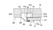
図6は図5のVI-VI線断面図である。溝部121は、放熱部材12の一方の面122のうち、LEDモジュール11の周囲の領域の一部に形成されている。溝部121の内面のうち、基板111の一側面111cよりも基板111の内側に位置する面を内側面121aとし、基板111の一側面111cよりも基板111の外側に位置する面を外側面121bとし、内側面121a及び外側面121bと交差する面を底面121cとする。内側面121aは、一例として、LEDモジュール11の電極113aよりも内側に位置しており、電極113aと回路113bの一部とが溝部121と重なっている。 6 is a cross-sectional view taken along line VI-VI in FIG. The
導電体113と放熱部材12との沿面距離D1と、基板111と放熱部材12との空間距離D2とは、LEDモジュール11の放熱部材12に対する絶縁性が得られるように設定されている。沿面距離D1は、導電体113と放熱部材12との間の基板111の外面に沿った距離であり、具体的には、溝部121の内側面121aから導電体113までの基板111の外面に沿った距離である。空間距離D2は、基板111の一側面111cと放熱部材12との間の空間を通る距離であり、具体的には、溝部の外側面121bと放熱部材12の一方の面122とが交差する角部123から基板111の導電体113までの空間距離である。 The creepage distance D1 between the
沿面距離D1は所定の値よりも大きくなるように設定されている。「所定の値」は、雷サージ試験における印加電圧に応じて定めることができる。例えば、印加電圧を4kVとした場合には、沿面距離D1を4mm以上とし、印加電圧を6kVとした場合には、沿面距離D1を6mm以上とすることができる。この場合、印加電圧が1kV増す毎に沿面距離D1を1mm大きくしているが、この印加電圧と沿面距離D1との関係は一例である。 The creeping distance D1 is set to be larger than a predetermined value. The “predetermined value” can be determined according to the applied voltage in the lightning surge test. For example, when the applied voltage is 4 kV, the creeping distance D1 can be 4 mm or more, and when the applied voltage is 6 kV, the creeping distance D1 can be 6 mm or more. In this case, every time the applied voltage increases by 1 kV, the creeping distance D1 is increased by 1 mm. The relationship between the applied voltage and the creeping distance D1 is an example.
空間距離D2は所定の値よりも大きくなるように設定されている。「所定の値」は、雷サージ試験における印加電圧に応じて定めることができる。例えば、印加電圧を4kVとした場合には、空間距離D2を4mm以上とし、印加電圧を6kVとした場合には、空間距離D2を6mm以上とすることができる。この場合、印加電圧が1kV増す毎に空間距離D2を1mm大きくしているが、この印加電圧と空間距離D2との関係は一例である。 The spatial distance D2 is set to be larger than a predetermined value. The “predetermined value” can be determined according to the applied voltage in the lightning surge test. For example, when the applied voltage is 4 kV, the spatial distance D2 can be 4 mm or more, and when the applied voltage is 6 kV, the spatial distance D2 can be 6 mm or more. In this case, every time the applied voltage increases by 1 kV, the spatial distance D2 is increased by 1 mm. The relationship between the applied voltage and the spatial distance D2 is an example.
なお、溝部121の底面121cは基板111の裏面111bに対して平行になるように形成されている。その結果、基板111の導電体113から底面121cまでの空間距離D3が一定となり、電界集中を抑制できるため、基板111から放熱部材12への放電を抑制することができる。 The
また、空間距離D3は所定の値よりも大きくなるように形成されている。「所定の値」は、雷サージ試験における印加電圧に応じて定めることができる。例えば、印加電圧を4kVとした場合には、空間距離D3を4mm以上とし、印加電圧を6kVとした場合には、空間距離D3を6mm以上とすることができる。この場合、印加電圧が1kV増す毎に空間距離D2を1mm大きくしているが、この印加電圧と空間距離D3との関係は一例である。 Further, the spatial distance D3 is formed to be larger than a predetermined value. The “predetermined value” can be determined according to the applied voltage in the lightning surge test. For example, when the applied voltage is 4 kV, the spatial distance D3 can be 4 mm or more, and when the applied voltage is 6 kV, the spatial distance D3 can be 6 mm or more. In this case, every time the applied voltage increases by 1 kV, the spatial distance D2 is increased by 1 mm. The relationship between the applied voltage and the spatial distance D3 is an example.
図7は電源ユニット20の分解斜視図である。電源ユニット20は、筐体21以外に、さらに、電源装置22と、端子台23と、端子カバー24と、基板支持具25とを有する。 FIG. 7 is an exploded perspective view of the
筐体21は箱状で、下ケース26と上ケース27とによって構成されている。下ケース26と上ケース27の各々は、亜鉛メッキ鋼板等の金属板をプレス加工することにより形成される。 The
下ケース26は、矩形状の底壁261と、底壁261の一側縁から上方に立ち上がる第1側壁262と、底壁261の他側縁から上方に立ち上がる第2側壁263とを有する。底壁261には、突起261bと、係合爪261c(図4参照)と、凹部261dとが形成されている。 The
凹部261dは、底壁261の一端側の端縁の一部を略半円状に切り欠くことによって形成されている。凹部261dは、エッジが下方向へ折り曲げられているため、凹部261d内を通る電線がエッジに接触しにくく、電線の被覆に損傷を与えることを軽減できる。 The
第1側壁262には、端子台23を取り付けるための孔262a及び切欠き262bと、端子カバー24を取り付けるための孔262cとが形成されている。 In the
第2側壁263の一端側の端縁には基板支持部264が形成されている。基板支持部264は、第2側壁263の一端側の端縁から突出するコの字形の突出片を第2側壁263と略平行になるように内側に折り曲げることにより形成される。基板支持部264はスリット264aを有している。図示しないが、第1側壁262の他端側の端縁にも基板支持部264が形成されている。 A
電源装置22は、電源回路や調光回路等を構成する電気部品221と、電気部品221が実装された基板222と、LEDモジュール11に接続される電線223と、端子台23に接続される電線224とを有する。電源回路は、商用電源から得られた交流電流を直流電流に変換する。調光回路は、電流の振幅又は位相を制御して電流量を調節する。電源装置22から発する熱は筐体21と放熱部材12とに伝達されて空気中へ放熱される。電源装置22の基板222は基板支持部264のスリット264aに挿入され、基板222は基板支持部264によって支持される。電線223は、LEDホルダー14によってLEDモジュール11の電極113aに接続される。 The
端子台23は、下ケース26の第1側壁262に形成された孔262a及び切欠き262bによって第1側壁262に取り付けられる。端子台23には、商用電源の電線が接続される。 The
端子カバー24は絶縁性材料により形成され、端子台23を覆うように下ケース26の第1側壁262に取り付けられる。 The
基板支持具25は絶縁性材料により形成され、下ケース26の底壁261に形成された貫通孔に下方から挿入される。基板支持具25の上端部は、基板222に形成された貫通孔222aに挿通される。基板222は、基板支持具25と基板支持部264とによって、底壁261と平行になるように支持される。 The
次に、図1を参照して、照明器具1の取付面への取り付け方法について説明する。以下の説明においては、照明器具1を天井に取り付ける場合を例に挙げている。 Next, with reference to FIG. 1, the attachment method to the attachment surface of the lighting fixture 1 is demonstrated. In the following description, the case where the lighting fixture 1 is attached to a ceiling is mentioned as an example.
まず、作業者は、天井裏空間に配設された商用電源の電線を端子台23に接続する。次に、作業者は、一対の取付バネ13を互いに接近する方向に弾性変形させるとともに、電源ユニット20の一端側(端面272の側)が他端側よりも下になるように照明器具1を傾けて、電源ユニット20を他端側から埋込穴に挿入する。 First, an operator connects a commercial power supply wire disposed in the ceiling space to the
作業者が電源ユニット20を埋込穴に挿入する際、電源ユニット20の他端側の灯具本体10からの突出長さが従来品よりも短いことに加えて、電源ユニット20の一端側の端面272が傾斜していて埋込穴の縁に引っ掛かりにくいため、従来品に比べて電源ユニット20を容易に埋込穴に挿入することができる。 When the operator inserts the
また、電源ユニット20の他端側の灯具本体10からの突出長さが従来品よりも短いため、天井裏に設置された断熱材等に電源ユニット20が当接しにくい。さらに、電源ユニット20は、一端側と中間部とで灯具本体10に支持されているため、電源ユニット20が屋根裏空間に設置された断熱材等に当接しても、従来品(電源ユニットが一端側のみでヒートシンクに支持されている)と比べると、筐体21が変形しにくい Moreover, since the protrusion length from the lamp
そして、作業者は、パッキン18が埋込穴の開口部の周囲に圧接されるまで照明器具1を埋込穴に押し込むとともに、一対の取付バネ13から手を離す。一対の取付バネ13は、互いに離反する方向に弾性復帰して埋込穴の縁に圧接される。その結果、一対の取付バネ13の弾発力によって、照明器具1が埋込穴に固定される。 Then, the operator pushes the lighting fixture 1 into the embedding hole until the packing 18 is pressed around the opening of the embedding hole, and releases his hands from the pair of mounting springs 13. The pair of attachment springs 13 are elastically restored in directions away from each other and are pressed against the edges of the embedding holes. As a result, the lighting fixture 1 is fixed to the embedding hole by the elastic force of the pair of mounting springs 13.
電源ユニット20と灯具本体10とは取付面に直交する方向に重なるように配置されており、加えて放熱部材12が板状であるため、照明器具1の外形寸法は従来品よりも小さい。したがって、従来品の取付スペースと比べて照明器具1の取付スペースは小さい。また、照明器具1は、従来品と比べて、埋込穴に挿入する際に屋根裏空間内の断熱材等と干渉しにくいため、取付面への取り付けが容易である。 Since the
以上、図面(図1〜図7)を参照しながら本発明の実施形態について説明した。但し、本発明は上記の実施形態に限られるものではなく、その要旨を逸脱しない範囲で種々の態様において実施することが可能である(例えば、下記に示す(1)〜(5))。なお、図面を理解しやすくするために、それぞれの各構成要素の厚み、長さ、個数等は、図面作成の都合上から、実際とは異なる。また、上記の実施形態で示す各構成要素の形状、寸法等は一例であって、特に限定されるものではなく、本発明の効果から実質的に逸脱しない範囲で種々の変更が可能である。 The embodiments of the present invention have been described above with reference to the drawings (FIGS. 1 to 7). However, the present invention is not limited to the above-described embodiment, and can be implemented in various modes without departing from the gist thereof (for example, (1) to (5) shown below). In order to facilitate understanding of the drawings, the thickness, length, number, and the like of each component are different from the actual for convenience of drawing. Moreover, the shape, dimension, etc. of each component shown by said embodiment are an example, Comprising: It does not specifically limit, A various change is possible in the range which does not deviate substantially from the effect of this invention.
(1)本実施形態では、LEDモジュールを光源としているが、LEDモジュール以外の光源(例えば、有機ELモジュール)を備えた照明器具にも本発明を適用可能である。 (1) In the present embodiment, the LED module is used as the light source, but the present invention can also be applied to a lighting fixture including a light source (for example, an organic EL module) other than the LED module.
(2)本実施形態では、電源ユニットを灯具本体に支持させる突起を電源ユニットに設けているが、当該突起を灯具本体に設けてもよく、灯具本体と電源ユニットとの両方に設けてもよい。 (2) In this embodiment, the projection for supporting the power supply unit on the lamp body is provided on the power supply unit. However, the projection may be provided on the lamp body, or may be provided on both the lamp body and the power supply unit. .
(3)本実施形態では、取付バネが2つの場合について説明したが、取付バネは3つ以上でもよく、1つでもよい。 (3) In this embodiment, although the case where there were two attachment springs was demonstrated, three or more attachment springs may be sufficient as it.
(4)本実施形態では、電源ユニットを灯具本体に固定する締結部材がビスである場合について説明したが、ビス以外の締結部材(例えば、リベット)で電源ユニットを灯具本体に固定してもよい。 (4) In this embodiment, the case where the fastening member that fixes the power supply unit to the lamp body is a screw has been described. However, the power supply unit may be fixed to the lamp body using a fastening member other than a screw (for example, a rivet). .
(5)本発明は、ダウンライト以外の埋込型の照明器具(例えば、アッパーライト)にも適用可能である。また、本発明は、天井以外の取付面(例えば、床)に取り付ける照明器具にも適用可能である。 (5) The present invention can also be applied to an embedded lighting fixture (for example, an upper light) other than a downlight. The present invention can also be applied to a lighting fixture attached to an attachment surface (for example, a floor) other than the ceiling.
1 照明器具
10 灯具本体
11 LEDモジュール(光源)
12 放熱部材
13 取付バネ
18 パッキン
20 電源ユニット
21 筐体
111 基板
112 発光素子
113 導電体
121 溝部
121a 内側面
121b 外側面
181 切欠き
194 係合突起(第2係合部)
272 端面
261b 突起
261c 係合爪(第1係合部)
B1 ビス(締結部材)
C 空隙
D1 沿面距離
D2 空間距離DESCRIPTION OF SYMBOLS 1
12
272
B1 screw (fastening member)
C Air gap D1 Creepage distance D2 Spatial distance
Claims (10)
Translated fromJapanese光源を有する灯具本体と、
前記光源に電力を供給する電源ユニットと
を備え、
前記灯具本体と前記電源ユニットとは、前記取付面に直交する方向に重なるように配置されている、照明器具。
A lighting fixture embedded in the mounting surface,
A lamp body having a light source;
A power supply unit for supplying power to the light source,
The lighting apparatus, wherein the lamp body and the power supply unit are arranged so as to overlap in a direction orthogonal to the mounting surface.
前記電源ユニットと前記灯具本体とは、前記放熱部材を介して前記放熱部材の厚み方向に重なるように配置されている、請求項1に記載の照明器具。
The lamp body has a plate-like heat radiating member that radiates heat generated from the light source and / or the power supply unit,
The lighting apparatus according to claim 1, wherein the power supply unit and the lamp body are arranged so as to overlap in a thickness direction of the heat dissipation member via the heat dissipation member.
前記一端側の端面は、前記取付面に直交する方向に対して傾斜するとともに、前記筐体の外面のうち、前記灯具本体に対向する面に対して鋭角を成している、請求項1又は請求項2に記載の照明器具。
The power supply unit has a housing and is arranged so that one end side of the housing is positioned on the lamp body.
The end surface on the one end side is inclined with respect to a direction orthogonal to the mounting surface, and forms an acute angle with a surface of the outer surface of the housing that faces the lamp body. The lighting fixture according to claim 2.
前記電源ユニットと前記灯具本体とは、前記突起を介して当接している、請求項1から請求項3のうちの1項に記載の照明器具。
At least one of the power supply unit and the lamp body has a protrusion,
The lighting apparatus according to claim 1, wherein the power supply unit and the lamp body are in contact with each other through the protrusion.
The lighting apparatus according to claim 1, wherein the power supply unit and the lamp body are disposed so as to overlap with each other via a gap.
前記灯具本体は、前記第1係合部と係合する第2係合部を有し、
前記第1係合部と前記第2係合部とが係合した状態で、前記電源ユニットが1つの締結部材によって前記灯具本体に固定される、請求項1から請求項5のうちの1項に記載の照明器具。
The power supply unit has a first engagement portion,
The lamp body has a second engagement portion that engages with the first engagement portion,
The said power supply unit is fixed to the said lamp main body by one fastening member in the state which the said 1st engaging part and the said 2nd engaging part engaged, The one of Claims 1-5 The lighting fixture as described in.
前記取付面に形成された埋込穴に係脱自在に係合する取付バネと、
前記埋込穴の開口部の周囲に圧接されるパッキンと
を備え、
前記取付バネは、前記灯具本体が前記埋込穴に挿入された状態で前記埋込穴に当接して弾性変形し、
前記パッキンは、前記取付バネの弾性変形を許容する切欠きを有する、請求項1から請求項6のうちの1項に記載の照明器具。
The lamp body is
A mounting spring that detachably engages with an embedding hole formed in the mounting surface;
A packing pressed against the periphery of the opening of the embedding hole,
The mounting spring is elastically deformed in contact with the embedding hole in a state where the lamp body is inserted into the embedding hole,
The lighting device according to claim 1, wherein the packing has a notch that allows elastic deformation of the mounting spring.
前記放熱部材は、前記基板と重なり合う部分の一部に設けられた溝部を有する、請求項2に記載の照明器具。
The light source includes a substrate and a light emitting element provided on the front surface of the substrate, and is arranged so that a back surface of the substrate is in contact with the heat dissipation member,
The lighting device according to claim 2, wherein the heat radiating member has a groove provided in a part of a portion overlapping with the substrate.
前記溝部は、前記基板の一側面よりも前記基板の内側に位置する内側面を有し、
前記内側面から前記導電体までの沿面距離は、所定の値よりも大きくなるように設定されている、請求項8に記載の照明器具。
The light source has a conductor provided on the substrate,
The groove has an inner surface located inside the substrate rather than one side surface of the substrate,
The lighting fixture according to claim 8, wherein a creepage distance from the inner surface to the conductor is set to be larger than a predetermined value.
前記一側面から前記外側面までの空間距離は、所定の値よりも大きくなるように設定されている、請求項8又は請求項9に記載の照明器具。The groove portion has an outer surface located outside the substrate rather than one side surface of the substrate,
The lighting fixture according to claim 8 or 9, wherein a spatial distance from the one side surface to the outer side surface is set to be larger than a predetermined value.
Priority Applications (1)
| Application Number | Priority Date | Filing Date | Title |
|---|---|---|---|
| JP2014090431AJP2015210880A (en) | 2014-04-24 | 2014-04-24 | lighting equipment |
Applications Claiming Priority (1)
| Application Number | Priority Date | Filing Date | Title |
|---|---|---|---|
| JP2014090431AJP2015210880A (en) | 2014-04-24 | 2014-04-24 | lighting equipment |
Publications (1)
| Publication Number | Publication Date |
|---|---|
| JP2015210880Atrue JP2015210880A (en) | 2015-11-24 |
Family
ID=54612945
Family Applications (1)
| Application Number | Title | Priority Date | Filing Date |
|---|---|---|---|
| JP2014090431APendingJP2015210880A (en) | 2014-04-24 | 2014-04-24 | lighting equipment |
Country Status (1)
| Country | Link |
|---|---|
| JP (1) | JP2015210880A (en) |
Cited By (7)
| Publication number | Priority date | Publication date | Assignee | Title |
|---|---|---|---|---|
| JP2017183005A (en)* | 2016-03-29 | 2017-10-05 | コイズミ照明株式会社 | Lighting fixture |
| WO2018012160A1 (en)* | 2016-07-15 | 2018-01-18 | パナソニックIpマネジメント株式会社 | Heat sink and lighting apparatus |
| JP2018034873A (en)* | 2016-09-01 | 2018-03-08 | パナソニックIpマネジメント株式会社 | Packing material and packing box |
| JP2018056015A (en)* | 2016-09-29 | 2018-04-05 | パナソニックIpマネジメント株式会社 | lighting equipment |
| CN111578191A (en)* | 2019-02-18 | 2020-08-25 | 松下知识产权经营株式会社 | Lighting device |
| JP2020167124A (en)* | 2019-03-29 | 2020-10-08 | 東芝ライテック株式会社 | Lighting equipment |
| JP2021012767A (en)* | 2019-07-04 | 2021-02-04 | 三菱電機株式会社 | Light source unit and lighting equipment |
Citations (10)
| Publication number | Priority date | Publication date | Assignee | Title |
|---|---|---|---|---|
| JP2010073490A (en)* | 2008-09-18 | 2010-04-02 | Kokubu Denki Co Ltd | Embedded lighting fixture |
| JP2011187245A (en)* | 2010-03-05 | 2011-09-22 | Panasonic Electric Works Co Ltd | Luminaire |
| JP2011228128A (en)* | 2010-04-20 | 2011-11-10 | Panasonic Electric Works Co Ltd | Lighting fixture |
| JP2011233271A (en)* | 2010-04-23 | 2011-11-17 | Panasonic Electric Works Co Ltd | Lighting apparatus |
| JP2012094298A (en)* | 2010-10-25 | 2012-05-17 | Panasonic Corp | lighting equipment |
| JP2012129172A (en)* | 2010-12-17 | 2012-07-05 | Toshiba Lighting & Technology Corp | Lighting fixture |
| JP2013093270A (en)* | 2011-10-27 | 2013-05-16 | Mitsubishi Electric Corp | Lighting device |
| JP2013140772A (en)* | 2011-12-30 | 2013-07-18 | Posco Led Co Ltd | Optical semiconductor lighting device |
| JP2013239286A (en)* | 2012-05-14 | 2013-11-28 | Panasonic Corp | Lighting-up device and lighting fixture having the same |
| JP2015032467A (en)* | 2013-08-02 | 2015-02-16 | パナソニック株式会社 | lighting equipment |
- 2014
- 2014-04-24JPJP2014090431Apatent/JP2015210880A/enactivePending
Patent Citations (10)
| Publication number | Priority date | Publication date | Assignee | Title |
|---|---|---|---|---|
| JP2010073490A (en)* | 2008-09-18 | 2010-04-02 | Kokubu Denki Co Ltd | Embedded lighting fixture |
| JP2011187245A (en)* | 2010-03-05 | 2011-09-22 | Panasonic Electric Works Co Ltd | Luminaire |
| JP2011228128A (en)* | 2010-04-20 | 2011-11-10 | Panasonic Electric Works Co Ltd | Lighting fixture |
| JP2011233271A (en)* | 2010-04-23 | 2011-11-17 | Panasonic Electric Works Co Ltd | Lighting apparatus |
| JP2012094298A (en)* | 2010-10-25 | 2012-05-17 | Panasonic Corp | lighting equipment |
| JP2012129172A (en)* | 2010-12-17 | 2012-07-05 | Toshiba Lighting & Technology Corp | Lighting fixture |
| JP2013093270A (en)* | 2011-10-27 | 2013-05-16 | Mitsubishi Electric Corp | Lighting device |
| JP2013140772A (en)* | 2011-12-30 | 2013-07-18 | Posco Led Co Ltd | Optical semiconductor lighting device |
| JP2013239286A (en)* | 2012-05-14 | 2013-11-28 | Panasonic Corp | Lighting-up device and lighting fixture having the same |
| JP2015032467A (en)* | 2013-08-02 | 2015-02-16 | パナソニック株式会社 | lighting equipment |
Cited By (10)
| Publication number | Priority date | Publication date | Assignee | Title |
|---|---|---|---|---|
| JP2017183005A (en)* | 2016-03-29 | 2017-10-05 | コイズミ照明株式会社 | Lighting fixture |
| WO2018012160A1 (en)* | 2016-07-15 | 2018-01-18 | パナソニックIpマネジメント株式会社 | Heat sink and lighting apparatus |
| JPWO2018012160A1 (en)* | 2016-07-15 | 2019-03-22 | パナソニックIpマネジメント株式会社 | Heat sink and lighting equipment |
| JP2018034873A (en)* | 2016-09-01 | 2018-03-08 | パナソニックIpマネジメント株式会社 | Packing material and packing box |
| JP2018056015A (en)* | 2016-09-29 | 2018-04-05 | パナソニックIpマネジメント株式会社 | lighting equipment |
| CN111578191A (en)* | 2019-02-18 | 2020-08-25 | 松下知识产权经营株式会社 | Lighting device |
| JP2020167124A (en)* | 2019-03-29 | 2020-10-08 | 東芝ライテック株式会社 | Lighting equipment |
| JP7252514B2 (en) | 2019-03-29 | 2023-04-05 | 東芝ライテック株式会社 | lighting equipment |
| JP2021012767A (en)* | 2019-07-04 | 2021-02-04 | 三菱電機株式会社 | Light source unit and lighting equipment |
| JP7278893B2 (en) | 2019-07-04 | 2023-05-22 | 三菱電機株式会社 | Light source unit and lighting equipment |
Similar Documents
| Publication | Publication Date | Title |
|---|---|---|
| JP2015210880A (en) | lighting equipment | |
| JP5879564B2 (en) | Light emitting device and lighting apparatus using the same | |
| WO2011108500A1 (en) | Illumination appliance | |
| JP5480703B2 (en) | lighting equipment | |
| JP6495966B2 (en) | lighting equipment | |
| WO2013128732A1 (en) | Light-emitting device and lighting apparatus using same | |
| JP2016058339A (en) | Holder, lighting device, and method of manufacturing lighting device | |
| JP2012160264A (en) | Lighting fixture | |
| JP6408268B2 (en) | lighting equipment | |
| JP5701429B1 (en) | lighting equipment | |
| JP2017183220A (en) | Luminaire | |
| JP6979773B2 (en) | Lighting equipment and manufacturing method of lighting equipment | |
| JP6493675B2 (en) | lighting equipment | |
| JP2014222586A (en) | Lighting fixture | |
| JP2012160266A (en) | Lighting fixture | |
| JP6569935B2 (en) | Recessed lighting fixture | |
| JP2012160265A (en) | Lighting fixture | |
| JP6971592B2 (en) | Lighting equipment and manufacturing method of lighting equipment | |
| JP6369669B2 (en) | Recessed lighting fixture | |
| JP6750938B2 (en) | Lighting device and light source unit | |
| JP6803545B2 (en) | lighting equipment | |
| JP6226130B2 (en) | Lamp device and lighting device | |
| JP7547793B2 (en) | Heat dissipation device and lighting device equipped with heat dissipation device | |
| JP5072131B2 (en) | Power supply and lighting fixture | |
| JP2024005070A (en) | lighting equipment |
Legal Events
| Date | Code | Title | Description |
|---|---|---|---|
| A621 | Written request for application examination | Free format text:JAPANESE INTERMEDIATE CODE: A621 Effective date:20170302 | |
| A131 | Notification of reasons for refusal | Free format text:JAPANESE INTERMEDIATE CODE: A131 Effective date:20171121 | |
| A977 | Report on retrieval | Free format text:JAPANESE INTERMEDIATE CODE: A971007 Effective date:20171117 | |
| A521 | Request for written amendment filed | Free format text:JAPANESE INTERMEDIATE CODE: A523 Effective date:20180115 | |
| A131 | Notification of reasons for refusal | Free format text:JAPANESE INTERMEDIATE CODE: A131 Effective date:20180327 | |
| A02 | Decision of refusal | Free format text:JAPANESE INTERMEDIATE CODE: A02 Effective date:20181002 |