JP2015204656A - Power supply control device and power supply control method - Google Patents
Power supply control device and power supply control methodDownload PDFInfo
- Publication number
- JP2015204656A JP2015204656AJP2014081803AJP2014081803AJP2015204656AJP 2015204656 AJP2015204656 AJP 2015204656AJP 2014081803 AJP2014081803 AJP 2014081803AJP 2014081803 AJP2014081803 AJP 2014081803AJP 2015204656 AJP2015204656 AJP 2015204656A
- Authority
- JP
- Japan
- Prior art keywords
- power supply
- power
- relay
- control device
- supply control
- Prior art date
- Legal status (The legal status is an assumption and is not a legal conclusion. Google has not performed a legal analysis and makes no representation as to the accuracy of the status listed.)
- Granted
Links
Images


Classifications
- Y—GENERAL TAGGING OF NEW TECHNOLOGICAL DEVELOPMENTS; GENERAL TAGGING OF CROSS-SECTIONAL TECHNOLOGIES SPANNING OVER SEVERAL SECTIONS OF THE IPC; TECHNICAL SUBJECTS COVERED BY FORMER USPC CROSS-REFERENCE ART COLLECTIONS [XRACs] AND DIGESTS
- Y02—TECHNOLOGIES OR APPLICATIONS FOR MITIGATION OR ADAPTATION AGAINST CLIMATE CHANGE
- Y02E—REDUCTION OF GREENHOUSE GAS [GHG] EMISSIONS, RELATED TO ENERGY GENERATION, TRANSMISSION OR DISTRIBUTION
- Y02E10/00—Energy generation through renewable energy sources
- Y02E10/50—Photovoltaic [PV] energy
- Y02E10/56—Power conversion systems, e.g. maximum power point trackers
Landscapes
- Charge And Discharge Circuits For Batteries Or The Like (AREA)
- Supply And Distribution Of Alternating Current (AREA)
Abstract
Translated fromJapaneseDescription
Translated fromJapanese本発明は、複数の分散型電源の電力を活用する電源制御装置及び電源制御方法に関するものである。 The present invention relates to a power supply control apparatus and a power supply control method that utilize the power of a plurality of distributed power supplies.
近年、太陽光発電や燃料電池などの分散型電源を利用した分散型電源装置が普及しつつある。分散型電源装置は、分散型電源によって発電された直流の電力を、例えばパワーコンディショナ等を利用して交流の電力に変換して商用電力系統へ出力している。 In recent years, distributed power supply devices using distributed power sources such as solar power generation and fuel cells are becoming popular. The distributed power supply device converts DC power generated by the distributed power supply into AC power using, for example, a power conditioner and outputs the AC power to a commercial power system.
更に、需要家において、創エネルギー部と併せて、蓄電池等の蓄エネルギー部を設置し、創エネルギー部の生成した電力を蓄エネルギー部に蓄電して、必要なときに放電させることも検討されている(例えば、特許文献1参照)。特許文献1に記載された技術では、電力供給システムは、集合住宅を構成する複数の住戸で共用される共用蓄電池と制御装置とを備えている。制御装置は、各住戸において、太陽電池が発電した電力において、個別蓄電池に蓄積しきれない余剰電力を用いて共用蓄電池を充電する。 In addition, it has been considered that a consumer can install an energy storage unit such as a storage battery together with the energy creation unit, store the electric power generated by the energy creation unit in the energy storage unit, and discharge it when necessary. (For example, refer to Patent Document 1). In the technique described in Patent Literature 1, the power supply system includes a shared storage battery and a control device that are shared by a plurality of dwelling units that constitute the apartment house. In each dwelling unit, the control device charges the shared storage battery using surplus power that cannot be stored in the individual storage battery in the power generated by the solar battery.
特許文献1の電力供給システムでは、太陽電池が接続されたパワーコンディショナに対して、共用蓄電池から直流電力が供給される。しかしながら、パワーコンディショナの出力は交流であるため、既存のパワーコンディショナにおいて、直流電力をそのまま利用することができない。このため、パワーコンディショナの構成の変更等が必要で、設備構築のための負担が大きいという課題がある。 In the power supply system of Patent Document 1, DC power is supplied from a shared storage battery to a power conditioner to which a solar battery is connected. However, since the output of the power conditioner is alternating current, direct current power cannot be used as it is in the existing power conditioner. For this reason, the change of the structure of a power conditioner etc. is required and the subject that the burden for equipment construction is large occurs.
一方、創エネルギー部と蓄エネルギー部とを並列に並べて交流連携することも考えられる。しかしながら、交流連携の場合には、創蓄エネルギー部に接続された各パワーコンディショナは独立しているため、既存設備では制御の連携が容易でない。このため、創エネルギー部により発電した電力を有効利用することができなかった。 On the other hand, it is also conceivable that the energy creation unit and the energy storage unit are arranged in parallel and exchanged. However, in the case of alternating current cooperation, since each power conditioner connected to the creation energy department is independent, it is not easy to cooperate in control with existing equipment. For this reason, the electric power generated by the energy creation unit could not be effectively used.
本発明は、このような問題点に鑑みてなされたものであって、その目的は、既存の設備を活かしながら、電力を有効活用するための電源制御装置及び電源制御方法を提供することにある。 The present invention has been made in view of such problems, and an object of the present invention is to provide a power supply control device and a power supply control method for effectively using power while utilizing existing facilities. .
(1)上記課題を解決する電源制御装置は、第1の分散型電源の交流電力を入力する分散型電源接続部と、第2の分散型電源の交流電力を出力する電力変換部と、前記分散型電源接続部と系統電源との解列操作処理を行なう第1リレーと、前記分散型電源接続部及び前記電力変換部と、系統電源及び自立分電盤の切替器との接続操作処理を行なう第2リレーと、前記第1リレー及び前記第2リレーを制御する制御部を備える。そして、前記制御部が、前記系統電源の系統停電を検知した場合、前記第1リレーの解列操作処理を行ない、前記第2リレーの接続操作処理を行なうことを特徴とする。 (1) A power supply control device that solves the above problem includes a distributed power supply connection unit that inputs AC power of a first distributed power source, a power conversion unit that outputs AC power of a second distributed power source, and A connection operation process of a first relay that performs a disconnection operation process between a distributed power supply connection unit and a system power supply, the distributed power supply connection unit and the power conversion unit, and a system power supply and a switch of a stand-alone distribution board. A second relay to be performed; and a control unit for controlling the first relay and the second relay. And when the said control part detects the system power failure of the said system power supply, it performs the disconnection operation process of a said 1st relay, and performs the connection operation process of a said 2nd relay.
(2)上記電源制御装置において、系統停電時に、前記電力変換部から前記第1の分散型電源に対して供給される出力電圧を、前記系統電源の系統電圧に準じて安定化させる補償器を設けたことが好ましい。 (2) In the power supply control device, a compensator that stabilizes an output voltage supplied from the power conversion unit to the first distributed power supply in accordance with a system voltage of the system power supply when a system power failure occurs. It is preferable to provide it.
(3)上記電源制御装置において、前記電力変換部には、蓄エネルギー部が接続されることが好ましい。
(4)上記電源制御装置において、外部に設けられた蓄エネルギー部との外部接続部を設け、前記外部接続部を前記電力変換部に接続したことが好ましい。(3) In the power supply control device, an energy storage unit is preferably connected to the power conversion unit.
(4) In the power supply control device, it is preferable that an external connection unit with an energy storage unit provided outside is provided, and the external connection unit is connected to the power conversion unit.
(5)上記電源制御装置において、前記制御部が、系統連系時に前記電力変換部からの電力を制限することが好ましい。
(6)上記電源制御装置において、前記分散型電源接続部に接続され、前記第1リレーに接続された第1スイッチと、前記第1スイッチ及び前記第1リレーと、前記電力変換部との間に接続された第2スイッチとを更に備え、前記制御部が、第1、第2スイッチにより、前記第1の分散型電源の電力供給を制御することが好ましい。(5) In the power supply control device, it is preferable that the control unit limits the power from the power conversion unit during grid connection.
(6) In the power supply control device described above, between the first switch connected to the distributed power connection unit and connected to the first relay, the first switch and the first relay, and the power conversion unit. It is preferable that the control unit further controls the power supply of the first distributed power source by the first and second switches.
(7)上記電源制御装置において、前記制御部が、系統停電を検知した場合には、前記第2スイッチをオフ操作し、前記第2リレーをオン操作し、前記蓄エネルギー部からの前記第2リレーへの電力供給を安定化させた後に、前記第2スイッチをオン操作して、前記第1の分散型電源からの電力を前記第2リレーに電力供給を行なうことが好ましい。 (7) In the power supply control device, when the control unit detects a system power failure, the second switch is turned off, the second relay is turned on, and the second power from the energy storage unit is turned on. It is preferable that after the power supply to the relay is stabilized, the second switch is turned on to supply power from the first distributed power source to the second relay.
(8)上記電源制御装置において、前記制御部が、系統停電時において、前記蓄エネルギー部における充電状態に応じて、前記第1スイッチを制御することが好ましい。
(9)上記電源制御装置において、前記制御部が、前記第1リレー及び前記第2リレーをオフした場合、前記蓄エネルギー部における充電状態に応じて、前記第1スイッチを制御することが好ましい。(8) In the power supply control device, it is preferable that the control unit controls the first switch according to a state of charge in the energy storage unit during a system power failure.
(9) In the power supply control device, when the control unit turns off the first relay and the second relay, it is preferable to control the first switch according to a state of charge in the energy storage unit.
(10)上記電源制御装置において、前記制御部が、前記系統電源の電流を検知する第1の変流器と、前記第1の分散型電源の電流を検知する第2の変流器とに接続され、系統連系時には、前記第1の変流器で検知した電流に応じて、前記蓄エネルギー部への充放電を制御し、系統停電時には、前記第2の変流器で検知した電流に応じて、前記蓄エネルギー部への充放電を制御することが好ましい。 (10) In the power supply control device, the control unit includes a first current transformer that detects a current of the system power supply and a second current transformer that detects a current of the first distributed power supply. When connected to the grid, the charge / discharge to the energy storage unit is controlled according to the current detected by the first current transformer, and the current detected by the second current transformer at the time of system power failure Accordingly, it is preferable to control charging / discharging of the energy storage unit.
本発明によれば、既存の設備を活かしながら、電力を有効活用することができる。 According to the present invention, it is possible to effectively use electric power while utilizing existing facilities.
図1〜図3を用いて、電源制御装置の一実施形態を説明する。
図1に示すように、第1の実施形態では、分散型電源10として太陽電池パネル11を用いる場合を想定する。そして、太陽電池パネル11の発電電力を有効活用するために、電源制御装置40を利用する。An embodiment of a power supply control device will be described with reference to FIGS.
As shown in FIG. 1, in the first embodiment, it is assumed that a solar cell panel 11 is used as the
太陽電池パネル11は、太陽光エネルギーを直流電力に変換する発電装置であり、エネルギーを生産する創エネルギー部として機能する。太陽電池パネル11は、複数の太陽電池セルを接続してなる太陽電池パネルを主要部として備える。 The solar cell panel 11 is a power generation device that converts solar energy into DC power, and functions as an energy creation unit that produces energy. The solar cell panel 11 includes a solar cell panel formed by connecting a plurality of solar cells as a main part.
この太陽電池パネル11は、直流電圧を昇降圧するDCDCコンバータ21に接続される。このDCDCコンバータ21は、スイッチング素子のオン・オフ(スイッチング制御)により、必要な直流電圧(例えば、DC350V)を生成するチョッパ制御を行なう。このDCDCコンバータ21は、太陽光の日射状況の影響を受ける発電電力に応じた最大電力点追従制御(MPPT制御)を行なう。そして、太陽電池パネル11の出力(直流電圧)をバス電圧値に変換して直流電力線(DCバス)に出力する。 This solar cell panel 11 is connected to a
DCDCコンバータ21は、直流電力線を介して、系統連系インバータ31に接続される。この系統連系インバータ31は、スイッチング素子のスイッチング制御を行なうことにより、直流と交流との変換を行なう。そして、系統連系インバータ31は、第1の分散型電源の交流電力を出力する。ここでは、直流電力を、系統電源50に連系可能な電圧、周波数の交流電力(例えば、AC202V、50Hz)に変換する。 The DCDC
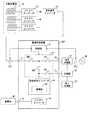
系統連系インバータ31は、電力線を介して、電源制御装置40に接続される。この電源制御装置40は、外部端子T1〜T3を備えている。系統連系インバータ31からの電力線は、外部端子T1(分散型電源接続部)に接続される。
また、外部端子T2は、住宅分電盤51に接続される。この住宅分電盤51は、系統電源50に接続される。The
The external terminal T2 is connected to the
外部端子T3は、切替器52に接続される。この切替器52は、住宅分電盤51及び自立分電盤53に接続される。この切替器52は、系統電源50の系統停電を検出した場合、住宅分電盤51と自立分電盤53とを切り離し、電源制御装置40の電力を自立分電盤53に供給する。また、系統電源50の復電を検出した場合、住宅分電盤51と自立分電盤53とを接続することにより、系統電力を自立分電盤53に供給する。 The external terminal T3 is connected to the
次に、電源制御装置40の内部構成を説明する。
この電源制御装置40は、制御部41、スイッチング部U1を備えている。スイッチング部U1には、スイッチSW1,SW2、系統連系保護リレー42、自立リレー43が設けられている。更に、電源制御装置40は、第2の分散型電源として、系統連系インバータ44、DCDCコンバータ45、蓄電池46を備えている。本実施形態では、系統連系インバータ44、DCDCコンバータ45が、電力変換部として機能する。Next, the internal configuration of the power
The power
制御部41には、変流器CT1,CT2が接続されている。変流器CT1,CT2は、接続先の交流電力線の電流値のセンシングを行なう。本実施形態では、変流器CT1は、系統連系インバータ31の交流電力線において出力電流を検知し、変流器CT2は系統電源50の交流電力線において系統電流を検知する。 The
そして、制御部41は、スイッチング部U1のスイッチSW1(第1スイッチ)、スイッチSW2(第2スイッチ)、系統連系保護リレー42(第1リレー)、自立リレー43(第2リレー)のスイッチングを制御する。 And the
また、制御部41は、系統電源50の系統電圧値、周波数について、系統連系時の系統正常範囲に関するデータを保持している。そして、系統電源50の系統電圧値、周波数と系統正常範囲とを比較し、系統停電を判定する。更に、制御部41は、自立電力不足を判定するための第1の基準電流値に関するデータを保持している。更に、制御部41は、分散型電源10の出力低下を判定するための第2の基準電流値に関するデータを保持している。更に、制御部41は、蓄電池46の満充電を判定するための満充電基準値に関するデータを保持している。 Moreover, the
次に、スイッチング部U1の構成を説明する。
スイッチSW1の第1端子は外部端子T1に接続され、スイッチSW1の第2端子は系統連系保護リレー42及びスイッチSW2に接続される。Next, the configuration of the switching unit U1 will be described.
The first terminal of the switch SW1 is connected to the external terminal T1, and the second terminal of the switch SW1 is connected to the grid connection protection relay 42 and the switch SW2.
スイッチSW2の第1端子は、上述したようにスイッチSW1に接続され、スイッチSW2の第2端子は、自立リレー43及び系統連系インバータ44に接続される。
系統連系保護リレー42の第1端子は、上述したようにスイッチSW1、SW2に接続され、第2端子は外部端子T2に接続される。
自立リレー43の第1端子は、上述したようにスイッチSW2及び系統連系インバータ44に接続され、第2端子は外部端子T3に接続される。The first terminal of the switch SW2 is connected to the switch SW1 as described above, and the second terminal of the switch SW2 is connected to the self-supporting
As described above, the first terminal of the grid connection protection relay 42 is connected to the switches SW1 and SW2, and the second terminal is connected to the external terminal T2.
As described above, the first terminal of the self-supporting
スイッチSW2及び自立リレー43に接続された系統連系インバータ44は、系統連系インバータ31と同様に、スイッチング素子のスイッチング制御を行なう。これにより、蓄電池46の出力(直流電力)を、系統電源50に連系可能な電圧、周波数の交流電力(例えば、AC202V、50Hz)に変換する。 Similarly to the
更に、系統連系インバータ44には、補償器441が設けられている。この補償器441は、系統連系インバータ44の出力を、電圧及び周波数を系統電圧に準じて安定化させた交流電圧(疑似系統電圧)にする。 Further, the
系統連系インバータ44は、直流電力線を介して、DCDCコンバータ45に接続される。
このDCDCコンバータ45は、DCDCコンバータ21と同様に、スイッチング制御により、直流電圧を昇降圧する。このDCDCコンバータ45は、蓄電池46に接続される。そして、DCDCコンバータ45は、蓄電池46の出力(直流)をバス電圧値に変換して直流電力線に出力したり、直流電力線から供給される電力を蓄電池46に供給したりする。
この蓄電池46は、電力を充電するとともに、充電した電力を出力する電池であり、繰り返し使用可能な蓄エネルギー部である。The
Similar to the
The
次に、図2を用いて、スイッチ制御処理を説明する。
まず、電源制御装置40の制御部41は、分散型電源からの電力供給処理を実行する(ステップS11)。具体的には、制御部41は、スイッチSW1、SW2をオンする。更に、制御部41は、系統連系保護リレー42をオンし、自立リレー43をオフする。これにより、系統連系を行なう。Next, the switch control process will be described with reference to FIG.
First, the
この場合、電源制御装置40の制御部41は、蓄電池の充放電制御処理を実行する(ステップS12)。具体的には、制御部41は、系統連系インバータ44に対して、変流器CT2で検知した電流値に応じて、蓄電池46の充放電電力を制御させる指示を行なう。ここで、系統電源50に対して逆潮流を検知した場合には、蓄電池46の放電を停止させる。 In this case, the
次に、電源制御装置40の制御部41は、系統停電かどうかについての判定処理を実行する(ステップS13)。具体的には、制御部41は、系統電源50の電圧、周波数を検出する。そして、系統電源50の電圧、周波数と系統正常範囲と系統正常範囲とを比較し、系統停電(系統異常状態)を判定する。 Next, the
系統停電でないと判定した場合(ステップS13において「NO」の場合)、電源制御装置40の制御部41は、蓄電池の放電制限処理(ステップS12)を継続する。この場合、スイッチSW1,SW2,系統連系保護リレー42はオン、自立リレー43はオフの状態が維持される。 When it determines with it not being a system | strain power failure (in the case of "NO" in step S13), the
一方、系統停電と判定した場合(ステップS13において「YES」の場合)、電源制御装置40の制御部41は、系統連系保護リレーのオフ操作処理を実行する(ステップS14)。具体的には、制御部41は、系統連系保護リレー42をオフする(解列操作処理)。これにより、電源制御装置40を系統電源50から解列する。 On the other hand, when it is determined that the system power failure has occurred (in the case of “YES” in step S13), the
次に、電源制御装置40の制御部41は、自立リレーのオン操作処理を実行する(ステップS15)。具体的には、制御部41は、自立リレー43をオンする(接続操作処理)。この場合、制御部41は、スイッチSW1,SW2を一旦オフし、蓄電池46からの電力が安定した段階で、スイッチSW1,SW2をオンする。これにより、分散型電源10と蓄電池46と自立分電盤53とが接続される。 Next, the
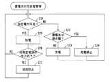
次に、電源制御装置40の制御部41は、蓄電池の充放電管理処理を実行する(ステップS16)。この処理については、図3を用いて後述する。
次に、電源制御装置40の制御部41は、系統復帰かどうかについての判定処理を実行する(ステップS17)。具体的には、制御部41は、系統電源50の系統電圧、周波数を検出し、系統正常範囲に戻ったと判定した場合、系統復帰(系統電源の復電)と判定する。Next, the
Next, the
系統復帰でないと判定した場合(ステップS17において「NO」の場合)、電源制御装置40の制御部41は、蓄電池の充放電管理処理(ステップS16)を継続する。
一方、系統復帰と判定した場合(ステップS17において「YES」の場合)、電源制御装置40の制御部41は、自立リレーのオフ操作処理を実行する(ステップS18)。具体的には、制御部41は、自立リレー43をオフする。これにより、電源制御装置40と自立分電盤53とが切り離される。
次に、電源制御装置40の制御部41は、系統連系保護リレーのオン操作処理を実行する(ステップS19)。具体的には、制御部41は、系統連系保護リレー42をオンする。これにより、電源制御装置40が系統電源50に接続される。When it determines with it not being a system | strain return (in the case of "NO" in step S17), the
On the other hand, when it is determined that the system has been restored (in the case of “YES” in step S17), the
Next, the
次に、図3を用いて、蓄電池の充放電管理処理を説明する。
まず、電源制御装置40の制御部41は、自立電力不足かどうかについての判定処理を実行する(ステップS21)。具体的には、制御部41は、変流器CT1から、供給されている電流の電流値を取得する。そして、制御部41は、変流器CT1から取得した電流値と第1の基準電流値とを比較する。変流器CT1から取得した電流値が第1の基準電流値以上の場合には、自立電力不足でないと判定する。Next, the charging / discharging management process of a storage battery is demonstrated using FIG.
First, the
自立電力不足でないと判定した場合(ステップS21において「NO」の場合)、電源制御装置40の制御部41は、蓄電池は満充電かどうかについての判定処理を実行する(ステップS22)。具体的には、制御部41は、DCDCコンバータ45から、蓄電池46の出力電圧値を取得する。そして、制御部41は、この出力電圧値に基づいて、蓄電池46の充電状態を特定する。出力電圧値が満充電基準値以下の場合には満充電でないと判定する。なお、制御部41が蓄電池46から蓄電量の内部残量状態に関する情報を取得し、この情報を用いて満充電を判断するようにしてもよい。この場合には、満充電基準値として、満充電と見なす内部残量に関する基準値を用いる。 If it is determined that there is no shortage of independent power (in the case of “NO” in step S21), the
蓄電池46は満充電でないと判定した場合(ステップS22において「NO」の場合)、電源制御装置40の制御部41は、充電処理を実行する(ステップS23)。具体的には、制御部41は、系統連系インバータ44、DCDCコンバータ45に、蓄電池46への充電の指示信号を送信する。この場合、系統連系インバータ31からの電力を、スイッチSW1,SW2、系統連系インバータ44、DCDCコンバータ45を介して、蓄電池46に供給する。そして、電源制御装置40の制御部41は、自立電力不足かどうかについての判定処理(ステップS21)に戻る。 When it is determined that the
一方、蓄電池46は満充電と判定した場合(ステップS22において「YES」の場合)、電源制御装置40の制御部41は、充電停止処理を実行する(ステップS24)。具体的には、制御部41は、スイッチSW1をオフすることにより、蓄電池46への電力供給を停止する。そして、電源制御装置40の制御部41は、自立電力不足かどうかについての判定処理(ステップS21)に戻る。 On the other hand, when it is determined that the
一方、変流器CT1から取得した電流値が第1の基準電流値未満であり、自立電力不足と判定した場合(ステップS21において「YES」の場合)、電源制御装置40の制御部41は、放電処理を実行する(ステップS25)。具体的には、制御部41は、系統連系インバータ44、DCDCコンバータ45に対して、蓄電池46の放電を指示する。この場合、蓄電池46からの電力は、DCDCコンバータ45、系統連系インバータ44を介して、自立リレー43に供給される。 On the other hand, when the current value acquired from the current transformer CT1 is less than the first reference current value and it is determined that the self-sustained power is insufficient (in the case of “YES” in step S21), the
次に、電源制御装置40の制御部41は、分散型電源の出力低下かどうかについての判定処理を実行する(ステップS26)。具体的には、制御部41は、変流器CT1から電流値を取得する。そして、取得した電流値が第2の基準電流値以下となった場合、分散型電源10の出力低下と判定する。 Next, the
分散型電源の出力低下と判定した場合(ステップS26において「YES」の場合)、電源制御装置40の制御部41は、逆流阻止処理を実行する(ステップS27)。具体的には、制御部41は、スイッチSW1をオフする。 When it is determined that the output of the distributed power supply is reduced (in the case of “YES” in step S26), the
一方、分散型電源の出力低下でないと判定した場合(ステップS26において「NO」の場合)、電源制御装置40の制御部41は、自立電力不足かどうかについての判定処理(ステップS21)に戻る。 On the other hand, when it is determined that the output of the distributed power supply is not reduced (in the case of “NO” in step S26), the
本実施形態によれば、以下のような効果を得ることができる。
(1)本実施形態では、分散型電源10は、電源制御装置40を介して、住宅分電盤51に接続される。そして、系統連系時には、電源制御装置40の制御部41は、分散型電源からの電力供給処理を実行する(ステップS11)。一方、系統停電時には、電源制御装置40の制御部41は、系統連系保護リレーのオフ操作処理(ステップS14)、自立リレーのオン操作処理(ステップS15)を実行する。これにより、系統停電時において、蓄電池46を利用して、系統連系インバータ44から交流電力(疑似系統電圧)を出力することができる。従って、太陽電池パネル11は、疑似系統電圧により、系統停電時においても、系統連系時と同様に発電を行なうことができる。このように、分散型電源10に対して交流連携により電源制御装置40を設けることができるので、既存設備を活かすことにより、設備投資負担を軽減することができる。
更に、ここでは、自立リレーのオン操作処理(ステップS15)を優先して行なう。これにより、蓄電池46から自立分電盤53への電力供給を優先して行なうことができる。According to this embodiment, the following effects can be obtained.
(1) In the present embodiment, the distributed
Furthermore, the self-relay relay ON operation process (step S15) is preferentially performed here. Thereby, it is possible to preferentially supply power from the
(2)本実施形態では、系統停電時には、電源制御装置40の制御部41は、蓄電池の充放電管理処理を実行する(ステップS16)。これにより、蓄電池46の過剰充電や過放電を抑制することができる。 (2) In this embodiment, at the time of a system power failure, the
(3)本実施形態では、制御部41には、変流器CT1,CT2が接続されている。そして、変流器CT1は、系統連系インバータ31からの交流電力線において出力電流を検知し、変流器CT2は系統電源50の交流電力線において系統電流を検知する。これにより、変流器CT1,CT2を用いて、分散型電源10の出力状態や、逆潮流状態を把握し、スイッチング部U1を制御することができる。従って、系統連系時には、変流器CT2で検知した電流に応じて、蓄電池46への充放電を制御し、系統停電時には、変流器CT1で検知した電流に応じて、蓄電池46への充放電を制御することができる。 (3) In the present embodiment, the current transformers CT1 and CT2 are connected to the
(4)本実施形態では、系統連系インバータ44には、補償器441が設けられている。これにより、系統停電時における周波数変動や電圧変動の影響を抑制した疑似系統電圧を出力することができる。 (4) In the present embodiment, the
なお、上記実施形態は以下のように変更してもよい。
・上記実施形態においては、分散型電源10の創エネルギー部として、太陽電池パネル11を用いたが、分散型電源10の種類は限定されるものではない。例えば、創エネルギー部として、風力発電装置を用いることも可能である。In addition, you may change the said embodiment as follows.
In the above embodiment, the solar cell panel 11 is used as the energy generating unit of the distributed
・上記実施形態においては、系統停電中に、蓄電池の充放電管理処理を実行する(ステップS16)。これに加えて、住宅内での電力需要がない場合に、蓄電池46の充電を管理する処理を実行してもよい。この場合には、電源制御装置40において、維持充電モードを実行する。このために、制御部41には、蓄電池46の長期保管に適した充電残量を判定するための維持充電基準値に関するデータを保持させておく。維持充電基準値としては、例えば、満充電に対して50%残量を用いることができる。 -In the said embodiment, the charging / discharging management process of a storage battery is performed during a system | strain power failure (step S16). In addition to this, when there is no electric power demand in the house, a process for managing charging of the
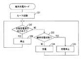
図4を用いて、維持充電モード処理を説明する。この維持充電モード処理は、利用者が維持充電モードを指示した場合に実行される。
まず、電源制御装置40の制御部41は、モード起動処理を実行する(ステップS31)。具体的には、利用者の操作に応じて、制御部41が、系統連系保護リレー42,自立リレー43をオフする。更に、制御部41は、スイッチSW1、SW2をオンする。The maintenance charge mode process will be described with reference to FIG. This maintenance charge mode process is executed when the user instructs maintenance charge mode.
First, the
次に、電源制御装置40の制御部41は、ステップS26と同様に、分散型電源の出力低下かどうかについての判定処理を実行する(ステップS32)。
分散型電源の出力は低下していないと判定した場合(ステップS32において「NO」の場合)、電源制御装置40の制御部41は、蓄電池は維持充電状態かどうかについての判定処理を実行する(ステップS33)。具体的には、制御部41は、蓄電池46の出力電圧値を取得する。この出力電圧値に基づいて、蓄電池46の充電状態を特定する。出力電圧値が維持充電基準値に達している場合には維持充電状態と判定する。なお、蓄電池46から内部残量状態の情報を取得し、この情報を用いて維持充電状態を判断するようにしてもよい。Next, the
When it is determined that the output of the distributed power supply has not decreased (in the case of “NO” in step S32), the
蓄電池は維持充電状態でないと判定した場合(ステップS33において「NO」の場合)、電源制御装置40の制御部41は、ステップS23と同様に、充電処理を実行する(ステップS34)。 When it determines with a storage battery not being a maintenance charge state (in the case of "NO" in step S33), the
一方、蓄電池は維持充電状態と判定した場合(ステップS33において「YES」の場合)、電源制御装置40の制御部41は、ステップS24と同様に、充電停止処理を実行する(ステップS35)。 On the other hand, when it determines with a storage battery being a maintenance charge state (in the case of "YES" in step S33), the
また、分散型電源の出力低下と判定した場合(ステップS32において「YES」の場合)、電源制御装置40の制御部41は、ステップS24と同様に、充電停止処理を実行する(ステップS36)。
これにより、利用者の不在時等のように、電力需要がない場合に、太陽電池パネル11等の分散型電源10を用いて、蓄電池46を、保管に適した充電状態に維持することができる。また、充電停止処理(ステップS36)により、分散型電源の発電量が低下した場合にもシステムの安定化を図ることができる。When it is determined that the output of the distributed power supply is reduced (in the case of “YES” in step S32), the
Thereby, when there is no electric power demand, such as when the user is absent, the
・上記実施形態においては、電源制御装置40内に、蓄エネルギー部としての蓄電池46を設ける。この蓄電池46は、電源制御装置40の外部に設けるようにしてもよい。 In the above embodiment, the
この場合には、図5に示すように、電源制御装置40Bを用いる。この電源制御装置40Bにおいては、電源制御装置40と同様に、スイッチング部U1、系統連系インバータ44を備える。そして、電源制御装置40Bには、DCDCコンバータ45に接続する外部端子T4(外部接続部)を設ける。そして、外部端子T4に接続された充電池60を利用する。これにより、利用者が既に所有している蓄電池等、多様な蓄エネルギー部を利用することができる。この場合、蓄エネルギー部として、電気自動車の車載充電装置等を利用することも可能である。更に、複数の蓄エネルギー部を併用することも可能である。 In this case, a power
10…分散型電源、11…太陽電池パネル、21,45…DCDCコンバータ部、31…系統連系インバータ、40,40B…電源制御装置、41…制御部、U1…スイッチング部、SW1,SW2…スイッチ、42…系統連系保護リレー、43…自立リレー、44…系統連系インバータ、441…補償器、46…蓄電池、T1,T2,T3,T4…外部端子、50…系統電源、51…住宅分電盤、52…切替器、53…自立分電盤。 DESCRIPTION OF
Claims (11)
Translated fromJapanese第2の分散型電源の交流電力を出力する電力変換部と、
前記分散型電源接続部と系統電源との解列操作処理を行なう第1リレーと、
前記分散型電源接続部及び前記電力変換部と、系統電源及び自立分電盤の切替器との接続操作処理を行なう第2リレーと、
前記第1リレー及び前記第2リレーを制御する制御部を備えた電源制御装置であって、
前記制御部が、前記系統電源の系統停電を検知した場合、前記第1リレーの解列操作処理を行ない、前記第2リレーの接続操作処理を行なうことを特徴とする電源制御装置。A distributed power source connection for inputting AC power of the first distributed power source;
A power converter that outputs AC power of the second distributed power source;
A first relay for performing a disconnection operation process between the distributed power connection and the system power;
A second relay that performs connection operation processing between the distributed power source connection unit and the power conversion unit, and a system power source and a switch of a stand-alone distribution board;
A power supply control device comprising a control unit for controlling the first relay and the second relay,
When the control unit detects a system power failure of the system power supply, the control unit performs a disconnection operation process of the first relay and performs a connection operation process of the second relay.
前記第1スイッチ及び前記第1リレーと、前記電力変換部との間に接続された第2スイッチとを更に備え、
前記制御部が、第1、第2スイッチにより、前記第1の分散型電源の電力供給を制御することを特徴とする請求項3〜5の何れか1項に記載の電源制御装置。A first switch connected to the distributed power connection and connected to the first relay;
A second switch connected between the first switch and the first relay and the power converter;
6. The power supply control device according to claim 3, wherein the control unit controls power supply of the first distributed power source by using first and second switches. 7.
前記蓄エネルギー部からの前記第2リレーへの電力供給を安定化させた後に、前記第2スイッチをオン操作して、前記第1の分散型電源からの電力を前記第2リレーに電力供給を行なうことを特徴とする請求項6に記載の電源制御装置。When the control unit detects a system power failure, it turns off the second switch, turns on the second relay,
After stabilizing the power supply from the energy storage unit to the second relay, the second switch is turned on to supply power from the first distributed power source to the second relay. The power supply control device according to claim 6, wherein the power supply control device is performed.
系統連系時には、前記第1の変流器で検知した電流に応じて、前記蓄エネルギー部への充放電を制御し、
系統停電時には、前記第2の変流器で検知した電流に応じて、前記蓄エネルギー部への充放電を制御することを特徴とする請求項3〜9の何れか1項に記載の電源制御装置。The controller is connected to a first current transformer for detecting a current of the system power supply and a second current transformer for detecting a current of the first distributed power supply;
During grid connection, according to the current detected by the first current transformer, the charge / discharge to the energy storage unit is controlled,
The power supply control according to any one of claims 3 to 9, wherein at the time of a system power failure, charging / discharging to the energy storage unit is controlled according to a current detected by the second current transformer. apparatus.
第2の分散型電源の交流電力を出力する電力変換部と、
前記分散型電源接続部と系統電源との解列操作処理を行なう第1リレーと、
前記分散型電源接続部及び前記電力変換部と、系統電源及び自立分電盤の切替器との接続操作処理を行なう第2リレーと、
前記第1リレー及び前記第2リレーを制御する制御部を備えた電源制御装置を用いて、電源を制御する方法であって、
前記制御部が、前記系統電源の系統停電を検知した場合、前記第1リレーの解列操作処理を行ない、前記第2リレーの接続操作処理を行なうことを特徴とする電源制御方法。A distributed power source connection for inputting AC power of the first distributed power source;
A power converter that outputs AC power of the second distributed power source;
A first relay for performing a disconnection operation process between the distributed power connection and the system power;
A second relay that performs connection operation processing between the distributed power source connection unit and the power conversion unit, and a system power source and a switch of a stand-alone distribution board;
A method for controlling a power supply using a power supply control device including a control unit for controlling the first relay and the second relay,
When the said control part detects the system power failure of the said system power supply, the disconnection operation process of the said 1st relay is performed, and the connection operation process of the said 2nd relay is performed, The power supply control method characterized by the above-mentioned.
Priority Applications (1)
| Application Number | Priority Date | Filing Date | Title |
|---|---|---|---|
| JP2014081803AJP6355017B2 (en) | 2014-04-11 | 2014-04-11 | Power supply control device and power supply control method |
Applications Claiming Priority (1)
| Application Number | Priority Date | Filing Date | Title |
|---|---|---|---|
| JP2014081803AJP6355017B2 (en) | 2014-04-11 | 2014-04-11 | Power supply control device and power supply control method |
Publications (2)
| Publication Number | Publication Date |
|---|---|
| JP2015204656Atrue JP2015204656A (en) | 2015-11-16 |
| JP6355017B2 JP6355017B2 (en) | 2018-07-11 |
Family
ID=54597824
Family Applications (1)
| Application Number | Title | Priority Date | Filing Date |
|---|---|---|---|
| JP2014081803AActiveJP6355017B2 (en) | 2014-04-11 | 2014-04-11 | Power supply control device and power supply control method |
Country Status (1)
| Country | Link |
|---|---|
| JP (1) | JP6355017B2 (en) |
Cited By (4)
| Publication number | Priority date | Publication date | Assignee | Title |
|---|---|---|---|---|
| JP2018207594A (en)* | 2017-05-31 | 2018-12-27 | 住友電気工業株式会社 | Power supply device and welding determination method |
| JP2021027783A (en)* | 2019-08-09 | 2021-02-22 | 住友電気工業株式会社 | Power storage system and control method for the same |
| JPWO2023145305A1 (en)* | 2022-01-27 | 2023-08-03 | ||
| WO2024185552A1 (en)* | 2023-03-07 | 2024-09-12 | 株式会社Gsユアサ | Electric power apparatus, electric power system, and method for controlling electric power apparatus |
Families Citing this family (1)
| Publication number | Priority date | Publication date | Assignee | Title |
|---|---|---|---|---|
| JPH0648385Y2 (en) | 1989-11-30 | 1994-12-12 | 株式会社島津製作所 | Full-scale material testing machine |
Citations (12)
| Publication number | Priority date | Publication date | Assignee | Title |
|---|---|---|---|---|
| JP2008113500A (en)* | 2006-10-30 | 2008-05-15 | Shinano Kenshi Co Ltd | Power supply system at disaster time |
| JP2008159301A (en)* | 2006-12-21 | 2008-07-10 | Sony Corp | Battery deterioration suppression method, battery storage chamber, and electronic equipment |
| JP2008278700A (en)* | 2007-05-02 | 2008-11-13 | Ntt Facilities Inc | Distributed power generator and power quality maintenance control method |
| US20110080044A1 (en)* | 2009-09-04 | 2011-04-07 | Voltwerk Electronics Gmbh | Standalone unit of a standalone power grid for communicating energy requests with another standalone unit |
| JP2011188607A (en)* | 2010-03-08 | 2011-09-22 | Seiko Electric Co Ltd | Power supply system, power supply method, and control device |
| JP2012186950A (en)* | 2011-03-07 | 2012-09-27 | Denso Corp | Electric power supply system |
| WO2013042509A1 (en)* | 2011-09-20 | 2013-03-28 | 三菱重工パーキング株式会社 | Mechanical parking facility and power supplying method for mechanical parking facility |
| JP2013192321A (en)* | 2012-03-13 | 2013-09-26 | Omron Corp | Charging power control device, charging power control method, program, and photovoltaic power generation system |
| JP2014007828A (en)* | 2012-06-22 | 2014-01-16 | Shindengen Electric Mfg Co Ltd | Power storage system |
| JP2014027856A (en)* | 2012-07-30 | 2014-02-06 | Mitsubishi Electric Corp | System interconnection apparatus |
| JP2014034288A (en)* | 2012-08-08 | 2014-02-24 | Denso Corp | Vehicular power source system |
| JP2014236568A (en)* | 2013-05-31 | 2014-12-15 | 株式会社三社電機製作所 | System interconnection system |
- 2014
- 2014-04-11JPJP2014081803Apatent/JP6355017B2/enactiveActive
Patent Citations (12)
| Publication number | Priority date | Publication date | Assignee | Title |
|---|---|---|---|---|
| JP2008113500A (en)* | 2006-10-30 | 2008-05-15 | Shinano Kenshi Co Ltd | Power supply system at disaster time |
| JP2008159301A (en)* | 2006-12-21 | 2008-07-10 | Sony Corp | Battery deterioration suppression method, battery storage chamber, and electronic equipment |
| JP2008278700A (en)* | 2007-05-02 | 2008-11-13 | Ntt Facilities Inc | Distributed power generator and power quality maintenance control method |
| US20110080044A1 (en)* | 2009-09-04 | 2011-04-07 | Voltwerk Electronics Gmbh | Standalone unit of a standalone power grid for communicating energy requests with another standalone unit |
| JP2011188607A (en)* | 2010-03-08 | 2011-09-22 | Seiko Electric Co Ltd | Power supply system, power supply method, and control device |
| JP2012186950A (en)* | 2011-03-07 | 2012-09-27 | Denso Corp | Electric power supply system |
| WO2013042509A1 (en)* | 2011-09-20 | 2013-03-28 | 三菱重工パーキング株式会社 | Mechanical parking facility and power supplying method for mechanical parking facility |
| JP2013192321A (en)* | 2012-03-13 | 2013-09-26 | Omron Corp | Charging power control device, charging power control method, program, and photovoltaic power generation system |
| JP2014007828A (en)* | 2012-06-22 | 2014-01-16 | Shindengen Electric Mfg Co Ltd | Power storage system |
| JP2014027856A (en)* | 2012-07-30 | 2014-02-06 | Mitsubishi Electric Corp | System interconnection apparatus |
| JP2014034288A (en)* | 2012-08-08 | 2014-02-24 | Denso Corp | Vehicular power source system |
| JP2014236568A (en)* | 2013-05-31 | 2014-12-15 | 株式会社三社電機製作所 | System interconnection system |
Cited By (6)
| Publication number | Priority date | Publication date | Assignee | Title |
|---|---|---|---|---|
| JP2018207594A (en)* | 2017-05-31 | 2018-12-27 | 住友電気工業株式会社 | Power supply device and welding determination method |
| JP2021027783A (en)* | 2019-08-09 | 2021-02-22 | 住友電気工業株式会社 | Power storage system and control method for the same |
| JP7310427B2 (en) | 2019-08-09 | 2023-07-19 | 住友電気工業株式会社 | Electricity storage system and its control method |
| JPWO2023145305A1 (en)* | 2022-01-27 | 2023-08-03 | ||
| JP7592898B2 (en) | 2022-01-27 | 2024-12-02 | 株式会社ジャパンディスプレイ | Lighting System |
| WO2024185552A1 (en)* | 2023-03-07 | 2024-09-12 | 株式会社Gsユアサ | Electric power apparatus, electric power system, and method for controlling electric power apparatus |
Also Published As
| Publication number | Publication date |
|---|---|
| JP6355017B2 (en) | 2018-07-11 |
Similar Documents
| Publication | Publication Date | Title |
|---|---|---|
| JP6160481B2 (en) | Power supply device, power supply system, and power supply control method | |
| JP6158562B2 (en) | Power conversion apparatus, control system, and control method | |
| WO2013011758A1 (en) | Storage battery system and method for controlling same | |
| EP2337178A2 (en) | Energy storage system of apartment building, integrated power management system, and method of controlling the system | |
| JP5960958B2 (en) | Power management system | |
| JP5475387B2 (en) | Power supply optimization device for power supply system | |
| KR101793579B1 (en) | Dc-ac common bus type hybrid power system | |
| US9705361B2 (en) | Power supply device and method of controlling power supply | |
| JP2013146171A (en) | Power supply system and power conditioner for charging and discharging | |
| JP2011109783A (en) | Power distribution system | |
| JP6355017B2 (en) | Power supply control device and power supply control method | |
| WO2011042781A1 (en) | Power supply system | |
| WO2015118844A1 (en) | Energy management device and energy management method | |
| JP2014230455A (en) | Power generator | |
| JP2008113500A (en) | Power supply system at disaster time | |
| KR20150085227A (en) | The control device and method for Energy Storage System | |
| JP6082610B2 (en) | Power supply system and power storage type power supply device | |
| JP2008072774A (en) | Natural energy generated output equalization arrangement | |
| JP2014121151A (en) | Power storage system and power supply system | |
| JP2015213409A (en) | Load leveling device | |
| JP6076381B2 (en) | Power supply system | |
| JP6145777B2 (en) | Power converter | |
| JP2016032379A (en) | Power supply system | |
| JP2011083059A (en) | Storage battery operation controller of power supply system | |
| JP2018207786A (en) | Power control system control method, power control system, and power control apparatus |
Legal Events
| Date | Code | Title | Description |
|---|---|---|---|
| A621 | Written request for application examination | Free format text:JAPANESE INTERMEDIATE CODE: A621 Effective date:20170127 | |
| A977 | Report on retrieval | Free format text:JAPANESE INTERMEDIATE CODE: A971007 Effective date:20171127 | |
| A131 | Notification of reasons for refusal | Free format text:JAPANESE INTERMEDIATE CODE: A131 Effective date:20171212 | |
| A521 | Request for written amendment filed | Free format text:JAPANESE INTERMEDIATE CODE: A523 Effective date:20180213 | |
| A131 | Notification of reasons for refusal | Free format text:JAPANESE INTERMEDIATE CODE: A131 Effective date:20180313 | |
| A521 | Request for written amendment filed | Free format text:JAPANESE INTERMEDIATE CODE: A523 Effective date:20180514 | |
| TRDD | Decision of grant or rejection written | ||
| A01 | Written decision to grant a patent or to grant a registration (utility model) | Free format text:JAPANESE INTERMEDIATE CODE: A01 Effective date:20180529 | |
| A61 | First payment of annual fees (during grant procedure) | Free format text:JAPANESE INTERMEDIATE CODE: A61 Effective date:20180531 | |
| R151 | Written notification of patent or utility model registration | Ref document number:6355017 Country of ref document:JP Free format text:JAPANESE INTERMEDIATE CODE: R151 |