JP2015199114A - Laser processing device and laser processing method - Google Patents
Laser processing device and laser processing methodDownload PDFInfo
- Publication number
- JP2015199114A JP2015199114AJP2014081188AJP2014081188AJP2015199114AJP 2015199114 AJP2015199114 AJP 2015199114AJP 2014081188 AJP2014081188 AJP 2014081188AJP 2014081188 AJP2014081188 AJP 2014081188AJP 2015199114 AJP2015199114 AJP 2015199114A
- Authority
- JP
- Japan
- Prior art keywords
- laser
- optical system
- laser processing
- condensing
- laser beam
- Prior art date
- Legal status (The legal status is an assumption and is not a legal conclusion. Google has not performed a legal analysis and makes no representation as to the accuracy of the status listed.)
- Pending
Links
Images


Landscapes
- Laser Beam Processing (AREA)
Abstract
Translated fromJapaneseDescription
Translated fromJapanese本発明は、レーザビームの照射により、加工材にピアス加工を行うレーザ加工装置及びレーザ加工方法に関する。 The present invention relates to a laser processing apparatus and a laser processing method for performing piercing on a workpiece by irradiation with a laser beam.
従来のピアス加工においては、加工するワークの材質や厚さによって、可変曲率ミラーの曲率を空気圧により変化させ、集光レンズに入射するビーム径及び発散角を同時に変更することで、ピアス加工時のスポット径及び焦点位置を所定の値に変化させていた(例えば、特許文献1参照)。 In the conventional piercing process, the curvature of the variable curvature mirror is changed by air pressure depending on the material and thickness of the workpiece to be processed, and the beam diameter and divergence angle incident on the condenser lens are changed at the same time. The spot diameter and the focal position are changed to predetermined values (for example, see Patent Document 1).
このようなピアス加工方法においては、ピアス加工中に集光ビーム径を変更できないため、ピアス加工の進展に伴い、最適なビーム径を選択できないという問題があった。 In such a piercing method, since the focused beam diameter cannot be changed during the piercing process, there has been a problem that an optimum beam diameter cannot be selected with the progress of the piercing process.
本発明は、上記に鑑みてなされたものであって、安定して高速にピアス加工を実施するためのレーザ加工装置及びレーザ加工方法を得ることを目的とする。 The present invention has been made in view of the above, and an object of the present invention is to obtain a laser processing apparatus and a laser processing method for stably performing piercing at high speed.
上述した課題を解決し、目的を達成するために、本発明は、レーザビームを発するレーザ発振器と、レーザビームを集光する集光レンズを備えたレーザ加工ヘッドと、レーザ発振器から出射されるレーザビームをレーザ加工ヘッドに導く伝搬光学系とを有し、集光レンズでレーザビームを被加工材に集光して被加工材にピアス加工を施すレーザ加工装置であって、集光レンズへ入射するレーザビームのビーム径を変化させるビーム径可変光学系と、ピアス加工の進展に伴い、レーザビームの集光点における集光径が大きくなるようにビーム径可変光学系を制御するコントローラとを有することを特徴とする。 In order to solve the above-described problems and achieve the object, the present invention provides a laser oscillator that emits a laser beam, a laser processing head that includes a condenser lens that condenses the laser beam, and a laser emitted from the laser oscillator. A laser processing apparatus that has a propagation optical system that guides a beam to a laser processing head, condenses the laser beam onto a workpiece by a condenser lens, and pierces the workpiece, and enters the condenser lens A variable beam diameter optical system that changes the beam diameter of the laser beam to be controlled, and a controller that controls the variable beam diameter optical system so that the condensing diameter at the condensing point of the laser beam increases as piercing progresses It is characterized by that.
本発明によれば、ピアス加工の進展に応じて集光ビーム径を小さくするようにしたので、加工する材質や厚さに対して、ピアス加工中に応じて最適なビーム強度のピアス加工条件を選択できるので、安定して高速にピアス加工を行えるという効果を奏する。 According to the present invention, the focused beam diameter is made smaller in accordance with the progress of the piercing process. Therefore, the piercing process conditions with the optimum beam intensity can be set according to the material and thickness to be processed. Since it can be selected, there is an effect that piercing can be performed stably and at high speed.
以下に、本発明にかかるレーザ加工装置及びレーザ加工方法の実施の形態を図面に基づいて詳細に説明する。なお、この実施の形態によりこの発明が限定されるものではない。 Embodiments of a laser processing apparatus and a laser processing method according to the present invention will be described below in detail with reference to the drawings. Note that the present invention is not limited to the embodiments.
実施の形態1.
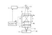
図1は、本発明の実施の形態1に係るレーザ加工装置の構成を示す断面図である。レーザ加工装置は、レーザ発振器1、伝搬光学系3、レーザ加工ヘッド4及びコントローラ20を有する。伝搬光学系3は、レーザ発振器1から発せられたレーザビーム2をレーザ加工ヘッド4に導くための光学系であり、例えば光ファイバである。伝搬光学系3の出力側のファイバ端3aには光コネクタ3bが設けられており、光コネクタ3bを介してレーザ加工ヘッド4にレーザビーム2を導光している。
FIG. 1 is a cross-sectional view showing the configuration of the laser processing apparatus according to
レーザ加工ヘッド4は、ビーム径可変光学系6、集光レンズ7及び加工ノズル8を有する。 The
ビーム径可変光学系6は複数の凸レンズ6a,6bで構成されており、かつレンズ間の間隔Lは、凸レンズ6aの焦点距離と凸レンズ6bの焦点距離とを足したものよりも長く、レーザビーム2は凸レンズ6a,6bの間で一度集光される。ビーム径可変光学系6を構成する複数の凸レンズ6a,6bは、個別に上下移動可能にレーザ加工ヘッド4内に設置されている。ビーム径可変光学系6を構成する凸レンズ6a,6bを上下動させる機構としては、レーザ加工ヘッド4内に設けられた駆動モータにより回転駆動されるボールねじを用いて凸レンズ6a,6bを移動させる機構を例として挙げることができる。 The variable beam diameter
集光レンズ7は、直径の大きいレーザビーム2が入射すると、集光点13でのビーム径が小さくなり、直径の小さいレーザビーム2が入射すると、集光点13でのビーム径が大きくなる光学特性を備えている。集光レンズ7はビーム径可変光学系6とは独立して上下移動可能にレーザ加工ヘッド4内に設置されている。集光レンズ7を上下動させる機構としては、レーザ加工ヘッド4内に設けられた駆動モータにより回転駆動されるボールねじを用いてレンズを移動させる機構を例として挙げることができる。 When the
加工ノズル8は、レーザ加工ヘッド4の先端に設けられている。 The
コントローラ20は、レーザ発振器1の発振の制御に加え、ビーム径可変光学系6の凸レンズ6a,6bや集光レンズ7の位置を制御する。 In addition to controlling the oscillation of the
レーザ発振器1から発振されたレーザビーム2は、伝搬光学系3によりファイバ端3aまで導かれ、ファイバ端3aからレーザ加工ヘッド4に出射される。レーザ加工ヘッド4内に出射されたレーザビーム2は、レーザ加工ヘッド4の内部に設けられたビーム径可変光学系6を経て、集光レンズ7に導かれる。集光レンズ7で集光されたレーザビーム2は、加工ノズル8を通過して被加工材10に照射される。これにより、被加工材10の表面には、集光点13に集光されたレーザビーム2によって加工穴11が形成される。 The
実施の形態1に係るレーザ加工装置は、ビーム径可変光学系6を構成する複数の凸レンズ6a,6b間の距離Lを変えることによって、集光レンズ7へ入射するビーム径Dを変化させることができるため、被加工材10上の集光点13に照射されるレーザビーム2の集光径Sも可変である。したがって、コントローラ20は、集光レンズ7に入射するレーザビーム2のビーム径Dを小さくすることで、被加工材10上での集光径Sを大きくすることができる。 The laser processing apparatus according to the first embodiment can change the beam diameter D incident on the
なお、本実施の形態では、集光レンズ7に入射するレーザビーム2はほぼ平行ビームとなっているため、コントローラ20は、集光レンズ7をビーム径可変光学系6とは独立して上下させることで、被加工材10上の集光点13の上下方向の位置を集光径Sとは独立して制御できる。 In the present embodiment, since the
図2は、ビーム径可変光学系のレンズ位置を変えることで、集光レンズへ入射するビーム径を小さくした状態のレーザ加工装置を示す図である。図1と比較して凸レンズ6aと凸レンズ6bとの間の間隔Lが広くなっている。また、凸レンズ6bは、集光レンズ7に出射するレーザビーム2が平行ビームとなる位置に移動しているため、凸レンズ6bを透過して集光レンズ7に入射するビーム径Dは図1の状態と比較して小さくなっている。この場合、被加工材10上の集光点13におけるレーザビーム2の集光径Sは大きくなる。図1、図2のいずれの状態においても、集光レンズ7は、レーザビーム2が被加工材10の表面に集光点13が形成される位置に配置されている。 FIG. 2 is a diagram illustrating the laser processing apparatus in a state where the beam diameter incident on the condenser lens is reduced by changing the lens position of the beam diameter variable optical system. Compared to FIG. 1, the distance L between the
板金レーザ加工における切断加工や穴開け加工においては、ピアス穴と呼ばれる加工穴を加工開始点に形成することが一般的に行われている。 In cutting and drilling in sheet metal laser processing, it is a common practice to form a processing hole called a piercing hole at the processing start point.
図3は、ピアス加工開始時の穴形状を示す図である。図4は、ピアス加工途中の穴形状を示す図である。加工穴11は、レーザビーム2の照射を継続するに従い、深く進展していく。レーザビーム2の伝搬において、最もパワー密度が高いのは集光点13であり、一般的に集光点13から離れていくに従い、ビーム径は大きくなり、パワー密度は小さくなっていく。したがって、ピアス穴における加工穴底12においては、加工が進展していくに従い、パワー密度は小さくなり、加工穴深さの進展速度は遅くなっていく。 FIG. 3 is a diagram showing a hole shape at the start of piercing. FIG. 4 is a diagram showing a hole shape during piercing. The processed
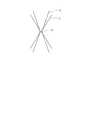
ここで、集光径とビーム径の伝搬との関係について説明する。図5は、レーザビームの伝搬状況を模式的に示す図であり、ビーム径を小さく絞った場合と、ビーム径を大きく絞った場合との2種類の伝搬状況が示されている。図5に示されるように、一般的に集光点におけるビーム径が小さいほど、集光点から離れた位置でのレーザビーム径は大きくなり、パワー密度が小さくなる。 Here, the relationship between the condensed diameter and the propagation of the beam diameter will be described. FIG. 5 is a diagram schematically showing the propagation state of the laser beam, and shows two kinds of propagation states, when the beam diameter is narrowed down and when the beam diameter is narrowed down. As shown in FIG. 5, generally, the smaller the beam diameter at the condensing point, the larger the laser beam diameter at a position away from the condensing point and the lower the power density.
したがって、加工穴底12におけるパワー密度を高めることは、集光点におけるビーム径を大きくすることで実現可能である。図6は、集光点におけるビーム径を大きくした状態を示す図である。集光点でのビーム径を大きくすることで、集光点でのパワー密度は低下するにもかかわらず、ビーム径拡大が低減されるため、加工穴底12におけるパワー密度を高くすることができる。すなわち、集光点におけるビーム径を拡大することで、加工穴底12でのパワー密度は高められ、ピアス加工の加工時間を短縮できる。 Therefore, increasing the power density at the processed hole bottom 12 can be realized by increasing the beam diameter at the focal point. FIG. 6 is a diagram showing a state in which the beam diameter at the focal point is increased. By increasing the beam diameter at the condensing point, although the power density at the condensing point is reduced, the expansion of the beam diameter is reduced, so that the power density at the processed hole bottom 12 can be increased. . That is, by enlarging the beam diameter at the focal point, the power density at the machining hole bottom 12 can be increased, and the machining time for piercing can be shortened.
あるいは、集光レンズ7の位置を加工点側に移動させることによって、集光点を加工穴底12に近づけてパワー密度の低下を抑制することができる。図7は、集光点を加工穴底に近づけた状態を示す図である。 Alternatively, by moving the position of the condensing
しかしながら、図7に示すようなビーム径を小さく絞った状態で、集光点を加工穴底12方向に動かした場合には、加工穴の入口側開口でレーザビームが干渉し、ビーム出力がケラレるため、かえって加工穴底12でのビーム強度が低下することとなり、加工速度が低下する。つまり、集光ビーム径が小さいままでは、集光点を大きく下げることはできない。 However, when the condensing point is moved toward the machining hole bottom 12 with the beam diameter reduced as shown in FIG. 7, the laser beam interferes with the opening on the entrance side of the machining hole, and the beam output becomes vignetting. Therefore, the beam intensity at the machining hole bottom 12 is lowered, and the machining speed is lowered. That is, if the focused beam diameter is small, the focused point cannot be lowered greatly.
図8は、集光点でのレーザビームの集光径を拡大した状態を示す図である。図8に示すように、集光点13でのレーザビームの集光径を拡大することで、加工穴入口側開口でのケラレを低減しつつ集光点13を下げることができる。これにより、加工穴底12でのビーム強度低下を低減でき、ピアス穴加工を高速化できる。 FIG. 8 is a diagram showing a state where the condensing diameter of the laser beam at the condensing point is enlarged. As shown in FIG. 8, by increasing the condensing diameter of the laser beam at the
本実施の形態では、ビーム径可変光学系6が2枚の凸レンズで構成され、かつ、レンズ間の間隔Lは、凸レンズ6aの焦点距離と凸レンズ6bの焦点距離とを足したものよりも長く、レーザビーム2は、凸レンズ6a,6b間で一度集光される場合を例としたが、レンズ間の間隔Lが、凸レンズ6aの焦点距離と凸レンズ6bの焦点距離とを足したものよりも短く、レーザビーム2は凸レンズ6a,6bの間で集光せずとも、ビーム径可変光学系を構成できる。その場合は、凸レンズ6aと凸レンズ6bとの間の間隔Lを狭くすることで集光点13におけるレーザビーム2の集光径を大きくできる。また、これまでは、2枚の凸レンズ6a,6bでビーム可変光学系6を構成したが、凸レンズと凹レンズとの組合せで、ビーム径可変光学系6を構成してもよい。その場合、凸レンズと凹レンズの間の間隔Lを広くすることで、集光レンズへ入射するビーム径Dが小さくなり、集光点13におけるレーザビーム2の集光径を大きくできる。 In the present embodiment, the beam diameter variable
また、ビーム品質や加工対象により収差の影響を低減する必要がある場合や、光学系を配置する空間の制限などにより、さらに多くのレンズを用いてビーム径可変光学系6を構成しても良い。前述と同様、各レンズの動かし方は、各レンズの焦点距離や配置の組合せに依存するが、集光点13におけるレーザビーム2の集光径が所望の大きさとなるように動かせばよい。また、集光レンズ7についても、本実施の形態では、1枚のレンズで構成される場合を例としたが、2枚以上のレンズにより集光光学系を構成するようにしても良い。また、本実施の形態ではピアス加工開始時のレーザビーム2の集光点13の位置を被加工材10の表面の場合を例としたが、被加工材10の材質や厚さによっては、集光点13の位置を、被加工材10の表面に限定せずとも良い。 In addition, the beam diameter variable
実施の形態2.
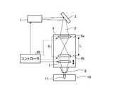
図9は、本発明の実施の形態2に係るレーザ加工装置の構成を示す断面図である。図10は、ビーム径可変光学系のレンズ位置を変えることで、集光レンズへ入射するビーム径を小さくした状態のレーザ加工装置を示す図である。実施の形態1においては、伝搬光学系3を光ファイバで構成したが、本実施の形態では、ミラーなどを用いて空間伝搬することで伝搬光学系3を構成する。
FIG. 9 is a cross-sectional view showing the configuration of the laser processing apparatus according to
図11は、気体レーザでのピアス加工時のレーザパルス条件の一例を示す図である。各々のパルスは、パルス幅に相当する時間、パルス高さに相当する強度でレーザ発振器1を発振させることを示している。ピアス加工時に加工箇所が過熱状態となることを防ぐために、図11に示すように、初期のパルスエネルギーを小さくし、穴形成が進むにつれてパルス周波数を高めるとともに、ピークエネルギーを挙げ、さらにパルスデューティを上げるなどして、パルスエネルギーを大きくしていくことが一般的である。図11の定格平均出力は、レーザ発振器1から出力可能な平均出力を示しているが、CO2レーザなどでは、デューティを調整することにより、定格平均出力以上のピークエネルギーを持つパルスを得ることが可能である。FIG. 11 is a diagram showing an example of laser pulse conditions during piercing with a gas laser. Each pulse indicates that the
また、短時間であれば、さらに高ピークで高パルスデューティなエネルギーパルスを得ることも可能であり、これによって、ピアス加工時の穴形成速度を高めることができる。 In addition, for a short time, it is also possible to obtain an energy pulse with a higher peak and a higher pulse duty, thereby increasing the hole formation speed during piercing.
図12は、固体レーザでのピアス加工時のレーザパルス条件の一例を示す図である。伝搬光学系3に光ファイバを用いたファイバレーザやディスクレーザなど、レーザダイオード励起によるレーザ(例えばYAGレーザ)の場合には、定格平均出力以上のパルスを得ることができない。これは、レーザ発振器1の励起源であるレーザダイオードを定格出力以上のパワーで動かすことは、急激な素子劣化を招くためである。このため、固体レーザでのピアス加工では、図12に示すように、定格平均出力以上のピークエネルギーを持ったパルスを得ることができず、ピアス加工が進展した段階においても、定格平均出力と同じピークエネルギーによりピアス加工を行うことになる。すなわち、定格平均出力以上のピークエネルギーを持つパルスを用いてピアス加工を高速化することは困難である。 FIG. 12 is a diagram showing an example of laser pulse conditions during piercing with a solid-state laser. In the case of a laser (for example, YAG laser) excited by a laser diode such as a fiber laser using an optical fiber for the propagation
伝搬光学系3を空間伝搬によって構成することで、レーザダイオード励起による固体レーザ以外にも、CO2レーザのような光ファイバではロスが大きくなるため伝搬できない波長帯のレーザを発振するレーザ発振器1を適用可能となる。この場合には、レーザ発振器1側でパルスピークエネルギーを高めることで被加工材10上でのパワー密度を高めることに加え、さらにビーム径可変光学系6によって、被加工材10上でのレーザビーム2の照射ビーム径を大きくできる。このため、実施の形態1よりもレーザビーム2のパワー密度を高め、ピアス加工をさらに高速化できる。By constructing the propagation
実施の形態3.
図13は、本発明の実施の形態3に係るレーザ加工装置の光学系の構成を示す図である。実施の形態1,2では、レーザ加工ヘッド4の中にビーム径可変光学系6を配置した構成を例としたが、本実施の形態では、伝搬光学系3を複数のミラーによって構成し、伝搬光学系3内の凹面曲率ミラー6c,6d間の距離をコントローラ20が変化させることによってビーム径可変光学系6を構成している。図13(a)は、レーザ発振器1から発せられたレーザビーム2が凹面曲率ミラー6c,6dで反射された後に、ミラー6eで反射されて集光レンズ7に入射する状態を示し、図13(b)は、凹面曲率ミラー6c,6dの間隔が図13(a)よりも広い状態を示す。凹面曲率ミラー6c,6dの間隔を広げることにより、凹面曲率ミラー6dからミラー6eに入射するレーザビーム2のビーム径が小さくなり、集光レンズ7に入射するレーザビーム2のビーム径Dは小さくなり、集光点13でのレーザビーム2の集光径Sは大きくなる。
FIG. 13 is a diagram showing the configuration of the optical system of the laser processing apparatus according to
本実施の形態においても、ピアス穴加工の進展に従い、凹面曲率ミラー間の距離を変更することで、集光レンズ7に入射するビーム径を変化させることができるため、被加工材10上の照射ビーム径をピアス加工の進展に伴って小さくすることが可能である。 Also in the present embodiment, since the beam diameter incident on the
また、レーザビーム2の吸収による熱に起因する焦点位置のずれや収差などは、レンズ等の透過光学系では問題となりやすい上に、レーザビームの出力に応じて焦点の位置ずれ量や収差の大きさが変化する。本実施の形態では、光学系をミラーとすることにより、レーザビーム2の吸収による熱に起因する焦点位置のずれや収差が低減されるため、出力を変化させた場合でも安定して動作させることが可能である。 Further, the focal position shift and aberration caused by heat due to absorption of the
また、集光レンズ7に上下移動させるための駆動系を設けることで、照射ビーム径とは独立に、集光ビーム位置を変化させることが可能である。 Further, by providing a driving system for moving the condensing
また、伝搬光学系3のうち、加工ヘッドに近い部分のミラー、例えば図13ではミラー6eを可変曲率ミラーとしても良い。その場合には、集光レンズ7を上下移動させなくても焦点位置を変更することが可能となる。また、本実施の形態では、可変ビーム光学系6として、2つの凹面曲率ミラーを用い、レーザビーム2を、可変ビーム光学系6の凹面曲率ミラー6c,6d間で集光させず、かつ、伝搬光学系3の途中にレーザビーム2を一度集光させた場合について、凹面曲率ミラーの動かし方について説明したが、可変ビーム光学系6に含まれる凹面曲率ミラーの曲率及び配置により、凹面曲率ミラー間及び、伝搬光学系3の途中で集光させるあるいは、集光しない等、どの組合せに対しても可変ビーム光学系6を構成することができる。この場合、集光点13でのレーザビーム2の集光径Sを大きくするための、凹面曲率ミラー6c,6dの動かし方は、凹面曲率ミラー6c,6dの各曲率及び他の伝搬光学系3を含めたミラー配置構成に依存する。 Further, in the propagation
図14は、実施の形態3に係るレーザ加工装置の伝搬光学系の別の構成を示す図である。図14に示す構成では、伝搬光学系3を構成するミラーのうちレーザ発振器1側のミラー60を可変曲率ミラーとしてビーム径可変光学系6を形成している。可変曲率ミラーであるミラー60の曲率をコントローラ20が変化させることで、集光レンズ7に入射するビーム径が変化する。図14(a)は、レーザ発振器1から発せられたレーザビーム2が可変曲率ミラー60で反射された後に、ミラー6eで反射されて集光レンズ7に入射する状態を示し、図14(b)は、可変曲率ミラー60の曲率が図14(a)よりも小さい状態を示す。可変曲率ミラー60の曲率を小さくすることにより、可変曲率ミラー60からミラー6eに入射するレーザビーム2のビーム径が小さくなり、集光レンズ7に入射するレーザビーム2のビーム径Dは小さくなり、集光点13でのレーザビーム2の集光径Sは大きくなる。 FIG. 14 is a diagram showing another configuration of the propagation optical system of the laser processing apparatus according to the third embodiment. In the configuration shown in FIG. 14, the beam diameter variable
また、本実施の形態では、伝搬光学系3にレーザビーム2を一度集光させる場合を例としたが、構成によっては、可変曲率ミラー60から集光レンズ7までの間にレーザビーム2を集光させなくてもよい。この場合は、可変曲率ミラー60の曲率を小さくすることにより,可変曲率ミラー60からミラー6eに入射するレーザビーム2のビーム径が小さくなり、集光レンズ7に入射するレーザビーム2のビーム径Dも小さくなり、集光点13でのレーザビーム2の集光径Sは大きくなる。また、集光レンズ7に上下移動させるための駆動系を設けることで、照射ビーム径とは独立に、集光ビーム位置を変化させることが可能である。 In this embodiment, the
さらに、伝搬光学系3のうち、加工ヘッドに近い部分のミラー、例えば図14ではミラー6eも可変曲率ミラーとしても良い。その場合には、集光レンズ7を上下移動させなくても焦点位置を変更することが可能となる。 Further, in the propagation
本実施の形態においても、伝搬光学系3は空間伝搬で構成されているので実施の形態2と同様の効果が得られる。 Also in this embodiment, since the propagation
以上のように、本発明にかかるレーザ加工装置及びレーザ加工方法は、レーザビームの集光径を大きくして集光点から離れた位置におけるパワー密度を高めることができる点で有用である。 As described above, the laser processing apparatus and the laser processing method according to the present invention are useful in that the power density at a position away from the condensing point can be increased by increasing the condensing diameter of the laser beam.
1 レーザ発振器、2 レーザビーム、3 伝搬光学系、4 レーザ加工ヘッド、6 ビーム径可変光学系、6a,6b 凸レンズ、6c,6d 凹面曲率ミラー、6e ミラー、7 集光レンズ、8 加工ノズル、10 被加工材、11 加工穴、12 加工穴底、13 集光点、20 コントローラ、60 可変曲率ミラー。 DESCRIPTION OF
Claims (7)
Translated fromJapanese前記集光レンズへ入射するレーザビームのビーム径を変化させるビーム径可変光学系と、
前記ピアス加工の進展に伴い、レーザビームの集光点における集光径が大きくなるように前記ビーム径可変光学系を制御するコントローラとを有することを特徴とするレーザ加工装置。A laser oscillator that emits a laser beam; a laser processing head that includes a condenser lens that condenses the laser beam; and a propagation optical system that guides the laser beam emitted from the laser oscillator to the laser processing head, A laser processing apparatus that focuses a laser beam on a workpiece with a condenser lens and pierces the workpiece,
A variable beam diameter optical system for changing the beam diameter of the laser beam incident on the condenser lens;
A laser processing apparatus comprising: a controller that controls the beam diameter variable optical system so that a condensing diameter at a condensing point of the laser beam is increased with the progress of the piercing process.
前記ビーム径可変光学系は、前記複数の曲率ミラーの間隔を変更可能とすることによって、前記伝搬光学系内に構成されることを特徴とする請求項1に記載のレーザ加工装置。The propagation optical system is composed of a plurality of curvature mirrors,
2. The laser processing apparatus according to claim 1, wherein the beam diameter variable optical system is configured in the propagation optical system by changing an interval between the plurality of curvature mirrors. 3.
前記ビーム径可変光学系は、前記複数の曲率ミラーのうちの少なくとも一つを可変曲率ミラーとすることによって、前記伝搬光学系内に構成されることを特徴とする請求項1に記載のレーザ加工装置。The propagation optical system is composed of a plurality of curvature mirrors,
2. The laser processing according to claim 1, wherein the beam diameter variable optical system is configured in the propagation optical system by using at least one of the plurality of curvature mirrors as a variable curvature mirror. 3. apparatus.
前記集光レンズへ入射するレーザビームのビーム径を変化させるビーム径可変光学系を用いて、前記ピアス加工の進展に伴い、前記被加工材に集光するレーザビームの集光径を大きくすることを特徴とするレーザ加工方法。A laser processing method for guiding a laser beam emitted from a laser oscillator to a condensing lens in a laser processing head by a propagation optical system and condensing the laser beam on a workpiece by the condensing lens. Because
Using a beam diameter variable optical system that changes the beam diameter of the laser beam incident on the condensing lens, and increasing the condensing diameter of the laser beam condensing on the workpiece as the piercing progresses. A laser processing method characterized by the above.
Priority Applications (1)
| Application Number | Priority Date | Filing Date | Title |
|---|---|---|---|
| JP2014081188AJP2015199114A (en) | 2014-04-10 | 2014-04-10 | Laser processing device and laser processing method |
Applications Claiming Priority (1)
| Application Number | Priority Date | Filing Date | Title |
|---|---|---|---|
| JP2014081188AJP2015199114A (en) | 2014-04-10 | 2014-04-10 | Laser processing device and laser processing method |
Publications (1)
| Publication Number | Publication Date |
|---|---|
| JP2015199114Atrue JP2015199114A (en) | 2015-11-12 |
Family
ID=54550920
Family Applications (1)
| Application Number | Title | Priority Date | Filing Date |
|---|---|---|---|
| JP2014081188APendingJP2015199114A (en) | 2014-04-10 | 2014-04-10 | Laser processing device and laser processing method |
Country Status (1)
| Country | Link |
|---|---|
| JP (1) | JP2015199114A (en) |
Cited By (6)
| Publication number | Priority date | Publication date | Assignee | Title |
|---|---|---|---|---|
| JP2017070957A (en)* | 2015-10-05 | 2017-04-13 | 株式会社アマダホールディングス | Laser beam machine and laser processing method |
| KR20190024683A (en)* | 2017-08-30 | 2019-03-08 | 가부시기가이샤 디스코 | Laser machining apparatus |
| KR101972075B1 (en)* | 2018-08-30 | 2019-08-16 | 이노포토닉스 주식회사 | Laser irradiation unit, and laser marking apparatus |
| US20200238438A1 (en)* | 2017-10-17 | 2020-07-30 | Mitsubishi Electric Corporation | Laser processing machine |
| WO2020179834A1 (en)* | 2019-03-07 | 2020-09-10 | 株式会社フジクラ | Control device and control method for fiber laser |
| JP2023027451A (en)* | 2021-08-17 | 2023-03-02 | キヤノン株式会社 | Optical device, processing method and article manufacturing method |
Citations (5)
| Publication number | Priority date | Publication date | Assignee | Title |
|---|---|---|---|---|
| JPH08267264A (en)* | 1995-01-25 | 1996-10-15 | Lumonics Ltd | Laser system |
| JPH11245074A (en)* | 1998-03-06 | 1999-09-14 | Oimatsu Sangyo:Kk | Focal point spot diameter variable device of laser beam in laser processing machine |
| WO2009148022A1 (en)* | 2008-06-04 | 2009-12-10 | 三菱電機株式会社 | Laser processing device and laser processing system |
| US20120080415A1 (en)* | 2009-06-06 | 2012-04-05 | Mtu Aero Engines Gmbh | Method and device for producing a hole in an object |
| WO2013187259A1 (en)* | 2012-06-15 | 2013-12-19 | 三菱電機株式会社 | Laser processing device |
- 2014
- 2014-04-10JPJP2014081188Apatent/JP2015199114A/enactivePending
Patent Citations (5)
| Publication number | Priority date | Publication date | Assignee | Title |
|---|---|---|---|---|
| JPH08267264A (en)* | 1995-01-25 | 1996-10-15 | Lumonics Ltd | Laser system |
| JPH11245074A (en)* | 1998-03-06 | 1999-09-14 | Oimatsu Sangyo:Kk | Focal point spot diameter variable device of laser beam in laser processing machine |
| WO2009148022A1 (en)* | 2008-06-04 | 2009-12-10 | 三菱電機株式会社 | Laser processing device and laser processing system |
| US20120080415A1 (en)* | 2009-06-06 | 2012-04-05 | Mtu Aero Engines Gmbh | Method and device for producing a hole in an object |
| WO2013187259A1 (en)* | 2012-06-15 | 2013-12-19 | 三菱電機株式会社 | Laser processing device |
Cited By (7)
| Publication number | Priority date | Publication date | Assignee | Title |
|---|---|---|---|---|
| JP2017070957A (en)* | 2015-10-05 | 2017-04-13 | 株式会社アマダホールディングス | Laser beam machine and laser processing method |
| KR20190024683A (en)* | 2017-08-30 | 2019-03-08 | 가부시기가이샤 디스코 | Laser machining apparatus |
| KR102535905B1 (en) | 2017-08-30 | 2023-05-23 | 가부시기가이샤 디스코 | Laser machining apparatus |
| US20200238438A1 (en)* | 2017-10-17 | 2020-07-30 | Mitsubishi Electric Corporation | Laser processing machine |
| KR101972075B1 (en)* | 2018-08-30 | 2019-08-16 | 이노포토닉스 주식회사 | Laser irradiation unit, and laser marking apparatus |
| WO2020179834A1 (en)* | 2019-03-07 | 2020-09-10 | 株式会社フジクラ | Control device and control method for fiber laser |
| JP2023027451A (en)* | 2021-08-17 | 2023-03-02 | キヤノン株式会社 | Optical device, processing method and article manufacturing method |
Similar Documents
| Publication | Publication Date | Title |
|---|---|---|
| JP7119094B2 (en) | Laser processing apparatus and method | |
| JP6887502B2 (en) | Laser Machining Equipment and Methods | |
| JP2015199114A (en) | Laser processing device and laser processing method | |
| JP6602860B2 (en) | Laser processing apparatus and laser processing method | |
| JP5361999B2 (en) | Laser processing apparatus and laser processing method | |
| JP5639046B2 (en) | Laser processing apparatus and laser processing method | |
| WO2010116917A1 (en) | Laser machining device and laser machining method | |
| JP5308431B2 (en) | Line processing method and laser processing apparatus using laser light | |
| KR101934558B1 (en) | Laser processing method | |
| JP2013532067A (en) | Fiber laser processing equipment that etches grooves that form initial cracks | |
| JP2006263771A (en) | Laser processing apparatus and laser processing method | |
| JP2009178720A (en) | Laser processing equipment | |
| WO2019064325A1 (en) | Laser processing method and laser processing device | |
| JP2004154813A (en) | Laser processing method and apparatus | |
| JP2008055478A (en) | Finishing method | |
| JP4740556B2 (en) | Line processing method and laser processing apparatus using laser light. | |
| JP6393555B2 (en) | Laser processing machine and laser cutting processing method | |
| JP2017124416A (en) | Laser processing apparatus and laser processing method | |
| JP2015199113A (en) | Laser processing apparatus and laser processing method | |
| JP2013078780A (en) | Laser beam machining apparatus | |
| JP6416801B2 (en) | Laser processing machine with processing head approach function | |
| KR101335688B1 (en) | Laser processing method for formation of microspike | |
| JP2007029952A (en) | Laser beam machining apparatus, and laser beam machining method | |
| JP5953353B2 (en) | Piercing method and laser processing machine | |
| WO2015136948A1 (en) | Laser processing method |
Legal Events
| Date | Code | Title | Description |
|---|---|---|---|
| A621 | Written request for application examination | Free format text:JAPANESE INTERMEDIATE CODE: A621 Effective date:20160929 | |
| A977 | Report on retrieval | Free format text:JAPANESE INTERMEDIATE CODE: A971007 Effective date:20170623 | |
| A131 | Notification of reasons for refusal | Free format text:JAPANESE INTERMEDIATE CODE: A131 Effective date:20170711 | |
| A521 | Request for written amendment filed | Free format text:JAPANESE INTERMEDIATE CODE: A523 Effective date:20170906 | |
| A131 | Notification of reasons for refusal | Free format text:JAPANESE INTERMEDIATE CODE: A131 Effective date:20180206 | |
| A02 | Decision of refusal | Free format text:JAPANESE INTERMEDIATE CODE: A02 Effective date:20180731 |