JP2015195417A - Photovoltaic module manufacturing method and topsheet structure manufacturing method - Google Patents
Photovoltaic module manufacturing method and topsheet structure manufacturing methodDownload PDFInfo
- Publication number
- JP2015195417A JP2015195417AJP2015160061AJP2015160061AJP2015195417AJP 2015195417 AJP2015195417 AJP 2015195417AJP 2015160061 AJP2015160061 AJP 2015160061AJP 2015160061 AJP2015160061 AJP 2015160061AJP 2015195417 AJP2015195417 AJP 2015195417A
- Authority
- JP
- Japan
- Prior art keywords
- layer
- moisture
- sealing layer
- manufacturing
- proof material
- Prior art date
- Legal status (The legal status is an assumption and is not a legal conclusion. Google has not performed a legal analysis and makes no representation as to the accuracy of the status listed.)
- Pending
Links
Images


Classifications
- H—ELECTRICITY
- H02—GENERATION; CONVERSION OR DISTRIBUTION OF ELECTRIC POWER
- H02S—GENERATION OF ELECTRIC POWER BY CONVERSION OF INFRARED RADIATION, VISIBLE LIGHT OR ULTRAVIOLET LIGHT, e.g. USING PHOTOVOLTAIC [PV] MODULES
- H02S20/00—Supporting structures for PV modules
- H02S20/20—Supporting structures directly fixed to an immovable object
- H02S20/22—Supporting structures directly fixed to an immovable object specially adapted for buildings
- H02S20/26—Building materials integrated with PV modules, e.g. façade elements
- B—PERFORMING OPERATIONS; TRANSPORTING
- B32—LAYERED PRODUCTS
- B32B—LAYERED PRODUCTS, i.e. PRODUCTS BUILT-UP OF STRATA OF FLAT OR NON-FLAT, e.g. CELLULAR OR HONEYCOMB, FORM
- B32B37/00—Methods or apparatus for laminating, e.g. by curing or by ultrasonic bonding
- B32B37/14—Methods or apparatus for laminating, e.g. by curing or by ultrasonic bonding characterised by the properties of the layers
- B32B37/16—Methods or apparatus for laminating, e.g. by curing or by ultrasonic bonding characterised by the properties of the layers with all layers existing as coherent layers before laminating
- B32B37/18—Methods or apparatus for laminating, e.g. by curing or by ultrasonic bonding characterised by the properties of the layers with all layers existing as coherent layers before laminating involving the assembly of discrete sheets or panels only
- B32B37/187—Methods or apparatus for laminating, e.g. by curing or by ultrasonic bonding characterised by the properties of the layers with all layers existing as coherent layers before laminating involving the assembly of discrete sheets or panels only the layers being placed in a carrier before going through the lamination process
- B—PERFORMING OPERATIONS; TRANSPORTING
- B32—LAYERED PRODUCTS
- B32B—LAYERED PRODUCTS, i.e. PRODUCTS BUILT-UP OF STRATA OF FLAT OR NON-FLAT, e.g. CELLULAR OR HONEYCOMB, FORM
- B32B38/00—Ancillary operations in connection with laminating processes
- B32B38/0012—Mechanical treatment, e.g. roughening, deforming, stretching
- H—ELECTRICITY
- H02—GENERATION; CONVERSION OR DISTRIBUTION OF ELECTRIC POWER
- H02S—GENERATION OF ELECTRIC POWER BY CONVERSION OF INFRARED RADIATION, VISIBLE LIGHT OR ULTRAVIOLET LIGHT, e.g. USING PHOTOVOLTAIC [PV] MODULES
- H02S20/00—Supporting structures for PV modules
- H02S20/20—Supporting structures directly fixed to an immovable object
- H02S20/22—Supporting structures directly fixed to an immovable object specially adapted for buildings
- H02S20/23—Supporting structures directly fixed to an immovable object specially adapted for buildings specially adapted for roof structures
- H—ELECTRICITY
- H10—SEMICONDUCTOR DEVICES; ELECTRIC SOLID-STATE DEVICES NOT OTHERWISE PROVIDED FOR
- H10F—INORGANIC SEMICONDUCTOR DEVICES SENSITIVE TO INFRARED RADIATION, LIGHT, ELECTROMAGNETIC RADIATION OF SHORTER WAVELENGTH OR CORPUSCULAR RADIATION
- H10F19/00—Integrated devices, or assemblies of multiple devices, comprising at least one photovoltaic cell covered by group H10F10/00, e.g. photovoltaic modules
- H10F19/80—Encapsulations or containers for integrated devices, or assemblies of multiple devices, having photovoltaic cells
- B—PERFORMING OPERATIONS; TRANSPORTING
- B32—LAYERED PRODUCTS
- B32B—LAYERED PRODUCTS, i.e. PRODUCTS BUILT-UP OF STRATA OF FLAT OR NON-FLAT, e.g. CELLULAR OR HONEYCOMB, FORM
- B32B2307/00—Properties of the layers or laminate
- B32B2307/70—Other properties
- B32B2307/724—Permeability to gases, adsorption
- B32B2307/7242—Non-permeable
- B—PERFORMING OPERATIONS; TRANSPORTING
- B32—LAYERED PRODUCTS
- B32B—LAYERED PRODUCTS, i.e. PRODUCTS BUILT-UP OF STRATA OF FLAT OR NON-FLAT, e.g. CELLULAR OR HONEYCOMB, FORM
- B32B2331/00—Polyvinylesters
- B32B2331/04—Polymers of vinyl acetate, e.g. PVA
- B—PERFORMING OPERATIONS; TRANSPORTING
- B32—LAYERED PRODUCTS
- B32B—LAYERED PRODUCTS, i.e. PRODUCTS BUILT-UP OF STRATA OF FLAT OR NON-FLAT, e.g. CELLULAR OR HONEYCOMB, FORM
- B32B2457/00—Electrical equipment
- B32B2457/12—Photovoltaic modules
- Y—GENERAL TAGGING OF NEW TECHNOLOGICAL DEVELOPMENTS; GENERAL TAGGING OF CROSS-SECTIONAL TECHNOLOGIES SPANNING OVER SEVERAL SECTIONS OF THE IPC; TECHNICAL SUBJECTS COVERED BY FORMER USPC CROSS-REFERENCE ART COLLECTIONS [XRACs] AND DIGESTS
- Y02—TECHNOLOGIES OR APPLICATIONS FOR MITIGATION OR ADAPTATION AGAINST CLIMATE CHANGE
- Y02A—TECHNOLOGIES FOR ADAPTATION TO CLIMATE CHANGE
- Y02A30/00—Adapting or protecting infrastructure or their operation
- Y02A30/60—Planning or developing urban green infrastructure
- Y—GENERAL TAGGING OF NEW TECHNOLOGICAL DEVELOPMENTS; GENERAL TAGGING OF CROSS-SECTIONAL TECHNOLOGIES SPANNING OVER SEVERAL SECTIONS OF THE IPC; TECHNICAL SUBJECTS COVERED BY FORMER USPC CROSS-REFERENCE ART COLLECTIONS [XRACs] AND DIGESTS
- Y02—TECHNOLOGIES OR APPLICATIONS FOR MITIGATION OR ADAPTATION AGAINST CLIMATE CHANGE
- Y02B—CLIMATE CHANGE MITIGATION TECHNOLOGIES RELATED TO BUILDINGS, e.g. HOUSING, HOUSE APPLIANCES OR RELATED END-USER APPLICATIONS
- Y02B10/00—Integration of renewable energy sources in buildings
- Y02B10/10—Photovoltaic [PV]
- Y—GENERAL TAGGING OF NEW TECHNOLOGICAL DEVELOPMENTS; GENERAL TAGGING OF CROSS-SECTIONAL TECHNOLOGIES SPANNING OVER SEVERAL SECTIONS OF THE IPC; TECHNICAL SUBJECTS COVERED BY FORMER USPC CROSS-REFERENCE ART COLLECTIONS [XRACs] AND DIGESTS
- Y02—TECHNOLOGIES OR APPLICATIONS FOR MITIGATION OR ADAPTATION AGAINST CLIMATE CHANGE
- Y02E—REDUCTION OF GREENHOUSE GAS [GHG] EMISSIONS, RELATED TO ENERGY GENERATION, TRANSMISSION OR DISTRIBUTION
- Y02E10/00—Energy generation through renewable energy sources
- Y02E10/50—Photovoltaic [PV] energy
- Y—GENERAL TAGGING OF NEW TECHNOLOGICAL DEVELOPMENTS; GENERAL TAGGING OF CROSS-SECTIONAL TECHNOLOGIES SPANNING OVER SEVERAL SECTIONS OF THE IPC; TECHNICAL SUBJECTS COVERED BY FORMER USPC CROSS-REFERENCE ART COLLECTIONS [XRACs] AND DIGESTS
- Y10—TECHNICAL SUBJECTS COVERED BY FORMER USPC
- Y10T—TECHNICAL SUBJECTS COVERED BY FORMER US CLASSIFICATION
- Y10T156/00—Adhesive bonding and miscellaneous chemical manufacture
- Y10T156/10—Methods of surface bonding and/or assembly therefor
- Y10T156/1002—Methods of surface bonding and/or assembly therefor with permanent bending or reshaping or surface deformation of self sustaining lamina
- Y10T156/1034—Overedge bending of lamina about edges of sheetlike base
- Y—GENERAL TAGGING OF NEW TECHNOLOGICAL DEVELOPMENTS; GENERAL TAGGING OF CROSS-SECTIONAL TECHNOLOGIES SPANNING OVER SEVERAL SECTIONS OF THE IPC; TECHNICAL SUBJECTS COVERED BY FORMER USPC CROSS-REFERENCE ART COLLECTIONS [XRACs] AND DIGESTS
- Y10—TECHNICAL SUBJECTS COVERED BY FORMER USPC
- Y10T—TECHNICAL SUBJECTS COVERED BY FORMER US CLASSIFICATION
- Y10T29/00—Metal working
- Y10T29/49—Method of mechanical manufacture
- Y10T29/49002—Electrical device making
- Y10T29/49117—Conductor or circuit manufacturing
Landscapes
- Engineering & Computer Science (AREA)
- Architecture (AREA)
- Civil Engineering (AREA)
- Structural Engineering (AREA)
- Mechanical Engineering (AREA)
- Photovoltaic Devices (AREA)
- Electroluminescent Light Sources (AREA)
Abstract
Description
Translated fromJapanese 関連出願へのクロスリファレンス
本出願は、合衆国法典第35編119条、並びに適用可能な外国法及び国際法の下で、2010年8月31日に出願されたアメリカ仮特許出願第61/378、801号に基づいて優先権が主張され、また、これを参照することにより、その全体がここに包含される。Cross Reference to Related Applications This application is filed in US Provisional Patent Application No. 61/378, filed on August 31, 2010, under 35 USC 119, and applicable foreign and international law. Priority is claimed under 801, and is hereby incorporated by reference in its entirety.
建物一体型太陽光発電(BIPV)素材は、一般に太陽電池セル(PV cells)
の使用を通して発電する素材を含み、建物の屋根や壁に設置するように構成される。いっ
たん設置されると、BIPV素材は、屋根ふき材や外壁材の保護素材として働き、また発
電する。従って、BIPV素材は柔軟性を有し、かつ10年、20年又はそれ以上の期間
のごとく長期間、保護特性と発電特性を維持できることが望ましい。Building-integrated photovoltaic (BIPV) materials are generally solar cells (PV cells)
Contains materials that generate electricity through the use of and is configured to be installed on the roofs and walls of buildings. Once installed, the BIPV material serves as a protective material for roofing and exterior walls and generates electricity. Therefore, it is desirable that the BIPV material has flexibility and can maintain the protective characteristics and power generation characteristics for a long period of time such as 10 years, 20 years or more.
BIPVモジュールは、一般に太陽電池セルの上に位置する多層トップシートと太陽電
池セルの下に位置する多層バックシートを含む。トップシートとバックシートは各々風雨
への露出、特に水や水蒸気への露出から太陽電池セルを保護するように構成され、典型的
にはラミネート加工のようなプロセスによって結合される。この保護機能を達成するため
に、トップシートとバックシートの一方又は両方が防湿材を含んでいてもよく、防湿材自
身は独立した多層構造の一部であることができる。A BIPV module generally includes a multilayer topsheet positioned above the solar cells and a multilayer backsheet positioned below the solar cells. The topsheet and backsheet are each configured to protect the solar cells from exposure to wind and rain, particularly exposure to water and water vapor, and are typically joined by a process such as laminating. To achieve this protection function, one or both of the topsheet and the backsheet may include a moisture barrier, and the moisture barrier itself may be part of an independent multilayer structure.
BIPVモジュールは2つのエリアで特に水の浸入を受けやすいが、それらは多層のトップシートとバックシートの端部であり、特に防湿材の近くである。水がこれらの端部に入ると、トップシート及び/又はバックシートの層の間に染み込み、それらの構造の機械的及び電気的安定性が脅かされる。従って、トップシートとバックシートの端部のための改善された保護を与えるBIPVモジュールは、そのモジュールの機械的な安定性と寿命に望ましい改善を提供する。 BIPV modules are particularly susceptible to water intrusion in two areas, but they are the edges of the multilayer topsheet and backsheet, especially near the moisture barrier. As water enters these edges, it penetrates between the topsheet and / or backsheet layers, threatening the mechanical and electrical stability of their structure. Thus, a BIPV module that provides improved protection for the topsheet and backsheet edges provides desirable improvements in the mechanical stability and lifetime of the module.
本教示は、とりわけ、高度な耐水性、物理的耐久性、電気的耐久性、並びに気温変動及びその他の環境条件に耐える能力を含む、様々な長期間の必要条件に適合するように構成された、改善されたBIPV素材を開示する。幾つかの実施形態の中で、開示されるBIPV素材はモジュールを含み、モジュールの2以上の層は、モジュールのいずれかの多層防湿材構造の近傍のような、モジュールのトップシート及び/又はバックシートの端部を保護するために、ラミネート加工の際に結合するように構成される。 The present teachings are configured to meet a variety of long-term requirements, including, among other things, high water resistance, physical durability, electrical durability, and the ability to withstand temperature fluctuations and other environmental conditions. An improved BIPV material is disclosed. In some embodiments, the disclosed BIPV material comprises a module, and two or more layers of the module may be in the vicinity of any multi-layer moisture barrier structure of the module, such as the topsheet and / or back of the module. In order to protect the edge of the sheet, it is configured to be joined during lamination.
本教示は、柔軟性を有する、薄膜の光起電素材を含むBIPV素材を製造し、組み立て、設置するための方法と装置を開示する。開示されるBIPV素材は、とりわけ、高度な耐水性、物理的耐久性、電気的耐久性、並びに気温変動及びその他の環境条件に耐える能力を含む、様々な長期間の必要条件に適合するように構成される。幾つかの実施形態の中で、開示されるBIPV素材はモジュールを含み、モジュールの2以上の層は、モジュールのいずれかの多層防湿材構造の近傍のような、モジュールのトップシート及び/又はバックシートの端部を保護するため、結合するように構成される。 The present teachings disclose a method and apparatus for manufacturing, assembling, and installing a BIPV material that includes a thin film photovoltaic material that is flexible. The disclosed BIPV material is adapted to various long-term requirements, including, among other things, high water resistance, physical durability, electrical durability, and the ability to withstand temperature fluctuations and other environmental conditions. Composed. In some embodiments, the disclosed BIPV material comprises a module, and two or more layers of the module may be in the vicinity of any multi-layer moisture barrier structure of the module, such as the topsheet and / or back of the module. Constructed to join to protect the edges of the sheet.
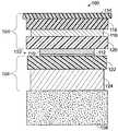
図1は、本教示の態様に従う光起電モジュールの断面図であり、光起電モジュールは一般に100で示される。光起電モジュール100は、一般に102で示されるPVセル層、一般に104で示されるトップシート、及び一般に106で示されるボトムシートを含む。光起電モジュール100は、また、ブチルマスチック接着層108のような屋根取付層を含むことができる。以下にさらに詳細に説明されるように、PVセル層102、トップシート104、及びボトムシート106は、各々それら自体が、様々な目的を果たす素材の複数の層を有し得る。 FIG. 1 is a cross-sectional view of a photovoltaic module in accordance with aspects of the present teachings, the photovoltaic module being generally designated 100.
さらに具体的には、PVセル層102は、それぞれが同様の構造を有する、相互接続された複数の光起電セルを含み得る。例えば、セル層102は、薄膜のPVセルであり、半導体吸収層110及び吸収層をその上部にて支持する基板112を含むことができる。半
導体吸収層110は、銅、インジウム、ガリウム、セレンからなる化合物(CIGS)の層をp型半導体層として、及び硫化カドミウム(CdS)の層をn型半導体層として含むことができるが、その他多数の光起電吸収層が知られている。CIGS/CdS型の光起電セルに関する記述は、ウェンドゥらに付与された特許文献1で見つけることができ、これを参照することにより、その全体がここに包含される。複数のそのようなセルは、各々、標準的な20〜40ミクロン(μm)の断面の厚さを有し、電気的に直列に、例えば、(図示しない)導電性リボン又はタブによって、結合され得る。More specifically, the
トップシート104は、様々な層、例えば、アッパー保護層114、アッパー封止層116、防湿材構造118及びローワー封止層120を含むことができる。 The
トップシート104のアッパー保護層114は、特に、摩耗、穿刺及び衝撃損傷(例えば、雹から)から、下に位置する層を保護するように構成されている。アッパー保護層は、例えば、略透明で、柔軟性を有する、耐候性フッ素ポリマー素材、例えば、エチレン−四フッ化エチレン(ETFE)フッ素ポリマーにて、約30〜150μmの断面厚さに構築することができる。 The upper
アッパー封止層116及びローワー封止層120は、それぞれ、エチレンビニルアセテート(EVA)のような素材にて、略透明で、柔軟性を有する層に構築されることができ、それぞれ、200〜500μmの断面厚さを有している。より一般的には、アッパー封止層116及びローワー封止層120は、それぞれ熱可塑性の層であることができ、又はその代わりに、116及び120の一方若しくは両方の層が熱硬化性の層であることができる。熱硬化性EVA素材の非パーオキサイド架橋剤の使用がローワー封止層120には特に適している。なぜなら、層120は、PVセル層102に近接しており、非パーオキサイド素材は、PVセル層のPV素材の劣化を軽減し得るからである。ある態様では、封止は、多層構造であることができ、層は、特に、例えば、EVAの層及び別個のUV吸収層を含む。 The
防湿材構造118は、それ自体が多層構造であることができ、全体の断面厚さの範囲は、約50〜150μmである。比較的厚く備えること、及び/又は比較的厚い防湿材構造は、モジュールの、特にその周囲近傍において、シワが生ずるのを防止するのに効果的である。防湿材構造118は、一般に(図示しない)幾つかの層を含み、そのような防湿材層は、例えば、金属酸化物素材の薄い層、及び、ポリエチレンテレフタレート(PET)及び/又はポリエチレンナフタレート(PEN)のような絶縁素材の、1つ又はそれ以上の、上及び/又は下に位置する層から構築される。PET及びPENは、紫外線(UV)放射による損傷を受け易いため、EVAの介在層やUV遮断剤を包含するその他の素材が、防湿材層と、PET及び/又はPEN層の間に配置され得る。同じ理由で、アッパー封止層116もUV遮断剤を包含し得る。 The
トップシート104と同様に、ボトムシート106も幾つかの層、例えば、ボトム封止層122及び多層バックシート構造124を含み得る。PVセル層102の上に配置される層と異なり、ボトムシート106の層は、透明である必要はない。 Similar to the
図1乃至図4で、PVセル層102の下側と直接接触しているように図示されているボトム封止層122は、いずれの場合も、熱可塑性素材、例えば、デンマーク、カールスランドのDNP社のdnpSolarセクションが製造する素材商品番号Z68によって構築され得る。ボトム封止層122に熱可塑性素材を使用することは、(例えば、モリブデンで被覆され得る)PVセル層102の裏側の接着性を向上することができ、PV層からのボトム封止の層剥離を減少させるのに有用である。さらに、熱可塑性ボトム封止層は、PVセルに接続しているリボンの座屈を引き起こすPV層にかかる力を減少させるのに十分な柔軟性を有している。また、熱可塑性ボトム封止層によって、PV層の下に配置される(図示しない)バイパスダイオードのような高浮き彫り構造又は部材をカバーしていても、なお、空気の存在下にて、急速加圧積層のような効果的な非真空積層をすることができるようになる。PVセルにバイパスダイオードを電気的に並列に備えることは、あるセルが損傷し、弱まり、又は遮光されたときに、モジュールのパワー損失、ヒステリシス及び損傷を回避するのに有用であり得る。モジュールの下にバイパスダイオードを配置することにより、モジュールのソーラー露出エリアの減少をすることなく、UV放射からダイオードを遮蔽することができる。 The
バックシート構造124は、例えば、薄膜の金属の防湿材層をポリマーに付着させた、複数の層を含むことができる。バックシート124は、一般に、最小限の熱的機械的応力によって、機械的安定性を付与しながら、PVセル層102の下側を水の侵入及びその他の混入物質から保護するように構成されている。本教示と関連して、好適に使用されるバックシート構造の例は、例えば、特許文献2で説明されており、またこれを参照することにより、その全体がここに包含される。 The
図1に図示されるように、様々なモジュール層、例えば、アッパー保護層114、アッパー封止層116、ローワー封止層120、ボトム封止層122、多層バックシート構造124、及び/又は接着層108は、それぞれ防湿材構造118の端部を越えるように延在することができる。そのため、これらの幾つか又は全ての層は、少なくとも1つのその他の層と、例えば、モジュールラミネート加工プロセスの際に、防湿材の端部を被覆し及び保護するため、結合するように構成されている。 As illustrated in FIG. 1, various module layers, such as an upper
より具体的には、アッパー保護層114及び/又はアッパー封止層116は、ローワー封止層120、ボトム封止層122、バックシート124及び/又は防湿材構造の下に配置される(図示しない)いずれの追加的な封止層と、防湿材構造118の端部を被覆し及び保護するため、結合するように構成され得る。これにより、防湿材構造の層の間への水及び水蒸気の侵入を抑止し又は防止さえすることができ、防湿材構造及びモジュール全体の安定性及び寿命の向上を実現し得る。 More specifically, the upper
これまでの説明では、PVセル層の上に配置される防湿材構造の端部の保護について焦点を合わせてきたが、同様の方法及び装置を、PVモジュールのその他の端部、例えば、多層バックシートの端部を保護するために使用することができる。例えば、アッパー保護層114、アッパー封止層116、ローワー封止層120及び/又はボトム封止層122のような様々なモジュール層は、多層バックシート124の端部の被覆及び保護のため、接着層108と(例えば、ラミネート加工プロセスの際に)結合するように構成されている。これにより、バックシートの層の間に湿気のような混入物質の染み込みを抑止することができ、バックシート及びモジュール全体の安定性及び寿命の向上を実現し得る。 While the discussion so far has focused on protecting the end of the moisture barrier structure placed over the PV cell layer, a similar method and apparatus can be applied to the other end of the PV module, such as a multilayer backplane. Can be used to protect the edge of the sheet. For example, various module layers such as the upper
アッパー保護層114、アッパー封止層116、ローワー封止層120、ボトム封止層122、バックシート124及び接着層108は、全て防湿材構造118の横方向端部よりも、横方向により遠くまで延出するように、図1において図示されている。同様に、前述の層は、全て防湿材構造118の(図示しない)縦方向端部よりも、縦方向により遠くまで延出することができる。例えば、モジュール100をロールツーロール法にて製造する場合、防湿材構造は、様々な保護層及び封止層が防湿材構造と縦方向に重なり合う間隙を残すために不連続的に供給され得る。連続的な素材は、その後、これらの間隙を横断して、1つ又はそれ以上の保護層が防湿材構造と重なり合う、個々のモジュールとする。 The upper
モジュールの全て(又はいずれも)の保護層が、防湿材構造の端部を越えて延在している必要はない。例えば、図2は、一般に100’で示される、本教示の態様による別の光起電モジュールの断面図である。モジュール100’の部材は、モジュール100の部材とほぼ同様であり、プライム符号の付いた参照番号は、図1における、プライム符号が付されていない対応する同様の部材について、図2において言及するために使用されるものである。しかしながら、モジュール100’では、ラミネート加工プロセス前の図示であるが、ローワー封止層120’及びボトム封止層122’は、防湿材構造118’の対応する線寸法よりも、それぞれ小さな横方向線寸法を有している。 It is not necessary for all (or any) protective layers of the module to extend beyond the edges of the moisture barrier structure. For example, FIG. 2 is a cross-sectional view of another photovoltaic module, generally designated 100 ', according to aspects of the present teachings. The members of the module 100 'are substantially similar to the members of the
図2の例では、ラミネート加工プロセスの際に施される加熱及び/又は加圧によって、ローワー封止層120’及びボトム封止層122’は、防湿材構造118’の横方向端部を越えて、横方向外側に押しつぶされる。ローワー封止層120’及びボトム封止層122’が当初、防湿材構造の対応する線寸法よりも、小さな縦方向線寸法を有する場合は、縦方向についても同様の既述が適用される。よって、ローワー封止層120’及びボトム封止層122’は、ラミネート加工プロセスの後は、防湿材構造118’の対応する線寸法よりも大きな線寸法を有し、これらの層は、なお防湿材構造の端部を被覆し及び保護するように構成され得る。一般に、いずれの保護層もラミネート加工プロセス前は、防湿材構造の対応する線寸法よりも小さな線寸法を有し、及びラミネート加工プロセス後は、防湿材構造の対応する線寸法よりも大きな線寸法を有するように、構成することができる。 In the example of FIG. 2, due to the heating and / or pressure applied during the laminating process, the
図3は、一般に100”で示される、本教示の態様による、さらに別の光起電モジュールの断面図である。モジュール100”は、モジュール100及び100’とほぼ同様であり、ダブルプライム符号の付いた参照番号は、それぞれ図1及び図2において、プライム符号が付されていない、及びプライム符号が付された、対応する部材について言及するために使用されるものである。しかしながら、図3では、ボトム封止層122”だけが、ラミネート加工プロセス前は、防湿材構造の対応する線寸法よりも小さな線寸法を有し、ラミネート加工プロセスの後は、防湿材構造の対応する線寸法よりも大きな線寸法を有するように構成されている。 FIG. 3 is a cross-sectional view of yet another photovoltaic module, generally designated 100 ″, in accordance with aspects of the present teachings.
いずれの特定の保護層の線寸法にかかわらず、モジュールのラミネート加工は、1つ又はそれ以上の保護層の断面積に変化をもたらし得る。例えば、ラミネート加工の際の加熱及び/又は加圧の適用は、ローワー封止層120(及び120’、120”)及び/又はボトム封止層122(及び122’、122”)が不均一になるようにし得る。より具体的には、モジュールのラミネート加工後は、モジュールの端部近傍のこれらの封止層の断面積は、モジュールの内側部の封止層の断面積と比較して大幅に減少している。換言すると、封止層は、ラミネート加工の際に、モジュールの端部近傍において先細りになるようにすることができる。これは、防湿材構造の端部近傍において、小さな厚さの封止材をもたらし、これが対応して、封止材、及び防湿材構造の層の間を通じた水の染み込みの機会を減少する。 Regardless of the line dimensions of any particular protective layer, the lamination of the module can result in a change in the cross-sectional area of one or more protective layers. For example, application of heat and / or pressure during laminating may cause the lower sealing layer 120 (and 120 ′, 120 ″) and / or the bottom sealing layer 122 (and 122 ′, 122 ″) to be non-uniform. Can be. More specifically, after laminating the module, the cross-sectional area of these sealing layers near the end of the module is greatly reduced compared to the cross-sectional area of the sealing layer inside the module. . In other words, the sealing layer can be tapered near the end of the module during lamination. This results in a small thickness of sealant near the edge of the moisture barrier structure, which correspondingly reduces the chance of water penetration through the sealant and layers of the moisture barrier structure.
モジュールの端部近傍における様々な保護層の断面積の減少は、図2及び図3に示すように、減少した線寸法の保護層(例えば、封止層)を備えることで容易に実現し得る。例えば、ローワー封止層120’及びボトム封止層122’の一方又は両方が、モジュールのラミネート加工前において、防湿材構造及びバックシートの対応する線寸法よりも小さな線寸法を有するときは、モジュールのラミネート加工後において、モジュールの端部近傍における防湿材構造及びバックシートの間の断面積を最小化することができる。 Reduction of the cross-sectional area of the various protective layers near the end of the module can be easily achieved by providing a protective layer (eg, a sealing layer) with reduced line dimensions, as shown in FIGS. . For example, if one or both of the
図4は、図3のモジュール100”の別の断面図であるが、本教示の態様によって、モジュールが僅かに変更されている。具体的には、モジュール100”は、ここでは、モジュールの周囲部に配置された接着部119”を含んでいる。より具体的には、接着層119”が防湿材構造118”の端部に沿って配置されるように、図4は図示している。これは、ラミネート加工の際、防湿材構造の端部への他の保護層の接着を容易にし得る。 FIG. 4 is another cross-sectional view of the
より一般的には、層119”のような接着層は、ラミネート加工後のモジュールの端部の保護を容易にするために、モジュールのいずれの周囲部又はその近傍に配置することができる。接着層は、モジュールの他の封止素材と同様の接着封止材から構築することができ、または接着層は、防湿材構造の端部及び/又は防湿材構造の端部を保護するように構成されたモジュールの他の層をしっかりと接合するように構成された、その他のいずれかの封止素材から構築することができる。 More generally, an adhesive layer such as
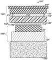
ある場合には、防湿材を含むトップシートは、BIPVモジュールの残部とは別に、独立した部材として、製造することができる。図5は、一般に200で示される、そのようなトップシート構造の断面図であり、本教示において好適に使用され得る。トップシート構造200は、アッパー保護層214、アッパー封止層216及び防湿材構造218を含む。これらの部材は、類似の番号で示される、モジュール100の対応する部材とほぼ同様である。従って、別に生産されるトップシート構造は、約280〜800μmの範囲の断面厚さを有し得る。トップシートを比較的大きな厚さとするか、さもなければ望ましく固くすることは、トップシートがラミネート加工されて、モジュール、特にモジュールの端部近傍に、シワが生じる可能性を減少するのに有用であり得る。 In some cases, the topsheet containing the moisture barrier can be manufactured as an independent member separately from the remainder of the BIPV module. FIG. 5 is a cross-sectional view of such a topsheet structure, generally indicated at 200, and can be suitably used in the present teachings. The
トップシート構造200のようなトップシートが別に製造されるときには、ラミネート加工も別に行われることができ、その場合、アッパー保護層214及び/又はアッパー封止層216の部分が、この最初のラミネート加工プロセスの際に、防湿材構造の端部を包み込むことができる。さらに、防湿材構造自体が防湿材の上に位置する保護層及び/又は防湿材の下に位置する保護層を含むことができ、この場合、1つ又はそれ以上のこれらの保護層は、ラミネート加工プロセス後に、防湿材構造の端部を被覆し及び保護するように構成することができる。よって、トップシート構造がPVセルと一体となってモジュールになる前であるにもかかわらずに、防湿材構造の端部は、被覆され及び保護されている。代替的に、又は追加的に、トップシートがモジュールに提供され、その後にラミネート加工されることができ、この場合は、防湿材の端部のより良好な保護をもたらすことができる。 When a topsheet, such as
一般に、防湿材構造(例えば、118、118’、118”又は218)の上に位置するいずれかの保護層及び/又は防湿材構造の下に位置するいずれかの保護層は、図1乃至図4に関連して上述したように結合して、又は図5に関連して上述したように防湿材構造の端部の周りに1つの保護層が配置されることによって、ラミネート加工プロセス後、防湿材構造の端部を被覆し及び保護するように構成されることができる。典型的には、独立したトップシート構造は2度ラミネート加工される。1度目は、その最初の製造の際に、及び2度目は、PVモジュールへの一体化の際である。この場合、1つの素材が端部を包み込むことと、2つ以上の素材が端部の周りにて結合することとの組み合わせによって、防湿材端部の保護が生じ得る。類似の態様で、ある場合には、多層バックシートを独立して設けることができ、この場合は、その端部は、少なくとも一部が、バックシートのPVモジュールへの一体化の前の、最初のラミネート加工プロセスにおいて保護される。 In general, any protective layer located above the moisture barrier structure (eg, 118, 118 ′, 118 ″ or 218) and / or any protective layer located below the moisture barrier structure is shown in FIGS. 4 after the laminating process, either by bonding as described above in connection with 4 or by placing one protective layer around the edge of the moisture barrier structure as described above in connection with FIG. It can be configured to cover and protect the edges of the material structure, typically a separate topsheet structure is laminated twice, the first time during its initial manufacture And the second time during the integration into the PV module, where one material wraps around the end and two or more materials combine around the end, Protection of the moisture barrier end can occur. In a similar manner, in some cases, a multi-layer backsheet can be provided independently, in which case its end is at least partly first before integration of the backsheet into the PV module. Protected in the laminating process.
Claims (20)
Translated fromJapanese前記ボトム封止層の上に、それぞれのセルが半導体吸収層と当該半導体吸収層をその上に支持する基板とを含み、電気的に相互接続された複数の光起電セルを配置する工程と、
防湿材の上に位置する保護層及び/又は当該防湿材の下に位置する保護層を含む防湿材構造を構成する工程と、当該防湿材構造の上にアッパー封止層を配置する工程と、当該アッパー封止層の上にアッパー保護層を配置する工程と、当該アッパー保護層及び/又は当該アッパー封止層の部分が前記防湿材構造の端部を包み込むように1度目のラミネート加工プロセスを実行する工程とを実行することによって独立したトップシート構造を別に製造する工程と、
前記光起電セルの上に前記トップシート構造を配置する工程と、
前記防湿材構造の端部を被覆し及び保護するために、前記アッパー保護層及び/又は前記アッパー封止層が前記ボトム封止層及び/又は前記バックシートと結合するように、2度目のラミネート加工プロセスで前記トップシート構造を前記ボトムシートにラミネートする工程と、
を備えることを特徴とする光起電モジュール製造方法。Providing a bottom sheet comprising a back sheet and a bottom sealing layer located on the back sheet;
Placing a plurality of electrically interconnected photovoltaic cells on the bottom sealing layer, each cell including a semiconductor absorption layer and a substrate supporting the semiconductor absorption layer thereon; and ,
A step of forming a moisture-proof material structure including a protective layer located on the moisture-proof material and / or a protective layer located under the moisture-proof material, and a step of arranging an upper sealing layer on the moisture-proof material structure; A step of arranging an upper protective layer on the upper sealing layer, and a first laminating process so that the upper protective layer and / or a portion of the upper sealing layer wraps an end of the moisture-proof material structure. Separately producing an independent topsheet structure by performing the performing step;
Disposing the topsheet structure on the photovoltaic cell;
A second laminate so that the upper protective layer and / or the upper sealing layer is bonded to the bottom sealing layer and / or the backsheet to cover and protect the edges of the moisture barrier structure. Laminating the top sheet structure to the bottom sheet in a processing process;
A photovoltaic module manufacturing method comprising:
防湿材層の上に位置する絶縁素材の層及び/又は当該防湿材層の下に位置する絶縁素材の層を含む防湿材構造を構成する工程と、
前記防湿材構造の上にアッパー封止層を配置する工程と、
前記アッパー封止層の上にアッパー保護層を配置する工程と、
前記防湿材構造の端部を被覆し及び保護するために、前記アッパー保護層及び/又は前記アッパー封止層の部分が前記防湿材構造の端部を包み込むように前記防湿材構造、前記アッパー封止層、および前記アッパー保護層を一緒にラミネート加工する工程と、
を備えることを特徴とするトップシート構造製造方法。A topsheet structure manufacturing method for manufacturing an independent topsheet structure for a photovoltaic cell comprising:
Forming a moisture-proof material structure including an insulating material layer located above the moisture-proof material layer and / or an insulating material layer located below the moisture-proof material layer;
Placing an upper sealing layer on the moisture barrier structure;
Placing an upper protective layer on the upper sealing layer;
In order to cover and protect the edge of the moisture barrier structure, the moisture protective material structure, the upper seal, and the upper protective layer and / or the upper sealing layer portion wraps the edge of the moisture barrier structure. Laminating the stop layer and the upper protective layer together;
A topsheet structure manufacturing method comprising:
前記ラミネート加工する工程が、前記ローワー封止層を前記防湿材構造、前記アッパー封止層、および前記アッパー保護層と一緒にラミネート加工することを含む、
ことを特徴とする請求項7に記載のトップシート構造製造方法。Providing a lower sealing layer under the moisture barrier structure;
The laminating step includes laminating the lower sealing layer together with the moisture barrier structure, the upper sealing layer, and the upper protective layer;
The method for producing a top sheet structure according to claim 7.
下に位置する絶縁素材の層と上に位置する絶縁素材の層との間に防湿材層を配置する工程と、
前記上に位置する絶縁素材の層の上にアッパー封止層を配置する工程と、
前記アッパー封止層の上にアッパー保護層を配置する工程と、
前記防湿材層の端部を被覆し及び保護するために、前記アッパー保護層及び/又は前記アッパー封止層の部分が前記防湿材層の端部を包み込むように前記層の全部を一緒にラミネート加工する工程と、
を備え、
結果として生じるラミネート加工されたトップシート構造が、更なるラミネーション加工工程において光起電モジュールにラミネートされることができる独立した構造として構成される、
ことを特徴とするトップシート構造製造方法。A topsheet structure manufacturing method for manufacturing a topsheet structure for a photovoltaic cell comprising:
Placing a moisture barrier layer between the underlying insulating material layer and the insulating material layer located above;
Disposing an upper sealing layer on the insulating material layer located above;
Placing an upper protective layer on the upper sealing layer;
In order to cover and protect the edge of the moisture barrier layer, all of the layers are laminated together so that the upper protective layer and / or the upper sealing layer portion wraps around the edge of the moisture barrier layer Process to process,
With
The resulting laminated topsheet structure is configured as an independent structure that can be laminated to the photovoltaic module in a further lamination process.
A top sheet structure manufacturing method characterized by the above.
前記層の全部を一緒にラミネート加工する工程が、前記ローワー封止層を残りの層と一緒にラミネート加工することを含む、
ことを特徴とする請求項14に記載のトップシート構造製造方法。Providing a lower sealing layer on the opposite side of the moisture barrier layer adjacent to the underlying insulating material layer;
Laminating all of the layers together includes laminating the lower sealing layer with the remaining layers;
The method of manufacturing a top sheet structure according to claim 14.
Applications Claiming Priority (2)
| Application Number | Priority Date | Filing Date | Title |
|---|---|---|---|
| US37880110P | 2010-08-31 | 2010-08-31 | |
| US61/378,801 | 2010-08-31 |
Related Parent Applications (1)
| Application Number | Title | Priority Date | Filing Date |
|---|---|---|---|
| JP2013527269ADivisionJP2013537001A (en) | 2010-08-31 | 2011-08-31 | Flexible building-integrated photovoltaic power generation structure |
Publications (1)
| Publication Number | Publication Date |
|---|---|
| JP2015195417Atrue JP2015195417A (en) | 2015-11-05 |
Family
ID=45773250
Family Applications (2)
| Application Number | Title | Priority Date | Filing Date |
|---|---|---|---|
| JP2013527269APendingJP2013537001A (en) | 2010-08-31 | 2011-08-31 | Flexible building-integrated photovoltaic power generation structure |
| JP2015160061APendingJP2015195417A (en) | 2010-08-31 | 2015-08-14 | Photovoltaic module manufacturing method and topsheet structure manufacturing method |
Family Applications Before (1)
| Application Number | Title | Priority Date | Filing Date |
|---|---|---|---|
| JP2013527269APendingJP2013537001A (en) | 2010-08-31 | 2011-08-31 | Flexible building-integrated photovoltaic power generation structure |
Country Status (5)
| Country | Link |
|---|---|
| US (2) | US20120222725A1 (en) |
| JP (2) | JP2013537001A (en) |
| CN (1) | CN103168416B (en) |
| DE (1) | DE112011102882T5 (en) |
| WO (1) | WO2012030971A1 (en) |
Families Citing this family (7)
| Publication number | Priority date | Publication date | Assignee | Title |
|---|---|---|---|---|
| CA2739766C (en)* | 2011-05-10 | 2016-08-23 | Robert Richardson | Roof solar panel for conventional sloping roof and shingle integration |
| SG2014007876A (en) | 2011-08-04 | 2014-03-28 | 3M Innovative Properties Co | Edge protected barrier assemblies |
| KR101305660B1 (en)* | 2011-10-17 | 2013-09-09 | 엘지이노텍 주식회사 | Solar cell module and method of fabricating the same |
| EP3168982A1 (en)* | 2015-11-13 | 2017-05-17 | S.A. Imperbel N.V. | Flexible multilayer system |
| CN107195715B (en)* | 2017-04-18 | 2019-12-10 | 东莞南玻光伏科技有限公司 | Solar photovoltaic modules and building curtain walls |
| CN108538940A (en)* | 2018-03-25 | 2018-09-14 | 宜兴锦尚太阳能科技有限公司 | A kind of solar components structure easy to maintain |
| CN116613229A (en) | 2023-06-25 | 2023-08-18 | 晶科能源股份有限公司 | Photovoltaic module |
Citations (5)
| Publication number | Priority date | Publication date | Assignee | Title |
|---|---|---|---|---|
| JPH07142756A (en)* | 1993-06-24 | 1995-06-02 | Canon Inc | Solar cell module and method of manufacturing the same |
| JP2000174298A (en)* | 1998-12-07 | 2000-06-23 | Bridgestone Corp | Cover material for solar cell, sealing film, and solar cell |
| JP2002026344A (en)* | 2000-07-11 | 2002-01-25 | Sanyo Electric Co Ltd | Solar cell module |
| JP2002083978A (en)* | 2000-09-05 | 2002-03-22 | Sanyo Electric Co Ltd | Method of manufacturing solar cell module |
| JP2010003860A (en)* | 2008-06-20 | 2010-01-07 | Honda Motor Co Ltd | Solar-cell module and its manufacturing method |
Family Cites Families (20)
| Publication number | Priority date | Publication date | Assignee | Title |
|---|---|---|---|---|
| JPS62132371A (en)* | 1985-12-05 | 1987-06-15 | Matsushita Electric Ind Co Ltd | solar module |
| JP4036616B2 (en)* | 2000-01-31 | 2008-01-23 | 三洋電機株式会社 | Solar cell module |
| US7194197B1 (en) | 2000-03-16 | 2007-03-20 | Global Solar Energy, Inc. | Nozzle-based, vapor-phase, plume delivery structure for use in production of thin-film deposition layer |
| US6729081B2 (en)* | 2000-06-09 | 2004-05-04 | United Solar Systems Corporation | Self-adhesive photovoltaic module |
| JP2006310680A (en)* | 2005-05-02 | 2006-11-09 | Kaneka Corp | Thin film solar cell module |
| US8039739B1 (en)* | 2006-05-05 | 2011-10-18 | Nanosolar, Inc. | Individually encapsulated solar cells and solar cell strings |
| US20070295390A1 (en)* | 2006-05-05 | 2007-12-27 | Nanosolar, Inc. | Individually encapsulated solar cells and solar cell strings having a substantially inorganic protective layer |
| US20070295385A1 (en)* | 2006-05-05 | 2007-12-27 | Nanosolar, Inc. | Individually encapsulated solar cells and solar cell strings having a substantially inorganic protective layer |
| EP2030248A2 (en)* | 2006-06-21 | 2009-03-04 | Evergreen Solar, Inc. | Frameless photovoltaic module |
| US20100297798A1 (en)* | 2006-07-27 | 2010-11-25 | Adriani Paul M | Individually Encapsulated Solar Cells and/or Solar Cell Strings |
| US7847184B2 (en)* | 2006-07-28 | 2010-12-07 | E. I. Du Pont De Nemours And Company | Low modulus solar cell encapsulant sheets with enhanced stability and adhesion |
| US20090114262A1 (en)* | 2006-08-18 | 2009-05-07 | Adriani Paul M | Methods and Devices for Large-Scale Solar Installations |
| US20080053519A1 (en)* | 2006-08-30 | 2008-03-06 | Miasole | Laminated photovoltaic cell |
| US20080302031A1 (en)* | 2007-06-05 | 2008-12-11 | Solar Roofing Systems, Inc., | Integrated solar roofing tile connection system |
| CN201134766Y (en)* | 2007-09-25 | 2008-10-15 | 上海太阳能工程技术研究中心有限公司 | Photovoltaic power generating sunshade panel |
| CN101448237B (en)* | 2008-02-02 | 2011-08-10 | 中兴通讯股份有限公司 | Discovery method of home link in mobile IP |
| AU2009234506B2 (en)* | 2008-04-09 | 2013-11-21 | Agency For Science, Technology And Research | Multilayer film for encapsulating oxygen and/or moisture sensitive electronic devices |
| EP2359407A4 (en) | 2008-12-16 | 2013-03-13 | Solopower Inc | METHODS OF MANUFACTURING AND STRUCTURES OF THIN FILM PHOTOVOLTAIC MODULE |
| US7960643B2 (en)* | 2009-05-12 | 2011-06-14 | Miasole | Isolated metallic flexible back sheet for solar module encapsulation |
| WO2011143205A1 (en)* | 2010-05-10 | 2011-11-17 | Global Solar Energy, Inc. | Multi-layer solar module backsheet |
- 2011
- 2011-08-31JPJP2013527269Apatent/JP2013537001A/enactivePending
- 2011-08-31USUS13/222,991patent/US20120222725A1/ennot_activeAbandoned
- 2011-08-31WOPCT/US2011/049983patent/WO2012030971A1/enactiveApplication Filing
- 2011-08-31DEDE112011102882Tpatent/DE112011102882T5/ennot_activeWithdrawn
- 2011-08-31CNCN201180041663.2Apatent/CN103168416B/enactiveActive
- 2015
- 2015-06-17USUS14/742,089patent/US9748894B2/enactiveActive
- 2015-08-14JPJP2015160061Apatent/JP2015195417A/enactivePending
Patent Citations (5)
| Publication number | Priority date | Publication date | Assignee | Title |
|---|---|---|---|---|
| JPH07142756A (en)* | 1993-06-24 | 1995-06-02 | Canon Inc | Solar cell module and method of manufacturing the same |
| JP2000174298A (en)* | 1998-12-07 | 2000-06-23 | Bridgestone Corp | Cover material for solar cell, sealing film, and solar cell |
| JP2002026344A (en)* | 2000-07-11 | 2002-01-25 | Sanyo Electric Co Ltd | Solar cell module |
| JP2002083978A (en)* | 2000-09-05 | 2002-03-22 | Sanyo Electric Co Ltd | Method of manufacturing solar cell module |
| JP2010003860A (en)* | 2008-06-20 | 2010-01-07 | Honda Motor Co Ltd | Solar-cell module and its manufacturing method |
Also Published As
| Publication number | Publication date |
|---|---|
| CN103168416B (en) | 2016-01-20 |
| US20120222725A1 (en) | 2012-09-06 |
| HK1186584A1 (en) | 2014-03-14 |
| WO2012030971A1 (en) | 2012-03-08 |
| US20150288323A1 (en) | 2015-10-08 |
| JP2013537001A (en) | 2013-09-26 |
| US9748894B2 (en) | 2017-08-29 |
| CN103168416A (en) | 2013-06-19 |
| DE112011102882T5 (en) | 2013-06-06 |
Similar Documents
| Publication | Publication Date | Title |
|---|---|---|
| JP2015195417A (en) | Photovoltaic module manufacturing method and topsheet structure manufacturing method | |
| US7960643B2 (en) | Isolated metallic flexible back sheet for solar module encapsulation | |
| US7829783B2 (en) | Isolated metallic flexible back sheet for solar module encapsulation | |
| JP6286736B2 (en) | Back contact type solar cell module | |
| US20140137939A1 (en) | Solar-cell module and manufacturing method therefor | |
| KR101286282B1 (en) | Frameless solar cell panel and manufacturing method therefor | |
| US20120152327A1 (en) | Method of manufacturing solar modules | |
| KR20190060886A (en) | Photovoltaic module and laminate | |
| US20120080065A1 (en) | Thin Film Photovoltaic Modules with Structural Bonds | |
| EP2693101B1 (en) | Solar lighting system | |
| JP2012089663A (en) | Solar cell module and manufacturing method of the same | |
| US20130000689A1 (en) | Photovoltaic module support assembly with standoff clamps | |
| JP2012204458A (en) | Method for manufacturing solar cell module | |
| JP2007067203A (en) | Solar cell module and method for manufacturing solar cell module | |
| JP2012094742A (en) | Solar battery module and method for producing the same | |
| JP2013089749A (en) | Frameless solar cell module | |
| JP7702844B2 (en) | Solar Cell Module | |
| KR101733054B1 (en) | Solar cell module | |
| JP2009200145A (en) | Solar cell back sheet and solar cell module | |
| JP4720174B2 (en) | Solar cell module | |
| JP2012094608A (en) | Solar cell module | |
| KR20090105822A (en) | Thin film solar cell and manufacturing method, thin film solar cell module | |
| HK1186584B (en) | Flexible building-integrated photovoltaic structure | |
| JP2014192455A (en) | Solar cell module | |
| JP2025130366A (en) | Perovskite solar cell and manufacturing method thereof |
Legal Events
| Date | Code | Title | Description |
|---|---|---|---|
| A521 | Request for written amendment filed | Free format text:JAPANESE INTERMEDIATE CODE: A523 Effective date:20150817 | |
| A621 | Written request for application examination | Free format text:JAPANESE INTERMEDIATE CODE: A621 Effective date:20150824 | |
| A521 | Request for written amendment filed | Free format text:JAPANESE INTERMEDIATE CODE: A523 Effective date:20150902 | |
| A131 | Notification of reasons for refusal | Free format text:JAPANESE INTERMEDIATE CODE: A131 Effective date:20160524 | |
| A977 | Report on retrieval | Free format text:JAPANESE INTERMEDIATE CODE: A971007 Effective date:20160525 | |
| A02 | Decision of refusal | Free format text:JAPANESE INTERMEDIATE CODE: A02 Effective date:20170110 |