JP2015185897A - Image encoding method and device - Google Patents
Image encoding method and deviceDownload PDFInfo
- Publication number
- JP2015185897A JP2015185897AJP2014058306AJP2014058306AJP2015185897AJP 2015185897 AJP2015185897 AJP 2015185897AJP 2014058306 AJP2014058306 AJP 2014058306AJP 2014058306 AJP2014058306 AJP 2014058306AJP 2015185897 AJP2015185897 AJP 2015185897A
- Authority
- JP
- Japan
- Prior art keywords
- intra prediction
- processing block
- processing
- block
- blocks
- Prior art date
- Legal status (The legal status is an assumption and is not a legal conclusion. Google has not performed a legal analysis and makes no representation as to the accuracy of the status listed.)
- Pending
Links
Images


Classifications
- H—ELECTRICITY
- H04—ELECTRIC COMMUNICATION TECHNIQUE
- H04N—PICTORIAL COMMUNICATION, e.g. TELEVISION
- H04N19/00—Methods or arrangements for coding, decoding, compressing or decompressing digital video signals
- H04N19/10—Methods or arrangements for coding, decoding, compressing or decompressing digital video signals using adaptive coding
- H04N19/102—Methods or arrangements for coding, decoding, compressing or decompressing digital video signals using adaptive coding characterised by the element, parameter or selection affected or controlled by the adaptive coding
- H04N19/103—Selection of coding mode or of prediction mode
- H—ELECTRICITY
- H04—ELECTRIC COMMUNICATION TECHNIQUE
- H04N—PICTORIAL COMMUNICATION, e.g. TELEVISION
- H04N19/00—Methods or arrangements for coding, decoding, compressing or decompressing digital video signals
- H04N19/50—Methods or arrangements for coding, decoding, compressing or decompressing digital video signals using predictive coding
- H04N19/593—Methods or arrangements for coding, decoding, compressing or decompressing digital video signals using predictive coding involving spatial prediction techniques
- H—ELECTRICITY
- H04—ELECTRIC COMMUNICATION TECHNIQUE
- H04N—PICTORIAL COMMUNICATION, e.g. TELEVISION
- H04N19/00—Methods or arrangements for coding, decoding, compressing or decompressing digital video signals
- H04N19/10—Methods or arrangements for coding, decoding, compressing or decompressing digital video signals using adaptive coding
- H04N19/102—Methods or arrangements for coding, decoding, compressing or decompressing digital video signals using adaptive coding characterised by the element, parameter or selection affected or controlled by the adaptive coding
- H04N19/124—Quantisation
- H—ELECTRICITY
- H04—ELECTRIC COMMUNICATION TECHNIQUE
- H04N—PICTORIAL COMMUNICATION, e.g. TELEVISION
- H04N19/00—Methods or arrangements for coding, decoding, compressing or decompressing digital video signals
- H04N19/60—Methods or arrangements for coding, decoding, compressing or decompressing digital video signals using transform coding
- H04N19/61—Methods or arrangements for coding, decoding, compressing or decompressing digital video signals using transform coding in combination with predictive coding
Landscapes
- Engineering & Computer Science (AREA)
- Multimedia (AREA)
- Signal Processing (AREA)
- Compression Or Coding Systems Of Tv Signals (AREA)
Abstract
Translated fromJapaneseDescription
Translated fromJapanese本開示は、イントラ予測を行う画像符号化方法及び画像符号化装置に関する。 The present disclosure relates to an image encoding method and an image encoding apparatus that perform intra prediction.
動画像符号化規格として、MPEG−4 AVC/H.264方式(以降、H.264方式と呼ぶ)が知られている。このような動画像符号化規格では、イントラ予測において、複数のイントラ予測モードから一つを選択してイントラ予測が行われる(例えば、特許文献1〜特許文献3を参照)。 As a moving picture coding standard, MPEG-4 AVC / H. The H.264 system (hereinafter referred to as the H.264 system) is known. In such a moving image coding standard, intra prediction is performed by selecting one of a plurality of intra prediction modes in intra prediction (see, for example,
また、H.264の次世代の動画像符号化規格としてHigh Efficiency Video Coding(HEVC)が検討されている。 H. High Efficiency Video Coding (HEVC) is being studied as a next-generation video coding standard of H.264.
画像符号化方法では、符号化処理の高速化が望まれている。 In the image encoding method, speeding up of the encoding process is desired.
本開示は、符号化処理の高速化を実現できる画像符号化方法及び画像符号化装置を提供する。 The present disclosure provides an image encoding method and an image encoding apparatus that can realize high-speed encoding processing.
本開示における画像符号化方法は、符号化対象のピクチャが分割されることで得られた複数の符号化単位ブロックの各々をイントラ予測の処理単位である複数の処理ブロックに分割する分割ステップと、前記複数の処理ブロックの各々に対して、所定の符号化規格で規定されている複数のイントラ予測モードから一つのイントラ予測モードを選択し、選択したイントラ予測モードでイントラ予測処理を行うイントラ予測ステップとを含み、前記複数のイントラ予測モードは、処理対象の処理ブロックの左下の処理ブロックを参照する左下参照モードを含み、前記複数の処理ブロックは、第1処理ブロックと、前記第1処理ブロックと同じサイズであり、前記第1処理ブロックの右上に位置する第2処理ブロックとを含み、前記所定の符号化規格では、前記第1処理ブロックの情報の後に前記第2処理ブロックの情報をビットストリームへ書き込むことが規定されており、前記イントラ予測ステップでは、前記左下参照モードの選択を禁止して前記第2処理ブロックのイントラ予測処理を行い、その後に前記第1処理ブロックのイントラ予測処理を行う。 An image encoding method according to the present disclosure includes a division step of dividing each of a plurality of coding unit blocks obtained by dividing a picture to be encoded into a plurality of processing blocks that are processing units of intra prediction; Intra prediction step of selecting one intra prediction mode from a plurality of intra prediction modes defined by a predetermined coding standard for each of the plurality of processing blocks, and performing an intra prediction process in the selected intra prediction mode The plurality of intra prediction modes includes a lower left reference mode that refers to a lower left processing block of a processing block to be processed, and the plurality of processing blocks include a first processing block, the first processing block, and A second processing block having the same size and positioned at the upper right of the first processing block. In the above, it is stipulated that the information of the second processing block is written into the bitstream after the information of the first processing block. In the intra prediction step, the selection of the lower left reference mode is prohibited and the second processing block is prohibited. A block intra prediction process is performed, and then an intra prediction process of the first processing block is performed.
本開示における画像符号化方法及び画像符号化装置は、符号化処理の高速化を実現できる。 The image encoding method and the image encoding apparatus according to the present disclosure can realize high-speed encoding processing.
以下、適宜図面を参照しながら、実施の形態を詳細に説明する。ただし、必要以上に詳細な説明は省略する場合がある。例えば、すでによく知られた事項の詳細説明や実質的に同一の構成に対する重複説明を省略する場合がある。これは、以下の説明が不必要に冗長になるのを避け、当業者の理解を容易にするためである。 Hereinafter, embodiments will be described in detail with reference to the drawings as appropriate. However, more detailed explanation than necessary may be omitted. For example, detailed descriptions of already well-known matters and repeated descriptions for substantially the same configuration may be omitted. This is to avoid the following description from becoming unnecessarily redundant and to facilitate understanding by those skilled in the art.
なお、発明者らは、当業者が本開示を十分に理解するために添付図面及び以下の説明を提供するのであって、これらによって特許請求の範囲に記載の主題を限定することを意図するものではない。 In addition, the inventors provide the accompanying drawings and the following description in order for those skilled in the art to fully understand the present disclosure, and these are intended to limit the subject matter described in the claims. is not.
(実施の形態)
以下、図1〜図14を用いて、本実施の形態を説明する。説明の便宜上、HEVCを用いて符号化する際の動作を説明する。(Embodiment)
Hereinafter, the present embodiment will be described with reference to FIGS. For convenience of explanation, an operation when encoding using HEVC will be described.
[画像符号化装置の構成]
図1は、本実施の形態に係る画像符号化装置100のブロック図である。[Configuration of Image Encoding Device]
FIG. 1 is a block diagram of an
画像符号化装置100は、ピクチャ単位で入力された動画像を符号化単位ブロック(コーディングユニット:CU)に分割し、CU単位で符号化処理を行うことで、符号列を生成する。なお、CUには複数のサブブロックが含まれる。画像符号化装置100が有する構成要素は、CU単位又はサブブロック単位で処理する。 The
図1に示す画像符号化装置100は、ピクチャバッファ101と、ピクチャ分割部102と、減算部103と、予測残差符号化部104と、係数符号列生成部105と、予測残差復号化部106と、加算部107と、イントラ予測部108と、量子化値決定部114と、ヘッダ符号列生成部115とを備える。 An
画像符号化装置100は、入力画像をHEVCの規格に基づいて圧縮符号化し、符号列を生成して出力する。 The image encoding
ピクチャバッファ101は、入力画像を取得し、記憶媒体に一時的に記憶する。例えば、ピクチャバッファ101は、表示を行う順にピクチャ単位で入力される入力画像を、符号化を行う順に並び替えて蓄積する。ピクチャバッファ101における記憶媒体として、DRAM(Dynamic Random Access Memory)メモリなど、入力画像を記憶できる記憶媒体であればどのようなものを利用しても構わない。 The
ピクチャ分割部102は、符号化対象のピクチャを複数の符号化単位ブロック(CU)に分割し、分割された複数の符号化単位ブロックの各々をイントラ予測の処理単位である複数の処理ブロック(プレディクションユニット:PU)に分割する分割部の一例である。ピクチャ分割部102は、減算部103又は量子化値決定部114からの読出し命令を受け付けた場合、ピクチャバッファ101から入力画像を取得する。そして、ピクチャ分割部102は、読出し命令に対応する画像信号を減算部103に出力する。 The
なお、CUおよびPUのブロックサイズは、当該CUおよびPUを利用して処理するまでに設定されていれば、どのようなタイミングで設定されても構わない。一方、CUのブロックサイズが設定された後にPUのブロックサイズが設定されても構わない。また、PUのブロックサイズが設定された後にCUのブロックサイズが設定されても構わない。さらに、CUおよびPUのブロックサイズが同時に設定されても構わない。 Note that the block size of the CU and PU may be set at any timing as long as the block size is set before processing using the CU and PU. On the other hand, the PU block size may be set after the CU block size is set. Further, the CU block size may be set after the PU block size is set. Furthermore, the block size of the CU and PU may be set simultaneously.
CUは、符号化単位ブロックの一例であり、例えば、64×64画素、32×32画素、16×16画素または8×8画素のブロックである。 A CU is an example of a coding unit block, and is, for example, a block of 64 × 64 pixels, 32 × 32 pixels, 16 × 16 pixels, or 8 × 8 pixels.
減算部103は、ピクチャ分割部102から出力される処理対象となる少なくとも1つ以上のCU(以下、対象CU)と、イントラ予測部108から出力される予測画像との差分を算出することで、残差信号を生成する。例えば、減算部103は、CU又はサブブロック毎に差分を算出する。減算部103は、残差信号を予測残差符号化部104に出力する。 The
予測残差符号化部104は、減算部103から出力される残差信号を直交変換することで、直交変換係数を生成する。予測残差符号化部104は、残差信号を直交変換する場合、直交変換用のサブブロック単位で処理を行う。ここで、直交変換用のサブブロックは、トランスフォームユニット(TU)と呼ばれる、複数の画素で構成される直交変換処理単位である。例えば、直交変換用のサブブロック(TU)は、32×32画素、16×16画素、8×8画素、又は4×4画素のブロックである。なお、入力信号が輝度成分および色差成分のうちいずれの信号かに依存してTUに利用できるブロックサイズが変わる。 The prediction
予測残差符号化部104は、さらに、得られた直交変換係数の各周波数成分を量子化することで量子化係数を生成する。そして、予測残差符号化部104は、量子化係数を係数符号列生成部105及び予測残差復号化部106に出力する。なお、予測残差符号化部104は、量子化値決定部114によって決定された量子化値を用いて、直交変換係数を量子化する。 The prediction
係数符号列生成部105は、予測残差符号化部104から出力される量子化係数を可変長符号化する。係数符号列生成部105は、可変長符号化によって生成される符号列をヘッダ符号列生成部115が生成した符号列に続けて追記する。これにより、係数符号列生成部105は、出力用の符号列信号を生成する。 The coefficient code
予測残差復号化部106は、予測残差符号化部104から出力される量子化係数を逆量子化及び逆直交変換することで、残差復号化信号を再構成する。予測残差復号化部106は、得られた残差復号化信号を加算部107に出力する。 The prediction
加算部107は、予測残差復号化部106から出力される残差復号化信号とイントラ予測部108から出力される予測画像とを加算することで、再構成画像信号を生成する。そして、加算部107は、再構成画像信号をイントラ予測部108に出力する。 The
イントラ予測部108は、少なくとも加算部107から出力される再構成画像信号に基づいて、ピクチャ分割部102から出力されるブロックに対する予測画像を生成する。イントラ予測部108は、予測画像を生成する場合、イントラ予測を用いる。 The
なお、イントラ予測部108は、予測用のサブブロック単位で予測画像を生成する。ここで、予測用のサブブロックとは、プレディクションユニット(PU)と呼ばれる、複数の画素で構成される予測処理単位である。例えば、予測用のサブブロック(PU)は、ピクチャ分割部102が出力する符号化単位ブロックを少なくとも1つ以上に分割して生成される領域である。例えば、PUは、64×64画素、32×32画素、16×16画素、8×8画素、又は4×4画素のブロックである。ここで、PUのサイズは、CUのサイズを基準にして決定される。具体的にPUのサイズは、CUのサイズと同じまたは一辺の長さが半分のサイズである。 The
イントラ予測部108は、既に符号化済みのCUに含まれる、対象CUの周辺に位置する画素データを用いて、対象CUの予測画像をPU毎に生成する。具体的には、イントラ予測部108は、対象CUに隣接する既に符号化済みの画素データに基づいてイントラ予測を行うことで、予測画像を生成する。 The
イントラ予測部108は、画像符号化装置100で想定している符号化規格であるHEVCに規定される35個のイントラ予測モードから1つのイントラ予測モードを選択する。さらに、イントラ予測部108は、選択したイントラ予測モードに基づいてイントラ予測を行うことで、処理対象の対象PUの予測画像を生成する。イントラ予測部108は、PU毎に予測画像を生成した結果として得られる、ピクチャ分割部102が出力するブロックの予測画像をTU単位で減算部103及び加算部107に出力する。 The
なお、イントラ予測部108のより詳細な動作については、後で説明する。 A more detailed operation of the
量子化値決定部114は、ピクチャ分割部102に格納されるピクチャに基づいて、予測残差符号化部104において残差信号を量子化する際の量子化値(量子化幅)を設定する。量子化値決定部114は、設定した量子化値を予測残差符号化部104及びヘッダ符号列生成部115に出力する。なお、量子化値決定部114は、量子化値の設定方法に、符号列信号のビットレートが目標とするビットレートに近づくように量子化値を設定する、いわゆるレート制御に基づく量子化値の設定方法を利用しても構わない。 The quantization
ヘッダ符号列生成部115は、イントラ予測部108が出力する予測情報と、量子化値決定部114が出力する量子化値と、その他の符号化制御に関する制御情報とを可変長符号化することで符号列を生成する。なお、予測情報には、例えば、イントラ予測モード、インター予測モード、動きベクトル、及び参照ピクチャを示す情報などが含まれる。また、制御情報は、係数符号列生成部105における処理の前までに取得可能な情報であり、ブロックの符号化時に適用した符号化条件を示す情報である。例えば、制御情報は、ピクチャ符号化タイプ又はブロック分割情報などを含む。例えば、ピクチャ符号化タイプとは、Iピクチャ、Pピクチャ又はBピクチャを示す情報、又は、ブロックに適用された予測方法に関する情報などである。また、ブロック分割情報は、例えば、直交変換時におけるサブブロックの分割情報、又は、イントラ予測部108におけるサブブロックの分割情報などを含む情報である。 The header code
[画像符号化処理]
次に、画像符号化装置100による画像符号化処理の流れを説明する。[Image coding processing]
Next, the flow of image encoding processing by the
図2は、画像符号化装置100による画像符号化処理のフローチャートである。 FIG. 2 is a flowchart of the image encoding process performed by the
図2に示すように、ピクチャ分割部102は、処理対象のピクチャを複数のCU(符号化単位ブロック)に分割する(S101)。次に、複数のCUのうち処理対象となる少なくとも1つ以上の対象CUが選択され減算部103に送出される(S102)。このとき、PUのサイズとCUの選択数によっては、処理順を、HEVC規格で定められているビットストリームへの書き込みの順序とは異なる順序に更新する。 As shown in FIG. 2, the
図3は、HEVC規格で定められているビットストリームへの書き込み順を示す図である。また、図4は、本実施の形態に係るイントラ予測の処理順を示す図である。なお、ここでは、CUが8×8画素であり、PUが4×4画素である場合を示す。つまり、隣接する4つのCUは、16個のPUを含む。また、図4において各PUに付与されている数字は、図3に示すHEVC規格における書き込み順を示している。 FIG. 3 is a diagram showing the order of writing to the bitstream defined by the HEVC standard. Moreover, FIG. 4 is a figure which shows the process order of the intra prediction which concerns on this Embodiment. Here, a case where CU is 8 × 8 pixels and PU is 4 × 4 pixels is shown. That is, four adjacent CUs include 16 PUs. Also, the numbers given to each PU in FIG. 4 indicate the order of writing in the HEVC standard shown in FIG.
図4に示すように、画像符号化装置100は、処理順を、HEVC規格で定められている書き込み順とは異なる順序に更新する。具体的には、図4に示す処理順は、ブロック3とブロック4との順序、ブロック7とブロック8との順序、ブロック11とブロック12との順序が図3に示す書き込み順と異なる。 As illustrated in FIG. 4, the
まず、ピクチャ分割部102は、対象CUを複数のPU(処理ブロック)に分割する(S103)。次に、イントラ予測部108は、複数のPUに対して、所定の処理順でイントラ予測処理及び符号化処理を行う(S104)。これにより、複数のPUに対応する複数の予測画像が順次生成される。また、各PUに対応する量子化係数及び再構成画像信号が生成される。 First, the
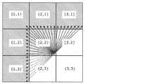
例えば、図5に示すように、当該複数のPUのうちCUの左上端に位置するPUを基準にして、横方向をX軸とし、縦方向をY軸とし、PUの位置を(X、Y){X、Y=0、1、2、3}と表現する。この場合、イントラ予測部108は、(0、0)、(1、0)、(0、1)、(2、0)、(1、1)、(3、0)、(2、1)、(0、2)、(3、1)、(1、2)、(0、3)、(2、2)、(1、3)、(3、2)、(2、3)、(3、3)のPUの順にイントラ予測処理を行う。 For example, as shown in FIG. 5, the horizontal direction is the X axis, the vertical direction is the Y axis, and the position of the PU is (X, Y) with reference to the PU located at the upper left corner of the CU among the plurality of PUs. ) {X, Y = 0, 1, 2, 3}. In this case, the
また、(2、0)及び(2、2)に位置するPUは、左下参照禁止ブロックであり、当該左下参照禁止ブロックに対しては、左下のPUの画素データを参照するイントラ予測モードを選択することが禁止される。なお、この処理については、後で詳細に説明する。 The PUs located at (2, 0) and (2, 2) are lower left reference prohibited blocks, and for the lower left reference prohibited blocks, the intra prediction mode that refers to the pixel data of the lower left PU is selected. Is prohibited. This process will be described later in detail.
次に、係数符号列生成部105は、HEVC規格で規定された順序(図3に示す順序)と異なる順序で生成された量子化係数をHEVC規格で規定された順序に並び替える。また、ヘッダ符号列生成部115は、イントラ予測部108から出力された各PUのイントラ予測処理に関する情報をHEVC規格に規定された順序に並べ替える(S105)。ここで、イントラ予測処理に関する情報とは、例えば、選択されたイントラ予測モードを示す情報等である。 Next, the coefficient code
このような並び変え処理が行われることにより、画像符号化装置100から出力される符号列は、HEVC規格に準拠した信号となり、HEVC規格に準拠した画像復号装置により正しく復号することができる。 By performing such rearrangement processing, the code string output from the
次に、ヘッダ符号列生成部115は、並び替えられた順序でイントラ予測処理に関する情報を可変長符号化する。また、係数符号列生成部105は、並び替えられた順序で量子化係数を可変長符号化することで、符号列を生成する(S106)。 Next, the header code
以上により、一つのCUに対する符号化処理が完了する。また、画像符号化装置100は、全てのCUに対して、この一連の処理を繰り返し行う(S107)。 Thus, the encoding process for one CU is completed. In addition, the
[イントラ予測処理]
以下、イントラ予測部108によるイントラ予測処理(図2のS104)について詳細に説明する。[Intra prediction processing]
Hereinafter, the intra prediction process (S104 in FIG. 2) by the
図6は、イントラ予測部108によるイントラ予測処理のフローチャートである。 FIG. 6 is a flowchart of intra prediction processing by the
まず、イントラ予測部108は、図5に示す処理順に従い、複数のPUから対象PUを選択し、PU単位で以降の処理を行う(S111)。 First, the
まず、イントラ予測部108は、対象PUが左下参照禁止ブロック(図5の(2、0)及び(2、2)に位置するPU)であるか否かを判定する(S112)。 First, the
対象PUが左下参照禁止ブロックである場合(S112でYes)、イントラ予測部108は、HEVC規格で規定されている35種類のイントラ予測モードのうち、対象PUの左下のPUを参照するイントラ予測モードの選択を禁止して対象PUにイントラ予測処理を行う(S113)。 When the target PU is a lower left reference prohibition block (Yes in S112), the
ここで、左下参照禁止ブロックは、HEVC規格に規定されるビットストリームとしての書き込み順で処理する場合には、左下のPUが符号化済みであり、当該左下のPUを参照できるPUであり、かつ、図5に示す処理順では、左下のPUの符号化が完了していないPUである。よって、イントラ予測部108は、このようなPUに対しては、左下のPUの参照を禁止する。 Here, the lower left reference prohibition block is a PU that has been encoded in the lower left PU and can refer to the lower left PU in the case of processing in the writing order as a bit stream defined in the HEVC standard, and In the processing order shown in FIG. 5, the PU has not been encoded in the lower left PU. Therefore, the
図7は、HEVC規格で規定されている35種類のイントラ予測モード(モード0〜モード34)を示す図である。図7に示すように、HEVC規格では、Planar予測モードと、DC予測モードと、33個の予測方向モードとが定義されている。 FIG. 7 is a diagram illustrating 35 types of intra prediction modes (
イントラ予測部108は、左下参照禁止ブロックに対して、これら35種類のイントラ予測モードのうち、左下のPUを参照するイントラ予測モードの選択を禁止する。具体的には、左下のPUを参照するイントラ予測モードとは、モード0(Planar予測モード)、及びモード2〜9である。 The
図8は、図5に示す左下参照禁止ブロック(2、2)と、その周辺ブロックを示す図である。図8に示すように、モード2〜9を禁止することにより、左下参照禁止ブロック(2、2)のイントラ予測処理において、左下ブロック(1、3)が参照されることを禁止できる。 FIG. 8 is a diagram showing the lower left reference prohibition block (2, 2) shown in FIG. 5 and its peripheral blocks. As shown in FIG. 8, by prohibiting
図9は、Planar予測モード(モード0)を説明するための図である。図9に示すように、Planar予測モードでは、イントラ予測部108は、対象PUの上、左、左下、右上のPUの各々に含まれる4つの参照画素の重み付け平均を算出することにより、対象画素の予測値を算出する。このように、Planar予測モードでも左下のPUが参照されるので、イントラ予測部108は、左下参照禁止ブロックに対して、Planar予測モードを禁止する。 FIG. 9 is a diagram for explaining the Planar prediction mode (mode 0). As illustrated in FIG. 9, in the Planar prediction mode, the
再度、図6に示すフローチャートを参照して説明を続ける。 The description will be continued with reference to the flowchart shown in FIG.
対象PUが左下参照禁止ブロックでない場合(S112でNo)、イントラ予測部108は、通常のイントラ予測処理を行う。すなわち、イントラ予測部108は、HEVC規格で規定されている35種類のイントラ予測モードのうちいずれかを選択し、対象PUにイントラ予測処理を行う(S114)。 When the target PU is not a lower left reference prohibition block (No in S112), the
ステップS113又はS114の後、減算部103は、対象PUと予測画像との差分である残差信号を生成する(S115)。次に、予測残差符号化部104は、残差信号に直交変換及び量子化を行うことで量子化係数を生成する(S116)。また、予測残差復号化部106は、量子化係数を逆量子化及び逆直交変換することで、残差復号化信号を生成する。次に、加算部107は、残差復号化信号と予測画像とを加算することで、再構成画像信号を生成する。この再構成画像信号は、以降のPUのイントラ予測処理に用いられる。 After step S113 or S114, the
以上により、一つのPUに対するイントラ予測処理が完了する。また、イントラ予測部108は、全てのPUに対して、この一連の処理を繰り返し行う(S117)。 Thus, the intra prediction process for one PU is completed. The
[本開示の効果]
以上のように、画像符号化装置100は、図5に示す順序でイントラ予測処理を行う。ここで、HEVC規格では、H.264では存在しない左下のPUを参照するイントラ予測モードが存在する。そのため、対象PUのイントラ予測処理を開始するまでに、左下のPUのイントラ予測処理が完了していることで、符号化効率を改善できる。この考えに基づき、図3に示す書き込み順が規定されている。[Effects of the present disclosure]
As described above, the
しかしながら、図3に示す書き込み順で処理するには、複数のPUを並列に処理することが困難であり、処理を高速化することができない。一方、図5に示す処理順を用いることで、複数のPUを図10に示すように並列に処理できる。なお、図10において各PUに付与されている数字は、図5に示す、本実施の形態における処理順を示す。図10に示す例では、ブロック2とブロック3とが並列処理され、ブロック4とブロック5とが並列処理される。また、図示していないが、以降も同様に並列処理可能である。 However, it is difficult to process a plurality of PUs in parallel to process in the writing order shown in FIG. 3, and the processing cannot be accelerated. On the other hand, by using the processing order shown in FIG. 5, a plurality of PUs can be processed in parallel as shown in FIG. In addition, the number provided to each PU in FIG. 10 shows the processing order in this Embodiment shown in FIG. In the example shown in FIG. 10,
このように、図5に示す処理順を用いることで、本実施の形態に係る画像符号化装置100は、イントラ予測処理を高速に行うことができる。 Thus, by using the processing order shown in FIG. 5,
また、上述したように、画像符号化装置100は、左下参照禁止ブロックを設定し、当該左下参照禁止ブロックでは左下のPUを参照することを禁止する。これにより、HEVC規格と異なる順序を用いた場合に処理が破綻することを防止できる。 Further, as described above, the
さらに、画像符号化装置100は、PU毎に生成された量子化係数を、HEVC規格で規定された順序に並び替える。これにより、画像符号化装置100は、HEVC規格に準拠した符号列を生成できる。 Furthermore, the
このように、画像符号化装置100は、HEVC規格で定められている書き込み順を、並列処理が可能な処理順に並び替える。また、並び替え前においては左下ブロックの参照が可能であり、かつ、並び替え後には左下ブロックの参照が行えないブロックに対して左下ブロックを参照することを禁止する。これにより、画像符号化装置100は、HEVC規格に準拠した符号列を高速に生成することができる。 As described above, the
[変形例]
上記図5では、CUが8×8画素であり、PUが4×4画素であって、そのCUが4つ隣接する例を説明したが、CU及びPUのサイズおよび数はこれに限定されていない。なお、処理対象となる少なくとも1つ以上の対象CUに同じサイズの4×4個のPUが含まれる場合の処理順は、図5と同様である。処理対象となる少なくとも1つ以上の対象CUに同じサイズの4×4個のPUが含まれる場合とは、例えば、CUが8×8画素であり、PUが8×8画素であって、そのCUが4つ隣接する場合、及び、CUが16×16画素であり、PUが16×16画素であって、そのCUが4つ隣接する場合等である。[Modification]
In FIG. 5 described above, an example in which a CU is 8 × 8 pixels, a PU is 4 × 4 pixels, and four CUs are adjacent to each other is described. However, the size and number of CUs and PUs are limited to this. Absent. Note that the processing order when 4 × 4 PUs of the same size are included in at least one or more target CUs to be processed is the same as in FIG. The case where 4 × 4 PUs of the same size are included in at least one target CU to be processed includes, for example, a CU of 8 × 8 pixels, a PU of 8 × 8 pixels, This is the case when four CUs are adjacent, and when the CU is 16 × 16 pixels, the PU is 16 × 16 pixels, and the four CUs are adjacent.
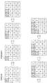
また、図11に、CUに同じサイズのPUが含まれCUが8つ隣接する場合の処理順を示す。CUに同じサイズのPUが含まれCUが8つ隣接する場合とは、例えば、CUが8×8画素であり、PUが4×4画素である場合、及び、CUが8×8画素であり、PUが8×8画素である場合等である。図11に示す処理順では、(2、0)、(2、2)、(2、4)、(2、6)、(4、0)、(4、2)、(4、4)、(4、6)、(6、0)、(6、2)、(6、4)及び(6、6)のPUが左下参照禁止ブロックに設定される。 FIG. 11 shows the processing order when PUs of the same size are included in a CU and eight CUs are adjacent to each other. The case where a CU includes PUs of the same size and eight CUs are adjacent is, for example, when the CU is 8 × 8 pixels, the PU is 4 × 4 pixels, and the CU is 8 × 8 pixels , When PU is 8 × 8 pixels. In the processing order shown in FIG. 11, (2, 0), (2, 2), (2, 4), (2, 6), (4, 0), (4, 2), (4, 4), The PUs of (4, 6), (6, 0), (6, 2), (6, 4) and (6, 6) are set as the lower left reference prohibition block.
また、図12に示すように、処理対象となる少なくとも1つ以上の対象CUには、異なるサイズのPUが含まれてもよい。この場合でも、HEVC規格における書き込み順通りに処理する場合において左下のPUを参照するPUであり、かつ、本開示の処理順では左下のPUよりも先に処理が行われるPU(図12の(2、0)のPU)が左下参照禁止ブロックに設定される。 Moreover, as shown in FIG. 12, PUs of different sizes may be included in at least one or more target CUs to be processed. Even in this case, when processing is performed according to the writing order in the HEVC standard, the PU refers to the lower left PU, and in the processing order of the present disclosure, the PU is processed before the lower left PU ((( 2, 0) PU) is set to the lower left reference prohibition block.
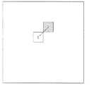
つまり、本開示では、図13に示すように、以下の条件に合致するPU(第2処理ブロック)が左下参照禁止ブロックに設定される。 That is, in the present disclosure, as illustrated in FIG. 13, a PU (second processing block) that satisfies the following condition is set as a lower left reference prohibition block.
(1)任意の第1処理ブロック(図13のPU1)と、当該第1処理ブロックと同じサイズであり、第1処理ブロックの右上に位置する第2処理ブロック(図13のブロック2)とが処理対象となる少なくとも1つ以上の対象CUに含まれる。 (1) An arbitrary first processing block (PU1 in FIG. 13) and a second processing block (
(2)HEVC規格では、第1処理ブロック(PU1)の情報の後に第2処理ブロック(PU2)の情報をビットストリームとして書き込むことが規定されている。 (2) The HEVC standard stipulates that information of the second processing block (PU2) is written as a bit stream after information of the first processing block (PU1).
(3)本開示の処理順では、第2処理ブロック(PU2)のイントラ予測処理が行われ、その後に第1処理ブロック(PU1)のイントラ予測処理が行われる。 (3) In the processing order of this indication, the intra prediction process of the 2nd processing block (PU2) is performed, and the intra prediction process of the 1st processing block (PU1) is performed after that.
また、図14に示すように、上記の条件(1)〜(3)に加え、さらに、以下の条件に合致するPU(第2処理ブロック)が左下参照禁止ブロックに設定されてもよい。 Further, as shown in FIG. 14, in addition to the above conditions (1) to (3), a PU (second processing block) that satisfies the following conditions may be set as a lower left reference prohibition block.
(4)第1処理ブロック(図14のPU3)と同じサイズであり、第1処理ブロックの上に位置する第3処理ブロック(図14のPU1)と、第1処理ブロック(PU3)と同じサイズであり、第1処理ブロック(PU3)の左に位置する第4処理ブロック(図14のPU2)とが処理対象となる少なくとも1つ以上の対象CUに含まれる。 (4) The same size as the first processing block (PU3 in FIG. 14) and the same size as the third processing block (PU1 in FIG. 14) located above the first processing block and the first processing block (PU3). And the fourth processing block (PU2 in FIG. 14) located to the left of the first processing block (PU3) is included in at least one target CU to be processed.
(5)本開示の処理順では、第3処理ブロック(PU1)、第4処理ブロック(PU2)、第2処理ブロック(PU4)、及び第1処理ブロック(PU3)の順にイントラ予測処理が行われる。 (5) In the processing order of the present disclosure, intra prediction processing is performed in the order of the third processing block (PU1), the fourth processing block (PU2), the second processing block (PU4), and the first processing block (PU3). .
なお、図13及び図14において、各PUに付与されている数字はHEVC規格における書き込み順を示している。また、矢印は本開示における処理順を示している。 In FIGS. 13 and 14, the numbers given to the PUs indicate the writing order in the HEVC standard. Moreover, the arrow has shown the process order in this indication.
また、上記図10に示す並列処理は一例であり、並列処理の仕方は任意でよい。例えば、図10に示す例において、ブロック3とブロック4とが並列処理されてもよい。また、図13に示す例では、複数の処理ブロック(PU)のうち、第1処理ブロック(図13のPU1)を含む第1処理ブロック群と、第2処理ブロック(図13のPU2)を含む第2処理ブロック群とを並列処理してもよい。 Further, the parallel processing shown in FIG. 10 is an example, and the method of parallel processing may be arbitrary. For example, in the example shown in FIG. 10, the
また、このように並列処理が行われる場合には、上述したPUの処理順において、あるPUの処理が完了した後に次のPUの処理の開始される必要はない。言い換えると、上述したPUの処理順は、PUの処理が開始される順序、又は、PUの処理が終了する順序であってもよい。例えば、図10に示す例において、ブロック2の処理の開始の後に、ブロック3の処理が開始されるのであれば、ブロック2とブロック3との処理の一部が同時に行われてもよい。 Further, when parallel processing is performed in this way, it is not necessary to start processing of the next PU after processing of a certain PU is completed in the processing order of PUs described above. In other words, the PU processing order described above may be the order in which PU processing is started or the order in which PU processing ends. For example, in the example shown in FIG. 10, if the process of
さらに、図10に示す例において、ブロック2とブロック3との処理が同時に開始されてもよいし、ブロック2の処理よりブロック3の処理が先に開始されてもよい。つまり、上述した処理順において、並列処理を行える範囲において、一部のPUの処理順を入れ替えてもよい。 Furthermore, in the example shown in FIG. 10, the processing of
また、上記説明では、HEVC規格が用いられる例を説明したが、左下の処理ブロック(PU)を参照するイントラ予測モードが用いられる任意の画像符号化規格に本開示を適用できる。 In the above description, an example in which the HEVC standard is used has been described. However, the present disclosure can be applied to any image coding standard in which an intra prediction mode that refers to the lower left processing block (PU) is used.
また、上記では説明の便宜上、画像符号化装置100が予測部としてイントラ予測部108のみを含む構成を説明したが、画像符号化装置100は、インター予測を行う機能ブロックを含んでもよい。 In addition, for convenience of explanation, the configuration in which the
また、図1では、単純に予測処理としてイントラ予測のみが用いられる場合を示したが、インターピクチャを含む入力動画像の中のイントラピクチャ、又は、インターピクチャの中で処理対象となる少なくとも1つ以上の対象イントラCUが集まった場合にも上記同様の処理を適用できる。 Further, FIG. 1 shows a case where only intra prediction is used as the prediction process, but at least one of the intra picture in the input moving image including the inter picture or the processing target in the inter picture. The same processing as described above can also be applied when the above target intra CUs gather.
以上のように、本開示における技術の例示として、実施の形態を説明した。そのために、添付図面および詳細な説明を提供した。 As described above, the embodiments have been described as examples of the technology in the present disclosure. For this purpose, the accompanying drawings and detailed description are provided.
したがって、添付図面および詳細な説明に記載された構成要素の中には、課題解決のために必須な構成要素だけでなく、上記技術を例示するために、課題解決のためには必須でない構成要素も含まれ得る。そのため、それらの必須ではない構成要素が添付図面や詳細な説明に記載されていることをもって、直ちに、それらの必須ではない構成要素が必須であるとの認定をするべきではない。 Accordingly, among the components described in the accompanying drawings and the detailed description, not only the components essential for solving the problem, but also the components not essential for solving the problem in order to illustrate the above technique. May also be included. Therefore, it should not be immediately recognized that these non-essential components are essential as those non-essential components are described in the accompanying drawings and detailed description.
また、上述の実施の形態は、本開示における技術を例示するためのものであるから、特許請求の範囲またはその均等の範囲において種々の変更、置き換え、付加、省略などを行うことができる。 Moreover, since the above-mentioned embodiment is for demonstrating the technique in this indication, a various change, replacement, addition, abbreviation, etc. can be performed in a claim or its equivalent range.
また、本開示に係る画像符号化方法は、符号化対象のピクチャが分割されることで得られた複数の符号化単位ブロック(CU)の各々をイントラ予測の処理単位である複数の処理ブロック(PU)に分割する分割ステップと、前記複数の処理ブロックの各々に対して、所定の符号化規格で規定されている複数のイントラ予測モードから一つのイントラ予測モードを選択し、選択したイントラ予測モードでイントラ予測処理を行うイントラ予測ステップとを含み、前記複数のイントラ予測モードは、処理対象の処理ブロックの左下の処理ブロックを参照する左下参照モードを含み、前記複数の処理ブロックは、第1処理ブロックと、前記第1処理ブロックと同じサイズであり、前記第1処理ブロックの右上に位置する第2処理ブロックとを含み、前記所定の符号化規格では、前記第1処理ブロックの情報の後に前記第2処理ブロックの情報をビットストリームへ書き込むことが規定されており、前記イントラ予測ステップでは、前記左下参照モードの選択を禁止して前記第2処理ブロックのイントラ予測処理を行い、その後に前記第1処理ブロックのイントラ予測処理を行う。 In addition, the image coding method according to the present disclosure is configured such that each of a plurality of coding unit blocks (CUs) obtained by dividing a picture to be coded is a plurality of processing blocks (intra prediction processing units) ( (PU) for each of the plurality of processing blocks, a single intra prediction mode is selected from a plurality of intra prediction modes defined by a predetermined coding standard, and the selected intra prediction mode is selected. An intra prediction step for performing an intra prediction process in the plurality of intra prediction modes, wherein the plurality of intra prediction modes include a lower left reference mode that refers to a lower left processing block of a processing block to be processed, and the plurality of processing blocks include a first process. And a second processing block that is the same size as the first processing block and is located at the upper right of the first processing block. The predetermined coding standard stipulates that the information of the second processing block is written to the bitstream after the information of the first processing block, and the selection of the lower left reference mode is prohibited in the intra prediction step. Then, intra prediction processing of the second processing block is performed, and then intra prediction processing of the first processing block is performed.
これにより、当該画像符号化方法は、前記所定の符号化規格とは異なる順序でイントラ予測処理を行うことができる。よって、当該画像符号化方法は、高速にイントラ予測処理を行うことができる。また、前記第2の処理ブロックが左下の処理ブロックを参照することを禁止することで、処理順序を変更したことにより処理が破綻することを防止できる。 Accordingly, the image encoding method can perform the intra prediction process in an order different from the predetermined encoding standard. Therefore, the image coding method can perform intra prediction processing at high speed. Further, by prohibiting the second processing block from referring to the lower left processing block, it is possible to prevent the processing from failing due to the change of the processing order.
例えば、前記画像符号化方法は、さらに、前記処理ブロックと前記イントラ予測処理により生成された予測画像との差分である残差信号を生成する残差信号生成ステップと、前記残差信号を直交変換及び量子化することで量子化係数を生成する量子化ステップと、前記複数の処理ブロックに対応する複数の前記量子化係数を、前記符号化規格に規定された順序に並び替える並び替えステップとを含んでもよい。 For example, the image coding method further includes a residual signal generation step of generating a residual signal that is a difference between the processing block and a predicted image generated by the intra prediction processing, and orthogonal transformation of the residual signal And a quantization step for generating quantization coefficients by quantization, and a rearrangement step for rearranging the plurality of quantization coefficients corresponding to the plurality of processing blocks in an order defined in the encoding standard. May be included.
これにより、前記符号化規格に準拠した符号列を生成できる。 Thereby, a code string compliant with the coding standard can be generated.
例えば、前記イントラ予測ステップでは、前記複数の処理ブロックのうち、前記第1処理ブロックを含む第1処理ブロック群と、前記第2処理ブロックを含む第2処理ブロック群とを並列処理してもよい。 For example, in the intra prediction step, among the plurality of processing blocks, a first processing block group including the first processing block and a second processing block group including the second processing block may be processed in parallel. .
これにより、当該画像符号化方法は、複数の処理ブロックを並列処理できるので、処理の高速化を実現できる。 Thereby, since the said image coding method can process a some process block in parallel, it can implement | achieve high-speed processing.
例えば、前記所定の符号化規格は、HEVC(High Efficiency Video Coding)規格であり、前記左下参照モードは、前記HEVC規格におけるモード0、及びモード2〜9であってもよい。 For example, the predetermined coding standard may be a HEVC (High Efficiency Video Coding) standard, and the lower left reference mode may be
これにより、当該画像符号化方法は、HEVC規格に準拠した符号列を高速に処理できる。 Accordingly, the image encoding method can process a code string conforming to the HEVC standard at high speed.
例えば、前記複数の処理ブロックは、さらに、前記第1処理ブロックと同じサイズであり、前記第1処理ブロックの上に位置する第3処理ブロックと、前記第1処理ブロックと同じサイズであり、前記第1処理ブロックの左に位置する第4処理ブロックとを含み、前記イントラ予測ステップでは、前記第3処理ブロック、前記第4処理ブロック、前記第2処理ブロック、及び前記第1処理ブロックの順にイントラ予測処理を行ってもよい。 For example, the plurality of processing blocks are further the same size as the first processing block, a third processing block located on the first processing block, and the same size as the first processing block, A fourth processing block located to the left of the first processing block, and in the intra prediction step, the third processing block, the fourth processing block, the second processing block, and the first processing block in this order. A prediction process may be performed.
例えば、前記複数の処理ブロックは、4×4個の同じサイズのブロックであり、前記複数の処理ブロックのうち前記符号化単位ブロックの左上端に位置する処理ブロックを基準にして、横方向をX軸とし、縦方向をY軸とし、前記処理ブロックの位置を(X、Y){X、Y=0、1、2、3}と表現する場合、前記イントラ予測ステップでは、(0、0)、(1、0)、(0、1)、(2、0)、(1、1)、(3、0)、(2、1)、(0、2)、(3、1)、(1、2)、(0、3)、(2、2)、(1、3)、(3、2)、(2、3)、(3、3)の処理ブロックの順にイントラ予測処理を行い、前記第2処理ブロックは、(2、0)及び(2、2)に位置する処理ブロックであってもよい。 For example, the plurality of processing blocks are 4 × 4 blocks having the same size, and the horizontal direction is X with respect to the processing block located at the upper left end of the coding unit block among the plurality of processing blocks. When the vertical direction is the Y axis and the processing block position is expressed as (X, Y) {X, Y = 0, 1, 2, 3}, in the intra prediction step, (0, 0) , (1, 0), (0, 1), (2, 0), (1, 1), (3, 0), (2, 1), (0, 2), (3, 1), ( 1, 2), (0, 3), (2, 2), (1, 3), (3, 2), (2, 3), (3, 3) in order of processing blocks The second processing block may be a processing block located at (2, 0) and (2, 2).
これにより、当該画像符号化方法は、4×4個の処理ブロックを含む符号化単位ブロックを高速に処理できる。 Accordingly, the image encoding method can process an encoding unit block including 4 × 4 processing blocks at high speed.
なお、これらの全般的または具体的な態様は、装置、システム、方法、集積回路、コンピュータプログラムまたはコンピュータ読み取り可能なCD−ROMなどの記録媒体で実現されてもよく、システム、方法、集積回路、コンピュータプログラム及び記録媒体の任意な組み合わせで実現されてもよい。 Note that these general or specific aspects may be realized by a recording medium such as an apparatus, a system, a method, an integrated circuit, a computer program, or a computer-readable CD-ROM. You may implement | achieve with arbitrary combinations of a computer program and a recording medium.
また、上記実施の形態において、各構成要素は、専用のハードウェアで構成されるか、各構成要素に適したソフトウェアプログラムを実行することによって実現されてもよい。各構成要素は、CPUまたはプロセッサなどのプログラム実行部が、ハードディスクまたは半導体メモリなどの記録媒体に記録されたソフトウェアプログラムを読み出して実行することによって実現されてもよい。 In the above-described embodiment, each component may be configured by dedicated hardware or may be realized by executing a software program suitable for each component. Each component may be realized by a program execution unit such as a CPU or a processor reading and executing a software program recorded on a recording medium such as a hard disk or a semiconductor memory.
また、上記で用いた数字は、全て本開示を具体的に説明するために例示するものであり、本開示は例示された数字に制限されない。 Moreover, all the numbers used above are illustrated for specifically explaining the present disclosure, and the present disclosure is not limited to the illustrated numbers.
また、ブロック図における機能ブロックの分割は一例であり、複数の機能ブロックを一つの機能ブロックとして実現したり、一つの機能ブロックを複数に分割したり、一部の機能を他の機能ブロックに移してもよい。また、類似する機能を有する複数の機能ブロックの機能を単一のハードウェア又はソフトウェアが並列又は時分割に処理してもよい。 In addition, division of functional blocks in the block diagram is an example, and a plurality of functional blocks can be realized as one functional block, a single functional block can be divided into a plurality of functions, or some functions can be transferred to other functional blocks. May be. In addition, functions of a plurality of functional blocks having similar functions may be processed in parallel or time-division by a single hardware or software.
また、上記のフローチャートに示す複数のステップが実行される順序は、本開示を具体的に説明するために例示するためのものであり、上記以外の順序であってもよい。また、上記ステップの一部が、他のステップと同時(並列)に実行されてもよい。 Further, the order in which the plurality of steps shown in the flowchart is executed is for illustrating the present disclosure specifically, and may be in an order other than the above. Also, some of the above steps may be executed simultaneously (in parallel) with other steps.
本開示は、画像符号化方法及び画像符号化装置に適用可能である。具体的には、レコーダ、デジタルカメラ又はタブレット端末装置などに、本開示は適用可能である。 The present disclosure is applicable to an image encoding method and an image encoding device. Specifically, the present disclosure can be applied to a recorder, a digital camera, a tablet terminal device, or the like.
100 画像符号化装置
101 ピクチャバッファ
102 ピクチャ分割部
103 減算部
104 予測残差符号化部
105 係数符号列生成部
106 予測残差復号化部
107 加算部
108 イントラ予測部
114 量子化値決定部
115 ヘッダ符号列生成部DESCRIPTION OF
Claims (7)
Translated fromJapanese前記複数の処理ブロックの各々に対して、所定の符号化規格で規定されている複数のイントラ予測モードから一つのイントラ予測モードを選択し、選択したイントラ予測モードでイントラ予測処理を行うイントラ予測ステップとを含み、
前記複数のイントラ予測モードは、処理対象の処理ブロックの左下の処理ブロックを参照する左下参照モードを含み、
前記複数の処理ブロックは、第1処理ブロックと、前記第1処理ブロックと同じサイズであり、前記第1処理ブロックの右上に位置する第2処理ブロックとを含み、
前記所定の符号化規格では、前記第1処理ブロックの情報の後に前記第2処理ブロックの情報をビットストリームへ書き込むことが規定されており、
前記イントラ予測ステップでは、前記左下参照モードの選択を禁止して前記第2処理ブロックのイントラ予測処理を行い、その後に前記第1処理ブロックのイントラ予測処理を行う
画像符号化方法。A division step of dividing each of a plurality of coding unit blocks obtained by dividing a picture to be coded into a plurality of processing blocks which are processing units of intra prediction;
Intra prediction step of selecting one intra prediction mode from a plurality of intra prediction modes defined by a predetermined coding standard for each of the plurality of processing blocks, and performing an intra prediction process in the selected intra prediction mode Including
The plurality of intra prediction modes include a lower left reference mode that refers to a lower left processing block of a processing block to be processed,
The plurality of processing blocks include a first processing block and a second processing block that is the same size as the first processing block and is located at the upper right of the first processing block,
The predetermined encoding standard stipulates that the information of the second processing block is written to the bitstream after the information of the first processing block.
In the intra prediction step, the selection of the lower left reference mode is prohibited, the intra prediction process of the second processing block is performed, and then the intra prediction process of the first processing block is performed.
前記処理ブロックと、前記イントラ予測処理により生成された予測画像との差分である残差信号を生成する残差信号生成ステップと、
前記残差信号を直交変換及び量子化することで量子化係数を生成する量子化ステップと、
前記複数の処理ブロックに対応する複数の前記量子化係数を、前記符号化規格に規定された順序に並び替える並び替えステップとを含む
請求項1記載の画像符号化方法。The image encoding method further includes:
A residual signal generation step of generating a residual signal that is a difference between the processing block and the prediction image generated by the intra prediction process;
A quantization step of generating a quantization coefficient by orthogonal transform and quantizing the residual signal;
The image encoding method according to claim 1, further comprising a rearrangement step of rearranging the plurality of quantization coefficients corresponding to the plurality of processing blocks in an order defined in the encoding standard.
前記複数の処理ブロックのうち、前記第1処理ブロックを含む第1処理ブロック群と、前記第2処理ブロックを含む第2処理ブロック群とを並列処理する
請求項1又は2記載の画像符号化方法。In the intra prediction step,
The image coding method according to claim 1 or 2, wherein, among the plurality of processing blocks, a first processing block group including the first processing block and a second processing block group including the second processing block are processed in parallel. .
前記左下参照モードは、前記HEVC規格におけるモード0、及びモード2〜9である
請求項1〜3のいずれか1項に記載の画像符号化方法。The predetermined encoding standard is a HEVC (High Efficiency Video Coding) standard,
The image coding method according to any one of claims 1 to 3, wherein the lower left reference mode is mode 0 and modes 2 to 9 in the HEVC standard.
前記第1処理ブロックと同じサイズであり、前記第1処理ブロックの上に位置する第3処理ブロックと、
前記第1処理ブロックと同じサイズであり、前記第1処理ブロックの左に位置する第4処理ブロックとを含み、
前記イントラ予測ステップでは、前記第3処理ブロック、前記第4処理ブロック、前記第2処理ブロック、及び前記第1処理ブロックの順にイントラ予測処理を行う
請求項1〜4のいずれか1項に記載の画像符号化方法。The plurality of processing blocks further includes:
A third processing block that is the same size as the first processing block and is located above the first processing block;
A fourth processing block that is the same size as the first processing block and is located to the left of the first processing block;
5. The intra prediction process is performed in the order of the third processing block, the fourth processing block, the second processing block, and the first processing block in the intra prediction step. Image coding method.
前記複数の処理ブロックのうち前記符号化単位ブロックの左上端に位置する処理ブロックを基準にして、横方向をX軸とし、縦方向をY軸とし、前記処理ブロックの位置を(X、Y){X、Y=0、1、2、3}と表現する場合、
前記イントラ予測ステップでは、(0、0)、(1、0)、(0、1)、(2、0)、(1、1)、(3、0)、(2、1)、(0、2)、(3、1)、(1、2)、(0、3)、(2、2)、(1、3)、(3、2)、(2、3)、(3、3)の処理ブロックの順にイントラ予測処理を行い、
前記第2処理ブロックは、(2、0)及び(2、2)に位置する処理ブロックである
請求項5記載の画像符号化方法。The plurality of processing blocks are 4 × 4 blocks of the same size,
Based on the processing block located at the upper left end of the coding unit block among the plurality of processing blocks, the horizontal direction is the X axis, the vertical direction is the Y axis, and the processing block position is (X, Y) When expressed as {X, Y = 0, 1, 2, 3},
In the intra prediction step, (0, 0), (1, 0), (0, 1), (2, 0), (1, 1), (3, 0), (2, 1), (0 2), (3, 1), (1, 2), (0, 3), (2, 2), (1, 3), (3, 2), (2, 3), (3, 3 ) Processing block in order of processing block,
The image coding method according to claim 5, wherein the second processing block is a processing block located at (2, 0) and (2, 2).
前記複数の処理ブロックの各々に対して、所定の符号化規格で規定されている複数のイントラ予測モードから一つのイントラ予測モードを選択し、選択したイントラ予測モードでイントラ予測処理を行うイントラ予測部とを備え、
前記複数のイントラ予測モードは、処理対象の処理ブロックの左下の処理ブロックを参照する左下参照モードを含み、
前記複数の処理ブロックは、第1処理ブロックと、前記第1処理ブロックと同じサイズであり、前記第1処理ブロックの右上に位置する第2処理ブロックとを含み、
前記所定の符号化規格では、前記第1処理ブロックの情報の後に前記第2処理ブロックの情報をビットストリームへ書き込むことが規定されており、
前記イントラ予測部は、前記左下参照モードの選択を禁止して前記第2処理ブロックのイントラ予測処理を行い、その後に前記第1処理ブロックのイントラ予測処理を行う
画像符号化装置。A dividing unit that divides each of a plurality of encoding unit blocks obtained by dividing a picture to be encoded into a plurality of processing blocks that are processing units of intra prediction;
An intra prediction unit that selects one intra prediction mode from a plurality of intra prediction modes defined by a predetermined coding standard for each of the plurality of processing blocks, and performs an intra prediction process in the selected intra prediction mode. And
The plurality of intra prediction modes include a lower left reference mode that refers to a lower left processing block of a processing target processing block,
The plurality of processing blocks include a first processing block and a second processing block that is the same size as the first processing block and is located at the upper right of the first processing block,
The predetermined encoding standard stipulates that the information of the second processing block is written to the bitstream after the information of the first processing block.
The said intra prediction part prohibits selection of the said lower left reference mode, performs the intra prediction process of the said 2nd processing block, and the image encoding apparatus which performs the intra prediction process of the said 1st processing block after that.
Priority Applications (3)
| Application Number | Priority Date | Filing Date | Title |
|---|---|---|---|
| JP2014058306AJP2015185897A (en) | 2014-03-20 | 2014-03-20 | Image encoding method and device |
| US14/619,993US9723326B2 (en) | 2014-03-20 | 2015-02-11 | Image encoding method and image encoding appartaus |
| US15/631,755US10038901B2 (en) | 2014-03-20 | 2017-06-23 | Image encoding method and image encoding apparatus |
Applications Claiming Priority (1)
| Application Number | Priority Date | Filing Date | Title |
|---|---|---|---|
| JP2014058306AJP2015185897A (en) | 2014-03-20 | 2014-03-20 | Image encoding method and device |
Publications (1)
| Publication Number | Publication Date |
|---|---|
| JP2015185897Atrue JP2015185897A (en) | 2015-10-22 |
Family
ID=54143317
Family Applications (1)
| Application Number | Title | Priority Date | Filing Date |
|---|---|---|---|
| JP2014058306APendingJP2015185897A (en) | 2014-03-20 | 2014-03-20 | Image encoding method and device |
Country Status (2)
| Country | Link |
|---|---|
| US (2) | US9723326B2 (en) |
| JP (1) | JP2015185897A (en) |
Families Citing this family (1)
| Publication number | Priority date | Publication date | Assignee | Title |
|---|---|---|---|---|
| CN112203087B (en)* | 2020-09-18 | 2021-05-14 | 广州佰锐网络科技有限公司 | HEVC intra-frame prediction mode rapid selection method and system |
Citations (6)
| Publication number | Priority date | Publication date | Assignee | Title |
|---|---|---|---|---|
| JP2004140473A (en)* | 2002-10-15 | 2004-05-13 | Sony Corp | Image information coding apparatus, decoding apparatus and method for coding image information, method for decoding |
| JP2005130509A (en)* | 2003-10-24 | 2005-05-19 | Samsung Electronics Co Ltd | Intra prediction method and apparatus |
| JP2007124409A (en)* | 2005-10-28 | 2007-05-17 | Matsushita Electric Ind Co Ltd | Image encoding device |
| JP2007150913A (en)* | 2005-11-29 | 2007-06-14 | Matsushita Electric Ind Co Ltd | Image encoding device |
| JP2008182527A (en)* | 2007-01-25 | 2008-08-07 | Matsushita Electric Ind Co Ltd | Image encoding apparatus and method, and imaging system |
| JP2011041037A (en)* | 2009-08-12 | 2011-02-24 | Sony Corp | Image processing apparatus and method |
Family Cites Families (31)
| Publication number | Priority date | Publication date | Assignee | Title |
|---|---|---|---|---|
| EP1645135A4 (en)* | 2003-01-10 | 2010-03-03 | Thomson Licensing | DEFINITION OF INTERPOLATION FILTERS FOR DISSIMULATION OF ERRORS IN AN ENCODED IMAGE |
| KR20050072526A (en)* | 2004-01-06 | 2005-07-12 | 삼성전자주식회사 | Prediction encoding apparatus, prediction encoding method, and computer readable recording medium storing a program for performing the method |
| KR100654436B1 (en)* | 2004-07-07 | 2006-12-06 | 삼성전자주식회사 | Method for video encoding and decoding, and video encoder and decoder |
| KR20060008523A (en)* | 2004-07-21 | 2006-01-27 | 삼성전자주식회사 | Intra prediction method of video and its device |
| US20080123750A1 (en)* | 2006-11-29 | 2008-05-29 | Michael Bronstein | Parallel deblocking filter for H.264 video codec |
| JP2008306413A (en) | 2007-06-06 | 2008-12-18 | Panasonic Corp | Image coding apparatus and image coding method |
| KR101496324B1 (en)* | 2007-10-17 | 2015-02-26 | 삼성전자주식회사 | Method and apparatus for video encoding, and method and apparatus for video decoding |
| US8451904B2 (en)* | 2009-06-24 | 2013-05-28 | Qualcomm Incorporated | 8-point transform for media data coding |
| US9172968B2 (en)* | 2010-07-09 | 2015-10-27 | Qualcomm Incorporated | Video coding using directional transforms |
| US8848779B2 (en)* | 2010-07-15 | 2014-09-30 | Sharp Laboratories Of America, Inc. | Method of parallel video coding based on block size |
| JP5563403B2 (en)* | 2010-08-12 | 2014-07-30 | 日本電信電話株式会社 | Video encoding method, video decoding method, video encoding device, video decoding device, and programs thereof |
| US8923395B2 (en)* | 2010-10-01 | 2014-12-30 | Qualcomm Incorporated | Video coding using intra-prediction |
| US10992958B2 (en)* | 2010-12-29 | 2021-04-27 | Qualcomm Incorporated | Video coding using mapped transforms and scanning modes |
| JP2012191295A (en) | 2011-03-09 | 2012-10-04 | Canon Inc | Image coding apparatus, image coding method, program, image decoding apparatus, image decoding method, and program |
| JP5982734B2 (en)* | 2011-03-11 | 2016-08-31 | ソニー株式会社 | Image processing apparatus and method |
| JP5149978B2 (en) | 2011-04-25 | 2013-02-20 | パナソニック株式会社 | Image coding apparatus and image coding method |
| ES2908152T3 (en)* | 2011-06-30 | 2022-04-27 | Sun Patent Trust | Image decoding procedure |
| US9807426B2 (en)* | 2011-07-01 | 2017-10-31 | Qualcomm Incorporated | Applying non-square transforms to video data |
| US9699456B2 (en)* | 2011-07-20 | 2017-07-04 | Qualcomm Incorporated | Buffering prediction data in video coding |
| US10110891B2 (en)* | 2011-09-29 | 2018-10-23 | Sharp Kabushiki Kaisha | Image decoding device, image decoding method, and image encoding device |
| TW201335769A (en)* | 2011-11-07 | 2013-09-01 | Vid Scale Inc | Video and data processing using even-odd integer transforms |
| US9955153B2 (en)* | 2012-01-05 | 2018-04-24 | Google Technology Holdings LLC | Devices and methods for sample adaptive offset coding |
| CN104041030B (en)* | 2012-01-19 | 2018-01-16 | 索尼公司 | Image processing equipment and method |
| JP2013150215A (en)* | 2012-01-20 | 2013-08-01 | Fujitsu Ltd | Moving image decoding device, moving image encoding device, moving image decoding method, moving image encoding method, moving image decoding program, and moving image encoding program |
| CN103563373B (en)* | 2012-02-03 | 2017-09-26 | 太阳专利托管公司 | Image encoding method and image encoding device |
| KR20140019221A (en)* | 2012-07-17 | 2014-02-14 | 한국전자통신연구원 | In-loop filtering method and apparatus using the smae |
| US9363508B2 (en)* | 2012-09-12 | 2016-06-07 | Broadcom Corporation | Delta QP handling in a high efficiency video decoder |
| US10542286B2 (en)* | 2012-12-19 | 2020-01-21 | ARRIS Enterprise LLC | Multi-layer video encoder/decoder with base layer intra mode used for enhancement layer intra mode prediction |
| US20140301463A1 (en)* | 2013-04-05 | 2014-10-09 | Nokia Corporation | Method and apparatus for video coding and decoding |
| US20150181208A1 (en)* | 2013-12-20 | 2015-06-25 | Qualcomm Incorporated | Thermal and power management with video coding |
| US9930342B2 (en)* | 2014-06-20 | 2018-03-27 | Qualcomm Incorporated | Systems and methods for signaling hypothetical reference decoder parameters in a parameter set |
- 2014
- 2014-03-20JPJP2014058306Apatent/JP2015185897A/enactivePending
- 2015
- 2015-02-11USUS14/619,993patent/US9723326B2/enactiveActive
- 2017
- 2017-06-23USUS15/631,755patent/US10038901B2/enactiveActive
Patent Citations (6)
| Publication number | Priority date | Publication date | Assignee | Title |
|---|---|---|---|---|
| JP2004140473A (en)* | 2002-10-15 | 2004-05-13 | Sony Corp | Image information coding apparatus, decoding apparatus and method for coding image information, method for decoding |
| JP2005130509A (en)* | 2003-10-24 | 2005-05-19 | Samsung Electronics Co Ltd | Intra prediction method and apparatus |
| JP2007124409A (en)* | 2005-10-28 | 2007-05-17 | Matsushita Electric Ind Co Ltd | Image encoding device |
| JP2007150913A (en)* | 2005-11-29 | 2007-06-14 | Matsushita Electric Ind Co Ltd | Image encoding device |
| JP2008182527A (en)* | 2007-01-25 | 2008-08-07 | Matsushita Electric Ind Co Ltd | Image encoding apparatus and method, and imaging system |
| JP2011041037A (en)* | 2009-08-12 | 2011-02-24 | Sony Corp | Image processing apparatus and method |
Non-Patent Citations (1)
| Title |
|---|
| JANI LAINEMA ET AL.: "Intra Coding of HEVC Standard", IEEE TRANSACTION ON CIRCUITS AND SYSTEMS FOR VIDEO TECHNOLOGY, vol. 22, no. 12, JPN6017000059, December 2012 (2012-12-01), pages 1792 - 1801, XP055559664, ISSN: 0003673596, DOI: 10.1109/TCSVT.2012.2221525* |
Also Published As
| Publication number | Publication date |
|---|---|
| US10038901B2 (en) | 2018-07-31 |
| US9723326B2 (en) | 2017-08-01 |
| US20170302919A1 (en) | 2017-10-19 |
| US20150271485A1 (en) | 2015-09-24 |
Similar Documents
| Publication | Publication Date | Title |
|---|---|---|
| JP6590918B2 (en) | Image encoding method, image decoding method, image encoding device, image decoding device, and program | |
| JP6282646B2 (en) | Video encoding method, decoding method, corresponding encoding and decoding apparatus, and computer program by predicting division of current block | |
| CN109922338B (en) | Image encoding device and method, image decoding device and method, and storage medium | |
| KR20130085977A (en) | Multiple sign bit hiding within a transform unit | |
| CN104904220B (en) | Encoding and decoding device and encoding and decoding method for depth image | |
| US12149688B2 (en) | Method and device for high-level image segmentation and image encoding/decoding | |
| KR20130062109A (en) | Method and apparatus for encoding and decoding image | |
| JP6708374B2 (en) | Method, device, program, and readable medium for determining a set of modifiable elements within a set of images | |
| KR20230162989A (en) | Multimedia data processing methods, apparatus, devices, computer-readable storage media, and computer program products | |
| CN108156460B (en) | Video decoding system, video decoding method, and computer storage medium therefor | |
| JP6187826B2 (en) | Moving picture coding apparatus and moving picture coding method | |
| CN109672889B (en) | Method and device for constrained sequence data headers | |
| US20160014415A1 (en) | Method and apparatus for performing wave-front parallel encoding procedure with constraint on coding mode and/or quantization parameter selection | |
| JP6469277B2 (en) | Image encoding device, image encoding method and program, image decoding device, image decoding method and program | |
| JP2015185897A (en) | Image encoding method and device | |
| JP6792996B2 (en) | Encoding device, decoding device and program | |
| JP6792997B2 (en) | Encoding device, decoding device and program | |
| JP4850806B2 (en) | Entropy encoding apparatus, entropy encoding method, and computer program | |
| JP6080077B2 (en) | Image encoding method and image encoding apparatus | |
| KR101971012B1 (en) | Image processing apparatus and method thereof | |
| WO2018216479A1 (en) | Image processing device and method, and program | |
| JP6308409B2 (en) | Moving picture coding apparatus and moving picture coding method | |
| US11159826B2 (en) | Method for encoding and decoding images, encoding and decoding device, and corresponding computer programs | |
| WO2022191947A1 (en) | State based dependent quantization and residual coding in video coding | |
| CN120345248A (en) | Signaling low dynamic range for image and video decoding |
Legal Events
| Date | Code | Title | Description |
|---|---|---|---|
| A621 | Written request for application examination | Free format text:JAPANESE INTERMEDIATE CODE: A621 Effective date:20160219 | |
| A977 | Report on retrieval | Free format text:JAPANESE INTERMEDIATE CODE: A971007 Effective date:20161226 | |
| A131 | Notification of reasons for refusal | Free format text:JAPANESE INTERMEDIATE CODE: A131 Effective date:20170110 | |
| A521 | Request for written amendment filed | Free format text:JAPANESE INTERMEDIATE CODE: A523 Effective date:20170309 | |
| A131 | Notification of reasons for refusal | Free format text:JAPANESE INTERMEDIATE CODE: A131 Effective date:20170404 | |
| A521 | Request for written amendment filed | Free format text:JAPANESE INTERMEDIATE CODE: A523 Effective date:20170601 | |
| A02 | Decision of refusal | Free format text:JAPANESE INTERMEDIATE CODE: A02 Effective date:20170704 | |
| A521 | Request for written amendment filed | Free format text:JAPANESE INTERMEDIATE CODE: A523 Effective date:20171004 | |
| A911 | Transfer to examiner for re-examination before appeal (zenchi) | Free format text:JAPANESE INTERMEDIATE CODE: A911 Effective date:20171013 | |
| A912 | Re-examination (zenchi) completed and case transferred to appeal board | Free format text:JAPANESE INTERMEDIATE CODE: A912 Effective date:20171102 |