JP2015181486A - catheter - Google Patents
catheterDownload PDFInfo
- Publication number
- JP2015181486A JP2015181486AJP2014057487AJP2014057487AJP2015181486AJP 2015181486 AJP2015181486 AJP 2015181486AJP 2014057487 AJP2014057487 AJP 2014057487AJP 2014057487 AJP2014057487 AJP 2014057487AJP 2015181486 AJP2015181486 AJP 2015181486A
- Authority
- JP
- Japan
- Prior art keywords
- outer tube
- catheter
- axis
- end side
- proximal end
- Prior art date
- Legal status (The legal status is an assumption and is not a legal conclusion. Google has not performed a legal analysis and makes no representation as to the accuracy of the status listed.)
- Granted
Links
- 239000000463materialSubstances0.000claimsdescription14
- 230000007423decreaseEffects0.000claimsdescription8
- 210000004204blood vesselAnatomy0.000description22
- 239000011247coating layerSubstances0.000description10
- 230000004048modificationEffects0.000description8
- 238000012986modificationMethods0.000description8
- 208000031481Pathologic ConstrictionDiseases0.000description3
- 239000004952PolyamideSubstances0.000description3
- 239000012141concentrateSubstances0.000description3
- 229920001577copolymerPolymers0.000description3
- 230000000704physical effectEffects0.000description3
- 229920002647polyamidePolymers0.000description3
- 229920000728polyesterPolymers0.000description3
- 239000002861polymer materialSubstances0.000description3
- 230000001012protectorEffects0.000description3
- 230000036262stenosisEffects0.000description3
- 208000037804stenosisDiseases0.000description3
- 239000004677NylonSubstances0.000description2
- TZCXTZWJZNENPQ-UHFFFAOYSA-Lbarium sulfateChemical compound[Ba+2].[O-]S([O-])(=O)=OTZCXTZWJZNENPQ-UHFFFAOYSA-L0.000description2
- 239000011248coating agentSubstances0.000description2
- 238000000576coating methodMethods0.000description2
- 230000003247decreasing effectEffects0.000description2
- 229920001971elastomerPolymers0.000description2
- 239000000806elastomerSubstances0.000description2
- 239000012530fluidSubstances0.000description2
- 230000001771impaired effectEffects0.000description2
- 239000010410layerSubstances0.000description2
- 229920001778nylonPolymers0.000description2
- 230000002093peripheral effectEffects0.000description2
- BASFCYQUMIYNBI-UHFFFAOYSA-NplatinumChemical compound[Pt]BASFCYQUMIYNBI-UHFFFAOYSA-N0.000description2
- 229920002401polyacrylamidePolymers0.000description2
- -1polyethylenePolymers0.000description2
- 229920000098polyolefinPolymers0.000description2
- 229920002635polyurethanePolymers0.000description2
- 239000004814polyurethaneSubstances0.000description2
- 230000002966stenotic effectEffects0.000description2
- KKJUPNGICOCCDW-UHFFFAOYSA-N7-N,N-Dimethylamino-1,2,3,4,5-pentathiocyclooctaneChemical compoundCN(C)C1CSSSSSC1KKJUPNGICOCCDW-UHFFFAOYSA-N0.000description1
- 206010002383Angina PectorisDiseases0.000description1
- PKAUISBSZACZJI-UHFFFAOYSA-NCC(=CC(=O)N)C.C(C(=C)C)(=O)OChemical compoundCC(=CC(=O)N)C.C(C(=C)C)(=O)OPKAUISBSZACZJI-UHFFFAOYSA-N0.000description1
- 229910000566Platinum-iridium alloyInorganic materials0.000description1
- 229920003171Poly (ethylene oxide)Polymers0.000description1
- 239000004698PolyethyleneSubstances0.000description1
- 239000004743PolypropyleneSubstances0.000description1
- 239000004372Polyvinyl alcoholSubstances0.000description1
- 238000005452bendingMethods0.000description1
- 229910000416bismuth oxideInorganic materials0.000description1
- 229920001400block copolymerPolymers0.000description1
- 239000001913celluloseSubstances0.000description1
- 229920002678cellulosePolymers0.000description1
- 239000000470constituentSubstances0.000description1
- TYIXMATWDRGMPF-UHFFFAOYSA-Ndibismuth;oxygen(2-)Chemical compound[O-2].[O-2].[O-2].[Bi+3].[Bi+3]TYIXMATWDRGMPF-UHFFFAOYSA-N0.000description1
- 230000000916dilatatory effectEffects0.000description1
- 239000013013elastic materialSubstances0.000description1
- 239000005038ethylene vinyl acetateSubstances0.000description1
- 230000002349favourable effectEffects0.000description1
- 238000002594fluoroscopyMethods0.000description1
- 229920000554ionomerPolymers0.000description1
- 229920000126latexPolymers0.000description1
- FPYJFEHAWHCUMM-UHFFFAOYSA-Nmaleic anhydrideChemical compoundO=C1OC(=O)C=C1FPYJFEHAWHCUMM-UHFFFAOYSA-N0.000description1
- 238000000034methodMethods0.000description1
- 239000000203mixtureSubstances0.000description1
- 208000010125myocardial infarctionDiseases0.000description1
- 229910052697platinumInorganic materials0.000description1
- HWLDNSXPUQTBOD-UHFFFAOYSA-Nplatinum-iridium alloyChemical class[Ir].[Pt]HWLDNSXPUQTBOD-UHFFFAOYSA-N0.000description1
- 229920001200poly(ethylene-vinyl acetate)Polymers0.000description1
- 229920001083polybutenePolymers0.000description1
- 229920000573polyethylenePolymers0.000description1
- 229920001155polypropylenePolymers0.000description1
- 229920002451polyvinyl alcoholPolymers0.000description1
- 239000004800polyvinyl chlorideSubstances0.000description1
- 229920000915polyvinyl chloridePolymers0.000description1
- 229920000036polyvinylpyrrolidonePolymers0.000description1
- 239000001267polyvinylpyrrolidoneSubstances0.000description1
- 235000013855polyvinylpyrrolidoneNutrition0.000description1
- 230000003014reinforcing effectEffects0.000description1
- 229920005989resinPolymers0.000description1
- 239000011347resinSubstances0.000description1
- 229920002379silicone rubberPolymers0.000description1
- 239000013589supplementSubstances0.000description1
- 229920001169thermoplasticPolymers0.000description1
- 229920005992thermoplastic resinPolymers0.000description1
- 239000004416thermosoftening plasticSubstances0.000description1
- WFKWXMTUELFFGS-UHFFFAOYSA-NtungstenChemical compound[W]WFKWXMTUELFFGS-UHFFFAOYSA-N0.000description1
- 229910052721tungstenInorganic materials0.000description1
- 239000010937tungstenSubstances0.000description1
- 230000002792vascularEffects0.000description1
Images


Landscapes
- Media Introduction/Drainage Providing Device (AREA)
Abstract
Description
Translated fromJapanese本発明は生体管腔内に挿入するカテーテルに関する。 The present invention relates to a catheter that is inserted into a living body lumen.
心筋梗塞や狭心症の治療の際に狭窄した血管を拡張するために使用する各種カテーテルには、狭窄した血管に対する通過性が要求される。通過性を高めるために、カテーテルを構成するシャフトへ親水性材料を被覆(コーティング)したり、あるいはシャフトの形状や素材の選定により、血管内での滑り性を高める方法が知られている(例えば、特許文献1を参照)。 Various catheters used for dilating a stenotic blood vessel in the treatment of myocardial infarction or angina pectoris are required to be able to pass through the stenotic blood vessel. In order to improve the passage, there is known a method for improving the slipperiness in the blood vessel by coating (coating) a hydrophilic material on the shaft constituting the catheter or by selecting the shape and material of the shaft (for example, , See Patent Document 1).
カテーテルシャフトの血管内滑り性を高めると、バックアップが取り難くなり、結果的に押し込み性(プッシャビリティ)が低下する虞がある。なお、バックアップとは、カテーテルのシャフトの一部を血管内壁面に接触させて、カテーテルの位置を安定的に維持できるように固定することを意味する。 If the intravascular slidability of the catheter shaft is increased, it is difficult to take backup, and as a result, the pushability may be reduced. Note that the back-up means that a part of the catheter shaft is brought into contact with the inner wall surface of the blood vessel and fixed so that the position of the catheter can be stably maintained.
本発明は、上述した課題に鑑みてなされ、高い滑り性および押し込み性を両立可能なカテーテルを提供することを目的とする。 This invention is made | formed in view of the subject mentioned above, and aims at providing the catheter which can make high slipperiness and pushability compatible.
上記目的を達成する本発明に係るカテーテルは、生体管腔内へ挿入可能なシャフトを備えるカテーテルであって、前記シャフトは、当該シャフトの軸線と直交する断面において外表面に外側へ突出する突出部および前記突出部よりも曲率が大きい中間部が交互に配置される第1の部位と、前記第1の部位よりも基端側に設けられ、前記シャフトの軸線と平行な断面において外表面に凹部および凸部が交互に並んで配置される第2の部位と、を有する。 The catheter according to the present invention that achieves the above object is a catheter including a shaft that can be inserted into a living body lumen, and the shaft protrudes outward on the outer surface in a cross section orthogonal to the axis of the shaft. And a first portion where intermediate portions having a curvature larger than that of the projecting portion are alternately arranged, and a recess portion formed on the outer surface in a cross section parallel to the axis of the shaft. And a second portion where the convex portions are alternately arranged.
上記のように構成したカテーテルは、生体管腔内へ挿入する際に、第1の部位の突出部が管腔壁面と接触しやすくなるとともに中間部が管腔壁面と接触し難くなるため、管腔壁面に対する接触面積が減少し、接触抵抗が低減して滑り性を高めることができる。さらに、カテーテルは、生体管腔内へ挿入する際に、第1の部位よりも基端側に設けられる第2の部位の凸部が管腔壁面と接触して適度な接触抵抗が得られ、バックアップ力を高めて、結果として押し込み性をも高めることができる。 When the catheter configured as described above is inserted into a living body lumen, the protruding portion of the first portion is likely to come into contact with the lumen wall surface and the intermediate portion is difficult to contact with the lumen wall surface. The contact area with respect to the cavity wall surface is reduced, the contact resistance is reduced, and the slipperiness can be increased. Furthermore, when the catheter is inserted into the living body lumen, the convex portion of the second part provided on the proximal end side with respect to the first part comes into contact with the lumen wall surface, and an appropriate contact resistance is obtained. The backup power can be increased, and as a result, the pushability can be improved.
前記第1の部位は、前記シャフトの軸線と平行な断面において外表面が平滑であるようにすれば、第1の部位の滑り性をより向上させることができる。 If the outer surface of the first part is smooth in a cross section parallel to the axis of the shaft, the slipping property of the first part can be further improved.
前記第1の部位は、基端側へ向かって前記突出部の曲率と前記中間部の曲率との差が徐々に小さくなるようにすれば、第1の部位の外表面は、先端側ほど接触抵抗が小さく、基端側へ向かうにしたがって接触抵抗が徐々に大きくなるため、第1の部位の先端側においては滑り性を高めつつ、第1の部位の基端側においては、滑り性を低減させてバックアップ力の低下を抑制して、良好な押し込み性を得ることができる。 If the difference between the curvature of the projecting portion and the curvature of the intermediate portion is gradually reduced toward the proximal end side, the outer surface of the first portion is more in contact with the first portion toward the distal end side. Since the resistance is small and the contact resistance gradually increases toward the base end side, the slip performance is reduced on the base end side of the first portion while the slip performance is enhanced on the tip end side of the first portion. Thus, it is possible to suppress the decrease in the backup force and obtain a good pushability.
前記第2の部位は、基端側へ向かって前記凸部の高さ、前記凹部の深さ、前記凸部の軸線方向における密度、および前記凹部の軸線方向における密度の少なくとも1つが、軸線方向に沿って徐々に変化するようにすれば、第2の部位の外表面の接触抵抗を、軸線に沿って徐々に変化させることができ、軸線方向の部位に応じて適切なバックアップ力を設定することができる。 In the second portion, at least one of a height of the convex portion, a depth of the concave portion, a density in the axial direction of the convex portion, and a density in the axial direction of the concave portion toward the base end side is an axial direction. The contact resistance of the outer surface of the second part can be gradually changed along the axis, and an appropriate backup force is set according to the part in the axial direction. be able to.
前記第2の部位は、先端方向へ移動する際の接触抵抗が、基端方向へ移動する際の接触抵抗よりも小さいようにすれば、カテーテルが先端方向へ移動する際には低い接触抵抗によって押し込み性が損なわれず、かつカテーテルが基端方向へ移動する際に適度な接触抵抗が得られてバックアップ力を高め、押し込み性を高めることができる。 If the contact resistance when moving in the distal direction is smaller than the contact resistance when moving in the proximal direction, the second part has a low contact resistance when the catheter moves in the distal direction. The pushability is not impaired, and when the catheter moves in the proximal direction, an appropriate contact resistance is obtained, the backup force is increased, and the pushability can be enhanced.
前記凸部の頂点を挟んで先端側の前記凹部に向かう先端側傾斜面の前記軸線に対する傾斜角は、前記凸部の頂点を挟んで基端側の前記凹部に向かう基端側傾斜面の前記軸線に対する傾斜角よりも小さいようにすれば、先端側傾斜面および基端側傾斜面の傾斜角の差によって、第2の部位が先端方向へ移動する際の接触抵抗を、基端方向へ移動する際の接触抵抗よりも小さくすることができる。 The inclination angle with respect to the axis of the distal-side inclined surface facing the concave portion on the distal end side across the vertex of the convex portion is the angle of inclination of the proximal-side inclined surface facing the concave portion on the proximal side across the vertex of the convex portion. If the inclination angle is smaller than the inclination angle with respect to the axis, the contact resistance when the second region moves in the distal direction is moved in the proximal direction due to the difference in inclination angle between the distal inclined surface and the proximal inclined surface. It can be made smaller than the contact resistance at the time.
前記シャフトは、前記第1の部位および前記第2の部位の間に、前記第1の部位から連続する前記突出部および前記中間部が形成されるとともに、前記第2の部位から連続する前記凹部および前記凸部が形成される混合部を有するようにすれば、混合部において、シャフトの先端から基端にわたってシャフトの形状が連続的に変化することになり、接触抵抗のみならず、シャフトの物性の変化も連続的に変化する。このため、第1の部位、混合部および第2の部位の各々の境界において応力が集中し難くなり、キンクの発生を抑制できるとともに、シャフトの破損等を抑制して安全性を高めることができる。 In the shaft, the protrusion and the intermediate portion that are continuous from the first portion are formed between the first portion and the second portion, and the concave portion that is continuous from the second portion is formed. If the mixing portion is formed with the convex portions, the shape of the shaft continuously changes from the distal end to the proximal end of the shaft in the mixing portion, and not only the contact resistance but also the physical properties of the shaft. The change of changes continuously. For this reason, it becomes difficult for stress to concentrate at the boundary of each of the first part, the mixing part, and the second part, so that the occurrence of kinks can be suppressed and the shaft can be prevented from being damaged and the safety can be improved. .
前記第1の部位は、親水性材料が被覆されるようにすれば、滑り性が要求される第1の部位の接触抵抗をより低下させて、滑り性をより向上させることができる。 If the first part is coated with a hydrophilic material, the contact resistance of the first part requiring slipperiness can be further reduced, and slippery can be further improved.
以下、図面を参照して、本発明の実施の形態を説明する。なお、図面の寸法比率は、説明の都合上、誇張されて実際の比率とは異なる場合がある。 Embodiments of the present invention will be described below with reference to the drawings. In addition, the dimension ratio of drawing is exaggerated on account of description, and may differ from an actual ratio.
なお、以下の説明において、カテーテルの手元側を「基端側」、挿入される側を「先端側」と称す。また、「カテーテル」は、医療用に使用される管体を含むものを表すものである。カテーテルの用途は治療用に限定されず、例えば検査用であってもよい。
<第1実施形態>In the following description, the proximal side of the catheter is referred to as “proximal end side”, and the inserted side is referred to as “distal end side”. The “catheter” represents one including a tube used for medical purposes. The use of the catheter is not limited to treatment, and may be for examination, for example.
<First Embodiment>
第1実施形態に係るカテーテル10は、例えばPTCA用の拡張カテーテル(バルーンカテーテル)や、ステントを縮径状態で狭窄部まで搬送し、狭窄部にて拡径、留置して狭窄部を拡張維持するためのカテーテル(ステント運搬用カテーテル)として使用される。カテーテル10は、図1に示すように、長尺なカテーテル本体20と、カテーテル本体20の先端に設けられるバルーン30と、カテーテル本体20の基端に固着されたハブ40と、耐キンクプロテクタ50と、X線不透過部材60とを有している。また、カテーテル本体20の外表面には、親水性材料で構成された親水性被覆層70が被覆(コーティング)される。 The
カテーテル本体20は、先端および基端が開口した管状体である外管80(シャフト)と、外管80の内部に配置される内管90とを備えている。外管80および内管90の間には、バルーン30を拡張するための拡張用流体が流通する拡張ルーメン21が形成されており、内管90の内側には、ガイドワイヤーが挿通されるガイドワイヤールーメン22が形成されている。 The
外管80は、ハブ40から先端方向へ延びる外管基端部81(第2の部位)と、外管基端部81から先端方向へ延びる外管先端部82(第1の部位)とを備えている。 The
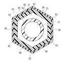
外管先端部82は、図2に示すように、外管80の軸線Xと直交する断面において外表面が多角形(本実施形態では六角形)で形成されている。外管先端部82の多角形の角部に対応する部位が、径方向の外側へ突出する突出部83を構成し、多角形の辺に対応する部位が、突出部83よりも曲率が大きい中間部84を構成しており、突出部83および中間部84が周方向に交互に配置されている。なお、突出部83は、鋭利に形成されずに曲面で形成されることが好ましいが、鋭利に形成されてもよく、または面取りされて形成されてもよい。突出部83が鋭利に形成されても、外管80の材料が柔軟であるため、生体組織への負担は比較的小さい。 As shown in FIG. 2, the outer surface of the outer tube
突出部83の曲率(曲率半径の逆数)は、特に限定されないが、1〜1000(1/mm)であることが好ましく、1.2〜500(1/mm)であることがより好ましく、2〜100(1/mm)であることがさらに好ましい。曲率が大きくなると、接触抵抗が減少するが、突出部83が鋭利となって接触する生体組織への負担が大きくなる。曲率が小さくなると、接触する生体組織への負担が小さくなるが、血管と接触する面積が増加し、押し込み性(プッシャビリティ)が低下する。なお、本実施形態では、突出部83および中間部84の曲率は、軸線Xに沿ういずれの位置においても略一定となっているが、位置によって異なってもよい。 The curvature of the protrusion 83 (the reciprocal of the radius of curvature) is not particularly limited, but is preferably 1 to 1000 (1 / mm), more preferably 1.2 to 500 (1 / mm). More preferably, it is -100 (1 / mm). When the curvature increases, the contact resistance decreases, but the
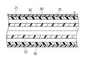
また、外管先端部82は、図3に示すように、外管80の軸線Xと平行な断面において外表面が平滑となっており、凹凸形状が形成されていない。 Further, as shown in FIG. 3, the outer tube
外管先端部82の軸線Xに沿う長さは、特に限定されず、カテーテル10の用途によって適宜設定されることが好ましいが、例えば100〜500mmである。外管先端部82の最大外径(六角形の角部における外径)は、特に限定されず、カテーテル10の用途によって適宜設定されることが好ましいが、例えば100〜500mmである。 The length along the axis X of the outer tube
外管基端部81は、図4に示すように、外管80の軸線Xと直交する断面において外表面が円形で形成されている。また、外管基端部81は、図5に示すように、外管80の軸線Xと平行な断面において、凸部86および凹部85が交互に並んで配置されている。各々の凸部86および凹部85は、外管80の外周面を360度にわたって環状に形成されている。凸部86は、凸部86の頂点を挟んで先端側の凹部85に向かう先端側傾斜面87と、凸部86の頂点を挟んで基端側の凹部85に向かう基端側傾斜面88とを備えている。先端側傾斜面87の軸線Xに対する傾斜角αは、基端側傾斜面88の軸線Xに対する傾斜角βよりも小さい。 As shown in FIG. 4, the outer tube
凸部86の高さ(凹部85の深さ)は、特に限定されないが、例えば0.001〜0.200mmであることが好ましく、より好ましくは0.005〜0.100mmであり、さらに好ましくは0.010〜0.050mmである。 The height of the convex portion 86 (depth of the concave portion 85) is not particularly limited, but is preferably 0.001 to 0.200 mm, more preferably 0.005 to 0.100 mm, and still more preferably. It is 0.010-0.050 mm.
傾斜角αは、特に限定されないが、例えば1〜85度であることが好ましく、より好ましくは10〜60度であり、さらに好ましくは15〜45度である。傾斜角βは、特に限定されないが、傾斜角αより大きいことが好ましく、より好ましくは傾斜角αよりも10度以上大きく、さらに好ましくは傾斜角αよりも45度以上大きい。なお、傾斜角βは、傾斜角αと等しくてもよい。また、傾斜角βは、90度を超えてもよい。凸部86の頂点は、鋭利に形成されてもよく、曲面で形成されてもよく、または面取りされてもよい。凸部86の頂点が鋭利であっても、凸部86が小さく、かつ外管80の材料が柔軟であるため、生体組織への負担は小さい。なお、凸部86の頂点が面取りされていれば、生体組織への負担を低減でき、凸部86の頂点が曲面で形成されていれば、生体組織への負担をより低減できる。 Although inclination angle (alpha) is not specifically limited, For example, it is preferable that it is 1-85 degree | times, More preferably, it is 10-60 degree, More preferably, it is 15-45 degree. The inclination angle β is not particularly limited, but is preferably larger than the inclination angle α, more preferably 10 degrees or more larger than the inclination angle α, and still more preferably 45 degrees larger than the inclination angle α. Note that the inclination angle β may be equal to the inclination angle α. Further, the inclination angle β may exceed 90 degrees. The vertex of the
外管80および内管90は、ある程度の可撓性を有する材料により形成されることが好ましく、そのような材料としては、例えば、ナイロン、ポリエステル、ポリアミド、ポリウレタン、ポリオレフィン、熱可塑性フッ素樹脂等である。外管80および内管90の構成材料は、同一でもよく、異なってもよい。 The
親水性被覆層70は、外管80の外管先端部82を被覆し、かつ外管基端部81を被覆していない。親水性被覆層70は、外管80の血管内での滑り性を向上させる。なお、親水性被覆層70が形成される範囲は、外管先端部82の全体であってもよく、一部であってもよく、外管基端部81の一部を含んでもよい。一例として、親水性被覆層70は、外管80の先端から基端方向へ320〜400mmの範囲でコーティングされる。 The
親水性被覆層70が湿潤すると、潤滑性を生じて摩擦抵抗(摺動抵抗)が低減し、血管等の生体管腔内での滑り性が向上する。 When the
親水性被覆層70を構成する親水性材料としては、例えば、セルロース系高分子物質、ポリエチレンオキサイド系高分子物質、無水マレイン酸系高分子物質(例えば、メチルビニルエーテル−無水マレイン酸共重合体のような無水マレイン酸共重合体)、アクリルアミド系高分子物質(例えば、ポリアクリルアミド、ポリグリシジルメタクリレート−ジメチルアクリルアミド(PGMA−DMAA)のブロック共重合体)、水溶性ナイロン、ポリビニルアルコール、ポリビニルピロリドン等が挙げられる。 Examples of the hydrophilic material constituting the
バルーン30は、拡張可能な管状の部材であり、先端側が内管90に接着され、基端側が外管80に接着されており、バルーン30の内部が、拡張ルーメン21に連通している。 The
バルーン30は、ある程度の可撓性を有する材料により形成されることが好ましく、そのような材料としては、例えば、ポリエチレン、ポリプロピレン、ポリブテン、エチレン−プロピレン共重合体、エチレン−酢酸ビニル共重合体、アイオノマー、あるいはこれら二種以上の混合物等のポリオレフィンや、軟質ポリ塩化ビニル樹脂、ポリアミド、ポリアミドエラストマー、ポリエステル、ポリエステルエラストマー、ポリウレタン、フッ素樹脂等の熱可塑性樹脂、シリコーンゴム、ラテックスゴム等が使用できる。 The
ハブ40は、外管80の拡張ルーメン21と連通して拡張用流体を流入出させる第1開口部41と、ガイドワイヤールーメン22と連通してガイドワイヤーを挿入する第2開口部42とを備えている。 The
耐キンクプロテクタ50は、カテーテル本体20とハブ40とを連結している部分に被せられる。耐キンクプロテクタ50は、弾性材料からなり、カテーテル本体20とハブ40とを連結している部分の付近での折れ曲がり(キンク)を防止することができる。 The
X線不透過部材60は、バルーン30内に位置する内管90の外表面に固定される環状の部材であり、本実施形態では、2カ所に設けられている。X線不透過部材60が設けられることで、カテーテル10を体内へ挿入した際に、カテーテル10の位置をX線透視下で確認することができる。 The X-ray
X線不透過部材60の材料としては、例えば、硫酸バリウム、酸化ビスマス、タングステン、プラチナ、プラチナ−イリジウム合金等である。 Examples of the material of the X-ray
次に、第1実施形態に係るカテーテル10の作用について説明する。 Next, the operation of the
第1実施形態に係るカテーテル10は、外管先端部82に、外管80の軸線Xと直交する断面において外側へ突出する突出部83と、突出部83よりも曲率が大きい中間部84が交互に配置されている。このため、カテーテル10を血管内へ挿入した際に、外管先端部82の突出部83が血管壁面と接触しやすくなるとともに、中間部84が血管壁面と接触し難くなる。このため、外管先端部82の血管壁面に対する接触面積を減少させることができ、接触抵抗を低減させて、血管内での滑り性を高めることができる。さらに、カテーテル10は、外管基端部81に、外管80の軸線Xと平行な断面において凹部85および凸部86が交互に並んで配置されている。このため、カテーテル10を血管内へ挿入した際に、外管基端部81の凸部86が血管壁面と接触して適度な接触抵抗が得られ、バックアップ力が高まり、押し込み性を高めることができる。このように、滑り性が要求される先端部位の血管内での滑り性を外管先端部82により高めつつも、滑り性が高まることにより生じやすいバックアップ力の低下を、外管先端部82よりも基端側に位置して押し込み力を先端側へ伝達する外管基端部81により補完することが可能となり、良好な押し込み性をも提供できる。 In the
また、外管先端部82は、外管80の軸線Xと平行な断面において外表面が平滑であるため、外管先端部82の血管内での滑り性をより向上させることができる。 Moreover, since the outer surface of the outer tube
また、凸部86の頂点を挟んで先端側の凹部85に向かう先端側傾斜面87の軸線Xに対する傾斜角αが、当該凸部86の頂点を挟んで基端側の凹部85に向かう基端側傾斜面88の軸線Xに対する傾斜角βよりも小さいため、外管基端部81が血管壁面(接触対象物)に対して先端方向へ滑る場合の接触抵抗を、基端方向へ滑る場合の接触抵抗よりも小さくすることができる。このため、カテーテル10が先端方向へ移動する際には低い接触抵抗によって押し込み性が損なわれず、かつカテーテル10が基端方向へ移動する際に適度な接触抵抗が得られてバックアップ力を高め、押し込み性を高めることができる。 In addition, the inclination angle α with respect to the axis X of the distal-side
また、外管先端部82は、親水性被覆層70が被覆されるため、滑り性が要求される外管先端部82の接触抵抗をより低下させて、滑り性をより向上させることができる。なお、本実施形態における外管先端部82は、突出部83および中間部84が形成されるため、仮に親水性被覆層70が設けられずとも、高い滑り性を備えることができる。 Moreover, since the outer tube | pipe front-end | tip
なお、本実施形態では、外管先端部82の外表面が軸線Xと直交する断面において六角形で形成されるが、多角形であれば角の数は限定されない。また、外管先端部82の外表面に形成される多角形は、正多角形でなくてもよい。また、図6に示す変形例のように、外管先端部82Aの外表面が軸線Xと直交する断面において星形となり、中間部84Aの曲率が負(マイナス)となってもよい。中間部84Aの曲率が負となれば、中間部84Aが血管壁面にさらに接触し難くなり、滑り性をさらに高めることができる。 In the present embodiment, the outer surface of the
また、外管80および内管90の少なくとも一方が、複数層で構成されたり、線状体や網状体からなる補強層が設けられてもよい。 Further, at least one of the
また、傾斜角αが、傾斜角β以上であってもよい。また、凸部および凹部は、外管の外表面に沿って螺旋状に形成されてもよい。 Further, the inclination angle α may be equal to or larger than the inclination angle β. Further, the convex portion and the concave portion may be formed in a spiral shape along the outer surface of the outer tube.
また、図7に示す変形例のように、外管基端部81Aの凸部86Aは、軸線Xに沿って間隔を開けて設けられてもよい。この場合、凸部86A同士の間に形成される平坦な部位が、凹部85Aを構成する。また、凹部が、軸線Xに沿って間隔を開けて設けられてもよい。この場合、凹部同士の間に形成される平坦な部位が、凸部を構成する。
<第2実施形態>Further, as in the modification shown in FIG. 7, the
Second Embodiment
第2実施形態に係るカテーテル100は、外管先端部111の外表面の形状のみが、第1実施形態に係るカテーテル10と異なる。なお、第1実施形態と同一の機能を有する部位には、同一の符号を付し、重複を避けるため、説明を省略する。 The
第2実施形態に係るカテーテル100の外管110の外管先端部111(第1の部位)は、図8〜12に示すように、外管110の軸線Xと直交する断面において外表面が多角形(本実施形態では六角形)で形成されている。外管先端部111の多角形の角部に対応する部位が、径方向の外側へ突出する突出部112を構成し、多角形の辺に対応する部位が、突出部112よりも曲率が大きい中間部113を構成しており、突出部112および中間部113が周方向に交互に配置されている。そして、外管先端部111は、突出部112の曲率が、基端側へ向かって徐々に小さくなっており、突出部112の曲率と中間部113の曲率との差が、基端側へ向かって徐々に小さくなっている。 The outer tube distal end portion 111 (first portion) of the
次に、第2実施形態に係るカテーテル100の作用について説明する。 Next, the operation of the
第2実施形態に係るカテーテル100は、外管先端部111の突出部112の曲率と、中間部113の曲率との差が、基端側へ向かって徐々に小さくなっているため、カテーテル100を血管内へ挿入した際に、曲率の差が大きい先端側では、中間部113が血管壁面と接触し難いために接触面積が減少する程度が大きく、曲率の差が小さい基端側では、曲率の差が大きい先端側と比較して、中間部113もある程度血管壁面と接触しやすくなるために、先端側と比較して接触面積が減少する程度が小さい。このため、外管先端部111の外表面は、先端側ほど接触抵抗が小さく、基端側へ向かうにしたがって、接触抵抗が徐々に大きくなる。このため、外管先端部111の先端側においては、血管内滑り性を高めつつ、外管先端部111の基端側においては、滑り性を低減させてバックアップ力の低下を抑制して、良好な押し込み性を得ることができる。 In the
このため、滑り性が要求されるカテーテル100の先端側の部位において高い滑り性を付与しつつ、バックアップ力が要求されるカテーテル100の基端側の部位において滑り性を低減させて、良好な押し込み性を得ることができる。 For this reason, while providing high slipperiness in the site | part of the front end side of the
また、外管先端部111の突出部112の曲率と、中間部113の曲率との差が、基端側へ向かって徐々に小さくなることで、外管先端部111の基端側の形状が、外管基端部81の形状に近くなるため、外管先端部111と外管基端部81との境界において形状変化が小さくなり、接触抵抗のみならず、外管110の物性の変化も小さくなる。このため、外管先端部111と外管基端部81との境界において応力が集中し難くなり、キンクの発生を抑制できるとともに、外管110の破損等を抑制して安全性を向上できる。
<第3実施形態>In addition, the difference between the curvature of the protruding
<Third Embodiment>
第3実施形態に係るカテーテル120は、外管基端部131の外表面の形状のみが、第1実施形態に係るカテーテル10と異なる。なお、第1実施形態と同一の機能を有する部位には、同一の符号を付し、重複を避けるため、説明を省略する。 The
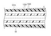
第3実施形態に係るカテーテル120の外管130の外管基端部131(第2の部位)は、外管130の軸線Xと直交する断面において外表面が円形で形成されており、外管130の軸線Xと平行な断面において、図13に示すように、凸部133および凹部132が交互に並んで配置されている。各々の凸部133および凹部132は、外管130の外周面を360度にわたって環状に形成されている。外管基端部131は、基端側の凹部132ほど深さが徐々に深くなっており、これにより、凸部133も基端側ほど高くなっている。 The outer tube proximal end portion 131 (second portion) of the outer tube 130 of the
次に、第3実施形態に係るカテーテル120の作用について説明する。 Next, the operation of the
第3実施形態に係るカテーテル120は、基端側の凹部132ほど深さが徐々に深くなっており、これにより、凸部133も基端側ほど高くなっているため、カテーテル120を血管内へ挿入した際に、凹部132が深く凸部133が高い先端側ほど、血管壁面と接触した際の接触抵抗が大きくなっている。このように、外管基端部131の外表面の接触抵抗を軸線X方向の部位に応じて変化させることで、軸線X方向の部位に応じて適切なバックアップ力を設定することができる。特に、外管基端部131の基端側においてはバックアップ力が高められるとともに、外管基端部131の先端側においてはバックアップ力が抑えられることで、バックアップ力が要求されるカテーテル120の基端側の部位において高いバックアップ力を付与しつつ、滑り性が要求されるカテーテル120の先端側の部位においてはバックアップ力を低減させて、良好な押し込み性を得ることができる。 In the
なお、第3実施形態に係るカテーテル120の変形例として、図14に示すように、軸線Xに沿って基端側ほど外管基端部131Aの接触抵抗が大きくなるように、基端側の凸部133Aほど高さを高くし、これにより、凹部132Aも基端側ほど深くなってもよい。 As a modified example of the
また、第3実施形態に係るカテーテル120の他の変形例として、図15に示すように、軸線Xに沿って基端側ほど外管基端部131Bの接触抵抗が大きくなるように、基端側の凸部133Bおよび凹部132Bほど、密度(凸部133Bまたは凹部132Bの、軸線Xに沿う単位長さ当たりの数)が高くなってもよい。 As another modification of the
また、上述した凸部の高さ、凹部の深さ、凸部の密度、および凹部の密度の少なくとも2つを、組み合わせて変化させてもよい。
<第4実施形態>Further, at least two of the height of the convex portion, the depth of the concave portion, the density of the convex portion, and the density of the concave portion described above may be changed in combination.
<Fourth embodiment>
第4実施形態に係るカテーテル140は、図16に示すように、混合部151を有する点で、前述の他の実施形態と異なる。なお、前述の他の実施形態と同様の機能を有する部位には、同一の符号を付し、重複を避けるため、説明を省略する。 As shown in FIG. 16, the
第4実施形態に係るカテーテル140の外管150は、第2実施形態の構成と同様の外管先端部111と、第3実施形態の構成と同様の外管基端部131と、外管先端部111および外管基端部131の間に設けられる混合部151とを有している。 The
外管先端部111(第1の部位)は、第2実施形態と同様に、突出部112の曲率が基端側へ向かって徐々に小さくなっており、突出部112の曲率と中間部113の曲率との差が、基端側へ向かって徐々に小さくなっている(図9〜12を参照)。 As in the second embodiment, the outer tube distal end portion 111 (first portion) has a gradually decreasing curvature toward the proximal end, and the curvature of the protruding
外管基端部131(第2の部位)は、第3実施形態と同様に、基端側の凹部132ほど深さが徐々に深くなり、かつ、凸部133も基端側ほど高くなっており、基端側ほど接触抵抗が大きくなっている(図13を参照)。 As in the third embodiment, the outer tube proximal end portion 131 (second portion) gradually becomes deeper as the
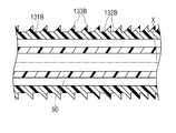
混合部151は、図17〜19に示すように、外管先端部111から連続する突出部152および中間部153を備えるとともに、外管基端部131から連続する凹部154および凸部155を備えている。 As shown in FIGS. 17 to 19, the
混合部151は、突出部152の曲率が、外管先端部111から連続して、基端側へ向かって徐々に小さくなっており、突出部152の曲率と中間部153の曲率との差が、基端側へ向かって徐々に小さくなっている。さらに、混合部151は、外管基端部131から連続して、先端側の凹部154ほど深さが徐々に浅くなり、かつ凸部155も先端側ほど低くなっており、基端側ほど接触抵抗が大きくなっている。 In the mixing
次に、第4実施形態に係るカテーテル140の作用について説明する。 Next, the operation of the
第4実施形態に係るカテーテル140は、混合部151において、外管先端部111から連続して、突出部152の曲率と中間部153の曲率との差が基端側へ向かって徐々に小さくなるとともに、外管基端部131から連続して、先端側の凹部154ほど深さが徐々に浅くなり、かつ凸部155も先端側ほど低くなっている。このため、混合部151において、外管150の先端から基端にわたって、外管150の形状が連続的に変化することになり、接触抵抗のみならず、外管150の物性の変化も連続的に変化する。このため、外管先端部111、混合部151および外管基端部131の各々の境界において応力が集中し難くなり、キンクの発生を抑制するとともに、外管150の破損等を抑制して安全性が向上する。 In the
なお、本発明は、上述した実施形態のみに限定されるものではなく、本発明の技術的思想内において当業者により種々変更が可能である。例えば、上述した実施形態に係るカテーテルは、バルーン30を有するバルーンカテーテルであるが、バルーンカテーテルでなくてもよく、生体管腔内に挿入可能なシャフトを有するカテーテルであれば、本発明を適用できる。 Note that the present invention is not limited to the above-described embodiments, and various modifications can be made by those skilled in the art within the technical idea of the present invention. For example, the catheter according to the above-described embodiment is a balloon catheter having the
また、上述の各実施形態に係るカテーテルは、ガイドワイヤーがカテーテルの全長にわたって挿入されるオーバーザワイヤ型(Over−the−wire type)であるが、ガイドワイヤーがカテーテルの先端部にのみ挿入されるラピッドエクスチェンジ型(Rapid exchange type)であってもよい。 Moreover, although the catheter which concerns on each above-mentioned embodiment is an over-the-wire type (Over-the-wire type) in which a guide wire is inserted over the full length of a catheter, rapid in which a guide wire is inserted only in the tip part of a catheter It may be an exchange type (Rapid exchange type).
10,100,120,140 カテーテル、
20 カテーテル本体、
70 親水性被覆層、
80,110,130,150 外管、
81,81A,111,131,131A、131B 外管基端部、
82,82A 外管先端部、
83,112,152 突出部、
84,84A,113,153 中間部、
85,85A,132,132A,132B,154 凹部、
86,86A,133,133A,133B,155 凸部、
87 先端側傾斜面、
88 基端側傾斜面、
90 内管、
151 混合部、
X 軸線。10, 100, 120, 140 catheter,
20 catheter body,
70 hydrophilic coating layer,
80, 110, 130, 150 outer pipe,
81, 81A, 111, 131, 131A, 131B outer tube proximal end,
82,82A outer tube tip,
83, 112, 152 protrusions,
84, 84A, 113, 153 middle part,
85, 85A, 132, 132A, 132B, 154 recess,
86, 86A, 133, 133A, 133B, 155 convex portion,
87 Tip side inclined surface,
88 base end side inclined surface,
90 inner pipe,
151 mixing section,
X axis.
Claims (8)
Translated fromJapanese前記シャフトは、
当該シャフトの軸線と直交する断面において外表面に外側へ突出する突出部および当該突出部よりも曲率が大きい中間部が交互に配置される第1の部位と、
前記第1の部位よりも基端側に設けられ、前記シャフトの軸線と平行な断面において外表面に凸部および凹部が交互に並んで配置される第2の部位と、を有するカテーテル。A catheter comprising a shaft that can be inserted into a body lumen,
The shaft is
In a cross section orthogonal to the axis of the shaft, the first portion where the protruding portion protruding outward on the outer surface and the intermediate portion having a larger curvature than the protruding portion are alternately arranged,
A catheter having a second portion provided on a proximal end side with respect to the first portion and having a convex portion and a concave portion alternately arranged on the outer surface in a cross section parallel to the axis of the shaft.
Priority Applications (1)
| Application Number | Priority Date | Filing Date | Title |
|---|---|---|---|
| JP2014057487AJP6342189B2 (en) | 2014-03-20 | 2014-03-20 | catheter |
Applications Claiming Priority (1)
| Application Number | Priority Date | Filing Date | Title |
|---|---|---|---|
| JP2014057487AJP6342189B2 (en) | 2014-03-20 | 2014-03-20 | catheter |
Publications (2)
| Publication Number | Publication Date |
|---|---|
| JP2015181486Atrue JP2015181486A (en) | 2015-10-22 |
| JP6342189B2 JP6342189B2 (en) | 2018-06-13 |
Family
ID=54348797
Family Applications (1)
| Application Number | Title | Priority Date | Filing Date |
|---|---|---|---|
| JP2014057487AActiveJP6342189B2 (en) | 2014-03-20 | 2014-03-20 | catheter |
Country Status (1)
| Country | Link |
|---|---|
| JP (1) | JP6342189B2 (en) |
Cited By (1)
| Publication number | Priority date | Publication date | Assignee | Title |
|---|---|---|---|---|
| CN114984404A (en)* | 2022-06-10 | 2022-09-02 | 惠州市顺美医疗科技有限公司 | Surface forming guide catheter and preparation method thereof |
Citations (13)
| Publication number | Priority date | Publication date | Assignee | Title |
|---|---|---|---|---|
| JPS62102767A (en)* | 1985-10-18 | 1987-05-13 | ブラゴベスチエンスキ ゴスダルストベンニ メデイツインスキ インステイテユト | Cannula for main artery |
| WO1993018813A1 (en)* | 1992-03-19 | 1993-09-30 | Keiji Igaki | Medical tube |
| JPH06510677A (en)* | 1991-07-26 | 1994-12-01 | ザ リージェンツ オブ ザ ユニバーシティ オブ カリフォルニア | stone evacuation stent |
| JP2000197704A (en)* | 1998-10-27 | 2000-07-18 | Terumo Corp | Medical tube and manufacture thereof |
| JP2000254235A (en)* | 1999-03-10 | 2000-09-19 | Terumo Corp | Medical tube and its manufacture |
| JP2002143293A (en)* | 2000-11-16 | 2002-05-21 | Terumo Corp | Multilayer tube for medical care |
| US20060264905A1 (en)* | 2005-05-02 | 2006-11-23 | Pulsar Vascular, Inc. | Improved Catheters |
| JP2007244771A (en)* | 2006-03-17 | 2007-09-27 | Nippon Sherwood Medical Industries Ltd | Stylet device and medical tube assembly |
| JP2007537769A (en)* | 2003-11-03 | 2007-12-27 | ヴァイマルン−シェルリ,アレクサンダー フォン | Instrument for insertion at least partially into a human body conduit, in particular sluice or catheter |
| JP2007537827A (en)* | 2004-05-20 | 2007-12-27 | ボストン サイエンティフィック リミテッド | Medical device having multiple layers |
| JP2008513180A (en)* | 2004-09-22 | 2008-05-01 | アボット、カーディオバスキュラー、システムズ、インコーポレーテッド | Delivery system for medical devices |
| JP2012165814A (en)* | 2011-02-10 | 2012-09-06 | Olympus Corp | Insertion unit |
| WO2013115330A1 (en)* | 2012-01-31 | 2013-08-08 | テルモ株式会社 | Catheter |
- 2014
- 2014-03-20JPJP2014057487Apatent/JP6342189B2/enactiveActive
Patent Citations (13)
| Publication number | Priority date | Publication date | Assignee | Title |
|---|---|---|---|---|
| JPS62102767A (en)* | 1985-10-18 | 1987-05-13 | ブラゴベスチエンスキ ゴスダルストベンニ メデイツインスキ インステイテユト | Cannula for main artery |
| JPH06510677A (en)* | 1991-07-26 | 1994-12-01 | ザ リージェンツ オブ ザ ユニバーシティ オブ カリフォルニア | stone evacuation stent |
| WO1993018813A1 (en)* | 1992-03-19 | 1993-09-30 | Keiji Igaki | Medical tube |
| JP2000197704A (en)* | 1998-10-27 | 2000-07-18 | Terumo Corp | Medical tube and manufacture thereof |
| JP2000254235A (en)* | 1999-03-10 | 2000-09-19 | Terumo Corp | Medical tube and its manufacture |
| JP2002143293A (en)* | 2000-11-16 | 2002-05-21 | Terumo Corp | Multilayer tube for medical care |
| JP2007537769A (en)* | 2003-11-03 | 2007-12-27 | ヴァイマルン−シェルリ,アレクサンダー フォン | Instrument for insertion at least partially into a human body conduit, in particular sluice or catheter |
| JP2007537827A (en)* | 2004-05-20 | 2007-12-27 | ボストン サイエンティフィック リミテッド | Medical device having multiple layers |
| JP2008513180A (en)* | 2004-09-22 | 2008-05-01 | アボット、カーディオバスキュラー、システムズ、インコーポレーテッド | Delivery system for medical devices |
| US20060264905A1 (en)* | 2005-05-02 | 2006-11-23 | Pulsar Vascular, Inc. | Improved Catheters |
| JP2007244771A (en)* | 2006-03-17 | 2007-09-27 | Nippon Sherwood Medical Industries Ltd | Stylet device and medical tube assembly |
| JP2012165814A (en)* | 2011-02-10 | 2012-09-06 | Olympus Corp | Insertion unit |
| WO2013115330A1 (en)* | 2012-01-31 | 2013-08-08 | テルモ株式会社 | Catheter |
Cited By (2)
| Publication number | Priority date | Publication date | Assignee | Title |
|---|---|---|---|---|
| CN114984404A (en)* | 2022-06-10 | 2022-09-02 | 惠州市顺美医疗科技有限公司 | Surface forming guide catheter and preparation method thereof |
| CN114984404B (en)* | 2022-06-10 | 2023-07-25 | 惠州市顺美医疗科技有限公司 | Surface-molded guide catheter and preparation method thereof |
Also Published As
| Publication number | Publication date |
|---|---|
| JP6342189B2 (en) | 2018-06-13 |
Similar Documents
| Publication | Publication Date | Title |
|---|---|---|
| EP3603726B1 (en) | Catheter assembly | |
| US10434289B2 (en) | Guide wire | |
| US11712544B2 (en) | Guide extension catheter | |
| JP4562197B2 (en) | Balloon catheter assembly | |
| JP2004024625A (en) | Catheter and medical tube | |
| US20220088354A1 (en) | Balloon catheter | |
| WO2020195697A1 (en) | Balloon catheter | |
| JP2015173913A (en) | angioplasty catheter | |
| WO2020195170A1 (en) | Balloon catheter | |
| US10850074B2 (en) | Guide wire | |
| JP2022148511A (en) | catheter | |
| CN115335103A (en) | Balloon catheter | |
| JP6342189B2 (en) | catheter | |
| JP2010119776A (en) | Catheter support having modified cross section | |
| CN220572506U (en) | interventional guidewire | |
| JP5822140B2 (en) | Thrombus aspiration catheter | |
| JP2005329063A (en) | Dilator | |
| JP6162802B2 (en) | catheter | |
| WO2021049261A1 (en) | Method for producing balloon catheter | |
| JP4316252B2 (en) | catheter | |
| JP7148308B2 (en) | balloon catheter | |
| JP2005329062A (en) | Introducer sheath | |
| WO2024042977A1 (en) | Balloon catheter-use balloon, and balloon catheter provided with same | |
| WO2024042978A1 (en) | Balloon for balloon catheter and balloon catheter provided therewith | |
| WO2025204437A1 (en) | Medical tubing |
Legal Events
| Date | Code | Title | Description |
|---|---|---|---|
| A621 | Written request for application examination | Free format text:JAPANESE INTERMEDIATE CODE: A621 Effective date:20161206 | |
| A977 | Report on retrieval | Free format text:JAPANESE INTERMEDIATE CODE: A971007 Effective date:20170926 | |
| A131 | Notification of reasons for refusal | Free format text:JAPANESE INTERMEDIATE CODE: A131 Effective date:20171030 | |
| A521 | Request for written amendment filed | Free format text:JAPANESE INTERMEDIATE CODE: A523 Effective date:20171228 | |
| TRDD | Decision of grant or rejection written | ||
| A01 | Written decision to grant a patent or to grant a registration (utility model) | Free format text:JAPANESE INTERMEDIATE CODE: A01 Effective date:20180416 | |
| A61 | First payment of annual fees (during grant procedure) | Free format text:JAPANESE INTERMEDIATE CODE: A61 Effective date:20180516 | |
| R150 | Certificate of patent or registration of utility model | Ref document number:6342189 Country of ref document:JP Free format text:JAPANESE INTERMEDIATE CODE: R150 | |
| R250 | Receipt of annual fees | Free format text:JAPANESE INTERMEDIATE CODE: R250 | |
| R250 | Receipt of annual fees | Free format text:JAPANESE INTERMEDIATE CODE: R250 | |
| R250 | Receipt of annual fees | Free format text:JAPANESE INTERMEDIATE CODE: R250 | |
| R250 | Receipt of annual fees | Free format text:JAPANESE INTERMEDIATE CODE: R250 |