JP2015179847A - Reflection and heat dissipation structures of led light source - Google Patents
Reflection and heat dissipation structures of led light sourceDownload PDFInfo
- Publication number
- JP2015179847A JP2015179847AJP2015077625AJP2015077625AJP2015179847AJP 2015179847 AJP2015179847 AJP 2015179847AJP 2015077625 AJP2015077625 AJP 2015077625AJP 2015077625 AJP2015077625 AJP 2015077625AJP 2015179847 AJP2015179847 AJP 2015179847A
- Authority
- JP
- Japan
- Prior art keywords
- led light
- light source
- heat dissipation
- reflection
- reflection member
- Prior art date
- Legal status (The legal status is an assumption and is not a legal conclusion. Google has not performed a legal analysis and makes no representation as to the accuracy of the status listed.)
- Pending
Links
Images


Landscapes
- Fastening Of Light Sources Or Lamp Holders (AREA)
- Electroluminescent Light Sources (AREA)
- Led Device Packages (AREA)
Abstract
Description
Translated fromJapanese本発明は、LED光源の反射及び放熱構造に関するもので、更に詳しくは、反射かつ放熱に優れた反射部材と放熱部材とを組み合わせ、かつ防塵・防水性を有するLED光源の反射及び放熱構造に関する。The present invention relates to a reflection and heat dissipation structure of an LED light source, and more particularly, to a reflection and heat dissipation structure of an LED light source that combines a reflection member excellent in reflection and heat dissipation and a heat dissipation member, and has dustproof and waterproof properties.
近年、光を装飾的に使用するための光源装置は、通常の電球から発光ダイオード(LED)に変わりつつある中、この発光ダイオード、即ちLEDは、消費電力も従来の電球に比べて少なく、工業用はもちろんのこと、一般家庭でも電球として使用されるようになった。このような中で装飾用LED光源は、大型のものから小型のものまで、種々知られている。その一例を挙げると、クリスマスツリーに用いられるライト光源で、この光源は鉢状ケース内に回転可能なカラーフィルターを通して得られた各種の色の光を光学繊維、即ち光ファイバー群へ照射するための、いわゆる装飾用光源が記載され、具体的には、豆電球、蛍光灯、放電ランプ、発光ダイオード(LED)等があることも示されており、これらの光源を使用した装飾用LED光源装置についても記載されている(例えば、特許文献1参照)。また本特許出願人が出願したクリスマスツリーにおいて、光ファイバーの端部に少なくとも一色又は多色に発光するLEDが複数個配置され、一部重ね合わせて色の合成を可能としたLED光源を有する光ファイバー装飾装置及びこれを使用したものが公開され、かつ特許となっている(例えば、特許文献2参照)。In recent years, light source devices for decorative use of light are changing from ordinary light bulbs to light emitting diodes (LEDs), and these light emitting diodes, that is, LEDs, consume less power than conventional light bulbs. Of course, it has been used as a light bulb in ordinary homes. Under such circumstances, various LED light sources for decoration are known from large to small. One example is a light source used in a Christmas tree. This light source is used to irradiate optical fibers, that is, optical fiber groups, with various colors of light obtained through a rotatable color filter in a bowl-shaped case. So-called decorative light sources are described, and specifically, it is also shown that there are miniature bulbs, fluorescent lamps, discharge lamps, light emitting diodes (LEDs), etc., and also about decorative LED light source devices using these light sources (For example, refer to Patent Document 1). Further, in the Christmas tree filed by the present applicant, an optical fiber decoration having an LED light source in which a plurality of LEDs emitting at least one color or multiple colors are arranged at the end of the optical fiber, and the colors can be synthesized by overlapping a part of them. An apparatus and a device using the same have been disclosed and patented (see, for example, Patent Document 2).
しかしながら、前述の如き特許文献1及び2に記載されている如きクリスマスツリーに用いられるLEDの発光光源が用いられているものの、カバー乃至フードを有するものが記載されているが、これらには、LED光源の照度を効率的に向上させたり、放熱性、特に高照度LED光源の放熱性については何ら考慮されていないという問題がある。However, although the light emitting light source of the LED used for the Christmas tree as described in
これに対して本発明者は、LED光源の発熱性を考慮し、十分な放熱性が得られるべく種々検討したところ、(1)LED光源の周囲の少なくとも一部に反射部材を有しすること、(2)該反射部材を熱伝導性に優れた金属部材を使用すること、更に(3)前記反射部材と組み合わせて更にLED光源に放熱部材を設置することにより、優れた反射性能と共に優れた放熱性を有するLED光源の反射及び放熱構造が得られることを見出し、この知見に基づいて本発明はなされたものである。したがって、本発明が解決しようとする課題は、反射部材による反射及び放熱効果を向上させるばかりでなく、更に補助放熱部材を組み合わせ、かつ防塵・防水することにより、防塵・防水性に加えて更なる放熱性に優れたLED光源の反射及び放熱構造を提供することにある。On the other hand, the present inventor has made various studies to obtain sufficient heat dissipation in consideration of the heat generation of the LED light source. (1) At least part of the periphery of the LED light source has a reflecting member. (2) The reflective member is made of a metal member having excellent thermal conductivity, and (3) the heat radiating member is further installed in the LED light source in combination with the reflective member. It has been found that a reflection and heat dissipation structure of an LED light source having heat dissipation properties can be obtained, and the present invention has been made based on this finding. Therefore, the problem to be solved by the present invention is not only to improve the reflection and heat dissipation effect by the reflective member, but also to further improve the dustproof and waterproof property by combining the auxiliary heat radiating member, and dustproofing and waterproofing. An object of the present invention is to provide an LED light source reflecting and radiating structure excellent in heat dissipation.
本発明の上記各課題は、以下の各発明によってそれぞれ達成される。The above-described problems of the present invention are achieved by the following inventions.
(1)LED光源の周囲の少なくとも一部に反射部材を有し、該反射部材は反射性能と共に放熱性に優れた放熱部材からなることを特徴とするLED光源の反射及び放熱構造。
(2)前記LED光源は、少なくとも一個のLED光源からなることを特徴とする前記第1項に記載のLED光源の反射及び放熱構造。
(3)前記LED光源は、基体上に複数のLED光源が一体的に有することを特徴とする前記第1項に記載のLED光源の反射及び放熱構造。
(4)前記LED光源は、面発光のLED光源からなることを特徴とする前記第1項に記載のLED光源の反射及び放熱構造。
(5)前記LED光源は、有機LED光源からなることを特徴とする前記第1項に記載のLED光源の反射及び放熱構造。
(6)前記反射部材は、該反射部材に接触して補助放熱部材を有することを特徴とする前記第1項乃至第5項のいずれかに記載のLED光源の反射及び放熱構造。(1) A reflection and heat dissipation structure for an LED light source, comprising a reflection member at least partially around the LED light source, the reflection member being composed of a heat dissipation member having excellent heat dissipation properties as well as reflection performance.
(2) The LED light source reflecting and radiating structure according to (1) above, wherein the LED light source comprises at least one LED light source.
(3) The LED light source reflection and heat dissipation structure according to (1), wherein the LED light source has a plurality of LED light sources integrally on a base.
(4) The LED light source reflection and heat dissipation structure according to (1), wherein the LED light source is a surface-emitting LED light source.
(5) The LED light source reflection and heat dissipation structure as described in (1) above, wherein the LED light source is an organic LED light source.
(6) The reflection and heat dissipation structure for an LED light source according to any one of (1) to (5), wherein the reflection member has an auxiliary heat dissipation member in contact with the reflection member.
本発明の第1項に記載のLED光源の反射及び放熱構造によれば、LED光源の周囲の少なくとも一部に反射部材を有し、該反射部材は反射性能と共に放熱性に優れた放熱部材からなることにより、反射部材の反射効率を維持しつつ、放熱性能をいっそう向上させることができるので、高照度LED光源を用いることができるという優れた効果を奏するものである。また上記の本発明の第2項に記載のLED光源の反射及び放熱構造は、前記第1項に記載のLED光源の反射及び放熱構造において、前記LED光源は、少なくとも一個のLED光源からなることにより、LED光源の数に応じて反射部材による反射効果で照度が向上すると共にLED光源のためその数が増加しても十分な放熱性が得られるという優れた効果を奏するものである。According to the reflection and heat dissipation structure of the LED light source according to the first aspect of the present invention, the reflection member has a reflection member on at least a part of the periphery of the LED light source, and the reflection member is a heat dissipation member excellent in heat dissipation with reflection performance. As a result, the heat dissipation performance can be further improved while maintaining the reflection efficiency of the reflecting member, so that an excellent effect that a high-illuminance LED light source can be used is achieved. The LED light source reflection and heat dissipation structure according to the second aspect of the present invention is the LED light source reflection and heat dissipation structure according to the first aspect, wherein the LED light source includes at least one LED light source. Thus, the illuminance is improved by the reflection effect of the reflecting member according to the number of LED light sources, and an excellent effect is obtained that sufficient heat dissipation can be obtained even if the number of the LED light sources increases.
上記の本発明の第3項に記載のLED光源の反射及び放熱構造は、前記第1項に記載のLED光源の反射及び放熱構造において、前記LED光源は、基体上に複数のLED光源が一体的に有することによっても、照度の向上はもちろんのこと、反射部材により放熱性能も極めて良好であるという優れた効果を奏するものである。The LED light source reflection and heat dissipation structure according to the third aspect of the present invention is the LED light source reflection and heat dissipation structure according to the first aspect, wherein the LED light source has a plurality of LED light sources integrated on a base. In addition to the improvement in illuminance, the reflective member also has an excellent effect that the heat dissipation performance is extremely good.
上記の本発明の第4項に記載のLED光源の反射及び放熱構造は、前記第1項に記載のLED光源の反射及び放熱構造において、前記LED光源は、面発光のLED光源からなることにより、取り付けが簡単であると共に裏面からの放熱性に優れたものが得られる。上記の本発明の第5項に記載のLED光源の反射及び放熱構造は、前記第1項に記載のLED光源の反射及び放熱構造において、前記LED光源は、有機LED光源からなることにより、取り付けが簡単かつ経済的であると共に裏面からの放熱性に優れたものが得られる。上記の本発明の第6項に記載のLED光源の反射及び放熱構造は、前記第1項乃至第5項のいずれかにおいて、前記反射部材は、該反射部材に接触して補助放熱部材を有することにより、放熱部材の熱が、更に補助放熱部材からも放熱され、いっそう優れた放熱性能が得られるという優れた効果を奏するものである。The LED light source reflection and heat dissipation structure according to the fourth aspect of the present invention is the LED light source reflection and heat dissipation structure according to the first aspect, wherein the LED light source is a surface-emitting LED light source. Thus, it is easy to mount and has excellent heat dissipation from the back surface. The LED light source reflection and heat dissipation structure according to the fifth aspect of the present invention is the LED light source reflection and heat dissipation structure according to the first aspect, wherein the LED light source is an organic LED light source and is attached. Is simple and economical and has excellent heat dissipation from the back surface. In the reflection and heat dissipation structure for an LED light source according to the sixth aspect of the present invention, in any one of the first to fifth aspects, the reflection member has an auxiliary heat dissipation member in contact with the reflection member. As a result, the heat of the heat radiating member is further radiated from the auxiliary heat radiating member, and an excellent effect is obtained that a further excellent heat radiating performance is obtained.
以下に、本発明の実施の形態を図面で説明するが、本発明は、これに限定されるものではない。本発明は、全方向に傾斜した反射部材の中心部にLED光源を有し、該反射部材は反射性能と共に放熱性に優れた放熱部材からなることを特徴とするLED光源の反射及び放熱構造である。Hereinafter, embodiments of the present invention will be described with reference to the drawings, but the present invention is not limited thereto. The present invention provides an LED light source reflecting and radiating structure characterized in that it has an LED light source at the center of a reflecting member inclined in all directions, and the reflecting member is composed of a heat radiating member having excellent heat dissipation as well as reflecting performance. is there.
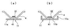
図1及び図2において、本発明のLED光源の反射及び放熱構造1,2は、少なくとも1個のLED光源3を中心にその周囲に全方向に傾斜した反射部材4を配置したものからなる。反射部材4の下部には補助放熱部材11を有するが、この補助放熱部材11は照度が低い場合は低発熱性であるから、なくてもよい。ここで、図1、図2は、反射部材4は、LED光源3を中心にその周囲に全方向に傾斜した反射部材が示されているが、これは、本発明の一部の例であって、これに限定されるものではなく、後述するように、図10に示される数多くの実施の形態がある。1 and 2, the LED light source reflection and
また、図2、図3において、LED光源3としては、各種のものが用いられ、具体的には、一個のLED光源、複数のLED光源、面発光のLED光源、有機LED光源等が用いられるが、これらのうち、面発光のLED光源、有機LED光源が好ましい。複数のLED光源31は、基板上に複数のLEDを搭載したものであり、また面発光のLED光源は、絶縁層を介して設けられた2枚の導電層を含む積層体に斜面を設け、この両導電層間にLEDを設けた構造からなる(特開2002−329893)。更に有機LED光源32は、発光層が有機化合物からなる発光ダイオード(LED)を構成しており、有機化合物中に注入された電子と正孔の再結合によって生じた励起子によって発光する、いわゆる有機ELをいう。このようなLED光源3の周囲には、すり鉢状の反射部材4が、LED光を反射して照度を向上させるために配置されている。2 and 3, various types of
この反射部材4としては、反射性能に優れたものであれば、特に限定されるものではないが、銀、アルミニウム、ステンレススチール等が挙げられる。これらの中で低コストを考えた場合、アルミニウム、ステンレススチールを用いるのが好ましい。この反射部材4の下面には補助放熱板11を有している。前述の如く反射部材4の形状は、すり鉢状に設けられ、その中央にLED光源3を有するものであるが、反射部材4は、反射性能と放熱性能を有している。更に放熱性を有する反射部材4は、放熱性能を向上させるために、反射部材4の底の裏面に接触して補助放熱部材11を設けている。具体的には、図2のa、図3のaに示されるように、補助放熱部材11aは、長方形のアルミニウム板が用いられている。これにより反射部材4からの熱が補助放熱部材11aに移行し、この補助放熱部材11aから熱放散され、放熱効果を促進する。図2のb、図3のcは、設置面積を少なくするなか、放熱効果を増大させるために補助放熱部材11bの両端を立ち上げる(立ち上げ部11c)ことによって放熱効果が促進される。図3のbは、更に放熱効果を促進させるために、補助放熱部材11dの両端をヒダ状部11fが設けられている。11gはヒダ状部を形成するための切込部11eである。The reflecting
一方、反射部材4は、反射部材としての機能を維持しつつ、放熱効果をよりいっそう良好にするために、放熱構造の部分図を示す。図4〜図9において、図4、図5は、ジグザグ型の凹凸部21からなる。即ち、図4では、反射部材4の片面にジグザグ型の凹凸21が設けられており、また図5では、該ジグザグ型の凹凸21が反射部材4の両面に設けられている。これにより反射効率を維持しつつ、極めて良好な放熱効果が得られる。また反射部材4の片面又は両面に前記ジグザグ型の凹凸に代えて凸部が丸みを帯びた波型を設けてもよいことは言うまでもない。On the other hand, the
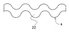
更に図6では、反射部材4の全体が波型22に形成されている。図7では、図6に示す波型22に形成された反射部材4に更に貫通孔23が設けられている。このように構成することにより光反射兼放熱フードの役割と共にいっそうの放熱効果を得ることができる。図8は、反射部材4の表面にエンボス状凹凸模様24を形成したものであり、放熱効果に優れていることはもちろんのこと、製造が簡単で、かつコスト削減にも寄与するという優れた効果を奏するものである。図9は、反射部材4の表面に形成する突起の形状が、円柱型、角柱型、円錐型、角錐型、逆角柱型、逆円錐型及び逆角錐型のいずれかを少なくとも一面に有するものからなり、具体的には、円柱型は円柱aである。この他楕円柱でもよい。角柱型には、b又はcがあり、例えば、断面が三角形c、四辺形b、長方形、五角形又は六角形などであってもよい。更に円錐型d、角錐型には三角錐e、四角錐f、逆角錐型には、逆三角錐h、逆四角錐gなどが挙げられる。Further, in FIG. 6, the entire reflecting
図10及び図11は、本発明に用いられるLED光源と反射部材との位置関係を示す略断面図である。なお、反射部材4において、LED光源3の背面、即ち反射部材4の閉塞部41は、平面であっても曲面であってもよく、特に限定されるものではない。図10のaは、円錐状反射部材4の閉塞部41の中央にLED光源3が位置している場合であり、図10のbは、2個又は2個以上の円錐状の閉塞部41が側面で一部重複し、かつ重複部が欠如した形状である。図10のcは、反射部材4の側壁の一部が欠如した形状であり、図10のd1は、円錐状反射部材4の開口面が内側に折り曲げられた形状(屈曲部)42からなり、この屈曲部42に少なくとも2個のLED光源3を有している。また図10のd2は、図10のd1の形態において、鏡43,43が設けられている。これによりLED光源3の光の方向を所望の方向に変更することができる。図11のeは、円錐状反射部材4の一部の側壁が垂直(44,44)に形成され、それぞれの円錐状反射部材4の閉塞部41には、それぞれLED光源3が設けられている。図11のfは、円筒状の反射部材4の閉塞部41にLED光源3を設けると共に筒体状体を適宜の方向に曲げた構造を有している。この際、屈曲部に鏡43を設けてもよい。図11のg1は、開口部が楕円形からなる円錐形の反射部材4であって、長手方向の側面45(図11のg2)からみた側断面図であり、長手方向の側面45が垂直部46を有する形状であり、図11のg2は、A−B線で切断したところをみた断面図である。この円錐状かつ開口部が楕円形の反射部材4の閉塞部41には、少なくとも1個のLED光源3を有してもよいが、この例では、2個のLED光源3を有している。FIG.10 and FIG.11 is a schematic sectional drawing which shows the positional relationship of the LED light source used for this invention, and a reflection member. In the reflecting
本発明では、防塵・防水したLED光源の反射及び放熱構造は、周知の防塵・防水手段を講じることができるが、具体例としては、LED光源を有する反射部材側を防塵・防水加工してもよく、この場合には、LED光源と反射部材とからなる表面に、例えばシリコーン等を被覆し、防水性を得たもので、放熱効果は特に反射部材の反対側の表面から放熱され、良好な防水特性と放熱効果が共に得られる。更に従来の発熱電球や省エネ電球にくらべLED光源3は、遥かに放熱量がすくなく、かつ大きさも小さいので、防水器具と一体に構成してもよい。特に独立した防水器具中にLED光源3を内蔵させることにより、より大きさを小さくすることができ、より軽量かつ低コストで防水性に優れた防止LED光源が得られる。したがって、本発明の防塵・防水手段は、上記に限定されるものではない。本発明においては、前記LED光源を有する反射部材側を防止加工したLED光源と反射部材とからなることにより、LED光源を有する反射部材側のみを防止加工しても放熱性能の効率は減少することなく、放熱性能には全く問題はないという優れた効果を奏するものである。In the present invention, the reflection and heat dissipation structure of the dust-proof / waterproof LED light source can take well-known dustproof / waterproof means, but as a specific example, the reflective member side having the LED light source may be dust-proof / waterproof processed. Well, in this case, the surface consisting of the LED light source and the reflecting member is covered with, for example, silicone to obtain waterproofness, and the heat dissipation effect is particularly good because the heat is dissipated from the opposite surface of the reflecting member. Both waterproof properties and heat dissipation effect can be obtained. Furthermore, the LED
本発明のLED光源の反射及び放熱構造は、一例として、装飾効果を一段と良好なものとするために、クリスマスツリーの光源として用いることができる。この際、反射部材4は、長時間、LED光源を使用し続けると熱が蓄積するが、この熱は反射部材4のアルミニウム素材により吸収されて放熱されると共に、更にこの反射部材4は補助放熱部材11を設けた場合は、反射板4の熱の一部は補助放熱部材11へ移行し放散される。この他、照明用LED光源にも使用されるが、照明用LED光源として使用する場合、更に反射部材4の外面に接触してプラスチック製、金属製、又は陶磁器製のカバーを設けてもよく、又はこれらのカバーの中に反射部材4を内設してもよい。As an example, the LED light source reflection and heat dissipation structure of the present invention can be used as a light source for a Christmas tree in order to further improve the decoration effect. At this time, the
本発明では、前述の如き作用効果を発揮するので、その用途としては、クリスマスツリー用装飾光源として最良であると共に、更にその他家庭用、店舗用など各種の用途に装飾用光源、更には照明用光源としても広く使用することができ、実用上極めて有用なLED光源の反射及び放熱構造である。In the present invention, since the above-described effects are exhibited, the use thereof is the best as a decoration light for a Christmas tree, and also a decoration light source for various uses such as home use and store use, and further for illumination. The LED light source reflection and heat dissipation structure can be widely used as a light source and is extremely useful in practice.
1、2 LED光源の反射及び放熱構造
3 LED光源
31 複数のLED光源
32 有機LED光源
4 反射部材
41 反射部材の閉塞部
42 屈曲部
43 鏡
45 側面
44、46 垂直部
11 補助放熱部材
11a 板状体
11b 立上り部を有する補助放熱部材
11c 立上り部
11dヒダを有する補助放熱部材
11e 切込部
11f ヒダ
21 ジグザグ型の凹凸部
22 波型
23 貫通孔
24 エンボス状凹凸模様
図9において、
a 円柱
b、c 角柱
d 円錐型
e 三角錐
f 四角錐
g 逆円錐台
h 逆三角錐
i 逆四角錐
DESCRIPTION OF
a Cylindrical b, c Square cylinder d Conical type e Triangular pyramid f Square pyramid g Reverse truncated cone h Reverse triangular pyramid i Reverse square pyramid
Claims (8)
Translated fromJapanese該反射部材(4)は、光の反射と放熱性能に優れた部材で構成し、
該反射部材(4)は、円錐状に形成され、かつ、開口面が内側に折り曲げられた屈曲部(42)を有し、
該屈曲部(42)に前記LED光源(3)を複数配置することを
特徴とするLED光源の反射部材及び放熱構造。In the reflection member and the heat dissipation structure of the LED light source having the reflection member (4) and the heat dissipation member around the LED light source (3),
The reflecting member (4) is composed of a member excellent in light reflection and heat dissipation performance,
The reflection member (4) has a bent portion (42) formed in a conical shape and having an opening surface bent inward.
A reflecting member and a heat dissipation structure for an LED light source, wherein a plurality of the LED light sources (3) are arranged in the bent portion (42).
特徴とするLED光源の反射部材及び放熱構造。The LED light source (3) according to claim 1, wherein the LED light source (3) includes a plurality of LEDs integrally formed on a substrate.
特徴とするLED光源の反射部材及び放熱構造。The reflection member and heat dissipation structure for an LED light source according to claim 1, wherein the LED light source (3) is an organic LED light source.
特徴とするLED光源の反射部材及び放熱構造。4. The LED light source reflecting member and heat dissipation structure according to claim 1, wherein the LED light source comprises a surface-emitting LED light source.
特徴とするLED光源の反射部材及び放熱構造。2. The reflecting member and heat dissipation structure for an LED light source according to claim 1, wherein the reflecting member (4) is a member excellent in light reflection and heat dissipation performance, such as silver, aluminum, and stainless steel.
特徴とするLED光源の反射部材及び放熱構造。The reflection member and heat dissipation structure for an LED light source according to claim 1, wherein the reflection member (4) is provided with a zigzag uneven portion (21).
特徴とするLED光源の反射部材及び放熱構造。The reflection member and heat dissipation structure for an LED light source according to claim 1, wherein the reflection member (4) is provided with a protrusion.
特徴とするLED光源の反射部材及び放熱構造。
8. The reflection member and heat dissipation structure for an LED light source according to claim 1, wherein the reflection member (4) has an auxiliary heat dissipation member (11) in contact with the reflection member (4).
Priority Applications (1)
| Application Number | Priority Date | Filing Date | Title |
|---|---|---|---|
| JP2015077625AJP2015179847A (en) | 2015-04-06 | 2015-04-06 | Reflection and heat dissipation structures of led light source |
Applications Claiming Priority (1)
| Application Number | Priority Date | Filing Date | Title |
|---|---|---|---|
| JP2015077625AJP2015179847A (en) | 2015-04-06 | 2015-04-06 | Reflection and heat dissipation structures of led light source |
Related Parent Applications (1)
| Application Number | Title | Priority Date | Filing Date |
|---|---|---|---|
| JP2010275672ADivisionJP2012124409A (en) | 2010-12-10 | 2010-12-10 | Reflection and heat dissipation structures of led light source |
Publications (1)
| Publication Number | Publication Date |
|---|---|
| JP2015179847Atrue JP2015179847A (en) | 2015-10-08 |
Family
ID=54263671
Family Applications (1)
| Application Number | Title | Priority Date | Filing Date |
|---|---|---|---|
| JP2015077625APendingJP2015179847A (en) | 2015-04-06 | 2015-04-06 | Reflection and heat dissipation structures of led light source |
Country Status (1)
| Country | Link |
|---|---|
| JP (1) | JP2015179847A (en) |
Citations (8)
| Publication number | Priority date | Publication date | Assignee | Title |
|---|---|---|---|---|
| US6149283A (en)* | 1998-12-09 | 2000-11-21 | Rensselaer Polytechnic Institute (Rpi) | LED lamp with reflector and multicolor adjuster |
| JP2004241318A (en)* | 2003-02-07 | 2004-08-26 | Seiwa Electric Mfg Co Ltd | Spot lighting fixture |
| JP2005513815A (en)* | 2001-12-29 | 2005-05-12 | 杭州富陽新穎電子有限公司 | Light emitting diode and light emitting diode lamp |
| WO2005055328A1 (en)* | 2003-12-05 | 2005-06-16 | Mitsubishi Denki Kabushiki Kaisha | Light emitting device and illumination instrument using the same |
| JP2009026584A (en)* | 2007-07-19 | 2009-02-05 | Okuju Co Ltd | Luminaire |
| JP2009218117A (en)* | 2008-03-11 | 2009-09-24 | Idemitsu Kosan Co Ltd | Organic electroluminescent panel |
| JP2009536440A (en)* | 2006-05-05 | 2009-10-08 | クリー エル イー ディー ライティング ソリューションズ インコーポレイテッド | Lighting device |
| JP2010528444A (en)* | 2007-05-29 | 2010-08-19 | コーニンクレッカ フィリップス エレクトロニクス エヌ ヴィ | Lighting system, lighting fixture and backlighting unit |
- 2015
- 2015-04-06JPJP2015077625Apatent/JP2015179847A/enactivePending
Patent Citations (8)
| Publication number | Priority date | Publication date | Assignee | Title |
|---|---|---|---|---|
| US6149283A (en)* | 1998-12-09 | 2000-11-21 | Rensselaer Polytechnic Institute (Rpi) | LED lamp with reflector and multicolor adjuster |
| JP2005513815A (en)* | 2001-12-29 | 2005-05-12 | 杭州富陽新穎電子有限公司 | Light emitting diode and light emitting diode lamp |
| JP2004241318A (en)* | 2003-02-07 | 2004-08-26 | Seiwa Electric Mfg Co Ltd | Spot lighting fixture |
| WO2005055328A1 (en)* | 2003-12-05 | 2005-06-16 | Mitsubishi Denki Kabushiki Kaisha | Light emitting device and illumination instrument using the same |
| JP2009536440A (en)* | 2006-05-05 | 2009-10-08 | クリー エル イー ディー ライティング ソリューションズ インコーポレイテッド | Lighting device |
| JP2010528444A (en)* | 2007-05-29 | 2010-08-19 | コーニンクレッカ フィリップス エレクトロニクス エヌ ヴィ | Lighting system, lighting fixture and backlighting unit |
| JP2009026584A (en)* | 2007-07-19 | 2009-02-05 | Okuju Co Ltd | Luminaire |
| JP2009218117A (en)* | 2008-03-11 | 2009-09-24 | Idemitsu Kosan Co Ltd | Organic electroluminescent panel |
Similar Documents
| Publication | Publication Date | Title |
|---|---|---|
| KR101781424B1 (en) | LED Illumination Equipment | |
| EP2752617B1 (en) | Spherical lamp with easy heat dissipation | |
| CA2736757C (en) | Lighting apparatus with heat dissipation system | |
| CN101586780B (en) | Reflector and lighting apparatus | |
| JP2010153044A (en) | Light source unit and luminaire | |
| TWM383697U (en) | LED lamp set and light-emitting bulb applying the lamp set | |
| JP3163443U (en) | LED lighting device | |
| JP2011023345A (en) | Light source unit, and illumination device | |
| JP2009129859A (en) | lighting equipment | |
| KR100990753B1 (en) | LED module with adjustable light angle | |
| KR101759085B1 (en) | The radiant heat structure for a LED lamp | |
| JP5703444B2 (en) | lighting equipment | |
| TWM399284U (en) | LED tube and led tube lamp | |
| JP2012124409A (en) | Reflection and heat dissipation structures of led light source | |
| TW201200803A (en) | LED lamp | |
| KR102112523B1 (en) | Lighting device | |
| JP2011175869A (en) | Light source unit and lighting device | |
| JP2011171236A (en) | Luminaire | |
| JP2015179847A (en) | Reflection and heat dissipation structures of led light source | |
| JP3166271U (en) | LED light source device for decoration | |
| KR101357322B1 (en) | Led illumination apparatus | |
| JP6616050B1 (en) | Lamp with floating light source | |
| JP3162155U (en) | LED light with improved illuminance and heat dissipation of LED lamp | |
| KR20150075462A (en) | LED illumination device | |
| KR101756331B1 (en) | Led lighting device |
Legal Events
| Date | Code | Title | Description |
|---|---|---|---|
| A977 | Report on retrieval | Free format text:JAPANESE INTERMEDIATE CODE: A971007 Effective date:20160127 | |
| A131 | Notification of reasons for refusal | Free format text:JAPANESE INTERMEDIATE CODE: A131 Effective date:20160202 | |
| A02 | Decision of refusal | Free format text:JAPANESE INTERMEDIATE CODE: A02 Effective date:20160809 |