JP2015165966A - Vessel sealing instrument - Google Patents
Vessel sealing instrumentDownload PDFInfo
- Publication number
- JP2015165966A JP2015165966AJP2015130629AJP2015130629AJP2015165966AJP 2015165966 AJP2015165966 AJP 2015165966AJP 2015130629 AJP2015130629 AJP 2015130629AJP 2015130629 AJP2015130629 AJP 2015130629AJP 2015165966 AJP2015165966 AJP 2015165966A
- Authority
- JP
- Japan
- Prior art keywords
- shaft
- jaw member
- switch
- knife
- forceps
- Prior art date
- Legal status (The legal status is an assumption and is not a legal conclusion. Google has not performed a legal analysis and makes no representation as to the accuracy of the status listed.)
- Granted
Links
- 238000007789sealingMethods0.000titleclaimsabstractdescription55
- 230000004044responseEffects0.000claimsdescription40
- 230000000994depressogenic effectEffects0.000claimsdescription20
- 230000000694effectsEffects0.000abstractdescription3
- 230000007246mechanismEffects0.000description42
- 239000012636effectorSubstances0.000description17
- 239000012212insulatorSubstances0.000description15
- 238000000034methodMethods0.000description14
- 210000004204blood vesselAnatomy0.000description8
- 230000004913activationEffects0.000description7
- 235000014676Phragmites communisNutrition0.000description6
- 239000004020conductorSubstances0.000description5
- 230000008569processEffects0.000description5
- 238000006073displacement reactionMethods0.000description4
- 238000002355open surgical procedureMethods0.000description4
- 229910000679solderInorganic materials0.000description4
- 230000015271coagulationEffects0.000description3
- 238000005345coagulationMethods0.000description3
- 239000002184metalSubstances0.000description3
- 230000005355Hall effectEffects0.000description2
- 230000009471actionEffects0.000description2
- 238000005452bendingMethods0.000description2
- 230000008859changeEffects0.000description2
- 238000006243chemical reactionMethods0.000description2
- 239000000843powderSubstances0.000description2
- 239000007787solidSubstances0.000description2
- 206010053567CoagulopathiesDiseases0.000description1
- 102000008186CollagenHuman genes0.000description1
- 108010035532CollagenProteins0.000description1
- 229910000831SteelInorganic materials0.000description1
- 239000000853adhesiveSubstances0.000description1
- 230000001070adhesive effectEffects0.000description1
- 238000013459approachMethods0.000description1
- 210000001367arteryAnatomy0.000description1
- 230000008901benefitEffects0.000description1
- 230000005540biological transmissionEffects0.000description1
- 230000000740bleeding effectEffects0.000description1
- 230000035602clottingEffects0.000description1
- 230000001112coagulating effectEffects0.000description1
- 239000011248coating agentSubstances0.000description1
- 238000000576coating methodMethods0.000description1
- 229920001436collagenPolymers0.000description1
- 230000000881depressing effectEffects0.000description1
- 238000011161developmentMethods0.000description1
- 238000001035dryingMethods0.000description1
- 238000005516engineering processMethods0.000description1
- 238000010304firingMethods0.000description1
- 238000010438heat treatmentMethods0.000description1
- 230000023597hemostasisEffects0.000description1
- 230000002439hemostatic effectEffects0.000description1
- 238000002347injectionMethods0.000description1
- 239000007924injectionSubstances0.000description1
- 230000013011matingEffects0.000description1
- 238000012986modificationMethods0.000description1
- 230000004048modificationEffects0.000description1
- 238000013021overheatingMethods0.000description1
- 238000003825pressingMethods0.000description1
- 230000009467reductionEffects0.000description1
- 239000004065semiconductorSubstances0.000description1
- 239000010959steelSubstances0.000description1
- 238000001356surgical procedureMethods0.000description1
- 230000002792vascularEffects0.000description1
- 238000003466weldingMethods0.000description1
Images


Classifications
- A—HUMAN NECESSITIES
- A61—MEDICAL OR VETERINARY SCIENCE; HYGIENE
- A61B—DIAGNOSIS; SURGERY; IDENTIFICATION
- A61B18/00—Surgical instruments, devices or methods for transferring non-mechanical forms of energy to or from the body
- A61B18/04—Surgical instruments, devices or methods for transferring non-mechanical forms of energy to or from the body by heating
- A61B18/12—Surgical instruments, devices or methods for transferring non-mechanical forms of energy to or from the body by heating by passing a current through the tissue to be heated, e.g. high-frequency current
- A61B18/14—Probes or electrodes therefor
- A61B18/1442—Probes having pivoting end effectors, e.g. forceps
- A—HUMAN NECESSITIES
- A61—MEDICAL OR VETERINARY SCIENCE; HYGIENE
- A61B—DIAGNOSIS; SURGERY; IDENTIFICATION
- A61B18/00—Surgical instruments, devices or methods for transferring non-mechanical forms of energy to or from the body
- A61B18/04—Surgical instruments, devices or methods for transferring non-mechanical forms of energy to or from the body by heating
- A61B18/12—Surgical instruments, devices or methods for transferring non-mechanical forms of energy to or from the body by heating by passing a current through the tissue to be heated, e.g. high-frequency current
- A—HUMAN NECESSITIES
- A61—MEDICAL OR VETERINARY SCIENCE; HYGIENE
- A61B—DIAGNOSIS; SURGERY; IDENTIFICATION
- A61B17/00—Surgical instruments, devices or methods
- A61B17/28—Surgical forceps
- A—HUMAN NECESSITIES
- A61—MEDICAL OR VETERINARY SCIENCE; HYGIENE
- A61N—ELECTROTHERAPY; MAGNETOTHERAPY; RADIATION THERAPY; ULTRASOUND THERAPY
- A61N1/00—Electrotherapy; Circuits therefor
- A61N1/18—Applying electric currents by contact electrodes
- A—HUMAN NECESSITIES
- A61—MEDICAL OR VETERINARY SCIENCE; HYGIENE
- A61B—DIAGNOSIS; SURGERY; IDENTIFICATION
- A61B18/00—Surgical instruments, devices or methods for transferring non-mechanical forms of energy to or from the body
- A61B2018/00053—Mechanical features of the instrument of device
- A61B2018/00297—Means for providing haptic feedback
- A61B2018/00309—Means for providing haptic feedback passive, e.g. palpable click when activating a button
- A—HUMAN NECESSITIES
- A61—MEDICAL OR VETERINARY SCIENCE; HYGIENE
- A61B—DIAGNOSIS; SURGERY; IDENTIFICATION
- A61B18/00—Surgical instruments, devices or methods for transferring non-mechanical forms of energy to or from the body
- A61B2018/00315—Surgical instruments, devices or methods for transferring non-mechanical forms of energy to or from the body for treatment of particular body parts
- A61B2018/00345—Vascular system
- A61B2018/00404—Blood vessels other than those in or around the heart
- A—HUMAN NECESSITIES
- A61—MEDICAL OR VETERINARY SCIENCE; HYGIENE
- A61B—DIAGNOSIS; SURGERY; IDENTIFICATION
- A61B18/00—Surgical instruments, devices or methods for transferring non-mechanical forms of energy to or from the body
- A61B2018/00571—Surgical instruments, devices or methods for transferring non-mechanical forms of energy to or from the body for achieving a particular surgical effect
- A61B2018/00601—Cutting
- A—HUMAN NECESSITIES
- A61—MEDICAL OR VETERINARY SCIENCE; HYGIENE
- A61B—DIAGNOSIS; SURGERY; IDENTIFICATION
- A61B18/00—Surgical instruments, devices or methods for transferring non-mechanical forms of energy to or from the body
- A61B2018/00571—Surgical instruments, devices or methods for transferring non-mechanical forms of energy to or from the body for achieving a particular surgical effect
- A61B2018/00607—Coagulation and cutting with the same instrument
- A—HUMAN NECESSITIES
- A61—MEDICAL OR VETERINARY SCIENCE; HYGIENE
- A61B—DIAGNOSIS; SURGERY; IDENTIFICATION
- A61B18/00—Surgical instruments, devices or methods for transferring non-mechanical forms of energy to or from the body
- A61B2018/00571—Surgical instruments, devices or methods for transferring non-mechanical forms of energy to or from the body for achieving a particular surgical effect
- A61B2018/0063—Sealing
- A—HUMAN NECESSITIES
- A61—MEDICAL OR VETERINARY SCIENCE; HYGIENE
- A61B—DIAGNOSIS; SURGERY; IDENTIFICATION
- A61B18/00—Surgical instruments, devices or methods for transferring non-mechanical forms of energy to or from the body
- A61B2018/0091—Handpieces of the surgical instrument or device
- A61B2018/00916—Handpieces of the surgical instrument or device with means for switching or controlling the main function of the instrument or device
- A—HUMAN NECESSITIES
- A61—MEDICAL OR VETERINARY SCIENCE; HYGIENE
- A61B—DIAGNOSIS; SURGERY; IDENTIFICATION
- A61B18/00—Surgical instruments, devices or methods for transferring non-mechanical forms of energy to or from the body
- A61B18/04—Surgical instruments, devices or methods for transferring non-mechanical forms of energy to or from the body by heating
- A61B18/12—Surgical instruments, devices or methods for transferring non-mechanical forms of energy to or from the body by heating by passing a current through the tissue to be heated, e.g. high-frequency current
- A61B18/14—Probes or electrodes therefor
- A61B2018/1405—Electrodes having a specific shape
- A61B2018/1412—Blade
- A—HUMAN NECESSITIES
- A61—MEDICAL OR VETERINARY SCIENCE; HYGIENE
- A61B—DIAGNOSIS; SURGERY; IDENTIFICATION
- A61B18/00—Surgical instruments, devices or methods for transferring non-mechanical forms of energy to or from the body
- A61B18/04—Surgical instruments, devices or methods for transferring non-mechanical forms of energy to or from the body by heating
- A61B18/12—Surgical instruments, devices or methods for transferring non-mechanical forms of energy to or from the body by heating by passing a current through the tissue to be heated, e.g. high-frequency current
- A61B18/14—Probes or electrodes therefor
- A61B18/1442—Probes having pivoting end effectors, e.g. forceps
- A61B2018/1452—Probes having pivoting end effectors, e.g. forceps including means for cutting
- A61B2018/1455—Probes having pivoting end effectors, e.g. forceps including means for cutting having a moving blade for cutting tissue grasped by the jaws
- A—HUMAN NECESSITIES
- A61—MEDICAL OR VETERINARY SCIENCE; HYGIENE
- A61B—DIAGNOSIS; SURGERY; IDENTIFICATION
- A61B90/00—Instruments, implements or accessories specially adapted for surgery or diagnosis and not covered by any of the groups A61B1/00 - A61B50/00, e.g. for luxation treatment or for protecting wound edges
- A61B90/03—Automatic limiting or abutting means, e.g. for safety
- A61B2090/033—Abutting means, stops, e.g. abutting on tissue or skin
- A61B2090/034—Abutting means, stops, e.g. abutting on tissue or skin abutting on parts of the device itself
- A—HUMAN NECESSITIES
- A61—MEDICAL OR VETERINARY SCIENCE; HYGIENE
- A61B—DIAGNOSIS; SURGERY; IDENTIFICATION
- A61B90/00—Instruments, implements or accessories specially adapted for surgery or diagnosis and not covered by any of the groups A61B1/00 - A61B50/00, e.g. for luxation treatment or for protecting wound edges
- A61B90/06—Measuring instruments not otherwise provided for
- A61B2090/064—Measuring instruments not otherwise provided for for measuring force, pressure or mechanical tension
- A61B2090/065—Measuring instruments not otherwise provided for for measuring force, pressure or mechanical tension for measuring contact or contact pressure
- A—HUMAN NECESSITIES
- A61—MEDICAL OR VETERINARY SCIENCE; HYGIENE
- A61B—DIAGNOSIS; SURGERY; IDENTIFICATION
- A61B34/00—Computer-aided surgery; Manipulators or robots specially adapted for use in surgery
- A61B34/70—Manipulators specially adapted for use in surgery
- A61B34/76—Manipulators having means for providing feel, e.g. force or tactile feedback
- A—HUMAN NECESSITIES
- A61—MEDICAL OR VETERINARY SCIENCE; HYGIENE
- A61B—DIAGNOSIS; SURGERY; IDENTIFICATION
- A61B90/00—Instruments, implements or accessories specially adapted for surgery or diagnosis and not covered by any of the groups A61B1/00 - A61B50/00, e.g. for luxation treatment or for protecting wound edges
- A61B90/03—Automatic limiting or abutting means, e.g. for safety
- A—HUMAN NECESSITIES
- A61—MEDICAL OR VETERINARY SCIENCE; HYGIENE
- A61B—DIAGNOSIS; SURGERY; IDENTIFICATION
- A61B90/00—Instruments, implements or accessories specially adapted for surgery or diagnosis and not covered by any of the groups A61B1/00 - A61B50/00, e.g. for luxation treatment or for protecting wound edges
- A61B90/06—Measuring instruments not otherwise provided for
Landscapes
- Health & Medical Sciences (AREA)
- Life Sciences & Earth Sciences (AREA)
- Surgery (AREA)
- Engineering & Computer Science (AREA)
- Animal Behavior & Ethology (AREA)
- General Health & Medical Sciences (AREA)
- Biomedical Technology (AREA)
- Veterinary Medicine (AREA)
- Public Health (AREA)
- Nuclear Medicine, Radiotherapy & Molecular Imaging (AREA)
- Molecular Biology (AREA)
- Medical Informatics (AREA)
- Heart & Thoracic Surgery (AREA)
- Physics & Mathematics (AREA)
- Plasma & Fusion (AREA)
- Otolaryngology (AREA)
- Oral & Maxillofacial Surgery (AREA)
- Pathology (AREA)
- Robotics (AREA)
- Ophthalmology & Optometry (AREA)
- Radiology & Medical Imaging (AREA)
- Surgical Instruments (AREA)
Abstract
Description
Translated fromJapanese (関連技術の背景)
本開示は、開口外科手術処置のために使用される鉗子に関する。さらに詳細には、本開示は、組織を密封するために電気外科電流を印加する鉗子に関する。(Background of related technology)
The present disclosure relates to forceps used for open surgical procedures. More particularly, the present disclosure relates to forceps that apply an electrosurgical current to seal tissue.
(技術分野)
止血鉗子または鉗子は、管を締めつけるために、その顎の間に機械的作用を使用する簡単なプライヤのような道具であり、組織を掴む、切り裂く、および/またはクランプするために開口外科手術処置において一般的に使用される。電気外科鉗子は、組織を凝固、焼灼、および/または密封するために組織および血管を熱することにより止血をもたらすように機械的クランピング作用および電気的エネルギーの双方を使用する。(Technical field)
A hemostatic forceps or forceps is a simple pliers-like tool that uses mechanical action between its jaws to tighten a tube, and open surgical procedures to grab, cut and / or clamp tissue In general. Electrosurgical forceps use both mechanical clamping action and electrical energy to provide hemostasis by heating tissue and blood vessels to coagulate, cauterize, and / or seal tissue.
特定の外科手術処置では、血管または脈管組織を密封または切断することが必要とされる。いくつかの刊行物の記事が電気外科手術を使用する、小血管を密封するための方法を開示している。非特許文献1の記事は、小血管を密封するために使用される双極凝固器を記述する。記事は、直径が2から2.5ミリより大きな直径を有する動脈を安全に凝固することは可能でないと記す。非特許文献2の第二の記事は、管壁が焦げることを回避するように管への電気外科電力を停止する方法を記述する。 Certain surgical procedures require sealing or cutting blood vessels or vascular tissue. Several publication articles disclose methods for sealing small blood vessels using electrosurgery. The article of Non-Patent Document 1 describes a bipolar coagulator used to seal small blood vessels. The article notes that it is not possible to safely coagulate an artery with a diameter greater than 2 to 2.5 mm. The second article of Non-Patent Document 2 describes a method for stopping electrosurgical power to a tube to avoid scorching the tube wall.
電気外科鉗子を使用することにより、外科医は、組織に印加される電気外科エネルギーの強度、周波数、および継続時間を制御することにより焼灼、凝固/乾燥、出血の低減または鈍化、および/または管の密封をし得る。概して、電気外科鉗子の電気的構成は、2つの分類1)単極電気外科鉗子、および2)双極電気外科鉗子、に類別され得る。 By using electrosurgical forceps, the surgeon can control cautery, coagulation / drying, bleeding reduction or blunting, and / or tube by controlling the intensity, frequency, and duration of electrosurgical energy applied to the tissue. Can be sealed. In general, the electrical configuration of electrosurgical forceps can be categorized into two categories: 1) monopolar electrosurgical forceps and 2) bipolar electrosurgical forceps.
単極鉗子は、クランピングエンドエフェクタに関連付けられる1つのアクティブ電極と、典型的に外部的に患者に付属されるリモートの患者リターン電極またはパッドとを使用する。電気外科エネルギーが印加される場合、エネルギーは、アクティブな電極から外科手術部へ、患者を通って、リターン電極に移動する。 Monopolar forceps use one active electrode associated with a clamping end effector and a remote patient return electrode or pad that is typically externally attached to the patient. When electrosurgical energy is applied, energy is transferred from the active electrode to the surgical site, through the patient, and to the return electrode.
双極電気外科鉗子は、2つの概ね対向する電極を使用し、これらの電極は、エンドエフェクタの内側の対向する表面に配置され、かつ、電気外科ジェネレータに電気的に結合される。各電極は、異なる電位に荷電される。組織は電気エネルギーの伝導体であるため、エフェクタがエフェクタの間の組織を掴むために使用される場合、電気エネルギーは組織を通して選択的に伝達され得る。 Bipolar electrosurgical forceps use two generally opposing electrodes that are disposed on opposing surfaces inside the end effector and are electrically coupled to an electrosurgical generator. Each electrode is charged to a different potential. Since tissue is a conductor of electrical energy, electrical energy can be selectively transmitted through the tissue when the effector is used to grasp tissue between effectors.
より大きな管に適切なシールをもたらすためには、2つの主な機械的パラメータ(管に適用される圧力と電極間のギャップとであり、双方は密封された管の厚さに影響を及ぼす)が正確に制御されなければならない。さらに詳細には、圧力の正確な適用は、管の壁に向かい合わすことと、組織インピーダンスを、充分な電気外科エネルギーが組織を通ることを可能にする充分に低い値に低減することと、組織の過熱中に拡張力を克服することと、良いシールのインジケーションである端部組織の厚さに寄与することとに対して重要である。融合された管壁は、0.001および0.006インチの間が最適であることが特定されている。この範囲以下では、シールは裂けるかまたは細断し、この範囲以上では、内腔が正しくまたは効果的に密封されない場合がある。 Two major mechanical parameters (the pressure applied to the tube and the gap between the electrodes, both affecting the thickness of the sealed tube) to provide a proper seal for larger tubes Must be accurately controlled. More particularly, the precise application of pressure faces the tube wall, reduces the tissue impedance to a sufficiently low value that allows sufficient electrosurgical energy to pass through the tissue, It is important to overcome the expansion force during overheating and to contribute to the end tissue thickness, which is a good seal indication. The fused tube wall has been identified as optimal between 0.001 and 0.006 inches. Below this range, the seal may tear or shred and above this range, the lumen may not be properly or effectively sealed.
小血管に関して、効果的な密封に対し、組織に適用される圧力は関連性が低くなるのに対し、電気的伝導性を有する表面間のギャップの距離が重要性を増す。言い換えれば、管が小さくなるにつれ、発動中に2つの電気的伝導性を有する表面が接触する可能性が増大する。 For small blood vessels, for effective sealing, the pressure applied to the tissue is less relevant, whereas the distance of the gap between the electrically conductive surfaces becomes more important. In other words, the smaller the tube, the greater the chance that two electrically conductive surfaces will come into contact during firing.
電気外科方法は、管壁に大きな閉鎖力を適用することが可能な器具と共に、適切な電気外科出力曲線を使用して、より大きな管を密封することが可能であり得る。小血管を凝固するプロセスは、基本的に電気外科管密封と異なると考えられている。本明細書の目的のために、「凝固」は、組織細胞が破裂され乾燥される、組織を脱水するプロセスと規定され、管密封は、融合された一塊に再形成するために、組織におけるコラーゲンを液状化するプロセスとして規定される。従って、小血管の凝固は、小血管を恒久的に閉鎖するために充分である。より大きな管は、恒久的な閉鎖を確実にするために密封される必要がある。 The electrosurgical method may be able to seal a larger tube using an appropriate electrosurgical output curve with an instrument capable of applying a large closing force to the tube wall. The process of coagulating small blood vessels is considered fundamentally different from electrosurgical tube sealing. For the purposes of this specification, “coagulation” is defined as the process of dehydrating the tissue, where the tissue cells are ruptured and dried, and the tube seal is collagen in the tissue to reform into a fused mass. Is defined as the process of liquefaction. Thus, clotting of small blood vessels is sufficient to permanently close the small blood vessels. Larger tubes need to be sealed to ensure permanent closure.
様々な開口外科手術処置のために、数多くの双極電気外科鉗子が過去に提案されている。しかし、これらの設計の一部は血管に一定の再現可能な圧力を提供しない場合があり、非効果的または一定でないシールをもたらし得る。例えば、Willisへの特許文献1と、Hiltebrandtへの特許文献2および特許文献3と、Boebelへの特許文献4、特許文献5、および特許文献6と、Lottickへの特許文献7、特許文献8、特許文献9、および特許文献10と、Sternらへの特許文献11と、Eggersらへの特許文献12と、Richardsonらへの特許文献13は、すべて管または組織を凝固、切断、および/または密封するための電気外科器具に関する。 A number of bipolar electrosurgical forceps have been proposed in the past for various open surgical procedures. However, some of these designs may not provide a constant and reproducible pressure on the vessel, which can result in an ineffective or non-constant seal. For example, Patent Document 1 to Willis, Patent Document 2 and Patent Document 3 to Hiltbrandt, Patent Document 4, Patent Document 5, and Patent Document 6 to Boebel, Patent Document 7, and Patent Document 8 to Lottic, U.S. Patent Nos. 5,099,086 and 5,099,961 to Stern et al., U.S. Patent No. 6,057,028 to Eggers et al., And U.S. Patent No. 5,047,097 to Richardson et al. All coagulate, cut and / or seal a tube or tissue. The present invention relates to an electrosurgical instrument.
これらの器具の多くは、刃部材またはせん断部材を含み、これらの部材は、単に組織を機械的および/または電気機械的な態様で切断し、管の密封の目的に対して比較的非効果的である。他の器具は、正しい密封の厚さを得るためにクランピング圧力のみに依存し、正しく制御された場合に、一貫して効果的な組織シールを確定し得るギャップ公差および/または平行性要件および平坦性要件などのパラメータを考慮するように設計されていない。例えば、クランピング圧力のみを制御することによりもたらされる密封された組織の厚さを充分に制御することは、2つの理由のどちらかのために困難であることが周知である。2つの理由とは、1)大きすぎる力が適用された場合、2極が接触し、エネルギーが組織を通して伝達されず、非効果的なシールをもたらす可能性があることと、2)小さすぎる力が適用される場合、より厚く、より信頼できないシールが生成されることとである。 Many of these instruments include blade members or shear members that simply cut tissue in a mechanical and / or electromechanical manner and are relatively ineffective for tube sealing purposes. It is. Other instruments rely only on the clamping pressure to obtain the correct seal thickness and, when properly controlled, gap tolerance and / or parallelism requirements that can consistently establish an effective tissue seal and It is not designed to take into account parameters such as flatness requirements. For example, it is well known that it is difficult to fully control the thickness of the sealed tissue provided by controlling only the clamping pressure for either of two reasons. Two reasons are: 1) If too much force is applied, the two poles are in contact and energy may not be transmitted through the tissue, resulting in an ineffective seal, and 2) too little force Is applied, a thicker and less reliable seal is produced.
本開示の実施形態によると、双極電気外科器具は、第一のシャフトおよび第二のシャフトを含み、第一のシャフトおよび第二のシャフトは、それぞれ、第一のシャフトおよび第二のシャフトの遠位端から延びる顎部材と、第一のシャフトおよび第二のシャフトの近位端に配置されたハンドルとを有する。ハンドルは、顎部材が互いに対して離れた関係に配置された第一の位置から、顎部材が組織を掴むように協働する第二の位置への顎部材の互いに対するピボットの周りの移動をもたらす。各顎部材は、組織の密封をもたらすために、顎部材が顎部材の間に保持された組織を通してエネルギーを選択的に伝導することが可能であるように電気外科エネルギー源に接続するように適合される。顎部材のうちの少なくとも1つは、顎部材のうちの少なくとも1つの長さに沿って規定されたナイフチャンネルを含む。ナイフチャンネルは、顎部材の間に掴まれた組織を切断するために、ナイフチャンネルに沿って切断メカニズムを往復させるように構成される。また、器具は、切断メカニズムが顎部材の間に掴まれた組織に対して近位に配置された第一の位置から、切断メカニズムが顎部材の間に掴まれた組織に対して遠位に配置された少なくとも1つの後続の位置へ切断メカニズムを選択的に前進させるためのアクチュエータを含む。また、器具は、第一のシャフト上に配置されたスイッチを含む。スイッチは、第一の位置から第二の位置への顎部材の移動の際に、第二のシャフトに配置された機械的インターフェイスとの係合を付勢して、第一の位置と少なくとも1つの後続の位置との間で押し下げられるように構成される。スイッチの第一の位置は、顎部材の間に掴まれた組織における所望の圧力に対応する情報をユーザに伝達し、少なくとも1つの後続の位置は、顎部材に電気外科エネルギーを供給するために、電気外科エネルギー源を発動するように構成される。 According to an embodiment of the present disclosure, the bipolar electrosurgical instrument includes a first shaft and a second shaft, the first shaft and the second shaft being respectively remote from the first shaft and the second shaft. A jaw member extending from the distal end and a handle disposed at the proximal end of the first shaft and the second shaft. The handle moves the jaw members about a pivot relative to each other from a first position where the jaw members are disposed in a spaced relationship relative to each other to a second position where the jaw members cooperate to grasp tissue. Bring. Each jaw member is adapted to connect to an electrosurgical energy source so that the jaw member can selectively conduct energy through the tissue held between the jaw members to provide a tissue seal Is done. At least one of the jaw members includes a knife channel defined along the length of at least one of the jaw members. The knife channel is configured to reciprocate the cutting mechanism along the knife channel to cut tissue grasped between the jaw members. The instrument may also be distal to the tissue where the cutting mechanism is clamped between the jaw members from a first position where the cutting mechanism is positioned proximal to the tissue gripped between the jaw members. An actuator for selectively advancing the cutting mechanism to at least one subsequent position that is disposed. The instrument also includes a switch disposed on the first shaft. The switch urges engagement with a mechanical interface disposed on the second shaft upon movement of the jaw member from the first position to the second position to at least one of the first position and the first position. Configured to be depressed between two subsequent positions. The first position of the switch communicates to the user information corresponding to the desired pressure in the tissue grasped between the jaw members, and at least one subsequent position is for supplying electrosurgical energy to the jaw members. Configured to activate an electrosurgical energy source.
本開示の別の実施形態によると、双極電気外科器具は、第一のシャフトおよび第二のシャフトを含み、第一のシャフトおよび第二のシャフトは、それぞれ、第一のシャフトおよび第二のシャフトの遠位端から延びる顎部材と、第一のシャフトおよび第二のシャフトの近位端に配置されたハンドルとを有し、ハンドルは、顎部材が互いに対して離れた関係に配置された第一の位置から、顎部材が組織を掴むように協働する第二の位置への顎部材の互いに対するピボットの周りの移動をもたらす。各顎部材は、組織の密封をもたらすために、顎部材が顎部材の間に保持された組織を通してエネルギーを選択的に伝導することが可能であるように電気外科エネルギー源に接続するように適合される。ナイフチャンネルが顎部材の一方または両方の長さに沿って規定される。ナイフチャンネルは、顎部材の間に掴まれた組織を切断するために、ナイフチャンネルに沿って切断メカニズムを往復させるように構成される。また、器具は、切断メカニズムが顎部材の間に掴まれた組織に対して近位に配置された第一の位置から、切断メカニズムが顎部材の間に掴まれた組織に対して遠位に配置された少なくとも1つの後続の位置へ切断メカニズムを選択的に前進させるためのアクチュエータを含む。また、器具は、第一のシャフト上に配置されたスイッチを含む。スイッチは、第一の位置から第二の位置への顎部材の移動の際に、第二のシャフトとの係合を付勢して、少なくとも2つの位置の間で押し下げられるように構成される。スイッチは、スイッチの第一の位置へ移動すると、第一の触知応答を生成し、スイッチの少なくとも1つの後続の位置へ移動すると、後続の触知応答を生成する。第一の触知応答は、顎部材の間に掴まれた組織における既定の圧力に対応する情報をユーザに伝達し、後続の触知応答は、顎部材に電気外科エネルギーを供給するために、電気外科エネルギー源を発動するように構成される。 According to another embodiment of the present disclosure, the bipolar electrosurgical instrument includes a first shaft and a second shaft, wherein the first shaft and the second shaft are the first shaft and the second shaft, respectively. A jaw member extending from the distal end of the first shaft and a handle disposed at the proximal end of the first shaft and the second shaft, wherein the handle is a first member in which the jaw members are disposed in a spaced relationship relative to each other. From one position, the jaw members move around a pivot relative to each other to a second position where the jaw members cooperate to grab tissue. Each jaw member is adapted to connect to an electrosurgical energy source so that the jaw member can selectively conduct energy through the tissue held between the jaw members to provide a tissue seal Is done. A knife channel is defined along the length of one or both of the jaw members. The knife channel is configured to reciprocate the cutting mechanism along the knife channel to cut tissue grasped between the jaw members. The instrument may also be distal to the tissue where the cutting mechanism is clamped between the jaw members from a first position where the cutting mechanism is positioned proximal to the tissue gripped between the jaw members. An actuator for selectively advancing the cutting mechanism to at least one subsequent position that is disposed. The instrument also includes a switch disposed on the first shaft. The switch is configured to bias the engagement with the second shaft and be depressed between at least two positions upon movement of the jaw member from the first position to the second position. . When the switch moves to the first position of the switch, it generates a first tactile response, and when it moves to at least one subsequent position of the switch, it generates a subsequent tactile response. The first tactile response communicates to the user information corresponding to a predetermined pressure in the tissue grasped between the jaw members, and the subsequent tactile response provides electrosurgical energy to the jaw members. Configured to activate an electrosurgical energy source.
本開示の別の実施形態によると、電気外科処理を実行する方法は、第一のシャフトおよび第二のシャフトに関連する第一の顎部材と第二の顎部材との間に組織を掴むために、双極鉗子の第一のシャフトおよび第二のシャフトを近接するステップを含む。また、方法は、顎部材の間に掴まれた組織に適用された既定の掴む圧力に対応する情報をユーザに伝達するために、第一のシャフトおよび第二のシャフトの近接においてスイッチを第一の位置に押し下げるステップと、顎部材に電気外科エネルギーを供給するために、電気外科エネルギー源を発動するようにスイッチを少なくとも1つの後続の位置に押し下げるステップとを含む。 According to another embodiment of the present disclosure, a method for performing an electrosurgical process is for gripping tissue between a first jaw member and a second jaw member associated with a first shaft and a second shaft. A step of proximate the first and second shafts of the bipolar forceps. The method also includes a first switch in proximity to the first shaft and the second shaft to communicate to the user information corresponding to a predetermined grasping pressure applied to the tissue grasped between the jaw members. And pressing the switch to at least one subsequent position to activate an electrosurgical energy source to supply electrosurgical energy to the jaw members.
本発明は例えば以下を提供する。
(項目1)第一のシャフトおよび第二のシャフトであって、上記第一のシャフトおよび上記第二のシャフトのそれぞれは、上記第一のシャフトおよび上記第二のシャフトの遠位端から延びる顎部材と、上記第一のシャフトおよび上記第二のシャフトの近位端に配置されたハンドルとを有し、上記ハンドルは、上記顎部材が互いに対して離れた関係に配置された第一の位置から、上記顎部材が上記顎部材の間に組織を掴むように協働する第二の位置への上記顎部材の互いに対するピボットの周りの移動をもたらし、各顎部材は、電気外科エネルギー源に接続するように適合され、上記顎部材は、組織密封をもたらすために、上記顎部材の間に保持された組織を通して選択的にエネルギーを伝導することが可能であり、上記顎部材のうちの少なくとも1つは、上記顎部材のうちの少なくとも1つの長さに沿って規定されたナイフチャンネルを含み、上記ナイフチャンネルは、上記顎部材の間に掴まれた組織を切断するために、上記ナイフチャンネルに沿って切断メカニズムを往復させるよう構成される、第一のシャフトおよび第二のシャフトと、
上記切断メカニズムが上記顎部材の間に掴まれた組織に対して近位に配置された第一の位置から、上記切断メカニズムが上記顎部材の間に掴まれた組織に対して遠位に配置された少なくとも1つの後続の位置へ上記切断メカニズムを選択的に前進させるためのアクチュエータと、
上記第一のシャフト上に配置されたスイッチであって、上記スイッチは、上記顎部材の第一の位置から第二の位置への移動の際に、上記第二のシャフト上に配置された機械的インターフェイスとの係合を付勢して、第一の位置と少なくとも1つの後続の位置との間で押し下げられるように構成され、上記スイッチの第一の位置は、上記顎部材の間に掴まれた組織に対する所望の圧力に対応する情報をユーザに伝達し、上記少なくとも1つの後続の位置は、上記顎部材に電気外科エネルギー供給するために電気外科エネルギー源を発動するように構成されている、スイッチと
を含む、双極電気外科器具。
(項目2) 上記スイッチは、上記スイッチの上記第一の位置へ移動すると、第一の触知応答を生成し、上記スイッチの少なくとも1つの後続の位置へ移動すると、後続の触知応答を生成する、上記項目に記載の双極電気外科鉗子。
(項目3) 上記所望の圧力は、鉗子内に配置された少なくとも1つのひずみゲージにより測定される約3kg/cm2から約16kg/cm2の範囲にある、上記項目のいずれか一項に記載の双極電気外科器具。
(項目4) 上記所望の圧力は、上記第一のシャフトおよび上記第二のシャフトの互いに対する感知された近さにより決定される約3kg/cm2から約16kg/cm2の範囲にある、上記項目のいずれか一項に記載の双極電気外科器具。
(項目5) 上記スイッチの第一の位置は、上記第一のシャフトおよび上記第二のシャフトの最初の閉鎖圧力に対応し、上記スイッチの少なくとも1つの後続の位置は、上記最初の閉鎖圧力よりも高い上記第一のシャフトおよび上記第二のシャフトの後続の閉鎖圧力に対応する、上記項目のいずれか一項に記載の双極電気外科鉗子。
(項目6) 上記顎部材が上記第一の位置に配置されている場合に、上記切断メカニズムの往復を防止するように構成された安全ロックアウトをさらに含む、上記項目のいずれか一項に記載の双極電気外科器具。
(項目7) 第一の電位および第二の電位を搬送する第一のリードおよび第二のリードが、上記第一のシャフトおよび上記第二のシャフトのうちの1つに機能的に結合する単一のケーブルに束ねられている、上記項目のいずれか一項に記載の双極電気外科器具。
(項目8) 第一のリードおよび第二のリードのうちの少なくとも1つが、上記ピボットを通して配置されている、上記項目のいずれか一項に記載の双極電気外科器具。
(項目9) 上記顎部材のそれぞれは、電気的伝導性を有する密封表面を含み、上記顎部材のうちの少なくとも1つは、上記電気的伝導性を有する密封表面上に配置された少なくとも1つの非伝導性のストップ部材を含み、上記電気的伝導性を有する密封表面は、組織が上記電気的伝導性を有する密封表面の間に保持される場合に、対向する上記電気的伝導性を有する密封表面の間の距離を制御するように構成される、上記項目のいずれか一項に記載の双極電気外科器具。
(項目10) 第一のシャフトおよび第二のシャフトであって、上記第一のシャフトおよび上記第二のシャフトのそれぞれは、上記第一のシャフトおよび上記第二のシャフトの遠位端から延びる顎部材と、上記第一のシャフトおよび上記第二のシャフトの近位端に配置されたハンドルとを有し、上記ハンドルは、上記顎部材が互いに対して離れた関係に配置された第一の位置から、上記顎部材が上記顎部材の間に組織を掴むように協働する第二の位置への上記顎部材の互いに対するピボットの周りの移動をもたらし、各顎部材は電気外科エネルギー源に接続するように適合され、上記顎部材は、上記顎部材が組織の密封をもたらすために、上記顎部材の間に保持された組織を通して選択的にエネルギーを伝導することが可能であり、上記顎部材のうちの少なくとも1つは、上記顎部材のうちの少なくとも1つの長さに沿って規定されたナイフチャンネルを含み、上記ナイフチャンネルは、上記顎部材の間に掴まれた組織を切断するために、上記ナイフチャンネルに沿って切断メカニズムを往復させるように構成される、第一のシャフトおよび第二のシャフトと、
上記切断メカニズムが上記顎部材の間に掴まれた組織に対して近位に配置された第一の位置から、上記切断メカニズムが上記顎部材の間に保持された組織に対して遠位に配置された少なくとも1つの後続の位置へ上記切断メカニズムを選択的に前進させるためのアクチュエータと、
上記第一のシャフトに配置されたスイッチであって、上記スイッチは、上記顎部材の第一の位置から第二の位置への移動の際に、上記第二のシャフトとの係合を付勢して、少なくとも2つの位置の間で押し下げられるように構成され、上記スイッチは、上記スイッチの第一の位置へ移動すると、第一の触知応答を生成し、上記スイッチの少なくとも1つの後続の位置へ移動すると、後続の触知応答を生成し、上記第一の触知応答は、上記顎部材の間に掴まれた組織における既定の圧力に対応する情報をユーザに伝達し、上記後続の触知応答は、上記顎部材に電気外科エネルギーを供給するために、上記電気外科エネルギー源を発動するように構成される、スイッチと
を含む、双極電気外科器具。
(項目11) 上記スイッチの第一の位置は、上記第一のシャフトおよび上記第二のシャフトの最初の閉鎖圧力に対応し、上記スイッチの少なくとも1つの後続の位置は、上記最初の閉鎖圧力よりも高い上記第一のシャフトおよび上記第二のシャフトの後続の閉鎖圧力に対応する、上記項目に記載の双極電気外科鉗子。
(項目12) 上記顎部材が上記第一の位置に配置されている場合に上記切断メカニズムの往復を防止するように構成された安全ロックアウトをさらに含む、上記項目のいずれか一項に記載の双極電気外科器具。
(項目13) 第一のシャフトおよび第二のシャフトに関連する第一の顎部材と第二の顎部材との間に組織を掴むために双極鉗子の上記第一のシャフトおよび上記第二のシャフトを近接するステップと、
上記顎部材の間に掴まれた組織に適用された既定の掴む圧力に対応する情報をユーザに伝達するように、上記第一のシャフトおよび上記第二のシャフトの近接の際にスイッチを第一の位置に押し下げるステップと、
上記顎部材に電気外科エネルギーを供給するために、電気外科エネルギー源を発動するように少なくとも1つの後続の位置に上記スイッチを押し下げるステップと
を含む、電気外科処置を実行する方法。
(項目14) 切断メカニズムが上記顎部材の間に掴まれた組織に対して近位に配置された第一の位置から、上記切断メカニズムが上記顎部材の間に保持された組織に対して遠位に配置された少なくとも1つの後続の位置へ上記切断メカニズムを選択的に前進させるステップをさらに含む、上記項目に記載の方法。
(項目15) 上記第一の押し下げられた位置に対応する第一の触知応答を生成するステップをさらに含む、上記項目のいずれか一項に記載の方法。
(項目16) 上記少なくとも1つの後続の押し下げられた位置に対応する第二の触知応答を生成するステップをさらに含む、上記項目のいずれか一項に記載の方法。
(項目1A) 第一のシャフトおよび第二のシャフトであって、該第一のシャフトおよび該第二のシャフトのそれぞれは、該第一のシャフトおよび該第二のシャフトの遠位端から延びる顎部材と、該第一のシャフトおよび該第二のシャフトの近位端に配置されたハンドルとを有し、該ハンドルは、該顎部材が互いに対して離れた関係に配置された第一の位置から、該顎部材が該顎部材の間に組織を掴むように協働する第二の位置への該顎部材の互いに対するピボットの周りの移動をもたらし、各顎部材は、電気外科エネルギー源に接続するように適合され、該顎部材は、組織密封をもたらすために、該顎部材の間に保持された組織を通して選択的にエネルギーを伝導することが可能であり、該顎部材のうちの少なくとも1つは、該顎部材のうちの少なくとも1つの長さに沿って規定されたナイフチャンネルを含み、該ナイフチャンネルは、該顎部材の間に掴まれた組織を切断するために、該ナイフチャンネルに沿って切断メカニズムを往復させるような大きさを有する、第一のシャフトおよび第二のシャフトと、
該切断メカニズムが該顎部材の間に掴まれた組織に対して近位に配置された第一の位置から、該切断メカニズムが該顎部材の間に保持された組織に対して遠位に配置された少なくとも1つの後続の位置へ該切断メカニズムを選択的に前進させるためのアクチュエータと、
該第一のシャフト上に配置されたスイッチであって、該スイッチは、該顎部材の第一の位置から第二の位置への移動の際に、該第二のシャフト上に配置された機械的インターフェイスとの係合を付勢して、第一の位置と少なくとも1つの後続の位置との間で押し下げられるように構成され、該スイッチの第一の位置は、該顎部材の間に掴まれた組織に対する所望の圧力に対応する情報をユーザに伝達し、該少なくとも1つの後続の位置は、該顎部材に電気外科エネルギーを供給するために該器具を発動するように構成されている、スイッチと
を含む、双極電気外科器具。
(項目2A) 前記スイッチは、該スイッチの前記第一の位置へ移動すると、第一の触知応答を生成し、該スイッチの少なくとも1つの後続の位置へ移動すると、後続の触知応答を生成する、上記項目に記載の双極電気外科器具。
(項目3A) 前記所望の圧力は、鉗子内に配置された少なくとも1つのひずみゲージにより測定される約3kg/cm2から約16kg/cm2の範囲にある、上記項目のいずれか一項に記載の双極電気外科器具。
(項目4A) 前記所望の圧力は、前記第一のシャフトおよび前記第二のシャフトの互いに対する感知された近さにより決定される約3kg/cm2から約16kg/cm2の範囲にある、上記項目のいずれか一項に記載の双極電気外科器具。
(項目5A) 前記スイッチの第一の位置は、前記第一のシャフトおよび前記第二のシャフトの最初の閉鎖圧力に対応し、前記スイッチの少なくとも1つの後続の位置は、該最初の閉鎖圧力よりも高い該第一のシャフトおよび該第二のシャフトの後続の閉鎖圧力に対応する、上記項目のいずれか一項に記載の双極電気外科器具。
(項目6A) 前記顎部材が前記第一の位置に配置されている場合に、前記切断メカニズムの往復を防止するように構成された安全ロックアウトをさらに含む、上記項目のいずれか一項に記載の双極電気外科器具。
(項目7A) 第一の電位および第二の電位を搬送する第一のリードおよび第二のリードが、前記第一のシャフトおよび前記第二のシャフトのうちの1つに機能的に結合する単一のケーブルに束ねられている、上記項目のいずれか一項に記載の双極電気外科器具。
(項目8A) 第一のリードおよび第二のリードのうちの少なくとも1つが、前記ピボットを通して配置されている、上記項目のいずれか一項に記載の双極電気外科器具。
(項目9A) 前記顎部材のそれぞれは、電気的伝導性を有する密封表面を含み、該顎部材のうちの少なくとも1つは、該電気的伝導性を有する密封表面上に配置された少なくとも1つの非伝導性のストップ部材を含み、該電気的伝導性を有する密封表面は、組織が該電気的伝導性を有する密封表面の間に保持される場合に、対向する該電気的伝導性を有する密封表面の間の距離を制御するように構成される、上記項目のいずれか一項に記載の双極電気外科器具。
(項目10A) 第一のシャフトおよび第二のシャフトであって、該第一のシャフトおよび該第二のシャフトのそれぞれは、該第一のシャフトおよび該第二のシャフトの遠位端から延びる顎部材と、該第一のシャフトおよび該第二のシャフトの近位端に配置されたハンドルとを有し、該ハンドルは、該顎部材が互いに対して離れた関係に配置された第一の位置から、該顎部材が該顎部材の間に組織を掴むように協働する第二の位置への該顎部材の互いに対するピボットの周りの移動をもたらし、各顎部材は電気外科エネルギー源に接続するように適合され、該顎部材は、該顎部材が組織の密封をもたらすために、該顎部材の間に保持された組織を通して選択的にエネルギーを伝導することが可能であり、該顎部材のうちの少なくとも1つは、該顎部材のうちの少なくとも1つの長さに沿って規定されたナイフチャンネルを含み、該ナイフチャンネルは、該顎部材の間に掴まれた組織を切断するために、該ナイフチャンネルに沿って切断メカニズムを往復させるように構成される、第一のシャフトおよび第二のシャフトと、
該切断メカニズムが該顎部材の間に掴まれた組織に対して近位に配置された第一の位置から、該切断メカニズムが該顎部材の間に保持された組織に対して遠位に配置された少なくとも1つの後続の位置へ該切断メカニズムを選択的に前進させるためのアクチュエータと、
該第一のシャフトに配置されたスイッチであって、該スイッチは、該顎部材の第一の位置から第二の位置への移動の際に、該第二のシャフトとの係合を付勢して、少なくとも2つの位置の間で押し下げられるように構成され、該スイッチは、該スイッチの第一の位置へ移動すると、第一の触知応答を生成し、該スイッチの少なくとも1つの後続の位置へ移動すると、後続の触知応答を生成し、該後続の触知応答は、該顎部材への電気外科エネルギーの発動を示す、スイッチと
を含む、双極電気外科器具。
(項目11A) 前記スイッチの第一の位置は、前記第一のシャフトおよび前記第二のシャフトの最初の閉鎖圧力に対応し、前記スイッチの少なくとも1つの後続の位置は、該最初の閉鎖圧力よりも高い該第一のシャフトおよび該第二のシャフトの後続の閉鎖圧力に対応する、上記項目に記載の双極電気外科器具。
(項目12A) 前記顎部材が前記第一の位置に配置されている場合に前記切断メカニズムの往復を防止するように構成された安全ロックアウトをさらに含む、上記項目のいずれか一項に記載の双極電気外科器具。For example, the present invention provides the following.
(Item 1) A first shaft and a second shaft, wherein each of the first shaft and the second shaft extends from a distal end of the first shaft and the second shaft. A member and a handle disposed at a proximal end of the first shaft and the second shaft, wherein the handle is a first position in which the jaw members are disposed in a spaced relationship relative to each other. The jaw members move about a pivot relative to each other to a second position where the jaw members cooperate to grab tissue between the jaw members, each jaw member being a source of electrosurgical energy. Adapted to connect, the jaw member is capable of selectively conducting energy through tissue held between the jaw members to provide a tissue seal, and less of the jaw members Another includes a knife channel defined along the length of at least one of the jaw members, the knife channel configured to cut the tissue grasped between the jaw members. A first shaft and a second shaft configured to reciprocate a cutting mechanism along the channel;
From a first position where the cutting mechanism is located proximal to the tissue grasped between the jaw members, the cutting mechanism is located distal to the tissue grasped between the jaw members An actuator for selectively advancing the cutting mechanism to at least one subsequent position
A switch disposed on the first shaft, wherein the switch is a machine disposed on the second shaft upon movement of the jaw member from a first position to a second position. And is configured to be depressed between a first position and at least one subsequent position, the first position of the switch being grasped between the jaw members. Communicates information to the user corresponding to the desired pressure on the tissue, and the at least one subsequent position is configured to activate an electrosurgical energy source to deliver electrosurgical energy to the jaw member. Bipolar electrosurgical instruments, including switches and
(Item 2) The switch generates a first tactile response when moved to the first position of the switch, and generates a subsequent tactile response when moved to at least one subsequent position of the switch. The bipolar electrosurgical forceps according to the above item.
(Item 3) The desired pressure is in the range of about 3 kg / cm2 to about 16 kg / cm2 as measured by at least one strain gage disposed within forceps, according to any one of the above items Bipolar electrosurgical instrument.
(Item 4) The desired pressure is in the range of about 3 kg / cm2 to about 16 kg / cm2 as determined by proximity sensed relative to each other of said first shaft and said second shaft, said A bipolar electrosurgical instrument according to any one of the items.
(Item 5) The first position of the switch corresponds to an initial closing pressure of the first shaft and the second shaft, and at least one subsequent position of the switch is greater than the initial closing pressure. The bipolar electrosurgical forceps according to any of the preceding items, corresponding to a higher closing pressure of the first shaft and the second shaft.
(Item 6) The item of any one of the preceding items, further comprising a safety lockout configured to prevent reciprocation of the cutting mechanism when the jaw member is disposed in the first position. Bipolar electrosurgical instrument.
(Item 7) A first lead and a second lead carrying a first potential and a second potential are functionally coupled to one of the first shaft and the second shaft. A bipolar electrosurgical instrument according to any one of the preceding items, bundled in one cable.
8. The bipolar electrosurgical instrument according to any one of the preceding items, wherein at least one of the first lead and the second lead is disposed through the pivot.
9. Each of the jaw members includes a sealing surface having electrical conductivity, and at least one of the jaw members is at least one disposed on the sealing surface having electrical conductivity. The electrically conductive sealing surface including a non-conductive stop member is opposite to the electrically conductive seal when tissue is held between the electrically conductive sealing surfaces. A bipolar electrosurgical instrument according to any one of the preceding items, configured to control the distance between the surfaces.
(Item 10) A first shaft and a second shaft, wherein each of the first shaft and the second shaft extends from a distal end of the first shaft and the second shaft. A member and a handle disposed at a proximal end of the first shaft and the second shaft, wherein the handle is a first position in which the jaw members are disposed in a spaced relationship relative to each other. From which the jaw members move about a pivot relative to each other to a second position where the jaw members cooperate to grasp tissue between the jaw members, each jaw member connected to an electrosurgical energy source The jaw member is capable of selectively conducting energy through the tissue held between the jaw members in order for the jaw member to provide a tissue seal, the jaw member At least one of which includes a knife channel defined along the length of at least one of the jaw members, the knife channel for cutting tissue grasped between the jaw members. A first shaft and a second shaft configured to reciprocate a cutting mechanism along the knife channel;
The cutting mechanism is positioned distal to the tissue held between the jaw members from a first position positioned proximal to the tissue grasped between the jaw members. An actuator for selectively advancing the cutting mechanism to at least one subsequent position
A switch disposed on the first shaft, wherein the switch biases engagement with the second shaft when the jaw member moves from a first position to a second position; And is configured to be depressed between at least two positions, the switch generating a first tactile response when moved to the first position of the switch, and at least one subsequent of the switch When moved to a position, a subsequent tactile response is generated, the first tactile response conveys information corresponding to a predetermined pressure in the tissue grasped between the jaw members to the user and the subsequent tactile response. A bipolar electrosurgical instrument comprising: a switch configured to activate the electrosurgical energy source to deliver electrosurgical energy to the jaw member.
(Item 11) The first position of the switch corresponds to an initial closing pressure of the first shaft and the second shaft, and at least one subsequent position of the switch is less than the initial closing pressure. The bipolar electrosurgical forceps according to any of the preceding items, corresponding to a higher closing pressure of the first shaft and the second shaft.
(Item 12) The safety device according to any one of the preceding items, further comprising a safety lockout configured to prevent reciprocation of the cutting mechanism when the jaw member is disposed in the first position. Bipolar electrosurgical instrument.
The first shaft and the second shaft of the bipolar forceps for grasping tissue between the first jaw member and the second jaw member associated with the first shaft and the second shaft. A step of approaching,
The first switch and the second shaft are proximate to the first shaft to communicate information corresponding to a predetermined gripping pressure applied to the tissue grasped between the jaw members. Step down to the position of
Depressing the switch to at least one subsequent position to activate an electrosurgical energy source to deliver electrosurgical energy to the jaw member.
(Item 14) From a first position where the cutting mechanism is located proximal to the tissue grasped between the jaw members, the cutting mechanism is remote from the tissue held between the jaw members. The method of any of the preceding items, further comprising selectively advancing the cutting mechanism to at least one subsequent position disposed at a position.
15. The method of any one of the preceding items, further comprising generating a first tactile response corresponding to the first depressed position.
16. The method of any one of the preceding items, further comprising generating a second tactile response corresponding to the at least one subsequent depressed position.
(Item 1A) A first shaft and a second shaft, wherein each of the first shaft and the second shaft extends from a distal end of the first shaft and the second shaft. A member and a handle disposed at a proximal end of the first shaft and the second shaft, the handle being in a first position where the jaw members are disposed in a spaced relationship relative to each other. The jaw members move about a pivot relative to each other to a second position where the jaw members cooperate to grab tissue between the jaw members, each jaw member being a source of electrosurgical energy. Adapted to connect, the jaw member being capable of selectively conducting energy through tissue held between the jaw members to provide a tissue seal, wherein at least one of the jaw members One of the jaw members A knife channel defined along at least one length of the knife channel, the knife channel reciprocating a cutting mechanism along the knife channel to cut tissue grasped between the jaw members. A first shaft and a second shaft having different sizes;
The cutting mechanism is positioned distal to the tissue held between the jaw members from a first position positioned proximal to the tissue grasped between the jaw members. An actuator for selectively advancing the cutting mechanism to at least one subsequent position
A switch disposed on the first shaft, wherein the switch is a machine disposed on the second shaft upon movement of the jaw member from a first position to a second position. And is configured to be depressed between a first position and at least one subsequent position, the first position of the switch being grasped between the jaw members. Transmitting information to the user corresponding to the desired pressure on the prepared tissue, wherein the at least one subsequent position is configured to activate the instrument to provide electrosurgical energy to the jaw member; A bipolar electrosurgical instrument including a switch.
(Item 2A) The switch generates a first tactile response when moved to the first position of the switch, and generates a subsequent tactile response when moved to at least one subsequent position of the switch. The bipolar electrosurgical instrument according to the above item.
(Item 3A) the desired pressure is in the range of about 3 kg / cm2 to about 16 kg / cm2 as measured by at least one strain gage disposed within forceps, according to any one of the above items Bipolar electrosurgical instrument.
(Item 4A) the desired pressure is in the range of about 3 kg / cm2 to about 16 kg / cm2 as determined by proximity sensed relative to each other of said first shaft and said second shaft, said A bipolar electrosurgical instrument according to any one of the items.
(Item 5A) The first position of the switch corresponds to an initial closing pressure of the first shaft and the second shaft, and at least one subsequent position of the switch is less than the initial closing pressure. A bipolar electrosurgical instrument according to any one of the preceding items, corresponding to a higher closing pressure of the first shaft and the second shaft.
(Item 6A) The item of any one of the preceding items, further comprising a safety lockout configured to prevent reciprocation of the cutting mechanism when the jaw member is disposed in the first position. Bipolar electrosurgical instrument.
(Item 7A) A first lead and a second lead carrying a first potential and a second potential are functionally coupled to one of the first shaft and the second shaft. A bipolar electrosurgical instrument according to any one of the preceding items, bundled in one cable.
(Item 8A) The bipolar electrosurgical instrument according to any one of the preceding items, wherein at least one of the first lead and the second lead is disposed through the pivot.
(Item 9A) Each of the jaw members includes an electrically conductive sealing surface, and at least one of the jaw members is at least one disposed on the electrically conductive sealing surface. The electrically conductive sealing surface including a non-conductive stop member is opposed to the electrically conductive seal when tissue is held between the electrically conductive sealing surfaces. A bipolar electrosurgical instrument according to any one of the preceding items, configured to control the distance between the surfaces.
(Item 10A) A first shaft and a second shaft, wherein each of the first shaft and the second shaft extends from a distal end of the first shaft and the second shaft. A member and a handle disposed at a proximal end of the first shaft and the second shaft, the handle being in a first position where the jaw members are disposed in a spaced relationship relative to each other. From which the jaw members move about a pivot relative to each other to a second position where the jaw members cooperate to grasp tissue between the jaw members, each jaw member connected to an electrosurgical energy source The jaw member is capable of selectively conducting energy through the tissue held between the jaw members so that the jaw member provides a tissue seal, the jaw member At least one of the A knife channel defined along the length of at least one of the jaw members, the knife channel including a cutting mechanism along the knife channel to cut tissue grasped between the jaw members A first shaft and a second shaft configured to reciprocate;
The cutting mechanism is positioned distal to the tissue held between the jaw members from a first position positioned proximal to the tissue grasped between the jaw members. An actuator for selectively advancing the cutting mechanism to at least one subsequent position
A switch disposed on the first shaft, the switch biasing engagement with the second shaft as the jaw member moves from a first position to a second position; The switch is configured to be depressed between at least two positions, the switch generating a first tactile response when moved to the first position of the switch, and at least one subsequent of the switch A bipolar electrosurgical instrument comprising: a switch that, when moved to a position, generates a subsequent tactile response, the subsequent tactile response indicating activation of electrosurgical energy to the jaw member.
(Item 11A) The first position of the switch corresponds to an initial closing pressure of the first shaft and the second shaft, and at least one subsequent position of the switch is less than the initial closing pressure. The bipolar electrosurgical instrument of claim 1, wherein the bipolar electrosurgical instrument corresponds to a higher closing pressure of the first shaft and the second shaft.
(Item 12A) According to any one of the preceding items, further comprising a safety lockout configured to prevent reciprocation of the cutting mechanism when the jaw member is disposed in the first position. Bipolar electrosurgical instrument.
(摘要)
双極電気外科器具は、その遠位端から延びる顎部材をそれぞれ有する第一のシャフトおよび第二のシャフトを含む。各顎部材は、顎部材がその間に保持された組織を通してエネルギーを選択的に伝導することが可能であるように電気外科エネルギー源に接続するように適合される。ナイフチャンネルは、ナイフチャンネルに沿って切断メカニズムを往復させるように構成される。アクチュエータは、切断メカニズムを選択的に前進させる。スイッチが第一のシャフト上に配置され、第二のシャフト上に配置された機械的インターフェイスとの係合を付勢して、第一の位置と少なくとも1つの後続の位置との間で押し下げられるように構成される。スイッチの第一の位置は、組織における所望の圧力に対応する情報をユーザに伝達し、少なくとも1つの後続の位置は、顎部材に電気外科エネルギーを供給するために、電気外科エネルギー源を発動するように構成される。(Summary)
The bipolar electrosurgical instrument includes a first shaft and a second shaft each having a jaw member extending from a distal end thereof. Each jaw member is adapted to connect to an electrosurgical energy source so that the jaw member can selectively conduct energy through the tissue held therebetween. The knife channel is configured to reciprocate the cutting mechanism along the knife channel. The actuator selectively advances the cutting mechanism. A switch is disposed on the first shaft and is depressed between a first position and at least one subsequent position, biasing engagement with a mechanical interface disposed on the second shaft. Configured as follows. The first position of the switch communicates information to the user corresponding to the desired pressure in the tissue, and at least one subsequent position activates an electrosurgical energy source to provide electrosurgical energy to the jaw members. Configured as follows.
対象器具の様々な実施形態が図面への参照と共に本明細書で記述される。 Various embodiments of the subject device are described herein with reference to the drawings.
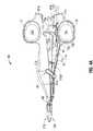
最初に図1および2を参照すると、開口外科手術処理での使用のための鉗子10は、細長いシャフト部分12aおよび12bを含み、各シャフト部分12aおよび12bは、それぞれ、近位端14aおよび14bと、遠位端16aおよび16bとを有する。図面、および以下に続く記述において、「近位」という用語は、従来的であるように、ユーザにより近い鉗子10の端部を指し、「遠位」という用語は、ユーザから離れた端部を指す。 Referring initially to FIGS. 1 and 2, a
鉗子10は、シャフト12aおよび12bの、それぞれ、遠位端16aおよび16bに付属するエンドエフェクタアセンブリ100を含む。エンドエフェクタアセンブリ100は、1組の対向する顎部材110および120を含み、顎部材110および120は、組織を掴むために旋回可能に接続され、互いに対しピボット65(図2)の周りを移動可能である。ピボット65は、顎部材120の近位端に配置された、対向する半分部65aおよび65bを含み、チャンネル126(図4C)の両側に配置され、チャンネル126は、以下に詳細に論考されるように、チャンネル126を通る切断メカニズムまたはナイフ85の往復を容易にするように構成される(図2)。
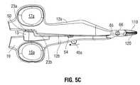
シャフト12aおよび12bのそれぞれは、シャフト12aおよび12bのそれぞれの近位端14aおよび14bにそれぞれ配置されたハンドル15および17を含む。各ハンドル15および17は、ユーザの指を受け取るためのハンドル15および17のそれぞれを通った指穴15aおよび17aをそれぞれ規定する。ハンドル15および17は、シャフト12aおよび12bの互いに対する動作を容易にし、次に、顎部材110および120が互いに対して離れた関係に配置される開いた位置から、顎部材110および120がその間に組織を掴むように協働するクランピングまたは閉じた位置に顎部材110および120を旋回する。 Each of the
図2で最良に示されるように、シャフト12aは、2つのコンポーネント、すなわち12a1および12a2から構成され、これらの2つのコンポーネントは、シャフト12aを形成するように一緒に結合される。同様に、シャフト12bは、2つのコンポーネント、すなわち12b1および12b2から構成され、これらの2つのコンポーネントは、シャフト12bを形成するように一緒に結合される。一部の実施形態では、コンポーネントの半分部12a1および12a2と、コンポーネントの半分部12b1および12b2は、複数の異なる溶接点で一緒に超音波的に溶接され(るか)、および/またはスナップ嵌め、接着剤、ファスナなどを含む任意の適当な方法により機械的に一緒に結合され得る。 As best shown in FIG. 2, the
シャフト12bの配列は、シャフト12aから幾分異なる。さらに詳細には、シャフト12aは、ナイフ85および作動メカニズム40を収納するために概ね中空である。作動メカニズム40は、左手および右手でのトリガー45の操作を容易にするために、シャフト12aの両側に配置されたハンドル部材45aおよび45bを有するトリガー45に機能的に関連付けされる。トリガー45は、一連の適当な協働する要素(例えば、図2は、トリガーリンク43、ナイフ押しリンク41、バネ49、および抗展開リンク47を示す)に機能的に関連付けられ、これらの要素は、トリガー45の作動と同時に顎部材110および120の間に掴まれた組織を通してナイフ85を作動するために機械的に協働するように構成される(明確な図示なし)。ハンドル部材45aおよび45bは、ハンドル部材45aおよび45bのどちらか一方の使用が、ナイフチャンネル115を通ってナイフ85が往復するようにトリガー45を操作するように、同一な様式で動作する(図5C)。さらに、シャフト12bの近位端14bは、スイッチ空洞13を含み、スイッチ空洞13は、シャフト12bの内向する表面23bから突出し、スイッチ空洞13内に押し下げ可能なスイッチ50(およびスイッチ50に関連する電子コンポーネント)を据えつけるように構成される。スイッチ50は、シャフト12aおよび12bの互いへの近接において、スイッチ50がシャフト12aの近位端14aの対向する内向する表面23aに押し下げられて付勢係合するように、シャフト12aの近位端14aの対向する内向する表面23aと整列する。 The arrangement of the
図1に示されるように、近位端にプラグ200を有する電気外科ケーブル210は、鉗子10を電気外科ジェネレータ(図示なし)に接続する。さらに詳細には、ケーブル210の遠位端は、近位シャフトコネクタ19によりシャフト12bにしっかりと保持され、ケーブル210の近位端は、電気外科ジェネレータに電気的および機械的に係合するように構成された突起部202a、202b、および202cを有するプラグ200を含む。 As shown in FIG. 1, an
顎部材110および120の組織を掴む部分は、概ね対称的であり、組織を掴むことおよび密封することをもたらすために、ピボット65の周りでの容易な回転を可能にするために協働する同様なコンポーネントの特徴を含む。その結果、そうでないと明記されない限り、顎部材110および顎部材110と関連する機能的特徴は、本明細書に最初に詳細に記述され、顎部材120に関する同様なコンポーネント特徴は、その後簡単に概要される。 The tissue gripping portions of
図3Aおよび3Bを参照すると、顎部材110は、外側筐体116aと、第一の非伝導プラスチック絶縁体108aおよび第二の非伝導プラスチック絶縁体114aと、電気的伝導性を有する密封表面112aとを含む。第一および第二の絶縁体108aおよび114aは、2段階オーバーモールド成形プロセスにより顎筐体116aの周りにオーバーモールド成形される。さらに詳細には、第一の絶縁体108aが、顎筐体116aを密封表面112aから電気的に絶縁するために、顎筐体116aの周りにオーバーモールド成形され、第二の絶縁体114aが、顎筐体116aに電気的伝導性を有する密封表面112aを固定するために顎筐体116aの周りにオーバーモールド成形される。これは、スタンピング、オーバーモールド成形、スタンピングされた密封表面のオーバーモールド成形、および/または金属粉末射出成型された密封表面のオーバーモールド成形により達成され得る。顎部材110および120は、伝導性を有する材料から生成される。一部の実施形態では、顎部材110および120は、密封中に迷走電流の集中を低減するために、絶縁コーティングで粉末塗装される。 Referring to FIGS. 3A and 3B, the
図3Bの断面図により最良に示されるように、顎部材110および120が閉じた位置にある場合に、組織が対向する、電気的伝導性を有する密封表面112aおよび112bにより掴まれるように、顎部材110の電気的伝導性の有する密封表面112aは、顎筐体116aおよび第二の絶縁体114aから突出している。 As best shown by the cross-sectional view of FIG. 3B, when the
同様に、顎部材120は、外側筐体116bと、第一および第二のプラスチック絶縁体108bおよび114bと、顎筐体116bおよび第二の絶縁体114bから突出した、電気的伝導性を有する密封表面112bを含む、顎部材110に対応する同様な要素を含む。顎部材110に関して上記されたように、第一の絶縁体108bは、顎筐体116bを密封表面112bから電気的に絶縁し、第二の絶縁体114bは、顎筐体116bに密封表面112bを固定する。絶縁体114aおよび114bは、密封中に交流電流または迷走電流経路を低減するために、それぞれ、顎部材110および120の全長に沿って延びる。一部の実施形態では、密封表面112aおよび112bのそれぞれは、各絶縁体114aおよび114bが、それぞれの密封表面112aおよび112bと、半径に概ね接する境界線を共有する縁に沿って合う、および/または半径に沿って合うような半径を有する外側の周縁を含み得る。 Similarly, the
図3Aおよび3Bに示されるように、顎部材の少なくとも1つ(例えば、顎部材120)は、電気的伝導性を有する密封表面112bおよび/または112aの内向する表面に配置された少なくとも1つのストップ部材750を含む。あるいは、またはその上、1つまたは複数のストップ部材750は、電気的伝導性を有する密封表面112a、112bに隣接して、またはピボット65に近接して配置され得る。1つのまたは複数のストップ部材750は、組織の密封および切断中に、組織の把握および操作と、対向する顎部材110と120との間のギャップを規定することとを容易にする。一部の実施形態では、1つまたは複数のストップ部材750は、約0.001インチ(約0.03ミリメートル)から約0.006インチ(約0.015ミリメートル)の範囲内に対向する顎部材110および120の間のギャップ距離を維持する。 As shown in FIGS. 3A and 3B, at least one of the jaw members (eg, jaw member 120) has at least one stop disposed on the inwardly facing
図2に示されるように、シャフト12bは、シャフト12b内に配置され、かつ、ハンドル15と顎部材110との間に延びる梁57を含む。一部の実施形態では、梁57は、顎部材110と120との間に掴まれた組織に、ユーザが追加的な密封圧力を生成することを可能にするために、柔軟な鉄鋼で構成される。さらに詳細には、エンドエフェクタアセンブリ100が組織の周りで閉じられたときには、シャフト12aおよび12bは、顎部材110と120との間に必要とされる閉鎖圧力を生成するために、梁57の柔軟性を使用するように互いに向かって圧搾され得る。この場面では、梁57に関連する圧縮力により実現された機械的な有利点は、顎部材110と120との間に掴まれた組織の周りに一貫した、一定で正確な閉鎖圧力を容易にし、確定する(例えば、約3kg/cm2から約16kg/cm2の作業圧力範囲内)。組織に印加される電気外科エネルギーの強度、周波数、および持続時間を制御することにより、ユーザは組織を密封し得る。一部の実施形態では、密封中の対向する密封表面112aおよび112bの間のギャップ距離は、約0.001インチから約0.005インチにわたる。As shown in FIG. 2, the
一部の実施形態では、密封表面112aおよび112bは、鋭い縁での電流の集中と、高い点の間でのアーキングとを避けるために、比較的平坦である。その上、係合された場合の組織の反力のために、顎部材110および120のそれぞれは、曲がることに抵抗するように製造され得る(例えば、平行な状態で一定の組織の厚さに対して一定の圧力を提供するように長さに沿って先細りし、顎部材110および120のより厚い近位部分は、組織の反力により曲がることに抵抗する)。 In some embodiments, the sealing
図3A、3B、4B、および4Cに示されるように、顎部材110および120の少なくとも1つは、その間に配置されたナイフチャンネル115aおよび/または115bをそれぞれ含む。ナイフチャンネル115aおよび/または115bは、ナイフチャンネル115aおよび/または115bを通るナイフ85の往復を可能にするように構成される。描写される実施形態では、組織を掴むときに顎部材110および120に関連するそれぞれの2つの対向するチャンネルの半分部115aおよび115bが一体となる場合に、完全なナイフチャンネル115が形成される。各プラスチック絶縁体108aおよび108bは、ナイフチャンネル115を通る往復のときに、ナイフ85がプラスチック絶縁体108aおよび108bに接触しないように、またはプラスチック絶縁体108aおよび108bを切断しないように、対向するナイフチャンネルの半分部115aおよび115bのそれぞれと縦に整列するトラフ121aおよび121bをそれぞれ含む。一部の実施形態では、ナイフチャンネル115aおよび115b、およびナイフチャンネル115aおよび115bのそれぞれのトラフ121aおよび121bの幅は、それらの全長に沿って等しい場合がある。 As shown in FIGS. 3A, 3B, 4B, and 4C, at least one of the
図4Aに最良に示されるように、ケーブル210の内部は、リード71a、71b、および71cを収納する。リード71a、71b、および71cは、ケーブル210を通ってプラグ200から延び、シャフト12bの近位コネクタ19内のケーブル210の遠位端を出る。さらに詳細には、リード71aは、突起部202bとスイッチ50の第一の端子75aとの間に相互接続される。リード71bは、突起部202cとソルダースリーブ73aとの間に相互接続され、ソルダースリーブ73aは、次に、リード71bをRFリード71dと、コネクタリード71fを介してスイッチ50の第二の端子75bとに接続する。RFリード71dは、電気外科エネルギーの第一の電位をリード71bから密封表面112aに搬送する。リード71cは、突起部202aとソルダースリーブ73bとの間に相互接続され、ソルダースリーブ73bは、次に、リード71cをRFリード71eに接続する。RFリード71eは、電気外科エネルギーの第二の電位をリード71cから密封表面112bに搬送する。 As best shown in FIG. 4A, the interior of
図4Bを参照すると、密封表面112aの近位端から延びるジャンクション311a(図3A)に接続するために、リード71dのための通路を提供するように、リードチャンネル77が顎部材110の近位端に規定される。リードチャンネル77の近位端は、軌道70に開き、軌道70は、細くなった近位端72と、弓形の側壁68を規定する広がった遠位端74とを有する概ね細長い構成を含む。リード71dは、軌道70の近位端72を通る通路と、さらにジャンクション311aへの接続のためにリードチャンネル77を通る通路とに従ってルーティングされる。 Referring to FIG. 4B, a
図4Cを参照すると、ピボットの半分部65aおよび65bは、チャンネル126を通るナイフ85の移動を容易にするために、チャンネル126の両側に配置される(図5A−5C)。ピボットの半分部65aおよび65bは、分割された球状構成で配置され、各々がベース部分165aおよび165bをそれぞれ含み、ベース部分165aおよび165bは、それらの上に、それぞれ、拡張部分166aおよび166bを支持する。拡張部分166aおよび166bは、顎部材110を顎部材120に旋回可能に固定するために、ピボットプレート66を通して配置される、それらに応じて大きさを決められた開口部67aおよび67bと係合するように構成される。リードチャンネル109は、密封表面112bの近位端から延びるジャンクション311bに接続するために、リード71eのための通路を提供するように顎部材120の近位端に規定される。リード71eは、軌道70を通る通路と、さらに対向するピボットの半分部65aと65bとの間と、ジャンクション311bへの接続のためにリードチャンネル109とを通る通路に従ってルーティングされる。 Referring to FIG. 4C,
図5A−5Cを参照すると、ユーザがスイッチ50を押し下げるようにシャフト12aおよび12bに閉鎖圧力を適用するにつれ(図5B)、スイッチ50の変位の関数としてスイッチ50に適用された閉鎖力に対応する第一の閾値が満たされ、スイッチ50の変位は スイッチ50が顎部材110と120との間に配置された組織を完全に掴むことに対応する第一の触知応答を生成することをもたらす。第一の触知応答に続いて、ユーザがシャフト12aおよび12bに追加的な閉鎖圧力を適用するにつれ(図5C)、スイッチ50の変位の関数としてスイッチ50に適用された閉鎖力に対応する第二の閾値が満たされ、スイッチ50の変位は、スイッチ50が密封表面112aおよび112bに電気外科エネルギーを提供するために電気外科ジェネレータに生成された信号に対応する第二の触知応答を生成することをもたらす。さらに詳細には、第二の触知応答は、スイッチ端子75aと75bとの間で通常開いている回路の閉鎖を示し、次に、リード71aと71bとの間での電気的接続の確立を示す。リード71aと71bとの間での電気的接続の結果、電気外科ジェネレータは、突起部202bと202cとの間の電圧の降下を感知し、それに応答してリード71dおよび71eを介して密封表面112aおよび112bに電気外科エネルギーを供給する。 Referring to FIGS. 5A-5C, as the user applies closing pressure to
1つの実施形態では、第一の触知応答は、エンドエフェクタ100が活性化される前に、ユーザが必要に応じて組織を自由に近づけ、操作し、掴むことができる最大の掴む圧力に到達したことをユーザに示す。この場合、第二の触知応答は、エンドエフェクタ100の電気外科発動をユーザに示す。スイッチ50は、上記の第一触知応答と第二の触知応答との間に、および/または第二の触知応答に後続の複数の他の触知応答を含み得、これらの応答は、以下に詳細に論考されるように、例えばナイフ85および/または作動アセンブリ40の動作、作動アセンブリ40に関連する安全ロックアウトメカニズムの動作のような鉗子10の特定の機能に対応する。 In one embodiment, the first tactile response reaches the maximum grasping pressure that allows the user to freely approach, manipulate, and grasp the tissue as needed before the
図4Aに示されるように、鉗子10は、エンドエフェクタ100により目標組織に適用されているクランピング力または掴む力が測定および/または検出され得るようにシャフト12aおよび12bの一方または双方内に配置されたゲージまたはセンサ要素87を含み得る。例えば、一部の実施形態では、センサ要素87は、顎部材110および120の一方または双方に操作可能に関連付けられるひずみゲージ87であり得る。センサ要素87は、組織圧力を検出するために、シャフト12aおよび12bの一方または双方および/または顎部材110および120の一方または双方内に配置され得る1つ以上のホール効果センサ、または例えば金属ひずみゲージ、ピエゾ抵抗ひずみゲージのようなひずみゲージであり得る。金属ひずみゲージは、伝導性を有する材料の個体形状(例えば長さ、幅、厚さなど)が機械的応力により変化するにつれ、伝導性を有する材料の抵抗が伝導性を有する材料の固体形状の変化の関数として変化する原理に基づいて動作する。抵抗におけるこの変化は、例えば、顎部材110および120により組織に適用された機械的応力のようなひずみまたは適用された機械的応力を検出するために使用される。ピエゾ抵抗ひずみゲージは、機械的応力の適用による半導体の変化する抵抗に基づいて動作する。 As shown in FIG. 4A, the
ホール効果センサは、顎部材110と120との間の磁界の強さと、顎部材110と120との間の距離との間の検出された関係に基づいて顎部材110と120との間のギャップを決定するように組み込まれ得る。 The Hall effect sensor is a gap between
一部の実施形態では、図4Aに示されるように、1つ以上のリードスイッチ81aおよび81bの互いに対する近さを決定するために、1つ以上のリードスイッチ81aおよび81bがシャフト12aおよび12b内に組み込まれ得る。さらに詳細には、1つのまたは複数のリードスイッチは、シャフトの1つ(例えばシャフト12a)内に配置されたスイッチ81aと、対向するシャフト(例えばシャフト12b)内に配置された磁気要素81b(例えば、電磁石、永久磁石、コイルなど)から成り得、シャフト12aおよび12bが近接するとき、リードスイッチ81aは、磁気要素81bの磁界により発動または閉鎖され、同様に、シャフト12aおよび12bが互いに離されるにつれ、磁界の欠如がリードスイッチ81aを非アクティブ化するかまたは開く。この態様で、シャフト12aおよび12bの近さ、従って顎部材110および120の近さがリードスイッチ81aの電磁要素81bへの反応に基づいて決定され得る。 In some embodiments, as shown in FIG. 4A, one or
前に論考された任意のセンサ、スイッチ、および/または1つもしくは複数のひずみゲージは、ひずみゲージにより検出されたひずみが回路を通る電気信号を変更するように電子回路内に組み込まれ得る。この目的を留意して、ひずみゲージ、スイッチ50および/または電気外科ジェネレータ(図示なし)間の電子回路は、電子回路への所望の組織圧力のような情報の伝達を可能にする。この情報は、ひずみゲージにより検出されたような顎部材110と120との間に掴まれた組織における所望のおよび/または既定の圧力が達成されるまでスイッチが発動されないように、スイッチ50の発動に結び付けられ得る。従って、ひずみゲージは、顎部材110と120との間の掴まれた組織に適用された圧力がひずみゲージに影響を及ぼすように鉗子10に(例えば、1つ以上の顎部材110および120上に)戦略的に配置され得る。 Any of the sensors, switches, and / or one or more strain gauges previously discussed may be incorporated into an electronic circuit such that the strain detected by the strain gauge changes the electrical signal through the circuit. With this objective in mind, an electronic circuit between the strain gauge,
使用において、鉗子10は、スイッチ50の特定の触知応答(例えば、第一の触知応答)が、上記の1つ以上のセンサ、スイッチ、および/または1つもしくは複数のひずみゲージの使用を通して決定されるような組織における既定の掴む圧力に対応するように較正され得る。1つの実施形態において、組織への規定の掴む圧力は、約3kg/cm2から約16kg/cm2の範囲内にあり、別の実施形態では、約7kg/cm2から約13kg/cm2の範囲内にある。一部の実施形態では、スイッチ50は、複数の触知応答を生成し得、これらの触知応答のそれぞれは、異なる既定の掴む力に対応する。ロードセル、ひずみゲージなどのような力感知デバイスまたは力測定デバイスのさらに詳細な論考には、2006年4月21日に出願された、出願者が共通の米国出願第11/409,154号に参照がなされる。In use,
図2、4B、および4Cに示されるように、ピボット65は、顎部材120を通して規定される開口部125を通して接続し、開口部125の周縁部の周りに規定された円周沿いのリップまたはフランジ78(図4B)内に据えつけられたピボットプレート66に嵌合係合し、その結果、ピボット65は、開いた位置と閉じた位置との間で顎部材110および120を移動させる開口部125内で回転可能に移動可能である。 As shown in FIGS. 2, 4B, and 4C, the
一部の実施形態では、ナイフ85の作動は、スイッチ50の発動に関連付けられる。例えば、センサ87は、顎部材110と120および/またはその間に保持された組織に対するナイフ85の位置を検出するように構成された位置センサとして具現化され得る。そのうえ、またはあるいは、センサ87は、センサ50の第一および第二の触知応答のいずれかを検出するように構成され得、それに応じてナイフ85の作動を許容するかまたは防止し得る。例えば、センサ87からのフィードバックに基づいて、以下にさらに詳細に記述されるように、作動メカニズム40に関連する任意の1つ以上の協働する要素またはロックアウトメカニズムが、ナイフ85の作動を許容または防止するために活性化または非活性化され得る。 In some embodiments, the activation of the
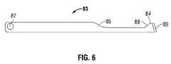
図6に示されるように、ナイフ85は、ナイフ85の遠位端でナイフ85のプロフィールを低減する段86を含む。ナイフ85の遠位端は、鋭利にされた遠位切断縁89の方のナイフ85のプロフィールを増大する段88を有する。ナイフ85は、ナイフチャンネル15を通ったナイフ85の円滑な後退を容易にするために、鋭利にされた遠位切断縁89が段88と合う面取りされた部分84を含む。 As shown in FIG. 6, the
一部の実施形態では、鉗子10は、顎部材110および120が開いた位置に配置されている場合にナイフ85の非意図的な発動を防止するために一緒に働く一連の適当な協働する要素(例えば、抗展開リンク47、トリガーリンク43)を有する安全ロックアウトメカニズムを含み得る。概して、抗展開リンク47は、顎部材110および120が組織の周りで閉じられるまでナイフ85の前進を防止するようにトリガーリンク43と機械的に協働する。鉗子10での使用のためのこのような安全ロックアウトメカニズムの1つは、2010年10月1日に出願された“Blade Deployment Mechanisms for Surgical Forceps”と題される、出願者が共通の米国出願第12/896,100号に記述される。 In some embodiments, the
一部の実施形態では、任意の1つ以上の安全ロックアウトメカニズムの協働する要素(例えば、抗展開リンク47)は、電気的にスイッチ50と相互接続され得、機械的に安全ロックアウトメカニズムを操作するためのスイッチ50の発動を介して(例えば、リード71a、71b、71c、71d、71eのうちの任意の1つのリードを介して)活性化されるように構成された適当な電気機械コンポーネント(例えば、バネ、ロッド、ソレノイドなど)を含み得る。例えば、エンドエフェクタ100を活性化するためにリード71dおよび71eを通した電気的伝導のときに、安全ロックアウトメカニズムがナイフ85の選択的な作動を可能にするように係合を解くような抗展開リンク47の作動をもたらすように抗展開リンク47が活性化される。この場合、例として、ナイフ85の選択的な発動は、スイッチ50が少なくとも第一の触知応答を生成するように押し下げられるまで防止され得る。 In some embodiments, the cooperating elements (eg, anti-deployment link 47) of any one or more safety lockout mechanisms can be electrically interconnected with the
本開示のいくつかの実施形態が図面に示されるが、本開示は当該分野が許容する限り範囲が広く、明細書がそのように読まれることが意図されるために、本開示がそれらの図面に制限されることが意図されない。従って、上記は、制限的に解釈されるものではなく、単に特定の実施形態の例示化として解釈されるべきである。当業者は、本明細書に添付の特許請求の範囲および精神内の他の改変を想起する。 While several embodiments of the present disclosure are shown in the drawings, the present disclosure is intended to be read as such so that the disclosure is as broad as the field permits and the present disclosure is intended to read the drawings. It is not intended to be limited to. Therefore, the above description should not be construed as limiting, but merely as exemplifications of particular embodiments. Those skilled in the art will envision other modifications within the scope and spirit of the claims appended hereto.
12a シャフト
12b シャフト
15 ハンドル
17 ハンドル
45 トリガー
100 エンドエフェクタ
110 顎部材
120 顎部材
210 電気外科ケーブル
Claims (13)
Translated fromJapanese第二のシャフト(12b)であって、該第二のシャフト(12b)は、その遠位端に第二の顎部材(110)を有し、該第一の顎部材および該第二の顎部材のそれぞれは、電気的伝導性を有する密封表面(112a、112b)を含み、該第一のシャフトおよび該第二のシャフトは、該第一の顎部材および該第二の顎部材が開いた位置と閉じた位置との間で移動可能であるように、ピボット(65)の周りで互いに旋回可能に結合されている、第二のシャフト(12b)と、A second shaft (12b) having a second jaw member (110) at its distal end, the first jaw member and the second jaw Each of the members includes an electrically conductive sealing surface (112a, 112b), the first shaft and the second shaft being open by the first jaw member and the second jaw member A second shaft (12b) that is pivotally coupled to each other about a pivot (65) so as to be movable between a position and a closed position;
該第一のシャフト上に配置されたトリガー(45)と、A trigger (45) disposed on the first shaft;
該トリガーに機能的に結合されたナイフ(85)であって、該トリガーの作動が該ナイフをナイフチャンネル(115)を通って遠位に並進させ、該ナイフチャンネル(115)は、該第一の顎部材および該第二の顎部材のうちの少なくとも1つを少なくとも部分的に通って延びている、ナイフ(85)と、A knife (85) operatively coupled to the trigger, the actuation of the trigger translating the knife distally through the knife channel (115), the knife channel (115) A knife (85) extending at least partially through at least one of said jaw member and said second jaw member;
該第一の顎部材および該第二の顎部材が該開いた位置にある場合に該ナイフの遠位への並進を防止するように構成された抗展開リンク(47)であって、該第一の顎部材および該第二の顎部材の該閉じた位置への移動が、該抗展開リンクを移動させて該ナイフの遠位への並進を可能にする、抗展開リンク(47)と、An anti-deployment link (47) configured to prevent distal translation of the knife when the first jaw member and the second jaw member are in the open position; An anti-deployment link (47) wherein movement of the one jaw member and the second jaw member to the closed position moves the anti-deployment link to allow distal translation of the knife;
該第一のシャフトおよび該第二のシャフトのうちの1つの上に配置されたスイッチ(50)であって、該スイッチ(50)は、電気外科エネルギー源から該電気的伝導性を有する密封表面のそれぞれへの電気外科エネルギーの供給を制御するために該第一の顎部材および該第二の顎部材が該閉じた位置にある場合に、押し下げられるように構成されている、スイッチ(50)とA switch (50) disposed on one of the first shaft and the second shaft, wherein the switch (50) is a sealing surface having the electrical conductivity from an electrosurgical energy source. A switch (50) configured to be depressed when the first jaw member and the second jaw member are in the closed position to control the supply of electrosurgical energy to each of the When
を含む、鉗子。Including, forceps.
第二のシャフト(12b)であって、該第二のシャフト(12b)は、その遠位端に第二の顎部材(110)を有し、該第一の顎部材および該第二の顎部材のそれぞれは、電気的伝導性を有する密封表面(112a、112b)を含み、該第一のシャフトおよび該第二のシャフトは、該第一の顎部材および該第二の顎部材が開いた位置と閉じた位置との間で移動可能であるように、ピボット(65)の周りで互いに旋回可能に結合され、該第一のシャフトおよび該第二のシャフトのそれぞれは、その近位端に配置されたハンドル(15、17)を含み、該ハンドルのそれぞれは、該開いた位置と該閉じた位置との間での該第一の顎部材および該第二の顎部材の移動を容易にするために指穴(15a、17a)を規定し、該電気的伝導性を有する密封表面のうちの少なくとも1つは、複数のストップ部材(750)を含み、該複数のストップ部材は、該第一の顎部材および該第二の顎部材が該閉じた位置にある場合に該電気的伝導性を有する密封表面の間の距離を維持するように構成されている、第二のシャフト(12b)と、A second shaft (12b) having a second jaw member (110) at its distal end, the first jaw member and the second jaw Each of the members includes an electrically conductive sealing surface (112a, 112b), the first shaft and the second shaft being open by the first jaw member and the second jaw member Pivotally coupled to each other about a pivot (65) so as to be movable between a position and a closed position, each of the first shaft and the second shaft being at its proximal end Includes handles (15, 17) disposed, each of which facilitates movement of the first and second jaw members between the open and closed positions. To define the finger holes (15a, 17a) and to have the electrical conductivity At least one of the sealing surfaces includes a plurality of stop members (750), wherein the plurality of stop members are disposed when the first jaw member and the second jaw member are in the closed position. A second shaft (12b) configured to maintain a distance between the electrically conductive sealing surfaces;
該第一のシャフト上に配置されたトリガー(45)と、A trigger (45) disposed on the first shaft;
該トリガーに機能的に結合されたナイフ(85)であって、該トリガーの作動が該ナイフをナイフチャンネル(115)を通って遠位に並進させ、該ナイフチャンネル(115)は、該第一の顎部材および該第二の顎部材のうちの少なくとも1つを少なくとも部分的に通って延びている、ナイフ(85)と、A knife (85) operatively coupled to the trigger, the actuation of the trigger translating the knife distally through the knife channel (115), the knife channel (115) A knife (85) extending at least partially through at least one of said jaw member and said second jaw member;
該第一の顎部材および該第二の顎部材が該開いた位置にある場合に該ナイフの遠位への並進を防止するように構成された抗展開リンク(47)であって、該第一の顎部材および該第二の顎部材の該閉じた位置への移動が、該抗展開リンクを移動させて該ナイフの遠位への並進を可能にする、抗展開リンク(47)と、An anti-deployment link (47) configured to prevent distal translation of the knife when the first jaw member and the second jaw member are in the open position; An anti-deployment link (47) wherein movement of the one jaw member and the second jaw member to the closed position moves the anti-deployment link to allow distal translation of the knife;
該第一のシャフトおよび該第二のシャフトのうちの1つの上に配置されたスイッチ(50)であって、該スイッチ(50)は、電気外科エネルギー源から該電気的伝導性を有する密封表面のそれぞれへの電気外科エネルギーの供給を制御するために該第一の顎部材および該第二の顎部材が該閉じた位置にある場合に、押し下げられるように構成されている、スイッチ(50)と、A switch (50) disposed on one of the first shaft and the second shaft, wherein the switch (50) is a sealing surface having the electrical conductivity from an electrosurgical energy source. A switch (50) configured to be depressed when the first jaw member and the second jaw member are in the closed position to control the supply of electrosurgical energy to each of the When,
該電気的伝導性を有する密封表面のそれぞれを該電気外科エネルギー源に電気的に結合するように構成された電気外科ケーブル(210)とAn electrosurgical cable (210) configured to electrically couple each of the electrically conductive sealing surfaces to the electrosurgical energy source;
を含む、鉗子。Including, forceps.
Applications Claiming Priority (2)
| Application Number | Priority Date | Filing Date | Title |
|---|---|---|---|
| US12/897,346US9655672B2 (en) | 2010-10-04 | 2010-10-04 | Vessel sealing instrument |
| US12/897,346 | 2010-10-04 |
Related Parent Applications (1)
| Application Number | Title | Priority Date | Filing Date |
|---|---|---|---|
| JP2011219394ADivisionJP5789470B2 (en) | 2010-10-04 | 2011-10-03 | Tube sealing device |
Related Child Applications (1)
| Application Number | Title | Priority Date | Filing Date |
|---|---|---|---|
| JP2016151717ADivisionJP6189501B2 (en) | 2010-10-04 | 2016-08-02 | forceps |
Publications (2)
| Publication Number | Publication Date |
|---|---|
| JP2015165966Atrue JP2015165966A (en) | 2015-09-24 |
| JP6204943B2 JP6204943B2 (en) | 2017-09-27 |
Family
ID=44774006
Family Applications (3)
| Application Number | Title | Priority Date | Filing Date |
|---|---|---|---|
| JP2011219394AActiveJP5789470B2 (en) | 2010-10-04 | 2011-10-03 | Tube sealing device |
| JP2015130629AActiveJP6204943B2 (en) | 2010-10-04 | 2015-06-30 | Tube sealing device |
| JP2016151717AActiveJP6189501B2 (en) | 2010-10-04 | 2016-08-02 | forceps |
Family Applications Before (1)
| Application Number | Title | Priority Date | Filing Date |
|---|---|---|---|
| JP2011219394AActiveJP5789470B2 (en) | 2010-10-04 | 2011-10-03 | Tube sealing device |
Family Applications After (1)
| Application Number | Title | Priority Date | Filing Date |
|---|---|---|---|
| JP2016151717AActiveJP6189501B2 (en) | 2010-10-04 | 2016-08-02 | forceps |
Country Status (10)
| Country | Link |
|---|---|
| US (8) | US9655672B2 (en) |
| EP (3) | EP3045135A1 (en) |
| JP (3) | JP5789470B2 (en) |
| KR (1) | KR101858725B1 (en) |
| CN (2) | CN105055020B (en) |
| AU (1) | AU2011226904B2 (en) |
| BR (1) | BRPI1107044A8 (en) |
| CA (1) | CA2754243C (en) |
| ES (1) | ES2438172T3 (en) |
| MX (1) | MX2011010210A (en) |
Cited By (1)
| Publication number | Priority date | Publication date | Assignee | Title |
|---|---|---|---|---|
| JP2019518488A (en)* | 2016-04-15 | 2019-07-04 | エシコン エルエルシーEthicon LLC | Surgical instrument with improved stop / start control during firing motion |
Families Citing this family (247)
| Publication number | Priority date | Publication date | Assignee | Title |
|---|---|---|---|---|
| US7364577B2 (en) | 2002-02-11 | 2008-04-29 | Sherwood Services Ag | Vessel sealing system |
| ES2262639T3 (en) | 2001-04-06 | 2006-12-01 | Sherwood Services Ag | SHUTTER AND DIVIDER OF GLASSES WITH BUMPER MEMBERS N OCONDUCTIVES. |
| US9848938B2 (en) | 2003-11-13 | 2017-12-26 | Covidien Ag | Compressible jaw configuration with bipolar RF output electrodes for soft tissue fusion |
| US7367976B2 (en) | 2003-11-17 | 2008-05-06 | Sherwood Services Ag | Bipolar forceps having monopolar extension |
| US7628791B2 (en) | 2005-08-19 | 2009-12-08 | Covidien Ag | Single action tissue sealer |
| CA2561034C (en) | 2005-09-30 | 2014-12-09 | Sherwood Services Ag | Flexible endoscopic catheter with an end effector for coagulating and transfecting tissue |
| ES2442241T3 (en) | 2008-03-31 | 2014-02-10 | Applied Medical Resources Corporation | Electrosurgical system with a switching mechanism |
| US8142473B2 (en) | 2008-10-03 | 2012-03-27 | Tyco Healthcare Group Lp | Method of transferring rotational motion in an articulating surgical instrument |
| US8114122B2 (en) | 2009-01-13 | 2012-02-14 | Tyco Healthcare Group Lp | Apparatus, system, and method for performing an electrosurgical procedure |
| US8187273B2 (en) | 2009-05-07 | 2012-05-29 | Tyco Healthcare Group Lp | Apparatus, system, and method for performing an electrosurgical procedure |
| US8246618B2 (en) | 2009-07-08 | 2012-08-21 | Tyco Healthcare Group Lp | Electrosurgical jaws with offset knife |
| US8133254B2 (en) | 2009-09-18 | 2012-03-13 | Tyco Healthcare Group Lp | In vivo attachable and detachable end effector assembly and laparoscopic surgical instrument and methods therefor |
| US8112871B2 (en) | 2009-09-28 | 2012-02-14 | Tyco Healthcare Group Lp | Method for manufacturing electrosurgical seal plates |
| US9028495B2 (en) | 2010-06-23 | 2015-05-12 | Covidien Lp | Surgical instrument with a separable coaxial joint |
| US8795269B2 (en) | 2010-07-26 | 2014-08-05 | Covidien Lp | Rotary tissue sealer and divider |
| US8814864B2 (en) | 2010-08-23 | 2014-08-26 | Covidien Lp | Method of manufacturing tissue sealing electrodes |
| US9005200B2 (en) | 2010-09-30 | 2015-04-14 | Covidien Lp | Vessel sealing instrument |
| US9017372B2 (en) | 2010-10-01 | 2015-04-28 | Covidien Lp | Blade deployment mechanisms for surgical forceps |
| AU2011308509B8 (en) | 2010-10-01 | 2015-04-02 | Applied Medical Resources Corporation | Electrosurgical instrument |
| US9655672B2 (en)* | 2010-10-04 | 2017-05-23 | Covidien Lp | Vessel sealing instrument |
| US9345534B2 (en)* | 2010-10-04 | 2016-05-24 | Covidien Lp | Vessel sealing instrument |
| US8932293B2 (en) | 2010-11-17 | 2015-01-13 | Covidien Lp | Method and apparatus for vascular tissue sealing with reduced energy consumption |
| US8945175B2 (en) | 2011-01-14 | 2015-02-03 | Covidien Lp | Latch mechanism for surgical instruments |
| US9113940B2 (en) | 2011-01-14 | 2015-08-25 | Covidien Lp | Trigger lockout and kickback mechanism for surgical instruments |
| US8900232B2 (en) | 2011-05-06 | 2014-12-02 | Covidien Lp | Bifurcated shaft for surgical instrument |
| US8939972B2 (en) | 2011-05-06 | 2015-01-27 | Covidien Lp | Surgical forceps |
| US8685009B2 (en) | 2011-05-16 | 2014-04-01 | Covidien Lp | Thread-like knife for tissue cutting |
| US8852185B2 (en) | 2011-05-19 | 2014-10-07 | Covidien Lp | Apparatus for performing an electrosurgical procedure |
| US9615877B2 (en) | 2011-06-17 | 2017-04-11 | Covidien Lp | Tissue sealing forceps |
| US8745840B2 (en) | 2011-07-11 | 2014-06-10 | Covidien Lp | Surgical forceps and method of manufacturing thereof |
| US9039732B2 (en) | 2011-07-11 | 2015-05-26 | Covidien Lp | Surgical forceps |
| US8852186B2 (en) | 2011-08-09 | 2014-10-07 | Covidien Lp | Microwave sensing for tissue sealing |
| US8845636B2 (en) | 2011-09-16 | 2014-09-30 | Covidien Lp | Seal plate with insulation displacement connection |
| US8864795B2 (en) | 2011-10-03 | 2014-10-21 | Covidien Lp | Surgical forceps |
| US9492221B2 (en) | 2011-10-20 | 2016-11-15 | Covidien Lp | Dissection scissors on surgical device |
| US8968308B2 (en) | 2011-10-20 | 2015-03-03 | Covidien Lp | Multi-circuit seal plates |
| US9314295B2 (en) | 2011-10-20 | 2016-04-19 | Covidien Lp | Dissection scissors on surgical device |
| USD680220S1 (en) | 2012-01-12 | 2013-04-16 | Coviden IP | Slider handle for laparoscopic device |
| AU2013230575B2 (en)* | 2012-03-08 | 2017-01-19 | Covidien Lp | Vessel sealing instrument |
| US8920461B2 (en) | 2012-05-01 | 2014-12-30 | Covidien Lp | Surgical forceps with bifurcated flanged jaw components |
| US9034009B2 (en) | 2012-05-01 | 2015-05-19 | Covidien Lp | Surgical forceps |
| CN105007850B (en)* | 2012-05-02 | 2018-04-24 | 伊西康内外科公司 | For the electro-surgical device for cutting and solidifying |
| US9039731B2 (en) | 2012-05-08 | 2015-05-26 | Covidien Lp | Surgical forceps including blade safety mechanism |
| US11871901B2 (en) | 2012-05-20 | 2024-01-16 | Cilag Gmbh International | Method for situational awareness for surgical network or surgical network connected device capable of adjusting function based on a sensed situation or usage |
| US12226070B2 (en) | 2012-05-20 | 2025-02-18 | Cilag Gmbh International | System comprising control circuit to determine a property of a fluid at a surgical site |
| DE102012105263A1 (en)* | 2012-06-18 | 2013-12-19 | Aesculap Ag | RF sealing instrument |
| US9039691B2 (en) | 2012-06-29 | 2015-05-26 | Covidien Lp | Surgical forceps |
| US8939975B2 (en) | 2012-07-17 | 2015-01-27 | Covidien Lp | Gap control via overmold teeth and hard stops |
| US9192421B2 (en) | 2012-07-24 | 2015-11-24 | Covidien Lp | Blade lockout mechanism for surgical forceps |
| US9610114B2 (en)* | 2013-01-29 | 2017-04-04 | Ethicon Endo-Surgery, Llc | Bipolar electrosurgical hand shears |
| US9655673B2 (en) | 2013-03-11 | 2017-05-23 | Covidien Lp | Surgical instrument |
| US9456863B2 (en) | 2013-03-11 | 2016-10-04 | Covidien Lp | Surgical instrument with switch activation control |
| US10070916B2 (en) | 2013-03-11 | 2018-09-11 | Covidien Lp | Surgical instrument with system and method for springing open jaw members |
| CN105380711B (en) | 2013-03-15 | 2018-01-02 | 捷锐士阿希迈公司(以奥林巴斯美国外科技术名义) | Combine electrosurgery device |
| JP6153654B2 (en) | 2013-03-15 | 2017-06-28 | ジャイラス エーシーエムアイ インク | Combined electrosurgical device |
| CN105142556B (en) | 2013-03-15 | 2019-01-08 | 捷锐士阿希迈公司(以奥林巴斯美国外科技术名义) | Bias surgical clamp |
| WO2014143472A1 (en) | 2013-03-15 | 2014-09-18 | GYRUS ACMI, INC. (d/b/a OLYMPUS SURGICAL TECHNOLOGIES AMERICA) | Electrosurgical instrument |
| JP6141506B2 (en) | 2013-03-15 | 2017-06-07 | ジャイラス エーシーエムアイ インク | Combined electrosurgical device |
| US9622810B2 (en)* | 2013-05-10 | 2017-04-18 | Covidien Lp | Surgical forceps |
| WO2015017989A1 (en) | 2013-08-07 | 2015-02-12 | Covidien Lp | Bipolar surgical instrument |
| AU2013397838B2 (en) | 2013-08-07 | 2018-08-16 | Covidien Lp | Bipolar surgical instrument with tissue stop |
| CN104665925B (en)* | 2013-08-07 | 2018-01-16 | 柯惠有限合伙公司 | bipolar forceps |
| AU2013375909B2 (en)* | 2013-08-07 | 2015-07-30 | Covidien Lp | Bipolar surgical instrument |
| US10499975B2 (en) | 2013-08-07 | 2019-12-10 | Covidien Lp | Bipolar surgical instrument |
| USD744644S1 (en)* | 2013-08-07 | 2015-12-01 | Covidien Lp | Disposable housing for open vessel sealer with mechanical cutter |
| AU2015264858B2 (en)* | 2013-08-07 | 2018-03-01 | Covidien Lp | Bipolar surgical instrument |
| USD738499S1 (en)* | 2013-08-07 | 2015-09-08 | Covidien Lp | Open vessel sealer with mechanical cutter |
| CN109512506B (en)* | 2013-08-07 | 2022-03-22 | 柯惠有限合伙公司 | Bipolar surgical instrument |
| US20150066026A1 (en)* | 2013-08-30 | 2015-03-05 | Covidien Lp | Switch assemblies for multi-function, energy-based surgical instruments |
| EP2853219B1 (en)* | 2013-09-10 | 2018-06-06 | Erbe Elektromedizin GmbH | Vessel sealing instrument |
| US9468454B2 (en)* | 2014-01-28 | 2016-10-18 | Ethicon Endo-Surgery, Inc. | Motor control and feedback in powered surgical devices |
| US10231776B2 (en) | 2014-01-29 | 2019-03-19 | Covidien Lp | Tissue sealing instrument with tissue-dissecting electrode |
| WO2015176074A2 (en) | 2014-05-16 | 2015-11-19 | Applied Medical Resources Corporation | Electrosurgical system |
| JP6735272B2 (en) | 2014-05-30 | 2020-08-05 | アプライド メディカル リソーシーズ コーポレイション | Electrosurgical sealing and incision system |
| US9433460B2 (en)* | 2014-05-30 | 2016-09-06 | Bipad, Llc | Electrosurgery actuator |
| EP2982325B1 (en)* | 2014-08-04 | 2020-03-18 | Erbe Elektromedizin GmbH | Method for producing a branch and surgical instrument with a tool having branches |
| US20160038168A1 (en)* | 2014-08-11 | 2016-02-11 | Covidien Lp | Surgical forceps and methods of manufacturing the same |
| US10660694B2 (en) | 2014-08-27 | 2020-05-26 | Covidien Lp | Vessel sealing instrument and switch assemblies thereof |
| US10080606B2 (en) | 2014-09-17 | 2018-09-25 | Covidien Lp | Method of forming a member of an end effector |
| US11504192B2 (en) | 2014-10-30 | 2022-11-22 | Cilag Gmbh International | Method of hub communication with surgical instrument systems |
| KR102545505B1 (en) | 2014-12-23 | 2023-06-20 | 어플라이드 메디컬 리소시스 코포레이션 | Bipolar Electrosurgical Sealers and Dividers |
| WO2016169039A1 (en)* | 2015-04-24 | 2016-10-27 | Covidien Lp | Disposable connector for use with reusable vessel sealing divider device |
| US10758257B2 (en)* | 2015-04-24 | 2020-09-01 | Covidien Lp | Vessel sealing device with fine dissection function |
| USD844138S1 (en) | 2015-07-17 | 2019-03-26 | Covidien Lp | Handle assembly of a multi-function surgical instrument |
| USD844139S1 (en) | 2015-07-17 | 2019-03-26 | Covidien Lp | Monopolar assembly of a multi-function surgical instrument |
| US10987159B2 (en) | 2015-08-26 | 2021-04-27 | Covidien Lp | Electrosurgical end effector assemblies and electrosurgical forceps configured to reduce thermal spread |
| US10245057B2 (en)* | 2015-10-28 | 2019-04-02 | Covidien Lp | Surgical instruments including knife assemblies with reducible cutting height |
| US10426543B2 (en) | 2016-01-23 | 2019-10-01 | Covidien Lp | Knife trigger for vessel sealer |
| US20170209206A1 (en) | 2016-01-23 | 2017-07-27 | Covidien Lp | Devices and methods for tissue sealing and mechanical clipping |
| JP6216482B1 (en)* | 2016-02-02 | 2017-10-18 | オリンパス株式会社 | Endoscopic treatment tool |
| USD819815S1 (en)* | 2016-03-09 | 2018-06-05 | Covidien Lp | L-shaped blade trigger for an electrosurgical instrument |
| USD828554S1 (en)* | 2016-03-09 | 2018-09-11 | Covidien Lp | Contoured blade trigger for an electrosurgical instrument |
| CN109069200B (en)* | 2016-03-31 | 2021-06-18 | 捷锐士阿希迈公司(以奥林巴斯美国外科技术名义) | Disengagement mechanism for electrosurgical clamps |
| US10682154B2 (en) | 2016-08-02 | 2020-06-16 | Covidien Lp | Cutting mechanisms for surgical end effector assemblies, instruments, and systems |
| US10631887B2 (en) | 2016-08-15 | 2020-04-28 | Covidien Lp | Electrosurgical forceps for video assisted thoracoscopic surgery and other surgical procedures |
| AU2017324880B2 (en)* | 2016-09-06 | 2022-12-01 | I.C. Medical, Inc. | Monopolar electrosurgery blade and electrosurgery blade assembly |
| JP6326609B2 (en)* | 2016-12-01 | 2018-05-23 | コヴィディエン リミテッド パートナーシップ | Bipolar surgical instrument |
| JP6368348B2 (en)* | 2016-12-01 | 2018-08-01 | コヴィディエン リミテッド パートナーシップ | Bipolar surgical instrument |
| US10881445B2 (en) | 2017-02-09 | 2021-01-05 | Covidien Lp | Adapters, systems incorporating the same, and methods for providing an electrosurgical forceps with clip-applying functionality |
| US11540872B2 (en)* | 2017-03-13 | 2023-01-03 | Covidien Lp | Electrosurgical instrument with trigger driven cutting function |
| US10973567B2 (en) | 2017-05-12 | 2021-04-13 | Covidien Lp | Electrosurgical forceps for grasping, treating, and/or dividing tissue |
| US11172980B2 (en) | 2017-05-12 | 2021-11-16 | Covidien Lp | Electrosurgical forceps for grasping, treating, and/or dividing tissue |
| USD854149S1 (en) | 2017-06-08 | 2019-07-16 | Covidien Lp | End effector for open vessel sealer |
| US10653475B2 (en) | 2017-06-08 | 2020-05-19 | Covidien Lp | Knife lockout for electrosurgical forceps |
| USD843574S1 (en) | 2017-06-08 | 2019-03-19 | Covidien Lp | Knife for open vessel sealer |
| USD854684S1 (en) | 2017-06-08 | 2019-07-23 | Covidien Lp | Open vessel sealer with mechanical cutter |
| US11564756B2 (en) | 2017-10-30 | 2023-01-31 | Cilag Gmbh International | Method of hub communication with surgical instrument systems |
| US11925373B2 (en) | 2017-10-30 | 2024-03-12 | Cilag Gmbh International | Surgical suturing instrument comprising a non-circular needle |
| US11026687B2 (en) | 2017-10-30 | 2021-06-08 | Cilag Gmbh International | Clip applier comprising clip advancing systems |
| US11311342B2 (en) | 2017-10-30 | 2022-04-26 | Cilag Gmbh International | Method for communicating with surgical instrument systems |
| US11911045B2 (en) | 2017-10-30 | 2024-02-27 | Cllag GmbH International | Method for operating a powered articulating multi-clip applier |
| US11510741B2 (en) | 2017-10-30 | 2022-11-29 | Cilag Gmbh International | Method for producing a surgical instrument comprising a smart electrical system |
| US11317919B2 (en) | 2017-10-30 | 2022-05-03 | Cilag Gmbh International | Clip applier comprising a clip crimping system |
| US11291510B2 (en) | 2017-10-30 | 2022-04-05 | Cilag Gmbh International | Method of hub communication with surgical instrument systems |
| US11229436B2 (en) | 2017-10-30 | 2022-01-25 | Cilag Gmbh International | Surgical system comprising a surgical tool and a surgical hub |
| US11801098B2 (en) | 2017-10-30 | 2023-10-31 | Cilag Gmbh International | Method of hub communication with surgical instrument systems |
| US11432885B2 (en) | 2017-12-28 | 2022-09-06 | Cilag Gmbh International | Sensing arrangements for robot-assisted surgical platforms |
| US11857152B2 (en) | 2017-12-28 | 2024-01-02 | Cilag Gmbh International | Surgical hub spatial awareness to determine devices in operating theater |
| US11304763B2 (en) | 2017-12-28 | 2022-04-19 | Cilag Gmbh International | Image capturing of the areas outside the abdomen to improve placement and control of a surgical device in use |
| US11786245B2 (en) | 2017-12-28 | 2023-10-17 | Cilag Gmbh International | Surgical systems with prioritized data transmission capabilities |
| US12376855B2 (en) | 2017-12-28 | 2025-08-05 | Cilag Gmbh International | Safety systems for smart powered surgical stapling |
| US20190201142A1 (en) | 2017-12-28 | 2019-07-04 | Ethicon Llc | Automatic tool adjustments for robot-assisted surgical platforms |
| US11832840B2 (en) | 2017-12-28 | 2023-12-05 | Cilag Gmbh International | Surgical instrument having a flexible circuit |
| US10892995B2 (en) | 2017-12-28 | 2021-01-12 | Ethicon Llc | Surgical network determination of prioritization of communication, interaction, or processing based on system or device needs |
| US12396806B2 (en) | 2017-12-28 | 2025-08-26 | Cilag Gmbh International | Adjustment of a surgical device function based on situational awareness |
| US11304745B2 (en) | 2017-12-28 | 2022-04-19 | Cilag Gmbh International | Surgical evacuation sensing and display |
| US11896322B2 (en) | 2017-12-28 | 2024-02-13 | Cilag Gmbh International | Sensing the patient position and contact utilizing the mono-polar return pad electrode to provide situational awareness to the hub |
| US11540855B2 (en) | 2017-12-28 | 2023-01-03 | Cilag Gmbh International | Controlling activation of an ultrasonic surgical instrument according to the presence of tissue |
| US11132462B2 (en) | 2017-12-28 | 2021-09-28 | Cilag Gmbh International | Data stripping method to interrogate patient records and create anonymized record |
| US11832899B2 (en) | 2017-12-28 | 2023-12-05 | Cilag Gmbh International | Surgical systems with autonomously adjustable control programs |
| US12062442B2 (en) | 2017-12-28 | 2024-08-13 | Cilag Gmbh International | Method for operating surgical instrument systems |
| US11419630B2 (en) | 2017-12-28 | 2022-08-23 | Cilag Gmbh International | Surgical system distributed processing |
| US11266468B2 (en) | 2017-12-28 | 2022-03-08 | Cilag Gmbh International | Cooperative utilization of data derived from secondary sources by intelligent surgical hubs |
| US20230037577A1 (en)* | 2017-12-28 | 2023-02-09 | Cilag Gmbh International | Activation of energy devices |
| US12127729B2 (en) | 2017-12-28 | 2024-10-29 | Cilag Gmbh International | Method for smoke evacuation for surgical hub |
| US11284936B2 (en) | 2017-12-28 | 2022-03-29 | Cilag Gmbh International | Surgical instrument having a flexible electrode |
| US12096916B2 (en) | 2017-12-28 | 2024-09-24 | Cilag Gmbh International | Method of sensing particulate from smoke evacuated from a patient, adjusting the pump speed based on the sensed information, and communicating the functional parameters of the system to the hub |
| US11424027B2 (en) | 2017-12-28 | 2022-08-23 | Cilag Gmbh International | Method for operating surgical instrument systems |
| US11937769B2 (en) | 2017-12-28 | 2024-03-26 | Cilag Gmbh International | Method of hub communication, processing, storage and display |
| US11602393B2 (en) | 2017-12-28 | 2023-03-14 | Cilag Gmbh International | Surgical evacuation sensing and generator control |
| US11376002B2 (en) | 2017-12-28 | 2022-07-05 | Cilag Gmbh International | Surgical instrument cartridge sensor assemblies |
| US11529187B2 (en) | 2017-12-28 | 2022-12-20 | Cilag Gmbh International | Surgical evacuation sensor arrangements |
| US11903601B2 (en) | 2017-12-28 | 2024-02-20 | Cilag Gmbh International | Surgical instrument comprising a plurality of drive systems |
| US20190206569A1 (en) | 2017-12-28 | 2019-07-04 | Ethicon Llc | Method of cloud based data analytics for use with the hub |
| US11464559B2 (en) | 2017-12-28 | 2022-10-11 | Cilag Gmbh International | Estimating state of ultrasonic end effector and control system therefor |
| US11253315B2 (en) | 2017-12-28 | 2022-02-22 | Cilag Gmbh International | Increasing radio frequency to create pad-less monopolar loop |
| US11304699B2 (en) | 2017-12-28 | 2022-04-19 | Cilag Gmbh International | Method for adaptive control schemes for surgical network control and interaction |
| US11998193B2 (en) | 2017-12-28 | 2024-06-04 | Cilag Gmbh International | Method for usage of the shroud as an aspect of sensing or controlling a powered surgical device, and a control algorithm to adjust its default operation |
| US11969216B2 (en) | 2017-12-28 | 2024-04-30 | Cilag Gmbh International | Surgical network recommendations from real time analysis of procedure variables against a baseline highlighting differences from the optimal solution |
| US11818052B2 (en) | 2017-12-28 | 2023-11-14 | Cilag Gmbh International | Surgical network determination of prioritization of communication, interaction, or processing based on system or device needs |
| US11324557B2 (en) | 2017-12-28 | 2022-05-10 | Cilag Gmbh International | Surgical instrument with a sensing array |
| US11786251B2 (en) | 2017-12-28 | 2023-10-17 | Cilag Gmbh International | Method for adaptive control schemes for surgical network control and interaction |
| US11559307B2 (en) | 2017-12-28 | 2023-01-24 | Cilag Gmbh International | Method of robotic hub communication, detection, and control |
| WO2019133144A1 (en) | 2017-12-28 | 2019-07-04 | Ethicon Llc | Detection and escalation of security responses of surgical instruments to increasing severity threats |
| US11291495B2 (en) | 2017-12-28 | 2022-04-05 | Cilag Gmbh International | Interruption of energy due to inadvertent capacitive coupling |
| US11364075B2 (en) | 2017-12-28 | 2022-06-21 | Cilag Gmbh International | Radio frequency energy device for delivering combined electrical signals |
| US20190201090A1 (en) | 2017-12-28 | 2019-07-04 | Ethicon Llc | Capacitive coupled return path pad with separable array elements |
| US11633237B2 (en) | 2017-12-28 | 2023-04-25 | Cilag Gmbh International | Usage and technique analysis of surgeon / staff performance against a baseline to optimize device utilization and performance for both current and future procedures |
| US11576677B2 (en) | 2017-12-28 | 2023-02-14 | Cilag Gmbh International | Method of hub communication, processing, display, and cloud analytics |
| US11571234B2 (en) | 2017-12-28 | 2023-02-07 | Cilag Gmbh International | Temperature control of ultrasonic end effector and control system therefor |
| US11166772B2 (en) | 2017-12-28 | 2021-11-09 | Cilag Gmbh International | Surgical hub coordination of control and communication of operating room devices |
| US11896443B2 (en) | 2017-12-28 | 2024-02-13 | Cilag Gmbh International | Control of a surgical system through a surgical barrier |
| US11423007B2 (en) | 2017-12-28 | 2022-08-23 | Cilag Gmbh International | Adjustment of device control programs based on stratified contextual data in addition to the data |
| US11659023B2 (en) | 2017-12-28 | 2023-05-23 | Cilag Gmbh International | Method of hub communication |
| US11589888B2 (en) | 2017-12-28 | 2023-02-28 | Cilag Gmbh International | Method for controlling smart energy devices |
| US20190201039A1 (en) | 2017-12-28 | 2019-07-04 | Ethicon Llc | Situational awareness of electrosurgical systems |
| US11317937B2 (en) | 2018-03-08 | 2022-05-03 | Cilag Gmbh International | Determining the state of an ultrasonic end effector |
| US11678881B2 (en) | 2017-12-28 | 2023-06-20 | Cilag Gmbh International | Spatial awareness of surgical hubs in operating rooms |
| US11666331B2 (en) | 2017-12-28 | 2023-06-06 | Cilag Gmbh International | Systems for detecting proximity of surgical end effector to cancerous tissue |
| US10918310B2 (en) | 2018-01-03 | 2021-02-16 | Biosense Webster (Israel) Ltd. | Fast anatomical mapping (FAM) using volume filling |
| US11076921B2 (en) | 2017-12-28 | 2021-08-03 | Cilag Gmbh International | Adaptive control program updates for surgical hubs |
| US11202570B2 (en) | 2017-12-28 | 2021-12-21 | Cilag Gmbh International | Communication hub and storage device for storing parameters and status of a surgical device to be shared with cloud based analytics systems |
| US11278281B2 (en) | 2017-12-28 | 2022-03-22 | Cilag Gmbh International | Interactive surgical system |
| US11612444B2 (en) | 2017-12-28 | 2023-03-28 | Cilag Gmbh International | Adjustment of a surgical device function based on situational awareness |
| US20190201112A1 (en) | 2017-12-28 | 2019-07-04 | Ethicon Llc | Computer implemented interactive surgical systems |
| US11234756B2 (en) | 2017-12-28 | 2022-02-01 | Cilag Gmbh International | Powered surgical tool with predefined adjustable control algorithm for controlling end effector parameter |
| US11464535B2 (en) | 2017-12-28 | 2022-10-11 | Cilag Gmbh International | Detection of end effector emersion in liquid |
| US11419667B2 (en) | 2017-12-28 | 2022-08-23 | Cilag Gmbh International | Ultrasonic energy device which varies pressure applied by clamp arm to provide threshold control pressure at a cut progression location |
| US11744604B2 (en) | 2017-12-28 | 2023-09-05 | Cilag Gmbh International | Surgical instrument with a hardware-only control circuit |
| US11446052B2 (en) | 2017-12-28 | 2022-09-20 | Cilag Gmbh International | Variation of radio frequency and ultrasonic power level in cooperation with varying clamp arm pressure to achieve predefined heat flux or power applied to tissue |
| US11257589B2 (en) | 2017-12-28 | 2022-02-22 | Cilag Gmbh International | Real-time analysis of comprehensive cost of all instrumentation used in surgery utilizing data fluidity to track instruments through stocking and in-house processes |
| US11304720B2 (en)* | 2017-12-28 | 2022-04-19 | Cilag Gmbh International | Activation of energy devices |
| US11410259B2 (en) | 2017-12-28 | 2022-08-09 | Cilag Gmbh International | Adaptive control program updates for surgical devices |
| US11109866B2 (en) | 2017-12-28 | 2021-09-07 | Cilag Gmbh International | Method for circular stapler control algorithm adjustment based on situational awareness |
| US11969142B2 (en) | 2017-12-28 | 2024-04-30 | Cilag Gmbh International | Method of compressing tissue within a stapling device and simultaneously displaying the location of the tissue within the jaws |
| US11696760B2 (en) | 2017-12-28 | 2023-07-11 | Cilag Gmbh International | Safety systems for smart powered surgical stapling |
| US11311306B2 (en) | 2017-12-28 | 2022-04-26 | Cilag Gmbh International | Surgical systems for detecting end effector tissue distribution irregularities |
| US11179208B2 (en) | 2017-12-28 | 2021-11-23 | Cilag Gmbh International | Cloud-based medical analytics for security and authentication trends and reactive measures |
| US11179175B2 (en) | 2017-12-28 | 2021-11-23 | Cilag Gmbh International | Controlling an ultrasonic surgical instrument according to tissue location |
| US11389164B2 (en) | 2017-12-28 | 2022-07-19 | Cilag Gmbh International | Method of using reinforced flexible circuits with multiple sensors to optimize performance of radio frequency devices |
| US11559308B2 (en) | 2017-12-28 | 2023-01-24 | Cilag Gmbh International | Method for smart energy device infrastructure |
| US11026751B2 (en) | 2017-12-28 | 2021-06-08 | Cilag Gmbh International | Display of alignment of staple cartridge to prior linear staple line |
| US10758310B2 (en) | 2017-12-28 | 2020-09-01 | Ethicon Llc | Wireless pairing of a surgical device with another device within a sterile surgical field based on the usage and situational awareness of devices |
| US11013563B2 (en) | 2017-12-28 | 2021-05-25 | Ethicon Llc | Drive arrangements for robot-assisted surgical platforms |
| US11308075B2 (en) | 2017-12-28 | 2022-04-19 | Cilag Gmbh International | Surgical network, instrument, and cloud responses based on validation of received dataset and authentication of its source and integrity |
| US11864728B2 (en) | 2017-12-28 | 2024-01-09 | Cilag Gmbh International | Characterization of tissue irregularities through the use of mono-chromatic light refractivity |
| US11273001B2 (en) | 2017-12-28 | 2022-03-15 | Cilag Gmbh International | Surgical hub and modular device response adjustment based on situational awareness |
| US11259830B2 (en) | 2018-03-08 | 2022-03-01 | Cilag Gmbh International | Methods for controlling temperature in ultrasonic device |
| JP7460524B2 (en)* | 2018-03-08 | 2024-04-02 | エシコン エルエルシー | Starting the energy device |
| US11986233B2 (en) | 2018-03-08 | 2024-05-21 | Cilag Gmbh International | Adjustment of complex impedance to compensate for lost power in an articulating ultrasonic device |
| US12303159B2 (en) | 2018-03-08 | 2025-05-20 | Cilag Gmbh International | Methods for estimating and controlling state of ultrasonic end effector |
| US11534196B2 (en) | 2018-03-08 | 2022-12-27 | Cilag Gmbh International | Using spectroscopy to determine device use state in combo instrument |
| CN108294820A (en)* | 2018-03-15 | 2018-07-20 | 广州派若弥医疗器械有限公司 | A kind of Low-temp. electrothermal melting welding knife |
| US11213294B2 (en) | 2018-03-28 | 2022-01-04 | Cilag Gmbh International | Surgical instrument comprising co-operating lockout features |
| US11471156B2 (en) | 2018-03-28 | 2022-10-18 | Cilag Gmbh International | Surgical stapling devices with improved rotary driven closure systems |
| US11278280B2 (en) | 2018-03-28 | 2022-03-22 | Cilag Gmbh International | Surgical instrument comprising a jaw closure lockout |
| US11090047B2 (en) | 2018-03-28 | 2021-08-17 | Cilag Gmbh International | Surgical instrument comprising an adaptive control system |
| US11589865B2 (en) | 2018-03-28 | 2023-02-28 | Cilag Gmbh International | Methods for controlling a powered surgical stapler that has separate rotary closure and firing systems |
| US10780544B2 (en) | 2018-04-24 | 2020-09-22 | Covidien Lp | Systems and methods facilitating reprocessing of surgical instruments |
| EP3578125B1 (en)* | 2018-06-08 | 2024-05-08 | Erbe Elektromedizin GmbH | Laparoscopic forceps instrument |
| US11896291B2 (en) | 2018-07-02 | 2024-02-13 | Covidien Lp | Electrically-insulative shafts, methods of manufacturing electrically-insulative shafts, and energy-based surgical instruments incorporating electrically-insulative shafts |
| US11607265B2 (en) | 2018-08-24 | 2023-03-21 | Covidien Lp | Cutting electrode enhancement for laparoscopic electrosurgical device |
| JP7610777B2 (en) | 2018-09-05 | 2025-01-09 | アプライド メディカル リソーシーズ コーポレイション | Electrosurgical Generator Control System |
| US11490953B2 (en)* | 2018-10-01 | 2022-11-08 | Covidien Lp | Electrosurgical instrument and passively cooled jaw members thereof |
| US11376062B2 (en) | 2018-10-12 | 2022-07-05 | Covidien Lp | Electrosurgical forceps |
| US11471211B2 (en) | 2018-10-12 | 2022-10-18 | Covidien Lp | Electrosurgical forceps |
| WO2020086534A1 (en) | 2018-10-22 | 2020-04-30 | The Trustees Of Columbia University In The City Of New York | Systems and apparatuses for manipulating bendable allografts |
| TWI693927B (en)* | 2018-10-26 | 2020-05-21 | 怡忠生命科學有限公司 | Vascular punch |
| US11696796B2 (en) | 2018-11-16 | 2023-07-11 | Applied Medical Resources Corporation | Electrosurgical system |
| US11350982B2 (en) | 2018-12-05 | 2022-06-07 | Covidien Lp | Electrosurgical forceps |
| US11464511B2 (en) | 2019-02-19 | 2022-10-11 | Cilag Gmbh International | Surgical staple cartridges with movable authentication key arrangements |
| US11357503B2 (en) | 2019-02-19 | 2022-06-14 | Cilag Gmbh International | Staple cartridge retainers with frangible retention features and methods of using same |
| US11369377B2 (en) | 2019-02-19 | 2022-06-28 | Cilag Gmbh International | Surgical stapling assembly with cartridge based retainer configured to unlock a firing lockout |
| US11331100B2 (en) | 2019-02-19 | 2022-05-17 | Cilag Gmbh International | Staple cartridge retainer system with authentication keys |
| US11317915B2 (en) | 2019-02-19 | 2022-05-03 | Cilag Gmbh International | Universal cartridge based key feature that unlocks multiple lockout arrangements in different surgical staplers |
| US11523861B2 (en) | 2019-03-22 | 2022-12-13 | Covidien Lp | Methods for manufacturing a jaw assembly for an electrosurgical forceps |
| US11471212B2 (en) | 2019-04-04 | 2022-10-18 | Cilag Gmbh International | Electrosurgical devices with monopolar and bipolar functionality |
| US11241269B2 (en) | 2019-04-04 | 2022-02-08 | Cilag Gmbh International | Surgical devices switchable between monopolar functionality and bipolar functionality |
| CN110279462A (en)* | 2019-04-09 | 2019-09-27 | 广州派若弥医疗器械有限公司 | A kind of jaw type electric heating melting welding knife |
| PL3725250T3 (en)* | 2019-04-17 | 2022-06-27 | Erbe Elektromedizin Gmbh | Electrical surgical instrument with joint sealing |
| PL3744266T3 (en)* | 2019-05-27 | 2024-05-06 | Erbe Elektromedizin Gmbh | ELECTROSURGICAL INSTRUMENT |
| USD952144S1 (en) | 2019-06-25 | 2022-05-17 | Cilag Gmbh International | Surgical staple cartridge retainer with firing system authentication key |
| USD950728S1 (en) | 2019-06-25 | 2022-05-03 | Cilag Gmbh International | Surgical staple cartridge |
| USD964564S1 (en) | 2019-06-25 | 2022-09-20 | Cilag Gmbh International | Surgical staple cartridge retainer with a closure system authentication key |
| US11172979B2 (en) | 2019-07-02 | 2021-11-16 | Jamison Alexander | Removable tip for use with electrosurgical devices |
| US11191586B2 (en) | 2019-07-02 | 2021-12-07 | Jamison Alexander | Removable tip for use with electrosurgical devices |
| CN110522509A (en)* | 2019-08-30 | 2019-12-03 | 江苏邦士医疗科技有限公司 | A multi-functional scissor-type high-frequency electric knife that can reduce thermal damage |
| US12402934B2 (en) | 2019-09-15 | 2025-09-02 | Covidien Lp | Electrosurgical instrument for grasping, treating, and/or dividing tissue incorporating thermal management feature |
| US11622804B2 (en) | 2020-03-16 | 2023-04-11 | Covidien Lp | Forceps with linear trigger mechanism |
| US12295641B2 (en) | 2020-07-01 | 2025-05-13 | Covidien Lp | Electrosurgical forceps with swivel action nerve probe |
| US11660109B2 (en) | 2020-09-08 | 2023-05-30 | Covidien Lp | Cutting elements for surgical instruments such as for use in robotic surgical systems |
| EP4062848A1 (en)* | 2021-03-25 | 2022-09-28 | Erbe Elektromedizin GmbH | Medical instrument and method and modular system for manufacturing such instruments |
| USD965147S1 (en)* | 2021-03-29 | 2022-09-27 | ECA Medical Instruments, Inc. | Surgical forceps |
| CN114041870A (en)* | 2021-12-24 | 2022-02-15 | 剑虎医疗科技(苏州)有限公司 | Bipolar high-frequency energy blood vessel closer and using method |
| DE102022100924A1 (en) | 2022-01-17 | 2023-07-20 | Aesculap Ag | Caiman Ring Forceps - Manual HF activation |
| DE102022108032A1 (en) | 2022-04-04 | 2023-10-05 | Aesculap Ag | Surgical instrument with locking mechanism |
| CN116942257A (en)* | 2023-08-01 | 2023-10-27 | 南昌华安众辉健康科技股份有限公司 | Surgical instrument |
Citations (9)
| Publication number | Priority date | Publication date | Assignee | Title |
|---|---|---|---|---|
| US5122139A (en)* | 1989-11-13 | 1992-06-16 | Select-Medizintechnik Hermann Sutter Gmbh | Medical coagulation instrument |
| JP2000135222A (en)* | 1998-08-27 | 2000-05-16 | Olympus Optical Co Ltd | High frequency treatment device |
| US20040092927A1 (en)* | 2002-11-05 | 2004-05-13 | Podhajsky Ronald J. | Electrosurgical pencil having a single button variable control |
| JP2005144193A (en)* | 2003-11-19 | 2005-06-09 | Sherwood Services Ag | Blood vessel sealing instrument for open operation with cutting mechanism |
| US20060167452A1 (en)* | 2005-01-14 | 2006-07-27 | Moses Michael C | Open vessel sealing instrument |
| JP2007275291A (en)* | 2006-04-06 | 2007-10-25 | Olympus Medical Systems Corp | Ultrasonic treatment device |
| JP2009509706A (en)* | 2005-10-04 | 2009-03-12 | エルベ エレクトロメディジン ゲーエムベーハー | Electrosurgical instrument |
| US20090171353A1 (en)* | 1998-10-23 | 2009-07-02 | Johnson Kristin D | Vessel Sealing Instrument |
| US20100130977A1 (en)* | 2005-08-19 | 2010-05-27 | Covidien Ag | Single Action Tissue Sealer |
Family Cites Families (265)
| Publication number | Priority date | Publication date | Assignee | Title |
|---|---|---|---|---|
| US2176479A (en) | 1937-03-20 | 1939-10-17 | David A Willis | Apparatus for finding and removing metal particles from human and animal bodies |
| US3100489A (en) | 1957-09-30 | 1963-08-13 | Medtronic Inc | Cautery device |
| US3896283A (en) | 1971-09-01 | 1975-07-22 | Syndyne Corp | Two-stage push button switch |
| SU401367A1 (en) | 1971-10-05 | 1973-10-12 | Тернопольский государственный медицинский институт | BIAKTIVNYE ELECTRO SURGICAL INSTRUMENT |
| DE2415263A1 (en) | 1974-03-29 | 1975-10-02 | Aesculap Werke Ag | Surgical H.F. coagulation probe has electrode tongs - with exposed ends of insulated conductors forming tong-jaws |
| US4031898A (en) | 1974-12-03 | 1977-06-28 | Siegfried Hiltebrandt | Surgical instrument for coagulation purposes |
| DE2514501A1 (en) | 1975-04-03 | 1976-10-21 | Karl Storz | Bipolar coagulation instrument for endoscopes - has two high frequency electrodes looped over central insulating piece |
| JPS55106B1 (en) | 1975-04-03 | 1980-01-05 | ||
| US4005714A (en) | 1975-05-03 | 1977-02-01 | Richard Wolf Gmbh | Bipolar coagulation forceps |
| FR2315286A2 (en) | 1975-06-26 | 1977-01-21 | Lamidey Marcel | H.F. blood coagulating dissecting forceps - with adjustable stops to vary clamping space and circuit making contacts |
| USD249549S (en) | 1976-10-22 | 1978-09-19 | Aspen Laboratories, Inc. | Electrosurgical handle |
| USD263020S (en) | 1980-01-22 | 1982-02-16 | Rau Iii David M | Retractable knife |
| US5026370A (en) | 1981-03-11 | 1991-06-25 | Lottick Edward A | Electrocautery instrument |
| US4370980A (en) | 1981-03-11 | 1983-02-01 | Lottick Edward A | Electrocautery hemostat |
| CA1192465A (en) | 1981-03-11 | 1985-08-27 | Edward A. Lottick | Removable switch electrocautery instruments |
| US5116332A (en) | 1981-03-11 | 1992-05-26 | Lottick Edward A | Electrocautery hemostat |
| JPS58168310U (en) | 1982-05-07 | 1983-11-10 | オリンパス光学工業株式会社 | Support device with fall prevention mechanism for surgical microscope |
| US4671274A (en) | 1984-01-30 | 1987-06-09 | Kharkovsky Nauchno-Issledovatelsky Institut Obschei I | Bipolar electrosurgical instrument |
| JPS60211451A (en) | 1984-04-05 | 1985-10-23 | Asahi Chem Ind Co Ltd | Photosensitive elastomer composition |
| DE3423356C2 (en) | 1984-06-25 | 1986-06-26 | Berchtold Medizin-Elektronik GmbH & Co, 7200 Tuttlingen | Electrosurgical high frequency cutting instrument |
| US4657016A (en) | 1984-08-20 | 1987-04-14 | Garito Jon C | Electrosurgical handpiece for blades, needles and forceps |
| US4661667A (en) | 1984-11-21 | 1987-04-28 | Hosiden Electronics Co., Ltd. | Two-stage locking push switch |
| USD299413S (en) | 1985-07-17 | 1989-01-17 | The Stanley Works | Folding pocket saw handle |
| US4655216A (en) | 1985-07-23 | 1987-04-07 | Alfred Tischer | Combination instrument for laparoscopical tube sterilization |
| USD295893S (en) | 1985-09-25 | 1988-05-24 | Acme United Corporation | Disposable surgical clamp |
| USD295894S (en) | 1985-09-26 | 1988-05-24 | Acme United Corporation | Disposable surgical scissors |
| US4659881A (en) | 1986-01-27 | 1987-04-21 | Eastman Kodak Company | Multidome multistage switch assembly |
| USD298353S (en) | 1986-05-06 | 1988-11-01 | Vitalmetrics, Inc. | Handle for surgical instrument |
| JPH0540112Y2 (en) | 1987-03-03 | 1993-10-12 | ||
| JPS6424051A (en) | 1987-07-16 | 1989-01-26 | Meisho Koki Kk | Sheet glass having transparency pattern and its production |
| DE8712328U1 (en) | 1987-09-11 | 1988-02-18 | Jakoubek, Franz, 7201 Emmingen-Liptingen | Endoscopy forceps |
| US4799264A (en) | 1987-09-28 | 1989-01-17 | Plummer Jan P | Speaker system |
| US4931047A (en) | 1987-09-30 | 1990-06-05 | Cavitron, Inc. | Method and apparatus for providing enhanced tissue fragmentation and/or hemostasis |
| JPH04502328A (en) | 1988-12-05 | 1992-04-23 | ザ・トラステイーズ・オブ・コロンビア・ユニヴアーシテイ・イン・ザ・シテイ・オブ・ニユー・ヨーク | Novel derivative of cyclosporin A, antibodies against it and uses thereof |
| US5215101A (en) | 1990-05-10 | 1993-06-01 | Symbiosis Corporation | Sharply angled kelly (Jacobs's) clamp |
| JP2806511B2 (en) | 1990-07-31 | 1998-09-30 | 松下電工株式会社 | Manufacturing method of sintered alloy |
| US5190541A (en) | 1990-10-17 | 1993-03-02 | Boston Scientific Corporation | Surgical instrument and method |
| JP2951418B2 (en) | 1991-02-08 | 1999-09-20 | トキコ株式会社 | Sample liquid component analyzer |
| US5484436A (en) | 1991-06-07 | 1996-01-16 | Hemostatic Surgery Corporation | Bi-polar electrosurgical instruments and methods of making |
| US5330471A (en) | 1991-06-07 | 1994-07-19 | Hemostatic Surgery Corporation | Bi-polar electrosurgical endoscopic instruments and methods of use |
| US5472443A (en) | 1991-06-07 | 1995-12-05 | Hemostatic Surgery Corporation | Electrosurgical apparatus employing constant voltage and methods of use |
| DE4130064A1 (en) | 1991-09-11 | 1993-03-18 | Wolf Gmbh Richard | ENDOSCOPIC COAGULATION GRIPPER |
| DE4131176C2 (en) | 1991-09-19 | 1994-12-08 | Wolf Gmbh Richard | Medical forceps |
| USD348930S (en) | 1991-10-11 | 1994-07-19 | Ethicon, Inc. | Endoscopic stapler |
| BE1006840A5 (en) | 1992-05-04 | 1995-01-03 | Solvay | Catalyst system for olefin polymerisation; method for the polymerization and polymers therefrom. |
| US5443463A (en) | 1992-05-01 | 1995-08-22 | Vesta Medical, Inc. | Coagulating forceps |
| JP2655974B2 (en) | 1992-07-15 | 1997-09-24 | 矢崎総業株式会社 | Rotation transmission cable device for vehicle instrument |
| USD349341S (en) | 1992-10-28 | 1994-08-02 | Microsurge, Inc. | Endoscopic grasper |
| US5403312A (en) | 1993-07-22 | 1995-04-04 | Ethicon, Inc. | Electrosurgical hemostatic device |
| DE4303882C2 (en) | 1993-02-10 | 1995-02-09 | Kernforschungsz Karlsruhe | Combination instrument for separation and coagulation for minimally invasive surgery |
| GB9309142D0 (en) | 1993-05-04 | 1993-06-16 | Gyrus Medical Ltd | Laparoscopic instrument |
| USD343453S (en) | 1993-05-05 | 1994-01-18 | Laparomed Corporation | Handle for laparoscopic surgical instrument |
| USD354564S (en) | 1993-06-25 | 1995-01-17 | Richard-Allan Medical Industries, Inc. | Surgical clip applier |
| DE4333983A1 (en) | 1993-10-05 | 1995-04-06 | Delma Elektro Med App | High frequency electrosurgical instrument |
| GB9322464D0 (en) | 1993-11-01 | 1993-12-22 | Gyrus Medical Ltd | Electrosurgical apparatus |
| USD358887S (en) | 1993-12-02 | 1995-05-30 | Cobot Medical Corporation | Combined cutting and coagulating forceps |
| DE4403252A1 (en) | 1994-02-03 | 1995-08-10 | Michael Hauser | Instrument shaft for min. invasive surgery |
| GB9413070D0 (en) | 1994-06-29 | 1994-08-17 | Gyrus Medical Ltd | Electrosurgical apparatus |
| DE69530642T2 (en) | 1994-07-29 | 2004-04-01 | Olympus Optical Co., Ltd. | Medical instrument for use in combination with endoscopes |
| USD384413S (en) | 1994-10-07 | 1997-09-30 | United States Surgical Corporation | Endoscopic suturing instrument |
| GB9425781D0 (en) | 1994-12-21 | 1995-02-22 | Gyrus Medical Ltd | Electrosurgical instrument |
| US5559311A (en) | 1994-12-27 | 1996-09-24 | General Motors Corporation | Dual detent dome switch assembly |
| DE19506363A1 (en) | 1995-02-24 | 1996-08-29 | Frost Lore Geb Haupt | Non-invasive thermometry in organs under hyperthermia and coagulation conditions |
| US5510584A (en) | 1995-03-07 | 1996-04-23 | Itt Corporation | Sequentially operated snap action membrane switches |
| US6056735A (en) | 1996-04-04 | 2000-05-02 | Olympus Optical Co., Ltd. | Ultrasound treatment system |
| US5957923A (en) | 1995-04-20 | 1999-09-28 | Symbiosis Corporation | Loop electrodes for electrocautery probes for use with a resectoscope |
| DE19515914C1 (en) | 1995-05-02 | 1996-07-25 | Aesculap Ag | Tong or scissor-shaped surgical instrument |
| US6293942B1 (en) | 1995-06-23 | 2001-09-25 | Gyrus Medical Limited | Electrosurgical generator method |
| US5827274A (en) | 1995-07-18 | 1998-10-27 | Richard Wolf Gmbh | Electrode for vaporizing tissue |
| JPH1024051A (en) | 1995-09-20 | 1998-01-27 | Olympus Optical Co Ltd | Coagulation forceps with separating function |
| AU703455B2 (en) | 1995-10-20 | 1999-03-25 | Ethicon Endo-Surgery, Inc. | Self protecting knife for curved jaw surgical instruments |
| EP0871405B1 (en) | 1995-11-20 | 2001-02-14 | Storz Endoskop GmbH | Bipolar high-frequency surgical instrument |
| US6126656A (en) | 1996-01-30 | 2000-10-03 | Utah Medical Products, Inc. | Electrosurgical cutting device |
| DE19608716C1 (en) | 1996-03-06 | 1997-04-17 | Aesculap Ag | Bipolar surgical holding instrument |
| USD416089S (en) | 1996-04-08 | 1999-11-02 | Richard-Allan Medical Industries, Inc. | Endoscopic linear stapling and dividing surgical instrument |
| US5717176A (en) | 1996-07-17 | 1998-02-10 | United Technologies Automotive, Inc. | Sequentially operated membrane switches |
| DE29616210U1 (en) | 1996-09-18 | 1996-11-14 | Olympus Winter & Ibe Gmbh, 22045 Hamburg | Handle for surgical instruments |
| US5923475A (en) | 1996-11-27 | 1999-07-13 | Eastman Kodak Company | Laser printer using a fly's eye integrator |
| US5891142A (en) | 1996-12-06 | 1999-04-06 | Eggers & Associates, Inc. | Electrosurgical forceps |
| US5951549A (en) | 1996-12-20 | 1999-09-14 | Enable Medical Corporation | Bipolar electrosurgical scissors |
| US5891140A (en) | 1996-12-23 | 1999-04-06 | Cardiothoracic Systems, Inc. | Electrosurgical device for harvesting a vessel especially the internal mammary artery for coronary artery bypass grafting |
| US7083613B2 (en) | 1997-03-05 | 2006-08-01 | The Trustees Of Columbia University In The City Of New York | Ringed forceps |
| US5925043A (en) | 1997-04-30 | 1999-07-20 | Medquest Products, Inc. | Electrosurgical electrode with a conductive, non-stick coating |
| USH2037H1 (en) | 1997-05-14 | 2002-07-02 | David C. Yates | Electrosurgical hemostatic device including an anvil |
| US5911719A (en) | 1997-06-05 | 1999-06-15 | Eggers; Philip E. | Resistively heating cutting and coagulating surgical instrument |
| US6096037A (en) | 1997-07-29 | 2000-08-01 | Medtronic, Inc. | Tissue sealing electrosurgery device and methods of sealing tissue |
| US6024744A (en) | 1997-08-27 | 2000-02-15 | Ethicon, Inc. | Combined bipolar scissor and grasper |
| DE19738457B4 (en) | 1997-09-03 | 2009-01-02 | Celon Ag Medical Instruments | Method and device for in vivo deep coagulation of biological tissue volumes while sparing the tissue surface with high frequency alternating current |
| EP1674044B1 (en) | 1997-10-09 | 2015-08-19 | Aesculap AG | Systems for organ resection |
| USD402028S (en) | 1997-10-10 | 1998-12-01 | Invasatec, Inc. | Hand controller for medical system |
| US5898147A (en) | 1997-10-29 | 1999-04-27 | C & K Components, Inc. | Dual tact switch assembly |
| DE19751108A1 (en) | 1997-11-18 | 1999-05-20 | Beger Frank Michael Dipl Desig | Electrosurgical operation tool, especially for diathermy |
| JPH11169381A (en) | 1997-12-15 | 1999-06-29 | Olympus Optical Co Ltd | High frequency treating device |
| EP0923907A1 (en) | 1997-12-19 | 1999-06-23 | Gyrus Medical Limited | An electrosurgical instrument |
| US6010516A (en) | 1998-03-20 | 2000-01-04 | Hulka; Jaroslav F. | Bipolar coaptation clamps |
| US6029782A (en) | 1998-03-24 | 2000-02-29 | Dana Corporation | Multiple actuator brake |
| USD449886S1 (en) | 1998-10-23 | 2001-10-30 | Sherwood Services Ag | Forceps with disposable electrode |
| USD425201S (en) | 1998-10-23 | 2000-05-16 | Sherwood Services Ag | Disposable electrode assembly |
| US6585735B1 (en)* | 1998-10-23 | 2003-07-01 | Sherwood Services Ag | Endoscopic bipolar electrosurgical forceps |
| AU756626B2 (en) | 1998-10-23 | 2003-01-16 | Covidien Ag | Open vessel sealing forceps with disposable electrodes |
| USD424694S (en) | 1998-10-23 | 2000-05-09 | Sherwood Services Ag | Forceps |
| DE19858512C1 (en) | 1998-12-18 | 2000-05-25 | Storz Karl Gmbh & Co Kg | Bipolar medical instrument for minimally invasive surgery for endoscopic operations; has mutually insulated leads passing through tubular shaft to conductor elements on linked jaw parts |
| US6235027B1 (en) | 1999-01-21 | 2001-05-22 | Garrett D. Herzon | Thermal cautery surgical forceps |
| US6666875B1 (en) | 1999-03-05 | 2003-12-23 | Olympus Optical Co., Ltd. | Surgical apparatus permitting recharge of battery-driven surgical instrument in noncontact state |
| GB9911956D0 (en) | 1999-05-21 | 1999-07-21 | Gyrus Medical Ltd | Electrosurgery system and method |
| GB9911954D0 (en) | 1999-05-21 | 1999-07-21 | Gyrus Medical Ltd | Electrosurgery system and instrument |
| GB9912625D0 (en) | 1999-05-28 | 1999-07-28 | Gyrus Medical Ltd | An electrosurgical generator and system |
| GB9912627D0 (en) | 1999-05-28 | 1999-07-28 | Gyrus Medical Ltd | An electrosurgical instrument |
| GB9913652D0 (en) | 1999-06-11 | 1999-08-11 | Gyrus Medical Ltd | An electrosurgical generator |
| DE19940689A1 (en) | 1999-08-27 | 2001-04-05 | Storz Karl Gmbh & Co Kg | Bipolar medical instrument |
| USD465281S1 (en) | 1999-09-21 | 2002-11-05 | Karl Storz Gmbh & Co. Kg | Endoscopic medical instrument |
| DE10003020C2 (en) | 2000-01-25 | 2001-12-06 | Aesculap Ag & Co Kg | Bipolar barrel instrument |
| US6492602B2 (en) | 2000-02-10 | 2002-12-10 | Alps Electric Co., Ltd. | Two-position pushbutton switch |
| US6500169B1 (en) | 2000-05-15 | 2002-12-31 | Stryker Corporation | Powered surgical handpiece with membrane switch |
| DE10027727C1 (en) | 2000-06-03 | 2001-12-06 | Aesculap Ag & Co Kg | Scissors-shaped or forceps-shaped surgical instrument |
| DE10045375C2 (en) | 2000-09-14 | 2002-10-24 | Aesculap Ag & Co Kg | Medical instrument |
| US7273483B2 (en) | 2000-10-20 | 2007-09-25 | Ethicon Endo-Surgery, Inc. | Apparatus and method for alerting generator functions in an ultrasonic surgical system |
| US6303887B1 (en) | 2001-02-23 | 2001-10-16 | Shin-Etsu Polymer Co., Ltd. | Pushbutton switch element for pushbutton switch structure |
| USD454951S1 (en) | 2001-02-27 | 2002-03-26 | Visionary Biomedical, Inc. | Steerable catheter |
| USD466209S1 (en) | 2001-02-27 | 2002-11-26 | Visionary Biomedical, Inc. | Steerable catheter |
| US6682527B2 (en) | 2001-03-13 | 2004-01-27 | Perfect Surgical Techniques, Inc. | Method and system for heating tissue with a bipolar instrument |
| US6774330B2 (en) | 2001-03-27 | 2004-08-10 | Trw Inc. | Multi-stage push button switch apparatus |
| USD457959S1 (en) | 2001-04-06 | 2002-05-28 | Sherwood Services Ag | Vessel sealer |
| DE60136395D1 (en) | 2001-04-06 | 2008-12-11 | Covidien Ag | Vessel sealing device |
| USD457958S1 (en) | 2001-04-06 | 2002-05-28 | Sherwood Services Ag | Vessel sealer and divider |
| US7083618B2 (en) | 2001-04-06 | 2006-08-01 | Sherwood Services Ag | Vessel sealer and divider |
| US6802843B2 (en) | 2001-09-13 | 2004-10-12 | Csaba Truckai | Electrosurgical working end with resistive gradient electrodes |
| JP4131011B2 (en) | 2002-04-09 | 2008-08-13 | Hoya株式会社 | Endoscopic sputum treatment device |
| US6747218B2 (en) | 2002-09-20 | 2004-06-08 | Sherwood Services Ag | Electrosurgical haptic switch including snap dome and printed circuit stepped contact array |
| EP1795140B1 (en)* | 2002-10-04 | 2017-02-22 | Covidien AG | Electrode assembly for sealing and cutting tissue |
| US7931649B2 (en) | 2002-10-04 | 2011-04-26 | Tyco Healthcare Group Lp | Vessel sealing instrument with electrical cutting mechanism |
| USD493888S1 (en) | 2003-02-04 | 2004-08-03 | Sherwood Services Ag | Electrosurgical pencil with pistol grip |
| JP3938760B2 (en) | 2003-05-12 | 2007-06-27 | オリンパス株式会社 | Fluid control input means |
| USD496997S1 (en) | 2003-05-15 | 2004-10-05 | Sherwood Services Ag | Vessel sealer and divider |
| USD499181S1 (en) | 2003-05-15 | 2004-11-30 | Sherwood Services Ag | Handle for a vessel sealer and divider |
| USD502994S1 (en) | 2003-05-21 | 2005-03-15 | Blake, Iii Joseph W | Repeating multi-clip applier |
| USD545432S1 (en) | 2003-08-08 | 2007-06-26 | Olympus Corporation | Distal portion of hemostatic forceps for endoscope |
| USD509297S1 (en) | 2003-10-17 | 2005-09-06 | Tyco Healthcare Group, Lp | Surgical instrument |
| US7252667B2 (en) | 2003-11-19 | 2007-08-07 | Sherwood Services Ag | Open vessel sealing instrument with cutting mechanism and distal lockout |
| US7500975B2 (en) | 2003-11-19 | 2009-03-10 | Covidien Ag | Spring loaded reciprocating tissue cutting mechanism in a forceps-style electrosurgical instrument |
| US7811283B2 (en) | 2003-11-19 | 2010-10-12 | Covidien Ag | Open vessel sealing instrument with hourglass cutting mechanism and over-ratchet safety |
| USD541938S1 (en) | 2004-04-09 | 2007-05-01 | Sherwood Services Ag | Open vessel sealer with mechanical cutter |
| DE102004026179B4 (en) | 2004-05-14 | 2009-01-22 | Erbe Elektromedizin Gmbh | Electrosurgical instrument |
| CN1906719A (en) | 2004-06-15 | 2007-01-31 | 日本航空电子工业株式会社 | Dome contact and multistage operating electric switch containing the same |
| USD533942S1 (en) | 2004-06-30 | 2006-12-19 | Sherwood Services Ag | Open vessel sealer with mechanical cutter |
| USD535027S1 (en) | 2004-10-06 | 2007-01-09 | Sherwood Services Ag | Low profile vessel sealing and cutting mechanism |
| USD525361S1 (en) | 2004-10-06 | 2006-07-18 | Sherwood Services Ag | Hemostat style elongated dissecting and dividing instrument |
| USD531311S1 (en) | 2004-10-06 | 2006-10-31 | Sherwood Services Ag | Pistol grip style elongated dissecting and dividing instrument |
| USD541418S1 (en) | 2004-10-06 | 2007-04-24 | Sherwood Services Ag | Lung sealing device |
| USD567943S1 (en) | 2004-10-08 | 2008-04-29 | Sherwood Services Ag | Over-ratchet safety for a vessel sealing instrument |
| USD533274S1 (en) | 2004-10-12 | 2006-12-05 | Allegiance Corporation | Handle for surgical suction-irrigation device |
| USD582038S1 (en) | 2004-10-13 | 2008-12-02 | Medtronic, Inc. | Transurethral needle ablation device |
| USD564662S1 (en) | 2004-10-13 | 2008-03-18 | Sherwood Services Ag | Hourglass-shaped knife for electrosurgical forceps |
| US20060271042A1 (en)* | 2005-05-26 | 2006-11-30 | Gyrus Medical, Inc. | Cutting and coagulating electrosurgical forceps having cam controlled jaw closure |
| USD538932S1 (en) | 2005-06-30 | 2007-03-20 | Medical Action Industries Inc. | Surgical needle holder |
| US7837685B2 (en) | 2005-07-13 | 2010-11-23 | Covidien Ag | Switch mechanisms for safe activation of energy on an electrosurgical instrument |
| US7722607B2 (en) | 2005-09-30 | 2010-05-25 | Covidien Ag | In-line vessel sealer and divider |
| JP4370302B2 (en) | 2006-01-13 | 2009-11-25 | オリンパスメディカルシステムズ株式会社 | Press operation type two-stage switch device and endoscope to which the same is applied |
| US7766910B2 (en)* | 2006-01-24 | 2010-08-03 | Tyco Healthcare Group Lp | Vessel sealer and divider for large tissue structures |
| US8734443B2 (en) | 2006-01-24 | 2014-05-27 | Covidien Lp | Vessel sealer and divider for large tissue structures |
| US8298232B2 (en) | 2006-01-24 | 2012-10-30 | Tyco Healthcare Group Lp | Endoscopic vessel sealer and divider for large tissue structures |
| US8241282B2 (en) | 2006-01-24 | 2012-08-14 | Tyco Healthcare Group Lp | Vessel sealing cutting assemblies |
| USD541611S1 (en) | 2006-01-26 | 2007-05-01 | Robert Bosch Gmbh | Cordless screwdriver |
| US7674003B2 (en) | 2006-04-20 | 2010-03-09 | Streamlight, Inc. | Flashlight having plural switches and a controller |
| US20080004608A1 (en) | 2006-06-30 | 2008-01-03 | Alcon, Inc. | Multifunction surgical probe |
| US7744615B2 (en) | 2006-07-18 | 2010-06-29 | Covidien Ag | Apparatus and method for transecting tissue on a bipolar vessel sealing instrument |
| US20080033428A1 (en)* | 2006-08-04 | 2008-02-07 | Sherwood Services Ag | System and method for disabling handswitching on an electrosurgical instrument |
| USD547154S1 (en) | 2006-09-08 | 2007-07-24 | Winsource Industries Limited | Rotary driving tool |
| US7738971B2 (en) | 2007-01-10 | 2010-06-15 | Ethicon Endo-Surgery, Inc. | Post-sterilization programming of surgical instruments |
| JP5165696B2 (en) | 2007-01-16 | 2013-03-21 | エシコン・エンド−サージェリィ・インコーポレイテッド | Ultrasonic device for cutting and coagulation |
| USD575395S1 (en) | 2007-02-15 | 2008-08-19 | Tyco Healthcare Group Lp | Hemostat style elongated dissecting and dividing instrument |
| US20080208108A1 (en) | 2007-02-28 | 2008-08-28 | Kenichi Kimura | Treatment apparatus for operation |
| USD575401S1 (en) | 2007-06-12 | 2008-08-19 | Tyco Healthcare Group Lp | Vessel sealer |
| DE202007009317U1 (en) | 2007-06-26 | 2007-08-30 | Aesculap Ag & Co. Kg | Surgical instrument |
| DE202007009165U1 (en) | 2007-06-29 | 2007-08-30 | Kls Martin Gmbh + Co. Kg | Surgical instrument e.g. tube shaft, for use in e.g. high frequency coagulation instrument, has separator inserted through opening such that largest extension of opening transverse to moving direction corresponds to dimension of separator |
| US8808319B2 (en) | 2007-07-27 | 2014-08-19 | Ethicon Endo-Surgery, Inc. | Surgical instruments |
| US9050098B2 (en) | 2007-11-28 | 2015-06-09 | Covidien Ag | Cordless medical cauterization and cutting device |
| US8758342B2 (en) | 2007-11-28 | 2014-06-24 | Covidien Ag | Cordless power-assisted medical cauterization and cutting device |
| US8334468B2 (en) | 2008-11-06 | 2012-12-18 | Covidien Ag | Method of switching a cordless hand-held ultrasonic cautery cutting device |
| GB2467883B (en) | 2007-12-18 | 2013-02-13 | Bovie Medical Corp | Surgical apparatus with removable tool cartridge |
| US20090182331A1 (en)* | 2008-01-11 | 2009-07-16 | Live Tissue Connect, Inc. | Bipolar modular forceps cover assembly |
| JP5496520B2 (en) | 2008-02-14 | 2014-05-21 | エシコン・エンド−サージェリィ・インコーポレイテッド | Motorized cutting and fastening device with control circuit to optimize battery use |
| US8328802B2 (en)* | 2008-03-19 | 2012-12-11 | Covidien Ag | Cordless medical cauterization and cutting device |
| US8834465B2 (en) | 2008-07-15 | 2014-09-16 | Immersion Corporation | Modular tool with signal feedback |
| USD621503S1 (en) | 2009-04-28 | 2010-08-10 | Tyco Healthcare Group Ip | Pistol grip laparoscopic sealing and dissection device |
| USD617900S1 (en) | 2009-05-13 | 2010-06-15 | Tyco Healthcare Group Lp | End effector tip with undercut bottom jaw |
| USD617902S1 (en) | 2009-05-13 | 2010-06-15 | Tyco Healthcare Group Lp | End effector tip with undercut top jaw |
| USD617901S1 (en) | 2009-05-13 | 2010-06-15 | Tyco Healthcare Group Lp | End effector chamfered tip |
| USD617903S1 (en) | 2009-05-13 | 2010-06-15 | Tyco Healthcare Group Lp | End effector pointed tip |
| USD618798S1 (en) | 2009-05-13 | 2010-06-29 | Tyco Healthcare Group Lp | Vessel sealing jaw seal plate |
| US8650728B2 (en) | 2009-06-24 | 2014-02-18 | Ethicon Endo-Surgery, Inc. | Method of assembling a transducer for a surgical instrument |
| US8461744B2 (en) | 2009-07-15 | 2013-06-11 | Ethicon Endo-Surgery, Inc. | Rotating transducer mount for ultrasonic surgical instruments |
| USD630324S1 (en) | 2009-08-05 | 2011-01-04 | Tyco Healthcare Group Lp | Dissecting surgical jaw |
| US8968358B2 (en) | 2009-08-05 | 2015-03-03 | Covidien Lp | Blunt tissue dissection surgical instrument jaw designs |
| US8357159B2 (en) | 2009-09-03 | 2013-01-22 | Covidien Lp | Open vessel sealing instrument with pivot assembly |
| USD627462S1 (en) | 2009-09-09 | 2010-11-16 | Tyco Healthcare Group Lp | Knife channel of a jaw device |
| US9820806B2 (en) | 2009-09-29 | 2017-11-21 | Covidien Lp | Switch assembly for electrosurgical instrument |
| US8292886B2 (en) | 2009-10-06 | 2012-10-23 | Tyco Healthcare Group Lp | Apparatus, system, and method for performing an electrosurgical procedure |
| US8512371B2 (en) | 2009-10-06 | 2013-08-20 | Covidien Lp | Jaw, blade and gap manufacturing for surgical instruments with small jaws |
| US8343151B2 (en) | 2009-10-09 | 2013-01-01 | Covidien Lp | Vessel sealer and divider with captured cutting element |
| US8388647B2 (en) | 2009-10-28 | 2013-03-05 | Covidien Lp | Apparatus for tissue sealing |
| US9060798B2 (en) | 2009-11-16 | 2015-06-23 | Covidien Lp | Surgical forceps capable of adjusting sealing pressure based on vessel size |
| USD628290S1 (en) | 2009-11-30 | 2010-11-30 | Tyco Healthcare Group Lp | Surgical instrument handle |
| USD628289S1 (en) | 2009-11-30 | 2010-11-30 | Tyco Healthcare Group Lp | Surgical instrument handle |
| US8480671B2 (en) | 2010-01-22 | 2013-07-09 | Covidien Lp | Compact jaw including split pivot pin |
| US8556929B2 (en) | 2010-01-29 | 2013-10-15 | Covidien Lp | Surgical forceps capable of adjusting seal plate width based on vessel size |
| US8858553B2 (en) | 2010-01-29 | 2014-10-14 | Covidien Lp | Dielectric jaw insert for electrosurgical end effector |
| US9585709B2 (en) | 2010-02-05 | 2017-03-07 | Covidien Lp | Square wave for vessel sealing |
| US8808288B2 (en) | 2010-03-08 | 2014-08-19 | Covidien Lp | Surgical forceps including belt blade reverser mechanism |
| US8740898B2 (en) | 2010-03-22 | 2014-06-03 | Covidien Lp | Surgical forceps |
| US8425511B2 (en) | 2010-03-26 | 2013-04-23 | Covidien Lp | Clamp and scissor forceps |
| EP2425790B1 (en) | 2010-03-31 | 2015-09-30 | Olympus Medical Systems Corp. | Medical system and surgical treatment tool |
| US8961504B2 (en) | 2010-04-09 | 2015-02-24 | Covidien Lp | Optical hydrology arrays and system and method for monitoring water displacement during treatment of patient tissue |
| US8597295B2 (en) | 2010-04-12 | 2013-12-03 | Covidien Lp | Surgical instrument with non-contact electrical coupling |
| US8623018B2 (en) | 2010-04-13 | 2014-01-07 | Covidien Lp | Sealing plate temperature control |
| US8568397B2 (en) | 2010-04-28 | 2013-10-29 | Covidien Lp | Induction sealing |
| US20110270251A1 (en) | 2010-04-29 | 2011-11-03 | Tyco Healthcare Group Lp | Insulated Sealing Plate |
| US8439913B2 (en) | 2010-04-29 | 2013-05-14 | Covidien Lp | Pressure sensing sealing plate |
| US20110270245A1 (en) | 2010-04-29 | 2011-11-03 | Tyco Healthcare Group Lp | Sealing Plate Having Depressions with Ceramic Insulation |
| US8968359B2 (en) | 2010-05-04 | 2015-03-03 | Covidien Lp | Surgical forceps |
| US10265118B2 (en) | 2010-05-04 | 2019-04-23 | Covidien Lp | Pinion blade drive mechanism for a laparoscopic vessel dissector |
| US11278345B2 (en) | 2010-05-25 | 2022-03-22 | Covidien Lp | Accurate jaw closure force in a catheter based instrument |
| US8672939B2 (en) | 2010-06-01 | 2014-03-18 | Covidien Lp | Surgical device for performing an electrosurgical procedure |
| US8491625B2 (en) | 2010-06-02 | 2013-07-23 | Covidien Lp | Apparatus for performing an electrosurgical procedure |
| US8469991B2 (en) | 2010-06-02 | 2013-06-25 | Covidien Lp | Apparatus for performing an electrosurgical procedure |
| US8585736B2 (en) | 2010-06-02 | 2013-11-19 | Covidien Lp | Apparatus for performing an electrosurgical procedure |
| US8491624B2 (en) | 2010-06-02 | 2013-07-23 | Covidien Lp | Apparatus for performing an electrosurgical procedure |
| US8469992B2 (en) | 2010-06-02 | 2013-06-25 | Covidien Lp | Apparatus for performing an electrosurgical procedure |
| US8430877B2 (en) | 2010-06-02 | 2013-04-30 | Covidien Lp | Apparatus for performing an electrosurgical procedure |
| US8540749B2 (en) | 2010-06-02 | 2013-09-24 | Covidien Lp | Apparatus for performing an electrosurgical procedure |
| US8491626B2 (en) | 2010-06-02 | 2013-07-23 | Covidien Lp | Apparatus for performing an electrosurgical procedure |
| US8409247B2 (en) | 2010-06-02 | 2013-04-02 | Covidien Lp | Apparatus for performing an electrosurgical procedure |
| US8409246B2 (en) | 2010-06-02 | 2013-04-02 | Covidien Lp | Apparatus for performing an electrosurgical procedure |
| US9028495B2 (en) | 2010-06-23 | 2015-05-12 | Covidien Lp | Surgical instrument with a separable coaxial joint |
| US8647343B2 (en) | 2010-06-23 | 2014-02-11 | Covidien Lp | Surgical forceps for sealing and dividing tissue |
| US8512336B2 (en) | 2010-07-08 | 2013-08-20 | Covidien Lp | Optimal geometries for creating current densities in a bipolar electrode configuration |
| US8795269B2 (en) | 2010-07-26 | 2014-08-05 | Covidien Lp | Rotary tissue sealer and divider |
| US8641712B2 (en) | 2010-07-28 | 2014-02-04 | Covidien Lp | Local optimization of electrode current densities |
| US8888775B2 (en) | 2010-08-10 | 2014-11-18 | Covidien Lp | Surgical forceps including shape memory cutter |
| US8298233B2 (en) | 2010-08-20 | 2012-10-30 | Tyco Healthcare Group Lp | Surgical instrument configured for use with interchangeable hand grips |
| US8652135B2 (en) | 2010-08-23 | 2014-02-18 | Covidien Lp | Surgical forceps |
| US8814864B2 (en) | 2010-08-23 | 2014-08-26 | Covidien Lp | Method of manufacturing tissue sealing electrodes |
| US20120059372A1 (en) | 2010-09-07 | 2012-03-08 | Johnson Kristin D | Electrosurgical Instrument |
| US8734445B2 (en) | 2010-09-07 | 2014-05-27 | Covidien Lp | Electrosurgical instrument with sealing and dissection modes and related methods of use |
| US8663222B2 (en) | 2010-09-07 | 2014-03-04 | Covidien Lp | Dynamic and static bipolar electrical sealing and cutting device |
| US8968357B2 (en) | 2010-09-07 | 2015-03-03 | Covidien Lp | Collet based locking mechanism |
| US9498278B2 (en) | 2010-09-08 | 2016-11-22 | Covidien Lp | Asymmetrical electrodes for bipolar vessel sealing |
| US20120059409A1 (en) | 2010-09-08 | 2012-03-08 | Tyco Healthcare Group Lp | Retractable Ratchet Mechanism for Surgical Instruments |
| US9005200B2 (en)* | 2010-09-30 | 2015-04-14 | Covidien Lp | Vessel sealing instrument |
| US9017372B2 (en) | 2010-10-01 | 2015-04-28 | Covidien Lp | Blade deployment mechanisms for surgical forceps |
| US9655672B2 (en)* | 2010-10-04 | 2017-05-23 | Covidien Lp | Vessel sealing instrument |
| US9345534B2 (en)* | 2010-10-04 | 2016-05-24 | Covidien Lp | Vessel sealing instrument |
| US8906018B2 (en) | 2010-10-18 | 2014-12-09 | Covidien Lp | Surgical forceps |
| US8840639B2 (en) | 2010-10-29 | 2014-09-23 | Covidien Lp | Apparatus for performing an electrosurgical procedure |
| US9028484B2 (en) | 2010-11-16 | 2015-05-12 | Covidien Lp | Fingertip electrosurgical instruments for use in hand-assisted surgery and systems including same |
| US20120123404A1 (en) | 2010-11-16 | 2012-05-17 | Tyco Healthcare Group Lp | Fingertip Electrosurgical Instruments for Use in Hand-Assisted Surgery and Systems Including Same |
| US8932293B2 (en) | 2010-11-17 | 2015-01-13 | Covidien Lp | Method and apparatus for vascular tissue sealing with reduced energy consumption |
| US8685021B2 (en) | 2010-11-17 | 2014-04-01 | Covidien Lp | Method and apparatus for vascular tissue sealing with active cooling of jaws at the end of the sealing cycle |
| US9333002B2 (en) | 2010-11-19 | 2016-05-10 | Covidien Lp | Apparatus for performing an electrosurgical procedure |
| US8920421B2 (en) | 2010-11-29 | 2014-12-30 | Covidien Lp | System and method for tissue sealing |
| US8784418B2 (en) | 2010-11-29 | 2014-07-22 | Covidien Lp | Endoscopic surgical forceps |
| US20120172868A1 (en) | 2010-12-30 | 2012-07-05 | Tyco Healthcare Group Lp | Apparatus for Performing an Electrosurgical Procedure |
| US8936614B2 (en) | 2010-12-30 | 2015-01-20 | Covidien Lp | Combined unilateral/bilateral jaws on a surgical instrument |
| AU2013375909B2 (en)* | 2013-08-07 | 2015-07-30 | Covidien Lp | Bipolar surgical instrument |
| FR3011095B1 (en) | 2013-09-26 | 2016-12-23 | Valeo Vision | ADAPTIVE OPTICAL FILTER FOR GLASSES OF GLASSES |
- 2010
- 2010-10-04USUS12/897,346patent/US9655672B2/enactiveActive
- 2011
- 2011-09-27AUAU2011226904Apatent/AU2011226904B2/enactiveActive
- 2011-09-28MXMX2011010210Apatent/MX2011010210A/enactiveIP Right Grant
- 2011-09-30EPEP16157269.8Apatent/EP3045135A1/ennot_activeWithdrawn
- 2011-09-30EPEP13182009.4Apatent/EP2671528B1/enactiveActive
- 2011-09-30ESES11183476.8Tpatent/ES2438172T3/enactiveActive
- 2011-09-30EPEP11183476.8Apatent/EP2436330B1/enactiveActive
- 2011-10-03BRBRPI1107044Apatent/BRPI1107044A8/ennot_activeApplication Discontinuation
- 2011-10-03CACA2754243Apatent/CA2754243C/enactiveActive
- 2011-10-03JPJP2011219394Apatent/JP5789470B2/enactiveActive
- 2011-10-04KRKR1020110100757Apatent/KR101858725B1/ennot_activeExpired - Fee Related
- 2011-10-10CNCN201510390550.3Apatent/CN105055020B/enactiveActive
- 2011-10-10CNCN201110309635.6Apatent/CN102525639B/enactiveActive
- 2015
- 2015-06-30JPJP2015130629Apatent/JP6204943B2/enactiveActive
- 2015-07-09USUS14/795,246patent/US9498279B2/enactiveActive
- 2016
- 2016-02-09USUS15/018,985patent/US9795439B2/enactiveActive
- 2016-08-02JPJP2016151717Apatent/JP6189501B2/enactiveActive
- 2017
- 2017-10-24USUS15/791,552patent/US10201384B2/enactiveActive
- 2019
- 2019-02-07USUS16/269,660patent/US10729488B2/enactiveActive
- 2020
- 2020-06-26USUS16/912,807patent/US11000330B2/enactiveActive
- 2021
- 2021-05-11USUS17/316,862patent/US11779385B2/enactiveActive
- 2023
- 2023-10-03USUS18/479,902patent/US20240024021A1/enactivePending
Patent Citations (9)
| Publication number | Priority date | Publication date | Assignee | Title |
|---|---|---|---|---|
| US5122139A (en)* | 1989-11-13 | 1992-06-16 | Select-Medizintechnik Hermann Sutter Gmbh | Medical coagulation instrument |
| JP2000135222A (en)* | 1998-08-27 | 2000-05-16 | Olympus Optical Co Ltd | High frequency treatment device |
| US20090171353A1 (en)* | 1998-10-23 | 2009-07-02 | Johnson Kristin D | Vessel Sealing Instrument |
| US20040092927A1 (en)* | 2002-11-05 | 2004-05-13 | Podhajsky Ronald J. | Electrosurgical pencil having a single button variable control |
| JP2005144193A (en)* | 2003-11-19 | 2005-06-09 | Sherwood Services Ag | Blood vessel sealing instrument for open operation with cutting mechanism |
| US20060167452A1 (en)* | 2005-01-14 | 2006-07-27 | Moses Michael C | Open vessel sealing instrument |
| US20100130977A1 (en)* | 2005-08-19 | 2010-05-27 | Covidien Ag | Single Action Tissue Sealer |
| JP2009509706A (en)* | 2005-10-04 | 2009-03-12 | エルベ エレクトロメディジン ゲーエムベーハー | Electrosurgical instrument |
| JP2007275291A (en)* | 2006-04-06 | 2007-10-25 | Olympus Medical Systems Corp | Ultrasonic treatment device |
Cited By (1)
| Publication number | Priority date | Publication date | Assignee | Title |
|---|---|---|---|---|
| JP2019518488A (en)* | 2016-04-15 | 2019-07-04 | エシコン エルエルシーEthicon LLC | Surgical instrument with improved stop / start control during firing motion |
Also Published As
Similar Documents
| Publication | Publication Date | Title |
|---|---|---|
| JP6189501B2 (en) | forceps | |
| AU2017201783B2 (en) | Vessel sealing instrument | |
| US10245099B2 (en) | Vessel sealing instrument | |
| AU2018204073B2 (en) | Vessel sealing instrument | |
| AU2014227486A1 (en) | Vessel sealing instrument |
Legal Events
| Date | Code | Title | Description |
|---|---|---|---|
| A621 | Written request for application examination | Free format text:JAPANESE INTERMEDIATE CODE: A621 Effective date:20150630 | |
| A977 | Report on retrieval | Free format text:JAPANESE INTERMEDIATE CODE: A971007 Effective date:20160428 | |
| A131 | Notification of reasons for refusal | Free format text:JAPANESE INTERMEDIATE CODE: A131 Effective date:20160506 | |
| A521 | Request for written amendment filed | Free format text:JAPANESE INTERMEDIATE CODE: A523 Effective date:20160802 | |
| A131 | Notification of reasons for refusal | Free format text:JAPANESE INTERMEDIATE CODE: A131 Effective date:20170111 | |
| A521 | Request for written amendment filed | Free format text:JAPANESE INTERMEDIATE CODE: A523 Effective date:20170407 | |
| TRDD | Decision of grant or rejection written | ||
| A01 | Written decision to grant a patent or to grant a registration (utility model) | Free format text:JAPANESE INTERMEDIATE CODE: A01 Effective date:20170817 | |
| A61 | First payment of annual fees (during grant procedure) | Free format text:JAPANESE INTERMEDIATE CODE: A61 Effective date:20170901 | |
| R150 | Certificate of patent or registration of utility model | Ref document number:6204943 Country of ref document:JP Free format text:JAPANESE INTERMEDIATE CODE: R150 | |
| R250 | Receipt of annual fees | Free format text:JAPANESE INTERMEDIATE CODE: R250 | |
| R250 | Receipt of annual fees | Free format text:JAPANESE INTERMEDIATE CODE: R250 | |
| R250 | Receipt of annual fees | Free format text:JAPANESE INTERMEDIATE CODE: R250 | |
| R250 | Receipt of annual fees | Free format text:JAPANESE INTERMEDIATE CODE: R250 | |
| R250 | Receipt of annual fees | Free format text:JAPANESE INTERMEDIATE CODE: R250 |