Movatterモバイル変換


[0]ホーム

URL:


JP2015158409A - automatic analyzer - Google Patents

automatic analyzer
Download PDF

Info

Publication number
JP2015158409A
JP2015158409AJP2014032874AJP2014032874AJP2015158409AJP 2015158409 AJP2015158409 AJP 2015158409AJP 2014032874 AJP2014032874 AJP 2014032874AJP 2014032874 AJP2014032874 AJP 2014032874AJP 2015158409 AJP2015158409 AJP 2015158409A
Authority
JP
Japan
Prior art keywords
reaction vessel
reagent
cleaning
unit
sample
Prior art date
Legal status (The legal status is an assumption and is not a legal conclusion. Google has not performed a legal analysis and makes no representation as to the accuracy of the status listed.)
Granted
Application number
JP2014032874A
Other languages
Japanese (ja)
Other versions
JP6342181B2 (en
Inventor
信泰 小林
Nobuyasu Kobayashi
信泰 小林
Current Assignee (The listed assignees may be inaccurate. Google has not performed a legal analysis and makes no representation or warranty as to the accuracy of the list.)
Toshiba Corp
Canon Medical Systems Corp
Original Assignee
Toshiba Corp
Toshiba Medical Systems Corp
Priority date (The priority date is an assumption and is not a legal conclusion. Google has not performed a legal analysis and makes no representation as to the accuracy of the date listed.)
Filing date
Publication date
Application filed by Toshiba Corp, Toshiba Medical Systems CorpfiledCriticalToshiba Corp
Priority to JP2014032874ApriorityCriticalpatent/JP6342181B2/en
Publication of JP2015158409ApublicationCriticalpatent/JP2015158409A/en
Application grantedgrantedCritical
Publication of JP6342181B2publicationCriticalpatent/JP6342181B2/en
Activelegal-statusCriticalCurrent
Anticipated expirationlegal-statusCritical

Links

Images

Landscapes

Abstract

Translated fromJapanese

【課題】反応容器外面の汚れを早期発見することができる自動分析装置を提供する。
【解決手段】反応容器19の外面と接触する空気を熱媒体として反応容器19内に吐出された試料及び試薬の混合液を一定の温度に保持する恒温部20と、反応容器19に光を照射して混合液を測定する測定部31とを備え、反応容器19は、測定部31から照射された光が入射する入射領域19a及びこの入射領域19aから入射した光が出射する出射領域19bよりも上方の外面に、水溶液に溶解して入射領域19a又は出射領域19bに達したときに測定部31により検出可能な被検出体33が配置されている。
【選択図】 図6
An automatic analyzer capable of early detection of contamination on the outer surface of a reaction vessel is provided.
SOLUTION: A constant temperature section 20 for holding a mixed solution of a sample and a reagent discharged into the reaction container 19 at a constant temperature using air in contact with the outer surface of the reaction container 19 as a heat medium, and irradiating the reaction container 19 with light. The reaction vessel 19 has an incident area 19a where light irradiated from the measurement section 31 is incident and an emission area 19b where light incident from the incident area 19a is emitted. On the upper outer surface, a detection object 33 that can be detected by the measurement unit 31 when it is dissolved in an aqueous solution and reaches the incident area 19a or the emission area 19b is disposed.
[Selection] Figure 6

Description

Translated fromJapanese

本発明の実施形態は、被検体から採取された試料等の液体に含まれる成分を分析する自動分析装置に関する。  Embodiments described herein relate generally to an automatic analyzer that analyzes components contained in a liquid such as a sample collected from a subject.

自動分析装置は生化学検査項目や免疫検査項目等を対象とし、被検体から採取された試料に含まれる検査項目成分とこの検査項目の分析に用いる試薬との反応によって生ずる色調や濁りの変化を光学的に測定する。この測定により、試料中の様々な検査項目成分の濃度や酵素の活性等で表される分析データを生成する。  The automatic analyzer is intended for biochemical test items, immunological test items, etc., and changes in color tone and turbidity caused by the reaction between the test item components contained in the sample collected from the subject and the reagents used in the analysis of this test item. Measure optically. By this measurement, analytical data represented by the concentrations of various test item components in the sample, enzyme activities, and the like are generated.

この自動分析装置では、試料と試薬の混合液を収容する反応容器が恒温槽内に配置され、一定温度に保持された反応容器に光を照射して混合液を測定する。そして、水等の液体を熱媒体として反応容器を一定の温度に保持する恒温方法が知られている。また、空気を熱媒体として反応容器を一定の温度に保持する恒温方法がある。  In this automatic analyzer, a reaction vessel that contains a mixed solution of a sample and a reagent is disposed in a thermostatic bath, and the mixture is measured by irradiating light to the reaction vessel maintained at a constant temperature. A constant temperature method is known in which a reaction vessel is maintained at a constant temperature using a liquid such as water as a heat medium. There is also a constant temperature method in which the reaction vessel is kept at a constant temperature using air as a heat medium.

特開2011−149905号公報JP2011-149905A

しかしながら、空気を熱媒体とする恒温方法では、光を照射する反応容器外面に液体等の汚れが付着すると光学的測定に悪影響を与えやすいにもかかわらず、すぐには汚れを発見できない問題がある。  However, in the constant temperature method using air as a heat medium, if dirt such as liquid adheres to the outer surface of the reaction container that irradiates light, there is a problem that the dirt cannot be found immediately even though it tends to adversely affect the optical measurement. .

実施形態は、上記問題点を解決するためになされたもので、反応容器外面の汚れによる悪影響を未然に防ぐことができる自動分析装置を提供することを目的とする。  The embodiment has been made to solve the above-described problems, and an object thereof is to provide an automatic analyzer that can prevent adverse effects due to contamination on the outer surface of the reaction vessel.

上記目的を達成するために、実施形態の自動分析装置は、試料及び試薬の混合液を収容する反応容器と、前記反応容器内面を洗浄する洗浄ノズルと、前記洗浄ノズルにより洗浄された前記反応容器内に吐出される前記試料及び試薬の混合液を、当該反応容器外面と接触する空気を熱媒体として一定の温度に保持する恒温部と、前記恒温部により一定温度に保持された前記反応容器内の混合液を、当該反応容器に光を照射して測定する測定部とを備え、前記反応容器は、前記測定部から照射された光が入射する入射領域及びこの入射領域から入射した光が出射する出射領域よりも上方の外面に、水溶液に溶解して前記入射領域又は前記出射領域に達したときに前記測定部により検出可能な被検出体が配置されていることを特徴とする。  In order to achieve the above object, an automatic analyzer according to an embodiment includes a reaction container that contains a mixed solution of a sample and a reagent, a cleaning nozzle that cleans the inner surface of the reaction container, and the reaction container that is cleaned by the cleaning nozzle. A constant temperature part that holds the liquid mixture of the sample and the reagent that is discharged into the inside of the reaction container as a heating medium at a constant temperature, and the inside of the reaction container that is maintained at a constant temperature by the constant temperature part A measurement unit that irradiates the reaction container with light and measures the incident light, and the reaction container emits light incident from the incident region and light incident from the incident region. An object to be detected that can be detected by the measurement unit when it is dissolved in an aqueous solution and reaches the incident area or the emission area is disposed on the outer surface above the emission area.

実施形態に係る自動分析装置の構成を示すブロック図。The block diagram which shows the structure of the automatic analyzer which concerns on embodiment.実施形態に係る分析部の構成を示す斜視図。The perspective view which shows the structure of the analysis part which concerns on embodiment.実施形態に係る恒温部の構成を示す断面図。Sectional drawing which shows the structure of the thermostat which concerns on embodiment.実施形態に係る洗浄ノズルの構成及び反応容器の停止位置の一例を示す図。The figure which shows an example of the structure of the washing nozzle which concerns on embodiment, and the stop position of a reaction container.実施形態に係る反応容器の動作を示す図。The figure which shows operation | movement of the reaction container which concerns on embodiment.実施形態に係る反応容器の構成の一例を示す図。The figure which shows an example of a structure of the reaction container which concerns on embodiment.

以下、図面を参照して実施形態を説明する。  Hereinafter, embodiments will be described with reference to the drawings.

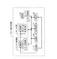
図1は、実施形態に係る自動分析装置の構成を示したブロック図である。この自動分析装置100は、各検査項目の標準試料や被検試料と各検査項目の分析用の試薬との混合液を測定して標準データや被検データを生成する分析部10と、分析部10の所定の分析ユニットの洗浄が必要か否かを判定する判定部60と、分析部10の測定に関る各分析ユニットを駆動する駆動部66と、駆動部66を制御する分析制御部67とを備えている。  FIG. 1 is a block diagram illustrating a configuration of an automatic analyzer according to the embodiment. The automatic analyzer 100 includes ananalysis unit 10 that generates a standard data and test data by measuring a mixed solution of a standard sample or test sample for each test item and an analysis reagent for each test item, and an analysis unit. Adetermination unit 60 that determines whether or not the ten predetermined analysis units need to be cleaned, adrive unit 66 that drives each analysis unit related to the measurement of theanalysis unit 10, and ananalysis control unit 67 that controls thedrive unit 66. And.

また、自動分析装置100は、分析部10で生成された標準データや被検データを処理して検量データや分析データを生成するデータ処理部70と、データ処理部70で生成された検量データや分析データを出力する出力部80と、各検査項目の分析パラメータを設定するための入力等を行う操作部90と、判定部60、分析制御部67、データ処理部70、及び出力部80を統括して制御するシステム制御部91とを備えている。  The automatic analyzer 100 also processes the standard data and test data generated by theanalysis unit 10 to generate calibration data and analysis data, and the calibration data generated by thedata processing unit 70. An output unit 80 that outputs analysis data, anoperation unit 90 that performs input for setting analysis parameters of each inspection item, adetermination unit 60, ananalysis control unit 67, adata processing unit 70, and an output unit 80 are integrated. And asystem control unit 91 that performs control.

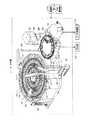
図2は、分析部10の構成を示した斜視図である。この分析部10は、標準試料や被検試料等の試料を収容する試料容器11と、この試料容器11を移動可能に保持するサンプルラック12と、各検査項分析用の試薬である例えば1試薬系及び2試薬系の第1試薬並びに2試薬系の第2試薬を収容する試薬容器13と、この試薬容器13を保冷する試薬庫17とを備えている。  FIG. 2 is a perspective view showing the configuration of theanalysis unit 10. Theanalysis unit 10 includes asample container 11 for storing a sample such as a standard sample or a test sample, asample rack 12 for holding thesample container 11 so as to be movable, and a reagent for analyzing each test item, for example, one reagentA reagent container 13 for storing the first reagent of the system and the two reagent system and the second reagent of the two reagent system, and areagent container 17 for keeping thereagent container 13 cool are provided.

また、試薬庫17内に格納された試薬容器13を移動可能に保持する第1及び第2試薬ラック15,16と、この第1及び第2試薬ラック15,16に保持された試薬容器13に貼付されるラベルから試薬情報を読み取るリーダ18とを備えている。また、回転移動可能に円周上に一列に配列された試料及び試薬を収容する複数の反応容器19と、反応容器19内面を洗浄する洗浄ノズル32とを備えている。  In addition, the first and second reagent racks 15 and 16 that hold thereagent containers 13 stored in thereagent storage 17 movably, and thereagent containers 13 held in the first and second reagent racks 15 and 16 And areader 18 that reads reagent information from a label to be attached. In addition, a plurality ofreaction containers 19 for storing samples and reagents arranged in a line on the circumference so as to be rotatable and movable, and acleaning nozzle 32 for cleaning the inner surface of thereaction container 19 are provided.

また、サンプルラック12に保持された試料容器11内の試料を吸引して洗浄ノズル32により洗浄が行われた反応容器19内へ吐出する分注を行うサンプル分注プローブ21と、サンプル分注プローブ21を回動移動及び上下移動可能に保持するサンプル分注アーム22とを備えている。  Further, asample dispensing probe 21 for dispensing a sample in thesample container 11 held in thesample rack 12 and discharging it into thereaction container 19 cleaned by thecleaning nozzle 32, and a sample dispensing probe And asample dispensing arm 22 for holding 21 in a rotatable and vertically movable manner.

また、第1試薬ラック15に保持された試薬容器13内の第1試薬を吸引して試料が吐出された反応容器19内に吐出する分注を行う第1試薬分注プローブ23と、第1試薬分注プローブ23を回動移動及び上下移動可能に保持する第1試薬分注アーム24とを備えている。  In addition, a firstreagent dispensing probe 23 that performs dispensing to suck the first reagent in thereagent container 13 held in thefirst reagent rack 15 and discharge it into thereaction container 19 from which the sample has been discharged; A firstreagent dispensing arm 24 that holds thereagent dispensing probe 23 so as to be able to rotate and move up and down is provided.

また、反応容器19内に吐出された試料と第1試薬の混合液を撹拌する第1撹拌子25と、第1撹拌子25を回動移動及び上下移動可能に保持する第1撹拌アーム26とを備えている。また、第2試薬ラック16に保持された試薬容器13内の第2試薬を吸引して第1試薬が吐出された反応容器19内に吐出する分注を行う第2試薬分注プローブ27と、第2試薬分注プローブ27を回動移動及び上下移動可能に保持する第2試薬分注アーム28とを備えている。  Also, afirst stirrer 25 that stirs the mixed liquid of the sample and the first reagent discharged into thereaction container 19, and afirst stirrer arm 26 that holds thefirst stirrer 25 so as to be capable of rotating and moving up and down It has. A secondreagent dispensing probe 27 for aspirating the second reagent in thereagent container 13 held in thesecond reagent rack 16 and dispensing it into thereaction container 19 from which the first reagent has been discharged; A secondreagent dispensing arm 28 that holds the secondreagent dispensing probe 27 so as to be capable of rotating and moving up and down is provided.

また、反応容器19内に吐出された試料、第1試薬及び第2試薬の混合液を撹拌する第2撹拌子29と、第2撹拌子29を回動移動及び上下移動可能に保持する第2撹拌アーム30とを備えている。また、反応容器19外面と接触する空気を熱媒体として反応容器19内の混合液を一定の温度に保持する恒温部20と、恒温部20により一定の温度に保持された反応容器19内の混合液を光学的に測定する測定部31とを備えている。  Thesecond stirrer 29 for stirring the sample discharged into thereaction container 19, the mixed solution of the first reagent and the second reagent, and thesecond stirrer 29 are held so as to be capable of rotating and vertically moving. And astirring arm 30. In addition, aconstant temperature part 20 that maintains the mixed liquid in thereaction container 19 at a constant temperature using air that contacts the outer surface of thereaction container 19 as a heat medium, and a mixture in thereaction container 19 that is maintained at a constant temperature by theconstant temperature part 20. And ameasuring unit 31 for optically measuring the liquid.

そして、測定部31は、反応容器19に光を照射する光源及び反応容器19を透過した光のうちの例えば近紫外から近赤外までの間の複数の波長域の光を検出する光検出器を備えている。そして、洗浄ノズル32により洗浄された後、試料及び試薬が吐出される前に測定位置を通過する反応容器19に光を照射し、反応容器19を透過した光を検出する検出信号に基づいて、反応容器19外面の洗浄が必要であるか否かを判定するための判定データを生成する。  And themeasurement part 31 is the photodetector which detects the light of the several wavelength range between the light source which irradiates light to thereaction container 19, and the light which permeate | transmitted thereaction container 19, for example from near ultraviolet to near infrared. It has. Then, after the cleaning by thecleaning nozzle 32, before the sample and the reagent are discharged, thereaction container 19 that passes through the measurement position is irradiated with light, and based on the detection signal that detects the light transmitted through thereaction container 19, Determination data for determining whether or not the outer surface of thereaction container 19 is necessary is generated.

また、測定部31は、標準試料及び試薬が吐出された後に測定位置を通過する反応容器19に光を照射し、反応容器19を透過した光を検出する検出信号に基づいて標準データを生成する。また、被検試料及び試薬が吐出された後に測定位置を通過する反応容器19に光を照射し、反応容器19を透過した光を検出する検出信号に基づいて被検データを生成する。  Further, themeasurement unit 31 emits light to thereaction container 19 that passes through the measurement position after the standard sample and the reagent are discharged, and generates standard data based on a detection signal that detects the light transmitted through thereaction container 19. . Further, after the test sample and the reagent are discharged, thereaction container 19 that passes through the measurement position is irradiated with light, and test data is generated based on a detection signal that detects the light transmitted through thereaction container 19.

判定部60は、分析部10の測定部31で生成された判定データに基づいて、反応容器19外面の洗浄が必要であるか否かを判定する。そして、判定データが予め設定された許容範囲内である場合、反応容器19の外面が汚染されていないため外面洗浄が不要であると判定する。また、判定データが予め設定された許容範囲から外れている場合、反応容器19の外面が汚染されているため、反応容器19外面の洗浄が必要であると判定する。  Thedetermination unit 60 determines whether or not the outer surface of thereaction container 19 needs to be cleaned based on the determination data generated by themeasurement unit 31 of theanalysis unit 10. When the determination data is within the preset allowable range, it is determined that the outer surface cleaning is unnecessary because the outer surface of thereaction container 19 is not contaminated. If the determination data is outside the preset allowable range, it is determined that the outer surface of thereaction container 19 needs to be cleaned because the outer surface of thereaction container 19 is contaminated.

駆動部66は、分析部10のサンプルラック12を駆動して試料容器11を移動する。また、第1試薬ラック15及び第2試薬ラック16をそれぞれ独立に駆動して試薬容器13を回動する。また、恒温部20の一部を駆動して反応容器19を回転移動する。また、サンプル分注アーム22、第1試薬分注アーム24、第1撹拌アーム26、第2試薬分注アーム28、及び第2撹拌アーム30をそれぞれ回動駆動及び上下駆動して、サンプル分注プローブ21、第1試薬分注プローブ23、第1撹拌子25、第2試薬分注プローブ27、及び第2撹拌子29をそれぞれ回動移動及び上下移動する。また、洗浄ノズル32を上下移動する。  Thedrive unit 66 drives thesample rack 12 of theanalysis unit 10 and moves thesample container 11. Further, thereagent container 13 is rotated by independently driving thefirst reagent rack 15 and thesecond reagent rack 16. Further, a part of theconstant temperature unit 20 is driven to rotate and move thereaction vessel 19. In addition, thesample dispensing arm 22, the firstreagent dispensing arm 24, the firststirring arm 26, the secondreagent dispensing arm 28, and the second stirringarm 30 are respectively rotated and driven up and down to sample dispensing. Theprobe 21, the firstreagent dispensing probe 23, thefirst stirring bar 25, the secondreagent dispensing probe 27, and thesecond stirring bar 29 are rotated and moved up and down, respectively. Further, thecleaning nozzle 32 is moved up and down.

また、駆動部66は、サンプル分注プローブ21に試料の吸引及び吐出を行わせるためのポンプを駆動する。また、第1試薬分注プローブ23に第1試薬の吸引及び吐出を行わせるためのポンプを駆動する。第2試薬分注プローブ27に第2試薬の吸引及び吐出を行わせるためのポンプを駆動する。また、第1撹拌子25を撹拌駆動する。また、第2撹拌子29を撹拌駆動する。また、洗浄ノズル32に反応容器19内の洗浄を行わせるためのポンプを駆動する。また、恒温部20を駆動して反応容器19を加熱する。  Thedrive unit 66 drives a pump for causing thesample dispensing probe 21 to suck and discharge the sample. Further, the pump for causing the firstreagent dispensing probe 23 to suck and discharge the first reagent is driven. A pump for causing the secondreagent dispensing probe 27 to suck and discharge the second reagent is driven. Further, thefirst stirrer 25 is driven to stir. Further, thesecond stirrer 29 is driven to stir. Further, the pump for driving thecleaning nozzle 32 to clean the inside of thereaction vessel 19 is driven. Further, theconstant temperature unit 20 is driven to heat thereaction vessel 19.

分析制御部67は、駆動部66を制御して反応容器19を一定の温度に保持させる。また、判定部60により洗浄が不要であると判定された反応容器19内への試料、第1試薬及び第2試薬の吐出を実行させる。また、判定部60により洗浄が必要であると判定された反応容器19内への試料、第1試薬及び第2試薬の吐出を停止させる。  Theanalysis control unit 67 controls thedrive unit 66 to keep thereaction vessel 19 at a constant temperature. In addition, the sample, the first reagent, and the second reagent are discharged into thereaction container 19 that is determined to be unnecessary by thedetermination unit 60. In addition, the discharge of the sample, the first reagent, and the second reagent into thereaction container 19 determined to be necessary for cleaning by thedetermination unit 60 is stopped.

図1のデータ処理部70は、分析部10の測定部31で生成された標準データや被検データを処理して各検査項目の検量データや分析データを生成する演算部71と、演算部71で生成された標準データや分析データを保存するデータ記憶部72とを備えている。  Adata processing unit 70 in FIG. 1 processes a standard data and test data generated by themeasurement unit 31 of theanalysis unit 10 to generate calibration data and analysis data for each inspection item, and a calculation unit 71. And a data storage unit 72 for storing the standard data and the analysis data generated in (1).

演算部71は、測定部31で生成された標準データ及び標準試料に予め設定された標準値の関係を示す検量データを生成し、生成した検量データを出力部80に出力すると共にデータ記憶部72に保存する。また、測定部31で生成された被検データに対応する検量データをデータ記憶部72から読み出して濃度値や酵素の活性値として表される分析データを生成する。そして、生成した分析データを出力部80に出力すると共にデータ記憶部72に保存する。  The calculation unit 71 generates calibration data indicating the relationship between the standard data generated by themeasurement unit 31 and a standard value set in advance in the standard sample, and outputs the generated calibration data to the output unit 80 and the data storage unit 72. Save to. Also, calibration data corresponding to the test data generated by themeasurement unit 31 is read from the data storage unit 72 to generate analysis data expressed as a concentration value or an enzyme activity value. The generated analysis data is output to the output unit 80 and stored in the data storage unit 72.

データ記憶部72は、ハードディスク等のメモリデバイスを備え、演算部71から出力された検量データを検査項目毎に保存する。また、演算部71から出力された各検査項目の分析データを被検試料毎に保存する。  The data storage unit 72 includes a memory device such as a hard disk, and stores the calibration data output from the calculation unit 71 for each inspection item. In addition, the analysis data of each inspection item output from the calculation unit 71 is stored for each test sample.

出力部80は、データ処理部70の演算部71から出力された検量データや分析データを印刷出力する印刷部81及び表示出力する表示部82を備えている。そして、印刷部81は、プリンタなどを備え、演算部71から出力された検量データや分析データを予め設定されたフォーマットに従って、プリンタ用紙などに印刷する。  The output unit 80 includes aprinting unit 81 that prints and outputs calibration data and analysis data output from the calculation unit 71 of thedata processing unit 70 and a display unit 82 that displays and outputs the data. Theprinting unit 81 includes a printer or the like, and prints the calibration data and analysis data output from the calculation unit 71 on printer paper or the like according to a preset format.

表示部82は、CRTや液晶パネルなどのモニタを備え、演算部71から出力された検量データや分析データを表示する。また、検査項目毎に分析パラメータを設定するための分析パラメータ設定画面、被検試料毎にこの被検試料を識別する氏名やID等の被検識別情報の設定及び検査に必要な検査項目を設定するための検査項目設定画面等を表示する。  The display unit 82 includes a monitor such as a CRT or a liquid crystal panel, and displays calibration data and analysis data output from the calculation unit 71. Also, an analysis parameter setting screen for setting analysis parameters for each inspection item, setting of test identification information such as name and ID for identifying the test sample for each test sample, and setting of inspection items necessary for the test To display the inspection item setting screen and so on.

操作部90は、キーボード、マウス、ボタン、タッチキーパネルなどの入力デバイスを備え、各検査項目の分析パラメータを設定するための入力、被検試料の被検識別情報及び検査項目を設定するための入力等を行う。  Theoperation unit 90 includes input devices such as a keyboard, a mouse, a button, and a touch key panel, and is used to set input for setting analysis parameters of each test item, test identification information of a test sample, and test items. Perform input etc.

システム制御部91は、CPU及び記憶回路を備え、操作部90からの操作により入力されたコマンド信号、各検査項目の分析パラメータ、被検識別情報及び検査項目等の入力情報を記憶回路に記憶した後、これらの入力情報に基づいて、判定部60、分析制御部67、データ処理部70、及び出力部80を統括してシステム全体を制御する。  Thesystem control unit 91 includes a CPU and a storage circuit, and stores input information such as command signals input by operation from theoperation unit 90, analysis parameters of each inspection item, test identification information, and inspection items in the storage circuit. Thereafter, based on the input information, thedetermination unit 60, theanalysis control unit 67, thedata processing unit 70, and the output unit 80 are integrated to control the entire system.

次に、図2乃至図6を参照して、分析部10における恒温部20、洗浄ノズル32及び反応容器19の構成及び反応容器19の停止位置の一例を説明する。
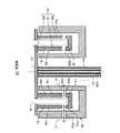
図3は、恒温部20の構成を示した断面図である。この恒温部20は、反応容器19が配置される恒温槽40と、反応容器19を保持する反応ディスク41とを備えている。また、反応ディスク41を回転可能に支持する回転軸42と、反応容器19内の混合液を一定の温度に保持する加熱部43とを備えている。
Next, with reference to FIG. 2 thru | or FIG. 6, the example of the structure of thethermostat 20 in theanalysis part 10, the washing | cleaningnozzle 32, and thereaction container 19 and the stop position of thereaction container 19 is demonstrated.
FIG. 3 is a cross-sectional view showing the configuration of theconstant temperature unit 20. Theconstant temperature unit 20 includes aconstant temperature bath 40 in which thereaction vessel 19 is disposed, and areaction disk 41 that holds thereaction vessel 19. Moreover, the rotatingshaft 42 which supports thereaction disk 41 rotatably is provided, and theheating part 43 which hold | maintains the liquid mixture in thereaction container 19 at fixed temperature.

恒温槽40は、回転移動する反応容器19の円軌道に沿って上端部が開口した円環状空間の通路が形成され、その通路に反応容器19及び加熱部43が配置されている。また、外周側及び内周側の側壁に測定部31からの光が通過する2つの開口が形成されている。そして、外周側の側壁に形成された開口を閉塞するように測定部31の光が透過する例えばガラス材からなる透過窓40aが配設され、内周側の側壁に形成された開口を閉塞するように透過窓40a及び反応容器19の下端部近傍を透過した光が透過する透過窓40bが配設されている。  Theconstant temperature bath 40 is formed with a passage in an annular space whose upper end is opened along the circular orbit of thereaction vessel 19 that rotates, and thereaction vessel 19 and theheating unit 43 are arranged in the passage. In addition, two openings through which light from themeasurement unit 31 passes are formed on the outer peripheral side and inner peripheral side walls. Then, atransmission window 40a made of, for example, a glass material through which the light of themeasurement unit 31 is transmitted is disposed so as to close the opening formed on the outer peripheral side wall, and the opening formed on the inner peripheral side wall is blocked. Thus, thetransmission window 40a and thetransmission window 40b through which the light transmitted through the vicinity of the lower end portion of thereaction vessel 19 is disposed are arranged.

反応ディスク41は、恒温槽40の上部の開口全体を覆うように配置され、縁辺の円周上に等間隔に設けられた複数の開口部で反応容器19の上端部を保持している。また、下側に配置された加熱部43の上端部を保持している。  Thereaction disk 41 is disposed so as to cover the entire upper opening of thethermostatic bath 40, and holds the upper end of thereaction vessel 19 with a plurality of openings provided at equal intervals on the circumference of the edge. Moreover, the upper end part of theheating part 43 arrange | positioned below is hold | maintained.

回転軸42は、恒温槽40の中央を貫通して配置され、上端部が反応ディスク41の中心部に連結されている。また、中空をなし、加熱部43に反応容器19を加熱する電力を供給するためのケーブル421が挿通配置されている。そして、駆動部66により回転駆動される。この駆動により反応ディスク41が回転され、反応ディスク41の回転により反応容器19が回転移動する。  The rotatingshaft 42 is disposed through the center of thethermostatic chamber 40, and the upper end portion is connected to the central portion of thereaction disk 41. In addition, acable 421 for supplying power for heating thereaction vessel 19 to theheating unit 43 is inserted and arranged. And it is rotationally driven by thedrive part 66. FIG. By this driving, thereaction disk 41 is rotated, and thereaction container 19 is rotated by the rotation of thereaction disk 41.

加熱部43は、恒温槽40内に配置され、反応容器19をこの上端部以外を包囲する空気を熱媒体として加熱するための恒温ブロック50と、恒温ブロック50を加熱するヒータ51と、恒温ブロック50の温度を検出する温度センサ52とを備えている。  Theheating unit 43 is disposed in theconstant temperature bath 40, and aconstant temperature block 50 for heating thereaction vessel 19 with air surrounding the upper end other than the upper end as a heat medium, aheater 51 for heating theconstant temperature block 50, and a constant temperature block. And atemperature sensor 52 for detecting 50 temperatures.

恒温ブロック50は、例えば熱伝導性に優れたアルミニウム材により形成され、上端部が反応ディスク41に固定されている。また、上端部が開口した円環状空間を形成し、円環状空間に反応容器19上端部以外を近接包囲して恒温槽40内の通路に配置される。また、測定部31から照射され、恒温槽40の透過窓40aを透過した光が測定位置Mの反応容器19に入射可能なように、反応容器19と同じ数の開口部50aが外周側の側壁に形成されている。また、測定位置Mの反応容器19から出射した光が通過可能なように内周側の側壁に反応容器19と同じ数の開口部50bが形成されている。  Theconstant temperature block 50 is formed of, for example, an aluminum material having excellent thermal conductivity, and the upper end portion is fixed to thereaction disk 41. In addition, an annular space having an open upper end is formed, and the space other than the upper end of thereaction vessel 19 is enclosed in the annular space so as to be disposed in the passage in thethermostat 40. Further, the same number ofopenings 50a as thereaction vessel 19 are provided on the outer side wall so that the light irradiated from themeasurement unit 31 and transmitted through thetransmission window 40a of thethermostat 40 can enter thereaction vessel 19 at the measurement position M. Is formed. Further, the same number ofopenings 50b as thereaction vessel 19 are formed on the inner side wall so that light emitted from thereaction vessel 19 at the measurement position M can pass therethrough.

ヒータ51は、例えば恒温ブロック50の内周側の側壁内に環状に配置される。そして、駆動部66により駆動され、恒温ブロック50を加熱する。また、温度センサ52は、恒温部ブロック50上部に配置されている。そして、温度センサ52で検出された温度に基づいてヒータ51の駆動が分析制御部67により制御され、恒温ブロック50に近接された反応容器19内の混合液を、その反応容器19外面と接触する空気を熱媒体として例えば37℃の一定の温度に保持する。  For example, theheater 51 is arranged in an annular shape in the inner peripheral side wall of thethermostatic block 50. And it drives by thedrive part 66 and heats theconstant temperature block 50. FIG. Further, thetemperature sensor 52 is arranged on the upper part of theconstant temperature block 50. Then, based on the temperature detected by thetemperature sensor 52, the driving of theheater 51 is controlled by theanalysis control unit 67, and the liquid mixture in thereaction container 19 close to theconstant temperature block 50 is brought into contact with the outer surface of thereaction container 19. For example, air is maintained at a constant temperature of 37 ° C. as a heat medium.

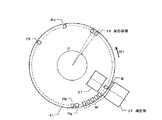
図4は、洗浄ノズル32の構成及び各反応容器19が停止する停止位置の一例を示した図である。
洗浄ノズル32は、例えば第1乃至第5洗浄ノズル321乃至325により構成され、駆動部66の上下駆動によりそれぞれ上下方向に移動可能に配置される。そして、恒温部20の反応ディスク41が回転しているとき、反応ディスク41上方の上停止位置で停止している。そして、反応ディスク41が停止しているとき、下方向に移動して洗浄位置Wの第1乃至第5洗浄位置W1乃至W5で停止した反応容器19内に進入して洗浄を行う。洗浄を終了した後、上方向に移動して上停止位置で停止する。
FIG. 4 is a diagram showing an example of the configuration of the cleaningnozzle 32 and a stop position where eachreaction vessel 19 stops.
The cleaningnozzle 32 includes, for example, first to fifth cleaning nozzles 321 to 325, and is arranged so as to be movable in the vertical direction by the vertical drive of thedrive unit 66. And when thereaction disk 41 of thethermostat 20 is rotating, it stops at the upper stop position above thereaction disk 41. When thereaction disk 41 is stopped, thereaction disk 41 moves downward and enters thereaction vessel 19 stopped at the first to fifth cleaning positions W1 to W5 of the cleaning position W to perform cleaning. After finishing the cleaning, it moves upward and stops at the upper stop position.

第1洗浄ノズル321は、第1洗浄位置W1で停止する反応容器19内の混合液の吸引による洗浄を行う。また、第2洗浄ノズル322は、第1洗浄位置W1で洗浄が行われた後に第2洗浄位置W2で停止する反応容器19内に残留する混合液を洗い落とすための例えばアルカリ性洗浄液等の第1の洗浄液の吐出及び吸引による洗浄を行う。また、第3洗浄ノズル323は、第2洗浄位置W2で洗浄が行われた後に第3洗浄位置W3で停止する反応容器19内に残留する混合液や第1の洗浄液等の液体を洗い落とすための例えば酸性洗浄液等の第2の洗浄液の吐出及び吸引による洗浄を行う。また、第4洗浄ノズル324は、第3洗浄位置W3で洗浄が行われた後に第4洗浄位置W4で停止する反応容器19内に残留する液体を洗い落とすための洗浄水等の第3の洗浄液の吐出及び吸引による洗浄を行う。また、第5洗浄ノズル325は、第4洗浄位置W4で洗浄が行われた後に第5洗浄位置W5で停止する反応容器19内に残留する液体の吸引による洗浄を行う。  The first cleaning nozzle 321 performs cleaning by sucking the mixed liquid in thereaction vessel 19 stopped at the first cleaning position W1. In addition, the second cleaning nozzle 322 is a first cleaning agent such as an alkaline cleaning solution for washing away the mixed liquid remaining in thereaction vessel 19 stopped at the second cleaning position W2 after the cleaning is performed at the first cleaning position W1. Cleaning is performed by discharging and suctioning the cleaning liquid. In addition, the third cleaning nozzle 323 is used to wash away liquids such as the mixed liquid and the first cleaning liquid remaining in thereaction container 19 stopped at the third cleaning position W3 after the cleaning is performed at the second cleaning position W2. For example, cleaning is performed by discharging and sucking a second cleaning liquid such as an acidic cleaning liquid. Further, the fourth cleaning nozzle 324 is configured to supply a third cleaning liquid such as cleaning water for cleaning the liquid remaining in thereaction vessel 19 stopped at the fourth cleaning position W4 after the cleaning is performed at the third cleaning position W3. Cleaning by discharge and suction is performed. The fifth cleaning nozzle 325 performs cleaning by sucking the liquid remaining in thereaction container 19 that stops at the fifth cleaning position W5 after cleaning is performed at the fourth cleaning position W4.

なお、反応容器19内の洗浄には、測定部31で検出可能な複数の波長域の光をほぼ吸収しない第1乃至第3の洗浄液を用いる。  For cleaning thereaction container 19, first to third cleaning liquids that hardly absorb light in a plurality of wavelength regions that can be detected by themeasurement unit 31 are used.

各反応容器19は、駆動部66による反応ディスク41の回転駆動により、1サイクルタイム毎に一方向へ回転移動して移動前とは異なる各停止位置で停止し、1サイクルタイムよりも長い時間である1ラウンドタイム毎に同じ停止位置で停止する。ここでは、図5に示すように、反応ディスク41の角度θの回転駆動により、1サイクルタイム毎に矢印R1方向へ回転移動して、例えば移動前にR1方向とは反対方向に隣接する反応容器19の位置である、1ピッチ進行した位置で停止する。  Eachreaction container 19 is rotationally moved in one direction every cycle time by the rotation drive of thereaction disk 41 by thedrive unit 66 and stops at each stop position different from that before the movement, and in a time longer than one cycle time. Stop at the same stop position every round time. Here, as shown in FIG. 5, thereaction disk 41 is rotationally moved in the direction of the arrow R1 every cycle time by the rotational drive of the angle θ, for example, the reaction container adjacent in the opposite direction to the R1 direction before the movement. It stops at a position advanced by one pitch, which is the position of 19.

そして、反応容器19は、洗浄を終えて洗浄位置Wの第5洗浄位置W5で停止しているとき分析制御部67により被検試料毎に設定された検査項目の分析用として決定される。検査項目が決定された反応容器19は、所定のサイクルタイム経過後にサンプル分注プローブ21により試料が吐出される試料吐出位置Paで停止する。試料吐出位置Paで停止した後、第1試薬分注プローブ23により第1試薬が吐出される第1試薬吐出位置Pbで停止する。第1試薬吐出位置Pbで停止した後、第1撹拌子25により混合液の撹拌が行われる第1撹拌位置Pcで停止する。第1撹拌位置Pcで停止した後、第2試薬分注プローブ27により第2試薬が吐出される第2試薬吐出位置Pdで停止する。第2試薬吐出位置Pdで停止した後、第2撹拌子29により混合液の撹拌が行われる第2撹拌位置Peで停止する。第2撹拌位置Peで停止した後、洗浄位置Wで停止して洗浄が行われる。  Thereaction container 19 is determined for analysis of the inspection item set for each test sample by theanalysis control unit 67 when the cleaning is finished and stopped at the fifth cleaning position W5 of the cleaning position W. Thereaction container 19 in which the inspection item is determined stops at the sample discharge position Pa where the sample is discharged by thesample dispensing probe 21 after a predetermined cycle time has elapsed. After stopping at the sample discharge position Pa, it stops at the first reagent discharge position Pb where the first reagent is discharged by the firstreagent dispensing probe 23. After stopping at the first reagent discharge position Pb, the first stirringbar 25 stops at the first stirring position Pc where the liquid mixture is stirred. After stopping at the first stirring position Pc, it stops at the second reagent discharge position Pd where the second reagent is discharged by the secondreagent dispensing probe 27. After stopping at the second reagent discharge position Pd, the second stirringbar 29 stops at the second stirring position Pe where the mixed liquid is stirred. After stopping at the second stirring position Pe, cleaning is performed after stopping at the cleaning position W.

図6は、反応容器19の構成を示した図である。この反応容器19は例えば四角柱状をなし、上端部に洗浄ノズル32等が進入する開口部を有する。そして、測定位置Mにおいて、測定部31から照射され、恒温槽40の透過窓40aを透過した光が入射する斜線で示す入射領域19a及びこの入射領域19aから入射した光が出射する斜線で示す出射領域19bよりも上方の外面に、水溶液に溶解して入射領域19a又は出射領域19bに達したときに測定部31により検出可能な被検出体33が配置されている。  FIG. 6 is a diagram showing the configuration of thereaction vessel 19. Thereaction vessel 19 has, for example, a rectangular column shape and has an opening through which the cleaningnozzle 32 and the like enter at the upper end. Then, at the measurement position M, the incident area 19a indicated by the oblique line where the light irradiated from themeasurement unit 31 and transmitted through thetransmission window 40a of thethermostatic chamber 40 is incident, and the emission indicated by the oblique line where the light incident from the incident area 19a is emitted. Anobject 33 to be detected that can be detected by themeasurement unit 31 when dissolved in an aqueous solution and reaches the incident area 19a or theemission area 19b is disposed on the outer surface above thearea 19b.

被検出体33としては、測定部31で検出可能な複数の波長域のうちの第1の波長域で高い吸収を示し、第2の波長域で低い吸収を示す水溶性の色素を用いる。そして、第2乃至第4洗浄ノズル322乃至324のいずれかの洗浄ノズルから吐出された洗浄液が飛散して反応容器19の入射領域19a又は出射領域19bに達する場合に経由する外面の上端部に、色素を保持するテープで包囲するように固定配置されている。  As thedetection target 33, a water-soluble dye that exhibits high absorption in the first wavelength region among the plurality of wavelength regions that can be detected by themeasurement unit 31 and exhibits low absorption in the second wavelength region is used. Then, at the upper end portion of the outer surface through which the cleaning liquid discharged from any of the second to fourth cleaning nozzles 322 to 324 scatters and reaches the incident area 19a or theemission area 19b of thereaction vessel 19, It is fixedly arranged so as to be surrounded by a tape that holds the dye.

このように、反応容器19外面上端部に被検出体33を配置することにより、各第2乃至第4洗浄ノズル322乃至324から吐出され、飛散して反応容器19の入射領域19a又は出射領域19bに達する洗浄液を、この洗浄液に含まれる被検出体33の吸収特性を利用して測定部31で精度よく検出することができる。  As described above, by arranging thedetection target 33 on the upper end of the outer surface of thereaction vessel 19, the second to fourth cleaning nozzles 322 to 324 are discharged and scattered to enter the incident region 19a or theemission region 19b of thereaction vessel 19. Can be accurately detected by themeasurement unit 31 using the absorption characteristics of thedetection target 33 contained in the cleaning liquid.

これにより、反応容器19の入射領域19a又は出射領域19bに洗浄液が達した場合、放置しておくと時間の経過に伴い、入射領域19a又は出射領域19bの洗浄液に付着する空気中の成分や、水分の蒸発により残存する洗浄液の成分による光の散乱等により光学的測定に与える悪影響を未然に防ぐことができる。  Thereby, when the cleaning liquid reaches the incident area 19a or theemission area 19b of thereaction container 19, the components in the air attached to the cleaning liquid in the incident area 19a or theemission area 19b with the passage of time, It is possible to prevent adverse effects on the optical measurement due to light scattering by the components of the cleaning liquid remaining due to evaporation of moisture.

以下、図1乃至図6を参照して、自動分析装置100の動作の一例を説明する。  Hereinafter, an example of the operation of the automatic analyzer 100 will be described with reference to FIGS. 1 to 6.

操作部90から測定開始の入力が行われると、分析制御部67は、駆動部66を制御して分析部10を作動させる。分析部10の洗浄ノズル32は、洗浄位置Wで停止した反応容器19内面を洗浄する。洗浄が行われた反応容器19は回転移動する。測定部31は、洗浄ノズル32により洗浄が行われてから試料及び試薬が吐出される前の反応容器19を透過した光のうち、第1及び第2の波長域の光を検出する検出信号に基づいて判定データを生成する。  When the measurement start input is performed from theoperation unit 90, theanalysis control unit 67 controls thedrive unit 66 to operate theanalysis unit 10. The cleaningnozzle 32 of theanalysis unit 10 cleans the inner surface of thereaction vessel 19 stopped at the cleaning position W. Thereaction vessel 19 that has been cleaned rotates. Themeasurement unit 31 generates a detection signal for detecting light in the first and second wavelength regions from the light transmitted through thereaction container 19 before the sample and the reagent are discharged after the cleaning by the cleaningnozzle 32. Based on this, determination data is generated.

ここでは、反応容器19を透過した第1の波長域の光の検出信号を増幅してデジタル信号に変換した第1の透過光強度を求める。また、反応容器19を透過した第2の波長域の光の検出信号を増幅してデジタル信号に変換した第2の透過光強度を求める。そして、第1の透過光強度と第2の透過光強度の差を判定データとして生成する。  Here, the first transmitted light intensity obtained by amplifying the detection signal of the light in the first wavelength band transmitted through thereaction vessel 19 and converting it into a digital signal is obtained. Further, the second transmitted light intensity obtained by amplifying the detection signal of the light in the second wavelength range that has passed through thereaction vessel 19 and converting it into a digital signal is obtained. Then, a difference between the first transmitted light intensity and the second transmitted light intensity is generated as determination data.

判定部60は、測定部31で生成された判定データに対応する反応容器19外面の洗浄が必要であるか否かを判定する。そして、判定データが予め設定された許容範囲内である場合、被検出体33の検出が不可能であるため入射領域19a又は出射領域19bが汚染されていないと判断し、反応容器19の外面洗浄が不要であると判定する。また、判定データが許容範囲から外れている場合、判定した反応容器19外面の入射領域19a又は出射領域19bに被検出体33を含む洗浄液が付着して汚染されていると判断し、反応容器19外面の洗浄が必要であると判定する。  Thedetermination unit 60 determines whether it is necessary to clean the outer surface of thereaction container 19 corresponding to the determination data generated by themeasurement unit 31. If the determination data is within a preset allowable range, it is determined that the incident region 19a or theemission region 19b is not contaminated because the detection of thedetection target 33 is impossible, and the outer surface of thereaction vessel 19 is cleaned. Is determined to be unnecessary. Further, when the determination data is out of the allowable range, it is determined that the cleaning liquid including thedetection target 33 is attached to the incident area 19a or theemission area 19b on the outer surface of thedetermined reaction container 19 and is contaminated. It is determined that the outer surface needs to be cleaned.

分析制御部67は、判定部60により洗浄が必要であると判定された反応容器19内への試料、第1試薬及び第2試薬の吐出を停止させ、洗浄が必要であると判定された反応容器19を識別する例えば容器番号等の識別情報をシステム制御部91に出力する。システム制御部91は、判定部60により洗浄が必要であると判定された反応容器19の識別情報をエラーメッセージと共に表示部82に表示させる。  Theanalysis control unit 67 stops the discharge of the sample, the first reagent, and the second reagent into thereaction container 19 that is determined to be cleaned by thedetermination unit 60, and the reaction that is determined to need cleaning. For example, identification information such as a container number for identifying thecontainer 19 is output to thesystem control unit 91. Thesystem control unit 91 causes the display unit 82 to display the identification information of thereaction container 19 determined by thedetermination unit 60 to be cleaned together with an error message.

このように、外面の洗浄が必要であると判定された反応容器19への試料及び試薬の吐出を停止させることにより、反応容器19外面に付着する洗浄液が原因で測定部31の測定に与える悪影響を未然に防ぐことができる。  In this way, by stopping the discharge of the sample and the reagent to thereaction container 19 determined to require the outer surface to be cleaned, the adverse effect on the measurement of the measuringunit 31 due to the cleaning liquid adhering to the outer surface of thereaction container 19 Can be prevented in advance.

サンプル分注プローブ21は、外面洗浄が不要であると判定された反応容器19内に被検試料を吐出する。また、第1試薬分注プローブ23は、被検試料が吐出された反応容器19内に第1試薬を吐出する。また、第2試薬分注プローブは、第1試薬が吐出された反応容器19内に第2試薬を吐出する。恒温部20は、被検試料、第1試薬及び第2試薬が吐出された反応容器19内の混合液を一定の温度に保持する。測定部31は、一定温度に保持された反応容器19内の混合液を測定して被検データを生成する。データ処理部70は、測定部31で生成された被検データに基づいて分析データを生成する。出力部80は、データ処理部70で生成された分析データを印刷出力及び表示出力する。  Thesample dispensing probe 21 discharges the test sample into thereaction container 19 that is determined not to require external surface cleaning. The firstreagent dispensing probe 23 discharges the first reagent into thereaction container 19 from which the test sample has been discharged. Further, the second reagent dispensing probe discharges the second reagent into thereaction container 19 from which the first reagent has been discharged. Theconstant temperature unit 20 holds the liquid mixture in thereaction container 19 from which the test sample, the first reagent, and the second reagent are discharged at a constant temperature. The measuringunit 31 measures the mixed liquid in thereaction container 19 held at a constant temperature and generates test data. Thedata processing unit 70 generates analysis data based on the test data generated by themeasurement unit 31. The output unit 80 prints out and displays the analysis data generated by thedata processing unit 70.

なお、操作部90から洗浄開始の入力が行われると、洗浄ノズル32は、洗浄位置Wで停止した反応容器19内面を洗浄する。測定部31は、洗浄ノズル32により洗浄が行われた反応容器19を透過した光のうち、第1及び第2の波長域の光を検出する検出信号に基づいて判定データを生成する。判定部60は、測定部31で生成された判定データに対応する反応容器19外面の洗浄が必要であるか否かを判定する。そして、判定データが許容範囲内である場合、反応容器19の外面洗浄が不要であると判定する。また、判定データが許容範囲から外れている場合、反応容器19外面の洗浄が必要であると判定する。分析制御部67は、判定部60により洗浄が必要であると判定された反応容器19を識別する例えば容器番号等の識別情報をシステム制御部91に出力する。システム制御部91は、判定部60により洗浄が必要であると判定された反応容器19の識別情報をエラーメッセージと共に表示部82に表示させる。  In addition, when the start of cleaning is input from theoperation unit 90, the cleaningnozzle 32 cleans the inner surface of thereaction vessel 19 stopped at the cleaning position W. Themeasurement unit 31 generates determination data based on a detection signal for detecting light in the first and second wavelength regions out of the light transmitted through thereaction container 19 cleaned by the cleaningnozzle 32. Thedetermination unit 60 determines whether it is necessary to clean the outer surface of thereaction container 19 corresponding to the determination data generated by themeasurement unit 31. When the determination data is within the allowable range, it is determined that the outer surface cleaning of thereaction container 19 is not necessary. If the determination data is out of the allowable range, it is determined that the outer surface of thereaction vessel 19 needs to be cleaned. Theanalysis control unit 67 outputs identification information, such as a container number, for identifying thereaction container 19 determined to be necessary for cleaning by thedetermination unit 60 to thesystem control unit 91. Thesystem control unit 91 causes the display unit 82 to display the identification information of thereaction container 19 determined by thedetermination unit 60 to be cleaned together with an error message.

以上述べた実施形態によれば、空気を熱媒体として反応容器19内の混合液を一定に保持し、反応容器19に光を照射して混合液を光学的に測定する場合、反応容器19外面上端部に被検出体33を配置することにより、洗浄ノズル32から吐出され、飛散して反応容器19の入射領域19a又は出射領域19bに達する洗浄液を、この洗浄液に含まれる被検出体33の吸収特性を利用して測定部31で精度よく検出することができる。  According to the embodiment described above, when the liquid mixture in thereaction vessel 19 is kept constant using air as a heat medium and the liquid mixture is optically measured by irradiating thereaction vessel 19 with light, the outer surface of thereaction vessel 19 By disposing thedetection target 33 at the upper end, the cleaning liquid discharged from the cleaningnozzle 32 and scattered to reach the incident area 19a or theemission area 19b of thereaction container 19 is absorbed by thedetection target 33 contained in the cleaning liquid. The characteristic can be used to accurately detect themeasurement unit 31.

そして、洗浄ノズル32により洗浄が行われてから試料及び試薬が吐出される前の反応容器19を測定して判定データを生成し、生成した判定データに基づいて反応容器19外面の洗浄が必要であるか否かを判定することができる。そして、外面の洗浄が必要であると判定された反応容器19への試料及び試薬の吐出を停止させることにより、反応容器19外面に付着する洗浄液が原因で測定部31の測定に与える悪影響を未然に防ぐことができる。  Then, after the cleaningnozzle 32 performs cleaning, thereaction container 19 is measured before the sample and the reagent are discharged, and determination data is generated. Based on the generated determination data, the outer surface of thereaction container 19 needs to be cleaned. It can be determined whether or not there is. Then, by stopping the discharge of the sample and the reagent to thereaction container 19 determined to require the outer surface cleaning, the adverse effect on the measurement of the measuringunit 31 due to the cleaning liquid adhering to the outer surface of thereaction container 19 is obviated. Can be prevented.

本発明のいくつかの実施形態を説明したが、これらの実施形態は、例として提示したものであり、発明の範囲を限定することを意図していない。これら新規な実施形態は、その他の様々な形態で実施されることが可能であり、発明の要旨を逸脱しない範囲で、種々の省略、置き換え、変更を行うことができる。これら実施形態やその変形は、発明の範囲や要旨に含まれると共に、特許請求の範囲に記載された発明とその均等の範囲に含まれる。  Although several embodiments of the present invention have been described, these embodiments are presented by way of example and are not intended to limit the scope of the invention. These novel embodiments can be implemented in various other forms, and various omissions, replacements, and changes can be made without departing from the scope of the invention. These embodiments and modifications thereof are included in the scope and gist of the invention, and are included in the invention described in the claims and the equivalents thereof.

M 測定位置
19 反応容器
19a 入射領域
19b 出射領域
20 恒温部
31 測定部
32 洗浄ノズル
33 被検出体
43 加熱部
M Measurement position 19 Reaction vessel19a Incident area19b Emission area 20Constant temperature section 31Measuring section 32Cleaning nozzle 33 Detectedobject 43 Heating section

Claims (4)

Translated fromJapanese
試料及び試薬の混合液を収容する反応容器と、
前記反応容器内面を洗浄する洗浄ノズルと、
前記洗浄ノズルにより洗浄された前記反応容器内に吐出される前記試料及び試薬の混合液を、当該反応容器外面と接触する空気を熱媒体として一定の温度に保持する恒温部と、
前記恒温部により一定温度に保持された前記反応容器内の混合液を、当該反応容器に光を照射して測定する測定部とを備え、
前記反応容器は、前記測定部から照射された光が入射する入射領域及びこの入射領域から入射した光が出射する出射領域よりも上方の外面に、水溶液に溶解して前記入射領域又は前記出射領域に達したときに前記測定部により検出可能な被検出体が配置されていることを特徴とする自動分析装置。
A reaction vessel containing a mixture of a sample and a reagent;
A cleaning nozzle for cleaning the inner surface of the reaction vessel;
A constant temperature section for maintaining the liquid mixture of the sample and the reagent discharged into the reaction vessel washed by the washing nozzle at a constant temperature using air contacting the outer surface of the reaction vessel as a heat medium;
A measurement unit that measures the liquid mixture in the reaction vessel held at a constant temperature by the constant temperature unit by irradiating the reaction vessel with light;
The reaction vessel is dissolved in an aqueous solution on the outer surface above the incident region where the light irradiated from the measurement unit is incident and the emission region where the light incident from the incident region is emitted. An automatic analyzer is provided, in which a detection object that can be detected by the measurement unit when the value reaches is reached.
前記反応容器外面の洗浄が必要であるか否かを判定する判定部を有し、
前記測定部は、前記洗浄ノズルにより洗浄が行われてから前記試料及び前記試薬が吐出される前の前記反応容器を透過した光のうち、前記被検出体で吸収される所定の波長域の検出信号に基づいて判定データを生成し、
前記判定部は、前記判定データが予め設定された許容範囲内である場合に前記反応容器外面洗浄を不要であると判定し、前記判定データが予め設定された許容範囲から外れている場合に前記反応容器外面洗浄を必要であると判定することを特徴とする請求項1に記載の自動分析装置。
A determination unit for determining whether or not the outer surface of the reaction vessel needs to be cleaned;
The measurement unit detects a predetermined wavelength range absorbed by the detection target, out of light transmitted through the reaction container after the sample and the reagent are discharged after being cleaned by the cleaning nozzle. Generate decision data based on the signal,
The determination unit determines that the reaction vessel outer surface cleaning is unnecessary when the determination data is within a preset allowable range, and the determination data is out of a predetermined allowable range. The automatic analyzer according to claim 1, wherein it is determined that the outer surface of the reaction container needs to be cleaned.
前記判定部により外面洗浄が必要であると判定された前記反応容器内への前記試料及び試薬の吐出を停止させる分析制御部を有することを特徴とする請求項1又は請求項2に記載の自動分析装置。  3. The automatic control device according to claim 1, further comprising an analysis control unit configured to stop the discharge of the sample and the reagent into the reaction container that is determined to require outer surface cleaning by the determination unit. Analysis equipment. 前記被検出体は、前記測定部により検出可能な波長域に吸収を有する水溶性の色素であることを特徴とする請求項1乃至請求項3のいずれか1項に記載の自動分析装置。  The automatic analyzer according to any one of claims 1 to 3, wherein the detection target is a water-soluble dye having absorption in a wavelength range detectable by the measurement unit.
JP2014032874A2014-02-242014-02-24 Automatic analyzerActiveJP6342181B2 (en)

Priority Applications (1)

Application NumberPriority DateFiling DateTitle
JP2014032874AJP6342181B2 (en)2014-02-242014-02-24 Automatic analyzer

Applications Claiming Priority (1)

Application NumberPriority DateFiling DateTitle
JP2014032874AJP6342181B2 (en)2014-02-242014-02-24 Automatic analyzer

Publications (2)

Publication NumberPublication Date
JP2015158409Atrue JP2015158409A (en)2015-09-03
JP6342181B2 JP6342181B2 (en)2018-06-13

Family

ID=54182495

Family Applications (1)

Application NumberTitlePriority DateFiling Date
JP2014032874AActiveJP6342181B2 (en)2014-02-242014-02-24 Automatic analyzer

Country Status (1)

CountryLink
JP (1)JP6342181B2 (en)

Cited By (3)

* Cited by examiner, † Cited by third party
Publication numberPriority datePublication dateAssigneeTitle
KR20190097606A (en)*2018-02-122019-08-21한국과학기술연구원Compact multi molecular diagnosis apparatus
KR20190097605A (en)*2018-02-122019-08-21한국과학기술연구원Compact multi molecular diagnosis system
JP2025501607A (en)*2021-12-232025-01-22ヘモキュー・アクチボラグ Method and analyzer for analyzing a blood sample - Patents.com

Families Citing this family (1)

* Cited by examiner, † Cited by third party
Publication numberPriority datePublication dateAssigneeTitle
JP3176536B2 (en)1995-07-262001-06-18東京瓦斯株式会社 Absorption refrigerator and its operation control method

Citations (5)

* Cited by examiner, † Cited by third party
Publication numberPriority datePublication dateAssigneeTitle
JPS5940171A (en)*1982-08-311984-03-05Toshiba CorpThermostatic device
JPS6125064A (en)*1984-07-141986-02-03Shimadzu CorpAutomatic chemical analyzer
US5246665A (en)*1991-06-031993-09-21Abbott LaboratoriesHeat and air flow control for assay carrier
JP2010243307A (en)*2009-04-062010-10-28Toshiba Corp Automatic analyzer
JP2012220436A (en)*2011-04-132012-11-12Toshiba CorpAutoanalyzer

Patent Citations (5)

* Cited by examiner, † Cited by third party
Publication numberPriority datePublication dateAssigneeTitle
JPS5940171A (en)*1982-08-311984-03-05Toshiba CorpThermostatic device
JPS6125064A (en)*1984-07-141986-02-03Shimadzu CorpAutomatic chemical analyzer
US5246665A (en)*1991-06-031993-09-21Abbott LaboratoriesHeat and air flow control for assay carrier
JP2010243307A (en)*2009-04-062010-10-28Toshiba Corp Automatic analyzer
JP2012220436A (en)*2011-04-132012-11-12Toshiba CorpAutoanalyzer

Cited By (5)

* Cited by examiner, † Cited by third party
Publication numberPriority datePublication dateAssigneeTitle
KR20190097606A (en)*2018-02-122019-08-21한국과학기술연구원Compact multi molecular diagnosis apparatus
KR20190097605A (en)*2018-02-122019-08-21한국과학기술연구원Compact multi molecular diagnosis system
KR102043036B1 (en)*2018-02-122019-11-11한국과학기술연구원Compact multi molecular diagnosis apparatus
KR102041440B1 (en)*2018-02-122019-11-27한국과학기술연구원Compact multi molecular diagnosis system
JP2025501607A (en)*2021-12-232025-01-22ヘモキュー・アクチボラグ Method and analyzer for analyzing a blood sample - Patents.com

Also Published As

Publication numberPublication date
JP6342181B2 (en)2018-06-13

Similar Documents

PublicationPublication DateTitle
JP4940032B2 (en) Automatic analyzer and its reagent storage
JP6560016B2 (en) Automatic analyzer
US9804184B2 (en)Automated analyzer and method for lifting and lowering rod-like member in automated analyzer
CN104871007A (en)Automatic analyzer
JP2007303937A (en)Autoanalyzer
JP6342181B2 (en) Automatic analyzer
JP2011149885A (en)Automatic analyzer
JP5996350B2 (en) Automatic analyzer
JP5748782B2 (en) Automatic analyzer
JP2017150871A (en) Automatic analyzer
JP2014106033A (en)Automatic analyzer
JP5261290B2 (en) Automatic analyzer
JP2017194325A (en)Automatic analyzer
JP2014066730A (en)Automatic analyzing apparatus
JP5739236B2 (en) Automatic analyzer
JP5931540B2 (en) Automatic analyzer and inspection system
JP2011099834A (en)Automatic analysis device
JP2015143667A (en)Autoanalyzer
JP6521628B2 (en) Automatic analyzer
JP6758821B2 (en) Automatic analyzer
JP5216621B2 (en) Automatic analyzer
JP2008058250A (en)Analyzer
JP7123548B2 (en) automatic analyzer
JP2017207294A (en)Automatic analyzer
JP2007309742A (en)Autoanalyzer

Legal Events

DateCodeTitleDescription
A711Notification of change in applicant

Free format text:JAPANESE INTERMEDIATE CODE: A711

Effective date:20160620

RD07Notification of extinguishment of power of attorney

Free format text:JAPANESE INTERMEDIATE CODE: A7427

Effective date:20160627

A621Written request for application examination

Free format text:JAPANESE INTERMEDIATE CODE: A621

Effective date:20170203

A131Notification of reasons for refusal

Free format text:JAPANESE INTERMEDIATE CODE: A131

Effective date:20171128

A977Report on retrieval

Free format text:JAPANESE INTERMEDIATE CODE: A971007

Effective date:20171124

A521Request for written amendment filed

Free format text:JAPANESE INTERMEDIATE CODE: A523

Effective date:20180129

TRDDDecision of grant or rejection written
A01Written decision to grant a patent or to grant a registration (utility model)

Free format text:JAPANESE INTERMEDIATE CODE: A01

Effective date:20180417

A61First payment of annual fees (during grant procedure)

Free format text:JAPANESE INTERMEDIATE CODE: A61

Effective date:20180516

R150Certificate of patent or registration of utility model

Ref document number:6342181

Country of ref document:JP

Free format text:JAPANESE INTERMEDIATE CODE: R150


[8]ページ先頭

©2009-2025 Movatter.jp